YardMax PIG00-15958 - Uncategorized PETSAFE - Free user manual and instructions
Find the device manual for free YardMax PIG00-15958 PETSAFE in PDF.


| Product Type | Cordless In-Ground Pet Fence System |
| Brand | PetSafe |
| Model | YardMax PIG00-15958 |
| Power Source (Transmitter) | 10 D cell batteries (not included) |
| Power Source (Receiver Collar) | Rechargeable battery (charger included) |
| Boundary Wire Length | 500 ft (expandable to 1000 ft) |
| Operating Modes | YardMax Mode (A) and Traditional Mode (B) |
| Static Correction Levels | 5 levels plus tone-only (level 1) |
| Receiver Collar Battery Life | Up to 3 months per charge |
| Receiver Collar Charging Time | 2-3 hours (first charge) |
| Boundary Range (YardMax Mode) | 2 to 5 ft above pet's neck height |
| Boundary Range (Traditional Mode) | 2 to 15 ft from boundary wire |
| Waterproof Transmitter | Yes |
| Safety Features | Over Correction Protection, Anti-Linger Prevention, Run Through Prevention, ReadyTest, PerfectFit |
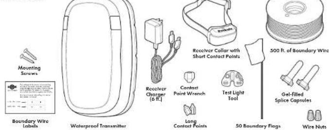
| Included Accessories | Mounting screws, boundary wire labels, receiver charger, contact point wrench, long contact points, receiver collar with short contact points, test light tool, 500 ft boundary wire, gel-filled splice capsules, 50 boundary flags, wire nuts |
| Warranty | 1 year limited warranty |
| Customer Support | USA/Canada: 800-732-2677, Australia: 1800 786 608, New Zealand: 0800 543 054 |
Frequently Asked Questions - YardMax PIG00-15958 PETSAFE
User questions about YardMax PIG00-15958 PETSAFE
0 question about this device. Answer the ones you know or ask your own.
Ask a new question about this device
Download the instructions for your Uncategorized in PDF format for free! Find your manual YardMax PIG00-15958 - PETSAFE and take your electronic device back in hand. On this page are published all the documents necessary for the use of your device. YardMax PIG00-15958 by PETSAFE.
USER MANUAL YardMax PIG00-15958 PETSAFE
natural_image
Line drawing of a pet safety harness with a strap and tag (no text or symbols)
natural_image
Line drawing of a rounded rectangular object with two side slots, resembling a device or container (no text or symbols)Please read this entire Product Manual before beginning
Welcome
You and your pet were made for each other. Our aim is to help you have the best companionship and the most memorable moments together. Your new YardMax Cardless in Ground Fence system is designed to give your act maximum freedom while keeping him safe.
We know that safe puts make happy owners. Before getting started, please have your utilities marked, and take a moment to read through the important safety information. If you have any questions, please don't hesitate to contact us.
Hereinafter Radio Systems Corporation, Radio Systems PetSafe Europe Ltd., Radio Systems Australia Pty Ltd, and any other affiliate or brand of Radio Systems Corporation may be referred to collectively as "We" or "Us."
Important Safety Information
Explanation of attention words and symbols used in this Product Manual:

This is the safety alert symbol. It is used to alert you to potential personal injury hazards. Obey of safety messages that follow this symbol to avoid possible injury or death.

WARNING indicates a hazardous situation which, if not avoided, could result in death or serious injury.

CAUTION, used with the safety alert symbol, indicates a hazardous situation which, if not avoided, could result in minor or moderate injury.

CAUTION, used without the safety alert symbol, indicates a hazardous situation which, if not avoided, could result in harm to your pet.

NOTICE is used to address practices not related to personal injury.
▲WARNING
- Not for use with aggressive pets. Do not use this product if your pet is prone to aggressive behavior. Aggressive pets can cause severe injury or death to their owners and others. If you are not sure that this product is right for your pet, please talk to your verification or a certified trainer.
- Before you begin installing the boundary wire, turn off the transmitter.
- Underground cables can carry high voltage. Have all underground cables marked before you dig to bury your wire. In most areas this is a free service. Avoid those cables when you dig.
- Do not install, connect or remove your system during a lightning storm. If the storm is close enough for you to hear thunder, it is close enough to create hazardous surges.
- To avoid risk of severe injury, follow all safety instructions for your power tools. Be sure to always wear your safety goggles.
- The battery should be charged in areas with temperatures ranging from 32°F to 113°F / 0°C to 45°C. Recharging the battery outside of this temperature range can cause the battery to overhead, opleads or catch fire.
CAUTION
- Wire on top of the ground may be a trip hazard. Be careful when placing wires and testing the system.
- This system is NOT a solid barrier. It is designed to act as a deterrent to remind pets to remain within the extubsted boundary by use of static correction. It is important that you reinforce training with your pet on a regular basis. Since the tolerance level to static correction varies from pet to pet, Radio Systems Corporation CANNOT guarantee that the system will in all cases, keep a pet within the extubsted boundary. Not all pets can be trained to avoid crossing the boundary! Therefore, if you have reason to believe that your pet may prove a danger to others or harm himself if he is not kept from crossing the boundary, you should NOT rely solely upon this system to confine your pet. Radio Systems Corporation shall NOT be liable for any property damage, economic loss or any consequential damages sustained as a result of any animal crossing the boundary.
CAUTION
Proper fit of the receiver collar is important. A receiver collar worn for too long or made too tight on your pet's neck may cause skin damage, ranging from redness to pressure ulcers. This condition is commonly known as bed sores.
- Avoid leaving the receiver collar on your pet for more than 12 hours per day.
- When possible reposition the collar on your pet's neck every 1 to 2 hours.
- Check the fit to prevent excessive pressure; follow the instructions in this Product Manual.
• Regularly recheck the fit to prevent excessive pressure; follow the instructions in this Product Manual.
- You may need to trim the hair in the area of the contact points. Never shave your pet's neck; this may lead to a rash or infarction.
- Never connect a leash to a collar with contact points. It will cause excessive pressure on the contact points.
- When using a separate collar for a bunch, do not put pressure on the nominal collar
- Wash your pet's rock area and the contact points of the new car collar weekly with a same cloth.
- Examine the contact area daily for signs of a rash or a sore.
- If a rash or sore is found, discontinue use of the receiver collar until the skin has healed.
• If the condition persists beyond 43 hours, see your veteranization.
* For additional information on bed rows and pressure ranges, please visit our website.
• Proper training of your put is essential to successfully using the system. During the first 2 weeks of training, do not use the
system without direct supervision of your pet.
- The receiver collar should not be on your pet when the system is tested. If it is, your pet may receive an unintended correction.
- Do not change the transmitter setting from Traditional mode (B) to YardMax * mode (A) without verifying that the receiver collar will still contain your pet.
- If the receiver collar fails the ReadyTest startup, the receiver collar is automatically turned off. Your pet will not be contained
• Always remove your net's receiver color before performing any lens transmitter testing. This will prevent
unintended corrections.
- The boundary width of the system must be tested whenever an adjustment is made to the put area to prevent unfunded corrections to your pet.
NOTICE
- Avoid damage to the insulation of the boundary wire during installation; damage may cause areas of weak signal and lead to early failure of the boundary.
• To conserve your batteries, when unused for long periods of time, remove them.
- You should expect hundreds of recharge cycles from your battery; however, do not charge your receiver collar every night. Charging too often can reduce battery life.
- Charge your receiver collar when the receiver indicator light blinks red.
- When mowing or trimming your grass, use care not to cut the boundary wire.
• To prevent an unintended correction, after the boundary flags have been placed, be sure to set the static correction on the receiver collar back to level 1, which is one only.
What's Covered
| How it Works.... | 6 |
| 4 Steps to o Contained Pet.... | 6 |
| Inear the Transmit for Batteries.... | 6 |
| Charge the Coller.... | 7 |
| Have Your Utilities Marked.... | 7 |
| Choose a location.... | 7 |
| YarWixr ^2 Mode (A).... | 8 |
| Tradmonel Mode (B).... | 8 |
| Base Planning Tips.... | 9 |
| Prepare the Coller.... | 13 |
| Connect the Wire.... | 13 |
| Mount the Transmitter (opfront).... | 14 |
| Turn on the Transmitter.... | 14 |
| Test the Fence Direction.... | 14 |
| Test the Coller.... | 15 |
| Buy the Boundary Wire.... | 17 |
| Flower the Boundary Hoge.... | 18 |
| Fit the Coller.... | 19 |
| Training.... | 20 |
| Advanced Features.... | 22 |
| System Test.... | 23 |
| Wire Break Location Test.... | 24 |
| Receiver Collor Status Indicators.... | 25 |
| Transmitter Alarms.... | 26 |
| Troubleshooting.... | 26 |
| Customer Care International.... | 28 |
| Terms of Use and Limitation of Liability.... | 28 |
| Warranty.... | 28 |
| Battery Disposal.... | 29 |
| Compliance.... | 29 |
| Layout Child.... | 30 |
In the Box
You May Also Need
• Additional wire and Flags (Part N FIG00-13769)
• Additional wine muts and gel-lined spline capsules
• Drill with Phillips drill bit
- 5moll Phillips screwdriver
- Staple gun
- Sessions
• lighter
• Pieri - Space shovel or lawn edge
- Wire stripping pliers
• Waterproofing compound (e.g. silicone caulk)
• Non-metallic color and bleach
- PVC pipe or water hose
• Circular saw with masonry blade
- Mounting stroke
Understand the Transmitter
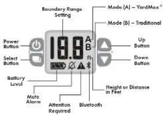
Power Button
Pass and hold the power button down firmly for 5 seconds to turn on the
transmitter. To turn all the transmitter, press and hold the power button
Select Button
The select button allows you to edit the 2 transmitter settings. The order of the selection is as follows:
- Boundary range
2 ft. to 15 ft. (varies by mode) - Boundary mode
(A) or (B)
To Edit the Transmitter Settings:
-
Press the select button. The boundary range setting will start to flash.
-
Use the up and down buttons to change the range.
- Press the select button again. The mode setting will start to flash.
- Use the up or down barons to choose the mode:
(A) - YardMax or [B] - Traditional
Notes: Settings can only be edited while they are flashing
Up and Down Buttons
The up and down buttons are used to change the boundary settings. They also mute the alarm.
Bluetooth ^® Icon
Bluetooth capability is not yet available, but your transmitter was
built with future updates in mind. Check our website for Bluetooth
technology announcements
Each time the transmitter is powered by, the Bluetooth * ion will flash for 3 minutes and then disappear.
Battery Level Icon
The battery icon displays 3 bars with a full charge. Replace the batteries when the battery icon shows 1 bar or no bars. Typically, battery life lasts 9 to 12 months. If the battery level becomes too low, the lights will flash red once every few seconds, along with a single alarm tone.
Attention Required Icon
The attention required icon will appear if there is an issue with the system. A unique alarm will also initially sound. The most common alarm are for a wine break, wine degranulation or if it was becomes disconnected from the transmitter. Even after the alarm is mued, the attention required icon will continue to display until the problem is resolved.
Muting the Alarm
An alarm tone will seem if on issue with the system is detected. The lights will flash red 1 to 3 times depending on the issue. To mute the alarm, press any button except the power button. This will mute the alarm; however, the lights will continue to flash until the problem is resolved. The mute alarm icon will appear, indicating that you have turned off the alarm.
Refer to the table "Transmitter Alarms" on page 26 for a complete guide to all the status lights and tones for the transmitter.
LED Display and Buttons
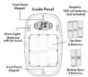
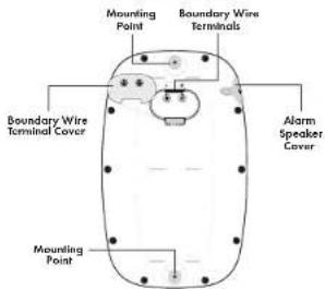
Transmitter Back
gelsafe.com+1 (800) 732-2677 54
How It Works
The YardMax® Cordless In-Ground Fence™ system allows you to safely keep your pet within the boundary you set. The PetSafe® brand has safely used static correction for decades and have helped millions of pets live happier, healthier and more active lives.
The system works by sending a signal through a buried wire (boundary wire). Your pet wears a receiver collar that picks up the signal. It warns your pet with a beep when he enters the warning zone. If your pet continues to venture out, the color will issue a safe but starting correction, similar to the static you feel if you drug your food across a carpet and then touch a door handle. Of course, different pets respond to different levels of correction. The collar has 5 levels of correction plus one-only setting to accommodate any pet. The only pets that we do not recommend the system for are aggressive pets and pets younger than 6 months of age or under 3 h. Make sure to go through the training as described on page 20 before leaving your pet unattended.
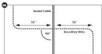
Please note that large metal objects and wires can ONLY and/or modulate signals in unpredictable ways. Make a plan for how you will work around any large metal objects like sheds, or conditioning units or existing wires. Call your utility company to have your utility lines marked. You can cross utility lines but only or 90^ angles (see figure 3A).
Note: if you buy extra wire, the system is expandable up to 1,000 ft.
4 Steps to a Contained Pet
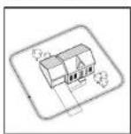
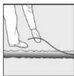
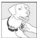
1. Plan Your Layout 2. Install Your System
3. Fit the Collar on Your Pet
4. Train Your Pet
An important thing to note even before you get stared, is that you should always remove the receiver collar from your pet while inside or when the system is not in use. Also, never leave it on your pet for more than 12 consecutive hours, and absolutely never attach a leash to it—use a separate caller for that. Excessive pressure and continuous use without brunks could hurt your gut's skin.
Installation time can vary based on the size of your yard and the layout you choose. Training your port to understand the system typically takes a couple of weeks. No worries though, we will get through everything you need to know here, and you can always reference our setup videos or give us a call if you have a question.
Quick tip: Using a small branching or down edging tool instead of a show, can serve you a lot of time when burying your wine. These can be found at your local hardware store.
Insert the Transmitter Batteries
-
The transmitter requires 10 D cell batteries. It does not have an AC port.
-
Remove the magnetic cover from the transmitter and set in aside.
-
Remove the 10 screws to the battery door with a Phillips screwdriver.
-
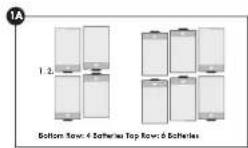
Insert 4 D cell batteries into the bottom row first, in the direction shown [1A]
-
Insert the remaining 6 batteries on the top row.
After you insert the first battery on the top row, the unit will temporarily turn on and go through a startup cycle. All basic orders on the LED will lease, the lights will lease and the transmitter will emit a tape. The LED display will then disapprove and the transmitter will be off.
- Reattose the batteries doar and magnetic cover to the transmitter
We do not recommended turning on the transmitter at this time. We will explain later on pages 13 and 14 how to connect the wires and turn on the transmitter.
Note: Battery line typically lasts 9 to 12 months. Check the battery status monthly. Replace the batteries when the battery is not shown (or no baro
△WARNING
Underground cables can carry high voltage. Have all underground cables marked before you dig to bury your wire. In most areas, this is a free service. Avoid these cables when you dig.
Charge the Collar
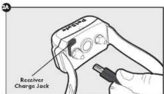
Open the rubber cap on the back of the receiver collar and plug the adaptor into your collar to begin charging (2A). The collar light is red while charging and green when fully charged. The first charge will take about 2 or 3 hours. Each charge can last up to 3 months depending on the frequency of use. Only recharge the collar when the indicator light begins to blink red.
Have Your Utilities Marked
-
Call your utility company to have your utility lines marked. If you have neighbors using on in-ground pet containment system, you will want to ask them where the boundary is located. Place your wire at least 10 ft away from it.
-
large metal objects and wires can cause interference in unpredictable ways. Make a plan for how you will work around any large metal objects, like sheets or existing wires. You can cross utility lines at a 90° angle [3A].
Choose a Location
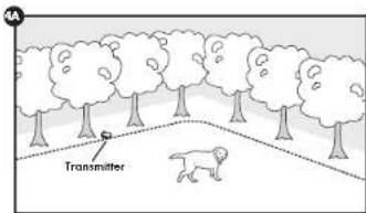
For outside use, the ideal location of the transmitter is along the outer perimeter of your property, ideally mounted to a post or placed under a tree (4A). However, the transmitter can be placed indoors or on the side of your home. There are a few things to consider when choosing a location:
- Place the transmittance in a shaded area to avoid direct sunlight. Extreme temperatures can affect battery life and may cause damage to the batteries, affecting the system operation. The temperatures in the placed location should not fall below -25°F / -32°C, or rise above 130°F / 55°C.
- The transmitter should be at least 3 ft. from large metal objects like an outdoor shed or indoor appliances. These items may interfere with the signal consistency
- Place the transmitter is a visible location where you will be able to hear any alarms and see the alarm lights if your system detects an issue.
- If you plan to mount the transmitter or decide to place it indoors, keep in mind that the boundary wire that runs from the transmitter out to the main boundary wire must be twisted together. Be sure to leave plenty of extra wire near the transmitter when planning your layout.
- Do not move the transmitter until the boundary wire is connected to it.
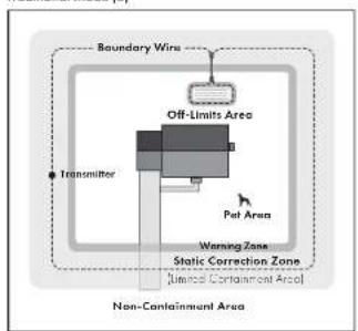
The system has 2 modes: YardMax ^- (A) and Traditional [B].
YardMax ^① Mode (A)
- The warning zone begins directly at the boundary wire, so your pet van maximizes yard space.
- The connection team is perceived to be infinite past the boundary wire. If your per continues beyond the boundary wire, he will be much more inclined to turn and head back.
- This mode is ideal for small yards; it allows your pet to use up to 30% more of the pet area than with Traditional mode [6].
- This mode does not have the ability to create off-linds unions to surround things like gardens or pools unless combined with a Powz Away® barrier product.
- After 15 seconds of continuous correction, the system will time out. This is to avoid correcting a pet that may be stuck outside his boundaries.
YardMax Mode (A)
![Boundary Wire 30% More Yard Than Traditional Mode Transmitter Pet Area Warning Zone Static Correction Zone [Intrinsic Control Section (A.6)]](/content/2026/05/886610/images/4525d39132ee493eceec13ca5f41ea75dfebc8f796517f5ad46c916b579f3e03.jpg)
Traditional Mode (B)
- The warning zone begins before the boundary wire, to yard space is reduced.
- Only this mode has the ability to create off-limits areas to surround area like gardens or pools.
- The correction area is limited and is set by the boundary width, so if your put bolts through the extra static correction zone, he will no longer be corrected.
- After 1.5 seconds of continuous correction, the system will time out. This is to avoid correcting a set that may be stuck within the static connection zone.
Traditional Mode (B)
flowchart
graph TD
    A["Boundary Wire"] --> B["Off-Limits Area"]
    B --> C["Transmitter"]
    C --> D["Pet Area"]
    D --> E["Warning Zone"]
    E --> F["Static Correction Zone"]
    F --> G["Non-Containment Area"]
    style A fill:#f9f,stroke:#333
    style B fill:#ccf,stroke:#333
    style C fill:#cfc,stroke:#333
    style D fill:#fcc,stroke:#333
    style E fill:#cff,stroke:#333
    style F fill:#ffc,stroke:#333
    style G fill:#fcc,stroke:#333
Basic Planning Tips
- Always plan your layout, position the boundary wire and test the system as outlined in this Product Manual before burying the boundary wire. You do not want to find out after burying the wire that there is a problem with your input to a clean connection scheme.
- Layout grids are provided at the back of this Produce Manual
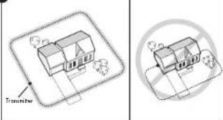
The boundary wire must start at the lance transeither and make a continuous loop back to it (5A).
• Always use recorded variances with a 3 ft. minimum radius (58). - You can create off-limits across to protect gardens, pools or landscaping by splicing a twisted section of wire from the main boundary wire. Traditional mode (B) only. This will allow your pet to cross this section without a correction.
- All layouts need to be at least 10 ft. from neighboring in-ground per containment systems.
• Cross any utility loss of a 90° angle
• Work carefully, a risk in the wire insulation could create a weak area in the signal field and reduces the life of the wire. - If you one mounting the transmitter or placing it indiscray, then the boundary wire needs to be twisted together before being connected to the transmitter. Be sure to leave plenty of extra wire near the transmitter when planning your layout.
- Ensure there is at least 10 ft. between the boundary wire and any danger zones like roadways.
5A
natural_image
Two technical diagrams showing 3D architectural or mechanical components with no visible text, numbers, or symbols.5B

Sample Layouts
Sample layouts are provided to help you visualize your yard.
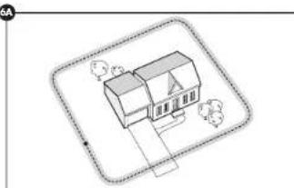
Single Loop Layout
With a single loop layout, the boundary wire starts at the fence transmitter, and continues all the way around the perimeter of the property and then connects back to the fence transmitter. This forms a boundary zone with a single wire (6A). This is appropriate for YardMax® mode [AI] or Traditional mode [BI].
6A
natural_image
Isometric line drawing of a house with surrounding trees and pathways (no text or symbols)Double Loop Layout
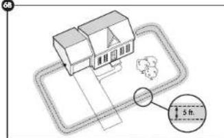
With a double loop layout, the boundary wire starts at the fence transmitter, and continues around the property to form a boundary zone in one section of your property (e.g., front yard only). Then the wire makes a U-turn back along the same path and connects back to the fence transmitter. This forms a boundary zone with a double wire [6B]. This only works in Traditional mode [6]
68
petsafe.com+1 (800) 732-2677 98
YardMax \* Mode (A) Layouts
The YardMax™ mode (A) can only be used with a single loop perimeter layout. It cannot be used to create off-limits areas.
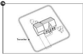
Sample 1 (7A)
Perimeter loop With a perimeter loop, YardMax® mode (A) allows your per to maximize the put area and room for entire property mainly and safely.
Sample 2 (78)
Perimeter Loop Using Existing Fence This layout allows you to include your existing fence on part of your layout and keep your act from jumping out or digging under your existing fence. This layout also gravity reduces the installation time since most of the wire will not need to be buried.
Traditional Mode (B) Layouts
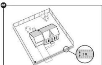
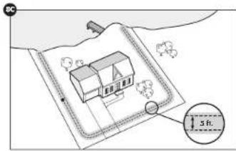
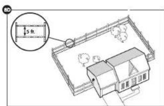
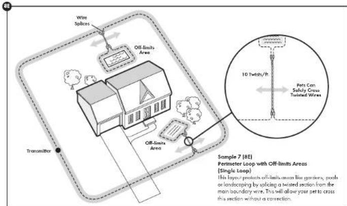
Traditional mode [B] has the ability to create off limits areas to surround things like gardens or pools (BE), and it can be used with either a single loop or a double loop layout. Sample 1 [7A] and Sample 2 [7B] layouts may be also be used in Traditional mode [8]. There should be at least 3 ft. of separation between wires when using a double loop.
Sample 3 (8A)
Front Yard or Back Yard Only (Double Loop)
Sample 4 (8B)
Front Boundary Only (Double Loop)
natural_image
Isometric line drawing of a house with trees and a labeled container (no text or symbols beyond label)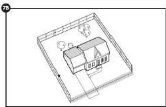
natural_image
Isometric line drawing of a two-story house with windows and roof, no text or symbols present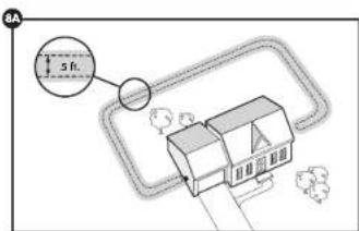
Sample 5 (8C) Waterfront Property (Double Loop)
Sample 6 (8D) Wire Loop Attached to Existing Fence (Double Loop)
petsale.com+1 [800]732-2677 1110
Additional Boundary Wire
The YardMax® Cordless In-Ground Fence™ system supports up to 1,000 ft. of boundary wire. You may purchase an additional 500 ft. spool at the store where you purchased the kit or through the PerSafe Customer Care Center.
The table on the right indicates the approximate length of boundary wire needed for a square, single loop layout. The length will vary due to the amount of twisted wire and the layout used.
Position the Boundary Wire
Once you have designed your layout, the next step is to position the wire. Hold all on buying the wire until you have tested the system list.
- Start with one end of the wire at the transmitter, but do not turn it on yet. Run the wire all the way around your planned perimeter and back to the transmitter.
Off-limits Areas
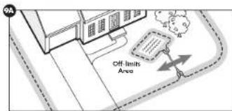
- For off-limits means like gardeners, you will need to splice a section between the main boundary wire and the off-limits area (9A). This will allow your pet to cross this section without a correction.
- Also, keep in mind that if you plan to mount the transmitter to a post or you decide to place it away from the main boundary location, the boundary wire that runs from the transmitter out to the main boundary must also be twisted together.
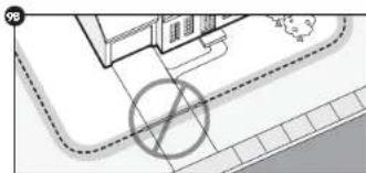
- Twisting both ends of the wire together 10-12 times per foot cancels the signal and allows your put to cross without remolding a connection. Any crossover areas must be within the boundary and cannot be along the perimeter of the boundary 1981. Although not required, it is recommended that you cut and splice the wire between each twisted section.
- The latest way to twist 2 wires is to cut 2 process a little longer than the length you need, twist them, and then splice in that section. Anchor one end of the 2 wires to something secure (or have a partner hold them), and insert the other end into a power drill. Pull the wire tight and then use the drill to slowly twist the wire. Follow the splicing guide below to learn how to reconnect this twisted portion back to the main boundary wire.
Splicing Guide
Your system comes with 2 gel-filled splice capsules to ensure that your salices are waterproof. Contact our Customer Care Center if you would like to purchase more splice capsules
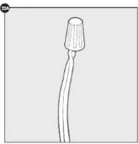
a. Strip approximately ^2 in. of insulation off the ends of the wires to be spliced (9C).
b. Place the wire nut over the stripped ends and twist the wire nut around the wires (9C). Make sure there is no copper exposed beyond the end of the wire nut.
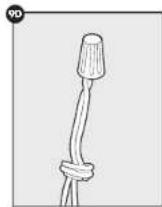
c. Tie a knot 3 to 4 in. from the wire out [9D]. Ensure that the wire nut is secure on the wire splice.
d. Once you have securely spliced the wires together, open the lid of the gel-filled splice capsule and insert the wire nut as deeply as possible into the waterproof gel inside the capsule [9E].
a. Snap the lid of the capsule shut (9F).
| Acres Feet of Wire Needed Number of Extra Spoals Needed | ||
| 12 415 | ||
| 12 430 | ||
| 12 500 | 1 | |
| 1 | 835 | 1 |
| 1/2 | 1,000 | 1 |
natural_image
Isometric view of a building with a dashed road and a circular symbol (no text or labels)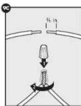
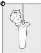
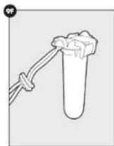
CAUTION If the receiver collar fails the ReadyTest startup, the receiver collar is automatically turned off, your pet will not be contained.
Prepare the Collar
Turn On the Receiver Collar
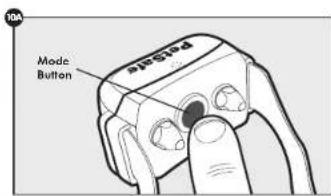
The collar will automatically turn on whenever it is removed from the charger. To turn on the receiver collar when it is not on the charger, press and hold the mode indicator for 1 second [10A].
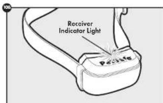
The collar will then go through the ReadyTest. The indicator light will flash green once and then go off for 1 second. It will then come back on and glow continuously for 5 seconds—either solid red, solid green, or red+green together to indicate the status of the battery [10B]. Finally, there will be a series of red flashes which represent the static correction level. The receiver collar will then automatically start the PerfectFit test by flashing red+green together every second for 90 seconds.
ReadyTest
ReadyTest is a mode that automatically starts every time you remove the receiver caller from the charger or first turn it on. If the ReadyTest's feature does detect a problem, the receiver caller will continually loop and the indicator light will grow solid red for 20 seconds. The receiver caller will automatically turn off. Do not put the receiver caller on your pet at this time: your pet will not be contained. Instead, turn the receiver caller back on and repeat the test. If the receiver caller continues to fall the ReadyTest startup, call the Customer Care Center. If the receiver caller is on your pet during the ReadyTest startup, the test will fail and the receiver caller will automatically turn off. This also means the system will not contain your pull
PerfectFit
After the ReadyTest, the PerfectFit music will automatically start. This test is an added feature to verify a "perfect" fit of the color around your pet's neck; however, it is not required for the system to function. For 90 seconds
the receiver collar on your pet and adjust the fit within the 90 seconds or it will go back to normal operation mode and flash the status of the battery (rod, green, or rod-green together) every 4 seconds.
After you adjust the collar on your seat and the contact points one touching his or her skin (or if you headwarrantly touch both of the contact points with your fingers), the receiver collar will emit a unique double tone. You will know you have the proper fit offer you hear 5 consecutive double tones and you see 5 green flashes. Then the receiver collar moves into normal operation mode and flashes the status of the battery every 4 seconds.
Turn Off the Receiver Collar
To turn off the receiver collar, press and hold the mode button (10A) continuously for 5 seconds until the red light turns off. To extend the time between charging the receiver collar, consider turning off the receiver collar when it is not in use.
Set the Static Correction Level
The static execution levels increase in strength from 2 to 6, with level 1 being tone only [so corrected on], and level 6 being the maximum setting
1. Press and hold the mode button [10A] until you see a red light, then let go. The color will emit a series of red flashes that correspond to the current correction level (e.g., 4 red flashes means level 4).
2. Press and hold the mode button again for 1 second to increase the level by one setting. You must count the number of red flashes to determine the level setting.
Refer to the table "Receiver Collar Status Indicators" on page 25 for a complete guide to all the status lights and tones for the receiver collar.
Connect the Wires
- Cut off 1 in. from the ends of each boundary wire to ensure a clean, straight end.
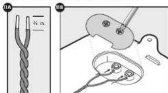
- Strip 14 in. of insulation from the 2 ends of the wires in order to connect them to the transmitter (11A)
- Remove the cover on the back of the transmitter with a Philips screwdriver to access the boundary wire terminals (118).
- Slightly bend the boundary wires and insert them through the holes in each terminal (118).
- Place the cover back only the transmitter.
- Tighten each screw to secure the boundary wine. Over tightening the screw can cause the wine to break.
petsale.com+1 [800]732-2677 1312
CAUTION
- The receiver collar should NOT be on your per when the system is tested. Your pet may receive an unintended correction.
• To prevent an unintended correction for your pet, rest the boundary location and width alter any change.
Mount the Transmitter (optional)
- Now that the wires have been connected, it is safe to mount the transmitter.
to a post be other state surface. - Use the 2 mounting screws provided to attach the transmitter. We
recommend using a power drill with a Philips drill bit.
Turn on the Transmitter
- Press and hold down the power button firmly for 5 seconds to turn on the transmitter. It will then go through a startup cycle. All the icons on the LED will flash, the lights will flash rod and the transmitter will omit a tone.
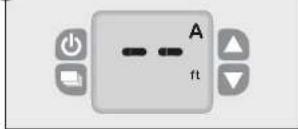
The first time you turn on the transmitter, the LED display will show 2 dashes, indicating that a boundary range has not been set (12A). The default mode setting is (A).
Test the Fence Direction
You must verify that your fence is transmitting in the correct direction to contain your put. You will need to do this test in mode (A), regardless of which final mode you plan to use.
- Set the mode setting to [A] if it is not already set to [A].
- Press the select button on the transmitter: the 2 dashed lines will begin to flash.
- Use the up button to change the height to 3 ft.
- Press the select button twice to save the setting and begin the operational mode.
- Make sure the receiver collar is turned on by holding the mode button for 1 second.
Note: When you remove the receiver collar from the charger, or first turn it on, the receiver collar will automatically go into ReadyTest® startup mode.
- Set the static correction on the receiver caller to level 6.
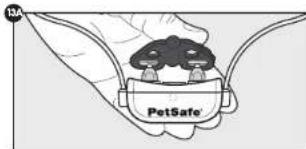
- Place the test light tool contacts onto the contact points of the receiver pillar (13A)
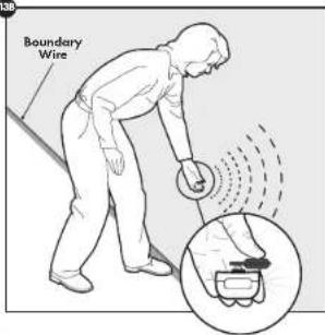
- Starting inside the net money, hold the receiver collar about 1 ft above the ground with the context points facing upwards and approach a straight section of your boundary wire that is at least 50 ft long.
- As you cross the wire (138), you will hear the warning tone and see the test light flash as you walk through the correction zone.
If the rest light tool does not flash - Turn around and walk back across the boundary wire into the pet area to see if it illuminates the seal light in that direction instead. If it does, reverse the wire at the connector to the force transmitter. Then repeat step 9.
- If it does not illuminate in either direction, move the receiver collar closer to the ground and repeat step 9.
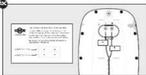
- Once you have verified that things are working as they should be, use the provided labels to identify the wires to the lance transmitter (13C). Fuel the |+| label and wrap it around the wire going to the |+| connection. Do the same for the |-| wire. If anything gets disconnected, you will be able to reconnect easily.
12A
138
10C
CAUTION
Northern climates can affect the range of the signal. In mode (AI, excessive snowfall (>112ft) may place your pet outside the signal field allowing your pet to leave the pet area. You may need to switch to mode (BI) or increase the boundary height setting until the snow reaches
Test the Collar
YardMax Mode (A) Installation
These steps are very similar to the ones used for testing the fence direction. With YardMax mode [A] the boundary setting is determined by the height of your put.
- The mode setting should still set to (A) from the fence direction step.
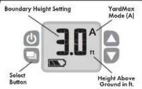
- Next you will enter a boundary height setting that is 1 ft above your pet's neck. For example, if your dog's neck is 2 ft from the ground, set the height to 3 ft (14A). To do this, press the select button until the boundary height setting flashes. Use the up or down buttons to adjust the height setting to the appropriate value. Press the select button twice to save it and begin the operational mode.
Note: The range for mode (A) is 2 ft. to 5 ft. - Make sure the static correction on the receiver color is set to level d.
- Place the test light tool against the receiver collar contacts and hold the contact points facing upwards.
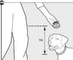
- Held the receiver calls about 1 H above your pet's work height [148].
Quick tips: See where this measurement relates to your body [148]. When you walk over the boundary wire with the receiver collar at this height, you want the receiver collar to tone and flash no higher than this. Adjust the boundary height setting until this is accomplished
- Starting inside the pat area, slowly approach a straight section of your boundary wire that is at least 50 ft. long. As you cross the wire, you will hear the warning tone and see the test light flash as you continue to walk through the correction zone. If you do not see the test light tool flash, increase the boundary height by 12 ft. and retest.
- Continue adjusting and retesting until the test light flashes at the boundary 1 ft. above the height where the receiver collar is positioned on your pat's neck.
- Repeat this test of different places along the boundary wire to verify that it is working everywhere. If you find an area where the collar activates less than 1 ft. above your per's neck, increase the height by ½ ft. and set again.
Note: To ensure that the signal is not coupled to any wires or other metallic objects, we will do one more test inside the pet area with mode (8).
- Use the select button to change the boundary width setting to 10 ft.
- Switch the mode to (B)
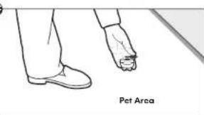
- With the test light tool and receiver collar contact points facing upward, walk throughout the per area with the receiver collar as close to the ground as possible (14C).
Note: The color will activate when within approximately 10 ft. of the boundary wire. This is normal for this operation mode. - The color should not activate within the per area. If there is no activation within the per area, you can change the needs back to (A).
- If however, the receiver caller stands activate within the port area, it means that you need to adjust the boundary wire where it crosses a cable or electrical wire (see figure 3A on page 71 or where it approaches another metallic object. Other options include reducing the boundary height setting or switching to Traditional mode (8). After the adjustment, raise the system.
- Once the boundary height setting is established, set the correction level on the receiver circle to level 1 for training.
It is now time to buy your boundary wind
14A
14B
MC
Test the Collar
Traditional Mode (B) Installation
These steps are very similar to the ones used for testing the fence direction. However, with Traditional mode [8], the boundary setting is determined by the width of the boundary, instead of the height of the pet.
- The mode needs to be changed to [B].
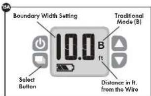
- Press the select button until the boundary width setting flashes. In this case, the setting should already be set to 3 ft. during the fence test.
- Press the select button again and mode [A] will flush. Press the down arrow to change the mode to [B]. This will automatically set the default value for mode (B) to 10 ft. Press the select button twice to save it [15A] Note: The range for mode (B) is 2 ft. to 1.5 ft
- Make sure that the static correction on the receiver collar is set to level 6.
- Place the test light tool against the receiver collar contact points and hold the contact points locating upwards.
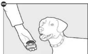
- Hold the receiver collar at your pet's neck height [158].
- Starting inside the pet area, approach a straight section of your boundary wire that is at least 50 ft. long (15C). The rest light will begin to flash 2 seconds after the warning tube. Walk back into the pet area until the beeping stops.
- Adjust the boundary width setting to establish the warning zone. We recommend setting it so that the warning zone begins at least 10 m before the boundary wire.
- Support this best at different places along the boundary wine to vary that it is working properly everywhere.
Note: To ensure that the signal is not coupled to any wires or other metallic objects, we will do one more but inside the net area.
-
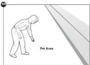
With the last light coil and receiver color current points facing upward, walk throughout the pet area (15D).
-
The collar should not activate within the pet area. If the receiver collar does activate within the pet area, it means that you need to adjust the boundary wire where it crosses a cable or electrical wire (see figure 3A on page 71 or where it approaches another metallic object. Another option is to reduce the boundary width setting by several feet. After the adjustment, actual the system.
-
Now that the boundary width is established, set the correction level on the receiver collar to level 1 for training.
It is now safe to bury your boundary wirel
natural_image
Illustration of a dog receiving food from a hand (no text or symbols)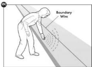
⚠ WARNING Underground cables can carry high voltage. Have all underground cables marked before you dig to bury your wire. In most areas, this is a free service. Avoid these cables when you dig.
⚠ WARNING Follow all safety instructions for your power tools. But sure to always wear your safety spectrum.
Bury the Boundary Wire
It is recommended to bury the boundary wire to protect it and prevent disabling the system. Other options include covering the wire with mulch or using lawn staples to secure the wire in plans.
- Cut a trench 1-3 in deep along your planned boundary. It only needs to be as wide as the wire.
Quick Tips: Lawn tranchers, which you can often run from a local hardware store, work great and make for a quick job. You can also use a flat shovel, like a trenching shovel. - Place the boundary wire into the trench, maintaining some stack to allow it to expand and contract with temperature variations.
- Use a blunt tool such as a wooden paint sick to push the boundary wire into the trench. Be careful nor to damage the boundary wire insulation.
Utilizing an Existing Fence
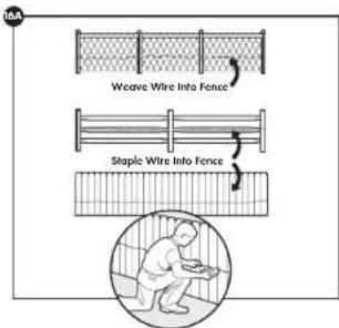
The boundary wire can be attached to a chain link fence, split rail fence or a wooden privacy fence. The boundary wire can be attached as high as needed. However, make sure the boundary setting is at a high enough range for your pet to receive the signal.
• Chain Link Fence (16A):
Weave the boundary wire through the links or use plastic quick ties.
+ Wooden Split Rail or Privacy Fence (16A):
Use staples to attach the boundary wire. Avoid puncturing the insulation of the boundary wire.
• Double Loop with an Existing Fence:
Run the boundary wire on top of the fence and return it on the bottom of the fence to get the 5 ft. separation needed.
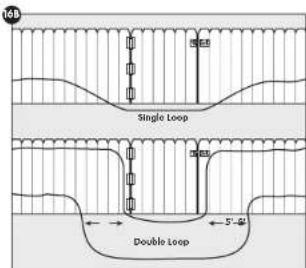
Utilizing an Existing Gate
• Gate [Single Loop] (16B):
Bury the boundary wire in the ground across the gate opening.
Bury both boundary wires across the gate opening while keeping them 5 ft apart.
Note: The signal is still active across the gate. Your put cannot pass through an open gate.
actsale.com+1 (800) 732-2677 1716
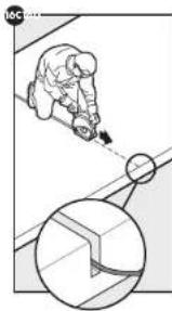
Cross Hard Surfaces (driveways, sidewalks, etc.)
- Concrete Driveway or Sidewalk (16C): Place the boundary wire in a convenient expansion joint or create a groove using a circular saw and memory blade. Place the boundary wire in the groove and cover with an appropriate waterproofing compound or foam backer rod. For boat nails, brush away dirt or other debris before patching.
- Gravel or Dirt Driveway (T&D): Place the boundary wire in a PVC pipe or water hose to protect the boundary wire before burying.
Place the Boundary Flags
The boundary flags are visual reminders for your pet of where the warning zone is located.
- Flows the hot light contacts on the contact points. Held the nutrient collar or the height of your per's neck.
- Walk towards the waiting zone until the receiver collar beeps (17A).
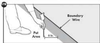
- If you are in YardMax ^ mode (A) place the boundary flag along the boundary wire approximately 6 in inside the set area (17B).
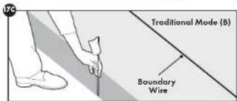
- If you are in Traditional mode (D) place the boundary flag where you hear the loop [17C].
- Walk back into the pet area until the keeping steps
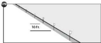
- Repeat this process along the warning zone until it is marked with boundary flags every 10 ft. (17D).
natural_image
Illustration of a person using a tool to cut or mark a circular object on a tiled floor, with an inset magnified view showing the same object (no text or symbols present)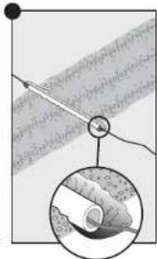
natural_image
Diagram showing a hand holding a pen with a magnified inset of the pen tip (no text or symbols present)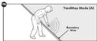
CAUTION
Proper fit of the receiver collar is important. A receiver collar worn for too long or made too tight on your pet's neck may cause skin damage, ranging from redness to pressure ulcers. This condition is commonly known as bed sores.
- Avoid leaving the receiver collar on your pet for more than 12 hours per day.
- When possible reposition the receiver collar on your pet's neck every 1 to 2 hours.
- Check the fit to prevent excessive pressure; follow the instructions in this Product Manual.
- Never connect to back to the price per dollar, it will cause excessive premiums on the
- Work your pet's work area and the contact points of the receiver color when with a game cloth
- Examine the contact area daily for signs of a rash or a sore.
• If a rash or sore is found, discontinue use of the receiver collar until the skin has healed
• If the condition persists beyond 48 hours, see your valuation
• For additional information at bad rates and pressure necrosis, please visit our website.
These steps will help keep your pet secure and comfortable. Millions of pets are comfortable while they wear stainless steel contact points. Some pets are sensitive to contact pressure. You may find after some time that your pet is very tolerant of the receiver collar. If so, you may relax some of these precautions. It is important to continue daily checks of the contact area. If darkness or sorens are found, discontinues use until the skin has fully healed.
CAUTION
You may need to trim the hair in the area of the contact points. Never shave your pet's neck, this may lead to a rash or infection.
Fit the Collar
Important: Your receiver collar comes installed with short contact points. If your pat has long or thick hair, use the long contact points instead. Epitine or switch the contact points by using the contact point wrench. The proper fit and placement of your receiver collar is important for effective training. The contact points must have direct contact with your pat's skin on the underside of his neck.
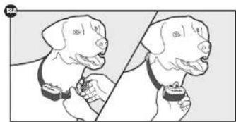
- Be sure the receiver collar is off before placing it on your pet. Then with your pet standing, the receiver collar simply onto your pet's neck so that the contact points make contact with your pet's skin on the underside of his or her neck. Make sure the PetSafe. Page is right-side up (18A).
- Check the tightness of the receiver collar by inserting one finger between the end of a contact point and your per's neck. The fit should be snug but not constricting.
- Allow your pet to wear the receiver collar for a few minutes, then check it again.
- The collar will slip it is not properly threaded. The slide buckle prevents the collar from increasing loose around your pat's neck and the ridges must be facing up (188).
- While the receiver collar is still off your part, turn it on by holding the mode button until a green light comes on. The first thing your receiver collar does is a ReadyTest startup [page 13] to ensure that it is ready for use. You will know it is done when there is a series of red flushes indicating the current static correction level. Do not touch the contact points during the ReadyTest startup.
- Once the ReadyTest startup is done, the receiver collar will automatically go through an optional PerfectFit Test (page 13), which lasts for 90 seconds. This mode begins with simultaneous flashing red+ green lights.
- Place the collar on your pet and adjust the fit.
- The receiver collar will emit a unique double tone as the contact points touch your per's skin. You will know that you have the proper fit when you hear the receiver collar emit the double tone and if finishes gram 5 consecutive times.
- After 90 seconds, the receiver collar moves into normal operation mode. If you do not hear the 5 consecutive double tone, adjust for collar and repeat the PerfectFit Test.
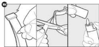
- Once you are satisfied with the fit of the receiver collar, remove it from your pet and trim it, but make sure to allow room for growth or a thicker winter coat. Use a lighter to seal the cut so that it will not carry (18C)
natural_image
Illustration of two dog breeds with collar clips, no text or symbols present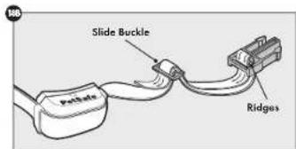
natural_image
Illustration of three-step manual techniques for handling a tool, no text or symbols presentpetsafe.com1 (800) 732-2677 1910
CAUTION
If the receiver collar fails the ReadyTest® startup, the receiver collar is automatically turned off. Your per will not be contained.
Training
- Remember that this system is not a solid corner. Using it successfully requires that you spent some time training your pat
- Finish each training session on a positive note with lots of praise and play. Remove the color after each training session.
- While your put is still learning the boundary, contain him by another means, such as with a pen or a leash.
- Put a separate non-metallic collar on your pet's neck and attach a leash.
- Be sure to place the cellar on your dog's neck with the PetSafe logo lining up
- If your per appears to be stressed, slow down the training schedule, add additional days of training or increase the amount of play time. Common stress signals include pulling on the leash toward the house, ears tucked or pulled back, tail down or tucked between legs, body lowered, nervous/frantic movement or stiffening of the pet's body, lip-licking or yawning.
Day 1
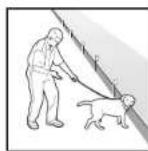
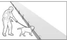
For the first day, start with the collar set to level 1, tone-only. With your pet on a leash and with his favorite treats on hand, allow him to explore the pet area [19A]. Allow your pet to cross the boundary (19B) and limit the tone from the collar, then ask him to come track into the pet area (19C) and praise and reward him. Your goal is for your dog to associate taking inside the pet area with rewarding experiences. Dogs are sensitive. Keep your mood upward as dogs can understand when you are happy or upset. Do 2 or 3 training sessions for about 10-15 minutes each. Do not try to do too much too quickly. Many frequent short sessions are better than less frequent, larger sessions.
Days 2-4
On days 2 through 4, repeat this process, but with the collar set to level 2—the mildest static correction level. Closely others your pet's behavior while he is in the correction zone (1983), and note whether or not your dog responds to the correction. Indicators of a response are looking around in curiosity, sticking off the ears or scratching at the collar. If he does not respond, check the fit of the collar to make sure the contact points are meeting contrast with his skin. If the collar is fit correctly and your dog does not respond, then move up to the next correction level and repeat the process. On 2 or 3 training sessions for about 10–15 minutes each. Your goal is for your dog to consistently choose to stay in the per area. If necessary, and in many days of training before moving on to the next step.
Days 5-8
On days 5 through 8, retain the collar settings from the last training session, but stage some distractions to test your dog's reliability. The goal is to have your pet stay within the boundary even with new temptations. Start with simple temptations and work your way up. Some examples are
- Have a family member cross from inside the boundary and exit.
- Place a toy outside the boundary.
• Have a friend or neighbor walk another pet outside the boundary area.
Remember to keep your pet on a lunch throughout this process while he is still earning the boundary. Also, never cook your pet to leave the
19A
natural_image
Illustration of a person walking with a dog on a leash, no text or symbols present198
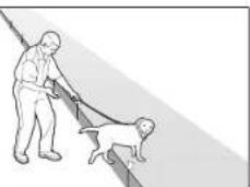
natural_image
Illustration of a person pulling a dog on a leash (no text or symbols)19C
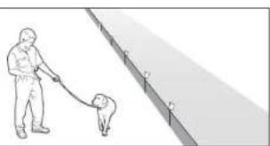
natural_image
Illustration of a person walking with a dog on a leash, no text or symbols presentCAUTION
Be sure the extra collar does not put pressure on the contact points.
pet area.
Days 9-30
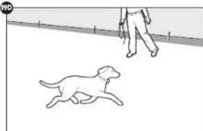
Once your pet consistently respects the boundary regardless of distractions or temptations, he is ready for the next step unleashed supervision (1990). Stay close by with a leash at hand. Play with your pet for a while during the first few sessions. If your dog does not try to cross the boundary, occupy yourself with another task in the yard, and allow him to freely explore. Continue watching your pet. If he escapes, remove the collar and lead him back into the pet area. Start these sessions at about 15 minutes and generally work up to an hour or more.
When your pet proves trustworthy, you can let him out on his own. Continue to check on him regularly. You can remove every other boundary marker every 4 days until all the markers are removed. Save them in case you move or need to train another pet.
19D
natural_image
Line drawing of a dog running on a path with a person walking nearby (no text or symbols)Taking Your Pet Out of the Pet Area
Important: Remove the receiver collar and leave it at home.
Once your pet learns the boundary, he will be reluctant to cross it for walks or car rides.
Option 1:
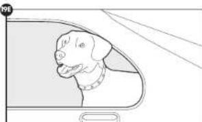
Replace the receiver collar with a regular collar. Put your pet in a car that is within the pet area and drive him out of the pet area [19E].
Option 2:
Replace the receiver collar with a regular collar and leash. Walk your pet out of the pet area while giving a command such as "OK" of a specific place along the boundary (the end of your driveway, sidewalk, etc.). Always leave the pet area from the same spot in your yard with a leash and your pet will associate leaving the pet area only on a leash, only at this spot, and only with a person. You may initially need to convince your pet to leave for pet area with a trust and lots of praise.
Note: You may also carry your pet out of the pet area.
Congratulations! You have now completed the training program. You are both ready to enjoy more freedom. Just make sure to continue to check the tightness of the receiver collar and remove it when it is not in use.
19E
natural_image
Line drawing of a dog peeking out of a vehicle's side window (no text or symbols)Advanced Features
Anti-Linger Prevention
The Anti-Linger Prevention fixture keeps your pet from staying in the warning zone for long periods of time and draining the receiver collar's rechargeable battery. Your pet will hear a 2-second warning tone when he reaches the warning zone. If your pet does not return to the pet area after 2 seconds, he will receive a continuous static correction until he returns to the pet area or until the Over Correction Protection fixture is enabled.
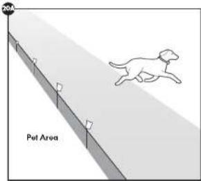
Run Through Prevention
This system includes a unique Run Through Prevention feature so that your pet cannot "run through" the pet area without receiving an increased level of static correction. [20A].
YardMax Mode [A]
When your pet crosses over the wire and passes the warning zone, static correction is activated. The ideal warning zone distance is where the receiver collar activates between 1 to 1½ ft. above your pet's neck height. If you have a very timid pet, you may increase the warning zone distance to allow more distance before the Run Through Prevention. You can accomplish this by increasing the height of the receiver collar activation.
Traditional Mode [B]
The receiver collar automatically increases the static correction when your pet continues more than 20% of the way through the boundary width. For example, if the signal is detected 10 lt. from the wire and your pet enters the static correction zone, this feature is activated when he is approximately 8 lt. from the boundary wire. Your pet will then receive a static correction that is or an increased level corresponding to the static correction level setting on the receiver collar.
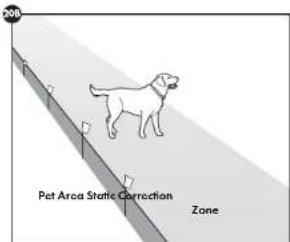
Over Correction Protection
Over Correction Protection is designed to protect your pet from prolonged static correction if he "freezes" in the static correction zone or runs beyond the boundary [20B].
YordMax \* Mode [A]
In the unlikely event that your pet "freezes" or continues beyond the boundary, the static correction duration continues for 15 seconds. The receiver collar locks out further static correction and the green light will remain on for 10 seconds. The receiver collar remains locked out until your pet re-enters the pet area.
Traditional Mode [B]
In the unlikely event that your pet "freezes" in the static correction zone, this feature limits the static correction duration to 15 seconds. While the receiver collar locks out further static correction, the green light will remain on for 10 seconds. The receiver collar remains locked out until your pet leaves the static correction zone.
System Test
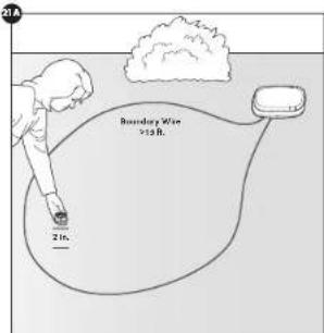
The system test is used to determine the cause of system problems that have not been addressed elsewhere in this guide. You will need a piece of boundary wire greater than 1.5 ft. long with X in. of insulation removed from each and to one as a test loop wire.
Follow the steps below to perform the system test:
-
Make a note of the mode (A or B), the width/height setting and your color setting so that you can return to these levels at the completion of the tasks.
-
Turn off the transmitter.
-
Remove the collar from your dog and make sure it is fully charged.
-
Set the color correction level to 6.
-
Disconnect the boundary wires from the boundary wire terminals to the fence transmitter.
-
Insert the two ends of the test loop wire into the open boundary wire terminals on the transmitter.
-
Turn the transmitter back on.
-
Set to Traditional mode (B).
-
Adjust the boundary width setting to 2 ft.
-
Place the test light tool contacts on the contact points of the collar. While holding the collar with the test light tool in place, approach the wire from the outside loop, keeping the collar 2 in off the ground (21A). Make a mental rate of the distance where the collar activates from the wire.
-
Set the ordinary width to 5 ft. and repeat step 8. The distance where the collar activates should be greater than the previous result.
-
If more than one collar is used on this system, repeat the above set on each collar.
-
Interpreting the results:
a. If the LCD display is not it on the fence transmitter, or the alarm is on for any of the above tests, there is a problem with the transmitter. Contact the Customer Care Center.
b. If the LCD display is on, but the collar does not activate on the last loop wire, the collar is not working. Contact the Customer Care Center.
c. If the LCD display is on, and the color is activating or different distances on the heat loop wire; the problem is most likely in the containment boundary wire—see the wire break location test
- When the testing is complete, reconnect and verify that the boundary wire is plugged into the transmitter.
1.5. Return the mode, the width/height setting and the collar setting to their original levels.
Wire Break Location Test
Please impact these overs for signs of damage.
Wire breaks are commonly found:
• At the win suit point of the house
- Where the wine enters the ground from the house, usually caused by string trimmers
- Where the wires cross sidewalks or driveways, usually caused by edging and string trimmers
- Around landscaping and flower beds, usually caused by digging, or working up the soil
- In donated low/g
- At wire splices where gel-filled capsules have not been installed
If you still cannot find the break in the boundary wire, there are 2 options for locating it:
Option 1: It is recommended to contact the Customer Care Center to purchase a Wine Break Locator [RFA-590] (228). The Wine Break Locator detects full breaks, not partial breaks.
Option 2: Follow the procedure below:
- Using the focus transmitter
- Connect bath ends of your boundary wire to one loop terminal on the transmitter.
- Measure and cut a load wire which is half the length of your total boundary wire footage.
- Connect one end of seat wire to the other loop terminal on the transmitter.
- Locate the halfway point of your boundary and cut the boundary wire.
- Spice the other end of the test wire to either side of your boundary wire, where you cut it in half.
- Plug in the fence transmitter, set to Traditional mode [3], and check the transmitter for the wire break alarm. If the wire break alarm is on, you can assume that the break is in this half of the boundary wire.
- If the wire break alarm did not come on, you may assume there is a break in the other portion of the boundary wire. However, there is a small chance of having more than one break in your system. Be sure to check both halves of your entire loop.
- Replace the damaged boundary wire with new boundary wire.
- Reconnect the boundary wire to the transmitter.
- Check the loop indicator light. If the loop indicator light is on, test the system with the receiver caller.
natural_image
Simple line drawing of a bulb-like object with a pointed tip and curved stem (no text or symbols)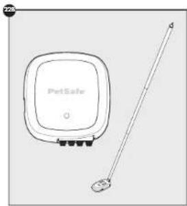
natural_image
Line drawing of a portable security device with a sensor and antenna (no text or symbols)Receiver Collar Status Indicators
The receiver collar light end the alarm tones are used to determine the operational mode, the battery status and the connection level status to the receiver collar status table below to understand the status lights and tones for the receiver collar. During normal operation, the receiver collar light will flush every 4 seconds to indicate the battery status as shown in the table below. If your receiver collar has not been moved for at least 20 seconds, the battery status light will function, but the receiver collar will enter sleep mode to conserve battery life. To wake up the receiver collar simply pick it up and flip it over on choke it.
| Receiver Collar Status Table | ||
| Light Status Alarm Tone Condition | ||
| While Plugged into the Receiver Charger | ||
| Solid red No tone Charge in progress | ||
| Solid green No tone | Charge complete | |
| No light | No tone | Charge failure-contact Customer Care Center |
| ReadyTest' Startup(After removing the receiver collar from the charger or other first turning it on) | ||
| Off for 1 second | No tone | Unit is starting the ReadyTest' startup feature |
| Continuous red, green, or red*green together[5 seconds] | No tone | Battery charge status |
| Flashing red from 1 to 6 times | No tone | Receiver collar is reporting thestatic correction level from 1 to 6 |
| Continuous red | 20 seconds | ReadyTest' failure:Unit is not operational - contact Customer Care Center |
| PerfectFit Test | ||
| Flashing red*green together(every 1 seconds) | No tone | Unit is in PerfectFit mode for 90 secondsafter the UnityTest startup is completed |
| Flashing green(every 1 seconds) | 5 consecutive double tonesfor a confirmed fit | PerfectFit mode indicates that the collar is making thuccontact with the pat's skin |
| Static Correction Level | ||
| Flashing red from 1 to 6 times | No tone | Receiver collar is reporting thestatic correction level from 1 to 6 |
| Receiver Activation Status | ||
| Fast pulsating green | Warning tone Warning tone | |
| Fast pulsating red | Duration of the correction | Static correction is being delivered(up to 15 seconds) |
| Continuous green(10 seconds) | No tone | Over Correction Protection feature;Collar is locked for 10 seconds |
| Slow blinking greenelevery 4 seconds) | No tone | Collar battery charge 100%-60% |
| Slow blinking red*green togetherlevery 4 seconds) | No tone | Collar battery charge 60%-20% |
| Slow blinking red(every 4 seconds) | No tone | Collar battery charge 20% or less;Charge immediately |
petsce.com-1 (800) 732-2677 2524
Transmitter Alarms
| Light Status Alarm Tone Alarm Condition | ||
| 1 red Flash 1 tone Low battery | ||
| 2 red Flashes 2 tones | System problem:Call the Customer Cone Center | |
| 3 red Flashes 3 tones | Wire problem:1. Wire break 2. Wire degradation 3. Wire disconnected from transmitter | |
Notes: When an issue is detected, the real alarm lights will flash and the alarm tone will sound until the problem is resolved. Pressing any of the buttons (except the power button) will silence the alarm, but the lights will continue to flash. The more alarm icon will indicate that you have silenced the alarm.
Troubleshooting
| The receiver collar is not beeping or correcting. | Make sure the receiver collar is turned on, and the battery status lights are fading every 4 seconds.Charge the receiver collar and go through the ReadyTest®stump and Perfecter diagnostic tests.Check that the fence transmitter power is turned on and the display is on. If not, check and replace the batteries.In YardMax mode (A), excessive snowfall [>11⁄2 ft.] may place your pet outside the signal field. You may need to switch to Traditional mode [B] or increase the boundary height until the snow records. |
| The receiver collar is beeping, but the pet is not responding to the static correction. | Make sure the static correction level is set at 2 or above.Test the receiver collar with the test light by walking toward the boundary wire. If the test light flashes, adjust the fit of the receiver collar using the Perfecter feature.Trim your pet's far where the contact points touch the neck or use the long contact points.Increase the static correction level.Repeat the training stops to reinforce the training |
| In YardMax® mode (A), the receiver collar corrects when the pet returns to the Pet Area. | Check that the fence mode is set to YardMax® mode (A) and not mode [B].Reverse the wires connected to the fence transmitter.Repeat the boundary. |
| The receiver collar has to be held on top of the boundary wire to activate. | Charge the receiver collar.Traditional mode (B) only - press the up button to adjust the boundary width setting, this increases the distance from the boundary wire that the retainer collar activates. The recommended distance is 10 ft. from the boundary wire.If using a double loop, make sure the boundary wires are separated by at least 5 ft.Check and replace the transmitter batteries.If the receiver collar still has to be held on top of the boundary wire, perform the System Tool (pragc 2.3). |
| The receiver collar activates inside the house. | Make sure the boundary wire is not running within 1.5 ft. of the house. That signal can transmit through the walls of your home.If the fence transmitter is inside the house, make sure the boundary wires coming from outside and going to the fence transmitter are twisted in order to cancel the signal.Transitional mode (B) only - adjust the boundary width setting to decrease the distance from the boundary wire that the receiver collar activates. |
| Why does the transmitter display a Bluetooth® icon? | Your transmitter was built with future updates in mind. Check petsafe.com regularly for announcements regarding Bluetooth® technology. |
| I have an inconsistent signal. | • Make sure the fence transmitter is at least 3 ft from large naval objects or appliances. • Make sure all the boundary wire turns are produced with at least a 3 ft radius. • Make sure the boundary wire is not running parallel to or within 10 ft of electrical wires, neighboring containment systems, telephone wires, television or umbrella cables, or satellite dishes. • If a neighboring containment system may be causing an inconsistent signal, move the boundary wire further away from the neighboring containment system. |
| Transmitter status light and alarm indicate a wire problem. | • Check the boundary wire connections at the fence transmitter for proper connection. • Check outside for broken or damaged boundary wires. • Perform the System Test (page 23) • Perform the Wire Break Location Test (page 24). |
| There is no display on the fence transmitter. | • Verify that the transmitter power is turned on. • Verify that the batteries are installed correctly. • Replace the batteries. • If new batteries do not solve the problem, call the Customer Care Center. |
| Receiver collar is not charging. | • Check that the charger is properly seated into the receiver collar jack. • If the indicator light on the receiver collar still does not glow red when connected to charger, there is a problem with the charger. If the indicator light gives red when placed on the charger but goes out after disconnecting the receiver collar without performing the ReadyTest startup, there is a problem with the receiver collar. Call the Customer Care Center. |
| In YardMax® mode (A), my pet is able to cross the boundary wire in either direction without receiving a static correction. | • Make sure the fence transmitter is set to YardMax® mode (A). • Starting inside the pet area, when crossing the boundary wire, the receiver collar should tone at a distance of 1 ft above the pet's neck height (page 10). |
| In YardMax® mode (A), the receiver collar corrects within the pet area. | • Check and make sure that the receiver activation height is not greater than 1/6 ft above the pet's neck height (page 15) when crossing the boundary wire. • There could be an inconsistent signal due to close proximity to telephone wires or television cables, etc. Readjust the boundary wires where they cross buried cables (page 7). |
| My pet reacts strongly to the static correction and has become fearful. | • Lower the static correction load. • Makes sure you are in control of the situation when your pet receives his first static corrections have him on a head attached to a separate, non-metallic collar and tied sun into the pet area and praise sun. If your pet remains bright, suspend training and start again the next day. Make wire to end all training sessions on a positive note with loss of praise and play. |
| The receiver collar has injured my pet's neck. | • Feeling to follow the important safety information at the front of this Product Manual box control pressure holes. Some descriptions of adequate pressure ulcers describe the sizes as looking like burns on the pet's neck. Be assured that electronic collars do not use enough energy to create electrical burns. The energy in an output pulse is only a few thousands of a leads; this similar is nature to the static pulse that you may test when getting out of your car. In some cases, pressure ulcers are described as chemical burns. The battery in your receiver collar is sealed; in addition, your collar's heating is also sealed. This redundant sealing makes it virtually impossible, without noise or abuse, for your receiver collar battery to look onto your pet's neck. Please review and follow the important safety information stating on page 2, as well as the color function (page 19). |
Customer Care International
USA & Canada—Tel: 800-732-2677
Monday–Friday 8 AM – 8 PM / Saturday 9 AM – 5 PM
Australia—Tel: 1800 786 608
Monday-Friday 8:30 AM - 5 PM
New Zealand—Tel: 0800 543 054
Monday-Friday 10:30 AM - 7 PM
Terms of Use and Limitation of Liability
Terms of Use
The use of this product is subject to your acceptance without modification of the terms, conditions and notices contained with this product. Use of this product implies acceptance of all such terms, conditions, and notices. If you do not wish to accept these terms, conditions, and notices, please return the product, unused, in its original packaging and at your own cost and risk to the relevant Customer Care location together with proof of purchase for a full refund.
2. Proper Use
Proper Use includes, without limitation, reviewing the entire Product Manual and any specific safety information statements. The specific temperament or size/weight of your pet may not be suitable for this product. If you are unsure whether this product is appropriate for your pet, please consult your registration or certified trainer prior to use. For products used with pets where training is desired, Radio Systems Corporation recommends that these training products are not used if your pet is aggressive and accepts no liability for data mining suitability in individual cases.
3. No Unlawful or Prohibited Use
This product is designed for use with pets only. This product is not intended to harm, injure or provoke. Using this product in a way that is not intended could result in violation of Federal, State or local laws.
4. Limitation of Liability
In no event shall Radio Systems Corporation or any of its associates companies liable for [i] any direct, indirect, punitive, incidental, special or consequential damage and/or [ii] any loss or damages whatsoever arising out of or connected with the use or misuse of this product. The Purchaser assumes all risks and liability from the use of this product to the fullest extent permissible by law.
5. Modification of Terms and Conditions
Radio Systems Corporation reserves the right to change the terms, conditions and notices governing this product from time to time. If such changes have been notified to you prior to your use of this product, they shall be binding on you as if incorporated herein.
Warranty
One Year Non-Transferable Limited Warranty
This Product has the benefit of a limited manufacturer's warranty. Complete details of the warranty applicable to this Product and its terms can be found at www.petsafe.com and/or are available by contacting your local Customer Care Center.
United States and Canada
Radio Systems Corporation
10427 FelSale Woe
Knoxville, TN 37932 USA
Australia/New Zealand—in compliance with the Australian Consumer Law, Warranties Against Defects, effective January 1, 2012, warranty details of this Product are as follows:
One year Non-Transferable Limited Warranty
What is covered: Radio Systems Australia Pty Ltd (Barminthel referred to us "Radio Systems") warrants to the original retail purchaser, and set any other purchaser or subsequent owner, that its Product, when subject to normal and proper residential use, will be free from defects in material or workmanship for a portion of one ('1') year from the purchase date. An "original retail consumer purchaser" is a person or entity who originally purchases the Product, or a gift recipient of a new Product that is unopened and in its original packaging. When serviced by Radio Systems Customer Service, Radio Systems covers labor and parts for one year of ownership; after the first year, a service or upgrade charge will apply relative to replacement of the Product with new or refurbished items at Radio Systems' sole discretion.
The limited warranty is non-transferable and shall automatically terminate if the original retail consumer purchaser resells the Radio Systems Product or transfers the property on which the Radio Systems Product is instated. This Limited Warranty excludes accident damage due to dog chews, lighting damage, or neglect alteration and misuse. Consumers who purchase products outside of Australia, New Zealand or from an unauthorized dealer will need to return the Product to the original place of purchase for any warranty issues.
Please note that Radio Systems does not provide refunds, replacements or upgrades for change of mind, or for any other reason outside of these. Warranty terms.
Claims Procedures: Any claim made under this Warranty should be made directly to Radio Systems Australia Pty Ltd Customer Care Centre at:
Radio Systems Australia Pty Ltd.
PO Box 2442
Australia Fair QID 4215 Australia
Australia Residents. 1800 786 608
New Zealand Residents: 0600 543 054
Email: aus-infl@petsale.net
To file a claim, a proof of purchase must be provided. Without a proof of purchase, Radio Systems will not repair or replace faulty components. Radio Systems requests the Consumer to contact the Radio Systems Customer Care Centre to obtain a Warranty Return number, prior to sending the Product. Failure to do so may delay in the repair or replacement of the Product.
If the Product is deemed to be faulty within 30 days from state of original purchase, Radio Systems will organize for a replacement and to be sent in advance of returning the faulty Product. A Post Bag will be included with the replacement Product for the return of the faulty Product. The Product must be returned within 2 days of receiving the replacement if the Product is deemed to be faulty after 30 days from the date of original purchase, the consumer will be required to return on the Product to Radio Systems at the consumer's own expense. Radio Systems will test and replace the faulty unit or its components and return to the consumer free of charge provided the Product is within its said warranty period. This warranty is in addition to other nights and remedies available to you under the law. Radio Systems goods come with guarantees that cannot be excised and/or the Australia Consumer Law. You are entitled to a replacement or refund due to a major failure and for compensation for any other reasonably reasonable loss or damage. You are also entitled to have the goods repaired or replaced if the goods fail to be of acceptable quality and the failure does not amount to a major failure.
Should you have any queries or require any further information, please correct our Customer Care Carls on 1800 784 608 [Australia] or 0800 543 054 [New Zealand].

Battery Disposal
Separate collection of spent batteries is required in many regions; check the regulations in your area before discarding spent batteries. At the end of the product life, please contact our Customer Care Center to receive instructions on proper disposal of the unit. Please do not dispose of the unit in household or municipal waste. For a listing of Customer Care Center telephone numbers in your area, visit our website at www.petsafe.com.
Compliance
FCC
This device compares with part 15 of the FCC Rules. Operation is subject to the following two conditions: (1) This device may not cause harmful interference, and (2) this device must accept any interference received, including interference that may cause undesired operation.
NOTE: This equipment has been tested and found to comply with the limits for a Class B digital device, pursuant to part 15 of the FCC Rules. These limits are designed to provide reasonable protection against harmful interference in a residential installation. This equipment generates, use, and commands radio frequency energy and, if not installed and used in accordance with the instructions, may cause harmful interference to radio communications. However, there is no guarantee that interference will not exceed its specific installation. If interference does not take into radio or television subscription, which can be determined by turning the equipment off and on, the user is encouraged to try to correct the interference by one or more of the following quantities:
- Reorient or relocate the interfered receiving antenna.
- Increase the separation between the equipment and the receiver.
- Connect the equipment into an outlet on a circuit different from that to which the receiver is connected.
- Contact the Customer Care Center at 1 (800) 732-2677
CAUTION: Modification or changes to this equipment not expressly approved by Radio Systems Corporation may void the user's authority to operate the equipment.
IC
This device complies with industry Canada Exorc-exempt RSS standards ^[5] . Operation is subject to the following two conditions: [1] this device may not cause interference, and [2] this device must accept any interference, including interference that may cause undesired operation of the device.
ACMA
This device compares with the applicable EMC requirements specified by the ACMA (Australian Communications and Media Authority)
For a list of patents protecting this product, please visit www.radiosystemscorporation.com/potants
Layout Grid Layout Grid

natural_image
Blank grid paper with no text, numbers, or symbols
natural_image
Blank grid paper with no text, numbers, or symbolspetsole.com +1 |800| 732-2677 3130
Radio Systems Corporation
10427 PetSafe Way
Knoxville, TN 37932
+1 (800) 732-2677
petsafe.com
L400-2058/3
©2019 Radio Systems Corporation

protect. teach. love.
After verifying that the receiver collar is operating correctly at the boundary, fold each label in half around the appropriate boundary wire that connects to the transmitter. One sticker is for the positive wire, and the other is for the negative wire. Labeling the wires is convenient, should they both become disconnected from the unit.

PetSafe
Thank you for choosing the PetSafe® brand for you and your pet.
PLEASE DO NOT RETURN THIS PRODUCT TO THE STORE.
ATTENTION – NE RETOURNEZ PAS CE PRODUIT AU MAGASIN.
PARE - NO DEVUELVA ESTE PRODUCTO A LA TIENDA.
This product includes a One Year Warranty.
We are here to help.
For troubleshooting, product support, How to Videos, or Warranty information, visit our website 24/7 or call us toll-free.
Customer Care Center - USA & Canada - Tel: 800-732-2677
Mon-Fri 8 a.m. - 8 p.m. EST, Sat 9 a.m. - 5 p.m. EST
Customer Care Centre - Australia - Tel: 1800 786 608
Mon-Fri 8:30 a.m. - 5 p.m.
Customer Care Centre - New Zealand - Tel: 0800 543 054
Mon-Fri 10:30 a.m.-7 p.m.
- Welcome
- Important Safety Information
- ▲WARNING
- CAUTION
- NOTICE
- You May Also Need
- Understand the Transmitter
- Power Button
- Select Button
- To Edit the Transmitter Settings:
- Up and Down Buttons
- Bluetooth ® Icon
- Battery Level Icon
- Attention Required Icon
- Muting the Alarm
- How It Works
- Insert the Transmitter Batteries
- △WARNING
- Charge the Collar
- Have Your Utilities Marked
- Choose a Location
- YardMax ① Mode (A)
- Traditional Mode (B)
- Basic Planning Tips
- Sample Layouts
- Single Loop Layout
- Double Loop Layout
- YardMax \* Mode (A) Layouts
- Sample 1 (7A)
- Sample 2 (78)
- Traditional Mode (B) Layouts
- Sample 3 (8A)
- Sample 4 (8B)
- Additional Boundary Wire
- Position the Boundary Wire
- Off-limits Areas
- Splicing Guide
- Prepare the Collar
- Turn On the Receiver Collar
- ReadyTest
- PerfectFit
- Turn Off the Receiver Collar
- Set the Static Correction Level
- Connect the Wires
- Mount the Transmitter (optional)
- Turn on the Transmitter
- Test the Fence Direction
- Test the Collar
- YardMax Mode (A) Installation
- Traditional Mode (B) Installation
- Bury the Boundary Wire
- Utilizing an Existing Fence
- Utilizing an Existing Gate
- Cross Hard Surfaces (driveways, sidewalks, etc.)
- Place the Boundary Flags
- Fit the Collar
- Training
- Day 1
- Days 2-4
- Days 5-8
- Days 9-30
- Taking Your Pet Out of the Pet Area
- Option 1:
- Option 2:
- Advanced Features
- Anti-Linger Prevention
- Run Through Prevention
- YardMax Mode [A]
- Traditional Mode [B]
- Over Correction Protection
- YordMax \* Mode [A]
- System Test
- Follow the steps below to perform the system test:
- Wire Break Location Test
- Wire breaks are commonly found:
- Receiver Collar Status Indicators
- Customer Care International
- Terms of Use and Limitation of Liability
- Terms of Use
- Proper Use
- No Unlawful or Prohibited Use
- Limitation of Liability
- Modification of Terms and Conditions
- Warranty
- One Year Non-Transferable Limited Warranty
- United States and Canada
- Radio Systems Australia Pty Ltd.
- PO Box 2442
- Battery Disposal
- Compliance
- FCC
- IC
- ACMA
- PetSafe
- We are here to help.
Brand : PETSAFE
Model : YardMax PIG00-15958
Category : Uncategorized