
MT265CPS - Hedge trimmers MCCULLOCH - Free user manual and instructions
Find the device manual for free MT265CPS MCCULLOCH in PDF.

| Product Type | Grass Trimmer / Brush Cutter |
| Brand | McCulloch |
| Model | MT265CPS |
| Engine Type | 2-cycle, air-cooled, chrome cylinder |
| Displacement | 26 cc |
| Dry Weight (without fuel, cutting attachment, guard) | 5.4 kg (MT265CPS) / 6.05 kg (AT3A62FI) |
| Fuel Tank Capacity | 550 cc |
| Fuel Mixture Ratio | 40:1 (2.5%) unleaded petrol with 2-cycle oil |
| Cutting Width (Twin Line Head) | 43 cm |
| Cutting Width (Blade) | 23 cm |
| Handle Type | D-handle (MT265CPS) or Bike handle (AT3A62FI) |
| Sound Power Level (Guaranteed) | 110 dB(A) |
| Vibration Level | 7.760 m/s² (K=1.5) |
| Spark Plug Gap | 0.635 mm (0.025 in) |
| Trimmer Line Diameter | 2.4 mm (0.095 in) |
| Trimmer Line Length per Spool | 4.5 m |
| Drive Type | Centrifugal clutch |
| Ignition | Electronic |
| Maximum Engine Power | 0.78 kW |
| Cutting Attachments | Twin line bump feed head and 4-tooth metal blade (included) |
| Safety Features | Cutting attachment shield with line limiter, muffler guard, shoulder strap (MT265CPS) |
| Quick-Change Coupler | Yes, for easy attachment changes |
| Choke | 3-position: Full choke, half choke, run |
| Primer Bulb | Yes, for easier starting |
Frequently Asked Questions - MT265CPS MCCULLOCH
User questions about MT265CPS MCCULLOCH
0 question about this device. Answer the ones you know or ask your own.
Ask a new question about this device
Download the instructions for your Hedge trimmers in PDF format for free! Find your manual MT265CPS - MCCULLOCH and take your electronic device back in hand. On this page are published all the documents necessary for the use of your device. MT265CPS by MCCULLOCH.
USER MANUAL MT265CPS MCCULLOCH
GB Operator's manualOriginal instructions
Husqvama AB
SE-561 82 Huskvarna
Sweden
576191710
Rev. 4 2012-12-07
WARNING: For your own safety please read this manual before attempting to operate your new unit. Failure to follow instructions can result in serious personal injury. Spend a few moments to familiarize yourself with your trimmer before each use.

MT 265 CPS
AT3A62FI

GENERAL SAFETY RULES
McCULLOCH
GB
Meaningofsymbolsmarkedontheproduct
| Read the user manual before using the machine | Keep people or animals at least 15m away from the machine during operation | ||
| Whenever the machine is in use, safety glasses must be worn to safeguard against flying objects. Hearing protection must also be used in order to protect to operators hearing. If the operator is working in an area where there is a risk of falling objects a safety helmet must also be worn. | Warning! Cutting elements continue to rotate after the engine turned off | ||
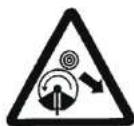
| Warning: Rotating blades | |||
| Beware of thrown objects | |||
| Acoustic power level LWA accordance with directive 2000/14/EC + 2005/88/EC | |||
| Warning! Hot surface | Sound pressure level at 7.5 metres. | ||
| Wear gloves to protect your hands | Maximum rotational frequency of the spindle for cutting head | ||
| Wear foot protection | Maximum rotational frequency of the spindle for blade |
WARNING! When using petrol powered tools, basic safety precautions, including the following, should always be followed to reduce the risk of serious personal injury and/or damage to the unit.
Read all these instructions before operating this product and save these instructions.
WARNING! This machine produces an electromagnetic field during operation. This field may under some circumstances interfere with active or passive medical implants. To reduce the risk of serious or fatal injury, we recommend persons with medical implants to consult their physician and the medical implant manufacturer before operating this machine.
WHAT TO DO
READ YOUR USER MANUAL AND ALL SUPPLEMENTS (IF ANY ENCLOSED) THOROUGHLY BEFORE OPERATING YOUR UNIT.


WARNING: Keep children, bystanders, and animals 50 feet (15 metres) away. If approached stop unit immediately.
- Wear close fitting, tough work clothing that will provide protection, such as long slacks or trousers, safety work shoes, heavy duty work gloves, hard hat, a safety face shield, or safety glasses for eye protection and a good grade of ear plugs or other sound barriers for hearing protection.
- Refuel in a safe place. Open fuel cap slowly to release any pressure which may have formed in fuel tank. To prevent a fire hazard, move at least 10 feet (3 metres) from fueling area before starting.
- Turn unit off before setting it down.
- Always hold unit firmly with both hands, the thumb and fingers encircling the handles.
- Keep all screws and fasteners tight. Never operate your equipment when it is improperly adjusted or not completely and securely assembled.
-
Keep handles dry, clean and free of fuel mixture.
-
Keep trimmer head as close to ground as practical. Avoid hitting small objects with trimmer head. When cutting on a slope, stand below trimmer head. NEVER cut or trim on a hill or slope, etc. If there is the slightest chance of slipping, sliding or losing firm footing.
- Check area you will be trimming for debris that may be struck or thrown during operation.
- Keep all parts of your body and clothing away from trimmer head when starting or running engine. Before starting engine, make sure trimmer head will not come in contact with any obstacle.
- Stop engine before examining cutting line.
- Store equipment away from possible ignition sources, such as gas-powered water heaters, clothes dryers, or oil-fired furnaces, portable heaters, etc.
- Aways keep the debris shield, trimmer head, and engine free of debris build-up.
- Operation of equipment should always be restricted to mature and properly instructed individuals.
- WARNING: The emission of exhaust gases is toxic.
- Emergency Stopping Procedure. When it is necessary to stop engine immediately, DEPRESS the switch to stop.
- This unit has a clutch. The routine for checking that the clutch is working correctly is that when the engine returns to idle the trimmer head stops spinning.
- Tighten the cap of oil and fuel tank to prevent the loss of oil and fuel during transport
- It is recommended that daily inspection before use and after dropping or other impacts to prevent significant damage or defects.
McCULLOCH
GB
- Prolonged use of this product expose the operator to vibrations and may produce 'whitefinger' disease. In order to reduce the risk, please wear gloves and keep your hands warm. If any of the 'whitefinger' symptoms appear, seek medical advice immediately.
BRUSH / GRASS BLADE SAFETY PRECAUTIONS
- FOLLOW ALL WARNINGS and instructions regarding operation and blade installation.
- BLADE CAN VIOLENTLY THRUST AWAY FROM MATERIAL IT CANNOT CUT - Blade thrust car cause serious Injury. Keep people and animals 50 feet (15 metres) away in all directions. If blade contacts foreign objects during operation, turn off engine and allow coasting blade to stop. Then check blade for damage. Always discard blade if it is warped or cracked.
- BLADE THROWS OBJECTS VIOLENTLY - Wear eye, face, and leg protection. Always clear work area of any foreign objects before using blade. Keep people and animals 50 feet (15 metres) away in all directions.
- INSPECT YOUR TRIMMER AND ATTACHMENTS BEFORE EACH USE - Never use unless all blade- attaching hardware is properly installed.
- BLADE COASTS AFTER THROTTLE IS RELEASED
- A coasting blade can cut you or bystanders. Before performing any service on the blade, always turn off engine, and be sure coasting blade has stopped.
- 50-FOOT (15 metres) DIAMETER HAZARD ZONE - Bystanders can be injured. Keep people and animals 50 feet (15 metres) away in all directions.
WHAT NOT TO DO
- DO NOT USE ANY OTHER FUEL than that recommended in your manual. Always follow instructions in the Fuel and Lubrication section of this manual. Never use petrol unless it is properly mixed with 2-cycle engine lubricant. Permanent damage to engine will result, voiding manufacturer's warranty.
- DO NOT SMOKE while refueling or operating equipment.
- DO NOT OPERATE UNIT WITHOUT A MUFFLER and properly installed muffler shield.
- DO NOT TOUCH or let your hands or body come in contact with a hot muffler or spark plug wire.
- DO NOT OPERATE UNIT IN AWKWARD POSITIONS, off balance, outstretched arms, or one-handed. Always use two hands when operating unit with thumbs and fingers encircling the handles.
- DO NOT RAISE TRIMMER HEADabove ground level while unit is operating. Injury to operator could result.
-
DO NOT USE UNIT FOR ANY PURPOSES OTHER than trimming lawn or garden areas.
-
DO NOT OPERATE UNIT FOR PROLONGED PERIODS. Rest periodically.
- DO NOT OPERATE UNIT WHILE UNDER THE INFLUENCE OF ALCOHOL OR DRUGS.
- DO NOT OPERATE UNIT UNLESS CUTTING ATTACHMENT GUARD AND/OR GUARD IS INSTALLED AND IN GOOD CONDITION.
- DO NOT ADD, REMOVE OR ALTER ANY COMPONENTS OF THIS PRODUCT. Doing so could cause personal injury and/or damage the unit voiding the manufacturer's warranty.
- DO NOT operate your unit near or around flammable liquids or gases whether in or out of doors. An explosion and/or fire may result.
- DO NOT USE ANY OTHER CUTTING ATTACHMENT. Use only McCulloch replacement parts and accessories, which are designed specifically to enhance the performance and maximize the safe operation of our products. Failure to do so may cause poor performance and possible injury. Use only the cutting head supplied with this product. Do not use any other cutting attachment. Use of such attachments will void your warranty and could result in serious bodily injury.
GENERAL IDENTIFICATION

6B. "BIKE" HANDLE (AT3A62FI)
-
THROTTLE TRIGGER
-
ON/OFF SWITCH
-
THROTTLE TRIGGER LOCK
OUT
-
THROTTLE LOCK
-
CHOKE LEVER
-
STARTER ROPE HOUSING
-
FUEL TANK
-
AIR FILTER COVER
-
STARTER HANDLE
-
MUFFLER SHIELD
-
PRIMER BULB
-
SHOULDER STRAP (MT 265 CPS)
-
COUPLER
-
HARNESS (AT3A62FI)
SAFETY FEATURES
3 CUTTING ATTACHMENT SHIELD must be installed to prevent debris from being thrown at the operator and prevent the string from extending longer than necessary.
16 MUFFLER SHIELD helps prevent hands, body and/or combustible materials from making contact with a hot muffler.
SPECIFICATIONS
| Model No. | MT 265 CPS | AT3A62FI |
| Engine Type | Air-coated, 2-Cycle,Chrome Cylinder | Air-coated, 2-Cycle,Chrome Cylinder |
| Displacement | 26 cm ^2 | 26 cm ^2 |
| Dry Weight (without fuel, cutting attachment and guard) | 5.4 Kg | 6.05Kg |
| Fuel Capacity | 550cm ^2 | 550cm ^2 |
| Bump Head | Twin Line Bump Feed | Twin Line Bump Feed |
| Blade 4 Teeth | 4 Teeth | 4 Teeth |
| Drive Shaft Length | 66cm + 68cm | 66cm + 68cm |
| Cutting Width (Twin Line Head)(Blade) | 43cm23cm | 43cm23cm |
| Handle | "D" Handle | Bike handle |
| Ignition | .Electronic | .Electronic |
| Drive | Centrifugal Clutch | Centrifugal Clutch |
| Sound pressure level (EN ISO 11806)(K=2.5) | 95.37 db(A) | 98.37 db(A) |
| Sound power level (EN ISO 11806)(K=2.5) | 107.31 db(A) | 107.31 db(A) |
| Guarantee sound power level (200V/4°C+20538°C) | 110 db(A) | 110 db(A) |
| Vibration (K=1.5) | 7.760 m/s | 7.760 m/s ^2 |
| Maximum Engine Performance | 0.78 kW | 0.78 kW |
| Engine Speed (rotational frequency) at recommended max. spindle rotational frequency | ||
| (Bump Feed Head) | 9000 min | 9000 min ^2 |
| (Blade) | 11000 min ^2 | 11000 min ^2 |
| Maximum rotational frequency of the spindle | ||
| (Bump Feed Head) | 6700 min | 6700 min ^2 |
| (Blade) | 8200 min | 8200 min ^2 |
| Isole speed | 3000±300 min ^2 | 3000±300 min ^2 |
| Specific fuel consumption | 415.3 g/kWh | 415.3 g/kWh |
McCULLOCK
GBG
ASSEMBLY INSTRUCTIONS

WARNING: Please assemble the unit according to the assembly instructions. Failure to do so may cause injury to the operator.
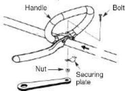
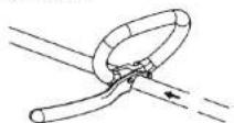
• "P" ATTACHING THE HANDLE (MT 265 CPS)
DANGER: To avoid serious injury, the barrier portion of the handle must be installed as shown to provide a barrier between operator and the spinning blade.
- Position the loop handle on the shaft. Note that the handle must be mounted in front of direction arrow on the shaft. (The distance between both handles shall be at least 250mm.)
Wrench
- Install the bolt, securing plate and nut as shown in the illustration.
- Make a final adjustment of the handle to a comfortable working position. Tighten the nut firmly with wrench (provided).
- "BIKE" HANDLE INSTALLATION (AT3A62FI)
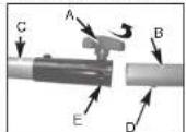
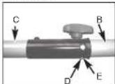
- To install handle onto unit, you will need the following components from your user kit: "Bike" handle (A), fixing holder (B), clamp (C) and screws (D). (Fig. 1C)
- Install the fixing holder (B) before the sponge sleeve (E), and adjust it to a proper position.
- Install the Bike handle (A) on the fixing holder, put the other clamp (C) over bike-handle, adjust handle to appropriate position and tighten the other 2 screws (D). The left handle shall be at least 200mm horizontally perpendicularly from the shaft tube. The handle shaft must be mounted on the right side of direction of arrow head on the handle shaft.
- Install wire tie (F) included in the user kit as shown (Fig. 1E).
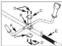
Fig. 1C
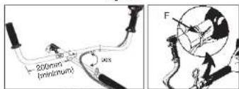
Fig. 1D Fig. 1E
• INSTALLING THE ATTACHMENT

WARNING: To avoid serious personal injury, shut unit off before removing or installing attachment.
NOTE: To make installing or removing the attachment easier, place the unit on the ground or on a work bench. 1. Turn the knob (A) counterclockwise to loosen (Fig. 2A).
- While firmly holding the attachment (B), push it straight into the Quick-Change coupler (C) until the release button (D) appears in the primary hole (E) of the Quick-Change coupler. (Fig. 2B)
- Turn the knob (A) clockwise to tighten. (Fig. 2C)

CAUTION: The release button must be in the primary hole and the knob securely lightened before operating this unit.
All attachments are designed to be used in the primary hole unless otherwise indicated in the specific attachments operators manual. If the incorrect hole is used, it could result in injury, or damage to the unit.
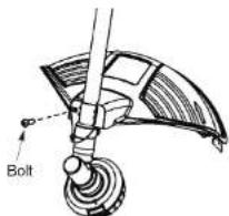
WARNING: The shield must be properly installed. The shield provides partial protection to the operator and others from the risk of thrown objects, and is equipped with a line limiter blade which cuts excess line to the proper length. The line limiter blade (on underside of shield) is sharp and can cut you.
1. Insert bracket into slot on shield.
2. Pivot shield to align holes in shield and bracket.
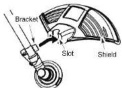
- Secure shield to bracket with bolt.
- CONFIGURING YOUR UNIT
You can configure your unit using a cutting head for grass and light weeds, or a weed blade for cutting grass, weeds, and brush up to 1 cm in diameter. To assemble your unit, go to the section for the desired configuration and follow the instructions.
• ASSEMBLY INFORMATION - TRIMMER HEAD

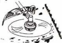
NOTE: Remove the blade before attaching the trimmer head. To remove blade, align hole in the dust cup with the hole in the side of the gearbox by rotating the blade. Insert a small screwdriver into aligned holes. This will keep the shaft from turning while loosening the blade nut.
McCULLOCH
Remove blade nut by turning clockwise. Remove the screwdriver. Remove both washers and blade. See INSTALLATION OF THE METAL BLADE for Illustrations. Be sure to store all parts and instructions for future use. Never use the trimmer head with the metal blade installed.
• INSTALLATION OF THE TRIMMER HEAD
NOTE: If your unit has a plastic cover over the threads on the threaded shaft, remove the covering to expose the threads. Before installing the trimmer head, make sure the dust cup and retaining washer are positioned on the gearbox.
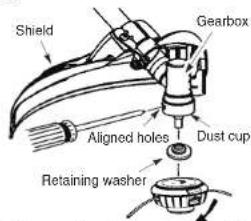
NOTE: Make sure all parts are properly installed as shown in the illustration before installing the trimmer head. 1. Align hole in the dust cup with the hole in the side of the gearbox by rotating the dust cup.
- Insert a small screwdriver into aligned holes. This will keep the shaft from turning while tightening trimmer head.
- While holding the screwdriver in position, thread trimmer head onto the shaft in the direction shown on the decal (counterclockwise). Tighten until secure. NOTE: The retaining washer must be positioned with the raised section facing toward the gearbox.
• ASSEMBLY INFORMATION - METAL BLADE

NOTE: Remove the trimmer head before installing the weed blade. To remove the trimmer head, align hole in the dust cup with the hole in the side of the gearbox by rotating the dust cup. Insert a small screwdriver into aligned holes. This will keep the shaft from turning while loosening the trimmer head. Remove the trimmer head by turning clockwise. Remove the screwdriver. See INSTALLATION OF THE CUTTING HEAD for illustrations. Be sure to store all parts and instructions for future use.
McCULLOCH
GB
• INSTALLATION OF THE METAL BLADE
WARNING: Wear protective gloves when handling or performing maintenance on the blade to avoid injury. The blade is sharp and can cut you even when it is not moving.
WARNING: Do not use any blades, or fastening hardware other than the washers and nuts shown in the following illustrations. These parts must be provided by McCulloch and installed as shown below. Failure to use proper parts can cause the blade to fly off and seriously hurt you or others.
NOTE: The dust cup is located on the gearbox shaft and not in the parts bag. All other fasteners mentioned in the following assembly steps are in the parts bag.
1. Install the blade and the retaining washer over the threaded shaft.
2. Make sure the raised part of the retaining washer is facing the gearbox and the raised area fits into the hole in the center of the blade.
3. Slide the blade and retaining washer onto the shaft of the gearbox.
4. Place the cupped washer onto the shaft. Make sure the cupped side of the washer is toward the blade.
5. Install the blade nut by threading onto the shaft counterclockwise.
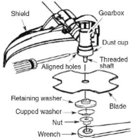
NOTE: Make sure all parts are in place as illustrated, and the blade is sandwiched between the dust cup and the retaining washer. There should be no space between the blade and the dust cup or the retaining washer.
- Align hole in dust cup with hole in side of gearbox by rotating the blade.
- Insert a small screwdriver into aligned holes. This will keep the shaft from turning while lightening the blade nut.
- Tighten blade nut firmly with wrench (provided) while holding screwdriver in position.
- Remove the screwdriver.
- Turn blade by hand. If the blade binds against the shield, or appears to be uneven, the blade is not centered, and you must reinstall.
NOTE: To remove blade, insert screwdriver into aligned holes. Unthread the nut (clockwise direction) and remove parts. Be sure to store parts and instructions for future use.
- REMOVE AND INSTALLATION THE BLADE COVER

CAUTION: Before you take apart the blades, wear gloves to prevent any danger.

CAUTION: When the machine is not in use of in transportation, make sure blades have been covered.
-
Before assembling blades, please remove the blades cover first.
-
Refer figure 6A and Figure 6B, hold the blades cover, and pull slightly the cover outward the cover can be taken apart.
- Refer to figure 6C and 6D, and assemble in the opposite way to cover the blades.

Fig. 6A

Fig. 6B
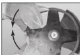
Fig. 6C
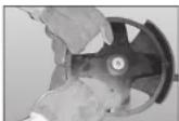
Fig. 6D
FUEL AND LUBRICATION

WARNING: Never use straight petrol in your unit. This will cause permanent engine damage and void the manufacturer's warranty for that product. Never use a fuel mixture that has been stored for over 30 days.

WARNING: If 2-cycle lubricant other than McCulloch Custom Lubricant is to be used, it must be a premium grade oil for 2-cycle air cooled engines mixed at a 40:1 ratio. Do not use an 2-cycle oil product with a recommended mixing ratio of 100:1. If insufficient lubrication is the cause of engine damage, it voids the manufacturer's engine warranty.

WARNING: Lack of lubrication voids engine warranty. Fuel and oil must be mixed at 40:1.
McCULLOCH
GB

WARNING: Remove fuel cap slowly when refueling.
This engine is certified to operate on unloaded petrol. Before operation, petrol must be mixed with a good quality 2-cycle air-cooled engine oil designed to be mixed at a ratio of 40:1. A 40:1 ratio is obtained by mixing 5 litres of unloaded petrol with 125ml of oil. DO NOT USE automotive oil or marine oil. These oils will cause engine damage. When mixing fuel, follow instructions printed on oil container. Once oil is added to petrol, shake container momentarily to assure that the fuel is thoroughly mixed. Always read and follow the safety rules relating to fuel before fueling your unit.
FUEL REQUIREMENTS
Use good quality unleaded petrol. The lowest recommended octane grade is 90 (RON).
IMPORTANT
Use of alcohol blended fuels (called gaschol or using ethanol or methanol) can cause major enging performance and durability problems.

WARNING: Alternative fuels (not petrol) such as E-15 (15% alcohol), E-20 (20% alcohol), E-65 (65% alcohol) are NOT classified as petrol and are NOT approved for use in 2-stroke petrol engines. Use of alternative fuels will cause problems such as: improper clutch engagements, overheating, vapor lock, power lose, lubrication deficiency, deterioration of fuel lines, gaskets and internal carbustor components, etc. Alternative fuels cause high moisture absorption into the fuel/oil mixture leading to oil and fuel separation.
• FUEL AND LUBRICATION

Fuel & Oil Mix 40:1 (2.5%)
• FUEL / OIL MIXTURE RATIOS
| Petrol - Litre Two-Stroke Oil - ml | |
| 40:1 (2.5%) | |
| 2 50 | |
| 5 125 | |
| 10 | 250 |
OPERATING INSTRUCTIONS
- SHOULDER HARNESS

WARNING: ALWAYS WEAR SHOULDER HARNESS when operating unit with a blade. Attach harness to trimmer after starting unit and engine is running at IDLE. Turn ENGINE OFF before disconnecting shoulder harness.
NOTE: When you install the cutting attachment, please follow the below requirements.
1a. Put the harness on so the shoulder strap is over your LEFT shoulder.
1b. For Model AT3A62FI, the shoulder straps are on your both shoulders. NOTE: Pull the black strip(E) in order to quickly release the harness from the operator in the event of emergency. (Fig 8C)
2. Attach the harness clip (C) to the ring (D) mounted on the shaft (Fig. 8A and 8B and 8D).
3. Adjust length of shoulder strap so trimmer head is parallel to the ground as it hangs from the strap. A few practice swings without starting engine should be made to determine correct balance.
NOTE: Detach the shoulder harness from the unit before starting engine.
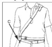
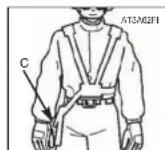
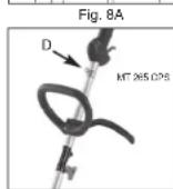
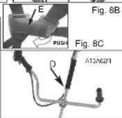
Fig. 8D
McCULLOCK
GBG
When operating unit, clip shoulder strap onto clamp, stand as shown and check for the following:
- Wear eye protection and heavy clothing.
- Extend your left arm and hold loop handle with your left hand.
- Hold throttle grip with your right hand with finger on throttle trigger.
- Keep unit below waist level.
- Keep shoulder strap pad centered on your left shoulder.
- Maintain full weight of tool on your left shoulder. - Without bending over, keep the blade or trimmer head near and parallel to the ground and not crowded into material being cut.
• STARTING A COLD ENGINE
NOTE: To minimize load on engine during starting and warm-up, trim excess cutter line to 13cm (Fig. 9A). 1. Press ON/OFF switch to the "RUN (I)" position (Fig.9B).
- Your unit is designed with a 3 position choke; FULL CHOKE "N", HALF CHOKE "I", and RUN "III". Move choke lever to FULL CHOKE "N" position (Fig. 9C).
3a. For "P" handle "", squeeze throttle trigger to full position.(MT 265 CPS)
3b. For Bike handle “X”, set throttle lock (C); Press the lockout switch (A) down and then holding trigger (B) at partially open position, press down and hold throttle lock (C). Release throttle trigger (B). Throttle trigger (B) will now remain in the partially depressed position (Fig. 9B). (AT3A62FI)
- Press the primer bulb (A) 10 times (Fig. 9D).
-
Wait 10 sec.
-
A smooth rapid pull is required for a strong spark. Pull starter rope briskly maximum 6 times. (Fig. 9F) As soon as the engine sounds as if it is trying to start (even if less than 6 pulls) then move the choke lever to HALF CHOKE "1" position. (Fig. 9G)
-
Pull starter rope again while trigger is in the full throttle position until engine starts. (Fig. 9F)
-
Once engine is started, leave the choke lever in the HALF CHOKE "↑" position for 20 seconds, then move choke lever to RUN "III". (Fig. 9H) If engine does not start, go back to step 2.
NOTE: If engine fails to start after repeated attempts, refer to Troubleshooting section.
NOTE: Always pull starter rope straight out. Pulling starter at an angle will cause rope to rub against the eyelet. This friction will cause the rope to fray and wear more quickly. Always hold starter handle when rope retracts. Never allow rope to snap back from extended position. This could cause rope to snag or fray and also damage the starter assembly.
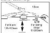
Fig. 9A Fig. 9B
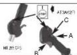
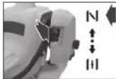

Fig. 9C Fig. 9D
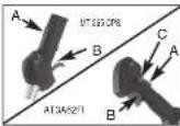

Fig. 9E Fig. 9F
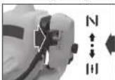
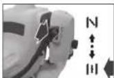
Fig. 9G Fig. 9H
• WARM ENGINE START
- Move switch to the "RUN" position (Fig. 10A).
- Place choke in HALF CHOKE * 1 position (Fig. 10B).
- Grasp throttle handle firmly, squeeze throttle trigger to FULL position.
- Pull starter rope briskly until engine starts, but no more than 6 times. Keep throttle at FULL position until engine runs smoothly.
- If engine does not start, place choke in RUN 1 position and pull starter rope 5 more times. If engine still does not start it is probably flooded. Wait 5 minutes and repeat procedure with choke in RUN 1 position and throttle full open.
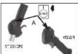
Fig. 10A
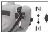
Fig. 10B
• TO STOP ENGINE
Release throttle trigger. Let engine return to idle. Push and hold ignition stop switch until engine stops.
McCULLOCH
TRIMMER INSTRUCTIONS
• OPERATING INSTRUCTIONS FOR USE WITH TRIMMER HEAD
WARNING: Always wear eye protection. Never lean over the trimmer head. Rocks or debris can ricochet or be thrown into eyes and face and cause blindness or other serious injury.
Before trimming, bring engine to a speed sufficient to cut material to be trimmed.
When cutting grass, engine RPM should be maintained at a level where the trimmer line cuts grass cleanly without overloading or slowing the engine.
Always release the throttle trigger and allow the engine to return to idle speed when not cutting.
To stop engine:
- Release the throttle trigger.
- Push and hold the ON/STOP switch in the STOP position until the engine stops.
Advance line by tapping the bottom of the cutting head lightly on the ground while engine is running at full speed. The metal line limiter blade attached to the guard will cut the line to the proper length.
WARNING: Use only 2.4 mm diameter line. Other sizes of line will not advance properly and will result in improper cutting head function or can cause serious injury. Do not use other materials such as wire, string, rope, etc. Wire can break off during cutting and become a dangerous missile that can cause serious injury.
• CUTTING METHODS
WARNING: Do not crowd the line when cutting around hard objects (rock, gravel, fence posts, etc.), which can damage the trimmer head, become entangled in the line, or be thrown causing a serious hazard.
- The tip of the line does the cutting. You will achieve the best performance and minimum line wear by not crowding the line into the cutting area. The right and wrong ways are shown below.
Tip of line does
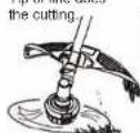
Right
Line crowded into

Wrong
- The line will easily remove grass and weeds from around walls, fences, trees and flower beds, but it also can cut the tender bark of trees or shrubs and scar fences.
- For trimming or scalping, use less than full throttle to increase line life and decrease head wear, especially:
- During light duty cutting.
- Near objects around which the line can wrap such as small posts, trees or fence
- For mowing or sweeping, use full throttle for a good clean job.
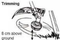
TRIMMING - Hold the bottom of the trimmer head about 8 cm above the ground and at an angle. Allow only the tip of the line to make contact. Do not force trimmer line into work area.
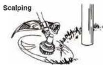
SCALPING - The scalping technique removes unwanted vegetation down to the ground. Hold the bottom of the trimmer head about 8 cm above the ground and at an angle. Allow the tip of the line to strike the ground around trees, posts, monuments, etc. This technique increases line wear.
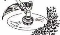
MOWING - Your trimmer is ideal for mowing in places conventional lawn mowers cannot reach. In the mowing position, keep the line parallel to the ground. Avoid pressing the head into the ground as this can scalp the ground and damage the tool.
Mowing
SWEEPING - The fanning action of the rotating line can be used to blow away loose debris from an area. Keep the line parallel to and above the area surface and swing the tool from side to side.
Sweeping
• TRIMMING PROCEDURES
When properly equipped with a cutting attachment guard and cutting head, your unit will trim unsightly weeds and tall grass in those hard-to-reach areas - along fences, walls, foundations and around trees. It can also be used for scalping to remove vegetation down to the ground for easier preparation of a garden or to clean out a particular area. NOTE: Even with care, trimming around foundations, brick or stone walls, curves, etc., will result in above normal string wear.
TRIMMING / MOWING
Swing trimmer with a sickle-like motion from side to side. Do not tilt the cutting head during the procedure. Test area to be trimmed for proper cutting height. Keep cutting head at same level for even depth of cut (Fig. 12A).
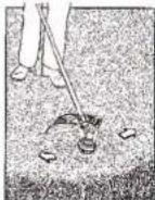
Fig. 12A
OPERATING INSTRUCTIONS FOR USE WITH WEED BLADE
- Blade Thrust is a reaction that only occurs when using a bladed unit. This reaction can cause serious injury. Carefully study this section. It is important that you understand what causes blade thrust, how you can reduce the chance of its occurring, and how you can remain in control of unit if blade thrust occurs.
WHAT CAUSES BLADE THRUST - Blade Thrust can occur when the spinning blade contacts an object that it does not cut. This contact causes the blade to stop for an instant and then suddenly move or "thrust" away from the object that was hit. The "thrusting" reaction can be violent enough to cause the operator
McCULLOCH
GBG
to be propelled in any direction and lose control of the unit. The uncontrolled unit can cause serious injury if the blade contacts the operator or others.
- WHEN BLADE THRUST OCCURS - Blade Thrust can occur without warning if the blade snags, stalls, or blinds. This is more likely to occur in areas where it is difficult to see the material being cut. By using the unit properly, the occurrence of blade thrust will be reduced and the operator will be less likely to lose control.
- Cut only grass, weeds, and woody brush up to 1 cm in diameter with the weed blade. Do not let the blade contact material it cannot cut such as stumps, rocks, fences, metal, etc., or clusters of hard, woody brush having a diameter greater than 1 cm.
- Keep the blade sharp. A dull blade is more likely to snag and thrust.
- Cut only at full throttle. The blade will have maximum cutting power and is less likely to bind or stall.
- "Feed" the blade deliberately and not too rapidly. The blade can thrust away if it is fed too rapidly.
- The grass is cut down with a sideways, swinging movement, where the movement from right-to-left is the cutting stroke and the movement from left-to-right is the return stroke. Let the left-hand side of the blade do the cutting.
- Use the shoulder strap and keep a firm grip on the unit with both hands. A properly adjusted shoulder strap will support the weight of the unit, freeing your arms and hands to control and guide the cutting motion.
- Keep feet comfortably spread apart and braced for a possible sudden, rapid thrust of unit. Do not
overreach. Keep firm footing and balance. - Keep blade below waist level; it will be easier to maintain control of unit.
- Do not raise the engine above your waist as the blade can come dangerously close to your body.
- Do not swing unit with such force that you are in danger of losing your balance.
Bring the engine to cutting speed before entering the material to be cut. If the blade does not turn when you squeeze the throttle trigger, make sure shaft is fully inserted into the engine.
Always release the throttle trigger and allow engine to return to idle speed when not cutting. The blade should not turn while the engine is running at idle. If the blade turns at idle, do not use your unit. Refer to the CARBURETOR ADJUSTMENT section or contact your authorized service dealer.
- Maintain good firm footing while using the unit. Do this by planting feet firmly in a comfortable apart position. - Cut while swinging the upper part of your body from right to left.
McCULLOCH
- As you move forward to the next area to cut, be sure to maintain your balance and footing.
WARNING: The operator or others must not try to clear away cut material with the engine running or the blade turning to avoid serious injury. Stop engine and blade before removing materials wrapped around blade or shaft.
MAINTENANCE INSTRUCTIONS
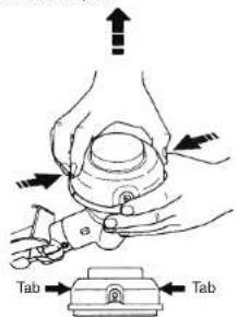
• REPLACING THE LINE
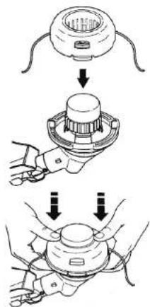
-
Press the tabs on the side of the trimmer head and remove cover and spool.
-
Remove any remaining line.
- Clean dirt and debris from all parts. Replace spool if it is worn or damaged.
- Replace with a pre-wound spool, or replace line using a 4.5 metre length of 2.4 mm diameter McCulloch brand line.
WARNING: Never use wire, rope, string, etc., which can break off and become a dangerous missile.
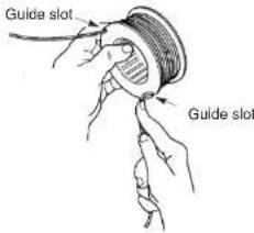
- When installing new line on an existing spool, hold the spool as shown.
- Bend the line at the midpoint and insert the bend into the slot in the center rim of the spool. Ensure line snaps into position in the slot.
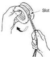
- With your finger between the lines, wrap the lines evenly and firmly around the spool in a clockwise direction.
Cover
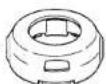
Spool

- Position the lines in the guide slots.
- Place the spool in the cover as shown below.
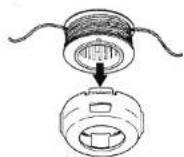
- Insert the ends of the lines through exit holes in the sides of the cover.
Line exit hole
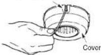
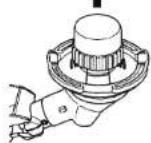
- Reinstall the spool and cover onto the trimmer head. Push until cover snaps into place.
McCULLOCH
GBG
• BLADE REPLACEMENT
Refer to the ASSEMBLY section for blade replacement instructions and illustrations.
• CARBURETOR ADJUSTMENT
WARNING: Keep others away when making idle speed adjustments. The trimmer head will be spinning during most of this procedure. Wear your protective equipment and observe all safety precautions. After making adjustments, the trimmer head must not move/spin at idle speed. The carburetor has been carefully set at the factory. Adjustments may be necessary if you notice any of the following conditions:
- Engine will not idle when the throttle is released.
- The immter head moves/spins at idle speed. Make adjustments with the unit supported so the cutting attachment is off the ground and will not make contact with any object. Hold the unit by hand while running and making adjustments. Keep all parts of your body away from the cutting attachment and muffler.
Idle Speed Adjustment
Allow engine to Idle. Adjust speed until engine runs without trimmer head moving or spinning (idle speed too fast) or engine stalling (idle speed too slow).
- Turn idle speed screw clockwise to increase engine speed if engine stalls or dies.
- Turn idle speed screw counterclockwise to decrease engine speed if trimmer head moves or spins at idle speed.
WARNING: Recheck the idle speed after each adjustment. The trimmer head must not move or spin at idle speed to avoid serious injury to the operator or others.
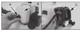
• AIR FILTER

To Clean Air Filter:
-
Remove knob (A) holding air filter cover in place remove cover (B) and lift filter (C) from air box (Fig. 16).
-
Wash filter in soap and water.DO NOT USE PETROL! 3. Air dry filter.
-
Reinstall filter.
NOTE: Replace filter if frayed, torn, damaged or unable to be cleaned.
McCULLOCH
natural_image
Two-panel photo showing a hand holding a device labeled A and B, and a close-up of a device with labeled components C (no visible text or symbols)Fig. 16
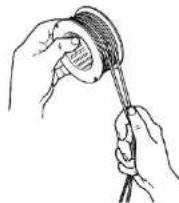
• FUEL CAP / FILTER

CAUTION: Remove fuel from unit and store in approved container before starting this procedure. Open fuel cap slowly to release any pressure which may have formed in fuel tank.
-
Completely remove fuel cap (A) from fuel tank (B) to be able to remove fuel filter (D) from tank. Use a piece of wire (C) with a hook formed at the end to pull filter out of tank. (Fig. 17A & Fig. 17B)
-
Pull filter (D) off with a twisting motion
- Replace fuel filter (D). (Fig. 17C)
NOTE: Never operate the trimmer without the fuel filter. Internal engine damage could result!
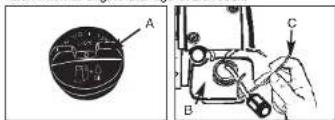
Fig. 17B
Fig. 17A
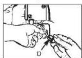
Fig. 17C
• CARBURETOR ADJUSTMENT
The carburetor was pre-set at the factory for optimum performance. If further adjustments are necessary, please take your unit to the nearest Authorized Service Center.
• SPARK PLUG
-
Spark plug gap = .025° (.635mm) (Fig. 18).
-
Torque to 105 to 130 inch pounds (12 to 15 N·m). Connect spark plug boot.
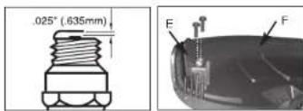
Fig. 19
• CUTTING ATTACHMENT GUARD KNIFE SHARPENING
-
Remove cutter knife (A) from cutting attachment guard (B) (Fig. 19).
-
Place knife in a bench vise. Sharpen knife using a flat file, being careful to maintain the angle of cutting edge. File in one direction only.
• STORING A UNIT

WARNING: Failure to follow these steps may cause vanish to form in the carburetor and difficult starting or permanent damage following storage.
• REMOVING A UNIT FROM STORAGE
- Perform all the general maintenance recommended in the Maintenance Section of your User Manual.
- Clean exterior of engine, Output Shaft, cutting attachment guard and cutting head.
- Drain fuel from the fuel tank.
- After fuel is drained, start engine.
- Run engine at idle until unit stops. This will purge the carburetor of fuel.
- Allow engine to cool (approx. 5 minutes).
- Using a spark plug wrench, remove the spark plug.
- Pour 1 teaspoon of clean 2-cycle oil into the combustion chamber. Pull starter rope slowly several times to coat internal components. Replace spark plug.
- Store unit in a cool, dry place away from any source of ignition such as an oil burner, water heater, etc.
- Remove spark plug.
- Pull starter rope briskly to clear excess oil from combustion chamber.
- Clean and gap spark plug or install a new spark plug with proper gap.
- Prepare unit for operation.
- Fill fuel tank with new, fresh fuel / oil mixture. See Fuel and Lubrication Section.
McCULLOCH
GB
TROUBLE SHOOTING THE ENGINE
| PROBLEM | PROBABLE CAUSE | CORRECTIVE ACTION |
| Unit won't start or starts but will not run. | Incorrect starting procedures. | Follow instructions in the User Manual. |
| Incorrect carburetor mixture adjustment setting. | Have carburetor adjusted by an Authorized Service Center. | |
| Fooled spark plug | Clean / gap or replace plug. | |
| Fuel filter blocked. | Replace fuel filter. | |
| Unit starts, but engine has low power. | Incorrect lever position on choke. | Move to RUN position. |
| Dirty spark arrester screen. | Replace spark arrester screen. | |
| Dirty air filter. | Remove, clean and reinstall filter. | |
| Incorrect carburetor mixture adjustment setting. | Have carburetor adjusted by an Authorized Service Center. | |
| Engine halates. | Incorrect carburetor mixture adjustment setting. | Have carburetor adjusted by an Authorized Service Center. |
| No power under load. | ||
| Runs errabically. | Incorrectly gapped spark plug. | Clean / gap or replace plug. |
| Smokes excessively. | Incorrect carburetor mixture adjustment setting. | Have carburetor adjusted by an Authorized Service Center. |
| Incorrect fuel mixture. | Use properly mixed fuel (40:1 mixture). |

EC DECLARATION OF CONFORMITY
Business name of the manufacturer: Husqvarna AB
Full address of the manufacturer: SE-561 82 Huskvarna, Sweden
We declaring that the machinery
Product name: Grass trimmer, Gasoline
Commercial name: Gasoline trimmer
Function: Trimming grass
Model: MT 265 CPS /AT3A62FI
Type: Powered by gasoline
Fulfils all the relevant provisions of Directives
2006/42/EC, 2004/108/EC, 2000/14/EC+2005/88/EC,
97/68/EC+2004/26/EC, 2011/65/EU
and tested in accordance with below standards
EN ISO 11806:2011
EN ISO 14982:2009
Person authorised to compile the technical file and making
this declaration:

Name, surname : Bo R Jonsson
Position/Title : R&D Manager
Address : SE-561 82 Huskvarna, Sweden
Place and date of the declaration: Shanghai, PRC 2012/7/30