
32Q - Chauffe-eau et chaudière BOSCH - Free user manual and instructions
Find the device manual for free 32Q BOSCH in PDF.

| Product Type | Gas-fired combination boiler (heating and domestic hot water) |
| Model | Bosch 32Q |
| Dimensions (H x W x D) | approx. 700 x 400 x 300 mm |
| Weight | approx. 28 kg |
| Power Supply | 230 V AC, 50 Hz |
| Gas Type | Natural gas (G20) / LPG (G31) convertible |
| Heat Output (CH) | 24 - 32 kW (modulating) |
| DHW Flow Rate | up to 15 L/min at ΔT 35°C |
| Energy Efficiency Class | A (for heating) / A (for hot water) |
| NOx Class | Class 5 (low emissions) |
| Main Functions | Central heating and domestic hot water production; weather compensation compatible; built-in pump and expansion vessel |
| Display | LCD screen with status icons and error codes |
| Control Interface | Rotary knobs and push buttons |
| Maintenance | Annual service recommended; clean primary heat exchanger and burner, check gas pressure and seals |
| Cleaning | Wipe casing with damp cloth; do not use abrasive cleaners |
| Safety Features | Flame detection, overheat protection, frost protection, pressure relief valve, automatic air vent |
| Spare Parts Availability | Common parts available through Bosch service centers; typical lifespan of key components >10 years |
| Repairability | Modular design with replaceable main components (fan, pump, gas valve, PCB) |
Frequently Asked Questions - 32Q BOSCH
User questions about 32Q BOSCH
0 question about this device. Answer the ones you know or ask your own.
Ask a new question about this device
Download the instructions for your Chauffe-eau et chaudière in PDF format for free! Find your manual 32Q - BOSCH and take your electronic device back in hand. On this page are published all the documents necessary for the use of your device. 32Q by BOSCH.
USER MANUAL 32Q BOSCH
Installation & Owner's Guide
32L Electronic
Internal / External Model
KM3211WH
KM3211WHQ
To be installed and serviced only by an authorised person
This appliance is not suitable for use as a pool heater
The "authorised installing person" is responsible for:
- Correct commissioning of this appliance.
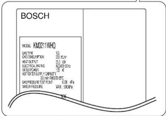
- Ensure unit performs to the specifications stated on the rating label.
- Demonstrate operation of unit to customer before leaving.
- Hand these instructions to customer.
Service Department: 1300 30 70 42
www.bosch.com.au
This appliance must be installed in accordance with the manufacturer's installation instructions, AS 5601 (AS5601), NZ 5261, AS3500.4.2 and all Local Water, Building and Gas fitting regulations.
Failure to install this appliance in accordance with these installation instructions may void warranty
In the interest of continued product improvement, Bosch reserves the right to alter these specifications without notice.
Contents
Contents 2
Owner's Guide
Important Safety Information.... 3
General Parts
Main Unit....6
Names and Functions of Each Parts 7
Initial Operation 9
How to Use
When using RCM3211
Clock Adjustment 10
Running Hot Water 11
Setting Hot Water Temperature.... 12
Filling Up the Bath 14
Circulation Operation 15
Suspension of Circulation 16
Timer Setting Period for Circulation 17
Other Setting Options 20
Confirmation Beeper On/Off 22
When using RCS3211
Running Hot Water 23
Setting Hot Water Temperature.... 24
Confirmation Beeper On/Off 26
No remote controller case
Running Hot Water 27
Preventing Damage from Freezing 28
When Unused for an Extended Period 29
Regular Maintenance.... 31
Troubleshooting 33
Follow-up Service 37
Specifications 38
External Outfitting 39
Combustion Unit and Gas Route 41
Hot-Water Feed Route 43
Electronic Controller 48
Remote Controller and Attached Set 50
Installation Guide....52
-
Installation Examples .... 52
-
Quick Connect Multi System Installation 53
-
Before Installation 54
-
Choosing Installation Site 54
-
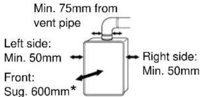
Installation Clearances .... 56
-
Installation....57
-
Vent Pipe Installation 58
-
Gas Piping 61
-
Water Piping 62
-
Plumbing Applications 65
-
Electrical Wiring 66
-
Commissioning....69
-
Dimensions 70
Remote Controller Installation Guide.... 74
Important Safety Information-1
To prevent damage to property and injury to the user, the icons shown below will be used to warn of varying levels of danger.
Every indication is critical to the safe operation of the water heater and must be understood and observed.
Potential dangers from accidents during installation and use are divided into the following three categories. Closely observe these warnings; they are critical to your safety.
Installation Guide
Robert Bosch
(Australia) Pty. Ltd.
GAS WATER HEATER
KM3211WH (Indoor or Outdoor Installation)
KM3211WHQ (Indoor or Outdoor Installation / Instant hot water supply type)
WARNING: If the information in this manual is not followed exactly, a fire or explosion may result causing property damage, personal injury or death.
| Potential dangers from accidents during installation and use are divided into the following three categories. Closely observe these warnings, they are critical to your safety. | |
 Danger Danger | Danger of serious injury or even death as well as danger of fire when the product is misused by ignoring this symbol. |
 Warning Warning | Possibility of serious injury or even death as well as possibility of fire when the product is misused by ignoring this symbol. |
 Caution Caution | Possibility of bodily injury or damage to property when the product is misused by ignoring this symbol. |

Prohibited

Disconnect Power

Ground

Be sure to do
Requests to Installers

Caution
- In order to use the water heater safely, read this installation manual carefully, and follow the installation instructions.
- Failures and damage caused by erroneous work or work not as instructed in this manual are not covered by the warranty.
- Check that the installation was done properly in accordance with this Installation Manual upon completion.
This appliance must be installed in accordance with the manufactures installation instructions, AG5601, AS3500.4.2, AS300 wiring regulations and all Local Building, Water and Gas Fitting.
Other icons
 | Electric Shock. |  | High Temperature. |  | Be sure to do. |  | Ground. | |
 | Prohibited |  | No flame. |  | Don't touch. |  | Don't disassemble the equipment. |  Don't touch with a wet hand. Don't touch with a wet hand. |
Important Safety Information-2
Warning

If you detect abnormal combustion or abnormal odors:
- Turn off the hot water supply
- Turn off the power to the water heater
- Turn off gas and water at the main
- Consult the nearest Bosch Agent
This will prevent fire, electric shocks or damage to the unit.

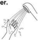
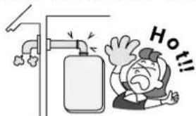
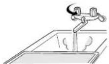
Check the temperature of the running hot water before entering the shower.
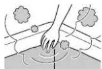
Check the temperature before stepping into the bath tub.

Do not turn off the water heater or change the water temperature while someone is using the hot water.

Be sure the gas/power supplied matches the gas on the rating plate.
For Natural Gas

Do not allow small children to play unsupervised in the bathroom. Do not allow small children to bathe unsupervised.

Contact a qualified service technician for any necessary repairs, service or maintenance.

Warning

Do not place combustibles such as laundry, newspapers, oils etc. near the heater or the exhaust vent terminal.
Exhaust vent terminal (indoor installation)
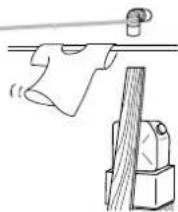

Do not use combustible chemicals such as oil, gasoline, benzene etc. in the vicinity of the heater or the exhaust vent terminal.

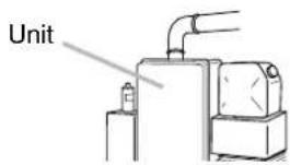
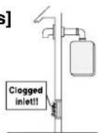
[When installing indoors] Where Applicable: Check the air supply vent for dust or obstructions.

Leave the proper clearance between the water heater and nearby objects (trees, timber, boxes with flammable materials etc.).
* Indicates suggested clearances for maintenance.

Do not place or use a spray can near the heater or the exhaust vent terminal.

Caution

Be sure to electrically ground the unit.

Do not touch the power cord with wet hands.


Keep power cord free of dust.

Do not use a broken or modified power cord. Do not bind, bend or stretch power cords. Do not scratch, modify, or subject them to impact or force.

Do not use the water heater for other than its intended use.

Do not touch the exhaust vent pipe during or immediately after operation of the water heater.

Do not use hair spray or spray detergent in the vicinity of the heater.

Do not install in salons or other locations where hair spray or other aerosols will be used.

Do not install in locations where excessive dust or debris will be in the air.
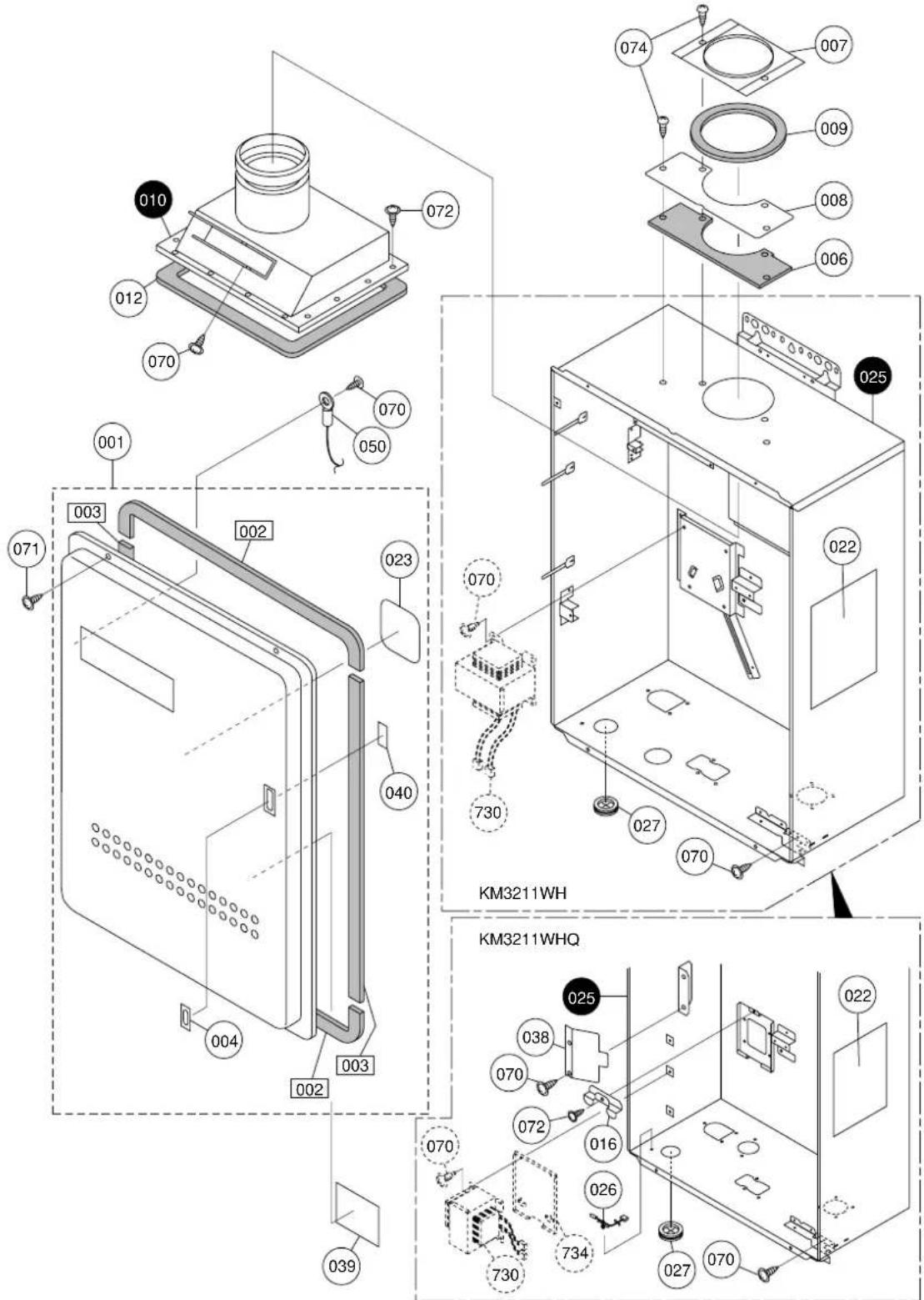
General Parts
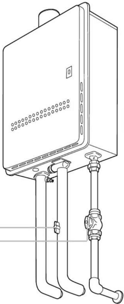
Main Unit
Indoor or Outdoor Wall Mounted, Power Vented Model KM3211WH, KM3211WHQ
* KM3211WH shown, pipe arrangement differs slightly on the KM3211WHQ model.
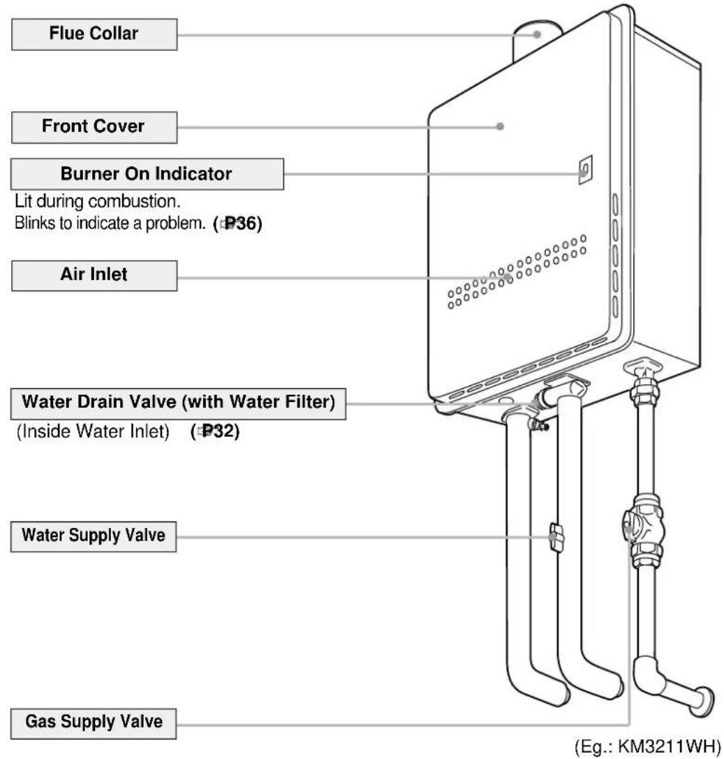
* The above illustration shows an example of installation. The exact installation configuration may be slightly different.
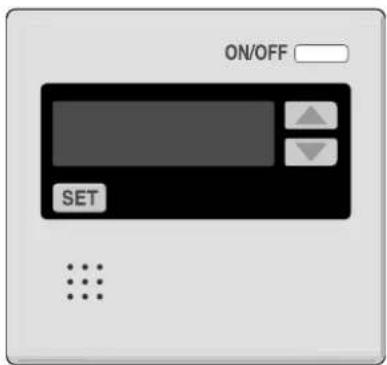
Names and Functions of Each Parts-1
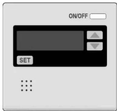
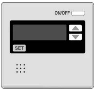
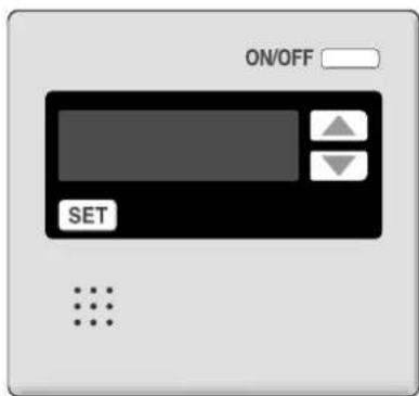
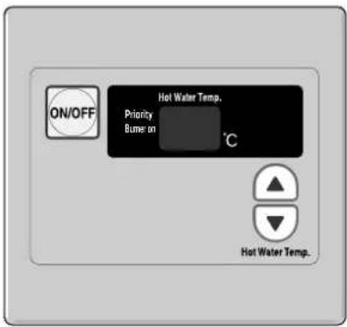
Main Remote Controller (RCM3211)
* This remote controller is basically used with KM3211WHQ.
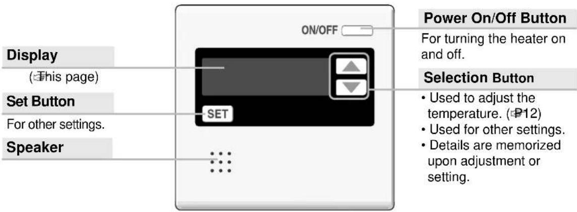
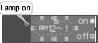
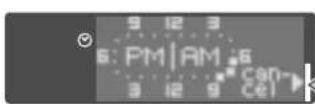
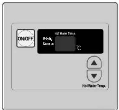
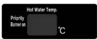
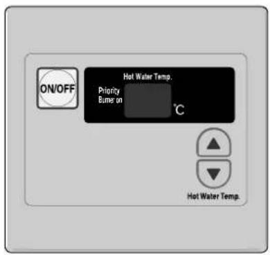
Display
The illustration below shows the remote controller display. What is actually displayed depends on how the water heater is set.
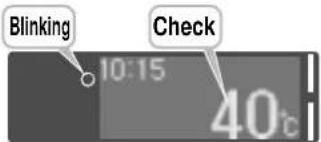
Circulation mode Display ○
When this is displayed, circulation mode is on. (P15 and 19)
Timer Display for Hot Water √
Blinking :During circulation
Lit : Circulation timer is set.
√ Blinking : During setting (P17 and 19) for circulation mode.
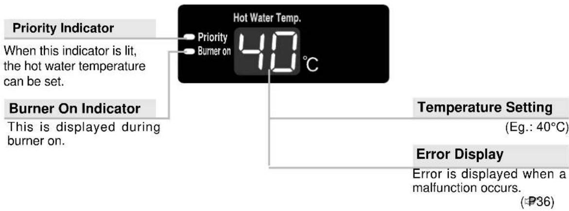
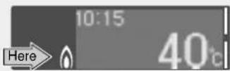
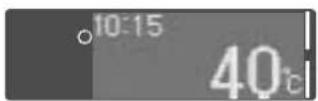
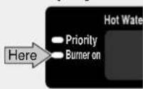
Burner On Display
This is displayed when the burner is on.
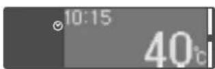
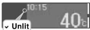
Timer Display
(Eg.: 10:15)
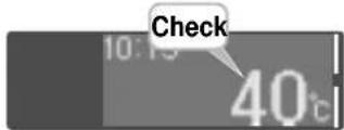
Error Display
Error is displayed when malfunction occurs. (P36)
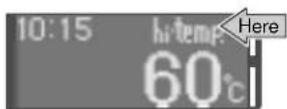
High Temperature Display
When the hot water temperature is set between 60 - 80°C, "hi-temp" blinks for 10 seconds.
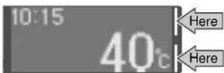
Selection Bar Display
Selection switches that can be operated are indicated by the bar display lighting up or blinking.
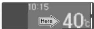
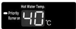
Temperature Setting
(Eg.: 40°C)
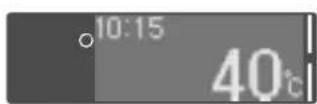
- < Scroll display > to prevent the remote controller screen from burning out
* In order to prevent the screen burning out, about 10 minutes after any remote control operation, the screen display begins to scroll sideways.
* As soon as the remote controller is used again, the scrolling stops.
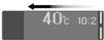
Current time (when the clock is set) the hot water temperature scrolls sideways.
Names and Functions of Each Parts-2
Waterproof Sub Remote Controller (RCS3211)
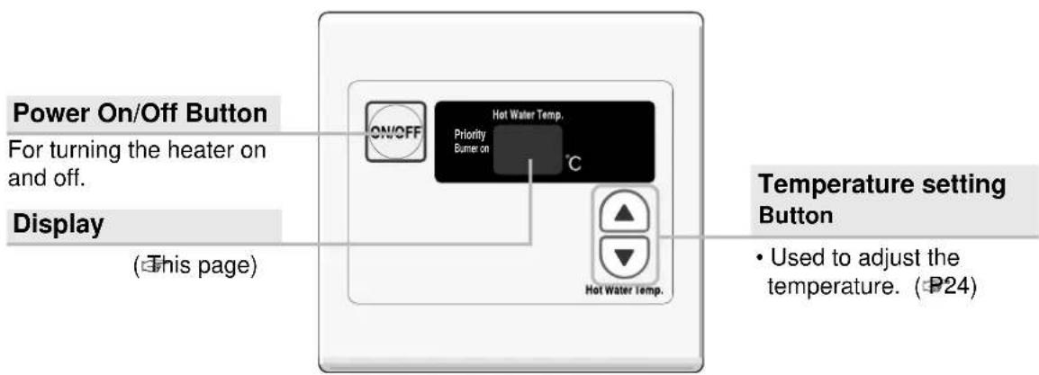
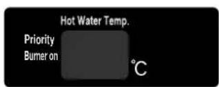
- Display
The illustration below shows the remote controller display. What is actually displayed depends on how the water heater is set.
Initial Operation
Before the first use of your water heater, make the following preparations.
Follow steps 1 through 4.
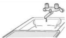
1 Open the water supply valve.

2 Open a hot water fixture to confirm that water is available, and then close the fixture again.
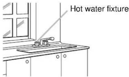
3 Open the gas supply valve.
4 Turn on the power.
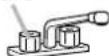
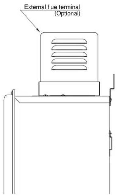
natural_image
Technical line drawing of a mechanical device with pipes and a ventilation cover (no text or symbols)(Eg.: KM3211WH)
When using RCM3211
Clock Adjustment

On this Display Operation Description
1

Press the
ON/OFF
button to turn it "On".
* The ON/OFF is lit.
* When Circulation is on, the O symbol blinks and circulation mode starts automatically. (P15)
< Display detail >
2
(Eg.: 40°C)
Press the SET
button to change the display until "time set" is shown.
3

Use the

buttons
to adjust the clock.
* The time changes in 1-minute increments with each press on the button, and then in 10-minute increments if the button is kept pressed down.

* When the SET button is pressed, or the console is left untouched for about 20 seconds, the settings screen ends.

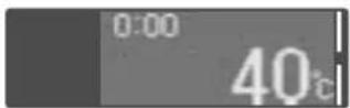
In the event of a power cut or after disconnecting the power supply, when the power is restored, the clock on the display screen shows "0:00", so the clock needs to be re-set.
When using RCM3211
Running Hot Water
On this Display Operation Description
1

Press the
ON/OFF
button to turn it
"On".
* The ON/OFF □ is lit.
* When Circulation is on, the ○ symbol blinks and circulation mode starts automatically. (P15)
< Display detail >

2
Previous set temperature
(Eg.: 40°C)
Turn on hot water.
* This is lit during combustion.
(Display example)

WARNING

Whenever using the hot water, such as when using the shower, check the temperature shown on the remote controller first, and then test the hot water temperature by hand.
Be especially careful if using hot water after previously using water at 60^ C or above to prevent scalding.

WARNING

While the shower is being used, no one other than the user should change the temperature, the power switch must not be turned "off". (when using sub remote controller.)
This is to prevent scalding if the temperature rises. Conversely, if the temperature drops or the power switch is turned "off", the user may be upset when the water suddenly becomes much colder.
When using RCM3211
Setting Hot Water Temperature

On this Display Operation Description
1

Press the
ON/OFF
button to turn it "On".
* The ON/OFF □ is lit.
* When Circulation is on, the O symbol blinks and circulation mode starts automatically. (P15)
2
(Eg.: 40°C)
Use the

buttons to adjust the temperature.

WARNING

While the shower is being used, no one other than the user should change the temperature, the power switch must not be turned "off". (when using sub remote controller.)
This is to prevent scalding if the temperature rises. Conversely, if the temperature drops or the power switch is turned "off", the user may be upset when the water suddenly becomes much colder.
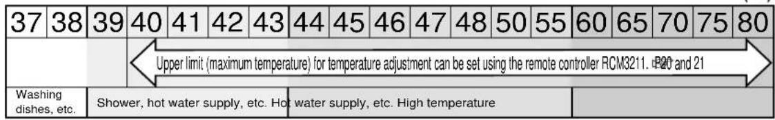
- Approximate hot water conditions
(°C)
| 37 | 38 | 39 | 40 | 41 | 42 | 43 | 44 | 45 | 46 | 47 | 48 | 50 | 55 | 60 | 65 | 70 | 75 | 80 |
| Set the maximum temperature to suit your own preference. (P20 and 21) | ||||||||||||||||||
| Washing dishes, etc. | Shower, hot water supply, etc. Hot water supply, etc. High temperature | |||||||||||||||||
- Hot water temperatures are approximations, and may differ from actual temperatures depending on external factors, such as the season and length of piping involved.
- When low temperatures are set (for washing dishes, etc.), if the ambient water temperature is already quite high, it may be difficult to ensure the resultant water temperature is as per the setting.
- When the hot water temperature is adjusted using thermostat-controlled water mixing valves, set the temperature on the remote controller to about 10^ C higher than that required to ensure the appropriate temperature.
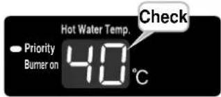
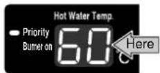
- When setting high temperatures (60 - 80°C);
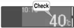
- When a high temperature is set, the readout on the right is shown.
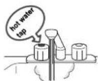
- Please check the temperature displayed before using any hot water.
Be especially careful using any hot water after any previous setting of between 60 - 80°C.
(Eg.: 60°C)
Temperature display flashes for about 10 seconds to indicate high temperature.
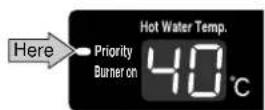
- Please switch to the priority setting if the temperature cannot be adjusted (when an additional remote controller is attached).
- If the power switch on the remote controller is turned "on", the remote controller has priority in adjusting the temperature.
- When the temperature can be adjusted (console has priority), the display screen is shown as per right.
- If the temperature cannot be adjusted, turn the power switch to "off", and then turn it "on" again.
(Eg.: 40°C)
When using RCM3211
Filling Up the Bath
On this Display Operation Description
Preparation 1. Insert the bathplug into the plughole.
1

Press the
ON/OFF □ button to turn it "On".
* The ON/OFF is lit.
* When Circulation is on, the ○ symbol blinks and circulation mode starts automatically. (P15)
2
(Display example)
Turn on hot water.
* Please set to the highest temperature when using thermostat controlled water mixing valves.
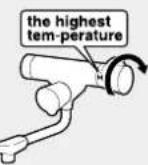
3
When the bath is full, turn off the taps.

WARNING

Check the bathwater temperature with your hand before getting into the bath.
To prevent scalding.
When using RCM3211 Display of ☐ on the remote controller
Circulation Operation
* Instant hot water operation means that water within the hot water supply line is to be heated, and enables hot water to be supplied instantly.
* If C is not displayed on the remote controller, circulation is not available.
On this Display Operation Description
1

Press the
ON/OFF □ button to turn it "On".
* The Symbol blinks and circulation mode starts automatically.
Previously set hot water temperature (Eg.: 40°C)
* See Pages 12 - 13 for details on how to adjust the temperature.
* When the temperature is set at 65°C or above, the temperature of circulation water will be at 60°C.

WARNING

When reducing the temperature setting from very high during instant hot water operation, be wary of the actual temperature.
To prevent scalding.
Even after the temperature is changed, very hot water remains within the pipe.

WARNING

When "priority" is switched to the remote controller during circulation
Hot water circulates at the temperature set by the remote controller with priority right.

Hot water temperatures are approximations, and may differ from actual temperatures depending on external factors, such as the season and length of piping involved.
When using RCM3211 Display of ☐ on the remote controller
Suspension of Circulation

When the hot water tank circulation system is used, do not stop the circulation mode.
If you are unsure how to use such a system, please contact the retailer.
On this Display Operation Description
1
(Eg.: 40°C)
Press the SET
button to change the display to "pre-heat".
2
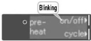
Press the

button until "off" is blinking.
* The C symbol is no longer displayed, circulation mode stops.
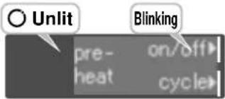
* When the SET button is pressed, or the console is left untouched for about 20 seconds, the settings screen ends.
* Circulation stops until the ON/OFF □ is turned "On", again or until the next timer setting.
When using RCM3211
Display of ☐ on the remote controller
Timer Setting Period for Circulation-1
When a timer period is set, circulation mode will automatically turn on during that time.
Until the timer operation is canceled (P19), circulation operates during the same period every day.
When using a hot water storage tank circulation system, do not set the timer for instant hot water operation.
If you are unsure how to use such a system, please contact the retailer.
On this Display Operation Description
Preparation
An example of using hot water from 6:00 a.m. to 9:00 p.m. is described.
- Check the temperature settings.
- Check that the current time is correct.
1

Press the
ON/OFF button to turn it "On".
* The ON/OFF is lit.
* The Symbol blinks and circulation mode starts automatically.
2
Press the SET
button to change the display to "pre-heat".
3

Use the ▼
button to select the "cycle".
4
Press the button
until the □ is set to "AM 6 - 7".
(Continued)
When using RCM3211 Display of ☐ on the remote controller
Timer Setting Period for Circulation-2

(Continued)
| On this Display Operation Description | |||
| 5 |  | Press thebuttonseveral times, until theis set to “PM 8 - 9”. | * Circulation operates during theperiod set by the. |
 | <Completion of setting > | * When theSETbutton is pressed,or the console is left untouched forabout 20 seconds, the settingsscreen ends.* If the clock is not adjusted, thescreen for clock adjustment willbe shown. (P10)* The setting details will showthe on/off run time of thecirculation pump.Note; the circulation pump willcommence operation inthe next run time period. | |
Circulation starts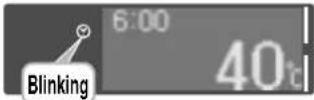 | * Circulation starts.* ON/OFFautomaticallyswitches “ON.” | ||
Circulation stops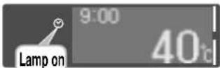 | * Circulation ends.* ON/OFFwill not be turned“OFF” automatically. | ||
When the operation switch is turned “Off” | * About 1min. later thewill notbe displayed, but it will havethe memory of the timersetting. | ||
On this Display Operation Description
●Modification of the timer setting
Cancel the settings as per the following “Cancellation of timer operation” procedure, and then re-set in accordance with the procedure detailed on Pages 17 - 18.
● Confirmation of timer setting
Follow procedures 1 - 2 of “Cancellation of timer operation”, and check the timer setting on the screen under procedure 3.
* Pressing the SET button, or leaving it unattended for about 20 seconds, finalizes the confirmation screen.
● Cancellation of timer operation (when instant hot water is regularly operated)
1
Press the SET
button to change the display to "pre-heat".
2

Use the ▼
button to select the "cycle".
3
Use the button to select "Cancel".
* "Cycle-on" is displayed instantly.
* The timer settings are memorized even after being cancelled.
When using RCM3211
Other Setting Options

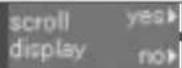
Switching scroll display
Scroll display (P7) can be switched on = "yes" or off = "no".
Draining the unit
This is set to drain the unit.
On this Display
1

2
[Scroll display] (P7)
[Draining the unit] (P29)

[Maximum temperature setting] (P13)
3
yes
Scroll display is turned on.
no
Scroll display is turned off.
yes
Condition is suitable for draining the unit. (P29)
no
Stops draining the unit.
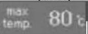
80°C
75°C
- (in 5°C increments)
50°C
48°C
- (in 1°C increments)
40°C
= Initial setting < factory setting >
Modification of the maximum temperature setting
The maximum temperature setting can be modified.
On this Display
Operation
* This may not be displayed depending on the installation conditions.

Power is switched "Off" again.
* This is only used for installation and maintenance purposes, so please do not touch.
① Press the ON/OFF button to "OFF".
② Press the SET button to show the settings screen.
Press the SET button to select the setting to be modified.
(Setting changes each time the button is pressed.)

Use the buttons to modify the setting.
(Setting changes each time the button is pressed.)
* When the SET button is pressed, or the console is left untouched for about 20 seconds, the settings screen ends.
* Repeat procedures 2 - 3 again to adjust other settings.
When using RCM3211
Confirmation Beeper On/Off

The remote controller will emit a sound when any button is pushed. This sound can be muted if it is desired.
* Initial factory setting is with sound.
Operation Description
1 Press the ON/OFF button for about five seconds.
* Setting is possible regardless of whether the power switch is ON/OFF.
When using RCS3211
Running Hot Water
On this Display Operation Description
1
Press the

button to turn it "On".
* Hot water supply temperature is displayed.
2
Previous set temperature (Eg.: 40°C)
Turn on hot water.
* This is lit during combustion.
< Display details >

WARNING

Whenever using the hot water, such as when using the shower, check the temperature shown on the remote controller first, and then test the hot water temperature by hand.
Be especially careful if using hot water after previously using water at 60^ C or above to prevent scalding.

WARNING

While the shower is being used, no one other than the user should change the temperature, the power switch must not be turned "off", when using sub remote controller.
This is to prevent scalding if the temperature rises. Conversely, if the temperature reduces or the power switch is turned "off", the user may be upset when the water suddenly becomes much colder.
When using RCS3211
Setting Hot Water Temperture
On this Display Operation Description
1

Press the
button to turn it
"On".
* Hot water supply temperature is displayed.
2
(Eg.: 40°C)
Use the
buttons to adjust the temperature.

WARNING

While the shower is being used, no one other than the user should change the temperature, the power switch must not be turned "off", when using sub remote controller.
This is to prevent scalding if the temperature rises. Conversely, if the temperature reduces or the power switch is turned "off", the user may be upset when the water suddenly becomes much colder.
• Approximate hot water conditions
(°C)
- Hot water temperatures are approximations, and may differ from actual temperatures depending on external factors, such as the season and length of piping involved.
- When low temperatures are set (for washing dishes, etc.), if the ambient water temperature is already quite high, it may be difficult to ensure the resultant water temperature is as per the setting.
- When the hot water temperature is adjusted using thermostat-controlled water mixing valves, set the temperature on the remote controller to about 10°C higher than that required to ensure the appropriate temperature.
- When setting high temperatures (60 - 80°C);
When setting high temperatures (60 - 80°C);
- When a high temperature is set, the readout on the right is shown.
- Please check the temperature displayed before using any hot water.
Be especially careful using any hot water after any previous setting of between 60 - 80°C.
(Eg.: 60°C)
Temperature display flashes for about 10 seconds to indicate high temperature.
- Please switch to the priority setting if the temperature cannot be adjusted.
- If the power switch on the remote controller is turned "on", the remote controller has priority in adjusting the temperature.
- When the temperature can be adjusted (console has priority), the display screen is shown as per right.
- If the temperature cannot be adjusted, turn the power switch to "off", and then turn it "on" again.
(Eg.: 40°C)
When using RCS3211
Confirmation Beeper On/Off
The remote controller will emit a sound when any button is pushed. This sound can be muted if it is desired.
* Initial factory setting is with sound.
Operation Description
1 Press the ON/OFF button for about five seconds.
* Setting is possible regardless of whether the power switch is ON/OFF.
No remote controller case
Running Hot Water
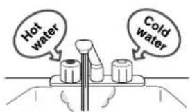
The water temperature will be set at 60^ C (fixed). Please mix in some cold water through the water mixing valves.

WARNING

Whenever using hot water, such as when using the shower, first test the hot water temperature by hand.
To prevent scalding.
Operation Description
1
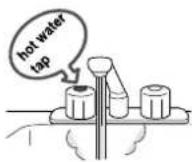
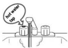
Turn on hot water.
2
Temperature adjustment for hot water supply
3
Turn off the hot water tap after use.

Contact your installer if you wish to fix the temperature at 42^ C, 45^ C, or 75^ C (such as to connect a dishwasher, etc.). If the temperature is set at 75^ C, use thermostat-controlled water mixing valves to prevent scalding when using other taps.
Preventing Damage from Freezing
The heater and piping can be damaged if cold temperatures cause water to freeze inside the unit. The damage can be prevented with the following method:
Normal cold [outside temperatures between 0°C - 10°C with no wind]
At these temperatures, the units have freeze prevention heaters that will prevent freezing.
* Do not disconnect the power. The freeze prevention heaters will not work if the power is disconnected.
* The freeze prevention will work regardless of whether the operation button on the remote controller has been turned on.
When the temperature drops, the freeze-prevention heaters are automatically activated to keep the unit warm and prevent it from freezing.
The freeze prevention heaters will not prevent the plumbing external to the unit from freezing. Protect this plumbing with insulation. If you are still worried that your heater will freeze, contact the nearest Bosch Service Dealer.
For severely cold temperatures
outside temperature including wind chill of less than -10°C
Run water to prevent freezing.
- Turn the unit on with the Power Button on the Remote Controller.
- Close the gas supply valve.
-
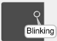
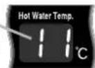
Open a hot water fixture and let it run for approx. 1 minute, and then check that the number 11 is flashing on the remote controller display.
* If multiple units are being used, drain each unit for approx.1 minute.
* It is possible that a different number may be displayed on the remote controller, but as long as it is flashing, you may continue. Hot Water Fixture
Hot Water Fixture -
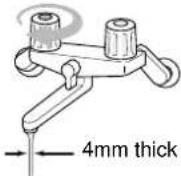
Adjust a hot water fixture, and keep a small amount of hot water running. (0.4L/minute or about 4mm thick.)
* If there is a mixing valve, set it to the highest level.
* When linking multiple units, discharge water equivalent to 0.4L/minute per unit.
- The flow may become unstable from time to time. Check the flow 30 minutes later.
• This method can be applied not only to the heater, but also to the water supply, water piping and mixing valve.
- Remember that if the mixing valve is set to the maximum level, there is a risk of scalding.
- If freezing still might occur, drain the water from the unit following the steps on P29.
If water will not flow because it is frozen
- Close the gas and water valves.
- Turn off the operation button.
- Open the water supply valve from time to time to check whether water is running.
-
When the water is flowing again, check for water leaks from the equipment and piping, or follow steps 1 through 4 on P9 ("Initial Operation").
-
If the heater or the piping is frozen, do not use the heater, or it may become damaged.
- Repairs for damage caused by freezing, is not covered by the warranty.
When Unused for an Extended Period-1
If the water heater will not be used for a long period of time, drain the water.

CAUTION

Whenever the unit is checked, maintained, or drained, the power switch must be turned "Off", and it must be allowed to cool down first.
To prevent scalding.
The water within the appliance is still very hot, for a short period after use.
Preparation
A bucket for draining water.
Drainage using the remote controller RCM3211
1 Follow the procedure on Pgs. 20 - 21, and set "Drain the heater" to "yes".
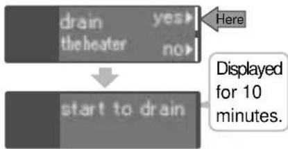
flowchart
graph TD
    A["drain"] --> B["the heater"]
    B --> C{yes}
    B --> D{no}
    C --> E["Here"]
    D --> F["start to drain"]
    F --> G["Displayed for 10 minutes."]
2 Close the water supply valve.
3 Fully open all hot water fixtures.
Fixture

4 Open all cleanout plugs by turning them to the left.
(Position of the cleanout plugs ☐30)
* Draining starts.
5 When the water is completely drained, replace all drain plugs and close the hot water fixtures.
6 Close the gas valve.
Manual draining
1
Close the gas valve.
2
-
Turn the power switch "On". (If there is no remote controller, make sure that the power is plugged in.)
-
Open the hot water tap fully, leave it in that position for at least one minute, and then turn off the
Fixture
* For conjunct setting: Allow at least one minute per unit
* Error display <11> may appear on the remote controller, but this is not an error. Do not turn the power switch "Off".
3
Close the water supply valve.
4
Fully open all hot water fixtures.
Fixture
5
Open all cleanout plugs by turning them to the left.
(Position of the cleanout plugs ☐30)
* Draining starts.
6
When the water is completely drained, replace all drain plugs and close the hot water fixtures.
(Continued)
When Unused for an Extended Period-2
If the water heater will not be used for a long period of time, drain the water.
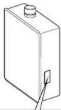
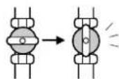
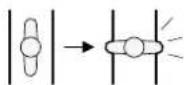
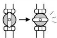
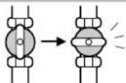
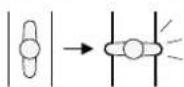
Position of the cleanout plugs

* The shapes of the cleanout plugs are as pictured on the right.
* The cleanout plugs may not be clearly visible as they are partially hidden behind the pipe insulation.
* Water may not drain out fully even though the cleanout plugs are loosened, depending on the pipe arrangement. In this case, fully remove the cleanout plugs. (Make sure not to mislay them.)
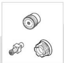
natural_image
Three mechanical component illustrations (cylindrical, threaded, and flanged) shown in line drawings without any text or symbols.For re-use
Please start to use it again in accordance with the "Initial Operation" procedure on P9.
Regular Maintenance-1
Inspection (Once a month)

Caution

High Temperature
To avoid burns, wait until the equipment cools down before draining the water. The appliance will remain hot after it is turned off.
Check
For laundry, newspaper, timber, oil, spray cans and other combustible materials. (P5)
Check
For abnormal sounds during operation.
Check
For abnormalities in external appearance, discoloration or flaws.
Check
For water leaks from the equipment and piping.
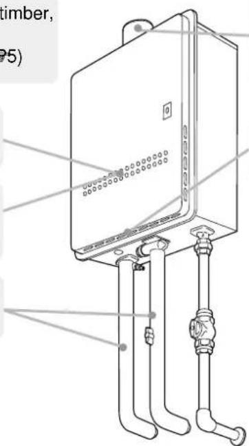
(Eg.: KM3211WH)
Check
For dust and soot in the exhaust vent or exhaust vent terminal.
Check
For dust or debris in the air inlet.
Maintenance (Once a month)
Equipment
Wipe the outside surface with a wet cloth, then dry the surface. Use a neutral detergent to clean any stains.
Remote Controller
Wipe the surface with a wet cloth.
- Do not use petrol, oil or fatty detergents to clean the remote controller; deformation may occur.
- The remote controller is water resistant but not water proof. Keep it is dry as possible.
Regular Maintenance-2
Maintenance (Once a month)
Water Drain Valve (with Water Filter)
If the water drain valve (with water filter) is covered with debris, the hot water may not run smoothly, or the unit may produce cold water. Check and clean the filter as explained below.
* To avoid burns, wait until the equipment cools down before draining the water. The appliance will remain hot after it is turned off.
* Water will be discharged from the trap plug. Place a container, etc. to receive the discharged water.
1. Close the water supply valve.
2. Open all hot water fixtures.
3. Remove the inlet and outlet drain plugs (about 1L will drain out)
4. Take the water drain valve (with water filter) out of the inlet. (See illustration to right).
5. Clean the water drain valve (with water filter) with a brush under running water.
6. Replace the water drain valve (with water filter). (Take care not to lose the packing.)
7. Close all hot water fixtures.
8. Open the water supply valve and check that water does not leak from the drain plugs or water drain valve (with water filter).
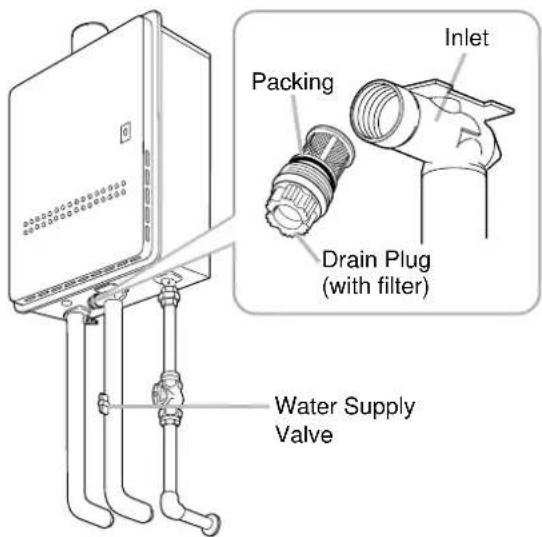
(Eg.: KM3211WH)
Troubleshooting-1
Temperature
| Hot water is not available when the hot water fixture is opened. | Are the gas and water supply valves fully open?Is the water supply cut off?Is the hot water fixture sufficiently open?Is the heater frozen?Is the gas meter working?(For LP) Is there enough gas in the tank?Is the operation button turned on?Have you allowed enough time for the cold water in the pipes to drain out? |
| Hot water is not available at low temperatures. | Are the gas and water supply valves fully open?Is the water temperature setting appropriate check remote controller?If the supply water is at a high temperature, you may need to increase the flow rate through the heater to get a low temperature out of it. |
| Hot water is not available at high temperatures. | Are the gas and water supply valves fully open?Is the water temperature setting appropriate, check remote controller? |
| Cold water comes out when the fixture is barely opened. Only cold water is available at low flow rates. | The heater stops burning when the flow of hot water becomes less than 3 LPM. Open the hot water fixture more, and the water temperature will stabilize. |
Troubleshooting-2
Amount of hot water
The pressure at a certain fixture is not constant.
- When hot water is demanded at other fixtures, the amount available may be reduced.
- Pressure fluctuations and other plumbing conditions can cause the temperature and pressure at a fixture to be unstable, but it should stabilize after a short time.
- To keep the temperature stable, the heater limits the amount of water that can flow through it to a small amount initially, but the amount increases over time.
Remote controller
| The power lamp is not lit. • Has the power been cut? | |
| Clock shows “0:00”. | • If the power is disconnected for any reason, when the power is reconnected, the clock on the display screen shows “0:00”, indicating that it needs to be reset. (P10) |
| After the power is cut, the hot water supply temperature is different. | • If using the remote controller RCS3211, the hot water temperature display reverts to the factory setting, so please check it. |
| The display on the remote controller moves continuously. | • In order to prevent the screen from burning out, after the remote controller has not been used for about 10 minutes, the screen display changes, and continuously scrolls sideways. (P7,20-21) |
| The symbol is blinking.The combustion indicator / the burner on indicator turns on and off. | • During instant hot water operation, the combustion heater turns on and off intermittently. This is normal. |
| Temperature setting cannot be increased. | • Has the maximum temperature setting been changed?(P20-21) |
Sound
The fan can be heard after operation is stopped.
- The fan runs for a while to accelerate ignition after the operation button is turned on.
Other
| The Heater stops burning during operation. | Are the gas and water supply valves fully open?Is the water supply cut off?Is the hot water fixture sufficiently open?Is the gas meter working?(For LP) Is there enough gas in the tank? |
| exhaust vent on a cold day. | This is normal on cold days. White smoke comes out of the |
| The hot water becomes turbid. | This is harmless. Small bubbles appear as the air in the water is heated and depressurized rapidly to atmospheric pressure. It is similar to the bubbles in beer or carbonated beverages. |
| Water leaks from the drain plugs on the outlet. | When the main unit is highly pressurized, water will leak from the drain plugs as a safety so that the unit is not damaged by the high pressure.These plugs are pressure relief valves. If water is leaking out of them, excessive pressure is being supplied to the unit: Have the water pressure checked by your installer or Bosch Service Dealer. |
Troubleshooting-3
Please check the failure display on the remote controller or the combustion lamp on the main body.
In the event of a failure, the cause is notified by a blinking failure display. Please resolve the problem in accordance with the table below.

Failure display blinks (This display is an example.)
(if using RCM3211) (if using RCS3211)
| Failure display | Details of Failure Remedy | |
| 11F11 | Fault occurs with the ignition switch at the hot water supply side. | Turn the power “Off”, make sure that the gas valve is open and that the gas meter (microcomputer meter) has not shut off the gas, and if this is the problem, please rectify it. Then, turn the power “On”, and when the hot water tap is turned on, it is back to normal if nothing is displayed. |
| 99F99 | Fault occurs with combustion of the unit. | Please contact your retailer or gas supplier. |
[Combustion lamp is lit. (P6)]
In the event of a failure, you are notified by the combustion lamp blinking at the front of the unit. Please resolve the problem in accordance with the table below.
| Combustion lamp Details of Failure Remedy | ||
| Continuously blinkingLitUnlit | Fault occurs with the unit. | Make sure that the gas valve is open. Close the hot water tap, then reopen it, and it is back to normal if the combustion lamp is no longer lit. |
Contact a Bosch service dealer if:
- Any other error code appears.
- An error code is indicated again after the above actions were followed.
• There are any other questions.
Follow-up Service
Requesting Service
First follow the instructions in the troubleshooting section (P33 to P36). If the error is not corrected, contact your Bosch Service Dealer.
We will need to know:
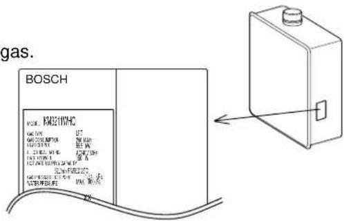
The Model ...... (check the rating plate)
*See P4 for the location of the label
Date of purchase ..... (see the warranty)
Details of problem ... (flashing error codes, etc., in as much detail as possible)
Your name, address, and telephone number

natural_image
Cartoon illustration of a girl with surprised expression and waving (no text or symbols)* A request for service may be rejected if the water heater is installed in a location where working on the unit may be dangerous. Contact a plumber.
Warranty
Be sure that the shop name, date of purchase and other necessary items are filled in. Read the content carefully, and keep in a safe place.
For repairs after the warranty period, there will be a charge on any service, and service will only be performed if the unit is deemed repairable. See Warranty Document on page 78.
Minimum period of time for stocking repair parts
Bosch will stock repair parts for this unit for a minimum of ten years after production has ceased. These are the parts necessary to repair or maintain this unit.
Specifications
- Specifications may be changed without prior notice.
- The capacity may differ slightly, depending on the water pressure, water supply, piping conditions, and water temperature.
Specifications
| Item | Specification | ||
| Model Name | KM3211WH | KM3211WHQ | |
| Type | InstallationAir Supply/Exhaust | Indoor or Outdoor, Wall HangingPower Vented | |
| Ignition | Direct Ignition | ||
| Minimum Pressure for Maximum flow | 200 kPa | ||
| Minimum Flow Rate | 3.5 L/min. | ||
| Dimensions | 61.5 cm(Height) x 46.4 cm(Width) x 24 cm(Depth) | ||
| Weight | 29 kg | 32 kg | |
| Water Holding Capacity | 1.1 Litre | ||
| Connection Sizes | Water Inlet | 3/4" | |
| Hot Water Outlet | 3/4" | ||
| Hot Water Return | - | 1 | |
| Gas Inlet | 3/4" | ||
| Power Supply | Supply | 240 VAC (50Hz) | |
| Consumption | NG:100WLP:115WFreeze Prevention 115W | NG:135WLP:150WFreeze Prevention 140W | |
| Materials | Casing | Zincified Steel Plate/Polyester Coating | |
| Flue Collar | Stainless Steel | ||
| Heat Exchanger | Copper Sheeting, Copper Tubing | ||
| Safety Devices | Flame Rod, Thermal Fuse, Pressure Relief Valve, Lightning Protection Device (ZNR), Electric Leakage Prevention Device, Overheat Prevention Device, Freezing Prevention Device, Fan Rotation Detector | ||
| Accessories | Remote Controller, Anchoring Screws | ||
Performance
| Item | Maximum Performance | Minimum Performance | |
| Gas Consumption | NG | 250 MJ/h | 20 MJ/h |
| LP | 250 MJ/h | 18 MJ/h | |
| Hot Water Capacity | 25°C Rise 32 L/min. | ||
| 58°C Rise 13 L/min. | |||
| Capacity Range | 3 - 32 L/min. | ||
| Temperature Settings | 37 - 48, 50, 55, 60, 65, 70, 75, 80°C (Bridge 83°C) | ||
| Default Temperature Options | 40, 50, 60, 83°C | ||
External outfittingExKM3210WHHKQK3232WMWHQKM3211WHQ
External outfittingExKM321dWHTKQ3232WMHQKM3211WHQ
| Part Nos. | Part Names | Order Nos. | Qty/unit | Note |
| 001 | KM3211WH BOS Front set-AS SKA7035 1 For KM3211WH | |||
| KM3211WHQ BOS Front set-AS | SKA7036 | 1 For KM3211WHQ | ||
| 002 | Front packing S AAP | AAPL015 | 2 | |
| 003 | Front packing L AAP | AAPL017 | 2 | |
| 004 | Lamp seal plate DEC | DECK008 | 1 | |
| 006 | Case top packing EDM | EDML001 | 1 | |
| 007 | Case top cover 2 EDL | EDLA005 1 | ||
| 008 | Case top cover EDM | EDMA003 | 1 | |
| 009 | Exhaust cylinder packing EDL | EDLL002 1 | ||
| 010 | Exhause box EDM | EDMF001 | 1 009, 012 | also replace |
| 012 | Exhause joint packing DHN | DHNL003 | 1 | |
| 016 | Pump fixing plate DHN | DHNA007 | 1 For KM3211WHQ | |
| 022 | Caution label BOSCH EJX | EJXK004 1 | ||
| 023 | Plug insulation sheet CRU | CRUK002 | 1 | |
| 025 | Case H EJX | EJXA011 | 1 | For KM3211WH 022 also replace |
| Case QH EJX | EJXA001 | 1 | For KM3211WHQ 022 also replace | |
| 026 | Airthermistor 300 BWC | BWCH003 | 1 For KM3211WHQ | |
| 027 | Cord Bush C1 | 7355009 | 1 | |
| 038 | Shield plate EAD | EADA011 1 For KM3211WHQ | ||
| 039 | Connection diagram label BOSCH EJX | EJXK007 1 | ||
| 040 | Raintight seal plate BUB | BUBK004 | 1 | |
| 050 | Connection Cord 2 DMB | DMBJ010 | 1 | |
| 070 | Cross recessed round-head collar N-tapping screw 4X8 | SUS410 | ||
| 071 | Cross recessed truss type3 EVERTIGHT tapping screw with PW 4X12 | SUS410 dacrotized | ||
| 072 | Cross recessed round-head collar N-tapping screw 4X10 | SUS410 | ||
| 073 | Cross recessed round-head collar N-tapping screw 4X12 | SUS410 | ||
| 074 | Cross recessed truss type3 S TIGHT tapping screw4X10 | SUS410 pre-coating | ||
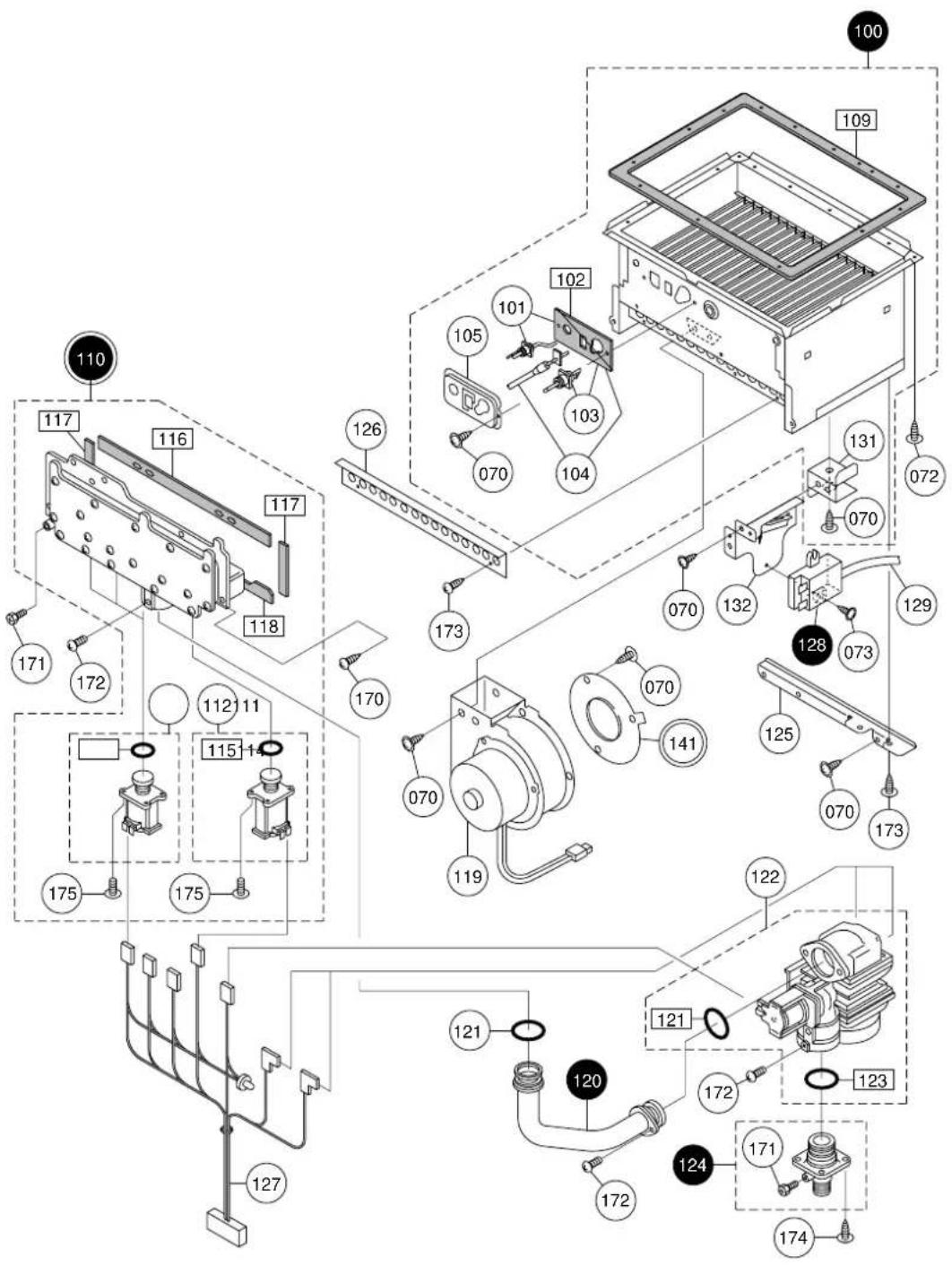
Combution unit and gas route CdkM3210WhKAKQ24WHWHQKM3211WHQ
Combution unit and gas routeCokM321b1WhIKKMMg2WMWHQKM3211WHQ
| Part Nos. | Part Names | Order Nos. | Qtyunit | Note |
| 100 Combustion tube set EAC SET-V SBP7302 1 116, 117, 118 also replace | ||||
| 101 | Flame rod DLK SET-V | SBA7506 1 | ||
| 102 | Plug packing(for N) DLK | DLKL012 | 1 | |
| 103 | Ignition plug Q(N) SET-V | SBA7504 1 | ||
| 104 | Burner sensor DLK SET-V | SBA7505 1 | ||
| 105 Plug fixing plate(for N) DLK | DLKC009 1 | |||
| 109 | Suction air joint packing DHN | DHNL002 1 | ||
| 110 | Manifold set 15 DHN SET-AS | SAR7812 | 1 | For LPG 121 also replace |
| Manifold set 24 DHN SET-AS | SAR7574 | 1 | For NG 121 also replace | |
| 111 | Solenoid S16L CRU SET-AS | SAQ7346 | 3 | |
| 112 | Solenoid S24L CRU SET-AS | SAQ7406 | 1 | |
| 114 | O-ring S30 type 1A | SAD6433 | 3 | |
| 115 | O-ring S-38 | SAD6372 | 1 | |
| 116 | Manifold seal packing top CRP | CRPL002 1 | ||
| 117 | Manifold seal packing side CRP | CRPL004 2 | ||
| 118 | Manifold seal packing bottom CRP | CRPL003 1 | ||
| 119 | Fan moter Q CXB | CXBF030 1 | ||
| 120 | Manifold pipe DHN | DHNE015 | 1 121 also replace | |
| 121 | O-ring P25.5 | SAB1512 2 | ||
| 122 | Gas mech. S24DQ CRP SET-V | SAQ7708 | 1 | |
| 123 | O-ring JASO 2028A | B590109 | 1 | |
| 124 | Gas fitting 20ASET CRU | CRUE016 | 1 | 123 also replace |
| 125 | Mounting plate for burner case DLT | DLTC001 | 1 | |
| 126 | Main damper 11 CRP | CRPC052 | 1 | |
| 127 | Conduit R10 DEK | DEKJ014 | 1 | |
| 128 | Igniter AGV | AGVJ007 | 1 | 129 also replace |
| 129 | High-voltage cord 470 | SAC1229 | 1 | |
| 131 | Mounting plate for igniter EAC | EACC011 | 1 | |
| 132 | Mounting plate for igniter DTJ | DTJA015 | 1 | |
| 141 | Bell-mouse 4 CRU | CRUC045 | 1 For LPG | |
| Bell-mouse 8 CRU | CRUC046 | 1 For NG | ||
| 170 | Cross recessed round-head type3 EVERTIGHT tapping screw 5x16 | SUS410 | ||
| 171 | Cross recessed hexagon head machine screw M4X8 | SWRM chromate, pre-coating | ||
| 172 | Cross recessed round-head machine screw M4-81 | SUS430 black | ||
| 173 | Cross recessed round-head N-tapping screw 4X8 | SUS410 | ||
| 174 | Cross recessed round-head collar type3 EVERTIGHT tapping screw 4X12 | SUS410 | ||
| 175 | Cross recessed round-head SPAKmachine screw with guide M4X12 | SUS22 chromate | ||
Hot-water feed route1HdK-W32r1MedKb3211WH
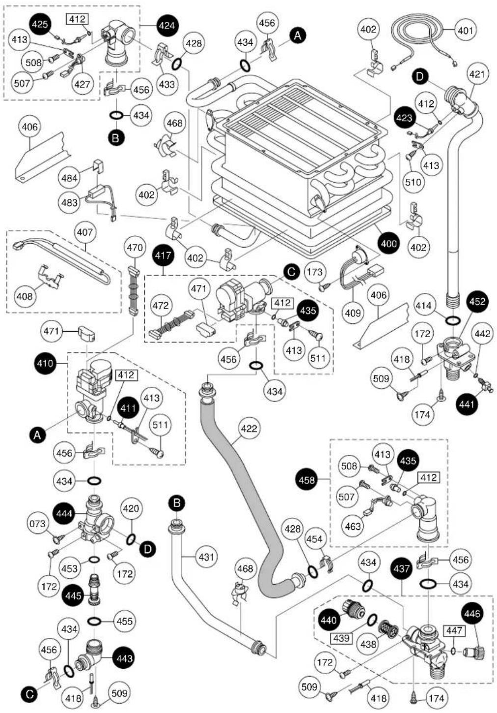
Hot-water feed route2HokM32er1WedQkM6211WHQ
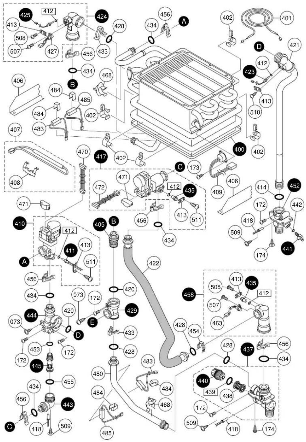
Hot-water feed route3HdKM32dr1MdKMM32WMHQKM3211WHQ
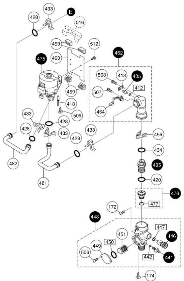
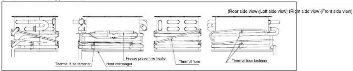
(Thermal fuse rounding procedure)
Hot-water feed routeHokM3211WedKM0232WM/HQKM3211WHQ
| Part Nos. | Part Names | Order Nos. | Qty / unit | Note |
| 400 | Heat exchanger EAC SET-AS | SBN7205 | 1 | 012, 109, 401, 402, 428, 434also replace |
| 401 Thermal fuse DHN SET-V SBA7398 1 | ||||
| 402 Thermal fuse fastener CXD CXDH003 5 | ||||
| 405 | Water inlet coupling DJP | DJPD012 | 2 | For KM3211WHQ 420, 434 also replace |
| 406 Thermal fuse cover DHN | DHNA014 2 | |||
| 407 | Freeze preventive heater Q DJW SET-V | SKA7037 | 1 | |
| 408 | Heater fastener EHK | EHKH001 1 | ||
| 409 | Remaining flame safety device 120 DJP DJPH002 1 | |||
| 410 | Water flow servo set 2 DZT | DZTD011 1 434 | also replace | |
| 411 | Heat exchanger thermistor-300 BWC | BWCD098 | 1 412 also replace | |
| 412 | O-ring P4C | 1323709 | 5 | For KM3211WH |
| O-ring P4C | 1323709 | 6 For KM3211WHQ | ||
| 413 | Thermistor holding plate ALS | ALSD088 5 For KM3211WH | ||
| Thermistor holding plate ALS | ALSD088 6 For KM3211WHQ | |||
| 414 | O-ring P20C | 3059502 | 1 | |
| 417 | Water flow servo set 1 DZT | DZTD010 1 434 | also replace | |
| 418 | Freeze preventive heater 3 DJW | DJWH003 | 3 For KM3211WH | |
| Freeze preventive heater 3 DJW | DJWH003 | 4 For KM3211WHQ | ||
| 420 | O-ring P22C | 7573308 | 1 For KM3211WH | |
| O-ring P22C | 7573308 | 3 | For KM3211WHQ | |
| 421 | Hot-water feed pipe DHN DHND010 1 | |||
| 422 | Bypass pipe EAC | EACD003 1 | ||
| 423 | Hot-water thermistor-300 BWC | BWCD096 | 1 412 also replace | |
| 424 | Water flow sensor set 3 DUV | DUVD019 1 428 | 434 also replace | |
| 425 | Water inlet thermistor-300 BWC | BWCD097 | 1 412 also replace | |
| 427 | Water outlet magnetic sensor BWC | BWCD090 | 1 | |
| 428 | O-ring P12.5C | 3359808 | 2 | For KM3211WH |
| O-ring P12.5C | 3359808 | 8 For KM3211WHQ | ||
| 429 | Branching fittingSET DHN | DHND018 | 1 | For KM3211WHQ 420, 428 also replace |
| 431 | Water inlet pipe EAC | EACD001 1 For KM3211WH | ||
| 433 | Quick fastener 13-22 | SAD6537 1 For KM3211WH | ||
| Quick fastener 13-22 | SAD6537 6 For KM3211WHQ | |||
| 434 | O-ring P16C | 3223302 | 7 | |
| 435 | Shut-off cock AXG | AXGD089 | 2 | For KM3211WH 412 also replace |
| Shut-off cock AXG | AXGD089 | 3 | For KM3211WHQ 412 also replace | |
| 437 | Water inlet fitting 20ASET EAC | EACD006 | 1 | For KM3211WH 434 also replace |
| Water inlet fitting 20ASET EBA | EBAD003 | 1 | For KM3211WHQ 428, 434 also replace | |
| 438 | Water filter (SUS) EGB | EGBD032 | 1 For KM3211WH | |
| Water filter DTJ | DTJD005 1 For KM3211WHQ | |||
| 439 | O-ring 16DF BRQ | BRQL008 1 | ||
| 440 | Water filter cap DTJ | DTJD006 1 439 | also replace | |
| 441 | Drain cock CRU | CRUD003 | 1 | For KM3211WH 442 also replace |
| Drain cock CRU | CRUD003 | 2 | For KM3211WHQ 442 also replace | |
| 442 | Hot-water resistant O-ring P3 | SAD6633 1 For KM3211WH | ||
| Hot-water resistant O-ring P3 | SAD6633 2 For KM3211WHQ | |||
| 443 | Mixing coupling EAC | EACD007 | 1 | 434, 455 also replace |
| 444 | Mixing body EAC | EACD013 | 1 | 420, 434, 453, 455 also replace |
| 445 | Mixing cylinder BWC | BWCD035 | 1 | 453, 455 also replace |
| 446 | QMF safety valve A(S) | SAA2811 | 1 | 447 also replace |
| 447 | Hot water resistant O-ring P9 | SAD6635 1 | ||
| 448 | Return fitting 15A SET EAD | EADD010 | 1 | For KM3211WHQ 420, 477 also replace |
| 449 | Water inlet fitting cover CRU | CRUD005 | 1 | For KM3211WHQ |
| 450 | O-ring JASO 2023 type1 A | SAA6433 | 1 | For KM3211WHQ |
| 451 | Water filter SUS DMM | DMMD002 | 1 For KM3211WHQ | |
| 452 | Hot-water outlet fitting HGH | HGHD101 | 1 | 414, 442 also replace |
| 453 | O-ring P11C | 1326503 | 1 | |
| 454 | Quick fastener 12.7 | 6340202 | 1 | |
| 455 | O-ring JASO 2026 type4 C | SAA6483 | 1 | |
| 456 | Quick fastener 16A | 6340300 | 6 For KM3211WH | |
| Quick fastener 16A | 6340300 | 7 For KM3211WHQ | ||
| 458 | Water flow sensor SET1 DUV | DUVD017 1 428 | 434 also replace | |
| 459 | Pump vibration proof rubber ALS | ALSD058 4 For KM3211WHQ | ||
| 460 | Pump foot DAN | DANA012 | 1 | For KM3211WHQ |
Hot-water feed routeHdK-Wa2r1MddKb3232WMHQKM3211WHQ
| Part Nos. | Part Names | Order Nos. | Q'ty / unit | Note |
| 462 | Water flow sensor SET1 DUV | DUVD018 | 1 | For KM3211WHQ 428, 434 also replace |
| 463 Magnetic sensor BWC BWCD093 1 | ||||
| 464 Magnetic sensor for circulation BWC BWCD092 1 For KM3211WHQ | ||||
| 468 Freeze Protection Thermostat BVU | BVUH002 2 | |||
| 470 Conduit 86 DZT | DZTJ008 | 1 | ||
| 471 Waterproof cover CZL | OZLD041 | 2 | ||
| 472 Servo motor cable conduit (86) DZT | DZTJ009 | 1 | ||
| 475 Pump HK DHN | DHND026 | 1 | For KM3211WHQ 428 also replace | |
| 476 Shut-off valve SET DSC | DSCD028 | 1 | For KM3211WHQ 420 also replace | |
| 477 O-ring P14C | 1326708 | 1 For KM3211WHQ | ||
| 480 | Water inlet pipe EAD | EADD001 | 1 | For KM3211WHQ |
| 481 | Return pipe EAD | EADD006 | 1 | For KM3211WHQ |
| 482 | Pump comes out of pipe EAD | EADD008 | 1 | For KM3211WHQ |
| 483 Dummy heater 240V DJW | DJWH004 | 1 For KM3211WH | ||
| Dummy heater 240V DJW | DJWH004 | 2 For KM3211WHQ | ||
| 484 | Heater fastener M AJB | AJBL002 | 1 | For KM3211WH |
| Heater fastener M AJB | AJBL002 | 4 | For KM3211WHQ | |
| 485 Freeze preventive heater2 DJW | DJWH002 | 2 For KM3211WHQ | ||
| 506 | Cross recessed round-head machine screw M4X8 | For KM3211WHQ SUS430 | ||
| 507 Cross recessed truss P TIGHT screw 4X10 | SUS305 | |||
| 508 Cross recessed round-head P TIGHT screw 4X14 | SUS305 | |||
| 509 Cross & straight recessed round-head collar type3 S TIGHT tapping screw 4X8 | SUS410 | |||
| 510 Cross & straight recessed type3 S TIGHT tapping screw 4X8 | SUS410 | |||
| 511 Cross recessed round-head P TIGHT screw 4X14 | SUS410 | |||
| 512 Cross recessed round-head type3 EVERTIGHT tapping screw 4X8 | For KM3211WHQ SWRM chromate | |||
Electric controller ElecM3210MMdKeKM3232WMWHQKM3211WHQ
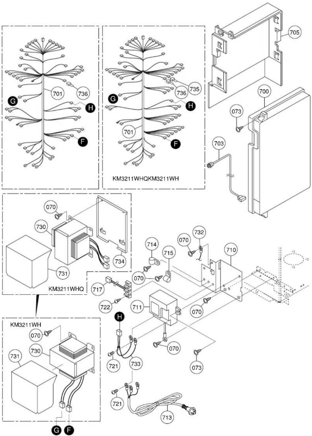
Electric controllerElectM320dWbIKM3232WMHQKM3211WHQ
| Part Nos. | Part Names | Order Nos. | Q'ty / unit | Note |
| 700 Relay case EJX SET-AS SHA7706 1 | ||||
| 701 Harness H BOSCH EJX EJXJ031 1 For KM3211WH | ||||
| Harness QH BOSCH EJX EJXJ011 1 For KM3211WHQ | ||||
| 703 Lamp cable conduit CRP CRPJ014 1 | ||||
| 705 Relay case cover DEK DEKA014 1 | ||||
| 710 Mounting plate for terminal block DZT | DZTA006 1 | |||
| 711 Short circuit safety device 240 EJS | EJSJ022 | 1 | ||
| 713 Power cord EJX | EJXJ017 1 | |||
| 714 Nylon clamp HP-4N (NK-4N) | 7287909 | 1 | ||
| 715 Nylon clamp HP-5N (NK-5N) | 7224001 | 1 | ||
| 717 Conduit 90-2 CCP | CCPJ028 | 1 | ||
| 721 Cross recessed bind machine screw M3.5X6 | SUS430 | |||
| 722 Cross recessed round-head N tapping screw 4X12 | SUS410 | |||
| 730 Transformer EJX | EJXJ021 1 | |||
| 731 Transformer cover EJS | EJSA021 | 1 | ||
| 732 Connection Cord 1 DEM | DEMJ009 1 | |||
| 733 Conduit R92-250 EJS | EJSJ016 | 1 | ||
| 734 Mounting plate for Transformer for Q EJS | EJSA016 | 1 | For KM3211WHQ | |
| 735 System select connector EJS | EJSJ015 | 1 | For KM3211WHQ | |
| 736 Heating level change connector for 83 DTJ | DTJJ031 | 1 | ||
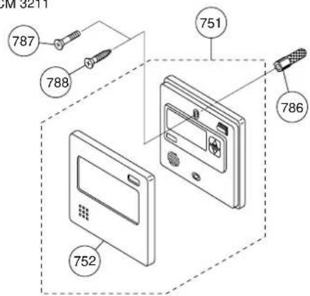
Remote controller and attached setReKM32 toWHKK3221WHHQK58211WHQ
Remote controller
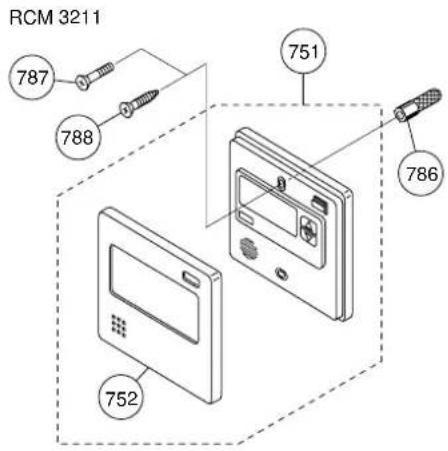
Additional remote controllerKitchen remote controller RCS 3211
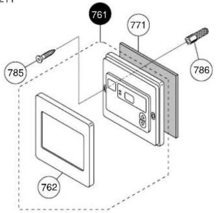
Attached set
KM3211WHQ
Kitchen remote controller
RCM 3211

| Special part Special part no. | |
| instruction manual | 888 |
Remote controller and attached setRem032 toWtDKK032 WMHQKM3211WHQ
| Part Nos. | Part Names | Order Nos. | Q'ty / unit | Note |
| 751 RC-7508M body BOS QPA QPAJ007 1752 M Drssed frame body BOS QPA QPAA007 1761 RC-7002B body BOS QKA QKAJ026 1 771 also replace762 B Drssed frame body BOS QKA771 Wall packing QHU | QKAA326 1QHUA115 | 1 | ||
| 785 Cross recessed round wood screw 4.1X25786 Oar plug 6X25787 Cross recessed flat-head screw M4X35788 Cross recessed flat-head wood screw (All screw)4.1X20 SWRM chromate | SUS305SWRM chromate | |||
| 800 GQ3210WZF-2BOS packing P setV803 Cross recessed round-head type 1 tapping screw 5X35888 Instruction manual GQ-3211WZH BOSCH | SKA7038SAR8191 1 | 1SUS305 | ||
Installation Guide
Robert Bosch (Australia) Pty. Ltd.
GAS WATER HEATER
KM3211WH (Indoor or Outdoor Installation)
KM3211WHQ (Indoor or Outdoor Installation / Internal pump unit)
WARNING: If the information in this manual is not followed exactly, a fire or explosion may result causing property damage, personal injury or death.
| Potential dangers from accidents during installation and use are divided into the following three categories. Closely observe these warnings, they are critical to your safety. | |
 Danger Danger | Danger of serious injury or even death as well as the danger of fire when the product is misused by ignoring this symbol. |
 Warning Warning | Possibility of serious injury or even death as well as the possibility of fire when the product is misused by ignoring this symbol. |
 Caution Caution | Possibility of bodily injury or damage to property when the product is misused by ignoring this symbol. |

Prohibited

Disconnect Power

Ground

Be sure to do
10 Basic Steps for Installation
- Check cold water supply pressures, min. & max. as per page 62
- Check gas pipe sizing as per AG5601
- Determine most suitable location for appliance
- Check Relevant Gas, Water & Electrical Regulations
- Fix hot water appliance to wall surface as per page 57
- Locate & connect cold and hot water piping to unit as per page 62
- Check gas inlet and burner pressures & adjust as per page 61
- Check operation of appliance and adjust as per page 66
- Familiarise yourself with the appliance's operation, and advise customer of its operation
- Supply customer with these operating instructions and any other relevant paperwork
1. Installation Examples
| Part | Shape | Q'ty | Part | Shape | Q'ty |
| Fixing Screwø 5X35 |  | 5 | Guide | 1 | |
| Note 1)Remote control unit for kitchen |  | 1 set | Note 1) Supplied with WHQ model only. | ||
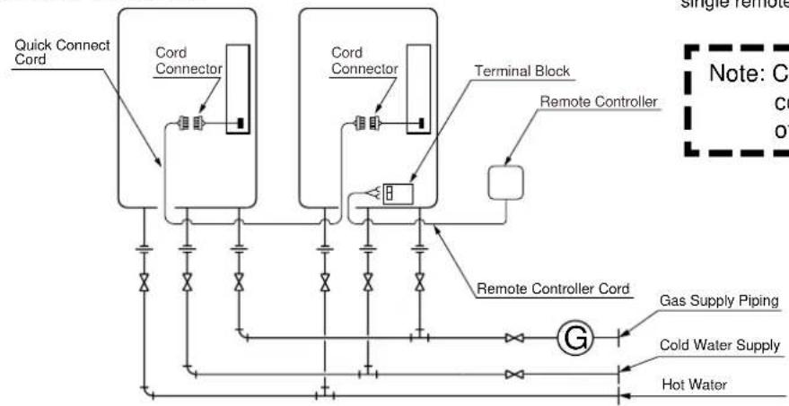
2. Quick Connect Multi System Installation
- The Quick Connect Multi System allows the installation of two units together utilizing only the Quick Connect Cord.
The Quick Connect Cord is 2m. long. Install the two units 470mm - 950mm apart at the center to ensure the cord will be able to reach between the units. (See Typical Plumbing diagram). (If the distance between the two units is too great, not only will the cord not be able to reach, but the water temperature may also become unstable because of the difference in pipe length between the two units.)
System Diagram
flowchart
graph TD
    A["Quick Connect Cord"] --> B["Cord Connector"]
    B --> C["Terminal Block"]
    C --> D["Remote Controller"]
    D --> E["Gas Supply Piping"]
    D --> F["Cold Water Supply"]
    D --> G["Hot Water"]
    B --> H["Cord Connector"]
    H --> I["Remote Controller"]
    I --> J["Gas Supply Piping"]
    style A fill:#f9f,stroke:#333
    style B fill:#ccf,stroke:#333
    style C fill:#cfc,stroke:#333
    style D fill:#fcc,stroke:#333
    style E fill:#ffc,stroke:#333
    style F fill:#fcc,stroke:#333
    style G fill:#fcc,stroke:#333
* When connecting 2 devices, use only a single remote controller.
Note: Connect the remote controller to only one of the devices.
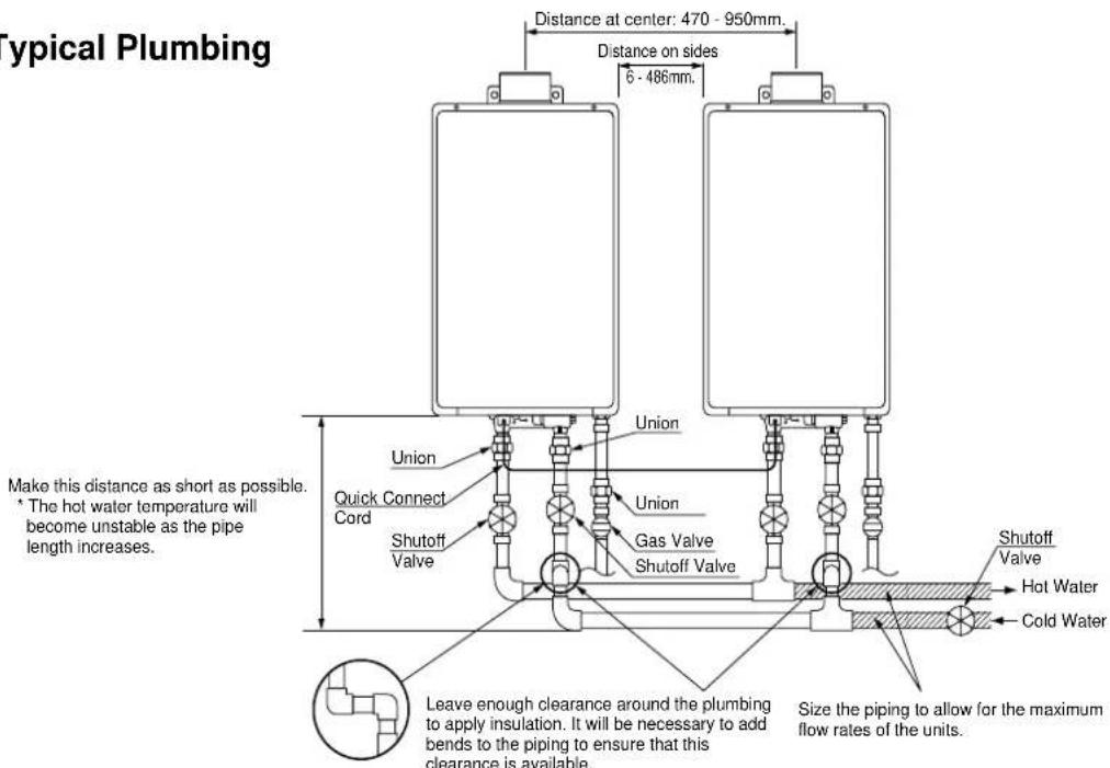
- Insulate the hot water piping to prevent heat loss. Insulate and apply heating materials to the cold water supply piping to prevent heat loss and freezing of pipes when exposed to excessively cold temperatures.
3. Before Installation

Caution
Check the Gas
- Check that the rating plate indicates the correct type of gas. Check that the gas supply line is sized for 250 MJ/h for this unit.
Check the Power
- The power supply required is 240V AC, at 50Hz. Using the incorrect voltage may result in fire or electric shock.
Do Not Use Equipment for Purposes Other Than Those Specified
- Do not use for purposes other than increasing the temperature of the water supply.
Do not use in areas of poor water quality
Use Extreme Caution if Using With A Solar Pre-Heater
- Using this unit with a solar pre-heater can lead to unpredictable output temperatures and possibly scalding. If absolutely necessary, use mixing valves to ensure output temperatures do not get to scalding levels. Do not use a solar pre-heater with the quick-connect multi-system.
Replacement
* Check the fixing brackets and exhaust vent yearly to make sure they do not need to be replaced. Do not install unit in a bathroom or other occupied room, installation in an improper location may cause failures or fire.
4. Choosing Installation Site
* Locate the appliance in an area where leakage from the unit or connections will not result in damage to the area adjacent to the appliance or to the lower floors of the structure. When such locations cannot be avoided, it is recommended that a suitable drain pan, adequately drained, be installed under the appliance. The pan must not restrict combustion air flow.

Caution
• Install the water heater in a location where it is free from obstacles and stagnant air.
- Consult with the customer concerning the location of installation.
- Do not install the water heater near staircases or emergency exits.
- Avoid places where fires are common, such as those where petrol and adhesives are handled, or places in which corrosive gases (ammonia, chlorine, sulfur, ethylene compounds, acids) are present. This may cause incomplete combustion or failures.

natural_image
Line drawing of a mechanical setup with a tool and a base, no text or symbols present• Install the exhaust vent so that there are no obstacles around the termination and so that exhaust can't accumulate. Do not enclose the termination with corrugated metal or other materials.
- Do not install the water heater where the exhaust will blow on outer walls or material not resistant to heat. Also consider the surrounding trees and animals.
The heat and moisture from the water heater may cause discoloration of walls and resinous materials, or corrosion of aluminum materials.
- Do not locate the vent termination towards a window or any other structure which has glass or wired glass facing the termination.
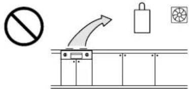
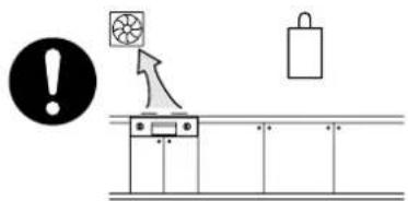
- Avoid installation above gas ranges or stoves.
- Avoid installation between the kitchen fan and stove. If oily fumes or a large amount of steam are present in the installation location, take measures to prevent the fumes and steam from entering into the equipment.
- Avoid installation in places where dust or debris will accumulate. Dust may block the air-supply opening, causing the performance of the device fan to drop and incomplete combustion to occur as a result.
• Install in a location where the exhaust gas flow will not be affected by fans or range hoods. See AS5601.
• Take care that noise and exhaust gas will not affect neighbors. - Make sure that the location allows installation of the exhaust vent as specified.
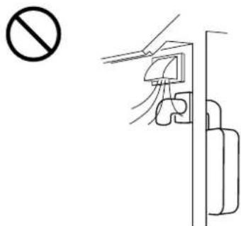
- Avoid installation in places where special chemical agents (e.g., hair spray or spray detergent) are used. Ignition failures and malfunction may occur as a result.
- For outdoor installation, use the outdoor vent cap. If it is necessary to vent above the roof line in an outdoor installation, also use the base of the vent cap for rain protection.
- Avoid installations where the unit will be exposed to excessive winds.
- Before installing, make sure that the vent termination (or the vent cap in an outdoor installation) will have the proper clearances according to the AS5601.
5. Installation Clearances

Caution
Before installing, check for the following:
Install in accordance with relevant building and mechanical codes, as well as any local, state or national regulations.
| Item | Check Illustration | |
| Distance from combustibles | ·Maintain the following clearances from both combustible and non-combustible materials.·If the unit will be installed in the vicinity of a permanent kitchen range or stove that has the possibility of generating steam that contains fats or oils, use a dividing plate or other measure to ensure that the unit is not exposed to air containing such impurities.* The dividing plate should be incombustible and the width must exceed that of the device.* Do not remove mounting brackets to reduce air gap at rear.In Accordance To AS5601 | (unit: mm)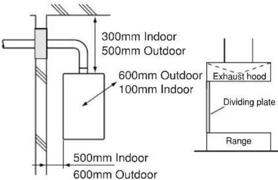 |
| Securing of space for repair/inspection | ·If possible, leave 200mm or more on either side of the unit to facilitate inspection.·If possible, leave 600mm or more in front of the unit to facilitate maintenance and service if necessary. | 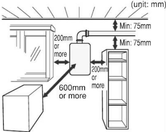 |
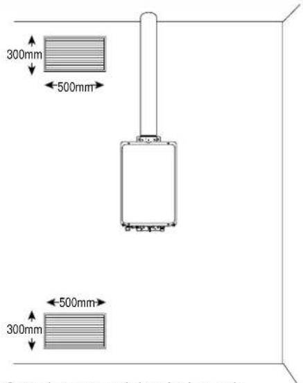
| Outdoor Clearances to any Opening into Any Building | ·Maintain the following clearances to any opening in any building:1.5m below and 0.5m horizontally from any door, window or gravity air inlet.1m above any forced air inlet.500mm below an overhang. | (unit: mm)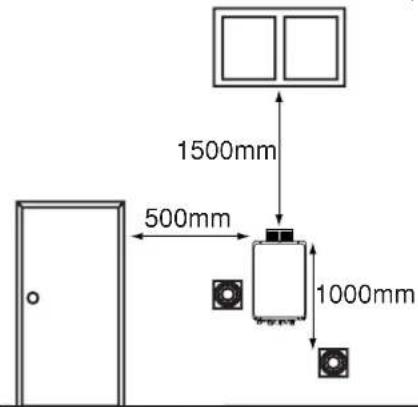 |
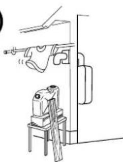
6. Installation
Securing to the wall
Installation must conform with all local Building, Water or Gas Regulations or using AS5601. A heavy load will be applied to the wall on which the water heater is mounted. If the strength of the wall is not sufficient, reinforcement will be necessary.
- Mount water heater in a vertical position with flue facing upwards
- Be sure to mount the water heater on an upright wall.
| Item | Check | Illustration |
| Location of drill hole | 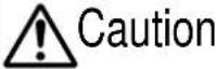 When installing with bare hands, take caution to not inflict injury.Be careful not to hit electrical wiring, gas, or water piping while drilling holes. When installing with bare hands, take caution to not inflict injury.Be careful not to hit electrical wiring, gas, or water piping while drilling holes. | Location of drill holeMounting (upper)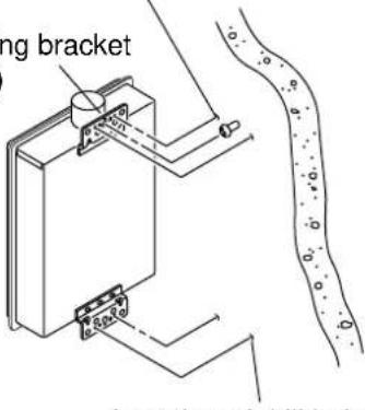 Location of drill hole Location of drill hole |
| 1. Determine position of the unit.2. Place unit on wall and mark position of fixings. | ||
| Mounting | 3. Remove unit and drill holes for fixings.4. Mount unit and tighten fixings.(Note: fixings should be sufficient to support the weight of the unit).Make sure the unit is installed securely so that it will not fall or move due to vibrations. | Fixing Screw |
| Water heater and building structure | • Ensure water heater is firmly fixed to the structure. | 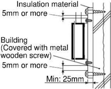 |
7. Vent Pipe Installation (Indoor Installation Only)
Vent Piping
- Use only approved vent materials.
- Follow the vent pipe manufacturer's installation instructions.
Pipe diameter 100mm
| No. of Elbows Max. Straight Vent Length | |
| 3 | 5m |
| 2 | 9m |
| 1 13m | |
- Make the vertical section of the exhaust vent as short as possible.
-
Maintain the same vent pipe diameter all the way to the end.
-
Make sure vent pipe is gas tight and will not leak. Use silicon sealant wherever necessary.
- Do not place any dangerous objects at the end of the exhaust vent.
- Steam (smoke) or water drops may come out from the end of the exhaust pipe. Select the location for the end of the vent so that steam is not visible, and the vent is not wet with dripping water.
- If snow is expected to accumulate, take care that the end of the pipe is not covered with snow or hit by falling lumps of snow.
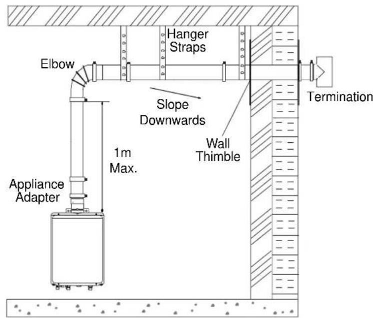
- Use a maximum of 1m of straight vertical pipe before the first elbow.
- Use a minimum total of 1m of straight vent pipe.
- Consult the vent pipe manufacturer's installation instructions for chimney connections.
- Do not common vent or connect more than one appliance to this venting system.
Horizontal Vent Termination
- Terminate at least 350mm above ground.
- Terminate at least 2.3m above a public walkway, 2m from the combustion air intake of any appliance, and 1m from any other building opening, gas utility meter, service regulator etc.
- Terminate at least 1m above any forced air inlet, 1.5m below, 1.5m horizontally from and 300mm above any door, window, or gravity air inlet into any building as per AS5601.
- Slope the horizontal vent 6mm downwards for every 300mm.
- Use a condensation drain if necessary.
Vertical Vent Termination
- Terminate at least 1.8m from the combustion air intake of any appliance, and 1m from any other building opening, gas utility meter, service regulator etc.
- Enclose exterior vent systems below the roof line to limit condensation and protect against mechanical failure.
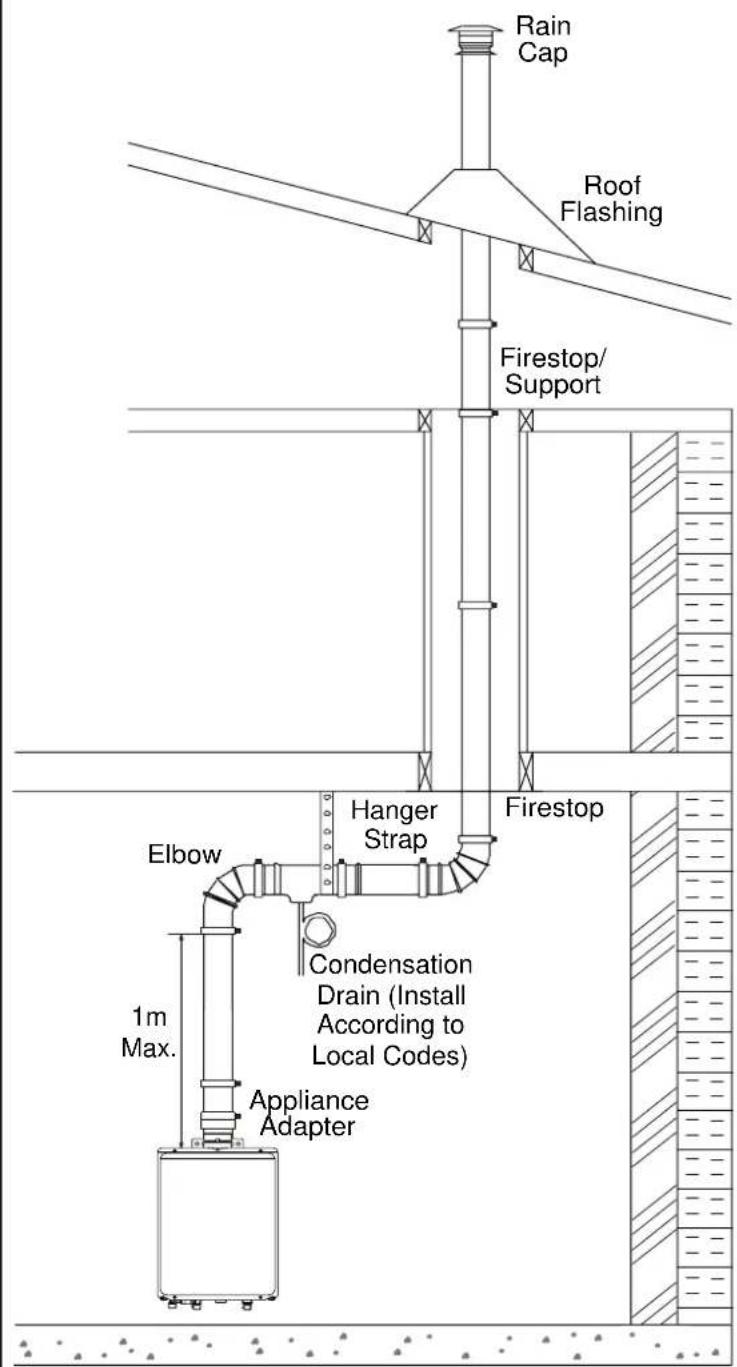
- When the vent penetrates a floor or ceiling and is not running in a fire rated shaft, a firestop and support is required.
- Terminate the vent system at least 1m above, but not more than 2m above the roof line, or according to the vent pipe manufacturer's instructions.
- Provide vertical support every 3.6m or as required by the vent pipe manufacturer's instructions.
- Slope the horizontal vent 6mm downwards for every 300mm.
- Do not vent straight upwards. Always have a horizontal section of venting.
• Install a condensation drain in the horizontal section of the venting.
Air inlet
Observe the commercial gas equipment installation criteria and operation criteria.
- Size the air inlet according to the AS5601.
- Be sure to provide adequate air inlet.
- The air inlet needs to open to the outside air from the room in which the water heater is used.
For internal installations be sure to provide adequate ventilation for the unit to operate correctly and safely (refer to AS5601)
Openings supplying indoor air
8. Gas Piping
Follow the instructions from the gas supplier.
The appliance must be disconnected from the gas supply piping system during any pressure testing of that system at test pressures in excess of 3.5 kPa.
The appliance and its gas connections must be leak tested before operation.
The inlet gas pressure must be within the range specified. This is for the purposes of input adjustment. In order to choose the proper size for the gas line, consult local codes and/or the AS5601.
Gas Pressure
Size the gas line according to total MJ/h demand of the building and length from the meter or regulator so that the following supply pressures are available even at maximum demand (Refer AS5601):
Natural Gas Pressure inlet 1.13kPa
LP Gas Pressure inlet 2.75kPa
Gas Meter
Select a gas meter capable of supplying the entire J/h demand of all gas appliances in the building.
Gas Connection
- Do not use piping with a diameter smaller than the inlet diameter of the water heater.
- Gas flex lines are not recommended unless they are rated for 260 MJ/h.
• Install a gas shutoff valve on the supply line. - Use only approved gas piping materials.
Measuring Gas Pressure
In order to check the gas supply pressure to the unit, a tap is provided on the gas inlet. Remove the hex head philips screw from the tap, and connect a manometer using a silicon tube.
Operate the unit and check pressure.
In order to check the gas manifold pressure, a pair of taps are provided on the gas valve inside the unit.
The pressure can be checked either by removing the hex head philips screw and connecting a manometer with a silicon tube, or by removing the 3mm NPT screw with an allen wrench and connecting the appropriate pressure gauge.
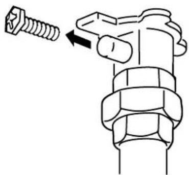
natural_image
Diagram of a mechanical component with a bolt and nut, showing a directional arrow (no text or symbols)9. Water Piping
Ask a qualified plumber to perform the installation of the plumbing. Observe all applicable codes.
This appliance is suitable for potable water applications. Do not use this appliance if any part has been underwater. Immediately call a qualified service technician to inspect the appliance and replace any part of the control system and gas control which has been under water.
If the water heater is installed in a closed water supply system, such as one having a backflow preventer in the cold water supply line, means shall be provided to control thermal expansion. Contact the water supplier or a local plumbing inspector on how to control this situation.
This pressure relief valve must be capable of an hourly J rated temperature steam discharge of 250 MJ/h. Multiple valves may be used. The pressure relief capacity must not exceed 1029 kPa. The relief valve must be installed such that the discharge will be conducted to a suitable place for disposal when relief occurs. No reducing coupling or other restriction may be installed in the discharge line. The discharge line must be installed to allow complete drainage of both the valve and the line.
Piping and components connected to the water heater shall be suitable for use with potable water.
Toxic chemicals, such as those used for boiler treatment, shall not be introduced into the potable water.
A water heater used to supply potable water may not be connected to any heating system or components previously used with a nonpotable water heating appliance.
When water is required in one part of the system at a higher temperature than in the rest of the system, means such as a mixing valve shall be installed to temper the water to reduce the scalding hazard.
- Flush water through the pipe to clean out metal powder, sand and dirt before connecting it.
• Take appropriate heat insulation measures (e.g., wrapping with heat insulation materials, using electric heaters) according to the climate of the region to prevent the pipe from freezing.
- Use a union coupling or flexible pipe for connecting the pipes to reduce the force applied to the piping.
- Do not use piping with a diameter smaller than the coupling.
- When feed water pressure is too high, insert a depressurizing valve, or take water hammer prevention measures.
- Avoid using joints as much as possible to keep the piping simple.
- Avoid piping in which an air holdup can occur.
- Use approved piping materials.
- If installing the unit on a roof:
If the unit is installed on a roof to supply water to the levels below, make sure that the water pressure supplied to the unit does not drop below 199 kPa. It may be necessary to install a pump system to ensure that the water pressure is maintained at this level.
Check the pressure before putting the unit into operation.
Failing to supply the proper pressure to the unit may result in noisy operation, shorter lifetime of the unit, and may cause the unit to shut down frequently.
Supply water piping
- Do not use PVC piping.
- Mount a shut off valve (near the inlet).
- In order for the client to use the water heater comfortably, 200 to 900kPa of pressure is needed from the water supply.
Be sure to check the water pressure. If the water pressure is low, the water heater cannot perform to its full capability, and may become a source of trouble for the client.
Drain piping
- Expansion water may drop from the pressure prevention device and wet the floor. If necessary, provide drain piping or use a drain hose to remove the water.
Hot water piping
- Do not use lead or PVC piping.
• The longer the piping, the greater the heat loss. Try to make the piping as short as possible.
- Use a mixing valve with a low water resistance. Use shower heads with low pressure loss.
- If necessary, use a pump or other means to ensure that the supply water pressure to the inlet of the heater does not fall below 199 kPa when the maximum amount of water is being demanded. Also install a pressure meter on the inlet. If this is not done, local boiling will occur inside the water heater causing abnormal sounds and decreasing the durability of the heat exchanger.

It is recommended that for sanitary fixtures use primarily for the purpose of personal hygiene, that a temperature control device be fitted (such as a tempering valve) as per AS3498.
Instantaneous Hot Water Piping Works [For KM3211WHQ]
These appliances cannot be linked.
Precaution of piping works
- Be sure to connect a return pipe to circulate the hot water. (A one-way pipe is not allowed.)
- The circulation pipe shall not be longer than 60 m (back to base), with no more than 20 bends. (Contact the relevant waterworks department for direct connection to city water at a distance of over 30m.)
- Piping diameter shall be as follows:
| Forward | R3/4 |
| Return | R1/2 |
- Limit of height differential is as follows.
* In this case, 196 kPa or more is required as the water supply pressure at the appliance inlet.
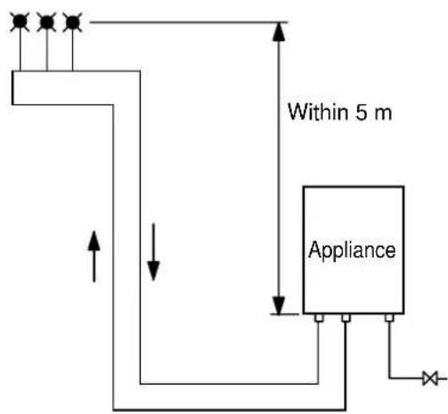
flowchart
graph TD
    A["Current Source"] --> B["Device"]
    B --> C["Appliance"]
    C --> D["Output"]
    style A fill:#f9f,stroke:#333
    style D fill:#ccf,stroke:#333
    note right of B: Within 5 m
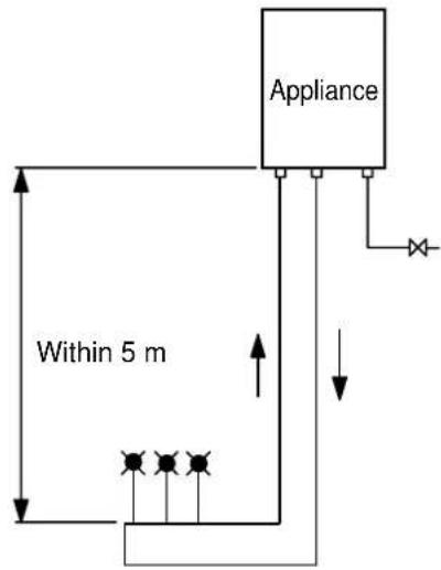
flowchart
graph TD
    A["Appliance"] --> B["Device"]
    B --> C["Control Point"]
    C --> D["Device with four indicators"]
    D --> E["Device with three indicators"]
    E --> F["Device with one indicator"]
    F --> G["Device with one indicator"]
    G --> H["Device with one indicator"]
    H --> I["Device with one indicator"]
    I --> J["Device with one indicator"]
    J --> K["Device with one indicator"]
    K --> L["Device with one indicator"]
    L --> M["Device with one indicator"]
    M --> N["Device with one indicator"]
    N --> O["Device with one indicator"]
    O --> P["Device with one indicator"]
    P --> Q["Device with one indicator"]
    Q --> R["Device with one indicator"]
    R --> S["Device with one indicator"]
    S --> T["Device with one indicator"]
    T --> U["Device with one indicator"]
    U --> V["Device with one indicator"]
    V --> W["Device with one indicator"]
    W --> X["Device with one indicator"]
    X --> Y["Device with one indicator"]
    Y --> Z["Device with one indicator"]
- Since there occurs improper circulation, do not conduct two routes of piping.
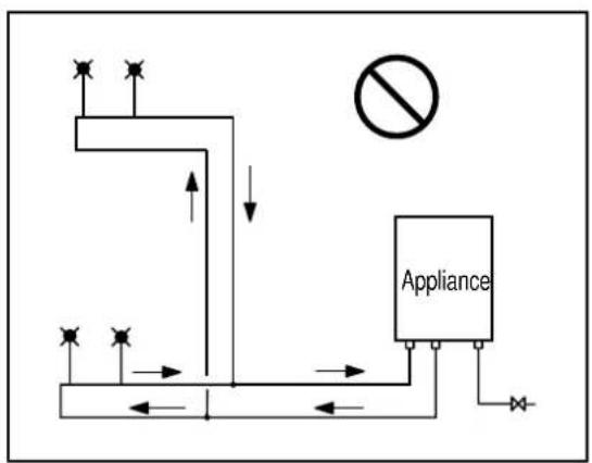
flowchart
graph TD
    A["Device"] --> B{Air Condition}
    B -->|Yes| C["Return to Air"]
    B -->|No| D["Return to Air"]
    C --> E["Return to Air"]
    D --> F["Return to Air"]
    G["No Smoking"] --> H["Appliance"]
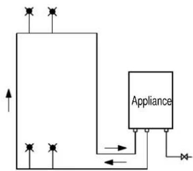
flowchart
graph TD
    A["Input Port 1"] --> B["Process Block"]
    C["Input Port 2"] --> B
    D["Input Port 3"] --> B
    B --> E["Appliance"]
    E --> F["Output Port"]
    style B fill:#f9f,stroke:#333
    style E fill:#ccf,stroke:#333
- Expanded water shall be handled in the following way.
When the instant hot water function is used, the volume of the water within the pipe expands, so this must be followed.
Method using the safety valve
( As expanded water is discharged through ) the safety valve, water must be run off.
Method using the expansion tank
(In situations where the water cannot be discharged)
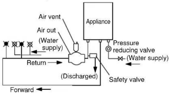
flowchart
graph TD
    A["Air vent"] --> B["Return"]
    C["Air out (Water supply)"] --> B
    D["Appliance"] --> E["(Discharged)"]
    F["Pressure reducing valve (Water supply)"] --> E
    G["Safety valve"] --> E
    H["Forward"] --> I["Return"]
- If the water input pressure (static sound pressure) is up to 392 kPa; Safety valve X 1
- If the water input pressure (static sound pressure) is 392 kPa or more; Pressure reduction valve X 1 + Safety valve X 1
- Safety valve
687 kPa set up
• Pressure reduction valve 196 kPa set up
(to be arranged on site)
392 kPa set up
(to be arranged on site)
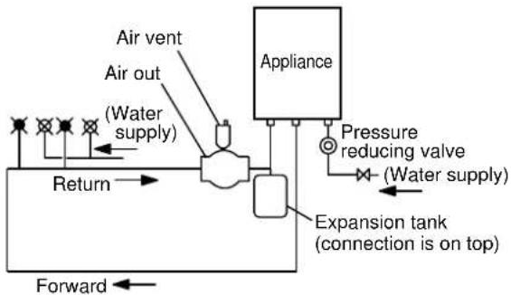
flowchart
graph LR
    A["Air vent"] --> B["Air out (Water supply)"]
    B --> C["Return"]
    D["Appliance"] --> E["Pressure reducing valve (Water supply)"]
    E --> F["Expansion tank (connection is on top)"]
    F --> G["Forward"]
- The expansion tank shall be installed on the return line.
- The expansion tank shall be installed with the connector on top as per the above illustration.
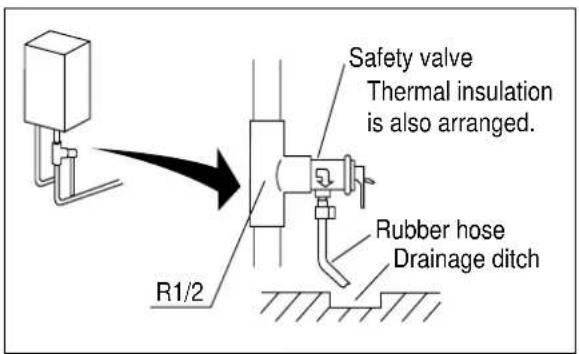
* In order to prevent air pockets in the circulation pump, air outlet / air vent shall be installed near the appliance on the return line.
* The pipe must be firmly secured. If it is not secured firmly, abnormal noise may be generated when the circulation pump is running.
* Thermal insulation suited to the location must be used to prevent the pipe from freezing.
- Plumbing Applications
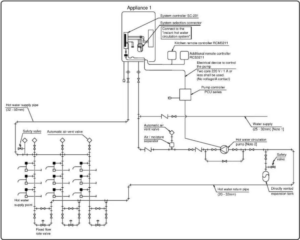
flowchart
graph TD
    A["Appliance 1"] --> B["System controller SC-201"]
    B --> C["System selection connector"]
    C --> D["Connect to the "instant hot water circulation system""]
    D --> E["Kitchen remote controller RCM3211"]
    E --> F["Additional remote controller RCS3211"]
    F --> G["Electrical device to control the pump"]
    G --> H["Two core 220 V / 1 A or less shall be used. (No voltage/A contact)"]
    H --> I["Pump controller PCU series"]
    I --> J["Automatic air vent valve"]
    J --> K["Air / moisture separator"]
    K --> L["Automatic air vent valve"]
    L --> M["Hot water return pipe (20 - 32mm)"]
    M --> N["Safety valve"]
    M --> O["Directly vented expansion tank"]
    P["Hot water supply pipe (32 - 50mm)"] --> Q["Safety valve"]
    P --> R["Automatic air vent valve"]
    S["Hot water supply point"] --> T["Fixed flow rate valve"]
    U["Water supply (25 - 32mm) [Note 1"]] --> V["Hot water circulation pump [Note 2"]]
    W["Hot water return pipe (20 - 32mm)"] --> X["Safety valve"]
11. Electrical Wiring
Consult a qualified electrician for the electrical work.

Do not connect electrical power to the unit until all electrical wiring has been completed.
This appliance must be electrically grounded in accordance with Electrical Authority Regulations.
Caution: Label all wires prior to disconnection when servicing controls. Wiring errors can cause improper and dangerous operation.
Verify proper operation after servicing.
Field wiring to be performed at time of appliance installation.

Caution
Do not turn on the power until the electrical wiring is finished. This may cause electrical shock or damage to the equipment to occur.
- The electrical supply required by the water heater is 240V AC at 50 Hz. The power consumption may be up to 135W. Use an appropriate circuit.
- Do not disconnect the power supply when not in use. When the power is off, the freeze prevention in the water heater will not activate, resulting in possible freezing damage.
- Do not let the power cord contact the gas piping.
Tie the redundant power cord outside the water heater. Putting the redundant length of cord inside the water heater may cause electrical interference and faulty operation.
Ground
• To prevent an electric shock, always plug power lead into an earth powerpoint.
- Power source to be within 500mm of the bottom of the unit.
Remote Controller
- Applicable Model
| KM3211WH | KM3211WHQ | ||
| Remote controller | Main | RCM3211 | RCM3211 (included) |
* Up to three remote controllers can be connected. Additional remote controllers cannot be connected by themselves.
- The remote controller must be installed in accordance with the installation manual enclosed in the package.
• KM3211WHQ cannot be used without a remote controller (main appliance body only).
Changing the temperature for operation of the main body
Can be used without the remote controller (main appliance only). The hot water temperature on the RCM3211 can be switched between four settings (75, 60, 50, & 40°C).
Refer to the following for the setup method. When 75 or 60°C is set, the water is very hot, so make sure that a mixing valve is installed.
- Press the [▲] or [▼] button on the remote controller prior to switching on the controller. Changes must be made within 10 minutes of the power being supplied to the unit. If the display does not switch to maintenance mode despite pressing the [ ] or [ ] buttons, unplug the power and repeat the above procedure.
- The item number and data are shown as well as "Maintenance". (Initial setting for the item number is "99".)
- When the [▲] button is pressed, the "99" displayed will change to 10, 11, ..., 1F, 20, 21, etc..., and conversely when the [▼] button is pressed, the "99" displayed will change to 10, FF, FE, FD, FC, 27, etc...
- 14 and 15 are set as per procedure 3. When the setup switch is pressed, "ON" or "OFF" blink.
| Temp.Item No. | 14 | 15 |
| 40°C | ON | ON |
| 50°C | ONOFF | |
| 60°C | OFF | OFF |
| 75°C | OFFON |
* Factory Default Setting
- Press [ ] button to switch between ON and OFF.
Note: The setting changes can be cancelled by pressing the Power On/Off button before confirming the settings, or if the unit is left alone for ten minutes without confirming the settings. If the default setting needs to be changed again, disconnect the electrical power to the unit, reconnect it and follow this procedure again.
- Once setup is complete, press the [▲] and [▼] buttons simultaneously for at least five seconds while the item number is blinking. Once completed, a buzzer sounds. (The modified setup will not be recorded unless this step is performed.)
Connecting Remote Controller Cord to Unit
- Keep the remote controller cord away from the freeze prevention heaters in the unit.
- Tie the redundant cord outside the water heater. Do not put the extra length inside the equipment.
- The remote controller cord can be extended up to 100m with Remote controller cord.
- Use a Y type terminal with a resin sleeve. (Without the sleeve, the copper wire may corrode and cause problems).
- Be sure to hand tighten when screwing to the terminal block. Power tools may cause damage to the terminal block.
Remote controller cord
-
Use Remote controller cord for any extensions.
• Install according to the National Electrical Code and all applicable local codes. -
Remove the front cover of the heater (4 screws).
- Pass the remote controller cord through the wiring throughway and into the unit.
- Connect the Y terminals at the end of the remote controller cord to the terminal block.
- Secure the remote controller cord with a clamp.
- Replace the front cover.
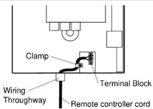
12. Commissioning
The installer should test operate the unit, explain to the customer how to use the unit, and give the owner this manual before leaving the installation
- Preparation … (1) Ensure all lines are purged / flushed of debris prior to connection to appliance.
(2) Open the shut off valve on the water supply, check that water passes through the valve and close the valve.
(3) Open the gas supply valve, turn on the power supply, and turn on the Operation switch on the remote controller (the Operation lamp turns on).
(1) Open a hot water fixture and confirm that the "Burner On" lamp comes on, and that hot water is being produced. (If necessary, repeat until the air in the gas piping is bled out).
* White smoke may be noticed from the exhaust vent during cold weather. However, this is not a malfunction of the unit.
* If an "11" error code appears on the remote controller, turn the unit off and then back on again, and then open a hot water fixture again.
(2) Change the temperature setting on the remote controller and check that the water temperature changes.
- If the water heater does not operate normally, refer to "Troubleshooting" in the Operation Manual.
* After the trial operation, clean the filter in the cold water inlet.
- Turn the system power on with the remote controller.
- Slowly open a hot water fixture and check that the units ignite sequentially. Check to see that the hot water temperature is the same as the temperature displayed on the remote controller. (*1)
* If both units do not ignite, switch which unit will ignite first by pressing the Max. or Min. Manifold Pressure Set Button on the circuit board. (*2)
Unit A Ignites Unit B Doesn't Ignite
Press Max. or Min. Manifold Pressure Set Button on Unit B
Unit A Doesn't Ignite Unit B Ignites
* If an 11 or F11 error code flashes on the remote controller, hit the Power Button on the remote controller off and on 2-3 times.
* If (*1) and (*2) cannot be done, the Quick Connect Cord may not be properly connected. Check that the cord is properly connected.
Caution
Handling after trial operation
- In Freezing areas: If the unit will not be used immediately, close off all gas and water shutoff valves, drain all of the water out of the unit and the plumbing system to prevent the unit and system from freezing, and bleed the gas out of the gas line. Freezing is not covered by the warranty.
Lighting Instructions
This water heater does not have a pilot. It is equipped with an ignition device that automatically lights the burner.
- Read the safety information in the installation manual or on the front of the water heater.
- Turn off all electrical power to the unit.
- Do not attempt to light the burner by hand.
- Turn the gas control manual valve (external to the unit) clockwise to the off position.
- Wait five minutes to clear out any gas. If the smell of gas remains, stop, and follow the instructions on page 4 of this manual.
- Turn the gas control manual valve counterclockwise to the on position.
- Turn on electric power to the unit.
- The unit will now operate whenever hot water is called for. If the unit will not operate, follow the shutdown instructions and call a service technician.
Shutdown Instructions
- Stop any water demand.
- Turn off electric power.
- Turn the gas control manual valve clockwise to the off position.
Should overheating occur, or the gas supply fail to shut off, turn off the manual control valve to the appliance.
13. Dimensions
KM3211WH
(unit: mm)
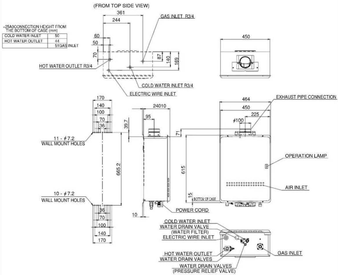
KM3211WHQ
(unit: mm)
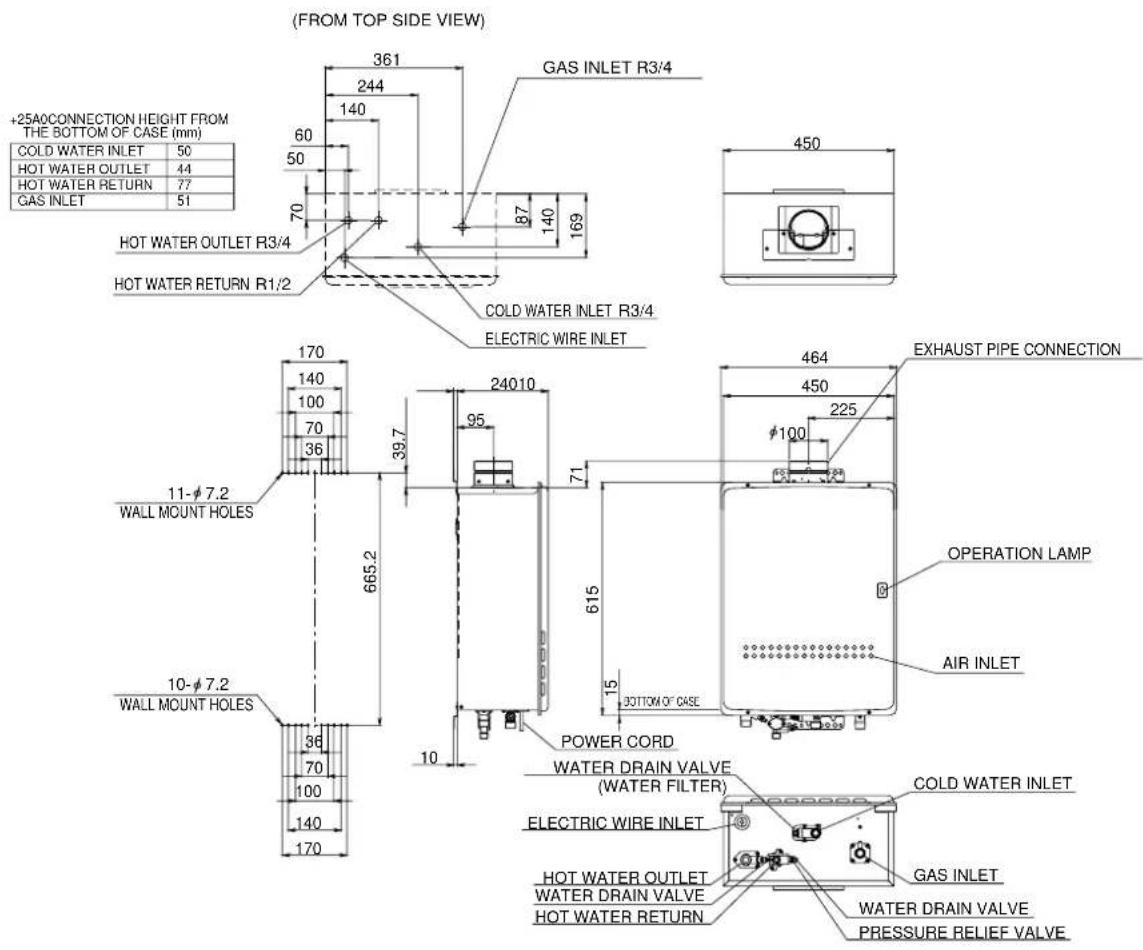
Connecting Quick Connect Cord
For Quick Connect Multi System Installation use a Quick Connect Cord (Sold Separately).
Caution
The wire coloring on the Quick Connect Cord will not be the same as the wire coloring from the connection plug inside the unit.
* The remote controller can be connected to either unit A or B.
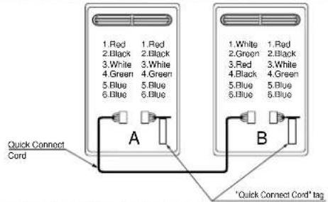
Instruction for connecting the Quick Connect Cord to each unit:
- Turn off the power.
- Remove the front cover of the heater (4 screws).
- Pass the Quick Connect Cord through the wiring throughway and into the unit.
- Plug the connector on the Quick Connect Cord to the receptacle inside the unit.
- Attach the ground wire of the Quick Connect Cord to the terminal block fixing plate. (If the ground wire is not attached, electrical noise may cause problems)
- Secure the coupling cord with a clamp.
- Replace the front cover.
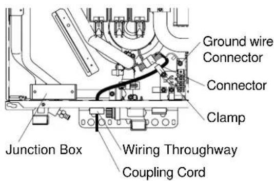
Remarks
Do not drink water that has been inside the unit for an extended period of time. Do not drink the first use of hot water from the unit in the morning.
Clean the filter on the water inlet as frequently as required by the quality of your local water.
Keep the area around the unit clean.
If boxes, weeds, cobwebs, cockroaches etc. are in the vicinity of the unit, damage or fire can result.
Do not install the equipment where the exhaust will blow on walls or windows.
Do not use in areas of poor water quality.
This can cause damage and reduce durability.
If scale forms and a descaling solution must be used, the warranty will be void.
This unit is only approved for installation up to 1372m. above sea level.
Do not use parts other than those specified for this equipment.
Do not disassemble the remote controller.
Do not use petrol, oil or fat detergents to clean the remote controller.
This may cause deformation.
Do not get the remote controller wet.
Although it is water resistant, too much water can cause damage.
Do not splash water on the remote controller. Do not expose the remote controller to steam.
Do not locate the remote controller near stoves or ovens, this may cause damage or failure.
Preventing damage from freezing (P28)
Damage can occur from frozen water within the device and pipes even in warm environments. Be sure to read below for appropriate measures. Repairs for damage caused by freezing are not covered by the warranty.
Take necessary measures to prevent freezing of water and leakage of gas when leaving the unit unused for long periods of time. (P29 - P30)
If it is snowing, check the air inlet, exhaust gas vent and exhaust vent terminal for blockage.
Remote Controller RCM3211
Installation Guide
For Installers:
Read this installation guide carefully before carrying out installation.
Robert Bosch (Australia) Pty. Ltd.
Note
Do not connect power to the water heater before the remote controller has been properly installed.
(1) Remove the decorative cover. (The decorative cover is attached very simply.)
Connect the Y-shaped terminal to the terminal block at the back of the remote controller.
* In the case of exposed wiring (attachment to the wall), first open up the cord intake on the main remote controller body using pliers. (Take care not to damage the board in the process.)
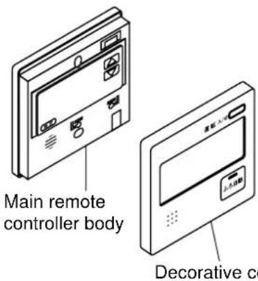
(2) Position the holes (diameter: 6 mm X depth: 25 - 30 mm) to secure the remote controller for the kitchen, and knock in all the raw plugs. Next, secure it using oval-headed wood screws.
* The screws must be tightened manually, and the remote controller secured properly without rattling.
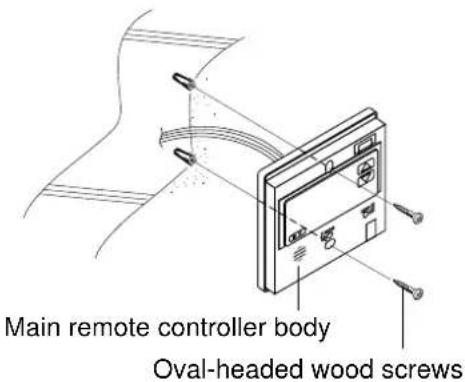
(3) Replace the decorative cover.
Remote Controller RCS3211
Installation Guide
For Installers:
Read this installation guide carefully before carrying out installation.
Robert Bosch (Australia) Pty. Ltd.
Note
Do not connect power to the water heater before the remote controller has been properly installed.
- Put the remote controller cord through the wall from the bathroom. Be sure to place the 2P connector at the room side.
Ordinary bathroom and shower room
Unit bath and shower unit
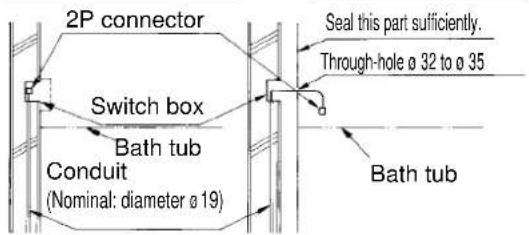
Use the JIS-C83361 switch box for individual use at the remote controller side.
* A back support board illustrated below is needed to install the remote controller on the wall panel of the bath unit.
[Install the back support board at the rear side of the wall panel prior to installation.]
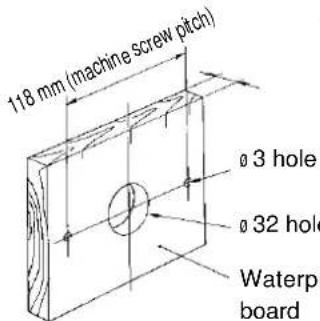
Dimensions of back support board (reference)
- Drill two holes (6, 25 to 30 mm deep) on the wall to secure the remote controller case, and embed the wall plugs into the holes.
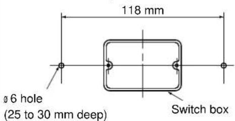
-
Take off the decorative frame from the remote controller.
-
Apply the wall packing to the rear side of the remote controller.
-
Connect the connector.
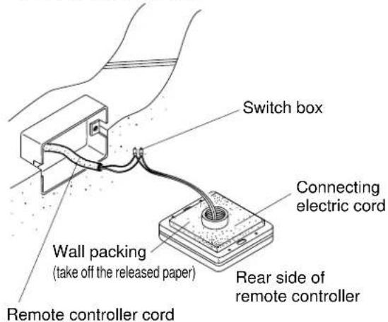
- Secure the remote controller with two Phillips roundhead wood screws.
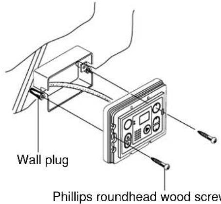
- Fit the decorative frame on the remote controller.
BOSCH
MODEL KM3211WHQ
| GAS TYPE | LPG |
| GAS CONSUMPTION | 250 MJ/hr |
| HEAT OUTPUT | 55.5 kW |
| ELECTRICAL RATING | AC240V 50Hz |
| RATED POWER | 150 W |
| HOT WATER SUPPLY CAPACITY | |
| 32L/min RAISED 25°C | |
| GAS PRESSURE TEST POINT | 1.54 kPa |
| WATER PRESSURE | MAX : 900kPa |
SERIAL NUMBER XXXX.XX - XXXXXX NORITZ CORPORATION
AGA APPROVAL CERTIFICATION NUMBER :
XXXX XXXXXX
BOSCH
MODEL KM3211WHQ
| GAS TYPE | NG |
| GAS CONSUMPTION | 250 MJ/hr |
| HEAT OUTPUT | 55.5 kW |
| ELECTRICAL RATING | AC240V 50Hz |
| RATED POWER | 135 W |
| HOT WATER SUPPLY CAPACITY32L/min RAISED 25°C | |
| GAS PRESSURE TEST POINT | 0.68 kPa |
| WATER PRESSURE | MAX:900kPa |
SERIAL NUMBER XXXX.XX - XXXXXX NORITZ CORPORATION
AGA APPROVAL CERTIFICATION NUMBER :
XXXX XXXXXX
WATER QUALITY
All Bosch water heating appliances are constructed from high quality materials and components and all are certified for compliance with relevant parts of Australian and New Zealand gas, electrical and water standards.
Whilst Bosch water heaters are warranted against defects, the warranty is conditional upon correct installation and use, in accordance with detailed instructions provided with the heater. In the case of the water supplied to the heater, it is important that the water quality be of acceptable standard.
The water quality limits/parameters listed in water quality table are considered acceptable and generally, Australian and New Zealand suburban water supplies fall within these limits/parameters.
In areas of Australia and New Zealand where water may be supplied, either fully or partly, from bores, artesian wells or similar, one or more of the important limits may well be exceeded and the heater could, therefore, be at risk of failure.
Where uncertainty exists concerning water quality, intending appliance users should seek a water analysis from the water supplying authority and in cases where it is established that the water supply does not meet the quality requirements of the water quality table, the Bosch warranty would not apply.
WATER QUALITY TABLE
Maximum levels
| pH Saturation | Total Chlorides Index(LSI) Hardness (langelier) | Sodium Iron | |||
| 6.5-9 +0.4 to | 200mg/l 250mg/ Minus 1.0 @65C | 180mg/l 1mg/l |
Robert Bosch (Australia) Pty Ltd (Bosch)
Manufacturer's Warranty
(Applicable for purchases from 1 January 2012)
All Bosch hot water units are carefully checked, tested and subject to stringent quality controls.
1. Warranty
Bosch offers, at its option, to repair or exchange this Bosch hot water unit or the relevant part listed in clause 2 below at no charge, if it becomes faulty or defective in manufacture or materials during the warranty period also stated in clause 2. This warranty is offered in addition to any other rights or remedies held by a consumer at law.
2. Warranty periods & coverage
(a) Domestic applications: 3 years (parts and labour)
(b) Heat exchangers used in domestic applications: 10 years (part only)
(c) Commercial applications: 2 years (parts and labour)
(d) Heat exchangers used in commercial applications: 5 years (part only)
All warranty periods commence on the date of purchase of the hot water unit by the end-user. However, where the date of purchase by the end-user is more than 24 months after the date of manufacture, all warranty periods will automatically commence 24 months after the date of manufacture.
3. Warranty exclusions
This warranty is VOID if any damage to or failure of the hot water unit is caused wholly or partly by:
(a) faulty installation
(b) neglect, misuse, accidental or non-accidental damage, failure to follow instructions
(c) use of the unit for purposes other than which it was designed or approved
(d) unauthorised repairs or alterations to the unit without Bosch's consent
(e) use of unauthorised parts and accessories without Bosch's consent
(f) use of non-potable water or bore water in the hot water unit (see product instructions for further details)
(g) continued use after a fault becomes known or apparent.
This warranty DOES NOT include:
(a) costs of consumables or accessories
(b) wear and tear, normal or scheduled maintenance
(c) to the extent permitted by law, any damage to property, personal injury, direct or indirect loss, consequential losses or other expenses
(d) changes in the condition or operational qualities of the hot water unit due to incorrect storage or mounting or due to climatic, environmental or other influences.
NOTE: Any service call costs incurred by the owner or user of the hot water unit for any matter not covered by the terms of this warranty will not be reimbursed by Bosch, even if those costs are incurred during the warranty period. If the hot water unit is located outside the usual operating area of a Bosch service agent, the agent's travel, freight or similar costs are not covered by this warranty and must be paid by the owner or user of the hot water unit.
4. Warranty conditions
(a) Proof of purchase may be required.
(b) The hot water unit must be installed by an authorised and licensed installer.
(c) Proof may be required of the date of installation and correct commissioning of the hot water unit has been carried out to Bosch's satisfaction (such as a certificate of compliance).
(d) Repair or replacement of the hot water unit or any parts under this warranty does not lengthen or renew the warranty period.
(e) This warranty is not transferable and is only offered to the original purchaser of the hot water unit.
(f) No employee or agent of Bosch is authorised to amend the terms of this warranty.
(g) This warranty only applies to Bosch hot water units purchased from an authorised reseller and installed in Australia or New Zealand.
(h) To the extent that any condition or warranty implied by law is excludable, such condition or warranty is excluded.
5. How to lodge a warranty claim and warranty procedure
(a) Warranty claims must be made with the Bosch Customer Contact Centre (Australia: ph 1300 307 037; New Zealand: ph 0800 543 352). Please be ready to provide the model and serial numbers, date of installation, purchase details and a full description of the problem. Warranty claims must be made before the end of the warranty period.
(b) All warranty service calls must conducted by an authorised Bosch service agent.
(c) Invoices for attendance and repair of a hot water unit by third parties not authorised by Bosch will not be accepted for payment by Bosch.
6. Privacy Act 1988 (Cth)
A customer's personal information collected during warranty claims may be used for the provision of customer support, for the provision of information about products and services and for other marketing activities undertaken by Bosch and its Bosch Service Agents who are authorised to carry out warranty repairs on behalf of Bosch (Purpose). Bosch is committed to protecting the privacy of its customers' personal information. It will act in compliance with the National Privacy Principles and Privacy Act 1988 (Cth). Bosch will not forward customers' personal information to third parties other than for the Purpose. A customer can object at any time to the use of their personal information for the Purpose. Bosch will cease to use a customer's personal information accordingly if an objection is made.
7. Bosch contact details
If you have any questions about this warranty or to lodge a warranty claim, please contact:
Robert Bosch (Australia) Pty Ltd
1555 Centre Road, Clayton, Victoria 3168
Tel: Australia: 1300 307 037
Tel: New Zealand: 0800 543 352
IMPORTANT NOTE FOR AUSTRALIAN CONSUMERS
Our goods come with guarantees that cannot be excluded under the Australian Consumer Law. You are entitled to a replacement or refund for a major failure and for compensation for any other reasonably foreseeable loss or damage. You are also entitled to have the goods repaired or replaced if the goods fail to be of acceptable quality and the failure does not amount to a major failure.