
RVE 6480 - Cooktop ROSIERES - Free user manual and instructions
Find the device manual for free RVE 6480 ROSIERES in PDF.
| Product type | Ceramic hob |
| Brand | ROSIERES |
| Model | RVE 6480 |
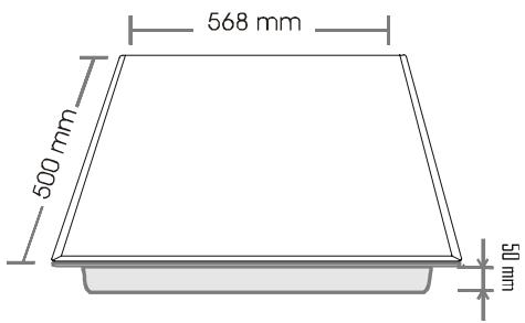
| Dimensions (W x D x H) | 568 x 500 x 55 mm |
| Glass thickness | 4 mm |
| Total installed power | 7200 W |
| Cooking zones (front right, front left, rear right, rear left) | Halolight 1800 W ∅190, Highlight 1200 W ∅155, Highlight 1800 W ∅190, Halolight 2400 W ∅220 |
| Controls type | Touch controls |
| Electrical supply | 230 V single-phase (25 A fuse, 3G2.5 cable); adaptable to two-phase, three-phase |
| Recess dimensions (W x D) | 560 x 490 mm |
| Main functions | Programmable timer 99 min, control lock, boost function, residual heat indicator (H), automatic safety shut-off |
| Care and cleaning | Specific product for ceramic hob and scraper; avoid overly damp sponge and abrasive products |
| Safety | Key lock, automatic shut-off in case of overflow or time exceeded, residual heat indicator |
Frequently Asked Questions - RVE 6480 ROSIERES
User questions about RVE 6480 ROSIERES
0 question about this device. Answer the ones you know or ask your own.
Ask a new question about this device
Download the instructions for your Cooktop in PDF format for free! Find your manual RVE 6480 - ROSIERES and take your electronic device back in hand. On this page are published all the documents necessary for the use of your device. RVE 6480 by ROSIERES.
USER MANUAL RVE 6480 ROSIERES
GB INSTRUCTIONS FOR USE AND INSTALLATION Glass Ceramic Hobs
natural_image
Close-up of a black electronic component being inserted with a tool, showing a white arrow pointing to a small component (no text or symbols visible)
natural_image
Close-up of a mechanical component with a white arrow pointing to a specific part (no text or symbols visible)natural_image
Three identical illustrations of cooking pots with crossed-out arrows indicating no need or prohibition (no text or symbols)natural_image
Gray spherical object with numbered vertices (0-12) and a small white circle at the top center, no text or symbols present.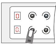
natural_image
Illustration of a hand using a tool to apply black ink onto two circular indentations on a flat surface (no text or symbols). Electrical connection 26-29
. Fitting ....30-31
USE
. Presentation 32
. The zones .... 32
. Choosing utensils .... 33
. VITROCERAMIC HOB WITH CONTROL KNOBS .... 34
. VITROCERAMIC HOB WITH SENSITIVE TOUCHES ......35-40
. Cleaning the ceramic hob 41
TECHNICAL INFORMATION 42-43
PROBLEMS AND SOLUTIONS 44-45
SAFETY INSTRUCTIONS - RECOMMENDATIONS
- It is strongly recommended to keep children away from the cooking zones while they are in operation or when they are switched off, so long as the residual heat indicator is on, in order to prevent the risks of serious burns.
- When cooking with fats or oils, take care always to watch the cooking process as heated fats and oils can catch fire rapidly.
- Aluminium foil and plastic containers must not be placed on the hot surfaces.
- The halogen heat source equipping the ceramic hob gives off a strong light, do not stare at the heat source lamps.
- After every use, some cleaning of the top is necessary to prevent the build up of dirt and grease. If left, this is recooked when the hob is used and burns giving off smoke and unpleasant smells, not to mention the risks of fire propagation.
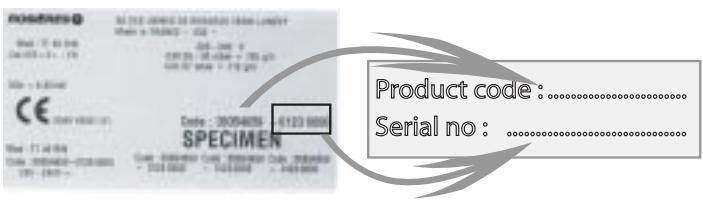
READ THE INSTRUCTIONS CAREFULLY TO MAKE THE MOST OF YOUR HOB. We recommend you keep the instructions for installation and use for later reference, and before installing the hob, note its serial number below in case you need to get help from the after sales service.
. Identification plate
(located under the hob's bottom casing)
- On the electronic vitroceramic hob, the hob's control area is sensitive, do not place hot containers on it.
- Never cook directly on the hob surface, use pots and pans.
• Always centre the pan well on the cooking zone used. - Do not use the hob surface as a cutting board, or work top.
- Do not slide pans on the hob: risk of scratching.
- Do not store heavy objects above the hob, they can fall and damage it.
- Do not store any objects whatever on the hob.
- In the unlikely event of a crack appearing on the glass, immediately disconnect the unit from the mains and contact the after-sales service directly.
INSTALLATION – ELECTRICAL CONNECTION
The operational setting up of household appliances in their environment is a delicate operation that, if not done correctly, can have serious consequences for consumer safety.
Therefore, this work must be entrusted to a professional who can carry it out in compliance with the technical standards in force.
However, if despite this recommendation, the consumer carries out the installation themselves, the ROSIERES will not accept any responsibility in case of technical failure of the product whether or not it causes damage to goods and/or persons.
«The installation receiving the appliance referred to must comply with the standard in force in the installation country».
The ROSIERES does not accept any responsibility if this provision is not complied with.
Caution:
- Before connecting, check the power supply voltage shown on the meter, the circuit breaker setting, the fuse rating and the earth continuity of the installation.
- The electrical connection to the mains must use an earthed socket outlet, or pass through an all-pole cutting device having a minimum contact opening distance of 3 mm.
If the appliance has a socket outlet, it must be installed so that the socket outlet is accessible.
- The green/yellow protection wire must be linked to the earth terminals, of the appliance on one side, and the installation on the other side.
- We cannot be held responsible for any incident or its consequences that may arise during the use of an appliance not linked to the earth, or linked to an earth whose continuity is defective.
- All work in relation to the power supply cable must be carried out by the after sales service or someone with similar qualifications.
The hob is fitted with a power supply cord which allows it to be connected only to a power supply of 220-240 V between phases or between phase and neutral.
- Connect to a socket, to choose the correct fuse, you must refer on the table on page 28 or 29.
It is however possible to connect the hob to :
. Three phase 220-240 V3\~
. Three phase 380-415 V3N\~
To proceed to the new connection, you must adhere the following instructions.
- Before making the connection, make sure that the installation is protected by a suitable fuse, see table on next page, and that it is fitted with wires of a large enough section to supply the appliance normally.
1- Operations to be carried out on the existing connection :
. Turn over the hob, glass side against the work top, taking care to protect the glass.
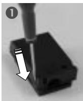
. Open the cover in the following sequence :
- find the two tabs located on the sides,
- put the blade of a flat screwdriver in front of each tab, push in and press,
- remove the cover.
. Pull out the supply cord :
- remove the screws retaining the terminal block
which contains the shunt bars and the conductors of the supply cord, - unscrew the cable clamp to release the power supplying cord.
- Pull out the supply cord.
natural_image
Close-up of a black electronic component with a white arrow pointing to a small component (no text or symbols visible)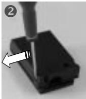
natural_image
Close-up of a mechanical component with a white arrow pointing to a specific part (no text or symbols visible)2- Operations to be carried out to make a new connection :
. Choose the power supply cable in accordance with the recommendations in the table on next pages 28 or 29.
. Pass the power supply cable into the clamp.
. Strip the end of each conductor of the supply cord on a 10 mm length, by taking in account the requested length of the cord for the connection to the terminal block.
. According to the installation and with the help of shunt bars which you should have recovered in the first operation, fix the conductor as shown on the chart.
. Screw the cable clamp and fix the cover.
TERMINAL BLOCK
The unit or support for the hob, as well as the walls of any adjacent units, must be made of high temperature resisting material. In addition, the laminate covering the unit or support should be laid using heat-resistant adhesive to prevent it coming away.
Installation:
- A seal is supplied with the hob. To install it,
. turn over the hob, glass side down, taking care to protect the glass.
. place the seal all round the hob.
. make sure it is placed correctly to prevent any ingress into the support unit.
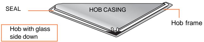
- The body of the hob is fitted with 4 locations holes to take the fixing clamps intended to fix the hob in the unit. Place the 4 fixing clamps, in such a way that the hob is placed perfectly in the support unit.
- Leave a gap of at least 5 cm between the appliance and any neighbouring vertical surfaces.
- If, according to the hob's installation, the casing bottom is near a zone normally accessible during handling and/or storage, install a partition 1 cm from the casing bottom, to prevent any risks of burns or deterioration.
• VITROCERAMIC HOB WITH CONTROL KNOBS
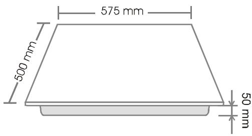
HOB: width 60 cm
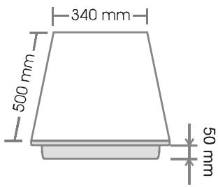
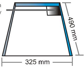
HOB: width 34 cm
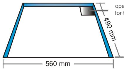
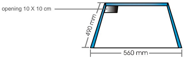
opening 10 X 10 cm for the power supply
• VITROCERAMIC HOB WITH SENSITIVES TOUCHES
HOB: width 60 cm
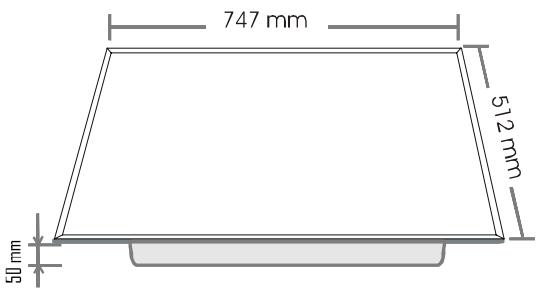
HOB: width 75 cm
Fitting the hob above a ventilated oven* (*equipped with a cooling fan for the electrical components)
Fitting the hob in a support unit
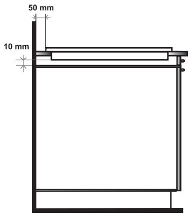
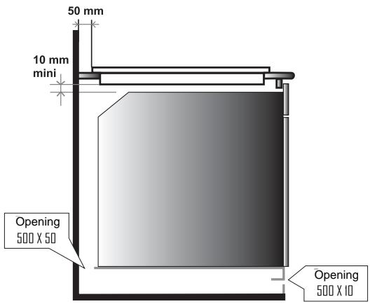
It is forbidden to fit the hob above a non-ventilated oven
PRESENTATION
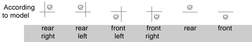
| FRONT RIGHT | FRONT LEFT | REAR RIGHT | REAR LEFT | |
| VITROCERAMIC HOB WITH CONTROL KNOBS | ||||
| RVM 324 | Highlight | Halolight | ||
| 1200 W - ∅155 | 2400 W - ∅220 | |||
| RVM 634 | Highlight | Halolight | Highlight | |
| 1500+900 W - ∅180-275 | 2400 W - ∅220 | 1800 W - ∅190 | ||
| RVM 640 | Highlight | Highlight | Highlight | Highlight |
| 1800 W - ∅190 | 1200 W - ∅155 | 1800 W - ∅190 | 2500 W - ∅220 | |
| RVM 644 | Highlight | Highlight | Highlight | Highlight |
| 1800 W - ∅190 | 1200 W - ∅155 | 1800 W - ∅190 | 2400 W - ∅220 | |
| VITROCERAMIC HOB WITH TOUCH SENSITIVE CONTROLS | ||||
| RVE 6340 | Highlight | Halolight | Highlight | |
| 1000+1200 W | 2400 W - ∅220 | 1800 W - ∅190 | ||
| ∅155-215 | ||||
| RVE 6460 | Highlight | Highlight | Highlight | Highlight |
| 1200 W - ∅155 | 1000+1200 W | 2500 W - ∅220 | 1200 W - ∅155 | |
| ∅155-215 | ||||
| RVE 6440 | Highlight | Highlight | Highlight | Halolight |
| 1800 W - ∅190 | 1200 W - ∅155 | 1800 W - ∅190 | 2400 W - ∅220 | |
| RVE 6480 | Halolight | Highlight | Highlight | Halolight |
| 1800 W - ∅190 | 1200 W - ∅155 | 1800 W - ∅190 | 2400 W - ∅220 | |
| RVE 7410 | Highlight | Highlight | Highlight | Highlight |
| 1200 W | 1500+900 W | 1000+1200 W | 1200 W | |
| ∅155 | ∅180-275 | ∅155+220 | ∅155 | |
The hob is fitted with different zones :
- high light zone : a metallic conductor strip is spread uniformly over the whole surface unit. It is effective within 3 seconds and is suitable for steady, homogeneous and also sustained cooking.
- halolight zone : it is a combination of halogen (1/3) and high light (2/3). The temperature rise of this surface unit is extremely rapid. It is suitable for frying meat, rapid boiling and intensive cooking where a hight temperature is required for a very short period of time.
COUP DE FE

The new ceramic hob improves performance thanks to better heat exchange between the High Light system and the ceramic surface. This enhances the heat output achieving the same performances as the traditional coup de feu.
Thanks to technical know how and to the new design the hob delivers an improved performance yet retaining its durability and quality.
The cooking efficiency improves by 15%, thanks to the new "Coup de feu".
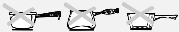
CHOOSING UTENSILS
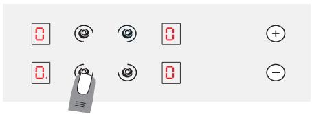
You should use high quality utensils to obtain good cooking results:
natural_image
Three identical illustrations of cooking pots with crossed-out black X marks, no text or symbols present.- Use high quality utensils with flat bottoms: a very flat bottom eliminates hot spots causing food to stick, and the thickness of the metal gives excellent heat distribution.
- Make sure that utensil bottoms are dry: when you fill the container or use a pan straight out of the fridge, for example, make sure that it is dry; this check will stop any dirt getting on the cooking surface.
- Use pans big enough to fully cover the heat source: it is best to make sure that the bottom is at least as large as the cooking zone. If the bottom is slightly larger, the energy is used most efficiently.
The following information will help you select the pans best adapted to obtain good results.
Stainless steel: advised.
Especially good with a “Sandwich” bottom. The “Sandwich” bottom combines the qualities of stainless steel (appearance, long life and stability) with the advantages of aluminium or copper (heat transmission and uniform distribution).
Aluminium: thick bottom recommended. Good conductivity. Warning: sometimes aluminium residues appear as traces on the hob, but they can be removed if cleaned off rapidly. Thin aluminium should not be used.
Cast iron/ceramic: not advised.
Poor performance. Can scratch the surface.
Copper bottom: thick bottom recommended.
Excellent performance, but copper can leave traces that can look like scratches. They can be removed if the hob is cleaned rapidly. However, do not let water evaporate from pans completely, the overheated metal can stick to the surface. An overheated copper pan can leave traces that risk marking the hob permanently.
Porcelain/Enamelled steel: good performance.
Only with flat bottom, not too thick and smooth.
VITROCERAMIC HOB WITH CONTROL KNOBS
USE :
- Locate the sign corresponding to the surface unit you need :
- It is recommended to heat the pan on high level until properly warmed up and then lower to desired cooking setting.
- The residual heat indicator lights up when the surface unit temperature is 60^ and above. It will stay on, even if the unit is switched off, until the surface has cooled down. It will switch off when the temperature of the surface falls below.
- To switch off a surface unit, turn the corresponding knob back on the "0" setting.
The RVM 634 vitroceramic hob has a surface unit with extension, allowing the use of large sized cooking vessels.
natural_image
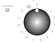
Circular object with numbered positions and a small circular mark at the top (no text or symbols)- To switch on the 1500 W surface unit, turn the knob right to the requested setting.
- To switch on the surface unit with extension, turn the knob right, pass over the setting 12, force the spring till the stop, then come back on the requested setting.
- By setting the knob on "0", the surface unit will totally stop.
- Positions: the examples below are intended as guidelines. When you become familiar with using your hob you will be able to work out settings to suit yourself.
| Positions | Some tips..... | ||
| 1 | 1 - 2 | Very low | To keep a dish hot, melt butter and chocolate... |
| 2 | 3 - 4 | Low | Slow cooking, sauces, stews, rice pudding, poached eggs... |
| 3 | 5 - 6 | Moderate | Beans, frozen foods, fruit, boiling water... |
| 4 | 7 - 8 | Medium | Steamed apples, fresh vegetables, pasta, crepes, fish... |
| 5 | 9 - 10 | High | More intense cooking, omelettes, steaks.... |
| 6 | 11 - 12 | Very high | Steaks, chops, frying... |
VITROCERAMIC HOB WITH TOUCH SENSITIVE CONTROLS
- PRESENTATION
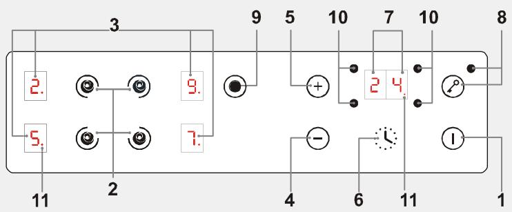
TOUCH SENSITIVE CONTROLS
flowchart
graph TD
    A["2."] --> B["5."]
    C["3"] --> D["7."]
    E["9"] --> F["+"]
    G["10"] --> H["2 4"]
    I["11"] --> J["-"]
    K["1"] --> L["11"]
    style A fill:#f9f,stroke:#333
    style C fill:#f9f,stroke:#333
    style E fill:#f9f,stroke:#333
    style G fill:#f9f,stroke:#333
    style I fill:#f9f,stroke:#333
    style K fill:#f9f,stroke:#333
    style L fill:#f9f,stroke:#333
- Hob on/off button
- Cooking zone selection button
- Heat level display
- "-" touch
- "+" touch
- Timer selection button
- Timer display
- Control locking button with indicator lamp
- Additional cooking zone control touch
- Cooking zone programming indicator: when displayed, it shows that the timer controls the cooking zone
- Control LED:
. on: the cooking zone or timer is active, modification is possible
. off: the cooking zone or timer is set to the last recorded data
* according to model
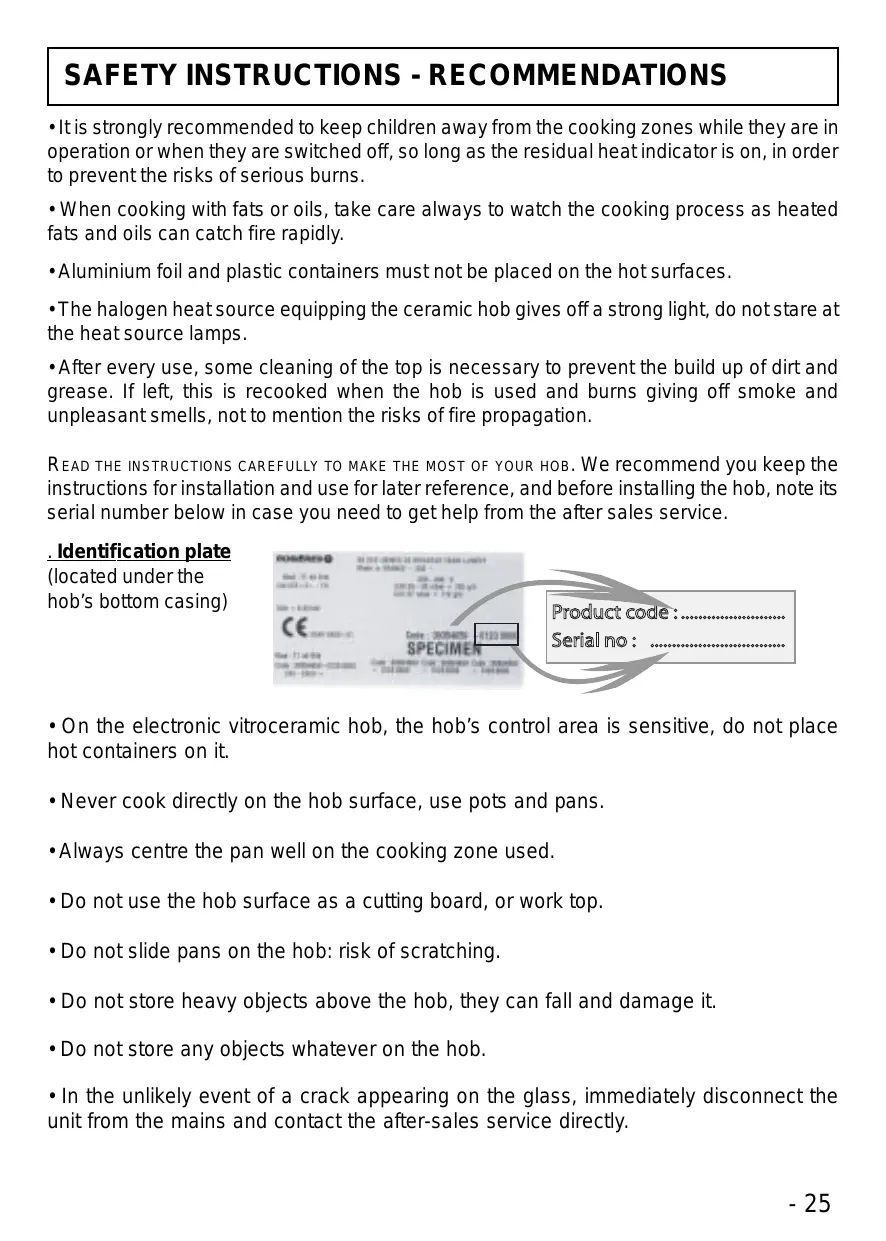
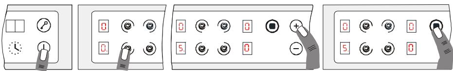
• After powering up the hob, wait 8 seconds to activate the electronic controls.
. Press the button Ⓘ, for 3 seconds.
Electronic control of the hob is activated. In each display zone the heat level 0 is displayed and the control LED blinks.
. After 10 seconds without use, the electronic control goes off and the starting operation has to be repeated.
• STARTING A COOKING ZONE
. Press the selection button of the required cooking zone. In the display zone, the control LED is on steady. It shows that the zone is live.
. Press the ⭕ or ⏻ button to select a heat level between 1 and 9.
→ Press the ⊕ button and heat level 1 is displayed, press the 9 button and heat level ⊖ is displayed.
→ Hold down the ⊕ or ⊖ button and the heat level increases or decreases gradually.
The following examples are for information only. Personal experience should then let you adapt these settings to your taste and habits.
0 : Off
1 : )
2 : ) ..... Melting heat
3 : Keeping hot
4 : Heating up
5 : Thawing, stewing, full cooking, low temperature cooking
6 : Cooking without lid
7 : Frying, meat browning and roasting
8 : High temperature cooking and roasting, seizing
9 : Frying, boiling large quantities of water.....
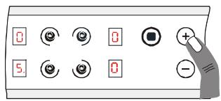
• STOPPING A COOKING ZONE
The cooking zone must be live. In the display zone, the control LED must be on. If not, select the required zone again.
. Press the ⏻ button to display heat level ☐ . Now the zone goes off, the indicator ☐ goes off after 10 seconds.
. To stop rapidly, press the ⊕ and ⊖ buttons at the same time. The heat level automatically goes down to ☐. The cooking zone goes off.
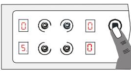
- GENERAL STOP
The cooking zones and the timer can be stopped at any moment by pressing for 3 seconds on the On-Off button.
• RESIDUAL HEAT INDICATOR
The control panel tells the user when the surface temperature of the cooking zones exceeds about 60^ C, by the following displaying: H.
For ending the cooking, we advise switching off the cooking zone and using the residual heat of the zone to finish cooking gently.
When the temperature goes back below 60^ C, the H display goes off.
N.B. After a cut in the current, the residual heat indicator disappears completely, even if the surface temperature exceeds 60^ C.
• OPERATING THE ADDITIONAL COOKING ZONE
An additional cooking zone is fitted to certain hob models. It can be either concentric or extendable. To start the additional cooking zone:
. Press the button Ⓘ. In the next 10 seconds,
. Press the button for the zone with the addition. In the display zone, the blinking lamp goes steady. It shows that the zone is live.
. Select a heat level between 1 and 9.
. Press the button Ⓞ to start the additional zone.
To stop the additional zone:
the cooking zone with addition must be live: in the display zone, the lamp must be on. If not, select the relevant zone again.
. Press the button Ⓞ. The additional cooking zone goes off.
. To rapidly stop the complete cooking zone, press the ⊕ or ⊖ button at the same time. The heat level automatically goes down to ☐. The cooking zone goes off.
• PROGRAMMING A COOKING ZONE
Every cooking zone can be programmed for a maximum time of 99 minutes. Only one zone, at a time, can be programmed.
. Start the required zone by following the previous instructions.
The control LED near the heat level must be displayed, it shows that the zone is live.
. Press the Timer button.
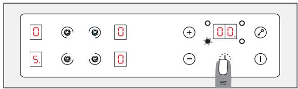
The zone mark around the timer display shows the controlled zone.
. Press the ⭕ button to select the time in minutes.
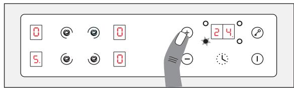
This is saved automatically after three seconds.
→ The programmed time can be modified at any moment by pressing the timer selection button, the timer control LED must be on.
When the time has run, the cooking zone goes off automatically and an audible beep sounds for 1 minute. Press any button to stop it.
→ The programmed time can be reset to ☐ using the ⊖ button and pressing the ⊕ and ⊖ buttons at the same time, the cooking zone is then no longer linked to the timer but stays operational. So you will have to stop the zone manually.
→ The timer can be used alone as a reminder, it will ring at the end of the programmed time.
The locking function holds the current settings, or prevents anyone from starting the hob. It is also useful for cleaning the control strip as the controls can be locked without the hob being on.
. Start the required cooking zones.
. Select a heat level for each of them.
. Press the ⏻ button to set the data; in this way no other button works, except the On/Off button. The locking indicator lamp comes on.
locking indicator lamp
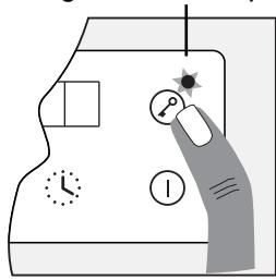
To release the locking function, just press the ⏻ button; the indicator lamp goes off, all the controls work again.
If when the controls are locked, the timer is on, the time will be counted automatically and the zone switched off at the end of the programmed time.
If the locking control is on when the hob is finally shut down, the locking control stays operational and prevents any action when the hob is restarted. Press the ⏻ button to unlock.
Every cooking zone on the hob is equipped with a fast heater for raising the cooking zone's temperature faster:
Starting the fast heater
. Start the required zone, press the "+" button to obtain position "9", release the button briefly and press it again; the display alternates showing R "fast heater" and 3 heat level.
. If necessary reduce to the required heat position.
| Cooking position | Power released (%) | Time of fast heater (minutes) | Maximum operating time before automatic cut off* |
| 0 | 0% | 0 | 0 H |
| 1 | 3% | 1 | 6 H |
| 2 | 6% | 3 | 6 H |
| 3 | 11% | 5 | 5 H |
| 4 | 16% | 6.5 | 5 H |
| 5 | 19% | 8.5 | 4 H |
| 6 | 32% | 2.5 | 1.5 H |
| 7 | 45% | 3.5 | 1.5 H |
| 8 | 65% | 4.5 | 1.5 H |
| 9 | 100% | 0 | 1.5 H |
E.g. 1800 W zone at position 6 = 32% of 1800 W power released
When the “Fast heater” is on, the zone supplies 1800 W power for 2.5 minutes, and adjusts to 576 W after this time.
* The cooking zones cut off automatically if they are left on too long. The cut off depends on the heat level used.
CLEANING THE CERAMIC HOB
- It is important to wait for the ceramic hob surface to cool completely before cleaning it.
- Only use special products for cleaning ceramic surfaces, cream and scraper. You can find them easily in the shops.
- Avoid spills; messes that fall onto the cooking surface burn fast and are then harder to clean off.
- It is recommended to keep away from the cooking surface anything likely to melt like plastic articles, sugar or products with a high sugar content.
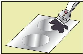
CLEANING:
. Sprinkle a few drops of special ceramic surface cleaner.
. Rub, working hard on any stained parts, using slightly damp soft cloth or kitchen roll.
. Wipe with dry soft cloth or kitchen roll until the surface is clean.
If stains remain after this usual cleaning:
. Sprinkle a few more drops of special cleaner.
. Use a scraper, keeping it at an angle of 30^ to the hob, until the difficult marks go.
. Wipe with dry soft cloth or kitchen roll until the surface is clean.
. Repeat if necessary.
natural_image
Illustration of a hand using a tool to apply black ink onto circular indentations on a flat surface (no text or symbols)ADVICE:
Regular cleaning leaves an protective layer that is essential to prevent scratches and wear. Make sure that the surface is clean before using the hob again.
To remove traces of water and scale, use a few drops of white vinegar or lemon juice. Finish off by wiping with absorbent paper, and then apply a few drops of special cleaner and wipe. Ceramic glass withstands the rubbing of flat-bottomed cooking utensils, but it is nevertheless advisable to lift them before moving them.
On vitroceramic hob with control knobs, for thorough cleaning, the control knobs can be removed by pulling them upwards. Only clean with soapy water and dry well before placing them. Be careful not to let any water get into the holes and take care when replaced the control knobs.
NOTE:
. Avoid using a sponge with too much water.
. Never use a steel tool like a knife or screwdriver.
. A razor blade scraper cannot damage the surface if it is used at an angle of 30^ .
. Do not leave the razor blade scraper within the reach of children.
. Do not use abrasive cleaners or scouring powder.
- The hob frame:
To clean your hob's frame without harm, wash it with soap and water, rinse, and then dry with a soft cloth.
DATA SHEET
All data is given for information only. In order to improve the quality of its products, ROSIERES may modify its appliances with technological developments which adhere to the conditions set out in the Consumer code.

Ceramic hobs comply with the requirements of Directives 73/23/CEE and 89/336/CEE.
| RVM 324 | RVM 634 | RVM 640 | RVM 644 | |
| DIMENSIONS OF THE APPLIANCE (in mm) | ||||
| Width | 340 | 575 | 575 | 575 |
| Depth | 500 | 500 | 500 | 500 |
| Height | 50 | 50 | 50 | 50 |
| Ceramic glass thickness | 4 | 4 | 4 | 4 |
| COOKING ZONE POWER AND ∅ | ||||
| Front right | High light∅ 1551200 W | High light extensible1500+900 W∅ 180-275 | High light -∅ 1901800 W | High light∅ 1901800 W |
| Front left | High light∅ 1551200 W | High light∅ 1551200 W | ||
| Rear right | Halolight∅ 2202400 W | Halolight∅ 2202400 W | High light -∅ 1901800 W | High light -∅ 1901800 W |
| Rear left | Highlight -∅ 1901800 W | High light -∅ 2202500 W | High light -∅ 2202400 W | |
| Total installed power | 3600 W | 6600 W | 7300 W | 7200 W |
| Type of controls | knobs | knobs | knobs | knobs |
| FITTING DIMENSIONS | ||||
| Width | 325 mm | 560 mm | 560 mm | 560 mm |
| Depth | 490 mm | 490 mm | 490 mm | 490 mm |
| RVE 6340 | RVE 6440 | RVE 6460 | RVE 6480 | RVE 7410 | |
| DIMENSIONS OF THE APPLIANCE (in mm) | |||||
| Width | 568 | 568 | 568 | 568 | 747 |
| Depth | 500 | 500 | 500 | 500 | 512 |
| Height | 55 | 55 | 55 | 55 | 55 |
| Ceramic glass thickness | 4 | 4 | 4 | 4 | 4 |
| COOKING ZONE POWER AND ∅ | |||||
| Front right | High light∅ 155+2151000+1200 W | High light -∅ 1901800 W | High light -∅ 1551200 W | Halo light -∅ 1901800 W | High light∅ 1551200 W |
| Front left | Halo light -∅ 2202400 W | High light -∅ 1551200 W | High light∅ 155+2151000+1200 W | High light -∅ 1551200 W | High light∅ 180+2751500+900 W |
| Rear right | High light -∅ 1901800 W | High light -∅ 1901800 W | High light -∅ 2202500 W | High light -∅ 1901800 W | High light -∅ 155+2201000+1200 W |
| Rear left | Halo light -∅ 2202400 W | High light -∅ 1401200 W | Halo light -∅ 2202400 W | High light -∅ 1551200 W | |
| Total power installed | 6400 W | 7200 W | 7100 W | 7200 W | 7000 W |
| Type of controls | sensitive | sensitive | sensitive | sensitive | sensitive |
| FITTING DIMENSIONS | |||||
| Width | 560 mm | 560 mm | 560 mm | 560 mm | 560 mm |
| Depth | 490 mm | 490 mm | 490 mm | 490 mm | 490 mm |
PROBLEMS AND SOLUTIONS
The cooking zones do not simmer or only fry gently
- Only use flat-bottomed pans. If light is visible between the pan and the hob, the zone is not transmitting heat correctly.
- The pan bottom should fully cover the diameter of the selected zone.
The cooking is too slow
- Unsuitable pans are being used. Only use flat-bottomed utensils, that are heavy and have a diameter at least the same as the cooking zone.
Small scratches or abrasions on the hob's glass surface
- Incorrect cleaning or rough-bottomed pans are used; particles like grains of sand or salt get between the hob and the bottom of the pan. Refer to the "CLEANING" section; make sure that pan bottoms are clean before use and only use smooth bottomed pans. Scratches can be lessened only the cleaning is done correctly.
Metal marks
- Do not slide aluminium pans on the hob. Refer to the cleaning recommendations.
- You use the correct materials, but the stains persist. Use a razor blade and follow the “CLEANING” section.
Dark stains
- Use a razor blade and follow the "CLEANING" section.
Light surfaces on the hob
- Marks from an aluminium or copper pan, but also mineral, water or food deposits; they can be removed using the cream cleaner.
Caramelisation or melted plastic on the hob.
- Refer to the "CLEANING" section.
The hob does not operate or certain zones don't work
- The shunts are not positioned correctly on the terminal board. Have a check made that the connection is done in compliance with the recommendations, page 28 & 29.
HOB WITH SENSITIVE TOUCHES
The hob is not operating.
- A big spill or object covers at least two buttons, for at least 10 seconds. Clean up the spill or remove the object.
- The control panel is locked. Press the "Locking" button to release.
The hob does not cut off.
- The control panel is locked. Press the “Locking” button to release. Refer to the section, “Operating time” page 40.
The hob stops automatically
- A spill covers at least two buttons for more than 10 seconds; the hob switches to safety, and an audible beep sounds. Clean up the spill or remove the object.
- The cooking zones stop automatically if they are left on for too long. Refer to the section, “Opera ting time” page 40.
Frequency of on/off operations for cooking zones
- The on-off cycles vary according to the required heat level:
- low level: short operating time,
- high level: long operating time.
“H” display, residual heat indicator, blinking.
- The electronic temperature is too high. A technician should verify the fitting in compliance with the recommendations, page 30 & 31.
ÍNDICE
natural_image
Close-up of a mechanical component with a white arrow pointing to a small black part (no visible text or symbols)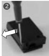
natural_image
Close-up of a mechanical component with a white arrow pointing to a specific part (no text or symbols visible). Liberar el cable:
natural_image
Close-up of a mechanical component with internal channels and a separate schematic symbol (no readable text or labels)Puentes derivadores
x 3
| MONOPHASE220-240 V~ | BIPHASE220-240 V2~ | TRIPHASE220-240 V3~ | TRIPHASE380-415 V3N~ | |
| RVM 324 | ||||
| Fusible | 16 A | 16 A | 16 A | 16 A |
| Cable | 3G1,5H05VVF oH05RRF | 3G1,5H05VVF oH05RRF | 4G1,5H05VVF oH05RRF | 5G1,5H05VVF oH05RRF |
| RVM 634 | ||||
| Fusible | 32 A | 32 A | 20 A | 16 A |
| Cable | 3G4H05VVF | 3G4H05VVF | 4G2,5H05VVF oH05RRF | 5G1,5H05VVF oH05RRF |
| RVM 640 | ||||
| Fusible | 25 A | 25 A | 25 A | 16 A |
| Cable | 3G2,5H05VVF oH05RRF | 3G2,5H05VVF oH05RRF | 4G2,5H05VVF oH05RRF | 5G1,5H05VVF oH05RRF |
| RVM 644 | ||||
| Fusible | 25 A | 25 A | 25 A | 16 A |
| Cable | 3G2,5H05VVF oH05RRF | 3G2,5H05VVF oH05RRF | 4G2,5H05VVF oH05RRF | 5G1,5H05VVF oH05RRF. |
| Conexión al borne | 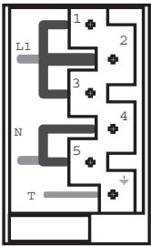 | 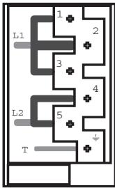 | 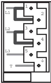 | 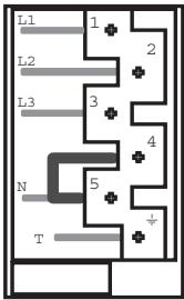 |
| Puentear:establecer un puente con la ayuda de una varilla shunt | L1 : FasePuentear 1-2 yPuentear 2-3N : NeutroPuentear 4-5T : TierraMONOFASICO220-240 V~ | L1 : FasePuentear 1-2 yPuentear 2-3L2 : FasePuentear 4-5T : TierraBIFASICO220-240 V2~ | L1 : FasePuentear 1-2L2 : FasePuentear 3-4L3 : Fase 5T : TierraTRIFASICO220-240 V3~ | L1 : Fase 1L2 : Fase 2L3 : Fase 3N : NeutroPuentear 4-5T : TierraTRIFASICO380-415 V3N~ |
| RVE 6340 | ||||
| Fusible | 32 A | 32 A | 20 A | 16 A |
| Cable | 3G4H05VVF | 3G4H05VVF | 4G2,5H05VVF oH05RRF | 5G1,5H05VVF oH05RRF |
| RVE 6440 | ||||
| Fusible | 25 A | 25 A | 25 A | 16 A |
| Cable | 3G2,5H05VVF oH05RRF | 3G2,5H05VVF oH05RRF | 4G2,5H05VVF oH05RRF | 5G1,5H05VVF oH05RRF |
| RVE 6480 | ||||
| Fusible | 25 A | 25 A | 25 A | 16 A |
| Cable | 3G2,5H05VVF oH05RRF | 3G2,5H05VVF oH05RRF | 4G2,5H05VVF oH05RRF | 5G1,5H05VVF oH05RR |
| RVE 7410 | ||||
| Fusible | 25 A | 25 A | 20 A | 16 A |
| Cable | 3G2,5H05VVF oH05RRF | 3G2,5H05VVF oH05RRF | 4G2,5H05VVF oH05RRF | 5G1,5H05VVF oH05RRF |
| RVE 6460 | ||||
| Fusible | 25 A | 25 A | 20 A | 16 A |
| Cable | 3G2,5H05VVF oH05RRF | 3G2,5H05VVF oH05RRF | 4G2,5H05VVF oH05RRF | 5G1,5H05VVF oH05RR |
| Conexión al borne | 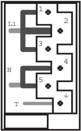 | 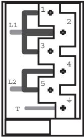 | 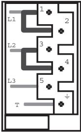 | 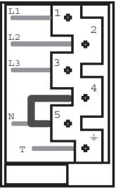 |
| Puentear :establecer unpuente con laayuda de unavarilla shunt | L1 : FasePuentear 1-2Puentear 2-3N : NeutroPuentear 4-5T : Tierra | L1 : FasePuentear 1-2Puentear 2-3L2 : FasePuentear 4-5T : Tierra | L1 : FasePuentear 1-2L2 : FasePuentear 3-4L3 : Fase 5T : Tierra | L1 : Fase 1L2 : Fase 2L3 : Fase 3N : NeutroPuentear 4-5T : Tierra |
natural_image
Three identical illustrations of a cooking pot with a handle crossed out by a diagonal line (no text or symbols)natural_image
Circular object with numbered positions and a small circular mark on top, no text or symbols presentnatural_image
Illustration of a paintbrush applying black paint onto a square plate with two circular cavities (no text or symbols)FICHA TÉCNICA
PROBLEMLÖSUNGEN 88-89
natural_image
Close-up of a black electronic component being inserted with a screwdriver, showing a white arrow pointing to a small hole (no text or symbols visible)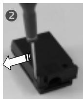
natural_image
Close-up of a mechanical component with a tool inserted, showing a white arrow pointing to a specific part (no text or symbols visible)natural_image
Close-up of a mechanical component with internal circuitry and no visible text or symbolsBrücken
x 3
| EINPHASIG220-240 V~ | ZWEIPHASIG220-240 V2~ | DREIPHASIG220-240 V3~ | DREIPHASIG380-415 V3N~ | |
| RVM 324 | ||||
| Sicherung | 16 A | 16 A | 16 A | 16 A |
| Kabeltyp | 3G1,5H05VVF oderH05RRF | 3G1,5H05VVF oderH05RRF | 4G1,5H05VVF oderH05RRF | 5G1,5H05VVF oderH05RRF |
| RVM 634 | ||||
| Sicherung | 32 A | 32 A | 20 A | 16 A |
| Kabeltyp | 3G4H05VVF | 3G4H05VVF | 4G2,5H05VVF oderH05RRF | 5G1,5H05VVF oderH05RRF |
| RVM 640 | ||||
| Sicherung | 25 A | 25 A | 25 A | 16 A |
| Kabeltyp | 3G2,5H05VVF oderH05RRF | 3G2,5H05VVF oderH05RRF | 4G2,5H05VVF oderH05RRF | 5G1,5H05VVF oderH05RRF |
| RVM 644 | ||||
| Sicherung | 25 A | 25 A | 25 A | 16 A |
| Kabeltyp | 3G2,5H05VVF oderH05RRF | 3G2,5H05VVF oderH05RRF | 4G2,5H05VVF oderH05RRF | 5G1,5H05VVF oderH05RR |
| ANSCHLUßAN DASKLEMMBRETT | 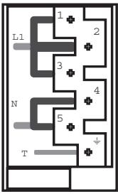 | 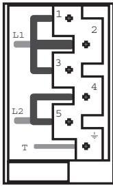 | 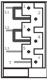 | 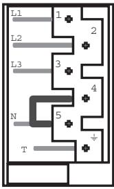 |
| Shunt:Schlagen Sie eine Brücke mittels eines parallel-widerstands | L1 : PhaseShunt 1-2 und Shunt 2-3N : NulleiterShunt 4-5T : Erdung | L1 : PhaseShunt 1-2 und Shunt 2-3L2 : PhaseShunt 4-5T : Erdung | L1 : PhaseShunt 1-2L2 : PhaseShunt 3-4L3 : Phase 5T : Erdung | L1 : Phase 1L2 : Phase 2L3 : Phase 3N : NulleiterShunt 4-5T : Erdung |
| RVE 6340 | ||||
| Sicherung | 32 A | 32 A | 20 A | 16 A |
| Kabeltyp | 3G4H05VVF | 3G4H05VVF | 4G2,5H05VVF oderH05RRF | 5G1,5H05VVF oderH05RRF |
| RVE 6440 | ||||
| Sicherung | 25 A | 25 A | 25 A | 16 A |
| Kabeltyp | 3G2,5H05VVF oderH05RRF | 3G2,5H05VVF oderH05RRF | 4G2,5H05VVF oderH05RRF | 5G1,5H05VVF oderH05RRF |
| RVE 6480 | ||||
| Sicherung | 25 A | 25 A | 25 A | 16 A |
| Kabeltyp | 3G2,5H05VVF oderH05RRF | 3G2,5H05VVF oderH05RRF | 4G2,5H05VVF oderH05RRF | 5G1,5H05VVF oderH05RRF |
| RVE 7410 | ||||
| Sicherung | 25 A | 25 A | 20 A | 16 A |
| Kabeltyp | 3G2,5H05VVF oderH05RRF | 3G2,5H05VVF oderH05RRF | 4G2,5H05VVF oderH05RRF | 5G1,5H05VVF oderH05RRF |
| RVE 6460 | ||||
| Sicherung | 25 A | 25 A | 20 A | 16 A |
| Kabeltyp | 3G2,5H05VVF oderH05RRF | 3G2,5H05VVF oderH05RRF | 4G2,5H05VVF oderH05RRF | 5G1,5H05VVF oderH05RRF |
| ANSCHLUßAN DASKLEMMBRETT | 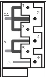 | 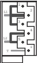 | 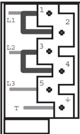 | 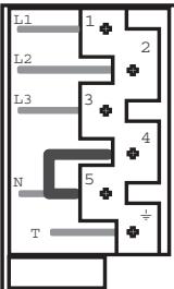 |
| Shunt:Schlagen Sie eine Brücke mittels eines parallel-widerstands | L1 : PhaseShunt 1-2 und Shunt 2-3N : NulleiterShunt 4-5T : Erdung | L1 : PhaseShunt 1-2 und Shunt 2-3L2 : PhaseShunt 4-5T : Erdung | L1 : PhaseShunt 1-2L2 : PhaseShunt 3-4L3 : Phase 5T : Erdung | L1 : Phase 1L2 : Phase 2L3 : Phase 3N : NulleiterShunt 4-5T : Erdung |
INSTALLATION - EINBAU
natural_image
Three identical illustrations of cooking utensils crossed out, no text or symbols presentnatural_image
Illustration of a paintbrush applying black paint to a square plate with two circular indentations (no text or symbols)
- GB INSTRUCTIONS FOR USE AND INSTALLATION Glass Ceramic Hobs
- USE
- SAFETY INSTRUCTIONS - RECOMMENDATIONS
- Identification plate
- INSTALLATION – ELECTRICAL CONNECTION
- Caution:
- To proceed to the new connection, you must adhere the following instructions.
- 1- Operations to be carried out on the existing connection :
- 2- Operations to be carried out to make a new connection :
- Installation:
- • VITROCERAMIC HOB WITH CONTROL KNOBS
- • VITROCERAMIC HOB WITH SENSITIVES TOUCHES
- CHOOSING UTENSILS
- Stainless steel: advised.
- VITROCERAMIC HOB WITH CONTROL KNOBS
- USE :
- VITROCERAMIC HOB WITH TOUCH SENSITIVE CONTROLS
- - PRESENTATION
- • STOPPING A COOKING ZONE
- - GENERAL STOP
- • RESIDUAL HEAT INDICATOR
- • OPERATING THE ADDITIONAL COOKING ZONE
- To stop the additional zone:
- • PROGRAMMING A COOKING ZONE
- Starting the fast heater
- E.g. 1800 W zone at position 6 = 32% of 1800 W power released
- CLEANING THE CERAMIC HOB
- CLEANING:
- ADVICE:
- NOTE:
- - The hob frame:
- DATA SHEET
- PROBLEMS AND SOLUTIONS
- The cooking zones do not simmer or only fry gently
- The cooking is too slow
- Small scratches or abrasions on the hob's glass surface
- Metal marks
- Dark stains
- Light surfaces on the hob
- Caramelisation or melted plastic on the hob.
- The hob does not operate or certain zones don't work
- HOB WITH SENSITIVE TOUCHES
- The hob is not operating.
- The hob does not cut off.
- The hob stops automatically
- Frequency of on/off operations for cooking zones
- “H” display, residual heat indicator, blinking.
- ÍNDICE
- FICHA TÉCNICA
- INSTALLATION - EINBAU
Brand : ROSIERES
Model : RVE 6480
Category : Cooktop