Chime - Chime eufy - Free user manual and instructions
Find the device manual for free Chime eufy in PDF.

| Product type | Wireless Doorbell Chime |
| Brand | Eufy |
| Model | Chime |
| Dimensions (approx.) | 3.5 x 3.5 x 1.5 in (89 x 89 x 38 mm) |
| Weight (approx.) | 5.3 oz (150 g) |
| Power supply | AC 100-240V, 50/60 Hz (plug-in adapter) |
| Power consumption | Standby: <0.5W; Active: <2W |
| Wireless range | Up to 300 ft (90 m) in open area |
| Compatible doorbells | Eufy Video Doorbell (all models) |
| Number of melodies | 20 pre-installed tones |
| Volume levels | 4 adjustable levels (including mute) |
| LED indicator | Blue ring for notification, red for pairing |
| Mounting | Plug directly into wall outlet (no mounting required) |
| Operating temperature | 14°F to 122°F (-10°C to 50°C) |
| Humidity tolerance | Up to 90% non-condensing |
| Certifications | FCC, CE, RoHS |
| Maintenance | Wipe with a soft, dry cloth; do not use liquid cleaners |
| Safety | Low voltage, no user-serviceable parts inside |
| Spare parts | Not available separately; contact Eufy support for replacement |
| Repair | Do not attempt to repair; contact Eufy authorized service |
| Warranty | 1 year limited warranty |
Frequently Asked Questions - Chime eufy
User questions about Chime eufy
0 question about this device. Answer the ones you know or ask your own.
Ask a new question about this device
Download the instructions for your Chime in PDF format for free! Find your manual Chime - eufy and take your electronic device back in hand. On this page are published all the documents necessary for the use of your device. Chime by eufy.
USER MANUAL Chime eufy
Anker Innovations Limited. All rights reserved, eufy Security and eufy Security Logo are trademarks of Anker Innovations Limited, registered in the United States and other countries. All other trademarks are the property of their respective owners.
51005001514 V03

natural_image
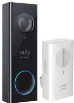
Two connected devices: a black 'oufy Security' wall and a white 'oufy Smartwatch' device, both without visible text or symbols.Quick Start Guide
Video Doorbell 2K (Wired)
Table of Content
What's in the Box 02
What's Required for Installation 03
How the System Works 03
EufySecurity App Installation 04
Video Doorbell Installation 05
Safety
16
Customer Service 18
What's in the Box
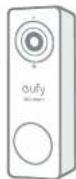
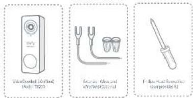
Video Doorbell 2K (Wired)
Model: T8200
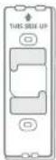
Screw Hole
Positioning-Card
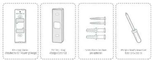
Mounting Bracket (Attached to 15° Mounting Wedge)
15° Mounting Wedge (Optional)
FCC ID: 2AOKB-T8200
IC: 23451-T8200
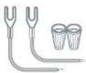
Extension Wires and Wire Nuts (Optional)
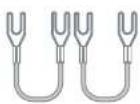
Jumper for Existing Chime (The second one is optional)
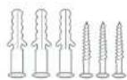
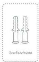
Screw Packs (Anchors are optional)

Doorbell Detaching Pin
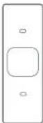
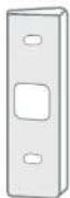
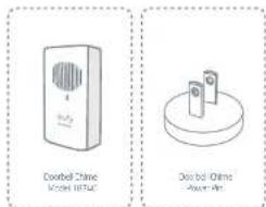
Doorbell Chime
Model: T8740

Doorbell Chime
Power Pin

Quick Start Guide
02 English English
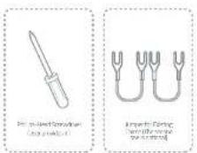
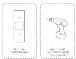
What's Required for Installation
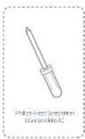
Phillips-Head Screwdriver
Power Drill with 1/4" (6.35mm) Drill Bit
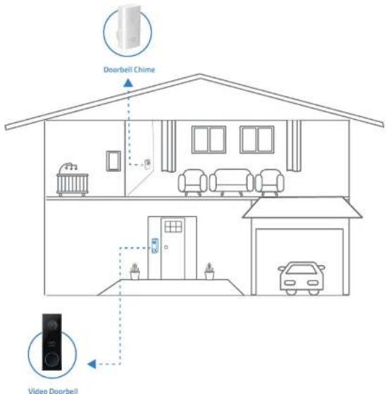
How the System Works
The Video Doorbell system includes 2 parts. One is the video doorbell at your porch. The other is the electronic chime plugged on indoor power socket. The video doorbell is powered by existing doorbell wires. In order to get sufficient power from the doorbell circuit, user needs to bypass the existing doorbell chime on the circuit.
EufySecurity App Installation
Search keyword "EufySecurity" on App Store or Google Play and install the App on your phone.


Register or log into the App. Add video doorbell (Wired) and scan the QR code for later installation process. QR code can be found on the back of the video doorbell and the on the back of the documentation box.
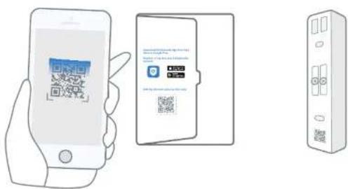
Deal with the physical installation first then come back to the App for in-App setup.
Video Doorbell Installation
Note: Make sure you have installed the EufySecurity App and scan the QR code before start handling the doorbell installation.
Step 1
Ring the existing doorbell, make sure it's working and locate the place of your existing chimes in the house.
Step 2
Shut off the master circuit breaker in your house. Turn the lights in your home on / off to make sure the electricity in your house is properly shut off.
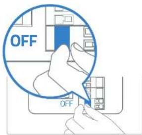
Note: Always be careful when handling electricity wiring. If you're not comfortable to do it yourself, do consult a qualified electrician.
04 English English
05
Step 3
Find the doorbell chime in your house, then remove the cover and find the screw terminals with TRANS and FRONT markings. Use the provided jumper for existing chime to connect the two terminals. This is to bypass the doorbell chime and will not affect the normal operation of the circuit.
Note:
- The video doorbell requires user to bypass the existing chime first to get sufficient power. Without this step, the video doorbell will still be able to power on but will operate unstably.
• In most cases, the existing doorbell circuit looks like below chart. Find the existing doorbell chime in your house, remove the cover and take a photo of the wire connection in case you need to reconnect it. - Use the provided jumper to connect FRONT and TRANS terminals to bypass the chime on the circuit. Do not remove the original wire connecting to the chime. If your doorbell chime has different markings or you have multiple chimes, refer to the help session in the App for the custom wiring instructions or consult a qualified electrician.
- When the jumper is in place, the existing chime will not sound anymore.
What are required: Jumper for existing chime / Phillips-Head Screwdriver
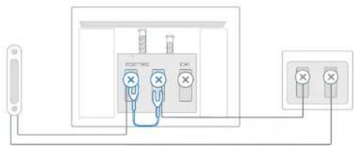
Existing china in the house Doorbell Transformer Existing Doorbell Button
06 English English
Step 4
Remove the existing doorbell button at the front door. Pull the two wires out carefully when removing the old doorbell. Straighten the wire ends if necessary.
What's required: Phillips-Head Screwdriver
07
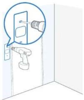
Step 5
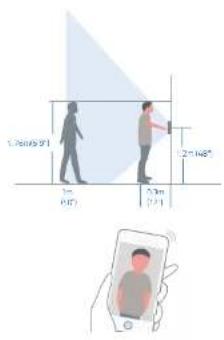
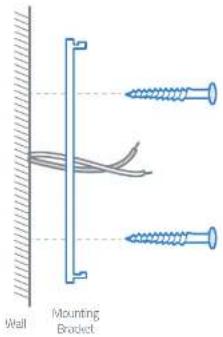
Determine the mounting position of the doorbell. Check if you can reuse the existing holes on the wall. Use the Screw Hole Positioning-Card to mark the screw holes in the place of the existing doorbell button, place it at least 1.2m(48") high from the ground for optimal viewing result, then drill holes (Use 1/4" (6.35mm) drill bit).
What are required: Power Drill with 1/4" (6.35mm) Drill Bit / Screw Hole Positioning-Card
Optional: Use the 15^ mounting wedge as a supplementary mounting bracket if you wish to see more on a specific side.
Without 15° Mounting wedge
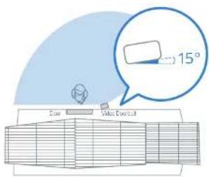
With 15° Mounting wedge
Step 6
Use the anchors provided when installing in materials such as stucco, brick, or concrete. There is no need to use anchor. If you were installing on wooden doorframe.
What's required: Anchors
natural_image
Diagram showing a pipe joint with a blue arrow indicating direction, no text or symbols present08 English English
09
Step 7
Lead the two doorbell wires through the central square hole on the bracket before start mounting. Insert the two screws provided through the screw holes or through the 15° mounting wedge (install the mounting bracket to the 15° mounting wedge in prior), and fasten the screws tightly.
What are required: Mounting Bracket / Screw Packs / 15° Mounting Wedge(Optional) / Phillips-Head Screwdriver
Without 15° Mounting Wedge
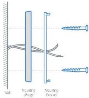
With 15° Mounting Wedge
10 English English
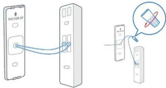
Step 8
Connect the wires to the two terminals at the back of the doorbell, then tighten the terminal screws. Wire can connect to any terminal as the electric current is alternating current.
Note: To prevent short-circuit, make sure the wires are not touching each other after connecting them to the terminals. If the wires are too short, use the extension wires and wire nuts provided to make them longer. Use electrical wiring tape to secure the connection if the wall doesn't have space for wire nuts:
What are required: Extension Wires and Wire Nuts (Optional) / Video doorbell / Phillips-Head Screwdriver
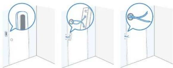
Step 9
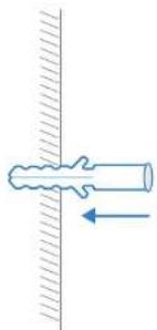
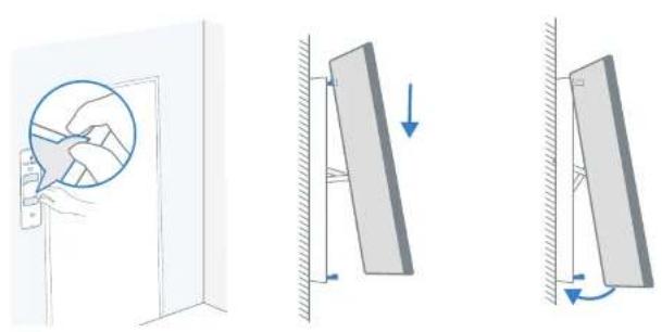
There are 2 thermal conductive pads on the mounting bracket. They're used to conduct heat from video doorbell to the metal bracket. Remove the films on the thermal conductive pads before you mount the doorbell.
Hook the doorbell on top of the mounting bracket and then snap the doorbell bottom to the bracket. You may hear a "click" sound.
Use the doorbell detaching pin provided if you wish to detach the doorbell from the mounting Bracket. Press and hold the hole on the bottom of the doorbell and then lift its bottom to take it off.
The detaching pin has magnet pad on the black-color side. Stick it on iron surface where you can find it easily.
What's required: Doorbell detaching pin
natural_image
Diagram showing three mechanical or structural states: a close-up of a door lock mechanism, a vertical panel with downward force arrows, and a right-angle view of the panel being tilted (no text or symbols present)
12 English English
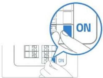
Step 10
Switch the master circuit breaker in your house back to ON.
Step 11
Wait until the doorbell ring flashes yellow. Then follow the on-screen instructions in EufySecurity App to connect the video doorbell to your home Wi-Fi.
14 English English
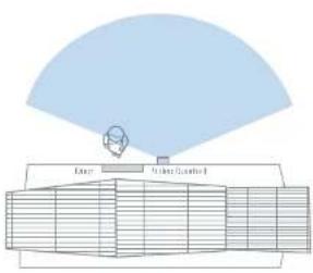
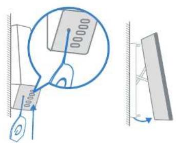
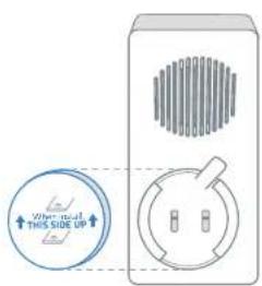
Step 12
Follow the on-screen instructions in EufySecurity App. Install the doorbell power pin to the doorbell chime and then pair it to your video doorbell.
Note: One video doorbell can link up to 4 electronic chimes. Use the volume and music buttons on the side of the electronic chime to adjust the volume and ringtone.
What are required: Doorbell chime / Doorbell chime power pin
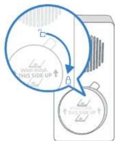
flowchart
graph TD
    A["When Initial This Side Up"] --> B["Lock Icon"]
    B --> C["Next State Up"]
Safety
FCC Statement
This device complies with Part 15 of the FCC Rules. Operation is subject to the following two conditions: (1) this device may not cause harmful interference, and (2) this device must accept any interference received, including interference that may cause undesired operation.
Warning: Changes or modifications not expressly approved by the party responsible for compliance could void the user's authority to operate the equipment.
Note: This equipment has been tested and found to comply with the limits for a Class B digital device, pursuant to Part 15 of the FCC Rules. These limits are designed to provide reasonable protection against harmful interference in a residential installation.
This equipment generates uses and can radiate radio frequency energy and, if not installed and used in accordance with the instructions, may cause harmful interference to radio communications. However, there is no guarantee that interference will not occur in a particular installation. If this equipment does cause harmful interference to radio or television reception, which can be determined by turning the equipment off and on, the user is encouraged to try to correct the interference by one or more of the following measures: (1) Reorient or relocate the receiving antenna. (2) Increase the separation between the equipment and receiver. (3) Connect the equipment into an outlet on a circuit different from that to which the receiver is connected. (4) Consult the dealer or an experienced radio/TV technician for help.
FCC Radio Frequency Exposure Statement
The device has been evaluated to meet general RF exposure requirements. The device can be used in fixed/mobile exposure condition. The min separation distance is 20cm.
Notice: Shielded cables
All connections to other computing devices must be made using shielded cables to maintain compliance with FCC regulations.
The following Importer is the responsible party
Company Name: POWER MOBILE LIFE, LLC
Address: 400 108th Ave NE Ste 400, Bellevue, WA 98004-5541
Telephone:1-205-383-8247
CE This product complies with the radio interference requirements of the European Community.
Declaration of Conformity
Hereby, Anker Innovations Limited declares that this device is in compliance with the essential requirements and other relevant provisions of Directive 2014/53/EU. For the declaration of conformity, visit the Web site www.euflife.com
Do not use the Device in the environment at too high or too low temperature, never expose the Device under strong sunshine or too wet environment.
The suitable temperature for T8200 is -20°C-50°C
The suitable temperature for T8740 is 0°C-45°C.
16 English English
RF exposure information: The Maximum Permissible Exposure (MPE) level has been calculated based on a distance of d=20 cm between the device and the human body. To maintain compliance with RF exposure requirement, use product that maintains a 20cm distance between the device and human body.
CAUTION RISK OF EXPLOSION IF BATTERY IS REPLACED BY AN INCORRECT TYPE, DISPOSE OF USED BATTERIES ACCORDING TO THE INSTRUCTIONS
Wi-Fi Operating Frequency Range: 2412-2472MHz for EU;
Wifi Max Output Power: 19dBm
Bluetooth Operating Frequency Range:2402-2480MHz; Bluetooth Max Output Power:8dBm 433MHz Frequency Range:433.92MHz;433MHz Max Output Power:10dBm
The following importer is the responsible party (contact for EU matters only) Importer: Anker Technology (UK) Ltd
Importer Address: Suite B, Fairgate House, 205 Kings Road, Tyseley, Birmingham, B11 2AA, United Kingdom
This product is designed and manufactured with high quality materials and components, which can be recycled and reused.
This symbol means the product must not be discarded as household waste, and should be delivered to an appropriate collection facility for recycling. Proper disposal and recycling helps protect natural resources, human health and the environment. For more information on disposal and recycling of this product, contact your local municipality, disposal service, or the shop where you bought this product. This device complies with Industry Canada licence-exempt RSS standard(s). Operation is subject to the following two conditions:
(1) this device may not cause interference, and
(2) this device must accept any interference, including interference that may cause undesired operation of the device."
Please note that your rights under applicable law governing the sale of consumer goods remain unaffected by the warranties given in this Limited Warranty.
This Class B digital apparatus complies with Canadian ICES-003.
When using the product, maintain a distance of 20cm from the body to ensure compliance with RF exposure requirements.
12-month limited warranty
Call Us
United States +1 (800) 988 /973 Mon-Fri 9AM-5PM (PT)
United Kingdom +44 (0) 1604 936 200 Mon-Fri 6AM-11AM (GMT)
Germany +49 (0) 69 9579 7960 Mon-Fri 6:00-11:00
- Email Us
Customer Support: support@eufylife.com
Anker Innovations Limited
Room 1318-19, Hollywood Plaza, 610 Nathan Road, Mongkok, Kowloon, Hong Kong

@EufyOfficial

@EufyOfficial

eufyofficial