
ULN-2 - Hi-Fi System Metric Halo - Free user manual and instructions
Find the device manual for free ULN-2 Metric Halo in PDF.


| Product Type | High-Performance Audio Interface / AD/DA Converter with Preamplifiers |
| Brand | Metric Halo |
| Model | ULN-2 (Ultra-Low Noise 2-Channel) |
| Dimensions (approx.) | Half-rack 1U (approx. 8.5" x 1.75" x 8" / 216 x 44 x 203 mm) |
| Weight (approx.) | 4.4 lb (2.0 kg) |
| Power Supply | External 24V DC 48W world-ready power supply with IEC cord |
| Analog Inputs | 2x Mic/Line/Instrument (XLR/TRS combo) with +48V phantom power, 72dB gain, TRS insert send/return |
| Analog Outputs | Monitor L/R (TRS), 2x Analog Line Out (TRS), 1x Headphone (1/4" TRS) |
| Digital I/O | 1x AES/EBU (XLR), 1x S/PDIF (RCA), 1x ADAT/TOSLINK optical (8 channels), Word Clock I/O (BNC) |
| Computer Connectivity | FireWire 400 (IEEE 1394a) 6-pin |
| Supported Sample Rates | 44.1, 48, 88.2, 96, 176.4, 192 kHz |
| DSP Processing | Built-in 2d processing card; optional +DSP license for over 100 plug-ins (EQ, dynamics, reverb, etc.) |
| MIO Console Software | Comprehensive mixer, routing, monitor controller, and recording panel |
| Front Panel Controls | Input gain knobs, trim switches, phantom power, metering, monitor level, headphone level, dim/mute |
| Key Features | Ultra-low noise mic preamps, high-resolution conversion, 2d DSP, flexible routing, hardware monitor controller, snapshot recall |
| Included Accessories | IEC power cord, external power supply, 30" and 4.5m FireWire cables, rack ears with fasteners, rubber feet, software CD, warranty card |
| Maintenance & Cleaning | Wipe with dry cloth; avoid liquids. Keep ventilation clear. No user-serviceable parts inside. |
| Safety | Use only supplied power supply. Do not block vents. Operate in dry environment. Disconnect power before cleaning. |
| Spare Parts & Service | Contact Metric Halo or authorized dealers for replacement power supply, FireWire cables, rack ears, and jumpers. |
| Reparability | Unit contains no user-serviceable parts; refer to Metric Halo for repairs or firmware updates. |
Frequently Asked Questions - ULN-2 Metric Halo
User questions about ULN-2 Metric Halo
0 question about this device. Answer the ones you know or ask your own.
Ask a new question about this device
Download the instructions for your Hi-Fi System in PDF format for free! Find your manual ULN-2 - Metric Halo and take your electronic device back in hand. On this page are published all the documents necessary for the use of your device. ULN-2 by Metric Halo.
USER MANUAL ULN-2 Metric Halo
Mobile I/O User's Guide
Mobile I/O Users Guide
Metric Halo
Revision: v5.6.01
Publication date Mon Aug 26 15:05:10 EDT 2013
Copyright © 2013 Metric Halo
Table of Contents
Introduction 20
I. Quick Start Guides 21
- 2882 Quick Start Guide 23
Prepare the unit for use 23
Connect the 2882 24
Take a listen 24
MIO Console 24
The Console window 25
The Mixer window 26
The 2882 and surround 27
Unleash the DSP 29
Additional Resources 29
- ULN-2 Quick Start Guide 30
Prepare the unit for use 30
Connect the ULN-2 31
Take a listen 31
MIO Console 31
The Console window 31
The Mixer window 32
The ULN-2 and surround 33
Unleash the DSP 36
Additional Resources 36
- LIO-8 Quick Start Guide 37
Prepare the unit for use 37
Connect the LIO-8 38
Get familiar with the front panel 38
Take a listen 38
MIO Console 38
The Console window 39
The Mixer window 40
The LIO-8 and surround 41
Unleash the DSP 43
Additional Resources 43
- ULN-8 Quick Start Guide 45
Prepare the unit for use 45
Connect the ULN-8 46
Get familiar with the front panel 46
Take a listen 46
MIO Console 46
The Console window 47
The Mixer window 48
The ULN-8 and surround 49
Unleash the DSP 51
Additional Resources 51
II. Interfaces 53
5.2882 Users Guide 56
2882 Overview 56
What it is 56
What it has 56
What you need to use it 57
What comes with it 57
Using the 2882 Hardware 58
2882 Front Panel 58
2882 Rear Panel 59
2882 Signal Flow 60
Making connections to the 2882 60
2882 Specifications 65
- ULN-2 Users Guide 69
ULN-2 Overview 69
What it is 69
What it has 69
What you need to use it 70
What comes with it 70
Using the ULN-2 Hardware 71
ULN-2 Front Panel 71
ULN-2 Rear Panel 73
Signal Flow 74
Making connections to the ULN-2 74
ULN-2 Specifications 79
- LIO-8 Users Guide 84
LIO-8 Overview 84
What it is 84
What it has 84
What you need to use it 85
What comes with it 85
Using the LIO-8 Hardware 87
LIO-8 Front Panel 87
LIO-8 Rear Panel 88
Signal Flow 89
Making connections to the LIO-8 89
LIO-8 Specifications 92
- ULN-8 Users Guide 97
ULN-8 Overview 97
What it is 97
What it has 97
What you need to use it 98
What comes with it 98
Using the ULN-8 Hardware 100
ULN-8 Front Panel 100
ULN-8 Rear Panel 101
Signal Flow 102
Making connections to the ULN-8 102
ULN-8 Specifications 105
- ULN/LIO-8 Front Panel Guide 111
Front Panel Overview 111
Sample Rate Indicators and Control 111
Clock Source Indicators and Control 112
Control Mode Indicators and Selector 112
I/O Trim Mode Indicators and Selector 113
Channel Mode Indicators 113
Per Channel Control Knobs 114
High Resolution Meters 114
System Status Indicators 116
AES Status Indicators 116
Monitor Control Section 117
Front Panel DI Inputs 117
Control Mode Details 118
Monitor 118
Preset 119
Input 119
Link 119
+48 120
U/M — User Mode .... 120
Input Trim 120
Meters on the Knobs 121
Output Trim 121
Illumination (Brightness) Adjustment 121
Front Panel Preferences in MIO Console 121
Infrared Remote operation 123
III. Software 127
- Installation and Registration 133
Installing MIO Console 133
Included Packages 133
Installation 133
Registration & Licensing 133
Registering your interface 133
License management 135
Purchasing a software license 137
Receiving MH Special Deals 138
- MIO Console Overview 141
MIO Console Software 141
MIO Console Overview 142
The Console Window 142
I/O Panel 143
Box Tabs 143
Front Panel Preferences 144
Analog Input Control 145
Optimizing Input Levels 148
Analog Input Channel Link 148
Digital Input Meters 149
Cans Controls 149
System Controls 151
Analog Output Control 155
Analog Output Channel Link 156
Digital Output Meters 156
Box Info 156
Parameter Pop-up Controls 157
Pop-up Commands 157
Pop-up Presets 158
The Mixer Window 159
Routing 163
A Quick Tour of the v. 5 Mixer 164
Technology 166
Configuration 167
Using Templates for Configuration 167
Manual Configuration 168
Mixer Configuration Tasks 170
Input Strip Details 171
Selection-based Linking 175
Plug-ins 176
Plug-In Graphs (requires +DSP license) 176
Plug-in Macros (requires +DSP license) 177
Sends 177
I/O insert 178
Master Strip Details 181
Routing Summary 186
FireWire Returns 187
- Monitor Controller 189
Overview 189
Ultra-Quick Start Guide to Configuring the Monitor Controller 189
Adding the Bus Output of your Mix Bus to the Monitor Controller 189
Configuring the Monitor Controller 189
Monitor Control Interface and Basic Operation 190
Determine Configuration 191
Identifying Monitor Sources 191
Identifying Monitor Output Paths 191
Using the Monitor Controller 192
Selecting an Input Source 193
Selecting an Output Path 193
Adjusting the Monitor Level 193
Dimming the output 193
Muting the output 193
Locking the output 193
Overriding the currently selected source 193
Selecting Source Override Channels 193
The Monitor Controller as Floating Window 194
Mini Monitor Controller Window 194
Switch between Monitor Controller and Mini Monitor Controller windows 194
Key Commands 194
Configuring the Monitor Controller 195
Configuring Monitor Sources 195
Configuring Monitor Output Paths 197
Changing the per path Calibration 199
Monitor Controller Preferences 199
Monitor Controller FAQ: 200
- Routing Examples ...... 201
Introduction 201
Effects for tracking 201
Controlling Multiple Monitors 208
Virtualizing Windows audio programs 213
Introduction 213
How it Works 213
What you need 213
How to set it up 213
Tips for Specific Host DAWs 214
Routing Tips for Logic 214
Routing Tips for Digital Performer 215
Routing Tips for Cubase 218
Routing Tips for Pro Tools 221
Conclusion 231
- Record Panel 232
Overview 232
Record Panel Description 232
Recording 235
Playback 236
Multibox considerations 237
Record Panel Key Commands 237
Record Panel Prefs 237
- DSP Implementation Guide 241
Plug-in Processing in the v.5 Mixer 241
Inserts 241
Plug-in UI's 241
Multichannel Plug-ins 242
Graphs 243
Patch Library Pop-up Menu 246
- Saving and Recalling Your Setups 247
Factory Default 247
Box Merge 247
Boot States and Snapshots 248
ULN-2 Snapshot Recall 248
ULN/LIO-8 Snapshot Recall 249
2882 Snapshot Recall 249
Console Files 249
ConsoleSync 250
- MIO Console Preferences 252
Accessing the preferences 252
Other Preferences 255
- ConsoleConnect 256
ConsoleConnect Overview 256
Introduction to ConsoleConnect 256
How it works 256
Total Recall 256
Universal Access 256
Using ConsoleConnect 256
Selecting the mode 257
Communication 260
Finding the Plug-in 260
Tips for Specific Host DAWs 261
Logic 261
Digital Performer 261
Cubase 262
GarageBand 263
Pro Tools Tips 265
Support 265
- Control Surface Support 266
Control Surface Preferences 266
Details of EuCon Control Surface Support 267
Control Room Support 267
Mixer Model 268
Details of Mackie Control Protocol Control Surface Support 269
Mackie Control Default Key Commands 269
Control Room Support 269
Mixer Model 269
- +DSP 271
DSP Package Comparison 271
+DSP Plug-in Documentation 273
MIO Volume Control (Linear) 273
MIO Volume Control (LPF) 274
MIO M/S Processor 274
MIO M/S Decoder 275
MIO Static Matrix 276
MIOComp 277
MIOEq 6 Band 278
MIOEq 12 Band 279
MIOLimit 280
MIOStrip 282
MIO Channel Summer 285
MIO Channel Difference 285
MIO Channel Sum/Difference 285
MIO Channel Multiplier 286
MIODelay 286
MIOModDelay 286
MIO Delay (1k) 287
MIO Delay (24k) 287
MIO Delay (96k) 288
MIO Delay (1k IM) 288
MIO Delay (2k-15k IM) 289
MIO Delay (2k-15k) 289
MIO MultiTap Delay 290
MIOAllpass 293
MIOAllpassVD 293
MIOHardClip 294
MIOSoftClip Type 1 294
MIOSoftClip Type 2 295
MIOSoftClip Type 3 295
MIOSoftDistortion Type 1 296
MIOSoftDistortion Type 2 296
MIOSoftDistortion Type 3 297
MIOSlew 297
MIOInSlew 297
MIO 4th Order Nonlinear Map 298
MIO 4th Order Symmetrical Nonlinear Map 298
MIO 4th Order [dB] Nonlinear Map 299
MIO 4th Order [dB] Symmetrical Nonlinear Map 300
MIO A/B Switch (Linear) 301
MIO A/B Switch (LPF) 301
MIOQuadOsc 302
MIOQuadLFO 302
MIOQuadNCO 303
MIOQuadNCO-Glide 303
Noise 304
Simple Dither (TPDF) 304
Simple Dither (TPDF Hipass) 304
Scale/Offset 305
SVF Control 305
NC SVF 306
MIOSimplePitchShifter 306
HaloVerb 306
HaloVerb for +DSP 307
EnvelopeDetector 308
TransientControl 309
CV -> NCO Freq 310
Abs 310
Max 310
Min 311
Select 311
Map Range 311
Constant 311
Divide 312
Square Root 312
Reciprocal Square Root 312
ADSR 312
Exponential ADSR 313
Band Split 314
IV. Appendices 315
A. MIO Console Key Commands 318
Key Commands 318
B. Updating your Firmware 322
Introduction 322
Installing a firmware update 322
Rolling back your firmware 324
C. Updating the Driver 325
Introduction 325
D. FireWire 326
Overview 326
FireWire FAQ 327
E. CoreAudio 329
About CoreAudio™ Technology 329
How The CoreAudio Driver Works 329
CoreAudio Transport And Sample Rates 329
Channel Names 330
Channel Enables 330
CoreAudio Buffers 330
Setting The CoreAudio Buffer Size 330
Sample Size 330
Clock Sources 331
F. Troubleshooting Guide 332
COMPUTER DOES NOT SEE MOBILE I/O 332
MOBILE I/O IS NOT POWERED UP 332
SOFTWARE IS NOT INSTALLED PROPERLY 332
THE FIREWIRE BUS DID NOT RESET CORRECTLY 332
THE FIREWIRE CABLE IS NOT CONNECTED OR BAD 333
THE FIREWIRE HARDWARE HAS BEEN DAMAGED 333
NO OUTPUT FROM MOBILE I/O 333
MISSING METERS IN MIO CONSOLE 334
COULD NOT INSTANTIATE PLUG-IN 334
DIGITAL DISTORTION 335
INTERFACE HAS CRASHED 335
CORRUPTED BOOTSTATE 335
CORRUPTED CONSOLE STATE 335
LICENSE REINSTALLATION 335
GROUND LOOPS 335
FIRMWARE UPDATE PROBLEMS 337
BUS POWERING MOBILE I/O 337
NOT ENOUGH POWER ON THE BUS 337
OTHER BUS POWERED DEVICES 338
G. DB25 Pinouts 339
H. ULN-8/LIO-8 Jumper Settings 341
Overview 341
D.I. Board 342
Line input grounding 342
Output levels 343
Power supply 343
I. ULN-R Installation Guide 345
ULN-R Parts and Tools 345
Installing the mic pres: 346
J. Support Resources 351
K. Changelog 352
Glossary 355
Index 365
List of Figures
1.1.Mobile I/O 2882 23
1.2. 2882 Routing 24
1.3. Console Window 25
1.4. Mixer Window 26
1.5. Surround Mixer 27
1.6. Configuring the Monitor Controller 28
1.7. The Configured Monitor Controller 28
2.1.Mobile I/O ULN-2 30
2.2. ULN-2 Routing 30
2.3. Console Window 31
2.4. Mixer Window 32
2.5. Surround Mixer 34
2.6. Configuring the Monitor Controller 35
2.7. The Configured Monitor Controller 35
3.1. LIO-8 37
3.2. LIO-8 Routing 38
3.3. Console Window 39
3.4. Mixer Window 40
3.5. Surround Mixer 41
3.6. Configuring the Monitor Controller 42
3.7. The Configured Monitor Controller 43
4.1. ULN-8 45
4.2. ULN-8 Routing 46
4.3. Console Window 47
4.4. Mixer Window 48
4.5. Surround Mixer 49
4.6. Configuring the Monitor Controller 50
4.7. The Configured Monitor Controller 51
5.1.Mobile I/O 2882 56
5.2. Mobile I/O Unit 57
5.3. IEC Power Cord 57
5.4. External Power Supply 57
5.5. 30" IEEE 1394 9-pin to 6-pin 1394 Cable 58
5.6. 4.5 meter IEEE 1394 9-pin to 6-pin 1394 Cable 58
5.7. Rack Ears 58
5.8. 2882 Front Panel 58
5.9. 2882 Rear Panel 59
5.10.2882 Signal Flow 60
5.11.2882 Routing 60
5.12. Telescoping Shield Cable for Instruments 61
5.13. XLR to Balanced TRS Cable 62
5.14. TRS to TS Unbalanced Cable 62
5.15. TRS to RCA Unbalanced Cable 62
6.1. Mobile I/O ULN-2 69
6.2.Mobile I/O Unit 70
6.3. IEC Power Cord 70
6.4. External Power Supply 71
6.5. 30" IEEE 1394 9-pin to 6-pin 1394 cable 71
6.6. 4.5 meter IEEE 1394 9-pin to 6-pin 1394 Cable 71
6.7. Rack Ears 71
6.8. ULN-2 Front Panel 71
6.9. ULN-2 Front Panel Snapshot Controls 73
6.10. ULN-2 Rear Panel 73
6.11. ULN-2 Signal Flow 74
6.12. ULN-2 Routing 75
6.13. Telescoping Shield Cable for Instruments 76
6.14. XLR to Balanced TRS Cable 76
6.15. TRS to TS Unbalanced Cable 77
6.16. TRS to RCA Unbalanced Cable 77
7.1. LIO-8 84
7.2. LIO-8 Unit 85
7.3. IEC Power Cord 85
7.4. External Power Supply 86
7.5. 30" IEEE 1394 9-pin to 6-pin 1394 Cable 86
7.6. 4.5 meter IEEE 1394 9-pin to 6-pin 1394 Cable 86
7.7. Rack Ears 86
7.8. Jumpers for Internal Configuration 86
7.9. LIO-8 Front Panel 87
7.10. LIO-8 Rear Panel 88
7.11. LIO-8 Signal Flow 89
7.12. LIO-8 Routing 89
8.1. ULN-8 97
8.2. ULN-8 Unit 98
8.3. IEC Power Cord 98
8.4. External Power Supply 99
8.5. 30" IEEE 1394 9-pin to 6-pin 1394 Cable 99
8.6. 4.5 meter IEEE 1394 9-pin to 6-pin 1394 cable 99
8.7. Rack Ears 99
8.8. Jumpers for Internal Configuration 99
8.9. ULN-8 Front Panel 100
8.10. ULN-8 Rear Panel 101
8.11. ULN-8 Signal Flow 102
8.12. ULN-8 Routing 102
9.1. ULN-8 Front Panel 111
9.2. Sample Rate 112
9.3. Clock Source 112
9.4. Control Mode 113
9.5.I/O Trim Mode Indicators 113
9.6.Mic/Line Indicator 114
9.7. Front Panel Control Knob 114
9.8. Analog I/O Meters 115
9.9. Front Panel Numeric Readout 115
9.10. Positive Gain Display 115
9.11. Negative Gain Display 116
9.12. System Status 116
9.13. AES Indicators 116
9.14. Monitor Control Knob 117
9.15. Cans Jack 117
9.16. DI Jacks 118
9.17. Disclosure Triangle 121
9.18. Front Panel Preference Sheet 122
9.19. Knob in Focus 123
9.20. Capture Mode 124
9.21. Captured IR Command 125
9.22. IR Test Mode 125
10.1. Registration Message 134
10.2. Registration Window 134
10.3. Registration Selection 135
10.4. Registration Error 135
10.5. Registration Successful 135
10.6. Unit Selection Menu 135
10.7. License Management Window 136
10.8. License Options 137
10.9. Demo Installed 137
10.10.Expired Demo 137
10.11. MH Special Deals Menu Item 138
10.12.MH Special Deals Page 139
10.13. Confirmation Page 140
11.1.MIO Mixer 141
11.2. MIO Console 142
11.3.View Panel Pane Selector Bar 142
11.4.I/O Panel 143
11.5. Box Tabs 144
11.6. Box Tab Pop-up Menu 144
11.7. Front Panel Prefs Sheet 145
11.8. Parameter Pop-up Menu 146
11.9. Phantom Power Button 146
11.10.Level Standard Pop-up Menu 146
11.11. Gain Trim Knob 147
11.12. Channel Label 148
11.13. Channel Level Meter 148
11.14. Analog Input Channel Link 148
11.15. Digital Input Meters 149
11.16. Headphone Controls 150
11.17. System Controls 151
11.18. Clock Source Pop-up Menu for 2882 and ULN-2 151
11.19. Clock Source Pop-up Menu for LIO-8 and ULN-8 152
11.20. Sample Rate Pop-up Menu (2882 and ULN-2) 153
11.21. Sample Rate Pop-up Menu (LIO-8 and ULN-8) 153
11.22.WC Out Pop-up 154
11.23. DI Source Pop-up 154
11.24. DI SRC Button 154
11.25. High Power Button 154
11.26. Lock Indicators 155
11.27. Box Info 157
11.28. Parameter Pop-up Menu 158
11.29. Template Selection Dialog 160
11.30. Configure Mixer Sheet 161
11.31. v. 5 2d Routing Model 163
11.32.Input to Master Output Signal Flow 165
11.33. v.5 Mixer Channel Strip 166
11.34. Blank Mixer Window 167
11.35. Template Window 168
11.36. ULN-8 Tracking Cue Mix + Reverb 168
11.37. Configure Mixer Sheet 169
11.38.v.5 Mixer Input Strip 172
11.39. v.5 Mixer Panner Controls 174
11.40. v.5 Mixer Direct Pan Assignment 174
11.41.Sends Mixer Window 178
11.42. I/O insert 178
11.43. A post-MIOStrip, Pre-HaloVerb insert 179
11.44. Post-limiter sends on a Analog 1 and Digital 1 180
11.45. I/O insert routing to and from MainStage 180
11.46. MainStage set to send and return on channels 3/4 180
11.47. v.5 Mixer Routing Connections 182
11.48. Bus Output Assign Pop-up Menu 184
11.49. v.5 Mixer Routing Connections 186
11.50. +DSP Mid-Side Mastering Process Inserted in Logic Using Logic's I/O Plug-in and MIO FireWire Returns 188
11.51. Routing from Logic to SpectraFoo via FireWire Returns 188
12.1. Monitor Controller Configuration Pane 189
12.2. Monitor Controller Window 190
12.3.v.5 Monitor Controller UI 192
12.4. v.5 Mini Monitor Controller UI 194
12.5. Monitor Controller Configure Button 196
12.6. Monitor Controller Configuration Pane 196
12.7.Add Monitor Source Dialog 196
12.8.New Monitor Source Input List 197
12.9. Monitor Controller Configure Button 197
12.10. Monitor Controller Configuration Dialog Sheet 198
12.11.Add Monitor Output Dialog 198
12.12.New Output in List 198
12.13. v.5 Monitor Control Calibration 199
13.1. Example ULN-2 Setup 201
13.2. Mix Config Sheet 202
13.3.Newly Created Busses 203
13.4. Basic Mixer Configuration 204
13.5. Selected Strips 205
13.6. Inserting Send to Reverb Bus 205
13.7. After Inserting the Sends 206
13.8. Making the Output Assignment 207
13.9. Selecting the Reverb Plug-in 207
13.10. Factory Default Settings 207
13.11. 100% Wet Default Settings 207
13.12. Final Configuration 208
13.13. Example 2882 Setup 209
13.14. 2882 Basic with Monitor Control 209
13.15. Template MC Configuration 210
13.16. Add Small Monitor Path 211
13.17. Select Path 211
13.18. Channels Selected 211
13.19. Closed List 211
13.20. Reordered List 211
13.21. Final MC Config 212
13.22. Final Monitor Controller 212
13.23. Inserting the I/O Plug-in 214
13.24. Using Logic I/O Plug-ins for Insert Processing on Output Objects 215
13.25. The Input Bundle Configuration 216
13.26. The Output Bundle Configuration 216
13.27. Single Channel +DSP Mid/Side Compressor 217
13.28. Multichannel Bussed +DSP Parallel Compressor 218
13.29. Defining the External FX 218
13.30. Inserting the External FX 219
13.31. +DSP Graph Inserted into Cubase 219
13.32. Setting the VST Outputs 220
13.33. Setting the VST Inputs 220
13.34. Setting the VST Outputs in the Mixer 221
13.35. Routing to Firewire 222
13.36.Input Tab 223
13.37. Insert Tab 224
13.38. Configuring the MIO Mixer, DAW 9-14 225
13.39. Configuring the I/O insert to send and return on Analog 3 225
13.40. Configuring the MIO Mixer, DAW 15-16 226
13.41. Delay Compensation 227
13.42. Delay Compensation for 2882/ULN-2 227
13.43. Delay Compensation for LIO/ULN-8 227
13.44. Output Tab 228
13.45. Output Tab 229
13.46. Mapping to DAW 1-16 230
13.47. Connecting a Three Box System 231
14.1. Record Panel 232
14.2.Time Readouts 232
14.3. Record Time Display Options 233
14.4. Transport Controls 233
14.5. Progress Meters 233
14.6.Play Position 234
14.7. Tracks Overview 234
14.8. Track Header 235
14.9. Zoom Buttons 235
14.10. Recording Prefs Button 238
14.11. Recording Preferences Sheet 238
14.12. Record File Format Pop-up 239
15.1. Insert Menu 241
15.2. Inserted Plug-in 241
15.3.M/S Plug-in UI 241
15.4.MIOStrip UI 242
15.5. Plug-in Bar 242
15.6. Selecting the Graph 243
15.7. The Graph Window 243
15.8. Selecting a New Instance from the Plug-in Menu 244
15.9. Positioning the New Instance in the Graph 244
15.10. Starting a Connection 244
15.11. Completing the Connection 245
15.12. Making a Mult 245
15.13. Connecting the Output 245
16.1. Factory default conflict dialog 247
16.2. Utilities Menu 248
16.3. ULN-2 Front Panel Snapshot Controls 249
16.4. ULN-8 Front Panel in Preset mode 249
16.5. File menu 250
16.6. Dialog to load the factory default or state on the computer 250
16.7. Box and console sync dialog 251
17.1. MIO Console Preferences 252
17.2. On Launch Pop-up 253
17.3. ConsoleSync Pop-up 253
17.4. Channel Strip Meters Post Fader Preference 255
18.1.MIO Console Preferences 258
18.2. MIO Console Status Menu 259
18.3. ConsoleConnect Presets 260
18.4. When Things Go Wrong: Partially Instantiated AU 261
18.5. MIOConsoleConnect Inserted in a V-Rack 261
18.6. Add an Instrument Track 262
18.7. Insert MIOConsoleConnect 262
18.8. Track Details 263
18.9. Track Edit Tab 263
18.10. MIO Console as a Plug-in in GarageBand 264
D.1. Correctly Mixed FW800/400 Chain 327
D.2. Incorrectly Mixed FW800/400 Chain 327
D.3. Using a Hub in a Mixed Speed Chain 328
F.1. Utilities Menu 334
F.2. 2d Out of Memory 334
G.1. Analog DB25 pinouts 339
G.2. AES I/O DB25 pinouts 340
H.1. Top Screw Placement 341
H.2. Side Screw Placement, with Rack Ear 341
H.3. Side Screw Placement, No Rack Ear 341
H.4. D.I. Board Jumper Sites 342
H.5. Shield Lift Jumper Sites 342
H.6. Output Level Jumper Sites 343
H.7. PSU Jumper Sites 344
I.1.DB25 Connector Board 345
I.2. 4 Channel ULN-R Mic Pre Board 345
I.3. 3 Pin Phantom Power Cable 345
1.4. 20 Pin Ribbon Cable Jumper 345
1.5. 7/16" Standoffs 346
1.6. Phillips Head Screw 346
1.7.Top Screw Placement 346
1.8. Side Screw Placement, with Rack Ear 347
1.9. Side Screw Placement, No Rack Ear 347
I.10.Mic In Blank Plate 347
I.11.DB25 Connector Board Fitted 347
I.12.DB25 Connector Board (Interior) 348
I.13. Phantom Power Jumpers on the PSU Board 348
I.14. Phantom Supply Cable and Ch. 1-4 Connectors 349
I.15. Installing the Ch. 1-4 Mic Pre Board 349
I.16. Installing the Ch. 5-8 Mic Pre Board 350
-
Cross-section of a Coaxial Cable 356
-
Linear Fade 359
-
Logarithmic Fade 359
-
0° Phase Offset 361
-
180° Phase Offset 361
-
Phase Cancellation 362
List of Tables
5.1.Mic/Line Inputs 65
5.2. 2882 Maximums 65
5.3. 2882 Converter Latency 65
5.4. 2882 Input Processing 66
5.5. 2882 Output Processing 66
5.6. 2882 Front Panel 66
5.7. 2882 Back Panel 67
5.8. 2882 Software 67
5.9.2882 Power 67
5.10.2882 Case 67
6.1.Mic Inputs 79
6.2. ULN-2 Equivalent Input Noise (E.I.N.) 20 Hz - 20 kHz Flat @ 72 dB Gain .... 80
6.3. ULN-2 Frequency Response 80
6.4. ULN-2 Crosstalk @1kHz 80
6.5. ULN-2 Maximums 80
6.6. ULN-2 Converter Latency 80
6.7. ULN-2 Input Processing 80
6.8. ULN-2 Output Processing 81
6.9. ULN-2 Front Panel 81
6.10. ULN-2 Back Panel 81
6.11. ULN-2 Software 82
6.12. ULN-2 Power 82
6.13. ULN-2 Case 82
7.1. LIO-8 Voltage Rails 92
7.2. LIO-8 Maximum I/O Levels (Balanced) 92
7.3. LIO-8 Monitor Controller 92
7.4. LIO-8 Line Input + ADC 93
7.5. LIO-8 Line Input + ADC Frequency Response 93
7.6. LIO-8 Converter Latency 93
7.7. LIO-8 Input Processing 93
7.8. LIO-8 Output Processing 94
7.9. LIO-8 Front Panel 94
7.10. LIO-8 Back Panel 95
7.11. LIO-8 Software 95
7.12. LIO-8 Power 95
7.13. LIO-8 Case 96
8.1. ULN-8 Voltage Rails 105
8.2. ULN-8 Maximum I/O Levels (Balanced) 106
8.3. ULN-8 Monitor Controller 106
8.4. ULN-8 Mic Pre Input + ADC 106
8.5. ULN-8 Mic Pre + ADC Frequency Response 107
8.6. ULN-8 Line Input + ADC 107
8.7. ULN-8 Line Input + ADC Frequency Response 107
8.8. ULN-8 Converter Latency 108
8.9. ULN-8 Input Processing 108
8.10. ULN-8 Output Processing 108
8.11. ULN-8 Front Panel 108
8.12. ULN-8 Back Panel 109
8.13. ULN-8 Software 110
8.14. ULN-8 Power 110
8.15. ULN-8 Case 110
9.1.Mic/Line Indicator Modes 114
12.1. Default Monitor Control Key Commands 195
14.1. Record Panel Key Commands 237
18.1. Monitor Controller Key Commands 259
19.1. Mackie Control Default Key Commands 269
20.1. Building Block plug-ins 271
20.2. 2d Amps 272
20.3. 2d Effects 272
20.4. 2d Reverbs 272
20.5. 2d Mastering 273
20.6. 2d Pedals 273
20.7. 2d Cabinets 273
20.8. Internal memory delay times 289
20.9. External memory delay times 290
20.10. Multitap delay times 293
A.1. Default MIO Console Key Commands 318
A.2. Pane Select Key Commands in 2d Expanded Mode 320
A.3. Pane Select Key Commands in Legacy Mode 320
A.4. Menu Key Commands 320
G.1. AES crossover cable pinout 340
H.1. D.I. board gain settings 342
Introduction
This documentation covers:
- MIO Console
• 2882
• ULN-2
• LIO-8
• ULN-8
• +DSP
This is an evolving document; this means that as features are changed or added, this manual will be updated (without an addendum or supplement). Changes will be noted in the Changelog appendix.
We provide the manual in PDF form for user convenience, to eliminate printing costs which would be added to the price of the products and to reduce waste by not printing copies that would have to be destroyed once they became out of date.
If you would like a printed copy of this manual, you may order one directly from Lulu, a print on demand company. The url for the manual is http://www.lulu.com/product/paperback/mobile-io-users-guide/15835858. The manual is professionally printed in black and white and perfect bound. The price is for the printing itself, we do not receive any proceeds from sales.
Part I. Quick Start Guides
Table of Contents
- 2882 Quick Start Guide 23
Prepare the unit for use 23
Connect the 2882 24
Take a listen 24
MIO Console 24
The Console window 25
The Mixer window 26
The 2882 and surround 27
Unleash the DSP 29
Additional Resources 29
- ULN-2 Quick Start Guide 30
Prepare the unit for use 30
Connect the ULN-2 31
Take a listen 31
MIO Console 31
The Console window 31
The Mixer window 32
The ULN-2 and surround 33
Unleash the DSP 36
Additional Resources 36
- LIO-8 Quick Start Guide 37
Prepare the unit for use 37
Connect the LIO-8 38
Get familiar with the front panel 38
Take a listen 38
MIO Console 38
The Console window 39
The Mixer window 40
The LIO-8 and surround 41
Unleash the DSP 43
Additional Resources 43
- ULN-8 Quick Start Guide 45
Prepare the unit for use 45
Connect the ULN-8 46
Get familiar with the front panel 46
Take a listen 46
MIO Console 46
The Console window 47
The Mixer window 48
The ULN-8 and surround 49
Unleash the DSP 51
Additional Resources 51
1. 2882 Quick Start Guide
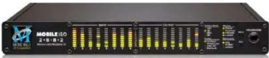
Figure 1.1: Mobile I/O 2882
Prepare the unit for use
Unpack the 2882 and make sure all the parts are there:
• One Mobile I/O 2882 unit
• One IEC Power Cord appropriate for your area
• One 24-volt 48-watt world-ready external power supply
• One 30" IEEE 1394 9-pin to 6-pin FireWire Cable
• One 4.5 meter IEEE 1394 9-pin to 6-pin FireWire Cable
- Two Rack Ears w/ fasteners
- Rubber feet
• MIO Software CD-ROM
• Warranty/Registration Card
Bask in the look and feel of the 2882! Once you're finished, connect the power supply, and connect your monitors to Analog Out 1/2. Many people find it useful to put a pad between their amps or powered monitors and the 2882's outputs; this allows the 2882 to work at full digital resolution without overdriving the amplifiers.
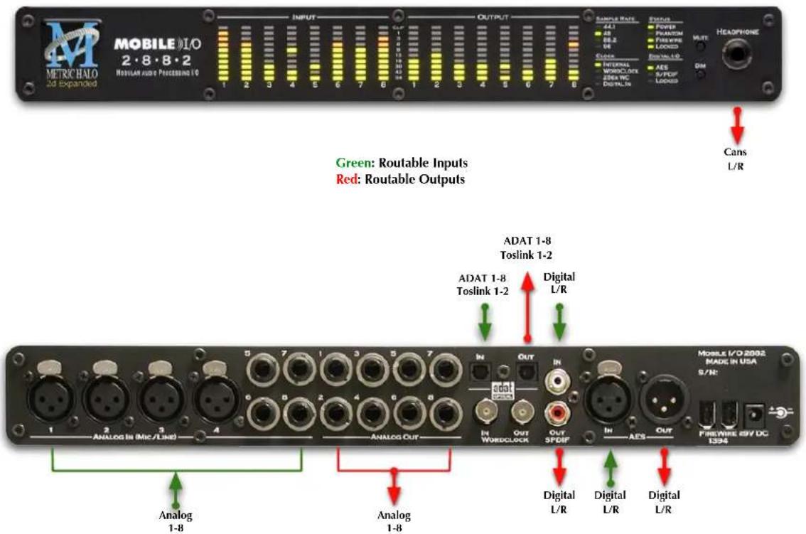
Figure 1.2: 2882 Routing
Connect the 2882
Go to your computer and install the driver and MIO Console application driver from the included disc (this will require a restart). Please see the section on software installation if you need clarification. Connect the FireWire cable between the 2882 and your computer, then go to the System Preferences and select it as the system's sound input and output.
Take a listen
Now we're ready to listen. Don't launch MIO Console yet; open iTunes, turn its volume slider down and play some music. Bring the volume up to a comfortable level, and try the Dim and Mute buttons. Enjoy simply listening to music.
MIO Console
Once you've listened for a while, launch MIO Console. If you're launching MIO Console for the first time, you'll see the factory default setup; more information on this is available in the Saving and Recalling Your Setups section of this manual.
Using Legacy Interfaces
If you are also using an older Legacy interface without a 2d card, open the application's preferences and turn on "Legacy Support". You will need to quit and relaunch MIO Console. All Metric Halo interfaces manufactured since 2007 contain a 2d card.
The Console window
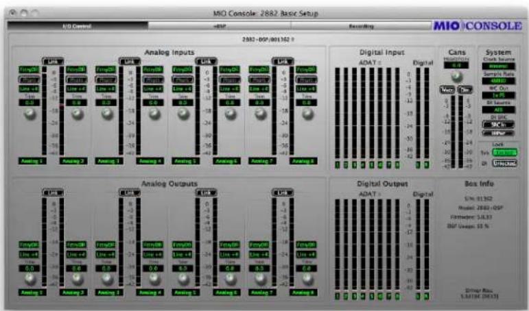
Figure 1.3: Console Window
There are a few important things to look at here. To the right, the "System" column lets you set the clock source, sample rate and whether the wordclock output is 1x or 256x rate. In the "Lock" column you can see if the 2882 is receiving a valid clock on the selected source.
Toward the top of the window you will see the text "2882/xxx" where "xxx" is the serial number of the box. By clicking on this you will get a menu of options for removal of offline boxes (you shouldn't have any at this point).
The I/O Control tab has metering and control for the analog I/O. You can link stereo pairs, set operating levels and gain. The I/O Control tab is synchronized with the Front Panel; changes in one place are reflected in the other. There is also metering for digital I/O. If you click on the +DSP tab, you have access to a "Virtual" DSP area. Next is the "Recording" tab. Any channel that is assigned to a "FW" channel via a direct out or bus output is available for recording via MIO Console's Record Panel.
The Mixer window

Figure 1.4: Mixer Window
The Mixer window presents you with a familiar interface to the 2882. At the top of every channelstrip is a pulldown list of available sources. For analog inputs you can select the input type, enable phantom power and set gain. Below the head-amp area is the Character menu. This lets you select any of our DSP based circuit emulations for your inputs, busses and outputs. Some are very subtle, so you may want to try different Characters on different signals. Next is a pre-insert direct out. This lets you route the channelstrip to any unused analog or digital output, as well as to "FW" channels. The FireWire channels allow you to return audio from the 2882 to your computer.
Below Character are the insert slots. Here you can insert plugins, route to sends (additional busses), call up macros (pre-made DSP processors) and instantiate graphs. A graph is a "DSP playground" where you can build your own signal processing chains and save them for later recall. You'll notice that there is another direct out under the inserts- this one is post-insert. Any signal routed from this direct out has all of your inserted processing applied, whereas the pre-insert direct out doesn't.
The pan control reconfigures depending on the type of channel and the bus that it is assigned to:
- There are no pan controls on a channel assigned to a mono bus.
- Mono input channels will have a pan knob when assigned to stereo or LCR busses.
- Mono input channels assigned to LCRS through 7.1 busses will have joysticks. Right clicking on the joystick will allow you to hard assign the input channel to a specific output channel, i.e. Center.
- Multichannel inputs (stereo and above) have no pan control.
Every input channel has a phase reverse button, as well as solo, mute and record enable (active if assigned to FW). The names of the faders can be changed in the "Configure Mixer" pane available from the Mixer menu. Finally, the pulldown menu at the bottom of the strip lets you assign the input to any available bus. You can find more detail about the controls in the channelstrips in the Input Strip Details section of the MIO Console overview.
If you go to the Window menu and select "Show Monitor Control Window" the software Monitor Controller will appear. It is highly flexible, and controls the analog level control in the 2882. There is a wealth of knowledge in the Monitor Controller section on how to set up and use the Monitor Controller.
You should now be in a good position to fire up a native DAW and put the 2882 through its paces. Select the 2882 as your audio interface in your DAW's hardware configuration; the analog inputs will be available on inputs 1-8, ADAT will be available on 9-16 and AES/Spdif digital inputs will be available on 17-18 (as determined by the FW channel assignments). Send your DAW's signal to outputs 1/2 and it will come into the 2882 on DAW 1/2. By using the FW channels to send audio to your DAW and the DAW input returns from your computer you have a virtual patchbay to route audio between your DAW and the 2882.
The 2882 and surround
If you're working in surround, it's easy to configure the 2882 for monitoring and processing. Go to the Mixer menu and select "Configure Mixer". At the top of the pane you'll see the "Main" bus, which is stereo and a Master. Master busses are routed to outputs, while Aux busses are routed back into Master busses (for returns, subgroups, etc.). If you click on the bus type you can change it from "Stereo" to whatever width you need; let's say you're working in 5.1. Select "5.1" and hit configure. Voila! All the mono channels now have joysticks instead of pan knobs, and the Main bus is automatically routed to Analog 1-6. Your DAW is still coming in on two channels, but that's easy to change. Go to the top of the DAW 1/2 channelstrip and click on the assignment pulldown. You have the choice of a mono channel, or a 6 channel strip. By selecting DAW 1-6, your audio will come into the 2882 as positioned by your host. Your other choice would be to make this channel mono, and add five more channelstrips via the Mixer menu. This way you can position your audio with the MIO Mixer.

Figure 1.5: Surround Mixer
To make it easier to monitor in surround, let's use the Monitor Controller. Click on the assignment pulldown at the bottom of the Main bus and select "N/C" to remove the assignment to the analog outs. Now hold down the shift key and click the pulldown again; the Main bus was "multed" to the headphones in the template which means it was routed to Analog 1/2 and the Cans at the same time. Now that we're working in surround, the Cans aren't as useful. By holding down Shift and clicking on the Cans-Digital 4 line, we clear the mult. Now click on the pulldown one more time and select "Add to Monitor Controller". Go to the Window menu and select "Show Monitor Control Window".
The Monitor Controller shows the Main bus is the Monitor Source, but we need to define an output. Click the "Configure" button to open the MC pane. Click "+" under Monitor Paths and you'll have the option to add a Monitor Output. Give the path a name (like "Surround") and select 5.1 as the bus type. Now you can assign your output channels. If you want to select your outputs sequentially, a shortcut is to hold down the Option
key when selecting the first channel. For example, hold down Option and click the assignment for the Left channel and select Analog 1. The rest of the channels will fill in automatically.

Figure 1.6: Configuring the Monitor Controller
Choose "OK" and you now have a surround monitor controller!
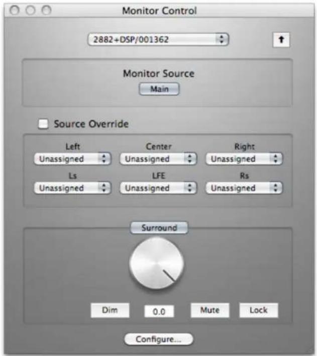
Figure 1.7: The Configured Monitor Controller
Unleash the DSP
Every 2882 is based on the 2d processing card and may be purchased with an optional +DSP license. The +DSP can be added by the user at any time (except on Legacy interfaces); if you purchased a unit with the +DSP license, it is preinstalled in the hardware and ready to go. This gives you powerful processing in the box, and the ability to work with processing and monitoring whose latency is equivalent to the converter overhead.
There are two ways to access the DSP:
- You can insert processes directly in the mixer strip inserts; this works well for standalone processes like eq, compressors, etc.
- Insert a graph +DSP ONLY. This lets you chain plugins together, use them in parallel, and create configurations that would be difficult (or impossible) with other platforms.
You should definitely check out the following processes:
- MIOStrip: Gating, EQ and compression powerhouse.
- Character: The sound of different analog circuits and devices available on any input, output or bus. Some can be subtle, so stack them across an entire mix. Try SoftSat on your main bus; you'll like it.
- Haloverb: Great sounding reverb, doesn't use any CPU from your host. What's not to love?
You should read the DSP Implementation section to learn more about how to work with DSP, and the +DSP documentation details the over 100 plug-ins available with the +DSP license.
This should get you started with the 2882!
Additional Resources
The 2882 is an exceptionally deep product, and there are many features, applications and workflows to discover. We have published a series of technical notes and tutorial movies that go in depth about the Mobile I/Oplatform. Please take a look at them to learn more about the 2882: http://mhsecure.com/metric_halo/support/tutorials.html
2. ULN-2 Quick Start Guide

Figure 2.1: Mobile I/O ULN-2
Prepare the unit for use
Unpack the ULN-2 and make sure all the parts are there:
• One Mobile I/O 2882 unit
• One IEC Power Cord appropriate for your area
• One 24-volt 48-watt world-ready external power supply
• One 30" IEEE 1394 9-pin to 6-pin FireWire Cable
• One 4.5 meter IEEE 1394 9-pin to 6-pin FireWire Cable
- Two Rack Ears w/ fasteners
- Rubber feet
• MIO Software CD-ROM
• Warranty/Registration Card
Bask in the look and feel of the ULN-2! Once you're finished, connect the power supply, and connect your monitors to Monitor Out L/R.


Figure 2.2: ULN-2 Routing
Connect the ULN-2
Go to your computer and install the driver and MIO Console application driver from the included disc (this will require a restart). Please see the section on software installation if you need clarification. Connect the FireWire cable between the ULN-2 and your computer, then go to the System Preferences and select it as the system's sound input and output.
Take a listen
Don't launch MIO Console yet; turn the Monitor level on the front panel down, open iTunes and play some music. Bring the Monitor level up to a comfortable level and listen.
MIO Console
Once you've listened for a while, launch MIO Console. If you're launching MIO Console for the first time, you'll see the factory default setup; more information on this is available in the Saving and Recalling Your Setups section of this manual.
Using Legacy Interfaces
If you are also using an older Legacy interface without a 2d card, open the application's preferences and turn on "Legacy Support". You will need to quit and relaunch MIO Console. All Metric Halo interfaces manufactured since 2007 contain a 2d card.
The Console window

Figure 2.3: Console Window
There are a few important things to look at here. To the right, the "System" column lets you set the clock source, sample rate and whether the wordclock output is 1x or 256x rate. In the "Lock" column you can see if the ULN-2 is receiving a valid clock on the selected source.
Toward the top of the window you will see the text "ULN-2/xxx" where "xxx" is the serial number of the box. By clicking on this you will get a menu of options for removal of offline boxes (you shouldn't have any at this point).
The I/O Control tab has metering for the analog and digital I/O. If you click on the +DSP tab, you have access to a "Virtual" DSP area. Next is the "Recording" tab. Any channel that is assigned to a "FW" channel via a direct out or bus output is available for recording via MIO Console's Record Panel.
The Mixer window
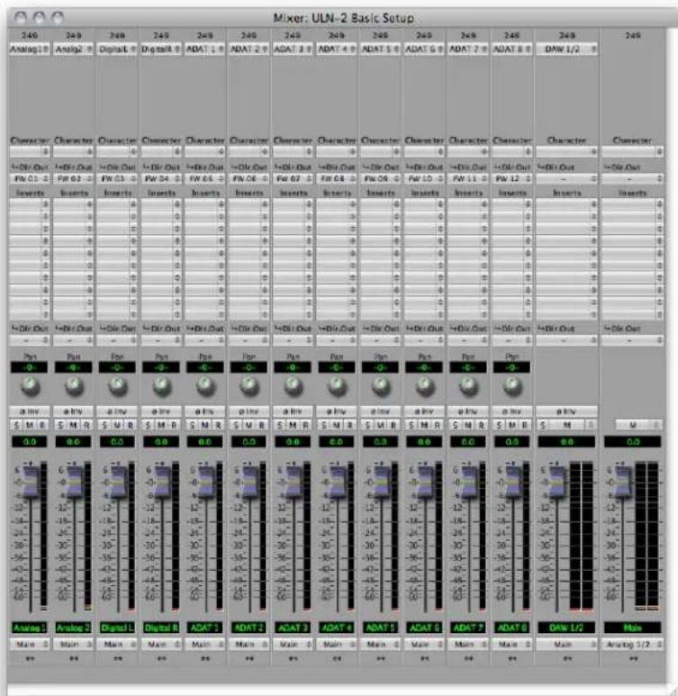
Figure 2.4: Mixer Window
The Mixer window presents you with a familiar interface to the ULN-2. At the top of every channelstrip is a pulldown list of available sources. Below that is the Character menu. This lets you select any of our DSP based circuit emulations for your inputs, busses and outputs. Some are very subtle, so you may want to try different Characters on different signals. Next is a pre-insert direct out. This lets you route the channelstrip to any unused analog or digital output, as well as to "FW" channels. The FireWire channels allow you to return audio from the ULN-2 to your computer.
Below Character are the insert slots. Here you can insert plugins, route to sends (additional busses), call up macros (pre-made DSP processors) and instantiate graphs. A graph is a "DSP playground" where you can build your own signal processing chains and save them for later recall. You'll notice that there is another direct out under the inserts- this one is post-insert. Any signal routed from this direct out has all of your inserted processing applied, whereas the pre-insert direct out doesn't.
The pan control reconfigures depending on the type of channel and the bus that it is assigned to:
- There are no pan controls on a channel assigned to a mono bus.
-
Mono input channels will have a pan knob when assigned to stereo or LCR busses.
-
Mono input channels assigned to LCRS through 7.1 busses will have joysticks. Right clicking on the joystick will allow you to hard assign the input channel to a specific output channel, i.e. Center.
- Multichannel inputs (stereo and above) have no pan control.
Keep in mind that the while ULN-2 is primarily a stereo device in the analog domain, it is possible to work in multichannel by using the optical I/O.
Every input channel has a phase reverse button, as well as solo, mute and record enable (active if assigned to FW). The names of the faders can be changed in the "Configure Mixer" pane available from the Mixer menu. Finally, the pulldown menu at the bottom of the strip lets you assign the input to any available bus. You can find more detail about the controls in the channelstrips in the Input Strip Details section of the MIO Console overview.
If you go to the Window menu and select "Show Monitor Control Window" you will be presented with our software Monitor Controller. It is highly flexible, and controls the analog level control in the ULN-2. There is a wealth of knowledge in the Monitor Controller section on how to set up and use the Monitor Controller.
You should now be in a good position to fire up a native DAW and put the ULN-2 through its paces. Select the ULN-2 as your audio interface; the analog inputs will be inputs 1-2, AES/Spdif digital inputs will be 3-4 and ADAT will be 5-12 (as determined by the FW channel assignments). Send your DAW's signal to outputs 1/2 and it will come into the ULN-2 on DAW 1/2. By using the FW channels to send audio to your DAW and the DAW input returns from your computer you have a virtual patchbay to route audio between your DAW and the ULN-2.
The ULN-2 and surround
If you're working in surround it's easy to configure the ULN-2 for processing and monitoring via an ADAT based D/A. Go to the Mixer menu and select "Configure Mixer". At the top of the pane you'll see the "Main" bus, which is stereo and a Master. Master busses are routed to outputs, while Aux busses are routed back into Master busses (for returns, subgroups, etc.). If you click on the bus type you can change it from "Stereo" to whatever width you need; let's say you're working in 5.1. Select "5.1" and hit configure. Voila! All the mono channels now have joysticks instead of pan knobs, and the Main bus is automatically routed to Analog 1-6. Your DAW is still coming in on two channels, but that's easy to change. Go to the top of the DAW 1/2 channelstrip and click on the assignment pulldown. You have the choice of a mono channel, or a 6 channel strip. By selecting DAW 1-6, your audio will come into the ULN-2 as positioned by your host. Your other choice would be to make this channel mono, and add five more channelstrips via the Mixer menu. This way you can position your audio with the MIO Mixer.

Figure 2.5: Surround Mixer
To make it easier to monitor in surround, let's use the Monitor Controller. Click on the assignment pulldown at the bottom of the Main bus and select "N/C" to remove the assignment to the analog outs. Now hold down the shift key and click the pulldown again; the Main bus was "multed" to the Monitor bus in the template which means it was routed to Analog 1/2 and the Monitor at the same time. Now that we're working in surround, we need to send to the ADAT outs. By holding down shift and clicking on the Monitor L-n/c line, we clear the mult. Now click on the pulldown one more time and select "Add to Monitor Controller". Go to the Window menu and select "Show Monitor Control Window".
The Monitor Controller shows the Main bus is the Monitor Source, but we need to define an output. Click the "Configure" button to open the MC pane. Click the "+" under Monitor Paths and you'll have the option to add a Monitor Output. Give the path a name (like "Surround") and select 5.1 as the bus type. Now you can assign your output channels. If you want to select your outputs sequentially, a shortcut is to hold down the Option key when selecting the first channel. For example, hold down Option and click the assignment for the Left channel and select ADAT 1. The rest of the channels will fill in automatically.

Figure 2.6: Configuring the Monitor Controller
Choose "OK" and you now have a surround monitor controller!

Figure 2.7: The Configured Monitor Controller
Unleash the DSP
Every ULN-2 is based on the 2d processing card and may be purchased with an optional +DSP license. The +DSP can be added by the user at any time (except on Legacy interfaces); if you purchased a unit with the +DSP license, it is preinstalled in the hardware and ready to go. This gives you powerful processing in the box, and the ability to work with processing and monitoring whose latency is equivalent to the converter overhead.
There are two ways to access the DSP:
- You can insert processes directly in the mixer strip inserts; this works well for standalone processes like eq, compressors, etc.
- Insert a graph +DSP ONLY. This lets you chain plugins together, use them in parallel, and create configurations that would be difficult (or impossible) with other platforms.
You should definitely check out the following processes:
- MIOStrip: Gating, EQ and compression powerhouse.
- Character: The sound of different analog circuits and devices available on any input, output or bus. Some can be subtle, so stack them across an entire mix. Try SoftSat on your main bus; you'll like it.
- Haloverb: Great sounding reverb, doesn't use any CPU from your host. What's not to love?
You should read the DSP Implementation section to learn more about how to work with DSP, and the +DSP documentation details the over 100 plug-ins available with the +DSP license.
This should get you started with the ULN-2!
Additional Resources
The ULN-2 is an exceptionally deep product, and there are many features, applications and workflows to discover. We have published a series of technical notes and tutorial movies that go in depth about the Mobile I/O platform. Please take a look at them to learn more about the ULN-2: http://mhsecure.com/metric_halo/support/tutorials.html
3. LIO-8 Quick Start Guide

Figure 3.1: LIO-8
Prepare the unit for use
Unpack the LIO-8 and make sure all the parts are there:
- One LIO-8 unit
• One IEC Power Cord appropriate for your area
• One 24-volt 48-watt world-ready external power supply
• One 30" IEEE 1394 9-pin to 6-pin FireWire Cable
• One 4.5 meter IEEE 1394 9-pin to 6-pin FireWire Cable - Two Rack Ears w/ fasteners
- Rubber feet
- Configuration jumpers
• MIO Software CD-ROM
• Warranty/Registration Card
Bask in the look and feel of the LIO-8! Once you're finished, connect the power supply. Now connect your input and output cables along with your monitors and signal sources. Your monitors should be connected to Analog Out 1/2, either via a DB25 cable or the 1/4" TRS jacks. Turn the unit on using the front panel switch. Cool, isn't it?

Figure 3.2: LIO-8 Routing
Connect the LIO-8
Go to your computer and install the driver and MIO Console application driver from the included disc (this will require a restart). Please see the section on software installation if you need clarification. Connect the FireWire cable between the LIO-8 and your computer, then go to the System Preferences and select it as the system's sound input and output.
Get familiar with the front panel
Look at the LED under the Monitor Control encoder; the "Monitor Control" LED should be illuminated. If "Cans" is lit, push the encoder to switch it (all encoders have shaft buttons). The LED should be green; if it is yellow, push the "Dim" button. If it is red push the "Mute" button. Now that you're sure that you're looking at the Monitor Controller and that is not dimmed and unmuted, turn it down. The meters are now showing the gain value of the Monitor Controller. This will happen any time you adjust an encoder.
Take a listen
Now we're ready to listen. Don't launch MIO Console yet; open iTunes and play some music. Turn up the Monitor Controller to a comfortable level, then try the Dim and Mute buttons again. Next, connect a pair of headphones to the front panel. Push the Mute button to turn off your monitors, then press the Monitor encoder. Turn the level down (you're now controlling the headphone amplifier), then put on your cans and turn up the encoder.
MIO Console
Once you're comfortable with the Monitor Controller and how it works, launch MIO Console. If you're launching MIO Console for the first time, you'll see the factory default setup; more information on this is available in the Saving and Recalling Your Setups section of this manual.
Using Legacy Interfaces
If you are also using an older Legacy interface without a 2d card, open the application's preferences and turn on "Legacy Support". You will need to quit and relaunch MIO Console. All Metric Halo interfaces manufactured since 2007 contain a 2d card.
The Console window

Figure 3.3: Console Window
There are a few important things to look at here. To the right, the "System" column lets you set the clock source, sample rate and whether the wordclock output is 1x or 256x rate. In the "Lock" column you can see if the LIO-8 is receiving a valid clock on the selected source.
Toward the top of the window you will see the text "LIO-8/xxx" where "xxx" is the serial number of the box. By clicking on this you will get a menu of options for removal of offline boxes (you shouldn't have any at this point).
The I/O Control tab has metering and control for the analog I/O. You can link stereo pairs, set operating levels and gain. The I/O Control tab is synchronized with the Front Panel; changes in one place are reflected in the other. There is also metering for digital I/O. If you click on the +DSP tab, you have access to a "Virtual" DSP area. Next is the "Recording" tab. Any channel that is assigned to a "FW" channel via a direct out or bus output is available for recording via MIO Console's Record Panel.
The Mixer window
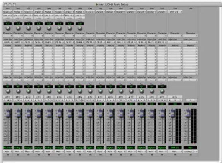
Figure 3.4: Mixer Window
The Mixer window presents you with a familiar interface to the LIO-8. At the top of every channelstrip is a pulldown list of available sources. For analog inputs you can select the input type, enable phantom power and set gain. Below the head-amp area is the Character menu. This lets you select any of our DSP based circuit emulations for your inputs, busses and outputs. Some are very subtle, so you may want to try different Characters on different signals. Next is a pre-insert direct out. This lets you route the channelstrip to any unused analog or digital output, as well as to "FW" channels. The FireWire channels allow you to return audio from the LIO-8 to your computer.
Below Character are the insert slots. Here you can insert plugins, route to sends (additional busses), call up macros (pre-made DSP processors) and instantiate graphs. A graph is a "DSP playground" where you can build your own signal processing chains and save them for later recall. You'll notice that there is another direct out under the inserts- this one is post-insert. Any signal routed from this direct out has all of your inserted processing applied, whereas the pre-insert direct out doesn't.
The pan control reconfigures depending on the type of channel and the bus that it is assigned to:
- There are no pan controls on a channel assigned to a mono bus.
- Mono input channels will have a pan knob when assigned to stereo or LCR busses.
- Mono input channels assigned to LCRS through 7.1 busses will have joysticks. Right clicking on the joystick will allow you to hard assign the input channel to a specific output channel, i.e. Center.
- Multichannel inputs (stereo and above) have no pan control.
Every input channel has a phase reverse button, as well as solo, mute and record enable (active if assigned to FW). The names of the faders can be changed in the "Configure Mixer" pane available from the Mixer menu. Finally, the pulldown menu at the bottom of the strip lets you assign the input to any available bus. You can find more detail about the controls in the channelstrips in the Input Strip Details section of the MIO Console overview.
If you go to the Window menu and select "Show Monitor Control Window" the software Monitor Controller will appear. It is highly flexible, and controls the analog level control in the LIO-8. There is a wealth of knowledge in the Monitor Controller section on how to set up and use the Monitor Controller.
You should now be in a good position to fire up a native DAW and put the LIO-8 through its paces. Select the LIO-8 as your audio interface; the analog inputs will be inputs 1-8, digital inputs will be 9-16 (as determined by the FW channel assignments). Send your DAW's signal to outputs 1/2 and it will come into the LIO-8 on DAW 1/2. By using the FW channels to send audio to your DAW and the DAW input returns from your computer you have a virtual patchbay to route audio between your DAW and the LIO-8.
The LIO-8 and surround
If you're working in surround, it's easy to configure the LIO-8 for monitoring and processing. Go to the Mixer menu and select "Configure Mixer". At the top of the pane you'll see the "Main" bus, which is stereo and a Master. Master busses are routed to outputs, while Aux busses are routed back into Master busses (for returns, subgroups, etc.). If you click on the bus type you can change it from "Stereo" to whatever width you need; let's say you're working in 5.1. Select "5.1" and hit configure. Voila! All the mono channels now have joysticks instead of pan knobs, and the Main bus is automatically routed to Analog 1-6. Your DAW is still coming in on two channels, but that's easy to change. Go to the top of the DAW 1/2 channelstrip and click on the assignment pulldown. You have the choice of a mono channel, or a 6 channel strip. By selecting DAW 1-6, your audio will come into the LIO-8 as positioned by your host. Your other choice would be to make this channel mono, and add five more channelstrips via the Mixer menu. This way you can position your audio with the MIO Mixer.
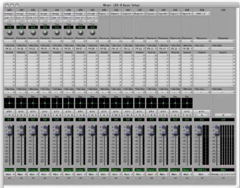
Figure 3.5: Surround Mixer
To make it easier to monitor in surround, let's use the Monitor Controller. Click on the assignment pulldown at the bottom of the Main bus and select "N/C" to remove the assignment to the analog outs. Now hold down the shift key and click the pulldown again; the Main bus was "multed" to the headphones in the template which means it was routed to Analog 1/2 and the Cans at the same time. Now that we're working in surround, the Cans aren't as useful. By holding down Shift and clicking on the Cans-Digital 4 line, we clear the mult. Now click on the pulldown one more time and select "Add to Monitor Controller". Go to the Window menu and select "Show Monitor Control Window".
The Monitor Controller shows the Main bus is the Monitor Source, but we need to define an output. Click the "Configure" button to open the MC pane. Click "+" under Monitor Paths and you'll have the option to add a Monitor Output. Give the path a name (like "Surround") and select 5.1 as the bus type. Now you can assign
your output channels. If you want to select your outputs sequentially, a shortcut is to hold down the Option key when selecting the first channel. For example, hold down Option and click the assignment for the Left channel and select Analog 1. The rest of the channels will fill in automatically. They default to Monitor level, which is optimized for connecting to self powered monitors or amplifiers. If you are connecting to another device like a mixing console you can change this to Line.
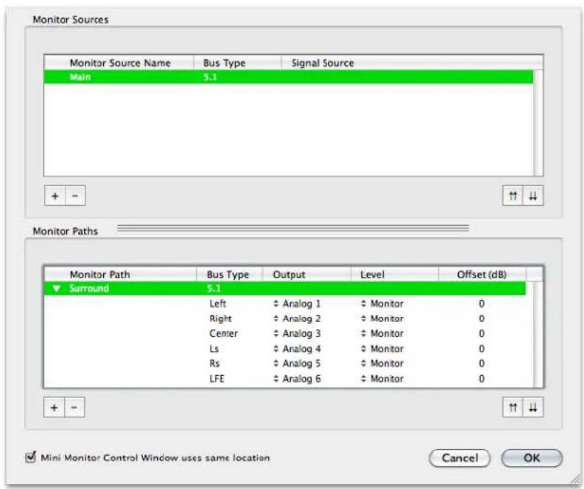
Figure 3.6: Configuring the Monitor Controller
Choose "OK" and you now have a surround monitor controller!
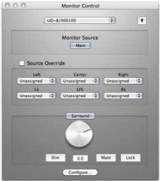
Figure 3.7: The Configured Monitor Controller
Unleash the DSP
Every LIO-8 is based on the 2d processing card and may be purchased with an optional +DSP license. The +DSP can be added by the user at any time (except on Legacy interfaces); if you purchased a unit with the +DSP license, it is preinstalled in the hardware and ready to go. This gives you powerful processing in the box, and the ability to work with processing and monitoring whose latency is equivalent to the converter overhead.
There are two ways to access the DSP:
- You can insert processes directly in the mixer strip inserts; this works well for standalone processes like eq, compressors, etc.
- Insert a graph +DSP ONLY. This lets you chain plugins together, use them in parallel, and create configurations that would be difficult (or impossible) with other platforms.
You should definitely check out the following processes:
- MIOStrip: Gating, EQ and compression powerhouse.
- Character: The sound of different analog circuits and devices available on any input, output or bus. Some can be subtle, so stack them across an entire mix. Try SoftSat on your main bus; you'll like it.
- Haloverb: Great sounding reverb, doesn't use any CPU from your host. What's not to love?
You should read the DSP Implementation section to learn more about how to work with DSP, and the +DSP documentation details the over 100 plug-ins available with the +DSP license.
This should get you started with the LIO-8!
Additional Resources
The LIO-8 is an exceptionally deep product, and there are many features, applications and workflows to discover. We have published a series of technical notes and tutorial movies that go in depth about the Mobile
I/O platform. Please take a look at them to learn more about the LIO-8: http://mhsecure.com/metric_halo/support/tutorials.html
4. ULN-8 Quick Start Guide

Figure 4.1: ULN-8
Prepare the unit for use
Unpack the ULN-8 and make sure all the parts are there:
- One ULN-8 unit
• One IEC Power Cord appropriate for your area
• One 24-volt 48-watt world-ready external power supply
• One 30" IEEE 1394 9-pin to 6-pin FireWire Cable
• One 4.5 meter IEEE 1394 9-pin to 6-pin FireWire Cable - Two Rack Ears w/ fasteners
- Rubber feet
- Configuration jumpers
• MIO Software CD-ROM
• Warranty/Registration Card
Bask in the look and feel of the ULN-8! Once you're finished, connect the power supply. Now connect your input and output cables along with your monitors and signal sources. Your monitors should be connected to Analog Out 1/2, either via a DB25 cable or the 1/4st TRS jacks. Turn the unit on using the front panel switch. Cool, isn't it?
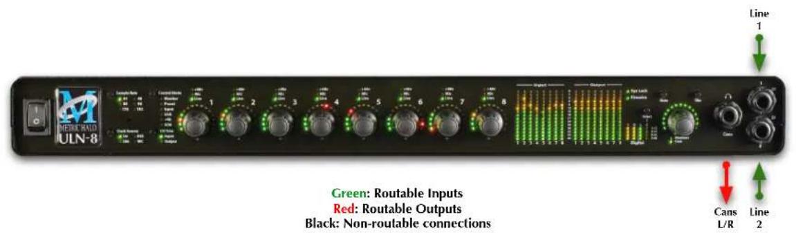

Figure 4.2: ULN-8 Routing
Connect the ULN-8
Go to your computer and install the driver and MIO Console application driver from the included disc (this will require a restart). Please see the section on software installation if you need clarification. Connect the FireWire cable between the ULN-8 and your computer, then go to the System Preferences and select it as the system's sound input and output.
Get familiar with the front panel
Look at the LED under the Monitor Control encoder; the "Monitor Control" LED should be illuminated. If "Cans" is lit, push the encoder to switch it (all encoders have shaft buttons). The LED should be green; if it is yellow, push the "Dim" button. If it is red push the "Mute" button. Now that you're sure that you're looking at the Monitor Controller and that is not dimmed and unmuted, turn it down. The meters are now showing the gain value of the Monitor Controller. This will happen any time you adjust an encoder.
Take a listen
Now we're ready to listen. Don't launch MIO Console yet; open iTunes and play some music. Turn up the Monitor Controller to a comfortable level, then try the Dim and Mute buttons again. Next, connect a pair of headphones to the front panel. Push the Mute button to turn off your monitors, then press the Monitor encoder. Turn the level down (you're now controlling the headphone amplifier), then put on your cans and turn up the encoder.
MIO Console
Once you're comfortable with the Monitor Controller and how it works, launch MIO Console. If you're launching MIO Console for the first time, you'll see the factory default setup; more information on this is available in the Saving and Recalling Your Setups section of this manual.
Using Legacy Interfaces
If you are also using an older Legacy interface without a 2d card, open the application's preferences and turn on "Legacy Support". You will need to quit and relaunch MIO Console. All Metric Halo interfaces manufactured since 2007 contain a 2d card.
The Console window

Figure 4.3: Console Window
There are a few important things to look at here. To the right, the "System" column lets you set the clock source, sample rate and whether the wordclock output is 1x or 256x rate. In the "Lock" column you can see if the ULN-8 is receiving a valid clock on the selected source and use the "DI" buttons to select which AES input pair should be used as a clock source if you are clocking via "Digital".
Toward the top of the window you will see the text "ULN-8/xxx" where "xxx" is the serial number of the box. By clicking on this you will get a menu of options, including "Front Panel Prefs". If you select this you will bring up a pane that will let you tailor the front panel to your liking. You can also remove offline boxes (you shouldn't have any at this point).
The I/O Control tab has metering and control for the analog I/O. You can link stereo pairs, set operating levels and gain. The I/O Control tab is synchronized with the Front Panel; changes in one place are reflected in the other. There is also metering for digital I/O. If you click on the +DSP tab, you have access to a "Virtual" DSP area. Next is the "Recording" tab. Any channel that is assigned to a "FW" channel via a direct out or bus output is available for recording via MIO Console's Record Panel.
The Mixer window

Figure 4.4: Mixer Window
The Mixer window presents you with a familiar interface to the ULN-8. At the top of every channelstrip is a pulldown list of available sources. For analog inputs you can select the input type, enable phantom power and set gain. Below the head-amp area is the Character menu. This lets you select any of our DSP based circuit emulations for your inputs, busses and outputs. Some are very subtle, so you may want to try different Characters on different signals. Next is a pre-insert direct out. This lets you route the channelstrip to any unused analog or digital output, as well as to "FW" channels. The FireWire channels allow you to return audio from the ULN-8 to your computer.
Below Character are the insert slots. Here you can insert plugins, route to sends (additional busses), call up macros (pre-made DSP processors) and instantiate graphs. A graph is a "DSP playground" where you can build your own signal processing chains and save them for later recall. You'll notice that there is another direct out under the inserts- this one is post-insert. Any signal routed from this direct out has all of your inserted processing applied, whereas the pre-insert direct out doesn't.
The pan control reconfigures depending on the type of channel and the bus that it is assigned to:
- There are no pan controls on a channel assigned to a mono bus.
- Mono input channels will have a pan knob when assigned to stereo or LCR busses.
- Mono input channels assigned to LCRS through 7.1 busses will have joysticks. Right clicking on the joystick will allow you to hard assign the input channel to a specific output channel, i.e. Center.
- Multichannel inputs (stereo and above) have no pan control.
Every input channel has a phase reverse button, as well as solo, mute and record enable (active if assigned to FW). The names of the faders can be changed in the "Configure Mixer" pane available from the Mixer menu. Finally, the pulldown menu at the bottom of the strip lets you assign the input to any available bus. You can find more detail about the controls in the channelstrips in the Input Strip Details section of the MIO Console overview.
If you go to the Window menu and select "Show Monitor Control Window" you will be presented with our software Monitor Controller. It is highly flexible, and controls the analog level control in the ULN-8. There is a wealth of knowledge in the Monitor Controller section on how to set up and use the Monitor Controller.
You should now be in a good position to fire up a native DAW and put the ULN-8 through its paces. Select the ULN-8 as your audio interface; the analog inputs will be inputs 1-8, digital inputs will be 9-16 (as determined by the FW channel assignments). Send your DAW's signal to outputs 1/2 and it will come into the ULN-8 on DAW 1/2. By using the FW channels to send audio to your DAW and the DAW input returns from your computer you have a virtual patchbay to route audio between your DAW and the ULN-8.
The ULN-8 and surround
If you're working in surround, it's easy to configure the ULN-8 for monitoring and processing. Go to the Mixer menu and select "Configure Mixer". At the top of the pane you'll see the "Main" bus, which is stereo and a Master. Master busses are routed to outputs, while Aux busses are routed back into Master busses (for returns, subgroups, etc.). If you click on the bus type you can change it from "Stereo" to whatever width you need; let's say you're working in 5.1. Select "5.1" and hit configure. Voila! All the mono channels now have joysticks instead of pan knobs, and the Main bus is automatically routed to Analog 1-6. Your DAW is still coming in on two channels, but that's easy to change. Go to the top of the DAW 1/2 channelstrip and click on the assignment pulldown. You have the choice of a mono channel, or a 6 channel strip. By selecting DAW 1-6, your audio will come into the ULN-8 as positioned by your host. Your other choice would be to make this channel mono, and add five more channelstrips via the Mixer menu. This way you can position your audio with the MIO Mixer.

Figure 4.5: Surround Mixer
To make it easier to monitor in surround, let's use the Monitor Controller. Click on the assignment pulldown at the bottom of the Main bus and select "N/C" to remove the assignment to the analog outs. Now hold down the shift key and click the pulldown again; the Main bus was "multed" to the headphones in the template which means it was routed to Analog 1/2 and the Cans at the same time. Now that we're working in surround, the Cans aren't as useful. By holding down Shift and clicking on the Cans-Digital 4 line, we clear the mult. Now click on the pulldown one more time and select "Add to Monitor Controller". Go to the Window menu and select "Show Monitor Control Window".
The Monitor Controller shows the Main bus is the Monitor Source, but we need to define an output. Click the "Configure" button to open the MC pane. Click "+" under Monitor Paths and you'll have the option to add a Monitor Output. Give the path a name (like "Surround") and select 5.1 as the bus type. Now you can assign
your output channels. If you want to select your outputs sequentially, a shortcut is to hold down the Option key when selecting the first channel. For example, hold down Option and click the assignment for the Left channel and select Analog 1. The rest of the channels will fill in automatically. They default to Monitor level, which is optimized for connecting to self powered monitors or amplifiers. If you are connecting to another device like a mixing console you can change this to Line.

Figure 4.6: Configuring the Monitor Controller
Choose "OK" and you now have a surround monitor controller!
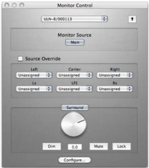
Figure 4.7: The Configured Monitor Controller
Unleash the DSP
Every ULN-8 is based on the 2d processing card and includes a +DSP license. This gives you powerful processing in the box, and the ability to work with processing and monitoring whose latency is equivalent to the converter overhead.
There are two ways to access the DSP:
- You can insert processes directly in the mixer strip inserts; this works well for standalone processes like eq, compressors, etc.
- Insert a graph +DSP ONLY. This lets you chain plugins together, use them in parallel, and create configurations that would be difficult (or impossible) with other platforms.
You should definitely check out the following processes:
- MIOStrip: Gating, EQ and compression powerhouse.
- Character: The sound of different analog circuits and devices available on any input, output or bus. Some can be subtle, so stack them across an entire mix. Try SoftSat on your main bus; you'll like it.
- Haloverb: Great sounding reverb, doesn't use any CPU from your host. What's not to love?
You should read the DSP Implementation section to learn more about how to work with DSP, and the +DSP documentation details the over 100 plug-ins available with the +DSP license.
This should get you started with the ULN-8!
Additional Resources
The ULN-8 is an exceptionally deep product, and there are many features, applications and workflows to discover. We have published a series of technical notes and tutorial movies that go in depth about the Mobile
I/O platform. Please take a look at them to learn more about the ULN-8: http://mhsecure.com/metric_halo/support/tutorials.html
Part II. Interfaces
Table of Contents
- 2882 Users Guide .... 56
2882 Overview 56
What it is 56
What it has 56
What you need to use it 57
What comes with it 57
Using the 2882 Hardware 58
2882 Front Panel 58
2882 Rear Panel 59
2882 Signal Flow 60
Making connections to the 2882 60
2882 Specifications 65
- ULN-2 Users Guide 69
ULN-2 Overview 69
What it is 69
What it has 69
What you need to use it 70
What comes with it 70
Using the ULN-2 Hardware 71
ULN-2 Front Panel 71
ULN-2 Rear Panel 73
Signal Flow 74
Making connections to the ULN-2 74
ULN-2 Specifications 79
- LIO-8 Users Guide 84
LIO-8 Overview 84
What it is 84
What it has 84
What you need to use it 85
What comes with it 85
Using the LIO-8 Hardware 87
LIO-8 Front Panel 87
LIO-8 Rear Panel 88
Signal Flow 89
Making connections to the LIO-8 89
LIO-8 Specifications 92
- ULN-8 Users Guide 97
ULN-8 Overview 97
What it is 97
What it has 97
What you need to use it 98
What comes with it 98
Using the ULN-8 Hardware 100
ULN-8 Front Panel 100
ULN-8 Rear Panel 101
Signal Flow 102
Making connections to the ULN-8 102
ULN-8 Specifications 105
- ULN/LIO-8 Front Panel Guide 111
Front Panel Overview 111
Sample Rate Indicators and Control 111
Interfaces
Clock Source Indicators and Control 112
Control Mode Indicators and Selector 112
I/O Trim Mode Indicators and Selector 113
Channel Mode Indicators 113
Per Channel Control Knobs 114
High Resolution Meters 114
System Status Indicators 116
AES Status Indicators 116
Monitor Control Section 117
Front Panel DI Inputs 117
Control Mode Details 118
Monitor 118
Preset 119
Input 119
Link 119
+48 120
U/M — User Mode 120
Input Trim 120
Meters on the Knobs 121
Output Trim 121
Illumination (Brightness) Adjustment 121
Front Panel Preferences in MIO Console 121
Infrared Remote operation 123
5. 2882 Users Guide
2882 Overview

Figure 5.1: Mobile I/O 2882
What it is
Mobile I/O is a portable, high-quality, modular FireWire-based multi-format audio converter, interface, and processor for professional audio applications. The 2882 model line is equipped with eight balanced analog inputs (4 on XLR and 4 on 1/4" TRS), two channels of Digital I/O (AES/EBU and S/PDIF), eight channels of ADAT® optical I/O support (switchable to 2 channel TOSLINK), and eight balanced analog outputs (1/4" TRS), as well as wordclock in/out and 2 IEEE 1394 FireWire connectors that support 400 Mbs operation. All inputs and outputs are capable of 24-bit/96kHz operation.
What it has
• 18 simultaneous input channels and 20 simultaneous output channels
• full 24 bit/96kHz audio
- 8 independent channels of mic-pre with switchable phantom power
- Fully Portable Capabilities – Bus and Battery Powerable
- Rack Mount Kit
• 44.1, 48, 88.2, 96kHz Sampling Rates
• 24 bit 110 dB Dynamic Range A/D converters
• 24 bit 120 dB Dynamic Range D/A converters
- 8 Balanced Analog Inputs – 4 XLR, 4 TRS 1/4"
- 8 Balanced Analog Outputs – 8 TRS 1/4"
- Selectable stereo Digital Inputs AES/EBU or S/PDIF
• Stereo Digital Outputs AES/EBU and S/PDIF
- 8 ADAT® Optical Inputs and Outputs (or 2 TOSLINK)
• Sample Rate Conversion (SRC) on Digital I/O
- Built-in 80-bit, fully interpolated, multi-bus mixer for near-zero latency foldback of all input channels and all DAW busses simultaneously
• Full cross point router for I/O management
• Word Clock 1x, 256x
- Front Panel Metering for Analog Inputs and Outputs
• Full console metering of every channel and mix bus
• Total recall of every console parameter
Options (can be installed before or after purchase)
- +DSP license
What you need to use it
- Computer:
- Any Mac that supports Mac OS X with a FireWire port
• Universal Binary (native support for PPC and Intel)
• Mac OS X 10.3.9 or newer required
• Mac OS X 10.4.11 or newer recommended
• Peripheral FireWire Adaptors supported:
• OHCI compliant PCCard, PCI card, ExpressCard or PCIe card
- Software: All CoreAudio compliant software is compatible with Mobile I/O, including:
- Cubase
- Digital Performer
- GarageBand
- iTunes
• Live - Logic
- Nuendo
- Pro Tools
- PreMaster CD
- soundBlade
- WaveBurner
• and hundreds more...
What comes with it
Your Mobile I/O 2882 package contains the following items:
• One Mobile I/O 2882 unit:
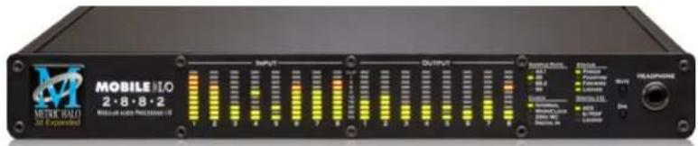
Figure 5.2: Mobile I/O Unit
• One IEC Power Cord appropriate for your area

Figure 5.3: IEC Power Cord
• One 24-volt 48-watt world-ready external power supply

Figure 5.4: External Power Supply
• One 30" IEEE 1394 9-pin to 6-pin FireWire Cable

Figure 5.5: 30" IEEE 1394 9-pin to 6-pin 1394 Cable
• One 4.5 meter IEEE 1394 9-pin to 6-pin FireWire Cable

Figure 5.6: 4.5 meter IEEE 1394 9-pin to 6-pin 1394 Cable
- Two Rack Ears w/ fasteners

Figure 5.7: Rack Ears
• MIO Software CD-ROM
• Warranty/Registration Card
If any of these items are missing from your package when you open it, please contact Metric Halo or your dealer immediately for assistance.
6-pin to 6-pin IEEE 1394 cables are available from MH Direct.
Using the 2882 Hardware
2882 Front Panel

Figure 5.8: 2882 Front Panel
The 2882 front panel provides ten-segment metering for the 8 analog inputs and outputs. The meters are fast PPM peak reading meters with auto-resetting peak holds.
The front panel also provides 2882 system status at a glance:
• Sample Rate (nominal 44.1, 48, 88.2, or 96)
- The Sample Rate is determined from the currently selected clock source so it will accurately indicate the current sample rate, even when the clock source is being provided by an external device.
- Clock source:
- Internal indicates that the system is internally clocked
- Wordclock indicates that system is being clocked from the wordclock input
- 256x WC indicates that the system is being clocked from a 256x clock at the wordclock input
- Digital In indicates that the system is being clocked from the selected digital input (AES or S/PDIF)
• Power — Indicates that the 2882 is receiving power.
- Phantom power — Indicates that at least one of the preamps has the phantom power enabled.
- FireWire — Indicates that the 2882 has been successfully connected to a FireWire bus and has detected the isochronous cycle required to transmit and receive audio.
- Locked — Indicates that the system clock recovery circuit is properly locked to the selected clock source. If this light is not illuminated, the 2882 will not be locked to a clock and will revert to its failsafe internal clock source. Even if the Locked light is not illuminated, the actual sample rate will still be indicated on the front panel display.
• Digital I/O Section:
- The AES and S/PDIF lights are mutually exclusive and indicate which of the two input ports are feeding the Stereo Digital input of 2882. The Locked light indicates when the digital receiver is locked to the incoming digital audio signal.
The Mobile I/O front panel also provides access to the Headphone output and some associated controls. The headphone output jack is a TRS 1/4" jack that provides the Left Channel on the tip, the Right Channel on the ring and the ground return for the two channels on the sleeve. These signals are all ground referred, so they may also be split and fed single-ended (unbalanced) to an external audio device.
The 2882 headphone output is suited to a wide range of impedances. Headphones with lower impedance would be expected to get louder than those with higher impedance.
The Mute and Dim buttons provide instant access to simple level control for the headphone output. The Mute button provides a quick, tactile "panic switch" which mutes the front panel headphone outputs in case of accidental feedback loops and other audio unpleasanties. The Dim button attenuates the front panel headphone output by 18 dB.
2882 Rear Panel

Figure 5.9: 2882 Rear Panel
The Mobile I/O rear panel features:
• 4 channels balanced XLR inputs. Each input has:
• 24-bit 96kHz A/D converters (110dB SNR)
- remote controllable pre-amps with 40 dB of gain
- remote switchable input impedance characteristics
- remote switchable 20dB pad
- remote switchable 48v Phantom power, with 10mA current limit
• 4 channels balanced TRS inputs. Each input has:
• 24-bit 96kHz A/D converters (110dB SNR)
- remote controllable pre-amps with 40 dB of gain
- remote switchable input impedance characteristics
- remote switchable 20dB pad
- remote switchable 48v Phantom power, with 10mA current limit
- 8 channels balanced TRS outputs. Each output has:
• 24-bit 96kHz D/A converters (120dB SNR)
- remote controllable output gain (from -12dBV up)
• TOSLINK connectors for ADAT Optical or Optical SPDIF I/O
- 8 channels of ADAT® lightpipe input (switchable to Optical SPDIF)
- 8 channels of ADAT® lightpipe output (switchable to Optical SPDIF)
• Wordclock input/output on BNC connectors
• 256x Wordclock input/output on BNC connectors
- Stereo S/PDIF input/output on RCA connectors
- Stereo AES/EBU input/output on XLR connectors
• 2 IEEE 1394 (FireWire) ports (400 Mbs)
• 1 2.1mm DC power jack (9v - 30v, center positive, 15 Watts)
2882 Signal Flow
![graph LR A["Analog Input 1-B"] --> B["Pad"] B --> C["Mic/Line Switch"] C --> D["A/D"] D --> E["DSP"] E --> F["D/A"] F --> G["Headphone Amplifier"] G --> H["Headphone Jack"] F --> I["Line Amplifiers"] I --> J["Outputs 1-8"] E --> K["AES"] E --> L["SPDIF"] K --> M["AES"] L --> N["SPDIF"] M --> O["* Op…](/content/2026/05/884165/images/679b6f9ba3ff4ab56d208843d8276cff82b6104dd6b99c4e79656b7b241d2e05.jpg)
Figure 5.10: 2882 Signal Flow
Making connections to the 2882

Figure 5.11: 2882 Routing
Click here for a larger version
There are six classes of connections you can make to the 2882 hardware:
- Analog Audio
- Copper-based Digital Audio
- Optical-based Digital Audio
- Clock Sync
- FireWire
- Power
Analog Audio Connections
The analog I/O connections on the Mobile I/O have been engineered for maximum flexibility in that they support both balanced and unbalanced connections with a wide range of input and output levels and a wide range of matching impedances. This means that Mobile I/O handles sources from mic level to line level and from mic impedance to guitar impedance. With that in mind, there are a number of aspects of the design that you should take into account when interfacing with Mobile I/O.
Whenever possible, use balanced interconnects with Mobile I/O. The performance of balanced interconnects is much higher and much more resistant to noise interference and electrical (power) wiring problems. The expense of balanced interconnects is not substantially higher than unbalanced connections, so if the gear that you are interfacing with supports balanced connection — use it. If you cannot utilize balanced interconnects, there are connection schemes that you can use that will maximize performance.
On input, at line level, it is sufficient to simply use standard unbalanced (TS) connections. If you are interfacing with the Mobile I/O XLR inputs, you will need to ensure that pin 3 is grounded in the unbalanced adapter cable. More information about adjusting the input level can be found in the MIO Console software chapter.
The Mobile I/O XLR inputs are all wired pin 2 hot and the 1/4" inputs are wired Tip hot.
TIP:
To use the 2882 TRS input with guitar or bass, you can simply use a standard TS guitar cable (patch cord) and it will work fine. However, you can take advantage of the balanced input design of the 2882 to get more noise rejection than you thought possible on a guitar input.
In order to do this, you will need to make a pseudo-balanced telescoping shield guitar cable. This can be constructed with a TRS connector, a TS connector and balanced microphone cable. This cable will treat the guitar as a floating balanced source and provide a telescoping shield from the 2882 ground.
![graph LR A["Instrument"] -->|Tip| B["Sleeve"] B --> C["Mobile I/O"] C -->|Ring (Cold)| D["Sleeve Ring Tip"] C -->|Ring (Shield)| E["Tip (Hot)"]](/content/2026/05/884165/images/7ae9f37cece612cc4102b97d067a75525a8908ce0e12ba2e058a4c1071512357.jpg)
Figure 5.12: Telescoping Shield Cable for Instruments
If you want to use the TRS inputs with balanced microphones, you will need an XLR female to 1/4" TRS balanced plug adapter cable. These are available commercially, or you can construct one easily. The connections are Tip to Pin 2, Ring to Pin 3 and Sleeve to Pin 1:

Figure 5.13: XLR to Balanced TRS Cable
On output, the situation is a bit more complex. If you are driving an unbalanced load, you will get the best performance by not connecting the ring of the TRS jack to ground. In order to do this, you can simply use a balanced TRS/TRS connector with the unbalanced gear. You can also construct a special cable with a TRS connector and a TS connector. In this cable, you just let the ring of the TRS connector float:
![graph LR A["NO CONNECTION"] --> B["BALANCED 1/4" TRS CONNECTOR"] B --> C["SLEEVE (SHIELD)"] C --> D["TIP UNBALANCED 1/4" TS CONNECTOR"] D --> E["SLEEVE (SHIELD)"]](/content/2026/05/884165/images/7d90004ec96fc342d44ff5874f5f07493a330a67384962a241ca18cc041c53a9.jpg)
Figure 5.14: TRS to TS Unbalanced Cable
Alternatively, the TS connector can be replaced with an RCA connector for interfacing with gear that has RCA unbalanced interconnects.

Figure 5.15: TRS to RCA Unbalanced Cable
MAKING THE 1/4" CONNECTION
When you connect a 1/4" plug to a 2882 jack, insert it straight and firmly, ensuring that the plug is fully inserted into the jack. If the plug is not fully inserted you will get level shifts, phase flips, distortion, or no sound.
To disconnect a 1/4" plug, firmly pull the plug straight out from the connector body. The connectors on 2882 are stiff, so you may have to exert some force to remove the plug.
MAKING THE XLR CONNECTION
When you connect a Male XLR plug to a 2882 jack, ensure that you have aligned the pins with the connector body and insert firmly until the retention tab clicks.
To disconnect the plug, press the metal retention tab flush against the box, and pull the plug from the 2882.
Output Attenuation
You may find that the 2882's analog outputs are too "hot" for your amps or powered speakers; if you find yourself:
- Turning your amps or speakers down further than normal (barely on)
- Bringing the master fader in MIO Console or the Monitor Control level down more than a few dB
Then you are overdriving the inputs of your monitors. In this case, you should use a pad (also called an inline attenuator) on the outputs of the 2882. You should use a pad with 20-40dB of attenuation. These devices are available through music gear stores or online.
Copper-Based Digital Audio
2882 supports 2 channels of digital audio over copper-based connections. These connections can be made using either S/PDIF interconnects with the RCA connectors or with AES interconnects using the XLR connectors. Even though only one of the AES or S/PDIF inputs can be active at any given time, you can have different digital sources connected to each of the input connectors at the same time – you use the MIO Console application to select the active input. Audio routed to the digital outputs will be mirrored by both S/PDIF and AES outputs. This allows you to send the same stereo pair to two devices at once.
We recommend that you use the AES interconnect mechanism to establish the digital communication between the 2882 and other digital devices. The jitter and electrical noise tolerance on AES interconnects is substantially better than with S/PDIF interconnects. The AES interconnect standard is equivalent to balanced audio interconnections. If you need to use S/PDIF interconnects, try to use the shortest cables you can and, if possible, use special purpose 75 ohm S/PDIF or video cables.
The RCA connectors used for S/PDIF are friction fit coaxial connectors. When you connect them, ensure that they are fully inserted and tight.
The XLR connectors used for AES are fully locking. When connecting to them, make sure that you align the pins and insert firmly. When you remove the connector, make sure that you release the lock by pressing the lock release button before you pull the connector out of the 2882.
SRC
Normally, when working with digital audio transport, you must take care to ensure that all devices communicating with one another are synchronized to the same audio clock. While this is still an important consideration with 2882, the hardware provides a special feature to simplify copper-based digital connections to the box. The digital input on 2882 has an optional asynchronous sample rate converter (SRC) that will automatically match the sample rate of the incoming audio to the sample rate of the 2882. This converter is enabled by default and you can disable it in the System section of the MIO Console. If you have synchronized the 2882 to the external source (using any of the extensive synchronization methods provided by 2882), you will generally want to disable the SRC in order to get 24-bit transparent audio transport over the digital input.
Optical-Based Digital Audio
Mobile I/O provides two TOSLINK™ connectors on the back panel. One is a transmit connector and the other is a receive connector. These connectors are used with Plastic Optical Fiber (TOSLINK) cables to communicate with other devices. The TOSLINK connectors can be used to communicate with either the ADAT® Optical communication protocol or the Optical SPDIF communication protocol. Each port can be independently switched between the two protocols via MIO Console.
The ADAT Optical standard allows a device to transmit 8 channels of 24-bit audio at up to 50kHz along with digital audio clock information.
The Optical SPDIF communication protocol allows a device to transmit 2 channels of 24 bit audio at 96kHz, along with digital audio clock information.
Since Mobile I/O provides direct routing within the box, you can easily configure the unit to work as an ADAT based 8 channel A/D/A. Refer to the chapter on MIO Console for information about configuring the routing.
Clock Sync
Clock sync is a serious consideration in any digital audio system.
If you are recording analog sources with 2882, you can simply use the unit's high-quality internal clock source to drive the converters. This is the easiest case to deal with.
If you need to interface with other devices digitally or ensure sample accurate sync with video sources, the extensive clock synchronization capabilities of 2882 will prove to be more reliable (and better sounding) than most higher priced alternatives.
There are four different ways to get external clock information into the unit:
- Sending a 1x word clock signal into the WC Input BNC.
- Sending a 256x word clock signal into the WC Input BNC.
- Sending an AES or S/PDIF signal into the Digital input.
- Sending an ADAT signal into the Optical Digital input.
The BNC word clock input port is a 75 Ohm terminated coaxial input. It should be driven by a 75 Ohm source driver and interconnected with 75 Ohm coaxial cable. If you do not use proper cabling and source drive, you will introduce reflections on the word clock cable which will propagate jitter into the recovered word clock. This is true whether you use the port as a 1x WC input or a 256x WC input, but becomes more important when the clock signal is 256x.
1x is generally appropriate for use with devices that provide a word clock output. If your device provides a 256x output, you may find that you get better results using that clock signal. The Digidesign® line of Pro Tools® products use 256x as their “SuperClock™” clocking signal.
The AES recommended procedure for distributing clock is to use an AES clock signal. The AES clock signal is an AES digital audio signal with no audio activity. 2882 only uses the AES preambles for clock recovery, so it is immune to data dependent jitter effects. This means you can reliably use the Digital Input as a clock source with or without audio data.
FireWire
Detailed information on FireWire implementation can be found in the FireWire appendix.
Power
One of 2882's great strengths is the flexibility of its power system. 2882 can be powered from any DC source (including bus power) in the range of 9V to 30V as long as it provides 12 Watts of power. The DC input on the 2882 is a 2.1mm coaxial power connector, center positive. So if you are powering the unit with a third party power source and it supplies 9V, the power source will have to provide 1.4 amps of current. If you are powering the unit with 12V, the power source will have to provide 1 amp of current, and so on.
The 2882 ships with a world-ready 24 volt, 2 amp power supply. You can plug this supply into any AC power source from 90V to 240V, 50Hz - 60Hz, using an appropriate IEC power cord, and it will supply the proper power to the 2882 on the 2.1mm coaxial power connector. 2882 will automatically supply the extra power to the FireWire bus. This means that the 2882 and its power supply can be used to power other bus-powerable FireWire devices including hard-drives, hubs, and other 2882 units.
Since 2882 is DC powered, you can also power up the 2882 using the FireWire bus or another DC source. The 2882 uses 12 Watts of power, so the device supplying the bus power must be capable of sourcing that
much power. Most desktop Macs provide more than enough power for 2882 and one other low power device. Most laptops provide enough power for 2882, but not enough for 2882 and another bus-powered device at the same time. If you are using a Powerbook computer, you should not expect to be able to power both the 2882 and a hard drive from the computer. The power capabilities of individual computers vary, so you will have to test the complete system to determine exactly how much your computer can handle.
If you find that the computer is not capable of powering 2882 or does not provide enough run time, you may want to explore using an external power source with the 2882. Check with Metric Halo for details on different battery power solutions for 2882.
As with all electronic devices, when connecting an external power source to the 2882, you should first connect the power source to 2882 while it is in an unenergized state (e.g. not connected to the mains or switched off). After the connection to 2882 has been made, you should energize the power source.
If you connect an energized power source to the 2882's 2.1mm power connector you may see a small spark when you make the connection. This is due to surge current and is normal if you connect a power source in this way. While this will not damage the 2882 in any way, to avoid the spark just connect the power connector to 2882 before connecting the power source to the wall.
2882 Specifications
Table 5.1. Mic/Line Inputs
| Mic/Line Inputs | |
| Line +4 Gain Range -2 dB – +40.5 dB | |
| Line -10 Gain Range -13.8 dB – +28.7 dB | |
| Inst Gain Range 0 dB – +42.5 dB | |
| Mic Gain Range 0 dB – +42.5 dB | |
| Mic Pad Gain Range -20 dB – +22.5 dB | |
| Line Input Impedance 10k Ω | |
| Instrument Input Impedance 200k Ω | |
| Mic Input Impedance 200k Ω (12k Ω with phantom) | |
| Mic Pad Input Impedance 10k Ω (6k Ω with phantom) |
Table 5.2. 2882 Maximums
| Maximums | |
| Max Gain 42.5 dB | |
| Preamp Headroom 20 dB above Digital Clip | |
| Phantom Power +48v Regulated, high current, individually switch-able, P48 test compliant, short circuit/ hot-swap pro-tected | |
| Output +26 dBu |
Table 5.3. 2882 Converter Latency
| Latency | |
| A/D 39 samples | |
| D/A 28 samples |
Table 5.4. 2882 Input Processing
| Input Processing | |
| M/S Decode Instantiable | |
| Parametric EQ Instantiable | |
| Dynamics Instantiable | |
| Character Instantiable | |
| Reverb Instantiable | |
| Delay Instantiable | |
| Nearly Infinite Combinations via +DSP Optional |
Table 5.5. 2882 Output Processing
| Output Processing | |
| M/S Encode Instantiable | |
| Parametric EQ Instantiable | |
| Dynamics Instantiable | |
| Character Instantiable | |
| Reverb Instantiable | |
| Dither Instantiable | |
| Mix Foldown Instantiable | |
| Nearly Infinite Combinations via +DSP Optional |
Table 5.6. 2882 Front Panel
| Front Panel | |
| Indicator LEDs 177 | |
| Meters 16 | |
| Segments per Meter 10 | |
| Controls • Mute | • Dim |
| Sample Rate Indicators 4 | |
| Clock Source Indicators | 4 |
| Power Indicator | 1 |
| Phantom Power Indicator | 1 |
| Firewire Indicator | 1 |
| System Lock Indicator | 1 |
| Digital I/O Source Indicators | 2 |
| Digital Input Lock Indicator | 1 |
| Mute Indicator | 1 |
| Dim Indicator | 1 |
| Headphone Output (Dedicated DAC) | TRS Stereo |
Table 5.7. 2882 Back Panel
| Back Panel | |
| Word Clock Connectors (In and Out) 75 Ω BNC | |
| AES Connectors (2 Channels In and Out) XLR | |
| SPDIF Connectors (2 Channels In and Out) RCA | |
| Optical Connectors (8 or 2 Channels In and Out) TOSLINK | |
| Mic/Line/Inst Input Connectors (8 Channels) Ch. 1-4: NeutrikTM Combo XLR/TRS Ch. 5-8: TRS | |
| Analog Output Connectors (8 Channels) TRS | |
| FireWire Connectors (2) 1394a 6-Pin | |
| Power (Unswitched) 2.1mm Coaxial | |
| Security Slot Kensington | |
Table 5.8. 2882 Software
| Software | |
| Driver CoreAudio Mac OS X | |
| Mac OS X 10.3.9 or newer | |
| Architectures PPC, Intel | |
| MIO Console Included | |
| Record Panel Included | |
| LTC Decoder Included | |
| Mixer Included | |
| +DSP License Optional |
Table 5.9. 2882 Power
| Power | |
| Voltage | 9v - 30v |
| Power 8 Watts | |
| FireWire Bus Powerable | Yes |
| Passes FireWire Bus Power | Yes |
| Supplies FireWire Bus Power | Yes |
| External Supply (Input) | 100-240VAC |
| External Supply (Max Input Current) | 1.2 A |
| External Supply (Output) | 24 VDC |
| External Supply (Max Output Current) | 2.0 A |
| External Supply Connector | 2.1mm coaxial |
Table 5.10. 2882 Case
| Case | |
| Material | Powder Coated Aluminum |
| Fasteners | 7/64" Hex Socket Head |
| Weight | 4.5 lbs |
| Weight 2 kg | |
| Dimensions 13.5" x 11" x 1.73" | |
| Dimensions 34.3 cm x 27.9 cm x 4.4 cm | |
| Rack Ears (included) Powder Coated Steel |
6. ULN-2 Users Guide
ULN-2 Overview

Figure 6.1: Mobile I/O ULN-2
What it is
ULN-2 is the result of a dream to create a piece of audio gear that provides unbelievable audio quality while at the same time offering a degree of mobility and convenience that until very recently was simply not possible. The successful integration of world-class analog stages, excellent A/D/A conversion, and the amazing digital mixing, routing and FireWire connectivity that has already made the Mobile I/O line famous, places the ULN-2 in a unique position among computer audio interfaces.
ULN-2 is a portable, high-quality, modular FireWire-based multi-format audio converter, interface, and processor for professional audio applications. The ULN-2 is equipped with two balanced analog inputs on Neutrik™ combo connectors, two channels of Digital I/O (AES/EBU and S/PDIF), eight channels of Optical I/O (switchable between ADAT and TOSLINK), two balanced analog outputs (1/4" TRS), two balanced monitor outputs for connecting directly to power amps and self powered monitors, as well as wordclock in/out and 2 IEEE 1394 FireWire connectors that support 400 Mbs operation. All inputs and outputs are capable of 24-bit/96kHz operation.
What it has
• 12 simultaneous input channels and 14 simultaneous output channels
• full 24 bit/96kHz audio
- 2 independent channels of high gain, low-noise mic-pre with switchable phantom power
- Fully Portable Capabilities – Bus and Battery Powerable
- Rack Mount Kit
• 44.1, 48, 88.2, 96kHz Sampling Rates
• 24 bit 110 dB Dynamic Range A/D converters
• 24 bit 120 dB Dynamic Range D/A converters
- Selectable stereo Digital Inputs (AES/EBU or S/PDIF)
- Selectable multichannel Optical Inputs (ADAT or TOSLINK)
• Stereo Digital Outputs (AES/EBU and S/PDIF)
- Selectable multichannel Optical Outputs (ADAT or TOSLINK)
• Sample Rate Conversion (SRC) on Digital I/O
- Built-in 80-bit, fully interpolated, multi-bus mixer for near-zero latency foldback of all input channels and all DAW busses simultaneously
• Full cross point router for I/O management
- Word Clock 1x, 256x
- Front Panel Metering for Analog Inputs and main Outputs
• Full console metering of every channel and mix bus
• Total recall of every console parameter
Options (can be installed before or after purchase)
• 1 or 2 channels of Jensen input transformers
• +DSP license
What you need to use it
- Computer:
- Any Mac that supports Mac OS X with a FireWire port
• Universal Binary (native support for PPC and Intel)
• Mac OS X 10.3.9 or newer required
• Mac OS X 10.4.11 or newer recommended
• Peripheral FireWire Adaptors supported:
- OHCI compliant PCCard, PCI card, ExpressCard or PCIe card
- Software: All CoreAudio compliant software is compatible with Mobile I/O, including:
- Cubase
- Digital Performer
- GarageBand
- iTunes
• Live - Logic
- Nuendo
• Pro Tools - PreMaster CD
- soundBlade
- WaveBurner
• and hundreds more...
What comes with it
Your ULN-2 package contains the following items:
- One ULN-2 unit:

Figure 6.2: Mobile I/O Unit
• One IEC Power Cord appropriate for your area
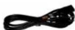
Figure 6.3: IEC Power Cord
• One 24-volt 48-watt world-ready external power supply

Figure 6.4: External Power Supply
• One 30" IEEE 1394 9-pin to 6-pin FireWire Cable

Figure 6.5: 30" IEEE 1394 9-pin to 6-pin 1394 cable
• One 4.5 meter IEEE 1394 9-pin to 6-pin FireWire Cable

Figure 6.6: 4.5 meter IEEE 1394 9-pin to 6-pin 1394 Cable
- Two Rack Ears w/ fasteners
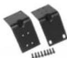
Figure 6.7: Rack Ears
• MIO Software CD-ROM
• Warranty/Registration Card
If any of these items are missing from your package when you open it, please contact Metric Halo or your dealer immediately for assistance.
6-pin to 6-pin IEEE 1394 cables are available from MH Direct.
Using the ULN-2 Hardware
ULN-2 Front Panel

Figure 6.8: ULN-2 Front Panel
The ULN-2 front panel provides ten-segment metering for the 2 analog inputs and the main outputs as well as knobs and switches to control the input, monitor, and headphones sections. The meters are fast PPM peak reading meters with auto-resetting peak holds.
Each input channel has the following controls:
- Input gain knob — This is a 12 position gold-contact rotary switch which allows you to control the gain of the selected input.
-
Phantom Power enable switch — This is a push-button switch which enables/disables Phantom power. Push the switch IN to enable phantom power.
-
Trim Enable switch — This is a push-button switch which allows you to control whether the attenuator trim pot is in the signal path or not. Push the switch IN to enable the trim pot. The attenuation range of the trim pot is 0dB to -20dB.
- Mic/TRS switch — This is a push-button switch which selects the input stage. The ULN-2 has two distinct input stages: The Mic Amp and the DI Amp.
- The Mic Amp is optimized for high gain and very low noise with low impedance sources like microphones. This input is connected to the XLR portion of the Neutrik combo connector. Maximum gain is 72 dB. Push the Mic/TRS switch IN to select the MIC input.
- The DI amp is optimized for high impedance sources like magnetic pick-ups. This input is connected to the TRS portion of the Neutrik combo connector. Maximum gain is 63 dB. The Mic/TRS switch should be in the OUT position to use this input.
- Trim Pot — The trim pot controls a passive attenuator. The attenuator is buffered between the return receiver and the A/D converter so its operation is transparent with regard to sound quality. Push the the trim enable switch IN to enable the trim pot. The attenuation range of the trim pot is 0dB to -20dB.
The front panel also provides ULN-2 system status at a glance:
• Sample Rate (nominal 44.1, 48, 88.2, or 96)
- The Sample Rate is determined from the currently selected clock source so it will accurately indicate the current sample rate, even when the clock source is being provided by an external device.
- Clock source:
- Internal indicates that the system is internally clocked
- Wordclock indicates that system is being clocked from the wordclock input
- 256x WC indicates that the system is being clocked from a 256x clock at the wordclock input
- Digital In indicates that the system is being clocked from the selected digital input (AES or S/PDIF)
- Power — Indicates that the ULN-2 is receiving power.
- FireWire — Indicates that the ULN-2 has been successfully connected to a FireWire bus and has detected the isochronous cycle required to transmit and receive audio.
- Locked — Indicates that the system clock recovery circuit is properly locked to the selected clock source. If this light is not illuminated, the ULN-2 will not be locked to a clock and will revert to its failsafe internal clock source. Even if the Locked light is not illuminated, the actual sample rate will still be indicated on the front panel display.
• Digital I/O Section:
- The AES and S/PDIF lights are mutually exclusive and indicate which of the two input ports are feeding the Stereo Digital input of ULN-2. The Locked light indicates when the digital receiver is locked to the incoming digital audio signal.
The ULN-2 hardware supports Persistent State Snapshots. There are 10 snapshot slots in the ULN-2 that are recallable from the controls on the ULN-2 front panel. Each Persistent State Snapshot contains a complete description of the state of the box, including Sample Rate, Clock Source, Digital input source, Sample Rate Converter Enable, Mixer Configuration, Levels and +DSP configuration and routing. In other words, a snapshot saves every aspect of the configuration of the ULN-2.
The first snapshot slot is special as it is used by the unit to configure the hardware and the routing when the ULN-2 starts up. The other 9 slots are available for storing alternate configurations that can be selected "on the fly" after the ULN-2 is up and running.
When a computer is attached to the ULN-2, the front-panel controls to select snapshots are locked-out since the computer is actively controlling the configuration of the box.
If the computer is not attached, the two tact-switches on the left-side of the front-panel (between the status indicators and the meters) may be used to select the snapshot that you want to use to configure the ULN-2.
These buttons are labeled with up and down arrows. The currently selected snapshot is indicated by the column of LED's labeled C, 1, 2, 3, 4, 5, 6, 7, 8, 9. When the ULN-2 turns on, the "C" indicator will be illuminated, indicating that the unit has booted up with the state that was stored in the "Boot Snapshot".

Figure 6.9: ULN-2 Front Panel Snapshot Controls
Pressing the up arrow will move to the next higher snapshot in the list (e.g. if you are currently on snapshot 3, you will move to snapshot 2). Conversely, pressing the down arrow will move to the next lower snapshot in the list (e.g. if you are currently on snapshot 3, you will move to snapshot 4). If you are at either beginning of the list and you press the up arrow, you will wrap around to the last item in the list. When you select a new snapshot, the new snapshot is applied to the box immediately.
Please see the Bootstates and Snapshots section of this manual for information on saving your information into the ULN-2.
The ULN-2 front panel provides access to the level control knobs for headphones and for the monitor outs. The headphone output jack is on the front panel and the monitor output jacks are located on the back of the unit.
The headphone output jack is a TRS 1/4" jack that provides the Left Channel on the tip, the Right Channel on the ring and the ground return for the two channels on the sleeve. The ULN-8 headphone output is suited to a wide range of impedances. Headphones with lower impedance would be expected to get louder than those with higher impedance.
The Monitor output jacks are balanced TRS connectors.
ULN-2 Rear Panel

Figure 6.10: ULN-2 Rear Panel
The ULN-2 rear panel features:
- 2 channels balanced MIC/LINE/INSTRUMENT inputs on Neutrik™ Combo connectors. Each input has:
• 24-bit 96kHz A/D converters (110dB SNR)
- high gain, low noise Mic amps with up to 72 dB of gain (fed by the XLR connector)
- high gain, low noise DI amps with up to 63 dB of gain (fed by the TRS connector)
- switchable input impedance characteristics (Mic input 3.3k Ohms, DI input 200k Ohms)
- switchable 48V Phantom power (on XLR connector)
- balanced analog inserts (S1, S2, R1, R2 jacks) which are post preamp but pre A/D. You can use the inserts to patch in analog processing between the preamp and the A/D converter. The send jack can also be used to send a mult of the input signal to another device while still using the A/D section of the ULN-2. This allows the ULN-2 to be used as an active mic splitter.
- 2 channels balanced TRS main outputs. Each output has:
• 24-bit 96kHz D/A converters (120dB SNR)
- switchable +4/-10 level
• 2 channels balanced Monitor output with front panel level control - Connect these outputs directly to power amps or self powered monitors
- 4-pin XLR power port for use with broadcast batteries
- Compatible with any 4-pin XLR power system with the following characteristics: 9v - 30v DC, Pin 4 Hot, 15 Watts
• TOSLINK connectors for ADAT Optical or Optical SPDIF I/O
• Wordclock input/output on BNC connectors
• 256x Wordclock input/output on BNC connectors - Stereo S/PDIF input/output on RCA connectors
- Stereo AES/EBU input/output on XLR connectors
• 2 IEEE 1394 (FireWire) ports (400 Mbps)
• 1 2.1mm DC power jack (9v - 30v, center positive, 15 Watts)
Signal Flow
![graph TD subgraph_Input_1["Input TRS"] --> A1["D.I. Amp"] end subgraph_Input_XLR["Input XLR"] --> B1["Mic Amp"] end subgraph_Input_2["Input TRS"] --> C1["D.I. Amp"] end subgraph_Input_XLR["Input XLR"] --> D1["Mic Amp"] end A1 --> E1["To Send"] B1 --> E1 C1 --> E1 E1 --> F1["From Return"] F1 --> G1["…](/content/2026/05/884165/images/31f1c87d2bd1ade27335cab493ac67dae534129d86a032319d388d7782be5c86.jpg)
Figure 6.11: ULN-2 Signal Flow
Making connections to the ULN-2

Figure 6.12: ULN-2 Routing
Click here for a larger version
What's the difference between the Analog outs and Monitor outs, and how do I send to the headphones?
- The Analog outputs get their signal from "Analog 1/2" in MIO Console, and their level is controlled via software
- The Monitor outputs and headphones get their signal from "Monitor L/R" in MIO Console, and their output levels are controlled via the front panel knobs
There are six classes of connections you can make to the ULN-2 hardware:
- Analog Audio
- Copper-based Digital Audio
- Optical-based Digital Audio
- Clock Sync
- FireWire
- Power
Analog Audio Connections
The analog I/O connections on the ULN-2 have been engineered for maximum flexibility in that they support both balanced and unbalanced connections with a wide range of input and output levels and a wide range of matching impedances. This means that ULN-2 handles sources from mic level to line level and from mic impedance to guitar impedance. With that in mind, there are a number of aspects of the design that you should take into account when interfacing with ULN-2.
There are really three distinct analog input stages available in a ULN-2 input:
-
The Mic amp, which is fed by the XLR portion of the Combo connector.
-
The DI amp which is fed by the TRS portion of the combo connector.
- The TRS return jack. This is a line level input which is the shortest path to the A/D converter.
Each input path is optimized for specific sources, but each is capable of handling a wide variety of sources. For example, both the Mic amp and the DI amp are capable of receiving Line level inputs. Additionally the DI input is capable of 63 dB of gain and can be used with dynamic microphones (phantom power is only available with the Mic Amp).
Feel free to experiment with the different input paths and choose the one which works best for a given application.
Whenever possible, use balanced interconnects with ULN-2. The performance of balanced interconnects is much higher and much more resistant to noise interference and electrical (power) wiring problems. The expense of balanced interconnects is not substantially higher than unbalanced connections, so if the gear that you are interfacing with supports balanced connection — use it.
If you cannot utilize balanced interconnects, there are connection schemes that you can use that will maximize performance.
On input, at line level, it is sufficient to simply use standard unbalanced (TS) connections. If you are interfacing with the ULN-2 XLR inputs, you will need to ensure that pin 3 is grounded in the unbalanced adapter cable. The ULN-2 XLR inputs are all wired pin 2 hot and the 1/4" inputs are wired Tip hot.
TIP: To use the ULN-2 TRS input with guitar or bass, you can simply use a standard TS guitar cable (patch cord) and it will work fine. However, you can take advantage of the balanced input design of the ULN-2 to get more noise rejection than you thought possible on a guitar input.
In order to do this, you will need to make a pseudo-balanced telescoping shield guitar cable. This can be constructed with a TRS connector, a TS connector and balanced microphone cable. This cable will treat the guitar as a floating balanced source and provide a telescoping shield from the ULN-2 ground.
![graph LR A["Instrument"] --> B["Sleeve"] B --> C["Mobile I/O"] C --> D["Sleeve Ring Tip"] B --> E["Tip (Hot)"] B --> F["Sleeve (Shield)"] B --> G["Ring (Cold)"]](/content/2026/05/884165/images/648efbd6d8a21f427f1718c0f971313f8ca5ef22d1ab9640256317e6b43def58.jpg)
Figure 6.13: Telescoping Shield Cable for Instruments
If you want to use the TRS inputs with balanced microphones, you will need an XLR female to 1/4" TRS balanced plug adapter cable. These are available commercially, or you can construct one easily. The connections are Tip to Pin 2, Ring to Pin 3 and Sleeve to Pin 1:
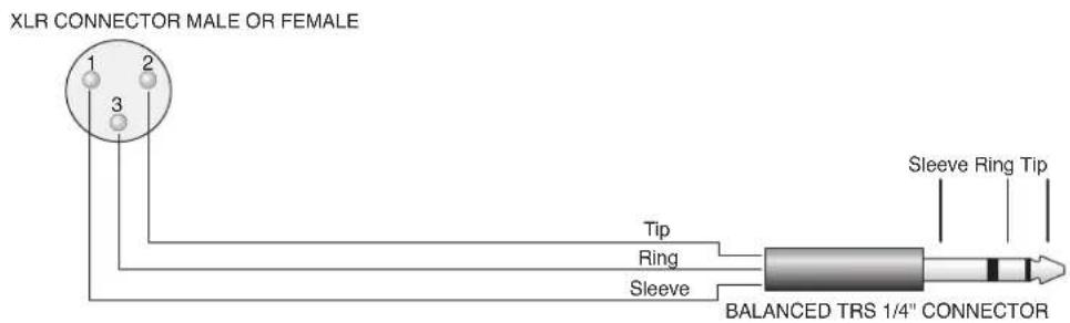
Figure 6.14: XLR to Balanced TRS Cable
On output, the situation is a bit more complex. If you are driving an unbalanced load, you will get the best performance by not connecting the ring of the TRS jack to ground. In order to do this, you can simply use a balanced TRS/TRS connector with the unbalanced gear. You can also construct a special cable with a TRS connector and a TS connector. In this cable, you just let the ring of the TRS connector float:
![graph LR A["BALANCED 1/4" TRS CONNECTOR"] -->|TIP| B["SLEEVE (SHIELD)"] B --> C["UNBALANCED 1/4" TS CONNECTOR"] C -->|TIP| D["SLEEVE (SHIELD)"] D --> E["NO CONNECTION"]](/content/2026/05/884165/images/ec71a0f80812bc975f0133e20003062c8278b5d678bd02636b39b112a7d365a6.jpg)
Figure 6.15: TRS to TS Unbalanced Cable
Alternatively, the TS connector can be replaced with an RCA connector for interfacing with gear that has RCA unbalanced interconnects.
![graph LR A["BALANCED 1/4" TRS CONNECTOR"] -->|TIP| B["SLEEVE (SHIELD)"] B --> C["RCA CONNECTOR"] C -->|PIN| D["BARREL (SHIELD)"] A --> E["NO CONNECTION"]](/content/2026/05/884165/images/69a399dd768e9713e826b1fe105c3a1845cf054399804f0af1599392352e5ba7.jpg)
Figure 6.16: TRS to RCA Unbalanced Cable
MAKING THE 1/4" CONNECTION
When you connect a 1/4" plug to a ULN-2 jack, insert it straight and firmly, ensuring that the plug is fully inserted into the jack. If the plug is not fully inserted you will get level shifts, phase flips, distortion, or no sound.
To disconnect a 1/4" plug, firmly pull the plug straight out from the connector body. The connectors on ULN-2 are stiff, so you may have to exert some force to remove the plug.
MAKING THE XLR CONNECTION
When you connect a Male XLR plug to a ULN-2 jack, ensure that you have aligned the pins with the connector body and insert firmly until the retention tab clicks.
To disconnect the plug, press the metal retention tab flush against the box, and pull the plug from the ULN-2.
Copper-Based Digital Audio
ULN-2 supports 2 channels of digital audio over copper-based connections. These connections can be made using either S/PDIF interconnects with the RCA connectors or with AES interconnects using the XLR connectors. Even though only one of the AES or S/PDIF inputs can be active at any given time, you can have different digital sources connected to each of the input connectors at the same time – you use the MIO Console application to select the active input. Audio routed to the digital outputs will be mirrored by both S/PDIF and AES outputs. This allows you to send the same stereo pair to two devices at once.
We recommend that you use the AES interconnect mechanism to establish the digital communication between the ULN-2 and other digital devices. The jitter and electrical noise tolerance on AES interconnects is substantially better than with S/PDIF interconnects. The AES interconnect standard is equivalent to balanced audio interconnections. If you need to use S/PDIF interconnects, try to use the shortest cables you can and, if possible, use special purpose 75 ohm S/PDIF or video cables.
The RCA connectors used for S/PDIF are friction fit coaxial connectors. When you connect them, ensure that they are fully inserted and tight.
The XLR connectors used for AES are fully locking. When connecting to them, make sure that you align the pins and insert firmly. When you remove the connector, make sure that you release the lock by pressing the lock release button before you pull the connector out of the ULN-2.
SRC
Normally, when working with digital audio transport, you must take care to ensure that all devices communicating with one another are synchronized to the same audio clock. While this is still an important consideration with ULN-2, the hardware provides a special feature to simplify copper-based digital connections to the box. The digital input on ULN-2 has an optional asynchronous sample rate converter (SRC) that will automatically match the sample rate of the incoming audio to the sample rate of the ULN-2. This converter is enabled by default and you can disable it in the System section of the MIO Console. If you have synchronized the ULN-2 to the external source (using any of the extensive synchronization methods provided by ULN-2), you will generally want to disable the SRC in order to get 24-bit transparent audio transport over the digital input.
Optical-Based Digital Audio
The ULN-2 Expanded provides two TOSLINK™ connectors on the back panel. One is a transmit connector and the other is a receive connector. These connectors are used with Plastic Optical Fiber (TOSLINK) cables to communicate with other devices. The TOSLINK connectors can be used to communicate with either the ADAT® Optical communication protocol or the Optical SPDIF communication protocol. Each port can be independently switched between the two protocols via MIO Console.
The ADAT Optical standard allows a device to transmit 8 channels of 24-bit audio at up to 50kHz along with digital audio clock information.
The Optical SPDIF communication protocol allows a device to transmit 2 channels of 24 bit audio at 96kHz, along with digital audio clock information.
Since Mobile I/O provides direct routing within the box, you can easily configure the unit to work as an ADAT based 8 channel A/D/A. Refer to the chapter on MIO Console for information about configuring the routing.
Clock Sync
Clock sync is a serious consideration in any digital audio system.
If you are recording analog sources with ULN-2, you can simply use the unit's high-quality internal clock source to drive the converters. This is the easiest case to deal with.
If you need to interface with other devices digitally or ensure sample accurate sync with video sources, the extensive clock synchronization capabilities of ULN-2 will prove to be more reliable (and better sounding) than most higher priced alternatives.
There are four different ways to get external clock information into the unit:
- Sending a 1x word clock signal into the WC Input BNC.
- Sending a 256x word clock signal into the WC Input BNC.
- Sending an AES or S/PDIF signal into the Digital input.
- Sending an ADAT signal into the Optical Digital input.
The BNC word clock input port is a 75 Ohm terminated coaxial input. It should be driven by a 75 Ohm source driver and interconnected with 75 Ohm coaxial cable. If you do not use proper cabling and source drive, you will introduce reflections on the word clock cable which will propagate jitter into the recovered word clock. This is true whether you use the port as a 1x WC input or a 256x WC input, but becomes more important when the clock signal is 256x.
1x is generally appropriate for use with devices that provide a word clock output. If your device provides a 256x output, you may find that you get better results using that clock signal. The Digidesign® line of Pro Tools® products use 256x as their "SuperClock™" clocking signal.
The AES recommended procedure for distributing clock is to use an AES clock signal. The AES clock signal is an AES digital audio signal with no audio activity. ULN-2 only uses the AES preambles for clock recovery, so it is immune to data dependent jitter effects. This means you can reliably use the Digital Input as a clock source with or without audio data.
FireWire
Detailed information on FireWire implementation can be found in the FireWire appendix.
Power
One of ULN-2's many great strengths is the flexibility of its power system. ULN-2 can be powered from any DC source (including bus power) in the range of 9V to 30V as long as it provides 12 Watts of power. The DC inputs on ULN-2 are a 2.1mm coaxial power connector, center positive and a 4-pin XLR connector Pin 4 Hot. So if you are powering the unit with a third party power source and it supplies 9V, the power source will have to provide 1.4 amps of current. If you are powering the unit with 12V, the power source will have to provide 1 amp of current, and so on.
The ULN-2 ships with a world-ready 24 volt, 2 amp power supply. You can plug this supply into any AC power source from 90V to 240V, 50Hz - 60Hz, using an appropriate IEC power cord, and it will supply the proper power to the ULN-2 on the 2.1mm coaxial power connector. ULN-2 will automatically supply the extra power to the FireWire bus. This means that the ULN-2 and its power supply can be used to power other bus-powerable FireWire devices including hard-drives, hubs, and other ULN-2 units.
Since ULN-2 is DC powered, you can also power up the ULN-2 using the FireWire bus or another DC source. The ULN-2 uses 12 Watts of power, so the device supplying the bus power must be capable of sourcing that much power. Most desktop Macs provide more than enough power for ULN-2 and one other low power device. Most laptops provide enough power for ULN-2, but not enough for ULN-2 and another bus-powered device at the same time. If you are using a Powerbook computer, you should not expect to be able to power both the ULN-2 and a hard drive from the computer. The power capabilities of individual computers vary, so you will have to test the complete system to determine exactly how much your computer can handle.
If you find that the computer is not capable of powering ULN-2 or does not provide enough run time, you may want to explore using an external power source with the ULN-2. Check with Metric Halo for details on different battery power solutions for ULN-2.
As with all electronic devices, when connecting an external power source to the ULN-2, you should first connect the power source to ULN-2 while it is in an unenergized state (e.g. not connected to the mains or switched off). After the connection to ULN-2 has been made, you should energize the power source.
If you connect an energized power source to the ULN-2's 2.1mm power connector you may see a small spark when you make the connection. This is due to surge current and is normal if you connect a power source in this way. While this will not damage the ULN-2 in any way, to avoid the spark just connect the power connector to ULN-2 before connecting the power source to the wall.
ULN-2 Specifications
Table 6.1. Mic Inputs
| Mic Inputs | |
| Stepped Gain Range +6 dB – +72 dB (6 dB Steps) | |
| Gain Range with Trim -14dB – +70 dB | |
| Input Impedance 3.3k Ω | |
| Harmonic Distortion @1kHz(+9dBu in @ 6 dB Gain) | 0.0005% |
| Intermodulation Distortion 1k component(19 kHz/20kHz @ +8dBu) | -96 dBu |
Table 6.2. ULN-2 Equivalent Input Noise (E.I.N.) 20 Hz - 20 kHz Flat @ 72 dB Gain
| Equivalent Input Noise (E.I.N.) | |
| 150 Ω Source -130.5 dBu | |
| 50 Ω Source -132.0 dBu | |
| 0 Ω Source -134.0 dBu |
Table 6.3. ULN-2 Frequency Response
| Frequency Response | |
| 18 Hz -> 20 kHz ± 0.1 dB | |
| 8 Hz -> 50 kHz -± 1.0 dB | |
| 3 Hz -> 100 kHz ± 3.0 dB |
Table 6.4. ULN-2 Crosstalk @1kHz
| Crosstalk @1kHz | |
| trim link engaged -107 dB | |
| trim link disengaged -132 dB |
Table 6.5. ULN-2 Maximums
| Maximums | |
| Max Gain 72 dB | |
| Preamp Headroom 20 dB above Digital Clip | |
| Phantom Power +48v Regulated, high current, individually switch-able, P48 test compliant, short circuit/ hot-swap pro-tected | |
Table 6.6. ULN-2 Converter Latency
| Latency | |
| A/D 39 samples | |
| D/A 28 samples |
Table 6.7. ULN-2 Input Processing
| Input Processing | |
| M/S Decode Instantiable | |
| Parametric EQ Instantiable | |
| Dynamics Instantiable | |
| Character Instantiable | |
| Reverb | Instantiable |
| Delay | Instantiable |
| Nearly Infinite Combinations via +DSP Optional |
Table 6.8. ULN-2 Output Processing
| Output Processing | |
| M/S Encode Instantiable | |
| Parametric EQ Instantiable | |
| Dynamics Instantiable | |
| Character Instantiable | |
| Reverb Instantiable | |
| Dither Instantiable | |
| Mix Foldown Instantiable | |
| Nearly Infinite Combinations via +DSP Optional |
Table 6.9. ULN-2 Front Panel
| Front Panel | |
| Indicator LEDs 64 | |
| Meters 4 | |
| Segments per Meter 10 | |
| Controls • Stepped Gain (12 steps 6dB – 72 dB) | Continuous Attenuator on returnAttenuation linkMic/Line Select switchIndependent Monitor Volume ControlsIndependent Phantom Power ControlsPreset Recall Buttons |
| Sample Rate Indicators 4 | |
| Clock Source Indicators 4 | |
| Digital I/O Source Indicators 2 | |
| System Lock Indicator | 1 |
| Firewire Indicator | 1 |
| Power Indicator | 1 |
| Preset Recall Indicators | 10 |
| Headphone Output (Dedicated DAC) | TRS Stereo |
Table 6.10. ULN-2 Back Panel
| Back Panel | |
| Word Clock Connectors (In and Out) | 75 Ω BNC |
| AES Connectors (2 Channels In and Out) | XLR |
| SPDIF Connectors (2 Channels In and Out) | RCA |
| Optical Connectors (8 or 2 Channels In and Out) | TOSLINK |
| Mic/Line Input Connectors (2 Channels) | NeutrikTM Combo XLR/TRS |
| Insert Send Connectors (2 Channels) TRS | |
| Insert Return Connectors (2 Channels) TRS | |
| Analog Output Connectors (2 Channels, switchable +4/-10) | TRS |
| Monitor Output Connectors (2 Channels) TRS | |
| FireWire Connectors (2) 1394a 6-Pin | |
| Power (Unswitched) 2.1mm Coaxial | |
| Power (Unswitched) 4-Pin XLR | |
| Security Slot Kensington |
Table 6.11. ULN-2 Software
| Software | |
| Driver CoreAudio Mac OS X | |
| Mac OS X 10.3.9 or newer | |
| Architectures PPC, Intel | |
| MIO Console Included | |
| Record Panel Included | |
| LTC Decoder Included | |
| Mixer Included | |
| +DSP License Optional |
Table 6.12. ULN-2 Power
| Power | |
| Voltage 9v - 30v | |
| Power 8 Watts | |
| FireWire Bus Powerable Yes | |
| Passes FireWire Bus Power Yes | |
| Supplies FireWire Bus Power | Yes |
| External Supply (Input) | 100-240VAC |
| External Supply (Max Input Current) | 1.2 A |
| External Supply (Output) | 24 VDC |
| External Supply (Max Output Current) | 2.0 A |
| External Supply Connector | 2.1mm coaxial, 4-Pin XLR |
Table 6.13. ULN-2 Case
| Case | |
| Material | Powder Coated Aluminum |
| Fasteners | 7/64" Hex Socket Head |
| Weight | 4 lbs |
| Weight | 1.8 kg |
| Dimensions 13.5" x 8.25" x 1.73" | |
| Dimensions 34.3 cm x 21 cm x 4.4 cm | |
| Rack Ears (included) Powder Coated Steel |
7. LIO-8 Users Guide
LIO-8 Overview
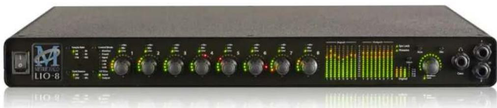
Figure 7.1: LIO-8
What it is
The LIO-8 is a portable, archival-quality, modular FireWire-based multi-format audio converter, interface, and processor for professional audio applications. The LIO-8 is equipped with eight balanced line inputs, eight channels of AES digital I/O, eight balanced sends and eight balanced analog outputs, as well as wordclock in/out, MIDI in/out, SMPTE in/out and 2 IEEE 1394 FireWire connectors that support 400 Mbs operation. All inputs and outputs are capable of 24-bit/192kHz operation.
What it has
- 18 simultaneous input channels and 20 simultaneous output channels
• Full 24 bit/192kHz audio
• 44.1, 48, 88.2, 96, 176.4, 192kHz Sampling Rates
• 8 channels of 24 bit A/D converters
• 10 channels of 24 bit D/A converters
• 8 Balanced Line Inputs – DB25 - 8 Balanced line level Sends – DB25
- 8 Balanced Analog Outputs – DB25, channels 1 and 2 multed on 1/4" TRS
- 8 channels of AES I/O, single wire for 44.1-192KHz operation - DB25
- 2 channels of DI available on the front panel - 1/4" TRS
- Front panel cans output with discreet high quality D/A and amplification - 1/4" TRS
• Word Clock 1x, 256x on 75ohm terminated BNC - SMPTE I/O on 1/4" TRS
- Front Panel Metering for Analog Inputs and Outputs on 15 segment multicolor LEDs
- Front Panel signal present, lock and clock selection multicolor LEDs for AES I/O
• 9 detented Front Panel encoders - Built-in 80-bit, fully interpolated, multi-bus mixer for near-zero latency foldback of all input channels and all DAW busses simultaneously
• Full cross point router for I/O management
• Full console metering of every channel and mix bus
• Total recall of every console parameter - Portable Capabilities – Battery Powerable
- Rack Mount Kit
Options (can be installed before or after purchase)
• 4 or 8 channels of ULN-R Microphone preamps
- +DSP license
What you need to use it
- Computer:
- Any Mac that supports Mac OS X with a FireWire port
• Universal Binary (native support for PPC and Intel)
• Mac OS X 10.2.8 or newer required
• Mac OS X 10.4.11 or newer recommended
• Peripheral FireWire Adaptors supported:
• OHCI compliant PCCard, PCI card, ExpressCard or PCIe card
- Software: All CoreAudio compliant software is compatible with Mobile I/O, including:
- Cubase
- Digital Performer
- GarageBand
- iTunes
• Live - Logic
- Nuendo
- Pro Tools
- PreMaster CD
- soundBlade
- WaveBurner
• and hundreds more...
What comes with it
Your LIO-8 package contains the following items:
- One LIO-8 unit:

Figure 7.2: LIO-8 Unit
• One IEC Power Cord appropriate for your area

Figure 7.3: IEC Power Cord
• One 24-volt 48-watt world-ready external power supply
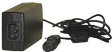
Figure 7.4: External Power Supply
• One 30" IEEE 1394 9-pin to 6-pin FireWire Cable

Figure 7.5: 30" IEEE 1394 9-pin to 6-pin 1394 Cable
• One 4.5 meter IEEE 1394 9-pin to 6-pin FireWire Cable

Figure 7.6: 4.5 meter IEEE 1394 9-pin to 6-pin 1394 Cable
- Two Rack Ears w/ fasteners, rubber feet

Figure 7.7: Rack Ears

Figure 7.8: Jumpers for Internal Configuration
• MIO Software CD-ROM
• Warranty/Registration Card
If any of these items are missing from your package when you open it, please contact Metric Halo or your dealer immediately for assistance.
6-pin to 6-pin IEEE 1394 cables are available from MH Direct.
Using the LIO-8 Hardware
LIO-8 Front Panel

Figure 7.9: LIO-8 Front Panel
The front panel provides LIO-8 system control and status at a glance (The Front Panel includes features that are only enabled if you install one or two of available add-on Mic Pre boards. When no Mic Pre boards are installed, these features are disabled and are present for future expansion. The Mic Pre related features are noted below.):
• Monitor- Select the Monitor Controller input or output
- Preset- Recall one of the eight stored system configurations
- Input- Step through the available input sources (only active if fitted with optional mic pres)
- Link- Link multiple input and output encoders for stereo or multichannel use
- +48- Enable phantom power, per channel (only active if fitted with optional mic pres)
• U/M- User mode (for future expansion)
- Power switch for rear 4 pin XLR connector (jumper defeatable)
• Sample Rate (nominal 44.1, 48, 88.2, 96, 176.4 or 192KHz)
- The Sample Rate is determined from the currently selected clock source so it will accurately indicate the current sample rate, even when the clock source is being provided by an external device.
- Clock source:
- Internal indicates that the system is internally clocked
• Wordclock indicates that system is being clocked from the wordclock input - 256x WC indicates that the system is being clocked from a 256x clock at the wordclock input
-
Digital In indicates that the system is being clocked from the selected digital input
-
Control Mode — Indicates what parameters the encoders are modifying:
- I/O Trim — Indicates whether you are modifying input or output channel gain.
- Input Status- Indicates mic input, line input or mic s/r by channel (fixed on "Line" if no Mic Pre is fitted).
- Encoders- Eight detented encoders for multipurpose control, with push-switches.
- 15-segment metering for the 8 analog inputs and outputs using multicolor LEDs, which also display gain values during encoder use. The meters are fast PPM peak reading meters with auto-resetting peak holds.
- SysLock — Indicates that the system clock recovery circuit is properly locked to the selected clock source. If this light is not illuminated, the LIO-8 will not be locked to a clock and will revert to its failsafe internal clock source. Even if the Locked light is not illuminated, the actual sample rate will still be indicated on the front panel display.
- FireWire — Indicates that the LIO-8 has been successfully connected to a FireWire bus and has detected the isochronous cycle required to transmit and receive audio.
- Signal present indicators for AES input and output, as well as digital lock and cable select button and indicators.
• Monitor Control Section:
- The Mute and Dim buttons provide instant access to simple level control for the selected Monitor path or headphone output. The Mute button provides a quick, tactile "panic switch" which mutes the monitors or front panel headphone output in case of accidental feedback loops and other audio unpleasanties. The Dim button attenuates the selected path by 20 dB.
- The Monitor Control encoder provides front panel adjustment for your audio. By pressing the encoder, it can toggle between affecting the Monitor Control section or headphones. There are two multicolor LEDs below the encoder that indicate which path the encoder is modifying as well as mute and dim status.
The LIO-8 front panel also provides access to the Headphone output. The headphone output jack is a TRS 1/4" jack that provides the Left Channel on the tip, the Right Channel on the ring and the ground return for the two channels on the sleeve. These signals are all ground referred, so they may also be split and fed single-ended (unbalanced) to an external audio device.
The LIO-8 headphone output is suited to a wide range of impedances. Headphones with lower impedance would be expected to get louder than those with higher impedance.
There are two DI inputs on the front panel, which are paralleled with Line inputs 1 and 2. The DI inputs can provide 0, 10, or 20db of gain selectable via internal jumpers.
More information regarding the front panel can be found in the ULN/LIO-8 Front Panel Guide.
LIO-8 Rear Panel

Figure 7.10: LIO-8 Rear Panel
The LIO-8 rear panel features:
• 4 pin XLR DC power jack (14v - 28v, 32 Watts)
- 8 channels balanced line inputs on DB25. Each input has:
- -12 dB to +31.5 dB of gain range
• Dynamic Range (-60 dB, flat 0-22.05 kHz, typ): 115 dB
• +0/-1.0dB @ fs = 192KHz: 1.8 Hz - 64.7 kHz
- Noise Floor (flat 0-22.05 kHz, typ): 115 dB
- 8 channels balanced line level sends on DB25 that mirror the analog inputs
- 8 channels balanced line/monitor outputs on DB25. Each output has:
• 24-bit 192kHz D/A converters (120dB SNR)
• Gain range from -96 dB to +30 dB
- Outputs 1 and 2 are also multed to 1/4'' TRS connectors
• 8 channels AES digital I/O on DB25
- Single wire mode for full 8 channels at 44.1-192KHz operation
- Expansion Port for DB-25 for 4 or 8 channels of Mic Pre (field installable)
• Wordclock input/output on BNC connectors at 1x or 256x rates
• MIDI I/O to connect a control surface to MIO Console
- SMPTE input and output on 1/4" TRS
• Kensington security slot
• 2 IEEE 1394 (FireWire) ports (400 Mbs)
- 1 2.1mm DC power jack (14v - 28v, center positive, 32 Watts), unswitched
Signal Flow
![graph TD subgraph Analog Input 1-2 A["DI TRS"] --> B["D.I. Amp"] C["Line DB25"] --> D["Line Amp"] E["Mic DB25"] --> F["Mic Amp"] G["Send DB25"] --> H["Send Amp"] I["Analog Input 3-8"] --> J["Line DB25"] K["Mic DB25"] --> L["Mic Amp"] M["Send DB25"] --> N["Send Amp"] end subgraph Analog Input 3-8 O["…](/content/2026/05/884165/images/64d55e9b4ab0c2a64d15b95413c83bcbcfe6722b615c559c88c8ced952bbfe8a.jpg)
Figure 7.11: LIO-8 Signal Flow
Making connections to the LIO-8
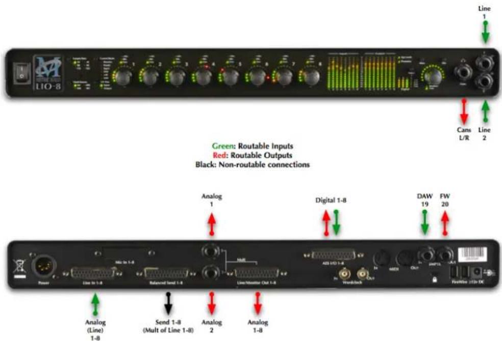
Figure 7.12: LIO-8 Routing
Click here for a larger version
There are seven classes of connections you can make to the LIO-8 hardware:
- Analog Audio
- AES Digital Audio
-
Clock Sync
-
FireWire
- Power
- MIDI
- SMPTE
Analog Audio Connections
The analog I/O connections on the LIO-8 have been engineered for maximum flexibility in that they support both balanced and unbalanced connections with a wide range of input and output levels and a wide range of matching impedances. The line inputs have an impedance of 10k Ω. With that in mind, there are a number of aspects of the design that you should take into account when interfacing with the LIO-8. All multichannel audio connections are made using industry standard DB25 connectors, which are pin-compatible with cables using the Tascam/Digidesign standard.
Wiring details for this connector can be found in the DB25 Pinouts appendix.
Whenever possible, use balanced connections with the LIO-8. The performance of balanced interconnects is much higher and much more resistant to noise interference and electrical (power) wiring problems. The expense of balanced interconnects is not substantially higher than unbalanced connections, so if the gear that you are interfacing with supports balanced connection — use it. If you cannot utilize balanced interconnects, there are connection schemes that you can use that will maximize performance.
On input, at line level, it is sufficient to simply use standard unbalanced connections. If you are interfacing with the LIO-8 line inputs, you will need to ensure that the cold pin is grounded in the unbalanced adapter cable (Pin 3 if connecting to an XLR loom, Ring if connecting to a TRS loom). More information about adjusting the input level can be found in the MIO Console software chapter.
On output, at line level, it is sufficient to simply use standard unbalanced connections. If you are interfacing with the LIO-8 line inputs, for best performance you should ensure that the cold pin is left floating in the unbalanced adapter cable (Pin 3 if connecting to an XLR loom, Ring if connecting to a TRS loom). More information about adjusting the output level can be found in the MIO Console software chapter.
LIO-8 DB25 cables should be wired pin 2 or Tip hot. The front and rear 1/4" connectors are wired Tip hot. The headphone connector is wired Tip/Left, Ring/Right, Sleeve/Ground.
Connecting to the Dls
The DI inputs provide an excellent high impedance input for directly connecting instruments to the LIO-8. These inputs are unity-gain summed with the corresponding line input from the back panel. This means that if you have signal connected to both the DI and line input for a given channel the ADC will see a mix of those two inputs. If you do not wish to have signal from one of the connectors you need to physically disconnect that input or otherwise ensure that no signal is present at the unused input.
Each DI input supports balanced connections via TRS cable. You can connect a source to the DI via a balanced interconnect (if the source is actually a balanced output), an unbalanced interconnect (if the source is unbalanced like most instruments), or a telescoping shielded cable (which is an alternate unbalanced connection that provides additional shielding).
Since the DI inputs provide an ultra-high input impedance, if you connect an unbalanced source to the DI via a balanced cable you will float the negative input and will effectively inject a large DC offset into the output of the DI which will cause the associated ADC to mute. As a result you must use either a TS cable or a telescoping shield cable with unbalanced sources.
When you remove the connector from the DI jack, the DI connects its inputs to ground internally to remove any possible residual DC offset or pickup noise. If you disconnect the cable from the source but leave it connected to the DI input, the cable will function as an antenna and will inject noise into your inputs and may cause enough of a DC offset to mute the ADC. As a result you should always disconnect the cable from the DI rather than the instrument.
Balanced Sends
The LIO-8 has eight balanced sends; these mirror the analog signal present at the Line input. This allows you to use the sends as a splitter to feed a mixing console, recorder or other equipment.
You cannot route signal from a DAW channel to the balanced sends; to route signals from your computer to the D/A converters, you must use the Line/Monitor outputs.
AES Digital Audio
The LIO-8 supports 8 channels of digital audio over copper-based connections. The native format of the LIO-8 is AES, but can be converted to SPDIF or optical using third-party adapters. The LIO-8 operates in single-wire mode, providing 8 channels of digital audio at all sample rates. The LIO-8's digital I/O connections are made using industry standard Tascam/Digidesign pinout DB25 cables.
Wiring details for this connector can be found in the DB25 Pinouts appendix.
Clock Sync
Clock sync is a serious consideration in any digital audio system.
If you are recording analog sources with LIO-8, you can simply use the unit's high-quality internal clock source to drive the converters. This is the easiest case to deal with.
If you need to interface with other devices digitally or ensure sample accurate sync with video sources, the extensive clock synchronization capabilities of LIO-8 will prove to be more reliable (and better sounding) than most higher priced alternatives.
There are three different ways to get external clock information into the unit:
- Sending a 1x word clock signal into the WC Input BNC.
- Sending a 256x word clock signal into the WC Input BNC.
- Sending an AES signal into the Digital input.
The BNC word clock input port is a 75 Ohm terminated coaxial input. It should be driven by a 75 Ohm source driver and interconnected with 75 Ohm coaxial cable. If you do not use proper cabling and source drive, you will introduce reflections on the word clock cable which will propagate jitter into the recovered word clock. This is true whether you use the port as a 1x WC input or a 256x WC input, but becomes more important when the clock signal is 256x.
1x is generally appropriate for use with devices that provide a word clock output. If your device provides a 256x output, you may find that you get better results using that clock signal. The Digidesign® line of Pro Tools® products use 256x as their “SuperClock™” clocking signal.
The AES recommended procedure for distributing clock is to use an AES clock signal. The AES clock signal is an AES digital audio signal with no audio activity. The LIO-8 only uses the AES preambles for clock recovery, so it is immune to data dependent jitter effects. This means you can reliably use the Digital Input as a clock source with or without audio data.
FireWire
Detailed information on FireWire implementation can be found in the FireWire appendix.
Power
One of LIO-8's great strengths is the flexibility of its power system. The LIO-8 can be powered from any DC source in the range of 14V to 28V as long as it provides 32 Watts of power. The DC inputs on the LIO-8 are a 2.1mm coaxial power connector, center positive and a 4-pin XLR connector Pin 4 Hot. So if you are powering the unit with a third party power source and it supplies 14V, the power source will have to provide 2.3 amps of current. If you are powering the unit with 24V, the power source will have to provide 1.3 amps of current, and so on.
The LIO-8 ships with a world-ready 24 volt, 2 amp power supply. You can plug this supply into any AC power source from 90V to 240V, 50Hz - 60Hz, using an appropriate IEC power cord, and it will supply the proper power to the LIO-8 on the 4 pin XLR power connector. The LIO-8 will not supply power to the FireWire bus, but will pass power coming from other devices.
As with all electronic devices, when connecting an external power source to the LIO-8, you should first connect the power source to the LIO-8 while it is in an unenergized state (e.g. not connected to the mains or switched off). After the connection to the LIO-8 has been made, you should energize the power source.
If you connect an energized power source to the LIO-8's 2.1mm power connector you may see a small spark when you make the connection. This is due to surge current and is normal if you connect a power source in this way. While this will not damage the LIO-8 in any way, to avoid the spark just connect the power connector to LIO-8 before connecting the power source to the wall.
MIDI
The LIO-8 offers MIDI input and output ports for direct connection of a control surface. These ports are only active while MIO Console is running; the LIO-8 cannot utilize a control surface in standalone operation. MIO Console makes these ports available to other applications while it is running, but the MIDI implementation is currently optimized for control use only- it is not recommended to use these ports for connecting keyboards or other devices that require accurate timing.
SMPTE
The LIO-8 has SMPTE input and output ports for timecode use. The SMPTE I/O occupy their own channels and do not require using a channel of A/D or D/A conversion. SMPTE input is presented to CoreAudio applications as DAW 19 in our driver, and is accessible via any CoreAudio compliant software including the Record Panel in MIO Console. SMPTE output may be accessed by routing the SMPTE signal to FW 20. Please note that MIO Console does not natively decode or encode MTC at this time; if you need to synchronise to MTC, you will need third party software.
LIO-8 Specifications
Table 7.1. LIO-8 Voltage Rails
| Rails | |
| Analog Rails (low power) ±9.9 Volts | |
| Analog Rails (high power) ±12.6 Volts |
Table 7.2. LIO-8 Maximum I/O Levels (Balanced)
| Maximum I/O Levels (Balanced) | |
| Peak Line Output @ 0 dBFS (no jumper/low power) +1 | 18.5 dBu |
| Peak Line Output @ 0 dBFS (output jumper/low pow-er) | +22.0 dBu |
| Peak Line Output @ 0 dBFS (output jumper/high power) | +24.5 dBu |
| Analog Send Max Output +21.5 dBu | |
| Line In Max Input +24.5 dBu | |
| Output Impedance 5 Ω |
Table 7.3. LIO-8 Monitor Controller
| Monitor Controller | |
| Nominal FS output (Balanced) Output Jumper Off -19 | 0 dBu |
| Nominal FS output (Balanced) Output Jumper On -12.0 dBu | |
| Maximum Output Same as Line | |
| Gain Range -96 dB to +30 dB | |
| Gain Precision ±0.05 dB | |
| Gain Step 0.5 dB | |
Table 7.4. LIO-8 Line Input + ADC
| Line Input + ADC | |
| Input Impedance 10k Ω | |
| Dynamic Range (-60 dB, flat 0-22.05 kHz, typ) 115 dB | |
| Dynamic Range (-60 dB, A-weighted, typ) 118 dB | |
| Noise Floor (flat 0-22.05 kHz, typ) 115 dB | |
| Noise Floor (A-weighted, typ) 117.9 dB | |
| THD D/A/A/D loop @ -12 dBFS 0.0005 % | |
| THD D/A/A/D loop @ -0 dBFS 0.0015 % | |
| Crosstalk @ 1kHz -127 dB | |
| IMD 1k component (19 kHz/20kHz @ +8dBu) -104 dBu | |
| Gain Range -12 dB to +31.5 dB | |
| Gain Precision ±0.05 dB | |
| Gain Step 0.5 dB |
Table 7.5. LIO-8 Line Input + ADC Frequency Response
| Line Input + ADC Frequency Response | |
| +0/-0.1dB @ fs = 44100 Hz 5.7 Hz - 20.5 kHz | |
| +0/-1.0dB @ fs = 44100 Hz 1.8 Hz - 21.0 kHz | |
| +0/-0.1dB @ fs = 96000 Hz 5.7 Hz - 43.9 kHz | |
| +0/-1.0dB @ fs = 96000 Hz 1.8 Hz - 45.4 kHz | |
| +0/-0.1dB @ fs = 192000 Hz 5.7 Hz - 42.1 kHz | |
| +0/-1.0dB @ fs = 192000 Hz 1.8 Hz - 64.7 kHz | |
| 5° low-end in-channel phase deviation point | 10.7 Hz |
| Interchannel phase 0 Hz - 20 kHz | < ±0.05° |
| Crosstalk from SMPTE Input | <-142 dB |
Table 7.6. LIO-8 Converter Latency
| Latency | |
| A/D | 63 samples |
| D/A | 44 samples |
Table 7.7. LIO-8 Input Processing
| Input Processing | |
| M/S Decode | Instantiable |
| Parametric EQ Instantiable | |
| Dynamics Instantiable | |
| Character Instantiable | |
| Reverb Instantiable | |
| Delay Instantiable | |
| Nearly Infinite Combinations via +DSP Optional |
Table 7.8. LIO-8 Output Processing
| Output Processing | |
| M/S Encode Instantiable | |
| Parametric EQ Instantiable | |
| Dynamics Instantiable | |
| Character Instantiable | |
| Reverb Instantiable | |
| Dither Instantiable | |
| Mix Foldown Instantiable |
Table 7.9. LIO-8 Front Panel
| Front Panel | |
| Indicator LEDs (Bicolor) 495 | |
| Meters 16 | |
| Segments per Meter 15 | |
| Channel Encoder Knobs 8 | |
| Encoders Have Shaft Push Buttons Yes | |
| Monitor Controller Encoder Knobs 1 | |
| Monitor Controller Mute Yes | |
| Monitor Controller Dim Yes | |
| Indicators Per Encoder | 16 |
| Sample Rate Indicators | 6 |
| Clock Source Indicators 4 | |
| AES Clock Source Indicators | 4 |
| AES Lock Indicators 4 | |
| AES Input Signal Indicators | 4 |
| AES Output Signal Indicators | 4 |
| System Lock Indicator | 1 |
| Firewire Indicator | 1 |
| Front Panel Modes | 14 |
| Headphone Output (Dedicated DAC) | TRS Stereo |
| DI Inputs (2) | TRS Balanced |
| DI Input Impedance 10M Ω | |
| DI Input Fixed Gain (Jumper Selectable) 0/10/20 dB | |
| DI Input Variable Gain -12 dB to 31.5 dB | |
| Power Switch (Jumper Defeatable) Toggle |
Table 7.10. LIO-8 Back Panel
| Back Panel | |
| MIDI Connectors (In and Out) 5-Pin DIN | |
| SMPTE Connectors (In and Out) Balanced TRS | |
| Word Clock Connectors (In and Out) 75 Ω BNC | |
| AES Connector (8 Channels In and Out) DB-25 | |
| AES Connector Pinout Tascam/Digidesign Digital | |
| Line Input Connector (8 Channels) DB-25 | |
| Line Input Pinout Tascam/Digidesign Analog | |
| Send Output Connector (8 Channels) DB-25 | |
| Send Output Pinout Tascam/Digidesign Analog | |
| Line/Monitor Output Connector (8 Channels) DB-25 | |
| Line/Monitor Output Pinout Tascam/Digidesign Analog | |
| Line/Monitor Mult Output Connectors (Analog 1/2) TRS Balanced | |
| FireWire Connectors (2) 1394a 6-Pin | |
| Power (Unswitched) | 2.1mm Coaxial |
| Power (Switched) | 4-Pin XLR |
| Security Slot | Kensignton |
Table 7.11. LIO-8 Software
| Software | |
| Driver | CoreAudio Mac OS X |
| Mac OS X | 10.3.9 or newer |
| Architectures | PPC, Intel |
| MIO Console | Included |
| Record Panel | Included |
| LTC Decoder | Included |
| Mixer | Included |
| +DSP License | Optional |
Table 7.12. LIO-8 Power
| Power | |
| Voltage | 14v - 28v |
| Power | 24 Watts |
| FireWire Bus Powerable | No |
| Passes FireWire Bus Power Yes | |
| Supplies FireWire Bus Power No | |
| External Supply (Input) 100-240VAC | |
| External Supply (Max Input Current) 1.2 A | |
| External Supply (Output) 24 VDC | |
| External Supply (Max Output Current) 2.0 A | |
| External Supply Connector 4-Pin XLR |
Table 7.13. LIO-8 Case
| Case | |
| Material Powder Coated Aluminum | |
| Fasteners 3mm Phillips Head | |
| Weight 6 lbs | |
| Weight 2.7 kg | |
| Dimensions 17" x 13" x 1.72" | |
| Dimensions 432 x 330 x 44 mm | |
| Rack Ears (included) Powder Coated Steel | |
| Rear Rack Mounts Available |
8. ULN-8 Users Guide
ULN-8 Overview

Figure 8.1: ULN-8
What it is
The ULN-8 is a portable, archival-quality, modular FireWire-based multi-format audio converter, interface, and processor for professional audio applications. The ULN-8 is equipped with eight balanced mic inputs, eight balanced line inputs, eight channels of AES digital I/O, eight balanced sends and eight balanced analog outputs, as well as wordclock in/out, MIDI in/out, SMPTE in/out and 2 IEEE 1394 FireWire connectors that support 400 Mbs operation. All inputs and outputs are capable of 24-bit/192kHz operation.
What it has
• 18 simultaneous input channels and 20 simultaneous output channels
• Full 24 bit/192kHz audio
• 44.1, 48, 88.2, 96, 176.4, 192kHz Sampling Rates
- 8 channels of 24 bit A/D converters
• 10 channels of 24 bit D/A converters
- 8 Balanced Microphone Inputs with switchable phantom power – DB25
• 8 Balanced Line Inputs – DB25
- 8 Balanced line level Sends – DB25
- 8 Balanced Analog Outputs – DB25, channels 1 and 2 multed on 1/4" TRS
- 8 channels of AES I/O, single wire for 44.1-192KHz operation - DB25
- 2 channels of DI available on the front panel - 1/4" TRS
- Front panel cans output with discreet high quality D/A and amplification - 1/4" TRS
• Word Clock 1x, 256x on 75ohm terminated BNC
- SMPTE I/O on 1/4" TRS
- Front Panel Metering for Analog Inputs and Outputs on 15 segment multicolor LEDs
- Front Panel signal present, lock and clock selection multicolor LEDs for AES I/O
• 9 detented Front Panel encoders
- Built-in 80-bit, fully interpolated, multi-bus mixer for near-zero latency foldback of all input channels and all DAW busses simultaneously
• Full cross point router for I/O management
• Full console metering of every channel and mix bus
• Total recall of every console parameter
• +DSP license included
- Portable Capabilities – Battery Powerable
- Rack Mount Kit
What you need to use it
- Computer:
- Any Mac that supports Mac OS X with a FireWire port
• Universal Binary (native support for PPC and Intel)
• Mac OS X 10.2.8 or newer required
• Mac OS X 10.4.11 or newer recommended
• Peripheral FireWire Adaptors supported:
• OHCI compliant PCCard, PCI card, ExpressCard or PCIe card
- Software: All CoreAudio compliant software is compatible with Mobile I/O, including:
- Cubase
- Digital Performer
- GarageBand
- iTunes
• Live - Logic
- Nuendo
- Pro Tools
- PreMaster CD
- soundBlade
- WaveBurner
• and hundreds more...
What comes with it
Your ULN-8 package contains the following items:
- One ULN-8 unit:

Figure 8.2: ULN-8 Unit
• One IEC Power Cord appropriate for your area

Figure 8.3: IEC Power Cord
• One 24-volt 48-watt world-ready external power supply
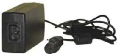
Figure 8.4: External Power Supply
• One 30" IEEE 1394 9-pin to 6-pin FireWire Cable

Figure 8.5: 30" IEEE 1394 9-pin to 6-pin 1394 Cable
• One 4.5 meter IEEE 1394 9-pin to 6-pin FireWire Cable

Figure 8.6: 4.5 meter IEEE 1394 9-pin to 6-pin 1394 cable
- Two Rack Ears w/ fasteners, rubber feet
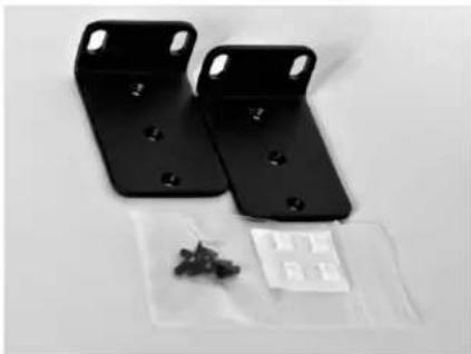
Figure 8.7: Rack Ears

Figure 8.8: Jumpers for Internal Configuration
• MIO Software CD-ROM
• Warranty/Registration Card
If any of these items are missing from your package when you open it, please contact Metric Halo or your dealer immediately for assistance.
6-pin to 6-pin IEEE 1394 cables are available from MH Direct.
Using the ULN-8 Hardware
ULN-8 Front Panel

Figure 8.9: ULN-8 Front Panel
The front panel provides ULN-8 system control and status at a glance:
• Monitor- Select the Monitor Controller input or output
- Preset- Recall one of the eight stored system configurations
- Input- Step through the available input sources
- Link- Link multiple input and output encoders for stereo or multichannel use
• +48- Enable phantom power, per channel
• U/M- User mode (for future expansion)
- Power switch for rear 4 pin XLR connector (jumper defeatable)
• Sample Rate (nominal 44.1, 48, 88.2, 96, 176.4 or 192KHz)
- The Sample Rate is determined from the currently selected clock source so it will accurately indicate the current sample rate, even when the clock source is being provided by an external device.
- Clock source:
- Internal indicates that the system is internally clocked
- Wordclock indicates that system is being clocked from the wordclock input
- 256x WC indicates that the system is being clocked from a 256x clock at the wordclock input
- Digital In indicates that the system is being clocked from the selected digital input
- Control Mode — Indicates what parameters the encoders are modifying:
- I/O Trim — Indicates whether you are modifying input or output channel gain.
- Input Status- Indicates mic input, line input or mic s/r by channel.
- Encoders- Eight detented encoders for multipurpose control, with push-switches.
- 15-segment metering for the 8 analog inputs and outputs using multicolor LEDs, which also display gain values during encoder use. The meters are fast PPM peak reading meters with auto-resetting peak holds.
- SysLock — Indicates that the system clock recovery circuit is properly locked to the selected clock source. If this light is not illuminated, the ULN-8 will not be locked to a clock and will revert to its failsafe internal clock source. Even if the Locked light is not illuminated, the actual sample rate will still be indicated on the front panel display.
- FireWire — Indicates that the ULN-8 has been successfully connected to a FireWire bus and has detected the isochronous cycle required to transmit and receive audio.
- Signal present indicators for AES input and output, as well as digital lock and cable select button and indicators.
• Monitor Control Section:
- The Mute and Dim buttons provide instant access to simple level control for the selected Monitor path or headphone output. The Mute button provides a quick, tactile "panic switch" which mutes
the monitors or front panel headphone output in case of accidental feedback loops and other audio unpleasanties. The Dim button attenuates the selected path by 20 dB.
- The Monitor Control encoder provides front panel adjustment for your audio. By pressing the encoder, it can toggle between affecting the Monitor Control section or headphones. There are two multicolor LEDs below the encoder that indicate which path the encoder is modifying as well as mute and dim status.
The ULN-8 front panel also provides access to the Headphone output. The headphone output jack is a TRS 1/4" jack that provides the Left Channel on the tip, the Right Channel on the ring and the ground return for the two channels on the sleeve. These signals are all ground referred, so they may also be split and fed single-ended (unbalanced) to an external audio device.
The ULN-8 headphone output is suited to a wide range of impedances. Headphones with lower impedance would be expected to get louder than those with higher impedance.
There are two DI inputs on the front panel, which are paralleled with Line inputs 1 and 2. The DI inputs can provide 0, 10, or 20db of gain selectable via internal jumpers.
More information regarding the front panel can be found in the ULN/LIO-8 Front Panel Guide.
ULN-8 Rear Panel

Figure 8.10: ULN-8 Rear Panel
The ULN-8 rear panel features:
• 4 pin XLR DC power jack (14v - 28v, 32 Watts)
- 8 channels balanced mic inputs on DB25. Each input has:
- -22 dB to +91.5 dB of gain range
• Dynamic Range (-60 dB, flat 0-22.05 kHz, typ): 115 dB
- +0/-1.0dB @ fs = 192KHz: 2.9 Hz - 64.7 kHz
- Noise Floor (flat 0-22.05 kHz, typ): 115 dB
- remote switchable 48v Phantom power, with 10mA current limit
- 8 channels balanced line inputs on DB25. Each input has:
- -12 dB to +31.5 dB of gain range
• Dynamic Range (-60 dB, flat 0-22.05 kHz, typ): 115 dB
• +0/-1.0dB @ fs = 192KHz: 1.8 Hz - 64.7 kHz
- Noise Floor (flat 0-22.05 kHz, typ): 115 dB
- 8 channels balanced line level sends on DB25 that mirror the selected input
- 8 channels balanced line/monitor outputs on DB25. Each output has:
• 24-bit 192kHz D/A converters (120dB SNR)
• Gain range from -96 dB to +30 dB
- Outputs 1 and 2 also multed to 1/4'' TRS connectors
• 8 channels AES digital I/O on DB25
- Single wire mode for full 8 channels at 44.1-192KHz operation
- Wordclock input/output on BNC connectors at 1x or 256x rates
• MIDI I/O to connect a control surface to MIO Console
- SMPTE input and output on 1/4" TRS
• Kensington security slot
• 2 IEEE 1394 (FireWire) ports (400 Mbs)
- 1 2.1mm DC power jack (14v - 28v, center positive, 32 Watts), unswitched
Signal Flow
![graph TD subgraph Analog Input 1-2 A["DI TRS"] --> B["O.I Amp"] C["Line DB25"] --> D["Line Amp"] E["Mic DB25"] --> F["Mic Amp"] G["Send DB25"] --> H["Send Amp"] I["Analog Input 3-8"] --> J["Line DB25"] --> K["Line Amp"] L["Mic DB25"] --> M["Mic Amp"] N["Send DB25"] --> O["Send Amp"] end subgraph Ana…](/content/2026/05/884165/images/3c873d3ecff2fb3233bc51a0f23ead8c409742e5aedd03e4d6400df73c9e49a8.jpg)
Figure 8.11: ULN-8 Signal Flow
Making connections to the ULN-8
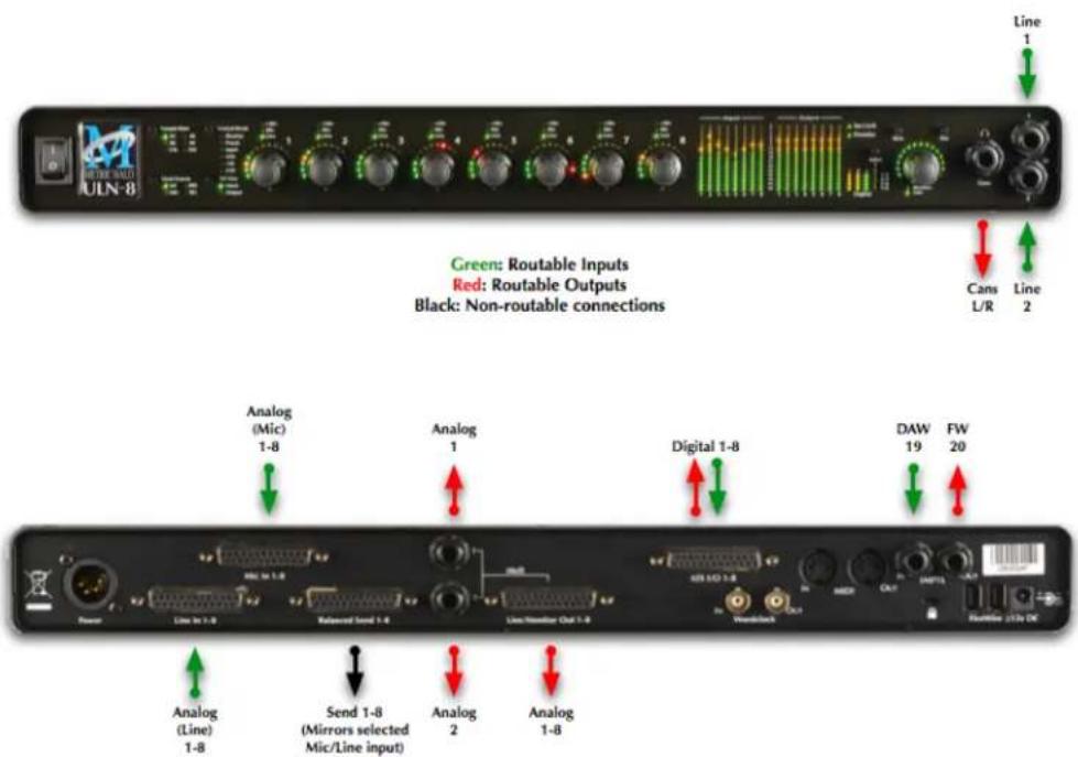
Figure 8.12: ULN-8 Routing
Click here for a larger version
There are seven classes of connections you can make to the ULN-8 hardware:
- Analog Audio
- AES Digital Audio
- Clock Sync
- FireWire
- Power
- MIDI
- SMPTE
Analog Audio Connections
The analog I/O connections on the ULN-8 have been engineered for maximum flexibility in that they support both balanced and unbalanced connections with a wide range of input and output levels and a wide range of matching impedances. The microphone inputs have an impedance of 3.3k Ω, and the line inputs are 10k Ω. With that in mind, there are a number of aspects of the design that you should take into account when interfacing with the ULN-8. All multichannel audio connections are made using industry standard DB25 connectors, which are pin-compatible with cables using the Tascam/Digidesign standard.
Wiring details for this connector can be found in the DB25 Pinouts appendix.
Whenever possible, use balanced connections with the ULN-8. The performance of balanced interconnects is much higher and much more resistant to noise interference and electrical (power) wiring problems. The expense of balanced interconnects is not substantially higher than unbalanced connections, so if the gear that you are interfacing with supports balanced connection — use it. If you cannot utilize balanced interconnects, there are connection schemes that you can use that will maximize performance.
On input, at line level, it is sufficient to simply use standard unbalanced (TS) connections. If you are interfacing with the Mobile I/O XLR inputs, you will need to ensure that pin 3 is grounded in the unbalanced adapter cable. More information about adjusting the input level can be found in the MIO Console software chapter.
ULN-8 DB25 cables should be wired pin 2 or Tip hot. The front and rear 1/4" connectors are wired Tip hot. The headphone connector is wired Tip/Left, Ring/Right, Sleeve/Ground.
Connecting to the DIs
The DI inputs provide an excellent high impedance input for directly connecting instruments to the ULN-8. These inputs are unity-gain summed with the corresponding line input from the back panel. This means that if you have signal connected to both the DI and line input for a given channel the ADC will see a mix of those two inputs. If you do not wish to have signal from one of the connectors you need to physically disconnect that input or otherwise ensure that no signal is present at the unused input.
You may notice that the MIO Console has an input selection for "Inst". This can be used as a visual reminder that you are plugged into the DI, but has no operational effect on the input. Selecting "Inst" on any channel of the ULN-8 sets the input to Line +4; the only DI input is available from the front panel jacks for inputs 1 and 2.
Each DI input supports balanced connections via TRS cable. You can connect a source to the DI via a balanced interconnect (if the source is actually a balanced output), an unbalanced interconnect (if the source is unbalanced like most instruments), or a telescoping shielded cable (which is an alternate unbalanced connection that provides additional shielding).
Since the DI inputs provide an ultra-high input impedance, if you connect an unbalanced source to the DI via a balanced cable you will float the negative input and will effectively inject a large DC offset into the output of the DI which will cause the associated ADC to mute. As a result you must use either a TS cable or a telescoping shield cable with unbalanced sources.
When you remove the connector from the DI jack, the DI connects its inputs to ground internally to remove any possible residual DC offset or pickup noise. If you disconnect the cable from the source but leave it connected to the DI input, the cable will function as an antenna and will inject noise into your inputs and may cause
enough of a DC offset to mute the ADC. As a result you should always disconnect the cable from the DI rather than the instrument.
Balanced Sends and Mic S/R Mode
The ULN-8 has eight balanced sends; these mirror the analog input you have selected to feed that channel's A/D converter. For example, if you select the Mic input on analog channel 1, the output of that mic preamp will be available at send 1. If you select the Line input on analog channel 1, the Line in signal will be available at send 1. This allows you to use the sends as a splitter to feed a mixing console, recorder or other equipment.
Using analog inserts on the ULN-8
The "Mic S/R" input mode creates pre-converter inserts on a per-channel basis by utilizing the Mic input as the channel input and Line input as the insert return. For example, to insert a compressor on Analog 1:
- Set Analog 1's input type to Mic S/R
- Connect your signal (mic or line level) to Mic input 1
- Connect Send 1 to your compressor's input
- Connect your compressor's output to Line input 1
You have now inserted your compressor between the output of the mic preamp and the A/D converter.
You cannot route signal from a DAW channel to the balanced sends; to route signals from your computer to the D/A converters, you must use the Line/Monitor outputs.
AES Digital Audio
The ULN-8 supports 8 channels of digital audio over copper-based connections. The native format of the ULN-8 is AES, but can be converted to SPDIF or optical using third-party adapters. The ULN-8 operates in single-wire mode, providing 8 channels of digital audio at all sample rates. The ULN-8's digital I/O connections are made using industry standard Tascam/Digidesign pinout DB25 cables. If you want to connect the ULN-8 to a device that uses the Yamaha DB25 pinout, you will need to source a DB25 crossover cable.
Wiring details for this connector can be found in the DB25 Pinouts appendix.
Clock Sync
Clock sync is a serious consideration in any digital audio system.
If you are recording analog sources with ULN-8, you can simply use the unit's high-quality internal clock source to drive the converters. This is the easiest case to deal with.
If you need to interface with other devices digitally or ensure sample accurate sync with video sources, the extensive clock synchronization capabilities of ULN-8 will prove to be more reliable (and better sounding) than most higher priced alternatives.
There are three different ways to get external clock information into the unit:
- Sending a 1x word clock signal into the WC Input BNC.
- Sending a 256x word clock signal into the WC Input BNC.
- Sending an AES signal into the Digital input.
The BNC word clock input port is a 75 Ohm terminated coaxial input. It should be driven by a 75 Ohm source driver and interconnected with 75 Ohm coaxial cable. If you do not use proper cabling and source drive, you will introduce reflections on the word clock cable which will propagate jitter into the recovered word clock. This is true whether you use the port as a 1x WC input or a 256x WC input, but becomes more important when the clock signal is 256x.
1x is generally appropriate for use with devices that provide a word clock output. If your device provides a 256x output, you may find that you get better results using that clock signal. The Digidesign® line of Pro Tools® products use 256x as their "SuperClock™" clocking signal.
The AES recommended procedure for distributing clock is to use an AES clock signal. The AES clock signal is an AES digital audio signal with no audio activity. The ULN-8 only uses the AES preambles for clock recovery, so it is immune to data dependent jitter effects. This means you can reliably use the Digital Input as a clock source with or without audio data.
FireWire
Detailed information on FireWire implementation can be found in the FireWire appendix.
Power
One of ULN-8's great strengths is the flexibility of its power system. The ULN-8 can be powered from any DC source in the range of 14V to 28V as long as it provides 32 Watts of power. The DC inputs on the ULN-8 are a 2.1mm coaxial power connector, center positive and a 4-pin XLR connector Pin 4 Hot. So if you are powering the unit with a third party power source and it supplies 14V, the power source will have to provide 2.3 amps of current. If you are powering the unit with 24V, the power source will have to provide 1.3 amps of current, and so on.
The ULN-8 ships with a world-ready 24 volt, 2 amp power supply. You can plug this supply into any AC power source from 90V to 240V, 50Hz - 60Hz, using an appropriate IEC power cord, and it will supply the proper power to the ULN-8 on the 4 pin XLR power connector. The ULN-8 will not supply power to the FireWire bus, but will pass power coming from other devices.
As with all electronic devices, when connecting an external power source to the ULN-8, you should first connect the power source to the ULN-8 while it is in an unenergized state (e.g. not connected to the mains or switched off). After the connection to the ULN-8 has been made, you should energize the power source.
If you connect an energized power source to the ULN-8's 2.1mm power connector you may see a small spark when you make the connection. This is due to surge current and is normal if you connect a power source in this way. While this will not damage the ULN-8 in any way, to avoid the spark just connect the power connector to ULN-8 before connecting the power source to the wall.
MIDI
The ULN-8 offers MIDI input and output ports for direct connection of a control surface. These ports are only active while MIO Console is running; the ULN-8 cannot utilize a control surface in standalone operation. MIO Console makes these ports available to other applications while it is running, but the MIDI implementation is currently optimized for control use only- it is not recommended to use these ports for connecting keyboards or other devices that require accurate timing.
SMPTE
The ULN-8 has SMPTE input and output ports for timecode use. The SMPTE I/O occupy their own channels and do not require using a channel of A/D or D/A conversion. SMPTE input is presented to CoreAudio applications as DAW 19 in our driver, and is accessible via any CoreAudio compliant software including the Record Panel in MIO Console. SMPTE output may be accessed by routing the SMPTE signal to FW 20. Please note that MIO Console does not natively decode or encode MTC at this time; if you need to synchronise to MTC, you will need third party software.
ULN-8 Specifications
Table 8.1. ULN-8 Voltage Rails
| Rails | |
| Preamp Rails ±15.8 Volts | |
| Analog Rails (low power) ±9.9 Volts | |
| Analog Rails (high power) ±12.6 Volts | |
| Phantom Power 48 ± 0.1 Volts | |
| Max Phantom Current Per Mic 10 ma |
Table 8.2. ULN-8 Maximum I/O Levels (Balanced)
| Maximum I/O Levels (Balanced) | |
| Peak Line Output @ 0 dBFS (no jumper/low power) +1 | 8.5 dBu |
| Peak Line Output @ 0 dBFS (output jumper/low pow-er) | +22.0 dBu |
| Peak Line Output @ 0 dBFS (output jumper/high power) | +24.5 dBu |
| Analog Send Max Output +21.5 dBu | |
| Mic Pre Max Input +20 dBu | |
| Line In Max Input +24.5 dBu | |
| Output Impedance 5 Ω |
Table 8.3. ULN-8 Monitor Controller
| Monitor Controller | |
| Nominal FS output (Balanced) Output Jumper Off -19.0 dBu | |
| Nominal FS output (Balanced) Output Jumper On -12.0 dBu | |
| Maximum Output Same as Line | |
| Gain Range -96 dB to +30 dB | |
| Gain Precision ±0.05 dB | |
| Gain Step 0.5 dB | |
Table 8.4. ULN-8 Mic Pre Input + ADC
| Mic Pre Input + ADC | |
| Input Impedance 3.3k Ω | |
| Dynamic Range (-60 dB, flat 0-22.05 kHz, typ) 115 dB | |
| Dynamic Range (-60 dB, A-weighted, typ) | 118 dB |
| Noise Floor (flat 0-22.05 kHz, typ) | 115 dB |
| Noise Floor (A-weighted, typ) | 117.9 dB |
| Gain Range -22 dB to +91.5 dB | |
| Gain Precision ±0.05 dB | |
| Gain Step 0.5 dB | |
| THD D/A/A/D loop @ -12 dBFS | 0.0007 % |
| THD D/A/A/D loop @ -12 dBFS +12 dB Gain | 0.0015 % |
| THD D/A/A/D loop @ -0 dBFS | 0.0023 % |
| Crosstalk @ 1kHz | -110dB |
| IMD 1k component (19 kHz/20kHz @ +8dBu) | -104 dBu |
| EIN @ 60 dB Gain (150 Ω Source Impedance) -130.50 dBu | |
| EIN @ 60 dB Gain (0 Ω Source Impedance) -133.25 dBu | |
| Analog Send Calibration (ADC = 0 dBFS) +21.5 dBu | |
| Phantom Power (Switchable Per Channel) +48 Volts | |
Table 8.5. ULN-8 Mic Pre + ADC Frequency Response
| Mic Pre + ADC Frequency Response | |
| +0/-0.1dB @ fs = 44100 Hz 8.9 Hz - 20.5 kHz | |
| +0/-1.0dB @ fs = 44100 Hz 2.9 Hz - 21.0 kHz | |
| +0/-0.1dB @ fs = 96000 Hz 8.9 Hz - 43.9 kHz | |
| +0/-1.0dB @ fs = 96000 Hz 2.9 Hz - 45.4 kHz | |
| +0/-0.1dB @ fs = 192000 Hz 8.9 Hz - 42.1 kHz | |
| +0/-1.0dB @ fs = 192000 Hz 2.9 Hz - 64.7 kHz | |
| 5° low-end in-channel phase deviation point 20.0 Hz | |
| Interchannel phase 0 Hz - 20 kHz < ±0.05° | |
| Crosstalk from SMPTE Input < -142 dB |
Table 8.6. ULN-8 Line Input + ADC
| Line Input + ADC | |
| Input Impedance 10k Ω | |
| Dynamic Range (-60 dB, flat 0-22.05 kHz, typ) 115 dB | |
| Dynamic Range (-60 dB, A-weighted, typ) 118 dB | |
| Noise Floor (flat 0-22.05 kHz, typ) 115 dB | |
| Noise Floor (A-weighted, typ) 117.9 dB | |
| THD D/A/A/D loop @ -12 dBFS 0.0005 % | |
| THD D/A/A/D loop @ -0 dBFS 0.0015 % | |
| Crosstalk @ 1kHz | -127 dB |
| IMD 1k component (19 kHz/20kHz @ +8dBu) | -104 dBu |
| Gain Range | -12 dB to +31.5 dB |
| Gain Precision | ±0.05 dB |
| Gain Step | 0.5 dB |
Table 8.7. ULN-8 Line Input + ADC Frequency Response
| Line Input + ADC Frequency Response | |
| +0/-0.1dB @ fs = 44100 Hz 5.7 Hz - 20.5 kHz | |
| +0/-1.0dB @ fs = 44100 Hz 1.8 Hz - 21.0 kHz | |
| +0/-0.1dB @ fs = 96000 Hz 5.7 Hz - 43.9 kHz | |
| +0/-1.0dB @ fs = 96000 Hz 1.8 Hz - 45.4 kHz | |
| +0/-0.1dB @ fs = 192000 Hz 5.7 Hz - 42.1 kHz | |
| +0/-1.0dB @ fs = 192000 Hz 1.8 Hz - 64.7 kHz | |
| 5° low-end in-channel phase deviation point 10.7 Hz | |
| Interchannel phase 0 Hz - 20 kHz < ±0.05° | |
| Crosstalk from SMPTE Input < -142 dB |
Table 8.8. ULN-8 Converter Latency
| Latency | |
| A/D 63 samples | |
| D/A 44 samples |
Table 8.9. ULN-8 Input Processing
| Input Processing | |
| M/S Decode Instantiable | |
| Parametric EQ Instantiable | |
| Dynamics Instantiable | |
| Limiting Instantiable | |
| Character Instantiable | |
| Transient Control Instantiable | |
| Reverb Instantiable | |
| Delay Instantiable | |
| Nearly Infinite Combinations via +DSP Instantiable |
Table 8.10. ULN-8 Output Processing
| Output Processing | |
| M/S Encode Instantiable | |
| Parametric EQ Instantiable | |
| Dynamics Instantiable | |
| Limiting Instantiable | |
| Character Instantiable | |
| Transient Control Instantiable | |
| Reverb Instantiable | |
| Dither Instantiable | |
| Mix Foldown Instantiable | |
| Signal Generation | Instantiable |
| Nearly Infinite Combinations via +DSP Instantiable |
Table 8.11. ULN-8 Front Panel
| Front Panel | |
| Indicator LEDs (Bicolor) | 495 |
| Meters | 16 |
| Segments per Meter | 15 |
| Channel Encoder Knobs | 8 |
| Encoders Have Shaft Push Buttons Yes | |
| Monitor Controller Encoder Knobs 1 | |
| Monitor Controller Mute Yes | |
| Monitor Controller Dim Yes | |
| Indicators Per Encoder 16 | |
| Sample Rate Indicators 6 | |
| Clock Source Indicators 4 | |
| AES Clock Source Indicators 4 | |
| AES Lock Indicators 4 | |
| AES Input Signal Indicators 4 | |
| AES Output Signal Indicators 4 | |
| System Lock Indicator 1 | |
| Firewire Indicator 1 | |
| Front Panel Modes 14 | |
| Headphone Output (Dedicated DAC) TRS Stereo | |
| DI Inputs (2) TRS Balanced | |
| DI Input Impedance 10M Ω | |
| DI Input Fixed Gain (Jumper Selectable) | 0/10/20 dB |
| DI Input Variable Gain -12 dB to 31.5 dB | |
| Power Switch (Jumper Defeatable) | Toggle |
Table 8.12. ULN-8 Back Panel
| Back Panel | |
| MIDI Connectors (In and Out) | 5-Pin DIN |
| SMPTE Connectors (In and Out) | Balanced TRS |
| Word Clock Connectors (In and Out) | 75 Ω BNC |
| AES Connector (8 Channels In and Out) | DB-25 |
| AES Connector Pinout | Tascam/Digidesign Digital |
| Mic Input Connector (8 Channels) | DB-25 |
| Mic Input Pinout | Tascam/Digidesign Analog |
| Line Input Connector (8 Channels) DB-25 | |
| Line Input Pinout | Tascam/Digidesign Analog |
| Send Output Connector (8 Channels) | DB-25 |
| Send Output Pinout Tascam/Digidesign Analog | |
| Line/Monitor Output Connector (8 Channels) | DB-25 |
| Line/Monitor Output Pinout | Tascam/Digidesign Analog |
| Line/Monitor Mult Output Connectors (Analog 1/2) | TRS Balanced |
| FireWire Connectors (2) | 1394a 6-Pin |
| Power (Unswitched) | 2.1mm Coaxial |
| Power (Switched) 4-Pin XLR | |
| Security Slot Kensignton |
Table 8.13. ULN-8 Software
| Software | |
| Driver CoreAudio Mac OS X | |
| Mac OS X 10.3.9 or newer | |
| Architectures PPC, Intel | |
| MIO Console Included | |
| Record Panel Included | |
| LTC Decoder Included | |
| Mixer Included | |
| +DSP License Included |
Table 8.14. ULN-8 Power
| Power | |
| Voltage 14v - 28v | |
| Power 32 Watts | |
| FireWire Bus Powerable No | |
| Passes FireWire Bus Power Yes | |
| Supplies FireWire Bus Power No | |
| External Supply (Input) I00-240VAC | |
| External Supply (Max Input Current) 1.2 A | |
| External Supply (Output) 24 VDC | |
| External Supply (Max Output Current) | 2.0 A |
| External Supply Connector | 4-Pin XLR |
Table 8.15. ULN-8 Case
| Case | |
| Material | Powder Coated Aluminum |
| Fasteners | 3mm Phillips Head |
| Weight | 6 lbs |
| Weight | 2.7 kg |
| Dimensions | 17" x 13" x 1.72" |
| Dimensions | 432 x 330 x 44 mm |
| Rack Ears (included) | Powder Coated Steel |
| Rear Rack Mounts | Available |
9. ULN/LIO-8 Front Panel Guide
Front Panel Overview
The ULN-8 and LIO-8 feature a flexible front panel with comprehensive controls, status and meter readouts. The Front Panel allows you to utilize the interface without any computer attached and also communicates bidirectionally with MIO Console to keep the Console controls and the Front Panel controls synchronized at all times.

Figure 9.1: ULN-8 Front Panel
A note for LIO-8 owners:
References to "Mic" features only apply to you if you have the optional ULN-R microphone preamps installed.
The Front Panel is split into a number of functional areas:
• Sample Rate Indicators and Control
- Clock Source Indicators and Control
• Control Mode Indicators and Selector
• I/O Trim Mode Indicators and Selector
- Channel Mode Indicators (above the knobs)
• Per Channel Control Knobs with value indicators
• High Resolution 1.5 Segment Input Meters
• High Resolution 15 Segment Output Meters
• System Status Indicators
• AES Status Indicators (per cable)
- Input Signal
- Output Signal
- Input Locked
• Cable Select for Clock Source
• Monitor Control Section
- Mute and Dim buttons for Monitor Control
• Monitor Control Knob
• Dedicated Headphone out Jack
• Summed DI inputs for channels 1 and 2
Let's take each of these functional areas one by one and explain the details.
Sample Rate Indicators and Control
The Sample Rate area of the Front Panel has 6 indicator LEDs to show you the nominal sample rate that the box is running at. The available sample rates are:
• 44.1k
• 48k
• 88.2k
• 96k
• 176.4k
• 192k
The Front Panel also has a Tactile switch next to the "Sample Rate" legend that may be used to cycle through the available nominal sample rates when the unit is running on internal clock. Every time you press the tact switch, the unit will switch to the next higher sample rate, unless it is currently at 192k, in which case it will switch back to 44.1k.

Figure 9.2: Sample Rate
These indicators show the current nominal rate, so if you are externally clocked from a source that is running at a pulled-up or pulled-down rate, the indicator will show the closest nominal rate.
Clock Source Indicators and Control
The Clock Source area of the Front Panel has 4 indicator LEDs to show you the currently selected clock source for the box. The clock sources are:
- Int — Internal Clock
- AES — Clock from selected AES cable
• 256 — Clock from BNC input from a 256x clock - WC — Clock from BNC input from a 1x clock
The tactile switch next to the "Clock Source" legend steps through the available clock sources. When using a clock source other than Internal, pushing the Clock Source button cycles through the 1, 2, and 4x clock rates for the currently selected source before moving to the next selection.

Figure 9.3: Clock Source
Control Mode Indicators and Selector
The Control Mode area of the Front Panel has 6 indicator LEDs to show you the currently selected front panel control mode for the box. The control modes are:
- Monitor
- Preset
- Input
- Link
• +48
• U/M
The details of each control mode will be addressed in dedicated sections of the documentation below. One thing that is critical to understand is that it is possible for none of the indicators listed above to be illuminated. If this is the case, then it means that the front panel control mode is indicated by one of the I/O trim mode indicator LEDs. If one of the indicators listed above is illuminated, it means that the I/O trim mode indicator LED reflects whether the controls are going to affect input channels or output channels.

Figure 9.4: Control Mode
The tactile switch next to the "Control Mode" legend steps through the available control modes.
I/O Trim Mode Indicators and Selector
The I/O Trim area of the Front Panel has 2 indicator LEDs:
- Input
- Output
to show you the currently selected front panel control focus for the box.
The details of each focus mode will be addressed in the dedicated control mode sections of the documentation below. In addition, the Input trim mode and Output trim mode will also be discussed in more detail. These two modes are selected when none of the indicators in the Control Mode section are illuminated.
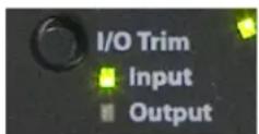
Figure 9.5: I/O Trim Mode Indicators
The tactile switch next to the "I/O Trim" legend steps through the available focus/control modes.
Channel Mode Indicators
The Channel Mode area is above the 8 channel control knobs. Each knob has 3 LEDs above it that reflect the state of the associated input channel mode. The indicators are:
• +48v
- Mic
- Line
The +48v indicator is illuminated RED when the associated Mic Pre channel has Phantom power energized.

Figure 9.6: Mic/Line Indicator
The Mic and Line indicators are utilized as a group and are illuminated to indicate the following input modes:
Table 9.1. Mic/Line Indicator Modes
| Mic Line Mode | ||
| On (green) Off Input from Mic Pre Input | ||
| Off On (green) Input from Line Input | ||
| On (green) On (green) Mic Send/Return Mode |
Per Channel Control Knobs
The eight numbered knobs are detented rotary encoders with integrated push button tact switches. Each knob has a ring of 15 bi-color (red/green) LEDs around it and a bi-color "flexi" led below it. Both the ring of LEDs and the "flexi" LED may be used for different purposes depending on the current control mode.

Figure 9.7: Front Panel Control Knob
The operational effect of the knobs depends on the currently selected control mode for the front panel. When the currently selected control mode is a mode that controls channel parameters (e.g. Input, Link, +48, Input Trim and Output Trim) each knob is associated with the channel number indicated next to the knob. When the currently selected control mode is a global mode (e.g. Monitor, Preset, and U/M), then the knob reflects the associated selection number for the mode. See below for more details.
The data displayed in the indicator ring around each knob is also determined by the currently selected mode. The indicator ring supports displaying the following kinds of data:
• High Resolution "Digital Dual Vernier™" gain readout
- Input Meters
- Selected State for Mode Selection (Monitor, Preset, and U/M Modes)
- Link Status Indication (Link Mode)
The details of each of these indication modes will be discussed in the dedicated control mode sections of the documentation below.
High Resolution Meters
The Front Panel provides 16 meter bars with 15 segments per bar. Every segment is a bi-color LED with programmable color. The meters are grouped into two 8 meter blocks; the block on the left hand side is used for Analog Input meters and the block on the right is used for Analog Output meters. By default, the 15 segments
of the meters are used to indicate signal levels at -66, -54, -42, -36, -30, -24, -21, -18, -15, -12, -9, -6, -3, -1, and 0 dBFS.
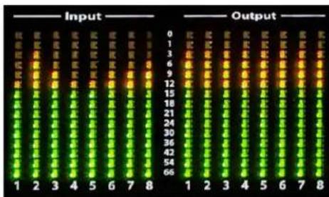
Figure 9.8: Analog I/O Meters
Since each element in the meter is a bi-color LED, the colors of the segments is under software control. The meters are configured to show green until -12 dBFS, yellow until -1 dBFS, and Red for the 0 dBFS indicator. In addition to the configured level-based color break-points, the meters have a user-configurable "clip" level and clip-hold time. The clip characteristics are configurable independently for the inputs and outputs. When the level of a specific metered channel exceeds the clip level you have specified the entire meter bar turns Red, and remains Red for the clip-hold time that you have specified. This unique functionality immediately and unmistakably alerts you to overs that occur.
The default setting for the output meter block is for the clip threshold to be at 0dB (which means that the full-bar clip indication never turns on). This is configured this way because any setting lower than 0dB will indicate nearly continuous clipping in most contemporary mastered material.
The output meter section has a secondary function in addition to metering the analog output channels. When you make a change to an I/O or monitor gain from the front panel, the output meter section is temporarily used as a bitmap display that numerically shows the current gain level in dB. The digits are arranged in two rows. The top row shows the tens and units places and the bottom row shows the overall sign and the tenths place. When the gain is positive (greater than or equal to 0 dB), the digits are shown in green. When the gain is negative (less than 0 dB), the digits are shown in yellow.

Figure 9.9: Front Panel Numeric Readout
For example, if the gain being read out is 10.0 dB, then the display will look like:

Figure 9.10: Positive Gain Display
If the gain being read out is -21.5 dB, then the display will look like:

Figure 9.11: Negative Gain Display
System Status Indicators
The Front Panel has two system status indicators to let you know if the box has detected a valid FireWire connection and to let you know if the System's internal PLL is locked.
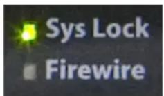
Figure 9.12: System Status
The FireWire Indicator will be illuminated green whenever the box detects a valid sequence of FireWire isochronous cycles on the connected FireWire bus. When the FireWire indicator is illuminated, it means that the box is communicating with the FireWire bus properly.
The Sys Lock indicator will be illuminated green when the internal PLL is locked and within normal operating ranges. This indicator lets you know if the box is locked to a valid clock source.
AES Status Indicators
There are a total of 16 indicators in this area. There are 4 columns and 4 rows. Each row represents a different AES port/cable. Each port carries two channels of audio, so the columns are labeled 1+2, 3+4, 5+6 and 7+8. The columns provide indicators for 4 different types of status:
• / — Input Level for corresponding port
- O — Output Level for corresponding port
- L — Input receiver Locked for corresponding port
• C — Input port selected as AES clock source
The Input Level and Output Level indicators show the highest level on the channel pair via brightness and color. They can be treated as "signal present indicators".
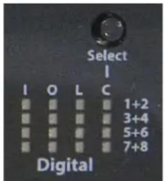
Figure 9.13: AES Indicators
The Locked indicator is illuminated when the AES receiver for the corresponding input port detects and locks to a valid AES signal. Please note that this does NOT indicate that the input is locked at the same rate as the
rest of the box, but just that the AES signal is being properly decoded and (a) could be used as a valid clock source and (b) will provide valid audio if the input is running at the same rate as the rest of the box.
The AES Clock source indicator is illuminated when the corresponding input port has been selected as the clock reference for external AES clock. At most one of the 4 AES Clock source indicators will be illuminated. If the box's clock source is not set to AES, then none of these indicators will be illuminated.
Monitor Control Section
The Front Panel provides a Monitor Control Section that allows you to control both the dedicated headphone monitor level and the monitor level of the outputs assigned to the monitor controller. You switch between the headphones and the monitor controller by pressing the monitor control knob (activating the integrated switch). The currently selected path is indicated by the currently illuminated LED under the monitor control knob.
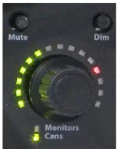
Figure 9.14: Monitor Control Knob
In addition to the Monitor Control knob, there are two tact switches above the Monitor Control knob — Mute and Dim. These two buttons function as toggle switches and apply to the currently selected monitor path. When the MUTE is engaged, the selected path indicator turns Red and the output is muted. When the DIM is engaged, the selected path indicated turns yellow, and the output level is turned down by 20 dB. Both MUTE and DIM can be engaged at the same time, and the MUTE mode will dominate.
The Front Panel includes a dedicated headphone output with its own discrete DAC, headphone amp and analog domain volume control. The monitor control knob controls the Volume Control for this output when the monitor control mode is set to Cans.

Figure 9.15: Cans Jack
Front Panel DI Inputs
The Front Panel provides two Ultra-Hi-Z DI inputs that are summed into the Channel 1 and Channel 2 line input paths. The DI inputs have programmable gains that are configured via jumpers (this requires opening the box). The signals applied at the DI will appear on the corresponding line inputs mixed with any signal present at the line input on the back panel. If you do not want this mixing, you should ensure that only one connector
is actually utilized at a time (the back-panel connector or the DI connector). You can utilize this to good effect if you need to add an additional input -- but the sum is a unity gain sum so you need to get the relative levels correct at the inputs. The mix on these inputs is printed at the ADC.

Figure 9.16: DI Jacks
Control Mode Details
Selecting Amongst the Control Modes
Each time you press the tactile switch next to the "Control Mode" legend, the control mode will switch to next control mode in the list. You can also switch directly to any of the control modes with a direct access shortcut. To directly access a particular control mode, press and hold the Control Mode button, and while holding the Control Mode button, press the knob switch for the mode you want to select directly:
- Monitor
- Preset
- Input
- Link
5.+48 - U/M
- Input Trim
- Output Trim
The details of each control mode are discussed in depth below.
Monitor
When Monitor Mode is selected, the integrated switches in the 8 channel control knobs function as selector switches for the Monitor Controller in MIO Console. Monitor Mode requires MIO Console to be running to function.
In Monitor Mode, the I/O Trim selection controls which Monitor Controller Selector the switches will affect. If the I/O Trim selection indicator is on Input, then the selection controls will choose from the Monitor Controller Input Sources. If the I/O Trim selection indicator is on Output, then the selection controls will choose from the Monitor Controller Output Destination.
The currently selected path (source or destination) is indicated by illuminating the ring around the corresponding knob in yellow.
Communication between the MIO Console Monitor Controller and the front panel is bi-directional — making changes in the software will be reflected on the Front Panel, and making changes via the Front Panel will be reflected in the software.
Preset
When Preset Mode is selected, the integrated switches in the 8 channel control knobs function as selector switches to load a stored snapshot state from Flash memory into the currently running hardware. When you select Preset Mode, the snapshot registers that have a preset stored in memory (you store these snapshots using the Utility menu in MIO Console) will have their rings illuminated in dim green. Pressing the switch on a knob that has a dim green ring illuminated around it will load that snapshot and will change the illumination to bright green (which indicates the currently loaded snapshot).
You can use this feature to pre-configure complex routings and processing for the ULN-8 and LIO-8, and then be able to recall these configurations for using the interface with no computer present as a stand-alone Pre-amp/Converter with any processing that you find appropriate for your uses (for example- you could pre-configure low-cut filters or M/S decoders on channel pairs, and have that configuration available for instant recall).
Please see the Bootstates and Snapshots section of this manual for information on saving your information into the ULN/LIO-8.
Front panel recall on the ULN-8/LIO-8
On the ULN-8 and LIO-8, encoder 1 recalls the "bootstate" snapshot. User snapshot #1 is recalled on encoder 2 and so on through snapshot #7 on encoder 8. There is no snapshot recall on the Monitor Control encoder, since that button toggles between Monitor and Cans.
Input
When Input Mode is selected, the knob shaft switches toggle the corresponding input mode between Line, Mic and Mic S/R modes. The rotary knob continues to indicate and control the currently selected I/O Trim (see below).
Link
When Link Mode is selected, the knob shaft switches can be used to configure linking between the trim knobs. The trim link system implemented in the control panel is very flexible.
Both Input Gain Links and Output Gain links can be controlled. You choose which set of links is being edit by choosing between Input Trim mode and Output Trim mode.
Link Model: The basic model of the trim link system is that you choose a master knob and then choose other knobs to be linked to that master knob. When you change the gain on the master, the same gain change is applied to the slave knobs. The link is unidirectional. This means that if you turn one of the slave knobs, that gain change created by that action will only be applied to the slave knob itself, and not to the master that it is linked to or any of the other slaves. Now, each knob can be a master and two or more knobs can be cross-linked, so you can configure bi-directional links, but you may want to consider the benefits of unidirectional links as they allow you to trim a slave gain relative to a master gain after the link has been created.
When you first enter Link Mode, all the knob indicators will be off. You choose a master knob by pressing the knob switch. The master knob indicator will be illuminated green. Now you can press the knob switches for the slave knobs that you would like to assign to the selected master (the knobs assigned as slaves will illuminate in yellow). To choose a new master knob to configure, press the knob switch on the currently selected master knob (the one illuminated in green) and all the knob indicators will turn off. Now you can select another master knob to configure by pressing the knob button.
If you want to configure a pair (say 1 and 2) of knobs cross-linked, you can follow these steps:
- Select Link Mode
- Press knob 1 to select it as a master — it will illuminate green
- Press knob 2 to select it as a slave of knob 1 — it will illuminate yellow
- Press knob 1 to deselect it — this will remove the illumination from all the knobs
- Press knob 2 to select it as a master — it will illuminate green
- Press knob 1 to select it as a slave of knob 2 — it will illuminate yellow
- Press knob 2 to deselect it — this will remove the illumination from all the knobs
After step 4, knob 2 was slaved to knob 1 -- rotating knob 1 would change both knob 1 gain and knob 2 gain, but changing the knob 2 gain would not change knob 1's gain. After step 7 knob 1 was also slaved to knob 2, so changing either knob will cause a corresponding change in both knobs.
+48
When Input Mode is selected, the knob shaft switches toggle the corresponding input preamp's phantom power on and off. It is possible to turn on the preamp phantom power even if the line input is currently selected. This is so that you can use the input mode to switch between the Line and Mic inputs without pulsing the phantom power on and off. The rotary knob continues to indicate and control the currently selected I/O Trim (see below).
U/M — User Mode
When User Mode Mode is selected, the knobs function as a software configured control surface for MIO Console. At the present time, there are no functions in MIO Console that are controlled by User Mode.
Input Trim
When the Input Trim light is the only illuminated indicator in the Control Mode Column, the Front Panel is in Input Trim Control Mode. When Input Trim Control Mode is selected, rotating one of the 8 control knobs will adjust the input gain of the associated analog input channel (and preamp, if the selected input is the Mic input). The current gain of the channel is indicated via Metric Halo's Digital Dual Vernier™ indication technology in the indicator ring around the knob. When you change a gain or press the knob shaft switch, the current gain is indicated numerically on the output meter area of the front panel.
By default, each click of the knob will increase (CW) or decrease (CCW) the gain of the associated channel by 0.5 dB. If you press and hold the knob shaft button while rotating the knob, it will adjust the gain by 3 dB per click. These values may be changed in the Front Panel Preferences in MIO Console.
The box automatically interpolates the gain in hardware as you are changing it -- allowing even dramatic changes in the gain to be made clicklessly and transparently.
Changes to channel gains are automatically applied across any link-groups that you have configured, allowing you to seamlessly adjust gains on 1 to 8 channels simultaneously.
Digital Dual Vernier™ Indication Technology
All of the control knobs utilize Digital Dual Vernier technology to provide precise indication of the current setting of the associated value over a wide range. Each knob has 15 bi-color indicators. The dual vernier approach uses two different colors to indicate both the coarse setting of the control and the fine offset from the coarse setting.
The coarse setting is indicated by segments that are illuminated green. As the coarse setting increases, segments are illuminated in a clockwise direction starting from the left hand side of the ring. Each illuminated green segment indicates a 7.5 dB increase in level.
A single segment will be illuminated Red to indicate the positive offset from the current coarse setting indicated by the green bar. Each fine segment indicates an increase of 0.5 dB. When no segment is illuminated Red, it means that there is no offset (0 dB) from the level indicated by the green bar.
Meters on the Knobs
The input knobs support an additional indicator mode, when the Front Panel is in Input Trim mode: Input Meter mode. When this mode is selected, rather than showing the Dual Vernier level of the input gain on each knob, the channel's input meter is shown on the indicator ring of the corresponding knob. The configured break-point colors are used for the indicators, and if the input channel clips, the same settings for full-bar clip indication and hold are used on the knob indicator meters.
This mode, combined with the precise numerical readout of the gain available on the front panel, is ideal for tracking because the channel levels are indicated concentrically around the control used to adjust the channel gain. This allows you to simply reach out to a clipping or overly high channel and turn it down without having to engage in any difficult mental gymnastics to try to correlate the meter with the control.
Toggling meter modes
To toggle between meters on the knob mode and dual vernier mode, press and hold knob #1 and then (while still holding knob #1) press knob #8.
Output Trim
When the Output Trim light is the only illuminated indicator in the Control Mode Column, the Front Panel is in Output Trim Control Mode. When Output Trim Control Mode is selected, rotating one of the 8 control knobs will adjust the output gain of the associated analog output channel. The current gain of the channel is indicated via Digital Dual Vernier indication technology in the indicator ring around the knob. When you change a gain or press the knob shaft switch, the current gain is indicated numerically on the output meter area of the front panel.
By default, each click of the knob will increase (CW) or decrease (CCW) the gain of the associated channel by 0.5 dB. If you press and hold the knob shaft button while rotating the knob, it will adjust the gain by 3 dB per click. These values may be changed in the Front Panel Preferences in MIO Console.
The box automatically interpolates the gain in hardware as you are changing it -- allowing even dramatic changes in the gain to be made clicklessly and transparently.
Changes to channel gains are automatically applied across any link-groups that you have configured, allowing you to seamlessly adjust gains on 1 to 8 channels simultaneously.
Illumination (Brightness) Adjustment
In either Control or I/O Trim mode, the illumination level of the front panel may be adjusted by holding down the I/O Trim tact switch and rotating channel encoder 8.
Front Panel Preferences in MIO Console
There are several aspects of the front panel's operation that can be changed from within MIO Console. These preferences are set per box. In the I/O Control tab, there are a set of disclosure arrows next to the serial number of each interface
ULN-8/000113
Figure 9.17: Disclosure Triangle
indicating that this has a contextual menu. Click this to access the menu, and select "Front Panel Prefs..." at the bottom. The front panel preference sheet will appear:

Figure 9.18: Front Panel Preference Sheet
The options are:
- Input Links matrix
Allows you to link input channel encoders (more info in the Link mode section).
• Output Links matrix
Allows you to link output channel encoders (more info in the Link mode section). - Front Panel Brightness
Scales the brightness level of the front panel (more info in the Illumination adjustment section).
• Front Panel Normal Intensity
Sets the maximum illumination level; the brightness scales to this point. - Numeric Hold Time
The time in seconds that the meters display numeric levels after adjusting an encoder. - Clip Hold Time
The time in seconds that the meter LEDs stay red after clipping occurs. - Input Clip Threshold
The input level at which a signal is considered clipped.
• Output Clip Threshold
The output level at which a signal is considered clipped.
• Front Panel Knob Gain Steps
Normal: The amount of gain change per encoder click when not pushed in.
Pushed In: The amount of gain change per encoder click when pushed in. - Enable IR Remote
Enables the infrared remote receiver on the selected unit's faceplate. - Edit IR...
This button will open the Infrared Remote Preferences pane.
Infrared Remote operation
When the "Enable IR Remote" preference is enabled, your LIO-8 or ULN-8 will respond to IR commands from any remote that sends NEC codes (for example, the white Apple remotes). If you have multiple interfaces you should only enable IR on one box, unless you are going to use several different remotes controls.
The IR remote works on the concept of a knob being "focussed" which is indicated by the LEDs around the knob being brighter. Once a knob is focussed, its value can be changed. In the example below, knob 3 is focussed:

Figure 9.19: Knob in Focus
To be able to focus a knob, the front panel must be in one of the following Control Modes:
- Input
- Link
• +48
• I/O Trim (no Control Mode LEDs lit)
The available commands for IR operation are:
- Focussed Knob: Increment Value Increases the value of the focussed knob.
- Focussed Knob: Decrement Value Decreases the value of the focussed knob.
- Focus Previous Knob Moves the focus one knob to the left. If you send this command when knob 1 is focussed, no knob will be focussed. This can be used to make sure that you don't accidentally change values during a session.
- Focus Next Knob Moves the focus one knob to the right. If no knob is focussed, use this command to start focus on knob 1.
- Select FP Control Mode Cycles through the front panel control modes.
- Select I/O Trim Mode Toggles between Input trim and Output trim.
- Click Focussed Knob Simulates pushing an encoder; used to select presets, enable phantom power, etc.
- Monitor: Increase Volume Increases the volume of the Monitor Controller without having to focus that knob.
- Monitor: Decrease Volume
Decreases the volume of the Monitor Controller without having to focus that knob.
• Monitor: Toggle Mute Mutes the Monitor Controller output.
Out of the box, your interface is programmed to respond to the white Apple remote, with the following functions:
- Up- Focussed Knob: Increment Value
- Down- Focussed Knob: Decrement Value
• Left-Focus Previous Knob
• Right-Focus Next Knob - Play- Select I/O Trim Mode
- Menu- Select FP Control Mode
If you want to control different functions or use a remote other than the Apple remote, you must program the IR codes. To do this, open the front panel preferences for the interface you want to listen to IR and click the "Edit IR..." button to access the Infrared Remote Preferences window:
To start, set the Infrared Remote Mode to "Capture Commands":

Figure 9.20: Capture Mode
Point your remote control at the front panel of the unit, and press the button that you would like to activate the highlighted command. If the remote is compatible, you will see a hexadecimal code listed and the next command will be highlighted:

Figure 9.21: Captured IR Command
If the code isn't learned, you should try another remote. If you would like to learn a different command, click on the command you would like to learn.
To confirm that a code has been learned correctly, switch the mode to "Test Commands" and push the button again:
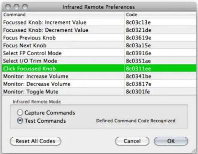
Figure 9.22: IR Test Mode
If the remote code is not recognized, "Received Command Not Found" will be displayed in red text.
If you make a mistake or wish to reprogram your codes, pressing the "Reset All Codes" button will delete all learned codes and restore the box to the default Apple IR programming.
Once you have learned the commands you want, hit the "OK" button. The IR codes are stored in your interface, and will function even when MIO Console is not running.
IR Remotes and the Monitor Controller
At this time, the Monitor Controller requires MIO Console to be running to change input or output paths. However, you can still change the Monitor Controller level while MIO Console is offline.
When using the IR remote, pushing a button once will send the associated command once. If you hold the button down, the command will repeat after approximately one second. This allows you to change values in small increments or over a large range.
Part III. Software
Table of Contents
- Installation and Registration 133
Installing MIO Console 133
Included Packages 133
Installation 133
Registration & Licensing 133
Registering your interface 133
License management 135
Purchasing a software license 137
Receiving MH Special Deals 138
- MIO Console Overview 141
MIO Console Software 141
MIO Console Overview 142
The Console Window 142
I/O Panel 143
Box Tabs 143
Front Panel Preferences 144
Analog Input Control 145
Optimizing Input Levels 148
Analog Input Channel Link 148
Digital Input Meters 149
Cans Controls 149
System Controls 151
Analog Output Control 155
Analog Output Channel Link 156
Digital Output Meters 156
Box Info 156
Parameter Pop-up Controls 157
Pop-up Commands 157
Pop-up Presets 158
The Mixer Window 159
Routing 163
A Quick Tour of the v. 5 Mixer 164
Technology 166
Configuration 167
Using Templates for Configuration 167
Manual Configuration 168
Mixer Configuration Tasks 170
Input Strip Details 171
Selection-based Linking 175
Plug-ins 176
Plug-In Graphs (requires +DSP license) 176
Plug-in Macros (requires +DSP license) 177
Sends 177
I/O insert 178
Master Strip Details 181
Routing Summary 186
FireWire Returns 187
- Monitor Controller 189
Overview 189
Ultra-Quick Start Guide to Configuring the Monitor Controller 189
Adding the Bus Output of your Mix Bus to the Monitor Controller 189
Configuring the Monitor Controller 189
Monitor Control Interface and Basic Operation 190
Determine Configuration 191
Identifying Monitor Sources 191
Identifying Monitor Output Paths 191
Using the Monitor Controller 192
Selecting an Input Source 193
Selecting an Output Path 193
Adjusting the Monitor Level 193
Dimming the output 193
Muting the output 193
Locking the output 193
Overriding the currently selected source 193
Selecting Source Override Channels 193
The Monitor Controller as Floating Window 194
Mini Monitor Controller Window 194
Switch between Monitor Controller and Mini Monitor Controller windows 194
Key Commands 194
Configuring the Monitor Controller 195
Configuring Monitor Sources 195
Configuring Monitor Output Paths 197
Changing the per path Calibration 199
Monitor Controller Preferences 199
Monitor Controller FAQ: 200
- Routing Examples 201
Introduction 201
Effects for tracking 201
Controlling Multiple Monitors 208
Virtualizing Windows audio programs 213
Introduction 213
How it Works 213
What you need 213
How to set it up 213
Tips for Specific Host DAWs 214
Routing Tips for Logic 214
Routing Tips for Digital Performer 215
Routing Tips for Cubase 218
Routing Tips for Pro Tools 221
Conclusion 231
- Record Panel 232
Overview 232
Record Panel Description 232
Recording 235
Playback 236
Multibox considerations 237
Record Panel Key Commands 237
Record Panel Prefs 237
- DSP Implementation Guide 241
Plug-in Processing in the v.5 Mixer 241
Inserts 241
Plug-in UI's 241
Multichannel Plug-ins 242
Graphs 243
Patch Library Pop-up Menu 246
Software
- Saving and Recalling Your Setups 247
Factory Default 247
Box Merge 247
Boot States and Snapshots 248
ULN-2 Snapshot Recall 248
ULN/LIO-8 Snapshot Recall 249
2882 Snapshot Recall 249
Console Files 249
ConsoleSync 250
- MIO Console Preferences 252
Accessing the preferences 252
Other Preferences 255
- ConsoleConnect 256
ConsoleConnect Overview 256
Introduction to ConsoleConnect 256
How it works 256
Total Recall 256
Universal Access 256
Using ConsoleConnect 256
Selecting the mode 257
Communication 260
Finding the Plug-in 260
Tips for Specific Host DAWs 261
Logic 261
Digital Performer 261
Cubase 262
GarageBand 263
Pro Tools Tips 265
Support 265
- Control Surface Support 266
Control Surface Preferences 266
Details of EuCon Control Surface Support 267
Control Room Support 267
Mixer Model 268
Details of Mackie Control Protocol Control Surface Support 269
Mackie Control Default Key Commands 269
Control Room Support 269
Mixer Model 269
- +DSP 271
DSP Package Comparison 271
+DSP Plug-in Documentation 273
MIO Volume Control (Linear) 273
MIO Volume Control (LPF) 274
MIO M/S Processor 274
MIO M/S Decoder 275
MIO Static Matrix 276
MIOComp 277
MIOEq 6 Band 278
MIOEq 12 Band 279
MIOLimit 280
MIOStrip 282
MIO Channel Summer 285
MIO Channel Difference 285
MIO Channel Sum/Difference 285
MIO Channel Multiplier 286
MIODelay 286
MIOModDelay 286
MIO Delay (1k) 287
MIO Delay (24k) 287
MIO Delay (96k) 288
MIO Delay (1k IM) 288
MIO Delay (2k-15k IM) 289
MIO Delay (2k-15k) 289
MIO MultiTap Delay 290
MIOAllpass 293
MIOAllpassVD 293
MIOHardClip 294
MIOSoftClip Type 1 294
MIOSoftClip Type 2 295
MIOSoftClip Type 3 295
MIOSoftDistortion Type 1 296
MIOSoftDistortion Type 2 296
MIOSoftDistortion Type 3 297
MIOSlew 297
MIOInSlew 297
MIO 4th Order Nonlinear Map 298
MIO 4th Order Symmetrical Nonlinear Map 298
MIO 4th Order [dB] Nonlinear Map 299
MIO 4th Order [dB] Symmetrical Nonlinear Map 300
MIO A/B Switch (Linear) 301
MIO A/B Switch (LPF) 301
MIOQuadOsc 302
MIOQuadLFO 302
MIOQuadNCO 303
MIOQuadNCO-Glide 303
Noise 304
Simple Dither (TPDF) 304
Simple Dither (TPDF Hipass) 304
Scale/Offset 305
SVF Control 305
NC SVF 306
MIOSimplePitchShifter 306
HaloVerb 306
HaloVerb for +DSP 307
EnvelopeDetector 308
TransientControl 309
CV -> NCO Freq 310
Abs 310
Max 310
Min 311
Select 311
Map Range 311
Constant 311
Divide 312
Square Root 312
Reciprocal Square Root 312
ADSR 312
Exponential ADSR 313
Software
Band Split 314
10. Installation and Registration
Installing MIO Console
Included Packages
The MIO Console installer folder contains several components:
- MIO Console: The application that provides control for all Metric Halo interfaces.
- MIODriver_XXX_Universal.pkg: This is the driver that lets the computer communicate with your interface. More information on the driver is available in the Driver Update appendix.
- FirmwareFor2dCardBoxes: Contains the current firmware for interfaces with a 2d card. All new interfaces contain a 2d card. More information on installing firmware is available in the Firmware Update appendix.
- MIO Plug-in Presets Installer.pkg: Installs preset files for plug-ins.
- ConsoleConnect.pkg: Installs the ConsoleConnect plug-in. More information is available in the ConsoleConnect chapter.
- FirmwareForLegacyBoxes: Contains the current firmware for interfaces without a 2d card.
- ReadMe.pdf: Contains important information regarding MIO Console.
Installation
To install the software, perform the following steps:
- Put the MIO Console application in your Applications folder
- Run the MIODriver package
- Run the MIO Plug-in Presets Installer package
- Run the ConsoleConnect package
If you are upgrading an existing installation of MIO Console, you should check the firmware currently installed in your interface. If it is older than the one included in the installer, you must upgrade the firmware to ensure proper operation with the new MIO Console and driver.
Important!
You should install all the components in the MIO Console installation folder, but you must install the driver to get audio to and from your interface.
Registration & Licensing
Registering your interface
Internet required!
Your computer must be online to register interfaces and manage licenses.
When you launch MIO Console with an unregistered interface attached, you'll see the following dialog:

Figure 10.1: Registration Message
Your options are:
- OK: Opens the registration window.
- Later: Closes the message. The message will appear again the next time you launch MIO Console.
- Do not show this message again: This will set MIO Console to no longer warn you about unregistered units after this message is closed. You can set MIO Console to check for unregistered units again by going to MIO Console's preferences and enabling the "Check for unregistered units" option. Please note that this option will not be present in systems running Mac OS 10.4; to manage this function you must go to MIO Console's preferences.
Click OK, and the registration window will open:
Figure 10.2: Registration Window
In the upper left corner is a menu to select which interface to register (if more than one unregistered unit is connected):

Figure 10.3: Registration Selection
You can choose to register all attached units or select a specific interface.
After selecting the unit(s) you wish to register, fill in the registration form; required fields are labeled in black, optional information is labeled in gray. When you're finished, hit OK. If there are any required fields empty, you'll receive a warning and the missing information will be labeled in red:

Figure 10.4: Registration Error
Once your information is correct and accepted, you will see this message:

Figure 10.5: Registration Successful
You will receive an email from confirming your registration. This email also includes information on support, help resources and other useful links.
Once your interfaces are registered, you can get demos and purchase optional software licenses.
License management
To manage your software licenses, go to MIO Console's application menu and select "Manage Licenses..."
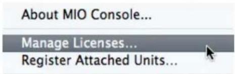
Figure 10.6: Unit Selection Menu
This will open the Hardware Licenses window:
| Hardware Licenses | |||
| Model | Serial Number | License | Status |
| LIO-8 | 100 | +DSP License | Demo/Purchase Available |
| LIO-8 | 100 | TransientControl Lic... | Demo/Purchase Available |
Figure 10.7: License Management Window
This window will show the status of your software licenses:
- Requires Registration: This interface must be registered before licenses may be managed.
- Getting Status: MIO Console is looking up the license status from our servers.
- Demo/Purchase Available: You do not have a license for this software package on this interface; you may request a demo or purchase a license.
- Demo Installed/Purchase Available: A demo license is installed and valid; you may purchase a license.
- Purchase Available/Demo Expired: Your demo license has expired; you may request a demo extension or purchase a license.
- Licensed: A license code for this software package is installed on the interface.
• Built-in License: A license for this software is part of the interface. The license is inseparable from the hardware. This is the case for the +DSP license in the ULN-8 and legacy 2882/ULN-2 units. - Licensed via Bundle:A license for this software package is present, because the software is part of a bundle that is licensed.
Refresh Status and Reload Licenses buttons
In normal operation, you will not need to use these controls on your own and will only need them when working with MH Support. These controls are hidden by default, and can be shown by clicking the button in the upper right corner.
Clicking on the "Refresh Status" button will cause MIO Console to refresh the licensing information between the connected interfaces and our servers.
Clicking "Reload Licenses" will make MIO Console re-sync the licenses on file with Metric Halo and your interfaces. If the flash memory in your interface needs to be erased (which would only happen under direction from Metric Halo Support), clicking "Reload Licenses" will restore your registered licenses back into the unit.
If you click on a software package that is available for a unit, you will see the following options:
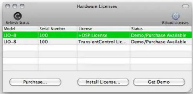
Figure 10.8: License Options
• Purchase: This will take you to the online store where you can purchase an unlock code.
• Install License: Once you have an unlock code (either from the MH online store or your dealer) you can click this button to enter it.
- Get Demo: This button will request a 30 day demo of the selected software package.
For example: if you request a +DSP demo license, you will see the following dialog:
Figure 10.9: Demo Installed
The demo license is now installed in your interface and is available for immediate use! After 30 days, the license will expire; you will then see a button in the Hardware License window to request a new demo.

Figure 10.10: Expired Demo
This demo extension is granted at Metric Halo's discretion, and may be shorter than 30 days. After sending your request you will receive an email within two business days to let you know if the extension has been granted.
Purchasing a software license
To purchase a software license online, simply open the Manage Licenses window and select the software license you wish to purchase. Clicking the "Purchase..." button will open a browser and take you to the online store. You may also purchase software licenses from your dealer.
Once you have purchased the license, you will receive an email from Metric Halo with the license code, as well as a special mhlicense://link. You can:
- Copy the license code, open the "Manage Licenses" window in MIO Console, select "Install License..." and paste the code.
- Click the link in the email, which will launch MIO Console and insert the information into the license management system.
Receiving MH Special Deals
From time to time, Metric Halo will have customer loyalty offers where existing customers get discounts on new products. If there is an offer for owners of interfaces or software that runs on the interface (like +DSP) you may generate your coupon from MIO Console.
Once your hardware is registered as discussed previously in this section, make sure your computer is connected to the internet and go to the main MIO Console menu and select "Get MH Special Deals":
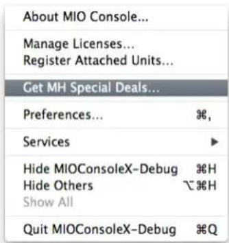
Figure 10.11: MH Special Deals Menu Item
MIO Console will connect to the registration server and confirm your eligibility. Your web browser will open and display a confirmation page; in this example, +DSP owners can receive a discount on the Metric Halo Production Bundle:
METRIC HALO
Mobile I/O Special Deals
All owners of existing Mobile VO + DSP licenses are eligible for a discounted purchase of the Metric Halo Production Bundle.
In order to recieve your discount, you must complete the form below. Please follow these steps:
- Select the eligible box that you would like to use to get your discount.
- Enter the email address where you want to recieve the discount coupon.
- (optional) If you have an existing license for ChannelStrip-TDM, ChannelStrip-MAS, ChannelStrip-RTAS, ChannelStrip-VST, ChannelStrip Native OS X, or ChannelStrip TDM OS X, enter your serial number in the serial number field to get upgrade credit for your ChannelStrip license as well. (if you have used your OS 9 serial number to upgrade to OS X, you will only be able to use the OS X serial number for this upgrade).
- Click "Submit" and then you should be good to go!
Once your request has been processed you will receive a discount coupon via email for the product that you chose. You may redeem the coupon at the Metric Halo Online Store.
Eligible Boxes:
(21) 00612 - 2882+DSP
(21) 01362 - 2882+DSP
email address:

ChannelStrip Serial Number:
(optional)
Submit
Figure 10.12: MH Special Deals Page
Select one of the eligible boxes, and enter the serial number of any other eligible products you own. Click on the Submit button, and you will receive your confirmation:
April 3, 2012
Thank you for using MH Special Deals for Mobile I/O. We were able to verify your eligibility, and we have created a discount code that you may use in the Metric Halo Online Store to purchase a license for Metric Halo Production Bundle at a reduced price.
Your discount code and instructions for how to use it have been sent to the email that you specified on the form ( @ ). If you do not receive the email within the next few minutes, please check your junk mail or spam filter. If you cannot find the email or specified an incorrect email address, please contact our support team for assistance.
If you need help, please open a ticket on our Support Site or call +1 (727) 725-9555 x208 during regular business hours.
Return to Metric Halo website
Request Another Upgrade Code
Figure 10.13: Confirmation Page
You will receive an email from Metric Halo with a coupon code that you may present to your dealer or use at https://www.mhsecure.com/mhdirect/home.php to your redeem your discount.
11. MIO Console Overview
MIO Console Software
MIO Console is the nerve center of your Mobile I/O. Functioning as a standalone application, MIO Console provides full control of every aspect of Mobile I/O. The console software allows you to rapidly and easily adjust all of the Analog Input and Output channel parameters, system sample rate, Digital I/O source, and system clock source.
In order to simplify work flow and optimize the extent of system control, MIO Console supports comprehensive preset management on both a global and individual control level.
The preset management pop-up controls within MIO Console allow you to configure various aspects of Mobile I/O and save that configuration information for later recall. Various applications include storing routing configurations for monitor setups, mixer configurations for stem and scene recall, and storing analog level standards for interfacing with external gear and managing different mastering standards.

Figure 11.1: MIO Mixer

Figure 11.2: MIO Console
Global configuration snapshots allow you to save each and every aspect of Mobile I/O's configuration for later, total instant recall. This is useful for preconfiguring Mobile I/O and bringing back the configuration once at the gig, managing separate location setups, or for saving complex studio routing setups for quick changeover.
MIO Console Overview
The MIO Console application has two main windows:
- The Console window, which is used for box-specific hardware settings.
- The Mixer window, which provides a unified view of whatever channels you want to use from all connected boxes.
Only 2d Expanded interfaces can access the Mixer window; Legacy boxes (those without 2d cards) are limited to using the Console window only. More information on MIO Console operation for Legacy boxes can be found in the "MIO Console for Legacy Boxes" documentation. It is possible to use both Expanded and Legacy boxes at the same time by turning on "Enable Support For Legacy Boxes" in the MIO Console preferences.
Let's start by looking at the Console window, since there are many important hardware settings in this area. Then, we'll look at the Mixer window, where you define the flexible environment that will be your work surface.
The Console Window
The MIO Console window has a view panel selector bar that runs along the top of the window. This bar indicates which of the console view panels is currently active. You can tell which panel is active because the button in the bar is "pushed in." To switch to one of the other panels, simply click on the name of the panel you want to use. The view will change instantly to the one that you have selected.

Figure 11.3: View Panel Pane Selector Bar
Under the view panel selector bar is the currently selected view panel. You control the various aspects of the box with the controls in each view. MIO Console has three main panels:
- I/O Panel
- +DSP Panel
- Record Panel
When working with a Legacy interface, the Mixer and Routing Panels will also be present. More information on these panels can be found in the "MIO Console for Legacy Boxes" documentation.
The +DSP panel works differently on 2d Expanded and Legacy boxes:
- 2d Expanded: The functionality originally provided by the +DSP Panel has been integrated into the Mixer via Graph inserts. The +DSP Panel does not provide any useful functionality for 2d Expanded boxes, but is still present to allow users to migrate +DSP patches from files created with Legacy boxes to 2d Expanded boxes. See the Technology section of this chapter for more information about the underlying +DSP Graph technology.
- Legacy: Allows you to see and modify what's going on "behind the scenes" in the DSP of your interfaces. See the "MIO Console for Legacy Boxes" documentation for more information.
The Record Panel is our built-in multitrack recording utility. Documentation on the RP can be found in the Record Panel chapter.
I/O Panel
This panel provides full control and metering of all of the analog I/O that the box provides. The top half of the view is dedicated to inputs and the bottom half is dedicated to outputs. You access this panel by clicking on the "I/O Control" button of the view panel selector bar.
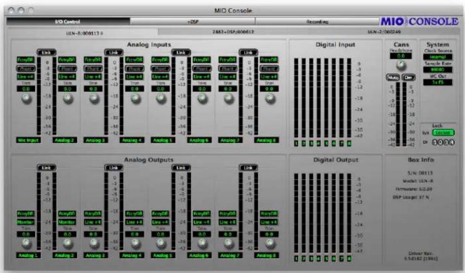
Figure 11.4: I/O Panel
Box Tabs
At the top of the panel are Box Tabs — one for each box known to the system. You choose which box you are controlling by clicking on the desired box tab. Boxes can be either Online or Offline. If a box is not connected to the computer but it is known to MIO Console, it will be listed as Offline in MIO Console. You can modify the configuration of an Offline box, and that configuration can be saved, but, of course, the changes will not control the Hardware until it is reconnected to the computer.

Figure 11.5: Box Tabs
MIO Console maintains information about the state of your system persistently. The boxes that have been attached to the computer will be remembered, and their presence in the system can be maintained indefinitely by either the saved system state (saved in your Preferences to maintain the state of the system between launches of MIO Console) or by you explicitly saving the state of the console into a file for later recall (or into a ConsoleConnect host's session file). In any case, it is possible to have Offline boxes in your system state that refer to a box that you are no longer using. MIO Console provides commands to remove these boxes from the system state.
Each box tab provides a contextual menu that you can pop-up to apply commands to the specific box. Right-click or control-click the currently active box tab to reveal the pop-up menu:

Figure 11.6: Box Tab Pop-up Menu
This menu provides the following commands:
- Forget This Offline Box — this command will remove the box from the system state.
- Forget This Offline Box (and Delete From Mixer) — this command will remove the box from the system state and delete any channels associated with it from the Mixer.
- Forget All Offline Boxes — this command will remove all boxes that are offline from the system state.
- Forget All Offline Boxes (and Delete From Mixer) — this command will remove offline boxes from the system state and delete any channels associated with them from the Mixer.
- Identify Box — this command will cause a lightshow to appear on the front panel meters of the box associated with the tab. Use this command to identify which physical box is represented by the tab.
- Reset Box Output Channel Names — this command resets all of the user-specified names for output channels to the factory default settings for the hardware.
- Reset Box Input Channel Names — this command resets all of the user-specified names for input channels to the factory default settings for the hardware.
- Reset All Box Channel Names — this command resets all of the user-specified names for the I/O channels to the factory default settings for the hardware.
Front Panel Preferences
On the ULN-8 and LIO-8, selecting "Front Panel Prefs..." will reveal the following sheet:
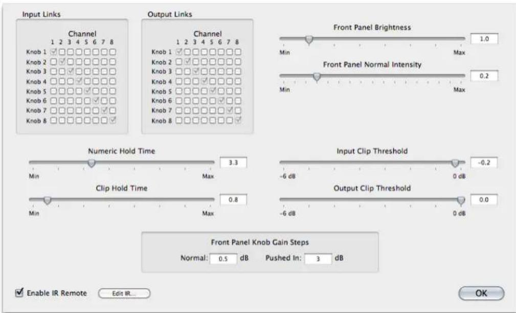
Figure 11.7: Front Panel Prefs Sheet
The options are:
- Input Links matrix
Allows you to link input channel encoders (more info in the ULN/LIO-8 Front Panel Guide).
• Output Links matrix
Allows you to link output channel encoders (more info in the ULN/LIO-8 Front Panel Guide). - Front Panel Brightness
Scales the brightness level of the front panel (more info in the ULN/LIO-8 Front Panel Guide).
• Front Panel Normal Intensity
Sets the maximum illumination level; the brightness scales to this point. - Numeric Hold Time
The time in seconds that the meters display numeric levels after adjusting an encoder. - Clip Hold Time
The time in seconds that the meter LEDs stay red after clipping occurs. - Input Clip Threshold
The input level at which a signal is considered clipped.
• Output Clip Threshold
The output level at which a signal is considered clipped.
• Front Panel Knob Gain Steps
Normal: The amount of gain change per encoder click when not pushed in.
Pushed In: The amount of gain change per encoder click when pushed in. - Enable IR Remote and Edit IR
Enabling this option will activate the infrared remote receiver on the selected unit's faceplate; the "Edit IR..." button will open the Infrared Remote Preferences window (more info in the ULN/LIO-8 Front Panel Guide).
Analog Input Control
For each analog input channel on the Mobile I/O (except the ULN-2, as it has analog front panel controls), you will find a channel strip that contains:
- Parameter Pop-up control menu
Figure 11.8: Parameter Pop-up Menu
The Parameter pop-up control allows you to save, recall, and manage all of the parameters associated with the head amp of a channel strip in one place. The control is documented in detail in the Parameter Pop-up Controls section of this chapter. All presets are automatically shared between all of the input channels.
- Phantom Power enable button
Figure 11.9: Phantom Power Button
The Phantom Power enable button allows you to control whether or not +48v phantom power is applied to the input by the Mobile I/O. This button is only enabled if you have selected Mic or Mic/Pad as the input level standard. If you are using one of the other level standards, Phantom Power is automatically disabled. If you have enabled Phantom Power on this channel, the button will be illuminated bright red. In addition, the Mobile I/O front panel will illuminate the "Phantom" indicator if any of the input channels have Phantom Power enabled.
Phantom power is appropriate for use with condenser microphones or other devices that can (and must) be powered by the preamp. Mobile I/O limits the amount of phantom power to 10mA per channel, preventing device damage due to shorts. Some (rare) microphones may require more power than is provided by 10mA; you will need an external power supply to power those mics.
- Level Standard pop-up menu
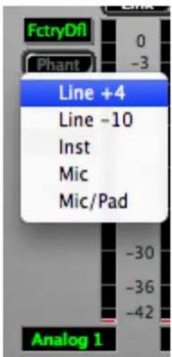
Figure 11.10: Level Standard Pop-up Menu
This control allows you to select the input level and impedance characteristics for the input channel. The available choices are:
• Line +4 — This format supports input levels up to:
- 2882: +26 dBu. The input impedance is approximately 10k Ω, and the inline pad is engaged. Phantom power is not available.
- LIO-8: +24.5 dBu. The input impedance is approximately 10k Ω , and the Line Input is selected.
- ULN-8: +24.5 dBu. The input impedance is approximately 10k Ω , and the Line Input is selected.
This format is appropriate for interfacing with professional audio equipment.
• Line -10 — This format supports input levels up to:
- 2882: +15 dBu. The input impedance is approximately 10k Ω, and the inline pad is engaged. Phantom power is not available.
- LIO-8: +13.5 dBu. The input impedance is approximately 10k Ω, and the Line Input is selected.
- ULN-8: +13.5 dBu. The input impedance is approximately 10k Ω, and the Line Input is selected.
This format is appropriate for interfacing with prosumer and consumer audio equipment.
- Inst (Instrument) — This format supports input levels up to +6 dBu. The input impedance is approximately 200k, and the inline pad is not engaged. Phantom power is not available. This format is appropriate for interfacing with high output impedance sources like guitar pickups.
On the LIO-8 and ULN-8, the front panel DI inputs are always connected in parallel with Line inputs 1 and 2. The "Inst" option is left here as a visual reminder that the DI input was being used when the console state is saved.
- Mic — This format supports input levels up to:
- 2882:+6 dBu. The input impedance is approximately 200k Ω (12k Ω with phantom power engaged) and the inline pad is not engaged. Phantom power is available.
- ULN-8: +20 dBu. The input impedance is approximately 3.3k Ω, and the Mic Input is selected. Phantom power is available.
This format is appropriate for interfacing with dynamic and condenser microphones on low to mid level sources.
Tip for 2882 users:
You may find that for very low level sources, especially with low-sensitivity microphones, that your SNR improves if you take advantage of a high-quality external mic preamp. External preamps are recommended for certain types of recording and microphones, especially classical recording and ribbon mics.
- Mic/Pad (2882 only)— This format supports input levels up to +26 dBu. The input impedance is approximately 10k, (6k with phantom power engaged), and the inline pad is engaged. Phantom power is available. This format is appropriate for phantom powered condenser mics that put out near-line level signals (often the case when you are using condenser microphones on bass drums or other very loud sources).
- Gain Trim knob
Figure 11.11: Gain Trim Knob
The Gain Trim knob allows you to adjust the analog gain of the input stage in the range determined by the input standard that you have selected; this range will vary by interface model. The gain is indicated in dB relative to the nominal level of the input standard you have selected. The gain changes are smoother near the bottom of the scale, with the steps increasing in size as you reach the gain limit.
- Channel Label

Figure 11.12: Channel Label
This simply labels which channel is associated with the channel strip. Click in the label to edit the channel name.
- Channel Level Meter
This is a peak reading, high-resolution, fast PPM meter. It shows the post converter level of the input signal of the associated channel. The peak hold bar indicates the highest level seen on the channel since the last reset. You can reset the hold by clicking on the meter. These meters are simply high resolution versions of the meters shown on the front panel of the box – all the meter data is generated by the Mobile I/O hardware.

Figure 11.13: Channel Level Meter
Optimizing Input Levels
The Analog to Digital converters (ADC) in most devices function best when the peak level is around -6 dBFS (lowest distortion, best sound). This is also true of the ADCs in Mobile I/O. Since you have full level control of the input with the gain trim knob, you will find that you get the best quality recordings if you try to set the nominal peak level of the input at about -6 dBFS. In addition to providing the best recording quality, it has the added benefit that you will be operating with an extra 6 dB of headroom before clipping. There is no drawback to optimizing your levels in this way, and plenty of benefit.
Analog Input Channel Link
Figure 11.14: Analog Input Channel Link
In addition to the channel specific controls, each channel pair shares a Link button. When the Link button is engaged, the trim-value is set to 0 and changes made to one channel of the pair will automatically be applied
to the other channel of the pair. This is very useful if you are miking with a stereo pair and need to maintain level balance between the two preamps — with the Link button engaged, the balance is automatic and exact.
Digital Input Meters
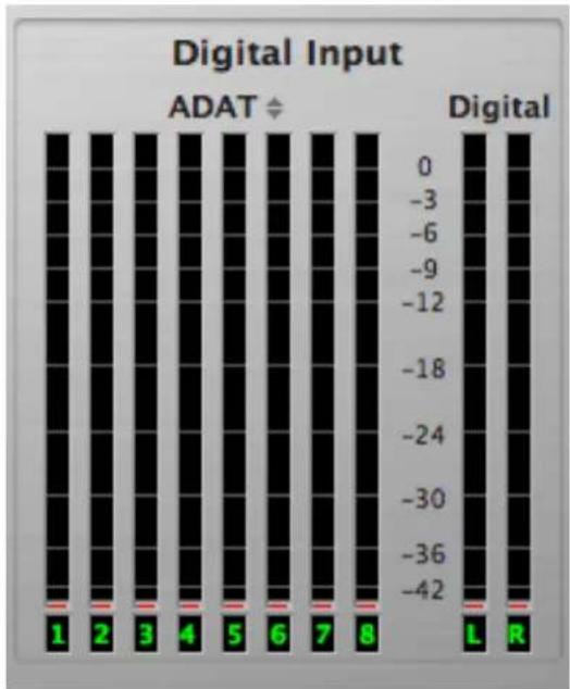
Figure 11.15: Digital Input Meters
To the right of the Analog Input control section is the Digital Input Meter section. This group of meters provides level metering for all of the digital inputs on the Mobile I/O. These meters have the same response characteristics as the analog input meters and show you the audio activity on ADAT channels 1-8 and digital input channels 1-2, going from left to right on the 2882 and ULN-2. The ULN-8/LIO-8 digital input meters are for AES inputs 1-8, with no secondary meters.
Please note that when the 2882 and ULN-2 are clocking at 2x rates (88.2-96k), the ADAT input is not functional.
The label above the bank of 8 channel meters is a pop-up control that allows you to select between ADAT optical format and TOSLINK Optical SPDIF for the optical input connector. Click on the control to pop-up a menu to select between the different modes of operation. The mode is independently selectable for both the input and output.
If you have selected TOSLINK for either the input or output section, you will only see meters for channels 1+2 of the optical digital section. These correspond to the levels that are being transmitted or received in the optical SPDIF signal.
Cans Controls
The next control block to the right is the Cans (Headphones) control section.

Figure 11.16: Headphone Controls
The Headphone level control knob provides about 40dB of analog gain control on the headphone output. The Mute and Dim buttons reflect the state of the hardware mute and dim controls for the front panel headphone output. Engaging one of these buttons will also engage the associated control on the hardware.
When the Mute function is engaged, the headphone output will be muted. When the Dim function is engaged, the headphone output will be padded by 18 dB. The meters in this section show the headphone output pre-mute/dim block.
Please note that the Headphone level control will not be present when viewing the settings for the ULN-2, as it uses analog controls on the front panel.
System Controls
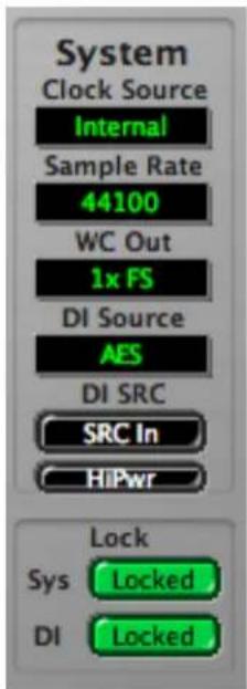
Figure 11.17: System Controls
The System block provides controls that adjust various system level aspects of the Mobile I/O hardware:
- The Clock Source pop-up menu controls the system clock source used by the hardware for digital synchronization and driving the converters. The choices for 2882 and ULN-2 are:
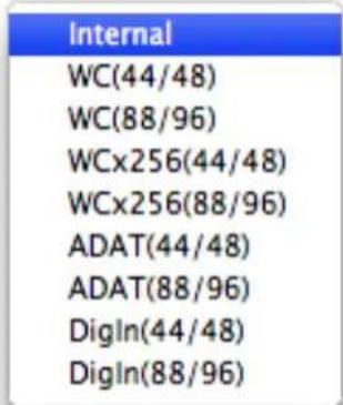
Figure 11.18: Clock Source Pop-up Menu for 2882 and ULN-2
- Internal directs Mobile I/O to use its internal clock. You must select this if you want to set the sample rate from the Mobile I/O. If any other clock source has been selected, the console will not allow you to change the sample rate since the sample rate is determined by the external clock source.
- WC (44/48) directs Mobile I/O to clock off of an external Word Clock Source at single rate (e.g. fs = 32k-50k)
-
WC (88/96) directs Mobile I/O to clock off of an external Word Clock Source at double rate (e.g. fs = 64k-100k)
-
WCx256 (44/48) directs Mobile I/O to clock off of an external 256fs Clock Source at single rate (e.g. fs = 32k-50k)
- WCx256 (88/96) directs Mobile I/O to clock off of an external 256fs Clock Source at double rate (e.g. fs = 64k-100k)
- ADAT (44/48) directs Mobile I/O to clock off of the incoming ADAT stream and run at single rate. All 8 ADAT channels are available. You will generally want to select this source if you intend to use ADAT input.
- ADAT (88/96) directs Mobile I/O to clock off of the incoming ADAT stream and run at double rate. Please note that although it is possible to clock the Mobile I/O via SMUX, the ADAT input will not be functional.
- DigIn (44/48) directs Mobile I/O to clock off of the selected stereo digital input at single rate (e.g. fs = 32k-50k). This allows operation of the digital input without SRC, and from devices that must supply clock.
- DigIn (88/96) directs Mobile I/O to clock off of the selected stereo digital input at double rate (e.g. fs = 64k-100k). This allows operation of the digital input without SRC, and from devices that must supply clock.
The choices for LIO-8 and ULN-8 are:
| Internal |
| WC (44.1/48) |
| WC (88.2/96) |
| WC (176/192) |
| WCx256 (44.1/48) |
| WCx256 (88.2/96) |
| WCx256 (176/192) |
| AES 1 (1x) |
| AES 1 (2x) |
| AES 1 (4x) |
| AES 2 (1x) |
| AES 2 (2x) |
| AES 2 (4x) |
| AES 3 (1x) |
| AES 3 (2x) |
| AES 3 (4x) |
| AES 4 (1x) |
| AES 4 (2x) |
| AES 4 (4x) |
Figure 11.19: Clock Source Pop-up Menu for LIO-8 and ULN-8
- Internal directs the LIO/ULN-8 to use its internal clock. You must select this if you want to set the sample rate from the LIO/ULN-8. If any other clock source has been selected, the console will not allow you to change the sample rate since the sample rate is determined by the external clock source.
-
WC (44/48) directs the LIO/ULN-8 to clock off of an external Word Clock Source at single rate (e.g. fs = 32k-50k)
-
WC (88/96) directs the LIO/ULN-8 to clock off of an external Word Clock Source at double rate (e.g. fs = 64k-100k)
- WC (176/192) directs the LIO/ULN-8 to clock off of an external Word Clock Source at quad rate (e.g. fs = 128k-200k)
- WCx256 (44/48) directs the LIO/ULN-8 to clock off of an external 256fs Clock Source at single rate (e.g. fs = 32k-50k)
- WCx256 (88/96) directs the LIO/ULN-8 to clock off of an external 256fs Clock Source at double rate (e.g. fs = 64k-100k)
- WCx256 (176/192) directs the LIO/ULN-8 to clock off of an external 256fs Clock Source at quad rate (e.g. fs = 128k-200k)
- AES 1 (1x) directs the LIO/ULN-8 to clock off of AES stereo input 1 at single rate (e.g. fs = 32k-50k).
- AES 1 (2x) directs the LIO/ULN-8 to clock off of AES stereo input 1 at double rate (e.g. fs = 64k-100k).
- AES 1 (4x) directs the LIO/ULN-8 to clock off of AES stereo input 1 at quad rate (e.g. fs = 128k-200k).
- AES 2 (1x) directs the LIO/ULN-8 to clock off of AES stereo input 2 at single rate (e.g. fs = 32k-50k).
- AES 2 (2x) directs the LIO/ULN-8 to clock off of AES stereo input 2 at double rate (e.g. fs = 64k-100k).
- AES 2 (4x) directs the LIO/ULN-8 to clock off of AES stereo input 2 at quad rate (e.g. fs = 128k-200k).
- AES 3 (1x) directs the LIO/ULN-8 to clock off of AES stereo input 3 at single rate (e.g. fs = 32k-50k).
- AES 3 (2x) directs the LIO/ULN-8 to clock off of AES stereo input 3 at double rate (e.g. fs = 64k-100k).
- AES 3 (4x) directs the LIO/ULN-8 to clock off of AES stereo input 3 at quad rate (e.g. fs = 128k-200k).
- AES 4 (1x) directs the LIO/ULN-8 to clock off of AES stereo input 4 at single rate (e.g. fs = 32k-50k).
- AES 4 (2x) directs the LIO/ULN-8 to clock off of AES stereo input 4 at double rate (e.g. fs = 64k-100k).
- AES 4 (4x) directs the LIO/ULN-8 to clock off of AES stereo input 4 at quad rate (e.g. fs = 128k-200k).
- The Sample Rate pop-up menu allows you to select the sample rate when you are using internal clock. The Mobile I/O must be running on internal clock for the Sample Rate pop-up menu to have any effect. If the Mobile I/O is running from an external clock source, you cannot select the sample rate since it is determined by the external clock source.
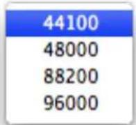
Figure 11.20: Sample Rate Pop-up Menu (2882 and ULN-2)
| 44100 |
| 48000 |
| 88200 |
| 96000 |
| 176400 |
| 192000 |
Figure 11.21: Sample Rate Pop-up Menu (LIO-8 and ULN-8)
- The WC Out pop-up menu allows you to select the output clock signal the Mobile I/O generates on its WC Out BNC connector. The available choices are 1x and 256x. The 1x signal is appropriate for driving devices that accept a Word Clock signal. The 256x signal is appropriate for driving devices that accept 256x or SuperClock signals. Refer to the documentation for the external device to determine what is the most appropriate clock reference for it.

Figure 11.22: WC Out Pop-up
- The DI Source pop-up menu allows you to select the active input for the digital input pair. The choices are AES and S/PDIF. This selector physically switches the input to the digital audio receiver between the RCA input and the XLR input. 2882/ULN-2 ONLY
Figure 11.23: DI Source Pop-up
- The DI SRC button enables and disables the asynchronous sample rate converter (SRC) in the Mobile I/O digital audio receiver. When the SRC is engaged (button illuminated yellow), the digital audio receiver will automatically synchronize the input signal to the Mobile I/O system clock over a wide range of sample rate ratios. 2882/ULN-2 ONLY

Figure 11.24: DI SRC Button
This allows you to, for example, digitally transfer a sample from a CD player into a 96k session without any clocking problems. If you want to make bit-transparent transfers, you will need to disengage the SRC and ensure that the Mobile I/O and the external device are both using the same digital audio clock via one of the Mobile I/O synchronization mechanisms.
- The High Power button enables a higher voltage rail for the 2882's analog outputs providing greater output headroom and reduced distortion at high analog output levels, but requires substantially higher (>5W) supply power. High-power mode is useful when driving the outputs at +4 dBu levels. This is most appropriate when sending line-level out of the 2882 to equipment with high analog rails like large format consoles. When high-power mode is enabled, the 2882 can put out +24 dBu balanced at full scale.
All other hardware models are effectively in High Power mode at all times.

Figure 11.25: High Power Button
WARNING: You MUST power the 2882 from an external power source BEFORE enabling High Power mode. FAILURE TO USE AN EXTERNAL POWER SOURCE IN HIGH POWER MODE MAY CAUSE DAMAGE TO YOUR COMPUTER.
- The Lock indicators show which elements of the Mobile I/O clocking system are properly locked. The clocking system must be locked for the unit to behave as expected. If the system is not locked, audio will play at the wrong rate and will be distorted or noisy. Under normal circumstances, the system should always be locked, but if you have selected an external clock source and the clock signal is not present, corrupted or out-of-range, the system may unlock. There are indicators for the system and the digital input.

Figure 11.26: Lock Indicators
Analog Output Control
The bottom half of the panel is dedicated to the hardware outputs of the Mobile I/O. Much like the analog inputs, each of the eight analog outputs has a set of controls associated with it. The controls are similar to the analog input controls. If these controls are “grayed out”, it is because they are referenced by the Monitor Controller, which removes direct control from this panel. If you want to control the analog output from this panel, you must remove the Monitor Control output path that references it. Each output channel (except the ULN-2, as it has analog front panel controls) has:
- Parameter Pop-up control: The Parameter Pop-up control allows you to save, recall, and manage the parameters associated with an analog output in one place. The control is documented in detail in the Parameter Pop-up Controls section of this chapter. All presets are automatically shared between all of the output channels.
- Level Standard pop-up menu: This control allows you to select the output level for the channel. The available choices are:
- Line +4 —
- 2882: This format supports output levels up to +26 dBu. The standard setting with the trim knob set to 0 dB yields a +24 dBu output when the digital signal driving the DAC is 0 dBFS. This corresponds to +4 dBu nominal with 20 dB of digital headroom.
- LIO-8: This format supports output levels up to +18.5 dBu (jumper selectable to 24.5 dBu). The standard setting with the trim knob set to 0 dB yields a +18.5 dBu output when the digital signal driving the DAC is 0 dBFS. This corresponds to +4 dBu nominal with 20 dB of digital headroom.
- ULN-8: This format supports output levels up to +18.5 dBu (jumper selectable to 24.5 dBu). The standard setting with the trim knob set to 0 dB yields a +18.5 dBu output when the digital signal driving the DAC is 0 dBFS. This corresponds to +4 dBu nominal with 20 dB of digital headroom.
You can use the trim knob to adjust the analog output level to be consistent with the needs of other audio gear. The output impedance is approximately 50 Ω on the 2882 and 5 Ω on the LIO-8/ULN-8. This format is appropriate for interfacing with professional audio equipment.
- Line -10 —
- 2882: This format supports a nominal output level of -10 dBV with 20 dB of digital headroom. The output impedance is approximately 50 Ω.
- LIO-8: This format supports a nominal output level of -10 dBV with 20 dB of digital headroom. The output impedance is approximately 5 Ω.
- ULN-8: This format supports a nominal output level of -10 dBV with 20 dB of digital headroom. The output impedance is approximately 5 Ω.
You can use the trim knob to adjust the analog output level to be consistent with the needs of other audio gear. This format is appropriate for interfacing with prosumer and consumer audio equipment.
- Monitor (LIO-8/ULN-8 only) — This format incorporates a 30 dB analog domain pad. You can use the trim knob to adjust the analog output level to be consistent with the needs of other audio gear. The output impedance is approximately 5 Ω. This format is appropriate for interfacing with amplifiers and selfpowered speakers.
- Gain Trim knob: The Gain Trim knob allows you to adjust the analog gain of the output stage (post DAC) in the range determined by the output standard that you have selected; this range will vary by interface model. The gain is indicated in dB relative to the nominal level of the output standard you have selected. The gain changes are smoother near the bottom of the scale, with the steps increasing in size as you reach the +40dB gain limit. Unless the signal is quite low, you will put the output stage into analog clipping well before you hit the 40dB gain limit.
- Channel Label: This simply labels which channel is associated with the output. Click in the label to edit the channel name.
- Channel Level Meter: This is a peak reading, high-resolution, fast PPM meter. It shows the pre converter level of the output signal of the associated channel. The peak hold bar indicates the highest level seen on the channel since the last reset. You can reset the hold by clicking on the meter. These meters are simply high resolution versions of the meters shown on the front panel of the box – all the meter data is generated by the Mobile I/O hardware.
Analog Output Channel Link
In addition to the channel specific controls, each channel pair shares a Link button. When the Link button is engaged, the trim-value is set to 0 and changes made to one channel of the pair will automatically be applied to the other channel of the pair. This is very useful if you are driving a stereo monitor section or stereo device. By engaging the Link button, you will ensure that both channels have precisely the same amount of analog gain applied post DAC.
Digital Output Meters
To the right of the Analog Output controls is the Digital Meters section. This group of meters provides level metering for all of the digital outputs on the Mobile I/O. These meters have the same response characteristics as the analog output meters, and show you the audio activity on ADAT output channels 1-8 and digital output channels 1-2, going from left to right. The ULN-8 shows AES output channels 1-8.
Please note that when the 2882 and ULN-2 are clocking at 2x rates (88.2-96k), the ADAT output is not useable. Both channels of the stereo digital output remain active at all sample rates on the 2882 and ULN-2.
The label above the bank of 8 channel meters is a pop-up control that allows you to select between ADAT optical format and TOSLINK Optical SPDIF for the optical output connector. Click on the control to pop-up a menu to select between the different modes of operation. The mode is independently selectable for both the input and output.
If you have selected TOSLINK for either the input or output section, you will only see meters for channels 1+2 of the optical digital section. These correspond to the levels that are being transmitted or received in the optical SPDIF signal.
Box Info
The Box Info section of the panel, in the lower right-hand corner of the window, shows you information about the currently connected and selected Mobile I/O unit. This section displays the Serial Number, Model Information and Firmware revision of the connected box as well as the Driver revision. All of this information can be useful in trying to track down any connection problems that may arise.
![Box Info S/N: 00113 Model: ULN-8 Firmware: 5.0.30 DSP Usage: 15 % Driver Rev. 5.3d182 [1991]](/content/2026/05/884165/images/ae5a6d15be7e9c516a02869f3e0c21b23e8a8258bf1d13739bce312351fafcc6.jpg)
Figure 11.27: Box Info
If there is no information displayed in the Box Info section, the software is not communicating properly with the Mobile I/O hardware, or there is no Mobile I/O present on the FireWire bus.
If the FireWire light on the front panel of the Mobile I/O is illuminated but the box information does not appear in the console window, it is very likely that the software has not been installed properly. If this is the case, please refer to the installation instructions for details on how to properly install the software.
If, on the other hand, the FireWire light on the front panel of the Mobile I/O is not illuminated, the box is not communicating properly with the computer. Please check the cabling of your Mobile I/O and other devices on the FireWire bus and make sure that everything is connected correctly. If that does not properly establish the connection, try rebooting your computer. As a last resort, try connecting only the Mobile I/O to the computer to ensure that communication can be established.
The Box Info section also shows the DSP usage of the connected box. This is a rough indication of how much of your interface's 2d DSP is being used. This includes mixers and plug-ins. This does not reflect the memory being used. It is possible to use less than 100% DSP but still overload the system if you instantiate too many delays or reverbs.
Parameter Pop-up Controls
The Parameter Popup control is MIO Console's unified mechanism for handling presets for the various sections of the Mobile I/O. Each element of the console that supports the Parameter Library mechanism has a parameter Pop-up control associated with it. These elements include:
- Input Channels (superseded by the Mixer Window)
- Output Channels
Each instance of the Parameter Pop-up control provides the same commands and options for every section of the console.
Pop-up Commands
The parameter pop-up provides a hierarchical, categorized library of configuration presets for the associated section of the console. The menu is divided into three portions. The first portion consists of all of the items
above the "Factory Default" item. The second portion is the "Factory Default" item and the third portion is the hierarchical items below the "Factory Default" item (see Parameter Pop-up Menu).
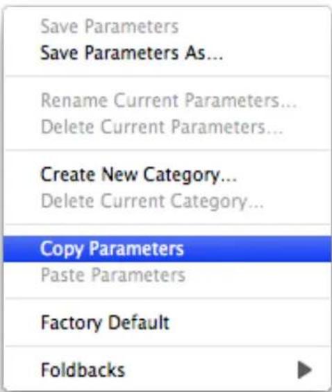
Figure 11.28: Parameter Pop-up Menu
The commands in the first portion of the menu allow you to save and manage the presets in the library. All of the presets are shared between like elements in the console. The preset commands are:
- Save Parameters — use this command to save the current state of the associated console settings to the currently selected preset (will appear as "Save Parameters As..." if there is no currently selected preset)
- Save Parameters As... — use this command to name and select a category to save the current state of the associated console settings as a preset into the library
- Rename Current Parameters... — use this command to rename the currently selected preset
- Delete Current Parameters — use this command to remove the currently selected preset from the library
- Create New Category — use this command to add a new category to the library
- Delete Category — use this command to delete the currently selected category and all of its associated presets
- Copy Parameters — use this command to copy the current state of the associated console settings to the clipboard; you can use this to copy your settings from one block to another
- Paste Parameters — If the clipboard contains compatible settings, this command will be available and will set the current state of the associated console settings to the settings on the clipboard. Use this with the "Copy Parameters" command to duplicate settings from one channel to another or from one mix to another
The "Factory Default" command will set the current state of the associated console settings to the default settings.
Pop-up Presets
In the third part of the menu, each of the categories will be listed as a hierarchical menu title. Each of the presets for each category will be listed in the submenu under the category menu. The currently selected category and preset are drawn in bold, so you will know what is currently active.
Selecting a preset from the menu will make that preset active and will set the current state of the associated console settings to the values contained within the preset. The name of the currently selected preset will be drawn in the pop-up area in the console window to indicate which preset is active.
If you change the settings in the console, the name of the preset will be drawn in italics indicating that the current settings differ from the selected preset.
For the Input and Output channels, you can hold down the
To access the parameter pop-up for the mixer tabs, either click and hold the associated mixer tab or
We have provided an initial set of presets for the various parameter libraries. The presets for the output channels are relatively complete and give you an idea of the power and flexibility of this approach to parameter management.
The Mixer Window
Perhaps the most fundamental thing for you to understand is that the v.5 mixer model is based upon user-configuration. The advantage to this is that you can build the exact mixer you need for any specific task or set of circumstances.
The v.5 mixer takes the approach of allowing you to define your configuration up to the limits of the hardware. This has a number of significant benefits to the user:
- You only utilize the resources you need. This conserves resources, allowing you to direct more DSP towards what you are focussed on without having resources utilized by functions or features that are irrelevant to your task-at-hand.
- The UI directly reflects the elements of the hardware that are of interest to you, and does not present elements that are superfluous to the work that you are trying to accomplish.
- The configuration-based UI allows us to directly integrate features such as routing into the UI of channels that you have added to your configuration.
The way the Mixer is configured can vary:
- If a box is not connected the first time you launch MIO Console, you will see the Template selector. After a template is opened, MIO Console will default to loading the last state of the Mixer.
- If a box is connected the first time you launch MIO Console, the Mixer will reflect the factory default setup. This is part of the ConsoleSync engine.
- You may open a console document or template at any time.
- You may use ConsoleConnect.
For more information on the factory default state, ConsoleSync, and ConsoleConnect please read the Saving and Recalling Your Setups section.
In order to demonstrate some possible uses of your interface we've included templates with MIO Console. The template selection dialog is displayed on first launch if no box is attached, and it can be accessed at any time from the File menu.

Figure 11.29: Template Selection Dialog
Alternatively, you can use the following steps to configure a mixer from scratch.
The easiest way to create a new mixer configuration is to use the Mixer » Configure Mixer... menu command. Selecting this command presents the Configure Mixer sheet, which allows you to do bulk configuration of the mixer.
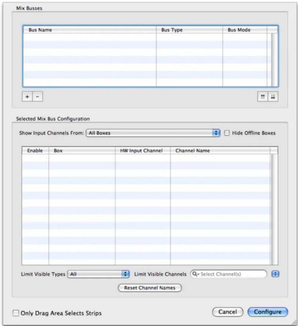
Figure 11.30: Configure Mixer Sheet
The sheet is split into two major sections:
- Mix Busses
- Selected Mix Bus Configuration
You create and configure the mix busses using the top section, then you configure the channels you assign to the busses in the bottom area. When you select a mix bus from the table in the Mix Busses section, the Selected Mix Bus Configuration area automatically updates to reflect the current configuration of the selected mix bus. All of the available input channels are listed in the Selected Mix Bus Configuration, and you can assign any of the channels to the selected mix bus by checking the channel's Enable check-box.
Mixer Configuration Summary
To quickly configure a mixer that will send your selected inputs to your studio monitors and to your computer:
- Select the Mixer » Configure Mixer... menu command.
- Create a Mix Bus as described in "To Create a Mix Bus" below.
- Add input channels as described in "To Add an input channel to a Mix Bus" below. Be sure to add some physical inputs and some DAW inputs so you can route both physical and computer inputs through the mixer.
- When you have finished Enabling the input channels you wish in your mixer, click the Configure button in the Configure Mixer sheet to create your mixer.
- In the Input channel strips for each of your physical inputs, click on the Direct Output pop-up menu (either pre- or post-send, up to you), select "Auto." This assigns each Input strip to a FireWire output.
- In the Master Strip, click the Bus Output pop-up menu and select the physical outputs to which your studio monitors are connected.
That's it! You've just created your first v.5 mixer. You can now route the audio signal from your Mobile I/O's physical inputs to your computer, from your computer to your Mobile I/O, and connected the mixer to your studio monitors.
To Create a Mix Bus
- Click the "+" button — this creates a new stereo bus with a default name.
- Double-click the new bus in the list; you can now edit the bus name.
- You can adjust the bus type with the pop-up in the Bus Type column.
To Delete a Mix Bus
- Select the bus you want to delete
- Click the "-" button — this deletes the bus and de-assigns the channels assigned to the bus (but it won't delete the channelstrips from the Mixer window).
To Add an input channel to a Mix Bus
- Select the bus to which you want to add a channel.
- Check the box in the "Enable" column for the channel you want to add to the bus.
To Remove an input channel from a Mix Bus
- Select the bus from which you want to remove the channel.
- Uncheck the box in the "Enable" column for the channel you want to remove from the bus.
When you have finished configuring your mixer, click the Configure button in the bottom right. The mixer you have configured will now appear in the Mixer window.
The v.5 Mixer removes the direct-route connection between the physical inputs and FireWire that has existed in the Mobile I/O since it was originally shipped. Instead, the v.5 Mixer extends and enhances the concept of FireWire returns. In fact, all audio is now sent to the computer via FireWire returns. In other words, if you want to send audio from your Mobile I/O's inputs to your computer, you will need to assign those inputs to FireWire returns manually via the Direct Outs in the mixer input strips. Hint: selecting "Auto" in an input strip's direct output pop-up menu will automatically assign the direct out to the next available FireWire output.
The Mixer you have created will automatically contain Input channel strips for all of your configured channels, and a Master channel strip for the Mix Bus. Now you'll just need to route your Master strip to the desired physical outputs using the Bus Output pop-up menu at the bottom of the Master strip, and you can hear all the inputs assigned to that mix bus through your MIO outputs. See below for more details about Master Strips.
Routing
The following illustrates the overall routing structure of the Mobile I/O with the v.5 mixer:
![graph TD A["CoreAudio Application"] -->|In| B["Mobile I/O Driver"] B -->|FW| C["v.5 Mixer (on Mobile I/O DSP)"] C -->|Outputs (Digital, Analog, Cans)| D["Monitor Controller"] D -->|Inputs (Digital, Analog)| C C -->|DAW| B B -->|Out| A C -->|Inputs (Digital, Analog)| D](/content/2026/05/884165/images/c465382e2621b72f6bbc1a19bdd918e159646d7791762dbb7d80c39d69f3d7f1.jpg)
Figure 11.31: v. 5 2d Routing Model
As you can see, instead of the hardwired direct-routing of inputs, all of the audio streams that are sent to the computer are routed to FireWire returns. The mixer provides the facilities to easily route any of the audio in the system to the computer — even between applications! MIO Console acts as a virtual patchbay, allowing you to route signals with complete flexibility.
Routing is critical!
It is very important to understand that the v.5 mixer does not provide default routings!
You must choose where you want your audio to go. If you don't route a mix bus to a physical output, you will not hear any audio. If you don't route an input to FireWire it will not be available to any applications in your computer.
Routing in v.5 is really easy — so just remember — if you are not hearing or seeing your audio where you expect to, check your routings!
A Quick Tour of the v. 5 Mixer
The v.5 mixer provides the following functions:
- Many channels per interface.
- All interfaces support 18 channels to/from the computer over FireWire at 44.1-96kHz sample rates
- ULN-8 and LIO-8 support 8 channels to/from the computer over FireWire at 176.4-192kHz sample rates
- You may connect up to 3 interfaces per FireWire bus at 44.1-96kHz rates or 2 interfaces at 176.4-192kHz rates. For more information please refer to the appendix on FireWire.
- Multiple mix busses (limited only by DSP resources) with up to 48 inputs per bus.
• Each bus supports a configurable width (mono to 7.1 surround)
• Each bus provides full metering
- Any bus may be used as an input source for any other bus
- Any number of channel strips, up to 48 per mix bus.
- Each channel strip may be fed by any available source in the system (including physical I/O, FireWire, DAW returns, or busses in the system.
- Channel strips for physical I/O provide direct access to any available I/O controls (like phantom power or input trim).
• Each channel strip provides a phase invert button.
• Each channel strip offers our unique Character processing control.
- Each channel strip provides a pre-insert Direct Out routing point to route the channel strip to any Physical Output or FireWire Return. This may be used for recording dry signals and/or routing the MIO as a stand-alone A/D converter.
• Each channel strip provides ten (10) Plug-in insert slots.
- Each channel strip provides a post-insert Direct Out routing point to route the channel strip to any Physical Output or FireWire Return. This may be used for recording wet signals and/or routing signals through the MIO to use it as a signal processor.
- Each mono channel strip provides a panner appropriate for the kind of bus it is feeding. For strips feeding mono busses, there is no panner; for strips feeding stereo and LCR buses, a knob panner is used; for strips feeding an LCRS bus and beyond, a surround panner is used. Multichannel input strips do not provide panners; they feed directly into the bus, and panning must be done at the source feeding the input.
• Each channel strip provides a record-enable button that is linked to the record panel.
• Each channel strip provides a mute button, solo button, and level fader.
• Each channel strip provides a meter that reflects the input level to the mixer.
- Each channel strip provides a bus-assign routing control to select which mix bus (or busses) will be fed by the channel strip.
![graph TD A["Input Strips"] --> B["Bus 1"] B --> C["Bus Routing"] C --> D["Master Strip"] D --> E["Output Routing"] E --> F["To Outputs"] G["Inputs"] --> A H["Mix Bus"] --> D I["+ + + + +"] --> B J["+"] --> B](/content/2026/05/884165/images/50dbdc110378d0d0418606ba38645fdc6c8fb00d4abe82d93dda76ff0cdd03b2.jpg)
Figure 11.32: Input to Master Output Signal Flow
• Each master mix bus also has an associated master strip with:
- Summing bus Character processing control.
- Pre-insert Direct Out routing point to route the master strip to any Physical Output or FireWire Return.
- Ten (10) Plug In insert slots.
- A fader to control the mix level — this master fader applies across all channels in the bus. Please note: This fader gain is applied before the direct outs and inserts in the strip.
- A meter that reflects the output level of the mixer. Please note: The bus meters reflect the post-fader, pre-insert level.
• Each master strip provides a record-enable button that is linked to the record panel.
- A mute to silence the entire bus.
- Each master strip provides an output assign routing control to allow you to route the mix to any Physical Output or FireWire Return. This routing control allows you to create mults and assign the mix as a source for the Monitor Controller.
• Each Plug-in insert point can host plug-ins of the following type:
- Basic +DSP plug-ins (like MIOStrip, MIOEq, MIOLimit, etc.).
- Sends, used to send the signal from that point in the process chain to another bus
- Graph plug-ins, which implement a routable sub-graph. This allows the creation of complex +DSP patches that can be simply inserted into the overall signal path.
- Plug-in Macros, which provide pre-configured signal processing engines. Some of these macros are monolithic — you cannot see or edit their internal structure; others are simply pre-configured graph macros that can be used as a starting point to create your own graphs.

Figure 11.33: v.5 Mixer Channel Strip
Thanks to the new routing functionality in the mixer, we have been able to completely remove the patchbay from the system. With the new routing and plug-in functionality in the mixer, coupled with the availability of the Graph plug-ins, we have also been able to completely remove the overall +DSP graph interface from the system. These changes make utilizing the power of the Mobile I/O and +DSP far more elegant and intuitive.
The Mixer, Routing and +DSP panes in the MIO Console window are no longer required when all the units you are using have 2d Cards installed. If your entire system is 2d Card enhanced, you can disable these panes in MIO Console preferences. If you continue to use units that do not have 2d Cards installed, you will still need to use those panes in the MIO Console window to control those elements of your legacy units.
Technology
The v.5 mixer is based upon Metric Halo's +DSP graph technology (explained in the Graphs section of the DSP Implementation Guide). With the 2d Card, we have created the concept of an Übergraph. The Übergraph is an internal +DSP graph that represents the entirety of the interface including the 2d DSP, all the physical I/O and the FireWire I/O. Since the +DSP graph provides infinite routing and multing capabilities with integrated latency compensation, the addition of full access to all I/O resources means that everything can go everywhere in the new system.
What does the Übergraph do for me?
While the v.5 mixer is based upon the Übergraph, it does not allow you to interact directly with it. Rather, the v.5 mixer manages all of the plug-ins and connections within the Übergraph for you. Even though you may be creating an incredibly complex network of plug-ins with many mults and bus to bus routes, the user interaction required for you to control the system is simple and direct. This explanation of the Übergraph is included to give you a deep understanding of the v.5 architecture, nothing more.
The v.5 mixer works as complex routing manager, adding plug-ins (including mixer plug-ins) to the Übergraph based upon your configuration commands. Because the +DSP engine automatically configures the runtime environment to compensate for routing latency in the configured DSP graph, you can rely on the fact that bus to bus routes all arrive with no routing latency. This allows you to configure sub-mixes and stems, including sub-bus processing, without having to worry about phase-cancellation problems or other latency related issues.
The v.5 mixer builds a model of your desired mix bus structure and also tracks all of the routes that you create between busses, bus outputs and direct outs. The mixer then ensures that everything stays routed properly as you add and remove plug-ins, channels and busses. This technology makes the manipulation of your mixer and routing simple — rather than think about how to route the elements of the mixer, you simply insert things where you want them and the mixer takes care of all the routing for you. Since the model is based upon the +DSP graph, you have much more flexibility in your routing options with regards to arbitrary sends, I/O, direct outs, and mults than you have in most digital mixers.
Configuration
As described above, the v.5 mixer starts with a clean slate — nothing connected:

Figure 11.34: Blank Mixer Window
In order to use the Mobile I/O with v.5, you must have a mixer configured. This means that you need to load one of the supplied mixer templates (using the "Open Template..." command), a saved MIO Console Settings file (if you have one), or you can create a new mixer configuration.
Using Templates for Configuration
The easiest way to create a new mixer configuration is to start with a template using the File » Open Template... menu command. When you select this command, you are presented with the "Choose Configuration Template..." window:
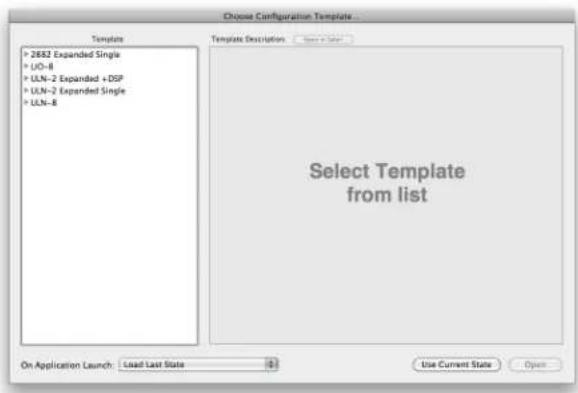
Figure 11.35: Template Window
To start with a template, click the template you would like to use in the "Template" list on the left side of the window. A description of the template will appear in the "Template Description" area to give you more information about the template. You can browse through the templates to choose which one is the best starting point for you. For example, if you select "ULN-8 Tracking Cue Mix + Reverb", you will see the following description:

Figure 11.36: ULN-8 Tracking Cue Mix + Reverb
Once you decide to use the selected template, click the Open button. If you decide that you don't want to use one of the templates, you can click the "Use Current State" button to use the state that is currently loaded in the console. If you are using the Template dialog at application launch, this will load the state that the console was in the last time you quit MIO Console. If this is your very first launch ever of the MIO Console, you will then need to manually configure your mixer.
Manual Configuration
The next way to create a new mixer configuration is to use the Mixer » Configure Mixer... menu command. When you select this command, you will see the Configure Mixer sheet:

Figure 11.37: Configure Mixer Sheet
The Configure Mixer Sheet allows you to do bulk configuration of the mixer. The sheet is split into two major sections:
- Mix Busses
- Selected Mix Bus Configuration
You create and configure the mix busses using the top section, then you configure the channels you assign to the busses in the bottom area. When you select a mix bus from the table in the Mix Busses section, the Selected Mix Bus Configuration area automatically updates to reflect the current configuration of the selected mix bus. All of the available input channels are listed in the Selected Mix Bus Configuration, and you can assign any of the channels to the selected mix bus by checking the channel's Enable check-box.
Each mix bus has a number of attributes that you can control:
- Bus Name
- Bus Type
- Bus Mode
The Bus Name is the name you assign to the bus. It is used throughout the Mixer UI to identify the bus. You can name the bus anything you like.
The Bus Type determines the number of channels of the bus (mono, stereo, etc.). The type of bus determines the type of panner used to connect the input-strips to the bus. We have implemented the following types so far:
- Mono
- Stereo
• LCR - Left, Center, Right
• Quad - Four-corner surround
• LCRS - LCR with one back-channel -
5.0 - LCR with left surround and right surround
-
5.1 - 5.0 with LFE
• 7.1 - 5.1 with Left-Center and Right-Center
The Bus Mode allows you to determine if the bus has a master fader or not. If the mode is Master Bus the mixer will create a master fader for the bus. If the mode is Aux Bus the mixer will not create a master fader, but you can assign the bus to another bus to create a return fader.
Naming Input Channels
In the Selected Mix Bus Configuration pane, you may give the input channels meaningful names. To name a channel, simply click on the Channel Name value. When renaming multiple channels you may use the Tab key to move to the next channel. You may only may only rename MONO input channels. MIO Console will automatically create names for multichannel inputs. For example, if you rename DAW 1 "Drums L" and DAW 2 "Drums R", MIO Console will show the stereo DAW 1/2 signal as "Drums L/R". This is to allow MIO Console to intelligently create channel names for all multichannel widths, i.e. stereo, LCR, quad, etc.
Mixer Configuration Tasks
The following task lists are succinct guides to performing the specific configuration tasks you will need to engage in while configuring a mixer using the Configure Mixer Sheet.
To Create a Mix Bus:
- Click the " + " button — this creates a new stereo bus with a default name.
- Double-click the new bus in the list; you can now edit the bus name.
- You can adjust the bus type from the pop-up menu in the Bus Type column.
To Delete a Mix Bus:
- Select the bus you want to delete
- Click the " - " button — this deletes the bus and de-assigns the channels that were assigned to the bus (but it won't delete the input channel strips in the mixer).
To Add a channel to a Mix Bus:
- Select the bus to which you want to add the channel.
- Check the box in the "Enable" column for the input channel you want to add to the bus. Your choice of input channels consists of any of the physical analog and digital inputs from your Mobile I/O, as well as any available inputs from your computer (called "DAW" inputs). The channels you select here are the channels that will be available in your mixer as Input strip destinations.
To Rename an Input Channel in a Mix Bus:
- In the "Channel Name" column, double-click the name you wish to rename.
- Type the new name of the input channel.
To Remove a channel from a Mix Bus:
- Select the bus from which you want to remove the channel.
- Uncheck the box in the "Enable" column for the channel you want to remove from the bus.
To Add/Remove all visible channels to/from a Mix Bus:
- Select the bus you want to configure.
To filter the channels visible in the Selected Mix Bus Configuration area:
- Select the bus you want to view.
- You can use the "Limit Visible Types" menu to choose whether you will see All, Mono, or Multichannel sources listed. You can also:
- Type the text that you want to use to filter the visible channels in the search field.
- Click the pop-up menu next to the search field to quickly enter standard search text items (like "Analog" or "DAW")
-
Click the magnifying glass inside the search field to choose whether to search by Channel Type or Channel Name
-
To remove the filter, delete the text in the search field.
To return to a blank mixer at any time, select "Clear Mixer Config" in the "Mixer" menu.
Input Strip Details
Every Input strip in the v.5 mixer has a similar set of controls. The following figure shows each element with a label; a detailed description follows below:

Figure 11.38: v.5 Mixer Input Strip
- Input Select: This pop-up menu lets you choose the audio source for the input strip. You can select either a physical input or the output of a bus. For a physical input, there may be further physical routing that can be selected using the Physical Input Source pop-up.
Working with multichannel inputs:
Once you have assigned a channel to a bus, MIO Console will constrain your audio sources to:
- Mono inputs
- Inputs that have the same number of channels as the bus
If you need to send an input to a bus with a different channel count, you need to:
- Choose "Create Multiple Mixer Strips..." from the Mixer menu
- Enter the number of strips you want, and select the number of channels (Mono to 7.1) from the pop-up menu
- Select the channels you want to use in the strip from the Input Select pop-up
-
Assign the input strip to a bus
-
Physical Input Source: This pop-up menu will be present if the source you choose in the Input Select pop-up menu has further physical routing or level control selections available. For example, the Analog inputs on the 2882 allow for the selection of Line +4, Line -10, Mic, Mic/Pad and Instrument inputs. This pop-up allows you to make those selections. (Note: the Physical Input Source controls are identical to those on the I/O Control tab of the MIO Console. Changes made to the Physical Input Source propagate to items in the Mixer window and vice versa). If the input does not have these sort of selections (such as a digital input), then this control will not be present.
- Phantom Power: This button will be present if the physical input supports phantom power. Click this button to enable the digitally controlled phantom power. The button is red when phantom power is enabled.
- Input Gain/Trim: This knob and numeric display will be present if the physical input supports digitally controllable analog input gain. The knob automatically adjusts the gain between the available minimum gain and maximum gain for your hardware. You can also type a gain amount directly in the Input Gain/Trim numeric display. If you type in an amount that is below the minimum allowable gain, the gain will be set to the minimum allowable. If you type in an amount that is above the maximum allowable gain, the gain will be set to the maximum allowable. The display readout is in dB.
- Character Select: All input strips support this control which allows you to select which character model will be applied to the input signal. The various character models offer unique, high quality harmonic and tonal coloration to your signal. Choose "None" to disable character modeling. You may also Option-click the Character setting to bypass it for easy A/B listening.
- Direct Output Routing Point (pre-Inserts): As signal runs through the input strip there are a number of points from which you can route the signal to an output. This Direct Output pop-up menu controls the first available route point. This route point is "pre-insert," meaning it occurs before any plug-in processing is applied to the signal. You can choose any Physical Output or FireWire Return on the same box as the destination for this Direct Out. If you choose the "Auto" item in the menu, the mixer will automatically route to the next available output. This routing point is the appropriate one to use for "Dry" recording — meaning that you are only using the Mobile I/O as a preamp and converter, and not for any of its mixing abilities or DSP plug-ins.
Important Note!
You can't assign the direct out to an output until you have associated the mixer strip to an input using the Input Select!
- Plug-in Inserts: Like the "insert slots" in modern DAWs, these pop-up menus function as inserts into the signal path, allowing you to insert any of the available plug-ins directly into the signal path. The processes are applied sequentially from top to bottom. If you have a multi-channel input channel strip,
you can still insert mono plug-ins on the strip; the mixer will automatically insert enough plug-ins to process every channel in the strip and will also automatically link all the mono instances together. This allows you to use the full range of +DSP plug-ins on multi-channel input strips.
In addition to standard plug-ins, you can also insert plug-in graphs directly into the strip. When you insert a plug-in graph, the signal in the strip is connected from the output of the preceding slot to the input of the inserted graph and from the output of the graph to the input of the next slot. Within the inserted graph you can do all the cool +DSP tricks that you have always been able to do, including feedback loops, mults, and so on. This allows you to build complex processing graphs and easily insert them into your production workflow.
- Direct Output Routing Point (post inserts): This pop-up menu controls the second and last available route point. It occurs "post-insert" meaning it occurs after any plug-in processing from the inserts has been applied to the signal. You can choose any Physical Output or FireWire Return on the same box as the destination for this Direct Out. If you choose the "Auto" item in the menu, the mixer will automatically route to the next available output. This routing point is the appropriate one to use for "Wet" recording — meaning that in addition to using the Mobile I/O as a preamp and converter, you are also utilizing it to apply DSP processes into your record channel.
Important Note!
You can't assign a direct out to an output until you have associated the mixer strip to an input using the Input Select!
- Panner: Stereo and multi-channel input strips include a panner section. This is a context sensitive control; in other words, the type of panner that appears depends on the number of channels on the input channel strip. If the mix bus is a mono bus, there will be no panner. If the mix bus is Stereo bus or a three-channel LCR bus the panner will be a knob control with pan display. If the mix bus is a 4-channel or higher bus, the panner will be a surround panner. Use the panner to position the channel in the mixer's sound field. The different panner controls look like:

Figure 11.39: v.5 Mixer Panner Controls
You may also right (or Control) click on a surround panner to bring up a direct assignment menu. This is useful for assigning a mono input to a specific surround output channel. Clicking the direct assignment will return you to the surround panner.

Figure 11.40: v.5 Mixer Direct Pan Assignment
- Phase Invert: Clicking this button will invert the phase of the input signal at the mixer input. The button turns yellow when enabled.
- Solo: When any solo button is engaged on any channel in a mix bus, the mix bus will only pass signal for channels that have the solo button engaged. This solo functions as a solo-in-place, meaning all pan, level, and DSP processing settings on the channel strips are maintained. Having solo engaged does not affect the signal at any of the direct outs. The solo button turns orange when engaged.
- ⌘ (Command) click on any solo button will clear all solos in the bus except for the solo you click on.
- ∨ (Option) click on any solo button will set all solos in the bus to the new value — you can use this to clear all solos on the bus.
- Mute: When this button is engaged signal in the associated channel is muted at the mixer. This does not affect the signal at the direct outs or pre-fader sends. The mute button turns blue when engaged.
- (Option) click on any mute button will set all mutes in the bus to the new value.
- Record Enable: This button enables recording of the associated channel(s) in the record panel. The Record Enable button turns red when engaged.
- (Option) click will set all record enable buttons in the bus to the new value.
- Fader Gain display: Shows the channel gain level in dB. Click in the readout display to edit the level numerically.
- Channel Fader: This fader allows you to adjust the level of this channel to the assigned bus.
- Channel Meter: This meter shows the post insert signal level, and can be made pre or post fader.
- Channel Name: Shows the name assigned to the channel in the Mixer Config sheet. You can rename each channel using the Mixer Config dialog window as explained above in "Mixer Configuration Tasks."
- Bus Select: Use this pop-up menu to select the bus that the input channel strip is assigned to.
- Select/Drag Strip: This area lets you select an input channel strip and move the strip either right or left within the mixer.
- Clicking in this area will select the strip if it is not already selected.
- Ⓧ (Command) click will toggle the selection.
- 仓 (Shift) click will add strips to the current selection. All strips between the shift-clicked strip and the currently selected strip will become selected.
- Click and drag to move the selected strips left or right in the mixer.
You can click outside any strip to deselect all strips.
Selection-based Linking
When you have multiple strips selected, the changes you make to a selected strip will be applied to all the selected strips. For example, if you have multiple input channel strips selected and you choose a setting for "Character" on one of the selected strips, that setting for Character is applied to all selected strips.
This feature allows you to quickly apply bulk changes to the state of the mixer.
The parameters that are linked by selection are:
• Physical Input source
- Character
- Pre-insert Direct Out, if you select Auto or n/c
- Any Plug In Insert — the same plug-in will be inserted on each selected strip
- Post-insert Direct Out, if you select Auto or n/c
- Phase Invert
- Solo
- Mute
- Record Enable
- Bus Assignment
- Dragging — all selected strips will be consolidated and dragged as a block
The following parameters are linked by selection, but the link is only applied if the
- Input Gain/Trim
- Pan position
- Channel Fader Gain
Plug-ins
The v.5 Mixer provides an insert model for using +DSP plug-ins. The 2d Hardware includes a basic set of plug-ins that provide "nuts & bolts" production processing:
- MIOStrip — a complete channel strip plug-in which includes:
- Gate w/ sidechain filter
- Compressor w/ sidechain filter
- 6-band EQ
- MIODelay — a short time track alignment delay
- M/S Decoder
• Dither - HaloVerb
- Metric Halo's exclusive Character signal processing per channel
- Multichannel mixer with surround support
- Bus send plug-in for routing signals within channel strips to busses
When the +DSP license is added to 2d, the options grow dramatically. All +DSP plug-ins can be inserted directly into the insert slots in the channel strips, or you can insert a +DSP graph into any of the insert slots, and then insert and connect a graph populated with +DSP plug-ins within the inserted graph.
The plug-ins that may be inserted in any given slot depend on the number of channels of a given input channel strip. All mono plug-ins may always be inserted in any slot; if you insert a mono plug-in into a strip that has a multichannel input (for example a bus master strip or bus return strip, or a multichannel input strip), the mixer will automatically instantiate multiple copies of the plug-in (for example — two plug-ins into a stereo strip and 5 plug-ins into a 5.0 strip), and link the parameters of the instances so that when you control the inserted plug-in, it will control all instances.
If you are working with a multi-channel strip, only plug-ins that make sense for the number of channels of the strip will also be available; for example, with a stereo strip, you will see both the mono and stereo versions of the MIOComp and MIOLimit dynamics processors; you can select the version that works best for you. At the present time, there are few processors that have specifically been built for multi-channel strips with more than two channels. If you expect to use (or change to) a bus with multiple channels beyond stereo, you will probably want to use the mono version of the plug-in as they can be automatically instantiated as you adjust the number of channels of the strip.
More info on using plug-ins via inserts can be found on the DSP Implementation Guide.
Plug-In Graphs (requires +DSP license)
When you insert a graph in the mixer, the graph is automatically generated with input and output ports to match the number of channels of the strip that it is inserted into. The default state of an inserted graph is for the inputs to be connected directly to the outputs.
When you open the graph UI for the insert, you can insert any set of plug-ins into the graph that is shown in the graph UI window. These plug-ins can be connected by virtual cables, their UIs opened, and parameters set. The graph I/O connections will automatically be routed to the appropriate points in the strip that hosts the graph. The graph will be saved and recalled with the rest of the mixer. You can also choose to save the graph independently as kind of a "preset" that can be inserted again and again into the mixer.
The graph inserts also have access to the saved graph patch library — this lets you migrate patches that you have created in +DSP in v.4 or earlier to inserts in v.5. You can also save the configuration of your graph insert into the library as a preset, so as you work with the mixer, you can build up a set of “secret weapon” processors that can be instantly recalled and tweaked as needed.
To Migrate Graph Patches from v.4 or earlier Consoles:
Graph patches created in v.4 or earlier consoles may require a little clean up for use with v.5.
- If the graph patch you want to load is already set up to take input from Analog 1 (for a mono patch), Analog 1-2 (for a stereo patch) or Analog 1-N (for a multi-channel patch), then you can just use it directly in v.5.
- If the graph patch you want to migrate is set up to take input from another source (say Analog 6, or Digital, or DAW, or ADAT), you need to open the graph in the Virtual DSP area of the +DSP pane and change the inputs to patch to Analog 1 (for a mono patch), Analog 1-2 (for a stereo patch) or Analog 1-N (for a multi-channel patch). The same applies for output assignments. Make sure to set the outputs to Process Bus 1-N. Save the patch with the new input and output assignments and it is ready to be used in a v. 5 graph plug in.
Also, please note that v. 4 and earlier medium and long delays will not currently load on the 2d DSP. However, MIO Console v.5 includes new 2d compatible delays that you should be able to use to replace the older medium and long delays.
Graphs may be instantiated into any insert point of any type of channel strip, whether it is an input strip, aux return strip or a master fader strip. This allows you to configure (or utilize pre-configured) processing in a variety of ways as appropriate for the project that you are working on. For example, you can insert a one in-one out graph into a mono input strip to implement anything from a guitar amp model to a parallel compressor or a feedback delay. You might insert a 2-in 2-out on an aux return strip and build a stereo reverb or echo time domain processor to process the send bus; you would insert sends on the various input strips to route the audio to your reverb graph.
More info on using graphs can be found in the DSP Implementation Guide.
Plug-in Macros (requires +DSP license)
With a +DSP license, the v.5 Mixer also supports the direct insertion of Plug-in Macros, which are pre-made Graphs. Metric Halo includes a number of bonus macros with the +DSP license, including reverbs, guitar processing models, mastering tools, delays and other effects. Some of the macros are open — once you insert the macro, you will have full access to the graph, and you can edit it, modify it and interact with it as you please. Other macros are closed and represent a monolithic processor; you can insert them, and they do the job they were designed for, but they cannot be edited.
Channel width and macros:
Please note that macros are either mono or stereo. You will see different macros in the insert menu depending upon the width of the channel.
Sends
Any insert in the mixer may be used to send the audio from that point in the signal path to any bus defined in the mixer that is instantiated in the same interface. When you insert a send to a bus on a strip, a new send strip is automatically added to the mixer; when you insert a send or click on a send tile in the mixer, MIO Console will automatically open the Sends Mixer window:
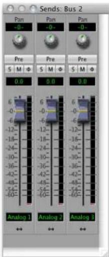
Figure 11.41: Sends Mixer Window
The Sends Mixer window shows the all the send strips for currently selected bus. Send strips are more limited than full input strips. Each Send Strip has a panner (if appropriate for the bus width and send width), phase invert, solo, mute and pre/post fader buttons, as well as a send level fader and level meter. All of the elements common with the full input strips function in the same way as the elements in the full strip.
The control element that is unique to the send strip is the Pre/Post Fader button (the button labeled "Pre" in the illustration above). When this button is not illuminated, the send functions "Post Fader" relative to the mixer fader for the strip that the send is inserted on. This means that the level of the signal will be adjusted by the input channel strip's level fader. This is default state of the Pre/Post Fader button. Since the signal is actually routed from wherever the send is inserted, the "Post Fader" state does not control the routing of the send, but rather the level; the total send level will be the sum of the source fader level and the send fader level. When you have selected "Post Fader" mode for the send, the send will also respect the mute and solo state of the strip that the send is inserted on.
In "Pre-fader" mode, only the send level fader controls the level of the signal to the send destination. Also, the send does not take the mute or solo state of the strip into account when sending the signal to the send destination. When "Pre-fader" mode has been selected, the button will be illuminated in lavender.
If you have set a custom color for an input in the main Mixer window, that input's channel in the Send window will be the same color for easy identification.
I/O insert
The I/O or "/Input/Output insert is used to route signals out of the mixer strip and back in at the insert slot. Signals may be routed to any available analog or digital connection, as well as DAW and FW channels.
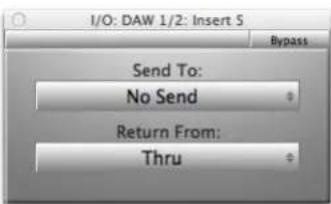
Figure 11.42: I/O insert
The I/O insert has three parameters:
- Send To: This menu shows the available output connections.
- Return From: This menu shows the available input connections.
- Bypass: When the I/O insert is bypassed, signal will continue to be routed to the "Send To" output, and the original audio will pass unmodified to the next insert slot. Any audio present on the "Return From" input will be ignored.
Connections that are already in use (for example, outputs used in the Monitor Controller) will be unavailable. There are three ways to use the I/O insert:
- Send and return: Select the "Send To" destination and the "Return From" source. Audio will be routed to the "Send To" output and be received from the "Return From" input, interrupting the original audio and creating a virtual insert point in that slot.
- Send only: Set the "Send To" for whatever output you need, and leave the Return From set to "Thru". The audio will be sent to the selected output and will also pass through the strip. This essentially uses the I/O insert as another direct output.
- Return only: Set the "Return From" to the desired input, and leave the "Send To" set to "No Send". The audio will be received from the selected input and will replace the audio from the strip's source. This allows you to override the strip's source and route audio from one source through the processing and routing of another.
One of the most common uses of the I/O insert is to create a virtual insert point for using external devices. As an example, let's look at how to insert an external analog processor on a channel. We'll connect the processor using Analog 3/4:
- In the channel strip, insert the "I/O" plug-in.
- Select "Analog 3/4" in the "Send To" menu and connect the Analog 3/4 outputs to the inputs of your device.
- Select "Analog 3/4" in the "Return From" menu and connect the outputs of your device to the Analog 3/4 inputs of the interface.
- Adjust the input and output gains in the I/O Control tab of the Console window for the proper send and return levels.
The flexibility of the I/O insert allows you to accomplish more advanced routing with less mixer channels:
- The I/O insert can be instantiated anywhere in the insert slots, so it can be used to route audio presome effects and post- others.
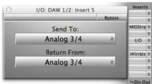
Figure 11.43: A post-MIOStrip, Pre-HaloVerb insert
This same configuration could be used as a send-only, to provide an output that includes MIOStrip but not HaloVerb by selecting "Thru" in the "Return From" menu.
- Instantiate the I/O insert after a MIOLimit as a second post-insert direct out to feed two external recorders while tracking.

Figure 11.44: Post-limiter sends on a Analog 1 and Digital 1
- Since the I/O insert can be used with FireWire channels, it can be used to route audio to and from software. For example, you can insert MainStage or other standalone signal processors into MIO Console channels and busses.
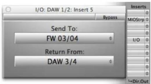
Figure 11.45: I/O insert routing to and from MainStage
![Preferences General Audio MIDI Display Audio Audio Output: LIO-8/4P [100] Setup... Audio Input: LIO-8/4P [100] Setup... I/O Buffer Size: 128 Samples ✓ I/O Safety Buffer Resulting Roundtrip Latency: 12.9 ms Sample Rate: 44100 Hz Apply Changes Silence Previous Patch: 60 seconds Hot-Plug Behavior: Aler…](/content/2026/05/884165/images/103d556a9c30a514aa1603c5b1ac58d486ce77914923dbbcb6562bd5c29c643b.jpg)
Figure 11.46: MainStage set to send and return on channels 3/4
Latency in the I/O Insert
Using the I/O insert incurs the following latencies:
- When using an analog send/return to insert an external device on a 2882 or ULN-2, there will be 74 samples of latency
- When using an analog send/return to insert an external device on a LIO-8 or ULN-8, there will be 116 samples of latency
- When using FireWire to insert a plug-in hosted on your computer, there will be latency of double the host buffer size plus 66 samples
Most hosts offer delay compensation for inserts, please consult their documentation for more info.
Master Strip Details
Master Strips are used to control the signal processing and output routing for mix busses. Rather like the Input Strips, they provide Character, Direct Outs, Inserts, and Mute controls. They also provide a very flexible strip output routing pop-up that allows you to route the output of the processed mix bus to any specific output path, mult it to many output paths, or to assign it to the Monitor Controller.

Figure 11.47: v.5 Mixer Routing Connections
- Box Number: This is the serial number of the interface, and is provided at the top of the strip to help identify which interface the mixer strips are associated with in a multi-box system.
- Character Select: All master strips support this control which allows you to select which character model will be applied to the input signal. The various character models offer unique, high quality harmonic and tonal coloration to your signal. Choose "None" to disable character modeling.
- Direct Output Routing Point (pre-Inserts): As signal runs through the master strip there are a number of points from which you can route the signal to an output. This Direct Output pop-up menu controls the first available route point. This route point is "pre-insert," meaning it occurs before any plug-in processing is applied to the signal. You can choose any Physical Output or FireWire Return on the same box as the destination for this Direct Out. If you choose the "Auto" item in the menu, the mixer will automatically route to the next available output. This routing point is the appropriate one to use for "Dry" recording — meaning that you are only using the Mobile I/O as a preamp and converter, and not for any of its mixing abilities or DSP plug-ins.
Important Note!
You can't assign a direct out to an output until you have associated the mixer strip to an input using the Input Select!
- Plug-in Inserts: Like the "insert slots" in modern DAWs, these pop-up menus function as inserts into the signal path, allowing you to insert any of the available plug-ins directly into the signal path. The processes are applied sequentially from top to bottom. If you have a multi-channel master strip, you can still insert mono plug-ins on the strip; the mixer will automatically insert enough plug-ins to process every channel in the strip and will also automatically link all the mono instances together. This allows you to use the full range of +DSP plug-ins on multi-channel input strips.
In addition to standard plug-ins, you can also insert plug-in graphs directly into the strip. When you insert a plug-in graph, the signal in the strip is connected from the output of the preceding slot to the input of the inserted graph and from the output of the graph to the input of the next slot. Within the inserted graph you can do all the cool +DSP tricks that you have always been able to do, including feedback loops, mults, and so on. This allows you to build complex processing graphs and easily insert them into your production workflow.
- Direct Output Routing Point (post inserts): This pop-up menu controls the second and last available route point. It occurs "post-insert" meaning it occurs after any plug-in processing from the inserts has been applied to the signal. You can choose any Physical Output or FireWire Return on the same box as the destination for this Direct Out. If you choose the "Auto" item in the menu, the mixer will automatically route to the next available output. This routing point is the appropriate one to use for "Wet" recording — meaning that in addition to using the Mobile I/O as a preamp and converter, you are also utilizing it to apply DSP processes into your record channel.
Important Note!
You can't assign a direct out to an output until you have associated the mixer strip to an input using the Input Select!
- Mute: When this button is engaged signal in the associated bus is muted at the output. This does not affect the signal at the direct outs or pre-fader sends. The mute button turns blue when engaged.
- Record Enable: This button enables recording of the associated channel(s) in the record panel. The Record Enable button turns red when engaged.
- ∨ (Option) click will set all record enable buttons in the bus to the new value.
- Fader Gain display: Shows the channel gain level in dB. Click in the read out to edit the level numerically.
- Channel Fader: This fader allows you to adjust the channel gain level.
- Channel Meter: This meter shows the pre-fader, post insert signal level.
- Bus Name: Shows the name of the bus that this master strip is controlling. You can name this bus in the Config Mixer sheet as explained above in "Configure Mixer sheet"
- Bus Output Assign: Use this pop-up menu to select which outputs the bus is routed to. The menu that appears when you click on this control looks like the following:

Figure 11.48: Bus Output Assign Pop-up Menu
As you can see, there are items for the Monitor Controller, No Connection (n/c) and the available output paths. If an output path is already assigned elsewhere in the system, it will be grayed out in the menu. This ensures that you can not accidentally assign two busses to the same physical output (since only one will actually be connected). With this pop-up, you can control three different kinds of assignment for the bus output:
-
Monitor Controller Assign: This is an on/off item in the pop-up menu. If the bus is assigned to the monitor controller (by selecting the item in the menu), there will be a diamond next to the Monitor Controller item, and the bus will appear as a pre-configured input path in the Monitor Controller. If there is no Primary output path assigned, but the bus is assigned to the Monitor Controller, "MC" will appear in the mixer UI in the pop-up control to indicate that the Monitor Controller is assigned.
-
Primary: Select an output in the Bus Output pop-up menu and it will be assigned as the primary output; this means the bus will be routed to the primary output path. The Primary output will be indicated in the menu by a checkmark. When you select another output from the list (other than the Monitor Controller item), the primary output will be changed to the path that you select and the old path will be disconnected. If there is a Primary output assigned, its name will be shown in the pop-up menu control in the Mixer UI. Select "n/c" to de-assign the primary output path.
-
Mult: Hold the (Shift) key down while selecting an output in the menu to add it to the mult list. This means that the bus will be routed to that path in addition to the Primary output and any other mult outputs. When a path has been multed to, the item in the menu is listed as "Mult to: ..." with the "..." replaced by the name of the path (as in the screen shot above). To remove a path from the mult list, select it again with the shift key held down.
Important Note!
You can't assign a Master strip to an output until you have assigned an input to it!
- Select/Drag Strip: This area lets you select an input channel strip and move the strip either right or left within the mixer.
- Clicking in this area will select the strip if it is not already selected.
- ⌘ (Command) click will toggle the selection.
- 仓 (Shift) click will add strips to the current selection. All strips between the shift-clicked strip and the currently selected strip will become selected.
- Click and drag to move the selected strips left or right in the mixer.
You can click outside any strip to deselect all strips.
Routing Summary
All routing in v.5 is managed through the mixer and monitor controller. The diagram below summarizes the routing control points and what elements of the routing model they control:
![graph TD A["CoreAudio Application"] -->|In| B["Mobile I/O Driver"] B -->|FW| C["v.5 Mixer (on Mobile I/O DSP)"] C -->|DAW| D["Monitor Controller"] D -->|Outputs (Digital, Analog, Cans)| C C --> E["Inputs (Digital, Analog)"] E --> F["Analog 1 Bus 1"] F --> G["Main MC"] G --> H["Inserts"] H --> I["Cha…](/content/2026/05/884165/images/830d1525f0db6cf2f43ebd39a7a5783198f5cb07e7470418773398cb25c78b7f.jpg)
Figure 11.49: v.5 Mixer Routing Connections
In the diagram above, the various colored arrows indicate different routing elements:
- The red arrows indicate input strip input assignment points. These indicate elements to route from either DAW outputs (signals sent from the computer to the Mobile I/O) or from physical inputs (Analog or Digital) to the strip's input.
- The blue arrows indicate input strip direct routing points. These indicate elements you can route from the direct out patch points to either FireWire returns (signals sent to the computer from the Mobile I/O) or to physical outputs (Analog or Digital).
- The pink arrows indicate mix bus direct routing points. These indicate elements you can route from the direct out patch points to either FireWire returns (signals sent to the computer from the Mobile I/O) or to physical outputs (Analog or Digital). The routing point from the bottom of the strip can be used to route to multiple output points and to assign the mix bus as a source for the Monitor Controller.
- The yellow arrow indicates a mix bus assignment to the Monitor Controller. This indicates an element to route from the bus output patch point to the Monitor Controller. When assigned to the Monitor Controller, the Monitor Controller can be used to route the mix bus source to any of the defined monitor output paths.
- The green arrow indicates a mix bus assignment for an input strip. This indicates an element you can route from the input strip to a mix bus. When assigned to a mix bus the input is added to the specified mix bus.
These routing elements allow you to completely configure the routing resources of the mobile I/O and accomplish any set of routings required quickly and easily, directly from the signal source.
FireWire Returns
The Mixer is the hub of all audio in the interface, with the ability to route between physical I/O, CoreAudio and internal busses. The Mobile I/O driver provides for 18 channels of audio to and from the host over FireWire at 44.1-96kHz rates and 8 channels of communication at 176.4-192kHz on the ULN-8 and LIO-8.
The Power of Returns
FireWire Returns allow you to:
- Add +DSP elements to live mixes and DAW sessions without the need for any physical cabling.
- Use +DSP elements in a send and return environment from your DAW of choice.
- Record your dry input along with printed channel processing using parallel +DSP routings.
- Utilize the pristine 80-bit mixer in the MIO and mix within your MIO and route it back to the DAW for final bounces.
- Route audio between Core Audio applications without the need for 3rd party audio routing applications.
![graph TD A["Input"] --> B["I/O"] B --> C["Output Volumes: 0.000"] C --> D["Output: 2.4 (G11) (DAW3/1)"] D --> E["Input: 61/07 (G11) (FW13/1)"] E --> F["Input Volumes: 0.000"] F --> G["Latency Detection: Ping"] G --> H["Latency Offset: 0.000"] H --> I["Output"] I --> J["612 (DAW3/)"] J --> K["Charact…](/content/2026/05/884165/images/e5a5890f2ebb15d41e39e2950f561e270a1e02a210c625916d8135c45aa05df5.jpg)
Figure 11.50: +DSP Mid-Side Mastering Process Inserted in Logic Using Logic's I/O Plug-in and MIO FireWire Returns
FireWire Returns are not just for +DSP users. If you own an interface without +DSP, you can use the 2d plug-ins with FireWire Returns for out of the box mixing, or for direct routing connection between multiple CoreAudio applications.
For example, you can use the FireWire returns to route ANY audio from ANY CoreAudio application to our award winning SpectraFoo application.
![graph TD A["CD drive"] --> B["Character"] B --> C["FW01/0"] D["Image"] --> E["113 DAW1/"] F["Image"] --> G["1+Dir.Out"] H["Image"] --> I["1+Dir.Out"] style A fill:#f9f,stroke:#333 style B fill:#ccf,stroke:#333 style C fill:#cfc,stroke:#333 style D fill:#fcc,stroke:#333 style E fill:#ffc,stroke:#333…](/content/2026/05/884165/images/2d07a4e4b3abca3cfe838271d85a5d45e16d29ff67c746c324c1f7987c2abd05.jpg)
Figure 11.51: Routing from Logic to SpectraFoo via FireWire Returns
You can also use the routing resources to capture the output of any CoreAudio application (or set of CoreAudio applications) using the Record Panel or any other CoreAudio recording application.
12. Monitor Controller
Overview
The Monitor Control window consolidates the most important monitoring functions for your MIO into one convenient window. You can configure which sources you want to monitor and from which outputs they will be monitored, for any number of channels from mono to 7.1 Surround. You can configure the Monitor Controller as a floating window so it always remains accessible, even when the MIO Console is hidden. You can choose between the full size Monitor Control window and a smaller Mini Controller window that contains nearly all the functions of its big brother. Finally, as an optional component of the MIO Console, if the Monitor Controller simply doesn't fit into your workflow, you don't need to use it.
Ultra-Quick Start Guide to Configuring the Monitor Controller
If you just want to set your main outputs of your Mix Bus to be controlled by the monitor controller, follow the steps below:
Adding the Bus Output of your Mix Bus to the Monitor Controller
- In the Master strip for your Mix Bus in the v.5 mixer, click the Bus Output pop-up menu.
- Select Add to Monitor Controller. The Bus Output of your Mix Bus is now automatically configured as the Monitor Source for the Monitor Controller.
Configuring the Monitor Controller
- Select Window > Show Monitor Control Window.
- Click the Configure button at the bottom of the Monitor Controller window. The Configure Monitor Controller sheet appears:
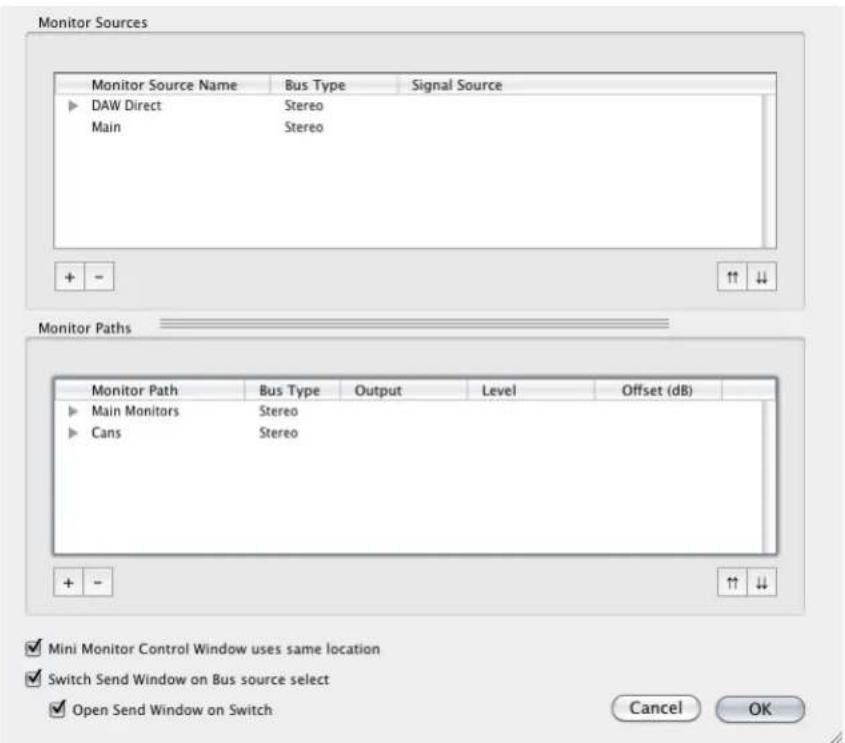
Figure 12.1: Monitor Controller Configuration Pane
-
Click the '+' button in the Monitor Paths section at the bottom of the Configure Monitor Controller sheet. The Add Monitor Output dialog appears.
-
Enter the name of the new Monitor Output Path.
-
Select the Bus Type of the new Monitor Output Path.
-
Click OK. The new path will appear in the Monitor Path list.
-
Click the pop-up menu in the "Output" column for the Left Channel of the path. Select the appropriate output channel from the list. This includes Physical Outputs and Firewire channels.
-
Repeat step 7 for each of the channels that make up the bus.
-
Click Ok. The Monitor Controller now has your Bus Output configured as its Monitor Source, and the Output Path configured above.
Monitor Control Interface and Basic Operation
The Monitor Control window interface has four sections:

Figure 12.2: Monitor Controller Window
- Global Functions: Includes Mobile I/O selection pop-up menu, Utility and Configure buttons
• Monitor Source: Includes tabs to select between defined Monitor Sources
- Source Override: When this box is checked, the sources selected in the Source Override pop-up menu will be routed to the Output Path instead of the selected Monitor Source.
- Output Section: Includes tabs to select between defined Output Paths as well as the monitor controls themselves.
In order to use the Monitor Controller, you'll need to do the following:
-
Configure one or more Monitor Sources
-
Configure one or more Monitor Output Paths
-
Select a Monitor Source to monitor
-
Select an Output Path for your monitored signal
After completing these tasks, you can use the Monitor Control window to control all the monitoring functions for the selected Monitor Source, which you will hear via the selected Output Path.
MIO Console automatically saves your Monitor Sources and Output Paths, so you will only need to define each Monitor Source and Output Path once. You can use the Monitor Controller with only one Monitor Source and one Output Path defined, or you can define as many as you'd like of either or both and use the Monitor Controller to switch between them.
Determine Configuration
The most important step in working with the Monitor controller is to determine how signal is routed through your mixer. Once you know how your signal flows through the mixer to the Mix Bus, configuring and using the Monitor Controller is very simple. In order to configure the Monitor Controller you will need to identify two different types of audio channels in your system:
• Monitor Sources (inputs to the Monitor Controller)
• Monitor Output Paths (outputs from the Monitor Controller)
Identifying Monitor Sources
The selectable input source that you wish to monitor is called the Monitor Source. Your sources can come from the physical hardware inputs of the Mobile I/O or they can be virtual inputs streaming into the MIO over the FireWire cable, and can consist of any number of channels from a mono channel to eight channels forming a 7.1 surround signal. You can freely name your Monitor Source in order to more clearly identify what sources are being monitored. For example, if your monitor source was your AES inputs, you might want to name your Monitor Source "AES input" or simply "AES". On the other hand, if you have a DAT player connected to your AES input, you might instead want to name the Monitor Source name "DAT".
You can also use mix busses as sources in the Monitor Controller. To add a mix bus to the Monitor Controller, you simply select the "Add to Monitor Controller" item in the Bus Output pop-up menu at the bottom of the master strip for the bus. This automatically creates a Monitor Controller source for you. The mixer will automatically maintain the routing of the bus output to the monitor controller for you.
When you create a Monitor Source, you specify the type of path you are making, and the name of the new path. The type of path (Mono, Stereo, LCR, LCRS, Quad, 5.0, 5.1, 7.1) you choose will allow the Monitor Controller to automatically create channel slots for each component channel.
The Monitor controller uses the channel assignments to match the sub-channels between Monitor Sources and Monitor Output Paths and automatically route your selected source to your selected Monitor Output Path.
Once you have identified the sources you want to select from in your system, you use the Monitor Controller's Configuration Dialog to set up the sources. See "Configuring Monitor Sources" for more details.
Identifying Monitor Output Paths
A Monitor Output Path defines a selectable destination for your monitor system. It can be anything from a single Mono channel, to a 7.1 surround path. Monitor Output Paths are associated with real physical outputs that you have connected to Monitoring devices (like Speakers/Amplifiers or Headphones). These destinations are unlikely to change frequently, but you may have more than one destination that you use routinely. For example, you may have the following monitoring systems in your studio:
- Console (or desk) mounted nearfield (small) stereo monitors.
- A larger far-field 5.1 surround monitor system.
- A pair of studio headphones.
You may want to monitor any of the Monitor Sources through any of these monitoring systems, but only through one at a time. So in this case you would configure three Monitor Output Paths, each with its own physical outputs — one for each system listed above.
As with the Monitor Sources, you choose the names for these Monitor Output Paths in a way that makes sense to you.
When you create a Monitor Output Path, you specify the type of path you are making, and the name of the new path. The type of path (Mono, Stereo, LCR, LCRS, Quad, 5.0, 5.1, 7.1) you choose will allow the Monitor Controller to automatically create channel slots for each component channel.
The Monitor controller uses the channel assignments to match the sub-channels between Monitor Sources and Monitor Output Paths and automatically route your selected source to your selected Monitor Output Path
Once you have identified the output paths you want to select from in your system, you use the Monitor Controller's Configuration Dialog to set up the outputs. See "Configuring Monitor Output Paths" for more details.
Using the Monitor Controller
Using the Monitor Controller is very simple. The Monitor Controller UI only controls one box at a time, so if you have multiple boxes attached you need to select the box you want to control from the pop-up menu at the top of the window.

Figure 12.3: v.5 Monitor Controller UI
The monitor control window may be set to operate as a "Utility" Window (a "Utility" Window is a floating window that floats above all the other windows in the system — including windows from other applications). When configured in this way, the window will float above all other applications and will always be active (unless hidden). If you click the up-arrow button to the right of the box select pop-up menu so that it is highlighted, the window will operate as a Utility window. Click the button again (un-highlighting it) to return the window to operation as a normal floating window. The Key Command to hide and show the Monitor Control window is global and may be used to hide and show the Monitor Control window even when you are using other applications. When the Monitor Control window is functioning as a Utility window, it will remain visible and active even when MIO Console is hidden.
Once you have selected the box to control, you only have a few simple tasks to utilize the Monitor Controller.
Selecting an Input Source
The Monitor Source area will contain buttons representing all of your defined Monitor Sources. To select the input that will feed your Output Path, simply click on one of these buttons. The selected input will automatically be routed to the current monitor output. There are key-commands defined for the first eight monitor sources.
Selecting an Output Path
The Monitor Output area will contain buttons representing all of your defined Output Paths. To select the monitor output that will be fed by the selected Monitor Source, simply click on one of these buttons. The selected output will automatically be routed so that it receives signal from the currently selected input. There are key-commands defined for the first eight monitor output paths.
Adjusting the Monitor Level
To adjust the monitor volume, click and drag the Level Control Knob; drag the knob up to raise the volume, drag it down to lower the volume. You can also adjust the monitor level using two-finger trackpad scrolling, mouse-wheel, or mighty-mouse wheel when the cursor is placed over the Level Control Knob. If you know the exact value you wish for the monitor level, you can also click inside the Monitor Level Display and enter a numeric value directly.
Dimming the output
Sometimes, you may want to temporarily drop the output level significantly. For these situations, the Monitor controller includes a Dim button that will drop the output by 20dB when Dim is engaged. Click the Dim button to engage/disengage the Dim function.
Muting the output
Click the Mute button to mute/unmute the currently selected Monitor Output. The button appears grayed out when the output is muted.
Locking the output
Click the lock button to lock/unlock the monitor output level at its current setting. The button appears grayed out when the output level is locked. The Monitor Source and Monitor Output routing capabilities and mute functionality of the Monitor Controller function normally when the output level is locked.
Overriding the currently selected source
By clicking on the Source Override checkbox, you can switch the selected Monitor Source for the sources selected in the channel pop-up menus of the Source Override section. This can be useful if you find that you need to monitor something, or to A/B your normal Monitoring Sources, with a "one off" source. For example, you may have a number of Monitor Sources configured for analog audio streams, audio from your computer, and so on, but for one session only, you may need to monitor a signal streaming in digitally from the AES inputs. So in this situation, rather than configuring a Monitor Source, you might want to simply select the AES inputs in the Source Override channels.
Selecting Source Override Channels
Before you can use the Source Override checkbox, you need to use the channel pop-up menu to select a source for at least one channel.
You do not need to select sources for every pop-up menu in the Source Override section:
- For Mono signals, select a source for the Left channel.
- For Stereo signals, select sources for the Left and Right channels.
- For Quad signals, select sources for the Left, Right, Ls, and Rs channels.
Note: You can not switch to a 7.1 surround source using Source Override.
The Monitor Controller as Floating Window
You can configure the Monitor Controller to be a floating window, also known as a "Utility Window" in official Mac OS X terminology. As a Mac OS X Utility Window, the Monitor Controller will remain "floating" on top of all other windows on screen, even if the MIO Console application is hidden. One advantage to setting the Monitor Controller to be a floating window is that you will always be able to quickly adjust the monitoring level regardless of how many other windows you have active. If you have an unexpected noise burst, this feature might just save your equipment—and your hearing!
Click the Up Arrow button in the upper right corner of the Monitor Control window to toggle between Utility and non-Utility mode.
Mini Monitor Controller Window
The full Monitor Control window requires a fair amount of screen space. For this reason, you can invoke a Mini Monitor Controller window, which offers nearly identical functionality in a window much smaller than the full Monitor Control window.
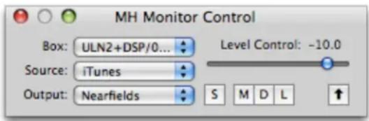
Figure 12.4: v.5 Mini Monitor Controller UI
As you can see, the Mini Monitor Controller offers identical buttons for Dim, Mute, and Lock, as well as the Utility Window button in the upper right corner. You can select among your configured Monitor Sources and Output Paths using the respective pop-up menus. You can invoke the Source Override section using the "S" button. You can adjust the volume level using the Level Control slider. Invoking the Configure window and choosing Source Override channels are the only functions that you cannot do from the Mini Controller window.
Switch between Monitor Controller and Mini Monitor Controller windows
You can toggle the display between the large Monitor Control Window and the Mini Monitor control window by clicking the Zoom button in the window's title bar (the little green + pill).
Note: Here's a way to conserve screen space while keeping the Monitor Controller available:
- Configure all your Monitor Sources, Output Paths, and Source Override channels in the Monitor Control window
- Toggle the window to the Mini Controller
- Click the Utility mode button
- Place the Mini Controller in an unobtrusive part of your monitor, such as one of the corners.
You now have a fully configured monitoring controller always available to you that requires a minimum of screen real estate.
Key Commands
The Monitor Controller defines key commands for each of its operations. You can change the default key commands with the Console's Key Commands window. If you have a programmable HID device (like the
Contour Shuttle Pro), you can assign appropriate key-commands to the buttons of the HID device to control the monitor controller. You can edit all the Key Commands in MIO Console.
Note:
The key commands you have set for the monitor control commands are global; they work even if MIO Console is not the front-most application. This means that if you set up your HID controller to use the MIO Console key commands always (e.g. in global mode), you can control the monitor controller from the HID device or keyboard even when you are in another app (like iTunes, Logic, DP, the Finder, etc.).
The following table lists all the default key commands:
Table 12.1. Default Monitor Control Key Commands
| Command Key Sequence | |
| Switch to/from Mini Controller | ⌘ F (Command + Option + Control + F) |
| Volume Up | ⌘ ^↑ (Command + Option + Control + ↑) |
| Volume Down | ⌘ ^↓ (Command + Option + Control + ↓) |
| Toggle Dim | ⌘ D (Command + Option + Control + D) |
| Toggle Mute | ⌘ M (Command + Option + Control + M) |
| Toggle Window Visibility | ⌘ V (Command + Option + Control + V) |
| Monitor Source Override | ⌘ S (Command + Option + Control + S) |
| Select Monitor Source 1 | ⌘ 1 (Command + Option + Control + 1) |
| Select Monitor Source 2 | ⌘ 2 (Command + Option + Control + 2) |
| Select Monitor Source 3 | ⌘ 3 (Command + Option + Control + 3) |
| Select Monitor Source 4 | ⌘ 4 (Command + Option + Control + 4) |
| Select Monitor Source 5 | ⌘ 5 (Command + Option + Control + 5) |
| Select Monitor Source 6 | ⌘ 6 (Command + Option + Control + 6) |
| Select Monitor Source 7 | ⌘ 7 (Command + Option + Control + 7) |
| Select Monitor Source 8 | ⌘ 8 (Command + Option + Control + 8) |
| Select Monitor Output 1 | ⌘ 1 (Command + Option + 1) |
| Select Monitor Output 2 | ⌘ 2 (Command + Option + 2) |
| Select Monitor Output 3 | ⌘ 3 (Command + Option + 3) |
| Select Monitor Output 4 | ⌘ 4 (Command + Option + 4) |
| Select Monitor Output 5 | ⌘ 5 (Command + Option + 5) |
| Select Monitor Output 6 | ⌘ 6 (Command + Option + 6) |
| Select Monitor Output 7 | ⌘ 7 (Command + Option + 7) |
| Select Monitor Output 8 | ⌘ 8 (Command + Option + 8) |
Configuring the Monitor Controller
Click the "Configure..." button to open the Configuration Dialog for the Monitor Controller. See the next sections for details.
Configuring Monitor Sources
To access the Configuration Dialog, click the "Configure..." button in the Monitor Controller window:

Figure 12.5: Monitor Controller Configure Button
The Monitor Controller's Configuration Dialog sheet will open:
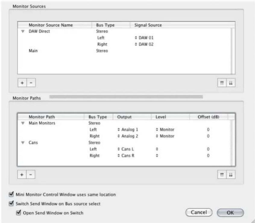
Figure 12.6: Monitor Controller Configuration Pane
Adding a New Monitor Source
- Click the '+' button in the Monitor Sources pane.
- The Add Monitor source dialog appears:

Figure 12.7: Add Monitor Source Dialog
- Enter the name of the new Monitor Source.
- Select the Bus Type of the new Monitor Source.
- Click OK. The new source will appear in the Monitor Source List:

Figure 12.8: New Monitor Source Input List
- Click the pop-up menu in the "Signal Source" column for the Left Channel of the source. Select the appropriate physical source channel from the list. This includes Physical Input and DAW channels.
- Repeat step 6 for each of the channels that make up the bus.
- If you decide (now or later) that you want to change the name of the Monitor Source, you can edit the name in the list (you can double-click the name to edit it).
- Repeat from step #1 for each source you want to add.
Removing a Monitor Source
- Click the source(s) you want to remove in the Monitor Source List.
- Click the '-' button.
Changing the order of the Monitor Sources
- Click the source(s) you want to move in the Monitor Source List.
- Click the up-arrow button to move the selected sources higher in the list.
- Click the down-arrow button to move the selected sources lower in the list.
Configuring Monitor Output Paths
Monitor Output paths are more configurable than Monitor sources; besides configuring the actual output channels in the path, you can also define the level standard used by the output channel (if your hardware supports that) and per-channel level offsets. This is useful for compensating for gain structure differences in output paths on a per-channel basis. For example, if you have some balanced amps and unbalanced amps in your system you can define different level standards for them, or if different amps have different sensitivities, you can define different per-channel offsets. The per-channel level control and per-channel output type controls are accessed from the Monitor Controller configuration dialog.
The Monitor Controller also supports per-path level calibration to allow you to calibrate and normalize levels between different output paths. This can be used to set your nominal 0 dB level to match a monitoring standard or to normalize levels between multiple monitor paths.
To access the Configuration Dialog, click the "Configure..." button in the Monitor Controller window:

Figure 12.9: Monitor Controller Configure Button
The Monitor Controller's Configuration Dialog sheet will open:

Figure 12.10: Monitor Controller Configuration Dialog Sheet
Adding a New Monitor Output Path
- Click the '+' button in the Monitor Paths pane.
- The Add Monitor Output dialog appears:

Figure 12.11: Add Monitor Output Dialog
- Enter the name of the new Monitor Output Path.
- Select the Bus Type of the new Monitor Source.
- Don't worry about the "Type" pop-up menu — it is reserved for future use. All you need to know is that the Type must be "Control Room" for the Monitor Controller to work correctly.
- Click OK. The new source will appear in the Monitor Paths List:

Figure 12.12: New Output in List
- Click the pop-up menu in the "Output" column for the Left Channel of the Monitor Path. Select the appropriate physical destination channel from the list.
- Repeat step 7 for each of the channels that make up the bus.
- If you decide (now or later) that you want to change the name of the Monitor Output Path, you can edit the name in the list. Double-click the name to edit it.
- Repeat from step #1 for each Monitor Output Path you want to add.
Removing a Monitor Output Path
- Click the output path(s) you want to remove in the Monitor Paths List.
- Click the '-' button.
Changing the order of the Monitor Output Path
- Click the output path(s) you want to move in the Monitor Paths List.
- Click the up-arrows button to move the selected output paths higher in the list.
- Click the down-arrows button to move the output paths lower in the list.
Changing the per path Calibration
The Monitor Output Path calibration control is accessed via a contextual pop-up menu on the main Monitor Controller level control knob:

Figure 12.13: v.5 Monitor Control Calibration
To Calibrate a Monitor path:
- Select the output path to calibrate (Mains in the screenshot above).
- Adjust the level knob to generate the desired reference level at the output.
- ^ (Control)-click (or right-click a multi-button mouse or trackball) the knob to pop-up a contextual menu.
- Select the Set Path Calibration item.
- The calibration will be set for the path, and the level control will be adjusted to read 0.0.
To Remove Calibration from a Monitor path:
- Select the output path to calibrate (Mains in the screenshot above).
- ^ (Control)-click the knob to pop-up a contextual menu.
- Select the Remove Path Calibration item.
- The calibration will be removed from the path, and the level control will be adjusted so that the output level does not change.
Monitor Controller Preferences
There are several preferences available in the Monitor Controller Configuration Dialog sheet:
- Mini Monitor Control Window uses same location: If enabled, the Mini and full Monitor Control windows will open in the same spot when toggled. If not enabled, you may move them to different locations.
- Switch Send Window on Bus source select: When enabled, selecting a bus in the Monitor Source section will cause that bus to be displayed in the Send window. When not enabled, the send window will display the bus last selected in the Mixer window regardless of whether a bus is selected as the Monitor Source.
For example, let's say you're using a bus as a cue feed for a performer. If the cue bus is assigned to the Monitor Controller, selecting the bus as the Monitor Source will bring the cue mix to the front and send it to your monitor source, making it easy to refine the cue mix.
- Open Send Window on Switch: If a bus is selected as the Monitor Source and the Send window is not open, the send window will be opened for you if this preference is enabled. "Switch Send Window on Bus source select" must be enabled for this preference to be active.
Monitor Controller FAQ:
- Why are some of my output trim controls grayed out in the "Analog I/O Control" pane of the MIO Console window?
A: When you have assigned an output as part of a Monitor Path, the monitor controller takes control of that channel for the purpose of controlling its output level. Since the monitor controller is controlling the channel level, it would not make sense for the trim knob in the Analog I/O Control pane to also change that setting. As a result, the corresponding control in the "Analog I/O Control" pane is disabled and its setting automatically updated as you adjust the Monitor Controller. If you remove that channel from all Output Paths in the monitor controller, that output will be restored to manual control in the "Analog I/O Control" pane, and its trim knob will no longer be grayed out.
- Why are some of my outputs grayed out in the Direct Out, I/O insert and Bus Output assignment menus in the Mixer window?
A: When you have assigned an output as part of a Monitor Path, the monitor controller takes control of that channel for the purpose of controlling its routing. Since the monitor controller is controlling the channel, it would not make sense for you to change the routing independently. As a result the corresponding routing control in the assignment menus is disabled and "grayed out". Its setting is automatically updated by the monitor controller as you make changes, and if you remove that channel from all monitor paths, it will be available again in the assignment menus.
- Why is the Monitor Level Control and Dim button grayed out and disabled?
A: There are two reasons that the Level Control can be disabled. The first reason is that you have locked the Level Control with the "Lock" button. The second reason is that there is no currently selected Output Path.
- Why does selecting one Monitor Path mute all the other Monitor Paths?
A: Control Room Monitor Paths are exclusive; only one is active at a time. As a result, selecting one Monitor Path will automatically mute all the other paths. If you want an output to be active all the time, route it manually in the patchbay — don't add it to the Monitor Controller. This would be appropriate for an aux send, for example.
- I can't figure out how to configure the Monitor Sources or Output Paths from the mini Monitor Control Window. How do I do it?
A: You can't configure the Monitor Controller directly from the mini Monitor Control Window. You need to switch back to the large Monitor Control Window first by clicking the Zoom button in the mini Monitor Control Window.
- I can't figure out how to configure the Source Override sources from the mini Monitor Control Window. How do I do it?
A: You can't configure the Source Override directly from the mini Monitor Control Window. You need to switch back to the large Monitor Control Window first by clicking the Zoom button in the mini Monitor Control Window.
13. Routing Examples
Introduction
This document provides a hands-on description of how to configure the mixer and router for a somewhat complex tracking situation. This document is only for 2d Expanded units. You can compare this document to corresponding document (Routing Applications for Unexpanded Units) for un-expanded units to see how much easier the process has gotten with the 2d Card and the v.5 mixer.
Effects for tracking
![graph TD A["Headphones"] --> B["Microphones"] B --> C["AES/EBU"] C --> D["OutBoard Effects/instruments"] D --> E["Small Monitors"] D --> F["Big Monitors"]](/content/2026/05/884165/images/59a876de17f881aa601ab489d2b1138dc88c2f925c0b0e0c98aaa43b37e1f36d.jpg)
Figure 13.1: Example ULN-2 Setup
In this section we will go step by step through an application that is possible with a ULN-2 configured as shown in illustration Example ULN-2 Setup above. After reading this section you should have a feel for how to apply Mobile I/O's routing and mixing capabilities.
Many performers (especially singers) find it easier to get a good take if they have some sweetening effects in their headphone mix while tracking. These will usually be temporary effects and will not necessarily make it into the final mix but they can make the difference between a good take and a bad take.
With the 2d Card, we can add reverb "In the Box". You can still connect outboard gear to add other effects if desired.
The first thing we need to do is configure our mixers and routing. For this setup we will use two mix busses in MIO Console: one for the actual headphone mix and one for the send mix to the reverb. To do this we need to bring up the Mixer Config sheet for the v.5 mixer:
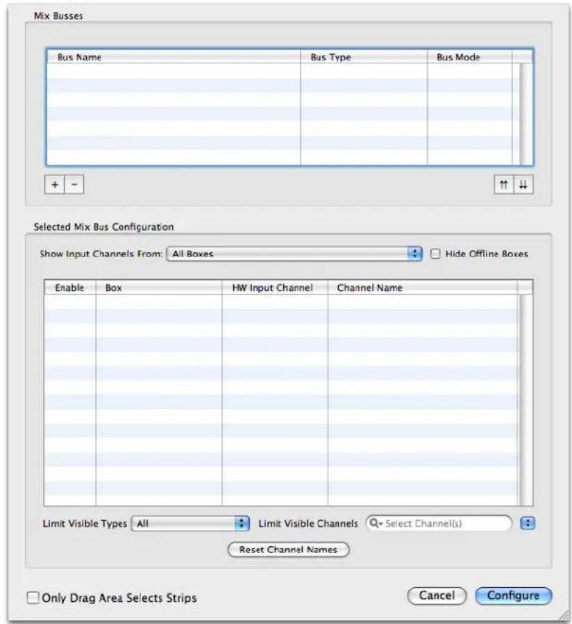
Figure 13.2: Mix Config Sheet
Add two busses to the mixer by clicking the + button in the Mix Busses section twice. Double click the first bus to name it, and tab to name the second bus. Also, set the Reverb bus's Bus Mode to Aux Bus:

Figure 13.3: Newly Created Busses
After you have created the busses, you still need to assign the desired inputs to the Monitor bus. To do this, first select the Monitor bus in the Mix Busses list and then just click the check boxes for the inputs you need in the Selected Mix Bus Configuration list
- Analog 1
- Analog 2
- DAW 1/2 (a stereo channel towards the bottom of the list)
- Reverb (the Reverb Bus — it is at the bottom of the list)
In addition, if you would like to use any of the other inputs (AES or ADAT), you can simply add them to the bus by clicking the proper check boxes in the list.
You don't need to add any of the inputs to the Reverb bus — we'll do that with sends in the mixer.
Click the Configure button, and MIO Console will configure the basic mixer for you:

Figure 13.4: Basic Mixer Configuration
Now we need to add sends to get the audio from the inputs to the Reverb bus. This can be done in bulk by selecting the desired input strips and then inserting the send in one of the insert slots.
First select the strips:

Figure 13.5: Selected Strips
Then insert the send:
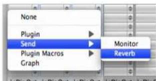
Figure 13.6: Inserting Send to Reverb Bus
After you have done this, the Sends window will appear, and each strip will have a send inserted:
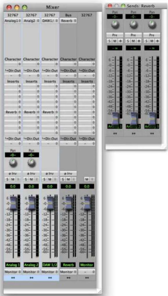
Figure 13.7: After Inserting the Sends
As you can see, you now have a fader and panner for each send that you can use to set the level and pan of the signal into the reverb. The Pre buttons on each send strip make the send strip Post Fader when disabled, and Pre Fader when enabled (lavender colored).
We still need to route the Monitor Mix to the headphones. This is done directly from the Master Fader strip output pop-up at the very bottom of the Monitor strip:

Figure 13.8: Making the Output Assignment
Finally, we need to add a HaloVerb reverb plug-in to the Reverb bus return:
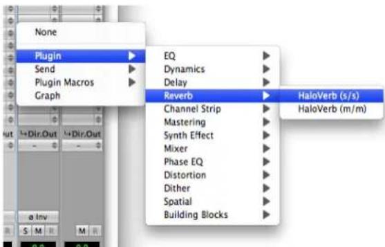
Figure 13.9: Selecting the Reverb Plug-in
Once you insert the plug-in, you will see the HaloVerb UI with the Factory Default settings:

Figure 13.10: Factory Default Settings
Now, for the configuration we have set up, with a dedicated return for the reverb that will be mixed back in with the Monitor bus, we really don't want to have the dry signal of the Reverb bus mixed back in; rather we want to have the 100% wet signal, so we need to turn down the Direct dB parameter to mute the dry signal:
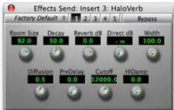
Figure 13.11: 100% Wet Default Settings
Now everything is basically configured. You can set up the dry headphone mix on the main faders in the Mixer window. Once we have basic balances set, you can switch to the Send window. In the Send mixer we
can unmute each channel and set its send level to the reverb. If you want it to match the levels of the dry headphone mix, you can ensure that all the sends are Post Fader and all the send faders are set to unity gain. If you would rather set the reverb send levels independently of the dry mix, you can make the sends Pre Fader.
Tweak the HaloVerb settings to taste. Notice that even if you set the Direct dB parameter back to 0 dB there is no phasing introduced, because the v.5 mixer is absolutely phase coherent, even with routing between multiple busses.
Your final configuration will look something like this:

Figure 13.12: Final Configuration
If you want to use this example as a tracking set up, choose Save As... from the file menu. This brings up a standard Macintosh save dialog and allows you to save the entire state of MIO Console as a setup document.
Controlling Multiple Monitors
You can use the Monitor Controller features of Mobile I/O to set up multiple monitor paths and easily switch between them. The Monitor Controller is an intelligent router and volume controller that was designed specifically to manage monitoring systems.
For this example we will work with a 2882 and have two sets of powered monitors connected to the Mobile I/O. The first set will be connected to Analog Outputs 1-2 and the second to Analog Outputs 3-4.
![graph TD A["Microphones"] --> B["External Piano/Converter with ADAT Output"] C["Headphones"] --> D["Front Panel Headphone Cd"] E["Drums"] --> F["Microphones"] G["Big Monitors"] --> H["Small Monitors"] I["Outlookers/Instruments"] --> J["ADAT Optical"]](/content/2026/05/884165/images/35c4bc5fcf2f492c6d3cded341d1df089c89ae93d930c515c59bb8e62795fc1d.jpg)
Figure 13.13: Example 2882 Setup
We will start with the "2882 Basic with Monitor Control" template as that configuration gets us most of the way there. The configuration looks like:

Figure 13.14: 2882 Basic with Monitor Control
The starting template is appropriate for recording with a 2d Expanded 2882 and playing stereo material through the box. It is set up to allow you to do zero-latency monitoring without additional configuration. It also contains a configured monitor controller for monitor switching and volume control.
This template configures a single 2882 with:
- All inputs routed to the computer
- All analog inputs set to Line +4 input level
- All inputs routed to a stereo monitor mix
- All inputs to the stereo monitor mix are unmuted
- Stereo Output 1+2 from the computer routed to the monitor mix
• Monitor mixer is routed to the Monitor Controller
However, the template does not provide support for our scenario of two sets of stereo monitors. So we can quickly add that to the configuration. The Monitor Controller configuration in the template looks like:
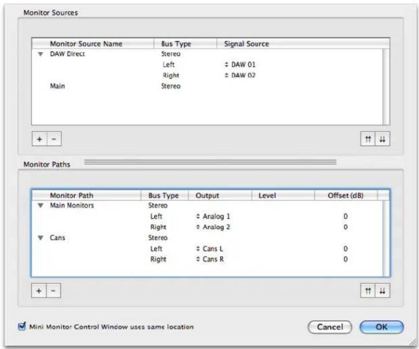
Figure 13.15: Template MC Configuration
The configuration includes a DAW Direct source that routes directly from the DAW 01 & DAW 02 channels from the computer, and the Main Stereo bus is also available as a source for the Monitor Controller.
The configuration also includes two Monitor Paths for output. One, named "Main Monitors", routes out to Analog 1+2, and the other, named "Cans", routes out to the Cans connector on the front panel.
This is pretty close to what we want, but we need to have another Monitor Path for the "Small" monitors, and we want to rename "Main Monitors" to "Big".
So, first we add another Monitor Path by clicking the + button in the Monitor Paths section:

Figure 13.16: Add Small Monitor Path
Then select the output channels for the path (click the pop-up for the Left Channel); hold down the option key to select successive channels in one step:
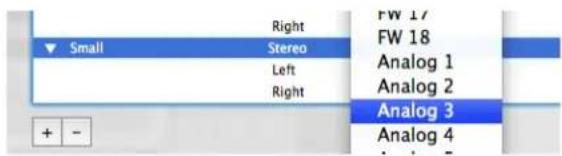
Figure 13.17: Select Path
After you make the selection the path will be configured:
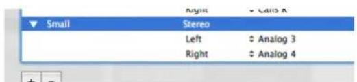
Figure 13.18: Channels Selected
You can close the disclosure arrows for the Monitor Paths list:

Figure 13.19: Closed List
And move the Small Monitor Path to be the second item by clicking the up arrows button:

Figure 13.20: Reordered List
And rename the "Main Monitors" Path to "Big" by double clicking the path, and typing the new name. When you are done it will look like:
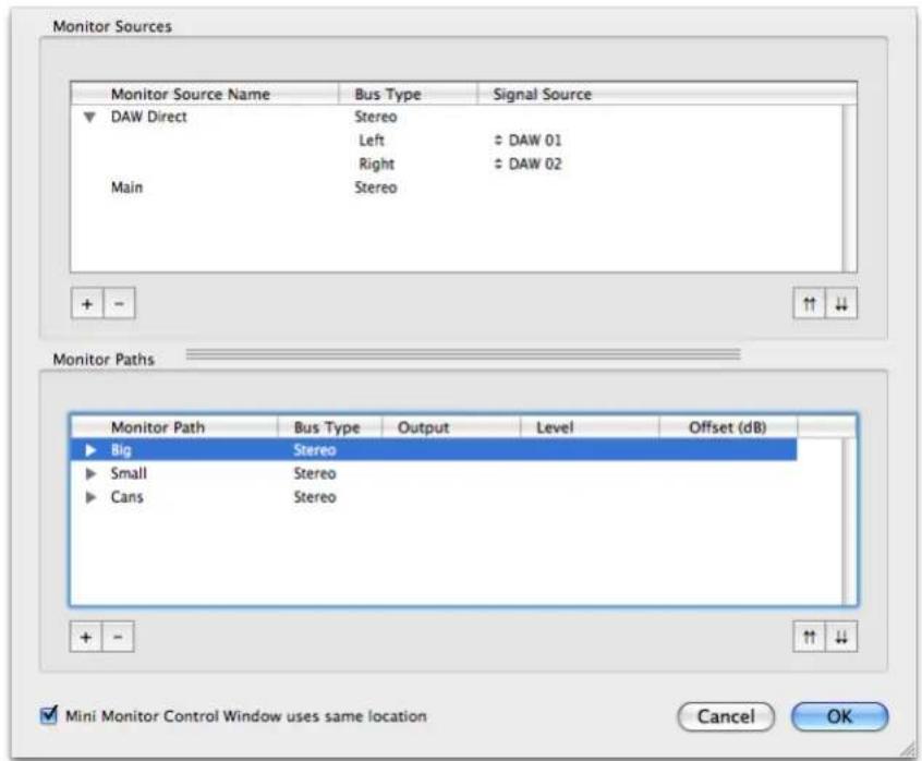
Figure 13.21: Final MC Config
After you click the OK button, the Monitor Controller window will look like this:

Figure 13.22: Final Monitor Controller
We want to make sure that both Analog 1+2 or Analog 3+4 has signal, but not both at the same time; sound should only come from one set of speakers at a time. That is precisely what the Monitor Controller will do for us; sound will only be routed to one of the Monitor Paths at a time, and the unselected Monitor Paths will be muted.
To switch between the Big monitors and the Small monitors, all you have to do is click on the path you want to be active in the output selector bar right above the output gain control knob.
If you want to use this example as a tracking set up, choose Save As... from the file menu. This brings up a standard Macintosh save dialog and allows you to save the entire state of MIO Console as a setup document.
Virtualizing Windows audio programs
Introduction
With the introduction of virtualization technology from:
- Parallels (http://www.parallels.com/products/desktop)
- VMware Fusion (http://www.vmware.com/products/fusion/)
Mobile I/O users have an exciting new way of using their Mobile I/O hardware with their Intel-based Macs. Since virtualization allows you to run Windows at near-native speeds under Mac OS X on your Intel-based Mac, it also provides a path to allow you to use Windows-based software with your Mobile I/O.
How it Works
The hardware abstraction layer provides a standard Windows stereo audio driver to the Windows programs running in the virtualization layer. Parallels and Fusion connect this virtual audio driver to the actual audio hardware using the CoreAudio driver running under the host OS (Mac OS X). This allows you connect an audio program running in Windows (under virtualization) to your MIO! The virtualization technology provides remarkable levels of performance on the Intel-based Macs and allows audio programs to run in realtime while running virtualized under Mac OS X. Since the Mobile I/O CoreAudio driver and MIO Console are running natively under Mac OS X, they run at full performance. You can run MIO Console (and any other Mac OS X application) in parallel with the Windows programs running under the virtualization layer. This means that you have full access to +DSP, the Mixer and all the analog I/O controls in MIO Console.
What you need
In order to be able to use your Windows applications with the MIO, you will need the following:
• An Intel-based Mac
• A copy of Parallels or Fusion
- An install of the Windows operating system
- The Windows-based audio apps you want to use
• and, of course, a Mobile I/O
How to set it up
The first step is to acquire and install the software. It can be purchased from:
- Parallels website
- VMware website
It is very easy to install; just follow the instructions provided by the manufacturer. Part of the installation process is a simple procedure for installing the Windows operating system on the virtual machine. Of course, if you already have virtualization software and Windows installed on your Mac you are pretty much ready to go.
The next step is to install the Windows-based audio software on the virtual machine. This is exactly the same process as it is to install the software on Windows.
Finally, you need to select the MIO as the default audio input and output device for the Mac in System Preferences > Sound. Once you have made this selection, Windows' audio will be routed to and from channels 1 and 2 of your MIO.
Now launch the Windows-based audio application and start working. The stereo output from the app will appear on DAW 1 and 2 in the MIO; Analog Inputs 1 + 2 will appear on the inputs to the Windows audio app.
You can also launch MIO Console (running natively in Mac OS X), and use it to control the patchbay, mixer, +DSP, mic pre gains, etc. – just as you would if your audio app was Mac OS X native.
So grab Wavelab or Reaper or Nuendo and have fun!
Tips for Specific Host DAWs
Please follow the links below for specific tips on how to maximize your experience with FireWire returns:
- Logic
- Digital Performer
- Cubase
• ProTools
Routing Tips for Logic
Using Logic I/O plug-ins
Using Logic I/O plug-ins on track objects (normal audio tracks) to route through processing on the MIO is pretty straight forward.
- Insert the I/O plug in on the logic channel you want to process in +DSP

Figure 13.23: Inserting the I/O Plug-in
- Set the I/O plug's Outputs pop-up to any output other than the pair you are monitoring through. For example, if your main mix is going out of outputs 1-2, you can set the outputs of the I/O plug to any output other than 1 and 2 (in the illustration below we use DAW 3/4).
- In the MIO Mixer, create a channelstrip for DAW 3/4. Assign its POST-insert Direct Out to FW channels that you aren't using as an inputs to Logic already: we'll use FW 11/12.
- Set the input of the Logic I/O plug to input 11-12 (to match the send that you have selected) and the +DSP processed signal is now being returned to the Logic Track.
- Insert your processing (in this example, a +DSP graph) in this channelstrip.
- You are done!
![graph TD A["I/O"] --> B["612"] B --> C["Character"] C --> D["Inserts Graph"] D --> E["Output"] style A fill:#f9f,stroke:#333 style B fill:#ccf,stroke:#333 style C fill:#cfc,stroke:#333 style D fill:#fcc,stroke:#333 style E fill:#cff,stroke:#333](/content/2026/05/884165/images/d4f7d6c8c0f560f26330444a485a1a3004e422c152147f3dc5040018ccbdc891.jpg)
Figure 13.24: Using Logic I/O Plug-ins for Insert Processing on Output Objects
Routing Tips for Digital Performer
Routing for Insert processing in Digital Performer
Since Digital Performer does not provide an I/O plug-in for inserting an audio routing loop to external processing, you need to be a bit careful when configuring the routing in Digital Performer. If you don't follow this approach, you have a good chance of setting up a feedback loop (and no one wants that!)
In order to insert a +DSP process in DP, you need to route the audio to be processed to discrete channels on the Mobile I/O. The critical point is that you cannot send the audio that you want to process directly to the same outputs that you will be using for monitoring as completing the return will create a feedback loop.
Configuring Bundles and MIO Console to make your life easier
Since DP allows you to configure your physical I/O using Audio Bundles, you find that it makes routing a lot easier if you pre-configure some audio bundles and name them in a way that makes sense.
In the illustrations below, we have created bundles for I/O and +DSP Loop Processing. Here is what the Audio Bundles window looks like after the bundles have been created and named:
![Bundles Inputs Outputs Busses Instruments MIDI Devices 2882+DSP [612] MV NAME MODEL [612] FW 1 1 [612] FW 2 2 [612] FW 3 3 [612] FW 4 4 [612] FW 5 5 [612] FW 6 6 [612] FW 7 7 [612] FW 8 8 [612] FW 9 9 [612] FW 10 10 [612] FW 11 11 [612] FW 12 12 [612] FW 13 13 [612] FW 14 14 [612] FW 15 15 [612] FW…](/content/2026/05/884165/images/7d672338536dedf7a55b62c67a0470e6c8c84ac6ce307c78d8aaff84b9e13b0c.jpg)
Figure 13.25: The Input Bundle Configuration
![Bundles Inputs Outputs Busses Instruments MIDI Devices 2882+DSP [612] MY NAME MODEL Main Out Stereo +DSP Loop Send 1 Stereo Add Add Multiple Delete Delete Unused Edit](/content/2026/05/884165/images/b9fd3f466217df0c1f1e47855b56bf78f28ff21d2801e37abacd52e8f390f369.jpg)
Figure 13.26: The Output Bundle Configuration
As you can see from the illustrations above, we have created two Mono input bundles and one Stereo input for Analog 1+2 to be used as inputs for tracking and a Stereo input bundle for the +DSP return. We have also created two Stereo output bundles; one for the Main Mix (Main Out) and one for the +DSP Send (+DSP Loop Send 1).
To insert a +DSP process chain on a single channel
Follow these steps:
- On the mixer strip of the channel that you want to process in +DSP, select a Mobile I/O output that is different from the main stereo output that you are using for the rest of the mix. If you have not yet created a bundle for that output, you can create a new bundle on the fly for your output channel. So, for example, if you are monitoring your main mix on DAW 1 and 2, you could send the channel out on DAW 3 and 4.
- Create a channelstrip in the MIO Mixer for the DAW channels you've selected.
- Insert your processing in the channelstrip; here, we're using a Mid/Side Compressor graph.
- Route the POST-insert Direct outs to FireWire Returns to unused inputs in DP. We're using FW 11/12.
-
Create an Aux Fader in your DP project, and set its input to correspond to the FW return channel you have selected (FW 11/12 in this example).
-
Assign the output of the Aux fader to the main output bundle of your mix.

Figure 13.27: Single Channel +DSP Mid/Side Compressor
To insert a +DSP process chain on a submix
Follow these steps:
- On the mixer strip of the channels that you want to process in +DSP, select a bus to route the submix to (for example, Bus 1-2). You can assign as many channels as you want to the send bus and form a submix using the DP mixer.
- Create an aux fader track, and set the input of the aux to the bus that you sent the submix to (e.g. Bus 1-2). Set the output of the aux to Mobile I/O outputs that are different from the main stereo output that you are using for the rest of the mix. If you have not yet created a bundle for that output, you can create a new bundle on the fly for your output channel(s). So, for example, if you are monitoring your main mix on DAW 1 and 2, you could send the channel out on DAW 3 and 4.
- Create a chanelstrip in MIO Console for the DAW channels that are carrying your submix; in this example, DAW 3/4.
- Insert your processing in the channelstrip- we're using a parallel compressor.
- Route the POST-insert Direct outs to FireWire Returns to unused inputs in DP. We're using FW 11/12.
- Create another Aux Fader in your DP project, and set its inputs to correspond to the FW return channels you have selected.
- Assign the output of the Aux fader to the main output bundle of your mix.
![graph TD A["612"] --> B["DAW3/"] B --> C["Character"] C --> D["I→Dir.Out"] C --> E["Inserts"] D --> F["Graph"] E --> G["I→Dir.Out"] E --> H["FW11/1"]](/content/2026/05/884165/images/68485f343ad9d735dd8c9f3f350b35d29a7697ebcc220cf0a4b4d1886cc08735.jpg)
Figure 13.28: Multichannel Bussed +DSP Parallel Compressor
Routing Tips for Cubase
Routing for Insert processing in Cubase
Using External Effects on track objects (normal audio tracks) to route through processing on the MIO is pretty straight forward.
- Define the External Effects in the VST Connections:
![VST Connections - External FX Inputs Outputs Group/FX External FX External Instruments Studio Add External FX Favorites Bus Name Speakers Audio Device Device Port Delay Send Gain Return Gain MIDI Device External 3-4 Stereo/Stereo 0.00 ms (0) 0.00 dB 0.00 dB No Link Send Bus 1 Stereo ULN-8 [113] -o l…](/content/2026/05/884165/images/4cd5d8f07ccaf8fb0b1cebb06e428d8f30643dc5fe5b74efe0075da28a65ab3a.jpg)
Figure 13.29: Defining the External FX
Set the External FX's send outputs to any outputs other than the pair you are monitoring through. For example, if your main mix is going out of outputs 1-2, you can set the outputs of the External FX to any
output other than 1 and 2 (in the illustration above we use DAW 3/4). Set the Return Bus inputs to be any unused channels; here we use FW 3/4.
-
In the MIO Mixer, create a channelstrip for DAW 3/4. Assign its POST-insert Direct Out to FW channels 3/4.
-
Insert the External Effect into an Insert slot in the channel you'd like to process.

Figure 13.30: Inserting the External FX
-
Insert your processing (in this example, a +DSP graph) in this channelstrip.
-
You are done!
![graph TD A["Audio 17"] --> B["External 3-4"] B --> C["113 DAW 3/4"] C --> D["Character"] D --> E["+Dir.Out"] E --> F["Inserts Graph"] F --> G["+Dir.Out FW 03/04"] G --> H["Digital Display"] H --> I["Output"]](/content/2026/05/884165/images/fe20d0332963acd1994ffa0d2663b40dd1d9b12da8d0461308fb10fdccf0aaba.jpg)
Figure 13.31: +DSP Graph Inserted into Cubase
Configuring VST Connections for an entire mix
In Cubase it's necessary to define the mapping of inputs and outputs to your audio device. Lets create a session that corresponds to the "DAW Analog Summing" template in MIO Console; this preset takes 18 channels from your DAW, sums them in the MIO Mixer and returns them to the DAW over FW 1/2. The mix is also directly sent from the MIO Mixer to Analog Outputs 1/2 as well as the Cans. We will not be using Cubase's mixer for monitoring.
The first step is to create a new session with 18 mono audio tracks for playback, one stereo track for recording and one instrument track for ConsoleConnect. Go to the VST Connections window and delete the default stereo bus, create 18 mono busses and assign each to a channel of your interface.
![VST Connections - Outputs Inputs Outputs Group/FX External FX External Instruments Studio All Add Bus Presets Bus Name Speakers Audio Device Device Port Click Mono Out Mono ULN-8 [113] ULN-8 [113] 1 Mono Out 2 Mono ULN-8 [113] ULN-8 [113] 2 Mono Out 3 Mono ULN-8 [113] ULN-8 [113] 3 Mono Out 4 Mono U…](/content/2026/05/884165/images/5f5aa27ef789d87be35e6c4ea217ffd4852f14d9f26b0058fb57af881db60fd7.jpg)
Figure 13.32: Setting the VST Outputs
Next we need to create an input mapping for FW 1/2, so that we can record the mix back into Cubase.
![VST Connections - Inputs Inputs Outputs Group/FX External FX External Instruments Studio All Add Bus Presets Bus Name Speakers Audio Device Device Port Stereo In Stereo ULN-8 [113] left ULN-8 [113] 1 right ULN-8 [113] 2](/content/2026/05/884165/images/8c4e894a31d05cd52491c1f226e385a241d1b35c4c931e9e8797acc609480566.jpg)
Figure 13.33: Setting the VST Inputs
The final step is to assign your audio in Cubase's mixer:
- Set the inputs on your 18 playback channels to "No Bus".
- Set the outputs sequentially (Audio 1 to Mono Out 1, Audio 2 to Mono Out 2, etc).
- Set the input of your stereo mixdown channel to "Stereo In".
- Set the output of your stereo mixdown channel to "No Bus".

Figure 13.34: Setting the VST Outputs in the Mixer
This will route your 18 tracks to the MIO Mixer; the stereo mix will be monitored directly from the MIO Mixer as well as being routed into Cubase where it can be recorded.
Routing Tips for Pro Tools
With the release of Pro Tools 9, it became possible to use Metric Halo interfaces directly with Pro Tools - this gives you access to MIO Console, 2d, +DSP and our conversion without any other hardware.
There are several ways to configure the MIO Mixer for use with Pro Tools; let's look at a few.
Inputs
In MIO Console, route your analog or digital inputs to Firewire channels:

Figure 13.35: Routing to Firewire
In the example above, the eight analog inputs of the LIO-8 are routed to FW channels 1-8. Since we've used the direct outputs after the inserts, You can record into Pro Tools with your DSP effects. If you use the direct outs before the inserts, any DSP effects won't be recorded. This would allow you to record the "dry" signal, but put effects like MIOStrip in for the performers' mix!
If you want to work with stereo inputs, simply create stereo channels instead of mono or use a combination of both. You can also route busses from the MIO Mixer into Pro Tools via the Firewire channels.
In Pro Tools, open the "I/O" window in the "Setup" menu and go to the "Input" tab:
![I/O Setup Input Output Bus Insert Mic Preamps H/W Insert Delay A LIO-R [100] Name Format 1 2 3 4 5 6 7 8 9 10 11 12 13 14 15 16 17 18 19 20 Input 1 ✓ Mono N Input 2 ✓ Mono M Input 3 ✓ Mono N Input 4 ✓ Mono N Input 5 ✓ Mono M Input 6 ✓ Mono N Input 7 ✓ Mono M Input 8 ✓ Mono N New Path... New Sub-Path…](/content/2026/05/884165/images/75fb3d419445c8e653916b4d607f94e2c0893a5e7a7f23a0d2be3912ae031ce5.jpg)
Figure 13.36: Input Tab
We've created eight input paths and set them to channels 1-8 from the LIO-8. You can also create stereo input paths to match your MIO Mixer setup if you're working that way.
Inserts
It's easy to create inserts in MIO Console to use in Pro Tools for mixing; you can route your audio through external processors or your interface's DSP and return it back to Pro Tools. Here's how –
Defining Inserts in PT
You can use the routing flexibility of MIO Console to configure several kinds of inserts with Pro Tools. Start by opening the "I/O" window in the "Setup" menu and go to the "Insert" tab:
![I/O Setup Input Output Bus Insert Mic Preamps H/W Insert Delay Name Format A LIO-R [100] 1 2 3 4 5 6 7 8 9 10 11 12 13 14 15 16 17 18 19 20 Insert 1 ✓ Mono Insert 2 ✓ Mono Insert 3 ✓ Mono Insert 4 ✓ Mono Insert 5 ✓ Mono Insert 6 ✓ Mono Insert 7 ✓ Mono Insert 8 ✓ Mono New Path... New Sub-Path Delete…](/content/2026/05/884165/images/4355da5aed72ea5c5386478a98aa8f254cb1fc64a2da5109b9cd4d9fe332988e.jpg)
Figure 13.37: Insert Tab
Define as many inserts as you need and map them to the inputs and outputs of your interface. In this example, we've created eight inserts and assigned them to I/O 9 to 16 so that they don't conflict with the input channels.
Now we'll configure MIO Console.
Analog/Digital Inserts
To use the analog and digital I/O of your interface as insert points, set up your Pro Tools I/O as above and configure the MIO Mixer:
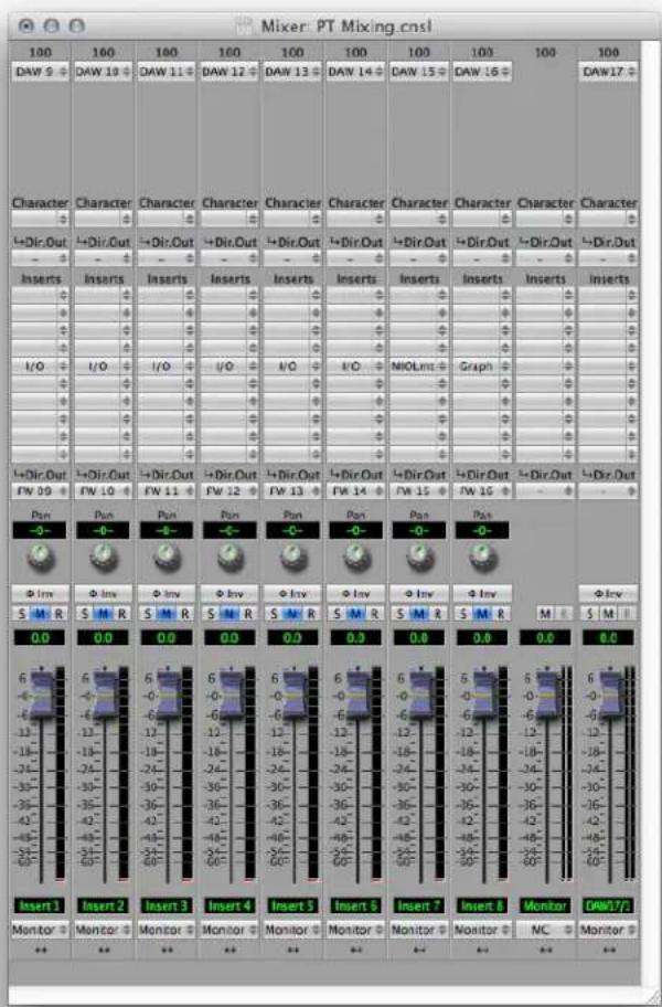
Figure 13.38: Configuring the MIO Mixer, DAW 9-14
-
Create a DAW channel for each insert send and assign the post-insert direct out to the corresponding FW output. Assign the channelstrip to your monitor bus (so that the meters will be active) and make sure to mute it so that the insert will not be double monitored in MIO Console.
-
Insert the "I/O" insert on each channel. Open the I/O and assign the send and return to your desired input and output:

Figure 13.39: Configuring the I/O insert to send and return on Analog 3
Connect your external device to the send output and return input you specified in the I/O insert.
- Back in Pro Tools' mixer, put an I/O insert in the desired channelstrip. The send from Pro Tools will go out the DAW channel in MIO Console, be processed, and then return to Pro Tools over the FW
channel. Since we muted the channel in MIO Console, you won't hear the audio there but will hear it after it gets routed back into Pro Tools.
For more information on the I/O insert please refer to the I/O insert section of the Mixer Window overview.
If you're using analog outputs 1 and 2 for monitoring, you can use the other 6 analog outputs for sends. You can also insert whatever DSP processing you want in the MIO Console mixer channels to pre or post process your hardware inserts!
In this scenario, Pro Tools' delay compensation will be accurate.
DSP Inserts
Using your 2d and +DSP effects via the I/O insert is a great way to integrate your interface's processing into your session. Add the insert paths to your session's I/O setup like we did for analog inserts and create the corresponding routing in MIO Console:

Figure 13.40: Configuring the MIO Mixer, DAW 15-16
-
Create a DAW channel for each insert send and assign the post-insert direct out to the corresponding FW channel. Assign the channelstrip to your monitor bus (so that the meters will be active) and make sure to mute it. Insert whatever processing you want in the inserts.
-
Insert plug-ins or graphs in the mixer channels that you created.
- Back in Pro Tools' mixer, put an I/O insert in the desired channelstrip. The send from Pro Tools will go out the DAW channel in MIO Console, be processed, and then return to Pro Tools over the FW channel. Since we muted the channel in MIO Console, you won't hear the audio there but will hear it after it gets routed back into Pro Tools- just like it was an outboard piece of gear.
DSP Insert Latency
One thing you need to be aware of when you use DSP inserts this way is latency. Pro Tools calculates its delay compensation using a value that the MIO driver reports. However, this value reports the latency of the DSP and A/D/D/A conversion. If you're not using an analog device, Pro Tools will not compensate properly- but there's an easy way to adjust this:
Go to the bottom of the channelstrip in Pro Tool's Mix window and show Delay Compensation:

Figure 13.41: Delay Compensation
On every track that you use a DSP insert, add:
- 74 samples of compensation for 2882 and ULN-2 channels:
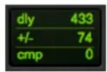
Figure 13.42: Delay Compensation for 2882/ULN-2
• 116 samples of compensation for LIO-8 and ULN-8 channels:

Figure 13.43: Delay Compensation for LIO/ULN-8
Your delays will now be delay compensated properly.
Mixing
Stereo Mix
One way to work with your outputs is to create your stereo mix using Pro Tools' mixer. To do this, go to the "Setup" menu in Pro Tools, select "I/O..." and go to the Output tab:
![I/O Setup Input Output Bus Insert Mic Prcamps H/W Insert Delay A I/O-8 [100] Name Format 1 2 3 4 5 6 7 8 9 10 11 12 13 14 15 16 17 18 19 20 Monitor Stereo L R New Path... Delete Path Audition Paths: none Default Bus 1-2,... Default Sessions overwrite current I/O Setup when opened Import Settings Exp…](/content/2026/05/884165/images/411121f0c2a681abbc3d79a9aae29d249a38985073db55921a9f2e949700394f.jpg)
Figure 13.44: Output Tab
In this example we've put the monitor output to the MIO Mixer is on DAW 17/18; this way the first 16 DAW channels are available for inserts and other uses.
Stem Mix or "Summing"
Another method to work with your outputs is to create your stereo mix in the MIO Mixer and use Pro Tools for playback and volume automation. To do this, go to the "Setup" menu in Pro Tools, select "I/O..." and go to the Output tab:
![I/O Setup Input Output Bus Insert Mic Prcamps H/W Insert Delay A I/O-8 [100] Name Format 1 2 3 4 5 6 7 8 9 10 11 12 13 14 15 16 17 18 19 20 Output 1 ✓ Mono Mali Output 2 ✓ Mono Mali Output 3 ✓ Mono Mali Output 4 ✓ Mono Mali Output 5 ✓ Mono Mali Output 6 ✓ Mono Mali Output 7 ✓ Mono Mali Output 8 ✓ Mo…](/content/2026/05/884165/images/9bdf68c5140195c26ce913249ffda8e2b8985f559d21a1590bfcd59a5ad11909.jpg)
Figure 13.45: Output Tab
Create 16 mono outputs and map them to DAW 1-16 in MIO Console:
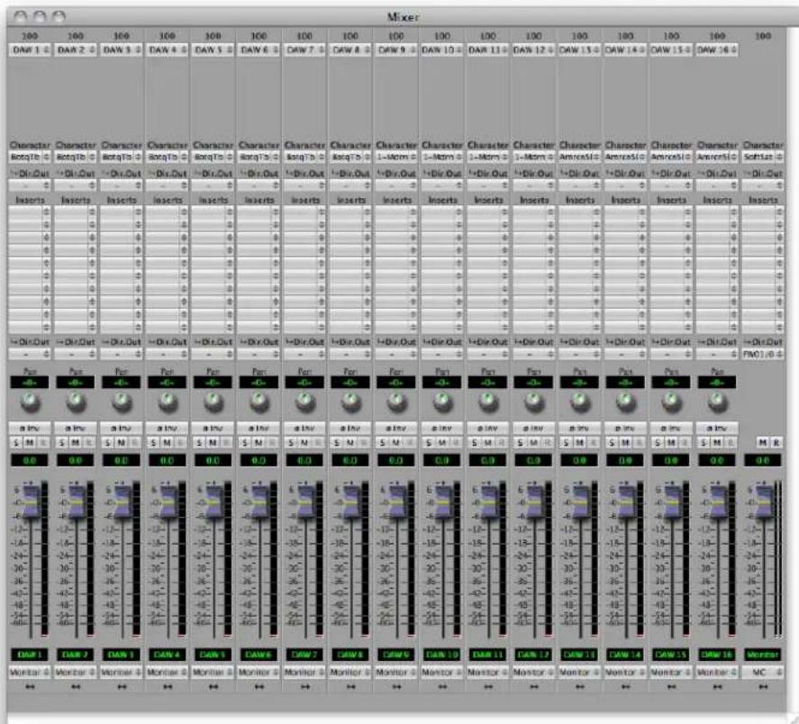
Figure 13.46: Mapping to DAW 1-16
The 16 DAW channels from Pro Tools are routed to a stereo bus. Every channel and bus can have Character, our exclusive analog emulation. You can use it to "heat" up your mixes!
The stereo bus is routed to FW 1/2, which will send it back onto Pro Tools. This will allow you to record the stereo master back into the session.
Aggregates and Multitrack
Pro Tools has a few things to be aware of when working with multiple interfaces:
- You are limited to 32 I/O channels
• They are always the first32 channels of any device or aggregate - Metric Halo interfaces provide 18 channels of I/O between the computer and the interface; on LIO-8 and ULN-8 interfaces, channels 19/20 are reserved for timecode and do not transport audio
Given these limitations, how can you record and playback 24 tracks? It's not difficult with a little configuration. Let's say you wanted to use 24 channels of ULN-8:
![graph TD A["Analog 1-8"] --> B["Box #1"] C["Analog 9-16"] --> D["Box #2"] E["Analog 17-24"] --> F["Box #3"] B <--> G["Digital 1-8"] D <--> G F <--> G G <--> H["Firewire"] H --> I["Aggregate Device"] I <--> J["Pro Tools"] H --> K["MIO Console"] K --> L["Red Arrow"] style H fill:#ffcccc,stroke:#333](/content/2026/05/884165/images/103ef61ebf6ebbf9323bc3aaca30b115a40382606c9fcc16816ec7388fc262eb.jpg)
Figure 13.47: Connecting a Three Box System
- Analog I/O 1-8 are on box #1, which is the first box of an aggregate. These should appear as FW 1-8 in the aggregate.
- Analog I/O 9-16 are on box #2; this is connected to box #1 over AES and is not part of the aggregate. In box #1, the AES channels would be sent to FW 9-16 via the direct outs.
- Analog I/O 17-24 are on box #3, which is the second box of an aggregate. These should appear as FW 21-29 in the aggregate.
Conclusion
The preceding examples should give you a sense of the possibilities that are enabled by the routing and mixing features of Mobile I/O. While this is just a starting point, we have covered all of the basic operations required to manipulate Mobile I/O with complex routing. You should be able to build upon these scenarios to construct routings that suit your needs and your workflow.
14. Record Panel
Overview
MIO Console integrates a dedicated multichannel recording interface. The Record Panel allows you to record with Mobile I/O right out of the box without needing to add any additional software to your system.
The Record Panel was purpose built for doing massive multichannel recordings with multiple boxes. We have deployed systems recording 72 channels at 96k, and have tested systems with even greater channel capability. The Record Panel is not an editor; it does not support overdubs; it is optimized for capturing audio to disk with no muss and no fuss, with extreme reliability.
The Record Panel is accessed using the Recording panel button in the MIO Console window:

Figure 14.1: Record Panel
Record Panel Description
The Record Panel UI has a number of elements that work together to allow you to configure and monitor your recording.
The first element is the time readouts:

Figure 14.2: Time Readouts
The Clock readout shows the wall-clock time and may be used for logging. It is formatted as HH:MM:SS.
The Record Time readout shows how long the recording has been running for when the Record Panel is in record mode, and how long the Record Panel has been playing for when in playback mode. The time format can be changed by Control-clicking the Record Time readout:

Figure 14.3: Record Time Display Options
The Disk Time Remaining readout shows the time available on the selected recording disk. It automatically adjusts based upon sample rate, number of armed tracks, sample size and the amount of space available on the target disk. It updates as the recording progresses and is formatted as HH:MM:SS.
The next elements are the transport controls:
Figure 14.4: Transport Controls
The first button is the Stop button. Clicking this button will stop both the record and playback transport. When all transports are stopped, this button will be lit yellow.
The second button is the Play button. Clicking this button will start the playback transport if the RP is not already playing audio. If the RP is already playing, clicking the button will stop the playback transport. When the playback transport is running, this button will be lit green.
The third button is the Record button. Clicking this button will start the recording transport if the RP is not already recording audio. If the RP is already recording, clicking the button will terminate the current take and seamlessly And sample-accurately start the next one, continuing recording. When the playback transport is running, this button will be lit red (as shown in the picture above).
The next elements are the progress meters:

Figure 14.5: Progress Meters
The CPU Meter shows the percentage of your computer's processing power being consumed by the Record Panel.
The Rec Meter shows the amount of the record buffer that has been consumed by audio that has not been saved to disk. Under normal operation, this meter will pulse upwards and return to a value near zero periodically. If your disk is too slow, this meter will increase towards 100%, and if it reaches 100% it means that the disk is not recording fast enough and there will be glitches in the recorded audio. This meter is only active during recording.
The Play Meter shows the amount of the play buffer that is empty (not yet read from disk). Under normal operation, this meter will pulse upwards and return to a value near zero periodically. The RP uses an adaptive
algorithm for filling the play buffer so the behavior of this meter may appear somewhat erratic. If your disk is too slow, this meter will increase towards 100%, and if it reaches 100% it means that the disk is not supplying data fast enough and there will be glitches in the playback audio. This meter is only active during playback.
The next element is the Play position meter:

Figure 14.6: Play Position
When audio is playing back, this meter indicates the current playback position in the take. You can click in this meter during playback to cue playback to a different location within the take.
The next element is the tracks overview:
| MIO #1 FW01 DAW 1 | R | |
| MIO #1 FW02 DAW 2 | R | |
| MIO #1 FW03 Digital L | R | |
| MIO #1 FW04 Digital R | R | |
| MIO #1 FW05 nc | R | |
| MIO #1 FW06 nc | R | |
| MIO #1 FW07 nc | R | |
| MIO #1 FW08 nc | R | |
| MIO #1 FW09 ADAT 1 | R | |
| MIO #1 FW10 ADAT 2 | R | |
| MIO #1 FW11 ADAT 3 | R | |
| MIO #1 FW12 ADAT 4 | R | |
| MIO #1 FW13 ADAT 5 | R | |
| MIO #1 FW14 ADAT 6 | R | |
| MIO #1 FW15 ADAT 7 | R | |
| MIO #1 FW16 ADAT 8 | R | |
| MIO #1 FW17 nc | R | |
| MIO #1 FW18 nc | R |
Figure 14.7: Tracks Overview
The tracks overview shows all the tracks available for recording. Tracks are added to the tracks overview in one of two ways:
- For 2d Expanded boxes: Only channels that have been assigned to FireWire returns (FW 01 — FW 18) will appear in the tracks overview. This allows you to control which tracks should be displayed; if you have no interest in recording a track, just don't assign it to FireWire. Note that channels that aren't assigned to a FireWire channel are not available in any CoreAudio application.
- For Legacy Boxes: All input channels will automatically be displayed in the Record Panel because they are all automatically assigned to FireWire.
For 2d Expanded boxes, the tracks appear in the same order that the FireWire assigns appear in the mixer, so you can choose the track order by reordering the mixer strips in the 2d Mixer UI.
For legacy boxes, the tracks appear in the same order that they do in the Matrix and as inputs to the computer.
So, you have much more control over what appears in the RP when you have a 2d Expanded box. In addition to the rules listed above for how tracks are added to the tracks overview, there is a global preference (controlled via the Recording Menu) that allows you to control whether tracks from offline boxes (that obviously
cannot be recorded from) should be listed in the tracks overview. It may be useful to list tracks from offline boxes if you are doing offline configuration, but in general you will not want to show tracks from offline boxes.
When you are recording, each track shows a continuously updating track overview for the signal that has been recorded for that channel. You can scroll back and forth in time; if the horizontal scroller is set to the far right, the track overview will autoscroll, keeping the updating area of the track overviews in view.
Each track has a track header:
Figure 14.8: Track Header
The track header shows the box, the FireWire channel and the channel name for the track. If the height of the tracks is too small for both lines to fit, only the channel name for the track is displayed. The channel name is automatically set by the source for the track; you can change the names by editing the input names appropriately.
To the immediate right of the label is a track record enable button. When the button is red, the track is record enabled and will be recorded the next time you hit record. While you can change the record enable state of the track while recording, it will have no affect on the current take — just the next take.
You can control the track enables directly from the Record Panel, or, if you are using a 2d Expanded box, you can control the record enables from the mixer. The mixer interface is especially convenient because one Record Enable button may actually control multiple tracks.
Finally, there are zoom buttons in the lower right corner of the window that control the zoom level of the tracks overview:

Figure 14.9: Zoom Buttons
The buttons with the + in the magnifying glass icon zoom in (increase magnification), and the buttons with the - in the magnifying glass icon zoom out (decrease magnification). The buttons stacked on the right side control the vertical zoom and the buttons along the bottom control the horizontal zoom.
Recording
When you click the Record button (or initiate record using a control surface or command key), the Record Panel recording engine creates a new Take Folder for you. The Take Folder is created in the Record Folder that you set using the Recording > Set Record Folder... menu command. If you don't set a Record Folder before you start recording, the RP will default to using the Documents folder in your home directory.
Each time you start recording a new Take Folder is created. Depending on the state of the Name Take Folders incrementally recording preference, this Take Folder will be named in one of two ways:
- If the preference is not checked, the Take Folder will be named:
Take_YYMMDDhhmmss
with YY = year, MM = month, DD = day, hh = hour, mm = minute, and ss = second - If the preference is checked, the Take Folder will be named:
Take_NNN
with NNN = take number
Each Take Folder will contain one audio file for each track that is Record Enabled when you start the take. Each audio file will be named as follows:
TT-
Where:
- TT = track number
= the name shown in the second line in the track header = extension for the selected audio file type
The Take Folder will also contain a log file written by the recording engine.
While the RP is recording, each enabled track will show a continuously updating track overview that shows the history of the peak envelope of the channel. The track overview will autoscroll as time progresses. You can use the scrollbars to adjust the currently displayed portion of the audio history, and the zoom buttons to control what period of time is displayed.
As each take is started, the current playback folder is set to the current take folder.
Clicking the Record button while the RP is recording will immediately start a new take which starts with the next sample of audio.
Clicking Stop will end the current take (and stop any current playback as well).
"Quit while recording" dialog
If you try to quit MIO Console while tracks are recording, you will see a dialog asking if you really want to quit. This will prevent you from accidentally quitting while tracks are being written.
Playback
The RP can playback take folders (actually any folder of audio files). The file types and bit depths of the files in the folder can be mixed (the playback engine will automatically adjust). The playback engine ignores the sample rates of the files in the take folder — it simply plays out the samples at the current sample rate of the hardware.
As described in the previous section, the RP automatically sets the current playback folder to last take folder (so you can play back the last take by just clicking play). If you wish to play back a different take folder, use the Recording > Set Playback Folder... menu command to choose the Take Folder you want to play back.
When you click the play button, the RP playback engine will find the size of the recording, load the audio into the playback buffer, and begin streaming it to the HW. The audio is streamed out on successive DAW channels starting at DAW 01 on the first box (as set by the box tab order in the Console window) and increasing until the first box is full (18 channels for current HW), then moving on to DAW 01 for the next box if there are more than 18 channels. It continues on in this way until it runs out of audio files or boxes.
Files recorded by the RP and played back without any naming changes will be played back in track order. If the take folder does not use the RP's naming conventions, then the playback track order will be determined by the alphabetical sort-order of the audio file names.
You can cue within the take by clicking in the Pos meter. If there is no Recording active, the Record Time read out will show the current time of the playback position within the take. Once the playback engine has run out of samples on disk, the playback engine will stop.
If you want to stop playback without stopping a current record take, you can click the Play button again to stop playback.
The RP playback engine enables a couple of cool tricks:
- You can record with no playback
- You can start playback, and then start recording a new take
- You can start recording a new take, and then start playback of the take while it is being recorded (basically read-after-write playback)
Clicking Stop will end the current take playback (and stop any current recording as well).
Multibox considerations
The Record Panel is capable of recording from multiple boxes simultaneously up to very large track counts. The boxes can even be spread across multiple FireWire busses to support more channels than can be transported on one FireWire bus. It is critical, however, that all the boxes in the system are on the same clock.
If you run the boxes wild, it may appear that the recording is functioning, but eventually the recording buffer will desynchronize and distortion or glitches will be introduced into the recording.
You can use any available clock source to ensure that the boxes are all on the same clock reference. Both AES and Word Clock are good choices.
The Record Panel will only record from a box if there are tracks enabled on that box. You can use this feature to chain one box to another via ADAT (for example) and effectively use one box as an expander for another. The expander box can be on the FireWire bus and controlled by MIO Console, but it will not use FW bandwidth or isochronous resources if there are no tracks enabled on it. This allows you to effectively double the number of boxes that can be added to one FireWire bus.
Record Panel Key Commands
MIO Console defines a number of key commands that you can use to control the Record Panel from the keyboard or a configurable HID device:
Table 14.1. Record Panel Key Commands
| Command Key Sequence | |
| Record Panel: Zoom In Channels | ⌘↑ (Command + ↑) |
| Record Panel: Zoom Out Channels | ⌘↓ (Command + ↓) |
| Record Panel: Zoom In Timeline | ⌘← (Command + ←) |
| Record Panel: Zoom Out Timeline | ⌘→ (Command + →) |
| Record Panel: Scroll Channels Up | ↑↑ (Shift + ↑) |
| Record Panel: Scroll Channels Down | ↑↓ (Shift + ↓) |
| Record Panel: Scroll Timeline Right | ↑← (Shift + ←) |
| Record Panel: Scroll Timeline Left | ↑→ (Shift + →) |
| Record Panel: Play | ⌘J (Command + J) |
| Record Panel: Stop | ⌘K (Command + K) |
| Record Panel: Record | ⌘L (Command + L) |
You can change each of these key commands if you like. See MIO Console Key Commands for more details.
Record Panel Prefs
You control various aspects of the way that the Record Panel records using the Recording Preferences sheet. Access the sheet using the Recording > Recording Preferences... menu command or the Record Panel prefs button:

Figure 14.10: Recording Prefs Button
The Recording Preferences sheet will appear:
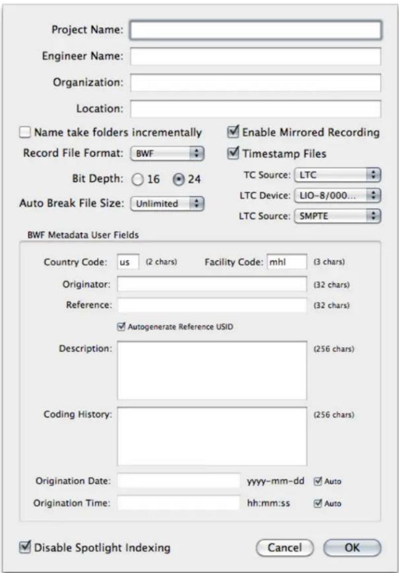
Figure 14.11: Recording Preferences Sheet
You can specify various text strings that may be included in the metadata included with some files using the 4 text entry fields.
There is a preference to control how Take Folders are named. Every time you hit record, the Record Panel will create a new Take Folder that will contain all the audio files for the take. If this checkbox is not checked, the Take Folder is named with a Date/Time stamp. If the checkbox is checked, each take will be sequentially named so that you will have a sequence of takes starting with 1 and incrementing by one each time you click record.
Next is a preference to enable Mirrored Recording. This will record your audio to two separate drives simultaneously. This gives you redundancy in case of a drive failure, or can be used to create a delivery drive that can be handed to a client immediately after recording. To use this feature, check the Enable Mirrored Recording checkbox, then use the Recording > Set Record Mirror Folder... menu command to choose your secondary record drive.
You may specify the file format that the Record Panel uses to record with the Record File Format pop-up menu which has the following choices:
Figure 14.12: Record File Format Pop-up
You can choose the file format to use based upon the following criteria:
• AIFF
AIFF file type is the standard Apple Audio file. It requires finalization at the end of recording and has a 2 GB filesize limit. It does not support timestamping.
• SDII
SDII is the streaming audio file type defined by Digidesign. It supports arbitrary file length and is always complete (it does not require finalization at the end of recording), but does require a Mac OS resource fork, and so is less portable to other systems.
• WAV
WAV is Microsoft's standard RIFF audio file type. It requires finalization at the end of recording and has a 2 GB filesize limit. It does not support timestamping.
• BWF
BWF is the EBU standard audio file based upon the WAV file format. It requires finalization at the end of recording and has a 2 GB filesize limit. It does support timestamping and standardized metadata.
• CAF
CAF is the Apple's new standard audio file format. Very portable to other systems - but other systems may not have support for CAF yet; does not require finalization at end of recording and has no file size limit. Supports timestamping and extended standard metadata.
• CAF-LE
CAF is the Apple's new standard audio file format. Very portable to other systems - but other systems may not have support for CAF yet; does not require finalization at end of recording and has no file size limit. Supports timestamping and extended standard metadata. This selection writes audio data in Little Endian Format; this is the native format for Intel processors.
The Record Panel allows for timestamping of recorded files. To timestamp your recordings:
- Set the Record File Format to "BWF".
- Click the Timestamp Files checkbox.
- Select the TC Source. There are two options:
- TOD
(Time Of Day) from your computer's clock -
LTC
(Linear Time Code) -
Select the interface that will be receiving timecode under LTC Device
- Select the input that the timecode is received on. On the ULN-8, this would normally be the SMPTE input, but can be received from any other input that is routed to a FireWire channel. On the 2882 and ULN-2, timecode can be received on any input that is routed to a FireWire channel.
You can specify the bit depth that you would like to record at. Using 16-bit files saves space but provides less dynamic range. The Record Panel does not dither the incoming 24-bit signal to 16-bits (it is just truncated). You can use dither in the MIO Mixer to dither to 16-bit for recording if you will record at 16-bit.
Next is the Auto Break File Size pop-up. This allows you to have the Record Panel automatically begin a new take once your record files hit a specified size. The choices are Unlimited (no break), 512MB, 1GB, 2GB and 4GB. This can be used to ensure that your files respect cross-platform and file format size restrictions. The split between takes is sample accurate.
If you record using the BWF file format, the Record Panel will include a BEXT chunk with recording metadata. This probably is only useful to you if you work with an EBU facility. The BWF Metadata User Fields allow you to set the following codes in the BEXT chunk:
• Country Code (2 chars) and Facility Code (3 chars)
These are used to create the USID (if the USID checkbox is ticked).
- Originator (32 chars)
Sets the BWF Originator field.
• Reference (32 chars)
Sets the BWF OriginatorRef field (unless the Autogenerate Reference USID box is ticked; if it is, then the USID is used).
• Description (256 chars)
Sets the BWF Description field (supports the entry of line breaks).
• Coding History (256 chars)
Sets the BWF CodingHistory field (supports the entry of line breaks).
• Origination Date and Time
Set the BWF OriginationDate and OriginationTime respectively. If the "Auto" checkboxes are ticked, the corresponding field is automatically set as per the BWF standard.
More information about BEXT chunks is available from the EBU at http://www.ebu.ch/fr/technical/publications/userguides/bwf_user_guide.php.
Apple's Spotlight can cause audible glitches in a recording if the record file is indexed while the files are being written. This preference (which is on by default) will add a ".noindex" suffix to the take folder to stop Spotlight from indexing the active recording. When the recording is finished, simply delete the ".noindex" suffix to allow Spotlight to index it for searching. This preference should only be turned if you have excluded your main record and mirror drives in Spotlight's "Privacy" tab or have disabled Spotlight indexing entirely through other means.
15. DSP Implementation Guide
Plug-in Processing in the v.5 Mixer
There are two levels of DSP available in 2d Expanded interfaces:
- The basic 2d plug-in set, which is only accessible via the channelstrip inserts
- The +DSP plug-in set, which is available via the inserts or graphs
You can see a comparison of the two DSP packages in the DSP Package Comparison appendix.
Inserts
Click anywhere on an empty insert slot, and you'll see the insert menu:

Figure 15.1: Insert Menu
Here you can select available plug-ins from the categories in the Plug-in menu, or select a Send bus. On +DSP boxes you can also select Macros and Graphs, which we'll cover in the Graphs section. Once you have selected a plug-in, it will be listed in the assigned insert slot:

Figure 15.2: Inserted Plug-in
Clicking on the name of the plug-in will open its UI, and clicking on the disclosure triangles to the right of the name will open the insert menu.
Plug-in UI's
To open the UI for a plug-in, click on it in the Mixer insert (or double click the plug-in if it is in a graph).

Figure 15.3: M/S Plug-in UI

Figure 15.4: MIOStrip UI
The M/S processor uses a generic interface -- one that is automatically created from the parameters in the plug-in. The MIOStrip uses a custom interface -- one generated by us with a specific layout and special UI elements. All of the plug-in UI's share the plug-in bar at the top of the window. This bar provides generic services for managing the state of any plug-in.

Figure 15.5: Plug-in Bar
Every plug-in window has a parameter library pop-up, 5 setup registers and a master bypass button. The parameter library pop-up is like all the other parameter library pop-ups in the console. The parameter library is automatically shared amongst all instances of a particular plug-in type. Actually, it is automatically shared amongst all instances of compatible plug-in types, so MIOStrip Mono and MIOStrip Stereo automatically share preset libraries.
The 5 setup registers are a unique feature of +DSP. Each button corresponds to a set of parameters. If the button has not been activated, the register will be clear, and nothing will happen when you click on the button. When you click onto another register button, the current plug-in parameters will be saved into the register button. This allows you to make multiple alternate setups, and instantly switch between the setups. Sort of an A/B/C/D/E switch.
For plug-ins that have a sidechain, there is a pop-up that allows you to select any input or bus as a sidechain source.
Finally, the bypass button in the header bar is a master bypass for all processing in the plug-in.
Multichannel Plug-ins
Many plug-ins come in two versions; m/m (mono in – mono out) and s/s (stereo in – stereo out). MIO Console's inserts are context aware; you will always have the m/m option, and will have the s/s option on stereo tracks.
If you need to insert a plug-in on a multichannel (LCR to 7.1) input or bus, simply insert the m/m version and MIO Console will instantiate the plug-in on every channel of the input or bus. The UIs will be linked; adjustments you make will be applied to all channels of the plug-in. If you wish to adjust the plug-in on a per-channel basis, you can:
- Use mono input channels instead of a multichannel source
- Insert a graph into the multichannel source or bus, and instantiate multiple plug-ins there
What's the difference between using a m/m vs. s/s plug-in on a stereo channel?
When you insert an m/m plug-in on a stereo channel, you are creating two separate mono signal paths. For example, inserting an m/m compressor on a stereo input will create two plug-ins with each detector fed from a single channel. The two channels will be processed independently. A stereo compressor would feed the detector from both channels and process them together.
Graphs
A graph is a freeform area in which you can create your own DSP processing chains. To open a graph, select the Graph option from the insert menu:

Figure 15.6: Selecting the Graph
and you will see this window:

Figure 15.7: The Graph Window
To the left are the inputs for the graph, and to the right are the outputs. A newly instantiated graph has the inputs and outputs connected, so that it will not interrupt the signal. The I/O will match the number of channels in the object the graph is inserted in; a mono channel will have a mono graph, a stereo channel will have two channels of audio in the graph, etc.
The Plug-in pop-up menu contains all of the available instantiable plug-ins. When you select a plug-in from this menu, a new instance is created on the selected DSP, and you may drag the instance to a convenient location in the Graph area.

Figure 15.8: Selecting a New Instance from the Plug-in Menu

Figure 15.9: Positioning the New Instance in the Graph
Once you have added the Plug-ins you want to use, you can wire them up. To make connections, click on a port (one of the small gray triangles next to the port name), and then drag the connection to the target. When you have made a valid connection, the connection line will switch from Gray to Green. You can make as many mults as you like of a signal source but only one connection can be made to a processor input or process bus port. If you make a new connection to an input that already has a connection, the old connection will be automatically disconnected. To remove a connection without establishing a new one, ^ (Control)-click on the input port to which the connection is made.
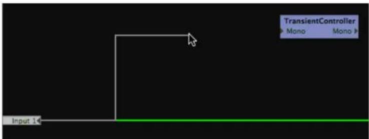
Figure 15.10: Starting a Connection
![graph TD A["Input 14"] --> B["TransientController Mono"] B --> C["Mono"]](/content/2026/05/884165/images/fb2649b416d360ef2531a9726fc6905c3dfb9ca93d2413a0e122be0df7bca68e.jpg)
Figure 15.11: Completing the Connection
![graph TD A["Input 1"] --> B["MIOEq 6 Band"] B --> C["TransientController Mono Mono"] style B fill:#f9f,stroke:#333,stroke-width:2px](/content/2026/05/884165/images/4dedf76392826c97629e1b1104ff10005b9736910e18b4edbcf1acf442a7050e.jpg)
Figure 15.12: Making a Mult
After everything is placed and wired up, you will need to ensure that you have routed the output of your signal processors to the appropriate port on the output side of the graph. When you are done, you will have a complete graph. For example:
![graph LR A["A"] --> Summer["Summer"] B["B"] --> Summer Summer --> A+B["A + B"] A+B --> Output["Output + 1"]](/content/2026/05/884165/images/706d7f9abe02e5736d4b08978a1d1aa1cee52986c46ca44362e5a060c84dd549.jpg)
Figure 15.13: Connecting the Output
As you can see, once the output of the final plug-in was connected to the output port, the input-to-output connection was removed, and you are now listening to the processing chain.
The graph is continuously modifiable. You can drag the plug-ins around as you like, and you can add new plug-ins, even while you are processing audio with the existing graph. You can make and break connections as you please.
There is no routing delay within the plug-in graph. So if you make mults with different plug-in paths on each side of the mult, the two paths will remain time-aligned. This allows you to configure parallel processing paths without the virtually impossible task of time-aligning the parallel paths.
At this point, you will want to be able to control each plug-in's parameters. Double-click on any plug-in to view its UI as described previously.
Patch Library Pop-up Menu
The Patch Library pop-up menu allows you to save the complete state of the plug-in graph. This menu works like all the other Library pop-up menus in MIOConsole.
16. Saving and Recalling Your Setups
MIO Console and your interface keep their data in what are called states. A state is the collection of data that tells the system how the interface is configured, how your mixer is set up, etc. This data is stored in several ways:
- Factory default: This is part of the interface's firmware and defines how the interface should be set up if there is no bootstate. The factory default cannot be modified in the box, but can be modified and saved as a bootstate.
- Boot state: This is a state stored in your interface that defines how the interface will be configured when it is powered up. The bootstate overrides the factory default.
- Snapshots: Snapshots are stored in the interface and can be used when the box is used standalone (not connected to a computer).
- Console file: This saves your state as a file on your computer with a ".cns1" suffix and can be opened by MIO Console.
- ConsoleConnect: Using the ConsoleConnect plug-in with your DAW saves the state as a plug-in preset that is saved with your DAW session. Please see the ConsoleConnect section for more information.
Factory Default
When an interface is connected to the computer and there is no data for it, MIO Console will automatically re-create the factory default mixer in the Mixer window so that you may start working with the interface immediately.
If there is state data on the computer for the interface you are connecting, you will see this dialog:
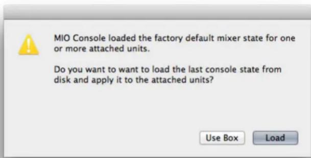
Figure 16.1: Factory default conflict dialog
- If you choose Use Box, the factory default of the box will configure the mixer.
- If you choose Load, the data on the computer will be sent to the box.
Box Merge
If a second (or third, etc.) interface is added to an existing system and there is no state info for the new box in the current mixer, MIO Console will automatically add the factory default setup of the new box to the existing system. Keep in mind that while both interfaces are shown in the same window, they do not share audio busses; you must interconnect them manually as described in the multibox mixing tutorial at http://mhsecure.com/metric_halo/support/tutorials.html.
Boot States and Snapshots
All Mobile I/O hardware has support for setting a Boot State — the configuration the hardware will use when the unit boots up. This boot state includes the entire state of the unit including the configuration of the mixer, the router, sample rate, clocking, analog I/O levels (for HW that has digital control), and +DSP configuration.
This functionality allows you to fully configure your hardware and "pour" a complete digital signal processing engine into the HW for instant-on processing.
In order to configure the boot state and snapshots for your interface, you will need to utilize the MIO Console application. Configuring and storing snapshots in the box is very simple:
- First, attach the interface to the computer and start up MIO Console.
- Use MIO Console to configure the box. Set up all aspects that you care about. Once you have the configuration as you like it, you are ready to save the snapshot.
- Choose the appropriate save command from the Utilities Menu
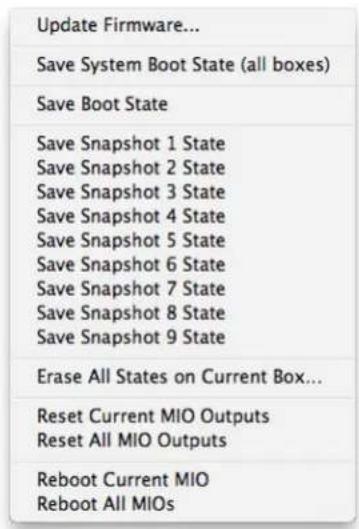
Figure 16.2: Utilities Menu
- "Save System Boot State (all boxes)" will save the states of all connected boxes into all connected boxes. This is useful when all boxes in a system will always be used together.
- "Save Boot State" will save the state of the selected box tab in the Console window as that box's bootstate only.
-
To save the snapshot to one of the other snapshot slots, choose the appropriate "Save Snapshot x State" item (where x is the appropriate number).
-
Save a copy of the current Console state to a file on your hard disk with an appropriate name (like "Snapshot 1" for the 1st snapshot) so that you have a copy of the state on the computer if you want to modify it in the future.
ULN-2 Snapshot Recall
The ULN-2 hardware extends the Boot State and adds support for Persistent State Snapshots. There are 10 snapshot slots in the ULN-2 that are recallable from the controls on the ULN-2 front panel. Each Persistent State Snapshot contains a complete description of the state of the box, including Sample Rate, Clock Source, Digital input source, Sample Rate Converter Enable, Mixer Configuration, Levels and +DSP configuration and routing. In other words, a snapshot saves every aspect of the configuration of the ULN-2.
The first snapshot slot is special as it is used by the unit to configure the hardware and the routing when the ULN-2 starts up. The other 9 slots are available for storing alternate configurations that can be selected "on the fly" after the ULN-2 is up and running.
When a computer is attached to the ULN-2, the front-panel controls to select snapshots are locked-out since the computer is actively controlling the configuration of the box.
If the computer is not attached, the two tact-switches on the left-side of the front-panel (between the status indicators and the meters) may be used to select the snapshot that you want to use to configure the ULN-2. These buttons are labeled with up and down arrows. The currently selected snapshot is indicated by the column of LED's labeled C, 1, 2, 3, 4, 5, 6, 7, 8, 9. When the ULN-2 turns on, the "C" indicator will be illuminated, indicating that the unit has booted up with the state that was stored in the "Boot Snapshot".

Figure 16.3: ULN-2 Front Panel Snapshot Controls
Pressing the up arrow will move to the next higher snapshot in the list (e.g. if you are currently on snapshot 3, you will move to snapshot 2). Conversely, pressing the down arrow will move to the next lower snapshot in the list (e.g. if you are currently on snapshot 3, you will move to snapshot 4). If you are at either beginning of the list and you press the up arrow, you will wrap around to the last item in the list. When you select a new snapshot, the new snapshot is applied to the box immediately.
ULN/LIO-8 Snapshot Recall
The ULN-8 and LIO-8 provide for front panel recall of eight snapshots; they are stored in the same manner as the ULN-2, and are recalled by going to the "Preset" Control Mode and pushing the channel encoder that corresponds to the preset number you wish to recall.
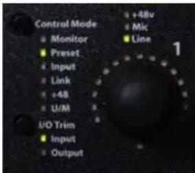
Figure 16.4: ULN-8 Front Panel in Preset mode
Front panel recall on the ULN-8/LIO-8
On the ULN-8 and LIO-8, encoder 1 recalls the "bootstate" snapshot. User snapshot #1 is recalled on encoder 2 and so on through snapshot #7 on encoder 8. There is no snapshot recall on the Monitor Control encoder, since that button toggles between Monitor and Cans.
2882 Snapshot Recall
With v.5, the 2882 supports an alternate boot state as well. This is the state that is saved in the "Snapshot 1" state slot. If there in nothing saved in this slot, the alternate boot state will be the factory default boot state.
To access the alternate boot-state on the 2882, simply hold the front-panel DIM button while powering the unit. This will select the alternate boot state.
Console Files
To save your current console setup, go to the File menu and select "Save":

Figure 16.5: File menu
You will be asked what to name the file and where to save the file. If you have modified and existing file, you will only be able to "Save As", which which will write your changes to the open file.
To reopen this configuration later you can double-click the .cnsl file in the Finder, drag the file icon onto the MIO Console icon in the Dock, or use the "Open" command in MIO Console's File menu.
ConsoleSync
ConsoleSync bridges the gap between using your interface connected to your computer and using it as a standalone device by ensuring that the hardware and MIO Console are always synchronized. Your changes in MIO Console are saved to the interface automatically; this happens one second after your last adjustment. If you make changes to your interface while using it away from the computer, those changes are reflected in MIO Console when you reconnect.
ConsoleSync provides a number of benefits:
- The technology used in ConsoleSync allows you to quit MIO Console and relaunch with no interruption of audio playing through the unit. For example, when using your interface on stage you can quit MIO Console to free up resources for your other audio software then relaunch MIO Console to make an adjustment without interrupting the audio.
- Connecting your interface to a new computer for the first time? Launch MIO Console, connect the interface and your bootstate automatically loads. Once MIO Console has created a state on your computer, subsequent relaunches will show this dialog:
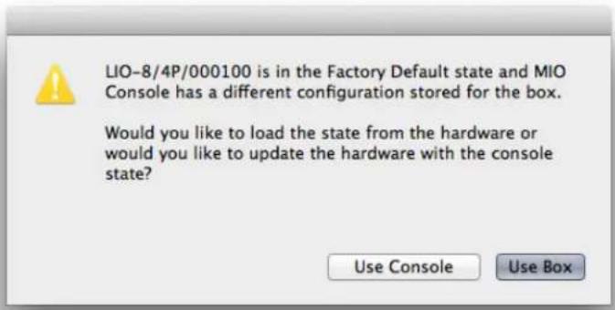
Figure 16.6: Dialog to load the factory default or state on the computer
- If your interface has a bootstate stored and MIO Console has no mixer loaded, plugging your interface into your computer will automatically load the bootstate into MIO Console.
- Changes made to the front panel of the ULN-8 and LIO-8 are synced when MIO Console is launched. For example if you quit MIO Console and change an input gain from the front panel of the ULN-8 while tracking in a DAW, the gain change will be reflected in MIO Console the next time it is launched.
- If you disconnect your interface and then reconnect it (for example, you take your laptop away then bring it back) without quitting MIO Console, ConsoleSync will compare the states in the interface and in MIO Console. If they don't match, you will see this dialog:

Figure 16.7: Box and console sync dialog
In this example, a parameter in MIO Console was changed after the box was disconnected. You are now able to choose whether you want to load the data from the interface or from MIO Console.
- If "Use Box" is selected, the state stored in the hardware will be applied to all boxes.
- If "Use Console" is selected, the state stored in MIO Console will be applied to all boxes.
If the state is loaded from the hardware, you will see the text "Loaded from box" in the title bar of the Console and Mixer windows.
Please note that the synchronized state is stored in volatile RAM, and will be erased when you turn the interface off. To store a state in the hardware permanently, use a bootstate or snapshot as described above.
17. MIO Console Preferences
Accessing the preferences
MIO Console has a number of preferences that you can set to control aspects of its behavior. These preferences are accessed via the MIO Console > Preferences... command (or via ⌘, (Command + comma) key sequence). When you select the Preferences command, the Preferences sheet is shown on the MIO Console window:
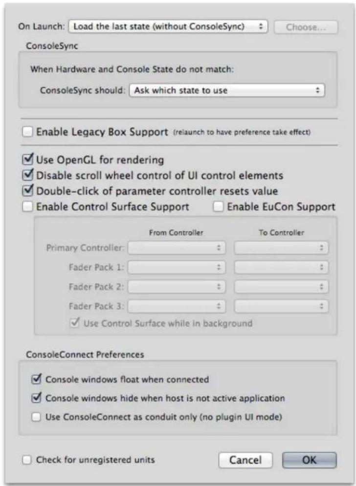
Figure 17.1: MIO Console Preferences
The preferences you can control are:
- What MIO Console does on launch. The On Launch pop-up allows you to select from:

Figure 17.2: On Launch Pop-up
- Load the last state (with ConsoleSync) — This will cause MIO Console to compare the state that is stored in the hardware and the last state stored in the MIO Console Prefs in your Preferences folder. If the timestamp on the states are the same, MIO Console will automatically load the stored state. If the timestamps are different, MIO Console will behave as set in the ConsoleSync setting below. When this is selected, there is no document association with the state that is loaded. This is MIO Console's default setting.
- Load the last state (without ConsoleSync) — This will cause MIO Console to load the state that was saved to the hard drive. The last state is stored in the MIO Console Prefs in your Preferences folder. When this is selected, there is no document association with the state that is loaded. This is the "classic" MIO Console behavior, how MIO Console functioned before ConsoleSync was introduced.
- Load the last open document — This will cause MIO Console to load the last document that was opened or saved in MIO Console. If you made changes to the last opened document and did not save them, the state that is loaded will reflect what is on disk — not the changes that you had made. When this is selected, the document will be reloaded and changes you make can be saved to the document.
- Load the specified document — This will cause MIO Console to load the document that you specify with the Choose... button. When this is selected, the document will be reloaded and changes you make can be saved to the document.
- Reset Configuration — This will cause MIO Console to load a blank configuration when it is launched.
- Show Template Dialog — This will cause MIO Console to show the template selection dialog each time it is launched.
- What MIO Console does when the states stored in the interface and on the computer do not match. The ConsoleSync pop-up allows you to select from:

Figure 17.3: ConsoleSync Pop-up
- Ask which state to use — This will display a dialog asking whether you would like to load the state data from the interface or from the computer. This is MIO Console's default setting.
- Use Hardware State — This will cause MIO Console to always load the state that is stored in the interface. Any state stored on your computer will be overwritten.
- Use Console State — This will cause MIO Console to always load the state stored on your computer. This is also equivalent to the "classic" MIO Console behavior, how MIO Console functioned before ConsoleSync was introduced.
- Enable Legacy Box Support — When checked, this will cause MIO Console to include the Mixer and Routing panels in the MIO Console window to support routing and mixing on boxes without a 2d Card. If all the units you will use on the computer are 2d Expanded you should leave this option unchecked, and
those panels will be omitted from the UI on the next launch of MIO Console. This will streamline the UI by removing elements that you do not need. The default state is for Legacy Box Support to be disabled.
- Use OpenGL for rendering — When checked, this will cause MIO Console to accelerate the display of much of the graphics in the application using OpenGL Hardware Acceleration. This option is on by default since it can dramatically reduce the amount of CPU used by MIO Console for updating Meters and other graphical elements on newer machines, but can be turned off if you experience graphics issues.
- Disable scroll wheel control of UI control elements — When unchecked, MIO Console will change the value of the control element (knob, fader, etc.) that is under the mouse when you move the scrollwheel or do two-fingered dragging on a laptop. If you check this control, this will disable the scrollwheel for changing the value of control elements. The default is for the scrollwheel to be recognized.
- Double—click of parameter controller resets value — When checked, double-clicking on a control element (knob, fader, etc.) will reset the value of the control to the default value. The default is for this to be unchecked.
-
Enable Control Surface Support — When checked, MIO Console will listen to Mackie Control protocol messages on the specified MIDI Ports. Use the controller pop-ups to select the MIDI I/O for your control surface. The default is for this to be unchecked.
-
Primary Controller — Select the MIDI ports for the primary (generally the master section) Mackie Control Protocol control surface unit. MIO Console will treat this as the right-most controller in terms of fader layout
- Fader Pack 1 — Select the MIDI ports for the Mackie Control Protocol first fader pack used in the system. MIO Console will place this fader pack to the left of the Primary Controller in terms of fader layout
- Fader Pack 2 — Select the MIDI ports for the Mackie Control Protocol first fader pack used in the system. MIO Console will place this fader pack to the left of Fader Pack 1 in terms of fader layout
- Fader Pack 3 — Select the MIDI ports for the Mackie Control Protocol first fader pack used in the system. MIO Console will place this fader pack to the left of Fader Pack 2 in terms of fader layout
- Use Control Surface while in background — When checked, MIO Console will continue to use the Mackie Control Protocol Control Surface units, even if it is not the active application on your computer. Uncheck this if you will use the same control surface units in another host program too. This does not apply to EuCon Control surfaces as EuCon manages application switching.
- Enable EuCon Support — When checked, MIO Console will automatically connect to EuCon services if you have the EuCon software and hardware installed. This box is not checked by default. If you have a EuCon control surface, you must check this box in order to use it with MIO Console. If you do not wish to use your EuCon control surface with MIO Console, uncheck this box and MIO Console will disconnect from EuCon services.
- ConsoleConnect Preferences are used to control the behavior of MIO Console when you are using the MIOConsoleConnect plug-in in a host app:
- Console windows float when connected — When checked, all MIO Console windows will float above all of the host's windows. If this is not checked, then the MIO Console windows will intermix with the host application's windows.
- Console windows hide when host is not active application — When checked, all MIO Console windows will hide when you switch out of the hosting application and will be re-shown when the host application is made active again. This is especially useful when the Console windows float when connected preference is checked.
- Use ConsoleConnect as conduit only — When checked, MIO Console will not switch to plug-in mode when the MIOConsoleConnect plug-in connects to MIO Console. Rather, MIO Console will continue to run as a standalone application, but will get data from and supply data to the MIOConsoleConnect plug-in to preserve the configuration in the host's session. This is useful, especially to work around corner case issues with plug-in mode (mostly related to text editing).
•
Check for unregistered units — When checked, MIO Console will connect to the registration server (if the computer is online) and prompt you to register your interface if it is not registered. Please see the section on Registration and Licensing for more information.
Other Preferences
There are specific preferences in three other locations in MIO Console:
- The box specific preferences, available by clicking on the serial number of the interface in the I/O tab. These are detailed in the Box Tabs section of the MIO Console Overview.
- The Record Panel preferences, available in the Recording menu or the Prefs button in the Recording pane. These are detailed in the Record Panel Prefs section of the Record Panel chapter.
- The Channel Strip Meters Post Fader setting, available in the Mixer menu. The default is Post Fader, meaning that the channel faders show the signal level after the fader. To show the Pre Fader level, uncheck this setting.
| Create New Mono Mixer Strip | ⌘N |
| Create Multiple Mixer Strips... | ⌘M |
| Create New Bus... | ⌘B |
| Configure Mixer... | ⌘C |
| Set Color for Selected Strips... | ⌘C |
| Set Width for Selected Strips | ▶ |
| Delete Selected Strips | ⌘D |
| √ Channel Strip Meters Post Fader | ⌘P |
| Clear Mixer Config | |
Figure 17.4: Channel Strip Meters Post Fader Preference
- More information on the Control Surface preferences is available in the Control Surface Support chapter.
18. ConsoleConnect
ConsoleConnect Overview
Introduction to ConsoleConnect
Designed from the ground up to seamlessly integrate MIO Console with your preferred digital audio workstation software, ConsoleConnect allows you to use the MIO as if it were designed in concert with your workstation. This is a quantum leap forward for both the Mobile I/O and your native host allowing you to have the level of integration that, up until now, has only been found in dedicated hardware workstations. But unlike those dedicated workstations, it works with your choice of audio software allowing you the freedom to choose the solution that works best for you, or to move between multiple hosts with no loss of integration.
How it works
ConsoleConnect is built upon Metric Halo technology that allows the MIOConsoleConnect plug-in (which is available in the AU, VST, RTAS and AAX formats) to connect to Metric Halo's MIO Console control application. The connection provides bi-directional communication between the host and MIO Console, allowing the host to load the complete state of your MIO system (for all the units attached to your computer) and save it automatically and completely in the session file for your project.
What it doesn't do is route audio; you need to route audio from your DAW into the MIO Mixer using DAW channels and back into your host using FW Returns.
Total Recall
When you reopen your project, the MIOConsoleConnect plug-in will automatically launch MIO Console and update the state of your hardware to match the settings saved in your session. This is all done automatically and transparently to you. Since the MIO can have complex routings, mixer settings, analog level settings and +DSP patches, ConsoleConnect extends total recall of your session outside the bounds of your workstation software and out into the physical world.
Being able to have total recall of the complete hardware state in your host's session files is very exciting and powerful, and opens up many new possibilities. For example, this in-session total recall gives you the ability to preconfigure host session templates that automatically prepare your hardware for tracking (setting up the Mic pres and monitor mixes, for example). If this was the extent of the integration, it would be very useful. But ConsoleConnect does not stop there.
Universal Access
The plug-in provides full access to MIO Console from within the context of the hosting workstation. This means that you can be interacting with the MIO hardware while still having full control over your host application. Riding gains, adjusting monitor mixes, inserting and tweaking plug-ins is now a snap, and can be done from within your host application. All your host app windows remain fully active and the host's keycommands are also fully active, so things like transport control continue to work as you would expect, with no need to "shift gears" mentally, simply because you need to make an adjustment to the hardware. And best of all, when you save your session, everything is stored exactly as it is, so when you come back to your session, the hardware is reset to be exactly as it was.
Using ConsoleConnect
Using ConsoleConnect is simple; insert it in your DAW once, and it will store the state of MIO Console in your DAW's session file when you save. You may also use ConsoleConnect to save presets in your DAW's plug-in format so that you can reuse your common tracking and mixing setups across multiple sessions.
ConsoleConnect can run in one of two modes:
- Plug-in Mode, which allows you to erase the artificial boundary between your DAW and MIO Console. It makes MIO Console work like a part of your DAW by making the MIO Console windows appear inside your DAW's as plug-in windows. MIO Console is still running, but does not appear as a normal application. If you want to have instant access to all the features of MIO Console from within your host and you don't mind floating windows, then plug-in mode is for you.
- Conduit Mode, which allows you to save and restore all of your MIO configuration data within your host's session, and also allows you to use plug-in presets to switch your MIO configuration on the fly, but leaves MIO Console running as a completely independent application, with its own menubar. If you have grown used to using standard Mac key-commands and OS features like Exposé to switch back and forth between your host and MIO Console, you may find that Conduit mode suits you better. In addition, if you frequently use the Record Panel, and are changing record folders (and especially creating new ones) often, you may find that the work goes smoother when MIO Console is running as a completely separate application.
Whichever way you go, all your MIO Console settings, including routing, mixing, and +DSP will be saved and recalled directly from your host's session file.
Selecting the mode
You control the mode that ConsoleConnect uses via the MIO Console Preferences in the MIO Console application.
To access these preferences, select the Preferences... command from the "MIO Console" menu in MIO Console. You will see:

Figure 18.1: MIO Console Preferences
The preferences are:
- Console windows float when connected checkbox: when checked, if MIO Console is connected to a host via ConsoleConnect, and is running in plug-in mode, this causes all MIO Console windows to be created in the floating window layer. All the windows will float above normal document windows. If your host uses floating windows for plug-ins, the MIO Console windows will be in the same layer as the host's plug-ins.
- Console windows hide when host is not active application checkbox: when checked, if MIO Console is connected to a host via ConsoleConnect, and is running in plug-in mode, this causes all MIO Console to be automatically hidden if you switch from the host to another application.
- Use ConsoleConnect as a conduit only (no plug-in UI mode) checkbox: when checked, selects Conduit mode for ConsoleConnect. Make sure this is unchecked if you want to run in plug-in mode.
Plug-in mode
When you insert MIOConsoleConnect into your DAW, one of two things will happen:
-
If the proper version of MIO Console (the one that came with the plugs) is already running, the plug-in will connect to MIO Console, and make MIO Console run as a plug-in in the host.
-
If MIO Console isn't running yet, the plug-in will Launch MIO Console as a plug-in in the host.
Once MIO Console is in plug-in mode, its windows are put into the floating window layer of the host. This means that all the MIO Console windows work like plug-in windows in the host. You can modify MIO Console to control your hardware, view meters, etc. All while your key commands continue to work in the host (transport, etc.).
Since MIO Console could have a large number of windows open (when you include plug-in windows, etc.) and the Console Window itself is a pretty big plug-in window, you will definitely want to hide all the MIO Console windows from time to time. This is accomplished with the following key-commands:
Table 18.1. Monitor Controller Key Commands
| Command Key Sequence | |
| Show/Hide all Console Windows | ⌘^H (Command + Option + Control + H) |
| Show/Hide the MIO Console Window | ⌘^C (Command + Option + Control + C) |
| Show/Hide the MIO Mixer Window | ⌘^X (Command + Option + Control + X) |
| Show/Hide the Monitor Controller Window | ⌘^V (Command + Option + Control + V) |
| Toggle the Monitor Controller size | ⌘^F (Command + Option + Control + F) |
Those are the default keys; you can edit them by editing the MIO Console Command key preferences (which has its own key-command: ⌘ Z (Command + Option + Control + Z))
Status Menu in Plug-in Mode
Since MIO Console loses its menubar when you are running it in Plug-in mode, you lose access to a number of commands that are only available from the menubar (for example: MIO Console Preferences, Recording Preferences, etc.). In order to provide you with access to these critical commands, we have added a MIO "Status Menu" to the menubar. This MIO menu appears on in the area on the right-hand side of the menubar, and provides access to the most critical commands that you may need while running in Plug-in mode:

Figure 18.2: MIO Console Status Menu
Conduit mode
When you insert MIOConsoleConnect into your DAW, one of two things will happen:
- If the proper version of MIO Console (the one that came with the plugs) is already running, the plug-in will connect to MIOConsole.
- If MIO Console isn't running yet, the plug-in will Launch MIOConsole.
Once MIO Console is in Conduit mode, its continues to function as a stand-alone application. This means that you can command-tab between your host and MIO Console; you can use Exposé to reveal windows, etc.
Communication
The ConsoleConnect Plug-in that you insert into the host has bidirectional communication with MIO Console. This is true in both Plug-in mode and Conduit mode. When the host asks the plug-in for its state (to save in the session or to save a preset), the plug-in gets all the data from MIOConsole. When the host sets the state on the plug-in (preset recall or opening up a session), the plug-in forwards the data to the Console which then acts on it.
The entire configuration of MIO Console (for all the boxes attached to the machine) is saved in your session for you, and automatically recalled when you open the session back up. So now, your MIO is PART of your DAW session; any routing, level, mix, +DSP setups that you make are saved as in your DAW's session file and are instantly returned to the way that you had them set when you reopen your session.
ConsoleConnect also supports saving and recalling presets using the host's preset mechanism, you can also create multiple setups (routing, +DSP, etc.) and save them as presets for the MIOConsoleConnect plug-in. In the case of AU, the presets will also be shared between hosts. Switching your setup is as simple as recalling a preset for the MIOConsoleConnect plug-in. In fact, the MIO Console UI doesn't even need to be visible to recall presets -- even if MIO Console is hidden, selecting the preset will recall it and assert it onto the Hardware.
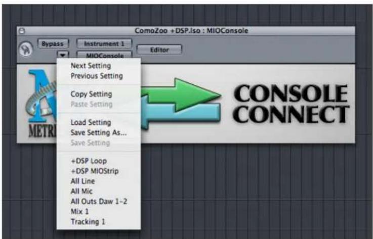
Figure 18.3: ConsoleConnect Presets
The data saved for the plug-in includes the entire console state (including offline boxes). This means that if you have multiple MIO Systems that you move between, you can have a different setup for each different box saved in your session and the proper settings will be applied when you launch the session — automatically sending the settings to the proper box.
Finding the Plug-in
Some hosts put the MIOConsoleConnect plug-in in a funny place. The list below points you in the right direction for some of the most common hosts.
- Logic: you will find MIOConsoleConnect under: AU Plug-in > Metric Halo > MIOConsoleConnect
- Digital Performer: it will either be (depending on whether or not you have other Metric Halo AUs installed):
• Metric Halo: MIOConsoleConnect
• Metric Halo > MIOConsoleConnect - Cubase: you will find MIOConsoleConnect under: Legacy VSTs
- Pro Tools: you will find MIOConsoleConnect under: Wrapped Plug-ins > MIOConsoleConnect
Tips for Specific Host DAWs
Please follow the links below for specific tips on how to maximize your experience with ConsoleConnect.
- Logic
- Digital Performer
- Cubase
- GarageBand
- ProTools
Logic
The best place to insert MIOConsoleConnect is on an unused (virtual) instrument channel. The MIOConsole-Connect plug-in will work on any type of channel but it will use no CPU on a channel with no audio. You only need to insert MIOConsoleConnect once per session in order to save every parameter of all connected Metric Halo boxes with your session.
Digital Performer
MIOConsoleConnect is an AU in DP
Since Digital Performer has first-class support for the AU plug-in standard, we did not make a MAS-specific plug-in for ConsoleConnect. Instead, you can simply use the AU plug-in with Digital Performer.
You should be aware of a quirk in DP/MAS that affects the use of AU plug-ins in Digital Performer. In order to fully instantiate an AU plug-in in Digital Performer you must have the I/O on the mixer strip fully configured.
If you insert MIOConsoleConnect (or any AU for that matter) and the DP plug-in window opens with no plug-in UI, you do not have the mixer channel you are trying to use configured. All you need to do to get things rolling is make sure that the output for the mixer strip is set to a valid, live output bundle.
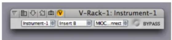
Figure 18.4: When Things Go Wrong: Partially Instantiated AU
Where to Insert MIOConsoleConnect
In Digital Performer, you will need to decide if your MIO Console configuration should apply to the entire session, or if you want it to change from sequence to sequence within the session. If you want it apply to the entire session and use multiple sequences per session in DP, you will want to add the MIOConsoleConnect plug-in in to the session's V-Rack. If you only use one sequence per session, or if you want the MIO Configuration to be different in each sequence, you can insert the MIOConsoleConnect plug-in in each sequence, and DP will switch the plug-in as it moves from sequence to sequence.
Where to Insert MIOConsoleConnect when using V-Rack (recommended)

Figure 18.5: MIOConsoleConnect Inserted in a V-Rack
Due to the MAS issue described above, you need to be a bit careful when inserting MIOConsoleConnect in the V-Rack. We recommend that you:
- Create a new mono Master Fader in the V-Rack
- Set the output for the Master Fader to an unused bus (for example Bus 64) — this is very important
- Insert MIOConsoleConnect on this mixer strip
The MIOConsoleConnect plug-in will work on any type of channel but it will use no CPU on a channel configured as described above (please note: that no audio will be running through this master fader track; it is just a placeholder for the plug-in). You only need to insert MIOConsoleConnect once per session in the V-Rack in order to save every parameter of all connected Metric Halo boxes with your session. If you use per-sequence MIOConsoleConnect instances, you cannot put MIOConsoleConnect in the V-Rack.
Where to Insert MIOConsoleConnect per Sequence
If you choose to insert MIOConsoleConnect in each sequence rather than in the V-Rack you will need to keep some things in mind: Due to the MAS quirk described earlier, you need to be a bit careful when inserting MIOConsoleConnect in the Mixer. We recommend that you:
- Insert MIOConsoleConnect in each sequence, or you will lose access to MIOConsole, or may experience inconsistent recall of the MIO Parameters.
- Launch MIO Console before inserting MIOConsoleConnect or opening a session with MIOConsoleConnect inserted. This will keep MIO Console from being quit and relaunched as you move from sequence to sequence.
The MIOConsoleConnect plug-in will work on any type of channel but it will use no CPU on an audio track with no audio regions. You will still need to make sure that the channel has a valid output bundle assigned in order for DP to actually instantiate the plug-in, as described above. You only need to insert MIOConsoleConnect once per sequence in order to save every parameter of all connected Metric Halo boxes with your session.
Cubase
The best place to insert MIOConsoleConnect is on an unused (virtual) instrument channel.

Figure 18.6: Add an Instrument Track
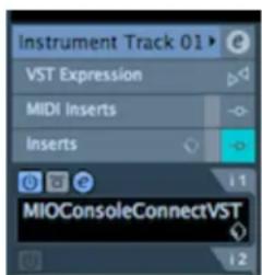
Figure 18.7: Insert MIOConsoleConnect
The MIOConsoleConnect plug-in will work on any type of channel but it will use no CPU on a channel with no audio. You only need to insert MIOConsoleConnect once per session in order to save every parameter of all connected Metric Halo boxes with your session.
GarageBand
When GarageBand starts up with a new song, by default you get a "Grand Piano" track every time. We'll use this track to insert the MIOConsoleConnect plug-in.
Once GarageBand has loaded, and you see your "Grand Piano" track, double-click on the name "Grand Piano" to bring up the full details for the track. The track details will show up on the right side and alternatively can be instantiated with the following key command: (✗1).
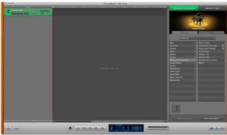
Figure 18.8: Track Details
This will open the details in the "Browse" tab. Click on the "Edit" tab to show additional track details:

Figure 18.9: Track Edit Tab
Under "Sound Generator" (which is GarageBand's way of inserting virtual instruments) please select "none" from the list; this will allow the track to function, but cost you no CPU power.
Below the generator section is the "Effects" section. Since this track isn't passing audio, go ahead and remove the checkmarks from: Compressor, Visual EQ, Echo and Reverb. This will also save you some CPU.
In the effects section, there are four empty slots – this is where you can insert 3rd party AU plug-ins. Move your mouse over a slot and it will read "Click here to add an effect". Click on the slot and you will see a propagated list of all you're your AU plug-ins. Scroll down until you see "MIOConsoleConnect". Selecting the plug-in will automatically instantiate the plug in window for the MIOConsole.

Figure 18.10: MIO Console as a Plug-in in GarageBand
To access the preset management in GarageBand, look back at the track details. When you move your mouse over the icon next to MIOConsoleConnect, it turns into the edit icon which has sliders. Please click it:

Figure 18.11: Preset Management
Doing so will bring up the following window:

Figure 18.12: MIOConsoleConnect UI
On this interface, you will find a pop-up menu called "Manual". This is how GarageBand manages its presets. Clicking on this will enable you to make or recall a preset from within GarageBand.
Once you have saved some presets, you can recall them more directly by clicking on the "Manual" menu under "MIOConsoleConnect".

Figure 18.13: Direct Preset Recall
Note:
The preset you create will contain a complete state of all the boxes in your system including: Routing, Matrix Parameters, Patchbay, +DSP and Record Panel Settings for each box.
Additionally, when in Plug-in mode, you will notice small tab in your menu bar called "MIO". This enables you to access the menu commands found in the standalone version of the MIO Console while you're in plug-in mode.
Pro Tools Tips
The best place to insert MIOConsoleConnect is on an unused (virtual) instrument channel. The MIOConsole-Connect plug-in will work on any type of channel but it will use no CPU on a channel with no audio. You only need to insert MIOConsoleConnect once per session in order to save every parameter of all connected Metric Halo boxes with your session.

Figure 18.14: Inserting MIOConsoleConnect
Support
If you have any questions about Mobile I/O or ConsoleConnect, please check the FAQ. If you can't find your answer there, please contact Metric Halo Support for further assistance.
19. Control Surface Support
Control Surface Preferences
MIO Console has extensive support for external tactile control surface units. MIO Console supports two different Control Surface communication protocols: Euphonix's EuCon and Mackie Design's Mackie Control Protocol. Both protocols are supported simultaneously, so you can use both types of controllers at the same time. If both controllers are controlling the same elements of MIO Console, MIO Console will keep both protocols synchronized. More interesting, however, is that the two different control surface systems can be used to control different parts of MIO Console at the same time, allowing you to control different parts of a mix or even two different mix busses simultaneously with multiple control surface units.
The first step in using the Control Surface support is enabling and configuring your Control Surfaces. This is done from the MIO Console Preferences panel. These preferences are accessed via the MIO Console > Preferences...command (or via the ⌘, (Command + comma key sequence). When you select the Preferences command, the Preferences sheet is shown on the MIO Console window:

Figure 19.1: MIO Console Preferences
The relevant preferences for Control Surface support are:
- Enable Control Surface Support—When checked, MIO Console will listen to Mackie Control protocol messages on the specified MIDI Ports. Use the controller pop-ups to select the MIDI I/O for your control surface. The default is for this to be unchecked.
- Primary Controller— Select the MIDI ports for the primary (generally the master section) Mackie Control surface. MIO Console will treat this as the right-most controller in terms of fader layout
- Fader Pack 1—Select the MIDI ports for the first Mackie Control fader pack used in the system. MIO Console will place this fader pack to the left of the Primary Controller in terms of fader layout
- Fader Pack 2—Select the MIDI ports for the second Mackie Control fader pack used in the system. MIO Console will place this fader pack to the left of Fader Pack 1 in terms of fader layout
- Fader Pack 3—Select the MIDI ports for the third Mackie Control fader pack used in the system. MIO Console will place this fader pack to the left of Fader Pack 2 in terms of fader layout
- Use Control Surface while in background—When checked, MIO Console will continue to use the Mackie Control units, even if it is not the active application on your computer. Uncheck this if you will use the same control surface units in another host program too. This does not apply to EuCon Control surfaces as EuCon manages application switching.
- Enable EuCon Support—When checked, MIO Console will automatically connect to EuCon services if you have the EuCon software and hardware installed. This box is not checked by default. If you have a EuCon control surface, you must check this box in order to use it with MIO Console. If you do not wish to use your EuCon control surface with MIO Console, uncheck this box and MIO Console will disconnect from EuCon services.
Once you have enabled support for the type of surface you want to use, and, in the case of Mackie Control surfaces, have selected the relevant communication ports, MIO Console will connect to the surfaces and begin communication, including updating of the surface faders, scribble strip read-outs, and metering.
Note: If you wish to control MIO Console via EuCon and will be using ConsoleConnect, you must use ConsoleConnect in Conduit only mode as EuCon will automatically disconnect from MIO Console when it is running as a plug-in.
Note: If you wish to control MIO Console via Mackie Control and will be using MIOConsoleConnect, you will need to determine if you also intend to control the host application with the Mackie Control surface. If you will use the surface with your host you must use ConsoleConnect in Conduit only mode, as the control surface will become confused if you have both MIO Console and the host communicating with it at the same time. You will also need to ensure that the "Use Control Surface while in background" option is not checked, so that MIO Console will automatically disconnect from the surface when you switch to the host app.
If you will not use the Mackie Control with your host software but will use MIO Console as a plug-in via ConsoleConnect, then you will need to ensure that the "Use Control Surface while in background" option is checked in MIO Console Preferences, otherwise MIO Console will disconnect from the surface when it switches to plug-in mode. The details of working with MIO Console's Control Surface support are similar, but not precisely the same for the two different Control Surface protocols. The details are explained below in the sections on EuCon and Mackie Control.
Details of EuCon Control Surface Support
The EuCon protocol is supported by all of Euphonix's control surface hardware including the Artist series (MC Control and MC Mix) and the Pro Series. While MIO Console should work well with the Pro Series, we have not done any testing with that hardware.
The EuCon protocol works by having the EuCon client application (MIO Console in this case) build a model to represent the controllable items in the client and their structure and organization. This model is used by the EuCon system to map the controls over the available control surface hardware. Since the mapping is done by EuCon, much of the details of interacting with the control surface are actually implemented in EuCon and are consistent from application to application.
EuCon and EuControl provide facilities for locking strips to faders and locking the Control Room (Monitor Control) section and transport control section to a specific application. All of these facilities can be useful when working with MIO Console, especially the Control Room locking if you are using the MIO Monitor Controller to control your source switching and monitor level. Please consult your EuCon documentation for details on how to use these facilities of EuCon.
Control Room Support
The Control Room Controls are only available on the MC Control Hardware (and are not available on the MC Mix Hardware).
The Control Room knob on the MC Control will control the Monitor Control Level in MIO Console, if you have configured the Monitor Controller. Note that the Control Room knob provides very fine control; don't turn it too fast when you first use it — experiment a little to get a feel for the gain ramp. Pressing the Control Room knob toggles the state of the Monitor Control Mute.
The Setup tab on the MC Control touch screen provides access to the source selection list and the cut (mute) and dim buttons. You can select from the configured Monitor Controller source from the source list via the MC Control touch screen, and you can also control the Mute and Dim state of the Monitor Controller from the touchscreen.
Mixer Model
MIO Console maps the v.5 mixer strips onto the EuCon surface in the order that they appear in the v.5 mixer window. If you want to change the order of the strips on the surface, simply change the order of the strips in the window. As soon as you finish reordering the strips, MIO Console will update the model on the surface.
Since each send in the MIO Mixer has its own strip in the send window, MIO Console supports switching the EuCon model to map the sends to a selected bus. When you select the sends, the currently selected send bus is mapped onto the surface. If you select sends again, the next send bus is mapped onto the surface. You can also return to the main Mix window at any time.
Unfortunately, due to a bug in EuCon at this writing, the method for selecting the sends bus is different on the MC Artist and on the MC Mix surfaces.
To Select the Sends bus (or move to the next Send bus) on MC Mix Simultaneously press the MC Mix SHIFT and PREV buttons
To Select the Main Mix Window on MC Mix
- Simultaneously press the MC Mix SHIFT and RTZ buttons
- -or- Simultaneously press the MC Mix SHIFT and Mixer (nudge left) buttons
To Select the Sends bus (or move to the next Send bus) on MC Control Press the "Aux" soft knob
To Select the Main Mix Window on MC Control
- Press the "Mix" soft knob
- -or- Simultaneously press the MC Control SHIFT and Mixer (nudge left) buttons
NOTE: If you accidentally press the "Aux" or "Mix" buttons on the MC Mix, the functions will work as expected, but you will lose the ability to control the Pan on your strips, and the nudge and bank buttons will not function as expected. This is due to a bug in EuCon. In order to resolve this condition, simply press the Pan button on the MC Mix -- everything will return to normal operation.
MIO Console will automatically configure the EuCon strips to match the configuration of the underlying mixer strip (including channel name, panner, number of channel meters, input controls, etc.)
In the EuCon environment, the channel controls are mapped onto so-called 'knob-sets'.
On the MC Control, you access the knobset by pressing the soft-knob labelled with the knobset name. The knobsets that are supported by MIO Console are the "Pan" and "Input" knobsets (as well as the "Aux" and "Mix" knobsets for switching amongst the send busses).
On the MC Mix, the knobsets are selected via the buttons on the left hand side of the surface. Again, the operative knobsets are "Pan" and "Input" knobsets (as well as the "Aux" and "Mix" knobsets for switching amongst the send busses — but these need to be avoided due to the bug described above).
Details of Mackie Control Protocol Control Surface Support
The Mackie Control is supported by the currently shipping Mackie Control Universal (with integrated USB interface) and Mackie Control Universal XT Fader pack products. It is also supported by the older Mackie Control products. In addition to the Mackie products, the Mackie Control Protocol is emulated by a number of third-party MIDI controllers and is supported with a wide-variety of generic MIDI controllers via the use of a third party program called LC Xmu available from Opus Locus.
With Mackie Control, the application (MIO Console in this case) controls all aspects of the control surface behavior — the Mackie Control is effectively a giant mouse with many buttons and sliders and readouts.
With the Mackie Hardware, only the MCU master section provides surface navigation buttons for nudging and banking as well as input, pan and send selection, so with most control surface implementations you need at least one master section to be able to access these features. With MIO Console, we have made these control surface commands available as mappable key-commands as well as control surface commands. This allows you access these functions from the keyboard of your computer, or, even better through a mappable HID like the ShuttleXpress or ShuttlePro. Since you can access these commands without having the master section, it is possible to configure a control surface by just using fader packs, which can provide a cost savings and a density improvement for certain applications.
Mackie Control Default Key Commands
Table 19.1. Mackie Control Default Key Commands
| Command Key Sequence | |
| Control Surface: Select Pans | 1 (Shift + Option + Control 1) |
| Control Surface: Select Input Gains | 2 (Shift + Option + Control 2) |
| Control Surface: Select Sends | 3 (Shift + Option + Control 3) |
| Control Surface: Bank Down | 4 (Shift + Option + Control 4) |
| Control Surface: Bank Up | 5 (Shift + Option + Control 5) |
| Control Surface: Shift Down | 6 (Shift + Option + Control 6) |
| Control Surface: Shift Up | 7 (Shift + Option + Control 7) |
| Control Surface: Toggle Legacy Mode | 8 (Shift + Option + Control 8) |
Control Room Support
The Jog wheel on the MCU is mapped to the master volume on the MIO Monitor Controller, and may be used to control your main monitor level.
Mixer Model
MIO Console maps the v.5 mixer strips onto the Mackie Control surfaces in the order that they appear in the v.5 mixer window, left to right onto the units in the following order: Fader Pack 3, Fader Pack 2, Fader Pack 1, Primary Controller. If you want to change the order of the strips on the surface, simply change the order of the strips in the window. As soon as you finish reordering the strips, MIO Console will update the model on the surface.
Since each send in the MIO Mixer has its own strip in the send window, MIO Console supports switching the Mixer model to map the sends to a selected bus. When you select the sends, the currently selected send bus is mapped onto the surface. If you select sends again, the next send bus is mapped onto the surface. You can also return to the main Mix window at any time.
To Select the Sends bus (or move to the next Send bus)
Press the 'VPOT ASSIGN' button labelled 'SEND'
To Select the Main Mix Window
- Press the 'VPOT ASSIGN' button labelled 'TRACK'
- -or- Press the 'VPOT ASSIGN' button labelled 'PAN/SURROUND'
To Select the Input Gain on the VPot for the Strips
Press the 'VPOT ASSIGN' button labelled 'TRACK'
To Select the Pan Control on the VPot for the Strips
Press the 'VPOT ASSIGN' button labelled 'PAN/SURROUND'
The Fader Bank and Fader Nudge buttons allow you to move the window of faders on the surface across the mixer. MIO Console will automatically update the scribble strips, metering, fader levels, VPot readouts and button states as you shift through the strips.
When you have attentioned a send bus onto the surface, the "Assignment" readout will show the bus number of the attentioned send bus. When the main mix window is on the surface, the "Assignment" readout will be blank.
Press the switch on the V-Pot to toggle the state of the phase invert on the associated channel.
The Select button on each strip will toggle the select state of the associated mixer channel strip. You can use this with the mixers ad-hoc linking to make multi-channel adjustments to the mixer.
The transport controls control the state of the Record Panel's transport and also reflect the state of the transport. The Timecode readout will show the current record or playback time.
All other master section controls are currently unassigned.
20. +DSP
DSP Package Comparison
All currently shipping interfaces (and older units that have been upgraded with a 2d card) come with the "2d Expanded" plug-in set. The ULN-8 includes a +DSP license; it is an option on all other interfaces. Below is a comparison of the included plug-ins and capabilities of the two packages.
Table 20.1. Building Block plug-ins
| Feature 2d Expanded 2d Expanded +DSP | ||
| Character (22 types) √√ | ||
| Multibus Mixer √√ | ||
| Surround Support √√ | ||
| Monitor Controller √√ | ||
| MIOStrip √√ | ||
| M/S Decoder √√ | ||
| Short Delay √√ | ||
| Dither √√ | ||
| HaloVerb √√ | ||
| TransientController √ | ||
| MIO EQ 6 √ | ||
| MIO EQ 12 √ | ||
| MIO Comp | √ | |
| MIO Limit √ | ||
| MIO State Variable Filter | √ | |
| NC State Variable Filter | √ | |
| Linkwitz-Riley Band Split Filter | √ | |
| Delays Family (15 plug-ins) | √ | |
| MIO Simple Pitch Shifter | √ | |
| Allpass filters (2 plug-ins) | √ | |
| MIO Soft Clip Family (3 plug-ins) | √ | |
| MIO Nonlinear Map Family (4 plug-ins) | √ | |
| MIO Volume Control Family (16 plug-ins) | √ | |
| MIO A/B Switch Family (16 plug-ins) | √ | |
| MIO M/S Processor | √ | |
| Static Matrix Family (5 plug-ins) | √ | |
| Channel op Family (5 plug-ins) | √ | |
| Math Family (9 plug-ins) | √ | |
| Envelope Family (2 plug-ins) | √ | |
| Oscillator Family (6 plug-ins) | √ | |
| MIO Mod Delay | √ | |
| Insertable Graphs (infinite possibilites) √ |
Table 20.2. 2d Amps
| 2d Amps 2d Expanded 2d Expanded +DSP | ||
| Bass Head √ | ||
| Bass Head Shape 1 √ | ||
| Bass Head Shape 2 √ | ||
| British Mil Spec √ | ||
| British Mil Spec Bright Cab √ | ||
| British Mil Spec Grind √ | ||
| British Mil Spec Light Grind √ | ||
| British Mil Spec Rhythm √ | ||
| British Mil Spec+Vibrato+Trem √ | ||
| MH Clean √ | ||
| MH Clean Tweed √ | ||
| MH Hi-Gain √ | ||
| Small Dark √ | ||
| Small Dark No Cab | √ | |
| Small Tweed Crunch | √ | |
| Small Tweed Touch O' Dirt | √ |
Table 20.3. 2d Effects
| 2d Effects | 2d Expanded 2d Expanded +DSP |
| Autoflanger | |
| Autoflanger 2 | |
| Autoflanger 3 | |
| Cool Mono Echo | |
| LoFi Mod Echo | |
| Mono Rotary | |
| Slap Delay | |
| Vibrato+Tremolo | |
| Stereo Rotary Speaker |
Table 20.4. 2d Reverbs
| 2d Reverbs | 2d Expanded 2d Expanded +DSP |
| Diffuse Prime | |
| Diffuse Room | |
| Early Diffuse Room (no tail) | |
| Hall 1 |
| 2d Reverbs 2d Expanded 2d Expanded +DSP | ||
| LongVerb √ | ||
| Med Diffuse Room √ | ||
| ModVerb √ | ||
| Small Diffuse Room √ |
Table 20.5. 2d Mastering
| 2d Mastering 2d Expanded 2d Expanded +DSP | ||
| Parallel Compressor √ | ||
| Parallel Limiter √ | ||
| Mid-Side Compressor √ | ||
| Mid-Side EQ √ | ||
| Mid-Side Limit √ | ||
| Stereo Parallel Limiter √ |
Table 20.6. 2d Pedals
| 2d Pedals 2d Expanded 2d Expanded +DSP | ||
| Nezumi √ | ||
| Nezumi Less Gain √ | ||
| Screamer | √ |
Table 20.7. 2d Cabinets
| Cabinets | 2d Expanded 2d Expanded +DSP |
| Closed 2x12 | |
| Closed 2x12 with Air | |
| 4x12 Cab √ |
+DSP Plug-in Documentation
MIO Volume Control (Linear)
- Synopsis: MIO Volume Control - Linear Interpolation
• Category: Building Blocks
• Channels: 1, 2, 3, 4, 5, 6, 7, 8
Description:
The output of this plugin is the input with the specified gain applied to each input channel. The gain is specified by the Volume parameter in dB. The Glide parameter controls how quickly the applied gain will change when you change the Volume parameter. This version of the plugin changes the gain linearly between the old value and the new value. To change the gain logarithmically, use the MIO Volume Control (LPF) plug-in.
Parameters:
Volume [-120, 20] dB
Specifies the gain applied to the input signal.
Glide [0, 1k]
Specifies the rate at which the gain will change. If the Glide value is close to 0 (especially between .1 and 1), the gain will change slowly. If Glide is close to 1000, the gain will change quickly.
Master Bypass {On, Off}
When bypassed, the gain will be set to 0dB, passing the input signal unchanged.
MIO Volume Control (LPF)
- Synopsis: MIO Volume Control - Low Pass Filtered Interpolation
- Category: Building Blocks
- Channels: 1, 2, 3, 4, 5, 6, 7, 8
Description:
The output of this plugin is the input with the specified gain applied to each input channel. The gain is specified by the Volume parameter in dB. The Glide parameter controls how quickly the applied gain will change when you change the Volume parameter. This version of the plugin uses a single-pole low pass filter (LPF) to change the gain between the old value and the new value logarithmically. To change the gain linearly, use the MIO Volume Control (Linear) plug-in.
Parameters:
Volume [-120, 20] dB
Specifies the gain applied to the input signal.
Glide [0, 1k]
Specifies the rate at which the gain will change. If the Glide value is close to 0 (especially between .1 and 1), the gain will change slowly. If Glide is close to 1000, the gain will change quickly.
Master Bypass {On, Off}
When bypassed, the gain will be set to 0dB, passing the input signal unchanged.
MIO M/S Processor
• Synopsis: Mid/Side Processor
• Category: Spatial, Building Blocks
- Channels: 2
Description:
MIO M/S is a flexible Mid/Side channel processor. It can be used to decode material that was previously encoded as Mid/Side. It can also be used to encode a left/right stereo field into a mid/side signal. In addition to being used to encode or decode existing signals, it you also use two instances of MIO M/S to build a transcoding signal chain in the +DSP graph.
Since you have access to the individual Mid and Side signals after encoding, you can insert additional processing blocks between the encoder and the decoder, including EQ, delay, compression and limiting. This allows you to build signal chains that alter the overall size, nature and depth of the stereo field.
Parameters:
Enable {Off, On}
When engaged, enables all the processing of the module.
Mid Invert {Off, On}
When enabled, inverts the 1st input channel before processing.
Side Invert {Off, On}
When enabled, inverts the 2nd input channel before processing.
Mode {Decode (Constant Amplitude), Decode (Constant Power), Encode (Constant Amplitude), Encode (Constant Power), LR->MS->LR}
Selects the processing mode.
Decode (Constant Amplitude)
Makes input 1 be the Mid Channel and input 2 the Side Channel. In this mode, the processor decodes the M/S input to Left and Right outputs, keeping the total amplitude constant. The center point is output compensated to not clip.
Decode (Constant Power)
Makes input 1 be the Mid Channel and input 2 the Side Channel. In this mode, the processor decodes the M/S input to Left and Right outputs, keeping the total power constant (the amplitude increases, and may go over 1). It is possible to clip audio using this setting.
Encode (Constant Amplitude)
Makes input 1 be the Left Channel and input 2 the Right Channel. In this mode, the processor encodes the Left and Right inputs to M/S outputs, keeping the total amplitude constant. The center point is output compensated to not clip.
Encode (Constant Power)
Makes input 1 be the Left Channel and input 2 the Right Channel. In this mode, the processor encodes the Left and Right inputs to M/S outputs, keeping the total power constant (the amplitude increases, and may go over 1). It is possible to clip audio using this setting.
LR->MS->LR
Makes input 1 be the Left Channel and input 2 the Right Channel. In this mode, the processor encodes the Left and Right inputs to an internal M/S representation, applies the width and rotation transformations in the M/S representation and then decodes the transformed M/S channels back to Left and Right outputs.
Width [0, 1]
Adjusts the width of the transformed field. When this parameter is 0, the output will be mono. When this is 1, the full stereo width is represented.
Rotation [-180, 180]°
Rotates the stereo field by the specified angle.
Master Bypass {On, Off}
Bypasses all of the processing.
MIO M/S Decoder
- Synopsis: Mid/Side Decoder
• Category: Spatial, Building Blocks - Channels: 2
Description:
M/S Decoder is a Mid/Side Decoder. It can be used to decode material that was previously encoded as Mid/Side.
Parameters:
Mid Invert {Off, On}
When enabled, inverts the 1st input channel before processing.
Side Invert {Off, On}
When enabled, inverts the 2nd input channel before processing.
Width [0, 1]
Adjusts the width of the transformed field. When this parameter is 0, the output will be mono.
When this is 1, the full stereo width is represented.
Master Bypass {On, Off}
Bypasses all of the processing.
MIO Static Matrix
• Synopsis: Static Matrix Mixer
• Category: Building Blocks
- Channels: 2x2, 3x3, 4x4, 5x5, 6x6
Description:
MIO Static Matrix implements a matrix mixer with a crosspoint matrix is static, which means that gain changes are not interpolated. As a result, changing the gain of a crosspoint that has signal running through it will result in a click at the output of the associated buss.
Each crosspoint gain connects an input to an output buss. The gains multiply the input signal, and all the signals in each buss are summed to form the output of the buss. The gains in this implementation are specified as linear multipliers. This means that rather than being specified in dB, the gain specified in the UI is the actual multiplier coefficient used by the mixer. This means that the input signal is multiplied by the number specified for the crosspoint gain. The gain that you specify for each crosspoint can range from -1.0 to 1.0.
When the gain is set to 1.0, this is equivalent to having a fader set to 0dB, which means that the signal will be pass through unchanged. This is easy to understand because anything multiplied by 1 is unchanged. As the coefficient you set is decreased, the gain is decreased as well, until the coefficient is set to 0. For example, if you use a coefficient of 0.5, the signal will be at half the original level, or a gain of -6.02 dB. When coefficient is 0, the signal is muted, and the effective gain is -∞ .
When coefficient is less than 0, the crosspoint has the effect of both applying gain AND inverting the signal. The gain applied is the same as would occur with a positive coefficient, but the signal will be inverted.
Parameters:
1->1 [-1, 1]
Sets the gain of input 1 mixed into output 1.
2->1 [-1, 1]
Sets the gain of input 2 mixed into output 1.
1->2 [-1, 1]
Sets the gain of input 1 mixed into output 2.
2->2 [-1, 1]
Sets the gain of input 2 mixed into output 2.
... and so on for the rest of the available channels.
Master Bypass {On, Off}
Puts the mixer into direct route mode (e.g. all inputs are directly routed to the corresponding outputs, and no mixing occurs).
MIOComp
- Synopsis: Flexible Signal Dynamics Compressor
• Category: Dynamics, Mastering - Channels: 1, 2
Description:
MIOComp is a flexible, full featured dynamics processor that provides compression/limiting functionality.
The compressor provides a flexible detector that can be driven from the input signal or a sidechain input. The detector computes the input level of the source signal, using the user specified Attack and Release times to control the responsiveness of gain cell of the compressor.
When the detected level is below the Threshold, the gain cell passes the signal with no change. Conversely, when the detected level is above the Threshold, the signal is attenuated based upon the Ratio, Knee and the level of the signal above the Threshold.
When the Knee is set to 0, MIOComp acts a hard-threshold compressor. For every dB (x) the signal is above the Threshold, the output signal increase above Threshold by x | Ratio.
When the Knee is set to a value above 0, the knee will be softened, and the effective Ratio will increase gradually from 1 to the specified Ratio. The transition is made more gradual as the Knee is increased from 0 to 1.
After the compressor gain-reduction has been applied to the signal, an additional make-up gain block applies a user specified Makeup Gain to the signal. If the Auto Gain has been enabled, the user specified Makeup Gain is applied in addition to the compressor computed make-up gain.
After the make-up gain has been applied, the output signal is limited to level specified by the Out Ceiling. This output ceiling limiter captures the effects of fast-transient breakthrough and is especially useful when using MIOComp on highly impulsive signals with large compression ratios.
Parameters:
Enable {Off, On} Enables the compressor.
Threshold [-100, 0] dB
Sets the threshold at which the compressor begins to act. There will be no gain reduction applied by the compressor when the input signal is below this threshold.
Ratio [1, 100k]
The gain reduction ratio that is applied to the input signal when the signal is above threshold. The actual ratio applied also depends on the knee parameter which can be used to soften the knee and make the applied ratio progressive.
Attack [1∞, 500∞] s
The characteristic attack time of the application of the gain reduction. Longer attack times will cause MIOComp to be less responsive to short transients. Short attack times are required to use MIOComp as a signal limiter, but very short attack times can lead to distortion in the output signal. The attack time is applied in the detector stage of MIOComp.
Release [5∞, 5] s
The characteristic release time of the application of the gain reduction. Longer release times will cause MIOComp to be maintain the gain reduction for a longer period of time after transients. Longer release times are appropriate when using MIOComp as a leveling amp/AGC. Alternatively, shorter release times are appropriate when using MIOComp to increase the apparent level of impulsive material. Very short release times can lead to distortion in the output signal. The release time is applied in the detector stage of MIOComp.
Knee [0, 1]
Adjusts the shape of the knee of the compressor as the detector goes above threshold. When knee is set to 0, the transition from no gain reduction to the specified ratio is immediate at the specified threshold. As this parameter is increased, the transition between the 1:1 ratio and the specified ratio is made more and more progressive, thus "softening" the action of the compressor.
Out Ceiling [-60, 0] dB
Sets the maximum output level of the compressor. The output signal is hard-clipped, post compressor, at this signal level.
Makeup Gain [-30, 30] dB
Sets the additional gain applied to the signal post compressor. Is used to raise sub-threshold signal level rather than reduce the super-threshold signal level.
Auto Gain {Off, On}
When enabled, causes the compressor to automatically adjust the makeup gain to keep full-scale input approximately at full-scale on output. This is a huertistic rule, and will likely need to be trimmed by the user using the Makeup Gain.
SC Source {Off, On}
Chooses the detector input source. Select between the input signal, and the sidechain input.
Master Bypass {On, Off}
When enabled, fully bypasses the plugin.
See also:
MIOLimit
MIOEq 6 Band
• Synopsis: 6 band Fully Parametric EQ
• Category: EQ, Mastering
- Channels: 1, 2
Description:
MIOEq 6 Band implements a mono or stereo 6-band IIR EQ processor. Each band is fully parametric, and can be set to any of the filter types. All the parameters of all the bands can be set to any of valid settings. The composite EQ curve is applied to the input signal, and the master gain is then applied to the processed signal.
Note: Each band of EQ is capable of being configured as one of 6 types of EQ Filter. The types are: Peaking/Parametric, Low Shelf, Hi Shelf, Hi Cut, Low Cut, Band Pass, and RIAA. The first 5 types are parametric filters that allow you to use the Frequency, Gain and Bandwidth controls to adjust position and shape of the filter that is applied. The RIAA type is special. It is used to decode a signal that has been RIAA encoded (for example, the signal on a phonograph disc). This filter type would be selected if you need to decode the output of a phonograph player that is directly connected to the inputs of
your interface, with the use of an external RIAA phono preamp. Only one band of EQ should be set to RIAA on a channel as using the filter twice will not provide useful results.
Master Parameters:
Enable{Off, On}
Enables the EQ block. When disabled, the EQ (including the master gain) is hard-bypassed, and does not consume DSP power.
Gain[-80, 10] dB
Master gain applied to the signal at the output of the EQ block. Since the EQ is implemented as a high-resolution floating point process, you can bring the output signal of the EQ out of any degree of clipping using this parameter.
Master Bypass{On, Off}
Disables the EQ block. When disabled, the EQ (including the master gain) is hard-bypassed, and does not consume DSP power.
Per-filter Parameters:
Enable{Off, On}
Enables the band. When disabled, the band is hard-bypassed.
Gain[-24, 24] dB
Sets the parametric gain on the EQ band. For peaking filters, this is the gain at the peak of the band. For shelving filters, this is the gain at the extreme limit of the filter. This parameter is ignored for the high and low pass filter types as well as the bandpass filter type.
Frequency[20, 22k] Hz
Sets the characteristic frequency of the filter band.
Bandwidth[0.01, 2.5] Oct
Sets the bandwidth of the filter band in octaves.
Type{Peaking/Parametric, Low Shelf, Hi Shelf, Hi Cut, Low Cut, Band Pass, RIAA}
Chooses the type of filter that is applied for the band.
See also:
MIOEq 12 Band
MIOEq 12 Band
• Synopsis: 12 band Fully Parametric EQ
• Category: EQ, Mastering
- Channels: 1, 2
Description:
MIOEq 12 Band implements a mono or stereo 12-band IIR EQ processor. Each band is fully parametric, and can be set to any of the filter types. All the parameters of all the bands can be set to any of valid settings. The composite EQ curve is applied to the input signal, and the master gain is then applied to the processed signal.
Note: Each band of EQ is capable of being configured as one of 6 types of EQ Filter. The types are: Peaking/Parametric, Low Shelf, Hi Shelf, Hi Cut, Low Cut, Band Pass, and RIAA. The first 5 types are parametric filters that allow you to use the Frequency, Gain and Bandwidth controls to adjust position and shape of the filter that is applied. The RIAA type is special. It is used to decode a signal that has
been RIAA encoded (for example, the signal on a phonograph disc). This filter type would be selected if you need to decode the output of a phonograph player that is directly connected to the inputs of your interface, with the use of an external RIAA phono preamp. Only one band of EQ should be set to RIAA on a channel as using the filter twice will not provide useful results.
Master Parameters:
Enable{Off, On}
Enables the EQ block. When disabled, the EQ (including the master gain) is hard-bypassed, and does not consume DSP power.
Gain[-80, 10] dB
Master gain applied to the signal at the output of the EQ block. Since the EQ is implemented as a high-resolution floating point process, you can bring the output signal of the EQ out of any degree of clipping using this parameter.
Master Bypass{On, Off}
Disables the EQ block. When disabled, the EQ (including the master gain) is hard-bypassed, and does not consume DSP power.
Per-filter Parameters:
Enable{Off, On}
Enables the band. When disabled, the band is hard-bypassed.
Gain[-24, 24] dB
Sets the parametric gain on the EQ band. For peaking filters, this is the gain at the peak of the band. For shelving filters, this is the gain at the extreme limit of the filter. This parameter is ignored for the high and low pass filter types as well as the bandpass filter type.
Frequency[20, 22k] Hz
Sets the characteristic frequency of the filter band.
Bandwidth[0.01, 2.5] Oct
Sets the bandwidth of the filter band in octaves.
Type{Peaking/Parametric, Low Shelf, Hi Shelf, Hi Cut, Low Cut, Band Pass, RIAA}
Chooses the type of filter that is applied for the band.
See also:
MIOEq 6 Band
MIOLimit
- Synopsis: Flexible Signal Dynamics Limiter
• Category: Dynamics, Mastering - Channels: 1, 2
Description:
MIOLimit is a flexible, full featured dynamics processor that provides signal limiting functionality.
The limiter provides a flexible detector that can be driven from the input signal or a sidechain input. The detector computes the input level of the source signal, using the user specified Release time to control the responsiveness of gain cell of the limiter.
When the detected level is below the Threshold, the gain cell passes the signal with no change. Conversely, when the detected level is above the Threshold, the signal is attenuated based upon the Knee and the level of the signal above the Threshold.
When the Knee is set to 0, MIOLimit acts a hard-threshold brickwall limiter.
When the Knee is set to a value above 0, the knee will be softened, and the effective ratio will increase gradually from 1 to infinity. The transition is made more gradual as the Knee is increased from 0 to 1.
After the limiter gain-reduction has been applied to the signal, an additional make-up gain block applies a user specified Makeup Gain to the signal. If the Auto Gain has been enabled, the user specified Makeup Gain is applied in addition to the limiter computed make-up gain.
After the make-up gain has been applied, the output signal is limited to level specified by the Out Ceiling. This output ceiling limiter captures the effects of fast-transient breakthrough and is especially useful when using MIOLimit on highly impulsive signals with large compression ratios.
Parameters:
Enable {Off, On}
Enables the limiter.
Threshold [-60, 0] dB
Sets the threshold at which the limiter begins to act. There will be no gain reduction applied by the limiter when the input signal is below this threshold.
Release [5∞, 5] s
The characteristic release time of the application of the gain reduction. Longer release times will cause MIOLimit to be maintain the gain reduction for a longer period of time after transients. Longer release times are appropriate when using MIOLimit as a leveling amp/AGC. Alternatively, shorter release times are appropriate when using MIOLimit to increase the apparent level of impulsive material. Very short release times can lead to distortion in the output signal. The release time is applied in the detector stage of MIOLimit.
Knee [0, 1]
Adjusts the shape of the knee of the limiter as the detector goes above threshold. When knee is set to 0, the transition from no gain reduction to the specified ratio is immediate at the specified threshold. As this parameter is increased, the transition between the 1:1 ratio and the specified ratio is made more and more progressive, thus "softening" the action of the limiter.
Out Ceiling [-120, 0] dB
Sets the maximum output level of the limiter. The output signal is hard-clipped, post limiter, at this signal level.
Makeup Gain [-30, 30] dB
Sets the additional gain applied to the signal post limiter. Is used to raise sub-threshold signal level rather than reduce the super-threshold signal level.
Auto Gain {Off, On}
When enabled, causes the limiter to automatically adjust the makeup gain to keep full-scale input approximately at full-scale on output. This is a huertistic rule, and will likely need to be trimmed by the user using the Makeup Gain.
SC Source {Off, On}
Chooses the detector input source. Select between the input signal, and the sidechain input.
Master Bypass {On, Off}
When enabled, fully bypasses the plugin.
See also:
MIOComp
MIOStrip
• Synopsis: Mobile I/O Channel Processor
• Category: EQ, Dynamics, Channel Strip
- Channels: 1, 2
Description:
MIOSrip provides a complete channel strip processor in one self-contained signal processor. It includes dynamics (gate and compressor with side-chain EQ) and EQ in a flexible, internally routable package.
MIOStrip is a mono or stereo processor and provides a mono sidechain input channel.
The default signal flow through the processor is: input → gate → EQ → compressor → output.
When when Comp Comp First is enabled, the EQ and compressor order is swapped, and the signal flow becomes:
input → gate → compressor → EQ → output.
The dynamics processor blocks normally detect the level from the signal that is at the input of the dynamics block, optionally pre-processed by the block's associated side-chain EQ. It is also possible to route the side-chain input channel to the input of each block's side-chain EQ and detector. This allows you to use an external key signal to control the dynamics processing in the channel strip. You can select the side-chain source of each dynamics block independently.
Note: Each band of EQ is capable of being configured as one of 6 types of EQ Filter. The types are: Peaking/Parametric, Low Shelf, Hi Shelf, Hi Cut, Low Cut, Band Pass, and RIAA. The first 5 types are parametric filters that allow you to use the Frequency, Gain and Bandwidth controls to adjust position and shape of the filter that is applied. The RIAA type is special. It is used to decode a signal that has been RIAA encoded (for example, the signal on a phonograph disc). This filter type would be selected if you need to decode the output of a phonograph player that is directly connected to the inputs of your interface, with the use of an external RIAA phono preamp. Only one band of EQ should be set to RIAA on a channel as using the filter twice will not provide useful results.
Parameters:
Gate Enable {Off, On}
Enables the gate. When disabled, the gate is hard-bypassed, and does not consume DSP power.
Gate Threshold [-100, 0] dB
Sets the threshold at which the gate begins to act. There will be no gain reduction applied by the gate when the input signal is above this threshold.
Gate Attack [-1∞, 100∞] s
The characteristic attack time of the removal of the gain reduction. Longer attack times will cause the gate to cut off the initial transients that bring the gate out of gain reduction. When the attack time is negative, the Gate detector applies an auto-attack to the incoming signal to accurately track fast transients smoothly. The attack time is applied in the detector stage of the Gate block.
Gate Release [5∞, 5] s
The characteristic release time of the application of the gain reduction. Longer release times will cause the gate to be less responsive to short transient signal drops. Very short release times can lead to distortion in the output signal. The release time is applied in the detector stage of the Gate block.
Gate Sidechain EQ SC Source {Off, On}
Chooses the detector input source. Select between the processed signal and the sidechain input.
Gate Sidechain EQ Enable {Off, On}
Enables the EQ on the gate's detector input.
Gate Sidechain EQ Gain [-24, 24] dB
Sets the parametric gain on the EQ band. For peaking filters, this is the gain at the peak of the band. For shelving filters, this is the gain at the extreme limit of the filter. This parameter is ignored for the high and low pass filter types as well as the bandpass filter type.
Gate Sidechain EQ Frequency [20, 22k] Hz
Sets the characteristic frequency of the filter band.
Gate Sidechain EQ Bandwidth [0.01, 2.5] Oct
Sets the bandwidth of the filter band in octaves.
Gate Sidechain EQ Type {Peaking/Parametric, Low Shelf, Hi Shelf, Hi Cut, Low Cut, Band Pass, RIAA}
Chooses the type of filter that is applied for the band.
Comp Enable {Off, On}
Enables the compressor. When disabled, the compressor is hard-bypassed, and does not consume DSP power.
Comp Threshold [-100, 0] dB
Sets the threshold at which the compressor begins to act. There will be no gain reduction applied by the compressor when the input signal is below this threshold.
Comp Ratio [1, 1k]
The gain reduction ratio that is applied to the input signal when the signal is above threshold. The actual ratio applied also depends on the knee parameter which can be used to soften the knee and make the applied ratio progressive.
Comp Attack [1∞, 500∞] s
The characteristic attack time of the application of the gain reduction. Longer attack times will cause MIOStrip to be less responsive to short transients. Short attack times are required to use MIOStrip as a signal limiter, but very short attack times can lead to distortion in the output signal. The attack time is applied in the detector stage of MIOStrip.
Comp Release [1,5] s
The characteristic release time of the application of the gain reduction. Longer release times will cause MIOStrip to be maintain the gain reduction for a longer period of time after transients. Longer release times are appropriate when using MIOStrip as a leveling amp/AGC. Alternatively, shorter release times are appropriate when using MIOStrip to increase the apparent level of impulsive material. Very short release times can lead to distortion in the output signal. The release time is applied in the detector stage of MIOStrip.
Comp Knee [-1, 1]
Adjusts the shape of the knee of the compressor as the detector goes above threshold. When knee is set to 0, the transition from no gain reduction to the specified ratio is immediate at the specified threshold. As this parameter is increased, the transition between the 1:1 ratio and the specified ratio is made more and more progressive, thus "softening" the action of the compressor.
Comp Makeup Gain [-30, 30] dB
Sets the additional gain applied to the signal post compressor. Is used to raise sub-threshold signal level rather than reduce the super-threshold signal level.
Comp Auto Gain {Off, On}
When enabled, causes the compressor to automatically adjust the makeup gain to keep full-scale input approximately at full-scale on output. This is a huertistic rule, and will likely need to be trimmed by the user using the Comp Makeup Gain
Comp Comp First {Off, On}
When enabled, the signal will flow through the compressor block first and the output of the compressor block will then flow into the EQ block. If this is not enabled, the signal will run through the EQ first and then through the compressor.
Comp Sidechain EQ SC Source {Off, On}
Chooses the detector input source. Select between the processed signal and the sidechain input.
Comp Sidechain EQ Enable {Off, On}
Enables the EQ on the compressor's detector input.
Comp Sidechain EQ Gain [-24, 24] dB
Sets the parametric gain on the EQ band. For peaking filters, this is the gain at the peak of the band. For shelving filters, this is the gain at the extreme limit of the filter. This parameter is ignored for the high and low pass filter types as well as the bandpass filter type.
Comp Sidechain EQ Frequency [20, 22k] Hz
Sets the characteristic frequency of the filter band.
Comp Sidechain EQ Bandwidth [0.01, 2.5] Oct
Sets the bandwidth of the filter band in octaves.
Comp Sidechain EQ Type {Peaking/Parametric, Low Shelf, Hi Shelf, Hi Cut, Low Cut, Band Pass, RIAA}
Chooses the type of filter that is applied for the band.
EQ Enable {Off, On}
Enables the EQ block. When disabled, the EQ is hard-bypassed, and does not consume DSP power.
EQ Gain [-80, 10] dB
Master gain applied to the signal at the output of the EQ block. Since the EQ is implemented as a high-resolution floating point process, you can bring the output signal of the EQ out of any degree of clipping using this parameter.
EQ Band Enable {Off, On}
Enables the band. When disabled, the band is hard-bypassed.
EQ Band Gain [-24, 24] dB
Sets the parametric gain on the EQ band. For peaking filters, this is the gain at the peak of the band. For shelving filters, this is the gain at the extreme limit of the filter. This parameter is ignored for the high and low pass filter types as well as the bandpass filter type.
EQ Band Frequency [20, 22k] Hz
Sets the characteristic frequency of the filter band.
EQ Band Bandwidth [0.01, 2.5] Oct
Sets the bandwidth of the filter band in octaves.
EQ Band Type {Peaking/Parametric, Low Shelf, Hi Shelf, Hi Cut, Low Cut, Band Pass, RIAA}
Chooses the type of filter that is applied for the band.
Master Bypass {On, Off}
When enabled, hard-bypasses the entire plug-in, and substantially reduces the amount of DSP power used.
MIO Channel Summer
• Synopsis: Channel Summer
- Category: Building Blocks
- Channels: 2
Description:
Summer takes its inputs and forms the sum (A+B) of the two signals.
Parameters:
Master Bypass {On, Off}
See also:
MIO Channel Difference, MIO Channel Sum/Difference, MIO Channel Multiplier
MIO Channel Difference
• Synopsis: Channel Difference
- Category: Building Blocks
- Channels: 2
Description:
Difference takes its inputs and forms the difference (A-B) of the two signals.
Parameters:
Master Bypass {On, Off}
See also:
MIO Channel Summer, MIO Channel Sum/Difference, MIO Channel Multiplier
MIO Channel Sum/Difference
• Synopsis: Channel Sum/Difference
- Category: Building Blocks
- Channels: 2
Description:
Sum/Difference takes its inputs and forms the sum (A+B) and difference (A-B) of the two signals.
Parameters:
Master Bypass {On, Off}
See also:
MIO Channel Summer, MIO Channel Difference, MIO Channel Multiplier
MIO Channel Multiplier
- Synopsis: Channel Multiplier
• Category: Building Blocks - Channels: 2
Description:
Multiplier takes its inputs and forms the product (A · B) of the two signals.
Parameters:
Master Bypass {On, Off}
See also:
MIO Channel Summer, MIO Channel Difference, MIO Channel Sum/Difference
MIODelay
- Synopsis: Adjustable Sample Delay - 255 samples max
- Category: Delay, Building Blocks
- Channels: 1, 2
Description:
Provides an integer sample delay from the input to the output. Changes in the delay time are not interpolated, which means that changing the delay time will result in a glitch. As a result, this delay is most suited for use as a fixed delay (as part of an algorithm or for a fixed compensation).
This version of the delay provides up to 255 samples of delay (5.3 ms memory in the DSP to provide the highest possible DSP performance.
Parameters:
Delay (samp) [0, 255] samps Specifies the delay through the process block in samples.
Master Bypass {On, Off} When engaged sets the delay through the block to 0.
See also:
MIOModDelay, MIO Delay (1k), MIO Delay (24k), MIO Delay (96k), MIO Delay (1k IM), MIO MultiTap Delay
MIOModDelay
- Synopsis: Control Signal Modulated Interpolated Delay
- Category: Delay, Building Blocks
- Channels: 1, 2
Description:
MIOModDelay is a dynamic, interpolating delay that uses a audio control signal to set the delay time through the process. The input control signal is clipped to the range of 0.0...1.0, and then is multiplied with the maximum delay specified by Delay (samp). The resulting fractional delay is applied to the input signal to form the output signal.
Since the delay is variable on a sample by sample basis, and it supports fractional delays, the MIOMod-Delay can be used for automatic modulation effects like vibrato and chorus.
Parameters:
Delay (samp) [0, 1.023k] samps
Sets the maximum delay, in samples, applied to the input signal.
Master Bypass {On, Off}
When bypassed, the delay through the process is 0.
See also:
MIODelay, MIO Delay (1k), MIO Delay (24k), MIO Delay (96k), MIO Delay (1k IM), MIO MultiTap Delay
MIO Delay (1k)
• Synopsis: Short (1024 sample) Delay
- Category: Delay, Building Blocks
- Channels: 1, 2
Description:
Provides an integer sample delay from the input to the output. Changes in the delay time are interpolated, allowing you to change the delay time with no glitches. For large changes in the delay time, the interpolation has the effect of shifting the pitch of the delayed signal as the delay time is changing.
This version of the delay utilizes the external memory block for the delay buffer. If you get a message that MIO Console can't instantiate the plug-in, try using the IM version.
Parameters:
Delay (samp) [0, 1.023k] samps
Specifies the delay through the process block in samples.
Specifies the delay through the process block in milliseconds.
Master Bypass {On, Off}
When engaged sets the delay through the block to 0.
MIO Delay (24k)
• Synopsis: Medium (500ms) Delay
- Category: Delay, Building Blocks
- Channels: 1, 2
Description:
Provides an integer sample delay from the input to the output. Changes in the delay time are interpolated, allowing you to change the delay time with no glitches. For large changes in the delay time, the interpolation has the effect of shifting the pitch of the delayed signal as the delay time is changing.
This version of the delay utilizes the external memory block for the delay buffer. If you get a message that MIO Console can't instantiate the plug-in, you will need to use fewer memory-intensive plugins such as delays and reverbs.
Parameters:
Delay (samp) [0, 23.999k] samps Specifies the delay through the process block in samples.
Delay (ms) [0, 544.195] ms Specifies the delay through the process block in milliseconds.
Master Bypass {On, Off} When engaged sets the delay through the block to 0.
MIO Delay (96k)
• Synopsis: Long (2 sec) Delay
- Category: Delay, Building Blocks
- Channels: 1, 2
Description:
Provides an integer sample delay from the input to the output. Changes in the delay time are interpolated, allowing you to change the delay time with no glitches. For large changes in the delay time, the interpolation has the effect of shifting the pitch of the delayed signal as the delay time is changing.
This version of the delay utilizes the external memory block for the delay buffer. If you get a message that MIO Console can't instantiate the plug-in, you will need to use fewer memory-intensive plugins such as delays and reverbs
Parameters:
Delay (samp) [0, 95.999k] samps Specifies the delay through the process block in samples.
Delay (ms) [0, 2.17685k] ms Specifies the delay through the process block in milliseconds.
Master Bypass {On, Off} When engaged sets the delay through the block to 0.
MIO Delay (1k IM)
- Synopsis: Short (1024 sample/Internal Memory) Delay
• Category: Delay, Building Blocks - Channels: 1, 2
Description:
Provides an integer sample delay from the input to the output. Changes in the delay time are interpolated, allowing you to change the delay time with no glitches. For large changes in the delay time, the interpolation has the effect of shifting the pitch of the delayed signal as the delay time is changing.
This version of the delay utilizes the Internal Memory block for the delay buffer. If you get a message that MIO Console can't instantiate the plug-in, try using the non-IM version.
Parameters:
Delay (samp) [0, 1.023k] samps Specifies the delay through the process block in samples.
Specifies the delay through the process block in milliseconds.
Master Bypass {On, Off}
When engaged sets the delay through the block to 0.
MIO Delay (2k-15k IM)
• Synopsis: Internal Memory Delays
• Category: Delay, Building Blocks
- Channels: 1
Description:
Provides an integer sample delay from the input to the output. Changes in the delay time are interpolated, allowing you to change the delay time with no glitches. For large changes in the delay time, the interpolation has the effect of shifting the pitch of the delayed signal as the delay time is changing.
This version of the delay utilizes the Internal Memory block for the delay buffer. If you get a message that MIO Console can't instantiate the plug-in, try using the non-IM version.
Parameters:
Delay (samp) [0, See table] samps Specifies the delay through the process block in samples.
Delay (ms) |0, See table| ms Specifies the delay through the process block in milliseconds.
Master Bypass {On, Off} When engaged sets the delay through the block to 0.
Table 20.8. Internal memory delay times
| Plug-in version Delay (samples) Delay (ms) | |
| 2k 2048 46.4172 | |
| 3k 3072 69.6372 | |
| 4k 4096 92.8571 | |
| 5k 5120 116.077 | |
| 6k 6144 46.4172 | |
| 7k 7165 162.517 | |
| 8k 8192 185.737 | |
| 9k 9216 208.957 | |
| 10k 10240 232.177 | |
| 15k 15360 348.277 |
MIO Delay (2k-15k)
• Synopsis: External Memory Delay
• Category: Delay, Building Blocks
- Channels: 1
Description:
Provides an integer sample delay from the input to the output. Changes in the delay time are interpolated, allowing you to change the delay time with no glitches. For large changes in the delay time, the interpolation has the effect of shifting the pitch of the delayed signal as the delay time is changing.
This version of the delay utilizes the external memory block for the delay buffer. If you get a message that MIO Console can't instantiate the plug-in, try using the IM version.
Parameters:
Delay (samp) [0, See table] samps
Specifies the delay through the process block in samples.
Delay (ms) [0, See table] ms
Specifies the delay through the process block in milliseconds.
Master Bypass {On, Off}
When engaged sets the delay through the block to 0.
Table 20.9. External memory delay times
| Plug-in version Delay (samples) Delay (ms) | |
| 2k 2048 46.4172 | |
| 3k 3072 69.6372 | |
| 4k 4096 92.8571 | |
| 5k 5120 116.077 | |
| 6k 6144 46.4172 | |
| 7k 7165 162.517 | |
| 8k 8192 185.737 | |
| 9k 9216 208.957 | |
| 10k 10240 232.177 | |
| 15k 15360 348.277 |
MIO MultiTap Delay
- Synopsis: MultiTap Delay
• Category: Delay, Building Blocks - Channels: 1
Description:
The Medium and Long versions of this plug-in are not currently compatible with 2d Expanded interfaces
MIO MultiTap Delay implements a multi-tapped delay line. The total delay line length in this implementation varies; see the table below. Each delay tap is independent from the other taps, and provides controls to set the tap delay, gain level and polarity invert. Each tap can be enabled and disabled independently as well.
The delayed signal for each tap is available on dedicated outputs for further processing. The contributions of each tap are also summed together and the summed signal is available on the last output of the processing block.
The MIO MultiTap Delay is appropriate for creating the initial delays for a reverb algorithm. It can also be used to create multiple delayed copies of a signal. This second application can be used in a musical context or could be used to create multiple time-aligned feeds for a distributed sound reproduction system (e.g. a PA with multiple fill zones).
Parameters:
Enable {Off, On}
Enable the tap. When enabled, the tap generates output from on its dedicated output port and contributes to the summed output.
Delay (samp) [0, 1.023k] samps
Sets the delay, in samples, between the input and output of this tap.
Gain [-160, 10] dB
Sets the gain of the delayed signal.
Invert {Off, On}
When enabled, inverts the delayed signal relative to the input polarity.
Enable {Off, On}
Enable the tap. When enabled, the tap generates output from on its dedicated output port and contributes to the summed output.
Delay (samp) [0, 1.023k] samps
Sets the delay, in samples, between the input and output of this tap.
Gain [-160, 10] dB
Sets the gain of the delayed signal.
Invert {Off, On}
When enabled, inverts the delayed signal relative to the input polarity.
Enable {Off, On}
Enable the tap. When enabled, the tap generates output from on its dedicated output port and contributes to the summed output.
Delay (samp) [0, 1.023k] samps
Sets the delay, in samples, between the input and output of this tap.
Gain [-160, 10] dB
Sets the gain of the delayed signal.
Invert {Off, On}
When enabled, inverts the delayed signal relative to the input polarity.
Enable {Off, On}
Enable the tap. When enabled, the tap generates output from on its dedicated output port and contributes to the summed output.
Delay (samp) [0, 1.023k] samps
Sets the delay, in samples, between the input and output of this tap.
Gain [-160, 10] dB
Sets the gain of the delayed signal.
Invert {Off, On}
When enabled, inverts the delayed signal relative to the input polarity.
Enable {Off, On}
Enable the tap. When enabled, the tap generates output from on its dedicated output port and contributes to the summed output.
Delay (samp) [0, 1.023k] samps
Sets the delay, in samples, between the input and output of this tap.
Gain [-160, 10] dB
Sets the gain of the delayed signal.
Invert {Off, On}
When enabled, inverts the delayed signal relative to the input polarity.
Enable {Off, On}
Enable the tap. When enabled, the tap generates output from on its dedicated output port and contributes to the summed output.
Delay (samp) [0, 1.023k] samps
Sets the delay, in samples, between the input and output of this tap.
Gain [-160, 10] dB
Sets the gain of the delayed signal.
Invert {Off, On}
When enabled, inverts the delayed signal relative to the input polarity.
Enable {Off, On}
Enable the tap. When enabled, the tap generates output from on its dedicated output port and contributes to the summed output.
Delay (samp) [0, 1.023k] samps
Sets the delay, in samples, between the input and output of this tap.
Gain [-160, 10] dB
Sets the gain of the delayed signal.
Invert {Off, On}
When enabled, inverts the delayed signal relative to the input polarity.
Enable {Off, On}
Enable the tap. When enabled, the tap generates output from on its dedicated output port and contributes to the summed output.
Delay (samp) [0, 1.023k] samps
Sets the delay, in samples, between the input and output of this tap.
Gain [-160, 10] dB
Sets the gain of the delayed signal.
Invert {Off, On}
When enabled, inverts the delayed signal relative to the input polarity.
Master Bypass {On, Off}
Table 20.10. Multitap delay times
| Plug-in version Delay (samples) Delay (ms) | |
| Short 1024 21 | |
| Medium 24000 500 | |
| Long 96000 2000 |
MIOAllpass
- Synopsis: First Order Allpass Filter
• Category: Phase EQ, Building Blocks - Channels: 1
Description:
MIOAllpass provides an adjustable high-order all-pass filter. When the Coeff is 0, the filter acts as a pure single sample delay. As the Coeff is adjusted away from 0, the phase shift becomes more and more non-linear as a function of phase. The MIOAllpass can be used to implement a phase equalizer and is also useful as a reverb building block.
Parameters:
Coeff [-1, 1] s
Sets the coefficient of the of the all-pass filter.
See also:
MIOAllpassVD
MIOAllpassVD
- Synopsis: Variable Delay First Order Allpass Filter
- Category: Phase EQ, Building Blocks
- Channels: 1
Description:
MIOAllpassVD provides an adjustable high-order all-pass filter. When the Coeff is 0, the filter acts as a pure delay, with the delay time set by Allpass(samp). As the Coeff is adjusted away from 0, the phase shift becomes more and more non-linear as a function of phase. The MIOAllpassVD can be used to implement a phase equalizer and is also useful as a reverb building block.
Parameters:
Coeff [-1, 1] s
Sets the coefficient of the of the all-pass filter.
Allpass(samp) [0, 255] samps
Sets the delay time of the pure-delay portion of the allpass filter. This parameter is in samples.
See also:
MIOAllpass
MIOHardClip
- Synopsis: Adjustable Threshold Hard Clipper
- Category: Distortion, Building Blocks
- Channels: 1
Description:
Applies a hard clipping threshold to the input signal. The Threshold specifies the absolute level at which the signal will be clipped. If the absolute value of the signal (on a sample by sample basis) is greater than the level specified by Threshold the output will be set to ± Threshold (with the sign determined by the sign of the input sample).
This is equivalent to the hard clipping that occurs when a fixed point signal hits full-scale, with the addition that you can adjust the level of the clipping point. This is not musically useful by itself, but it is very useful in combination with other basic processing blocks.
Parameters:
Threshold [0, 4] samps
Sets the linear sample value at which the input will be clipped.
Master Bypass {On, Off}
Disables the clipper and passes the signal through untouched.
See also:
MIOSoftClip Type 1, MIOSoftClip Type 2, MIOSoftClip Type 3
MIOSoftClip Type 1
- Synopsis: Type 1 Soft Saturation Clipper
- Category: Distortion, Building Blocks
- Channels: 1
Description:
When the absolute value of the input signal level reaches the specified Threshold (on a sample by sample basis), Metric Halo type 1 saturation is applied to the signal. Type 1 saturation is very gentle, low order distortion applied to the signal symmetrically.
The overall gain through the process block is automatically adjusted so that a full-scale input signal creates a full-scale output. When the input signal is below the specified Threshold, the output signal is just the input signal with the over-all gain applied, and no additional non-linearity.
MIOSoftClip(1) is useful for applying soft saturation in signal processing loops (for example, inside a feedback delay line). It is also useful for saturating the output of other processors like the MIO Compressor and MIO Limiter.
Parameters:
Threshold [0, 4] samps
Threshold at which the saturation begins to be applied.
Master Bypass {On, Off}
Disables the saturation and passes the signal through untouched.
See also:
MIOHardClip, MIOSoftClip Type 2, MIOSoftClip Type 3
MIOSoftClip Type 2
• Synopsis: Type 2 Soft Saturation Clipper
• Category: Distortion, Building Blocks
- Channels: 1
Description:
When the absolute value of the input signal level reaches the specified Threshold (on a sample by sample basis), Metric Halo Type 2 saturation is applied to the signal. Type 2 saturation is more aggressive than Type 1 saturation, but still provides relatively gentle, low order distortion that is applied to the signal symmetrically.
The overall gain through the process block is automatically adjusted so that a full-scale input signal creates a full-scale output. When the input signal is below the specified Threshold, the output signal is just the input signal with the over-all gain applied, and no additional non-linearity.
MIOSoftClip(2) is useful for applying soft saturation in signal processing loops (for example, inside a feedback delay line). It is also useful for saturating the output of other processors like the MIO Compressor and MIO Limiter.
Parameters:
Threshold [0, 4] samps Threshold at which the saturation begins to be applied.
Master Bypass {On, Off} Disables the saturation and passes the signal through untouched.
See also:
MIOHardClip, MIOSoftClip Type 1, MIOSoftClip Type 3
MIOSoftClip Type 3
- Synopsis: Type 3 Soft Saturation Clipper
- Category: Distortion, Building Blocks
- Channels: 1
Description:
When the absolute value of the input signal level reaches the specified Threshold (on a sample by sample basis), Metric Halo Type 3 saturation is applied to the signal. Type 3 saturation is more aggressive than Type 2 saturation, and when driven sufficiently hard, can cause audible distortion, but is very useful in punching up percussive signals, and in softening rarely clipping signals.
The overall gain through the process block is automatically adjusted so that a full-scale input signal creates a full-scale output. When the input signal is below the specified Threshold, the output signal is just the input signal with the over-all gain applied, and no additional non-linearity.
MIOSoftClip(3) is useful for applying soft saturation in signal processing loops (for example, inside a feedback delay line). It is also useful for saturating the output of other processors like the MIO Compressor and MIO Limiter.
Parameters:
Threshold [0, 4] samps Threshold at which the saturation begins to be applied.
Master Bypass {On, Off}
Disables the saturation and passes the signal through untouched.
See also:
MIOHardClip, MIOSoftClip Type 1, MIOSoftClip Type 2
MIOSoftDistortion Type 1
- Synopsis: Type 1 Soft Distortion Generator
- Category: Distortion, Building Blocks
- Channels: 1
Description:
When the absolute value of the input signal level reaches the specified Threshold (on a sample by sample basis), Metric Halo Type 1 distortion is generated and sent to the output. This signal may be added to the input to generate the same effect as the Type 1 soft clipper. The point of this signal processing module is to allow you to further process the distortion signal before adding it back into the original signal.
Parameters:
Threshold [0, 4] samps
Threshold at which the saturation begins to be applied.
Master Bypass {On, Off}
Disables the distortion generator and causes the output to be zero.
See also:
MIOSoftDistortion Type 1, MIOSoftDistortion Type 2
MIOSoftDistortion Type 2
- Synopsis: Type 2 Soft Distortion Generator
- Category: Distortion, Building Blocks
- Channels: 1
Description:
When the absolute value of the input signal level reaches the specified Threshold (on a sample by sample basis), Metric Halo type 2 distortion is generated and sent to the output. This signal may be added to the input to generate the same effect as the Type 2 soft clipper. The point of this signal processing module is to allow you to further process the distortion signal before adding it back into the original signal.
Parameters:
Threshold [0, 4] samps
Threshold at which the saturation begins to be applied.
Master Bypass {On, Off}
Disables the distortion generator and causes the output to be zero.
See also:
MIOSoftDistortion Type 1, MIOSoftDistortion Type 2
MIOSoftDistortion Type 3
- Synopsis: Type 3 Soft Distortion Generator
- Category: Distortion, Building Blocks
- Channels: 1
Description:
When the absolute value of the input signal level reaches the specified Threshold (on a sample by sample basis), Metric Halo Type 3 distortion is generated and sent to the output. This signal may be added to the input to generate the same effect as the Type 3 soft clipper. The point of this signal processing module is to allow you to further process the distortion signal before adding it back into the original signal.
Parameters:
Threshold [0, 4] samps Threshold at which the saturation begins to be applied.
Master Bypass {On, Off} Disables the distortion generator and causes the output to be zero.
See also:
MIOSoftDistortion Type 1, MIOSoftDistortion Type 2
MIOSlew
- Synopsis: Output Slew Rate Limiter
- Category: Distortion, Building Blocks
- Channels: 1
Description:
MIOSlew limits the slew rate of the output to the maximum slew rate specified by the Slew Rate parameter. This block simulates the effect of slew rate limiting on the output of a signal driver. The slew rate limitation has the effect of a slow-rolloff nonlinear filter, and is an interesting distortion effect.
Parameters:
Slew Rate [0, 100] samps Sets the maximum change in the output on a sample-by-sample basis.
Master Bypass {On, Off} Causes the maximum slew rate to be ∞ , and provides a hard-bypass to the signal processor.
See also:
MIOLnSlew
MIOInSlew
• Synopsis: Input Slew Rate Limiter
- Category: Distortion, Building Blocks
- Channels: 1
Description:
MIOInSlew limits the slew rate of the input to the maximum slew rate specified by the Slew Rate parameter. This block simulates the effect of slew rate limiting on the output of a signal driver. The slew rate limitation has the effect of a slow-rolloff nonlinear filter, and is an interesting distortion effect.
Parameters:
Slew Rate [0, 100] samps
Sets the maximum change in the input on a sample-by-sample basis.
Master Bypass {On, Off}
Causes the maximum slew rate to be ∞ , and provides a hard-bypass to the signal processor.
See also:
MIOSlew
MIO 4th Order Nonlinear Map
• Synopsis: 4th Order Nonlinear Map
- Category: Distortion, Building Blocks
- Channels: 1
Description:
MIO NL(4) Map applies the nonlinear map specified by the parameters to the input signal to form the output signal. The quadratic term creates second-harmonic distortion. The cubic term creates third-harmonic distortion. The quartic term creates both second-harmonic and fourth-harmonic distortion.
Theres non-linearities can be applied to generate a wide variety of wave-shapers and distortion effects.
Parameters:
x^1 [-4, 4]
Sets the coefficient of the linear term of the map.
x^2 [-4, 4]
Sets the coefficient of the quadratic term of the map.
x^3 [-4, 4]
Sets the coefficient of the cubic term of the map.
x^4 [-4, 4]
Sets the coefficient of the quartic term of the map.
Master Gain [-4, 4]
Sets the overall gain of the output post mapping.
Master Bypass {On, Off}
When enabled, bypasses the process so that the output is the same as the input.
MIO 4th Order Symmetrical Nonlinear Map
- Synopsis: 4th Order Symmetrical Nonlinear Map
- Category: Distortion, Building Blocks
- Channels: 1
Description:
MIO SNL(4) Map applies a symmertrized version of the nonlinear map specified by the parameters. This means that the applied non-linearity has the same relative polarity to the input signal polarity. You
can use this to apply a non-linearity that always reduces the amplitude of the input signal, whether the input is positive or negative.
The non-linearity generated by this symmeterized map generates high-order odd harmonics for the even order terms, and low-order odd harmonics for the odd order terms.
Parameters:
x^1 [-4, 4]
Sets the coefficient of the linear term of the map.
x^2 [-4, 4]
Sets the coefficient of the quadratic term of the map.
x^3 [-4, 4]
Sets the coefficient of the cubic term of the map.
x^4 [-4, 4]
Sets the coefficient of the quartic term of the map.
Master Gain [-4, 4]
Sets the overall gain of the output post mapping.
Master Bypass {On, Off}
When enabled, bypasses the process so that the output is the same as the input.
MIO 4th Order [dB] Nonlinear Map
• Synopsis: 4th Order [dB] Nonlinear Map
- Category: Distortion, Building Blocks
- Channels: 1
Description:
MIO NL(4) [dB] Map applies the nonlinear map specified by the parameters to the input signal to form the output signal. The quadratic term creates second-harmonic distortion. The cubic term creates third-harmonic distortion. The quartic term creates both second-harmonic and fourth-harmonic distortion.
Theres non-linearities can be applied to generate a wide variety of wave-shapers and distortion effects.
Parameters:
x^1 [-300, 12] dB
Sets the coefficient (in dB) of the linear term of the map.
x^2 [-300, 12] dB
Sets the coefficient (in dB) of the quadratic term of the map.
x^3 [-300, 12] dB
Sets the coefficient (in dB) of the cubic term of the map.
x^4 [-300, 12] dB
Sets the coefficient (in dB) of the quartic term of the map.
Inv {Off, On}
Sets the sign of the linear coefficient (the sign is negative when enabled).
Inv {Off, On}
Sets the sign of the quadratic coefficient (the sign is negative when enabled).
Inv {Off, On}
Sets the sign of the cubic coefficient (the sign is negative when enabled).
Inv {Off, On}
Sets the sign of the quartic coefficient (the sign is negative when enabled).
Master Gain [-300, 12] dB
Sets the overall gain of the output post mapping.
Master Bypass {On, Off}
When enabled, bypasses the process so that the output is the same as the input.
MIO 4th Order [dB] Symmetrical Nonlinear Map
- Synopsis: 4th Order [dB] Symmetrical Nonlinear Map
- Category: Distortion, Building Blocks
- Channels: 1
Description:
MIO SNL(4) [dB] Map applies a symmerized version of the nonlinear map specified by the parameters. This means that the applied non-linearity has the same relative polarity to the input signal polarity. You can use this to apply a non-linearity that always reduces the amplitude of the input signal, whether the input is positive or negative.
The non-linearity generated by this symmeterized map generates high-order odd harmonics for the even order terms, and low-order odd harmonics for the odd order terms.
Parameters:
x^1 [-300, 12] dB
Sets the coefficient (in dB) of the linear term of the map.
x^2 [-300, 12] dB
Sets the coefficient (in dB) of the quadratic term of the map.
x^3 [-300, 12] dB
Sets the coefficient (in dB) of the cubic term of the map.
x^4 [-300, 12] dB
Sets the coefficient (in dB) of the quartic term of the map.
Inv {Off, On}
Sets the sign of the linear coefficient (the sign is negative when enabled).
Inv {Off, On}
Sets the sign of the quadratic coefficient (the sign is negative when enabled).
Inv {Off, On}
Sets the sign of the cubic coefficient (the sign is negative when enabled).
Inv {Off, On}
Sets the sign of the quartic coefficient (the sign is negative when enabled).
Master Gain [-300, 12] dB
Sets the overall gain of the output post mapping.
Master Bypass {On, Off}
When enabled, bypasses the process so that the output is the same as the input.
MIO A/B Switch (Linear)
- Synopsis: A/B Switch - Linear Interpolation
- Category: Signal Switch, Building Blocks
- Channels: 2->1, 4->2, 6->3, 8->4, 10->5, 12->6, 14->7, 16->8
Description:
The MIO A/B (Linear) is a multichannel process block that allows you to crossfade between multichannel input ports. The MIO A/B (Linear) implements a mono channel input port selector switch. Since the switch implements cross-fading between its inputs, it can also be used as a constant amplitude mixer. The Glide parameter controls how quickly the gain coefficient changes. This implementation of the switch interpolates the gain linearly. This means that the gain changes at a constant rate per sample as the internal gain approaches the selected gain.
Parameters:
A Blend [0, 1] Sets the portion of the output that comes from the first input port when the A/B switch is turned on. The portion of the output that comes from the second input port is the complement of this value.
B Blend [0, 1] Sets the portion of the output that comes from the first input port when the A/B switch is turned off. The portion of the output that comes from the second input port is the complement of this value.
Glide [0, 1] Sets the rate that the process uses to change the internal values of its cross-fade parameter. Large values lead to faster changes. A value of 1 will cause the gain to change instantly, but could lead to clicks. Very small values will cause the gain change to take place very slowly, which can be used to provide a triggerable, automatic crossfade.
A/B {On, Off} Chooses the Port 1 gain from the A Blend (on) or B Blend (off) parameters.
Master Bypass {On, Off} When bypassed, MIO A/B (1/Linear) will pass the signal from the A port(s) untouched.
See also:
MIO A/B Switch (LPF)
MIO A/B Switch (LPF)
- Synopsis: A/B Switch - Low Pass Filtered Interpolation
- Category: Signal Switch, Building Blocks
- Channels: 2->1, 4->2, 6->3, 8->4, 10->5, 12->6, 14->7, 16->8
Description:
The MIO A/B (LPF) is a multichannel process block that allows you to crossfade between multichannel input ports. The MIO A/B (LPF) implements a mono channel input port selector switch. Since the switch implements cross-fading between its inputs, it can also be used as a constant amplitude mixer. The Glide parameter controls how quickly the gain coefficient changes. This implementation of the switch uses a single-pole Low Pass Filter to interpolate the gain. This means that the gain will change
more quickly when it initially changes and the change per sample will decrease as the internal gain approaches the selected gain.
Parameters:
A Blend [0, 1] Sets the portion of the output that comes from the first input port when the A/B switch is turned on. The portion of the output that comes from the second input port is the complement of this value.
B Blend [0, 1] Sets the portion of the output that comes from the first input port when the A/B switch is turned off. The portion of the output that comes from the second input port is the complement of this value.
Glide [0, 1] Sets the rate that the process uses to change the internal values of its cross-fade parameter. Large values lead to faster changes. A value of 1 will cause the gain to change instantly, but could lead to clicks. Very small values will cause the gain change to take place very slowly, which can be used to provide a triggerable, automatic crossfade.
A/B {On, Off} Chooses the Port 1 gain from the A Blend (on) or B Blend (off) parameters.
Master Bypass {On, Off} When bypassed, MIO A/B (1/LPF) will pass the signal from the A port(s) untouched.
See also:
MIO A/B Switch (Linear)
MIOQuadOsc
• Synopsis: Quadrature Sine Oscillator
- Category: Signal Generator, Building Blocks
- Channels: 0
Description:
MIOQuadOsc is a signal generator which functions as a Quadrature Oscillator whose oscillation frequency is precisely controlled by the Frequency parameter. The Quadrature oscillator generates a very pure, low-distortion sinusoidal waveform at one output and the quadrature (90 degree phase shifted) waveform at the other output.
Parameters:
Frequency [1m, 22k] Hz Precisely sets the frequency of the oscillator.
See also:
MIOQuadLFO, MIOQuadNCO - Numerically Controlled Oscillator, MIOQuadNCO-Glide, Noise
MIOQuadLFO
- Synopsis: Quadrature Sine Low Frequency Oscillator
- Category: Signal Generator, Building Blocks
- Channels: 0
Description:
MIOQuadLFO is a signal generator which functions as a Low Frequency Quadrature Oscillator whose oscillation frequency is precisely controlled by the Frequency parameter. The Quadrature oscillator generates a very pure, low-distortion sinusoidal waveform at one output and the quadrature (90 degree phase shifted) waveform at the other output.
Parameters:
Frequency [1m, 20] Hz
Precisely sets the frequency of the oscillator.
See also:
MIOQuadOsc, MIOQuadNCO - Numerically Controlled Oscillator, MIOQuadNCO-Glide, Noise
MIOQuadNCO
- Synopsis: Numerically Controlled Oscillator
- Category: Signal Generator, Building Blocks
- Channels: 1
Description:
MIOQuadNCO provides a Quadrature Oscillator whose oscillation frequency is controlled by the audio signal at the control input. The oscillation frequency changes approximately linearly with the input signal.
The frequency of oscillation is 0 Hz when the control input is 1, and is Fs/2 when the control input is -1.
See also:
MIOQuadOsc, MIOQuadLFO, MIOQuadNCO-Glide, Noise
MIOQuadNCO-Glide
- Synopsis: Interpolated Numerically Controlled Quadrature Sine Oscillator
- Category: Signal Generator, Building Blocks
- Channels: 1
Description:
MIOQuadNCO-Glide provides a Quadrature Oscillator whose oscillation frequency is controlled by the audio signal at the control input. The oscillation frequency changes approximately linearly with the input signal.
The frequency of oscillation is 0 Hz when the control input is 1, and is Fs/2 when the control input is -1.
MIOQuadNCO-Glide filters the control input signal using the Glide parameter to control how quickly the oscillator frequency follows the control input.
Parameters:
Glide [0.1, 1k]
Sets the glide rate of the change of the oscillator frequency to changes in the control signal input. When the Glide is set to 0, the oscillator will not change in response to changes in the control signal. When the glide is set to 1, the oscillator will change instantaneously (like the normal QuadNCO). In between values cause the oscillator to interpolate changes in the control signal at a faster or slower rate.
See also:
MIOQuadOsc, MIOQuadLFO, MIOQuadNCO - Numerically Controlled Oscillator, Noise
Noise
- Synopsis: Full Scale White Noise Generator
- Category: Signal Generator, Building Blocks
- Channels: 1
Description:
Noise is a signal generator that creates uniform randomly distributed full-scale white noise.
See also:
MIOQuadOsc, MIOQuadLFO, MIOQuadNCO - Numerically Controlled Oscillator, MIOQuad-NCO-Glide
Simple Dither (TPDF)
• Synopsis: Triangular Flat Dither
• Category: Dither, Building Blocks
- Channels: 1
Description:
Simple Dither (TPDF) applies white power spectrum dither to the input signal at the bit-depth specified by the Bits parameter, and truncates the dithered signal to the specified bit depth. The applied dither is created with 2 LSB pk-pk triangular probability distribution function white noise.
Parameters:
Bits [1, 24] bits
Used to specify the final the bit depth of the dithered and truncated signal.
Master Bypass {On, Off}
See also:
Simple Dither (TPDF Hipass)
Simple Dither (TPDF Hipass)
• Synopsis: Triangular Hipass Dither
• Category: Dither, Building Blocks
- Channels: 1
Description:
Simple Dither (TPDF Hipass) applies high-pass filtered dither to the input signal at the bit-depth specified by the Bits parameter, and truncates the dithered signal to the specified bit depth. The applied dither is created with 2 LSB pk-pk triangular probability distribution function white noise filtered with a high-pass characteristic.
Parameters:
Bits [1, 24] bits
Used to specify the final the bit depth of the dithered and truncated signal.
Master Bypass {On, Off}
See also:
Simple Dither (TPDF)
Scale/Offset
• Synopsis: Scale and Offset Signal
- Category: Building Blocks
- Channels: 1
Description:
Scale/Offset is used to apply an affine transformation to the input signal on a sample by sample basis. This can be used to suitably scale and offset control signals used as audio-rate controls for blocks that accept such signals, or it can be used to set scale and bias on signals before they are driven into non-linear elements. The added DC bias can be used to condition the waveshaping applied by the nonlinear signal processing blocks. The remaining DC offset can be removed by another Scale/Offset instance, or by using a DC-Block filter.
Parameters:
Scale [-5, 5]
Gain applied to input signal.
Offset [-1, 1]
DC-Offset added to the scaled input signal.
Master Bypass {On, Off}
When engaged, the process block is hard-bypassed, and the output signal is the same as the input signal.
SVF Control
- Synopsis: Interpolated Multimode Filter
- Category: EQ, Synth Effect, Building Blocks
- Channels: 1
Description:
SVF Control is a monophonic process block that simultaneously applies multiple filters (high pass, low pass, band pass and notch) to the input signal. Each filter is available on a different output of the process block.
The filter parameters are fully interpolated, so you can modify them without causing any glitches in the audio being processed. In addition, the SVF Control provides a Glide control parameter that allows you to control the interpolation rate. This allows you to configure the filter so that it reacts instantly to parameter changes, or has a slower gliding behavior.
The F parameter allows you to set the center/cutoff frequency of the various filters. The Q parameter allows you to control the resonance at the cutoff frequency. Larger Q's will increase the peaking at the cutoff frequency.
Parameters:
F [0, 5.5k] Hz
Sets the center frequency/corner frequency of the filter.
Q [0.5, 1k]
Sets the quality factor of the filter, and controls the resonance at the cutoff frequency.
Glide [1m, 1]
Sets the glide rate of changes to the other parameters. When the Glide is set to 0, the filter will not change in response to parameter changes. When the glide is set to 1, the filter will change
instantaneously. In between values cause the filter to interpolate changes in the parameters at a faster or slower rate.
Gain [-100, 27] dB
Sets the output gain of the filter.
NC SVF
- Synopsis: Numerically Controlled State Variable Filter
• Category: EQ, Synth Effect, Building Blocks - Channels: 1
Description:
NC SVF is a monophonic process block that simultaneously applies multiple filters (high pass, low pass, band pass and notch) to the input signal. Each filter is available on a different output of the process block.
The filter parameters are driven by the 2 control inputs (Cutoff and Resonance) and are fully interpolated, so you can modify them at audio rates without causing any glitches in the audio being processed.
The Cutoff input allows you to set the center/cutoff frequency of the various filters. The Resonance input allows you to control the resonance at the cutoff frequency. The Resonance control signal is the inverse of the Q factor of the filter (1/Q). Larger Q's will increase the peaking at the cutoff frequency.
MIOSimplePitchShifter
• Synopsis: Simple Pitch Shifter
• Category: Synth Effect, Building Blocks
- Channels: 1
Description:
The MIOSimplePitchShifter is a monophonic process block that shifts the pitch of the input signal by the specified number of half-steps (12 half-steps per octave).
The MIOSimplePitchShifter provides one parameter (Steps), which is the amount of pitch shift to apply to the signal. The shift parameter has a range of -24 half-steps (-2 Octaves) to +24 half-steps (+2 Octaves), and may take on any fractional value in the range.
There is a small amount of effective delay on the pitch shifted signal, but it is generally not noticeable when the shifted signal is summed back with the original signal. Depending upon the frequency of the input signal there may be a small amount of AM modulation in the output signal. This will appear as apparent tremolo on the output.
Parameters:
Steps [-24, 24]
Sets the amount of pitch-shift applied to the input in half-steps. This parameter supports micro-tonal shifts.
HaloVerb
• Synopsis: Reverb for Mobile I/O
- Category: Reverb
- Channels: 1, 2
Description:
HaloVerb is a mono to mono or stereo to stereo reverb that can be used as a send processor or an inline processor. This version of HaloVerb is optimized for use on the 2d Card, and will run at all sample rates. The 2d card will support up to 4 instances of HaloVerb in mono or 2 instances in stereo (limited by memory requirements).
Parameters:
Room Size [65, 99] M
Sets the effective size of the room; can also be thought of as Reverb Time. Larger numbers make the room bigger and the reverb time longer.
Decay [0, 100] %
Sets the damping of the regenerative filters of the room. Larger values roll the high-end off faster.
Reverb dB [-inf, 9.54243] dB
Sets the level of the reverb signal mixed into the output.
Direct dB [-inf, 9.54243] dB
Sets the level of the direct (dry) signal mixed into the output.
Width [0, 100] %
Controls how "Stereo" the output of the reverb is. Setting this to 0 will generate a mono reverb output. Setting this to 100 will provide maximally stereo reverb output.
Diffusion [0, 1] %
Controls how much diffusion is applied to reverberant field.
PreDelay [0, 45] ms
Sets how much delay (in milliseconds) is applied to the reverb signal before it is mixed in with the dry signal.
Cutoff [20, 20k] Hz
Sets the cutoff frequency (in Hz) of the high-end contouring filter.
HiDamp [-40, 0] dB
Sets the gain (in dB) of the high-end contouring filter.
Master Bypass {On, Off}
When bypassed, the reverb passes the input through un-touched.
HaloVerb for +DSP
• Synopsis: Reverb for Mobile I/O
- Category: Reverb
- Channels: 1, 2
Description:
HaloVerb for +DSP is a mono to mono or stereo to stereo reverb that can be used as a send processor or an inline processor. This version of HaloVerb for +DSP is optimized for use on the +DSP processor on unexpanded MIO+DSP units, and will run all sample rates. The +DSP processor will support up to 2 instances of HaloVerb for +DSP in mono or 1 instance in stereo (limited by DSP power).
Parameters:
Room Size [65, 99] M
Sets the effective size of the room; can also be thought of as Reverb Time. Larger numbers make the room bigger and the reverb time longer.
Decay [0, 100] %
Sets the damping of the regenerative filters of the room. Larger values roll the high-end off faster.
Reverb dB [-inf, 9.54243] dB
Sets the level of the reverb signal mixed into the output.
Direct dB [-inf, 9.54243] dB
Sets the level of the direct (dry) signal mixed into the output.
Diffusion [0, 1] %
Controls how much diffusion is applied to reverberant field.
PreDelay [0, 45] ms
Sets how much delay (in milliseconds) is applied to the reverb signal before it is mixed in with the dry signal.
Cutoff [20, 20k] Hz
Sets the cutoff frequency (in Hz) of the high-end contouring filter.
HiDamp [-40, 0] dB
Sets the gain (in dB) of the high-end contouring filter.
Master Bypass {On, Off}
When bypassed, the reverb passes the input through un-touched.
EnvelopeDetector
• Synopsis: Envelope control signal extractor
• Category: Building Blocks
- Channels: 1
Description:
EnvelopeDetector is a mono process that generates the signal amplitude envelope from its input. The output of EnvelopeDetector may be used to apply the envelope of one signal to another or may be used as the control signal for any plug-in that supports control input. For example, it can be used to control the corner frequency of an NC SVF filter or the oscillation frequency of a MIOQuadNCO - Numerically Controlled Oscillator. For these sorts of control inputs, you will generally need to map the range of the output to the range expected by the control input. There are a variety of plug-ins in +DSP that can be used for this purpose, including Map Range and CV -> NCO Freq (m/m).
EnvelopeDetector provides two parameters for controlling the envelope extraction process. Attack controls how quickly the envelope follows the attack of the input signal and Release controls how quickly the envelope follows the signal as the level drops below the current envelope level.
Parameters:
Attack [0, 100] ms Controls how quickly the envelope follows the attack of the input signal.
Release |0, 1k| ms Controls how quickly the envelope follows the signal as the level drops below the current envelope level.
Master Bypass {On, Off} Has no effect on this plug-in.
TransientControl
• Synopsis: Transient Dynamics Shaper
- Category: Dynamics, Building Blocks
- Channels: 1, 2
Description:
TransientControl is a dynamics shaping processor. By using the Trans and Sustn controls, it is possible to accentuate the transient or sustained components of a signal; for example, by increasing the Trans and decreasing the Sustn of a snare drum, you can accentuate the hit and decrease the ring. Conversely, by decreasing the Trans of an electric bass, you can remove the attack of a pick. The Gain control can be used to apply makeup gain (or padding) after processing.
The UI has three modes: Basic, Basic with process metering, and Advanced with process metering:
1) Basic: Provides access to the Trans, Sustn and Gain controls along with input metering.
2) Basic with process metering: As above, but with the addition of a process meter. Activity above the horizon of the meter shows the amount of gain increase from the Trans and Sustn adjustments, while activity below the horizon shows the amount of gain reduction. The scale of this display can be adjusted by clicking the process meter. This menu will let you configure whether the gain adjustment from the Gain control is factored into the meter, as well as allowing you to save your metering preferences as default.
3) Advanced with process metering: This view adds access to the F.Atk, S.Atk, Rls, Atk, F.Rls and S.Rls controls. These are used to fine tune the transient and sustain detectors. For most purposes the default values will work well, but these will allow you to create dramatic effects or fine tune the processor for your needs.
Parameters:
Trans [-300, 300] % Controls the gain applied to the transient portion of the signal.
Sustn [-1k, 1k] % Controls the gain applied to the sustain portion of the signal.
Gain [-24, 24] dB Master output gain in dB.
F. Atk [0, 100] ms Sets the fast attack time of the transient detector.
S.Atk |0, 100| ms Sets the slow attack of the transient detector.
Rls [0, 1k] ms Sets the release of the transient detector.
Atk [0, 100] ms Sets the attack of the sustain detector.
F.Rls [0, 1k] ms Sets the fast release of the sustain detector.
S.Rls [0, 1k] ms Sets the slow release of the sustain detector.
Master Bypass {On, Off}
When enabled, fully bypasses the plugin.
UI Mode {0, 1, 2}
Selects the UI of the plug-in: Basic, Basic with process metering, Advanced with process metering.
Display Gain Range {0, 1, 2, 3, 4, 5}
Sets the gain range for the process metering display.
Include Output Gain {0, 1}
Sets whether the gain from the Gain control is figured into the process metering.
CV -> NCO Freq
- Synopsis: Convert Linear Control Signal to Control Signal for NCO
- Category: Building Blocks
- Channels: 1
Description:
CV -> NCO Freq converts a control signal in the range [0, 1] to a control signal for the MIOQuadNCO - Numerically Controlled Oscillator. You can specify the frequency that will be synthesized when the input control signal is 0 using the Lo Freq parameter. Conversely, when the input control signal is 1, the synthesized frequency is determined by the High Freq parameter. The frequency generated is linearly interpolated between these the frequencies specified by the parameters for input signals between 0 and 1. If you set the Lo Freq to be higher than the High Freq, the frequency synthesized will decrease as the input control signal increases.
Parameters:
Lo Freq [1m, 22k] Hz
sets the frequency generated by a connected NCO when the input control signal is 0.
High Freq [1m, 22k] Hz
sets the frequency generated by a connected NCO when the input control signal is 1.
Abs
- Synopsis: Generates the absolute value of its input
- Category: Math
- Channels: 1
Description:
The Abs process functions as a full-wave rectifier, generating the absolute value of its input. This means that the output of Abs is always positive. Postive input signal samples are passed through with no change; negative input signal samples are negated so that positive equivalent sample value is passed to the output.
Max
- Synopsis: Selects the maximum value of its two inputs
- Category: Math
- Channels: 2
Description:
Max passes the input that has the largest value on a sample by sample basis. The output of Max is the greater of its inputs.
Min
- Synopsis: Selects the minimum value of its two inputs
- Category: Math
- Channels: 2
Description:
Min passes the input that has the smallest value on a sample by sample basis. The output of Min is the smaller of its inputs.
Select
- Synopsis: Selects the value of its inputs based upon the value of the control input
- Category: Math
- Channels: 2
Description:
Select passes one of its inputs (x or y) based upon the value of the signal at its Cntl input. When Cntl is ≥ 0 , the signal at input x is passed to the output. When Cntl < 0, the signal at input y is passed to the output. This determination is made on a sample by sample basis, so the Select plug-in can be used to modulate or select between two different signals based upon the value of a third signal, which could be a control signal or an audio signal.
Map Range
- Synopsis: Linearly maps input signal based on parameter selections
- Category: Math
- Channels: 1
Description:
Map Range linearly maps the signal at the input to its output based upon the control parameters specified. Map Range allows you to map an arbitrary input range to an arbitrary output range, optionally clipping the output signal to the specified output range. The output signal is determined by the equation out = in * (Out Hi - Out Low) |(In Hi - In Low) + Out Low. If Clip Out is enabled, the output signal will be clipped to the range [Out Low, Out Hi].
Parameters:
In Low [-1, 1] Low End of input range.
In Hi [-1, 1] High End of input range.
Out Low [-1, 1] Low End of output range.
Out Hi [-1, 1] High End of output range.
Clip Out {Off, On} If Enabled, the output signal is clipped to the range specified by [Out Low, Out Hi].
Constant
- Synopsis: Output a constant DC signal
- Category: Math
- Channels: 0
Description:
Constant generates a constant DC signal with the value specified by Constant. This is useful for generating a constant signal to be used as a control signal to be used as an input for other processing blocks such as MIO Channel Multiplier, NC SVF, Max, Min and Select.
Parameters:
Constant [-100, 100]
The value of the output signal.
Divide
- Synopsis: Math operation to divide one signal by another
- Category: Math
- Channels: 2
Description:
Divide generates the signal (x y) from the input signals x and y. Mathematically, this would be ∞ when y=0, but in general that will cause numerical stability problems in the processing graph, so the output is limited to a very large, but not infinite value in the case that y=0. In general, this will be most useful when y is a control signal with a non-zero value.
Please note that Divide is a relatively expensive operation, and should be avoided if possible (for example, if you want to scale input signal X by a constant value, you are much better off multiplying by the reciprocal of the scale factor).
Square Root
- Synopsis: Computes the Square Root of the input signal
- Category: Math
- Channels: 1
Description:
Square Root generates an output signal that is the Square Root of the input signal on a sample by sample basis. Since +DSP does not support processing imaginary numbers, the output of Square Root is flushed to zero if the input value is
Reciprocal Square Root
- Synopsis: Computes the 1/(Square Root of the input signal)
• Category: Building Blocks - Channels: 1
Description:
Reciprocal Square Root generates an output signal that is the inverse of the Square Root of the input signal on a sample by sample basis. Since +DSP does not support processing imaginary numbers, the output of Reciprocal Square Root is flushed to a large, but not infinite number if the input value is
ADSR
- Synopsis: Generates an envelope and frequency from a MIDI note message
- Category: Math
- Channels: 0
Description:
ADSR generates a note envelope and NCO oscillator control signal from an input MIDI note message. The ADSR plugin listens for MIDI notes from every MIDI device in the system, and when it detects a note on message, it generates envelope control signal based upon the Attack, Decay, Sustain, and Release parameters and the MIDI note on velocity. It also generates a NCO oscillator control signal based upon the note value from the incoming MIDI message.
The envelope generated ramps linearly between off, the volume set by the note-on velocity, the sustain level and off again; the linear ramp can be used for a variety of special effects, but the exponential ramp is much more natural sounding than a linear ramp for most applications.
To utilize this plugin, you would connect the Envelope output to one side of a Channel Multiplier block, and the Frequency output to the input of a NCO plugin, and then output of the NCO to the other side of the Channel Multiplier block. You can add additional processing to both the Envelope and Frequency outputs to make much more interesting synth tones.
ADSR is a monophonic envelope processor and a new note on message will steal the voice from a currently active note-on message.
Parameters:
Attack [0, 1k] ms
The amount of time for the volume envelope to reach the peak volume after the detection of the note on message.
Decay [0, 5k] ms
The amount of time for the volume envelope to decay to the sustain volume after the detection reaching the peak level.
Sustain [-60, 0] dB
The sustain level of the signal in dB below the peak volume.
Release [0, 5k] ms
The amount of time for the volume envelope to decay back to muted after the plugin detects a corresponding note-off message.
Exponential ADSR
- Synopsis: Generates an envelope and frequency from a MIDI note message
- Category: Math
- Channels: 0
Description:
Exponential ADSR generates a note envelope and NCO oscillator control signal from an input MIDI note message. The Exponential ADSR plugin listens for MIDI notes from every MIDI device in the system, and when it detects a note on message, it generates envelope control signal based upon the Attack, Decay, Sustain, and Release parameters and the MIDI note on velocity. It also generates a NCO oscillator control signal based upon the note value from the incoming MIDI message.
The envelope generated ramps exponentially between off, the volume set by the note-on velocity, the sustain level and off again; the exponential ramp is much more natural sounding than a linear ramp, although the linear ramp can be used for a variety of special effects.
To utilize this plugin, you would connect the Envelope output to one side of a Channel Multiplier block, and the Frequency output to the input of a NCO plugin, and then output of the NCO to the
other side of the Channel Multiplier block. You can add additional processing to both the Envelope and Frequency outputs to make much more interesting synth tones.
Exponential ADSR is a monophonic envelope processor and a new note on message will steal the voice from a currently active note-on message.
Parameters:
Attack [0, 1k] ms
The amount of time for the volume envelope to reach the peak volume after the detection of the note on message.
Decay [0, 5k] ms
The amount of time for the volume envelope to decay to the sustain volume after the detection reaching the peak level.
Sustain [-60, 0] dB
The sustain level of the signal in dB below the peak volume.
Release [0, 5k] ms
The amount of time for the volume envelope to decay back to muted after the plugin detects a corresponding note-off message.
Band Split
- Synopsis: BandSplit – Crossover for Mobile I/O
- Category: Math
- Channels: 1, 2
Description:
Band Split is a mono in, two out or stereo in, four out crossover module. The input is processed by a 24dB/octave Linkwitz-Riley filter, with frequencies below F output from the "Low" output and those above F output from the "High" output.
Parameters:
F [10, 20k]
Sets the crossover frequency (in Hz) of the bandsplit.
Part IV. Appendices
Table of Contents
A. MIO Console Key Commands 318
Key Commands 318
B. Updating your Firmware 322
Introduction 322
Installing a firmware update 322
Rolling back your firmware 324
C. Updating the Driver 325
Introduction 325
D. FireWire 326
Overview 326
FireWire FAQ 327
E. CoreAudio 329
About CoreAudio™ Technology 329
How The CoreAudio Driver Works 329
CoreAudio Transport And Sample Rates 329
Channel Names 330
Channel Enables 330
CoreAudio Buffers 330
Setting The CoreAudio Buffer Size 330
Sample Size 330
Clock Sources 331
F. Troubleshooting Guide 332
COMPUTER DOES NOT SEE MOBILE I/O 332
MOBILE I/O IS NOT POWERED UP 332
SOFTWARE IS NOT INSTALLED PROPERLY 332
THE FIREWIRE BUS DID NOT RESET CORRECTLY 332
THE FIREWIRE CABLE IS NOT CONNECTED OR BAD 333
THE FIREWIRE HARDWARE HAS BEEN DAMAGED 333
NO OUTPUT FROM MOBILE I/O 333
MISSING METERS IN MIO CONSOLE 334
COULD NOT INSTANTIATE PLUG-IN 334
DIGITAL DISTORTION 335
INTERFACE HAS CRASHED 335
CORRUPTED BOOTSTATE 335
CORRUPTED CONSOLE STATE 335
LICENSE REINSTALLATION 335
GROUND LOOPS 335
FIRMWARE UPDATE PROBLEMS 337
BUS POWERING MOBILE I/O 337
NOT ENOUGH POWER ON THE BUS 337
OTHER BUS POWERED DEVICES 338
G. DB25 Pinouts 339
H. ULN-8/LIO-8 Jumper Settings 341
Overview 341
D.I. Board 342
Line input grounding 342
Output levels 343
Power supply 343
I. ULN-R Installation Guide 345
ULN-R Parts and Tools 345
Installing the mic pres: 346
Appendices
J. Support Resources 351
K. Changelog 352
A. MIO Console Key Commands
Key Commands
MIO Console supports many key commands that you can use. Often, these key commands are supplied with the intention that you will use them with a third-party HID (Human Interface Device) controller device (for example, a Contour Shuttle Pro), so the key commands may involve many modifier keys. Many these key commands can be changed by you, while some of them are fixed.
To view the editable key commands, you can select the Edit > Edit Key Commands... menu command, or, you can use the ⌘\^Z (Command + Option + Control + Z) key command.
To edit one of these key commands, simply double click the command in the list and the "Set Key Command" dialog will appear:
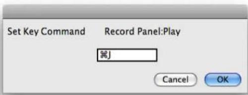
Figure A.1: Set Key Command
Type the new key sequence you would like to use and click the OK button to set the new sequence.
The following table lists all of the default key commands that can be edited:
Table A.1. Default MIO Console Key Commands
| Command Key Sequence | |
| Close All Documents | ⌘ \W (Command + Option + W) |
| Close All Floating Windows | ⌘ \W (Command + Shift + Option + W) |
| Close Front Floating Window | ⌘ \W (Command + Shift + W) |
| Enable High Power Mode (2882) | ⌘ \^P (Command + Option + Control + P) |
| Hide/Show Command Keys Window | ⌘ \^Z (Command + Option + Control + Z) |
| Reset All Meters (Clear Peaks) | ⌘D (Command + D) |
| Hide/Show Mixer Window | ⌘ = (Command + =) |
| Hide/Show Console Window | ⌘ \^C (Command + Option + Control + C) |
| Hide/Show All MIO Console Windows | ⌘ \^H (Command + Option + Control + H) |
| Toggle Graph 'Enable PlugIn Window' | ⌘ \I (Command + Shift + I) |
| Record Panel: Zoom In Channels | ⌘ ↑ (Command + ↑) |
| Record Panel: Zoom Out Channels | ⌘ ↓ (Command + ↓) |
| Record Panel: Zoom In Timeline | ⌘ ← (Command + ←) |
| Record Panel: Zoom Out Timeline | ⌘ → (Command + →) |
| Record Panel: Scroll Channels Up | \↑ (Shift + ↑) |
| Record Panel: Scroll Channels Down | \↓ (Shift + ↓) |
| Record Panel: Scroll Timeline Right | ← (Shift + ←) |
| Record Panel: Scroll Timeline Left | → (Shift + →) |
| Record Panel: Play | ※J (Command + J) |
| Record Panel: Stop | ※K (Command + K) |
| Record Panel: Record | ※L (Command + L) |
| Switch to/from Mini Controller | ※F (Command + Option + Control + F) |
| Volume Up | ※\^↑ (Command + Option + Control + ) |
| Volume Down | ※\^↓ (Command + Option + Control + ) |
| Toggle Dim | ※D (Command + Option + Control + D) |
| Toggle Mute | ※M (Command + Option + Control + M) |
| Toggle Window Visibility | ※V (Command + Option + Control + V) |
| Monitor Source Override | ※S (Command + Option + Control + S) |
| Select Monitor Source 1 | ※\1 (Command + Option + Control + 1) |
| Select Monitor Source 2 | ※\2 (Command + Option + Control + 2) |
| Select Monitor Source 3 | ※\3 (Command + Option + Control + 3) |
| Select Monitor Source 4 | ※\4 (Command + Option + Control + 4) |
| Select Monitor Source 5 | ※\5 (Command + Option + Control + 5) |
| Select Monitor Source 6 | ※\6 (Command + Option + Control + 6) |
| Select Monitor Source 7 | ※\7 (Command + Option + Control + 7) |
| Select Monitor Source 8 | ※\8 (Command + Option + Control + 8) |
| Select Monitor Output 1 | ※\1 (Command + Option + 1) |
| Select Monitor Output 2 | ※\2 (Command + Option + 2) |
| Select Monitor Output 3 | ※\3 (Command + Option + 3) |
| Select Monitor Output 4 | ※\4 (Command + Option + 4) |
| Select Monitor Output 5 | ※\5 (Command + Option + 5) |
| Select Monitor Output 6 | ※\6 (Command + Option + 6) |
| Select Monitor Output 7 | ※\7 (Command + Option + 7) |
| Select Monitor Output 8 | ※\8 (Command + Option + 8) |
| Control Surface: Select Pans | \ 1 (Shift + Option + Control 1) |
| Control Surface: Select Input Gains | \ 2 (Shift + Option + Control 2) |
| Control Surface: Select Sends | \ 3 (Shift + Option + Control 3) |
| Control Surface: Bank Down | \ 4 (Shift + Option + Control 4) |
| Control Surface: Bank Up | \ 5 (Shift + Option + Control 5) |
| Control Surface: Shift Down | \ 6 (Shift + Option + Control 6) |
| Control Surface: Shift Up | \ 7 (Shift + Option + Control 7) |
| Control Surface: Toggle Legacy Mode | \ 8 (Shift + Option + Control 8) |
Some of the key-commands depend upon whether or not you are running MIO Console in legacy mode. In Legacy Mode, there are 5 Panels in the MIO Console window, whereas if you disable legacy mode there are only 5 Panels in the MIO Console window.
Table A.2. Pane Select Key Commands in 2d Expanded Mode
| Command Key Sequence | |
| Select Pane: I/O Control | 1 (Command + 1) |
| Select Pane: +DSP | 2 (Command + 2) |
| Select Pane: Recording | 3 (Command + 3) |
Table A.3. Pane Select Key Commands in Legacy Mode
| Command Key Sequence | |
| Select Pane: I/O Control | ※1 (Command + 1) |
| Select Pane: Mixer | ※2 (Command + 2) |
| Select Pane: Routing | ※3 (Command + 3) |
| Select Pane: +DSP | ※4 (Command + 4) |
| Select Pane: Recording | ※5 (Command + 5) |
MIO Console also provides many key-commands via the menus; these commands cannot be edited:
Table A.4. Menu Key Commands
| Command Key Sequence | |
| MIO Console > Preferences | ⌘, (Command + comma) |
| MIO Console > Hide | ⌘H (Command + H) |
| MIO Console > Hide Others | ⌘ ⇌H (Command + Shift + H) |
| MIO Console > Quit | ⌘Q (Command + Q) |
| File > Open | ⌘O (Command + O) |
| File > Template | ⌘ ⇌O (Command + Shift + O) |
| File > Close | ⌘W (Command + W) |
| File > Save | ⌘S (Command + S) |
| File > Save As | ⌘ ⇌S (Command + Shift + S) |
| Edit > Undo | ⌘Z (Command + Z) |
| Edit > Redo | ⌘ ⇌Z (Command + Shift + Z) |
| Edit > Cut | ⌘X (Command + X) |
| Edit > Copy | ⌘C (Command + C) |
| Edit > Paste | ⌘V (Command + V) |
| Edit > Select All | ⌘A (Command + A) |
| Recording > Set Record Folder | ⌘T (Command + T) |
| Recording > Set Playback Folder | ⌘Y (Command + Y) |
| Recording > Recording Preferences | ⌘R (Command + R) |
| Mixer > Create New Mono Mixer Strip | ⌘ ⇌N (Command + Shift + N) |
| Mixer > Create Multiple Mixer Strips | ⌘ ⇌M (Command + Shift + M) |
| Mixer > Create New Bus | ※☆B (Command + Shift + B) |
| Mixer > Configure Mixer | ※☆C (Command + Shift + C) |
| Mixer > Create New Bus | ※☆B (Command + Shift + B) |
| Mixer > Set Color For Selected Strips | ※\C (Command + Option + C) |
| Mixer > Delete Selected Strips | ※☆D (Command + Shift + D) |
| Mixer > Channel Strip Meters Post Fader | ※☆P (Command + Shift + P) |
| Window > Show/Hide All Floating Windows | ※B (Command + B) |
B. Updating your Firmware
Introduction
The Mobile I/O is a complex device with a complex DSP-based signal processing and control architecture. One of the major strengths of Mobile I/O's design is that the operating system of the box can be upgraded at any time by updating the firmware. The firmware provides data to the hardware upon system boot that configures both fundamental aspects of the hardware and the operating system for the box. This data is stored in a memory device on the Mobile I/O motherboard. The data can be updated at any time, but it will be maintained indefinitely, even without any power being applied to the Mobile I/O.
Since the hardware itself can be reconfigured by the firmware, this approach allows Metric Halo to make major enhancements to Mobile I/O without any physical changes to the hardware. In the past we have used software deployed firmware updates to increase the FireWire access speed, provide independent headphone channels, and improve the converter sound quality over its already exceptional character.
Since the firmware updates exist simply as data, they can be sent to you in a variety of ways, whether via CD, email or download from our website. The MIO Console Application provides a built-in tool to update firmware directly from the console. The following section describes how to use the built-in tool.
You may have had the experience of updating the firmware for your computer in the past. As you may know, this can be a stressful procedure, since there is a moment while the old firmware is being replaced by the new firmware, and if the process is interrupted you may be left with no firmware at all. Metric Halo has addressed this issue with a “safe firmware update” procedure. The Mobile I/O uses a dual-boot procedure. The first boot happens in the first 100ms (about 0.1 seconds) and has been extensively tested. It is smart enough to do two things:
- It can boot the secondary boot image
- It can update the secondary boot image over the FireWire bus
Actually, the primary boot firmware is much smarter than that. The box is completely functional on the primary boot, but all of the more advanced features of the box are enabled by the second boot. The firmware revision of the primary boot is 1.1.00.
As soon as the primary boot image has booted, it checks the secondary boot image, and if the secondary boot image is installed and not corrupted in any way, the system immediately boots the secondary image. If the secondary image is corrupted or if you have held down the front-panel Mute button during the initial boot process, the Mobile I/O will not boot the secondary image and will stay in "Safety Boot Mode". This is a mechanism you can use if you install firmware that has problems and you need to back up or install a newer image.
The safe boot mechanism allows you to back out of a firmware update if you find that the new firmware has some problem that was not present in a previous version of the firmware. Metric Halo support may ask you to do this during troubleshooting if you encounter any problems.
In the future, Metric Halo may change the methods or tools used to find, download, and accomplish firmware updates. If the tools change, they will be accompanied by an updated version of this Appendix.
Installing a firmware update
In order to install a firmware update, follow these steps:
- If there is an associated driver update, install the new driver:
- Double click the driver installer package and use the Apple installer to update the MIO Driver package. This will require you to reboot your computer.
- Make sure your Mobile I/O is powered up and connected to your computer. It is strongly recommended that you turn off any amplifiers or powered speakers connected to the unit; it is possible that the MIO could produce noise during the firmware update that could damage your speakers.
- Run the MIO Console.
- Be sure that you don't have any audio apps communicating with the MIO (don't have any audio apps running during the Firmware update).
- Select "Update Firmware..." from the "Utilities" Menu. You will see the following dialog:
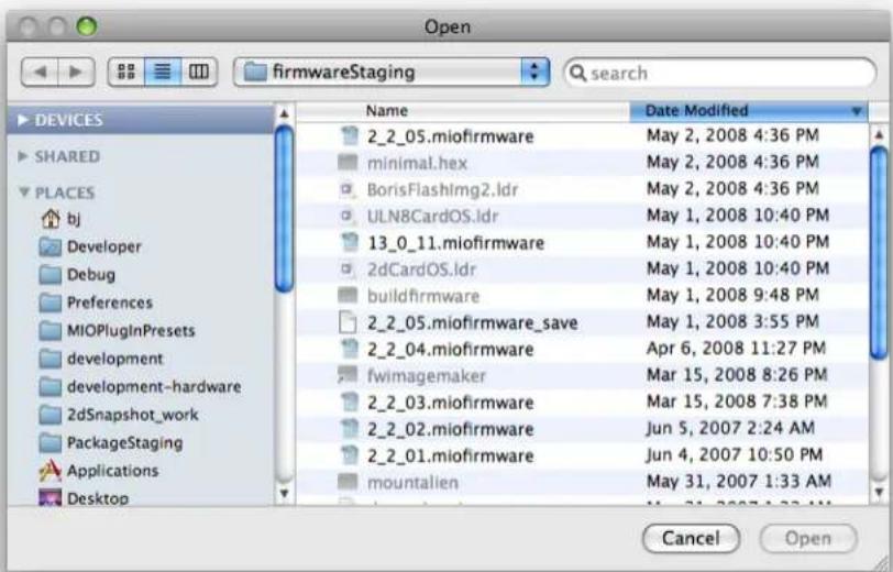
Figure B.1: Update Firmware Choose Dialog
- Select the new Firmware file to install on your Mobile I/O hardware, and click the Choose button. Firmware files will be supplied by Metric Halo with a name that contains the firmware version number in the following format:
.miofirmware Only valid firmware files will be selectable in the dialog box.
You will see this dialog:

Figure B.2: Firmware Update Warning
Once you are sure that all attached speakers and headphones are turned off or disconnected, click the "Install" button.
The Console will find your Mobile I/O on the FireWire bus and begin sending commands to it. While the update is taking place, a progress window will displayed on the screen:
Figure B.3: Update Firmware Progress Window
When the firmware update has completed, the progress window will disappear. You may see this dialog:

Figure B.4: Firmware Update Complete
If you see this message, you must follow these steps for the new firmware to be recognized:
- Disconnect the updated MIO from FireWire and all power sources for a minimum of 30 seconds.
- Reboot the MIO
-
Reconnect the MIO to the computer
-
If everything has proceeded properly, the Mobile I/O will be recognized and the new firmware version will be displayed in the "Box Info" pane in MIO Console.
- If a problem has occurred, the firmware will not be updated and/or the box will have safety booted. In this case, repeat the firmware update procedure again from step 1.
If you do not see this message, your interface has automatically rebooted and should report the new firmware version in the Console window's I/O tab.
If your interface does not appear to pass audio or MIO Console does not reconnect to your interface, you should try rebooting your Mac. (This may be required if some application is holding on to a reference to the MIO Driver and the driver is not unloaded by disconnecting the unit from the computer).
Information on troubleshooting firmware installation problems is available in the Troubleshooting Guide's firmware section.
Rolling back your firmware
If you find that you have problems with any given release, you can always go back to a previous release by downloading a package from http://www.mhlabs.com/ and following the update instructions in that package. Please do not roll back the firmware to an earlier version than was originally supplied with your unit unless instructed to do so by Metric Halo.
C. Updating the Driver
Introduction
The MIO Driver is the conduit between your interface and CoreAudio. We occasionally update the driver to provide new features, fix bugs or maintain compatibility with new Apple operating systems.
Updating the driver is a simple process, but there is a definite procedure that should be followed:
- Quit all software.
- Disconnect your interface(s) from your computer.
- Double click the driver installer package and use the Apple installer to update the MIO Driver package. You will be required to reboot your computer.
- Make sure your interfaces are powered up and connected to your computer.
- Run the MIO Console.
- Go to the I/O tab of the Console Window and confirm that the interfaces are online and that the driver version in the lower right of the window is correct.
If the MIO Console installer contains a newer version of firmware than the one installed in your interface, you may upgrade the firmware now. Instructions are available in the Updating your Firmware appendix.
D. FireWire
Overview
FireWire® is Apple's registered trademark for the IEEE 1394 High-Speed Serial Bus. FireWire started as an Apple technology to replace a variety of interface ports on the back of the computer. After promulgating a number of closed proprietary technologies in the early days of the Macintosh, Apple determined that open standards were better for the Mac, for the industry, and for Apple itself. On that basis they opened their technology for standardization under the auspices of the Institute of Electrical and Electronics Engineers, Inc. (IEEE), an international organization that promotes standards in the field of electronics. FireWire was standardized as IEEE 1394 and promoted for open licensing in the industry.
The first widespread adoption of the technology was for DV camcorders where space was at a premium and bus powering was not perceived as a real issue since all camcorders have batteries. Sony designed an alternative version of the standard 6-pin FireWire connector that provided 1394-based communication with 4-pins in a much smaller form-factor. This version of the connector sacrificed bus-power support and mechanical stability for reduced space requirements. Sony dubbed this version of IEEE 1394 "i.Link®." This became the de facto standard in the DV world, and was later added to the IEEE 1394 standard. Both i.Link and FireWire refer to the same underlying standard and are completely interoperable. Obviously, i.Link connectors and FireWire connectors cannot be used together without adapters.
Newer Macintosh computers come with a FireWire 800 connector, which is a 9-pin rectangular connector with a polarizing key. Your Metric Halo interface uses the FireWire flavor of the IEEE1394 connector with 6-pins for bus power support. The unit ships with two 9-pin to 6-pin FireWire cables, one that is 0.5 meters long (about 18 inches), and the other 4.5m (about 14.5 feet) long.
If you are using an older Macintosh computer with a FireWire 400 connector, you will need to source a 6-pin to 6-pin cable. Short 6-pin to 6-pin cable for interconnecting interfaces are available from us at MH Direct or other sources.
If you want to use the interface with a 4-pin FireWire device, you will need to purchase a 6-pin to 4-pin adapter cable. These cables are available from a wide variety of retail sources. If you are using a 4-pin cable to connect any device to the computer with the interface, bus power will not be available.
The 6-pin FireWire connector is polarized by its shape, one end of the connector is pointed. The FireWire ports on the rear panel point downwards toward the bottom of the box. It will be very difficult to insert the connector upside down, but it is possible if you force it. If the plug is inserted into the socket upside down, the socket will be destroyed.
NEVER FORCE A FIREWIRE CONNECTOR INTO A FIREWIRE SOCKET.
Devices connected to the FireWire bus are autoconfiguring. You do not need to set IDs or DIP switches or in any way configure the devices in order to facilitate communication between devices or to configure the bus.
FireWire devices on the same bus must be connected in a tree structure with no loops. This means that devices can be connected to each other in any order, and any device with multiple ports can act as a chain or a hub for other FireWire devices, but you should never be able to get from one device to another by more than one path. If you construct a loop in the bus, it will not operate properly and you will not be able access some or all of the devices on the bus.
Although you are able to attach devices in any order on the FireWire bus, the order of attachment will have an impact on performance. Most current model FireWire devices support 400 Mbs operation, but many older devices may only support 100 or 200 Mbs operation. These devices act as a bottleneck in the bus and limit the
speed of any bus traffic that flows through them. In order to maximize performance, you want to ensure that low speed devices are not used to join high speed devices. In practice this generally means that you should attach your interface directly to your computer or through a high speed hub.
To connect the interface to your computer simply plug a FireWire cable into the interface and into the computer. The FireWire bus provides a path for all communication between the computer and box – audio, control and meter data.
Metric Halo's audio transport takes advantage of FireWire's support for isochronous transmission, in which the hardware can reserve a dedicated amount of bandwidth on the bus for moving audio samples. Since the audio must be transmitted on a regular basis to ensure continuous playback and recording, the isochronous model is perfect for this task.
Control changes and meter data are transmitted using asynchronous transactions on the FireWire bus. This transmission approach makes use of the unreserved bandwidth on the bus and competes with things like FireWire hard disk accesses for time. Under normal circumstances this is completely transparent to the user. If the bus becomes overloaded, you may find that disk accesses and meter updates slow down. If you are experiencing bus overloads, you can always add a second FireWire bus with a third-party FireWire card (PC-Card or PCI card depending on your machine), and offload one or more devices to the second bus.
FireWire FAQ
There is a lot of "wisdom" on the Internet regarding FireWire and how it does (and doesn't) work. Unfortunately, much of it is incorrect and leads to a lot of confusion. Let's take a look at some common statements about FireWire:
GENERAL:
- "You can't use a FW400 device on a computer with FW800 ports." -False
All you need is a FW400 to FW800 cable or adapter. Your computer and peripherals will do the rest. - "My computer has two FW ports, so I have two FW busses." -False
Your computer has one FireWire bus and an internal hub. To have more than one FW bus you need to use a PCI card or ExpressCard expansion card. - "If I connect a FW400 device to a FW800 bus, it will slow the entire bus down to 400 Mbs." -False In a mixed speed bus, everything after the slowest device runs at the slower speed.
For example, in this FW800 chain:
![graph LR A["computer"] <--> B["FW800 FW400 FW800 host FW800 device"] B <--> C["FW400 device"]](/content/2026/05/884165/images/f13498aa945471f823f8bf2019533cff60e54468b346d8fd34723cdc3689fed6.jpg)
Figure D.1: Correctly Mixed FW800/400 Chain
The FW800 device communicates with the computer at 800 Mbs, and the FW400 device communicates at 400 Mbs. However, in this chain:
![graph LR A["computer"] <--> B["FW400 device"] B <--> C["FW400FW800 device"] C <--> D["FW800 device"]](/content/2026/05/884165/images/eaf1c3b8a607efb386b126d77c2233a627805e04d896eaf6f8d2f6ec28f75a6a.jpg)
Figure D.2: Incorrectly Mixed FW800/400 Chain
The FW800 device's speed is reduced to 400 Mbs, since the slower device is connected between it and the computer.
If you keep the FW800 connections together those devices will run at 800 Mbs regardless of whether there are FW400 devices in the chain. If you intermix FW800 and FW400 devices, you will lose bus speed on any FW800 device connected after a FW400 device.
- "Using a FW hub will speed up my connection." -Not exactly...
A hub won't speed up your FW bus, but will allow all devices connected to it to run at their maximum speed. If a FW800 hub is connected to the computer with a FW800 cable, then all the FW800 connections to the hub will run at 800 Mbs, and all FW400 connections will run at 400 Mbs. The connection between the computer and the hub will switch between 800 Mbs and 400 Mbs on a per-packet basis depending on the speed of the source or destination of the packet (source for inbound to the computer, destination for outbound from the computer).
![graph TD A["FW800 host computer"] -->|FW800| B["FW800 hub"] B -->|FW400| C["FW400 device"] B -->|FW800| D["FW800 device"]](/content/2026/05/884165/images/097cc2a6eeca3db91764eb0a3445bd767f3c94bf64a7d83d26dc584e2df92359.jpg)
Figure D.3: Using a Hub in a Mixed Speed Chain
The other advantages of a hub are:
- External hubs usually provide power isolation, so bad cables or faulty devices can't damage your computer's or device's FW ports.
- Easier patching; you don't have to shut down an entire FW chain to unpatch or shut off a device in the middle.
METRIC HALO SPECIFIC:
- "How many boxes can I use on one FireWire bus?"
This depends on the sample rate you're working in. You can currently use three interfaces on one bus at 44.1-48 kHz, and two at 88.2-192 kHz. -
"Can I attach hard drives or more interfaces to the second FireWire port on my MIO?"
Yes, with two things to remember: -
Remember the rules about connecting FW800 and FW400 devices on the same bus.
-
If you're recording at high track counts or sample rates, you may need to connect your hard drive to another bus (or another type of bus, like SATA).
- "I can't expand my Mac, so I can't add another FW bus or SATA bus. How can I work with high track counts?"
Try using a USB 2 drive. While you want FireWire's isochronous transfers to get audio into your computer, asynchronous transfers to your hard drive are fine. If you are having dropouts, noise or other problems in your audio chain with your interface and drive on the same bus, try connecting the hard drive via USB to lighten the load on your FW bus. Even if you decide not to use the USB drive full time, this is a good troubleshooting tool.
E. CoreAudio
About CoreAudio™ Technology
CoreAudio is Apple® Computer's technology standard for interfacing applications to multichannel audio hardware with professional quality. Apple defined the standard and made it the primary interface for audio in OS X. It provides the mechanism for making high-resolution, multi-channel, low-latency connections between audio hardware and audio applications on Mac OS X.
All Mac OS X computer applications provide support for communicating with audio hardware via CoreAudio. As such, it was the natural standard for Metric Halo to support for interfacing with Mobile I/O. Applications (programs) that communicate with hardware via CoreAudio drivers are called CoreAudio Hosts.
The CoreAudio standard is quite rich and provides a number of places where host applications may or may not properly support the specification. There are some hosts that were implemented early that did not get support for multichannel/multistream devices implemented correctly. Most of these hosts have been fixed or are in the process of being fixed now. If you encounter any problems with specific hosts, please let us know about it – but also please let the host vendor know about it. CoreAudio puts many more requirements on hosts than it does on drivers, so it is very likely that any such problems are in the host.
Metric Halo has done extensive testing with the major CoreAudio hosts, and some of the minor ones, and has worked to ensure maximum compatibility with all hosts. Even if you are using a host that is not specifically discussed here, you are unlikely to encounter problems. If you do, please file a bug report with both Metric Halo and the developer of the CoreAudio host. Please send bug reports to support at mhsecure.com with the subject MIOBUG Report.
How The CoreAudio Driver Works
The Mobile I/O CoreAudio driver is provided by Mac OS X KEXT. The KEXT is a Mac OS X kernel extension. This extension enhances the Mac OS operating system to provide support for communicating with the Mobile I/O hardware. The Mobile I/O driver is implemented as a KEXT due to the requirements of CoreAudio.
The KEXT is provided in a Mac OS X bundle called "MobilelODriver.kext". This bundle is installed in the / System/Library/Extensions folder. Since this folder is managed by the system, you will have to have administrator access on the computer to install the driver.
The CoreAudio driver provides the required information for CoreAudio to discover and control Mobile I/O. Once the driver has been installed, CoreAudio will automatically find Mobile I/O units as they are attached to the computer and will publish the availability of the hardware to all interested CoreAudio hosts.
CoreAudio is inherently a multiclient interface — more than one CoreAudio host can communicate with the hardware at the same time. Multiple hosts can receive the audio from a Mobile I/O at the same time, and multiple hosts can send audio to the Mobile I/O at the same time. When multiple hosts send audio to the hardware at the same time, CoreAudio will automatically mix the audio before it is sent to the Mobile I/O.
While this multiclient operation is a very cool feature of CoreAudio, and can be very helpful for many operations, you must be careful about unintended interactions. In particular, it is very easy to set up the system such that sounds from programs like email clients and other productivity tools will be mixed into your main audio stream (this happens when you set up the default audio output path so that you can use iTunes with the Mobile I/O). If you are not careful, you can check your mail and have the "Mail received" sound printed into the bounce that you are doing in the background.
CoreAudio Transport And Sample Rates
CoreAudio supports a wide variety of audio transport standards. As a practical matter, CoreAudio supports multichannel transport of 24 bit audio via floating point streams at virtually any sample rate. Many hosts only
support a small number of sample rates and may not support all of the sample rates that are available with the Mobile I/O hardware.
Channel Names
CoreAudio provides a mechanism for the driver to tell the host the names of the channels. Some hosts do not use this information and "make up" their own names for the channels. This mechanism is not dynamic, so the Mobile I/O driver cannot update the host's names as you adjust the Output Patchbay router or mixer channel assignments.
In v.5 the driver reports stream names to the CoreAudio host for both input and output. Since all I/O in the Mobile I/O is routed by you, you can refer to the names in your application and in MIO Console — they will match. Inputs are called FW 01, FW 02, ..., FW 18, and outputs are called DAW 01, DAW 02, ..., DAW 18.
Channel Enables
CoreAudio supports enabling and disabling audio streams. This is a relatively new feature of CoreAudio, and many hosts do not yet support it. It is not clear exactly how the user would control this functionality at this time. For applications that provide manual control over enabled channels, you will get the best performance if you only enable the channels you need. For applications that automatically maintain the enabled channels, you will get the best performance if you only assign channels to outputs you really want to use, and only record enable channels that you intend to record on.
CoreAudio Buffers
Audio channels are transported individually to the host in buffer sized chunks. The size of the audio buffers has an effect on the CPU load of the audio application, as well as the round-trip latency from input to output when the audio is routed through the host application for monitoring or processing.
Generally, the CPU load increases as the buffer size decreases. On the other hand, the latency decreases as the buffer size decreases.
Since, in general, you want the lowest CPU load and the lowest latency, you will have to make trade-offs.
The mixer engine in Mobile I/O helps substantially with this issue, because for the common critical monitoring configuration (monitoring while tracking external sources), the Mobile I/O mixer removes all of the computer transport latency from the monitor path and allows you to decouple the latency from the buffer size.
In the case that you are trying to perform with a softsynth running in your host, Mobile I/O's mixer does not help decrease the latency since the signal is being generated on the computer. In this case you'll want to minimize the output latency by selecting the smallest CoreAudio buffer size possible. This will depend on your computer hardware, the amount of processing you are doing, and the CoreAudio host you use. The MIO CoreAudio driver has been optimized to support extremely small buffer sizes (down to 32 samples on Intel-based HW) and best-in-industry safety offsets.
Setting The CoreAudio Buffer Size
The methods used to set the CoreAudio buffer size will vary from host to host. Some CoreAudio hosts provide direct controls for adjusting the buffer size and others do not. If your host does not support setting the buffer size directly, you will have to use the host's default buffer size.
Sample Size
The Mobile I/O CoreAudio driver provides the CoreAudio host with 24-bit samples in 32-bit floating point streams. It is the responsibility of the host to dither the incoming audio to 16-bit samples before recording them, if you record 16-bit. If the host does not dither the samples to 16-bit, they will be truncated by the host when they are recorded. For best recording quality, use your host's 24-bit recording option.
Clock Sources
The CoreAudio specification provides the capability for hosts to control the hardware clock source. Some hosts provide a user interface to do this, others do not. If the host does provide an interface to do this, you will be able to select one of the Mobile I/O external clock sources directly from the host. If the host does not provide an interface, you will need to use the MIO Console to select the external clock source. If you have selected an external clock source using either the host or the console, you will not be able to control the system sample rate from the computer. MIO Console will automatically reflect the clock source and sample rate set by the host.
F. Troubleshooting Guide
COMPUTER DOES NOT SEE MOBILE I/O
If you attach Mobile I/O to your computer, and the computer is unable to communicate with the Mobile I/O hardware there are five basic possibilities for the source of the problem:
- The Mobile I/O is not powered up
- The Software is not installed properly
- The FireWire bus did not reset correctly
- The FireWire cable is not connected or bad
- The FireWire hardware has been damaged
MOBILE I/O IS NOT POWERED UP
The first thing to check is that the Mobile I/O is, in fact, powered up.
If Mobile I/O is powered up and booted properly, the Power, Sample Rate, and Locked front panel indicators will be illuminated. If these indicators are not illuminated, the Mobile I/O is not powered properly or the unit's firmware has been corrupted. If you determine that you are powering Mobile I/O properly and the indicators are not illuminated, you will need to contact Metric Halo support.
If you are bus powering the Mobile I/O, there is a possibility that you have overloaded the power rating of the power source. Please see the troubleshooting section "Not enough power on the Bus" for details on troubleshooting this problem.
If the Mobile I/O is properly powered, then check the next possibility.
SOFTWARE IS NOT INSTALLED PROPERLY
In order for the computer to properly communicate with the Mobile I/O, the various components of the driver software need to be installed correctly. If the software is not installed correctly, the communication between the computer and Mobile I/O will fail in various ways. If the MobileIODriver.kext is not properly installed in the /System/Library/Extensions folder of your computer, you will not be able to use the Mobile I/O for audio and you will not be able to control the sample rate or clock source of the Mobile I/O with the computer.
- The symptom of this is that the Front Panel FireWire indicator is illuminated, but the Mobile I/O does not appear as a Sound Output device in the Sound panel of the "System Preferences" application, nor does it appear in the Apple Audio/MIDI Setup Application.
- To correct this condition, make sure the MobileLODriver.kext file is installed correctly, reboot and then reconnect the Mobile I/O to the computer. If the software is installed properly, check the next possibility.
THE FIREWIRE BUS DID NOT RESET CORRECTLY
When a device is plugged into the FireWire bus, a FireWire bus reset occurs automatically. The bus reset interrupts bus activity and reconfigures the bus so that all devices on the bus become aware of all the other devices on the bus. Sometimes the reset does not complete successfully, and the bus becomes partially hung. In this case, the "FireWire" indicator on the front panel of the Mobile I/O will not be illuminated. When the "FireWire" indicator on the front panel is not illuminated, the Mobile I/O cannot transport audio over the FireWire bus.
Generally, this condition can be fixed by disconnecting the Mobile I/O from the bus and reconnecting it.
If the disconnect/reconnect cycle does not fix the problem, another device on the bus may be interfering with the proper operation of the bus. If you have other devices on the bus, try disconnecting them from the bus and only using the Mobile I/O.
If removing other devices from the bus solves the problem, it is likely that there is a problem with either one of the devices you removed or with one of the cables connecting the devices. You'll need to isolate the problem component.
If removing the other devices from the bus does not fix the problem, check the next possibility.
THE FIREWIRE CABLE IS NOT CONNECTED OR BAD
Check the simple thing first; is the unit connected? If the FireWire status LED on the front panel is not on and/or there is no information listed in the Box Info pane in MIO Console, confirm that the FireWire cable is plugged in firmly at both ends.
Metric Halo provides two high-quality overspec'ed FireWire cables for use with Mobile I/O and we recommend you use them. For various reasons you may decide to use other cables than the ones provided by Metric Halo. Under ideal circumstances all FireWire cables will provide years of service. However, cables will and do go bad. Cable failures can be difficult to track down. If you are experiencing problems with connecting or bus powering Mobile I/O you should try swapping the cable with another known-good cable.
If the FireWire cable is not the source of the problem, check the next possibility.
THE FIREWIRE HARDWARE HAS BEEN DAMAGED
If all else fails, it may be that the FireWire hardware on either the Mobile I/O or the computer has been damaged. While this is an exceptionally rare occurrence, it is a possibility. The FireWire hardware can be damaged in the following ways:
- If you insert a FireWire cable into a port upside down, it will damage the FireWire port and/or the connector. It is difficult to insert the connector upside down, but it is possible to force it. Never force a FireWire connector!
- It requires significant pressure, but it is possible to force a FireWire connector over a male XLR connector pin. If you do this, the connector will be shorted and it will destroy the port on the other end. Again, never force a FireWire connector.
- Some devices that are bus-powerable and conform to the IEEE1394 standard will return power to the remote FireWire port if a power ground fault occurs. If the remote port is protected against this situation, nothing will happen. If the device does not use bus power, nothing will happen. But, if the device is fully compliant, uses bus power, and the remote device is not protected and supplies a high enough voltage on the bus, the remote device port will self-destruct.
If the FireWire hardware on the computer has been damaged, it will not communicate with any FireWire devices. Be sure that you are not checking this case with a bad cable, as a bad cable can make it seem like the FireWire hardware has failed since it will consistently keep devices from connecting properly to the computer. If the computer is damaged, you will need to contact the manufacturer for a repair or, as a stopgap measure, you can use a third-party FireWire adapter card. Metric Halo also recommends the use of a third party FireWire hub between the computer and any FireWire devices. Any potential issues will damage the hub, not the computer, saving time and money in the long run.
If the FireWire hardware on the Mobile I/O has been damaged the MIO will not communicate with any other devices. In this case, please contact Metric Halo support for help in getting your Mobile I/O hardware repaired.
NO OUTPUT FROM MOBILE I/O
If the output meters of your interface show activity but you hear no audio, you can reset the outputs of a single box or all connected boxes from MIO Console's Utilities menu:

Figure F.1: Utilities Menu
MISSING METERS IN MIO CONSOLE
There is a limit in the 2d card that only the first seven busses in MIO Console have active metering. If you create and eighth bus (or more), they will pass audio but will not have active meters.
COULD NOT INSTANTIATE PLUG-IN
If you see the following dialog in MIO Console:

Figure F.2: 2d Out of Memory
This means that you are trying to exceed the memory of your interface, which is used for delays and reverbs. The memory available is separate from the DSP available, and will change greatly due to the sample rate of the interface and the plug-ins in use.
DIGITAL DISTORTION
If your interface passes audio but there is distortion or other audible artifacts, check the DSP Usage in the Box Info area of the Console window. If this value is over 100%, you are overloading the DSP. Try removing some plug-ins, graphs, or busses to lower the DSP load.
INTERFACE HAS CRASHED
If your interface becomes non-responsive or stops passing audio, you can try to reboot one or all attached interfaces by using the "Reboot Current MIO" and "Reboot All MIOs" commands in the Utilities menu. If this does not work, you will have to cycle power on the unit.
CORRUPTED BOOTSTATE
If your interface does not function properly when:
• Used standalone (not connected to a computer)
- Connected to a computer but MIO Console is NOT RUNNING
You may have a corrupted bootstate or snapshot stored in the interface's internal memory. To clear the stored states go to MIO Console's Console window and select the box tab for the problem unit, then select "Erase All States on Current Box..." in the Utility menu. This will erase the bootstate and all stored presets from the flash memory. Turn off the interface, then turn it back on and confirm that the unit is working properly.
If the unit is still not operating properly, please contact MH Support.
CORRUPTED CONSOLE STATE
If your interface does not function properly when connected to a computer and MIO Console is RUNNING, you may have a corrupted console state file.
Removing a corrupted state file
Make sure MIO Console is not running, then open a Finder window and go to /Library/Preferences in your user folder. Delete any files with "MIOConsoleStatev2" in the name. In the MIO Console Preferences folder, delete the "MIO Console State" file. This will clear the stored information from MIO Console.
LICENSE REINSTALLATION
Under extreme circumstances, MH Support may need to erase the flash memory in your interface to fix other issues; erasing the flash will erase any installed licenses in the interface. To reinstall your licenses, make sure that your computer is connected to the internet and the effected interface is connected to the computer and is on. Launch MIO Console, and select "Manage Licenses..." from the MIO Console menu.
In the License Management window, click the oblong button in the upper right corner to disclose the "Refresh Status" and "Reload Licenses" buttons. First click the "Refresh Status" button to make MIO Console confirm your license status with Metric Halo, then click the "Reload Licenses" button to reinstall your licenses back into the interface.
GROUND LOOPS
Audio systems, in general, are susceptible to ground loop problems. Digital Audio Interfaces for computers are even more susceptible to grounding issues since they must interface with the computer's system ground, which tends to be much more dirty than the ground used by audio gear. By taking care when you connect the various components of your audio system you can avoid the hums, buzzes, and noises that characterize ground loops and other grounding problems.
First of all, most grounding issues go away if you utilize balanced interconnects between your audio gear. Balanced interconnects inherently reject ground differentials and common mode interference introduced by
grounding problems. Balanced connections are not much more expensive than unbalanced connections and solve so many problems that if both ends of the connection support balanced interconnect, you should not even consider using unbalanced cables.
You may get the idea that we hate unbalanced connections. You're right. We do. You should too.
If you have to use unbalanced connections, or if any ground-related problems remain, you will find that the key to the issue is ensuring that you have a common hard ground between all the gear that you are interfacing. This is commonly referred to as a technical ground. A technical ground is characterized by a consistent low impedance path between each device and a common reference ground, ideally connected directly to earth ground. The above is sometimes difficult due to electrical wiring problems in the house, studio, or stage you are using. In the extreme case, you may need to hire a qualified electrician to untangle and correct electrical service problems in your working environment.
Unbalanced connections are a fact of life when interfacing with guitar amps, and, paradoxically, guitar amps are extremely sensitive to grounding issues since they use so much gain to achieve the effect of a "Guitar Amp". If you will be interfacing with guitars and guitar amps, you need to be very careful about grounding.
Common electrical wiring approaches to residential installations, and sub-par studio and stage installations use daisy-chained grounds for ease of installation and economy. Unfortunately, daisy-chained grounds can introduce significant ground differentials between sockets, and these differentials can vary depending on other loads (like refrigerators, TV's and other household appliances) on the circuit.
Other problems with electrical service installations are improper wiring of power phases to the three-phase service and improper connections between the safety ground and hot legs of the three-phase service. These types of problems tend to be characterized by loud 60Hz hums in the audio system. Unfortunately, these types of problems extend well beyond noise in your audio system to genuine safety hazards. If you determine that your electrical wiring has problems beyond a simple daisy-chained ground, you should consult a licensed electrician immediately, as ignoring these problems can damage either you or your gear.
If you do not have a well implemented technical ground, you will want to ensure that all of the devices in your audio system are plugged into the same phase and same ground. You can generally accomplish this by running all your gear off of the same socket (using a power strip or power conditioner) if your gear uses less power than is supplied by a single circuit from your premises' wiring (generally 10-15 amps in residential installations and 20 amps in commercial installations).
It is usually a bad idea to put some devices in your system on a power conditioner and other devices on a separate strip, socket or conditioner, unless you have a technical ground. The power conditioner can introduce a ground differential.
The power supply provided with Mac laptops does not have a hard ground. This means that if the laptop is plugged in, it will dump high frequency buzz into the ground. That ground is shared with the Mobile I/O FireWire cable. If Mobile I/O will be connected unbalanced to other audio gear, the ground buzz can contaminate the signal if the Mobile I/O is not hard-grounded to the same ground as your other audio gear. To hard ground the Mobile I/O you will need to use a 3-pin power cable on the Mobile I/O power supply and power the Mobile I/O with the power supply. Plug the 3-pin IEC power cable into the same circuit and same ground as your other gear.
On the other hand, if you are encountering ground loop problems while operating with the Mobile I/O's power supply, you may find that lifting the Mobile I/O's ground resolves the problem. This can be accomplished by using a 2-Pin IEC cable (without the third ground pin), or by using a ground lift block (generally available in hardware stores, also known as a 3 pin to 2 pin converter). In general, it is better to resolve the fundamental grounding problems in your system, but this is a quick fix that may help. There are no hard and fast rules for solving this type of problem other than fixing the fundamental grounding issues, so if you go this route, you will have to experiment with lifting various grounds in your system until you find the magic combination. Or switch to balanced interconnects.
Finally, the Apple Cinema Display has a known issue with its backlight dimmer. If you run the Apple Cinema Display with its backlight at anything other than full brightness, the backlight dimmer will introduce a midrange buzz into the system ground which will appear in unbalanced interconnects (input and output) with Mobile I/O. This issue affects other devices that connect to the computer's system ground. The work around is to run the display at full brightness, or use balanced interconnects.
FIRMWARE UPDATE PROBLEMS
Details on updating the firmware of Mobile I/O are available in the Updating Firmware appendix.
It is possible for firmware updates to "not take". This appears to be related to DSP loading issues in the Mobile I/O, other devices on the FireWire bus, and the state of the FireWire system software on the Mac. If you have problems with updating the firmware, try the following procedure:
- Remove all devices from the FireWire bus
- If your Mobile I/O is using external power, disconnect the power
- Reboot your computer
- Attach the external power supply to the Mobile I/O while holding down the front panel Mute button; this will boot the Mobile I/O into the safety boot firmware
- Connect the Mobile I/O to your computer
- Run the firmware updater
Since Mobile I/O implements safe-boot and safe firmware update, you should always be able to use this procedure to update the firmware, even if something goes horribly wrong (like losing power during an update).
BUS POWERING MOBILE I/O
ULN-8 and LIO-8 owners:
It is not possible to power the ULN-8 or LIO-8 via FireWire bus power.
If you are bus powering the Mobile I/O, there is a possibility that you have overloaded the power rating of the power source.
NOT ENOUGH POWER ON THE BUS
While all Macintosh computers with built-in FireWire supply bus power, some models do not provide enough power on the bus to power Mobile I/O. If this is the case, you will generally find that the Mobile I/O will boot on initial connection, but will then lose power or will reboot repeatedly after a short period of operation.
Newer Intel Macs have implemented an in-rush current limit circuit breaker that may trigger when powering a Mobile I/O unit. This will prevent the computer from booting the unit, but not from powering it. So you can use an external supply or battery to get the unit powered up and then use the computer's bus power to provide power to the Mobile I/O.
Some Mac models provide enough power if they are plugged into the wall, but will not provide enough power while running on batteries. If the computer does not provide enough power, you will need to use an external power source with Mobile I/O.
The external power supply provided with Mobile I/O is the perfect solution if you are using Mobile I/O in an environment where ac power is available. The external power supply will actually provide power to the bus and can be user to power other bus-powered peripherals (see other bus powered devices).
If AC power is not available, you will need to use an external battery-based power source to power Mobile I/O. Any source that provides 9V-30V and can support 12-15W of power consumption will work well with Mobile I/O. Check with Metric Halo for specific recommendations.
When using an external battery source, DO power Mobile I/O directly from the battery – not through an inverter. DON'T power the computer with an external battery and use the computer to power Mobile I/O; doing so will not resolve your bus power problems, and it will give you more limited run times. If you need to use the external battery with the computer use two batteries or split the DC supply at the battery and power both the Mobile I/O and the computer.
OTHER BUS POWERED DEVICES
Mobile I/O consumes enough power that it is very unlikely that you will be able to successfully bus power Mobile I/O and any other bus-powered device (except for a hub) from the same computer. If you plan on using other bus-powerable devices with your computer, you will need to either self- power your other devices or self-power the Mobile I/O. It is probably best to use the Mobile I/O's power supply in this situation since Mobile I/O will then provide approximately 30 Watts of power to the bus (roughly 3x what most Portable Mac's will supply). This will allow you to power all the rest of your devices without any concern of running out of power.
G. DB25 Pinouts

Analog Input DB-25

Analog Output DB-25
Figure G.1: Analog DB25 pinouts
Common wiring pinouts:
XLR:
- HOT: Pin 2
- COLD: Pin 3
• GND: Pin 1
TRS:
- HOT: Tip
• COLD: Ring
• GND: Shield
TS (unbalanced 1/4"):
- HOT: Tip
• COLD: Do not connect
• GND: Shield
RCA:
- HOT: Pin
• COLD: Do not connect
• GND: Barrel

Figure G.2: AES I/O DB25 pinouts
Wiring pinout for XLR:
- HOT: Pin 2
- COLD: Pin 3
- GND: Pin 1
Table G.1. AES crossover cable pinout
| DB25 #1 DB25 #2 | |
| 24 18 | |
| 12 | 6 |
| 25 19 | |
| 10 | 4 |
| 23 17 | |
| 11 | 5 |
| 21 15 | |
| 9 | 3 |
| 22 16 | |
| 7 | 1 |
| 20 14 | |
| 8 | 2 |
H. ULN-8/LIO-8 Jumper Settings
Overview
There are a number of settings that can be configured in the ULN-8 and LIO-8 using jumpers. We'll detail them here.
To access the ULN-8/LIO-8 configuration jumpers:
- Remove the six screws from the top of the case:
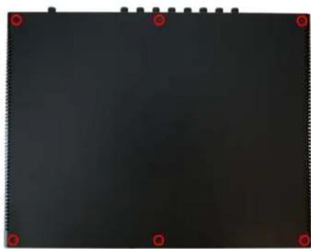
Figure H.1: Top Screw Placement
- Remove the screws from the left and right sides of the case. If the rack ears are fitted, there will be five screws per side. Please note that the screws on the rack ears are longer than the others. Be sure to put the longer screws back in the rack ears when you reassemble the LIO-8.

Figure H.2: Side Screw Placement, with Rack Ear
If the rack ears are not fitted, there will be three screws per side.

Figure H.3: Side Screw Placement, No Rack Ear
Remove the top cover, and rotate the unit so that the rear panel is facing you.
Reassembly is the reverse.
D.I. Board
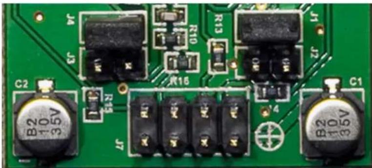
Figure H.4: D.I. Board Jumper Sites
There are 4 pairs of pin headers on the DI board mounted to the front panel, two pair per channel. The pair of pins closest to the TRS connectors (for each channel) is the low gain set. The pair closest to the ribbon cable is the high gain set.
When installing a jumper, it should be within the white box next to the jumper label, not connecting adjacent jumpers.
Table H.1. D.I. board gain settings
Line input grounding
The shield on the line inputs can be lifted on a per-channel basis. These jumpers can be accessed directly on the LIO-8; to access them on the ULN-8 (or LIO-8 with mic pres) you must remove the mic pre(s) and connector board. These jumpers are located on the connector board at the rear of the interface, directly behind the Line input connector. The channels start with input 1 on J1 and go the right, ending with channel 8 on J18.
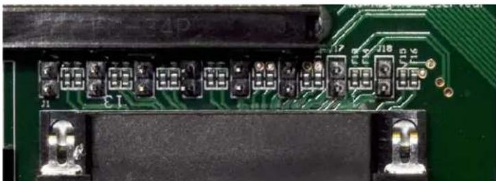
Figure H.5: Shield Lift Jumper Sites
By removing the jumpers, you disconnect the shield from the connected input. Having the jumper installed connects the shield to the ground of the interface.
Connecting unbalanced sources
It has been our experience that it is best to have the ground jumpers installed when connecting unbalanced sources to the line inputs.
Output levels
Jumpers can be installed to raise the operating output level of the analog outputs. There are a few reasons why they are not installed by default:
- The factory configuration of the ULN-8 Line outputs is +18 dBu, which is a very common level for interfacing with a large majority of existing gear.
- The noise performance is better optimized when the outputs are set to Monitor mode when interfacing with powered monitors.
• The box runs cooler and uses less power.
- The jumpers can always be applied to raise the outputs to +24 dBu, for a chain that is optimized at this operating level (i.e. chains at many mastering studios). At this level, 0 VU = -20dBFS.
Front

Rear
Figure H.6: Output Level Jumper Sites
These jumpers are located on the largest circuit board, in line with the Line/Monitor output connector. In the diagram above, the channels are in the following order from left to right: 2 1 4 3 6 5 8 7. In each case, J11 corresponds to the even (right) channel of the pair, and J8 corresponds to the odd (left) channel of the pair.
Setting the output level jumpers
To increase the output levels, install the jumpers on the sites toward the front of the unit.
Do not install jumpers to the sites closest toward the rear panel.
You must also install jumper J2 on the power supply board.
The jumpers must run from front to rear, not side to side. Unless you have a very specific reason all jumpers should either be removed or present, not intermixed. The difference in output level could lead to confusion.
Power supply
There are three jumpers on the power supply board:
• J9 disables the power supply for the preamps
• J8 disables the phantom power supply
These should both be installed if no preamps are installed. They must be removed if any preamps are installed.
- J7 bypasses the front panel power switch. Installing a jumper at this site will provide constant power from the 4 pin XLR power jack.
- J2 enables high power mode. It must be installed if any of the output jumpers are installed.

Figure H.7: PSU Jumper Sites
I. ULN-R Installation Guide
ULN-R Parts and Tools
The ULN-R Mic Pre (Ch. 1-4) kit includes the following parts:
• 1) DB25 connector board

Figure I.1: DB25 Connector Board
• 1) 4 channel ULN-R mic pre board

Figure 1.2: 4 Channel ULN-R Mic Pre Board
• 1) 3 pin phantom power cable

Figure 1.3: 3 Pin Phantom Power Cable
• 1) 20 Pin Ribbon Cable Jumper
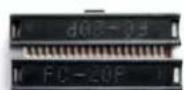
Figure 1.4: 20 Pin Ribbon Cable Jumper
• 2) 7/16" standoffs

Figure I.5: 7/16" Standoffs
• 3) Phillips head screws
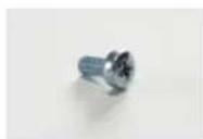
Figure 1.6: Phillips Head Screw
The ULN-R Mic Pre (Ch. 5-8) kit includes the following parts:
• 1) 4 channel ULN-R mic pre board
• 1) 20 pin ribbon cable jumper
• 4) Phillips head screws
The Ch. 1-4 kit must be installed for the Ch 5-8 kit to function!
To install the ULN-R mic pre option in the LIO-8 you will need:
• #1 Phillips screwdriver
- 7/16" nutdriver (Ch. 1-4 kit only)
- silicone caulk
Please familiarize yourself with the parts and instructions before opening the LIO-8.
Be sure to discharge any static energy on your body before touching the interior of the LIO-8.
Installing the mic pres:
- Remove the six screws from the top of the case:

Figure I.7: Top Screw Placement
- Remove the screws from the left and right sides of the case. If the rack ears are fitted, there will be five screws per side. Please note that the screws on the rack ears are longer than the others. Be sure to put the longer screws back in the rack ears when you reassemble the LIO-8.

Figure 1.8: Side Screw Placement, with Rack Ear
If the rack ears are not fitted, there will be three screws per side.

Figure 1.9: Side Screw Placement, No Rack Ear
Remove the top cover, and rotate the unit so that the rear panel is facing you. If you are installing the Ch. 5-8 kit only, jump to step 9.
- Remove the two screws holding the Mic In cover plate, then remove the plate from inside the LIO-8.
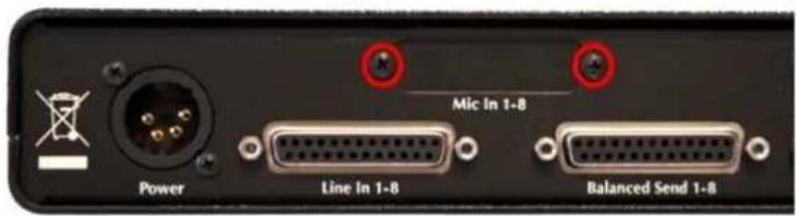
Figure I.10: Mic In Blank Plate
- Put the DB25 connector board into the LIO-8 so that the connector comes through the hole that you just uncovered. Put the two 7/16" standoffs through the rear panel and screw them into the DB25 connector.

Figure I.11: DB25 Connector Board Fitted
- Use a Phillips head screw to secure the connector board to the standoff below it and put a dab of silicone caulk on the screw to hold it in place. Next, make sure that connector J5 is bent out at a slight angle; this is to ensure that the phantom power cable will clear the top cover.

Figure I.12: DB25 Connector Board (Interior)
- Remove the jumpers from J8 and J9 on the power supply board at the front of the LIO:
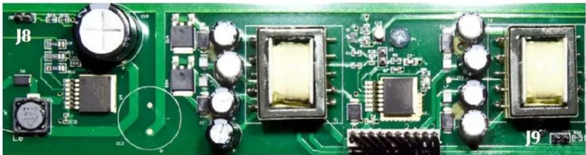
Figure I.13: Phantom Power Jumpers on the PSU Board
- Connect the phantom power cable between connector J5 on the DB25 connector board to connector J5 on the power supply board at the front of the LIO:
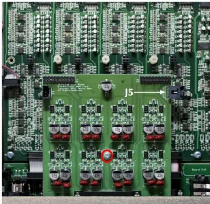
Figure I.14: Phantom Supply Cable and Ch. 1-4 Connectors
- Install the mic pre board, making sure that the pins on the bottom of the board line up with the sockets highlighted in the picture above. You must install the channel 1-4 board in this position. Use two Phillips head screws to secure the mic pre board and dab them with caulk. Fit the ribbon cable jumper between the mic pre and DB25 connector board, making sure that the pins are lined up.

Figure I.15: Installing the Ch. 1-4 Mic Pre Board
- If you are installing the channel 5-8 mic pre kit, install it in the sockets next to the channel 1-4 board, making sure the pins are properly seated. Use four Phillips head screws to secure the mic pre board and dab them with caulk. Fit the ribbon cable jumper between the mic pre and DB25 connector board, making sure that the pins are lined up.

Figure I.16: Installing the Ch. 5-8 Mic Pre Board
The installation is finished! Replace the top cover, and replace the six crews on the top of the case. Then replace the screws on the left and right side, remembering to use the longer screws on the rack ears. It sometimes helps to squeeze the top and bottom of the case together when replacing the side screws, to ensure that the outer holes line up with the threaded inserts.
Once you have reassembled the unit, connect it to your computer and power it up. When looking at an Analog input in MIO Console, you will now have the "Mic" and "Mic S/R" selections as input choices, as well as phantom power control.
If you have any questions about the installation process, contact support@mhlabs.com.
J. Support Resources
Metric Halo has several resources to help you; if you have questions that aren't answered in this document, we have further materials online:
• Our FAO: http://www.mhsecure.com/faq
- Our technote and tutorial library: http://mhsecure.com/metric_halo/support/tutorials.html
You may also consider joining our user email list, where you may ask questions of other users. You can subscribe to the list at https://mail.music.vt.edu/mailman/listinfo/mobileio.
If you still have questions or are experiencing problems with your interface, you can open a support ticket online at https://www.mhsecure.com/support.
K. Changelog
v5.6.01:
Changes:
- Added ConsoleSync "On Launch" behaviors to MIO Console preferences
- Added ConsoleSync preferences to MIO Console preferences
- Added ConsoleConnect support for 64 bit VST hosts
- Enabled Retina support for MIO Console
- Updated firmware version to 5.0.44
Bugfixes:
- Fixed a bug where the I/O insert routing was not correctly updated
- Fixed a bug where the I/O insert could not be instantiated on an aux bus
- Fixed a crash where the +DSP noise generator plug-in would stop output if the interface's sample rate changed
- Fixed a crash when loading factory default mixer for an unknown box type
- Fixed grunge that occurs on some hardware with ConsoleSync
- Protect against a crash when we have a failed instantiation on change of width of mixer strip
- Disable trying to load the DSP Load percentage from an offline box
- Properly track output path settings so that console does not offset the trim on outputs when loading back from hardware
- Reset Analog I/O configuration and refresh MIO Console window when loading Factory Default state
- Fix corruption of HW gains by Monitor Controller when box state is preloaded from prefs state and then is loaded back from HW via ConsoleSync
- Ensure that MIO Console respects eLoadLastStateWithoutConsoleSync when the hardware is in the Factory Default state
• Workaround for failed flash update when hardware sees stuck bits in DRAM - Fix crash that could occur if no box is selected in MIO Console Window
- Select newly discovered box in MIO Console window if there are were no boxes in the system
- Update compatibility version number of boot-states in firmware
v5.6:
Changes:
- Added I/O insert to the Mixer
- Added ConsoleSync (console synchronization engine)
- Added factory default auto-load for when there is no box state on the computer
- Added box merging in the Mixer when a box is added and there is no data for it in the state on the computer
- Added "Save System Boot State (all boxes)" command
- Added "Channel Strip Meters Post Fader" setting to the MIO menu when ConsoleConnect is in plug-in mode
- Added AAX plugin for ConsoleConnect
- Fixed a bug where plug-in and graph preset names were not tracked properly
- Override Mac OS X autorestore behavior with users preference
-
Changed Enable Legacy Box Support preference to be off by default
-
Changed Use OpenGL for rendering preference to be on by default
- Changed the Record Panel Name take folders incrementally preference to be on by default
- Changed the Record Panel Record File Format preference to default to BWF instead of SDII
- Changed the Record Panel Auto Break File Size preference to default to 2GB instead of Unlimited
- Added support for Eucon 3.0
- Manual: Added Quick Start Guides
- Manual: Moved interface documentation for better flow
- Manual: Moved the host-specific routing tips to the Routing Examples section
- Manual: Moved +DSP documentation into the Software section from the Appendix
- Manual: Condensed +DSP plug-in documentation
Bugfixes:
- Fixed a bug where it was possible to assign to an output reserved by the Monitor Controller
- Fixed a bug where the ULN-8 Factory Default template would not open properly
- Fixed a bug affecting the update of inserted graphs output destinations
- Fixed a polarity inversion in the headphone output of the LIO-8 and ULN-8
- Fix crash that occurs when undoing the deletion of a bus that was assigned as an aux input of another bus
- Add workaround for uninstantiable plugins - fixes apparent crash
v5.5.1:
Changes:
- Added support to disable the MH Special Offers menu item if there are no online units
- Added Mac Developer Code signature for MIO Console to support GateKeeper on Mountain Lion (10.8)
Bugfixes:
- Fixed problem with Fader gain jumping (and causing huge distortion) if software implementation of Mackie Control Protocol device
- Changed API used to set window bounds to avoid new Lion bug that causes hang when repositioning Monitor Control window
v5.5:
Changes:
• Support for MH Special Deals customer loyalty gateway
- Added templates that correspond to factory default boot-states for each box type
- Added "Show/Hide Monitor Control Window" command to ConsoleConnect MIO menu
- Swapped Mute and Dim buttons in Monitor Controller UI to match order on ULN-8/LIO-8 Front Panel
Bugfixes:
- Fixed spurious warning message indicating that the record panel is recording when you quit MIO Console
- Fixed a crash that can occur on second time Record is clicked
- Added code to ensure that boot-states are written and recalled reliably
- Removed unnecessary logging
- Auto-save changes to preferences so that on-disk prefs are always correct
- Fixed Infinite Loop crash with Monitor Controller windows on Lion (10.7)
v5.4.04:
Changes:
- Send window channels display in the color set in the main mixer window
- Changed pre/post indication in send windows
• Character can be bypassed via Option-clicking - Added preference to autoselect send windows when chosen in the Monitor Controller
- Added key command for Monitor Controller Source Override
- Record Panel now supports up to sixteen interfaces
Bugfixes:
- Creating a new file while recording eliminated the ".noindex" extension
- Name is not updated in Record Panel when channel is renamed
- RP Prefs are written per session rather than immediately
- Names in Record Panel do not update
- Boot States can be corrupted and lead to crashes on the hardware
- Scrollwheel support is inverted when Lion "Natural Scrolling" is enabled
- +4/-10 Level setting in monitor control does not change level under certain conditions
- Removing ULN boards from ULN-8 has side effect of disabling the bundled +DSP license
• Fixed localization issues - Licensing toolbar hidden and not show-able on Lion
• Fixed some localization issues - Problem with with typo copying input linking to output linking if links are updated. (LIO-8/ULN-8 only)
Glossary Symbols
+DSP A collection of plug-ins that run on the processor inside our interfaces. There are over 100 plug-ins in the +DSP package.
+DSP requires a software license to run; it is included with the ULN-8, and can be added to all other interfaces. The license is added by putting an unlock code into MIO Console while the interface is connected to the computer. One license extends to all interfaces connected to the computer; if you move an unlicensed interface to another computer, it loses the license.
2d Metric Halo's second generation DSP card. The 2d card is part of every new interface, and is available as an upgrade for older units.
Ω See Ohm
A
ADAT In the context of Metric Halo interfaces, a standard for digitally connecting two devices together. ADAT sends and receives 8 channels of 24 bit/48k sample rate audio over one TOSLINK optical cable.
ADC Analog to Digital Converter. The integrated circuit that receives an analog signal at its input and outputs a digital representation of it.
AES In the context of Metric Halo interfaces, a standard for digitally connecting two devices together. AES sends and receives two channels of audio per cable, using 110 Ω cable. A single cable is usually terminated with XLR (or sometimes BNC) connectors. Multichannel AES devices (such as the LIO-8 and ULN-8) often will use multichannel cables terminated with DB25 connectors.
Attenuate To turn down. Commonly refers to a tool used to lower the output of a device to make its operating level compatible with another device's input, i.e. an inline attenuator placed between the output of a 2882 and the input of a power amplifier.
Aux See Bus
B
Balanced connection A method of connecting audio equipment that is very resistant to electrical noise. A balanced connector usually has three pins per channel. At the output the connections are:
- "Hot" or "Plus": The unmodified signal
- "Cold" or "Minus": The signal 180° out of phase relative to the original
- Ground
At the input, the "Cold" signal is rotated in phase 180° again and summed with the "Hot" signal. Any noise picked up in the cable between the devices
is now out of phase in the "Cold" signal, and when the "Hot" and "Cold" are summed the noise will cancel and only the original signal will remain.
BNC A locking connector used for connecting RF and digital interfacing signals
over a coaxial cable. Commonly used in audio for wordclock connections, as well as digital interfacing.
Boost To increase gain.
Bus A bus is used to mix signals together. To hear all of your inputs, they need
to be assigned to a bus, and the bus must be assigned to an output (such as monitors or headphones). There are several types of busses:
- Summing or master mix bus: this is where all the signals are finally mixed together.
- Master bus: In MIO Console, a master bus outputs to Firewire channels, physical outputs or the Monitor Controller.
- Aux bus: Used for “auxiliary” mixes, often for effects sends. In MIO Console, an Aux bus outputs to a Master bus. Example uses would be for reverb sends or stem mixing.
C
Cans Another term for headphones.
Coaxial Within the scope of this manual, coaxial refers to a type of cable that has
a central conductor (used for the signal) surrounded by insulation which is then surrounded by a woven metal shield (used for ground) and finally an outer jacket.

Figure 316: Cross-section of a Coaxial Cable
Cut To decrease gain.
D
DAC Digital to Analog Converter. The integrated circuit that receives digital data
at its input and outputs an analog representation of it.
DB25 A D-sub connector with 25 pins. These are becoming more common in audio
devices, since you can connect eight balanced channels of audio with one
DB25. Two devices with DB25 connectors can be directly patched together
with a DB25 to DB25 cable, or you may use a DB25 fan-out to interface with other types of connectors, such as XLR or TRS.
dB Decibel; a logarithmic unit of measurement used to describe sound levels
relative to a reference level, both acoustically and electrically. There are several suffixes added to dB to indicate the reference quantity or weighting function used:
- dBFS: Decibels relative to full scale; 0 dBFS is the maximum level in a digital audio system, since the level cannot go over 0.
- dBu: Decibels relative to 0.775 volts, across a 600Ω load.
- dBV: Decibels relative to 1 volt, with no impedance specification.
DI Direct Inject. Used to connect a high impedance, low level unbalanced
signal to a low impedance balanced input. The DI input provides a high-impedance to the source keeping the input from loading down or filtering the source. DI inputs are used to connect guitar, bass and keyboards to the interface. Sometimes also called Direct Input.
Direct out An output that allows you to route a signal without going through a bus. In
MIO Console's Mixer, both inputs and busses have direct outs that allow you to send audio to FireWire channels or physical analog/digital outputs.
Dither The process of intentionally adding low-level noise to a signal to remove
quantization distortion. Dither is most commonly used when preparing 24 bit material for CD delivery (which is 16 bit) and should be the last step in the process.
Dry An unaffected audio signal. If you were to record a signal before and after
running it through a reverb, the pre-reverb signal would be dry and the post-reverb signal would be wet. Many processors have controls to let you set the wet/dry ratio.
DSP Digital Signal Processing. This can mean:
- A physical integrated circuit that processes audio- "All Metric Halo interfaces have a DSP chip in them called 2d."
- The program that makes a DSP chip do useful things, usually referred to as plug-ins- "The MIOStrip DSP plug-in gives me gating, compression and EQ right in the interface!"
F
Fader A form of level control; inputs in the Mixer have faders that set the level at
which they send audio to busses, and busses have faders that set their output level.
fs Stands for sampling rate. For example, fs=44.1k means that the sample rate
is 44,100 samples per second.
G
Gain
The measure of a device's ability to increase the level of an audio signal.
In audio, gain is usually referred to in dB; for example, the mic preamps in
the ULN-8 have 92.5 dB of gain. This means that they can take an incoming signal and increase its level by 92.5 dB.
Graph A free-form area for creating signal processors. Inputs are on the left and
outputs are on the right. DSP building blocks are placed in the Graph and connected by dragging virtual wires between the inputs and outputs of the blocks and the Graph itself. Graphs can be saved for repeated use. More in-depth information is available in the Graphs section of the DSP Implementation Guide.
Group See Stem
H
Head amp Head Amplifier - another term for microphone preamplifier.
Headroom The amount that an audio signal can go above a nominal point before dis-
tortion. The maximum level in a digital system is 0 dBFS, so if we say the nominal point is -18 dB, the system has 18 dB of headroom. Exceeding the headroom in a system or device will cause distortion.
|
Impedance The opposition of a circuit to alternating current. In audio, it is important to match the impedance characteristics of inputs and outputs:
- High impedance sources (guitar, bass, keyboards) should be plugged into a DI. These are commonly called "Hi-Z".
- Low impedance sources (microphones, line-level devices) should be plugged into mic preamps or line-level inputs. These are commonly called "Lo-Z".
Insert There are two kinds of inserts used by Metric Halo:
- Analog: The ULN-2 and ULN-8 offer insert points that allow external processors to be patched between the onboard mic pres and A/D converters. The output is called the send, and the input back into the interface is the return.
- DSP: MIO Console has 10 insert slots per strip that allow plug-ins, Graphs, and sends to be placed in the signal path.
L
Latency The delay between when an audio signal enters and exits a device, process
or sound system. A system with high latency sounds "behind" the performers, because there is an audible delay between when they make a sound and it is heard from the audio gear.
Line level Describes the electrical signal level used to connect audio devices together.
Common nominal line levels are +4 dBu and -10 dBV.
Linear fade A fade up or down which has a constant gain change over time. In the ex-
ample below, the linear fade causes the straight lines in the fade in and out.

Figure 317: Linear Fade
Logarithmic fade A fade up or down which changes gain faster at the end of a fade up and
faster at the beginning of a fade out. In the example below, the Logarithmic fade causes the curved lines in the fade in and out. A logarithmic fade tends to sound more natural on audio material.
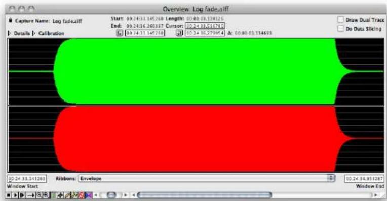
Figure 318: Logarithmic Fade
M
Mic Pre Microphone Preamplifier. A device (or part or a larger device such as a mix-
ing console or audio interface) that takes the low output signal of a microphone (referred to as mic level) and amplifies it to a higher level (referred to as line level).
This must be done in order to make the microphone's output compatible with the working level of mixers and other devices, giving it the name "pre" amplifier.
M/S Stands for Mid/Side, and most commonly refers to a technique of using two microphones-
- Mid, (cardioid, omni or figure-8) facing the event to be recorded
- Side, (always figure-8) turned 90° in relation to the Mid. Should be placed as close as possible to the Mid's diaphragm.
The two signals are matrixed to stereo using a M/S decoder. The advantage of M/S recording is that the stereo width is variable from true mono through stereo and can be modified after recording.
The M/S Processor included with +DSP adds the ability to encode stereo to M/S, allowing you to separately processes the center and sides of a pre-recorded stereo signal.
Mult To send one signal to "multiple" places at once. For example, you could mult your stereo mix to Analog 1-2 and Digital 1-2 to send them to different devices simultaneously.
Mult can also refer to a multichannel cable; for example, a DB25 cable is used as an eight channel mult with the LIO-8 and ULN-8.
N
Nominal level The operating level at which a device is designed to operate. For example, the nominal level of a professional audio device is usually +4dBu, while the nominal level of a microphone is typically -60 dBv. To connect these devices together we need a third device to make their nominal levels compatible, in this case a mic pre.
O
Ohm (Ω) Unit used in the measurement of resistance and impedance. Often used with prefixes to indicate large values, such as "k" (kilo) which equals 1000; for example, 5 kΩ means five thousand ohms (or 5 kilo ohms). Similarly, "M" (mega) is used to indicate 1,000,000; so 10 MΩ means 10 million ohms (or 10 megaohms).
Optical SPDIF A standard for digitally connecting two devices together. Optical SPDIF sends and receives two channels of audio, using a TOSLINK optical cable.
Over Occurs when a signal exceeds the headroom of a system, potentially causing unpleasant distortion.
P
Panner Allows you to determine where a sound is heard in the soundfield. The panners in MIO Console are context sensitive, meaning they change depending on how many channels are in the bus you are sending to:
- Mono bus: No panner
- Stereo or LCR bus: Pan knob
- Quad to 7.1 bus: "X-Y" surround panner
Phantom power A DC voltage applied to a microphone input used to power a condenser microphone or DI box. Phantom power is most commonly 48 volts, and should not be turned on if a line level device is connected to the input.
Phase Describes the position of one sound wave relative to another, or in relation
to time. Let's look at phase between two signals. In the first example, the two signals have the same phase:
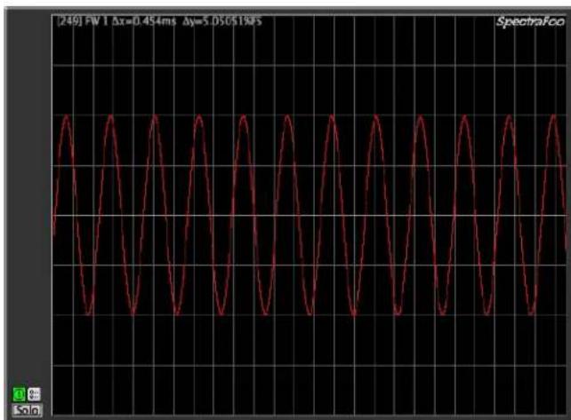
Figure 319: 0° Phase Offset
The two signals are drawn perfectly on top of each other. In the next example, the right signal is 180° out of phase with the left signal. When the audio on the left is at its highest, the right is at its lowest and vice versa. A signal that is 180° out of phase is also called “polarity inverted” or “phase inverted”
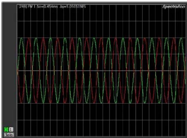
Figure 320: 180° Phase Offset
If we sum the signals together, we get nothing; the high of the left is cancelled out by the low of the right. This is called phase cancellation
![[249] FW 1 Δx=0.454ms Δy=5.050519%S SpectraFoo](/content/2026/05/884165/images/91bd49cca79a7726d808705f4d99bd93d07d23d799ba4322fcb09ea9f6c6d8c3.jpg)
Figure 321: Phase Cancellation
Post Means "after". Common uses:
- Post-fader: After the fader. A post-fader meter would show the level of an audio signal including the boost or cut of the fader.
- Post-insert: After the insert. A post-insert direct out would send wet audio.
PPM meter Peak Program Meter. This type of audio meter features a fast response, allowing you to see peak signal level and catch potential overs quickly.
Pre Means "before". Common uses:
See also Mic Pre
- Pre-fader: Before the fader. A pre-fader meter would show the level of the audio before the fader, so the meter's display would not show boost or cut from the fader.
- Pre-insert: Before the insert. A pre-insert direct out would send dry audio.
R
RCA A two conductor connector, sometimes called a phono connector. RCA connectors use a two conductor (often coaxial) cable to carry unbalanced signals, and are wired with signal to the center pin and ground to the ring. Inputs and outputs are both on female (jacks) and interconnect cables are male to male (plugs). Extensions are male to female.
S
Scene A "picture" of your MIO Console setup. All your routing, fader levels, DSP plug-ins, etc. are saved so that they can be quickly recalled. This can be done by saving from MIO Console using "File/Save" and "File/Open" or from your DAW using MIOConsoleConnect.
Send There are two kinds of sends used by Metric Halo:
- Analog: In the ULN-2 and ULN-8, the send is the physical output of the insert.
- Digital: In MIO Console, a send is used to route an channel to busses other than the main bus. Sends are accessed via the inserts.
SNR Signal to Noise Ratio; a measurement used to indicate how much a signal is corrupted by noise. The higher this number is in dB, the less noise will be added to your signal by the equipment. For example, a 120 dB SNR means that the gear's self noise is 120 dB below the audio.
SPDIF Sony/Philips Digital InterFace, a standard for digitally connecting two devices together. SPDIF sends and receives two channels of audio, using a 75 Ω cable terminated with RCA connectors.
Stem Also called a group or subgroup. A stem is a part of a mix that contains similar inputs. For example, a drum stem contains only the drums tracks in a song; this allows for easy mixing and processing of the drums. MIO Console allows you to create stems, as well as mix the stems together for an overall final mix.
Subgroup See Stem
Sum To add or combine signals. For example, a summing bus combines the signals from several inputs into a single mix.
T
TOSLINK An optical interface and cable designed by Toshiba to carry digital audio between devices. TOSLINK uses a plastic fiber to carry the digital information, and is either terminated in a semi-square plug (used on the 2882 and ULN-2) or a round "Mini-TOSLINK" found on some laptops.
TRS Tip Ring Sleeve. A type of connector found on musical instruments, headphones, patchbays, and other audio electronics. TRS connectors are commonly 1/8" or 1/4" in diameter. Wiring schemes for TRS connectors are:
- Mono balanced: "Hot" or "Plus" on Tip, "Cold" or "Minus" on Ring and Ground on Sleeve
- Stereo unbalanced (headphones, etc.): Left on Tip, Right on Ring, Ground on Sleeve
Inputs and outputs are both on female (jacks) and interconnect cables are male to male (plugs). Extensions are male to female.
U
Unbalanced connection A method of connecting audio equipment. A balanced connector usually has two pins per channel, signal and ground. Unbalanced connections are susceptible to noise from external sources.
An unbalanced connection can also occur when a balanced connection loses one leg due to a faulty connector or cable; the connection is now susceptible to noise and will drop in level.
W
Wet If a signal has been mixed with an effect, it is said to be wet. If there is no
uneffected signal present, the signal is 100% wet. Many processors have controls to let you set the wet/dry ratio; a processor used on a send or aux is usually set to 100% wet.
Word clock (WC) Used to synchronize multiple digital devices. Commonly used to connect
a master clock to all devices in a studio to ensure that they are in sample accurate sync. Word clocks are connected via 75 Ω BNC cables, and must be terminated for proper operation. All Metric Halo interfaces feature self-terminating WC connectors.
X
XLR A professional, locking connector that (usually) has three conductors and
carries a balanced signal; Ground on pin 1, "Hot" or "Plus" on pin 2 and "Cold" or "Minus" on pin 3. Male XLR connectors are used for outputs and females for inputs.
Index
A
ADAT Optical Digital Audio
2882, 63
ULN-2, 78
AES DB25 pinouts, 339
AES Digital Audio
2882, 63
LIO-8, 91
ULN-2, 77
ULN-8, 104
AES Status Indicators (ULN-8/LIO-8), 116
Analog Audio Connections
2882, 61
LIO-8, 90
ULN-2, 75
ULN-8, 103
Analog DB25 pinouts, 339
Analog Input Channel Link, 148
Analog Output Channel Link, 156
Aux Bus, 170
B
Balanced Sends
LIO-8, 91
ULN-8, 104
Boot State, 248
Bootstate
Save System Boot State, 248
Save System Boot State (all boxes), 248
Box Info, 156
Box Tab, 143
Boxes per FW bus, 164, 328
Brightness Adjustment (ULN-8/LIO-8), 121
Bus Mode, 170
Bus Name, 183
Bus Output Assign, 183
Bus Powering Mobile I/O, 337
Bus Select, 175
Bus Type, 169
C
Cans Controls, 149
Changelog, 352
Channel Fader, 175, 183
Channel Label, 148
Channel Level Meter, 148
Channel Meter, 175, 183
Channel mode (ULN-8/LIO-8), 113
Channel Name, 170, 175
Channel strip, 164, 171
Bus Select, 175
Channel, 164, 171
Channel Fader, 175
Channel Meter, 175
Channel Name, 175
Character Select, 173
Direct Output Routing Point (post inserts), 174
Direct Output Routing Point (pre-Inserts), 173
Fader Gain display, 175
Input Gain/Trim, 173
Input Select, 172
Master, 165, 181
Mute, 175
Panner, 174
Phantom Power, 173
Phase Invert, 174
Physical Input Source, 173
Plug-in Inserts, 173
Select/Drag Strip, 175
Channel Strip Meters Post Fader
Metering, 255
Channels strip
Solo, 175
Clip Hold Time (ULN -8/LIO-8), 122
Clock source
2882, 58
ADAT (44/48), 152
ADAT (88/96), 152
AES 1 (1x), 153
AES 1 (2x), 153
AES 1 (4x), 153
AES 2 (1x), 153
AES 2 (2x), 153
AES 2 (4x), 153
AES 3 (1x), 153
AES 3 (2x), 153
AES 3 (4x), 153
AES 4 (1x), 153
AES 4 (2x), 153
AES 4 (4x), 153
DigIn (44/48), 152
Digln (88/96), 152
Internal, 151
ULN-2, 72
ULN-8/LIO-8, 112
WC (176/192), 153
WC (44/48), 151
WC (88/96), 151
WCx256 (176/192), 153
WCx256 (44/48), 152
WCx256 (88/96), 152
Clock Sync
2882, 64
LIO-8, 91
ULN-2, 78
ULN-8, 104
Computer does not see Mobile I/O, 332
Console file, 249
Console Window, 142
ConsoleConnect
Conduit mode, 259
Cubase tips, 262
Digital Performer tips, 261
Finding the Plug-in, 260
FireWire returns, 187
GarageBand tips, 263
Key Commands, 259
Logic tips, 261
Overview, 256
Plug-in mode, 258
Preferences, 257
Pro Tools tips, 265
Status menu, 259
ConsoleSync, 250
Control mode (ULN-8/LIO-8), 112
Control Surface
Eucon and MIOConsoleConnect, 267
EuCon Control Room Support, 267
EuCon Control Surface Support, 267
EuCon Mixer Model, 268
Mackie Control and MIOConsoleConnect, 267
Mackie Control Default Key Commands, 269
Mackie Control Room Support, 269
Mackie Control Surface Support, 269
Mackie Mixer Model, 269
Control Surface Preferences
Enable Control Surface Support, 266
Enable EuCon Support, 267
Fader packs, 266
Primary controller, 266
Use Control Surface while in background, 267
CoreAudio
Buffers, 330
Channel enables, 330
Channel names, 330
Clock sources, 331
Driver, 329
Overview, 329
Sample size, 330
Transport and sample rates, 329
Could Not Instantiate Plug-In, 334
D
DI Inputs
LIO-8, 90
ULN-2, 72
ULN-8, 103
ULN-8/LIO-8, 117
DI Source pop-up menu, 154
DI SRC button (2882, ULN-2), 154
Digital Input Meters, 149
Digital Output Meters, 156
Dim
2882, 59
ULN-8/LIO-8, 117
Direct Output Routing Point (post inserts), 174, 183
Direct Output Routing Point (pre-Inserts), 173, 182
Driver
Revision number, 156
Updating, 325
DSP
Bypass, 242
Graphs, 243
Inserts, 241
Making connections in Graphs, 244
Patch Library Pop-up Menu, 246
Plug-in packages, 271
Plug-in UIs, 241
Setup registers, 242
Sidechain, 242
DSP Panel, 143
E
Edit IR... (ULN-8/LIO-8), 122
Enable IR Remote (ULN-8/LIO-8), 122
Encoder (ULN-8/LIO-8), 117
Erase All States on Current Box, 335
EuCon (see Control Surface)
F
Fader Gain display, 175, 183
FAQ, 351
FireWire
2882, 64
FAQ, 327
LIO-8, 91
Overview, 326
ULN-2, 79
ULN-8, 105
FireWire Bus Did Not Reset Correctly, 332
FireWire Cable Is Not Connected or Bad, 333
FireWire Hardware Has Been Damaged, 333
Firmware (Updating), 322
Firmware Update Problems, 337
Forget All Offline Boxes, 144
Forget All Offline Boxes (and Delete From Mixer), 144
Forget Offline Box, 144
Forget This Offline Box (and Delete From Mixer), 144
Front Panel
2882, 58
LIO-8, 87
ULN-2, 71
ULN-8, 100
Front Panel (ULN-8/LIO-8)
+48 mode, 120
AES Status Indicators, 116
Channel mode, 113
Clock source, 112
Control mode, 112
DI Inputs, 117
Dim, 117
Encoder, 117
Gain display, 115
Headphones, 117
High Resolution Metering, 114
I/O trim, 113
Illumination (Brightness) Adjustment, 121
Infrared Remote, 123
Input mode, 119
Input trim, 120
Link mode, 119
Meters on the Knobs, 121
Monitor Control Section, 117
Monitor mode, 118
Mute, 117
Output Trim, 121
Overview, 111
Per Channel Control Knobs, 114
Preferences in MIO Console, 121
Preset mode, 119
Sample rate, 111
Selecting Control Modes, 118
System Status Indicators, 116
User mode, 120
Front Panel Knob Gain Steps (ULN-8/LIO-8), 122
Front Panel Normal Intensity (ULN-8/LIO-8), 122
Front Panel Preferences, 144
FW channels per box, 164
G
Gain display (ULN-8/LIO-8), 115
Gain Trim knob, 147
Graphs, 243
Ground Loops, 335
H
Headphones
2882, 59
ULN-2, 73
ULN-8/LIO-8, 117
High Power mode (2882), 154
|
I/O insert in the Mixer, 178
I/O Panel, 143
I/O trim (ULN-8/LIO-8), 113
Identify Box, 144
Infrared Remote
Front Panel (ULN-8/LIO-8), 123
Input Clip Threshold (ULN-8/LIO-8), 122
Input gain knob (ULN-2), 71
Input mode (ULN-8/LIO-8), 119
Input trim (ULN-8/LIO-8), 120
Inserts (ULN-2), 73
Inst (Instrument), 147
Interfaces per FW bus, 164, 328
J
Jumpers
Accessing, 341
DI Board, 342
Line input grounding, 342
Output levels, 343
Power supply, 343
K
Key Commands
ConsoleConnect, 259
MIO Console, 318
Record Panel, 237
L
Level Standard pop-up menu, 146, 155
License management, 135
Refresh status, 136
Reload licenses, 136
Line +4, 146, 155
Line -10, 147, 155
Link mode (ULN-8/LIO-8), 119
LIO-8
AES DB25 pinouts, 339
AES Digital Audio, 91
Analog Audio Connections, 90
Analog DB25 pinouts, 339
Balanced Sends, 91
Clock Sync, 91
DI inputs, 90
FireWire, 91
Front Panel, 87
(see also Front Panel ULN-8/LIO-8)
Front Panel Guide, 111
Jumpers, 341
MIDI, 92
Monitor (output level), 156
Overview, 84
Power, 91
Rear Panel, 88
Routing, 89
Signal Flow, 89
SMPTE, 92
Specifications, 92
What comes with it, 85
What you need to use it, 85
Lock indicators, 155
LTC, 239
M
Mackie Control (see Control Surface)
Mailing list, 351
Master Bus, 170
Master strip, 165, 181
Bus Name, 183
Bus Output Assign, 183
Channel Fader, 183
Channel Meter, 183
Character Select, 182
Direct Output Routing Point (post inserts), 183
Direct Output Routing Point (pre-Inserts), 182
Fader Gain display, 183
Monitor Controller Assign, 184
Mult output assignment, 184
Mute, 183
Plug-in Inserts, 183
Primary output assignment, 184
Record Enable, 183
Metering
(ULN-8/LIO-8), 114
2882, 58
Channel Strip Meters Post Fader, 255
ULN-2, 71
Meters on the Knobs (ULN-8/LIO-8), 121
Mic, 147
Mic Amp (ULN-2), 72
Mic S/R Mode (ULN-8), 104
Mic/Pad, 147
Mic/TRS switch (ULN-2), 72
MIDI
LIO-8, 92
ULN-8, 105
MIO Console
Installing, 133
Key Commands, 318
Preferences, 252
MIO Console Preferences
Check for unregistered units, 254
Console windows float when connected, 254
Console windows hide when host is not active ap-
plication, 254
ConsoleConnect Preferences, 254
ConsoleSync, 253
Disable scroll wheel control of UI control elements, 254
Double-click of parameter controller resets value, 254
Enable Control Surface Support, 254
Enable EuCon Support, 254
Enable Legacy Box Support, 253
Fader Packs, 254
On Launch, 252
Primary Controller, 254
Use ConsoleConnect as conduit only, 254
Use Control Surface while in background, 254
Use OpenGL for rendering, 254
MIO Console Window, 142
Missing meters in MIO Console, 334
Mix Bus, 164
Mixer Configuration
Add a channel to a Mix Bus, 170
Add/Remove all visible channels to/from a Mix Bus, 171
Create a Mix Bus, 170
Delete a Mix Bus, 170
Filter visible channels, 171
Input Channel Names, 170
Remove a channel from a Mix Bus, 171
Rename an Input Channel, 170
Mixer strip
Channel, 164, 171
Master, 165, 181
Mixer Window, 159
Mobile I/O 2882
ADAT Optical Digital Audio, 63
AES Digital Audio, 63
Analog Audio Connections, 61
Clock source, 58
Clock Sync, 64
Dim, 59
FireWire, 64
Front Panel, 58
Headphones, 59
High Power mode, 154
Metering, 58
Mute, 59
Output attenuation, 62
Overview, 56
Power, 64
Rear Panel, 59
Routing, 60
Signal Flow, 60
SPDIF Digital Audio, 63
Specifications, 65
SRC, 63
System Status Indicators, 58
TOSLINK Optical Digital Audio, 63
What comes with it, 57
What you need to use it, 57
Mobile I/O Is Not Powered Up, 332
Monitor (output level), 156
Monitor Control Section (ULN-8/LIO-8), 117
Monitor Controller
Adding a new Monitor Path, 198
Adding a New Monitor Source, 196
Adjusting the Monitor Level, 193
As a floating window, 194
Changing the order of the Monitor Output Paths, 199
Changing the order of the Monitor Sources, 197
Changing the per Path Calibration, 199
Configuring Monitor Output Paths, 197
Configuring the Monitor Controller, 195
Dimming the output, 193
FAQ, 200
Identifying Monitor Source, 191
Identifying Output Paths, 191
Interface and Basic operation, 190
Key Commands, 194
Locking the output, 193
Mini Monitor Controller Window, 194
Muting the output, 193
Overview, 189
Preferences, 199
Removing a Monitor Output Path, 199
Removing a Monitor Source, 197
Selecting an Input Source, 193
Selecting an Output Path, 193
Source Override, 193
Switching window size, 194
Ultra-Quick Start Guide, 189
Monitor Controller Assign, 184
Monitor mode (ULN-8/LIO-8), 118
Monitor Outputs (ULN-2), 74
Mute, 175, 183
2882, 59
ULN-8/LIO-8, 117
N
Numeric Hold Time (ULN-8/LIO-8), 122
0
Offline box, 143
Optimizing Input Levels, 148
Output Clip Threshold (ULN-8/LIO-8), 122
Output Trim (ULN-8/LIO-8), 121
Overview
2882, 56
ConsoleConnect, 256
CoreAudio, 329
FireWire, 326
Front Panel (ULN-8/LIO-8), 111
LIO-8, 84
Record Panel, 232
ULN-2, 69
ULN-8, 97
P
Panner, 174
Parameter Pop-up Controls, 157
Per Channel Control Knobs (ULN-8/LIO-8), 114
Persistent State Snapshots (ULN-2), 72
Phantom (+48) mode (ULN-8/LIO-8), 120
Phantom Power
Channel strip, 173
Phantom Power enable button (2882, ULN-8), 146
Phantom Power enable switch (ULN-2), 71
Phase Invert, 174
Plug-In Graphs, 176
Plug-in Inserts, 183
Plug-in Macros, 177
Plug-in packages, 271
Plug-ins, 176
Pop-up Presets, 158
Power
2882, 64
LIO-8, 91
ULN-2, 79
ULN-8, 105
Preferences
ConsoleConnect, 257
Control Surface, 266
Front Panel, 144
MIO Console, 252
Monitor Controller, 199
Record Panel, 237
Preset mode (ULN-8/LIO-8), 119
R
Rear Panel
2882, 59
LIO-8, 88
ULN-2, 73
ULN-8, 101
Reboot MIO, 335
Record Enable, 183
Record Panel
Key Commands, 237
Mirrored recording, 239
Multibox considerations, 237
Overview, 232
Play position, 234
Playback, 236
Playback folder, 236
Preferences, 237
Progress meters, 233
Record folder, 235
Recording, 235
SMPTE, 240
Take folder, 235
Time readouts, 232
Track header, 235
Tracks overview, 234
Transport controls, 233
Zoom buttons, 235
Record Panel preferences
Auto Break, 240
BEXT chunk, 240
Bit depth, 240
Disable Spotlight Indexing, 240
File format, 239
Take folder, 238
Timestamping, 239
Registration, 133
Reset All Box Channel Names, 144
Reset Box Input Channel Names, 144
Reset MIO Outputs, 333
RIAA decoder, 278, 279, 282
Routing
2882, 60
LIO-8, 89
ULN-2, 74
ULN-8, 102
Routing Application Examples
Controlling multiple monitors, 208
Effects for tracking, 201
Routing Summary, 186
S
Safety Boot, 337
Sample rate (ULN-8/LIO-8), 111
Sample Rate pop-up menu, 153
Select/Drag Strip, 175
Selecting Control Modes (ULN-8/LIO-8), 118
Selection-based Linking, 175
Sends, 177
Sidechain, 242
Signal Flow
2882, 60
LIO-8, 89
ULN-2, 74
ULN-8, 102
SMPTE
LIO-8, 92
Record Panel, 240
ULN-8, 105
SMUX, 149
Snapshots, 248
Snapshots (2882), 249
Snapshots (ULN-2), 248
Snapshots (ULN/LIO-8), 249
(see also ULN/LIO-8 Front Panel Presets)
Software Is Not Installed Properly, 332
Software License
Demo, 137
Purchase, 137
Solo, 175
SPDIF Digital Audio
2882, 63
ULN-2, 77
Specifications
LIO-8, 92
Mobile I/O 2882, 65
ULN-2, 79
ULN-8, 105
SRC
2882, 63
ULN-2, 78
Support, 351
System Controls, 151
System Status Indicators
2882, 58
ULN-2, 72
ULN-8/LIO-8, 116
T
Technote, 351
Templates, 159
TOD, 239
TOSLINK, 149, 156
TOSLINK Optical Digital Audio
2882, 63
ULN-2,78
Trim Enable switch (ULN-2), 72
Trim Pot (ULN-2), 72
Troubleshooting
Boot state, 335
Bus Powering Mobile I/O, 337
Computer does not see Mobile I/O, 332
Console state file, 335
Could Not Instantiate Plug-In, 334
Crashed interface, 335
Distortion, 335
FireWire Bus Did Not Reset Correctly, 332
FireWire Cable Is Not Connected or Bad, 333
FireWire Hardware Has Been Damaged, 333
Firmware Update Problems, 337
Ground Loops, 335
License Reinstallation, 335
Missing meters in MIO Console, 334
Mobile I/O Is Not Powered Up, 332
No output, 333
Safety Boot, 337
Software Is Not Installed Properly, 332
Tutorial, 351
U
Übergraph, 166
ULN-2
ADAT Optical Digital Audio, 78
AES Digital Audio, 77
Analog Audio Connections, 75
Analog outputs, 75
Clock source, 72
Clock Sync, 78
DI inputs, 72
FireWire, 79
Front Panel, 71
Headphones, 73, 75
Input gain knob, 71
Inserts, 73
Metering, 71
Mic Amp, 72
Mic/TRS switch, 72
Monitor Outputs, 74, 75
Overview, 69
Phantom Power enable switch, 71
Power, 79
Rear Panel, 73
Routing, 74
Signal Flow, 74
SPDIF Digital Audio, 77
Specifications, 79
SRC, 78
System Status Indicators, 72
TOSLINK Optical Digital Audio, 78
Trim Enable switch, 72
Trim Pot, 72
What comes with it, 70
What you need to use it, 70
ULN-8
AES DB25 pinouts, 339
AES Digital Audio, 104
Analog Audio Connections, 103
Analog DB25 pinouts, 339
Balanced Sends, 104
Clock Sync, 104
DI inputs, 103
FireWire, 105
Front Panel, 100
(see also Front Panel ULN-8/LIO-8)
Front Panel Guide, 111
Jumpers, 341
Mic S/R Mode, 104
MIDI, 105
Monitor (output level), 156
Overview, 97
Power, 105
Rear Panel, 101
Routing, 102
Signal Flow, 102
SMPTE, 105
Specifications, 105
What comes with it, 98
What you need to use it, 98
Updating
Driver, 325
Firmware, 322
User mode (ULN-8/LIO-8), 120
W
WC Out pop-up menu, 154
What comes with it
2882, 57
LIO-8, 85
ULN-2, 70
ULN-8, 98
What you need to use it
2882, 57
LIO-8, 85
ULN-2, 70
ULN-8, 98
Windows, 213

- MOBILE I/O USER'S GUIDE
- MOBILE I/O USERS GUIDE
- TABLE OF CONTENTS
- INTRODUCTION 20
- QUICK START GUIDES 21
- INTERFACES 53
- OTHER BUS POWERED DEVICES 338
- LIST OF FIGURES
- LIST OF TABLES
- INTRODUCTION
- PART I. QUICK START GUIDES
- 2882 QUICK START GUIDE
- PREPARE THE UNIT FOR USE
- CONNECT THE 2882
- TAKE A LISTEN
- MIO CONSOLE
- USING LEGACY INTERFACES
- THE CONSOLE WINDOW
- THE MIXER WINDOW
- THE 2882 AND SURROUND
- UNLEASH THE DSP
- ADDITIONAL RESOURCES
- ULN-2 QUICK START GUIDE
- CONNECT THE ULN-2
- THE ULN-2 AND SURROUND
- LIO-8 QUICK START GUIDE
- CONNECT THE LIO-8
- GET FAMILIAR WITH THE FRONT PANEL
- THE LIO-8 AND SURROUND
- ULN-8 QUICK START GUIDE
- CONNECT THE ULN-8
- THE ULN-8 AND SURROUND
- PART II. INTERFACES
- INTERFACES
- 2882 USERS GUIDE
- 2882 OVERVIEW
- WHAT IT IS
- WHAT IT HAS
- WHAT YOU NEED TO USE IT
- WHAT COMES WITH IT
- USING THE 2882 HARDWARE
- 2882 FRONT PANEL
- 2882 REAR PANEL
- 2882 SIGNAL FLOW
- MAKING CONNECTIONS TO THE 2882
- CLICK HERE FOR A LARGER VERSION
- ANALOG AUDIO CONNECTIONS
- TIP
- MAKING THE 1/4" CONNECTION
- MAKING THE XLR CONNECTION
- OUTPUT ATTENUATION
- COPPER-BASED DIGITAL AUDIO
- SRC
- OPTICAL-BASED DIGITAL AUDIO
- CLOCK SYNC
- FIREWIRE
- POWER
- 2882 SPECIFICATIONS
- ULN-2 USERS GUIDE
- ULN-2 OVERVIEW
- USING THE ULN-2 HARDWARE
- ULN-2 FRONT PANEL
- ULN-2 REAR PANEL
- WHAT'S THE DIFFERENCE BETWEEN THE ANALOG OUTS AND MONITOR OUTS, AND HOW DO I SEND TO THE HEADPHONES
- ULN-2 SPECIFICATIONS
- LIO-8 USERS GUIDE
- USING THE LIO-8 HARDWARE
- LIO-8 FRONT PANEL
- LIO-8 REAR PANEL
- CONNECTING TO THE DLS
- BALANCED SENDS
- AES DIGITAL AUDIO
- MIDI
- SMPTE
- LIO-8 SPECIFICATIONS
- ULN-8 USERS GUIDE
- ULN-8 OVERVIEW
- USING THE ULN-8 HARDWARE
- ULN-8 FRONT PANEL
- ULN-8 REAR PANEL
- CONNECTING TO THE DIS
- BALANCED SENDS AND MIC S/R MODE
- USING ANALOG INSERTS ON THE ULN-8
- ULN-8 SPECIFICATIONS
- ULN/LIO-8 FRONT PANEL GUIDE
- FRONT PANEL OVERVIEW
- A NOTE FOR LIO-8 OWNERS
- SAMPLE RATE INDICATORS AND CONTROL
- CLOCK SOURCE INDICATORS AND CONTROL
- CONTROL MODE INDICATORS AND SELECTOR
- I/O TRIM MODE INDICATORS AND SELECTOR
- CHANNEL MODE INDICATORS
- PER CHANNEL CONTROL KNOBS
- HIGH RESOLUTION METERS
- SYSTEM STATUS INDICATORS
- AES STATUS INDICATORS
- MONITOR CONTROL SECTION
- FRONT PANEL DI INPUTS
- CONTROL MODE DETAILS
- SELECTING AMONGST THE CONTROL MODES
- MONITOR
- PRESET
- FRONT PANEL RECALL ON THE ULN-8/LIO-8
- INPUT
- LINK
- 48
- U/M — USER MODE
- INPUT TRIM
- DIGITAL DUAL VERNIER™ INDICATION TECHNOLOGY
- METERS ON THE KNOBS
- TOGGLING METER MODES
- OUTPUT TRIM
- ILLUMINATION (BRIGHTNESS) ADJUSTMENT
- FRONT PANEL PREFERENCES IN MIO CONSOLE
- INFRARED REMOTE OPERATION
- IR REMOTES AND THE MONITOR CONTROLLER
- PART III. SOFTWARE
- SOFTWARE
- INSTALLATION AND REGISTRATION
- INSTALLING MIO CONSOLE
- INCLUDED PACKAGES
- INSTALLATION
- IMPORTANT
- REGISTRATION & LICENSING
- REGISTERING YOUR INTERFACE
- INTERNET REQUIRED
- LICENSE MANAGEMENT
- REFRESH STATUS AND RELOAD LICENSES BUTTONS
- PURCHASING A SOFTWARE LICENSE
- RECEIVING MH SPECIAL DEALS
- MOBILE I/O SPECIAL DEALS
- FIGURE 10.13: CONFIRMATION PAGE
- MIO CONSOLE OVERVIEW
- MIO CONSOLE SOFTWARE
- I/O PANEL
- BOX TABS
- FRONT PANEL PREFERENCES
- ANALOG INPUT CONTROL
- TIP FOR 2882 USERS
- OPTIMIZING INPUT LEVELS
- ANALOG INPUT CHANNEL LINK
- DIGITAL INPUT METERS
- CANS CONTROLS
- SYSTEM CONTROLS
- ANALOG OUTPUT CONTROL
- ANALOG OUTPUT CHANNEL LINK
- DIGITAL OUTPUT METERS
- BOX INFO
- PARAMETER POP-UP CONTROLS
- POP-UP COMMANDS
- POP-UP PRESETS
- MIXER CONFIGURATION SUMMARY
- TO CREATE A MIX BUS
- TO DELETE A MIX BUS
- TO ADD AN INPUT CHANNEL TO A MIX BUS
- TO REMOVE AN INPUT CHANNEL FROM A MIX BUS
- ROUTING
- ROUTING IS CRITICAL
- A QUICK TOUR OF THE V. 5 MIXER
- TECHNOLOGY
- WHAT DOES THE ÜBERGRAPH DO FOR ME
- CONFIGURATION
- USING TEMPLATES FOR CONFIGURATION
- MANUAL CONFIGURATION
- MIXER CONFIGURATION TASKS
- TO ADD A CHANNEL TO A MIX BUS
- TO RENAME AN INPUT CHANNEL IN A MIX BUS
- TO REMOVE A CHANNEL FROM A MIX BUS
- TO ADD/REMOVE ALL VISIBLE CHANNELS TO/FROM A MIX BUS
- TO FILTER THE CHANNELS VISIBLE IN THE SELECTED MIX BUS CONFIGURATION AREA
- INPUT STRIP DETAILS
- WORKING WITH MULTICHANNEL INPUTS
- IMPORTANT NOTE
- SELECTION-BASED LINKING
- PLUG-INS
- PLUG-IN GRAPHS (REQUIRES +DSP LICENSE)
- TO MIGRATE GRAPH PATCHES FROM V.4 OR EARLIER CONSOLES
- PLUG-IN MACROS (REQUIRES +DSP LICENSE)
- CHANNEL WIDTH AND MACROS
- SENDS
- I/O INSERT
- LATENCY IN THE I/O INSERT
- MASTER STRIP DETAILS
- ROUTING SUMMARY
- FIREWIRE RETURNS
- THE POWER OF RETURNS
- MONITOR CONTROLLER
- OVERVIEW
- ULTRA-QUICK START GUIDE TO CONFIGURING THE MONITOR CONTROLLER
- ADDING THE BUS OUTPUT OF YOUR MIX BUS TO THE MONITOR CONTROLLER
- CONFIGURING THE MONITOR CONTROLLER
- MONITOR CONTROL INTERFACE AND BASIC OPERATION
- DETERMINE CONFIGURATION
- IDENTIFYING MONITOR SOURCES
- IDENTIFYING MONITOR OUTPUT PATHS
- USING THE MONITOR CONTROLLER
- SELECTING AN INPUT SOURCE
- SELECTING AN OUTPUT PATH
- ADJUSTING THE MONITOR LEVEL
- DIMMING THE OUTPUT
- MUTING THE OUTPUT
- LOCKING THE OUTPUT
- OVERRIDING THE CURRENTLY SELECTED SOURCE
- SELECTING SOURCE OVERRIDE CHANNELS
- THE MONITOR CONTROLLER AS FLOATING WINDOW
- MINI MONITOR CONTROLLER WINDOW
- SWITCH BETWEEN MONITOR CONTROLLER AND MINI MONITOR CONTROLLER WINDOWS
- KEY COMMANDS
- NOTE
- CONFIGURING MONITOR SOURCES
- ADDING A NEW MONITOR SOURCE
- REMOVING A MONITOR SOURCE
- CHANGING THE ORDER OF THE MONITOR SOURCES
- CONFIGURING MONITOR OUTPUT PATHS
- ADDING A NEW MONITOR OUTPUT PATH
- REMOVING A MONITOR OUTPUT PATH
- CHANGING THE ORDER OF THE MONITOR OUTPUT PATH
- CHANGING THE PER PATH CALIBRATION
- TO CALIBRATE A MONITOR PATH
- TO REMOVE CALIBRATION FROM A MONITOR PATH
- MONITOR CONTROLLER PREFERENCES
- MONITOR CONTROLLER FAQ
- ROUTING EXAMPLES
- EFFECTS FOR TRACKING
- CONTROLLING MULTIPLE MONITORS
- VIRTUALIZING WINDOWS AUDIO PROGRAMS
- HOW IT WORKS
- WHAT YOU NEED
- HOW TO SET IT UP
- TIPS FOR SPECIFIC HOST DAWS
- ROUTING TIPS FOR LOGIC
- USING LOGIC I/O PLUG-INS
- ROUTING TIPS FOR DIGITAL PERFORMER
- ROUTING FOR INSERT PROCESSING IN DIGITAL PERFORMER
- CONFIGURING BUNDLES AND MIO CONSOLE TO MAKE YOUR LIFE EASIER
- TO INSERT A +DSP PROCESS CHAIN ON A SINGLE CHANNEL
- TO INSERT A +DSP PROCESS CHAIN ON A SUBMIX
- ROUTING TIPS FOR CUBASE
- ROUTING FOR INSERT PROCESSING IN CUBASE
- CONFIGURING VST CONNECTIONS FOR AN ENTIRE MIX
- ROUTING TIPS FOR PRO TOOLS
- INPUTS
- INSERTS
- DEFINING INSERTS IN PT
- ANALOG/DIGITAL INSERTS
- DSP INSERTS
- DSP INSERT LATENCY
- MIXING
- STEREO MIX
- STEM MIX OR "SUMMING
- AGGREGATES AND MULTITRACK
- CONCLUSION
- RECORD PANEL
- RECORD PANEL DESCRIPTION
- RECORDING
- QUIT WHILE RECORDING" DIALOG
- PLAYBACK
- MULTIBOX CONSIDERATIONS
- RECORD PANEL KEY COMMANDS
- RECORD PANEL PREFS
- DSP IMPLEMENTATION GUIDE
- PLUG-IN PROCESSING IN THE V.5 MIXER
- PLUG-IN UI'S
- MULTICHANNEL PLUG-INS
- WHAT'S THE DIFFERENCE BETWEEN USING A M/M VS. S/S PLUG-IN ON A STEREO CHANNEL
- GRAPHS
- PATCH LIBRARY POP-UP MENU
- SAVING AND RECALLING YOUR SETUPS
- FACTORY DEFAULT
- BOX MERGE
- BOOT STATES AND SNAPSHOTS
- ULN-2 SNAPSHOT RECALL
- ULN/LIO-8 SNAPSHOT RECALL
- 2882 SNAPSHOT RECALL
- CONSOLE FILES
- CONSOLESYNC
- MIO CONSOLE PREFERENCES
- ACCESSING THE PREFERENCES
- OTHER PREFERENCES
- CONSOLECONNECT
- CONSOLECONNECT OVERVIEW
- INTRODUCTION TO CONSOLECONNECT
- TOTAL RECALL
- UNIVERSAL ACCESS
- USING CONSOLECONNECT
- SELECTING THE MODE
- PLUG-IN MODE
- STATUS MENU IN PLUG-IN MODE
- CONDUIT MODE
- COMMUNICATION
- FINDING THE PLUG-IN
- LOGIC
- DIGITAL PERFORMER
- MIOCONSOLECONNECT IS AN AU IN DP
- WHERE TO INSERT MIOCONSOLECONNECT
- WHERE TO INSERT MIOCONSOLECONNECT PER SEQUENCE
- CUBASE
- GARAGEBAND
- PRO TOOLS TIPS
- SUPPORT
- CONTROL SURFACE SUPPORT
- CONTROL SURFACE PREFERENCES
- DETAILS OF EUCON CONTROL SURFACE SUPPORT
- CONTROL ROOM SUPPORT
- MIXER MODEL
- TO SELECT THE MAIN MIX WINDOW ON MC MIX
- TO SELECT THE MAIN MIX WINDOW ON MC CONTROL
- DETAILS OF MACKIE CONTROL PROTOCOL CONTROL SURFACE SUPPORT
- MACKIE CONTROL DEFAULT KEY COMMANDS
- TO SELECT THE SENDS BUS (OR MOVE TO THE NEXT SEND BUS)
- TO SELECT THE MAIN MIX WINDOW
- TO SELECT THE INPUT GAIN ON THE VPOT FOR THE STRIPS
- TO SELECT THE PAN CONTROL ON THE VPOT FOR THE STRIPS
- DSP
- DSP PACKAGE COMPARISON
- DSP PLUG-IN DOCUMENTATION
- MIO VOLUME CONTROL (LINEAR)
- DESCRIPTION
- PARAMETERS
- MIO VOLUME CONTROL (LPF)
- MIO M/S PROCESSOR
- MIO M/S DECODER
- MIO STATIC MATRIX
- MIOCOMP
- RELEASE [5∞, 5] S
- KNEE [0, 1]
- OUT CEILING [-60, 0] DB
- MAKEUP GAIN [-30, 30] DB
- AUTO GAIN {OFF, ON}
- SC SOURCE {OFF, ON}
- MASTER BYPASS {ON, OFF}
- SEE ALSO
- MIOEQ 6 BAND
- MASTER PARAMETERS
- PER-FILTER PARAMETERS
- MIOEQ 12 BAND
- MIOLIMIT
- MIOSTRIP
- MIO CHANNEL SUMMER
- MIO CHANNEL DIFFERENCE
- MIO CHANNEL SUM/DIFFERENCE
- MIO CHANNEL MULTIPLIER
- MIODELAY
- MIOMODDELAY
- MIO DELAY (1K)
- MIO DELAY (24K)
- MIO DELAY (96K)
- MIO DELAY (1K IM)
- MIO DELAY (2K-15K IM)
- MIO DELAY (2K-15K)
- MIO MULTITAP DELAY
- MIOALLPASS
- MIOALLPASSVD
- MIOHARDCLIP
- MIOSOFTCLIP TYPE 1
- MIOSOFTCLIP TYPE 2
- MIOSOFTCLIP TYPE 3
- MIOSOFTDISTORTION TYPE 1
- MIOSOFTDISTORTION TYPE 2
- MIOSOFTDISTORTION TYPE 3
- MIOSLEW
- MIOINSLEW
- MIO 4TH ORDER NONLINEAR MAP
- MIO 4TH ORDER SYMMETRICAL NONLINEAR MAP
- MIO 4TH ORDER [DB] NONLINEAR MAP
- MIO 4TH ORDER [DB] SYMMETRICAL NONLINEAR MAP
- MIO A/B SWITCH (LINEAR)
- MIO A/B SWITCH (LPF)
- MIOQUADOSC
- MIOQUADLFO
- MIOQUADNCO
- MIOQUADNCO-GLIDE
- NOISE
- SIMPLE DITHER (TPDF)
- SIMPLE DITHER (TPDF HIPASS)
- SCALE/OFFSET
- SVF CONTROL
- NC SVF
- MIOSIMPLEPITCHSHIFTER
- HALOVERB
- HALOVERB FOR +DSP
- ENVELOPEDETECTOR
- TRANSIENTCONTROL
- CV -> NCO FREQ
- ABS
- MAX
- MIN
- SELECT
- MAP RANGE
- CONSTANT
- DIVIDE
- SQUARE ROOT
- RECIPROCAL SQUARE ROOT
- ADSR
- EXPONENTIAL ADSR
- BAND SPLIT
- PART IV. APPENDICES
- APPENDICES
- MIO CONSOLE KEY COMMANDS
- UPDATING YOUR FIRMWARE
- INSTALLING A FIRMWARE UPDATE
- ROLLING BACK YOUR FIRMWARE
- UPDATING THE DRIVER
- FIREWIRE FAQ
- GENERAL
- METRIC HALO SPECIFIC
- COREAUDIO
- ABOUT COREAUDIO™ TECHNOLOGY
- HOW THE COREAUDIO DRIVER WORKS
- COREAUDIO TRANSPORT AND SAMPLE RATES
- CHANNEL NAMES
- CHANNEL ENABLES
- COREAUDIO BUFFERS
- SETTING THE COREAUDIO BUFFER SIZE
- SAMPLE SIZE
- CLOCK SOURCES
- TROUBLESHOOTING GUIDE
- COMPUTER DOES NOT SEE MOBILE I/O
- MOBILE I/O IS NOT POWERED UP
- SOFTWARE IS NOT INSTALLED PROPERLY
- THE FIREWIRE BUS DID NOT RESET CORRECTLY
- THE FIREWIRE CABLE IS NOT CONNECTED OR BAD
- THE FIREWIRE HARDWARE HAS BEEN DAMAGED
- NO OUTPUT FROM MOBILE I/O
- MISSING METERS IN MIO CONSOLE
- COULD NOT INSTANTIATE PLUG-IN
- DIGITAL DISTORTION
- INTERFACE HAS CRASHED
- CORRUPTED BOOTSTATE
- CORRUPTED CONSOLE STATE
- REMOVING A CORRUPTED STATE FILE
- LICENSE REINSTALLATION
- GROUND LOOPS
- FIRMWARE UPDATE PROBLEMS
- BUS POWERING MOBILE I/O
- ULN-8 AND LIO-8 OWNERS
- NOT ENOUGH POWER ON THE BUS
- OTHER BUS POWERED DEVICES
- DB25 PINOUTS
- ULN-8/LIO-8 JUMPER SETTINGS
- D.I. BOARD
- LINE INPUT GROUNDING
- CONNECTING UNBALANCED SOURCES
- OUTPUT LEVELS
- REAR
- SETTING THE OUTPUT LEVEL JUMPERS
- POWER SUPPLY
- ULN-R INSTALLATION GUIDE
- ULN-R PARTS AND TOOLS
- INSTALLING THE MIC PRES
- SUPPORT RESOURCES
- CHANGELOG
- CHANGES
- BUGFIXES
- V5.6
- V5.5.1
- V5.5
- V5.4.04
- GLOSSARY SYMBOLS
- A
- B
- C
- D
- F
- G
- H
- L
- M
- N
- O
- P
- R
- S
- T
- U
- W
- X
- INDEX
- E
- J
- K
- 0
Brand : Metric Halo
Model : ULN-2
Category : Hi-Fi System