
Voice Channel - Processor ART - Free user manual and instructions
Find the device manual for free Voice Channel ART in PDF.


| Product Type | Tube Microphone Preamplifier / Voice Processor |
| Brand | ART |
| Model | Voice Channel |
| Form Factor | 1U Rackmount |
| Inputs | Balanced XLR (Microphone), Unbalanced 1/4" TS (Instrument) |
| Outputs | Balanced XLR, Unbalanced 1/4" TS |
| Preamp Type | Vacuum Tube (12AX7) |
| Compression | Variable Ratio, Threshold, Attack, Release, Hard/Soft Knee |
| Equalization | 3-Band: Low Shelf, Parametric Mid, High Shelf |
| De-esser | Fixed frequency de-esser with threshold control |
| Output Level Control | Master volume with VU meter |
| Phantom Power | +48V, switchable |
| Power Supply | Internal, 120V AC (230V AC for export models) |
| Dimensions (W x D x H) | 19" x 6.5" x 1.75" (482 x 165 x 44 mm) |
| Weight | 5.0 lbs (2.27 kg) |
| Frequency Response | 10 Hz - 40 kHz (±0.5 dB) |
| Signal-to-Noise Ratio | >100 dB (A-weighted) |
| THD+N | <0.01% (typical) |
| Cleaning | Wipe with dry cloth; avoid solvents; keep vents clear |
| Safety | Use grounded outlet; do not expose to moisture; no user-serviceable parts inside |
| Spare Parts | Contact ART support for replacement tubes (12AX7) and power supply |
| Reparability | Serviceable by qualified technician; vacuum tube replacement can be done by user with caution |
Frequently Asked Questions - Voice Channel ART
User questions about Voice Channel ART
0 question about this device. Answer the ones you know or ask your own.
Ask a new question about this device
Download the instructions for your Processor in PDF format for free! Find your manual Voice Channel - ART and take your electronic device back in hand. On this page are published all the documents necessary for the use of your device. Voice Channel by ART.
USER MANUAL Voice Channel ART
Tube Channel Strip with Digital Connectivity

SERVICE MANUAL

APPLIED RESEARCH AND TECHNOLOGY
IMPORTANT SAFETY INSTRUCTIONS – READ FIRST

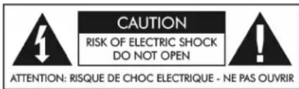

This symbol, wherever it appears. This symbol, wherever it appears, alerts alerts you to the presence of uninsulated you to important operating and maintenance dangerous voltage inside the enclosure. Voltage instructions in the accompanying literature that may be sufficient to constitute a risk of shock. Please read manual.
Read instructions:
Retain these safety and operating instructions for future reference. Heed all warnings printed here and on the equipment. Follow the operating instructions printed in this user guide.
Do not open:
Aside from one vacuum tube, there are no user serviceable parts inside. Refer any service work to qualified technical personnel only.
Power sources:
Only connect the unit to mains power of the type marked on the rear panel. The power source must provide a good ground connection.
Power cord:
Use the power cord with sealed mains plug appropriate for your local mains supply as provided with the equipment. If the provided plug does not fit into your outlet consult your service agent. Route the power cord so that it is not likely to be walked on, stretched or pinched by items placed upon or against.
Grounding:
Do not defeat the grounding and polarization means of the power cord plug. Do not remove or tamper with the ground connection on the power cord.
Ventilation:
Do not obstruct the ventilation slots or position the unit where the air required for ventilation is impeded. If the unit is to be operated in a rack, case or other furniture, ensure that it is constructed to allow adequate ventilation.
Moisture:
To reduce the risk of fire or electrical shock do not expose the unit to rain, moisture or use in damp or wet conditions. Do not place a container of liquid on it, which may spill into any openings.
Heat:
Do not locate the unit in a place close to excessive heat or direct sunlight, as this could be a fire hazard. Locate the unit away from any equipment, which produces heat such as: power supplies, power amplifiers and heaters.
Environment:
Protect from excessive dirt, dust, heat, and vibration when operating and storing. Avoid tobacco ash, drink spillage and smoke, especially that associated with smoke machines.
Handling:
To prevent damage to the controls and cosmetics avoid rough handling and excessive vibration. Protect the controls from damage during transit. Use adequate padding if you need to ship the unit. To avoid injury to yourself or damage to the equipment take care when lifting, moving or carrying the unit.
Servicing:
Switch off the equipment and unplug the power cord immediately if it is exposed to moisture, spilled liquid, objects fallen into opening, or the power cord or plug becomes damaged during a lightning storm or if smoke odor or noise is noted. Refer servicing to qualified technical personnel only.
Installation:
Install the unit in accordance with the instructions printed in the user guide.
Voice Channel
Tube Channel Strip with Digital Connectivity
IMPORTANT SAFETY INSTRUCTIONS – READ FIRST ....1
INTRODUCTION......4
INSTALLATION....4
AC Power Hookup 4
Analog Audio Connections 4
USB OPERATION 5
FRONT PANEL CONTROLS and JACKS......6
Mic Preamp Controls....6
Instrument Input 6
Gain Control 6
Impedance Control....6
Pad Switch 6
Phantom Power 6
Invert Switch....6
Low Cut Switch....6
Tube Voltage Switch 7
Dynamic Processor Controls 8
Threshold Control....8
Ratio Control 8
De-esser Control 8
De-esser Freq. Control....8
Attack Control....8
Release Control....9
Gain Reduction LED Meter....9
Expander/Gate Switch....9
Expander/Gate Threshold Control....9
Semi-Parametric EQ 10
EQ Position Switch....10
EQ Bypass Switch....10
Output Level Control 11
Output Level Meters 11
Sample Rate/Dither Control....12
Optical Output Switch....12
REAR PANEL CONNECTIONS....13
Mic/Line Input....13
Mic Preamp Output 13
Insert Input 13
Balanced Output....13
A/D Main Insert and A/D CH2 Insert....13
Wordclock Input and Thru Jacks 13
ADAT Input Jack 14
Optical Output Jack....14
S/PDIF Output Jack....14
AES/EBU Output Jack....14
USB Jack....14
APPLICATIONS 15
Bypassing Components Of The Voice Channel™ 15
Optimizing The Preamp For Lowest Noise....15
Utilizing Pre/Post Compression EQ....15
SERVICE PARTS 16
FULL BILL OF MATERIALS 19
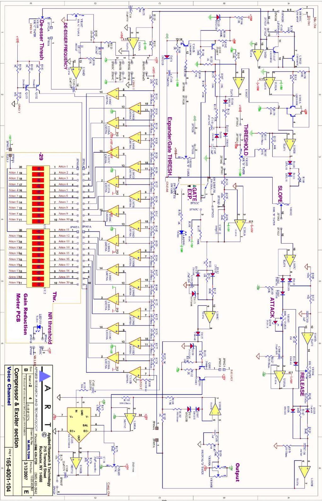
SCHEMATICS....28
WARRANTY INFORMATION....32
Limited Warranty (USA only) 32
Online Registration 32
Exclusions 32
SERVICE 33
SPECIFICATIONS....34
LIST OF FIGURES
FIGURE 1 – Preamp section ....7
FIGURE 2 – Dynamics Section....7
FIGURE 3 - Equalizer Section ...... 10
FIGURE 4 – Signal Flow Block Diagram ...... 11
FIGURE 5 – Output Section ...... 12
FIGURE 6 - Rear Panel 12
FIGURE 7 - Wordclock Termination....14
INTRODUCTION
The ART Voice Channel is the answer to your recording and computer audio interface needs. Our second-generation discrete Class-A microphone preamp provides clean quiet gain while maintaining incredible transparency. A powerful dynamics processor subtly controls transients and noise of the most demanding sources. The ART Voice Channel's semi-parametric EQ offers wide tune-ability and can be patched before OR after the dynamics processor. Separate insertion jacks allow you to use your favorite external signal processing gear immediately after the Mic preamp and before the EQ and dynamics processor. Another patch point exists just before the A/D converters. Choose between a wide range of outputs including balanced analog output, 44.1 KHz to 192 KHz AES/EBU, S/PDIF, ADAT and USB. Both analog and digital meters provide a detailed indication of audio levels.
INSTALLATION
The ART Voice Channel may be used in a wide variety of applications and environments. In a rack-mountable, all-steel enclosure, the unit is designed for continuous professional use. Mounting location is not critical, however for greater performance reliability we recommend that you not place the unit on top of power amps, or other sources of heat and/or strong magnetic fields. The tube circuitry needs about a minute to “warm up” and stabilize from a cold power up.
AC Power Hookup
The ART Voice Channel has an internal power supply. Only connect the unit to mains power of the type marked on the rear panel. The power source must provide a good ground connection, and the ground pin on the mains plug should never be defeated.
Analog Audio Connections
Audio connections to and from the Voice Channel are:
Front panel balanced combo input: [XLR] Pin 2 = Hot (+), Pin 3 = Cold (-), Pin 1 = Ground [1/4-inch] Tip = Hot (+), Sleeve = Ground
Rear panel balanced combo input: [XLR] Pin 2 = Hot (+), Pin 3 = Cold (-), Pin 1 = Ground [1/4-inch] Tip = Hot (+), Ring = Cold (-), Sleeve = Ground
Rear panel balanced 1/4" output: Tip = Hot (+), Ring = Cold (-), Sleeve = Ground
Rear panel 1/4" insert input: Tip = Hot (+), Sleeve = Ground
Mic Preamp Output: Tip = Hot (+), Sleeve = Ground
A/D Main & A/D CH2 Inserts: Tip = Input, Ring = Output, Sleeve = Ground
USB OPERATION
Connect your analog jacks and power up the unit first. Next, set the front panel controls for proper operation as per the previous sections. Then connect the USB cable to the appropriate input on your computer and lastly to the USB connector on the Voice Channel.
Once the USB connection is made and your computer is on, the unit will automatically connect and try to set your computer “Default Audio Device” to be “USB Audio CODEC”. Usually the computer will do this automatically whenever a USB device is first connected, but it is sometimes necessary to make the selection manually. The same settings may need to be made in your particular audio application as well (Check your application instructions). These settings should be made while the Voice Channel and computer are connected and powered on.
FRONT PANEL CONTROLS and JACKS
Mic Preamp Controls
The Voice Channel input consists of a discrete Class-A differential preamp. The circuit is optimized for low impedance microphones as well as line level signals. Up to 60dB of gain is available from this stage. The output can be inverted using the INVERT switch.
The impedance of the front and rear XLR inputs is continuously variable for fine-tuning the preamp to a wide variety of mics. Phantom power is available on the XLR inputs as well.
A selectable low-cut filter removes rumble, wind noise, and pops, thereby increasing clarity.
Instrument Input
The 14 -inch T/S jack on the front panel provides a high impedance unbalanced input, and when used, automatically switches off the mic pre-amp. (The rear combo jack's 14 -inch T/R/S balanced input is lower impedance and is part of the mic pre-amp. The rear jack is not intended to be used with high impedance microphones or instruments.) NOTE: When using the INSTRUMENT INPUT, the PAD switch is disabled and does NOT affect the gain.
Gain Control
This control adjusts both the mic pre-amp gain as well as the instrument input gain. The gain marked applies to the mic pre-amp without the PAD switch depressed. The instrument input gain markings are on the right side of the slash (/). Refer to the APPLICATIONS section to learn how to optimize the gain control for low noise operation.
Impedance Control
This knob sets the load impedance at the front and rear panel XLR inputs of the Voice Channel. Use the IMPEDANCE CONTROL to subtly tune the sound of your microphone. Various microphones will change their sound at differing load impedances. The correct setting is subjective. Adjust this control to personal taste.
Pad Switch
This switch reduces the mic pre-amp gain by up to 20dB to prevent clipping when high level mic, or line level signals are applied to the balanced XLR or 14 -inch T/R/S inputs. This switch does NOT affect the 14 -inch T/S front panel INSTRUMENT INPUT.
Phantom Power
The switch safely applies +48Volt phantom power to the XLR inputs. Use phantom power only when the microphone that you are using requires it. Doing so will extend the life of the Voice Channel as well as reducing the possibility of shock hazard.
Invert Switch
This switch selects the output phase of the Voice Channel. There is a 180 degree phase shift through the Voice Channel ^™ when lit.
Low Cut Switch
This switch inserts a 100Hz 6dB/Oct. Low-Cut filter into the signal path. The filter is designed to remove rumble, pops, and wind noise, yet still sound natural.

FIGURE 1 – Preamp section
Tube Voltage Switch
The vacuum tube preamp section can be adjusted to run at two different plate voltages. Refer to Figure 2 for the location of the switch.
Choose the “NORMAL” setting for adding warmth to the input signal. This setting has an increased amount of tube saturation at higher signal levels.
Choose the "HIGH" setting to increase overall gain, headroom, and bandwidth.
NOTE: The change between tube voltage modes is gradual, taking 10 to 20 seconds to be fully activated.
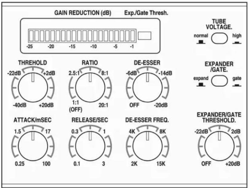
FIGURE 2 – Dynamics Section
Dynamic Processor Controls
The ART Voice Channel dynamics section consists of an above threshold Compressor/Limiter with De-esser plus a selectable Expander/Gate. The attack and release controls allow a wide range of adjustment while the complex detector assures fast response without distortion. The De-esser is frequency tunable.
Threshold Control
This control sets the level, above which the Compressor/Limiter in the Voice Channel starts to act on the input signal. As the control is turned clockwise, more input signal is required to begin reducing gain. The compression action can be seen in the Gain Reduction LED meter.
Ratio Control
The RATIO control sets the amount of gain reduction that takes place based on how far the input signal is over the threshold level (set by the THRESHOLD control). When the control is fully counterclockwise, the Compressor/Limiter is OFF.
A good starting point for vocals is 2.5:1.
To have the unit act as a limiter, set the RATIO control to 20:1.
De-esser Control
The DE-ESSER control sets how much more the gain is reduced at high frequencies when using the Compressor/Limiter. The most common application is reducing sibilance when compressing vocals. When fully counterclockwise, the De-esser function is OFF. As the control is turned clockwise, high frequency material is compressed more than mid and low frequency material.
De-esser Freq. Control
This control selects which high frequencies the DE-ESSER acts upon. Turned fully counterclockwise, the DE-ESSER acts on the upper mid-range. When set fully clockwise, only the highest frequencies are reduced more during de-essing compression. Center the DE-ESSER FREQ. control as a starting point for vocal work.
Attack Control
The ATTACK control sets the time it takes the Compressor/Limiter to respond to increases in signal level (by reducing gain). You can use this control to shape the “front end” of the dynamics envelope.
One example is to listen to a snare hit and adjust the attack control. A short attack makes the snare sound "thin". As the attacks go longer (and the knob is turned clockwise) you should hear more of the thump in the compressed snare. The downside is that this creates an overshoot, (a large transient), the length of which is the time set by the ATTACK control.
Overshoots less than 1 msec are very hard to hear even when they are clipped. If the attack is set too fast, the gain may be reduced too much and thereby create a “pumping” sound ^1 . One way to eliminate this is to use the LOW CUT filter to remove plosive sounds in vocals that can make the detector overreact.
Release Control
The RELEASE control sets the time the Compressor/Limiter takes to increase the gain after the input level drops.
Longer settings maintain the dynamics of the input signal, while shorter settings reduce the dynamics. Shorter settings will also increase the apparent reverberation, and at extreme gain reduction settings, lead to "breathing" artifacts ^2
Gain Reduction LED Meter
The GAIN REDUCTION meter displays the Compressor/Limiter's attenuation action. The meter covers a very large range while offering high resolution.
The large yellow LED at the right-hand end of the meter indicates Expander or Gate action. The brightness of the LED indicates the amount of gain reduction for the Expander function. Since the Gate is either ON or OFF, there is no brightness variation.
Expander/Gate Switch
This switch allows the selection of the Expander or the Gate functions. Both are useful in reducing unwanted background noise in the audio signal.
In the "OUT" position the Expander function is selected. Use this mode to gradually reduce background noise and maintain some of the input dynamics. This is useful for instruments with gradually decaying amplitude envelopes.
Depress this switch to select the Gate mode. This mode quickly cuts off the noise as the input signal drops.
Expander/Gate Threshold Control
The Expander/Gate action begins below the level indicated by the EXPANDER/GATE THRESHOLD control. The EXPANDER/GATE THRESH. LED in the GAIN REDUCTION display will light when the Expander or Gate attenuates the input signal.
The Expander/Gate Threshold detector has built-in hysteresis, which causes the unit to trigger "ON" at a higher level than the level required to trigger back to the "OFF" state.
The Expander slope is about 1:1.5. This is subtle enough to maintain the decay envelope of the source material and still lower the noise as the input signal drops. The EXPANDER/GATE THRESH. LED will light dimly for the first 5dB of gain reduction, and then glow brightly as the attenuation increases above this level.
The Gate function has an intelligent detector with a fast “attack” and “release”, coupled with a program dependant “hold”. The hold time is longer for sustained passages and shorter for transients. As the input drops below the threshold and the input signal is muted, the EXPANDER/GATE THRESH. LED lights brightly.
You can turn off the Expander/Gate function by setting the THRESHOLD control fully counterclockwise to "OFF".
Semi-Parametric EQ
The ART Voice Channel offers a four-band semi-parametric equalizer. The EQ can be bypassed as well as positioned before or after the dynamics processing section. Each band has ± 15dB of control range.
The High and Low EQ bands are shelving type with a switch selectable turnover point.
The two Mid bands can be continuously tuned over a five octave range.

FIGURE 3 – Equalizer Section
EQ Position Switch
The EQ POSITION switch allows you to connect the EQ before or after the dynamics processing block. This is useful in cases where the input signal needs a great deal of EQ before the Compressor/Limiter processes it. One example of using the EQ in the “PRE” position is using the LOW EQ control as a tunable low frequency cut, supplementing the LOW CUT filter switch.
Refer to Figure 4 for the block diagram of the Tube Channel. Note that the Mic preamp insert jack function is located before the EQ position switch.
EQ Bypass Switch
This switch allows you to instantly set the EQ completely flat without loosing the current EQ settings.

flowchart
graph TD
    A["PHANTOM POWER"] --> B["INPUT: 28/6dB"]
    C["PAD"] --> D["20/3dB"]
    D --> E["GAIN: 43/18dB"]
    E --> F["Instrument pre-omp"]
    F --> G["TUBE VOLTAGE"]
    G --> H["Tube gain stage"]
    H --> I["LOW CUT"]
    I --> J["INVERT"]
    J --> K["OUTPUT OUTPUT"]
    K --> L["PRE"]
    L --> M["POST"]
    M --> N["DYNAMICS PROCESSOR"]
    N --> O["PRE"]
    O --> P["POST"]
    P --> Q["OUTPUT BUFFER"]
    Q --> R["OUTPUT LEVEL"]
    S["IMPEDANCE"] --> T["368 1.2K"]
    T --> U["150 3K"]
    U --> V["Micro pre-omp"]
    V --> W["Phantom"]
    X["INVERT"] --> Y["Inverter"]
    Z["EQ PRE/POST"] --> AA["EQ"]
    AB["BALANCED OUTPUTS"] --> AC["LEFT A/D INSERT"]
    AD["SAMPLE RATE/DITHER"] --> AE["A/D converter"]
    AF["USB A/D converters"] --> AG["S/PDIF AES/EBU ADAT OUTPUTS"]
    AH["RIGHT A/D INSERT"] --> AI["USB A/D OUTPUT"]
    AJ["MIX PREAMP OUTPUT"] --> AK["PRE"]
    AL["INSERT INPUT"] --> AM["POST"]
    AN["DYNAMICS PROCESSOR"] --> AO["PRE"]
    AP["BANANCED OUTPUTS"] --> AQ["A/B/A/B", "A/B/A/B", "A/B/A/B", "A/B/A/B", "A/B/A/B", "A/B/A/B", "A/B/A/B", "A/B/A/B", "A/B/A/B", "A/B/A/B", "A/B/A/B", "A/B/A/B", "A/B/A/B", "A/B/A/B", "A/B/A/B", "A/B/A/B", "A/B/A/B", "A/B/A/C", "A/B/A/C", "A/B/A/C", "A/B/A/C", "A/B/A/C", "A/B/A/C", "A/B/A/C", "A/B/A/C", "A/B/A/C", "A/B/A/C", "A/B/A/C", "A/B/A/C", "A/B/A/C", "A/B/A/C", "A/B/A/C", "A/B/A/C", "A/B/A/C", "A /B /B /C" --> AB
FIGURE 4 – Signal Flow Block Diagram
Output Level Control
The OUTPUT LEVEL control provides gain or attenuation to adjust for a variety of system operating levels. This control affects the levels sent to the A/D converter and to the balanced analog OUTPUT jacks.
Output Level Meters
The ART Voice Channel provides both analog and digital output meters. The meters monitor the signal level just after the output control. This signal is sent to both the analog and digital outputs.
"0" VU on the analog VU meter corresponds to +4dBu on the balanced outputs, and about -20dB on the LED bargraph meter.
The LED bargraph meter indicates peak levels as well as average levels. Average levels are indicated by a continuous string of LEDs being lit. Peak levels are indicated by a single LED and are held for about 2 seconds. The last LED in the meter is marked "Clip", and it indicates that the output level is set too high.
The A/D Clip indicator LEDs act independent of the OUTPUT LEVEL meter. This provides an accurate indication of A/D converter clipping. This is useful when using the A/D insertion jacks, since the level at the converters will not be indicated on the main meters when these inputs are used.

FIGURE 5 – Output Section
Sample Rate/Dither Control
The SAMPLE RATE/DITHER knob selects the sample rate for the AES/EBU, S/PDIF, and optical outputs. It also selects the dither applied. Set the switch appropriately to match up with 16 or 24 bit encoding.
NOTE: This control does NOT affect the USB output.
Optical Output Switch
The OPTICAL OUTPUT switch sets the signal format of the rear panel OPTICAL OUTPUT connector. In ADAT mode channels 1 and 2 are the "left" and "right" A/D outputs of the Voice Channel respectively. NOTE: If the A/D insertion jacks are not being used, both channels 1 and 2 carry the same signal. If the ADAT INPUT is also being used, channels 3 thru 8 are passed through along with channels 1 and 2 of the ART Voice Channel.
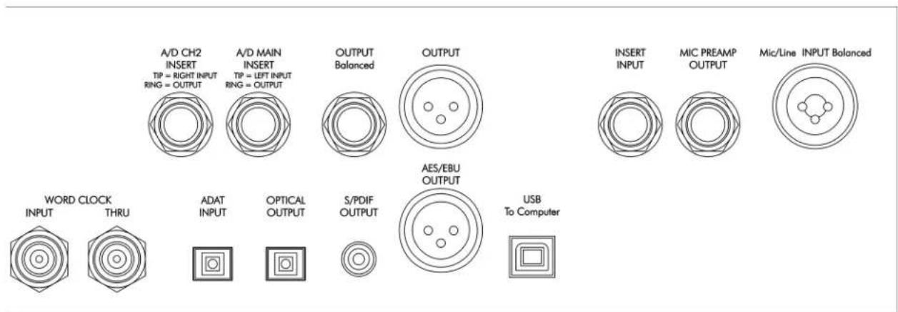
FIGURE 6 – Rear Panel
REAR PANEL CONNECTIONS
Mic/Line Input
This “combo” jack provides balanced inputs to the microphone preamplifier. The XLR connection is in parallel with the front input jack XLR. The input impedance of both XLR connections is variable by the front panel Impedance knob.
The rear 14 -inch input of the combo jack overrides the front panel XLR input when used. This input's impedance is NOT affected by the front panel Impedance control and is fixed at 20K Ohms.
The Front panel Instrument input overrides the rear jack when it is used.
Mic Preamp Output
This 14 -inch T/S unbalanced jack provides a direct signal from the microphone preamplifier, ahead of the EQ and dynamics processors. This output can be used in conjunction with the INSERT INPUT jack to insert external signal processors between the main preamp section and the EQ and dynamics processing of the Voice Channel.
Insert Input
This 14 -inch T/S unbalanced jack is an input to the EQ and dynamics processing sections. This input can be used in conjunction with the MIC PREAMP OUTPUT jack to insert external signal processors between the main preamp section and the EQ and dynamics processing of the Voice Channel ^™ .
Balanced Output
The analog output of the Voice Channel is available on both a 14 -inch TRS balanced jack and an XLR jack. This output is active balanced, and will adjust to balanced or unbalanced termination without gain change. The LED and analog meter monitor the level present at this output. "0" VU on the analog meter corresponds with +4dBu (about 1.2 Volts RMS).
A/D Main Insert and A/D CH2 Insert
Signal processing can be added between the analog output of the Voice Channel and the "left" and "right" channels of the A/D converter by using the A/D MAIN INSERT and the A/D CH2 INSERT respectively. Use a 14 -inch T/R/S (stereo) cable. The Ring is the output of the preamp and the Tip is the input to the A/D converter.
In order to use just the A/D converter and not the Voice Channel preamp, simply plug a standard 14 -inch T/S phone cable into either A/D insertion jack.
Wordclock Input and Thru Jacks
The WORDCLOCK INPUT is used to externally sync the Voice Channel to a master clock source. The BNC WORDCLOCK INPUT jack is connected directly to the BNC WORDCLOCK THRU jack, providing the ability to loop through the Voice Channel and connect other devices to the wordclock sync source, saving the use of a BNC T-adapter.
The input is high impedance thus leaving the wordclock connection unterminated. (A 75 Ohm BNC terminator should be used on the WORDCLOCK THRU jack if the WORDCLOCK INPUT jack is used only by itself.)
Select the EXT/16 or EXT/24 sample rate setting on the front panel to utilize External Wordclock mode.
Refer to FIGURE 7 for wordclock termination examples.

flowchart
graph TD
    A["FROM SOURCE OF WORDCLOCK SIGNAL"] --> B["WORD CLOCK INPUT"]
    C["75 Ohm TERMINATOR PLUG"] --> D["WORD CLOCK THRU"]
    B --> E["Voice Channel"]
    D --> E
    F["FROM SOURCE OF WORDCLOCK SIGNAL"] --> G["WORD CLOCK INPUT"]
    H["TO NEXT UNIT"] --> I["WORD CLOCK THRU"]
    J["WORD CLOCK INPUT"] --> K["Voice Channel"]
    L["WORD CLOCK THRU"] --> M["Voice Channel"]
FIGURE 7 – Wordclock Termination
ADAT Input Jack
The optical ADAT input allows the Voice Channel A/D converter to synchronize to systems using ADAT optical connections. The Voice Channel inserts its output in channels 1 and 2 of the ADAT stream while passing through channels 3 thru 8. Select ADAT/16 or ADAT/24 with the Sample Rate control on the front panel to enable this mode.
Optical Output Jack
The OPTICAL OUTPUT jack works in conjunction with the front panel OPTICAL OUTPUT switch, to output either an ADAT formatted signal or a TOS formatted signal. The front panel SAMPLE RATE/DITHER control sets the sample rate, dither, and sync source for this output.
S/PDIF Output Jack
This connector provides S/PDIF formatted digital outputs from the "left" and "right" A/D converters. The front panel SAMPLE RATE/DITHER control sets the sample rate, dither, and sync source for this output.
AES/EBU Output Jack
This connector provides AES/EBU signal level digital outputs from the "left" and "right" A/D converters. The front panel SAMPLE RATE/DITHER control sets the sample rate, dither, and sync source for this output.
USB Jack
The USB jack provides the output of the Voice Channel to a direct computer USB connection. The Voice Channel will be recognized as a standard audio device on the PC or Mac. The sample rate and bit depth of this interface is set by the computer and is independent of the front panel settings. The audio data formats are limited to 32 KHz, 44.1 KHz, 48 KHz, 16 or 24 bit encoding.
APPLICATIONS
Bypassing Components Of The Voice Channel
To bypass the vacuum tube microphone preamp: Use the preamp INSERT INPUT jack.
To bypass the Compressor/Limiter: Set the RATIO control fully counterclockwise to 1:1.
To bypass the Expander/Gate: Set the EXPANDER/GATE THRESHOLD control fully counterclockwise to OFF.
To bypass the EQ: Use the EQ bypass switch.
Optimizing The Preamp For Lowest Noise
The preamp of the ART Voice Channel can be optimized for low noise by combining use of the PAD and Input GAIN control for mic and line level signals. NOTE: The PAD control has no effect on the INSTRUMENT INPUT (Front panel 1/4" input of the INPUT combo jack).
First, bypass the Compressor/Limiter, Expander/Gate and EQ. Next center the OUTPUT LEVEL control to "0" dB of gain. The OUTPUT LEVEL LED meter can now be used to correctly indicate the clip level of the input stage.
Second, start with the PAD in the "OUT" position and the GAIN control centered. Refer to the OUTPUT LEVEL LED meter's peak-hold function. Make sure that this meter never indicates clipping (the red LED is held on after a transient). The peak-hold indicator can be in the "yellow" range or in the -5dB range of levels.
If the signal level is too high, depress the PAD switch.
Third, adjust the GAIN control to keep the peak levels in the -5dB range of the OUTPUT LEVEL LED meter.
Utilizing Pre/Post Compression EQ
The Equalizer section of the Voice Channel can be applied either before OR after the Compressor/Limiter. This function is useful in getting the best performance out of the unit.
Setting the Equalizer to “PRE COMP” is useful when the input signal contains too much low or high frequency information. Compressors in general work best when the audio is equalized first. (This can also serve to better control signal overshoots to the A/D converters as well.)
One example is a vocal where the performer/microphone combination produces a “popping” sound, and when compressed, the Compressor/Limiter “pumps”. Sometimes the use of the LOW CUT filter in the preamp section does not cut enough of this out, or cuts too much of the lower midrange out of the signal to be useful. Here, the EQ can surgically remove this information and better optimize the overall sound.
SERVICE PARTS
| ART Part # | Value Description Footprint | Qty Location | |||
| IC PARTS SECTION | |||||
| 100-1134-101 LM339 | AN QUAD COMPARATOR DIP14 5 | U106, U107, U108, U109, U110 | |||
| 100-1271-101 TL074 | Op-Amp, Quad, 14-pin DIP | DIP14 5 | U102, U103, U104, U201, U206 | ||
| 100-1403-101 74HC595 | 8-bit Shift Reg. w/Output Latch | DIP16 4 U205, U207, U301, U302 | |||
| 100-1397-101 74HC7046 | HIGH SPEED PLL w/LOCK DETECTOR | DIP16 1 U310 | |||
| 165-1387-102 MC68HRC908JK1P(20) | 8-Bit Microcontroller | DIP-20 | 1 | U200 | |
| 100-1359-101 | NE5532 | Op-Amp, Dual, 8-pin DIP | DIP8 | 7 | U5, U6, U100, U203, U204, U306, U309 |
| 100-1406-101 | OPA-2134 | Op-Amp, Dual, 8-pin DIP | DIP8 | 1 | U7 |
| 100-1104-101 | TL072 | Op-Amp, Dual, 8-pin DIP | DIP8 | 1 | U202 |
| 100-1333-103 THAT2181B VCA, Low-Noise, Low-THD | PAD-8 | 1 | U105 | ||
| REGULATOR/TRANSISTOR PARTS SECTION | |||||
| 100-1091-103 TIP112 | NPN Transistor, Darlington - Small Signal | TO220-VERT | 1 | Q1 | |
| 100-1089-101 uA7805 | Voltage Regulator - 7800 Family | TO220-VREG | 1 | U4 | |
| 100-1089-106 uA7812 | Voltage Regulator - 7800 Family | TO220-VREG | 1 | U3 | |
| 100-1042-102 uA7815 | Voltage Regulator - 7800 Family | TO220-VREG | 1 | U2 | |
| 100-1042-101 uA7915 | Voltage Regulator - 7900 Family | TO220-VREG | 1 | U1 | |
| 100-1181-101 2N4401 | NPN Transistor - Single TO92- | EBC 14 | Q3, Q4, Q5, Q6, Q7, Q8, Q9, Q10, Q11, Q100, Q104, Q300, Q301, Q308 | ||
| 100-1145-101 2N4403 | PNP Transistor - Single TO92- | EBC 10 | Q18, Q19, Q20, Q21, Q22, Q101, Q102, Q103, Q200, Q201 | ||
| POT AND TRIMMER PARTS SECTION | |||||
| 165-1164-101 CTS ABS. ENCODER | CTS ABSOLUTE ENCODER | CTS ABS. ENCODER | 1 | SW204 sample rate | |
| 100-1010-101 | 25K | POT-TRIMMER | TRIMHORIZ | 1 | VR109 THD trim |
| 100-1025-118 100K DUAL "C" TAPER | Pot, Dual Element | POT-9MM-DUAL | 2 | VR205 Mid-2 Freq, VR206 Mid-1 Freq | |
| 165-1027-105 | 5K DUAL/ 5%"C" TAPER | Pot, Dual Element | POT-16DUAL-H | 1 | VR2 Gain |
| 165-1025-121 100K "A" TAPER | POT - Single Control / Trimmer | POT-9MM-SGL | 1 | VR103 Attack | |
| 100-1025-101 | 100K "B" TAPER | POT-TRIMMER | POT-9MM-SGL | 1 | VR102 Ratio |
| 100-1025-103 10K "B" | TAPER POT-TRIMMER | POT-9MM-SGL 8 | VR100 Expand/gate, VR105 Threshold, VR106 Output, VR108 De-Esser, VR200 Mid-2, VR202 High, VR203 Low, VR204 Mid-1 | ||
| 165-1025-115 5K "A" | TAPER" | POT - Single Control / Trimmer | POT-9MM-SGL 1 | VR1 Impedance | |
| 164-1025-122 5K "C" | TAPER | POT - Single Control / Trimmer POT-9MM-SGL 2 | VR104 Release, VR107 De-Esser Freq | ||
| CONNECTOR/JACK PARTS SECTION | |||||
| 100-5082-102 GP1FA550RZ Fiber optic reciever GP1FA550TZ 1 U317 | |||||
| 100-5082-103 | GP1FA550TZ | Fiber optic transmitter | GP1FA550TZ | 1 | U316 |
| 100-5291-101 XLR-PHONE COMBO | NEUTRIK XLR/PHONE COMBO JACK | XLR COMBO-HORZ | 2 | JK3 MIC/LINE INPUT, JK4 INPUT MIC/INST | |
| 100-5270-102 XLR-M-H | Switchcraft PD3MRML2 Male XLR right angle rear mount | XLR-M-H | 2 | JK201 OUTPUT, JK302 AES/EBU OUTPUT | |
| 100-5035-101 jack 1/4" washer gnd. | REFERENCE CLIFF CL14422 | J-CLIF-GND | 5 | JK1 INSERT IN, JK2 MIC PRE OUTPUT, JK200 OUTPUT BALANCED, JK303 A/D CH2 INSERT, JK304 A/D MAIN INSERT | |
| 100-5225-102 J-CLIFF-GND | Jack, Cliff Stereo, with Grounding Clip | J-CLIF-GND | 5 | JK1, JK2, JK200, JK303, JK304 | |
| 100-5262-101 | TAB-FASTON | TAB.250 | 11 | P1- P7, P201-P204 | |
| 100-5080-101 BNC CONNECTOR | BNC-RAP2001 REFERENCE SWITCHCRAFT | BNC RT WITH WASHER AND NUT | 2 | JK300, JK301 WORDCLOCK | |
| 100-5081-101 RCA-041 SW JACK | 90 degree switched RCA jack | RCA SW | 1 JK305 | S/PDIF | |
| 169-1001-101 USB CONNECTOR | Power Dynamics USB-FB1RPX1 | JK306 | 1 JK306 | USB | |
| INDICATOR PARTS SECTION | |||||
| LEDREPAIRKIT | LED Back light | 1 | M1 | ||
| 100-2005-107 | VU METER W/tbox | NISSEI TN73 W/O BEZEL | 1 | M1 | |
| SWITCH PARTS SECTION | |||||
| 100-5022-104 SW-4PDT Switch, 4PDT, PCB Mount | SW-4PDT-FH-LIT2 | 2 | SW101 EQ POSITION, SW202 LOW FREQ | ||
| 100-5022-102 SW-DPT-FH Switch, DPDT, PCB mount | SW-DPDT-FH-LIT2 | 9 | SW1, SW2, SW3, SW4, SW6, SW100, SW200, SW201, SW222 All other switches | ||
| 165-2001-101 | E-SWITCH P277-EE-1-C-X-C | E-SWITCH POWER SWITCH #P227-EE-2-C-X-C | SW-DPST-PWR 1 | SW5 PWR SWT | |
| MISC. PARTS | |||||
| 100-1200-101 | 12AX7A | TUBE-9PIN | 1 | V1 | |
| MECHANICAL PARTS SECTION | |||||
| 100-1511-101 | TRANSFORMER, TOROID | 20V-0-20V @.7A + 9V@.4A 120/240V PRIMARY | 1 | TR100 ( MAY REQUIRE FEMALE CONNECTORS) | |
| ART Part # | Value Description | Footprint | Qty Location | ||
| 100-5052-107 .75" KNOB /BLACK | TAIWAN KNOB 42006-2G-D (TKE) 2 VR2 GAIN, VR106 OUTPUT | ||||
| 100-5052-108 0.5" KNOB /BLACK | TAIWAN KNOB 42006-4G-D (TKE) 14 | VR1, VR100, VR102, VR103, VR104, VR105, VR107, VR108, VR200, VR202, VR203, VR204, VR205, VR206, SW204 | |||
| 164-2004-101 LIT SWITCH CAP 12 | SW1, SW2, SW3, SW4, SW5, SW6, SW100, SW101, SW200, SW201, SW202, SW222 | ||||
FULL BILL OF MATERIALS
| ART Part # | Value Description | Footprint | Qty | Location | |
| AXIAL PARTS SECTION | |||||
| 100-1002-190 0 Ohm jumper | Resistor, Carbon Film,5% AXIAL0.4 1 R339 | ||||
| 100-1002-176 1.5K | Resistor, Carbon Film,5% AXIAL0.4 4 R242, R243, R244, R245 | ||||
| 100-1002-191 10 Ohms | Resistor, Carbon Film,5% AXIAL0.4 4 R29, R31, R32, R33 | ||||
| 100-1002-103 100 Ohms | Resistor, Carbon Film,5% | AXIAL0.4 21 | R69, R73, R163, R166, R254,R255, R256, R300, R308, R334,R180, R260-C269 | ||
| 100-1002-134 100K | Resistor, Carbon Film,5% AXIAL0.4 16 | R43, R44, R45, R46, R49, R50,R71, R100, R104, R108, R110,R115, R118, R133, R275, R305 | |||
| 100-1002-117 10K | Resistor, Carbon Film,5% AXIAL0.4 44 | R3-R17, R34, R36, R63, R70,R105, R106, R116, R117, R129,R132, R179, R200-R209, R231,R232, R233, R234, R235, R276,R277, R324 | |||
| 100-1001-401 10.0k Ohms | Resistor, Carbon Film,1% AXIAL0.4 2 R130, R131 | ||||
| 100-1002-184 10M | Resistor, Carbon Film,5% AXIAL0.4 1 R147 | ||||
| 100-1002-192 150 Ohms Resistor, Carbon | Film AXIAL0.4 12 | R68, R127, R146, R155, R164,R169, R172, R175, R176, R177,R309, R314 | |||
| 100-1002-119 15K | Resistor, Carbon Film,5% AXIAL0.4 1 R320 | ||||
| 100-1002-221 120K | Resistor, Carbon Film,5% | AXIAL0.4 1 R143 | |||
| 100-1002-177 160K | Resistor, Carbon Film,5% AXIAL0.4 1 R173 | ||||
| 100-1002-106 1K | Resistor, Carbon Film,5% AXIAL0.4 10 | R66, R120, R121, R122, R215,R222, R223, R224, R225,R270 | |||
| 100-1002-144 1M Resistor, Carbon Film AXIAL0.4 16 | R55, R56, R57, R135, R140, R153,R154, R226, R227, R228, R229,R230, R310, R311, R312, R325 | ||||
| 100-1002-216 33 Ohms | Resistor, Carbon Film,5% | AXIAL0.4 1 R30 | |||
| 100-1001-339 2.49K | Resistor, Carbon Film | AXIAL0.4 2 R51, R52 | |||
| 100-1002-109 2.4K | Resistor, Carbon Film,5% AXIAL0.4 4 R62, R344, R345, R346 | ||||
| 100-1002-182 200K | Resistor, Carbon Film,5% | AXIAL0.4 1 R109 | |||
| 100-1002-122 20K | Resistor, Carbon Film,5% AXIAL0.4 7 R40-R42, R170, R174, R217, R304 | ||||
| 100-1001-435 22.6K | Resistor, Carbon Film,5% | AXIAL0.4 2 R53, R54 | |||
| 100-1002-123 22K | Resistor, Carbon Film,5% AXIAL0.4 2 R240, R241 | ||||
| 24 Ohms | Resistor, Carbon Film,5% AXIAL0.4 1 R67 | ||||
| 100-1002-124 24K | Resistor, Carbon Film,5% | AXIAL0.4 1 R113 | |||
| 100-1002-104 200 Ohms | Resistor, Carbon Film,5% | AXIAL0.4 2 R18, R211 | |||
| 100-1002-181 240 Ohms | Resistor, Carbon Film,5% | AXIAL0.4 1 R144 | |||
| 100-1002197 270 Ohms | Resistor, Carbon Film,5% AXIAL0.4 2 R326, R329 | ||||
| 100-1002-138 240K | Resistor, Carbon Film,5% AXIAL0.4 2 R60, R72 | ||||
| 100-1002-153 2K | Resistor, Carbon Film,5% | AXIAL0.4 23 | R1, R27, R28, R35, R37, R38,R112, R123, R125, R126, R162,R165, R168, R210, R212, R213,R214, R216, R246, R247, R271,R313, R342 | ||
| 27 Ohms, 1/2 W | AXIAL0.5 1 R273 | ||||
| 100-1002-199 2.7K | Resistor, Carbon Film,5% AXIAL0.4 4 R236, R237, R238, R239 | ||||
| 100-1002-112 3.9K | Resistor, Carbon Film,5% AXIAL0.4 1 R272 | ||||
| 100-1002-159 300K | Resistor, Carbon Film,5% AXIAL0.4 4 R156, R157, R158 | ||||
| 100-1002-169 330 Ohms | Resistor, Carbon Film,5% | AXIAL0.4 19 | R11, R114, R119, R124, R128,R136, R137, R141, R142, R148,R181, R182, R183, R259, R306,R327, R330, R332 | ||
| 100-1002-127 33K | Resistor, Carbon Film,5% AXIAL0.4 3 R134, R145, R160 | ||||
| 100-1002-128 39K | Resistor, Carbon Film,5% | AXIAL0.4 1 R151 | |||
| 100-1002-110 3K | Resistor, Carbon Film,5% AXIAL0.4 1 R315 | ||||
| 100-1002-102 4.7 ohm | Resistor, Carbon Film,5% AXIAL0.4 1 R274 | ||||
| 100-1002-113 4.7K | Resistor, Carbon Film,5% AXIAL0.4 3 R2, R103, R317 | ||||
| 100-1001-368 4.99K | Resistor, Carbon Film,5% | AXIAL0.4 8 | R58, R59, R61, R171, R218, R219,R220, R221 | ||
| 100-1002-179 47 Ohms | Resistor, Carbon Film,5% AXIAL0.4 2 R257, R258 | ||||
| 100-1002-141 470K | Resistor, Carbon Film,5% | AXIAL0.4 4 R139, R150, R159, R161 | |||
| 100-1002-130 47K | Resistor, Carbon Film,5% AXIAL0.4 1 R252 | ||||
| 100-1002-114 5.1K | Resistor, Carbon Film,5% AXIAL0.4 8 | R102, R183, R301, R319, R322,R323, R328, R333 | |||
| 100-1002-185 5.1M | Resistor, Carbon Film,5% AXIAL0.4 2 R64, R65 | ||||
| ART Part # | Value | Description Footprint | Qty | Location | |
| 100-1002-187 510 Ohms | Resistor, Carbon Film,5% AXIAL0.4 18 | R19, R20, R21, R22, R23, R24,R25, R26, R124, R302, R303,R309, R314, R316, R321 R340,R341, R343 | |||
| 100-1002-154 51K | Resistor, Carbon Film,5% AXIAL0.4 2 R152, R331 | ||||
| 100-1002-115 6.8K | Resistor, Carbon Film,5% AXIAL0.4 2 R47, R48 | ||||
| 100-1002-218 620 Ohms | Resistor, Carbon Film,5% AXIAL0.4 1 R337 | ||||
| 100-1002-116 7.5K | Resistor, Carbon Film,5% | AXIAL0.4 1 R101 | |||
| 100-1002-213 75 Ohms | Resistor, Carbon Film,5% AXIAL0.4 3 R178, R180, R338 | ||||
| 100-1001-485 75K | Resistor, Carbon Film,5% | AXIAL0.4 1 R149 | |||
| OPTIONAL PART DO NOT STUFF | 2 R335, R336 | ||||
| 100-1005-117 470pF | Resistor, Carbon Film,5% CAP-AXIAL 1 C217 | ||||
| 100-1005-111 .001uF | Resistor, Carbon Film,5% CAP-AXIAL 1 C216 | ||||
| 100-1001-401 10.0k Ohms | Resistor, Carbon Film,1% AXIAL0.4 4 R248-251 | ||||
| SMT RESISTORS | |||||
| 1K Ohms | 0603 | 2 | R347, R348 | ||
| 200 Ohms | 0603 | 2 | R349, R350 | ||
| RADIAL PARTS SECTION | |||||
| 100-1035-103 .01uF | Capacitor, Film / Ceramic | RADIAL0.1 1 | C47 | ||
| 100-1038-101 100pF | Capacitor, Film / Ceramic | RADIAL0.1 | 13 | C28, C43, C107, C202, C203,C204, C205, C326, C327, C331,C332, C342, C343 | |
| 100-1036-104 | 10pF monobloc | Capacitor | RADIAL0.1 | 3 | C215, C220, C226 |
| 100-1036-102 150pF | Capacitor, Film / Ceramic | RADIAL0.1 1 | C28, C34 | ||
| 100-1036-109 20pF | monobloc | Capacitor, Film / Ceramic | RADIAL0.1 3 | C118, C348, C349 | |
| 100-1036-101 330pF | Capacitor, Film / Ceramic | RADIAL0.1 6 | C35, C38, | C39, C40, C52, C325 | |
| 100-1036-103 33pF | Capacitor, Film / Ceramic | RADIAL0.1 5 | C42, C44, | C46, C306, C307 | |
| 100-1036-120 47pF | Capacitor, Film / Ceramic | RADIAL0.1 1 | C300 | ||
| OPTIONAL PART DO NOT STUFF | RADIAL0.1 4 | C334, C335 | |||
| 100-1037T116 | .001uF | Capacitor, Film / Ceramic | RADIAL0.2 | ||
| 100-1037T103 | .0033uF | Capacitor, Film / Ceramic | RADIAL0.2 3 | C113, C117, C224 | |
| 100-1037T102 | .0047uF | Capacitor, Film / Ceramic | RADIAL0.2 1 | C218 | |
| 100-1037T106 | .015uF | Capacitor, Film / Ceramic | RADIAL0.2 1 | C225 | |
| 100-1037T107 | .022uF | Capacitor, Film / Ceramic | RADIAL0.2 3 | C209, C323, C324 | |
| ART Part # | Value Description Footprint | Qty | Location | ||
| 100-1037T111 .1uF | Capacitor, Film / Ceramic | RADIAL0.2 22 | C41, C103, C104, C105, C106,C206, R223, C308, C310, C311,C312, C313, C315, C316, C317,C318, C319, C320, C321, C322,R336, R337 | ||
| 100-1009T109 .22uF | Capacitor, Film / Ceramic | RADIAL0.2 2 C207, C208 | |||
| ELECTROLYTIC CAPACITOR PARTS SECTION | |||||
| 100-1162-115 | .15uF | Capacitor, Electrolytic(polarized) | LYTIC.1 | 3 C37 | C328, C329 |
| 100-1008-101 | .47uF 50V | Capacitor, Electrolytic(polarized) | LYTIC.1 | 4 C110 | C111, C221, C222 |
| 100-1008-102 | 1uF/50V | Capacitor, Electrolytic(polarized) | LYTIC.1 | 9 | C109, C114, C219, C228, C302,C338, C339, C340, C341 |
| 100-1162T114 220u | F/6.3V | Capacitor, Electrolytic(polarized) | LYTIC.1 | 9 | C29, C30, C31, C32, C33, C200,C201, C346, C347 |
| 100-1162T117 22uF | 35V | Capacitor, Electrolytic(polarized) | LYTIC.1 | 33 | C4, C5, C6, C7, C8, C9, C10, C11,C36, C49, C50, C51, C100, C101,C102, C115, C116, C210, C211,C212, C213, C214, C227, C230,C309, C333, C344, C345, C350 |
| 4.7uF | Capacitor, Electrolytic(polarized) | LYTIC.1 | 1 C47 | ||
| 100-1162-109 | 47uF | Capacitor, Electrolytic(polarized) | LYTIC.1 | 1 C301 | |
| 100-1162-124 | 100uF/100V | Capacitor, Electrolytic(polarized) | LYTIC.2 | 9 | C12, C13, C14, C15, C16, C17,C18, C19, C20 |
| 100-1162-125 | 100uF/200V | Capacitor, Electrolytic(polarized) | LYTIC.2 | 3 C21 | C22, C23 |
| 100-1162-107 | 2200uF/16V | Capacitor, Electrolytic(polarized) | LYTIC.2 | 3 C24 | C25, C48 |
| 100-1162-112 | 2200uF/35V | Capacitor, Electrolytic(polarized) | LYTIC.2 | 3 C1, | C2, C3 |
| 100-1162-110 | 470uF/25V | Capacitor, Electrolytic(polarized) | LYTIC.2 | 3 C26 | C27, C229 |
| OPTIONAL PARTS | DO NOT STUFF | C334, C335 | |||
| DIODE PARTS SECTION | |||||
| 100-1029T101 1N41 | 48 | Diode - Signal or PowerRectifier | DIODE0.4 | 26 | D13, D14, D18, D19, D100, D101,D102, D103, D104, D105, D106,D107, D108, D109, D110, D111,D112, D115, D118, D200, D202,D203, D205, D300, D301, D304 |
| 100-1030-102 | 1N5235B | Diode, Zener, <= 1w | DIODE0.4 | 1 | D114 |
| 100-1030-101 | 1N5231B | Diode, Zener, <= 1w | DIODE0.4 | 3 | D116,D119, D121 |
| 100-1030-107 1N5240B Diode, Zener, <= | 1w DIODE0.4 1 D113 | ||||
| 100-1030-101 1N5261B Diode, Zener, <= | 1w DIODE0.4 1 D15 | ||||
| 100-1030-108 1N5818 1N5818 shottkey diode DIODE0.4 3 D120, D201, D204 | |||||
| 100-1098-101 1N4003 | Diode - Signal or Power Rectifier | DIODE0.4LG 15 | D1, D2, D3, D4, D5, D6, D7, D8, D9, D10, D11, D12, D16, D17, D22, D23, D24 | ||
| IC PARTS SECTION | |||||
| 100-1134-101 LM339AN QUAD COMPARATOR DIP14 5 U106, U107, U108, U109, U110 | |||||
| 100-1271-101 TL074 | Op-Amp, Quad, 14-pin DIP | DIP14 5 U102, U103, U104, U201, U206 | |||
| 100-1403-101 74HC595 | 8-bit Shift Reg. w/Output Latch | DIP16 4 U205, U207, U301, U302 | |||
| 100-1397-101 74HC7046 | HIGH SPEED PLL w/LOCK DETECTOR | DIP16 1 U310 | |||
| 165-1387-102 MC68HRC908JK1P(20) | 8-Bit Microcontroller | DIP-20 | 1 | U200 | |
| 100-1359-101 NE5532 Op-Amp, Dual, 8-pin DIP | DIP8 | 7 | U5, U6, U100, U203, U204, U306, U309 | ||
| 100-1406-101 OPA-2134 Op-Amp, Dual, 8-pin DIP | DIP8 | 1 | U7 | ||
| 100-1104-101 TL072 Op-Amp, Dual, 8-pin DIP | DIP8 | 1 | U202 | ||
| 100-1333-103 THAT2181B | VCA, Low-Noise, Low-THD | PAD-8 | 1 | U105 | |
| SMT PARTS SECTION | |||||
| 100-1348-101 LM3046M | Transistor Array, 3-NPN + 1-Diff Pair NPN | SO-14 | 1 | U101 | |
| 100-1116-103 74HC00 | Quad 2-IN Nand Gate | SO-14 | 1 | U300 | |
| 100-1398-101 74HC74 | Flip-Flop, Dual D-Type w/Preset & Clear | SO-14 | 1 | U305 | |
| 100-1399-101 74HC161 | Synchronous 4-Bit Binary Counter | SO-16 | 2 | U303, U304 | |
| 100-1404-101 74HC4053 | Analog Switch, 3PDT - 3 Control Lines | SO-16 | 2 | U307, U308 | |
| 100-1401-101 AL-1401A | ALESIS OPTICAL OUTPUT GENERATOR | SOL-20 | 1 | U315 | |
| 100-1402-101 AL-1402 | ALESIS OPTICAL INPUT RECIEVER | SOL-24 | 1 | U313 | |
| 100-1410-101 PCM-1804 | 24 bit, 192KHz A/D converter | SSOP-28 | 1 | U314 | |
| 100-1409-101 DIT-4192 | 192KHz Digital audio transmitter | TSSOP-28 | 1 | U318 | |
| 165-2001-101 XF5756-ER9 | XFMRMS - 192KHz AES/EBU TRANSFORMER | XF5756-ER9 | 1 | TR300 | |
| PCM2902 USB INTERFACE I.C. | 1 | U311 | |||
| REGULATOR/TRANSISTOR PARTS SECTION | |||||
| ART Part # | Value Description Footprint | Qty | Location | ||
| 100-1091-103 TIP112 | 2 | NPN Transistor, Darlington - Small Signal | TO220-VERT 1 Q1 | ||
| 100-1134-105 | LM317T(3) | 3-TERMINAL ADJUSTABLE REGULATOR AND 3-AMP ADJUSTABLE REGULATOR TO220-VREG 1 U8 | |||
| 100-1089-101 uA7805 | Voltage Regulator - 7800 Family TO220-VREG 1 U4 | ||||
| 100-1089-106 uA7812 | Voltage Regulator - 7800 Family TO220-VREG 1 U3 | ||||
| 100-1042-102 uA7815 | Voltage Regulator - 7800 Family | TO220-VREG 1 U2 | |||
| 100-1042-101 uA7915 | Voltage Regulator - 7900 Family TO220-VREG 1 U1 | ||||
| 100-1181-101 2N4401 | NPN Transistor - Single TO92-EBC 14 | Q3, Q4, Q5, Q6, Q7, Q8, Q9, Q10, Q11, Q100, Q104, Q300, Q301, Q308 | |||
| 100-1145-101 2N4403 | PNP Transistor - Single TO92-EBC 10 | Q18, Q19, Q20, Q21, Q22, Q101, Q102, Q103, Q200, Q201 | |||
| 100-1144-103 2SA1316 | PNP - high gain,low noise/80V | TO92-ECB | 2 Q16, Q17 | ||
| 100-1098T103 | BF423 | PNP Transistor - Single | TO92-ECB | 4 | Q12, Q13, Q14, Q15 |
| POT AND TRIMMER PARTS SECTION | |||||
| 100-1164-101 | CTS ABS. ENCODER | CTS ABSOLUTE ENCODER | CTS ABS. ENCODER | 1 SW204 | |
| 100-1010-101 | 25K | POT-TRIMMER | TRIMHORZ | 1 | VR109 |
| 100-1025-105 | 100K DUAL "C" TAPER | Pot, Dual Element | POT-9MM-DUAL | 2 VR205, VR206 | |
| 100-1025-120 | 5K DUAL/ 5%"C" TAPER | Pot, Dual Element | POT-16DUAL-H | 1 | VR2 |
| 100-1025-121 100K | "A" TAPER | POT - Single Control / Trimmer | POT-9MM-SGL | 1 VR103 | |
| 100-1025-101 | 100K "B" TAPER | POT-TRIMMER | POT-9MM-SGL | 1 | VR102 |
| 100-1025-103 | 10K "B" TAPER | POT-TRIMMER | POT-9MM-SGL | 8 | VR100, VR105, VR106, VR108, VR200, VR202, VR203, VR204 |
| 165-1025-115 5K "A" TAPER | POT - Single Control / Trimmer | POT-9MM-SGL | 1 VR1 | ||
| 164-1025-122 5K "C" TAPER | POT - Single Control / Trimmer | POT-9MM-SGL | 2 VR104, VR107 | ||
| CONNECTOR/JACK PARTS SECTION | |||||
| 100-5082-102 | GP1FA550RZ | Fiber optic reciever | GP1FA550TZ | 1 | U317 |
| 100-5082-103 | GP1FA550TZ | Fiber optic transmitter | GP1FA550TZ | 1 | U316 |
| 100-5291-101 | XLR-PHONE COMBO | NEUTRIK XLR/PHONE COMBO JACK | XLR COMBO-HORZ | 2 JK3, JK4 | |
| 100-5270-102 XLR-M-H | Switchcraft PD3MRML2 Male XLR right angle rear mount | XLR-M-H | 2 JK201, JK302 | ||
| ART Part # | Value | Description | Footprint | Qty | Location |
| 100-5035-101 jack 1 | /4" washer gnd. | REFERENCE CLIFFCL14422 J-CLIF-GND 5 | JK1, JK2, JK200, | JK303, JK304 | |
| 100-5225-102 J-CLIFF-GND | Jack, Cliff Stereo, with Grounding Clip J-CLIF-GND 5 | JK1, JK2, JK200, | JK303, JK304 | ||
| 100-5262-101 TAB-FASTON TAB.250 | 1 P1-P7, P201-P204 | ||||
| 100-5080-101 BNC CONNECTOR | BNC-RAP2001REFERENCE SWITCHCRAFT | BNC RT WITH WASHER AND NUT 2 JK300, | JK301 | ||
| 100-5081-101 RCA-041 SW JACK | 90 degree switched RCA jack RCA SW | 1 JK305 | |||
| 100-1138-310 FLEX-10 | 10 WIDE FLEX STRIP,ONE END DEPICTED | SIP-10 | 10 | JP1, JP200, JP300, JP700, JP702,JP800, JP802, JP900, JP902, JP906 | |
| 100-1138-305 FLEX-5 | FLEX STRIP-FIVE WIDE | SIP-5 | 6 | JP310, JP704, JP804, JP806,JP904, JP908 | |
| 169-1001-101 USB CONNECTOR | Power Dynamics USB-FB1RPX1 | JK306 | 1 JK306 | ||
| INDICATOR PARTS SECTION | |||||
| 100-1136-103 Red | Kingbright-WP1043ID | Kingbright-WP1043ID | 2 | LED300, LED301 | |
| RED BARGRAPH | MV57164 REDBARGRAPH | 2 U111, U112 | |||
| GREEN BARGRAPH | MV54164 GREENBARGRAPH | 1 U113 | |||
| RED,YELLOW,GREEN | MV5A164 RED,YELLOW, GREENBARGRAPH | 1 U114 | |||
| 100-1136-104 | Yellow | Kingbright-WP1043YD | LED-L383 | 1 LED | 103 |
| 100-1132-102 Blue | LED - Single, T1, T1 3/4,T1 plus SMD 1205 SIZE,W/LENS - KINGBRIGHTAPTD3216PBC (BLUE) | LED-T1 | 2 LED2, LED222 | ||
| 100-1031-119 Orange | LED - Single, T1, T1 3/4,T1 plus SMD 1205 SIZE,W/LENS - KINGBRIGHTAPTD3216PBC (BLUE) | LED-T1 | 9 | LED1, LED3, LED4, LED6, LED100,LED101, LED200, LED201, LED202 | |
| 100-1031-122 Red | LED - Single, T1, T1 3/4,T1 plus SMD 1205 SIZE,W/LENS - KINGBRIGHTAPTD3216PBC (BLUE) | LED-T1 | 1 LED5 | ||
| 100-2005-107 VU METER W/box | NISSEI TN73 W/OBEZEL | 1 M1 | |||
| SWITCH PARTS SECTION | |||||
| 100-5022-104 SW-4PDT | Switch, 4PDT, PCBMount | SW-4PDT-FH-LIT2 | 2 SW | 101, SW202 | |
| 100-5022-102 SW-DPDT-FH | Switch, DPDT, PCBmount | SW-DPDT-FH-LIT2 | 9 | SW1, SW2, SW3, SW4, SW6,SW100, SW200, SW201, SW222 | |
| 165-2001-101 | E-SWITCH P277-EE-1-C-X-C | E-SWITCH POWERSWITCH #P227-EE-2-C-X-C | SW-DPST-PWR | 1 SW5 | |
| MISC. PARTS | |||||
| ART Part # | Value Description Footprint | Qty | Location | ||
| 100-1158T101 100u | H Inductor, Iron Core | CHOKE0.2 1 L401 | |||
| 100-1200-101 12AX | 7A TUBE-9PIN 1 V1 | ||||
| 100-1222-246 10.84 | 8MHz | Crystal - Series or Par. Mode | XTAL-HC18 1 X300 | ||
| 100-1222-246 12.00 | 0MHz | Crystal - Series or Par. Mode XTAL-HC18 1 X301 | |||
| 100-1228-103 RELA | Y-DPDT, 12V HS212 | 12 | RELAY-DPDT-DIP | 2 RL1, RL300 | |
| 100-5068-101 TUBE | SOCKET | Tube, Dual Triode (9-pin mini) | TUBE-9PIN 1 V1 | ||
| 100-5204-106 | HEATSINK #100-5204-106 | Heatsink, Add-On to TO-220 | HTSK-5204-106 5 | HS1, HS2, HS3, HS4, HS5 | |
| MECHANICAL PARTS SECTION | |||||
| 165-3001-103 | PCB BOARD | 1 | |||
| 100-5216-104 | .250" x .203" "L" bracket | Keystone #543-621 | BRKT-90^-FRT | 4 | Gain display, Output display |
| 100-1511-101 | TRANSFORMER, TOROID | 20V-0-20V @.7A + 9V@.4A 120/240V PRIMARY | 1 | TR100 ( MAY REQUIRE FEMALE CONNECTORS) | |
| 100-5027-122 6/32-3 | 3/8 ROLOX | 9 | POWER INLET, GND LUG,COVER, PCB-PCB STANDOFF | ||
| STANDOFF, PCB-PCB, 1.2", THREADED FOR 4-40 SCREWS | 2 | ||||
| Tube Shield/Spring/Collar | 1 V1 | ||||
| 4-4-40x 1/8" screws | 10 | V1, Gain Display, Output display | |||
| 2-.350"#4 threaded standoffs | 2 V1 | ||||
| 4-40 X 1/4" Pan head black, phillips | 12 | PCB to PCB standoffs, "L" brackets | |||
| 100-5030-106 | NUT 6-32 HEX NYLOK | 3 POWER INLET, GND LUG | |||
| #4BX3/8 PH PN HD ST BLK SCREW | 16 | CHASSIS TO FRONT, JK3,JK201,JK302,U316,U317 (OPTICAL JACKS), LED PCB MOUNTING | |||
| 100-5032-131 | SCREW 4-40X1/4 FLAT HEAD UNDER CUT | PCB TO STANDOFF | 2 SCREWS FOR JK4 | ||
| 100-5033-113 | 1/4 JACK PLASTIC NUT | REAR PANEL | 6 JK1,JK2,JK100,JK200,JK303,JK304 | ||
| ART Part # | Value | Description | Footprint | Qty | Location |
| 100-5052-107 .75" K | NOB /BLACK | TAIWAN KNOB 42006-2G-D (TKE) 2 VR2, VR106 | |||
| 100-5052-108 0.5" K | NOB /BLACK | TAIWAN KNOB 42006-4G-D (TKE) 14 | VR1, VR100, VR102, VR103, VR104, VR105, VR107, VR108, VR200, VR202, VR203, VR204, VR205, VR206, SW204 | ||
| 159-2009-200 | POWER INLET IEC w/FUSE W/ VOLTAGE SELECT | REAR PANEL 1 PL100 | |||
| 165-2001-200 FRONT PANEL 1 | |||||
| 165-2002-200 CHASSIS 1 | |||||
| 165-2003-200 COVER 1 | |||||
| 165-2004-200 Window 2.600 | X .650 1 Atten. Window | ||||
| 165-2005-200 Window 2.600 | X .650 1 Level Window | ||||
| 215-8002-100 | HARNESS .187 TO GND LUG | 1 HARNESS .187 TO GND LUG, 6" | |||
| 255-8002-101 | HARNESS PRIMARY AC | 1 | |||
| 165-2002-101 LIT SWITCH CAP 12 | SW1, SW2, SW3, SW4, SW5, SW6, SW100, SW101, SW200, SW201, SW202, SW222 | ||||
| #8 1 1/2" SCREW | FOR TRANSFORMER | 1 | TR100 | ||
| #8 WASHER | FOR TRANSFORMER | 1 | TR100 | ||
| #8 NYLOK NUT | FOR TRANSFORMER | 1 | TR100 | ||
| .125" ADHESIVE BASE STANDOFF | PCB TO CHASSIS | 2 | |||
| PACKAGING PARTS | |||||
| 500-5011-100 PKG BAG 1 | 15.75(OPEN)x26.500".002 | ||||
| 165- | PKG BOX | 1 MTL UNIT BOX | |||
| 100-6003-101 SERIAL LABEL 2 | |||||
| - | END CAPS | 2 PKG MTL ENS CAP | |||
| 000-100-120 | WARRANTY CARD | 1 | |||
| 000-100-121 | WARRANTY ENVELOPE | 1 | |||
| 165-5004-101 MANUAL 1 | PKG MANUAL | ||||
| MFG 9169-101 | BAG | 1 | PKG BAG 6"X6" X .002 FOR MANUAL PACKAGE | ||
| 100-1057-109 | 110V IEC POWER CORD | 1 | |||



WARRANTY INFORMATION
Limited Warranty (USA only)
Applied Research and Technology will provide warranty and service for this unit in accordance with the following warrants:
Applied Research and Technology, (A R T) warrants to the original purchaser that this product and the components thereof will be free from defects in workmanship and materials for a period of three years from the date of purchase. Applied Research and Technology will, without charge, repair or replace, at its option, defective product or component parts upon prepaid delivery to the factory service department or authorized service center, accompanied by proof of purchase date in the form of a valid sales receipt.
Online Registration
Please go to www.artproaudio.com. Select "Support", then "Product Registration" input your information here.
Exclusions
This warranty does not apply in the event of misuse or abuse of the product or as a result of unauthorized alterations or repairs. This warranty is void if the serial number is altered, defaced, or removed.
A R T reserves the right to make changes in design or make additions to or improvements upon this product without any obligation to install the same on products previously manufactured.
A R T shall not be liable for any consequential damages, including without limitation damages resulting from loss of use. Some states do not allow limitations of incidental or consequential damages, so the above limitation or exclusion may not apply to you. This warranty gives you specific rights and you may have other rights, which vary from state to state.
For units purchased outside the United States, an authorized distributor of Applied Research and Technology will provide service.
SERVICE
The following information is provided in the unlikely event that your unit requires service.
- Be sure that the unit is the cause of the problem. Check to make sure the unit has power, all cables are connected correctly, and the cables themselves are in working condition. You may want to consult with your dealer for assistance in troubleshooting or testing your particular configuration.
- If you believe that the ART unit is at fault, go to www.artproaudio.com. Select "Support", then "Return Authorization Request" to request a return authorization number.
- If you are returning the unit for service, pack the unit in its original carton or a reasonable substitute. The original packaging may not be suitable as a shipping carton, so consider putting the packaged unit in another box for shipping. Print the RA number clearly on the outside of the shipping box. Print your return shipping address on the outside of the box.
- Include, with your unit, a note with the RA number and your contact information, including a return shipping address (we cannot ship to a P.O. box) and a daytime phone number, and a description of the problem, preferably attached to the top of the unit. Also include a copy of your purchase receipt.
Please fill in the following information for your reference:
Date of purchase: ____
Purchased from: ____
Serial Number: ____
SPECIFICATIONS
Input Impedance
Mic 150 to 3.4K Ohms, variable
Line....20K Ohms
Instrument....2.5M Ohms
Preamp Insert....7.5K Ohms
A/D Inserts 10K Ohms
Output Impedance
Balanced Outputs....200 Ohms balanced
Preamp Output....100 Ohms
A/D Inserts 510 Ohms
Frequency Response
Analog In to Analog Out 12 Hz to 100 KHz +0, -1 dB
Analog In to Digital Out....12 Hz to 20 KHz +0, -1 dB @ 44.1 KHz sample rate
16 Hz to 42 KHz +0, -1 dB @ 96 KHz sample rate
THD
1 KHz ....≤ .015% typical
20 to 20 KHz ....≤ .033% typical
Equivalent Input Noise
Mic/Line....-130 dBu, Input shorted, Max gain, "A" weighted
Instrument....-105 dBu, Input shorted, Max gain, "A" weighted
Maximum Input Level
Mic/Line....+18 dBu balanced with PAD
Instrument....+15 dBu
Maximum Gain
Mic 70 dB (XLR to balanced output)
Instrument 40 dB (1/4-inch to balanced output)
Maximum Output level
Balanced....+20 dBu
Unbalanced....+20 dBu
Output Level At Meter 0 VU ....+4 dBu
Preamp
Microphone Gain....0 dB to +60 dB
Instrument Gain....+3 dB to +40 dB
Low Cut Filter 100 Hz, 1-pole, 6 dB/Octave
EQ
Boost/Cut ....±12 dB on each band
Low Freq. Tuning ....50/150 Hz Selectable
MID 1 Freq. Tuning....100 Hz to 3 KHz continuously variable
MID 2 Freq. Tuning....500 Hz to 15 KHz continuously variable
High Freq. Tuning....5K/15 KHz Selectable
Compressor/Limiter
Attack Time 250 uSec. to 100 mSec.
Release Time....100 mSec to 3 Sec.
De-esser Tuning....2.5 KHz to 15 KHz continuously variable
Compression Ratio....1:1 to 20:1
Expander Slope....1:1.5
Digital section
Wordclock Range....30 KHz to 204 KHz
Sample Rates....44.1 KHz, 48 KHz, 88.2 KHz, 96 KHz, 176 KHz, 192 KHz
A/D Dynamic Range....106 dB "A" weighted
USB A/D Dynamic Range....94 dB "A" weighted
Dimensions (HWD) 3.50-inch x 19.0-inch x 9.17-inch, 88.9mm x 483mm x 233mm
Weight....10.5 lbs., 4.76kg
Power Requirements....USA – 105 to 125 VAC/ 60 Hz Export units configured for country of destination.
USB Minimum System Requirements....USB Class compliant plug-and-play Mac and PC interface
Note: 0 dBu = 0.775 VRMS, 0 dBV = 1 VRMS
ART maintains a policy of constant product improvement. ART reserves the right to make changes in design, or make additions to, or improvements upon, this product without any obligation to install same on products previously manufactured. Therefore, specifications are subject to change without notice.

APPLIED RESEARCH AND TECHNOLOGY
www.artproaudio.com
E-mail: support@artproaudio.com
© 2020 Applied Research & Technology
Voice Channel
165-5004-107
Tube Channel Strip with Digital Connectivity


- IMPORTANT SAFETY INSTRUCTIONS – READ FIRST
- Read instructions:
- Do not open:
- Power sources:
- Power cord:
- Grounding:
- Ventilation:
- Moisture:
- Heat:
- Environment:
- Handling:
- Servicing:
- Installation:
- Voice Channel
- Tube Channel Strip with Digital Connectivity
- IMPORTANT SAFETY INSTRUCTIONS – READ FIRST ....1
- INTRODUCTION......4
- INSTALLATION....4
- FRONT PANEL CONTROLS and JACKS......6
- REAR PANEL CONNECTIONS....13
- APPLICATIONS 15
- SERVICE PARTS 16
- FULL BILL OF MATERIALS 19
- SCHEMATICS....28
- WARRANTY INFORMATION....32
- LIST OF FIGURES
- INTRODUCTION
- INSTALLATION
- AC Power Hookup
- Analog Audio Connections
- USB OPERATION
- FRONT PANEL CONTROLS and JACKS
- Mic Preamp Controls
- Instrument Input
- Gain Control
- Impedance Control
- Pad Switch
- Phantom Power
- Invert Switch
- Low Cut Switch
- Tube Voltage Switch
- Dynamic Processor Controls
- Threshold Control
- Ratio Control
- De-esser Control
- De-esser Freq. Control
- Attack Control
- Release Control
- Gain Reduction LED Meter
- Expander/Gate Switch
- Expander/Gate Threshold Control
- Semi-Parametric EQ
- EQ Position Switch
- EQ Bypass Switch
- Output Level Control
- Output Level Meters
- Sample Rate/Dither Control
- Optical Output Switch
- REAR PANEL CONNECTIONS
- Mic/Line Input
- Mic Preamp Output
- Insert Input
- Balanced Output
- A/D Main Insert and A/D CH2 Insert
- Wordclock Input and Thru Jacks
- ADAT Input Jack
- Optical Output Jack
- S/PDIF Output Jack
- AES/EBU Output Jack
- USB Jack
- APPLICATIONS
- Bypassing Components Of The Voice Channel
- Optimizing The Preamp For Lowest Noise
- Utilizing Pre/Post Compression EQ
- WARRANTY INFORMATION
- Limited Warranty (USA only)
- Online Registration
- Exclusions
- SERVICE
- SPECIFICATIONS
- Input Impedance
- Output Impedance
- Frequency Response
- THD
- Equivalent Input Noise
- Maximum Input Level
- Maximum Gain
- Maximum Output level
- Preamp
- EQ
- Compressor/Limiter
- Digital section
Brand : ART
Model : Voice Channel
Category : Processor