
UTX-M40 - Microphone SONY - Free user manual and instructions
Find the device manual for free UTX-M40 SONY in PDF.


| Product Type | Handheld Microphone Transmitter (UHF Wireless) |
| Model Number | UTX-M40 |
| Brand | Sony |
| Dimensions | Approximately 48 mm (diameter) × 258 mm (length) |
| Weight | Approximately 255 g (excluding batteries) |
| Power Supply | Two AA batteries (alkaline, NiMH, or lithium dry cell) |
| Battery Life | Approximately 8 hours with 30 mW output (alkaline) |
| Frequency Range | Depends on model (e.g., 470.125–541.875 MHz for 14UC/14LA) |
| RF Output Power | Selectable: 30 mW / 5 mW (specific models) |
| Audio Frequency Response | 70 Hz – 18 kHz (typical) |
| Microphone Element | Dynamic, unidirectional |
| Interchangeable Head | Yes, compatible with 31.3 mm diameter, 1.0 mm pitch capsules |
| Compander Modes | UWP-D, UWP, WL800 selectable |
| NFC SYNC Function | Yes, for quick frequency setting with compatible receivers |
| Display | OLED display with RF, audio level, battery, and menu |
| Audio Muting | Variable muting function via POWER/MUTE button |
| Auto Gain Mode | Yes, with +15 dB boost option |
| Operating Temperature | 0 °C to 50 °C (32 °F to 122 °F) |
| Storage Temperature | -20 °C to +55 °C (-4 °F to +131 °F) |
| Cleaning | Use a dry, soft cloth. Do not use thinners, benzene, or alcohol. |
| Safety Warning | Keep away from medical devices (contains magnets). Avoid condensation. |
| Replacement Parts | Microphone unit is replaceable; batteries are consumable. |
| Included Accessories | Microphone holder, Quick Start Guide, warranty card |
Frequently Asked Questions - UTX-M40 SONY
User questions about UTX-M40 SONY
0 question about this device. Answer the ones you know or ask your own.
Ask a new question about this device
Download the instructions for your Microphone in PDF format for free! Find your manual UTX-M40 - SONY and take your electronic device back in hand. On this page are published all the documents necessary for the use of your device. UTX-M40 by SONY.
USER MANUAL UTX-M40 SONY
UHF Wireless Microphone Package UHF Synthesized Transmitter UHF Synthesized Wireless Microphone UHF Synthesized Diversity Tuner
Operating Instructions
Before operating the unit, please read this manual thoroughly and retain it for future reference.
UWP-D21/D22/D26/D27
UTX-B40
UTX-M40
UTX-P40
URX-P40
URX-P41D
Table of Contents
Configuration of the Packages ....3
UWP-D21 3
UWP-D22 4
UWP-D26 5
UWP-D27 6
Models available separately.... 7
Features 8
UWP-D21 8
UWP-D22 8
UWP-D26 8
UWP-D27 8
Name and Function of Parts....9
Body-pack transmitter (UTX-B40)...... 9
Hand-held microphone (UTX-M40)...... 11
Plug-on transmitter (UTX-P40).... 12
Portable diversity tuner (URX-P40) ...... 14
Portable diversity tuner (URX-P41D) ..... 16
Power Supply....18
Inserting the batteries.... 18
Supplying power from a USB connector.... 20
Supplying power from an SMAD-P5 (option).... 20
Attaching Accessories....21
Attaching accessories to the body-pack transmitter (UTX-B40).... 21
Attaching accessories to the hand-held microphone (UTX-M40) 22
Attaching accessories to the plug-on transmitter (UTX-P40) 22
Attaching accessories to the portable diversity tuner (URX-P40/P41D)....22
Operation 23
If noise is generated 25
Tuner Settings ......26
Menu structure and operation 26
Setting the receive channel 27
Searching for available channels within a group (Clear Channel Scan) ...... 28
Searching for active channels within a group (Active Channel Scan) 29
Adjusting the monitor audio level ...... 30
Configuration menu.... 31
UTILITY menu.... 34
RX1/2 (tuner 1/2) menu.... 36
EXT.IN menu 38
Transmitter Settings ....39
Menu structure and operation ...... 39
Setting the transmit channel.... 40
Configuration menu 41
System Configuration Example ....45
Error Messages ....46
Troubleshooting......47
Important Notes on Use....51
Usage and storage 51
Cleaning.... 51
Specifications....52
Transmitter (UTX-B40/M40/P40)...... 52
Tuner (URX-P40/P41D).... 54
Configuration of the Packages
This manual is for the UWP-D21/D22/D26/D27 Wireless Microphone Packages. The contents of each package are described below.
Note
Some of the packages may not be available in certain countries or areas. In addition, the U90 model can only be used in the USA.
The use of U90 transmitters requires a license and is subject to restrictions on frequency selection and channel spacing. For details, consult your Sony dealer.
UWP-D21
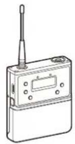
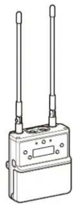
The package consists of a body-pack transmitter (UTX-B40), a portable diversity tuner (URX-P40), and their accessories. When used in conjunction with a compact camcorder, a mobile system for ENG (Electronic News Gathering) or EFP (Electronic Field Production) applications can be constructed.
Body-pack transmitter (UTX-B40) (1)
natural_image
Line drawing of a handheld electronic device with antenna and control panel (no text or symbols)Portable diversity tuner (URX-P40) (1)
natural_image
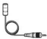
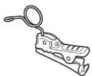
Line drawing of a two-wireless communication device with two antennas and a control panel (no text or symbols)Wind screen (1) Omni-directional lavalier microphone (1) Holder clip (1)
Supplied accessories

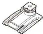
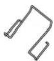
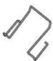
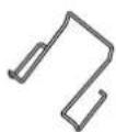
Shoe mount adaptor (1) Belt clip (2)
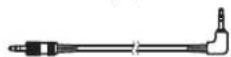
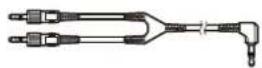
Stereo mini plug-BMP conversion cable for the URX-P40 (1)
XLR-BMP conversion output cable for the URX-P40/URX-P41D (1)

Before Use (1)
Quick Start Guide (1)
Warranty card (1) (UC, U, LA, KR models only)
UWP-D22
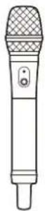
The package consists of a hand-held microphone (UTX-M40), a portable diversity tuner (URX-P40), and their accessories. When used in conjunction with a compact camcorder, a mobile system for ENG (Electronic News Gathering) or EFP (Electronic Field Production) applications can be constructed.
Hand-held microphone (UTX-M40) (1)
Supplied accessories
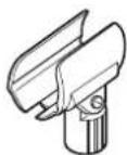
Microphone holder (1)
XLR-BMP conversion output cable for the URX-P40/URX-P41D (1)

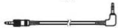
Stereo mini plug-BMP conversion cable for the URX-P40 (1)
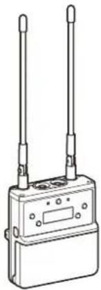
Portable diversity tuner (URX-P40) (1)
natural_image
Line drawing of a two-wireless wireless device with two antennas and a control panel (no text or symbols)Shoe mount adaptor (1)Belt clip (1)
Before Use (1)
Quick Start Guide (1)
Warranty card (1) (UC, U, LA, KR models only)
UWP-D26
The UWP-D26 consists of a plug-on transmitter (UTX-P40), a body-pack transmitter (UTX-B40), a portable diversity tuner (URX-P40), and their accessories. When used in conjunction with a compact camcorder, a mobile system for ENG (Electronic News Gathering) or EFP (Electronic Field Production) applications can be constructed.
Plug-on transmitter (UTX-P40) (1)
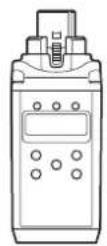
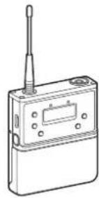
Body-pack transmitter (UTX-B40) (1)
natural_image
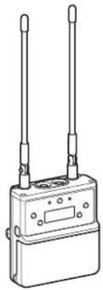
Line drawing of a handheld electronic device with antenna and control panel (no text or symbols)Portable diversity tuner (URX-P40) (1)
natural_image
Line drawing of a two-wire electronic device with two leads (no text or symbols)Supplied accessories
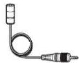
Omni-directional lavalier microphone (1)
Wind screen (1)

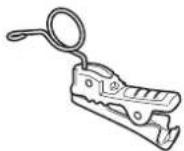
Holder clip (1)
Soft case (1)
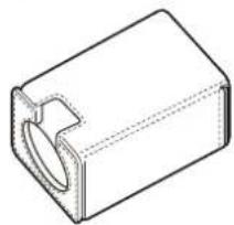
natural_image
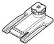
Technical line drawing of a rectangular mechanical part with a recessed cutout (no text or symbols)Shoe mount adaptor (1)
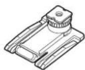
Belt clip (2)
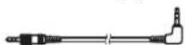
Stereo mini plug-BMP conversion cable for the URX-P40 (1)
XLR-BMP conversion output cable for the URX-P40/URX-P41D (1)

Before Use (1)
Quick Start Guide (1)
Warranty card (1) (UC, U, LA, KR models only)
UWP-D27
The package consists of two body-pack transmitters (UTX-B40), a portable diversity tuner (URX-P41D) that can receive two frequencies, and their accessories. When used in conjunction with a compact camcorder, a mobile system for ENG (Electronic News Gathering) or EFP (Electronic Field Production) applications can be constructed.
Body-pack transmitter (UTX-B40) (2)
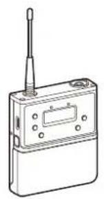
natural_image
Line drawing of a handheld electronic device with a antenna and control panel (no text or symbols)Portable diversity tuner (URX-P41D) (1)
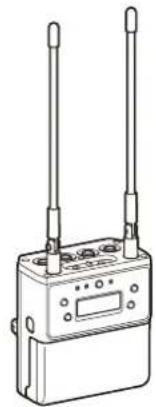
natural_image
Line drawing of a two-wireless wireless device with control panel and buttons (no text or symbols)Wind screen (2) Omni-directional lavalier microphone (2) Holder clip (2)
Supplied accessories
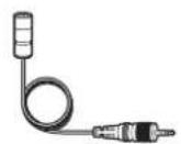

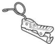
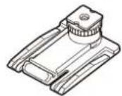
Shoe mount adaptor (1) Belt clip (3)
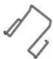
XLR-BMP conversion output cable for the URX-P40/URX-P41D (2)
Stereo mini plug-BMP conversion cable for the URX-P41D (1)
Before Use (1)
Quick Start Guide (1)
Warranty card (1) (UC, U, LA, KR models only)

Models available separately
The transmitter and tuner in each package are available for purchase separately. The components provided with each product are given below.
UTX-B40
• Body-pack transmitter (UTX-B40) (1)
- Omni-directional lavalier microphone (1)
- Wind screen (1)
- Holder clip (1)
- Belt clip (1)
- Before Use (1)
- Warranty card (1) (UC, U, LA, KR models only)
UTX-M40
• Hand-held microphone (UTX-M40) (1)
- Microphone holder (1)
- Before Use (1)
- Warranty card (1) (UC, U, LA, KR models only)
UTX-P40
- Plug-on transmitter (UTX-P40) (1)
- Soft case (1)
- Before Use (1)
- Warranty card (1) (UC, U, LA, KR models only)
URX-P40
- Portable diversity tuner (URX-P40) (1)
- Shoe mount adaptor (1)
- Belt clip (1)
- XLR-BMP conversion output cable for the URX-P40/URX-P41D (1)
- Stereo mini plug-BMP conversion cable for the URX-P40 (1)
- Before Use (1)
- Warranty card (1) (UC, U, LA, KR models only)
URX-P41D
- Portable diversity tuner (URX-P41D) (1)
- Shoe mount adaptor (1)
- Belt clip (1)
- XLR-BMP conversion output cable for the URX-P40/URX-P41D (2)
- Stereo mini plug-BMP conversion cable for the URX-P41D (1)
- Before Use (1)
- Warranty card (1) (UC, U, LA, KR models only)
Features
The UWP-D21/D22/D26/D27 (UWP-D series) Wireless Microphone Packages comprise a transmitter (body-pack transmitter (UTX-B40), hand-held microphone (UTX-M40), or plug-on transmitter (UTX-P40)) and a receiver (portable diversity tuner (URX-P40 or URX-P41D)). In combination with a compact camcorder or interchangeable-lens digital camera, the packages can be used for various purposes, such as ENG (Electronic News Gathering), EFP (Electronic Field Production), sports events, and weddings.
The features of each package are described below.
UWP-D21
• High quality sound with Sony Digital Audio Processing
- “NFC SYNC” function for quick and easy secure channel setting
• True diversity for stable signal reception
• Auto gain mode volume control
• + 1 5 dB gain volume boost mode for off-mic audio
• Line input available
- Channel memory function for fast switching between two receiver frequencies
• Transmitter frequency sent to receiver
• Headphone output for monitoring
• Monitor mode for using a receiver as an ear monitor
• Variable muting function
- Compatibility with Sony WL-800/UWP/UWP-D series
- Output level control for receiver
• High visibility OLED display for indoor/outdoor use
- USB for power supply
- Digital audio interface support using SMAD-P5 multi-interface shoe-mount adaptor (option)*
* For details on cameras that support this function, visit the Sony website.
UWP-D22
• High quality sound with Sony Digital Audio Processing
- "NFC SYNC" function for quick and easy secure channel setting
- True diversity for stable signal reception
- Interchangeable head for wide choice of microphone capsule
• Auto gain mode volume control
• +15 dB gain volume boost mode for off-mic audio
- Channel memory function for fast switching between two receiver frequencies
• Transmitter frequency sent to receiver
• Headphone output for monitoring
• Monitor mode for using a receiver as an ear monitor
• Variable muting function
- Compatibility with Sony WL-800/UWP/UWP-D series
• Output level control for receiver
• High visibility OLED display for indoor/outdoor use
- USB connector for power supply (URX-P40 only)
- Digital audio interface support using SMAD-P5 multi-interface shoe-mount adaptor (option)*
* For details on cameras that support this function, visit the Sony website.
UWP-D26
• High quality sound with Sony Digital Audio Processing
- “NFC SYNC” function for quick and easy secure channel setting
• True diversity for stable signal reception
• Auto gain mode volume control
• + 1 5 dB gain volume boost mode for off-mic audio
• Line input available
• +48V power supply (plug-on transmitter)
- Channel memory function for fast switching between two receiver frequencies
• Transmitter frequency sent to receiver
• Headphone output for monitoring
• Monitor mode for using a receiver as an ear monitor
• Variable muting function
- Compatibility with Sony WL-800/UWP series
- Output level control for receiver
• High visibility OLED display for indoor/outdoor use
- USB for power supply
- Digital audio interface support using SMAD-P5 multi-interface shoe-mount adaptor (option)*
* For details on cameras that support this function, visit the Sony website.
UWP-D27
• High quality sound with Sony Digital Audio Processing
- “NFC SYNC” function for quick and easy secure channel setting
- Space-diversity reception method for low dropouts (higher stability, true diversity reception in single channel operation mode)
- External microphone input connector supports plug-in power type external microphones and Sony BMP type lavalier microphones
• Built-in mixing function for flexible mixing and output of input signals
• Auto gain mode volume control
- +15 dB gain volume boost mode for off-mic audio
• Line input available
- ALL BAND scan function that scans all available frequency bands (Japan model, Korea model, 90U model, and E model do not have this function)
- Channel memory function for fast switching between two receiver frequencies
• Transmitter frequency sent to receiver
• Headphone output for monitoring
- Monitor mode for using a receiver as an ear monitor
• Variable muting function
- Compatibility with Sony WL-800/UWP/UWP-D series
- Channel configuration supported in combination with the UWP-D series equipped with an infrared communication function
- Output level control for receiver
- Equipped with output mode with wide range of output level settings
• High visibility OLED display for indoor/outdoor use - USB for power supply
- Digital audio interface support using SMAD-P5 multi-interface shoe-mount adaptor (option)*
* For details on cameras that support this function, visit the Sony website.
Name and Function of Parts
Body-pack transmitter (UTX-B40)
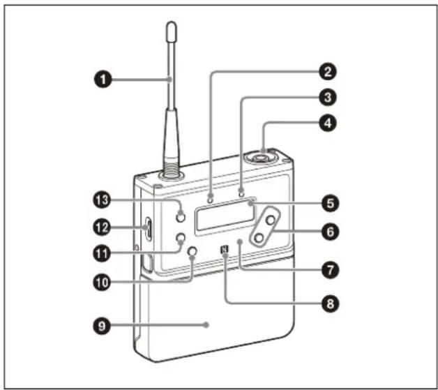
①Antenna
② POWER indicator
Displays the battery level.
| Indicator display Status | |
| On (green) Sufficient battery level | |
| Flashing (green) Battery is getting low | |
| Off Supply OFF | |
③AUDIO (audio input level) indicator
Turns on or off according to the audio input level as follows.
On (red): Audio input level is too high. If the sound is distorted, adjust the attenuation level to decrease the audio input level (page 41).
On (green): Audio input level is appropriate.
Off: There is no audio input or the input level is too low.
Flashing (orange): Audio is muted (i.e., disabled).
④Audio input connector (BMP type)
Connect to the supplied lavalier microphone.
Notes
- When the audio input level is set to MIC, a voltage for the lavalier microphone power supply is applied to the audio input connector. Special electrical wiring is used inside the audio input connector for this purpose.
- If a lavalier microphone other than the one supplied is connected, the proper performance may not be obtained.
⑤Display section
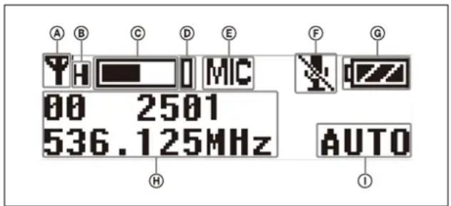
ⒶRF transmission indicator
Displays the current transmission status.
: Transmitting
- : T transmission stopped
®RF transmission power indicator
Indicates the current transmission power setting. You can change the setting with the RF transmission power setting function.
For details on the RF transmission power setting function, see “Setting the transmit output level (RF POWER)” (page 42).
©Au dio input level meter
Displays the audio input level.
(D)Peak indicator
Lights up when the signal is 3 dB below the level at which distortion begins as a warning of excessive input level.
⑤ Input level indicator
Displays the input level status.
MIC: Microphone input
LINE: Line input
⑤Muting status indicator
Displays an icon when the muting function is on.
For details about the muting function, see “Setting the operation of the audio muting function (MUTE SETTING) (UTX-B40/P40 only)” (page 42).
©Battery level indicator
Displays the battery level. "USB" is displayed when power is supplied from the USB connector.
For details, see "Battery level indicator" (page 19).
⑧Menu display section
Displays various functions. Press the + or - button to switch functions.
For details, see "Configuration menu" (page 41).
①Gain mode indicator
Displays the gain mode setting.
For details, see "Setting the audio gain (GAIN MODE)" (page 41).
6+ or - button
Selects functions or values shown on the display.
⑦Infrared detector
Receives the frequency and compander mode set on the tuner.
⑧N-Mark
Receives the frequency and commander mode set on the tuner. It also notifies the tuner about the frequency and commander mode set on the transmitter.
⑨B artery compartment
Accepts two AA batteries (alkaline, nickel metal hydride, or lithium dry cell batteries).
For details on how to insert batteries, see “Power Supply” (page 18).
⑩MUTE button
Turns the muting function on/off. You can change the muting function on/off control method in the configuration menu.
For details about switching the muting function on/off, see “Setting the operation of the audio muting function (MUTE SETTING) (UTX-B40/P40 only)” (page 42).
⑪ SET button
Adjusts displayed function settings and enters the displayed value.
Holding down the SET button while turning on the power turns the transmitter on without transmitting a signal (transmission stopped mode).
⑫USB connector (USB Type-C®)
Connect to a commercially available USB portable power supply.
When a USB portable power supply is connected while the power is turned on, the unit automatically operates with power supplied by the USB portable power supply.
13 POWER button
Turns the power on/off.
| Function Operation | |
| Supply ON Press button for one second or longer | |
| Supply OFF Press button until the indicator turns off | |
Hand-held microphone (UTX-M40)
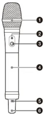
Inside the grip
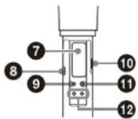
①Microphone unit
The standard-equipped microphone unit can be interchanged with another microphone unit having a diameter of 31.3 mm and a pitch of 1.0 mm.
For details on attaching and removing the microphone unit, see “Replacing the microphone unit” (page 22).
② POWER indicator
Displays the battery level and audio muting (i.e., audio enabled or disabled) status.
| Indicator display Status | |
| On (green) Sufficient battery level | |
| Flashing (green) Battery is getting low | |
| Off Supply OFF | |
| Flashing (orange) Audio is muted (i.e., disabled) | |
③PO WER/MUTE button
Turns the power on/off. You also use this button to turn the muting function on/off.
| Function Operation | |
| Supply ON Press button for one second or longer | |
| Supply OFF Press button until the indicator turns off | |
| Muting ON Press button | |
| Muting OFF | |
You can disable the power supply operation of the POWER/MUTE button and change the muting function on/off control method from the configuration menu.
For details, see “Setting the operation of the audio muting function (POWER/MUTE) (UTX-M40 only)” (page 42).
④ Battery compartment
Accepts two AA batteries (alkaline, nickel metal hydride, or lithium dry cell batteries).
For details on how to insert batteries, see “Power Supply” (page 18).
⑤N-Mark
Receives the frequency and commander mode set on the tuner. It also notifies the tuner about the frequency and commander mode set on the transmitter.
6 Antenna section
⑦ Display section
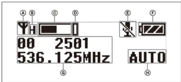
ⒶRF transmission indicator
Displays the current transmission status.
: Transmitting
- : Transmission stopped
®RF transmission power indicator
Indicates the current transmission power setting. You can change the setting with the RF transmission power setting function.
For details on the RF transmission power setting function, see “Setting the transmit output level (RF POWER)” (page 42).
©Audio input level meter
Displays the audio input level.
(D) Peak indicator
Lights up when the signal is 3 dB below the level at which distortion begins as a warning of excessive input level.
⑧Muting status indicator
Displays an icon when the muting function is on.
For details about the muting function, see “Setting the operation of the audio muting function (POWER/MUTE) (UTX-M40 only)” (page 42).
⑤Battery level indicator
Displays the battery level.
For details, see "Battery level indicator" (page 19).
©Menu display section
Displays various functions. Press the + or - button to switch functions.
For details, see "Configuration menu" (page 41).
⑧Gain mode indicator
Displays the gain mode setting.
For details, see “Setting the audio gain (GAIN MODE)” (page 41).
⑧Infrared detector
Receives the frequency and compander mode set on the tuner.
⑨ SET button
Adjusts displayed function settings and enters the displayed value.
Holding down the SET button while turning on the power turns the transmitter on without transmitting a signal (transmission stopped mode).
⑩USB connector (USB Type-C)
For use by service personnel.
⑪ POWER button
Turns the power on/off.
12+ or - button
Selects functions or values shown on the display.
Plug-on transmitter (UTX-P40)
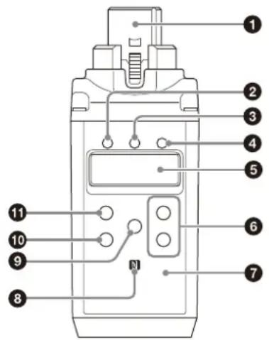
Front
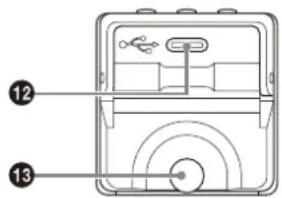
Bottom
①Audio input connector (XLR type)
Connect to a microphone or the line output of an audio mixer or other device.
②+48V (+48 V supply) indicator
Lights up when the unit is set to MIC input and is supplying power to the connected microphone.
③ POWER indicator
Displays the battery level.
| Indicator display Status | |
| On (green) Sufficient battery level | |
| Flashing (green) Battery is getting low | |
| Off Supply OFF | |
④AUDIO (audio input level) indicator
Turns on or off according to the audio input level as follows.
On (red): Audio input level is too high. If the sound is distorted, adjust the attenuation level to decrease the audio input level (page 41).
On (green): Audio input level is appropriate.
Off: There is no audio input or the input level is too low.
Flashing (orange): Audio is muted (i.e., disabled).
⑤Display section
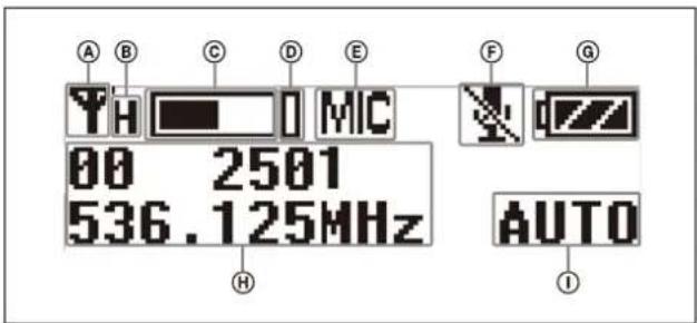
ⒶRF transmission indicator
Displays the current transmission status.
:Transmitting
- : T transmission stopped
®RF transmission power indicator
Indicates the current transmission power setting. You can change the setting with the RF transmission power setting function.
For details on the RF transmission power setting function, see “Setting the transmit output level (RF POWER)” (page 42).
©Audio input level meter
Displays the audio input level.
(D)Peak indicator
Lights up when the signal is 3 dB below the level at which distortion begins as a warning of excessive input level.
⑤ Input level indicator
Displays the input level status.
MIC: Microphone input
LINE : Line input
⑤Muting status indicator
Displays an icon when the muting function is on.
For details about the muting function, see “Setting the operation of the audio muting function (MUTE SETTING) (UTX-B40/P40 only)” (page 42).
©Battery level indicator
Displays the battery level. "USB" is displayed when power is supplied from the USB connector.
For details, see "Battery level indicator" (page 19).
⑧Menu display section
Displays various functions. Press the + or - button to switch functions.
For details, see "Configuration menu" (page 41).
①Gain mode indicator
Displays the gain mode setting.
For details, see "Setting the audio gain (GAIN MODE)" (page 41).
6+ or - button
Selects functions or values shown on the display.
⑦ Infrared detector
Receives the frequency and commander mode set on the tuner.
8N-Mark
Receives the frequency and commander mode set on the tuner. It also notifies the tuner about the frequency and commander mode set on the transmitter.
⑨MUTE button
Turns the muting function on/off. You can change the muting function on/off control method in the configuration menu.
For details about switching the muting function on/off, see "Setting the operation of the audio muting function (MUTE SETTING) (UTX-B40/P40 only)" (page 42).
⑩SET button
Adjusts displayed function settings and enters the displayed value.
Holding down the SET button while turning on the power turns the transmitter on without transmitting a signal (transmission stopped mode).
⑪ POWER button
Turns the power on/off.
| Function Operation | |
| Supply ON Press button for one second or longer | |
| Supply OFF Press button until the indicator turns off | |
⑫USB connector (USB Type-C)
Connect to a commercially available USB portable power supply.
When a USB portable power supply is connected while the power is turned on, the unit automatically operates with power supplied by the USB portable power supply.
⑬B artery compartment
Accepts two AA batteries (alkaline, nickel metal hydride, or lithium dry cell batteries).
For details on how to insert batteries, see "Power Supply" (page 18).
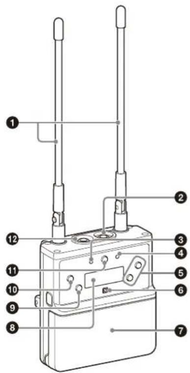
Portable diversity tuner (URX-P40)
Front
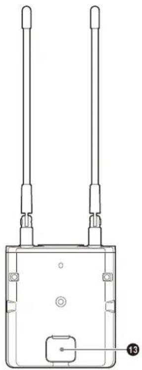
Rear
natural_image
Technical line drawing of a two-wire device with mounting holes and a labeled component (no text or symbols beyond basic outline)Bottom
①Antenna
②PHONES (monitor) connector (3.5-mm diameter, stereo mini jack)
Connect to headphones to monitor the audio output.
Note
Do not connect headphones with a monaural mini jack. This may short-circuit the headphone outputs, resulting in distorted sound output.
③ POWER indicator
Displays the battery level.
| Indicator display Status | |
| On (green) Sufficient battery level | |
| Flashing (green) Battery is getting low | |
| Off Supply OFF | |
④RF (radio frequency input) indicator
Displays the RF input level using the following colors.
On (green): Input level is 25 dB or more.
On (red): Input level is 15 dBμ to 25 dBμ.
Off: Input level is 15 dB or lower.
$$ * 0 \mathrm{dB} \mu = 1 \mu \mathrm{V} _ {\mathrm{EMF}} $$
⑤+ or - button
Selects functions or values shown on the display.
⑥N-Mark
Sends the set frequency and commander mode to the transmitter. It also detects the tuner about the frequency and commander mode set on the transmitter.
⑦ Battery compartment
Accepts two AA batteries (alkaline, nickel metal hydride, or lithium dry cell batteries).
For details on how to insert batteries, see "Power Supply" (page 18).
⑧ Display section
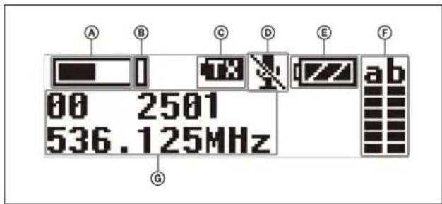
ⒶAudio input level meter
Displays the audio input level.
⑧Peak indicator
Lights up when the signal is 3 dB below the level at which distortion begins as a warning of excessive input level.
©Transmitter power warning indicator
Displays an icon when the remaining battery capacity of the transmitter being received is almost discharged.
Notes
- The icon is not displayed if the receive signal level is low.
- This function is enabled only when the transmitter is a UTX-B40/M40/P40.
©Transmitter muting status indicator
Displays an icon when the muting function of the transmitter being received is on.
Notes
- The icon is not displayed if the receive signal level is low.
- This function is enabled only when the transmitter is a UTX-B40/M40/P40.
⑤Battery level indicator
Displays the battery level. “USB” is displayed when power is supplied from the USB connector. “MI” is displayed when power is supplied from an SMAD-P5 (option).
For details, see "Battery level indicator" (page 19).
⑤RF (radio frequency input) level meter
Displays the RF input level. The number of lights will change depending on the input level.
6 lights: 60 dB or higher
5 lights: 50 dBμ to 60 dBμ
4 lights: 40 dBμ to 50 dBμ
3 lights: 30 dBμ to 40 dBμ
2 lights: 20 dBμ to 30 dBμ
1 light: 10 dBμ to 20 dBμ
No lights: 10 dBμ or lower
©M enu display section
Displays various functions. Press the + or - button to switch functions.
For details, see "Configuration menu" (page 31).
⑨NFC SYNC (NFC communication) button
Press to start a channel scan and for NFC communication with the transmitter.
For details, see "Operation" (page 23).
⑩SET button
Adjusts displayed function settings and enters the displayed value.
Holding down the SET button while turning on the power turns the transmitter on without transmitting a signal (transmission stopped mode).
11 POWER button
Turns the power on/off.
| Function Operation | |
| Supply ON Press button for one second or longer | |
| Supply OFF Press button until the indicator turns off | |
⑫ OUTPUT (audio output) connector (3.5-mm diameter, 3-pole locking mini jack, balanced output)
Connect one end of the supplied XLR-BMP conversion output cable for the URX-P40/URX-P41D or the stereo mini plug-BMP conversion cable for the URX-P40 here and the other end to the microphone input on a camcorder, mixer, or amplifier. If the microphone input connector on the connected device is a stereo mini jack, connect the straight (BMP) plug to the tuner and the L-shaped (stereo mini) plug to the microphone input connector on the device.
Notes
- To prevent damaging the tuner, do not apply a voltage to this connector from a microphone external power supply (MIC+48V) or other source.
- Connection to a plug-in power microphone input connector is supported using the stereo mini plug-BMP conversion cable for the URX-P40.
- When the SMAD-P5 (option) is connected, connecting the stereo mini plug-BMP conversion cable for the URX-P40 to a camcorder microphone input may cause noise to occur. In that case, use the supplied shoe mount adaptor.
- When the stereo mini plug-BMP conversion cable for the URX-P40 is connected, the output becomes unbalanced.
⑬Auxiliary connector
Refer to the SMAD-P5 (option) operating instructions for details about attaching to this unit.
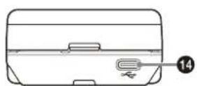
14USB connector (USB Type-C)
Connect to a commercially available USB portable power supply.
When the power is turned on, the unit operates with power supplied by the USB portable power supply.
Portable diversity tuner (URX-P41D)
Front
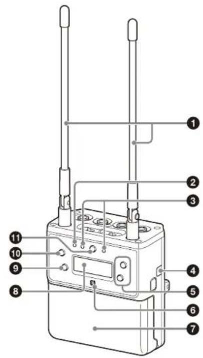
BottomTop
natural_image
Line drawing of a toolbox with a labeled part (no text or symbols beyond the number 16)Rear
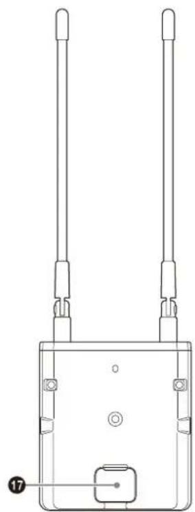
natural_image
Technical line drawing of a dual-axis antenna device with labeled component (no text or symbols beyond part numbers)①Antenna
② POWER indicator
Displays the battery level.
| Indicator display Status | |
| On (green) Sufficient battery level | |
| Flashing (green) Battery is getting low | |
| Off Supply OFF | |
③RF (radio frequency input) indicators
Lights up as shown below depending on the RF input level of tuner 1 and tuner 2.
On (green): Input level is 25 dBμ or more.
On (red): Input level is 15 dBμ to 25 dBμ.
Off: Input level is 15 dB or lower.
$$ * 0 \mathrm{dB} \mu = 1 \mu \mathrm{V} _ {\text { EMF }} $$
④Infrared transmitter port
Sends the set frequency and commander mode to the transmitter.
⑤+ or - button
Selects functions or values shown on the display.
6N-Mark
Sends the set frequency and commander mode to the transmitter. It also detects the tuner about the frequency and commander mode set on the transmitter.
⑦ Battery compartment
Accepts two AA batteries (alkaline, nickel metal hydride, or lithium dry cell batteries).
For details on how to insert batteries, see "Power Supply" (page 18).
⑧ Display section
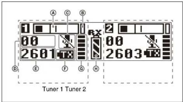
ⒶAudio input level meter
Displays the received audio signal level.
⑧Peak indicator
Lights up when the signal is 3 dB below the level at which distortion begins as a warning of excessive input level.
©Transmitter muting status indicator
Displays an icon when the muting function of the transmitter being received is on.
Notes
- The icon is not displayed if the receive signal level is low.
- This function is enabled only when the transmitter is a UTX-B40/M40/P40.
©Group display
Displays the configured receive group name.
⑤Ch annel display
Displays the configured receive channel name.
⑤Transmitter power warning indicator
Displays an icon when the remaining battery capacity of the transmitter being received is almost discharged.
Notes
- The icon is not displayed if the receive signal level is low.
- This function is enabled only when the transmitter is a UTX-B40/M40/P40.
©RF (radio frequency input) level meter
Displays the RF input level. The number of lights will change depending on the input level.
6 lights: 60 dB or higher
5 lights: 50 dBμ to 60 dBμ
4 lights: 40 dBμ to 50 dBμ
3 lights: 30 dBμ to 40 dBμ
2 lights: 20 dBμ to 30 dBμ
1 light: 10 dBμ to 20 dBμ
No lights: 10 dB or lower
⑧Battery level indicator
Displays the battery level. “USB” is displayed when power is supplied from the USB connector. “MI” is displayed when power is supplied from an SMAD-P5 (not supplied).
For details, see "Battery level indicator" (page 19).
⑨NFC SYNC (NFC communication) button
Press to start a channel scan and for NFC communication or IR SYNC with the transmitter.
For details, see "Operation" (page 23).
10SET button
Adjusts displayed function settings and enters the displayed value.
⑪ MENU button
Switches the menu to show on the display.
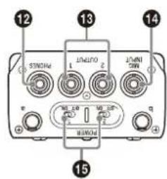
⑫PHONES (monitor) connector (3.5-mm diameter, stereo mini jack)
Connect to headphones to monitor the audio output.
Note
Do not connect headphones with a monaural mini jack. This may short-circuit the headphone outputs, resulting in distorted sound output.
13O OUTPUT 1/2 (audio output 1/2) connector (3.5-mm diameter, 3-pole locking mini jack, balanced output)
Connect one end of the supplied XLR-BMP conversion output cable for the URX-P40/URX-P41D or the stereo mini plug-BMP conversion cable for the URX-P41D here and the other end to the microphone input on a camcorder, mixer, or amplifier.
If the microphone input connector on the connected device is a stereo mini jack, connect the straight (BMP) plug to the tuner and the L-shaped (stereo mini) plug to the microphone input connector on the device.
Notes
- To prevent damaging the tuner, do not apply a voltage to this connector from a microphone external power supply (MIC+48V) or other source.
- Connection to a plug-in power microphone input connector is supported using the stereo mini plug-BMP conversion cable for the URX-P41D.
- When the SMAD-P5 (option) is connected, connecting the stereo mini plug-BMP conversion cable for the URX-P41D to a camcorder microphone input may cause noise to occur. In that case, use the supplied shoe mount adaptor.
- When the stereo mini plug-BMP conversion cable for the URX-P41D is connected, the output becomes unbalanced.
14 MIC INPUT (audio input) connector (3.5-mm diameter, stereo mini jack)
Connect to plug-in power type external microphones and Sony BMP type lavalier microphones
15 POWER switches
Turns tuner 1 and tuner 2 on/off.
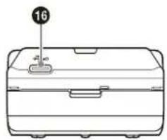
⑯USB connector (USB Type-C)
Connect to a commercially available USB portable power supply.
When the power is turned on, the unit operates with power supplied by the USB portable power supply.
⑰ A uxiliary connector
Refer to the SMAD-P5 (option) operating instructions for details about attaching to this unit.
Power Supply
This section describes the power supply of each device.
Body-pack transmitter (UTX-B40) and plug-on transmitter (UTX-P40)
The unit operates using power supplied from two AA batteries (alkaline, nickel metal hydride, or lithium dry cell batteries) or from a supply connected to the USB connector. If power is supplied simultaneously from batteries and from a supply connected to the USB connector, power from the USB connector has precedence. For details about inserting batteries in each device and displaying the battery level, or supplying power from a supply connected to the USB connector, see the following sections.
Hand-held microphone (UTX-M40)
The unit operates from two AA batteries (alkaline, nickel metal hydride, or lithium dry cell batteries). For details about inserting batteries and displaying the battery level, see the following sections.
Portable diversity tuner (URX-P40/P41D)
The unit operates from two AA batteries (alkaline, nickel metal hydride, or lithium dry cell batteries), power supplied from a supply connected to the USB connector, or power supplied from the auxiliary connector. The power supply that has precedence when both AA battery power and an external power supply via the USB connector or auxiliary connector are available can be specified using the POWER SOURCE (external power selection) function. Under the factory default setting, the power supplied from inserted AA batteries has precedence. For details about inserting batteries and displaying the battery level, or supplying power from supply connected to the USB connector, see the following sections.
For details on the POWER SOURCE function setting, see "Selecting the preferred power supply (POWER SOURCE)" (URX-P40: page 33, URX-P41D: page 35).
Notes
- The use of manganese batteries will result in poor performance. Do not use manganese batteries.
- AA size rechargeable lithium-ion batteries cannot be used.
Inserting the batteries
Notes
- Always use sets of the same type of battery. Do not use batteries of different types or batteries with different charge level together.
- Replacing the batteries during operation may generate a large noise. Be sure to turn off the unit before replacing the batteries.
Body-pack transmitter (UTX-B40) / portable diversity tuner (URX-P40/P41D)
The following describes the procedure using illustrations for the body-pack transmitter (UTX-B40). Batteries can be inserted in the portable diversity tuner (URX-P40/P41D) in the same manner.
1 On the UTX-B40/URX-P40, press and hold the POWER button to turn the power off. On the URX-P41D, operate the two POWER switches to turn the power off.
2 Press and hold the buttons on the left and right sides, and pull off the battery compartment.
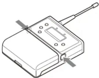
natural_image
Technical line drawing of a device with a rectangular base and antenna, no text or symbols present3 Open the battery compartment, insert two new AA batteries into the battery compartment with and polarities in the correct orientation, and reattach the compartment.
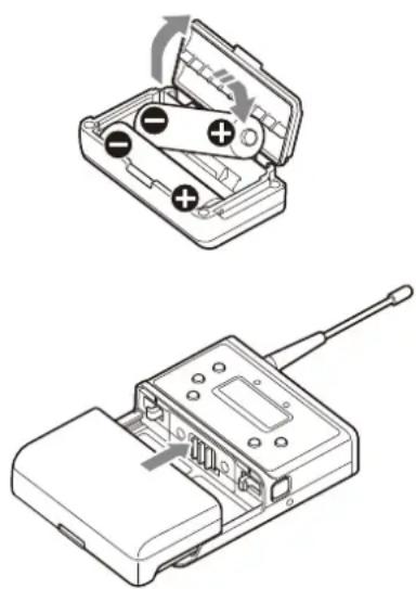
natural_image
Technical line drawings of a device with battery, switch, and antenna (no text or symbols)Make sure that the battery compartment is locked securely.
Note
When attaching the battery compartment, make sure that the battery compartment is locked securely on the left and right sides.
If either the left or right lock button is depressed, the battery compartment is not locked. Push the battery compartment in so that the lock buttons are flush with the sides of the device.
Locked Unlocked
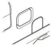
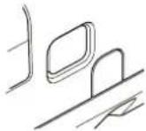
Hand-held microphone (UTX-M40)
1 Press and hold the POWER/MUTE button or POWER button to turn the power off.
Note
The button used to turn off power varies depending on the POWER/MUTE setting.
For details, see "Setting the operation of the audio muting function (POWER/MUTE) (UTX-M40 only)" (page 42).
2 Turn the grip in the direction of the arrow, and pull the grip down until the battery compartment is visible.
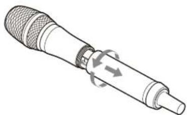
natural_image
Illustration of a mechanical device with internal components and directional arrows indicating motion (no text or symbols)3 Insert two new AA batteries into the battery compartment with and polarities in the correct orientation.
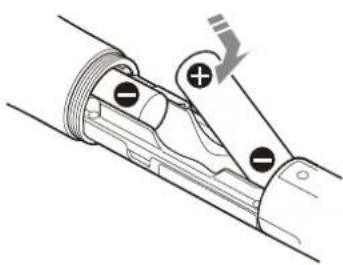
natural_image
Mechanical assembly diagram showing a lever mechanism with labeled joints and motion arrow (no text or symbols)4 Close the grip, turning it in the reverse direction of step 2.
Plug-on transmitter (UTX-P40)
1 Press and hold the POWER button to turn the power off.
2 Turn the battery compartment knob counterclockwise to open the cover.
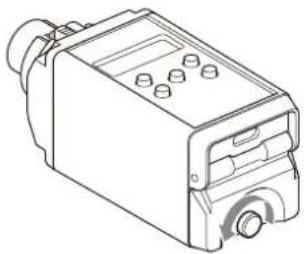
natural_image
Line drawing of a mechanical device with ports and mounting holes (no text or symbols)3 Insert two new AA batteries into the battery compartment with and polarities in the correct orientation.
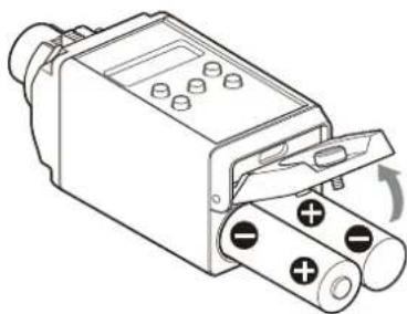
natural_image
Technical line drawing of a mechanical component with battery terminals and a rotary knob (no text or symbols)4 Close the battery compartment cover and turn the knob clockwise to lock the cover.
Check that the cover is fully closed before tightening the knob.
Battery level indicator
Turning the power on will display the battery level on the display.
Immediately replace both batteries with new batteries if the indicator starts flashing (indication 5 below). If using new alkaline batteries, use after checking the recommended time limits.
| Battery level indicator | Battery status | |
| 1 | Lights Good | |
| 2 | Lights Less than about  | 70% charge remaining |
| 3 | Lights Less than about  | 40% charge remaining |
| 4 | Lights Less than about  | 20% charge remaining |
| 5 | Flashes Almost empty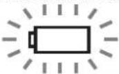 |
Notes
- When BATTERY TYPE is set to TYPE1, the battery level is indicated based on the use of new LR6 (size AA) alkaline batteries from a specific manufacturer.
The battery level may not be displayed correctly when different kinds of batteries, different brand of batteries, or old batteries are used. If using batteries other than size AA alkaline batteries, select the battery type using the BATTERY TYPE function.
- Rechargeable nickel metal hydride batteries may experience deterioration in battery performance with repeated charging/discharging over time, and the remaining charge display may not accurately indicate the remaining charge.
- If you plan to use the transmitter continuously for a long period of time, it is recommended that you replace the batteries with brand new ones.
- Battery power is gradually consumed, even when the unit is turned off. Remove the batteries from the unit before prolonged periods of disuse.
For details on the BATTERY TYPE function setting, see "Setting the battery type (BATTERY TYPE)" (URX-P40: page 33, URX-P41D: page 35, UTX-B40/M40/P40: page 43).
Battery precautions
Batteries may leak or explode if mistreated. Be sure to follow these instructions.
- Insert batteries in the correct and polarity orientation.
• Always replace the two batteries together with new ones. - Do not use different types of batteries or old and new ones together.
- Batteries cannot be charged with this unit.
- When not using the device for a long period of time, remove the batteries. If the batteries leak for any reason, consult your Sony service representative.
Supplying power from a USB connector
The transmitter (UTX-B40/P40) and tuner (URX-P40/P41D) can operate from a commercially available USB-output type AC adaptor or portable power supply connected to the USB connector.
When supplying power using a USB-output type AC adaptor or portable power supply, use a unit that satisfies the following conditions.
• Output connector: USB Type-C
- Rated voltage: 5 V
• Output current: 200 mA or higher
Displays “USB” when power is supplied from the USB connector.
Notes
- The UTX-M40 hand-held microphone cannot be supplied using a USB connector.
- Noise may occur in the audio depending on the AC adaptor or portable power supply that is connected. In such cases, you can reduce the noise by distancing the unit or lavalier microphone from the AC adaptor or
portable power supply or otherwise altering their positions.
- If a USB Type-C adaptor (from a different connector type) or a cable that does not comply with the USB Type-C standard is used, noise may occur or power may not be applied correctly. Always use cables that comply with the USB Type-C standard.
Supplying power from an SMAD-P5 (option)
The portable diversity tuner (URX-P40/P41D) can operate with cameras equipped with a multi-interface shoe, such as Sony video camera recorders and digital cameras that use an interchangeable lens, by connecting an SMAD-P5 (option) to the auxiliary connector. In addition, the power supply of the tuner and the camera can be linked.
By connecting this unit to an SMAD-P5 (option) and attaching to a camera equipped with a multi-interface shoe, audio signals can be sent from the tuner to the camera without the need for a cable. In addition, when connected to a camera equipped with a multi-interface shoe that supports digital audio input, the digital audio signal output from the tuner can be recorded directly by the camera.
Refer to the SMAD-P5 (option) operating instructions for details on how to attach it to the camera, how to link the power supply of the tuner with the camera, and how to switch the audio signal.
Note
When used with some cameras, operation of the power supply function and link on/off function with the SMAD-P5 (option) is not guaranteed.
For details, refer to the SMAD-P5 (option) operating instructions. For camera device information, visit the Sony website.
Attaching Accessories
This section describes how to attach the supplied accessories to each device.
Attaching accessories to the body-pack transmitter (UTX-B40)
Connecting the microphone
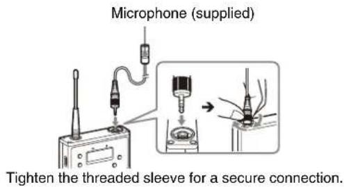
Note
Be sure to attach or remove the microphone after turning off the transmitter.
Attaching the holder clip to the microphone
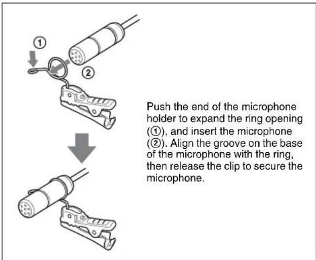
To secure the microphone cable
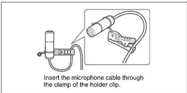
Attaching the wind screen to the microphone
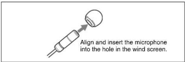
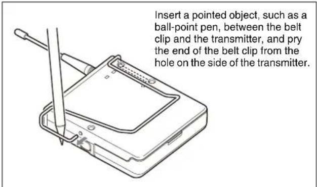
Attaching a belt clip
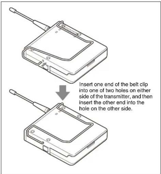
To remove a belt clip
Attaching accessories to the hand-held microphone (UTX-M40)
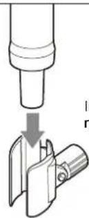
Attaching the microphone holder
natural_image
Diagram showing a mechanical component being inserted into a housing, with no visible text or symbols.Insert the base of the microphone into the holder.
Replacing the microphone unit
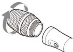
Removing the microphone unit
natural_image
Illustration of a mechanical component with mesh texture and a separate cylindrical part (no text or symbols)Turn the microphone unit in the direction of the arrow.
Attaching the microphone unit
Turn the microphone unit in the opposite direction from when you removed it, and make sure that the unit is securely attached to the microphone.
Attaching accessories to the plug-on transmitter (UTX-P40)
Attaching a microphone or cable
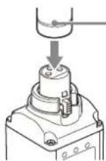
Microphone or cable connector
Push the microphone or cable connector (XLR-3-12C connector) into the audio input connector of the UTX-P40 until it clicks into place.
Disconnecting a microphone or cable
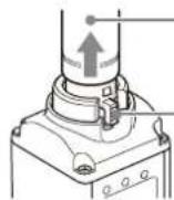
Microphone or cable connector
Release button
Press the release button firmly until the lock is fully released, and pull the microphone or cable out slowly.
Attaching accessories to the portable diversity tuner (URX-P40/P41D)
Connecting the conversion cable to the OUTPUT connector
Example: XLR-BMP conversion output cable for the URX-P40/URX-P41D (supplied)
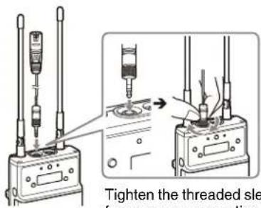
Tighten the threaded sleeve for a secure connection.
Attaching a belt clip
See "Attaching a belt clip" (page 21).
Attaching the shoe mount adaptor
Attach the belt clip before attaching the shoe mount adaptor (page 21).
Note
Attach belt clips upside-down if planning to attach the shoe mount adaptor.
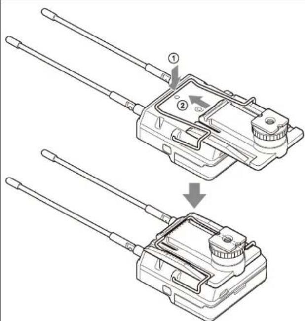
Push the bottom of the belt clip to make some space between the belt clip and the tuner (①), align the belt clip with the two vertical grooves on the shoe mount adaptor, and insert the adaptor in the direction of the arrow (②). Push the shoe mount adaptor in fully until the belt clip fits into the horizontal groove on the adaptor holds.
Note
If attaching a camcorder, bend the URX-P40/URX-P41D antenna down so that the antenna is not reflected on the display.
To remove the shoe mount adaptor
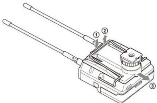
Push and hold the part labeled "PUSH" on the shoe mount adaptor (①), and disengage the horizontal part of the belt clip from the horizontal groove on the shoe mount adaptor (②). Then, push the shoe mount adaptor in the direction of the arrow (③).
Operation
Procedure for all transmitters (UTX-B40/M40/P40) and portable diversity tuner (URX-P40)
1 Connect the tuner as required.
For details about example connections, see "System Configuration Example" (page 45).
2 Press and hold the POWER button for at least one second on the tuner to turn the power on.
Note
Some noise may occur when power is turned on. Accordingly, turn down the audio input level of devices connected to the tuner when turning the power on.
3 Press and hold the NFC SYNC button on the tuner for at least three seconds.
Clear Channel Scan starts searching for an available channel within the configured channel group.
When Clear Channel Scan finishes, the channel with the least noise and interference will be set.
When the channel is set, NFC communication starts automatically.
For details about how to set the group, see "Setting the receive channel" (page 27).
4 Place the N-Marks of both the tuner and transmitter in close proximity (approximately 5 mm).
At this time, make sure that the transmitter is turned on or that the battery level is sufficient and the transmitter is turned off.
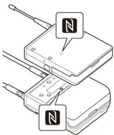
Example using a body-pack transmitter (UTX-B40). Similarly, place the N-Marks in close proximity when using other types of transmitters.
Information about the channel set on the tuner is sent to the transmitter, and then the transmit channel is set. "COMPLETE" is shown on the display of the transmitter and tuner, and the transmitter vibrates when setup is finished.
If the transmitter is turned off when NFC communication is initiated, the transmitter automatically turns on and starts transmitting.
Notes
- NFC communication lasts approximately 20 seconds. Perform step 4 within 20 seconds of performing step 3. If 20 seconds have elapsed, you can reestablish NFC communication using the SYNC RX->TX menu on the tuner.
- Communications using NFC may be adversely affected, depending on the surrounding environment. If this occurs, use the SYNC RX->TX menu on the tuner to reestablish the link.
- If “COMPLETE” is shown on the display of the tuner but the transmitter does not vibrate, the setup may not be finished. If this occurs, use the SYNC RX->TX menu on the tuner to reestablish the link.
Procedure for portable diversity tuner (URX-P41D)
1 Connect the tuner as required.
For details about example connections, see “System Configuration Example” (page 45).
2 Turn on both the POWER switches or just the POWER switch for the tuner you want to use.
Note
Some noise may occur when power is turned on. Accordingly, turn down the audio input level of devices connected to the tuner when turning the power on.
3 Press and hold the NFC SYNC button on the tuner for at least three seconds.
Clear Channel Scan starts.
When GROUP is set in SCAN TYPE
Searches for an available channel within the configured channel group.
When Clear Channel Scan finishes, the channel with the least noise and interference will be set.
When the channel is set, NFC or infrared communication starts automatically.
For details about how to set the group, see “Setting the receive channel” (page 27).
Notes
- When both tuner 1 and tuner 2 are turned on, scans in the band group configured on tuner 1.
Accordingly, the tuner 2 band setting is set to the same band group as tuner 1. To set different band
groups on tuners 1 and 2, turn on only one of the tuners at a time and press the NFC SYNC button to start scanning.
- If you select a group other than a group that supports multiple channel operation and use two or more UWP-D series at the same time, interference may occur. Set the channel group taking into account multiple channels, or set it to an unaffected channel.
For details about the groups and channels in each frequency band, refer to the "Frequency List".
When ALL BAND is set in SCAN TYPE
Searches for a available channel from among the receive frequency bands. When the detected receive channel options and frequencies are displayed alternately, press the SET button to confirm.
To use the confirmed channel, press the SET button to start NFC or infrared communication. To select another option, press the + button and then press the SET button. This operation displays the next option.
For details about how to set SCAN TYPE, see "Selecting the scan type (SCAN TYPE)" (page 35).
Note
The SCAN TYPE menu is not available on the Japan model, Korea model, 90U model, and E model, so SCAN TYPE cannot be selected.
4 Send information about the channel set on the tuner to the transmitter.
When SYNC MODE is set to NFC
Place the N-Marks of both the tuner and transmitter in close proximity (approximately 5 mm).
At this time, make sure that the transmitter is turned on or that the battery level is sufficient and the transmitter is turned off.
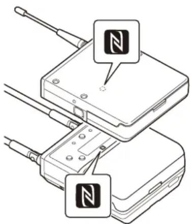
Example using a body-pack transmitter (UTX-B40). Similarly, place the N-Marks in close proximity when using other types of transmitters.
Information about the channel and commander mode set on the tuner are sent to the transmitter, and then the transmit channel is set.
“COMPLETE” is shown on the display of the transmitter and tuner, and the transmitter vibrates when setup is finished.
If the transmitter is turned off when NFC communication is initiated, the transmitter automatically turns on and starts transmitting.
When both tuners 1 and 2 are turned on, the tuner 1 and transmitter settings are configured and then tuner 2 NFC communication starts. In the same way as for tuner 1, place the N-Marks on tuner 2 and the transmitter to set in close proximity.
Notes
- When SYNC MODE is set to IR, NFC communication is not possible. For details about how to set SYNC MODE, see “Configuring using communication with the transmitter (SYNC MODE)” (page 35).
- NFC communication lasts approximately 20 seconds. Perform step 4 within 20 seconds of performing step 3. If more than 20 seconds have elapsed, a confirmation display appears prompting whether to start NFC communication. Restart the NFC communication.
- Communications using NFC may be adversely affected, depending on the surrounding environment.
- If “COMPLETE” is shown on the display of the tuner but the transmitter does not vibrate, the setup may not be finished. If this occurs, use the SYNC RX1 (2)->TX menu on the tuner to reestablish the link.
When SYNC MODE is set to IR
First press and hold the SET button on the transmitter and press and hold the POWER button for one second to turn the power on (transmission stopped mode), then place the infrared transmission port of the unit close to the infrared receptor of the transmitter.
Information about the channel set on the tuner is sent to the transmitter, and a prompt appears on the transmitter display asking if you want to change to that frequency.
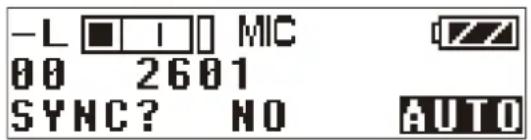
When both tuners 1 and 2 are turned on, the tuner 1 and transmitter settings are configured and then tuner 2 infrared communication starts. In the same way as for tuner 1, place the infrared receiver of the transmitter you want to set for tuner 2 close to the infrared transmission port of this unit.
Note
- When SYNC MODE is set to NFC, infrared communication is not possible. For details about how to set SYNC MODE, see “Configuring using communication with the transmitter (SYNC MODE)” (page 35).
- Infrared communication lasts approximately 10 seconds. Perform step 4 within 10 seconds of performing step 3. If more than 10 seconds have elapsed, a confirmation display appears prompting whether to start infrared communication. Restart the infrared communication.
- Place the unit and transmitter within about 20 cm (8 in.) of each other.
- If five seconds elapse without any user input after the prompt appears on the transmitter display, the transmitter returns to its previous state without changing the frequency.
- Communications using the infrared link may be adversely affected, depending on the surrounding environment.
If noise is generated
Depending on the environment where the devices are installed, external noise or radio waves may disrupt transmission on certain channels. When selecting a channel under these circumstances, turn off the transmitter. Then, on the tuner, select a channel for which the RF indicator does not light up (i.e., a channel free from noise or radio wave interference). Set the same channel on the transmitter.
Note
To prevent interference or noise, take the following precautions.
- Do not use two or more transmitters on the same channels.
- When operating two or more UWP-D series packages simultaneously, set each package to a different channel within the same channel group.
- When using two or more frequencies simultaneously on the URX-P41D, set different channels within the same group.
- Keep the antennas on the tuner and transmitter separated by at least 3 meters (about 10 feet).
- When operating two or more UWP-D series packages simultaneously with different channel groups, make sure that they are at least 100 meters (330 feet) apart if they are used within clear sight of each other (actual distance may vary depending on the circumstances).
Tuner Settings
Menu structure and operation
Procedure for portable diversity tuner (URX-P40)
There are two menu display modes that can be selected according to the application.
Simple mode
This mode displays only the required settings for the tuner and audio output.
You can enable simple mode by setting MENU MODE (menu display mode) to SIMPLE.
Configuration menus
• GP/CH (group/channel) select
• PHONES (monitor audio) setting
- BAND (frequency band) select (Not available on the Japan model, Korea model, 90U model, and E model)
- CLR CH SCAN (clear channel scan) function
- OUTPUT LEVEL (audio output level) setting
- SYNC RX->TX (NFC communication) function
• SYNC TX->RX (NFC communication) function
- POWER LOCK (POWER button lock) function
• RUNNING TIME (accumulated running time) display
- MENU MODE (menu display mode) setting
Advanced mode
This mode displays all configuration menus.
You can enable advanced mode by setting MENU MODE (menu display mode) to ADVANCED.
Note
The existing settings configured in advanced mode are active even when using simple mode.
Configuration menus
• GP/CH (group/channel) select
• PHONES (monitor audio) setting
- BAND (frequency band) select (Not available on the Japan model, Korea model, 90U model, and E model)
- CLR CH SCAN (clear channel scan) function
- OUTPUT LEVEL (audio output level) setting
• SYNC RX->TX (NFC communication) function
- SYNC TX->RX (NFC communication) function
- POWER LOCK (POWER button lock) function
• RUNNING TIME (accumulated running time) display
- MENU MODE (menu display mode) setting
• MONITOR MODE (monitor audio level screen lock) function
• CH MEMORY (store previous channel) function
- POWER SOURCE (external power selection) setting
• ACT CH SCAN (active channel scan) function
• COMPANDER (compander mode) setting
• BATTERY TYPE (battery type) setting
• DISPLAY MODE (display setting) function
• BRIGHTNESS (display brightness) setting
• FCT RESET (factory default setting) function
- VERSION (software version) display
Basic menu operation
The basic menu operation is the same in simple mode and advanced mode.
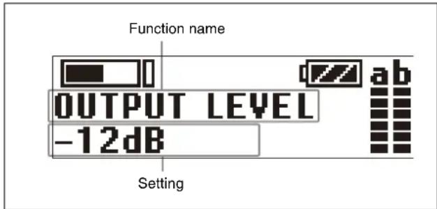
1 Press the + or - button to display the function to be set.
2 Press and hold the SET button until the setting starts flashing.
3 Press the + or - button to change the setting.
4 Press the SET button to enter the setting.
Note
If no operation is performed for 30 seconds, the display will turn off or will dim. Pressing any button will turn the display on again.
For details about display settings, see “Changing the display settings (DISPLAY MODE)” (page 33).
Procedure for portable diversity tuner (URX-P41D)
The menus and the hierarchy of each menu have the following structure.
UTILITY menu
You can display the UTILITY menu from the meter screen that displays various information about tuners 1 and 2.
The UTILITY menu is used to configure basic settings of the unit.
RX1 (tuner 1) menu
Configures RX1 (tuner 1) settings.
RX2 (tuner 2) menu
Configures RX2 (tuner 2) settings.
EXT.IN menu
Configures settings for a microphone connected to the MIC INPUT (audio input) connector.
Menu tree
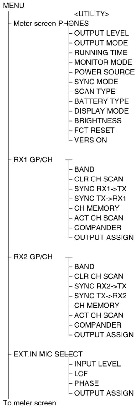
flowchart
graph TD
    A["To meter screen"] --> B["Meter screen PHONES"]
    B --> C["OUTPUT LEVEL"]
    B --> D["OUTPUT MODE"]
    B --> E["RUNNING TIME"]
    B --> F["MONITOR MODE"]
    B --> G["POWER SOURCE"]
    B --> H["SYNC MODE"]
    B --> I["SCAN TYPE"]
    B --> J["BATTERY TYPE"]
    B --> K["DISPLAY MODE"]
    B --> L["BRIGHTNESS"]
    B --> M["FCT RESET"]
    B --> N["VERSION"]

    A --> O["RX1 GP/CH"]
    O --> P["BAND"]
    O --> Q["CLR CH SCAN"]
    O --> R["SYNC RX1->TX"]
    O --> S["SYNC TX->RX1"]
    O --> T["CH MEMORY"]
    O --> U["ACT CH SCAN"]
    O --> V["COMPANDER"]
    O --> W["OUTPUT ASSIGN"]

    A --> X["RX2 GP/CH"]
    X --> Y["BAND"]
    X --> Z["CLR CH SCAN"]
    X --> AA["SYNC RX2->TX"]
    X --> AB["SYNC TX->RX2"]
    X --> AC["CH MEMORY"]
    X --> AD["ACT CH SCAN"]
    X --> AE["COMPANDER"]
    X --> AF["OUTPUT ASSIGN"]

    A --> AG["EXT.IN MIC SELECT"]
    AG --> AH["INPUT LEVEL"]
    AG --> AI["LCF"]
    AG --> AJ["PHASE"]
    AG --> AK["OUTPUT ASSIGN"]
Notes
- The SCAN TYPE and BAND menus are not available on the Japan model, Korea model, 90U model, and E model.
- When SYNC MODE is set to IR, SYNC TX->RX1(2) is not displayed.
Basic menu operation
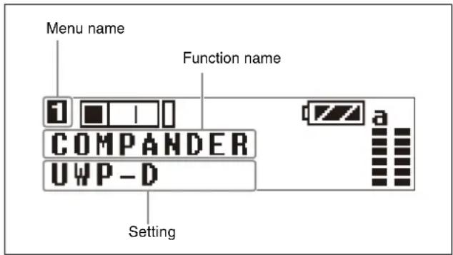
1 Press the MENU button and select the menu to set or change.
Each time you press the button, the display switches between the meter screen, RX1, RX2, EXT.IN, and meter screen in that order. To change an item in the UTILITY menu, display the meter screen.
2 Press the + or - button to display the function to be set.
3 Press and hold the SET button until the setting starts flashing.
4 Press the + or - button to change the setting.
5 Press the SET button to enter the setting.
Note
The menu for a tuner with the POWER switch in the OFF position is not displayed. If no operation is performed for 30 seconds, the display will turn off or will dim. Pressing any button will turn the display on again.
For details about display settings, see “Changing the display settings (DISPLAY MODE)” (page 36).
Setting the receive channel
Procedure for portable diversity tuner (URX-P40)
For details about the channel groups and channels that can be selected, refer to the "Frequency List".
1 Press the + or - button to display the GP/CH menu.
2 Press and hold the SET button for one second or longer.
The channel group display starts flashing.
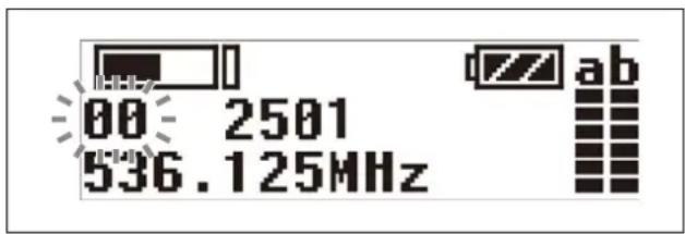
3 Press the + or - button to select the desired group name, then press the SET button.
The channel group is set, and the channel number display starts flashing.
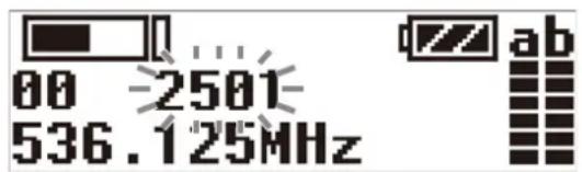
4 Press the + or - button to select the desired channel number, then press the SET button.
The displays stops flashing and the desired channel is set.
Procedure for portable diversity tuner (URX-P41D)
For details about the channel groups and channels that can be selected, refer to the “Frequency List”.
1 Press the MENU button to display the RX1 menu or RX2 menu, then press the + or - button to display the GP/CH screen.
2 Press and hold the SET button for one second or longer.
The channel group display starts flashing.
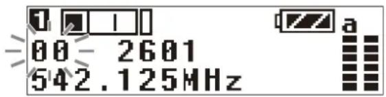
3 Press the + or - button to select the desired group name, then press the SET button.
The channel group is set, and the channel number display starts flashing.
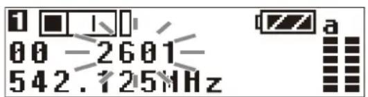
4 Press the + or - button to select the desired channel number, then press the SET button.
The displays stops flashing and the desired channel is set.
Notes
- If there is no user input within ten seconds after the channel group display or channel number display starts
flashing, the displayed setting that is flashing is saved. The same applies when setting other parameters.
- The frequency indicator changes in response to the channel number.
- The tuner continues to receive, even when setting the receive channel.
- Do not remove the batteries while setting the receive channel. If they are removed or the power is turned off, power the unit on again and repeat the procedure from the beginning.
- Make sure that the same channel is set on the transmitter and tuner within the same system.
Searching for available channels within a group (Clear Channel Scan)
Procedure for portable diversity tuner (URX-P40)
You can search for available channels within the specified channel group. Before performing this procedure, select the channel group.
For details, see "Setting the receive channel" (page 27).
1 Press the + or - button to display the CLR CH SCAN menu.
2 Press and hold the SET button for one second or longer.
Press and hold until the channel group and “+” display starts flashing.
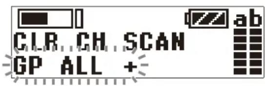
3 Press the + button.
The tuner starts to scan through the selected channel group. When available channels are found, the first channel number among the available channels starts flashing on the display.
To display the next available channel number
Press the + button.
To cancel searching
Press the – button. The display returns to the CLR CH SCAN menu.
4 Press the SET button when the desired channel number starts flashing.
The search for available channels finishes and the displayed channel is set.
Once a channel is confirmed, you can select whether to send the setting via NFC communication.
5 Select YES, and place the N-Marks of the transmitter and tuner in close proximity.
Information about the channel set on the tuner is sent to the transmitter, and then the transmit channel is set. If you do not want to set the transmitter channel, select NO or perform no action for ten seconds or longer to not send the setting to the transmitter.
To scan channels automatically
With the tuner power on, press and hold the NFC SYNC button for at least three seconds to automatically start a clear channel scan.
Procedure for portable diversity tuner (URX-P41D)
1 Press the MENU button to display the RX1 menu or RX2 menu, then press the + or - button to display the CLR CH SCAN screen.
2 Press and hold the SET button for one second or longer.
Press and hold until the channel group and “+” display starts flashing.
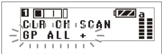
3 Press the + button.
When SCAN TYPE is set to GROUP
The tuner starts to scan for an available channel in the selected channel group. When available channels are found, the first channel number among the available channels starts flashing on the display.
To display the next available channel number
Press the + button.
To cancel searching
Press the – button. When you press the – button, the display returns to the CLR CH SCAN screen.
When SCAN TYPE is set to ALL BAND
The tuner starts to scan for an available channel within each group, and the available channels within those groups flash in ascending band group order.
To display the next group
Press the + button.
To cancel searching
Press the – button. When you press the – button, the display returns to the CLR CH SCAN screen.
For details about SCAN TYPE, see “Selecting the scan type (SCAN TYPE)” (page 35).
4 Press the SET button when the desired channel number starts flashing.
The search for available channels finishes and the displayed channel is set.
Once a channel is confirmed, you can send the setting via NFC communication or infrared communication, whichever is selected using SYNC MODE.
5 Send information about the channel set on the tuner to the transmitter.
When SYNC MODE is set to NFC
Select YES, and place the N-Marks of the transmitter and tuner in close proximity.
When SYNC MODE is set to IR
Select YES, and place the infrared transmission port of this unit and the infrared receptor of the transmitter in close proximity.
Information about the channel set on the tuner is sent to the transmitter, and then the transmit channel is set. If you do not want to set the transmitter channel, perform no action for ten seconds or longer. The settings are not sent to the transmitter.
For details about NFC communication or infrared communication, see “Configuring transmitter settings via NFC communication or infrared communication (SYNC RX1(2)->TX)” (page 36).
To scan channels automatically
With the tuner power on, press and hold the NFC SYNC button for at least three seconds to automatically start a clear channel scan.
Note
The configuration using the NFC SYNC button starts scanning for channels simultaneously on both tuners if both RX1 and RX2 are turned on. If you do not want to change channel on one of the tuners, turn the corresponding tuner off and then scan, or start a scan using CLR CH SCAN in the RX1 or RX2 menu.
Searching for active channels within a group (Active Channel Scan)
Procedure for portable diversity tuner (URX-P40)
You can search for channels in use within the specified channel group. This is useful when using more than one tuner in combination with a single transmitter.
Before performing this procedure, select the channel group.
For details, see "Setting the receive channel" (page 27).
1 Press the + or - button to display the ACT CH SCAN menu.
2 Press and hold the SET button for one second or longer.
Press and hold until the channel group and “+” display starts flashing.
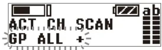
3 Press the + button.
The tuner starts to scan for active channels in the selected channel group. When active channels are found, the first channel number among the active channels starts flashing on the display.
To display the next active channel number
Press the + button.
To cancel searching
Press the – button. The display returns to the ACT CH SCAN menu.
4 Press the SET button when the desired channel number starts flashing.
The search for active channels finishes and the displayed channel is set.
Procedure for portable diversity tuner (URX-P41D)
1 Press the MENU button to display the RX1 menu or RX2 menu, then press the + or - button to display the ACT CH SCAN screen.
2 Press and hold the SET button for one second or longer.
Press and hold until the channel group and “+” display starts flashing.
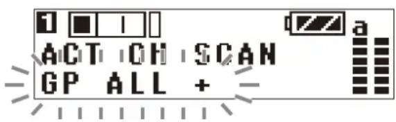
3 Press the + button.
The tuner starts to scan for active channels in the selected channel group. When active channels are found, the first channel number among the active channels starts flashing on the display.
To display the next active channel number Press the + button.
To cancel searching
Press the – button. The display returns to the ACT CH SCAN screen.
4 Press the SET button when the desired channel number starts flashing.
The search for active channels finishes and the displayed channel is set.
Adjusting the monitor audio level
Procedure for portable diversity tuner (URX-P40)
You can set the monitor audio level within the range 1 to 16.
1 Press the + or - button to display the PHONES menu. The current monitor audio level is displayed.
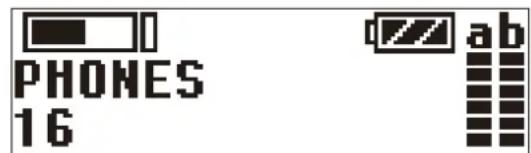
2 Press and hold the SET button for one second or longer.
Press and hold until the monitor audio level flashes.
3 Press the + or - button to set the desired monitor audio level, then press the SET button.
The setting value is stored. The setting is retained even after the power is turned off.
Procedure for portable diversity tuner (URX-P41D)
1 Press the MENU button to display the meter screen, then press the + or - button to display the PHONES screen.
The current monitor audio level is displayed.
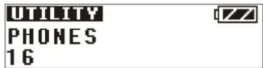
2 Press and hold the SET button for one second or longer.
Press and hold until the monitor audio level flashes.
3 Press the + or - button to set the desired monitor audio level, then press the SET button.
The setting is saved and retained even after the power is turned off.
Configuration menu
Procedure for portable diversity tuner (URX-P40)
This section describes each function and configurable items.
Underlined entries indicate factory default settings.
Selecting the group/channel (GP/CH)
The factory default setting varies depending on the model.
For details, see "Setting the receive channel" (page 27).
Adjusting the monitor audio level (PHONES)
Adjusts the monitor audio level for the headphones. The factory default setting is 12.
For details, see “Adjusting the monitor audio level” (page 30).
Selecting the frequency band (BAND)
Selects the receive frequency band.
Note
This menu is not available on Japanese and Korean models. On these models, the frequency band cannot be selected.
For details about the groups and channels in each frequency band, refer to the "Frequency List".
Searching for and selecting available channels (CLR CH SCAN)
Searches for available channels.
For details, see “Searching for available channels within a group (Clear Channel Scan)” (page 28).
Setting the audio output level (OUTPUT LEVEL)
Sets the audio output level. You can set the level in 3 dB increments in the range -12 dB to +12 dB. The factory default setting is 0 dB.
Note
The monitor output level does not change when you change the output level in the OUTPUT LEVEL menu. The monitor output level is adjusted separately.
For details about adjusting the monitor audio level, see "Adjusting the monitor audio level" (page 30).
Configuring transmitter settings via NFC communication (SYNC RX->TX)
Transfers the frequency and commander mode set on the tuner to a transmitter using NFC communication.
1 Press the + or - button to display the SYNC RX->TX menu.
2 Press and hold the SET button for one second or longer.
A confirmation screen appears.
3 Press the + or - button to display "YES," and press the SET button.
4 Place the N-Marks of both the tuner and transmitter in close proximity (approximately 5 mm).
At this time, make sure that the transmitter is turned on or that the battery level is sufficient and the transmitter is turned off.
The frequency and commander mode for use on the transmitter are set.
Notes
- NFC communication lasts approximately 20 seconds. Perform step 4 within 20 seconds of performing step 3. After 20 seconds have elapsed, NFC communication automatically finishes and the GP/CH menu appears.
- During NFC communication, the signal from a wireless microphone cannot be received.
Reflecting transmitter settings on the tuner via NFC communication (SYNC TX->RX)
Accesses the frequency and commander mode set on the transmitter and reflects those settings on the tuner using NFC communication.
1 Press the + or - button to display the SYNC TX->RX menu.
2 Press and hold the SET button for one second or longer.
A confirmation screen appears.
3 Press the + or - button to display "YES," and press the SET button.
4 Place the N-Marks of both the tuner and transmitter in close proximity (approximately 5 mm).
At this time, make sure that the transmitter is turned on or that the battery level is sufficient and the transmitter is turned off.
The frequency and commander mode for use on the tuner are set.
Notes
- NFC communication lasts approximately 20 seconds. Perform step 4 within 20 seconds of performing step 3. After 20 seconds have elapsed, NFC communication automatically finishes and the GP/CH menu appears.
- During NFC communication, the signal from a wireless microphone cannot be received.
Locking the POWER button (POWER LOCK)
You can lock the POWER button to prevent the power being turned off inadvertently during reception.
UNLOCK: Press and hold the POWER button to turn the power on/off.
LOCK: The power does not turn off, even after pressing the POWER button.
To release the lock state
To release the lock state, either set the POWER LOCK menu to UNLOCK or use the following procedure.
1 When the button is in the LOCK state, press and hold the POWER button.
A prompt appears asking you whether to release the lock state.
2 Press the + or - button to select YES, then press the SET button.
The lock state is released.
Note
If the batteries are removed and reinserted while the POWER button is set to LOCK, the power will turn on automatically but the lock state of the POWER button does not change.
Displaying the accumulated running time (RUNNING TIME)
Displays the accumulated running time of the tuner as a guide to total usage time.
The factory default setting is 00:00. Up to 99:59 can be displayed.
To reset the time display
1 Press and hold the SET button until the time display starts flashing.
2 Press the – button to display “00:00 CLR” and press the SET button.
Pressing the + button when "00:00 CLR" is displayed causes the time display to start flashing. You can press the SET button in this state to cancel the reset of the accumulated running time.
Setting the menu display mode (MENU MODE)
Sets the menu display mode.
SIMPLE: Displays only the required settings.
ADVANCED: Displays all settings.
Using monitor audio level mode (MONITOR MODE)
When this function is enabled, the display shows the monitor audio level screen (fixed). Using the + or - button changes the monitor audio level only.
1 Press the + or - button to display the MONITOR MODE menu.
2 Press and hold the SET button for one second or longer.
3 Press the + or - button to display "ON," and press the SET button.
Monitor audio level mode is activated, and displayed.
To release monitor audio level mode
1 Press and hold the SET button, POWER button, or NFC SYNC button for one second or longer until "ESCAPE?" is displayed.
2 Press the + or - button to display "YES," and press the SET button.
The lock state is released.
Notes
- This function is displayed in advanced mode only.
- This function is released when the power is turned off. Reconfigure the setting after the power is turned on.
Switching to the previous channel (CH MEMORY)
You can switch to the previously set channel. This is useful when using one tuner in combination with two transmitters.
Set the channel you want to use beforehand.
For details about how to set the channel, see “Setting the receive channel” (page 27).
1 Press the + or - button to display the CH MEMORY menu.
2 Press and hold the SET button until "YES?" starts flashing.
3 Press the SET button.
The previously set channel and the currently set channel are displayed.
Press the + or - button to toggle between the channels.
To exit the CH MEMORY function
1 Press and hold the SET button until "CANCEL?" is displayed.
2 Press the + or - button to display "YES," and press the SET button.
The display returns to the CH MEMORY menu.
Notes
- This function is displayed in advanced mode only.
- If this function is enabled with the factory default channel settings, two factory default channels are displayed.
- The NFC SYNC button is disabled while using this function. Disable this function first if you want to use the NFC SYNC button.
- When BAND is changed, the default channel in the new band is stored as the previously set channel.
Selecting the preferred power supply (POWER SOURCE)
Specifies whether the power supply from the batteries inserted in the unit or from an external USB portable power supply or accessory connected to the USB connector or auxiliary connector has precedence.
BATT -> EXT: Batteries inserted in the unit have precedence.
EXT -> BATT: Power supplied from a USB connector or externally connected sources have precedence.
BATT ONLY: Batteries inserted in the unit are used, and power supplied from the USB connector or auxiliary connector is not used even after the batteries are discharged.
Notes
- When BATT ->EXT or EXT ->BATT is specified and power from the preferred source is cut off, the power supply automatically switches to the other source.
Therefore, when only one power supply is available, that power supply will be used regardless of the POWER SOURCE setting. There may be a brief interruption in the audio when the power supply switches. - When power is supplied from both the USB connector and an external connection connector, select the supply from the USB connector.
Setting the frequency to an active channel (ACT CH SCAN)
Searches for channels already in use. This is useful when using more than one tuner in combination with a single transmitter.
Note
This function is displayed in advanced mode only.
For details, see “Searching for active channels within a group (Active Channel Scan)” (page 29).
Setting the commander mode (COMPANDER)
Sets the operating mode of the commander.
UWP-D: High speech quality mode supported in combination with UWP-D series devices.
UWP: Mode supported in combination with Sony UWP-series transmitters.
WL800: Mode supported in combination with Sony 800-series transmitters.
Notes
- This function is displayed in advanced mode only.
- No audio is output if the tone signal frequency is different due to the use of a combination of devices with different commander mode settings.
Setting the battery type (BATTERY TYPE)
You can set the type of battery being used in order to provide a more accurate battery level indication.
TYPE1: Recommended setting when using alkaline LR6 (size AA) batteries. Indicates the battery level based on the characteristics of new alkaline LR6 (size AA) batteries from a specific manufacturer.
TYPE2: Recommended setting when using rechargeable nickel metal hydride batteries.
TYPE3: Recommended setting when using lithium dry cell batteries.
Notes
- This function is displayed in advanced mode only.
- The characteristics of batteries change according to battery type and environmental conditions. It is recommended that you understand the characteristics of batteries before using them.
- AA size rechargeable lithium-ion batteries cannot be used.
Changing the display settings (DISPLAY MODE)
Changes the display mode of the OLED display when 30 seconds have elapsed without any button activity.
AUTO OFF: If no button operation is performed for 30 seconds, the display will turn off. Press a button to turn on the display again.
DIMMER: If no button operation is performed for 30 seconds, the display will dim. Press a button to turn on the display again.
Note
This function is displayed in advanced mode only.
Setting the display brightness (BRIGHTNESS)
Adjusts the brightness of the OLED display using ten levels.
The configurable values are given below.
(Dark) 1 2 3 4 5 6 7 8 9 10 (Bright)
Note
This function is displayed in advanced mode only.
Restoring factory default settings (FCT RESET)
Restores all parameters to their factory default settings. Press and hold the SET button. A prompt appears asking you whether to restore factory default settings. Press the + or - button to select YES, then press the SET button. The tuner parameters are restored to their factory default settings.
Notes
- This function is displayed in advanced mode only.
- After a reset, the audio output level and monitor output level are also restored to their factory default settings. Note that this may cause the volume on connected devices and in headphones to suddenly change.
Displaying the software version (VERSION)
Displays the software version of the tuner.
Note
This function is displayed in advanced mode only.
UTILITY menu
Procedure for portable diversity tuner (URX-P41D)
The UTILITY menu contains items related to the basic settings of the unit.
This section describes the functions and menu items.
Underlined entries indicate factory default settings.
Adjusting the monitor audio level (PHONES)
Adjusts the monitor audio level for the headphones. The factory default setting is 12.
For details about adjusting the monitor audio level, see "Adjusting the monitor audio level" (page 30).
Setting the audio output level (OUTPUT LEVEL)
Sets the audio output level. You can set the level in 3 dB increments in the range -12 dB to +12 dB. The factory default setting is 0 dB.
Note
The monitor output level does not change when you change the output level in the OUTPUT LEVEL menu. The monitor output level is adjusted separately.
For details about adjusting the monitor audio level, see "Adjusting the monitor audio level" (page 30).
Setting the audio output range (OUTPUT MODE)
Sets the audio output range of the OUTPUT 1/2 (audio output 1/2) connectors. You can set a wide range audio output level in combination with OUTPUT LEVEL.
NORMAL GAIN: Microphone level (reference level -60 dBV)
HIGH GAIN: High gain output mode (reference level -38 dBV)
Note
When outputting audio with the SMAD-P5 (option) connected, this function is not displayed. And the output from the OUTPUT 1/2 (audio output 1/2) connectors becomes NORMAL GAIN.
Displaying the accumulated running time (RUNNING TIME)
Displays the accumulated running time of the tuner as a guide to total usage time.
The factory default setting is 00:00. Up to 99:59 can be displayed.
To reset the time display
1 Press and hold the SET button until the time display starts flashing.
2 Press the – button to display “00:00 CLR” and press the SET button.
Pressing the + button when “00:00 CLR” is displayed causes the time display to start flashing. You can press the SET button in this state to cancel the reset of the accumulated running time.
Using monitor audio level mode (MONITOR MODE)
When this function is enabled, the display shows the monitor audio level screen (fixed). Using the + or - button changes the monitor audio level only.
1 Press the + or - button to display the MONITOR MODE menu.
2 Press and hold the SET button for one second or longer.
3 Press the + or - button to display "ON," and press the SET button.
Monitor audio level mode is activated, and displayed.
To release monitor audio level mode
1 Press and hold the SET button, MENU button, or NFC SYNC button for one second or longer until "ESCAPE?" is displayed.
2 Press the + or - button to display "YES," and press the SET button.
The lock state is released.
Notes
- This function is released when the power is turned off. Reconfigure the setting after the power is turned on.
- When the POWER switch is set to the OFF position, the power of each tuner is also turned off.
Selecting the preferred power supply (POWER SOURCE)
Specifies whether the power supply from the batteries inserted in the unit or from an external USB portable power supply or accessory connected to the USB connector or auxiliary connector has precedence.
BATT->EXT: Batteries inserted in the unit have precedence.
EXT->BATT: Power supplied from a USB connector or externally connected sources have precedence.
BATT ONLY: Batteries inserted in the unit are used, and power supplied from the USB connector or auxiliary connector is not used even after the batteries are discharged.
Note
When BATT->EXT or EXT->BATT is specified and power from the preferred source is cut off, the power supply automatically switches to the other source. Therefore, when only one power supply is available, that power supply will be used regardless of the POWER SOURCE setting. There may be a brief interruption in the audio when the power supply switches.
Configuring using communication with the transmitter (SYNC MODE)
Sets the communication method for setting the transmitter channel and commander mode. When using NFC communication, the channel and commander mode set on the transmitter are applied on the unit.
NFC: Configure using NFC communication.
IR: Configure using infrared communication.
Note
The communication method will vary depending on the transmitter. Configuring using communication is not possible if the combination with the SYNC MODE setting is not correct.
| Communication method for configuration on each transmitter | Tuner | ||
| URX-P41D | |||
| NFC communication | Infrared communication | ||
| Transmitter | UTX-B40 ○○ | ||
| UTX-M40 ○○ | |||
| UTX-P40 ○○ | |||
| UTX-B03 × ○ | |||
| UTX-B03HR × ○ | |||
| UTX-M03 × ○ | |||
| UTX-P03 × ○ | |||
| UWP-series transmitter | × | × | |
| WRT-series transmitter | × | × | |
Selecting the scan type (SCAN TYPE)
Selects the scan type when the NFC SYNC button is pressed, and the Clear Channel Scan and Active Channel Scan scan types.
GROUP: Scan the currently selected channel group.
ALL BAND: Scan the receive frequency band within a single TV channel and simultaneously scan each group that supports multiple channel operation.
Notes
- With ALL BAND, the group to scan is fixed. To scan other groups, select GROUP.
- The SCAN TYPE menu is not available on the Japan model, Korea model, 90U model, and E model, so SCAN TYPE cannot be selected.
For details about the groups and channels in each frequency band, refer to the “Frequency List”.
Setting the battery type (BATTERY TYPE)
You can set the type of battery being used in order to provide a more accurate battery level indication.
TYPE1: Recommended setting when using alkaline LR6 (size AA) batteries. Indicates the battery level based on the characteristics of new alkaline LR6 (size AA) batteries from a specific manufacturer.
TYPE2: Recommended setting when using 2000 mAh rechargeable nickel metal hydride batteries.
TYPE3: Recommended setting when using lithium dry cell batteries.
TYPE4: Recommended setting when using 2500 mAh rechargeable nickel metal hydride batteries.
Notes
- The characteristics of batteries change according to battery type and environmental conditions. It is recommended that you understand the characteristics of batteries before using them.
- AA size rechargeable lithium-ion batteries cannot be used.
Changing the display settings (DISPLAY MODE)
Changes the display mode of the OLED display when 30 seconds have elapsed without any button activity.
AUTO OFF: If no button operation is performed for 30 seconds, the display will turn off. Press a button to turn on the display again.
DIMMER: If no button operation is performed for 30 seconds, the display will dim. Press a button to turn on the display again.
Setting the display brightness (BRIGHTNESS)
Adjusts the brightness of the OLED display using ten levels. The configurable values are given below. (Dark) 1 2 3 4 5 6 7 8 9 10 (Bright)
Restoring factory default settings (FCT RESET)
Restores all parameters to their factory default settings. Press and hold the SET button. A prompt appears asking you whether to restore factory default settings. Press the + or - button to select YES, then press the SET button. The tuner parameters are restored to their factory default settings.
Note
After a reset, the audio output level and monitor output level are also restored to their factory default settings. Note that this may cause the volume on connected devices and in headphones to suddenly change.
Displaying the software version (VERSION)
Displays the software version of the tuner.
RX1/2 (tuner 1/2) menu
Procedure for portable diversity tuner (URX-P41D)
The RX1/2 menus are used to set the wireless receiver functions of the units.
For details about menu operations, see “Basic menu operation” (page 26).
Selecting the group/channel (GP/CH)
The factory default setting varies depending on the model.
For details, see "Setting the receive channel" (page 27).
Selecting the frequency band (BAND)
Selects the receive frequency band.
Note
This menu is not available on the Japan model, Korea model, 90U model, and E model. On these models, the frequency band cannot be selected.
For details about the groups and channels in each frequency band, refer to the “Frequency List”.
Searching for and selecting available channels (CLR CH SCAN)
Searches for available channels.
For details, see “Searching for available channels within a group (Clear Channel Scan)” (page 28).
Configuring transmitter settings via NFC communication or infrared communication (SYNC RX1(2)->TX)
Transfers the frequency and commander mode set on the tuner to a transmitter using NFC communication or infrared communication selected using SYNC MODE.
For details about SYNC MODE, see “Configuring using communication with the transmitter (SYNC MODE)” (page 35).
1 Set the group/channel (page 27).
2 Press the MENU button to display the RX1 menu or RX2 menu.
3 Press the + or - button to display the SYNC RX1(2)->TX screen.
4 Press and hold the SET button for one second or longer.
5 Press the + or - button to select YES, then press the SET button.
6 Send information about the channel set on the tuner to the transmitter.
When SYNC MODE is set to NFC
Place the N-Marks of both the tuner and transmitter in close proximity (approximately 5 mm).
At this time, make sure that the transmitter is turned on or that the battery level is sufficient and the transmitter is turned off.
The frequency and commander mode for use on the transmitter are set.
Notes
-
When SYNC MODE is set to IR, NFC communication is not possible.
For details about how to set SYNC MODE, see "Configuring using communication with the transmitter (SYNC MODE)" (page 35). -
NFC communication lasts approximately 20 seconds. Perform step 6 within 20 seconds of performing step 5. If more than 20 seconds have elapsed, a confirmation display appears prompting whether to start NFC communication. Restart the NFC communication.
- During NFC communication, the signal from the configured tuner's wireless microphone cannot be received.
When SYNC MODE is set to IR
Press and hold the SET button on the transmitter and press and hold the POWER button for one second to turn the power on.
When the power is on, place the infrared transmission port of this unit and the infrared receptor of the transmitter in close proximity.
Information about the channel set on the unit is sent to the transmitter, and a prompt appears on the transmitter display asking if you want to change to that frequency.
Press the + or - button to select YES, then press the SET button on the transmitter. The transmit channel and commander mode are set.
Notes
- When SYNC MODE is set to NFC, infrared communication is not possible. For details about how to set SYNC MODE, see “Configuring using communication with the transmitter (SYNC MODE)” (page 35).
- Infrared communication lasts approximately 10 seconds. Perform step 6 within 10 seconds of performing step 5. If more than 10 seconds have elapsed, a confirmation display appears prompting whether to start infrared communication. Restart the infrared communication.
Reflecting transmitter settings on the tuner via NFC communication (SYNC TX- >RX1(2))
Accesses the frequency and commander mode set on the transmitter and reflects those settings on the tuner using NFC communication.
1 Press the + or - button to display the SYNC TX->RX menu.
2 Press and hold the SET button for one second or longer.
A confirmation screen appears.
3 Press the + or - button to select YES, then press the SET button.
4 Place the N-Marks of both the tuner and transmitter in close proximity (approximately 5 mm).
At this time, make sure that the transmitter is turned on or that the battery level is sufficient and the transmitter is turned off.
The frequency and commander mode for use on the tuner are set.
Notes
- NFC communication lasts approximately 20 seconds. Perform step 4 within 20 seconds of performing step 3. If more than 20 seconds have elapsed, a confirmation display appears prompting whether to start NFC communication. Restart the NFC communication.
- During NFC communication, the signal from the configured tuner's wireless microphone cannot be received.
- When SYNC MODE is set to IR, the menu is not displayed and the function cannot be used. For details about SYNC MODE, see “Configuring using communication with the transmitter (SYNC MODE)” (page 35).
Switching to the previous channel (CH MEMORY)
You can switch to the previously set channel. This is useful when using one tuner in combination with two transmitters.
Set the channel you want to use beforehand.
For details about how to set a channel, see “Setting the receive channel” (page 27).
1 Press the + or - button to display the CH MEMORY menu.
2 Press and hold the SET button until "YES?" starts flashing.
3 Press the SET button.
The previously set channel and the currently set channel are displayed. Press the + or - button to toggle between the channels.
To exit the CH MEMORY function
1 Press and hold the SET button until "CANCEL?" is displayed.
2 Press the + or - button to display "YES," and press the SET button.
The display returns to the CH MEMORY menu.
Notes
- If this function is enabled with the factory default channel settings, two factory default channels are displayed.
- The NFC SYNC button is disabled while using this function. Disable this function first if you want to use the NFC SYNC button.
- When BAND is changed, the default channel in the new band is stored as the previously set channel.
Setting the frequency to an active channel (ACT CH SCAN)
Searches for channels already in use. This is useful when using more than one tuner in combination with a single transmitter.
For details, see “Searching for active channels within a group (Active Channel Scan)” (page 29).
Setting the commander mode (COMPANDER)
The commander mode must be switched depending on the transmitter to be combined with the unit.
You can set different commander modes for tuner 1 and tuner 2.
Notes
- When operating in conjunction with UWP-D series transmitters, set the commander mode of the transmitter to the same setting as the unit (URX-P41D).
- No audio is output if the tone signal frequency is different due to the use of a combination of devices with different commander mode settings.
1 Press the MENU button to display the RX1 menu or RX2 menu.
2 Press the + or - button to display the COMPANDER screen.
3 Press and hold the SET button for one second or longer.
The selected items starts flashing.
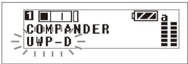
4 Press the + or - button to select the commander mode, then press the SET button.
The selected commander mode is set.
UWP-D: Select for combination with Sony UWP-D-series transmitters.
UWP: Select for combination with Sony UWP-series transmitters.
WL800: Select for combination with Sony WRT-series transmitters.
Transmitter and commander mode combinations
Configure the correct commander mode for the transmitter you are using.
Note
No audio will be output if the combination of transmitter and commander mode setting is incorrect.
| Transmitter Compander mode of unit | ||||
| UWP-D series (UTX-B40, UTX-M40, UTX-P40, UTX-B03, UTX-M03, UTX-P03, UTX-B03HR) | Compander mode: UWP-D | ○×× | ||
| Compander mode: UWP | ×○× | |||
| Compander mode: WL800 | ××○ | |||
| Transmitter Compander mode of unit | |||
| UWP series (UTX-B2, UTX-H2) × | ○× | ||
| WRT series (WRT-822, WRT-860, etc.) | ××○ | ||
Selecting the connector for output of received audio (OUTPUT ASSIGN)
Selects the connector for output of the received signal. The factory default settings are OUT1 for tuner 1 and OUT2 for tuner 2.
OUT1: Output audio from the OUTPUT 1 connector.
OUT1/2: Output audio from both the OUTPUT 1/2 connectors.
OUT2: Output audio from the OUTPUT 2 connector. The following combination of output connector settings are supported.
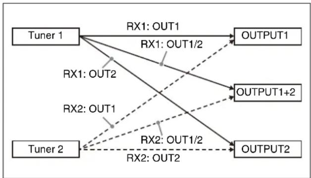
flowchart
graph TD
    A["Tuner 1"] -->|RX1: OUT1| B["OUTPUT1"]
    A -->|RX1: OUT2| C["OUTPUT2"]
    D["Tuner 2"] -->|RX2: OUT1| E["OUTPUT1+2"]
    D -->|RX2: OUT2| F["OUTPUT2"]
    A -->|RX1: OUT1/2| B
    A -->|RX1: OUT1/2| C
    D -->|RX2: OUT1/2| E
    D -->|RX2: OUT1/2| F
EXT.IN menu
Procedure for portable diversity tuner (URX-P41D)
The EXT.IN menu is used to configure settings for a microphone connected to the MIC INPUT (audio input) connector of the unit.
Selecting an external microphone to use (MIC SELECT)
Selects the type of microphone connected to the MIC INPUT (audio input) connector.
OFF: Select when not using an external microphone. PLUG-IN PWR: Select when using an plug-in power type microphone.
MONO BMP+5V: Select when using a Sony lavalier microphone.
Adjusting the input level (INPUT LEVEL)
You can set the input level in the range -12 dB to +12 dB.
Adjust according to the microphone to be connected.
The factory default setting is 0 dB.
Setting the low-cut filter (LCF)
You can set the low-cut filter to reduce noise caused by wind.
You can set the cutoff frequency to OFF/LOW/MID/HIGH.
OFF: No filtering
LOW: 100 Hz cutoff frequency
MID: 150 Hz cutoff frequency
HIGH: 200 Hz cutoff frequency
Switching the phase of the microphone (PHASE)
You can switch the phase of a connected microphone to output audio in reverse phase.
NORMAL: Phase is not reversed.
INVERT: Reverses the phase internally.
Selecting the connector for output of input audio (OUTPUT ASSIGN)
Selects the connector for output of the input signal.
OUT1: Output audio from the OUTPUT 1 connector. If the connected microphone is a stereo (L/R) type, the signals are mixed for output.
OUT1/2 (L/R): Output audio from both the OUTPUT 1/2 connectors. If the connected microphone is a stereo (L/R) type, the L signal is output from OUTPUT 1 and the R signal is output from OUTPUT 2.
OUT2: Output audio from the OUTPUT 2 connector. If the connected microphone is a stereo (L/R) type, the signals are mixed for output.
The following combination of output connector settings are supported.
Parentheses ( ) indicate the output for stereo (L/R) type microphones.
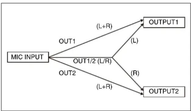
flowchart
graph TD
    A["MIC INPUT"] -->|OUT1| B["OUTPUT1"]
    A -->|OUT1/2 (L/R)| C["OUTPUT2"]
    A -->|OUT2| D["OUTPUT2"]
    B -->|(L+R)| E["(L)"]
    B -->|(R)| F["(R)"]
Transmitter Settings
Menu structure and operation
Procedure for all transmitters (UTX-B40/M40/P40)
There are three menu display modes that can be selected according to the application.
Simple mode
This mode displays only the required settings for transmitting audio.
You can enable simple mode by setting MENU MODE (menu display mode) to SIMPLE.
Configuration menus
• GP/CH (group/channel) select
- BAND (frequency band) select (Not available on the Japan model, Korea model, 90U model, and E model)
- ATTENUATOR (attenuator) setting
• GAIN MODE (audio gain) setting
• LCF (low-cut filter) setting
- INPUT LEVEL (audio input level) select (UTX-B40/P40 only)
• RF POWER (RF transmit output level) select
• +48V SUPPLY (+48 V power supply) setting (UTX-P40 only)
- POWER LOCK (POWER button lock) function
- RUNNING TIME (accumulated running time) display
- MENU MODE (menu display mode) setting
Note
The following configuration menus cannot be modified during transmission. Set these menus in transmission stopped mode.
• GP/CH (group/channel) select
• BAND (frequency band) select (Not available on the Japan model, Korea model, 90U model, and E model)
• RF POWER (RF transmit output level) select
Advanced mode
This mode displays all configuration menus.
You can enable advanced mode by setting MENU MODE (menu display mode) to ADVANCED.
Note
The existing settings configured in advanced mode are active even when using simple mode.
Configuration menus
• GP/CH (group/channel) select
• BAND (frequency band) select (Not available on the Japan model, Korea model, 90U model, and E model)
- ATTENUATOR (attenuator) setting
• GAIN MODE (audio gain) setting
• LCF (low-cut filter) setting
- INPUT LEVEL (audio input level) select (UTX-B40/P40 only)
• RF POWER (RF transmit output level) select
• +48V SUPPLY (+48 V power supply) setting (UTX-P40 only)
- POWER LOCK (POWER button lock) function
- RUNNING TIME (accumulated running time) display
- MENU MODE (menu display mode) setting
- MUTE SETTING (audio muting setting) function (UTX-B40/P40 only)
- POWER/MUTE (power supply / audio muting) setting (UTX-M40 only)
• AUDIO PHASE (phase switching) setting (UTX-B40 only)
• COMPANDER (compander mode) setting
- OCUPNCY SENS (motion detection sensor mode) setting
• BATTERY TYPE (battery type) setting
• DISPLAY MODE (display setting) function
• BRIGHTNESS (display brightness) setting
• FCT RESET (factory default setting) function
- VERSION (software version) display
Note
The following configuration menus cannot be modified during transmission. Set these menus in transmission stopped mode.
• GP/CH (group/channel) select
- BAND (frequency band) select (Not available on the Japan model, Korea model, 90U model, and E model)
• RF POWER (RF transmit output level) select
• FCT RESET (factory default setting) function
Transmission stopped mode
This mode allows settings to be modified when RF transmission has stopped.
Use this mode to make settings without risk of interrupting other wireless traffic when setting channels and other settings.
With the power off, press and hold the SET button and press the POWER button or POWER/MUTE button for at least one second to turn the power on and to display the transmission stopped mode menu.
The following configuration menus can only be modified in transmission stopped mode.
• GP/CH (group/channel) select
• BAND (frequency band) select (Not available on the Japan model, Korea model, 90U model, and E model)
• RF POWER (RF transmit output level) select
- FCT RESET (factory default setting) function
Basic menu operation
The basic menu operation is the same in simple mode, advanced mode, and transmission stopped mode.
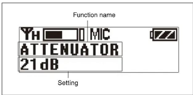
1 Press the + or - button to display the function to be set.
2 Press and hold the SET button until the setting starts flashing.
3 Press the + or - button to change the setting.
4 Press the SET button to enter the setting.
Note
If no operation is performed for 30 seconds, the display will turn off or will dim. Pressing any button will turn the display on again.
For details about display settings, see “Changing the display settings (DISPLAY MODE)” (page 43).
Setting the transmit channel
Procedure for all transmitters (UTX-B40/M40/P40)
For details about the channel groups and channels that can be selected, refer to the “Frequency List”.
1 Press and hold the SET button and press and hold the POWER button or POWER/MUTE button to turn the power on in transmission stopped mode.
2 Press the + or - button to display the GP/CH menu.
3 Press and hold the SET button for one second or longer.
Press and hold until the channel group display starts flashing.
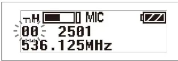
4 Press the + or - button to select the desired group name, then press the SET button.
The channel group is set, and the channel number display starts flashing.
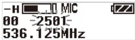
5 Press the + or - button to select the desired channel number, then press the SET button.
The displays stops flashing and the desired channel is set.
6 Press and hold the POWER button or POWER/MUTE button to turn the power off.
Notes
- If there is no user input within ten seconds after the channel group display or channel number display starts flashing, the displayed setting that is flashing is saved. The same applies when setting other parameters.
- The frequency indicator changes in response to the channel number.
- This function can be modified in transmission stopped mode only.
- Do not remove the batteries while making settings. If they are removed, re-insert them and repeat the procedure from the beginning.
- Make sure that the same channel is set on the transmitter and tuner within the same system.
Configuration menu
Procedure for all transmitters (UTX-B40/M40/P40)
This section describes each function and configurable items.
Underlined entries indicate factory default settings.
Selecting the group/channel (GP/CH)
The factory default setting varies depending on the model.
For details, see "Setting the transmit channel" (page 40).
Note
This function can be modified in transmission stopped mode only.
Selecting the frequency band (BAND)
Selects the transmit frequency band.
Notes
- This function can be modified in transmission stopped mode only.
- This menu is not available on Japanese and Korean models. On these models, the frequency band cannot be selected.
For details about the groups and channels in each frequency band, refer to the “Frequency List”.
Adjusting the audio input attenuation level (ATTENUATOR)
You can set the audio input attenuation level in 3 dB increments to reduce noise distortion. The factory default setting is 9 dB on the UTX-B40, and 0 dB on the UTX-M40/P40.
Notes
- On the UTX-B40/P40, “---” is displayed if INPUT LEVEL is set to LINE and GAIN MODE is set to AUTO GAIN, and the attenuation level cannot be modified (fixed).
- If the attenuation level is set too high, the noise level may increase. Set the level as close as possible to 0 dB if using a lavalier microphone attached to your torso.
Setting the audio gain (GAIN MODE)
AUTO GAIN: Sets the gain high, and uses a limiter to help prevent distortion.
NORMAL: Enables adjustment of the attenuation level. The attenuator can be adjusted to match the connected microphone.
15dB BOOST: Boosts the gain by 15 dB for when the microphone is not near the person's mouth and the audio level is insufficient.
Notes
- On the UTX-B40/P40, “---” is displayed if INPUT LEVEL is set to LINE, and the audio gain cannot be modified.
- When GAIN MODE is set to AUTO GAIN, the ATTENUATOR setting cannot be modified.
- Changing the GAIN MODE setting may cause the volume on devices connected to the tuner and in headphones to suddenly change.
Setting the low-cut filter (LCF)
You can set the low-cut filter to reduce noise caused by wind.
You can set the cutoff frequency to OFF/LOW/MID/HIGH.
OFF: No filtering
LOW: 100 Hz cutoff frequency
MID: 150 Hz cutoff frequency
HIGH: 200 Hz cutoff frequency
Switching the audio input level (INPUT LEVEL) (UTX-B40/P40 only)
Sets the input level according to the audio input device. You can switch between MIC and LINE. The factory default setting is MIC.
Notes
- Do not switch this function to “MIC” when the audio input source is an audio mixer or other line level device.
If an excessive audio level is input, it may cause noise distortion or damage the playback/recording equipment.
- “---” is displayed for ATTENUATOR and GAIN MODE if INPUT LEVEL is set to LINE, and the settings cannot be modified.
Setting the transmit output level (RF POWER)
Set the transmitted RF power to HIGH or LOW. The transmit power level varies depending on the model.
Note
This function can be modified in transmission stopped mode only.
Setting the microphone drive power supply (+48V SUPPLY) (UTX-P40 only)
You can supply power from the transmitter when using a microphone that requires an external power supply. When set to ON, power is supplied to the connected microphone and the +48 V indicator lights. The factory default setting is OFF.
Locking the POWER button (POWER LOCK)
You can lock the POWER button to prevent the power being turned off inadvertently during transmission.
UNLOCK: Press and hold the POWER button to turn the power on/off.
LOCK: The power does not turn off, even after pressing the POWER button.
To release the lock state
To release the lock state, either set the POWER LOCK menu to UNLOCK or use the following procedure.
1 When the button is in the LOCK state, press and hold the POWER button.
A prompt appears asking you whether to release the lock state.
2 Press the + or - button to select YES, then press the SET button.
The power turns off.
Note
If the batteries are removed and reinserted while the POWER button is set to LOCK, the power will turn on automatically but the lock state of the POWER button does not change.
Displaying the accumulated running time (RUNNING TIME)
Displays the accumulated running time of the transmitter as a guide to total usage time.
The factory default setting is 00:00. Up to 99:59 can be displayed.
To reset the time display
1 Press and hold the SET button until the time display starts flashing.
2 Press the – button to display “00:00 CLR” and press the SET button.
Pressing the + button when “00:00 CLR” is displayed causes the time display to start flashing. You can press the SET button in this state to cancel the reset of the accumulated running time.
Setting the menu display mode (MENU MODE)
Sets the menu display mode.
SIMPLE: Displays only the required settings.
ADVANCED: Displays all settings.
Setting the operation of the audio muting function (MUTE SETTING) (UTX-B40/P40 only)
Pressing the MUTE button while transmitting mutes the audio so that audio from the tuner is not output.
This function sets whether the audio is muted for various operations of the MUTE button.
MUTE(ALT): Audio is muted when the MUTE button is pressed. Pressing the MUTE button again restores the audio output.
MUTE HOLD: Audio is muted while the MUTE button is pressed, and audio is output when the MUTE button is released.
PTT HOLD: Audio is output while the MUTE button is pressed, and audio is muted when the MUTE button is released.
DISABLE: Audio is not muted regardless of the MUTE button operation.
Setting the operation of the audio muting function (POWER/MUTE) (UTX-M40 only)
Pressing the POWER/MUTE button while transmitting mutes the audio so that audio from the tuner is not output. This function sets whether the audio is muted for various operations of the POWER/MUTE button and whether the power is turned on/off using the POWER/MUTE button.
POWER/MUTE: Audio is muted when the POWER/MUTE button is pressed. Pressing the POWER/MUTE button again restores the audio output. The power can be turned on/off by pressing and holding the POWER/MUTE button for one second or longer.
MUTE(ALT): Audio is muted when the POWER/MUTE button is pressed. Pressing the POWER/MUTE button again restores the audio output. The power cannot be turned on/off using the POWER/MUTE button.
MUTE HOLD: Audio is muted while the POWER/MUTE button is pressed, and audio is output when the
POWER/MUTE button is released. The power cannot be turned on/off using the POWER/MUTE button.
PTT HOLD: Audio is output while the POWER/MUTE button is pressed, and audio is muted when the POWER/MUTE button is released. The power cannot be turned on/off using the POWER/MUTE button.
DISABLE: Audio is not muted regardless of the POWER/MUTE button operation. Also, the power cannot be turned on/off.
Switching the phase of the microphone (AUDIO PHASE) (UTX-B40 only)
You can switch the phase of a connected microphone (excluding the supplied lavalier microphone) to output audio in reverse phase.
NORMAL: Phase is not reversed. Set to NORMAL when the supplied lavalier microphone is connected.
INVERT: Reverses the phase within the transmitter.
Note
This function is displayed in advanced mode only.
Setting the commander mode (COMPANDER)
Sets the operating mode of the commander.
UWP-D: High speech quality mode supported in combination with UWP-D series devices.
UWP: Mode supported in combination with Sony UWP-series tuners.
WL800: Mode supported in combination with Sony 800-series tuners.
Notes
- This function is displayed in advanced mode only.
- No audio is output if the tone signal frequency is different due to the use of a combination of devices with different commander mode settings.
Setting motion detection sensor mode (OCUPNCY SENS)
Sets whether to reduce noise in the audio caused by an ultrasonic motion detection sensor.
When enabled, a high-cut filter is activated to reduce noise.
OFF: No filtering
LOW: 20 kHz cutoff frequency
HIGH: 15 kHz cutoff frequency
Note
This function is displayed in advanced mode only.
Setting the battery type (BATTERY TYPE)
You can set the type of battery being used in order to provide a more accurate battery level indication.
TYPE1: Recommended setting when using alkaline LR6 (size AA) batteries. Indicates the battery level based on
the characteristics of new alkaline LR6 (size AA) batteries from a specific manufacturer.
TYPE2: Recommended setting when using rechargeable nickel metal hydride batteries.
TYPE3: Recommended setting when using lithium dry cell batteries.
Notes
- This function is displayed in advanced mode only.
- The characteristics of batteries change according to battery type and environmental conditions. It is recommended that you understand the characteristics of batteries before using them.
- AA size rechargeable lithium-ion batteries cannot be used.
Changing the display settings (DISPLAY MODE)
Changes the display mode of the OLED display when 30 seconds have elapsed without any button activity.
AUTO OFF: If no button operation is performed for 30 seconds, the display will turn off. Press a button to turn on the display again.
DIMMER: If no button operation is performed for 30 seconds, the display will dim. Press a button to turn on the display again.
Note
This function is displayed in advanced mode only.
Setting the display brightness (BRIGHTNESS)
Adjusts the brightness of the OLED display using ten levels.
The configurable values are given below.
(Dark) 1 2 3 4 5 6 7 8 9 10 (Bright)
Note
This function is displayed in advanced mode only.
Restoring factory default settings (FCT RESET)
Restores all parameters to their factory default settings. Press and hold the SET button. A prompt appears asking you whether to restore factory default settings. Press the + or - button to select YES, then press the SET button. The transmitter parameters are restored to their factory default settings.
Notes
- This function can be used in transmission stopped mode only.
- After a reset, the audio input level is also restored to its factory default setting. Note that this may cause the volume on devices connected to the tuner and in headphones to suddenly change.
Displaying the software version (VERSION)
Displays the software version of the transmitter.
Note
This function is displayed in advanced mode only.
System Configuration Example
The following is a configuration example for use with UWP-D series devices.
Sample configuration for ENG (Electronic News Gathering) or EFP (Electronic Field Production) with a camcorder
For URX-P40 portable diversity tuner
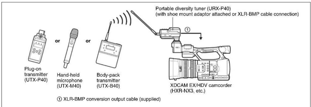
For URX-P41D portable diversity tuner
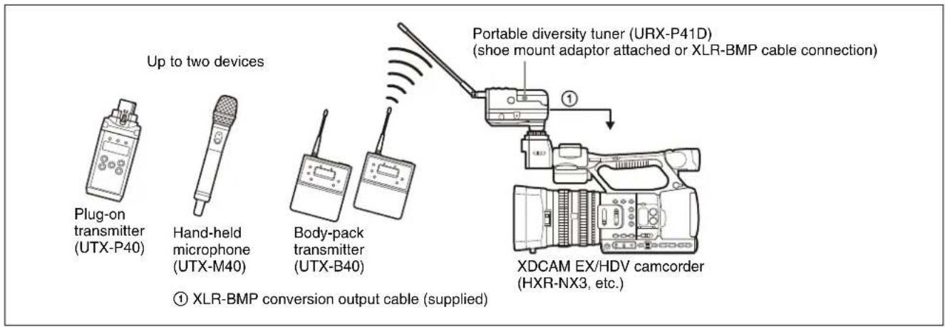
Error Messages
When a problem occurs, one of the following error messages may appear on the display.
| Message Meaning Solution | ||
| EEP ERROR | An error has occurred in the backup memory data. | Contact your point of purchase or Sony service representative. |
| PLL ERROR | An error occurred in the PLL synthesizer circuit. | Restart the unit. If the message persists, contact your point of purchase or Sony service representative. |
| NO TONE Audio signal output has been muted, because a tone signal different from the commander mode configured on the tuner was received. | Configure the commander mode for the transmitter you are using (see “Setting the commander mode (COMPANDER)” (page 38 or page 43).When operating in conjunction with UWP-D series transmitters (UTX-B40, UTX-M40, etc.), set the tuner and the transmitters to the same commander mode. | |
Troubleshooting
If you have any problem, use the following checklist before asking for repairs. If the problem persists, contact your point of purchase or Sony service representative.
| Symptom Cause Solution | ||
| The unit does not turn on. | The ⊕ and ⊖ polarity orientation of the batteries is incorrect. | Insert the batteries with the correct polarity orientation (page 18). |
| The batteries are getting low. Replace the batteries with new ones. | ||
| The battery terminals are dirty. | Clean the ⊕ and ⊖ terminals, and the battery compartment terminals^4) with a cotton swab. | |
| Batteries are not inserted despite POWER SOURCE being set to BATT ONLY. ^3) | Insert batteries, or change the POWER SOURCE setting (URX-P40: page 33, URX-P41D: page 35). | |
| The SMAD-P5 (option) is not connected correctly to the camera or tuner. | Refer to the SMAD-P5 (option) operating instructions and check that devices are attached correctly. ^3) | |
| The power supplies for the tuner and camera are not linked. | Refer to the SMAD-P5 (option) operating instructions and check that devices are started in the correct sequence. ^3) | |
| The unit does not turn off. | The POWER/MUTE button is locked. ^5) | Release the locked status in the POWER LOCK menu (page 42). |
| The unit is set so that power cannot be turned on/off using the POWER/MUTE button. ^6) | Set the POWER/MUTE menu to POWER/MUTE, or turn the unit off using the POWER button (page 42). | |
| The batteries become drained quickly. | The batteries are getting low. Replace the batteries with new ones. | |
| Manganese batteries are being used. Use alkaline batteries. The battery life of a manganese battery is less than half that of an alkaline battery. | ||
| The device is being used under cold conditions. | The batteries drain quickly under cold conditions. | |
| The channel cannot be changed. ^1) | The unit is not in transmission stopped mode. | Turn off the unit, and then turn it on again while holding down the SET button to switch to transmission stopped mode (page 40). |
| Symptom Cause Solution | ||
| There is no sound. The | channel setting on the transmitter is different from that on the tuner. | Use the same channel setting on both the transmitter and tuner. |
| The transmitter is not transmitting signals, or the transmission output is weak. | Confirm that the transmitter is turned on.Alternatively, reduce the distance between the transmitter and tuner. | |
| The transmitter is set to line level input.2) | Switch to microphone input (page 42). | |
| The compander mode setting on the transmitter is different from that on the tuner. | Use the same compander mode setting on both the transmitter and tuner (UTX-B40/M40/P40: page 43, URX-P40: page 33, URX-P41D: page 38). | |
| The transmitter is muted.1) | Press the POWER/MUTE button on the transmitter to release the muted state. | |
| The MUTE SETTING menu (POWER/MUTE menu on the UTX-M40) is set to PTT HOLD. Change the setting (page 42). | ||
| The audio output connector settings are incorrect.7) | Set the audio output connector settings in the OUTPUT ASSIGN menu (page 38). | |
| The Analog/Digital switch of the SMAD-P5 (option) is not set correctly. | Refer to the SMAD-P5 (option) operating instructions and change to the correct setting.3) | |
| If no sound is emitted from the microphone connected to the MIC INPUT connector, the external microphone is set to OFF or the microphone type is set incorrectly.7) | Configure the microphone setting to match the type of microphone using the MIC SELECT menu (page 38). | |
| The sound is weak. | The attenuation level on the transmitter is too high. | The input level of the transmitter is low. Set the attenuation of the transmitter to an appropriate level (page 41). |
| The volume on the amplifier or mixer is low. Adjust | the volume to an appropriate level. | |
| The transmitter is set to line level input.2) | Switch to microphone input (page 42). | |
| The compander mode setting on the transmitter is different from that on the tuner. | Use the same compander mode setting on both the transmitter and tuner (UTX-B40/M40/P40: page 43, URX-P40: page 33, URX-P41D: page 43). | |
| The supplied cable and the connected device are not connected correctly. | Check the operating instructions for the connected device and connect the device correctly. | |
| If the sound emitted from the microphone connected to the MIC INPUT connector is low, the configured level does not match the connected microphone.7) | Adjust the level according to the connected microphone using the INPUT LEVEL menu (page 39). | |
| The sound is distorted. | The attenuation level on the transmitter is too low or is set to 0. | The input level is extremely high. Set the attenuation on the transmitter so that the audio is not distorted (page 41). |
| The GAIN MODE menu of the transmitter is set to 15dB BOOST. | The input level is extremely high. Change the GAIN MODE setting so that the sound is not distorted (page 41). | |
| The channel setting on the transmitter is different from that on the tuner. | Use the same channel setting on both the transmitter and tuner. | |
| Headphones with a monaural mini jack are being used.3) | Use headphones with a stereo mini jack. | |
| The OUTPUT MODE menu of the tuner is set to HIGH GAIN.7) | The output level is extremely high. Change the OUTPUT MODE setting to NORMAL so that the sound is not distorted (page 34). | |
| If the sound emitted from the microphone connected to the MIC INPUT connector is distorted, the microphone type is set incorrectly.7) | Configure the microphone setting to match the type of microphone using the MIC SELECT menu (page 38). | |
| The attenuator cannot be set. | The GAIN MODE menu is set to AUTO GAIN, or the INPUT LEVEL menu is set to LINE. | Change the GAIN MODE menu and INPUT LEVEL menu settings (page 41). |
| There is sound interruption or noise. | The channel setting on the transmitter is different from that on the tuner. | Use the same channel setting on both the transmitter and tuner. |
| Two or more transmitters are set to the same channel. | Two or more transmitters cannot be used on the same channel. Refer to the frequency list, and reconfigure the channel on each transmitter. | |
| The transmitters are not set to the channels within the same channel group. | The channel plan is set so that no signal interference occurs when two or more transmitters are used simultaneously. Set each transmitter to a different channel within the same channel group. | |
| Adjacent channels are being used. Use the channels is separated by at least two channels (250 kHz). | ||
| If you hear a beeping noise or a beep in sync with the access lamp of the camcorder, the media of the camcorder may be being accessed or interference with the GPS block may be occurring.3) | Raise OUTPUT LEVEL by up to +12 dB on the tuner side (URX-P40: page 31, URX-P41D: page 34), and lower the reference input level on the camcorder side by the same amount. | |
| If crackling or squealing noise occurs, interference from the Wi-Fi block of the camcorder may be occurring.3) | Raise OUTPUT LEVEL by up to +12 dB on the tuner side (URX-P40: page 31, URX-P41D: page 34), and lower the reference input level on the camcorder side by the same amount. Alternatively, turn off the Wi-Fi function of the camcorder. | |
| If hum noise occurs, interference from the LCD backlight block of the camcorder may be occurring.3) | Raise OUTPUT LEVEL by up to +12 dB on the tuner side (URX-P40: page 31, URX-P41D: page 34), and lower the reference input level on the camcorder side by the same amount. Alternatively, set the viewfinder brightness on the camcorder to “Mid” or “Low”. | |
| Noise from the camcorder may be being superimposed in the tuner.3) | Raise OUTPUT LEVEL by up to +12 dB on the tuner side (URX-P40: page 31, URX-P41D: page 34), and lower the reference input level on the camcorder side by the same amount. | |
| The distance between the transmitter and tuner is short. | Move the transmitter and tuner further apart. | |
| If the received signal level is too high, noise may be generated by the tuner side which is not currently set to receive. | Turn off the unused tuner.7) | |
| The noise is louder when connected with SMAD-P5 (option) than when connected with the XLR-BMP conversion output cable (supplied with the URX-P40/URX-P41D) for a tuner. | The reference input level and reference recording level are different for each camcorder input connector, or the audio level is not set correctly.3) | Adjust the reference input level and reference recording level of the camcorder, or adjust OUTPUT LEVEL on the tuner to set the appropriate audio level. |
| The RF indicator on the tuner lights up even when the transmitter is off. | Jamming radio waves are being received. Set the channel on the tuner to a channel for which the RF indicator does not light, or use the Clear Channel Scan function to switch to a channel without interference. Then, set the transmitter to the same channel as the tuner. If using two or more transmitters, change to a channel group that is not affected. | |
| The transmitter channel cannot be set with infrared transmission. | The infrared receptor on the transmitter is too far from the infrared transmission port on the tuner.8) | Reduce the distance between the infrared receptor on the transmitter and the infrared transmission port on the tuner to within about 20 cm (8 in.). |
| Interference from infrared communications between other devices or from direct sunlight is present.8) | The transmitting distance is reduced when interference from strong sunlight, for example, is present. Place the transmitter and tuner as close to each other as possible. | |
| The SYNC MODE menu setting is NFC.7) | Change the SYNC MODE setting to IR (page 35). | |
| Symptom Cause Solution | ||
| The transmitter channel cannot be set via NFC communication. | The N-Marks of both units are not facing each other, or they are too far apart. Or there may be some metallic object between the N-Marks. | Place the N-Marks approximately 5 mm from each other. Make sure there are no metallic or other objects near them. |
| The grip is open. ^6) | ||
| The SYNC MODE menu setting is IR. ^7) | Change the SYNC MODE setting to NFC (page 35). | |
1) Body-pack transmitter (UTX-B40) / hand-held microphone (UTX-M40) / plug-on transmitter (UTX-P40) only
2) Body-pack transmitter (UTX-B40) / plug-on transmitter (UTX-P40) only
3) Portable diversity tuner (URX-P40) / portable diversity tuner (URX-P41D) only
4) Body-pack transmitter (UTX-B40) / portable diversity tuner (URX-P40) / portable diversity tuner (URX-P41D) only
5) Body-pack transmitter (UTX-B40) / plug-on transmitter (UTX-P40) / portable diversity tuner (URX-P40) only
6) Hand-held microphone (UTX-M40) only
7) Portable diversity tuner (URX-P41D) only
8) Body-pack transmitter (UTX-B40) / hand-held microphone (UTX-M40) / plug-on transmitter (URX-P40) / portable diversity tuner (URX-P41D) only
Important Notes on Use
The use of some frequency bands may be restricted by law, depending on the country or region. Check in advance before use.
The NFC communication function is used only for communication between a transmitter and a tuner. It cannot be used for communication with other devices.
Notes
• Always verify that the unit is operating properly before use. SONY WILL NOT BE LIABLE FOR DAMAGES OF ANY KIND INCLUDING, BUT NOT LIMITED TO, COMPENSATION OR REIMBURSEMENT ON ACCOUNT OF THE LOSS OF PRESENT OR PROSPECTIVE PROFITS DUE TO FAILURE OF THIS UNIT, EITHER DURING THE WARRANTY PERIOD OR AFTER EXPIRATION OF THE WARRANTY, OR FOR ANY OTHER REASON WHATSOEVER.
- SONY WILL NOT BE LIABLE FOR CLAIMS OF ANY KIND MADE BY USERS OF THIS UNIT OR MADE BY THIRD PARTIES.
- SONY WILL NOT BE LIABLE FOR THE TERMINATION OR DISCONTINUATION OF ANY SERVICES RELATED TO THIS UNIT THAT MAY RESULT DUE TO CIRCUMSTANCES OF ANY KIND.
Condensation
If the unit is suddenly taken from a cold to a warm location, or if ambient temperature suddenly rises, moisture may form on the outer surface of the unit and/or inside of the unit. This is known as condensation. If condensation occurs, turn off the unit and wait until the condensation clears before operating the unit. Operating the unit while condensation is present may damage the unit.
OLED panel
Due to the characteristics of the material used in the OLED panel, permanent burn-in or reduction in brightness may occur.
These problems are not a malfunction.
Consumable parts
The life expectancy of the electrolytic capacitor is about 5 years under normal operating temperatures and normal usage (8 hours per day; 25 days per month). If usage exceeds the above normal usage frequency, the life expectancy may be reduced correspondingly.
Do not place this product close to medical devices
This product (including accessories) has magnet(s) which may interfere with pacemakers, programmable shunt valves for hydrocephalus treatment, or other medical devices. Do not place this product close to persons who use such medical devices. Consult your doctor before using this product if you use any such medical device.
Usage and storage
- Operating the UWP-D series devices near electrical equipment (motors, transformers, or dimmers) may cause interference due to electromagnetic induction. Keep the devices as far from such equipment as possible.
- The presence of lighting equipment may produce electrical interference over a wide frequency range. In this case, interference may fluctuate with the position of the tuner antenna and position of the transmitter. Position the devices so that interference is minimized.
- To avoid degradation of the signal to noise ratio, do not use UWP-D devices in noisy places or in locations subject to vibration, such as the following:
- Near electrical equipment, such as motors, transformers, or dimmers
– Near air conditioning equipment or places subject to direct air flow from an air conditioner
– Near PA (public address) loudspeakers
– Near equipment that might knock against the tuner
Keep devices as far from such equipment as possible or use buffering material.
Cleaning
Clean the surface and the connectors of devices with a dry, soft cloth. Never use thinners, benzene, alcohol, or any other chemicals, since these may mar the finish.
To prevent electromagnetic interference
Some channels may be unable to be used due to noise generated due to the effects of external noise and/or radio interference. In this case, it is recommended to stop transmitting (turn the power off) or change to another frequency (change channel).
To prevent electromagnetic interference from portable communications devices
The use of portable telephones and other communications devices near this unit can result in malfunctions and interference with audio and video signals.
It is recommended that the portable communications devices near this unit be powered off.
Specifications
The N-Mark is a trademark or registered trademark of NFC Forum, Inc. in the United States and in other countries.
USB Type-C ^® and USB-C ^® are registered trademarks of USB Implementers Forum.
Design and specifications are subject to change without notice.
Transmitter (UTX-B40/M40/P40)
Items common to all transmitters
Oscillator type Crystal-controlled PLL synthesizer Carrier frequencies
14UC/14LA model: 470.125 MHz to 541.875 MHz (UHF-TV channels 14 to 25)
25UC/25LA model: 536.125 MHz to 607.875 MHz (UHF-TV channels 25 to 36)
90U model: 941.625 MHz to 951.875 MHz, 953.000 MHz to 956.125 MHz, and 956.625 MHz to 959.625 MHz
21CE model: 470.025 MHz to 542.000 MHz (UHF-TV channels 21 to 29)
33CE model: 566.025 MHz to 630.000 MHz (UHF-TV channels 33 to 40)
42CE model: 638.025 MHz to 694.000 MHz (UHF-TV channels 42 to 48)
42LA model: 638.125 MHz to 697.875 MHz (UHF-TV channels 42 to 51)
29CN model: 638.025 MHz to 694.000 MHz (UHF-TV channels 29 to 35)
KR model: 925.125 MHz to 937.375 MHz E model: 794.125 MHz to 805.875 MHz TW model: 510.125 MHz to 529.875 MHz
Preemphasis 50 μs
Reference frequency deviation ± 5kHz (-60dBV,1kHz input)
Distortion 0.9% or less (-60 dBV, 1 kHz input)
Signal-to-noise ratio
60 dB (-60 dBV, 1 kHz input) 102 dB (GAIN MODE set to AUTO GAIN, max.) 96 dB (GAIN MODE set to NORMAL, max.)
Audio delay Approx. 0.35 ms
Tone signal frequency
In UWP-D compander mode: 32.382 kHz
In UWP compander mode: 32 kHz
In WL800 compander mode: 32.768 kHz
Supply voltage DC 3.0 V (two LR6/AA size alkaline batteries)
DC 5.0 V (supplied from USB connector)
NFC function Built-in
IR SYNC function
Built-in
USB port USB Type-C
Operating temperature
0^ to 50^ (32°F to 122°F)
Storage temperature
-20^ to +55^ (-4^ to +131^)
Note
When used in locations with an ambient temperature of 45 ^ ( 113 ^ ) or higher, make sure the unit does not come into direct contact with your skin, as it may cause burns due to high temperature.
Body-pack transmitter (UTX-B40)
Antenna 1/4 λ wavelength wire antenna
Audio input connector
3.5-mm diameter 3-pole locking mini jack
Reference audio input level
-60 dBV (MIC input, GAIN MODE set to NORMAL, 0 dB attenuation) +4 dBu (LINE input)
RF output level 30 mW/5 mW selectable (UC, U, CE, LA, CN, TW models) 10 mW/2 mW selectable (E, KR models)
Frequency response
23 Hz to 18 kHz (Typical)
Attenuation 0 dB to 27 dB (3 dB steps)
Indicators POWER, AUDIO/MUTE
Battery life (measured with two LR6/AA size alkaline batteries at 25 °C (77 °F), DISPLAY MODE set to AUTO OFF)
Approx. 8 hours with output power of 30 mW (UC, U, CE, LA, CN, TW models)
Approx. 10 hours with output power of 10 mW (E, KR models)
Dimensions
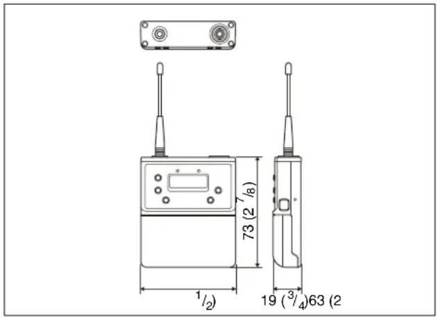
$$ 6 3 \times 7 3 \times 1 9 \mathrm{mm} (2 ^ {1} / _ {2} \times 2 ^ {7} / _ {8} \times {} ^ {3} / _ {4} \text {in.}) $$
(width / height / depth)
(excluding antenna)
Mass Approx. 83 g (2.9 oz) (excluding batteries)
Lavalier microphone (ECM-V1BMP)
Type Electret condenser microphone
Frequency response
40 Hz to 20,000 Hz
Directivity Omni-directional
Sensitivity -43.0 dB ±3 dB
(0 dB = 1 V/Pa, at 1 kHz)
Operating temperature
0^ to 50^ (32°F to 122°F)
Storage temperature
-20^ to +55^ (-4^ to +131^)
Cable 2.3 mm diameter, 2-conductor shielded
cable, 1.2 m (3.9 feet) long
Dimensions 6.8× 19.5mm ( ^9 /32×^25 / 32 in.)
(without cable and connector)
Mass Approx. 16.2 g (0.57 oz)
Hand-held microphone (UTX-M40)
Microphone unit
Dynamic
Directivity Unidirectional
Antenna 1/4 λ wavel length wire antenna
Reference audio input level
-55 dBV (GAIN MODE set to NORMAL, 0 dB attenuation)
Maximum audio input level
151 dB SPL (21 dB attenuation, using supplied microphone unit)
RF output level 30 mW/5 mW selectable (UC, U, CE, LA, CN, TW models)
10 mW/2 mW selectable (E, KR models)
Frequency response
70 Hz to 18 kHz (Typical)
Attenuation 0 dB to 21 dB (3 dB steps)
Indicator POWER/MUTE
Battery life (measured with two LR6/AA size alkaline batteries at 25 °C (77 °F), DISPLAY MODE set to AUTO OFF)
Approx. 8 hours with output power of 30 mW (UC, U, CE, LA, CN, TW models)
Approx. 10 hours with output power of 10 mW (E, KR models)
Dimensions
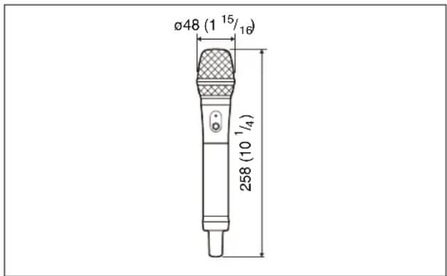
$$ \begin{array}{c} \varnothing 4 8 \times 2 5 8 \mathrm{mm} (1 ^ {1 5} / _ {1 6} \times 1 0 ^ {1} / _ {4} \text {in.}) \ (\text {diameter / length}) \end{array} $$
Mass Approx. 255 g (9.0 oz) (excluding batteries)
Plug-on transmitter (UTX-P40)
Reference audio input level
-60 dBV (MIC input, GAIN MODE set to NORMAL, 0 dB attenuation)
RF output level
40 mW/5 mW selectable (UC, U, LA, TW models)
30 mW/5 mW selectable (CE, CN models)
10 mW/2 mW selectable (E, KR models)
Frequency response
23 Hz to 18 kHz (Typical)
Attenuation 0 dB to 48 dB (3 dB steps)
Audio input connector
XLR-3-11C type (female)
Indicators POWER, AUDIO/MUTE, +48V
Battery life (measured with two LR6/AA size alkaline batteries at 25 °C (77 °F), DISPLAY MODE set to AUTO OFF)
During +48V OFF:
Approx. 7 hours with output power of 40 mW (UC, U, LA, TW models)
Approx. 8 hours with output power of 30 mW (CE, CN models)
Approx. 10 hours with output power of 10 mW (E, KR models)
During +48V ON and ECM-673 connection:
Approx. 6 hours with output power of 40 mW (UC, U, LA, TW models)
Approx. 6 hours with output power of 30 mW (CE, CN models)
Approx. 7 hours with output power of 10 mW (E, KR models)
Dimensions
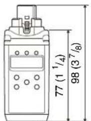
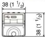
38 × 98 × 38 mm (1 ^1 /2 × 3 ^7 /8 × 1 ^1 /2 in.) (width / height / depth) (including the audio input connector) Mass Approx. 139 g (4.9 oz) (excluding batteries)
Tuner (URX-P40/P41D)
Items common to all tuners
Antenna 1/4 λ wavelength wire antenna (angle-adjustable)
Audio output level variation range -12 dB to +12 dB (3 dB steps)
Audio output connector 3.5-mm diameter 3-pole locking mini jack, Auxiliary connector
Headphone output level 10 mW max. (16-ohm)
Headphone output connector 3.5-mm diameter mini jack
Local oscillator Crystal-controlled PLL synthesizer Receive frequencies
14UC/14LA model: 470.125 MHz to 541.875 MHz (UHF-TV channels 14 to 25)
25UC/25LA model: 536.125 MHz to 607.875 MHz (UHF-TV channels 25 to 36)
90U model: 941.625 MHz to 951.875 MHz, 953.000 MHz to 956.125 MHz, and 956.625 MHz to 959.625 MHz
21CE model: 470.025 MHz to 542.000 MHz (UHF-TV channels 21 to 29)
33CE model: 566.025 MHz to 630.000 MHz (UHF-TV channels 33 to 40)
42CE model: 638.025 MHz to 694.000 MHz (UHF-TV channels 42 to 48)
42LA model: 638.125 MHz to 697.875 MHz (UHF-TV channels 42 to 51)
29CN model: 638.025 MHz to 694.000 MHz (UHF-TV channels 29 to 35
KR model: 925.125 MHz to 937.375 MHz
E model: 794.125 MHz to 805.875 MHz
TW model: 510.125 MHz to 529.875 MHz
Signal-to-noise ratio 60 dB (1 kHz sine wave, 5 kHz modulation) 96 dB (1 kHz sine wave, max deviation)
Audio delay Approx. 0.35 ms (analog output) Approx. 0.24 ms (digital output)
Deemphasis 50 μs Reference frequency deviation ±5 kHz
Frequency response 23 Hz to 18 kHz (Typical)
Distortion 0.9% or less (1 kHz sine wave, 5 kHz modulation)
Tone signal frequency In UWP-D compander mode: 32.382 kHz In UWP compander mode: 32 kHz In WL800 compander mode: 32.768 kHz
Operating temperature 0 °C to 50 °C (32 °F to 122 °F)
Storage temperature -20 ^ to +55 ^ ( -4 ^ to +131 ^ )
Note
When used in locations with an ambient temperature of 45 ^ ( 113 ^ ) or higher, make sure the unit does not come into direct contact with your skin, as it may cause burns due to high temperature.
USB port USB Type-C Supply voltage DC 3.0 V (two LR6/AA size alkaline batteries) DC 5.0 V (supplied from USB connector)
Portable diversity tuner (URX-P40)
Audio output level -60 dBV (3.5-mm diameter 3-pole locking mini jack, analog output, 0 dB audio output level) -20 dBFS (auxiliary connector, digital output, 0 dB audio output level) -50 dBV (auxiliary connector, analog output, 0 dB audio output level)
Reception method True diversity method
Indicators POWER, RF
NFC function Built-in
Battery life Approx. 6 hours (measured with two LR6/AA size alkaline batteries at 25 °C (77 °F), DISPLAY MODE set to AUTO OFF)
Dimensions
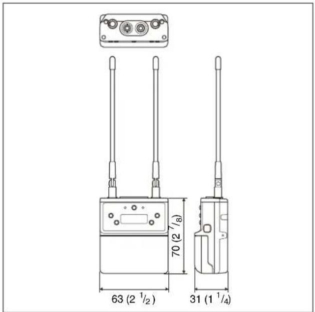
63 × 70 × 31 ~mm (2^1/2 × 2^7/8 × 1^1/_4 in.) (width / height / depth)
(excluding antenna)
Mass Approx. 131 g (4.6 oz) (excluding batteries)
Portable diversity tuner (URX-P41D)
Audio output level
-60 dBV (3.5-mm diameter 3-pole locking mini jack, analog output, 0 dB audio output level, OUTPUT MODE set to NORMAL)
-20 dBFS (auxiliary connector, digital output, 0 dB audio output level)
-50 dBV (auxiliary connector, analog output, 0 dB audio output level)
Audio input level
-50 dBV (during -60 dBV output, 1 kHz input frequency, INPUT LEVEL set to 0 dB)
Audio input connector
3.5-mm diameter 3-pole locking mini jack
Reception method
Space diversity system (true diversity system during one-channel operation)
Indicators POWER, RF 1/2
NFC function Built-in
IR SYNC function
Built-in
Battery life Approx. 4 hours 30 minutes (measured with two LR6/AA size alkaline batteries at 25 °C (77 °F), DISPLAY MODE set to AUTO OFF)
Dimensions
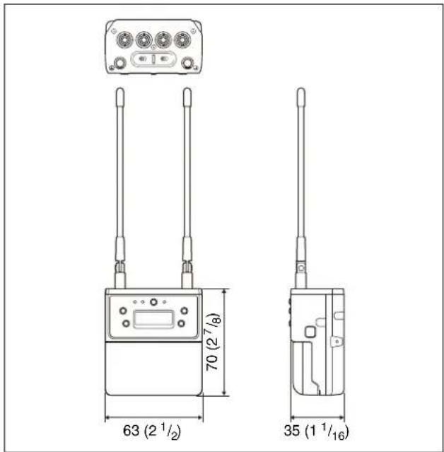
63 × 70 × 35 mm (2^1/2 × 2^7/8 × 1^7/_16 in.) (width/height/depth) (excluding antenna)
Mass
Approx. 159 g (5.6 oz) (excluding batteries)
- UHF Wireless Microphone Package UHF Synthesized Transmitter UHF Synthesized Wireless Microphone UHF Synthesized Diversity Tuner
- Table of Contents
- Configuration of the Packages ....3
- Features 8
- Name and Function of Parts....9
- Power Supply....18
- Attaching Accessories....21
- Operation 23
- Tuner Settings ......26
- Transmitter Settings ....39
- System Configuration Example ....45
- Error Messages ....46
- Troubleshooting......47
- Important Notes on Use....51
- Specifications....52
- Configuration of the Packages
- Note
- UWP-D21
- UWP-D22
- UWP-D26
- UWP-D27
- Models available separately
- UTX-B40
- UTX-M40
- UTX-P40
- URX-P40
- URX-P41D
- Features
- Name and Function of Parts
- ①Antenna
- ② POWER indicator
- ③AUDIO (audio input level) indicator
- ④Audio input connector (BMP type)
- Notes
- ⑤Display section
- ⒶRF transmission indicator
- ®RF transmission power indicator
- ©Au dio input level meter
- (D)Peak indicator
- ⑤ Input level indicator
- ⑤Muting status indicator
- ©Battery level indicator
- ⑧Menu display section
- ①Gain mode indicator
- 6+ or - button
- ⑦Infrared detector
- ⑧N-Mark
- ⑨B artery compartment
- ⑩MUTE button
- ⑪ SET button
- ⑫USB connector (USB Type-C®)
- POWER button
- Hand-held microphone (UTX-M40)
- ①Microphone unit
- ③PO WER/MUTE button
- ④ Battery compartment
- ⑤N-Mark
- Antenna section
- ⑦ Display section
- ©Audio input level meter
- Peak indicator
- ⑧Muting status indicator
- ⑤Battery level indicator
- ©Menu display section
- ⑧Gain mode indicator
- ⑧Infrared detector
- ⑨ SET button
- ⑩USB connector (USB Type-C)
- ⑪ POWER button
- 12+ or - button
- Plug-on transmitter (UTX-P40)
- ①Audio input connector (XLR type)
- ②+48V (+48 V supply) indicator
- ③ POWER indicator
- ④AUDIO (audio input level) indicator
- ⑦ Infrared detector
- 8N-Mark
- ⑨MUTE button
- ⑩SET button
- ⑫USB connector (USB Type-C)
- ⑬B artery compartment
- Portable diversity tuner (URX-P40)
- ②PHONES (monitor) connector (3.5-mm diameter, stereo mini jack)
- ④RF (radio frequency input) indicator
- ⑤+ or - button
- ⑥N-Mark
- ⑦ Battery compartment
- ⑧ Display section
- ⒶAudio input level meter
- ⑧Peak indicator
- ©Transmitter power warning indicator
- ©Transmitter muting status indicator
- ⑤RF (radio frequency input) level meter
- ©M enu display section
- ⑨NFC SYNC (NFC communication) button
- POWER button
- ⑫ OUTPUT (audio output) connector (3.5-mm diameter, 3-pole locking mini jack, balanced output)
- ⑬Auxiliary connector
- 14USB connector (USB Type-C)
- Portable diversity tuner (URX-P41D)
- ③RF (radio frequency input) indicators
- ④Infrared transmitter port
- 6N-Mark
- ©Group display
- ⑤Ch annel display
- ⑤Transmitter power warning indicator
- ©RF (radio frequency input) level meter
- ⑧Battery level indicator
- 10SET button
- ⑪ MENU button
- ⑫PHONES (monitor) connector (3.5-mm diameter, stereo mini jack)
- 13O OUTPUT 1/2 (audio output 1/2) connector (3.5-mm diameter, 3-pole locking mini jack, balanced output)
- MIC INPUT (audio input) connector (3.5-mm diameter, stereo mini jack)
- POWER switches
- ⑯USB connector (USB Type-C)
- ⑰ A uxiliary connector
- Power Supply
- Body-pack transmitter (UTX-B40) and plug-on transmitter (UTX-P40)
- Portable diversity tuner (URX-P40/P41D)
- Inserting the batteries
- Body-pack transmitter (UTX-B40) / portable diversity tuner (URX-P40/P41D)
- Battery level indicator
- Battery precautions
- Supplying power from a USB connector
- Supplying power from an SMAD-P5 (option)
- Attaching Accessories
- Attaching accessories to the body-pack transmitter (UTX-B40)
- Attaching accessories to the hand-held microphone (UTX-M40)
- Replacing the microphone unit
- Attaching the microphone unit
- Attaching accessories to the plug-on transmitter (UTX-P40)
- Attaching accessories to the portable diversity tuner (URX-P40/P41D)
- Connecting the conversion cable to the OUTPUT connector
- Attaching a belt clip
- Attaching the shoe mount adaptor
- To remove the shoe mount adaptor
- Operation
- Procedure for all transmitters (UTX-B40/M40/P40) and portable diversity tuner (URX-P40)
- Procedure for portable diversity tuner (URX-P41D)
- When GROUP is set in SCAN TYPE
- When ALL BAND is set in SCAN TYPE
- When SYNC MODE is set to NFC
- When SYNC MODE is set to IR
- If noise is generated
- Tuner Settings
- Menu structure and operation
- Procedure for portable diversity tuner (URX-P40)
- Simple mode
- Configuration menus
- Advanced mode
- Basic menu operation
- UTILITY menu
- RX1 (tuner 1) menu
- RX2 (tuner 2) menu
- EXT.IN menu
- Menu tree
- Setting the receive channel
- Searching for available channels within a group (Clear Channel Scan)
- To display the next available channel number
- To cancel searching
- To scan channels automatically
- When SCAN TYPE is set to GROUP
- When SCAN TYPE is set to ALL BAND
- To display the next group
- Searching for active channels within a group (Active Channel Scan)
- Adjusting the monitor audio level
- Configuration menu
- Selecting the group/channel (GP/CH)
- Adjusting the monitor audio level (PHONES)
- Selecting the frequency band (BAND)
- Searching for and selecting available channels (CLR CH SCAN)
- Setting the audio output level (OUTPUT LEVEL)
- Configuring transmitter settings via NFC communication (SYNC RX->TX)
- Reflecting transmitter settings on the tuner via NFC communication (SYNC TX->RX)
- Locking the POWER button (POWER LOCK)
- To release the lock state
- Displaying the accumulated running time (RUNNING TIME)
- To reset the time display
- Setting the menu display mode (MENU MODE)
- Using monitor audio level mode (MONITOR MODE)
- To release monitor audio level mode
- Switching to the previous channel (CH MEMORY)
- To exit the CH MEMORY function
- Selecting the preferred power supply (POWER SOURCE)
- Setting the frequency to an active channel (ACT CH SCAN)
- Setting the commander mode (COMPANDER)
- Setting the battery type (BATTERY TYPE)
- Changing the display settings (DISPLAY MODE)
- Setting the display brightness (BRIGHTNESS)
- Restoring factory default settings (FCT RESET)
- Displaying the software version (VERSION)
- Setting the audio output range (OUTPUT MODE)
- Configuring using communication with the transmitter (SYNC MODE)
- Selecting the scan type (SCAN TYPE)
- RX1/2 (tuner 1/2) menu
- Configuring transmitter settings via NFC communication or infrared communication (SYNC RX1(2)->TX)
- Reflecting transmitter settings on the tuner via NFC communication (SYNC TX- >RX1(2))
- Transmitter and commander mode combinations
- Selecting the connector for output of received audio (OUTPUT ASSIGN)
- Selecting an external microphone to use (MIC SELECT)
- Adjusting the input level (INPUT LEVEL)
- Setting the low-cut filter (LCF)
- Switching the phase of the microphone (PHASE)
- Selecting the connector for output of input audio (OUTPUT ASSIGN)
- Transmitter Settings
- Procedure for all transmitters (UTX-B40/M40/P40)
- Transmission stopped mode
- Setting the transmit channel
- Adjusting the audio input attenuation level (ATTENUATOR)
- Setting the audio gain (GAIN MODE)
- Switching the audio input level (INPUT LEVEL) (UTX-B40/P40 only)
- Setting the transmit output level (RF POWER)
- Setting the microphone drive power supply (+48V SUPPLY) (UTX-P40 only)
- Setting the operation of the audio muting function (MUTE SETTING) (UTX-B40/P40 only)
- Setting the operation of the audio muting function (POWER/MUTE) (UTX-M40 only)
- Switching the phase of the microphone (AUDIO PHASE) (UTX-B40 only)
- Setting motion detection sensor mode (OCUPNCY SENS)
- System Configuration Example
- Error Messages
- Troubleshooting
- Important Notes on Use
- Condensation
- OLED panel
- Consumable parts
- Do not place this product close to medical devices
- Usage and storage
- Cleaning
- To prevent electromagnetic interference
- To prevent electromagnetic interference from portable communications devices
- Specifications
- Transmitter (UTX-B40/M40/P40)
- Items common to all transmitters
- Body-pack transmitter (UTX-B40)
- Lavalier microphone (ECM-V1BMP)
- Tuner (URX-P40/P41D)
- Items common to all tuners
Brand : SONY
Model : UTX-M40
Category : Microphone