
DS-MP7608 - Dictaphone Hikvision - Free user manual and instructions
Find the device manual for free DS-MP7608 Hikvision in PDF.


| Product Type | Digital Voice Recorder (Dictaphone) |
| Brand | Hikvision |
| Model | DS-MP7608 |
| Dimensions | Approx. 120 x 60 x 15 mm |
| Weight | Approx. 100 g |
| Power Supply | Built-in rechargeable lithium battery, USB charging (5V DC) |
| Battery Life | Up to 20 hours continuous recording |
| Storage Capacity | Internal memory (8 GB) + microSD card slot (up to 32 GB) |
| Recording Format | MP3, WAV (PCM) |
| Recording Modes | High quality, long play, voice activated (VOR) |
| Interface | USB 2.0, microSD card slot, 3.5 mm earphone jack |
| Microphone | Built-in stereo microphone |
| Speaker | Built-in speaker for playback |
| Display | OLED display with backlight |
| File Management | Folder organization, password protection, file delete/lock |
| Date/Time Stamp | Configurable, embedded in file metadata |
| Security | Password protection for device access |
| Maintenance | Clean with soft dry cloth; avoid moisture and extreme temperatures |
| Spare Parts & Repairability | No user-serviceable parts; contact Hikvision service for battery replacement or repairs |
| General Information | Designed for professional audio recording; 51-page user manual available for download |
Frequently Asked Questions - DS-MP7608 Hikvision
User questions about DS-MP7608 Hikvision
0 question about this device. Answer the ones you know or ask your own.
Ask a new question about this device
Download the instructions for your Dictaphone in PDF format for free! Find your manual DS-MP7608 - Hikvision and take your electronic device back in hand. On this page are published all the documents necessary for the use of your device. DS-MP7608 by Hikvision.
USER MANUAL DS-MP7608 Hikvision
This Manual is subject to domestic and international copyright protection. Hangzhou Hikvision Digital Technology Co., Ltd. ("Hikvision") reserves all rights to this manual. This manual cannot be reproduced, changed, translated, or distributed, partially or wholly, by any means, without the prior written permission of Hikvision.
Please use this user manual under the guidance of professionals.
Trademarks
HIKVISION and other Hikvision marks are the property of Hikvision and are registered trademarks or the subject of applications for the same by Hikvision and/or its affiliates. Other trademarks mentioned in this manual are the properties of their respective owners. No right of license is given to use such trademarks without express permission.
Disclaimer
TO THE MAXIMUM EXTENT PERMITTED BY APPLICABLE LAW, HIKVISION MAKES NO WARRANTIES, EXPRESS OR IMPLIED, INCLUDING WITHOUT LIMITATION THE IMPLIED WARRANTIES OF MERCHANTABILITY AND FITNESS FOR A PARTICULAR PURPOSE, REGARDING THIS MANUAL.
HIKVISION DOES NOT WARRANT, GUARANTEE, OR MAKE ANY REPRESENTATIONS REGARDING THE USE OF THE MANUAL, OR THE CORRECTNESS, ACCURACY, OR RELIABILITY OF INFORMATION CONTAINED HEREIN. YOUR USE OF THIS MANUAL AND ANY RELIANCE ON THIS MANUAL SHALL BE WHOLLY AT YOUR OWN RISK AND RESPONSIBILITY.
REGARDING TO THE PRODUCT WITH INTERNET ACCESS, THE USE OF PRODUCT SHALL BE WHOLLY AT YOUR OWN RISKS. HIKVISION SHALL NOT TAKE ANY RESPONSIBILITIES FOR ABNORMAL OPERATION, PRIVACY LEAKAGE OR OTHER DAMAGES RESULTING FROM CYBER ATTACK, HACKER ATTACK, VIRUS INSPECTION, OR OTHER INTERNET SECURITY RISKS; HOWEVER, HIKVISION WILL PROVIDE TIMELY TECHNICAL SUPPORT IF REQUIRED.
SURVEILLANCE LAWS VARY BY JURISDICTION. PLEASE CHECK ALL RELEVANT LAWS IN YOUR JURISDICTION BEFORE USING THIS PRODUCT IN ORDER TO ENSURE THAT YOUR USE CONFORMS THE APPLICABLE LAW. HIKVISION SHALL NOT BE LIABLE IN THE EVENT THAT THIS PRODUCT IS USED WITH ILLEGITIMATE PURPOSES.
IN THE EVENT OF ANY CONFLICTS BETWEEN THIS MANUAL AND THE APPLICABLE LAW, THE LATER PREVAILS.
Regulatory Information
FCC Information
Please take attention that changes or modification not expressly approved by the party responsible for compliance could void the user's authority to operate the equipment.
FCC compliance: This equipment has been tested and found to comply with the limits for a Class B digital device, pursuant to part 15 of the FCC Rules. These limits are designed to provide reasonable protection against harmful interference in a residential installation. This equipment generates, uses and can radiate radio frequency energy and, if not installed and used in accordance with the instructions, may cause harmful interference to radio communications. However, there is no guarantee that interference will not occur in a particular installation. If this equipment does cause harmful interference to radio or television reception, which can be determined by turning the equipment off and on, the user is encouraged to try to correct the interference by one or more of the following measures:
- Reorient or relocate the receiving antenna.
- Increase the separation between the equipment and receiver.
- Connect the equipment into an outlet on a circuit different from that to which the receiver is connected.
- Consult the dealer or an experienced radio/TV technician for help.
This equipment should be installed and operated with a minimum distance 20cm between the radiator and your body.
FCC Conditions
This device complies with part 15 of the FCC Rules. Operation is subject to the following two conditions:
- This device may not cause harmful interference.
- This device must accept any interference received, including interference that may cause undesired operation.
EU Conformity Statement
CE
This product and - if applicable - the supplied accessories too are marked with "CE" and comply therefore with the applicable harmonized European standards listed under the RE Directive 2014/53/EU, the EMC Directive 2014/30/EU, the RoHS Directive 2011/65/EU.
[NO TEXT]
2012/19/EU (WEEE directive): Products marked with this symbol cannot be disposed of as unsorted municipal waste in the European Union. For proper recycling, return this product to your local supplier upon the purchase of

equivalent new equipment, or dispose of it at designated collection points. For more information see: www.recyclethis.info
2006/66/EC (battery directive): This product contains a battery that cannot be disposed of as unsorted municipal waste in the European Union. See the product documentation for specific battery information. The battery is marked with this symbol, which may include lettering to indicate cadmium (Cd), lead (Pb), or mercury (Hg). For proper recycling, return the battery to your supplier or to a designated collection point. For more information see: www.recyclethis.info
Symbol Conventions
The symbols that may be found in this document are defined as follows.
| Symbol Description | |
 Danger Danger | Indicates a hazardous situation which, if not avoided, will or could result in death or serious injury. |
 Caution Caution | Indicates a potentially hazardous situation which, if not avoided, could result in equipment damage, data loss, performance degradation, or unexpected results. |
 Note Note | Provides additional information to emphasize or supplement important points of the main text. |
Contents
Chapter 1 Product Introduction ...... 1
1.1 Introduction ...... 1
1.2 Key Features .... 1
Chapter 2 Start Up Device .... 2
2.1 Activate the Device 2
2.1.1 Default Information 2
2.1.2 Activation 2
2.2 Access Device via Web Browser 4
Chapter 3 Basic Operation .... 5
3.1 Configure Date & Time .... 5
3.2 IP Camera Adding 5
3.2.1 Activate IP Camera 5
3.2.2 Add IP Camera 6
3.2.3 Edit IP Camera 6
3.3 Recording 7
3.3.1 Format Storage Media 7
3.3.2 Configure Continuous Recording 7
3.3.3 Configure Event Triggered Recording 8
3.3.4 Disaster Storage 8
3.4 Playback 9
3.5 Backup 9
3.5.1 Back Up Videos 9
3.5.2 Back Up Clipped Videos 10
3.5.3 Back Up Pictures 10
Chapter 4 Network ...... 11
4.1 Network Connection 11
4.1.1 Dial 11
4.1.2 Connect Wi-Fi 11
4.1.3 Set Local Network 12
4.1.4 Port Configuration 12
4.1.5 DDNS Configuration 12
4.2 Platform Connection 13
4.2.1 Connect to Mobile Surveillance Platform 13
4.2.2 Connect to Guarding Vision 14
4.3 Network Sharing 15
4.3.1 Set Wi-Fi AP 15
4.3.2 Set Network Share 15
Chapter 5 Live View and Configuration ...... 16
5.1 Live View 16
5.1.1 Start/Stop Live View 16
5.1.2 Split Screen 16
5.1.3 Select Live View Stream 16
5.1.4 Manual Capture 16
5.1.5 Manual Recording 17
5.1.6 Start/Stop Two-Way Audio 17
5.1.7 Set Live View Volume 17
5.1.8 Full-Screen Live View 17
5.1.9 Channel-Zero 18
5.2 PTZ Operation 18
5.2.1 Configure PTZ 18
5.2.2 PTZ Control Panel 18
5.3 Local Configuration 19
Chapter 6 Mobile Device Features ...... 20
6.1 Timed Shutdown 20
6.2 Delayed Shutdown 20
6.3 Configure Satellite Positioning 20
6.4 Configure G-Sensor Alarm 21
6.5 Configure Sensor-in 22
Chapter 7 Camera Management ...... 23
7.1 Configure Encoding Parameters 23
7.2 Image Settings 23
7.2.1 Set Image Parameters 23
7.2.2 Set Mirror Type 23
7.2.3 Restore Default Parameters 23
7.3 Set OSD Parameters 24
7.4 Set Privacy Mask 24
Chapter 8 Driving Behavior Configuration 25
8.1 Smart Device Driving Behavior Configuration 25
8.1.1 Configuration 25
8.1.2 Play Videos and Pictures 26
8.2 Other Device Driving Behavior Configuration 26
8.2.1 Connect Smart Terminal 26
8.2.2 Set Arming 27
Chapter 9 Events and Alarms 28
9.1 Configure Motion Detection Alarm 28
9.2 Configure Video Loss Alarm 28
9.3 Configure Video Tampering Alarm 28
9.4 Configure Alarm Input 29
9.5 Configure Alarm Output 29
9.6 Configure Exception Alarm 30
9.7 Configure Arming Schedule 30
9.8 Configure Linkage Actions 30
9.8.1 Trigger Recording 30
9.8.2 Trigger Audible Warning 30
9.8.3 Full Screen Monitoring 31
9.8.4 Trigger Alarm Output 31
Chapter 10 Security ...... 32
10.1 User Account Management 32
10.2 Set Security Question 32
10.3 Configure Whitelist 33
10.4 SSH Settings 33
Chapter 11 Maintenance .... 34
11.1 View System Information 34
11.2 Search Log File 34
11.3 Upgrade the System 34
11.4 Rebooting 34
11.5 Restore Default Settings 34
11.6 Export Configuration File 35
11.7 Import Configuration File 35
11.8 Configure DST Settings 35
11.9 Configure Local Output 36
11.10 Configure RS-232 36
Chapter 12 Local Menu Operation .... 37
12.1 IP Camera Adding 37
12.1.1 Activate IP Camera 37
12.1.2 Add IP Camera 37
12.1.3 Edit IP Camera 38
12.2 Recording 38
12.2.1 Format Storage Media 38
12.2.2 Configure Recording Schedule 38
12.3 Playback 39
12.4 Back up 39
Chapter 1 Product Introduction
Introduce the recorder and its key features.
1.1 Introduction
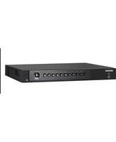
Adopting embedded Linux operating system, mobile video recorder (hereinafter referred to as the recorder) provides powerful monitoring functions. It can both work alone as a recorder and cooperate with other devices to build a comprehensive surveillance system. The recorder is widely applied to the surveillance projects of public transportation, school bus, etc.
1.2 Key Features
- User-friendly GUI providing easy and flexible operations.
- Pluggable 3G/4G module and built-in Wi-Fi module providing flexible data transmission solutions.
- Information collection interfaces collecting driving information such as left/right turn, braking, reversing, etc.
- Specialized aviation connectors ensuring signal stability.
- Ignition startup and delay (0 to 6h) shutdown.
- Battery protection avoids vehicle from running out of battery.
- Wide-range power input (+ 9 to + 32 VDC).
- Power-off protection avoids key data from loss.
- Tensile aluminum chassis with no fan design well adaptable to working environment.
- Software-based firewall supported.
- GNSS (Global Navigation Satellite System) module precisely positioning the vehicle via the satellite and recording the location information in the stream.
Chapter 2 Start Up Device
2.1 Activate the Device
You can activate the recorder via the SADP software, the Web, the client software or the local menu.

Caution
- If you want to activate the device via the SADP software, the Web or the iVMS-4200 client software, make sure that the device and your computer are in the same network segment.
• - If you want to activate the recorder via the local menu, you must connect the device to an external monitor.
2.1.1 Default Information
The default setting of the recorder is as follows:
- Default IP: 192.168.1.64.
- Default user name: admin.
2.1.2 Activation
For the first-time access, you need to activate the recorder by setting an admin password. No operation is allowed before activation.
Activate via Local Menu
You can activate the recorder via the local menu when it's connected to an external monitor.
Steps
- Enter the same password in Password and Confirm Password.

Note
We highly recommend you to create a strong password of your own choosing (using a minimum of 8 characters, including at least three kinds of following categories: upper case letters, lower case letters, numbers, and special characters) in order to increase the security of your product. And we recommend you reset your password regularly, especially in the high security system, resetting the password monthly or weekly can better protect your product.
- Click OK.
Activate via SADP
SADP software is used for detecting the online device, activating the device, and resetting the password. Get the SADP software from the supplied disk or the official website, and install the SADP according to the prompts. Follow the steps to activate the camera.
Before You Start
- Ensure your computer and the recorder are in the same network segment.
• Install the SADP software in your computer.
Steps
-
Run the SADP software.
-
Check the recorder status from the device list, and select the inactive recorder.
i Note
We highly recommend you to create a strong password of your own choosing (using a minimum of 8 characters, including at least three kinds of following categories: upper case letters, lower case letters, numbers, and special characters) in order to increase the security of your product. And we recommend you reset your password regularly, especially in the high security system, resetting the password monthly or weekly can better protect your product.
- Enter the same password in Password and Confirm Password.
- Click Activate.
Activate via iVMS-4200
iVMS-4200 is versatile video management software for multiple kinds of devices. Get the client software from the supplied disk or the official website, and install the software according to the prompts. Follow the steps to activate the device.
Before You Start
- Ensure your computer and the recorder are in the same network segment.
• Install the software in your computer.
Steps
- Run the software.
- Go to Control Panel → Device Management.
- Select inactive recorders.
- Click Activate.
i Note
We highly recommend you to create a strong password of your own choosing (using a minimum of 8 characters, including at least three kinds of following categories: upper case letters, lower case letters, numbers, and special characters) in order to increase the security of your product.
And we recommend you reset your password regularly, especially in the high security system, resetting the password monthly or weekly can better protect your product.
- Enter the same password in Password and Confirm Password.
- Click OK.
Activate via Web Browser
You can activate the device via a web browser.
Before You Start
Ensure your computer and the recorder are in the same network segment.
Steps
- Open web browser, input the IP address of the device and then press Enter.

We highly recommend you to create a strong password of your own choosing (using a minimum of 8 characters, including at least three kinds of following categories: upper case letters, lower case letters, numbers, and special characters) in order to increase the security of your product. And we recommend you reset your password regularly, especially in the high security system, resetting the password monthly or weekly can better protect your product.
- Enter the same password in Password and Confirm.
- Click OK.
2.2 Access Device via Web Browser
Get access to the recorder via web browser.
Steps
- Open the web browser, enter the IP address of the recorder, and then press Enter.
- Enter User Name and Password and click Login.
- Install the plug-in before viewing the live video and managing the camera. Please follow the installation prompts to install the plug-in.
What to do next
Click Logout in top right corner to log out the recorder.
Chapter 3 Basic Operation
You can perform the basic operations once the recorder is connected to an IP camera.

All the operations from Chapter 3 to Chapter 11 is done via web browser.
3.1 Configure Date & Time
Configure time zone and time synchronization mode.
Steps
-
Go to Configuration → System → System Settings → Time Settings.
-
Select Time Zone according to the recorder location.
-
Select time synchronization mode as NTP or Manual Time Sync.
-
If an NTP server is available, select NTP and enter NTP server information to synchronize NTP server time to your recorder.
- Select Manual Time Sync. and set time to customize the recorder time.
-
Select Manual Time Sync. and check Sync. with computer time to synchronize the computer time to your recorder.
-
Click Save.
3.2 IP Camera Adding
The section is only available for the recorder that supports network camera.
3.2.1 Activate IP Camera
Before adding an IP camera, activate it by setting a password for it.
Steps
-
Go to Configuration → System → Camera Management.
-
Select an inactivated IP camera.

We highly recommend you to create a strong password of your own choosing (using a minimum of 8 characters, including at least three kinds of following categories: upper case letters, lower case letters, numbers, and special characters) in order to increase the security of your product. And we recommend you reset your password regularly, especially in the high security system, resetting the password monthly or weekly can better protect your product.
-
Click Activation.
-
Enter the same password in New Password and Confirm.
- Click OK.
3.2.2 Add IP Camera
You can add the activated IP cameras. Ensure the device and IP cameras are in the same network segment.
Before You Start
The record and the camera to add must be in the same network segment.
Steps
- Go to Configuration → System → Camera Management.
- Optional: If the recorder and the camera are in different network segment, modify IP camera address.
1) Check the IP camera and click Modify.
2) Enter IP Address and Password.
3) Click OK.
- Select a camera and click Add.

If the recorder password is the same with the camera's, click Quick Add to add the camera.
- Enter IP camera information.
- Click OK.
3.2.3 Edit IP Camera
You can visit, delete, and modify the added IP cameras.
Before You Start
If the recorder contains only one network card, you can visit IP camera via the recorder. If the recorder contains dual network card, you need to enable virtual host function before visiting IP camera via the recorder. Go to Configuration → Network → Advanced Settings → Other and check Enable Virtual Host.
Steps
- Go to Configuration → System → Camera Management.
- Optional: Click address of IP camera to visit.
- Optional: Check IP cameras and click Delete to delete added IP cameras.
3.3 Recording
To record the videos for connected cameras, you need to install a storage media and format it, and configure the recording schedule.
3.3.1 Format Storage Media
A newly installed storage media must be initialized before it can be used.
Before You Start
Install a storage media.
Steps
-
Go to Configuration → Storage → Storage Management.
-
Check the storage media and click Format.
Result
After format, the storage media status should be Normal.
3.3.2 Configure Continuous Recording
The recorder is configured with all-day continuous recording by default.
Before You Start
Install and format a storage media.
Steps
-
Go to Configuration → Storage → Schedule Settings.
-
Select Channel No.
-
Check Enable.
-
Select recording type as Continuous.
-
Optional: Click Advanced to configure Pre-record and Post-record.
Pre-record
The time you set to start recording before the scheduled time or the event. For example, if an alarm triggers recording at 10:00, and the pre-record time is set as 5 seconds, the device starts to record at 9:59:55.
Post-record
The time you set to stop recording after the scheduled time or the event. For example, if an alarm triggered recording ends at 11:00, and the post-record time is set as 5 seconds, the device records until 11:00:05.
-
Set recording schedule. For detailed steps, refer to Configure Arming Schedule.
-
Optional: Click Copy to copy upper settings to other channel.
-
Click Save.
3.3.3 Configure Event Triggered Recording
Trigger recording when an event is triggered.
Before You Start
• Install and format the storage media.
- Configure event parameters. For details, refer to Events and Alarms.
Steps
- Go to Configuration → Storage → Schedule Settings.
- Select Channel No.
- Check Enable.
- Select recording type as Motion | Alarm, Alarm, Motion, or Motion & Alarm.
Motion | Alarm
Trigger recording when either motion detection or alarm input is detected.
Alarm
Trigger recording when alarm input is detected.
Motion
Trigger recording when either motion detection detected.
Motion & Alarm
Trigger recording when both motion detection and alarm input are detected.
- Optional: Click Advanced to configure Pre-record and Post-record.
Pre-record
The time you set to start recording before the scheduled time or the event. For example, if an alarm triggers recording at 10:00, and the pre-record time is set as 5 seconds, the device starts to record at 9:59:55.
Post-record
The time you set to stop recording after the scheduled time or the event. For example, if an alarm triggered recording ends at 11:00, and the post-record time is set as 5 seconds, the device records until 11:00:05.
- Set recording schedule. For detailed steps, refer to Configure Arming Schedule.
- Optional: Click Copy to to copy upper settings to other channel.
- Click Save.
3.3.4 Disaster Storage
The function is only available for recorder supporting mobile fireproof storage box. The recorder will save videos in both HDD and mobile fireproof storage box to ensure data security.
Before You Start
- Connect a mobile fireproof storage box to your recorder.
- Configure the recording schedule.
Steps
- Go to Configuration → Vehicle → Storage For Calamity
- Check Enable.
- Check Redundant Channel. The recorder will save the videos of the selected channels in both HDD and mobile fireproof storage box.
- Click Save.
3.4 Playback
Play videos saved in storage medias.
Steps
- Go to Playback.
- Click to select a channel in channel list.
- Select playback type as Ordinary Search or Event Search.
- To search all the videos, select Ordinary Search.
-
To search event videos, select Event Search.
-
Search search conditions.
-
Click Search.
-
Click ▶ to start playback.
| II | Pause. | I▶ | Single frame playback. |
| Fast forward. Slow forward. | |||
| Stop all playbacks. Capture. | For picture saving path, refer toConfiguration → Local → Save snapshots when playback to . | ||
| Turn on audio. Full screen. |
3.5 Backup
3.5.1 Back Up Videos
Download videos to a local path.
Steps
-
Go to Playback.
-
Click ↓.
- Search search conditions.
- Click Search.
- Check videos to download and click Download.
- For the video saving path, refer to Configuration → Local → Save Downloaded Files to .
3.5.2 Back Up Clipped Videos
Clip videos and save them to a local path.
Steps
- Go to Playback.
- Start playback.
- Click ✿ to start clipping.
- Click ✿ to stop clipping.
- For clipped video saving path, refer to Configuration → Local → Save clips to .
3.5.3 Back Up Pictures
Back up pictures to a local path.
Steps
- Go to Picture.
- Set search conditions.
- Click Search.
- Check pictures to download.
- Click Donwload.
- For picture saving path, refer to Configuration → Local → Picture and Clip Settings.
Chapter 4 Network
4.1 Network Connection
4.1.1 Dial
Set dialing parameters.
Before You Start
Install 3G/4G SIM card and connect 3G/4G antenna to your recorder.
Steps
- Go to Configuration → Network → Basic Settings → 3G/4G.
- Check Enable.
- Click Dial Parameters.
-
Select Network Mode.
-
Automatic: The recorder will automatically switch to the strongest network.
- Auto-Search and Auto-Switch: Network priority: 4G > 3G > 2G. The recorder will automatically connect the network of high priority.
- 3G: The recorder only connects 3G network.
-
4G: The recorder only connects 4G network.
-
Optional: To connect private network, enter Access Number, User Name, Password, and APN.
-
Click Save.
-
Optional: Click Wireless Dial-up Status to view dialing status.
4.1.2 Connect Wi-Fi
Configure Wi-Fi parameters.
Steps
-
Go to Configuration → Network → Basic Settings → TCP/IP.
-
Set WLAN parameters.
1) Click Wlan 1.
2) Optional: Check DHCP. Use SADP tool to obtain the recorder IP address when DHCP is enabled.
3) Enter wireless network IPv4 Address, IPv4 SubnetMask, IPv4 Default Gateway, and DNS Server.
4) Click Save.
- Go to Configuration → Network → Advanced Settings → Wi-Fi.
1) Check Enable Wi-Fi.
2) Click Search to search available wireless networks.
3) Select a wireless network in Wireless List.
4) Enter SSID.
5) Select Network Mode as Managed.
6) Select Security Mode and enter Wi-Fi key.
-
Click Save.
-
Optional: Go to Configuration → Network → Advanced Settings → Wi-Fi → Wi-Fi Status to view Wi-Fi status.
4.1.3 Set Local Network
Configure local network parameters.
Steps
-
Go to Configuration → Network → Basic Settings → TCP/IP.
-
Select LAN port.
-
Debug Interface: Used to debug the recorder.
-
Rear interface: Used to connect network cameras.
-
Enter network parameters: IPv4 Address, IPv4 Subnet Mask, and IPv4 Default Gateway.
-
Optional: To access the recorder via internet, configure DNS server.
-
Click Save.
4.1.4 Port Configuration
Go to Configuration → Network → Basic Settings → Port.
HTTP Port
Used to access the recorder via web browser.
RTSP Port
Used to get stream. HTTPS Port
HTTPS Port
Used for secure communication over a network.
Server Port
Used to access the recorder via client software.
4.1.5 DDNS Configuration
If your recorder external network is a dynamic IP address, you can use the Dynamic DNS (DDNS) for network access.
Before You Start
- Register your recorder on the DDNS server.
- Configure local network IP address, subnet mask, gateway, and DNS server.
- Create port mapping, default port:80, 8000, and 554.
Steps
- Go to Configuration → Network → Basic Settings → DDNS.
- Select DDNS Type.
- Enter server information.
- Click Save.
What to do next
Open the web browser and enter the recoder domain name to visit it.
4.2 Platform Connection
4.2.1 Connect to Mobile Surveillance Platform
The device can be remotely accessed via mobile surveillance platform.
Before You Start
Create the device ID on mobile surveillance platform.
Steps
- Go to Configuration → Network → Advanced Settings → Platform Access.
- Check Enable.
- Select Platform Access Mode as Ehome Platform.
- Select Server Address Type, and enter Server Address, Server Port, and Device ID.
Server Address
Enter the static IP address of mobile surveillance platform.
Server Port
The default value is 7660.
Device ID
The ID of the device registered on the mobile surveillance platform. If you leave it empty, device logs in to the platform with serial No.
5. Click OK.
i Note
- You can download mobile surveillance platform to your computer by visiting our official website and going to Home > VMS > Support > Download >HikCentralProfessionalV2.2.0. Official website: http://www.hikvision.com/en/.
- You can download iVMS-5260M to your mobile phone by searching it in app store/google play or scan QR code below. If you use Android system, install googleplay application on your mobile phone before scanning the QR code.
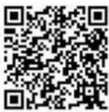
Figure 4-1 iOS
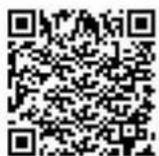
Figure 4-2 Android
4.2.2 Connect to Guarding Vision
The device can be remotely accessed via guarding vision platform.
Before You Start
- Connect your recorder to internet.
- Configure IP address, sub-netmask, gateway, and DNS server of LAN port.
Steps
- Go to Configuration → Network → Advanced Settings → Platform Access.
- Check Enable.
- Select Platform Access Mode as Guarding Vision.

Caution
Valid security code range [6-12]. You can use a combination of numbers, lowercase, and uppercase.
- Enter a customized Security Code. You need to enter the security code when adding the recorder in guarding vision.
- Click Save.
-
Visit guarding vision platform.
-
For computer user: Visit dev.guardingvision.com.
-
For mobile phone user: Download Guarding Vision application in app store or google play.
-
Register an account.
-
Add the recorder by its serial number (a 9-bit character printed in device lable) and security code.
- Start live view of your camera.
4.3 Network Sharing
4.3.1 Set Wi-Fi AP
The recorder can work as a wireless router. Othe devices can access network via the recorder.
Steps

Caution
You can only turn on one function between Wi-Fi AP and Wi-Fi. Turning on one of them will turn off the other.
- Go to Configuration → Network → Advanced Settings → Wi-Fi AP.
- Check Enable Wi-Fi AP, Enable AP Broadcast, and Enable WLAN HotSpot.
- Configure hotspot parameters.
1) Enter SSID (hotspot name).
2) Select Security Mode.
3) Enter IP Address and Sub-net Mask.

Note
The IP address must be in different network segment with TCP/IP address.
- Check Enable DHCP and enter Start IP Address and End IP Address.
- Click Save.
4.3.2 Set Network Share
Connect a peripheral device to your recorder with a network cable. The peripheral device can access internet after the recorder successfully dialed to internet.
Steps
- Go to Configuration → Network → Basic Settings → TCP/IP → Lan.
- Check Enable Network Share.
- Configure the network parameters for the peripheral device.
1) Set its IP address in the same network segment with your recorder.
2) Set its network gateway IP as the recorder IP address.
- Click Save.
The peripheral device can access internet after the recorder successfully dialed to internet.
Chapter 5 Live View and Configuration
5.1 Live View
5.1.1 Start/Stop Live View
Start/stop the live view of cameras.
Steps
- Go to Live View.
- Click ☐ to select window division and click to select a window to display the live view image.
- Double click a camera in the camera list to display its live image in selected window. Or click to start the live view of all cameras.
- Double click the camera again to stop its live view. Or click 📄 to stop the live view of all cameras.
5.1.2 Split Screen
Live view window division is selectable.
Window Division
Click to select live view window division.
Paging
Click ↕ to turn to previous/next window.
5.1.3 Select Live View Stream
The recorder supports main stream and sub-stream. Main stream is used for continuous recording and sub-stream is used for network transmission.
Click t_0^ in camera list to select live view stream.
5.1.4 Manual Capture
Capture live view pictures and save them to your computer.
Steps
- Go to Live View.
- Start live view of a camera.
-
Click
-
View captured pictures.
-
Enter the path popped up in the lower right corner.
- Go to Configuration → Local → Picture and Clip Settings for the saving path of captured pictures.
5.1.5 Manual Recording
Record videos in live view and save them to your computer.
Steps
- Go to Live View.
- Start live view of a camera.
- Click ➤ to start recording.
- Click to stop recording.
-
Go to the set saving path to view recorded videos.
-
Enter the path popped up in the lower right corner.
- Go to Configuration → Local → Record File Settings for picture saving path.
5.1.6 Start/Stop Two-Way Audio
You can have real-time two-way audio between your computer and the recorder.
Before You Start
Connect the audio input and output devices to the recorder and computer.
Steps
- Start the live view of a camera.
- Click 🖱️.
Result
- At computer end, you can hear the audio from recorder.
- At recorder end, you can hear the audio from computer.
5.1.7 Set Live View Volume
Turn on audio and adjust audio volume.
Click to turn on audio.
Drag the slider to adjust volume.
5.1.8 Full-Screen Live View
Display the live view image in full screen.
Start the live view and click ✕ to display the live view image in full screen.
Press Esc to exit from the full-screen mode.
5.1.9 Channel-Zero
Channel-zero, known as virtual channel, can show the videos from all channels of the recorder, reducing the bandwidth while simultaneously previewing from multi-channel.
Steps
- Go to Configuration → Video/Audio → Channel-zero.
- Check Enable Channel-zero Encoding.
- Select Max. Bitrate and Max. Frame Rate.
- Click Save.
- Go to Live View.
- Double click ZeroChannel 01 in the camera list to start live veiw of channel-zero.
5.2 PTZ Operation
Configure PTZ parameters and control PTZ.
5.2.1 Configure PTZ
Follow the steps to set PTZ parameters. The configuration of the PTZ parameters should be done before you control the PTZ camera.
Before You Start
Connect the RS-485 cables of the PTZ camera to EXT.DEV interface of the device.
Steps
- Go to Configuration → System → System Settings → PTZ Config.
- Select Channel No. of PTZ camera.
- Configure the parameters of the PTZ camera. All the parameters should be exactly the same with those of the PTZ camera.
- Click Save.
5.2.2 PTZ Control Panel
Go to Live View. Control PTZ camera via PTZ panel.

PTZ control panel may vary with recorder model.
| Icon DescriptionIcon Description | ||
| Direction buttons.Auto-scan button. | ||
| a | Zoom -. Zoom +. | d |
| d' | Focus +. Focus -. | # |
| o | Iris +. Iris -. | o |
| Turn on /off light. Start/stop wiper. |
5.3 Local Configuration
Local configuration refers to the parameters of live view image, videos and captured pictures.
Stream Type
Select the default live live stream type. Main stream and sub-stream are selectable.
Play Performance
Shortest Delay: The recorder ensures real-time capacity in priority.
Auto: Automatically adjust the live view stream to balance real-time capacity and fluency.
Rules
Reserved.
Image Size
Adjust the image aspect ratio.
Auto Start Live View
Enable: Automatically turn on live view after logged in the recorder.
Chapter 6 Mobile Device Features
6.1 Timed Shutdown
The recorder will automatically start up/shut down according the schedule.
Before You Start
Wire power cord. For details, refer to quick start guide.
Steps
- Go to Configuration → Vehicle → Start.
- Select Auto Work Type as Auto Working.
- Set the shutdown schedule. For detailed steps, refer to Configure Arming Schedule.
- Optional: Check Low Power Protect and select Low Power Protect Limit. If the voltage of the recorder reaches the selected threshold, the recorder will shut down automatically.
- Click Save.
6.2 Delayed Shutdown
You can set the shutdown delay time (Vehicle Ignition Startup and Shutdown) for the recorder.
Before You Start
Wire power cord. For details, refer to quick start guide.
Steps
- Go to Configuration → Vehicle → Start.
- Select Auto Work Type as Halt Delay.
- Select Delay Time.
- Click Save.
- Optional: Check Low Power Protect and select Low Power Protect Limit. If the voltage of the recorder reaches the selected percentage, the recorder will shut down automatically.
6.3 Configure Satellite Positioning
The built-in GNSS module supports GPS (Global Positioning System), enabling device positioning and speed limit alarm.
Before You Start
Install the positioning antenna.
Steps
- Go to Configuration → Vehicle → Position Settings.
- Select Position Module.
Built-in
Obtain data from the satellite positioning module built in the recorder.
Intelligent Display Terminal
Obtain data from display terminal.
3. Select Locating Module.
- Optional: Check Enable of Satellite Timing to synchronize recorder time with satellite time.
5. Configure speed limit.
1) Select Speed Units.
2) Enter Speed Limit of Alarm.
If vehicle speed exceeds the set value, the recorder will alarm.
- Check the channels you want the positioning information to be displayed.
The positioning information will be displayed in the live view and playback mode of the selected channel.
7. Configure linkage actions.
- If you want the speeding vehicle to trigger the speed alarm, check Trigger Alarm Output.
- If you want the speeding vehicle to trigger the system to beep, check Audible Warning.
8. Click Save.
6.4 Configure G-Sensor Alarm
G-Sensor detects and records acceleration information in 3-axial (X, Y, Z) directions.
Before You Start
Connect a G-sensor to the recorder.
Steps
-
Go to Configuration → Vehicle → G-Sensor.
-
Select module according to actual situation.
-
External: The G-sensor is connected to the device through RS-232/RS-485 interface.
-
Built-in: The G-sensor is a built-in module of the device.
-
Set the limit value for acceleration alarm in X, Y and Z directions.

X, Y and Z represent the direction of acceleration and the unit of alarm value is G (G=9.8 m/s ^2 ).
During driving, the recorder will alarm when acceleration of any direction exceeds the set value.
- Set the linkage actions for acceleration alarm, including Audible Warning and Alarm Output.
- Click Save.
6.5 Configure Sensor-in
Sensor-in detects and records the vehicle's driving information, including pedal braking, turning left/right, reversing, etc.
Before You Start
Connect the recorder sensor-in interface and vehicle corresponding interface. For details, refer to quick user guide.
Steps
- Go to Configuration → Vehicle → Sensor-In.
- Select Trigger Level and Pop Channel according to actual situation.
The the image of selected channel will be displayed in full screen when sensor-in is triggered. - Click Save.
Chapter 7 Camera Management
7.1 Configure Encoding Parameters
Configure encoding parameters to adjsut live view image and video parameters.
Go to Configuration → Video/Audio → Video.
In good network situation, you can set high resolution and bitrate to improve image quality.
In bad network situation, you can set low resolution, bitrate, and frame rate to get fluent image.
7.2 Image Settings
7.2.1 Set Image Parameters
You can adjust image parameters including bightness, contrast, etc.
Steps
- Go to Configuration → Image → Display Settings.
- Select Channel No.
- Select Scene according to actual situation.
- Adjust image parameters as desired.
7.2.2 Set Mirror Type
You can enable mirror image and set mirror type to get suitable image.
Steps
- Go to Configuration → Image → Display Settings.
- Select Mirror Type as desired.

The function varies with recorder model.
7.2.3 Restore Default Parameters
You can restore image parameters to defaults.
Go to Configuration → Image → Display Settings, select Channel No., and click Default.
7.3 Set OSD Parameters
Configure the camera name, OSD (On Screen Display) settings, etc.
Steps
- Go to Configuration → Image → OSD Settings.
- Select Channel No.
- Enter Camera Name, select Time Format and Date Format.
- Optional: Check Display Name, Dispaly Date, and Display Week as your desire.
- Set OSD Display Mode.
- Optional: To display text on OSD, check one text overlay and enter text.
- Drag the red frame on live view window to adjust OSD position.
- Click Save.
Result
The check display contents will be overlaied on the live view image and videos.
7.4 Set Privacy Mask
The privacy mask can be used to protect personal privacy by concealing parts of the image from view or recording with a masked area.
Up to four privacy mask areas are supported for each channel.
Steps
- Go to Configuration → Image → Privacy Mask.
- Select Channel No.
- Check Enable Privacy Mask.
-
Draw detection area.
1) Click Draw Area.
2) In preview area, drag to draw the detection area.
3) Click Stop Drawing. -
Click Save.
Result
The image of drawn area will be shield in the live view and videos.
Chapter 8 Driving Behavior Configuration
The function analyzing driver's behavior, including smoking, fatigue driving, talking on phone, etc. The recorder will trigger warning when these behaviors are detected.
8.1 Smart Device Driving Behavior Configuration
Only the recorder with A in model name supports driving behavior detection function. One recorder supports analyzing one channel at a time.
8.1.1 Configuration
Calibrate Camera Position
Calibrate network camera position before enabling driving behavior detection.
Before You Start
Add the network camera in your recorder.
Steps
- Go to Configuration → VCA → Driving Behaviors → IPC Position Calibration.
- Select Channel No.
- Adjust the network camera position to make the driver face image appear in the red frame and his chin is above the yellow line.
Configure Driving Behavior Analysis
Set the driving behavior analysis parameters according to actual situation to lower false detection rate.
Steps
- Go to Configuration → VCA → Driving Behaviors → Driving Behaviors.
- Select Camera No.
- Check behaviors to analyze and configure their parameters.
Alarm Time
Device alarms when the corresponding driving behavior lasts for the set time.
Confidence Interval
Available for on-the-phone detection and smoking detection. The higher the value is, the lower the false detection rate. You are recommended to use the default value.
Stop Detections when Driving in Low-Speed
The feature is valid when GPS positioning succeeded. When the vehicle speed is lower than the set value, all the driving behavior analyses will stop.
Voice Alarm
When it is checked, device will send out voice alarm when a checked behavior is detected.

Note
One recorder supports analyze driving behavior for one channel at a time. Enabling the driving behavior analysis will disable driving behavior analysis of other channels.
4. Click Save.
Result
When a concerned driving behavior is detected, the connected intercom will automatically send out audio broadcast.
8.1.2 Play Videos and Pictures
We take the example of playing videos to describe the steps.
Steps
- Go to Playback.
- Select a channel in channel list.
- Click Event Search.
- Select Event Type as Driver Behavior.
- Set search conditions.
- Click Search.
- Select videos to play.
8.2 Other Device Driving Behavior Configuration
For the recorder supports network camera, when the recorder and a smart terminal connects the same network camera, and the smart terminal is added to the recorder, the recorder will receive driving behavior analysis from the smart terminal.
8.2.1 Connect Smart Terminal
Before You Start
Add the same network camera to both smart terminal and recorder.
Steps
- Go to Configuration → Vehicle → Smart Terminal Access.
-
Check Enable.
-
Enter smart terminal information.
- Click Save.
8.2.2 Set Arming
In the set arming period, the recorder will trigger specified linkage method when the concerned driving behavior is detected.
Steps
- Go to Configuration → Event → Basic Event → Driving Behaviors.
- Select Channel No. and Driving Behaviors. The channel should be network camera that connected to both the added smart terminal and the recorder.
- Check Enable.
- Configure arming schedule. For detailed steps, refer to Configure Arming Schedule.
- Configure linkage method. For detailed steps, refer to Configure Linkage Actions.
- Click Save.
Chapter 9 Events and Alarms
9.1 Configure Motion Detection Alarm
When motion detection alarm is configured, once a motion event is detected, the device starts to record and multiple linkage actions will be triggered.
Steps
- Go to Configuration → Event → Basic Event → Motion Detection.
- Select Channel No.
- Draw detection area.
1) Click Draw Area.
2) In preview area, drag to draw the detection area.
3) Click Stop Drawing.
-
Configure arming schedule. For detailed steps, refer to Configure Arming Schedule.
-
Configure linkage method. For detailed steps, refer to Configure Linkage Actions.
- Set Sensitivity.
- Click Save.
9.2 Configure Video Loss Alarm
When the recorder cannot receive video signal from the analog cameras, the video loss alarm will be triggered. Linkage actions, including audible warning and alarm output, can be set to respond.
Steps
- Go to Configuration → Event → Basic Event → Video Loss.
- Check Enable Video Loss Detection.
- Configure arming schedule. For detailed steps, refer to Configure Arming Schedule.
- Configure linkage method. For detailed steps, refer to Configure Linkage Actions.
- Click Save.
9.3 Configure Video Tampering Alarm
A tampering alarm is triggered when the camera is covered and the monitoring area cannot be viewed. Linkage actions, including audible warning, alarm output, can be set to respond.
Steps
- Go to Configuration → Event → Basic Event → Video Tamptering.
- Select Channel No.
- Draw detection area.
1) Click Draw Area.
2) In preview area, drag to draw the detection area.
3) Click Stop Drawing.
- Configure arming schedule. For detailed steps, refer to Configure Arming Schedule.
- Configure linkage method. For detailed steps, refer to Configure Linkage Actions.
- Set Sensitivity.
- Click Save.
9.4 Configure Alarm Input
Configure the settings for alarm input, including trigger level, arming schedule and alarm linkage actions, etc.
Before You Start
Connect an alarm device to your recorder.
Steps
- Go to Configuration → Event → Basic Event → Alarm Input.
- Select Alarm Input No. and enter Alarm Name.
- Select Alarm Type according to alarm device type.
- Check Enable Alarm Input Handling.
- Configure arming schedule. For detailed steps, refer to Configure Arming Schedule.
- Configure linkage method. For detailed steps, refer to Configure Linkage Actions.
- Optional: Click Copy to and select desired channels to o copy the above settings to other alarm inputs.
- Click Save.
9.5 Configure Alarm Output
Configure the arming schedule, alarm duration time and alarm name for alarm output.
Before You Start
Connect alarm output device to your recorder. For details, refer to installation guide.
Steps
- Go to Configuration → Event → Basic Event → Alarm Output.
- Select Alarm Output No. and enter Alarm Name.
- Select Delay to set dwell time.
Alarm output will continue for the set time.
- Configure arming schedule. For detailed steps, refer to Configure Arming Schedule.
- Optional: Click Manual Alarm to trigger alarm manually. Click Stop Alarm to stop manual alarm.
- Optional: Click Copy to and select desired channels to o copy the above settings to other alarm outputs.
- Click Save.
9.6 Configure Exception Alarm
Configure alarms which are triggered by exceptions to take necessary actions in time.
Steps
- Go to Configuration → Event → Basic Event → Exception.
- Select Exception Type.
- Configure linkage method. For detailed steps, refer to Configure Linkage Actions.
- Click Save.
9.7 Configure Arming Schedule
Steps
- Drag in time line to draw a arming period.
- Adjust the set arming period.
- Click a period and adjust its length.
- Click a period, enter start time and end time, and click Save.
- Click Delete All to delete all periods.

Note
Up to 8 time periods can be set for each day and each of the time periods cannot be overlapped.
- Optional: Click Copy to and select desired days to copy the above settings to other days.
- Click Save.
9.8 Configure Linkage Actions
Check Linkage Method, select Settings, check the linkage actions needed, click Apply and OK.

Note
Linkage actions vary with event type.
9.8.1 Trigger Recording
To trigger recording when an event occurs, check Trigger Recording.
9.8.2 Trigger Audible Warning
To generate an audible warning when an event occurs, check Trigger Audible Warning.
9.8.3 Full Screen Monitoring
To display image from the arming channel in full screen, check Full Screen Monitoring.
9.8.4 Trigger Alarm Output
To trigger the alarm of alarm output device connected to the recorder, check Trigger Alarm Output.
Chapter 10 Security
10.1 User Account Management
You can add and delete users, and modify the password and permission of users.
Steps
- Go to Configuration → System → User Management.
- Click Add.
- Edit new user parameters and click OK to create the user.
i Note
We highly recommend you to create a strong password of your own choosing (using a minimum of 8 characters, including at least three kinds of following categories: upper case letters, lower case letters, numbers, and special characters) in order to increase the security of your product. And we recommend you reset your password regularly, especially in the high security system, resetting the password monthly or weekly can better protect your product.
Delete Select a user and click Delete to delete the user.
Modify Select a user and click Modify to modify the user information.
10.2 Set Security Question
If you forgot admin password, you can reset password by answering security questions. Follow the steps to set security questions.
Before You Start
Your computer and recorder must be in the same network segment.
Steps
- Go to Configuration → System → User Management.
- Click Security Question.
- Enter Admin Password.
- Set security questions.
- Click OK.
Result
If you forgot admin password, you can visit the recorder via computer in the same network segment with your recorder and click Forgot Password to reset password.
10.3 Configure Whitelist
Only the trusted IP addresses on the white list can access the device via the network.
Steps
-
Go to Configuration → System → Security → White List.
-
CheckEnable White List.
-
Click Add and enter desired IP Address.
-
Select an IP address and click Modify to edit the IP address.
-
Select an IP address and click Delete to delete the IP address.
-
Click Save.
10.4 SSH Settings
SSH is disabled by default for security reasons. This setting is reserved for professional maintenance personnel only.
Chapter 11 Maintenance
11.1 View System Information
You can view your recorder system information and edit recorder name and record number.
Go to Configuration → System → System Settings → Basic Information to view the recorder information. You can edit Device Nmae and Device No.
11.2 Search Log File
You can view and export logs saved in the recorder storage media.
Go to Configuration → System → Maintenance → Log to search or export logs.
11.3 Upgrade the System
You are recommended to upgrade the recorder with the help of professional technical support.
Before You Start
Save the upgrade file in computer.
Steps
- Go to Configuration → System → Maintenance → Upgrade & Maintenance.
- Click Browse and select upgrade file.
- Click Upgrade and click OK in popup message box to start upgrading.

Caution
The upgrading process will be 1 to 10 minutes, please don't disconnect power to the recorder during the process. The recorder reboots automatically after upgrading.
11.4 Rebooting
Reboot your recorder via menu instead of disconnecting power from the recorder.
Go to Configuration → System → Maintenance → Upgrade & Maintenance. Click Reboot and click OK in popup message box to start rebooting..
11.5 Restore Default Settings
If your recorder is abnormal, you can restore recorder to defaults settigs.
Go to Configuration → System → Maintenance → Upgrade & Maintenance.
Restore
Restore all parameters, except the network (including IP address, subnet mask, gateway, MTU, NIC working mode, default route, server port, etc.) and user account parameters, to the factory default settings.
Default
Restore all parameters to the factory defaultsettings.
11.6 Export Configuration File
The configuration files of the recorder can be exported to your computer for backup.
Steps
- Go to Configuration → System → Maintenance → Upgrade & Maintenance.
- Click Device Parameters and select the configuration file saving path.
11.7 Import Configuration File
The configuration file of one device can be imported to multiple devices if they are to be configured with the same parameters.
Steps

Caution
Only devices of the same model can share configuration file.
- Go to Configuration → System → Maintenance → Upgrade & Maintenance.
- Click Browse of Import Config. File and select configuration file.
- Click Import and click OK in popup message box to start importing.
11.8 Configure DST Settings
Configure DST (Daylight Saving Time) settings for the system.
Steps
- Go to Configuration → System → System Settings → Time Settings.
- Check Enable DST.
- Set Start Time and End Time for DST.
- Select DST Bias.
- Click Save.
11.9 Configure Local Output
You can configure local output and resolution remotely.
Go to Configuration → System → System Settings → Menu Output to configure Menu Output and Resolution.

Note
The function varies with model.
11.10 Configure RS-232
To debug recorder via serial port or connect serial device, you can configure RS-232 parameters.
Before You Start
Connect a serial device to your recorder RS-232 interface.
Steps
- Go to Configuration → System → System Settings → Serial Config.
- Select COM port the serial device connects to.
- EditBaudrate, Data Bit, Stop Bit, Parity, and Flow Control.
- Select Usage.
Console
Connect a computer to the recorder through the computer serial port. Recorder parameters can be configured by using software such as HyperTerminal. The serial port parameters must be the same as of the recorder when connecting with the computer serial port.
Transparent Channel
Connect a serial device directly to the recorder. The serial device will be controlled remotely by the computer through the network and the protocol of the serial device. If alarm button is connected, select RS-232 usage as Transparent Channel.
- Click Save.
Chapter 12 Local Menu Operation
Connect a display and a mouse to recorder, you can operate the recorder locally.
12.1 IP Camera Adding
The section is only available for the recorder that supports network camera.
12.1.1 Activate IP Camera
Before adding an IP camera, activate it by setting a password for it.
Before You Start
Connect the IP camera to IP camera interface in the recorder rear panel.
Steps
- Go to Menu → Other Settings → IPC Settings.
- Click Manual Management.
- Select an inactivated IP camera.
-
Activate the selected IP camera.
-
Click Quick Active. The IP camera password will be set as the same with the device password.
- Click Manu Active and enter the same password in New Password and Confirm.

Caution
We highly recommend you to create a strong password of your own choosing (using a minimum of 8 characters, including at least three kinds of following categories: upper case letters, lower case letters, numbers, and special characters) in order to increase the security of your product. And we recommend you reset your password regularly, especially in the high security system, resetting the password monthly or weekly can better protect your product.
12.1.2 Add IP Camera
Before You Start
The IP camera is active.
Steps
- Select Menu → Other Settings → IPC Settings
- Uncheck Auto Add and click Manage IP Camera.
- Edit camera IP address.
1) Select an IP camera and click Edit.
2) Enter an IP address that is in the same network segment with the recorder.
- Add the IP camera.
1) Click ManuAdd.
2) Select IP channel No. for the IP camera.
3) Edit the required information.
4) Click OK.
12.1.3 Edit IP Camera
You can edit or delete added IP cameras.
Steps
-
Go to Menu → Other Settings → IPC Settings.
-
Optional: You can change the parameters of the added IP cameras.
1) Select an IP camera.
2) Edit the parameters. If you change the IP address, you will connect to another IP camera.
3) Click OK.
- Optional: Select an IP camera, click Delete to delete the IP camera.
12.2 Recording
To record the videos for connected cameras, you need to install a storage media and format it, and configure the recording schedule.
12.2.1 Format Storage Media
A newly installed storage media must be formatted before it can be used.
Before You Start
Install storage media.
Steps
- Go to Menu → Storage.
- Check storage media to format.
- Click Format.
After format, the storage media Status should be Normal.
12.2.2 Configure Recording Schedule
All-day recording is on by default. Device will start and stop recording according to the configured recording schedule.
Before You Start
Install storage media and format it.
Steps
-
Go to Menu → Basic Settings → Record.
-
Select the camera to set recording schedule.
-
Click Set of Schedule.
-
Check Enable Schedule.
-
Select the day from the dropdown list for settings.
-
Configure all day schedule or custom schedule.
-
Check All Day to enable all-day recording, and then select the recording type from the dropdown list.
- Uncheck All Day, customize the time period for recording, and select the recording type for each time period.

Note
Up to 8 time periods can be set for each day and each of the time periods cannot be overlapped.
7. Click OK.
12.3 Playback
You can search and play back the videos stored on the recorder.
Steps
-
Go to Menu → Video Search.
-
Select Search Mode.
General
Normal videos.
Event
Motion detection, alarm, motion | alarm, motion&alarm videos.
-
Select Camera, Video Type, Start Time, and End Time.
-
Click Search.
-
Select a video and click Play.
12.4 Back up
Back up the videos stored on the recorder.
Before You Start
Connect a USB storage device to your recorder.
Steps
-
Go to Menu → Video Search.
-
Select Search Mode.
General
Normal videos.
Event
Motion detection, alarm, motion | alarm, motion&alarm videos.
-
Select Camera, Video Type Start Time, and End Time
-
Click Search.
-
Select the videos and click Export.

Note
The number of USB interface varies with recorder model. If your recorder contains only one USB interface, you can back up videos via remote control or touchscreen.

See Far, Go Further
- Trademarks
- Disclaimer
- Regulatory Information
- FCC Information
- FCC Conditions
- EU Conformity Statement
- Symbol Conventions
- Contents
- Chapter 1 Product Introduction ...... 1
- Chapter 2 Start Up Device .... 2
- Chapter 3 Basic Operation .... 5
- Chapter 4 Network ...... 11
- Chapter 5 Live View and Configuration ...... 16
- Chapter 6 Mobile Device Features ...... 20
- Chapter 7 Camera Management ...... 23
- Chapter 8 Driving Behavior Configuration 25
- Chapter 9 Events and Alarms 28
- Chapter 10 Security ...... 32
- Chapter 11 Maintenance .... 34
- Chapter 12 Local Menu Operation .... 37
- Chapter 1 Product Introduction
- Introduction
- Key Features
- Chapter 2 Start Up Device
- Activate the Device
- Caution
- Default Information
- Activation
- Activate via Local Menu
- Steps
- Note
- Activate via SADP
- Before You Start
- i Note
- Activate via iVMS-4200
- Activate via Web Browser
- Access Device via Web Browser
- What to do next
- Chapter 3 Basic Operation
- Configure Date & Time
- IP Camera Adding
- Activate IP Camera
- Add IP Camera
- Edit IP Camera
- Recording
- Format Storage Media
- Result
- Configure Continuous Recording
- Pre-record
- Post-record
- Configure Event Triggered Recording
- Disaster Storage
- Playback
- Backup
- Back Up Videos
- Back Up Clipped Videos
- Back Up Pictures
- Chapter 4 Network
- Network Connection
- Dial
- Connect Wi-Fi
- Set Local Network
- Port Configuration
- HTTP Port
- RTSP Port
- HTTPS Port
- Server Port
- DDNS Configuration
- Platform Connection
- Connect to Mobile Surveillance Platform
- Server Address
- Device ID
- Click OK.
- Connect to Guarding Vision
- Network Sharing
- Set Wi-Fi AP
- Set Network Share
- Chapter 5 Live View and Configuration
- Live View
- Start/Stop Live View
- Split Screen
- Window Division
- Paging
- Select Live View Stream
- Manual Capture
- Manual Recording
- Start/Stop Two-Way Audio
- Set Live View Volume
- Full-Screen Live View
- Channel-Zero
- PTZ Operation
- Configure PTZ
- PTZ Control Panel
- Local Configuration
- Stream Type
- Play Performance
- Rules
- Image Size
- Auto Start Live View
- Chapter 6 Mobile Device Features
- Timed Shutdown
- Delayed Shutdown
- Configure Satellite Positioning
- Built-in
- Intelligent Display Terminal
- Select Locating Module.
- Configure speed limit.
- Configure linkage actions.
- Click Save.
- Configure G-Sensor Alarm
- Configure Sensor-in
- Chapter 7 Camera Management
- Configure Encoding Parameters
- Image Settings
- Set Image Parameters
- Set Mirror Type
- Restore Default Parameters
- Set OSD Parameters
- Set Privacy Mask
- Chapter 8 Driving Behavior Configuration
- Smart Device Driving Behavior Configuration
- Configuration
- Calibrate Camera Position
- Configure Driving Behavior Analysis
- Confidence Interval
- Stop Detections when Driving in Low-Speed
- Voice Alarm
- Click Save.
- Play Videos and Pictures
- Other Device Driving Behavior Configuration
- Connect Smart Terminal
- Set Arming
- Chapter 9 Events and Alarms
- Configure Motion Detection Alarm
- Configure Video Loss Alarm
- Configure Video Tampering Alarm
- Configure Alarm Input
- Configure Alarm Output
- Configure Exception Alarm
- Configure Arming Schedule
- Configure Linkage Actions
- Trigger Recording
- Trigger Audible Warning
- Full Screen Monitoring
- Trigger Alarm Output
- Chapter 10 Security
- User Account Management
- Set Security Question
- Configure Whitelist
- SSH Settings
- Chapter 11 Maintenance
- View System Information
- Search Log File
- Upgrade the System
- Rebooting
- Restore Default Settings
- Restore
- Default
- Export Configuration File
- Import Configuration File
- Configure DST Settings
- Configure Local Output
- Configure RS-232
- Console
- Transparent Channel
- Chapter 12 Local Menu Operation
- IP Camera Adding
- Activate IP Camera
- Add IP Camera
- Edit IP Camera
- Recording
- Format Storage Media
- Configure Recording Schedule
- Click OK.
- Playback
- Back up
- General
- Event
Brand : Hikvision
Model : DS-MP7608
Category : Dictaphone