
WRN-810S - Video recorder Hanwha - Free user manual and instructions
Find the device manual for free WRN-810S Hanwha in PDF.


| Product Type | Network Video Recorder (NVR) |
| Brand | Hanwha |
| Model | WRN-810S |
| Video Channels | 8 channels |
| Maximum Recording Resolution | 4K (3840 x 2160) at 30 fps |
| Video Compression | H.265, H.264, MJPEG |
| Internal Storage | 1 x 3.5" SATA HDD (up to 16 TB) |
| Network Interface | 1 x Gigabit Ethernet RJ-45 |
| Power Supply | 12V DC, 4.17A (50W) |
| Power Consumption | Typical: 25W, Max: 50W |
| Dimensions (W x D x H) | 370 x 280 x 48 mm (14.6 x 11.0 x 1.9 in) |
| Weight | Approx. 3.2 kg (7.05 lb) without HDD |
| Operating Temperature | 0°C to 40°C (32°F to 104°F) |
| Operating Humidity | 20% to 85% RH (non-condensing) |
| Warranty | 2 years |
| Maintenance | Keep ventilated; clean dust from vents; update firmware regularly |
| Safety Features | Reset button, password protection, network security |
| Spare Parts Availability | Power adapter, SATA cables, screws, rack mount brackets |
| Repairability | Easy access to HDD and mainboard; replaceable power supply |
| General Information | Supports remote viewing via web browser and mobile app |
Frequently Asked Questions - WRN-810S Hanwha
User questions about WRN-810S Hanwha
0 question about this device. Answer the ones you know or ask your own.
Ask a new question about this device
Download the instructions for your Video recorder in PDF format for free! Find your manual WRN-810S - Hanwha and take your electronic device back in hand. On this page are published all the documents necessary for the use of your device. WRN-810S by Hanwha.
USER MANUAL WRN-810S Hanwha
©2020 Hanaha Techwin Co., Ltd. All rights reserved.
Trademark
Each of trademarks herein is acquired. The name of this product and other trademarks mentioned in this case is the registered trademark of any respective company.
Restriction
Copyright for this document is reserved. Once no circumstances, this document shall be reproduced distributed or changed, partially or exclusively without formal authorisation.
Disclaimer
Hanwha Techwin rules, he best, to verify the integrity and correctness of the contents in this document, but no formal guarantee shall be provided like that this document and the subsequent rules shall be contrary on the work-off responsibility. Hanwha Techwin reserves the right to charge the contents of this document (will put prior no. de
- Design and specifications are subject to change without prior notice. You can download the latest version from the Hanwha Techwin web site. (www.hanwha-security.com)
The initial administrator ID is "admin" and the password should be set when logging in for the first time. Please change your password every three months to safely protect personal information and to prevent the damage of the Information theft. Please, take note that it's a user's responsibility for the security and any other problems caused by mismanaging a password.
IMPORTANT SAFETY INSTRUCTIONS
Read these operating instructions carefully before using the unit. Follow all the safety instructions listed below.
Keep these operating instructions handy for future reference.
1) Read these instructions.
2) Keep these instructions.
3) Heed all warnings.
4) Follow all instructions.
5) Do not use this apparatus near water.
6) Clean the contaminated area on the product surface with a soft, dry cloth or a damp cloth. (Do not use a detergent or cosmetic products that contain alcohol, solvents or surfactants or oil constituents as they may deform or cause damage to the product.)
7) Do not block any ventilation openings, install in accordance with the manufacturer's instructions.
8) Do not install near any heat sources such as radiators, heat registers, stoves, or other apparatus (including amplifiers) that produce heat.
(3) Do not defeat the safety purpose of the polarized or grounding-type plug. A polarized plug has two blades with one wider than the other. A grounding type plug has two blades and a third grounding prong. The wide blade or the third prong are provided for your safety, if the provided plug does not fit into your outlet, consult an electrician for replacement of the obsolete outlet.
10) Protect the power cord from being waked on or pinched particularly at plugs, convenience receptacles, and the point where they exit from the apparatus.
11) Only use attachments/accessories specified by the manufacturer.
12) Use only with the cart, stand, tripod, bracket, or table specified by the manufacturer, or sold with the apparatus. When a cart is used, use caution when moving the cart/apparatus combination to avoid injury from tip-over.
13) Unplug this apparatus during lightning storms or when unused for long periods of time.
14) Refer all servicing to qualified service personnel. Servicing is required when the apparatus has been damaged in any way, such as power-supply cord or plug is damaged, liquid has been spilled or objects have fallen into the apparatus, the apparatus has been exposed to rain or moisture, does not operate normally, or has been dropped.

Standards Approvals
FC CE
- Any changes or modifications in construction of this device which are not expressly approved by the party responsible for compliance could void the user's authority to operate the equipment.
This device complies with part 15 of the FCC Rules. Operation is subject to the following two conditions: (1) This device may not cause harmful interference, and (2) this device must accept any interference received, including interference that may cause undesired operation.
This equipment has been tested and found to comply with the limits for a Class A digital device, pursuant to part 15 of the FCC Rules. These limits are designed to provide reasonable protection against harmful interference when the equipment is operated in a commercial environment. This equipment generates, uses, and can radiate radio frequency energy and, if not installed and used in accordance with the instruction manual, may cause harmful interference to radio communications. Operation of this equipment in a residential area is likely to cause harmful interference in which case the user will be required to correct the interference at his own expense.
BEFORE START
This manual provides operational information necessary for using the product and contains a description about each component part and its function as well as menu or network settings.
You have to keep in mind the following notices:
• Hanwha Techwin retains the copyright on this manual.
- This manual cannot be copied without Hanwina Techwin's prior written approval.
- We are not liable for any or all losses to the product incurred by your use of non-standard product or violation of instructions mentioned in this manual.
- Prior to opening the case, please consult a qualified technician first. Whenever this is needed power must be removed from the unit.
- Before adding a hard disk drive or external storage (USB memory, USB HDD, etc), check if it is compliant with this product. For the compatibility list, contact the retailer.
Warning
Battery
It is essential that when changing the battery in the unit, the replacement battery must be of the same type otherwise there may be a possibility of an explosion.
The following are the specifications of the battery you are using now.
- Normal voltage : 3V
• Normal capacity : 220mAh
Continuous standard load : Max. 0.4mA
Operating temperature: -30°C - +80°C
(22°F \~ -140°F)
CALIFORNIA USA ONLY
This Penchlorate warning applies only to primary CR (Morganese Divide) Lithium coin cells in the product sold or distributed ONLY in California USA. "Penchlorate Mineral - special handling may apply. See www.dsc.org/gov/hazardouswaste/perchlorate."
Caution
- Connect the power cord into a grounded outlet.
- The Mains plug is used as a disconnect device and shall stay readily operable at any time.
- Batteries shall not be exposed to excessive heat such as sunshine, fire or the like.
- RISK OF EXPLOSION IF BATTERY IS REPLACED BY AN INCORRECT TYPE. DISPOSE OF USED BATTERIES ACCORDING TO THE INSTRUCTIONS.
- When the HDD reaches its end of life, the stored video data may be damaged, and not be able to be recovered.
- The HDD status LED on the front of the system continuously blinks to indicate that the system's connection to the HDD is normal. Check the HDD status LED regularly to see if it blinks continuously. Recording may not be possible when there is an HDD failure. Periodically check the recording status and backup important data regularly.
ATTENTION
- IL Y A RISQUE D'EXPLOSION SI LA BATTERIE EST REMPLACÉE PAR UNE BATTERIE DE TYPE INCORRECT.
METTRE AU REBUT LES BATTERIES USAGÉES CONFORMÉMENT AUX INSTRUCTIONS.
System Shutdown
Turning off the power while the product is in operation, or undertaking improper actions may cause damage or malfunction to the hard drive or the product.
To safely power off, select the Power icon in the upper right corner of the desktop, then select the Power icon again in the drop menu, then select on Power Off in the following pop-up menu. Once the screen turns black after the Ubuntu splash screen, it is safe to power off the switch in the rear of the chassis and unplug the power cable.
You may want to install a UPS system for safe operation in order to prevent damage caused by an unexpected power stoppage. (Any questions concerning UPS, consult your UPS retailer.)

- If powered off abnormally, restarting may take more time for restoring data from hard disk drive for proper operation.
Operating Temperature
The guaranteed operating temperature range of this product is 0°C \~ 40°C (32°F \~ 104°F).
This product may not work properly if you run right after a long period of storage at a temperature below the guaranteed one.
Prior to using a device that has been stored for a long period in low temperatures, allow the product to stand at room temperature for a period.
Especially for the built-in HDD in the product, its guaranteed temperature range is 5°C \~ 55°C (41°F \~ 131°F). Likewise, the hard drive may not work at a temperature below the guaranteed one.
Ethernet Port
This equipment is for indoor use and all communication wirings should be limited to the inside of the building.
CONTENTS
OVERVIEW 3 Important Safety Instructions
3 Before Start
5 Contents
6 Features
7 Part Names and Functions (Front)
7 Part Names and Functions (Rear)
PRODUCT SPECIFICATION 13 product specification

INSTALLATION 8 Checking the installation environment
8 Rack Installation
9 HDD Addition
PRODUCT OVERVIEW 14 product specification

CONNECTING WITH OTHER DEVICE 11 Connecting to an external device
11 Connecting the USB
11 Connecting the Alarm Input/Output
12 Connecting the Network
FEATURES
The product records video and audio from network cameras to a hard disk, and enables playback from the hard disk.
It also provides remote monitoring environment for video and audio over the network using a remote computer.
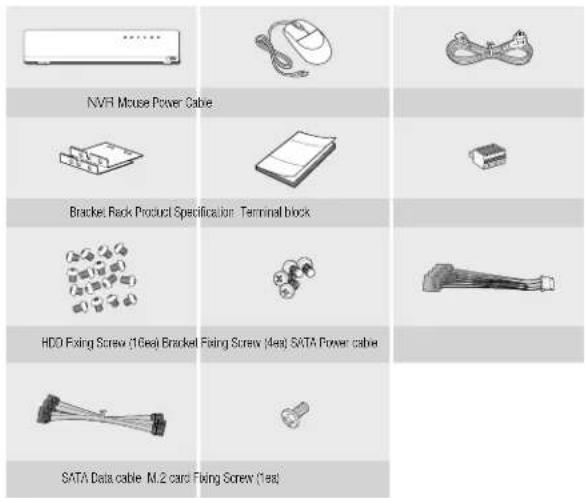
Package Contents
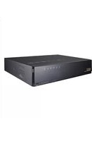
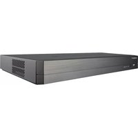
Please unwrap the product, and place the product on a flat place or in the place to be installed. Please check the following contents are included in addition to the main unit.

- The appearance of the components may differ from the image shown.
- Accessory category and quantity may differ depending on sales region.
- For some regions, HDD is not pre-installed. HDD Fixing Screw, SATA Power Cable, SATA data cable and SATA power/data cable quantity vary depending on the model.
WRN-1610S
WRN-810S

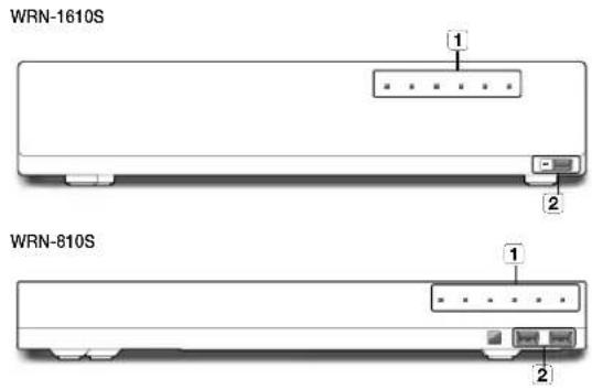
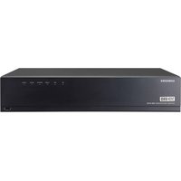
PART NAMES AND FUNCTIONS (FRONT)
| Part Names Functions | ||
| 1 | LED Indicator | REC : Lights on when recording is in progress. |
| HDD : Displays the normal access to FDD.LED turns on when accessing the hard disk. | ||
| ALARM : Lights on when an event pours. | ||
| NETWORK : Displays both network connection and data transfer status. | ||
| PoE OVER : LED will be turned on if PoE power exceeds 200 W/100 W(WRN-1610S/WRN-810S). | ||
| POWER : Shows the power ON/OFF status. | ||
| 2 | USB | Connects the USB devices. (USB 2.0 supported) |
PART NAMES AND FUNCTIONS (REAR)

| Part Names Functions | ||
| 1 | Ground connection | Terminal to connect a separate ground cable. = Add a ground cable to support the safe use of the device |
| 2 | VGA OUT | VGA Video Signal Output Port. |
| 3 | PoE (CAMERA) | Power supply port to connect to a camera. |
| 4 | AUDIO OUT | Audio Signal Output Port (Stereo jack). |
| 5 | USB | Connects the USB devices. (USB 2.0) |
| 6 | NETWORK1 | Port recommended for camera connection, which receives an image from the camera. (USB Ethernet - URUNTL) |
| NETWORK2 | Port recommended for connection with a network. (PCI Ethernet - URUNTL) | |
| 7 | ALARM | - ALARM IN : Alarm input ports. (1~4 C/I) - ALARM OUT : Alarm output ports. (1~2 C/I) |
| 8 | HDMI | HDMI connector port. |
| 9 | USB 3.0 | Connects the USB devices. (USB 3.0 supported) |
| 10 | Power | Terminal to connect power to. |
| 11 | Power Switch | Power on/off switch. |
installation
WISENET
Please take note of the followings before using this product.
- Do not use the product outdoor.
- Do not spill water or liquid in the connection part of the product.
- Do not impose the system to excessive shock or force.
- Do not pull out the power plug forcefully.
- Do not disassemble the product on your own.
- Do not exceed the rated input/output range.
- Use a certified power cord only.
- For the product with an input ground, use a grounded power plug.
CHECKING THE INSTALLATION ENVIRONMENT
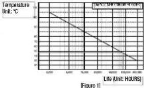
This product is a top-notch security device that is equipped with a high-capacity HDD and other key circuit boards. Temperature Unit: ℃
Note that an excessive internal temperature of the product may cause a system failure or a shortened product life (see the right figure). Keep in mind the following instructions before installing the product.
line
| Temperature (°C) | Life (hours) | | :--- | :--- | | 40 | 120 | | 35 | 110 | | 30 | 100 | | 25 | 90 | | 20 | 80 | | 15 | 70 | | 10 | 60 | | 5 | 50 | Figure 1When mounting the product on a rack, comply with the following instructions.
- Please ensure that the rack inside is not sealed.
- Please ensure the air is circulated through the inlet/outlet as shown in the picture.
- If you pile up the products or other rack-mount devices as shown in figure 2, secure room for ventilation or install a vent.
- For natural air convection, place the inlet at the bottom of the rack and the outlet on top.
- It is strongly recommended that a fan motor is installed at the inlet and the outlet for air circulation. (Please fit a filter at the inlet to screen dust or foreign substances.)
- Please maintain the temperature inside the rack or surrounding areas between 0°C - 40°C (32°F - 104°F) as shown in the figure 1.
Rack Mount Instructions - The following or similar rack-mount instructions are included with the installation instructions :
A) Elevated Operating Ambient - if installed in a closed or multi-unit rack assembly, the operating ambient temperature of the rack environment may be greater than room ambient. Therefore, consideration should be given to installing the equipment in an environment compatible with the maximum ambient temperature by the manufacturer.
B) Reduced Air Flow - Installation of the equipment in a rack should be such that the amount of air flow required for sale operation of the equipment is not compromised.
C) Mechanical Loading - Mounting of the equipment in the rack should be such that a hazardous condition is not achieved due to uneven mechanical loading.
8 installation


D) Circuit Overloading - Consideration should be given to the connection of the equipment to the supply circuit and the effect that overloading of the circuits might have on overcurrent protection and supply wiring. Appropriate consideration of equipment nameplate ratings should be used when addressing this concern.
E) Reliable Earthing - Reliable earthing of rack-mounted equipment should be maintained. Particular attention should be given to supply connections other than direct connections to the branch circuit (e.g., use of power strips).
RACK INSTALLATION
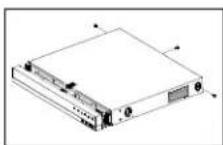
Install the Bracket-Rack as shown in the figure, and then fasten the screws on both sides.
- Fix the screws not to be loosened by vibrations.

Cautions when Installing in the Rack
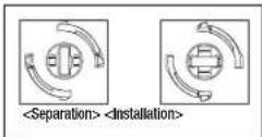
To install multiple NVRs in the rack, make sure to separate the FOOT at the bottom of each NVR.
- There are four FOOTs at the bottom of a NVR. Press the projected parts at both-ends of each "FOOT" and turn it counterclockwise.

- "FOOT" is separated from the main body when it is turned to the end of fastening groove.
HDD ADDITION
Make sure to unplug the power cord from the wall outlet to prevent possible electric shock, injury or product damage.
Please consult your provider for further information on HDD installation since improper installation or settings may damage the product.
■ Number of HDDs supported: Up to 4 HDDs supported (WRN-16105)
Up to 2 HDDs supported (AMEN-R1/OS)
- Make sure to unlock the power card from the wall outlet before proceeding with the installation.
- Cautions for data loss (HDD care)
Please pay attention so that the data inside the HDD is not damaged.
Before adding a HDD, please check the compatibility with this product
HDD is vulnerable to malfunction due to its sensitive nature especially against shock when operating.
Please ensure that the IDD is free from such shock.
We are not liable for any damage to the HDD incurred by user's carelessness or miss use.
- Cases might cause damage to HDD or recorded data
To minimize the risk of data loss from a damaged HDD, please backup data as often as possible.
If exposed to shock when disassembling or installing, data stored in the hard disk may be damaged
A sudden power failure or turning off the product while in HDD operation may damage the hard disk drive.
HDD or files stored inside may be damaged if the main body is moved or impacted during the HDD operation.
Cautions when installing a HDD
-
Do not apply excessive force to the HDD.
-
Pay attention so as not to lose the disassembly screws or accessories.
- If the screws or accessories are not put together correctly, the product may breakdown or not operate properly.
- Please check the HDD compatibility before adding a HDD.
- Please contact your nearest dealer to obtain the list of compatible devices.
Installing the HDD
If you are adding a new or previously used HDD to this product in addition to the HDD(s) originally installed, format the new HDD manually in the set before use.
How to install an HDD in WRN-1610S
- First, loosen the screws on the left/right sides and the rear side, and remove the cover.

- I cosen the screws on the left/right side (4 screws) and remove the bracket.

- Mount an HDD to the bracket and fix it with screws.

natural_image
Isometric line drawing of a server rack with multiple units and ventilation grilles (no text or labels)installation
Wisenet
- Connect the cable to the HDD by matching the HDD SATA/power cable number to the HDD position number on the bracket.
- For the HCD location number on the bracket, please refer to the figure below.

- Mount the bracket on which an additional HDD is mounted on the NVR, secure it with screws and connect the SATA/power cable to the connector on the main board by matching the number.
- For the connector numbers, please refer to the figure below.

natural_image
Isometric diagram of an electronic device with labeled components and wiring, showing internal layout and connections (no text or symbols present)- After ensuring that there is no problem with the connection terminal and routing inside the product, close and secure the cover using the screws.

How to install an HDD in WRN-810S
- First, loosen the screws on the left/right sides and the rear side, and remove the cover.

- After connecting one end of the HDD power and data cable to the HDD, connect the other end to the connector on the main board.
- See the images for the HDD location number and connect number of the bracket.

Gently press the connector before removing the HDD. Do not force to pull the cable.

- Using the provided screws, mount the HDD to the bottom cover.
- Up to two HDDs can be installed. The number of installable HDDs varies for each model.

natural_image
Pure technical diagram of a computer motherboard layout without any text, numbers, or symbols- After ensuring that there is no problem with the connection terminal and routing inside the product, close and secure the cover using the screws.
CONNECTING TO AN EXTERNAL DEVICE

flowchart
graph TD
    A["Device 1"] --> B["Device 2"]
    B --> C["Device 3"]
    D["Device 4"] --> E["Device 5"]
    F["Device 6"] --> G["Device 7"]
    H["Device 8"] --> I["Device 9"]
    J["Device 10"] --> K["Device 11"]
    L["Device 12"] --> M["Device 13"]
    N["Device 14"] --> O["Device 15"]
    P["Device 16"] --> Q["Device 17"]
    R["Device 18"] --> S["Device 19"]
    T["Device 20"] --> U["Device 21"]
    V["Device 22"] --> W["Device 23"]
    X["Device 24"] --> Y["Device 25"]
    Z["Device 26"] --> AA["Device 27"]
    AB["Device 28"] --> AC["Device 29"]
    AD["Device 30"] --> AE["Device 31"]
    AF["Device 32"] --> AG["Device 33"]
    AH["Device 34"] --> AI["Device 35"]
    AJ["Device 36"] --> AK["Device 37"]
    AL["Device 38"] --> AM["Device 39"]
    AN["Device 40"] --> AO["Device 41"]
    AP["Device 42"] --> AQ["Device 43"]
    AR["Device 44"] --> AS["Device 45"]
    AT["Device 46"] --> AU["Device 47"]
    AV["Device 48"] --> AW["Device 49"]
    AX["Device 50"] --> AY["Device 51"]
    AZ["Device 52"] --> BA["Device 53"]
    BB["Device 54"] --> BC["Device 55"]
    BD["Device 56"] --> BE["Device 57"]
    BF["Device 58"] --> BG["Device 59"]
    BH["Device 60"] --> BI["Device 61"]
    BJ["Device 62"] --> BK["Device 63"]
    BL["Device 64"] --> BM["Device 65"]
    BN["Device 66"] --> BO["Device 67"]
    BP["Device 68"] --> BQ["Device 69"]
    BR["Device 70"] --> BS["Device 71"]
    BT["Device 71"] --> BU["Device 72"]
    BV["Device 73"] --> BW["Device 74"]
    BX["Device 75"] --> BY["Device 76"]
    BZ["Device 77"] --> CA["Device 78"]
    CB["Device 79"] --> CC["Device 80"]
    DD["Device 81"] --> EE["Device 82"]
    FF["Device 83"] --> DG["Device 84"]
    DH["Device 85"] --> DI["Device 86"]
    DJ["Device 86"] --> DK["Device 87"]
    DL["Device 87"] --> DM["Device 88"]
- Unrated or improper power source may cause damage to the system. Ensure that you use only the rated power source before pressing the POWER button.
CONNECTING THE USB
- On the front of the product, there is a USB port.
- You can connect a USB HDD, USB memory or mouse to the USB port.
- If your USB HDD is connected to the system, it can be detected.
- The product supports hot plugging function that enables connecting/disconnecting USB devices while in operating the system.
If you use the USB device for Backup purposes, format it with FAT32 on PC if it is not formatted on the MVR.
- Some USB devices may fail to function properly due to compatibility issue, please check the device before using.
- Only USB storage devices that comply with the standards (having a metal cover) are guaranteed for data transfer.
- In case if the USB device's electric contacts have been worn out, data transfer between the devices may not properly function.

natural_image
Two technical diagrams showing a device with internal components and a no-smoking symbol (no text or labels present)CONNECTING THE ALARM INPUT/OUTPUT
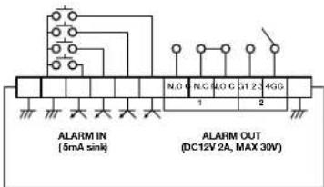
The Alarm In/Out port at the back is composed of the following.
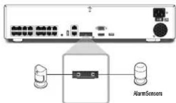
• ALARM IN 1 - 4 : Alarm Input Port
• ALARM OUT 1 \~ 2 : Alarm Output Port
CONNECTING THE NETWORK
Network connection via Ethernet (10/100/1000BaseT)

flowchart
graph TD
    A["Switch"] --> B["Internet"]
    C["Network Camera"] --> B
    D["Switch"] --> E["Internet"]
    F["Windows"] --> G["Network Viewer"]
Network connection via router

flowchart
graph TD
    A["Switch"] --> B["Network Camera"]
    B --> C["Network"]
    C --> D["DDGS Server (Data Center)"]
    C --> E["Windows Network Viewer"]
    C --> F["xDSL or Cable Modem"]
    F --> G["Bondband router"]
    G --> H["Network"]
    H --> I["xDSL or Cable Modem"]
Connecting to Internet through PPPoE

flowchart
graph TD
    A["Network"] --> B["Switch"]
    B --> C["Windows Network Viewer"]
    C --> D["PPPoE MODEM"]
    D --> E["Switch"]
    E --> F["Network Camera Network Camera"]
    D --> G["Phone(PPPoE) Line"]
Connecting the network cameras

PRODUCT SPECIFICATION
| Item | Details | ||
| WRN-1610S WRN-810S | |||
| Display | |||
| Network Camera | Inputs Max. 16ch (16 PoE, R) -45) Max. 8ch (8 PoE, RJ-45) | ||
| Live Local Display Tx HDMI / Tx VGA | |||
| Performance | |||
| Operating System Embedded USB/INTU | |||
| Storage | Built-In OTB - 6TB | ||
| Internal HDD | 4 SATA- Max. 24TB (6TB x 4EA) | 2 SATA- Max. 12TB (OTB x 2EA) | |
| Sensor I/O 4/2 | |||
| Network | |||
| Interface | RJ-45 (100BASE-T * 2EA,PoE 100BASE-TX * 16EA) | RJ-45 (100BASE-T * 2EA,PoE 100BASE-TX * 8EA) | |
| Functions | |||
| System Control Mouse, Keyboard | |||
| Indicator/Interface | |||
| Front | Indicator | LED(Status Indicator : 6EA-Power 1, Alarm 1, HDD 1, Network 1, Record 1, PoE OVER 1 | |
| Audio Stereo Jack (Left Right) | |||
| HDMI / VGA HDMI : Up to 4K (3810 x 2160), VSA : Max. 1080p | |||
| USB 3 DA (Front x1, Rear x2) | 3 DA (Front x2, Rear x7) | ||
| Item | Details | ||
| WRN-1610S WRN-810S | |||
| Connections | Ethernet | RJ-45 (1000BASE-T x 2EA, PoE 100BASE-TX x 18EA) | RJ-45 (1000BASE-T x 2EA, PoE 100BASE-TX x 8EA) |
| Alarm | (1) In(EA)(2) Out(2EA, Relay, Typical DC12V 2A, MAX 30V)- Relay Out(1NO/NC/COM)- Relay Out(2NO/CCM) | ||
| Environmental | |||
| Operating Temperature / Humidity | +0°C to +40°C (+32°F to +104°F) | ||
| Humidity | 20% ~ 85% RI | ||
| Electrical | |||
| Power | 100 ~ 240V AC | ||
| Power Consumption | Max. 320 W(4 IDDs, PoE(PoE-) on), Max. 63 W(4 HDDs, PoE(PoE+) off) | Max. 164 W(2 IDDs, PoE(PoE+) on), Max. 37 W(2 HDDs, PoE(PoE+) off) | |
| PoE Budget | Each Max. 30 W (0.55 A), Total Max. 200 W (3.7 A) | Each Max. 30 W (0.55 A), Total Max. 100 W (1.85 A) | |
| Mechanical | |||
| Color / Material | Back / Steel | ||
| Dimension (W×h×D) | 440 x 89.8 x 426.3 mm(17.32 x 3.54 x 16.78) | 370 x 50.7 x 324.3 mm(14.57 x 2 x 12.77) | |
| Weight | 5.2 kg (Based on no HDD) | 2.7 kg (Based on no HDD) | |
PRODUCT SPECIFICATION
- WRN-1610S
![440 [17.32] 88 [3.6] 89.8 [2.5]](/content/2026/05/882768/images/3b14f2a0d45e6774fe66800c3e5b5cd36ba6f1f78e28a25a09757dc8fd8168ba.jpg)
unit : mm [inches]
![42.57 [16.6] 428.3 [16.79]](/content/2026/05/882768/images/21b4c3306ab0536f1c96d5542098cf48434a2799a96361651ce4b2be704509ce.jpg)


natural_image
Front view of a computer interface panel with various electronic components (no visible text or labels)14 product overview
- WRN-810S
unit : mm [inches]
![370 [14.5/] 44 [1.73] 307.00](/content/2026/05/882768/images/7f5bcd8a97a72ade314ccc3c8b369e3b1b4691c51ff573e3539ce046eca217a8.jpg)

natural_image
Blank white image with a thin border and no visible text, symbols, or markings.![320 [12.6] 324.3 [277]](/content/2026/05/882768/images/20d83094b7fe8e652d3f406c16be97ef29229717c8bfedf30f63a68265a69135.jpg)

memo
Wisenet

natural_image
Blank white image with rounded corners (no text, symbols, or markings)
natural_image
Blank white image with rounded corners (no text, symbols, or markings)memo
Wisenet

natural_image
Blank white image with rounded corners (no text, symbols, or markings)
natural_image
Blank white image with rounded corners (no text, symbols, or markings)memo
Wisenet

Hanwha Techwin cares for the environment at all product manufacturing stages, and is taking measures to provide customers with more environmentally friendly products. The Eco mark represents Hanwha Techwin's devotion to creating environmentally friendly products, and indicates that the product satisfies the EU RoIS Directive.

Correct Disposal of This Product (Made Electrical & Electronic equipment)
Applicable in the European Union and other European countries with separate collection systems. This marking on the product, accessories of the share indicates that the product and its electronic accessories are, charged, received, USD cards should not be exposed or of other household items at the end of the working life. To prevent possible limits to the environment, or human health from controlled waste disposal please separate these items from other types of waste and stock items respectively to promote the sustainable use of water for resources.
He school users should contact either the retail or where they purchased this product, or their local government office. We call us to where and how they can take these items for and sometimes safe recycling.
Business users should contact their supplier and check the terms and conditions of the purchase contract. The product and its electronic accessories should not be mixed with other commercial wages for disposal.

Correct disposal of batteries in this product
Applicable in the European Union and other European countries with separate battery return systems.
This morning on the battery, manual or packaging and tones that the heater is in this conduct a round not be deposited or with other lab-acid waste at the end of their working life. Where marked, the chemical symbols to, Color-Flu indicate that the battery contains mercury, sodium or lead above the reference levels in the reverse 2005A16. If batteries are not properly disposed of, these substances can cause harm to human health or the environment
To protect natural resources and to promote material reuse, please separate batteries from other types of materials and recyclables. Item through your local, free battery return system
Head Office
6, Pangyo-ro 319 beon-gil, Bundang-gu, Seongnam-si,
Gyeonggi-do, 463-400 Rep. of KOREA
Tel: +82.70.7147.8753 Fax: +82.31.8018.3740
www.hanwha-security.com
Hanwha Techwin America
500 Frank W. Burr Blvd. Suite 43 Teaneck, NJ 07666
Toll Free +1.877.213.1222 Direct +1.201.325.6920
Fax +1.201.373.0124
www.hanwhasecurity.com
Hanwha Techwin Europe
Heriot House, Heriot Road, Chertsey, Surrey, KT16 9DT, United Kingdom
Tel +44.1372.235663 Fax +44.1932.57.8101
www.hanwha-security.eu
Hanwha Techwin Vietnam Hanoi Office
28th Floor, Handico Building, Pham Hung Street, Me Tri ward,
Nam Tu Liem District, Hanoi City, Vietnam
Tel: +84.91.982.40.88
www.hanwha-security.com

Hanwha
Techwin
PT01-005544A
- Trademark
- Restriction
- Disclaimer
- IMPORTANT SAFETY INSTRUCTIONS
- Standards Approvals
- FC CE
- BEFORE START
- Warning
- Battery
- CALIFORNIA USA ONLY
- Caution
- ATTENTION
- System Shutdown
- Operating Temperature
- Ethernet Port
- CONTENTS
- FEATURES
- Package Contents
- WRN-1610S
- WRN-810S
- installation
- WISENET
- CHECKING THE INSTALLATION ENVIRONMENT
- RACK INSTALLATION
- Cautions when Installing in the Rack
- HDD ADDITION
- - Cautions for data loss (HDD care)
- - Cases might cause damage to HDD or recorded data
- Cautions when installing a HDD
- Installing the HDD
- How to install an HDD in WRN-1610S
- How to install an HDD in WRN-810S
- CONNECTING TO AN EXTERNAL DEVICE
- CONNECTING THE USB
- CONNECTING THE ALARM INPUT/OUTPUT
- CONNECTING THE NETWORK
- PRODUCT SPECIFICATION
- Head Office
- Hanwha Techwin America
- Hanwha Techwin Europe
- Hanwha Techwin Vietnam Hanoi Office
Brand : Hanwha
Model : WRN-810S
Category : Video recorder