
AV-HS410 - Switch PANASONIC - Free user manual and instructions
Find the device manual for free AV-HS410 PANASONIC in PDF.

| Product Type | 1 ME Live Switcher |
| Supported Formats | 1080/59.94i, 1080/50i, 1080/24PsF, 1080/23.98PsF, 720/59.94p, 720/50p, 480/59.94i, 576/50i |
| Video Inputs | 8 x SDI, 1 x DVI-D (analog/digital), 2 x analog composite (optional), 2 x analog component (optional) |
| Video Outputs | 5 x SDI, 1 x DVI-D, 2 x analog (optional), 2 x down-converted (optional) |
| Reference Input | Black burst or tri-level sync |
| Effects | Background transitions (mix, wipe, cut), 2 x PinP, 1 x DSK, 1 x key (luma, chroma, linear, full), flying key, 3D effects |
| Wipe Patterns | Selectable patterns with borders, soft edges, and page turning effect |
| Multi View Output | Up to 16 images on one screen, configurable layouts |
| Memory | Shot memory, event memory, video memory (stills and clips up to 2 each) |
| Control | GPI I/O, RS-422 editor control, Ethernet for network settings |
| Built-in Display | LCD for menus and status, adjustable backlight |
| Dimensions (W x H x D) | Approx. 430 mm x 135 mm x 400 mm |
| Weight | Approx. 8.5 kg |
| Power Consumption | Approx. 80 W |
| Operating Temperature | 0°C to 40°C |
| Power Supply | 100-240 V AC, 50/60 Hz |
Frequently Asked Questions - AV-HS410 PANASONIC
User questions about AV-HS410 PANASONIC
0 question about this device. Answer the ones you know or ask your own.
Ask a new question about this device
Download the instructions for your Switch in PDF format for free! Find your manual AV-HS410 - PANASONIC and take your electronic device back in hand. On this page are published all the documents necessary for the use of your device. AV-HS410 by PANASONIC.
USER MANUAL AV-HS410 PANASONIC
Operating Instructions
Live Switcher
Model No. AV-HS410N
natural_image
Line drawing of a control panel with buttons, dials, and a screen (no text or symbols)
• How the Operating Instructions are configured
The
This
- For details on how to perform the basic menu operations, refer to "2-2. Basic menu operations" in the
• Information on software for this product
- Included with this product is software licensed under the GNU General Public License (GPL) and GNU Lesser General Public License (LGPL), and users are hereby informed that they have the right to obtain, change and redistribute the source codes of this software.
To obtain the source codes, go to the following home page:
http://pro-av.panasonic.net/
The manufacturer asks users to refrain from directing inquiries concerning the source codes they have obtained and other details to its representatives.
- Included with this product is software which is licensed under MIT-License.
Details on the above software can be found on the CD provided with the unit. Refer to the folder called "LDOC". (Details are given in the original (English language) text.)
Trademarks and registered trademarks
- Microsoft®Windows® XP, Windows Vista®, Windows® 7 and Internet Explorer® are either registered trademarks or trademarks of Microsoft Corporation in the United States and other countries.
- Intel® and Intel® Core™ are trademarks or registered trademarks of Intel Corporation in the United States and other countries.
- Adobe and Reader ^® are either registered trademarks or trademarks of Adobe Systems Incorporated in the United States and/or other countries.
• SDHC Logo is a trademark of SD-3C, LLC. - Primattis a registered trademark of IMAGICA DIGIX Inc.
- The copyrights of Primatte belong to IMAGICA DIGIX Inc.
- The patents for Primatte belong to IMAGICA DIGIX Inc.
- Other names of companies and products contained in these Operating Instructions may be trademarks or registered trademarks of their respective owners.
About copyright and licence
Distributing, copying, disassembling, reverse compiling, reverse engineering, and also exporting in violation of export laws of the software provided with this unit are expressly prohibited.
Abbreviations
The following abbreviations are used in this manual.
- Microsoft Windows® 7 Professional SP1 32/64-bit is abbreviated to "Windows 7".
- Microsoft Windows Vista® Business SP2 32-bit is abbreviated to "Windows Vista".
- Microsoft® Windows® XP Professional SP3 and Microsoft® Windows® XP Home Edition SP3 are abbreviated to "Windows XP".
- Windows® Internet Explorer® 8.0 is abbreviated to "Internet Explorer".
- In this manual, model AV-HS410N is given as "AV-HS410".
- Both SD memory cards and SDHC memory cards are described as "memory cards" in this manual.
When individual descriptions are provided, they are featured individually.
- Personal computers are referred to as "computers".
Illustrations and screen displays featured in the manual
- What is shown in the manual's illustrations and screen displays may differ from how it is actually appears.
Before use 5
Overview 5
Concerning the ratings display 5
Disclaimer of warranty 5
Network security 5
Concerning differences in the system versions ...... 6
1. Basic operations ...... 7
1-1. Background transition 7
1-1-1. Selecting the bus 7
1-1-2. Selecting the bus using the SHIFT function ..... 7
1-1-3. Selecting the bus mode 8
1-1-4. Selecting the transition mode 8
1-1-5. Manual transition 9
1-1-6. Auto transition 9
1-1-7. Cut transition 9
1-2. Wipe 10
1-2-1. Selecting the wipe pattern 10
1-2-2. Selecting the wipe direction 11
1-2-3. Wipe decorations (border, soft effect) 11
1-2-4. Setting the wipe start position 12
1-2-5. Modifying wipe 12
1-2-6. Setting the latency 14
1-3. Key 15
1-3-1. Selecting the key type 15
1-3-2. Selecting the key material 16
1-3-3. Key transitions 17
1-3-4. Key preview 19
1-3-5. Adjusting the luminance key and linear key ..... 19
1-3-6. Adjusting the chroma key 20
1-3-7. Key decorations 26
1-3-8. Masking the key signals 27
1-3-9. Flying key 28
1-3-10. Setting the priority 28
1-4. PinP (picture in picture).... 29
1-4-1. Selecting the PinP channel and material ..... 29
1-4-2. Transition between PinP materials 29
1-4-3. Selecting Shape 30
1-4-4. PinP preview 30
1-4-5. PinP transitions 30
1-4-6. PinP adjustments 31
1-4-7. Linking PinP1 and PinP2 32
1-4-8. PinP decorations 33
1-4-9. Trimming settings 34
1-5. DSK (downstream key) 35
1-5-1. Selecting the DSK type 35
1-5-2. Selecting the DSK material 36
1-5-3. DSK transitions 36
1-5-4. DSK preview.... 37
1-5-5. DSK adjustments 37
1-5-6. DSK decorations 38
1-5-7. Masking the DSK signals 39
1-6. Key Link 40
1-7. FTB (Fade to Black) 41
1-8. Internal color signals 42
1-8-1. Setting the color background 42
1-8-2. Setting the Wash effect 42
1-9. Switching the AUX output 44
1-9-1. Selecting the AUX output materials .... 44
1-9-2. AUX1 transitions 44
1-9-3. Setting enable/disable for the AUX1 transition 45
1-10. Memory 46
1-10-1. Memory registration and recall items 47
1-10-2. Storing the settings in the memory (Store) ..... 47
1-10-3. Recalling the operations stored in the memory (Recall) 48
1-10-4. Memory preview 49
1-10-5. Deleting the operations stored in the memory (Delete) 50
1-10-6. Selecting the buses whose settings are to be registered and or played back 51
1-10-7. Registering the material selection items ..... 52
1-10-8. Setting effect dissolve (shot memory) 52
1-10-9. Editing event memory timelines 53
1-10-10. Registering memories (Register) 59
1-11. Video memories 60
1-11-1. Recording still images (Still) 61
1-11-2. Recording moving images (Clip) 62
1-11-3. Saving Images in Flash Memory 63
1-11-4. Playing back moving images (Clip) 64
1-12. Memory card 67
1-12-1. Initializing the memory cards 69
1-12-2. Saving data on memory cards 69
1-12-3. Loading data from memory cards 70
1-12-4. Deleting files on memory cards 71
1-12-5. Displaying the memory card information ..... 71
1-13. Waveform monitor settings 72
1-14. Setting the status display 73
2. Input/output signal settings 74
2-1. Input signal settings 74
2-1-1. Setting the frame synchronizer 76
2-1-2. Setting the input mode 77
2-1-3. Setting the delay amount 78
2-1-4. Freezing the input signals 78
2-1-5. Setting the material names 78
2-1-6. Setting the up-converter 79
2-1-7. Setting the video process function 80
2-1-8. Setting the analog input gain (option) 80
2-1-9. Setting the analog composite input signals (option) 81
2-1-10. Setting the DVI input signals 82
2-1-11. Displaying the DVI input signal information ..... 86
2-1-12. Adjusting the DVI input signals 87
2-1-13. Automatic adjustment of the black level and white level (analog input signals) 87
2-2. Output signal settings 88
2-2-1. Assigning the output signals 89
2-2-2. Setting the SDI output color range 89
2-2-3. Setting the DVI output signals 90
2-2-4. Setting the down-converter (option) 92
2-3. Setting the sync signals 93
2-4. Adjusting the output signal phase 93
2-5. Setting the multi view display 97
2-5-1. Setting the screen layout 97
2-5-2. Setting the split frame and characters ..... 98
2-5-3. Setting the tally displays 98
2-5-4. Changing the material names 99
2-5-5. Setting the level meters 100
2-5-6. Setting the input signal marks 100
2-5-7. Setting the markers 100
2-5-8. High-resolution multi view mode .... 100
2-6. Setting the ancillary data and embedded audio data 101
3. System settings 102
3-1. Setting the system format 102
3-2. Setting the crosspoints ..... 103
3-2-1. Assigning signals to the crosspoints ..... 103
3-2-2. Setting the crosspoint switching 104
3-3. Button assignments.... 105
3-3-1. Setting the user buttons 105
3-4. Setting the date and time 106
3-5. Network settings .... 106
3-6. Setting the built-in display backlight and button illumination 107
3-7. Status displays 108
3-7-1. Alarm status displays 108
3-7-2. Alarm message 108
3-7-3. Displaying the version information and option information 109
3-8. Initialization 110
3-8-1. Initializing setting data 110
3-8-2. Initializing fader 110
4. External interfaces ...... 111
4-1. Setting the GPI I/O 111
4-2. LAN 115
4-3. EDITOR 115
4-4. COM 115
4-5. Plug-in software 116
5. Setting menu table 117
Appendix (glossary) 139
Index 142
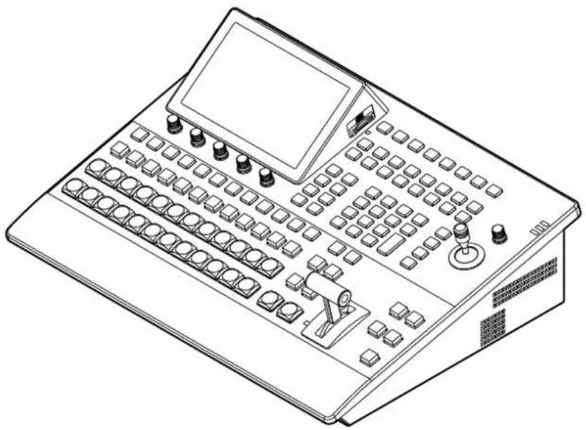
Overview
This unit is a 1 ME digital video switcher which supports a multiple number of HD and SD formats.
Despite its compact size, it comes with eight SDI inputs, one DVI-D input, five SDI outputs and one DVI-D output.
The unit comes with a luminance key and chroma keys provided as keyers in addition to the background transitions based on the cut, mix and wipe functions.
It also has one DSK line and two PinP lines for enabling video recording, playback and a host of other video production functions.
Furthermore, using the multi view display settings, the screen of a monitor can be split into a number of sections to accommodate up to sixteen images, enabling the number of monitors to be reduced and a space-saving system to be configured at low cost.
■ Concerning the ratings display
The unit's name, model number and electrical ratings are indicated on its side panel.
■ Disclaimer of warranty
IN NO EVENT SHALL Panasonic Corporation BE LIABLE TO ANY PARTY OR ANY PERSON, EXCEPT FOR REPLACEMENT OR REASONABLE MAINTENANCE OF THE PRODUCT, FOR THE CASES, INCLUDING BUT NOT LIMITED TO BELOW:
① ANY DAMAGE AND LOSS, INCLUDING WITHOUT LIMITATION, DIRECT OR INDIRECT, SPECIAL, CONSEQUENTIAL OR EXEMPLARY, ARISING OUT OF OR RELATING TO THE PRODUCT;
② PERSONAL INJURY OR ANY DAMAGE CAUSED BY INAPPROPRIATE USE OR NEGLIGENT OPERATION OF THE USER;
③ UNAUTHORIZED DISASSEMBLE, REPAIR OR MODIFICATION OF THE PRODUCT BY THE USER;
④ INCONVENIENCE OR ANY LOSS ARISING WHEN IMAGES ARE NOT DISPLAYED, DUE TO ANY REASON OR CAUSE INCLUDING ANY FAILURE OR PROBLEM OF THE PRODUCT;
⑤ ANY PROBLEM, CONSEQUENTIAL INCONVENIENCE, OR LOSS OR DAMAGE, ARISING OUT OF THE SYSTEM COMBINED BY THE DEVICES OF THIRD PARTY;
⑥ ANY INCONVENIENCE, DAMAGES OR LOSSES RESULTING FROM ACCIDENTS CAUSED BY AN INADEQUATE INSTALLATION METHOD OR ANY FACTORS OTHER THAN A DEFECT IN THE PRODUCT ITSELF:
⑦ LOSS OF REGISTERED DATA CAUSED BY ANY FAILURE;
⑧ ANY DAMAGE OR CLAIMS DUE TO LOSS OR LEAKAGE OF IMAGE DATA OR SETTING DATA SAVED ON THIS UNIT OR ON A MEMORY CARD OR COMPUTER.
■ Network security
The unit also has functions which are used when it is connected to a network. Using the unit when it has been connected to a network may possibly give rise to the following issues.
① Leakage or theft of information through this unit
② Use of this unit for illegal operations by persons with malicious intent
③ Interference with or stoppage of this unit by persons with malicious intent
It is your responsibility to take precautions such as those described below to protect yourself against the above network security risks.
- Use this unit in a network secured by a firewall, etc.
- If this unit is connected to a network that includes computers, make sure that the system is not infected by computer viruses or other malicious entities (using a regularly updated antivirus program, anti-spyware program, etc.).
The following points should be borne in mind as well.
- Use with the same segment is recommended for the equipment which is connected to the unit. If the unit is connected to equipment whose segments are different, events dependent upon the settings inherent to the network equipment, for instance, may occur so thoroughly check the connections with the equipment to which the unit will be connected prior to the start of operation.
- Do not choose an installation location where the unit, cables and other parts will be easily damaged.
■ Concerning differences in the system versions
This manual describes the functions which can be actuated in any model whose system version is V2.00.00 and up. The applicable functions are referred to as “This function can be actuated in any model whose system version is V2.00.00 and up”.
If the model has a system version below V2.00.00, the functions concerned cannot be used.
Neither will the menus and menu items concerned be displayed.
● How to check the system version
To check the system version of this unit, select System menu → Main Version sub menu → System Version item, and check the display for this item.
Refer to "3-7-3. Displaying the version information and option information".
- Restrictions on menus and functions
[Restrictions on menus]
| Menu Sub | menu Item | Model with system version V2.00.00 and up | Model with system version below V2.00.00 | |
| Video Memory | Clip1 Play Mode | Reverse | √ | — |
| Variable | √ | — | ||
| Clip2 Play Mode | Reverse | √ | — | |
| Variable | √ | — | ||
| Trans Sync All items | √ | — | ||
| Memory All items | √ | — | ||
√: Valid
—: Invalid
[Restrictions on functions]
| Function | Model with system version V2.00.00 and up | Model with system version below V2.00.00 | ||
| Status display | Still image (Still) | √ | — | Only a list of the names is displayed. |
| Moving image (Clip) | ||||
| Memory card | ||||
| Video memory saving | The images in the video memory are saved in the flash memory area. | √ | — | The images in the video memory cannot be saved automatically.Save the images manually on the memory card. |
| Moving image (Clip) playback | Moving image (Clip) operations are performed using the number keys. | √ | — | Moving image (Clip) cannot be operated using the number keys.Operate them using the menu. |
√: Valid
—: Invalid
1-1. Background transition
1-1-1. Selecting the bus
Press one of the crosspoint buttons to select the material to be used for the background transition.
Depending on the operating status, the button pressed will light in one of two colors.
| Lighting in red | When the selected input signals are output to PGM.(However, the indicator lights in amber during FTB operations.) |
| Lighting in green | When the selected input signals are not output to PGM. |


Lighting in red

Lighting in green
- When the crosspoint buttons are held down, the button numbers and the names of the input materials assigned to the buttons are displayed on the built-in display in the form of a list for as long as the crosspoint buttons remain held down.
1-1-2. Selecting the bus using the SHIFT function
The SHIFT function enables two materials to be allocated — the front material and the rear material — to one button, and the materials to be selected using the [SHIFT] button.
A total of 24 materials — front materials (1 to 12) and rear materials (13 to 24) — can be allocated to the three groups of 12 crosspoint buttons whether these buttons are the PGM/A bus crosspoint buttons, PST/B bus crosspoint buttons or AUX bus crosspoint buttons.
There are actually two SHIFT functions: "All SHIFT" for switching all the front materials to the rear materials or vice versa, and "Single SHIFT" for switching the front material of one crosspoint button with its rear material or vice versa.
"All SHIFT" works once the SHIFT function has been allocated to one of the user buttons.
"Single SHIFT" works once the SHIFT function has been allocated to the No.12 or No.1 crosspoint button of the crosspoint button group concerned by a menu operation.
All SHIFT
All SHIFT is used to switch all the materials of the PGM/A bus crosspoint buttons, PST/B bus crosspoint buttons or AUX bus crosspoint buttons from front materials to rear materials or vice versa.
The user button to which the SHIFT function has been allocated is used to switch between the front materials and rear materials.
① Allocate the SHIFT function to one of the user buttons. (For the method used to allocate this function to the user button, refer to "3-3-1. Setting the user buttons".)
② Each time the [SHIFT] button (user button) is pressed, the front materials are switched to the rear materials or vice versa.
- When the rear materials (13 to 24) have been selected, the [SHIFT] button (user button) lights in amber.
- When the button is pressed again, it goes off, and the front materials (1 to 12) are now selected.
1. Basic operations
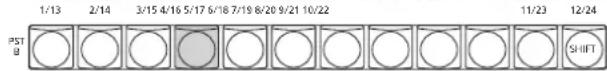
Single SHIFT
Single SHIFT is used to switch the individual material of a PGM/A bus crosspoint button, PST/B bus crosspoint button or AUX bus crosspoint button from a front material to a rear material or vice versa.
Switching between the front material and rear material is done using the crosspoint button in which the SHIFT function is allocated.
The SHIFT function can be allocated to button No.1 or No.12.
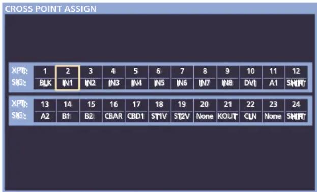
■ Allocating the SHIFT function
① Press the XPT button to light its indicator, and display the XPT menu.
② Use [F1] to display the XPT Setting sub menu.
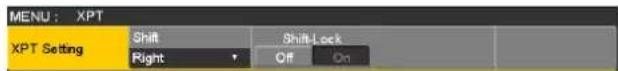
③ Use [F2] to select the button to which the SHIFT function is to be allocated using the Shift item.
| Right Button No.12 |
| Left Button No.1 |
| Off Function is not allocated. |
④ Use [F3] to select the operation to be performed when the [SHIFT] button is pressed using the Shift-Lock item.
| Off The rear material is selected only while the [SHIFT] button is pressed. |
| On The front material and rear material are switched each time the [SHIFT] button is pressed. |
- To use the materials that have been set in the button to which the SHIFT function is allocated, either set the SHIFT function off or allocate the SHIFT function to another button.
- If the [SHIFT] button for "Single SHIFT" is pressed when the rear materials (13 to 24) have been selected using "All SHIFT", the bus crosspoint buttons concerned will be switched to the front materials.
- When the crosspoint buttons are held down, the button numbers and the names of the input materials assigned to the buttons are displayed on the built-in display in the form of a list for as long as the crosspoint buttons remain held down.
1-1-3. Selecting the bus mode
Select the A/B bus system or flip-flop system (PGM/PST system) from the setting menu.
① Press the CONFIG SYS button to light its indicator, and display the Config menu.
② Use [F1] to display the Operate sub menu.

③ Use [F2], and select the A/B or PGM/PST (flip-flop system) using the Bus Mode item.
| A/B When the fader lever is at side A, the signals selected by the A bus are replaced PGM materials.When the fader lever is at side B, the signals selected by the B bus are replaced PGM materials. | |
| PGM-A/PST-B | Using a flip-flop system, the signals selected by the A bus are always replaced PGM materials, and the signals selected by the B bus are always replaced PST materials. |
| PGM-B/PST-A | Using a flip-flop system, the signals selected by the B bus are always replaced PGM materials, and the signals selected by the A bus are always replaced PST materials. |
1-1-4. Selecting the transition mode
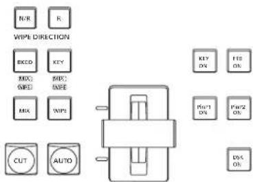
Select the transition mode using the MIX and WIPE buttons.
① Press the [BKGD] button in the transition area so that its indicator lights in amber.
When the [BKGD] button and [KEY] button are pressed at the same time, both buttons are selected.
② Use the [MIX] and [WIPE] buttons in the transition area to select the background transition mode. The indicator of the selected button lights in amber.
1. Basic operations
1-1-5. Manual transition
Operate the fader lever to execute transitions manually. If the fader lever has been operated during auto transition, auto transition will be switched to manual operation as soon as the fader position overtakes the amount of the transition being executed.
The bus tally LEDs on the left of the fader lever indicate the program bus output status.
| Top LED only lights | PGM/A bus output |
| Top and bottom LEDs light | During the transition |
| Bottom LED only lights | PST/B bus output |
1-1-6. Auto transition
- When the [AUTO] button is pressed, the transition is executed automatically using the transition time which has been set.
- The transition is executed in the remaining time when the [AUTO] button is pressed while the fader lever is being operated.
- The auto transition time is set using the Time menu.
① Press the TIME button to light its indicator, and display the Time menu.
② Use [F1] to display the BKGD sub menu.

③ Set the transition time.
When setting the transition time in frame units
Use [F4] to set the transition time in frames.
When setting the transition time in second units
Use [F3] to set the time in seconds and [F4] to set it in frames.
The display unit is set by selecting Config menu → Operate sub menu → Time Unit item.
| Sec The time is displayed as a number of seconds. |
| Frame The time is displayed as a number of frames. |
Any time from 0 to 999f can be set. The time which can be set when seconds are used as the display unit differs depending on the system format.
| 59.94i: max. 33s09f 59.94p: max. 16s39f | |
| 50i: max. 39s24f 50p: | max. 19s49f |
| 24PsF: max. 41s15f | 23.98PsF: max. 41s15f |
1-1-7. Cut transition
When the [CUT] button is pressed, the transition is executed instantly.
1. Basic operations
1-2. Wipe
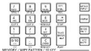
1-2-1. Selecting the wipe pattern
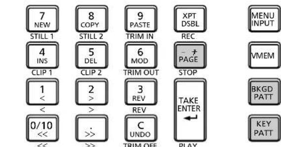
The wipe patterns are selected using the number keys.
① Press the [BKGD PATT] button (or [KEY PATT] button). The [BKGD PATT] button (or [KEY PATT] button) indicator lights in amber, and the pattern table screen appears on the built-in display.
② Use [F1] to select the page.
③ Use one of the number keys to select the pattern. The corresponding button lights in amber, and the pattern is switched.
④ Use [F5] to close the table screen.
- The table screen can also be closed by pressing the [BKGD PATT] button or [KEY PATT] button and turning off the button's indicator.
MEMORY / WIPE PATTERN / 10 KEY ____
■ Table of wipe patterns
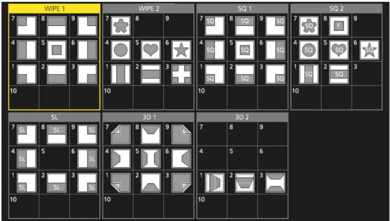
- The "SQ2: 8" pattern takes effect when the [KEY PATT] button has been pressed.
1. Basic operations
1-2-2. Selecting the wipe direction
Operate the wipe direction selector buttons to select the wipe direction for the background transition.
(The key transitions are set by the menu. The direction which is set here will not be reflected.)
See "1-3-3. Key transitions".
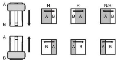
When the [R] indicator is off:
Wiping proceeds in the normal direction.
When the [R] indicator is lit:
Wiping proceeds in the reverse direction.
When the [N/R] indicator is lit:
The normal direction is replaced with the reverse direction (or vice versa) when the transition is completed.
(The lit and extinguished statuses of the [R] button are also switched in line with the direction of the wiping.)
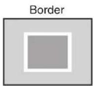
1-2-3. Wipe decorations (border, soft effect)
A border effect or soft effect can be added to the wiping of background transitions.
Setting the border and soft effect
① Press the EKCDD button to light its indicator, and display the Background menu.
② Use [F1] to display the Border sub menu.

③ Use [F2] to set On (or Off) for the border using the Border item.
④ Use [F3] to set the width of the border using the Width item.
⑤ Use [F4] to set the amount of soft effect using the Soft item.
When "On" has been selected as the Border item setting, the ratio of the soft effect to the border width is indicated as the amount of soft effect.
When only the soft effect is to be added to wipe, select "Off" as the Border item setting.
Setting the border color
① On the Background menu, use [F1] to display the Border Color sub menu.

② Use [F2], [F3] and [F4] to adjust the Hue, Sat and Lum of the border color.
■ To call the preset color
Use [F5] to select the preset color using the Load item, and press the [F5].
- When [F5] is pressed, what has been set so far is canceled and replaced with the preset color values.
- To save the values that were set before calling the preset color, refer to "1-10. Memory".
1. Basic operations
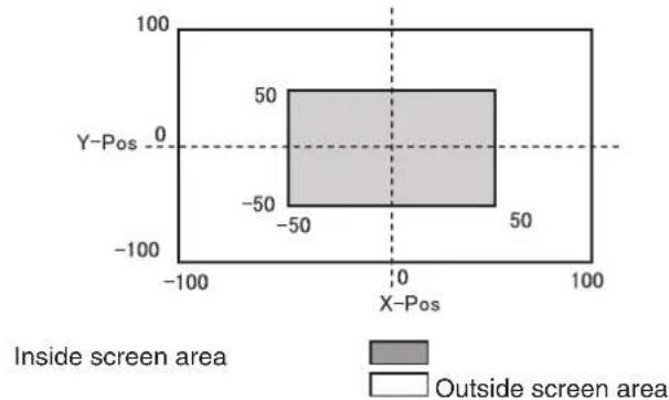
1-2-4. Setting the wipe start position
Wipe start can be set at any desired position.
Target patterns:
WIPE1: 5
WIPE2: 4, 5, 6, 7
SQ1: 5
SQ2: 4, 5, 6, 7
The WIPE pattern is set using the WIPE Position sub menu of the Background menu (or Key menu).
In the same way, the SQ pattern is set using the SQ Position sub menu of the Background menu (or Key menu).
① Press the EKG D button (or KEY button) to light its indicator, and display the Background menu (or Key menu).
② Use [F1] to display the WIPE Position sub menu (or SQ Position sub menu).
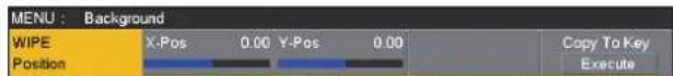
③ Either operate the positioners or use [F2] and [F3] to set the wipe start position using the X-Pos item and Y-Pos item.
This setting is possible only if the target pattern has been selected for the background or key pattern.
④ Either operate the fader lever or press the [AUTO] button to check the wipe operation.
(When, for instance, -50 has been set for X-Pos and -50 for Y-Pos, the following screen (or key) appears from the bottom left and wipe is performed while the screen (or key) moves to the screen center.)
scatter
| X-Pos | Y-Pos | Region | |-------|-------|--------------------| | -50 | 50 | Inside screen area | | 50 | 50 | Outside screen area |⑤ To copy the start position setting, press [F5] (Copy to Key or Copy to BKGD).
The background setting is copied to the key setting while the key setting is copied to the background setting.
1-2-5. Modifying wipe
Setting the 3D (page turning) effect
A lighting effect can be added to a wipe pattern.
Alternatively, the page turning effect parameter can be set.
These effects can be set for background transitions and key transitions.
Target patterns:
3D1: 1, 3, 7, 9
① Press the BKG0 button (or KEY button) to light its indicator, and display the Background menu (or Key menu).
② Use [F1] to display the 3D Modify sub menu.
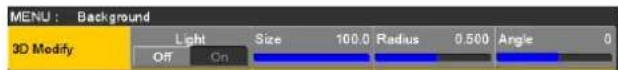
③ Use [F2] to select whether the lighting effect is to be added using the Light item.
On The lighting effect is added. Off The lighting effect is not added.
④ Use [F3] to set the size when images have been reduced using the Size item.
⑤ Use [F4] to set the radius of the page turning effect using the Radius item.
⑥ Use [F5] to set the direction of the page turning effect using the Angle item.
1. Basic operations
Setting the trimming
The trimming at the time a background transition is executed can be set.
Target patterns:
SQ1, SQ2, SL, 3D1, 3D2
The "4:3" and "4:3Smth" settings for the Trim item take effect when the HD format has been selected as the system format setting.
① On the Background menu, use [F1] to display the Modify sub menu.

② Use [F2] to set the trimming operation and transition operation using the Trim item.
| 16:9 (On) For trimming the edges around the material.This setting is used when a black border, for instance, can be seen around the material.When HD has been selected as the system format setting, “16:9” is displayed on the menu, but when SD has been selected as the system format setting, “On” is displayed on the menu. |
| 4:3 For trimming using the 4:3 aspect ratio and releasing the trimming when the transition is completed. |
| 4:3Smth For trimming using the 4:3 aspect ratio and executing the transition to 16:9 images smoothly. |
| Off No trimming |
③ Use [F3] to select the setting for automatic trimming (4:3 or 4:3Smth) in accordance with the material using the 4:3 Auto item.
| Off All input materials are targeted for automatic trimming. |
| On Using the up-converter setting, the input materials for which “Edge Crop” is selected are targeted for automatic trimming. |
1. Basic operations
1-2-6. Setting the latency
A delay amount can be set for the background image or key image.
① Press the CONFIG button to light its indicator, and display the Config menu.
② Use [F1] to display the Latency sub menu.

③ Use [F2] to set the delay amount for the background image using the BKGD item.
Alternatively, use [F3] to set the delay amount for the key image using the Key item.
| 1F Fix The image is delayed by one frame (1F).There will be no original image remaining when wipe is completed (when SQ1, SQ2, SL, 3D1 or 3D2 has been selected as the wipe pattern). |
| Minimum The image is not delayed.However, the image will be delayed by one frame (1F) when SQ1, SQ2, SL, 3D1 or 3D2 has been selected as the wipe pattern or when the flying key has been selected. |
■ BKGD items
| Delay amount setting | At times other than during transitions | MIX/WIPE SQ/SL/3D |
| Minimum No | delay No delay 1F delay | |
| 1F Fix 1F | delay 1F delay 1F delay |
■ Key items
| Delay amount setting | At times other than during transitions | MIX/WIPE | SQ/SL/3D/Flying key |
| Minimum No | delay No delay 1F delay | ||
| 1F Fix 1F | delay 1F delay 1F delay |
1. Basic operations
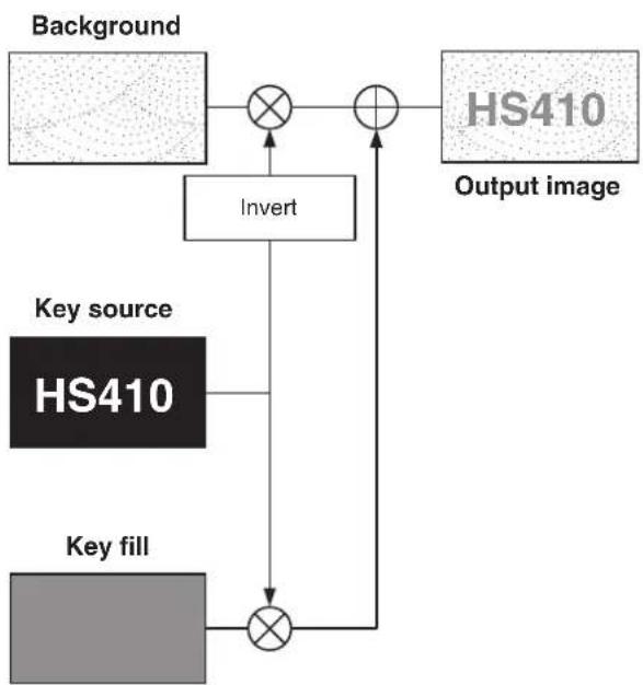
1-3. Key
This operation combines the background image with another image. The key definition can be adjusted, and an edge can be added to the combined image.
Also available as materials besides KEY for combining with the background image are PinP (picture in picture) and DSK (downstream key).
The default settings for priority (image positioning) are as shown in the figure below.
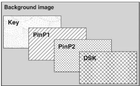
The priority for Key, PinP1 and PinP2 can be changed. Refer to "1-3-10. Setting the priority".
How key combinations work is shown in the figure below.
flowchart
graph TD
    A["HS410"] --> B["Invert"]
    B --> C["×"]
    C --> D["Output image"]
    E["Background"] --> F["×"]
    F --> G["×"]
    G --> H["Key source"]
    I["Key fill"] --> J["×"]
    J --> K["×"]
    K --> L["Output image"]
1-3-1. Selecting the key type
① Press the KEY button to light its indicator, and display the Key menu.
② Use [F1] to display the Key sub menu.
| MENU: Key | ||||
| Key | Type | Lum Key | Fill | PVW |
| Linear | Chroma Off | Bus | Auto | |
③ Use [F2] to select the Type item.
| Lum(luminance key/ self key) | This is for creating the key signals from the luminance component or luminance and chroma component of the key fill signal. |
| Linear(linear key/EXT key) | This is for creating the key signals from the luminance component of the key source signal.It is used when the key source signal and key fill signal are different. |
| Chroma(chroma key/ self key) | This is for creating the key signals using a specific hue of the key fill signal as the reference. |
| Full(full key/self key) | This is for creating the key signals using the images on the full screen as the key source signals.PinP combinations are possible in conjunction with the flying key.See “1-3-9. Flying key”. |
Since the luminance and chroma keys are operated as self keys, the key fill signals are used as the key source signals. For the full key, the images on the full screen are used as the key source signals.
When the luminance key, chroma key or full key has been selected as the key type, the key signals will remain unchanged even when the key source signals are switched.
When using the linear key, use material with a black background and white characters or shape to be combined by the key as the key source signal.
Material which is not black and white may not be combined clearly.
Material with a white background and black characters, etc. can be reversed using the key invert function for use.
1. Basic operations
④ When the luminance key has been selected, the chroma component can be included in the generation of the key signals in view of the self key application. (This does not apply to the linear key.)
Use [F3], and select the setting using the Lum Key item.
| Chroma On In | addition to the luminance component, the chroma component is also taken into account in the generation of the key signals.This is the setting for using a color with a low luminance component for the key signals (such as when defining blue characters). |
| Chroma Off The | the key signals are generated from only the luminance component. |
⑤ Use [F4] to select the fill type using the Fill item.
| Bus The bus signal is used for the key fill signal. |
| Matte The internal fill matte is used for the key fill signal. |
1-3-2. Selecting the key material
Selecting the key fill and key source signals
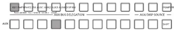
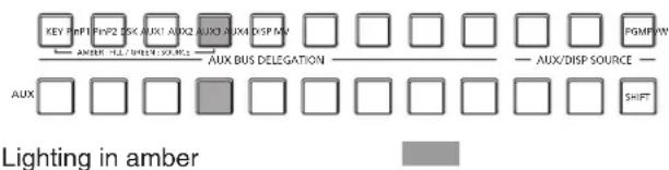
Press the [KEY] button in the AUX bus selection area, and switch the selection of the key fill signal (indicator lights in amber) and key source signal (indicator lights in green).
With the indicator of the [KEY] button lit in amber, press one of the AUX bus crosspoint buttons 1 to 12 to select the key fill signal.
The indicator of the selected AUX bus crosspoint button lights in amber. (It will light in red if the selected signal is being output from the PGM connector.)
flowchart
graph LR
    A["KEY"] --> B["SHPT"]
    B --> C["PFPZ"]
    C --> D["SKX"]
    D --> E["AUX1"]
    E --> F["AUX2"]
    F --> G["AUX3"]
    G --> H["JXMDSP MW"]
    H --> I["PGMPW"]
    I --> J["SHIFT"]
    K["AUX BUS DELEGATION"] --> L["□"]
    M["AUX/DISP SOURCE"] --> N["□"]
    O["AUX"] --> P["□"]
    Q["□"] --> R["□"]
    S["□"] --> T["□"]
    U["□"] --> V["□"]
    W["□"] --> X["□"]
Lighting in amber
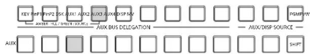
With the indicator of the [KEY] button lit in green, press one of the AUX bus crosspoint buttons 1 to 12 to select the key source signal.
The indicator of the selected AUX bus crosspoint button lights in green. (It will light in red if the selected signal is being output from the PGM connector.)
Since the luminance and chroma keys are operated as self keys, the key fill signals are used as the key source signals. When the luminance key or chroma key has been selected as the key type, the key signals will remain unchanged even when the key source signals are switched.
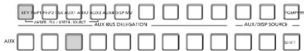
Lighting in green
1. Basic operations
Setting the fill matte color
① Press the KEY button to light its indicator, and display the Key menu.
② Use [F1] to display the Fill Matte sub menu.
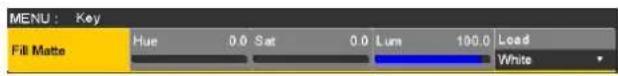
③ Use [F2], [F3] and [F4] to adjust the Hue, Sat and Lum of the fill matte.
■ To call the preset color
Use [F5] to select the preset color using the Load item, and press the [F5].
- When [F5] is pressed, what has been set so far is canceled and replaced with the preset color values.
- To save the values that were set before calling the preset color, refer to "1-10. Memory".
1-3-3. Key transitions
① Select the transition mode.
Press the [KEY] button in the transition area to light its indicator.
To execute a background transition and key transition at the same time, press the [BKGD] button and [KEY] button together to turn on both indicators.
② Select the transition type.
Use the [MIX] button or [WIPE] button in the transition area to select the key transition mode.
The selected button lights in amber, and the MIX or WIPE status indicator LED depending on the selected mode lights.
If WIPE has been selected, press the [KEY PATT] button in the memory/wipe pattern/number key area to light its indicator, and select the wipe pattern.
③ Set the time of the transition.
On the Time menu, use [F1] to display the Key sub menu.
As with a background transition, set the transition time.
1. Basic operations
④ Set the wipe direction.
On the Key menu, use [F1] to display the Transition sub menu. Use [F1] to set "Normal" or "Reverse" using the Keyout Pattern item.
| Normal The key out pattern moves in the same direction as the key in pattern. |
| Reverse The key out pattern moves in the opposite direction from the key in pattern. |
| Pattern example 1 Pattern example 2 | Pattern example 3WIPE1: 5WIPE2: 1 to 7 | Pattern example 4SQ1: 5SQ2: 1, 2, 4 to 73D1: 53D2: 1 to 3 | ||
| Key in |  |  |  |  |
| Key out(Normal) | ||||
| Key out(Reverse) | ||||

This indicates the areas where keys are combined.
- The operations for pattern example 3 are performed for the "WIPE1: 5" and "WIPE2: 1 to 7" patterns.
- The operations for pattern example 4 are performed for the "SQ1: 5", "SQ2: 1, 2, 4 to 7", "3D1: 5" and "3D2: 1 to 3" patterns. The same operations are performed for normal and reverse.
⑤ Execute the transition.
Press the [AUTO] button in the transition area to automatically execute the transition at the transition time that has been set.
Alternatively, execute the transition manually by operating the fader lever.
Key auto transition
When the [KEY ON] button in the transition area is pressed, the transition is automatically executed at the transition time that has been set.
During key in, the indicator of the [KEY ON] button blinks in red, and it lights in red when the transition is completed. If the [KEY ON] button is pressed with the picture completely keyed in, the Key image transition (key out) is executed. During key out, the indicator of the [KEY ON] button lights in red, and it goes off when the transition is completed. If the [KEY ON] button is pressed during the transition, the transition direction is reversed.
1. Basic operations
1-3-4. Key preview
Key preview images can be output to the preview output, and the keys can be adjusted and checked.
① On the Key menu, use [F1] to display the Key sub menu.
| MENU: Key | ||||
| Key | Type | Lum Key | Fill | PVW |
| Linear | Chroma Off | Bus | Auto | |
② Use [F5] to set the preview mode using the PVW item.
| On An image with key effects added is output to the preview output. |
| Off An image with no key effects added is output to the preview output. |
| Auto The preview image of the next transition is output to the preview output. |
When a user button to which the On/Off settings have been allocated is pressed, the setting is switched alternately between On (button indicator lights) and Off (button indicator extinguished), and the "Auto" setting is not selected.
| Menu User | button When the user button is pressed |
| On Lights Off: Extinguished | |
| Off Extinguished On: Lights | |
| Auto Extinguished On: Lights |
When "Auto" is selected using a menu operation, the user button indicator is turned off (extinguished).
1-3-5. Adjusting the luminance key and linear key
These steps are taken to adjust the luminance key and linear key definition.
① Press the KEY button to light its indicator, and display the Key menu.
② Use [F1] to display the Adjust sub menu.
| MENU: Key | ||||||
| Adjust | Clip | 0.0 | Gain | 100.0 | Density | 100.0 |
| Invert | ||||||
| Off On | ||||||
③ Use [F2], [F3] and [F4] to adjust the key definition.
④ Use [F5] to set key invert.
When "On" is selected, the key signals to be generated internally are inverted.
| Operation/ Parameter | Description of setting Setting range | |
| F2/ Clip | Reference level for generating key signals | 0.0 to 108.0 |
| F3/ Gain | Key amplitude 0.0 to 200.0 | |
| F4/ Density | Key density | 0.0 to 100.0 |
| F5/ Invert | Key signal inversion | On, Off |
1. Basic operations
1-3-6. Adjusting the chroma key
Sampling is executed for the selected key materials to adjust those aspects of the key that are to be compensated.
Step 1
■ To execute the sampling automatically
① Press the KEY button to light its indicator, and display the Chroma Key menu.
② Use [F1] to display the Auto Compute sub menu.
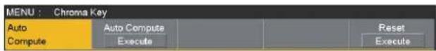
③ Press [F2] to execute the sampling automatically. To undo what has been sampled, press [F5].
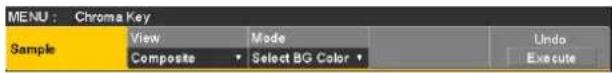
■ To execute the sampling manually
① Press the KEY button to light its indicator, and display the Chroma Key menu.
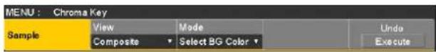
② Use [F1] to display the Sample sub menu.

③ Use [F2] to select "Composite" (composite image that combines the background image and key) using the View item.
④ Use [F3] to select "Select BG Color" using the Mode item.
| Select BG Color | A color for the background of the foreground image is specified. Normally, either a blue or green background is specified. |
⑤ Use the positioner to move the position of the sample marker.
To change the size of the sample marker, turn the rotary encoder [Z].
⑥ If the sample area that has been set is acceptable, press the rotary encoder [Z].
The area that has been set is now sampled.
⑦ To return to the pre-sampling status after sampling has been executed, press [F5].
The number of operations that can be undone is one only.
1. Basic operations
Step 2
The objective of this step is to remove the noise in the background image.
The noise is removed by carrying out this step several times.
① On the Chroma Key menu, use [F1] to display the Sample sub menu.
② Use [F2] to select "Matte" (Matte image) using the View item.
③ Use [F3] to select "Clean BG Noise" using the Mode item.
| Clean BG Noise | The noise in the background image is removed. |
④ Using the positioner, move the position of the sample marker to the position of the noise (white dots) in the background image.
To change the size of the sample marker, turn the rotary encoder [Z].
⑤ If the sample area that has been set is acceptable, press the rotary encoder [Z].
The noise in the area that has been set is now removed.
⑥ To return to the pre-sampling status after sampling has been executed, press [F5].
The number of operations that can be undone is one only.
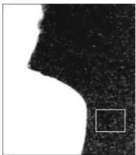
natural_image
Abstract black-and-white shape with a small square overlay (no text or symbols)Before the noise is removed

natural_image
Silhouette of a human head in profile against a white background (no text or symbols)After the noise is removed
Step 3
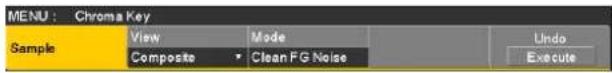
The objective of this step is to remove the noise in the foreground image.
The noise is removed by carrying out this step several times.
① Use [F2] to select "Matte" (Matte image) using the View item.

② Use [F3] to select "Clean FG Noise" using the Mode item.
| Clean FG Noise | The noise in the foreground image is removed. |
③ Using the positioner, move the position of the sample marker to the position of the noise (black dots) in the foreground image.
To change the size of the sample marker, turn the rotary encoder [Z].
④ If the sample area that has been set is acceptable, press the rotary encoder [Z].
The noise in the area that has been set is now removed.
⑤ To return to the pre-sampling status after sampling has been executed, press [F5].
The number of operations that can be undone is one only.
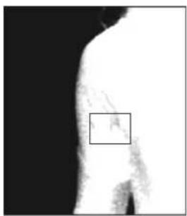
natural_image
Abstract grayscale image with a small white square overlay and a dark rectangular outline, no text or symbols present.Before the noise is removed

natural_image
Abstract black and white silhouette with no text or symbolsAfter the noise is removed
1. Basic operations
Step 4
After steps 1 to 3 have been carried out, noise will still remain in the detail areas such as the subject's hair as shown in the image below.
Noise remaining in the detail areas is also removed in "step 4".
If there are many areas with noise, the noise is removed by carrying out this step several times.
If there are few areas with noise, adjust the noise using the Mode item ("Spill+" and "Spill−") of the Sample sub menu.

natural_image
Woman in red shirt posing outdoors with hands on head, surrounded by green lawn and trees (no text or symbols visible)① Use [F2] to select "Composite" (composite image that combines the background image and key) using the View item.
② Use [F3] to select "Spill Sponge" using the Mode item.
Spill Sponge The noise remaining in the detailed areas is removed.
③ Using the positioner, move the position of the sample marker to the position of the remaining noise. To change the size of the sample marker, turn the rotary encoder [Z].
④ If the sample area that has been set is acceptable, press the rotary encoder [Z]. The noise in the area that has been set is now removed, and the colors become more natural.
⑤ To return to the pre-sampling status after sampling has been executed, press [F5]. The number of operations that can be undone is one only.
- Execute sampling in both the light and dark areas as the sample area.
- If the noise in the foreground image is not completely removed by carrying out the steps above, proceed with the FineTuning sub menu operation.
Step 5
The objective of this step is to finely adjust the image by adjusting the noise and transparency, for example.
① On the Chroma Key menu, use [F1] to display the Sample sub menu.

② Use [F2] to select the image to be adjusted using the View item.
| Composite Composite image that combines the background image and key |
| Matte Matte image |
| Proc.FG Process foreground image |
| FG Foreground image |
③ Use [F3] to select the adjustment function using the Mode item. For details on the items, refer to the following pages.
④ Using the positioner, move the position of the sample marker to the position to be sampled. To change the size of the sample marker, turn the rotary encoder [Z].
⑤ If the sample area that has been set is acceptable, press the rotary encoder [Z]. The area that has been set is now sampled.
⑥ To return to the condition of a step earlier after an adjustment has been made, press [F5]. The number of operations that can be undone is one only.
1. Basic operations
[Spill-] [Spill+]
In these modes, the noise in the foreground image can be removed or restored step by step through repeated sampling.
![PANASONIC AV-HS410 - [Spill-] [Spill+] - 1](/content/2026/05/882244/images/46ac082add5e4c5f91deee76c74798b81f77fc84ccaf1e4d4ce9e7124c4b2242.jpg)
natural_image
Woman in white shirt holding a device with smoke, standing indoors near a framed painting (no visible text or symbols)![PANASONIC AV-HS410 - [Spill-] [Spill+] - 2](/content/2026/05/882244/images/693a369dbef9803f0a6cdb2841db365b0af7c88d5f7417f122b51beea5d3b33a.jpg)
natural_image
Close-up of a person's upper body and shoulder, no visible text or symbols[+] Spill [-]
![PANASONIC AV-HS410 - [Spill-] [Spill+] - 3](/content/2026/05/882244/images/00a0471e834c625ed4e3c8c7bc1dd30cfba77f240ae4cb56afb3ee5fde17a5eb.jpg)
natural_image
Close-up of a white garment with a light-colored collar (no visible text or symbols)←
![PANASONIC AV-HS410 - [Spill-] [Spill+] - 4](/content/2026/05/882244/images/f1a4a86ba136191f8960765b85e09677f2a51426971c8142f0274073200c2a9b.jpg)
natural_image
Close-up of a white fabric with a dark seam, no visible text or symbols→
![PANASONIC AV-HS410 - [Spill-] [Spill+] - 5](/content/2026/05/882244/images/d19e651d280d135f34475f6c2f8fb62638dde41a956ee3acd1b69e276aede1a3.jpg)
natural_image
Close-up of a white garment with a light-colored collar and small button (no visible text or symbols)[Matte-] [Matte+]
In these modes, the matte information is adjusted.
If, for instance, the area of shadow in the foreground image is to be made lighter, use [Matte-] to adjust.
Conversely, to make it darker, use [Matte+].
Transparent images such as images of smoke or water can be made to stand out more.
![PANASONIC AV-HS410 - [Matte-] [Matte+] - 1](/content/2026/05/882244/images/073c6b89e5e383c0a9383e56580447e942b449bae0f39a5f8462846cb47181b5.jpg)
natural_image
Woman in white shirt standing beside a small object, with framed artwork on wall (no visible text or symbols)![PANASONIC AV-HS410 - [Matte-] [Matte+] - 2](/content/2026/05/882244/images/cd52d356efd42c83b16c9324fc34d6538979ccdef72cb55b054cb2ffcba83105.jpg)
natural_image
Blurred grayscale image with no discernible text, symbols, or identifiable objects[-] Matte [+]
![PANASONIC AV-HS410 - [Matte-] [Matte+] - 3](/content/2026/05/882244/images/0ba667f5f92715ecb005bd1016f8b9c83b5dfbca3c73fd21ba840d60a564f15d.jpg)
natural_image
Blurred grayscale image with indistinct shapes, no visible text or symbols←
![PANASONIC AV-HS410 - [Matte-] [Matte+] - 4](/content/2026/05/882244/images/1f013cfde5c55de37fa0db58ff56a6b756a34aa3f42af0829a27d6484668c568.jpg)
natural_image
Blurred grayscale image of an indistinct object, possibly a smoke or cloud formation (no visible text or symbols)→
![PANASONIC AV-HS410 - [Matte-] [Matte+] - 5](/content/2026/05/882244/images/e76c1043265167707710dba601cd5c224b26032ae633731c9017a32a249e7208.jpg)
natural_image
Blurred grayscale image of an indistinct cloud or smoke plume (no text or symbols visible)1. Basic operations
[Detail-] [Detail+]
In these modes, the noise in the background image can be removed step by step.
This is a useful way of adjusting images lost by other sampling operations to adjust the texture or transparency of images.
![PANASONIC AV-HS410 - [Detail-] [Detail+] - 1](/content/2026/05/882244/images/6986a76d0bfc6242a3d17b07626c60cddba0b5309fa73c0b974a7927ea1c667c.jpg)
natural_image
Interior scene with a person standing in a room, surrounded by furniture and a painting (no visible text or symbols)![PANASONIC AV-HS410 - [Detail-] [Detail+] - 2](/content/2026/05/882244/images/741ee9769edb0b1eb147a2992546317c4de403b214238cacffb71ca7505d26de.jpg)
natural_image
Person wearing black pants and white shoes standing on a plain surface (no text or symbols visible)[-] Detail [+]
![PANASONIC AV-HS410 - [Detail-] [Detail+] - 3](/content/2026/05/882244/images/4b8259e8b3a88df1c7f4b4ec1f8face9cbb7f97604100dd2158cd929d67a9ee4.jpg)
natural_image
Person wearing black shoes and feet on a white surface (no text or symbols visible)![PANASONIC AV-HS410 - [Detail-] [Detail+] - 4](/content/2026/05/882244/images/efb4cde858fb43480fe8376e89c94fb0e17e757902ca25755d5b21cd34c63167.jpg)
![PANASONIC AV-HS410 - [Detail-] [Detail+] - 5](/content/2026/05/882244/images/014c9361040ce765e85122c308f9859e62ff95cca419c63cf2d3ea7bebc6ff62.jpg)
natural_image
Close-up of human legs and feet wearing black shoes, standing on a white surface (no text or symbols visible)![PANASONIC AV-HS410 - [Detail-] [Detail+] - 6](/content/2026/05/882244/images/1dc9a1e5ac4a8a9b4e79e4acd2909b1449190586514b0ad6ab40c9461f38a026.jpg)
![PANASONIC AV-HS410 - [Detail-] [Detail+] - 7](/content/2026/05/882244/images/ae6c2a6a55302516df730f45a237b323421bcca3d9846b7611422bdd35472e82.jpg)
natural_image
Person wearing black boots standing on a white surface (no text or symbols visible)[Matte Sponge]
In this mode, the semi-transparent parts of the subject in a foreground image are selected and made matte (non-transparent). Unlike [Clean FG Noise] on the Sample sub menu, the color information is not changed in the process.
With [Clean FG Noise], the colors of the selected parts are restored to their original colors but, with [Matte Sponge], only the semi-transparent keys are made matte (non-transparent) while the colors remain unchanged and the original colors are not restored.
[Make FG Trans]
In this mode, the transparency of areas with a low transparency in the foreground image is increased.
This is useful when, for instance, areas covered with dark smoke or clouds in a foreground image are to be made semi-transparent.
[Restore Detail]
In this mode, the transparency of areas with a high transparency in the background image is reduced.
This is useful when, for instance, restoring the details of an image (such as an image with a subject who has loose hair or an image with smoke), which have been lost as a result of a [Clean BG Noise] or other such operation on the Sample sub menu, to what they were in the original image.
1. Basic operations
[FineTuning]
In this mode, detailed images can be adjusted.
① On the Chroma Key menu, use [F1] to display the Sample sub menu.
② Use [F2] to select "Composite" using the View item.
③ Use [F3] to select "FineTuning" using the Mode item.
④ Using the positioner, move the position of the sample marker to the position to be sampled.
To change the size of the sample marker, turn the rotary encoder [Z].
⑤ If the sample area that has been set is acceptable, press the rotary encoder [Z].
⑥ On the Chroma Key menu, use [F1] to display the Fine Tuning sub menu.

⑦ Use [F2] to remove or restore the noise using the Spill item.
When it is turned clockwise, a large amount of noise is removed from the foreground image, and the image colors increasingly approach the complementary color (opposite color) of the blue screen.
When it is turned counterclockwise, the image colors approach the colors of the original foreground image.
⑧ By turning [F3] clockwise, the matte of the colors closely resembling the colors of the foreground image can be adjusted using the Trans item.
This is useful when, for instance, areas covered with dark smoke or clouds in a foreground image are to be made semi-transparent.
⑨ By turning [F4] clockwise, the matte information for the colors closely resembling the colors of the background image can be adjusted using the Detail item.
This is useful when, for instance, restoring the details of an image (such as an image with a subject who has loose hair or an image with smoke), which have been lost in the foreground image as a result of sampling, to what they were in the original image.
Step 6
Finely adjust the chroma key signals which have been generated.
① On the Chroma Key menu, use [F1] to display the Adjust sub menu.

② Use [F2], and adjust the width of the chroma key signals using the Narrow item.
The key signal width can be adjusted horizontally in 0.5 (half-pixel) increments.
③ Use [F3], and adjust the horizontal phase of the chroma key signals using the Phase item.
The key signal position can be moved horizontally in 0.5 (half-pixel) increments.
1. Basic operations
1-3-7. Key decorations
A border, shadow or other edge can be added to the key.
Setting the key edge
① Press the KEY button to light its indicator, and display the Key menu.
② Use [F1] to display the Edge1 sub menu.
| MENU: Key | ||||
| Edge1 | Type | Width | Direction | Density |
| Off | 2 | 0 | 100% | |
③ Use [F2] to select the edge type.
| Off An edge is not added. |
| Border A border is added around the entire edge. |
| Drop A diagonal border is added. |
| Shadow A shadow is added. |
| Outline An outline (only a border with no fill) is added. |


④ Use [F3] to set the edge width.
⑤ Use [F4] to set the direction (in 45-degree increments) in which "Drop" and "Shadow" will be added.
⑥ Use [F5] to set the darkness (Density) of the edges.
Selecting the Edge Fill settings
Materials to be inserted as edges can be set.
① On the Key menu, use [F1] to display the Edge2 sub menu.

② Use [F2] to select the edge material using the Edge Fill items.
| Color | The color set using Edge Color is used. |
| CBGD1 | The color background is used. |
| CBGD2 | |
| Still1 | The still image video memory (Still1) is used. |
| Still2 | The still image video memory (Still2) is used. |
| Clip1 | The moving image video memory (Clip1) is used. |
| Clip2 | The moving image video memory (Clip2) is used. |
Setting the edge color
① On the Key menu, use [F1] to display the Edge Color sub menu.

② Use [F2], [F3] and [F4] to adjust the Hue, Sat and Lum of the edge color.
■ To call the preset color
Use [F5] to select the preset color using the Load item, and press the [F5].
- When [F5] is pressed, what has been set so far is canceled and replaced with the preset color values.
- To save the values that were set before calling the preset color, refer to "1-10. Memory".
1. Basic operations
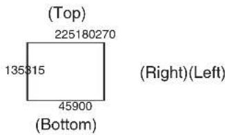
1-3-8. Masking the key signals
These steps are taken to mask the key signals using the mask signal of the box pattern.
① Press the KEY button to light its indicator, and display the Key menu.
② Use [F1] to display the Mask sub menu.
| MENU: Key | |||
| Mask | Mask | Invert | |
| Off | Off | On | |
③ Use [F2], and select the masking method using the Mask item.
| Off The key signals are not masked. | |
| Manual The area that is set using the Mask Adjust sub menu is masked. | |
| 4:3 The signals are masked to the 4:3 aspect ratio. |
④ Use [F3] to set whether to invert the mask signal using the Invert item.
| On The mask signal is inverted. |
| Off The mask signal is not inverted. |
⑤ Use [F1] to display the Mask Adjust sub menu.
| MENU: Key | |||||||
| Mask Adjust | Left | -25.00 | Top | 25.00 | Bottom | -25.00 | Right 25.00 |
⑥ Use [F2] to [F5] to set the area to be masked.
| Operation/ Parameter | Description of setting | Setting range/ Initial value |
| F2/ Left | Key left position | -50.00 to 50.00/-25.00 |
| F3/ Top | Key top position | -50.00 to 50.00/25.00 |
| F4/ Bottom | Key bottom position | -50.00 to 50.00/-25.00 |
| F5/ Right | Key right position | -50.00 to 50.00/25.00 |
The Left setting cannot exceed the Right setting (and vice versa) and, similarly, the Top setting cannot exceed the Bottom setting (and vice versa).
1. Basic operations
1-3-9. Flying key
Using DVE effects, this key enables the key signals that have been input to be moved, expanded or contracted. In order for the flying key to take effect, select "SQ2: 8" as the key transition.
Refer to "1-2-1. Selecting the wipe pattern".
When the key transition is executed, the keys are combined by the key signals set using the flying key menu.
(The transition effect is fixed at MIX.)
Since the flying key uses DVE effects, the image is delayed by one frame.
① Press the KEY button to light its indicator, and display the Key menu.
② Use [F1] to display the Flying Key sub menu.

③ Use [F2] to set the X coordinate of the key signal using the X-Pos item.
④ Use [F3] to set the Y coordinate of the key signal using the Y-Pos item.
⑤ Use [F4] to set the key signal change size (max. 400: 400 %) using the Size item.

flowchart
graph LR
    A["ABC"] --> B["ABC"]
Key signal When combined using the flying key
In order to add the edge of the key before the DVE effect, the thickness of the edge is also changed when the size is changed.
PinP combinations using the flying key
When "Full" is selected using the Type item in "1-3-1.
Selecting the key type", PinP combinations can be performed using the flying key.
(At this point in time, the Clip item and Gain item cannot be set on the Adjust sub menu.)
With the full key, the image on the full screen serves as the key source signal so an edge will not be added unless a further step is taken.
To add an edge, mask the key signals so that the key source signals are made smaller than the entire screen.
For details on masking, refer to "1-3-8. Masking the key signals".
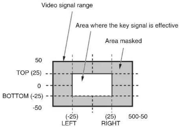
1-3-10. Setting the priority
The relative positions of the images when key, PinP1 and PinP2 images are to be superimposed onto one another can be set.
① Press the KEY button to light its indicator, and display the Key menu.
② Use [F1] to display the Key Priority sub menu.

③ Use [F2] to [F4] to set the relative positions using the Low item, Middle item and High item.
| Low This is used to set the image to be placed at the bottom. |
| Middle This is used to set the image to be placed in the middle. |
| High This is used to set the image to be placed at the top. |
flowchart
graph TD
    A["Low: Key"] --> B["Middle: PinP1"]
    B --> C["High: PinP2"]
1. Basic operations
1-4. PinP (picture in picture)
Another image can be combined with the background image. This unit supports two PinP channels.
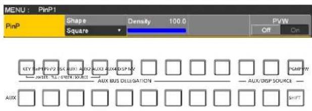
1-4-1. Selecting the PinP channel and material
Press the [PinP1] button (or [PinP2] button) among the AUX bus selector buttons.
When the [PinP1] button (or [PinP2] button) is lit, the PinP1 menu (or PinP2 menu) is displayed on the built-in display. The state in which the PinP1 materials (or PinP2 materials) are selected is now established for the AUX bus crosspoint buttons.
The selected AUX bus crosspoint button lights in amber. (It will light in red if the selected signal is a PGM output signal.)
1-4-2. Transition between PinP materials
When a PinP bus material has been selected, the effect to be produced when images are switched can be executed as a MIX transition. (Bus transition function)
- When one material set to the Dot by Dot mode and another material have been switched, cut switching where the images change in an instant is performed.
① Press the TIME button to light its indicator, and display the Time menu.
② Use [F1] to display the PinP1 BUS Trans sub menu (or PinP2 BUS Trans sub menu).
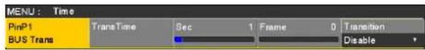
③ Use [F3] and [F4] to set the transition time.
④ Use [F5] to set enable or disable for the bus transition function.
| Enable Enable | |
| Disable | Disable |
While the transition is underway, the indicator of the transition source button lights, and the indicator of the transition destination button blinks.
When the transition is completed, the indicator of the transition source button goes off, and the indicator of the transition destination button lights.
When another signal has been selected while a transition is underway, the processing for the transition will continue from the interim point.
1. Basic operations
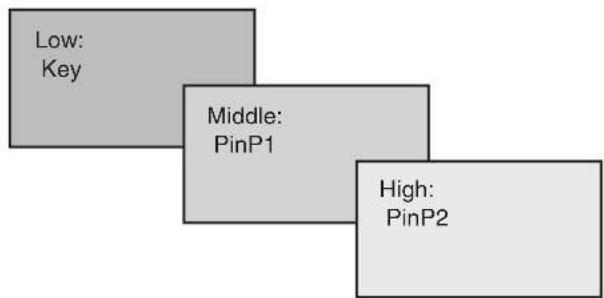
1-4-3. Selecting Shape
Square, Circle, Heart, Star or Flower can be selected as the shape used for combining PinP images.
① Press the PinP1 button to light its indicator, and display the PinP1 menu (or PinP2 menu).
② Use [F1] to display the PinP sub menu.
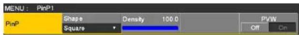
③ Use [F2] and, using the Shape item, select the shape used for combining images.
④ Use [F3] to adjust the transmissivity (darkness) applying when the images are combined using the Density item.
1-4-4. PinP preview
Select whether to output the PinP1 and PinP2 preview images to the preview output.
① On the PinP sub menu, use [F5] to set the PVW item.

| On An image with the PinP1 (or PinP2) effectadded is output to the preview output. |
| Off An image without the PinP1 (or PinP2) effectadded is output to the preview output. |
- The PVW On and Off settings can be allocated to the user buttons.
When "PinP1 PVW" (or "PinP2 PVW") is assigned to a user button, the PinP1 image (or PinP2 image) preview output is turned on or off every time the user button is pressed.
When "PinP PVW" is assigned to a user button, the PinP1 image and PinP2 image preview outputs are simultaneously turned on or off every time the user button is pressed.
Refer to "3-3-1. Setting the user buttons".
1-4-5. PinP transitions
① Set the transition time.
On the Time menu, use [F1] to display the PinP1 sub menu (or PinP2 sub menu).
As with background transitions, set the transition time. Refer to "1-1-6. Auto transition".
② When the [PinP1 ON] button (or [PinP2 ON] button) in the transition area is pressed, the PinP1 image (or PinP2 image) transitions (fades in) for the length of the transition time that has been set.
During fade-in, the [PinP1 ON] button (or [PinP2 ON] button) blinks in red, and when the transition is completed, it lights in red.
When the [PinP1 ON] button (or [PinP2 ON] button) is pressed after fade-in is completed, the PinP1 image (or PinP2 image) transitions (fades out).
During fade-out, the [PinP1 ON] button (or [PinP2 ON] button) lights in red, and when the transition is completed, it goes off.
If the [PinP1 ON] button (or [PinP2 ON] button) is pressed at any point during a transition, the direction of the transition is reversed.
1. Basic operations
1-4-6. PinP adjustments
Adjusting the PinP position and size
While the PinP menu is selected, adjust the X and Y coordinates using the positioner in the positioner area, and adjust the size using the rotary encoder [Z]. Alternatively, the settings can be performed on the menus.
① Press the PinP1 button to light its indicator, and display the PinP1 menu (or PinP2 menu).
② Use [F1] to display the Position sub menu.

③ Either operate the positioner and the rotary encoder [Z] or use [F2], [F3] and [F4] to set the X and Y coordinates and the size using the X-Pos, Y-Pos and Size items.
Select the dot by dot mode
When the system is set to the HD mode and an SD format image is to be used for the PinP material, the images can be combined in the dot by dot mode (actual-size images). In this mode, the SD format image will not be up-converted so image deterioration can be prevented.
- When "100.00" has been selected as the Size item setting on the Position sub menu, the size used for the combination will be the same number of lines as the SD format image.
① Press the IN OUT button to light its indicator, and display the Input menu.
② Use [F2] to select the signals for inputting the PinP material using the Select item.
③ Use [F1] to display the FS sub menu.

④ Use [F3] to select "Dot by Dot" using the Mode item, and press the [F3] to enter the selection.
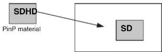
flowchart
graph TD
    A["PinP material"] --> B["SDHD"]
    B --> C["SD"]
PinP combined image
1. Basic operations
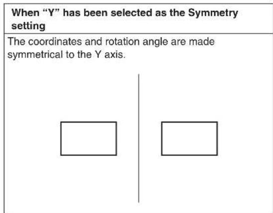
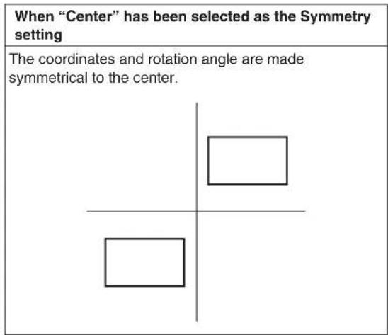
1-4-7. Linking PinP1 and PinP2
The PinP1 and PinP2 images perform a symmetrical operation for the axis whose coordinates and rotation angle have been set.
The image serving as the reference is the PinP image of the menu being operated.
Setting the priority
Set the relative positions of the images when key, PinP1 and PinP2 images are to be superimposed onto one another.
Refer to "1-3-10. Setting the priority".
Linking PinP1 and PinP2
① Press the PinP1 button to light its indicator, and display the PinP1 menu (or PinP2 menu).
② Use [F1] to display the Sync sub menu.
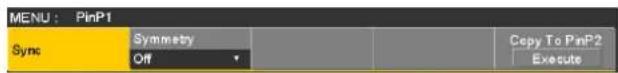
③ Use [F2] to select the position that will serve as the reference using the Symmetry item. The image serving as the reference is the PinP image of the menu being operated.

Copying the settings
The PinP1 settings can be copied to PinP2 and, similarly, the PinP2 settings can be copied to PinP1.
① On the PinP1 menu (or PinP2 menu), use [F1] to display the Sync sub menu.
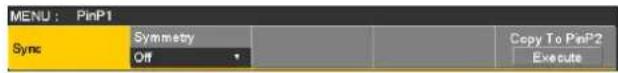
② Use [F2] to select "Off" using the Symmetry item.
③ When [F5] is pressed, the PinP1 (or PinP2) settings are copied and set in PinP2 (or PinP1).
Note
The following settings are not copied.
- Trim sub menu items
1. Basic operations
1-4-8. PinP decorations
A border or soft effect can be added to PinP.
① Press the PinP1 button to light its indicator, and display the PinP1 menu (or PinP2 menu).
② Use [F1] to display the Border sub menu.

③ Use [F2] to set On (or Off) for the border using the Border item.
④ Use [F3] to set the width of the border using the Width item.
⑤ Use [F4] to set the amount of soft effect using the Soft item. The soft effect is OFF if 0.0 is set.
When "On" has been selected as the Border item setting, the ratio of the soft effect to the border width is indicated as the amount of soft effect.
When only the soft effect is to be added to PinP, select "Off" as the Border item setting.
⑥ Use [F5] to set the change in the border width using the Mode item.
| Fix The border | width is kept constant. |
| Variable The border width changes to suit the PinP size. | |
Setting the border color
① On the PinP1 menu (or PinP2 menu), use [F1] to display the Border Color sub menu.

② Use [F2], [F3] and [F4] to adjust the Hue, Sat and Lum of the border color.
■ To call the preset color
Use [F5] to select the preset color using the Load item, and press the [F5].
- When [F5] is pressed, what has been set so far is canceled and replaced with the preset color values.
- To save the values that were set before calling the preset color, refer to "1-10. Memory".
1. Basic operations
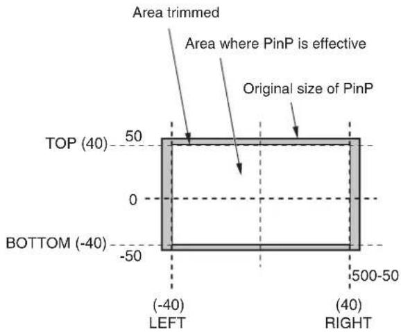
1-4-9. Trimming settings
① Press the PinP1 button to light its indicator, and display the PinP1 menu (or PinP2 menu).
② Use [F1] to display the Trim sub menu.

③ Use [F2] to select the trimming type using the Trim item.
| Off No trimming | |
| 4:3 Automatic trimming so that the aspect ratio is 4:3. | |
| Manual Trimming using the value set on the Trim Adjust sub menu. | |
④ Use [F3] to select the operation to be performed during the manual setting using the Manual item.
| Free The Left, | Right, Top and Bottom parameters change independently.However, the Left setting cannot exceed the Right setting (and vice versa) and, similarly, the Top setting cannot exceed the Bottom setting (and vice versa). |
| Pair The settings | are changed in such a way that the Left and Right trimming amounts and the Top and Bottom trimming amounts are the same. (This makes for a top-bottom and left-right symmetry.) |
⑤ Use [F1] to display the Trim Adjust sub menu, and use [F2], [F3], [F4] and [F5] to set the trimming values.
| Operation/ Parameter | Description of setting | Setting range/ Initial value |
| F2/ Left | Trimming value at left | -50.00 to 50.00/-40.00 |
| F3/ Top | Trimming value at top | -50.00 to 50.00/40.00 |
| F4/ Bottom | Trimming value at bottom | -50.00 to 50.00/-40.00 |
| F5/ Right | Trimming value at right | -50.00 to 50.00/40.00 |
1. Basic operations
1-5. DSK (downstream key)
Characters or other images can be combined with the background image.
1-5-1. Selecting the DSK type
① Press the DSK button to light its indicator, and display the DSK menu.
② Use [F1] to display the DSK sub menu.

③ Use [F2] to select the Type item.
| Lum(luminance key/ self key) | This is for creating the key signals from the luminance component of the key fill signal. |
| Linear(linear key/EXT key) | This is for creating the key signals from the luminance component of the key source signal.It is used when the key source signal and key fill signal are different. |
Since the luminance key is operated as a self key, the key fill signals are used as the key source signals. When the luminance key has been selected as the downstream key type, the key signals will remain unchanged even when the key source signals are switched.
When using the linear key, use material with a black background and white characters or shape to be combined by the key as the key source signal. Material which is not black and white may not be combined clearly. Material with a white background and black characters, etc. can be reversed using the key invert function for use.
④ When the luminance key has been selected, the chroma components can be contained in the key signals generated in view of the fact that it is used as a self key. (This is not applied to the linear key.) Use [F3] to select the setting using the Lum Key item.
| Chroma On In | addition to the luminance components, the chroma components are also factored in when generating the key signals. Use this setting if colors with low luminance components are used for the key signals (when, for instance, blue characters are to be removed). |
| Chroma Off The | the key signals are generated only from the luminance components. |
⑤ Use [F4] to select the fill type using the Fill item.
| Bus The bus signal is used for the key fill signal. |
| Matte The internal fill matte is used for the key fill signal. |
Setting the fill matte color
① On the DSK menu, use [F1] to display the Fill Matte sub menu.

② Use [F2], [F3] and [F4] to adjust the Hue, Sat and Lum of the fill matte.
■ To call the preset color
Use [F5] to select the preset color using the Load item, and press the [F5].
- When [F5] is pressed, what has been set so far is canceled and replaced with the preset color values.
- To save the values that were set before calling the preset color, refer to "1-10. Memory".
1-5-2. Selecting the DSK material
Selecting the DSK fill signal and DSK source signal
Press the [DSK] button in the AUX bus selection area to switch the selection of the DSK fill signal (indicator lights in amber) and DSK source signal (indicator lights in green).
While the indicator of the [DSK] button is lit in amber, press one of the AUX bus crosspoint buttons 1 to 12 to select the DSK fill signal.
The indicator of the selected AUX bus crosspoint button lights in amber. (It lights in red if the selected signal is being output from the PGM connector.)
flowchart
graph LR
    A["KEY"] --> B["HPF1"]
    B --> C["PHP2"]
    C --> D["DSK"]
    D --> E["AUX1"]
    E --> F["AUX2"]
    F --> G["AUX3"]
    G --> H["AUX4"]
    H --> I["DSP"]
    I --> J["UV"]
    J --> K["PGMP"]
    K --> L["UV"]
    L --> M["SHIFT"]
    N["AUX"] --> O["AUX BUS DELEGATION"]
    P["AUX/DISP SOURCE"] --> Q["UV"]
    R["Lighting in amber"]
While the indicator of the [DSK] button is lit in green, press one of the AUX bus crosspoint buttons 1 to 12 to select the DSK source signal.
The indicator of the selected AUX bus crosspoint button lights in green. (It lights in red if the selected signal is being output from the PGM connector.)
Since the luminance key is operated as a self key, the key fill signals are used as the key source signals. When the luminance key has been selected as the downstream key type, the key signals will remain unchanged even when the key source signals are switched.
flowchart
graph LR
    A["KEY SHPT"] --> B["PIV2"]
    B --> C["DSK AUX1 AUX2 AUX3 AUX4 DSP MV"]
    C --> D["AUX BUS DELEGATION"]
    D --> E["PGMPW"]
    F["AUX"] --> G["SHIFT"]
    H["SHPT"] --> I["SHIFT"]
    J["AUX/DISP SOURCE"] --> K["SHIFT"]
Lighting in green
1-5-3. DSK transitions
① Set the transition time.
Press the TIME button to light its indicator, and display the Time menu.
② Use [F1] to display the DSK sub menu.
As with background transitions, set the transition time.
Refer to "1-1-6. Auto transition".
③ When the [DSK ON] button in the transition area is pressed, the DSK image is combined (fades in) for the length of the transition time that has been set.
During fade-in, the [DSK ON] button blinks in red, and when the transition is completed, it lights in red.
When the [DSK ON] button is pressed after fade-in is completed, the DSK image transitions (fades out).
During fade-out, the [DSK ON] button lights in red, and when the transition (fade-out) is completed, it goes off. If the [DSK ON] button is pressed at any point during a transition, the direction of the transition is reversed.
1. Basic operations
1-5-4. DSK preview
Select whether to output the DSK preview image to the preview output.
① Press the DSK button to light its indicator, and display the DSK menu.
② Use [F1] to display the DSK sub menu.
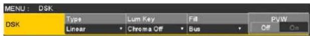
③ Use [F5] to set the PVW item.
| On An image with the DSK effect added is output to the preview output. |
| Off An image without the DSK effect added is output to the preview output. |
The PVW On and Off settings can be allocated to the user buttons.
Refer to "3-3-1. Setting the user buttons".
1-5-5. DSK adjustments
The DSK definition can be adjusted.
① Press the DSK button to light its indicator, and display the DSK menu.
② Use [F1] to display the Adjust sub menu.

③ Use [F2], [F3] and [F4] to adjust the DSK (downstream key) definition.
④ Use [F5] to set key invert.
If "On" is set, the key signals generated internally are inverted.
| Operation/ Parameter | Description of setting Setting range | |
| F2/ Clip | Reference level for generating key signals | 0.0 to 108.0 |
| F3/ Gain | Key amplitude 0.0 to 200.0 | |
| F4/ Density | Key density 0.0 to 100.0 | |
| F5/ Invert | Key signal inversion On, Off | |
1. Basic operations
1-5-6. DSK decorations
A border, shadow or other type of edge can be added to DSK.
Setting the edge
① Press the DSK button to light its indicator, and display the DSK menu.
② Use [F1] to display the Edge1 sub menu.
| MENU: DSK | ||||
| Edge1 | Type | Width | Direction | Density |
| Off | 2 | 0 | 100% | |
③ Use [F2] to select the edge type.
| Off An edge is not added. |
| Border A border is added around the entire edge. |
| Drop A diagonal border is added. |
| Shadow A shadow is added. |
| Outline An outline (only a border with no fill) is added. |

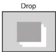


④ Use [F3] to set the edge width.
⑤ Use [F4] to set the direction (in 45-degree increments) in which "Drop" and "Shadow" will be added.
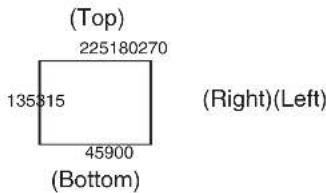
⑥ Use [F5] to set the darkness (Density) of the edges.
Setting Edge Fill
Materials to be inserted as edges can be set.
① On the DSK menu, use [F1] to display the Edge2 sub menu.

② Use [F2] to select the edge material using the Edge Fill item.
| Color | The color set using Edge Color is used. |
| CBGD1 | The color background is used. |
| CBGD2 | |
| Still1 | The still image video memory (Still1) is used. |
| Still2 | The still image video memory (Still2) is used. |
| Clip1 | The moving image video memory (Clip1) is used. |
| Clip2 | The moving image video memory (Clip2) is used. |
Setting the edge color
① On the DSK menu, use [F1] to display the Edge Color sub menu.

② Use [F2], [F3] and [F4] to adjust the Hue, Sat and Lum of the edge color.
■ To call the preset color
Use [F5] to select the preset color using the Load item, and press the [F5].
- When [F5] is pressed, what has been set so far is canceled and replaced with the preset color values.
- To save the values that were set before calling the preset color, refer to "1-10. Memory".
1. Basic operations
1-5-7. Masking the DSK signals
These steps are taken to mask the DSK signals using the mask signal of the box pattern.
① Press the DSK button to light its indicator, and display the DSK menu.
② Use [F1] to display the Mask sub menu.

③ Use [F2], and select the masking method using the Mask item.
| Off The DSK signals are not masked. | |
| Manual The area that is set using the Mask Adjust sub menu is masked. | |
| 4:3 The signals are masked to the 4:3 aspect ratio. |
④ Use [F3] to set whether to invert the mask signal using the Invert item.
| On The mask signal is inverted. |
| Off The mask signal is not inverted. |
⑤ Use [F1] to display the Mask Adjust sub menu.

⑥ Use [F2] to [F5] to set the area to be masked.
| Operation/ Parameter | Description of setting | Setting range/ Initial value |
| F2/ Left | DSK left position | -50.00 to 50.00/-25.00 |
| F3/ Top | DSK top position | -50.00 to 50.00/25.00 |
| F4/ Bottom | DSK bottom position | -50.00 to 50.00/-25.00 |
| F5/ Right | DSK right position | -50.00 to 50.00/25.00 |
The Left setting cannot exceed the Right setting (and vice versa) and, similarly, the Top setting cannot exceed the Bottom setting (and vice versa).
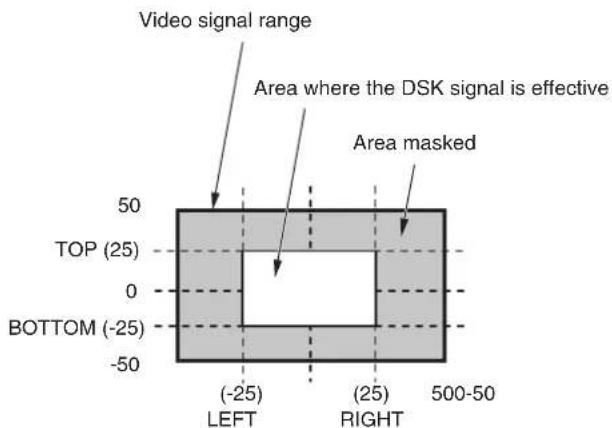
1. Basic operations
1-6. Key Link
This function makes it possible to link the "On" or "Off" setting of the [DSK ON] button and PinP buttons ([PinP1 ON] and [PinP2 ON]) with the "On" or "Off" (button indicator lights or off) of the [KEY ON] button.
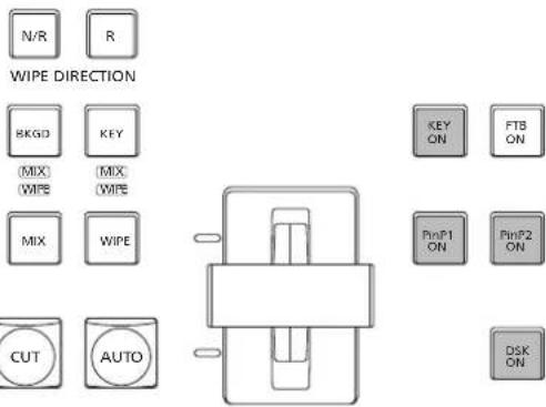
① Press the CONFIG button to light its indicator, and display the Config menu.
② Use [F1] to display the Operate sub menu.

③ Use [F3] to select the link operation using the Key Link item.
| Off This releases the link with the [KEY ON] button. | |
| DSK This links | the “On” or “Off” setting of the [DSK ON] button with the “On” or “Off” setting of the [KEY ON] button.When the [DSK ON] button is “On”, the [DSK ON] button remains “On” even when the [KEY ON] button is set to “On”.When the [DSK ON] button is “Off”, the [DSK ON] button remains “Off” even when the [KEY ON] button is set to “Off”.There is no link with the auto transition operation initiated by setting the [AUTO] button to “On” when the [KEY] button has been selected. |
| PinP1 This links | the “On” or “Off” setting of the [PinP1 ON] button with the “On” or “Off” setting of the [KEY ON] button.When the [PinP1 ON] button is “On”, the [PinP1 ON] button remains “On” even when the [KEY ON] button is set to “On”.When the [PinP1 ON] button is “Off”, the [PinP1 ON] button remains “Off” even when the [KEY ON] button is set to “Off”.There is no link with the auto transition operation initiated by setting the [AUTO] button to “On” when the [KEY] button has been selected. |
| PinP2 This links | the “On” or “Off” setting of the [PinP2 ON] button with the “On” or “Off” setting of the [KEY ON] button.When the [PinP2 ON] button is “On”, the [PinP2 ON] button remains “On” even when the [KEY ON] button is set to “On”.When the [PinP2 ON] button is “Off”, the [PinP2 ON] button remains “Off” even when the [KEY ON] button is set to “Off”.There is no link with the auto transition operation initiated by setting the [AUTO] button to “On” when the [KEY] button has been selected. |
| PinP1/2 This links | the “On” or “Off” settings of the [PinP1 ON] button and [PinP2 ON] button with the “On” or “Off” setting of the [KEY ON] button.When the [PinP1 ON] button and [PinP2 ON] button are “On”, the [PinP1 ON] button and [PinP2 ON] button remain “On” even when the [KEY ON] button is set to “On”.When the [PinP1 ON] button and [PinP2 ON] button are “Off”, the [PinP1 ON] button and [PinP2 ON] button remain “Off” even when the [KEY ON] button is set to “Off”.There is no link with the auto transition operation initiated by setting the [AUTO] button to “On” when the [KEY] button has been selected. |
1. Basic operations
1-7. FTB (Fade to Black)
The user can fade out from a program image to the black screen or fade in to a program image from a black screen.
① Set the duration of the transition.
Press the TIME button to light its indicator, and display the Time menu.
② Use [F1] to display the FTB sub menu.
As with a background transition, set the transition time.
Refer to "1-1-6. Auto transition".
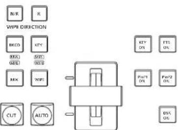
③ When the [FTB ON] button in the transition area is pressed, fade-out to the black screen is initiated for the length of the transition time that has been set.
During fade-out, the indicator of the [FTB ON] button blinks in red, and it lights in red when the transition (fade-out) is completed, and the black screen is displayed.*1
When the [FTB ON] button is pressed with the black screen displayed, fade-in to the program image is initiated.
During fade-in, the indicator of the [FTB ON] button lights in red, and it goes off when the transition (fade-in) is completed.
If the [FTB ON] button is pressed at any point during a transition, the direction of the transition is reversed.
*1: In the FTB status, the crosspoint button which is normally lit in red lights in amber.
Selecting the image
The image to be used for fading out can be selected.
① Press the CON=6 SYS button to light its indicator, and display the Config menu.
② Use [F1] to display the Assign sub menu.

③ Use [F2] to select the image to appear when fading out using the FTB Source item.
| Still1 The still image video memory (Still1) is used. | |
| Still2 The still image video memory (Still2) is used. | |
| Clip1 The moving image video memory (Clip1) is used. | |
| Clip2 The moving image video memory (Clip2) is used. | |
| CBGD1 | The color background is used. |
| CBGD2 | |
| White White background | |
| Black Black background | |
- If a setting other than "White" or "Black" has been selected using the FTB Source item, the corresponding crosspoint button will light in red in the FTB status.
1. Basic operations
1-8. Internal color signals
This unit supports two sets of internal color signals.
1-8-1. Setting the color background
The color background to be used by the bus can be set. Two methods are available: under one method the Hue (hue), Sat (color saturation) and Lum (luminance) are set, and under the other the 8 preset colors (white, yellow, cyan, green, magenta, red, blue and black) are called. The Hue, Sat and Lum of the called colors can also be adjusted.
Adjusting the colors
① Press the [KKCD] button to light its indicator, and display the Color Background menu.
② Use [F1] to display the CBGD1 Main sub menu (or CBGD2 Main sub menu).
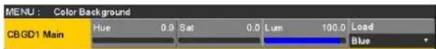
③ Use [F2], [F3] and [F4] to perform the color adjustments (Hue, Sat and Lum).
■ To call the preset color
Use [F5] to select the preset color using the Load item, and press the [F5].
- When [F5] is pressed, what has been set so far is canceled and replaced with the preset color values.
- To save the values that were set before calling the preset color, refer to "1-10. Memory".
1-8-2. Setting the Wash effect
The gradation effect for color backgrounds can be set.
Selecting the Wash effect and setting the colors
① Press the EKGDB button to light its indicator, and display the Color Background menu.
② Use [F1] to display the CBGD1 Wash sub menu (or CBGD2 Wash sub menu).
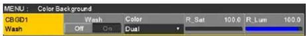
③ Use [F2] to set the Wash (gradation) effect using the Wash item.
| On The gradation effect is added. |
| Off The gradation effect is not added. |
④ Use [F3] to set the color of the Wash (gradation) effect using the Color item.
| Dual A dual-co | or gradation effect is added.(This results in a gradation of two colors,namely, the CBGD1 Main color and theCBGD1 Sub color.) |
| Rainbow The rainbow color gradation effect is added. | |
⑤ When "Dual" has been selected, use [F1] to display the CBGD1 Sub sub menu (or CBGD2 Sub sub menu), and set the sub color.
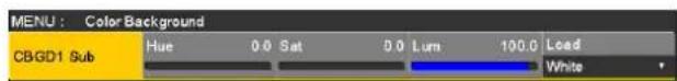
⑥ Use [F2], [F3] and [F4] to adjust the colors (Hue, Sat and Lum).
1. Basic operations
Adjusting the Wash waveforms
① On the Color Background menu, use [F1] to display the CBGD1 Wave sub menu (or CBGD2 Wave sub menu).
| MENU : Color Background | ||||||
| CBGD1 | Pattern | Cycle | 0 | Phase | 0.0 | Angle 0.0 |
| Wave | Sine | |||||
② Use [F2] to select the gradation waveforms using the Pattern item.
| Sine Sine waves are selected. |
| Saw Sawtooth waves are selected. |
③ Use [F3] to select the gradation cycle using the Cycle item.
④ Use [F4] to select the gradation phase using the Phase item.
⑤ Use [F5] to select the gradation angle using the Angle item.
Setting the Wash movements
① On the Color Background menu, use [F1] to display the CBGD1 Move sub menu (or CBGD2 Move sub menu).
| MENU : Color Background | |||
| CB GD1 | Move | Speed | 1.0 |
| Move | Off | ||
② Use [F2] to set the gradation movement using the Move item.
| Off No movement is set. |
| Roll The gradations are scrolled. |
| Rotation The gradations are rotated. |
③ Use [F3] to set the movement speed using the Speed item.
1-9. Switching the AUX output
1-9-1. Selecting the AUX output materials
The output signals of the AUX buses (AUX1 to AUX4) can be selected.
① Press one of the [AUX1] to [AUX4] buttons among the AUX bus selector buttons. The selected button lights in amber.
② Press one of the AUX bus crosspoint buttons. The selected signal is output to the pressed [AUX1] to [AUX4] button.
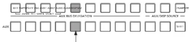
flowchart
graph TD
    A["KEY"] --> B["AUX"]
    C["INPUT"] --> D["AUX"]
    E["INPUT"] --> F["AUX"]
    G["INPUT"] --> H["AUX"]
    I["INPUT"] --> J["AUX"]
    K["INPUT"] --> L["AUX"]
    M["INPUT"] --> N["AUX"]
    O["INPUT"] --> P["AUX"]
    Q["OUTPUT"] --> R["AUX"]
    S["OUTPUT"] --> T["AUX"]
    U["OUTPUT"] --> V["AUX"]
    W["OUTPUT"] --> X["AUX"]
    Y["OUTPUT"] --> Z["AUX"]
    AA["OUTPUT"] --> AB["AUX"]
    AC["OUTPUT"] --> AD["AUX"]
    AE["OUTPUT"] --> AF["AUX"]
    AG["OUTPUT"] --> AH["AUX"]
    AI["OUTPUT"] --> AJ["AUX"]
    AK["OUTPUT"] --> AL["AUX"]
    AM["OUTPUT"] --> AN["AUX"]
    AO["OUTPUT"] --> AP["AUX"]
    AQ["OUTPUT"] --> AR["AUX"]
    AS["OUTPUT"] --> AT["AUX"]
    AU["OUTPUT"] --> AV["AUX"]
    AW["OUTPUT"] --> AX["AUX"]
    AY["OUTPUT"] --> AZ["AUX"]
    BA["OUTPUT"] --> BB["AUX"]
    BC["OUTPUT"] --> BD["AUX"]
    BE["OUTPUT"] --> BF["AUX"]
    BG["OUTPUT"] --> BH["AUX"]
    BI["OUTPUT"] --> BJ["AUX"]
    BK["OUTPUT"] --> BL["AUX"]
    BM["OUTPUT"] --> BN["AUX"]
    BO["OUTPUT"] --> BP["AUX"]
    BQ["OUTPUT"] --> BR["AUX"]
The button with the signals selected by AUX1 lights in amber.
| Name of signal Description of signal | |
| SDI IN1 to 8 SDI input signal 1 to 8 | |
| DVI IN DVI-D input signal | |
| INPUT A1, INPUT A2, INPUT B1, INPUT B2 | Input signal A1, Input signal A2, Input signal B1, Input signal B2 |
| PGM Program video signal | |
| PVW Preview video signal | |
| CLN Clean signal | |
| MV | Multi view display output signal |
| KeyOut | Key output signal |
| CBGD1, CBGD2 | Color background 1, 2 |
| CBAR | Color bar |
| Still1, Still2 | Video memory (still image) 1, 2 |
| Clip1, Clip2 | Video memory (moving image) 1, 2 |
| MEM-PVW | Memory preview video signals |
- When the AUX bus for which "MV" has been selected is displayed on the sub screen of the multi view display, the images are looped as if two mirrors were facing each other.
1-9-2. AUX1 transitions
The MIX transition is executed when the output signal set for AUX1 is switched.
① Press the [AUX1] button of the AUX bus selector buttons.
The selected button and its corresponding AUX bus crosspoint button light in amber.
② Press the AUX bus crosspoint button for the output signal to be switched to.
The MIX transition is now initiated for the length of the transition time that was set using the Time menu. While the transition is underway, the transition source AUX button lights in green, and the transition destination AUX button blinks in amber.
As soon as the transition is completed, the transition source AUX button goes off, and the transition destination AUX button lights in amber.
Furthermore, when another signal is selected at a midway point through a transition, the transition processing continues from that midway point.
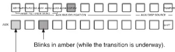
flowchart
graph TD
    A["KEY"] --> B["PHP1"]
    B --> C["PHP2"]
    C --> D["DISC"]
    D --> E["AUX1"]
    E --> F["AUXQ"]
    F --> G["AUX3"]
    G --> H["AUX4"]
    H --> I["DSP MV"]
    I --> J["□"]
    J --> K["□"]
    K --> L["□"]
    L --> M["□"]
    M --> N["□"]
    N --> O["□"]
    O --> P["□"]
    P --> Q["□"]
    Q --> R["□"]
    R --> S["□"]
    S --> T["□"]
    T --> U["□"]
    U --> V["□"]
    V --> W["□"]
    W --> X["□"]
    X --> Y["□"]
    Y --> Z["□"]
    Z --> AA["□"]
    AA --> AB["□"]
    AB --> AC["□"]
    AC --> AD["□"]
    AD --> AE["□"]
    AE --> AF["□"]
    AF --> AG["□"]
    AG --> AH["□"]
    AH --> AI["□"]
    AI --> AJ["□"]
    AJ --> AK["□"]
    AK --> AL["□"]
    AL --> AM["□"]
    AM --> AN["□"]
    AN --> AO["□"]
    AO --> AP["□"]
    AP --> AQ["□"]
    AQ --> AR["□"]
    AR --> AS["□"]
    AS --> AT["□"]
    AT --> AU["□"]
    AU --> AV["□"]
    AV --> AW["□"]
    AW --> AX["□"]
    AX --> AY["□"]
    AY --> AZ["□"]
    AZ --> BA["□"]
    BA --> BB["□"]
    BB --> BC["□"]
    BC --> BD["□"]
    BD --> BE["□"]
    BE --> BF["□"]
    BF --> BG["□"]
    BG --> BH["□"]
    BH --> BI["□"]
    BI --> BJ["□"]
    BJ --> BK["□"]
    BK --> BL["□"]
    BL --> BM["□"]
    BM --> BN["□"]
Lights in green.
1-9-3. Setting enable/disable for the AUX1 transition
The AUX1 transition time and transition enable/disable can be set.
① Press the TIME button to light its indicator, and display the Time menu.
② Use [F1] to display the AUX1 BUS Trans sub menu.

③ When the transition time is to be set in frame units, use [F4] for the setting.
④ When the transition time is to be set in second units, use [F3] to set the seconds and [F4] to set the frames.
Any time from 0 to 999f can be set. The time which can be set when seconds are used as the display unit differs depending on the system format.
| 59.94i: max. 33s09f 59.94p: max. 16s39f |
| 50i: max. 39s24f 50p: max. 19s49f |
| 24PsF: max. 41s15f 23.98PsF: max. 41s15f |
⑤ Use [F5] to set enable or disable for the transition using the Transition item.
| Enable Enable | |
| Disable Disable |
When disable has been set for the transition, the output signals are switched with no transition when the output signals set in AUX1 is switched.
1. Basic operations
1-10. Memory
■ Shot memories
The background transition pattern, PinP size, border width and other video effects can be registered in the memory and recalled. The memory used for this is referred to as a shot memory.
By setting effect dissolve, it is possible to ensure a smooth change of the switching from the current images to the images or operations registered in the shot memory.
■ Event memories
A multiple number of the video effects which can be registered in the shot memory can be registered and continuously played back while the current event and next event are interpolated to achieve the effect of a smooth transition. A group of these events are referred to as an event memory. Up to 64 events can be registered in one event memory.
- When operations such as playing are performed on event memories with a different system format to when the event memories were recorded, the operations will not be performed correctly.
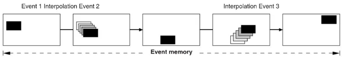
flowchart
graph LR
    A["Event 1 Interpolation Event 2"] --> B["Event memory"]
    B --> C["Interpolation Event 3"]
    C --> D["End"]
Up to a hundred shot memories and a hundred event memories can be registered.
The related operations are performed using the number keys.
Page 1 to page 10 can be specified for the page numbers of the memories.
Numbers 1 to 10 can be specified as the respective memory numbers for the specified page numbers.
Selecting the memory numbers
① Press the [SHOT MEM] or [EVENT MEM] button of the memory to be selected.
② Press the /+PAGE button.
The -/+ button indicator lights up, and the mode for specifying the memory page number is established.
The number key of the currently selected page lights in amber.
The number keys of the page numbers in which more than one memory is registered light in green.
The indicators of the number keys of page numbers in which no memories have been registered remain extinguished.
③ Press the number key (1 to 10) of the page number.
When the page number is determined, the /+PAGE button indicator goes off, and the mode for specifying the memory number is established.
If the page number is not going to be changed, press the /=PAGE button to turn off its indicator instead of pressing the number key. This establishes the mode for specifying the memory number.
④ Press the number key (1 to 10) corresponding to the memory number.
(Hold down the number key when specifying a memory number to register or delete the memory.)
1-10-1. Memory registration and recall items
| Applicable bus Material selection Transition Pattern Menu | ||||
| BKGD | PGM/A busPST/B bus | Fader amountWipe direction | BKGD patterns (MIX, WIPE) | BackgroundColor Background |
| Key | Key Fill busKey Source bus | Fader amountWipe direction | KEY patterns (MIX, WIPE) | KeyChroma Key |
| PinP1 | PinP1 bus PinP1 ON/OFF PinP1 | |||
| PinP2 | PinP2 bus PinP2 ON/OFF PinP2 | |||
1-10-2. Storing the settings in the memory (Store)
Images and operations to be registered can be set and then registered in the memories.
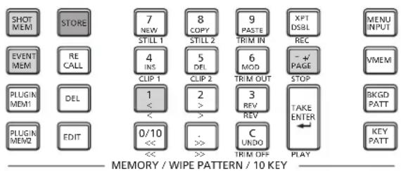
① Using the unit, set the images or operations to be kept in the memory.
② Press the [SHOT MEM] or [EVENT MEM] button of the memory in which the images or operations are to be registered.
Depending on the operation that was performed last, the [STORE] button, [RECALL] button, [DEL] button or [EDIT] button lights.
③ Select the bus (BKGD, KEY, PinP1 or PinP2) to be registered in the memory.
From the Shot Memory menu (or Event Memory menu), select the Store Select sub menu, and then select "On".
Refer to "1-10-1. Memory registration and recall items" and "1-10-6. Selecting the buses whose settings are to be registered and or played back".
④ When registering the BKGD (PGM/A or PST/B bus), KEY bus, PinP1 bus or PinP2 bus, set whether the "Material selection" item is to be stored.
From the Shot Memory menu (or Event Memory menu), select the XPT Disable sub menu, and then select "Off".
Refer to "1-10-1. Memory registration and recall items" and "1-10-7. Registering the material selection items".
⑤ Press the [STORE] button.
The [STORE] button indicator lights up, and the operations of other memory buttons — [EVENT MEM] (or [SHOT MEM]), [PLUGIN MEM1] and [PLUGIN MEM2] — no longer take effect.
⑥ Press the -/+ button, and press the number key (1 to 10) corresponding to the page number.
⑦ Hold down (for 2 seconds or so) the number key (1 to 10) corresponding to the number of the memory to be registered.
When the registration is completed, the number key corresponding to the memory number lights in green.
- The number keys whose indicators are lit in green have memories already registered in them. Delete the memory corresponding to the number key concerned, and register the new memory.
⑧ Repeat the above steps to register other kinds of settings in the memories.
1-10-3. Recalling the operations stored in the memory (Recall)
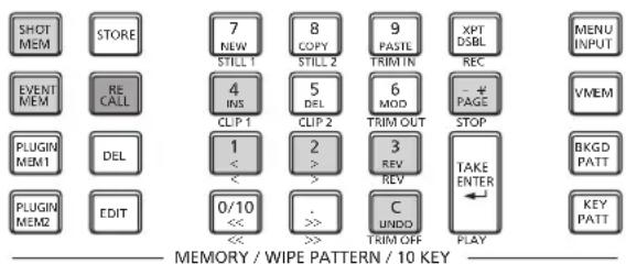
① Press the [SHOT MEM] or [EVENT MEM] button of the memory whose operations are to be recalled. Depending on the operation that was performed last, the [STORE] button, [RECALL] button, [DEL] button or [EDIT] button lights.
② Select the bus (BKGD, KEY, PinP1 or PinP2) to be recalled from the memory.
From the Shot Memory menu (or Event Memory menu), select the Recall Select sub menu, and then select "On".
Refer to "1-10-6. Selecting the buses whose settings are to be registered and or played back".
③ When selecting materials using the crosspoint buttons on the operation panel instead of using the registered "Material selection" item materials, press the [XPT DSBL] button to light its indicator in red.
Refer to "1-10-1. Memory registration and recall items".
④ Press the [RECALL] button.
The [RECALL] button indicator lights up, and the number key in which the memory is registered lights in green.
The operations of other memory buttons — [EVENT MEM] (or [SHOT MEM]), [PLUGIN MEM1] and [PLUGIN MEM2] — no longer take effect.
⑤ Press the -/+ button, and press the number key (1 to 10) corresponding to the page number.
⑥ Press the number key (1 to 10) corresponding to the number for the memory whose operations are to be recalled.
- In the case of a shot memory, the video effects are recalled, and playback starts.
During playback, the number key corresponding to the memory number blinks in green. - In the case of an event memory, the events are recalled, and playback starts.
During playback, the number key corresponding to the memory number blinks in green.
If there is a PAUSE event, playback pauses at that event, and the number key corresponding to the memory number blinks in amber.
Each time the number key corresponding to the memory number is pressed, playback or pause is selected alternately, and this selection is repeated.
⑦ When playback of the effects or events in the recalled memory number starts, the CUNDO button is enabled, and its indicator lights up. If this button is pressed during playback, playback is terminated.
1-10-4. Memory preview
The video effects in the shot memory or event memory can be output to the program signals after checking them using the memory preview bus (MEM-PVW).
① Press the SHOT EVENT button to light its indicator, and display the Shot Memory menu (or Event Memory menu).
② Use [F1] to display the MEM PVW sub menu.

③ Use [F2] to select "MEM-PVW" using the Mode item.
| PGM The video | effects are output to the program signals. |
| MEM-PVW The | video effects are first output to the memory preview bus (MEM-PVW) and then output to the program signals. |
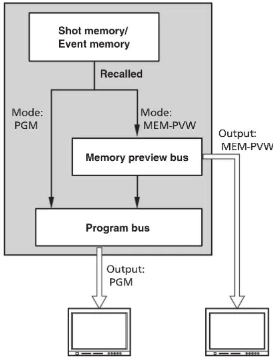
flowchart
graph TD
    A["Shot memory/Event memory"] -->|Recalled| B["Memory preview bus"]
    B --> C["Program bus"]
    C --> D["Output: MEM-PVW"]
    D --> E["Computer"]
    B -->|Mode: PGM| F["Computer"]
    C -->|Output: PGM| G["Computer"]
Program images Preview images
- The resolution of the images output from the memories is lower than normal.
Memory recall
① Press the [SHOT MEM] or [EVENT MEM] button of the memory whose video effects are to be recalled to select the memory.
(Press the button of the memory with the video effects for preview playback.)
Depending on the operation performed last, the indicator of the [STORE] button, [RECALL] button, [DEL] button or [EDIT] button lights up.
② Select the bus (BKGD, Key, PinP1 or PinP2) to be recalled from the memory.
From the Shot Memory menu (or Event Memory menu), select the Recall Select sub menu, and then select "On" or "Off".
Refer to "1-10-6. Selecting the buses whose settings are to be registered and or played back".
③ When selecting materials using the crosspoint buttons on the operation panel instead of using the registered "Material selection" item materials, press the [XPT DSBL] button to light its indicator in red.
Refer to "1-10-1. Memory registration and recall items".
④ Press the [RECALL] button.
The [RECALL] button indicator lights up, and the number key in which the memory is registered lights in green.
The operations of other memory buttons — [EVENT MEM] (or [SHOT MEM]), [PLUGIN MEM1] and [PLUGIN MEM2] — no longer take effect.
⑤ Press the -/+ button, and press the number key (1 to 10) corresponding to the page number.
Preview playback (output to the memory preview signals)
⑥ Press the number key (1 to 10) corresponding to the number for the preview playback memory.
The preview images are output to the memory preview bus (MEM-PVW).
- During preview playback, the number key corresponding to the memory number blinks in green. - If there is a PAUSE event, preview playback pauses at that event, and the number key corresponding to the memory number blinks in amber.
Each time the number key corresponding to the memory number is pressed, preview playback or pause is selected alternately, and this selection is repeated.
- When preview playback is completed, the indicators of the number key corresponding to the memory number and [TAKE/ENTER] button light in amber.
If the number key corresponding to the memory number is now pressed again, preview playback resumes.
Program output (output to the program signals)
⑦ For program output, press the [TAKE/ENTER] button.
- During output, the [TAKE/ENTER] button indicator blinks in green. - In the case of an event memory which contains a PAUSE event, the output pauses at that event, and the [TAKE/ENTER] button indicator blinks in amber. To resume the output, press the [TAKE/ENTER] button.
Each time the [TAKE/ENTER] button is pressed, output or pause is selected alternately, and this selection is repeated.
- When output is completed, the [TAKE/ENTER] button indicators lights in amber.
⑧ When program output is started, the C UNDO button takes effect, and its indicator lights up.
If the C UNDO button is pressed during output, playback is terminated.
| During preview playback | |||
| Button | During playback | Pause Stop | |
| Number key corresponding to memory numbers | Blinks (in green) | Blinks (in amber) | Lights (in amber) |
 | — | — | Lights (in amber) |
 | — — — | ||
| During program output | |||
| Button During output Pause Stop | |||
| Number key corresponding to memory numbers | Blinks (in green) | Blinks (in amber) | Lights (in amber) |
 | Blinks (in green) | Blinks (in amber) | Lights (in amber) |
 | Lights (in amber) | — | — |
1-10-5. Deleting the operations stored in the memory (Delete)
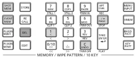
① Press the [SHOT MEM] or [EVENT MEM] button of the memory whose operations are to be deleted to select the memory.
The selected button lights in amber.
Depending on the operation that was performed last, the [STORE] button, [RECALL] button, [DEL] button or [EDIT] button lights.
② Press the [DEL] button.
The [DEL] button lights in red.
The button of the number key containing the stored operations lights in green.
- To change a page number, press the -/+ button, and press the number key (1 to 10) corresponding to the page number. Next, press the number key (1 to 10) corresponding to the number of the memory whose operations are to be deleted.
③ Hold down (for 2 seconds or so) the number key (1 to 10) corresponding to the number of the memory whose operations are to be deleted.
The button of the pressed number key goes off.
④ As soon as the stored operations are deleted, the button becomes operable and lights.
- If the button is pressed while the C UNDO button indicator is lit and the button was operable, the operation performed last is canceled.
1. Basic operations
1-10-6. Selecting the buses whose settings are to be registered and or played back
Selecting the buses for registering memories
Select the bus used for registering shot memories and event memories.
① Press the SHOT EVENT button to light its indicator, and display the Shot Memory menu (or Event Memory menu).
② Use [F1] to display the Store Select sub menu.
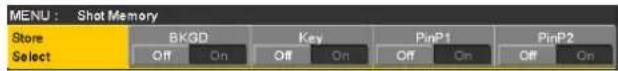
③ Use [F2] to set the BKGD item, [F3] to set the Key item, [F4] to set the PinP1 item, and [F5] to set the PinP2 item.
| On The bus settings are registered in the memories. |
| Off The bus settings are not registered in the memories. |
Selecting the buses for playing back memory settings
Select the bus used for playing back shot memory or event memory settings.
When the memory is played back, the settings of the registered bus are played back.
① Press the EVENT button to light its indicator, and display the Shot Memory menu (or Event Memory menu).
② Use [F1] to display the Recall Select sub menu.
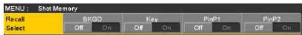
③ Use [F2] to set the BKGD item, [F3] to set the Key item, [F4] to set the PinP1 item, and [F5] to set the PinP2 item.
| On The bus settings are played back when the memory is played back.However, they will not be played back if they have not been registered in the memory. |
| Off The bus settings are not played back when the memory is played back. |
- When the SHOT EVENT button is pressed, the Shot Memory menu (or Event Memory menu) appears on the built-in display, and the information of the registered memories appears in the status area on the built-in display.
However, the information is not displayed when the [EDIT] button indicator is lit.
Page: 1 (1 to 10)
| No. | Name | EVENT | BKGD | Key | PinP1 | PinP2 | ||||
| SEL | XPT | SEL | XPT | SEL | XPT | SEL | XPT | |||
| 1-1 | SHOT001 | 1 | On | DSBL | On | DSBL | On | DSBL | On | DSBL |
| 1-2 | SHOT002 | 1 | On | DSBL | On | DSBL | On | DSBL | On | DSBL |
| 1-3 | SHOT003 | 1 | On | DSBL | On | DSBL | On | DSBL | On | DSBL |
| 1-4 | SHOT004 | 1 | On | DSBL | On | DSBL | On | DSBL | On | DSBL |
| 1-5 | SHOT005 | 1 | On | DSBL | On | DSBL | On | DSBL | On | DSBL |
| 1-6 | SHOT006 | 1 | On | DSBL | On | DSBL | On | DSBL | On | DSBL |
| 1-7 | SHOT007 | 1 | On | DSBL | On | DSBL | On | DSBL | On | DSBL |
| 1-8 | ||||||||||
| 1-9 | ||||||||||
| 1-10 | ||||||||||
1. Basic operations
1-10-7. Registering the material selection items
Set whether or not to register the "Material selection" items of the buses.
Refer to "1-10-1. Memory registration and recall items".
① Press the SHOT EVENT button to light its indicator, and display the Shot Memory menu (or Event Memory menu).
② Use [F1] to display the XPT Disable sub menu.
| MENU: Shot Memory | |||||||
| XPT Disable | BKGD | Key | PinP1 | PinP2 | |||
| Off | On | Off | On | Off | On | Off | |
③ Use [F2] to set the BKGD item, [F3] to set the Key item, [F4] to set the PinP1 item, and [F5] to set the PinP2 item.
| Off The “Material selection” items are not registered in the memories. |
| On The “Material selection” items are registered in the memories. |
- When the [XPT DSBL] button is pressed, its indicator lights in red.
The materials of the "Material selection" items registered in the buses are canceled.
1-10-8. Setting effect dissolve (shot memory)
Switching from the current image to the image or operation stored in the shot memory can be performed smoothly.
① Press the SHOT EVENT button to light its indicator, and display the Shot Memory menu.
② Use [F1] to display the Path sub menu.
| MENU: Shot Memory | ||||
| Path | Effect | PinP Bus | Hue Path | |
| Dissolve | Dissolve | Short | ||
③ Use [F2] to set the effect used for switching the images using the Effect item.
| Dissolve The images are switched using the dissolve effect. |
| Cut The images are switched using the cut effect. |
- The dissolve effect duration is set in the Effect Dissolve sub menu which is selected in the Time menu.
④ Use [F3] to set the PinP bus transition using the PinP Bus item.
| Dissolve The PinP bus images are switched using the dissolve effect. |
| Cut The PinP bus images are switched using the cut effect. |
⑤ Use [F4] to select the effect used for switching the colors using the Hue Path item.
The following colors are targeted by Hue.
• Colors of the color background
- Colors of the borders
- Colors of the edges
- Colors of the fill matte
| Short The colors are changed toward less hue on the vectorscope. |
| Long The colors are changed toward more hue on the vectorscope. |
| CW The Hue is changed clockwise on the vectorscope. |
| CCW The Hue is changed counterclockwise on the vectorscope. |
- Pressed number keys blink in green while the operation switching is underway.
- When the operation switching has been completed, the pressed number key lights in amber.
- When the Effect item is changed from "Dissolve" to "Cut" while operation is being switched, the dissolve effect is released, and the images are switched to the images of the selected shot memory in an instant.
- When the PinP Bus item is changed from "Dissolve" to "Cut" while operation is being switched, the dissolve effect is released, and the PinP images are instantly switched to the PinP images of the selected shot memory.
- During the operation switching, the operation of the fader lever is canceled.
- During the operation switching, other stored operations cannot be recalled.
- When initiating PinP1/2 transitions, the switching process is not stored in the memory.
1-10-9. Editing event memory timelines
Insertion or modification of the events can be edited on the timelines.
Timeline
A timeline is a succession of events in the event memories which have been joined together on the time axis.
■ Event points and edit points
On a timeline, the position where an event has been registered is called the event point, and the event currently being edited is called the current event memory.
When there is an edit point between one event point and another, the event point before the edit point serves as the current event memory.
(Event "n" in the figure below)
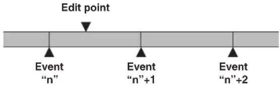
■ Event duration and total duration
The length of time as far as the next event is called the event duration.
The total of all the event durations is called the total duration. The present point in time on the timeline is called the current time.
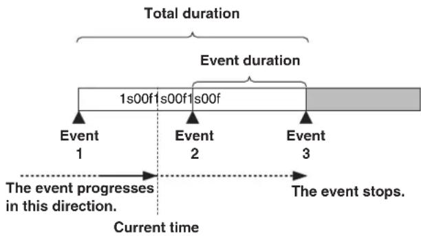
flowchart
graph TD
    A["Total duration"] --> B["Event duration"]
    B --> C["1s00f1s00f1s00f"]
    C --> D["Event 1"]
    C --> E["Event 2"]
    C --> F["Event 3"]
    G["Current time"] --> H["The event progresses in this direction."]
    H --> I["The event stops."]
Timeline editing flow
■ Modifying registered event memories
① Press the [EVENT MEM] button and light its indicator.
[EVENT MEM] button
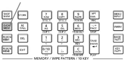
② Press the [RECALL] button to light its indicator, and use the PAGE button and number keys (1 to 10) to select the event memory to be modified.
Refer to "1-10-3. Recalling the operations stored in the memory (Recall)".
③ Press the [EDIT] button to establish the editing mode. (At this point, the timeline of the selected event memory is copied into the work area.) The timeline appears on the built-in display, and events can be inserted or modified.
④ Edit the timeline, and check what has been edited.
Refer to the operations described later.
⑤ Register the event memory which has been modified.
Refer to "1-10-2. Storing the settings in the memory (Store)".
■ Creating a new timeline
When this operation is performed, the timeline currently in the work area is deleted.
If it is required, register it in the event memory.
① Press the [EVENT MEM] button and light its indicator.
② Press the [EDIT] button to light its indicator, and press 7 NEW.
③ Create the new timeline.
Refer to the operations described later.
④ Register the event memory which has just been created.
Refer to "1-10-2. Storing the settings in the memory (Store)".
The timeline is edited in the work area.
After editing is completed, be absolutely sure to register which has been edited.
1. Basic operations
Setting the playback method
■ Setting the playback mode
① Press the [EVENT MEM] button and light its indicator. [EVENT MEM] button
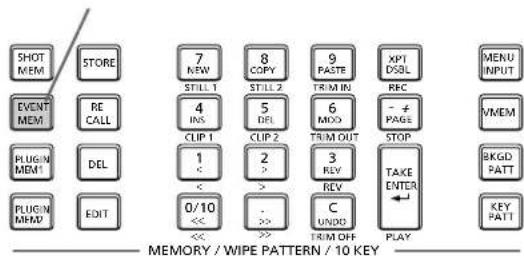
② Press the [EDIT] button to establish the editing mode.
③ Press the SHOT EVENT button to display the Event Memory menu.
④ Use [F1] to display the Run sub menu.

⑤ Use [F2] to set the playback mode using the Run Mode item.
| Repeat During | normal playback, playback stops at the last event, and if the [TAKE ENTER] button is now pressed, the images are played back in the same direction.During reverse playback^ , playback stops at the first event, and if the [TAKE ENTER] button is now pressed, the images are played back in the same direction. |
| Loop During normal playback, playback returns instantly from the last event to the first event, and what has been played back is repeated.During reverse playback^ , playback returns instantly from the first event to the last event, and what has been played back is repeated. | |
*: This function can be actuated in any model whose system version is V2.00.00 and up. Reverse playback cannot be performed in a model with a system version of below V2.00.00.
■ Setting the display mode
① Press the SHOT EVENT button to display the Event Memory menu.
② Use [F1] to display the Timeline sub menu.

③ Use [F2] to set the timeline display mode using the View item.
| Normal The timeline is displayed in a size which is one-half of the width of the built-in display screen. |
| Wide The timeline is displayed in the full size (as large as the entire width) of the built-in display screen. |
1. Basic operations
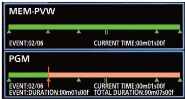
A green “△” below the timeline indicates an event point.
A green "II" indicates that "PAUSE" has been set for an event point.
If an edit point is over an event point, “△” or “||” for the event point is indicated in amber.
When "CLIP" (Clip1, Clip2) has been registered in an event, "▶" appears above the event point.
Similarly, when "GPI-Out" (GPI-O1 to GPI-O19) has been registered in an event, "Z" appears above the event point.
The timeline axis is indicated in green from the start event to the end event.
During playback, the part from the beginning to the current position is indicated in red.
Similarly, during reverse playback, the part from the end to the current position is indicated in red.
■ Number key operations
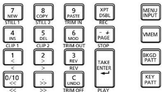
MEMORY / WIPE PATTERN / 10 KEY
 | Creates a new timeline. |
 | Copies events.An event is not copied if an edit point is not over the event. |
 IKIM IN IKIM IN | Pastes the copied events.If the edit point is an event point, the event is inserted after the event point.If the edit point is at any midway position in an event, the event is inserted at the edit point. |
 | Inserts events.If the edit point is an event point, the event is inserted after the event point.If the edit point is at any midway position in an event, the event is inserted at the edit point. |
 | Deletes events. |
 | Modifies events.This key cannot be operated if the edit point is not over the event point. |
 | Moves to the start event point. |
 | Moves to the end event point. |
 | Moves to the next event point. |
 | Moves to the previous event point. |
 | Reverses the playback direction (event numbers are put in their reverse sequence). |
 | Undoes the editing operation of the event.When the button is pressed, the operation performed last is canceled. |
 | Plays back events.When this button is operational, its indicator lights in amber.Each time it is pressed, operation is switched between playback and pause.During playback, its indicator blinks in green; during pause, it blinks in amber. |
1. Basic operations
Inserting events (Insert)
The current setting status can be inserted as an event after the current event memory.
When an event is inserted, the numbers of the events after the current event memory are each moved up by one.
① Use 0/10, 1, 2 and >> to select the event point (current event memory) which is to be inserted. To insert the event at a midway point of an event, play back the event to the place where the event is to be inserted, and stop the edit point.
② Operate the panel, and create the event.
③ Press 4 INS to insert the created event.
To cancel the event insertion, press the C UNDO button.
- When the number of events on the timeline has reached 64, no further events can be inserted.
- When the edit point is over the event point, the newly created event is inserted with the same duration as the current event memory.
- If the edit point is between one event point and another, the current event memory is split at the edit point position, and the newly created event is inserted.
Modifying events (Modify)
Already registered events can be modified.
① Use 0/10, 1, 2 and × to select the event point of the event to be modified.
② Operate the panel, and modify the event.
③ Press 6
to enter what has been modified.
To cancel the event modification, press the C
button.
Copying events (Copy)
Already registered events can be copied.
① Use 0/10, 1, 2 and ≈ to select the event point of the event to be copied.
② Press 8 COPY to copy the event.
Pasting events (Paste)
Copied events can be pasted.
① Use 0/10 , 1 , 2 and 3> to select the event point where the copied event is to be inserted.
To insert the copied event between one event point and another, play back the event to the place where the copied event is to be inserted, and stop the playback.
② Press 9 PASTR to paste the copied event.
To cancel the event pasting, press the C UNDO button.
- When the number of events on the timeline has reached 64, no further events can be inserted.
- When the edit point is over an event point, the copied event is inserted with the same duration as the current event memory.
- If the edit point is between one event point and another, the current event memory is split at the edit point position, and the copied event is inserted.
Deleting events (Delete)
Already registered events can be deleted.
① Use 0/10 , 1 , 2 and ··· to select the event point of the event to be deleted.
② Press 5 DEL to delete the event.
To cancel the event deletion, press the C UNDO button.
- Even if the edit point is midway through an event, the current event memory will be deleted.
Undoing what has been edited (Undo)
When the C UNDO button is pressed, the operation performed last is canceled.
1. Basic operations
Setting events using the menus
■ Registering marks
Marks can be registered and events inserted at the event points.
- Pause
- Clip playback
- GPI-Out output
① Use 0/10, 1, 2 and > to select the event where the mark is to be registered or the event inserted.
② Press the SHOT EVENT button to display the Event Memory menu.
③ Use [F1] to display the Mark sub menu.

④ Use [F2] (PAUSE item), [F3] (CLIP item) or [F4] (GPI-Out item) to select the item.
| PAUSE When | "On" is selected and the mark is registered in the event point, playback is paused at the mark position during event playback."||" appears above the timeline. |
| CLIP When "CI | p1" or "Clip2" is selected and the mark is registered in the event point, the clip is played back at the mark position during event playback."▶" appears above the timeline. |
| GPI-Out When | a GPI output port from "GPI-O1" to "GPI-O19" is selected and the mark is registered in the event point, pulse signals are output from the GPI Output port at the mark position during event playback."Z" appears above the timeline.For the Config menu → GPI-Out Port 1/5 sub menu to GPI-Out Port 5/5 sub menu → Assign item, check that the selected GPI output port is set to "Event MEM". |
⑤ Press 5 MOD to register the mark. In addition, press 4 INS to insert the event. To cancel the mark registration or event insertion, press the UNDO button.
■ Setting the event duration
The lengths of the events can be set.
① Use 0/10, 1, 2 and >> to select the event to be modified.
② Press the SHOT EVENT button to display the Event Memory menu.
③ Use [F1] to display the Event Duration sub menu.

④ Use [F2] (minute item: minutes), [F3] (second item: seconds) and [F4] (frame item: frames) to set the event length.
⑤ Press [F5] to enter the duration.
To cancel what has been modified, press the C UNDO button.
■ Setting the total duration
The total length of all the events from start to end can be set. When the total duration is changed, the durations of the events contained in the event memories are re-calculated using the duration ratio prior to the change.
However, the shortest duration of an event cannot be shorter than one frame.
① Press the [EVENT MEM] button and light its indicator.
② Press the [RECALL] button to light its indicator, and use the -14 button and number keys (1 to 10) to select the event memory to be modified.
Refer to "1-10-3. Recalling the operations stored in the memory (Recall)".
③ Press the SHOT EVENT button to display the Event Memory menu.
④ Use [F1] to display the Total Duration sub menu.

⑤ Use [F2] (minute item: minutes), [F3] (second item: seconds) and [F4] (frame item: frames) to set the event length.
⑥ Press [F5] to enter the duration.
- If no more events can be contained in the total duration which already has many events and which has been changed, the number of frames will be forcibly adjusted.
1. Basic operations
■ Setting the event switching effect (Path)
Switching from one event to another (bus switching) can be accomplished smoothly.
① Press the SPOT EVENT button to light its indicator, and display the Event Memory menu.
② Use [F1] to display the Path sub menu.
| MENU : Event Memory | ||||
| Path | Effect | PinP Bus | Trans Path | Hue Path |
| Dissolve | Dissolve | Linear | CW | |
③ Use [F2] to set the effect to be used for switching images using the Effect item.
| Dissolve The images are switched using the dissolve effect. |
| Cut The images are switched using the cut effect. |
- The dissolve effect duration is set in the Effect Dissolve sub menu which is selected on the Time menu.
④ Use [F3] to set the PinP bus transition using the PinP Bus item.
| Dissolve The PinP bus images are switched using the dissolve effect. |
| Cut The PinP bus images are switched using the cut effect. |
⑤ Use [F4] to select the path to be used for switching the images using the Trans Path item.
The following transitions are targeted.
• Width of the borders
- Soft effect of the borders
- Colors of the borders
- Positions of the images
- Trimming values
| Linear The switching from one image to another is interpolated linearly. |
| Step The parameters are updated when the events are passed through. |
⑥ Use [F5] to select the effect when the colors are switched using the Hue Path item. The following hues are targeted.
• Colors of the color background
- Colors of the borders
- Colors of the edges
• Colors of the fill matte
| Short The colors are changed toward less hue on the vectorscope. |
| Long The colors are changed toward more hue on the vectorscope. |
| CW The Hue is changed clockwise on the vectorscope. |
| CCW The Hue is changed counterclockwise on the vectorscope. |
| Step The color changes are updated when an event is passed through. |
1. Basic operations
1-10-10. Registering memories (Register)
Shot memories and event memories can be registered. Information on the memories is displayed in the status area of the built-in display, and names can be changed or copied.
① Press the SHOT EVENT button to light its indicator, and display the Shot Memory menu (or Event Memory menu). The information of the memories is now displayed in the status area of the built-in display.
② Use [F1] to display the Register sub menu.

Changing the names of the memories
The names (up to 16 characters) of the memories can be changed.
① On the Register sub menu, use [F2] to select the page number of the registered memories using the Page item.
② Use [F3] to select the memory number using the No. item.
③ Use [F4] to display the keyboard screen.
④ Use [F1] to [F3] to input the name, and press [F4]. To cancel the name which has been input and close the keyboard screen, press [F5].
Refer to "2-2-2. Keyboard screen operations" (
Copying memories
Memories can be copied.
To register a copied memory, select a number which has not been registered for any other memory.
① On the Register sub menu, use [F2] to select the page number of the registered memories using the Page item.
② Use [F3] to select the memory number using the No. item.
③ Use [F5] to select the number of the memory to which the memory will be copied, and press [F5].
1. Basic operations
1-11. Video memories
This unit can be used to store still image memories (Still) and moving image memories (Clip), each in two channels.
- Images with key signals can be stored in the video memories (still images and moving images).
- Images of up to 600 frames (20 seconds with the 59.94i format) can be stored in the moving image memories per channel in the standard mode, and images up to 300 frames (10 seconds with the 59.94i format) can be stored in the high-image-quality mode.
- The size of the images (number of seconds) which can be stored depends on the system format (frame rate).
- The video memory data can be stored onto, and read out from, memory cards.
There are some differences in the operations which can be performed depending on whether the system version of the model is V2.00.00 and up or under V2.00.00.
• Models whose system version is below V2.00.00
| Video memory operation | Current status | ||||||
| Clip1 Clip2 | |||||||
| Recording | Playback Stop | Recording Playback Stop | |||||
| Still1 | Recording — | — | √ | — | — | √ | |
| Still2 | Recording — | — | √ | — | — | √ | |
| Clip1 | Recording — | — | √ | ||||
| Playback | —— | √ | |||||
| Stop | √ | √ | √ | ||||
| Clip2 | Recording — | — | √ | ||||
| Playback | —— | √ | |||||
| Stop | √ | √ | √ | ||||
√: Valid —: Invalid
• Models whose system version is V2.00.00 and up
| Video memory operation | Current status | ||||||
| Clip1 Clip2 | |||||||
| Recording | Playback Stop | Recording Playback Stop | |||||
| Still1 | Recording — | √ | √ | — | √ | √ | |
| Still2 | Recording — | √ | √ | — | √ | √ | |
| Clip1 | Recording — | √ | √ | ||||
| Playback | √ | √ | √ | ||||
| Stop | √ | √ | √ | ||||
| Clip2 | Recording | — | √ | √ | |||
| Playback | √ | √ | √ | ||||
| Stop | √ | √ | √ | ||||
√: Valid —: Invalid
■ Video memory input/output
The image input materials can be selected from the output signals of the AUX buses (AUX1 to AUX4).
The key materials can be input from the KeyOut output signals.
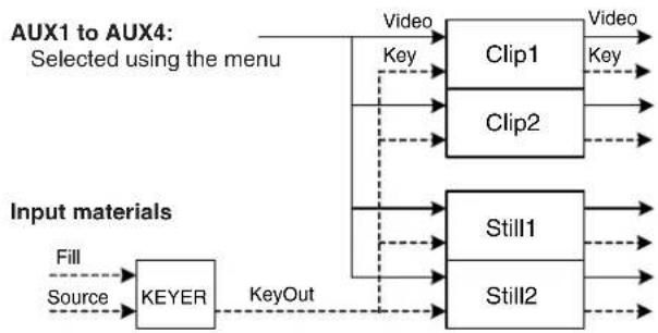
flowchart
graph TD
    A["Input materials"] --> B["KEYER"]
    B --> C["Fill"]
    B --> D["Source"]
    B --> E["KeyOut"]
    F["Video"] --> G["Clip1"]
    F --> H["Clip2"]
    F --> I["Still1"]
    F --> J["Still2"]
    G --> K["Video"]
    H --> L["Key"]
    I --> M["Key"]
    J --> N["Key"]
    style A fill:#f9f,stroke:#333
    style B fill:#ccf,stroke:#333
    style F fill:#cfc,stroke:#333
    style G fill:#fcc,stroke:#333
    style H fill:#fcc,stroke:#333
    style I fill:#fcc,stroke:#333
    style J fill:#fcc,stroke:#333
    style K fill:#cff,stroke:#333
    style L fill:#cff,stroke:#333
    style M fill:#cff,stroke:#333
    style N fill:#cff,stroke:#333
1. Basic operations
1-11-1. Recording still images (Still)
① Press the VMEM button to light its indicator, and display the Video Memory menu.
② Use [F1] to display the Video Memory3 sub menu.
| MENU:Video Memory | |||||
| Video | Total Time | Current Time | Key | Rec Lock | |
| Memory3 | 00s01f | 00s01f | Off | Off | On |
③ Use [F5] to select "Off" using the Rec Lock item.
- When the unit's power has been turned back on after it was turned off, the Rec Lock item setting is restored to "On".
④ Use [F1] to display the Video Memory1 sub menu.
| MENU:Video Memory | ||||
| Video | Select | Rec | Play | Stop |
| Memory 1 | Still | Execute | Execute | Execute |
⑤ Use [F2] to select "Still1" or "Still2" using the Select item.
⑥ Use [F1] to display the Rec1 sub menu.
| MENU:Video Memory | |||||||
| Rec1 | Preview | V Source | Key Enable | Review | |||
| Off | On | AUX 1 | Off | On | Off | On | |
⑦ Use [F2] to set the images to appear on the built-in display using the Preview item.
| On The image | appearing on the built-in display is forcibly switched to the image to be recorded (AUX1 to AUX4 selected using the V Source item) instead of the material selected by the DISP bus. |
| Off The image | source selected by the DISP bus is displayed as a preview. |
⑧ Use [F3] to set the image to be recorded in the video memory using the V Source item.
| AUX1 to AUX4 | The output signals of the AUX buses (AUX1 to AUX4) are recorded as the material. |
⑨ Use [F5] to set the review display using the Review item.
| On After the images have been recorded, theimages of the video memory recorded in theAUX bus are displayed (for 2 seconds or so).The next images can be recorded evenduring review display. |
| Off The reviewing display is not shown. |
⑩ Use [F1] to display the Video Memory1 sub menu.
| MENU:Video Memory | ||||
| VideoMemory 1 | SelectStill | RecExecute | PlayExecute | StopExecute |
⑪ As soon as [F3] (Rec) is pressed, the still images are recorded.*
*: This function can be actuated in any model whose system version is V2.00.00 and up. These operations cannot be performed in a model with a system version of below V2.00.00.
- If the [VMEM] button on the right of the number keys is pressed and the video memory operation mode has been established, the operation of this button is linked with the [XPT/DSBL] button among the number keys.
- When the recording of the still images is completed, thumbnails of the still images are displayed in the thumbnail screen.
1. Basic operations
1-11-2. Recording moving images (Clip)
① Press the VMEM button to light its indicator, and display the Video Memory menu.
② Use [F1] to display the Video Memory3 sub menu.
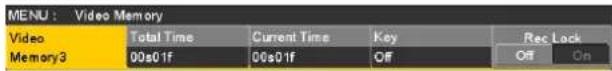
③ Use [F5] to select "Off" using the Rec Lock item.
- When the unit's power has been turned back on after it was turned off, the Rec Lock item setting is restored to "On".
④ Use [F1] to display the Video Memory1 sub menu.

⑤ Use [F2] to select "Clip1" or "Clip2" using the Select item.
⑥ Use [F1] to display the Rec1 sub menu.

⑦ Use [F2] to set the images to appear on the built-in display using the Preview item.
| On The image | appearing on the built-in display is forcibly switched to the image to be recorded (AUX1 to AUX4 selected using the V Source item) instead of the material selected by the DISP bus. |
| Off The image | source selected by the DISP bus is displayed as a preview. |
⑧ Use [F3] to set the image to be recorded in the video memory using the V Source item.
| AUX1 to AUX4 | The output signals of the AUX buses (AUX1 to AUX4) are recorded as the material. |
⑨ Use [F5] to set the review display using the Review item.
| On After the images have been recorded, theimages of the video memory recorded in theAUX bus are displayed (for 2 seconds or so). | |
| Off The review display is not shown. |
⑩ Use [F1] to display the Rec2 sub menu.
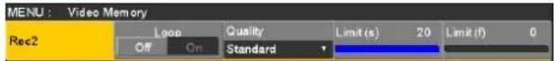
⑪ Use [F2] to select the recording repeat setting using the Loop item.
| On The recording of the images is continued until the stop operation is performed.If either of the following operations is performed while recording is in progress, the images are recorded up to the last frame, after which recording stops.When “Off” is selected as the Loop item setting.When [Stop] ([F5] of Video Memory sub menu) is pressed. | |
| Off Images are | recorded up to the maximum recording time (set using the Limit items), after which recording stops automatically. |
⑫ Use [F3] to set the quality of the images to be recorded using the Quality item.
| Standard Standard image qualityMaximum 600 frames(20 seconds with 59.94i format) |
| High High image qualityMaximum 300 frames(10 seconds with 59.94i format) |
⑬ Use [F4] to set the maximum recording time using the Limit item.
⑭ Use [F1] to display the Video Memory1 sub menu.

⑮ As soon as [F3] (Rec) is pressed, the recording of the moving images starts.
⑯ When [F5] (Stop) is pressed, the recording of the moving images is stopped.*
*: This function can be actuated in any model whose system version is V2.00.00 and up. These operations cannot be performed in a model with a system version of below V2.00.00.
- If the [VMEM] button on the right of the number keys is pressed and the video memory operation mode has been established, the operation of this button is linked with the -/+ button among the number keys.
- Thumbnails of moving images are displayed on the thumbnail screen.
While the thumbnails are displayed, the following information is also displayed on the thumbnail screen.
Current playback position (time), IN point position, OUT point position
- With the moving images on which the key signals are recorded, a yellow “○” mark is displayed for the thumbnail icons.
- The recording time is displayed in the Total Time item of the Video Memory3 sub menu.
Also, "On" is displayed for the Key item when the key signals have been recorded.
1-11-3. Saving Images in Flash Memory ✱
*: This function can be actuated in any model whose system version is V2.00.00 and up. These operations cannot be performed in a model with a system version of below V2.00.00.
Data for images stored in the video memory can be retained even when the power is turned off, by saving them in the flash memory area.
Whether to automatically save the image data stored in the video memory when the data is transferred from the AUX bus or to manually save them must be set.
Care must be taken when selecting manual saving, as image data stored in the video memory will be lost if the power is turned off before the saving operation is completed.
① Press the WELM button to light its indicator, and display the Video Memory menu.
② Use [F1] to display the Memory sub menu.
| MENU:Video Memory | ||||
| Memory | Mode | Select | Save | |
| Auto | ALL | Execute | ||
③ Use [F2] to select the saving method using the Mode item.
| Auto Automatic saving | |
| Manual Manual saving |
④ Use [F3] to select the video memory for saving data in the flash memory area using the Select item.
When "All" has been selected, all the video memories are saved.
⑤ Press the [F5] (Save) to save data in the flash memory area.
- The [F5] (Save) becomes enabled when "Manual" is selected in the Mode item.
-
When, in the case of the settings below, [Stop] ([F5] of the Video Memory sub menu) is pressed while video memory recording is in progress, the video memories are saved in the flash memory area immediately after [Stop] has been pressed.
-
Memory sub menu "Mode" item: "Auto"
- Rec2 sub menu "Loop" item: "On"
However, if the power is cut off during recording, the video memories will not be saved in the flash memory area.
1. Basic operations
1-11-4. Playing back moving images (Clip)
Establishing the playback mode
① Press the 📊VMLM button to light its indicator, and display the Video Memory menu.
② Use [F1] to display the Clip1 Play Mode sub menu (or Clip2 Play Mode sub menu).
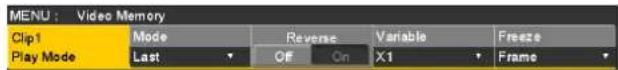
③ Use [F2] to select the playback mode using the Mode item.*
*: This function can be actuated in any model whose system version is V2.00.00 and up. These operations cannot be performed in a model with a system version of below V2.00.00.
| Lead Operation | returns to the start frame after playback. |
| Last Operation | stops at the end frame after playback. |
| Loop The end | frame and start frame are joined together and played back repeatedly. |
④ Use [F3] to select reverse playback using the Reverse item.
*: This function can be actuated in any model whose system version is V2.00.00 and up. These operations cannot be performed in a model with a system version of below V2.00.00.
| On The moving | images are played back in the reverse direction. |
| Off The moving | images are played back in the forward direction. |
- When the [VMEM] button on the right of the number key is pressed and the video memory operation mode has been established, the operation of this button is linked with the 3 REV button among the number keys.
⑤ Use [F4] to select the speed for variable speed playback using the Variable item.
$$ \begin{array}{l} \text {Speeds which can be selected:} \ \times 1 / 8, \times 1 / 4, \times 1 / 2, \times 1, \times 2, \times 4, \times 8 \end{array} $$
⑥ Use [F5] to select the image when operation is stopped using the Freeze item.
| Frame A frame image is played back. |
| Field A field image is played back. |
⑦ Use [F1] to display the Trans Sync sub menu:*
*: This function can be actuated in any model whose system version is V2.00.00 and up. These operations cannot be performed in a model with a system version of below V2.00.00.
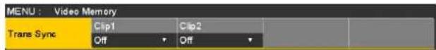
⑧ Use [F2] and [F3] to set the control button used for playing back moving images in tandem with the transition operation.
Use [F2] (Clip1 item) to set the Clip1 playback start button, and use [F3] (Clip2 item) to set the Clip2 playback start button.
*: This function can be actuated in any model whose system version is V2.00.00 and up. These operations cannot be performed in a model with a system version of below V2.00.00.
| Off Playback is | not performed in tandem with the transition operation. |
| KEY ON The p | playback of the moving images is started in tandem with the operation of the [KEY ON] button. |
| PinP1 ON | The playback of the moving images is started in tandem with the operation of the [PinP1 ON] button. |
| PinP2 ON | The playback of the moving images is started in tandem with the operation of the [PinP2 ON] button. |
| DSK ON | The playback of the moving images is started in tandem with the operation of the [DSK ON] button. |
| FTB ON | The playback of the moving images is started in tandem with the operation of the [FTB ON] button. |
Playing back the moving images
① Press the 📄WAFM 📁 button to light its indicator, and display the Video Memory menu.
② Use [F1] to display the Video Memory1 sub menu.
| MENU:Video Memory | ||||
| VideoMemory1 | Select | Rec | Play | Stop |
| Still | Execute | Execute | Execute | |
③ Use [F2] to select Clip1 or Clip2 using the Select item.
④ When [F4] (Play) is pressed, playback of the moving images is started.*
*: This function can be actuated in any model whose system version is V2.00.00 and up. These operations cannot be performed in a model with a system version of below V2.00.00.
- When the [VMEM] button on the right of the number key is pressed and the video memory operation mode has been established, the operation of this button is linked with the [TAKE/ENTER] button among the number keys.
- The current playback position (time) is displayed for the Current Time item on the Video Memory3 sub menu.
1. Basic operations
Moving to the first frame or last frame
① Press the 📄VMLM button to light its indicator, and display the Video Memory menu.
② Use [F1] to display the Video Memory2 sub menu.
| MENU:Video Memory | ||||
| VideoMemory2 | LEAD | LAST | ||
| Execute | Execute | |||
③ When [F2] (LEAD) is pressed, the current position is moved to the first (head) frame; conversely, when [F3] (LAST) is pressed, the current position is moved to the last frame.
- When the [VMEM] button located on the right of the number keys is pressed and the video memory operation mode has been established, the operation of number keys 0/10 and become linked.*
-: This function can be actuated in any model whose system version is V2.00.00 and up. These operations cannot be performed using the number keys with models whose system version is below V2.00.00.
Trimming moving images
The position where the playback of the moving images is to start (IN point) and the position when it is to end (OUT point) can be set.
① Press the [VMEM] button on the right of the number keys to establish the video memory operation mode.
② Use the number keys to stop the moving images at the position where the images are to be trimmed (IN point or OUT point).
③ Trim the moving images by operating the buttons below.
| 9PASTETRIM IN | Sets the trimming IN point. |
| 6MODTRIM OUT | Sets the trimming OUT point. |
| CUNDDTRIM OFF | Releases the trimming settings. |
- The trimmed moving images are played back from the IN point to the OUT point, however you can move anywhere in the section from the start point to the end point of the recorded moving images by operating 1 <, 2 >, 0/10 << and >>.
- Trimming can be set and released over and over again until the moving images are stored on the memory card.
- When the moving images are saved on an memory card, only the trimmed parts are saved and the parts no longer required are deleted.
■ Operations performed using the number keys\*
-: This function can be actuated in any model whose system version is V2.00.00 and up. These operations cannot be performed using the number keys with models whose system version is below V2.00.00.
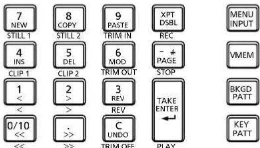
MEMORY / WIPE PATTERN / 10 KEY
| Selects Still1 as the operation target. | |
| Selects Still2 as the operation target. | |
| Selects Clip1 as the operation target. | |
| Selects Clip2 as the operation target. | |
| Sets the trimming IN point. | |
| Sets the trimming OUT point. | |
| Releases the trimming settings. | |
| Plays back the moving images one frame at a time in the reverse direction. | |
| Plays back the moving images one frame at a time in the forward direction. | |
| Sets the playback direction to reverse.(Button indicator lights: reverse direction; indicator off: forward direction) | |
| Transfers to the start frame of the moving images, and stops. | |
| Transfers to the end frame of the moving images, and stops. | |
| Plays back the moving images. | |
| Starts recording the moving images. | |
| Stops the recording or playback of the moving images. |
1. Basic operations
Displaying thumbnails\*
*: This function can be actuated in any model whose system version is V2.00.00 and up. These operations cannot be performed in a model with a system version of below V2.00.00.
- When the [VMEM] button located on the right of the number keys is pressed and the video memory operation mode has been established, thumbnails of the images registered in the video memories (Still1, Still2, Clip1, Clip2) can be shown on the built-in display.
1-12. Memory card
The unit's video memory data and setup data can be stored on memory card.
Conversely, this data can be loaded from the memory card to the unit.
Furthermore, it is possible to upgrade the unit's software.
- It may take a while to store a moving image of a long recording time with high image quality or a still image file with high image quality on the memory card.
(Approximately 10 minutes is necessary when data with total size of about 490 MB stored in "All file" is saved to a Panasonic Class 8 SDHC memory card.)
Video memory (still image data: Still1, Still2):
Bitmap (bmp), JPEG (jpg), TARGA (tga), TIFF (tif), GIF (gif), PNG (png)
HD/1080i: 1920×1080
HD/1080PsF: 1920×1080
HD/720p: 1280×720
SD/NTSC: 720×487
SD/PAL: 720×576
- The size of images is converted automatically if it does not match any of the "applicable sizes".
- The pixels of images in SD format are not square, so the aspect ratio will be different when the images are displayed on the computer and when they are imported into video memory (with NTSC format, they will be vertically long).
To keep the images true to their actual proportions, make sure the original size is 720 × 540 pixels. If the images are in NTSC format, use images shrunk to 720 × 487 pixels. If the images are in PAL format, use images enlarged to 720 × 576 pixels.
Video memories (moving image data: Clip1, Clip2):
This is the original format of the unit.
Data is stored in and read from these memories.
Shot memory data (Shot):
Data is stored in and read from these memories.
Event memory data (Event):
Data is stored in and read from these memories.
Setup data (Set Up):
The “setup data” refers to all the data stored in the unit with the exception of the following data.
The extension used for the setup data files is "h41".
Date, time, network settings, video memory data, shot memory data, event memory data
All file (All):
All the following data is stored.
Video memory data, shot memory data, event memory data, setup data
Plug-in software (Plug-in):
The plug-in software data is loaded.
It cannot be stored.
Software for upgrading (Upgrade):
The software for upgrading is loaded.
This software can be obtained from "Service and Support" on the home page whose address is provided below:
http://pro-av.panasonic.net/
For the upgrade procedure, follow the steps in the directions which are contained in the download file.
Log file (Log):
Log files stored in the unit can be saved.
● Concerning memory cards
Memory cards used with the unit should conform to SD or SDHC standards.
Be sure to format cards using the unit.
Memory cards with the following capacity can be used for the unit.
SDXC memory cards are not available for this product.
SD (from 8 MB to 2 GB)
SDHC (from 4 GB to 32 GB)
For the latest information not available in the Operating Instructions, visit the following Web sites.
http://pro-av.panasonic.net/
- Memory cards must not be used or stored in an environment where they may be
- Exposed to high temperatures/humidities;
- Exposed to water droplets; or
• Electrically charged.
1. Basic operations
The data is stored in the following folders on the memory card.
When data is to be loaded, first store the data in the respective folders, and then load the files.
| Data type SELECT item | Storage folder Extension | ||
| Video memoryStill image data | Still1, Still2 “HS40 | 0\IMAGE” bmp, jpg, tga, tif, gif, png | |
| Video memoryMoving image data | Clip1, Clip2 “HS41 | 0\CLIP” clp | |
| Shot memory data Shot “HS410\SHOT” $41 | |||
| Event memory data Event “HS410\EVENT” e41 | |||
| Setup data | Set Up | “HS410\SYSTEM” | h41 |
| All file | All | “HS410\ALL” | — * |
| Plug-in software | Plug-in | “HS410\PLUGIN” | plg |
| Software for upgrading | Upgrade | “HS410\SYSTEM” | 41d |
| Log file | Log | “HS410\LOG” | log |
*: In the case of "All file", folders with the names specified using the File Name item are created at the hierarchical level under the "ALL" folder, and the data is stored inside the folders which have been created.
The data is stored under the following filenames.
Still1.***, Still2.***, Clip1.clp, Clip2.clp, Shot.s41, Event.e41, Setup.h41
Memory card handling precautions
- Do NOT eject the memory card while the memory card access LED is lit.
When an memory card is ejected while the memory card access LED is lit, the transition may be temporarily suspended. In addition, the data stored on the memory card may be lost. - The data stored on memory cards may be lost as a result of misplacing the cards or performing erroneous operations, for instance. It is recommended that valuable data be stored on a computer or other device.
1-12-1. Initializing the memory cards
Before an memory card is used in this unit, the card must be initialized by the unit without fail.
By initializing the memory card formats (in compliance with the SD standard) it creates the dedicated directory. (All files saved on the memory card will be erased.)
① Insert the memory card into the unit's memory card slot.
② Press the VMEM SD Card button to light its indicator, and display the SD Card menu.
③ Use [F1] to display the File1 sub menu.
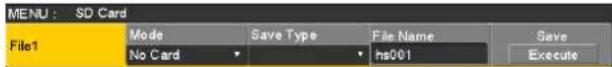
④ Use [F2] to select "Init" using the Mode item, and then press the [F2]. If the memory card has not been inserted, "No Card" will appear at the Mode item.
⑤ Press the [F1] (OK) to initialize the card.
Before using a memory card in this unit, initialize it. This unit also supports SDHC memory cards. Memory cards can be initialized no matter whether they are SD or SDHC memory cards.
1-12-2. Saving data on memory cards
① Insert the memory card which has been initialized by the unit, into the memory card slot.
② Press the 📊WMCM button to light its indicator, and display the SD Card menu.
③ Use [F1] to display the File1 sub menu.
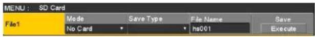
④ Use [F2] to select "Save" using the Mode item, and then press the [F2].
⑤ Use [F3] to select the data which is to be stored on the memory card using the Save Type item. The filename provided automatically is displayed in the File Name item. Filenames are provided automatically using the running number as shown below.
hs001.xxx to hs100.xxx
- When changing a filename, press [F4] to open the keyboard screen, input the filename, and close the keyboard screen.
Refer to "2-2-2. Keyboard screen operations" (Operating Instructions).
hs001 to hs100
- The name of the folder where the all files and log files are saved serves as the filenames of the all files and log files. The filenames of the all files and log files cannot be changed on the keyboard screen.
⑥ If the [F5] (Save) is now pressed, the file is stored on the memory card.
For the destinations where the data is stored, refer to .
- When storing video memory still images, the file format can be selected. On the SD Card menu, use [F1] to display the File2 sub menu, and select the format of the file to be used when storing the data on the memory card using the Format item.

1. Basic operations
1-12-3. Loading data from memory cards
① Insert the memory card on which the data is stored into the memory card slot.
Load the file after its data has been stored in the each folder.
Data stored in other folders will not be recognized by the unit.
For the destinations where the data is stored, refer to .
② On the SD Card menu, use [F1] to display the File1 sub menu.
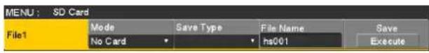
③ Use [F2] to select "Load" using the Mode item, and then press the [F2].
When [F2] is pressed, the file selection screen is displayed.
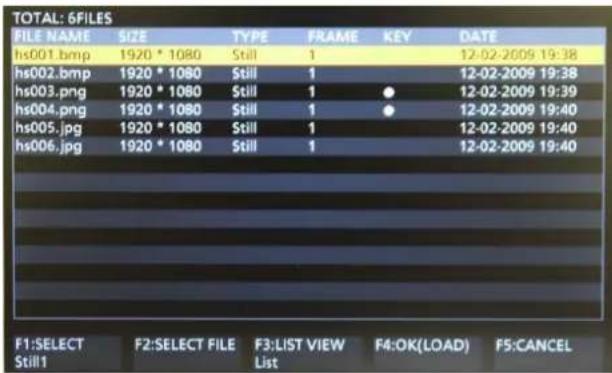
④ Use [F1] to select the type of file to be loaded using the SELECT item.
- Correlation between [F1] (for selecting a setting using the SELECT item) and [F3] on the file selection screen
| [F1]Settings selected using SELECT item | [F3]Displays and function |
| Still1, Still2, Clip1, Clip2 | F3: LIST VIEWUsing the [F3], it is possible to switch the screen display between “List (list files)” and “Thumbnail” (display thumbnails)". |
| Shot, Event, Set Up, All, Upgrade | F3:The [F3] cannot be operated.On the screen, the list of files is displayed. |
| Plug-in F3: INDEX | Using the [F3], it is possible to select the index number (1 to 10) of the files to be loaded.On the screen, the list of files is displayed. |
*: This function can be actuated in any model whose system version is V2.00.00 and up. The display cannot be switched to "Thumbnail" with a model whose system version is below V2.00.00.
⑤ Use [F2] to select the name of the file to be loaded using the SELECT FILE item. If the name of the file to be loaded consists of more than 8 characters, a shortened version of the filename will be displayed.
- When "Plug-in" has been selected using [F1] (SELECT item), use [F3] to select the index number (1 to 10) of the files to be loaded.
- Up to 100 files can be loaded from one folder.
- The following alphanumerics and symbols can be used as the characters for filenames (see below). Files using other characters will not be displayed by the unit.
A to Z, a to z, 0 to 9, Space, ! # \$ % & ' () - . @ ^ _ ` {}
⑥ Use [F4] to load the file.
Changing the sort mode
The way in which the file list displayed on the file selection screen is arranged can be specified.
① On the SD Card menu, use [F1] to display the File2 sub menu.

② Use [F2] to select the sort mode for the file selection screen using the Sort item.
| Newest The files | are arranged in sequence starting with the file having the most recent registration date and time. |
| Oldest The files | are arranged in sequence starting with the file having the oldest registration date and time. |
| Name The files | are arranged in filename sequence. |
1. Basic operations
1-12-4. Deleting files on memory cards
① Insert the memory card on which the data is stored into the memory card slot.
② On the SD Card menu, use [F1] to display the File1 sub menu.
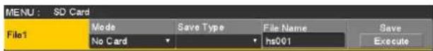
③ Use [F2] to select "Delete" using the Mode item, and then press the [F2].
When [F2] is pressed, the file selection screen is displayed.
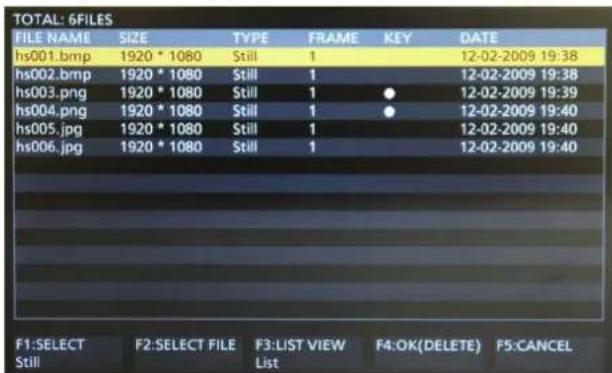
④ Use [F1] to select the type of file to be deleted using the SELECT item.
If the name of the file to be loaded consists of more than 8 characters, a shortened version of the filename will be displayed.
⑤ Use [F2] to select the name of the file to be deleted using the SELECT FILE item.
⑥ Use [F4] to delete the file.
1-12-5. Displaying the memory card information
① Insert the memory card on which the data is stored into the memory card slot.
② On the SD Card menu, use [F1] to display the Card Information sub menu.

| Free Space The memory card's total memory and remaining free space are displayed in megabyte units (MB).(Free space/card's total memory) |
1. Basic operations
1-13. Waveform monitor settings
WFM (waveform monitor) settings
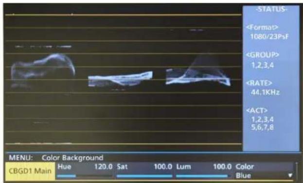
① Press the [WFM/VECT] button among the display mode buttons to display the waveform monitor on the built-in display.
② Press the CONFIG button to light its indicator, and display the Config menu.
③ Use [F1] to display the WFM sub menu.

④ Use [F2] to select the method to be used to display the signal waveforms using the Style item.
| Parade The signal waveforms are arranged and displayed. |
| Overlay The signal waveforms are superimposed onto each other and displayed. |
⑤ Use [F3] to select the signals whose waveforms are to be displayed using the Mode item.
| YPbPr | Waveforms of the Y, PB and PR signals are displayed. |
| RGB Waveforms of the R, G and B signals are displayed. | |
| Y Waveforms of the Y signal only are displayed. | |
VECTOR (vectorscope) settings
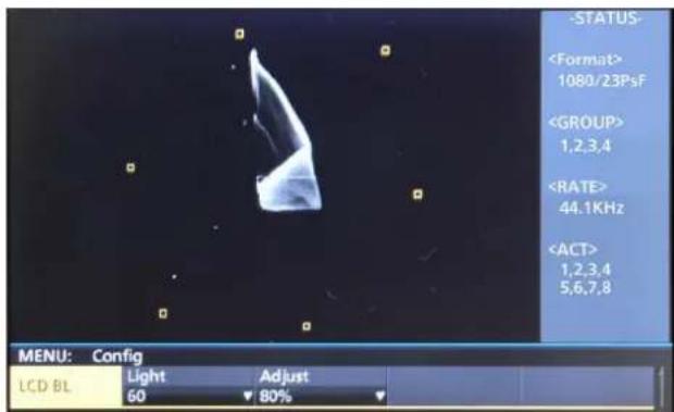
① Press the [WFM/VECT] button among the display mode buttons to display the vectorscope on the built-in display.
② Press the CON=O 5YS button to light its indicator, and display the Config menu.
③ Use [F1] to display the Vector sub menu.

④ Use [F2] to select the color bar reference marker using the Bar Target item.
| 75% The 75% color bar reference marker is displayed. |
| 100% The 100% color bar reference marker is displayed. |
1. Basic operations
1-14. Setting the status display
Displaying the audio status
When the menu display mode has been set to "1 line of menu display and full-screen image display", the audio status of the signals selected by the DISP bus is displayed on the WFM or VECTOR screen.
When SDI input signals are selected:
The status of the embedded audio is displayed.
When PGM, PVW, MV or AUX signals are selected:
When "ON" has been selected as the ancillary data setting, the status of the embedded audio is displayed.
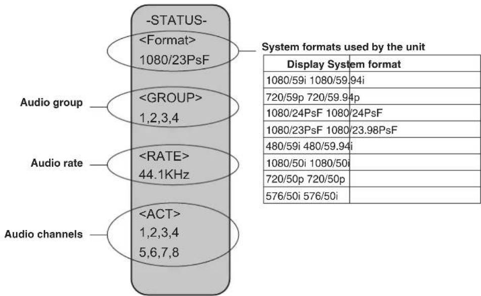
2. Input/output signal settings
2-1. Input signal settings
SDI IN1 to SDI IN8 are SDI signal inputs.
DVI IN is DVI-D signal input.
IN A1, IN A2, IN B1 and IN B2 can be set only when one of the following option boards has been connected.
• AV-HS04M1 (SDI Input Board)
• AV-HS04M2 (Analog Input Board)
• AV-HS04M3 (DVI Input Board)
• AV-HS04M6 (Analog Composite Input Board)
• AV-HS04M8 (Full-HD DVI Input Board)
Before setting the input signals, first select the input signal to be set using the Input sub menu.
① Press the IN OUT button to light its indicator, and display the Input menu.
② Use [F1] to display the Input sub menu.

③ Use [F2] to select the input signals using the Select item.
The menu display is switched in accordance with the input signals which have been selected. The menu title is set to "MENU: Input (signal type)/input connector (material name)".
| Signal type SDI, Analog, DVI, Composite |
| Material name Material name set in “2-1-5. Setting the material names”. |

2. Input/output signal settings
| Input connector | Setting menu and numbers of sections in this manual | ||||||
| FS Mode | Delay Freeze | Name | Up Converter | ||||
| 2-1-1 2-1-2 | 2-1-3 2-1-4 2-1-5 | 2-1-6 | |||||
| SDI IN1 to SDI IN4 | Standard SDI input ×8 lines | √ | Only Dot by Dot selectable | — | √ | √ | — |
| SDI IN5, SDI IN6 | √ | √ | — | √ √ | √ | ||
| SDI IN7, SDI IN8 | √ √ | √ √ √ | |||||
| DVI IN | Standard DVI-D input ×1 line | — — — | √ | √ | — | ||
| Option slot IN A1, IN A2, IN B1, IN B2 | AV-HS04M1 SDI input ×2 lines | √ | √ | — | √ √ | √ | |
| AV-HS04M2 Analog component input ×2 lines | √ | √ | — | √ √ | √ | ||
| AV-HS04M3 DVI-I input ×2 lines | — — — | √ | √ | — | |||
| AV-HS04M6 Analog composite input ×2 lines | √ | √ | — | √ √ | √ | ||
| AV-HS04M8 DVI-D input ×2 lines | — — — | √ | √ | — | |||
| Input connector | Setting menu and numbers of sections in this manual | |||||
| Video Process (SDI) | Gain | Video Process (Composite) | DVI Input (Digital) | DVI Input (Analog) | ||
| 2-1-7 2-1-8 | 2-1-9 2-1-10 | 2-1-10 | ||||
| SDI IN1 to SDI IN4 | Standard SDI input ×8 lines | √ | ——— | — | ||
| SDI IN5, SDI IN6 | √ | ——— | — | |||
| SDI IN7, SDI IN8 | √ | ——— | — | |||
| DVI IN | Standard DVI-D input ×1 line | ——— | √ | — | ||
| Option slot IN A1, IN A2, IN B1, IN B2 | AV-HS04M1 SDI input ×2 lines | ——— | —— | |||
| AV-HS04M2 Analog component input ×2 lines | — | √ | ——— | |||
| AV-HS04M3 DVI-I input ×2 lines | ——— | √ | √ | |||
| AV-HS04M6 Analog composite input ×2 lines | — | √ | √ | — | — | |
| AV-HS04M8 DVI-D input ×2 lines | ——— | √ | — | |||
√: Can be set.
—: Cannot be set.
2. Input/output signal settings
2-1-1. Setting the frame synchronizer
The frame synchronizer can be set to On or Off for each input. The DVI input frame synchronizer is permanently On. It cannot be set from On to Off or vice versa.
① On the Input sub menu, use [F2] to select the input to be set using the Select item.
Refer to "2-1. Input signal settings".
② Use [F1] to display the FS sub menu.

③ Use [F2] to set On or Off for the frame synchronizer using the FS item.
- If the output signal phase is set to 0H, Off cannot be selected as the FS item setting.
AVDL function is active while the frame synchronizer function is set to Off.
The AVDL function automatically adjusts the input image signal phase to the horizontal synchronization reference signal phase.
For details, refer to "2-4. Adjusting the output signal phase".
2. Input/output signal settings
2-1-2. Setting the input mode
The mode can be set for each input only when HD has been selected as the system format. When SD is selected as the system format, the input mode is always the same as Normal.
① On the FS sub menu, use [F3] to set the input mode using the Mode item.
| Normal Input signals in conformity with the system format take effect. | |
| Dot by Dot | When SD signals with the same frame rate as the system format have been input, they are input on a dot by dot (1× magnification) basis with no up-conversion. (This setting is only possible when the system format is 1080i.) In this mode, there is minimal deterioration in the image quality and, as such, the mode is used to combine SD format material using the PinP function. |
| Up Convert | When SD signals with the same frame rate as the system format have been input, they are up-converted. |
| Auto Input signals | in conformity with the system format take effect.Furthermore, if SD signals with the same frame rate as the system format are input when HD is selected as the system format, they are up-converted.In the Auto mode, the images may be disturbed when the input signals are switched. |
• ■ denotes a black screen.
- The Up Convert mode or Auto mode cannot be selected for inputs 1 to 4.
- If Dot by Dot, Up Convert or Auto mode is selected, the frame synchronizer will be turned on.
- The input mode cannot be changed when freeze is set to on.
2. Input/output signal settings
2-1-3. Setting the delay amount
The input signals can be delayed.
- The delay can be applied only to the SDI IN7 and SDI IN8 input signals.
① On the Input sub menu, use [F2] to select the input to be set using the Select item.
Refer to "2-1. Input signal settings".
② Use [F1] to display the FS sub menu.

③ Use [F4] to set the delay amount using the Delay item.
2-1-4. Freezing the input signals
The input signals can be frozen and used.
While signals are frozen, the tally signals of the corresponding input will not be output.
Setting freeze
① On the Input sub menu, use [F2] to select the input to be set using the Select item.
Refer to "2-1. Input signal settings".
② Use [F1] to display the Freeze sub menu.

③ Use [F2] to select the freeze method using the Select item.
| Frame The images are frozen frame by frame. |
| Field The images are frozen field by field.This is used to freeze moving images.With interlace signals, however, diagonal lines and moving parts appear jagged. |
Frame or Field can also be selected while an image is frozen.
④ Press the [F3] to freeze the input image or cancel the freeze.
If the [F3] is pressed while the display is "Off", the video signal is frozen, and the display is set to "On".
If the [F3] is pressed while the display is "On", the video signal freezing is canceled, and the display is set to "Off".
The "F" mark appears in front of the name of the material when the signals set for output of multi view displays are frozen.
- When the unit is used with the frame synchronizer function OFF, the output images may be disturbed when freezing is executed, but the frozen images will not be adversely affected.
- If, when the switcher is used with the frame synchronizer function at OFF, "On" is set as the freeze setting, the frame synchronizer function will be automatically switched to ON.
2-1-5. Setting the material names
Material names can be given to the input signals.
These names can be selected from the default settings or user settings.
① On the Input sub menu, use [F2] to select the input to be set using the Select item.
Refer to "2-1. Input signal settings".
② Use [F1] to display the Name sub menu.

③ Use [F2] to select the type of material names using the Type item.
| Default (default settings) | Select the material names from the following: SDI IN1 to SDI IN8, DVI IN, IN-A1, IN-A2, IN-B1 and IN-B2. |
| User (user settings) | The material names are set using up to 7 characters. |
2. Input/output signal settings
2-1-6. Setting the up-converter
Select the settings for SDI IN5 to SDI IN8, as well as for the up-converter that is built into the option boards listed below:
• AV-HS04M1 (SDI Input Board)
• AV-HS04M2 (Analog Input Board)
• AV-HS04M6 (Analog Composite Input Board)
① On the Input sub menu, use [F2] to select the input to be set using the Select item.
Refer to "2-1. Input signal settings".
② Use [F1] to display the Up Converter1 sub menu.

③ Use [F2] to select the scaling system using the Scale item.
| Squeeze The image is enlarged both horizontally and vertically to fill the entire screen. |
| Edge Crop The aspect ratio of the image is maintained, the image size is increased in accordance with the vertical resolution, and black bands are added at the left and right. |
| Letter Box The aspect ratio of the image is maintained, the image size is increased in accordance with the horizontal resolution, and the image is cropped at the top and bottom. |
| Input image Squeeze | |
| Edge Crop Letter Box | |
④ Use [F3] to set the image movement detection sensitivity using the Move Detect item.
| 1 Toward still images | |
| 3 Standard | |
| 5 Toward moving images | |
⑤ Use [F4] to set the extent of the edge sharpness for the images using the Sharp item.
| 1 Not sharp edges | |
| 3 Standard | |
| 5 Very sharp edges | |
⑥ Use [F5] to adjust the input image size (100 % to 110 %).
Fine-tuning of image positions
Fine-tuning of image positions is performed when "Edge Crop" is selected for the scaling method.
① Use [F1] to display the Up Converter2 sub menu.

② Use [F2] to select the image position using the Edge Crop Pos item.
| Center | The image is positioned at the center, and black images are added at the left and right. |
| Right | The image is positioned at the right, and a black image is added at the left. |
| Left | The image is positioned at the left, and a black image is added at the right. |
Setting the gamut limiter
① On the Up Converter2 sub menu, use [F4] to set the color range of the input signals using the Limiter item.
| MENU: Input(SDI/SDI INS(SDI-INPUT5) | |||
| Up Converter2 | Edge Crop Pos | Limiter | |
| Center | • | Off | |
| Off | The color range is not restricted. |
| 108 | The amplitude level of the colors (R, G and B) is restricted to 0% - 108%. |
| 104 | The amplitude level of the colors (R, G and B) is restricted to 0% - 104%. |
| 100 | The amplitude level of the colors (R, G and B) is restricted to 0% - 100%. |
2. Input/output signal settings
2-1-7. Setting the video process function
The video process function works for all the SDI input signal images.
The color tones can be changed for each input.
① On the Input sub menu, use [F2] to select the input to be set using the Select item.
Refer to "2-1. Input signal settings".
② Use [F1] to display the Video Process1 sub menu.

③ Use [F2] to select enable (On) or disable (Off) for the video process function using the Video Process item.
④ Use [F3] to set the Y signal gain using the Y-Gain item.
⑤ Use [F4] to set the pedestal level using the Pedestal item.
⑥ Use [F1] to display the Video Process2 sub menu.

⑦ Use [F3] to set the saturation gain using the C-Gain item.
⑧ Use [F4] to set the change in the hue using the Hue item.
Copying the settings
The video process settings already selected can be set for other input signals as well.
On the Video Process2 sub menu, use [F5] to select the input signals of the copy destination, and press [F5].

2-1-8. Setting the analog input gain (option)
When the analog input board (option) has been connected, the gain of the input signals can be set. Alternatively, when the analog composite input board (option) has been connected, the gain of the Y signals can be set. The setting range is ±30 steps, and the gain changes by approximately ±2 dB. The amount of change in the gain when it is changed by one step is not fixed.
① On the Input sub menu, use [F2] to select the input to be set using the Select item.
Refer to "2-1. Input signal settings".
② Use [F1] to display the Video Process sub menu.

③ Use [F2] to set the gain of the input signal (Y signal gain) using the Gain item.
2. Input/output signal settings
2-1-9. Setting the analog composite input signals (option)
When the analog composite input board (option) has been connected, the analog composite input signals can be set.
① On the Input sub menu, use [F2] to select the input to be set using the Select item.
Refer to "2-1. Input signal settings".
② Use [F1] to display the Video Process sub menu.

③ Use [F2] to set the gain of the input signal (Y signal gain) using the Gain item.
④ Use [F3] to adjust the chroma level using the Chroma item. (Maximum amount of variation: approx. ±3 dB) The auto color control function is activated, and the chroma level is kept at the value that has been set.
⑤ Use [F4] to adjust the pedestal level using the Ped item. (Maximum amount of variation: approx. ±100 mV)
⑥ Use [F5] to adjust the hue using the Hue item. (Maximum amount of variation: approx. ±20°) Adjustment of Hue is possible when the system format is 1080/59.94i, 720/59.94p and 480/59.94i.
For details on the other settings, refer to the operating instructions of the option board.
2. Input/output signal settings
2-1-10. Setting the DVI input signals
Set the DVI input signals when the DVI input board (option) or full-HD DVI input board (option) has been connected. Signals with the following resolutions can be input.
| DVI input signals | Standard(Digital) | DVI Input Board(Digital/Analog) | Full-HD DVI Input Board(Digital) |
| XGA(1024 × 768)/60 Hz | √ √ √ | ||
| WXGA(1280 × 768)/60 Hz | √ √ √ | ||
| SXGA(1280 × 1024)/60 Hz | √ √ √ | ||
| WSXGA+(1680 × 1050)/60 Hz | √ | — | √ |
| UXGA(1600 × 1200)/60 Hz | √ | — | √ |
| WUXGA(1920 × 1200)/60 Hz | √ | — | √ |
| 1080/59.94p(1920 × 1080)/59.94 Hz | √ | — | √ |
| 1080/50p(1920 × 1080)/50 Hz | √ | — | √ |
| 1080/59.94i(1920 × 1080)/59.94 Hz | √ | — | — |
| 1080/50i(1920 × 1080)/50 Hz | √ | — | — |
| 720/59.94p(1280 × 720)/59.94 Hz | √ | — | — |
| 720/50p(1280 × 720)/50 Hz | √ | — | — |
√: Can be set.
—: Cannot be set.
- If signals with any other resolutions or frequencies are input, the signals cannot be imported correctly. The images which are output at a time like this may be black or disturbed.
• These boards are incompatible with the HDCP (High-bandwidth Digital Content Protection).
① On the Input sub menu, use [F2] to select the input to be set using the Select item.
Refer to "2-1. Input signal settings".
② Use [F1] to display the DVI Input sub menu.
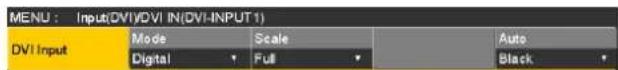
③ Use [F2] to select the signal system using the Mode item.
- Set this when the DVI input board (AV-HS04M3) has been connected.
| Digital Digital input signals of the DVI connector are effective. |
| Analog Analog input signals of the DVI connector are effective. |
④ Use [F3] to select the scaling method.
| Fit-V The aspect ratio of the input images is maintained, and the size of the images is increased or reduced in accordance with the vertical resolution. |
| Fit-H The aspect ratio of the input images is maintained, and the size of the images is increased or reduced in accordance with the horizontal resolution. |
| Full The size of the input images is increased or reduced in accordance with the system resolution.(The aspect ratio of the input images is not kept the same. The rate at which the image size is increased or reduced in the vertical direction and in the horizontal direction differs.) |
For details on the sizes that correspond to the formats, refer to "DVI input scaling size table" (on page 83).
2. Input/output signal settings
■ DVI input scaling size table
| DVI format Mode | HD/1080i HD/720P SD/NTSC SD/PAL | ||||
| 1920 × 1080 | 1280 × 720 | 720 × 487 | 720 × 576 | ||
XGA1024 × 768 | Fit-V | 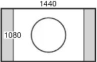 | 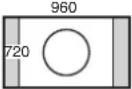 |  |  |
| Fit-H |  |  |  |  | |
| Full | 1920 | 1280 | 720 | 720 | |
SXGA1280 × 1024 | Fit-V | 1350 | 900 | 675 | 675 |
| Fit-H |  |  |  |  | |
| Full | 1920 | 1280 | 720 | 720 | |
WXGA1280 × 768 | Fit-V |  |  |  |  |
| Fit-H |  |  |  |  | |
| Full |  |  |  |  | |
: Black images are inserted here.
: The parts of the images protruding in these areas are cropped.
2. Input/output signal settings
| DVI format Mode | HD/1080i HD/720P SD/NTSC SD/PAL | ||||
| 1920 × 1080 | 1280 × 720 | 720 × 487 | 720 × 576 | ||
WSXGA+1680 × 1050 | Fit-V |  |  |  |  |
| Fit-H |  |  |  |  | |
| Full |  |  |  |  | |
UXGA1600 × 1200 | Fit-V |  |  |  | 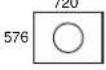 |
| Fit-H | 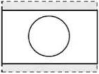 | 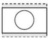 | 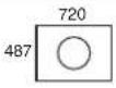 |  | |
| Full | 1920 | 1280 | 720 | 720 | |
| WUXGA1920 × 1200 | Fit-V |  |  |  |  |
| Fit-H |  |  |  |  | |
| Full | 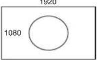 | 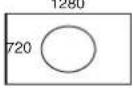 |  |  | |
: Black images are inserted here.
: The parts of the images protruding in these areas are cropped.
2. Input/output signal settings
| DVI format Mode | HD/1080i HD/720P SD/NTSC SD/PAL | ||||
| 1920 × 1080 | 1280 × 720 | 720 × 487 | 720 × 576 | ||
| 1080/59.94p1080/50p1080/59.94i1080/50i1920 × 1080 | Fit-V |  |  |  |  |
| Fit-H | 1920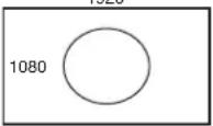 | 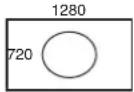 |  |  | |
| Full | 1920 | 1280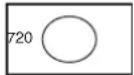 |  |  | |
| 720/59.94p720/50p1280 × 720 | Fit-V | 1920 | 1280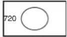 |  |  |
| Fit-H | 1920 | 1280 |  |  | |
| Full | 1920 | 1280 |  |  | |
: Black images are inserted here.
: The parts of the images protruding in these areas are cropped.
2. Input/output signal settings
2-1-11. Displaying the DVI input signal information
These are used to display the information concerning the DVI-D input signal images. The information cannot be changed.
① On the Input sub menu, use [F2] to select the input to be set using the Select item. Refer to "2-1. Input signal settings".
② Use [F1] to display the DVI Status sub menu.
| DVI Status | Size**** | Dot Clock**.MHz | H-Frequency**.kHz | V-Frequency**.Hz |
| Size This indicates the pixel count of the images. |
| Dot Clock This indicates the dot clock frequency of the images. |
| H-Frequency This indicates the horizontal frequency of the images. |
| V-Frequency This indicates the vertical frequency of the images. |
The formats supported are listed below.
| Input video signal | Dot clock frequency (MHz) | Frequency | |||
| Horizontal (kHz) | Vertical (Hz) | ||||
| XGA | 1024 × 768 | Digital 65.0 | 48.36 60.00 | ||
| WXGA | 1280 × 768 | Digital 79.5 | 47.78 59.87 | ||
| SXGA | 1280 × 1024 | Digital 108.0 | 63.98 60.02 | ||
| WSXGA+ | 1680 × 1050 | Digital 146.2 | 65.29 59.95 | ||
| UXGA | 1600 × 1200 | Digital 162.0 | 75.00 60.00 | ||
| WUXGA | 1920 × 1200 | Digital 154.0 | 74.04 59.95 | ||
| 1080/50p | 1920 × 1080 | Digital (RGB) 148.5 56.25 50.00 | |||
| 1080/59.94p | 1920 × 1080 | Digital (RGB) 148.5/1.001 67.50/1.001 | 60.00/1.001 | ||
| 1080/50i | 1920 × 1080 | Digital (RGB) 74.25 | 28.13 50.00 | ||
| 1080/59.94i | 1920 × 1080 | Digital (RGB) 74.25/1.001 | 33.72 60.00/1.001 | ||
| 720/50p | 1280 × 720 | Digital (RGB) 74.25 | 37.50 50.00 | ||
| 720/59.94p | 1280 × 720 | Digital (RGB) 74.25/1.001 | 44.96 60.00/1.001 | ||
- If the format of the input signals is not supported, it may not be possible to import the signals properly, and a black image or disturbed image may appear.
2. Input/output signal settings
2-1-12. Adjusting the DVI input signals
These are used to adjust the clock/phase and position of the DVI-D input signal.
Select the clock/phase and position of the signals when the DVI input board (AV-HS04M3) has been connected.
① On the Input sub menu, use [F2] to select the input to be set using the Select item.
Refer to "2-1. Input signal settings".
② Use [F1] to display the DVI Phase sub menu.

③ Use [F2] to adjust the clock phase of the analog input signals using the Clk Phs item.
While viewing the image quality, set the value at which the noise level is minimized.
④ Use [F3] to adjust the horizontal position using the H-Pos item.
⑤ Use [F4] to adjust the vertical position using the V-Pos item.
2-1-13. Automatic adjustment of the black level and white level (analog input signals)
The black level (offset) and white level (gain) of the analog input signals are adjusted automatically.
- Set this when the DVI input board (AV-HS04M3) has been connected.
Depending on the computer used, there may be some deviation from the correct levels of the black level or white level.
To proceed with automatic adjustment to correct this deviation, display the black-and-white signals (BW.bmp) on the supplied CD-ROM or the full-screen black signals and full-screen white signals on the computer connected to the DVI input connector, and input these signals as the DVI input signals.
When using the black-and-white signals, position them so that the boundary between black and white comes to the center of the monitor screen.
When using the full-screen black signals or full-screen white signals, display the black or white in an area that covers at least 80 % of the screen from the screen center.
Before making any adjustments, follow the instructions given in the "Automatic adjustment of the black level" section.
Automatic adjustment of the black level
Input the black-and-white signals (BW.bmp) or full-screen black signals.
Use [F5] to select "Black" in the Auto item, and press [F5] to adjust the black level automatically.
"Auto Setting" is displayed on the built-in display while adjustments are being made.
Automatic adjustment of the white level
Input the black-and-white signals (BW.bmp) or full-screen white signals.
Use [F5] to select "White" in the Auto item, and press [F5] to adjust the white level automatically.
"Auto Setting" is displayed on the built-in display while adjustments are being made.
Initializing the adjusted values
Use [F5] to select "Init" in the Auto item, and press [F5] to return the adjusted values to their factory settings.
"Auto Setting" is displayed on the built-in display while adjustments are being made.
2. Input/output signal settings
2-2. Output signal settings
SDI OUT1 to SDI OUT5 are SDI signal outputs.
DVI OUT is DVI-D signal output.
OUT A1, OUT A2, OUT B1 and OUT B2 can be set only when one of the following option boards has been connected.
• AV-HS04M4 (Analog Output Board)
• AV-HS04M5 (DVI/Analog Output Board)
• AV-HS04M7 (SDI Output Board)
Before proceeding to set the output signals, first select the output signals to be set using the Output sub menu.
① Press the IN OUT button to light its indicator, and display the Output menu.
② Use [F1] to display the Output sub menu.
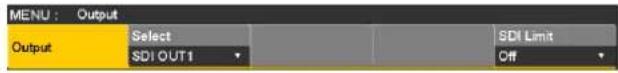
③ Use [F2] to select the output signals using the Select item.
The menu display is switched depending on the selected output signals. The menu title is set to "MENU: Output (signal type)/output connector".
Signal type SDI, Analog, DVI-D, DVI-I

| Output connector | Setting menu and numbers of sections in this manual | |||||
| Assign SDI | Output | DVI Output (Digital) | DVI Output (Analog) | Down Converter | ||
| 2-2-1 2-2-2 | 2-2-3 2-2-3 2-2-4 | |||||
| SDI OUT1 to SDI OUT5 | StandardSDI output ×5 lines | √ | √ | — — — | ||
| DVI OUT | StandardDVI-D output ×1 line | √ | — | √ | — | — |
| Option slot OUT A1, OUT A2, | AV-HS04M4Analog component output ×2 lines | √ | — — — — | |||
| AV-HS04M5DVI-I output ×1 lineAnalog component output ×1 line | √ | — | — | √ | — | |
| AV-HS04M7SDI output ×2 lines | √ | √ | — | — | √ | |
| Option slot OUT B1, OUT B2 | AV-HS04M4Analog component output ×2 lines | √ | — — — — | |||
| AV-HS04M5DVI-I output ×1 lineAnalog component output ×1 line | √ | — | — | √ | — | |
| AV-HS04M7SDI output ×2 lines | √ | √ | — | — | √ | |
√: Can be set.
—: Cannot be set.
2. Input/output signal settings
2-2-1. Assigning the output signals
The output signals can be assigned to the SDI OUT1 to SDI OUT5 connectors and DVI OUT connector.
① On the Output sub menu, use [F2] to select the output to be set using the Select item.
Refer to "2-2. Output signal settings".
② Use [F1] to display the Assign sub menu.
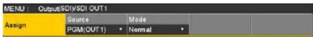
③ Use [F2] to set the type of output signal using the Source item.
| PGM An image | provided with the wipe, mix, key, downstream key or other effect is output at the switcher's main line output. |
| PVW This is the | preview output that enables the next operation to be checked before it is executed. |
| AUX1 to 4 The | signals selected by the 4 lines of AUX buses (AUX1 to AUX4) are output. |
| CLN The clean | signal (the image resulting when the key, downstream key or other effect has been removed from the PGM signal) is output.Refer to “Assigning the CLN signal”. |
| MV The multi view display signals are output.Multiple input signals and output signals are reduced in size and output to one screen. | |
| KeyOut The key signal is output. | |
| MEM-PVW In the memory preview mode, the shot memory and event memory effects are output to preview. | |
④ Use [F3] to set the output mode using the Mode item.
| Normal The same signals as the system format signals are output. | |
| Down Convert (down-converter) | This can be selected when the SDI output board (option: AV-HS04M7) has been connected.When the system format is 1080/59.94i or 720/59.94p, the signals are output in the 480/59.94i format.When the system format is 1080/50i or 720/50p, the signals are output in the 576/50i format.When the system format is SD (480/59.94i or 576/50i), this setting cannot be selected. |
Assigning the CLN signal
Set KEYCLN or DSKCLN as the CLN output.
① Press the CONFIG SYS button to light its indicator, and display the Config menu.
② Use [F1] to display the Assign sub menu.

③ Use [F3] to select the type of output signal using the CLN item.
| Key The PGM | signals minus the key effects are output.The Key, PinP1, PinP2 and DSK effects are not added. |
| DSK The PGM | signal minus the downstream key effects are output. |
2-2-2. Setting the SDI output color range
The color range can be set for the SDI output signal images.
- The same setting applies to all the SDI output signals.
① On the Output sub menu, use [F5] to set the color range using the SDI Limit item.
Refer to "2-2. Output signal settings".
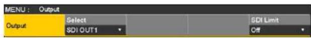
| Off | The color range is not restricted. |
| 108 | The amplitude level of the colors (R, G and B) is restricted to 0 % - 108 %. |
| 104 | The amplitude level of the colors (R, G and B) is restricted to 0 % - 104 %. |
| 100 | The amplitude level of the colors (R, G and B) is restricted to 0 % - 100 %. |
2. Input/output signal settings
2-2-3. Setting the DVI output signals
Set the DVI output signals of the standard output (DVI OUT) and the DVI output signals if the DVI/analog output board (option) has been connected.
① On the Output sub menu, use [F2] to select the output to be set using the Select item.
Refer to "2-2. Output signal settings".
② Use [F1] to display the DVI Output sub menu.
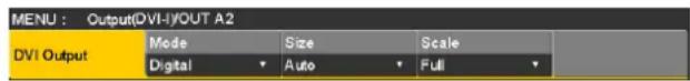
③ Use [F2] to select the signal system using the Mode item.
- Set this when the DVI/analog output board (AV-HS04M5) has been connected.
| Digital DVI digital signals are output from the DVI connector. | |
| Analog DVI analog signals (RGB) are output from the DVI connector.When “Analog” has been selected, the display position of the image may be off depending on the monitor which is connected. If it is off, adjust the position at the monitor.For details on the adjustment method, refer to the operating instructions of the monitor. |
④ Use [F3] to select the resolution of the images to be output using the Size item.
| Auto | The equipment information of the output destination is captured by the DVI signals, and the images are output at the optimum resolution.The vertical frequency is 60 Hz, and the maximum resolution is SXGA for analog output signals and WUXGA for digital output signals.If the equipment information cannot be captured or if the resolution and frequency which can be output by the unit are not contained in the equipment information, the images will be output at the XGA setting. |
Other signals are listed in the table below.
| DVI output signal Standard output (DVI OUT) DVI/Analog Output Board | ||||
| Size Output (Digital) (Digital) (Analog) | ||||
| XGA | (1024 × 768)/60 Hz √ √ | √ | ||
| WXGA | (1280 × 768)/60 Hz √ √ | √ | ||
| SXGA | (1280 × 1024)/60 Hz | √ | √ | √ |
| WSXGA+ | (1680 × 1050)/60 Hz | √ √ | — | |
| UXGA | (1600 × 1200)/60 Hz | √ √ | — | |
| WUXGA | (1920 × 1200)/60 Hz | √ √ | — | |
| 1080/59.94p | (1920 × 1080)/59.94 Hz | √ √ | — | |
| 1080/50p | (1920 × 1080)/50 Hz | √ √ | — | |
| 1080/59.94i | (1920 × 1080)/59.94 Hz | √ | — | — |
| 1080/50i | (1920 × 1080)/50 Hz | √ | — | — |
| 720/59.94p | (1280 × 720)/59.94 Hz | √ | — | — |
| 720/50p | (1280 × 720)/50 Hz √ | — | — | |
2. Input/output signal settings
⑤ Use [F4] to select the scaling method using the Scale item.| Fit-V The aspect ratio of the output images is maintained, and the size of the images is increased or reduced in accordance with the vertical resolution.(Black bands are inserted into the areas where there are no images. The protruding parts of the images are cropped.) |
| Fit-H The aspect ratio of the output images is maintained, and the size of the images is increased or reduced in accordance with the horizontal resolution.(Black bands are inserted into the areas where there are no images. The protruding parts of the images are cropped.) |
| Full The size of the output images is increased or reduced in accordance with the system resolution. |
| Fullx80% The size of the output image is increased or reduced in accordance with the 80 % size of the system resolution. |
| Fullx90% The size of the output image is increased or reduced in accordance with the 90 % size of the system resolution. |
■ Setting the video movement detection sensitivity
① Use [F1] to display the Assign sub menu.  ② Use [F3] to set the image movement detection sensitivity using the Move Detect item. 2. Input/output signal settings
2-2-4. Setting the down-converter (option)
Select the settings for the down-converter that is built into the SDI output board (option: AV-HS04M7). ① On the Output sub menu, use [F2] to select the output to be set using the Select item. Refer to "2-2. Output signal settings". ② Use [F1] to display the Down Converter sub menu.  ③ Use [F2] to select the scaling system using the Scale item.| Squeeze The top, bottom, left and right are reduced so that the aspect ratio is set to 4:3. |
| Edge Crop The aspect ratio is maintained, the image is reduced in size in line with the vertical resolution, and it is cropped at the left and right. |
| Letter Box The aspect ratio is maintained, the image is reduced in size in line with the horizontal resolution, and a black image is added at the top and bottom. |
| System image (HD) | ||
| Output image (SD) | ||
| Squeeze Edge | Crop Letter Box | |
| 90H(75H) When the system format is 1080/59.94i, the image is delayed from the system image (HD) by 90H, and output.When the system format is 720/59.94p, the image is delayed from the system image (HD) by 90H+1F (frame), and output.When the system format is 1080/50i, the image is delayed from the system image (HD) by 75H, and output.When the system format is 720/50p, the image is delayed from the system image (HD) by 75H+1F (frame), and output.When the system format is 1080/50i or 720/50p, “75H” is displayed on the menu. |
| 1F The image is output in-phase with a delay of 1 frame from the system image (HD). |
| 1 Standard |
| 5 Very sharp edges |
2. Input/output signal settings
2-3. Setting the sync signals
The sync signals to be used by the system can be selected.External sync:
For synchronization with an external sync signal (gen-lock). The reference input signal is looped through and output.| BB Black burst | signal (vertical phase of 0H) |
| BB Advanced | Black burst signalVertical phase of 90H when the 59.94i or 59.94p format is selected; vertical phase of 75H when the 50i or 50p format is selected |
| Tri-level sync | Tri-level sync signal (vertical phase of 0H)This can be selected when the system format is 1080/24PsF. |
| Internal For synchronization with an internal reference signal (INT).The REFOUT signal (black burst signal) is output from the two reference connectors.This cannot be selected when the system format is 1080/24PsF. | |
| Locked Synchronized with the external sync signal or internal reference signal. |
| UnLock Not synchronized with the external sync signal or internal reference signal. |
2-4. Adjusting the output signal phase
The phase of the output video signals can be adjusted. ① Press the CONTO button to light its indicator, and display the System menu. ② Use [F1] to display the Output Phase sub menu.| MENU : System/Unlocked | ||||
| Output Phase | System | H-Phase | 0 | V-Phase |
| OH | ||||
| 0H | The output video signals are output to the system Reference signal with using in-phase. The frame synchronizer function is ON for all input signals. |
| 1H | The output video signals are output to the system Reference signal with 1H delay. When the frame synchronizer function is ON, the output video signals are output with 1 frame + 1H delay. |
2. Input/output signal settings
flowchart
graph TD
    A["Reference (System standard)"] --> B["AVDL Range"]
    B --> C["Approx. 0.2H"]
    B --> D["Approx. -0.2H to +0.8H"]
    B --> E["Internal Fixed DL"]
    F["• 1H Output (+1H)"] --> B
    G["AVDL Range"] --> H["Approx. -0.7H to +0.3H"]
    G --> I["Internal Fixed DL"]
    J["Shortest Output (+0.5H)"] --> K["Approx. 0.3H"]
    J --> L["+0.5H"]
    M["Longest Output (+1.5H)"] --> N["Approx. 0.3H"]
    M --> O["+0.5H"]
    P["• 0H Output (1F delay for Reference and in-phase output)"] --> Q["Approx. 0.2H"]
    R["FS Range"] --> S["MAX less than approximately 1 frame"]
    T["Output Phase Variable Range"] --> U["H Phase (-0.5H to +0.5H) + V Phase (±100 lines)"]
    V["Reference (Phase Reference)"] --> W["Output Phase Variable Range"]
    X["Output Phase Variable Range"] --> Y["H Phase (-0.5H to +0.5H) + V Phase (±100 lines)"]
2. Input/output signal settings
flowchart
graph LR
    A["Input signals"] --> B["Frame synchronizer"]
    B --> C["FS: On, Off\nMode: Normal, Up Convert or Dot by Dot (cannot be selected when the system format is 720p)"]
    B --> D["Video effects"]
    D --> E["Output signals"]
    D --> F["Down-converter"]
    F --> G["Delay: 90H (75H) or 1F"]
    G --> H["②"]
    I["See "2-1-1. Setting the frame synchronizer"."] --> B
    J["See "2-2-4. Setting the down-converter (option)"."] --> F
| Output Phase | Input | Non-synchronized input | Output signal 1Normal | Output signal 2Down Converter (90H) | Output signal 2Down Converter (1F) | ||||
| System Mode FS Phase | Delay amount | Phase | Delay amount | Phase | Delay amount | ||||
| Sync signal (Reference): Black burst signal (BB), tri-level sync signal (Tri-level sync), internal reference signal (Internal) | |||||||||
| 1H Normal Off Not possible | Off Not possible | Reference | +1H 1H | 1+90H | 1H+90H | In-phase with 1 | 1H+1F | ||
| Normal On Possible Reference +1H Max. | 1F+1H | 1+90H | Max. 1F+1H +90H | In-phase with 1 | Max. 2F+1H | ||||
| Up Convert/ Dot by Dot | On (Forced) | Possible | |||||||
| 0H (Example 1) | Normal/ Up Convert/ Dot by Dot | On (Forced) | Possible In-phase with Reference | Max. 1F | 1+90H | Max. 1F+90H | In-phase with 1 | Max. 2F | |
| Sync signal (Reference): Black burst signal (BB Advanced) | |||||||||
| 1H Normal Off Not possible | Off Not possible | Reference | -90H+1H | 1H | 1+90H | 1H+90H | In-phase with 1 | 1F+1H | |
| Normal On Possible Reference | -90H+1H | Max. 1F-90H +1H | 1+90H | Max. 1F+1H | In-phase with 1 | Max. 2F-90H +1H | |||
| Up Convert/ Dot by Dot | On (Forced) | Possible | |||||||
| 0H (Example 2) | Normal/ Up Convert/ Dot by Dot | On (Forced) | Possible Reference | -90H | Max. 1F-90H | 1+90H (In-phase with Reference) | Max. 1F | In-phase with 1 | Max. 2F-90H |
2. Input/output signal settings
flowchart
graph TD
    A["Input signals (non-synchronized)"] --> B["F1F2"]
    B --> C["Sync signal (Reference)"]
    C --> D["1F (frame)"]
    D --> E["Output signal ①"]
    E --> F["F1F2"]
    F --> G["Output signal ② (90H)"]
    G --> H["F1F2"]
    H --> I["Output signal ② (1F)"]
    I --> J["F1F2"]
    J --> K["Output signal ② (1F)"]
    style A fill:#f9f,stroke:#333
    style K fill:#f9f,stroke:#333
    note right of E: Max. 1F
        F <--> F
        G <--> G
        H <--> H
        I <--> I
        J <--> J
        K <--> K
    end
flowchart
graph TD
    A["Input signals (non-synchronized)"] --> B["F1F2"]
    C["Sync signal (Reference)"] --> D["1F (frame)"]
    E["Output signal ①"] --> F["F1F2"]
    G["Output signal ② (90H)"] --> H["F1F2"]
    I["Output signal ② (1F)"] --> J["F1F2"]
    B --> K["Max. 1F–90H"]
    D --> L["Max. 1F"]
    F --> M["Max. 1F–90H"]
    H --> N["Max. 1F"]
    J --> O["Max. 2F–90H"]
2. Input/output signal settings
2-5. Setting the multi view display
2-5-1. Setting the screen layout
The following nine options are available as split screen layouts.| 4Split 5-aSplit 5-bSplit | |
| 6-aSplit 6-bSplit 9Split | |
| 10-aSplit 10-bSplit 16Split |
| 1 | 2 |
| 3 | 4 |
| 123 | ||
| 456 | ||
| 789 |
| 1 | 2 | ||
| 3 | 4 | 5 | 6 |
| 7 | 8 | 9 | 10 |
| 7 | 8 | 9 | 10 |
| 3 | 4 | 5 | 6 |
| 1 | 2 | ||
| 1 | 2 | 3 | 4 |
| 5 | 6 | 7 | 8 |
| 9 | 10 | 11 | 12 |
| 13 | 14 | 15 | 16 |
2. Input/output signal settings
2-5-2. Setting the split frame and characters
Set the frame, character brightness and background of the split screens to be displayed on the multi view display. ① Press the XPT button to light its indicator, and display the Multi View Display menu. ② Use [F1] to display the MV Frame sub menu.| MENU : Mult View Display | |||||
| MV Frame | Frame | Character | Label | Tally | |
| LUM75% | LUM75% | Off | On | Red+Green | |
| LUM0%, LUM25%, LUM50%, LUM75%, LUM100% | Select one of these settings for the brightness of the split frame (gray scale). |
| Off The split frame is not displayed. | |
| LUM0%, LUM25%, LUM50%, LUM75%, LUM100% | Select one of these character (gray scale) brightness settings. |
| Off The characters are not displayed. Neither is the character background shown. | |
| On The character background is displayed. |
| Off The character background is not displayed. |
2-5-3. Setting the tally displays
Set the tally displays to be superimposed onto the split frame of the multi view display. The red tally indicates material consisting of program outputs. The green tally indicates material selected by the preset bus. On the MV Frame sub menu, use [F5] to set the tally displays using the Tally item.| MENU: Multi View Display | |||||
| MV Frame | Frame | Character | Label | Tally | |
| LUM75% | LUM75% | Off | On | Red+Green | |
| Red+Green Both the red tally and green tally are displayed. |
| Red Only the red tally is displayed. |
| Off No tally displays are shown. |
2. Input/output signal settings
2-5-4. Changing the material names
The material names of the input signals (SDI IN1 to SDI IN8, DVI IN, IN-A1, IN-A2, IN-B1 or IN-B2) to be set on the multi view display can be changed. These names can be selected from the default settings or user settings. When the preset settings and user settings are established, the material name (CAM1, etc.) is displayed. ① On the Input sub menu, use [F2] to select the input to be set using the Select item. Refer to "2-1. Input signal settings". ② Use [F1] to display the Name sub menu.| MENU : Input:SDI/SDI IN1(SDI-INPUT1) | |||
| Name | Type | Name | |
| Default | |||
| Default (default settings) | Select the material names from the following: SDI IN1 to SDI IN8, DVI IN, IN-A1, IN-A2, IN-B1 and IN-B2. |
| User (user settings) | The material names are set using up to 7 characters. |
Preset type setting procedure
 ① On the Name sub menu, use [F2] to select "Preset" using the Type item. ② Use [F3] to select the material name using the Name item.User type setting procedure
 ① On the Name sub menu, use [F2] to select "User" using the Type item. ② Press [F3] to display the keyboard screen. ③ Using [F1] to [F3], input the name, and press [F4]. To clear the name which has been input and close the keyboard screen, press [F5]. Refer to "2-2-2. Keyboard screen operations" (2. Input/output signal settings
2-5-5. Setting the level meters
Level meters for the embedded audio signals transferred by the SDI input can be displayed on the split screens. Left display: Channel 1 of group 1 Right display: Channel 2 of group 1 ① Press the XPT MV button to light its indicator, and display the Multi View Display menu. ② Use [F1] to display the Display sub menu.  ③ Use [F2] to set the level meter display using the Level Meter item.| On The level meters are displayed. |
| Off The level meters are not displayed. |
2-5-6. Setting the input signal marks
The status of the input signals can be displayed in front of the material names displayed on the split screens. "F" mark: This appears when the input signals are frozen. “!”mark: This appears when no signals are input or when signals with different formats are input. \- When the "F" mark is displayed, the "!" mark is not displayed. ① On the Display sub menu, use [F3] to set the input signal status display using the Input Status item.  On The input signal status is displayed. Off The input signal status is not displayed.2-5-7. Setting the markers
Safety markers can be displayed for the multi view materials. The markers can be displayed when PGM or PVW materials are to be displayed in half their original size.| 4Split Sub screens 1 to 4 |
| 5/6/10Split 1 or 2 sub screens |
2-5-8. High-resolution multi view mode
The image output on a multi view display can be output in high resolution to DVI-D output. \- These settings can be established when the system mode is set to SD. ① Press the button to light its indicator, and display the System menu. ② Use [F1] to display the Format sub menu.  ③ Use [F3] to set "On" or "Off" using the Hi Resolution item, and press the [F3]. \- Turning this setting "On" switches the Source item to the default value if the following output signals in the Source item of the Assign submenu under the Output menu are set to "MV". SDI OUT1 to SDI OUT5, OUT-A1, OUT-A2, OUT-B1, OUT-B2 \- Turning this setting "On", while the multi view display signal is output to the AUX bus or DISP bus, switches the output signal to the black signal (internally generated signal).2. Input/output signal settings
2-6. Setting the ancillary data and embedded audio data
A function for allowing the V ancillary data and embedded audio data of the SDI input signals to pass through can be set.When an HD format is used:
The ancillary data starting with line 9 is allowed to pass through.When an SD format is used:
The ancillary data starting with line 12 is allowed to pass through. \- When 1080/59.94i, 720/59.94p, 1080/50i or 720/50p has been selected as the unit's system format setting, it is not possible to allow the ancillary data and embedded audio data to pass through even if SD format signals (480/59.94i or 576/50i) have been input in the Dot by Dot mode or Up Convert mode. Refer to "2-1-2. Setting the input mode". ① Press the CONFIGSYS button to light its indicator, and display the System menu. ② Use [F1] to display the Ancillary sub menu. Setting for the program output signals
③ Use [F3] to select "On" or "Off" using the PGM item.| On The ancillary data and embedded audio data of the SDI input materials selected by the PGM bus are allowed to pass through. |
| Off The ancillary data and embedded audio data are not allowed to pass through. |
Setting for the preview output signals
④ Use [F4] to select "On" or "Off" using the PVW item.| On The ancillary data and embedded audio data of the SDI input materials selected by the PST bus are allowed to pass through. |
| Off The ancillary data and embedded audio data are not allowed to pass through. |
Setting for the output signals of the multi view display
⑤ Use [F5] to select "PGM", "PVW" or "Off" using the MV item.| PGM The ancillary data and embedded audio data of the SDI input materials selected by the PGM bus are allowed to pass through. |
| PVW The ancillary data and embedded audio data of the SDI input materials selected by the PST bus are allowed to pass through. |
| Off The ancillary data and embedded audio data are not allowed to pass through. |
Setting for the output signals of the AUX buses (AUX1 to AUX4)
⑥ Use [F2] to select "On" or "Off" using the AUX item.| On The ancillary data and embedded audio data of the SDI input materials selected by the AUX bus (AUX1 to AUX4) are allowed to pass through. |
| Off The ancillary data and embedded audio data are not allowed to pass through. |
3. System settings
3-1. Setting the system format
One system format (input/output signal) can be selected. ① Press the CONHGE button to light its indicator, and display the System menu. ② Use [F1] to display the Format sub menu.  ③ Use [F2], select the format using the Format item, and press the [F2] to enter the selection.Setting the 16:9 squeeze mode
When the 16:9 squeeze mode is selected, a border width (wipe or PinP) is established that considers cases where SD format images are to be converted into the 16:9 aspect ratio and used. This setting is possible when SD is selected as the system format setting. On the Format sub menu, use [F4] to select whether to support the squeeze mode using the 16:9 Squeeze item.| On The squeeze mode is supported. |
| Off The squeeze mode is not supported. |
flowchart
graph LR
    A["Square"] --> B["Large Square"]
3-2. Setting the crosspoints
3-2-1. Assigning signals to the crosspoints
External video input signals and internally generated signals can be assigned to crosspoint buttons 1 to 24. When one of the crosspoint buttons 1 to 24 is held down, the status of the signal assigned is displayed on the built-in display while the button is held down. Changing the current assignment of the signals selected by the crosspoint buttons will cause the positions of the lit crosspoint buttons to change to correspond with the assignment change. The images output at this time will remain unchanged. The table below lists the materials which can be assigned.| Signal | What appears on the display | Description |
| SDI IN1 to SDI IN8 IN1 | to IN8 SDI input 1 to 8 | |
| DVI IN DVI DVI-D input | ||
| IN-A1, IN-A2, IN-B1, IN-B2 | A1, A2, B1, B2 | Option slot (SDI, analog component, analog composite and DVI) |
| Black BLK | Internally generated signal (black) | |
| CBGD1, CBGD2 CBD1 | CBD2 | Internally generated signal (color background) |
| CBAR CBAR | Internally generated signal (color bar) | |
| Still1V, Still1K, Still2V, Still2K | ST1V, ST1K, ST2V, ST2K | Still image video memory |
| Clip1V, Clip1K, Clip2V, Clip2K | CL1V, CL1K, CL2V, CL2K | Moving image video memory |
| MEM-PVW MPV Memory | preview (AUX bus and built-in display images only) | |
| AUX1 to AUX4 AUX1 to AUX4 AUX bus output (built-in display images only) | ||
| CLN CLN | CLN (AUX bus and built-in display images only) | |
| KeyOut | KOUT | KeyOut (AUX bus and built-in display images only) |
| Shift SHIFT | SHIFT function | |
| None | None | No assignment |
| Button | What appears on the display | Button | What appears on the display | Button | What appears on the display |
| XPT1 | BLK | XPT9 IN8 | XPT17 CBD1 | ||
| XPT2 IN1 | XPT10 | DVI | XPT18 ST1V | ||
| XPT3 IN2 | XPT11 | A1 | XPT19 ST2V | ||
| XPT4 | IN3 | XPT12 | None | XPT20 | None |
| XPT5 | IN4 | XPT13 | A2 | XPT21 | KOUT |
| XPT6 | IN5 | XPT14 | B1 | XPT22 | CLN |
| XPT7 | IN6 | XPT15 | B2 | XPT23 | None |
| XPT8 | IN7 | XPT16 | CBAR | XPT24 | None |
3. System settings
3-2-2. Setting the crosspoint switching
The timing at which the crosspoints are to be switched can be set. This switching involves the operations of the crosspoint buttons and [Cut] button. ① Press the XPT button to light its indicator, and display the XPT menu. ② Use [F1] to display the XPT Switch sub menu.| MENU: XPT | ||||
| XPT Switch | Timing | |||
| Any | ||||
| Any The crosspoints are switched in the nearest field. This is suited to live applications. |
| Field1 The crosspoints are switched in field 1.This is suited to editing applications. |
| Field2 The crosspoints are switched in field 2.This is suited to editing applications. |
3. System settings
3-3. Button assignments
3-3-1. Setting the user buttons
The user can assign several functions which can be set using the menu items into eight user buttons (U1 to U8). The user buttons light in amber when the assigned function is ON and are off when the assigned function is OFF. Each time the user button is pressed, the function setting alternates between ON and OFF. The table below lists the functions which can be assigned to the user buttons (U1 to U8).| Function name | Description of function |
| Key PVW Output the key image to the preview output. | |
| PinP PVW Outputs the PinP1 and PinP2 images simultaneously to the preview output. | |
| PinP1 PVW Output the PinP1 image to the preview output. | |
| PinP2 PVW Output the PinP2 image to the preview output. | |
| DSK PVW Output the DSK image to the preview output. | |
| GPII-EN Enables or disables GPI-In. | |
| GPIO-EN Enables or disables GPI-Out. | |
| SHIFT Switches all the A/B bus and AUX bus crosspoints between front and rear. | |
| AUX Trans Enables or disables the AUX bus transitions. | |
| PinP Trans Enables or disables the PinP bus transitions. | |
| EFF DSLV Switches effect dissolve between ON and OFF. | |
■ Default settings
| Button Function name Button Function name | |||
| U1 KEY | PVW U5 AUX Trans | ||
| U2 PinP | PVW U6 EFF DSLV | ||
| U3 DSK | PVW U7 SHIFT | ||
| U4 | PinP Trans | U8 | None |
- User Button1 sub menu
| MENU : Config | ||||
| User | User1 | User2 | User3 | User4 |
| Button1 | KEY PVW | PinP PVW | DSK PVW | PinP Trans |
- User Button2 sub menu
| MENU : Config | ||||
| User | User5 | User6 | User7 | User8 |
| Button2 | AUX Trans | EFF DSLV | SHIFT | None |
3. System settings
3-4. Setting the date and time
The user can set the date and time to be used as the memory card's time stamp. Be absolutely sure to set them when an memory card is to be used.Setting the date
① Press the CONTU button to light its indicator, and display the System menu. ② Use [F1] to display the Date sub menu.  ③ Use [F2] to set the year using the Year item. ④ Use [F3] to set the month using the Month item. ⑤ Use [F4] to set the day using the Date item. ⑥ Press the [F5] to enter the year/month/day.Setting the time
① On the System menu, use [F1] to display the Time sub menu.  ② Use [F2] to set the hour using the Hour item. ③ Use [F3] to set the minutes using the Minute item. ④ Use [F4] to set the seconds using the Second item. ⑤ Press the [F5] to enter the hour/minutes/seconds.3-5. Network settings
Proceed with the network settings to perform such tasks as updating the software version via LAN. The network initial setup is: IP address: 192.168.0.8, subnet mask: 255.255.255.0. When using the host computer with settings matching the initial setup, it is not necessary to setup via the menu. For the setting to take effect, the system must be rebooted. Turn the system's power off and then back on.Setting the IP address
① Press the CONC button to light its indicator, and display the System menu. ② Use [F1] to display the Network1 sub menu.  ③ Use [F2] to [F5] to set the IP address, and press the [F5] (Save) to enter the address.Setting the subnet mask
① On the System menu, use [F1] to display the Network2 sub menu.  ② Use [F2] to [F5] to set the subnet mask, and press the [F5] (Save) to enter the mask.Setting the gateway
① On the System menu, use [F1] to display the Network3 sub menu.  ② Use [F2] to [F5] to set the gateway, and then press [F5] (Save) to enter the setting.Display the MAC address
① On the System menu, use [F1] to display the Network4 sub menu. The MAC address now appears.3. System settings
3-6. Setting the built-in display backlight and button illumination
Setting the built-in display backlight
The built-in display backlight can be set to ON or OFF. It is also possible to automatically turn off the built-in display backlight when no control panel operation is performed within a set time interval. ① Press the CONRG button to light its indicator, and display the Config menu. ② Use [F1] to display the LCD BL sub menu.  ③ Use [F2] to select the setting for the backlight using the Light item.| On Backlight is | turned on all the time. |
| Off The backlight | turns off as soon as “Off” is selected as the setting.It lights up when the control panel is operated.(The “On” status is selected as the setting.) |
| 60, 120, 180 | When no control panel operation is performed within a set time interval (60 minutes, 120 minutes, 180 minutes), the built-in display backlight is turned off automatically.Even when the set time interval elapses and the display backlight is turned off, the backlight comes back on when a control panel operation is performed. |
Setting the button illumination
The button indicators in the areas listed below can be kept illuminated all the time. It is then easier to read the characters displayed on the buttons even when the unit is operated in dark places. • Memory/wipe pattern/number key area - User button area - Display area ① Press the CON-G button to light its indicator, and display the Config menu. ② Use [F1] to display the Button Illumination sub menu.  ③ Use [F2] to set the illumination of the button indicators using the Illumination item. On The button indicators are illuminated. Off The button indicators are not illuminated. ④ Use [F3] to set the brightness of the illumination using the Adjust item.3. System settings
3-7. Status displays
3-7-1. Alarm status displays
The alert status (alarms) for this unit's power supply and cooling fan are displayed on the built-in display. ① Press the button to light its indicator, and display the System menu. ② Use [F1] to display the Alarm sub menu.| MENU : System/Unlocked | |||
| Alarm | Power | Fan | Temperature |
| No Alarm | No Alarm | No Alarm | |
| No Alarm No irregularity |
| Alarm Irregularity |
3-7-2. Alarm message
A message is displayed on the built-in display when an alarm has occurred.| Alarm message displayed Type of trouble Operation | ||
| ALARM ! Fan Stop Shutdown of the cooling fan | When OK is pressed, the alarm message is cleared. • Contact your dealer immediately. | |
| ALARM ! Power Failure Drop in the supply voltage | ||
| ALARM ! Temperature Rise in the temperature inside the unit | ||
3. System settings
3-7-3. Displaying the version information and option information
Information on the unit's software and hardware versions and the versions of the options are displayed.Displaying the version information
① Press the button to light its indicator, and display the System menu. ② Use [F1] to display the Main Version sub menu.  \- The unit's system version information is displayed in the System Version item. ③ Use [F3] to select the type (Soft or FPGA) of the version to be displayed using the Module Type item. \- The item of the module that corresponds to the selected type can be selected as the Select item using [F4]. When [F4] is used, the version of the selected item is displayed in the Version item of [F5].Displaying the option version information
④ Use [F1] to display the Option Version sub menu.  ⑤ Use [F2] to select the option slot using the Select item.| SLOT A Option | slot A |
| SLOT B Option | slot B |
3. System settings
3-8. Initialization
3-8-1. Initializing setting data
Initialization returns the set data to the factory shipment status. The user can select one of two modes in which to initialize the data, namely, "Mode A" or "Mode B".3-8-2. Initializing fader
The range for executing a transition can be initialized by operating the fader lever. Initialization should be performed when transitions are not completed to the end even when the fader lever has been moved as far as it will go. ① Press [F3] in the Initial sub menu to perform initialization.  ② When initializing, use [F3] to select "Yes" and press the [F3]. When not initializing, use [F3] to select "No" and press the [F3].4-1. Setting the GPI I/O
The user can set the functions that are to be controlled from the GPI ports and set whether to enable the control. ① Press the CONTI button to light its indicator, and display the Config menu. ② Use [F1] to display the GPI-In Setting sub menu (or GPI-Out Setting sub menu).   ③ Use [F2] to set "On" or "Off" for the control to be exercised from the ports using the GPI-In Enable item (or GPI-Out Enable item). ④ Use [F3] to set the AUX bus to be used to notify the tally using the AUX Sel item. ⑤ Use [F1] to display GPI-In Port 1/2 sub menu and GPI-In Port 2/2 sub menu (or GPI-Out Port 1/5 sub menu to GPI-Out Port 5/5 sub menu).        ⑥ Use [F2] to [F5] to allocate the functions to be assigned to the respective pin numbers. Refer to "Control using the GPI Input port" and "Output from the GPI Output port". - Settings for the GPI-In Enable (or GPI-Out Enable) item can be assigned to one of the user buttons. Refer to "3-3-1. Setting the user buttons". ■ Control using the GPI Input port| Assign Item Description of function assigned Control method | ||
| AUTO AUTO button in transition area | Operations are performed using contact inputs (30 ms or more). | |
| CUT CUT button in transition area | ||
| KEY ON KEY ON button in transition area | ||
| DSK ON DSK ON button in transition area | ||
| PinP1 ON PinP1 ON button in transition area | ||
| PinP2 ON PinP2 ON button in transition area | ||
| FTB FTB button in transition area | ||
| BKGD AUTO AUTO button when the background is selected | ||
| BKGD CUT CUT button when the background is selected | ||
| KEY AUTO AUTO button when the key is selected | ||
| KEY CUT CUT button when the key is selected | ||
| REC Still1 | Still1 recording | |
| REC Still2 | Still2 recording | |
| REC Clip1 | Clip1 recording start | |
| REC Clip2 | Clip2 recording start | |
| STOP Clip1 Clip1 recording stop or playback stop | ||
| STOP Clip2 Clip2 recording stop or playback stop | ||
| PLAY Clip1 | Clip1 playback start | |
| PLAY Clip2 | Clip2 playback start | |
| AUX XPT 1 to 24 | Crosspoint buttons (1 to 24) used to switch the AUX buses.● Select the AUX buses (AUX1 to AUX4) to be controlled using the menu. | |
| REDTly DSBL | Red tally signal is not output | Functions are enabled using contact inputs (or disabled in open status). |
| GRNTly DSBL | Green tally signal is not output | |
| AUXTly DSBL | AUX tally signal is not output | |
| No Assign | No function assigned | |
| Assign Item Description of function assigned Output | ||
| CUT Cut transition executed | Low pulses are output (approx. 50 to 60 ms). | |
| KEY ON Key transition start | ||
| DSK ON DSK transition start | ||
| PinP1 ON PinP1 transition start | ||
| PinP2 ON PinP2 transition start | ||
| FTB ON FTB transition start | ||
| BKGD CUT Cut transition for the background executed | ||
| KEY CUT Cut transition for a key executed | ||
| EVENTMEM Event set by event memory executed | ||
| AUTO Auto transition execution in progress | A low level is output. | |
| BKGD AUTO Auto transition execution in progress for background | ||
| KEY AUTO | Auto transition execution in progress for key | |
| KEY Trans | Transition execution in progress for key | |
| DSK Trans | Transition execution in progress for DSK | |
| PinP1 Trans | Transition execution in progress for PinP1 | |
| PinP2 Trans | Transition execution in progress for PinP2 | |
| FTB Trans | Transition execution in progress for FTB | |
| REDTly1 to 13 | Red tally for INPUT1 to INPUT13 ^*1 | A low level is output during tally output. |
| GRNTly1 to 13 | Green tally for INPUT1 to INPUT13 ^*1 | |
| AUXTly1 to 13 | When INPUT1 to INPUT13 ^*1 have been selected by the AUX busSelect the AUX buses (AUX1 to AUX4) whose signals are to be output using the menu. | A low level is output while the inputs are selected. |
| No Assign | No function assigned | |
4. External interfaces
Example of GPI Out and ALARM connections Ensure that the conditions given below are satisfied. Dielectric strength: Max. DC 24 V Current: Max. 50 mA  Example of GPI In connections Provide contact inputs. AV-HS410  TALLY/GPI 1  TALLY/GPI 2 | Pin No. Signal | name Pin No. Signal name | |
| 1 GPI | -Out1 1 GPI | I-Out10 |
| 9 GPI | -Out9 9 GPI-Out18 | |
| 2 GPI | -Out2 2 GPI | I-Out11 |
| 10 ALARM | Out 10 GPI-Out19 | |
| 3 GPI | -Out3 3 GPI | I-Out12 |
| 11 GPI | -In1 11 GPI-In5 | |
| 4 GPI | -Out4 4 GPI | I-Out13 |
| 12 GPI | -In2 12 GPI-In6 | |
| 5 GPI | -Out5 5 GPI | I-Out14 |
| 13 GPI | -In3 13 GPI-In7 | |
| 6 GPI | -Out6 6 GPI | I-Out15 |
| 14 GPI | -In4 14 GPI-In8 | |
| 7 GPI | -Out7 7 GPI | I-Out16 |
| 15 GPI | -Com | |
| 8 GPI | -Out8 8 GPI | I-Out17 |
| 15 GPI-Com | ||
4. External interfaces
4-2. LAN
Connect the unit and computer or the unit and an external device\*. \*: An external device can be controlled from the unit. - Use a crossover cable (category 5 or above) when connecting the equipment directly. - Use a straight cable (category 5 or above) when connecting the equipment through a hub (switching hub). • It supports plug-in software.4-3. EDITOR
The unit can be controlled by an external device by connecting the device to the EDITOR connector. • It supports plug-in software. Use it with the settings below. Baud rate: 38400 bps Character length: 8 bit Parity: Odd Stop bit: 1 bit Flow control: None  RS-422, D-sub 9-pin, female, inch screw| Pin No. | Signal name | Description of signal |
| 1 | FRAME GROUND | Frame ground |
| 2 | TXD - | Send data (-) |
| 3 | RXD + | Receive data (+) |
| 4 | GROUND | Ground |
| 5 | NC | Not used |
| 6 | GROUND | Ground |
| 7 | TXD + | Send data (+) |
| 8 | RXD - | Receive data (-) |
| 9 | FRAME GROUND | Frame ground |
4-4. COM
An external device can be controlled from the unit. • It supports plug-in software. The communication system can be selected using the setting menu. ① Press the COMFIG button to light its indicator, and display the Config menu. ② Use [F1] to display the COM-Port sub menu.  ③ Use [F2] to select the communication system using the Mode item.| Mode: 1 (default setting) | Mode: 2 | Mode: 3 | |
| Baud rate | 9600 bps | 38400 bps | 38400 bps |
| Character length | 8 bit | 8 bit | 8 bit |
| Parity | None | Odd | None |
| Stop bit | 1 bit | 1 bit | 1 bit |
| Flow control | None | None | None |
| Pin No. | Signal name | Description of signal |
| 1 | FRAME GROUND | Frame ground |
| 2 | RXD – | Receive data (–) |
| 3 | TXD + | Send data (+) |
| 4 | GROUND | Ground |
| 5 | NC | Not used |
| 6 | GROUND | Ground |
| 7 | RXD + | Receive data (+) |
| 8 | TXD – | Send data (–) |
| 9 | FRAME GROUND | Frame ground |
4. External interfaces
4-5. Plug-in software
This unit enables plug-in software to be registered and its functions to be added. \- For detailed information regarding the plug-in software, ask the dealer from whom you purchased your unit.■ Registering a plug-in
The plug-in software can be loaded from an memory card, and registered in the unit. Refer to "1-12-3. Loading data from memory cards". When the plug-in software is registered, separate menu operations can be performed. It is also possible to delete plug-in software which has been registered.■ Opening the separate menu of the plug-in
① Press the PLICIN button to light its indicator, and display the Plug-in menu. ② Use [F1] to select the plug-in software. \- The plug-in name of the plug-in software registered is displayed on the sub menu.  ③ Press [F2] to open the menu of the plug-in software.■ Plug-in startup setting
This setting determines whether the plug-in software is to be started up when the unit is started up. On the "plug-in name" sub menu, use [F3] to establish the setting at startup using the Enable item. | On The plug-in | software is started up when the unit is started up. |
| Off The plug-in | software is not started up when the unit is started up. |
■ Version information
The plug-in software version is displayed in the Version item of the "plug-in name" sub menu. ■ Deleting plug-in software
① Press the Ⓗ button to display the Plug-in menu. ② Use [F1] to display the "plug-in name" sub menu whose plug-in software is to be deleted, and press [F5].  - The line of the selected "plug-in name" sub menu changes to a light gray display (it is grayed out). - The plug-in software in question is deleted when the unit is next started up.■ Plug-in software registration information
If the [MENU MODE] button of the display is pressed to set the display mode to "Menu display/Subscreen/Image display" when the Plug-in menu is displayed, the registration information of the plug-in software applications is displayed in the form of a list on the built-in display. \- The user can verify which plug-in software has been registered at which number on the Plug-in List.| Plug-in List | ||
| No. | Plug-in name | Version |
| 1 | Plug-in 1 | 0.00 |
| 2 | (No File) | |
| 3 | Plug-in 3 | 0.00 |
| 4 | (No File) | |
| 5 | Plug-in 5 | 0.00 |
| 6 | (No File) | |
| 7 | (No File) | |
| 8 | (No File) | |
| 9 | (No File) | |
| 10 | (No File) | |
5. Setting menu table
\- Settings for items indicated with (↓) are reflected when the item is selected and [F2], [F3], [F4] or [F5] is pressed.| Menu | Sub menu Parameter 1 Parameter 2 Parameter 3 | Parameter 4 | ||||
| Use [F1] to select. | Use [F2] to select. Use | [F3] to select. Use | [F4] to select. Use | [F5] to select. | ||
| Background Border | Parameter Border | Width Soft | ||||
| Setting range | On, Off | 0.1 to 100.0 | 0.0 to 100.0 | |||
| Default value Off 5.0 | 0.0 | |||||
| Border Color | Parameter | Hue | Sat | Lum | Load (↓) | |
| Setting range | 0.0 to 359.9 | 0.0 to 100.0 | 0.0 to 108.0 | White, Yellow, Cyan, Green, Magenta, Red, Blue, Black | ||
| Default value 0.0 0.0 | 100.0 | White | ||||
| WIPE Position | Parameter | X-Pos | Y-Pos | Copy To Key | ||
| Setting range -100.00 | to 100.00 | -100.00 to 100.00 | Execute | |||
| Default value 0.00 | 0.00 | |||||
| SQ Position | Parameter | X-Pos | Y-Pos | Copy To Key | ||
| Setting range -100.00 | to 100.00 | -100.00 to 100.00 | Execute | |||
| Default value 0.00 | 0.00 | |||||
| Modify Parameter Trim 4:3 Auto | ||||||
| Setting range Off, 16:9(On), 4:3, 4:3Smth | On, Off (Selection enabled when HD format is used) | |||||
| Default value Off Off | ||||||
| 3D Modify | Parameter | Light | Size | Radius | Angle | |
| Setting range | On, Off | 0.0 to 100.0 | 0.000 to 1.000 | -45 to +45 | ||
| Default value Off 100 | 0.50 | 0 | ||||
| Menu | Sub menu Parameter 1 Parameter | 2 Parameter 3 | Parameter 4 | |||
| Use [F1] to select. | Use [F2] to select. Use | [F3] to select. Use | [F4] to select. Use | [F5] to select. | ||
| Color Background CBGD1 Main Parameter Hue Sat Lum | Load (↓) | |||||
| Setting range | 0.0 to 359.9 | 0.0 to 100.0 | 0.0 to 108.0 | White, Yellow, Cyan, Green, Magenta, Red, Blue, Black | ||
| Default value 120.0 | 100.0 100.0 Blue | |||||
| CBGD1 Sub Parameter Hue Sat Lum | Load (↓) | |||||
| Setting range | 0.0 to 359.9 | 0.0 to 100.0 | 0.0 to 108.0 | White, Yellow, Cyan, Green, Magenta, Red, Blue, Black | ||
| Default value 0.0 0.0 | 100.0 White | |||||
| CBGD1 Wash | Parameter | Wash | Color | R-Sat | R-Lum | |
| Setting range | On, Off | Dual, Rainbow | 0.0 to 100.0 | 0.0 to 108.0 | ||
| Default value Off Dual | 100 | 0 100.0 | ||||
| CBGD1 Wave | Parameter | Pattern | Cycle | Phase | Angle | |
| Setting range | Sine, Saw | 0 to 100 | -180.0 to 180.0 | 0.0 to 360.0 | ||
| Default value Sine | 0 | 0.0 0.0 | ||||
| CBGD1 Move Parameter Move | Speed | |||||
| Setting range Off, Roll, Rotation | -50.0 to 50.0 | |||||
| Default value Off 1.0 | ||||||
| CBGD2 Main Parameter Hue Sat Lum | Load (↓) | |||||
| Setting range | 0.0 to 359.9 | 0.0 to 100.0 | 0.0 to 108.0 | White, Yellow, Cyan, Green, Magenta, Red, Blue, Black | ||
| Default value 0.0 100 | 0 100.0 Red | |||||
| CBGD2 Sub Parameter Hue Sat Lum | Load (↓) | |||||
| Setting range | 0.0 to 359.9 | 0.0 to 100.0 | 0.0 to 108.0 | White, Yellow, Cyan, Green, Magenta, Red, Blue, Black | ||
| Default value 0.0 0.0 | 100.0 White | |||||
| CBGD2 Wash | Parameter | Wash | Color | R-Sat | ||
| Setting range | On, Off | Dual, Rainbow | 0.0 to 100.0 | 0.0 to 108.0 | ||
| Default value Off Dual | 100 | 0 100.0 | ||||
| CBGD2 Wave | Parameter | Pattern | Cycle | Phase | Angle | |
| Setting range | Sine, Saw | 0 to 100 | -180.0 to 180.0 | 0.0 to 360.0 | ||
| Default value Sine | 0 | 0.0 0.0 | ||||
| CBGD2 Move Parameter Move | Speed | |||||
| Setting range Off, Roll, Rotation | -50.0 to 50.0 | |||||
| Default value Off 1.0 | ||||||
| Menu | Sub menu Parameter 1 Parameter 2 Parameter 3 Parameter 4 | |||||
| Use [F1] to select. | Use [F2] to select. Use | [F3] to select. Use | [F4] to select. Use | [F5] to select. | ||
| Key Key Parameter Type | Lum Key Fill PVW | |||||
| Setting range Lum, Linear, Chroma, Full Default value Linear Chroma Off Bus | Chroma On, Chroma Off Auto | Bus, Matte Auto | Off, On | |||
| Adjust | Parameter | Clip | Gain | Density | Invert | |
| Setting range | 0.0 to 108.0 | 0.0 to 200.0 | 0.0 to 100.0 | On, Off | ||
| Default value | 0.0 | 100.0 | 100.0 | Off | ||
| Fill Matte | Parameter | Hue | Sat | Lum | Load (↓) | |
| Setting range | 0.0 to 359.9 | 0.0 to 100.0 | 0.0 to 108.0 | White, Yellow, Cyan, Green, Magenta, Red, Blue, Black | ||
| Default value | 0.0 | 0.0 | 100.0 | White | ||
| Edge1 | Parameter | Type | Width | Direction | Density | |
| Setting range Off, Border, Drop, Shadow, Outline | 0 to 4 | 0, 45, 90, 135, 180, 225, 270, 315 | 25, 50, 75, 100% | |||
| Default value | Off | 2 | 0 | 100% | ||
| Edge2 | Parameter Edge Fill | |||||
| Setting range Color, CBGD1, CBGD2, Still1, Still2, Clip1, Clip2 | ||||||
| Default value Color | ||||||
| Edge Color | Parameter | Hue | Sat | Lum | Load (↓) | |
| Setting range | 0.0 to 359.9 | 0.0 to 100.0 | 0.0 to 108.0 | White, Yellow, Cyan, Green, Magenta, Red, Blue, Black | ||
| Default value | 0.0 | 0.0 | 0.0 | Black | ||
| Transition | Parameter Keyout Pattern | |||||
| Setting range Normal, Reverse | ||||||
| Default value Normal | ||||||
| WIPE Position | Parameter | X-Pos | Y-Pos | Copy To BKGD | ||
| Setting range -100.00 to 100.00 | -100.00 to 100.00 | Execute | ||||
| Default value 0.00 | 0.00 | |||||
| SQ Position | Parameter | X-Pos | Y-Pos | Copy To BKGD | ||
| Setting range -100.00 to 100.00 | -100.00 to 100.00 | Execute | ||||
| Default value 0.00 | 0.00 | |||||
| Flying Key | Parameter | X-Pos | Y-Pos | Size | ||
| Setting range -100.00 to 100.00 | -100.00 to 100.00 | 0.0 to 400.0 | ||||
| Default value 0.00 | 0.00 | 100.0 | ||||
| 3D Modify | Parameter | Light | Size | Radius | Angle | |
| Setting range | On, Off | 0.0 to 100.0 | 0.000 to 1.000 | -45 to +45 | ||
| Default value | Off | 100.0 | 0.500 | 0 | ||
| Menu | Sub menu Parameter 1 Parameter 2 Parameter 3 | Parameter 4 | ||||
| Use [F1] to select. | Use [F2] to select. Use | [F3] to select. Use | [F4] to select. Use | [F5] to select. | ||
| Key Mask Parameter Mask Invert | ||||||
| Setting range Off, Manual, 4:3 | On, Off | |||||
| Default value Off Off | ||||||
| Mask Adjust Parameter Left Top Bottom Right | ||||||
| Setting range | -50.00 to 50.00 | -50.00 to 50.00 | -50.00 to 50.00 | -50.00 to 50.00 | ||
| Default value -25.00 | 25.00 | -25.00 25.00 | ||||
| Key Priority | Parameter | Low | Middle | High | ||
| Setting range Key, Pin | P1, PinP2 | Key, PinP1, PinP2 | Key, PinP1, PinP2 | |||
| Default value Key | PinP1 PinP2 | |||||
| Chroma Key | Auto Compute | Parameter | Auto Compute | Reset | ||
| Setting range Execute | Execute | |||||
| Default value | ||||||
| Adjust Parameter Narrow Phase | ||||||
| Setting range Off, 0.5, 1.0, 1.5 | -4.0 to 4.0 | |||||
| Default value Off 0.0 | ||||||
| Sample | Parameter | View | Mode | Undo | ||
| Setting range Composite, Matte, Proc.FG, FG | Select BG Color, Clean BG Noise, Clean FG Noise, Spill Sponge, Spill-, Spill+, Matte-, Matte+, Detail-, Detail+, Matte Sponge, Make FG Trans, Restore Detail, FineTuning | Execute | ||||
| Default value Composite Select BG Color | ||||||
| Fine Tuning | Parameter | Spill | Trans | Detail | ||
| Setting range | -1000 to 1000 | -1000 to 1000 | -1000 to 1000 | |||
| Default value 0 | 0 | 0 | ||||
| Menu | Sub menu Parameter 1 Parameter | 2 Parameter 3 | Parameter 4 | |||
| Use [F1] to select. | Use [F2] to select. Use | [F3] to select. Use | [F4] to select. Use | [F5] to select. | ||
| PinP1 PinP Parameter | Shape Density PVW | |||||
| Setting range Square, | Circle,Heart, Flower,Star | 0.0 to 100.0 On, | Off | |||
| Default value Square | 100.0 Off | |||||
| Border Parameter | Border Width Soft | Mode | ||||
| Setting range | Off, On | 0.1 to 100.0 | 0.0 to 100.0 | Fix, Variable | ||
| Default value | Off | 5.0 | 0.0 | Fix | ||
| Border Color | Parameter | Hue | Sat | Lum | Load (↓) | |
| Setting range | 0.0 to 359.9 | 0.0 to 100.0 | 0.0 to 108.0 | White, Yellow,Cyan, Green,Magenta, Red,Blue, Black | ||
| Default value | 0.0 | 0.0 | 100.0 | White | ||
| Position | Parameter | X-Pos | Y-Pos | Size | ||
| Setting range -100.00 | to100.00 | -100.00 to100.00 | 0.00 to 100.00 | |||
| Default value 0.00 | 0.00 | 25.00 | ||||
| Trim | Parameter | Trim | Manual | |||
| Setting range Off, 4:3 | Manual(Fixed to “Off”when a settingother than Squarehas been selectedfor the Shape itemof the PinP submenu) | Free, Pair | ||||
| Default value Off | Free | |||||
| Trim Adjust | Parameter | Left | Top | Bottom | Right | |
| Setting range | -50.00 to 50.00 | -50.00 to 50.00 | -50.00 to 50.00 | -50.00 to 50.00 | ||
| Default value | -40.00 | 40.00 | -40.00 | 40.00 | ||
| Sync | Parameter | Symmetry | Copy To PinP2 | |||
| Synchronizes withthe PinP2 menusettings. | Setting range Off, X, Y,Default value Off | Execute | ||||
| Menu | Sub menu Parameter 1 Parameter | 2 Parameter 3 | Parameter 4 | |||
| Use [F1] to select. | Use [F2] to select. Use | [F3] to select. Use | [F4] to select. Use | [F5] to select. | ||
| PinP2 PinP Parameter | Shape Density PVW | |||||
| Setting range Square, | Circle,Heart, Flower,Star | 0.0 to 100.0 On, | Off | |||
| Default value Square | 100.0 Off | |||||
| Border Parameter | Border Width Soft | Mode | ||||
| Setting range | Off, On | 0.1 to 100.0 | 0.0 to 100.0 | Fix, Variable | ||
| Default value | Off | 5.0 | 0.0 | Fix | ||
| Border Color | Parameter | Hue | Sat | Lum | Load (↓) | |
| Setting range | 0.0 to 359.9 | 0.0 to 100.0 | 0.0 to 108.0 | White, Yellow,Cyan, Green,Magenta, Red,Blue, Black | ||
| Default value | 0.0 | 0.0 | 100.0 | White | ||
| Position | Parameter | X-Pos | Y-Pos | Size | ||
| Setting range -100.00 | to100.00 | -100.00 to100.00 | 0.00 to 100.00 | |||
| Default value 0.00 | 0.00 | 25.00 | ||||
| Trim | Parameter | Trim | Manual | |||
| Setting range Off, 4:3 | Manual(Fixed to “Off”when a settingother than Squarehas been selectedfor the Shape itemof the PinP submenu) | Free, Pair | ||||
| Default value Off | Free | |||||
| Trim Adjust | Parameter | Left | Top | Bottom | Right | |
| Setting range | -50.00 to 50.00 | -50.00 to 50.00 | -50.00 to 50.00 | -50.00 to 50.00 | ||
| Default value | -40.00 | 40.00 | -40.00 | 40.00 | ||
| Sync | Parameter | Symmetry | Copy To PinP1 | |||
| Synchronizes withthe PinP1 menusettings. | Setting range Off, X, Y,Default value Off | Execute | ||||
| Menu | Sub menu Parameter 1 Parameter 2 Parameter 3 | Parameter 4 | |||
| Use [F1] to select. | Use [F2] to select. Use | [F3] to select. Use | [F4] to select. Use | [F5] to select. | |
| DSK DSK Parameter Type Lum Key Fill | PVW | ||||
| Setting range Lum, Linear Chroma On, Default value Linear Chroma Off Bus Off | Chroma Off | Bus, Matte On, Off | |||
| Adjust | Parameter | Clip | Gain | Density | |
| Setting range | 0.0 to 108.0 | 0.0 to 200.0 | 0.0 to 100.0 | ||
| Default value | 0.0 | 100.0 | 100.0 | ||
| Fill Matte | Parameter | Hue | Sat | Lum | |
| Setting range | 0.0 to 359.9 | 0.0 to 100.0 | 0.0 to 108.0 | ||
| Default value | 0.0 | 0.0 | 100.0 | ||
| Edge1 | Parameter | Type | Width | Direction | |
| Setting range Off, Border, Drop, Shadow, Outline | 0 to 4 | 0, 45, 90, 135, 180, 225, 270, 315 | 25, 50, 75, 100% | ||
| Default value | Off | 2 | 0 | ||
| Edge2 | Parameter Edge Fill | ||||
| Setting range Color, CBGD1, CBGD2, Still1, Still2, Clip1, Clip2 | |||||
| Default value Color | |||||
| Edge Color Parameter Hue | Sat | Lum | |||
| Setting range | 0.0 to 359.9 | 0.0 to 100.0 | 0.0 to 108.0 | ||
| Default value | 0.0 | 0.0 | 0.0 | ||
| Mask Parameter Mask Invert | |||||
| Setting range Off, Manual, 4:3 | On, Off | ||||
| Default value Off Off | |||||
| Mask Adjust | Parameter | Left | Top | Bottom | |
| Setting range | -50.00 to 50.00 | -50.00 to 50.00 | -50.00 to 50.00 | ||
| Default value | -25.00 | 25.00 | -25.00 | ||
| Menu | Sub menu Parameter 1 Parameter 2 Parameter 3 Parameter 4 | |||||
| Use [F1] to select. | Use [F2] to select. Use | [F3] to select. Use | [F4] to select. Use | [F5] to select. | ||
| Time BKGD Parameter | TransTime Sec Frame | |||||
| Setting range 0 to 33 | (When 59.94 Hz is selected) | 0 to 999 | ||||
| Default value 1 0 | ||||||
| Key Parameter TransTime Sec Frame | ||||||
| Setting range 0 to 33 | (When 59.94 Hz is selected) | 0 to 999 | ||||
| Default value 1 0 | ||||||
| PinP1 Parameter TransTime Sec Frame | ||||||
| Setting range 0 to 33 | (When 59.94 Hz is selected) | 0 to 999 | ||||
| Default value 1 0 | ||||||
| PinP2 Parameter TransTime Sec Frame | ||||||
| Setting range 0 to 33 | (When 59.94 Hz is selected) | 0 to 999 | ||||
| Default value 1 0 | ||||||
| DSK Parameter TransTime Sec Frame | ||||||
| Setting range 0 to 33 | (When 59.94 Hz is selected) | 0 to 999 | ||||
| Default value 1 0 | ||||||
| AUX1 BUS Trans Parameter TransTime Sec Frame Transition | ||||||
| Setting range 0 to 33 | (When 59.94 Hz is selected) | 0 to 999 | Enable, Disable | |||
| Default value 1 0 Disable | ||||||
| PinP1 BUS Trans Parameter TransTime Sec Frame Transition | ||||||
| Setting range 0 to 33 | (When 59.94 Hz is selected) | 0 to 999 | Enable, Disable | |||
| Default value 1 0 Disable | ||||||
| PinP2 BUS Trans Parameter TransTime Sec Frame Transition | ||||||
| Setting range 0 to 33 | (When 59.94 Hz is selected) | 0 to 999 | Enable, Disable | |||
| Default value 1 0 Disable | ||||||
| Effect Dissolve | Parameter | TransTime | Sec | Frame | ||
| Setting range 0 to 33 | (When 59.94 Hz is selected) | 0 to 999 | ||||
| Default value 1 0 | ||||||
| FTB Parameter TransTime Sec Frame | ||||||
| Setting range 0 to 33 | (When 59.94 Hz is selected) | 0 to 999 | ||||
| Default value 1 0 | ||||||
| Plug-in | The plug-in name of the plug-in software registered is displayed on the sub menu. | Parameter | Open Menu | Enable | Version | Delete |
| Setting range | Execute | On, Off | Display only | Execute | ||
| Default value On | ||||||
| Menu | Sub menu Parameter 1 Parameter 2 Parameter 3 | Parameter 4 | ||||
| Use [F1] to select. | Use [F2] to select. Use | [F3] to select. Use | [F4] to select. Use | [F5] to select. | ||
| Video Memory | Video Memory1 | Parameter Select Rec | Play Stop | |||
| Setting range Still1, Still2, Clip1, Clip2 | Execute Execute | Execute | ||||
| Default value Still1 | ||||||
| Video Memory2 | Parameter LEAD LAST | |||||
| Setting range | Execute Execute | |||||
| Default value | ||||||
| Video Memory3 | Parameter Total Time | Current time Key Rec Lock | ||||
| Setting range The setting range differs from one format to another.1080/59.94i: 00s01f to 20s00f1080/50i: 00s01f to 24s00f1080/24PsF: 00s01f to 25s00f1080/23.98PsF: 00s01f to 25s00f720/59.94p: 00s01f to 10s00f720/50p: 00s01f to 12s00f480/59.94i: 00s01f to 20s00f576/50i: 00s01f to 24s00f | On, Off | On, Off | ||||
| Default value | 00s01f | 00s01f | Off | On | ||
| Rec1 | Parameter | Preview | V Source | Key Enable | Review | |
| Setting range | On, Off | AUX1 to 4 | On, Off | On, Off | ||
| Default value | Off | AUX1 | On | On | ||
| Rec2 | Parameter | Loop | Quality | Limit (s) | Limit (f) | |
| Setting range | On, Off | High, Standard | 0 to 20(When 59.94i is selected) | 0 to 600 | ||
| Default value | Off | Standard | 20 | 0 | ||
| Clip1 Play Mode | Parameter Mode | Reverse* | Variable* | Freeze | ||
| Setting range Lead, Last, Loop | On, Off | ×1, ×2, ×4,×8, ×1/2,×1/4, ×1/8 | Frame, Field | |||
| Default value Last Off | ×1 | Frame | ||||
| Clip2 Play Mode | Parameter Mode | Reverse* | Variable* | Freeze | ||
| Setting range Lead, Last, Loop | On, Off | ×1, ×2, ×4,×8, ×1/2,×1/4, ×1/8 | Frame, Field | |||
| Default value Last Off | ×1 | Frame | ||||
| Trans Sync‡ | Parameter Clip1 | Clip2 | ||||
| Setting range Off, KEY ON, PinP1 ON, PinP2 ON, DSK ON, FTB ON | Off, KEY ON, PinP1 ON, PinP2 ON, DSK ON, FTB ON | |||||
| Default value Off | Off | |||||
| Memory* | Parameter Mode | Select | Save | |||
| Setting range Auto, Manual Still1, Still2, Clip1, Clip2, All | Execute | |||||
| Default value Auto | All | |||||
| Menu | Sub menu Parameter 1 Parameter | 2 Parameter 3 | Parameter 4 | |||
| Use [F1] to select. | Use [F2] to select. Use | [F3] to select. Use | [F4] to select. Use | [F5] to select. | ||
| SD Card File1 Parameter | Mode (↓) | Save Type File Name Save | ||||
| Setting range Load, Save, Init, Delete, No Card | Still1, Still2, Clip1, Clip2, Shot, Event, Set Up, All, Log | Execute | ||||
| Default value No Card | All | |||||
| File2 Parameter Sort Format | ||||||
| Setting range Newest, Oldest, Name | bmp, tga, png, jpg, tif, gif | |||||
| Default value Name bmp | ||||||
| Card Information | Parameter Free Space | |||||
| Setting range 0 / 0 | ||||||
| Default value Display only | ||||||
| Shot Memory | Store Select | Parameter | BKGD | Key | PinP1 | PinP2 |
| Setting range | On, Off | On,Off | On, Off | On, Off | ||
| Default value | On | On | On | On | ||
| Recall Select | Parameter | BKGD | Key | PinP1 | PinP2 | |
| Setting range | On, Off | On,Off | On, Off | On, Off | ||
| Default value | On | On | On | On | ||
| XPT Disable | Parameter | BKGD | Key | PinP1 | PinP2 | |
| Setting range | On, Off | On,Off | On, Off | On, Off | ||
| Default value | Off | Off | Off | Off | ||
| Register | Parameter | Page | No. | Name | CopyTo (↓) | |
| Setting range | 1 to 10 | 1 to 10 | 1 to 100 | |||
| Default value 1 | 1 | 1 | ||||
| Path | Parameter | Effect | PinP Bus | Hue Path | ||
| Setting range Cut, Dissolve Cut, Dissolve | Short, Long, CW, CCW | |||||
| Default value | Dissolve | Dissolve | Short | |||
| MEM PVW | Parameter | Mode | ||||
| Setting range MEM-PVW, PGM | ||||||
| Default value | PGM | |||||
| Menu | Sub menu Parameter 1 Parameter 2 Parameter 3 Parameter 4 | |||||
| Use [F1] to select. | Use [F2] to select. Use | [F3] to select. Use | [F4] to select. Use | [F5] to select. | ||
| Event Memory Mark | Parameter PAUSE | CLIP GPI-Out | ||||
| Setting range On, Off | Clip1, Clip2, Off | GPI-O1 to | GPI-O19, Off | |||
| Default value Off Off | Off | |||||
| Event Duration | Parameter | minute | second | frame | Set | |
| Setting range | Execute | |||||
| Default value 0 | 0 | 0 | ||||
| Total Duration | Parameter | minute | second | frame | Set | |
| Setting range | Execute | |||||
| Default value 0 | 0 | 0 | ||||
| Timeline | Parameter View | |||||
| Setting range Normal, | Wide | |||||
| Default value Wide | ||||||
| Run | Parameter Run Mode | |||||
| Setting range | Repeat, Loop | |||||
| Default value Repeat | ||||||
| Store Select | Parameter | BKGD | Key | PinP1 | PinP2 | |
| Setting range On, Off | On,Off On, Off | On, Off | ||||
| Default value | On | On | On | On | ||
| Recall Select | Parameter | BKGD | Key | PinP1 | PinP2 | |
| Setting range On, Off | On, Off On, Off | On, Off | ||||
| Default value | On | On | On | On | ||
| XPT Disable | Parameter | BKGD | Key | PinP1 | PinP2 | |
| Setting range On, Off | On,Off On, Off | On, Off | ||||
| Default value Off Off | Off Off | |||||
| Register | Parameter | Page | No. | Name | CopyTo (↓) | |
| Setting range | 1 to 10 | 1 to 10 | 1 to 100 | |||
| Default value 1 | 1 | 1 | ||||
| Path | Parameter | Effect | PinP Bus | Trans Path | Hue Path | |
| Setting range Cut, Dissolve | Solve Cut, Dissolve | Linear, Step | Short, Long, | CW, CCW, Step | ||
| Default value | Dissolve | Dissolve | Linear | CW | ||
| MEM PVW | Parameter | Mode | ||||
| Setting range MEM-PVW, PGM | ||||||
| Default value | PGM | |||||
5. Setting menu table
| Menu | Sub menu Parameter 1 Parameter 2 Parameter 3 | Parameter 4 | |||
| Use [F1] to select. | Use [F2] to select. Use | [F3] to select. Use | [F4] to select. Use | [F5] to select. | |
| XPT | XPT Assign 1/6 | Parameter | XPT1Signal | XPT2Signal | XPT3Signal |
| Setting range | SDI IN1 to 8, DVI IN, IN-A1, IN-A2, IN-B1, IN-B2, Black, CBGD1, CBGD2, CBAR, Still1V, Still1K, Still2V, Still2K, Clip1V, Clip1K, Clip2V, Clip2K, MEM-PVW, CLN, KeyOut, None | ||||
| Default value Black SDI | IN1 SDI IN2 SDI | IN3 | |||
| XPT Assign 2/6 | Parameter XPT5Signal | XPT6Signal XPT7Signal XPT8Signal | |||
| Setting range | The setting range is the same as for the XPT Assign 1/6 sub menu. | ||||
| Default value SDI IN4 | SDI IN5 SDI IN6 SDI IN7 | ||||
| XPT Assign 3/6 | Parameter | XPT9Signal | XPT10Signal | XPT11Signal | |
| Setting range | The setting range is the same as for the XPT Assign 1/6 sub menu. | ||||
| Default value SDI IN8 | DVI IN IN-A1 None | ||||
| XPT Assign 4/6 | Parameter | XPT13Signal | XPT14Signal | XPT15Signal | |
| Setting range | The setting range is the same as for the XPT Assign 1/6 sub menu. | ||||
| Default value IN-A2 IN-B1 | IN-B2 CBAR | ||||
| XPT Assign 5/6 | Parameter | XPT17Signal | XPT18Signal | XPT19Signal | |
| Setting range | The setting range is the same as for the XPT Assign 1/6 sub menu. | ||||
| Default value | CBGD1 | Still1V | Still2V | ||
| XPT Assign 6/6 | Parameter | XPT21Signal | XPT22Signal | XPT23Signal | |
| Setting range | The setting range is the same as for the XPT Assign 1/6 sub menu. | ||||
| Default value KeyOut | CLN | None None | |||
| XPT Setting | Parameter | Shift | Shift-Lock | ||
| Setting range Off, Right, Left On, Off | |||||
| Default value Right Off | |||||
| XPT Switch | Parameter Timing | ||||
| Setting range Any, Field1, Field2 | |||||
| Default value Any | |||||
| Menu | Sub menu Parameter 1 Parameter | 2 Parameter 3 | Parameter 4 | |||
| Use [F1] to select. | Use [F2] to select. Use | [F3] to select. Use | [F4] to select. Use | [F5] to select. | ||
| Multi View Display MV Split Parameter | Split | |||||
| Setting range 4Split, | 5-aSplit,5-bSplit,6-aSplit,6-bSplit,9Split,10-aSplit,10-bSplit,16Split | |||||
| Default value 10-aSplit | ||||||
| MV Pattern 1/4 | Parameter Pos1Signal | Pos2Signal Pos | 3Signal Pos4Signal | |||
| Setting range | SDI IN1 to 8, DVI IN, IN-A1, IN-A2, IN-B1, IN-B2, CBGD1, CBGD2, Still1V, Still1K, Still2V, Still2K, Clip1V, Clip1K, Clip2V, Clip2K, PGM, PVW, MEM-PVW, Key Out, AUX1 to 4, Clock | |||||
| Default value PGM PVW | W SDI IN1 SDI IN2 | |||||
| MV Pattern 2/4 | Parameter Pos5Signal | Pos6Signal Pos | 7Signal Pos8Signal | |||
| Setting range | The setting range is the same as for the MV Pattern 1/4 sub menu. | |||||
| Default value SDI IN3 | SDI IN4 SDI IN5 $DI IN6 | |||||
| MV Pattern 3/4 | Parameter Pos9Signal | Pos10Signal Pos | 11Signal Pos12 Signal | |||
| Setting range | The setting range is the same as for the MV Pattern 1/4 sub menu. | |||||
| Default value SDI IN7 | SDI IN8 DVI IN Still1V | |||||
| MV Pattern 4/4 | Parameter Pos13Signal | Pos14Signal Pos | 15Signal Pos16Signal | |||
| Setting range | The setting range is the same as for the MV Pattern 1/4 sub menu. | |||||
| Default value | Still2V | Clip1V | Clip2V | AUX1 | ||
| MV Frame | Parameter | Frame | Character | Label | Tally | |
| Setting range LUM0%,LUM25%,LUM50%,LUM75%,LUM100%,Off | LUM0%,LUM25%,LUM50%,LUM75%,LUM100%,Off | On, Off Red, | Red+Green,Off | |||
| Default value | LUM75% | LUM75% | On | Red+Green | ||
| Display | Parameter | Level Meter | Input Status | Marker | Marker Size | |
| Setting range | On, Off | On, Off | 4:3, 16:9, Off | 80 to 100% | ||
| Default value | Off | On | Off | 95% | ||
| Menu | Sub menu Parameter 1 Parameter | 2 Parameter 3 | Parameter 4 | |||
| Use [F1] to select. | Use [F2] to select. Use | [F3] to select. Use | [F4] to select. Use | [F5] to select. | ||
| Input Input Parameter | Select (↓) | |||||
| Setting range SDI IN1 | to 8, DVI IN, IN-A1, IN-A2, IN-B1, IN-B2 | |||||
| Default value SDI IN1 | ||||||
| Input (SDI)/ X (***) | FS Parameter FS | Mode Delay | ||||
| SDI IN1 to SDI IN8, IN A1, IN A2, IN B1 or IN B2 is displayed in the X part.The material name (up to 10 characters) is displayed in the *** part. | Setting range On, Off | Normal, | Dot by Dot, Up Convert, Auto(Only SDI IN5 to SDI IN8 are covered by the "Up Convert" and "Auto" modes.) | 0 to 8f(Only SDI IN7 and SDI IN8 are involved here.) | ||
| Default value On | SDI IN1 to SDI IN4: NormalSDI IN5 to SDI IN8: Auto | 0f | ||||
| Freeze | Parameter | Select | Freeze | |||
| Setting range Frame, | Field On, Off | |||||
| Default value Frame Off | ||||||
| Name | Parameter | Type | Name | |||
| Setting range Default, | User | |||||
| Default value Default | ||||||
| Up Converter1 | Parameter | Scale | Move Detect | Sharp | Size | |
| (SDI IN5 to SDI IN8, IN A1, IN A2, IN B1, and IN B2 only) | Setting range Squeeze, | Edge Crop, Letter Box | 1 to 5 | 1 to 5 | 100 to 110 | |
| Default value | Squeeze | 3 | 3 | 100 | ||
| Up Converter2 | Parameter | Edge Crop Pos | Limiter | |||
| (SDI IN5 to SDI IN8, IN A1, IN A2, IN B1, and IN B2 only) | Setting range Center, | Right, Left | Off, 108, 104, 100(Only IN A1, IN A2, IN B1 and IN B2 are involved here.) | |||
| Default value | Center | Off | ||||
| Video Process1 | Parameter | Video Process | Y-Gain | Pedestal | ||
| Setting range | On, Off | 0.0 to 200.0 | -20.0 to 20.0 | |||
| Default value | Off | 100.0 | 0.0 | |||
| Video Process2 | Parameter | C-Gain | Hue | Copy From (↓) | ||
| Setting range | 0.0 to 200.0 | 0.0 to 359.9 | SDI IN1 to SDI IN8 | |||
| Default value | 100.0 | 0.0 | Default values vary depending on the selections of the Select Items in the Input submenu.* | |||
| Menu | Sub menu Parameter 1 Parameter | 2 Parameter 3 | Parameter 4 | |||
| Use [F1] to select. | Use [F2] to select. Use | [F3] to select. Use | [F4] to select. Use | [F5] to select. | ||
| Input (Analog) / X (****)IN A1, IN A2, IN B1 or IN B2 is displayed in the X part.The material name (up to 10 characters) is displayed in the *** part. | FS Parameter FS Mode | |||||
| Setting range On, Off | Normal, | Dot by Dot, Up Convert | ||||
| Default value On Normal | ||||||
| Freeze Parameter Select Freeze | ||||||
| Setting range Frame, Field On, Off | ||||||
| Default value Frame Off | ||||||
| Name | Parameter | Type | Name | |||
| Setting range Default, User | ||||||
| Default value Default | ||||||
| Up Converter1 | Parameter | Scale | Move Detect | Sharp | Size | |
| Setting range Squeeze, Edge Crop, Letter Box | 1 to 5 | 1 to 5 | 100 to 110 | |||
| Default value | Squeeze | 3 | 3 | 100 | ||
| Up Converter2 | Parameter | Edge Crop Pos | Limiter | |||
| Setting range Center, Right, Left | Off, 108, 104, 100 | |||||
| Default value Center | Off | |||||
| Video Process | Parameter Gain | |||||
| Setting range -30 to 30 | ||||||
| Default value 0 | ||||||
| Input (DVI) / X (****)DVI IN, IN A1, IN A2, IN B1 or IN B2 is displayed in the X part.The material name (up to 10 characters) is displayed in the *** part. | Freeze | Parameter | Select | Freeze | ||
| Setting range Frame, Field On, Off | ||||||
| Default value | Frame Off | |||||
| Name | Parameter | Type | Name | |||
| Setting range Default, User | ||||||
| Default value | Default | |||||
| DVI Input | Parameter | Mode | Scale | Auto (↓) | ||
| Setting range Digital, Analog (Enabled when the AV-HS04M3 option board has been connected.) | Fit-V, Fit-H, Full | Black, White (Enabled when the AV-HS04M3 option board has been connected.), Init | ||||
| Default value | Digital | Full | Black | |||
| DVI Phase | Parameter | Clk Phs | H-Pos | V-Pos | ||
| (Enabled when the AV-HS04M3 option board has been connected.) | Setting range | -16 to 15 | -100 to 100 | -100 to 100 | ||
| Default value | 0 | 0 | 0 | |||
| DVI Status | Display only | Size | Dot Clock | H-Frequency | V-Frequency | |
| ****x**** | ***.*MHz | **.*kHz | **.*Hz | |||
5. Setting menu table
| Menu | Sub menu Parameter 1 Parameter 2 Parameter 3 | Parameter 4 | ||||
| Use [F1] to select. | Use [F2] to select. Use | [F3] to select. Use | [F4] to select. Use | [F5] to select. | ||
| Input (Composite) / X (***) | FS Parameter FS Mode | |||||
| • IN A1, IN A2, IN B1 or IN B2 is displayed in the X part.• The material name (up to 10 characters) is displayed in the *** part. | Setting range On, Off | Dot by Dot, | Up Convert (Enabled when the system format is set to 1080/59.94i, 1080/24PsF, 1080/23.98PsF and 720/59.94p.) | |||
| Default value On Up | Convert | |||||
| Freeze Parameter | Select Freeze | |||||
| Setting range Frame, Field On, Off | ||||||
| Default value Frame Off | ||||||
| Name | Parameter | Type | Name | |||
| Setting range Default, User | ||||||
| Default value Default | ||||||
| Up Converter1 | Parameter | Scale | Move Detect | Sharp | Size | |
| Setting range Squeeze, Edge Crop, Letter Box | 1 to 5 | 1 to 5 | 100 to 110 | |||
| Default value | Squeeze | 3 | 3 | 100 | ||
| Up Converter2 | Parameter | Edge Crop Pos | Limiter | |||
| Setting range Center, Right, Left | Off, 108, 104, 100 | |||||
| Default value Center | Off | |||||
| Video Process | Parameter | Gain | Chroma | Ped | Hue | |
| Setting range | -30 to 30 | -8 to 7 | -100 to 100 | -30 to 30 (Enabled when the system format is set to 1080/59.94i, 720/59.94p and 480/59.94i.) | ||
| Default value | 0 | 0 | 0 | 0 | ||
| Menu | Sub menu Parameter 1 Parameter | 2 Parameter 3 | Parameter 4 | |||
| Use [F1] to select. | Use [F2] to select. Use | [F3] to select. Use | [F4] to select. Use | [F5] to select. | ||
| Output Output Parameter | Select (↓) | SDI Limit | ||||
| Setting range SDI OUT | 1 to 5, DVI OUT, OUT-A1, OUT-A2, OUT-B1, OUT-B2 | Off, 108, 104, 100 | ||||
| Default value SDI OUT | 1 Off | |||||
| Output (SDI) / Y SDI OUT1 to SDI OUT5, OUT A1, OUT A2, OUT B1 or OUT B2 is displayed in the Y part. (OUT A1, OUT A2, OUT B1 and OUT B2 take effect when the AV-HS04M7 board has been connected.) | Assign Parameter | Source Mode | ||||
| Setting range PGM, PV | VW, CLN, AUX1 to 4, MV, KeyOut, MEM-PVW | Normal, Down Convert ("Down Convert" takes effect when AV-HS04M7 is connected.) | ||||
| Default value | PGM(OUT1), PVW(OUT2), AUX1(OUT3), AUX2(OUT4), AUX3(OUT5), AUX1(OUTA1), AUX2(OUTA2), AUX3(OUTB1), AUX4(OUTB2) | Normal | ||||
| Down Converter | Parameter Scale | Delay | Sharp | |||
| (Enabled when the AV-HS04M7 option board has been connected.) | Setting range Squeeze, Edge Crop, Letter Box | 90H(75H), 1F | 1 to 5 | |||
| Default value | Squeeze | 90H(75H) | 3 | |||
| Output (Analog) / Y OUT A1, OUT A2, OUT B1 or OUT B2 is displayed in the Y part. (OUT A1, OUT A2, OUT B1 and OUT B2 take effect when the AV-HS04M4 board has been connected. OUT A2 and OUT B2 take effect when the AV-HS04M5 board has been connected.) | Assign Parameter | Source | ||||
| Setting range PGM, PV | VW, CLN, AUX1 to 4, MV, Key Out, MEM-PVW | |||||
| Default value | AUX1(OUTA1), AUX2(OUTA2), AUX3(OUTB1), AUX4(OUTB2) | |||||
| Menu | Sub menu Parameter 1 Parameter 2 Parameter 3 | Parameter 4 | ||||
| Use [F1] to select. | Use [F2] to select. Use | [F3] to select. Use | [F4] to select. Use | [F5] to select. | ||
| Output (DVI-D) / DVI OUT | Assign Parameter | Source Move Detect | ||||
| Setting range PGM, PVW,CLN, AUX1 to 4,MV, Key Out,MEM-PVW | 1 to 5 | |||||
| Default value MV 3 | ||||||
| DVI Output Parameter | Size (↓) | Scale | ||||
| Setting range Auto, XGA, | WXGA, SXGA,WSXGA+,UXGA,WUXGA,1080/59.94i,1080/59.94p,720/59.94p,720/50p,1080/50p,1080/50i | Fit-V, Fit-H,Full, Fullx80%,Fullx90% | ||||
| Default value Auto Full | ||||||
| Output (DVI-I) / YOUT A1 or OUT B1 isdisplayed in the Y part.(It takes effect when theAV-HS04M5 board hasbeen connected.) | Assign | Parameter | Source | Move Detect | ||
| Setting range PGM, PVW,CLN, AUX1 to 4,MV, Key Out,MEM-PVW | 1 to 5 | |||||
| Default value | AUX1(OUTA1),AUX3(OUTB1) | 3 | ||||
| DVI Output | Parameter | Mode | Size | Scale | ||
| Setting range Digital, | Analog | — Analog —Auto, XGA,WXGA, SXGA—Digital —Auto, XGA,WXGA, SXGA,WSXGA+,UXGA, WUXGA | Fit-V, Fit-H,Full, Fullx80%,Fullx90% | |||
| Default value | Digital | Auto | Full | |||
| Menu | Sub menu Parameter Bus Mode | Parameter 1 Parameter Use [F2] to select. Use | Parameter 2 Parameter 3 [F3] to select. Use | Parameter 4 [F4] to select. Use | [F5] to select. | |
| Config Operate Parameter Bus Mode | Key Link Time Unit | Delegation | ||||
| Setting range A/B, | PGM-A/PST-B,PGM-B/PST-A | Off, DSK,PinP1, PinP2,PinP1/2 | Sec, Frame On, Off | |||
| Default value PGM-A/ | PST-B Off Sec | On | ||||
| Assign | Parameter | FTB Source | CLN | |||
| Setting range Still1, Still2,Clip1, Clip2,CBGD1,CBGD2,White, Black | Key, DSK | |||||
| Default value Black | Key | |||||
| Latency | Parameter | BKGD | Key | |||
| Setting range 1F Fix, | Minimum | 1F Fix,Minimum | ||||
| Default value Minimum | Minimum | |||||
| LCD BL | Parameter | Light (↓) | Adjust | |||
| Setting range On, Off | 60,120, 180 | 80 to 150% | ||||
| Default value On | 100% | |||||
| Button Illumination | Parameter Illumination | Adjust | ||||
| Setting range On, Off | 80 to 150% | |||||
| Default value On | 100% | |||||
| WFM Parameter | Style | Mode | ||||
| Setting range Parade, | Overlay | YPbPr, RGB, Y | ||||
| Default value Parade | YPbPr | |||||
| Vector | Parameter Bar Target | |||||
| Setting range | 75%, 100% | |||||
| Default value 100% | ||||||
| User Button1 | Parameter | User1 | User2 | User3 | User4 | |
| Setting range KEY PVW, PinP PVW, PinP1PVW, PinP2PVW, DSK PVW, GPII-EN, GPIO-EN, SHIFT, AUX Trans, PinP Trans, EFF DSLV, None | ||||||
| Default value | KEY PVW | PinP PVW | DSK PVW | PinP Trans | ||
| User Button2 | Parameter | User5 | User6 | User7 | User8 | |
| Setting range | The setting range is the same as for the User Button1 sub menu. | |||||
| Default value AUX Trans | SHIFT None | |||||
| Menu | Sub menu Parameter 1 Parameter 2 Parameter 3 Parameter 4 | |||||
| Use [F1] to select. | Use [F2] to select. Use | [F3] to select. Use | [F4] to select. Use | [F5] to select. | ||
| Config GPI-In Setting | Parameter GPI-In Enable AUX Sel | |||||
| Setting range On, Off | AUX1 | to 4 | ||||
| Default value On AUX1 | ||||||
| GPI-In Port 1/2 | Parameter | Port1Assign | Port2Assign | Port3Assign | Port4Assign | |
| Setting range AUTO, CUT, KEY ON, DSK ON, PinP1 ON, PinP2 ON, FTB,BKGD AUTO, BKGD CUT, KEY AUTO, KEY CUT, REC Still1,REC Still2, REC Clip1, PLAY Clip1, STOP Clip1, REC Clip2,PLAY Clip2, STOP Clip2, AUX XPT1 to 24, RED Tly DSBL,GRN Tly DSBL, AUX Tly DSBL, No Assign | ||||||
| Default value No Assign No Assign No Assign No Assign | ||||||
| GPI-In Port 2/2 | Parameter | Port5Assign | Port6Assign | Port7Assign | Port8Assign | |
| Setting range | The setting range is the same as for the GPI-In Port 1/2 sub menu. | |||||
| Default value No Assign No Assign No Assign No Assign | ||||||
| GPI-Out Setting | Parameter GPI-Out Enable AUX Tly Sel | |||||
| Setting range On, Off | AUX1 | to 4 | ||||
| Default value On AUX1 | ||||||
| GPI-Out Port 1/5 | Parameter Port1Assign Port2Assign Port3Assign Port4Assign | |||||
| Setting range AUTO, CUT, KEY ON, DSK ON, PinP1 ON, PinP2 ON, FTB ON,BKGD AUTO, BKGD CUT, KEY AUTO, KEY CUT, KEY Trans,DSK Trans, PinP1Trans, PinP2Trans, FTB Trans, RED Tly1 to 13,GRN Tly1 to 13, AUX Tly1 to 13, Event MEM, No Assign | ||||||
| Default value No Assign No Assign No Assign No Assign | ||||||
| GPI-Out Port 2/5 | Parameter Port5Assign Port6Assign Port7Assign Port8Assign | |||||
| Setting range | The setting range is the same as for the GPI-Out Port 1/5 sub menu. | |||||
| Default value No Assign No Assign No Assign No Assign | ||||||
| GPI-Out Port 3/5 | Parameter | Port9Assign | Port10Assign | Port11Assign | Port12Assign | |
| Setting range The setting range is the same as for the GPI-Out Port 1/5 sub menu. | ||||||
| Default value No Assign No Assign No Assign No Assign | ||||||
| GPI-Out Port 4/5 | Parameter | Port13Assign | Port14Assign | Port15Assign | Port16Assign | |
| Setting range The setting range is the same as for the GPI-Out Port 1/5 sub menu. | ||||||
| Default value No Assign No Assign No Assign No Assign | ||||||
| GPI-Out Port 5/5 | Parameter | Port17Assign | Port18Assign | Port19Assign | ||
| Setting range The setting range is the same as for the GPI-Out Port 1/5 sub menu. | ||||||
| Default value No Assign No Assign No Assign | ||||||
| COM-Port | Parameter | Mode (↓) | ||||
| Setting range 1 to 3 | ||||||
| Default value 1 | ||||||
| System Menu | Parameter Lock | |||||
| Setting range On, Off | ||||||
| Default value Off | ||||||
| Menu | Sub menu Parameter 1 Parameter | 2 Parameter 3 | Parameter 4 | |||
| Use [F1] to select. | Use [F2] to select. Use | [F3] to select. Use | [F4] to select. Use | [F5] to select. | ||
| System /Locked(When locked) | (Message) Display only | System menu is locked | ||||
| System /Unlocked(When unlocked) | Format Parameter | Format (↓) | Hi Resolution 16:9 Squeeze | |||
| Setting range 1080/59.94i,1080/50i,1080/24PsF,1080/23.98PsF,720/59.94p,720/50p,480/59.94i,576/50i | On, Off (Selection enabled when SD format is used) | On, Off (Selection enabled when SD format is used) | ||||
| Default value 1080/59.94i Off Off | ||||||
| Output Phase Parameter System H-Phase V-Phase | ||||||
| Setting range 0H, 1H | The setting range differs from one format to another.1080/59.94i:-1100 to 10991080/50i:-1320 to 13191080/24PsF:-1375 to 13741080/23.98PsF:-1375 to 1374720/59.94p:-825 to 824720/50p:-990 to 989480/59.94i:-429 to 428576/50i:-432 to 431 | -100 to 100 | ||||
| Default value 0H | 0 | 0 | ||||
| Reference | Parameter | Sync (↓) | BB Setup | Gen Lock | ||
| Setting range BB, | BB Advanced,Tri-level sync,Internal | 0IRE, 7.5IRE | Locked, UnLock | |||
| Default value BB | 7.5IRE | UnLock | ||||
| Ancillary | Parameter | AUX | PGM | PVW | MV | |
| Setting range | On, Off | On, Off | On, Off | PGM, PVW, Off | ||
| Default value Off Off | Off Off | |||||
| Alarm | Parameter | Power | Fan | Temperature | ||
| Display only | Alarm,No Alarm | Alarm,No Alarm | Alarm,No Alarm | |||
| Initial | Parameter | Initial (↓) | Fader Initial | |||
| Setting range | Mode A,Mode B | Execute | ||||
| Default value | Mode A | |||||
| Menu | Sub menu Parameter 1 Parameter | 2 Parameter 3 | Parameter 4 | |||
| Use [F1] to select. | Use [F2] to select. Use | [F3] to select. Use | [F4] to select. Use | [F5] to select. | ||
| System /Unlocked(When unlocked) | Network1 Parameter IP Address | |||||
| Setting range 0 to 255Default value 192.168.0.8 | ||||||
| Network2 Parameter Subnet Mask | ||||||
| Setting range 0 to 255Default value 255.255.255.0 | ||||||
| Network3 Parameter Default Gateway | ||||||
| Setting range 0 to 255Default value 192.168.0.1 | ||||||
| Network4 Parameter MAC Address | ||||||
| Display only Display only | ||||||
| Date Parameter Year Month Date Set | ||||||
| Setting rangeDefault value --- | 2011 to 2035 | 1 to 12 | 1 to 31 | Execute | ||
| Time | Parameter | Hour | Minute | Second | Set | |
| Setting rangeDefault value --- | 0 to 23 | 0 to 59 | 0 to 59 | Execute | ||
| Main Version | Parameter | System Version | Module Type | Select | Version | |
| Setting range Version number Soft, FPGA | —Soft—Main1, Main2,BKGD, KEY,PinP, DSK,TIME, Plugin,VMEM,Memory,XPT/MV,Input, Output,Config, System,BKGDPat,XPTStat,HsifLibrary—FPGA—Main1, Main2,SDI, DVI,Control, Panel | |||||
| Default value | Soft | Main1 | ||||
| Option Version | Parameter | Select | Board | Version | ||
| Setting range SLOT A, SLOT B SDI-IN, Ana-IN,DVI-IN, DVID-IN,SDI-OUT,Ana-OUT,D/A-OUT,Csit-IN,None | Version number | |||||
| Default value | SLOT A | |||||
| Word Explanation | |
| AB Bus system | A bus control mode. By executing a transition, the A bus and B bus signals are output to the program images alternately. |
| Ancillary Data | The auxiliary data other than the video signals which is transmitted inside the data stream of the video serial interface. The data superimposed on the vertical blanking period is referred to as the V ancillary data (VANC). |
| Aspect ratio The ratio between the | horizontal and vertical dimensions of an image or screen.It is 16:9 for the HD format and 4:3 for the SD format. |
| AUX[Auxiliary Bus] | A spare bus which can be switched by signals other than the main line output signals. |
| AVDL[Automatic Video Delay Line] | A function to automatically adjust the input image signal phase to the horizontal synchronization reference signal phase. |
| BB[Black burst] | The black burst signal. A full-screen black level composite signal which is used as the reference signal for gen-lock. |
| Border The area or margin that is added to the edge of a wipe or key.Its width and color can be adjusted. The defocusing of the area around a border is referred to as the soft effect. | |
| Chroma key | This refers to the function for creating the key signals based on the color information of the video signals and combining the keys. |
| Clip The threshold level of the luminance when key signals are created from a key source. | |
| Color Background | The signals which are output from the internal color generator and used as the background image. |
| Cut This refers to the effect where the display is instantly switched to the next image. | |
| Density A parameter which is used to adjust the density of the key signals. | |
| Dot by Dot | This treats images as actual size (1×) images. With PinP, it allows SD images to be combined with HD images with no accompanying deterioration in the images themselves. |
| Down Converter This is the function that converts material in the HD format into the SD format. | |
| DSK [Downstream Key] | This refers to the key combination process which is performed at the end of the mix effect. The key is always combined with the foremost image. |
| DVE [Digital Video Effect] | This refers to the transition patterns accompanying size reductions or slide effects. |
| DVI[Digital Visual Interface] | A digital video interface standard.DVI-I can handle both digital signals and analog signals. |
| Embedded Audio | This refers to the audio data packets which are transferred inside the data stream of the video serial interface. |
| Flip Flop system(PGM/PST system) | A bus control mode. The signals selected by the program bus are always output as the program images. By executing a transition, the program bus and preset bus signals are switched over. |
| Flying Key | This function uses DVE effects to move, expand or reduce key signals. |
| Frame Synchronizer | A function which matches the synchronization of non-synchronized video input signals. |
| Freeze | A function which continues the display of the same image, creating the impression that the image has been “frozen”. |
| FTB [Fade to Black] | This is the effect where the background image is faded out to the black screen. |
| Genlock | A function for synchronizing the video signals using an external sync signal as the reference. |
| GPI[General Purpose Interface] | Interface signals which control auto transition from an external source. |
| Hue The color tone of the video signals. | |
| IRE A unit used for video signal levels. | The setup level (black level) of the signals is expressed as 0 IRE, 7.5 IRE, etc. |
| Key Edge The border or shadow added to the edges of keys. | |
| Key Fill | The signal that uses key combination processing to fill in the areas left blank by the key signals. |
| Key Gain A parameter which is used to adjust the amplitude of the key signals. | |
| Key Invert A function which inverts | the key signals. |
| Key Mask | This is the function that specifies the area for key combination using the box pattern, etc.When only part of the area of the key signals is used, key combination is executed with the unnecessary area masked. |
| Key Source The video signals for creating the key signals. | |
| Linear Key | The function which combines keys using monochrome key signals with gradations in its outlines as a reference. |
| Lum[Luminance] | The brightness portion of the video signals. |
| Luminance Key | The function which creates key signals based on the luminance (brightness) information of the video signals to combine keys. |
| ME[Mix Effect] | A video effect device which combines a number of video signals to create mix, wipe, key and other video signals. |
| Mix The picture-changing effect produced by overlapping one image with the next.It is also referred to as “dissolve”. | |
| Multi View Display | This function combines multiple materials and displays them on one screen. PGM, PVW and the input material can be previewed at the same time on a single screen. |
| OSD [On Screen Display] | This function enables settings to be performed on the menu screens which are displayed in the monitor output. |
| PinP [Picture in Picture] | This function combines a sub screen image with the background image. |
| PVW[Preview] | The function for checking ahead of time the image which will be output after the next transition. The image is output from the PVW system. |
| PGM[Program Bus] | The bus which always carries the program output signals. |
| PST[Preset Bus] | The bus which carries the program output signals after the next background transition. |
| RS-422 | A serial interface standard. It is the interface used to control the switcher from an editor or other external device. |
| Sat[Saturation] | This refers to the intensity of the color chrominance level of video signals. |
| SDI[Serial Digital Interface] | The standard by which video signals in various SD and HD formats are transmitted along a single coaxial cable. |
| Self Key | A function that creates key signals from key fill signals for combining keys. |
| Setup Data | The memory in which the control panel statuses can be saved and recalled.The button selection statuses as well as the border, color and other setting information can be saved in this memory. |
Appendix (glossary)
| Word Explanation | |
| Tally The signal which outputs the | program output statuses of the input signals to an external device. The LED that indicates the program output status on the control panel is also referred to as tally. |
| Transition A function that switches | from one image to another.Wipe, mix and other effects are available for the images during switching. |
| Tri-level Sync The sync signal used | for HD formats. |
| Trimming | This is the function that eliminates the unnecessary parts at the top, bottom, left and/or right of the images which are combined using the PinP function. |
| Up Converter | This is the function that converts material in the SD format into the HD format which yields a high resolution. |
| Video Memory This is the memory | in which the images (still images and moving images) with key signals can be stored. |
| Wipe A video effect in which one image is gradually replaced by another as the boundary between the two is moved using a preselected pattern. | |
B
MenuBackground
3D Modify 117 Border 117 Border Color 117 Modify 117 SQ Position 117 WIPE Position 117C
MenuChroma Key
Adjust 120 Auto Compute 120 FineTuning 120 Sample 120MenuColor Background
CBGD1 Main 118 CBGD1 Move 118 CBGD1 Sub 118 CBGD1 Wash 118 CBGD1 Wave 118 CBGD2 Main 118 CBGD2 Move 118 CBGD2 Sub 118 CBGD2 Wash 118 CBGD2 Wave 118MenuConfig
Assign 135 Button Illumination 135 COM-Port 136 GPI-In Port 1/2 136 GPI-In Port 2/2 136 GPI-In Setting 136 GPI-Out Port 1/5 136 GPI-Out Port 2/5 136 GPI-Out Port 3/5 136 GPI-Out Port 4/5 136 GPI-Out Port 5/5 136 GPI-Out Setting 136 Latency 135 LCD BL 135 Operate 135 System Menu 136 User Button1 135 User Button2 135 Vector 135 WFM 135D
117 MenuDSK 123
Adjust 123 DSK 123 Edge1 123 Edge2 123 Edge Color 123 Fill Matt 123 Mask 123 Mask Adjust 123E20
MenuEvent Memory 127
Event Duration 127 Mark 127 MEM PVW 127 118ath 127 Recall Select 127 Register 127 Run 127 Store Select 127 Timeline 127 Total Duration 127 XPT Disable 127|
MenuInput 130
135 _input 130MenuInput (Analog) 131
Freeze 131 FS 131 Name 131 Up Converter1 131 Up Converter2 131 Video Process 131MenuInput (Composite) 132
Freeze 132 FS 132 Name 132 Up Converter1 132 Up Converter2 132 Video Process 132MenuInput (DVI) 131
DVI Input 131 DVI Phase 131 DVI Status 131 Freeze 131 Name 131MenuInput (SDI)
Freeze 130 FS 130 Name 130 Up Converter1 130 Up Converter2 130 Video Process1 130 Video Process2 130K
MenuKey
3D Modify 119 Adjust 119 Edge1 119 Edge2 119 Edge Color 119 Fill Matte 119 Flying Key 119 Key 119 Key Priority 120 Mask 120 Mask Adjust 120 SQ Position 119 Transition 119 WIPE Position 119M
MenuMulti View Display
Display 129 MV Frame 129 MV Pattern 1/4 129 MV Pattern 2/4 129 MV Pattern 3/4 129 MV Pattern 4/4 129 MV Split 1290
MenuOutput
Output 133MenuOutput (Analog)
Assign 133MenuOutput (DVI-D)
Assign 134 DVI Output 134MenuOutput (DVI-I)
Assign 134 DVI Output 134MenuOutput (SDI)
Assign 133 Down Converter 133P0
MenuPinP1
121 Border 121 Border Color 121 PinP 121 Position 121 Sync 121 Trim 121 Trim Adjust 121119
MenuPinP2
122 Border 122 Border Color 122 PinP 122 Position 122 Sync 122 Trim 122 Trim Adjust 122MenuPlug-in
124S
MenuSD Card
126 Card Information 126 File1 126 File2 126129
MenuShot Memory
126 MEM PVW 126 Path 126 Recall Select 126 Register 126 Store Select 126 XPT Disable 126MenuSystem
137 Alarm 137 Ancillary 137 13Date 138 Format 137 Initial 137 133Main Version 138 Network1 138 Network2 138 134Network3 138 Network4 138 Option Version 138 Output Phase 137 134 Reference 137 Time 138T
MenuTime 124
AUX1 BUS Trans 124 BKGD 124 DSK 124 Effect Dissolve 124 FTB 124 Key 124 PinP1 124 PinP1 BUS Trans 124 PinP2 124 PinP2 BUS Trans 124V
MenuVideo Memory 125
Clip1 Play Mode 125 Clip2 Play Mode 125 Memory 125 Rec1 125 Rec2 125 Trans Sync 125 Video Memory1 125 Video Memory2 125 Video Memory3 125X
MenuXPT 128
XPT Assign 1/6 128 XPT Assign 2/6 128 XPT Assign 3/6 128 XPT Assign 4/6 128 XPT Assign 5/6 128 XPT Assign 6/6 128 XPT Setting 128 XPT Switch 128Memo
- Operating Instructions
- • Information on software for this product
- Trademarks and registered trademarks
- About copyright and licence
- Abbreviations
- Illustrations and screen displays featured in the manual
- Before use 5
- Basic operations ...... 7
- 1-1. Background transition 7
- 1-2. Wipe 10
- 1-3. Key 15
- 1-4. PinP (picture in picture).... 29
- 1-5. DSK (downstream key) 35
- 1-6. Key Link 40
- 1-7. FTB (Fade to Black) 41
- 1-8. Internal color signals 42
- 1-9. Switching the AUX output 44
- 1-10. Memory 46
- 1-11. Video memories 60
- 1-12. Memory card 67
- 1-13. Waveform monitor settings 72
- 1-14. Setting the status display 73
- Input/output signal settings 74
- 2-1. Input signal settings 74
- 2-2. Output signal settings 88
- 2-3. Setting the sync signals 93
- 2-4. Adjusting the output signal phase 93
- 2-5. Setting the multi view display 97
- 2-6. Setting the ancillary data and embedded audio data 101
- System settings 102
- External interfaces ...... 111
- Setting menu table 117
- Appendix (glossary) 139
- Index 142
- Overview
- ■ Concerning the ratings display
- ■ Disclaimer of warranty
- ■ Network security
- ■ Concerning differences in the system versions
- ● How to check the system version
- - Restrictions on menus and functions
- 1-1. Background transition
- 1-1-1. Selecting the bus
- 1-1-2. Selecting the bus using the SHIFT function
- All SHIFT
- Basic operations
- Single SHIFT
- ■ Allocating the SHIFT function
- 1-1-3. Selecting the bus mode
- 1-1-4. Selecting the transition mode
- 1-1-5. Manual transition
- 1-1-6. Auto transition
- 1-1-7. Cut transition
- 1-2. Wipe
- 1-2-1. Selecting the wipe pattern
- 1-2-2. Selecting the wipe direction
- 1-2-3. Wipe decorations (border, soft effect)
- Setting the border and soft effect
- Setting the border color
- ■ To call the preset color
- 1-2-4. Setting the wipe start position
- Target patterns:
- 1-2-5. Modifying wipe
- Setting the 3D (page turning) effect
- Setting the trimming
- 1-2-6. Setting the latency
- 1-3. Key
- 1-3-1. Selecting the key type
- 1-3-2. Selecting the key material
- Selecting the key fill and key source signals
- Setting the fill matte color
- 1-3-3. Key transitions
- PAGT
- ④ Set the wipe direction.
- ⑤ Execute the transition.
- Key auto transition
- 1-3-4. Key preview
- 1-3-5. Adjusting the luminance key and linear key
- 1-3-6. Adjusting the chroma key
- Step 1
- ■ To execute the sampling automatically
- ■ To execute the sampling manually
- Step 2
- Step 3
- Step 4
- Step 5
- [Spill-] [Spill+]
- [Matte-] [Matte+]
- [Detail-] [Detail+]
- [Matte Sponge]
- [Make FG Trans]
- [Restore Detail]
- [FineTuning]
- Step 6
- 1-3-7. Key decorations
- Setting the key edge
- Selecting the Edge Fill settings
- Setting the edge color
- 1-3-8. Masking the key signals
- 1-3-9. Flying key
- PinP combinations using the flying key
- 1-3-10. Setting the priority
- 1-4. PinP (picture in picture)
- 1-4-1. Selecting the PinP channel and material
- 1-4-2. Transition between PinP materials
- 1-4-3. Selecting Shape
- 1-4-4. PinP preview
- 1-4-5. PinP transitions
- 1-4-6. PinP adjustments
- Adjusting the PinP position and size
- Select the dot by dot mode
- 1-4-7. Linking PinP1 and PinP2
- Setting the priority
- Linking PinP1 and PinP2
- Copying the settings
- Note
- 1-4-8. PinP decorations
- 1-4-9. Trimming settings
- 1-5. DSK (downstream key)
- 1-5-1. Selecting the DSK type
- 1-5-2. Selecting the DSK material
- Selecting the DSK fill signal and DSK source signal
- 1-5-3. DSK transitions
- 1-5-4. DSK preview
- 1-5-5. DSK adjustments
- 1-5-6. DSK decorations
- Setting the edge
- Setting Edge Fill
- 1-5-7. Masking the DSK signals
- 1-6. Key Link
- 1-7. FTB (Fade to Black)
- Selecting the image
- 1-8. Internal color signals
- 1-8-1. Setting the color background
- Adjusting the colors
- 1-8-2. Setting the Wash effect
- Selecting the Wash effect and setting the colors
- Adjusting the Wash waveforms
- Setting the Wash movements
- 1-9. Switching the AUX output
- 1-9-1. Selecting the AUX output materials
- 1-9-2. AUX1 transitions
- 1-9-3. Setting enable/disable for the AUX1 transition
- 1-10. Memory
- ■ Shot memories
- ■ Event memories
- Selecting the memory numbers
- 1-10-1. Memory registration and recall items
- 1-10-2. Storing the settings in the memory (Store)
- 1-10-3. Recalling the operations stored in the memory (Recall)
- 1-10-4. Memory preview
- Memory recall
- Preview playback (output to the memory preview signals)
- Program output (output to the program signals)
- 1-10-5. Deleting the operations stored in the memory (Delete)
- 1-10-6. Selecting the buses whose settings are to be registered and or played back
- Selecting the buses for registering memories
- Selecting the buses for playing back memory settings
- 1-10-7. Registering the material selection items
- 1-10-8. Setting effect dissolve (shot memory)
- 1-10-9. Editing event memory timelines
- Timeline
- ■ Event points and edit points
- ■ Event duration and total duration
- Timeline editing flow
- ■ Modifying registered event memories
- ■ Creating a new timeline
- Setting the playback method
- ■ Setting the playback mode
- ■ Setting the display mode
- Inserting events (Insert)
- Modifying events (Modify)
- Copying events (Copy)
- Pasting events (Paste)
- Deleting events (Delete)
- Undoing what has been edited (Undo)
- Setting events using the menus
- ■ Registering marks
- ■ Setting the event duration
- ■ Setting the total duration
- ■ Setting the event switching effect (Path)
- 1-10-10. Registering memories (Register)
- Changing the names of the memories
- Copying memories
- 1-11. Video memories
- ■ Video memory input/output
- 1-11-1. Recording still images (Still)
- 1-11-2. Recording moving images (Clip)
- 1-11-3. Saving Images in Flash Memory ✱
- 1-11-4. Playing back moving images (Clip)
- Establishing the playback mode
- Playing back the moving images
- Moving to the first frame or last frame
- Trimming moving images
- ■ Operations performed using the number keys\*
- Displaying thumbnails\*
- 1-12. Memory card
- Video memory (still image data: Still1, Still2):
- Video memories (moving image data: Clip1, Clip2):
- Shot memory data (Shot):
- Event memory data (Event):
- Setup data (Set Up):
- All file (All):
- Plug-in software (Plug-in):
- Software for upgrading (Upgrade):
- http://pro-av.panasonic.net/
- Log file (Log):
- ● Concerning memory cards
- SD (from 8 MB to 2 GB)
- SDHC (from 4 GB to 32 GB)
- Memory card handling precautions
- 1-12-1. Initializing the memory cards
- 1-12-2. Saving data on memory cards
- 1-12-3. Loading data from memory cards
- Changing the sort mode
- 1-12-4. Deleting files on memory cards
- 1-12-5. Displaying the memory card information
- 1-13. Waveform monitor settings
- 1-14. Setting the status display
- Displaying the audio status
- Input/output signal settings
- 2-1. Input signal settings
- 2-1-1. Setting the frame synchronizer
- 2-1-2. Setting the input mode
- 2-1-3. Setting the delay amount
- 2-1-4. Freezing the input signals
- Setting freeze
- 2-1-5. Setting the material names
- 2-1-6. Setting the up-converter
- Fine-tuning of image positions
- Setting the gamut limiter
- 2-1-7. Setting the video process function
- 2-1-8. Setting the analog input gain (option)
- 2-1-9. Setting the analog composite input signals (option)
- 2-1-10. Setting the DVI input signals
- 2-1-11. Displaying the DVI input signal information
- 2-1-12. Adjusting the DVI input signals
- 2-1-13. Automatic adjustment of the black level and white level (analog input signals)
- Automatic adjustment of the black level
- Automatic adjustment of the white level
- Initializing the adjusted values
- 2-2. Output signal settings
- 2-2-1. Assigning the output signals
- Assigning the CLN signal
- 2-2-2. Setting the SDI output color range
- 2-2-3. Setting the DVI output signals
- ■ Setting the video movement detection sensitivity
- 2-2-4. Setting the down-converter (option)
- 2-3. Setting the sync signals
- External sync:
- 2-4. Adjusting the output signal phase
- 2-5. Setting the multi view display
- 2-5-1. Setting the screen layout
- 2-5-2. Setting the split frame and characters
- 2-5-3. Setting the tally displays
- 2-5-4. Changing the material names
- Preset type setting procedure
- User type setting procedure
- 2-5-5. Setting the level meters
- 2-5-6. Setting the input signal marks
- 2-5-7. Setting the markers
- 2-5-8. High-resolution multi view mode
- 2-6. Setting the ancillary data and embedded audio data
- When an HD format is used:
- When an SD format is used:
- Setting for the program output signals
- Setting for the preview output signals
- Setting for the output signals of the multi view display
- Setting for the output signals of the AUX buses (AUX1 to AUX4)
- System settings
- 3-1. Setting the system format
- Setting the 16:9 squeeze mode
- 3-2. Setting the crosspoints
- 3-2-1. Assigning signals to the crosspoints
- 3-2-2. Setting the crosspoint switching
- 3-3. Button assignments
- 3-3-1. Setting the user buttons
- ■ Default settings
- - User Button1 sub menu
- - User Button2 sub menu
- 3-4. Setting the date and time
- Setting the date
- Setting the time
- 3-5. Network settings
- Setting the IP address
- Setting the subnet mask
- Setting the gateway
- Display the MAC address
- 3-6. Setting the built-in display backlight and button illumination
- Setting the built-in display backlight
- Setting the button illumination
- 3-7. Status displays
- 3-7-1. Alarm status displays
- 3-7-2. Alarm message
- 3-7-3. Displaying the version information and option information
- Displaying the version information
- Displaying the option version information
- 3-8. Initialization
- 3-8-1. Initializing setting data
- 3-8-2. Initializing fader
- 4-1. Setting the GPI I/O
- External interfaces
- 4-2. LAN
- 4-3. EDITOR
- 4-4. COM
- 4-5. Plug-in software
- ■ Registering a plug-in
- ■ Opening the separate menu of the plug-in
- ■ Plug-in startup setting
- ■ Version information
- ■ Deleting plug-in software
- ■ Plug-in software registration information
- Setting menu table
- Appendix (glossary)
- B
- MenuBackground
- C
- MenuChroma Key
- MenuColor Background
- MenuConfig
- D
- MenuDSK 123
- E20
- MenuEvent Memory 127
- |
- MenuInput 130
- MenuInput (Analog) 131
- MenuInput (Composite) 132
- MenuInput (DVI) 131
- MenuInput (SDI)
- K
- MenuKey
- M
- MenuMulti View Display
- 0
- MenuOutput
- MenuOutput (Analog)
- MenuOutput (DVI-D)
- MenuOutput (DVI-I)
- MenuOutput (SDI)
- P0
- MenuPinP1
- 119
- MenuPinP2
- MenuPlug-in
- S
- MenuSD Card
- 129
- MenuShot Memory
- MenuSystem
- T
- MenuTime 124
- V
- MenuVideo Memory 125
- X
- MenuXPT 128
- Memo
Brand : PANASONIC
Model : AV-HS410
Category : Switch