
Anycast Touch Live AWS-750 - Console de production vidéo SONY - Free user manual and instructions
Find the device manual for free Anycast Touch Live AWS-750 SONY in PDF.


| Product Type | All-in-one Live Content Producer (video switcher, audio mixer, streaming encoder) |
| Brand | Sony |
| Model | Anycast Touch Live AWS-750 |
| Displays | Dual 7-inch touchscreens (main for video switching, sub for audio/settings) |
| Video Inputs | 6 total: HDMI (2 ports), RGB (2 ports), Composite (2 ports), HD/SD-SDI (4 BNCs) – some ports share, selectable |
| Video Outputs | 2x HD/SD-SDI (PGM only), 1x HD/SD-SDI (PGM/AUX selectable), 1x HDMI (PGM/AUX), 1x RGB (PGM/AUX) |
| Audio Inputs | 4x XLR/TRS combo (mic/line), 2x RCA (line), plus embedded audio from SDI/HDMI inputs |
| Audio Outputs | 2x XLR balanced (PGM), 2x RCA (MIX), 1x headphone jack (6.35mm) |
| Audio Mixing | 5-channel fader mixer with per-channel EQ, filter, limiter, compressor, pan, and PFL monitoring |
| Video Effects | Picture-in-Picture (PinP), chroma key, transitions (cut, mix, wipe), title/logo overlay |
| Titler | Built-in titler for creating and editing titles; supports user templates and still image import |
| Remote Camera Control | VISCA protocol via serial (RS-422) or IP; pan/tilt/zoom, preset save/recall, tracking function |
| Streaming | Live streaming to Ustream, YouTube, or custom RTMP servers; HD encoding (up to 1280x720); VOD recording |
| Recording | Internal 192 GB storage; records PGM or AUX to MXF (MPEG-2 HD, 35 Mbps); up to 600 min total |
| Supported File Formats | Still images: TIFF, PNG, JPEG; Movies: MXF, F4V, MOV, MP4, M2TS |
| Power Supply | DC 19.5V via included AC adapter (AC power cord not included) |
| Operating Environment | Temperature: 0–40°C (32–104°F); humidity: 20–80% (no condensation) |
| Ventilation | At least 30 cm (11.8 in) clearance on each side to prevent overheating |
| Included Accessories | AC adapter, anti-glare films (2), panel cover |
| Maintenance | Clean with soft cloth; anti-glare films replaceable; avoid condensation |
| Safety | Use on flat, level surface; do not block ventilation; keep away from moisture |
| Spare Parts & Repairability | LCD panel not user-serviceable; anti-glare films and panel cover are replaceable; software updates via USB |
Frequently Asked Questions - Anycast Touch Live AWS-750 SONY
User questions about Anycast Touch Live AWS-750 SONY
0 question about this device. Answer the ones you know or ask your own.
Ask a new question about this device
Download the instructions for your Console de production vidéo in PDF format for free! Find your manual Anycast Touch Live AWS-750 - SONY and take your electronic device back in hand. On this page are published all the documents necessary for the use of your device. Anycast Touch Live AWS-750 by SONY.
USER MANUAL Anycast Touch Live AWS-750 SONY
Live Content Producer
Operating Instructions
Before operating the unit, please read this manual thoroughly and retain it for future reference.
AWS-750
Software Version 2.11
Anycast Touch
HDMI
Table of Contents
Important Notes......6
Copyrights 6
Condensation 6
LCD panels 6
Points to Check Before Using Devices ..... 6
Installation 6
Note on Images Used in this Manual ...... 6
Version Update History......7
Functions Added with V2.1 7
Functions Added with V2.0 7
Functions Added with V1.3 7
Functions Added with V1.2 8
Overview
Features ....10
System Configuration and Operation Flow 12
Use in Various Events 12
Use in Lectures and Seminars ...... 13
Parts Identification....14
Front 14
Left 15
Right 16
Rear 17
Opening and Closing the Main Display....20
Opening the Main Display 20
Closing the Main Display 21
Applying the Anti-Glare Films......21
Using the Touchscreens....23
Getting Started
Operation Flow 25
Step 1: Connecting Devices .....26
Step 2: Turning the Unit On....27
Step 3: Initial Settings.....28
Video Signal Format Settings 28
Date and Time Settings 28
Adjusting the Display Brightness ..... 29
Step 4: Video Switching ....30
Switching after Viewing a Preview Video .... 30
Switching the PGM Directly (Direct Take) 31
Using Transition Effects ...... 32
Step 5: Audio Mixing ....33
Basic Operations
Using the Screens ....35
Main Screen.... 35
Sub Screen.... 39
Creating Lists ....41
Preparing Materials 41
Adding Input Sources to the Lists (Add Source) 42
Adding Still Images to the Lists (Add Still Picture) 42
Adding the Media Player to the Lists (Add Media Player) 43
Creating and Adding New Titles (Create New) 43
Editing Text Created in the Titler (Edit) 44
Removing Material Buttons from the Lists (Delete) 45
Changing the Sort Order of the Lists ..... 45
Inserting Titles ....46
Preparing Titles 46
Viewing Title Composites 46
Inserting Logos 48
Preparing Logos 48
Viewing Logo Composites 48
Controlling Remote Cameras ....49
Controlling Cameras 49
Saving Adjustments as Presets .... 51
Recalling Presets 52
Notes on Using an RM-IP10 53
Using the GUI Tally Function .....53
Using the Camera Tally Function .....54
Lighting Tallies on Remote Cameras .....54
Lighting Tallies on Cameras Connected via GPI 54
Playing Back Material Files in the Media Player....55
Playing Back Files 55
Repeat Playback 56
Entering Text ....57
Using the Virtual Keyboard.... 58
Advanced Operations
Compositing Videos Using Picture-in-Picture (PinP) ....59
Selecting Composite Patterns ....59
Selecting Composite Materials 60
Adjusting Overlay Videos 61
Inserting People onto Backgrounds (Chroma Keying)....63
Selecting Composite Patterns ......63
Selecting Composite Materials 64
Adjusting Overlay Video 1 ...... 64
Adjusting Overlay Video 2 ...... 66
Creating Scenes 67
Creating New Scenes 67
Editing Scenes 68
Replacing Thumbnails 68
Excluding Options from Scenes 68
Recalling Scenes 69
Tracking Targets (Tracking Function)....69
Preparation 69
Enabling the Tracking Function 70
Using Tracking Mode 70
Using Framing Mode 72
Switching the Second Output (AUX) .....73
Configuring AUX Settings 74
Switching the Video 74
Performing Detailed Audio Adjustments....76
Adjusting the Audio Quality for Each Channel 76
Switching the Monitored Audio 77
Adjusting MIX OUT Output Levels ..... 78
Adjusting the Embedded Audio of Input Sources 78
Recording Outputs from the Unit to the Internal Storage....79
Configuring Recording Settings 79
Starting and Stopping Recording 80
Streaming 81
Streaming Servers 81
Configuring Network Settings 81
Connecting to Ustream for Streaming ..... 81
Connecting to YouTube for Streaming .... 82
Connecting to a Standalone Server for Streaming 83
Configuring Custom Settings 84
Selecting the Source to be Encoded ..... 85
Starting and Stopping Live Streaming Transmissions 85
Recording VOD Files 85
Using External Devices for Video Switching and Other Operations .....87
Keyboard Operations 87
X-keys Operations 88
Creating Titles (Titler)......88
Starting and Quitting the Titler 88
Using the [Titler] Screen 90
Creating Titles 91
Saving Created Templates as User Templates 92
Managing Files (File Manager)......93
Displaying the [File Manager] Screen ..... 93
Using the [File Manager] Screen.... 93
Renaming Files 94
Importing Files 95
Exporting Files 96
Formatting External Drives 97
Saving and Loading Settings......97
Saving Settings 97
Loading Settings 98
Restoring Default Settings 98
Settings
Configuring Network Settings .....99
Configuring LAN 1 and LAN 2 Settings ...... 99
Configuring the Common Network Settings 100
Remote Camera Connections and Settings ....
Serial Connections 101
LAN Connections 102
Assigning Remote Cameras 103
Configuring System Settings ([System Setup] menu)....105
Displaying the [System Setup] Screen ... 105
[Language] Screen 105
[Video Setup] Screen 105
[Audio Setup] Screen 108
[Others] Screen 109
[About Anycast] Screen 110
[Service Log] Screen 110
Appendix
Software Updates ....111
Viewing Version Information ...... 111
Updating the Software 111
Troubleshooting ....112
Messages.... 112
! Icon Displays in Lists...... 112
Problems and Solutions ...... 112
Maintenance....116
Specifications ....116
Main Unit 116
Performance 118
Functions 118
Supported Input Formats 119
Supported Output Formats 120
File Formats 121
Data Saved to Projects 122
External Keyboards 123
Connector Pin Assignments 123
General Limitation on Transitions ...... 127
Glossary....128
Index....130
NOTICE TO USERS
© 2013 Sony Corporation. All rights reserved. This manual or the software described herein, in whole or in part, may not be reproduced, translated or reduced to any machine readable form without prior written approval from Sony Corporation.
SONY CORPORATION PROVIDES NO WARRANTY WITH REGARD TO THIS MANUAL, THE SOFTWARE OR OTHER INFORMATION CONTAINED HEREIN AND HEREBY EXPRESSLY DISCLAIMS ANY IMPLIED WARRANTIES OF MERCHANTABILITY OR FITNESS FOR ANY PARTICULAR PURPOSE WITH REGARD TO THIS MANUAL, THE SOFTWARE OR SUCH OTHER INFORMATION. IN NO EVENT SHALL SONY CORPORATION BE LIABLE FOR ANY INCIDENTAL, CONSEQUENTIAL OR SPECIAL DAMAGES, WHETHER BASED ON TORT, CONTRACT, OR OTHERWISE, ARISING OUT OF OR IN CONNECTION WITH THIS MANUAL, THE SOFTWARE OR OTHER INFORMATION CONTAINED HEREIN OR THE USE THEREOF.
Sony Corporation reserves the right to make any modification to this manual or the information contained herein at any time without notice. The software described herein may also be governed by the terms of a separate user license agreement.
- Anycast Station is registered trademark of Sony Corporation.
• The terms HDMI and HDMI High-Definition Multimedia Interface, and the HDMI Logo are trademarks or registered trademarks of HDMI Licensing LLC in the United States and other countries.
• USTREAM and the logo are trademarks or registered trademarks of Ustream, Inc. in the United States and other countries. - Adobe and the Adobe logo are trademarks or registered trademarks of Adobe Systems in the United States and other countries.
- YouTube and the YouTube logo are trademarks or registered trademarks of Google Inc.
• QR Code is a registered trademark of Denso Wave Inc. URL: http://www.qrcode.com/faqpatent.html - Wowza, Wowza Media Server, and their related logos are trademarks or registered trademarks of Wowza in the United States and other countries.
All other company and product names are trademarks or registered trademarks of the respective companies or their respective makers. Further, the ® or ™ symbols are not used in the text.
Important Notes
Copyrights
Using this unit for video and/or audio switching, or distribution over the Internet or otherwise may in some cases require the permission of the copyright holder of the video or audio.
To protect copyright, observe the following points carefully when using this unit.
- When connecting a recording device to this and recording video or audio, carefully observe laws relating to copyright.
- Without the permission of the copyright holder, the showing or distribution of video or audio material of which the copyright is held by a third party, and permitting of access to a private group or to the public is prohibited by law.
- Even with the right to show or distribute, the act of using this unit to edit original content with wipes or dissolves, for example, may be prohibited by law.
- With a software upgrade or functional extension, with the object of protecting copyright, the specifications for the video and audio signals that can be input may be changed without notice.
- Under copyright law, you may not use recorded video or audio other than for your personal enjoyment without the permission of the copyright holder. Note that at live performances, shows and exhibitions, even for your personal entertainment shooting may be restricted.
Condensation
If the unit is suddenly taken from a cold to a warm location, or if ambient temperature suddenly rises, moisture may form on the outer surface of the unit and/or inside of the unit. This is known as condensation. If condensation occurs, turn off the unit and wait until the condensation clears before operating the unit. Operating the unit while condensation is present may damage the unit.
LCD panels
The LCD panel fitted to this unit is manufactured with high precision technology, giving a functioning pixel ratio of at least 99.99%. Thus a very small proportion of pixels may be “stuck”, either always off (black), always on (red, green, or blue), or flashing. In addition, over a long period of use, because of the physical characteristics of the liquid crystal display, such “stuck” pixels may
appear spontaneously. These problems are not a malfunction. Note that any such problems have no effect on recorded data.
Points to Check Before Using Devices
- When streaming valuable data, be sure to check the device connections beforehand, or carry out a streaming test, to make sure that the system is operating normally.
- Verify that movie files can be played on the unit beforehand.
- Sony will not be liable for any data that fails to be recorded onto the internal storage during use of the unit's recording function.
Installation
Install the unit on a flat, level surface.
There are ventilation holes on both sides of the unit. To ensure adequate air flow, there must be a space of at least 30 cm (11 ^7/_8 inches) on each side of the unit.

Note on Images Used in this Manual
The images used in this manual are created to aid in explaining operations. The actual images that are displayed or output during operations may differ.
Version Update History
Functions Added with V2.1
The following functions have been added to V2.1 of AWS-750.
Additional destination streaming server supported
You can now connect to YouTube to perform streaming.
For details, see "Streaming" (page 81).
Additional operations via external devices
You can now perform a wider variety of control operations using keyboards and X-keys.
For details, see "Using External Devices for Video Switching and Other Operations" (page 87).
Functions Added with V2.0
The following functions have been added to V2.0 of AWS-750.
IP control for remote cameras and additional supported models
You can now control remote cameras via IP. Operation with an RM-IP10 IP Remote Controller is also possible. In addition, the SRG-300SE/301SE and SRG-120DH models are now supported.
For details, see “Controlling Remote Cameras” (page 49) and “Remote Camera Connections and Settings” (page 101).
Usable LAN 2 connector
You can now use the LAN 2 connector. The functions that can be configured for it differ from that of the LAN 1 connector.
For details, see “Right” (page 16) in the “Parts Identification” section and “Configuring Network Settings” (page 99).
Improved streaming settings
HD streaming support
You can now stream in HD quality. HD encoding presets have also been added.
Custom settings
You can now configure the bit rate, frame rate, and other detailed settings for individual destination streaming servers to one of four presets.
Additional destination streaming servers supported
In addition to Ustream, you can now connect to other standalone servers to perform streaming.
For details, see "Streaming" (page 81).
Repeat playback for the Media Player
You can now perform repeat playback by specifying a start and end position in the playback file.
For details, see “Playing Back Material Files in the Media Player” (page 55).
Functions Added with V1.3
The following functions have been added to V1.3 of AWS-750.
Support for HD SDI 720p input and output
You can now input and output HD SDI 720p (50p, 59.94p) video signals and embedded audio signals via the HD SDI input connectors and the HD SDI output connector.
For details, see [Input] (page 105) and [Output] (page 107) of the [System Setup] menu > [Video Setup] screen.
Notes
- The recording format will be fixed at 1080i, regardless of the video format of the SDI PGM connector.
- The HD SDI connector (PGM/AUX) cannot be switched to HD (720p).
Functions Added with V1.2
The following functions have been added to V1.2 of AWS-750.
Tracking function
You can now automatically track a specified object (e.g., a person) in the video of a camera connected to the unit via a VISCA cable.
A framing function that allows you to control VISCA cameras to center the video display on the object you specify is also supported.
For details, see “Tracking Targets (Tracking Function)” (page 69).
GUI tally function
A mode that displays tallies on the buttons of sources being used as the PGM output and NEXT selection sources in the main screen's [Input] list has been added.
For details, see “Using the GUI Tally Function” (page 53).
Camera tally function
You can now turn tally lamps on cameras on and off via the output pins on the GPI connector at the rear of the unit when a camera's video is being used as the PGM output or NEXT selection source. In addition, the tally lamps on remote cameras connected to the VISCA connector can also be turned on and off during PGM output.
For details, see “Using the Camera Tally Function” (page 54).
Expansion of Picture-in-Picture Function
The following functions have been added for the picture-in-picture effect patterns selected in the [Effect] list.
• Color and width adjustments for borders
- Custom configuration of overlay video sizes and rotation for adding a sense of perspective
- Opacity adjustment and top/bottom switching between overlapping overlay videos
- Crop adjustment
For details, see “Compositing Videos Using Picture-in-Picture (PinP)” (page 59).
User templates added to the Titler
You can import still image files to the “Titler Template” category. This allows you to insert text on or otherwise edit imported still image files before saving them as user templates and using them.
Editing such as text modification can also be performed on preset templates, which can then be saved as user templates.
For details, see "Creating Titles (Titler)" (page 88).
Angle of view processing for SD signals
You can now select [16:9 (Wide Zoom)] as the input format for SD signals (SD SDI / composite), in addition to [4:3 (Center)].
[Squeeze] and [Edge Crop] can also be selected as the output format for SD signals (SD SDI), in addition to [Letter Box].
For details, see “Supported Input Formats” (page 119) and “Supported Output Formats” (page 120).
Additional remote camera model support
The SRG-300H, EVI-H100S, and EVI-H100V models are now supported.
In addition, “Unknown” will be displayed for the device name of unsupported cameras.
For details, see “Remote Camera Connections and Settings” (page 101).
Simultaneous operations
The following operations can now be performed simultaneously.
- Pan/tile operations and zoom operations for remote cameras
- Enabling/disabling channels for multiple audio faders
[HDCP Handling] function added (HDCP support)
By enabling the [HDCP Handling] function, HDCP material that is input to an HDMI connector (IN4) can now be output from another HDMI connector (PGM/AUX).
However, due to compliance with HDCP, certain limitations apply when this function is enabled, such as the output of video and digital audio signals from connectors other than the HDMI output connector being disabled.
For details, see “[HDCP Handling]” under “System” (page 107).
Note
This function is only supported on AWS-750 units that support HDCP (i.e., units with the following serial numbers).
Serial number: 11001 or later
Timecode output function
Timecodes are now embedded in HD SDI outputs.
Overview
Features
The AWS-750 Live Content Producer is an all-in-one audiovisual production system equipped with video switching, camera control, audio mixing, and live Internet distribution functions. Video switching and audio mixing can be performed via simple operations.
Designed with user-friendliness in mind, the unit is equipped with two touchscreen displays, allowing you to monitor and switch source materials in the main screen while mixing audio and configuring settings in the sub screen, for example.

Sub screen
Perform audio mixing and setting configurations.
Video switching
Composites of up to seven sources
You can overlay up to six images onto a background video, including logos, titles, and separate picture-in-picture (PinP) videos (i.e., overlay videos).
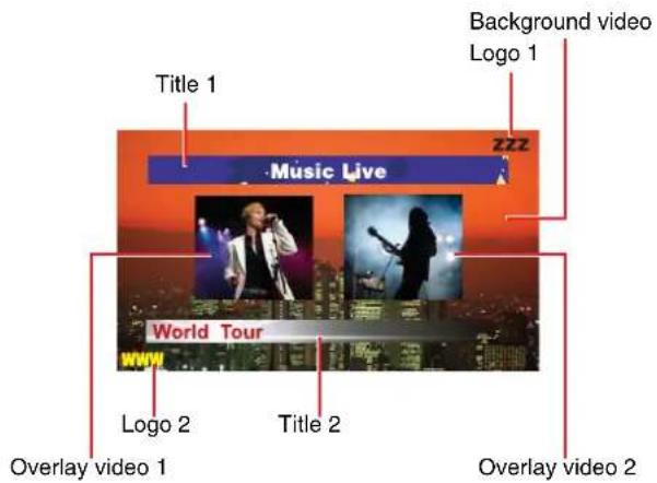
Composites can include up to two of each type of overlay (i.e., titles, logos, and overlay videos) at one time.
Variety of video inputs
The unit supports six video lines of input (HD/SD-SDI, composite, RGB, HDMI), allowing operations that utilize HD/SD video and PC signals at the same time, and production of a variety of video composites with high visual impact.
Video previewing
You can preview the video that will be used as the next program output in the [NEXT] viewer.
[PGM] viewer
Displays the current program output video.
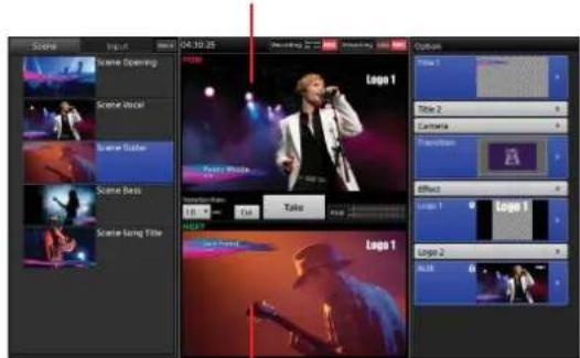
[NEXT] viewer
Displays the next program output video.
Saving video composites as scenes
You can save video composites as scenes that can be recalled whenever necessary.
Title creation
This unit includes a Titler function for creating titles via simple operations.
You can use the Titler to create titles that can be immediately inserted into videos or edited whenever necessary.
Recording to internal storage
You can record video composites and mixed down audio to the unit's internal storage. The recorded files can be edited using various nonlinear editors.
Two-channel output (AUX)
In addition to PGM, another video output (AUX) is available on this unit.
You can use this feature when you want to output two different videos using two projectors, or when you want to output a video without the titles and logos of the PGM output.
Audio mixing
You can mix up to five channels audio inputs.
Each channel is equipped with various functions, such as a fader, input trim, filter, equalizer, limiter, compressor, and pan (balance), allowing you to adjust the audio quality and levels for each channel individually.
Remote camera control
You can perform pan, tilt, zoom, and other remote controls for VISCA-compatible cameras. Pan, tilt, zoom, and other conditions can be saved as presets that can be recalled whenever necessary.
You can also track people and tap the [NEXT] viewer to move the center position of the camera to the tapped position.
Tally function
You can have the tally on a camera light when the camera's video is being used as the PGM output or NEXT selection source.
Tallies can also be displayed for the PGM output and NEXT selection sources in the [Input] list.
Streaming transmission
Video composites and mixed down audio can be encoded on the unit and streamed live using an external server, or recorded to the unit's internal storage as a VOD (video on demand) file.
System Configuration and Operation Flow
A system configuration example and the settings required for the configuration are described here.
Use in Various Events

flowchart
graph TD
    A["Large screen"] --> B["Projector"]
    C["Camera"] --> B
    D["Microphone"] --> B
    E["Microphone"] --> B
    F["Microphone"] --> B
    G["Microphone"] --> B
    H["Camera"] --> I["PA system/Speaker"]
    I --> J["Laptop"]
    K["AUX"] --> I
    L["Streaming transmission"] --> M["PGM"]
    M --> N["Computer used for presentation"]
    O["AWS-750"] --> I
    P["User group"] --> A
    Q["User group"] --> C
Preparation settings
• Video input/output settings (page 105)
• Audio input/output settings (page 108)
- Creating titles (page 46, 88)
• Preparing logos (page 46, 95)
- Creating and saving scenes (page 67)
- Assigning video inputs (page 41, 105)
- Streaming settings (page 81)
• AUX settings (page 73)
Operation flow

flowchart
graph TD
    A["Displaying camera images (page 30)"] --> B["Streaming transmission (page 81)"]

flowchart
graph TD
    A["Inserting titles and logos (page 46)"] --> B["Mixing audio (page 33)"]
    B --> C["Switching AUX sources (page 74)"]
    C --> D["Using the picture-in-picture effect (recalling scenes) (page 59, 67)"]
Use in Lectures and Seminars

flowchart
graph TD
    A["Camera"] --> B["Microphone"]
    B --> C["Large screen"]
    C --> D["Projector"]
    D --> E["PGM"]
    E --> F["Blu-ray disc / DVD"]
    F --> G["Nonlinear editing device"]
    G --> H["AWS-750"]
    H --> I["Computer used for displaying materials"]
    I --> J["Computer used for presentation"]
    J --> K["Remote camera"]
    K --> L["Cloud monitor with X^m(d/dx)^n(X^2-1)^n"]
Preparation settings
• Recording settings (page 79)
- Remote camera settings (page 101)
- Camera angle settings (page 49)
Operation flow

flowchart
graph TD
    A["Displaying images from the projector"] --> B["Recording (page 79)"]
    B --> C["Displaying camera images (page 30)"]

flowchart
graph TD
    A["Controlling remote cameras (page 49)"] --> B["Mixing audio (page 33)"]
    B --> C["Switching to picture-in-picture (page 59)"]
    C --> D["Exporting recorded material (page 96)"]
Parts Identification
Front

The unit's displays are touchscreens. For details on operations, see "Using the Touchscreens" (page 23).
①Main display
Displays the main screen used for performing video switching operations.
For details on basic operations, see "Main Screen" (page 35).
②Power indicator
Lights green when the unit is turned on.
③L button
Performs operations, such as source switching. The function of this button is identical to that of the [Take] button in the main screen.
④Internal speakers (L/R)
Outputs audio (L/R) for the monitor.
When headphones are connected to the HEADPHONES jack, output from the internal speakers is disabled.
⑤Sub display
Displays the sub screen used for adjustments, settings, and other operations.
For details on basic operations, see "Sub Screen" (page 39).
6R button
Performs operations, such as source switching. The function of this button is identical to that of the [Take] button in the main screen.
⑦ Access indicator
Blinks orange when the internal storage is being accessed.
Left

① Ventilation holes
Do not block the ventilation holes. Doing so may cause internal overheating, resulting in fire or damage to the unit.
When moving the unit after use, allow the unit to cool down sufficiently beforehand.
② (power) switch
Turns the unit on or off (page 27).
To turn off the unit, you can hold the switch for at least 4 seconds to force shutdown. If you force shutdown, the unit's settings data may not be saved in some cases.
③HEADPHONES jack (standard stereo phone)
Outputs audio for the monitor.
You can adjust the output level with [Monitor Level] in the [Audio Mixer] screen (page 34).
④ Release lever
Unlocks the main display from its closed state.
For details, see "Opening and Closing the Main Display" (page 20).
⑤Panel cover
Protects the main display.

Right

①USB ports ×4
Connect USB storage devices, keyboards, and other external devices here.
The SuperSpeed USB (USB3.0) is supported.
USB cameras and other USB devices not mentioned in this document are not supported.
Note
Each of the USB ports can supply a current of up to 900 mA. However, be sure to keep the total current of the four ports within 6 W (5 V 1200 mA). Operation may become unstable and the unit may not start up if 6 W is exceeded. Unusual amounts of heat may also be generated in such cases.
For details on using an external keyboard for video switching, see "Using External Devices for Video Switching and Other Operations" (page 87).
②Ventilation holes
Do not block the ventilation holes. Doing so may cause internal overheating, resulting in fire or damage to the unit.
When moving the unit after use, allow the unit to cool down sufficiently beforehand.
③ Release lever
Unlocks the main display from its closed state.
For details, see "Opening and Closing the Main Display" (page 20).
④ LAN 1 connector (RJ-45 modular jack)
⑤LAN 2 connector (RJ-45 modular jack)
Connect to a network when you want to control remote cameras via IP control or perform streaming transmissions, for example.
The LAN 1 connector is intended mainly for streaming, while the LAN 2 connector is intended mainly for camera control.
⑥ Reserve connector
Used for manufacturing purposes.
This cannot be used.
Rear
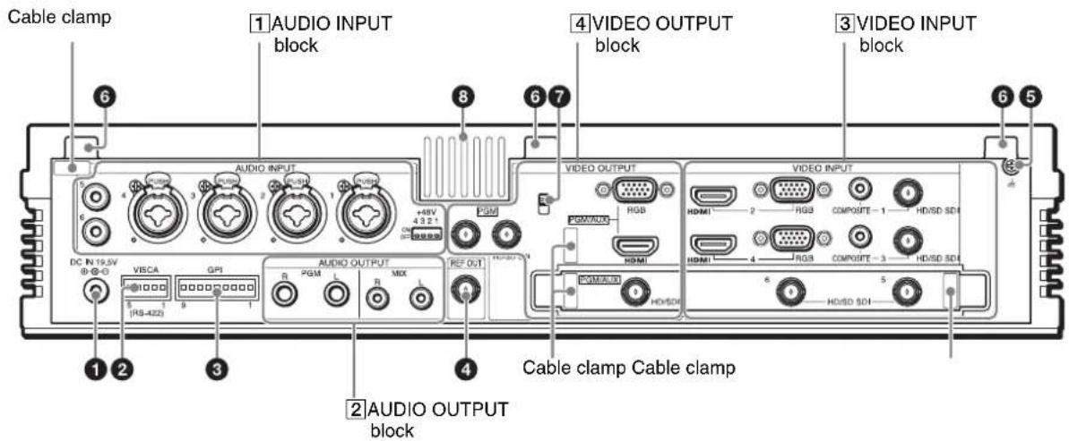
①DC IN 19.5V (DC power input) connector
Connect the supplied AC adapter here.
Be sure to use the nearby cable clamp to prevent the cable from disconnecting.
The AC adapter does not include an AC power cord.
For details on the AC power cord, see "Optional accessories" (page 117).
②VISCA connector (RS-422, 5-pin)
When you want to control a VISCA-compatible camera from this unit, connect the VISCA cable here (page 101).
For details on pin assignments on the connector, see "VISCA connector" (page 124).
③GPI connector
Connect this to the TALLY connector of a camera control unit (CCU) or similar device.
This allows you to light the tally lamps on the cameras being used as the PGM output and NEXT selection sources.
For details on settings, see "Lighting Tallies on Cameras Connected via GPI" (page 54).
For details on pin assignments on the connector, see "GPI connector" (page 123).
④REF OUT (reference signal output) connector (BNC type)
Outputs black burst (BB) signals.
⑤ (ground) connector
Connect the system grounding conductor here.
⑥Panel cover attachment points
Attach the hooks of the panel cover here (page 20).
⑦ Anti-theft wire slot
When you want to attach a commercially available anti-theft wire to the unit, attach it to this slot (3 × 7 mm (^1/8 in. × ^9/32 in.)) .
⑧ Ventilation holes
Do not block the ventilation holes. Doing so may cause internal overheating, resulting in fire or damage to the unit.
1 AUDIO INPUT block

①LINE IN connectors 5 and 6 (pin jacks)
Input analog audio signals from audio devices.
②MIC/LINE IN connectors 1, 2, 3, and 4 (balanced XLR 3-pin / TRS combo)
Input analog audio signals from microphones and audio devices.
③+48V switches
Use these when microphones that support external power supplies are connected to MIC/LINE IN connectors 1 to 4. When set to ON, the indicators light and +48V power is supplied from the unit.
Power is only supplied to the XLR connector contact points and not to the TRS contact points.
Use an insulated pointed object when setting a switch to the ON or OFF position.
Note
Always set these switches to OFF when you are not using microphones that supports external power supplies.
② AUDIO OUTPUT block

①PGM (PGM audio output) connectors L and R (balanced TRS)
Outputs program audio that was mixed down on this unit.
②MIX (MIX audio output) connectors L and R (pin jacks)
Outputs mixdown audio other than the program audio.
③VIDEO INPUT block
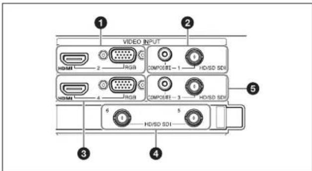
For details on supported signal formats, see "Supported Input Formats" (page 119).
①HDMI (HDMI input) connector 2 (Type A)
Inputs HDMI signals.
Notes
- Use a Sony HDMI cable.
Recommended cable example: HIGH SPEED HDMI CABLE DLC-HJ20 (2 m (6.6 feet)) - Use HDMI connector 4 when inputting copyright protected (HDCP) signals.
RGB (RGB video input) connector 2 (mini D-sub 15-pin)
Inputs RGB signals.
Tip
HDMI connector 2 and RGB connector 2 cannot be used simultaneously. Select one or the other for use.
② COMPOSITE (composite video input) connector 1 (pin jack)
Inputs analog video signals.
HD/SD SDI (SDI input) connector 1 (BNC type) Inputs HD/SD-SDI signals.
Tip
COMPOSITE connector 1 and HD/SD SDI connector 1 cannot be used simultaneously. Select one or the other for use.
③HDMI (HDMI input) connector 4 (Type A)
Inputs HDMI signals.
Note
Use a Sony HDMI cable.
Recommended cable example: HIGH SPEED HDMI CABLE DLC-HJ20 (2 m (6.6 feet))
For details on input of copyright protected (HDCP) signals, see “[HDCP Handling]” under “System” (page 107).
RGB (RGB video input) connector 4 (mini D-sub 15-pin)
Inputs RGB signals.
Tip
HDMI connector 4 and RGB connector 4 cannot be used simultaneously. Select one or the other for use.
④HD/SD SDI (SDI input) connectors 5 and 6 (BNC type)
Inputs HD/SD-SDI signals.
⑤ COMPOSITE (composite video input) connector 3 (pin jack)
Inputs analog video signals.
HD/SD SDI (SDI input) connector 3 (BNC type) Inputs HD/SD-SDI signals.
Tip
COMPOSITE connector 3 and HD/SD SDI connector 3 cannot be used simultaneously. Select one or the other for use.
4VIDEO OUTPUT block
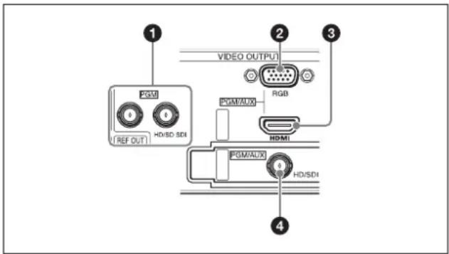
For details on supported signal formats, see “Supported Output Formats” (page 120).
①HD/SD SDI (SDI output) connectors (PGM only) (BNC type) × 2
Outputs the finished video processed on this unit (i.e., program video) as HD/SD-SDI signals.
②RGB (RGB output) connector (PGM/AUX) (mini D-sub 15-pin)
The following video is output as RGB signals based on whether PGM or AUX is selected.
PGM: PGM video
AUX: AUX video
For details on selecting PGM or AUX, see “[Video Setup] Screen” (page 105).
③HDMI (HDMI output) connector (Type A)
The following video and audio are output as HDMI signals based on whether PGM or AUX is selected.
- Video
PGM: PGM video
AUX: AUX video
• Audio
PGM: PGM audio
AUX: MIX audio
For details on selecting PGM or AUX, see “[Video Setup] Screen” (page 105).
Note
Use a Sony HDMI cable.
Recommended cable example: HIGH SPEED HDMI
CABLE DLC-HJ20 (2 m (6.6 feet))
④ HD SDI (SDI output) connector (PGM/AUX) (BNC type)
The following video and audio are output as HD SDI signals based on whether PGM or AUX is selected.
- Video
PGM: PGM video
AUX: AUX video
- Audio
PGM: PGM audio
AUX: MIX audio
For details on selecting PGM or AUX, see “[Video Setup] Screen” (page 105).

Opening and Closing the Main Display
Opening the Main Display
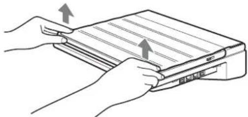
1 Lift the front portion of the panel cover to unlock it.
natural_image
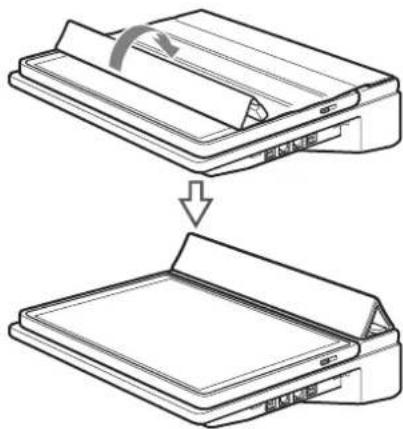
Line drawing of hands installing or adjusting a device panel (no text or symbols present)2 Open the panel cover.
natural_image
Diagram showing a folding or sheeting process of a document, with no visible text or symbols.Note
Initially, the panel cover may be stiff and may flip back to its original position.
3 Pull the release levers on the left and right sides in the direction of the arrows.

The left and right locks will release.
4 Lift the areas near the release levers, and slide the main display in the direction of the arrow.

natural_image
Line drawing of hands using a device to press or install a tablet (no text or symbols visible)The magnet locks will lock the display into place.

natural_image
Line drawing of a laptop with a flat screen and open base (no text or symbols)Magnet locks
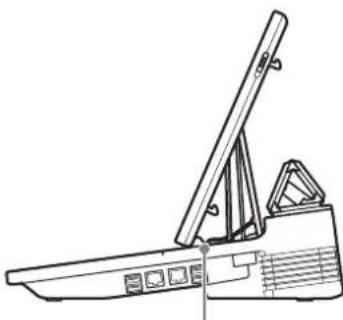
natural_image
Line drawing of a mechanical device with a lever and base (no text or symbols)Magnet lock (one each on left and right side)
Tip
The panel cover includes mounting hooks. You can attach and detach the hooks to the rear of the unit to attach or remove the cover.

Closing the Main Display
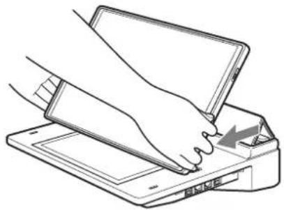
1 Hold the sides of the main display as illustrated, and pull the display in the direction of the arrow.
The magnet locks will release.
natural_image
Line drawing of a hand inserting a card into a printer (no text or symbols)2 Slide the main display to the position illustrated, and push the display in the direction of the arrows to lock it into place.
Make sure that the four hooks (two each on the right and left sides) are secure and that the main display does not open.

natural_image
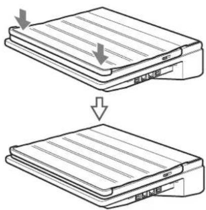
Diagram of a printer with two arrows indicating compression or disassembly (no text or symbols present)3 Close the panel cover.

natural_image
Line drawing of a printer with a paper roll and arrow indicating rotation (no text or symbols)4 Push in the direction of the arrows to lock the panel cover onto the main display.
Applying the Anti-Glare Films
Anti-glare films are supplied with this unit to protect the touchscreen displays.
Apply the anti-glare films in a dust-free environment to prevent dust from sticking to the films due to static electricity. In addition, apply the films in a well-lit environment so that you can see if air bubbles form.
Notes
- The anti-glare films cannot be reapplied once they are applied. Apply the anti-glare films with great care.
- Any dust left on the touchscreen surface will result in air bubbles.
Items to prepare
- Screen-cleaning solution
- Cleaning cloth (non-woven)
• Vinyl tape (3 cm (1 ^3 /16 in.) or more in width)
Applying the film to the main display
1 If the protective sheet from the factory is still attached, remove it.
2 Use the screen-cleaning solution and cleaning cloth to clean the main display and remove any fingerprints, dust, or smudges.
Be sure to also remove any leftover adhesive from the protective sheet from the factory that you removed.
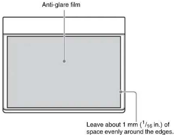
3 Place the anti-glare film for the touchscreen on the main display with its glossy side facing down.

Placement
Center the film so that the surrounding uncovered edges of the display are even.
Note
If you place the film all the way to the edge of either side, the film may shift as you are applying it to the display, resulting in misalignment.
4 Use vinyl tape to affix the anti-glare film to the right side of the display.

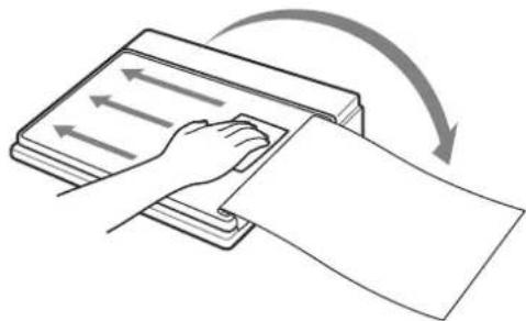
5 Flip the anti-glare film over, and use the screen-cleaning solution and cleaning cloth to wipe off any dust.
Wipe in a single direction from right to left. Verify that all specks of dust have been removed from the surface of the main display.
natural_image
Illustration of a hand pressing down on a sheet of paper with directional arrows indicating motion (no text or symbols)6 Place the anti-glare film back on the main display.
7 Peel off a portion of the backing sheet from the anti-glare film on the side with the vinyl tape (i.e., the inside), and use the cleaning cloth to slowly smooth out any air bubbles, starting from the center of the right side.
Apply the film while gradually peeling the backing sheet.

natural_image
Diagram showing a device being processed with a curved arrow indicating rotation (no text or symbols present)If air bubbles or leftover dust occur
- Remove the anti-glare film up to the location of the air bubble or leftover dust, and remove the air or dust as you reapply the film. In such cases, do not remove the entire film. You will not be able to reapply the film if you do so.
- If specks of dust are attached to the adhesive surface of the anti-glare film, use the adhesive surface of vinyl tape to remove them.
8 When the anti-glare film is fully applied, firmly rub the edges of the film.
9 Verify that there are no air bubbles or leftover dust, and remove the vinyl tape.
10 Use the screen-cleaning solution and cleaning cloth to wipe the anti-glare film.
Applying the film to the sub display
Apply the anti-glare film to the sub display using the procedure used for the main display.
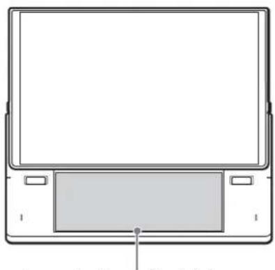
Place the anti-glare film on the sub display as follows.
Placement
Align the film with the front edges.
natural_image
Line drawing of a laptop front panel with control buttons and a screen (no text or symbols)Leave about 1 mm ( ^1/_16 in.) of space around the three front edges.
Using the Touchscreens
You can perform touchscreen gestures on the main display and sub display with your fingers in place of keyboard and mouse operations.
This section describes how to perform basic touchscreen operations.
Tip
Operation errors may occur on the touchscreens if the unit is in close proximity to transceivers or other devices that emit high interference. Keep sufficient distance between the unit and such devices to prevent errors.
Tap
Lightly tap on a position on the screen. This performs the same operation as clicking on a mouse.
Use this gesture to perform operations, such as making and confirming selections.

natural_image
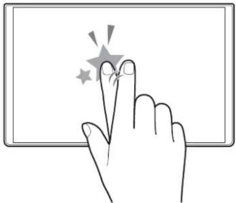
Hand pointing at a star icon on a tablet screen (no text or symbols)Double-tap
Lightly tap a position on the screen twice. This performs the same operation as double-clicking on a mouse.
natural_image
Illustration of a hand pressing a button with stars around it (no text or symbols)
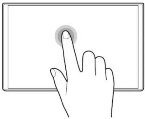
Tap and hold
Hold your finger in place for at least 1 second after tapping.
Use this gesture to perform operations, such as displaying context menus and viewing filenames that end in “...” in their entirety.
natural_image
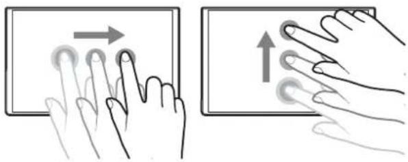
Illustration of a hand pressing a button on a tablet screen (no text or symbols)Drag
Slide your finger while holding it on the screen. This performs the same operation as dragging on a mouse. Use this gesture to perform operations, such as scrolling through lists and moving sliders.
natural_image
Illustration showing two hand gestures interacting with a tablet screen (no text or symbols)Flick
Slide your finger quickly and release.
Use this gesture to perform operations, such as scrolling quickly through lists.

natural_image
Illustration of two hands interacting with a tablet device, one pointing upward (no text or symbols)Getting Started
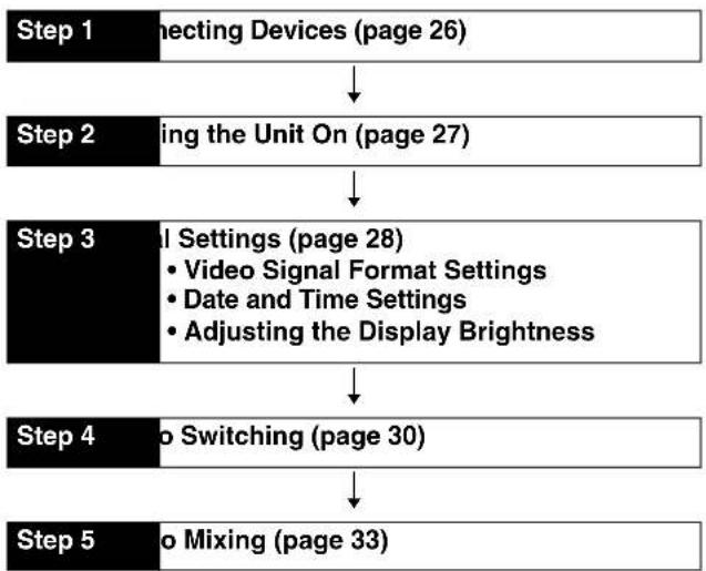
Operation Flow
This chapter describes the procedures for using the unit for the first time, including the connection of various devices, video switching, and audio adjustment. Perform the steps in this chapter and begin switching video to get started.
flowchart
graph TD
    A["Step 1 Connecting Devices (page 26)"] --> B["Step 2 Using the Unit On (page 27)"]
    B --> C["Step 3 Sett Settings (page 28)<br>• Video Signal Format Settings<br>• Date and Time Settings<br>• Adjusting the Display Brightness"]
    C --> D["Step 4 No Switching (page 30)"]
    D --> E["Step 5 No Mixing (page 33)"]
For details on operating the touchscreen, see "Using the Touchscreens" (page 23).
Default conditions of the unit
- Video input
| [Input] list display | Connector number | Input signal |
| IN1 1 SDI | ||
| IN2 2 HDMI | ||
| IN3 3 SDI | ||
| IN4 4 HDMI | ||
| IN5 5 SDI | ||
| IN6 6 SDI | ||
| Black Black signal generated internally by the unit | ||
| Color Bars Color bar signal generated internally by the unit | ||
• System format 1080 60i
• Channel fader assignments
| Name | Signal name | Input (L) | Input (R) |
| Fader 1 MIC1 | MIC/LINE1 | MIC/LINE1 | |
| Fader 2 MIC2 | MIC/LINE2 | MIC/LINE2 | |
| Fader 3 MIC3 | MIC/LINE3 | MIC/LINE3 | |
| Fader 4 MIC4 | MIC/LINE4 | MIC/LINE4 | |
| Fader 5 Used for audio embedded in SDI or HDMI signals or in videos played back in the Media Player (i.e., embedded audio). | |||
For details on changing the settings, see "Settings" (page 99).
Step 1: Connecting Devices
Connect the various devices to the rear of the unit.
If you have already connected the devices, proceed to "Step 2: Turning the Unit On" (page 27).
Connection example

1) When using 48 V condenser microphones (supporting external power supply), set the +48V switches on the rear panel to the ON positions.
2) For details on enabling and disabling input of copyright protected (HDCP) signals, see “[HDCP Handling]” under “System” (page 107).
3) For details on the AC adapter, see “① DC IN 19.5V (DC power input)” under “Rear” (page 17).
Step 2: Turning the Unit On
Turning the unit on
1 Connect the DC output plug of the supplied AC adapter to the DC IN 19.5V connector on the rear of the unit, and connect the AC adapter to a power supply.
2 Open the display on the unit.
For details, see "Opening and Closing the Main Display" (page 20).
3 Press the ⏻ switch on the left side of the unit.
When power is supplied, the power indicator on the front left side of the unit lights green, and the unit starts up.

natural_image
Front view of a portable electronic device with indicator lights and control buttons (no text or symbols on the device itself)The startup screen appears.
When startup is complete, the main screen and sub screen appear, and you can perform operations.
Main screen

If video is being input from cameras or other devices, the video will appear immediately.
Note
This unit is designed to be used with the main display in its upright position. Do not perform operations with the main display closed.
Turning the unit off
Press the ⏻ switch on the left side of the unit. A confirmation message appears.
The current conditions are saved before the unit shuts down and turns off. (The power indicator will turn off.)
Note
If you want to turn the unit on again after turning it off, wait at least 5 seconds before pressing the power switch again.
Step 3: Initial Settings
Specify the video signal format that will be handled by the unit and the date and time. If necessary, you can also adjust the brightness of the display.
If you have already configured these settings, proceed to "Step 4: Video Switching" (page 30).
Video Signal Format Settings
Specify the video signal format handled by the unit (i.e., system format) when necessary.
The default setting is [1080 60i].
Tip
The [60i] setting is actually equivalent to "59.94i."
Configuration is performed in the sub screen.
1 Tap at the top right of the sub screen.
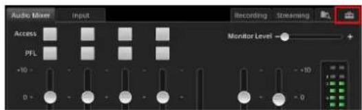
The [System Setup] screen appears.
2 Tap [Video].

The [Video Setup] screen appears.
3 Tap [System] in the menu to the left.

The [System] screen appears.
4 Select the system format in the [System Format] drop-down list.
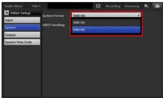
A confirmation message for restarting the unit appears.
5 Tap [Shutdown].
The unit shuts down.
6 Press the ⏻ switch on the left side of the unit to turn on the unit.
Changes to the system format will be applied after the unit restarts.
Date and Time Settings
Configure the unit's internal clock.
This setting is used for the following.
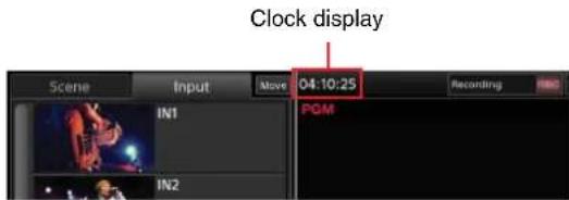
- Clock display in the main screen
- File creation and file update date and time
- System timecode
1 Tap the -tab to display the [System Setup] screen, and then tap [Date/Time].

The [Date/Time] screen appears.
2 Select the time zone.
①Select the area in the [Area] drop-down list.

The [Region] setting changes according to the selected area.
②Select the region in the [Region] drop-down list.

3 Specify the current date and time.
①Tap the [Date/Time] field.
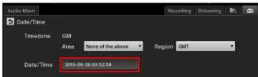
The configuration dialog box appears.
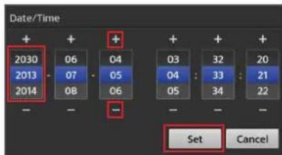
②Specify the month, day, year, hour, minute, and second in order, and then tap [Set]. The values highlighted in blue indicate the currently selected values. If the values you want to specify are not displayed,
drag the values up or down, or tap [+] or [-] to display the values.
A confirmation message appears.
③Tap [Shutdown].
The unit shuts down.
④ Press the ⏻ switch on the left side of the unit to turn on the unit.
Changes to the date and time will be applied after the unit restarts.
Adjusting the Display Brightness
You can adjust the backlight of the displays.
In the [System Setup] screen, drag the [LCD Backlight] sliders to adjust the brightness.
Use the [Main] slider to adjust the main screen and the [Sub] slider to adjust the sub screen.

Step 4: Video Switching
This section describes how to select an input source in the [Input] list and switch the program output video via simple operation.
Video switching is performed in the main screen.
Switching after Viewing a Preview Video
You can switch to the next video that you want to use for program output while viewing it as a preview video. The next program output video appears in the [NEXT] viewer.
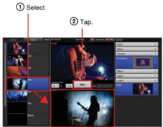
1 Tap [Input] to display the [Input] list.
The video currently being used for program output appears in the [PGM] viewer. Under initial conditions, a black signal is output.
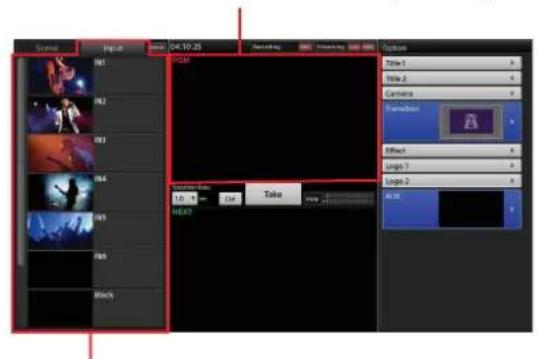
[Input] list
Displays videos being input to the unit (i.e., input sources).
2 In the [Input] list, select the input source you want to use for the program output.
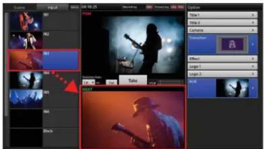
The selected input source appears in the [NEXT] viewer as the next video that will be used for program output.

The next program output video appears in the [NEXT] viewer.
3 Tap [Take].
![[Take] Scene Input View 04.10.25 Action Strike 1 Strike 2 Camera Animation Effect Logic 1 Logic 2 OK](/content/2026/05/882243/images/bb7f7db22084b418f55d82c0afb2b331fa79d59516331efd2e254b48266ddcdf.jpg)
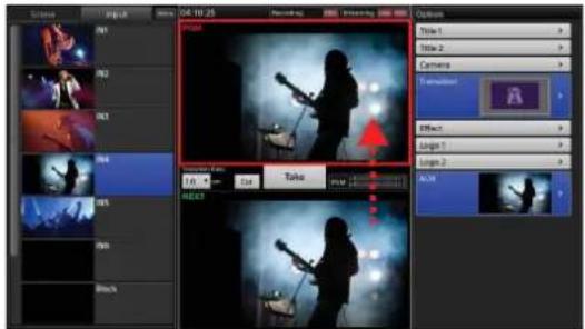
The video in the [NEXT] viewer appears in the [PGM] viewer and is output as the PGM output.
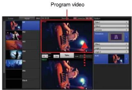
Tip
Pressing the L or R button at the left or right of the sub display performs the same operation as tapping [Take].
4 Repeat steps 2 to 3 to switch from one video to the next.

Videos switch from one to the next.

Tip
Under default conditions, tapping [Take] dissolves one video into the next using the “mix” transition method during switching. To instantly switch to the next video without a transition effect, use [Cut].
![[Cut] Transition Rate: 1.0 sec Cut Take PGM NEXT](/content/2026/05/882243/images/f73b22161c2142677fcf6c6328197ecaa2717f455604739253fd6120cc55f426.jpg)
For details on selecting transition methods other than mix, see “Using Transition Effects” (page 32).
Switching the PGM Directly (Direct Take)
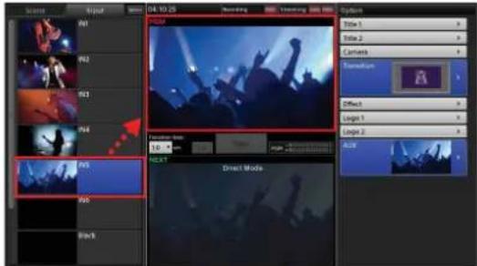
You can also switch the program video directly, without previewing videos in the [NEXT] viewer. This operation is referred to as a "direct take."
Direct takes are performed in direct mode.
1 Tap anywhere inside the [PGM] viewer to enter direct mode.

Direct mode is enabled, and the [NEXT] viewer display dims. In direct mode, "Direct Mode" appears in the [NEXT] viewer.

2 In the [Input] list, select the input source you want to use for the program output.
When you select the input source, the program video switches using the currently configured transition.
3 Repeat step 2 to switch from one video to the next.
For details on selecting other transition methods, see "Using Transition Effects" (page 32).
Exiting direct mode
Tap anywhere inside the [PGM] viewer again.
When you exit direct mode, the [NEXT] viewer brightens again.
Tip
Direct mode can also be used for switching operations outside of the [Input] list.
Using Transition Effects
You can select from the following transitions for video switching on this unit.
Tip
The transition function includes some limitations.
For details, see "General Limitation on Transitions" (page 127).
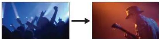
Cut
Switch from A to B instantly without transition effects.
A
natural_image
Two side-by-side photos: left shows silhouetted crowd under blue lighting, right shows silhouette of a musician with microphone (no text or symbols)Mix
Dissolve from one video into the next.

natural_image
Three sequential photos showing a crowd silhouette, a person holding a microphone, and a man in a hat, all in warm tones (no text or symbols)Wipe
Wipe the next output video over the program video.

natural_image
Sequence of three photos showing a person silhouette against a stage with raised arms, captured in blue and red tones (no text or symbols)1
In the [Input] list, select the input source you want to use for the next program output.

The selected video appears in the [NEXT] viewer.
2
In the [Option] menu, tap the area on the right side of the [Transition] button.
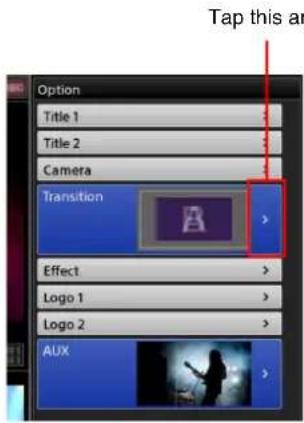
The [Transition] list appears.
3
Select the transition method you want to use, and then tap >.
You can select from four different directions for wipes.
![②Return to the [Option] menu. ① Select the transition method. Transition Cut Cut Mix Wipe 1 Wipe 2 Wipe 3 Wipe 4](/content/2026/05/882243/images/0a2eb43fdd25daaef66484d12db423832f06ce8bce4a35fe7231f520f3858acf.jpg)
The [Transition] list closes, and the [Option] menu appears again.
4
If you want to change the transition rate, select a transition rate in the [Transition Rate] drop-down list.
The default transition rate is 1.0 second.

Tip
If you selected [Cut] in step 3, switching will be instantaneous regardless of whether you changed the transition rate.
5 Tap [Take] to execute the transition.

The program video switches using the selected transition.
For details on changing the values for the [Transition Rate] options, see “[Transition Rate]” (page 109).
Step 5: Audio Mixing
You can mix the audio being input to the unit and mix it down to stereo program audio.
Audio operations are performed in the sub screen.
This section describes how to adjust the audio for each microphone and mix multiple audio channels.
1 Adjust the audio for each microphone.
Adjustments are made separately for each microphone.
Move the sliders while verifying the audio output and audio level meter.

Tips
- You can operate five channel faders at the same time.
- Channel 5 is reserved for the audio embedded in the SDI or HDMI video played back in the Media Player (embedded audio).
For details, see "Adjusting the Embedded Audio of Input Sources" (page 78). - A fader can be adjusted even when the channel is off. The adjustment will be enabled when the channel is turned on.
- If sound is barely audible even at the maximum channel fader level, change the MIC/LINE input level to [Low (-44dB)] in the [Audio Setup] screen. You can also adjust this in [Input Trim] (page 77) of the [Access] screen.
For details on configuration, see “[Input Channel Assign]” (page 108).
Viewing the audio level meter

2 Drag the slider for the PGM OUT fader to adjust the program output level.
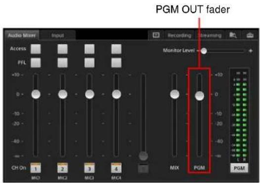
Checking each audio input
You can check the audio of each channel via the HEADPHONES jack or the internal speakers using the respective [PFL] buttons (pre-fader listen).
Tap and hold a [PFL] button to monitor only the audio from that channel while the button is held. The audio will be monitored until you release the button.
Tip
The program output, AUX output, and MIX output are not affected during pre-fader listen.
[PFL] buttons

In addition, the audio level meter switches to PFL mode (the button display switches to [PFL]) while the [PFL] button is held down, allowing you to check the levels of the audio input.
Adjusting the audio level for monitoring
Drag the [Monitor Level] slider to adjust the output level of the HEADPHONES jack and internal speakers within a range of 0 to 255.
![[Monitor Level] adjustment Recording Streaming Monitor Level - +](/content/2026/05/882243/images/accd9831bf87f9c86d247011bc684d1814c16d2c1eed725ab6c9901b05ed8deb.jpg)
For details on further operations and adjustments, see "Performing Detailed Audio Adjustments" (page 76).
Afterward
Proceed to “Basic Operations” (page 35) to gain a better understanding of this unit’s functions and how to master their operation.
Basic Operations
Using the Screens
This section describes the features of the main screen and sub screen and how to operate them.
Video switching is performed in the main screen, while various adjustments and settings are performed in the sub screen.
The results of adjustments and settings are applied immediately in the main screen. Depending on the adjustments and settings, perform them while viewing the main screen.
Main Screen
You can perform video switching operations in the main screen.
Parts identification
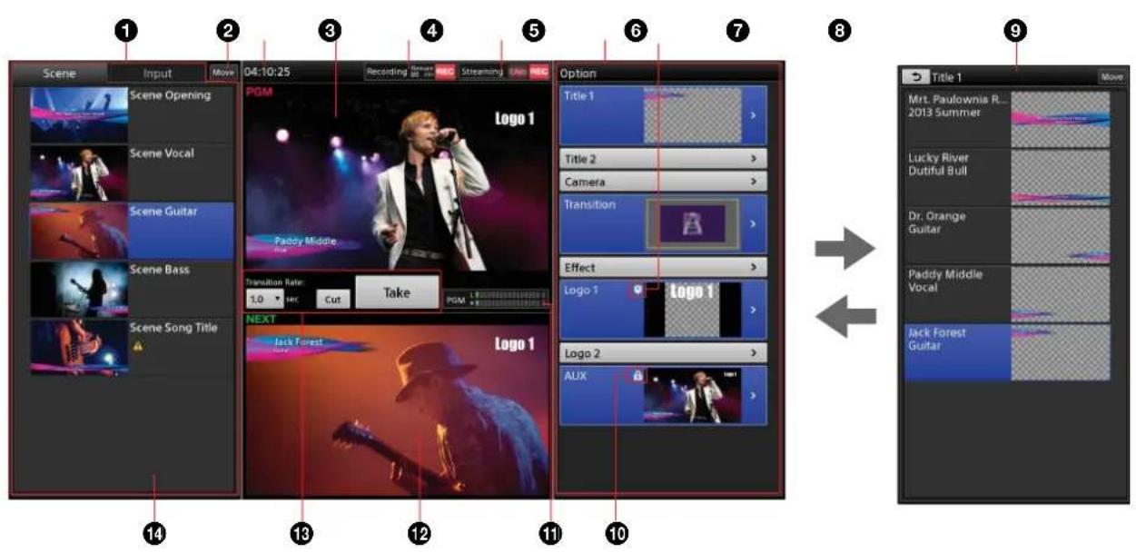
①[Scene] list / [Input] list
Videos that can be used as program output are displayed here. Select the button of the video you want to use for the program video from either list.
- The source currently selected in the [NEXT] viewer will be highlighted with a blue background.
![SONY Anycast Touch Live AWS-750 - ①[Scene] list / [Input] list - 1](/content/2026/05/882243/images/b11ece95d6529200c821b6a93ba3537d972b56c9a4fbf5e927f84387173e5e50.jpg)
- A light blue frame will appear around a source that is currently the target of an operation, such as deletion.
![SONY Anycast Touch Live AWS-750 - ①[Scene] list / [Input] list - 2](/content/2026/05/882243/images/aff8247792116ac1235dab8381622296d4c5750b084cfcb6babfeb55c020d9c2.jpg)
[Scene] list: Displays a list of registered scenes.
For details on loading saved scenes, see "Recalling Scenes" (page 69). For details on saving scenes, see "Creating Scenes" (page 67).
[Input] list: Displays a list of videos being input to the unit's input connectors, signals created internally on the unit (i.e., black and color bar signals), and other input sources. You can also add sources to the list and edit them.
For details, see "Creating Lists" (page 41).
When tally display is enabled
Tallies are displayed for the PGM output and NEXT selection sources in the [Input] list. The tallies are only displayed in the [Input] list.
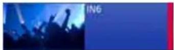
• PGM output source: Red tally

• NEXT selection source: Green tally
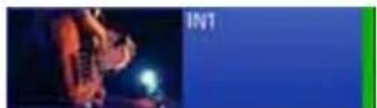
- Source selected as both the PGM output and NEXT selection: Red tally
For details on GUI tallies, see "Using the GUI Tally Function" (page 53).
②[Move]
Allows you to change the sort order of the items displayed in the [Scene] and [Input] lists (page 45).
③Clock display (page 28)
④[PGM] viewer
Displays the current program output video.
⑤Recording status
Program outputs and AUX outputs can be recorded onto the unit's internal storage in high-quality picture and audio.
The recording status is indicated in this area as follows.
![[Remain Time] Recording Remain 80 min REC [REC]](/content/2026/05/882243/images/80589a1efc517ce9c62dff14a71938fc0ff54916e93e4b6905d15890a1350f80.jpg)
[Remain Time]: When recording is in progress, this displays the remaining recording time. The
remaining time is continuously updated based on the status of the internal storage.
[REC]: When recording is in progress, this lights red. The indicator starts to blink when the remaining recording time reaches 10 minutes. When recording is not in progress, this will remain unlit. Tapping this area (i.e., within the frame) displays the [Recording] screen (page 79) in the sub screen.
For details on recording, see "Recording Outputs from the Unit to the Internal Storage" (page 79).
⑥Streaming status
Program video can be encoded on the unit and streamed live using an external server or recorded as a VOD (video on demand) file.
The streaming status is indicated in this area as follows.
![Streaming Live [Live] [REC] Throughput](/content/2026/05/882243/images/5ed7ee67855f010280ef2c8abea16f46a32b2a1f50611bce0333b5cbcb3624ff.jpg)
[Live]: When live streaming is in progress, this lights red. When streaming is not in progress, this will remain unlit.
[REC]: When recording is in progress, this lights red. When recording is not in progress, this will remain unlit.
Throughput: When streaming is in progress, this indicates the throughput. When the specified bit rate is met, the indicator lights green all the way to the far right end. As the throughput decreases and transmission slows, the indicators will turn yellow and eventually turn red. When streaming is not in progress, this will remain unlit.
Tapping this area (i.e., within the frame) displays the [Streaming] screen (page 81) in the sub screen.
For details on streaming, see "Streaming" (page 81).
⑦[Option] menu
Displays a list of options that can be added to the material that will be output next.
[Title 1] / [Title 2]: Insert titles onto the video (page 46).
[Camera]: When remote control is configured for the camera video, this allows you to save or load presets (page 52).
[Transition]: Select the transition method (page 32).
[Effect]: Compose a picture-in-picture (PinP) video with a video overlaid on another video (page 59), or insert people onto backgrounds via chroma keying. Composites that include both PinP and chroma keying are possible (page 63).
[Logo 1] / [Logo 2]: Insert logos onto video (page 46).
[AUX]: Select the material to output to AUX after a take (page 73).
To enable or disable options
Tap the following area of the button to enable or disable the respective option.
Enabled
The option is selected for use in the next program output.

Disabled
The material is ready for use but is not selected for use in the next program output.

Closed buttons
If the material for an option is not ready for use or the option is excluded from use with the next program output, the button will be closed.

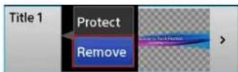
To close a button
Display the context menu of the respective button, and select [Remove].
To display the list for an option
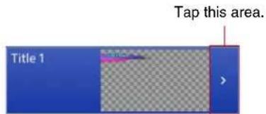
Tap the following area of the button to display the list for that option (see 8) that allows you to configure the option content.
- When the button is open
- When the button is closed
Tapping any area will display the list.

⑧ (Potect) icon
Indicates that the current title or logo is protected. When an item is protected, its current status is retained. Therefore, recalling a scene will not change its status.
When you recall a scene while a title or logo is protected, the video composite will be as follows.

To enable protection
Display the context menu for the [Title 1] / [Title 2] button or the [Logo 1] / [Logo 2] button in the [Option] menu, and select [Protect].
To disable protection
Display the context menu for the [Title 1] / [Title 2] button or the [Logo 1] / [Logo 2] button in the [Option] menu, and select [Unprotect].
⑨Option list
Displays a list of content for the option. Select the content you want to add to videos in this list.
Example: [Title 1] list
![Return to the [Option] menu. Change the sort order of the list (page 45). Title 1 Move Mt. Paulownia R... 2013 Summer Lucky River Dutiful Bull Dr. Orange Guitar Paddy Middle Vocal Jack Forest Guitar The currently enabled button is highlighted with a blue background.](/content/2026/05/882243/images/a04f1c325eada7a6c23bcda3a264016d9c9107046b980f21c2174abad7fc0ca7.jpg)
A light blue frame will appear around an option that is currently the target of an operation.
For details on editing the list, see “Creating Lists” (page 41).
⑩ (AUX lock) icon
Indicates that selection operations for the [AUX] list are locked.
Use this function when you are using the AUX video for the purposes recording, for example, and you do not want to perform switching.
Tips
- Direct mode operations while the lock is enabled do not affect the [AUX] list.
- The AUX lock applies to selection operations in the [AUX] list. If a source other than the AUX output is selected, that material will be output as AUX after a take.
To enable the lock
Display the context menu of the [AUX] button and select [Lock].

When you lock the status, the icon appears in the [Option] menu and [AUX] list of the main screen.
• [AUX] button in the [Option] menu

- Top of [AUX] list

To release the lock
Select [Unlock] in the context menu.
⑪Audio level meter
Displays the audio levels of the program output or the MIX output within a -60 dB to 0 dB range.
Viewing the audio level meter
![The far-left “—∞” level is always lit green. PGM L R Over-level indicator Lights red at the 0 dB level. Lights green up to the current level. The setting in the [Audio Mixer] screen of the sub screen appears here.](/content/2026/05/882243/images/28a3dd711fa4b1ae1554f09e503f15178323d0e594fe05daa9085bdbc76a7b95.jpg)
12[NEXT] viewer
Displays the next program output video. You can also preview options here.
13 Program output control area
Allows you to perform operations for the program output.
[Transition Rate]: Adjusts the transition rate of program video switching.
[Cut]: Switches the program video using a cut transition.
[Take]: Switches the program video using the selected transition method and transition rate.
The transition method is selected in [Transition] of the [Option] menu. For details, see “Using Transition Effects” (page 32).
14 mark
This warning mark appears if a problem exists with materials in the [Scene] list or [Option] menu.
For details, see “Icon Displays in Lists” (page 112).
Sub Screen
You can perform adjustments, configure settings, and enter text in the sub screen. Tapping each tab displays its respective operation screen.
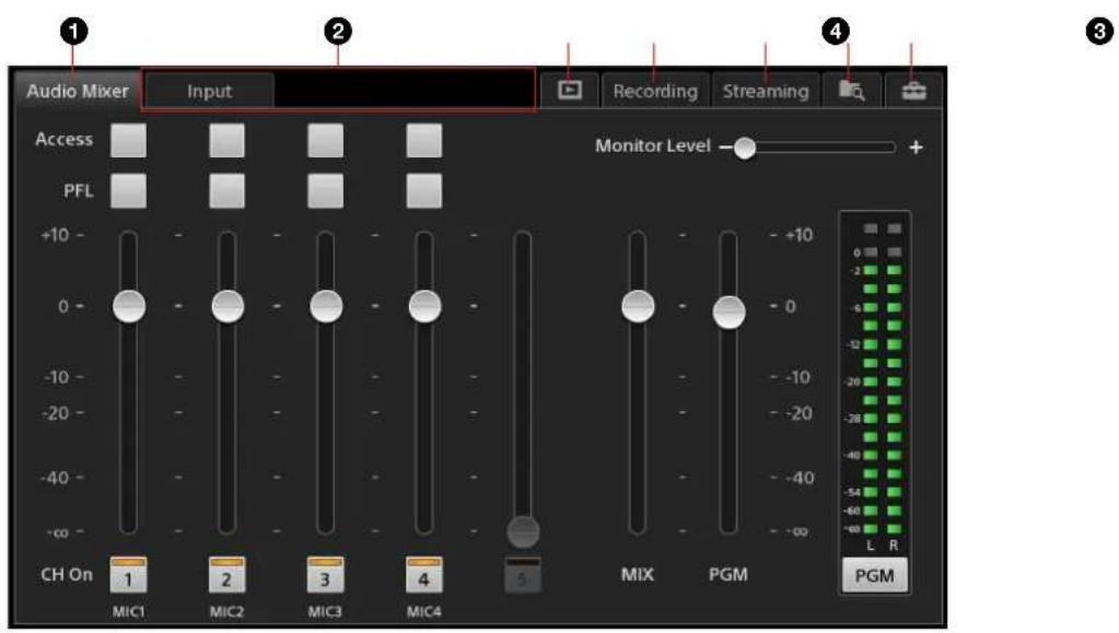
①[Audio Mixer] screen
Allows you to perform audio adjustments and mixing.
The [Audio Mixer] screen appears immediately after the unit starts up.
For details, see "Step 5: Audio Mixing" (page 33).
②Tabs that appear according to the selections and status of the main screen
[Input] tab
Appears when the input source selected in the [Input] list of the main screen includes audio.
Allows you to enable or disable the embedded audio.
Tip
When compositing video using PinP or chroma keying, the [Input] tab will only appear when an input source from the [Input [1]] list is selected. Embedded audio cannot be used for input sources in the [Input [2]] and [Input [3]] lists.
For details, see "Adjusting the Embedded Audio of Input Sources" (page 78).
[Camera] tab
Appears when a remote camera is assigned to the input source selected in the [Input] list of the main screen.
Allows you to perform manual controls for the remote camera, and configurations and adjustments for the tracking function.
For details, see "Controlling Remote Cameras" (page 49).
[Title] tab
Appears when the [Title 1] or [Title 2] list is displayed in the main screen.
Allows you to adjust the title appearance.
For details, see “To adjust the appearance of composites” (page 47) in the “Viewing Title Composites” section.
[Effect] tab
Appears when the [Effect] list is displayed in the main screen.
Allows you to adjust the size and position of the overlay video and the appearance of chroma key composites.
![SONY Anycast Touch Live AWS-750 - [Effect] tab - 1](/content/2026/05/882243/images/8aa71e238b218e6928aee535675b352b6ba5122885a60117c2b7b871325656e5.jpg)
For details, see “Compositing Videos Using Picture-in-Picture (PinP)” (page 59) and “Inserting People onto Backgrounds (Chroma Keying)” (page 63).
[Logo] tab
Appears when the [Logo 1] or [Logo 2] list is displayed in the main screen.
Allows you to adjust the logo position.
For details, see “To adjust the position” (page 48) in the “Viewing Logo Composites” section.
③(Media Player) tab
Appears when [Media Player] is registered in the [Input] list or [AUX] list of the main screen.
Allows you to perform playback operations for movies (or still images) using the Media Player.
For details, see “Playing Back Material Files in the Media Player” (page 55).
④[Recording] tab
Output can be recorded onto the unit's internal storage in high-quality picture and audio. You can perform operations and configurations related to recording in the [Recording] screen.
For details, see “Recording Outputs from the Unit to the Internal Storage” (page 79).
⑤[Streaming] tab
Output can be encoded on the unit and streamed live using an external server or recorded as a VOD (video on demand) file. You can perform operations and configurations related to streaming in the [Streaming] screen.
For details, see "Streaming" (page 81).
⑥ (file manager) tab
Allows you to manage files stored on the unit's internal storage.
For details, see “Managing Files (File Manager)” (page 93).
⑦ (system setup) tab
Allows you to configure system settings for the unit.
Creating Lists
You can create lists by adding materials to the [Input] list, [Title 1]/[Title 2] list, [Logo 1]/[Logo 2] list, and [AUX] list. Lists are created using the context menu that appears when you tap and hold an area within the respective list. The operations that can be performed and the materials that can be added will differ depending on the list.
| List Item | limit Alpha | channel support | Context menu operation | |||||
| Add Source 1)(page 42) | Add Still Picture (page 42) | Add Media Player (page 43) | Create New (page 43) | Edit (page 44) | Delete (page 45) | |||
| [Input] 99 | No Yes Yes | Yes Yes Yes | Yes | |||||
| [Title 1]/ [Title 2] | 99 Yes | Yes 2) | Yes | No | Yes Yes | Yes | ||
| [Logo 1]/ [Logo 2] | 7 | Yes | No | Yes 3) | No | No | No | Yes |
| [AUX] | 9 | No Yes | No 4) | Yes | No | No | Yes | |
1) The external signals configured in the [Video Setup] screen of the [System Setup] menu and the unit's internally generated signals are referred to as "sources" on this unit.
2) Only external signals can be added.
3) Only files imported to the [Logo] category can be added.
4) When adding still images, use [Add Media Player].
Note on image displays
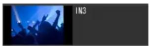
Materials with aspect ratios other than 16:9 will retain their aspect ratios and be fitted to the top and bottom of their displays (black bars appear on the left and right) in the thumbnails that appear in lists and in the [NEXT] and [PGM] viewers.
Examples: List thumbnails
• 16:9 material

• Material other than 16:9
Tip
The unit's internally generated signals have an aspect ratio of 16:9.
Preparing Materials
Prepare the materials to be added to the lists.
Input sources
Assign video input signals, specify input channels for embedded audio, and configure remote control settings for cameras in the [Video Setup] screen > [Input] of the [System Setup] menu.
For details on configuration, see “[Input]” (page 105).
Material files
Still image and movie files
Import still image files (including logos and titles created using other tools) and movie files to the unit's internal storage.
For details, see "Importing Files" (page 95).
Titles
Create titles using the Titler.
For details, see "Creating Titles (Titler)" (page 88).

Adding Input Sources to the Lists (Add Source)
Add the external signals configured in the [Video Setup] screen of the [System Setup] menu and the unit's internally generated signals to the lists.
1 Display the context menu in the position you want to add the input source, and select [Add Source].
If you perform the operation on a button, the item will be added below that button.

The [Add Source] dialog box appears.
2 Select the input source you want to add, and then tap [OK].

3 Tap [Close] to close the dialog box.
The input source is added to the specified position.
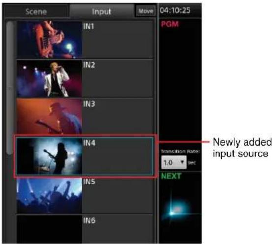
If necessary, you can change the input connector and name settings. For details, see “[Video Setup] Screen” (page 105).
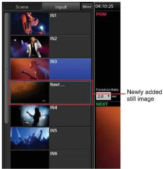
Adding Still Images to the Lists (Add Still Picture)
Add still images imported to the unit's internal storage or still images created with the Titler to the lists.
For details on importing files, see "Managing Files (File Manager)" (page 93).
For details on the Titler, see “Creating Titles (Titler)” (page 88).
1 Display the context menu in the position you want to add the still image, and select [Add Still Picture].
If you perform the operation on a button, the item will be added below that button.

The [Add Still Picture] dialog box appears.
2 Tap the file you want to add to place a check mark on it, and then tap [OK].
You can select multiple files.
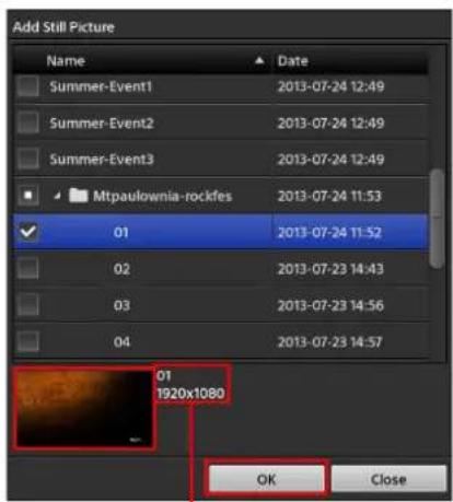
You can view the thumbnail and resolution of the file highlighted in blue.
3 Tap [Close] to close the dialog box.
The still image is added to the specified position.
Adding the Media Player to the Lists (Add Media Player)
Add the Media Player when you want to add movies imported to the unit's internal storage or files that were recorded to the unit's internal storage via the [Recording] or [Streaming] functions to the lists.
In addition, when you want to add still images to be used as PinP overlay videos or add still images to the [AUX] list, add the Media Player to the lists.
Tip
Only one instance of the Media Player can be added per list.
Display the context menu in the position you want to add the Media Player, and select [Add Media Player]. If you perform the operation on a button, the item will be added below that button.

The [Media Player] button is added to the list.
For details on Media Player operations, see "Playing Back Material Files in the Media Player" (page 55).
Creating and Adding New Titles (Create New)
You can start the Titler directly from a list and create titles and other still images to be added to the list. This is useful when you want to specify the destination for registration during the title creation process.
1 Display the context menu in the position you want to add the title, and select [Create New].

If you perform the operation on a button, the item will be added below that button.

The Titler starts, and the [Folder] dialog box for selecting the folder in which to save the file appears.
2 Create the title using the Titler.
For details, see steps 3 (page 89) and beyond in the "Starting from the [File Manager] screen" section and "Using the [Titler] Screen" (page 90).
3 If you want to create additional titles, display the context menu in the file list of the [Titler] screen, and select [Create New].
To create a new file by copying an existing file, display the same context menu and select [Copy] and then [Paste].
4 When you finish creation, close the [Titler] screen and return to the main screen.
The newly created still images are added to the list.
Tip
When you perform creation after starting the Titler from a list via [Create New], the still images are added directly to the list. The [Add Still Picture] operation is not necessary.
Editing Text Created in the Titler (Edit)
You can start the Titler directly from a list and edit text for still images that were created using the Titler.
1 Display the context menu on the button of the still image you want to edit, and select [Edit].
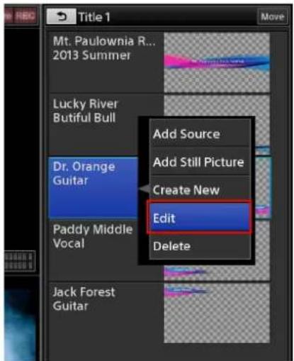
The Titler starts, and the editing screen of the selected still image appears.
2 Edit the text.

Tip
You can also edit other titles stored in the folder. However, edits will only be reflected in the list for files that are already registered to the list.
3 When you finish editing, close the [Titler] screen and return to the main screen.
The edits are reflected in the list.
Removing Material Buttons from the Lists (Delete)
Display the context menu on the button of the material you want to delete, and select [Delete].

Changing the Sort Order of the Lists
You can change the sort order of each list.
1 Tap [Move] at the top right of the list.
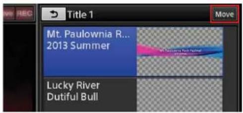
Move handles appear on each button. The [Move] button changes to [Done], and move mode is enabled.
2 Drag the move handle of the button you want to move to the desired position.
Dragging an area other than the move handle will not move the button.

3 When you finish sorting, tap [Done].
Move mode is disabled, and the [Done] button changes to [Move].

Inserting Titles
You can insert titles onto the program video using one of the following three methods.
- Insert a title created on this unit
- Insert a still image title created using a separate tool
- Insert an external signal
Depending on the material used for the title, the title will be inserted as follows.
- Insert a still image that includes an alpha channel
The area determined by the alpha channel will be displayed as the title.
Background video

Tip
When inserting still images that do not include alpha channels, clip, gain, and density adjustments are required.
For details on the clip, gain, and density settings, see "To adjust the appearance of composites" (page 47).
- Insert an external signal
Insert a signal from a computer that is connected via SDI or HDMI interface, for example. The portions of the image with high brightness will be displayed as the title.
Background video
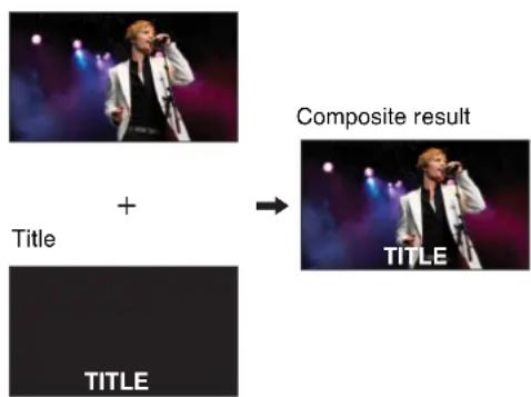
Tip
To produce a desired image, clip, gain, and density adjustments are required.
For details on the clip, gain, and density settings, see "To adjust the appearance of composites" (page 47).
Preparing Titles
Prepare the materials for titles, and add them to the [Title] list for options.
Prepare title materials using the following methods based on their intended purpose.
- When inserting titles created on this unit
Create titles using the Titler.
For details on creation, see “Creating Titles (Titler)” (page 88).
- When inserting still image titles created using a separate tool
Create a title file that includes an alpha channel using another tool beforehand, and then import that file to the unit's internal storage.
For details, see "Importing Files" (page 95).
- When using external input signals
For details on using external input signals, see “[Input]” (page 105).
Creating [Title] lists
Create lists by adding title materials to the [Title 1] and [Title 2] lists.
For details on creation, see "Creating Lists" (page 41).
Viewing Title Composites
You can view the appearance of a title that is inserted onto a video in the [NEXT] viewer.
This section describes the procedure for the [Title 1] list as an example.
1 In the [Input] list, select the background video on which you want to insert the title, and display it in the [NEXT] viewer.
2 Display the [Title 1] list.
3 Select the title you want to insert, and adjust its appearance.
When you select a title in the [Title 1] list, the title appears in the [NEXT] viewer.
Select the title you want to insert.

If the image includes an alpha channel, a checkered pattern appears in the areas where the background image will be displayed.
To adjust the appearance of composites
When you select the title you want to adjust in the [Title 1] list, the [Title 1] tab appears in the sub screen. Tap the [Title 1] tab to display the [Title 1] screen, and drag the sliders to perform adjustments.

[Clip]: Adjust the amount of background loss (i.e., clip value) within a range of 0.00 to 100.00.
[Gain]: Adjust the sharpness of outlines (i.e., gain value) within a range of -100.00 to +100.00.
[Density]: Adjust the transparency of the title within a range of 0.00 to 100.00.
Tip
Depending on the values configured for each setting, the title may not be displayed. In such cases, tap [Reset] to restore the original state, and perform adjustment again.
4 Tap
The [Title 1] list closes, and the [Option] menu appears again.
The thumbnail of the selected title appears on the [Title 1] button.
Tapping the button again removes the title display (i.e., the title will be in its disabled state).
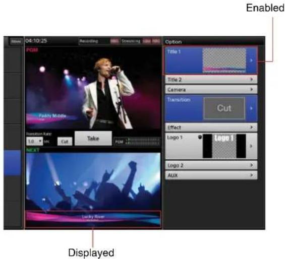

Inserting Logos
You can insert up to two still images at 320 × 320 size as logos onto the video. We recommend using images that include alpha channels for logos.
The area determined by the alpha channel will be displayed as the logo.
Logo with alpha channel


Composite result
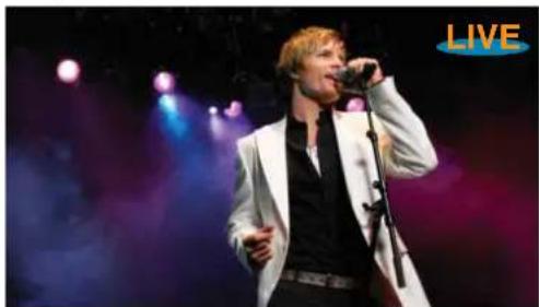
natural_image
Musician performing on stage with microphone and spotlights (no visible text or symbols)Preparing Logos
Create a logo file that includes an alpha channel using another tool beforehand, and then import that file to the unit's internal storage.
For details, see "Importing Files" (page 95).
Creating [Logo] lists
Create lists by adding logo materials to the [Logo 1] and [Logo 2] lists.
For details on creation, see "Creating Lists" (page 41).
Viewing Logo Composites
You can view the appearance of a logo that is inserted onto a video in the [NEXT] viewer.
This section describes the procedure for the [Logo 1] list as an example.
1 In the [Input] list, select the background video on which you want to insert the logo, and display it in the [NEXT] viewer.
2 Display the [Logo 1] list.
3 Select the logo you want to insert, and adjust its position.
When you select a logo in the [Logo 1] list, the logo appears in the [NEXT] viewer.
Select the logo you want to insert.

To adjust the position
When you select the logo you want to adjust in the [Logo 1] list, the [Logo 1] tab appears in the sub screen. Tap the [Logo 1] tab to display the [Logo 1] screen, and drag the adjustment handle to adjust the position.
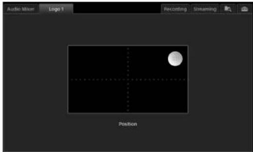
4 Tap ↗.
The [Logo 1] list closes, and the [Option] menu appears again.
The thumbnail of the selected logo appears on the [Logo 1] button.
Tapping the button again removes the title display (i.e., the title will be in its disabled state).

Displayed
Controlling Remote Cameras
The unit can control remote cameras via VISCA cable (serial connection) or LAN cable (LAN connection), and such connections are referred to as “VISCA connections.” The following controls can be performed via a VISCA connection.
- Controlling and adjusting cameras (page 49)
- Saving adjustments as presets (page 51)
• Recalling presets (page 52)
• Lighting tallies on remote cameras (page 54)
To control a camera, you must assign the camera images as an input source in the [Input] list and perform configurations to enable remote control beforehand. For details, see "Remote Camera Connections and Settings" (page 101).
You can also connect an RM-IP10 IP Remote Controller to the network and control cameras from the RM-IP10. For details on limitations and restrictions during such use, see "Notes on Using an RM-IP10" (page 53).
Tips
- Use the remote controller of the camera to configure setting items that cannot be configured from the unit. If you change the settings, be sure to restart the camera.
- Camera movement and behavior will vary depending on the camera model.
- When a camera is turned on, it starts up according to the settings stored in [Preset_1]. If you want to recall current pan/tilt positions and other camera conditions the next time you start up the camera, be sure to save them to [Preset_1] before turning off the camera.
Controlling Cameras
1 In the [Input] list of the main screen, select the camera input source you want to control and display its video in the [NEXT] viewer.
The [Camera] tab appears in the sub screen.
2 Tap the [Camera] tab.
The [Camera] screen appears.
3 Perform pan/tilt, zoom, iris, and other operations while viewing the video in the [NEXT] viewer.
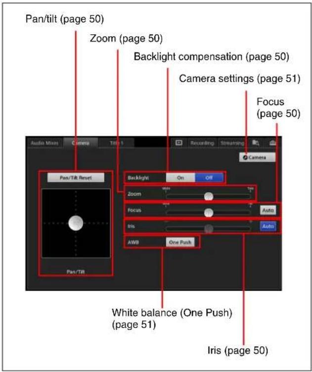
For details on each operation, see the following sections.
Tips
- If you tap the [NEXT] viewer while the [Camera] screen is displayed, adjustment handles appear in the [NEXT] viewer, allowing you to perform pan/tilt and zoom controls. If you tap the [NEXT] viewer again, control will return to the [Camera] screen.
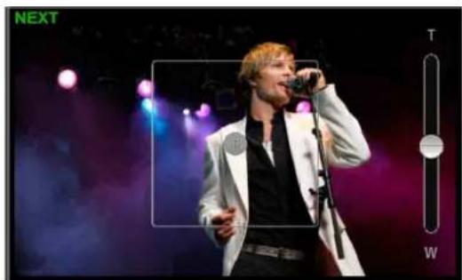
natural_image
Musician performing on stage with microphone and stage lights (no visible text or symbols)Adjustment handles will not appear for camera videos on which the tracking function is enabled.
For details on settings, see the [System Setup] > [Video Setup] > [Input] > [Tracking] setting (page 106).
- Although pan/tilt operations and zoom operations can be performed simultaneously in the sub screen, the [Pan/Tilt] adjustment handle and the [Zoom] slider cannot be operated simultaneously in the main screen.
Adjusting the pan/tilt
Drag the [Pan/Tilt] adjustment handle to adjust the pan and tilt of the camera.
- Dragging the handle diagonally adjusts both the pan and the tilt simultaneously. When you release your finger, the adjustment handle returns to its original position.
- If you want to redo adjustments from the home position, tap [Pan/Tilt Reset] to reset the pan/tilt positions.
Adjusting the zoom
Drag the [Zoom] slider to perform adjustments. When you release your finger, the slider returns to the middle position.
Adjusting the focus
You can select whether to adjust the focus automatically or manually in [Focus].
Adjustment switches between auto mode and manual mode with each tap of the [Auto] button.
Auto : Auto mode
Auto : Manual mode
If the focus is set to manual mode, drag the slider to perform adjustments. When you release your finger, the slider returns to the middle position.
Adjusting the iris
You can select whether to adjust the iris automatically or manually in [Iris].
Adjustment switches between auto mode and manual mode with each tap of the [Auto] button.
Auto : Auto mode
Auto : Manual mode
If the iris is set to manual mode, drag the slider to adjust. When you release your finger, the slider returns to the middle position.
Enabling backlight compensation
Tap the [On] button for [Backlight] to enable the backlight compensation function.
Tap [Off] to disable the function.
Tip
This setting can only be configured when [Iris] is set to auto mode. Backlight compensation is disabled when [Iris] is set to manual mode.
Automatically adjusting the white balance under the current conditions
Tap the [One Push] button for [AWB] (auto white balance).
This function can be used when [White Balance] is set to [One Push] in the [Camera Settings] screen (page 51). When you tap [One Push], the white balance will be adjusted according to the current subject of the image. After doing so, view the results of automatic adjustment and check that the white areas of the video are correct in the [NEXT] viewer.
Configuring camera settings
1 In the [Camera] screen, tap .● Camera
The [Camera Settings] screen appears.
2 Configure each item.
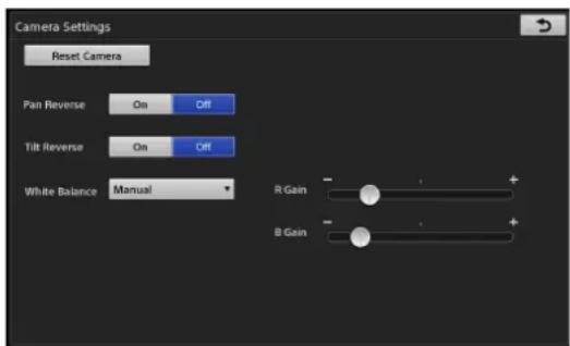
[Pan Reverse] / [Tilt Reverse]: Use these functions to correct the reversal of up, down, left, and right movement that occurs when the camera is installed upside down on a ceiling, for example. Select [On] to reverse up, down, left, and right movement, and select [Off] to enable normal movement.
Tip
If you change the [Pan Reverse] and [Tilt Reverse] settings, be sure to save the settings to [Preset_1] in the [Camera] list. The unit starts with the settings that are saved to [Preset_1]. If you do not save the settings to [Preset_1], the settings will revert to previous values.
[White Balance]: Select one of the following white balance modes.
• [Auto]: Automatic adjustment.
• [Indoor]: Indoor mode.
• [Outdoor]: Outdoor mode.
- [One Push]: Forcibly draw out whites from the lighting condition of the subject, and use this condition during shooting. [AWB] in the [Camera] screen is only enabled when [One Push] is selected here.
- [Manual]: Manual adjustment.
[R Gain] and [B Gain] adjustments are only enabled when [Manual] is selected here.
[R Gain]: Drag the slider to adjust the red gain.
[B Gain]: Drag the slider to adjust the blue gain.
3 When you finish configuration, tap ↗
The [Camera] screen appears again.
Resetting remote cameras
When you want to change the VISCA ID for cameras and reestablish connections to cameras, tap [Reset Camera] in the [Camera Settings] screen.
Depending on the camera model, the pan and tilt may return to their default positions. When you use the [Reset Camera] function, connection will be reestablished for all cameras connected for VISCA control.
Saving Adjustments as Presets
Up to 16 presets (up to 6 for the EVI-H100S and EVI-H100V) can be saved for each camera.
1 In the [Input] list, select the camera input source you want to control and display its video in the [NEXT] viewer.
The [Camera] tab appears in the sub screen.
2 Tap the [Camera] tab to display the [Camera] screen, and perform pan/tilt, iris, zoom and other operations.
3 Select [Camera] in the [Option] menu.

The [Camera] list appears.
4 Display the context menu in the position you want to add the preset, and select [Save].

This image will appear on buttons for which presets are not saved.
The preset is saved, and a thumbnail appears.
Notes
- Setting values are stored on the camera.
- [Preset_1] includes some items that are only applied whenever a camera is turned on. The next time the camera is turned on, it will start according to the conditions saved to [Preset_1].
Renaming presets
Display the context menu of the preset you want to rename, and select [Rename]. When the virtual keyboard appears, you can enter up to 20 alphanumeric characters.
Deleting presets from the list
Display the context menu of the preset you want to delete, and select [Delete].
Recalling Presets
1 In the [Input] list, select the camera input source you want to control and display its video in the [NEXT] viewer.
2 Select [Camera] in the [Option] menu.
The [Camera] list appears.
3 In the [Camera] list, select the preset you want to recall.
The preset video is recalled in the [NEXT] viewer.
When you select a preset...

Note
Depending on the [Camera] tab > [Tracking Settings] > [Pan/Tilt Limit Setting] settings (page 71), the camera video may not be recalled if the preset is out of the movement range.
Disabling presets
Use one of the following methods.
- Select [Off] in the [Camera] list.
- In the [Option] menu, display the context menu for the [Camera] button, and select [Remove] to close the button.
Notes on Using an RM-IP10
- Do not manually control the same camera from an RM-IP10 and the unit at the same time.
- If you configure position movement speeds by preset on the RM-IP10 and then recall a preset from the unit, the preset will be recalled using the speed configured on the RM-IP10. (This is because position movement speeds are stored in the camera's internal memory.)
- Even if the speed limit function for pan/tilt movement is enabled on the RM-IP10, the function will be ignored when performing pan/tilt operations from the unit. (This is because the function only applies to the RM-IP10.)
Using the GUI Tally Function
You can display tallies on the source buttons in the [Input] list that light for the sources being used as the PGM output and NEXT selection sources.
Tally display example:
PGM output: Red

NEXT selection: Green
Tips
- The [Input] list is the only list in which the tallies appear.
- Tallies will appear or disappear when [Take] is tapped, regardless of transition settings.
1 Display the [System Setup] screen in the sub screen, and tap [Others].
2 Tap [Customize GUI] to display the [Customize GUI] screen.
3 Select [On] for [Tally].
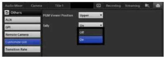

Using the Camera Tally Function
You can have the tallies on cameras light via the VISCA connector and the output pins of the GPI connector at the rear of the unit or via the LAN connector when the camera's video is being used as the PGM output or NEXT selection source in the [Input] list or [Title] list.
The cameras that are compatible with the tally function and the lighting conditions are as follows.
| Camera Lighting | condition | Setting |
| Remote cameras (VISCA connection) | In use as PGM output | Not required |
| Cameras connected to the GPI connector on the unit via the TALLY connector on a CCU, for example (GPI connection) | In use as PGM outputIn use as NEXT selection | Required |
Tips
- The tallies on remote cameras do not support lighting in response to NEXT selection.
- Tallies will light or turn off when [Take] is tapped, regardless of transition settings.
- This function does not apply to selections made in the [AUX] list.
Lighting Tallies on Remote Cameras
Connect the remote cameras and assign them to video input connectors.
For details on connecting cameras and assigning them to video input connectors, see "Remote Camera Connections and Settings" (page 101).
Notes on using an RM-IP10
When using an RM-IP10, the tally function on the RM-IP10 must be disabled.
For details, see "IP remote controller tally settings" (page 103).
Lighting Tallies on Cameras Connected via GPI
Connect the unit's GPI connector to the TALLY connector on a CCU, for example, and configure the conditions for GPI output. The tallies on the camera will light in response to the GPI outputs.
Tip
This function supports up to four cameras.
1 Connect the camera to the unit.
2 Connect the GPI connector on the unit to the TALLY connector on the CCU.
For details on pin assignments on the GPI connector, see "GPI connector" (page 123) in the "Connector Pin Assignments" section.
3 Select the input source of the camera in the [Input] list of the main screen, and verify the video.
4 Display the [System Setup] screen in the sub screen, and tap [Others].
5 Tap [GPI] to display the [GPI] screen.
6 Specify the GPI output conditions for each pin on the GPI connector.

[GPI OUT 1] to [GPI OUT 4]: Specify the conditions for GPI output.
• [Not Assigned]: Do not use this function.
- [PGM Tally Input1] to [PGM Tally Input6]: GPI output occurs when video from the selected camera is being used as the PGM output source.
- [NEXT Tally Input1] to [NEXT Tally Input6]: GPI output occurs when video from the selected camera is being used as the NEXT selection source.
Playing Back Material Files in the Media Player
The following material files can be played back in the Media Player.
- Movies and still images imported to the unit's internal storage
• Still images created with the Titler - Files recorded to the unit's internal storage via the [Recording] function
- Files recorded to the unit's internal storage via the [Streaming] function
For details on importing material files, see "Importing Files" (page 95).
For details on adding the Media Player to the list, see "Adding the Media Player to the Lists (Add Media Player)" (page 43).
Playing Back Files
1 Select [Media Player] in the main screen's list.
2 Tap the tab in the sub screen.
The [Media Player] screen appears.
3 Tap [Open].
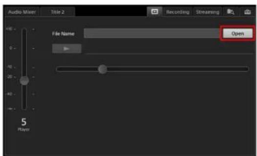
The [Open] dialog box appears.
4 Select the category to which the file belongs, select the file to play back, and then tap [OK].
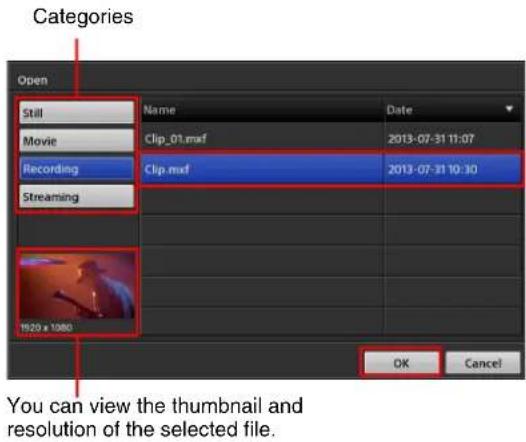
For details on categories, see "Managing Files (File Manager)" (page 93).
The thumbnail and name of the file appear in the [Media Player] screen and the list.
5 Adjust the playback start position and audio level of the file in the [Media Player] screen.
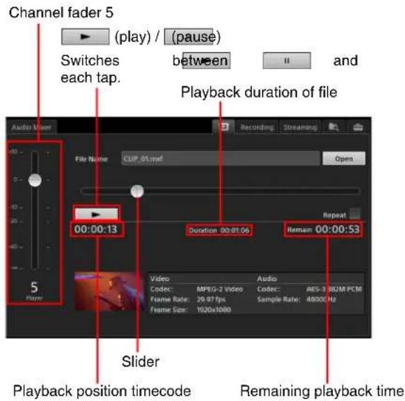
To adjust the playback position of files
Adjust the playback position by moving the slider while viewing the playback position timecode and video.
Tip
The timecode is a relative timecode with the beginning of the file being "00:00:00."
To adjust the audio
If a movie includes embedded audio, drag the channel fader to adjust the audio level.
Tips
- Embedded audio will be assigned to channel fader 5 automatically.
- When the [Media Player] tab is displayed, the unit enters audio preview mode automatically, allowing you to listen to audio via the HEADPHONES jack or the internal speakers. Audio preview does not affect the PGM output or MIX output.
6 Tap to verify file playback.
Verify that playback of the file is stable.
7 Tap [Take] or [Cut] in the main screen to switch the video.
Mixing embedded audio
If embedded audio is output due to a [Take] operation, the embedded audio is automatically assigned to channel fader 5.
After the [Take], you can adjust the audio level by dragging the slider for channel 5 in the [Audio Mixer] screen.
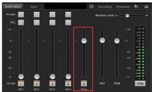
Tip
If channel fader 5 is being used for both input and the Media Player, the Media Player will have priority.
To stop playback
Tap in the [Media Player] screen.
Repeat Playback
You can specify a section of a file for repeat playback.
To specify the section for repeat playback
1 Select the [Repeat] checkbox in the [Media Player] screen.
Buttons for specifying the [Start] and [End] points and a bar representing the playback section appear.
2 Configure the [Start] point.
![[Start] point Bar representing the playback section [Repeat] Audio Mixer File Name CLIP 01.msf Open 00:00:10 Start 00:00:10 Duration 00:00:56 End 00:00:06 Video Audio Code: MPEG-2 Video Code: AES-3 382M PCM Frame Rate: 29.97 fps Sample Rate: 48000Hz Frame Size: 1920x1080 Player ① ②](/content/2026/05/882243/images/ad55be9a9a45435577c3997720bfe08ca2a7ca37f7cce21b1ef53a914d92e319.jpg)
①Play back the file or move the slider, and stop the file at the repeat playback start position.
②Tap (Start). The [Start] point is configured on the key frame immediately preceding the tapped position.
![Position where is tapped Key frames [Start] point that will be configured](/content/2026/05/882243/images/43de454fcc8edef7c5d2dda526f67691ff591f7f5b18a115d1326b36c46f569b.jpg)
The marker of the bar representing the playback section moves to the playback start position.
Tip
The video may move back slightly from the position where was tapped.
3 Configure the [End] point.
![Duration of playback section [End] point Audio Mixer File Name CLIP 01.msf Open 00:00:52 Repeat 00:00:42 Start 00:00:10 End 00:00:52 Video Audio Code: MPEG-2 Video Code: AES-3 382M PCM Frame Rate: 29.97 fps Sample Rate: 48000Hz Frame Size: 1920x1080 ② ① 5 Player](/content/2026/05/882243/images/305cf60ba9678554e5daea4d8ac4a21615ef8d082cf0f197db2bf77c2a488346.jpg)
①Play back the file or move the slider, and stop the file at the end of the repeat playback section.
②Tap ↓ (End). The [End] point is configured on the tapped position.
The marker of the bar representing the playback position moves to the end of the repeat playback section.
Tips
- The positions of the [Start] and [End] points can be reversed or the points can be configured at the same position. However, the entire file will be specified for repeat playback in such cases.
- The remaining playback time will not be displayed during repeat playback.
4 Tap (To [Start] Point) to jump to the [Start] point.
Tip
When performing repeat playback, be sure to use to jump to the [Start] point beforehand. If you do not jump to the [Start] position, playback will start from the current position.
5 Tap to verify the playback section.
Verify that playback of the file is stable.
For details on adjusting the audio, see "Playing Back Files" (page 55).
6 Tap [Take] or [Cut] in the main screen to switch the video.
The specified section will be played back repeatedly.
Tip
You cannot specify the number of times to repeat playback.
To disable repeat playback
In the [Media Player] screen, clear the [Repeat] checkbox.
Entering Text
Text is entered in the sub screen using the virtual keyboard.
1 Tap the text entry field in the main screen or the sub screen.
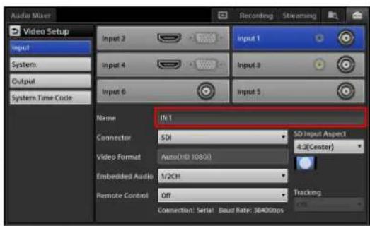
The virtual keyboard appears in the sub screen.
2 Enter the text.

The text appears on the virtual keyboard while it is being entered.
3 Tap (Enter) to confirm the entry.
The virtual keyboard closes, and the text is entered.
Tips
- Tapping on the virtual keyboard also confirms the entry.
- When entering text for the Titler, tapping any location that exits the entry mode confirms the entry.

Using the Virtual Keyboard
The following image of the virtual keyboard is a sample. Depending on the functions you are using, the keyboard that is displayed may differ.
The keyboard that is displayed will differ depending on the input language. For details on changing the input language, see “[Input Language]” (page 105) in the “[Language]” section.
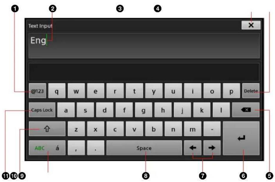
①[@123] (numeric) button
Switches to the numeric keyboard.
②Caret (green)
③ ×
Exits text entry mode, and closes the virtual keyboard.
④[Delete]
When characters are selected, this deletes the selected characters.
When characters are not selected, this deletes characters immediately following the caret one at a time.
⑤ (Y kspace)
Deletes characters immediately preceding the caret one at a time.
6 (Enter)
Confirms the text entry or inserts a line break.
⑦[←] and [→]
Moves the caret position to the left or right one position at a time.
⑧[Space]
Enters a space.
⑨[ABC á]
Switches the keyboard to umlaut character mode or standard alphabet mode with each tap.
After switching to umlaut character mode, entering a single character returns the keyboard to standard alphabet mode.
⑩[↑] (shift)
Switches the keyboard to upper case mode or lower case mode with each tap.
After switching to upper case mode, entering a single character returns the keyboard to lower case mode.
⑪[Caps Lock]
When this is enabled, the keyboard enters upper case mode. Disabling this returns the keyboard to lower case mode.
Advanced Operations
Compositing Videos Using Picture-in-Picture (PinP)
You can composite a video consisting of one video (overlay video) inserted on top of another video (background video) using the picture-in-picture effect. You can use up to two overlay videos.

You can select from the following PinP patterns.
Pattern_01 Pattern_02

natural_image
Simple diagram with a central square and four directional arrows pointing outward (no text or symbols)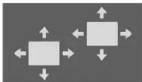
natural_image
Two gray squares with directional arrows indicating movement or flow, no text or symbols presentPattern_03 Pattern_04

natural_image
Two adjacent gray squares side by side on a dark background (no text or symbols)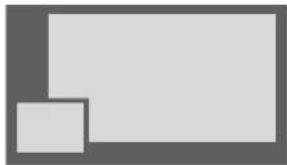
natural_image
Two overlapping gray rectangles with no text or symbolsPattern_05 Pattern_06

natural_image
Abstract geometric composition with two overlapping gray rectangles (no text or symbols)
natural_image
Abstract geometric composition with two gray rectangles and one smaller rectangle, no text or symbols present.Pattern_07 Pattern_08
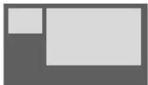
natural_image
Abstract geometric composition with two gray rectangles and one white rectangle, no text or symbols present.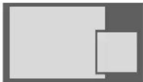
natural_image
Two overlapping gray squares of different sizes on a dark background (no text or symbols)Pattern_09 Pattern_10

natural_image
Two overlapping gray squares of different sizes, no text or symbols present
natural_image
Two gray geometric shapes: a large square and a small square, with no text or symbols.Pattern_11 OFF

natural_image
Abstract geometric composition with two overlapping rectangles (no text or symbols)
natural_image
Solid gray image with no visible content, text, or symbols.Selecting Composite Patterns
1 Select [Effect] in the [Option] menu.

The [Effect] list appears.
2 Select the pattern you want to use.
The video composite appears in the [NEXT] viewer according to the selected effect pattern.

3 Tap ↗.
The [Option] menu appears again.
Canceling composites
Use one of the following methods.
- Select [Off] in the [Effect] list
1 Select [Off].
The composite overlay video disappears.
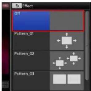
2 Tap ↗.
The [Option] menu appears again. The [Effect] button closes.
- Close the [Effect] button in the [Option] menu Display the context menu, and select [Remove].
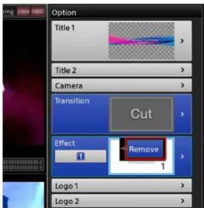
The [Effect] button closes, and the composite will be canceled.

Selecting Composite Materials
Select the videos you want to use for the composite in the [Input] list.
1 In the [Option] menu, tap the input control number button on the [Effect] button.
The control number appears in the [Option] menu and the [Input] list.
The number changes with each tap.
[1]: Background video
[2]: Overlay video 1
[3]: Overlay video 2 (for patterns with two)

A light blue frame appears around the area that the selected control number represents.
2 Verify the input control number, and select the input sources you want to use for the background video and overlay videos.
The selected video appears in the [NEXT] viewer.

Tip
If you want to use still images for the overlay image, use the Media Player.
For details on Media Player operations, see "Adding the Media Player to the Lists (Add Media Player)" (page 43).
Adjusting Overlay Videos
1 In the [Option] menu, tap the input control number button on the [Effect] button.
2 Display the [Effect] list.
3 In the sub screen, tap the [Effect] tab to display the [Effect] screen, and select the settings you want to adjust in the menu to the left.
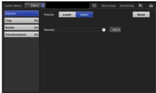
The items that you can configure will differ depending on the selected pattern.
For Pattern_03 to Pattern_11, only the [Border] setting can be configured.
- [Density]: Specify the opacity of the inserted image.
- [Crop]: Crop the portions of the overlay video that you do not want inserted.
- [Border]: Specify whether to add a border to the edges of the overlay video.
- [Transformation]: Adjust the size and position of the overlay video.
Tip
If there are two overlay videos, the target for adjustment in the sub screen will be as follows, depending on the selected input control number.
| Input control number Target for adjustment | |
| [1] Overlay video 1 | |
| [2] Overlay video 1 | |
| [3] Overlay video 2 | |
Configuring the [Density] settings
Specify the opacity of the inserted image.

[Priority]: Specify the top/bottom relationship between videos when overlay video 1 and overlay video 2 overlap.
This item cannot be configured when using [Pattern_01].
- [Lower]: When configuring overlay video 1, this places overlay video 1 under overlay video 2. When configuring overlay video 2, this places overlay video 2 under overlay video 1.
- [Upper]: When configuring overlay video 1, this places overlay video 1 over overlay video 2. When configuring overlay video 2, this places overlay video 2 over overlay video 1.
[Density]: Drag the slider to adjust the opacity of the inserted image.
To restore the original value
Tapping [Reset] restores the original value.
Configuring the [Crop] settings
Crop the portions of the overlay video that you do not want inserted.

[Crop]: Selects whether to use the [Crop] function.
• [On]: Enable the function.
• [Off]: Disable the function.
[Reset]: Sets the cropped area of the image to the following values.
| Item Setting values | ||||
| Left Top | Bottom Right | |||
| [Full] -100 | +100 -100 | +100 | ||
| [4:3] -75 + | 100 -100 + | 75 | ||
Tip
If you move the adjustment handles after enabling [Full] or [4:3] (highlighted in blue), the button will turn off (no longer highlighted), indicating deviation from the [Reset] settings.
Adjustment handles: Drag each handle to specify the areas of the image to be cropped.
Configuring the [Border] settings
Specify whether to add a border to the edges of the overlay video.
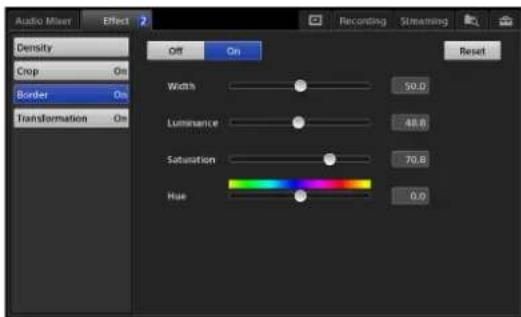
[Border]: Selects whether to add a border around the edges of the cropped image.
• [On]: Add a border.
• [Off]: A border is not added.
Drag the sliders for the following items to adjust them.
[Width]: Specify the width of the border.
[Luminance]: Specify the luminance of the border.
[Saturation]: Specify the saturation of the border.
[Hue]: Specify the hue of the border.
To restore the original value
Tapping [Reset] restores the original value.
Configuring the [Transformation] settings
Adjust the size and position of the overlay video.
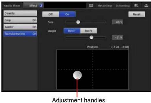
[Off] / [On]: Selects whether to use the [Transformation] function.
• [On]: Enable the function.
• [Off]: Disable the function.
[Size]: Drag the slider to adjust the size of the inserted image.
[Angle]: If you want to rotate the inserted image, select the rotation direction, and drag the slider to specify the angle of rotation.
• [Rot H]: Rotate the image horizontally
• [Rot V]: Rotate the image vertically.
[Position]: Drag the adjustment handle to adjust the position of the inserted image.
To restore the original value
Tapping [Reset] restores the original value.
Inserting People onto Backgrounds (Chroma Keying)
You can use chroma keying to insert a person onto a background, for example.
Chroma keying is a compositing technique that involves specifying regions of a single color in the overlay video (green in the following example), and inserting the regions other than the specified regions (a person in the following example) onto the background video. You can also adjust the size and position of the overlay video, and use chroma keying and PinP at the same time.
You can select from the following patterns.
Pattern_12
natural_image
Generic placeholder avatar icon, no text or symbols presentComposite example:

Pattern_13
natural_image
Generic user profile icon with silhouette and rectangle (no text or symbols)Composite example:

flowchart
graph TD
    A["Background video"] --> C["+"]
    B["Overlay video 1 (for chroma keying)"] --> C
    D["Overlay video 2"] --> C
    C --> E["Composite with PinP added"]
    E --> F["Overlay video 2"]
    F --> G["Background video"]
    G --> H["Overlay video 1"]
Tip
You can only add one PinP overlay video when using chroma keying.
Selecting Composite Patterns
1 Select [Effect] in the [Option] menu.

The [Effect] list appears.
2 Select [Pattern_12] or [Pattern_13].
The video composite appears in the [NEXT] viewer according to the selected effect pattern.

3 Tap ↗.
The [Option] menu appears again.
Canceling composites
For details, see "Canceling composites" (page 60) of the "Compositing Videos Using Picture-in-Picture (PinP)" section.
Selecting Composite Materials
Select the videos you want to use for the composite in the [Input] list.
1 In the [Option] menu, tap the input control number button on the [Effect] button.
The control number appears in the [Option] menu and the [Input] list.
The number changes with each tap.
[1]: Background video
[2]: Overlay video 1
[3]: Overlay video 2 (for patterns with two)
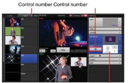
A light blue frame appears around the area that the selected control number represents.
2 Verify the input control number, and select the input sources you want to use for the background video and overlay videos.
Tip
If you want to use still images for the overlay image, use the Media Player.
For details on adding the Media Player, see "Adding the Media Player to the Lists (Add Media Player)" (page 43).
Adjusting Overlay Video 1
1 In the [Option] menu, tap [1] (background video) or [2] (overlay video 1) on the [Effect] button.

2 Display the [Effect] list.
3 In the sub screen, tap the [Effect] tab to display the [Effect] screen, and select the settings you want to adjust in the menu to the left.
Overlay video 1 can be adjusted, even when the [1] button (background video) is selected.

You can configure the following settings for overlay video 1.
- [Chromakey]: Specify the color that will not be composited with the background video, and adjust the compositing. The color region can be adjusted in [Auto] mode or [Manual] mode (page 65).
• [Crop]: Crop regions in overlay video 1 that you do not want included in the composite (page 66).
• [Transformation]: Adjust the size and position of overlay video 1 (page 66).
Adjusting [Chromakey] in [Auto] mode
In [Auto] mode, you specify the color that you do not want composited with the background video in the [NEXT] viewer, and adjustments are performed automatically.
1 Tap [Auto] for [Mode].
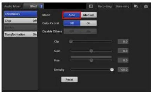
[Auto] mode is enabled, and the color picker (white frame) appears in the [NEXT] viewer.
2 Tap an area that includes the color you want to remove to move the color picker.

Tip
In [Auto] mode, the composite of only overlay video 1 and the background video will appear in the [NEXT] viewer. Titles and logos will not be displayed.
3 If necessary, adjust the outlines and density of the image to be inserted.

[Color Cancel]: Use this if remnants of the color that is supposed to be removed appear in the outlines of the inserted image (e.g., in a person's hair). When [On] is selected, the remnants of the specified color in the outlines are made colorless (usually gray in appearance) to reduce noticeability.
[Density]: Drag the slider to adjust the density of the inserted image.
To restore the original value
Tapping [Reset] restores the original value.
Adjusting [Chromakey] in [Manual] mode
In [Manual] mode, adjustments are performed by configuring each setting value manually. You can also perform automatic adjustment in [Auto] mode, and then perform fine adjustments in [Manual] mode.
1 Tap [Manual] for [Mode].
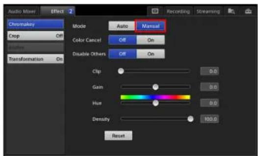
Tip
When you switch to [Manual] mode after performing automatic adjustment in [Auto] mode, the values for [Clip], [Gain], and [Hue] that were automatically obtained are retained and displayed initially.
2 Configure each item.

For details on the [Color Cancel] setting and the [Density] setting, see step 3 (page 65) in the "Adjusting [Chromakey] in [Auto] mode" section.
[Disable Others]: Selects whether to composite titles and logos during chroma key adjustment.
- [On]: Do not composite. Titles and logos are not composited, making it easier to perform manual adjustments.
- [Off]: Composite. This is useful when you want to confirm the image's appearance with titles and logos composited.
Drag the slider for each item to perform adjustments.
[Clip]: Adjust the amount of loss in the background video.
[Gain]: Adjust the sharpness of outlines.
[Hue]: Adjust the hues.
To restore the original values
Tapping [Reset] restores the original value.
Configuring the [Crop] settings
Crop regions in overlay video 1 that you do not want included in the composite.

For details on the [Crop] and [Reset] settings and the adjustment handles, see “Configuring the [Crop] settings” (page 61) in the “Adjusting Overlay Video” section.
Configuring the [Transformation] settings
Adjust the size and position of overlay video 1.

For details on setting items, see “Configuring the [Transformation] settings” (page 62) in the “Adjusting Overlay Video” section.
Adjusting Overlay Video 2
1 In the [Option] menu, tap [3] (overlay video 2) on the [Effect] button.
2 Display the [Effect] list.
3 In the sub screen, tap the [Effect] tab to display the [Effect] screen, and select the settings you want to adjust in the menu to the left.

You can configure the following settings for overlay video 2.
• [Crop]: Crop regions in overlay video 2 that you do not want included in the composite.
- [Border]: Specify whether to add a border to the edges of overlay video 2.
• [Transformation]: Adjust the size and position of overlay video 2.
Configuring the [Crop] settings
Crop regions in overlay video 2 that you do not want included in the composite.

For details on setting items, see "Configuring the [Crop] settings" (page 61) in the "Adjusting Overlay Video" section.
Configuring the [Border] settings
Specify whether to add a border to the edges of overlay video 2.

For details on setting items, see "Configuring the [Border] settings" (page 62) in the "Adjusting Overlay Video" section.
Configuring the [Transformation] settings
Adjust the size and position of overlay video 2.

For details on setting items, see “Configuring the [Transformation] settings” (page 62) in the “Adjusting Overlay Video” section.
Creating Scenes
You can save the current state of the [Input] list, [Option] menu, and the transition rate to the [Scene] list as a "scene." (You can save up to 99 scenes.) Stored scenes can be recalled whenever necessary.
For details on recalling scenes, see "Recalling Scenes" (page 69).
Creating New Scenes
1 Operate the [Input] list, [Option] menu, and transition rate to create the conditions you want to save as a scene in the [NEXT] viewer.
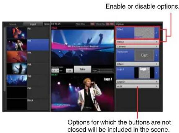
For details on excluding an option from the scene, see "Excluding Options from Scenes" (page 68).
2 Display the context menu in the [Scene] list, and select [Create New].
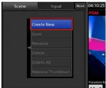
A button is added to the [Scene] list. The image that was currently displayed in the [NEXT] viewer appears as the thumbnail.
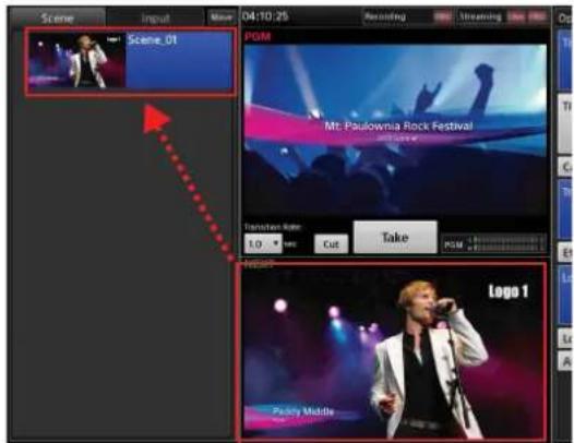
Sequential numbers will be assigned automatically to the names of the created scenes ([Scene_01] to [Scene_99]). If necessary, you can rename them.
Tip
If a scene does not include “effects” and only includes the input signal, that input signal will be displayed as a movie in the thumbnail.
Renaming scenes
Display the context menu of the scene you want to rename, and select [Rename]. When the virtual keyboard appears, you can enter up to 20 alphanumeric characters.
Deleting scenes from the list
Display the context menu of the scene you want to delete, and select [Delete].
Deleting all scenes from the list
Display the context menu of any scene in the list, and select [Delete All]. When the confirmation message appears, tap [Yes].
Editing Scenes
You can edit the video of a previously created scene.
1 In the [Scene] list, tap the scene you want to edit to display it in the [NEXT] viewer.
2 Edit to create the conditions you want to save to the scene.
For details on excluding an option from the scene, see "Excluding Options from Scenes" (page 68).
3 In the [Scene] list, display the context menu of the button to which you want to save the edited scene, and select [Save].

The edited scene overwrites the previous scene.
Replacing Thumbnails
When you display the context menu of a scene button and select [Replace Thumbnail], the image currently displayed in the [NEXT] viewer replaces the thumbnail image.
Excluding Options from Scenes
- Close the button in the [Option] menu
Display the context menu of the option to be excluded from the scene, and select [Remove].

The button closes, and the option will be excluded from the scene.
- When the option is [Effect] or [Camera]
You can also exclude an option using the following method.
Select [Off] in the [Effect] list or the [Camera] list.

Recalling Scenes
Video conditions that are saved to a scene can be selected as the program video. Previously saved scenes are displayed in the [Scene] list.
For details on saving scenes, see "Creating Scenes" (page 67).
1 Select the preset you want to recall in the [Scene] list.
The scene appears in the [NEXT] viewer.
![When you select a scene... Scene Opening 04:10:25 Recording Timeline Action Title 1 Title 2 Camera Transitions Effort Logo 1 Logo 2 ALUX ...the selected scene appears in the [NEXT] viewer.](/content/2026/05/882243/images/18a5f630efa519aa50c83da66c30af7657e2d842c4ff56b3b2f5052ee2a10de2.jpg)
2 Tap [Take] or [Cut] to switch the video.
When a title or logo is protected
If the icon appears on a title or logo button in the [Option] menu, the content of the current title or logo is protected.
In such cases, the current title or logo configuration will be unaffected and retained, even if a scene is recalled.
For details, see “⑧ protect) icon” (page 37).
Tracking Targets (Tracking Function)
Using the tracking function allows you to perform the following controls.
- Tap a person or other target in the [NEXT] viewer to track them (tracking mode).
- Tap a position in the [NEXT] viewer to center the camera on that position (framing mode).
Tracking may not be possible or tracking performance may deteriorate in the following cases.
- Subject
– The subject moves too quickly.
- The subject moves out into the distance away from the camera.
- The size of the subject changes significantly.
- The appearance of the subject's clothes varies significantly depending on the angle in which it is viewed.
- The subject's posture changes significantly.
- The subject is too small or too large.
- Environment
- The camera is shaking significantly.
- The background includes a variety of colors.
– There is low contrast between the subject and the background. - The subject and the background are similar in color.
– A portion of the subject becomes obscured by an obstruction.
– The subject moves past another person. - The brightness of the subject changes due to a light (e.g., projector).
Preparation
Perform the following before using the tracking mode.
- Position the camera so that it faces the subject directly.
- Smooth tracking may not be possible if the camera is positioned too far. Adjust the camera's position if adjustments to the [Speed] setting are not sufficient.
- Set [Pan Reverse] and [Tilt Reverse] to [On] if the camera's "IMG-FLIP" function is enabled or set them to [Off] if the camera's "IMG-FLIP" function is disabled, and then save the setting to [Preset_1].
Enabling the Tracking Function
1 Display the [System Setup] screen, and tap [Video].
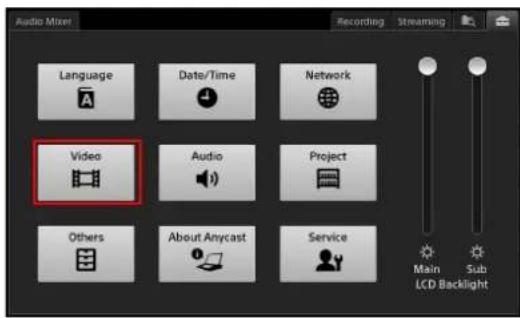
The [Video Setup] screen appears.
2 Tap [Input], and select the input connector of the target remote camera for control.
3 Select the target remote camera for control in [Remote Control], and select [On] for [Tracking].
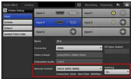
Tip
The tracking function can only be configured for one video input, with the video input that was configured last having priority.
Using Tracking Mode
In the [Camera] screen, tap [Tracking] to enable it.
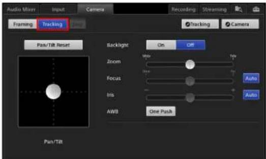
Tracking mode is enabled.
Tip
The mode cannot be changed while the camera is moving. Wait for the camera to stop before tapping [Tracking].
The tracking status appears in the [NEXT] viewer during tracking mode.
Note
The tracking status will not be displayed if an [Effect] is configured. Tracking cannot be started when the tracking status is not displayed.
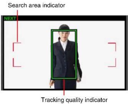
Search area indicator: Indicates the area in which the camera can find a tracking target.
Tracking quality indicator: Indicates the tracking quality or whether tracking is in standby by its color. The size of the frame is configured in the [Size] (page 71) of the [Tracking Settings] screen.
- :Tracking standby

W
a
r
n
i
Configuring tracking settings
Configure settings related to the tracking target. First select a preset for the tracking target's movement, and then perform fine adjustments.
1 In the [Input] list, tap the input source for which the tracking function is enabled to display its video in the [NEXT] viewer.
The [Camera] tab appears in the sub screen.
2 Tap the [Camera] tab to display the [Camera] screen, and tap . Tracking

The [Tracking Settings] screen appears.
3 Select a preset in [Preset] based on the size of the tracking target.

Tip
If you change any other setting values after enabling a preset button (highlighted in blue), the button will turn off (no longer highlighted) to indicate that it has been disabled.
4 Adjust the width of the tracking target in [Size].
The size specified here is the size of the tracking quality indicator frame that appears in the [NEXT] viewer.
[Aspect Ratio]: Select the aspect ratio.
• [Portrait]: Use for full-body or half-body shots.
• [Landscape]: Use for bust shots.
Slider: Adjust the width of the frame to match the width of the tracking target (shoulder width in the case of a person).
5 Specify the movement range (tracking range) for the camera in [Pan/Tilt Limit Setting].
By specifying the movement range, you can prevent the camera from pointing in unintended directions during tracking and make sure that your target does not move out of the camera's view.

①Use the adjustment handle to control the camera, and position the subject to the center of the screen.
②Move the camera up to the position you want to use as the upper limit of movement, and from that position, move the camera right to the position you want to use as the right limit of movement, and then tap [Set] at the upper right. The upper and right limits of the movement range will be set. (The button color will not change.)
Tip
Tapping [Reset] will clear both the upper and right limit settings.
③Use the adjustment handle to control the camera, and position the subject to the center of the screen again.
④Move the camera down to the position you want to use as the lower limit of movement, and from that position, move the camera left to the position you want to use as the left limit of movement, and then tap [Set] at the bottom left. The lower and left limits of the movement range will be set. (The button color will not change.)
Tip
Tapping [Reset] will clear both the lower and left limit settings.
6 Save the settings to [Preset_1] in the [Camera] list.
For details on how to save, see “Saving Adjustments as Presets” (page 51).
Tip
If you configure the [Pan/Tilt Limit Setting] settings, be sure to save the settings to [Preset_1]. The unit starts with the settings that are saved to [Preset_1]. If you do not save the settings to [Preset_1], the settings will revert to previous values.
7 Select the offset position for the tracking target in [Position Offset].
For example, if you want to use the camera video as a PinP background video, you can select [Left] or [Right] to position the target away from the overlay video.
[Left]: Offset to the left.
[Center]: Do not offset.
[Right]: Offset to the right.
Tip
If [Left] or [Right] is selected and the [Size] setting is too large, tracking may not be possible at the edges of the screen. If the camera does not move as intended, adjust the size of the tracking target.
8 Tap to return to the [Camera] screen.
Starting tracking
Tap the tracking target in the [NEXT] viewer to start tracking.
Tips
- We recommend tapping the tracking target when it is still to start tracking.
- Manual operations from the unit for all remote cameras will be disabled during tracking. Stop tracking before performing manual operations.
- Although you can control remote cameras during tracking from a RM-IP10, avoid doing so.
- The tracking status will not appear and tracking cannot be started if an [Effect] is configured.
Note
Tracking will stop automatically in the following cases. - When a camera preset is saved, deleted, or recalled
When tracking is lost
Tap the tracking target to start tracking again.
Stopping tracking
Tap [Stop].
Resuming tracking
Tap the tracking target in the [NEXT] viewer.
Performing adjustments according to the tracking target
Perform adjustment in the [Tracking Settings] screen.
Tip
Adjustments cannot be performed during tracking. Stop tracking before performing adjustments.

[Speed]: Drag the slider to adjust the tracking speed.
If the camera cannot keep up with the target, increase the tracking speed. Tracking may not be smooth if the speed is too fast.
If the camera moves faster than the target, decrease the tracking speed.
[Stabilize]: Select [On] to stabilize the video in the following situations.
- When shooting a tacking target that continuously makes small movements.
- When the camera shakes slightly due to the tracking function, even when the subject is still.
Tip
If the camera still shakes when [Stabilize] is set to [On], try lowering the [Speed] setting.
Using Framing Mode
Tip
Framing mode will not function if an [Effect] is configured.
1 In the [Input] list, tap the input source for which the tracking function is enabled to display its video in the [NEXT] viewer.
The [Camera] tab appears in the sub screen.
2 Tap the [Camera] tab to display the [Camera] screen, and tap [Framing] to enable it.

Framing mode is enabled.
Tip
The mode cannot be changed while the camera is moving. Wait for the camera to stop before tapping [Framing].
3 Tap the target in the [NEXT] viewer.
The tapped position moves to the center position.
Tip
If you tap a target while the camera is moving, the target will be disabled. In such cases, tap the target again after the camera stops.
Switching the Second Output (AUX)
In addition to PGM, another video composite output (AUX) is available on this unit.
You can select the AUX output from the input sources and the PGM. In addition, you can select “clean” versions of the PGM output that exclude specific composite images.
You can use this feature when you want to output two different videos using two projectors, or when you want to output a video without titles and logos alongside the PGM output.
Usage example 1: Output separate videos via two connected projectors

flowchart
graph TD
    A["World Tour"] --> B["PGM"]
    C["World Tour"] --> D["AUX"]
    B --> E["Laptop"]
    D --> E
Usage example 2: Remove "LIVE" displays for recording
If “LIVE” is displayed as [Logo1], output the video without the “LIVE” display for the purposes of recording.
• PGM
natural_image
Person performing on stage with microphone and microphone, surrounded by colorful smoke (no visible text or symbols)• AUX

natural_image
Person singing on stage with colorful lighting (no visible text or symbols)Configuring AUX Settings
Configuring [Clean] settings
To output an AUX signal that consists of the PGM output with titles and logos removed, select [Clean] in the [AUX] list. You can specify which signals to remove from the output under [AUX Clean]. Settings are configured in the [System Setup] screen.
1 Display the [System Setup] screen, and tap [Others].

The [Others] screen appears.
2 Tap [AUX], and select whether to include [Title 1], [Title 2], [Logo 1], and [Logo 2] in the clean video under [AUX Clean].
Select [On] to include an item, and select [Off] to exclude it.
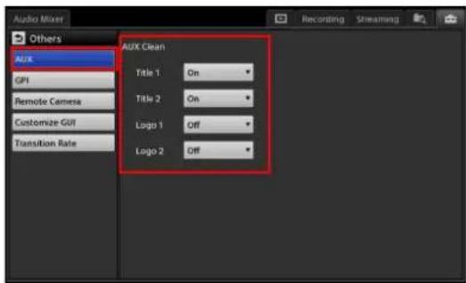
Outputting AUX from the PGM/AUX output connectors
Specify the connectors (RGB output, HDMI output, or SDI output connectors) you want to use for AUX output as [AUX].
1 Display the [System Setup] screen, and tap [Video].

The [Video Setup] screen appears.
2 Tap [Output] in the menu to the left, select the connector you want to use for AUX output in the screen that appears, and select [AUX] for [Video Source].

Switching the Video
Creating [AUX] lists
Create a list by adding input signals and still images to the [AUX] option list.
For details on creation, see "Creating Lists" (page 41).
Tip
[PGM] and [Clean] cannot be removed from the [AUX] list.
Switching videos
1 In the [AUX] list of the [Option] menu, select the select the material you want to use for the AUX output.
If you select [PGM], the output will be identical to the PGM output.
If you select [Clean], the output specified in the [System Setup] menu > [Others] > [AUX] screen will be used.
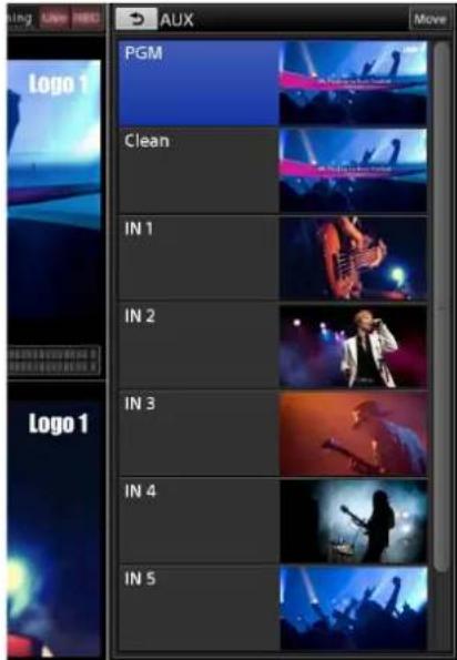
2 Tap [Take] or [Cut] to switch the video.
3 Verify the AUX output.
The AUX output will not be displayed in the [PGM] viewer or [NEXT] viewer. Connect a monitor, for example, to the AUX output connector, and verify the output video.
When the AUX selection status is protected
If the icon appears on the [AUX] button in the [Option] menu, selection operations for the [AUX] list are locked.
Switching of the AUX video is not possible in such cases.
For details, see “10 (AUX lock) icon” (page 38) in the “Main Screen” section.
Excluding AUX outputs from scenes
If you save a scene while the AUX button is open, the AUX selection will also be saved. To exclude an AUX selection when recalling a scene, remove the AUX setting.
Display the context menu of the [AUX] button and select [Remove].

The [AUX] button will close, and the AUX selection will be excluded.

Performing Detailed Audio Adjustments
You can adjust the audio quality for each channel individually, adjust the audio embedded in input sources, and perform other detailed audio adjustments.
Adjusting the Audio Quality for Each Channel
1 In the [Audio Mixer] screen, tap the [Access] button for the channel (1 to 4) to which the audio you want to adjust is assigned.
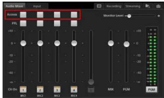
The [Access] screen for the selected channel appears.
2 Tap an item in the menu to the left, and perform adjustments in the screen that appears.
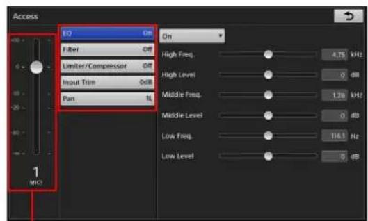
You can also adjust the level of the selected channel here.
You can configure the following settings in the [Access] screen.
[EQ]: Adjust the audio quality by using the equalizer function to specify the frequencies and levels of the high, middle, and low audio ranges (page 76).
[Filter]: Use the filter function to cut high frequencies and low frequencies (page 77).
[Limiter/Compressor]: When inputting audio with significant level differences, configure the limiter and compressor (page 77).
[Input Trim]: Adjust the audio input signal level (page 77). [Pan]: Adjust the left and right balance of the audio (page 77).
3 When you finish configuration, tap .
The [Access] screen appears again.
The following sections describe the settings in the [Access] screen in detail.
[EQ]
Adjust the audio quality by using the equalizer function to specify the frequencies of the high, middle, and low audio ranges.
Configure each setting after setting the equalizer function to [On].

Equalizer: The following settings become available when this is set to [On].
[High Freq.]: Adjust the central frequency of the high-frequency band within a range of 1.3 kHz to 17.4 kHz.
[High Level]: Adjust the level of the high-frequency band within a range of -15 dB to +15 dB.
[ Middle Freq. ]: Adjust the central frequency of the middle-frequency band within a range of 260 Hz to 6.4 kHz.
[ Middle Level]: Adjust the level of the middle-frequency band within a range of -15 dB to +15 dB.
[Low Freq.]: Adjust the central frequency of the low-frequency band within a range of 31 Hz to 420 Hz.
[Low Level]: Adjust the level of the low-frequency band within a range of -15 dB to +15 dB.
[Filter]
Use the filter function to cut high frequencies and low frequencies. This is useful for minimizing noise.
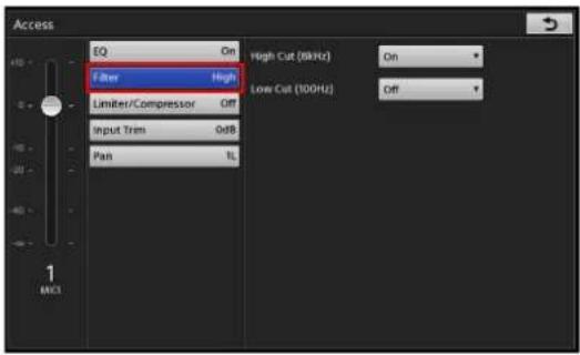
[High Cut (8kHz)]: When [On] is selected, high frequencies (8 kHz) are cut at 12 dB/Oct.
[Low Cut (100Hz)]: When [On] is selected, low frequencies (100 Hz) are cut at 12 dB/Oct.
[Limiter/Compressor]
Use the limiter and compressor when inputting audio with significant level differences.
- The limiter restricts the peak components of an audio signal with significant level differences. It also compresses sound that exceeds a certain threshold volume so that the threshold level is not exceeded, thus preventing excess outputs.
- The compressor gently compresses the level of audio that is at or above the threshold level, thereby smoothing out an audio signal with significant level differences.

Limiter/compressor: Select the audio compression method.
- [Limiter (100:1)]: Enable the limiter (100:1).
• [Compressor (2:1)]: Enable the compressor (2:1).
• [Off]: Disables both.
[Threshold]: Adjust the level (threshold) at which the limiter or compressor takes effect within a range of -60 dB to 0 dB.
[Reduction Meter]: Indicates the amount of dB gain reduction occurring on the input signal (i.e., the current compression effect).
[Input Trim]
Adjust the input signal level so that the proper input level is obtained when the fader is set to the 0 dB position.

[Trim]: Adjust the input level within a range of -15 dB to +15 dB.
[Pan]
Specify the stereo positioning for microphone inputs that consist predominantly of monaural audio.

[Pan]: Adjust the left and right audio balance within a range of 15L to Center to 15R.
Switching the Monitored Audio
Audio outputs from the unit (PGM output and MIX output) can be monitored via the HEADPHONES jack or the internal speakers.
Tapping [PGM]/[MIX] in the [Audio Mixer] screen switches between PGM output and MIX output.
![Audio Mixer Input Recording Streaming Access PFL Monitor Level +10 - 0 - -10 - 20 - 40 - - CH On 1 2 3 4 MIX PGM PGM Each tap switches between [PGM] and [MIX].](/content/2026/05/882243/images/a01f2c68104c91e050a84ba1c866978c42cb3a9f5b79b8a2e364aa481736dd13.jpg)
PGM: Audio output from PGM connectors L and R. When [PGM] is displayed, the audio level meter will also be switched to PGM.
MIX: Audio output from MIX connectors L and R. When [MIX] is displayed, the audio level meter will also be switched to MIX.
Adjusting MIX OUT Output Levels
Adjust the L/R output level for MIX OUT within a range of - to +10 dB using the MIX OUT fader in the [Audio Mixer] screen.

Adjusting the Embedded Audio of Input Sources
Embedded audio that is included in the input source selected in the [Input] list is automatically assigned to channel fader 5. If an input source in the [Input] list includes audio, the audio level can be adjusted beforehand.
Tip
When compositing video using PinP or chroma keying, the [Input] tab will only appear when an input source from the [Input [1]] list is selected. Embedded audio cannot be used for input sources in the [Input [2]] and [Input [3]] lists.
Using embedded audio
1 In the [Input] list of the main screen, select an input source that includes embedded audio.
The [Input] tab appears in the sub screen.
2 Tap the [Input] tab to display the [Input] screen, and set [Embedded Audio] to [On].

To adjust the audio
If a movie includes embedded audio, drag the slider to adjust the audio level.
Tips
- Embedded audio will be assigned to channel fader 5 automatically.
- When the [Input] tab is displayed, the unit enters audio preview mode automatically, allowing you to listen to audio via the HEADPHONES jack or the internal speakers. Audio preview does not affect the PGM output or MIX output.
When adjusting audio levels beforehand
Adjust the audio level using the channel fader in the [Input] screen.
The audio level is saved for each input source individually.

When mixing embedded audio after [Take]
Adjust the audio level using channel fader 5 in the [Audio Mixer] screen.
If embedded audio is output due to a [Take] operation, the embedded audio is automatically assigned to channel fader 5.

Tip
If channel fader 5 is being used for both input and the Media Player, the Media Player will have priority.
Recording Outputs from the Unit to the Internal Storage
Program outputs, AUX outputs, and audio outputs (PGM and MIX) can be recorded onto the unit's internal storage in high-quality picture and audio. The recorded files can be edited using various nonlinear editors.
Note
Data compatibility with all nonlinear editing devices is not guaranteed.
For details on the formats of the files recorded by this unit, see “Recording format” (page 121).
For further details, contact your dealer or local Sony representative.
Configuring Recording Settings
Settings related to recording are configured in the [Recording] screen of the sub screen.
You can display the [Recording] screen by tapping the recording status that appears at the top center of the main screen.

Tip
If [HDCP Handling] (page 107) is set to [On] in the [System] screen, tapping the [Recording] tab in the sub screen or the recording status in the main screen will not display the [Recording] screen.
Configure each setting in the [Recording] screen.
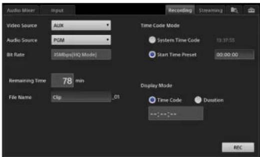
[Video Source]: Select [PGM] or [AUX] as the video you want to record.
[Audio Source]: Select [PGM] or [MIX] as the audio you want to record.
[Bit Rate]: This is fixed at 35 Mbps (HQ Mode).
[Remaining Time]: Displays the remaining recording time in minutes. When the remaining time reaches 10 minutes, the time is displayed in red.
[File Name]: Enter the name of the file to be recorded using up to 20 alphanumeric characters. You cannot overwrite files using the same name.
[Time Code Mode]: Select the timecode to use to start recording.
- [System Time Code]: Select this to use the time specified in the [System Setup] menu > [Date/Time].
- [Start Time Preset]: Select this to start recording from a specific timecode. When [Start Time Preset] is selected, tap the timecode display field, and specify the timecode in the [Start Time Preset] dialog box.

[Display Mode]: Select whether to display the timecode or the recording time in the time display when recording is in progress.
Select [Time Code] to display the timecode, or select [Duration] to display the recording time.
Starting and Stopping Recording
Starting recording
Tap [REC] in the [Recording] screen.

Recording starts.
When recording starts, [REC] changes to [Stop], and the [REC] status displayed at the top of the main screen lights red.

Recording will stop automatically in the following cases.
- When the remaining recording time reaches 0 minutes. - When the recording time of a single file reaches 6 hours.
Stopping recording
Tap [Stop].
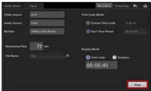
A confirmation message appears. When you tap [Yes], recording stops and the [REC] status turns off. [Stop] changes to [REC], and the [REC] status displayed at the top of the main screen turns off.
Streaming
Program video can be encoded on the unit and streamed live using an external server or saved to the unit's internal storage. Saved data can be exported to USB storage devices and other external drives as VOD (Video On Demand) files, and then uploaded to video-sharing websites via a computer and played back.
Note
The streaming function used by the unit allows third parties to access streaming data during transmissions. In addition, the recommended destination is a site where anyone can view its contents. If you want to protect confidential data during transmissions, we recommend consulting a specialist.
Streaming Servers
This unit includes an encoding function for streaming data, but it does not include a server function. Therefore, you must connect it to a streaming server.
As of December 2015, connection to the following servers has been verified.
- External servers
- Ustream
- YouTube
- Standalone server
- Adobe Media Server 5
– Wowza Media Server 3.5
Consult the streaming server administrator to acquire URL and login information and information required for connecting to the external server.
For details on acquiring information from Ustream and YouTube, see “Connecting to Ustream for Streaming” (page 81) and “Connecting to YouTube for Streaming” (page 82) respectively.
Configuring Network Settings
Configure the unit's network. The unit's network settings must be configured to perform streaming. We recommend connecting the network to the LAN 1 connector.
For details on settings, see “Configuring Network Settings” (page 81).
Connecting to Ustream for Streaming
Preparation
Acquire the connection destination URL and stream key information.
1 Connect to the Ustream website using a computer, for example, and create a broadcast.
2 Acquire the URL and stream key information.
- When importing the information to the unit, download the XML file and copy it to a USB storage device, for example, and connect the device to the USB connector on the unit.
- When entering the information manually, write down the information.
Memo
You can acquire the XML file used for connecting to Ustream by logging into a registered account on the Ustream website, and navigating through [Dashboard] > [Channel] > [Broadcast settings] > [Encoder settings].
Configuring streaming settings
Configure the settings required for connecting to Ustream and streaming in the [Streaming] screen of the sub screen. You can display the [Streaming] screen by tapping the streaming status that appears at the top center of the main screen.

Tip
If [HDCP Handling] (page 107) is set to [On] in the [System] screen, tapping the [Streaming] tab in the sub screen or the streaming status in the main screen will not display the [Streaming] screen.
Select [Ustream] for [Connection] in the [Streaming] screen, and configure each setting.
When you select [Ustream] for [Connection], the setting items displayed switch to those for Ustream.
![Select [Ustream]. Audio Mixer Connection Ustream URL http://www.assss.xxx/2000/2000/8000/xxx Stream Key abcdefg123456hjklmr7890xxx Encode Presets Medium Bandwidth Flash Custom Container Flash Total Bit Rate: 896kbps Video Audio Codec H 264 Codec AAC Bit Rate: 800kbps Bit Rate: 98kbps Frame Rate: 30fps Sample Rate: 48000Hz Frame Size: 640 x 360 Key Frame: 4 sec Video Source PGM Audio Source PGM Live Streaming Start VOD Recording Video 800, Audio 96 kbps File Name WODCLIP Out Start](/content/2026/05/882243/images/fd6d067c29de7a18df8b0708949678f56bcda187b3e20b80defc0beab5794ffc.jpg)
①[URL] and [Stream Key]
Enter the URL and stream key for the broadcast. When importing an XML file downloaded from Ustream, tap [Import] and import the XML file from the [Import] dialog box that appears.
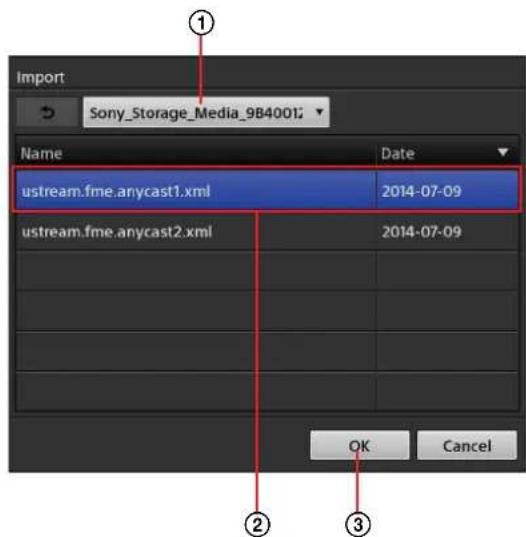
①Select the external drive on which the XML file is stored.
②Select the XML file you want to import.
③Tap [OK] to close the dialog box.
The XML file is imported, and the URL and stream key are automatically entered.
Tips
- Use [Full] when entering URL information in a format that includes information such as the stream key. It is not used under normal circumstances.
- This unit supports XML files of the format currently provided by Ustream.
②[Encode Presets]
Select a settings preset (encoding preset).
When you select an encoding preset, its settings appear in the area below it.
• [HD Bandwidth-Flash]: Flash settings for HD.
• [High Bandwidth-Flash]: Flash settings for the high bandwidth.
• [Medium Bandwidth-Flash]: Flash settings for the middle bandwidth.
- [Low Bandwidth-Flash]: Flash settings for the low bandwidth.
- [Ustream Custom 1]: Custom settings 1 for [Ustream].
- [Ustream Custom 2]: Custom settings 2 for [Ustream].
- [Ustream Custom 3]: Custom settings 3 for [Ustream].
- [Ustream Custom 4]: Custom settings 4 for [Ustream].
Custom (Custom Settings)
Configure the bit rate, frame rate, and other detailed settings.
The settings can be saved to four presets ([Custom 1] to [Custom 4]) for each destination streaming server.
For details on settings, see "Configuring Custom Settings" (page 84).
Connecting to YouTube for Streaming
Preparation
Perform the following preparations on the YouTube website.
1 Connect to the YouTube website using a computer, for example, and create a live event.
2 Set [Type] to [Custom], and configure the bit rate in [Ingestion Settings].
Tip
Configuring the settings with the “Custom ingestion” option selected prevents the stream name from being changed each time an event is created.
3 Select the encoder.
To select the unit, select [Other encoders]. The [URL] and [Stream Name] appear.
Configuring streaming settings
Configure the settings required for connecting to YouTube and streaming in the [Streaming] screen of the sub screen.
You can display the [Streaming] screen by tapping the streaming status that appears at the top center of the main screen.

Tip
If [HDCP Handling] (page 107) is set to [On] in the [System] screen, tapping the [Streaming] tab in the sub screen or the streaming status in the main screen will not display the [Streaming] screen.
Select [YouTube] for [Connection] in the [Streaming] screen, and configure each setting.
When you select [YouTube] for [Connection], the setting items displayed switch to those for YouTube.
![Select [YouTube]. Audio Mixer Connection YouTube URL Stream Name Encode Presets 854x480 - 1000kbps Custom Container Flash Total Bit Rate: 126kbps Video Audio Codec H.204 Codec AAC Bit Rate: 1000kbps Bit Rate: 126kbps Frame Rate: 30fps Sample Rate: 44100Hz Frame Size: 854 x 480 Key Frame: 2 sec Video Source AUX Audio Source PGM Live Streaming Start VOD Recording Video 1500 , Audio 192 kbps File Name: VODCLIP .04 Start](/content/2026/05/882243/images/c4c9e6561d3a4d7f9fdbbcd11c3ad9b7046eedf223e70d1e325697103c1f0392.jpg)

①[URL], [Stream Name]
Enter the URL and stream name of the upload destination.
Tip
Use [Full] when entering URL information in a format that includes information such as the stream name. This is not used under normal circumstances.
②[Encode Presets]
Select a settings preset (encoding preset).
When you select an encoding preset, its settings appear in the area below it.
• [1280×720 - 1500kbps]: HD setting.
• [854×480 - 1000kbps]: High bandwidth setting.
• [640×360 - 750kbps]: Medium bandwidth setting.
- [426×240 - 400kbps]: Low bandwidth setting.
- [YouTube Custom 1]: Custom settings 1 for [YouTube].
• [YouTube Custom 2]: Custom settings 2 for [YouTube].
- [YouTube Custom 3]: Custom settings 3 for [YouTube].
- [YouTube Custom 4]: Custom settings 4 for [YouTube].
Custom
(Custom Settings)
Configure the bit rate, frame rate, and other detailed settings.
The settings can be saved to four presets ([Custom 1] to [Custom 4]) for each streaming server.
For details on settings, see "Configuring Custom Settings" (page 84).
Connecting to a Standalone Server for Streaming
Configuring streaming settings
Configure the settings required for connecting to a standalone server for streaming in the [Streaming] screen of the sub screen.
You can display the [Streaming] screen by tapping the streaming status that appears at the top center of the main screen.

Tip
If [HDCP Handling] (page 107) is set to [On] in the [System] screen, tapping the [Streaming] tab in the sub screen or the streaming status in the main screen will not display the [Streaming] screen.
Select [Others] for [Connection] in the [Streaming] screen, and configure each setting.
When you select [Others] for [Connection], the setting items displayed switch to those for servers other than Ustream and YouTube.
![Select [Others]. Audio Mixer Connection Others URL http://www.xxxx/xxx/xxx/xxxx/xxxx/xxx Stream abcdefy123456yjkines7890xxx Encode Presets High Bandwidth Flash Custom Container: flash Total Bit Rate: 132kbps Video Audio Codec: H.204 Codec AAC Bit Rate: 1200kbps Bit Rate: 128kbps Frame Rate: 30fps Sample Rate: 44100Hz Frame Size: 960 x 54G Key Frame: 5 sec Video Source PGM Audio Source PGM Live Streaming Start VOD Recording Video 800, Audio 96 kbps File Name VODCLIP .04 Start](/content/2026/05/882243/images/d487dab90e3bff8b670e8430bdd080f344f6a4f588450f636cc5e1dae8bcaac7.jpg)
①[URL], [Stream]
Enter the URL and stream of the upload destination.
When importing a previously downloaded XML file, tap [Import] and import the XML file from the [Import] dialog box that appears.
①Select the external drive on which the XML file is stored.
②Select the XML file you want to import.
③Tap [OK] to close the dialog box.
The XML file is imported, and the URL and stream are automatically entered.
Tips
- Use [Full] when entering URL information in a format that includes information such as the stream. This is not used under normal circumstances.
- XML files that are encoded in UTF-8 and that are of the same format used by the Ustream XML file import function are supported.
②[Encode Presets]
Select a settings preset (encoding preset).
When you select an encoding preset, its settings appear in the area below it.
• [HD Bandwidth-Flash]: Flash settings for HD.
• [High Bandwidth-Flash]: Flash settings for the high bandwidth.
• [Medium Bandwidth-Flash]: Flash settings for the medium bandwidth.
- [Low Bandwidth-Flash]: Flash settings for the low bandwidth.
• [Others Custom 1]: Custom settings 1 for [Others].
• [Others Custom 2]: Custom settings 2 for [Others].
• [Others Custom 3]: Custom settings 3 for [Others].
• [Others Custom 4]: Custom settings 4 for [Others].
Custom (Custom Settings)
Configure the bit rate, frame rate, and other detailed settings.
The settings can be saved to four presets ([Custom 1] to [Custom 4]) for each streaming server.
For details on settings, see "Configuring Custom Settings" (page 84).
Configuring Custom Settings
Configure the bit rate, frame rate, and other detailed settings.
The settings can be saved to four presets ([Custom 1] to [Custom 4]) for each streaming server.
1 Select the encoding preset you want to use as the base in [Encode Presets] of the [Streaming] screen.
2 Tap Custom.
The [Custom Settings] screen appears.
The setting values of the preset selected in [Encode Presets] appear in the screen.
3 Configure each item.

①[Video]
Configure video settings.
[Bit Rate]: Enter a value between 200 kbps to 1,500 kbps for the video bit rate (10 Kbps increments).
[Frame Rate]: Select the video frame rate.
[Frame Size]: Select the aspect ratio of the video, and enter the video size. Specify a value between the following for the video size (2 pixel increments).
For 16:9: 106×60 to 1280×720
For 4:3: 80×60 to 960×720
Tips
- When you enter a vertical or horizontal size, the other dimension will be entered automatically based on the aspect ratio.
- When you change the aspect ratio while values are entered, the horizontal value will change automatically based on the vertical size.
[Key Frame Interval]: Select a value between 1 sec. to 5 sec. for the key frame interval.
②[Audio]
Configure audio settings.
[Bit Rate]: Select the audio bit rate.
[Sample Rate]: Select the audio sample rate.
③[Save as]
Save the settings to a preset.
Select the preset name, and tap [Save].
4 Tap to return to the [Streaming] screen.
Selecting the Source to be Encoded
Selecting the video source
In [Video Source], select [PGM] or [AUX] as the video you want to encode with this unit.
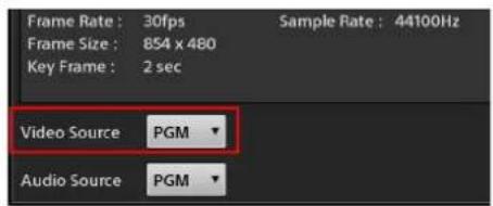
Selecting the audio source
In [Audio Source], select [PGM] or [MIX] as the audio you want to encode with this unit.
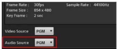
Starting and Stopping Live Streaming Transmissions
Perform controls in the [Live Streaming] area at the bottom right of the [Streaming] screen.
Starting transmission
Tap [Start].

Streaming transmission will start after connection with the streaming server is established.
For YouTube, start transmission from the YouTube website's "Live Control Room" after tapping [Start] for [Live Streaming].
Tip
If the vertical size for [Frame Size] in the streaming settings is set to 542 or higher, this function cannot be performed at the same time as [VOD Recording]. The function started first will have priority.
During transmission, [Start] changes to [Stop] and the transmission time appears (hh:mm:ss). In addition, the [Live] streaming status at the top of the main screen lights red, and an indicator that displays the current network throughput lights.
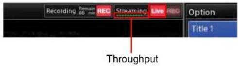
Streaming will stop automatically in the following cases.
- When connection with the streaming server cannot be detected for 10 seconds
Stopping transmission
Tap [Stop].
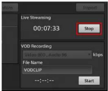
A confirmation message appears. When you tap [Yes], transmission stops and the [Live] streaming status and throughput indicator turn off.
Recording VOD Files
You can record a selected video source and audio source to the unit's internal storage as a VOD file.
For details on file formats, see "VOD recording format" (page 122).
Naming recorded VOD files
Tap the [File Name] field in the [VOD Recording] area at the bottom right of the [Streaming] screen, and enter up to 20 alphanumeric characters for the file name. You cannot overwrite files using the same name.
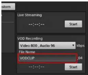
Changing the recording bit rate
Select a bit rate from the drop-down list.
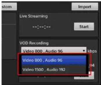
Starting recording
Tap [Start].

Recording starts.
Tip
If the vertical size for [Frame Size] in the streaming settings is set to 542 or higher, this function cannot be performed at the same time as [Streaming]. The function started first will have priority.
During recording, [Start] changes to [Stop] and the recording time appears (hh:mm:ss). In addition, the [REC] streaming status at the top of the main screen lights red.

Recording will stop automatically in the following cases.
- When the remaining recording time reaches 0
- When the recording time reaches 6 hours
Stopping recording
Tap [Stop].

A confirmation message appears. When you tap [Yes], recording stops and the [REC] streaming status turns off.
Using External Devices for Video Switching and Other Operations
You can connect external devices, such as keyboards and X-keys, to the unit's USB port and use them to perform certain main screen operations, such as video switching.
Keyboard Operations
You can perform the following operations.
| Item Key Description | ||
| Scene/Input | Tab Switch | between the [Scene] list and [Input] list. |
| Shift + Tab | Display the [Scene] list. | |
| Ctrl + Tab | Display the [Input] list. | |
| Take Space | Perform a take. | Takes will not be performed if the Space key is pressed during text entry. |
| Button 1 F1 | Select the first button of the buttons displayed in the [Scene] list or [Input] list. | |
| Button 2 F2 | Select the second button of the buttons displayed in the [Scene] list or [Input] list. | |
| Button 3 F3 | Select the third button of the buttons displayed in the [Scene] list or [Input] list. | |
| Button 4 F4 | Select the fourth button of the buttons displayed in the [Scene] list or [Input] list. | |
| Button 5 F5 | Select the fifth button of the buttons displayed in the [Scene] list or [Input] list. | |
| Button 6 F6 | Select the sixth button of the buttons displayed in the [Scene] list or [Input] list. | |
| Button 7 F7 | Select the seventh button of the buttons displayed in the [Scene] list or [Input] list. | |
| Page Up Page Up Display seven buttons of the previous page in the [Scene] list or [Input] list. | ||
| Page Down Page Down | Display seven buttons of the next page in the [Scene] list or [Input] list. | |
| Home Home | Display seven buttons of the first page of the [Scene] list or [Input] list. | |
| Item Key Description | ||
| End End | Display | seven buttons of the last page of the [Scene] list or [Input] list. |
| Go to Option Menu | F8 Display | the [Option] menu. When one of the [Option] menu's lists is displayed, pressing this key returns to the [Option] menu. |
| Title/Logo On/Off 1) | F9 Enable/disable [Title 1]. | |
| F10 Enable/disable [Title 2]. | ||
| F11 Enable/disable [Logo 1]. | ||
| F12 Enable/disable [Logo 2]. | ||
| Media Player | Shift + F1 | Play the file that is open in the [Media Player] screen. |
| Shift + F2 | Pause the file that is currently being played back. | |
| Shift + F3 | Jump to the repeat playback [Start] point of the file that is open in the [Media Player] screen. | |
| Shift + F4 | Configure the repeat playback [Start] point of the file that is open in the [Media Player] screen. | |
| Shift + F5 | Configure the repeat playback [End] point of the file that is open in the [Media Player] screen. | |
| Shift + F6 | Jump to the repeat playback [End] point of the file that is open in the [Media Player] screen. | |
| Recording | Shift + F7 | Start recording with the [Recording] function. |
| Shift + F8 | Stop recording with the [Recording] function. | |
| Streaming | Shift + F9 | Start live streaming. |
| Shift + F10 | Stop live streaming. | |
| Shift + F11 | Start recording with the [VOD Recording] function. | |
| Shift + F12 | Stop recording with the [VOD Recording] function. | |
1) When the [Option] menu is displayed, all of keys F9 to F12 are enabled. When any of the lists are displayed, only the corresponding key is enabled.
X-keys Operations
X-keys is a device that allows you to customize assignment of the ASCII codes that are sent when a button is pressed.
You can assign the key operations described in "Keyboard Operations" (page 87) to the keys on X-keys. This section depicts key assignments on a 24-key model as an example.
For details on assigning keys, refer to the X-keys instruction manual.
Example:
| Option Menu(F8) | Scene List(Shift + Tab) | Scene/Input(Tab) | Button 1(F1) |
| Title 1On/Off(F9) | Input List(Ctrl + Tab) | Home | Button 2(F2) |
| Title 2On/Off(F10) | Page Up | Button 3(F3) | |
| Logo 1On/Off(F11) | Page Down | Button 4(F4) | |
| Logo 2On/Off(F12) | End | Button 5(F5) | |
| Take(Space) | Button 7(F7) | Button 6(F6) | |
Creating Titles (Titler)
This unit includes a "Titler" function for creating title materials via simple operations.
Titles created using the Titler can be registered to the material lists and inserted into videos whenever necessary. The text in titles created with the Titler can also be changed easily.
You can also save created titles as user templates.
Still image files that are imported to the unit can also be added as user templates. For details, see “Managing Files (File Manager)” (page 93).
Tip
Operations performed in the Titler are saved automatically. You do not have to save them manually.
Starting and Quitting the Titler
You can start the Titler using one of the following methods.
- Start from the [File Manager] screen (page 88)
- Start from the [Input] list or the [Option] menu > [Title] list in the main screen (page 43)
You can also start the Titler from a previously created title in any list, and edit text. For details, see “Editing Text Created in the Titler (Edit)” (page 44).
Starting from the [File Manager] screen
Starting the Titler from the File Manager is useful when you want to create multiple titles in advance.
1 Tap the top right of the sub screen.
The [File Manager] screen appears.
2 Tap [Go to Titler] at the upper right of the screen.
![[Go to Titler] Audio Mixer Title 1 Recording Streaming Explore Import Export Go to Titler Still Name Date Size Movie Pattern-1 2014-03-10 02:35 0.2MB Logo Pattern-2 2014-03-10 02:35 0.3MB Recording Pattern-3 2014-03-10 02:35 0.3MB Streaming Concert 2014-03-13 06:30 Project Rock Festival 2014-03-13 06:27 Titler Template 01 2014-03-10 02:52 0.8MB 02 2014-03-10 03:55 0.2MB Remain: 191.0GB](/content/2026/05/882243/images/16196268e9f9ded42e6b19be8f06befbe984dc4793e2da23c519acdb4e71f487.jpg)
The Titler starts, and the [Folder] dialog box for selecting the folder in which to save the file appears. The virtual keyboard that allows you to enter text appears in the sub screen.
3 To create a new folder, tap [New Folder].
An “Untitled” folder is added to the bottom of the list. To create the title in an existing folder, select the folder and tap [Open]. In this case, the Titler starts without going to temple selection.
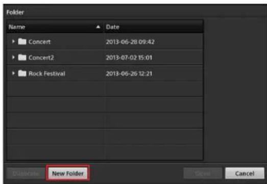
4 Rename the new folder, select this folder, and then tap [Open].

The [Template] dialog box appears.
5 Select the template you want to use, and then tap [Select].
To display a list of presets that are preinstalled on the unit, tap the [Preset] tab. To display a list of user templates, tap the [User] tab.
[Preset] tab and [User] tab

For details on user templates, see "Saving Created Templates as User Templates" (page 92).
The [Titler] screen appears using the selected template.

Tip
The graphics of both preset templates and user templates cannot be edited.
Quitting the Titler
Tap [Close] at the top right of the [Titler] screen.

The [Titler] screen closes, and the main screen appears again.
Using the [Titler] Screen
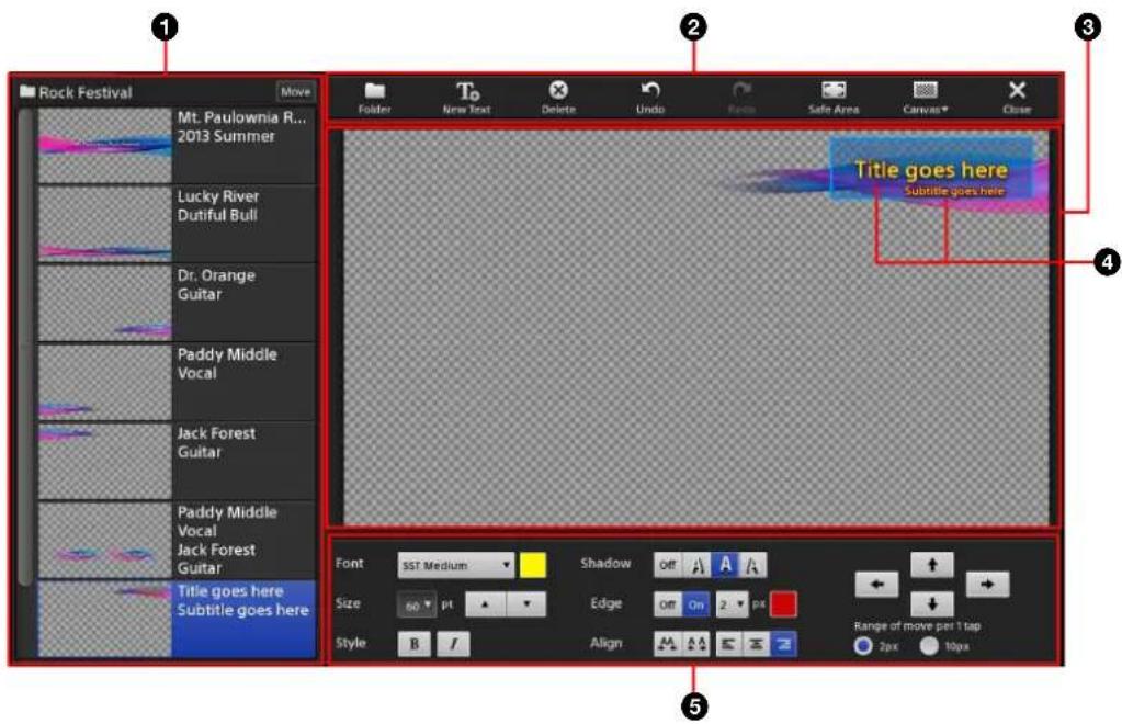
①File list
Displays a list of titles stored in the currently opened folder.
The folder name appears at the top left.

A thumbnail and the text objects included in the file appear on each button.

You can also display the context menu for the button to perform file operations.

[Create New]: Create a new title file (page 91).
[Copy]: Copy the selected file.
[Paste]: Insert a copied file below the selected button.
[Delete]: Delete the selected file.
[Save as Template]: Save the selected file as a user template.
You can change the sort order of the list. For details, see “Changing the Sort Order of the Lists” (page 45).
②Tool buttons
[Folder]: Display the [Folder] dialog box. Folders can only be selected when the Titler was started via [Go to Titler] from the [File Manager] screen.
[New Text]: Add up to four text objects.
[Delete]: Delete the selected text object.
[Undo]: Undo the previous operation.
[Redo]: Redo an undone operation.
[Safe Area]: Display a 16:9 safe area (90% zone and 80% zone) as a dotted line in the ③ editing area. Each tap of the button toggles its display.
[Canvas]: Select the pattern to display as the background canvas of the editing area (black, white, or checkered). The pattern selected here will only appear in the editing area. It will not be used as the background of the title.
[Close]: Quit the Titler.
③Editing area (page 91)
Edit the title in this area.
④Text objects
These are the text objects that you entered.
You can create up to four text objects for a single file. You can enter up to 300 characters in a single object and insert line breaks.
⑤Text properties area
You can configure text object settings, such as font, size, and color.
[Font]: Select the font type. Preset fonts and fonts imported using the File Manager appear in the drop-down list.
Text color: Tap the [Font] color box to display the color palette, and select the text color.

[Size]: Select the text size.
You can double-tap the field to enter a value, or tap or to change the value.
[Style]: Specify a style for the text.
Each tap of the bold or italic button enables or disables each style.
[Shadow]: Add a shadow effect to the text.
[Edge]: Add edges around the text. You can also specify the thickness and color of the edges.
- The edge thickness can specified within a range of 1 pixel to 10 pixels.
- Tapping the [Edge] color box displays the color palette.
[Align]: Adjust the space between each character.
Tapping marrows the space, and tapping widens it.
: Select from left-align ( ) centered ( ) and right-align ( ) for the text alignment.
: Move the text object in the direction of the arrow.
[Range of move per 1 tap]: Specify the amount of movement per tap.
Creating Titles
1 Display the context menu in the file list, and select [Create New].
The [Template] dialog box appears.
2 Tap the template you want to use, and then tap [Select].
The selected template appears in the editing area.
3 Edit the text objects.

You can perform the following operations for text objects.
For details on operations in the text properties area, see "Using the [Titler] Screen" (page 90).
- Move text objects
When you tap a text object, it enters a selected state and a frame appears around the selected object. Drag the text object, or use the arrow buttons in the text properties area to move the object.

You can drag the object to the desired position, and perform fine adjustments using the arrow buttons.
- Enter text
When you tap a text object, text entry mode is enabled and a dotted line appears around the selected object. A caret appears, allowing you to enter text.

- Enter text (select all)
When you double-tap a text object, text entry mode is enabled in a select all state.
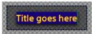
- Enter text (partial select)
When you tap and hold on text, text entry mode is enabled in a partial select state. You can drag the handles to adjust the selection range.
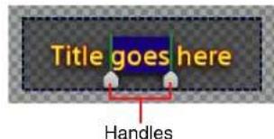
- Quit text entry
Tap outside of the text area. ◀ (Enter) on the virtual keyboard does not confirm entries, but instead inserts a line break.
- Deselect a text object
Tap outside of the text area.
Saving Created Templates as User Templates
You can save still images that were created using the Titler as user templates.
Tips
- Still images that belong to the [Titler Template] category in the File Manager will also be displayed in the user template list.
- Up to 999 user template files can be created. (This includes files imported to the [Titler Template] category of the File Manager.)
1 Display the context menu for the title you want to save as a user template, and select [Save as Template].
The [User] tab of the [Template] dialog box appears.
2 Verify that the selected title has been added to the user template list.
The user template will be automatically named "UserTemplate_
In the [User] tab, information on the selected template is displayed here.
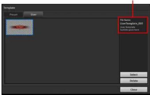
3 Tap [Close].
Deleting user templates
Select the template you want to delete, and then tap [Delete]. When the confirmation message appears, tap [Yes].
Managing Files (File Manager)
You can manage the following types of files stored on the unit's internal storage using the File Manager.
• Still image files imported from external drives
- Files created with the Titler
• Movie files imported from external drives
- Logos
- Files recorded using the [Recording] function or [Streaming] function
- Project files
- Fonts
- User templates created with the Titler
Displaying the [File Manager] Screen
Tap at the top right of the sub screen to display the [File Manager] screen.
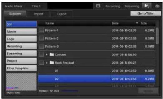
Using the [File Manager] Screen

①Categories
Files stored on the internal storage are divided into the following categories. When you select a category, a list of files appears in the ⑤ file list.
-
[Still]: Includes still image files imported to the internal storage. Materials created using the Titler are also included in this category.
• [Movie]: Includes movie files imported to the internal storage. -
[Logo]: Includes logo files (still image files) imported to the internal storage. Files included in this category are added to the [Logo] list.
- [Recording]: Includes files recorded using the [Recording] function.
- [Streaming]: Includes files recorded using the [Streaming] function.
- [Project]: Includes project files saved in [Project] of the [System Setup] menu.
- [Titler Template]: Includes files imported for use as user templates in the Titler and files saved as user templates using the Titler.
②[Explorer] tab
Allows you to perform operations, such as displaying file lists, deleting, and renaming.
③[Import] tab
Allows you to import files stored on USB storage devices and other external drives to the unit's internal storage (page 95).
④[Export] tab
Allows you to export files stored on the unit's internal storage to external drives (page 96).
⑤File list
Displays a list of folders and files that belong to the category selected in the ① categories area. When you select a folder, the files stored in that folder are displayed.
The names, update dates, and sizes of files are displayed in the list.
To sort the list, tap the title area ([Name], [Date], or [Size]), and tap ▲ or ▼. The button switches between ascending (▲) and descending (▼) order with each tap.
⑥[Go to Titler]
Starts the Titler.
For details on the Titler, see "Creating Titles (Titler)" (page 88).
⑦[Delete]
Deletes the files for which the checkboxes are selected in the list.
⑧[Remain] indicator
Displays the remaining space on the internal storage.
⑨File information
Displays the thumbnail and resolution of the file selected in the list.
Renaming Files
You can rename files stored on the unit's internal storage.
Tip
You cannot rename files created using the Titler.
1 Tap the [Explorer] tab to display the [Explorer] screen.
2 Select the row of the file you want to rename.

3 Tap the [Name] field of the selected row again.
Editing mode is enabled, and the virtual keyboard appears in the sub screen.
4 Enter the new file name, and tap confirm the entry.
Tip
If you import a file and the original file name includes prohibited characters, for example, a message will appear. In such cases, rename the file with the prohibited characters removed.

The virtual keyboard closes, and the file is renamed.
Importing Files
You can import still image and movie files to the unit's internal storage for as materials.
You can rename imported files. For details, see "Renaming Files" (page 94).
Preparing files
Prepare the following files with the following specifications based on their intended purpose.
For still images
| Recommended size 1920 × 1080 |
| File format .tiff, .tif, .png, .jpeg, .jpg, .jpe (alpha channels supported) |
| File name length 64 characters or less (excluding extension) |
For movies ^1)
| File format | .mxf (MPEG HD422 , LPCM) ^2) .mxf (MPEG HD, LPCM) ^2) .f4v (H.264, AAC) ^3) .mov (MPEG4, AAC) ^3) .mov (H.264, AAC) ^3) .mp4 (H.264, AAC or LPCM) ^3) .m2ts (H.264, AC-3) ^3) 2) 50/59.94i3) Up to 1920 × 1080, up to 30p |
| File name length 64 characters or less (excluding extension) | |
1) File formats may be converted in some cases. Verify that movie files can be played on the unit beforehand.
For logos
| Recommended size 320 × 320 |
| File format .tiff, .tif, .png, .jpeg, .jpg, .jpe (alpha channels supported) |
| File name length 64 characters or less (excluding extension) |
For fonts
| Extension .ttf, .pfb, .otf |
For user templates used in the Titler
| Recommended size 1920 × 1080 |
| File format .tiff, .tif, .png, .jpeg, .jpg, .jpe (alpha channels supported) |
| File name length 64 characters or less (excluding extension) |
Tip
Files can be imported as long as they are 1920 × 1080 or less in size, but they may be resized and repositioned.
• Still images and videos
- Files taller than 16:9: Aspect ratios will be retained with black bars added to the left and right.

natural_image
Two side-by-side photos showing a white teacup and saucer on a red tablecloth, with a spoon resting on the cup (no text or symbols visible)- Files wider than 16:9: Aspect ratios will be retained with the image enlarged vertically and the left and right sides cropped.

natural_image
Silhouette of palm trees against a twilight sky, showing a transformation from left to right (no text or symbols)• Logos
- Files smaller than 320 × 320 : Images are positioned at the top left with the remaining space transparent.

flowchart
graph TD
    A["LIVE"] --> B["LIVE"]
- Files larger than 320 × 320 : Images are positioned within a 320 × 320 space at the top left with the areas that extend beyond 320 cropped.

Importing files
Copy the files you want to import to an external drive beforehand.
1 Tap the [Import] tab to display the [Import] screen.
2 Select the category of the file you want to import.
[Still]: Still images used in the [Input] list or [Title] list.
[Movie]: Movies used in the Media Player.
[Logo]: Still images used in the [Logo] list.
[Font]: Fonts used in the Titler.
[Titler Template]: Still images used for user templates in the Titler.

3 Connect the external drive on which the file you want to import is stored to a USB port.
4 Tap ▼ in the list to the right, and select the external drive from which to import in the list that appears.
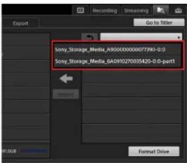
A list of files stored on the external drive appears.
5 Select the checkboxes of the files and folders you want to import, and tap [Import].
You can select multiple files.

The files are imported.
Tip
Even if you import a folder, the files within that folder will be imported to this unit without the folder.
Exporting Files
You can copy recorded files and VOD files stored on the unit's internal storage to external drives. If necessary, format the external drives beforehand.
For details on formatting, see "Formatting External Drives" (page 97).
1 Tap the [Export] tab to display the [Export] screen.
2 Select the category of the file you want to export, and select the checkboxes of the files you want to export. You can select multiple files.

3 Connect the external drive to a USB port.
4 Tap ▼ in the list to the right, select the external drive to which to export in the list that appears, and then tap [Export].

The files are exported.
Formatting External Drives
You can format an external drive if necessary.
Tips
• This unit supports FAT32.
- When exporting files that exceed 4 GB in size, format the drive on a computer using the exFAT file system.
- This unit does not support formatting of external drives that exceed 2 TB in size.
- Connect only one external drive when performing formatting. We do not recommend more than three partitions on an external drive.
1 Connect the USB storage device or external drive you want to format to a USB port.
2 Tap the [Import] tab or [Export] tab to display the [Import] screen or [Export] screen.
3 Tap [Format Drive] at the bottom right of the screen.

The [Format Drive] dialog box appears.
4 Select the target external drive, and tap [OK].
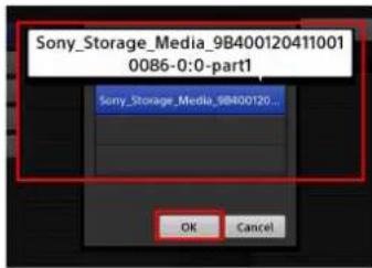
Tip
If the external drive is portioned, each partition will be displayed as a drive.
- To format a single partition, select a row that includes "part" in its name (e.g., "xxxxxx-part1").
- To format the entire drive as a single partition, select the row that does not include "part" in its name.
The external drive is formatted.
Saving and Loading Settings
You can save the current setting configurations to the internal storage as files (up to 99). These files are referred to as "projects."
Tip
Some conditions, such as tab selection states, are not saved.
Saving Settings
1 Display the [System Setup] screen, and tap [Project].
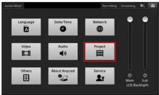
The [Project] screen appears.
2 Tap [Save] to display the [Save] screen.
3 Enter up to 20 alphanumeric characters for the file name, and tap [Save].
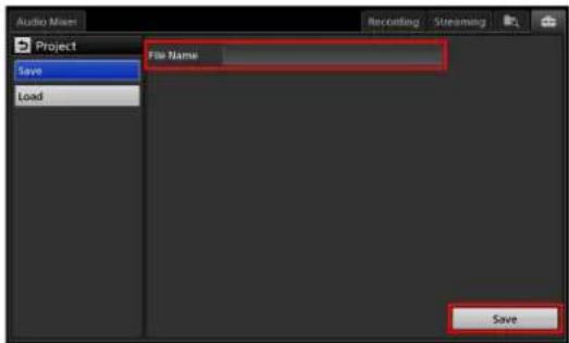
The project is saved.
Loading Settings
1 Select the project file you want to load in the [Load] screen of [Project], and tap [Load].

A confirmation message for restarting the unit appears.
2 Tap [OK].
The unit shuts down.
3 Press the ⏻ switch on the left side of the unit to turn on the unit.
Changes to the project will be applied after the unit restarts.
Restoring Default Settings
To reset list and [System Setup] conditions to their default conditions, load the [Default] project.
1 Tap [Default] in the [Load] screen.
A confirmation message for restarting the unit appears.
2 Tap [OK].
The unit shuts down.
3 Press the ⏻ switch on the left side of the unit to turn on the unit.
Changes to the project will be applied after the unit restarts.
Tip
Even if you restore the default settings, files imported to the internal storage, still images created with the Titler, and other files will be retained.
Settings
Configuring Network Settings
Configure the network connection settings for the unit that are required for IP control of remote cameras, streaming, etc.
Configure each setting item for [LAN 1], [LAN 2], and [Common] before tapping [Apply] to apply the settings.
Configuring LAN 1 and LAN 2 Settings
This section describes the LAN 1 settings as an example. Some of the settings described may not be available in the LAN 2 settings.
Notes
- Configure an IPv4 network environment to control remote cameras. We recommend using the LAN 2 connector.
- To prevent packet loss and delays, use a different network port for the streaming network and the remote camera control network.
1 Use LAN cables to connect the LAN 1 and LAN 2 connectors on the right side of the unit to a network hub, for example.
For details on connections when performing IP control for remote cameras, see "LAN Connections" (page 102).
2 Display the [System Setup] screen in the sub screen, and tap [Network].
The [Network] screen appears.
3 Tap [LAN 1] to display the [LAN 1] screen.
The [LAN 1] screen appears, and the MAC address of the connector and various settings are displayed.
4 Configure IPv4 or IPv6 settings based on the network environment you are using.
For details on the setting items, see the following sections.
When you are finished configuring settings in the [LAN 1] and [LAN 2] screens, configure the settings common to LAN 1 and LAN 2 in the [Common] screen (page 100).
When using an IPv4 network environment
Configure the following items.

IPv4 Mode: Select the mode for the IP address and other settings. The other setting items will change depending on the setting selected here.
• [Off]: Do not use IPv4.
- [Manual]: Enter the settings manually. When you select this mode, enter the IP address, prefix length, and default gateway. Enter period (.) separators for the IP address and default gateway. Enter an integer value from 8 to 30 for the prefix length. For example, enter "/24" for "255.255.255.0."
Tip
The default gateway cannot be configured for LAN 2.
- [DHCP]: Automatically configure the settings using the DHCP server information.
Tip
The DHCP cannot be configured for LAN 2.
When a mode other than [Off] is selected and you want to use the default gateway of this connector in IPv4, select the [Use] checkbox.
Tip
As this setting is linked to the [Default Gateway to be Used] setting in the [Common] screen, the setting configured last will be enabled.
When using an IPv6 network environment
Configure the following items.
Tip
IPv6 settings are only available for LAN 1.

IPv6 Mode: Select the mode for the IP address and other settings. The other setting items will change depending on the setting selected here.
• [Off]: Do not use IPv6.
- [Manual]: Enter the settings manually. When you select this mode, enter the IP address, prefix length, and default gateway. Enter colon (:) separators for the IP address and default gateway. Enter an integer value from 3 to 126 for the prefix length.
- [DHCP]: Automatically configure the settings using the DHCP server information.
- [Auto]: Configure the settings automatically. When a mode other than [Off] is selected and you want to use the default gateway of this connector in IPv6, select the [Use] checkbox.
Tip
As this setting is linked to the [Default Gateway to be Used] setting in the [Common] screen, the setting configured last will be enabled.
Configuring the Common Network Settings
Configure the host name, DNS server settings, and other settings that are common to LAN 1 and LAN 2.
1 Tap [Common] to display the [Common] screen.
2 Configure each item.

[Host Name]: Enter up to 63 alphanumeric characters for the host name.
[Default Gateway to be Used]: Select which default gateway to use for IPv4 and IPv6.
The available options are identical for [IPv4] and [IPv6].
• [Off]: Do not use a default gateway.
• [LAN 1]: Use the default gateway of LAN 1.
Tips
- When using the DHCP server, the values obtained from the DHCP server appear after you tap [Apply].
- As this setting is linked to the [Use] configurations of the Default Gateway settings in the [LAN 1] screen, the setting configured last will be enabled.
[DNS Mode]: Configure the DNS server setting.
• [Off]: Do not use DNS.
- [Manual]: Enter the settings manually. When this is selected, enter up to 253 alphanumeric characters for the domain name, and enter the primary DNS and secondary DNS. A tertiary DNS cannot be configured.
- [DHCP]: Automatically configure the settings using the DHCP server information.
3 After configuring all the settings in the [Network] screen, tap [Apply].
Remote Camera Connections and Settings
This section describes the connections and settings that are required to control VISCA cameras.
Supported models
As of July 2015, the following models have been verified.
| Camera / remote controller | Option board | Supported output | Connection interface |
| BRC-H900 – Switchable SDI (HD/SD) Serial RS-422 | |||
| BRBK-SA1 SD analog output | |||
| BRBK-HSD2 Switchable SDI (HD/SD) | |||
| BRBK-IP10 Switchable SDI (HD/SD) LAN | |||
| BRC-H700 HFBK-HD1 HD-SDI Serial RS-422 | |||
| HFBK-SD1 SD-SDI | |||
| BRC-Z700 – Composite, S-Video | Serial RS-422 | ||
| BRBK-HSD1 Switchable SDI (HD/SD) | |||
| BRBK-IP7Z | Switchable SDI (HD/SD) LAN | ||
| BRC-Z330 – Composite, S-Video | Serial RS-422 | ||
| BRBK-HSD2 Switchable SDI (HD/SD) | |||
| BRBK-IP10 Switchable SDI (HD/SD) LAN | |||
| SRG-300H/301H | – HDMI | Serial RS-422 / LAN ^1) | |
| SRG-300SE/301SE | – SDI | Serial RS-422 / LAN ^1) | |
| SRG-120DH | – HDMI | LAN | |
| EVI-H100S | – HD-SDI Serial RS-422 | ||
| EVI-H100V | – HDMI | Serial RS-422 | |
| RM-IP10 (IP remote controller) | – | LAN | |
1) Use a serial RS-422 connection or a LAN connection. Simultaneous connection of both is not supported.
Serial Connections
You can connect up to seven VISCA-compatible cameras to the unit via a daisy chain connection and control them. Configure the address number for each camera, and use the address numbers to specify which cameras to control.
For details configuring address numbers, refer to the instruction manual for the remote camera.
Connection example:
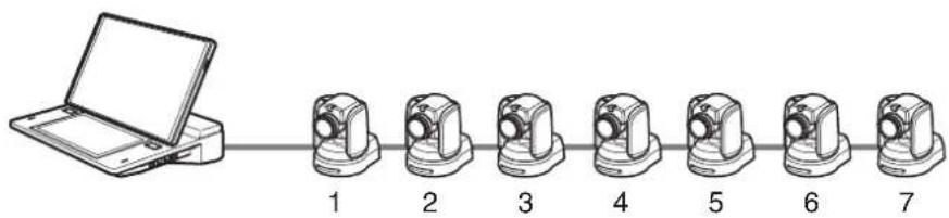
The above is an example of when camera address configuration is set to [Auto].
For details on pin assignments and connections for the VISCA connector, see “VISCA connector” in “Connector Pin Assignments” (page 124).
Tip
Images from up to six cameras can be input at the same time.
Specifying the connection method
1 Display the [System Setup] screen in the sub screen, and tap [Others].
The [Others] screen appears.
2 Tap [Remote Camera] to display the [Remote Camera] screen.
3 Select [Serial RS-422] for [Connection], and tap [Apply].

LAN Connections
Configure the network as follows using a switching hub (100 base-TX compatible).
Up to seven remote cameras, up to four IP remote controllers (RM-IP10), and a computer for configuring camera IP settings can be connected within the same network.
Connection example:

flowchart
graph TD
    A["AWS-750"] --> B["HDMI connector LAN connector"]
    A --> C["SDI connector LAN connector"]
    A --> D["Camera"]
    A --> E["Camera"]
    A --> F["Camera"]
    A --> G["Camera"]
    A --> H["Camera"]
    A --> I["Camera"]
    B --> J["LAN connector RM-IP10"]
    C --> K["LAN connector RM-IP10"]
    D --> L["LAN connector RM-IP10"]
    E --> M["LAN connector RM-IP10"]
    F --> N["LAN connector RM-IP10"]
    G --> O["LAN connector RM-IP10"]
    H --> P["LAN connector RM-IP10"]
    I --> Q["LAN connector RM-IP10"]
    J --> R["Computer for configuring camera IP settings"]
    K --> R
    L --> R
    M --> R
    N --> R
    O --> R
    P --> R
    Q --> R
    R --> S["LAN 1 or LAN 2 connector"]
Switching hub (100 base-TX compatible)
IP address settings for remote cameras and IP remote controllers
The IP addresses of the remote cameras and IP remote controllers are configured via the camera configuration tool on the computer used for configuring camera IP settings.
For details, refer to the instruction manual for the camera.
Tip
You cannot configure the IP address of the unit with the camera configuration tool. The unit will not be visible from the camera configuration tool.
IP remote controller tally settings
As the unit controls the camera tallies when an IP remote controller is used with the unit, be sure to set number 5 of DIP switch 2 to "ON."
Notes
- Use a LAN cable that is Category 5 or higher.
• To prevent packet loss and delays, use a network port that is different from the streaming network. - Do not use stacks of more than two switching hubs. Doing so will result in increased network delays.
- Remote cameras and IP remote controllers cannot be connected to public lines.
- Connect to either LAN 1 or LAN 2. We recommend connecting to LAN 2.
- Do not connect devices other than the unit, seven remote cameras, four IP remote controllers, and a single computer for configuring settings within the same network.
- Do not configure camera connections in which gateway traversal is required for camera control.
Configuring network settings
Configure the unit's network settings so that only the unit, the remote cameras, the IP remote controllers, and a computer for configuring camera IP settings exist on the same network.
Settings example for remote camera network:
For details on settings, see "Configuring Network Settings" (page 99).
Note
Remote camera control is supported only on IPv4 networks.
Specifying the connection method
1 Display the [System Setup] screen in the sub screen, and tap [Others].
The [Others] screen appears.
2 Tap [Remote Camera] to display the [Remote Camera] screen.
3 Select [LAN] for [Connection], and enter the IP address for each camera in the remote camera address fields (VISCA 1 to VISCA 7).
Use periods (.) as separators when entering the IP addresses.

Tip
The IP addresses for IP remote controllers do not need to be configured on the unit.
4 When you finish configuration, tap [Apply].
The cameras will be initialized.
Assigning Remote Cameras
After making each camera selectable in the [Input] list of the main screen, configure settings to enable remote control of the remote cameras.
Configure the settings while the remote cameras are connected to the unit.
1 Connect the remote camera to the unit.
2 Select the input source of the camera in the [Input] list of the main screen, and verify the video.
3 Display the [System Setup] screen in the sub screen, and tap [Video].
The [Video Setup] screen appears.
4 Tap [Input] to display the [Input] screen.
5 Configure video input settings for the connected remote camera.
For details on the video input signal settings, see "[Input]" (page 105).
6 Select the connected remote camera's address (VISCA 1 to VISCA 7) for each connector in [Remote Control].

Tip
If the camera model does not appear in the [Remote Control] drop-down list for an input connector to which a camera is assigned, reset the camera to its default settings.
For details on operations, see "Resetting remote cameras" (page 104).
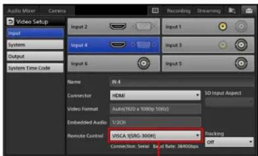
Cameras for which remote control is enabled appear as "address (model name)."
Tip
When a remote camera that is not supported by the unit is connected, its model name will appear as "Unknown." Some functions will not be available in such cases.
Linking the power control of the unit and remote cameras
You can link the power control of the unit (power on/off) to the power control of the remote cameras.
1 Display the [System Setup] screen in the sub screen, and tap [Others].
2 Tap [Remote Camera] to display the [Remote Camera] screen.
3 To link power control, select [Enable] for [Auto Power Control].

Tip
The SRG-300SE/301SE does not support [Auto Power Control].
Resetting remote cameras
Reset the remote cameras to default settings using the following methods when you want to reconnect remote cameras.
- Tap [Reset Camera] in the [Remote Camera] screen

- Display the [Camera] context menu in the [Option] menu, and select [Reset Camera]

When the reset the cameras, connection will be reestablished for all cameras connected for remote control. Depending on the camera model, the pan and tilt may return to their default positions.
Configuring System Settings ([System Setup] menu)
You can configure the following system settings in the [System Setup] menu.
| Screen Description | ||
| Language Specification | Specify the language displayed on the various screens and used for text entry. | page 105 |
| Date/Time Configuration | Configure the unit's internal clock. | page 28 |
| Network Configuration | Configure the unit's network settings. | page 99 |
| Video Setup | Configure video input and output settings and video signal settings. | page 105 |
| Audio Setup | Configure audio input and output settings and adjust settings. | page 108 |
| Project Save | the current settings to the internal storage as a file. Returning of the unit's project to the default condition is also performed here. | page 97 |
| Others Configuration | settings such as those for AUX, remote cameras, [PGM] and [NEXT] viewer positions, and transition rates. | page 109 |
| About Anycast | View the unit's version information and perform software updates. The settings necessary for managing the unit with SNMP are also configured here. | page 110 |
| Service Log | Export service logs. page 110 | |
The following sections provide a screen-by-screen explanation of the settings in the [System Setup] menu.
Displaying the [System Setup] Screen
Tap the tab at the top right of the sub screen to display the [System Setup] menu.

When you tap a button, the respective settings screen appears.
[Language] Screen
Specify the language displayed on the various screens and used for text entry.

[System Language]: Select the language used for screen displays.
[Input Language]: Select the language used for text entry in the Titler.
[Video Setup] Screen
Configure video input and output settings and video signal settings.
The following items are available in the [Video Setup] settings.
| Item Description | Reference | |
| Input Configure | settings related to video inputs. | page 105 |
| System | Configure settings related to video signals for the system as a whole. | page 28 page 106 |
| Output | Configure settings related to video outputs. | page 107 |
| System Time Code | Configure the system timecode. | page 108 |
[Input]
Configure settings related to video inputs.
Configure each setting after selecting a video input connector.
Video input connectors

[Input 1] to [Input 6]: Select the video input.
[Name]: Enter up to 20 alphanumeric characters for the video input name.
The name configured here will appear in the various lists in the main screen.
[Connector]: For [Input 1] to [Input 4], select the video input connector to assign to each video input number.
- For [Input 1] and [Input 3]: Select [SDI] or [Composite].
- For [Input 2] and [Input 4]: Select [RGB] or [HDMI].
Tip
[Input 5] and [Input 6] are fixed at SDI.
[SD Input Aspect]: Select the aspect ratio for SD input signals.
• [4:3 (Center)]: Center the 4:3 aspect ratio (i.e., fitted to the top and bottom of the display with black bars on the left and right).

• [16:9 (Wide Zoom)]: Stretch the aspect ratio to 16:9 (i.e., fitted to the left and right of the display).

Tip
The aspect ratio cannot be changed if a camera that is currently tracking in tracking mode exists.
[Video Format]: Select the signal format that will be input to each video input connector.
Tip
When [Auto] is selected for RGB or HDMI, the optimal signal is determined between the unit and input source device, and the video will be displayed at that resolution.
[Embedded Audio]: Specify the input channels of the embedded audio to be used.
• [1/2Ch]: Use channel 1 and 2 of the embedded audio.
• [3/4Ch]: Use channel 3 and 4 of the embedded audio.
Tip
Depending on the video input connector, some options may not be available.
- For HDMI, the setting is fixed at [1/2Ch].
- For composite and RGB, this setting is disabled due to the lack of embedded audio.
[Remote Control]: Configure control settings for remote cameras.
• [Off]: Disable remote control.
• [VISCA 1] to [VISCA 7]: Select the address of the remote camera to be controlled.
For details on remote camera settings, see "Remote Camera Connections and Settings" (page 101).
Tip
When a remote camera that is not supported by the unit is connected, its model name will appear as "Unknown." Some functions will not be available in such cases.
[Tracking]: Select whether to enable the tracking function on a remote camera. The tracking function will only be enabled on the last camera on which it is configured.
• [On]: Enable the tracking function.
• [Off]: Disable the tracking function.
For details on tracking, see "Tracking Targets (Tracking Function)" (page 69).
[System]
Configure settings related to video signals for the system as a whole.

[System Format]: Select the video signal format handled by the unit (i.e., system format). The unit will shut down if the system format is changed.
Tips
- The [60i] setting is actually equivalent to "59.94i."
- Changes to the system format will be applied after the unit restarts.
[HDCP Handling]: Specify how to handle HDMI input sources that are protected with HDCP. This setting only applies to Input 4.
- [Off]: Sources protected with HDCP are not handled. HDMI input sources that are protected with HDCP will be treated as black signals without audio.
- [On]: Sources protected with HDCP will be handled with their protection intact.
Notes
• The following limitations apply when this is set to [On].
- Output of signals other than HDMI is not possible. A gray monochrome screen appears instead.
- The [Recording] and [Streaming] functions cannot be used. In addition, the [HDCP Handling] setting cannot be configured while recording or streaming is in progress.
- Sources that are protected with HDCP and input to Input 2 will be treated as black signals without audio, regardless of this setting.
- For details on whether your AWS-750 unit supports the [HDCP Handling] setting, see “HDCP Handling” (page 120) for “HDMI (HDMI input) connectors 2 and 4” under “Specifications.”
[Output]
Configure settings related to video outputs.
Configure each setting after selecting a video output connector.
Video output connectors

Note
When [HDCP Handling] is set to [On] in [System], output of signals other than HDMI is not possible.
Video output connector: Select the video output connector you want to configure. When you select a video output connector, the current values are displayed for each setting item.
[Video Source]: Select [PGM] or [AUX] for the video output of the selected video output connector. The selectable video signals may differ depending on the output connector.
- For [SDI PGM]: The setting is fixed at [PGM].
- For [RGB], [SDI] and [HDMI]: Select [PGM] or [AUX].
[Audio Source]: Select [PGM] or [MIX] for the embedded audio signal output of the selected video output connector. The selectable embedded audio signals may differ depending on the output connector.
- For [SDI PGM]: The setting is fixed at [PGM].
- For [HDMI] and [SDI]: Select [PGM] or [MIX].
[Video Format]: Select the signal format that will be output to each video output connector.
Tips
- When [Auto] is selected for RGB or HDMI, the unit and output destination device are linked and the optimal signal is output, and the video will be displayed at the resolution of that signal.
- The video format for the HD SDI output connector (PGM/AUX) cannot be switched to 720p.
[SD Output Aspect]: Select the aspect ratio for SD output signals from the SDI PGM connector.
• [Letter Box]: Output with black bars on the top and bottom of the display.

• [Squeeze]: Output with the aspect ratio squeezed to 4:3.

- [Edge Crop]: Output with the left and right sides cropped.

[System Time Code]
Configure the system timecode.
The system timecode configured here is only embedded in the HD-SDI output (PGM only and PGM/AUX). It can also be used for the recording times of the [Recording] function.

[System Time Code]: Select the time to be used as the system timecode.
- [Local Time]: Select this to use the time specified in the [System Setup] menu > [Date/Time] as the system timecode.
- [Free Run Time]: Preset a time that differs from that of the [Local Time]. When this is selected, tap the setting value to display the [Free Run Time] dialog box, and then preset the time.

[Audio Setup] Screen
Configure audio input and output settings and adjust settings.
The following items are available in the [Audio Setup] settings.
| Item Description Reference | ||
| Input Channel Assign | Assign audio signals to the channel faders. | page 108 |
| MIC/LINE Configure the mic/line levels. page 108 | ||
| Output Adjust the PGM OUT and MIX OUT delays. | page 109 | |
| OSC (Oscillator) | Configure oscillator settings. page 109 | |
[Input Channel Assign]
Assign audio signals to the channel faders.
Configure each setting after selecting a channel.
Channels
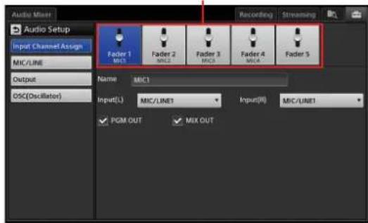
[Name]: Rename channels 1 to 4.
Enter up to 6 alphanumeric characters for the channel name.
[Input (L)] and [Input (R)]: Select the input signals to assign to the L and R of the channel.
• [MIC/LINE 1] to [MIC/LINE 4]: Assign the signals from MIC/LINE IN connectors 1 to 4
• [LINE 5] and [LINE 6]: Assign the signals from LINE IN connectors 5 and 6.
• [HDMI 2] and [HDMI 4]: Assign the signals from HDMI connectors 2 and 4.
• [SDI 1], [SDI 3], [SDI 5], and [SDI 6]: Assign the signals from SDI connectors 1, 3, 5, and 6.
Tips
- This setting is disabled when [RGB] is used for HDMI connector 2 and 4 and [Composite] is used for SDI connectors 1 and 3 in the [Video Setup] screen > [Input] settings.
- For HDMI and SDI embedded audio sources, when audio is selected for either the L channel or the R channel, the audio for the other channel in the pair will be selected automatically.
[PGM OUT]: Select this checkbox when you want to output the audio of channel faders 1 to 5 to PGM OUT.
[MIX OUT]: Select this checkbox when you want to output the audio of channel faders 1 to 5 to MIX OUT.
[MIC/LINE]
Adjust the mic/line levels when the input audio signal is too large or too small.
Configure the mic/line levels after selecting an audio input connector.
Audio input connectors

[MIC/LINE Level]: Select [High (+4dB)], [Middle
(-20dB)], or [Low (-44dB)] while using the base level
of the input device as a reference.
The mic/line levels can only be configured for [MIC/LINE 1] to [MIC/LINE 4].
[Output]
Adjust the PGM OUT and MIX OUT delays so that the video and audio matches.

[PGM Delay]: Adjust the delay time for PGM OUT. Drag the slider, and adjust the delay time within a range of 0 to 7.5 frames (0.25 increments).
[MIX Delay]: Adjust the delay time for MIX OUT. Drag the slider, and adjust the delay time within a range of 0 to 7.5 frames (0.25 increments).
[OSC (Oscillator)]
Configure settings for outputting oscillator signals that will be sued for adjustments.

[OSC Freq.]: Select the oscillator frequency.
Select [Off] (disable oscillator), [100Hz], [1kHz], or [10kHz].
[OUT Level]: Adjust the output level of the oscillator signal.
Drag the slider to adjust within a range of - to 0 dBFS.
[OSC OUT]: Select the checkbox of the output destination for the oscillator signal.
[Others] Screen
Configure settings such as those for AUX, remote cameras, [PGM] and [NEXT] viewer positions, and transition rates.
The following items are available in the [Others] settings.
| Item Description Reference | |
| AUX Configure this if necessary when outputting AUX. | page 73 |
| GPI Configure settings for using GPI output to light the tally lamps on the cameras being used as the PGM output and NEXT selection sources. | page 54 |
| Item Description Reference | ||
| Remote Camera | Configure this to perform remote controls for VISCA-compatible cameras. | page 101 |
| Customize GUI | Switch the display positions of the [PGM] viewer and the [NEXT] viewer, and specify whether to display tallies in the [Input] list. | page 109 |
| Transition Rate | Configure the selectable options for the transition rate in the main screen. | page 109 |
[Customize GUI]
Switch the display positions of the [PGM] viewer and the [NEXT] viewer, and specify whether to display tallies in the [Input] list.

[PGM Viewer Position]: Select whether to display the [PGM] viewer in the upper or lower position.
• [Upper]: Display the [PGM] viewer in the upper position.
- [Lower]: Display the [PGM] viewer in the lower position.
[Tally]: Specify whether to display tallies for the sources in the [Input] list.
• [Off]: Disable display.
• [On]: Enable display.
For details on tallies, see "Using the GUI Tally Function" (page 53).
[Transition Rate]
Configure the selectable options for the transition rate in the main screen.
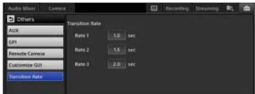
[Rate 1] to [Rate 3]: Configure the three selectable options that will appear in the drop-down list. Tap each setting value to display a dialog box, configure the transition rate within a range of 0.0 to 4.9 seconds, and then tap [Set].

[About Anycast] Screen
View the unit's version information, perform software updates, and configure the settings necessary for managing the unit with SNMP.
The following items are available in the [About Anycast] settings.
| Item Description Reference page | ||
| Information View the unit's system version, serial number, and unique device ID. | page 111 | |
| Update Update the unit's software. | page 111 | |
| SNMP Configure the settings necessary for managing the unit with SNMP. | page 110 | |
| License Display the end-user license agreement (EULA) for the software. | - | |
| Open Source | Display the open-source software (OSS) license list. | - |
[SNMP]
Configure the necessary settings for managing the unit with SNMP.
Tap [Apply] after configuring each setting.

[SNMP Agent Service]: Specify whether to enable the SNMP agent service.
• [Disable]: Disable the SNMP agent service.
- [Enable]: Enable the SNMP agent service. When this is selected, configure the items as well.
[SNMP MIB-2 Variables]: Enter the MIB-2 information.
- [sysName]: Displays the host name. To edit the [sysName], edit the host name in the [Common] screen of [Network].
- [sysContact]: Enter the administrator name. - [sysLocation]: Enter the unit's installation location.
[Community Names]: Specify the community names.
- [Read-only Community]: Enter the read-only community name.
- [Read-write Community]: Enter the read-write community name.
[Communication Hosts]: Specify the IP address of the SNMP manager. You can specify up to two.
- [IP Address 1] and [IP Address 2]: Enter the IP address or network address. Use periods (.) as separators when entering the settings.
[Apply]: Apply the settings.
Tip
If further information is required, contact your local Sony representative.
[Service Log] Screen
Export service logs.
A list of log files appears in the area to the left.
The start dates and times of acquisition are displayed for the file names of logs that are currently being acquired, and the start and end dates and times of acquisition are displayed for the file names of past logs.
Log currently being acquired.

The export procedure is identical to that in the File Manager. For details, see "Exporting Files" (page 96).
Tip
Logs are deleted after a specified period of time passes or a specified capacity is exceeded. As log deletion occurs during startup, the startup process may take longer in some cases.
Appendix
Software Updates
View the unit's version information and perform software updates.
Viewing Version Information
You can view the unit's system version, serial number, and unique ID in the [System Setup] menu > [About Anycast] > [Information].
You can view detailed version information by tapping [Detail Version].

Updating the Software
You can find information on version updates at the web portal of each dealer.
You can also access the information from the following URL.
http://www.sony.net/
Notes
- The updating procedure cannot be canceled once started.
- When update is complete, the unit shuts down automatically. Perform updates when shutdown is not a concern.
1 Save the update package to an external drive, and connect the drive to a USB port on the right side of the unit.
2 Display the [About Anycast] screen of the [System Setup] menu, and tap [Update] in the menu to the left. The [Update] screen appears.
3 Select the external drive on which the update package is stored.

When you select the external drive, the files stored on the drive are displayed.
Tip
If you changed the name of the update package, it will not appear in the list.
4 Select the file, and tap [Update].

The currently installed version and the version of the update package are displayed.
5 Check the versions, and tap [Yes] when you are ready to install.
Installation starts.
When installation is complete, a message appears.
6 Tap [OK].
The unit shuts down.
7 Remove the external drive.
Troubleshooting
Messages
During operation of the unit, messages will appear when problems occur. Read the messages, and follow their instructions. If the problem persists, write down the message number that is displayed, and contact your local Sony representative.
Message type Message number

The following types of message exist.

(Information): Notifications

(Verification): Messages that request verification

(Warning): Warnings that indicate that continuing an operation may result in error

(Error): Warnings that indicate severe errors, such as inability to continue operations and malfunctions
! Icon Displays in Lists
This warning mark appears if a problem exists with materials in the [Scene] list or [Option] menu. Check the status in the [Option] menu, and perform the appropriate operation.
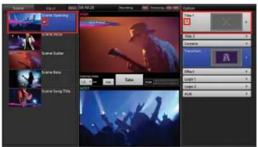
Tip
The "File Not Found" buttons in each list will be deleted from the lists the next time the unit is started.
Problems and Solutions
Check the following before requesting repairs. If the problem persists, contact your local Sony representative.
| Symptom Possible cause Solution | ||
| The unit does not turn on or start up properly. | An overcurrent is being supplied to a USB-connected device. | Disconnect the USB-connected device. In addition, disconnect the AC power cord of the AC adapter from the power outlet temporarily.For details, see “USB ports” (page 16). |
| Videos do not appear in the lists. The connected device is not turned on. | Restart the device. | |
| The cables are not connected properly. | ||
| The video input signals are not assigned properly. | ||
| The tab you want to operate does not appear in the sub screen. | The appropriate list is not open. Display the list for the desired option from the [Option] menu. | |
| The [Option] menu is open. For details, see “Sub Screen” (page 39). | ||
| Titles are not inserted properly. The image file that includes the alpha channel was not created properly. | Create the image file with the alpha channel again, and make sure to do so properly. | |
| Adjustments have not been performed properly. | ||
| Audio is not output from the headphones or speakers. (The audio level meter does not move.) | The connected device is not turned on. | Turn on the device. |
| The cables are not connected properly. | Connect the cables properly. | |
| The audio input signals are not assigned properly. | Assign the audio input signals properly. For details, see “[Input Channel Assign]” (page 108). | |
| The [CH On] button is turned off. Enable (i.e., light) the [CH On] button. For details, see “Step 5: Audio Mixing” (page 33). | ||
| The channel fader is lowered. Raise the channel fader. For details, see “Step 5: Audio Mixing” (page 33). | ||
| The PGM OUT fader is lowered. Raise the PGM OUT fader. For details, see “Step 5: Audio Mixing” (page 33). | ||
| The audio is not as expected. The PGM (or MIX) audio cannot be heard. | The target for monitoring is incorrect. | Tap [PGM] (or [MIX]) at the bottom of the audio level meter to switch to the audio you want to monitor. For details, see “Switching the Monitored Audio” (page 77). |
| The output settings are incorrect. Select the [PGM OUT] and [MIX OUT] checkboxes in [System Setup] > [Audio Setup] > [Input Channel Assign]. For details, see “[Input Channel Assign]” (on page 108). | ||
| Audio is not output from the headphones or speakers. (The audio level meter does move.) | The monitor output level is low. Raise the level via [Monitor Level] adjustment. For details, see “Adjusting the audio level for monitoring” (on page 34). | |
| Audio is not output from the internal speakers. | A device is connected to the monitor output connector. | When the HEADPHONES jack is in use, audio output from the internal speakers is disabled. Disconnect the device. |

| Symptom Possible cause Solution | ||
| Cameras cannot be controlled. Rem | ote control registration has not been performed. | Configure the settings that enable remote control.For details, see “Remote Camera Connections and Settings” (page 101). |
| The connection cable is faulty. Check that cables that were properly connected are being used.For details, see “Connector Pin Assignments” (page 123). | ||
| The baud rate of the connected camera is incorrect. | Set the baud rate of the connected camera to 38,400 bps.For details, refer to the instruction manual for the camera. | |
| The camera IP address registered on the unit does not match the camera’s actual IP address, or the unit’s network settings and the camera’s network segment do not match. | Check the network settings.For details, see “Configuring Network Settings” (page 99).For details, see “LAN Connections” (page 102) in the “Remote Camera Connections and Settings” section. | |
| The control buttons in the [Camera] tab cannot be enabled. | Tracking is in progress in tracking mode. | Stop tracking.For details, see “Stopping tracking” (page 72) in the “Using Tracking Mode” section. |
| A camera that is operating in tracking mode suddenly points up or down during tracking. | The [Pan/Tilt Limit] settings have not been configured for the camera. | Configure the [Pan/Tilt Limit] settings. You can prevent the target from moving out of view during tracking by doing so.For details, see “Configuring tracking settings” (page 70). |
| The movement range of the camera is narrow during camera control (pan/tilt). | The [Pan/Tilt Limit] settings have been configured for the camera. | Reset the [Pan/Tilt Limit Setting] in the [Tracking Settings] screen, or use the camera’s remote controller to turn off the [Pan/Tilt Limit] settings.For details on the [Tracking Settings] screen, see “Configuring tracking settings” (page 70). |
| Camera images are displayed upside down. | The settings on the camera are upside down. | Check the vertical image flip setting on the camera.For details, refer to the instruction manual for the camera. |
| The up, down, left, and right directions are reversed during camera control. | The [Pan Reverse] and [Tilt Reverse] settings in the [Camera Settings] screen are not configured correctly. | Configure the [Pan Reverse] and [Tilt Reverse] settings in the [Camera Settings] screen.For details, see “Configuring camera settings” (page 51). |
| I want to restore the factory default conditions. | - Contact your local Sony representative. | |
| Configured date and time settings change when the unit is restarted. | Incorrect date and time displays may indicate that the internal battery is low. | Contact your local Sony representative. |
| The touchscreens do not respond to taps. | You are touching a screen that is not related to the current operation. | Do not touch the screen that is not related to the current operation. |
| The following message appears, and connection to the streaming server is not possible.ID-3002 Streaming cannot start.Connection to the streaming server failed. | The server is not receiving the stream from the unit.Possible causes:• The server is down.• The server has been removed from the network. | Contact the server’s administrator. |
| The following message appears, and connection to the streaming server is not possible.ID-3003Streaming cannot start.The streaming server is not responding. | The server has been located, but it is not receiving the stream from the unit.Possible causes:The server's streaming service has been stopped.The service is starting up. | Contact the server's administrator. |
| The following message appears, and connection to the streaming server is not possible.ID-3004Streaming cannot startCannot resolve the hostname of streaming server.If the setting is correct, try restarting the unit. | The network settings (the DNS server settings in particular) are incorrect. | Check the network settings.If the settings are correct, restarting the unit and related network devices may allow connection.Connection to the server may not be possible from networks on which packet filtering is performed or from networks that require proxy server configurations. Contact an institution that specializes in networks. |
| Streaming stops and the following message appears repeatedly, even when [Start] is tapped, and streaming does not restart.ID-0020The connection to Streaming Server has been lost.Streaming will be stopped. | The previous connection to the streaming server could not be terminated due to unstable network conditions, and the transmission cannot be restarted until after the previous connection terminates. | Wait at least 30 seconds after the message first appears before attempting to restart transmission. If the problem persists, try restarting the unit to enable connection. |


Maintenance
Remove dust from the ventilation holes once per month or whenever necessary.
Specifications
Main Unit
General
Power requirements
19.5 V DC, 9.2 A
AC adapter Operating Voltage: 100-240 V AC,
2.5A, 50-60 Hz
Power consumption
160 W
Operating temperature
5 °C to 35 °C (42 °F to 95 °F)
Dimensions 415 mm × 102 mm ^1) × 336 mm
(16^3/8in. × 4^1/8in. × 13^1/_4in.) (W
× H × D)
Mass Approx. 7.2 kg ^2) (15 lb 14 oz.)
1) 97 mm (3 ^7/_8 in.): Serial numbers 10001 to 11139
99 mm (4 in.): Serial numbers 11140 to 11999
2) 6.5 kg (14 lb 5.3 oz.): Serial numbers 10001 to 11999
Main display open
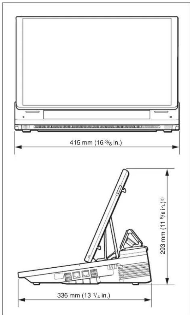
3) 291 mm (11 ^-1 / _2 in.): Serial numbers 10001 to 11139
Main display closed

4) 97 mm (3 ^7 /8 in.): Serial numbers 10001 to 11139
99 mm (4 in.): Serial numbers 11140 to 11999
Video signals
VIDEO INPUTS
HD/SD SDI BNC type (4)
SMPTE ST 292-1, SMPTE ST 259-C
Composite Phono jack (2)
RGB D-Sub 15pin Type (2) (Female)
HDMI HDMI (Type A) (2)
VIDEO OUTPUTS
HD/SD SDI BNC type (2)
SMPTE ST 292-1, SMPTE ST 259-C
HD SDI BNC type (1)
SMPTE ST 292-1
RGB D-Sub 15pin Type (1) (Female)
HDMI HDMI (Type A) (1)
REF OUT BNC Type (1)
Analog black burst signal
NTSC: 0.286 Vp-p, 75 Ω, negative sync
PAL: 0.3 Vp-p, 75 Ω, negative sync
Audio signals
AUDIO INPL
Analog inputs 1-4
XLR/TRS Combo Type (4)
Ref. Level: +4 dBu, -20 dBu, -44 dBu
Input impedance: 3.3 kΩ or more
Mic. Power: +48 V On/Off
Analog inputs 5-6
Phono jack (2)
Reference input level: -10 dBu
Input impedance: 10 kΩ or more
AUDIO OUTPUTS
PGM OUT TRS phone (2)
Reference level: +4 dBu (10 kΩ load)
Max. output level: +24 dBu
Output impedance: 150 Ω
MIX OUT Phono jack (2)
Reference level: -10 dBu (10 kΩ load)
Max. output level: +10 dBu
Output impedance: 470 Ω
HEADPHONES
HEADPHONES
1/4" Stereo Phone Jack Type (1)
Max. power: 35 mW × 2
Impedance: 47 Ω
Speaker Built-In Speaker 1W (2)
Size: 20mm (^13 / _16 in.) in diameter
Other Interfaces
LAN RJ45 Type (2)
100 base-TX, 1000 base-T
USB USB A Type (4)
SuperSpeed USB (USB3.0)
Max current output capability up to
1200 mA (total for four ports)
GPI 9-pin inline connector
Input (4): TTL Level
(VIH = 2.4 V, VIL = 0.8 V)
GPI inputs are not supported on this version.
Output (4): Open collector
Ic = 5mA (typ.), VCEO = 45V (max.)
VISCA
5 pin in-line connector (1)
RS-422 equiv.
Sony VISCA camera commands are supported.
Baud Rate: 38400 bps
LCD
Main display: 15.6" High Brightness
LCD 1920 × 1080 60 Hz, capacitance sensor
Sub display: 10.6" High Brightness
LCD 1280 × 768 60 Hz, capacitance sensor
Supplied accessories
Before Using This Unit (1)
AC adapter (1) VGP-AC19V56
Anti-glare film 393 mm × 236 mm
(15^1/2in. × 9^3/8in.)^1) (1)
266 mm × 156 mm (10 ^-1 / 2 in. × 6 ^-1 / 4 in.) (1)
Detachable panel cover (1)
Connector Phoenix Contact 5 pin (1) (Male)
Phoenix Contact 9 pin (1) (Male)
1) 373 mm×238 mm ( 14^3/4 in. × 9^3/8 in.): Serial numbers 10001 to 11999
Optional accessories
AC power cord (for USA and Canada)
125 V, 10 A, 2.4 m (7 ft. 10^1/_2 in.)
Part number: 1-551-812-31
AC power cord (for Europe)
250 V, 10 A, 2.5 m (8 ft. 2^1/_2 in.)
Part number: 1-782-929-12
AC power cord (for China)
250 V, 10 A, 1.83 m (6 ft. ^1/_2 in.)
Part number: 1-830-860-11
Design and specifications are subject to change without notice.
For the customers in Europe
ATTENTION
The electromagnetic field at the specific frequencies may influence the picture and sound of this unit.
Notes
• Always make a test recording, and verify that it was recorded successfully.
SONY WILL NOT BE LIABLE FOR DAMAGES OF ANY KIND INCLUDING, BUT NOT LIMITED TO, COMPENSATION OR REIMBURSEMENT ON ACCOUNT OF FAILURE OF THIS UNIT OR ITS RECORDING MEDIA, EXTERNAL STORAGE SYSTEMS OR ANY OTHER MEDIA OR STORAGE SYSTEMS TO RECORD CONTENT OF ANY TYPE.
• Always verify that the unit is operating properly before use. SONY WILL NOT BE LIABLE FOR DAMAGES OF ANY KIND INCLUDING, BUT NOT LIMITED TO, COMPENSATION OR REIMBURSEMENT ON ACCOUNT OF THE LOSS OF PRESENT OR PROSPECTIVE PROFITS DUE TO FAILURE OF THIS UNIT, EITHER DURING THE WARRANTY PERIOD OR AFTER EXPIRATION OF THE WARRANTY, OR FOR ANY OTHER REASON WHATSOEVER.
- SONY WILL NOT BE LIABLE FOR CLAIMS OF ANY KIND MADE BY USERS OF THIS UNIT OR MADE BY THIRD PARTIES.
- SONY WILL NOT BE LIABLE FOR THE LOSS, REPAIR, OR REPRODUCTION OF ANY DATA RECORDED ON THE INTERNAL STORAGE SYSTEM, RECORDING MEDIA, EXTERNAL STORAGE SYSTEMS OR ANY OTHER MEDIA OR STORAGE SYSTEMS.
- SONY WILL NOT BE LIABLE FOR THE TERMINATION OR DISCONTINUATION OF ANY SERVICES RELATED TO THIS UNIT THAT MAY RESULT DUE TO CIRCUMSTANCES OF ANY KIND.
Performance
Video signal performance
| Video process 10 bit, 422, 1920 × 1080 59.94/50i | |
| REF OUT subcarrier frequency | Less than 50 ppm |
Audio signal performance
| Sampling frequency | 48 kHz |
| Quantization 24 bit (A/D, D/A)40 bit (DSP) | |
| Frequency response (MIC/LINE) | 20 Hz to 20 kHz, +0.5 dB to -2 dB |
| THD (MIC/LINE -20 dBu 1 kHz) | 0.25% or less |
| Dynamic range 94 dB or more | |
Functions
Video switcher
| Configuration Input: | 6 Primary Video inputs +Internal Content1 M/E + 4 Keyer(2 × PinP, 2 × Title) + 2 LogoOutput: PGM OUTPUT, PGM/AUX OUTPUT |
| Video effect Transition: | Mix, Wipe (4 patterns)PinP: Single (2 patterns), Double (9 patterns)Chromakey: Standard, Chromakey + PinP |
| Key source Title: | Input Signals or Internal StillPicture (up to 1920 × 1080)Logo: Internal Still Picture(320 × 320) |
| Key type Title: | Luminance Key / Alfa ChannelLogo: Alfa Channel |
| Internal content Black | Color Bars (Non standard 7 bars type), Imported files |
| External controller | USB keyboard (US 101, 104 keys type) |
Audio mixer
| Configuration Input: | 6 Monaural / 6 StereoEmbedded Audio inputsMixing: 5 Stereo MixingOutput: PGM (Stereo) / MIX (Stereo) |
| Input control Input Trim: | -15 dB to +15 dBFilter: High Cut 8 kHz, Low Cut100 Hz (12 dB/Oct)EQ: 3 Band EqualizerLimiter: 100:1Compressor: 2:1Pan: 31 position |
| Oscillator 100 Hz, 1 | kHz, 10 kHz |
| Embedded audio | Input from SDI and HDMI: 2 channelsOutput to SDI and HDMI: 2 channelsLinear PCM |
Camera control
| Control protocol | VISCA |
| Connection interface | Serial RS-422, LAN |
| Recommended camera / remote controller | Camera: BRC-Z330, BRC-Z700, BRC-H700, BRC-H900, SRG-300H/301H, SRG-300SE/301SE, SRG-120DH, EVI-H100S, EVI-H100VIP remote controller: RM-IP10For details on option board pairings, see “Supported models” (page 101). |
| Max. controllable cameras | 6 cameras |
| Preset memory Memory: 16 (6 for the EVI-H100S and EVI-H100V)Items: Pan / Tilt / Zoom / Focus / Iris | |
Titler
| Preinstalled fonts 17 | fonts including SST Medium,DFHei-W5-A, SST Japanese ProRegular, and YDGothic 100 Pro |
| Preinstalled templates | 100 patterns and more |
| Import font format Vector Fonts (.ttf, pfb, off) | |
| Input language 10 languagesEnglish, Chinese (Simplified),Chinese (Traditional), Japanese,Korean, German, Spanish, Italian,Portuguese, French | |
| Input method editor Pin Yin (Chinese simplified)Changjie (Chinese traditional)Roman input (Japanese)Jamo input (Korean) | |
Media Player
| Playable files One still image file or one movie file | |
| Application data capacity | 192 GB |
Supported Input Formats
Tip
You can select from the following two output methods for SD input signals, based on the [System Setup] > [Video Setup] > [Input] > [SD Input Aspect] setting.
4:3 (Center) 16:9 (Wide Zoom)


HD/SD SDI (SDI input) connectors 1, 3, 5, and 6
Video
| HD/SD Resolution / ip | |
| HD When the system format is 1080 50i | |
| 1920 × 1080 50i | |
| 1280 × 720 50p | |
| When the system format is 1080 60i | |
| 1920 × 1080 59.94i | |
| 1280 × 720 59.94p | |
| SD When the system format is 1080 50i | |
| 720 × 576 (D1 625) 50i | |
| When the system format is 1080 60i | |
| 720 × 480 (D1 525) 59.94i | |
Audio
HD SDI 24-bit, SD SDI 20-bit, 48 kHz, 2 ch (select from 1/2 ch or 3/4 ch), L-PCM
COMPOSITE (composite video input) connectors 1 and 3
| Resolution | Frequency / ip |
| When the system format is 1080 50i | |
| 720 × 576 (PAL) | 50i |
| When the system format is 1080 60i | |
| 720 × 480 (NTSC) | 59.94i |
RGB (RGB input) connectors 2 and 4
| Resolution | Frequency / ip |
| 640 × 480 (VGA) | 60p |
| 1024 × 768 (XGA) | 60p75p |
| 1600 × 1200 (UXGA) | 60p |
| 1280 × 1024 (SXGA) | 60p |
| 1280 × 768 (WXGA) | 60p |
| 1600 × 900 | 60p |
| 1920 × 1080 (HD) | 60p |
HDMI (HDMI input) connectors 2 and 4
Video
| Resolution | Frequency / ip |
| 640 × 480 (VGA) | 59.94p60p |
| 1024 × 768 (XGA) | 60p75p |
| 1600 × 1200 (UXGA) | 60p |
| Resolution Frequency / ip | |
| 1280 × 1024 (SXGA) 60p | |
| 1280 × 768 (WXGA) 60p | |
| 1600 × 900 60p | |
| When the system format is 1080 50i | |
| 720 × 576 (SD) 50p | |
| 1920 × 1080 (HD) 50i | |
| 1920 × 1080 (HD) 50p | |
| 1920 × 1080 (HD) 60p | |
| When the system format is 1080 60i | |
| 720 × 480 (SD) 60p | |
| 720 × 480 (SD) 59.94p | |
| 1920 × 1080 (HD) 59.94i | |
| 1920 × 1080 (HD) 60i | |
| 1920 × 1080 (HD) 59.94p | |
| 1920 × 1080 (HD) 60p | |
24-bit / pixel
RGB 444, YCBCR 422, YCBCR 444 (auto select)
Audio
32 kHz, 44.1 kHz, 48 kHz (auto select)
16-bit, 20-bit, 24-bit (auto select)
L-PCM, 2 ch
HDCP Handling
HDMI connector 2: Not supported
HDMI connector 4: Supported only on AWS-750 units that support HDCP (i.e., units with the following serial numbers).
Serial number: 11001 or later
Supported Output Formats

You can select from the following three output methods for SD output signals, based on the [System Setup] > [Video Setup] > [Output] > [SD Output Aspect] setting.
Letter Box Squeeze

Edge Crop


HD/SD SDI (SDI output) connectors (PGM only)
Video
| HD/SD Resolution / ip | |
| HD When the system format is 1080 50i | |
| 1920 × 1080 50i | |
| 1280 × 720 50p | |
| When the system format is 1080 60i | |
| 1920 × 1080 59.94i | |
| 1280 × 720 59.94p | |
| SD When the system format is 1080 50i | |
| 720 × 576 (D1 625) 50i | |
| When the system format is 1080 60i | |
| 720 × 480 (D1 525) 59.94i | |
Audio
HD SDI 24-bit, SD SDI 20-bit, 48 kHz, 4 ch (3/4 ch and 1/2 ch are same), L-PCM
Time Code
The [System Time Code] is embedded in the ancillary data.
When the system format is 1080 60i, the added timecode is a drop frame timecode.
LTC and VITC will be embedded on the HD SDI video signal output from the SDI PGM connector.
The line numbers in which the timecodes are embedded are as follows.
| System format | Line number | ||
| HD SDI | VITC | 60i | Line 9 and line 571 (1080i) |
| 50i | Line 9 and line 571 (1080i) | ||
| LTC | 60i | Line 10 | |
| 50i | Line 10 | ||
HD SDI (SDI output) connector (PGM/AUX)
Video
| Resolution Frequency / ip | |
| When the system format is 1080 50i | |
| 1920 × 1080 | 50i |
| When the system format is 1080 60i | |
| 1920 × 1080 | 59.94i |
Audio
24-bit, 48 kHz, 4 ch (3/4 ch and 1/2 ch are same), L-PCM
Time Code
The [System Time Code] is embedded in the ancillary data.
When the system format is 1080 60i, the added timecode is a drop frame timecode.
The line numbers in which the timecodes are embedded are as follows.
| System format Line number | ||
| VITC 60i Line | 9 and line 571 | |
| 50i Line 9 and line 571 | ||
| LTC 60i Line | 10 | |
| 50i Line 10 | ||
RGB (RGB output) connector (PGM/AUX)
| Resolution Frequency / ip | |
| 640 × 480 (VGA) 60p | |
| 1024 × 768 (XGA) 60p | 75p |
| 1280 × 1024 (SXGA) 60p | |
| 1280 × 768 (WXGA) 60p | |
| 1920 × 1080 60p |
HDMI (output) connector
Video
| Resolution Frequency / ip | |
| 640 × 480 (VGA) 60p | |
| 1024 × 768 (XGA) 60p | 75p |
| 1280 × 1024 (SXGA) 60p | |
| 1280 × 768 (WXGA) 60p | |
| When the system format is 1080 50i | |
| 1920 × 1080 (HD) 50i | |
| 1920 × 1080 (HD) 50p | |
| When the system format is 1080 60i | |
| 1920 × 1080 (HD) 59.94i | |
| 1920 × 1080 (HD) 59.94p | |
24-bit / pixel
RGB 444, YCBCR 422 (auto select)
Audio
24-bit, 48 kHz, 2 ch, L-PCM
File Formats
Importable still images and movies
| Still image file format | .tiff, .tif, .png, .jpeg, .jpg, .jpe |
| Movie file format^1) | .mxf (MPEG HD422, LPCM) ^2) .mxf (MPEG HD, LPCM) ^2) .f4v (H.264, AAC) ^3) .mov (MPEG4, AAC) ^3) .mov (H.264, AAC) ^3) .mp4 (H.264, AAC or LPCM) ^3) .m2ts (H.264, AC-3) ^3) 2) 50/59.94i3) Up to 1920 × 1080, up to 30p |
| Application data capacity | 192 GB |
1) File formats may be converted in some cases. Verify that movie files can be played on the unit beforehand.
Recording function
Recorded video format
Determined by the [System Setup] > [Video Setup] > [System] > [System Format] setting (page 107).
Recording format
| Format MPEG | HD (.mxf)* Can be simultaneously recorded with VOD file. |
| Container format | MXF |
| Extension | .mxf |
| Video codec | MPEG-2 (Main Profile & High Level), HD Long 1920 × 1080 420, 8 bit, 35 Mbps |
| Audio codec | LPCM 2CH (all 4CH), 48 kHz, 16 bit |
| Recording source | Video: PGM or AUXAudio: PGM or MIX |
| Application data capacity | 192 GB |
| Maximum recording time | About 600 min.Up to 360 min. per file |
Streaming function
| Format Flash | |
| Protocol | RTMP |
| Video codec | H.264 |
| Audio codec | AAC |
Encoder presets
- For [ Ustream ]
| Item | Resolution (W × H) | Video + audio bit rate | Frame rate | Sample rate | Key frame interval |
| HD Bandwidth -Flash | 1280 × 720 | 1,500 kbps + 96 kbps | 30 fps or 25 fps ^1) | 48,000 Hz | 4 sec. |
| High Bandwidth -Flash | 960 × 540 | 1,000 kbps + 96 kbps | 30 fps or 25 fps ^1) | 48,000 Hz | 4 sec. |
| Medium Bandwidth -Flash | 640 × 360 | 800 kbps + 96 kbps | 30 fps or 25 fps ^1) | 48,000 Hz | 4 sec. |
| Low Bandwidth -Flash | 480 × 270 | 400 kbps + 64 kbps | 30 fps or 25 fps ^1) | 48,000 Hz | 4 sec. |
- For [YouTube]
| Item | Resolution (W × H) | Video + audio bit rate | Frame rate | Sample rate | Key frame interval |
| 1280×720-1500 kbps | 1280 × 720 | 1,500 kbps + 128 kbps | 30 fps or 25 fps ^1) | 44,100 Hz | 2 sec. |
| 854×480-1000 kbps | 854 × 480 | 1,000 kbps + 128 kbps | 30 fps or 25 fps ^1) | 44,100 Hz | 2 sec. |
| 640×360-750 kbps | 640 × 360 | 750 kbps + 128 kbps | 30 fps or 25 fps ^1) | 44,100 Hz | 2 sec. |
| 426×240-400 kbps | 426 × 240 | 400 kbps + 128 kbps | 30 fps or 25 fps ^1) | 44,100 Hz | 2 sec |
- For [Others]
| Item | Resolution (W × H) | Video + audio bit rate | Frame rate | Sample rate | Key frame interval |
| HD Bandwidth -Flash | 1280 × 720 | 1,500 kbps + 128 kbps | 30 fps or 25 fps ^1) | 44,100 Hz | 5 sec. |
| High Bandwidth -Flash | 960 × 540 | 1,200 kbps + 128 kbps | 30 fps or 25 fps ^1) | 44,100 Hz | 5 sec. |
| Medium Bandwidth -Flash | 640 × 360 | 800 kbps + 128 kbps | 30 fps or 25 fps ^1) | 44,100 Hz | 5 sec. |
| Low Bandwidth -Flash | 426 × 240 | 500 kbps + 128 kbps | 30 fps or 25 fps ^1) | 44,100 Hz | 5 sec. |
1) Depending on the [System Setup] > [Video Setup] > [System] > [System Format] setting (page 107), the frame rate will be as follows.
| Setting Frame rate | |
| 1080 50i 25 fps | |
| 1080 60i 30 fps |
VOD recording format
| Extension .f4v | |
| Video codec H.264Frame size: 960 × 540Frame rate: 30/25 fps based on system settingsBit rate: 800/1500 kbpsKey frame interval: 2 sec. | |
| Audio codec AACSample rate: 48,000 HzBit rate: 96/192 kbps | |
| Recording source | Video: PGM or AUXAudio: PGM or MIX |
| Maximum recording time | 360 minutes per file |
Supported external drive file systems
NTFS, HFS+, FAT, FAT32, exFAT
Tip
When exporting files that exceed 4 GB in size, format the external drive on a computer using the exFAT file system beforehand.
File system that can be formatted on the unit
FAT32 only
Tip
This unit does not support formatting of external drives that exceed 2 TB in size.
Data Saved to Projects
Main screen
| Item Can be | saved | |
| Location Setting | ||
| [Input] / [Scene] Tab | selections Yes | |
| [Input] list | Material list | Yes |
| [Scene] list | Material list | Yes |
| [Option] menu | List display | Yes |
| [Camera] list | Preset list | Yes |
| [Title 1] / [Title 2] list | Material list | Yes |
| [Effect] list | Effect list | Yes |
| [Logo 1] / [Logo 2] list | Material list | Yes |

| Item | Can be saved | |
| Location | Setting | |
| [AUX] list Material list Yes | ||
| Material selection Yes | ||
| [Transition] list Material list Yes | ||
| Material selection Yes | ||
| Transition rate Time | selection No | |
| [PGM] viewer Video | display No | |
| [NEXT] viewer Video | display No | |
| Selection of adjustment handles overlaid in the [NEXT] viewer | No | |
| Titler Various settings | No | |
Sub screen
| Item Can be saved | ||
| Location Setting | ||
| Tabs | Tab selection | No |
| [Audio Mixer] screen | Fader levels [Ch On] for each fader [Monitor Level] Monitor target | No (the level for fader 5 is remembered for each material) |
| [Access] screen ([Audio Mixer]) | [EQ] [Filter] [Limiter/ Compressor] [Input Trim] [Pan] | Yes |
| [Input] screen | [Embedded Audio] [Audio Level] | No (remembered for each material) |
| [Camera] screen | Controls | No (remembered for each material) |
| Various settings for the tracking function | No | |
| [Camera Settings] screen | Various settings | No (remembered for each material) |
| [Tracking Settings] screen | Various settings | No |
| [Title 1] / [Title 2] screen | Various settings | No (remembered for each material) |
| [Effect] screen Various settings Yes | ||
| [Logo 1] / [Logo 2] screen | Various settings | Yes |
| [Media Player] screen | Screen displays | No |
| [Recording] screen | Various settings | Yes |
| Item | Can be saved | |
| Location | Setting | |
| [Streaming] screen | Various settings 1) | Yes |
| [Custom Settings] | No | |
| [File Manager] screen | Screen displays | No |
| Various materials | No | |
| [System Setup] menu | [Language] | Yes |
| [Date/Time] | No | |
| [Network] | Yes | |
| [Video Setup] | Yes | |
| [Audio Setup] | Yes | |
| [Others] Yes | ||
| [LCD Backlight] | Yes | |
| [Project] | No | |
| [About Anycast] | No | |
| [Service Log] | No | |
| Virtual keyboard | Page selection Mode selection Shift Caps Lock | No |
1) When a project file that was saved in V1.32 or earlier is loaded in V2.0 or later, the settings will start at default values.
External Keyboards
- 101-key and 104-key English external keyboards are supported.
- The Ctrl key and other control keys may be disabled in some cases.
Connector Pin Assignments
GPI connector
9-pin
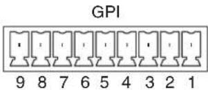
| Pin No. | Description |
| 1 | (Reserved) |
| 2 | (Reserved) |
| 3 | (Reserved) |
| 4 | (Reserved) |
| 5 | GPI OUT 1 On: Short, Off: Open |
| 6 | GPI OUT 2 On: Short, Off: Open |
| 7 GPI OUT | 3 On: Short, Off: Open |
| 8 GPI OUT | 4 On: Short, Off: Open |
| 9 | GND |
VISCA connector
RS-422, 5-pin
VISCA RS-422
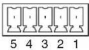
Model number Phoenix Contact: MC 1,5 / 5-ST-3,5
Note
As the baud rate is fixed at 38400 bps, configure the setting on the remote camera side.
Connection example:
AWS-750 Remote cameras

Appendix

flowchart
graph TD
    A["VISCA"] -->|Control| B["Cam 1"]
    A --> C["MISCA"]
    C --> D["Cam 2"]
    C --> E["Cam 3"]
    C --> F["Cam 4"]
    C --> G["Cam 5"]
    C --> H["Cam 6"]
VISCA RS-422 connection diagram
- For the BRC-H700, BRC-H900, BRC-Z330, or BRC-Z700

flowchart
graph TD
    A["to next connector"] --> B["Second remote camera VISCA RS-422 connector"]
    A --> C["Closest remote camera VISCA RS-422 connector"]
    D["AWS-750 VISCA connector"] --> E["1 GND"]
    D --> F["2 RXD IN -"]
    D --> G["3 RXD IN +"]
    D --> H["4 TXD IN -"]
    D --> I["5 TXD IN +"]
    E --> J["Use a 5-conductor cable consisting of two twisted pairs and a grounding wire (e.g., a Category 5 Ethernet cable)."]
    F --> J
    G --> J
    H --> J
    I --> J
    J --> K["1 RXD OUT -"]
    J --> L["2 RXD OUT +"]
    J --> M["3 TXD OUT -"]
    J --> N["4 TXD OUT +"]
    J --> O["5 GND"]
    J --> P["6 RXD IN -"]
    J --> Q["7 RXD IN +"]
    J --> R["8 TXD IN -"]
    J --> S["9 TXD IN +"]
    K --> T["1 RXD OUT -"]
    K --> U["2 RXD OUT +"]
    K --> V["3 TXD OUT -"]
    K --> W["4 TXD OUT +"]
    K --> X["5 GND"]
    L --> Y["6 RXD IN -"]
    L --> Z["7 RXD IN +"]
    L --> AA["8 TXD IN -"]
    L --> AB["9 TXD IN +"]

Appendix

Appendix

flowchart
graph TD
    A["to next connector"] --> B["Second remote camera VISCA RS-422 connector"]
    A --> C["Closest remote camera VISCA RS-422 connector"]
    D["AWS-750 VISCA connector"] --> E["1 GND"]
    D --> F["2 RXD IN -"]
    D --> G["3 RXD IN +"]
    D --> H["4 TXD IN -"]
    D --> I["5 TXD IN +"]
    J["Use a 5-conductor cable consisting of two twisted pairs and a grounding wire (e.g., a Category 5 Ethernet cable)."] --> K["5 GND"]
    J --> L["6 TXD OUT +"]
    J --> M["7 TXD OUT -"]
    J --> N["8 RXD OUT +"]
    J --> O["9 RXD OUT -"]
    P["Use a 5-conductor cable consisting of two twisted pairs and a grounding wire (e.g., a Category 5 Ethernet cable)."] --> Q["1 TXD IN +"]
    R["Using the 5-conductor cable consisting of two twisted pairs and a grounding wire (e.g., a Category 5 Ethernet cable)."] --> S["2 TXD IN -"]
    R --> T["3 RXD IN +"]
    R --> U["4 RXD IN -"]
For details on other models, refer to the instruction manual for the camera.
General Limitation on Transitions
In the following types of composites, videos may cut to each other despite transitions being configured or composites may not be displayed during transitions.
In addition, if even one of the following conditions is met, the other transitions may also be affected.
Condition 1
A transition is executed within the same title. Example: Title 1 (ABC) → Title 1 (XYZ)
Condition 2
Both of the background videos in the [Input] list are still image files. Example: Input [1] (123) → Input [1] (789)
Condition 3
A transition is executed with two effect patterns. Example 1: Pattern_03 → Pattern_04 Example 2: Pattern_03 (adjustment A) → Pattern_03 (adjustment B)

Glossary
Black burst signal
A reference signal used to achieve external synchronization (GenLock). This is a black composite signal.
Chroma key
A method of creating a composite picture by deleting components that contain a specified color (chroma). Typically, a subject is captured in front of a blue background, commonly referred to as a “blue screen,” and the blue background is removed, leaving only to subject for compositing.
Color bars
A test signal which displays vertical colored stripes on a monitor. Used to adjust the hue and saturation of colors on video cameras and monitors.
Compressor
A function which smoothly limits audio signals exceeding a certain threshold. Used to prevent distortion in high-level audio signals.
Default gateway
A router or computer on a network which serves as an entrance to an outside network. Other computers in the network access the outside network via the default gateway.
Delay
A function which delays audio to bring it into synchronization with video, used when video is input later than the corresponding audio.
DHCP (Dynamic Host Configuration Protocol)
A protocol for automatically assigning IP addresses to devices when they connect to a network, and recovering the addresses when they disconnect.
DNS (Domain Name System)
A system which allows Internet domain names to be translated into IP addresses.
Embedded audio
Audio that is included in a video signal.
Encoding
Data rate conversion that uses compression technology and is performed based on the transmission bandwidth and the capacity of the recording media.
Equalizer (EQ)
A function that controls levels for selected audio frequencies in the high, mid, and low regions. Used to strengthen or suppress specific frequencies in order to improve the audio.
Filter
A function that removes signals that are within a specified frequency region. Used to remove cable noise and other kinds of noise.
GPI (General Purpose Interface)
A general-purpose interface that controls connected devices by switching the logic of that port on or off.
HDCP (High-bandwidth Digital Content Protection)
A form of copyright protection that encrypts digital signals as they travel across connections and prevents unauthorized copying of content.
HDMI
A transmission interface standard for transferring video and audio as a digital signal.
Host name
A name assigned to a computer on a network to make it easier to identify. Usually consisting of alphanumeric characters, although conventions differ according to the system.
Key frames
When video data is compressed, frames that store enough data to compose the complete image and frames that store only the small changes between frames exist. Key frames refer to the former and exist as I pictures in MPEG and IDR frames in H.264.
The interval between key frames is configured during compression by the number of frames or by seconds. You can configure this with the [Key Frame Interval] setting in the stream encoding settings.
Limiter
A function which prevents audio levels from exceeding a specified threshold. Used to suppress peaks in audio with large differences in amplitude.
Logo
A permanently visible mark that is shown on videos and used to indicate copyrighted material, for example.
Mix
A new picture is mixed into an old picture, eventually replacing the old picture.
Mixdown
Combining audio inputs from multiple channels into one channel.
Monitor
To listen to audio and view video. Or a device for viewing and listening.
Oscillator
A transmitter that oscillates at a fixed frequency, such as a sine wave. This unit is equipped with an internal audio oscillator.
Pan
In audio, to adjust the left/right audio balance. In video, to move the camera to the left and right.
PFL (Pre-Fader Listen)
Monitoring audio before level adjustments with the audio channel faders. Used to check the input audio. On this system, pan and level control are not applied to PFL audio, even if trim, filter, EQ, pan, and level control settings have been made.
Picture-in-Picture (PinP)
An effect achieved by embedding a video within another video.
Prefix length
IP addresses, which act as labels for devices in a network, consist of a network portion that represents the subnet ^1) , and a host portion that
represents each device. A prefix length is the length of the network portion represented as the number of bits from its beginning, and is written as “/
1) A subnet is part of a larger network that is divided into smaller subnetworks.
Preset
A function which allows a set of electrical settings to be saved and reproduced as a single set of data. This system has a camera preset function.
Program (PGM)
The final video and audio signals output from this system, after the application of effects. The video seen by viewers.
RGB
An output signal format which displays pictures by using the three primary colors: Red, Green, and Blue.
Serial digital interface (SDI)
A standard for transmitting uncompressed digital video signals and embedded audio over a single coaxial cable.
SNMP (Simple Network Management Protocol)
A protocol that allows you to monitor and control connected devices via a network. Using SNMP provides benefits, such as being able to quickly determine faulty devices when network errors occur.
Streaming
A method of transferring audio and data over a network for real-time playback.
Threshold
The level at which a limiter or compressor is activated.
Thumbnail
An image which has been reduced in size for the purpose of displaying a list of many images.
Tilt
To move a camera up and down.
Transition
To switch the video and audio within a specified duration.
Trim
To adjust the input level of audio signals. These adjustments are performed at the input stage, before level adjustments with the audio channel faders.
TRS
A jack with three contacts; the tip, ring, and sleeve.
VISCA
A protocol developed by Sony which allows video equipment to be connected to computers.
VOD (Video On Demand)
A system that allows video content to be placed on a network, which viewers can access freely.
Wipe
The next picture moves in to replace the current picture, as if wiping the old picture away.
XLR
A 3-pin connector, often called a Cannon connector. A locking mechanism keeps the connector securely connected even when the cable is pulled. Very stable despite its simple structure, and often used on microphones to suppress handling noise.
Index
Symbols
+48V switches 17
A
AC power cord 117
Access indicator 14
[Access] screen 76
[Add Media Player] 43
[Add Source] 42
[Add Still Picture] 42
Adobe Media Server 81
Anti-glare films 21
Anti-theft wire slot 17
Audio 33
Audio adjustments 76
AUDIO INPUT block 17
Audio level for monitoring 34
Audio level meter 34, 38
[Audio Mixer] screen 76
Audio mixing 33
AUDIO OUTPUT block 18
[Audio Setup] 108
AUX 73
[AUX] lists 74
AUX lock 38
C
Camera preset 51
[Camera] screen 49
[Camera Settings] 51
[Camera Settings] screen 51
[Camera] tab 39, 49
Camera Tally 54
Channel faders 33
Chroma keying 63
COMPOSITE (composite video input)
connector 1 18
COMPOSITE (composite video input)
connector 3 18
[Compressor] 77
Compressor 77
Connections 26
Controlling cameras 49
[Create New] 43
Creating lists 41
Creating titles 88
[Customize GUI] 109
[Cut] 38
Cut 32
D
Date and time 28
[Date/Time] 29
DC power input connector 17
Default conditions 25
[Delete] 45
Direct mode 31
Direct take 31
Display brightness 29
Double-tap 23
Drag 24
E
[Edit] 44
[Effect] list 59, 63
[Effect] tab 39
Embedded audio 56, 78
Encoder presets 122
Entering text 57
[EQ] 76
Equalizer function 76
Exporting file 96
External devices 87
External keyboards 87, 123
F
File formats 121
File Manager 93
File manager tab 40
[Filter] 77
Filter function 77
Flick 24
Fonts 95
Formatting 97
[Framing] 73
Framing Mode 72
G
GPI connector 17
Ground connector 17
GUI Tally 53
H
HD/SD SDI (SDI input) connector 1 18
HD/SD SDI (SDI input) connector 3 18
HD/SD SDI (SDI input) connectors 5 and 6 18
HD/SD SDI (SDI output) connector (PGM/AUX) 19
HD/SD SDI (SDI output) connectors (PGM only) 19
[HDCP Handling] 107
HDMI (HDMI input) connector 2 18
HDMI (HDMI input) connector 4 18
HDMI (output) connector 19
HEADPHONES jack 15
|
Importing files 95
Input 105
[Input Channel Assign] 108
Input formats 119
[Input] list 35
Input sources 42
[Input] tab 39
[Input Trim] 77
Internal storage 42, 43, 55, 79, 93, 97
K
Keyboards 87
L
L button 14
LAN connectors 16
[Language] 105
[LCD Backlight] 29
[Limiter] 77
Limiter 77
[Limiter/Compressor] 77
List sort order 45
Lock 38
Logo 48
[Logo] lists 48
[Logo] screen 48
[Logo] tab 40
Logos 95
M
Main display 14, 20
Main screen 35
Managing files 93
Material files 55
Media Player 55
[Media Player] tab 40, 55
Messages 112
[MIC/LINE] 108
MIC/LINE IN connectors 17
Mix 32
MIX OUT 78
MIX OUT output levels 78
Mixing 33
[Monitor Level] 34
Monitor speakers 14
[Move] 36
Movies 95
N
[NEXT] viewer 38
0
Operation flow 25
Option list 38
[Option] menu 36
Optional accessories 117
OSC (Oscillator) 109
[Others] 109
[Output] 109
Output 107, 109
Output formats 120
P
[Pan] 77
Panel cover 15
Parts identification 14
[PFL] buttons 34
PGM OUT fader 34
[PGM] viewer 36
[PGM]/[MIX] 78
Picture-in-picture (PinP) 59
PinP 59
Power indicator 14
Power switch 15
Pre-fader listen 34
Preset templates 89
Presets 51, 52
Preview video 30
Program output video 30
Projects 97, 122
Protect 37
R
R button 14
Recorded video format 121
Recording 79
Recording format 121
Recording settings 79
Recording status 36
[Recording] tab 40
REF OUT (reference signal output) connector 17
Release lever 15, 16
[Remote Camera] 104
Remote cameras 49, 101
Repeat Playback 56
[Reset Camera] 51, 104
Restoring default settings 98
RGB (RGB output) connector (PGM/AUX) 19
RGB (RGB video input) connector 2 18
RGB (RGB video input) connector 4 18
S
[Scene] list 35
Scenes 67
[Service Log] 110
SNMP 110
Software updates 111
Specifications 116
Standalone Server 83
Still images 95
Streaming 81
Streaming status 36
[Streaming] tab 40
Sub display 14
Sub screen 39
Supplied accessories 117
[System] 28, 106
System configuration example 12
[System Setup] menu 105
System setup tab 40
[System Time Code] 108
T
Tap 23
Tap and hold 24
Template 89
[Title] lists 46
[Title] screen 47
[Title] tab 39
Titler 88
[Titler] screen 90
[Titler Template] 94
Titles 46
Touchscreen operations 23
[Tracking] 70
Tracking Function 69
Tracking Mode 70
[Tracking Settings] screen 71
Tracking status 70
[Transition Rate] 32
Transition rate 32, 109
Troubleshooting 112
Turning the unit off 27
Turning the unit on 27
U
Updating 111
USB ports 16
User templates 89, 92
Using external devices 87
Ustream 81
v
Version information 111
[Video Format] 106
VIDEO INPUT block 18
VIDEO OUTPUT block 19
[Video Setup] 105
Video signal formats 28
Video switching 30
Virtual keyboard 57, 58
VISCA cameras 101
VISCA connector 17, 124
VOD files 85
VOD recording format 122
W
Warning marks 112
[White Balance] 51
White balance 51
Wipe 32
X
X-keys 88
Y
YouTube 82
- Live Content Producer
- Table of Contents
- Important Notes......6
- Version Update History......7
- Overview
- Features ....10
- System Configuration and Operation Flow 12
- Parts Identification....14
- Opening and Closing the Main Display....20
- Applying the Anti-Glare Films......21
- Using the Touchscreens....23
- Getting Started
- Operation Flow 25
- Step 1: Connecting Devices .....26
- Step 2: Turning the Unit On....27
- Step 3: Initial Settings.....28
- Step 4: Video Switching ....30
- Step 5: Audio Mixing ....33
- Basic Operations
- Using the Screens ....35
- Creating Lists ....41
- Inserting Titles ....46
- Inserting Logos 48
- Controlling Remote Cameras ....49
- Advanced Operations
- Settings
- Configuring Network Settings .....99
- Remote Camera Connections and Settings ....
- Configuring System Settings ([System Setup] menu)....105
- Appendix
- Software Updates ....111
- Troubleshooting ....112
- Maintenance....116
- Specifications ....116
- Glossary....128
- Index....130
- NOTICE TO USERS
- Important Notes
- Copyrights
- Condensation
- LCD panels
- Points to Check Before Using Devices
- Installation
- Note on Images Used in this Manual
- Version Update History
- Functions Added with V2.1
- Additional destination streaming server supported
- Additional operations via external devices
- Functions Added with V2.0
- IP control for remote cameras and additional supported models
- Usable LAN 2 connector
- Improved streaming settings
- HD streaming support
- Custom settings
- Additional destination streaming servers supported
- Repeat playback for the Media Player
- Functions Added with V1.3
- Support for HD SDI 720p input and output
- Notes
- Functions Added with V1.2
- Tracking function
- GUI tally function
- Camera tally function
- Expansion of Picture-in-Picture Function
- User templates added to the Titler
- Angle of view processing for SD signals
- Additional remote camera model support
- Simultaneous operations
- [HDCP Handling] function added (HDCP support)
- Note
- Timecode output function
- Features
- Video switching
- Composites of up to seven sources
- Variety of video inputs
- Video previewing
- Saving video composites as scenes
- Title creation
- Recording to internal storage
- Two-channel output (AUX)
- Audio mixing
- Remote camera control
- Tally function
- Streaming transmission
- System Configuration and Operation Flow
- Preparation settings
- Parts Identification
- Front
- ①Main display
- ②Power indicator
- ③L button
- ④Internal speakers (L/R)
- ⑤Sub display
- 6R button
- ⑦ Access indicator
- Left
- ① Ventilation holes
- ② (power) switch
- ③HEADPHONES jack (standard stereo phone)
- ④ Release lever
- ⑤Panel cover
- Right
- ①USB ports ×4
- ②Ventilation holes
- ③ Release lever
- ④ LAN 1 connector (RJ-45 modular jack)
- ⑤LAN 2 connector (RJ-45 modular jack)
- ⑥ Reserve connector
- Rear
- ①DC IN 19.5V (DC power input) connector
- ②VISCA connector (RS-422, 5-pin)
- ③GPI connector
- ④REF OUT (reference signal output) connector (BNC type)
- ⑤ (ground) connector
- ⑥Panel cover attachment points
- ⑦ Anti-theft wire slot
- ⑧ Ventilation holes
- AUDIO INPUT block
- ①LINE IN connectors 5 and 6 (pin jacks)
- ②MIC/LINE IN connectors 1, 2, 3, and 4 (balanced XLR 3-pin / TRS combo)
- ③+48V switches
- ② AUDIO OUTPUT block
- ③VIDEO INPUT block
- Tip
- Opening and Closing the Main Display
- Opening the Main Display
- Closing the Main Display
- Applying the Anti-Glare Films
- Items to prepare
- Applying the film to the main display
- Placement
- If air bubbles or leftover dust occur
- Applying the film to the sub display
- Using the Touchscreens
- Tap
- Double-tap
- Tap and hold
- Drag
- Flick
- Operation Flow
- Default conditions of the unit
- Step 1: Connecting Devices
- Step 2: Turning the Unit On
- Turning the unit on
- Turning the unit off
- Step 3: Initial Settings
- Video Signal Format Settings
- Date and Time Settings
- Adjusting the Display Brightness
- Step 4: Video Switching
- Switching after Viewing a Preview Video
- Tap [Input] to display the [Input] list.
- In the [Input] list, select the input source you want to use for the program output.
- Tap [Take].
- Repeat steps 2 to 3 to switch from one video to the next.
- Switching the PGM Directly (Direct Take)
- Exiting direct mode
- Using Transition Effects
- Cut
- Mix
- Wipe
- 1
- 2
- 3
- 4
- Step 5: Audio Mixing
- Tips
- Checking each audio input
- Adjusting the audio level for monitoring
- Afterward
- Using the Screens
- Main Screen
- ①[Scene] list / [Input] list
- When tally display is enabled
- To enable or disable options
- Enabled
- Disabled
- Closed buttons
- To close a button
- To display the list for an option
- - When the button is open
- - When the button is closed
- ⑧ (Potect) icon
- To enable protection
- To disable protection
- ⑨Option list
- ⑩ (AUX lock) icon
- To enable the lock
- To release the lock
- ⑪Audio level meter
- Viewing the audio level meter
- 12[NEXT] viewer
- Program output control area
- mark
- Sub Screen
- ①[Audio Mixer] screen
- ②Tabs that appear according to the selections and status of the main screen
- [Input] tab
- [Camera] tab
- [Title] tab
- [Effect] tab
- [Logo] tab
- ③(Media Player) tab
- ④[Recording] tab
- ⑤[Streaming] tab
- ⑥ (file manager) tab
- ⑦ (system setup) tab
- Creating Lists
- Note on image displays
- Examples: List thumbnails
- Preparing Materials
- Input sources
- Material files
- Still image and movie files
- Titles
- Adding Input Sources to the Lists (Add Source)
- Adding Still Images to the Lists (Add Still Picture)
- Adding the Media Player to the Lists (Add Media Player)
- Creating and Adding New Titles (Create New)
- Editing Text Created in the Titler (Edit)
- Removing Material Buttons from the Lists (Delete)
- Changing the Sort Order of the Lists
- Inserting Titles
- - Insert a still image that includes an alpha channel
- - Insert an external signal
- Preparing Titles
- - When inserting titles created on this unit
- - When inserting still image titles created using a separate tool
- - When using external input signals
- Creating [Title] lists
- Viewing Title Composites
- To adjust the appearance of composites
- Tap
- Inserting Logos
- Preparing Logos
- Creating [Logo] lists
- Viewing Logo Composites
- To adjust the position
- Tap ↗.
- Controlling Remote Cameras
- Controlling Cameras
- Adjusting the pan/tilt
- Adjusting the zoom
- Adjusting the focus
- Adjusting the iris
- Enabling backlight compensation
- Automatically adjusting the white balance under the current conditions
- Configuring camera settings
- Resetting remote cameras
- Saving Adjustments as Presets
- Select [Camera] in the [Option] menu.
- Display the context menu in the position you want to add the preset, and select [Save].
- Renaming presets
- Deleting presets from the list
- Recalling Presets
- Disabling presets
- Notes on Using an RM-IP10
- Using the GUI Tally Function
- Tally display example:
- Using the Camera Tally Function
- Lighting Tallies on Remote Cameras
- Lighting Tallies on Cameras Connected via GPI
- Playing Back Material Files in the Media Player
- Playing Back Files
- To adjust the playback position of files
- To adjust the audio
- Mixing embedded audio
- To stop playback
- Repeat Playback
- To specify the section for repeat playback
- To disable repeat playback
- Entering Text
- Using the Virtual Keyboard
- Compositing Videos Using Picture-in-Picture (PinP)
- Selecting Composite Patterns
- Canceling composites
- Selecting Composite Materials
- Adjusting Overlay Videos
- Configuring the [Density] settings
- To restore the original value
- Configuring the [Crop] settings
- Configuring the [Border] settings
- Configuring the [Transformation] settings
- Inserting People onto Backgrounds (Chroma Keying)
- Tap ↗.
- Adjusting Overlay Video 1
- Adjusting [Chromakey] in [Auto] mode
- Tap [Auto] for [Mode].
- Tap an area that includes the color you want to remove to move the color picker.
- If necessary, adjust the outlines and density of the image to be inserted.
- Adjusting [Chromakey] in [Manual] mode
- Tap [Manual] for [Mode].
- Configure each item.
- To restore the original values
- Adjusting Overlay Video 2
- Creating Scenes
- Creating New Scenes
- Renaming scenes
- Deleting scenes from the list
- Deleting all scenes from the list
- Editing Scenes
- Replacing Thumbnails
- Excluding Options from Scenes
- Recalling Scenes
- When a title or logo is protected
- Tracking Targets (Tracking Function)
- Preparation
- Enabling the Tracking Function
- Using Tracking Mode
- Configuring tracking settings
- Starting tracking
- When tracking is lost
- Stopping tracking
- Resuming tracking
- Performing adjustments according to the tracking target
- Using Framing Mode
- Switching the Second Output (AUX)
- Configuring AUX Settings
- Configuring [Clean] settings
- Outputting AUX from the PGM/AUX output connectors
- Switching the Video
- Creating [AUX] lists
- Switching videos
- When the AUX selection status is protected
- Excluding AUX outputs from scenes
- Performing Detailed Audio Adjustments
- Adjusting the Audio Quality for Each Channel
- [EQ]
- [Filter]
- [Limiter/Compressor]
- [Input Trim]
- [Pan]
- Switching the Monitored Audio
- Adjusting MIX OUT Output Levels
- Adjusting the Embedded Audio of Input Sources
- Using embedded audio
- When adjusting audio levels beforehand
- When mixing embedded audio after [Take]
- Recording Outputs from the Unit to the Internal Storage
- Configuring Recording Settings
- Starting and Stopping Recording
- Starting recording
- Stopping recording
- Streaming
- Streaming Servers
- Configuring Network Settings
- Connecting to Ustream for Streaming
- Memo
- Configuring streaming settings
- ①[URL] and [Stream Key]
- ②[Encode Presets]
- Custom (Custom Settings)
- Connecting to YouTube for Streaming
- Custom
- (Custom Settings)
- Connecting to a Standalone Server for Streaming
- Configuring Custom Settings
- ①[Video]
- ②[Audio]
- ③[Save as]
- Selecting the Source to be Encoded
- Selecting the video source
- Selecting the audio source
- Starting and Stopping Live Streaming Transmissions
- Starting transmission
- Stopping transmission
- Recording VOD Files
- Naming recorded VOD files
- Changing the recording bit rate
- Using External Devices for Video Switching and Other Operations
- Keyboard Operations
- X-keys Operations
- Creating Titles (Titler)
- Starting and Quitting the Titler
- Starting from the [File Manager] screen
- To create a new folder, tap [New Folder].
- Rename the new folder, select this folder, and then tap [Open].
- Select the template you want to use, and then tap [Select].
- Quitting the Titler
- Using the [Titler] Screen
- ①File list
- ②Tool buttons
- ③Editing area (page 91)
- ④Text objects
- ⑤Text properties area
- Creating Titles
- - Move text objects
- - Enter text
- - Enter text (select all)
- - Enter text (partial select)
- - Quit text entry
- - Deselect a text object
- Saving Created Templates as User Templates
- Deleting user templates
- Managing Files (File Manager)
- Displaying the [File Manager] Screen
- Using the [File Manager] Screen
- ①Categories
- ②[Explorer] tab
- ③[Import] tab
- ④[Export] tab
- ⑤File list
- ⑥[Go to Titler]
- ⑦[Delete]
- ⑧[Remain] indicator
- ⑨File information
- Renaming Files
- Importing Files
- Preparing files
- • Still images and videos
- • Logos
- Exporting Files
- Formatting External Drives
- Saving and Loading Settings
- Saving Settings
- Loading Settings
- Restoring Default Settings
- Configuring LAN 1 and LAN 2 Settings
- When using an IPv4 network environment
- When using an IPv6 network environment
- Configuring the Common Network Settings
- Remote Camera Connections and Settings
- Supported models
- Serial Connections
- Connection example:
- Specifying the connection method
- LAN Connections
- IP address settings for remote cameras and IP remote controllers
- IP remote controller tally settings
- Settings example for remote camera network:
- Assigning Remote Cameras
- Linking the power control of the unit and remote cameras
- Configuring System Settings ([System Setup] menu)
- Displaying the [System Setup] Screen
- [Language] Screen
- [Video Setup] Screen
- [Input]
- [System]
- [Output]
- [System Time Code]
- [Audio Setup] Screen
- [Input Channel Assign]
- [MIC/LINE]
- [OSC (Oscillator)]
- [Others] Screen
- [Customize GUI]
- [Transition Rate]
- [About Anycast] Screen
- [SNMP]
- [Service Log] Screen
- Software Updates
- Viewing Version Information
- Updating the Software
- Troubleshooting
- Messages
- ! Icon Displays in Lists
- Problems and Solutions
- Maintenance
- Specifications
- Main Unit
- General
- Video signals
- VIDEO INPUTS
- VIDEO OUTPUTS
- Audio signals
- AUDIO INPL
- AUDIO OUTPUTS
- HEADPHONES
- Other Interfaces
- Supplied accessories
- Optional accessories
- For the customers in Europe
- ATTENTION
- Performance
- Video signal performance
- Audio signal performance
- Functions
- Video switcher
- Audio mixer
- Camera control
- Supported Input Formats
- HD/SD SDI (SDI input) connectors 1, 3, 5, and 6
- Audio
- COMPOSITE (composite video input) connectors 1 and 3
- HDMI (HDMI input) connectors 2 and 4
- HDCP Handling
- Supported Output Formats
- HD/SD SDI (SDI output) connectors (PGM only)
- Time Code
- HD SDI (SDI output) connector (PGM/AUX)
- File Formats
- Recording function
- Recorded video format
- Encoder presets
- Supported external drive file systems
- File system that can be formatted on the unit
- Data Saved to Projects
- External Keyboards
- Connector Pin Assignments
- GPI connector
- VISCA connector
- VISCA RS-422 connection diagram
- General Limitation on Transitions
- Condition 1
- Condition 2
- Condition 3
- Glossary
- Black burst signal
- Chroma key
- Color bars
- Compressor
- Default gateway
- Delay
- DHCP (Dynamic Host Configuration Protocol)
- DNS (Domain Name System)
- Embedded audio
- Encoding
- Equalizer (EQ)
- Filter
- GPI (General Purpose Interface)
- HDCP (High-bandwidth Digital Content Protection)
- HDMI
- Host name
- Key frames
- Limiter
- Logo
- Mixdown
- Monitor
- Oscillator
- Pan
- PFL (Pre-Fader Listen)
- Picture-in-Picture (PinP)
- Prefix length
- Preset
- Program (PGM)
- RGB
- Serial digital interface (SDI)
- SNMP (Simple Network Management Protocol)
- Threshold
- Thumbnail
- Tilt
- Transition
- Trim
- TRS
- VISCA
- VOD (Video On Demand)
- XLR
- Index
- Symbols
- A
- C
- D
- E
- F
- G
- H
- |
- K
- L
- M
- N
- 0
- P
- R
- S
- T
- U
- v
- W
- X
- Y
Brand : SONY
Model : Anycast Touch Live AWS-750
Category : Console de production vidéo