
QuickMatriX QMX150 - Switch Analog Way - Free user manual and instructions
Find the device manual for free QuickMatriX QMX150 Analog Way in PDF.


| Product Type | 8x2 Scaled Matrix Switcher |
| Dimensions (with rack mount) | 15.75 x 19 x 3.46 inches (400 x 483 x 88 mm) |
| Dimensions (without rack mount) | 14.17 x 17.3 x 3.46 inches (360 x 440 x 88 mm) |
| Weight | 6.3 kg (13.9 lb) |
| Power Supply | 100-240 VAC autosensing, 50/60 Hz, 110 W typical |
| Inputs | 8 seamless inputs: 4 universal analog (HD-15), 4 DVI-D, 2 HDMI, 2 3G/HD/SD-SDI (BNC), plus 4 analog audio, 2 S/PDIF |
| Outputs | 2 standard outputs: analog computer/video (HD-15), DVI-I (digital + analog) |
| Supported Video Formats | SDTV, EDTV, HDTV (720p, 1080i, 1080p, 1035i, 1080sF), computer formats up to 1920x1200 @ 60 Hz RB |
| Seamless Switching | True seamless with effects (cut, fade, slide, wipe, stretch) |
| Layers | Up to 3 layers per output (including keyed PIP) |
| Keying | Chroma key and luma key with DSK/titling |
| Frame Capture | 8 still frames (capture from Program or Preview) |
| Control | Front panel, RCS^2 remote software (Ethernet), RS232, support for Crestron and AMX drivers |
| Audio | Embedded audio (HDMI, SDI), analog audio inputs/outputs, S/PDIF, delay adjustment, gain control |
| HDCP Compliance | Full HDCP receiver and transmitter, can disable per input |
| Operating Temperature | 0 to +40°C (32 to 104°F) |
| Storage Temperature | -40 to +70°C (-40 to 158°F) |
| Humidity | 10 to 80% non-condensing |
| Maintenance | Clean with a dry cloth; avoid liquids; keep ventilation slots unobstructed |
| Safety | IEC 60950-1, UL listed; do not expose to rain/humidity; use grounding plug |
| Spare Parts & Repairability | 3-year warranty; RMA process; replacement power cord, audio screw terminals, rack ears |
| General Information | Brand: Analog Way, Model: QuickMatriX QMX150, Rack mount 2U, 87-page manual |
Frequently Asked Questions - QuickMatriX QMX150 Analog Way
User questions about QuickMatriX QMX150 Analog Way
0 question about this device. Answer the ones you know or ask your own.
Ask a new question about this device
Download the instructions for your Switch in PDF format for free! Find your manual QuickMatriX QMX150 - Analog Way and take your electronic device back in hand. On this page are published all the documents necessary for the use of your device. QuickMatriX QMX150 by Analog Way.
USER MANUAL QuickMatriX QMX150 Analog Way
Pioneer in Analog, Leader in Digital
THANK YOU
By following these simple steps you will be able to obtain the most from your powerful QuickMatriX and its many features.
- TRADEMARKS 6
- INTRODUCTION 6
- TERMS AND DEFINITIONS 7
- HARDWARE SPECIFICATIONS 8
4.1 Safety instructions 8
4.1.1 English
4.1.2 French
4.1.3 Italian
4.1.4 German
4.1.5 Spanish
4.2 Unpacking and inspection 13
4.3 Rack mount information 13
4.4 Cable and adaptor information 14
4.5 Hardware specifications....14
4.5.1 Signal descriptions
4.5.2 Supported video formats
4.5.3 Computer formats
4.5.4 Input Computer formats
4.5.5 Output Computer formats
4.6 Input specifications 16
4.7 Output specifications.... 18
4.7.1 Standard output
4.8 Communication specifications 19
4.8.1 Serial interface
4.8.2 LAN interface
4.9 Environmental specifications 20
4.10 HDCP management 21
4.10.1 Input HDCP detection
4.10.2 Output HDCP detection
4.10.3 Keys' checking
4.10.4 Output management
4.10.5 HDCP Classification
4.10.6 Status
5. CONNECTING THE QUICKMATRIX 22
5.1 Description 22
5.1.1 Rear panel
5.1.2 Front panel
6. CONTROLLING THE QUICKMATRIX 24
6.1 RCS^2 requirement 24
6.2 Connecting with the RCS ^2 24
6.3 RCS ^2 top menu 26
6.3.1 Setup
6.3.2 Edit
6.3.3 Live
7. OPERATING THE QUICKMATRIX FROM THE RCS ^2 27
7.1 Operating mode 27
7.2 Setup 27
7.2.1 Mode
7.2.2 Audio
7.2.3 Screens
7.2.4 Misc
7.2.5 Output management
7.2.6 Input management
7.2.7 Frame management
7.2.8 Audio management
7.2.9 Service management
7.2.10 Control management
7.3 Edit 38
7.3.1 Layer management
7.3.2 Layer adjustments
7.3.3 Effects
7.3.4 Preset load and save management
7.4 Live 43
8. OPERATING THROUGH THE FRONT PANEL 45
8.1 Front panel 45
8.1.1 Menu navigation
8.1.2 Home menu
8.1.3 Operating modes
8.1.4 Reseting default values
8.1.5 QuickMatriX color codes
8.2 Settings in Matrix mode 46
8.2.1 Source Input selection
8.2.2 Input selection settings
8.2.3 Source Output selection
8.2.4 Output selection settings
8.2.5 Working with layers
8.2.6 Working with layers functions
8.2.7 Layer adjustment menu
8.2.8 Layers with transitions
8.2.9 Capturing frames
8.2.10 Working with frames
8.2.11 Frame input setup menu
8.2.12 Creating presets
8.2.13 Working with presets
8.2.14 Working with audio
8.2.15 Working with Mirror modes
8.2.16 Special features
8.3 Menu tree 57
9. MAINTENANCE AND SUPPORT 81
9.1 Dashboard (RCS ^2 ) 81
10. APPLICATIONS NOTE AND TIPS 82
10.1 HDCP 82
11. WARRANTY 83
11.1 Warranty conditions 83
11.2 Repair and return instructions 83
11.3 Return conditions 83
12. CONTACT INFORMATION 84
13. APPENDICES 85
13.1 Crestron 2&3 series Midra™ Driver 85
13.2 AMX NetLinx® Integrated Controllers Midra™ Driver 85

1. TRADEMARKS
The terms HDMI, HDMI High-Definition Multimedia Interface and the HDMI logo are trademarks or registered trademarks of HDMI Licensing LLC in the United States and other countries.

2. INTRODUCTION
Thank you for choosing the Analog Way QuickMatriX. Before you start setting up your QuickMatriX for the first time, please read through all of the documentation to become familiar with its powerful features. The QuickMatriX can be used in several configurations, which results in a versatile video production tool for live event staging and fixed installation applications.

3. TERMS AND DEFINITIONS
LAYER: a "layer" is an image display element that has a visual priority.
PIP: a "PIP" (Picture In Picture) is a picture, typically of reduced size, which is positioned over another background image or other PIPs. PIPs can be repositioned, reduced, enlarged and displayed with borders. PIPs can overlap, depending on their visual priority. A PIP is considered as a layer.
FRAME: a "frame" is a full screen image which is selected from one of the still frames you can capture. A frame can be captured in flash memory from any video or computer source plugged into the machine.
KEYING: "Key" is an electronic process whereby a video image is electronically superimposed over another source or background, by dynamically removing a portion of the first image. For example, removing all content of a certain color (such as green or blue) is called a Chroma Key, and removing content based on its brightness or luminance levels is called a (Luma Key). Keys are typically used for titles, logos and special effects. QuickMatrix allows you to key a live source (such as a camera shot with green or blue background, or a title with a black background) over any other source or sources.
SEAMLESS: Clean transition with no glitch or loss of sync while switching between two sources. For example, fading through black to another source is a seamless transition.
TRUE SEAMLESS: Clean seamless transitions with no glitch or freeze between two sources. For example, crossfading from source to source is a true seamless transition.
RCS ^2 : Remote Control Software used to control, set up, and operate the device.
QUICK FRAME: The "Quick Frame" feature allows the instant display of a stored frame above all layers.

4. HARDWARE SPECIFICATIONS
4.1 Safety instructions
4.1.1 English
All of the safety and operating instructions should be read before the product is operated and should be maintained for further reference. Please follow all of the warnings on this product and its operating instructions.
- WARNING: To prevent the risk of electric shock and fire, do not expose this device to rain, humidity or intense heat sources (such as heaters and direct sunlight). Slots and openings in the device are provided for ventilation and to avoid overheating. Make sure the device is never placed near a textile surface that could block the openings. Also keep away from excessive dust, vibrations and shocks.
- POWER: Only use the power supply indicated on the device of the power source. Devices equipped with a grounding plug should only be used with a grounding type outlet. In no way should this grounding be modified, avoided or suppressed. Connection of equipment to main supply must be after branch circuit breaker of the building installation.
- POWER CORD: The device is equipped with a detachable power cord, to remove mains disconnect it at appliance coupler. A rear switch is also available, turn OFF to switch off the device.
Caution: The power cord constitutes the only mean to completely disconnect the equipment from the main power.
Apply the following guidelines:
- The equipment connected to the network must have a release system easily accessible and located outside the unit.
- Unplug the power cord; do not pull on the power cord but always on the plug itself.
- The outlet should always be near the device and easily accessible.
- Power supply cords should be routed so that they are not likely to be walked on or pinched by items placed upon or against them.
If the power supply cord is damaged, unplug the device. Using the device with a damaged power supply cord may expose your device to electric shocks or other hazards. Verify the condition of the power supply cords once in a while. Contact your dealer or service center for replacement if damaged.
- CONNECTIONS: All inputs and outputs (except for the power input) are Safety Extra Low Voltage (SELV) circuits as defined in UL/IEC 60950-1.
- SERVICING: Do not attempt to service this product yourself by opening or removing covers and screws since it may expose your device to electric shocks or other hazards. Refer all problems to qualified service personnel. You may lose warranty when you open the unit.
- OPENINGS: Never push objects of any kind into this product through the openings. If liquids have been spilled or objects have fallen into the device, unplug it immediately and have it checked by a qualified technician.
4.1.2 French
4.2 Unpacking and inspection
• 1 x QuickMatrixX (QMX150)
- 1 x Power supply cord
- 1 x Ethernet cross cable (for device update)
- 1 x Remote Control Software (RCS ^2 )*
- 1 x Set of 6 audio 5-pin screw terminals
- 1 x Front rack ears (the parts are stowed in the packaging foam)
- 1 x User manual (PDF)*
- 1 x Quick start guide*
* User manual, quick start guide and the RCS ^2 are available on www.analogway.com
Before racking and plugging any inputs and outputs, it is advised to power on the unit. Should you encounter any issue, you must contact immediately your local distributor or dealer, or closest Analog Way technical support offices (see chapter: 12. Contact information).
4.3 Rack mount information
Tabletop mounting: The QuickMatriX can be used directly on a table; the unit is equipped with 4 handy anti-slip rubber feet.
Rack mounting: The QuickMatriX is compatible with a 19" enclosure. Please follow the instructions below to install the device in a 19" rack.
Place the device in your rack. Attach the device to the rack by screwing 2 front ears on it (screws not included). Rear fixing is also recommended, in particular for permanent installations.
Connect all of the cables of the device and attach them to the rack with the help of tie wraps.
IMPORTANT:
- The openings in the side of the device are for cooling. Do not cover these openings to avoid blocking air circulation.
- Be sure that no weight in excess of 2 kg (4.4 Lbs.) is added onto the QuickMatrix.
- The maximum ambient operating temperature should not exceed 40^ C ( 104^ F).
- The rack and all mounted equipment in it must be reliably grounded according to national and/or local electrical standards.

Dismantling front handles of the device could invalidate warranty on after-sales services of your QuickMatriX. It is strongly advised to avoid using front handles as rests for your QuickMatriX, they are designed for manipulation purposes only.
If required, front handles of the device can be dismantled, but with caution. The original screws removed must not be reintroduced to their location without handles in place. Substantial damages can occur, including risk of electric shock from the main voltage. Only M4x12mm screws can be used. They are supplied with the unit.
4.4 Cable and adaptor information
A large choice of cables and adaptors are compatible with the QuickMatrixX. Please refer to the hardware specifications chapter to find the most suitable cables for your operations.
4.5 Hardware specifications
4.5.1 Signal descriptions
For each type of signal, here are the levels and the impedance accepted by the QuickMatrix.
Analog SDTV
| Type Levels Impedance | ||
| Composite 0,7 | Vpp + 0,3 Vpp 75 Ω | |
| S. Video Y = 0,7 | 7 Vpp + 0,3 VppC = 0,7 Vpp | 75 Ω |
| YUV Y = 0,7 | Vpp + 0,3 VppU = 0,7 VppV = 0,7 Vpp | 75 Ω |
| RGsB R = 0,7 | VppG = 0,7 Vpp + 0,3 VppB = 0,7 Vpp | 75 Ω |
| RGBS | R, G, B = 0,7 Vpp R, G, | B = 75 Ω |
| S = 0,3 Vpp 75 ΩorS = TTL | ||
Analog EDTV
| Type Levels Impedance | ||
| YUV Y = 0,7 | Vpp + 0,3 VppU = 0,7 VppV = 0,7 Vpp | 75 Ω |
| RGsB R = 0,7 | VppG = 0,7 Vpp + 0,3 VppB = 0,7 Vpp | 75 Ω |
| RGBS | R, G, B = 0,7 Vpp R, G, | B = 75 Ω |
| S = 0,3 Vpp 75 ΩorS = TTL | ||
Analog HDTV
These formats are compatible with bi-level and tri-level sync on 1 or 3 wires.
| Type Levels Impedance | ||
| YUV Y = 0,7 | Vpp ±0,3 VppU = 0,7 Vpp ±0,3 VppV = 0,7 Vpp ±0,3 Vpp | 75 Ω |
| RGsB R = 0,7 | Vpp ±0,3 VppG = 0,7 Vpp ±0,3 VppB = 0,7 Vpp ±0,3 Vpp | 75 Ω |
Digital SDTV
| Type Characteristics | |
| SD-SDI YUV - | 10 bits – 4.2.2 - 270 Mb/sNo payload ID managementOnly A-level type |
| DVI RGB ou | YUV – 8 bits – 4.4.4 – 16/235 - TMDS |
| HDMI RGB or | YUV – 8 bits – 4.4.4 or 4.2.2– 16/235 – TMDS |
Digital EDTV
| Type Characteristics | |
| DVI | RGB or YUV - 8 bits - 4.4.4 - 16/235 - TMDS |
| HDMI RGB or | YUV - 8 bits - 4.4.4 or 4.2.2- 16/235 - TMDS |
Digital HDTV
| Type Characteristics | |
| HD-SDI | YUV - 10 bits – 4.2.2 – 1,485Gb/s and 1,485/1.001Gb/sOnly A-level typeInput and output payload ID management for HDTV format only |
| 3G-SDI | YUV - 10 bits – 4.2.2 – 2,97Gb/s and 2,97/1.001Gb/sOnly A-level typeInput and output payload ID management for HDTV format only |
| DVI | RGB or YUV – 8 bits – 4.4.4 – 16/235 - TMDS |
| HDMI RGB or | YUV – 8 bits – 4.4.4 or 4.2.2– 16/235 – TMDS |
Analog computer Digital computer
| Type Levels Impedance | ||
| RGsB R = 0,7 | VppG = 0,7 Vpp + 0,3 VppB = 0,7 Vpp | 75 Ω |
| RGBS | R, G, B = 0,7 Vpp R, G, | B = 75 Ω |
| S = 0,3 Vpp 75Ω or S = TTL | ||
| RGBHV | R, G, B = 0,7 Vpp R, G, | B = 75 Ω |
| H = TTL and V = TTL | ||
| Type Characteristics | |
| DVI RGB – 8 | bits – 4.4.4 – 0/255 - TMDS |
| HDMI® RGB or YUV – 8 bits – 4.4.4 or 4.2.2- 0/255 – TMDS | |
4.5.2 Supported video formats
The QuickMatriX can support all the following video formats:
SDTV formats
| Standard Size Vertical frequency Horizontal frequency | |||
| NTSC 525/480i 59.94Hz/60Hz 15,735 KHz | |||
| PAL | 625/576i 50Hz | 15.625 | KHz |
| SECAM | 625/576i 50Hz | 15.625 | KHz |
EDTV formats
| Standard Size | Vertical frequency Horizontal frequency | ||
| 480p | 525/480p | 59.94Hz/60Hz | 31.47 KHz |
| 576p | 625/576p | 50Hz | 31.25 KHz |
HDTV formats
| Standard | Size | Vertical frequency |
| 720p | 1280 x 720 | 23.97Hz/24Hz/25Hz/29,97Hz/30Hz/50Hz/59.94Hz/60Hz |
| 1035i | 1920 x 1035 | 59.94Hz/60Hz |
| 1080i | 1920 x 1080 | 50Hz/59.94Hz/60Hz |
| 1080sF | 1920 x 1080 | 50Hz/59.94Hz/60Hz |
| 1080p | 1920 x 1080 | 23.97Hz/24Hz/25Hz/29,97Hz/30Hz/50Hz/59.94Hz/60Hz |
Cinema formats
| Format | Size | Vertical frequency |
| DCDM | 2048 x 1080 | 24Hz |
4.5.3 Computer formats
Important: The maximum pixel clock frequency is 165 MHz. Supported formats include 1920x1200 @ 60hz RB, 1600x1200 @60hz RB, 2048x1152 @60hz RB.
4.5.4 Input Computer formats
The QuickMatriX inputs support GTF (version 1.1), CVT (version 1.1) and DMT (version 1.0 rev 12) standards. All others non-standard formats are supported via the custom format capability of the framework.
4.5.5 Output Computer formats
The QuickMatriX outputs support GTF (version 1.1), CVT (version 1.1) and DMT (version 1.0 rev 12) standards. Other non-standard formats are supported via the custom format capability of the framework. The QuickMatriX offers a list of pre-defined output formats. The list of output formats is always displayed from increasing number of pixels per line and then number of lines.
| Format Size Aspect ratio | Frequency | |||
| 50 Hz | 60 Hz | |||
| VGA 640x | 480 4/3 Yes Yes | |||
| WVGA 848x | 480 16/9 Yes Yes | |||
| SVGA 800x | 600 4/3 Yes Yes | |||
| 720p 1280x | 720 16/9 Yes Yes | |||
| XGA 1024x | 768 4/3 Yes Yes | |||
| WXGA 1280x | 768 5/3 Yes Yes | |||
| SWXGA 1360x | 768 16/9 Yes Yes | |||
| 1366x768 1366x | 768 16/9 Yes Yes | |||
| WXGA2 | 1280x800 16/9 Yes Yes | |||
| SWXGAP | 1366x800 5/3 Yes Yes | |||
| 1152x864 4/3 Yes Yes | ||||
| 900p 1440x | 900 16/10 Yes Yes | |||
| 1440x900 3/2 Yes Yes | ||||
| 1600x900 16/9 Yes Yes | ||||
| 1280x960 4/3 Yes Yes | ||||
| SXGA | 1280x1024 5/4 Yes Yes | |||
| 1360x1024 4/3 Yes Yes | ||||
| SXGAP | 1400x1050 5/3 Yes Yes | |||
| Format Size Aspect ratio | Frequency | |||
| 50 Hz | 60 Hz | |||
| WSXGAP | 1680x1050 16/9 Yes Yes | |||
| 1080p | 1920x1080 16/9 Yes Yes | |||
| 2K | 2048x1080 17/9 Yes Yes | |||
| UXGA | 1600x1200 4/3 Yes Yes | |||
| WUXGA | 1920x1200 16/9 Yes Yes | |||
| 2048x1152 16/9 Yes Yes | ||||
4.6 Input specifications
The QuickMatriX offers 8 seamless inputs. Some inputs contain several plugs.
A plug corresponds to a socket or connector on the rear panel.
The following types of plugs are available on the rear panel:
- HDMI
- Single DVI-D (HDMI compatible),
- 3G/HD/SD-SDI (BNC),
- Universal Analog (HD-15)
The QuickMatriX uses an HDMI plug with a standard mounting screw above the connector. Please see the diagram below.
This hole is occupied by a Torx10 screw when you receive the unit. If desired, this screw can be removed and replaced by a compatible aftermarket HDMI plug locking mechanism to ensure a secure HDMI connection. This threaded hole should not be left empty.
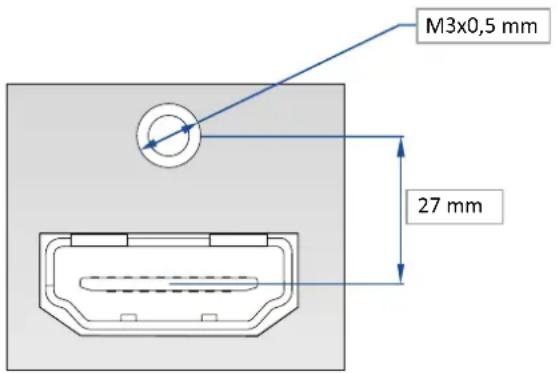
This hole is used by a TX10 screw when you receive the unit, if you wish to use an HDMI cable with a security fixing screw you can take this screw off and use your own in order to insure good fixing of your HDMI plug.
Please take a look at the accepted formats regarding the input plug type:
| Plug Type Formats | Signals | |
| Universal Analog Input SDTV | - EDTV - HDTV - Computer Analog SDTV - Analog EDTV - Analog HDTV - Analog Computer | |
| DVI-D Input SDTV - EDTV | - HDTV - Computer Digital SDTV - Digital EDTV - Digital HDTV - Digital Computer | |
| HDMI Input | SDTV - EDTV - HDTV - Computer | Digital SDTV - Digital EDTV - Digital HDTV - Digital Computer |
| 3G/HD/SD-SDI Input | SDTV - HDTV | Digital SDTV - Digital HDTV |
WARNING: Only the video and audio signal is processed for the HDMI ^® , and 3G/HD/SD-SDI inputs; other embedded auxiliary features are not supported or passed through. The embedded audio is processed. All other HDMI ^® features such as: HDMI Ethernet Channel, Audio Return Channel, 3D, 4K, Content Type, Deep Color and x.v.Color are NOT supported.
Each input can display only one active plug at a time. It is instantly available on the device and can be displayed simultaneously on many layers or outputs, with different sizes and positions.
| Standard | Size | HD-15 | 3G-SDI | HDMI | Single-Link DVI-D |
| NTSC | 525/480i | Yes | Yes | Yes | No |
| PAL | 625/576i | Yes | Yes | Yes | No |
| SECAM | 625/576i | Yes | Yes | Yes | No |
| EDTV 480p | 525/480p | Yes | No | Yes | Yes |
| EDTV 576p | 625/576p | Yes | No | Yes | Yes |
| HDTV 720p | 1280x720 | Yes | Yes | Yes | Yes |
| HDTV 1035i | 1920x1035 | Yes | Yes | Yes | Yes |
| HDTV 1080i | 1920x1080 | Yes | Yes | Yes | Yes |
| HDTV 1080p | 1920x1080 | Yes | Yes | Yes | Yes |
| HDTV 1080sF | 1920x1080 | Yes | Yes | Yes | Yes |
| HDTV 1080p | 1920x1080 | Yes | Yes | Yes | Yes |
| HDTV DCDM | 2048x1080 | No | Yes | No | No |
| VGA | 640x480 | Yes | No | Yes | Yes |
| 800x480 | 800x480 | Yes | No | Yes | Yes |
| WVGA | 848x480 | Yes | No | Yes | Yes |
| SVGA | 800x600 | Yes | No | Yes | Yes |
| 1280x600 | 1280x600 | Yes | No | Yes | Yes |
| 720p RGB | 1280x720 | Yes | No | Yes | Yes |
| XGA | 1024x768 | Yes | No | Yes | Yes |
| WXGA | 1280x768 | Yes | No | Yes | Yes |
| SWXGA | 1360x768 | Yes | No | Yes | Yes |
| Standard Size HD-15 3G-SDI HDMI | Single-Link DVI-D | ||||
| 1366x768 1366 | x768 Yes No Yes Yes | ||||
| 800p RGB 1280 | x800 Yes No Yes Yes | ||||
| SWXGA+ 1366x | 800 Yes No Yes Yes | ||||
| 1152x864 1152 | x864 Yes No Yes Yes | ||||
| 900p RGB 1440 | x900 Yes No Yes Yes | ||||
| 1600x900 1600 | x900 Yes No Yes Yes | ||||
| 960p RGB 1280 | x960 Yes No Yes Yes | ||||
| SXGA 1280x1024 | Yes No Yes Yes | ||||
| 1360x1024 1360 | x1024 Yes No Yes Yes | ||||
| DILA4/3 1364x | 1024 Yes No Yes Yes | ||||
| SXGA+ 1400x1 | 1050 Yes No Yes Yes | ||||
| WSXGA+ 1680x | 1050 Yes No Yes Yes | ||||
| 1080p RGB 1920 | x1080 Yes | ^1 | No Yes | ^1 | Yes ^1 |
| 2K | 2048x1080 Yes | ^1 | No Yes | ^1 | Yes ^1 |
| Q WXGA 2048x | 1152 Yes | ^1 | No Yes | ^1 | Yes ^1 |
| UXGA 1600x1 | 200 Yes | ^1 | No Yes | ^1 | Yes ^1 |
| WUXGA | 1920x1200 Yes | ^1 | No Yes | ^1 | Yes ^1 |
Note:
1) Reduced Blanking
4.7 Output specifications
4.7.1 Standard output
The QuickMatriX has two standard outputs.
The standard output contains:
- Analog Computer/Video (HD15),
- HDMI output over a DVI-I connector or DVI-I output (DVI-Analog and DVI-Digital).
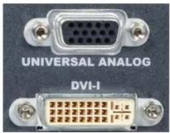
VGA
DVI-I
Please see the formats available on the output:
| Output Type | Format | Signal |
| Analog Computer/Video Output | HDTVComputer | Analog HDTVAnalog Computer |
| DVI-I Output | HDTVComputer | Digital HDTVDigital Computer |
Please note that SDTV and EDTV are not available on the standard output but only on the video output module.
4.8 Communication specifications
4.8.1 Serial interface
A standard RS232 interface is available through a DB9 female connector:
- It permits controlling the device
- It permits updating the device
Data Rate: 1200 to 115200 Bauds, 8 data bits, 1 stop bit, no parity bit, no flow control by default.
DTR & RTS needed for firmware upgrade.
4.8.2 LAN interface
A standard LAN interface is available through a RJ-45 connector
- It permits controlling the device
- It permits transferring configuration
- It permits connectivity with the RCS ^2 application
- It permits updating the device
4.8.2.1 Protocol
| Protocol Availability | |
| TCP Yes | |
| UDP Yes |
4.8.2.2 IP address
| Address allocation Availability |
| Static user defined address Yes |
Default IP address: 192.168.2.140
4.9 Environmental specifications
Dimensions:
D 15.75" x W 19" x H 3.46" with rack mount and handles
D 400 mm x W 483 mm x H 88 mm
D 14.17" x W 17.3" x H 3.46" without rack mount and handles
D 360 mm x W 440 mm x H 88 mm
Weight:
▶ 6,3kg / 13.9 lb (Compatible with a Standard 19" rack, Height = 2 U)
- Cooling air flows from right side to left side.
- Max ambient operating temperature: < 40^ C( < 104^ F) .
- Operating temperature: 0 to +40^ / +32^ to +104^
• Storage temperature: -40 to +70°C / -40°F to +158°F - Operating humidity: 10 to 80% (non condensing)
- Input voltage range: 100-240 VAC autosensing, 50/60 Hz
• Typical consumption: 110 W
ELECTRICAL SECURITY:
• IEC 60950-1:2005 (2nd Edition); Am 1:2009
- EN 60950-1:2006 + A1:2010 + A11:2009 + A12:2011, CSA C22.2; National Differences specified in the CB Test Report
• UL listed (Canada & US)
ELECTROMAGNETIC COMPATIBILITY:
• IEC 61000-3-2 (2009)
• IEC 61000-3-3 (2008)
• CISPR22 (2008)
• CISPR24 (2010)
• FCC Part15 of 2012
• IECS-003 of August 2012
ENVIRONMENT:
• RoHS
• WEEE
USE/TRANSPORT:
- ETS 300 019-2-2: Environmental conditions and environmental tests for telecommunications equipment; Part 2-2: specification of environmental tests; Transportation; Specification T 2.3: Public transportation
- ETS 300 019-2-3: Environmental conditions and environmental tests for telecommunications equipment; Part 2-3: specification of environmental tests; Stationary use at weather protected locations; Specification T 3.1 and T 3.1 E: Temperature-controlled locations

If your device should lose power unexpectedly, you may lose any unsaved settings.
4.10 HDCP management
4.10.1 Input HDCP detection
The input HDCP detection is managed by the input components according to HDCP specification.
4.10.2 Output HDCP detection
The QuickMatriX manages the output HDCP detection according to one of the following criteria:
- Hot plug,
- 3-second period attempt.
4.10.3 Keys' checking
Keys' checking is performed according to the most restrictive condition among the 2 following ones:
- Every 2 seconds
- Every 128 frames
4.10.4 Output management
HDCP protected content can be displayed only on HDCP protected outputs or displays. Therefore, whenever an HDCP protected source is placed into a layer routed to a non-protected output, the QuickMatriX will not output the protected content on this non-protected output, and the layer will be grayed.
If possible, the QuickMatriX will allow to display all other non-protected contents, otherwise the entire output will be muted until the protected content is no longer routed.
4.10.5 HDCP Classification
| Class Support | |
| HDCP Receiver Yes | |
| HDCP Transmitter Yes | |
| HDCP Repeater No |
HDCP Receiver
The HDCP negotiation can be enabled or disabled on all HDCP inputs.
HDCP Transmitter
The HDCP negotiation can be enabled or disabled on all HDCP outputs.
The QuickMatriX can manage HDCP repeaters on its outputs: up to 32 display devices can authenticate simultaneously on each output.
4.10.6 Status
In order to permit quick identification of all the HDCP operations on the device, the QuickMatriX provides a full set of status summary to help the user with the HDCP management:
- A front panel menu that displays all the general HDCP status of all inputs and outputs

5. CONNECTING THE QUICKMATRIX
5.1 Description
5.1.1 Rear panel

- Power supply: 100-240 VAC 2.5A 50/60HZ / FUSE F4A 250 VAC; internal, autoswitchable; 110W
- 3G/HD/SD-SDI: inputs #1 to #2
- S/PDIF: audio inputs #1 to #2
- MCO male connector: for audio inputs (balanced) #1 to #4
- MCO male connector: for audio outputs (balanced) #1 to #2
- S/PDIF: audio outputs #1 to #2
- Universal Analog Computer TV/HDTV: inputs #1 to #4
- DVI connectors: DVI-D inputs #1 to #4. Capability to receive digital audio signal from HDMI connector via an adaptor (HDMI-compatible)
- Ethernet plug
- HDMI connectors: HDMI inputs #3 to #6. Digital audio compliant
- Communication port: communication port with DB9 female connector
- Universal Analog Computer TV/HDTV: HD15 outputs #1 to #2
- DVI connectors: DVI-I outputs #1 to #2. Capability to transmit digital audio signal towards a HDMI connector via an adaptor (HDMI-compatible)
5.1.2 Front panel
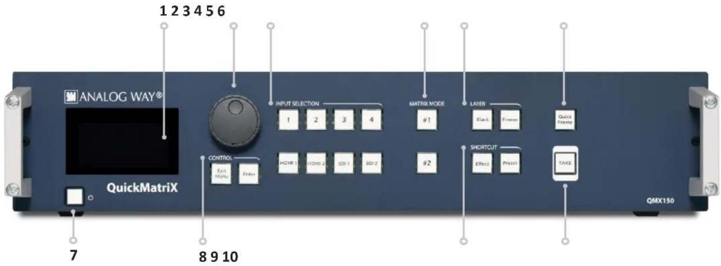
- Front panel display: 4-line VFD
- Menu scroll knob
- Input selection: - 1 to 4: access source 1 to 4
- HDMI 1/2: access HDMI 1 or HDMI 2
- SDI 1 to SDI 2: access SDI 1 to SDI 2
- Matrix mode: #1 to #2: select the output #1 or #2, a layer and a source, then press TAKE. This is a fast routing mode
- Layer: - Black: clear the layer
- Freeze: freeze/unfreeze the input selected in the currently selected layer
- Quick Frame: allows to quickly display a foreground frame
- On/Off - Stand-by: hold for 3 seconds for stand-by mode
- Control: Exit/menu: Home menu or back one level - Enter: validate the menu or command
- Shortcut: Effect: shortcut to transition menu - Preset: recall a custom stored preset
- TAKE: transition the pre-selected sources onto the Program output with the selected effects

6. CONTROLLING THE QUICKMATRIX
The QuickMatriX can be controlled and operated either via the Front Panel, from your computer via the RCS ^2 , or via one of our Event Controllers. (Control of the QuickMatriX can also be integrated into automation and control systems, contact your local technical support for more details.)
6.1 RCS ^2 requirement
The recommended requirements are:
- Adobe Air®
- 1Gb Ram
- 200Mb of free space
- 100Mb Network adaptor or above
- 1920x1080 optimized screen resolution
- 1366x768 as the minimum screen resolution.
Operating system:
- Windows XP SP3 or above
- Mac OS v10.7 or above
- Ubuntu v10 or above
- Linux OS 11 or above
For Linux users:
The RCS ^2 is an Adobe ^ AIR ^ application that requires the most recent version of this runtime. As Adobe ^ AIR ^ is no longer supported for desktop Linux distributions, please use a dedicated software such as WINE to use applications designed for Microsoft Windows on your operating system.
- First, install a Microsoft Windows compatibility layer software on your Linux PC.
- Then install the Adobe® AIR® last release using your emulator
- Finally, install the RCS ^2 using your emulator.
You are ready to use the RCS ^2 .
6.2 Connecting with the RCS ^2

The RCS2 is an Adobe Air application that runs on your computer. Before you can connect to your device, you must first download and install Adobe Air, then download and install the RCS2 on your computer.
In order to connect the RCS2 to the device, you need to use a LAN connection. Use a
crossover cable if you connect your computer directly to the unit, or use straight cables if you are connecting through a switch or hub.
Before switching ON the unit, please plug a LAN cable on the rear panel into the Ethernet port. Then switch ON the unit.
By default, the network settings on the QuickMatriX are
Default IP Address: 192.168.2.140
Default Subnet Mask: 255.255.255.0
Default port: 10500
To be able to connect to this address, your computer will need to be configured to use a unique IP address on the same network. If this setup will be part of a larger network with other devices, please check with your network administrator before plugging these devices into the network to avoid any IP address conflicts.
For example, you could assign the following static IP address to your computer:
Example Computer IP address: 192.168.2.50
Example Computer Subnet Mask: 255.255.255.0

To download the Remote Control Software, please visit our website and go into the product section. Then, into the download link, please download the RCS ^2 associated to your product. Install it and then open. Here is the startup screen.
Enter the IP address of the device and then the remote port. Click on SET AS DEFAULT if you want the software to remember your configuration.
Click on Connect to start the connection.

Once connected, you have access to this screen:

In case of difficulties:
- Verify that you are using the correct network cable and that it is free from defects. (Crossover or straight cable as required.)
- Check the IP address of both the device and the computer. It must have a unique IP address on the same network as your QuickMatrix. You may need to manually configure a static IP address for your computer in your computer's network configuration.
- You may need to temporarily disable any other networks on the computer, such as turning off the wifi connection.
- Close the RCS ^2 .
- Restart the RCS ^2 .
Once your computer has established connection, the RCS ^2 control panel will begin to load, and will begin to synchronize with the device. When the small “Sync” icon at the bottom right of the display has turned green, the RCS ^2 software is ready to use.

Some computers use an energy saving mode that turns off the network adaptor during periods of inactivity. To avoid the inconvenience of reconnecting the software during use, please ensure your network adaptor remains active by disabling the energy saving mode.
6.3 RCS ^2 top menu

6.3.1 Setup
The Setup page is where you will review and modify the device configuration, such as output resolutions, input settings, and more.
6.3.2 Edit
The Edit mode is the place where you will manage preset creation. You will make input selections, manage your inputs, adjust the layer attributes such as size, position, effect, etc. You can save all your screen configurations into presets, as well as review and recall them on each individual screen.
6.3.3 Live
The Live mode is the section where you will operate your show. You can quickly recall presets or make input selections, as well as setup a sequence of presets that can run continuously with custom durations, or wait for user interaction.

7. OPERATING THE QUICKMATRIX FROM THE RCS ^2
7.1 Operating mode
Before you start setting up your QuickMatriX for the first time, take some time to think about how you will be using it. The QuickMatriX offers one operating mode, which results in a versatile video production tool for live event staging and fixed installation applications.
NOTE: We recommend resetting the device to its default values every time you set up your shows or events.
7.2 Setup
Go to the setup section to start to set up your unit. A Setup assistant is available to help you to correctly adjust all basic setups of your unit.

7.2.1 Mode

The device can work in Matrix mode only.
Matrix mode
This mode turns your QuickMatrix into a true 8 x 2 scaled matrix, while preserving seamless switching capabilities. Program 1 and Program 2 outputs can be set to different resolutions and rates. Switching between any of the inputs can be done with the various effects (Cut, Fade, Slides...) and synchronized on both outputs.

7.2.2 Audio

In this section, you will setup the audio of your device, you have several modes. In all modes, you have the possibility to output the audio in AES3 or SPDIF:
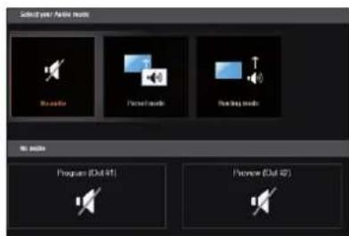
NO AUDIO: the audio of your device is switched off

PRESET MODE: the standard mode of use of the device
You have two possibilities:
- Top layer: the sound on the output will follow the audio input of the top layer.
- Breakaway: when breakaway is activated, the audio on the output is memorized into the preset. A change of preset, changes the audio on the output. A change of content into a video layer has no effect on the audio.
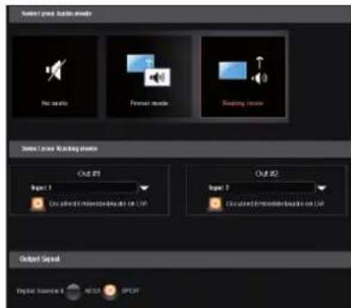
ROUTING MODE: in this configuration, simply choose an audio input to assign it to the output. The audio configuration remains the same during the show.
In this example input1 is on out1 and input 2 is on out 2
7.2.3 Screens

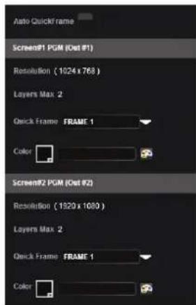
In the screen configuration, you will find the state of your screen. It indicates the screen resolution, the maximum number of layers you can use.
You will find configuration for the Quick Frame and the background color too. The Quick Frame will be your emergency frame that can be displayed in front of every layer. Here, select the frame slot number to be displayed as the Quick Frame. If you are in Matrix mode, you have 2 screens status.
7.2.4 Misc

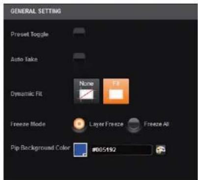
PRESET TOGGLE: by default, the device will not swap the Program and Preview busses during each TAKE. Disabling this option will leave the Preview bus unchanged during each TAKE, and only the Program will be updated. When this option is enabled, the Preview and Program busses will be swapped during each TAKE.
AUTOTAKE: enable the automatic TAKE. Each time a source is changed on preview, it triggers a TAKE to be launched.
DYNAMIC FIT: enable or disable the automatic recognition of black band for digital content. The size and the aspect ratio of the layer are automatically adapted.
FREEZE MODE: choose to freeze all inputs or only one input when you use the freeze function.
PIP BACKGROUND COLOR: here you chose the automatic color of PIP background, black is the default color.
7.2.5 Output management
Into the output section, you will be able to manage your output resolutions, formats, sync types, test patterns, etc. On the SETUP > OUTPUT TAB, the following screen will appear:

A short summary of each output settings appears on the main page. You can see the number of outputs, their resolution, rate and HDCP status.
Select an output to adjust by either clicking on it from the column on the left, or clicking the configuration cog icon for that output.
Once the individual output setup page is opened, you have access to:
- MODE: choose your rate generation mode, internal (free-running within the unit) or Framelock by choosing an input as a reference input,
- FORMAT: choose the output resolution format,
-RATE: choose the signal timing standards, if the mode is set to internal
-STATUS: the status menu will show you the current output status, - APPLY: click on this button to apply the new format/rate,
- PLUG STATUS: indicates the status of the attached monitor and confirms connectivity,
- TYPE: you can choose the type of output synchronization on the analog plug, for example RGsB for sync on green, or RGBHV for separate H and V sync wires,

- FORCE DVI MODE: select this box to force the output to DVI mode instead of the default HDMI autosense mode. When in DVI mode, no embedded audio will be transmitted,
- PATTERN: a selection of patterns is available to test your output. These patterns will override any input selection that you might have.
You can choose from:
- No Pattern – turns the pattern off
• Vertical or horizontal Grey Bars – displays grey bars
- Vertical or horizontal Color Bars – displays color bars
- Grid – displays an 8x8 box grid pattern
- SMPTE bars – displays the SMPTE color bar pattern
- Vertical Burst – displays alternating black and white 1 pixel wide columns
- Centering – displays a 1 pixel wide dotted line at the edge of the output (only available for computer formats)
- Vertical or horizontal gradient – displays a 0 to 100% gradient pattern.
- FLICKER: choose the value of the flicker filter to remove the flicker effect on your interlaced output screen,
- GAMMA: increase or decrease the gamma of your output,
- HDCP: enable/disable and see the HDCP status.
Depending on the output format chosen, only relevant settings will appear.
Custom format
The device offers the possibility to create your own output format:

Choose CVT mode (restricted settings) or FULL mode (full settings) and start to create your format by adjusting the Horizontal Vertical pixels, frame rates and reduced blanking.
Click on CHECK to verify if your format is a valid signal. You can SAVE and LOAD your Custom format.
7.2.6 Input management
Once your outputs are configured, you have now to configure the inputs connected to your device. Under the inputs section, you can view your inputs by active plugs or by all plugs (active and inactive).


In both cases, an AUTOSET ALL can be launched to set up automatically your inputs.
Once the AUTOSET ALL is done, you can check one by one your inputs and see if they were correctly detected by checking the input STATUS. The input STATUS is defined by a FORMAT and a RATE. If that information is not available, your input has not been properly detected or set up.
In this case, you can enter manually into each input settings by using the left menu:
Under the SIGNAL tab, you will find:
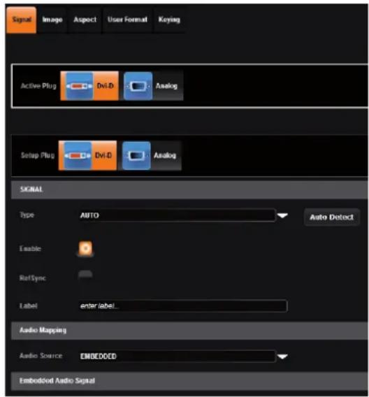
- ACTIVE PLUG: select the plug used by the unit at the moment. Only this plug can be displayed on your output,
-SETUPPLUG: select the plug you want to set up, all changes will be applied to this plug, even if this plug is active or not (do not mismatch with the active plug),
-SIGNALTYPE: define the type of your signal, video SD/HD YUV/RGB or Computer HV/SOG etc., - ENABLE: enable/disable the input,
- REF SYNC: affect the input to the ref sync input. Use this box only if your source is genlocked with the referenced source (framelock feature),
- LABEL: rename your input according to your source,
-AUDIOMAPPING: select the audio input that will be linked with the video input, -
EMBEDDED SIGNAL AUDIO: status indicates if an embedded audio signal is detected or not,
-
STATUS: format and size of the input,
- CONTROL: Black: select Black to transform your input in a uniform color,
Freeze: use this button to freeze the specific input,
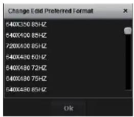
- EDID: choose the EDID for the selected plug.
Under the HDCP section, you can:
- Enable/disable the HDCP communication feature
- Read the HDCP status, If the HDCP status says Active, this output connection is currently utilizing HDCP to protect the signal. if the HDCP status indicates Idle, this output connection is currently not utilizing HDCP.
Next is the IMAGE tab, where you can find all settings about the display of your input:
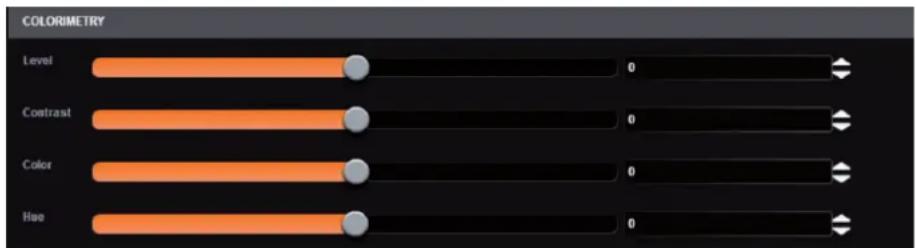
Under the COLORIMETRY section, you have:
- LEVEL: define the selected input luminosity level,
- CONTRAST: define the selected input contrast level,
- COLOR: define the selected input color level (0:black and white, full: full color),
- HUE: set up the hue phase of your NTSC signal.

Under the USER GAIN section, you find:
- THE RED/GREEN/BLUE: increase/decrease the Red/Green/Blue level of your input.
Next you have the ASPECT tab. All settings about the blanking and aspect ratio are available there:

bar
BLANKINGS ADJUSTMENTS | Category | Value | |---|---| | H Position | 256 | | H Size | 256 | | V Position | 256 | | V Size | 256 |Under the BLANKING ADJUSTEMENTS:
- H&V POSITION SIZE: you can manually adjust the input blanking with the V&H size or position.
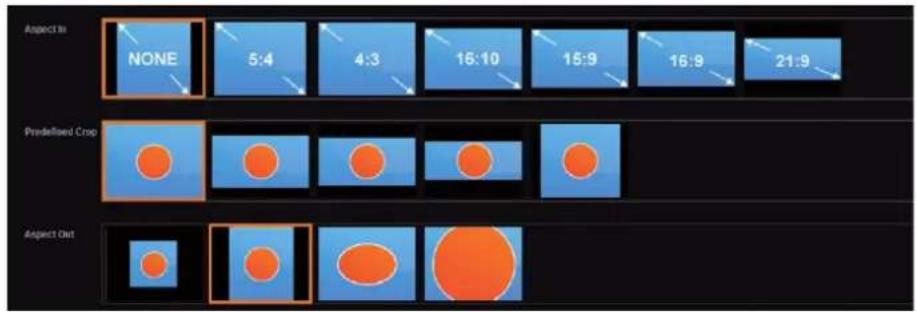
Under the ASPECT RATIO section:
- ASPECT IN: forces a particular aspect ratio for the source. (5:4, 4:3, etc). This setting has no effect when set to native,
- PREDEFINED CROP: choose a specific cropped ratio if you use a source with black bands on top/bottom or left/right,
- ASPECT OUT: define the way the image will be displayed into a layer (full screen, centered, cropped or 1:1),
- OVERSCAN: choose to apply or not a predefined zoom on the image (use with video signal).
Next settings available on the ASPECT tab are:
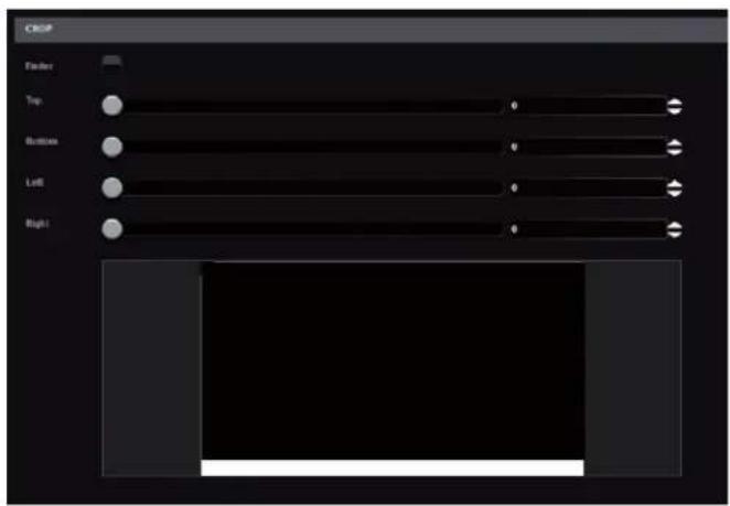
-CROP: use the Top, Bottom, Left and Right values to crop your input.
The next tab is the USER FORMAT:
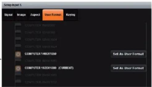
In this tab, you can explicitly define the input format. The input format is automatically detected by the QuickMatriX but you can change it or force it. The available formats are close to the current one, in terms of lines. This is only available for analog computer formats.
Keying Feature
With the keying feature, you will be able to key easily a color space or a specific luma on an input. The device offers an individual keying for each input. Into the input settings, find the keying menu: You have 2 ways of using the keying:

- COLORKILLER: classic color keyer removing a specific color space defined by user,
- LUMAKILLER: luma keyer removing a specific lumanance level range.
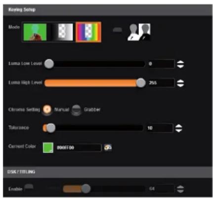
Keying setup can be done either by setting directly color references and tolerances or by using the color grab assistant.

-INVERTBUTTON: at any time you can choose to invert the actual keying using this button.

DSK TITLING: after your keying, the DSK titling feature allows you to play with the transparency of your deleted pixels. Enabling this, simply adjust the opacity settings to make your keyed pixels less or more dark. This is useful when keying white or light colored text over a bright background.
How to use the LUMA KEY:
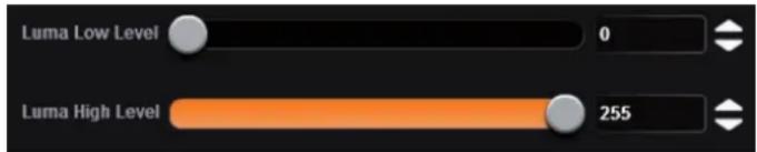
Select the lumakiller and then adjust manually, the luma level:
- Manually: set the minimum luminance value.
Luma Low Level: Everything darker than this value will be keyed away.
Luma High Level: Everything brighter than this value will be keyed away.
Then adjust the maximum luminance value to define the range of luminance levels which will be deleted. Once you have completed the setup of your keyed input, place the it in layer B on top of your background (such as a camera in layer A) in order to complete the keyed title or lower third effect.
How to use the CHROMA KEY:
- Manually: set the Hue and luminance to choose the color space you want to delete into your image.
Set it manually looking at the color change into Current color. If you want, you can quickly select a color from a color panel, clicking on CURRENT COLOR. Then click on the color itself to obtain the color panel. Once your main color is chosen, you can define a degree of tolerance around this color. The tolerance will define, around the main color, an area that will be keyed too. You may still need to make further adjustments to the luminance level to complete your key effect.
- Grabber: activate the grabber to grab the color you want to key. Move the cursor and click on the grab button to grab the color.
7.2.7 Frame management
To save a frame click on this button:

The next page opens.
From here you can capture from the main or from the Preview.
You can still freeze the output before saving your frame.
How to save a frame:
Choose first Program or Preview, click on FREEZE if you want to freeze your output. Then click on EXECUTE to save your frame into the selected slot.

7.2.8 Audio management
The audio section permits the management of level, balance, and other audio settings for each input.
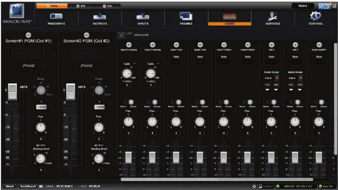
Before modifying the audio settings, be sure to check the audio input mapping. Each video input has one audio source mapped to it. The audio mapping configuration is found under Menu > Inputs > each input.

Into the AUDIO SETTINGS:
To display only the Current audio input which is played, click on Current button. only Current
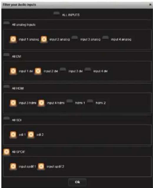
If you want to select which audio input will be displayed, click on the list button ☐ select the input audio source you want.

To setup your analog audio input, simply click on "ON PRELIST", if you have a Preview output, the audio input will be played on it. Then adjust the GAIN from -11 to +6dB.
A red indicator light will be displayed if you reach the input clip. If the input clip light is being illuminated, it means that the input gain is too high and the signal is being distorted. To solve this issue, decrease the gain value. The 0dB corresponds to a +4dBu signal in input. The gain manual adjustment is only available for analog input.
For every input, you have the possibility to set up your source as a mono audio or stereo audio source.
You have the possibility to adjust the level vs right level using the Pan knob.
All input still have their own level which is 0 by default, decrease or increase the value to modify the sound level:

Specific feature:
- DIGITAL SOURCE: all digital sources will have their sample rate displayed,
- SDI SOURCE: on SDI source you can choose 2 channels on one of the 4 groups.
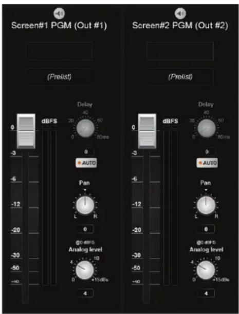
The available audio output controls depend on the device setup configuration. As you are in matrix mode, you will have 2 programs audio outputs.
For the audio output, you will find:
- A LEFT/RIGHT PAN ADJUSTMENT
- A GAIN ADJUSTMENT: this setting will help you to calibrate the analog audio output component. Depending on the device you will use after the analog way device, adjust carefully the analog gain. Basically, for a 0 level, the default value is 4 dBu.
- A MASTER LEVEL: it indicates the level of your input. On its right, a bar will move up and down to indicate the audio level in real time. A red button will turn on if the maximum level is reached.
- A DELAY ADJUSTMENT: the delay can be automatically calculated or manually adjusted. To adjust it manually, first disable the Auto button.
7.2.9 Service management
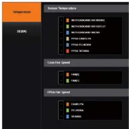
Into the service section, you will find tools to warn you if the unit has a problem.
Under TEMPERATURE, there is the alarm tab. If any fan FPGA or board are faulty, it will be displayed.
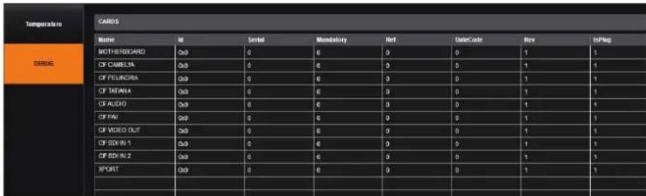
TECHNICAL SUPPORT: Display the different technical support contacts depending on your area.
7.2.10 Control management
In this menu, all specific settings, which cannot be sorted under the other menus, are listed:
Network

The interface loaded into the unit uses the IP configuration. Under INTERFACE, you can define a new:
- IP address
- Netmask
- Gateway
- Port: choose the port
- Protocol: choose TCP (by default) or UDP
Functions

Under function, you can edit:
- TIME: the internal real time clock,
- AUTO LOCK: when this feature is enabled, you will be locked out from selecting empty inputs that have no source connected,
- LCD BRIGHTNESS: adjust the brightness of your LCD,
- KEY BRIGHTNESS: adjust the brightness of your keyboard.
Erase memories
Into this section, you can erase individual settings.
- Erase input settings memory: all input settings will return to their default value. This includes image, aspect, user format and keying parameters.
- Erase thumbnail: all the thumbnails you store on your computer will be erased.
- Erase device preset memories
- Erase local preset memories
- Erase custom formats
Factory reset
Click on start to erase all settings (except network and RCS ^2 parameters). The unit will reboot itself after the factory reset.
7.3 Edit
7.3.1 Layer management
When you enter into the Edit menu, you will encounter by default this window. On this example, we have the Screen Program and the Screen 1 Preview. The following example can be applied for any other screen configurations.

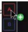
To display an input into the available layer A, simply drag and drop the input from the left column to the layer on the chosen screen. You can assign or change the inputs directly on Program as well as Preview.

You can assign a source to a layer by dropping the selected source into the layer letter icon, located on the left side of the layout window. This is particularly useful when the desired layer is hidden or blocked by other layers.
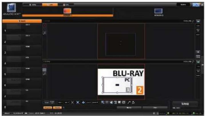
When a layer contains an input and is not empty, the RCS ^2 displays the input number or a customizable thumbnail icon that represents your input. Please note: this thumbnail is not a live image.
In this example, 2 inputs are affected to 2 layers into the Screen 1 Preview. The TAKE button on the bottom right side allows sending your configuration, made on the Preview screen, to the Program screen.
With each press of the TAKE button, the Preview screen is transitioned to the Program screen. By default, PRESET TOGGLE mode is disabled. That means, after a TAKE, the Preview stays as it was before. The Program and Preview will have the same content.

if desired, you can activate the PRESET TOGGLE mode from the SETUP >PRECONFIG >MISC menu, which will automatically swaps preview and program with each TAKE. After each TAKE, the Preview is reloaded with the previous Program.
Layers management
In this Edit mode, you have access to a lot of preset tools that can help you to create the preset you imagined.
7.3.2 Layer adjustments
The layer properties are found by opening the tab on the right side of the screen. Click on the double arrow button on the right to show or hide the layer adjustment tab.

Selected layer
The selected layer status information will indicate which screen, layer and source assigned to that layer are selected. You must select a layer in order to see the layer properties menu for that layer.
Reset feature
You can reset each category of layer settings quickly (Pos/Size, Transparency, Cropping, Border, Transitions, Effects, Timing) or you can choose to reset every settings in one click using the ALL button. You can freeze the input assigned to the selected layer using the Freeze button.
The settings reset here only affects the selected layer on the selected preset. For example, you can reset the layer settings for layer A on Preview, and Program will be unaffected until you press TAKE.

The QuickMatriX has the possibility to use a second layer. This layer can be displayed only with a controller (RCS ^2 , RK-350 or Vertige ^™ ). This layer has to be keyed. If not, it will be displayed in black.
Position/Size
Adjust the size horizontally (X) or vertically (Y), then adjust the width and the height of your layer. You can use the cursor or directly enter a value. To keep the aspect ratio by using the cursor, please enable the KEEP ASPECT RATIO button. You will find it on the right of the width and height cursors.
Transparency
Use the Transparency to give at your layer a transparent effect. Layers behind the transparency layer will show through more or less based on the transparency value.
Cropping (only for live layers)
The Cropping feature allows you to cut the part of the image you don't want. Simply adjust the size horizontally or vertically and then adjust the position to display only the desired content. This crop is a layer property, all inputs displayed in this layer will be cropped. Do not confuse this setting with the input crop which is specific to an input.
Transitions
On the Transitions section, you can filter which transitions you want to see. For Example, you can show just the Slide or Wipe transitions.
Each layer has an opening and a closing transition. The opening effect will be applied when the layer switch from a source to another source or when the layer is switching from empty and appears with a source.
To set up the duration of the transition, please see below the timing and duration settings. If you want to force the layer to perform a closing and opening transition, see FORCE TRANSITION.
7.3.3 Effects
Force transition
The Force Transition button disables the cross-transition between two sources into the same layers. Enabling the Force Transition, it forces the layer to go out and then go in with the desired effect instead of mixing directly the two sources.

Smooth Move
Enable the Smooth Move to perform a smooth transition on the layer. Disable the smooth move if you require a constant speed move.
Layer layout

The layer layout gives you access to several predefined layouts with 4, 3, 2 or 1 PIP already sized and placed into the output. It can help you to quickly set up 3 PIPs side by side for example. (Number of layers depends on the used mode.)
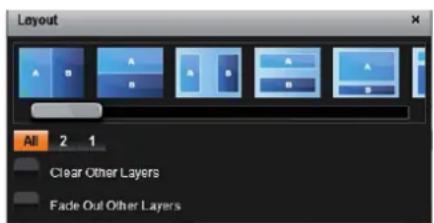
Once clicking on the layout button, you have access to the presets with 2, 1 PIPs or all layouts.
Two other options are available below:
- Clear other layers: layers already displayed and not included into the chosen layout will be cleared
- Fade out other layers: layers already displayed and not included into the chosen layout will be faded out during the transition. They are still present on the preset but with a 100% transparency.
After selecting the layout, the changes are applied on the selected screen. The size and position of all layers are updated. After applying a layout template, you can make further modifications to the layers before Taking your selections to Program.
Layer position
A layer position shortcut is also available. After having selected a layer, simply click on the Pos. button to have quickly access to a layer position. Choose the new position. The change is applied straight away on your preset.
Layer size
You can choose between several aspect ratio. Once selected, the new aspect ratio is applied on the selected layer.
Other layer adjustments:
- CLEAR BUTTON: this button allows you to clear the selected layer from your preset,
- CLEAR ALL BUTTON: remove all layers from your preset,
- CONTENT SIZE: set layer size to its content size,
- SCREEN SIZE: set layer size to screen size,
- LAYER SIZE/SOURCE RATIO: set the layer size to fit the source ratio,
- ALIGN BUTTON: you need first to select at less 2 layers, then you can align them horizontally or vertically (use Shift to select 2 layers),
- KEEP ASPECT RATIO BUTTON: enabling this feature will keep the layer aspect ratio during resizing,
- WREFRAME MODE: allows to enable/disable the layer thumbnails on your RCS ^2 ,
- SHOW LAYER OUT OF SCREEN: enable/disable the possibility to display a layer out of the screen into the RCS ^2 ,
- TRAP LAYERS ON SCREEN: disable the ability to position the layer off of the screen,
- HIDE UNUSED LAYERS: empty layers will not be displayed in the RCS ^2 ,
- TOGGLE PRESET: enable/disable the TOGGLE PRESET (the Preview becomes the previous Program),
- RELOAD PROGRAM: load the preset of the Program screen into the Preview screen,
- STEP BACK: return to the configuration you had before the last TAKE,
- MIRROR BUTTON: Mirror the mirror button allows you to define for each layer the way it will be copied in the preset. You can choose to mirror the layer or flip the position.

7.3.4 Preset load and save management
Save a preset

Once your preset is set up, you can store it into one of the 64 preset slots. To do that, click on SAVE MM and choose the number corresponding to the slot number.
![[S1] PGM : Save To MMemory(shift-click to edit details) To your device 1 2 2 4 5 6 7 8 To your computer 9 10 11 12 13 14 15 16 17 18 19 20 21 22 23 24 25 26 27 28 29 30 31 32 33 34 35 36 37 38 39 40 41 42 43 44 45 46 47 48 40 50 51 52 53 54 55 56 57 58 59 60 61 62 63 64](/content/2026/05/882242/images/b01b9ee132f3e156ed950900170fd5e1c6afe7cdc8bf81041021d20036ae46a9.jpg)
WARNING: in the RCS ^2 , you cannot save a preset for only 1 screen when you are in matrix mode, only MASTER MEMORIES can be saved into the EDIT section.
In addition, in the EDIT section, as you work on screen by screen, the load button loads only single memory. You will find the load MASTER MEMORIES in LIVE MODE.
The first 8 presets are stored into the unit, all the other presets are stored locally on your computer, and will only be available when using the RCS2 software.
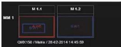
If you want to have more details, you can SHIFT+CLICK on any preset to bring up a detailed status window. In this window, you can rename each preset using the PRESET LABEL.

- The first icon displays a window with all preset detail,
- The second one allows you to let the windows open,
- The last one quits the window.
Load a preset

To recall a previously saved preset, click the Load button (on the right side of each screen) and select a preset to load.
![[51] PGM : Save To MMemory(shift click to edit details) To your device To your computer 9 10 11 12 13 14 15 16 17 18 19 20 21 22 23 24 25 26 27 28 29 30 31 32 33 34 35 36 37 38 39 40 41 42 43 44 45 46 47 48 49 50 51 52 53 54 55 56 57 58 59 60 61 62 63 64 MM 1 M 1.1 M 1.2 GAX150 / Macai / 28-02-2018 14:45:59](/content/2026/05/882242/images/ee35e121ca3b020eb390a3ed29ef0c73274dd4e63184bedbd6f7dc0754a08cd3.jpg)
Reset button

You can reset a screen using the reset button. Using that, all sizes and positions will be deleted. Your layers will be reset. If the «HIDE UNUSED LAYERS» button is enabled and all of your layers are empty and hidden, you can still access the layers using the layer icons on the left side of each screen.
7.4 Live
The Live mode is designed for easy live operation of the device after you have created some presets.
![Analog Way* Screen 1 Screen 2 [51] PGM (M1.1) 1024 x 768 BLU-RAY PC 1 2 PC BLU-RAY 2 1 Blu-RAY PC 1 2 BLU-RAY PC 1 2 Blu-RAY PC 1 2 Blu-RAY PC 1 2 Blu-RAY PC 1 2 Blu-RAY PC 1 2 Blu-RAY PC 1 2 Blu-RAY PC 1 2 Blu-RAY PC 1 2 Blu-RAY PC 1 2 Blu-RAY PC 1 2 Blu-LAB / Master / 20:03:20:14:14:45:39 About Dashboard Device v01.01 Build 5 - RCS: v01.00.20 Services QMX150 192.168.1.143 Sync OK](/content/2026/05/882242/images/9df46034803dccec30b6619e0c07096a3f188be3326249123cdd01137ce14c63.jpg)
On the right, you will find all your saved presets under the tab called "MASTER MEMORIES". A simple drag and drop on the screen will load your preset into the screen (Program or Preview).

If you want to change an input into your preset into the live mode, simply use the left source ribbon and drag and drop your input into a layer.
You can still use the load master memory to load a master memory from the memory of the device or the RCS ^2 using the following windows.
Please click on SAVE MASTER MEMORIES and then choose a number to save the current preset of the unit into a master memory.
To activate the QUICK FRAME, simply press the Quick Frame button (located on the right side of each screen).
Remember that a preset saved into a screen with a 1024x768 resolution, will keep its size into a screen of higher resolution. Therefore, it is best to save preset memories only after you have configured the output resolution.
You still have access to the LOAD/SAVE/RESET preset feature.
Once your preset is ready to send, use the T-bar, or the TAKE button.
You still have access to STEP BACK button.
When you use several screens, you have the possibility to load a preset on one or several screens. To TAKE only one screen separately, select which screens should be affected by the TAKE using this button:
| S1 | S2 |
SEQUENCE:
The sequence feature consists on a timeline composed by 16 scenes. Each scene can be filled by a preset memory. Simply click on MM to choose the memory slot you want to put into the scene.
To select the memory, simply choose it into the list or drag and drop it into the scene box from the memories selection (on the right).

This toolbar acts like a command for your timeline.
Simply click on play to launch the timeline.
You can stop the timeline at any moment using the pause or stop button.
Use the loop button to load again your timeline when it's finished.
Take a look at the global time of your timeline thanks to the clock on the right of the toolbar.
Note: To control the QuickMatriX, Analog Way also provides Crestron and AMX modules. For more details, see appendices.

8. OPERATING THROUGH THE FRONT PANEL
8.1 Front panel
8.1.1 Menu navigation
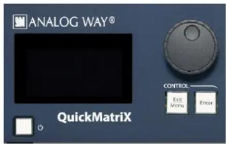
To access the QuickMatriX menu, press the EXIT/MENU button in the control section. To highlight items in the menu which will appear on the VFD screen, turn the scroll knob left or right to the desired menu item. When you have reached the desired menu item, press the ENTER button in the control section to access that menu function. Pressing the ENTER button when a selection has been made sets the value to that selection in the QuickMatriX memory. When all settings have been made, press the EXIT/MENU button to exit sub-menus and return to the main menu.

Simply selecting a menu item will not set it to that value. Be sure to press the ENTER button when parametering the menu items or to push the scroll knob.
8.1.2 Home menu
Pressing the MENU button in the menu section of the QuickMatriX, will display and give you access to the following items on the menu VFD screen:
- OUTPUT 1: select to set the output types and resolutions of Output #1,
- OUTPUT 2: select to set the output types and resolutions of Output #2,
- INPUT: select to configure the 10 individual input types and resolutions,
- PRESET: select to store and use presets,
- IMAGE*: select to change source image settings of an input,
- KEYING/TITLING*: select to access keying and titling controls and parameters when video layer is selected,
- SCREEN: setup your background color and your Quick Frame,
- LAYER*: select to adjust layer size, position, border, transparency or transitions,
- FRAMES: select to store (record), use and manage frames into the QuickMatriX,
- AUDIO: select to access all audio input and output parameters,
- CONTROL: select to access device software information, LAN settings, reset factory settings, and other user oriented functions.
* These items are only displayed if a valid input is assigned to the current layer.
8.1.3 Operating modes
The QuickMatrixX offers 1 mode to work from: the Matrix mode which turns your QuickMatrixX into a true 8x2 scaled matrix with numerous effects and PIPs (keyed only).
8.1.4 Reseting default values
It is strongly recommended resetting all of the default values of your QuickMatriX unit before setting up your shows and events. This will help eliminate confusion caused by unneeded settings from a previous operator. To do so, press the EXIT/MENU button and select Control in the menu by rotating the corresponding knob. Then press the ENTER button to enter the Reset/Erase sub-menu. Select Default Values by rotating the scroll knob, and press the ENTER button to enter your choice to restart your QuickMatriX with its factory settings. This operation should take approximately 30 seconds.
8.1.5 QuickMatriX color codes
Analog Way engineers have developed a handy, user friendly way of identifying machine status on the front panel, via the use of color codes on the buttons of the machine. All new Analog Way machines use the same codes, for quick recognition of the status of any device of the range, at any given time.
For the QuickMatrix, button color codes are as follow:
- Sources on the Program output are indicated in red when active,
- Sources on the Preview output are indicated in green when active,
- Buttons in the layer section turn red or green, depending on whether the selected layer is active in respectively the Program or Preview window,
- menu buttons are indicated in green,
-
Selecting a button with an available source or function will cause that button to blink green on the preview, or red once it is on the Program output,
• TAKE button reacts as follows: -
If take function is available, the button will appear in green.
- When the take function is active, it will light up red.
Solid red:

1 = Source is on the Program output
2 = Freeze enable
Solid green:

1 = Source is on Preview
2 = Function available for modification
Blinking red:

Layer/source selected or is currently active on the Program output
Blinking green:

Layer/source selected or is not currently active on the Program output
8.2 Settings in Matrix mode
8.2.1 Source Input selection
Plug your sources using the 4 multi-plug inputs, 2 HDMI Inputs or 2 3G/HD/SD-SDI inputs. Be sure that all connectors are firmly attached using all available locking screws.
8.2.2 Input selection settings
To set up your inputs automatically: Input menu > Auto settings
You can also do it manually on each input# using the ENTER and the Knob button and set up the inputs type one by one.
You can also check your actual input configuration using the config status: Input menu > Config Status
You can find several settings for each input (some settings are specific to some signal type):
- INPUT STATUS: display the input status,
- AUTOSET: launch an automatic setup on the inputs,
- FREEZE: freeze the input,
- ACTIVE PLUG: choose the active plug of the input,
- TYPE: to set up your input type (Computer, Video etc..),
- AUTOSET: launch an autoset on this plug,
- ENABLE: enable/disable the input#,
- SYNCHRONIZED: enable this option when you source is from the same refresh rate than the reference rate,
- HDCP ENABLE: enable/disable the HDCP automatic detection,
- HSYNC LOAD: to change the load of the sync signal,
- 3D COMBO FILTER: choose manually the combo filter for interlaced source,
- FORMAT: for analog source, choose to force a analog format,
- AUDIO INPUT: select the input audio source according to the input video source,
- EDID: set up your EDID for the selected plug,
- STATUS: to summarize the input status.
Concerning the HDMI inputs, a specific feature allows enable/disable the HDCP receiver for the input chosen. It can be very useful especially using a Mac: Input menu > HDMI # > HDCP detection
NOTE: The input status is available at any time in the status input menu and can give you information about format rate and HDCP status.
8.2.3 Source Output selection
Once your inputs all have been configured, the output settings of the QuickMatriX must be set according to the machines plugged on your QuickMatriX Program and Preview outputs (video projector, Preview monitor...).
NOTE: If you want to use HDCP content from your sources, be sure to attach HDCP compliant screens or projectors. If HDCP sources are used with non-HDCP compliant screens, the output image could be disabled.
8.2.4 Output selection settings
To set up the output, go in the Program Output #1 or Program Output #2 menu and choose first the adapted format/resolution, and then the appropriate rate for your screens by using the knob button and the ENTER button.
Program Output > Output Format > Output rate
Please note that a pair format/rate is only applied when the rate is validated.
Use the native resolution of your screens/projectors in order to obtain the best image quality. In the Program Output #2 menu, you can also match the output configuration the Program Output #1 to the Program Output #2 by checking the case Sync w/Out 1. It allows you to set up your outputs via the output 1 menu.
Prorgram output #2 > Synch w/Out 1
Some other settings are available too:
- OUTPUT STATUS: display the status of the selected output,
- OUTPUT FORMAT: choose the output format,
- OUTPUT RATE: choose the output rate,
- GAMMA: use this feature to set up the output gamma,
- ANALOG TYPE: set up the type of synchronization of your analog output,
- DVI TYPE: set up the type of color space of your digital output,
- DVI as HDMI: DVI output content as HDMI. Audio is included,
- HDCP DETECT: enable or not the HDCP detection on the output,
- CENTERING PIC: display the centering test pattern,
- TEST PATTERN: choose to display one of the available test pattern.
All changes have to be validated by pressing the ENTER button in order to be saved
NOTE: The output status can provide you all information about the output in real time. This feature is particularly needed when HDCP is used with long cable to be sure that the communication is well handled.
8.2.5 Working with layers
To work with Matrix mode, you first have to select the source then the output where you want to put the source.
Press Matrix #1 button > Press Source# button > Press input #1 Press Matrix #2 button > Press Output# button > Press input #3
Press TAKE to view the result on both screens
natural_image
Close-up of a blue audio workstation with multiple switches and control knobs (no visible text or labels)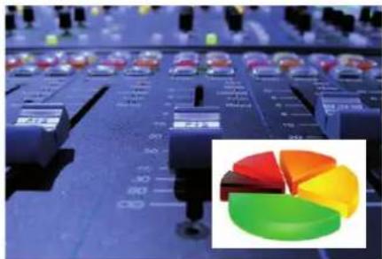
1 layer 1 layer + 1 PIP (keying)

The QuickMatriX has the possibility to use a second layer. This layer can be displayed only with a controller (RCS ^2 , RK-350 or Vertige ^™ ). This layer has to be keyed. If not, it will be displayed in black.
8.2.6 Working with layers functions
Once a source is assigned to a layer, you will have access to some layer settings in the Layer menu or directly by pressing the layer button.
The settings available depend on the layer selected:
- Layer adjusts: set up layer size and position,
- Layer zoom: set up layer zoom size and position,
- Size Templates: adjust a specific size (Fullscreen, 1/2, 1/3, ...),
- Transparency: adjust the layer transparency,
- Border: choose the border and adjust its properties,
- Opening and Closing effect: adjust the Open/Close effect type and duration,
- Smooth move: enable/disable smooth move,
- Status: get the selected layer status.
All changes have to be validated by pressing the ENTER button in order to be saved
Press TAKE to view the result on the Program screen.
Settings available:
| Settings Background live / PIP#1 PIP#2 | ||
| Position YES YES | ||
| Size YES YES | ||
| Zoom YES YES | ||
| Opening effects YES YES | ||
| Closing effects YES YES | ||
| Smooth Move YES YES | ||
The Program output can displayed simultaneously up to 3 layers stacked from bottom to top as follows:
- Layer A: one source selected from 8 inputs available,
- Quick Frame: one of the 8 frames available.
8.2.7 Layer adjustment menu
- To have access to the layer adjustment menu, a source has to be affected to your layer: Press source #
- Once a source is attached to layer, you can have access to the layer adjustment menu:
Go into Layer menu
Press TAKE to view the result on the Program screen
8.2.8 Layers with transitions
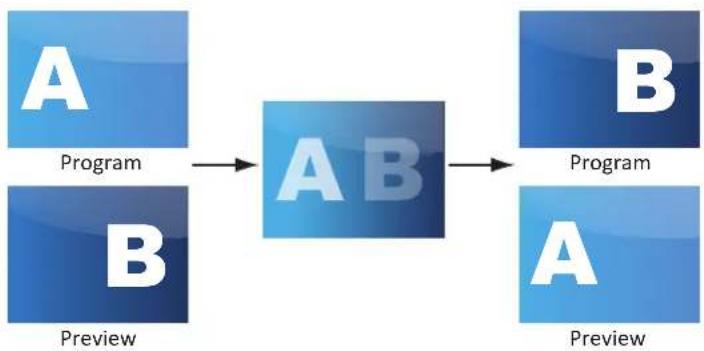
All the transitions (Cut, Fade or Transitions) are available in the native Matrix mode. You will be able to perform powerful transition effects seamlessly. It can depend on your configuration.
The QuickMatriX has 4 scalers, to understand how your effect will be performed, you need to know how many scalers are used on your outputs. Don't forget that you always need one free scaler to perform seamless transitions.
Example:
1 layer on each output > 2 scalers used > 2 seamless transitions
2 layers on each output > 4 scalers used > no seamless transition (ie: fade through black)
Transitions
All the settings are available in the Layer menu after pressing the selected layer.
To use it: Layer menu > Select the transition effect into the layer memory
The effect will be immediately attached to the selected layer (Preview).
- CUT: duration time can be set to delay the cut effect,
- FADE:
- Adjustable pre-timed fades or manual transition with T-Bar,
- Fade between any input, computer or video,
- Adjustable cross-fading duration,
- WIPE:
flowchart
graph LR
    A1["A"] --> AB["AB"]
    B1["B"] --> AB
    AB --> C1["Program"]
    C1 --> A2["A"]
    style A1 fill:#cce5ff,stroke:#333
    style B1 fill:#cce5ff,stroke:#333
    style C1 fill:#cce5ff,stroke:#333
-
Numerous wipes can be selected horizontal and vertical, from the center or outside, Zoom in and out,
• Horizontal: from left, center -or- vertical: from up, down, center, -
SLIDE:

natural_image
Group of business professionals in a meeting setting, seated around a table with one person standing and speaking (no visible text or signage)
natural_image
Business meeting scene with three professionals in a meeting, one holding a red flag (no visible text or symbols)
natural_image
Exterior view of a modern office building (no signage)
natural_image
Group of international flags waving against a clear blue sky (no text or symbols visible)
natural_image
Group of business professionals in a meeting setting, no visible text or symbols
natural_image
Group of business professionals in a meeting setting, no visible text or symbols
natural_image
People holding flags of the United Kingdom and France against a blue sky (no text or symbols visible)
natural_image
Group of international flags waving against a clear blue sky (no text or symbols visible)- Sliding of video or computer images during the transition,
• Horizontal: from/to left, right -or- vertical: from/to up, down.
The QuickMatrixX offers 21 seamless transition effects including 31 options, in addition to a dissolve (fade) and a cut effect.

flowchart
graph LR
    A["A"] <--> A2["A"]
    B["B"] <--> B3["B"]

CUT

FADE

SLIDE DOWN HARD
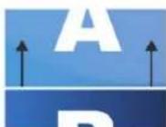
SLIDE UP HARD

SLIDE RIGHT HARD
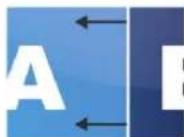
SLIDE LEFT HARD

SLIDE ANGLE TOP
LEFT CORNER HARD

SLIDE ANGLE TOP
RIGHT CORNER HARD

SLIDE ANGLE BOTTOM
LEFT CORNER HARD

SLIDE ANGLE BOTTOM RIGHT CORNER HARD

WIPE DOWN HARD WIPE UP HARD

UP HARD

WIPE RIGHT HARD WIPE LEFT HARD WIPE CENTER OUT HARDWIPE CENTER IN HARD
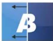
LEFT HARD WIPE CENTER OUT HARDWIPE CENTER IN HARD

UT HARDWIPE CENTER IN HARD

RD

WIPE CURTAIN IN
HARD

WIPE ANGLE TOP LEFT
CORNER HARD

WIPE ANGLE TOP RIGHT
CORNER HARD

WIPE ANGLE BOTTOM
LEFT CORNER HARD

WIPE ANGLE BOTTOM
RIGHT CORNER HARD

WIPE CIRCLE TOP
RIGHT CORNER HARD

WIPE CIRCLE CENTER
OUT HARD

STRETCH DOWN
HARD

STRETCH UP
HARD

STRETCH RIGHT HARD
STRETCH LEFT HARD

STRETCH CENTER
IN HARD

STRETCH CENTER
OUT HARD
STRETCH CURTAIN
IN HARD
8.2.9 Capturing frames
It is possible to store up to 8 frames in the QuickMatrix non volatile memory. To capture a frame, display the exact content you want to save on one of your outputs, at the exact resolution, you can use the freeze button if you want. Then follow this step:
Frames menu > record Frame menu > Frame #
Choose the frame number slot and wait until the unit finishes to save. Your frame is now saved and you can use it through the Quick Frame button.
The capture of frames can be done only under the following conditions:
- The capture can be done from the Program output #1 or the Program output #2,
- The disappearance of frames on the Program output is normal during saving.
A frame captures the state of the specified output at the output resolution, and must be recalled using the same output resolution. Resizing or other image manipulation of the captured frame is not possible.
Attempting to use a frame at a different resolution will result in a partial frame display or a frame which does not fill the screen. During the capture, the output is outlined by a white border and includes the pixels into the white rectangle.
8.2.10 Working with frames
Frames are mainly used as quick frames in a typical show or event setup, and can be recorded from any of the QuickMatrixX 8 sources and called back at the press of a single button. To use a frame, be sure first that it is well saved, then affect the frame to the Quick Frame layer going into the SCREEN menu then QUICK FRAME. To activate the Quick Frame, simply press the front panel Quick Frame button.
8.2.11 Frame input setup menu
In the frame input setup menu, you have the possibility to save a frame, and the possibility to erase a stored frame:
Frames menu > save Frame > Frame #
Frames menu > Erase > Frame #
8.2.12 Creating presets
The QuickMatriX allows the creation of user defined presets very easily. Any setup you have configured on screen, can be stored into one of the 8 available user presets.
-
After having configured layers, transitions, ... on your screen, go to the Preset menu by pressing the EXIT/MENU button, and select Preset by rotating the scroll knob. Then, press the ENTER button to enter the Preset sub-menu. Choose Preset Copy by scrolling with the corresponding knob, and press the ENTER button to access the sub-menu.
-
In the sub-menu, choose both screens or only Screen 1 or Screen 2 to determine which screen you want to memorize the preset from, then set the preset memory (#1 to #8) you wish to use as your "User Preset" (by default, the QuickMatriX will choose the next available preset in the QuickMatriX memory).
By pressing the ENTER button, the QuickMatrix will ask you to confirm. Select Yes, your screen is memorized as a preset.
8.2.13 Working with presets
In Matrix mode, you will find a new menu into Preset menu called "Preset management". This will help you to define what kind of preset you want to save:
- BOTH OUTPUT: preset saved for both outputs,
- CURRENT OUTPUT: preset saved only for the current output,
- OUTPUT 1: preset saved only for output #1,
- OUTPUT 2: preset saved only for output #2.
The 8 user presets of the QuickMatriX can be recalled at any stage during your show or event.
- Press the PRESET button, then press one of the eight first preset buttons to choose which memory (#1 to #8) you wish to use.
- Once you have selected your preset, simply press the TAKE button to view the result on your main screen.
8.2.14 Working with audio
Into the audio menu, you will find some audio adjustments:
- Audio mode:
- NO AUDIO: the audio of your device is switched off
- PRESET MODE: the standard mode of use of the device
You have two possibilities:
- Top layer: the sound on the output will follow the audio input of the top layer.
- Breakaway: when breakaway is activated, the audio on the output is memorized into the preset. A change of preset, changes the audio on the output. A change of content into a video layer has no effect on the audio.
- ROUTING MODE: in this configuration, simply choose an audio input to assign it to the output. The audio configuration remains the same during the show.
- Source settings: into this menu you will have access to all source settings:
- ANALOG SETTINGS:
- Mute: select to mute the input
- Stereo: select to choose between mono or stereo input
- Analog gain: set up the analog gain of your analog input (0 for 4dBu)
- Level/balance: select to adjust the input audio level and right and left balance.
- DIGITAL AUDIO:
- SPDIF/AES3: choose the digital audio output mode
- Main audio/prelist audio: define the main or prelist audio settings:
- PRESET MODE:
- Top layer: the sound on the output will follow the audio input of the top layer.
- Breakaway: when breakaway is activated, the audio on the output is memorized into the preset. A change of preset, changes the audio on the output. A change of content into a video layer has no effect on the audio.
- Master mute: select to mute your master audio
- Stereo: select to choose between mono or stereo output
- Analog level: set up the analog gain of your analog output (4dBu by default)
- Master volume: set your master volume of the output
- Balance: set the right/left balance of your output.
8.2.15 Working with Mirror modes
The Mirror Matrix mode is a specific Matrix mode where the output #2 will be the perfect mirror copy of the output #1. In that way, each settings apply to output #1 will be performed on the output #2 too.
Using the Mirror mode: the mirror mode can be activated layer by layer thanks to the layers menu. Select the chosen layer and go in the layer menu, then select the "Layer Copy Mode" menu. There are several mirror positioning options:
- No Copy: this mode is the standard Matrix mode, output #1 and #2 are independent.

natural_image
Two-panel image: left shows colorful audio stage equipment with a music player silhouette; right shows a group of performers on stage lighting (no text or symbols)OUTPUT #1 OUTPUT #2
- Clone mode: Outputs #1 and #2 will be the same. All changes on output #1 will be affected to output #2. Layers will have the same position and size.

natural_image
Two-panel image showing a blue abstract background with a circular icon above and a red-lit stage with a person at the bottom (no text or symbols)OUTPUT #1

natural_image
Two identical images showing a stylized object with a circular element above it, set against a blue abstract background (no text or symbols)OUTPUT #1 OUTPUT #2 OUTPUT #2
- Copy & H.pos Flip mode: Output #2 will be exactly the same as output #1 except the fact that the selected layer will have its H position flipped (standard Mirror mode).

natural_image
Two-panel image showing fighter jets flying in the sky: one with a white wavy line diagram, the other with a black outline of clouds against a blue sky.OUTPUT #1
natural_image
Sky with scattered clouds and a small inset image of a white wavy line against a blue sky (no text or symbols)OUTPUT #2

natural_image
Two identical panels showing multiple fighter jets flying in formation against a clear blue sky, with an inset magnified view of jet dispersion (no text or symbols visible)OUTPUT #1
OUTPUT #2
NOTES:
- Remember to simplify the use of this feature, you need to manipulate Output #1. While in mirror mode, Output #2 will follow.
- Every change on Output #2 will have an effect only on Output #2, but remember that if a change occurs on Output #1 after that, Output #2 will update automatically to match output 1.
8.2.16 Special features
- DYNAMIC FIT (automatically activates the transparent background)
• Automatic adjustment of the layer (Ratio) to fit the source image borders during a transition.

- Dynamic & Automatic adjustment of the layer to fit the source image borders (Black Stripe).

flowchart
graph LR
    A["Image live 1"] --> C["Output"]
    B["Image live 2"] --> C["Output"]
- SMOOTH MOVE EFFECT
- Smooth Move layer control the acceleration of the layer. The time can be different between the opening and closing layer,
- WORKING WITH DSK (Chroma / Luma key)
- QuickMatrix allows to use a live source with green or blue (or any color) background and to key it over another live input,
• Live background is removed and replaced by another source,
• Title can be keyed (DSK) on Analog or Digital Sources.
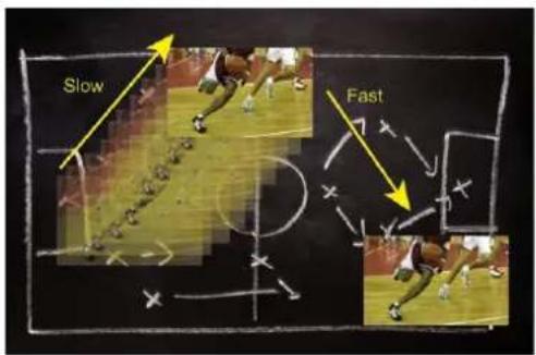
In the main menu, select the Keying/Titling menu.
You now have several choices to key your sources. The Luma Key and the Chroma Key based on the Luma pixel values and the Chroma pixel values and for both an additional Titling menu which can be useful to choose the transparency value of your keying.

natural_image
Three-panel image showing a camera on a green screen, a blue sky with clouds, and a black-and-white photo of a person on a table (no text or symbols)Keying/Titling menu > Type menu > Select your keying type
Once your keying mode is selected, the QuickMatriX provides you some keying advance setting:
For Luma Key:
- Luma Keying is used to key from a particular luminous intensity. It produces a hard edged key based on intensity, which is most suitable for titling effects. You can choose to key things that are extremely dark or extremely bright and keep everything in between, or invert to key only things that are of a medium intensity.
- The black and white levels define where to begin the keying. In the range 0 to 255, 0 represents no luminance, or black and 255 represents full luminance, or white.
- Level Black: As the Black Level is changed from 0 to 255, things that are black are first keyed out, followed by dark grey, then light grey, and so forth, until the entire picture is keyed out at 255.
- Level White: As the White Level is changed from 255 to 0, things that are white are first keyed out, followed by light grey, then dark grey, and so forth, until the entire picture is keyed out at 0.

For Chroma Key:
Chroma Keying is used to key from a particular color. It produces a key which is most suitable for moving images and “weatherman” style applications.
- Color grabber:
Select Chroma Key menu > Select Color grabber menu
Using a crosshair, you can select a particular hue based on what is on screen. Once you have adjusted the crosshairs to a desired position, press set/enter to capture the color value at that instant. You can then adjust the other parameters such as Tolerance to further refine your key.
- Manual Setting:
Select Chroma Key menu > Manual Settings menu
- R,G,B: these controls allow you to manually select a hue, defined by its Red, Green, and Blue values as you can find in Windows (Paint software).
- Tolerance: the Tolerance parameter allows you to expand your key color selection to include colors which are similar to the selected value. A tolerance of 1 will select only the desired hue, whereas a tolerance of 255 will select nearly all hues.
- Black Level: this option permits adjustment of the luminance levels of the keyed hue. The Black Level is the luminance lower bound. Colors in the selected hue range with a luminance brighter than the Black Level but darker than the White Level will be considered part of the key.
- White Level: this option permits adjustment of the luminance levels of the keyed hue. The White Level is the luminance lower bound. Colors in the selected hue range with a luminance brighter than the Black Level but darker than the White Level will be considered part of the key.
- Titling alpha: if you have selected one of the two Titling mode, the titling menu appears. This option places a transparent black backdrop behind the entire layer to which the key is applied. This effect is useful for using bright titles on bright backgrounds, such as clouds.
- Invert keying: by default, this mode is disabled. When this mode is activated, the key selection will remain on screen, and all other portions of the image will be keyed away. For example, you would see the green screen behind the actor, while the actor would be keyed away.
8.3 Menu tree
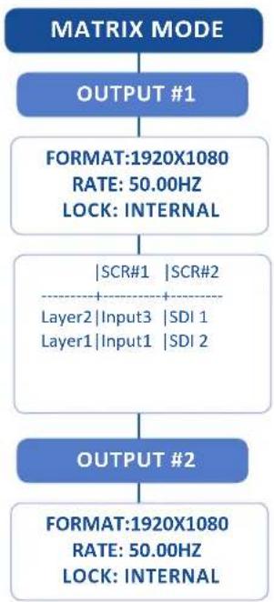
flowchart
graph TD
    A["MATRIX MODE"] --> B["OUTPUT #1"]
    B --> C["FORMAT:1920X1080\nRATE: 50.00HZ\nLOCK: INTERNAL"]
    C --> D["|SCR#1 | SCR#2\nLayer2 | Input3 | SDI 1\nLayer1 | Input1 | SDI 2"]
    D --> E["OUTPUT #2"]
    E --> F["FORMAT:1920X1080\nRATE: 50.00HZ\nLOCK: INTERNAL"]

flowchart
graph TD
    A["OUTPUT1 / OUTPUT2"] --> B["SYNC W/OUT1 (01)"]
    A --> C["OUTPUT STATUS"]
    A --> D["OUTPUT FORMAT (02)"]
    B --> E["HDTV 720P"]
    B --> F["HDTV 1035I"]
    B --> G["HDTV 1080I"]
    B --> H["HDTV 1080P"]
    B --> I["640 X 480 4/3"]
    B --> J["800 X 600 4/3"]
    B --> K["848 X 480 16/9"]
    B --> L["1024 X 768 4/3"]
    B --> M["1152 X 864 4/3"]
    B --> N["1280 X 720 16/9"]
    B --> O["1280 X 768 15/9"]
    B --> P["1280 X 800 16/10"]
    B --> Q["1280 X 960 4/3"]
    B --> R["1280 X 1024 5/4"]
    B --> S["1360 X 768 16/9"]
    B --> T["1360 X 1024 4/3"]
    B --> U["1366 X 768 16/9"]
    B --> V["1366 X 800 15/9"]
    B --> W["1400 X 1050 5/3"]
    B --> X["1440 X 900 16/10"]
    B --> Y["1600 X 900 16/9"]
    B --> Z["1600 X 1200 4/3"]
    B --> AA["1680 X 1050 16/10"]
    B --> AB["1920 X 1080 16/9"]
    B --> AC["1920 X 1200 16/10"]
    B --> AD["2048 X 1080"]
    B --> AE["2048 X 1152 16/9"]
    B --> AF["FORMAT CUSTOM 1"]
    B --> AG["FORMAT CUSTOM 2"]
(O1) Only for OUTPUT 2
(O2) For OUTPUT 2, only displayed when OUTPUT2 is not synchronized with OUTPUT1
(O3) Depending on the output format
(O4) Only for interlaced output format
(O5) Only Computer and HDTV
[...]

flowchart
graph TD
    A["FORMAT CUSTOM 3"] --> B["OUTPUT RATE(O2)"]
    C["FORMAT CUSTOM 4"] --> B
    D["FORMAT CUSTOM 5"] --> B
    E["FORMAT CUSTOM 6"] --> B
    F["FORMAT CUSTOM 7"] --> B
    G["FORMAT CUSTOM 8"] --> B
    H["FORMAT CUSTOM 9"] --> B
    I["FORMAT CUSTOM 10"] --> B
    J["INTERNAL REF"] --> K["FOLLOW X0.5"]
    K --> L["INPUT 1"]
    K --> M["INPUT 2"]
    K --> N["INPUT 3"]
    K --> O["INPUT 4"]
    K --> P["HDMI 1"]
    K --> Q["HDMI 2"]
    K --> R["SDI 1"]
    K --> S["SDI 2"]
    K --> T["FOLLOW X1"]
    K --> U["FOLLOW X2"]

flowchart
graph TD
    A["GAMMA"] --> B["FLICKER FILTER^(04)"]
    B --> C["ANALOG TYPE"]
    C --> D["RGBS"]
    C --> E["RGsB (SOG)"]
    C --> F["RGB HV"]
    C --> G["YUV"]
    H["DVI TYPE"] --> I["AUTO"]
    H --> J["RGB FULL (0-255)"]
    H --> K["RGB LIMITED (16-235)"]
    H --> L["YUV"]
    M["DVI AS HDMI"] --> N["HDCP DETECTION"]
    M --> O["CENTERING PIC"]
    P["TEST PATTERN"] --> Q["OFF"]
    Q --> R["V GREY SCALE"]
    Q --> S["H GREY SCALE"]
    Q --> T["V COLOR BAR"]
    Q --> U["H COLOR BAR"]
    Q --> V["GRID"]
    Q --> W["SMPTE"]
    Q --> X["BURST^(05)"]
    Q --> Y["V-GRADIENT"]
    Q --> Z["H-GRADIENT"]
[...]

flowchart
graph TD
    A["INPUTS"] --> B["CONFIG STATUS"]
    A --> C["AUTOSET ALL"]
    A --> D["SYNC. STATUS"]
    D --> E["INPUT 1: NO"]
    D --> F["INPUT 2: NO"]
    D --> G["INPUT 3: NO"]
    D --> H["INPUT 4: NO"]
    D --> I["HDMI 1: NO"]
    D --> J["HDMI 2: NO"]
    D --> K["SDI 1: NO"]
    D --> L["SDI 2: NO"]
    M["INPUT 1"] --> N["INPUT 2"]
    M --> O["INPUT 3"]
    M --> P["INPUT 4"]
    M --> Q["HDMI 1"]
    M --> R["HDMI 2"]
    M --> S["SDI 1"]
    M --> T["SDI 2"]
    U["INPUT STATUS"] --> V["INPUT 1\nACTIVE PLUG:(1)\nFRMT:\nRATE:(12)\nSYNC.POL.:(12)(13)\nHDCP(12)(14)"]
    W["AUTOSET"] --> X["FREEZE"]
    W --> Y["ACTIVE PLUG"]
    Y --> Z["ANALOG"]
    Y --> AA["DVI-D"]
    Y --> AB["SDI"]
    Y --> AC["HDMI"]
(I1) Displayed when input is a multiplug input.
(12) Displayed when a valid input signal is detected
(13) Displayed when it is an analog plug and when the signal is computer HV type
(I4) Displayed for HDMI and DVI-D plugs
(15) Displayed when the plug is analog, DVI-D or HDMI
(16) Displayed when the plug is analog
(17) Displayed when the plug is analog and the signal type is VIDEO RGBS
(18) Displayed when the plug is not SDI

flowchart
graph TD
    A["ANALOG SETTINGS"] --> B["TYPE(15)"]
    C["DVI-D SETTINGS"] --> B
    D["SDI SETTINGS"] --> B
    E["HDMI SETTINGS"] --> B
    B --> F["SDTV COMPOSITE(16)"]
    B --> G["SDTV YC(16)"]
    B --> H["VIDEO RGBS(16)"]
    B --> I["VIDEO RGsB(16)"]
    B --> J["VIDEO YUV(16)"]
    B --> K["COMPUTER SOG(16)"]
    B --> L["COMPUTER BW(16)"]
    B --> M["COMPUTER HV(16)"]
    B --> N["COMPUTER C TTL(16)"]
    B --> O["COMPUTER C ANA(16)"]
    B --> P["AUTO(16)"]
    B --> Q["YUV(16)"]
    B --> R["RGB FULL (0-255)(16)"]
    B --> S["RGB LTD (16-235)(16)"]
    F --> T["AUTOSET"]
    G --> U["ENABLE"]
    H --> V["SYNCHRONIZED"]
    I --> W["VCR MODE"]
    J --> X["HDCP ENABLE(14)"]
    K --> Y["H. SYNC. LOAD(17)"]
    L --> Z["HI-Z"]
    L --> AA["75 OHMS"]
    M --> AB["3D COMBO FILTER"]
    N --> AC["DISABLE"]
    N --> AD["DEFAULT"]
    N --> AE["LOW FILTERING"]
    N --> AF["HIGH FILTERING"]
    Y --> AG["FORMAT"]
    Z --> AH["AUDIO INPUT"]
    AA --> AH
    AB --> AH
    AC --> AH
    AD --> AH
    AE --> AH
    AF --> AH
    AG --> AI["NONE"]
    AG --> AJ["EMBEDDED"]
    AH --> AK["ANALOG 1"]
    AH --> AL["ANALOG 2"]
    AH --> AM["ANALOG 3"]
    AH --> AN["ANALOG 4"]
    AH --> AO["S/PDIF 1"]
    AH --> AP["S/PDIF 2"]
    AI --> AQ["SDI GROUP"]
    AJ --> AQ
    AK --> AQ
    AL --> AQ
    AM --> AQ
    AN --> AQ
    AO --> AQ
    AP --> AQ
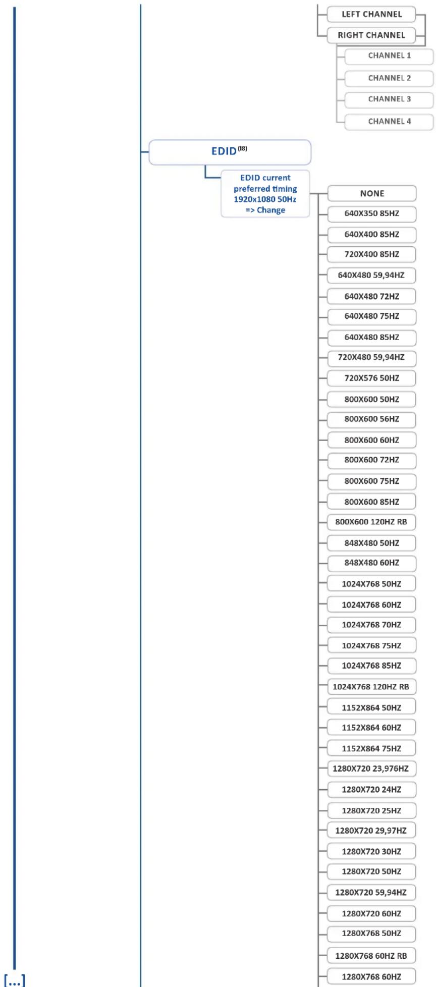
flowchart
graph TD
    A["EDID(18)"] --> B["EDID current preferred timing 1920x1080 50Hz => Change"]
    B --> C["NONE"]
    C --> D["640X350 85HZ"]
    C --> E["640X400 85HZ"]
    C --> F["720X400 85HZ"]
    C --> G["640X480 59,94HZ"]
    C --> H["640X480 72HZ"]
    C --> I["640X480 75HZ"]
    C --> J["640X480 85HZ"]
    C --> K["720X480 59,94HZ"]
    C --> L["720X576 50HZ"]
    C --> M["800X600 50HZ"]
    C --> N["800X600 56HZ"]
    C --> O["800X600 60HZ"]
    C --> P["800X600 72HZ"]
    C --> Q["800X600 75HZ"]
    C --> R["800X600 85HZ"]
    C --> S["800X600 120HZ RB"]
    C --> T["848X480 50HZ"]
    C --> U["848X480 60HZ"]
    C --> V["1024X768 50HZ"]
    C --> W["1024X768 60HZ"]
    C --> X["1024X768 70HZ"]
    C --> Y["1024X768 75HZ"]
    C --> Z["1024X768 85HZ"]
    C --> AA["1024X768 120HZ RB"]
    C --> AB["1152X864 50HZ"]
    C --> AC["1152X864 60HZ"]
    C --> AD["1152X864 75HZ"]
    C --> AE["1280X720 23,976HZ"]
    C --> AF["1280X720 24HZ"]
    C --> AG["1280X720 25HZ"]
    C --> AH["1280X720 29,97HZ"]
    C --> AI["1280X720 30HZ"]
    C --> AJ["1280X720 50HZ"]
    C --> AK["1280X720 59,94HZ"]
    C --> AL["1280X720 60HZ"]
    C --> AM["1280X768 50HZ"]
    C --> AN["1280X768 60HZ RB"]
    C --> AO["1280X768 60HZ"]
[...]
| 1280X768 75HZ |
| 1280X768 85HZ |
| 1280X768 120HZ RB |
| 1280X800 50HZ |
| 1280X800 60HZ RB |
| 1280X800 60HZ |
| 1280X800 75HZ |
| 1280X800 85HZ |
| 1280X800 120HZ RB |
| 1280X960 50HZ |
| 1280X960 60HZ |
| 1280X960 85HZ |
| 1280X960 120HZ RB |
| 1280X1024 50HZ |
| 1280X1024 60HZ |
| 1280X1024 75HZ |
| 1280X1024 85HZ |
| 1280X1024 120HZ RB |
| 1360X768 50HZ |
| 1360X768 60HZ |
| 1360X768 120HZ RB |
| 1360X1024 50HZ |
| 1360X1024 60HZ |
| 1366X768 50HZ |
| 1366X768 60HZ RB |
| 1366X768 60HZ |
| 1400X1050 50HZ |
| 1400X1050 60HZ RB |
| 1400X1050 60HZ |
| 1400X1050 75HZ |
| 1400X1050 85HZ |
| 1400X1050 120HZ RB |
| 1440X900 50HZ |
| 1440X900 60HZ RB |
| 1440X900 60HZ |
| 1440X900 75HZ |
| 1440X900 85HZ |
| 1440X900 120HZ RB |
| 1600X900 50HZ |
| 1600X900 60HZ RB |
| 1600X1200 60HZ |
| 1600X1200 60HZ |
| 1600X1200 65HZ |
| 1600X1200 70HZ |
| 1600X1200 75HZ |
| 1600X1200 85HZ |
| 1600X1200 120HZ RB |
| 1680X1050 50HZ |

flowchart
graph TD
    A["1680X1050 60HZ RB"] --> B["1680X1050 60HZ"]
    B --> C["1680X1050 75HZ"]
    C --> D["1680X1050 85HZ"]
    D --> E["1680X1050 120HZ RB"]
    E --> F["1920X1080 23,976HZ"]
    F --> G["1920X1080 24HZ"]
    G --> H["1920X1080 25HZ"]
    H --> I["1920X1080 29,97HZ"]
    I --> J["1920X1080 30HZ"]
    J --> K["1920X1080 50HZ"]
    K --> L["1920X1080 59,94HZ"]
    L --> M["1920X1080 60HZ"]
    M --> N["1920X1200 50HZ"]
    N --> O["1920X1200 60HZ RB"]
    O --> P["2048X1080 23,976HZ"]
    P --> Q["2048X1080 24HZ"]
    Q --> R["2048X1080 25HZ"]
    R --> S["2048X1080 29,97HZ"]
    S --> T["2048X1080 30HZ"]
    T --> U["2048X1080 50HZ"]
    U --> V["2048X1080 59,94HZ"]
    V --> W["2048X1080 60HZ"]
    W --> X["2048X1152 50HZ"]
    X --> Y["2048X1152 60HZ RB"]

    Z["PRESSET MGMT(P1)"] --> AA["BOTH OUTPUTS"]
    AA --> AB["CURRENT OUTPUT"]
    AB --> AC["OUTPUT 1"]
    AC --> AD["OUTPUT 2"]
    AD --> AE["STEP BACK"]
    AE --> AF["SAVE PRESET"]
    AF --> AG["SAVE FROM ->[ MAIN "]<-_SAVE_TO[" MEM1 "]]
    AG --> AH["SAVE PRESET FROM CURRENT->MEM1 ->NO YES"]

    style Z fill:#f9f,stroke:#333
    style AA fill:#bbf,stroke:#333
    style AB fill:#bbf,stroke:#333
    style AC fill:#bbf,stroke:#333
    style AD fill:#bbf,stroke:#333
    style AE fill:#bbf,stroke:#333
    style AF fill:#bbf,stroke:#333
    style AG fill:#bbf,stroke:#333
    style AH fill:#bbf,stroke:#333
LOAD PRESET
LOAD FROM
>[SCR1]< [MEM1]
LOAD TO
[SCR1] [MAIN]
LOAD PRESET FROM
[SCR1][MEM1]
-> [SCR1][MAIN]
->NO YES
ERASE PRESET
PRESET MEMORY 1 ^(P3)
PRESET MEMORY 2 ^(P3)
PRESET MEMORY 3 ^[P3]
PRESET MEMORY 4 ^(P3)
PRESET MEMORY 5 ^(P3)
PRESET MEMORY 6 ^(P3)
PRESET MEMORY 7 ^(P3)
PRESET MEMORY 8 ^(P3)
EMPTY(P4)
[...]

flowchart
graph TD
    A["IMAGE^(G1)"] --> B["AUTO CENTERING^(G2)"]
    A --> C["BLANKING ADJUST^(G3)"]
    C --> D["H POS"]
    C --> E["V POS"]
    C --> F["H SIZE"]
    C --> G["V SIZE"]
    A --> H["CROPPING"]
    H --> I["TOP"]
    H --> J["LEFT"]
    H --> K["BOTTOM"]
    H --> L["RIGHT"]
    A --> M["OPTIMIZE^(G2)"]
    M --> N["PHASE"]
    M --> O["H TOTAL^(G4)"]
    A --> P["UNDER/OVER^(G5)"]
    P --> Q["UNDERSCAN"]
    P --> R["OVERSCAN"]
    A --> S["ASPECT IN"]
    S --> T["NATIVE"]
    S --> U["5/4 (1.25:1)"]
    S --> V["4/3 (1.33:1)"]
    S --> W["16/10 (1.60:1)"]
    S --> X["15/9 (1.66:1)"]
    S --> Y["16/9 (1.77:1)"]
    S --> Z["21/9 (2.33:1)"]
    A --> AA["PREDEFINED CROP"]
    AA --> AB["NONE"]
    AA --> AC["LETTERBX 1.78:1"]
    AA --> AD["LETTERBX 1.85:1"]
    AA --> AE["LETTERBX 2.35:1"]
    AA --> AF["PILLARBX 1.33:1"]
(G1) Displayed when a valid input is affected to a layer
(G2) Displayed for computer analog signal, EDTV and HDTV analog video
(G3) Displayed for analog signal
(G4) Displayed for computer analog signal
(G5) Displayed for video signal
(G6) Displayed for interlaced signal
(G7) Displayed for 50 Hz interlaced signal and non-activated low latency
(G8) Displayed for 60 Hz interlaced signal and non-activated low latency

flowchart
graph TD
    A["ASPECT OUT"] --> B["1:1"]
    B --> C["CENTERED"]
    C --> D["FULL SCREEN"]
    D --> E["CROPPED"]
    F["SHARPNESS"] --> G["LOW"]
    G --> H["MEDIUM"]
    H --> I["HIGH"]
    J["COLORIMETRY"] --> K["BRIGHTNESS"]
    K --> L["CONTRAST"]
    L --> M["COLOR"]
    M --> N["HUE"]
    O["COMPONENT LEVEL (G3)"] --> P["RED"]
    O --> Q["GREEN"]
    O --> R["BLUE"]
    S["LOW LATENCY (G6)"] --> T["2:2 PULLDOWN (G7)"]
    T --> U["3:2 PULLDOWN (G8)"]
    U --> V["RESET SETTINGS"]
    V --> W["RESET THE PLUG TO ITS DEFAULT VALUES? ->NO YES"]
[...]

flowchart
graph TD
    A["KEYING/TITLING^(A4)"] --> B["TYPE"]
    B --> C["NONE"]
    B --> D["LUMakeY"]
    B --> E["CHROMakeY"]
    B --> F["LUMakeY+TITLING"]
    B --> G["CHROMakeY+TITLING"]
    A --> H["LUMakeY^(K2)"]
    H --> I["LEVEL BLACK"]
    H --> J["LEVEL WHITE"]
    A --> K["CHROMAKE^(K4)"]
    K --> L["COLOR GRABBER"]
    L --> M["H POS"]
    L --> N["V POS"]
    L --> O["TOLER."]
    L --> P["L BLACK"]
    L --> Q["L WHITE"]
    A --> R["MANUAL SETTING"]
    R --> S["R KEY"]
    R --> T["G KEY"]
    R --> U["B KEY"]
    R --> V["TOLER."]
    R --> W["L BLACK"]
    R --> X["L WHITE"]
    A --> Y["TITLING ALPHA^(K4)"]
    Y --> Z["TRANSPARENCY"]
    A --> AA["INVERT KEYING^(K5)"]
(K1) Displayed when a valid input is affected to a layer
(K2) Only displayed for Type = Luma key or Lumakey +Titling
(K3) Only displayed for Type = chroma key or chromakey +Titling
(K4) Only displayed for Type = Lumakey +Titling or Chromakey +Titling
(K5) Only displayed for Type different that None
(A4) Displayed if the switcher is on mixer or quadravision mode
[...]
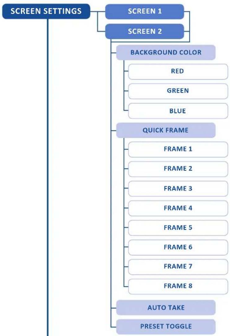
flowchart
graph TD
    A["SCREEN SETTINGS"] --> B["SCREEN 1"]
    A --> C["SCREEN 2"]
    B --> D["BACKGROUND COLOR"]
    C --> D
    D --> E["RED"]
    D --> F["GREEN"]
    D --> G["BLUE"]
    H["QUICK FRAME"] --> I["FRAME 1"]
    H --> J["FRAME 2"]
    H --> K["FRAME 3"]
    H --> L["FRAME 4"]
    H --> M["FRAME 5"]
    H --> N["FRAME 6"]
    H --> O["FRAME 7"]
    H --> P["FRAME 8"]
    Q["AUTO TAKE"] --> R["Preset TOGGLE"]
[...]

flowchart
graph TD
    A["LAYER^(Y1)"] --> B["LAYER COPY MODE^(Y2)"]
    B --> C["NO COPY"]
    B --> D["CLONE MODE"]
    B --> E["COPY & H. POS FLIP"]
    A --> F["LAYER ADJUST"]
    F --> G["H POS"]
    F --> H["V POS"]
    F --> I["HV POS"]
    F --> J["HV SIZE"]
    F --> K["H SIZE"]
    F --> L["V SIZE"]
    A --> M["LAYER ZOOM^(Y3)"]
    M --> N["H POS"]
    M --> O["V POS"]
    M --> P["H SIZE"]
    M --> Q["V SIZE"]
    A --> R["SIZE TEMPLATES"]
    R --> S["FULL SCREEN"]
    R --> T["3/4 FULL SCREEN"]
    R --> U["2/3 FULL SCREEN"]
    R --> V["1/2 FULL SCREEN"]
    R --> W["1/3 FULL SCREEN"]
    R --> X["1/4 FULL SCREEN"]
    A --> Y["TRANSPARENCY"]
(Y1) Displayed when a valid input is affected to a layer
(Y2) Only displayed in matrix mode
(Y3) Not available for frame
(Y4) Only slide, wipe and stretch
(Y5) Only wipe and stretch
(Y6) Only circle, wipe and stretch
(Y7) Only slide, wipe and circle

flowchart
graph TD
    A["OPENING EFFECT"] --> B["CLOSING EFFECT"]
    B --> C["TYPE"]
    C --> D["CUT"]
    C --> E["CLEAN CUT^(Y3)"]
    C --> F["FADE"]
    C --> G["SLIDE"]
    C --> H["WIPE"]
    B --> I["DIRECTION"]
    I --> J["LEFT TO RIGHT^(Y4)"]
    I --> K["RIGHT TO LEFT^(Y4)"]
    I --> L["BOTTOM TO TOP^(Y4)"]
    I --> M["TOP TO BOTTOM^(Y4)"]
    I --> N["VERTICAL FROM CENTER^(Y5)"]
    I --> O["HORIZONTAL FROM CENTER^(Y6)"]
    I --> P["HV FROM CENTER^(Y6)"]
    I --> Q["FROM BOTTOM LEFT CORNER^(Y7)"]
    I --> R["FROM BOTTOM RIGHT CORNER^(Y7)"]
    I --> S["FROM TOP LEFT CORNER^(Y7)"]
    I --> T["FROM TOP RIGHT CORNER^(Y7)"]
    A --> U["EFFECT DURATION"]
    U --> V["SMOOTH MOVE"]
    U --> W["STATUS"]
[...]

flowchart
graph TD
    A["FRAMES"] --> B["CAPTURE SOURCE"]
    B --> C["PROGRAM"]
    A --> D["RECORD FRAMES"]
    D --> E["FRAME 1"]
    D --> F["FRAME 2 [EMPTY"](F1)]
    D --> G["FRAME 3"]
    D --> H["FRAME 4"]
    D --> I["FRAME 5 [EMPTY"](F1)]
    D --> J["FRAME 6 [EMPTY"](F1)]
    D --> K["FRAME 7"]
    D --> L["FRAME 8"]
    A --> M["ERASE"]
    M --> N["FRAME 1(F2)"]
    M --> O["FRAME 3(F2)"]
    M --> P["FRAME 4(F2)"]
    M --> Q["FRAME 7(F2)"]
    M --> R["FRAME 8(F2)"]
(F1) Display "empty" is the slot is free
(F2) Only displays valid frame list
[...]

flowchart
graph TD
    A["AUDIO"] --> B["AUDIO MODE"]
    B --> C["NO AUDIO"]
    B --> D["PRESET MODE"]
    B --> E["ROUTING MODE"]
    A --> F["SOURCE SETTINGS^(A1)"]
    F --> G["ANALOG INPUT 1"]
    F --> H["ANALOG INPUT 2"]
    F --> I["ANALOG INPUT 3"]
    F --> J["ANALOG INPUT 4"]
    F --> K["DVI INPUT 1"]
    F --> L["DVI INPUT 2"]
    F --> M["DVI INPUT 3"]
    F --> N["DVI INPUT 4"]
    F --> O["HDMI INPUT 3"]
    F --> P["HDMI INPUT 4"]
    F --> Q["HDMI INPUT 5"]
    F --> R["HDMI INPUT 6"]
    F --> S["SDI INPUT 7"]
    F --> T["SDI INPUT 8"]
    F --> U["S/PDIF 1"]
    F --> V["S/PDIF 2"]
    V --> W["MUTE"]
    V --> X["STEREO"]
    V --> Y["ANALOG GAIN^(A1)"]
    V --> Z["LEVEL/BALANCE"]
    Z --> AA["LEVEL"]
    Z --> AB["BALANCE"]
    A --> AC["DIGITAL OUTPUT^(A1)"]
    AC --> AD["S/PDIF"]
    AC --> AE["AES3"]
(A1) Displayed if the audio mode is different of "no audio"
(A2) Displayed if the audio mode is "routing mode"
(A3) Displayed if the audio mode is "Preset mode"
(A4) Displayed if the audio input is analog
(A5) Displayed if the delay mode is manual
[...]

flowchart
graph TD
    A["OUTPUT 1(A2)"] --> B["PRESETMODE (A3)"]
    C["OUTPUT 2(A2)"] --> B
    D["OUT1 MAIN(A3)"] --> B
    E["OUT2 MAIN(A3)"] --> B
    B --> F["BREAKAWAY"]
    B --> G["TOP LAYER FOLLOW"]
    B --> H["MASTER MUTE"]
    B --> I["STEREO"]
    B --> J["ANALOG LEVEL"]
    B --> K["MASTER VOLUME"]
    B --> L["BALANCE"]
    B --> M["SOURCE"]
    M --> N["NONE"]
    M --> O["INPUT 1"]
    M --> P["INPUT 2"]
    M --> Q["INPUT 3"]
    M --> R["INPUT 4"]
    M --> S["HDMI 1"]
    M --> T["HDMI 2"]
    M --> U["SDI 1"]
    M --> V["SDI 2"]
    V --> W["LEVEL"]
    V --> X["BALANCE"]
    Y["DELAY MODE"] --> Z["AUTO ADJUST"]
    Y --> AA["MANUAL ADJUST"]
    Y --> AB["AUDIO DELAY(A7)"]
    Y --> AC["1KHZ OSC."]
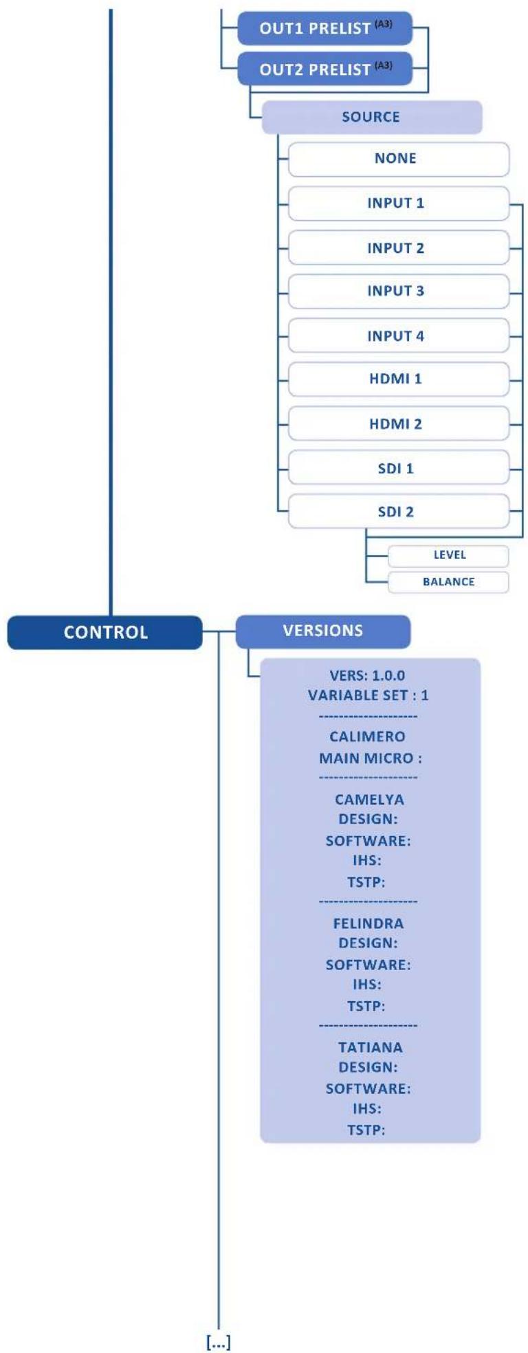
flowchart
graph TD
    A["OUT1 PRELIST (A3)"] --> C["SOURCE"]
    B["OUT2 PRELIST (A3)"] --> C
    C --> D["NONE"]
    C --> E["INPUT 1"]
    C --> F["INPUT 2"]
    C --> G["INPUT 3"]
    C --> H["INPUT 4"]
    C --> I["HDMI 1"]
    C --> J["HDMI 2"]
    C --> K["SDI 1"]
    C --> L["SDI 2"]
    L --> M["LEVEL"]
    L --> N["BALANCE"]
    O["CONTROL"] --> P["VERSIONS"]
    P --> Q["VERS: 1.0.0<br>VARIABLE SET : 1"]
    Q --> R["CALIMERO<br>MAIN MICRO :"]
    R --> S["CAMELYA<br>DESIGN: <br>SOFTWARE: <br>IHS: <br>TSTP:"]
    S --> T["FELINDRA<br>DESIGN: <br>SOFTWARE: <br>IHS: <br>TSTP:"]
    T --> U["TATIANA<br>DESIGN: <br>SOFTWARE: <br>IHS: <br>TSTP:"]
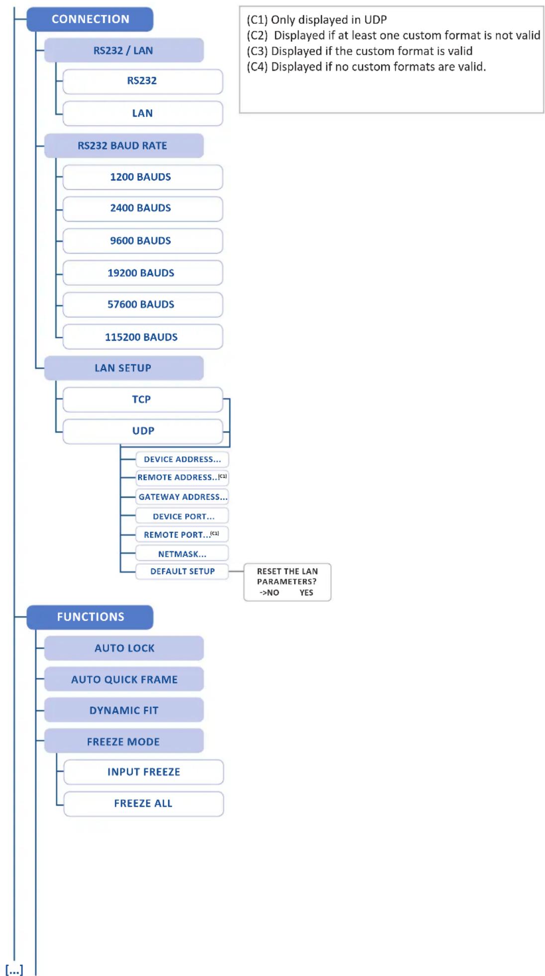
flowchart
graph TD
    A["CONNECTION"] --> B["RS232 / LAN"]
    B --> C["RS232"]
    B --> D["LAN"]
    A --> E["RS232 BAUD RATE"]
    E --> F["1200 BAUDS"]
    E --> G["2400 BAUDS"]
    E --> H["9600 BAUDS"]
    E --> I["19200 BAUDS"]
    E --> J["57600 BAUDS"]
    E --> K["115200 BAUDS"]
    A --> L["LAN SETUP"]
    L --> M["TCP"]
    L --> N["UDP"]
    N --> O["DEVICE ADDRESS..."]
    N --> P["REMOTE ADDRESS..(C1)"]
    N --> Q["GATEWAY ADDRESS..."]
    N --> R["DEVICE PORT..."]
    N --> S["REMOTE PORT..(C1)"]
    N --> T["NETMASK..."]
    N --> U["DEFAULT SETUP"]
    U --> V["RESET THE LAN PARAMETERS? ->NO YES"]
    W["FUNCTIONS"] --> X["AUTO LOCK"]
    W --> Y["AUTO QUICK FRAME"]
    W --> Z["DYNAMIC FIT"]
    W --> AA["FREEZE MODE"]
    W --> AB["INPUT FREEZE"]
    W --> AC["FREEZE ALL"]

flowchart
graph TD
    A["STANDBY"] --> B["BAUD RATE"]
    B --> C["SET MESSAGE ON"]
    C --> D["SET MESSAGE OFF"]
    D --> E["CLEAR MESSAGE ON"]
    E --> F["CLEAR MESSAGE OFF"]
    F --> G["STANDBY"]
    H["DATE/TIME"] --> I["YEAR"]
    H --> J["MONTH"]
    H --> K["DAY"]
    H --> L["HOUR"]
    H --> M["MINUTE"]
    H --> N["SECOND"]
    O["HDCP SUMMARY"] --> P["IN1 DVI-D: IDLE"]
    O --> Q["IN2 DVI-D: IDLE"]
    O --> R["IN3 DVI-D: IDLE"]
    O --> S["IN3 HDMI: IDLE"]
    O --> T["IN4 DVI-D: IDLE"]
    O --> U["IN4 HDMI: IDLE"]
    O --> V["IN5 HDMI: IDLE"]
    O --> W["IN6 HDMI: IDLE"]
    O --> X["OUT1 DVI-D: IDLE"]
    O --> Y["OUT2 DVI-D: IDLE"]
    Z["FRONT PANEL"] --> AA["KEY LOCKING"]
    AA --> AB["MENUS + KEYBOARD"]
    AA --> AC["ONLY MENUS"]

flowchart
graph TD
    A["MATRIX TK MODE"] --> B["TAKE BOTH"]
    B --> C["TAKE CUR.SCREEN"]
    C --> D["LCD BRIGHTNESS"]
    D --> E["KEY BRIGHTNESS"]
    E --> F["RESET/ERASE"]
    F --> G["RESET LAYERS"]
    G --> H["RESET THE LAYERS POSITION AND SIZE? ->NO YES"]
    H --> I["ERASE MEMORIES"]
    I --> J["ERASE ALL THE IMAGE SETTINGS? ->NO YES"]
    J --> K["ERASE PRESETS"]
    K --> L["ERASE ALL THE PRESET MEMORIES? ->NO YES"]
    L --> M["ERASE CUST.FRMT"]
    M --> N["ALL(C2)"]
    N --> O["ERASE ALL THE CUSTOM FORMATS? ->NO YES"]
    O --> P["COMPUT.CUSTOM1(C3)"]
    P --> Q["COMPUT.CUSTOM2(C3)"]
    Q --> R["COMPUT.CUSTOM3(C3)"]
    R --> S["COMPUT.CUSTOM4(C3)"]
    S --> T["COMPUT.CUSTOM5(C3)"]
    T --> U["COMPUT.CUSTOM6(C3)"]
    U --> V["COMPUT.CUSTOM7(C3)"]
    V --> W["COMPUT.CUSTOM8(C3)"]
    W --> X["COMPUT.CUSTOM9(C3)"]
    X --> Y["COMPUT.CUSTOM10(C3)"]
    Y --> Z["EMPTY(C4)"]
DEFAULT VALUES
RESET THE DEVICE TO ITS DEFAULT VALUES?
->NO YES
TECH. SUPPORT
THE AMERICAS
TECHSUPPORT@ANALOGWAYUSA.COM
TEL: +1 212 269 1902
[Non-Text]
EUROPE, MIDDLE EAST AND AFRICA
TECHSUPPORT@ANALOGWAY.COM
TEL: +33 (0)1 81 89 08 76
ASIA, PACIFIC
TECHSUPPORT@ANALOGWAYASIA.COM
TEL: +65 6292 5800

9. MAINTENANCE AND SUPPORT
9.1 Dashboard (RCS ^2 )
On the RCS ^2 , you have access to a chart with general information on the unit.
Please click on the Dashboard button: Dashboard

On this chart, you will find under the INFO tab, the Device name, the Serial number of your product, the actual firmware and the software version of the RCS ^2 . Under CONNECTIVITY, you will find the current IP address of your unit and its MAC address.

10. APPLICATIONS NOTE AND TIPS
10.1 HDCP
HDCP is a content protection mechanism which uses encryption to prevent high value content from being delivered to non-authorized devices. For example, Blu-ray players use HDCP on their HDMI outputs to ensure that the HDMI output cannot be routed to a digital recording device.
The QuickMatriX is fully HDCP compliant, meaning that you will be able to use the QuickMatriX to accept HDCP protected sources and route them to any HDCP protected outputs. As Analog Way is a licenced HDCP adoptor, this also means that the QuickMatriX is prevented from displaying any HDCP protected images on any non-HDCP compliant outputs (as is the case for all licenced HDCP compliant devices).
HDCP can only be used on certain connection formats, including DVI, HDMI, and Displayport. Keep in mind that simply because a connection is using a DVI, HDMI, or Displayport connection, it does not guarantee that the devices connected are maintaining an active HDCP connection. For example, you may find video recording or capture devices equipped with an HDMI input, however HDCP licencing forbids these devices from capturing HDCP protected content.
HDCP is not supported on connection formats such as composite, component, Svideo, SD-SDI, HD-SDI, 3G-SDI, or VGA. This means that any source which becomes protected by HDCP cannot be converted to these formats. For example, while you may find a Blu-ray player which can directly output a composite video signal, HDCP licencing forbids converting the HDCP protected HDMI signal back to composite or any other non-protected format.
To help troubleshoot HDCP in your installation, each input and output page is equipped with HDCP status information to indicate in realtime when HDCP encryption is being used.
Certain devices such as Macintosh computers can be misleading to use in conjunction with an HDCP compliant presentation switcher such as the QuickMatriX. This is because devices like the Mac computers can be used to output both HDCP protected content (such as a movie downloaded from iTunes) as well as non-HDCP protected content (such as a Keynote presentation or the desktop). When a computer first connects to an HDCP compliant device such as the QuickMatriX, it learns the capabilities of the device through the EDID connection. Upon seeing the HDCP compatibility of the attached QuickMatriX, devices like the Mac computers will immediately attempt to use HDCP encryption at all times, despite the content currently displayed on the computer screen. Since this source would now be considered an HDCP protected source, the QuickMatriX would be required to prevent it from being displayed on VGA or SDI outputs and only allow it to be displayed on outputs protected by HDCP. To work around this problem, the QuickMatriX allows the HDCP features of a particular input to be disabled, which in turn informs the Mac computer to avoid using HDCP, and allows content such as Keynote and the desktop to be displayed, as this input will no longer use HDCP protection. Please note that disabling the HDCP features of the input do not circumvent HDCP protections, and thus do not allow you to view any content which requires this protection.
For more information about HDCP, please refer to our whitepapers on HDCP, or visit the HDCP foundation website.

11. WARRANTY
11.1 Warranty conditions
Analog Way warrants the product against any defects in materials and workmanship for a period of three (3) years from the date of purchase when used in accordance with the user's manual and standard industry practices.
- In the unlikely event of any malfunction from such defects during the warranty period, Analog Way will, at its discretion, repair or replace the defective units.
-
The warranty does not apply if the product is determined to have been:
-
Improperly installed or abused,
- Handled with improper care,
- Used or stocked in abnormal conditions,
- Modified, opened,
-
Damaged by fire, war, or Natural disasters (Acts of God)
-
Analog Way's direct employees are solely authorized to make this determination.
- Analog Way reserves the right to refuse for repair and service a product for which the warranty is void.
- In no way shall Analog Way be responsible for direct or indirect loss of profit or consequential damages resulting from any defect in this product.
NOTE: Analog way offers a warranty extension of 2 years, it includes parts, labor and return shipping. If you are interested, please contact your territory sales representative.
11.2 Repair and return instructions
These Return Material Authorization (RMA) regulations determine the procedure to be followed when returning defective product. The aim is to ensure fast and simple handling of the returned product and bring the best satisfaction
In the unlikely event that a product is required to return for repair, please call the regional Maintenance center/Customer Service, and ask to receive a Return Material Authorization number (RMA). Three regional maintenance centers are available depending on your location. (See chapter: 12. Contact information)
- Before sending any device to Analog Way, please contact us to obtain a Return Material Authorization (RMA) number. Please have the model and serial number available and the reason for calling.
- RMAs are valid for 30 days, after which a new RMA must be requested.
- Package the unit securely in the original shipping materials or suitable equivalent. Analog Way is not responsible for damage which occurs due to improper packaging. The customer assumes responsibility until the unit arrives at our facility.
- Out-of-warranty products will be charged an evaluation fee if no problems are found or if you choose not to proceed with the repair.
- Discontinued products are not admitted for return and repair.
- Be sure to include the RMA number clearly on the shipping label or on the exterior of the package.
- No unit will be accepted without a valid RMA clearly visible.
11.3 Return conditions
In the unlikely event that you want to return the product, please call the regional Maintenance center/Customer Service
- If you are unhappy with the performance of any product purchased from us, you can return it within 30 days of purchase.
- Returned equipment must be in original condition with all accessories and packaging materials.
- Returns may be subject to a refurbishment and/or restocking fee.

12. CONTACT INFORMATION
The Americas
Europe, Middle East & Africa
Asia Pacific
Analog Way SAS - Headquarters
Sales/General information:
saleseuro@analogway.com
Technical support:
techsupport@analogway.com
Sales/General information:
salesusa@analogway.com
Technical support:
techsupport@analogwayusa.com
Analog Way Italy
Tel.: +39 02 39493943
salesitaly@analogway.com
Analog Way Pte Ltd
Tel.: +65 6292 5800
Fax: +65 6292 5205
152 Beach Road
15-03 Gateway East
SINGAPORE 189721
Sales/General information:
sales@analogwayasia.com
Technical support:
techsupport@analogwayasia.com
Analog Way UK
Tel.: +44 (0)2076 979133
salesuk@analogway.com

13. APPENDICES
13.1 Crestron 2 & 3 series Midra™ Driver

CRESTRON
Using this driver, software developers and integrators can easily provide powerful solutions for remotely controlling any Midra™ series Switchers through Crestron 2-series or 3-series Control Systems®.
The package includes:
- The precompiled driver modules that can be used for recalling presets, selecting source inputs, changing PIP content, configuring audio inputs and outputs...,
- One sample SIMPL program that demonstrates the use of all the features available within this driver (3 projects provided, targeting Crestron QM-RMC, MC3 and CP2E Control Systems®),
- Two VTPro sample projects, one for XPanel and one for the Crestron Mobile Pro® application (for iPad® and Android™ devices), both running with the sample program mentioned above,
- Help files in French and English.
The samples provided are ready-to-use programs and can be freely adapted or used as a base to build your own real-world Midra™ controller application.
13.2 AMX NetLinx® Integrated Controllers Midra™ Driver

Using this driver, software developers and integrators can easily provide powerful solutions for remotely controlling any Midra ^™ series Switchers through AMX NetLinx ^® integrated controllers.
The package includes:
- The precompiled driver modules that can be used for recalling presets, selecting source inputs, changing PIP content, configuring audio inputs and outputs...,
- One sample NetLinx® Studio program that demonstrates the use of all the features available within the driver,
- Two TPDesign4 sample projects, one for AMX Modero® S Touch Panels and one for Apple® iPad, both running with the sample program mentioned above,
- Help files in French and English.
The samples provided are ready-to-use programs and can be freely adapted or used as a base to build your own real-world Midra™ controller application.

natural_image
World map silhouette showing continents and oceans (no text or labels)Follow us



natural_image
Abstract blue 3D logo design on a metallic square background (no text or symbols)ANALOG WAY®
Pioneer in Analog, Leader in Digital
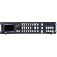


- THANK YOU
- HDCP management 21
- CONNECTING THE QUICKMATRIX 22
- Description 22
- CONTROLLING THE QUICKMATRIX 24
- OPERATING THE QUICKMATRIX FROM THE RCS 2 27
- Operating mode 27
- Setup 27
- Edit 38
- Live 43
- OPERATING THROUGH THE FRONT PANEL 45
- Front panel 45
- Settings in Matrix mode 46
- Menu tree 57
- MAINTENANCE AND SUPPORT 81
- Dashboard (RCS 2 ) 81
- APPLICATIONS NOTE AND TIPS 82
- HDCP 82
- WARRANTY 83
- CONTACT INFORMATION 84
- APPENDICES 85
- TRADEMARKS
- INTRODUCTION
- TERMS AND DEFINITIONS
- HARDWARE SPECIFICATIONS
- Safety instructions
- English
- Apply the following guidelines:
- French
- Unpacking and inspection
- Rack mount information
- IMPORTANT:
- Cable and adaptor information
- Hardware specifications
- Signal descriptions
- Analog HDTV
- Supported video formats
- Computer formats
- Input Computer formats
- Output Computer formats
- Input specifications
- Output specifications
- Standard output
- Communication specifications
- Serial interface
- LAN interface
- Protocol
- IP address
- Environmental specifications
- Dimensions:
- Weight:
- ELECTRICAL SECURITY:
- ELECTROMAGNETIC COMPATIBILITY:
- ENVIRONMENT:
- USE/TRANSPORT:
- HDCP management
- Input HDCP detection
- Output HDCP detection
- Keys' checking
- Output management
- HDCP Classification
- HDCP Receiver
- HDCP Transmitter
- Status
- CONNECTING THE QUICKMATRIX
- Description
- Rear panel
- Front panel
- CONTROLLING THE QUICKMATRIX
- RCS 2 requirement
- The recommended requirements are:
- Operating system:
- For Linux users:
- Connecting with the RCS 2
- In case of difficulties:
- RCS 2 top menu
- Setup
- Edit
- Live
- OPERATING THE QUICKMATRIX FROM THE RCS 2
- Operating mode
- Setup
- Mode
- Matrix mode
- Audio
- Screens
- Misc
- Output management
- Custom format
- Input management
- The next tab is the USER FORMAT:
- Keying Feature
- How to use the LUMA KEY:
- How to use the CHROMA KEY:
- Frame management
- How to save a frame:
- Audio management
- Specific feature:
- Service management
- Control management
- Network
- Functions
- Erase memories
- Factory reset
- Edit
- Layer management
- Layers management
- Layer adjustments
- Selected layer
- Reset feature
- Position/Size
- Transparency
- Cropping (only for live layers)
- Transitions
- Effects
- Force transition
- Smooth Move
- Layer layout
- Layer position
- Layer size
- Other layer adjustments:
- Preset load and save management
- Save a preset
- Load a preset
- Reset button
- Live
- SEQUENCE:
- OPERATING THROUGH THE FRONT PANEL
- Front panel
- Menu navigation
- Home menu
- Operating modes
- Reseting default values
- QuickMatriX color codes
- = Source is on the Program output
- = Freeze enable
- = Source is on Preview
- = Function available for modification
- Settings in Matrix mode
- Source Input selection
- Input selection settings
- Source Output selection
- Output selection settings
- Working with layers
- Working with layers functions
- Layer adjustment menu
- Layers with transitions
- - FADE:
- Capturing frames
- Frames menu > record Frame menu > Frame #
- Working with frames
- Frame input setup menu
- Creating presets
- Working with presets
- Working with audio
- - Audio mode:
- - ANALOG SETTINGS:
- - DIGITAL AUDIO:
- - PRESET MODE:
- Working with Mirror modes
- NOTES:
- Special features
- - SMOOTH MOVE EFFECT
- - WORKING WITH DSK (Chroma / Luma key)
- For Luma Key:
- For Chroma Key:
- - Color grabber:
- - Manual Setting:
- Menu tree
- LOAD PRESET
- ERASE PRESET
- TECH. SUPPORT
- MAINTENANCE AND SUPPORT
- Dashboard (RCS 2 )
- APPLICATIONS NOTE AND TIPS
- HDCP
- WARRANTY
- Warranty conditions
- Repair and return instructions
- Return conditions
- Analog Way SAS - Headquarters
- Sales/General information:
- Technical support:
- Analog Way Italy
- Analog Way Pte Ltd
- 15-03 Gateway East
- Analog Way UK
- APPENDICES
- Crestron 2 & 3 series Midra™ Driver
- CRESTRON
- The package includes:
- AMX NetLinx® Integrated Controllers Midra™ Driver
Brand : Analog Way
Model : QuickMatriX QMX150
Category : Switch