
ZED-10 - Audio Mixer ALLEN & HEATH - Free user manual and instructions
Find the device manual for free ZED-10 ALLEN & HEATH in PDF.


| Product Type | Analog Audio Mixer |
| Brand | Allen & Heath |
| Model | ZED-10 |
| Channels | 4 mono (XLR/TRS) + 2 stereo (RCA/TRS) |
| Frequency Response | 20 Hz - 20 kHz (+0/-1 dB) |
| EQ per Channel | 3-band (HF, Mid, LF) with sweepable mid |
| Aux Sends | 2 (pre/post switchable) |
| Stereo Return | 1 (RCA) |
| USB Audio | 2-in/2-out, 16-bit/48 kHz |
| Phantom Power | +48V (global switch) |
| Dimensions (W x D x H) | 315 mm x 200 mm x 100 mm |
| Weight | 2.6 kg |
| Power Supply | External 18V AC adapter (included) |
| Power Consumption | 20 W |
| Construction | Steel chassis, plastic knobs |
| Main Outputs | XLR (balanced) + TRS (balanced) |
| Headphone Output | 6.35 mm TRS with level control |
| Cleaning Instructions | Wipe with soft dry cloth; do not use solvents |
| Safety Warnings | Use only supplied adapter; avoid liquid ingress |
| Spare Parts & Repairability | Contact Allen & Heath support or authorized service |
| General Information | Ideal for small venues, rehearsals, and home studios |
Frequently Asked Questions - ZED-10 ALLEN & HEATH
User questions about ZED-10 ALLEN & HEATH
0 question about this device. Answer the ones you know or ask your own.
Ask a new question about this device
Download the instructions for your Audio Mixer in PDF format for free! Find your manual ZED-10 - ALLEN & HEATH and take your electronic device back in hand. On this page are published all the documents necessary for the use of your device. ZED-10 by ALLEN & HEATH.
USER MANUAL ZED-10 ALLEN & HEATH
natural_image
Red and black Allem & Heath audio workstation with visible knobs, capacitors, and speaker grille (no readable text or symbols on main body)Publication AP7880
CONTENTS
Warranty.... 4
Conformity Statement.... 5
Safety Instructions.... 6
Packed Items Checklist 9
Introduction to ZED-10.... 10
Specifications 12
Dimensions 13
Block Diagram.... 14
Mono Input Channel I&2 15
Mono Input Channel 3&4 (GTR I/P).... 18
Stereo Input Channel I.... 19
Stereo Input Channel 2.... 21
Master Section 22
USB Connection.... 24
Application Drawing—Live Mixing 25
Application Drawing—Studio Recording 26
Application Drawing—Using USB for effects (I).. 27
Application Drawing—Using USB for effects (2).. 28
Wiring Information 29
Product Support 30
WARRANTY
Limited One Year Warranty
This product is warranted to be free from defects in materials or workmanship for period of one year from the date of purchase by the original owner.
To ensure a high level of performance and reliability for which this equipment has been designed and manufactured, read this User Guide before operating. In the event of a failure, notify and return the defective unit to ALLEN & HEATH Limited or its authorised agent as soon as possible for repair under warranty subject to the following conditions
Conditions Of Warranty
The equipment has been installed and operated in accordance with the instructions in this User Guide.
The equipment has not been subject to misuse either intended or accidental, neglect, or alteration other than as described in the User Guide or Service Manual, or approved by ALLEN & HEATH.
Any necessary adjustment, alteration or repair has been carried out by ALLEN & HEATH or its authorised agent.
The defective unit is to be returned carriage prepaid to ALLEN & HEATH or its authorised agent with proof of purchase.
Units returned should be packed to avoid transit damage.
In certain territories the terms may vary.
Check with your ALLEN & HEATH agent for any additional warranty which may apply.
http://www.allen-heath.com
EMC & SAFETY
This product complies with the European Electro magnetic Compatibility directives 89/336/EEC & 92/31/EEC and the European Low Voltage Directives 73/23/EEC & 93/68/EEC.
This product has been tested to EN55103 Parts I & 2 1996 for use in Environments E1, E2, E3, and E4 to demonstrate compliance with the protection requirements in the European EMC directive 89/336/EEC. During some tests the specified performance figures of the product were affected. This is considered permissible and the product has been passed as acceptable for its intended use. Allen & Heath has a strict policy of ensuring all products are tested to the latest safety and EMC standards. Customers requiring more information about EMC and safety issues can contact Allen & Heath.
NOTE: Any changes or modifications to the console not approved by Allen & Heath could void the compliance of the console and therefore the users authority to operate it.
ZED-10 User Guide AP7880 Issue I
Copyright © 2009 Allen & Heath Limited. All rights reserved
Allen & Heath Limited
Kernick Industrial Estate, Penryn, Cornwall, TR10 9LU, UK
http://www.allen-heath.com
SAFETY INSTRUCTIONS
WARNING - Read the following before proceeding :
ATTENTION: RISQUE DE CHOC ELECTRIQUE – NE PAS OUVRIR

WARNING: This equipment must be earthed.
Read instructions:
Retain these safety and operating instructions for future reference. Adhere to all warnings printed here and on the console. Follow the operating instructions printed in this User Guide.
Do not remove cover:
Operate the console with its covers correctly fitted.
Power sources:
Connect the console to a mains power unit only of the type described in this User Guide and marked on the rear panel. Use the power cord with sealed mains plug appropriate for your local mains supply as provided with the console. If the provided plug does not fit into your outlet consult your service agent for assistance.
Power cord routing:
Route the power cord so that it is not likely to be walked on, stretched or pinched by items placed upon or against it.
Grounding:
Do not defeat the grounding and polarisation means of the power cord plug. Do not remove or tamper with the ground connection in the power cord.
SAFETY INSTRUCTIONS
Water and moisture:
To reduce the risk of fire or electric shock do not expose the console to rain or moisture or use it in damp or wet conditions. Do not place containers of liquids on it which might spill into any openings.
Ventilation:
Do not obstruct the ventilation slots or position the console where the air flow required for ventilation is impeded. If the console is to be operated in a rack unit or flightcase ensure that it is constructed to allow adequate ventilation.
Heat and vibration:
Do not locate the console in a place subject to excessive heat or direct sunlight as this could be a fire hazard. Locate the console away from any equipment which produces heat or causes excessive vibration.
Servicing:
Switch off the equipment and unplug the power cord immediately if it is exposed to moisture, spilled liquid, objects fallen into the openings, the power cord or plug become damaged, during lightening storms, or if smoke, odour or noise is noticed. Refer servicing to qualified technical personnel only.
Installation:
Install the console in accordance with the instructions printed in this User Guide. Do not connect the output of power amplifiers directly to the console. Use audio connectors and plugs only for their intended purpose.
Important Mains plug wiring instructions
The console is supplied with a moulded mains plug fitted to the AC mains power lead. Follow the instructions below if the mains plug has to be replaced. The wires in the mains lead are coloured in accordance with the following code:
| TERMINAL WIRE COLOUR | |||
| European | USA/Canada | ||
| L | LIVE | BROWN | BLACK |
| N | NEUTRAL | BLUE WHITE | |
| E | EARTH GND | GREEN & YELLOW | GREEN |
The wire which is coloured Green and Yellow must be connected to the terminal in the plug which is marked with the letter E or with the Earth symbol. This appliance must be earthed.
The wire which is coloured Blue must be connected to the terminal in the plug which is marked with the letter N.
The wire which is coloured Brown must be connected to the terminal in the plug which is marked with the letter L.
Ensure that these colour codes are followed carefully in the event of the plug being changed.
SAFETY INSTRUCTIONS
General Precautions:
| Damage : | To prevent damage to the controls and cosmetics avoid placing heavy objects on the control surface, scratching the surface with sharp objects, or rough handling and vibration. |
| Environment : | Protect from excessive dirt, dust, heat and vibration when operating and storing. Avoid tobacco ash, smoke, drinks spillage, and exposure to rain and moisture. If the console becomes wet, switch off and remove mains power immediately. Allow to dry out thoroughly before using again. |
| Cleaning : | Avoid the use of chemicals, abrasives or solvents. The control panel is best cleaned with a soft brush and dry lint-free cloth. The faders, switches and potentiometers are lubricated for life. The use of electrical lubricants on these parts is not recommended. The fader and potentiometer knobs may be removed for cleaning with a warm soapy solution. Rinse and allow to dry fully before refitting them. |
| Transporting : | Protect the controls from damage during transit. Use adequate packing if you need to ship the unit. |
Hearing : To avoid damage to your hearing do not operate
any sound system at excessively high volume.
This applies particularly to close-to-ear monitoring such as headphones and in-ear systems. Continued exposure to high volume sound can cause frequency selective or wide range hearing loss.
PACKED ITEMS
Check that you have received the following:
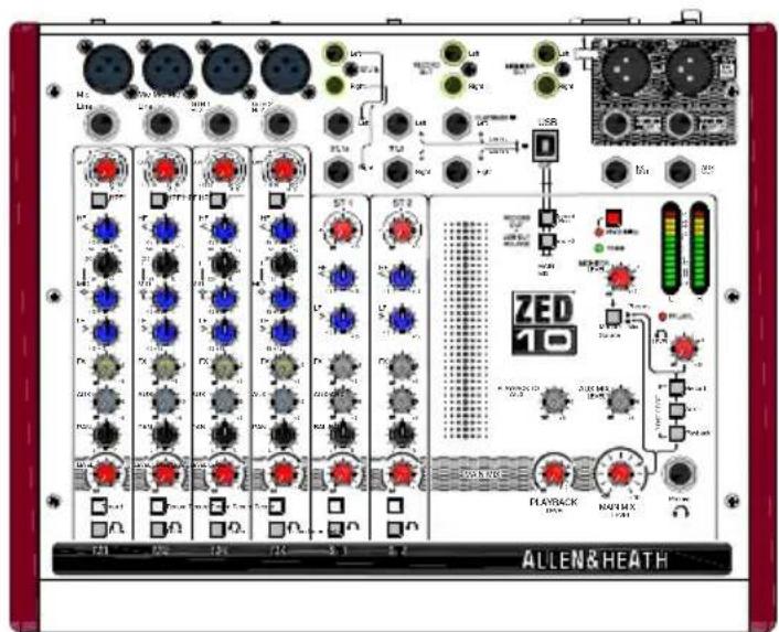
ZED-10 MIXER
natural_image
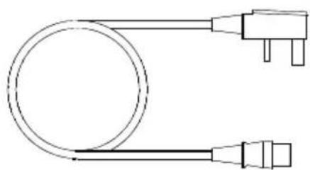
Pure electrical circuit lines without any symbolsMains Lead
Check that the correct mains plug is fitted.
This User Guide!
INTRODUCTION TO THE ZED-10
Background Overview:
The Allen & Heath ZED series mixers have been carefully and lovingly designed in the beautiful county of Cornwall in the UK and are manufactured alongside a wide range of professional audio mixing consoles to the same high standards. Many of the components used in ZED-10 and ZED-10FX are exactly the same as in the larger Allen & Heath products and the construction methods are also very similar — utilising individual vertically mounted channel circuit boards with each rotary control fixed with a metal nut to the front panel. This provides a very robust product that will resist damage and give years of reliable use. It also makes servicing much easier should it be required, with the ability to remove one particular channel from the mixer at a time. The vertical board construction method is unique in a product at this price point and puts the ZED-10 and ZED-10FX in a truly professional class of their own.
The audio circuitry is based on years of continual development and refinement, the performance of all the elements within the mixer is scrutinised and perfected to ensure the very best sound quality possible.
Multi-application:
ZED's are great for live mixing! Their layout makes them very easy to use and easy to achieve a great sound. They are also perfect for recording, either a live show or an audio project at home can be built up track by track using the USB digital audio interface. The flexibility and quality of these mixers make them stand out from the crowd. You can plug your guitars or instruments straight into the class A discrete FET high impedance inputs, cater for up to four microphones, two stereo sources with MP3 player compatibility, separate 2-track record outputs and a stereo playback input for 2-track replay or perhaps interval music from a CD player, XLR main stereo outputs with inserts, comprehensive monitoring with headphones and separate monitor speaker outputs, 48V microphone phantom power, DI level switching for sub mixing, and not least of all, on the ZED-10FX model, the same digital effects algorithms as those used on our flagship digital consoles costing 150 times as much! All this and the ability to withstand life being gigged night after night—there is nothing else like it at this price point.
ZED mixers are also ideal for teaching establishments, houses of worship, hotels and conference centres where their ease of use and robust qualities make them a top choice.
Mic/Line Pre-amps:
Based on the pre-amps from the MixWizard series, the ZED-10 & ZED-10FX pre-amps use low noise discrete transistor circuitry to achieve high gain (60dB max), low noise and good linearity.
GTR/Hi Z Inputs:
Specially designed for ZED-10 and ZED-10FX, two ultra high impedance discrete class A FET (Field Effect Transistor) inputs for plugging any kind of guitar or instrument straight in. A 26dB gain boost switch allows instruments with very low output pickups to be used, and the FET does a great job of approximating the valve/tube input circuitry commonly found on instrument combos or amplifiers.
INTRODUCTION TO THE ZED-10
EQ:
The ZED-10 and ZED-10FX mixers are equipped with a 3-band equaliser circuit on each mono input, with swept mid frequency section, and a 2-band EQ on the stereo channels. The frequency and response of each has been carefully chosen to give the maximum performance when using the EQ on a variety of sources.
Record Bus:
A separately switched stereo bus can be routed to from any channel creating a selective recording bus, monitoring bus or stereo clean feed output. You can even route just the effects processor output to this bus and use the mixer as a high end effects unit.
USB:
Getting audio to and from a computer easily is now a common requirement for live sound and music production. The way we have implemented this on ZED is super-flexible and super-easy! No longer do you need to fiddle around the back of your computer to get to the soundcard inputs, only to find that the levels are all wrong and noisy. Just plug in a USB lead to your ZED, select the USB routing on the mixer and the device on your computer and that's it! CD quality audio to and from your PC or MAC.
Internal power supply:
Not a “wall wart” - a proper built in power supply specifically designed and based on totally reliable technology.
SPECIFICATIONS
| Operating Levels | |
| Input | |
| Mono channel (XLR) Input -10 to -60dBu for nominal (+11dBu in max) | |
| Mono channel Line Input (Jack socket) +10 to -40dBu (+31dBu maximum) | |
| Stereo Input (Jack or phono sockets) 0dBu nominal (control = Off to +15dB) | |
| Output | |
| L/R Outputs ( XLR) Normal/DI out 0dBu/-30dBu +21dBu/-9dBu maximum. | |
| Aux & FX Outputs (Jack sockets) 0dBu nominal. +21dBu maximum. | |
| Record & Monitor Outputs (phono sockets) 0dBu nominal. +21dBu maximum. | |
| Frequency Response | |
| Mic in to Mix L/R Out, 30dB gain +0.5/-1dB 10Hz to 30kHz. | |
| Line in to Mix L/R out 0dB gain +0.5/-1dB 10Hz to 25kHz | |
| Stereo in to Mix L/R out +0.5/-1dB 10Hz to 30kHz | |
| THD+n | |
| Mic in to Mix L/R Out, 10dB gain 1kHz +10dBu out 0.002% | |
| Mic in to Mix L/R Out, 30dB gain 1kHz 0.01% | |
| Line in to Mix L/R out 0dB gain 0dBu 1kHz 0.003% | |
| Stereo in to Mix L/R out 0dB gain +10dBu 1kHz 0.002% | |
| Gtr Input to Mix L/R Out, 0dBu, Boost OUT | 0.015% |
| Gtr Input to Mix L/R Out, 0dBu, Boost IN | 2% Second Harmonic |
| Headroom | |
| Analogue Headroom from nominal (0Vu) | 21dB |
| USB in & out headroom from nominal (0Vu) | 14dB |
| Noise | |
| Mic Pre EIN @ max gain 150R input Z 22-22kHz | -127dBu |
| Mix L/R out, L/R faders = 0, Levels min, 22-22kHz | -96dBu |
| Mix L/R out, L/R faders = 0, Levels min, 22-22kHz | -96dBu |
| USB Audio CODEC (Coder/Decoder) | |
| USB Audio In/Out | USB 1.1 compliant 16bit. |
| Sample Rate | 32, 44.1, or 48kHz |
DIMENSIONS
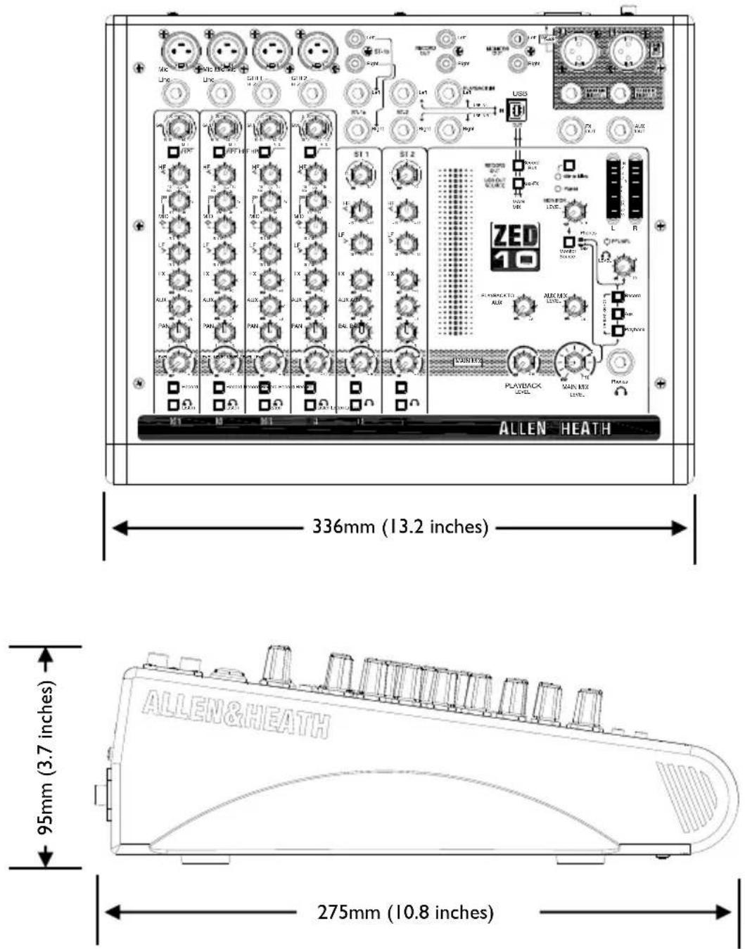
| Weight | |
| ZED-10 | |
| Unpacked 3.2kg (7 lb) | |
| Packed 4.4kg (9.7 lb) | |
BLOCK DIAGRAM SCHEMATIC
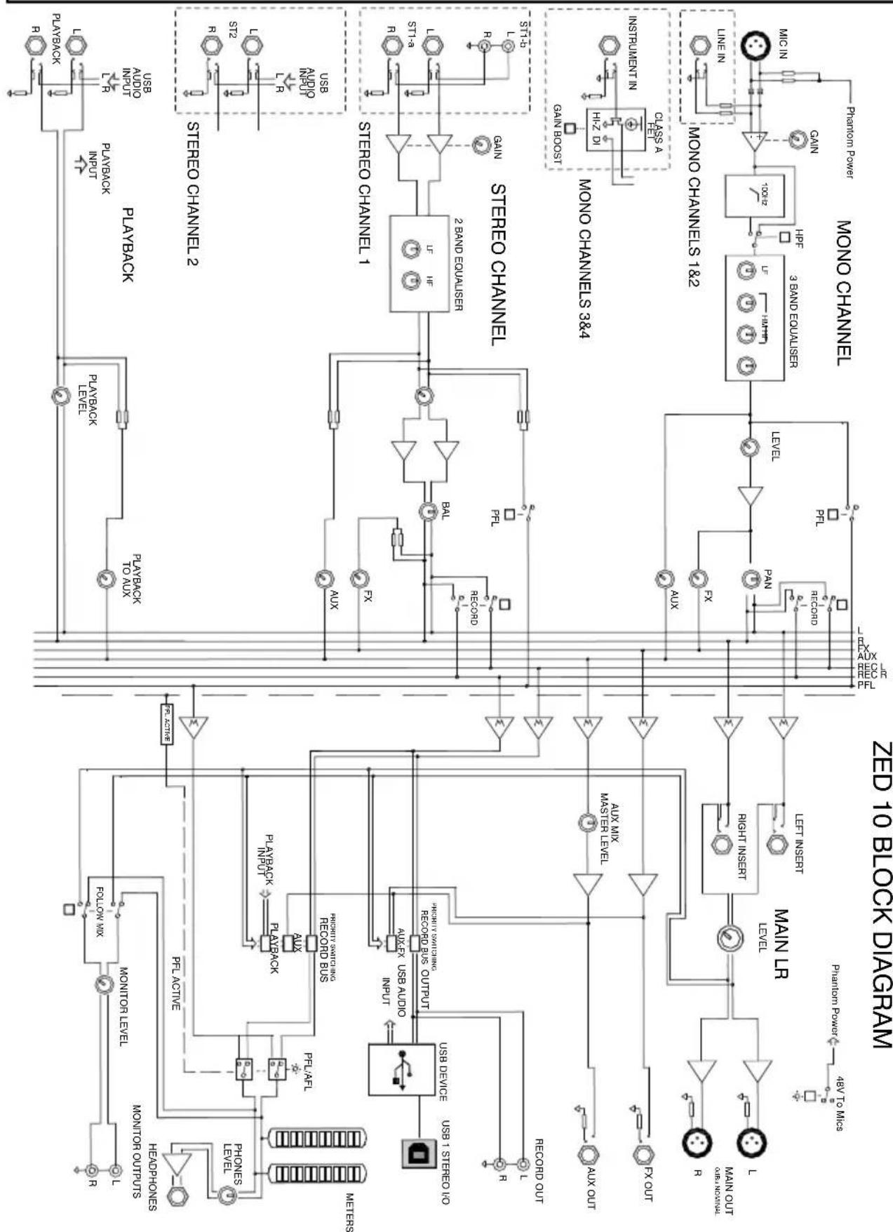
flowchart
graph TD
    subgraph Stereo Channel
        A["STREO CHANNEL 1"] --> B["2.0 2.0 2.0 2.0 2.0 2.0 2.0 2.0 2.0 2.0 2.0 2.0 2.0 2.0 2.0 2.0 2.0 2.0 2.0 2.0 2.0 2.0 2.0 2.0 2.0 2.0"]
        B --> C["PLBACK"]
        B --> D["PLBACK"]
        B --> E["PLAYBACK"]
        B --> F["PLAYBACK"]
        B --> G["PLAYBACK"]
    end

    subgraph Control Modules
        H["MINI"] --> I["MINI"]
        J["MINI"] --> K["MINI"]
        L["MINI"] --> M["MINI"]
        N["MINI"] --> O["MINI"]
        P["MINI"] --> Q["MINI"]
        R["MINI"] --> S["MINI"]
        T["MINI"] --> U["MINI"]
        V["MINI"] --> W["MINI"]
        X["MINI"] --> Y["MINI"]
        Z["MINI"] --> AA["MINI"]
        AB["MINI"] --> AC["MINI"]
        AD["MINI"] --> AE["MINI"]
        AF["MINI"] --> AG["MINI"]
        AH["MINI"] --> AI["MINI"]
        AJ["MINI"] --> AK["MINI"]
        AL["MINI"] --> AM["MINI"]
        AN["MINI"] --> AO["MINI"]
        AP["MINI"] --> AQ["MINI"]
        AR["MINI"] --> AS["MINI"]
        AT["MINI"] --> AU["MINI"]
        AV["MINI"] --> AW["MINI"]
        AX["MINI"] --> AY["MINI"]
        AZ["MINI"] --> BA["MINI"]
        BB["MINI"] --> BC["MINI"]
        BD["MINI"] --> BE["MINI"]
        BF["MINI"] --> BG["MINI"]
        BH["MINI"] --> BI["MINI"]
        BJ["MINI"] --> BK["MINI"]
        BL["MINI"] --> BM["MINI"]
        BN["MINI"] --> BO["MINI"]
        BP["MINI"] --> BQ["MINI"]
        BR["MINI"] --> BS["MINI"]
        BT["MINI"] --> BU["MINI"]
        BV["MINI"] --> BW["MINI"]
        BX["MINI"] --> BY["MINI"]
        BZ["MINI"] --> CA["MINI"]
        CB["MINI"] --> CD["MINI"]
        CE["MINI"] --> CF["MINI"]
        CG["MINI"] --> CH["MINI"]
        CI["MINI"] --> CJ["MINI"]
        CK["MINI"] --> CL["MINI"]
        CM["MINI"] --> CN["MINI"]
        CO["MINI"] --> CP["MINI"]
        CEA["MINI"] --> CEB
    end

    subgraph Control Components
        D1["MIN IIN"] --> E1["LIME IN"]
        D2["LIME IN"] --> E2["LIME IN"]
        D3["LIME IN"] --> E3["LIME IN"]
        D4["LIME IN"] --> E4["LIME IN"]
        D5["LIME IN"] --> E5["LIME IN"]
        D6["LIME IN"] --> E6["LIME IN"]
        D7["LIME IN"] --> E7["LIME IN"]
        D8["LIME IN"] --> E8["LIME IN"]
        D9["LIME IN"] --> E9["LIME IN"]
        D10["LIME IN"] --> E10["LIME IN"]
    end

    %% Note: The diagram shows a schematic of the system with labels such as 'MONO CHANNEL' and 'MINI' indicating block diagrams and logic gates.
Allen & Heath
ZED-10 User Guide
MONO INPUT CHANNEL I & 2
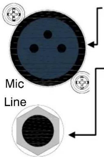
Mic Input Socket
Standard 3-Pin XLR socket wired as Pin 1=Chassis, Pin 2=hot (+), Pin 3=Cold (-).
Line Input Jack Socket
Standard 1/4" (6.25mm) Jack socket for balanced or unbalanced line level signals. Wired Tip=Hot(+), Ring=cold (-), Sleeve=Chassis.
The Line input connects to the XLR input through a circuit, so be aware that the two signals will add together if both inputs are plugged in simultaneously.
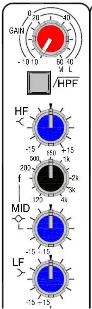
Gain Control
This adjusts the gain of the input amplifier to match the signal level of the source. The gain is varied from +10dB to +60dB for signals plugged in to the xlr socket (Mic Input) and -10dB to +40dB for signals plugged into the Line input jack.
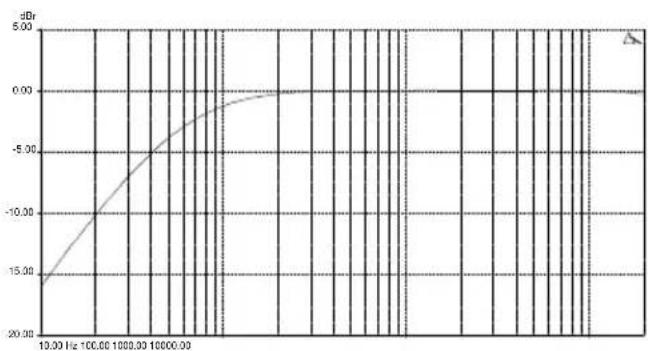
100Hz Hi-pass Filter
The Hi-pass filter is used for reducing pop noise and rumble from microphone signals. It is a single pole (6dB per octave) filter with a corner frequency set at 100Hz.
The filter affects signals from both Mic XLR and Line jack socket.
line
| Frequency (Hz) | Value (dB) | | -------------- | ---------- | | 10.00 | -15.00 | | 100.00 | -10.00 | | 1000.00 | -5.00 | | 10000.00 | 0.00 |MONO INPUT CHANNEL I & 2

Allen & Heath

HF EQ
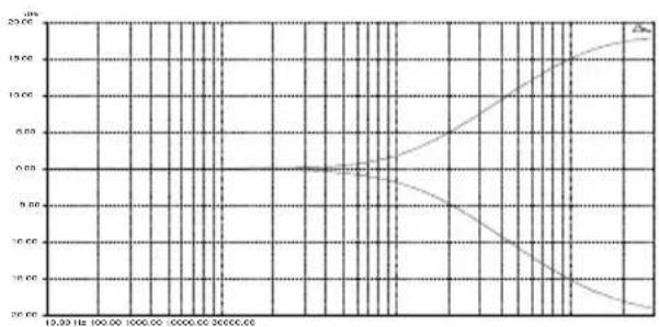
The HF (High Frequency) equaliser affects the frequency response of the higher audible frequencies. The corner frequency of 12kHz is around 3dB from the maximum cut or boost of the circuit. It has plenty of gain and actually gives slightly more that the +/-15dB legend suggests.
line
| Time (hours) | Δx | | ------------ | ------ | | 0 | 0.00 | | 10 | 0.00 | | 20 | 0.00 | | 30 | 0.00 | | 40 | 0.00 | | 50 | 0.00 | | 60 | 0.00 | | 70 | 0.00 | | 80 | 0.00 | | 90 | 0.00 | | 100 | 0.00 | | 110 | 0.00 | | 120 | 0.00 | | 130 | 0.00 | | 140 | 0.00 | | 150 | 0.00 | | 160 | 0.00 | | 170 | 0.00 | | 180 | 0.00 | | 190 | 0.00 | | 200 | 0.00 | | 210 | 0.00 | | 220 | 0.00 | | 230 | 0.00 | | 240 | 0.00 | | 250 | 0.00 | | 260 | 0.00 | | 270 | 0.00 | | 280 | 0.00 | | 290 | 0.00 | | 300 | 0.00 | | 310 | 0.00 | | 320 | 0.00 | | 330 | 0.00 | | 340 | 0.00 | | 350 | 0.00 | | 360 | 0.00 | | 370 | 0.00 | | 380 | 0.00 | | 390 | 0.00 | | 400 | 0.00 | | 410 | 0.00 | | 420 | 0.00 | | 430 | 0.00 | | 440 | 0.00 | | 450 | 0.00 | | 460 | 0.00 | | 470 | 0.00 | | 480 | 0.00 | | 490 | 0.00 | | 500 | 0.00 | | 510 | 5.5 | | 520 | 12.5 | | 530 | 25.5 | | 540 | 45.5 | | 550 | 65.5 | | 560 | 85.5 | | 570 | 115.5 | | 580 | 145.5 | | 590 | 175.5 | | 600 | 215.5 | | 610 | 255.5 | | 620 | 315.5 | | 630 | 385.5 | | 640 | 475.5 | | 650 | 585.5 | | 660 | 715.5 | | 670 | 865.5 | | 680 | 1125.5 | | 690 | 1425.5 | | 700 | 1825.5 | | 710 | 2225.5 | | 720 | 2725.5 | | 730 | 3325.5 | | 740 | 4125.5 | | 750 | 4925.5 | | 760 | 5825.5 | | 770 | 6825.5 | | 780 | 7925.5 | | 790 | 9125.5 | | 800 | 1142.5 | | Note: The data is already in CSV format, so no changes are needed for this example.
MF EQ
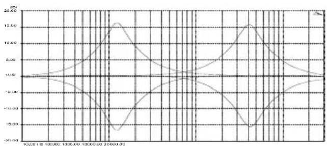
The MF (Mid Frequency) equaliser affects the middle of the audible frequency range. The frequency graduations on the sweep control are the centre frequencies of the EQ. The range has been carefully chosen to cover “boomy” frequencies around 120Hz to 250Hz which may need cutting back, or a lift at 2 to 3kHz may be required for microphone intelligibility.
line
| Time | Value | | -------- | ------ | | 10.00 | -4.00 | | 12.00 | -6.00 | | 14.00 | -8.00 | | 16.00 | -10.00 | | 18.00 | -12.00 | | 20.00 | -14.00 | | 22.00 | -16.00 | | 24.00 | -18.00 | | 26.00 | -20.00 | | 28.00 | -18.00 | | 30.00 | -16.00 | | 32.00 | -14.00 | | 34.00 | -12.00 | | 36.00 | -10.00 | | 38.00 | -8.00 | | 40.00 | -6.00 | | 42.00 | -4.00 | | 44.00 | -2.00 | | 46.00 | 0.00 | | 48.00 | 2.00 | | 50.00 | 4.00 | | 52.00 | 6.00 | | 54.00 | 8.00 | | 56.00 | 10.00 | | 58.00 | 12.00 | | 60.00 | 14.00 | | 62.00 | 16.00 | | 64.00 | 18.00 | | 66.00 | 20.00 | | 68.00 | 18.00 | | 70.00 | 16.00 | | 72.00 | 14.00 | | 74.00 | 12.00 | | 76.00 | 10.00 | | 78.00 | 8.00 | | 80.00 | 6.00 | | 82.00 | 4.00 | | 84.00 | 2.00 | | 86.00 | 0.00 | | 88.00 | -2.0 | | 90.00 | -4.0 | | 92.00 | -6.0 | | 94.00 | -8.0 | | 96.00 | -10.0 | | 98.00 | -12.0 | | 100.00 | -14.0 | | 12.25 | -16.55 | | 14.37 | -15.55 | | 16.57 | -13.75 | | 18.77 | -11.37 | | 21.97 | -9.25 | | 24.17 | -7.25 | | 26.37 | -5.375 | | 28.57 | -3.75 | | 31.77 | -2.375 | | 34.97 | -1.375 | | 37.17 | -1 | | 39.37 | -2 | | 41.57 | -4 | | 43.77 | -6 | | 45.97 | -8 | | 48.17 | -1 | | 51.37 | -2 | | 53.57 | -4 | | 55.77 | -6 | | 57.97 | -8 | | 61.25 | -1 | | 63.37 | -2 | | 65.57 | -4 | | 67.77 | -6 | | 71.25 | -8 | | 73.37 | -1 | | 75.57 | -2 | | 77.77 | -4 | | 81.25 | -6 | | 83.37 | -8 | | 85.57 | -1 | | 87.77 | -2 | | 91.25 | -4 | | 93.37 | -6 | | 95.57 | -8 | | 97.77 | -1 | | 12 | -4 | | The chart displays a line plot of a physical quantity over time (X-axis: Time in minutes, Y-axis: Amplitude). The data is plotted as a line graph with two distinct series labeled 'Value' and 'Type'. The values are annotated on the graph lines.LF EQ
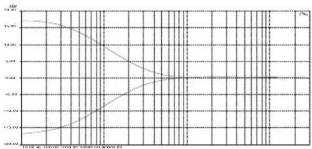
The LF (Low Frequency) equaliser affects the response at the low end of the audio range. The graph shows the response of the LF EQ at maximum cut and boost. The corner frequency is 80Hz.
line
| Time Point | Value | | ---------- | ------ | | 1st | 15.00 | | 2nd | 14.50 | | 3rd | 13.50 | | 4th | 12.50 | | 5th | 11.50 | | 6th | 10.50 | | 7th | 9.50 | | 8th | 8.50 | | 9th | 7.50 | | 10th | 6.50 | | 11th | 5.50 | | 12th | 4.50 | | 13th | 3.50 | | 14th | 2.50 | | 15th | 1.50 | | 16th | 0.50 | | 17th | -0.50 | | 18th | -1.50 | | 19th | -2.50 | | 20th | -3.50 | | 21st | -4.50 | | 22nd | -5.50 | | 23rd | -6.50 | | 24th | -7.50 | | 25th | -8.50 | | 26th | -9.50 | | 27th | -10.50 | | 28th | -11.50 | | 29th | -12.50 | | 30th | -13.50 | | 31st | -14.50 | | 32nd | -15.50 | | 33rd | -16.50 | | 34th | -17.50 | | 35th | -18.50 | | 36th | -19.50 | | 37th | -20.50 | | 38th | -21.50 | | 39th | -22.50 | | 40th | -23.50 | | 41st | -24.50 | | 42nd | -25.50 | | 43rd | -26.50 | | 44th | -27.50 | | 45th | -28.50 | | 46th | -29.50 | | 47th | -30.50 | | 48th | -31.50 | | 49th | -32.50 | | 50th | -33.50 | | 51st | -34.50 | | 52nd | -35.50 | | 53rd | -36.50 | | 54th | -37.50 | | 55th | -38.50 | | 56th | -39.50 | | 57th | -40.50 | | 58th | -41.50 | | 59th | -42.50 | | 60th | -43.50 | | 61st | -44.50 | | 62nd | -45.50 | | 63rd | -46.50 | | 64th | -47.50 | | 65th | -48.50 | | 66th | -49.50 | | 67th | -50.50 | | 68th | -51.50 | | 69th | -52.50 | | 70th | -53.50 | | 71st | -54.50 | | 72nd | -55.50 | | 73rd | -56.50 | | 74th | -57.50 | | 75th | -58.50 | | 76th | -59.50 | | 77th | -60.50 | | 78th | -61.50 | | 79th | -62.50 | | 80th | -63.50 | | 81st | -64.50 | | 82nd | -65.50 | | 83rd | -66.50 | | 84th | -67.50 | | 85th | -68.50 | | 86th | -69.50 | | 87th | -70.50 | | 88th | -71.50 | | 89th | -72.50 | | 90th | -73.50 | | 91st | -74.50 | | 92nd | -75.50 | | 93rd | -76.50 | | 94th | -77.50 | | 95th | -78.50 | | 96th | -79.50 | | 97th | -80.50 | | 98th | -81.50 | | 99th | -82.50 | | 100th | -83.50 |ZED-10 User Guide
MONO INPUT CHANNEL I & 2

FX send
This controls the level of signal that is sent to the effects bus and FX output from the channel. The signal is post-level which means it is affected by the channel Level control (so it stays in proportion to the signal going to Mix) and the send control has 6dB gain fully clockwise. There is no master level control for the FX bus.
AUX send
Controls the level of signal sent to the Auxiliary output from the channel. The signal is sourced pre-Level so is independent of the level being sent to the main L-R Mix. The send control has +6dB gain fully clockwise and unlike the FX bus, there is a master level control for the Aux output.
PAN
The pan control adjusts how the signal from the mono input channel is shared between the left and right stereo buses and subsequently the main stereo outputs. Set to the mid position, equal amounts of signal are fed to left and right, with pan set to L, none is sent to the Right bus.
LEVEL
The rotary Level or fader controls the amount of signal to the left & right buses, Record bus and to the FX send control. There is 10dB of gain fully clockwise and the unity gain position is marked by "0".
Record
Switches the channel signal to a separate stereo bus called Record. The Pan and Level controls affect the Record signal and the channel Mix L-R signal remains unaffected by this switch.
Listen
Switches the channel signal to the headphones or monitor output circuit for checking the channel signal. Takes the signal after the EQ but before the Level control (so you can check the signal before adding it to Mix or Record)
MONO INPUT CHANNEL 3 & 4
Hi Z input
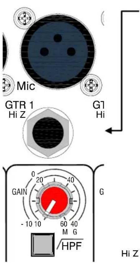
The only difference between mono inputs 1-2 and 3-4 is the Hi Z inputs for guitars or other instruments.
Standard 1/4" (6.25mm) Jack socket for unbalanced line level signals or instrument pickups. Wired Tip=Hot(+), Ring=cold (-), Sleeve=Chassis.
The Hi Z input connects to the XLR input through a circuit, so be aware that the two signals will add together if both inputs are plugged in simultaneously.
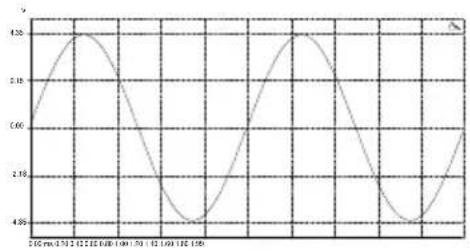
The Hi Z input can be used with normal line level signals but is designed specifically to match signals from instrument pickups. The input impedance is extremely high (10Mohms) and a FET (Field Effect Transistor) running in Class A mode emulates the type of circuits used in valve guitar combos or head amplifiers. The input circuit has soft asymmetric overdrive characteristics, giving a warm 2nd harmonic character to the sound if required.
Hi Z Input GAIN BOOST OUT
Hi Z Input GAIN BOOST IN
line
| Time (minutes) | Value | | -------------- | ----- | | 0 | 4.80 | | 1 | 4.75 | | 2 | 4.70 | | 3 | 4.65 | | 4 | 4.60 | | 5 | 4.55 | | 6 | 4.50 | | 7 | 4.55 | | 8 | 4.60 | | 9 | 4.65 | | 10 | 4.70 | | 11 | 4.75 | | 12 | 4.80 | | 13 | 4.75 | | 14 | 4.70 | | 15 | 4.65 | | 16 | 4.60 | | 17 | 4.55 | | 18 | 4.50 | | 19 | 4.55 | | 20 | 4.60 | | 21 | 4.65 | | 22 | 4.70 | | 23 | 4.75 | | 24 | 4.80 | | 25 | 4.75 | | 26 | 4.70 | | 27 | 4.65 | | 28 | 4.60 | | 29 | 4.55 | | 30 | 4.50 | | 31 | 4.55 | | 32 | 4.60 | | 33 | 4.65 | | 34 | 4.70 | | 35 | 4.75 | | 36 | 4.80 | | 37 | 4.75 | | 38 | 4.70 | | 39 | 4.65 | | 40 | 4.60 | | 41 | 4.55 | | 42 | 4.50 | | 43 | 4.55 | | 44 | 4.60 | | 45 | 4.65 | | 46 | 4.70 | | 47 | 4.75 | | 48 | 4.80 | | 49 | 4.75 | | 50 | 4.70 | | Note: The actual values may vary due to the random nature of the data generation. The provided values are just an example.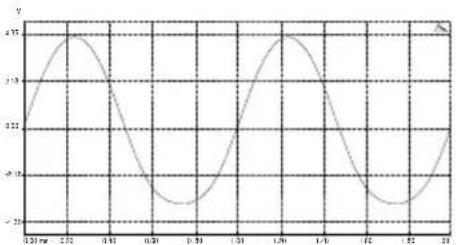
line
| Time (ms) | Value | | --------- | ----- | | 0.31 | -25 | | 0.41 | +25 | | 0.51 | -25 | | 0.61 | +25 | | 0.71 | -25 | | 0.81 | +25 | | 0.91 | -25 | | 1.01 | +25 | | 1.11 | -25 | | 1.21 | +25 | | 1.31 | -25 | | 1.41 | +25 | | 1.51 | -25 | | 1.61 | +25 | | 1.71 | -25 | | 1.81 | +25 | | 1.91 | -25 | | 2.01 | +25 | | 2.11 | -25 |Gain Boost
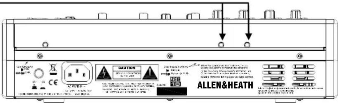
A recessed switch on the rear panel allows the HI Z input to be boosted by 26dB, useful for instruments with weak pickups or where more overdrive is required. When the XLR is being used or for normal line level signals (like keyboards)—make sure the switch is in the OUT position.
STEREO INPUT CHANNEL I
flowchart
graph TD
    A["Left"] --> B["ST-1b"]
    B --> C["Right"]
    C --> D["Left"]
    D --> E["ST-1a"]
    E --> F["Right"]
    G["ST 1"] --> H["0"]
    H --> I["-15"]
    I --> J["∞"]
    J --> K["+15"]
    K --> L["5"]
    M["HF"] --> N["-15"]
    N --> O["+15"]
    P["LF"] --> Q["-15"]
    Q --> R["+15"]
ST-Ib Inputs
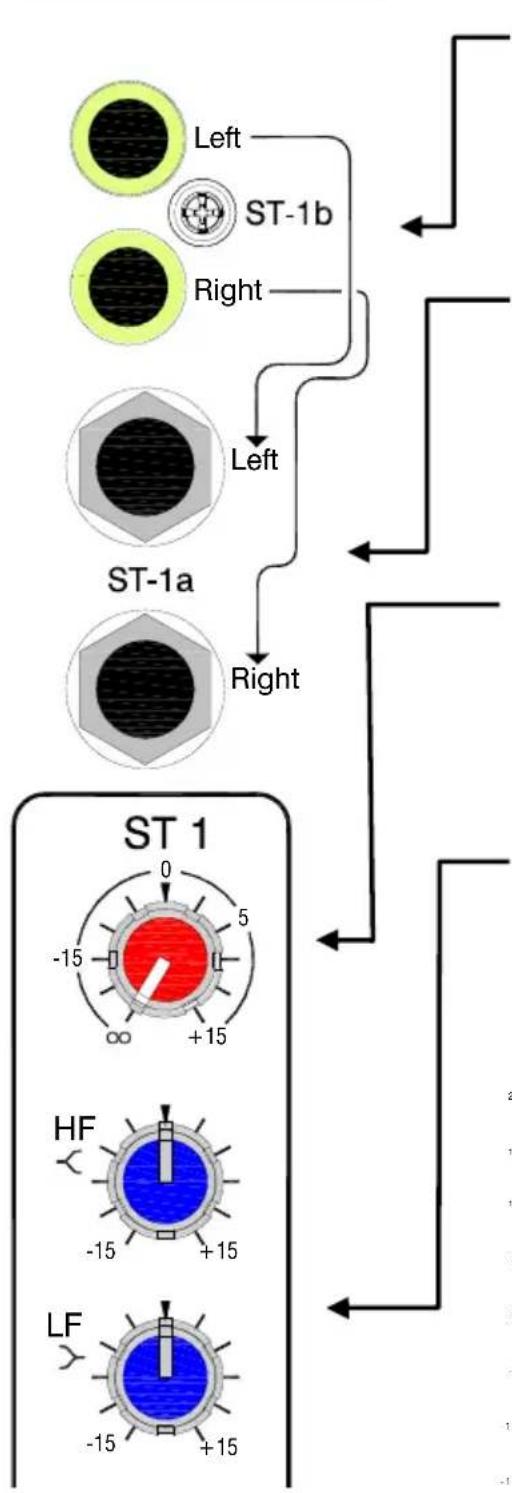
Standard RCA Phono sockets for unbalanced line level stereo signal sources from equipment such as CD players, sound modules or MP3 players. If your MP3 player has a mini jack socket (most common) use a stereo mini jack plug to 2 x RCA Phono lead.
ST-Ia Inputs
Standard 1/4" jack sockets for line level stereo signals. The STIb inputs (RCA Phono) are connected through the break contacts of these jack sockets so plugging into STIa will override the signals from STIb.
ST-I Gain
Adjusts the input level to the STI channel from off (maximum attenuation) to +15dB gain. For low level inputs from MP3 players, turn it fully clockwise.
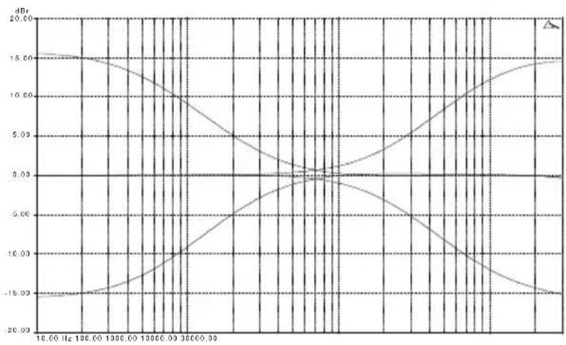
Stereo EQ
High frequency and low frequency equaliser with corner frequencies of 12kHz for the HF and 80Hz for the LF and maximum cut & boost of 15dB.
line
| Frequency (Hz) | Amplitude (dB) | | -------------- | -------------- | | 10.00 | 15.00 | | 130.00 | 14.50 | | 160.00 | 13.50 | | 190.00 | 12.00 | | 220.00 | 10.50 | | 250.00 | 9.00 | | 280.00 | 7.50 | | 310.00 | 6.00 | | 340.00 | 4.50 | | 370.00 | 3.00 | | 400.00 | 1.50 | | 430.00 | 0.50 | | 460.00 | -1.50 | | 490.00 | -3.50 | | 520.00 | -5.50 | | 550.00 | -7.50 | | 580.00 | -9.50 | | 610.00 | -11.50 | | 640.00 | -13.50 | | 670.00 | -15.50 | | 700.00 | -17.50 | | 730.00 | -19.50 | | 760.00 | -21.50 | | 790.00 | -23.50 | | 820.00 | -25.50 | | 850.00 | -27.50 | | 880.00 | -29.50 | | 910.00 | -31.50 | | 940.00 | -33.50 | | 970.00 | -35.50 | | 1000.00 | -37.50 | | 1346.72 | -39.50 | | 1696.72 | -41.50 | | 1996.72 | -43.50 | | 2346.72 | -45.50 | | 2696.72 | -47.50 | | 3146.72 | -49.50 | | 3496.72 | -51.50 | | 3846.72 | -53.50 | | 4216.72 | -55.50 | | 4576.72 | -57.50 | | 4946.72 | -59.50 | | 5316.72 | -61.50 | | 5686.72 | -63.50 | | 6 | -65 |Stereo channel EQ
STEREO INPUT CHANNEL I

FX send
This controls the level of signal that is sent to the effects bus and FX output from the stereo channel. The signal is post-level which means it is affected by the channel Level control (so it stays in proportion to the signal going to Mix) and the send control has 6dB gain fully clockwise. There is no master level control for the FX bus.
AUX send
Controls the level of signal sent to the Auxiliary output from the stereo channel. The signal is sourced pre-Level so is independent of the level being sent to the main L-R Mix. The send control has +6dB gain fully clockwise and unlike the FX bus, there is a master level control for the Aux output.
Balance
The balance control adjusts the relative level between the left and right stereo signals as they are sent to the stereo buses and subsequently the main stereo outputs. Set to the mid position, equal amounts of signal are fed to left and right, with Bal set to L, none is sent to the Right bus.
LEVEL
The rotary Level or fader controls the amount of signal to the left & right buses, Record bus and to the FX send control. There is 10dB of gain fully clockwise and the unity gain position is marked by "0".
Record
Switches the channel signal to a separate stereo bus called Record. The Bal and Level controls affect the Record signal and the channel Mix L-R signal remains unaffected by this switch.
Listen
Switches the channel signal to the headphones or monitor output circuit for checking the channel signal. Takes the signal after the EQ but before the Level control (so you can check the signal before adding it to Mix or Record)
STEREO INPUT CHANNEL 2
ST-2 Input
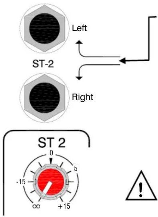
The USB audio input is connected through the break contacts of the standard 1/4" (6.25mm) jack sockets. Plugging into the jacks will override the USB input, so if you want to use the ST-2 channel for the USB input signal, make sure nothing is plugged into the jack sockets.
The rest of the features of the ST-2 channel are as described for ST-1
Important Note:
If the ST-2 channel is not being used for USB play-back or stereo input it is best to keep the level controls turned down so that unwanted noise from the inactive USB device is not passed to the mix.
flowchart
graph TD
    A["RECORD OUT"] --> B["Left"]
    A --> C["Right"]
    D["PLAYBACK IN Left"] --> E["USB IN L"]
    D --> F["USB IN R"]
    G["RECORD OUT + USB OUT SOURCE"] --> H["Record Bus"]
    H --> I["Aux-FX"]
    I --> J["L R MAIN MIX"]
    J --> K["OUT"]
    K --> L["USB"]
    L --> M["←"]
    M --> N["←"]
    N --> O["←"]
    O --> P["←"]
    P --> Q["←"]
    Q --> R["←"]
    R --> S["←"]
    S --> T["←"]
    T --> U["←"]
    U --> V["←"]
    V --> W["←"]
    W --> X["←"]
    X --> Y["←"]
    Y --> Z["←"]
    Z --> AA["←"]
    AA --> AB["←"]
    AB --> AC["←"]
    AC --> AD["←"]
    AD --> AE["←"]
    AE --> AF["←"]
    AF --> AG["←"]
    AG --> AH["←"]
    AH --> AI["←"]
    AI --> AJ["←"]
    AJ --> AK["←"]
    AK --> AL["←"]
    AL --> AM["←"]
    AM --> AN["←"]
    AN --> AO["←"]
    AO --> AP["←"]
    AP --> AQ["←"]
    AQ --> AR["←"]
    AR --> AS["←"]
    AS --> AT["←"]
    AT --> AU["←"]
    AU --> AV["←"]
    AV --> AW["←"]
    AW --> AX["←"]
    AX --> AY["←"]
    AY --> AZ["←"]
    AZ --> BA["←"]
    BA --> BB["←"]
    BB --> BC["←"]
    BC --> BD["←"]
    BD --> BE["←"]
    BE --> BF["←"]
    BF --> BG["←"]
    BG --> BH["←"]
    BH --> BI["←"]
    BI --> BJ["←"]
    BJ --> BK["←"]
    BK --> BL["←"]
    BL --> BM["←"]
    BM --> BN["←"]
    BN --> BO["←"]
    BO --> BP["←"]
    BP --> BQ["←"]
    BQ --> BR["←"]
    BR --> BS["←"]
    BS --> BT["←"]
    BT --> BU["←"]
    BU --> BV["←"]
    BV --> BW["←"]
    BW --> BX["←"]
    BX --> BY["←"]
    BY --> BZ["←"]
Record OUT
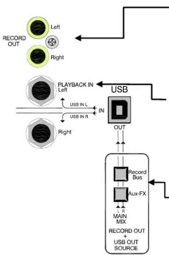
Standard RCA phono sockets for the stereo line level Record outputs sourced from the USB out selector switches. Useful for connecting to stereo recording devices, stereo mix feeds, or where selective channels are required to feed other equipment.
Playback Input
Standard 1/4" (6.25mm) jack sockets for unbalanced line level inputs. Can be used for additional stereo sources such as CD players for background music, or playing back a final mix from a recording device. The USB audio input is connected through the break contacts of these inputs, plugging into the jack sockets overrides the USB input.
USB OUT Source selector switches
Select the signal source for the USB audio output and the Record output. With both switches up the main Mix is selected. The Record Bus switch will override the Aux-FX switch if both are pressed.
MASTER SECTION
Main Mix Out XLR connectors
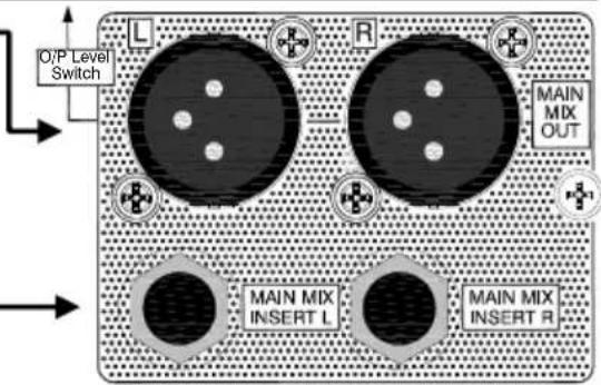
Standard XLR output connectors for the main stereo mix. Impedance balanced to aid interference rejection. A recessed switch on the rear panel reduces the level by 30dB if it is required to submix these outputs into the XLR inputs of another mixer.
Main Mix Insert jack sockets
Standard 1/4" (6.25mm) jack sockets wired:
Tip = send, Ring = return, Sleeve = Chassis. Nominal level is 0dBu.
Effects & Aux bus Outputs
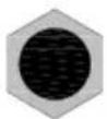
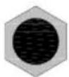
Standard 1/4" (6.25mm) jack sockets wired:
Tip = hot, Ring = cold, Sleeve = Chassis. Nominal level is 0dBu.
The FX out is the Effects bus output, and can be used for connecting to external equipment such as an effects processor.
The AUX out is taken from after the AUX MIX master level control.
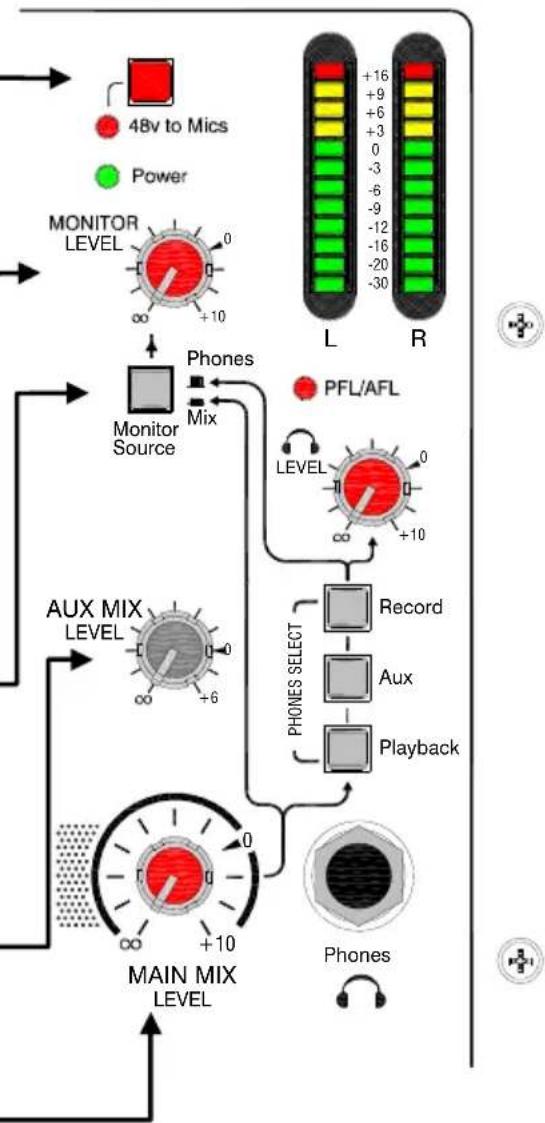
48v to Microphones
Switches industry standard 48v (phantom power) to all 4 microphone inputs for use with condenser microphones.
Monitor Level
Controls the volume of the stereo monitor outputs from off (fully attenuated) to +10dB of gain.
Monitor Source switch
This allows the stereo monitor outputs (RCA phonos) to be sourced either from the headphone monitor selection, or from the main stereo mix. Useful for splitting the functions of the stereo monitor outputs from the headphones.
Aux Mix Level control
The master volume control for the Aux mix bus. Adjusts the level from off (fully attenuated) to +6dB gain.
Main Mix Level
This is the master volume control for the main stereo mix. Range is from off (fully attenuated) to +10dB of gain.
FX OUT
AUX OUT
flowchart
graph TD
    A["48V to Mics"] --> B["MONITOR LEVEL"]
    C["Power"] --> B
    B --> D["MONITOR Source"]
    D --> E["AUX MIX LEVEL"]
    E --> F["MAIN MIX LEVEL"]
    F --> G["MONITOR L/R"]
    G --> H["PFL/AFL LEVEL"]
    H --> I["Record"]
    I --> J["Aux"]
    J --> K["Playback"]
    K --> L["Phones"]
    L --> M["+10"]
    M --> N["+6"]
    N --> O["+10"]
    O --> P["Phones SELECT"]
    P --> Q["MONITOR Schematic"]
    style A fill:#f9f,stroke:#333
    style C fill:#f9f,stroke:#333
    style B fill:#ccf,stroke:#333
    style D fill:#cfc,stroke:#333
    style F fill:#fcc,stroke:#333
    style G fill:#cff,stroke:#333
    style H fill:#ffc,stroke:#333
    style I fill:#ffc,stroke:#333
    style J fill:#ffc,stroke:#333
    style K fill:#ffc,stroke:#333
    style L fill:#cfc,stroke:#333
    style M fill:#cfc,stroke:#333
MASTER SECTION
flowchart
graph TD
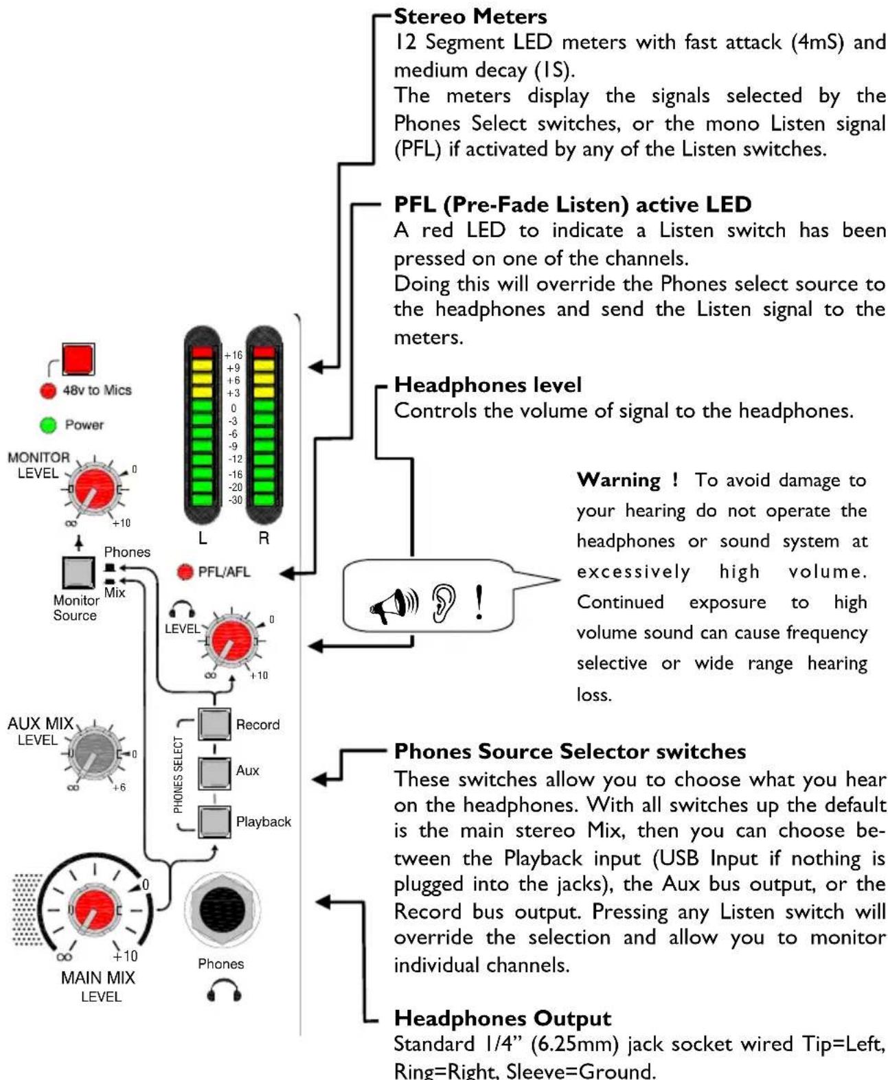
    A["Stereo Meters"] --> B["12 Segment LED meters with fast attack (4mS) and medium decay (1S)."]
    B --> C["The meters display the signals selected by the Phones Select switches, or the mono Listen signal (PFL) if activated by any of the Listen switches."]
    C --> D["PFL (Pre-Fade Listen) active LED"]
    D --> E["A red LED to indicate a Listen switch has been pressed on one of the channels."]
    E --> F["Doing this will override the Phones select source to the headphones and send the Listen signal to the meters."]
    F --> G["Headphones level"]
    G --> H["Controls the volume of signal to the headphones."]
    H --> I["Warning! To avoid damage to your hearing do not operate the headphones or sound system at excessively high volume. Continued exposure to high volume sound can cause frequency selective or wide range hearing loss."]
    I --> J["Phone Source Selector switches"]
    J --> K["These switches allow you to choose what you hear on the headphones. With all switches up the default is the main stereo Mix, then you can choose between the Playback input (USB Input if nothing is plugged into the jacks), the Aux bus output, or the Record bus output. Pressing any Listen switch will override the selection and allow you to monitor individual channels."]
    K --> L["Headphones Output"]
    L --> M["Standard 1/4" (6.25mm) jack socket wired Tip=Left, Ring=Right, Sleeve=Ground."]
CONNECTING TO A COMPUTER
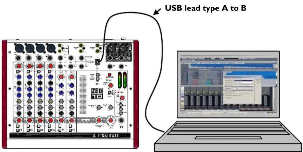
USB Audio Interface
The ZED is equipped with a stereo bi-directional USB 1.1 compliant audio CODEC. It is fully compliant with USB 2 ports and uses standard Windows and MAC Core Audio Drivers. In other words, plug it in and your computer will find it and be able to transfer audio to and from the ZED USB device.
You will need some form of audio software running on your computer to be able to store and play back what you record, but on a basic level, you can use your computers media player to play straight to the ZED device.
Important Note:
If there seems to be no audio transfer between the computer and your ZED, or the level is very low, please check the volume level setting of the Audio Device in your computers' operating system. This may need to be set to the Max position.
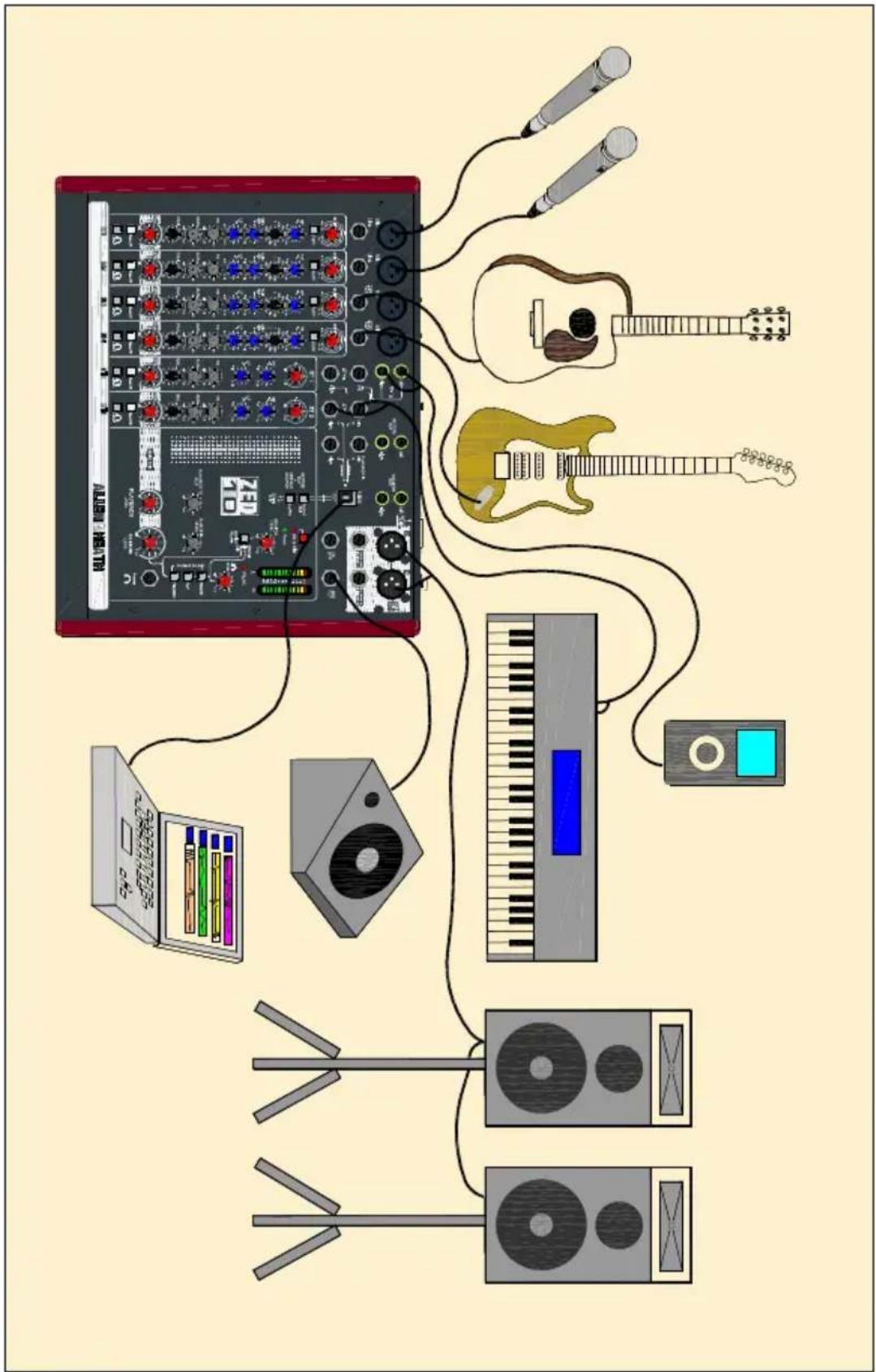
APPLICATION DRAWING—LIVE MIXING
APPLICATION DRAWING—USING USB FOR EFFECTS LOOP-I
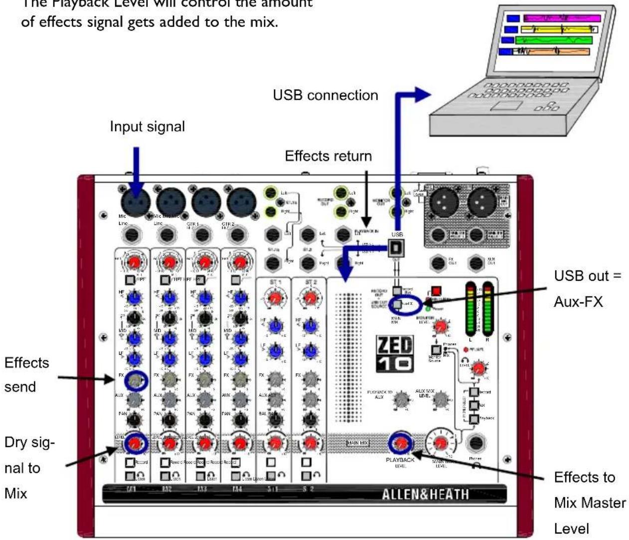
A simple way to use effects processor plugins running on a computer audio application or DAW is to use the USB audio connection and select the Aux-FX as the output source. In the audio application route the FX signal (USB Right) to a track or bus containing the effects plugin and route the track/bus output back to the ZED (USB audio device). In the ZED-10 you can return the effects to either the Playback input or the ST2 input, here the Playback input is used.
The effects send on the channel will control the amount of signal to the FX processor (in proportion with the Level control).
The Playback Level will control the amount of effects signal gets added to the mix.
APPLICATION DRAWING—USING USB FOR EFFECTS LOOP-2
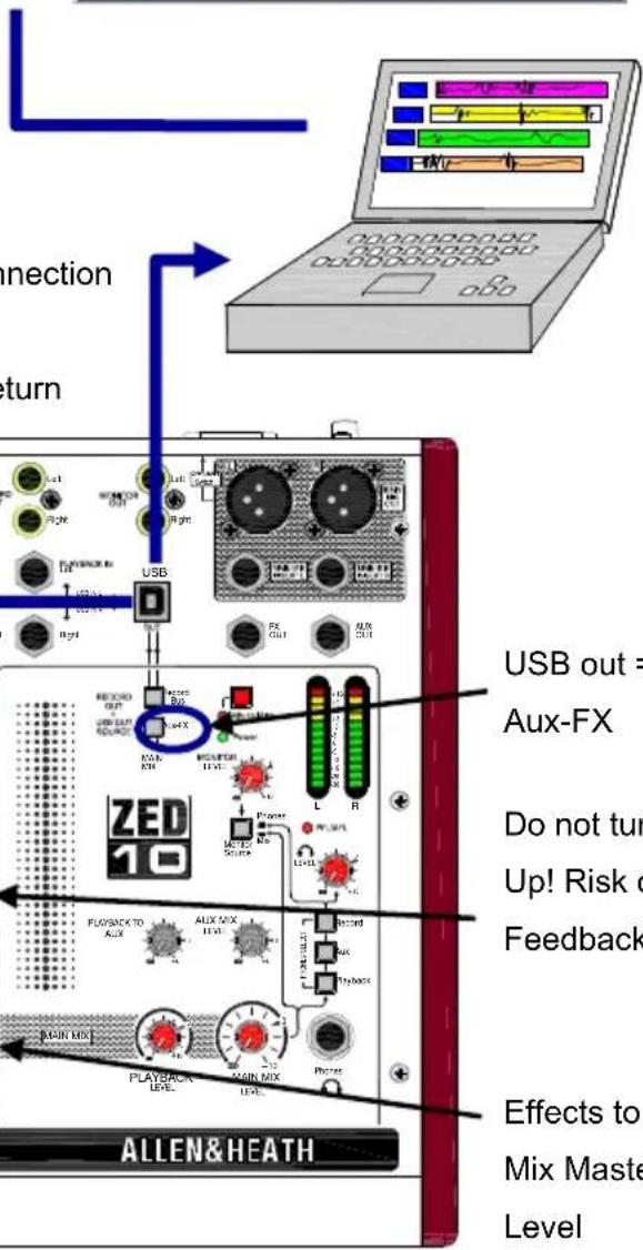
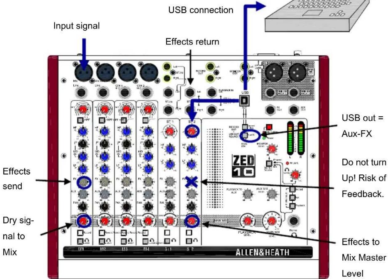
USB FX loop Using ST2 for Effects Return
In the audio software application add the plugin to the track (here it's a reverb) Try to ensure the processor output is effect only (no dry signal).
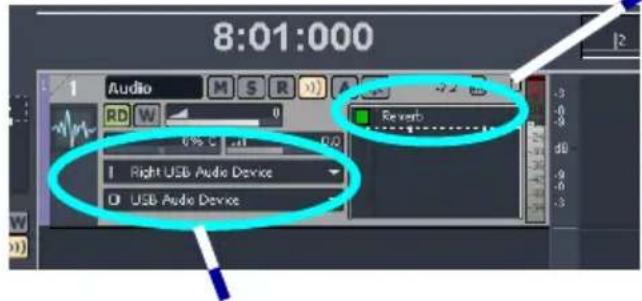
In the audio software create route the right USB channel to an audio track (from FX). Then route the track output to the USB audio device in stereo (back to the ZED).
![Sonitusfx: Reverb [1: Audio] - ZLD-10 Reverb Preset: No Preset Bipact Undo Setup A Reset Presets 7 Input Hute 0.0 dB Low Cut 75 Hz High Cut 4.0 kHz Prestelay 0 ms Room Size 56 Diffusion 87 % Bass Multiplier 1.0 x Crossover 500 Hz Decay Time 1.5 s High Damping 4.0 kHz Dry Hute -Inf dB E.R. Hute -3.5 dB Reverb Hute -12.0 dB Width 100 % Output Stereo Tail Sonitus:reverb calkerywalk](/content/2026/05/882089/images/e675f3c00eb4e6548e3af1fc479079c54e609006c710b39329101f5a072325ce.jpg)
WIRING INFORMATION
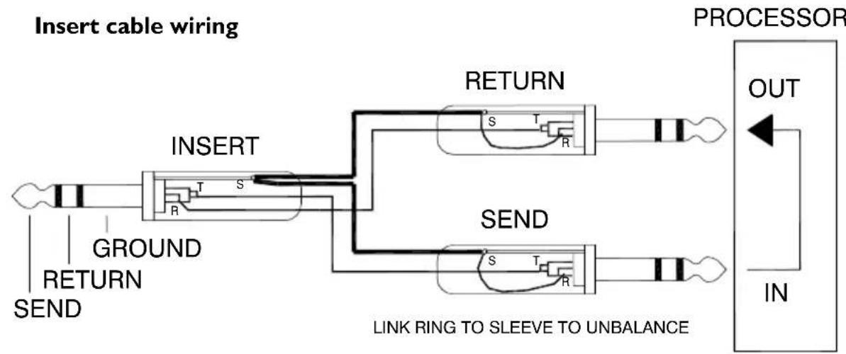
flowchart
graph LR
    A["Insert cable wiring"] --> B["INSERT"]
    B --> C["RETURN"]
    B --> D["SEND"]
    C --> E["PROCESSOR OUT"]
    D --> F["PROCESSOR IN"]
    G["GROUND"] --> B
    H["SEND"] --> D
    I["LINK RING TO SLEEVE TO UNBALANCE"] --> D
General Wiring Information
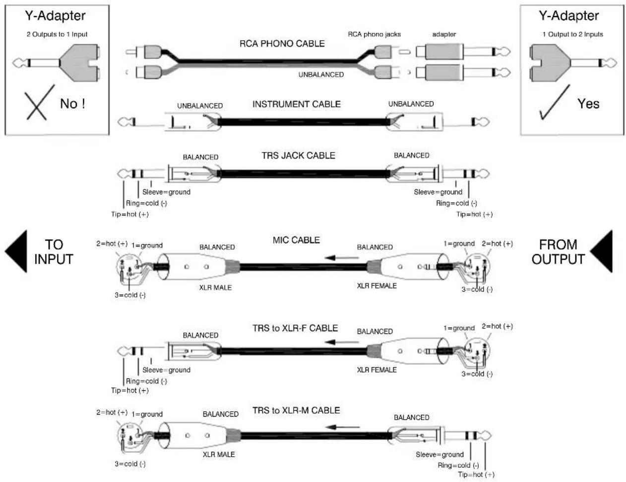
flowchart
graph TD
    A["Y-Adapter"] --> B["2 Outputs to 1 Input"]
    B --> C{No!}
    C --> D["RCA PHONO CABLE"]
    D --> E["UNBALANCED"]
    E --> F["RCA phono jacks"]
    F --> G["adapter"]
    G --> H["UnBALANCED"]
    H --> I["INSTRUMENT CABLE"]
    I --> J["UNBALANCED"]
    J --> K["BALANCED"]
    K --> L["TRS JACK CABLE"]
    L --> M["BALANCED"]
    M --> N["Sleeve=ground"]
    N --> O["Ring=cold (-)"]
    O --> P["Tip=hot (+)"]
    P --> Q["TO INPUT"]
    Q --> R["2=hot (+) 1=ground"]
    R --> S["XLR MALE"]
    S --> T["MIC CABLE"]
    T --> U["BALANCED"]
    U --> V["XLR FEMALE"]
    V --> W["1=ground 2=hot (+)"]
    W --> X["3=cold (-)"]
    X --> Y["BALANCED"]
    Y --> Z["TRS to XLR-F CABLE"]
    Z --> AA["BALANCED"]
    AA --> AB["XLR FEMALE"]
    AB --> AC["1=ground 2=hot (+)"]
    AC --> AD["3=cold (-)"]
    AD --> AE["BALANCED"]
    AE --> AF["2=hot (+) 1=ground"]
    AF --> AG["XLR MALE"]
    AG --> AH["BALANCED"]
    AH --> AI["TRS to XLR-M CABLE"]
    AI --> AJ["BALANCED"]
    AJ --> AK["Sleeve=ground"]
    AK --> AL["Ring=cold (-)"]
    AL --> AM["Tip=hot (+)"]
    AM --> AN["TO OUTPUT"]
natural_image
Three-panel grayscale image showing electronic components and a grid-patterned structure, no visible text or symbols.Large Live Sound mixers — iLive digital, ML and GL Series
Small Format Live Sound mixers — ZED, MixWizards and PA Series
DJ products — Xone Series
Sound Management Series — iDR Series
Registering your product
Thank you for buying the Allen & Heath ZED-10 mixer. We hope that you are happy with it and that you enjoy many years of faithful service with it.
Please go to www.allen-heath.com/register.asp and register your product's serial number and your details. By registering with us and becoming an official Registered User, you will ensure that any warranty claim you might make is actioned quickly and with the minimum delay.
Alternatively, you may either copy or cut off this section of the page, fill in the details, and return it by mail to:
Allen & Heath Ltd, Kernick Industrial Estate, Penryn, Cornwall TR10 9LU, UK
ALLEN&HEATH PRODUCT REGISTRATION
| SERIAL NUMBER |
| Please return this section of the card by mail and retain the other part for your records. You can also register online at www.allen-health.com. Thanks for your help. |
Your Name:
| Company Name: |
| Address 1: |
| Address 2: |
| Town/City: | County/State: |
| Country: | Postcode/Zip: |
| Telephone: |
| Email: |
| Why did you choose this console? |
Which other products did you you consider before choosing A&H?
Is there any thing you would like to improve on this mixer?
What audio magazines do you read?
| If you were going to design a mixer for your work, what are the 6 most important features it should have (in order of importance) | |
| 1 | 2 |
| 3 | 4 |
| 5 | 6 |
| We may use the information you provide to inform you of future product developments. We will not give or sell this data to third parties. Please indicate with an x' if you do not wish to receive any further communications from us. □ |

- CONTENTS
- WARRANTY
- Limited One Year Warranty
- Conditions Of Warranty
- EMC & SAFETY
- SAFETY INSTRUCTIONS
- WARNING: This equipment must be earthed.
- Read instructions:
- Do not remove cover:
- Power sources:
- Power cord routing:
- Grounding:
- Water and moisture:
- Ventilation:
- Heat and vibration:
- Servicing:
- Installation:
- Important Mains plug wiring instructions
- General Precautions:
- PACKED ITEMS
- INTRODUCTION TO THE ZED-10
- Background Overview:
- Multi-application:
- Mic/Line Pre-amps:
- GTR/Hi Z Inputs:
- EQ:
- Record Bus:
- USB:
- Internal power supply:
- SPECIFICATIONS
- DIMENSIONS
- MONO INPUT CHANNEL I & 2
- Mic Input Socket
- Line Input Jack Socket
- Gain Control
- 100Hz Hi-pass Filter
- HF EQ
- MF EQ
- LF EQ
- FX send
- AUX send
- PAN
- LEVEL
- Record
- Listen
- MONO INPUT CHANNEL 3 & 4
- Hi Z input
- Gain Boost
- STEREO INPUT CHANNEL I
- ST-Ib Inputs
- ST-Ia Inputs
- ST-I Gain
- Stereo EQ
- Balance
- STEREO INPUT CHANNEL 2
- ST-2 Input
- Important Note:
- Record OUT
- Playback Input
- USB OUT Source selector switches
- MASTER SECTION
- Main Mix Out XLR connectors
- Main Mix Insert jack sockets
- Effects & Aux bus Outputs
- 48v to Microphones
- Monitor Level
- Monitor Source switch
- Aux Mix Level control
- Main Mix Level
- CONNECTING TO A COMPUTER
- USB Audio Interface
- APPLICATION DRAWING—LIVE MIXING
- APPLICATION DRAWING—USING USB FOR EFFECTS LOOP-I
- APPLICATION DRAWING—USING USB FOR EFFECTS LOOP-2
- USB FX loop Using ST2 for Effects Return
- WIRING INFORMATION
- Registering your product
Brand : ALLEN & HEATH
Model : ZED-10
Category : Audio Mixer