INR-407 - Video recorder ACTi - Free user manual and instructions
Find the device manual for free INR-407 ACTi in PDF.


| Product Type | Network Video Recorder (NVR) |
| Brand | ACTi |
| Model | INR-407 |
| Max Channels | 256 |
| Hard Drive Bays | 8 (3.5-inch SATA, hot-swappable) |
| Form Factor | Rackmount, 2U |
| RAID Support | Hardware RAID (0, 1, 5, 10) via utility |
| Operating System | Windows-based |
| Video Output | HDMI, DVI, DisplayPort |
| Network Interface | Ethernet (RJ-45) |
| Power Supply | 250W (typical, internal) |
| Dimensions (H x W x D) | 3.5 x 19 x 20 inches (approx, 2U rack) |
| Weight | 15 kg (33 lbs) approximate without disks |
| Compatible Cameras | ACTi, ONVIF, and other brands |
| Recording Modes | Continuous schedule and event-based recording |
| Remote Access | Web client (NVR interface) |
| Included Accessories | Rail kit, power cord, universal converter, disk screws, warranty card |
| Certified Hard Drives | ACTi HDD list at www.acti.com/hddselector |
| Cooling | Front-to-back airflow, min 5 cm clearance |
Frequently Asked Questions - INR-407 ACTi
User questions about INR-407 ACTi
0 question about this device. Answer the ones you know or ask your own.
Ask a new question about this device
Download the instructions for your Video recorder in PDF format for free! Find your manual INR-407 - ACTi and take your electronic device back in hand. On this page are published all the documents necessary for the use of your device. INR-407 by ACTi.
USER MANUAL INR-407 ACTi
Quick Installation Guide
INR-406
128-Channel 8-Bay Rackmount Standalone NVR
INR-407
256-Channel 8-Bay Rackmount Standalone NVR
BEFORE YOU START
Thank you for purchasing ACTi Standalone Network Video Recorder. This guide contains all the information you need to quickly set up ACTi INR server system via local interface.
For detailed instructions on installation, operation and how to log in to INR as a web client, please refer to the product manuals provided on ACTi corporate website.
The items below are prerequisite for installation:
• Network cameras
• Network cables
- Network switch
• Monitor (with HDMI, DVI or Display Port cable)
- USB mouse
• At least one ACTi-certified 3.5-inch SATA hard disk
Find the certified disk models at http://www.acti.com/hddselector
HARDWARE INSTALLATION
UNPACK
This package contains:
• INR
- Rail Kit
- Power Cord
• Universal Converter
- Disk Screws Pack - Warranty Card
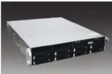
natural_image
Front view of a silver rack-mounted server with multiple drive bays (no visible text or labels)AT A GLANCE
Front Panel
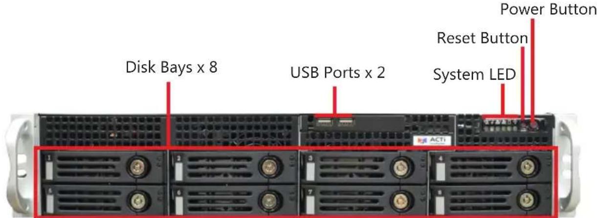
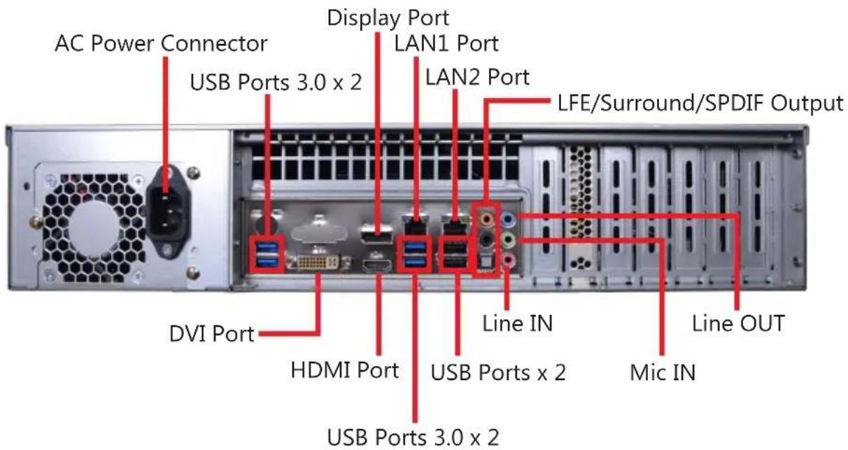
Rear Panel
RACKMOUNT THE UNIT
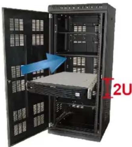
This unit is designed to be mounted on a standard server rack, which occupies 2U (3.5") of vertical space.
-
Allow a minimum of 5 cm clearance at the front and the rear for front-to-back airflow of the unit.
-
Use the bundled rail kit, and install that to support the entire unit.
-
Secure the unit onto the rack.
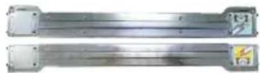
natural_image
Two metallic cylindrical metal components with mounting flanges and mounting holes (no visible text or symbols)INR Sliding Rail Kit
natural_image
Interior view of a server rack with open doors and a blue arrow pointing to a rack unit, labeled 'I2U' in red (no text on cabinet or equipment)HARD DISK INSTALLATION
Make sure this unit is turned off, and insert the hard disks into the disk bays following the sequence of tray numbers.
REMOVE THE TRAY
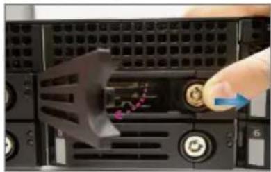
Step 1
Slide the lock tab aside, and the hinge tab will pop out by itself.
natural_image
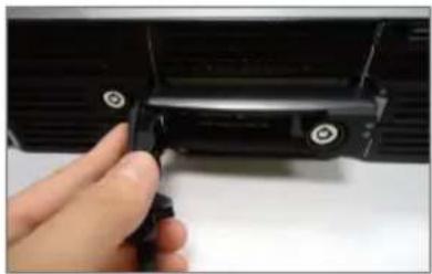
Close-up of a computer tower with a hand interacting with the screen, showing a stock chart overlay (no readable text or symbols)Step 2
Hold the tab lever and pull out the tray.
natural_image
Close-up of a hand holding a black plastic clip with screws, against a white background (no text or symbols visible)INSTALL THE TRAY
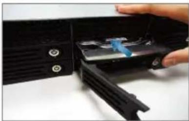
Step 4
Place your thumb on the lock to push the tray into position in the chassis.
natural_image
Close-up of a hand inserting a black plastic device into a black plastic housing (no text or symbols visible)Step 5
Press the hinge tab until it clicks into place.
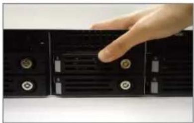
natural_image
Hand pointing at a black rack-mounted drive with multiple ports and buttons (no visible text or symbols)MOUNT THE DISK
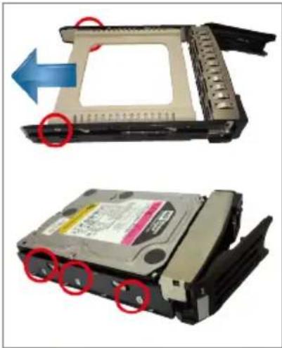
Step 3
Loosen the two screws on the tray to remove the dummy disk. Secure the hard disk on the tray with the provided disk screws. Make sure the disk connector faces towards the SATA contacts inside the unit.
natural_image
Two views of a hard disk drive showing internal components and mounting holes, with arrows indicating motion direction (no text or symbols present)CONNECT THE DEVICES
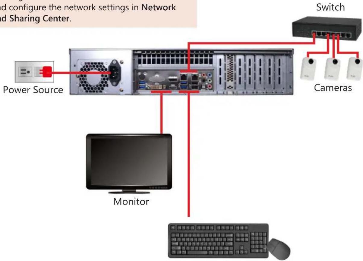
The example below displays a network consisting of only INR, network cameras and required peripherals. Please remember to enable the DHCP service on your router for INR to obtain an IP address automatically.
Note
To assign a static IP address to INR, enter Windows and configure the network settings in Network and Sharing Center.
USB Devices
START-UP
- On the front panel, press the Power Button to turn on the unit.
- On the Windows login screen, follow the on-screen instructions to setup your login password. This will be used in succeeding Windows login. It is strongly recommended not to leave the password blank.
CREATE HARDWARE RAID (OPTIONAL)
As this unit supports hardware RAID configuration, you can make disk arrays using the bundled software utility.
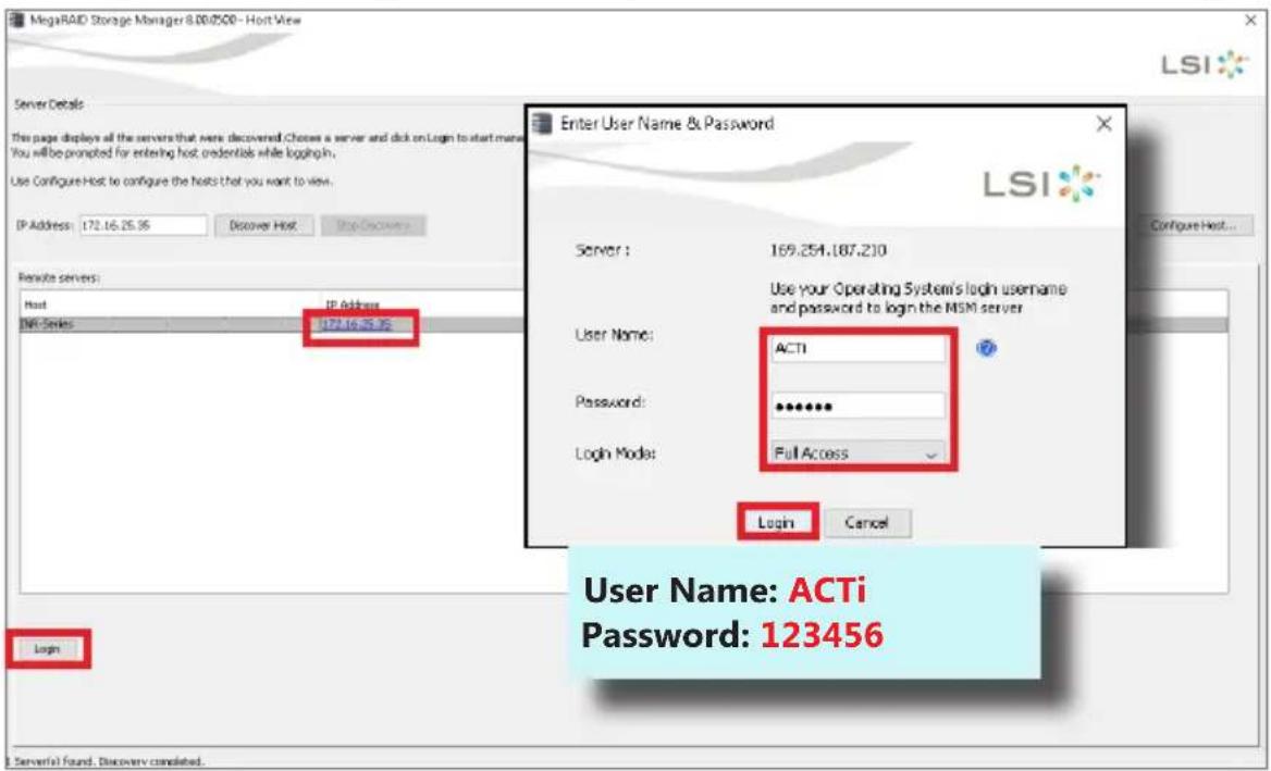
- On Windows Desktop, double-click on the shortcut to initialize the RAID management utility.
- On Remote servers list, select the IP address of this server and click on "Login". On the login window, input the credentials and click "Login".
- On the Dashboard page, click on "Create virtual drive".
![MegaRAID Storage Manager - 800/500 Manage Go To Log Tools Help Dashboard Physical Logical Controller: AVAGO MegaRAID SAG 9361-0 (Bus 1, Dev 0) Properties Status: Optimal Excluses: 0 Backplanes: 1 Drives: 1 Drive groups: 0 Virtual Drive(s): 0 View server profile Usage Total Capacity: $95.656 GB Configured Capacity: 8 Bytes Unconfigured Capacity: $95.656 GB Background Operations Virtual drive operations in progress: 0 Drive operations in progress: 0 More details Premium Features MegaRAID PathPath Enabled MegaRAID RAD6 Enabled MegaRAID RAD5 Enabled Increase Premium Features Actions Create virtual drive Create CacheCodeTM Load configuration Update Formers Service plan Help How to use MDAI How to create virtual drive? How to enable premium features? Glwarey ID Error Level Date / Time Description 640 [Information, 0] 2020-07-27, 15:38:06 Successful log on to the server User: ACTL Client: 172.16.25.35 Access Mode: Pull Client Time: 2020-07-27,15:38:06 639 [Information, 0] 2020-07-27, 15:25:06 Controller ID: 0 Time-established since power on Time 2020-07-27,15:25:19 82 Seconds 638 [Information, 0] 2020-07-27, 15:24:12 Controller ID: 0 Time-established since power on Time 2020-07-27,15:25:19 28 Seconds 637 [Warning, 1] Secondhand from reboot Controller ID: 0 BBU disabled changing with logical drives to WT 636 [Information, 0] Secondhand from reboot Controller ID: 0 Device inserted Device Type: Disk Device Id: →←→↓](/content/2026/05/881809/images/e6e5cb112776d627aa8433ea4e326a1eb7311a34ed9de245c3c85b484c730d08.jpg)
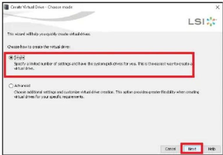
- Choose "Simple" mode and then click on "Next".
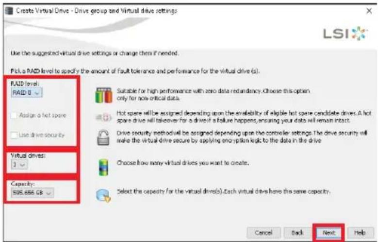
- Select the RAID level, number of Virtual drives (arrays) and the Capacity of the array, and then click on "Next".
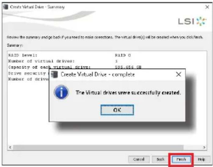
- On confirmation window, click on "Finish".
SOFTWARE CONFIGURATION
CREATE DISK VOLUMES
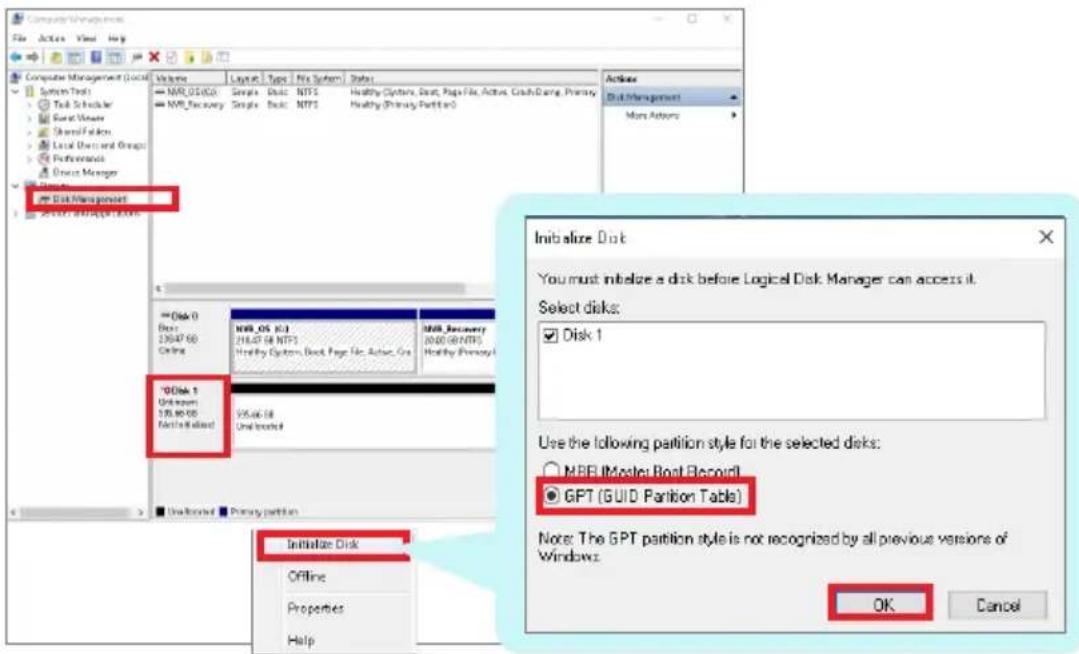
Use Windows Disk Management to create disk volumes so that INR can access the available storage space.
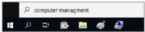
- On Windows Search Box, search and enter "computer management".
- Select "Disk Management", right-click on a disk title and select "Initialize Disk", choose "GPT" as the partition style and click on "OK".
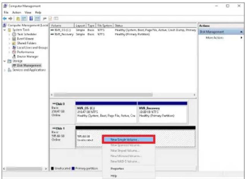
- Right-click on the initialized disk and select the volume type to make a new volume.
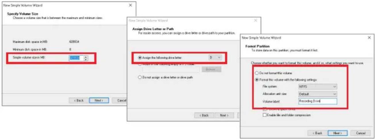
- Follow the on-screen Wizard to complete. Make sure you assign the desired drive letter and give a proper label name to this volume.
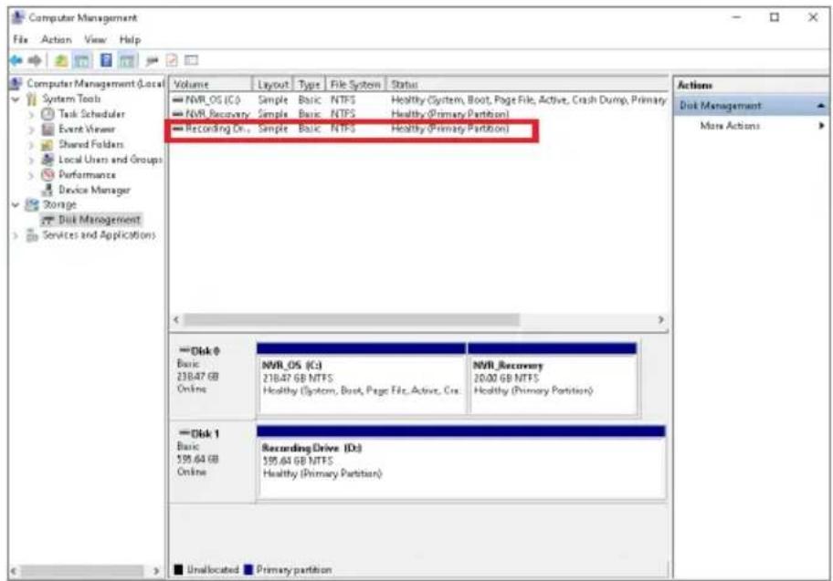
- After the volume is created, it is shown on Volume List and is ready for recording.
Note
To make a Striped volume, a Mirrored volume or a RAID-5 volume, it is recommended that you select disks of the same model and capacity.
Note
For detailed instructions on choosing the RAID types and troubleshooting hard disk issues, please refer to System Administrator's manual provided on ACTi Download Center at http://www.acti.com/downloadcenter
SET ADMIN PASSWORD
For first-time use, make sure to setup the administrator password.
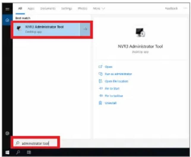
- On Windows Search Box, search and enter "administrator tool".
- Click NVR3 Administrator Tool to open the application.
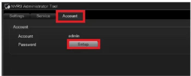
- On the tool interface, go to the Account page, then click the Password Setup button.
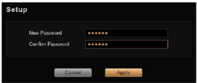
- Type the preferred password, and then click Apply.
LOG IN
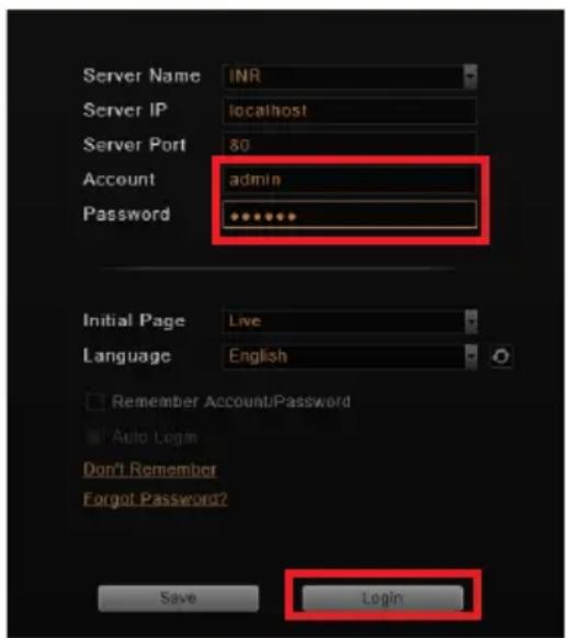
On Windows Destop, double-click on to enter NVR interface.

Type the Account and Password, and click Login.
CREATE USERS
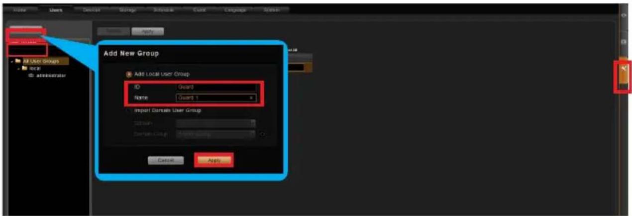
On NVR screen, click Setup button to enter Setup page and then Users tab.
-
Select "User Groups", click "Add" to start adding a new user group.
-
Input group ID, Name, and click "Apply".
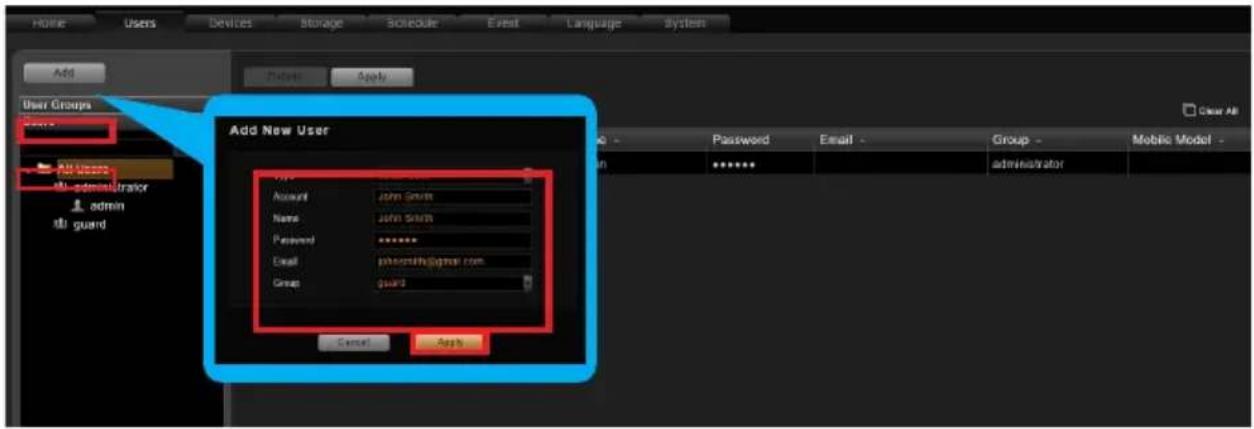
- Click on the Users panel, click "Add" to start adding a new user.
- Input the user's Account, Password, Email address and select its User Group, and then click "Apply".
SELECT STORAGE DRIVES
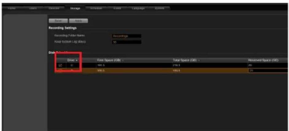
- Go to Setup page and then Storage tab.
- On Disk Drive List, de-select C Drive, and select other storage drives.
- Click "Apply".
ADD CAMERAS
- Go to Setup page and then Devices tab.
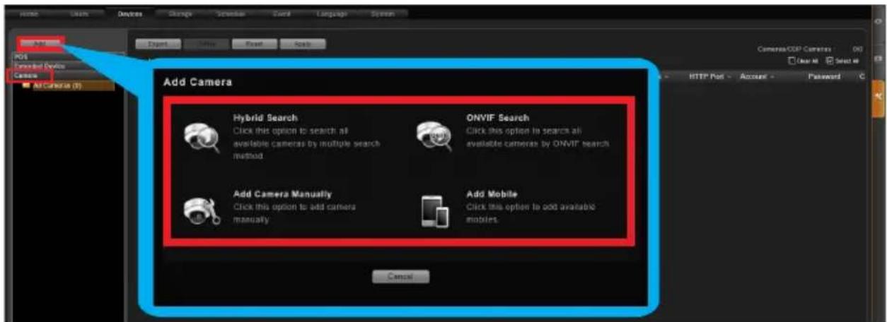
- Select the Camera panel, and then Click "Add".
- Choose a search method based on your network environment and camera brand.
Search Cameras
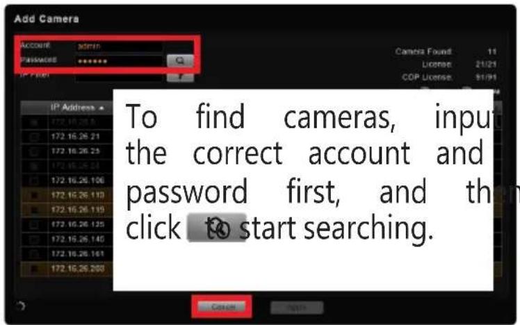
Use "Hybrid Search" to automatically search the network for all cameras, or click "ONVIF Search" for ONVIF-compliant cameras of any brand.
After selecting your desired cameras, click "Apply".
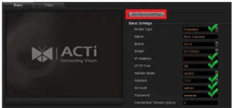
Add Camera Manually
If you are adding a camera located in another network, use "Add Camera Manually". Fill in Media Type, Protocol, IP Address, HTTP Port, Account and
Password. Finally, click "Get Device Settings" and then "Apply".
Add Mobile
Use "Add Mobile" to search for mobile device cameras in the network. Select the device and click "Accept".
CONFIGURE CAMERA SETTINGS
-
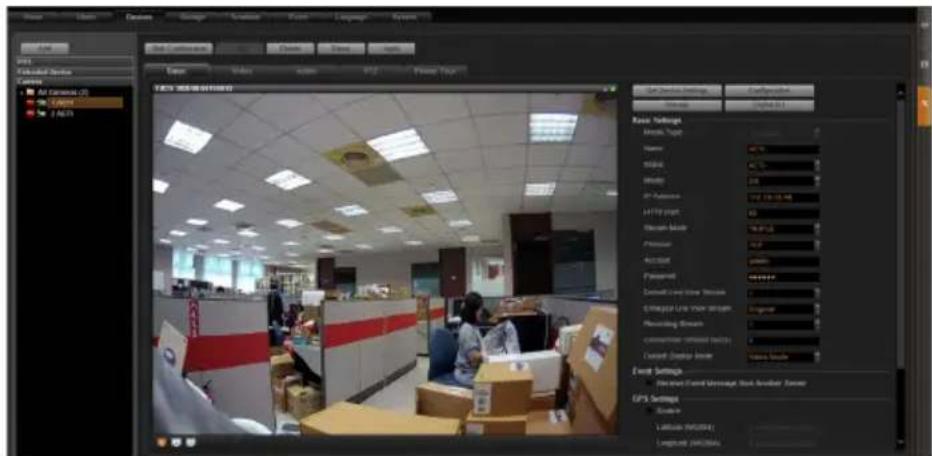
Go to Setup page and then Devices tab. Choose the camera from the Camera List.
-
Select Basic, Video, Audio, PTZ, or Preset Tour tab to configure related settings.
-
Click "Apply" to save the settings.
Note
Availability of page tabs depend on camera capabilities.
SET RECORDING SCHEDULE
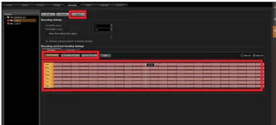
The recording service automatically starts full-time recording for a newly added camera. You can modify the recording schedule to suit your needs.
-
Go to Setup page and then Schedule tab. Select the camera from Camera List.
-
Choose a recording mode: or Schedule Recording Event Recording
Schedule Recording: Records video continuously during the scheduled session.
Event Recording: Records video based on specific triggers such as when a motion is detected by the camera.
-
Drag on the time table to define the time session.
-
Click "Apply".
Note
If you have any question during system installation, please feel free to contact our engineers via ACTi Customer Help Desk platform at http://www.acti.com/CHD
CUSTOMIZE VIEWS
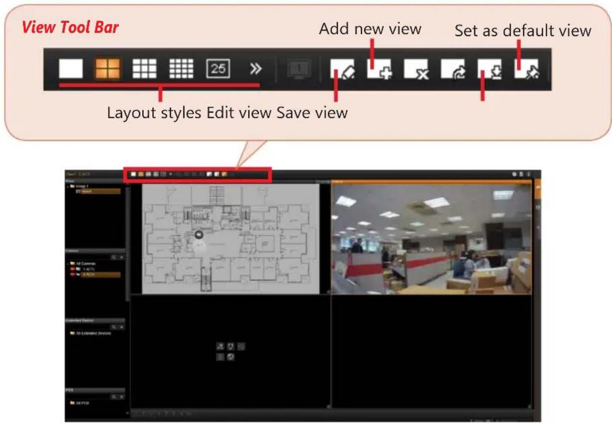
- Go to Live View page. On top of the screen, click on ☐ on the View Tool Bar to create a new layout, then click on ☐ to enter edit mode.
- Select a layout style.
- To add a camera view, pull a camera from Camera List to a channel. To add a map view, mouse over a channel and click on upload the map. Drag the lower right corner to adjust the channel size.
- On the View Tool Bar, click on to save this view.
- You can set this view as default view by clicking on .
VALIDATION

To check live streaming of all channels, go to Live View page, double-click on 📄 camera List.

To check recording, go to Playback page, and then select (double-click) a view from View List or a camera from Camera List. Drag on the time bar to see the recorded video.
Due to continuous product improvements, some contents may have changed from the time this documentation was printed. You can download the latest user documentation, which shall prevail over the printed version provided in the package, from http://www.acti.com/downloadcenter.
- Quick Installation Guide
- BEFORE YOU START
- HARDWARE INSTALLATION
- UNPACK
- AT A GLANCE
- RACKMOUNT THE UNIT
- HARD DISK INSTALLATION
- REMOVE THE TRAY
- Step 1
- Step 2
- INSTALL THE TRAY
- Step 4
- Step 5
- MOUNT THE DISK
- Step 3
- CONNECT THE DEVICES
- Note
- START-UP
- CREATE HARDWARE RAID (OPTIONAL)
- SOFTWARE CONFIGURATION
- CREATE DISK VOLUMES
- SET ADMIN PASSWORD
- LOG IN
- CREATE USERS
- SELECT STORAGE DRIVES
- ADD CAMERAS
- Search Cameras
- Add Camera Manually
- Add Mobile
- CONFIGURE CAMERA SETTINGS
- SET RECORDING SCHEDULE
- CUSTOMIZE VIEWS
- VALIDATION
Brand : ACTi
Model : INR-407
Category : Video recorder