
KTV24XV - Range hood BERTAZZONI - Free user manual and instructions
Find the device manual for free KTV24XV BERTAZZONI in PDF.


| Brand | Bertazzoni |
| Model | KTV24XV |
| Product Type | Slide-out range hood |
| Width | 60 cm (23 9/16") |
| Depth | 26 cm (10 1/4") |
| Height (overall) | 7.6 cm (3") |
| Exhaust Diameter | 15 cm (6") |
| Electrical Supply | 120 V ~ 60 Hz, 15 A |
| Total Power | Not specified |
| Lighting Type | LED (integrated GU10 bulb) |
| Number of Speeds | 3 (low, medium, high) |
| Automatic Operation | Yes, with sliding panel |
| Minimum Distance from Cooking Surface | 61 cm (24") |
| Maximum Recommended Distance | 76 cm (30") |
| Grease Filter Type | Dishwasher-safe metal |
| Grease Filter Cleaning Frequency | Every 2 months |
| Charcoal Filter Type | Active, non-washable, replaceable |
| Charcoal Filter Replacement Frequency | Every 4 months |
| Exhaust Configuration | Vertical or recirculation (with charcoal filters) |
| Recommended Duct Type | Rigid metal, 6" diameter |
| Maximum Duct Length | 10.7 m (35 ft) with straight duct |
| Housing Material | Stainless steel |
| Warranty | Consult Bertazzoni website |
Frequently Asked Questions - KTV24XV BERTAZZONI
User questions about KTV24XV BERTAZZONI
0 question about this device. Answer the ones you know or ask your own.
Ask a new question about this device
Download the instructions for your Range hood in PDF format for free! Find your manual KTV24XV - BERTAZZONI and take your electronic device back in hand. On this page are published all the documents necessary for the use of your device. KTV24XV by BERTAZZONI.
USER MANUAL KTV24XV BERTAZZONI
natural_image
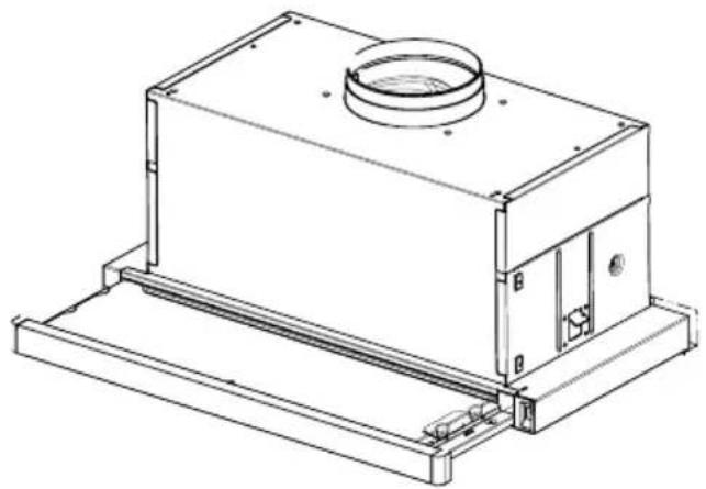
Technical line drawing of a mechanical housing or enclosure with mounting base and circular top component (no text or symbols)Installation Instructions Use and Care Information
READ AND SAVE THESE INSTRUCTIONS BEFORE YOU START INSTALLING THIS RANGEHOOD
WARNING: - TO REDUCE THE RISK OF A RANGE TOP GREASE FIRE:
a) Never leave surface units unattended at high settings. Boilovers cause smoking and greasy spillovers that may ignite. Heat oils slowly on low or medium setting.
b) Always turn hood ON when cooking at high heat or when flambeing food (i.e. Crepes Suzette, Cherries Jubilee, Peppercorn Beef Flambé).
c) Clean ventilating fans frequently. Grease should not be allowed to accumulate on fan or filter.
d) Use proper pan size. Always use cookware appropriate for the size of the surface element.
WARNING: - TO REDUCE THE RISK OF INJURY TO PERSONS IN THE EVENT OF A RANGE TOP GREASE FIRE, OBSERVE THE FOLLOWING*:
a) SMOTHER FLAMES with a close-fitting lid, cookie sheet, or metal tray, then turn off the burner. BE CAREFUL TO PREVENT BURNS. If the flames do not go out immediately EVACUATE AND CALL THE FIRE DEPARTMENT.
b) NEVER PICK UP A FLAMING PAN - You may be burned.
c) DO NOT USE WATER, including wet dishcloths or towels - a violent steam explosion will result.
d) Use an extinguisher ONLY if:
- You know you have a Class ABC extinguisher, and you already know how to operate it.
- The fire is small and contained in the area where it started.
- The fire department is being called.
- You can fight the fire with your back to an exit.
* Based on "Kitchen Firesafety Tips" published by NFPA
WARNING - TO REDUCE THE RISK OF FIRE OR ELECTRIC SHOCK, do not use this fan with any solid-state speed control device.
WARNING - TO REDUCE THE RISK OF FIRE, ELECTRICAL SHOCK, OR INJURY TO PERSONS, OBSERVE THE FOLLOWING:
- Use this unit only in the manner intended by the manufacturer. If you have any questions, contact the manufacturer.
- Before servicing or cleaning unit, switch power off at service panel and lock the service disconnecting means to prevent power from being switched on accidentally. When the service disconnecting means cannot be locked, securely fasten a prominent warning device, such as a tag, to the service panel.
CAUTION: For General Ventilating Use Only. Do Not Use To Exhaust Hazardous or Explosive Materials and Vapors.
WARNING - TO REDUCE THE RISK OF FIRE, ELECTRICAL SHOCK, OR INJURY TO PERSONS, OBSERVE THE FOLLOWING:
- Installation Work And Electrical Wiring Must Be Done By Qualified Person(s) In Accordance With All Applicable Codes And Standards, Including Fire-Rated Construction.
- Sufficient air is needed for proper combustion and exhausting of gases through the flue (chimney) of fuel burning equipment to prevent backdrafting. Follow the heating equipment manufacturer's guideline and safety standards such as those published by the National Fire Protection Association (NFPA), and the American Society for Heating, Refrigeration and Air Conditioning Engineers (ASHRAE), and the local code authorities.
- When cutting or drilling into wall or ceiling, do not damage electrical wiring and other hidden utilities.
- Ducted fans must always be vented to the outdoors.
ALL WALL AND FLOOR OPENINGS WHERE THE RANGEHOOD IS INSTALLED MUST BE SEALED.
This rangehood requires at least 24" of clearance between the bottom of the rangehood and the cooking surface or countertop. This hood has been approved by UL at this distance from the cooktop.
This minimum clearance may be higher depending on local building codes. For gas cooktops and combination ranges, a minimum of 30" is recommended and may be required.
Overhead cabinets on both sides of this unit must be a minimum of 18" above the cooking surface or countertop. Consult the cooktop or range installation instructions given by the manufacturer before making any cutouts.
MOBILE HOME INSTALLATION The installation of this rangehood must conform to the Manufactured Home Construction and Safety Standards, Title 24 CFR, Part 3280 (formerly Federal Standard for Mobile Home Construction and Safety, Title 24, HUD, Part 280). See Electrical Requirements.
VENTING REQUIREMENTS
Determine which venting method is best for your application. Ductwork can extend either through the wall or the roof.
The length of the ductwork and the number of elbows should be kept to a minimum to provide efficient performance. The size of the ductwork should be uniform. Do not install two elbows together. Use duct tape to seal all joints in the ductwork system. Use caulking to seal exterior wall or floor opening around the cap.
Flexible ductwork is not recommended. Flexible ductwork creates back pressure and air turbulence that greatly reduces performance.
Make sure there is proper clearance within the wall or floor for exhaust duct before making cutouts. Do not cut a joist or stud unless absolutely necessary. If a joist or stud must be cut, then a supporting frame must be constructed.
WARNING - To Reduce The Risk Of Fire, Use Only Metal Ductwork.
CAUTION - To reduce risk of fire and to properly exhaust air, be sure to duct air outside – Do not vent exhaust air into spaces within walls or ceilings or into attics, crawl spaces, or garages.
Cold Weather installations
An additional back draft damper should be installed to minimize backward cold air flow and a nonmetallic thermal break should be installed to minimize conduction of outside temperatures as part of the vent system. The damper should be on the cold air side of the thermal break. The break should be as close as possible to where the vent system enters the heated portion of the house.

WARNING
- Venting system MUST terminate outside the home.
- DO NOT terminate the ductwork in an attic or other enclosed space.
- DO NOT use 4" laundry-type wall caps.
- Flexible-type ductwork is not recommended.
- DO NOT obstruct the flow of combustion and ventilation air.
- Failure to follow venting requirements may result in a fire.
ELECTRICAL REQUIREMENTS
A 120 volt, 60 Hz AC-only electrical supply is required on a separate 15 amp fused circuit. A time-delay fuse or circuit breaker is recommended. The fuse must be sized per local codes in accordance with the electrical rating of this unit as specified on the serial/rating plate located inside the unit near the field wiring compartment.

WARNING
- Electrical ground is required on this rangehood.
- If cold water pipe is interrupted by plastic, nonmetallic gaskets or other materials, DO NOT use for grounding.
- DO NOT ground to a gas pipe.
- DO NOT have a fuse in the neutral or grounding circuit. A fuse in the neutral or grounding circuit could result in electrical shock.
- Check with a qualified electrician if you are in doubt as to whether the rangehood is properly grounded.
- Failure to follow electrical requirements may result in a fire.
State of California Proposition 65 Warning (US only)
WARNING
This product contains chemicals known to the State of California to cause cancer and birth defects or other reproductive harm.
For more information go to www.P65Warnings.ca.gov
DIMENSIONS
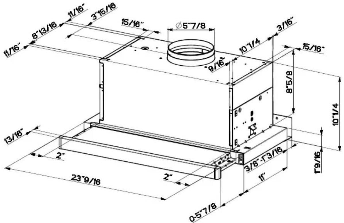
Pre-Planning Your Installation - Important: The recommended height to install this hood off the cooktop is a minimum of 24" and a maximum of 30" for maximum effectiveness. Also consult the cooktop manufacturer's recommendation.
NOTE: For top venting (comes standard in this position), use the left dimensional diagram. Refer to page 7 for directions for direct rear venting.
RANGEHOOD COMPONENTS
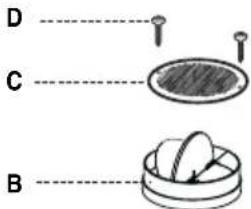
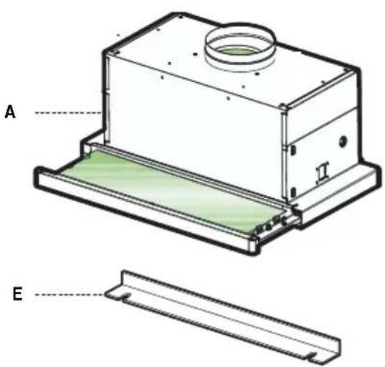
A. RANGEHOOD BODY
B. DAMPER
C. PLASTIC VENT GRATE
D. SCREWS
E. REAR TRIM STRIP
TOOLS NEEDED FOR INSTALLATION
- Saber Saw or Jig Saw
- Drill
• 1 1/4" Wood Drill Bit - Pliers
• Phillips Screwdriver
• Wire Stripper or Utility Knife - Metal Snips
• Measuring Tape or Ruler - Level
- Pencil
- Caulking Gun
- Duct Tape
PARTS SUPPLIED FOR INSTALLATION
• 1 Backdraft Damper
• 1 Vent Grate (for recirculating installations only)
- 1 Vinyl Trim
• 1 Literature Package
PARTS NEEDED FOR INSTALLATION
• 2 Conduit Connectors
• Power Supply Cable
- 1 Wall or Roof Cap
- All Metal Ductwork
PLAN THE DUCTWORK
The KTV24XV slideout rangehood is designed to offer wide flexibility of installations.
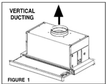
The rangehood can be ducted vertically through a 6" round vent.
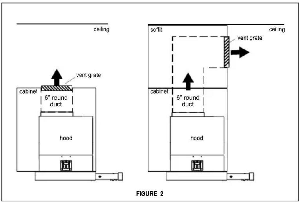
The unit can also be installed in a recirculating configuration. The unit comes standard in the top venting position.
FIGURES 1 shows vertical installations for this unit.
FIGURE 2 shows recirculating installation.
The KTV24XV requires 6" round ductwork.
To ensure that the blower performs to its highest possible capacity, ductwork should be as short and straight as possilbe.
The ductrun should not exceed 35 feet if ducted with the required minimum of 6" round duct.
Calculate the length of the ductwork by adding the equivai-lent feet in FIGURE A for each piece of duct in the system An example is given in FIGURE B.
For best results, use no more than three 90° elbows. Make sure that there is a minimum of 24" of straight duct between elbows if more than one is used. Do not install two elbows together.
If you must elbow right away, do it as far away from the hood's exhaust opening as possible.
| 45° Elbow | 3.0 feet |
| 90° Elbow | 5.0 feet |
| 90° Flat Elbow | 12.0 feet |
| Wall Cap | 0.0 feet |
FIGURE A
| 9 Feet Straight Duct | 9.0 feet |
| 2 - 90° Elbows | 10.0 feet |
| Wall Cap | 0.0 feet |
| Total System | 19.0 feet |
| FIGURE B | |
RECIRCULATING INSTALLATIONS
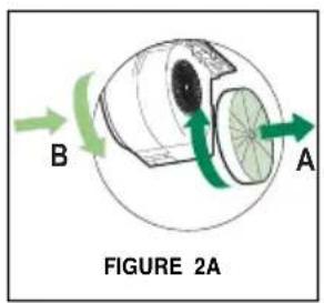
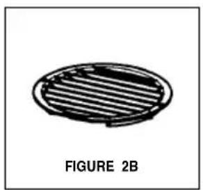
For recirculating installations (FIGURE 2), Charcoal Filters are necessary. Remove the two grease filters and set aside. Attach one charcoal filter to each end of the blower. Each charcoal filter attaches to the black grid on the side of the blower. Rotate the filter clockwise to install and counterclockwise to remove (FIGURE 2A). Replace the two grease filters. Some ductwork must be installed to exhaust the rangehood back into the kitchen, either at the top of the cabinet or at the face of the soffit. A plastic vent grate (FIGURE 2B) supplied with the rangehood can be used to cover the duct opening. This duct work must not terminate into a dead air space.
natural_image
Simple line drawing of a circular object with horizontal stripes, labeled 'FIGURE 2B' below (no other text or symbols)PREPARE THE CABINET
- Disconnect and move freestanding range from cabinet opening to provide easier access to upper cabinet and rear wall. Put a thick, protective covering over cooktops, set-in ranges or countertops to protect from damage or dirt.
- Determine and clearly mark with a pencil the center line of the cabinet on the wall and on the underside of the cabinet where the rangehood will be installed.
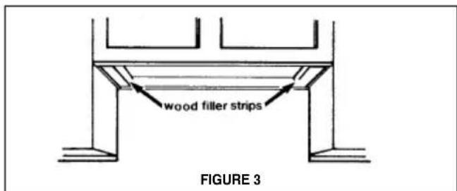
- If the cabinet bottom is recessed, wood blocks need to be installed to insure proper alignment with the cabinet bottom. Wood blocks should be flush or recessed 1/16" to 1/8" within the cabinet bottom as indicated in FIGURE 3.
- Determine the proper cutouts for the ductwork. Make all necessary cuts in the walls or cabinets for the ductwork. Install the ductwork before mounting the rangehood.
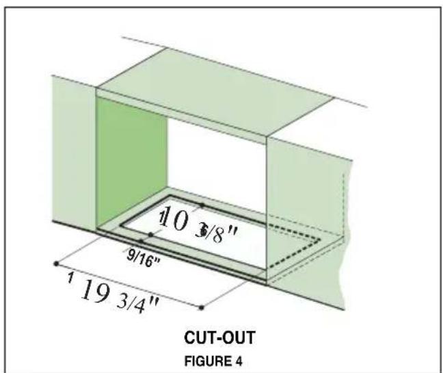
MAKE THE CUT-OUT OPENING (FIGURE 4)
WHERE THE RANGEHOOD WILL BE INSTALLED.
INSTALL THE RANGEHOOD
- Remove the rangehood from the carton and place on a flat surface. Cover the surface to prevent accidental damage. Remove all parts including the backdraft damper, plastic grille and literature package before discarding the carton. Remove the grease filters and set aside (see FIGURE 7 on next page for instructions.
-
Place the round damper into the exhaust opening of the rangehood and press down.
-
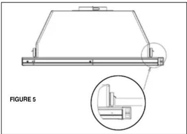
The rangehood mounts to the cabinet by two spring loaded brackets, one on each side of the rangehood (FIGURE 5). Lift the rangehood into the cutout opening in the cabinet. Be careful not to damage the cabinet, rangehood or other appliances.
natural_image
Technical line drawing of a mechanical component with an inset magnified detail (no text or symbols)- The spring loaded brackets are factory set to accommodate a thickness between 1 3/16" and 2 1/4". If your cabinet bottom is less than 1 3/16" thick, the spring loaded brackets can be removed and repositioned down from the top setting to the bottom setting by removing the four phillips screws.
- Tighten the rangehood to the cabinet by rotating the screws with a phillips screw driver.
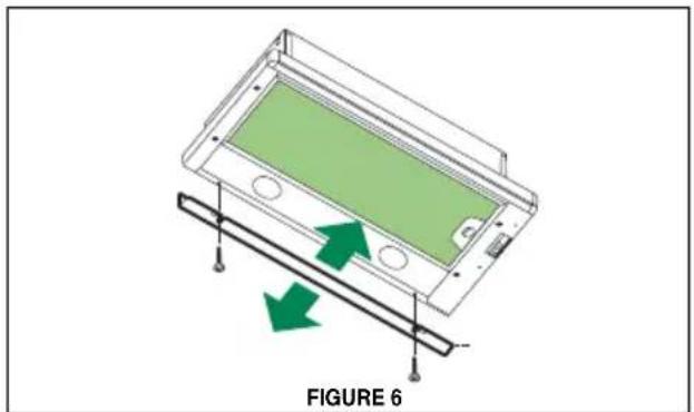
- A metal trim strip (FIGURE 6) is included to cover the underside of any remaining exposed cabinet. Attach the strip to the bottom of the back of the rangehood with the three screws provided.
natural_image
Diagram of a device with green highlighted screen and green arrows indicating movement or force, labeled 'FIGURE 6' (no text or symbols on the diagram itself)field wiring compartment with
7
ELECTRICAL INSTALLATION WITH CONNECTION CABLE
GROUNDING INSTRUCTIONS This appliance must be grounded. In the event of an electrical short circuit, grounding reduces the risk of electric shock by providing an escape wire for the electric current. This appliance is equipped with a cord having a grounding wire with a grounding plug. The plug must be plugged into an outlet that is properly installed and grounded.
WARNING - Improper grounding can result in a risk of electric shock.
Consult a qualified electrician if the grounding instructions are not completely understood, or if doubt exists as to whether the appliance is properly grounded.
Do not use an extension cord. If the power supply cord is too short, have a qualified electrician install an outlet near the appliance.
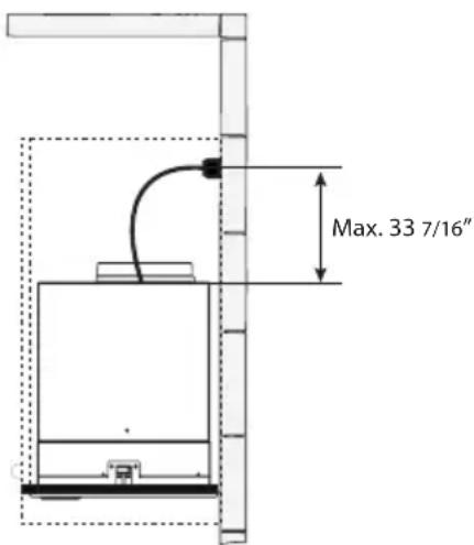
WARNING - "The supply cord shall be accessible for inspection after installation".
USE AND CARE INFORMATION
For Best Results
Start the rangehood several minutes before cooking to develop proper airflow. Allow the rangehood to operate for several minutes after cooking is complete to clear all smoke and odors from the kitchen.
Rangehood Control Panel
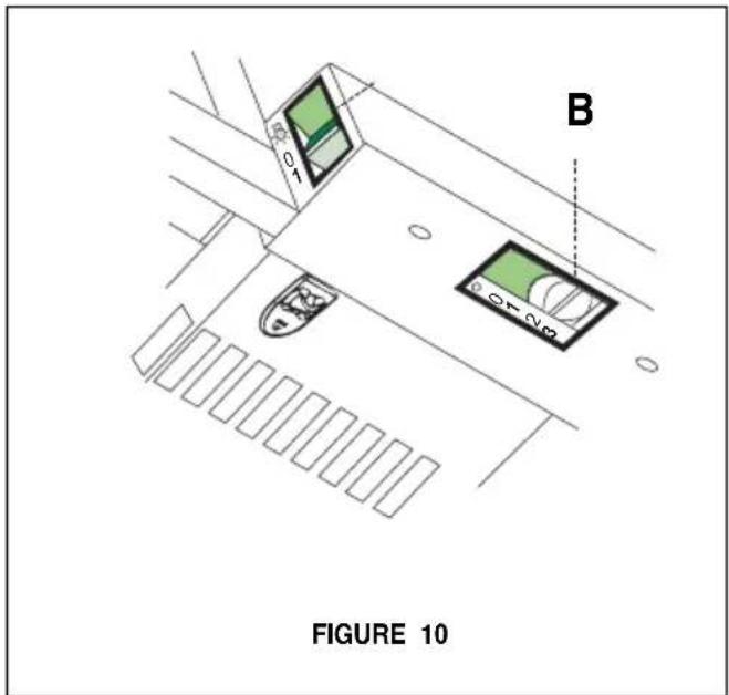
All controls are located on the right side of the rangehood.
Light On/Off Switch
TheOn/Off switch for the led light is located behind the front trim. Moving the switch to the 1 Position turns the light On. Moving the switch to the 0 position turns the light off.
Blower Speed Switch
B in FIGURE 10 shows the speed control switch for the blower. Moving the switch to the 1 Position turns the blower on LOW. Moving the switch to the 2 Position turns the blower on MEDIUM. Moving the switch to the 3 Position turns the blower on HIGH. Moving the switch to the 0 Position turns the blower off.
Automatic Operation
As long as the blower and light switches are on, the blower and light will automatically operate when the visor is opened and shut off when the visor is closed.
Cleaning metal grease filters
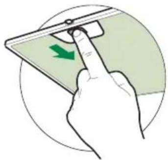
The metal grease filters can be cleaned in hot detergent solution or washed in the dishwasher. They should be cleaned every 2 months use, or more frequently if use is particularly heavy.
- Open the visor by pulling it.
- Remove the filter, pushing the lever towards the back of the unit and at the same time pulling downward.
- Wash the filter without bending it, leave it to dry thoroughly before replacing (if the surface of the filter changes color over time, this will have absolutely no effect on its efficiency).
- Replace, taking care to ensure that the handle faces forward.
- Cleaning in dishwasher may dull the finish of the metal grease filter.
- Close the visor.
natural_image
Hand inserting a green arrow on a smartphone screen (no text or symbols visible)Replacing Activated Charcoal Filter
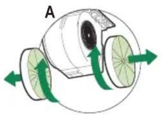
The Activated Charcoal Filters are not washable and cannot be regenerated, and must be replaced approximately every 4 months of operation, or more frequently with heavy usage.
- Open the visor by pulling it.
- Remove the Filter, pushing it towards the back of the unit and at the same time pulling downward.
- Remove the saturated Activated Charcoal Filters, as indicated (A).
• Fit the new Filters, as indicated (B). - Replace, taking care to ensure that the handle faces forwards.
- Close the visor.
natural_image
Diagram of a mechanical device with green arrows indicating rotational or directional movement (no text or symbols)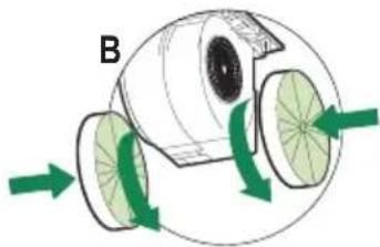
natural_image
Diagram of a mechanical device with green arrows indicating rotational or flow direction (no text or symbols)Lighting unit
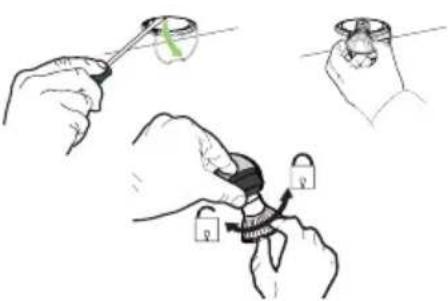
- Turn off electrical supply before replacing bulbs, and make sure bulbs are cool to touch before proceeding.
- Remove the snap-on lamp cover by levering it from under the metal ring, supporting it with one hand.
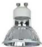
- Replace the lamp with a new one of the same type, making sure that you insert the two pins properly into the housings on the lamp holder.
- Replace the snap-on lamp cover.
natural_image
Illustration of hands using a tool to adjust a small object with a green arc, no text or symbols presentGu10 self-ballasted led lamps – listed in ac-
cordance with ul 1993/nmx-j-578/1-ance/csa c22.2 No. 1993
For any warranty information and service request, contact us:

In USA: https://us.bertazzoni.com/more/support In Canada: https://ca.bertazzoni.com/more/support
VEUILLEZ LIRE ET CONSERVER LA PRÉSENTE NOTICE AVANT DE COMMENCER L'INSTALLATION DE LA HOTTE DE CUISINE
AVERTISSEMENT : POUR RÉDUIRE LE RISQUE D'UN FEU DE GRAISSE SUR LA TABLE DE CUISSON :
PLANIFIER LA CANALISATION
INSTALLATIONS AVEC RECYCLAGE
natural_image
Simple line drawing of a circular object with horizontal lines, labeled 'FIGURE 2B' below (no other text or symbols)PRÉPARATION DE L'ARMOIRE
FIGURE 4
DÉCOUPER L'OUVERTURE OÙ LA HOTTE SERA INSTALLÉE (FIGURE 4).
INSTALLATION DE LA HOTTE
natural_image
Technical line drawing of a mechanical component with an inset close-up view (no text or symbols)natural_image
Hand inserting a green arrow on a device screen, enclosed in a circular frame (no text or symbols)natural_image
Diagram of a mechanical device with green arrows indicating rotational or directional motion (no text or symbols)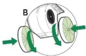
natural_image
Diagram of a biological or mechanical structure with green arrows indicating rotational or directional movement (no text or symbols)Système d'éclairage
natural_image
Illustration of hands using a tool to adjust a small object with a lock, no text or symbols present- READ AND SAVE THESE INSTRUCTIONS BEFORE YOU START INSTALLING THIS RANGEHOOD
- VENTING REQUIREMENTS
- Cold Weather installations
- WARNING
- ELECTRICAL REQUIREMENTS
- State of California Proposition 65 Warning (US only)
- TOOLS NEEDED FOR INSTALLATION
- PARTS SUPPLIED FOR INSTALLATION
- PARTS NEEDED FOR INSTALLATION
- PLAN THE DUCTWORK
- RECIRCULATING INSTALLATIONS
- PREPARE THE CABINET
- INSTALL THE RANGEHOOD
- 7
- ELECTRICAL INSTALLATION WITH CONNECTION CABLE
- USE AND CARE INFORMATION
- For Best Results
- Rangehood Control Panel
- Light On/Off Switch
- Blower Speed Switch
- Automatic Operation
- Cleaning metal grease filters
- Replacing Activated Charcoal Filter
- Lighting unit
- VEUILLEZ LIRE ET CONSERVER LA PRÉSENTE NOTICE AVANT DE COMMENCER L'INSTALLATION DE LA HOTTE DE CUISINE
- PLANIFIER LA CANALISATION
- INSTALLATIONS AVEC RECYCLAGE
- PRÉPARATION DE L'ARMOIRE
- DÉCOUPER L'OUVERTURE OÙ LA HOTTE SERA INSTALLÉE (FIGURE 4).
- INSTALLATION DE LA HOTTE
- Système d'éclairage
Brand : BERTAZZONI
Model : KTV24XV
Category : Range hood