
VPL-VW915ES - Vidéo-projecteur SONY - Free user manual and instructions
Find the device manual for free VPL-VW915ES SONY in PDF.


| Product Type | Video Projector |
| Brand | Sony |
| Model | VPL-VW915ES |
| Display System | SXRD panel, projection system |
| Display Device | 0.74-inch (18.8 mm) SXRD |
| Number of Pixels | 26,542,080 pixels (8,847,360 pixels × 3) |
| Projection Lens | 2.06 times zoom lens (motorized), f = 21.7 mm to 44.7 mm, F3.0 to F4.0 |
| Light Source | Laser diode |
| Projection Image Size | 60-inch to 300-inch (1,524 mm to 7,620 mm) measured diagonally |
| Resolution | 4K (4096 × 2160) / (3840 × 2160) |
| Inputs/Outputs | HDMI (HDCP 2.2) × 2, TRIGGER × 2 (mini jack, DC 12 V, Max. 100 mA), REMOTE (RS-232C D-sub 9-pin), LAN (RJ45, 10BASE-T/100BASE-TX), IR IN (minijack), USB (Type A, DC 5 V, Max. 500 mA) |
| Power Requirements | AC 100 V to 240 V, 4.3 A to 1.8 A, 50/60 Hz |
| Power Consumption | 430 W |
| Standby Power Consumption | 0.4 W (Remote Start Off), 1.0 W (LAN, Remote Start On) |
| Operating Temperature | 5°C to 35°C (41°F to 95°F) |
| Operating Humidity | 20% to 80% (no condensation) |
| Storage Temperature | -10°C to +60°C (14°F to 140°F) |
| Storage Humidity | 20% to 80% (no condensation) |
| Dimensions (W × H × D) | 560 mm × 223 mm × 496 mm (22 1/16 in × 8 25/32 in × 19 17/32 in) without protrusions |
| Mass | Approx. 20 kg (44 lb) |
| Supplied Accessories | See Quick Reference Manual |
| Optional Accessories | Projector Suspension Support: PSS-H10 |
Frequently Asked Questions - VPL-VW915ES SONY
User questions about VPL-VW915ES SONY
0 question about this device. Answer the ones you know or ask your own.
Ask a new question about this device
Download the instructions for your Vidéo-projecteur in PDF format for free! Find your manual VPL-VW915ES - SONY and take your electronic device back in hand. On this page are published all the documents necessary for the use of your device. VPL-VW915ES by SONY.
USER MANUAL VPL-VW915ES SONY
Operating Instructions
Before operating the unit, please read this manual, supplied Quick Reference Manual and Safety Regulations thoroughly, and retain them for future reference.
VPL-VW790ES
VPL-VW915ES
4K
SARD
Silicon X-tal Reflective Display
HDMI
Table of Contents
Location of Controls
Front/Right Side 3
Rear/Left Side/Bottom 4
Remote Control 5
Connections and Preparations
Installing the Unit 6
Adjusting the Picture Position 6
Connecting to Video Equipment or a Computer ..... 10
Projecting
Projecting the Picture 11
Turning Off the Power 11
Watching 3D Video Images .... 11
Using the 3D Glasses ...... 12
Using the Picture Position 12
Selecting the Aspect Ratio According to the Video Signal 13
Selecting the Picture Viewing Mode .... 15
Using the Menus
Operation through the Menus 16
Picture Menu 18
Advanced Picture Menu 23
Screen Menu 24
Setup Menu 26
Function Menu 27
Items Locked by Settings Lock 29
Installation Menu 30
Information Menu 32
About the Preset Memory 32
Using Network Features
Displaying the Control Window of the Unit with a Web
Browser 33
Operating the Control Window 34
Switching the Page 34
Setting the Access Limitation 34
Confirming the Information Regarding the Unit 34
Error Handling
Troubleshooting 35
About Indicators 37
Message Lists 38
Others
Updating the Software 39
About HDR (high dynamic range) 39
About the Simulated 3D Feature .... 39
NOTICES AND LICENSES FOR SOFTWARE USED IN THIS PRODUCT 39
Specifications 40
Preset Signals 41
Input Signals and Adjustment/Setting Items ..... 42
Compatible 3D Signals .... 43
3D Signals and Adjustable/Setting Items ...... 43
Aspect Mode 44
Motionflow 45
Storage Conditions of Adjustment/Setting Items 46
Projection Distance and Lens Shift Range 48
Dimensions 52
Front/Right Side
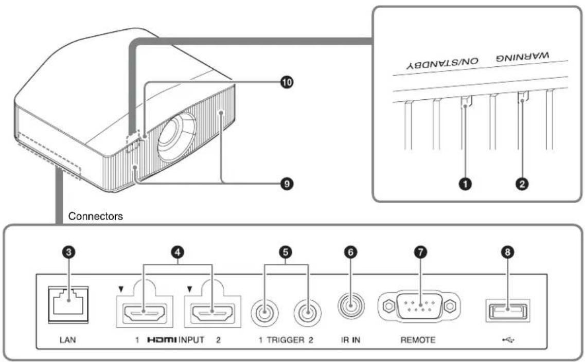
Indicators
①ON/STANDBY indicator (page 37)
②WARNING indicator (page 37)
Connectors
③LAN connector (page 33)
④HDMI 1/HDMI 2 connector (page 10)
⑤TRIGGER 1/TRIGGER 2 connector (page 30)
⑥IR IN connector
Inputs the signals to control the projector.
⑦REMOTE connector
Connects to a computer, etc. for remote control.
⑧USB connector (page 39)
Others
⑨ Ventilation holes (intake)
⑩Remote control detector (page 6)
Rear/Left Side/Bottom
The buttons on the control panel function the same as those on the remote control.
Control panel
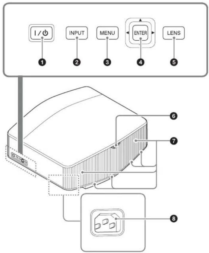
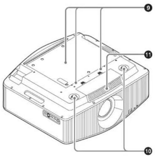
Control panel
①I/⏻ (On/Standby) button (page 7)
②INPUT button (page 11)
③MENU button (page 16)
④ ↑/↓/←/→ (arrow)/ENTER button (page 16)
⑤LENS button (page 6)
Others
⑥ Remote control detector (page 6)
⑦ Ventilation holes (exhaust)
⑧ AC IN socket (page 7)
⑨Projector suspension support attaching hole (page 53)
⑩Front feet (adjustable) (page 8)
⑪Ventilation holes (intake)
Remote Control
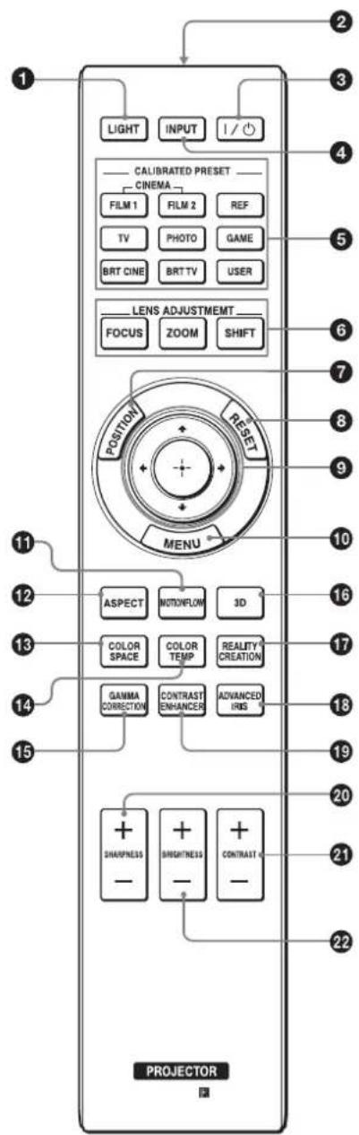
①LIGHT button Illuminates the buttons on the remote control.
②Infrared transmitter
3 I/⏻ (On/Standby) button (page 7)
④INPUT button (page 11)
⑤ CALIBRATED PRESET buttons (page 15)
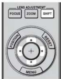
⑥LENS ADJUSTMENT buttons (page 7)
⑦ POSITION button (page 12)
⑧RESET button (page 17)
9 ↑/↓/←/→ (arrow)/ ⊕ (enter) button (page 16)
⑩MENU button (page 16)
⑪MOTIONFLOW button (page 19)
⑫ASPECT button (page 13)
⑬COLOR SPACE button (page 22)
⑭ COLOR TEMP button (page 20)
15 GAMMA CORRECTION button (page 21)
163D button (page 11)
17REALITY CREATION button (page 18)
18 ADVANCED IRIS button (page 19)
19 CONTRAST ENHANCER button (page 19)
20SHARPNESS +/- button (page 20)
21CONTRAST +/- button (page 19)
22 BRIGHTNESS +/- button (page 19)
Connections and Preparations
Installing the Unit
The installation distance between the unit and a screen varies depending on the size of the screen or whether or not you use the lens shift features. Install this unit so that it fits the size of your screen. For details on the distance between the unit and the screen (the projection distance) and the size of projected video, see “Projection Distance and Lens Shift Range” (page 48).
1 Position the unit so that the lens is parallel to the screen.
Top view
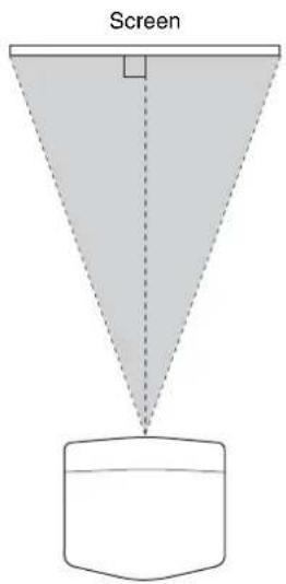
2 Project an image on the screen and adjust the picture so that it fits the screen (page 6).
Note
When using a screen with an uneven surface, stripes pattern may rarely appear on the screen depending on the distance between the screen and the unit or the zooming magnifications. This is not a malfunction of the unit.
Adjusting the Picture Position
Project an image on the screen and then adjust the picture position.
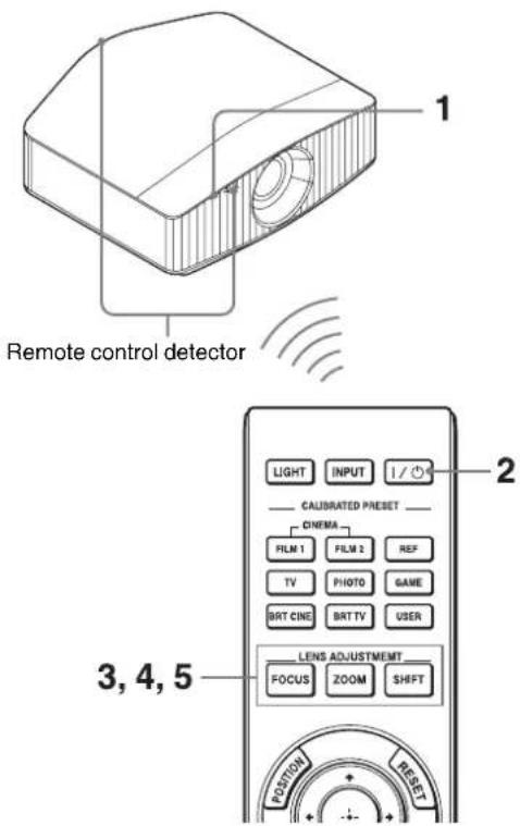
Tips
- The I/① (On/Standby), INPUT, and MENU buttons on the side panel of the unit have the same functions as those on the remote control. The ↑/↓/←/→ (arrow)/ENTER button of the unit has the same function as the ↑/↓/←/→ (arrow)/ ⊕ (enter) button on the remote control. The LENS button functions the same way as the LENS ADJUSTMENT (FOCUS, ZOOM, SHIFT) buttons on the remote control.
- When adjusting the lens, each time you press the LENS button on the unit, the lens adjustment function switches between "Lens Focus," "Lens Zoom" and "Lens Shift."

Note
Depending on the installation location of the unit, you may not be able to control it with the remote control. In this case, point the remote control at the remote control detector of the unit or the screen.
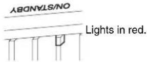
1 After connecting the AC power cord to the unit, plug the AC power cord into a wall outlet.
The ON/STANDBY indicator lights in red and the unit goes into standby mode.
2 Press the I/⏻ (On/Standby) button to turn on the unit.
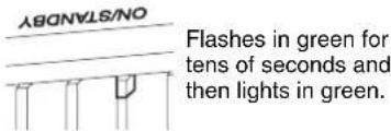
The ON/STANDBY indicator flashes in green, and then lights in green.
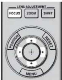
3 Adjust the focus.
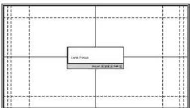
Press the LENS ADJUSTMENT (FOCUS) button to display the Lens Focus adjustment window (test pattern). Then adjust the focus of the picture by pressing the ↑/↓/↔/→ button.
flowchart
graph TD
    A["Late Focus"] --> B["Grid 1"]
    A --> C["Grid 2"]
    A --> D["Grid 3"]
    A --> E["Grid 4"]
    A --> F["Grid 5"]
    A --> G["Grid 6"]
    A --> H["Grid 7"]
    A --> I["Grid 8"]
Tips
- When "Lens Control" is set to "Off" on the Installation menu, you cannot adjust the focus, the picture size or the proper position by pressing the FOCUS, ZOOM or SHIFT button (page 30).
- When "Test Pattern" is set to "Off" on the Function menu, the test pattern is not displayed (page 28).
Note
Adjust the lens by using buttons on the remote control or the control panel of the unit. Never make adjustments by directly turning the lens with your hands, which may cause damage or malfunction to the unit.
4 Adjust the picture size.
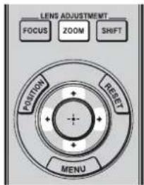
Press the LENS ADJUSTMENT (ZOOM) button to display the Lens Zoom adjustment window (test pattern). Then adjust the size of the picture by pressing the ↑/↓/←/→ button.
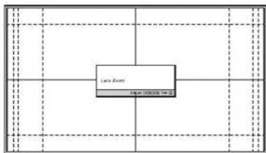
flowchart
graph TD
    A["Lane Span"] --> B["40mm 1000000 Hz"]
    B --> C["Grid Grid"]
    style A fill:#f9f,stroke:#333
    style B fill:#ccf,stroke:#333
    style C fill:#cfc,stroke:#333
To make the picture larger, press / . To make the picture smaller, press / .
5 Adjust the picture position.
Press the LENS ADJUSTMENT (SHIFT) button to display the Lens Shift adjustment window (test pattern). Then adjust to the proper position of the picture by pressing the /// button.
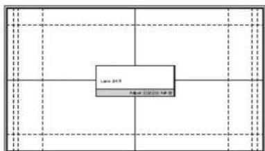
flowchart
graph TD
    A["Late 2019"] --> B["Period 2019"]
    B --> C["End"]
Tips
- Whenever you press the button, the test pattern disappears.
- Press the RESET button on the remote control while the Lens Shift adjustment window is displayed, the shift position returns to the center of the lens (factory default position). The zoom and focus are not changed.
Note
When adjusting the picture position, do not touch the lens unit, otherwise your fingers may be pinched by the moving parts.
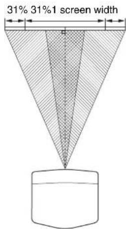
To adjust the horizontal position
Press ←/→.
The picture projected on the screen moves right or left by a maximum of 31% of the screen width from the center of the lens.
Top view
[Non-Text]
: Picture position when moving the picture to the left at maximum
[Non-Text]
: Picture position when moving the picture to the right at maximum
To adjust the vertical position
Press ↑/↓.
The picture projected on the screen moves up by a maximum of 85% or moves down by a maximum of 80% of the screen height from the center of the lens.
Side view
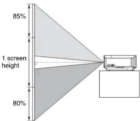
[Non-Text]
: Picture position when moving the picture upward at maximum
The image is too blurry to recognize any text content.
: Picture position when moving the picture downward at maximum
Note
The range to move the picture projected on the screen can be adjusted only within the octagon area illustrated below. For details, see “Projection Distance and Lens Shift Range” (page 48).
Range of movement of the projected picture
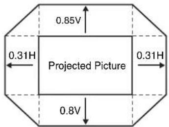
H: Width of the projected picture
V: Height of the projected picture
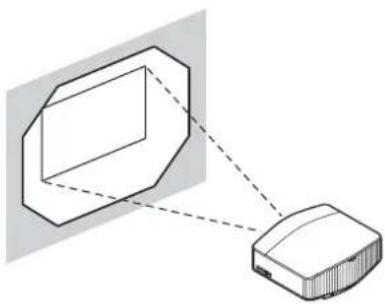
natural_image
Diagram showing a device connected to a rectangular box with a dashed line indicating connection (no text or symbols present)To adjust the tilt of the installation surface
If the unit is installed on an uneven surface, use the front feet (adjustable) to keep the unit level.
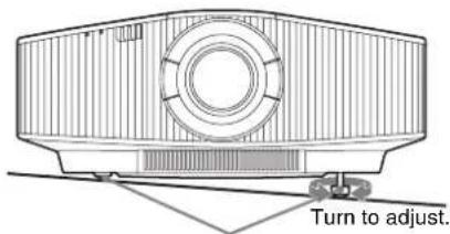
Front feet (adjustable)
Notes
- If the unit is tilted up or down, the projected image may be trapezoidal.
- Be careful not to catch your finger when turning the front feet (adjustable).
Lens adjustment window (test pattern)
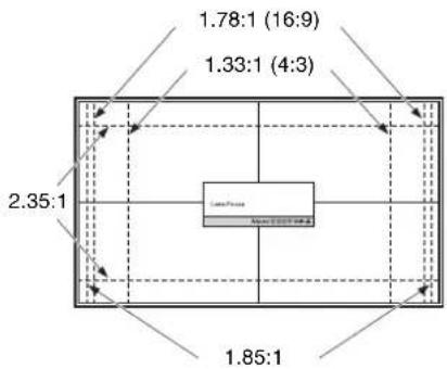
The dashed lines show the screen sizes of each aspect ratio.
Connecting to Video Equipment or a Computer
You can enjoy high picture quality by connecting a DVD player/recorder, Blu-ray Disc player/recorder, or PlayStation® equipped with HDMI output to the HDMI input of the unit.
When making connections, be sure to do the following:
- Turn off all equipment before making any connections.
- Use the proper cables for each connection.
- Insert the cable plugs properly; poor connection at the plugs may cause a malfunction or poor picture quality. When pulling out a cable, be sure to pull it out from the plug, not the cable itself.
- Refer to the operating instructions of the connected equipment.
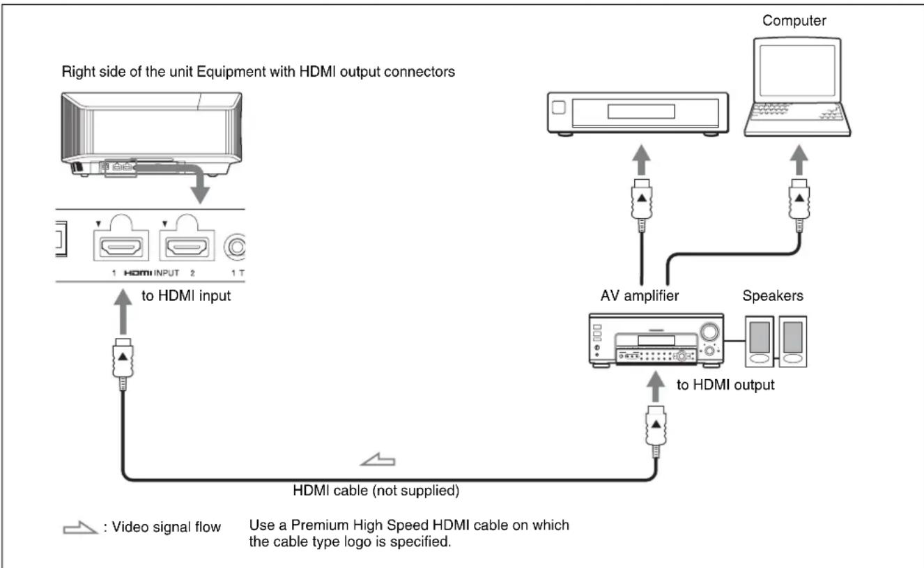
flowchart
graph TD
    A["Right side of the unit Equipment with HDMI output connectors"] --> B["Device 1: HDMI INPUT"]
    B --> C["Device 2: HDMI INPUT"]
    C --> D["Device 1 T: to HDMI input"]
    D --> E["Device 3: to HDMI output"]
    E --> F["Computer"]
    F --> G["AV amplifier"]
    G --> H[" Speakers"]
    H --> I["Device 4: to HDMI output"]
    I --> J["Device 5: AV amplifier"]
    J --> K["Device 6: AV amplifier"]
    style A fill:#f9f,stroke:#333
    style F fill:#ccf,stroke:#333
    style G fill:#cfc,stroke:#333
    style H fill:#fcc,stroke:#333
    style I fill:#cff,stroke:#333
    note right of A: Right side of the unit Equipment with HDMI output connectors
    note left of A: Video signal flow
    note right of H: Use a Premium High Speed HDMI cable on which the cable type logo is specified.
Notes
- Use a Premium High Speed HDMI cable. If using a cable other than a Premium High Speed cable, 4K video images may not be properly displayed.
- When connecting an HDMI cable to the unit, make sure the ▼ mark on the upper part of the HDMI input of the unit and the ▲ mark on the connector of the cable are faced at each other.
- If the picture from equipment connected to the unit with an HDMI cable is not correct, check the settings of the connected equipment.
- If you set your computer, such as a notebook type, to output the signal to both computer's display and this equipment, the picture of the equipment may not appear properly. Set your computer to output the signal to only the external monitor. For details, refer to the computer's operating instructions supplied with your computer. For settings of the computer, consult with the manufacturer of the computer.
When you monitor and control the projector via the network, access the Setup page of the projector (page 33) via a Web browser and enable the desired control protocol.
Projecting the Picture
1 Turn on both the unit and the equipment connected to the unit.
2 Press INPUT to display the input palette on the screen.
3 Select the equipment from which you want to display images.
Press INPUT repeatedly or press ↑/↓/⊕ (enter) to select the equipment from which to project.
Tips
- When “Status” is set to “Off” on the Setup menu, the input palette does not appear. Press the INPUT button to switch between input terminals sequentially.
- You can change the language for the menu and on-screen displays in "Language" on the Setup menu (page 26).
Turning Off the Power
1 Press the I/⏻ (On/Standby) button.
The message “POWER OFF?” appears.
2 Press the I/⏻ (On/Standby) button again before the message disappears.
The ON/STANDBY indicator flashes in green and the fan continues to run to reduce the internal heat.
The fan stops and the ON/STANDBY indicator changes from flashing green to remaining red.
The power is turned off completely, and you can disconnect the AC power cord.
Note
Never disconnect the AC power cord while the indicator is flashing.
Tip
You can turn off the unit by holding the I/⏻ (On/Standby) button for about 1 second, instead of performing the above steps.
Watching 3D Video Images
You can enjoy powerful 3D video images, such as from 3D games and 3D Blu-ray Discs, using the Active 3D Glasses.
1 Turn on the HDMI equipment for 3D compatibility connected to the unit, then play the 3D content. For details on how to play 3D content, refer to the operating instructions for the connected equipment.
2 Turn on the unit and project the 3D video image. For details on how to project the image, see "Projecting the Picture" (page 11).
3 Turn on the 3D glasses, and then put them on so that they fit comfortably.
For details on how to use the 3D glasses, see “Using the 3D Glasses” (page 12).
Tip
The factory default setting for “2D-3D Display Sel.” is “Auto” to allow projecting 3D video images automatically when the unit detects 3D signals.
Notes
- It may not be possible to display 3D video image, depending on the type of signal. Set the “2D-3D Display Sel.” to “3D,” and “3D Format” to “Side-by-Side” or “Over-Under” to suit the format of the 3D content you want to watch (page 27).
- Use the 3D glasses within the communication range (page 12).
- There are differences in perception of 3D video images among individuals.
- When the temperature of the usage environment is low, the 3D effect may be diminished.
Adjusting/Setting the 3D functions
You can adjust/set the 3D functions by pressing the 3D button on the remote control or with the "3D Settings" of the Function ☐ menu. For details, see "3D Settings" (page 27).
Using the 3D Glasses
1 Turn on the 3D glasses, and register them on the unit. For details on how to register the 3D glasses, refer to the operating instructions supplied with the 3D glasses.
2 Put on the 3D glasses.
3 Turn toward the screen.
Precautions for use
Misoperation may occur if:
• The viewing position is too far from the projector
- There are other communication devices, such as a wireless LAN (IEEE802.11 b/g/n) or a microwave with a bandwidth of 2.4 GHz, near the unit
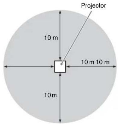
3D glasses communication range
The following figure indicates the communication range of the 3D glasses. If you try to watch 3D video images from a distance greater than the communication range or install the unit outside the communication range, the 3D glasses may not be able to display the images properly. Also, the distance varies depending on the environment of the room and installation environment of the unit.
Top or side view
Using the Picture Position
You can store up to five combinations of lens settings (focus, picture size, picture position), aspect ratio, and blanking. These settings can be recalled.
In the factory preset setting, the Picture Position is not stored.
1 Press POSITION.
The Picture Position selecting palette is displayed.
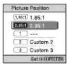
2 Press POSITION repeatedly, or press // to select the position.
The settings of the position selected is recalled. Store or delete lens settings, aspect ratio, and blanking in the "Picture Position" of the Screen menu (page 24).
The position where the lens settings, aspect ratio, and blanking are not stored is displayed as “---.”
Tip To hide the reminder displayed on the screen when the position is read out, set "Status" to "Off" on the Setup menu.
Image of the lens moving
In the example below, the images with aspect ratio of 1.78:1 (16:9) and 2.35:1 are projected on a 2.35:1 screen.
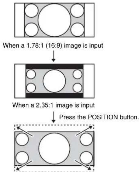
flowchart
graph TD
    A["When a 1.78:1 (16:9) image is input"] --> B["When a 2.35:1 image is input"]
    B --> C["Press the POSITION button."]
The 2.35:1 image expands to fill the screen.
Notes
• After you have selected and confirmed the lens position, the lens starts to move. Do not touch, or place anything near, the lens, otherwise it may cause injury or a malfunction.
- If you press any button on the remote control or the unit while the lens is moving, the lens stops. In this case, select the lens position again or adjust the lens manually.
- The Picture Position function is not guaranteed to reproduce the lens settings precisely.
- When you use the subtended screen angle of two or more aspects using lens zoom, install the unit within the specified parameters referring to "Projection distance" (page 49). With some setting positions, the range of lens shift may be restricted, even though the unit is installed within the specified parameters.
Selecting the Aspect Ratio According to the Video Signal
You can select an aspect ratio best suited for the video signal received.
Press ASPECT.
Each time you press the button, you can select the "Aspect" setting. You can also select it using the menu (page 24).
| Original image | Recommended setting and resultant images |
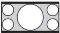 1.85:1 1.85:1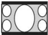 Squeezed 1.85:1 Squeezed 1.85:1 | 1.85:1 Zoom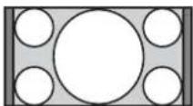 |
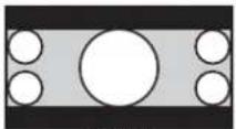 2.35:1 2.35:1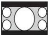 Squeezed 2.35:1 Squeezed 2.35:1 | 2.35:1 Zoom |
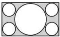 1.78:1 (16:9) 1.78:1 (16:9)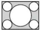 1.33:1 (4:3) 1.33:1 (4:3)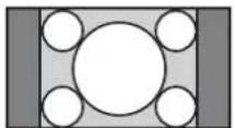 1.33:1 (4:3) with side panels 1.33:1 (4:3) with side panels | Normal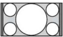 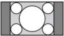 |
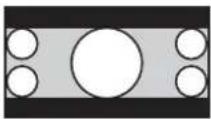 2.35:1 2.35:1 | V Stretch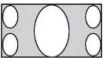 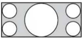 When using an anamorphic lens When using an anamorphic lens |
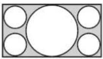 16:9 16:9 | Squeeze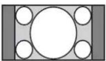 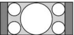 When using an anamorphic lens When using an anamorphic lens |
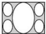 Squeezed Squeezed | Stretch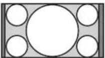 |
Note
Selectable aspect modes vary depending on the input signal (page 44).
Notes on switching the "Aspect" setting
- Select the aspect mode taking into account that changing the aspect ratio of the original picture will provide a different look from that of the original image.
- Note that if the unit is used for profit or for public viewing, modifying the original picture by switching the aspect may constitute an infringement of the rights of authors or producers, which are legally protected.
Selecting the Picture Viewing Mode
You can select the picture viewing mode that best suits the type of video source or room conditions.
You can save and use different preset modes for 2D/3D respectively.
Press one of the CALIBRATED PRESET buttons.
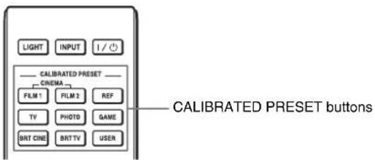
| Setting items Description | |
| CINEMA FILM 1 | Picture quality suited to reproducing the highly dynamic and clear images typical of master positive film. |
| CINEMA FILM 2 | Picture quality suited to reproducing the rich tone and color typical of a movie theater, based on the “CINEMA FILM 1.” |
| REF A picture quality | setup suitable for when you want to reproduce faithfully the original image quality, or for enjoying image quality, without any adjustment. |
| TV Picture quality | suited for watching TV programs, sports, concerts, and other video images. |
| PHOTO Ideal for | projecting still images taken with a digital camera. |
| GAME Picture quality | suited to gaming, with well-modulated colors and fast response. |
| BRT CINE Picture | quality suited for watching movies in a bright environment, such as a living room. |
| BRT TV Picture quality | suited for watching TV programs, sports, concerts, and other video images in a bright environment, such as a living room. |
| USER Adjusts the picture quality | quality to suit your taste then saves the setting. The factory default setting is the same as “REF.” |
Using the Menus
Note
The menu displays used for the explanation may be different from the actual menu display.
Operation through the Menus
The unit is equipped with an on-screen menu for making various adjustments and settings. If you select an item name followed by an arrow (▶), the next menu window with setting items appears.
1 Press MENU.
The menu window appears.
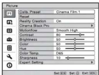
2 Press ↑/↓ to select a menu item, and press → or ⊕. The items that can be set or adjusted with the selected menu appear. The item presently selected is shown in white.
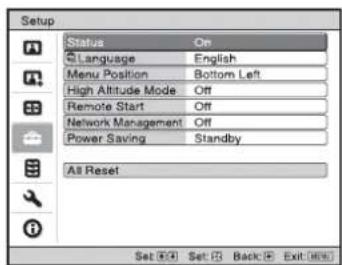
3 Press ↑/↓ to select an item you want to set or adjust and press → or ⊕
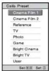
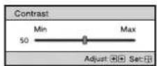
The setting items are displayed in a pop-up menu, in a setting menu, in an adjustment menu or in the next menu window.
Pop-up menu
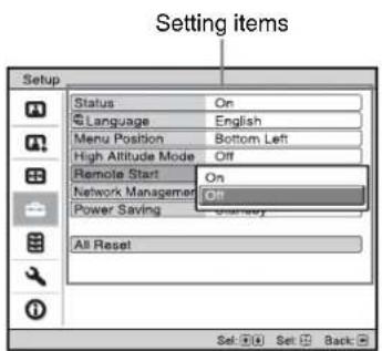
Setting menu
Adjustment menu
Next menu window
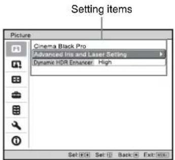
4 Make the setting or adjustment of an item.
When changing the adjustment level
Press ↑/→ to increase the value, and press ↓/← to decrease the value. Press ⓣ to store the setting and restore the original menu screen.
When changing the setting
Press ↑/↓ to change the setting. Press ⓣ to restore the original screen. You can restore the original screen using ← depending on the selected item.
To clear the menu
Press MENU.
To reset the picture that has been adjusted
Select "Reset" from the Picture menu.
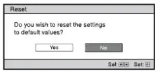
When the screen display appears, select "Yes" using and press ⚙
All of the following settings are reset to its factory preset value:
“Reality Creation,” “Cinema Black Pro,” “Motionflow,” “Contrast,” “Brightness,” “Color,” “Hue,” “Color Temp.,” “Sharpness,” and “Expert Setting” on the Picture menu
To reset the items that have been adjusted
Select an item in the menu screen, and display the pop-up menu, the setting menu, or the adjustment menu.
Press RESET on the remote control to reset only the selected settings to its factory preset value.
Note
The RESET button on the remote control is available only when the adjustment menu or the setting menu is selected.

Picture Menu
The Picture menu is used for adjusting the picture.
Note
These items may not be adjustable or configurable, depending on the type of input signal. For details, see “Input Signals and Adjustment/Setting Items” (page 42).
Item names in brackets represent those printed on the remote control.
| Setting items Description | |
| Calib. Preset [CALIBRATED PRESET] | You can select the picture viewing mode that best suits the type of video source or the environment.You can save and use different preset modes for 2D/3D respectively.Cinema Film 1: Picture quality suited to reproducing the highly dynamic and clear images typical of master positive film.Cinema Film 2: Picture quality suited to reproducing the rich tone and color typical of a movie theater, based on the Cinema Film 1.Reference:A picture quality setup suitable for when you want to reproduce faithfully the original image quality, or for enjoying image quality, without any adjustment.TV: Picture quality suited for watching TV programs, sports, concerts, and other video images.Photo:Ideal for projecting still images taken with a digital camera.Game:Picture quality suited to gaming, with well-modulated colors and fast response.Bright Cinema:Picture quality suited for watching movies in a bright environment, such as a living room.Bright TV:Picture quality suited for watching TV programs, sports, concerts, and other video images in a bright environment, such as a living room.User:You can adjust the picture quality to suit your taste, and save the setting. The factory default setting is the same as “Reference.”TipAny adjustments to picture quality settings are saved for each input. |
| Reset | Resets all currently selected Calib. Preset mode settings to their default values (page 17).TipReset does not affect settings saved for items of “Color Temp.” |
| Reality Creation [REALITY CREATION] | Adjusts the detail and noise processing of images. (Super-resolution function)On:Adjusts the settings of “Reality Creation.”Database:Select “Normal” or “Mastered in 4K.”“Mastered in 4K” provides image quality suitable for Blu-ray DiscTM “Mastered in 4K” releasing from Sony Pictures Home Entertainment.Resolution:When you increase the setting value, the texture and detail of the picture become sharper. Noise Filtering:When you increase the setting value, the noise (picture roughness) becomes less prominent.D.Focus Optimizer:When you set to “On,” it optimizes the projected image. It achieves enhanced texture and picture details and sharpens the picture.Test:On/Off:Changes “On” and “Off” at a certain frequency to check the effect of “Reality Creation.”TipThe display position of status during the test works together with the “Menu Position” setting (page 26).Off:The “Reality Creation” function is not applied. |
Setting items Description
| Cinema Black Pro | |
| Advanced Iris and Laser Setting[ADVANCED IRIS] | Dynamic Control: Adjusts the range of the laser light and iris (diaphragm).Full: Automatically adjusts the laser light, iris (diaphragm), and signal processing according to the brightness level of the input source and optimizes the amount of light. This results in a bright and high contrast image.Limited: Compared to “Full,” it suppresses the movement and brightness of the laser light and iris (diaphragm). This is suitable for viewing a picture in a dark room.Off: The “Dynamic Control” function is not applied.Laser Light Output: The higher the setting, the brighter the picture. The lower the setting, the darker the picture.TipAdjust “Laser Light Output” according to the brightness of the picture. |
| Dynamic HDR Enhancer[CONTRAST ENHANCER] | For HDR content, automatically adjusts the range of movement of the laser light and iris (diaphragm), and the signal level of bright and dark parts to optimize contrast according to a scene.Increases image sharpness and makes the image dynamic.“Contrast Enhancer” appears instead of “Dynamic HDR Enhancer” and performs the image processing suitable for the SDR signal in the following cases:- When the SDR signal is input with “Auto” set for “HDR”- When “HDR” is set to “Off”High/Middle/Low: You can adjust the Dynamic HDR Enhancer/Contrast Enhancer.Off: The Dynamic HDR Enhancer function is not applied. |
| Motionflow [MOTIONFLOW] | Smooth High: Provides smoother picture movement; especially effective for film-based content.Smooth Low: Provides smoother picture movement for standard use.True Cinema: Images, such as a movie created in 24 frames per second, are reproduced at the original framerate.Off: The “Motionflow” function is not applied.TipsSelect “Off” if the selected “Smooth High,” “Smooth Low,” or “True Cinema” results in a distorted picture.Depending on the picture content, you may not see the effect visually even if you have changed the settings.Only “Off” is available when a signal with a resolution of 4096 × 2160 is input. |
| Contrast[CONTRAST] | Adjusts the contrast.Higher values increase the sharpness in images, while lower values decrease the sharpness.You can make adjustments by pressing the CONTRAST +/- button on the remote control.“Contrast(HDR)” appears instead of “Contrast” for the following cases:- When the HDR signal is input with “Auto” set for HDR- When “HDR” is set to “HDR10,” “HDR Reference,” or “HLG” |
| Brightness[BRIGHTNESS] | Adjusts the brightness of the picture.The higher the setting, the brighter the picture. The lower the setting, the darker the picture.You can make adjustments by pressing the BRIGHTNESS +/- button on the remote control. |
| Color Adjusts the color density. | The higher the setting, the greater the intensity. The lower the setting, the lower the intensity. |
| Hue Adjusts the color tone. | The higher the setting, the more greenish the picture becomes. The lower the setting, the more reddish the picture becomes. |
| Setting items Description | |
| Color Temp.[COLOR TEMP] | Adjusts the color temperature.D93:Equivalent to 9,300 K color temperature normally used in TVs. Gives white colors a blue tint.D75:Equivalent to 7,500 K color temperature used as an ancillary standard illuminant. Gives a neutral tint between “D93” and “D65.”D65:Equivalent to 6,500 K color temperature used as a standard illuminant. Gives white colors a red tint.D55:Equivalent to 5,500 K color temperature used as an ancillary standard illuminant. Gives white colors an even redder tint.Custom 1 to 5:Enables you to adjust, set, and store your favorite color temperature.The factory default settings are as follows.Custom 1:Same as the “D93” color temperature setting.Custom 2:Same as the “D75” color temperature setting.Custom 3:Same as the “D65” color temperature setting.Custom 4:Same as the “D55” color temperature setting.Custom 5:Setting that prioritizes brightness.TipYou can adjust each item to a color temperature according to your preference. |
| Sharpness[SHARPNESS] | Sharpens the outline of the picture, or reduces the noise.The higher the setting, the sharper the picture. The lower the setting, the softer the picture, thus reducing the noise.You can make adjustments by pressing the SHARPNESS +/- button on the remote control. |
| Expert Setting | |
| NR (Noise Reduction) Reduces the roughness or noise of the picture.Auto:Detects the noise level to reduce the roughness or noise of the picture automatically.High/Middle/Low:Select a setting according to the roughness or noise of the input signal source.Off:The NR (noise reduction) function is not applied.TipThe noise level may not be detected accurately with “Auto” depending on the input signal source. If the picture is unacceptable with “Auto,” select a setting from among “High,” “Middle,” “Low” or “Off.” | |
| MPEG NR (MPEG Noise Reduction) | Reduces block noise and mosquito noise, particularly in digital signals.Auto:Detects the noise level to reduce the block noise and mosquito noise of the picture automatically.High/Middle/Low:Select a setting according to the block noise and mosquito noise of the input signal source.Off:The MPEG NR (MPEG noise reduction) function is not applied.TipThe noise level may not be detected accurately with “Auto” depending on the input signal source. If the picture is unacceptable with “Auto,” select a setting from among “High,” “Middle,” “Low” or “Off.” |
| Smooth Gradation Smooths the gradation of the flat parts of images.High/Middle/Low:You can adjust the smooth gradation effect.Off:The smooth gradation function is not applied.TipThis item is not available for 3D signals. | |
| Film Mode According to the film source you have selected, make a setting for playback.Auto:Suitable for reproducing the original picture movement. Normally, set this to “Auto.”Off:Plays back the picture in progressive format without detecting video signals automatically.TipThis item is compatible with a 1080i signal only. | |
Setting items Description
| Gamma Correction[GAMMA CORRECTION] | Adjusts the response characteristics of the tone of the picture.Select a favorite tone from 10 options.1.8: Bright Produces a brighter picture overall.22.12.22.42.6: Dark Produces a darker picture overall.Gamma 7: Enhances the dark parts and sharpens the images.Gamma 8: Produces a brighter picture than Gamma 7. Select this when you watch in a bright environment, such as a living room.Gamma 9: Produces a brighter picture than Gamma 8.Gamma 10: Increases the sharpness in images. Select this when you watch TV programs, etc., in a bright environment, such as a living room.Off: The “Gamma Correction” function is not applied. |
| Color Correction | On: Adjusts Hue, Saturation and Brightness of the selected colors.Repeat steps 1 and 2 described below to specify the target color.1 Press ↑/↓ to select “Color Select,” then press ←/→ to select the color you want to adjust among “Red,” “Yellow,” “Green,” “Cyan,” “Blue,” and “Magenta.”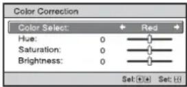 2 Press ↑/↓ to select “Hue,” “Saturation” or “Brightness,” then adjust them to suit your taste using ←/→ while watching the projected picture.Off: The “Color Correction” effect is not applied. 2 Press ↑/↓ to select “Hue,” “Saturation” or “Brightness,” then adjust them to suit your taste using ←/→ while watching the projected picture.Off: The “Color Correction” effect is not applied. |
| Clear White Emphasizes vivid whites.High/Low: You can adjust the “Clear White” effect.Off: The “Clear White” effect is not applied. | |
| x.v.Color Set this item when connecting the unit with equipment that supports x.v.Color and playing back an x.v.Color video signal.On: You can play back an x.v.Color video signal.Off: The “x.v.Color” function is not applied.TipSetting x.v.Color to “On” disables gamma adjustment. | |
| HDR Sets how to play back HDR content.Auto: Distinguishes HDR content automatically and applies the optimal picture quality. You can change the HDR setting that is automatically selected when HDR10-compatible content is distinguished.HDR10/HLG: When an input signal supports HDR10, the “HDR10” setting is applied, and when it supports HLG, the “HLG” setting is applied.HDR Reference/HLG: When an input signal supports HDR10, the “HDR Reference” setting is applied, and when it supports HLG, the “HLG” setting is applied.When an input signal supports BT.2020, the “Color Space” is set to “BT.2020” automatically. When a signal other than BT.2020 is input, the mode set in “Color Space” is applied. (“BT.2020” is not available in this case.)HDR10: Set when playing back HDR10-compatible content.HDR Reference: This mode is suitable for playing back HDR10-compatible content with a maximum brightness of 1,000 nit.HLG: Set when playing back HLG-compatible content.Off: Set when playing back content other than HDR content.All of the modes of “Color Space” are selectable when “HDR10,” “HDR Reference,” “HLG,” or “Off” is selected.Notes· If the setting is not correct for the input content, the bright and dark areas of the video may appear too bright or too dark.· When setting “HDR10” or “HDR Reference,” compare the picture quality in both modes, and select the one that optimally displays the average brightness and tone of the bright parts. | |
Setting items Description
| Color Space[COLOR SPACE] | Converts the color space.BT.709: An ITU-R BT.709 color space, which is used for high-definition television broadcast or Blu-ray Disc. The color space is equivalent to sRGB.BT.2020: The color space is wider than BT.709. Use this setting when playing back HDR content.Color Space 1: The color space suited for watching TV programs and video images, such as sports, concerts, etc.Color Space 2: The color space suited for watching TV programs, sports, concerts, and other video images in a bright environment, such as a living room.Color Space 3: The color space suited for watching movies in a bright environment, such as a living room.Custom: You can adjust the color space setting. |
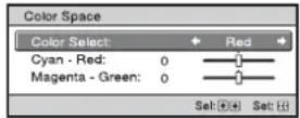
Note
When "HDR" is set to "Auto," the selectable mode changes according to the signal type (page 21).
| Input Lag Reduction Reduces the delay of the display for a video. |
| On:Shortens the time to display the input video image; effective for increasing the performance of the display reaction speed when using an external controller, etc. |
| Off:Turns the Input Lag Reduction function off. |
Tip
When "Input Lag Reduction" is set to "On," "Motionflow," "NR," and "MPEG NR" cannot be set.

Advanced Picture Menu
You can adjust the gaps in color that have occurred after a long period of use.
Notes
- Auto Calibration results in relatively coarse calibration. The color settings are not guaranteed to be the same as the factory default values.
- The colors are projected automatically while performing "Pre Check" or "Adjust." This is not a malfunction.
- Do not turn off the power or operate the remote control or control panel during "Pre Check" or "Adjust," as the process may be canceled.
Tips
- dE is an indicator of changing color. The smaller the value of dE, the fewer the changes caused by the color.
- Perform the calibration after the power has been on for more than 30 minutes.
- It takes a few minutes for "Pre Check" or "Adjust" to complete.
- If the “Pre Check” or “Adjust” function fails, try it again.
- When “Pre Check” or “Adjust” starts, the screen position may shift as the lens returns to its factory default position. After completion, the screen returns to its previous position automatically.
- If the environment, such as the brightness of the room, changes while performing “Pre Check” or “Adjust”, measurement may be affected.
Setting items Description
| Auto Calibration | Pre Check: Checks the color difference against the factory default settings, before calibration starts.Adjust: Performs Auto Calibration.Before/After: Toggles the factory default settings and the setting after the calibration at a certain frequency. You can check the effect of the calibration by monitoring the actual image.Reset: Resets the calibration results, and returns to the factory default settings. |

Screen Menu
You can set the picture size, aspect mode, etc.
Note
These items may not be available, depending on the type of input signal. For details, see “Input Signals and Adjustment/Setting Items” (page 42).
Item names in brackets represent those printed on the remote control.
| Setting items Description | |
| Picture Position[POSITION] | You can store up to five combinations of lens settings, aspect ratio, and blanking.After setting the lens (focus, picture size, picture position), select from “1.85:1,” “2.35:1,” “Custom 1,”“Custom 2,” or “Custom 3” depending on the subtended screen angle, and after confirming, continue byselecting “Save,” “Delete,” or “Select.”Save: Stores the current lens settings (focus, picture size, picture position) in the selected position. If asetting is already stored in that position, it is overwritten.Delete: Deletes the stored setting. After the setting is deleted, “1.85:1,” “2.35:1,” “Custom 1,” “Custom2,” or “Custom 3” in the display change to “---.”Select: Recalls the settings of the selected position.TipsThe optimal aspect ratio is preset for each picture position. The aspect ratio can be changed and savedfor each picture position.When saving the Picture Position, temporarily move the picture from the saving point down 5 cm ormore. Move the picture up again and save. This improves the precision of the Picture Position whencalling it.NotesAfter you have selected and confirmed the lens position, the lens starts to move. Do not touch the lensand the area around the lens, otherwise it may cause injury or a malfunction.If you press any button on the remote control or the unit while the lens is moving, the lens stops. Inthis case, select the lens position again or adjust the lens manually.When you use a 2.35:1 or a 16:9 subtended screen angle with the Picture Position function, make surethat the installation position is suitable (page 12).The Picture Position function is not guaranteed to reproduce the lens settings precisely. |
| Aspect[ASPECT] | You can set the aspect ratio of the picture to be displayed for the current input signal (page 13).1.85:1 Zoom: A 1.85:1 aspect ratio picture is displayed in its original aspect ratio, enlarged so that blackbands do not appear at the top and bottom of the projection surface.2.35:1 Zoom: A 2.35:1 aspect ratio picture is displayed in its original aspect ratio, enlarged so that blackbands at the top and bottom of the projection surface are as small as possible. When you select “2.35:1Zoom” from “Trigger Select 1/2” on the Installation menu, a 12 V signal is output from theTRIGGER 1 or TRIGGER 2 connector (page 30).Normal: Input video is displayed in its original aspect ratio, enlarged to fill the projection surface. Thismode is suitable for viewing 1.78:1 (16:9) and 1.33:1 (4:3) video.V Stretch: This is the most suitable mode for using a 2.35:1 screen to view 2.35:1 video with acommercially available anamorphic lens.When you select “V Stretch” from “Trigger Select 1/2” on the Installation menu, a 12 V signal isoutput from the TRIGGER 1 or TRIGGER 2 connector (page 30).Squeeze: With this setting, 1.78:1 (16:9) and 1.33:1 (4:3) video will be displayed in their correct aspectratios when you use a commercially available anamorphic lens.Stretch: Displays video that has been squeezed to 1.33:1 (4:3) as 1.78:1 (16:9) aspect ratio.TipsWhen you select “V Stretch” or “Squeeze,” select the anamorphic lens type from “Anamorphic Lens”in the Installation menu.Selectable aspect modes vary depending on the input signal (page 44).Aspect setting is stored for each of the five Picture Positions. Adjust the aspect after selecting thePicture Position. Final adjusted values are stored automatically. |
Setting items Description
Blanking This feature allows you to adjust the displayable region within the four directions of the screen.
On: Select the edge to adjust by highlighting Left, Right, Top, or Bottom using the ↑/↓ button. Adjust the amount of blanking using the ←/→ button.
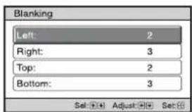
Off: Turns off the Blanking function.
Tips
- Depending on the aspect ratio setting, right/left blanking may not be available.
- Blanking setting is stored for each of the five Picture Positions. Adjust the blanking after selecting the Picture Position. Final adjusted values are stored automatically.

Setup Menu
The Setup menu is used to change the factory preset settings, etc.
| Setting items Description | |
| Status Sets whether or not the on-screen display is displayed.On: Displays on-screen messages and menus.Off: Turns off the on-screen displays, other than certain menus, a message when turning off the power, and warning messages. | |
| Language Selects the language used in the menu and on-screen displays. | |
| Menu Position You can change the position to display the menu on the projection surface.Bottom Left: Displays the menu on the bottom left area of the projection surface.Center: Displays the menu on the center of the projection surface. | |
| High Altitude Mode Sets the unit to operate at the prevailing atmospheric pressure.On: Use this setting when using the unit at an altitude of 1,500 m (approx. 4,900 ft) or higher.Off: Use this setting when using the unit at normal altitudes.TipWhen this item is set to “On,” the fan noise becomes slightly louder since the fan speed increases. | |
| Remote Start Sets the Remote Start settings.On: You can turn on the power from a PC or a terminal which is connected to a network.Off: Turns off the Remote Start function.TipsTo use the function, the unit should be connected to the network in advance (page 31).To turn on the power with the Remote Start function, a special command should be sent from a PC or a terminal. For details, consult with qualified Sony personnel.NoteWhen the Remote Start is set to “On,” the standby power requirement will increase. When Network Management is set to “On,” Remote Start is automatically fixed at “Off” and is not displayed in the menu. | |
| Network Management | On: Set when connected to the network and continuously communicating with the projector control equipment.Off: Turns off the Network Management function.NoteWhen Network Management is set to “On,” the network function is continuously enabled. Set Network Management to “Off” for normal use. If you set to “On,” the power consumption increases. |
| Power Saving Sets the Power Saving mode.Standby: If no signal is input for 10 minutes, power is turned off automatically and the projector goes into standby mode.Off: Disables the Power Saving function. | |
| All Reset All settings are initialized to their factory preset values. | |

Function Menu
The Function menu is used for changing the settings of the various functions of the unit.
Setting items Description
| 3D Settings You can change the settings of the 3D function. | |
| 2D-3D Display Sel. For Switching the video images to “2D” or “3D.”Auto: Displays 3D video images when HDMI signals with 3D information* are input. Displays 2D video images when other signals are input.3D: Displays 3D video images according to the 3D system selected in “3D Format.” However, when HDMI signals with 3D information are input to the unit, displays 3D video images according to the 3D system of those HDMI signals.* The 3D information is additional information to discriminate 3D. Some HDMI signals have additional information to discriminate 3D and some HDMI signals have none.3D Format: Set the 3D system when the input HDMI signals do not include 3D information.Simulated 3D: Converts 2D video images to 3D video images. The setting can be made only for input the HD signals.The simulated 3D feature may have limited effect, depending on the video source.There are differences in perception of 3D video images among individuals.Side-by-Side: Select this to display 3D images as two similar images, side-by-side.Over-Under: Select this to display 3D images as two similar images, one above the other.Tips“2D-3D Display Sel.” cannot be set to “3D” for some video sources. For available 3D signals, see “Compatible 3D Signals” (page 43).The simulated 3D feature may have limited effect, depending on the screen size (100 to 120 inches recommended) and the video source.The menu display has a ghost while a 3D video image is displayed and is best viewed with the 3D glasses. | |
| 3D Depth Adjust For adjusting the depth of the 3D video images on the projection surface. The setting can be made only when a 3D Format other than “Simulated 3D” is selected.Depth -2 -1 0 +1 +2← NormalFrontDepthWe recommend that “3D Depth Adjust” be set to “0.” The 3D video images may be difficult to perceive, depending on the setting of “3D Depth Adjust.” | |
| Simulated 3D Effect | For adjusting the 3D effect when 2D content is converted to 3D video images. You can select the effect from among “High,” “Middle,” and “Low.”TipThere are differences in perception of 3D video images converted by the simulated 3D function among individuals. |
| Dynamic Range Sets the video input level for HDMI 1 and HDMI 2 connectors.Auto: Sets the video input level automatically.Limited: The video input level is set for signals that are equivalent to 16-235.Full: The video input level is set for signals that are equivalent to 0-255.NoteIf the video output setting of the connected HDMI device is not set correctly, light and dark parts of the video may appear too light or too dark. | |
| HDMI Signal Format Switches the video signal formats for 4K.Standard Format: Displays a picture in the standard HDMI format.Enhanced Format: Displays a picture in a more detailed HDMI format.TipsA picture or sound may not be output normally when “Enhanced Format” is selected. In this case, set to “Standard Format.”It may take time to display a picture after switching the video signal formats. | |
Setting items Description
| Test Pattern Displays a test pattern according to the setting.On: A test pattern appears on the screen to be used when adjusting the lens with “Lens Focus,” “Lens Zoom,” and “Lens Shift.”Off: A test pattern does not appear.TipWhile the test pattern is displayed, it is only displayed in green to allow you to adjust the focus easily. |
| Settings Lock Locks menu item settings to prevent operational error (page 29).Off: Cancels the Settings Lock.Level A: Group 1 items (below) are not displayed on the menu, and are not available.Level B: Group 1 and Group 2 items (below) are not displayed on the menus, and are not available. |
Items Locked by Settings Lock
Group 1 Group 2
| Picture menu |
| Reset |
| Reality Creation |
| Advanced Iris and Laser Setting |
| Dynamic HDR Enhancer |
| Motionflow |
| Contrast |
| Brightness |
| Color |
| Hue |
| Color Temp. |
| Sharpness |
| NR |
| MPEG NR |
| Smooth Gradation |
| Film Mode |
| Gamma Correction |
| Color Correction |
| Clear White |
| x.v.Color |
| HDR |
| Color Space |
| Input Lag Reduction |
Advanced Picture menu
Auto Calibration
| Setup menu |
| Status |
| Language |
| Menu Position |
| High Altitude Mode |
| Remote Start |
| Network Management |
| Power Saving |
| Function menu |
| Dynamic Range |
| Test Pattern |
| Installation menu |
| Image Flip |
| Lens Control |
| Anamorphic Lens |
| Trigger Select |
| IR Receiver |
| Panel Alignment |
| Network Setting |
Installation Menu
The Installation menu is used for changing the installation settings.
| Setting items Description | |
| Image Flip Flips the picture on the screen horizontally and/or vertically.HV: Flips the picture horizontally and vertically.H: Flips the picture horizontally.V: Flips the picture vertically.Off: The picture does not flip.Use this item for installation for the rear projection or ceiling installation. | |
| Lens Control Avoids any operation of the lens such as “Lens Focus,” “Lens Zoom,” and “Lens Shift,” by mistake.On: Enables adjustment of the lens.Off: Prevents any adjustment of the lens. | |
| Anamorphic Lens Select a setting to match the anamorphic lens conversion ratio.1.24x: Select this when you use an anamorphic lens with a horizontal rate of 1.24x.1.32x: Select this when you use an anamorphic lens with a horizontal rate of 1.32x. | |
| Trigger Select Switches the output function of the TRIGGER 1/TRIGGER 2 connector.Off: Turns off the TRIGGER connector function.Power: Outputs 12 V signals from the TRIGGER 1/TRIGGER 2 connectors when the unit is on. The TRIGGER 1/TRIGGER 2 connectors do not output any signals when the unit is in standby.V Stretch: Works with the “Aspect” setting’s “V Stretch” (page 24) and outputs a 12 V signal from the TRIGGER 1 or TRIGGER 2 connector.2.35:1 Zoom: Works with the “Aspect” setting’s “2.35:1 Zoom” (page 24) and outputs a 12 V signal from the TRIGGER 1 or TRIGGER 2 connector. | |
| IR Receiver Selects the remote control detectors (IR Receiver) on the front and rear of the unit.Front & Rear: Activates both the front and rear detectors.Front: Activates the front detector only.Rear: Activates the rear detector only. | |
| Panel Alignment | This feature allows you to adjust the gaps in the color of characters or the picture on the screen.Adjust: Adjusts the gaps in the colors selecting “Adjust Item” or “Adjust Color.”Adjust Item: Selects how to make adjustments from below.Shift: Shifts the whole picture and makes adjustments.Zone: Selects the desired range and makes adjustments.Adjust Color: Assigns the desired color to adjust the gaps in color. Select “R” (Red) or “B” (Blue) to make adjustments based on “G” (Green).Pattern Color: Select “R/G” (Red and Green) or “R/G/B” (White, all colors) when “Adjust Color” is “R” (Red). Select “B/G” (Blue and Green) or “R/G/B” (White, all colors) when the “Adjust Color” is “B” (Blue).Adjust: The shift adjustment and zone adjustment of the color selected in “Adjust Color” can be made with the ←/→/↑/↓ button.When “Shift” is selected: Assign the settings of the horizontal direction (H) with the ←/→ button and the vertical direction (V) with the ↑/↓ button on the shift adjustment screen. |
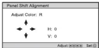
Setting items Description
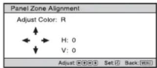
When “Zone” is selected: Select the position to adjust with the / button for the horizontal position (H Position) and the / button for the vertical position (V Position), then press .
![Panel Zone Alignment Adjust Color: R H Position: 10 V Position: 10 Set: [F] [G] [H] Set: [S] Back: [W] [X]](/content/2026/05/880636/images/c1e1ff10e80ce2c65d5f6ed776d42c6a97e8425b34714e2fcc2a110bd531f4c5.jpg)
Set the amount to adjust with the / button for the horizontal direction (H) and with the / button for the vertical direction (V). You can select the position to adjust again by pressing
Reset: Returns to the factory settings.
Preset: The optimized data has been preset.
Note
Depending on the adjustments made above, colors may become uneven or the resolution may change.
Network Setting Perform internet protocol settings.
IPv4 Setting
IP Address Setup: Selects the IP address setting method.
Auto(DHCP): The IP address is assigned automatically from the DHCP server such as a router.
Manual: Specifies the IP address manually.
When "Manual" is selected for "IP Address Setup," input "IP Address," "Subnet Mask," and "Default
Gateway." Select each item with the ↑/↓ button, then press ⊕ button. Select the frame to input with the
←/→ button and input the value with the ↑/↓ button. When all items are entered, select "Apply," and then
press the button. The entered settings will be registered.
IP Address: Sets the unit's IP address.
Subnet Mask: Sets the unit's subnet mask.
Default Gateway: Sets the unit's default gateway.
MAC Address: Displays the unit's MAC address. This cannot be changed.
Apply: Enables the IP address that is set manually.
IPv6 Information Displays the IPv6 information.
When you set the IPv6 IP address, set it on a Web browser (page 33).
Information Menu
The Information menu displays the model name, serial number, input signal type/format, software version and the cumulated hours of usage of the light.
Items Description
| Model Name Displays the model name |
| Serial No. Displays the serial number. |
| Signal type Displays the resolution of the input signal which you are selecting. When input signals with 3D information are input, the type of input signals and the 3D format are displayed. |
| Color Format Displays the color format of the input signal which you are selecting. |
| Color Space Displays the color space of the input signal which you are selecting (“BT.601,” “BT.709,” or “BT.2020”). |
| HDR Format When the input signal is compatible with HDR, “HDR10” or “HLG” is displayed according to the input signal. |
| Software Version Displays the software version. |
| Light Timer Displays how long the light has been turned on (total usage). |
Note
You cannot adjust or change the displays listed above.
About the Preset Memory
This unit has default image data to adjust preset data for input signals appropriately according to the signals shown in "Preset Signals" (page 41) (the preset memory). When the preset signal is input, the unit automatically detects the signal type and recalls the data for the signal from the preset memory to adjust it to an optimum picture. The signal type is displayed in the Information menu.
Note
Depending on the computer input signal, parts of projection image may be hidden or displayed incorrectly.
Using Network Features
Connection to the network allows you to operate the following features.
Use the projector with only necessary functions enabled.
- Checking the current status of the unit via a Web browser.
- Making the network settings for the unit.
• Network monitoring and controlling with control protocol (Advertisement, ADCP, AMX DDDP (Dynamic Device Discovery Protocol), Crestron RoomView, Control4).
Notes
- When connecting this projector with the network, consult with the person who sets up the network. The network must be secured.
- When using this projector connected with the network, access the Control window via a Web browser and change the access limitation of the factory preset values (page 34). It is recommended to change the password regularly.
- When the setting on the Web browser is completed, close the Web browser to log out.
- The menu displays used for the explanation below may be different depending on the model you are using.
- Supported Web browsers are Internet Explorer (version 11 or later), Safari, and Chrome.
• The menu displays only English. - If the browser of your computer is set to [Use a proxy server] when you have access to the unit from your computer, click the check mark to set accessing without using a proxy server.
• AMX DDDP is not compatible with IPv6.
• These network functions are available when the unit is turned on.
Displaying the Control Window of the Unit with a Web Browser
1 Connect the LAN cable.
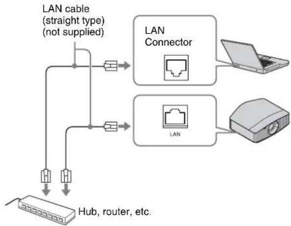
flowchart
graph TD
    A["LAN cable (straight type) (not supplied)"] --> B["LAN Connector"]
    A --> C["LAN"]
    B --> D["Laptop"]
    C --> E["Laptop"]
    F["Hub, router, etc."] --> A
2 Set the network settings for the unit using "Network Setting" on the Installation menu (page 31).
3 Start a Web browser on the computer, enter the following in the address field, then press the Enter key on your computer.
http://xxx.xxx.xxx.xxx
(xxx.xxx.xxx.xxx: IP address for the unit)
When connecting by the IPv6 address
http://[xxxx:xxxx:-xxxx]
You can confirm the IP address of the unit under "Network Setting" on the Installation menu.
The following window appears in the Web browser:
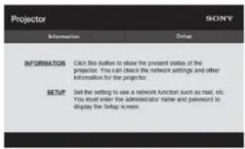
Once you make the network settings, you can open the Control window only by performing step 3 of this procedure.
Operating the Control Window
Switching the Page
Click one of the Page Switching buttons to display the desired setting page.
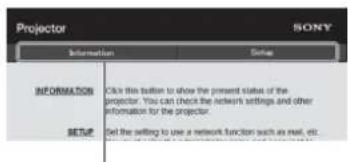
Page Switching buttons
Setting the Access Limitation
You can limit a user for accessing any particular page.
Administrator: Allowed access to all pages
User: Allowed access to all pages except the Setup page
When you access the Setup page for the first time, input "root" as the user name and "Projector" as the password in the authentication dialog.
When you log in for the first time, the window that prompts you to change the password is displayed. Follow the instructions on the screen to change the password.
The name of the administrator is preset to "root."
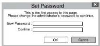
![Projector SONY Administrator Name: NEX Password: Confirm Password: Access User Name: Password: Confirm Password: Access Entry area for [Administrator]](/content/2026/05/880636/images/9752cf4df98ab78128317c9527251b591ac76a71cdb16200f89da054ea38a78a.jpg)
Entry area for [User]
The password can be changed in the Password page in the Setup page.
When you change the password, enter a new password.
The password of the administrator and user should be 8 to 16 characters that includes both alphabet and numeric characters. Alphabet is case-sensitive.
The default password "Projector" cannot be set as a new password.
Note
If you forget your password, consult with qualified Sony personnel. The password will be reset with your permission.
Confirming the Information Regarding the Unit
You can confirm the current settings for the unit on the Information page.
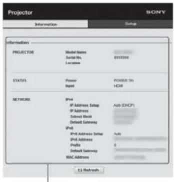
Information area
Troubleshooting
If the unit appears to be operating erratically, try to diagnose and correct the problem using the following instructions. If the problem persists, consult with qualified Sony personnel.
Power
| Symptom Cause and Remedy Page | |
| The power is not turned on. | The power may not turn on if you turn the power off with I/⏻ (On/Standby) button and turn it on again in a short time. After about 1 minute, turn the power on. |
| Check the indicators. 37 | |
| The power is suddenly turned off. Check that “Power Saving” in the Setup me#is set to “Standby.” 26 | |
Picture
| Symptom Cause and Remedy Page | ||
| No picture. Check that the connecting cable is connected to the external equipment properly. 10 | ||
| Select the input source correctly using the INPUT button. 11 | ||
| Check that the computer signal is set for output to an external monitor.If a notebook computer and the signal is output to its display and an external monitor, the external monitor's image may not be displayed correctly. Set your computer to output the signal to only an external monitor. | - | |
| The picture has ghosts. | Video images are displayed in 3D. Watch the 3D video images using the 3D glasses, and set “2D-3D Display Sel.” to “3D.” | 12, 27 |
| Bright or dark area of the video appears too bright or too dark. | This symptom may occur when a signal level other than those of HDMI standard is input.Switch the output level of the connected equipment, or switch the Dynamic Range on the Function menu of the unit. | 27 |
| The picture is too dark. | Adjust “Contrast” or “Brightness” on the Picture menu properly. | 19 |
| The picture is not clear. | Adjust the focus. | 7 |
| If the lens is clouded with dew condensation, leave the unit for about 2 hours with the power on. | - | |
| The color of characters or the picture is not appropriate. | Select the desired color registration in “Panel Alignment” on the Installation menu. | 30 |
| Image is left on the projection image. (Image retention) | When high contrast non-moving images are displayed for a long period of time, there may be some image retention on the projection image. This is only a temporary condition.Turning off the power for a while will eliminate the retained image. | - |
| Some color appears around the picture. | It may appear due to condensation.Wait for about 5 minutes with the power on. | - |
On-screen display
| Symptom Cause and Remedy Page | ||
| On-screen display does not appear. | Set “Status” on the Setup [icon] menu to “On.” | 26 |
| Check if the ON/STANDBY indicator should light in green. When the ON/STANDBY indicator blinks in green, the unit is starting up. Wait until it stops blinking and remains lit in green. | 7 | |
| The model name does not disappear from the screen. | The display mode of the unit may be set at the time of purchase. Consult with your local dealer or qualified Sony personnel. | - |
Remote control
| Symptom Cause and Remedy Page | ||
| The remote control does not work. Batteries could be weak. Replace them with new batteries. – | ||
| Insert the batteries with the correct polarities. – | ||
| If there is a fluorescent lamp near the remote control detector, the unit may work improperly or inadvertently. | – | |
| Confirm the position of the remote control detector on the unit. 3, 4 | ||
| Set “IR Receiver” to “Front & Rear” on the Installation menu. | 30 | |
| Make sure that the cable is not connected to the IR IN connector. | 3 | |
3D video images
| Symptom Cause and Remedy Page | ||
| The video image does not seem like 3D video images. | Check if the 3D glasses are turned on. 12 | |
| Make sure that the battery in the 3D glasses is sufficiently charged. - | ||
| Set “2D-3D Display Sel.” to “Auto” or “3D.” 27 | ||
| Check if the input signals are compatible 3D signals. 43 | ||
| The 3D signals may not be input depending on the specifications of the connected AV selector/AV amplifier/external equipment. If the 3D signal is not input, confirm the specifications and/or settings of the AV selector/AV amplifier/external equipment. | - | |
| When the viewing position is too far from the unit, the 3D glasses may not be able to display the images properly. | 12 | |
| The screen size is not appropriate. Set the zooming magnification to low or watch the image from farther away from the screen. | 48 | |
| For details, see “Precautions for use” of “Using the 3D Glasses.” | 12 | |
Others
| Symptom Cause and Remedy Page | ||
| The fan is noisy. | Check the setting of “High Altitude Mode” on the Setup [icon] menu. | 26 |
| Make sure that the room temperature is not too high. | - | |
| Check the installation requirements of the unit.Fan speed increases to maintain the product reliability of the projector’s components in a room where the temperature is higher than normal. The fan noise becomes slightly louder in these rooms. The approximate normal temperature for the unit is 25°C (77°F). | - | |
| The lens shift cannot be adjusted. | The lens shift cannot be adjusted over the range of movement. Adjust the lens shift within the range of movement. | 8, 48 |
About Indicators
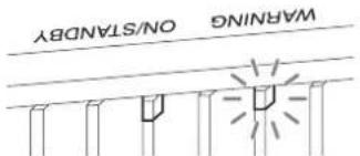
The ON/STANDBY or WARNING indicator lights up or flashes if there is any trouble with your projector.
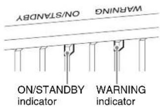
| Flashing/Lighting indicators The number of flashes | Cause and Remedy |
 (Flashes in red)(Lights in red) (Flashes in red)(Lights in red) | Three times The unit does not light properly due to an abnormality of the light source and light source power. Turn off, then turn on the power after a while.If the symptom persists, consult qualified Sony personnel. |
| Six times The unit detects a drop impact.If there is abnormality on the unit, consult with qualified Sony personnel.If there are no abnormalities on the unit, disconnect the AC power cord and check that the ON/STANDBY indicator turns off, then connect the AC power cord and turn the unit on. | |
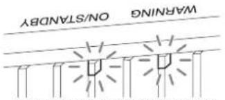 (Flashes in red) (Flashes in red)Both indicators flash (Flashes in red) (Flashes in red)Both indicators flash | Twice The internal temperature is unusually high. Check to ensure that nothing is blocking the ventilation holes and the unit is not being used at high altitudes. |
| Three times The fan is broken. Consult with qualified Sony personnel. |
Note
If the symptom persists even after carrying out the above methods, consult with qualified Sony personnel.
If the indicator starts flashing in a way of other than the above, turn off, and then turn on the power with the I/⏻ (On/Standby) button on the remote control or control panel of the unit.
If the symptom is shown again, consult with qualified Sony personnel.
Message Lists
Warning messages
| Symptom Cause and Remedy Page | ||
| High temp.! Light off in 1 min. Turn off the power. – | ||
| Check to ensure that nothing is blocking the ventilation holes. 3, 4 | ||
| Frequency is out of range! Frequency is out of range. Input a signal that is within the acceptable frequency range of the unit. | 41 | |
| Projector temperature is high. High Altitude Mode should be “On” if Projector is being used at high altitude. | Check to ensure that nothing is blocking the ventilation holes. 3, 4 | |
| When using the unit at high altitude, set “High Altitude Mode” to “On.” | 26 | |
| NoteWhen temperature inside the unit remains high, “High Altitude Mode” is switched to “On” in 1 minute, then the fan speed increases. | ||
| Power Saving Mode is set. Projector will automatically enter Standby Mode in 1 minute. | “Power Saving” is set to “Standby.” | 26 |
| NoteIf no signal is input, the power turns off after 1 minute, and the projector goes into standby mode. | ||
Caution messages
| Symptom Cause and Remedy Page | |
| x→ | No signal is input in the selected input. Check connections. 10 |
| Not applicable! Press the appropriate button.The operation to be activated by the button is currently prohibited. | |
| Settings Lock enabled. “Settings Lock” is set to “Level A” or “Level B.” 28 | |
Updating the Software
You can download files to update the software of the unit. Copy the downloaded files to your USB memory, insert the USB memory to the USB terminal of the unit, then perform the update.
To use the features updated, insert a USB memory device into a PC connected to the internet.
Download the update files from the following Sony website:
https://www.pro.sony.eu/
The website also explains how to install the update.
Note
Some USB memories may not be supported for use. For details, refer to the website above.
About HDR (high dynamic range)
HDR is a video expression which improves the ability to express dark places and bright places compared to previous video expressions.
About the Simulated 3D Feature
- Use the simulated 3D function taking into account that the picture will provide a different look from the original images, because this function converts the video images.
- Note that if the unit is used for profit or for public viewing, displaying 2D video images as 3D video images by converting to the simulated 3D may constitute an infringement of the rights of authors or producers, which are legally protected.
NOTICES AND LICENSES FOR SOFTWARE USED IN THIS PRODUCT
Refer to “Software License Information” supplied separately.
Trademark Information
- “PlayStation” is a registered trademark of Sony Interactive Entertainment Inc.
- The terms HDMI and HDMI High-Definition Multimedia Interface, and the HDMI Logo are trademarks or registered trademarks of HDMI Licensing Administrator, Inc. in the United States and other countries.
- “Blu-ray” and “Blu-ray Disc” are trademarks of Blu-ray Disc Association.
- “x.v.Color (x.v.Colour),” “Motionflow,” and their logos are trademarks of Sony Corporation.
This projector supports DeepColor, x.v.Color, LipSync, computer input signal, 3D signal, 4K signal of HDMI standards. It also supports HDCP.
Specifications
| Item Description | ||
| Display System SXRD panel, projection system | ||
| Display device Size of effective display area | 0.74-inch (18.8 mm) SXRD | |
| Number of pixels 26,542,080 pixels (8,847,360 pixels × 3) | ||
| Projection lens 2.06 times zoom lens (motorized) | ||
| f = 21.7 mm to 44.7 mm | ||
| F3.0 to F4.0 | ||
| Light source Laser diode | ||
| Projection image size 60-inch to 300-inch (1,524 mm to 7,620 mm) (measured diagonally) | ||
| Accepted digital signals See “Preset Signals” (page 41). | ||
| Inputs/Outputs HDMI connectors (HDCP 2.2) | ×2 | |
| TRIGGER connectors | ×2, mini jack, DC 12 V, Max. 100 mA | |
| REMOTE connector RS-232C: D-sub 9-pin (male) | ||
| LAN connector RJ45, 10BASE-T/100BASE-TX | ||
| IR IN connectors Minijack | ||
| USB connector | Type A, DC 5 V, Max. 500 mA | |
| Outside dimensions (w/h/d) | 560 mm × 223 mm × 496 mm (22 ^1/_16 inches × 8 ^25/_32 inches × 19 ^17/_32 inches) (without protrusions) | |
| Mass | Approx. 20 kg (44 lb) | |
| Power requirements | AC 100 V to 240 V, 4.3 A to 1.8 A, 50/60 Hz | |
| Power consumption | 430 W | |
| Standby mode power consumption | Standby | 0.4 W (when “Remote Start” is set to “Off”) |
| Networked Standby | 1.0 W (LAN) (when “Remote Start” is set to “On”)When a LAN terminal is not connected, it becomes a low power consumption mode (0.5 W). | |
| Operating temperature | 5°C to 35°C (41°F to 95°F) | |
| Operating humidity | 20% to 80% (no condensation) | |
| Storage temperature | -10°C to +60°C (14°F to 140°F) | |
| Storage humidity | 20% to 80% (no condensation) | |
| Supplied accessories | See “Checking the Supplied Accessories” on the Quick Reference Manual. | |
| Optional accessories | Projector Suspension Support: PSS-H10 | |
Notes
- The values for mass and dimensions are approximate.
- Not all optional accessories are available in all countries and area. Please check with your local Sony Authorized Dealer.
• Information on optional accessories in this manual is current as of September 2020.
Design and specifications of this unit and its optional accessories are subject to change without notice.
Preset Signals
The following table shows the signals and video formats which you can project using this unit.
When a signal other than the preset signals shown below is input, the picture may not be displayed properly.
| Preset memory no. | Preset signal (resolution) | fH (kHz) | fV (Hz) | Sync | ||
| 5 480/60p | 480/60p (Progressive NTSC) (720 × 480p) 31.470 60.000 - | |||||
| 6 576/50p | 576/50p (Progressive PAL) (720 × 576p) 31.250 50.000 - | |||||
| 7 1080/60i | 1080/60i (1920 × 1080i) 33.750 60.000 - | |||||
| 8 1080/50i | 1080/50i (1920 × 1080i) 28.130 50.000 - | |||||
| 10 720/60p | 720/60p (1280 × 720p) | 45.000 60.000 - | ||||
| 11 720/50p | 720/50p (1280 × 720p) | 37.500 50.000 - | ||||
| 12 1080/60p | 1080/60p (1920 × 1080p) | 67.500 60.000 - | ||||
| 13 1080/50p | 1080/50p (1920 × 1080p) | 56.260 50.000 - | ||||
| 14 1080/24p | 1080/24p (1920 × 1080p) | 26.973 23.976 - | ||||
| 18 720/60p (Frame packing) | 720/60p (1280 × 720p) | 90.000 60.000 - | ||||
| 19 720/50p (Frame packing) | 720/50p (1280 × 720p) | 75.000 50.000 - | ||||
| 20 1080/24p (Frame packing) | 1080/24p (1920 × 1080p) | 53.946 23.976 - | ||||
| 26 | 640 × 480 | VESA 60 | 31.469 | 59.940 | H-Neg, V-Neg | |
| 32 | 800 × 600 | VESA 60 | 37.879 | 60.317 | H-Pos, V-Pos | |
| 37 | 1024 × 768 | VESA 60 | 48.363 | 60.004 | H-Neg, V-Neg | |
| 45 | 1280 × 960 | VESA 60 | 60.000 | 60.000 | H-Pos, V-Pos | |
| 47 | 1280 × 1024 | VESA 60 | 63.974 | 60.013 | H-Pos, V-Pos | |
| 50 | 1400 × 1050 | SXGA+ | 65.317 | 59.978 | H-Neg, V-Pos | |
| 55 | 1280 × 768 | 1280 × 768/60 | 47.776 | 59.870 | H-Neg, V-Pos | |
| 71 1920 × | 1080/60i (Frame packing) | 1080/60i (1920 × 1080i) 67.500 60.000 | - | |||
| 72 1920 × | 1080/50i (Frame packing) | 1080/50i (1920 × 1080i) 56.250 50.000 | - | |||
| 74 | 3840 × 2160/60p | 3840 × 2160/60p (3840 × 2160) | 135.000 | 60.000 | - | |
| 75 | 3840 × 2160/50p | 3840 × 2160/50p (3840 × 2160) | 112.500 | 50.000 | - | |
| 76 | 4096 × 2160/60p | 4096 × 2160/60p (4096 × 2160) | 135.000 | 60.000 | - | |
| 77 | 4096 × 2160/50p | 4096 × 2160/50p (4096 × 2160) | 112.500 | 50.000 | - | |
| 78 4096 × | 2160/30p | 4096 × 2160/30p (4096 × 2160) | 67.500 30.000 - | |||
| 79 4096 × | 2160/25p | 4096 × 2160/25p (4096 × 2160) | 56.250 25.000 - | |||
| 93 3840 × | 2160/24p | 3840 × 2160/24p (3840 × 2160) | 53.946 23.976 - | |||
| 94 3840 × | 2160/25p | 3840 × 2160/25p (3840 × 2160) | 56.250 25.000 - | |||
| Preset memory no. | Preset signal (resolution) | fH (kHz) | fV (Hz) | Sync | |
| 95 3840 × | 2160/30p 3840 × 2160/30p (3840 × 2160) 67.433 29.970 – | ||||
| 96 4096 × | 2160/24p 4096 × 2160/24p (4096 × 2160) 54.000 24.000 – | ||||
Preset memory numbers for each input signal
Digital signal
| Signal Preset memory number | |
| Component signal (HDMI 1, 2 connectors) 5 to 8, 10 to 14, 18 to 20, | 71, 72, 74 to 79, 93 to 96 |
| Video GBR signal (HDMI 1, 2 connectors) 5 to 8, 10 to 14, 18 to 20, | 71, 72, 74 to 79, 93 to 96 |
| Computer signal (HDMI 1, 2 connectors) 10*, 12*, 26, 32, 37, 45, 47, 50, 55 | |
* Some digital signals input from computers may be displayed as preset memory number of Component or Video GBR signal.
Input Signals and Adjustment/Setting Items
The items in the menus available to adjust differ depending on the input signal. The following tables indicate them. The items that cannot be adjusted/set are not displayed in the menu.
Picture menu
| Item | Input signal | ||
| Component signal Video G | BR signal Computer signal | ||
| Reality Creation | ● | ● | |
| Advanced Iris and Laser Setting | ● | ● | ● |
| Dynamic HDR Enhancer ● | ● | - | |
| Motionflow*1 | ● | ● | |
| Contrast | ● | ● | ● |
| Brightness | ● | ● | |
| Color | ● | ● | |
| Hue | ● | ● | |
| Color Temp. | ● | ● | ● |
| Sharpness | ● | ● | |
| NR | ● (excluding preset memory numbers 18 to 20, 71, and 72) | ● (excluding preset memory numbers 18 to 20, 71, and 72) | - |
| MPEG NR | ● (excluding preset memory numbers 18 to 20, 71, and 72) | ● (excluding preset memory numbers 18 to 20, 71, and 72) | - |
| Smooth Gradation | ● (excluding preset memory numbers 18 to 20, 71 and 72) | ● (excluding preset memory numbers 18 to 20, 71 and 72) | - |
| Film Mode | ● (excluding preset memory numbers 5, 6, 10 to 14, 18 to 20, 74 to 79, and 93 to 96) | ● (excluding preset memory numbers 5, 6, 10 to 14, 18 to 20, 74 to 79, and 93 to 96) | - |
| Gamma Correction | ● | ● | ● |
| Color Correction | ● | ● | |
| Clear White | ● | ● | |
| x.v.Color | ● | - | - |
| HDR | ● (preset memory numbers 74 to 79 and 93 to 96 only) | ● (preset memory numbers 74 to 79 and 93 to 96 only) | - |
| Color Space | ● | ● | ● |
●: Adjustable/can be set
-: Not adjustable/cannot be set
*1: For further details, refer to the tables in “Motionflow” (page 45).
Screen menu
| Item | Input signal | ||
| Component signal Video GBR signal Computer signal | |||
| Aspcct^*1 | ● | ● | - |
●: Adjustable/can be set
-: Not adjustable/cannot be set
*1: For further details, refer to the tables in "Aspect Mode" (page 44).
Note
When connecting a cable such as an HDMI cable, etc., check the type of the signal in the Information ⓘ menu (page 32) and “Digital signal” (page 42), and check items that are adjustable/can be set.
Compatible 3D Signals
This unit accepts the following types of 3D signals.
| Resolution 3D signal format | |
| 720/60p, 720/50p Side-by-Side format | Over-Under format* |
| Frame packing* | |
| 1080/60i, 1080/50i Side-by-Side format* | |
| 1080/24P Side-by-Side format | |
| Over-Under format* | |
| Frame packing* | |
| 1080/60p, 1080/50p Side-by-Side format | |
*: Mandatory 3D format of the HDMI standards.
3D Signals and Adjustable/Setting Items
Some items on the menus may not be available to adjust/set, depending on the 3D signals.
The items that cannot be adjusted are not displayed on the menu. The following tables indicate those items.
| Item | 3D signals | |||
| 720/60p, 720/50p | 1080/60i, 1080/50i | 1080/24p | 1080/60p, 1080/50p | |
| Reality Creation | ● | ● | ● | ● |
| Advanced Iris and Laser Setting*1 | ● | ● | ● | ● |
| Motionflow*2 | ● | ● | ● | ● |
| NR | - | - | - | - |
| MPEG NR | - | - | - | - |
| Smooth Gradation | - | - | - | - |
| Film Mode | - | ● | - | - |
| x.v.Color | ● | ● | ● | ● |
| HDR | - | - | - | - |
| Aspect*3 | ● | ● | ● | ● |
●: Adjustable/can be set
-: Not adjustable/cannot be set
*1: "Dynamic Control" cannot be selected.
*2: This item is not available when the 3D signal is 720/60p Frame packing/Over-Under format or 1080/60p Over-Under format.
*3: For further details, refer to the tables in "Aspect Mode" (page 44).
When the unit is set to convert 2D video images to 3D video images, some items on the menus may be not available to adjust/set, depending on the "3D Format" settings on the Function menu. The items that cannot be adjusted are not displayed on the menu. The following tables indicate these items.
| Item | 3D signals | ||
| Over-Under Side-by-Side Simulated 3D | |||
| Reality Creation | ● | ● | ● |
| Advanced Iris and Laser Setting*1 | ● | ● | ● |
| Motionflow*2 | ● | ● | ● |
| NR -- ● | |||
| MPEG NR -- ● | |||
| Smooth Gradation ● | ● | ● | |
| Film Mode*3 | - ● | ● | |
| x.v.Color ● | ● | ● | |
| HDR --- | |||
| Aspect*4 | ● | ● | ● |
●: Adjustable/can be set
-: Not adjustable/cannot be set
*1: "Dynamic Control" cannot be selected.
*2: This item is not available when the 3D signal is 720/60p Frame packing/Over-Under format or 1080/60p Over-Under format.
*3: This item is available only when the 1080/60i or 1080/50i signal is input.
*4: For further details, refer to the tables in "Aspect Mode" (page 44).
Aspect Mode
Selectable items vary depending on the type of input signal or 3D format.
For details, see the tables below. Items that cannot be selected are not displayed in the menu.
2D
| Acceptable signals | 4096 × 2160 | 3840 × 2160 | 1920 × 10801280 × 720 | 720 × 480720 × 576 | Others |
| Preset memory number(page 41) | 76 to 79, 96 | 74, 75, 93 to 95 | 7, 8, 10 to 14 | 5, 6 | 26, 32, 37, 45, 47,50,55 |
| 1.85:1 Zoom | - | ● | ● | ● | - |
| 2.35:1 Zoom | - | ● | ● | ● | - |
| Normal | ● | ● | ● | ● | ●* ^1 |
| V Stretch | ● | ● | ● | ● | - |
| Squeeze | ● | ● | ● | ● | - |
| Stretch | - | - | - | ● | - |
*1: Not displayed in the menu as fixed at Normal.
3D
| Acceptable signals 1920 × 1080, 1280 × 720 | ||||
| 3D format | Side-by-Side | Over-Under | Frame packing | Simulated 3D |
| Preset memory number(page 41) | 7, 8, 10 to 14 | 10 to 14 | 18 to 20, 71, 72 | 7, 8, 10 to 14 |
| 1.85:1 Zoom | ● | ● | ● | ● |
| 2.35:1 Zoom | ● | ● | ● | ● |
| Normal | ● | ● | ● | ● |
| V Stretch | ● | ● | ● | ● |
| Squeeze ● | ● | ● | ● | |
| Stretch | — | — | — | — |
Motionflow
Selectable items vary depending on the type of input signal or 3D format.
For details, see the tables below. Items that cannot be selected are not displayed in the menu.
2D
| Acceptable signals | 1920 × 10801280 × 720720 × 480720 × 576 | 3840 × 2160 4096 × 2160 Others | ||
| Preset memory number (page 41) | 5 to 8, 10 to 14 | 74, 75, 93 to 95 | 76 to 79, 96 | 26, 32, 37, 45, 47, 50, 55 |
| Smooth High | ● | ● | - | - |
| Smooth Low | ● | ● | - | - |
| True Cinema | ● | ● | - | - |
3D
| Acceptable signals | 1920 × 1080, 1280 × 720 | |||||||
| 3D format | Frame packing | Over-Under | Side-by-Side | Simulated 3D | ||||
| Preset memory number (page 41) | 18 | 19 | 20, 71, 72 | 10,12 | 11,13 | 14 | 7, 8, 10 to 14 | 7, 8, 10 to 14 |
| Smooth High | - | - | ● | - | - | ● | ● | ● |
| Smooth Low | - | ● | ● | - | ● | ● | ● | ● |
| True Cinema | - | - | - | - | - | - | - | - |
Storage Conditions of Adjustment/Setting Items
Each adjustable/setting item is individually stored for each input connector. For further details, see the tables below.
Preset memory numbers for each input signal
| Input Preset memory numbers | |
| HDMI 1 (2D) 5 to 8, 10 to 14, 26, 32, 37, 45 | 47, 50, 55, 74 to 79, 93 to 96 |
| HDMI 2 (2D) | |
| HDMI 1 (3D) 7, 8, 10 to 14, 18 to 20, 71, 72 | |
| HDMI 2 (3D) |
Picture menu
| Item Storage conditions | |
| Calib. Preset For each input connector and 2D/3D | |
| Reset For each input connector, 2D/3D, HDR/SDR | *1, and Calib. Preset |
| Reality Creation | |
| Advanced Iris and Laser Setting | |
| Dynamic HDR Enhancer | |
| Motionflow | |
| Contrast | |
| Brightness | |
| Color | |
| Hue | |
| Color Temp. | |
| D93 - D55 | |
| Custom 1-5 | |
| Gain R For each Color Temp., D93-D55 and Custom 1-5 | |
| Gain G | |
| Gain B | |
| Bias R | |
| Bias G | |
| Bias B | |
| Sharpness For each input connector, 2D/3D, HDR/SDR | *1, and Calib. Preset |
| NR | |
| MPEG NR | |
| Smooth Gradation | |
| Film Mode | |
| Gamma Correction | |
| Color Correction | |
| Clear White | |
| x.v.Color | |
| HDR For each input connector and Calib. Preset | |
| Color Space For each input connector, 2D/3D, HDR/SDR | *1, and Calib. Preset |
| Cyan - Red For each Color | Space |
| Magenta - Green | |
| Input Lag Reduction | For each input connector, 2D/3D, HDR/SDR*1, and Calib. Preset |
*1: HDR/SDR
HDR: When the HDR signal is input with "Auto" set for HDR
When "HDR" is set to "HDR10," "HDR Reference," or "HLG"
SDR : Settings other than the above
Screen menu
| Item Storage conditions | |
| Aspect For Picture Position 1 | 85:1, 2.35:1, or Custom 1-3 |
| Blanking |
Projection Distance and Lens Shift Range
The projection distance refers to the distance between the front of the lens and the projected surface.
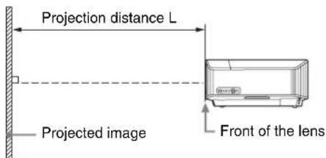
The lens shift range represents the distance in percent (\%) by which the lens can be shifted from the center of the projected image. The lens shift range is regarded as 0% when the point Ⓐ in the illustration (point where a line drawn from the center of the lens and the projected image cross at right angles) is aligned with the center of the projected image and full width or full height of the projected image is regarded as 100%.
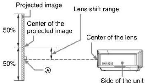
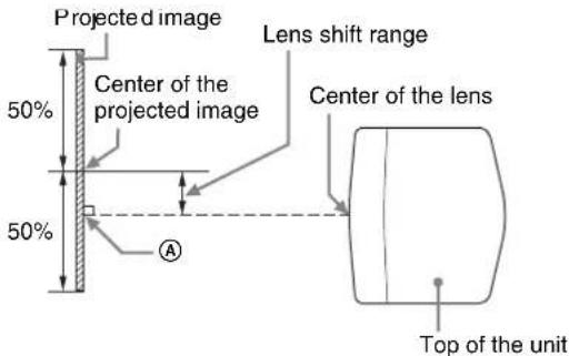
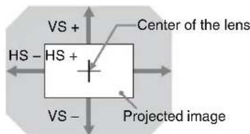
Shaded region: Lens shift range
VS +: Vertical lens shift range (up) [%]
VS -: Vertical lens shift range (down) [%]
HS +:Horizontal lens shift range (right) [%]
HS -:Horizontal lens shift range (left) [%]
When projecting in 1.90:1 (Native Full Display 17:9) format
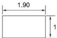
Projection distance
Unit: m (inches)
| Projection image size | Projection distance L | |
| Diagonal Width × Height | ||
| 80" (2.03 m) 1.80 × 0.95 (71 × 37) 2.32 – 4.77 (91 – 187) | ||
| 100" (2.54 m) 2.25 × 1.18 (88 × 47) 2.90 – 5.97 (115 – 235) | ||
| 120" (3.05 m) 2.70 × 1.42 (106 × 56) 3.49 – 7.18 (138 – 282) | ||
| 150" (3.81 m) 3.37 × 1.78 (133 × 70) 4.38 – 8.98 (173 – 353) | ||
| 200" (5.08 m) 4.49 × 2.37 (177 × 93) 5.85 – 11.99 (231 – 472) | ||
Projection distance formula
D: Projection image size (")
Example) Enter 80 in D for the 80" projection image size. Unit: m (inches)
| Projection distance L(minimal length) | Projection distance L(maximal length) |
| L = 0.029432 × D - 0.0434 (L = 1.158727 × D - 1.7084) | L = 0.060197 × D - 0.0420 (L = 2.369978 × D - 1.6545) |
Lens shift range
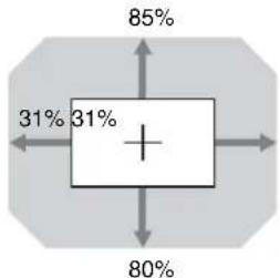
boxplot
| Category | Value (%) | |---|---| | Top Box | 85 | | Bottom Box | 31 | | Center Box | 31 | | Right Box | 80 |$$ \begin{array}{l} \mathrm{VS} + = 85 - 2.742 \times (\mathrm{HS} + \text { or } \mathrm{HS} -) [\% ] \ \mathrm{VS} - = 80 - 2.742 \times (\mathrm{HS} + \text { or } \mathrm{HS} -) [\% ] \ \mathrm{HS} + = \mathrm{HS} - = 31 - 0.365 \times (\mathrm{VS} + \text { or } \mathrm{VS} -) [\% ] \ \end{array} $$
When projecting in 1.78:1 (16:9) format
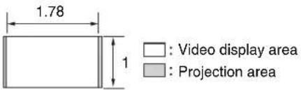
Projection distance
Unit: m (inches)
| Projection image size | Projection distance L | |
| Diagonal Width × Height | ||
| 80" (2.03 m) 1.77 × 1.00 (70 × 39) 2.44 – 5.01 (96 – 197) | ||
| 100" (2.54 m) 2.21 × 1.25 (87 × 49) 3.05 – 6.28 (121 – 247) | ||
| 120" (3.05 m) 2.66 × 1.49 (105 × 59) 3.67 – 7.55 (145 – 297) | ||
| 150" (3.81 m) 3.32 × 1.87 (131 × 74) 4.60 – 9.44 (181 – 371) | ||
| 200" (5.08 m) 4.43 × 2.49 (174 × 98) 6.15 – 12.61 (242 – 496) | ||
Projection distance formula
D: Projection image size (")
Example) Enter 80 in D for the 80" projection image size. Unit: m (inches)
| Projection distance L(minimal length) | Projection distance L(maximal length) |
| L = 0.030934 × D - 0.0434 (L = 1.217856 × D - 1.7084) | L = 0.063269 × D - 0.0420 (L = 2.490916 × D - 1.6545) |
Lens shift range
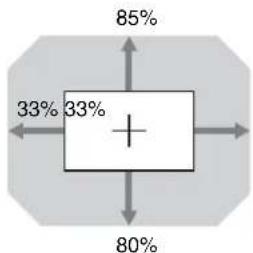
boxplot
| Value (%) | |---| | 85 | | 33 | | 33 | | 80 |$$ \begin{array}{l} \mathrm{VS} + = 85 - 2.576 \times (\mathrm{HS} + \text { or } \mathrm{HS} -) [\% ] \ \mathrm{VS} - = 80 - 2.576 \times (\mathrm{HS} + \text { or } \mathrm{HS} -) [\% ] \ \mathrm{HS} + = \mathrm{HS} - = 33 - 0.388 \times (\mathrm{VS} + \text { or } \mathrm{VS} -) [\% ] \ \end{array} $$
When projecting in 2.35:1 format
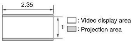
Projection distance
Unit: m (inches)
| Projection image size | Projection distance L | |
| Diagonal Width × Height | ||
| 80" (2.03 m) 1.87 × 0.80 (74 × 31) 2.41 – 4.96 (95 – 195) | ||
| 100" (2.54 m) 2.34 × 0.99 (92 × 39) 3.02 – 6.22 (119 – 244) | ||
| 120" (3.05 m) 2.80 × 1.19 (110 × 47) 3.64 – 7.47 (143 – 294) | ||
| 150" (3.81 m) 3.51 × 1.49 (138 × 59) 4.55 – 9.35 (180 – 368) | ||
| 200" (5.08 m) 4.67 × 1.99 (184 × 78) 6.08 – 12.48 (240 – 491) | ||
Projection distance formula
D: Projection image size (")
Example) Enter 80 in D for the 80" projection image size. Unit: m (inches)
| Projection distance L(minimal length) | Projection distance L(maximal length) |
| L = 0.030617 × D - 0.0434 (L = 1.205377 × D - 1.7084) | L = 0.062621 × D - 0.0420 (L = 2.465393 × D - 1.6545) |
Lens shift range
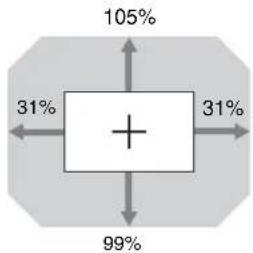
pie
| Category | Percentage (%) | |---|---| | Top Left | 105 | | Bottom Left | 31 | | Bottom Right | 99 | | Bottom Right | 31 | The label '+' in the center is centered within the diagram. The arrows indicate directional relationships or transitions between these categories.$$ \begin{array}{l} \mathrm{VS} + = 105 - 3.387 \times (\mathrm{HS} + \text { or } \mathrm{HS} -) [\% ] \ \mathrm{VS} - = 99 - 3.387 \times (\mathrm{HS} + \text {or HS} -) [\% ] \ \mathrm{HS} + = \mathrm{HS} - = 31 - 0.295 \times (\mathrm{VS} + \text { or } \mathrm{VS} -) [\% ] \ \end{array} $$
Dimensions
Front
Unit: mm (inches)
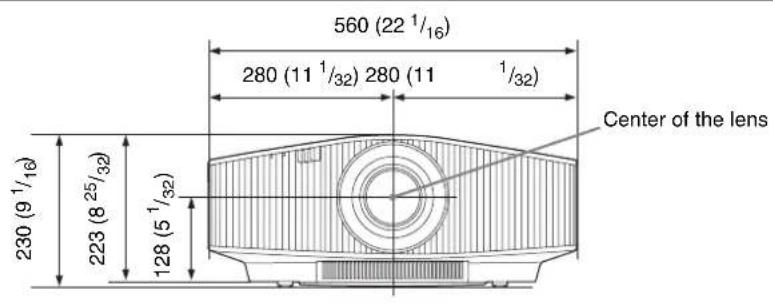
Bottom
Unit: mm (inches)
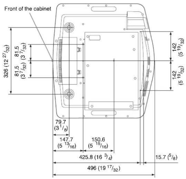
The distance between the front of the lens and the front of the cabinet
Unit: mm (inches)
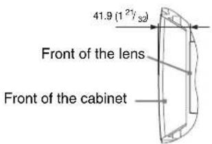
Attaching the PSS-H10 projector suspension support
Front view
Unit: mm (inches)
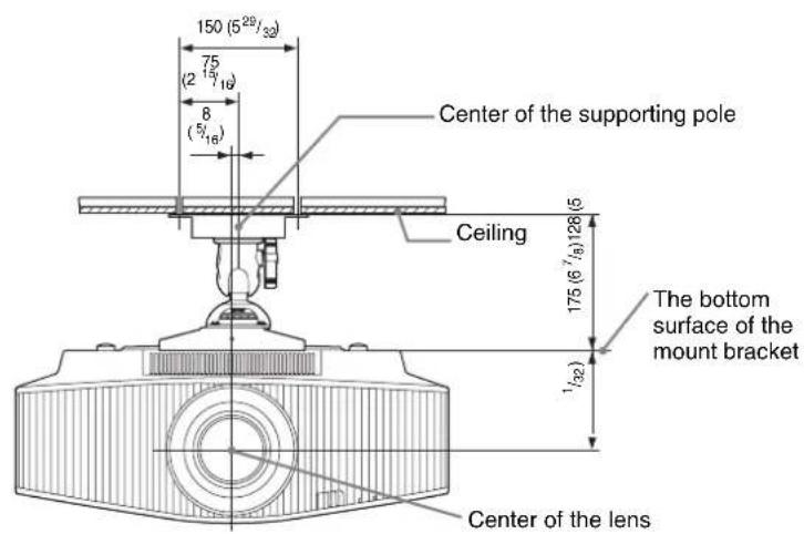
Unit: mm (inches)
Side view
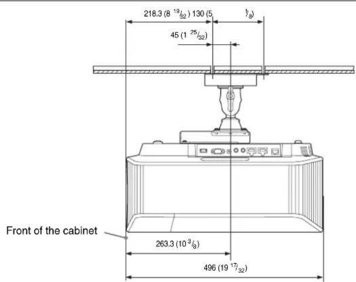
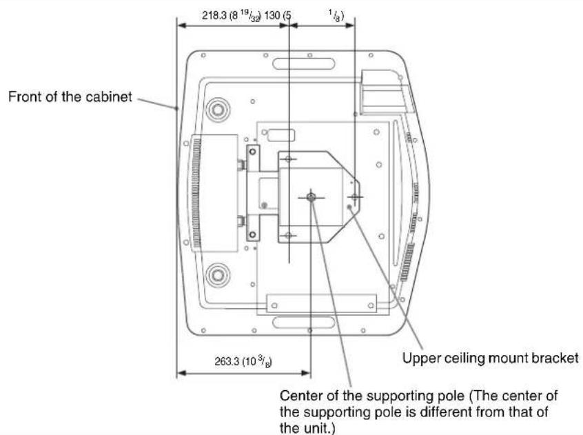
Holes for the ceiling mount
Use the screws with a length of 5.3 mm ( ^7/32 inches, minimum) to 7.0 mm ( ^9/32 inches, maximum) for the ceiling mount. Recommended tightening torque (tension when turning a screw towards the direction of rotation): 1.4 ± 0.2 N-m
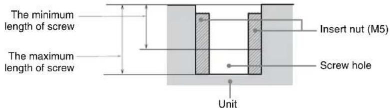
- Operating Instructions
- Table of Contents
- Location of Controls
- Connections and Preparations
- Projecting
- Using the Menus
- Using Network Features
- Error Handling
- Others
- Indicators
- Connectors
- Rear/Left Side/Bottom
- Control panel
- Remote Control
- Installing the Unit
- Note
- Adjusting the Picture Position
- Tips
- To adjust the horizontal position
- Top view
- To adjust the vertical position
- Side view
- Range of movement of the projected picture
- To adjust the tilt of the installation surface
- Notes
- Lens adjustment window (test pattern)
- Connecting to Video Equipment or a Computer
- When making connections, be sure to do the following:
- Projecting the Picture
- Turning Off the Power
- Tip
- Watching 3D Video Images
- Adjusting/Setting the 3D functions
- Using the 3D Glasses
- Precautions for use
- 3D glasses communication range
- Using the Picture Position
- Image of the lens moving
- Selecting the Aspect Ratio According to the Video Signal
- Notes on switching the "Aspect" setting
- Selecting the Picture Viewing Mode
- Operation through the Menus
- Press MENU.
- Pop-up menu
- Setting menu
- Adjustment menu
- Next menu window
- When changing the adjustment level
- When changing the setting
- To clear the menu
- To reset the picture that has been adjusted
- To reset the items that have been adjusted
- Picture Menu
- Advanced Picture Menu
- Screen Menu
- Setting items Description
- Setup Menu
- Function Menu
- Items Locked by Settings Lock
- Installation Menu
- Information Menu
- About the Preset Memory
- Displaying the Control Window of the Unit with a Web Browser
- When connecting by the IPv6 address
- Operating the Control Window
- Switching the Page
- Setting the Access Limitation
- Confirming the Information Regarding the Unit
- Troubleshooting
- 3D video images
- About Indicators
- Message Lists
- Warning messages
- Caution messages
- Updating the Software
- About HDR (high dynamic range)
- About the Simulated 3D Feature
- NOTICES AND LICENSES FOR SOFTWARE USED IN THIS PRODUCT
- Trademark Information
- Specifications
- Preset Signals
- Preset memory numbers for each input signal
- Input Signals and Adjustment/Setting Items
- Compatible 3D Signals
- 3D Signals and Adjustable/Setting Items
- Aspect Mode
- Motionflow
- Storage Conditions of Adjustment/Setting Items
- Projection Distance and Lens Shift Range
- When projecting in 1.90:1 (Native Full Display 17:9) format
- Projection distance
- Projection distance formula
- D: Projection image size (")
- Lens shift range
- When projecting in 1.78:1 (16:9) format
- When projecting in 2.35:1 format
- Dimensions
- Attaching the PSS-H10 projector suspension support
- Holes for the ceiling mount
Brand : SONY
Model : VPL-VW915ES
Category : Vidéo-projecteur