
eCA120 - Receiver Ecler - Free user manual and instructions
Find the device manual for free eCA120 Ecler in PDF.


| Product Type | Receiver / Power Amplifier |
| Brand | Ecler |
| Model | eCA120 |
| Channels | 2 |
| Output Power | 120W per channel (4 ohms) |
| Frequency Response | 20 Hz – 20 kHz (±0.5 dB) |
| Total Harmonic Distortion (THD) | < 0.1% |
| Input Sensitivity | 0.775V (0 dBu) |
| Input Impedance | 10 kΩ (balanced), 20 kΩ (unbalanced) |
| Output Impedance | 4-16 Ω per channel |
| Connections | XLR, TRS, Speakon, binding posts |
| Protection Features | Short circuit, thermal, overload, DC offset |
| Cooling | Variable speed fan |
| Rack Mountable | Yes, 19" standard, 2U height |
| Dimensions (W x H x D) | 483 x 88 x 300 mm |
| Weight | 8.5 kg |
| Power Supply | 230 VAC, 50-60 Hz |
| Power Consumption | 400W max |
| Operating Temperature | 0°C to 40°C |
| Accessories Included | Power cord, rack ears, user manual |
| Intended Use | Professional audio, PA, installation |
Frequently Asked Questions - eCA120 Ecler
User questions about eCA120 Ecler
0 question about this device. Answer the ones you know or ask your own.
Ask a new question about this device
Download the instructions for your Receiver in PDF format for free! Find your manual eCA120 - Ecler and take your electronic device back in hand. On this page are published all the documents necessary for the use of your device. eCA120 by Ecler.
USER MANUAL eCA120 Ecler
USER MANUAL
INDEX
- IMPORTANT REMARK....3
- IMPORTANT SAFETY INSTRUCTIONS....3
- IMPORTANT NOTE....5
- COMPLIANCE WITH INTERNATIONAL STANDARDS....5
- INTRODUCTION....6
5.1. Main characteristics....6
- INSTALLATION....7
6.1. Location and assembly....7
6.2. Mains connection....7
6.3. Audio input connections 8
6.4. Audio output connections 8
6.5. Remote control port 8
- OPERATION AND USAGE....9
7.1. Start up....9
7.2. AUTO STANDBY Function....9
7.3. LED indicators .... 10
7.4. Setup jumpers....10
- CLEANING....10
- DIAGRAM and LIST OF FUNCTIONS....11
- BLOCK DIAGRAM....12
- CONFIGURATION DIAGRAM ....12
- TECHNICAL CHARACTERISTICS....13
1. IMPORTANT REMARK

WARNING: SHOCK HAZARD - DO NOT OPEN
AVIS: RISQUE DE CHOC ÉLECTRIQUE - NE PAS OUVRIR

The lightning flash with arrowhead symbol, within an equilateral triangle, is intended to alert the user to the presence of uninsulated “dangerous voltage” within the product’s enclosure that may be of sufficient magnitude to constitute a risk of electric shock to persons.

The exclamation point within an equilateral triangle is intended to alert the user to the presence of important operating and maintenance (servicing) instructions in the literature accompanying the appliance.
WARNING (If applicable): The terminals marked with symbol of “⚡” may be of sufficient magnitude to constitute a risk of electric shock. The external wiring connected to the terminals requires installation by an instructed person or the use of ready-made leads or cords.
WARNING: To prevent fire or shock hazard, do not expose this equipment to rain or moisture.
WARNING: An apparatus with Class I construction shall be connected to a mains socket-outlet with a protective earthing connection.
2. IMPORTANT SAFETY INSTRUCTIONS
- Read these instructions.
- Keep these instructions.
- Heed all warnings.
- Follow all instructions.
- Do not use this apparatus near water.
-
Clean only with dry cloth.
-
Do not block any ventilation openings. Install in accordance with the manufacturer's instructions.
-
Do not install near any heat sources such as radiators, heat registers, stoves, or other apparatus (including amplifiers) that produce heat.
-
Do not defeat the safety purpose of the polarized or grounding type plug. A polarized plug has two blades with one wider than the other. A grounding type plug has two blades and a third grounding prong. The wide blade or the third prong are provided for your safety. If the provided plug does not fit into your outlet, consult an electrician for replacement of the obsolete outlet.
- Protect the power cord from being walked on or pinched particularly at the plugs, convenience receptacles, and at the point where they exit from the apparatus.
- Only use attachments/accessories specified by the manufacturer.
- Unplug the apparatus during lightening sorts or when unused for long periods of time.
- Refer all servicing to qualified personnel. Servicing is required when the apparatus has been damaged in any way, such as power supply cord or plug is damaged, liquid has been spilled or objects have fallen into the apparatus, the apparatus has been exposed to rain or moisture, does not operate normally, or has been dropped.
- Disconnecting from mains: When switching off the POWER switch, all the functions and light indicators of the unit will be stopped, but fully disconnecting the device from mains is done by unplugging the power cable from the mains input socket. For this reason, it always shall remain easily accessible.
- Equipment is connected to a socket-outlet with earthing connection by means of a power cord.
- The marking information is located at the bottom of the unit.
- The apparatus shall not be exposed to dripping or splashing and that no objects filled with liquids, such as vases, shall be placed on apparatus.
- This product is for indoor use only.
NOTE: This equipment has been tested and found to comply with the limits for a Class A digital device, pursuant to part 15 of the FCC Rules. These limits are designed to provide reasonable protection against harmful interference when the equipment is operated in a commercial environment. This equipment generates, uses, and can radiate radio frequency energy and, if not installed and used in accordance with the instruction manual, may cause harmful interference to radio communications. Operation of this equipment in a residential area is likely to cause harmful interference in which case the user will be required to correct the interference at his own expense.

WARNING: This product must not be discarded, under any circumstance, as unsorted urban waste. Take to the nearest electrical and electronic waste treatment centre.
NEEC AUDIO BARCELONA, S.L. accepts no liability for any damage that may be caused to people, animal or objects due to failure to comply with the warnings above.
3. IMPORTANT NOTE
Thank you for choosing our Ecler eCA120 Stereo Micro-Amplifier!
It is VERY IMPORTANT to carefully read this manual and to fully understand its contents before any connection in order to maximize your use and get the best performance from this equipment.
To ensure optimal operation of this device, we strongly recommend that its maintenance be carried out by our authorised Technical Services.
All ECLER products are covered by warranty, please refer to www.ecler.com or the warranty card included with this product for the period of validity and conditions.
4. COMPLIANCE WITH INTERNATIONAL STANDARDS
The eCA120 micro amplifier complies with the following international standards:
• EN55103-1 Electromagnetic Compatibility.
Product family standard for audio, video, audio-visual and entertainment lighting control apparatus for professional use Part 1: Emission
• EN55103-2 Electromagnetic Compatibility.
Product family standard for audio, video, audio-visual and entertainment lighting control apparatus for professional use Part 2: Immunity
- EN60065 Audio, video and similar electronic apparatus. Safety requirements Complying with the requirements of directives 2006/95/EC and 2004/108/EC
5. INTRODUCTION
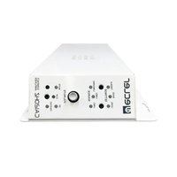
The eCA120 is a stereo amplifier with a very small size and a remote control function through a 0-10VDC port; it's an ideal choice for audio-visual applications: school rooms, meeting rooms, multimedia presentations, commercial premises, etc.
5.1. Main characteristics
- 2 x 60 W RMS @ 4 Ω amplifier
• Universal external power supply - AUTO STANDBY function: in the absence of an audio signal the unit automatically goes into STANDBY mode, minimising power consumption
• Lightweight, silent, high-performance amplifier (fan-free convection cooling) - Suitable for stereo and parallel (mono)
- 1 unbalanced stereo line input (LINE IN / STACK), with dual RCA connector and 3-pin Euroblock connector
- Local volume control by knob
- Remote volume control by Wpa series wall panel (0-10VDC)
6. INSTALLATION
WARNING: Non-compliance with the instructions or neglecting warnings may cause malfunction or even damage the unit:
- Avoid turning on the device without the speakers connected to its outputs and without having previously set the volume/gain controls to minimum level.
- Always use shielded cables to make connections between devices.
- In an amplifier, avoid placing the speaker output cables close to other signal cables (micro, line...). This may cause the system to oscillate, damaging the amplifier and speakers.
6.1. Location and assembly
The eCA120 is suitable for installation on a wall or under a surface (table, shelf, cupboard, etc.), thanks to its design and layout of its connectors, controls and LED indicator lights.
6.2. Mains connection
The amplifier is powered by alternating current through its external power source: 100-240 VAC and 50-60 Hz.
This apparatus must be earthed through its mains cable (earth resistance, Rg = 30 Ω, or lower). The atmosphere should be as dry and dust free as possible. Do not expose the unit to rain or water splashes. Do not place liquid containers or incandescent objects like candles on top of the unit.

Should any work or connection / disconnection task be done, always disconnect the unit from the mains supply. There are no elements that can be manipulated by the user inside the amplifier.
To avoid buzzing, do not allow the power cable to intertwine with the shielded cables that transport the audio signal.
6.3. Audio input connections
The eCA120 input channel only supports stereo line signals (or two mono signals). It has an unbalanced stereo connection with dual RCA connector and 3-pin Euroblock connector (LINE IN / STACK). This input is designed to support -6dBV to 0dBV signals, given that the rotary volume control of the front panel has an extra +6dB of gain at its maximum position.
This audio input can receive signals from CD players, radio tuners, mixing consoles, media players, audio outputs of computers and tablets, etc.
LINE IN and STACK connections are linked, so that when you use one of them as an audio signal input for your unit, you can use the other to send that signal to another unit or external equipment.
Note: Turntables CANNOT BE CONNECTED directly to this device because none of the inputs have an RIAA preamp.
6.4. Audio output connections
The amplified output (OUT L and R) have Euroblock connectors.
The connection cable that connects the eCA120 connectors and the speakers should be good quality, with a suitable cross section and as short as possible.
The L and R outputs respectively deliver an amplified version of the L and R inputs of the unit.
Remember that the minimum load impedance for each output channel is 4 . For correct operation of the eCA120, under no circumstances must you work with impedance lower than specified above.
6.5. Remote control port
The RJ-45 REMOTE connector allows to connect a WpaVOL-type wall control panel (or another model of the Wpa series) to adjust the overall output volume. The connection is made with a standard CAT5 cable between the Wpa wall panel and the REMOTE connector of the eCA120.
Note: The jumper labeled "REMOTE" on the front panel has to be in the ON position to enable the remote volume control.
Start up the eCA120 by connecting the equipment to an external power source to which the DC 24V connector of the eCA120 has already been connected. The LED indicator ON/STBY immediately lights up on the front panel. We recommend you turn on all the devices in the following order: sound sources, mixer, equalisers, active filters and processors and, finally power amplifiers. Powering off should be done by following the exact reverse sequence. Following this order, the introduced noise due to turning on or switching off the devices will not affect those further on in the chain and will be inaudible.
Once turned on, the front volume control (VOLUME) and the controller connected to the REMOTE port (if any) may be used to set the output volume of the signal amplified by the unit.
7.2. AUTO STANDBY Function
The AUTO STANDBY function (idle or low consumption mode) means you can install the eCA120 in inaccessible places and leave the device connected to the mains power supply permanently because when no signal is detected, it automatically goes into standby mode, saving energy.
To enable the AUTO STANDBY mode, the jumper labeled "AUTO STBY" on the front panel has to be in the ON position. When it is enabled and after 2 minutes or more without any audio signal at the audio input of the device (or a very weak signal, lower than the activation threshold), the eCA120 will automatically switch into standby mode, lighting up the amber ON/STBY LED located on the front panel of the device. When a valid audio signal is detected in any of the inputs, the eCA120 leaves standby mode and starts operating normally again and the ON/STBY LED goes green.
When enabling the AUTO STANDBY mode with the front panel jumper (ON position), one of the 2 following assumptions may occur:
a) There is NO audio signal in the inputs. Result: the amplifier immediately goes into AUTO STANDBY mode
b) There is an audio signal in the inputs. Result: the amplifier stays active
7.3. LED indicators
- SP: The signal presence or SP LED indicator shows that there is a signal in the amplifier input. This lights up when the input level reaches the established detection threshold.
- CLIP: The saturation or CLIP LED indicator comes on when the signal delivered to the speakers is close to the amplifier's clipping or saturation level. Input signals should be set to ensure the CLIP (saturation or cut off) indicators never stay on, but that they do so at most to the beat of the lowest sound frequencies. Otherwise the amplified signal will be distorted with low quality and low intelligibility.
Note: If the input signal is too high, the CLIP indicator lighting up very frequently over a short time interval (a few seconds), the amplifier may go into protection mode, being muted to return to normal operation in a short time
- ON/STBY: the green light comes on when the equipment is in normal operating mode and it goes orange when it is in standby or low consumption mode (STANDBY).
7.4. Setup jumpers
- REMOTE: REMOTE: enables (ON) the remote volume control from a Wpa-type wall panel (or another model of the Wpa series) connected to the REMOTE port.
- AUTO STANDBY: Switch the AUTO STANDBY function on (ON) or off. When the function is on, the eCA120 will automatically go into STANDBY or low consumption mode in the absence of audio signals in its inputs.
8. CLEANING
The eCA120 must not be cleaned with solvents or abrasive substances which may damage the prints. Clean using a cloth moistened in water and a neutral liquid detergent, then dry with a clean cloth. Under no circumstances allow water to enter any of the orifices in the equipment.
9. DIAGRAM and LIST OF FUNCTIONS

1 ON/STBY on or standby indicator light
2 DC24V power connector
3 CLIP indicator light
4 OUT L/R amplified output
5 SP input signal presence indicator light
6 VOLUME knob
7 Euroblock input line, LINE
8 RCA input line, LINE1
9 RJ-45, REMOTE connector
10 REMOTE & AUTO STANDBY jumpers
10. BLOCK DIAGRAM

flowchart
graph TD
    A["LINE"] --> B["ON/STBY"]
    C["STACK"] --> D["SP"]
    D --> E["ON"]
    E --> F["OFF"]
    F --> G["SIGNAL DETECT."]
    G --> H["OUTSTBY"]
    I["REMOTE"] --> J["ON/OFF"]
    K["VCA"] --> L["GENERAL VOLUME"]
    M["CLIP"] --> N["OUT L"]
    O["OUT R"] --> P["OUT R"]
    Q["SD AMPLIFIER"] --> G
    style A fill:#f9f,stroke:#333
    style C fill:#f9f,stroke:#333
    style I fill:#ccf,stroke:#333
    style K fill:#ccf,stroke:#333
    style O fill:#ccf,stroke:#333
11. CONFIGURATION DIAGRAM
| Power (stereo/mono) | 2x56W@4Ω 1% THD |
| 2x68W@4Ω 10% THD | |
| 2x34W@8Ω 1% THD | |
| 2x41W@8Ω 10% THD | |
| Frequency response | 15Hz - 30kHz (-3dB) |
| THD+Noise @ 1kHz Full Pwr. SPKR OUT | < 0.15% |
| Channel crosstalk @ 1kHz | >65dB |
| Inputs Sensitivity nom/Impedance | 0dBV/>20kΩ (VOLUME at 0dB) |
| Volume adjust | -∞ to +6dBV |
| Signal Noise Ratio | >85dB (VOLUME at 0dB) |
| Remote control (externally selectable) | Master Volume |
| Analog. 0 -10V based | |
| Auto standby | Time: 2 minutes (aprox.) |
| Threshold: -40dBV (L&R) | |
| DC supply | 24V |
| Mains (using supplied DC adapter) | 100-240VAC + External PSU 24VDC |
| Power consumption | |
| pink noise, 1/8 power | 38VA / 26W |
| pink noise, 1/3 power | 61VA / 51W |
| Standby (time 2 minutes) | <2.5W |
| General | |
| Dimensions WxDxH Weight | 190x90x48mm (knobs and connectors excluded) |
| 600g | |

ecler
All product characteristics are subject to variation due to production tolerances.
NEEC AUDIO BARCELONA S.L. reserves the right to make changes or improvements in the design or manufacturing that may affect these product specifications.
For technical queries contact your supplier, distributor or complete the contact form on our website, in Support / Technical requests.
Motors, 166-168 08038 Barcelona - Spain - (+34) 932238403 | information@ecler.com | www.ecler.com




- USER MANUAL
- INDEX
- IMPORTANT REMARK
- IMPORTANT SAFETY INSTRUCTIONS
- IMPORTANT NOTE
- COMPLIANCE WITH INTERNATIONAL STANDARDS
- INTRODUCTION
- Main characteristics
- INSTALLATION
- Location and assembly
- Mains connection
- Audio input connections
- Audio output connections
- Remote control port
- AUTO STANDBY Function
- LED indicators
- Setup jumpers
- CLEANING
- DIAGRAM and LIST OF FUNCTIONS
- BLOCK DIAGRAM
- CONFIGURATION DIAGRAM
Brand : Ecler
Model : eCA120
Category : Receiver