
USG Flex 200 - Hardware firewall ZYXEL - Free user manual and instructions
Find the device manual for free USG Flex 200 ZYXEL in PDF.


| Product Type | Hardware Firewall (UTM) |
| Model | USG Flex 200 |
| Dimensions (W x D x H) | 300 x 220 x 43.5 mm (1U) |
| Weight | 2.2 kg |
| Power Supply | 100-240V AC, 60W max |
| Default Management IP | https://myrouter.local or https://192.168.1.1 |
| Default Username | admin |
| Default Password | 1234 (see device label) |
| Firewall Throughput | 5 Gbps (stateful inspection) |
| VPN Throughput | 1.5 Gbps (IPSec) |
| Maximum Concurrent Sessions | 10,000 |
| Ethernet Ports | 4 x Gigabit Ethernet (P1: WAN, P2: WAN/DMZ, P3-P4: LAN) |
| Additional Interfaces | 1 x USB 2.0, 1 x Console (RJ-45) |
| VPN Support | IPSec, SSL VPN, L2TP over IPSec, Remote AP VPN |
| Security Features | Intrusion Prevention, Anti-Malware, Content Filtering, Application Patrol, Web Filtering, Reputation Filter, Sandboxing, Email Security, SSL Inspection, Anomaly Detection |
| Management Modes | On-Premises (Web/CLI), Nebula Cloud, Cloud Monitoring |
| High Availability | Device HA (Active/Passive) |
| Wireless Capabilities | AP Controller (manages up to 32 Zyxel APs) |
| Cooling Type | Fanless (passive) |
| Operating Temperature | 0°C to 40°C |
| Safety & Compliance | CE, FCC, RoHS |
| Repair & Spare Parts | No user-serviceable parts; contact authorized service center |
| Maintenance | Firmware upgrade via web, configuration backup/restore |
Frequently Asked Questions - USG Flex 200 ZYXEL
User questions about USG Flex 200 ZYXEL
0 question about this device. Answer the ones you know or ask your own.
Ask a new question about this device
Download the instructions for your Hardware firewall in PDF format for free! Find your manual USG Flex 200 - ZYXEL and take your electronic device back in hand. On this page are published all the documents necessary for the use of your device. USG Flex 200 by ZYXEL.
USER MANUAL USG Flex 200 ZYXEL
ZyWALL USG FLEX Series
Default Login Details
| Login IP Address https://(IP assigned by NCC)orhttps://myrouter.localorhttps://192.168.1.1 | |
| User Name admin | |
| Password | See Zyxel Device label or 1234 |
Version 5.38 Edition 1, 4/2024
bar
| Category | Value | | -------- | ----- | | Password | 1234 | | See Lyxel Device label | 1234 |IMPORTANT!
READ CAREFULLY BEFORE USE.
KEEP THIS GUIDE FOR FUTURE REFERENCE.
This is a User's Guide for a series of products. Not all products support all firmware features. Screenshots and graphics in this book may differ slightly from your product due to differences in product features or web configurator brand style. Every effort has been made to ensure that the information in this manual is accurate.
Note: The version number on the cover page refers to the Zyxel Device's latest firmware version to which this User's Guide applies.
Related Documentation
- Quick Start Guide
The Quick Start Guide shows how to connect the Zyxel Device and access the Web Configurator wizards. (See the wizard real time help for information on configuring each screen.) It also contains a connection diagram and package contents list.
- CLI Reference Guide
The CLI Reference Guide explains how to use the Command-Line Interface (CLI) to configure the Zyxel Device.
Note: It is recommended you use the Web Configurator to configure the Zyxel Device.
• Web Configurator Online Help
Click the help icon in any screen for help in configuring that screen and supplementary information.
- More Information
Go to support.zyxel.com to find other information on Zyxel Device.
Document Conventions
Warnings and Notes
These are how warnings and notes are shown in this guide.
Warnings tell you about things that could harm you or your device.
Note: Notes tell you other important information (for example, other things you may need to configure or helpful tips) or recommendations.
Syntax Conventions
- All models in this series may be referred to as the "Zyxel Device" in this guide.
- Product labels, screen names, field labels and field choices are all in bold font.
- A right angle bracket (>) within a screen name denotes a mouse click. For example, Configuration > Network > Interface > Ethernet means you first click Configuration in the navigation panel, then Network, then the Interface sub menu and finally the Ethernet tab to get to that screen.
Icons Used in Figures
Figures in this user guide may use the following generic icons. The Zyxel Device icon is not an exact representation of your device.
Zyxel Device | Generic Router | Wireless Router / Access Point |
Switch Firewall Server |  |  |
Internet Network Cloud Smartphone |  |  |
USB Dongle | ||
Contents Overview
Introduction 29
Initial Setup Wizard 69
Hardware, Interfaces and Zones 96
Quick Setup Wizards 107
Dashboard 154
Monitor 165
Licensing 257
Wireless 266
Interfaces 319
Routing 433
DDNS 460
NAT 466
Redirect Service 484
ALG 490
UPnP 497
IP/MAC Binding 512
BWM (Bandwidth Management) 584
Web Authentication 602
Hotspot 632
Printer Manager 650
Free Time 662
IPnP 667
Walled Garden 670
Advertisement Screen 676
Security Policy 679
Application Patrol 713
Content Filter 727
Anti-Malware 776
Reputation Filter 797
IPS 832
Sandboxing 859
Email Security 863
Collaborative Detection & Response 882
SSL Inspection 896
IP Exception 921
Astra Cloud Security 926
Object 929
Device HA 1055
Mgmt. & Analytics 1062
System 1076
Log and Report 1139
File Manager 1153
Diagnostics 1174
Packet Flow Explore 1196
Shutdown 1203
Troubleshooting 1206
Table of Contents
Document Conventions ....3
Contents Overview 4
Table of Contents......6
Part I: User's Guide....28
Chapter 1 Introduction ...... 29
1.1 Overview 29
1.1.1 Model Feature Differences 29
1.2 On Premises Mode 30
1.3 Monitor Mode 31
1.4 Nebula Mode 32
1.4.1 NCC Portal 33
1.4.2 Your Zyxel Device 33
1.4.3 Activation Email 34
1.5 Changing the Mode 35
1.5.1 From Nebula Mode to On Premises Mode 35
1.5.2 From On Premises Mode to Nebula Mode 37
1.5.3 From Nebula Mode to Cloud Monitoring Mode 37
1.6 Registration at Zyxel 37
1.6.1 Grace Period 38
1.6.2 Applications ...... 38
1.7 Management Overview 41
1.8 Web Configurator 43
1.8.1 Web Configurator Access 43
1.8.2 Security Check for Web Interface Overview 46
1.8.3 The Security Check for Web Interface Screen 49
1.8.4 Remote Access to the Zyxel Device Networks 51
1.8.5 Web Configurator Screens Overview 51
1.8.6 Navigation Panel 56
1.8.7 Tables and Lists 65
Chapter 2 Initial Setup Wizard....69
2.1 Initial Setup Wizard: Select Management Mode 69
2.1.1 Welcome Screen 70
2.1.2 Internet Access Setup - WAN Interface 70
2.1.3 Internet Access: Ethernet 72
2.1.4 Internet Access: PPPoE 73
2.1.5 Internet Access: PPTP 74
2.1.6 Internet Access: L2TP 76
2.1.7 Internet Access Setup - Second WAN Interface 78
2.1.8 Internet Access: Congratulations 79
2.1.9 Date and Time Settings 80
2.1.10 Register Device 80
2.1.11 Activate Service 82
2.1.12 Service Settings 83
2.1.13 Service Settings: SecuReporter 84
2.1.14 Wireless Settings: Management Mode 85
2.1.15 Wireless Settings: AP Controller 86
2.1.16 Wireless Settings: SSID & Security 86
2.1.17 Remote Management 87
2.2 Nebula Mode Initial Setup Wizard 88
2.2.1 Connect to Internet (WAN) 89
2.2.2 Internet Access: Ethernet 90
2.2.3 Internet Access: PPPoE 91
2.2.4 Internet Access: Congratulations 93
2.2.5 QR Code 94
Chapter 3 Hardware, Interfaces and Zones......96
3.1 Hardware Overview 96
3.1.1 Front Panels 96
3.1.2 Rear Panels 99
3.2 Installation Scenarios 101
3.2.1 Desktop Installation Procedure 102
3.2.2 Rack-mounting 102
3.2.3 Wall-mounting 103
3.3 Default Zones, Interfaces, and Ports 105
3.4 Stopping the Zyxel Device 106
Chapter 4 Quick Setup Wizards....107
4.1 Quick Setup Overview 107
4.2 WAN Interface Quick Setup 108
4.2.1 Choose an Ethernet Interface 108
4.2.2 Select WAN Type 109
4.2.3 Configure WAN IP Settings 109
4.2.4 ISP and WAN and ISP Connection Settings 110
4.2.5 Quick Setup Interface Wizard: Summary 113
4.3 Remote Access VPN Setup-Scenario 114
4.3.1 IKEv2 IPSec Client- VPN Configuration 115
4.3.2 IKEv2 IPSec Client- User Authentication 117
4.3.3 IKEv2 IPSec Client- Summary 117
4.3.4 IKEv2 IPSec Client-Config Provision 118
4.3.5 L2TP over IPSec Client-VPN Configuration 119
4.3.6 L2TP over IPSec Client- User Authentication 120
4.3.7 L2TP over IPSec Client- Summary 121
4.3.8 L2TP over IPSec Client-Config Provision 122
4.4 VPN Setup Wizard 122
4.4.1 Welcome 122
4.4.2 VPN Setup Wizard: Wizard Type 123
4.4.3 VPN Express Wizard - Scenario 124
4.4.4 VPN Express Wizard - Configuration 125
4.4.5 VPN Express Wizard - Summary 125
4.4.6 VPN Express Wizard - Finish 126
4.4.7 VPN Advanced Wizard - Scenario 127
4.4.8 VPN Advanced Wizard - Phase 1 Settings 128
4.4.9 VPN Advanced Wizard - Phase 2 130
4.4.10 VPN Advanced Wizard - Summary 131
4.4.11 VPN Advanced Wizard - Finish 133
4.5 VPN Settings for Configuration Provisioning Wizard: Wizard Type 134
4.5.1 Configuration Provisioning Express Wizard - VPN Settings 134
4.5.2 Configuration Provisioning VPN Express Wizard - Configuration 135
4.5.3 VPN Settings for Configuration Provisioning Express Wizard - Summary 136
4.5.4 VPN Settings for Configuration Provisioning Express Wizard - Finish 137
4.5.5 VPN Settings for Configuration Provisioning Advanced Wizard - Scenario ..... 138
4.5.6 VPN Settings for Configuration Provisioning Advanced Wizard - Phase 1 Settings .... 139
4.5.7 VPN Settings for Configuration Provisioning Advanced Wizard - Phase 2 ....140
4.5.8 VPN Settings for Configuration Provisioning Advanced Wizard - Summary 141
4.5.9 VPN Settings for Configuration Provisioning Advanced Wizard - Finish 144
4.6 VPN Settings for L2TP VPN Settings Wizard 144
4.6.1 L2TP VPN Settings 145
4.6.2 L2TP VPN Settings 146
4.6.3 VPN Settings for L2TP VPN Setting Wizard - Summary 146
4.6.4 VPN Settings for L2TP VPN Setting Wizard - Completed 148
4.7 Wireless Setup Wizard 148
4.7.1 Management Mode 149
4.7.2 SSID 149
4.7.3 Radio 151
4.7.4 Summary 152
4.7.5 Wizard Completed 153
Chapter 5
Dashboard 154
5.1 Overview 154
5.1.1 What You Can Do in this Chapter 154
5.2 The General Screen 154
5.2.1 Device Information Screen 156
5.2.2 System Status Screen 157
5.2.3 Tx/Rx Statistics 157
5.2.4 The Latest Logs Screen 158
5.2.5 System Resources Screen 158
5.2.6 DHCP Table Screen 160
5.2.7 Number of Login Users Screen 161
5.2.8 Current Login User 162
5.2.9 VPN Status 162
5.2.10 SSL VPN Status 162
5.3 The Advanced Threat Protection Screen 163
Part II: Technical Reference....164
Chapter 6
Monitor 165
6.1 Overview 165
6.1.1 What You Can Do in this Chapter 165
6.2 The Port Statistics Screen 167
6.2.1 The Port Statistics Graph Screen 168
6.3 Interface Status Screen 169
6.4 The Traffic Statistics Screen 173
6.5 The Session Monitor Screen 176
6.6 The DHCP Table Screen 178
6.7 The Device Insight Screen 179
6.7.1 The Device Insight Edit Screen 182
6.7.2 The Device Insight Feedback Screen 182
6.8 The Login Users Screen 183
6.9 Dynamic Guest 185
6.10 IGMP Statistics 186
6.11 The DDNS Status Screen 187
6.12 IP/MAC Binding 188
6.13 Cellular Status Screen 189
6.13.1 More Information .... 191
6.14 The UPnP Port Status Screen 192
6.15 USB Storage Screen 193
6.16 Ethernet Neighbor Screen 194
6.17 FQDN Object Screen 195
6.18 Virtual Server Load Balancing 197
6.19 AP Information: AP List 198
6.19.1 AP List: More Information 203
6.19.2 AP List: Edit AP 205
6.20 AP Information: Radio List 209
6.20.1 Radio List: More Information 211
6.21 AP Information: Built-in AP 212
6.22 AP Information: Top N APs 213
6.23 AP Information: Single AP 214
6.24 ZyMesh 215
6.25 SSID Info 216
6.26 Station Info: Station List 217
6.27 Station Info: Top N Stations 219
6.28 Station Info: Single Station 220
6.29 Detected Device 221
6.30 Wireless Health 223
6.31 The Printer Status Screen 224
6.32 The IPSec Screen 224
6.32.1 Regular Expressions in Searching IPSec SAs 226
6.33 The SSL Screen 226
6.34 The L2TP over IPSec Screen 227
6.35 The Remote AP VPN Screen 228
6.36 The App Patrol Screen 229
6.37 The Content Filter Screen 230
6.37.1 Web Content Filter 230
6.37.2 DNS Content Filter 231
6.38 The Anti-Malware Screen 233
6.39 The Reputation Filter Screen 235
6.39.1 IP Reputation 235
6.39.2 DNS Threat Filter 237
6.39.3 URL Threat Filter 238
6.40 The IPS Screen 239
6.41 Sandboxing 242
6.42 The Email Security Screens 243
6.42.1 Email Security Summary 243
6.42.2 The Email Security Status Screen 245
6.43 Collaborative Detection & Response (CDR) 247
6.43.1 CDR History 248
6.44 The SSL Inspection Screens 249
6.44.1 Certificate Cache List 250
6.45 Log Screens 251
6.45.1 View Log 252
6.45.2 View AP Log 253
6.45.3 Dynamic Users Log 255
Chapter 7 Licensing ....257
7.1 Registration Overview 257
7.1.1 What you Need to Know 257
7.1.2 Gold Pack License and UTM Bundled License 258
7.1.3 Registration Screen 260
7.1.4 Service Screen 261
7.2 Signature Update 263
7.2.1 What you Need to Know 263
7.2.2 The Signature Screen 263
7.2.3 Auto Update 264
Chapter 8 Wireless ....266
8.1 Overview 266
8.1.1 What You Can Do in this Chapter 266
8.1.2 What You Need to Know 266
8.2 Built-in AP 270
8.2.1 Wireless > Built-in AP > General > Add/Edit SSID 272
8.2.2 Wireless > Built-in AP > Radio 275
8.3 Controller Screen 281
8.3.1 Connecting an AP to the Zyxel Device 282
8.3.2 Connecting an AP to the Zyxel Device Manually 283
8.3.3 Connecting an AP to the Zyxel Device Using DHCP Option 138 283
8.4 AP Management Screens 284
8.4.1 Mgmt. AP List 284
8.4.2 AP Policy 300
8.4.3 AP Group 301
8.4.4 Firmware 307
8.5 Rogue AP 309
8.5.1 Add/Edit Rogue/Friendly List 311
8.6 Wireless Health 312
8.7 Auto Healing 313
8.8 RTLS Overview 314
8.8.1 What You Can Do in this Chapter 315
8.8.2 Before You Begin 315
8.8.3 Configuring RTLS 316
8.9 Technical Reference 316
8.9.1 Dynamic Channel Selection 316
8.9.2 Load Balancing 318
Chapter 9 Interfaces......319
9.1 Interface Overview 319
9.1.1 What You Can Do in this Chapter 319
9.1.2 What You Need to Know 320
9.1.3 What You Need to Do First 324
9.2 Port Role 324
9.3 Port Group 325
9.4 Port Configuration 326
9.5 Ethernet Summary Screen 328
9.5.1 Ethernet Edit 330
9.5.2 Proxy ARP 346
9.5.3 Virtual Interfaces 347
9.5.4 References 349
9.5.5 Add/Edit DHCPv6 Request/Release Options 349
9.5.6 Add/Edit DHCP Extended Options 350
9.6 PPP Interfaces 352
9.6.1 PPP Interface Summary 352
9.6.2 PPP Interface Add or Edit 354
9.7 Cellular Configuration Screen 359
9.7.1 Cellular Choose Slot 362
9.7.2 Add / Edit Cellular Configuration 362
9.8 Tunnel Interfaces 368
9.8.1 Configuring a Tunnel 370
9.8.2 Tunnel Add or Edit Screen 371
9.9 VLAN Interfaces 375
9.9.1 VLAN Summary Screen 376
9.9.2 VLAN Add/Edit 377
9.10 Bridge Interfaces 389
9.10.1 Bridge Summary 390
9.10.2 Bridge Add/Edit 392
9.11 LAG 402
9.11.1 Available Interfaces for LAG 403
9.11.2 LAG Summary Screen 403
9.11.3 LAG Add/Edit 404
9.12 VTI 414
9.12.1 Restrictions for IPSec Virtual Tunnel Interface 414
9.12.2 VTI Screen 415
9.12.3 VTI Add/Edit 415
9.13 Trunk Overview 419
9.13.1 What You Need to Know 419
9.14 The Trunk Summary Screen 422
9.14.1 Configuring a User-Defined Trunk 423
9.14.2 Configuring the System Default Trunk 425
9.15 Example: WAN Trunk Failover 426
9.16 Example: Trunk Tagged VLAN Traffic to a Switch 428
9.17 Interface Technical Reference 428
Chapter 10
Routing 433
10.1 Policy and Static Routes Overview 433
10.1.1 What You Can Do in this Chapter 433
10.1.2 What You Need to Know 434
10.2 Policy Route Screen 435
10.2.1 Policy Route Edit Screen 437
10.3 IP Static Route Screen 442
10.3.1 Static Route Add/Edit Screen 442
10.4 Policy Routing Technical Reference 444
10.5 Routing Protocols Overview 444
10.5.1 What You Need to Know 445
10.6 The RIP Screen 445
10.7 The OSPF Screen 447
10.7.1 Configuring the OSPF Screen 450
10.7.2 OSPF Area Add/Edit Screen 451
10.7.3 Virtual Link Add/Edit Screen 453
10.8 BGP (Border Gateway Protocol) 454
10.8.1 Allow BGP Packets to Enter the Zyxel Device 455
10.8.2 Configuring the BGP Screen 455
10.8.3 The BGP Neighbors Screen 457
10.8.4 Example Scenario 458
Chapter 11
DDNS 460
11.1 DDNS Overview 460
11.1.1 What You Can Do in this Chapter 460
11.1.2 What You Need to Know 460
11.2 The DDNS Screen 461
11.2.1 The Dynamic DNS Add/Edit Screen 462
Chapter 12
NAT 466
12.1 Overview 466
12.2 NAT Overview 466
12.2.1 What You Can Do in this Chapter 466
12.2.2 What You Need to Know 467
12.3 The NAT Screen 468
12.3.1 The NAT Add/Edit Screen 469
12.4 NAT Technical Reference 472
12.5 Virtual Server Load Balancing 474
12.5.1 Load Balancing Example 1 474
12.5.2 Load Balancing Example 2 475
12.5.3 Virtual Server Load Balancing Process 476
12.5.4 Load Balancing Rules 477
12.5.5 Virtual Server Load Balancing Algorithms 478
12.6 The Virtual Server Load Balancer Screen 479
12.6.1 Adding/Editing a Virtual Server Load Balancing Rule 479
Chapter 13
Redirect Service 484
13.1 Overview 484
13.1.1 HTTP Redirect 484
13.1.2 SMTP Redirect 484
13.1.3 What You Can Do in this Chapter 485
13.1.4 What You Need to Know 485
13.2 The Redirect Service Screen 487
13.2.1 The Redirect Service Edit Screen 488
Chapter 14
ALG 490
14.1 ALG Overview 490
14.1.1 What You Need to Know 490
14.1.2 Before You Begin 493
14.2 The ALG Screen 493
14.3 ALG Technical Reference 495
Chapter 15
UPnP 497
15.1 UPnP and NAT-PMP Overview 497
15.2 What You Need to Know 497
15.2.1 NAT Traversal 497
15.2.2 Cautions with UPnP and NAT-PMP 498
15.3 UPnP Screen 498
15.4 Technical Reference 499
15.4.1 Turning on UPnP in Windows 7 Example 499
15.4.2 Turn on UPnP in Windows 10 Example 503
15.4.3 Auto-discover Your UPnP-enabled Network Device 505
15.4.4 Web Configurator Easy Access in Windows 7 508
15.4.5 Web Configurator Easy Access in Windows 10 .... 510
Chapter 16
IP/ MAC Binding 512
16.1 IP/MAC Binding Overview 512
16.1.1 What You Can Do in this Chapter 512
16.1.2 What You Need to Know 512
16.2 IP/MAC Binding Summary 513
16.2.1 IP/MAC Binding Edit 514
16.2.2 Static DHCP Edit 515
16.3 IP/MAC Binding Exempt List 516
Chapter 17
Layer 2 Isolation....517
17.1 Overview 517
17.1.1 What You Can Do in this Chapter 517
17.2 Layer-2 Isolation General Screen 517
17.3 Allow List Screen 518
17.3.1 Add/Edit Allow List Rule 519
Chapter 18
DNS Inbound LB....521
18.1 DNS Inbound Load Balancing Overview 521
18.1.1 What You Can Do in this Chapter 521
18.2 The DNS Inbound LB Screen 522
18.2.1 The DNS Inbound LB Add/Edit Screen 523
18.2.2 The DNS Inbound LB Add/Edit Member Screen 525
Chapter 19
IPSec VPN 527
19.1 Virtual Private Networks (VPN) Overview 527
19.1.1 What You Can Do in this Chapter 529
19.1.2 What You Need to Know 529
19.1.3 Before You Begin 532
19.2 The VPN Connection Screen 532
19.2.1 The VPN Connection Add/Edit Screen 534
19.3 The VPN Gateway Screen 541
19.3.1 The VPN Gateway Add/Edit Screen 543
19.4 VPN Concentrator 550
19.4.1 VPN Concentrator Requirements and Suggestions 551
19.4.2 VPN Concentrator Screen 551
19.4.3 The VPN Concentrator Add/Edit Screen 552
19.5 Zyxel Device IPSec VPN Client Configuration Provisioning 553
19.6 Example: IPSec VPN with IKEv2 on a Mobile Phone 555
19.6.1 Configuration on Android 556
19.6.2 Configuration on iOS 556
19.7 IPSec VPN Background Information 557
Chapter 20
SSL VPN....566
20.1 Overview 566
20.1.1 What You Can Do in this Chapter 566
20.1.2 What You Need to Know 566
20.2 The SSL Access Privilege Screen 567
20.2.1 The SSL Access Privilege Policy Add/Edit Screen 569
20.3 The SSL Global Setting Screen 571
Chapter 21
L2TP VPN 572
21.1 Overview 572
21.1.1 What You Can Do in this Chapter 572
21.1.2 What You Need to Know 572
21.2 L2TP VPN Screen 573
21.2.1 Example: L2TP and Zyxel Device Behind a NAT Router 575
Chapter 22
Remote AP VPN....578
22.1 Overview 578
22.2 Configuring a Remote AP 579
22.3 Remote AP VPN Screen 583
Chapter 23
BWM (Bandwidth Management) 584
23.1 Overview 584
23.1.1 What You Can Do in this Chapter 584
23.1.2 What You Need to Know 584
23.2 The Bandwidth Management Configuration 588
23.2.1 The Bandwidth Management Add/Edit Screen 591
23.3 Example: Prioritize a Specific Application 600
Chapter 24
Web Authentication 602
24.1 Web Auth Overview 602
24.1.1 What You Can Do in this Chapter 602
24.1.2 What You Need to Know 603
24.2 Web Authentication General Screen 604
24.2.1 User-Authentication Access Control Example 609
24.2.2 Authentication Type Screen 615
24.2.3 Custom Web Portal / User Agreement File Screen 619
24.3 SSO Overview 620
24.4 SSO - Zyxel Device Configuration 622
24.4.1 Configuration Overview 622
24.4.2 Configure the Zyxel Device to Communicate with SSO 622
24.4.3 Enable Web Authentication 623
24.4.4 Create a Security Policy 625
24.4.5 Configure User Information 626
24.4.6 Configure an Authentication Method 627
24.4.7 Configure Active Directory 628
24.5 SSO Agent Configuration 629
Chapter 25
Hotspot....632
25.1 Overview 632
25.2 Billing Overview 632
25.2.1 What You Need to Know 632
25.3 The Billing > General Screen 633
25.4 The Billing > Billing Profile Screen 635
25.4.1 The Account Generator Screen 636
25.4.2 The Account Redeem Screen 639
25.4.3 The Billing Profile Add/Edit Screen 641
25.5 The Billing > Discount Screen 642
25.5.1 The Discount Add/Edit Screen 644
25.6 The Billing > Payment Service Screen 644
25.6.1 The Payment Service > Desktop / Mobile View Screen 646
Chapter 26
Printer Manager 650
26.1 Printer Manager Overview 650
26.1.1 What You Can Do in this Chapter 650
26.2 The Printer Manager > General Screen 650
26.2.1 Add Printer Rule 653
26.2.2 Edit Printer Rule 653
26.2.3 Discover Printer 654
26.2.4 Edit Printer Manager (Discover Printer) 656
26.3 The Printout Configuration Screen 657
26.4 Printer Reports Overview 658
26.4.1 Key Combinations 658
Table of Contents
26.4.2 Daily Account Summary 658
26.4.3 Monthly Account Summary 659
26.4.4 Account Report Notes 659
26.4.5 System Status 660
Chapter 27
Free Time....662
27.1 Free Time Overview 662
27.1.1 What You Can Do in this Chapter 662
27.2 The Free Time Screen 662
Chapter 28
IPnP 667
28.1 IPnP Overview 667
28.1.1 What You Can Do in this Chapter 667
28.1.2 IPnP Screen 668
Chapter 29
Walled Garden....670
29.1 Walled Garden Overview 670
29.2 Walled Garden > General Screen 670
29.3 Walled Garden > URL Base Screen 671
29.3.1 Adding/Editing a Walled Garden URL 672
29.4 Walled Garden > Domain/IP Base Screen 673
29.4.1 Adding/Editing a Walled Garden Domain or IP 674
29.4.2 Walled Garden Login Example 674
Chapter 30
Advertisement Screen....676
30.1 Advertisement Overview 676
30.1.1 Adding/Editing an Advertisement URL 677
Chapter 31
Security Policy 679
31.1 Overview 679
31.2 One Security 680
31.3 What You Can Do in this Chapter 683
31.3.1 What You Need to Know 683
31.4 The Security Policy Screen 685
31.4.1 Configuring the Security Policy Control Screen 686
31.4.2 The Security Check for Web Interface Screen 689
31.4.3 The Security Policy Control Add/Edit Screen 691
31.4.4 Example: Allow a Server to Ping the Zyxel Device Without Creating Logs 693
31.4.5 Example: Create a Guest Network with Internet Access Only 694
31.5 Anomaly Detection and Prevention Overview 697
31.5.1 The Anomaly Detection and Prevention General Screen 697
31.5.2 Creating New ADP Profiles 698
31.5.3 Traffic Anomaly Profiles 700
31.5.4 Protocol Anomaly Profiles 702
31.5.5 The ADP Allow List Screen 706
31.5.6 Creating New ADP Allow List Rule 707
31.6 The Session Control Screen 707
31.6.1 The Session Control Add/Edit Screen 709
31.7 Security Policy Example Applications 710
Chapter 32
Application Patrol 713
32.1 Overview 713
32.1.1 What You Can Do in this Chapter 713
32.1.2 What You Need to Know 713
32.2 Application Patrol Profile 714
32.2.1 Profile Action: Apply to a Security Policy 715
32.2.2 Application Patrol Profile > Add/Edit - My Application 718
32.2.3 Application Patrol Profile > Add/Edit - Query Result 719
32.3 Example: Block an Application 721
32.3.1 Block an Application At a Specified Time 724
32.3.2 Block YouTube 726
Chapter 33
Content Filter 727
33.1 Overview 727
33.1.1 What You Can Do in this Chapter 727
33.1.2 What You Need to Know 727
33.1.3 Before You Begin 729
33.2 Web Content Filter General Screen 730
33.2.1 Apply to a Security Policy 732
33.2.2 Web Content Filter Add Category Service 734
33.2.3 Content Filter Add Filter Profile Custom Service 747
33.3 Web Content Filter Trusted Web Sites Screen 750
33.4 Web Content Filter Forbidden Web Sites Screen 751
33.5 DNS Content Filter General Screen 752
33.5.1 DNS Content Filter Add Profile 754
33.6 DNS Content Filter Allow List Screen 767
33.7 DNS Content Filter Block List Screen 768
33.8 Content Filter Technical Reference 769
33.9 Example: Block LAN Users From Using a Remote WAN Application 770
Chapter 34
Anti-Malware 776
34.1 Overview 776
34.1.1 What You Can Do in this Chapter 780
34.2 Anti-Malware Screen 781
34.3 The Allow List Screen 785
34.4 The Block List Screen 786
34.5 Anti-Malware Signature Searching 787
34.6 Anti-Malware Profile 788
34.6.1 Add or Edit an Anti-Malware Profile 789
34.6.2 Link a Profile 791
34.6.3 Anti-Malware Advance Screen 792
34.6.4 Remove Profiles 794
34.7 Anti-Malware Technical Reference 795
Chapter 35
Reputation Filter 797
35.1 Overview 797
35.1.1 What You Need to Know 797
35.1.2 What You Can Do in this Chapter 797
35.2 IP Reputation Screen 798
35.2.1 IP Reputation Allow List Screen 801
35.2.2 IP Reputation Block List Screen 802
35.2.3 IP Reputation External Block List Screen 803
35.2.4 IP Reputation External Block List Screen Add/Edit 805
35.3 DNS Threat Filter Screen 806
35.3.1 DNS Threat Filter Allow List Screen 809
35.3.2 DNS Threat Filter Block List Screen 811
35.4 DNS Threat Filter Profile 812
35.4.1 Add or Edit a DNS Threat Filter Profile 813
35.4.2 Link a Profile 815
35.4.3 DNS Threat Filter Advance Screen 816
35.4.4 Remove Profiles 818
35.5 URL Threat Filter Screen 819
35.5.1 URL Threat Filter Allow List Screen 822
35.5.2 URL Threat Filter Block List Screen 823
35.5.3 URL Threat Filter External Block List Screen 824
35.6 URL Threat Filter Profile 826
35.6.1 Add or Edit a URL Threat Filter Profile 827
35.6.2 Link a Profile 829
35.6.3 URL Threat Filter Advance Screen 829
35.6.4 Remove Profiles 831
Chapter 36
IPS 832
36.1 Overview 832
36.1.1 What You Can Do in this Chapter 832
36.1.2 What You Need To Know 832
36.1.3 Before You Begin 833
36.2 The IPS Screen 833
36.2.1 Query Example 840
36.3 IPS Custom Signatures 841
36.3.1 Add / Edit Custom Signatures 842
36.3.2 Custom Signature Example 846
36.3.3 Applying Custom Signatures 848
36.3.4 Verifying Custom Signatures 849
36.4 The Allow List Screen 849
36.5 IPS Profile 850
36.5.1 Add or Edit an IPS Profile 851
36.5.2 Link a Profile 853
36.5.3 The IPS Advance Screen 854
36.5.4 Remove Profiles 855
36.6 IPS Technical Reference 856
Chapter 37
Sandboxing 859
37.1 Overview 859
37.1.1 What You Need to Know 860
37.2 Sandboxing Screen 860
Chapter 38
Email Security 863
38.1 Overview 863
38.1.1 What You Can Do in this Chapter 863
38.1.2 What You Need to Know 863
38.2 Before You Begin 864
38.3 The Email Security Screen 865
38.4 The Allow List Screen 867
38.5 The Block List Screen 868
38.5.1 The Block or Allow List Add/Edit Screen 869
38.5.2 Regular Expressions in Block or Allow List Entries 871
38.6 Email Security Profile 871
38.6.1 Add or Edit Email Security Profile 872
38.6.2 Link a Profile 874
38.6.3 The Email Security Advance Screen 875
38.6.4 Remove Profiles 878
38.7 Email Security Technical Reference 878
Chapter 39
Collaborative Detection & Response 882
39.1 Overview 882
39.1.1 What You Can Do in this Chapter 883
39.2 Before You Begin 883
39.3 The Collaborative Detection & Response Screen 885
39.3.1 Add VLAN 887
39.4 The Exempt List Screen 894
Chapter 40
SSL Inspection....896
40.1 Overview 896
40.1.1 What You Can Do in this Chapter 896
40.1.2 What You Need To Know 897
40.1.3 What You Can Do in this Chapter 897
40.1.4 Before You Begin 897
40.2 The SSL Inspection Profile Screen 897
40.2.1 Apply to a Security Policy 900
40.2.2 Add / Edit SSL Inspection Profiles 903
40.3 Exclude List Screen 904
40.4 Certificate Update Screen 917
40.5 Install a CA Certificate in a Browser 918
Chapter 41
IP Exception....921
41.1 Overview 921
41.2 The IP Exception Screen 921
41.2.1 The IP Exception Add/Edit Screen 922
41.3 Example: Bypass a Website 923
Chapter 42
Astra Cloud Security 926
42.1 Overview 926
42.2 Astra Cloud Security Screen 927
Chapter 43
Object 929
43.1 The Device Insight Screen 929
43.1.1 Device Insight Add/Edit Screen 930
43.1.2 Example: Block a Profile 931
43.2 Zones Overview 935
43.2.1 What You Need to Know 936
43.2.2 The Zone Screen 937
43.3 User/Group Overview 938
43.3.1 What You Need To Know 939
43.3.2 User/Group User Summary Screen 941
43.3.3 User Add/Edit General Screen 942
43.3.4 User Add/Edit Two-factor Authentication Screen 946
43.3.5 User/Group Group Summary Screen 949
43.3.6 User/Group Setting Screen 950
43.3.7 User/Group MAC Address Summary Screen 955
43.3.8 User /Group Technical Reference 957
43.4 AP Profile Overview 958
43.4.1 Radio Screen 960
43.4.2 SSID Screen 966
43.5 MON Profile 985
43.5.1 Configuring MON Profile 986
43.5.2 Add/Edit MON Profile 987
43.5.3 Technical Reference 988
43.6 ZyMesh Overview 989
43.6.1 ZyMesh Profile 991
43.6.2 Add/Edit ZyMesh Profile 992
43.7 Address/Geo IP Overview 992
43.7.1 What You Need To Know 993
43.7.2 Address Summary Screen 993
43.7.3 Address Group Summary Screen 997
43.7.4 Geo IP Summary Screen 999
43.8 Service Overview 1002
43.8.1 What You Need to Know 1002
43.8.2 The Service Summary Screen 1003
43.8.3 The Service Group Summary Screen 1005
43.9 Schedule Overview 1007
43.9.1 What You Need to Know 1007
43.9.2 The Schedule Screen 1007
43.9.3 The Schedule Group Screen 1010
43.10 AAA Server Overview 1012
43.10.1 Directory Service (AD/LDAP) 1012
43.10.2 RADIUS Server 1013
43.10.3 ASAS 1013
43.10.4 What You Need To Know 1014
43.10.5 Active Directory or LDAP Server Summary 1015
43.10.6 RADIUS Server Summary 1018
43.11 Auth. Method Overview 1021
43.11.1 Before You Begin 1021
43.11.2 Example: Selecting a VPN Authentication Method 1021
43.11.3 Authentication Method Objects 1022
43.11.4 Two-Factor Authentication 1024
43.11.5 Two-Factor Authentication VPN Access 1027
43.11.6 Two-Factor Authentication Admin Access 1029
43.11.7 Example: Admin Login with Two-factor Authentication by SMS 1030
43.12 Certificate Overview 1031
43.12.1 What You Need to Know 1031
43.12.2 Verifying a Certificate 1033
43.12.3 The My Certificates Screen 1034
43.12.4 The Trusted Certificates Screen 1043
43.12.5 Certificates Technical Reference 1048
43.13 ISP Account Overview 1048
43.13.1 ISP Account Summary 1048
43.14 DHCPv6 Overview 1051
43.14.1 The DHCPv6 Request Screen 1051
43.14.2 DHCPv6 Lease Screen 1053
Chapter 44
Device HA....1055
44.1 Device HA Overview 1055
44.1.1 What You Can Do in These Screens 1055
44.2 Device HA Status 1055
44.3 Device HA Pro 1057
44.3.1 Deploying Device HA Pro 1058
44.3.2 Configuring Device HA Pro 1058
44.4 View Log 1060
Chapter 45
Mgmt. & Analytics....1062
45.1 Mgmt. & Analytics Overview 1062
45.1.1 What You Can Do in this Chapter 1062
45.2 Cloud CNM SecuManager 1062
45.3 Cloud CNM SecuReporter 1065
45.4 Nebula 1070
45.4.1 Cloud Monitoring Mode 1070
45.4.2 Cloud Management Scenario A - Native Mode 1072
Chapter 46
System....1076
46.1 Overview 1076
46.1.1 What You Can Do in this Chapter 1076
46.2 Host Name 1077
46.3 USB Storage 1077
46.4 Date and Time 1079
46.4.1 Pre-defined NTP Time Servers List 1082
46.4.2 Time Server Synchronization 1082
46.5 Console Port Speed 1083
46.6 DNS Overview.... 1084
46.6.1 DNS Server Address Assignment 1084
46.6.2 Configuring the DNS Screen 1084
46.6.3 (IPv6) Address Record 1088
46.6.4 PTR Record 1088
46.6.5 Adding an (IPv6) Address/PTR Record 1088
46.6.6 CNAME Record 1089
46.6.7 Adding a CNAME Record 1089
46.6.8 Domain Zone Forwarder 1090
46.6.9 Adding a Domain Zone Forwarder 1090
46.6.10 MX Record 1091
46.6.11 Adding a MX Record 1091
46.6.12 Security Option Control 1092
46.6.13 Editing a Security Option Control 1092
46.6.14 Adding a DNS Service Control Rule 1093
46.7 WWW Overview 1094
46.7.1 Service Access Limitations 1094
46.7.2 System Timeout 1094
46.7.3 HTTPS 1094
46.7.4 Configuring WWW Service Control 1095
46.7.5 Service Control Rules 1098
46.7.6 Customizing the WWW Login Page 1099
46.7.7 HTTPS Example 1104
46.8 SSH 1111
46.8.1 SSH Implementation on the Zyxel Device 1112
46.8.2 Requirements for Using SSH 1112
46.8.3 Configuring SSH 1112
46.8.4 Service Control Rules 1113
46.8.5 SSH Example 1114
46.9 Telnet 1115
46.9.1 Configuring Telnet 1115
46.9.2 Service Control Rules 1117
46.10 FTP 1117
46.10.1 Configuring FTP 1117
46.10.2 Service Control Rules 1119
46.11 SNMP 1119
46.11.1 SNMPv3 and Security 1120
46.11.2 Supported MIBs 1121
46.11.3 SNMP Traps 1121
46.11.4 Configuring SNMP 1121
46.11.5 Add SNMPv3 User 1124
46.11.6 Service Control Rules 1124
46.12 Authentication Server 1125
46.12.1 Add/Edit Trusted RADIUS Client 1127
46.13 Notification > Mail Server 1128
46.14 Notification > SMS 1129
46.15 Notification > Response Message 1131
46.16 Language Screen 1131
46.17 IPv6 Screen 1132
46.18 Zyxel One Network (ZON) Utility 1133
46.18.1 Requirements 1133
46.18.2 Run the ZON Utility 1134
46.18.3 Zyxel One Network (ZON) System Screen 1137
Chapter 47
Log and Report....1139
47.1 Overview 1139
47.1.1 What You Can Do In this Chapter 1139
47.2 Email Daily Report 1139
47.3 Log Setting Screens 1141
47.3.1 Log Setting Summary 1141
47.3.2 Edit System Log Settings 1143
47.3.3 Edit Log on USB Storage Setting 1147
47.3.4 Edit Remote Server Log Settings 1148
47.3.5 Log Category Settings Screen 1150
Chapter 48
File Manager 1153
48.1 Overview 1153
48.1.1 What You Can Do in this Chapter 1153
48.1.2 What you Need to Know 1153
48.2 The Configuration Screen 1157
48.2.1 The Configuration Schedule Backup Screen 1162
48.3 Firmware Management 1163
48.3.1 Cloud Helper 1163
48.3.2 The Firmware Management Screen 1166
48.3.3 Firmware Upgrade via USB Stick 1170
48.3.4 Firmware Integrity Check 1170
48.4 The Shell Script Screen 1171
Chapter 49
Diagnostics 1174
49.1 Overview 1174
49.1.1 What You Can Do in this Chapter 1174
49.2 The Diagnostics Screens 1174
49.2.1 Scripts 1174
49.2.2 The Diagnostics Controller Screen 1175
49.2.3 The Diagnostics AP Screen 1177
49.2.4 The Diagnostics Files Screen 1179
49.3 The Packet Capture Screen 1180
49.3.1 The Packet Capture on AP Screen 1182
49.3.2 The Packet Capture Files Screen 1185
49.3.3 The Packet Capture Remote Capture Screen 1186
49.4 The CPU / Memory Status Screen 1187
49.5 The System Log Screen 1189
49.6 The Network Tool Screen 1189
49.7 The Routing Traces Screen 1193
49.8 The Wireless Frame Capture Screen 1194
49.8.1 The Wireless Frame Capture Files Screen 1195
Chapter 50
Packet Flow Explore 1196
50.1 Overview 1196
50.1.1 What You Can Do in this Chapter 1196
50.2 Routing Status 1196
50.3 The SNAT Status Screen 1200
Chapter 51
Shutdown 1203
51.1 Overview 1203
51.1.1 What You Need To Know 1203
51.2 The Shutdown / Reboot Screen 1203
Part III: Appendices and Troubleshooting.... 1205
Chapter 52
Troubleshooting....1206
52.1 Resetting the Zyxel Device 1224
52.2 Getting More Troubleshooting Help 1225
Appendix A Customer Support 1226
Appendix B Product Features.... 1232
Appendix C Legal Information 1236
PART I
User's Guide
CHAPTER 1 Introduction
1.1 Overview
Zyxel Device refers to these models as outlined below.
- USG FLEX 100
- USG FLEX 100AX
- USG FLEX 100W
- USG FLEX 200
- USG FLEX 500
- USG FLEX 700
1.1.1 Model Feature Differences
Note the following differences between the USG FLEX models:
Table 1 USG FLEX Model Feature Comparison
| FEATURE/ MODEL | USG FLEX 100 | USG FLEX 100W/USG FLEX 100AX | USG FLEX 200 | USG FLEX 500 | USG FLEX 700 |
| Microsoft Azure YES YES YES YES YES | |||||
| Amazon VPC | CLI only | CLI only | CLI only | CLI only | CLI only |
| Anomaly Detection & Prevention | YES | YES | YES | YES | YES |
| Email Security (Anti-Spam) | YES | YES | YES | YES | YES |
| IPS (IDP) YES YES YES YES YES | |||||
| Anti-Malware YES YES YES YES YES | |||||
| App Patrol YES YES YES YES YES | |||||
| Web Filtering (Content Filtering) | YES | YES | YES | YES | YES |
| SecuReporter | YES | YES | YES | YES | YES |
| Reputation Filter (IP and DNS) | YES | YES | YES | YES | YES |
| URL Threat Filter | YES | YES | YES | YES | YES |
| Sandboxing | YES | YES | YES | YES | YES |
| Secure WiFi | YES | YES | YES | YES | YES |
| IP Exception | YES | YES | YES | YES | YES |
| AP Controller | YES | YES | YES | YES | YES |
| Device HA Pro | NO | NO | NO | YES | YES |
| Hotspot Management | NO | NO | YES | YES | YES |
| Concurrent Device Upgrade | NO | NO | NO | YES | YES |
| LAG NO NO NO YES YES | |||||
| Port Group | NO | NO | NO | NO | YES |
| Port Role | YES | YES | YES | YES | NO |
| SD-WAN Mode NO NO NO NO | |||||
| SSL Application YES YES YES YES | |||||
| SSL encrypted traffic inspection | YES | YES | YES | YES | YES |
| Bundled UTM Feature License Validity | 1 year 1 year 1 | year 1 year 1 year | |||
| Virtual Server Load Balancing | YES | YES | YES | YES | YES |
| Built-in AP | NO | YES | NO | NO | NO |
| Management by Nebula Control Center (NCC) | YES YES YES YES | YES |
- Not all models support all features. See Table 1.1.1 on page 29 for the specific features that your model supports.
Table 2 Security Feature List
| • Application Security (Application Patrol) | • Intrusion Prevention System (IPS) |
| • Anomaly Detection & Prevention (ADP) | • Web Filtering (Content Filtering) |
| • Malware Blocker (Anti-Virus) | • Email Security (Anti-Spam) |
| • Secure Socket Layer (SSL) encrypted traffic Inspection |
The following security features work without a security license:
- Configuration > Content Filter > Trusted Web Sites
- Configuration > IPS > Custom Signatures
- Configuration > Anti-Virus > Black/White List
- Configuration > Anti-Spam/Email Security > Block/Allow List
For information on interface names by model, default port or interface name mapping, and default interface or zone mapping please see Section 3.3 on page 105.
See the product's datasheet for detailed information on a specific model.
1.2 On Premises Mode
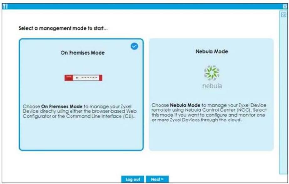
When you log into the Web Configurator for the first time or when you reset the Zyxel Device to its default configuration, the Initial Setup Wizard screen displays. Choose On Premises Mode to manage your Zyxel Device directly using either the browser-based Web Configurator or the Command Line Interface (CLI).
Figure 1 On Premises Mode
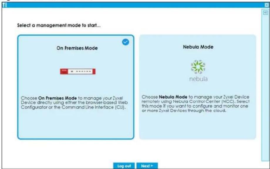
Follow the wizard to configure the Zyxel Device network settings to manage your Zyxel Device directly. Note that once you complete the device registration step and register your Zyxel Device at portal.myzyxel.com, you cannot change to Nebula Mode unless you reset the Zyxel Device.
1.3 Monitor Mode
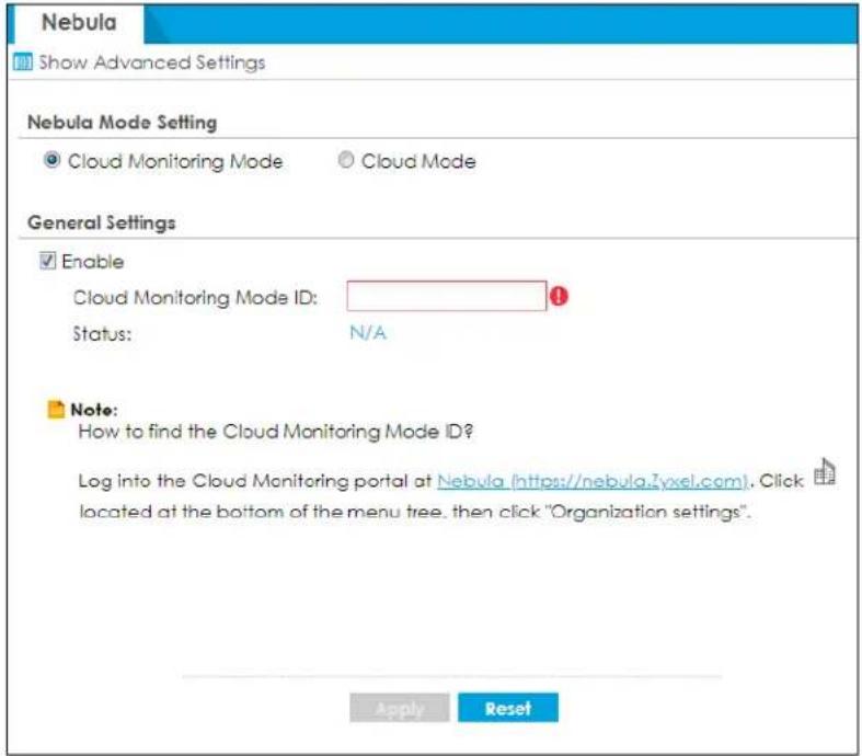
Select Monitor Mode in Configuration > Mgmt. & Analytics > Nebula > Monitor Mode to monitor your Zyxel Device using Nebula Control Center (NCC) but configure settings on the web configurator at the same time. You must have created an organization and a site on NCC first.
Note: You cannot set the Zyxel Device to Monitor Mode if Device HA is enabled on the Zyxel Device.
Figure 2 Configuration > Mgmt. & Analytics > Nebula > Monitor Mode
1.4 Nebula Mode
When you log into the Web Configurator for the first time or when you reset the Zyxel Device to its default configuration, the Initial Setup Wizard screen displays. Choose Nebula Mode to manage your Zyxel Device remotely using Nebula Control Center (NCC). Select this mode if you want to configure and monitor one or more Zyxel Devices through the cloud.
Figure 3 Nebula Mode
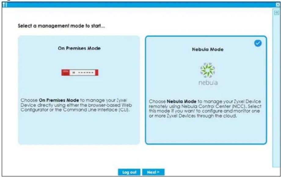
Follow the wizard to configure the Zyxel Device network settings to connect to NCC. Note that once you complete the WAN configuration step, you cannot change to On Premises Mode unless you reset the Zyxel Device.
Nebula Control Center (NCC) is an Internet portal that allows you to configure and monitor groups of Zyxel Devices in organizations. You cannot manage a Zyxel Device directly through the Web Configurator or Command Line Interface (CLI) when NCC is managing the Zyxel Device. See Table 1.1.1 on page 29 to see which Zyxel Devices can be managed by NCC.
Follow this procedure to have NCC manage your Zyxel Device.
1.4.1 NCC Portal
You should already have created an account at myZyxel.com. Follow these steps at the NCC portal.
1 Log into NCC (https://nebula.zyxel.com) with your Zyxel account. If you do not have a Zyxel account, you will be redirected to another screen to create one.
2 After you log in, click Go under Nebula Control Center and then Let's Start to run the NCC setup wizard. Create an organization and a site or select an existing site.
3 Add the Zyxel Device to this site by entering its MAC address and serial number. You'll find the MAC address and serial number of the Zyxel Device on its label or scan the QR code using the Nebula Mobile app.
4 Configure the WAN interface that the Zyxel Device will use to connect to NCC through the Internet.
5 If you're given a choice, select Native Mode. If you cannot select Native Mode, configure the email address of the person who will configure the Zyxel Device for management by NCC. An email will be sent to this person containing an activation link that allows management of the Zyxel Device by NCC.
1.4.2 Your Zyxel Device
The person who will configure the Zyxel Device for management by NCC should follow this procedure.
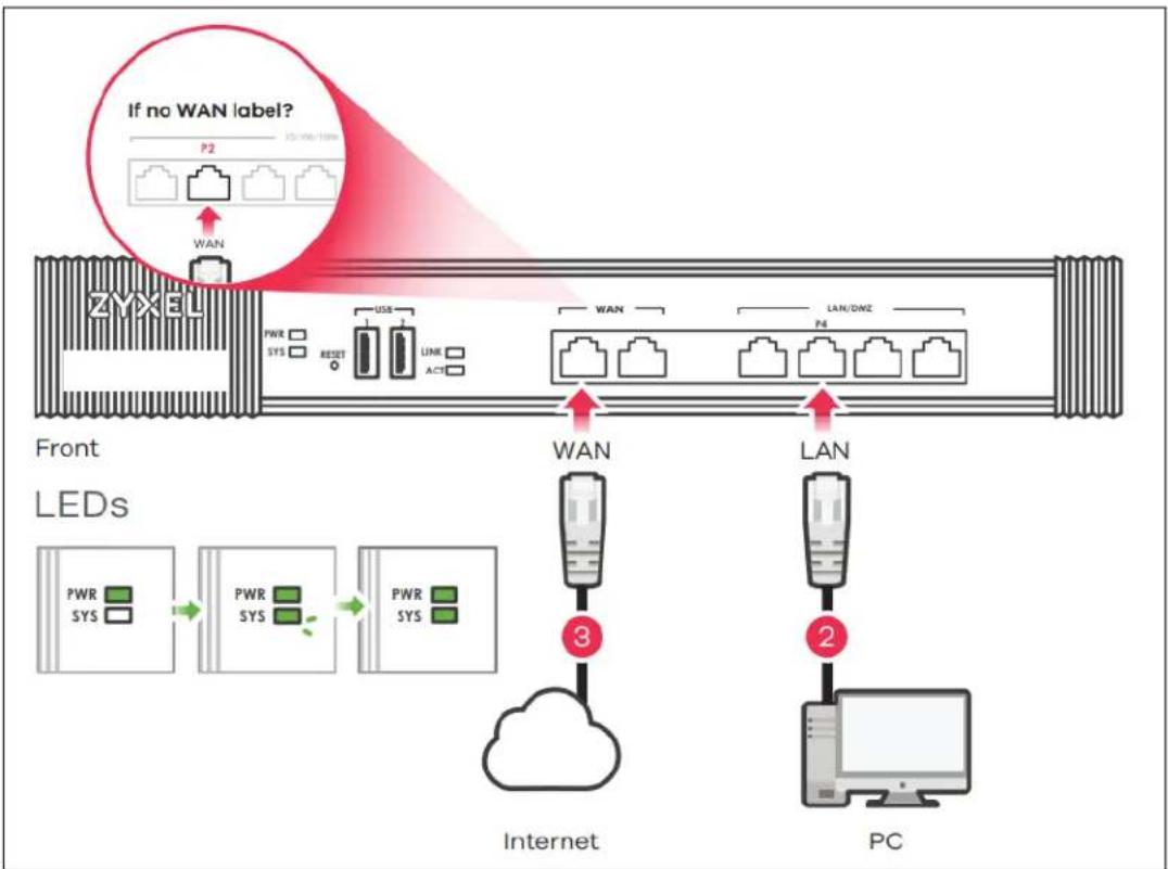
1 Use an Ethernet cable to connect the WAN port of the Zyxel Device (P1 or P2) to the Ethernet port of a device that will provide Internet access.
flowchart
graph TD
    A["Front LEDs"] --> B["LED Port 1"]
    B --> C["LED Port 2"]
    C --> D["LED Port 3"]
    D --> E["PC"]
    style A fill:#f9f,stroke:#333
    style B fill:#ccf,stroke:#333
    style C fill:#cfc,stroke:#333
    style D fill:#fcc,stroke:#333
    note right of A: "If no WAN label?"
    note right of B: P2
    note right of C: LAN/DMZ
    note right of D: LAN
    note left of A: PWR SYS
    note left of B: PWR SYS RESET
    note right of C: LINK ACT
    note right of D: LAN
    note right of E: Cloud
    note right of D: PC
2 Use another Ethernet cable to connect the LAN port of the Zyxel Device (P3 or P4) to your computer. Make sure your computer can receive an IP address automatically. This is the default for all computers, so the computer should be fine unless you changed it.
3 Connect the power port to an appropriate power source and turn on the Zyxel Device. Wait for the SYS LED to turn solid green.
4 Back up your current configuration before passing management to NCC. Log into the web configurator, and go to Maintenance > File Manager > Configuration File. Select startup-config.conf, then click Download.
5 If you cannot select Native Mode, reset the Zyxel Device to the factory defaults. Push the Reset button until the port connection LEDs turn off (after about 5 seconds). Your Zyxel Device will reboot to the factory defaults and all previous configurations will be erased.
Skip this step if you did not configure your Zyxel Device before (including just logging in and changing the default password.). You must reset the Zyxel Device if it does not have the factory default configuration.
1.4.3 Activation Email
If you cannot select Native Mode in the NCC setup wizard, do the following after the Zyxel Device is on:
1 Check your mailbox for an email from NCC. You may need to check your spam folder
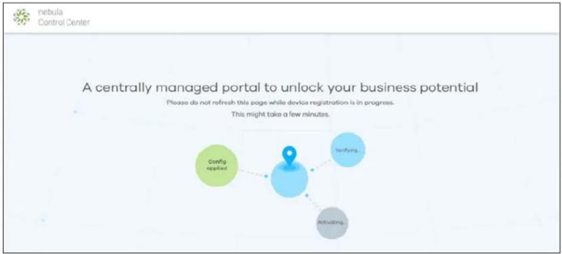
2 Follow the instructions in the email if you did not complete the instructions above. Look for an activation link in the email. Click the activation link or copy the link to your web browser. You will see a screen saying NCC registration is in process. Please wait.
flowchart
graph TD
    A["Config applied"] --> B["Verifying"]
    B --> C["Activating"]
3 When you see a screen saying NCC registration has succeeded, management of your Zyxel Device has passed to Nebula Control Center. The NCC administrator can now configure and manage your device.
Note: ZTP is supported in firmware version 5.37 or earlier.
1.5 Changing the Mode
Follow the steps below to change your Zyxel Device from On Premises Mode to Nebula Mode or from Nebula Mode to On Premises Mode.
1.5.1 From Nebula Mode to On Premises Mode
Follow this procedure if you want to manage the Zyxel Device directly using the web configurator or CLI.
1 Log into NCC (https://nebula.zyxel.com) with your Zyxel account. Go to Organization-wide > License & Inventory > Devices.
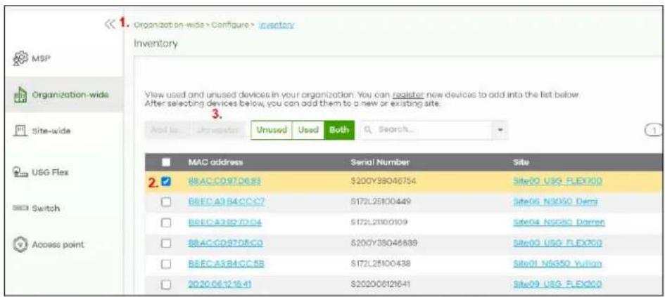
2 Select the Zyxel Device you want to remove from NCC. You must know the MAC address and serial number.
3 Click Remove from organization.
4 If the Zyxel Device is connected to NCC, the Zyxel Device will automatically reset after you remove the Zyxel Device from the organization and site.
If the Zyxel Device is not connected to NCC, press the reset button. The Zyxel Device will reboot to the factory defaults.
All NCC configurations for the Zyxel Device will be erased.
5 Log into the Zyxel Device. Run the wizard and choose On Premises Mode.
6 To restore your previous configuration, log into the web configurator, and go to Maintenance > File Manager > Configuration File.
7 Under Upload Configuration File, click Browse, select the startup-config.conf on your computer that you backed up previously and click Upload. The Zyxel Device will then return to the previous settings.
1.5.2 From On Premises Mode to Nebula Mode
1 Back up your current configuration in Maintenance > File Manager > Configuration File.
2 Reset the Zyxel Device to the factory default by pushing the Reset button until the port connection LEDs turn off (after about 5 seconds). Your Zyxel Device will reboot to the factory defaults.
3 Log into the Zyxel Device. Run the wizard and choose Nebula Mode.
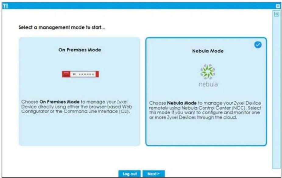
4 If you have a choice of Native Mode or ZTP, select Native Mode.
1.5.3 From Nebula Mode to Cloud Monitoring Mode
See Cloud Monitoring Mode to Nebula Mode if you want to monitor the Zyxel Device using Nebula Control Center (NCC) while configuring settings on the web configurator at the same time.
1.6 Registration at Zyxel
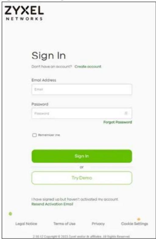
portal.myZyxel.com is Zyxel's online services center where you can register your Zyxel Device and manage subscription services available for your Zyxel Device (see Configuration > Licensing > Registration > Service for services available for your Zyxel Device).
- For Zyxel Devices that already have firmware version 4.25 or later, you have to register your Zyxel Device and activate the corresponding service at Zyxel (through your Zyxel Device).
- For Zyxel Devices upgrading to firmware version 4.25 or later, you may skip registering your Zyxel Device and activating the corresponding service at Zyxel (through your Zyxel Device). However, it is highly recommended to at least register your Zyxel Device. At the time of writing, the Firmware Upgrade license providing Cloud Helper new firmware notifications, is free when you register your Zyxel Device.
Note: You need to create a Zyxel account at http://portal.myZyxel.com before you can register your device and activate the services at Zyxel.
You may need your Zyxel Device's serial number and LAN MAC address to register it at Zyxel. See the label at the back of the Zyxel Device's for details.
Figure 4 Zyxel Login
1.6.1 Grace Period
SecuReporter and service licenses have a 15-day grace period after a license expires. Services will continue to work in this period during which you will receive notifications to renew your licenses. New licenses are valid for 1 year from the date of purchase.
1.6.2 Applications
These are some Zyxel Device application scenarios.
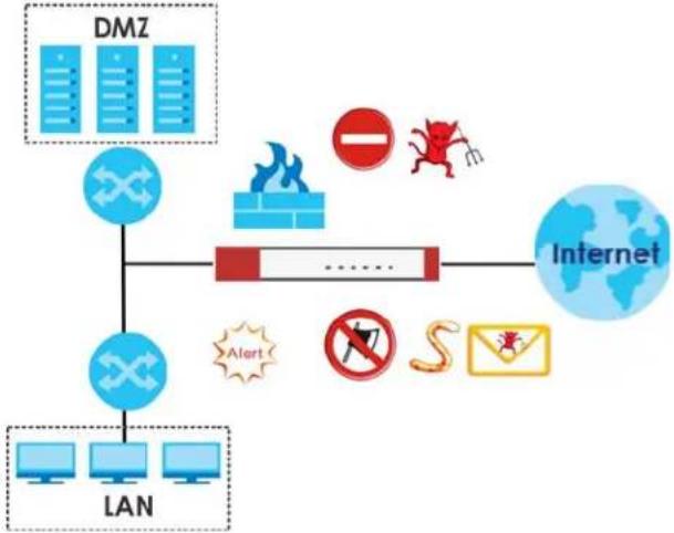
Security Router
Security includes a Stateful Packet Inspection (SPI) firewall.
Figure 5 Applications: Security Router Applications: Security Router
flowchart
graph TD
    A["DMZ"] --> B["Internet"]
    C["LAN"] --> B
    D["Warning icon"] --> E["Fire"]
    F["Warning icon"] --> G["No"]
    H["Warning icon"] --> I["Sweaker"]
    J["Warning icon"] --> K["Phone Icon"]
    L["Warning icon"] --> M["Computer Icon"]
IPv6 Routing
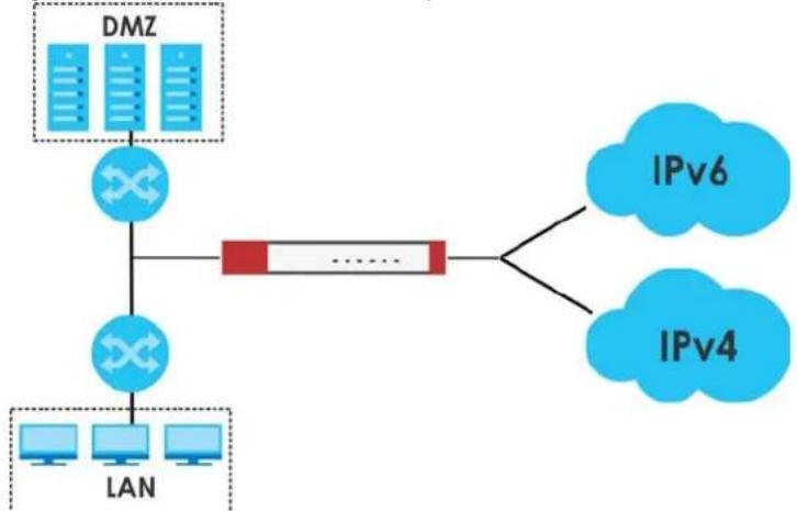
The Zyxel Device supports IPv6 Ethernet, PPP, VLAN, and bridge routing. You may also create IPv6 policy routes and IPv6 objects. The Zyxel Device can also route IPv6 packets through IPv4 networks using different tunneling methods.
Figure 6 Applications: IPv6 Routing
flowchart
graph TD
    A["DMZ"] --> B["Router"]
    C["LAN"] --> B
    B --> D["IPv6"]
    B --> E["IPv4"]
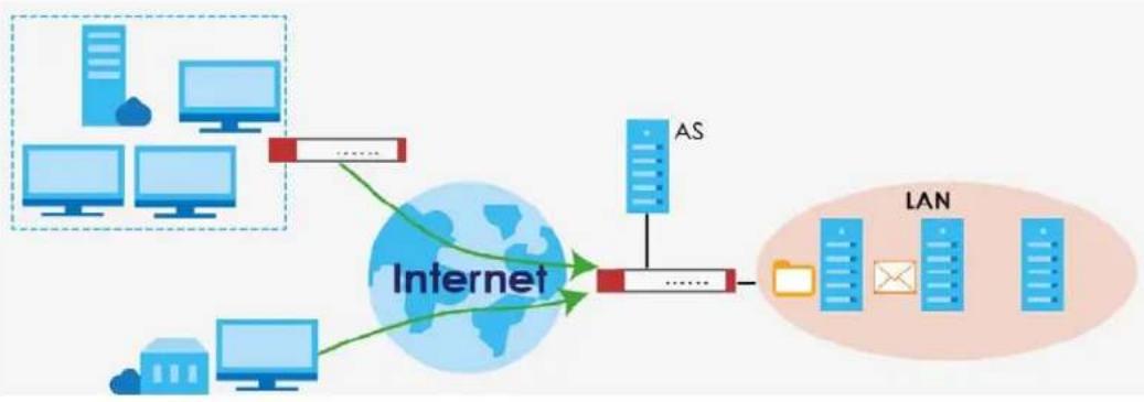
VPN Connectivity
Set up VPN tunnels with other companies, branch offices, telecommuters, and business travelers to provide secure access to your network. AS is an Authentication Server in the below figure.
Figure 7 Applications: VPN Connectivity
flowchart
graph TD
    A["Internet"] --> B["AS"]
    A --> C["LAN"]
    B --> D["Client Devices"]
    C --> E["Client Devices"]
    style A fill:#f9f,stroke:#333
    style B fill:#bbf,stroke:#333
    style C fill:#bfb,stroke:#333
SSL VPN Network Access
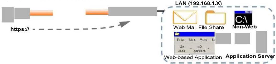
SSL VPN lets remote users use their web browsers for a very easy-to-use VPN solution. A user just browses to the Zyxel Device's web address and enters his user name and password to securely connect to the Zyxel Device's network. Here full tunnel mode creates a virtual connection for a remote user and gives him a private IP address in the same subnet as the local network so he can access network resources in the same way as if he were part of the internal network.
Figure 8 SSL VPN With Full Tunnel Mode
flowchart
graph LR
    A["https://"] --> B["LAN (192.168.1.X)"]
    B --> C["Web Mail File Share"]
    B --> D["Non-Web"]
    C --> E["Application Server"]
    D --> E
    style A fill:#f9f,stroke:#333
    style B fill:#ccf,stroke:#333
    style C fill:#cff,stroke:#333
    style D fill:#ffc,stroke:#333
User-Authentication Access Control
Set up security policies to restrict access to sensitive information and shared resources based on the user who is trying to access it. In the following figure user A can access both the Internet and an internal file server. User B has a lower level of access and can only access the Internet. User C is not even logged in, so and cannot access either the Internet or the file server.
Figure 9 Applications: User-Authentication Access Control
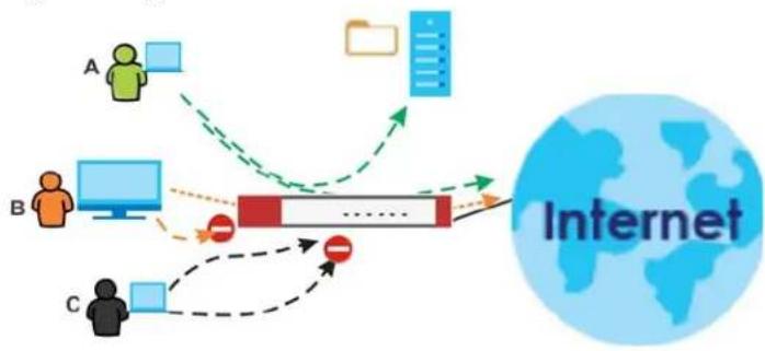
flowchart
graph TD
    A["User A"] -->|Data Flow| Device["Central Device"]
    B["User B"] -->|Data Flow| Device
    C["User C"] -->|Data Flow| Device
    Device -->|Data Flow| Internet["Internet"]
    style A fill:#f9f,stroke:#333
    style B fill:#ccf,stroke:#333
    style C fill:#cfc,stroke:#333
    style Internet fill:#fff,stroke:#333
Load Balancing
Set up multiple connections to the Internet on the same port, or different ports, including cellular interfaces. In either case, you can balance the traffic loads between them.
Figure 10 Applications: Multiple WAN Interfaces
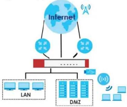
flowchart
graph TD
    A["Internet"] --> B["LAN"]
    A --> C["DMZ"]
    B --> D["Computer 1"]
    B --> E["Computer 2"]
    C --> F["Computer 3"]
    C --> G["Computer 4"]
    D --> H["Wireless Device"]
    E --> I["Wireless Device"]
    F --> J["Wireless Device"]
    G --> K["Wireless Device"]
1.7 Management Overview
You can manage the Zyxel Device in the following ways.
Web Configurator
The Web Configurator allows easy Zyxel Device setup and management using an Internet browser. This User's Guide provides information about the Web Configurator.
Figure 11 Managing the Zyxel Device: Web Configurator
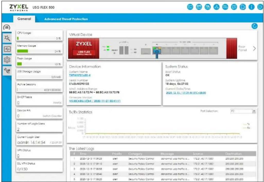
Command-Line Interface (CLI)
The CLI allows you to use text-based commands to configure the Zyxel Device. Access it using remote management (for example, SSH or Telnet) or via the physical or Web Configurator console port. See the Command Reference Guide for CLI details. The default settings for the console port are:
Table 3 Console Port Default Settings
| SETTING VALUE | |
| Speed 115200 bps | |
| Data Bits 8 | |
| Parity None | |
| Stop Bit 1 | |
| Flow Control Off |
FTP
Use File Transfer Protocol for firmware upgrades and configuration backup or restore.
SNMP
The device can be monitored and/or managed by an SNMP manager. See Section 46.11 on page 1119.
CloudCNM
Use the CloudCNM screen (see Section 46.16 on page 1131) to enable and configure management of the Zyxel Device by a Central Network Management system.
Management Authentication
Managers must be authenticated with a username and password, using one of:
- Local Zyxel Device authentication
• An external RADIUS server - An external LDAP server
- Certificates
1.8 Web Configurator
The Web Configurator is an HTML-based management interface that allows easy system setup and management through Internet browser. Use a browser that supports HTML5, such as Microsoft Edge, Internet Explorer 11, Mozilla Firefox, or Google Chrome.
In order to use the Web Configurator you need to allow:
- Web browser pop-up windows from your device.
- JavaScript (enabled by default).
- Java permissions (enabled by default).
The recommended minimum screen resolution is 1024 x 768 pixels.
Note: Screenshots and graphics in this book may differ slightly from your product due to differences in product features or Web Configurator brand style.
1.8.1 Web Configurator Access
1 Make sure your Zyxel Device hardware is properly connected. See the Quick Start Guide.
2 In your browser go to https://192.168.1.1 or https://myrouter.local. By default, the Zyxel Device automatically routes this request to its HTTPS server, and it is recommended to keep this setting. The Login screen appears.
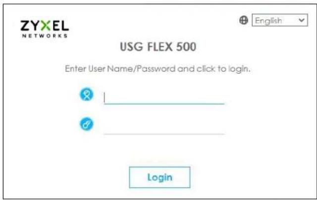
If you want to change the display language for the Zyxel Device's Web Configurator screens, select from the drop-down list box. You can also change the display language in Configuration> System> Language
3 Type the user name (default: "admin") and password (default: "1234").
4 Click Login. After you log in for the first time using the default user name and password, you must change the default admin password in the Update Admin Info screen. Enter a new password of from 1 to 64 characters.
In Configuration > Object > User/ Group > Setting, you can enable Password Complexity to require a new password to consist of at least 8 characters and at most 64, where at least 1 character must be a number, at least 1 a lower case letter, at least 1 an upper case letter and at least 1 a special character from the keyboard, such as !@#\$%^&*()_. +. You can also require periodic changing of the password in that screen by configuring Password must changed every (days).
Make a note of your new password, enter it in the following screen, then click Apply.
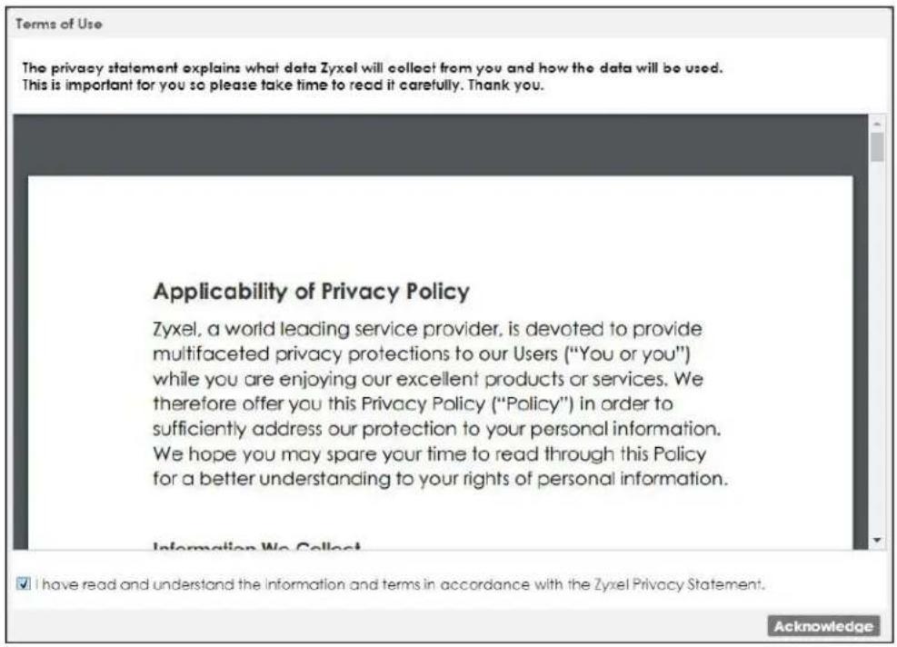
5 A Terms of Use screen displays. Read the statement, then click Acknowledge to proceed.
Note: If you are using an Internet Explorer browser, the Terms of Use will be downloaded automatically.
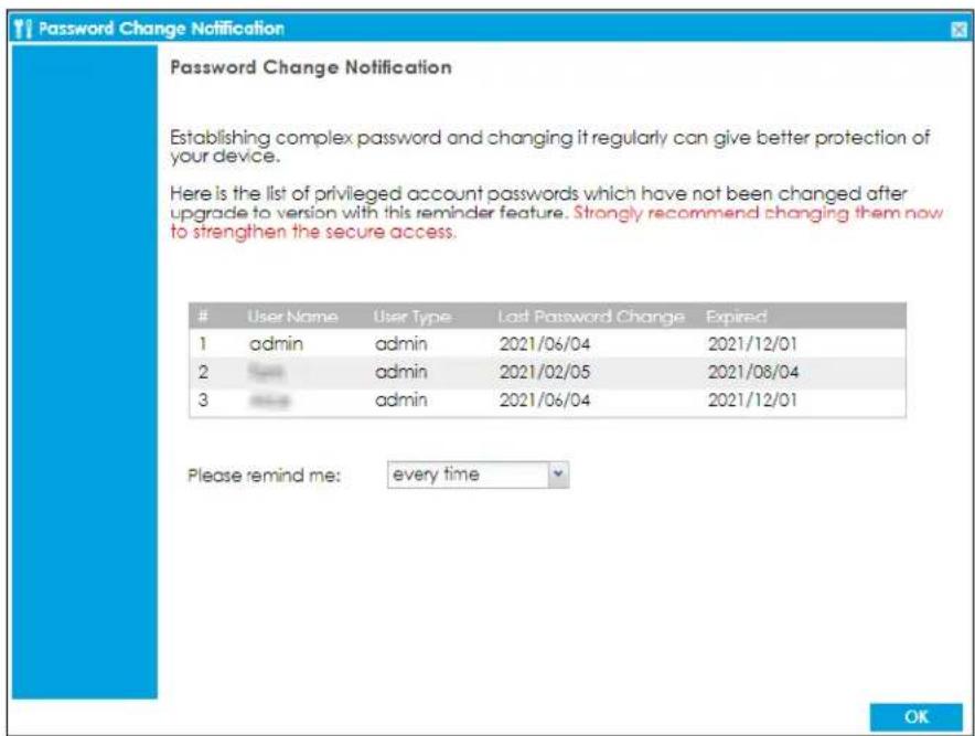
6 The Password Change Notification screen displays. Use this screen to view all the admin accounts expiry information. We recommend you to change your password regularly in Configuration> Object> User/Group> User. Select how often to display the screen and click OK.
7 The Network Risk Warning screen displays any unregistered or disabled security services. If your Zyxel Device is not registered, you will see a prompt to register it. Select how often to display the screen and click OK.
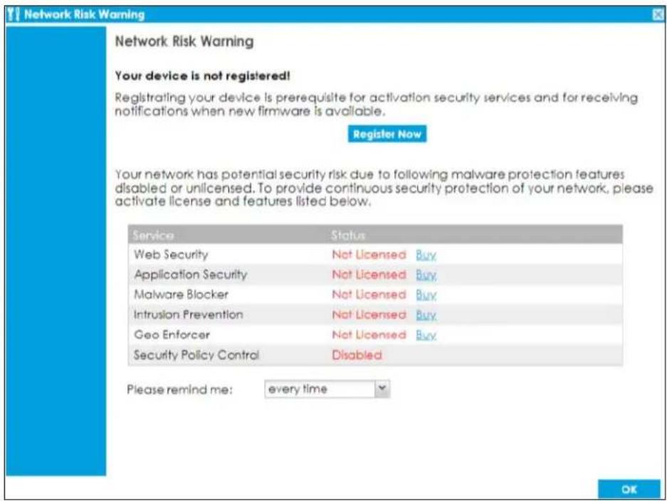
If you select Never and you later want to bring this screen back, use these commands (note the space before the underscore).
Router> enable
Router#
Router# configure terminal
Router(config)#
Router(config)# service-register _setremind
after-10-days
after-180-days
after-30-days
every-time
never
Router(config)# service-register _setremind every-time
Router(config)#
See the Command Line Interface (CLI) Reference Guide (RG) for details on all supported commands.
8 Follow the directions in the Update Admin Info screen. If you change the default password, the Login screen appears after you click Apply. If you click Ignore, the Installation Setup Wizard opens if the ZyWALL is using its default configuration; otherwise the dashboard appears.
1.8.2 Security Check for Web Interface Overview
Use this screen to configure settings to secure your Zyxel Device. You can configure:
- Secure SSL access from the Internet to the Zyxel Device.
- Secure SSL access from the Internet to the network behind the Zyxel Device.
- The default port that IPSec VPN clients use to retrieve VPN rule settings from the Zyxel Device.
- The default port for two-factor authentication for VPN clients to access the network behind the Zyxel Device.
1.8.2.1 Secure SSL Access from the Internet to the Zyxel Device
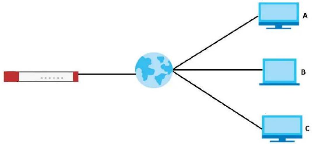
You can configure up to 3 trusted computers to access the Zyxel Device using secure SSL. The default HTTPS SSL port is 443. If you change this, remote connections from the Internet must use this port. For example, if you change this to port 8800 and the Zyxel Device is using IP address 1.1.1.1, then remote users must use https://1.1.1.1:8800.
In Figure 12 on page 47, A, B and C can connect to the Zyxel Device to access the Zyxel Device web configurator for remote management.
Configure a new port between 1024 to 65535 that is not in use by other services.
Figure 12 Secure SSL Access Example
flowchart
graph TD
    A["User"] --> B["Global Node"]
    B --> C1["A"]
    B --> C2["B"]
    B --> C3["C"]
1.8.2.2 Secure SSL VPN Access from the Internet to the Network Behind the Zyxel Device
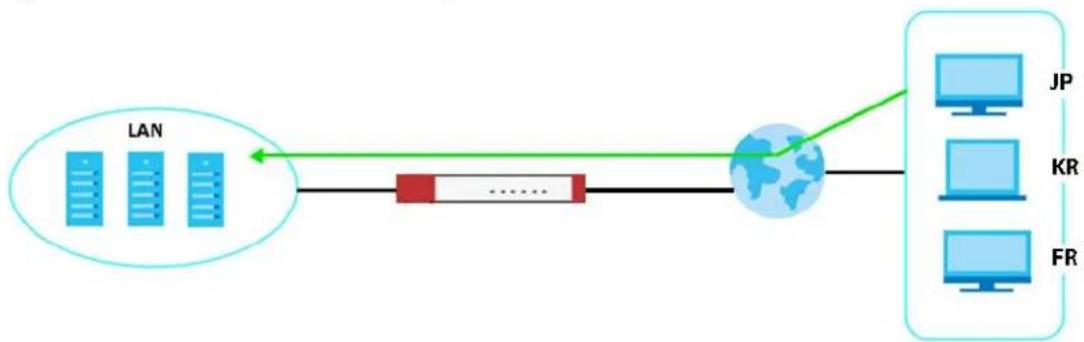
The default SSL VPN port is 443. If you change the default SSL VPN port on the Zyxel Device, make sure to make the same change to SecuExtender, the SSL VPN client software. Configure a new port between 1024 to 65535 that is not in use by other services.
You can also restrict SSL VPN access to up to 3 locations on the Internet.
Figure 13 Secure SSL VPN Access Example
flowchart
graph LR
    A["LAN"] --> B["Router"]
    B --> C["JP"]
    B --> D["KR"]
    B --> E["FR"]
The table below describes the abbreviations used in the figure.
Table 4 Countries Abbreviations
| ABBREVIATION COUNTRY | |
| JP Japan | |
| KR Korea | |
| FR France |
1.8.2.3 Change the Default IPSec VPN Provisioning Port
Change the default port that IPSec VPN clients use to retrieve VPN rule settings from the Zyxel Device. The default is 443 which is already in use for remote management by default. If you change the default IPSec VPN port on the Zyxel Device, make sure to make the same change to the Zyxel IPSec VPN client.
Configure a new port between 1024 to 65535 that is not in use by other services.
Figure 14 IPSec VPN Provisioning Example

flowchart
graph LR
    A["LAN"] --> B["Router"]
    B --> C["Computer"]
    style A fill:#f9f,stroke:#333
    style B fill:#ccf,stroke:#333
    style C fill:#cfc,stroke:#333
Note: The remote management port, the SSL VPN port and the IPSec VPN port all use 443 by default. If you do not change the default ports, then only 3 connections of the remote management and SSL VPN will be allowed at one time.
1.8.2.4 Change the Default Port for Two-Factor VPN Access Authentication
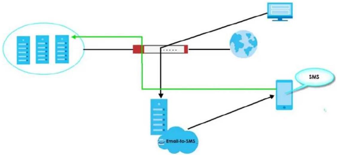
Change the default port for two-factor authentication for VPN clients to access the network behind the Zyxel Device. VPN clients do not need to change the port number on their devices, because the link to access the network behind the Zyxel Devices will contain the new port number. For example, if you change this to port 8008 and the link is using a.b.c.d, then VPN clients will see this link in their email or SMS to retrieve settings: https://a.b.c.d:8008.
You can also change this port in Object > Auth. Method > Two-factor Authentication > VPN Access. See Section 43.11.4 on page 1024 for more information on two-factor authentication.
Configure a new port between 1024 to 65535 that is not in use by other services.
Figure 15 Two-Factor Authentication Example
flowchart
graph TD
    A["Server"] --> B["Mobile Device"]
    B --> C["Email-to-SMS"]
    C --> D["Mobile Phone"]
    D --> E["SMS"]
    E --> B
    style A fill:#f9f,stroke:#333
    style B fill:#ccf,stroke:#333
    style C fill:#cfc,stroke:#333
    style D fill:#fcc,stroke:#333
    style E fill:#cff,stroke:#333
Overall Port Configuration Example
Below is an example of configuring these ports to avoid port conflict.
Table 5 Port Configuration Example
| REMOTE MANAGEMENT | SSL VPN | IPSEC VPN PROVISIONING | TWO-FACTOR VPN ACCESS AUTHENTICATION |
| 8800 8080 443 (default) 8008 |
1.8.2.5 Other Security Measures
New firmware contains patches to enhance security. Make sure to check for new firmware regularly and update firmware in Maintenance > Firmware Management.
Change admin passwords regularly. Select Enable Password Complexity in Object > User/Group > Setting to require the user to use a password that's not easy to guess. The password must include:
• at least 8 characters
- at least one upper case alphabetic character and at least one lower case alphabetic character
- on e num eric char acter
• one special character such as @#\$%^
1.8.3 The Security Check for Web Interface Screen
The following screen appears when the Zyxel Device detects a rule that allows traffic such as HTTP, HTTPS, SSL and so on to access to your Zyxel Device from any IPv4 source on the WAN. This may expose your Zyxel Device to a security risk. Configure settings in this screen to allow access only from specified IP addresses, FQDNs or regions to secure your Zyxel Device.
Figure 16 Security Check for Web Interface
![Security Check for Web Interface You have a rule that allows anyone from the Internet to access the Device web configurator and SSL VPN service. To reduce risk, please restrict access by source IP address and geolocation respectively. Strongly suggest to update your device and change passwords regularly. ■ Restrict Device management from the WAN Port: 443 (1...65535) Restrict access only to trusted host Trusted Host 1: [IP or FQDN] Trusted Host 2: [IP or FQDN] [Optional] Trusted Host 3: [IP or FQDN] [Optional] ■ Restrict SSL VPN access from the WAN Port: 443 (1...65535) Restrict access by GeoIP Trusted Geolocation 1: Trusted Geolocation 2: Trusted Geolocation 3: [Optional] [Optional] ■ Change Two-Factor Authentication Port Port: 8008 (1...65535) ■ Change the Zyxcel IPSec VPN Client Provisioning Port Port: 443 (1...65535) Please remind me: every time OK Cancel](/content/2026/05/878280/images/8346c8517d5976e6c4ec232d39de52eaf6c91421771b9098d66df256478bf4c0.jpg)
The following table describes the labels in this screen.
Table 6 Security Check for Web Interface
| LABEL DESCRIPTION | |
| Allow secure remote management from WAN | Select this to allow access to the Zyxel Device remotely only from specified IP addresses or Fully Qualified Domain Names (FQDNs), such as 1.1.1.1 or www.zyxel.com. See Section 1.8.2.1 on page 47 for more information. |
| Port Configure a new port between | 1024 to 65535 to use it to access the web configurator. Do not use a port number that has been used.For example, use https://1.1.1.1:8800 if you changed the default HTTPS port to 8800. |
| Trusted Host 1-3 | Configure the IP addresses or FQDNs that are allowed to access the Zyxel Device. |
| Allow SSL VPN access from WAN | Select this to allow SSL VPN clients to access the Zyxel Device only from specified regions. See Section 1.8.2.2 on page 47 for more information. |
| Port Configure a new port between | 1024 to 65535 to use it to access the web configurator using SSL VPN. Do not use a port number that has been used.The port you configure here must be the same as the port you use in SecuExtender. See Section 1.8.2.2 on page 47 for more information on SecuExtender. |
| Trusted Geolocation 1-3 | Select the regions that are allowed to access the Zyxel Device from the drop-down list box. |
| Change Two-Factor Authentication Port | Select this to change the port VPN clients use to access the Zyxel Device LAN with two-factor authentication. See Section 1.8.2.4 on page 48 for more information.Configure a new port between 1024 to 65535. Do not use a port number that has been used. |
| Change Zyxel IPSec VPN Client Provisioning Port | Select this to change the port IPSec VPN clients use to retrieve VPN rule settings from the Zyxel Device. See Section 1.8.2.3 on page 48 for more information.Configure a new port between 1024 to 65535. Do not use a port number that has been used.The port you configure here must be the same as the port you use when logging in as a Zyxel IPSec VPN client. |
| Please remind me | Select how often to display the screen from the drop-down list box. |
| OK | Click OK to save your changes back to the Zyxel Device. |
| Cancel | Click Cancel to exit this screen without saving your changes. |
1.8.4 Remote Access to the Zyxel Device Networks
Your Zyxel Device keeps your networks safe while allowing external access by applying the security measures below:
- Two-Factor Authentication: Use two-factor authentication to have double-layer security to access the Zyxel Device. The first layer is the VPN client/Zyxel Device's login user name / password. The second layer is an authorized SMS (via mobile phone number) or email address. See Section 43.11.4 on page 1024 for more information on two-factor authentication.
- Device Insight: The Zyxel Device can identify and display the basic information and status of clients that are connected to the Zyxel Device networks in Monitor > Network Status > Device Insight. See Section 6.7 on page 179 for more information on viewing the device insight.
Create device insight profiles in Configuration > Object > Device Insight to block specified clients from accessing the Internet or the Zyxel Device. See Section 43.1 on page 929 for more information on creating and using the device insight profiles.
- IPSec VPN: You can create highly secure connections with IKEv2 or EAP authentication to access networks behind the Zyxel Device. For example, home workers can securely access company resources if they have proper authentication. See Chapter 19 on page 527 for more information on IPSec VPN.
- Upload Bandwidth Limit: Zyxel subscription-based SecuExtender IPSec VPN clients with Windows version 5.6.80.007 or later or macOS version 1.2.0.7 or later support upload bandwidth limit. Use this to set the maximum bandwidth for uploading traffic from IPSec VPN clients over IPSec VPN tunnels. See Section 19.5 on page 553 for more information on upload bandwidth limit.
1.8.5 Web Configurator Screens Overview
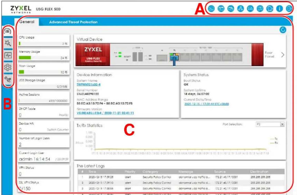
The Web Configurator screen is divided into these parts:
- A – title bar
- B – navigation panel
- C - main window
Figure 17 Web Configurator Screen Overview
Title Bar
Figure 18 Title Bar

natural_image
Row of blue circular icons representing media and information-related functions (no text or symbols)The title bar icons in the upper right corner provide the following functions.
Table 7 Title Bar: Web Configurator Icons
| LABEL DESCRIPTION | |
| SecuReporter | This icon shows when SecuReporter is enabled and the Zyxel Device is added to an organization.Click this to open the SecuReporter portal page. |
| Web Console | Click this to open one or multiple console windows from which you can run command line interface (CLI) commands. You will be prompted to enter your user name and password. See the Command Reference Guide for information about the commands-currenting in to the Zyxel Device with HTTPS, so you can open one or multiple console windows. |
| CLI | Click this to open a popup window that displays the CLI commands sent by the Web Configurator to the Zyxel Device. |
| Reference | Click this to check which configuration items reference an object. |
| Site Map | Click this to see an overview of links to the Web Configurator screens. |
| Community | Go tohttps://community.zyxel.comfor product discussions. |
| Help Click this to open the help page for the current screen. | |
| Notification | Only Admin or Limited Admin can see notifications. Notifications display what's new in the Zyxel Device firmware (ZLD), information on security services about to expire.Slide the switch to Off if you don't want notifications. Click an item to see more details on it.Click the Refresh icon or refresh the browser page to update notifications. The latest notification appears at the top. An item is removed once it has been read.Up to five notifications can be shown here. If there are more than five notifications, then click All Notifications to see them. |
| About | Click this to display basic information about the Zyxel Device. |
| Logout Click this to | log out of the Web Configurator. |
About
Click About to display basic information about the Zyxel Device.
Figure 19 About
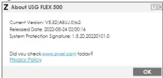
This table describes the fields in this screen.
Table 8 About
| LABEL DESCRIPTION | |
| Current Version This shows the firmware version of the Zyxel Device. | |
| Released Date | This shows the date (yyyy-mm-dd) and time (hh:mm:ss) when the firmware is released. |
| System Protection Signature | This shows the system protection signature version of the Zyxel Device. These signatures do not require a license. The Zyxel Device will synch with the Cloud Helper Server every day to update these signatures automatically.System protection signatures protect your Zyxel Device and local networks from web attacks, such as command injection, cross-site scripting and path traversal.Command injection: This is an attack in which an attacker uses the Zyxel Device vulnerabilities to execute commands to control your Zyxel Device.Cross-site scripting: This is an attack in which an attacker implants malicious scripts in a website. When you visit this website, the malicious scripts are sent and executed on your web browser.Path traversal: This is an attack that allows an attacker to access files you store in the web root folder. |
| OK Click this to close the screen. | |
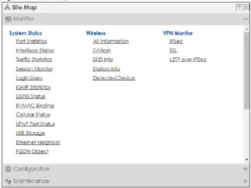
Site Map
Click Site MAP to see an overview of links to the Web Configurator screens. Click a screen's link to go to that screen.
Figure 20 Site Map
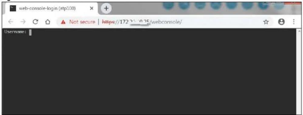
Web Console
Click Web Console to open one or multiple console windows from which you can run CLI commands. You will be prompted to enter your user name and password. See the Command Reference Guide for information about the commands. Logging in to the Zyxel Device with HTTPS, so you can open one or multiple console windows.
Figure 21 Web Console Window
Reference
Click Reference to open the Reference screen. Select the type of object and the individual object and click Refresh to show which configuration settings reference the object.
Figure 22 Reference
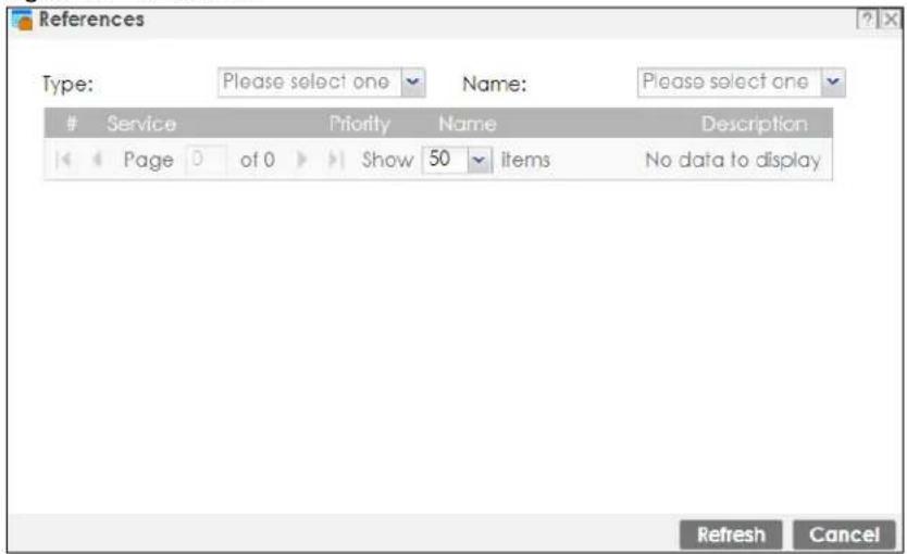
The fields vary with the type of object. This table describes labels that can appear in this screen.
Table 9 Reference
| LABEL DESCRIPTION | |
| Type Select an | object type to see the services. |
| Name | This identifies the object for which the configuration settings that use it are displayed. Click the object's name to display the object's configuration screen in the main window. |
| # This field is a sequential value, and it is not associated with any entry. | |
| Service | This is the type of setting that references the selected object. Click a service's name to display the service's configuration screen in the main window. |
| Priority | If it is applicable, this field lists the referencing configuration item's position in its list, otherwise N/A displays. |
| Name | This field identifies the configuration item that references the object. |
| Description | If the referencing configuration item has a description configured, it displays here. |
| Refresh Click this to update the information in this screen. | |
| Cancel | Click Cancel to close the screen. |
CLI Messages
Click CLI to look at the CLI commands sent by the Web Configurator. Open the pop-up window and then click some menus in the Web Configurator to display the corresponding commands.
Figure 23 CLI Messages
![[6] show users all [7] show users current [8] show app-watch-dog config [9] show usb-storage [10] show sa counter [11] show service-register status sslvpn-status CLI End Cancel](/content/2026/05/878280/images/e9dce41824a68277dfb0118bb97e05ff5b935ebbe20e0adb13346549262dbd48.jpg)
1.8.6 Navigation Panel
Use the navigation panel menu items to open status and configuration screens. Click the arrow in the middle of the right edge of the navigation panel to hide the panel or drag to resize it. The following sections introduce the Zyxel Device's navigation panel menus and their screens.
Figure 24 Navigation Panel
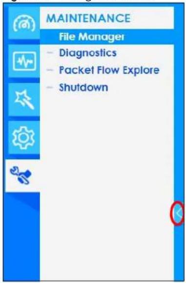
Dashboard
The dashboard displays general device information, system status, system resource usage, licensed service status, and interface status in widgets that you can re-arrange to suit your needs. See the Web Help for details on the dashboard.
Monitor Menu
The monitor menu screens display status and statistics information.
Table 10 Monitor Menu Screens Summary
| FOLDER OR LINK TAB FUNCTION | ||
| Traffic Statistics | ||
| Port Statistics | Port Statistics | Displays packet statistics for each physical port. |
| Interface Status Interface Summary | Displays general interface information and packet statistics. | |
| Traffic Statistics Traffic Statistics | Collect and display traffic statistics. | |
| Session Monitor Session Monitor | Displays the status of all current sessions. | |
| Network Status | ||
| DHCP Table | DHCP Table | Displays a list of interfaces and their DHCP-assigned IP addresses. |
| Device Insight Device Insight | Displays a list of WiFi and wireless clients connected to the Zyxel Device networks. | |
| Login Users | Login Users | Lists the users currently logged into the Zyxel Device. |
| Dynamic Guest Dynamic Guest | List the dynamic guest accounts in the Zyxel Device's local database. These are accounts that are created automatically and allowed to access the Zyxel Device's services for a certain period of time. | |
| IGMP Statistics IGMP Statistics | Collect and display IGMP statistics. | |
| DDNS Status | DDNS Status | Displays the status of the Zyxel Device's DDNS domain names. |
| IP/MAC Binding IP/MAC Binding | Lists the devices that have received an IP address from Zyxel Device interfaces using IP/MAC binding. | |
| Cellular Status Cellular Status | Displays details about the Zyxel Device's mobile broadband connection status. | |
| UPnP Port Status | Port Statistics | Displays details about UPnP connections going through the Zyxel Device. |
| USB Storage | Storage Information | Displays details about USB device connected to the Zyxel Device. |
| Ethernet Neighbor | Ethernet Neighbor | View and manage the Zyxel Device's neighboring devices via Smart Connect (Layer Link Discovery Protocol (LLDP)). Use the Zyxel One Network (ZON) utility to view and manage the Zyxel Device's neighboring devices via the Zyxel Discovery Protocol (ZDP). |
| FQDN Object | FQDN Object | Displays FQDN (Fully Qualified Domain Name) object cache lists used in DNS queries. |
| Virtual Server LB Virtual Server Load Balancer Status | Displays traffic statistics between a client and a real server. | |
| Wireless | ||
| AP Information | AP List | Lists APs managed by the Zyxel Device. |
| Radio List Lists | wireless details of APs managed by the Zyxel Device. | |
| Built-in AP | Displays associated wireless client usage and number. (For Zyxel Device model names containing 'W'.) | |
| Top N APs | Lists managed APs with the most wireless traffic usage and most associated wireless stations. | |
| Single AP | Lists APs wireless traffic usage and associated wireless stations for a managed AP. | |
| FOLDER OR LINK | TAB | FUNCTION |
| ZyMesh ZyMesh Link Info | Display statistics about ZyMesh wireless connections between managed APs. | |
| SSID Info | SSID Info | Display information about the AP's wireless clients. |
| Station Info | Station List | Lists wireless clients associated with the APs managed by the Zyxel Device. |
| Top N Stations | Lists wireless stations with the most wireless traffic usage. | |
| Single Station | Lists wireless traffic usage for an associated wireless station. | |
| Detected Device | Detected Device | Display information about suspected rogue APs. |
| Wireless Health Wireless Health | Displays information about health or wireless networks for your APs and connected wireless clients. | |
| Printer Status | Printer Status | Display information about the connected statement printers. |
| VPN Monitor | ||
| IPSec IPSec Displays and manages the active IPSec SAs. | ||
| SSL | SSL | Lists users currently logged into the VPN SSL client portal. You can also log out individual users and delete related session information. |
| L2TP over IPSec L2TP over IPSec | Displays details about current L2TP sessions. | |
| Remote AP VPN Remote AP VPN | Displays and manages the active remote APs. | |
| Security Statistics | ||
| App Patrol | Summary | Displays application patrol statistics. |
| Content Filter | Web Content Filter | Collect and display web content filter statistics. |
| DNS Content Filter | Collect and display DNS content filter statistics. | |
| Anti-Malware | Summary | Collect and display statistics on the malware that the Zyxel Device has detected. |
| Reputation Filter | Summary | Displays counts, IP addresses and URLs that are blocked by the Zyxel Device. |
| IPS | Summary | Collect and display statistics on the intrusions that the Zyxel Device has detected. |
| Sandboxing | Summary | Displays the sandboxing statistics. |
| Email Security | Summary | Collect and display spam statistics. |
| Status | Displays how many mail sessions the ZyWALL is currently checking and DNSBL (Domain Name Service-based spam Black List) statistics. | |
| CDR | Containment List | Displays what clients are currently contained by Collaborative Detection & Response (CDR). |
| History | Displays what clients were and are contained by Collaborative Detection & Response (CDR). | |
| SSL Inspection | Summary | Collect and display SSL Inspection statistics. |
| Certificate Cache List | Displays traffic to destination servers using certificates. | |
| Log | View Log | Lists log entries. |
| View AP Log | Lists AP log entries. | |
| Dynamic Users Log | Lists the Zyxel Device's dynamic guest account log messages. | |
Configuration Menu
Use the configuration menu screens to configure the Zyxel Device's features.
Table 11 Configuration Menu Screens Summary
| FOLDER OR LINK TAB FUNCTION | ||
| Quick Setup Quickly | configure WAN interfaces or VPN connections. | |
| Licensing | ||
| Registration | Registration | Register the device and activate trial services. |
| Service View the licensed service status and upgrade licensed services. | ||
| Signature Update | Signature Update signatures immediately or by a schedule. | |
| Wireless | ||
| Built-in AP | General | Allow WiFi clients to access your Zyxel Device wirelessly to connect to the network. |
| Controller | Configuration | Configure manual or automatic controller registration. |
| AP Management | Mgmt AP List | Edit or remove entries in the lists of APs managed by the Zyxel Device. |
| AP Policy | Configure the AP controller's IP address on the managed APs and determine the action the managed APs take if the current AP controller fails. | |
| AP Group Create groups of APs, define their radio, VLAN, port and load balancing settings. | ||
| Firmware | Update the firmware on APs connected to your Zyxel Device. | |
| Rogue AP | Rogue/Friendly AP List | Configure how the Zyxel Device monitors rogue APs. |
| Wireless Health | Wireless Health | Enable wireless health to improve the APs wireless network performance in Zyxel Device networks. |
| Auto Healing | Auto Healing | Enable auto healing to extend the wireless service coverage area of the managed APs when one of the APs fails. |
| RTLS | Real Time Location System | Use the managed APs as part of an Ekahau RTLS to track the location of Ekahau WiFi tags. |
| Network | ||
| Interface | Port Port Role/Port Group/ Port Configuration | Use this screen to set the Zyxel Device's flexible ports such as LAN, OPT, WLAN, or DMZ. |
| Ethernet | Manage Ethernet interfaces and virtual Ethernet interfaces. | |
| PPP | Create and manage PPPoE and PPTP interfaces. | |
| Cellular | Configure a cellular Internet connection for an installed mobile broadband card. | |
| Tunnel | Configure tunneling between IPv4 and IPv6 networks. | |
| VLAN | Create and manage VLAN interfaces and virtual VLAN interfaces. | |
| Bridge | Create and manage bridges and virtual bridge interfaces. | |
| LAG | Configure interface and LAG parameters for each LAG interface. | |
| VTI | Configure IP address assignment and interface parameters for VTI (Virtual Tunnel Interface). | |
| Trunk | Create and manage trunks (groups of interfaces) for load balancing. | |
| FOLDER OR LINK | TAB | FUNCTION |
| Routing Policy Route Create and manage routing policies. | ||
| DDNS | DDNS | Define and manage the Zyxel Device's DDNS domain names. |
| NAT NAT Set up and manage port forwarding rules. | ||
| Virtual Server Load Balancer | Configure virtual server load balancer rules that distribute incoming connection requests to a virtual server between multiple real (physical) servers | |
| Redirect Service | Redirect Service Set up and manage HTTP and SMTP redirection rules. | |
| ALG ALG Configure SIP, H.323, and FTP pass-through settings. | ||
| UPnP | UPnP | Configure interfaces that allow UPnP and NAT-PMP connections. |
| IP/MAC Binding | Summary | Configure IP to MAC address bindings for devices connected to each supported interface. |
| Exempt List | Configure ranges of IP addresses to which the Zyxel Device does not apply IP/MAC binding. | |
| Layer 2 Isolation | General | Enable layer-2 isolation on the Zyxel Device and the internal interfaces. |
| Allow List | Enable and configure the allow list. | |
| DNS Inbound LB | DNS Load Balancing | Configure DNS Load Balancing. |
| VPN | ||
| IPSec VPN | VPN Connection | Configure IPSec tunnels. |
| VPN Gateway | Configure IKE tunnels. | |
| Concentrator | Combine IPSec VPN connections into a single secure network | |
| Configuration Provisioning | Set who can retrieve VPN rule settings from the Zyxel Device using the Zyxel Device IPSec VPN Client. | |
| SSL VPN | Access Privilege | Configure SSL VPN access rights for users and groups. |
| Global Setting | Configure the Zyxel Device's SSL VPN settings that apply to all connections. | |
| L2TP VPN | L2TP VPN | Configure L2TP over IPSec tunnels. |
| Remote AP VPN | Remote AP VPN | Configure the IP address pool for the Zyxel Device to assign an IP address to the outgoing interface of each RAP IPSec tunnel. |
| BWM | BWM | Enable and configure bandwidth management rules. |
| Web Authentication | Web Authentication General/Authentication Type/Custom Web Portal File/Custom User Agreement File | Define a web portal and exempt services from authentication. |
| SSO | Configure the Zyxel Device to work with a Single Sign On agent. | |
| Hotspot | ||
| Billing | General | Configure the general billing settings, such as the accounting method. |
| Billing Profile | Configure the billing profiles for the web-based account generator and each button on the connected statement printer. | |
| Discount Configure discount price plans. | ||
| Payment Service Enable online payment service and configure the service pages. | ||
| Printer Manager | General | Configure the printer list, enable printer management and customize the account printout. |
| Printout Configuration | Detect the connected statement printers, change their IP addresses and/or add them to the managed printer list. | |
| Free Time | Free Time | Allow users to get a free account for Internet surfing during the specified time period. |
| IPnP | IPnP | Enable IPnP on the Zyxel Device and the internal interfaces. |
| Walled Garden Walled Garden General/URL Base/ Domain/IP Base | Create walled garden links that display in the login screen. | |
| Advertisement Ad | Advertisement Enable and set advertisement links. | |
| Security Policy | ||
| Policy Control | Policy | Create and manage level-3 traffic rules and apply Security Service profiles. |
| ADP General Dis | play and manage ADP | bindings. |
| Profile | Create and manage ADP profiles. | |
| Allow List | Create an allow list for certain IP or services to let them pass the ADP flood detection. | |
| Session Control | Session Control | Limit the number of concurrent client NAT/security policy sessions. |
| Security Service | ||
| AppPatrol | Profile | Manage different types of traffic in this screen. Create App Patrol template(s) of settings to apply to a traffic flow using a security policy. |
| Content Filter | Web Content Filter: General | Create and manage the detailed filtering rules for content filtering profiles and then apply to a traffic flow using a security policy. |
| Web Content Filter: Trusted Web Sites | Create a list of allowed web sites that bypass content filtering policies. | |
| Web Content Filter: Forbidden Web Sites | Create a list of web sites to block regardless of content filtering policies. | |
| DNS Content Filter: General | Create and manage the detailed filtering rules for DNS content filtering profiles and then apply to a traffic flow using a security policy. | |
| DNS Content Filter: Allow List | Create a list of allowed web sites that bypass DNS content filtering policies. | |
| DNS Content Filter: Block List | Create a list of web sites to block regardless of content filtering policies. | |
| Anti-Malware | Anti-Malware | Enable, specify actions to take when encountering malware or compressed files, and set up a black list to identify files with malware file patterns and a white list to identify files that should not be checked for malware. |
| Block/Allow List | Set up a block list to identify spam and an allow list to identify legitimate email. | |
| Signature | Search for particular signatures to get more information about them. | |
| Reputation Filter | IP ReputationGeneral/Allow List/Block List/ External Block List | Enable IP reputation and specify what action the Zyxel Device takes when any IP address with bad reputation is detected.You can also set up an allow list to identify which IPv4 addresses should be allowed, and a block list to identify which IPv4 addresses should be blocked.Set up an external block list which uses block list entries stored in a file on a web server that supports HTTP or HTTPS and is reachable from the Zyxel Device. The Zyxel Device will block incoming and outgoing packets from the black list entries in this file. |
| DNS Threat FilterGeneral/Profile/Allow List/ Block List | Enable DNS threat filtering and specify what action the Zyxel Device takes when a access attempt to a blocked Fully Qualified Domain Name (FQDN) is detected.You can also set up an allow list to identify which FQDNs should be allowed, and a block list to identify which FQDNs should be blocked. | |
| General/Allow List/Block List/ External Block List | Enable URL filtering and specify what action the Zyxel Device takes when a access attempt to a blocked website is detected.You can also set up an allow list to identify which IPv4 addresses and/or URLs should be allowed, and a block list to identify which IPv4 addresses and/or URLs should be blocked.Set up an external block list which uses block list entries stored in a file on a web server that supports HTTP or HTTPS and is reachable from the Zyxel Device. The Zyxel Device will block incoming and outgoing packets from the black list entries in this file. | |
| IPS IPS Enable and | configure IPS settings | Create, import, or export customsignatures. |
| Allow List | Configure signatures that will be exempted from IPS inspection. | |
| Sandboxing | Sandboxing | Enable sandboxing, and specify the actions the Zyxel Device takes when malicious or suspicious files are detected. |
| Email Security | Email Security | Turn email security on or off and manage email security policies. Create email security templates of settings to apply to a traffic flow using a security policy. |
| Block/Allow List Set up | a block list to identify spam and an allow list to identify legitimate email. | |
| CDR Collaborative | Detection & Response | Turn CDR on or off and manage CDR policies. Create CDR templates of settings to apply to a traffic flow using a security policy.Configure Collaborative Detection & Response triggering policies with containment actions. |
| Exempt List Set up a list of devices that are exempt from Collaborative Detection & Response checking.Configure IPv4 and/or MAC addresses of devices that are exempt from CDR checking. | ||
| SSL Inspection | Profile | Decrypt HTTPS traffic for Security Service inspection. Create SSL Inspection templates of settings to apply to a traffic flow using a security policy. |
| Exclude List Configure | services to be excluded from SSL Inspection. | |
| Certificate Update Use | this screen to update the latest certificates of servers using SSL connections to the Zyxel Device network. | |
| FOLDER OR LINK TAB | FUNCTION | |
| IP Exception | IP Exception | Use this screen to view the IP exception list for the anti-malware and IPS (Intrusion Prevention System) features.The Zyxel Device will not intercept nor inspect the incoming packets that match the rules in the IP exception list for the anti-malware and/or IPS (Intrusion Prevention System) features. |
| Object | ||
| Device Insight | Device Insight | Configure profiles to block specified clients from accessing the Internet or the Zyxel Device. |
| Zone | Zone | Configure zone templates used to define various policies. |
| User/Group User | Create and manage users. | |
| Group Create and manage groups of users. | ||
| Setting | Manage default settings for all users, general settings for user sessions, and rules to force user authentication. | |
| MAC Address Configure the MAC addresses of wireless clients for MAC authentication using the local user database. | ||
| AP Profile | Radio | Create templates of radio settings to apply to policies as an object. |
| SSID | Create templates of wireless settings to apply to radio profiles or policies as an object. | |
| MON Profile | MON Profile | Create and manage rogue AP monitoring files that can be associated with different APs. |
| ZyMesh Profile ZyMesh Profile Create and manage ZyMesh files that can be associated with different APs. | ||
| Address/Geo IP | Address | Create and manage host, range, and network (subnet) addresses. |
| Address Group | Create and manage groups of addresses to apply to policies as a single objects. | |
| Geo IP | Update the database of country-to-IP address mappings and manually configure country-to-IP address mappings for geographic address objects that can be used in security policies. | |
| Service | Service | Create and manage TCP and UDP services. |
| Service Group | Create and manage groups of services to apply to policies as a single object. | |
| Schedule | Schedule | Create one-time and recurring schedules. |
| Schedule Group Create and manage groups of schedules to apply to policies as a single object. | ||
| AAA Server | Active Directory | Configure the Active Directory settings. |
| LDAP | Configure the LDAP settings. | |
| RADIUS | Configure the RADIUS settings. | |
| Auth. Method | Authentication Method | Create and manage ways of authenticating users. |
| Two-factor Authentication | Configure SMS or email authentication to access the Zyxel Device via a VPN tunnel. | |
| Certificate | My Certificates | Create and manage the Zyxel Device's certificates. |
| Trusted Certificates | Import and manage certificates from trusted sources. | |
| ISP Account | ISP Account | Create and manage ISP account information for PPPoE/PPTP interfaces. |
| FOLDER OR LINK | TAB | FUNCTION |
| DHCPv6 | Request | Configure IPv6 DHCP request type and interface information. |
| Lease | Configure IPv6 DHCP lease type and interface information. | |
| Device HA | Device HA Status | See the license status for Device HA Pro, and see the status of the active and passive devices. |
| Device HA Pro | Configure Device HA Pro global settings, monitored interfaces and synchronization settings. | |
| View Log See logs of the active and passive devices | ||
| Mgmt. & Analytics | SecuManager | Enable and configure management of the Zyxel Device by a Central Network Management system. |
| SecuReporter | Enable SecuReporter logging and access the SecuReporter security analytics portal that collects and analyzes logs from your Zyxel Device in order to identify anomalies, alert on potential internal or external threats, and report on network usage. | |
| Nebula Use this screen to let Nebula manage your Zyxel Device. | ||
| System | ||
| Host Name | Host Name | Configure the system and domain name for the Zyxel Device. |
| USB Storage | Settings | Configure the settings for the connected USB devices. |
| Date/Time | Date/Time | Configure the current date, time, and time zone in the Zyxel Device. |
| Console Speed | Console Speed | Set the console speed. |
| DNS | DNS | Configure the DNS server and address records for the Zyxel Device. |
| WWW | Service Control | Configure HTTP, HTTPS, and general authentication. |
| Login Page | Configure how the login and access user screens look. | |
| SSH | SSH | Configure SSH server and SSH service settings. |
| TELNET | TELNET | Configure telnet server settings for the Zyxel Device. |
| FTP | FTP | Configure FTP server settings. |
| SNMP | SNMP | Configure SNMP communities and services. |
| Auth. Server | Auth. Server | Configure the Zyxel Device to act as a RADIUS server. |
| Notification | Mail Server | Configure a mail server with authentication to send reports and password expiration notification emails. |
| SMS | Enable the SMS service to send dynamic guest account information in text messages and authorization for VPN tunnel access to a secured network. | |
| Response Message | Create a web page when access to a website is restricted due to a security service. | |
| Language | Language | Select the Web Configurator language. |
| IPv6 | IPv6 | Enable IPv6 globally on the Zyxel Device here. |
| ZON | ZON | Use the Zyxel One Network (ZON) utility to view and manage the Zyxel Device's neighboring devices via the Zyxel Discovery Protocol (ZDP). |
| Log & Report | ||
| Email Daily Report | Email Daily Report | Configure where and how to send daily reports and what reports to send. |
| Log Settings | Log Settings | Configure the system log, email logs, and remote syslog servers. |
Maintenance Menu
Use the maintenance menu screens to manage configuration and firmware files, run diagnostics, and reboot or shut down the Zyxel Device.
Table 12 Maintenance Menu Screens Summary
| FOLDER OR LINK | TAB FUNCTION | |
| File Manager | Configuration File Manage and upload configuration files for the Zyxel Device. | |
| Firmware Management | View the current firmware version and upload firmware. Reboot with your choice of firmware. | |
| Shell Script | Manage and run shell script files for the Zyxel Device. | |
| Diagnostics Diagnostics Collect diagnostic information.This screen includes the sub-tabs below:• C on t r o l l e r• AP• Filer | ||
1.8.7 Tables and Lists
Web Configurator tables and lists are flexible with several options for how to display their entries.
Click a column heading to sort the table's entries according to that column's criteria.
Figure 25 Sorting Table Entries by a Column's Criteria
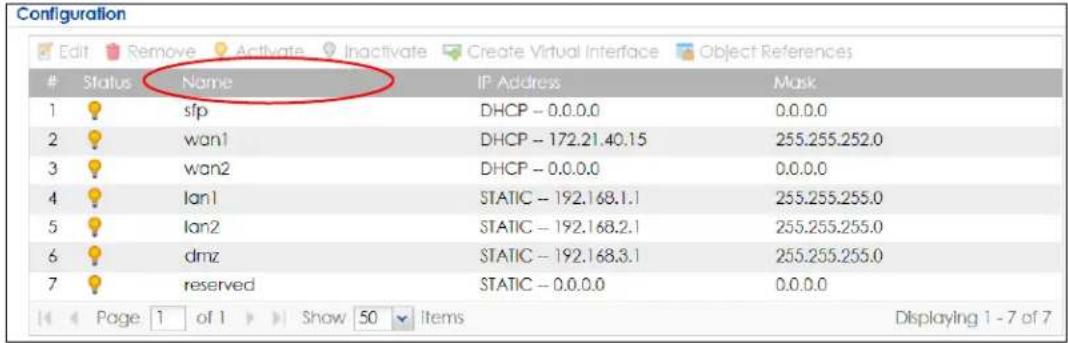
Click the down arrow next to a column heading for more options about how to display the entries. The options available vary depending on the type of fields in the column. Here are some examples of what you can do:
- Sort in ascending or descending (reverse) alphabetical order
- Select which columns to display
• Group entries by field
• Show entries in groups - Filter by mathematical operators (<, >, or =) or searching for text
Figure 26 Common Table Column Options
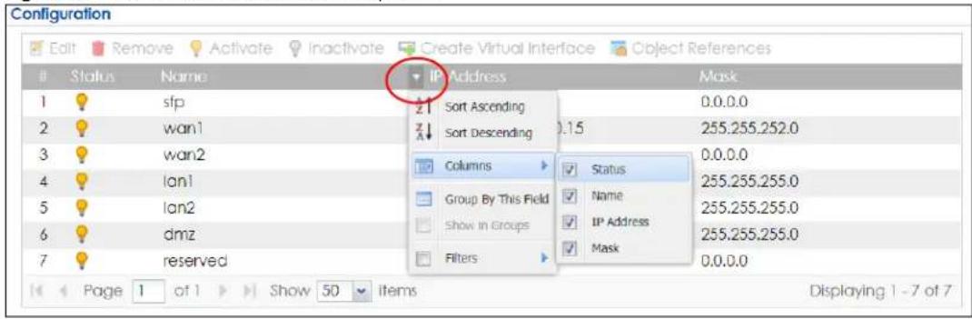
Select a column heading cell's right border and drag to re-size the column.
Figure 27 Resizing a Table Column

Select a column heading and drag and drop it to change the column order. A green check mark displays next to the column's title when you drag the column to a valid new location.
Figure 28 Moving Columns
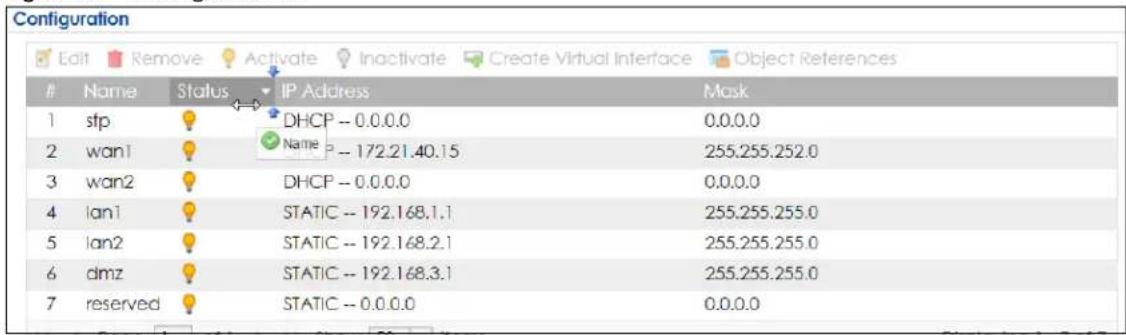
Use the icons and fields at the bottom of the table to navigate to different pages of entries and control how many entries display at a time.
Figure 29 Navigating Pages of Table Entries

The tables have icons for working with table entries. You can often use the [Shift] or [Ctrl] key to select multiple entries to remove, activate, or deactivate.
Figure 30 Common Table Icons

Here are descriptions for the most common table icons.
Table 13 Common Table Icons
| LABEL DESCRIPTION | |
| Add | Click this to create a new entry. For features where the entry's position in the numbered list is important (features where the Zyxel Device applies the table's entries in order like the security policy for example), you can select an entry and click Add to create a new entry after the selected entry. |
| Edit | Double-click an entry or select it and click Edit to open a screen where you can modify the entry's settings. In some tables you can just click a table entry and edit it directly in the table. For those types of tables small red triangles display for table entries with changes that you have not yet applied. |
| Remove | To remove an entry, select it and click Remove. The Zyxel Device confirms you want to remove it before doing so. |
| Activate | To turn on an entry, select it and click Activate. |
| Inactivate | To turn off an entry, select it and click Inactivate. |
| Connect | To connect an entry, select it and click Connect. |
| Disconnect | To disconnect an entry, select it and click Disconnect. |
| References | Select an entry and click References to check which settings use the entry. |
| Move | To change an entry's position in a numbered list, select it and click Move to display a field to type a number for where you want to put that entry and press [ENTER] to move the entry to the number that you typed. For example, if you type 6, the entry you are moving becomes number 6 and the previous entry 6 (if there is one) gets pushed up (or down) one. |
Working with Lists
When a list of available entries displays next to a list of selected entries, you can often just double-click an entry to move it from one list to the other. In some lists you can also use the [Shift] or [Ctrl] key to select multiple entries, and then use the arrow button to move them to the other list.
Figure 31 Working with Lists
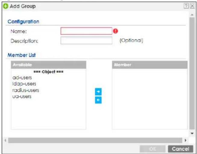
CHAPTER 2
Initial Setup Wizard
2.1 Initial Setup Wizard: Select Management Mode
When you log into the Web Configurator for the first time or when you reset the Zyxel Device to its default configuration, the Initial Setup Wizard screen displays. This wizard helps you configure Internet connection settings and activate subscription services.
Note: For Zyxel Devices that already have firmware version 4.25 or later, you have to register your Zyxel Device and activate the corresponding service at Zyxel Account(through your Zyxel Device).
This chapter provides information on configuring the Web Configurator's Initial Setup Wizard. See the feature-specific chapters in this User's Guide for background information.
- Click the double arrow in the upper right corner to display or hide the help.
- Click Logout to exit the Initial Setup Wizard or click Next to continue the wizard. Click Finish at the end of the wizard to complete the wizard.
Select On Premises Mode to manage your Zyxel Device using the Web Configurator or the Command Line Interface (CLI). Use this mode to secure your networks with the Zyxel Device security services. Follow the On Premises mode wizard to set up your Zyxel Device, such as configuring the WAN settings, registering your Zyxel Device and allowing remote access to your Zyxel Device.
Select Nebula Mode to manage your Zyxel Device using Nebula Control Center (NCC). NCC is a cloud based network management system that allows you to remotely manage and monitor your Zyxel Device. Use this mode to manage your Zyxel Device with accounts at different privilege levels. You can also manage your Zyxel Device licenses and status through NCC.Follow the Nebula mode wizard to configure the WAN settings to pass the management of your Zyxel Device to NCC.
Note: You need to press the reset button to change the Zyxel Device mode once you finish the wizard. You will not see this screen if you reset the Zyxel Device through the web configurator or the CLI.
Figure 32 Management Mode: On Premises Mode
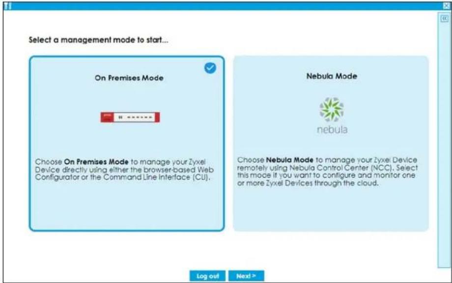
2.1.1 Welcome Screen
Select On Premises Mode in the previous screen to show the Welcome screen. Use this screen to see the settings you can configure using the On Premises mode initial setup wizard.
Figure 33 On Premises Mode- Welcome
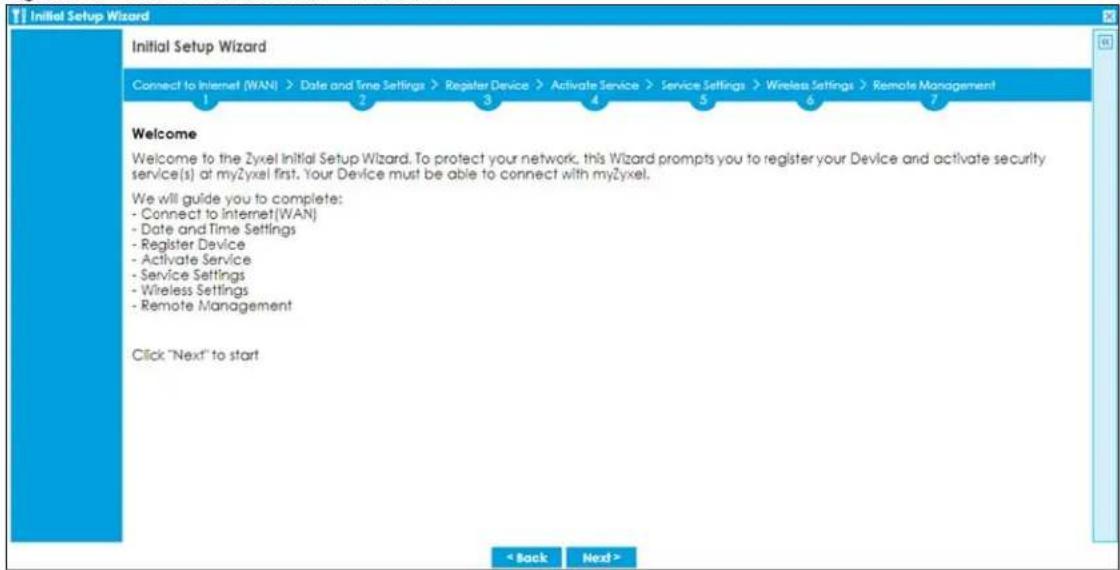
2.1.2 Internet Access Setup - WAN Interface
Use this screen to set how many WAN interfaces to configure and the first WAN interface's type of encapsulation and method of IP address assignment.
The screens vary depending on the encapsulation type. Refer to information provided by your ISP to know what to enter in each field.
Note: Enter the Internet access information exactly as your ISP gave it to you. Leave a field blank if you don't have that information.
- I have two ISPs: Select this option to configure two Internet connections. Leave it cleared to configure just one. This option appears when you are configuring the first WAN interface.
- VLAN Tagged: Select this to tag the traffic going out from the Zyxel Device. Enter a VLAN ID. This 12-bit number uniquely identifies each VLAN. Allowed values are 1-4080.
- Encapsulation: Choose the Ethernet option when the WAN port is used as a regular Ethernet. Choose PPPoE, PPTP or L2TP for a dial-up connection according to the information from your ISP.
- MTU: The Maximum Transmission Unit. Type the maximum size of each data packet, in bytes, that can move through this interface. If a larger packet arrives, the Zyxel Device divides it into smaller fragments. Allowed values are 576-1500. Usually, this value is 1500.
- WAN Interface: This is the interface you are configuring for Internet access.
• Zone: This is the security zone to which this interface and Internet connection belong.
- IP Address Assignment: Select Auto if your ISP did not assign you a fixed IP address. Select Static if the ISP assigned a fixed IP address.
- DHCP Option 60: This field will show if you choose Auto as the IP Address Assignment. DHCP Option 60 is used by the Zyxel Device for identification to the DHCP server using the VCI (Vendor Class Identifier) on the DHCP server. The Zyxel Device adds it in the initial DHCP discovery message that a DHCP client broadcasts in search of an IP address. The DHCP server can assign different IP addresses or options to clients with the specific VCI or reject the request from clients without the specific VCI.
Type a string using up to 63 of these characters [a-zA-Z0-9!\"#\%&\'()*+,-./;<=>?@\$ \^_^{}] to identify this Zyxel Device to the DHCP server. For example, Zyxel-TW.
Figure 34 Internet Access
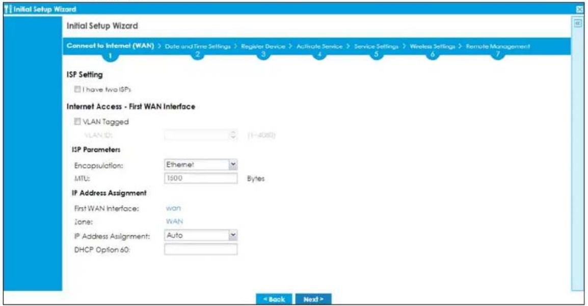
2.1.3 Internet Access: Ethernet
This screen is read-only if you set the previous screen's IP Address Assignment field to Auto. If you set the previous screen's IP Address Assignment field to Static, use this screen to configure your IP address settings.
- VLAN ID: This displays the VLAN ID tag for the traffic going out from the Zyxel Device, which you configured in the previous screen.
- Encapsulation: This displays the type of Internet connection you are configuring.
- MTU: This displays the maximum size of each data packet that can move through this interface.
- First WAN Interface: This is the number of the interface that will connect with your ISP.
- Zone: This is the security zone to which this interface and Internet connection will belong.
- IP Address: Enter your (static) public IP address. Auto displays if you selected Auto as the IP Address Assignment in the previous screen.
- DHCP Option 60: This field will show if you selected Auto as the IP Address Assignment in the previous screen. This displays the string you configured to identify DHCP server using VCI.
The following fields display if you selected static IP address assignment.
- IP Subnet Mask: Enter the subnet mask for this WAN connection's IP address.
- Gateway IP Address: Enter the IP address of the router through which this WAN connection will send traffic (the default gateway).
- First / Second DNS Server: These fields display if you selected static IP address assignment. The Domain Name System (DNS) maps a domain name to an IP address and vice versa. Enter a DNS server's IP address(es). The DNS server is extremely important because without it, you must know the IP address of a computer before you can access it. The Zyxel Device uses these (in the order you specify here) to resolve domain names for VPN, DDNS and the time server. Leave the field as 0.0.0.0 if you do not want to configure DNS servers.
2.1.3.1 Possible Errors
- Check that your cable connection is coming from the correct interface you're using for the WAN connection on the Zyxel Device.
- Check that the interface is connected to the device you're using for Internet access such as a broadband router and that the router is turned on. The LED of the interface you're using for the WAN connection on the Zyxel Device should be orange.
- If your Zyxel Device was not able to obtain an IP address, check that your Internet access information uses DHCP as the WAN connection type. If it fails again, check with your Internet service provider or administrator for correct WAN settings.
- If your Zyxel Device was not able to use the IP address entered, check that you were given an IP address, subnet mask and gateway address as part of your Internet access information. Re-enter your IP address, subnet mask and gateway IP address exactly as given. If it fails again, check with your Internet service provider or administrator for correct IP address, subnet mask and gateway address and other WAN settings.
Figure 35 Internet Access: Ethernet Encapsulation
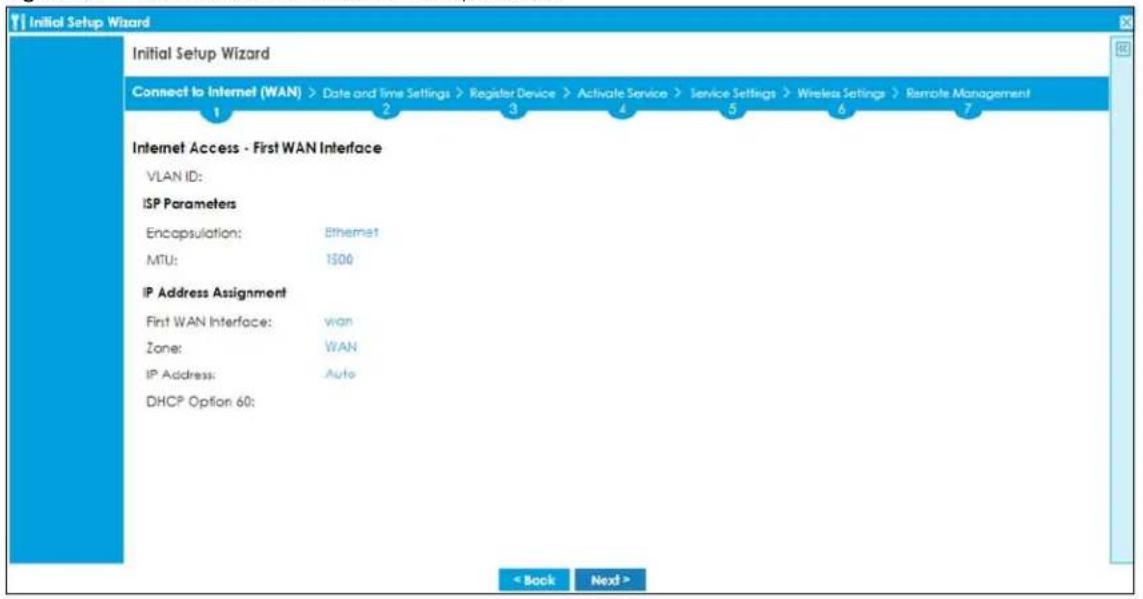
2.1.4 Internet Access: PPPoE
2.1.4.1 Internet Access - First WAN Interface
- VLAN ID: This displays the VLAN ID tag for the traffic going out from the Zyxel Device, which you configured in the previous screen.
2.1.4.2 ISP Parameters
- VLAN ID: This displays the VLAN ID tag for the traffic going out from the Zyxel Device, which you configured in the previous screen.
- Encapsulation: This displays the type of Internet connection you are configuring.
- MTU: This displays the maximum size of each data packet that can move through this interface.
- Type the PPPoE Service Name from your service provider. PPPoE uses a service name to identify and reach the PPPoE server. You can use alphanumeric and -_@\$./ characters, and it can be up to 64 characters long.
-
Authentication Type - Select an authentication protocol for outgoing connection requests. Options are:
-
Chap/PAP - Your Zyxel Device accepts either CHAP or PAP when requested by the remote node.
• Chap - Your Zyxel Device accepts CHAP only.
• PAP - Your Zyxel Device accepts PAP only.
• MSCHAP - Your Zyxel Device accepts MSCHAP only.
• MSCHAP-V2 - Your Zyxel Device accepts MSCHAP-V2 only. -
Type the User Name given to you by your ISP. You can use alphanumeric and -_@\$./ characters, and it can be up to 31 characters long.
- Type the Password associated with the user name. Use up to 64 ASCII characters except the [] and ?. This field can be blank.
- Select Nailed-Up if you do not want the connection to time out. Otherwise, type the Idle Timeout in seconds that elapses before the router automatically disconnects from the PPPoE server.
2.1.4.3 WAN IP Address Assignments
- WAN Interface: This is the name of the interface that will connect with your ISP.
- Zone: This is the security zone to which this interface and Internet connection will belong.
- IP Address: Enter your (static) public IP address. Auto displays if you selected Auto as the IP Address Assignment in the previous screen.
- First / Second DNS Server: These fields display if you selected static IP address assignment. The Domain Name System (DNS) maps a domain name to an IP address and vice versa. Enter a DNS server's IP address(es). The DNS server is extremely important because without it, you must know the IP address of a computer before you can access it. The Zyxel Device uses these (in the order you specify here) to resolve domain names for VPN, DDNS and the time server. Leave the field as 0.0.0.0 if you do not want to configure DNS servers. If you do not configure a DNS server, you must know the IP address of a machine in order to access it.
2.1.4.4 Possible Errors
- Check that you're using the correct PPPoE Service Name and Authentication Type.
- Make sure that your Internet access information uses PPPoE as the WAN connection type. Re-enter your PPPoE user name and password exactly as given. If it fails again, check with your Internet service provider or administrator for correct WAN settings and user credentials.
- If you were given an IP address and DNS server information as part of your Internet access information, re-enter them exactly as given. If it fails again, check with your Internet service provider or administrator for correct IP address, subnet mask and gateway address and other WAN settings.
Figure 36 Internet Access: PPPoE Encapsulation
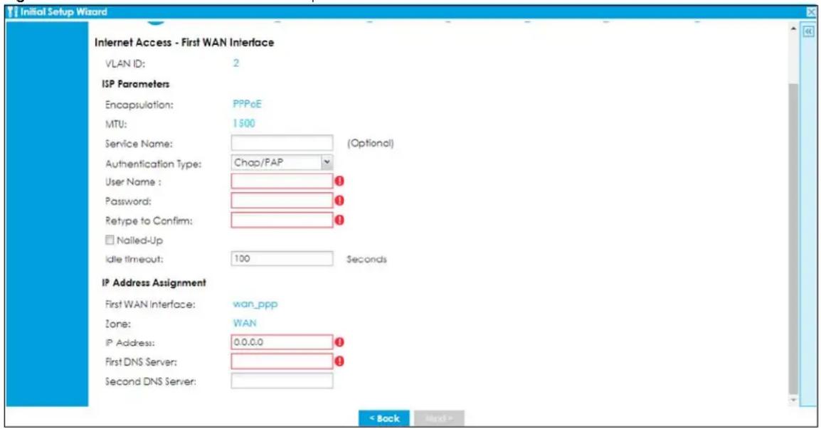
2.1.5 Internet Access: PPTP
2.1.5.1 ISP Parameters
- MTU: This displays the maximum size of each data packet that can move through this interface.
- Authentication Type - Select an authentication protocol for outgoing calls. Options are:
- Chap/PAP - Your Zyxel Device accepts either CHAP or PAP when requested by the remote node.
-
Chap - Your Zyxel Device accepts CHAP only.
-
PAP - Your Zyxel Device accepts PAP only.
• MSCHAP - Your Zyxel Device accepts MSCHAP only. -
MSCHAP-V2 - Your Zyxel Device accepts MSCHAP-V2 only.
-
Type the User Name given to you by your ISP. You can use alphanumeric and -@\$./ characters, and it can be up to 31 characters long.
- Type the Password associated with the user name. Use up to 64 ASCII characters except the [] and ?. This field can be blank. Re-type your password in the next field to confirm it.
- Select Nailed-Up if you do not want the connection to time out. Otherwise, type the Idle Timeout in seconds that elapses before the router automatically disconnects from the PPTP server.
2.1.5.2 PPTP Configuration
- Base Interface: This identifies the Ethernet interface you configure to connect with a modem or router.
- Type a Base IP Address (static) assigned to you by your ISP.
- Type the IP Subnet Mask assigned to you by your ISP (if given).
- Gateway IP Address: Enter the IP address of the router through which this WAN connection will send traffic (the default gateway).
- Server IP: Type the IP address of the PPTP server.
- Type a Connection ID or connection name. It must follow the "c:id" and "n:name" format. For example, C:12 or N:My ISP. This field is optional and depends on the requirements of your broadband modem or router. You can use alphanumeric and -_: characters, and it can be up to 31 characters long.
2.1.5.3 WAN IP Address Assignments
- First WAN Interface: This is the connection type on the interface you are configuring to connect with your ISP.
- Zone This is the security zone to which this interface and Internet connection will belong.
- IP Address: Enter your (static) public IP address. Auto displays if you selected Auto as the IP Address Assignment in the previous screen.
- First / Second DNS Server: These fields display if you selected static IP address assignment. The Domain Name System (DNS) maps a domain name to an IP address and vice versa. Enter a DNS server's IP address(es). The DNS server is extremely important because without it, you must know the IP address of a computer before you can access it. The Zyxel Device uses these (in the order you specify here) to resolve domain names for VPN, DDNS and the time server. Leave the field as 0.0.0.0 if you do not want to configure DNS servers.
2.1.5.4 Possible Errors
- Check that you're using the correct PPPT Service IP, Base IP Address, IP Subnet Mask, Gateway IP Address, Connection ID and Authentication Type.
- Make sure that your Internet access information uses PPTP as the WAN connection type. Re-enter your PPTP user name and password exactly as given. If it fails again, check with your Internet service provider or administrator for correct WAN settings and user credentials.
- If you were given an IP address and DNS server information as part of your Internet access information, re-enter them exactly as given. If it fails again, check with your Internet service provider or administrator for correct IP address, subnet mask and gateway address and other WAN settings.
Figure 37 Internet Access: PPTP Encapsulation
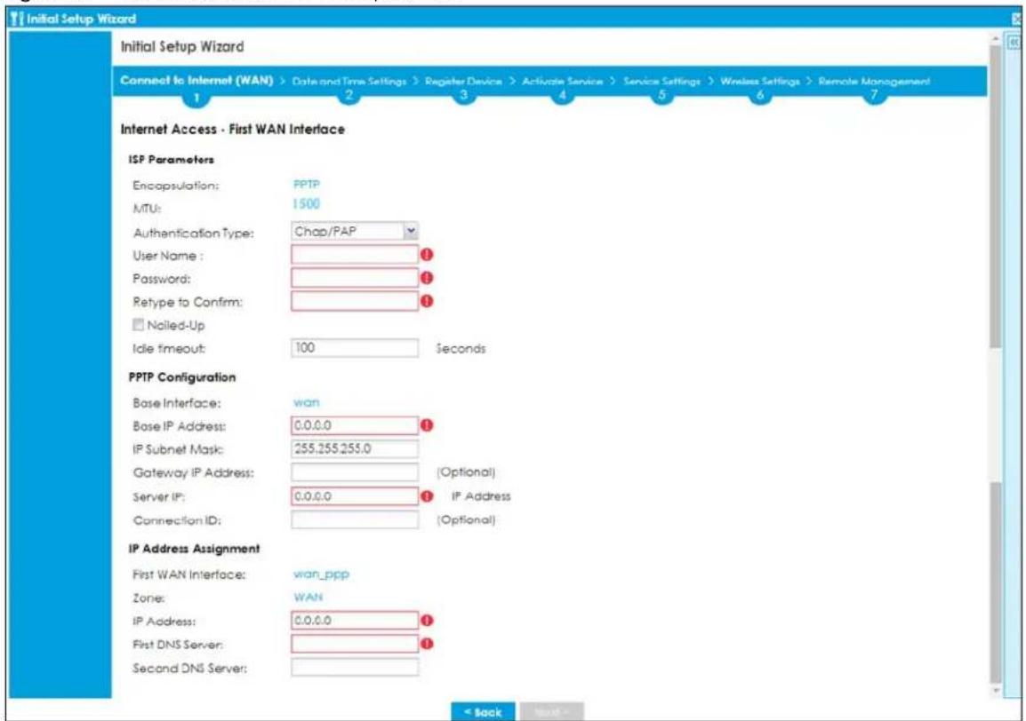
2.1.6 Internet Access: L2TP
2.1.6.1 ISP Parameters
- Authentication Type - Select an authentication protocol for outgoing connection requests. Options are:
- Chap/PAP - Your Zyxel Device accepts either CHAP or PAP when requested by the remote node.
• Chap - Your Zyxel Device accepts CHAP only. - PAP - Your Zyxel Device accepts PAP only.
• MSCHAP - Your Zyxel Device accepts MSCHAP only.
• MSCHAP-V2 - Your Zyxel Device accepts MSCHAP-V2 only.
- Type the User Name given to you by your ISP. You can use alphanumeric and -_@\$./ characters, and it can be up to 31 characters long.
- Type the Password associated with the user name. Use up to 64 ASCII characters except the [] and ?. This field can be blank.
- Select Nailed-Up if you do not want the connection to time out. Otherwise, type the Idle Timeout in seconds that elapses before the router automatically disconnects from the PPPoE server.
2.1.6.2 L2TP Configuration
- Base Interface: This identifies the Ethernet interface you configure to connect with a modem or router.
- Type a Base IP Address (static) assigned to you by your ISP.
-
IP Subnet Mask: Enter the subnet mask for this WAN connection's IP address.
-
Gateway IP Address: Enter the IP address of the router through which this WAN connection will send traffic (the default gateway).
- Server IP: Type the IP address of the L2TP server.
2.1.6.3 WAN IP Address Assignments
- WAN Interface: This is the name of the interface that will connect with your ISP.
- Zone: This is the security zone to which this interface and Internet connection will belong.
- IP Address: Enter your (static) public IP address. Auto displays if you selected Auto as the IP Address Assignment in the previous screen.
- First / Second DNS Server: These fields display if you selected static IP address assignment. The Domain Name System (DNS) maps a domain name to an IP address and vice versa. Enter a DNS server's IP address(es). The DNS server is extremely important because without it, you must know the IP address of a computer before you can access it. The Zyxel Device uses these (in the order you specify here) to resolve domain names for VPN, DDNS and the time server. Leave the field as 0.0.0.0 if you do not want to configure DNS servers.
2.1.6.4 Possible Errors
- Check that you're using the correct L2PT Server IP, Subnet Mask, Gateway IP Address, IP Subnet Mask and Authentication Type.
- Make sure that your Internet access information uses L2TP as the WAN connection type. Re-enter your L2TP user name and password exactly as given. If it fails again, check with your Internet service provider or administrator for correct WAN settings and user credentials.
- If you were given an IP address and DNS server information as part of your Internet access information, re-enter them exactly as given. If it fails again, check with your Internet service provider or administrator for correct IP address, subnet mask and gateway address and other WAN settings.
Figure 38 Internet Access: L2TP Encapsulation
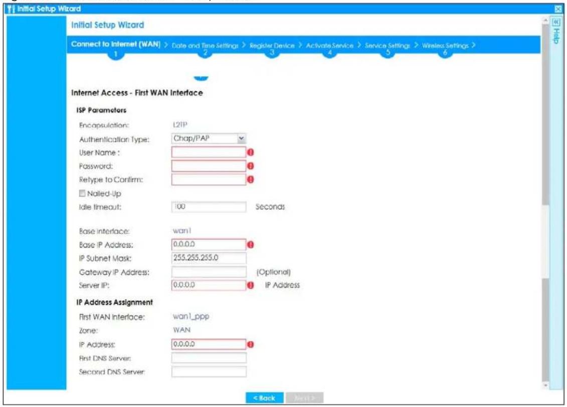
2.1.7 Internet Access Setup - Second WAN Interface
If you selected I have two ISPs, after you configure the First WAN Interface, you can configure the Second WAN Interface. The screens for configuring the second WAN interface are similar to the first (see Section 2.1.2 on page 70).
Figure 39 Internet Access: Step 3: Second WAN Interface
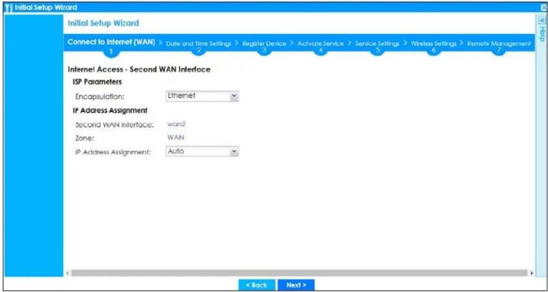
2.1.8 Internet Access: Congratulations
You have set up your Zyxel Device to access the Internet. A screen displays with your settings. Click Connection Test to check that you can access the Internet. If you cannot, click Back and confirm that you entered the settings correctly. If you have, check that you got the correct settings from your ISP or network administrator.
Figure 40 Internet Access: Summary
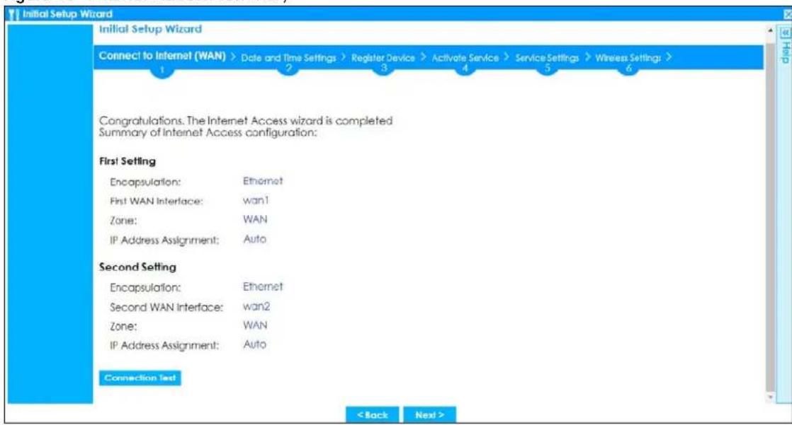
2.1.9 Date and Time Settings
It's important to have correct date and time values in the logs. The Zyxel Device can automatically update the time and date by detecting your time zone and whether Daylight Savings is in effect in that time zone.
If your Zyxel Device cannot get the correct date and time, it may not be able to connect to a time server. Check that the Zyxel Device has Internet access, then click Sync. Now.
Figure 41 Date and Time Settings
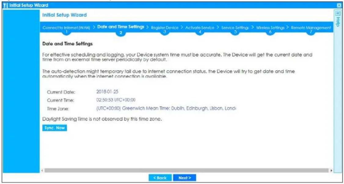
2.1.10 Register Device
Click the Register button in this screen to register your device at account.zyxel.com.
Note: The Zyxel Device must be connected to the Internet in order to register.
Figure 42 Register Device
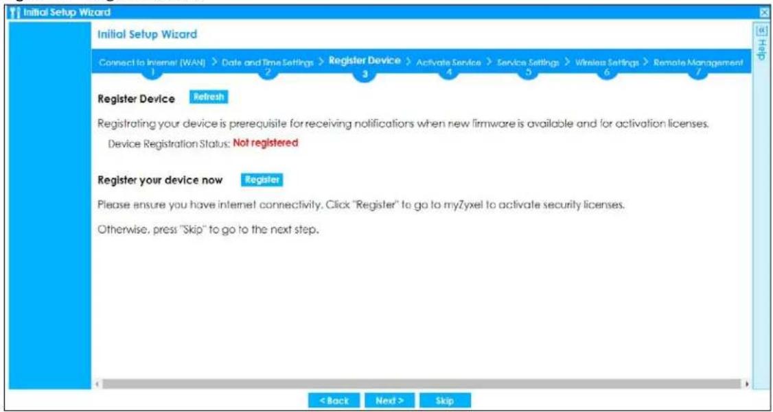
You may need the Zyxel Device's serial number and LAN MAC address to register it at Zyxel Account if you have not already done so. Refer to the label at the back of the Zyxel Device's for details.
Figure 43 myZyxel Login
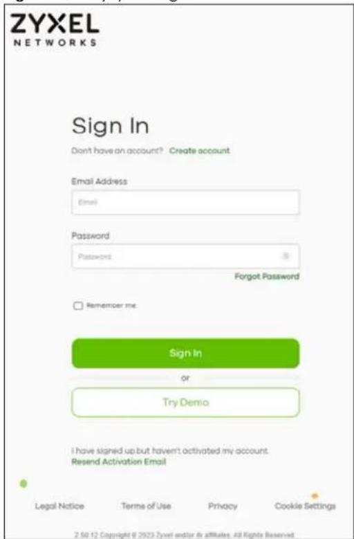
Click Refresh or use the Configuration > Licensing > Registration screen to update your Zyxel Device registration status. Please note that you cannot change to Nebula Mode once you click Next unless you reset the Zyxel Device.
Figure 44 Registered Device
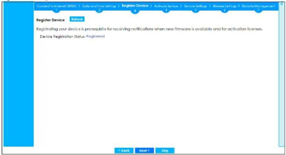
2.1.11 Activate Service
After you register your Zyxel Device, you can register for the services supported by your model. See Subscription Services Available on page 257 for more information on the subscription services for the two types of security packs.
Here are the services available for the Zyxel Device.
- Web Filtering (CF): access a database that can block websites by category.
- IPS (IDP): use this feature to detect Intrusion Detection and Prevention attacks.
- Application Patrol: use signatures for Application Patrol inspection to manage the use of various applications on the network.
- Anti-Malware: use signatures to detect malware patterns in files.
- Email Security (Anti-Spam): use anti-spam signatures to mark or discard spam (unsolicited commercial or junk email).
- Sandboxing: provide a safe environment to separate running programs from your network and host devices. This field is available with a Gold Security Pack license.
- Reputation Filter: use this feature to detect and manage IP addresses, FQDNs or URLs with a bad reputation. This field is available with a Gold Security Pack license.
- SecuReporter: collect and analyze logs from your Zyxel Device in order to identify anomalies, notify you of potential internal or external threats, and report on network usage.
- Collaborative Detection & Response: detect wired and WiFi clients that are sending malicious traffic in your network and then block or quarantine traffic coming from them.
• Network Premium: allow users to log in once to get access to permitted resources.
Figure 45 USG FLEX Activate Service
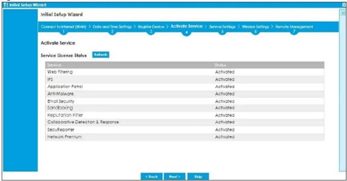
Click Refresh and wait a few moments for the registration information to update in this screen. If the page does not refresh, make sure the Internet connection is working and click Refresh again. To check your Internet connection, try to access the Internet from a computer connected to a LAN port on the Zyxel Device. If you cannot, then check your Internet access settings on the Zyxel Device.
2.1.12 Service Settings
You can enable or disable the following features in this screen. This screen varies depending on the security pack that you purchase. See Subscription Services Available on page 257 for more information on the subscription services for the two types of security packs.
Note: Select the I have read SecuReporter GDPR and agree policy check box to have SecuReporter collect and analyze logs from this Zyxel Device. This check box won't appear again if you have already selected this before.
- Use this feature to detect and block access to specific URLs, by comparing URL addresses of sites that users attempt to access with a database of either permitted or blocked sites.
- Anti-Malware: Use this feature to detect malware patterns in files.
- IPS: Use this feature to detect Intrusion Detection and Prevention attacks.
- IP Reputation: Use this feature to detect and block IP addresses with a bad reputation. This field is available with a Gold Security Pack license.
- DNS Threat Filter: Use this feature to detect and block domain names with a bad reputation. This field is available with a Gold Security Pack license.
- Sandboxing: Use this feature to provide a safe environment to separate running programs from your network and host devices. This field is available with a Gold Security Pack license.
- Content Filter: Use this feature to access a database that can block websites by category.
- App Patrol: Use this feature to manage the use of various applications on the network.
-
Email Security: Use this feature to mark or discard spam (unsolicited commercial or junk email).
-
SecuReporter: Use this feature to collect and analyze logs from your Zyxel Device in order to identify anomalies, notify you of potential internal or external threats, and report on network usage.
- Collaborative Detection & Response: Use this feature to detect wired and WiFi clients that are sending malicious traffic in your network and then block or quarantine traffic coming from them.
Figure 46 USG FLEX Service Settings
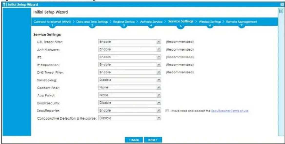
2.1.13 Service Settings: SecuReporter
Use this screen to add the Zyxel Device to a new or existing organization, and choose the level of data protection for traffic going through this Zyxel Device.
- Server Status: This is the connection status between the Zyxel Device and the SecuReporter server. This field shows Connected when the Zyxel Device can synchronize with the SecuReporter server. This field shows Timeout when the Zyxel Device can't synchronize with the SecuReporter server. This field shows Fail when the connection between the Zyxel Device and the SecuReporter server is down.
- Device Name: Enter the name of the Zyxel Device. This Zyxel Device will be added to a new or existing organization.
- Organization: This field appears if you haven't created an organization in the SecuReporter server. Type a name of up to 255 characters and description to create a new organization.
- Select from existing organization: Select an existing organization from the drop-down list box to add the Zyxel Device to the selected organization.
- Create new organization: Type a name of up to 255 characters and description to create a new organization.
- Partially Anonymous: Select this and personal data, such as user names, MAC addresses, email addresses, and host names, will be replaced with artificial identifiers in downloaded logs.
- Fully Anonymous: Select this and personal data, such as user names, MAC addresses, email addresses, and host names, will be replaced with anonymized information in downloaded logs.
- Non-Anonymous: Select this and personal data, such as user names, MAC addresses, email addresses, and host names, will be identifiable in downloaded logs.
Figure 47 SecuReporter Settings
![Initial Setup Wizard Initial Setup Wizard Connect to Internet (WAN) > Date and Time Settings > Register Device > Activate Service > Service Settings > Wireless Settings > Remote Management 1 2 3 4 5 6 7 SecuReporter Setting Server Status: Connected Device Name: ATP200_Fran Select from existing organization Create new organization Organization: Org1 Organization: Org1 Data Protection Policy Read the data protection policy and then choose the level of data protection for traffic going through this Zyxel Device. Partially Anonymous Fully Anonymous Non-Anonymous Personal data [user names, MAC addresses, email addresses and host names] are replaced with artificial identifiers in downloaded Archive Logs. Personal data can be removed from SecuReporter. Personal data [user names, MAC addresses, email addresses and host names] are replaced with anonymized information in Analyzer, Reports, and downloaded Archive Logs. Data can no longer be traced back to individual people. Data [user names, MAC addresses, email addresses and host names] are clearly identifiable in Analyzer, Reports, and downloaded Archive Logs. Personal data cannot be removed from SecuReporter. < Back Next >](/content/2026/05/878280/images/59dab614761f4e7a330618bad24d2495d76cf6c3a6c9029af8ad65e897f0bad9.jpg)
The following screen appears when the Zyxel Device is already added in an organization.
Figure 48 SecuReporter Settings
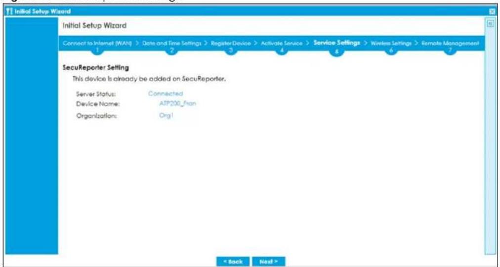
2.1.14 Wireless Settings: Management Mode
The Management Mode screen appears for Zyxel Devices that have a built-in AP. Select Built-in AP if you want WiFi clients to access your Zyxel Device wirelessly. Select AP Controller to allow the Zyxel Device to manage APs in the same network as the Zyxel Device. Both modes cannot work simultaneously. Click Next to continue the wizard.
Figure 49 Wireless Setup Wizard > Management Mode (Models with Built-in AP)
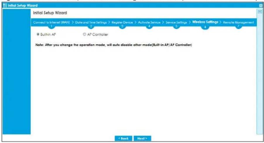
2.1.15 Wireless Settings: AP Controller
The Zyxel Device can act as an AP Controller that can manage APs in the same network as the Zyxel Device. Select Yes if you want your Zyxel Device to manage APs in your network; otherwise select No.
Figure 50 Wireless Setup Wizard > Management Mode
![Initial Setup Wizard Connect to Internet NAVA > Date and Line Settings > Register Device > Activate Service > Service Settings > Wireless Settings > Remote Management Do you like to enable AP Controller feature ? [Enable this feature ONLY when you manage to deploy USG RLEX 500 to control managed AP in your network] Yes No < Back Next >](/content/2026/05/878280/images/fecbfaf5e61c6100b985a97267382e6f45f43bb900f98f22dc0cce688f4bf424.jpg)
2.1.16 Wireless Settings: SSID & Security
Configure SSID and wireless security in this screen.
SSID Setting
- SSID - Enter a descriptive name of up to 32 printable characters for the wireless LAN.
- Security Mode - Select Pre-Shared Key to add security on this wireless network. Otherwise, select None to allow any wireless client to associate this network without authentication.
-
Pre-Shared Key - Enter a pre-shared key of between 8 and 63 case-sensitive ASCII characters (including spaces and symbols) or 64 hexadecimal characters.
-
Hidden SSID - Select this option if you want to hide the SSID in the outgoing beacon frame. A wireless client then cannot obtain the SSID through scanning using a site survey tool.
- Enable Intra-BSS Traffic Blocking - Select this option if you want to prevent crossover traffic from within the same SSID. Wireless clients can still access the wired network but cannot communicate with each other.
For Zyxel Devices with Built - in AP Only
Bridged to: Zyxel Devices with W in the model name have a built-in AP. Select an interface to bridge with the built-in AP wireless network. Devices connected to this interface will then be in the same broadcast domain as devices in the AP wireless network.
Figure 51 Wireless Settings: SSID & Security
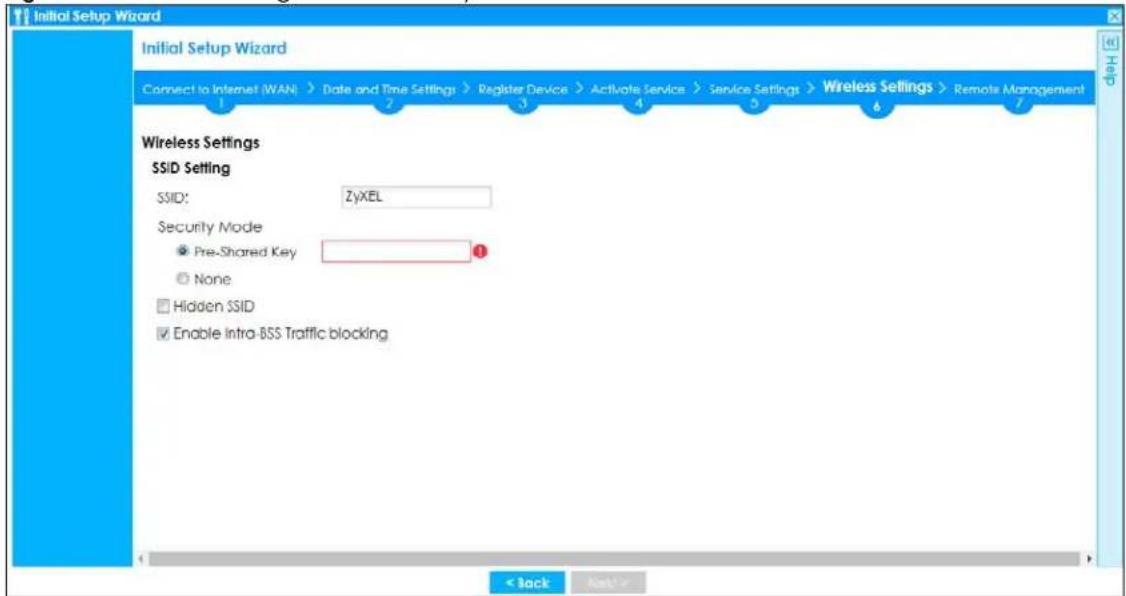
2.1.17 Remote Management
Configure settings in this screen to add a rule that has priority over other rules in Policy Control. It restricts access to the web configurator and SSL VPN service from the Internet.
Figure 52 Remote Management
![Initial Setup Wizard Connect to Internet (WAN) > Date and Time Settings > Register Device > Activate Service > Service Settings > Wireless Settings > Remote Management 1 2 3 4 5 6 7 Remote Management Best practice of reduce attack surface from outside. Strongly recommend to change the default port and restrict the accessible source. Allow secure remote management from WAN Port 443 [1..6583] (If Request access only to trusted host) Trusted Host 1: [IP or PQON] Trusted Host 2: [IP or PQON] (Optional) Trusted Host 3: [IP or PQON] (Optional) Allow SSL VPN access from WAN Port 1043 [1..6583] (If Request access by QasP) Trusted Geolocation 1: [Optional] Trusted Geolocation 2: [Optional] Trusted Geolocation 3: [Optional] < Back Finish](/content/2026/05/878280/images/e629f13eeedc28ee4499059d95d10e8f144059c13821461660649e590f867f1b.jpg)
- Enable Allow secure remote management from WAN to create a rule in the Policy Control screen. It allows you to access the Zyxel Device from the WAN using HTTPS.
- Enable Restrict access only to trusted host to have the Zyxel Device allow access only from the IP addresses or FQDNs specified in the fields below.
- Enable Allow SSL VPN access from WAN to allow access to the Zyxel Device remotely through the SSL VPN tunnel.
- Enable Restrict access by GeoIP to have the Zyxel Device allow access only from countries specified in the fields below.
Figure 53 Object > Service > Service Group - HTTPS
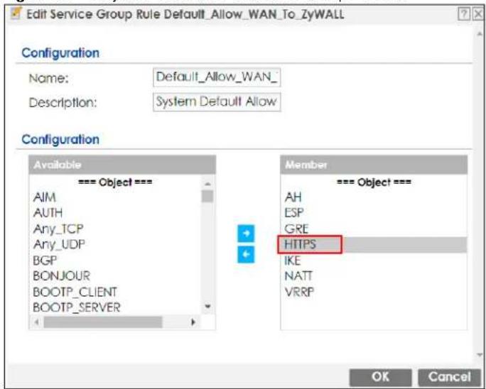
2.2 Nebula Mode Initial Setup Wizard
Select Nebula Mode to manage and monitor your Zyxel Device remotely. Follow the wizard to configure the WAN settings to pass the management of your Zyxel Device to NCC.
Figure 54 Management Mode: Nebula Mode
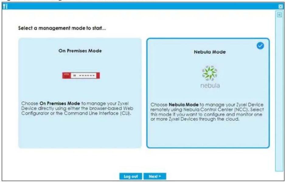
2.2.1 Connect to Internet (WAN)
Configure the WAN interface that the Zyxel Device will use to connect to Nebula through the Internet.
Use this screen to set how many WAN interfaces to configure and the first WAN interface's type of encapsulation and method of IP address assignment.
The screens vary depending on the encapsulation type. Refer to information provided by your ISP to know what to enter in each field.
Note: Enter the Internet access information exactly as your ISP gave it to you. Leave a field blank if you don't have that information.
- I have two ISPs: Select this option to configure two Internet connections. Leave it cleared to configure just one. This option appears when you are configuring the first WAN interface.
- VLAN Tagged: Select this to tag the traffic going out from the Zyxel Device. Enter a VLAN ID. This 12-bit number uniquely identifies each VLAN. Allowed values are 1-4080.
- Encapsulation: Choose the Ethernet option when the WAN port is used as a regular Ethernet. Choose PPPoE for a dial-up connection according to the information from your ISP.
- MTU: The Maximum Transmission Unit. Type the maximum size of each data packet, in bytes, that can move through this interface. If a larger packet arrives, the Zyxel Device divides it into smaller fragments. Allowed values are 576-1500. Usually, this value is 1500.
- WAN Interface: This is the interface you are configuring for Internet access.
- IP Address Assignment: Select Auto if your ISP did not assign you a fixed IP address. Select Static if the ISP assigned a fixed IP address.
- DHCP Option 60: This field will show if you choose Auto as the IP Address Assignment. DHCP Option 60 is used by the Zyxel Device for identification to the DHCP server using the VCI (Vendor Class Identifier) on the DHCP server. The Zyxel Device adds it in the initial DHCP discovery message that a DHCP client broadcasts in search of an IP address. The DHCP server can assign different IP addresses or options to clients with the specific VCI or reject the request from clients without the specific VCI.
Type a string using up to 63 of these characters [a-zA-Z0-9!\"#\$%&\'()*+,-./;<==>@[\]\^_^{}] to identify this Zyxel Device to the DHCP server. For example, Zyxel-TW.
Figure 55 Internet Access
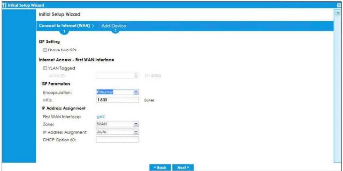
2.2.2 Internet Access: Ethernet
This screen is read-only if you set the previous screen's IP Address Assignment field to Auto. If you set the previous screen's IP Address Assignment field to Static, use this screen to configure your IP address settings.
- VLAN ID: This displays the VLAN ID tag for the traffic going out from Zyxel Device you configured in the previous screen.
- Encapsulation: This displays the type of Internet connection you are configuring.
- MTU: This displays the maximum size of each data packet that can move through this interface.
- First WAN Interface: This is the number of the interface that will connect with your ISP.
- IP Address: Enter your (static) public IP address. Auto displays if you selected Auto as the IP Address Assignment in the previous screen.
- DHCP Option 60: This field will show if you selected Auto as the IP Address Assignment in the previous screen. This displays the string you configured to identify DHCP server using VCI.
The following fields display if you selected static IP address assignment.
- IP Subnet Mask: Enter the subnet mask for this WAN connection's IP address.
- Gateway IP Address: Enter the IP address of the router through which this WAN connection will send traffic (the default gateway).
- First / Second DNS Server: These fields display if you selected static IP address assignment. The Domain Name System (DNS) maps a domain name to an IP address and vice versa. Enter a DNS server's IP address(es). The DNS server is extremely important because without it, you must know the IP address of a computer before you can access it. The Zyxel Device uses these (in the order you specify here) to resolve domain names for VPN, DDNS and the time server. Leave the field as 0.0.0.0 if you do not want to configure DNS servers. If you do not configure a DNS server, you must know the IP address of a machine in order to access it.
2.2.2.1 Possible Errors
- Check that your cable connection is coming from the correct interface you're using for the WAN connection on the Zyxel Device.
- Check that the interface is connected to the device you're using for Internet access such as a broadband router and that the router is turned on. The LED of the interface you're using for the WAN connection on the Zyxel Device should be orange.
- If your Zyxel Device was not able to obtain an IP address, check that your Internet access information uses DHCP as the WAN connection type. If it fails again, check with your Internet service provider or administrator for correct WAN settings.
- If your Zyxel Device was not able to use the IP address entered, check that you were given an IP address, subnet mask and gateway address as part of your Internet access information. Re-enter your IP address, subnet mask and gateway IP address exactly as given. If it fails again, check with your Internet service provider or administrator for correct IP address, subnet mask and gateway address and other WAN settings.
Figure 56 Internet Access: Ethernet Encapsulation
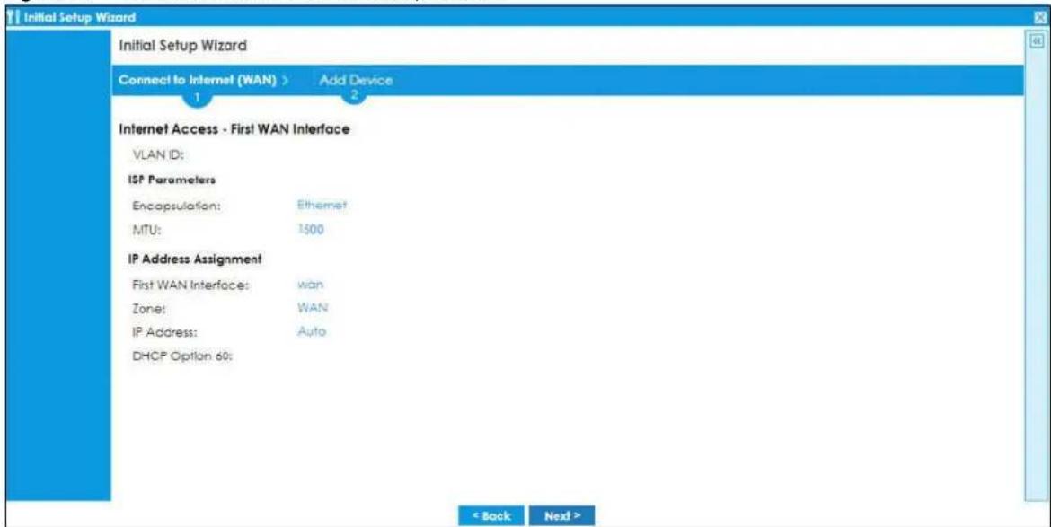
2.2.3 Internet Access: PPPoE
Internet Access - First WAN Interface
- VLAN ID: This displays the VLAN ID tag for the traffic going out from the Zyxel Device, which you configured in the previous screen.
ISP Parameters
- Encapsulation: This displays the type of Internet connection you are configuring.
- MTU: This displays the maximum size of each data packet that can move through this interface.
- Type the PPPoE Service Name from your service provider. PPPoE uses a service name to identify and reach the PPPoE server. You can use alphanumeric and -_@\$./ characters, and it can be up to 64 characters long.
- Authentication Type - Select an authentication protocol for outgoing connection requests. Options are:
- Chap/PAP - Your Zyxel Device accepts either CHAP or PAP when requested by the remote node.
- Chap - Your Zyxel Device accepts CHAP only.
- PAP - Your Zyxel Device accepts PAP only.
• MSCHAP - Your Zyxel Device accepts MSCHAP only. - MSCHAP-V2 - Your Zyxel Device accepts MSCHAP-V2 only.
- Type the User Name given to you by your ISP. You can use alphanumeric and -@\$./ characters, and it can be up to 31 characters long.
- Type the Password associated with the user name. Use up to 64 ASCII characters except the [] and ?. This field can be blank.
IP Address Assignments
- WAN Interface: This is the name of the interface that will connect with your ISP.
- IP Address: This displays Auto as the IP Address Assignment is set to Auto in the previous screen.
The following fields display if you selected static IP address assignment.
- IP Subnet Mask: Enter the subnet mask for this WAN connection's IP address.
- Gateway IP Address: Enter the IP address of the router through which this WAN connection will send traffic (the default gateway).
- First / Second DNS Server: These fields display if you selected static IP address assignment. The Domain Name System (DNS) maps a domain name to an IP address and vice versa. Enter a DNS server's IP address(es). The DNS server is extremely important because without it, you must know the IP address of a computer before you can access it. The Zyxel Device uses these (in the order you specify here) to resolve domain names for VPN, DDNS and the time server. Leave the field as 0.0.0.0 if you do not want to configure DNS servers. If you do not configure a DNS server, you must know the IP address of a machine in order to access it.
2.2.3.1 Possible Errors
- Make sure that your Internet access information uses PPPoE as the WAN connection type. Re-enter your PPPoE user name and password exactly as given. If it fails again, check with your Internet service provider or administrator for correct WAN settings and user credentials.
Figure 57 Internet Access: PPPoE Encapsulation
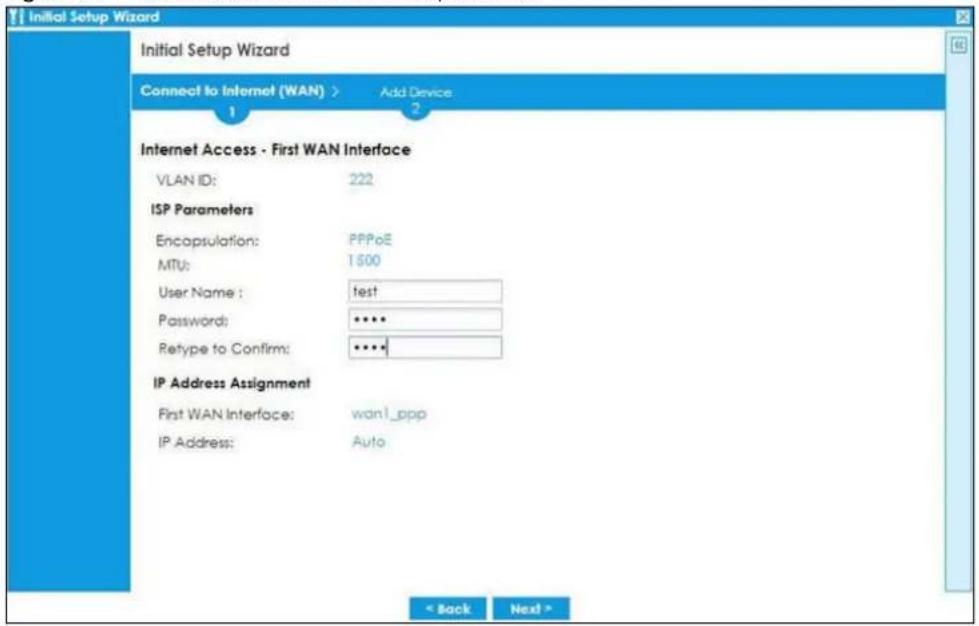
2.2.4 Internet Access: Congratulations
You have set up your Zyxel Device to access the Internet. A screen displays with your settings. Click Connection Test to check that you can access the Internet. If you cannot, click Back and confirm that you entered the settings correctly. If you have, check that you got the correct settings from your ISP or network administrator.
Click Next to go to the next screen to finish the Nebula mode wizard. Please note that you cannot change to On Premises Mode once you click Next unless you reset the Zyxel Device.
If you cannot access Nebula through the Internet after you left this screen, log in to the Zyxel Device using the support account. Use the Local GUI web configurator for troubleshooting.
Figure 58 Internet Access: Summary
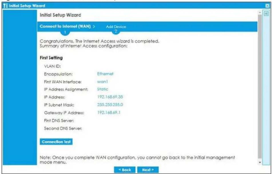
2.2.5 QR Code
Click the link to go to Nebula. Follow the steps in this screen to run the Nebula setup wizard.
Create an organization and a site. Add the Zyxel Device to this site by entering its MAC address and serial number. Select Native Mode when you're given a choice. Click Finish to close the wizard.
Figure 59 Go to Nebula
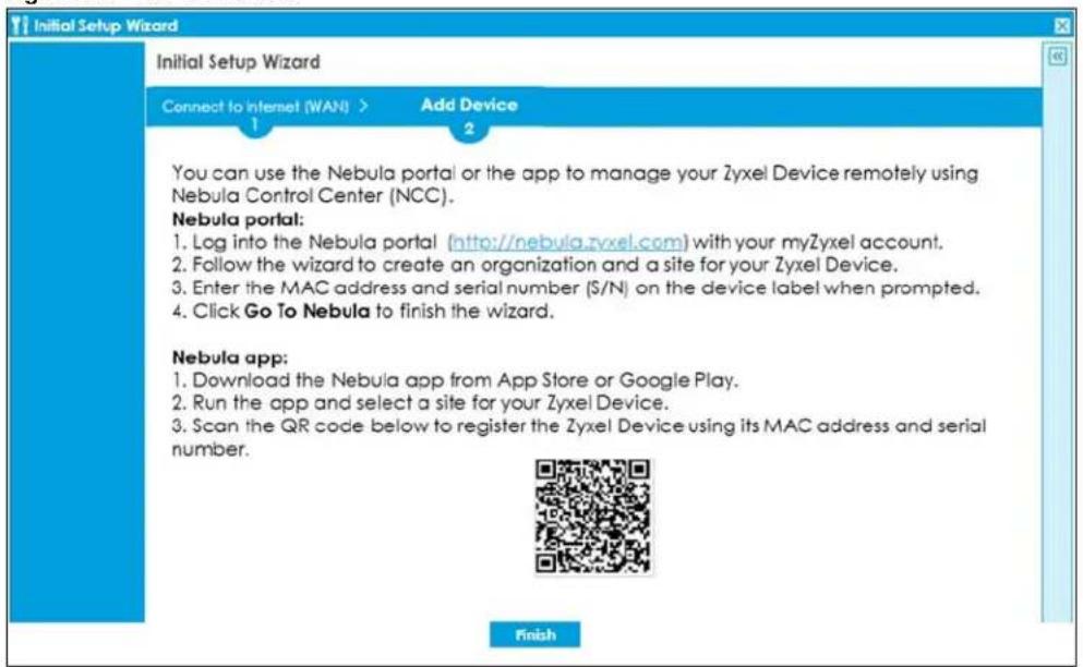
If you see this screen right after you select Nebula Mode, click the link or the Go to Nebula button to go to Nebula directly. Follow the steps in this screen to run the Nebula setup wizard.
Configure the WAN interface that the Zyxel Device will use to connect to Nebula through the Internet on the Nebula setup wizard. Configure an email address to receive the activation link. Follow the steps in the email to allow automatic management of the Zyxel Device by Nebula (ZTP). Click Back to go back to the management mode selection screen.
Figure 60 Go to Nebula
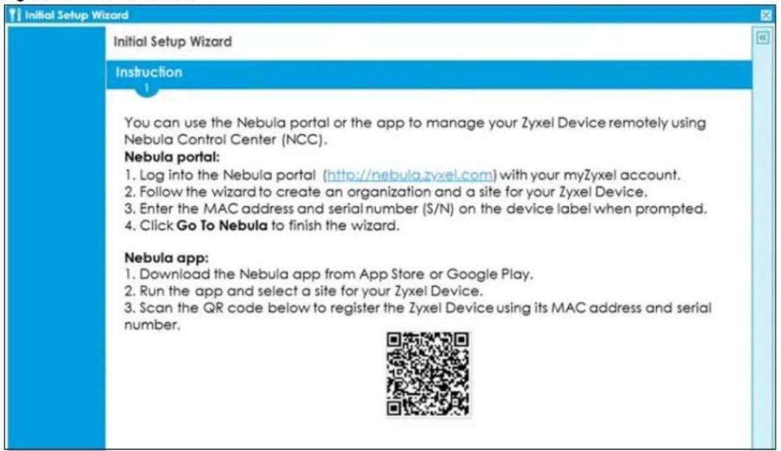
CHAPTER 3
Hardware, Interfaces and Zones
3.1 Hardware Overview
This section describes the front and rear panels for each model.
Note: Your Zyxel Device may not support SFP if its hardware version is HW:Rev 2.0. Please check your Zyxel Device label.
The following table summarizes the port features of the Zyxel Device by model.
Table 14 USG FLEX Series Port Comparison Table
| USG FLEX MODELS USG | FLEX 100 | USG FLEX 100W/USG FLEX 100AX | USG FLEX 200 | USG FLEX 500 USG | FLEX 700 |
| USB 3.0 Ports 1 1 2 2 2 | |||||
| 1 Gbps SFP interface 1 1 1 | 1 2 | ||||
| 10/100/1000 Mbps Ethernet WAN Ports | 1 1 2 -- | ||||
| 10/100/1000 Mbps Ethernet Ports | 4 4 4 7 12 | ||||
| Console Port | 1 (RJ45) | 1 (RJ45) | 1 (DB9) | 1 (DB9) | 1 (DB9) |
For information on interface names by model, default port or interface name mapping, and default interface or zone mapping please see Section 3.3 on page 105.
3.1.1 Front Panels
The LED indicators are located on the front panel.
Figure 61 USG FLEX 100 Front Panel

Figure 62 USG FLEX 100AX Front Panel
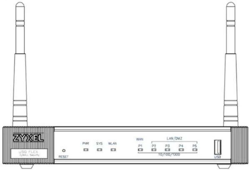
Figure 63 USG FLEX 100W Front Panel

Figure 64 USG FLEX 200 Front Panel

Figure 65 USG FLEX 500 Front Panel

Figure 66 USG FLEX 700 Front Panel

The following table describes the front panel LEDs.
Table 15 LED Descriptions
| LED COLOR STATUS | DESCRIPTION | ||
| PWR Off The Zyxel Device is turned off. | |||
| Green On | The Zyxel Device is turned on. | ||
| Red | On | There is a hardware component failure. Shut down the device, wait for a few minutes and then restart the device. If the LED turns red again, then please contact your vendor. | |
| SYS | Green | Off | The Zyxel Device is not ready or has failed. |
| On The Zyxel Device is ready and running. | |||
| Blinking The | Zyxel Device is booting. | ||
| Red On The Zyxel Device has an error or has failed. | |||
| 2.4G | Green | Off | The 2.4G wireless interface is off. |
| On The 2.4G wireless interface is ready. | |||
| Blinking The | 2.4G wireless connection is active. | ||
| 5G | Green | Off | The 5G wireless interface is off. |
| On The 5G wireless interface is ready. | |||
| Blinking The | 5G wireless connection is active. | ||
| P1 (SFP) | |||
| LINK | Yellow | Off | There is no connection on this port. |
| On This port | has a successful 1000 Mbps link. | ||
| Green | Off | There is no connection on this port. | |
| On This port | has a successful 100 Mbps link. | ||
| ACT | Green | Off | There is no traffic on this port. |
| Blinking | The Zyxel Device is sending or receiving packets on this port at 100/1000 Mbps. | ||
| P2, P3... (WAN/LAN/DMZ) | Yellow | Off | There is no connection on this port. |
| On This port | has a successful 1000 Mbps link. | ||
| Blinking | The Zyxel Device is sending or receiving packets on this port at 1000 Mbps. | ||
| Green | Off | There is no connection on this port. | |
| On This port | has a successful 10/100 Mbps link. | ||
| Blinking | The Zyxel Device is sending or receiving packets on this port at 10/100 Mbps. | ||
The following table describes the ports on the front panel.
Table 16 Front Panel Ports
| LABEL DESCRIPTION | |
| RESET | Press the button in for about 5 seconds (or until theSYS LED starts to blink), then release it to return the Zyxel Device to the factory defaults (password is 1234, LAN IP address 192.168.1.1 and so on). |
| CONSOLE | You can use the console port to manage the Zyxel Device using CLI commands. You will be prompted to enter your user name and password. See the Command Reference Guide for more information about the CLI.When configuring using the console port, you need a computer equipped with communications software configured to the following parameters:Speed 115200 bpsData Bits 8Parity NoneStop Bit Flow Control Off |
| USB | Connect a storage device for system logs (seeMaintenance > Diagnostics > System Log) and storage (seeConfiguration > System > USB Storage). |
| P1-P5 (USG FLEX 100AX)P2-P7 ( USG FLEX 200)P2-P8 ( USG FLEX 500)P1-P12 (USG FLEX 700) | These are 1G RJ-45 Ethernet ports. |
3.1.2 Rear Panels
The connection ports are located on the rear panel.
Figure 67 USG FLEX 100 Rear Panel

Figure 68 USG FLEX 100AX Rear Panel
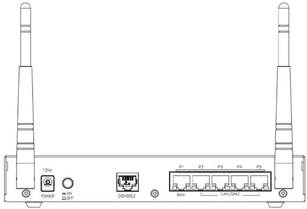
Figure 69 USG FLEX 100W Rear Panel
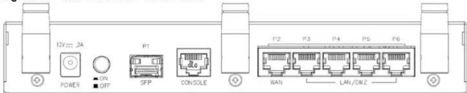
Figure 70 USG FLEX 200 Rear Panel

Figure 71 USG FLEX 500 Rear Panel

Figure 72 USG FLEX 700 Rear Panel

Note: Make sure you connect the Zyxel Device's power cord to a socket-outlet with an earthing connection or its equivalent.
The following table describes the items on the rear panel.
Table 17 Rear Panel Items
| LABEL DESCRIPTION | |
| Console | You can use the console port to manage the Zyxel Device using CLI commands. You will be prompted to enter your user name and password. See the Command Reference Guide for more information about the CLI.When configuring using the console port, you need a computer equipped with communications software configured to the following parameters:Speed 115200 bpsData Bits 8Parity NoneSt o p Bit 1Flow Control Off |
| Power | Use the included power cord to connect the power socket to a power outlet. Turn the power switch on if your Zyxel Device has a power switch. |
| Lock | Attach a lock-and-cable from the Kensington lock (the small, metal-reinforced, oval hole) to a permanent object, such as a pole, to secure the Zyxel Device in place. |
| Fan | The fans are for cooling the Zyxel Device. Make sure they are not obstructed to allow maximum ventilation. |
Note: Use an 8-wire Ethernet cable to run your Gigabit Ethernet connection at 1000 Mbps. Using a 4-wire Ethernet cable limits your connection to 100 Mbps. Note that the connection speed also depends on what the Ethernet device at the other end can support.
3.2 Installation Scenarios
The Zyxel Device can be:
- Placed on a desktop.
• Wall-mounted on a wall. - Rack-mounted on a standard EIA rack.
The following table summarizes the installation scenarios of the Zyxel Device by model.
Table 18 USG FLEX Series Installation Comparison Table
| USG FLEX MODELS USG | FLEX 100 | USG FLEX 100W/USG FLEX 100AX | USG FLEX 200 | USG FLEX 500 | USG FLEX 700 |
| Rubber feet for desktop placement | Yes Yes Yes Yes | ||||
| Wall Mounting | Yes | Yes | Yes | No | No |
| Rack Mounting | No | No | No | Yes | Yes |
WARNING! Do NOT block the ventilation holes on the Zyxel Device. Allow 100 mm clearance for the ventilation holes to prevent your Zyxel Device from overheating. Do not store things on the Zyxel Device. Do not place a Zyxel Device on another high temperature device. Overheating could affect the performance of your Zyxel Device, or even damage it.
3.2.1 Desktop Installation Procedure
1 Make sure the Zyxel Device is clean and dry.
2 Remove the adhesive backing from the rubber feet.
3 Attach the rubber feet to each corner on the bottom of the Zyxel Device. These rubber feet help protect the Zyxel Device from shock or vibration, and allow air circulation.
Figure 73 Attaching Rubber Feet
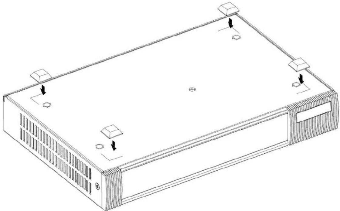
natural_image
Line drawing of a rectangular electronic device with mounting holes and ventilation slots (no text or symbols)4 Set the Zyxel Device on a smooth, level surface strong enough to support the weight of the Zyxel Device and the connected cables. Make sure there is a power outlet nearby.
Note: Make sure to use the rubber feet when stacking the Zyxel Devices on a desk.
3.2.2 Rack-mounting
Use the following steps to mount the Zyxel Device on an EIA standard size, 19-inch rack or in a wiring closet with other equipment using a rack-mounting kit. Make sure the rack will safely support the combined weight of all the equipment it contains and that the position of the ZyWALL does not make
the rack unstable or top-heavy. Take all necessary precautions to anchor the rack securely before installing the unit.
Use a #2 Phillips screwdriver to install the screws.
Note: Failure to use the proper screws may damage the unit.
1 Align one bracket with the holes on one side of the Zyxel Device and secure it with the included bracket screws (smaller than the rack-mounting screws).
2 Attach the other bracket in a similar fashion.
Figure 74 Attach Brackets
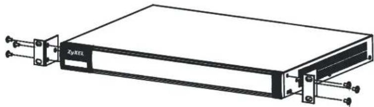
natural_image
Technical line drawing of a ZyXEL device with mounting brackets and connectors (no text or symbols)3 After attaching both mounting brackets, position the Zyxel Device in the rack and match up the bracket holes with the rack holes. Secure the Zyxel Device to the rack with the rack-mounting screws.
Figure 75 Mount on Rack
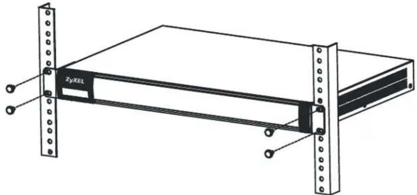
natural_image
Technical line drawing of a server rack unit with metal frame and mounting feet (no text or symbols)Note: Make sure there is at least 100 mm of clearance at the sides and 100 mm in the rear to allow air circulation and the attachment of cables and the power cord. When stacking in a rack, make sure there is at least 40 mm of clearance between Zyxel Devices.
3.2.3 Wall-mounting
Do the following to attach your Zyxel Device to a wall.
The following table lists the distance "X" between mounting holes for each model:
Table 19 Distance "X" Between FLEX Mounting Holes
| MODEL NAME DISTANCE “X” | |
| USG FLEX 100 174 mm (6.85") |
Table 19 Distance "X" Between FLEX Mounting Holes
| MODEL NAME DISTANCE “X” | |
| USG FLEX 100W 174 mm (6.85") | |
| USG FLEX 200 206 mm (8.11") |
1 Drill into a wall two holes 3 mm - 4 mm (0.12" - 0.16") wide, 20 mm - 30 mm (0.79" - 1.18") deep and a distance X (see the preceding table) apart. Place two screw anchors in the holes.
Figure 76 Wall Mounting Screw Specifications
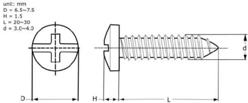
2 Screw two screws with 6 mm - 8 mm (0.24" - 0.31") wide heads into the screw anchors. Do not screw the screws all the way in to the wall; leave a small gap between the head of the screw and the wall.
The gap must be big enough for the screw heads to slide into the screw slots and the connection cables to run down the back of the Zyxel Device.
Note: Make sure the screws are securely fixed to the wall and strong enough to hold the weight of the Zyxel Device with the connection cables.
3 Use the holes on the bottom of the Zyxel Device to hang the Zyxel Device on the screws.
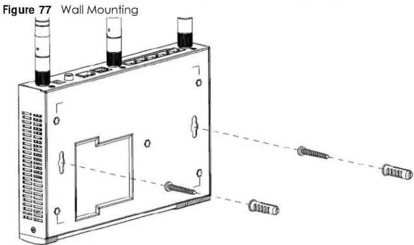
Note: Wall-mount the Zyxel Device horizontally. The Zyxel Device's side panels with ventilation slots should not be facing up or down as this position is less safe.
Make sure there is 100 mm of clearance at the sides and 1 – 1.5 mm distance between the screw head and the wall to allow air circulation and the attachment of cables and the power cord.
3.3 Default Zones, Interfaces, and Ports
The default configurations for zones, interfaces, and ports are as follows. References to interfaces may be generic rather than the specific name used in your model. For example, this guide may use "the WAN interface" rather than "wan1" or "wan2", "ge2" or "ge3".
An OPT (optional) Ethernet port can be configured as an additional WAN port, LAN, WLAN, or DMZ port.
The following table shows the default physical port and interface mapping for each model at the time of writing.
Table 20 Default Physical Port – Interface Mapping
| PORT / INTERFACE P1 P2 P3 P4 P5 P6 P7 P8 P9 P10 P11 P12 P13 P14 | ||||||||||||||
| USG FLEX 100 sfp wan | lan1 lan1 lan1 | opt | ||||||||||||
| USG FLEX 100AX wan | lan1 lan1 lan1 | opt | ||||||||||||
| USG FLEX 100W sfp wan | lan1 lan1 lan1 | opt | ||||||||||||
| USG FLEX 200 | sfp | wan | wan | lan1 | lan1 | lan1 | lan1 | |||||||
| USG FLEX 500 ge1 ge2 | ge3 ge4 ge5 | ge6 ge7 ge8 | ||||||||||||
| USG FLEX 700 ge1 ge2 | ge3 ge4 ge5 | ge6 ge7 ge8 | ge9 ge1 | 0 | gel1 | gel2 | gel3 | gel4 | ||||||
The following table shows the default interface and zone mapping for each model at the time of writing.
Table 21 Default Zone - Interface Mapping
| ZONE / INTERFACE | SFP | WAN | LAN1 | LAN2 | DMZ | OPT |
| USG FLEX 100 | sfp_ppp | WAN1_PPP | LAN1 | LAN2 | DMZ | opt_ppp |
| USG FLEX 100W/USG FLEX 100AX | sfp_ppp | WAN1_PPP | LAN1 | LAN2 | DMZ | opt_ppp |
Table 22 Default Zone – Interface Mapping
| ZONE / INTERFACE | WAN | LAN1 | LAN2 | DMZ | OPT | NO DEFAULT ZONE |
| USG FLEX 200 | WAN1 | LAN1 | LAN2 | DMZ | SFP | GE7 |
| WAN1_PPP | SFP_PPP | GE7_PPP | ||||
| WAN2 | GE8 | |||||
| WAN2_PPP | GE8_PPP |
Table 23 Default Zone – Interface Mapping
| ZONE / INTERFACE | WAN | LAN | DMZ | OPT | NO DEFAULT ZONE |
| USG FLEX 500 GE2 | GE4 | GE6 GE1 | GE7 | ||
| GE2_PPP | GE5 | GE1_PPP | GE7_PPP | ||
| GE3 | GE8 | ||||
| GE3_PPP | GE8_PPP | ||||
| USG FLEX 700 GE1 | GE3 | GE5 GE13 | GE6-GE12 | ||
| GE1_ppp | GE4 | GE13_ppp | GE6_ppp-GE12_ppp | ||
| GE2 | GE14 | ||||
| GE2_ppp | GE14_ppp |
3.4 Stopping the Zyxel Device
Always use Maintenance > Shutdown > Shutdown or the shutdown command before you turn off the Zyxel Device or remove the power. Not doing so can cause the firmware to become corrupt.
CHAPTER 4
Quick Setup Wizards
4.1 Quick Setup Overview
The Web Configurator's quick setup wizards help you configure Internet and VPN connection settings. This chapter provides information on configuring the quick setup screens in the Web Configurator. See the feature-specific chapters in this User's Guide for background information.
In the Web Configurator, click Quick Setup to open the first Quick Setup screen.
Figure 78 USG FLEX Quick Setup
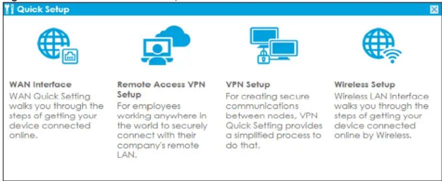
- WAN Interface
Click this link to open a wizard to set up a WAN (Internet) connection. This wizard creates matching ISP account settings in the Zyxel Device if you use PPPoE or PPTP. See Section 4.2 on page 108.
- Remote Access VPN Setup
Click this link to open a wizard to configure a VPN (Virtual Private Network) rule for a secure connection to another computer or network. Zyxel VPN Client creates a full or split tunnel VPN rule for clients with SecuExtender IPSec. L2TP over IPSec Client creates full tunnel VPN rule for clients with supported mobile devices.
- VPN Setup
Use VPN Setup to configure a VPN (Virtual Private Network) rule for a secure connection to another computer or network. Use VPN Settings for Configuration Provisioning to set up a VPN rule that can be retrieved with the Zyxel Device IPSec VPN Client. You only need to enter a user name, password and the IP address of the Zyxel Device in the IPSec VPN Client to get all VPN settings automatically from the Zyxel Device. See Section 4.4 on page 122. Use VPN Settings for L2TP VPN Settings to configure the L2TP VPN for clients.
- Wireless Setup
Use this wizard to configure the Zyxel Device as an AP Controller that can manage APs in the same network as the Zyxel Device or the built-in AP if your Zyxel Device has this feature.
- Wizard Help
If the help does not automatically display when you run the wizard, click the arrow to display it.
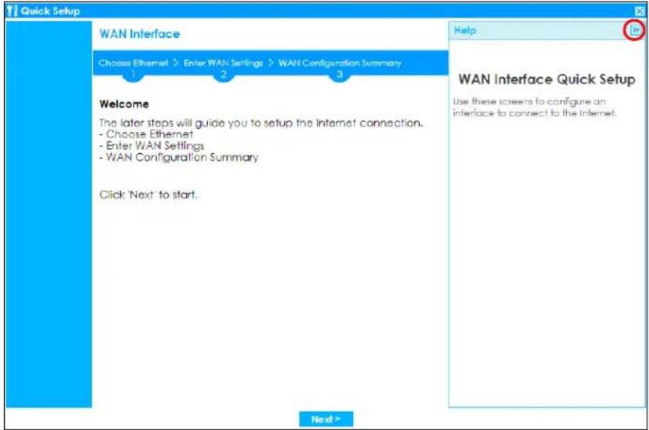
4.2 WAN Interface Quick Setup
Click WAN Interface in the main Quick Setup screen to open the WAN Interface Quick Setup Wizard Welcome screen. Use these screens to configure an interface to connect to the Internet. Click Next.
Figure 79 WAN Interface Quick Setup Wizard
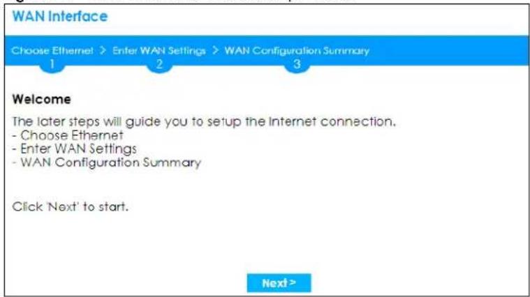
4.2.1 Choose an Ethernet Interface
Select a WAN interface (names vary by model) that you want to configure for a WAN connection and click Next.
Figure 80 Choose an Ethernet Interface
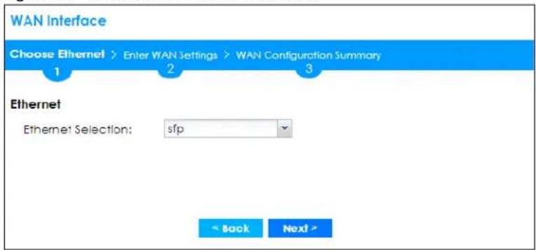
4.2.2 Select WAN Type
WAN Type Selection: Select the type of encapsulation this connection is to use. Choose Ethernet when the WAN port is used as a regular Ethernet.
Otherwise, choose PPPoE, PPTP or L2TP for a dial-up connection according to the information from your ISP.
Figure 81 WAN Interface Setup: Step 2
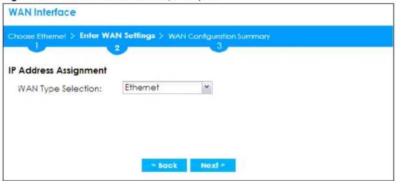
The screens vary depending on what encapsulation type you use. Refer to information provided by your ISP to know what to enter in each field. Leave a field blank if you don't have that information.
Note: Enter the Internet access information exactly as your ISP gave it to you.
4.2.3 Configure WAN IP Settings
Use this screen to select whether the interface should use a fixed or dynamic IP address.
Figure 82 WAN Interface Setup: Step 2 Ethernet Dynamic IP
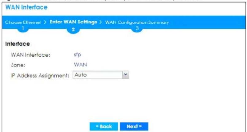
Figure 83 WAN Interface Setup: Step 2 Ethernet Static IP
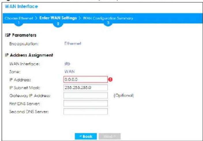
- WAN Interface: This is the interface you are configuring for Internet access.
• Zone: This is the security zone to which this interface and Internet connection belong. - IP Address Assignment: Select Auto If your ISP did not assign you a fixed IP address. Select Static if you have a fixed IP address and enter the IP address, subnet mask, gateway IP address (optional) and DNS server IP address(es).
4.2.4 ISP and WAN and ISP Connection Settings
Use this screen to configure the ISP and WAN interface settings. This screen is read-only if you select Ethernet and set the IP Address Assignment to Auto. If you set the IP Address Assignment to Static and/or select PPTP or PPPoE, enter the Internet access information exactly as your ISP gave it to you.
Note: Enter the Internet access information exactly as your ISP gave it to you.
Figure 84 WAN and ISP Connection Settings: (PPTP)
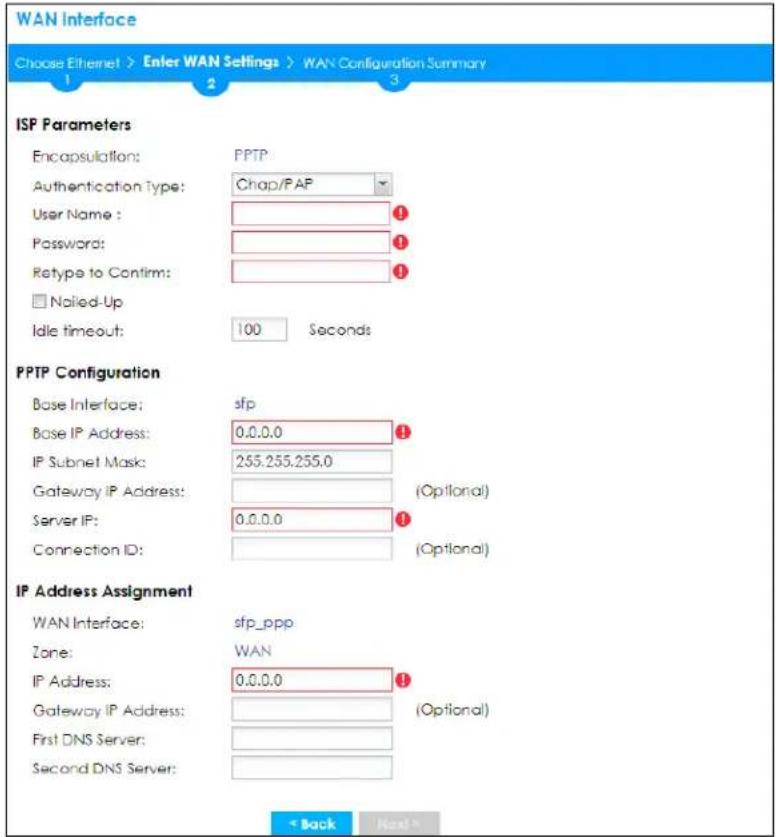
Figure 85 WAN and ISP Connection Settings: (PPPoE)
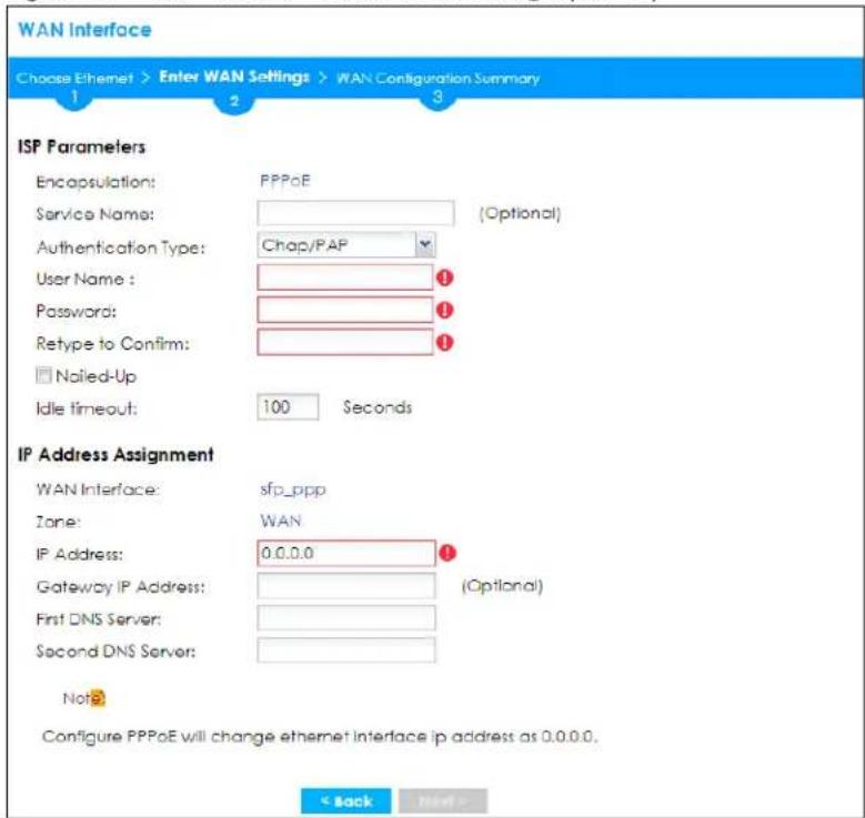
Figure 86 WAN and ISP Connection Settings: (L2TP)
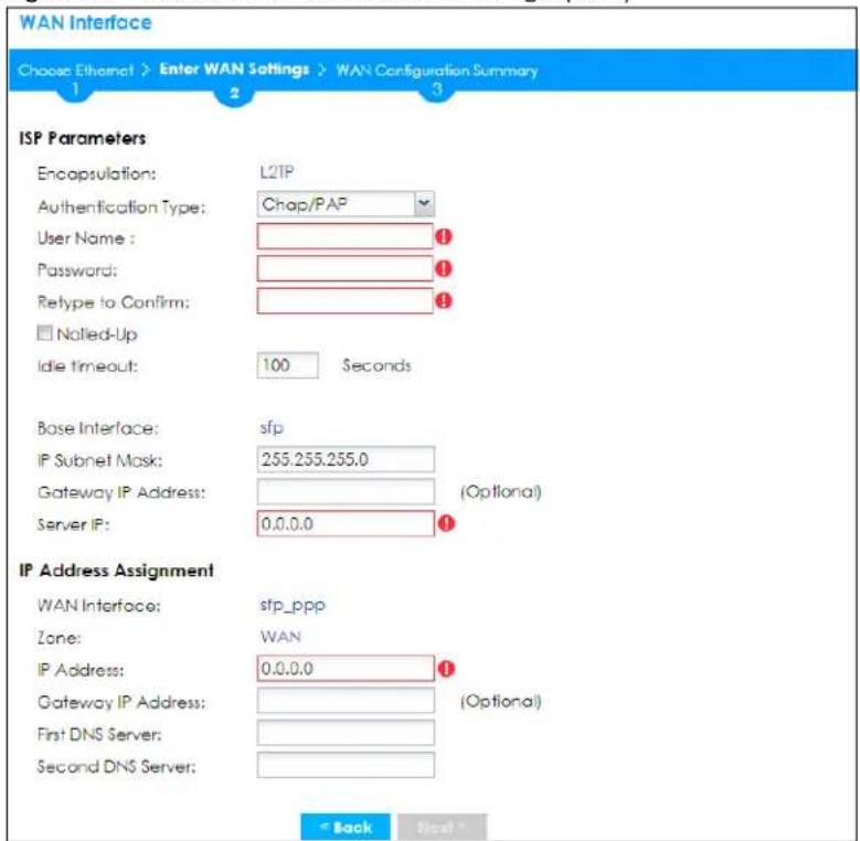
ISP Parameter: This section appears if the interface uses a PPPoE or PPTP Internet connection.
- Encapsulation: This displays the type of Internet connection you are configuring.
• Service Name: Type the PPPoE service name if you were given one by your ISP. - Authentication Type: Use the drop-down list box to select an authentication protocol for outgoing calls. Options are:
- CHAP/PAP - Your Zyxel Device accepts either CHAP or PAP when requested by this remote node.
- CHAP - Your Zyxel Device accepts CHAP only.
- PAP - Your Zyxel Device accepts PAP only.
• MSCHAP - Your Zyxel Device accepts MSCHAP only.
• MSCHAP-V2 - Your Zyxel Device accepts MSCHAP-V2 only. - User Name: Type the user name given to you by your ISP. You can use alphanumeric and -@\$ ./ characters, and it can be up to 31 characters long.
- Password: Type the password associated with the user name above. Use up to 64 ASCII characters except the [] and ?. This field can be blank.
- Retype to Confirm: Type your password again for confirmation.
- Nailed-Up: Select Nailed-Up if you do not want the connection to time out.
- Idle Timeout: Type the time in seconds that elapses before the router automatically disconnects from the PPPoE server. 0 means no timeout.
- PPTP Configuration: This section only appears if the interface uses a PPTP Internet connection.
- Base Interface: This displays the identity of the Ethernet interface you configure to connect with a modem or router.
-
Base IP Address: Type the (static) IP address assigned to you by your ISP.
-
IP Subnet Mask: Type the subnet mask assigned to you by your ISP (if given).
- Gateway IP Address: For PPTP or L2TP, type the gateway IP address if you were given one by your ISP.
- Server IP: Type the IP address of the PPTP server.
- Connection ID: Enter the connection ID or connection name in this field. It must follow the "c:id" and "n:name" format. For example, C:12 or N:My ISP. This field is optional and depends on the requirements of your DSL modem. You can use alphanumeric and -: characters, and it can be up to 31 characters long.
IP Address Assignment
- WAN Interface: This displays the identity of the interface you configure to connect with your ISP.
• Zone: This field displays to which security zone this interface and Internet connection will belong. - IP Address: This field is read-only when the WAN interface uses a dynamic IP address. If your WAN interface uses a static IP address, enter it in this field.
- IP Subnet Mask: If your WAN interface uses Ethernet encapsulation with a static IP address, enter the subnet mask in this field.
- Gateway IP Address: Type the IP address of the Ethernet device connected to this WAN port.
- First DNS Server / Second DNS Server: These fields only display for an interface with a static IP address. Enter the DNS server IP address(es) in the field(s) to the right. Leave the field as 0.0.0.0 if you do not want to configure DNS servers. If you do not configure a DNS server, you must know the IP address of a machine in order to access it.
4.2.5 Quick Setup Interface Wizard: Summary
This screen displays an example WAN interface's settings.
Figure 87 Interface Wizard: Summary WAN
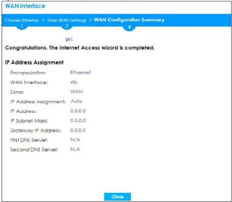
-
Encapsulation: This displays what encapsulation this interface uses to connect to the Internet.
-
Service Name: This field only appears for a PPPoE interface. It displays the PPPoE service name specified in the ISP account.
- Server IP: This field only appears for a PPTP interface. It displays the IP address of the PPTP server.
- User Name: This is the user name given to you by your ISP.
- Nailed-Up: If No displays the connection will not time out. Yes means the Zyxel Device uses the idle timeout.
- Idle Timeout: This is how many seconds the connection can be idle before the router automatically disconnects from the PPPoE server. 0 means no timeout.
- Connection ID: If you specified a connection ID, it displays here.
- WAN Interface: This identifies the interface you configure to connect with your ISP.
- Zone: This field displays to which security zone this interface and Internet connection will belong.
- IP Address Assignment: This field displays whether the WAN IP address is static or dynamic (Auto).
- IP Address: This field displays the current IP address of the Zyxel Device WAN interface selected in this wizard.
- IP Subnet Mask: This field displays the subnet mask of the Zyxel Device WAN interface selected in this wizard.
- Gateway IP Address: This field displays the IP address of the Ethernet device connected to this WAN port.
- First DNS Server / Second DNS Server: If the IP Address Assignment is Static, these fields display the DNS server IP address(es).
4.3 Remote Access VPN Setup-Scenario
The purpose of this wizard is to create VPN rules to securely access a company's network from anywhere.
Use the IKEv2 IPSec Client scenario if the VPN client has a SecuExtender VPN client or a non-SecuExtender VPN client.
A non-SecuExtender VPN client is a computer or mobile operating system that supports IPSec VPN with IKEv2. The supported computer or mobile operating systems are:
- Windows 8 and later versions.
- iOS 14.8 and later versions.
• macOS 10.12 and later versions. - Android 10.0 and later versions. Install strongSwan on your device first.
Use the L2TP over IPSec Client scenario if the VPN client has a supported computer or mobile operating system. This scenario supports clients with:
- Windows 8 and later versions.
- iOS 13 and later versions.
• macOS 10.12.2 and later versions. - Android 10.0 and later versions.
Figure 88 Remote Access VPN Setup Wizard Welcome
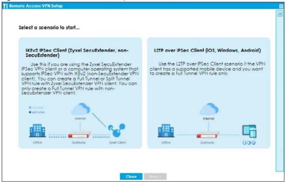
4.3.1 IKEv2 IPSec Client- VPN Configuration
This is for:
- A client using the Zyxel VPN Client with SecuExtender IPSec that wants to create a Full Tunnel or Split Tunnel VPN rule.
- A client using a non-SecuExtender VPN client that wants to create a Full Tunnel VPN rule.
Use this screen to configure basic settings such as pre-shared key, incoming interface and tunnel mode.
Figure 89 IKEv2 IPSec Client: VPN Configuration
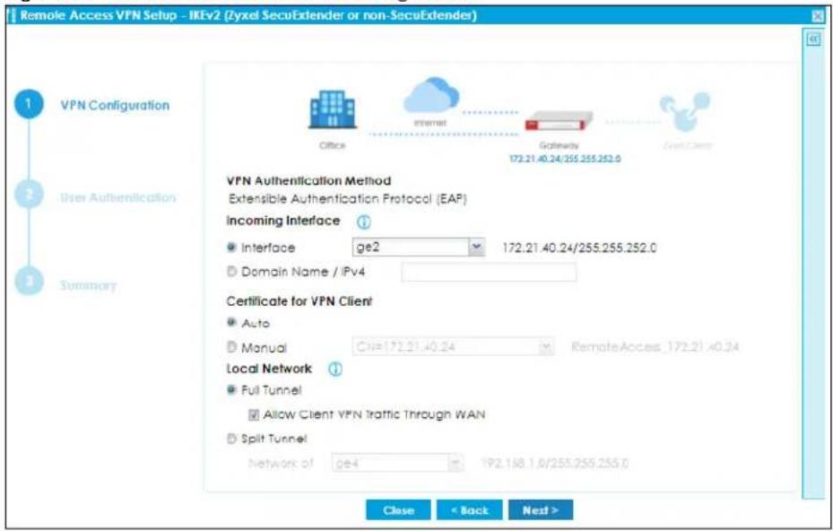
- The IKEv2 IPSec Client scenario supports Extended Authentication Protocol (EAP) authentication. EAP is important when connecting to existing enterprise authentication systems.
- Choose Interface if you want to use a pre-configured interface on the Zyxel Device. Select an interface from the drop-down list box for incoming traffic to your Zyxel Device.
- Choose Domain Name/ IPv4 if you are using a static IP address or if you are using DDNS to assign the interface a dynamic IP address. Enter the domain name or the IP address in the text box. For example, vpn.zyxel.com.
- Choose Auto to have the Zyxel Device generate a certificate from the current wizard settings. This is the certificate the Zyxel Device uses to identify itself when setting up the VPN tunnel.
- Choose Manual to select an existing certificate from the drop down list box. This field is not available if there is no existing certificate for the wizard rule you are configuring.
Note: Please make sure the Host IP Address or the Host Domain Name in the certificate you want to select matches the incoming interface IP Address or Domain Name. If a VPN client is on the WAN, the IP Address or the Domain Name must be public. Create a new certificate in Configuration > Object > Certificate > My Certificate if no existing certificate matches the wizard rule IP Address or Domain Name.
- Full Tunnel encrypts all traffic through the VPN. Clear Allow Client VPN Traffic Through WAN if you want to block traffic from the remote client to the Internet. Select Allow Client VPN Traffic Through WAN to allow only traffic encrypted by the Zyxel Device from the remote client to the Internet.
- Split Tunnel only encrypts traffic going to a networks behind the Zyxel Device. Select the interface to the LAN, DMZ or guest network from the drop-down list box. Traffic going to the Internet through this interface is encrypted. Traffic going to the Internet from the remote client does not go through the Zyxel Device and is not encrypted.
Figure 90 IKEv2 IPSec Client: Client Network and Upload Bandwidth Limit
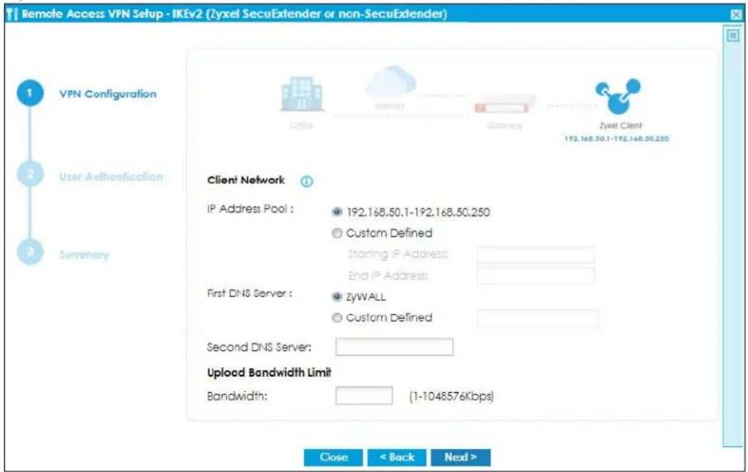
- The IP Address Pool is used to assign IP addresses to the VPN clients. You can define the range of the IP Address Pool by entering a starting IP address and an ending IP address under Customer Defined.
-
The Domain Name System (DNS) maps a domain name to an IP address and vice versa. The Zyxel Device uses these to resolve domain names for VPN. The Zyxel Device can act as a DNS proxy. Alternatively, assign a custom DNS server that is reachable from the network behind the Zyxel Device.
-
For the Second DNS Server, enter a secondary DNS server's IP address that is checked if the first one is unavailable.
- Upload Bandwidth Limit is only available for Zyxel subscription-based SecuExtender IPSec VPN clients with Windows versions 5.6.80.007 or later or macOS versions 1.2.0.7 or later.
- Use Upload Bandwidth Limit to set the maximum bandwidth for uploading traffic from Zyxel IPSec VPN clients over IPSec VPN tunnels. You can also change the bandwidth limit in Configuration >VPN >IPSec VPN >Configuration Provisioning.
4.3.2 IKEv2 IPSec Client- User Authentication
Use this screen to add users to allow them to access the VPN tunnel.
Figure 91 IKEv2 IPSec Client: User Authentication
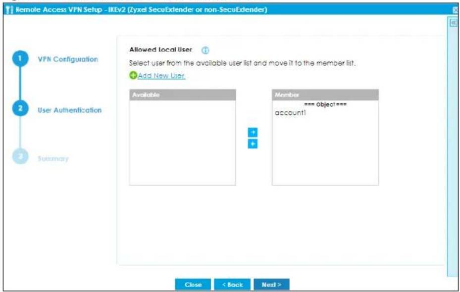
- Only local users configured on the Zyxel Device can be added to the Member list to be allowed VPN access in the wizard.
- If you want to add users from external databases, you may modify the rule in Configuration> Object> User/Group> User> Add A User in Expert Mode.
4.3.3 IKEv2 IPSec Client- Summary
Use this screen to view the summary of your previous configuration.
Figure 92 IKEv2 IPSec Client: Summary
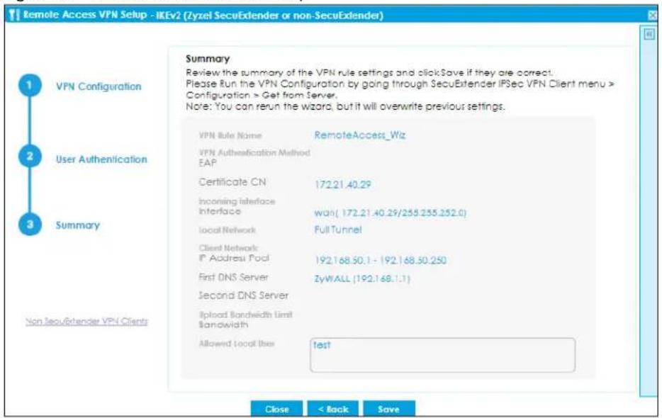
- The default name for the VPN rule created using the wizard is RemoteAccess_Wiz.
- After you click Save, the RemoteAccess_Wiz rule now appears in VPN> IPSec VPN> VPN Connection and VPN> IPSec VPN> VPN Gateway. If you modify a rule created using the wizard here, please change the name. If you want to rerun the wizard without changing the name, you will be prompted to overwrite the previously modified VPN rule.
4.3.4 IKEv2 IPSec Client-Config Provision
Click Non SecuExtender VPN Client on the left to show the following screen. This scenario is for VPN clients without SecuExtender IPSec. Use this screen to download a VPN configuration script to send to VPN clients using supported operating systems.
Figure 93 IKEv2 IPSec Client: Config Provision
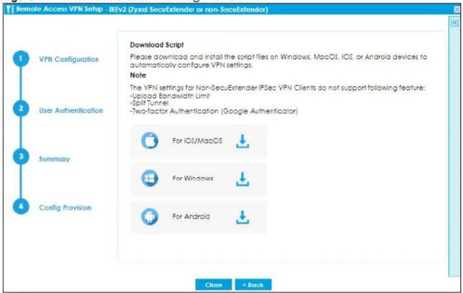
To use the Download Script, your device needs to support:
- For supported Windows, iOS and macOS clients, click the link to download the VPN configuration script and send it to the remote VPN client.
- For Android clients, install strongSwan on your Android device first. Then click the link to download the VPN configuration script and send it to the client along with the Pre-Shared Key.
4.3.5 L2TP over IPSec Client-VPN Configuration
This scenario is for a client using a L2TP over IPSec Client with supported computer or mobile operating systems that wants to create a Full Tunnel VPN rule only. Use this screen to configure basic settings such as pre-shared key, incoming interface and tunnel mode.
Figure 94 L2TP over IPSec Client: VPN Configuration
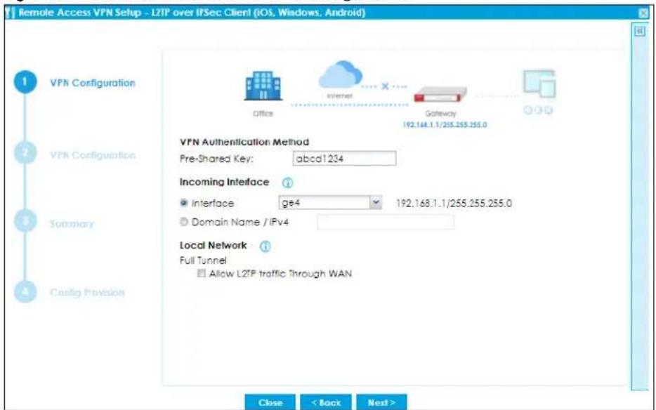
- For Pre-Shared Key, enter 8-128 alphanumeric characters (0-9, a-z, A_Z) or 8-128 pairs of hexadecimal characters (0-9, A-F) beginning with 0x.
- Choose Interface if you want to use a pre-configured interface on the Zyxel Device. Select an interface from the drop-down list box for incoming traffic to your Zyxel Device.
- Choose Domain Name/ IPv4 if you are using a static IP address or if you are using DDNS to assign the interface a dynamic IP address. Enter the domain name or the IP address in the text box. For example, vpn.zyxel.com.
- Full Tunnel encrypts all traffic through the VPN. Clear Allow Client VPN Traffic Through WAN if you want to block remote traffic from the remote client to the Internet. Select Allow Client VPN Traffic Through WAN to allow only traffic encrypted by the Zyxel Device from the remote client to the Internet.
Figure 95 L2TP over IPSec Client: VPN Configuration for Zyxel Client
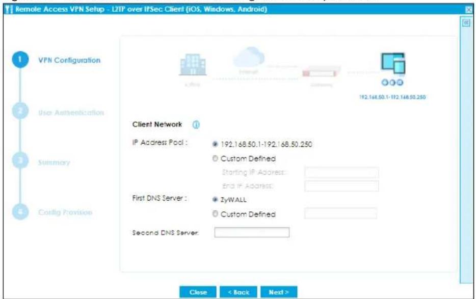
- The IP Address Pool is used to assign to the L2TP VPN clients. Alternatively, you can define the range of the IP Address Pool by entering a starting IP address and an ending IP address under Customer Defined.
- The Domain Name System (DNS) maps a domain name to an IP address and vice versa. The Zyxel Device uses these to resolve domain names for VPN. The Zyxel Device can act as a DNS proxy. Alternatively, assign a custom DNS server that is reachable from then network behind the Zyxel Device.
- For the Second DNS Server, enter a secondary DNS server's IP address that is checked if the first one is unavailable.
4.3.6 L2TP over IPSec Client- User Authentication
Use this screen to add users to allow them to access the VPN.
Figure 96 L2TP over IPSec Client: User Authentication
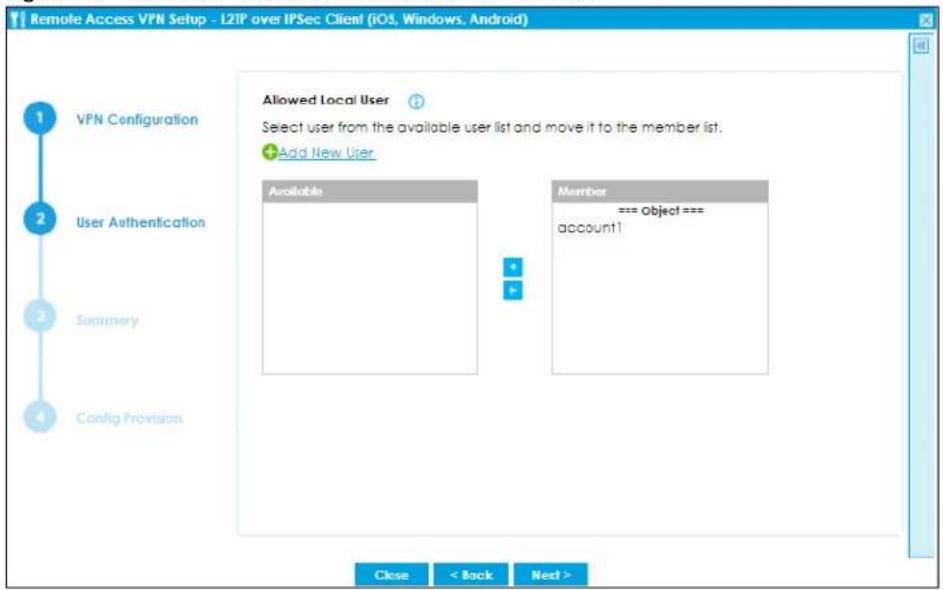
- Only local users configured on the Zyxel Device can be added to the Member list to be allowed VPN access in the wizard.
- If you want to add users from external databases, you may modify the rule in Configuration> Object> User/Group> User> Add A User in Expert Mode.
4.3.7 L2TP over IPSec Client- Summary
Use this screen to view the summary of your previous configuration.
Figure 97 L2TP over IPSec Client: User Summary
![Remote Access VPN Setup - L2TP over IPSec Client (iOS, Windows, Android) Summary Review the summary of the VPN rule settings and click Save if they are correct. Please Run the VPN Configuration by going through SecuExtender IPSec VPN Client menu > Configuration > Get from Server. Note: You can rerun the wizard, but it will overwrite previous settings. VPN Rule Name RemoteAccess_L2TP_Wiz VPN Authentication Method Pre-Shared Key abcd1234 Incoming Interface Interface ge4( 192.168.1.1/255.255.255.0) Local Network Full Tunnel Client Network IP Address Pool 192.168.50.1-192.168.50.250 First DNS Server ZyWALL [192.168.1.1] Second DNS Server Allowed Local User accounted1 Close < Back Save](/content/2026/05/878280/images/591c7363bf475988fe146a67c3d319d5a980f82f9c37ffd7f4e05f3cae8a8bb4.jpg)
- The default name for the VPN rule created using the wizard is RemoteAccess_L2TP_Wiz.
- After you click Save, the RemoteAccess_L2TP_Wiz rule now appears in VPN>L2TP VPN. If you modify a rule created using the wizard here, please change the name. If you want to rerun the wizard without changing the name, you will be prompted to overwrite the previously modified VPN rule.
4.3.8 L2TP over IPSec Client-Config Provision
Use this screen to download a VPN configuration script to send to VPN clients using supported operating systems.
Figure 98 L2TP over IPSec Client: Config Provision
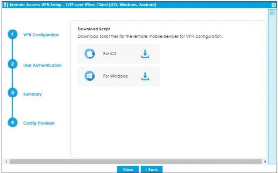
To use the Download Script, your device needs to support:
- For Windows, iOS and macOS clients, click the link to download the VPN configuration script and send it to the remote VPN client.
- For and Android and Windows 7 clients, you need to configure the rule manually. Send the Pre-Shared Key and the Zyxel Device interface IP or domain name to the client. Users with Android 10.0 and later versions or Windows 7 must configure an L2TP over IPSec rule on their mobile device using this information.
4.4 VPN Setup Wizard
Click VPN Setup in the main Quick Setup screen to open the VPN Setup Wizard Welcome screen.
4.4.1 Welcome
Use wizards to create Virtual Private Network (VPN) rules. After you complete the wizard, the Phase 1 rule settings appear in the Configuration > VPN > IPSec VPN > VPN Gateway screen and the Phase 2 rule settings appear in the Configuration > VPN > IPSec VPN > VPN Connection screen.
- VPN Settings configures a VPN tunnel for a secure connection to another computer or network.
- VPN Settings for Configuration Provisioning sets up a VPN rule the Zyxel Device IPSec VPN Client can retrieve. Just enter a user name, password and the IP address of the Zyxel Device in the IPSec VPN Client to get the VPN settings automatically from the Zyxel Device.
- VPN Settings for L2TP VPN Settings sets up a L2TP VPN rule that the Zyxel Device IPSec L2TP VPN client can retrieve.
Figure 99 VPN Setup Wizard Welcome
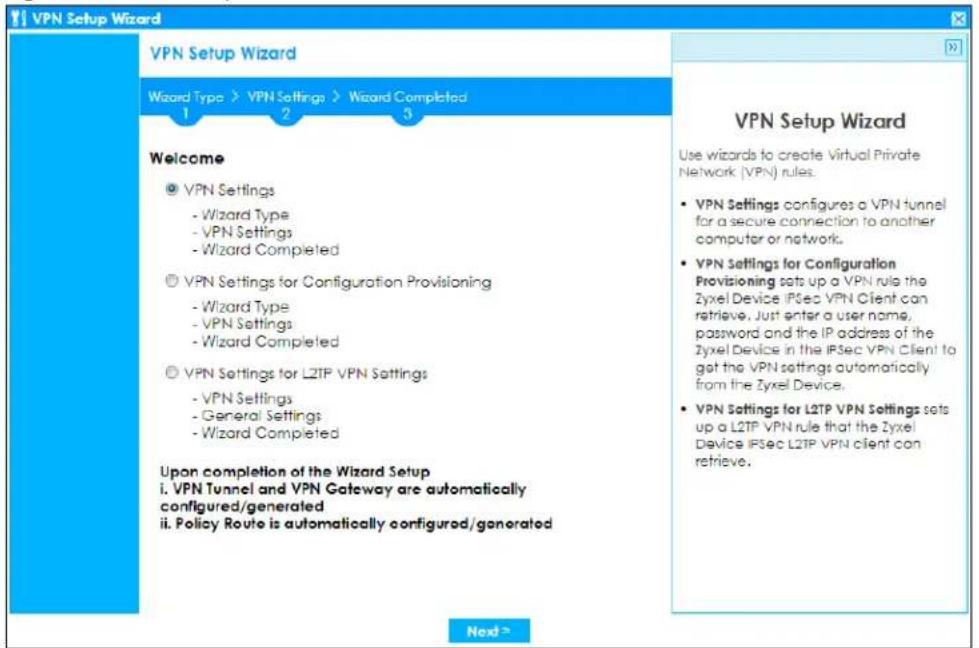
4.4.2 VPN Setup Wizard: Wizard Type
Choose Express to create a VPN rule with the default phase 1 and phase 2 settings to connect to another ZLD-based Zyxel Device using a pre-shared key.
Choose Advanced to change the default settings and/or use certificates instead of a pre-shared key to create a VPN rule to connect to another IPSec device.
Figure 100 VPN Setup Wizard: Wizard Type
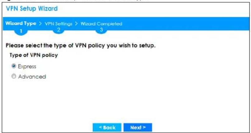
4.4.3 VPN Express Wizard - Scenario
Click the Express radio button as shown in Figure 100 on page 123 to display the following screen.
Figure 101 VPN Express Wizard: Scenario
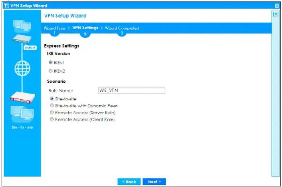
IKE (Internet Key Exchange) Version: IKEv1 and IKEv2
IKE (Internet Key Exchange) is a protocol used in security associations to send data securely. IKE uses certificates or pre-shared keys for authentication and a Diffie-Hellman key exchange to set up a shared session secret from which encryption keys are derived.
IKEv2 supports Extended Authentication Protocol (EAP) authentication, and IKEv1 supports X-Auth. EAP is important when connecting to existing enterprise authentication systems.
Scenario
Rule Name: Type the name used to identify this VPN connection (and VPN gateway). You may use 1-31 alphanumeric characters, underscores (_), or dashes (-), but the first character cannot be a number. This value is case-sensitive.
Select the scenario that best describes your intended VPN connection. The figure on the left of the screen changes to match the scenario you select.
- Site-to-site - The remote IPSec device has a static IP address or a domain name. This Zyxel Device can initiate the VPN tunnel.
- Site-to-site with Dynamic Peer - The remote IPSec device has a dynamic IP address. Only the remote IPSec device can initiate the VPN tunnel.
- Remote Access (Server Role) - Allow incoming connections from IPSec VPN clients. The clients have dynamic IP addresses and are also known as dial-in users. Only the clients can initiate the VPN tunnel.
- Remote Access (Client Role) - Connect to an IPSec server. This Zyxel Device is the client (dial-in user) and can initiate the VPN tunnel.
4.4.4 VPN Express Wizard - Configuration
Figure 102 VPN Express Wizard: Configuration
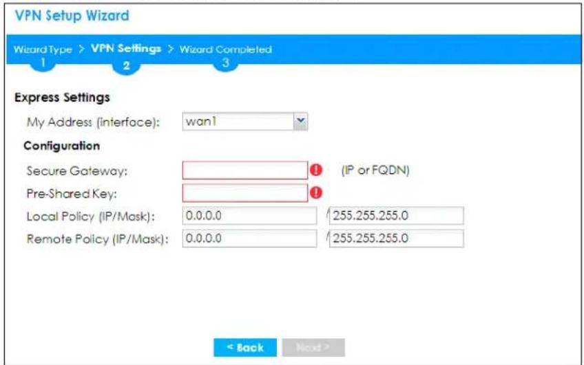
- My Address (interface): Select an interface from the drop-down list box to use on your Zyxel Device.
- Secure Gateway: Any displays in this field if it is not configurable for the chosen scenario. Otherwise, enter the WAN IP address or domain name of the remote IPSec device (secure gateway) to identify the remote IPSec router by its IP address or a domain name. Use 0.0.0.0 if the remote IPSec router has a dynamic WAN IP address.
- Pre-Shared Key: Type the password. Both ends of the VPN tunnel must use the same password. Use 8 to 31 case-sensitive ASCII characters or 8 to 31 pairs of hexadecimal ("0-9", "A-F") characters. Proceed a hexadecimal key with "0x". You will receive a PYLD_MALFORMED (payload malformed) packet if the same pre-shared key is not used on both ends.
- Local Policy (IP/ Mask): Type the IP address of a computer on your network that can use the tunnel. You can also specify a subnet. This must match the remote IP address configured on the remote IPSec device.
- Remote Policy (IP/ Mask): Any displays in this field if it is not configurable for the chosen scenario. Otherwise, type the IP address of a computer behind the remote IPSec device. You can also specify a subnet. This must match the local IP address configured on the remote IPSec device.
4.4.5 VPN Express Wizard - Summary
This screen provides a read-only summary of the VPN tunnel's configuration and commands that you can copy and paste into another ZLD-based Zyxel Device's command line interface to configure it.
Figure 103 VPN Express Wizard: Summary
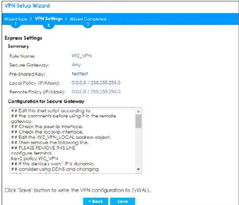
- Rule Name: Identifies the VPN gateway policy.
- Secure Gateway: IP address or domain name of the remote IPSec device. If this field displays Any, only the remote IPSec device can initiate the VPN connection.
- Pre-Shared Key: VPN tunnel password. It identifies a communicating party during a phase 1 IKE negotiation.
- Local Policy: IP address and subnet mask of the computers on the network behind your Zyxel Device that can use the tunnel.
- Remote Policy: IP address and subnet mask of the computers on the network behind the remote IPSec device that can use the tunnel. If this field displays Any, only the remote IPSec device can initiate the VPN connection.
- Copy and paste the Configuration for Secure Gateway commands into another ZLD-based Zyxel Device's command line interface to configure it to serve as the other end of this VPN tunnel. You can also use a text editor to save these commands as a shell script file with a ".zysh" filename extension. Use the file manager to run the script in order to configure the VPN connection. See the commands reference guide for details on the commands displayed in this list.
4.4.6 VPN Express Wizard - Finish
Now the rule is configured on the Zyxel Device. The Phase 1 rule settings appear in the VPN > IPSec VPN > VPN Gateway screen and the Phase 2 rule settings appear in the VPN > IPSec VPN > VPN Connection screen.
Figure 104 VPN Express Wizard: Finish
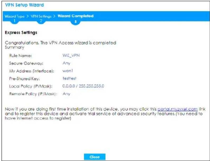
Click Close to exit the wizard.
4.4.7 VPN Advanced Wizard - Scenario
Click the Advanced radio button as shown in Figure 100 on page 123 to display the following screen.
Figure 105 VPN Advanced Wizard: Scenario
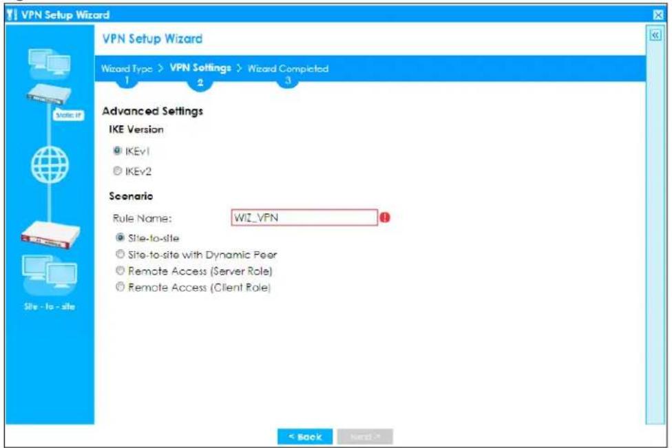
IKE (Internet Key Exchange) Version: IKEv1 and IKEv2
IKE (Internet Key Exchange) is a protocol used in security associations to send data securely. IKE uses certificates or pre-shared keys for authentication and a Diffie–Hellman key exchange to set up a shared session secret from which encryption keys are derived.
IKEv2 supports Extended Authentication Protocol (EAP) authentication, and IKEv1 supports X-Auth. EAP is important when connecting to existing enterprise authentication systems.
Scenario
Rule Name: Type the name used to identify this VPN connection (and VPN gateway). You may use 1-31 alphanumeric characters, underscores (_), or dashes (-), but the first character cannot be a number. This value is case-sensitive.
Select the scenario that best describes your intended VPN connection. The figure on the left of the screen changes to match the scenario you select.
- Site-to-site - The remote IPSec device has a static IP address or a domain name. This Zyxel Device can initiate the VPN tunnel.
- Site-to-site with Dynamic Peer - The remote IPSec device has a dynamic IP address. Only the remote IPSec device can initiate the VPN tunnel.
- Remote Access (Server Role) - Allow incoming connections from IPSec VPN clients. The clients have dynamic IP addresses and are also known as dial-in users. Only the clients can initiate the VPN tunnel.
- Remote Access (Client Role) - Connect to an IPSec server. This Zyxel Device is the client (dial-in user) and can initiate the VPN tunnel.
4.4.8 VPN Advanced Wizard - Phase 1 Settings
There are two phases to every IKE (Internet Key Exchange) negotiation – phase 1 (Authentication) and phase 2 (Key Exchange). A phase 1 exchange establishes an IKE SA (Security Association).
Figure 106 VPN Advanced Wizard: Phase 1 Settings
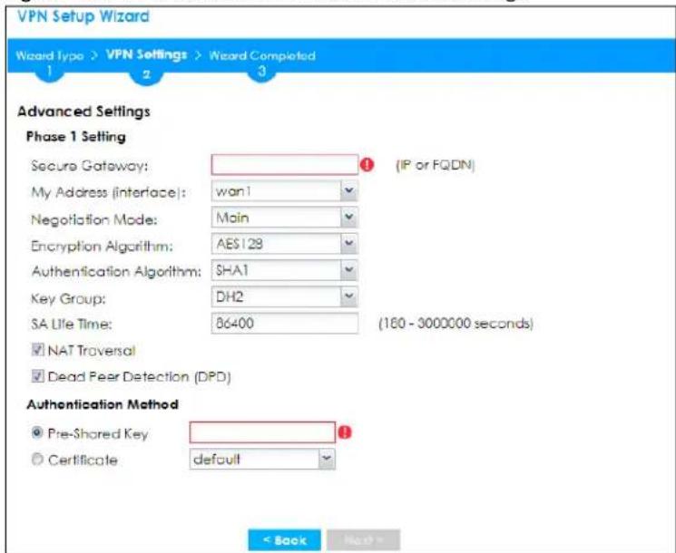
- Secure Gateway: Any displays in this field if it is not configurable for the chosen scenario. Otherwise, enter the WAN IP address or domain name of the remote IPSec device (secure gateway) to identify the remote IPSec device by its IP address or a domain name. Use 0.0.0.0 if the remote IPSec device has a dynamic WAN IP address.
- My Address (interface): Select an interface from the drop-down list box to use on your Zyxel Device.
- Negotiation Mode: This displays Main or Aggressive:
- Main encrypts the Zyxel Device's and remote IPSec router's identities but takes more time to establish the IKE SA.
- Aggressive is faster but does not encrypt the identities.
The Zyxel Device and the remote IPSec router must use the same negotiation mode. Multiple SAs connecting through a secure gateway must have the same negotiation mode.
- Encryption Algorithm: 3DES and AES use encryption. The longer the key, the higher the security (this may affect throughput). Both sender and receiver must use the same secret key, which can be used to encrypt and decrypt the message or to generate and verify a message authentication code. The DES encryption algorithm uses a 56-bit key. Triple DES (3DES) is a variation on DES that uses a 168-bit key. As a result, 3DES is more secure than DES. It also requires more processing power, resulting in increased latency and decreased throughput. AES128 uses a 128-bit key and is faster than 3DES. AES192 uses a 192-bit key, and AES256 uses a 256-bit key.
- Authentication Algorithm: MD5 gives minimal security and SHA512 gives the highest security. MD5 (Message Digest 5) and SHA (Secure Hash Algorithm) are hash algorithms used to authenticate packet data. The stronger the algorithm the slower it is.
- Key Group: DH5 is more secure than DH1 or DH2 (although it may affect throughput). DH1 (default) refers to Diffie-Hellman Group 1 a 768 bit random number. DH2 refers to Diffie-Hellman Group 2 a 1024 bit (1Kb) random number. DH5 refers to Diffie-Hellman Group 5 a 1536 bit random number.
- SA Life Time: Set how often the Zyxel Device renegotiates the IKE SA. A short SA life time increases security, but renegotiation temporarily disconnects the VPN tunnel.
- NAT Traversal: Select this if the VPN tunnel must pass through NAT (there is a NAT router between the IPSec devices).
Note: The remote IPSec device must also have NAT traversal enabled. See the help in the main IPSec VPN screens for more information.
- Dead Peer Detection (DPD) has the Zyxel Device make sure the remote IPSec device is there before transmitting data through the IKE SA. If there has been no traffic for at least 15 seconds, the Zyxel Device sends a message to the remote IPSec device. If it responds, the Zyxel Device transmits the data. If it does not respond, the Zyxel Device shuts down the IKE SA.
- Authentication Method: Select Pre-Shared Key to use a password or Certificate to use one of the Zyxel Device's certificates.
4.4.9 VPN Advanced Wizard - Phase 2
Phase 2 in an IKE uses the SA that was established in phase 1 to negotiate SAs for IPSec.
Figure 107 VPN Advanced Wizard: Phase 2 Settings
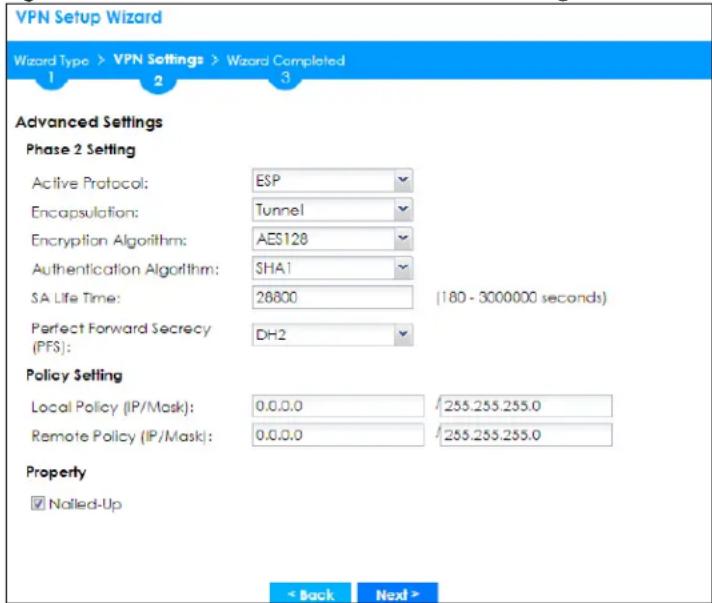
• Active Protocol: ESP is compatible with NAT, AH is not.
- Encapsulation: Tunnel is compatible with NAT, Transport is not.
- Encryption Algorithm: 3DES and AES use encryption. The longer the AES key, the higher the security (this may affect throughput). Null uses no encryption.
- Authentication Algorithm: MD5 gives minimal security and SHA512 gives the highest security. MD5 (Message Digest 5) and SHA (Secure Hash Algorithm) are hash algorithms used to authenticate packet data. The stronger the algorithm the slower it is.
- SA Life Time: Set how often the Zyxel Device renegotiates the IKE SA. A short SA life time increases security, but renegotiation temporarily disconnects the VPN tunnel.
- Perfect Forward Secrecy (PFS): Disabling PFS allows faster IPSec setup, but is less secure. Select DH1, DH2 or DH5 to enable PFS. DH5 is more secure than DH1 or DH2 (although it may affect throughput). DH1 refers to Diffie-Hellman Group 1 a 768 bit random number. DH2 refers to Diffie-Hellman Group 2 a 1024 bit (1Kb) random number. DH5 refers to Diffie-Hellman Group 5 a 1536 bit random number (more secure, yet slower).
- Local Policy (IP/ Mask): Type the IP address of a computer on your network. You can also specify a subnet. This must match the remote IP address configured on the remote IPSec device.
- Remote Policy (IP/ Mask): Type the IP address of a computer behind the remote IPSec device. You can also specify a subnet. This must match the local IP address configured on the remote IPSec device.
- Nailed-Up: This displays for the site-to-site and remote access client role scenarios. Select this to have the Zyxel Device automatically renegotiate the IPSec SA when the SA life time expires.
4.4.10 VPN Advanced Wizard - Summary
This is a read-only summary of the VPN tunnel settings.
Figure 108 VPN Advanced Wizard: Summary
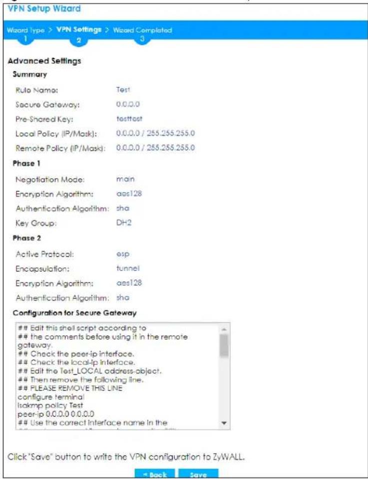
- Rule Name: Identifies the VPN connection (and the VPN gateway).
- Secure Gateway: IP address or domain name of the remote IPSec device.
• Pre-Shared Key: VPN tunnel password. - Certificate: The certificate the Zyxel Device uses to identify itself when setting up the VPN tunnel.
- Local Policy: IP address and subnet mask of the computers on the network behind your Zyxel Device that can use the tunnel.
- Remote Policy: IP address and subnet mask of the computers on the network behind the remote IPSec device that can use the tunnel.
Phase 1
- Negotiation Mode: This displays Main or Aggressive:
- Main encrypts the Zyxel Device's and remote IPSec router's identities but takes more time to establish the IKE SA.
- Aggressive is faster but does not encrypt the identities.
The Zyxel Device and the remote IPSec router must use the same negotiation mode. Multiple SAs connecting through a secure gateway must have the same negotiation mode.
- Encryption Algorithm: This displays the encryption method used. The longer the key, the higher the security, the lower the throughput (possibly).
- DES uses a 56-bit key.
• 3DES uses a 168-bit key.
• AES128 uses a 128-bit key.
• AES192 uses a 192-bit key.
• AES256 uses a 256-bit key.
- Authentication Algorithm: This displays the authentication algorithm used. The stronger the algorithm, the slower it is.
• MD5 gives minimal security.
• SHA1 gives higher security.
• SHA256 gives the highest security.
• Active Protocol: This displays ESP (compatible with NAT) or AH.
- Encapsulation: This displays Tunnel (compatible with NAT) or Transport.
- Encryption Algorithm: This displays the encryption method used. The longer the key, the higher the security, the lower the throughput (possibly).
• DES uses a 56-bit key.
• 3DES uses a 168-bit key.
• AES128 uses a 128-bit key.
• AES192 uses a 192-bit key.
• AES256 uses a 256-bit key.
- Null uses no encryption.
- Authentication Algorithm: This displays the authentication algorithm used. The stronger the algorithm, the slower it is.
• MD5 gives minimal security.
• SHA1 gives higher security.
• SHA256 gives the highest security.
Copy and paste the Configuration for Remote Gateway commands into another ZLD-based Zyxel Device's command line interface.
Click Save to save the VPN rule.
4.4.11 VPN Advanced Wizard - Finish
Now the rule is configured on the Zyxel Device. The Phase 1 rule settings appear in the VPN > IPSec VPN > VPN Gateway screen and the Phase 2 rule settings appear in the VPN > IPSec VPN > VPN Connection screen.
Figure 109 VPN Wizard: Finish
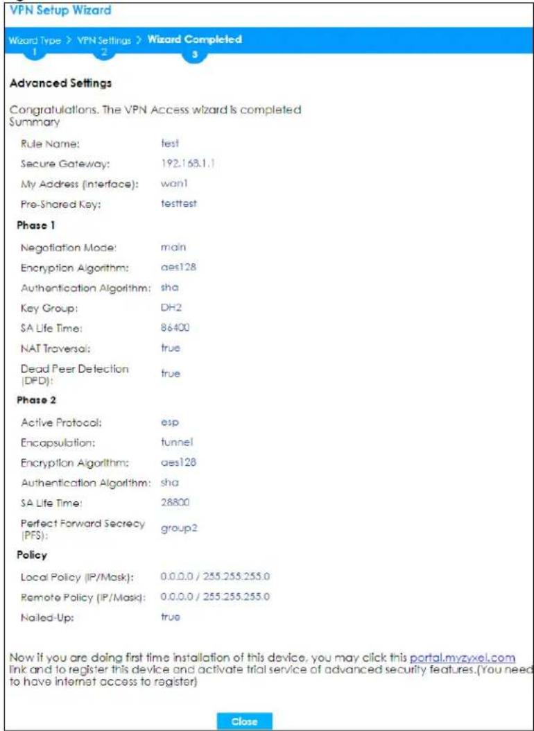
Click Close to exit the wizard.
4.5 VPN Settings for Configuration Provisioning Wizard: Wizard Type
Use VPN Settings for Configuration Provisioning to set up a VPN rule that can be retrieved with the Zyxel Device IPSec VPN Client.
VPN rules for the Zyxel Device IPSec VPN Client have certain restrictions. They must not contain the following settings:
• AH active protocol
- NULL encryption
• SHA512 authentication
• A subnet or range remote policy
Choose Express to create a VPN rule with the default phase 1 and phase 2 settings and to use a pre-shared key.
Choose Advanced to change the default settings and/or use certificates instead of a pre-shared key in the VPN rule.
Figure 110 VPN Settings for Configuration Provisioning Express Wizard: Wizard Type
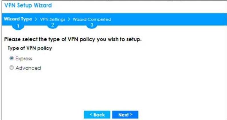
4.5.1 Configuration Provisioning Express Wizard - VPN Settings
Click the Express radio button as shown in the previous screen to display the following screen.
Figure 111 VPN for Configuration Provisioning Express Wizard: Settings Scenario
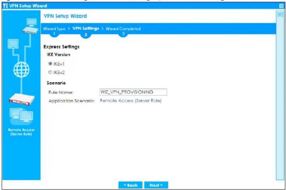
- IKE (Internet Key Exchange) is a protocol used in security associations to send data securely. IKE uses certificates or pre-shared keys for authentication and a Diffie–Hellman key exchange to set up a shared session secret from which encryption keys are derived.
- IKEv2 supports Extended Authentication Protocol (EAP) authentication, and IKEv1 supports X-Auth. EAP is important when connecting to existing enterprise authentication systems.
- Rule Name: Type the name used to identify this VPN connection (and VPN gateway). You may use 1-31 alphanumeric characters, underscores (_), or dashes (-), but the first character cannot be a number. This value is case-sensitive.
- Application Scenario: Only the Remote Access (Server Role) is allowed in this wizard. It allows incoming connections from the Zyxel Device IPSec VPN Client.
4.5.2 Configuration Provisioning VPN Express Wizard - Configuration
Click Next to continue the wizard.
Figure 112 VPN for Configuration Provisioning Express Wizard: Configuration
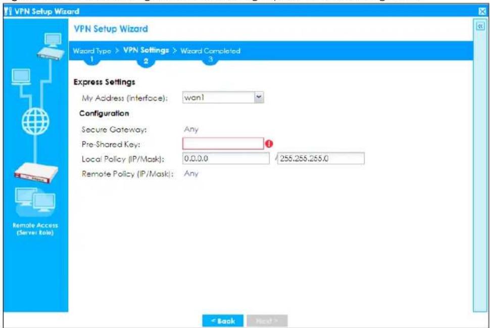
- My Address (interface): Select an interface from the drop-down list box to use on your Zyxel Device.
- Secure Gateway: Any displays in this field because it is not configurable in this wizard. It allows incoming connections from the Zyxel Device IPSec VPN Client.
- Pre-Shared Key: Type the password. Both ends of the VPN tunnel must use the same password. Use 8 to 31 case-sensitive ASCII characters or 8 to 31 pairs of hexadecimal ("0-9", "A-F") characters. Proceed a hexadecimal key with "0x". You will receive a PYLD_MALFORMED (payload malformed) packet if the same pre-shared key is not used on both ends.
- Local Policy (IP/ Mask): Type the IP address of a computer on your network. You can also specify a subnet. This must match the remote IP address configured on the remote IPSec device.
- Remote Policy (IP/Mask): Any displays in this field because it is not configurable in this wizard.
4.5.3 VPN Settings for Configuration Provisioning Express Wizard - Summary
This screen has a read-only summary of the VPN tunnel's configuration and commands you can copy and paste into another ZLD-based Zyxel Device's command line interface to configure it.
Figure 113 VPN for Configuration Provisioning Express Wizard: Summary
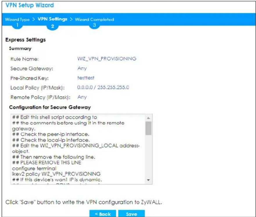
- Rule Name: Identifies the VPN gateway policy.
- Secure Gateway: Any displays in this field because it is not configurable in this wizard. It allows incoming connections from the Zyxel Device IPSec VPN Client.
- Pre-Shared Key: VPN tunnel password. It identifies a communicating party during a phase 1 IKE negotiation.
- Local Policy: (Static) IP address and subnet mask of the computers on the network behind your Zyxel Device that can be accessed using the tunnel.
- Remote Policy: Any displays in this field because it is not configurable in this wizard.
- The Configuration for Secure Gateway displays the configuration that the Zyxel Device IPSec VPN Client will get from the Zyxel Device.
- Click Save to save the VPN rule.
4.5.4 VPN Settings for Configuration Provisioning Express Wizard - Finish
The rule is now configured on the Zyxel Device. The Phase 1 rule settings appear in the Configuration >VPN > IPSec VPN > VPN Gateway screen and the Phase 2 rule settings appear in the Configuration >VPN > IPSec VPN > VPN Connection screen. Enter the IP address of the Zyxel Device in the Zyxel Device IPSec VPN Client to get all these VPN settings automatically from the Zyxel Device.
Figure 114 VPN for Configuration Provisioning Express Wizard: Finish
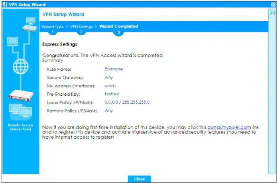
Click Close to exit the wizard.
4.5.5 VPN Settings for Configuration Provisioning Advanced Wizard - Scenario
Click the Advanced radio button as shown in Figure 110 on page 134 to display the following screen.
Figure 115 VPN for Configuration Provisioning Advanced Wizard: Scenario Settings
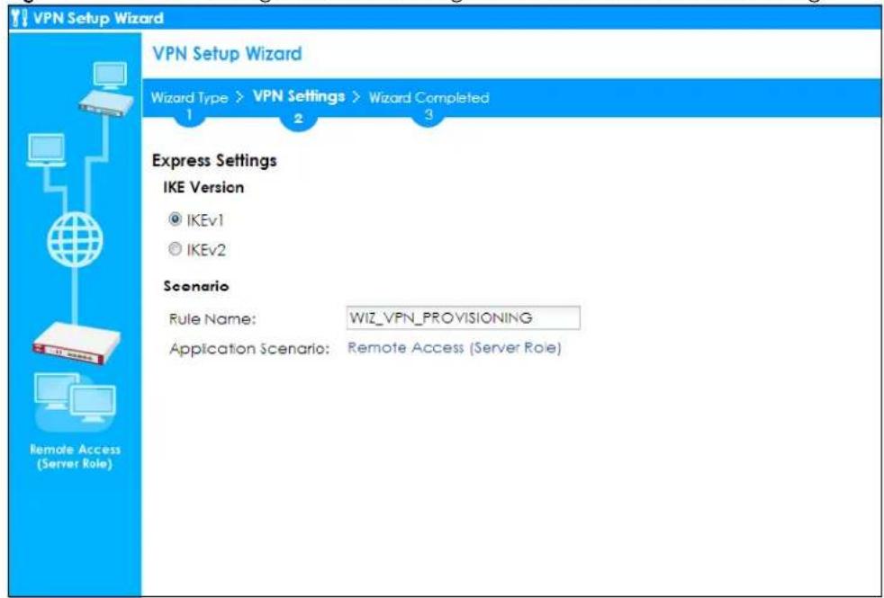
- IKE (Internet Key Exchange) is a protocol used in security associations to send data securely. IKE uses certificates or pre-shared keys for authentication and a Diffie–Hellman key exchange to set up a shared session secret from which encryption keys are derived.
- IKEv2 supports Extended Authentication Protocol (EAP) authentication, and IKEv1 supports X-Auth. EAP is important when connecting to existing enterprise authentication systems.
- Rule Name: Type the name used to identify this VPN connection (and VPN gateway). You may use 1-31 alphanumeric characters, underscores (_), or dashes (-), but the first character cannot be a number. This value is case-sensitive.
- Application Scenario: Only the Remote Access (Server Role) is allowed in this wizard. It allows incoming connections from the Zyxel Device IPSec VPN Client.
Click Next to continue the wizard.
4.5.6 VPN Settings for Configuration Provisioning Advanced Wizard - Phase 1 Settings
There are two phases to every IKE (Internet Key Exchange) negotiation – phase 1 (Authentication) and phase 2 (Key Exchange). A phase 1 exchange establishes an IKE SA (Security Association).
Figure 116 VPN for Configuration Provisioning Advanced Wizard: Phase 1 Settings
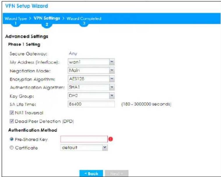
- Secure Gateway: Any displays in this field because it is not configurable in this wizard. It allows incoming connections from the Zyxel Device IPSec VPN Client.
- My Address (interface): Select an interface from the drop-down list box to use on your Zyxel Device.
• Negotiation Mode: This displays Main or Aggressive: - Main encrypts the Zyxel Device's and remote IPSec router's identities but takes more time to establish the IKE SA.
- Aggressive is faster but does not encrypt the identities.
The Zyxel Device and the remote IPSec router must use the same negotiation mode. Multiple SAs connecting through a secure gateway must have the same negotiation mode.
- Encryption Algorithm: 3DES and AES use encryption. The longer the key, the higher the security (this may affect throughput). Both sender and receiver must know the same secret key, which can be used to encrypt and decrypt the message or to generate and verify a message authentication code. The DES encryption algorithm uses a 56-bit key. Triple DES (3DES) is a variation on DES that uses a 168-bit key. As a result, 3DES is more secure than DES. It also requires more processing power, resulting in increased latency and decreased throughput. AES128 uses a 128-bit key and is faster than 3DES. AES192 uses a 192-bit key and AES256 uses a 256-bit key.
- Authentication Algorithm: MD5 (Message Digest 5) and SHA (Secure Hash Algorithm) are hash algorithms used to authenticate packet data. MD5 gives minimal security. SHA1 gives higher security and SHA256 gives the highest security. The stronger the algorithm, the slower it is.
- Key Group: DH5 is more secure than DH1 or DH2 (although it may affect throughput). DH1 (default) refers to Diffie-Hellman Group 1 a 768 bit random number. DH2 refers to Diffie-Hellman Group 2 a 1024 bit (1Kb) random number. DH5 refers to Diffie-Hellman Group 5 a 1536 bit random number.
- SA Life Time: Set how often the Zyxel Device renegotiates the IKE SA. A short SA life time increases security, but renegotiation temporarily disconnects the VPN tunnel.
- Authentication Method: Select Pre-Shared Key to use a password or Certificate to use one of the Zyxel Device's certificates.
4.5.7 VPN Settings for Configuration Provisioning Advanced Wizard - Phase 2
Phase 2 in an IKE uses the SA that was established in phase 1 to negotiate SAs for IPSec.
Figure 117 VPN for Configuration Provisioning Advanced Wizard: Phase 2 Settings
![VPN Setup Wizard Wizard Type > VPN Settings > Wizard Completed 1 2 3 Advanced Settings Phase 2 Setting Active Protocol: ESP Encapsulation: Tunnel Encryption Algorithm: AES128 Authentication Algorithm: SHA1 SA Life Time: 28800 (180 - 3000000 seconds) Perfect Forward Secrecy [PFS]: DH2 Policy Setting Local Policy (IP/Mask): 0.0.0.0 / 255.255.255.0 Remote Policy (IP/Mask): Any < Back Next >](/content/2026/05/878280/images/9e922b798ca5c0931334c1a3957f8e57a26443b1d9747681db7116e657f15a81.jpg)
• Active Protocol: ESP is compatible with NAT. AH is not available in this wizard.
- Encapsulation: Tunnel is compatible with NAT, Transport is not.
- Encryption Algorithm: 3DES and AES use encryption. The longer the AES key, the higher the security (this may affect throughput). Null uses no encryption.
- Authentication Algorithm: MD5 (Message Digest 5) and SHA (Secure Hash Algorithm) are hash algorithms used to authenticate packet data. MD5 gives minimal security. SHA1 gives higher security and SHA256 gives the highest security. The stronger the algorithm, the slower it is.
- SA Life Time: Set how often the Zyxel Device renegotiates the IKE SA. A short SA life time increases security, but renegotiation temporarily disconnects the VPN tunnel.
- Perfect Forward Secrecy (PFS): Disabling PFS allows faster IPSec setup, but is less secure. Select DH1, DH2 or DH5 to enable PFS. DH5 is more secure than DH1 or DH2 (although it may affect throughput). DH1 refers to Diffie-Hellman Group 1 a 768 bit random number. DH2 refers to Diffie-Hellman Group 2 a 1024 bit (1Kb) random number. DH5 refers to Diffie-Hellman Group 5 a 1536 bit random number (more secure, yet slower).
- Local Policy (IP/ Mask): Type the IP address of a computer on your network. You can also specify a subnet. This must match the remote IP address configured on the remote IPSec device.
- Remote Policy (IP/Mask): Any displays in this field because it is not configurable in this wizard.
- Nailed-Up: This displays for the site-to-site and remote access client role scenarios. Select this to have the Zyxel Device automatically renegotiate the IPSec SA when the SA life time expires.
4.5.8 VPN Settings for Configuration Provisioning Advanced Wizard - Summary
This is a read-only summary of the VPN tunnel settings.
Figure 118 VPN for Configuration Provisioning Advanced Wizard: Summary
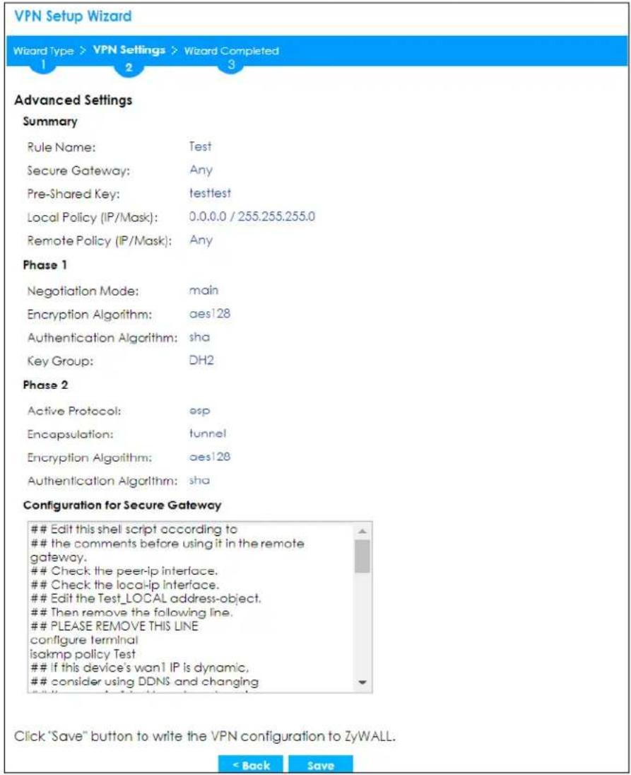
Summary
- Rule Name: Identifies the VPN connection (and the VPN gateway).
- Secure Gateway: Any displays in this field because it is not configurable in this wizard. It allows incoming connections from the Zyxel Device IPSec VPN Client.
• Pre-Shared Key: VPN tunnel password. - Local Policy: IP address and subnet mask of the computers on the network behind your Zyxel Device that can use the tunnel.
- Remote Policy: Any displays in this field because it is not configurable in this wizard.
Phase 1
• Negotiation Mode: This displays Main or Aggressive:
- Main encrypts the Zyxel Device's and remote IPSec router's identities but takes more time to establish the IKE SA.
- Aggressive is faster but does not encrypt the identities.
The Zyxel Device and the remote IPSec router must use the same negotiation mode. Multiple SAs connecting through a secure gateway must have the same negotiation mode.
- Encryption Algorithm: This displays the encryption method used. The longer the key, the higher the security, the lower the throughput (possibly).
• DES uses a 56-bit key.
• 3DES uses a 168-bit key.
• AES128 uses a 128-bit key.
• AES192 uses a 192-bit key.
• AES256 uses a 256-bit key.
- Authentication Algorithm: This displays the authentication algorithm used. The stronger the algorithm, the slower it is.
• MD5 gives minimal security.
• SHA1 gives higher security.
• SHA256 gives the highest security.
• Active Protocol: This displays ESP (compatible with NAT) or AH.
- Encapsulation: This displays Tunnel (compatible with NAT) or Transport.
- Encryption Algorithm: This displays the encryption method used. The longer the key, the higher the security, the lower the throughput (possibly).
• DES uses a 56-bit key.
• 3DES uses a 168-bit key.
- AES128 uses a 128-bit key.
• AES192 uses a 192-bit key.
• AES256 uses a 256-bit key.
- Null uses no encryption.
- Authentication Algorithm: This displays the authentication algorithm used. The stronger the algorithm, the slower it is.
• MD5 gives minimal security.
• SHA1 gives higher security.
• SHA256 gives the highest security.
The Configuration for Secure Gateway displays the configuration that the Zyxel Device IPSec VPN Client will get from the Zyxel Device.
Click Save to save the VPN rule.
4.5.9 VPN Settings for Configuration Provisioning Advanced Wizard - Finish
The rule is now configured on the Zyxel Device. The Phase 1 rule settings appear in the VPN > IPSec VPN > VPN Gateway screen and the Phase 2 rule settings appear in the VPN > IPSec VPN > VPN Connection screen. Enter the IP address of the Zyxel Device in the Zyxel Device IPSec VPN Client to get all these VPN settings automatically from the Zyxel Device.
Figure 119 VPN for Configuration Provisioning Advanced Wizard: Finish
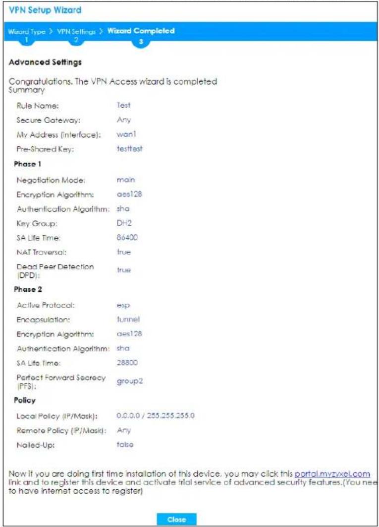
Click Close to exit the wizard.
4.6 VPN Settings for L2TP VPN Settings Wizard
Use VPN Settings for L2TP VPN Settings to set up an L2TP VPN rule. Click Configuration > Quick Setup > VPN Setup and select VPN Settings for L2TP VPN Settings to see the following screen.
Figure 120 VPN Settings for L2TP VPN Settings Wizard: L2TP VPN Settings
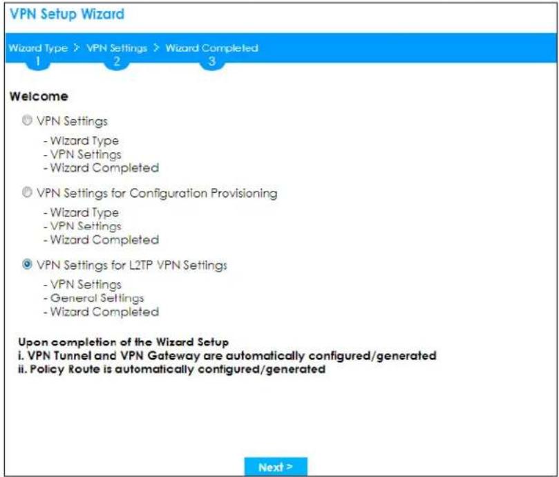
Click Next to continue the wizard.
4.6.1 L2TP VPN Settings
Figure 121 VPN Settings for L2TP VPN Settings Wizard: L2TP VPN Settings
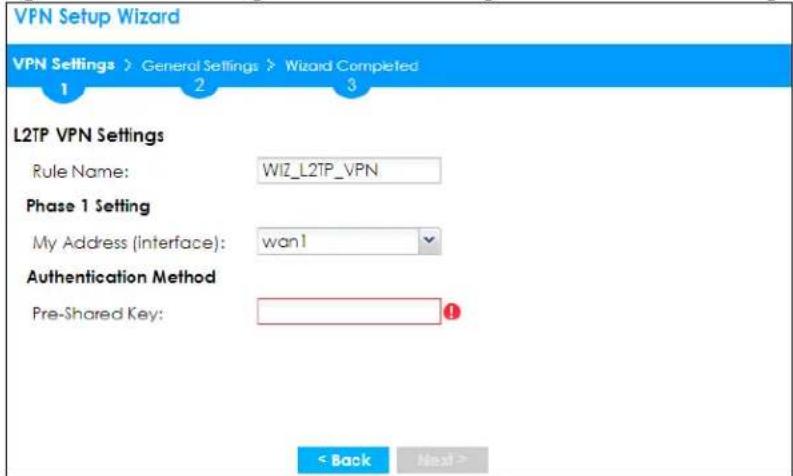
- Rule Name: Type the name used to identify this L2TP VPN connection (and L2TP VPN gateway). You may use 1-31 alphanumeric characters, underscores (_), or dashes (-), but the first character cannot be a number. This value is case-sensitive.
-
My Address (interface): Select one of the interfaces from the pull down menu to apply the L2TP VPN rule.
-
Pre-Shared Key: Type the password. Both ends of the VPN tunnel must use the same password. Use 8 to 31 case-sensitive ASCII characters or 8 to 31 pairs of hexadecimal ("0-9", "A-F") characters. Proceed a hexadecimal key with "0x". You will receive a PYLD_MALFORMED (payload malformed) packet if the same pre-shared key is not used on both ends.
- Click Next to continue the wizard.
4.6.2 L2TP VPN Settings
Figure 122 VPN Settings for L2TP VPN Settings Wizard: L2TP VPN Settings
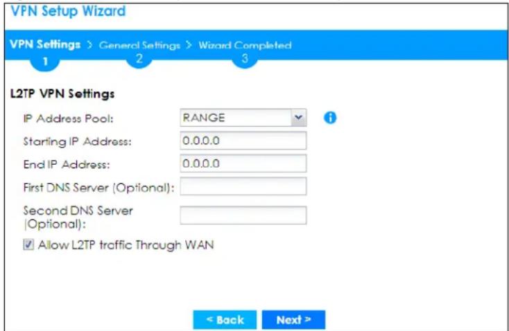
- IP Address Pool: Select RANGE or SUBNET from the pull down menu. This IP address pool is used to assign to the L2TP VPN clients.
- Starting IP Address: Enter the starting IP address in the field.
- End IP Address: Enter the ending IP address in the field.
• Network: Enter the IPv4 IP address in this field if you selected SUBNET. - Netmask: Enter the associated subnet mask of the subnet in this field.
- First DNS Server (Optional): Enter the first DNS server IP address in the field. Leave the field as 0.0.0.0 if you do not want to configure DNS servers. If you do not configure a DNS server you must know the IP address of a machine in order to access it.
- Second DNS Server (Optional): Enter the second DNS server IP address in the field. Leave the field as 0.0.0.0 if you do not want to configure DNS servers. If you do not configure a DNS server you must know the IP address of a machine in order to access it.
- Allow L2TP traffic Through WAN: Select this check box to allow traffic from L2TP clients to go to the Internet.
Click Next to continue the wizard.
Note: DNS (Domain Name System) is for mapping a domain name to its corresponding IP address and vice versa. The DNS server is extremely important because without it, you must know the IP address of a computer before you can access it. The Zyxel Device uses a system DNS server (in the order you specify here) to resolve domain names for VPN, DDNS and the time server.
4.6.3 VPN Settings for L2TP VPN Setting Wizard - Summary
This is a read-only summary of the L2TP VPN settings.
Figure 123 VPN Settings for L2TP VPN Settings Advanced Settings Wizard: Summary
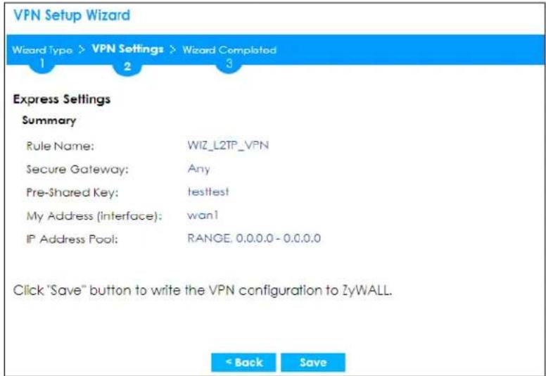
- Rule Name: Identifies the L2TP VPN connection (and the L2TP VPN gateway).
- Secure Gateway: Any displays in this field because it is not configurable in this wizard. It allows incoming connections from the L2TP VPN Client.
• Pre-Shared Key: L2TP VPN tunnel password.
• My Address (Interface): This displays the interface to use on your Zyxel Device for the L2TP tunnel. - IP Address Pool: This displays the IP address pool used to assign to the L2TP VPN clients.
Click Save to complete the L2TP VPN Setting and the following screen will show.
4.6.4 VPN Settings for L2TP VPN Setting Wizard - Completed
Figure 124 VPN Settings for L2TP VPN Settings Wizard: Finish
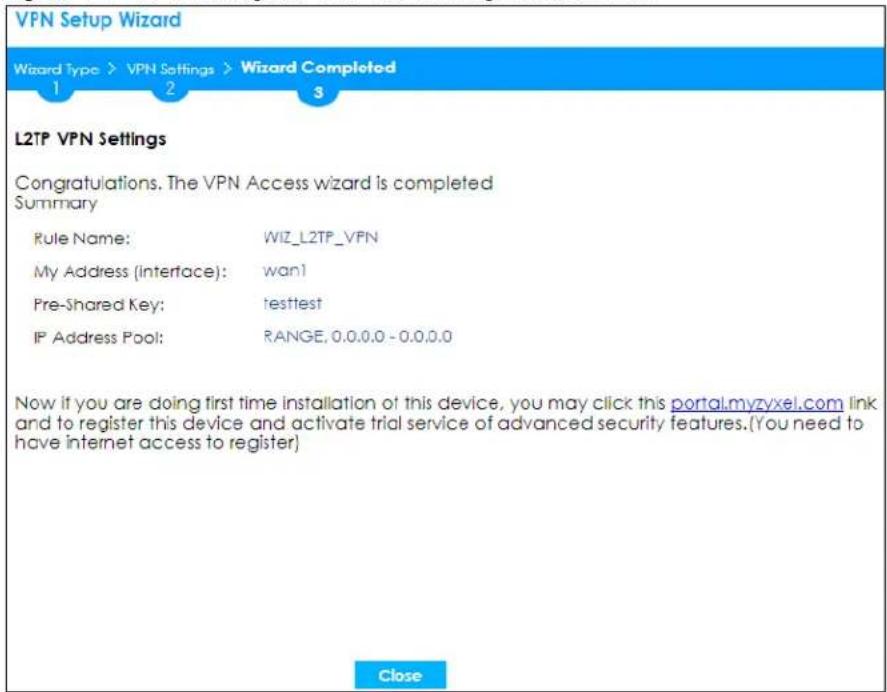
Te rule is now configured on the Zyxel Device. The L2TP VPN rule settings appear in the Configuration >VPN >L2TP VPN screen and also in the Configuration >VPN >IPSec VPN >VPN Connection and VPN Gateway screen.
4.7 Wireless Setup Wizard
Click Wireless Setup in the main Quick Setup screen to begin the wireless setup wizard. Changes in the wizard are not saved until you save them in the Summary screen.
Figure 125 Quick Setup Wizard
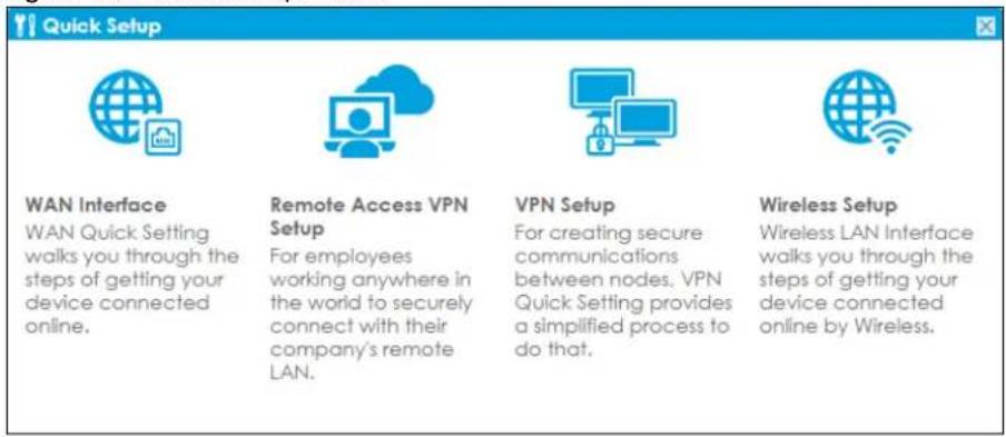
4.7.1 Management Mode
The Management Mode screen appears for Zyxel Devices that have a built-in AP.
Figure 126 Wireless Setup Wizard > Management Mode
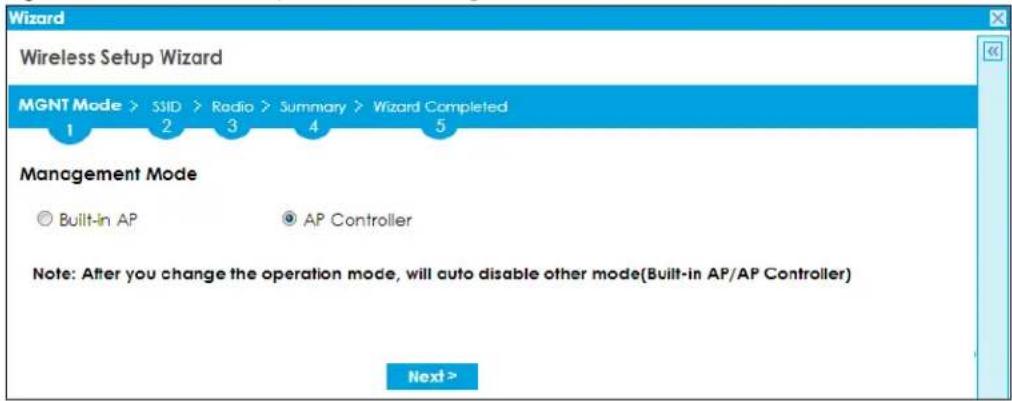
Select Built-in AP if you want WiFi clients to access your Zyxel Device wirelessly. Select AP Controller to allow the Zyxel Device to manage APs in the same network as the Zyxel Device. Both modes cannot work simultaneously. Click Next to continue the wizard.
4.7.2 SSID
The next screen in the wireless wizard is SSID.
Figure 127 Wireless Setup Wizard > SSID - AP Controller
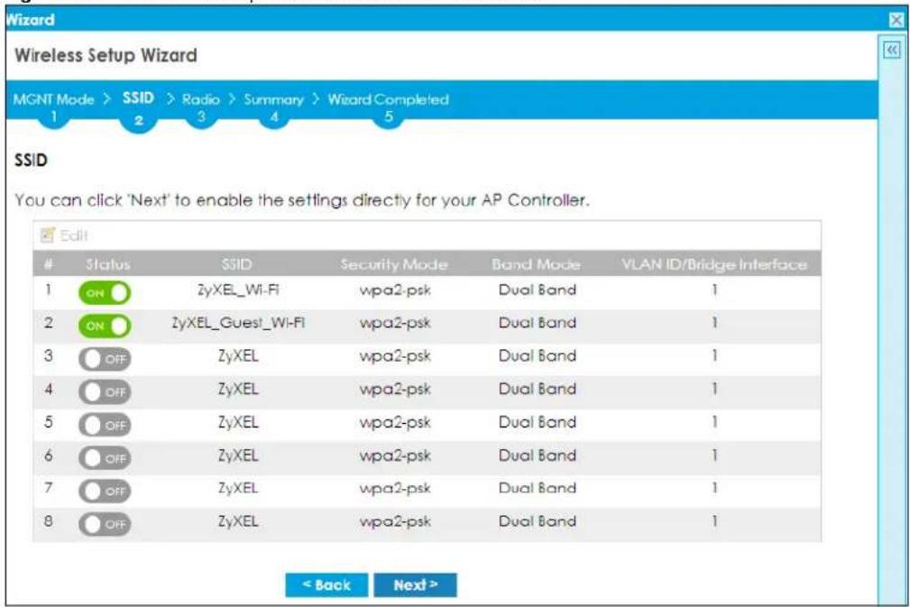
Use the SSID screen for AP Controller to manage APs connected to the Zyxel Device that are identified by SSID. Select an AP, then click Edit to create or change AP settings.
Figure 128 Wireless Setup Wizard > SSID - Built-in AP
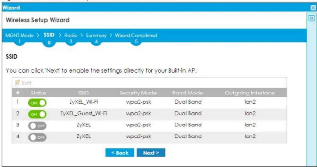
Use the SSID screen for Built-in AP to manage internal WiFi networks in the Zyxel Device that are identified by SSID. Select a WiFi network, then click Edit to create or change WiFi network settings.
Figure 129 Wireless Setup Wizard > SSID - Built-in AP > Edit SSID - Pre-Shared Key
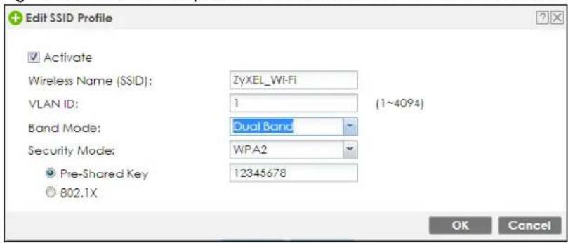
Figure 130 Wireless Setup Wizard > SSID - Built-in AP > Edit SSID - 802.1x
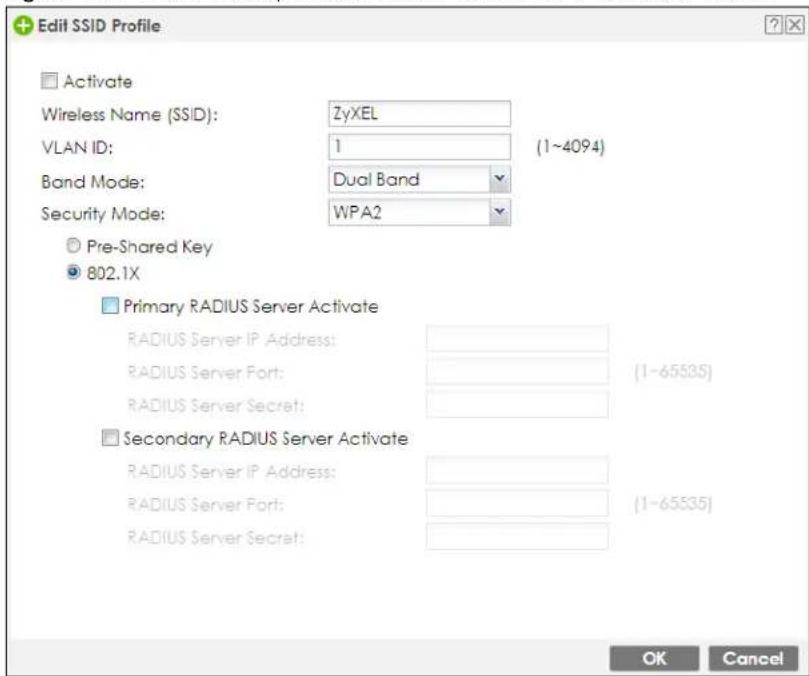
- Select Activate to enable the WiFi network for users connected to the Zyxel Device.
- The Wireless Name (SSID) identifies the WiFi network. Enter a unique SSID for each WiFi network.
- Enter a VLAN ID, which is the VLAN identifier that external APs must use to communicate with the Zyxel Device.
- Select the Band Mode according to the bands that APs or WiFi clients support. Select Dual Band if both 2.4G or 5G are supported.
- Use Security Mode to authenticate WiFi clients using the local database on the Zyxel Device with a pre-shared key or on a RADIUS external authentication database using 802.1x. Wi-Fi Protected Access (WPA, IEEE 802.11i). WPA is a wireless security standard for encryption, authentication and key management. Only WPA2 is supported in the wireless wizard. If you want to use WEP or WPA, then use the Configuration > Wireless screens.
Select WPA2, then enter a Pre-Shared Key or select 802.1x and configure the RADIUS server IP address, server port and secret (password). Select None if you do not want security for this WiFi network (not recommended).
Click OK to save your settings and return to the wireless setup wizard. Click Cancel to not save your settings and return to the wireless setup wizard. Click Next to continue the wireless setup wizard.
4.7.3 Radio
The next screen in the wireless setup wizard is Radio.
Figure 131 Wireless Setup Wizard > Radio
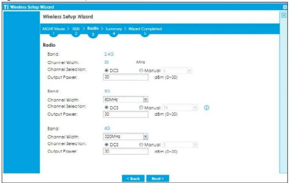
- Select DCS (Dynamic Channel Selection) to allow the Zyxel Device to automatically select a less-used channel in an environment where there are many WiFi devices and there may be interference. DCS is not supported on a Zyxel Device which is in repeater mode. Alternatively, select Manual to choose a specific channel that the Zyxel Device must use.
- Set the Output Power of the Zyxel Device. The greater the output power, the greater the WiFi coverage of the Zyxel Device. Too great an output power may cause interference with other WiFi devices.
-
Select the WiFi channel bandwidth you want the Zyxel Device to use.
-
40 MHz (channel bonding or dual channel) bonds two adjacent radio channels to increase throughput.
- An 80 MHz channel consists of two adjacent 40 MHz channels. The WiFi clients must also support 40 MHz or 80 MHz.
- Select 20 MHz if the Zyxel Device is in a location with WiFi signal obstructions, or if you want to lessen radio interference with other WiFi clients in the coverage area, or the WiFi clients do not support channel bonding.
- Select 40MHz, 80MHz, 160 MHz or 320 MHz to allow the Zyxel Device to adjust the channel bandwidth automatically where not all its WiFi clients support 40 MHz, 80 MHz, 160 MHz and/or 320MHz channels.
Note: If the environment has poor signal-to-noise ratio (SNR), the Zyxel Device will switch to a lower bandwidth automatically.
4.7.4 Summary
The next screen in the wireless setup wizard is Summary.
Figure 132 Wireless Setup Wizard > Summary
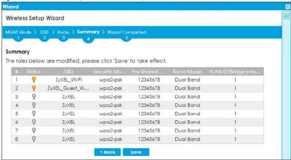
Review your settings in the Summary screen, then click Save to save the changes to the Zyxel Device. Click Back if you want to make more changes.
4.7.5 Wizard Completed
The next screen in the wireless wizard is Wizard Completed.
Figure 133 Wireless Setup Wizard > Wizard Completed
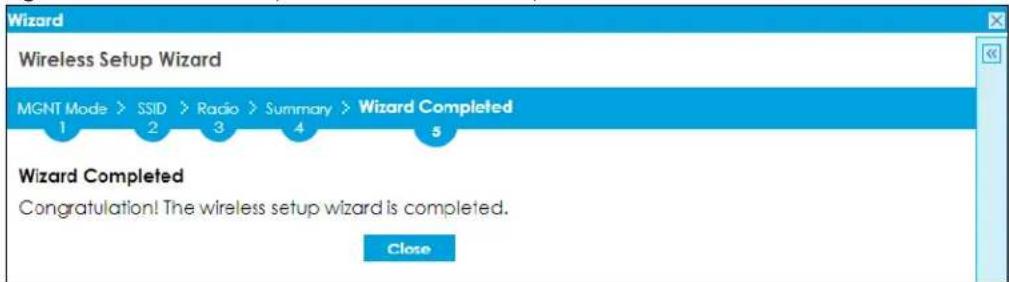
This screen shows that your changes have been successfully saved to the Zyxel Device. Click Close to exit the wizard. Run the wizard again if you want to make changes.
CHAPTER 5 Dashboard
5.1 Overview
Use the Dashboard screens to check status information about the Zyxel Device.
5.1.1 What You Can Do in this Chapter
Use the main Dashboard screen to see the Zyxel Device's general device information, system status, and system resource usage. You can also display other status screens for more information.
Use the Dashboard screens to view the following.
• Device Information Screen on page 156
• System Status Screen on page 157
• Tx/Rx Statistics on page 157
• The Latest Logs Screen on page 158
• System Resources Screen on page 158
• DHCP Table Screen on page 160
• Number of Login Users Screen on page 161
• Current Login User on page 162
• VPN Status on page 162
- SSL VPN Status on page 162
5.2 The General Screen
The Dashboard screen displays when you log into the Zyxel Device or click Dashboard in the navigation panel. The dashboard displays general device information, system status, system resource usage, licensed service status, and interface status in widgets that you can re-arrange to suit your needs. You can also collapse, refresh, and close individual widgets.
Click on the icon to go to the OneSecurity website where there is guidance on configuration walkthroughs, troubleshooting, and other information.
Figure 134 Dashboard USG FLEX
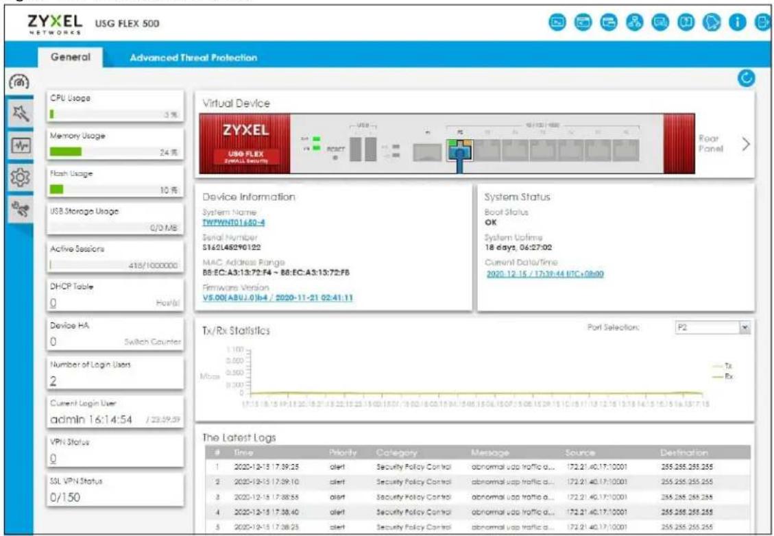
The following table describes the labels in this screen.
Table 24 Dashboard
| LABEL DESCRIPTION | |
| Refresh Now | Click this to update the widget's information immediately. |
| Virtual Device | |
| Rear Panel | Click this to view details about the Zyxel Device's rear panel. Hover your cursor over a connected interface or slot to display status details. |
| Front Panel | Click this to view details about the status of the Zyxel Device's front panel LEDs and connections. See Section 3.1.1 on page 96 for LED descriptions. An unconnected interface or slot appears grayed out. |
| The following front and rear panel labels display when you hover your cursor over a connected interface or slot. | |
| Name This field | displays the name of each interface. |
| LABEL DESCRIPTION | |
| Status | This field displays the current status of each interface or device installed in a slot. The possible values depend on what type of interface it is.Inactive- The Ethernet interface is disabled.Down- The Ethernet interface does not have any physical ports associated with it or the Ethernet interface is enabled but not connected.Speed / Duplex- The Ethernet interface is enabled and connected. This field displays the port speed and duplex setting (Full or Half).The status for a WLAN card isnone.For cellular (mobile broadband) interfaces, seeSection 9.7 on page 359for the status that can appear.For the auxiliary interface:Inactive- The auxiliary interface is disabled-connected- The auxiliary interface is enabled and connected.Disconnected- The auxiliary interface is not connected. |
| Zone | This field displays the zone to which the interface is currently assigned. |
| IP Address/ Mask | This field displays the current IP address and subnet mask assigned to the interface. If the interface is a member of an active virtual router, this field displays the IP address it is currently using. This is either the static IP address of the interface (if it is the master) or the management IP address (if it is a backup). |
5.2.1 Device Information Screen
The Device Information screen displays Zyxel Device's system and model name, serial number, MAC address and firmware version shown in the below screen.
Figure 135 Dashboard > Device Information (Example)
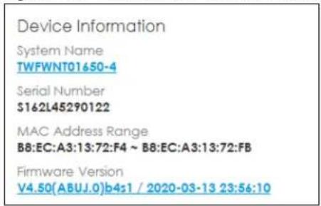
Figure 136
The table describes the fields in this screen.
Table 25 Dashboard > Device Information
| LABEL DESCRIPTION | |
| System Name | This field displays the name used to identify the Zyxel Device on any network. Click the link and open the Host Name screen where you can edit and make changes to the system and domain name. |
| Serial Number | This field displays the serial number of this Zyxel Device. The serial number is used for device tracking and control. |
Table 25 Dashboard > Device Information
| LABEL DESCRIPTION | |
| MAC Address Range | This field displays the MAC addresses used by the Zyxel Device. Each physical port has one MAC address. The first MAC address is assigned to physical port 1, the second MAC address is assigned to physical port 2, and so on. |
| Firmware Version | This field displays the version number and date of the firmware the Zyxel Device is currently running. Click the link to open the Firmware Package screen where you can upload firmware. |
5.2.2 System Status Screen
Figure 137 Dashboard > System Status (Example)
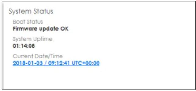
The table describes the fields in the screen.
Table 26 Dashboard > System Status
| LABEL DESCRIPTION | |
| Boot Status This field displays details about the Zyxel Device's startup state.OK - The Zyxel Device started up successfully.Firmware update OK - A firmware update was successful.Problematic configuration after firmware update - The application of the configuration failed after a firmware upgrade.System default configuration - The Zyxel Device successfully applied the system default configuration. This occurs when the Zyxel Device starts for the first time or you intentionally reset the Zyxel Device to the system default settings.Fallback to lastgood configuration - The Zyxel Device was unable to apply the startup-config.conf configuration file and fell back to the lastgood.conf configuration file.Fallback to system default configuration - The Zyxel Device was unable to apply the lastgood.conf configuration file and fell back to the system default configuration file (system-default.conf).Booting in progress - The Zyxel Device is still applying the system configuration. | |
| System Uptime | This field displays how long the Zyxel Device has been running since it last restarted or was turned on. |
| Current Date/Time | This field displays the current date and time in the Zyxel Device. The format is yyyy-mm-dd hh:mm:ss. Click on the link to see the Date/Time screen where you can make edits and changes to the date, time and time zone information. |
5.2.3 Tx/Rx Statistics
This screen displays a line graph of packet statistics for each physical port.
Figure 138 Dashboard > Tx/Rx Statistics

line
| Time | Tx/Rx (Millions) | | -------- | ---------------- | | 08:00 | 1.00 | | 09:00 | 1.00 | | 10:00 | 1.00 | | 11:00 | 1.00 | | 12:00 | 1.00 | | 13:00 | 1.00 | | 14:00 | 1.00 | | 15:00 | 1.00 | | 16:00 | 1.00 | | 17:00 | 1.00 | | 18:00 | 1.00 | | 19:00 | 1.00 | | 20:00 | 1.00 | | 21:00 | 1.00 | | 22:00 | 1.00 | | 23:00 | 1.00 | | 24:00 | 1.00 | | 25:00 | 1.00 | | 26:00 | 1.00 | | 27:00 | 1.00 | | 28:00 | 1.00 | | 29:00 | 1.00 | | 30:00 | 1.00 | | 31:00 | 1.00 | | 32:00 | 1.00 | | 33:00 | 1.00 | | 34:00 | 1.00 | | 35:00 | 1.00 | | 36:00 | 1.00 | | 37:00 | 1.00 | | 38:00 | 1.00 | | 39:00 | 1.00 | | 40:00 | 1.00 | | 41:00 | 1.00 | | 42:00 | 1.00 | | 43:00 | 1.00 | | 44:00 | 1.00 | | 45:00 | 1.00 | | 46:00 | 1.00 | | 47:00 | 1.00 | | 48:00 | 1.00 | | 49:00 | 1.00 | | 50:00 | 1.00 | | 51:00 | 1.00 | | 52:00 | 1.00 | | 53:00 | 1.00 | | 54:00 | 1.00 | | 55:00 | 1.00 | | 56:00 | 1.00 | | 57:00 | 1.00 | | 58:00 | 1.00 | | 59:00 | 1.00 | | 60:00 | 1.00 | | 61:00 | 1.00 | | 62:00 | 1.00 | | 63:00 | 1.00 | | 64:00 | 1.00 | | 65:00 | 1.00 | | 66:00 | 1.00 | | 67:00 | 1.00 | | 68:00 | 1.00 | | 69:00 | 1.00 | | 70:00 | 1.00 | | 71:00 | 1.00 | | 72:00 | 1.00 | | 73:00 | 1.00 | | 74:00 | 1.00 | | 75:00 | 1.00 | | 76:00 | 1.00 | | 77:00 | 1.00 | | 78:00 | 1.00 | | 79:00 | 1.00 | | 80:00 | 1.5 | | 81:5 | - | | 82:5 | - | | 83:5 | - | | 84:5 | - | | 85:5 | - | | 86:5 | - | | 87:5 | - | | 88:5 | - | | 89:5 | - | | 98:5 | - | | Note: The actual values are not provided in the code image.This table describes the fields in the above screen.
Table 27 Dashboard > Tx/Rx Statistics
| LABEL DESCRIPTION | |
| Mbps The y-axis represents the speed of transmission or reception. | |
| Time | The x-axis shows the time period over which the transmission or reception occurred. |
5.2.4 The Latest Logs Screen
Figure 139 Dashboard > The Latest Logs
| The Latest Logs | ||||||
| # | Time | Priority | Category | Message * | Source | Destination |
| 1 | 2018-01-04 01:00:06 | client | ap-firmware | AP firmware download flags. Reason: Device can't connect to cloud server. | ||
| 2 | 2018-01-04 01:28:53 | client | ap-firmware | AP firmware download flags. Reason: Device can't connect to cloud server. | ||
| 3 | 2018-01-04 01:27:39 | client | ap-firmware | AP firmware download flags. Reason: Device can't connect to cloud server. | ||
| 4 | 2018-01-04 01:26:24 | client | ap-firmware | AP firmware download flags. Reason: Device can't connect to cloud server. | ||
| 5 | 2018-01-04 01:26:06 | client | ap-firmware | AP firmware download flags. Reason: Device can't connect to cloud server. | ||
The table describes the fields in the screen.
Table 28 Dashboard > The Latest Log
| LABEL DESCRIPTION | |
| # This is the entry's rank in the list of alert logs. | |
| Time This field displays the date and time the log was created. | |
| Priority This field displays the severity of the log. | |
| Category This field displays the type of log generated. | |
| Message This field displays the actual log message. | |
| Source | This field displays the source address (if any) in the packet that generated the log. |
| Destination | This field displays the destination address (if any) in the packet that generated the log. |
5.2.5 System Resources Screen
These fields display the percentage of system resources that are used.
Figure 140 Dashboard > System Resources
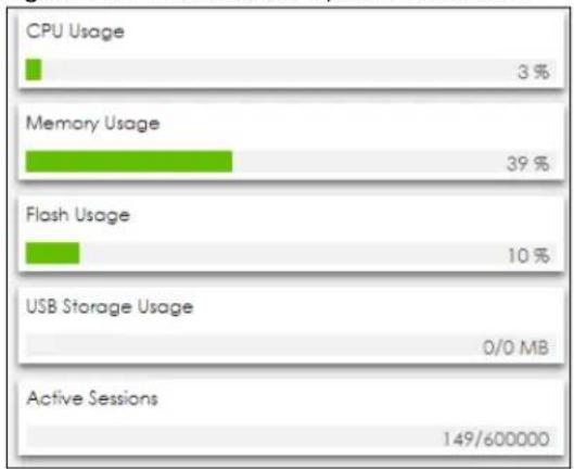
bar
| Category | Percentage (%) | | :--- | :--- | | CPU Usage | 3 | | Memory Usage | 39 | | Flash Usage | 10 | | USB Storage Usage | 0/0 MB | | Active Sessions | 149/600000 |The table describes the fields in the screen.
Table 29 Dashboard > System Resources
| LABEL DESCRIPTION | |
| CPU Usage | This field displays what percentage of the Zyxel Device's processing capability is currently being used. Hover your cursor over this field to display the Show CPU Usage icon that takes you to a chart of the Zyxel Device's recent CPU usage. |
| Memory Usage | This field displays what percentage of the Zyxel Device's RAM is currently being used. Hover your cursor over this field to display the Show Memory Usage icon that takes you to a chart of the Zyxel Device's recent memory usage. |
| Flash Usage | This field displays what percentage of the Zyxel Device's onboard flash memory is currently being used. |
| USB Storage Usage | This field shows how much storage in the USB device connected to the Zyxel Device is in use. |
| Active Sessions | This field shows how many sessions, established and non-established, that pass through/from/to/within the ZyWALL. Hover your cursor over this field to display icons. Click the Detail icon to go to the Session Monitor screen to see details about the active sessions. Click the Show Active Sessions icon to display a chart of Zyxel Device's recent session usage. |
5.2.5.1 System Resources Chart
The following screen displays when you click the system resources bar.
Figure 141 Dashboard > System Resources > Chart
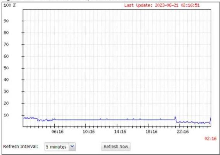
line
| Time | Value | | -------- | ----- | | 06:16 | ~8 | | 10:16 | ~7 | | 14:16 | ~7 | | 18:16 | ~7 | | 22:16 | ~9 | | 02:16 | ~8 |The table describes the fields in the screen.
Table 30 Dashboard > System Resources > Chart
| LABEL DESCRIPTION | |
| Data Collecting Interval | This field displays the time interval in minutes the Zyxel Device collects the system resources data. |
| Chart Refresh Interval | Select a time interval in minutes for renewing the system resources chart. |
5.2.6 DHCP Table Screen
Click on the number to look at the IP addresses currently assigned to DHCP clients and the IP addresses reserved for specific MAC addresses. The following screen will show.
Figure 142 Dashboard > DHCP Table
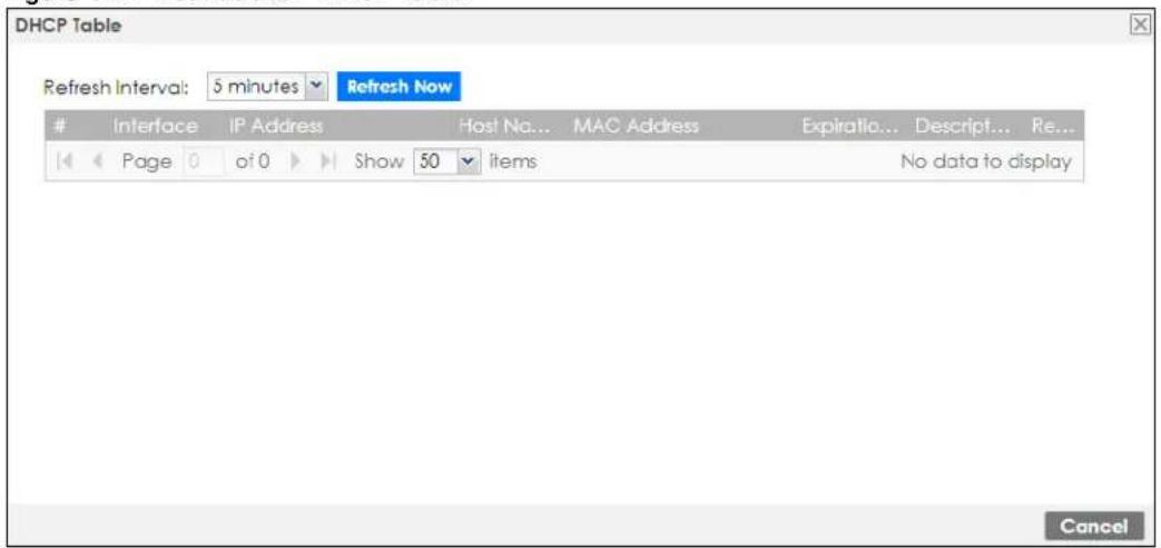
This table describes the fields in the above screen.
Table 31 Dashboard > DHCP Table
| LABEL DESCRIPTION | |
| Refresh Interval Select how often you want this window to be updated automatically. | |
| Refresh Now | Click this to update the information in the window right away. |
| # | This field is a sequential value, and it is not associated with a specific entry. |
| Interface This field identifies the interface that assigned an IP address to a DHCP client. | |
| IP Address | This field displays the IP address currently assigned to a DHCP client or reserved for a specific MAC address. Click the column's heading cell to sort the table entries by IP address. Click the heading cell again to reverse the sort order. |
| Host Name | This field displays the name used to identify this device on the network (the computer name). The Zyxel Device learns these from the DHCP client requests. "None" shows here for a static DHCP entry. |
| MAC Address | This field displays the MAC address to which the IP address is currently assigned or for which the IP address is reserved. Click the column's heading cell to sort the table entries by MAC address. Click the heading cell again to reverse the sort order. |
| Expiration Time | This is the period of time DHCP-assigned addresses is used. |
| Description | For a static DHCP entry, the host name or the description you configured shows here. This field is blank for dynamic DHCP entries. |
| Reserve | If this field is selected, this entry is a static DHCP entry. The IP address is reserved for the MAC address.If this field is clear, this entry is a dynamic DHCP entry. The IP address is assigned to a DHCP client.To create a static DHCP entry using an existing dynamic DHCP entry, select this field, and then clickApply.To remove a static DHCP entry, clear this field, and then clickApply. |
5.2.7 Number of Login Users Screen
Click the Number of Login Users link to see the following screen.
Figure 143 Dashboard > Number of Login Users
| Number of Login Users | |||||||
| # | User ID ▲ | Reauth/Lease Time | Session Tim... | Type | IP Address | User Info | Forco Logout |
| 1 | admin | unlimited / 00:29:59 | unlimited | http/https | 10.214.80.33 | admin(ad... | Logout |
The table describes the fields in the screen.
Table 32 Dashboard > Number of Login Users
| LABEL DESCRIPTION | |
| # | This field is a sequential value and is not associated with any entry. |
| User ID | This field displays the user name of each user who is currently logged in to the Zyxel Device. |
| Reauth/Lease Time | This field displays the amount of reauthentication time remaining and the amount of lease time remaining for each user. |
| Session Timeout | This field displays the total account of time the account (authenticated by an external server) can use to log into the UAG or access the Internet through the Zyxel Device.This shows unlimited for an administrator account. |
| Type | This field displays the way the user logged in to the Zyxel Device. |
| IP address | This field displays the IP address of the computer used to log in to the Zyxel Device. |
| User Info | This field displays the types of user accounts the Zyxel Device uses. If the user type isext-user(external user), this field will show its external-group information when you move your mouse over it.If the external user matches two external-group objects, both external-group object names will be shown. |
| Force Logout Click this icon to | end a user’s session. |
5.2.8 Current Login User
This field displays the user name used to log in to the current session, the amount of reauthentication time remaining, and the amount of lease time remaining.
Figure 144 Dashboard > Current Login User

5.2.9 VPN Status
Click on the link to look at the VPN tunnels that are currently established.
Figure 145 Dashboard > VPN Status

This table describes the fields in the above screen.
Table 33 Dashboard > VPN Status
| LABEL DESCRIPTION | |
| # | This field is a sequential value and is not associated with any entry. |
| Name This field displays the name of the VPN tunnel. | |
| Encapsulation | This field displays the type of encapsulation the VPN tunnel uses. |
| Algorithm | This field displays the hash algorithm that the VPN tunnel uses to authenticate packet data. |
| Refresh Interval Select how often you want this window to be updated automatically. | |
| Refresh Now | Click this to update the information in the window right away. |
5.2.10 SSL VPN Status
The first number is the actual number of VPN tunnels up and the second number is the maximum number of SSL VPN tunnels allowed.
Figure 146 Dashboard > SSL VPN Status

5.3 The Advanced Threat Protection Screen
Use the Advanced Threat Protection screen to check security status information about the Zyxel Device.
Figure 147 Dashboard > Advanced Threat Protection - USG FLEX Series
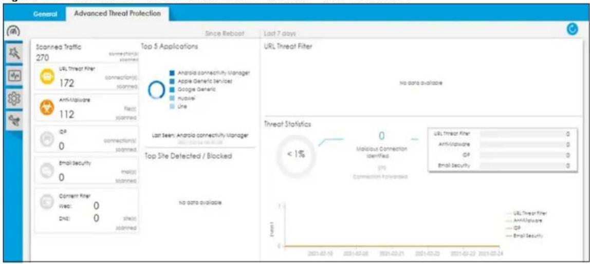
This screen gives the following information:
• The amount of scanned traffic
• The number of scanned connections for URL Threat filtering
• The number of scanned files for sandboxing
• The number of scanned files for anti-malware
• The number of scanned connections for IDP
• The number of scanned emails for email security
• The number of the scanned sites for content filtering
• Top 5 applications that are used the most
• Top 5 URLs that are detected the most
• Reputation filter reports
- URL Threat filter reports
- Sandboxing reports
- Threat statistics
Click the Refresh icon to update the information in the window right away.
PART II
Technical Reference
CHAPTER 6 Monitor
6.1 Overview
Use the Monitor screens to check status and statistics information.
6.1.1 What You Can Do in this Chapter
Use the Monitor screens for the following.
- Use the Traffic Statistics > Port Statistics screen (see Section 6.2.1 on page 168) to look at packet statistics for each physical port.
- Use the Traffic Statistics > Port Statistics > Graph View screen (see Section 6.2.1 on page 168) to look at a line graph of packet statistics for each physical port.
- Use the Traffic Statistics > Interface Status screen (Section 6.3 on page 169) to see all of the Zyxel Device's interfaces and their packet statistics.
- Use the Traffic Statistics > Traffic Statistics screen (see Section 6.4 on page 173) to start or stop data collection and view statistics.
- Use the Traffic Statistics > Session Monitor screen (see Section 6.5 on page 176) to view sessions by user or service.
- Use the Network Status > DHCP Table screen (see Section 6.6 on page 178) to view a list of interfaces and their DHCP-assigned IP addresses.
- Use the Network Status > Device Insight screen (see Section 6.7 on page 179) to view the status of the clients connected to the Zyxel Device.
- Use the Network Status > Login Users screen (Section 6.6 on page 178) to look at a list of the users currently logged into the Zyxel Device.
- Use the Network Status > Dynamic Guest screen (Section 6.9 on page 185) to look at a list of the automatically created users allowed to access the Zyxel Device's service.
- Use the Network Status > IGMP Statistics screen (see Section 6.10 on page 186) to view multicasting details.
- Use the Network Status > DDNS Status screen (see Section 6.11 on page 187) to view the status of the Zyxel Device's DDNS domain names.
- Use the Network Status > IP/MAC Binding screen (Section 6.12 on page 188) to view a list of devices that have received an IP address from Zyxel Device interfaces with IP/MAC binding enabled.
- Use the Network Status > Cellular Status screen (Section 6.13 on page 189) to check your mobile broadband connection status.
- Use the Network Status > UPnP Port Status screen (see Section 6.14 on page 192) to look at a list of the NAT port mapping rules that UPnP creates on the Zyxel Device.
- Use the Network Status > USB Storage screen (Section 6.15 on page 193) to view information about a connected USB storage device.
-
Use the Network Status > Ethernet Neighbor screen (Section 6.16 on page 194) to view and manage the Zyxel Device's neighboring devices via Layer Link Discovery Protocol (LLDP).
-
Use the Network Status > FQDN Object screen (Section 6.17 on page 195) to display fully qualified domain name (FQDN) object cache lists used in DNS queries.
- Use the Network Status > Virtual Server LB screen (Section 6.18 on page 197) to display distribution of incoming connection requests to a virtual server between multiple real (physical) servers.
- Use the Wireless > AP Information > AP List screen (Section 6.19 on page 198) to display which APs are currently connected to the Zyxel Device.
- Use the Wireless > AP Information > Radio List screen (Section 6.20 on page 209) to display statistics about the wireless radio transmitters in each of the APs connected to the Zyxel Device.
- Use the Wireless > AP Information > Built-in AP screen (Section 6.21 on page 212) to display the number of wireless clients connected to the Zyxel Device with built-in AP and their WiFi usage.
- Use the Wireless > AP Information > Top N APs screen (Section 6.22 on page 213) to view managed APs with the most wireless traffic usage and most associated wireless stations.
- Use the Wireless > AP Information > Single AP screen (Section 6.23 on page 214) to view APs wireless traffic usage and associated wireless stations for a managed AP.
- Use the Wireless > ZyMesh screen (Section 6.24 on page 215) to display statistics about the ZyMesh wireless connections between the managed APs.
- Use the Wireless > SSID Info screen (Section 6.25 on page 216) to display the number of wireless clients that are currently connected to an SSID and the SSID's security mode.
- Use the Wireless > Station Info > Station List screen (Section 6.26 on page 217) to view information on connected wireless stations.
- Use the Wireless > Station Info > Top N Stations screen (Section 6.27 on page 219) to view wireless stations with the most wireless traffic usage.
- Use the Wireless > Station Info > Single Station screen (Section 6.28 on page 220) to view wireless traffic usage for an associated wireless station.
- Use the Wireless > Detected Device screen (Section 6.29 on page 221) to view information about suspected rogue APs.
- Use the Wireless > Wireless Health screen (Section 6.30 on page 223) to view information about health of wireless networks for your APs and connected wireless clients.
- Use the Printer Status screen (see Section 6.31 on page 224) to view information about the connected statement printers.
- Use the VPN Monitor > IPSec screen (Section 6.32 on page 224) to display and manage active IPSec SAs.
- Use the VPN Monitor > SSL screen (see Section 6.33 on page 226) to list the users currently logged into the VPN SSL client portal. You can also log out individual users and delete related session information.
- Use the VPN Monitor > L2TP over IPSec screen (see Section 6.34 on page 227) to display and manage the Zyxel Device's connected L2TP VPN sessions.
- Use the VPN Monitor> Remote AP VPN screen (see Section 6.35 on page 228) to display and manage active remote AP radio.
- Use the Security Statistics > App Patrol screen (see Section 6.36 on page 229) to start or stop data collection and view application statistics
- Use the Security Statistics > Content Filter screen (Section 6.37 on page 230) to start or stop data collection and view content filter statistics.
- Use the Security Statistics > Anti-Malware screen (see Section 6.38 on page 233) to start or stop data collection and view statistics.
- Use the Security Statistics > Reputation Filter screen (see Section 6.39 on page 235) to view statistics of IP reputation and URL Threat filtering.
-
Use the Security Statistics > IPS screen (Section 6.40 on page 239) to start or stop data collection and view IPS statistics.
-
Use the Security Statistics > Email Security > Summary screen (Section 6.42 on page 243) to start or stop data collection and view spam statistics.
- Use the Security Statistics > Email Security > Status screen (Section 6.42.2 on page 245) to see how many mail sessions the Zyxel Device is currently checking and DNSBL statistics.
- Use the Security Statistics > CDR screen (Section 6.43 on page 247) to view devices blocked or quarantined by Collaborative Detection & Response (CDR).
- Use the Security Statistics > SSL Inspection screen (Section 6.44 on page 249) to see a report on SSL Inspection and a certificate cache list.
- Use the Log > View Log screen (see Section 6.45.1 on page 252) to view the Zyxel Device's current log messages. You can change the way the log is displayed, you can email the log, and you can also clear the log in this screen.
- Use the Log > View AP Log screen (see Section 6.45.2 on page 253) to view the Zyxel Device's current wireless AP log messages.
- Use the Log > Dynamic Users Log screen (see Section 6.45.3 on page 255) to view the Zyxel Device's dynamic guest account log messages.
6.2 The Port Statistics Screen
Use this screen to look at packet statistics for each Gigabit Ethernet port. To access this screen, click Monitor > Traffic Statistics > Port Statistics.
Figure 148 Monitor > Traffic Statistics > Port Statistics
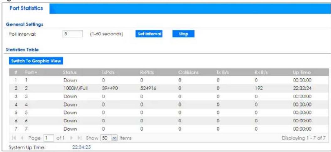
The following table describes the labels in this screen.
Table 34 Monitor > Traffic Statistics > Port Statistics
| LABEL DESCRIPTION | |
| Poll Interval | Enter how often you want this window to be updated automatically, and click Set Interval. |
| Set Interval | Click this to set the Poll Interval the screen uses. |
| Stop | Click this to stop the window from updating automatically. You can start it again by setting the Poll Interval and clicking Set Interval. |
| Switch to Graphic View | Click this to display the port statistics as a line graph. |
| # This field is a sequential value, and it is not associated with a specific port. | |
| Port This field displays the physical port number. | |
| Status This field displays the current status of the physical port. | |
| TxPkts | This field displays the number of packets transmitted from the Zyxel Device on the physical port since it was last connected. |
| RxPkts | This field displays the number of packets received by the Zyxel Device on the physical port since it was last connected. |
| Collisions | This field displays the number of collisions on the physical port since it was last connected. |
| Tx B/s | This field displays the transmission speed, in bytes per second, on the physical port in the one-second interval before the screen updated. |
| Rx B/s | This field displays the reception speed, in bytes per second, on the physical port in the one-second interval before the screen updated. |
| Up Time This field displays how long the physical port has been connected. | |
| System Up Time | This field displays how long the Zyxel Device has been running since it last restarted or was turned on. |
6.2.1 The Port Statistics Graph Screen
Use this screen to look at a line graph of packet statistics for each physical port. To access this screen, click Port Statistics on the Status screen and then the Switch to Graphic View Button.
Figure 149 Monitor > Traffic Statistics > Port Statistics > Switch to Graphic View
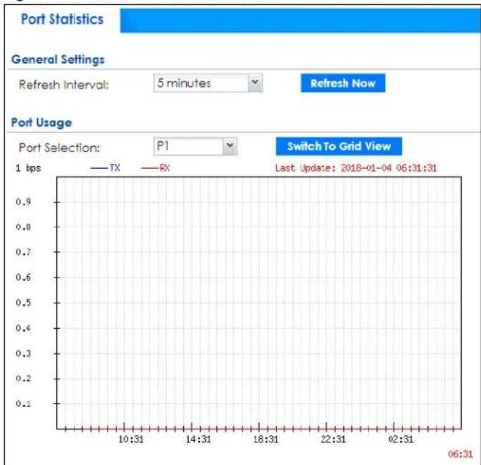
line
| Time | TX | RX | | -------- | ---- | ---- | | 06:31 | 0.9 | 0.9 |The following table describes the labels in this screen.
Table 35 Monitor > Traffic Statistics > Port Statistics > Switch to Graphic View
| LABEL DESCRIPTION | |
| Refresh Interval Enter how often you want this window to be automatically updated. | |
| Refresh Now | Click this to update the information in the window right away. |
| Port Selection | Select the number of the physical port for which you want to display graphics. |
| Switch to Grid View | Click this to display the port statistics as a table. |
| bps The y-axis represents the speed of transmission or reception. | |
| time | The x-axis shows the time period over which the transmission or reception occurred |
| TX | This line represents traffic transmitted from the Zyxel Device on the physical port since it was last connected. |
| RX | This line represents the traffic received by the Zyxel Device on the physical port since it was last connected. |
| Last Update | This field displays the date and time the information in the window was last updated. |
6.3 Interface Status Screen
This screen lists all of the Zyxel Device's interfaces and gives packet statistics for them. Click Monitor > Traffic Statistics > Interface Summary to access this screen.
Figure 150 Monitor > Traffic Statistics > Interface Summary
| Interface Summary | |||||||
| Interface Status | |||||||
| Name | Port/Bit... | Status | Zone | IP Addr/... | IP Assign... | Services | Action |
| - sfp | P1 | Down | OPT | 0.0.0.0 / ... | Static | n/a | n/a |
| - sfp_ppp | P1 | Inactive | OPT | 0.0.0.0 / ... | Dynamic | n/a | n/a |
| - wan1 | P2 | 1000M/Full | WAN | 172.21.4... | DHCP cli... | n/a | Renew |
| - wan1_ppp | P2 | Inactive | WAN | 0.0.0.0 / ... | Dynamic | n/a | n/a |
| - wan2 | P3 | Down | WAN | 0.0.0.0 / ... | DHCP cli... | n/a | Renew |
| - wan2_ppp | P3 | Inactive | WAN | 0.0.0.0 / ... | Dynamic | n/a | n/a |
| - lan1 | P4, P5, P6 | Down | LAN1 | 192.168.... | Static | DHCP se... | n/a |
| - lan2 | n/a | Down | LAN2 | 192.168.... | Static | DHCP se... | n/a |
| - dmz | n/a | Down | DMZ | 192.168.... | Static | DHCP se... | n/a |
| - reserved | P7 | Down | n/a | 0.0.0.0 / ... | Static | n/a | n/a |
Each field is described in the following table.
Table 36 Monitor > Traffic Statistics > Interface Summary
| LABEL DESCRIPTION | |
| Interface StatusIf an Ethernet interface does not have any physical ports associated with it, its entry is displayed in light gray text. | |
| Name | This field displays the name of each interface. If there is anExpandicon (plus-sign) next to the name, click this to look at the status of virtual interfaces on top of this interface. |
| Port/Binding This field displays the physical port number. | |
Table 36 Monitor > Traffic Statistics > Interface Summary
| LABEL DESCRIPTION | |
| Status | This field displays the current status of each interface. The possible values depend on what type of interface it is.For Ethernet interfaces:Inactive- The Ethernet interface is disabled.Down- The Ethernet interface does not have any physical ports associated with it or the Ethernet interface is enabled but not connected.Speed/ Duplex- The Ethernet interface is enabled and connected. This field displays the port speed and duplex setting (Full or Half).For cellular (mobile broadband) interfaces, see Section 6.15 on page 193 the Web Help for the status that can appear.For the auxiliary interface:Inactive- The auxiliary interface is disabled-connected- The auxiliary interface is enabled and connected.Disconnected- The auxiliary interface is not connected.For virtual interfaces, this field always displays Up. If the virtual interface is disabled, it does not appear in the list.For VLAN and bridge interfaces, this field always displays Up. If the VLAN or bridge interface is disabled, it does not appear in the list.For PPP interfaces:Connected- The PPP interface is connected.Disconnected- The PPP interface is not connected.If the PPP interface is disabled, it does not appear in the list.For WLAN interfaces:Up- The WLAN interface is enabled.Down- The WLAN interface is disabled. |
| Zone | This field displays the zone to which the interface is assigned. |
| IP Addr/Netmask | This field displays the current IP address and subnet mask assigned to the interface. If the IP address and subnet mask are 0.0.0.0, the interface is disabled or did not receive an IP address and subnet mask via DHCP.If this interface is a member of an active virtual router, this field displays the IP address it is currently using. This is either the static IP address of the interface (if it is the master) or the management IP address (if it is a backup). |
| IP Assignment This field displays how the interface gets its IP address.Static- This interface has a static IP address.DHCP Client- This interface gets its IP address from a DHCP server. | |
| Services | This field lists which services the interface provides to the network. Examples include DHCP relay, DHCP server, DDNS, RIP, and OSPF. This field displays n/a if the interface does not provide any services to the network. |
| Action | Use this field to get or to update the IP address for the interface. Click Renew to send a new DHCP request to a DHCP server. Click Connect to try to connect a PPPoE/PPTP interface. If the interface cannot use one of these ways to get or to update its IP address, this field displays n/a. |
| Tunnel Interface StatusThis displays the details of the Zyxel Device's configured tunnel interfaces. | |
| Name This field displays the name of the interface. | |
| Status | The activate (light bulb) icon is lit when the entry is active and dimmed when the entry is inactive. |
Table 36 Monitor > Traffic Statistics > Interface Summary
| LABEL DESCRIPTION | |
| Zone | This field displays the zone to which the interface is assigned. |
| IP Address | This is the IP address of the interface. If the interface is active (and connected), the Zyxel Device tunnels local traffic sent to this IP address to the Remote Gateway Address. |
| My Address | This is the interface or IP address uses to identify itself to the remote gateway. The Zyxel Device uses this as the source for the packets it tunnels to the remote gateway. |
| Remote Gateway Address | This is the IP address or domain name of the remote gateway to which this interface tunnels traffic. |
| Mode This field displays the tunnel mode that you are using. | |
| IPv6 Interface StatusIf an Ethernet interface does not have any physical ports associated with it, its entry is displayed in light gray text. | |
| Name | This field displays the name of each interface. If there is an Expand icon (plus-sign) next to the name, click this to look at the status of virtual interfaces on top of this interface. |
| Port This field displays the physical port number. | |
| Status | This field displays the current status of each interface. The possible values depend on what type of interface it is.For Ethernet interfaces:Inactive - The Ethernet interface is disabled.Down - The Ethernet interface does not have any physical ports associated with it or the Ethernet interface is enabled but not connected.Speed / Duplex - The Ethernet interface is enabled and connected. This field displays the port speed and duplex setting (Full or Half).For cellular (mobile broadband) interfaces, see Section 6.15 on page 193 the Web Help for the status that can appear.For the auxiliary interface:Inactive - The auxiliary interface is disabled-connected - The auxiliary interface is enabled and connected.Disconnected - The auxiliary interface is not connected.For virtual interfaces, this field always displays Up. If the virtual interface is disabled, it does not appear in the list.For VLAN and bridge interfaces, this field always displays Up. If the VLAN or bridge interface is disabled, it does not appear in the list.For PPP interfaces:Connected - The PPP interface is connected.Disconnected - The PPP interface is not connected.If the PPP interface is disabled, it does not appear in the list.For WLAN interfaces:Up - The WLAN interface is enabled.Down - The WLAN interface is disabled. |
| Zone | This field displays the zone to which the interface is assigned. |
| IP Address | This field displays the current IPv6 address assigned to the interface. If the IPv6 address is ::, the interface is disabled or did not receive an IPv6 address via DHCP.If this interface is a member of an active virtual router, this field displays the IPv6 address it is currently using. This is either the static IPv6 address of the interface (if it is the master) or the management IPv6 address (if it is a backup). |
Table 36 Monitor > Traffic Statistics > Interface Summary
| LABEL DESCRIPTION | |
| Services | This field lists which services the interface provides to the network. Examples include DHCP relay, DHCP server, DDNS, RIP, and OSPF. This field displays n/a if the interface does not provide any services to the network. |
| Action | Use this field to get or to update the IP address for the interface. Click Renew to send a new DHCP request to a DHCP server. Click Connect to try to connect a PPPoE/PPTP interface. If the interface cannot use one of these ways to get or to update its IP address, this field displays n/a. |
| Interface Statistics | |
| This table provides packet statistics for each interface. | |
| Refresh Click this button to update the information on the screen. | |
| Name | This field displays the name of each interface. If there is a Expand icon (plus-sign) next to the name, click this to look at the statistics for virtual interfaces on top of this interface. |
| Status This field displays the current status of the interface.• Down - The interface is not connected.• Speed / Duplex - The interface is connected. This field displays the port speed and duplex setting (Full or Half).This field displays Connected and the accumulated connection time (hh:mm:ss) when the PPP interface is connected. | |
| TxPkts | This field displays the number of packets transmitted from the Zyxel Device on the interface since it was last connected. |
| RxPkts | This field displays the number of packets received by the Zyxel Device on the interface since it was last connected. |
| Tx B/s | This field displays the transmission speed, in bytes per second, on the interface in the one-second interval before the screen updated. |
| Rx B/s | This field displays the reception speed, in bytes per second, on the interface in the one-second interval before the screen updated. |
6.4 The Traffic Statistics Screen
Click Monitor > Traffic Statistics > Traffic Statistics to display the Traffic Statistics screen. This screen provides basic information about the following for example:
- Most-visited Web sites and the number of times each one was visited. This count may not be accurate in some cases because the Zyxel Device counts HTTP GET packets. Please see Table 37 on page 174 for more information.
- Most-used protocols or service ports and the amount of traffic on each one
• LAN IP with heaviest traffic and how much traffic has been sent to and from each one
You use the Traffic Statistics screen to tell the Zyxel Device when to start and when to stop collecting information for these reports. You cannot schedule data collection; you have to start and stop it manually on the Traffic Statistics screen.
Figure 151 Monitor > Traffic Statistics > Traffic Statistics
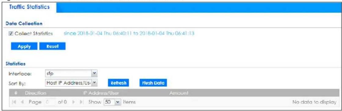
There is a limit on the number of records shown in the report. Please see Table 38 on page 175 for more information. The following table describes the labels in this screen.
Table 37 Monitor > Traffic Statistics > Traffic Statistics
| LABEL DESCRIPTION | |
| Data Collection | |
| Collect Statistics | Select this to have the Zyxel Device collect data for the report. If the Zyxel Device has already been collecting data, the collection period displays to the right. The progress is not tracked here real-time, but you can click the Refresh button to update it. |
| Apply | Click Apply to save your changes back to the Zyxel Device. |
| Reset | Click Reset to return the screen to its last-saved settings. |
| Statistics | |
| Interface | Select the interface from which to collect information. You can collect information from Ethernet, VLAN, bridge and PPPoE/PPTP interfaces. |
| Sort By Select the type of report to display. Choices are:Host IP Address/ User - displays the IP addresses or users with the most traffic and how much traffic has been sent to and from each one.Service/ Port - displays the most-used protocols or service ports and the amount of traffic for each one.Web Site Hits - displays the most-visited Web sites and how many times each one has been visited.Country - displays the countries with the most traffic and the amount of traffic for each one.Each type of report has different information in the report (below). | |
| Refresh Click this button to update the report display. | |
| Flush Data | Click this button to discard all of the screen's statistics and update the report display. |
| These fields are available when the Traffic Type is Host IP Address/ User. | |
| # | This field is the rank of each record. The IP addresses and users are sorted by the amount of traffic. |
| Direction | This field indicates whether the IP address or user is sending or receiving traffic.Ingress- traffic is coming from the IP address or user to the Zyxel Device.Egress - traffic is going from the Zyxel Device to the IP address or user. |
| IP Address/User | This field displays the IP address or user in this record. The maximum number of IP addresses or users in this report is indicated in Table 38 on page 175. |
| Amount | This field displays how much traffic was sent or received from the indicated IP address or user. If the Direction is Ingress, a red bar is displayed; if the Direction is Egress, a blue bar is displayed. The unit of measure is bytes, Kbytes, Mbytes or Gbytes, depending on the amount of traffic for the particular IP address or user. The count starts over at zero if the number of bytes passes the byte count limit. See Table 38 on page 175.These fields are available when the Traffic Type is Service/Port. |
| # | This field is the rank of each record. The protocols and service ports are sorted by the amount of traffic. |
| Service/Port | This field displays the service and port in this record. The maximum number of services and service ports in this report is indicated in Table 38 on page 175. |
| Protocol This field indicates what protocol the service was using. | |
| Direction | This field indicates whether the indicated protocol or service port is sending or receiving traffic.Ingress- traffic is coming into the Zyxel Devicethrough the interfaceEgress- traffic is going out from the Zyxel Device through the interface |
| Amount | This field displays how much traffic was sent or received from the indicated service / port. If the Direction is Ingress, a red bar is displayed; if the Direction is Egress, a blue bar is displayed. The unit of measure is bytes, Kbytes, Mbytes, Gbytes, or Tbytes, depending on the amount of traffic for the particular protocol or service port. The count starts over at zero if the number of bytes passes the byte count limit. See Table 38 on page 175. |
| These fields are available when the Traffic Type is Web Site Hits. | |
| # | This field is the rank of each record. The domain names are sorted by the number of hits. |
| Web Site | This field displays the domain names most often visited. The Zyxel Device counts each page viewed on a Web site as another hit. The maximum number of domain names in this report is indicated in Table 38 on page 175. |
| Hits | This field displays how many hits the Web site received. The Zyxel Device counts hits by counting HTTP GET packets. Many Web sites have HTTP GET references to other Web sites, and the Zyxel Device counts these as hits too. The count starts over at zero if the number of hits passes the hit count limit. See Table 38 on page 175. |
| These fields are available when the Traffic Type is Country. | |
| # | This field is the rank of each record. The country name is sorted by the amount of traffic. |
| Direction | This field indicates whether the indicated protocol or service port is sending or receiving traffic.Ingress- traffic is coming into the Zyxel Devicethrough the interfaceEgress- traffic is going out from the Zyxel Device through the interface |
| Country Name | This field displays the name of the country. |
| Country This field displays the country code. | |
| Amount | This field displays how much traffic was sent or received from the indicated country. If the Direction is Ingress, a red bar is displayed; if the Direction is Egress, a blue bar is displayed. The unit of measure is bytes, Kbytes, Mbytes, Gbytes, or Tbytes, depending on the amount of traffic for the particular protocol or service port. The count starts over at zero if the number of bytes passes the byte count limit. See Table 38 on page 175.Ingress- traffic is coming into the Zyxel Device from the country.Egress- traffic is going from the Zyxel Device to the country. |
The following table displays the maximum number of records shown in the report, the byte count limit, and the hit count limit.
Table 38 Maximum Values for Reports
| LABEL DESCRIPTION | |
| Maximum Number of Records 20 | |
| Byte Count Limit 2 | ^64 bytes; this is just less than 17 million terabytes. |
| Hit Count Limit 2 | ^64 hits; this is over 1.8 × 10^19 hits. |
6.5 The Session Monitor Screen
The Session Monitor screen displays all established sessions that pass through the Zyxel Device for debugging or statistical analysis. It is not possible to manage sessions in this screen. The following information is displayed.
- User who started the session
- Protocol or service port used
- Source address
- Destination address
• Number of bytes received (so far)
• Number of bytes transmitted (so far)
• Duration (so far)
You can look at all established sessions that passed through the Zyxel Device by user, service, source IP address, or destination IP address. You can also filter the information by user, protocol / service or service group, source address, and/or destination address and view it by user.
Click Monitor > Traffic Statistics > Session Monitor to display the following screen.
Figure 152 Monitor > Traffic Statistics > Session Monitor
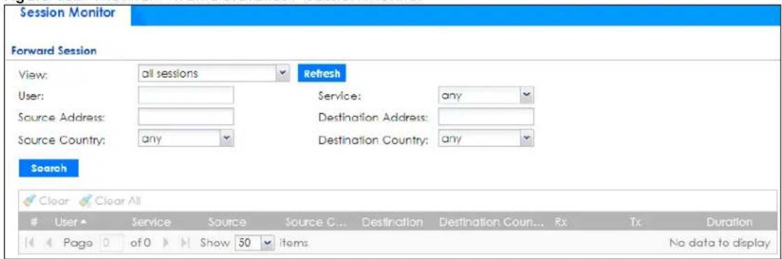
The following table describes the labels in this screen.
Table 39 Monitor > Traffic Statistics > Session Monitor
| LABEL DESCRIPTION | |
| View | Select how you want the established sessions that passed through the Zyxel Device to be displayed. Choices are:sessions by users- display all active sessions grouped by usersessions by services- display all active sessions grouped by service or protocolsessions by source IP- display all active sessions grouped by source IP addresssession by source region- display all active sessions grouped by where the traffic is coming from by countrysessions by destination IP- display all active sessions grouped by destination IP addressessions by destination region- display all active sessions grouped by where the traffic is going to by countryall sessions- filter the active sessions by the User, Service, Source Address, and Destination Address, and display each session individually (sorted by user). |
| Refresh | Click this button to update the information on the screen. The screen also refreshes automatically when you open and close the screen. |
| LABEL DESCRIPTION | |
| The User, Service, Source Address, Destination Address, Source Country and Destination Country fields display if you view all sessions. Select your desired filter criteria and click the Refresh button to filter the list of sessions. | |
| User | This field displays when View is set to all sessions. Type the user whose sessions you want to view. It is not possible to type part of the user name or use wildcards in this field; you must enter the whole user name. |
| Service | This field displays when View is set to all sessions. Select the service or service group whose sessions you want to view. The Zyxel Device identifies the service by comparing the protocol and destination port of each packet to the protocol and port of each services that is defined. |
| Source Address | This field displays when View is set to all sessions. Type the source IP address whose sessions you want to view. You cannot include the source port. |
| Source Country | This field displays when View is set to all sessions. Select the country where the traffic is coming from. |
| Destination Address | This field displays when View is set to all sessions. Type the destination IP address whose sessions you want to view. You cannot include the destination port. |
| Destination Country | This field displays when View is set to all sessions. Select the country where the traffic is going to. |
| Search | Click this to display all sessions in the table below according to the criteria you defined above. |
| Clear Clear All | Administrators can use these buttons to forcibly terminate selected TCP/UDP connections. Select one or multiple connections and then click Clear; click Clear All to terminate all connections displayed. Cleared sessions display on the Log >View Log screen. |
| # | This field is the rank of each record. The names are sorted by the name of user in active session. You can use the pull down menu on the right to choose sorting method. |
| User This field displays the user in each active session. If you are looking at the sessions by users (or all sessions) report, click + or - to display or hide details about a user's sessions. | |
| Service | This field displays the protocol used in each active session. If you are looking at the sessions by services report, click + or - to display or hide details about a protocol's sessions. |
| Source | This field displays the source IP address and port in each active session. If you are looking at the sessions by source IP report, click + or - to display or hide details about a source IP address's sessions. |
| Source Country | This field displays the source country in each active session. |
| Destination | This field displays the destination IP address and port in each active session. If you are looking at the sessions by destination IP report, click + or - to display or hide details about a destination IP address's sessions. |
| Destination Country | This field displays the destination country in each active session. |
| Rx | This field displays the amount of information received by the source in the active session. |
| Tx | This field displays the amount of information transmitted by the source in the active session. |
| Duration | This field displays the length of the active session in seconds. |
6.6 The DHCP Table Screen
Use this screen to look at a list of interfaces and their DHCP-assigned IP addresses. To access this screen, click Monitor > Network Status > DHCP Table.
Figure 153 Monitor > Network Status > DHCP Table
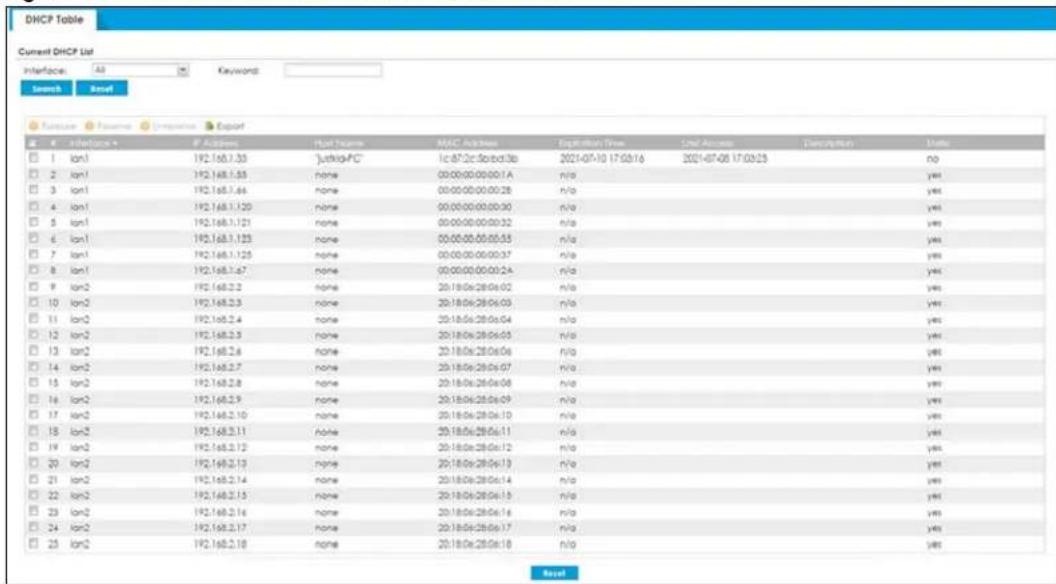
The following table describes the labels in this screen.
Table 40 Monitor > Network Status > DHCP Table
| LABEL DESCRIPTION | |
| Current DHCP List | |
| Interface | Select a Zyxel Device interface that has DHCP enabled to show to which devices it has assigned DHCP IP addresses. |
| Keyword | Enter a keyword to display the interfaces and their information, such as IP addresses, MAC addresses and so on. The field is case-sensitive. |
| Search | Click to update the list of interfaces shown in the table below based on the search criteria.Your search criteria is retained when navigating between screens. |
| Reset | Click to return this search criteria to the factory defaults and display all interfaces with DHCP enabled. |
| Release | Select an entry and click on this button to let other devices use the dynamic DHCP that is currently assigned to the selected entry. |
| Reserve | Select an entry and click on this button to set the entry as a static DHCP entry. The IP address will be reserved for the MAC address after you click this button. |
| Unreserve | Select an entry and click on this button to set the entry from a static DHCP entry to a dynamic DHCP entry. The IP address is assigned to a DHCP client. |
| Export# | To export as a csv file on your computer, select them and click Export. Click Save in the file download dialogue box and then select a location and name for the file. You can edit the file after it is saved on your computer.To import the file you export here to recover the settings you configure now later on the Zyxel Device, go toConfiguration> Network> Interface> Ethernet/VLAN> DCHP Setting.This field is a sequential value, and it is not associated with a specific entry. |
| Interface | This field identifies the interface that assigned an IP address to a DHCP client. |
| IP Address | This field displays the IP address currently assigned to a DHCP client or reserved for a specific MAC address. Click the column's heading cell to sort the table entries by IP address. Click the heading cell again to reverse the sort order. |
| Host Name | This field displays the name used to identify this device on the network (the computer name). The Zyxel Device learns these from the DHCP client requests. "None" shows here for a static DHCP entry. |
| MAC Address | This field displays the MAC address to which the IP address is currently assigned or for which the IP address is reserved. Click the column's heading cell to sort the table entries by MAC address. Click the heading cell again to reverse the sort order. |
| Expiration Time | This displays the date and time the DHCP-assigned address will be renewed. |
| Last Access This is when | the last time any traffic pass through the interface. |
| Description | For a static DHCP entry, the host name or the description you configured shows here. This field is blank for dynamic DHCP entries. |
| Static | This field displays if the address in the IP address field is reserved for the clients connected to this interface.Yes means that the clients connected to the interface will always get the IP address shown in the table. |
6.7 The Device Insight Screen
The Device Insight screen displays the status of the clients connected to the Zyxel Device, such as if a client is sending traffic to the Zyxel Device or if a client's MAC address is in the CDR block list. See Chapter 39 on page 882 for more information on CDR.
It also displays the basic information and the status of the clients. The clients show in this screen may include clients connected to the Zyxel Device:
• Using wired connections.
- Through access points (APs) using wired connections.
- Through access points (APs) using WiFi connections.
- Through built-in access points using WiFi connections.
• Using SecuExtender (IPSec VPN clients).
Use Device Insight to identify and monitor clients connected to the Zyxel Device internal LAN/VLAN DMZ networks in the same IP subnet. This feature collects client information, including:
- Hostname
• IP address and MAC address - Operating system
- Category, such as mobile phones or computers
- Connected interface
You can create a profile based on clients' categories and operating systems, and then apply the created profile to the Zyxel Device security policies. See Section 43.1 on page 929 for more information on creating and using Device Insight profiles.
Note: To collect clients' information using Device Insight, the clients must be in the same IP subnet in the LAN/VLAN/DMZ networks behind the Zyxel Device. Information from clients that are in different IP subnets in the LAN/VLAN/DMZ networks might not be collected correctly as traffic must pass through another router or a layer-3 switch to the Zyxel Device.
In the graphic below, A is a client connected to the Zyxel Device using a wired connection. B is a client connected to the Zyxel Device through an AP using a wired connection. C is a client connected to the Zyxel Device through an AP using a WiFi connection.
Figure 154 Clients' Device Insight Example
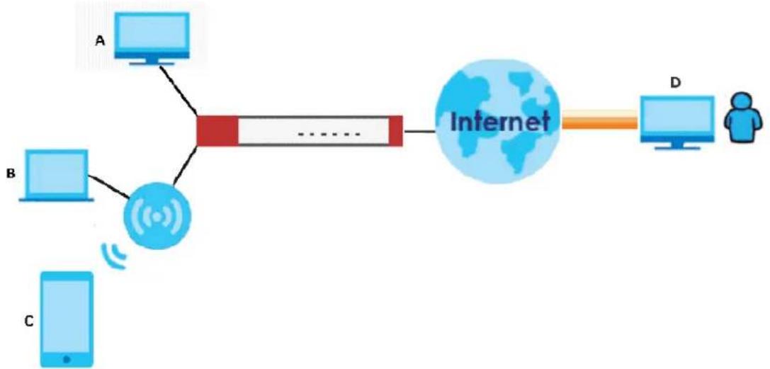
flowchart
graph TD
    A["Device A"] --> C["Internet"]
    B["Device B"] --> C
    C --> D["User"]
    C -->|Wireless Signal| C
    C -->|Signal| C
Click Monitor> Device Inventory to show the following screen.
Figure 155 Monitor > Device Insight
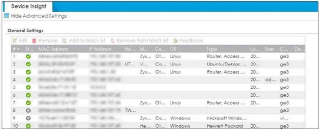
The following table describes the labels in this screen.
Table 41 Monitor > Network Status > Device Insight
| LABEL DESCRIPTION | |
| Hide/Show Advanced Settings | Click this button to display a greater or lesser number of configuration fields. |
| Edit | Double-click an entry or select it and click Edit to modify the entry's settings in the Description field. |
| Remove | Select an entry and click Remove to remove a client from the table that's no longer connected to your network.For example, guest A visited your company over a month ago. Guest A used his cellphone to connect to your Zyxel Device networks. His cellphone was identified and shown in the Device Insight table. Guest A has left for over a month and you're sure he will not return in the near future. You can use the Remove button to remove his device from this table. Guest A's device will be identified and shown in the table again if he connects to your Zyxel Device networks in the future.Please note that clients that are blocked cannot be removed. Make sure to unblock clients before you remove them. |
| Add to block list | Select an entry and click Add to block list to stop the selected client from connecting to the Zyxel Device. |
| Remove from block list | Select an entry and click Remove from block list to allow the selected client to connect to the Zyxel Device. |
| Feedback | Select an entry and click Feedback to report on a client that is wrongly identified regarding its Category, Operating System or Type. |
| # | This field is a sequential value, and it is not associated with a specific service. |
| Status This field displays the status of the clients.On line ( )- The VPN connection between the client and the Zyxel Device is up.Off line ( )- The VPN connection between the client and the Zyxel Device is down.Block ( )- The client is blocked from the connection to the Zyxel Device.CDR Block ( )- The client's MAC address is blocked by CDR. | |
| MAC Address | This field displays the MAC address of the client. |
| IP Address This field displays the IP address of the client. | |
| Hostname | This field displays the name used to identify this device on the network. |
| Manufacturer | This field displays the manufacturer of the client, such as Apple or Samsung. |
| Category | This field displays the type of the device of the client, such as printer or smart TV. |
| OS This field displays the operating system of the client. | |
| OS Version | This field displays the version of the operating system of the client. |
| Type | This field displays the model names of the client. |
| First-seen | This field displays the time when the client first sends traffic to the Zyxel Device. |
| Last-seen | This field displays the time when the client last sends traffic to the Zyxel Device. |
| User | This field displays the type of user account the client uses. See Section 43.3 on page 938 for more information the user account types. |
| Auth method | This field displays the authentication method that is used to authenticate the client. |
| TX rate (Kbps) | This field displays the transmission rate of the client to which the Zyxel Device is connected. |
| RX rate (Kbps) | This field displays the reception rate of the client to which the Zyxel Device is connected. |
| Connected to | This field displays if the client is connected directly to the Zyxel Device or to an AP that is connected to the Zyxel Device. |
| Description This field displays the descriptive name of the client. | |
6.7.1 The Device Insight Edit Screen
Use this screen to edit the description for connected clients. Click Monitor > Network Status > Device Insight > Edit to display the following screen.
Figure 156 Monitor > Network Status > Device Insight > Edit
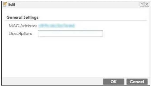
The following table describes the labels in this screen.
Table 42 Monitor > Network Status > Device Insight > Edit
| LABEL DESCRIPTION | |
| Description | Enter a descriptive name for this client. You can use up to 31 characters, spaces and underscores are allowed. |
| OK Click OK to save your changes back to the Zyxel Device. | |
| Cancel | Click Cancel to exit this screen without saving your changes. |
6.7.2 The Device Insight Feedback Screen
Use this screen to report on clients that are wrongly identified. Click Monitor > Network Status > Device Insight > Feedback to display the following screen.
Figure 157 Monitor > Network Status > Device Insight > Feedback
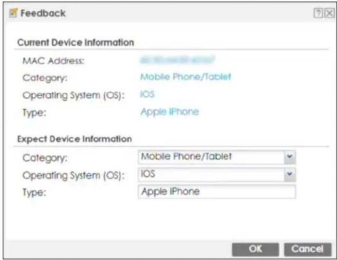
The following table describes the labels in this screen.
Table 43 Monitor > Network Status > Device Insight > Feedback
| LABEL DESCRIPTION | |
| Current Device Information | |
| MAC address | This field displays the MAC address of the client. |
| Category | This field displays the type of the device of the client, such as printer or smart TV. |
| Operating System This field | displays the operating system of the client. |
| Type This field displays the | model names of the client. |
| Expect Device Information | |
| Category | This field will display the current type of the client device identified by the Zyxel Device.If you think it's wrong, select the type of device you believe is correct from the drop-down list box. If it is correct, leave it as it is. |
| Operating System | This field will display the current operating system of the client identified by the Zyxel Device.If you think it's wrong, select the operating system you believe is correct from the drop-down list box. If it is correct, leave it as it is. |
| Type | This field will display the current model name of the client identified by the Zyxel Device.If you think it's wrong, type the model name you believe is correct. If it is correct, leave it as it is. |
| OK Click OK to send your feedback to the Zyxel database. | |
| Cancel | Click Cancel to exit this screen without saving your changes. |
6.8 The Login Users Screen
Use this screen to see a list of users currently logged into the Zyxel Device. To access this screen, click Monitor > Network Status > Login Users.
Figure 158 Monitor > Network Status > Login Users
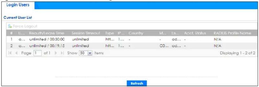
The following table describes the labels in this screen.
Table 44 Monitor > Network Status > Login Users
| LABEL DESCRIPTION | |
| Force Logout Select a user row and click this icon to end a user's session. | |
| # This field is a sequential value and is not associated with any entry. | |
| User ID | This field displays the user name of each user who is currently logged in to the Zyxel Device. |
| Reauth/Lease Time | This field displays the amount of reauthentication time remaining and the amount of lease time remaining for each user. See Section 43.14.1 on page 1051 for more information on the reauthentication time and lease time. |
| Session Timeout | This field displays the total account of time the account (authenticated by an external server) can use to log into the Zyxel Device or access the Internet through the Zyxel Device.This shows unlimited for an administrator account. |
| Type | This field displays the way the user logged into the Zyxel Device. The user can log into the Zyxel Device using HTTP, HTTPS, Telnet, SSH, FTP and console. |
| IP Address | This field displays the IP address of the computer used to log in to the Zyxel Device. |
| Country | The Internet Assigned Numbers Authority (IANA) has reserved the following blocks of Private IPv4 addresses:10.0.0.0 - 10.255.255.255172.16.0.0 - 172.31.255.255192.168.0.0 - 192.168.255.255224.0.0.0 - 239.255.255.255The Zyxel Device cannot identify a user's country if the user accessed the Zyxel Device using one of the private IPv4 addresses listed above. This field will display a hyphen (-). |
| MAC | This field displays the MAC address of the computer used to log into the Zyxel Device. |
| User Info | This field displays the types of user accounts the Zyxel Device uses. If the user type is ext-user (external user), this field will show its external-group information when you move your mouse over it.If the external user matches two external-group objects, both external-group object names will be shown.See Section 43.3.1 on page 939 for more information on the user accounts. |
| Created Date This field | displays the date the account was created.This field displays a hyphen (-) if the account was created on a Zyxel Device with firmware version earlier than 5.10. |
| Acct. Status | For a captive portal login, this field displays the accounting status of the account used to log into the Zyxel Device.Accounting-onmeans accounting is being performed for the user login.Accounting-offmeans accounting has stopped for this user login.A “-” displays if accounting is not enabled for this login. |
| RADIUS Profile Name | This field displays the name of the RADIUS profile used to authenticate the login through the captive portal.N/Adisplays for logins that do not use the captive portal and RADIUS server authentication. |
| Refresh Click this button | to update the information on the screen. |
6.9 Dynamic Guest
A dynamic guest account has a dynamically-created user name and password that allows a guest user to access the Internet or the Zyxel Device's services in a specified period of time. Multiple dynamic guest accounts can be automatically generated at one time for guest users by using the web configurator and the guest-manager account. Guest users can log in with the dynamic accounts when connecting to an SSID for a specified time unit. Use this screen to look at a list of dynamic guest user accounts on the Zyxel Device's local database. To access this screen, click Monitor > Network Status > Dynamic Guest.
Figure 159 Monitor > Network Status > Dynamic Guest
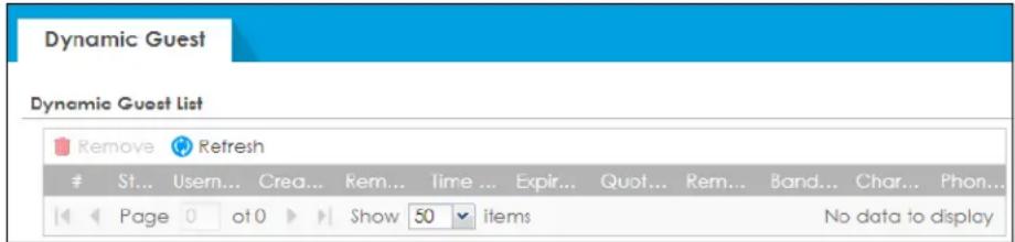
The following table describes the labels in this screen.
Table 45 Monitor > Network Status > Dynamic Guest
| LABEL DESCRIPTION | |
| Dynamic Guest List | |
| Remove | Select an entry and click this button to remove it from the list.Note: If you delete a valid user account which is in use, the Zyxel Device ends the user session. |
| # | This field is a sequential value and is not associated with any entry. |
| Status | This field displays whether the dynamic user account is active or not. |
| Username This field displays the user name of the dynamic user account. | |
| Create Time | This field displays when the dynamic user account was created. |
| Remaining Time | This field displays the amount of Internet access time remaining for each dynamic user account. |
| Time Period | This field displays the duration of Internet access for the dynamic user account. |
| Expiration Time | This field displays the date and time the Internet access becomes invalid. Once the time allocated to a dynamic account is used up or a dynamic account remains unused after the expiration time, the account is deleted from the account list. |
| Quota (T/U/D) | This field displays how much data in both directions (Total) or upstream data (Upload) and downstream data (Download) can be transmitted through the WAN interface before the Internet access expires. |
| Remaining Quota | This field displays how much more data can be transmitted through the WAN interface before the Internet access expires. |
| Bandwidth (U/D) | This field displays the maximum upstream (Upload) and downstream (Download) bandwidth allowed for the dynamic user account in kilobits per second. |
| Charge This field displays access price per time unit. | |
| Payment Info This field displays the method of payment for each account. | |
| Real Name This field displays the user's name of the account. | |
| Email This field displays the email address of the account. | |
| Phone Number This displays the user's phone number. | |
| User Role This field displays the role of the account. | |
The following table describes the icons in this screen.
Table 46 Monitor > Network Status > Dynamic Guest Icons
 | This guest account is un-used. |
 | This guest account is in use and online. |
 | This guest account has been used but is offline now. |
| [83BD] | This guest account expired. |
| [H0DA] | This guest account has been deleted. |
6.10 IGMP Statistics
The Internet Group Management Protocol (IGMP) Statistics is used by Zyxel Device IP hosts to inform adjacent router about multicast group memberships. It can also be used for one-to-many networking applications such as online streaming video and gaming, distribution of company newsletters, updating address book of mobile computer users in the field allowing more efficient use of resources when supporting these types of applications. Click Monitor > Network Status > IGMP Statistics to open the following screen.
Figure 160 Monitor > Network Status > IGMP Statistics
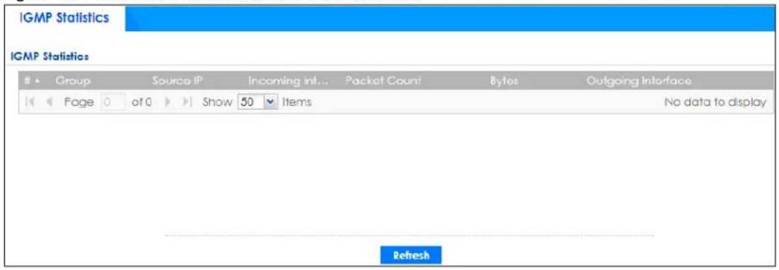
The following table describes the labels in this screen.
Table 47 Monitor > Network Status > IGMP Statistics
| LABEL DESCRIPTION | |
| # | This field is a sequential value, and it is not associated with a specific IGMP Statistics. |
| Group | This field displays the group of devices in the IGMP. |
| Source IP This field displays the | host source IP information of the IGMP. |
| Incoming Interface | This field displays the incoming interface that's connected on the IGMP. |
| Packet Count This field displays the | packet size of the data being transferred. |
| Bytes This field displays the size of the data being transferred in Byes. | |
| Outgoing Interface | This field displays the outgoing interface that's connected on the IGMP. |
| Refresh Click this button to up | date the information on the screen. |
6.11 The DDNS Status Screen
The DDNS Status screen shows the status of the Zyxel Device's DDNS domain names. Click Monitor > Network Status > DDNS Status to open the following screen.
Figure 161 Monitor > Network Status > DDNS Status
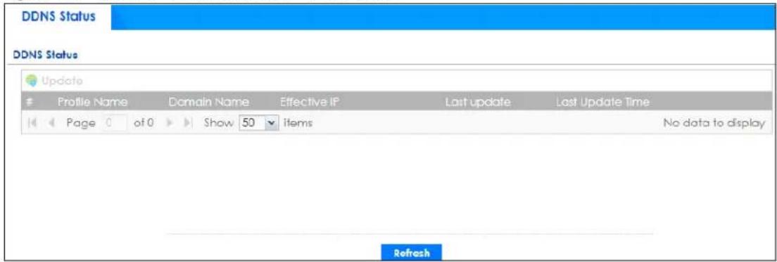
The following table describes the labels in this screen.
Table 48 Monitor > Network Status > DDNS Status
| LABEL DESCRIPTION | |
| Update | Click this to have the Zyxel Device update the profile to the DDNS server. The Zyxel Device attempts to resolve the IP address for the domain name. |
| # This field is a sequential value, and it is not associated with a specific DDNS server. | |
| Profile Name | This field displays the descriptive profile name for this entry. |
| Domain Name | This field displays each domain name the Zyxel Device can route. |
| Effective IP This is the (resolved) IP address of the domain name. | |
| Last Update | This shows whether the last attempt to resolve the IP address for the domain name was successful or not. Updating means the Zyxel Device is currently attempting to resolve the IP address for the domain name. |
| Last Update Time | This shows when the last attempt to resolve the IP address for the domain name occurred (in year-month-day hour:minute:second format). |
| Refresh | Click this button to update the information on the screen. |
6.12 IP/MAC Binding
Click Monitor > Network Status > IP/MAC Binding to open the IP/MAC Binding screen. This screen lists the devices that have received an IP address from Zyxel Device interfaces with IP/MAC binding enabled and have ever established a session with the Zyxel Device. Devices that have never established a session with the Zyxel Device do not display in the list.
Figure 162 Monitor > Network Status > IP/MAC Binding
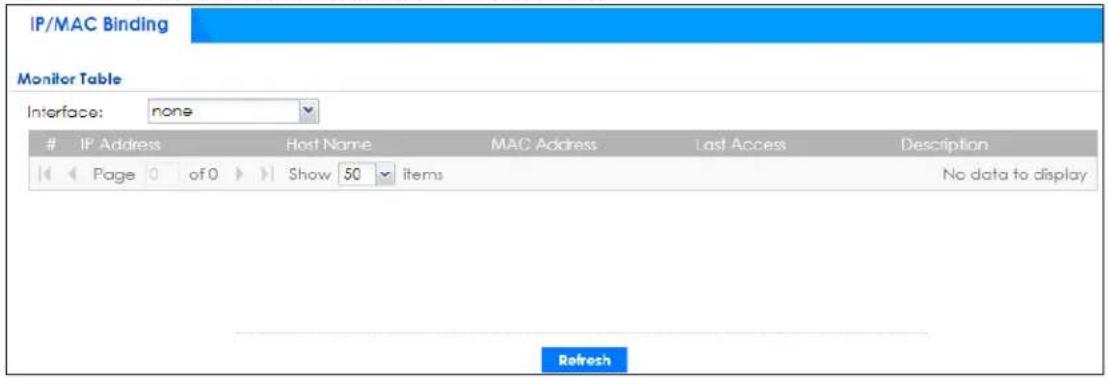
The following table describes the labels in this screen.
Table 49 Monitor > Network Status > IP/MAC Binding
| LABEL DESCRIPTION | |
| Interface | Select a Zyxel Device interface that has IP/MAC binding enabled to show to which devices it has assigned an IP address. |
| # | This field is a sequential value, and it is not associated with a specific IP/MAC binding entry. |
| IP Address This is the IP address that the Zyxel Device assigned to a device. | |
| Host Name | This field displays the name used to identify this device on the network (the computer name). The Zyxel Device learns these from the DHCP client requests. |
| MAC Address | This field displays the MAC address to which the IP address is currently assigned. |
| Last Access | This is when the device last established a session with the Zyxel Device through this interface. |
| Description | This field displays the description of the IP/MAC binding. |
| Refresh Click this button | to update the information on the screen. |
6.13 Cellular Status Screen
This screen displays your mobile broadband connection status. Click Monitor > Network Status > Cellular Status to display this screen.
Figure 163 Monitor > Network Status > Cellular Status
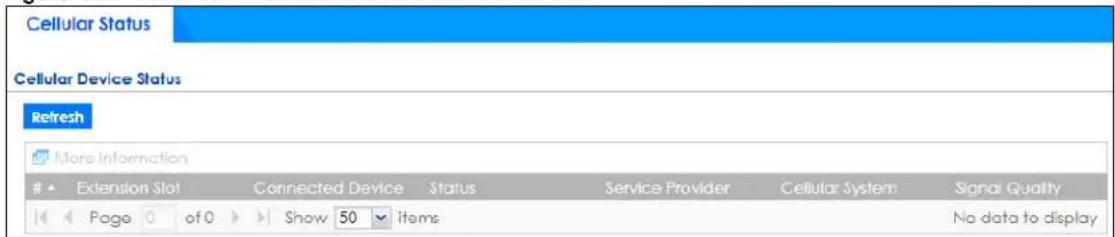
The following table describes the labels in this screen.
Table 50 Monitor > Network Status > Cellular Status
| LABEL DESCRIPTION | |
| Refresh | Click this button to update the information on the screen. |
| More Information | Click this to display more information on your mobile broadband, such as the signal strength, IMEA/ESN and IMSI. This is only available when the mobile broadband device attached and activated on your Zyxel Device. Refer to Section 6.13.1 on page 191. |
| # | This field is a sequential value, and it is not associated with any interface. |
| Extension Slot This field displays where the entry's cellular card is located. | |
| Connected Device This field displays the model name of the cellular card. | |
| Status | No device - no mobile broadband device is connected to the Zyxel Device.No Service - no mobile broadband network is available in the area; you cannot connect to the Internet.Limited Service - returned by the service provider in cases where the SIM card is expired, the user failed to pay for the service and so on; you cannot connect to the Internet.Device detected - displays when you connect a mobile broadband device.Device error - a mobile broadband device is connected but there is an error.Probe device fail - the Zyxel Device's test of the mobile broadband device failed.Probe device ok - the Zyxel Device's test of the mobile broadband device succeeded.Init device fail - the Zyxel Device was not able to initialize the mobile broadband device.Init device ok - the Zyxel Device initialized the mobile broadband card.Check lock fail - the Zyxel Device's check of whether or not the mobile broadband device is locked failed.Device locked - the mobile broadband device is locked.SIM error - there is a SIM card error on the mobile broadband device.SIM locked-PUK - the PUK is locked on the mobile broadband device's SIM card.SIM locked-PIN - the PIN is locked on the mobile broadband device's SIM card.Unlock PUK fail - Your attempt to unlock a WCDMA mobile broadband device's PUK failed because you entered an incorrect PUK.Unlock PIN fail - Your attempt to unlock a WCDMA mobile broadband device's PIN failed because you entered an incorrect PIN.Unlock device fail - Your attempt to unlock a CDMA2000 mobile broadband device failed because you entered an incorrect device code.Device unlocked - You entered the correct device code and unlocked a CDMA2000 mobile broadband device.Get dev-info fail - The Zyxel Device cannot get cellular device information.Get dev-info ok - The Zyxel Device succeeded in retrieving mobile broadband device information.Searching network - The mobile broadband device is searching for a network.Get signal fail - The mobile broadband device cannot get a signal from a network.Network found - The mobile broadband device found a network.Apply config - The Zyxel Device is applying your configuration to the mobile broadband device.Inactive - The mobile broadband interface is disabled.Active - The mobile broadband interface is enabled.Incorrect device - The connected mobile broadband device is not compatible with the Zyxel Device.Correct device - The Zyxel Device detected a compatible mobile broadband device.Set band fail - Applying your band selection was not successful.Set band ok - The Zyxel Device successfully applied your band selection.Set profile fail - Applying your ISP settings was not successful.Set profile ok - The Zyxel Device successfully applied your ISP settings.PPP fail - The Zyxel Device failed to create a PPP connection for the cellular interface.Need auth-password - You need to enter the password for the mobile broadband card on the cellular edit screen.Device ready - The Zyxel Device successfully applied all of your configuration and you can use the mobile broadband connection. |
| Service Provider | This displays the name of your network service provider. This shows Limited Service if the service provider has stopped service to the mobile broadband card. For example if the bill has not been paid or the account has expired. |
| Cellular System | This field displays what type of cellular network the mobile broadband connection is using. The network type varies depending on the mobile broadband card you inserted and could be UMTS, UMTS/HSDPA, GPRS or EDGE when you insert a GSM mobile broadband card, or 1xRTT, EVDO Rev.0 or EVDO Rev.A when you insert a CDMA mobile broadband card. |
| Signal Quality | This displays the strength of the signal. The signal strength mainly depends on the antenna output power and the distance between your Zyxel Device and the service provider's base station. |
6.13.1 More Information
This screen displays more information on your mobile broadband, such as the signal strength, IMEA/ESN and IMSI that helps identify your mobile broadband device and SIM card. Click Monitor > Network Status > Cellular Status > More Information to display this screen.
Note: This screen is only available when the mobile broadband device is attached to and activated on the Zyxel Device.
Figure 164 Monitor > Network Status > Cellular Status > More Information
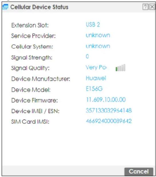
The following table describes the labels in this screen.
Table 51 Monitor > Network Status > Cellular Status > More Information
| LABEL DESCRIPTION | |
| Extension Slot | This field displays where the entry's cellular card is located. |
| Service Provider | This displays the name of your network service provider. This shows Limited Service if the service provider has stopped service to the mobile broadband card. For example if the bill has not been paid or the account has expired. |
| Cellular System | This field displays what type of cellular network the mobile broadband connection is using. The network type varies depending on the mobile broadband card you inserted and could be UMTS, UMTS/ HSDPA, GPRS or EDGE when you insert a GSM mobile broadband card, or 1xRTT, EVDO Rev.0 or EVDO Rev.A when you insert a CDMA mobile broadband card. |
| Signal Strength | This is the Signal Quality measured in dBm. |
| Signal Quality | This displays the strength of the signal. The signal strength mainly depends on the antenna output power and the distance between your Zyxel Device and the service provider's base station. |
| Device Manufacturer | This shows the name of the company that produced the mobile broadband device. |
| Device Model This field displays the model name of the cellular card. | |
| Device Firmware This shows the software version of the mobile broadband device. | |
| Device IMEI/ESN | IMEI (International Mobile Equipment Identity) is a 15-digit code in decimal format that identifies the mobile broadband device.ESN (Electronic Serial Number) is an 8-digit code in hexadecimal format that identifies the mobile broadband device. |
| SIM Card IMSI | IMSI (International Mobile Subscriber Identity) is a 15-digit code that identifies the SIM card. |
6.14 The UPnP Port Status Screen
Use this screen to look at the NAT port mapping rules that UPnP creates on the Zyxel Device. To access this screen, click Monitor > Network Status > UPnP Port Status.
Figure 165 Monitor > Network Status > UPnP Port Status
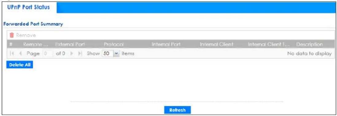
The following table describes the labels in this screen.
Table 52 Monitor > Network Status > UPnP Port Status
| LABEL DESCRIPTION | |
| Remove Select an entry and click this button to remove it from the list. | |
| # | This is the index number of the UPnP-created NAT mapping rule entry. |
| LABEL DESCRIPTION | |
| Remote Host | This field displays the source IP address (on the WAN) of inbound IP packets. Since this is often a wild-card, the field may be blank.When the field is blank, the Zyxel Device forwards all traffic sent to theExternal Porton the WAN interface to theInternal Clienton theInternal Port.When this field displays an external IP address, the NAT rule has the Zyxel Device forward inbound packets to theInternal Clientfrom that IP address only. |
| External Port | This field displays the port number that the Zyxel Device “listens” non the WAN port) for connection requests destined for the NAT rule’sInternal PortandInternal Client. The Zyxel Device forwards incoming packets (from the WAN) with this port number to theInternal Clienton theInternal Port(on the LAN). If the field displays “0”, the Zyxel Device ignores theInternal Portvalue and forwards requests on all external port numbers (that are otherwise unmapped) to theInternal Client. |
| Protocol This field displays the protocol of the NAT mapping rule (TCP or UDP). | |
| Internal Port | This field displays the port number on theInternal Clientto which the Zyxel Device should forward incoming connection requests. |
| Internal Client | This field displays the DNS host name or IP address of a client on the LAN. Multiple NAT clients can use a single port simultaneously if the internal client field is set to 255.255.255.255 for UDP mappings. |
| Internal Client Type | This field displays the type of the client application on the LAN. |
| Description This field | displays a text explanation of the NAT mapping rule. |
| Delete All Click this to | remove all mapping rules from the NAT table. |
| Refresh | Click this button to update the information on the screen. |
6.15 USB Storage Screen
This screen displays information about a connected USB storage device. Click Monitor > Network Status > USB Storage to display this screen.
Figure 166 Monitor > Network Status > USB Storage
| Storage Information | |
| Information | |
| Device Description: | N/A |
| Usage: | N/A |
| File System: | N/A |
| Speed: | N/A |
| Status: | none |
| Detail: | none |
The following table describes the labels in this screen.
Table 53 Monitor > Network Status > USB Storage
| LABEL DESCRIPTION | |
| Device description This is a | basic description of the type of USB device. |
| Usage | This field displays how much of the USB storage device's capacity is currently being used out of its total capacity and what percentage that makes. |
| Filesystem | This field displays what file system the USB storage device is formatted with. This field displaysUnknownif the file system of the USB storage device is not supported by the Zyxel Device, such as NTFS. |
| Speed | This field displays the connection speed the USB storage device supports. |
| Status | Ready- you can have the Zyxel Device use the USB storage device.ClickRemove Nowto stop the Zyxel Device from using the USB storage device so you can remove it.Unused- the connected USB storage device was manually unmounted by using the Remove Nowbutton or for some reason the Zyxel Device cannot mount it.ClickUse Itto have the Zyxel Device mount a connected USB storage device. This button is grayed out if the file system is not supported (unknown) by the Zyxel Device. none- no USB storage device is connected. |
| Detail | This field displays any other information the Zyxel Device retrieves from the USB storage device.Deactivated- the use of a USB storage device is disabled (turned off) on the Zyxel Device.OutofSpace- the available disk space is less than the disk space full threshold.Mounting- the Zyxel Device is mounting the USB storage device.Removing- the Zyxel Device is unmounting the USB storage device. none- the USB device is operating normally or not connected. |
6.16 Ethernet Neighbor Screen
The Ethernet Neighbor screen allows you to view the Zyxel Device's neighboring devices in one place.
It uses Smart Connect, that is Link Layer Discovery Protocol (LLDP) for discovering and configuring LLDP-aware devices in the same broadcast domain as the Zyxel Device that you're logged into using the web configurator.
LLDP is a layer-2 protocol that allows a network device to advertise its identity and capabilities on the local network. It also allows the device to maintain and store information from adjacent devices which are directly connected to the network device. This helps you discover network changes and perform necessary network reconfiguration and management.
Note: Enable Smart Connect on the System > ZON screen.
See also System > ZON for more information on the Zyxel One Network (ZON) utility that uses the Zyxel Discovery Protocol (ZDP) for discovering and configuring ZDP-aware Zyxel devices on the same network as the computer on which the ZON utility is installed.
Click Monitor > Network Status > Ethernet Neighbor to see the following screen
Figure 167 Monitor > Network Status > Ethernet Neighbor
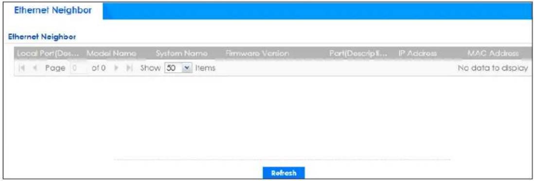
The following table describes the fields on the previous screen.
Table 54 Monitor > Network Status > Ethernet Neighbor
| LABEL DESCRIPTION | |
| Local Port (Description) | This field displays the port of the Zyxel Device, on which the neighboring device is discovered.For Zyxel Devices that supportPort Role, if ports 3 to 5 are grouped together and there is a connection to P5 only, the Zyxel Device will display P3 as the interface port number (even though there is no connection to that port). |
| Model Name This field displays the model name of the discovered device. | |
| System Name This field displays the system name of the discovered device. | |
| Firmware Version This field displays the firmware version of the discovered device. | |
| Port (Description) | This field displays the first internal port on the discovered device. Internal is an interface type displayed on theNetwork > Interface > Ethernet > Editscreen. For example, if P1 and P2 are WAN, P3 to P5 are LAN, and P6 is DMZ, then Zyxel Device will display P3 as the first internal interface port number.For Zyxel Devices that supportPort Role, if ports 3 to 5 are grouped together and there is a connection to P5 only, the Zyxel Device will display P3 as the first internal interface port number (even though there is no connection to that port). |
| IP Address This field displays the IP address of the discovered device. | |
| MAC Address This field displays the MAC address of the discovered device. | |
| Refresh Click this button to update the information on the screen. | |
6.17 FQDN Object Screen
Click Monitor > Network Status > FQDN Object to open the FQDN Object screen. View FQDN-to-IP address mappings cached in this screen. An FQDN is resolved to its IP address using the DNS server configured on the Zyxel Device. If the Zyxel Device receives a DNS query for an FQDN and the Zyxel Device has an FQDN cache entry, the Zyxel Device can map the IP address in a DNS response without having to query a DNS name server. The Zyxel Device updates FQDN-to-IP address mappings when the TTL (Time To Live) setting expires.
You can configure FQDN objects in Configuration > Object > Address/ Geo IP > Address or Configuration > Object > Address/ Geo IP > Address Group.
FQDN can be used in Security Policy, Policy Route, BWM and Web Authentication profiles as source and destination criteria. FQDN with a wildcard (for example, *.zyxel.com) can be used in these profiles as destination criteria only.
Suppose you want to block certain users from going to a website with a dynamically updated IP address using DDNS. Create an FQDN object for the website in Object > Address, and then create a Security Policy in Security Policy > Policy Control > Add. Use the FQDN object to identify the website as a destination, and configure specific users to block. When a user tries to connect to the forbidden website, the Zyxel Device first checks the IP address - website mapping in response to the DNS query and then finds the FQDN object match. The Security Policy that has this FQDN object match can then block the configured users from accessing the website.
Figure 168 Monitor > Network Status > FQDN Object
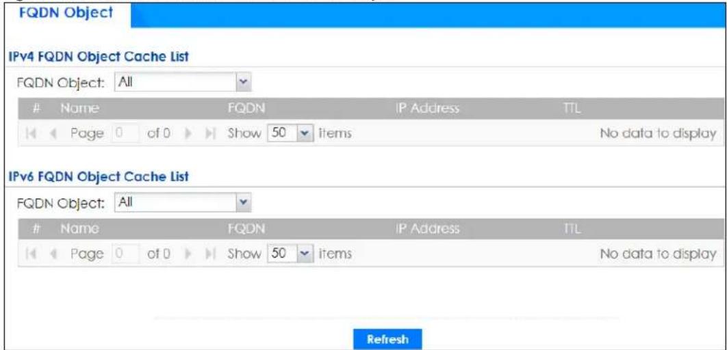
The following table describes the fields on the previous screen.
Table 55 Monitor > Network Status > FQDN Object
| LABEL DESCRIPTION | |
| IPv4 FQDN Object Cache ListYou must first configure IPv4 FQDN objects inConfiguration > Object > Address/ Geo IP in the IPv4 Address Configuration field. | |
| FQDN Object | Select a previously created object from the drop-down list box to display related FQDN object caches used in DNS queries. |
| # This is the index number of the FQDN entry. | |
| Name This field displays the name of the selected FQDN object used in DNS queries. | |
| FQDN This field displays a host's fully qualified domain name. | |
| IP Address | This field displays the mapping of the FQDN to an IP address. This is the IP address of a host. |
| TTL This field displays the number of seconds the Zyxel Device holds IP address - FQDN object mapping in its cache. The mapping is updated when the TTL (Time To Live) setting expires. | |
| IPv6 FQDN Object Cache ListYou must first configure IPv6 FQDN objects inConfiguration > Object > Address/ Geo IP in the IPv6 Address Configuration field. | |
Table 55 Monitor > Network Status > FQDN Object
| LABEL DESCRIPTION | |
| FQDN Object | Select an object from the drop-down list box to display related IPv6 FQDN object caches used in DNS queries. |
| # This is the index number of | the IPv6 FQDN entry. |
| Name This field displays the | name of the selected IPv6 FQDN object used in DNS queries. |
| FQDN This field displays a host's fully qualified domain name. | |
| IP Address | This field displays the mapping of the FQDN to an IPv6 address. This is the IPv6 address of a host. |
| TTL This field displays the num | ber of seconds the Zyxel Device holds IP address - FQDN object mapping in its cache. The mapping is updated when the TTL (Time To Live) setting expires. |
| Refresh Click this button to | update the information on the screen. |
6.18 Virtual Server Load Balancing
Virtual server load balancing allows you to distribute incoming connection requests to a virtual server between multiple real (physical) servers. This helps reduce each server's workload and to decrease virtual server response times.
Use this screen to view traffic statistics between a client and a real server. You can then assess if loading among real servers is balanced. If not, you may need to change the loading algorithm.
Please see Section 12.5 on page 474 for more information on virtual load balancing server.
Click Monitor > Network Status > Virtual Server LB to see the following screen
Figure 169 Monitor > Network Status > Virtual Server LB
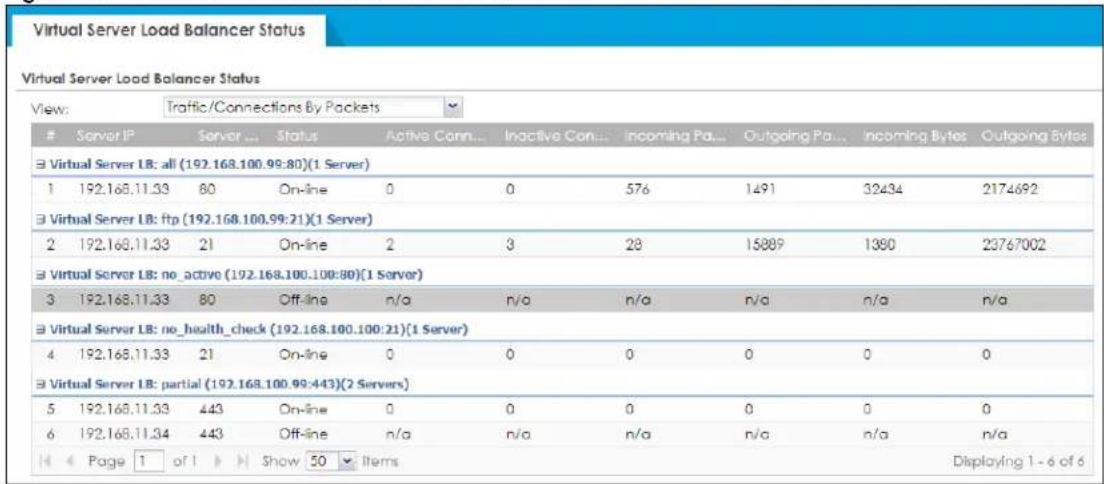
The following table describes the labels in this screen.
Table 56 Monitor > Network Status > Virtual Server LB
| LABEL DESCRIPTION | |
| View Select how to view the virtual server load balancing traffic. | |
| # This is the index number of a table entry. | |
| Server IP | This field displays the IP address of the real server to which the virtual server load balancing traffic is coming from/going to. |
| Server Port | This field displays the port number on the real server that identifies the service the client requested. |
| Status | This field displays the result of the health check. If the health check fails, it will display Off-line, if the health check is OK, it displays On-line. |
| The following fields display when you choose Traffic/Connections By Packets | |
| Active Connection | This field displays the number of active connections between the real server and clients for the specified service. |
| Inactive Connection | This field displays the number of once active, but now idle connections between the real server and clients for the specified service. |
| Incoming Packets | This field displays the number of packets going to the real server from clients for the specified service. |
| Outgoing Packets | This field displays the number of packets coming from the real server to clients for the specified service. |
| Incoming Bytes | This field displays the number of bytes going to the real server from clients for the specified service. |
| Outgoing Bytes | This field displays the number of bytes coming from the real server to clients for the specified service. |
| The following fields display when you choose Traffic/Connections By Rates | |
| Connections/s | This field displays the number of connections per second between the real server and clients for the specified service. |
| Incoming Packets/s | This field displays the number of packets per second going to the real server from clients for the specified service. |
| Outgoing Packets/s | This field displays the number of packets per second coming from the real server to clients for the specified service. |
| Incoming Bytes/s | This field displays the number of bytes per second going to the real server from clients for the specified service. |
| Outgoing Bytes/s | This field displays the number of bytes per second coming from the real server to clients for the specified service. |
| Refresh | Click this button to update the information on the screen. |
6.19 AP Information: AP List
The AP Information menu contains AP List, Radio List, Top N APs and Single AP screens. Click Monitor > Wireless > AP Information to display the AP List screen.
Figure 170 Monitor > Wireless > AP Information > AP List
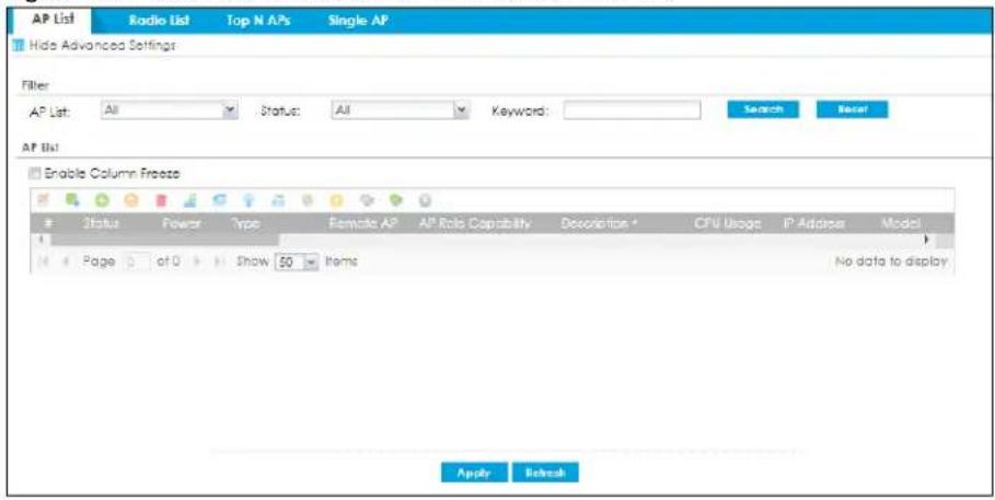
The following table describes the labels in this screen.
Table 57 Monitor > Wireless > AP Information > AP List
| LABEL DESCRIPTION | |
| Filter | Click Show Advanced Settings to reveal Filter fields where you can display managed APs by status, keyword or those managed by the Nebula portal. |
| AP List Select the type | of APs you want to display.Select All to show all kinds of APs that are currently or used to be connected to the Zyxel Device.Select NebulaFlexPRO to show the APs that can work in Nebula cloud management mode. |
| Status Select the status | of APs you want to display.You can display APs managed by the Zyxel Device according to the following:Online All: APs that are online now + APs with configuration conflict + APs with non-supported features + APs that are now updating firmwareOnline: APs that are online nowConflict: APs with configurations in conflict with the Zyxel Device (see More Details)Non Support: APs with features not supported by the Zyxel Device (see More Details)Updating: APs that are have updated firmware and rebootedOffline All: Offline + Offline for Firmware UpdateOffline: The CAPWAP server did not receive keep-alive packets from these APs in the last 2 minutes (Offline All - Offline for Firmware Update)Offline for Firmware Update: APs that were rebooted before updating firmwareUn-Mgmt: APs that are not managed by the Zyxel Device |
| Keyword | Enter a keyword to display the APs that include it in their AP information, such as model number, firmware version, MAC address and so on. This field is case-sensitive. |
| Search Click this to update | date the list of APs based on the search criteria.Your search criteria is retained when navigating between screens. |
| Reset | Click this to return the search criteria to the factory defaults and display all currently or previously connected APs without a filter. |
| Enable Column Freeze | Select this to lock the index columns in place while scrolling to the right. |
| Edit the selected rule | Select an AP and click this to change the selected AP's properties, such as its group, radio, VLAN and port settings. |
| Add to Mgmt AP List | Select an AP and click this to add the selected AP to the managed AP list. |
| Reboot device | Select one or multiple APs and click this button to force the AP(s) to restart. |
| Remove the selected rule | Select one or multiple APs and click this button to remove the AP(s) from the manged AP list.Note: If on theConfiguration > Wireless > Controllerscreen you set theRegistration Type to Always Accept, then as soon as you remove an AP from this list it reconnects. |
| DCS Now | Select one or multiple APs and click this button to use DCS (Dynamic Channel Selection) to allow the AP to automatically find a less-used channel in an environment where there are many APs and there may be interference.Note: You should have enabled DCS in the applied AP radio profile before the APs can use DCS.Note: DCS is not supported on the radio which is working in repeater AP mode. |
| More Information | Select an AP and click this to view a daily station count about the selected AP. The count records station activity on the AP over a consecutive 24 hour period. |
| Radio Information | Select an online AP and click this button to go to theMonitor > Wireless > AP Information > Radio Listscreen to view detailed information about the AP's radios. |
| Query Controller Log | Select one or multiple APs and click this button to go to theMonitor > Log > View Logscreen to view the selected AP's current log messages. |
| Nebula | Select an AP and click this to open a screen where you can set whether the AP's IP address and VLAN settings will be changed when it goes into Nebula cloud management mode.Note: The AP will be set to Nebula cloud management mode and removed from the managed AP list right after you clickOK. |
| Upgrade Firmware Now | Select one or more APs and click this button to update the APs' firmware version. |
| Suppression On | Select an AP and click this button to enable the AP's LED suppression mode. All the LEDs of the AP will turn off after the AP is ready. This button is not available if the selected AP doesn't support suppression mode. |
| Suppression Off | Select an AP and click this button to disable the AP's LED suppression mode. The AP LEDs stay lit after the AP is ready. This button is not available if the selected AP doesn't support suppression mode. |
| Locator On | Select an AP and click this button to run the locator feature. The AP's Locator LED will start to blink for 10 minutes by default. It will show the actual location of the AP between several devices on the network. |
| # This field is a sequential value, and it is not associated with any entry. | |
| Status This field displays the status of AP.Online All: APs that are online now + APs with configuration conflict + APs with non-supported features + APs that are now updating firmwareOnline: APs that are online nowConflict: APs with configurations in conflict with the Zyxel Device (see More Details)Non Support: APs with features not supported by the Zyxel Device (see More Details)Updating: APs that are have updated firmware and rebootedOffline All: Offline + Offline for Firmware UpdateOffline: The CAPWAP server did not receive keep-alive packets from these APs in the last 2 minutes (Offline All - Offline for Firmware Update)Offline for Firmware Update: APs that were rebooted before updating firmwareUn-Mgmt: APs that are not managed by the Zyxel Device | |
| Description | This field displays the AP's description, which you can configure by selecting the AP's entry and clicking theEditbutton. |
| CPU Usage This field displays the CPU Usage of the AP. | |
| IP Address This field displays the IP address of the AP. | |
| MAC Address This field displays the MAC address of the AP. | |
| Station 2.4G | This field displays the number of 2.4G wireless clients connected to the AP. |
| Station 5G This field displays the number of 5G wireless clients connected to the AP. | |
| Station 6G This field displays the number of 6G wireless clients connected to the AP. | |
| Recent Online Time | This displays the most recent time the AP came on-line. N/A displays if the AP has not come on-line since the Zyxel Device last started up. |
| Power This field displays the AP's power status.Full - the AP receives power using a power adapter and/or through a PoE switch/injector using IEEE 802.3at PoE plus. The PoE device that supports IEEE 802.3at PoE Plus can supply power of up to 30W per Ethernet port.Limited - the AP receives power through a PoE switch/injector using IEEE 802.3af PoE even when it is also connected to a power source using a power adaptor. The PoE device that supports IEEE 802.3af PoE can supply power of up to 15.4W per Ethernet port.When the AP is in limited power mode, the AP throughput decreases and has just one transmitting radio chain.It always shows Full if the AP does not support power detection. | |
| Type | This indicates whether the AP is on the managed AP list (Mgmt) or not (Un-Mgmt).This displays Limited when the AP is configured by conflicted or unsupported setting(s). |
| Model | This field displays the AP's hardware model information. It displays N/A (not applicable) only when the AP disconnects from the Zyxel Device and the information is unavailable as a result. |
| R1 Mode/ Profile/ZyMesh Profile | This field displays the operating mode (AP, MON, rootap, or repeater), AP radio profile name and ZyMesh profile name for Radio1. It displays - for the ZyMesh profile for a radio not using a ZyMesh profile. |
| R2 Mode/ Profile/ZyMesh Profile | This field displays the operating mode (AP, MON, rootap, or repeater), AP radio profile name and ZyMesh profile name for Radio2. It displays - for the ZyMesh profile for a radio not using a ZyMesh profile. |
| R3 Mode/ Profile/ZyMesh Profile | This field displays the operating mode (AP, MON, rootap, or repeater), AP radio profile name and ZyMesh profile name for Radio3. It displays - for the ZyMesh profile for a radio not using a ZyMesh profile. |
| Version This field displays the AP's current firmware version. | |
| Group This displays the name of the AP group to which the AP belongs. | |
| Mgmt. VLAN ID (AC/AP) | This displays the Access Controller (the Zyxel Device) and runtime management VLAN ID setting for the AP. VLAN Conflict displays if the AP's management VLAN ID does not match the Mgmt. VLAN ID(AC). This field displays n/a if the Zyxel Device cannot get VLAN information from the AP. |
| Last Off-line Time | This field displays the date and time that the AP was last logged out. |
| LED Status This field displays the AP LED status. | |
| N/A displays if the AP does not support LED suppression mode and/or have a locator LED to show the actual location of the AP.A gray LED icon signifies that the AP LED suppression mode is enabled. All the LEDs of the AP will turn off after the AP is ready.A green LED icon signifies that the AP LED suppression mode is disabled and the AP LEDs stay lit after the AP is ready.A sun icon signifies that the AP's locator LED is blinking.A circle signifies that the AP's locator LED is extinguished. | |
| Ethernet Uplink | This field displays the AP's uplink port speed and duplex mode (Full or Half). |
| Bluetooth | This field displays the AP's Bluetooth Low Energy (BLE) capability. Bluetooth Low Energy, which is also known as Bluetooth Smart, transmits less data over a shorter distance and consumes less power than classic Bluetooth. APs communicate with other BLE enabled devices using advertisements.N/A displays if the AP does not support BLE.Unavailable displays if the AP supports Bluetooth, but there is no BLE USB dongle connected to the USB port of the AP. Some APs, such as the WAC5302D-S, need to have a supported BLE USB dongle attached to act as a beacon to broadcast packets.Available displays if the AP supports Bluetooth, detects a BLE device and advertising is inactive.Advertising displays if the AP supports Bluetooth, detects a BLE device and advertising is activated, which means the BLE device can broadcasts packets to every device around it. |
| Location This field displays the AP's location you configured. | |
| Roaming Group | This field displays the name of roaming group to which the AP belongs. |
| Load Balancing Group | This field displays the AP's load balance status when load balancing is enabled on the Zyxel Device. Otherwise, it shows nothing when load balancing is disabled or the radio is in monitor mode. |
| S/N This field displays the serial number of the AP. | |
| System Name This field | displays the system name to identify the AP on a network. |
| Apply | Click Apply to save your changes back to the Zyxel Device. |
| Refresh | Click Refresh to update the AP list. |
The following table describes the icons in this screen.
Table 58 Monitor > Wireless > AP Information > AP List Icons
| LABEL DESCRIPTION | |
| This AP is not on the management list. | |
| This AP is on the management list and online. | |
| This AP is in the process of having its firmware updated. | |
| This AP is on the management list but offline. | |
| This indicates one of the following cases:This AP has a runtime management VLAN ID setting that conflicts with the VLAN ID setting on the Access Controller (the Zyxel Device).A setting the Zyxel Device assigns to this AP does not match the AP's capability. | |
6.19.1 AP List: More Information
Use this screen to look at:
• Station statistics for the connected AP.
- Configuration information, port status and station statistics for the connected AP.
To access this screen, select an entry and click the More Information button on the AP List screen.
Figure 171 Monitor > Wireless > AP Information > AP List > More Information
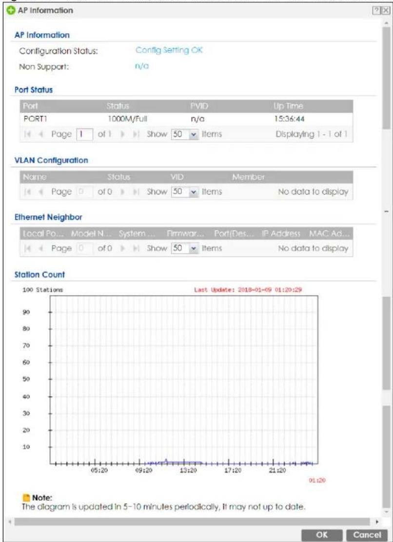
The following table describes the labels in this screen.
Table 59 Monitor > Wireless > AP Information > AP List > More Information
| LABEL DESCRIPTION | |
| Configuration Status | This displays whether or not any of the AP's configuration is in conflict with the Zyxel Device's settings for the AP. |
| Conflict | If any of the AP's configuration conflicts with the ZyWALL's settings for the AP, this field displays which configuration conflicts. It displays n/a if none of the AP's configuration conflicts with the ZyWALL's settings for the AP. |
| Non Support | If any of the AP's configuration conflicts with the Zyxel Device's settings for the AP, this field displays which configuration conflicts. It displays n/a if none of the AP's configuration conflicts with the Zyxel Device's settings for the AP. |
| Port Status | |
| Port | This shows the name of the physical Ethernet port on the Zyxel Device. |
| Status This field displays the current status of each physical port on the AP. Down - The port is not connected. Speed / Duplex - The port is connected. This field displays the port speed and duplex setting (Full or Half). | |
| PVID This shows the port's PVID. A PVID (Port VLAN ID) is a tag that adds to incoming untagged frames received on a port so that the frames are forwarded to the VLAN group that the tag defines. | |
| Up Time This field displays how long the physical port has been connected. | |
| Tx Bcast | This field displays the number of broadcast packets transmitted on the port. |
| Rx Bcast This field displays the number of broadcast packets received on the port. | |
| VLAN Configuration | |
| Name This shows the name of the VLAN. | |
| Status This displays whether or not the VLAN is activated. | |
| VID This shows the VLAN ID number. | |
| Member This field displays the Ethernet port(s) that is a member of this VLAN. | |
| Ethernet Neighbor | |
| Local Port (Description) | This field displays the port of the Zyxel Device, on which the neighboring device is discovered. For Zyxel Devices that support Port Role, if ports 3 to 5 are grouped together and there is a connection to P5 only, the Zyxel Device will display P3 as the interface port number (even though there is no connection to that port). |
| Model Name This field displays the model name of the discovered device. | |
| System Name This field displays the system name of the discovered device. | |
| Firmware Version | This field displays the firmware version of the discovered device. |
| Port (Description) | This field displays the first internal port on the discovered device. Internal is an interface type displayed on the Network > Interface > Ethernet > Edit screen. For example, if P1 and P2 are WAN, P3 to P5 are LAN, and P6 is DMZ, then Zyxel Device will display P3 as the first internal interface port number. For Zyxel Devices that support Port Role, if ports 3 to 5 are grouped together and there is a connection to P5 only, the Zyxel Device will display P3 as the first internal interface port number (even though there is no connection to that port). |
| IP Address This field displays the IP address of the discovered device. | |
| MAC Address | This field displays the MAC address of the discovered device. |
| LABEL DESCRIPTION | |
| Station Count | |
| The y-axis represents the number of connected stations. | |
| The x-axis shows the time over which a station was connected. | |
| Last Update | This field displays the date and time the information in the window was last updated. |
| OK | Click OK to save your changes back to the Zyxel Device. |
| Cancel | Click Cancel to exit this screen without saving your changes. |
6.19.2 AP List: Edit AP
Select an AP and click the Edit Selected Rule button in the Monitor > Wireless > AP Information > AP List table to display this screen.
Figure 172 Monitor > Wireless > AP Information > AP List > Edit AP
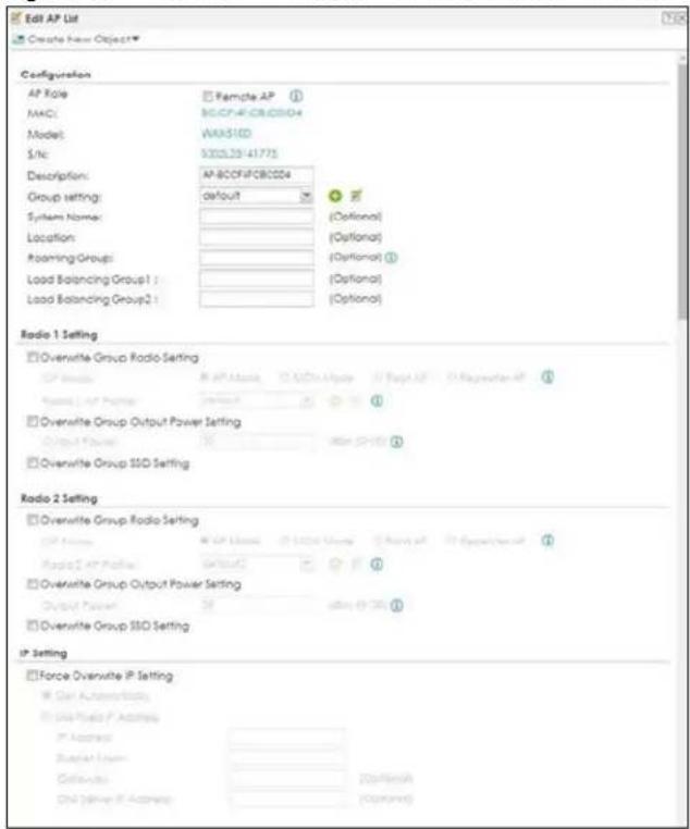
Figure 173 Monitor > Wireless > AP Information > AP List > Edit AP (continued)
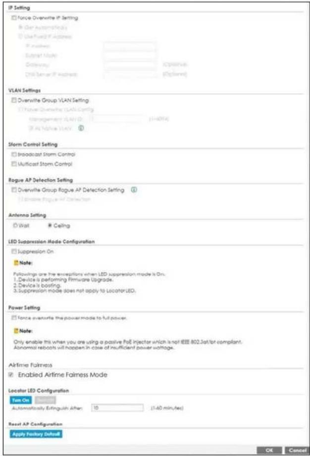
Each field is described in the following table.
Table 60 Monitor > Wireless > AP Information > AP List > Edit AP
| LABEL DESCRIPTION | |
| Create new Object | Use this menu to create a new Radio Profile object to associate with this AP. |
| MAC This displays the | MAC address of the selected AP. |
| Model | This field displays the AP's hardware model information. It displays N/A (not applicable) only when the AP disconnects from the Zyxel Device and the information is unavailable as a result. |
| Description | Enter a description for this AP. You can use up to 31 characters, spaces and underscores allowed. |
| Group Setting Select on AP group to which you want this AP to belong. | |
| System Name | Enter a name to identify the AP on a network. This is usually the AP's fully qualified domain name. |
| Location Specify the name of the place where the AP is located. | |
| Roaming Group | Specify the name of the roaming group to which the AP belongs. You can use up to 31 alphanumeric and @# characters. Dashes and underscores are also allowed. The name should start with a letter or digit.The 802.11k neighbor list a client requests from the AP is generated according to the roaming group and RCPI (Received Channel Power Indicator) value of its neighbor APs.When a client wants to roam from the current AP to another, other APs in the same roaming group or not in a roaming group will be candidates for roaming. Neighbor APs in a different roaming group will be excluded from the 802.11k neighbor lists even when the neighbor AP has the best signal strength.If the AP's roaming group is not configured, any neighbor APs can be candidates for roaming. |
| Load Balancing Group 1/2 | Load balancing is only applied to APs within the same group. If a load balancing group is not assigned to an AP, it will belong to a default group.Each AP can belong to up to two groups. |
| Radio 1/2/3 Setting | |
| Override Group Radio Setting | Select this option to overwrite the AP radio settings with the settings you configure here. |
| Radio 1/2/3 OP Mode | Select the operating mode for radio 1, radio 2 or radio 3.AP Mode means the AP can receive connections from wireless clients and pass their data traffic through to the Zyxel Device to be managed (or subsequently passed on to an upstream gateway for managing).MON Mode means the AP monitors the broadcast area for other APs, then passes their information on to the Zyxel Device where it can be determined if those APs are friendly or rogue. If an AP is set to this mode it cannot receive connections from wireless clients. |
| Radio 1/2/3 Profile | Select a profile from the list. If no profile exists, you can create a new one through the Create new Object menu. |
| Override Group Output Power Setting | Select this option to overwrite the AP output power setting with the setting you configure here. |
| Output Power Set the | output power of the AP. |
| Override Group SSID Setting | Select this option to overwrite the AP SSID profile setting with the setting you configure here.This section allows you to associate an SSID profile with the radio. |
| Edit | Select an SSID and click this button to reassign it. The selected SSID becomes editable immediately upon clicking. |
| # | This is the index number of the SSID profile. You can associate up to eight SSID profiles with an AP radio. |
| SSID Profile Indicates which SSID profile is associated with this radio profile. | |
| IP Setting | |
| Force Overwrite IP Setting | Select this to change the AP's IP address setting to match the configuration in this screen. |
| Get Automatically | Select this to have the AP act as a DHCP client and automatically get the IP address, subnet mask, and gateway address from a DHCP server. |
| Used Fixed IP Address | Select this if you want to specify the IP address, subnet mask, gateway and DNS server address manually. |
| IP Address Enter the IP | address for the AP. |
| Subnet Mask | Enter the subnet mask of the AP in dot decimal notation. The subnet mask indicates what part of the IP address is the same for all devices in the network. |
| Gateway | Enter the IP address of the gateway. The AP sends packets to the gateway when it does not know how to route the packet to its destination. The gateway should be on the same network as the AP. |
| DNS Server IP Address | Enter the IP address of the DNS server. |
| VLAN Settings | |
| Override Group VLAN Setting | Select this option to overwrite the AP VLAN setting with the setting you configure here. |
| Force Overwrite VLAN Config | Select this to have the Zyxel Device change the AP's management VLAN to match the configuration in this screen. |
| Management VLAN ID | Enter a VLAN ID for this AP. |
| As Native VLAN | Select this option to treat this VLAN ID as a VLAN created on the Zyxel Device and not one assigned to it from outside the network. |
| Storm Control Setting | Traffic storm control limits the number of broadcast and/or multicast packets the Zyxel Device receives on the ports. When the maximum number of allowable broadcast and/or multicast packets is reached, the subsequent packets are discarded.Select Broadcast Storm Control to enable broadcast storm control on the Zyxel Device.Enabling this will drop ingress broadcast traffic in the physical Ethernet port if it exceeds the maximum traffic rate.Select Multicast Storm Control to enable multicast storm control on the Zyxel Device.Enabling this will drop ingress multicast traffic in the physical Ethernet port if it exceeds the maximum traffic rate. |
| Rogue AP Detection Setting | This feature allows the Zyxel Device to monitor the WiFi signals for other wireless APs. A rogue AP is a wireless access point operating in a network's coverage area that is not under the control of the network administrator, and which can potentially open up holes in a network's security.Select this check box to detect Rogue APs in the network. |
| Antenna Setting | Select Wall if you mount the Zyxel Device to a wall. Select Ceiling if the Zyxel Device is mounted on a ceiling. You can switch from Wall to Ceiling if there are still wireless dead zones, and vice versa. |
| LED Suppression Mode Configuration | If the Suppression On check box is checked, the LEDs of yourZyxel Device will turn off after it's ready.If the check box is unchecked, the LEDs will stay lit after theZyxel Device is ready. |
| Power Setting | Select this check box if you are using a PoE injector that does not support PoE negotiation.Otherwise, the Zyxel Device cannot draw full power from the power sourcing equipment.Enable this power mode to improve the Zyxel Device's performance in this situation.Note: Ensure that the power sourcing equipment can supply enough power to the AP to avoid abnormal system reboots.Note: Only enable this if you are using a passive PoE injector that is not IEEE 802.3at/bt compliant but can still provide full power. |
| Locator LED Configuration | Click Turn On button to activate the locator. The Locator function will show the actual location of the Zyxel Device between several devices in the network.Otherwise, click Turn Off to disable the locator feature. |
| Automatically Extinguish After | Enter a time interval between 1 and 60 minutes to stop the locator LED from blinking.Default is 10 minutes. |
| Reset APConfiguration | ClickApply Factory Defaultto reset all of the AP settings to the factory defaults. |
| OK | Click OKto save your changes back to the Zyxel Device. |
| Cancel | Click Cancelto close the window with changes unsaved. |
6.20 AP Information: Radio List
Click Monitor > Wireless > AP Information > Radio List to display the Radio List screen.
Figure 174 Monitor > Wireless > AP Information > Radio List
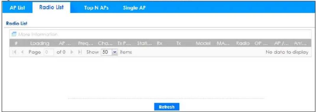
Figure 175 Monitor > Wireless > AP Information > Radio List (Built-in AP Mode)
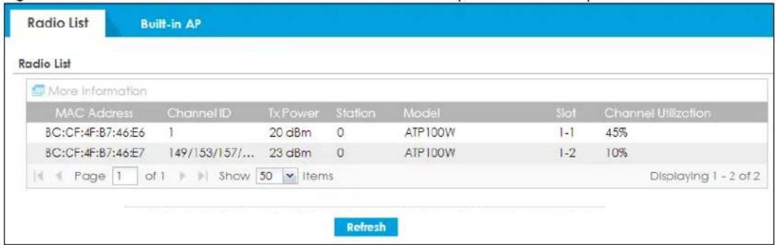
The following table describes the labels in this screen.
Table 61 Monitor > Wireless > AP Information > Radio List
| LABEL DESCRIPTION | |
| More Information | Click this icon to see the traffic statistics, station count, SSID, Security Mode and VLAN ID information on the AP. |
| Enable Column Freeze | Select this to lock the index columns in place while scrolling to the right. |
| # This field is a sequential value, and it is not associated with a specific radio. | |
| Loading | This indicates the AP's load balance status (UnderLoad or OverLoad) when load balancing is enabled on the AP. Otherwise, it shows - when load balancing is disabled or the radio is in monitor mode. |
Table 61 Monitor > Wireless > AP Information > Radio List
| LABEL DESCRIPTION | |
| AP Description | Enter a description for this AP. You can use up to 31 characters, spaces and underscores allowed. |
| Frequency Band | This field displays the WLAN frequency band using the IEEE 802.11 a/b/g/n standard of 2.4 or 5 GHz. |
| Channel ID This field displays the WLAN channels using the IEEE 802.11 protocols. | |
| Tx Power This shows the radio's output power (in dBm). | |
| Station This field displays the station count information. | |
| Rx This field displays the total number of bytes received by the radio. | |
| Tx This field displays the total number of bytes transmitted by the radio. | |
| Model | This field displays the AP's hardware model information. It displays N/A (not applicable) only when the AP disconnects from the Zyxel Device and the information is unavailable as a result. |
| MAC Address This field displays the MAC address of the AP. | |
| Radio This field displays the Radio number. For example 1. | |
| OP Mode | This field displays the operating mode of the AP. It displays n/a for the profile for a radio not using an AP profile.AP Mode means the AP can receive connections from wireless clients and pass their data traffic through to the Zyxel Device to be managed (or subsequently passed on to an upstream gateway for managing). |
6.20.1 Radio List: More Information
This screen allows you to view detailed information about a selected radio's SSID(s), wireless traffic and wireless clients for the preceding 24 hours. To access this window, select an entry and click the More Information button on the Radio List screen.
Figure 176 Monitor > Wireless > AP Information > Radio List > More Information
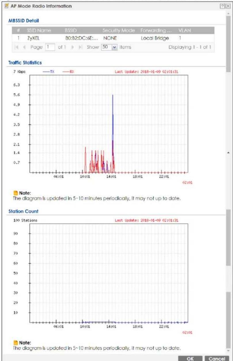
The following table describes the labels in this screen.
Table 62 Monitor > Wireless > AP Information > Radio List > More Information
| LABEL DESCRIPTION | |
| MBSSID Detail | This list shows information about the SSID(s) that is associated with the radio over the preceding 24 hours. |
| # | This is the items sequential number in the list. It has no bearing on the actual data in this list. |
| SSID Name | This displays an SSID associated with this radio. There can be up to eight maximum. |
| BSSID | This displays the MAC address associated with the SSID. |
| Security Mode | This displays the security mode in which the SSID is operating. |
| Forwarding Mode | This field indicates the forwarding mode (Local Bridge or Tunnel) associated with the SSID profile. |
| VLAN This displays the VLAN | N ID associated with the SSID. |
| Traffic Statistics | This graph displays the overall traffic information about the radio over the preceding 24 hours. |
| y-axis | This axis represents the amount of data moved across this radio in megabytes per second. |
| x-axis | This axis represents the amount of time over which the data moved across this radio. |
| Station Count | This graph displays information about all the wireless clients that have connected to the radio over the preceding 24 hours. |
| y-axis | The y-axis represents the number of connected wireless clients. |
| x-axis | The x-axis shows the time over which a wireless client was connected. |
| Last Update | This field displays the date and time the information in the window was last updated. |
| OK Click this to close this window. | |
| Cancel Click this to close this window. | |
6.21 AP Information: Built-in AP
Use this screen to display the number of wireless clients connected to the built-in AP and their WiFi usage. Click Monitor > Wireless > AP Information > Built-in AP to display this screen.
Figure 177 Monitor > Wireless > AP Information > Built-in AP
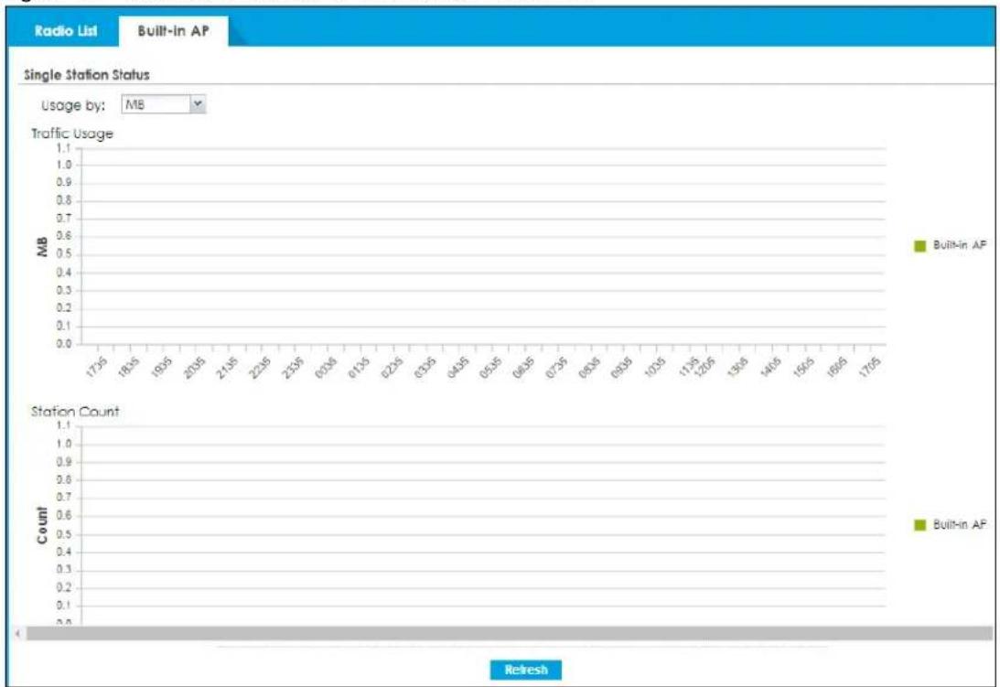
bar
Single Station Status | Usage by: | MB | | :--- | :--- | | Traffic Usage | 1.1 | | MB | 0.5 | | Built-in AP | 1795 | | Station Count | 1.1 | | Count | 0.6 | | Built-in AP | 1795 |The following table describes the labels in this screen.
Table 63 Monitor > Wireless > AP Information > Built-in AP
| LABEL DESCRIPTION | |
| Single Station Status | |
| Usage by Select the measure | unit in GB or MB to display the graph. |
| Traffic Usage This graph displays traffic in the preceding 24 hours. | |
| y-axis | The y-axis represents the amount of traffic in megabytes/gigabytes. |
| x-axis | The x-axis represents the time over which wireless traffic flows transmitting from/to the AP. |
| Station Count | This graph displays the number of wireless stations that have connected to the AP in the preceding 24 hours. |
| y-axis | The y-axis represents the number of connected wireless stations. |
| x-axis The x-axis represents | the time over which a wireless client was connected. |
| Refresh | Click Refresh to update this screen. |
6.22 AP Information: Top N APs
Use this screen to view the top five or top ten wireless traffic usage and associated wireless stations for the preceding 24 hours. Click Monitor > Wireless > AP Information > Top N APs to display the Top N APs screen.
Figure 178 Monitor > Wireless > AP Information > Top N APs
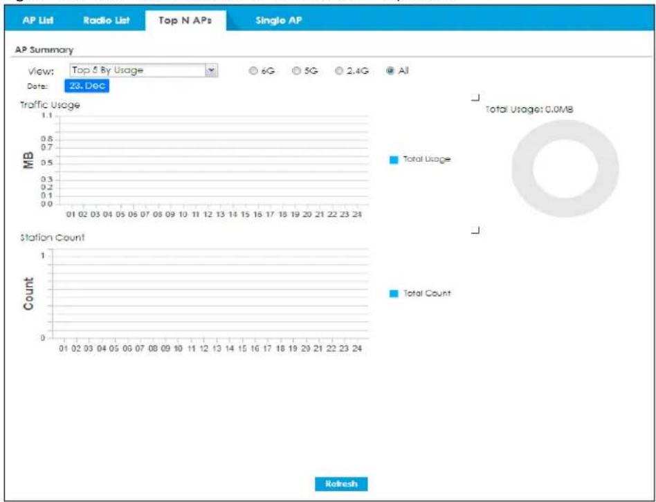
bar
| Metric | Value | | ---------------- | --------- | | Total Usage | 0.0MB | | Station Count | - | | Total Count | - | | Station Count | - | | Station Count | - | | Station Count | - | | Station Count | - | | Station Count | - | | Station Count | - | | Station Count | - | | Station Count | - | | Station Count | - | | Station Count | - | | Station Count | - | | Station Count | - | | Station Count | - |The following table describes the labels in this screen.
Table 64 Monitor > Wireless > AP Information > Top N APs
| LABEL DESCRIPTION | |
| View | Select this to view the top five or top ten wireless traffic for the preceding 24 hours. |
| Usage by | If you view the data usage by Usage, select the frequency band and the measure unit in GB or MB to display the graph.If you view the date usage by Station Number, select the measure unit in GB or MB to display the graph. |
| Traffic Usage | This graph displays the overall traffic information about the top five or top ten wireless traffic for the preceding 24 hours. |
| y-axis | The y-axis represents the amount of traffic in megabytes/gigabytes. |
| x-axis | The x-axis represents the time over which wireless traffic flows transmitting from/to the AP. |
| Station Count | This graph displays information about all the wireless stations that have connected to the AP for the preceding 24 hours. |
| y-axis | The y-axis represents the number of connected wireless stations. |
| x-axis The x-axis represents | the time over which a wireless client was connected. |
| Refresh | Click Refresh to update this screen. |
6.23 AP Information: Single AP
Use this screen to view wireless traffic usage and wireless stations for a managed AP. Click Monitor > Wireless > AP Information > Single AP to display the Single AP screen.
Figure 179 Monitor > Wireless > AP Information > Single AP
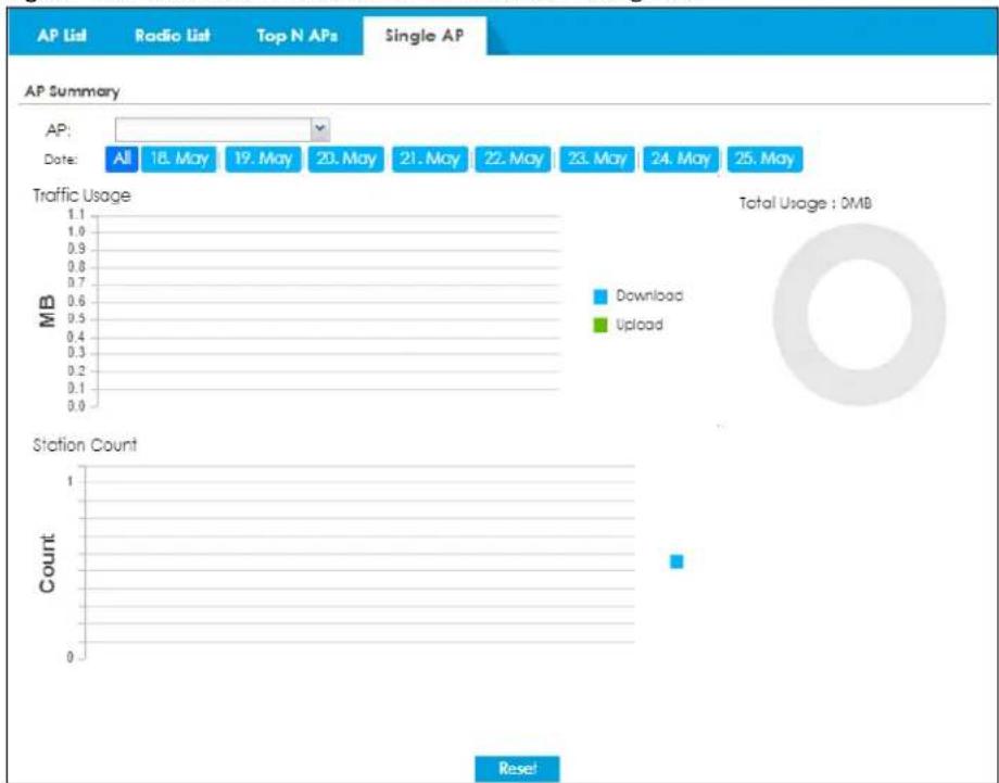
The following table describes the labels in this screen.
Table 65 Monitor > Wireless > AP Information > Single AP
| LABEL DESCRIPTION | |
| AP Selection | Select a managed AP from the drop-down list box to view its wireless traffic usage and wireless stations. |
| Usage by Select the measure | unit in GB or MB to display the graph. |
| Traffic Usage | This graph displays the overall traffic information about the AP you specified for the preceding 24 hours. |
| y-axis | The y-axis represents the amount of traffic in megabytes/gigabytes. |
| x-axis | The x-axis represents the time over which wireless traffic flows transmitting from/to the AP. |
| Station Count | This graph displays information about all the wireless stations that have connected to the AP for the preceding 24 hours. |
| y-axis | The y-axis represents the number of connected wireless stations. |
| x-axis The x-axis represents | the time over which a wireless client was connected. |
| Refresh | Click Refresh to update this screen. |
6.24 ZyMesh
Use this screen to view the ZyMesh traffic statistics between the managed APs. Click Monitor > Wireless > ZyMesh to display this screen.
Figure 180 Monitor > Wireless > ZyMesh
The following table describes the labels in this screen.
Table 66 Monitor > Wireless > ZyMesh
| LABEL DESCRIPTION | |
| # | This field displays the index number of the managed AP (in repeater mode) in this list. |
| Description | This field displays the descriptive name of the managed AP (in repeater mode). |
| IP Address | This field displays the IP address of the managed AP (in repeater mode). |
| Channel ID | This field displays the number of the channel used by the managed AP (in repeater mode). |
| Hop | This is the hop count of the managed AP. For example, “1” means the managed AP is connected to a root AP directly. “2” means there is another repeater AP between the managed AP and the root AP. |
| Uplink AP Info | This shows the role and descriptive name of the managed AP to which this managed AP is connected wirelessly. |
| SSID Name | This indicates the name of the wireless network (SSID) the managed AP uses to associated with another managed AP. |
| Signal Strength | Before the slash, this shows the signal strength the uplink AP (a root AP or a repeater) receives from this managed AP (in repeater mode).After the slash, this shows the signal strength this managed AP (in repeater mode) receives from the uplink AP. |
| Link Up Time | This field displays the time the managed AP first associated with the root AP or repeater. |
| MAC Address | This field displays the MAC address of the managed AP (in repeater mode). |
| Tx Power This field displays the | output power of the managed AP (in repeater mode). |
| Root AP | This field displays the descriptive name of the root AP to which the managed AP is connected wirelessly. |
| Tx Rate | This field displays the maximum transmission rate of the root AP or repeater to which the managed AP is connected. |
| Rx Rate | This field displays the maximum reception rate of the root AP or repeater to which the managed AP is connected. |
| Refresh | Click Refresh to update this screen. |
6.25 SSID Info
Use this screen to view the number of wireless clients currently connected to an SSID and the security type used by the SSID. Click Monitor > Wireless > SSID Info to display this screen.
Figure 181 Monitor > Wireless > SSID Info
The following table describes the labels in this screen.
Table 67 Monitor > Wireless > SSID Info
| LABEL DESCRIPTION | |
| # This is the SSID's index number in this list. | |
| SSID | This indicates the name of the wireless network to which the client is connected. A single AP can have multiple SSIDs or networks. |
| 2.4GHz | This shows the number of wireless clients which are currently connected to the SSID using the 2.4 GHz frequency band, Click the number to go to the Station Info > Station List screen. See Section 6.27 on page 219. |
| 5GHz | This shows the number of wireless clients which are currently connected to the SSID using the 5 GHz frequency band, Click the number to go to the Station Info > Station List screen. See Section 6.27 on page 219. |
| 6GHz | This shows the number of wireless clients which are currently connected to the SSID using the 6 GHz frequency band, Click the number to go to the Station Info > Station List screen. See Section 6.27 on page 219. |
| SSID Profile Name | This indicates the name of the SSID profile in which the SSID is defined. |
| Security Mode | This indicates which secure encryption methods is being used by the SSID. |
| Refresh | Click Refresh to update this screen. |
6.26 Station Info: Station List
The Station Info menu contains Station List, Top N Stations and Single Station screens. This screen displays information about connected wireless stations. Click Monitor > Wireless > Station Info > Station List to display this screen.
Figure 182 Monitor > Wireless > Station Info > Station List
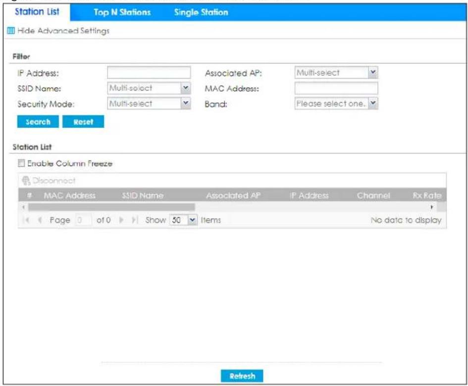
The following table describes the labels in this screen.
Table 68 Monitor > Wireless > Station Info > Station List
| LABEL DESCRIPTION | |
| Hide/Show Advanced Settings | Click this button to display a greater or lesser number of configuration fields. |
| Show Filter/ Hide Filer Click this button to show or hide the filter settings. | |
| Filter | |
| IP Address | Enter the IP address of the station you want to display. This field is case-sensitive. |
| Associated AP Select the AP(s) with which the stations you want to display associate. | |
| SSID Name | Select the SSID(s) to which the stations you want to display are connected. |
| MAC Address | Enter the MAC address of the station you want to display. This field is case-sensitive. |
| Security Mode | Select the security mode(s) used by the stations you want to display. |
| Account | Enter the user account name of the station you want to display. This field is case-sensitive. |
| Login Type | Select the login method(s) used by the stations you want to display. |
| Band Select the frequency band used by the stations you want to display. | |
| Search Click this to update the list of stations based on the search criteria.Your search criteria is retained when navigating between screens. | |
| Reset Click this to return the search criteria to the factory defaults and display all connected stations without a filter. | |
| Enable Column Freeze | Select this to lock the index columns in place while scrolling to the right. |
| Station List | |
| LABEL | DESCRIPTION |
| # | This field is a sequential value, and it is not associated with a specific station. |
| MAC Address | This field displays the MAC address of the station. |
| SSID Name This field displays the SSID names of the station. | |
| Associated AP | This field displays the APs that are associated with the station. |
| IP Address This field displays the IP address of the station. | |
| Channel | This field displays the number of the channel used by the station to connect to the network. |
| Rx Rate This field displays the receive data rate of the station. | |
| Tx Rate This field displays the transmit data rate of the station. | |
| Signal Strength | This field displays the signal strength of the station. |
| Association Time | This field displays the time duration the station was online and offline. |
| Enterprise This field displays the RADIUS server of the station. | |
| Captive Portal | This displays whether the station logged into the network via the captive portal login page. |
| MAC Auth | This displays whether the station logged into the network via MAC authentication. |
| Band This field displays the frequency band which is currently being used by the station. | |
| Capability | This displays the supported standard currently being used by the station or the standards supported by the station. |
| 802.11 Features | This displays whether the station supports IEEE802.11r, IEEE 802.11k, IEEE 802.11v or none of the above (N/A). |
| Security Mode This field displays the security mode the station is using. | |
| Download This field displays the number of bytes received by the station. | |
| Upload | This field displays the number of bytes transmitted from the station. |
| Refresh | Click Refresh to update this screen. |
6.27 Station Info: Top N Stations
Use this screen to view the top five or top ten traffic statistics of the wireless stations. Click Monitor > Wireless > Station Info > Top N Stations to display this screen.
Figure 183 Monitor > Wireless > Station Info > Top N Stations
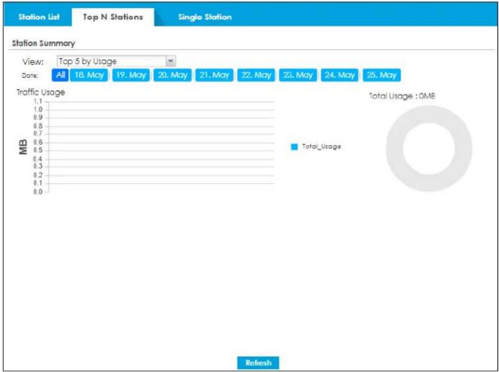
bar
| Station | Total_Usage | | ------- | ----------- | | All | 18. May | | 19. May | 20. May | | 21. May | 22. May | | 23. May | 24. May | | 24. May | 25. May |The following table describes the labels in this screen.
Table 69 Monitor > Wireless > Station Info > Top N Stations
| LABEL DESCRIPTION | |
| View | Select this to view the top five or top ten traffic statistics of the wireless stations. |
| Usage by Select the measure | unit in GB or MB to display the graph. |
| Traffic Usage | This graph displays the overall traffic information about the stations for the preceding 24 hours. |
| y-axis | This axis represents the amount of data moved across stations in megabytes per second. |
| Refresh | Click Refresh to update this screen. |
6.28 Station Info: Single Station
Use this screen to view traffic statistics of the wireless station you specified. Click Monitor > Wireless > Station Info > Single Station to display this screen.
Figure 184 Monitor > Wireless > Station Info > Single Station
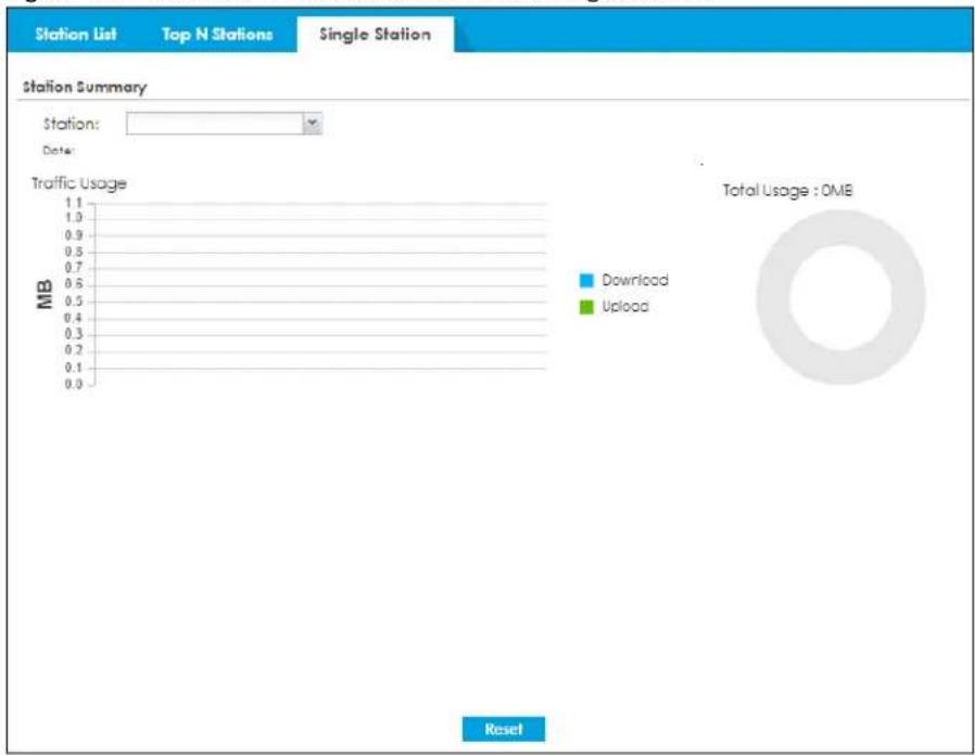
The following table describes the labels in this screen.
Table 70 Monitor > Wireless > Station Info > Single Station
| LABEL DESCRIPTION | |
| Station Selection | Select this to view the traffic statistics of the wireless station. |
| Usage by Select the measure | unit in GB or MB to display the graph. |
| Traffic Usage | This graph displays the overall traffic information about the station over the preceding 24 hours. |
| y-axis | This axis represents the amount of data moved across this station in megabytes per second. |
| Refresh | Click Refresh to update this screen. |
6.29 Detected Device
Use this screen to view information about wireless devices detected by the AP. Click Monitor > Wireless > Detected Device to access this screen.
Note: At least one radio of the APs connected to the Zyxel Device must be set to monitor mode (on the Configuration > Wireless > AP Management screen) in order to detect other wireless devices in its vicinity.
Figure 185 Monitor > Wireless > Detected Device
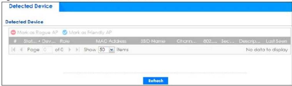
The following table describes the labels in this screen.
Table 71 Monitor > Wireless > Detected Device
| LABEL DESCRIPTION | |
| Discovered APs | |
| Rogue AP This shows how many devices are detected as rogue APs. | |
| Suspected rogue AP This shows how many devices are detected as possible rogue APs. | |
| Friendly AP | This shows how many devices are detected as friendly APs. |
| Un-Classified AP | This shows how many devices are detected, but have not been classified as either Rogue or Friendly by the Zyxel Device. |
| Detect now Click this button for the Zyxel Device to scan for APs in the network. | |
| Mark as Rogue AP | Click this button to mark the selected AP as a rogue AP. A rogue AP can be contained on theConfiguration > Wireless > MON Mode screen. |
| Mark as Friendly AP | Click this button to mark the selected AP as a friendly AP. For more on managing friendly APs, see theConfiguration > Wireless > MON Mode screen. |
| # This is the station's index number in this list. | |
| Role | This indicates the detected device's role (such as friendly or rogue). |
| Classified by This indicates the detected device's classification rule. | |
| MAC Address | This indicates the detected device's MAC address. |
| SSID Name This indicates the detected device's SSID. | |
| Channel ID | This indicates the detected device's channel ID. |
| 802.11 Mode | This indicates the 802.11 mode (a/b/g/n) transmitted by the detected device. |
| Security | This indicates the encryption method (if any) used by the detected device. |
| Seen by | This indicates which AP detects the device.If an AP in monitor mode detected this AP, this column will show “N/A”.If an AP usingRogue AP Detectiondetected this device, it will show the name of the AP and the signal strength from the detected device. If the wireless device is detected by more than one AP, only the top 5 APs with the highest signal strength will be shown. |
| Group | This indicates which group the detected device belongs. |
| Description | This displays the detected device's description. For more on managing friendly and rogue APs, see theConfiguration > Wireless > MON Mode screen. |
| Last Seen | This indicates the last time the device was detected by the Zyxel Device. |
| Refresh | Click this to refresh the items displayed on this page. |
6.30 Wireless Health
Use this screen to view the health or wireless networks for your APs and connected wireless clients. Click Monitor > Wireless > Wireless Health to access this screen.
Figure 186 Monitor > Wireless > Wireless Health
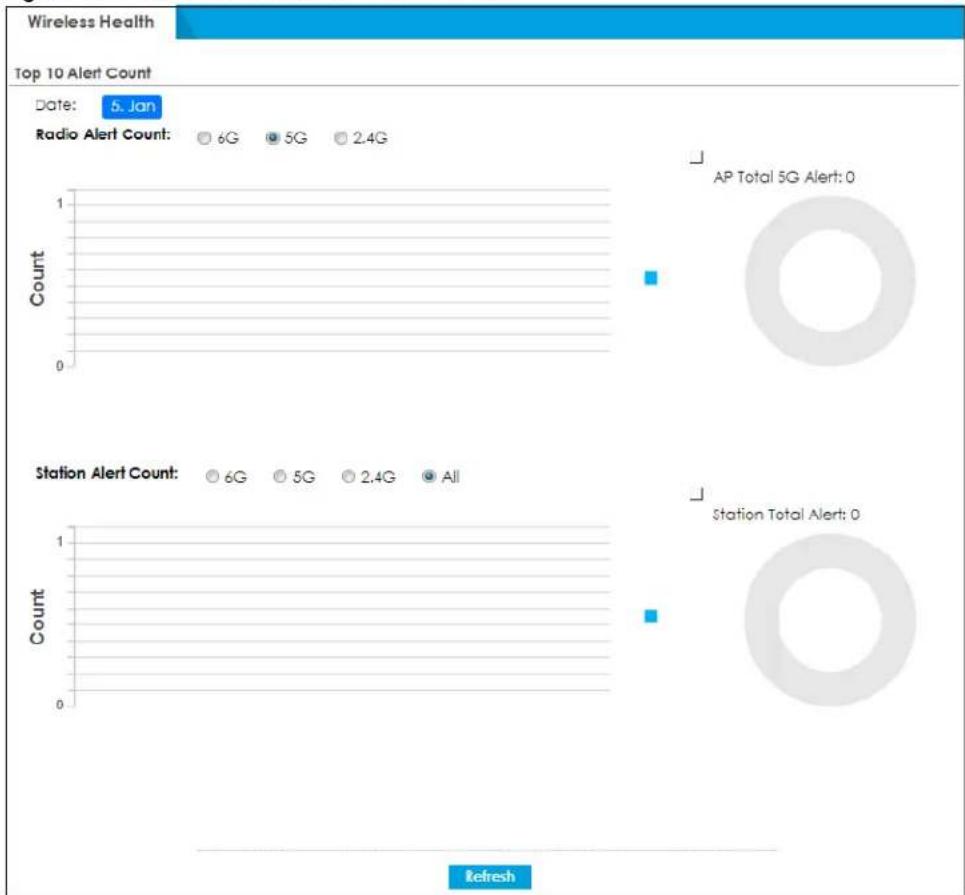
bar
| Alert Type | Station Alert Count | | ---------- | ------------------- | | 6G | 6 | | 5G | 5 | | 2.4G | 2.4 | | All | 0 |The following table describes the labels in this screen.
Table 72 Monitor > Wireless > Wireless Health
| LABEL DESCRIPTION | |
| Top 10 Alert Count | This chart shows the top 10 APs that are in poor states of wireless health for the most times. |
| Date This field shows the current date in theZyxel Device. | |
| Radio Alert Count | Select 2.4G, 5G or 6G to view the APs 2.4G, 5G or 6G radios wireless health. |
| y-axis The y-axis represents the state of wireless health. | |
| x-axis | The x-axis shows the time period over which the APs health states are recorded. |
| Station Alert Count | This chart shows how many times the client is in a poor state or wireless health. |
| y-axis The y-axis represents the state of wireless health. | |
| x-axis | The x-axis shows the time period over which the client health state is recorded. |
| Refresh | Click this to refresh the items displayed on this page. |
6.31 The Printer Status Screen
This screen displays information about the connected statement printer. Click Monitor > Printer Status to display this screen.
Figure 187 Monitor > Printer Status

The following table describes the labels in this screen.
Table 73 Monitor > Printer Status
| LABEL DESCRIPTION | |
| # This is the index number of the printer in the list. | |
| IPv4 Address | This field displays the IP address of the printer that you configured in the screen. |
| Update Time | This field displays the date and time the Zyxel Device last synchronized with the printer.This shows n/a when the printer status is sync fail. |
| Status | This field displays whether the Zyxel Device can connect to the printer and update the printer information. |
| Description | This field displays the descriptive name of the printer that you configured in the screen. |
| Nickname | This field displays the nickname of the printer that you configured in the Edit screen. |
| Firmware Version | This field displays the model number and firmware version of the printer.This shows n/a when the printer status is sync fail. |
| MAC This field displays the MAC address of the printer. | |
6.32 The IPSec Screen
You can use the IPSec screen to display and to manage active IPSec SAs. To access this screen, click Monitor >VPN Monitor >IPSec. The following screen appears. Click a column's heading cell to sort the table entries by that column's criteria. Click the heading cell again to reverse the sort order.
Figure 188 Monitor > VPN Monitor > IPSec
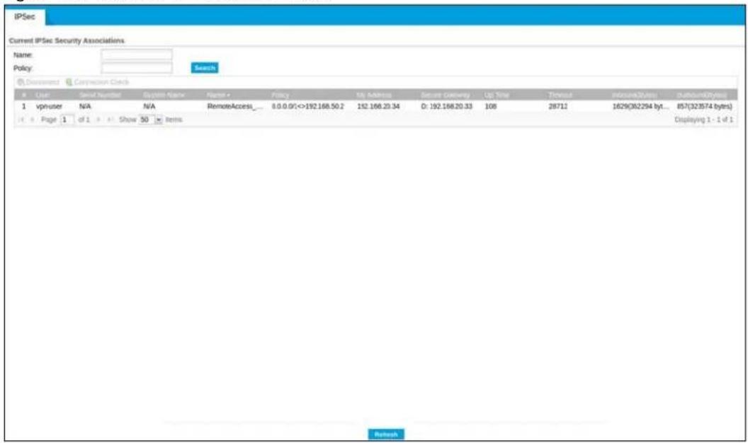
Each field is described in the following table.
Table 74 Monitor > VPN Monitor > IPSec
| LABEL DESCRIPTION | |
| Name | Type the name of a IPSec SA here and click Search to find it (if it is associated). You can use a keyword or regular expression. Use up to 30 alphanumeric and _+-.()!^:? | []<>/ characters. See Section 6.32.1 on page 226 for more details. |
| Policy | Type the IP address(es) or names of the local and remote policies for an IPSec SA and click Search to find it. You can use a keyword or regular expression. Use up to 30 alphanumeric and _+-.()!^:? | {}[]<>/ characters. See Section 6.32.1 on page 226 for more details. |
| Search Click this button to search for an IPSec SA that matches the information you specified above. | |
| Disconnect | Select an IPSec SA and click this button to disconnect it. |
| Connection Check Select an IPSec SA and click this button to check the connection. | |
| # This field is a sequential value, and it is not associated with a specific SA. | |
| User | This field only displays the client names if they're using EAP or X-auth for authentication.If a client is connected to the Zyxel Device without using Extended Authentication Protocol (EAP) or X-Auth, this field will be empty. |
| Serial Number This field displays the serial number of this Zyxel Device. | |
| System Name This field displays the name used to identify the Zyxel Device. | |
| Name This field displays the name of the IPSec SA. | |
| Policy | This field displays the content of the local and remote policies for this IPSec SA. The IP addresses, not the address objects, are displayed. |
| My Address This field displays the IP address of local computer. | |
| Secure Gateway This field displays the secure gateway information. | |
| Up Time | This field displays how many seconds the IPSec SA has been active. This field displays N/A if the IPSec SA uses manual keys. |
| Timeout | This field displays how many seconds remain in the SA life time, before the Zyxel Device automatically disconnects the IPSec SA. This field displays N/A if the IPSec SA uses manual keys. |
| Inbound (Bytes) | This field displays the amount of traffic that has gone through the IPSec SA from the remote IPSec router to the Zyxel Device since the IPSec SA was established. |
| Outbound (Bytes) | This field displays the amount of traffic that has gone through the IPSec SA from the Zyxel Device to the remote IPSec router since the IPSec SA was established. |
6.32.1 Regular Expressions in Searching IPSec SAs
A question mark (?) lets a single character in the VPN connection or policy name vary. For example, use "a?c" (without the quotation marks) to specify abc, acc and so on.
Wildcards (*) let multiple VPN connection or policy names match the pattern. For example, use "*abc" (without the quotation marks) to specify any VPN connection or policy name that ends with "abc". A VPN connection named "testabc" would match. There could be any number (of any type) of characters in front of the "abc" at the end and the VPN connection or policy name would still match. A VPN connection or policy name named "testacc" for example would not match.
A * in the middle of a VPN connection or policy name has the Zyxel Device check the beginning and end and ignore the middle. For example, with "abc*123", any VPN connection or policy name starting with "abc" and ending in "123" matches, no matter how many characters are in between.
The whole VPN connection or policy name has to match if you do not use a question mark or asterisk.
6.33 The SSL Screen
The Zyxel Device keeps track of the users who are currently logged into the VPN SSL client. Click Monitor >VPN Monitor >SSL to display the user list.
Use this screen to do the following:
• View a list of active SSL VPN connections.
- Log out individual users and delete related session information.
Once a user logs out, the corresponding entry is removed from the screen.
Figure 189 Monitor > VPN Monitor > SSL

The following table describes the labels in this screen.
Table 75 Monitor > VPN Monitor > SSL
| LABEL DESCRIPTION | |
| Disconnect | Select a connection and click this button to terminate the user's connection and delete corresponding session information from the Zyxel Device. |
| Refresh | Click Refresh to update this screen. |
| # This field is a sequential | value, and it is not associated with a specific SSL. |
| User | This field displays the account user name used to establish this SSL VPN connection. |
| Access | This field displays the name of the SSL VPN application the user is accessing. |
| Login Address | This field displays the IP address the user used to establish this SSL VPN connection. |
| Connected Time | This field displays the time this connection was established. |
| Inbound (Bytes) | This field displays the number of bytes received by the Zyxel Device on this connection. |
| Outbound (Bytes) | This field displays the number of bytes transmitted by the Zyxel Device on this connection. |
6.34 The L2TP over IPSec Screen
Click Monitor > VPN Monitor > L2TP over IPSec to open the following screen. Use this screen to display and manage the Zyxel Device's connected L2TP VPN sessions.
Figure 190 Monitor > VPN Monitor > L2TP over IPSec

The following table describes the fields in this screen.
Table 76 Monitor > VPN Monitor > L2TP over IPSec
| LABEL DESCRIPTION | |
| Disconnect | Select a connection and click this button to disconnect it. |
| Refresh | Click Refresh to update this screen. |
| # | This field is a sequential value, and it is not associated with a specific L2TP VPN session. |
| User Name | This field displays the remote user's user name. |
| Hostname | This field displays the name of the computer that has this L2TP VPN connection with the Zyxel Device. |
| Assigned IP | This field displays the IP address that the Zyxel Device assigned for the remote user's computer to use within the L2TP VPN tunnel. |
| Public IP | This field displays the public IP address that the remote user is using to connect to the Internet. |
6.35 The Remote AP VPN Screen
You can use the Remote AP VPN Monitor screen to display and to manage active remote AP. Remote AP enables the Zyxel Device to connect to an Access Point (AP) through a secure VPN tunnel. See Chapter 22 on page 578 for more information. To access this screen, click Monitor >VPN Monitor >Remote AP VPN. The following screen appears. Click a column's heading cell to sort the table entries by that column's criteria. Click the heading cell again to reverse the sort order.
Figure 191 Monitor > VPN Monitor > Remote AP VPN
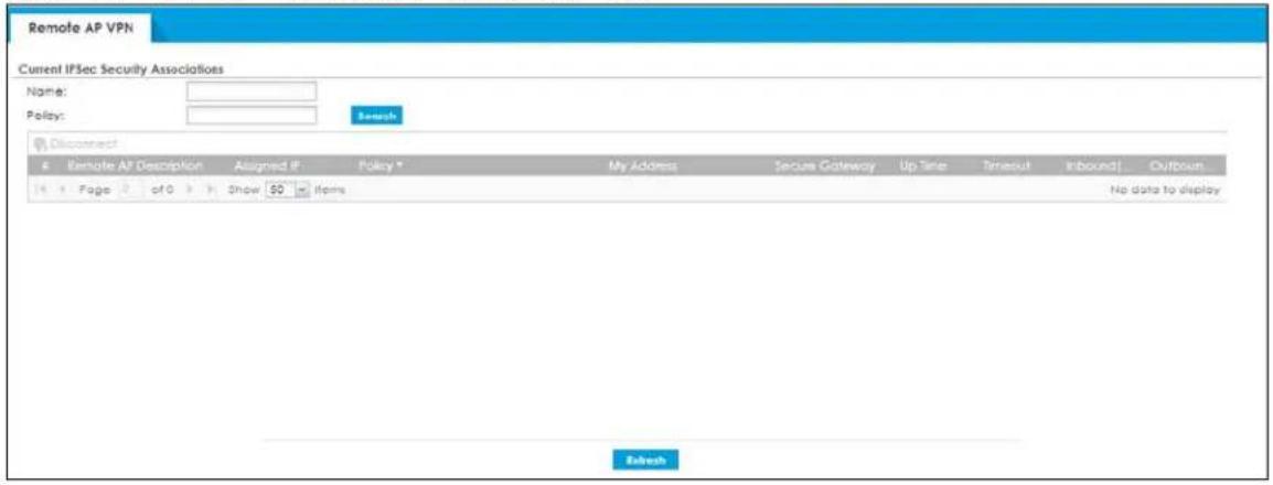
Each field is described in the following table.
Table 77 Monitor > VPN Monitor > Remote AP VPN
| LABEL DESCRIPTION | |
| Name | Type the name of a remote AP here and click Search to find it (if it is associated). You can use a keyword or regular expression. Use up to 30 alphanumeric and _+-.()!^:? | []<>/ characters. See Section 6.32.1 on page 226 for more details. |
| Policy | Type the IP address or name of the local and remote policies for a remote AP and click Search to find it. You can use a keyword or regular expression. Use up to 30 alphanumeric and _+-.()!^:? | {}[]<>/ characters. See Section 6.32.1 on page 226 for more details. |
| Search Click this button to search for a remote AP that matches the information you specified above. | |
| Disconnect | Select a remote AP and click this button to disconnect it. |
| # | This field is a sequential value, and it is not associated with a specific remote AP. |
| Remote AP Description | This fields displays the remote AP description, which you can configure in Configuration> Wireless> AP Management, see Section 8.4 on page 284 for more information. |
| Assigned IP | This field displays the IP address the Zyxel Device assigns to the remote AP from the IP address pool you set in Configuration> VPN> Remote AP VPN. See Chapter 22 on page 578 for more information. |
| Policy | This field displays the content of the local and remote policies for this remote AP. The IP addresses, not the address objects, are displayed. |
| My Address This field displays the IP address of the Zyxel Device. | |
| Secure Gateway | This field displays the IP address of the remote AP. |
| Up Time | This field displays how many seconds the remote AP has been connected to the Zyxel Device. |
| Timeout | This field displays how many seconds remain before the Zyxel Device disconnects from the remote AP. |
| Inbound (Bytes) | This field displays the amount of traffic that has gone through the IPSec tunnel from the remote AP to the Zyxel Device since the remote AP was established. |
| Outbound (Bytes) | This field displays the amount of traffic that has gone through the IPSec tunnel from the Zyxel Device to the remote AP since the remote AP was established. |
6.36 The App Patrol Screen
Application patrol provides a convenient way to manage the use of various applications on the network. It manages general protocols (for example, HTTP and FTP) and instant messenger (IM), peer-to-peer (P2P), Voice over IP (VoIP), and streaming (RSTP) applications. You can even control the use of a particular application's individual features (like text messaging, voice, video conferencing, and file transfers).
Click Monitor > Security Statistics > App Patrol > Summary to display the following screen. This screen displays Application Patrol statistics based on the App Patrol profiles bound to Security Policy profiles.
Figure 192 Monitor > Security Statistics > App Patrol > Summary
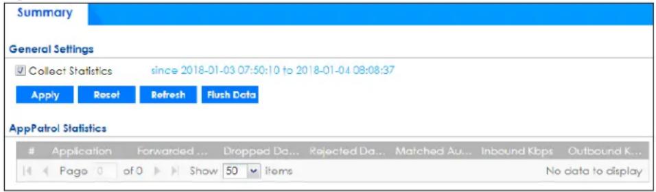
The following table describes the labels in this screen.
Table 78 Monitor > Security Statistics > App Patrol > Summary
| LABEL DESCRIPTION | |
| Collect Statistics | Select this check box to have the Zyxel Device collect app patrol statistics.The collection starting time displays after you clickApply. All of the statistics in this screen are for the time period starting at the time displayed here. The format is year, month, day and hour, minute, second. All of the statistics are erased if you restart the Zyxel Device or clickFlush Data. Collecting starts over and a new collection start time displays. |
| Apply | ClickApplyto save your changes back to the Zyxel Device. |
| Reset | ClickResetto return the screen to its last-saved settings. |
| Refresh Click this button to | update the report display. |
| Flush Data | Click this button to discard all of the screen's statistics and update the report display. |
| App Patrol Statistics | |
| # This field is a sequential | value, and it is not associated with a specific App Patrol session. |
| Application This is the protocol. | |
Table 78 Monitor > Security Statistics > App Patrol > Summary
| LABEL DESCRIPTION | |
| Forwarded Data (KB) | This is how much of the application's traffic the Zyxel Device has sent (in kilobytes). |
| Dropped Data (KB) | This is how much of the application's traffic the Zyxel Device has discarded without notifying the client (in kilobytes). This traffic was dropped because it matched an application policy set to "drop". |
| Rejected Data (KB) | This is how much of the application's traffic the Zyxel Device has discarded and notified the client that the traffic was rejected (in kilobytes). This traffic was rejected because it matched an application policy set to "reject". |
| Matched Auto Connection | This is how much of the application's traffic the Zyxel Device identified by examining the IP payload. |
| Inbound Kbps | This field displays the amount of the application's traffic that has gone to the ZyWALL (in kilo bits per second). |
| Outbound Kbps | This field displays the amount of the application's traffic that has gone from the ZyWALL (in kilo bits per second). |
6.37 The Content Filter Screen
Click Monitor > Security Statistics > Content Filter to display the following screens. These screens display some basic statistics on web content filter and DNS content filer, such as the number of web pages and FQDNs inspected.
6.37.1 Web Content Filter
This screens display web content filter statistics.
Figure 193 Monitor > Security Statistics > Content Filter > Web Content Filter
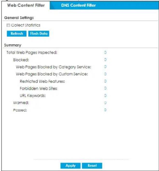
The following table describes the labels in this screen.
Table 79 Monitor > Security Statistics > Content Filter> Web Content Filter
| LABEL DESCRIPTION | |
| General Settings | |
| Collect Statistics | Select this check box to have the Zyxel Device collect web content filtering statistics.The collection starting time displays after you clickApply. All of the statistics in this screen are for the time period starting at the time displayed here. The format is year, month, day and hour, minute, second. All of the statistics are erased if you restart the Zyxel Device or clickFlush Data. Collecting starts over and a new collection start time displays. |
| Refresh Click this button to update the report display. | |
| Flush Data | Click this button to discard all of the screen's statistics and update the report display. |
| Summary | |
| Total Web Page Inspected | This field displays the number of web pages that the Zyxel Device's web content filter feature has checked. |
| Blocked This is the number of web pages that the Zyxel Device blocked access. | |
| Web Pages Blocked by Category Service | This is the number of web pages that matched an external database web content filtering category selected in the Zyxel Device and for which the Zyxel Device displayed a warning before allowing users access. |
| Web Page Blocked by Custom Service | This is the number of web pages to which the Zyxel Device did not allow access due to the web content filtering custom service configuration. |
| Restricted Web Features | This is the number of web pages to which the ZyWALL limited access or removed cookies due to the content filtering custom service's restricted web features configuration. |
| Forbidden Web Sites | This is the number of web pages to which the Zyxel Device did not allow access because they matched the content filtering custom service's forbidden web sites list. |
| URL Keywords | This is the number of web pages to which the Zyxel Device did not allow access because they contained one of the content filtering custom service's list of forbidden keywords. |
| Warned This is the number of web pages for which the Zyxel Device displayed a warning message to the access requesters. | |
| Passed This is the number of web pages to which the Zyxel Device allowed access. | |
| Apply | ClickApplyto save your changes back to the Zyxel Device. |
| Reset | ClickResetto return the screen to its last-saved settings. |
6.37.2 DNS Content Filter
This screens display DNS content filter statistics.
Figure 194 Monitor > Security Statistics > Content Filter > DNS Content Filter
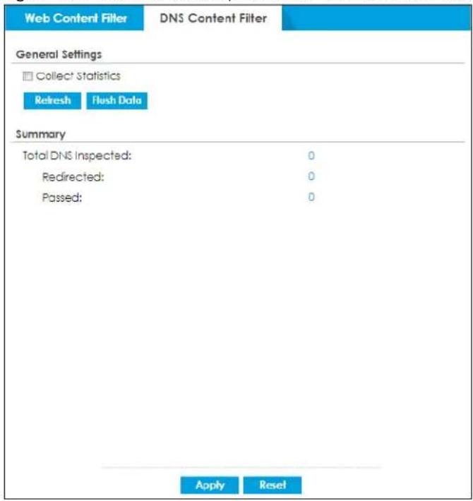
The following table describes the labels in this screen.
Table 80 Monitor > Security Statistics > Content Filter> DNS Content Filter
| LABEL DESCRIPTION | |
| General Settings | |
| Collect Statistics | Select this check box to have the Zyxel Device collect DNS content filtering statistics.The collection starting time displays after you clickApply. All of the statistics in this screen are for the time period starting at the time displayed here. The format is year, month, day and hour, minute, second. All of the statistics are erased if you restart the Zyxel Device or clickFlush Data. Collecting starts over and a new collection start time displays. |
| Refresh Click this button to update the report display. | |
| Flush Data | Click this button to discard all of the screen's statistics and update the report display. |
| Summary | |
| Total DNS Inspected | This field displays the number of FQDNs that the Zyxel Device's DNS content filter feature has checked. |
| Redirected | This is the number of FQDNs that the Zyxel Device redirects. |
| Passed | This is the number of FQDNs to which the Zyxel Device allowed access. |
| Apply | ClickApplyto save your changes back to the Zyxel Device. |
| Reset | ClickResetto return the screen to its last-saved settings. |
6.38 The Anti-Malware Screen
Click Monitor > Security Statistics > Anti-Malware > Summary to display the following screen. This screen displays anti-statistics.
Figure 195 Monitor > Security Statistics > Anti-Malware > Summary: Virus Name
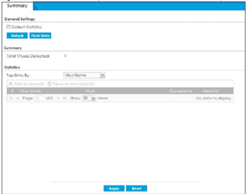
The following table describes the labels in this screen.
Table 81 Monitor > Security Statistics > Anti-Malware > Summary: Virus Name
| LABEL DESCRIPTION | |
| Collect Statistics | Select this check box to have the Zyxel Device collect anti- statistics.The collection starting time displays after you clickApply. All of the statistics in this screen are for the time period starting at the time displayed here. The format is year, month, day and hour, minute, second. All of the statistics are erased if you restart the Zyxel Device or clickFlush Data. Collecting starts over and a new collection start time displays. |
| Apply | ClickApplyto save your changes back to the Zyxel Device. |
| Reset | ClickResetto return the screen to its last-saved settings. |
| Refresh Click this button to update the report display. | |
| Flush Data | Click this button to discard all of the screen's statistics and update the report display. |
| Total Viruses Detected This field displays the number of different viruses that the Zyxel Device has detected. | |
| Top Entries By | Use this field to have the following (read-only) table display the top anti- log entries by Virus Name, Source IP, and Destination IP, Source IPv6 and Destination IPv6. This table displays the most common, recent virus logs. See the log screen for less common virus logs or use a syslog server to record all virus logs.SelectVirus Nameto list the most common viruses that the Zyxel Device has detected.SelectSource IP to list the source IP addresses from which the Zyxel Device has detected the most virus-infected files.SelectDestination IP to list the most common destination IP addresses for virus-infected files that Zyxel Device has detected.SelectSource IPv6 to list the source IPv6 addresses from which the Zyxel Device has detected the most virus-infected files.SelectDestination IPv6 to list the most common destination IPv6 addresses for virus-infected files that Zyxel Device has detected. |
| Add to allow list Select an entry and click this to add it to the anti-malware allow list. | |
| Remove from allow list | Select an entry and click this to remove it from the anti-malware allow list. |
| # This field displays the entry's rank in the list of the top entries. | |
| Virus name | This column displays when you display the entries byVirus Name. This displays the name of a detected virus. |
| Hash | This column displays a hash value, MD5 (Message Digest 5) and SHA (Secure Hash Algorithm), of the detected virus file.MD5 and SHA are hash algorithms used to authenticate packet data. |
| Source IP | This column displays when you display the entries bySource IP. It shows the source IP address of virus-infected files that the Zyxel Device has detected. |
| Source IPv6 | his column displays when you display the entries bySource IPv6. It shows the source IPv6 address of virus-infected files that the Zyxel Device has detected. |
| Destination IP | This column displays when you display the entries byDestination IP. It shows the destination IP address of virus-infected files that the Zyxel Device has detected. |
| Destination IPv6 | This column displays when you display the entries byDestination IPv6. It shows the destination IPv6 address of virus-infected files that the Zyxel Device has detected. |
| Occurrences | This field displays how many times the Zyxel Device has detected the event described in the entry. |
| Allow List | Click thisto add this signature to the anti-malware allow list.Click thisto remove this signature from the anti-malware allow list. |
The statistics display as follows when you display the top entries by source IP.
Figure 196 Monitor > Security Statistics > Anti-Malware > Summary: Source IP

The statistics display as follows when you display the top entries by source IPv6.
Figure 197 Monitor > Security Statistics > Anti-Malware: Source IPv6

The statistics display as follows when you display the top entries by destination IP.
Figure 198 Monitor > Security Statistics > Anti-Malware > Summary: Destination IP

The statistics display as follows when you display the top entries by destination IPv6.
Figure 199 Monitor > Security Statistics > Anti-Malware: Destination IPv6

6.39 The Reputation Filter Screen
Click Monitor > Security Statistics > Reputation Filter to display the following screens. These screens display IP reputation, DNS threat filter and URL threat filter statistics.
6.39.1 IP Reputation
This screen displays IP reputation statistics.
Figure 200 Monitor > Security Statistics > Reputation Filter > IP Reputation
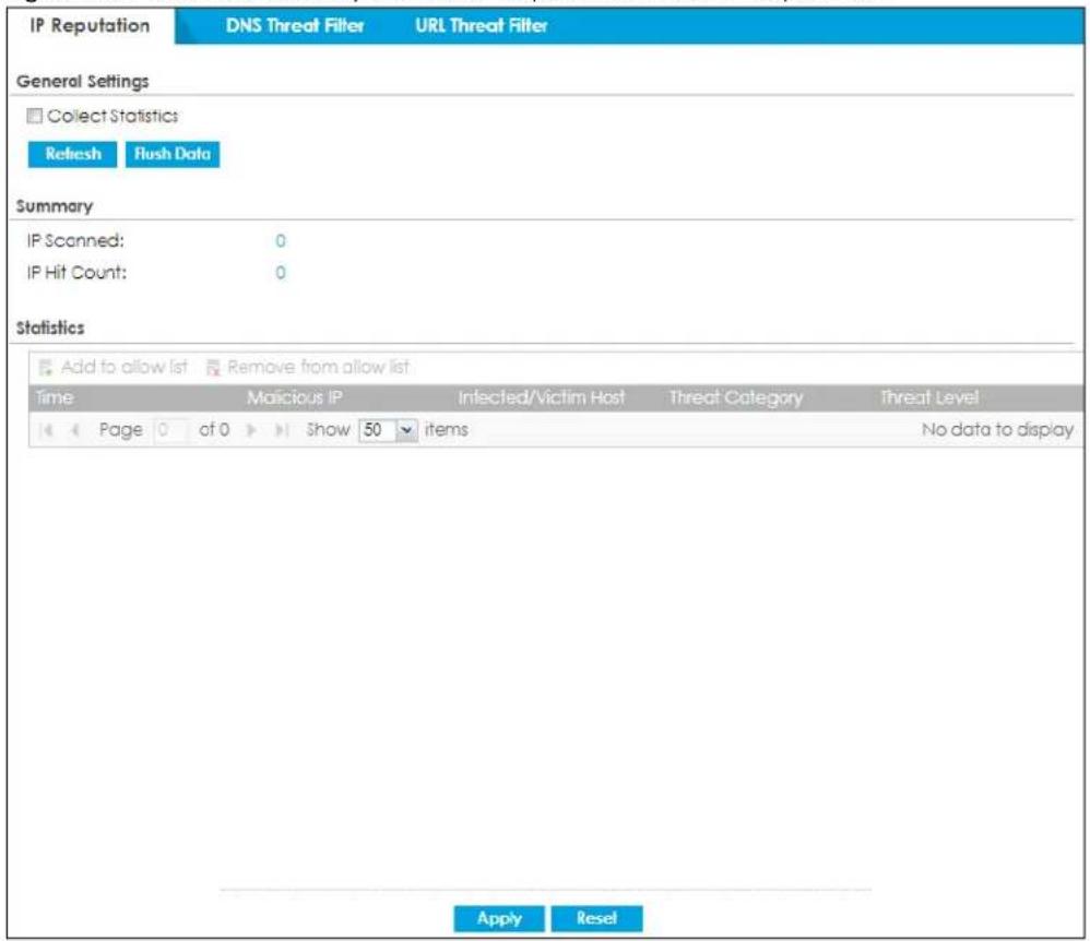
The following table describes the labels in this screen.
Table 82 Monitor > Security Statistics > Reputation Filter > IP Reputation
| LABEL DESCRIPTION | |
| Collect Statistics | Select this check box to have the Zyxel Device collect anti- statistics.The collection starting time displays after you clickApply. All of the statistics in this screen are for the time period starting at the time displayed here. The format is year, month, day and hour, minute, second. All of the statistics are erased if you restart the Zyxel Device or clickFlush Data. Collecting starts over and a new collection start time displays. |
| Refresh Click this button to update the report display. | |
| Flush Data | Click this button to discard all of the screen's statistics and update the report display. |
| Summary | |
| IP Scanned | This field displays the total number of IPv4 addresses that have been scanned. |
| IP Hit Count | This field displays the total number of the hit counts on the scanned IPv4 addresses. |
| Statistics | |
| Add to allow list | Select an entry and click this to add it to the IP reputation allow list. |
| Remove from allow list | Select an entry and click this to remove it from the IP reputation allow list. |
| Time | This field displays the date and time the entry was created. |
| Malicious IP This field displays the IPv4 address with bad reputation. | |
| Infected/Victim Host This field displays the MAC address of the infected host. | |
Table 82 Monitor > Security Statistics > Reputation Filter > IP Reputation
| LABEL DESCRIPTION | |
| Threat Category This field | displays the category of the entry. |
| Threat Level This field displays the threat level of the entry. | |
6.39.2 DNS Threat Filter
This screen displays DNS threat filter statistics.
Figure 201 Monitor > Security Statistics > Reputation Filter > DNS Threat Filter
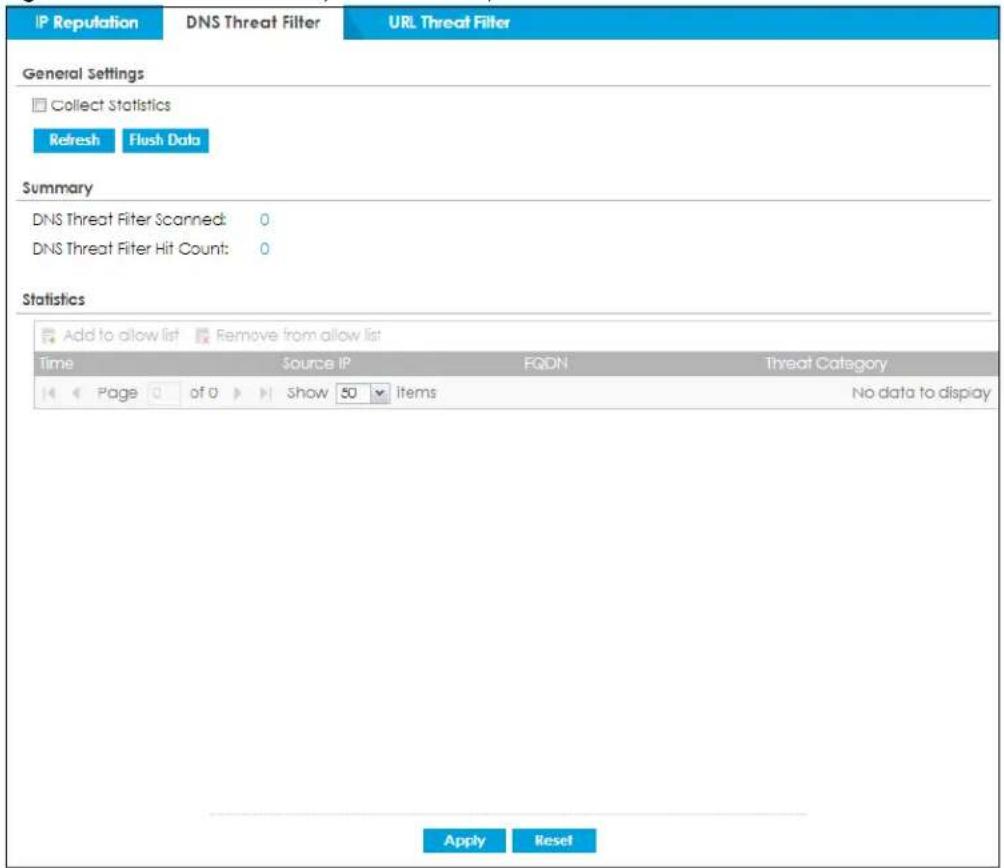
The following table describes the labels in this screen.
Table 83 Monitor > Security Statistics > Reputation Filter > DNS Threat Filter
| LABEL DESCRIPTION | |
| Collect Statistics | Select this check box to have the Zyxel Device collect anti- statistics.The collection starting time displays after you clickApply. All of the statistics in this screen are for the time period starting at the time displayed here. The format is year, month, day and hour, minute, second. All of the statistics are erased if you restart the Zyxel Device or clickFlush Data. Collecting starts over and a new collection start time displays. |
| Refresh Click this button to update the report display. | |
| Flush Data | Click this button to discard all of the screen's statistics and update the report display. |
| Summary | |
Table 83 Monitor > Security Statistics > Reputation Filter > DNS Threat Filter
| LABEL DESCRIPTION | |
| DNS Filter Scanned | This field displays the total number of FQDNs that have been scanned. |
| DNS Filter Hit Count | This field displays the total number of the hit counts on the scanned FQDNs. |
| Statistics | |
| Add to allow list | Select an entry and click this to add it to the DNS filtering allow list. |
| Remove from allow list | Select an entry and click this to remove it from the DNS filtering allow list. |
| Time | This field displays the date and time the entry was created. |
| Source IP This field displays the source IP address of traffic that you want to trace. | |
| FQDN This field displays the FQDN of an infected website. | |
| Threat Category This field | displays the category of the entry. |
| Apply | Click Apply to save your changes back to the Zyxel Device. |
| Reset | Click Reset to return the screen to its last-saved settings. |
6.39.3 URL Threat Filter
This screen displays URL threat filter statistics.
Figure 202 Monitor > Security Statistics > Reputation Filter > URL Threat Filter
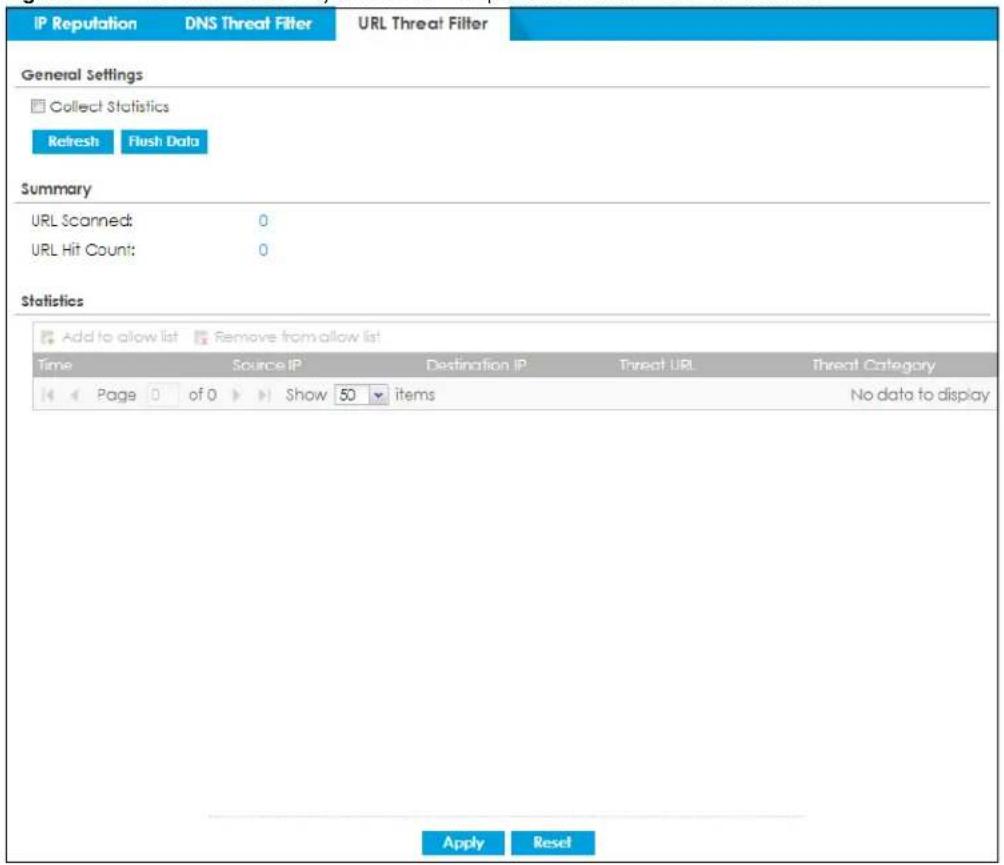
The following table describes the labels in this screen.
Table 84 Monitor > Security Statistics > Reputation Filter > URL Threat Filter
| LABEL DESCRIPTION | |
| Collect Statistics | Select this check box to have the Zyxel Device collect anti- statistics.The collection starting time displays after you clickApply. All of the statistics in this screen are for the time period starting at the time displayed here. The format is year, month, day and hour, minute, second. All of the statistics are erased if you restart the Zyxel Device or clickFlush Data. Collecting starts over and a new collection start time displays. |
| Refresh Click this button to update the report display. | |
| Flush Data | Click this button to discard all of the screen's statistics and update the report display. |
| Summary | |
| URL Scanned This field displays the total number of URLs that have been scanned. | |
| URL Hit Count | This field displays the total number of the hit counts on the scanned URLs. |
| DNS Filter Scanned | This field displays the total number of FQDNs that have been scanned. |
| DNS Filter Hit Count | This field displays the total number of the hit counts on the scanned FQDNs. |
| Statistics | |
| Add to allow list | Select an entry and click this to add it to the URL Threat filtering allow list. |
| Remove from allow list | Select an entry and click this to remove it from the URL Threat filtering allow list. |
| Time | This field displays the date and time the entry was created. |
| Source IP This field displays the source IP address of traffic that you want to trace. | |
| Destination IP This field displays the destination IP address of traffic. | |
| Threat URL This field displays the URL of an infected website or a botnet C&C server.IP reputation only blocks incoming and outgoing traffic coming from an IP address that is defined as botnet. If an IP address is not defined as botnet, only incoming traffic is blocked. | |
| Threat Category This field displays the category of the entry. | |
| DNS Filter FQDN Detected | |
| Add to white list | Select an entry and click this to add it to the DNS filtering white list. |
| Remove from white list | Select an entry and click this to remove it from the DNS filtering white list. |
| Time | This field displays the date and time the entry was created. |
| Source IP This field displays the source IP address of traffic that you want to trace. | |
| FQDN | This field displays the FQDN of an infected website. |
| Threat Category This field displays the category of the entry. | |
| Apply | ClickApplyto save your changes back to the Zyxel Device. |
| Reset | ClickResetto return the screen to its last-saved settings. |
6.40 The IPS Screen
Click Monitor > Security Statistics > IPS > Summary to display the following screen. This screen displays IPS (Intrusion Prevention System) statistics.
Figure 203 Monitor > Security Statistics > IPS > Summary: Signature Name
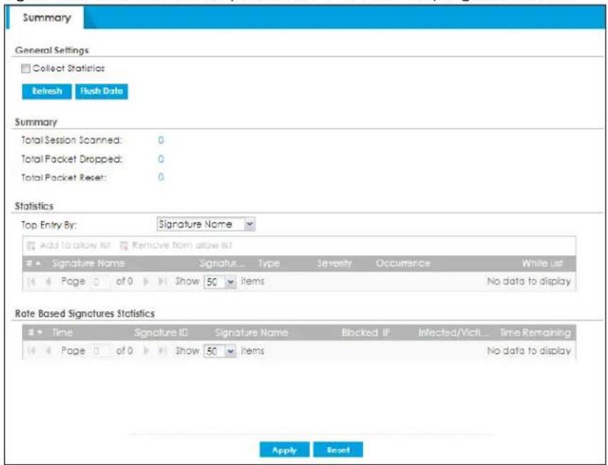
The following table describes the labels in this screen.
Table 85 Monitor > Security Statistics > IPS > Summary
| LABEL DESCRIPTION | |
| Collect Statistics | Select this check box to have the Zyxel Device collect IPS statistics.The collection starting time displays after you clickApply. All of the statistics in this screen are for the time period starting at the time displayed here. The format is year, month, day and hour, minute, second. All of the statistics are erased if you restart the Zyxel Device or clickFlush Data. Collecting starts over and a new collection start time displays. |
| Apply | ClickApplyto save your changes back to the Zyxel Device. |
| Reset | ClickResetto return the screen to its last-saved settings. |
| Refresh Click this button to update the report display. | |
| Flush Data | Click this button to discard all of the screen's statistics and update the report display. |
| Total Session Scanned | This field displays the number of sessions that the Zyxel Device has checked for intrusion characteristics. |
| Total Packet Dropped | The Zyxel Device can detect and drop malicious packets from network traffic. This field displays the number of packets that the Zyxel Device has dropped. |
| Total Packet Reset | The Zyxel Device can detect and drop malicious packets from network traffic. This field displays the number of packets that the Zyxel Device has reset. |
| Top Entries By | Use this field to have the following (read-only) table display the top IPS log entries by Signature Name, Source IP or Destination IP. This table displays the most common, recent IPS logs. See the log screen for less common IPS logs or use a syslog server to record all IPS logs.SelectSignature Nameto list the most common signatures that the Zyxel Device has detected.SelectSource IP to list the source IP addresses from which the Zyxel Device has detected the most intrusion attempts.SelectDestination IP to list the most common destination IP addresses for intrusion attempts that the Zyxel Device has detected. |
| LABEL | DESCRIPTION |
| Add to allow list | Select a signature and click this to add the selected signature to the IPS allow list. |
| Remove from allow list | Select a signature and click this to remove the selected signature from the IPS allow list. |
| Statistics | |
| # | This field displays the entry's rank in the list of the top entries. |
| Signature Name | This column displays when you display the entries by Signature Name. The signature name identifies the type of intrusion pattern. Click the hyperlink for more detailed information on the intrusion. |
| Signature ID | This column displays when you display the entries by Signature Name. The signature ID is a unique value given to each intrusion detected. |
| Type | This column displays when you display the entries by Signature Name. It shows the categories of intrusions. |
| Severity | This column displays when you display the entries by Signature Name. It shows the level of threat that the intrusions may pose. |
| Source IP | This column displays when you display the entries by Source. It shows the source IP address of the intrusion attempts. |
| Destination IP | This column displays when you display the entries by Destination. It shows the destination IP address at which intrusion attempts were targeted. |
| Occurrences | This field displays how many times the Zyxel Device has detected the event described in the entry. |
| Allow List | Click this to add this signature to the IPS allow list.Click this to remove this signature from the IPS allow list. |
| Rate Based Signatures Statistics | This table displays the rate based signatures statistics.IPS signatures identify traffic packets with suspicious malicious patterns. The Zyxel Device can then respond instantaneously according to the action you define.If you do not want the Zyxel Device to respond instantaneously for each suspicious packet detected, use rate based signatures. See Section 36.1.2 on page 832 for more information on rate based signatures. |
| # | This field displays the entry's rank in the list of the top entries. |
| Time | This column displays the date and time IPS blocked this IP address. |
| Signature ID | This column displays when you display the entries by Signature Name. The signature ID is a unique value given to each intrusion detected. |
| Signature Name | This column displays when you display the entries by Signature Name. The signature name identifies the type of intrusion pattern. Click the hyperlink for more detailed information on the intrusion. |
| Blocked IP | This field displays the IP address that is blocked by IPS. |
| Interactive/Victim Host | This field displays the IP address of the infected host. |
| Time Remaining | This field displays the amount of time left until the blocked IP address is released by IPS. |
The statistics display as follows when you display the top entries by source.
Figure 204 Monitor > Security Statistics > IPS > Summary: Source IP

The statistics display as follows when you display the top entries by destination.
Figure 205 Monitor > Security Statistics > IPS > Summary: Destination IP

6.41 Sandboxing
Click Monitor > Security Statistics > Sandboxing to display the following screen. This screen displays sandboxing statistics.
Figure 206 Monitor > Security Statistics > Sandboxing
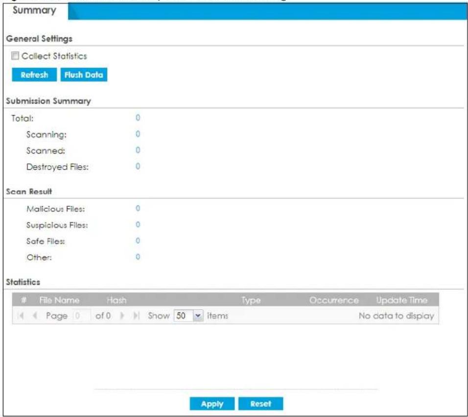
The following table describes the labels in this screen.
Table 86 Monitor > Security Statistics > Sandboxing
| LABEL DESCRIPTION | |
| Collect Statistics | Select this check box to have the Zyxel Device collect sandboxing statistics.The collection starting time displays after you clickApply. All of the statistics in this screen are for the time period starting at the time displayed here. The format is year, month, day and hour, minute, second. All of the statistics are erased if you restart the Zyxel Device or clickFlush Data. Collecting starts over and a new collection start time displays. |
| Refresh Click this button to update the report display. | |
| LABEL | DESCRIPTION |
| Flush Data | Click this button to discard all of the screen's statistics and update the report display. |
| Submission Summary | |
| Total | This field displays the total number of files that the Zyxel Device sent to the Defend Center for analysis. |
| Scanning | This field displays the total number of files that the Zyxel Device is still scanning. |
| Scanned This field displays the total number of files that have been scanned. | |
| Destroyed Files This shows the number of files that have been destroyed. | |
| Scan Result | |
| Malicious Files | This shows the number of malicious files that have been detected. Malicious files are files given a high score for characteristics by the Defend Center. |
| Suspicious Files | This shows the number of suspicious files that have been detected. Suspicious files are files given a medium score for characteristics by the Defend Center. |
| Safe File | This shows the number of clean files that have been detected. Safe files are files given a low score for characteristics by the Defend Center. |
| Other | This shows the number of internal and external networks errors. |
| Statistics | |
| # This is the entry's index number in the list. | |
| File Name This column displays the file name of the detected virus file. | |
| Hash | This column displays a hash value, MD5 (Message Digest 5) and SHA (Secure Hash Algorithm), of the detected virus file.MD5 and SHA are hash algorithms used to authenticate packet data. |
| Type This field displays the file type of the detected virus file. | |
| Occurrence | This field displays how many times the Zyxel Device has detected the event described in the entry. |
| Update Time | This field displays the last time the Zyxel Device updates the sandboxing statistics table. |
| Apply | Click Apply to save your changes back to the Zyxel Device. |
| Reset | Click Reset to return the screen to its last-saved settings. |
6.42 The Email Security Screens
The Email Security menu contains the Summary and Status screens.
6.42.1 Email Security Summary
Click Monitor > Security Statistics > Email Security > Summary to display the following screen. This screen displays spam statistics.
Figure 207 Monitor > Security Statistics > Email Security > Summary
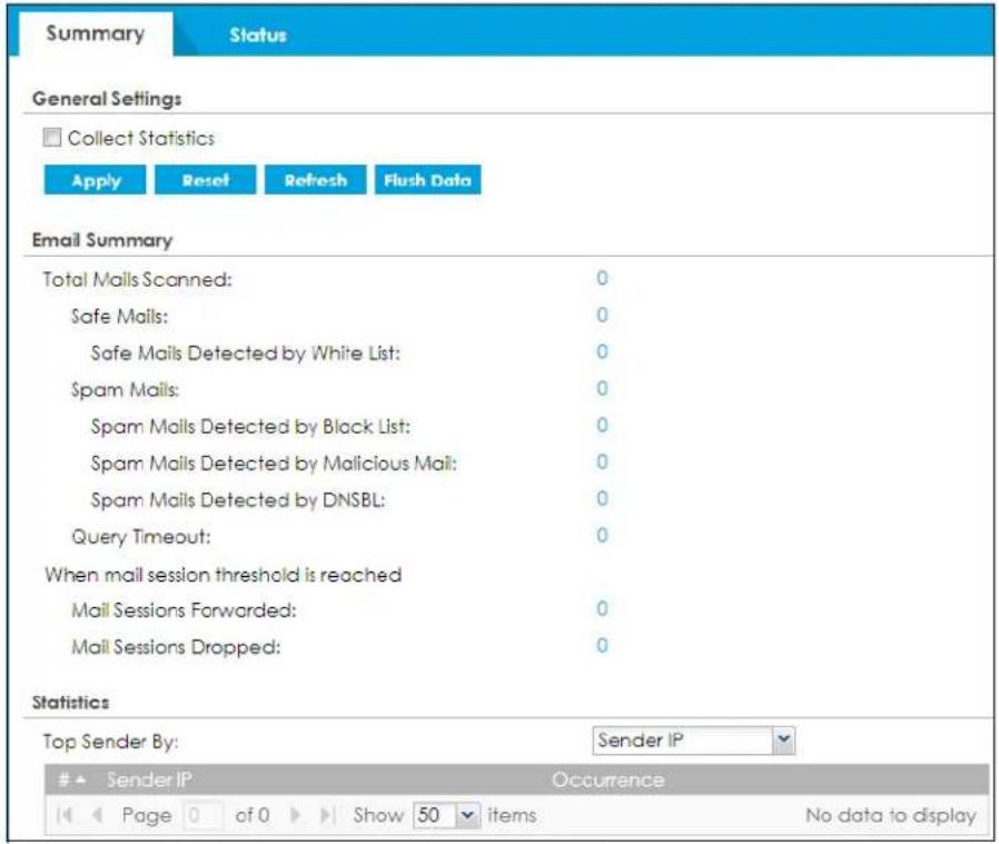
The following table describes the labels in this screen.
Table 87 Monitor > Security Statistics > Email Security > Summary
| LABEL DESCRIPTION | |
| Collect Statistics | Select this check box to have the Zyxel Device collect email security statistics.The collection starting time displays after you clickApply. All of the statistics in this screen are for the time period starting at the time displayed here. The format is year, month, day and hour, minute, second. All of the statistics are erased if you restart the Zyxel Device or clickFlush Data. Collecting starts over and a new collection start time displays. |
| Refresh Click this button | to update the report display. |
| Flush Data | Click this button to discard all of the screen's statistics and update the report display. |
| Summary | |
| Total Mails Scanned | This field displays the number of emails that the Zyxel Device's email security feature has checked. |
| Safe Mails | This is the number of emails that the Zyxel Device has determined to not be spam. |
| Safe Mails Detected by Allow list | This is the number of emails that matched an entry in the Zyxel Device's email security allow list. |
| Spam Mails | This is the number of emails that the Zyxel Device has determined to be spam. |
| Spam Mails Detected by Block List | This is the number of emails that matched an entry in the Zyxel Device's email security block list. |
| Spam Mails Detected by Malicious Mail | This is the number of emails that the Zyxel Device has determined to have malicious contents. |
| Spam Mails Detected by DNSBL | The Zyxel Device can check the sender and relay IP addresses in an email's header against DNS (Domain Name Service)-based spam Black Lists (DNSBLs). This is the number of emails that had a sender or relay IP address in the header which matched one of the DNSBLs that the Zyxel Device uses. |
| Query Timeout | This is how many queries that were sent to the Zyxel Device's configured list of DNSBL domains or Mail Scan services and did not receive a response in time. |
| When mail session threshold is reached | |
| Mail Sessions Forwarded | This is how many email sessions the Zyxel Device allowed because they exceeded the maximum number of email sessions that the email security feature can check at a time.You can see the Zyxel Device's threshold of concurrent email sessions on theEmail Security>Statusscreen.Use theEmail Security>Summaryscreen to set whether the Zyxel Device forwards or drops sessions that exceed this threshold. |
| Mail Sessions Dropped | This is how many email sessions the Zyxel Device dropped because they exceeded the maximum number of email sessions that the email security feature can check at a time.You can see the Zyxel Device's threshold of concurrent email sessions on theEmail Security>Statusscreen.Use theEmail Security>Summaryscreen to set whether the Zyxel Device forwards or drops sessions that exceed this threshold. |
| Statistics | |
| Top Sender By | Use this field to list the top email or IP addresses from which the Zyxel Device has detected the most spam.SelectSender IPto list the source IP addresses from which the Zyxel Device has detected the most spam.SelectSender Email Addressto list the top email addresses from which the Zyxel Device has detected the most spam. |
| # This field displays the entry's rank in the list of the top entries. | |
| Sender IP | This column displays when you display the entries bySender IP. It shows the source IP address of spam emails that the Zyxel Device has detected. |
| Sender Email Address | This column displays when you display the entries bySender Email Address. This column displays the email addresses from which the Zyxel Device has detected the most spam. |
| Occurrence | This field displays how many spam emails the Zyxel Device detected from the sender. |
| Apply | ClickApplyto save your changes back to the Zyxel Device. |
| Reset | ClickResetto return the screen to its last-saved settings. |
6.42.2 The Email Security Status Screen
Click Monitor > Security Statistics > Email Security > Status to display the Email Security Status screen.
Use the Email Security Status screen to see how many email sessions the email security feature is scanning and statistics for the DNSBLs.
Figure 208 Monitor > Security Statistics > Email Security > Status
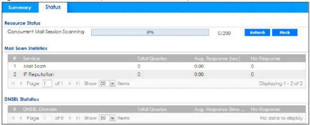
The following table describes the labels in this screen.
Table 88 Monitor > Security Statistics > Email Security > Status
| LABEL DESCRIPTION | |
| Resource Status | |
| Concurrent Mail Session Scanning | The darker shaded part of the bar shows how much of the Zyxel Device's total spam checking capability is currently being used.The lighter shaded part of the bar and the pop-up show the historical high.The first number to the right of the bar is how many email sessions the Zyxel Device is presently checking for spam. The second number is the maximum number of email sessions that the Zyxel Device can check at once. An email session is when an email client and email server (or two email servers) connect through the Zyxel Device. |
| Refresh | Click this button to update the information displayed on this screen. |
| Flush | Click this button to clear the DNSBL statistics. This also clears the concurrent mail session scanning bar's historical high. |
| Mail Scan Statistics | These are the statistics for the service the Zyxel Device uses. These statistics are for when the Zyxel Device actually queries the service servers. |
| # This is the entry's index number in the list. | |
| Service This displays the name of the service. | |
| Total Queries | This is the total number of queries the Zyxel Device has sent to this service. |
| Avg. Response Time (sec) | This is the average for how long it takes to receive a reply from this service. |
| No Response | This is how many queries the Zyxel Device sent to this service without receiving a reply. |
| DNSBL Statistics | These are the statistics for the DNSBL the Zyxel Device uses. These statistics are for when the Zyxel Device actually queries the DNSBL servers. Matches for DNSBL responses stored in the cache do not affect these statistics. |
| # This is the entry's index number in the list. | |
| DNSBL Domain | These are the DNSBLs the Zyxel Device uses to check sender and relay IP addresses in emails. |
| Total Queries | This is the total number of DNS queries the Zyxel Device has sent to this DNSBL. |
| Avg. Response Time (sec) | This is the average for how long it takes to receive a reply from this DNSBL. |
| No Response | This is how many DNS queries the Zyxel Device sent to this DNSBL without receiving a reply. |
6.43 Collaborative Detection & Response (CDR)
Collaborative Detection & Response (CDR) allows you to detect wired and WiFi clients that are sending malicious traffic in your network and then block or quarantine traffic coming from them. In this way, malicious traffic is not spread throughout the network. Secure policies can block malicious traffic for specific traffic flows, but CDR can block malicious traffic from the sender. Malicious traffic is identified using a combination of Web Filtering, Anti-Malware and IPS (IDP) signatures.
Click Monitor > Security Statistics > CDR> Containment List to display a screen that shows what clients are currently contained by CDR.
Figure 209 Monitor > Security Statistics > CDR > Containment List by IP
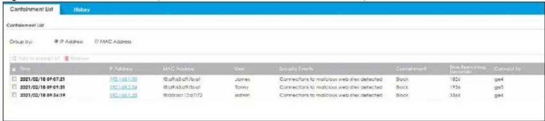
Figure 210 Monitor > Security Statistics > CDR > Containment List by MAC
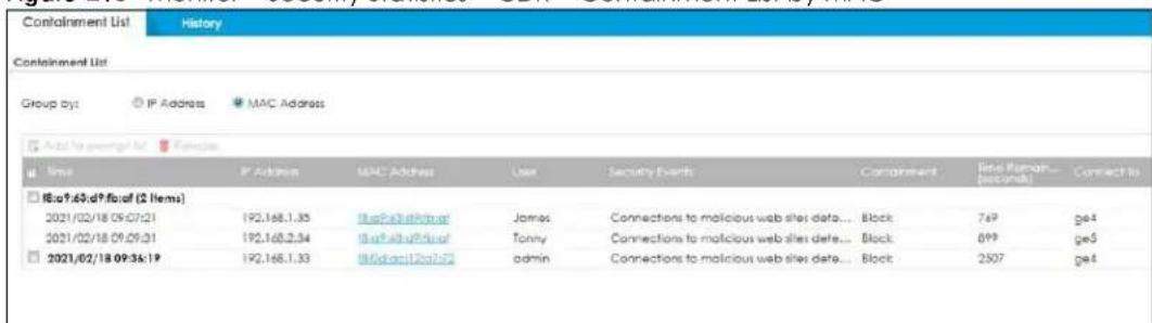
The following table describes the labels in this screen.
Table 89 Monitor > Security Statistics > CDR > Containment List
| LABEL DESCRIPTION | |
| Containment List | This table displays up to 512 devices that CDR is blocking or quarantining. Containment list items remain even if the Zyxel Device or managed AP reboots. |
| Group by | Choose to sort security events for contained devices by IP Address or MAC Address. For example, if three security events occur for a client identified by IP address, then under Time, the IP address of the client is shown with the times the security events occurred beneath this IP address.Wired clients are blocked based on IP address by default. You can change that to blocking based on MAC address using the cdr blocked-by mac command in configuration mode in the Command Line Interface (CLI). Note that if you have a switch between the client and the Zyxel Device, then blocking by MAC address could block all traffic from the switch if the client MAC address is not forwarded through the switch.WiFi clients are blocked or quarantined based on MAC address by default. |
| Add to exempt list | Select a client and then click this to release this device from CDR containment and also bypass this device from future CDR checking. This device is then removed from this table and added to theHistoryscreen. |
| Release | Select a client and then click this to release this device from CDR containment. This device is then removed from this table and added to theHistoryscreen. |
| Time | This field displays the date and time CDR contained this client |
| IP Address | This field displays the IPv4 address of the client contained by CDR. |
| MAC Address | This field displays the MAC address of the client contained by CDR. |
| User | The field displays the user name of a client contained by CDR who has been authenticated for Internet access. The field is blank if user authentication is not required. |
| Security Events | This field displays details on the category of signature that triggered CDR: Web Filtering, Anti-Malware or IPS (IDP). |
| Containment | This field displays if the client is blocked, quarantined or just triggers an alert. |
| Time Remaining (Seconds) | This field displays the amount of time left until this client is released by CDR |
| Connect to | This field displays the description of the AP or the interface of the Zyxel Device that the contained client is connected to. |
| Refresh | Click this button to update the information on the screen. |
6.43.1 CDR History
Click Monitor > Security Statistics > CDR> History to display a screen that shows what clients were and are contained by CDR.
Figure 211 Monitor > Security Statistics > CDR > History: Authenticated Users
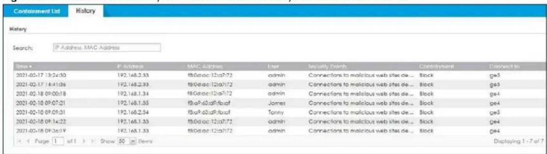
Figure 212 Monitor > Security Statistics > CDR> History: Non-Authenticated Users
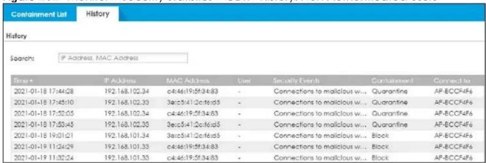
The following table describes the labels in this screen.
Table 90 Monitor > Security Statistics > CDR> History
| LABEL DESCRIPTION | |
| History This table displays up | to 1024 devices that CDR has blocked or quarantined |
| Time | This field displays the date and time CDR contained this client |
| IP Address | This field displays the IPv4 address of the client contained by CDR. |
| MAC Address | This field displays the MAC address of the client contained by CDR. |
| User | The field displays the user name of a client contained by CDR who has been authenticated for Internet access. The field is blank if user authentication is not required. |
| Security Events | This field displays details on the category of signature that triggered CDR: Web Filtering, Anti-Malware or IPS (IDP). |
| Containment | This field displays if the client is blocked, quarantined or just triggers an alert. |
| Connect to | This field displays the description of the AP or the interface of the Zyxel Device that the contained client is connected to. |
| Refresh | Click this button to update the information on the screen. |
6.44 The SSL Inspection Screens
The Zyxel Device uses SSL Inspection to decrypt SSL traffic, sends it to the Security Service engines for inspection, then encrypts traffic that passes inspection and forwards it. You must enable SSL Inspection if you want to use Content Filtering 2.0 Safe Search.
Click Monitor > Security Statistics > SSL Inspection > Summary to display the following screen.
Figure 213 Monitor > Security Statistics > SSL Inspection > Summary
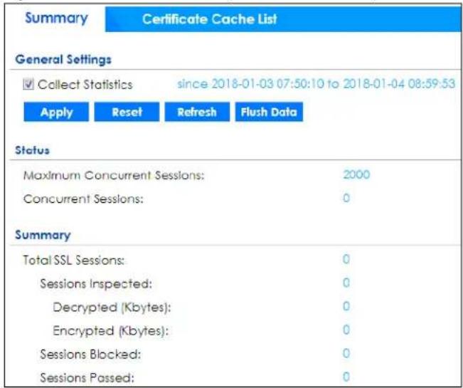
The following table describes the labels in this screen.
Table 91 Monitor > Security Statistics > SSL Inspection > Summary
| LABEL DESCRIPTION | |
| Collect Statistics | Select this check box to have the Zyxel Device collect SSL Inspection statistics.The collection starting time displays after you clickApply. All of the statistics in this screen are for the time period starting at the time displayed here. The format is year, month, day and hour, minute, second. All of the statistics are erased if you restart the Zyxel Device or clickFlush Data. Collecting starts over and a new collection start time displays. |
| Refresh Click this button to update the report display. | |
| Flush Data | Click this button to discard all of the screen's statistics and update the report display. |
| Status | |
| Maximum Concurrent Sessions | This shows the maximum number of simultaneous SSL Inspection sessions allowed for your Zyxel Device model. |
| Concurrent Sessions | This shows the actual number of simultaneous SSL Inspection sessions in progress. |
| Summary | |
| Total SSL Sessions | This is the total of SSL sessions inspected and number of sessions blocked and number of sessions passed since data was last flushed or the Zyxel Device last rebooted afterCollect Statisticswas enabled. |
| Sessions Inspected | This shows the total number of SSL sessions inspected since data was last flushed or the Zyxel Device last rebooted afterCollect Statisticswas enabled |
| Decrypted (Kbytes) | This shows the number of kilobytes (KB) of data that was decrypted for Security Service inspection. |
| Encrypted (Kbytes) | This shows the number of kilobytes (KB) of data that was re-encrypted after Security Service inspection and then forwarded. |
| Sessions Blocked This shows the number of SSL sessions blocked. | |
| Sessions Passed This shows the number of SSL sessions passed. | |
| Apply | ClickApplyto save your changes back to the Zyxel Device. |
| Reset | ClickResetto return the screen to its last-saved settings. |
6.44.1 Certificate Cache List
SSL traffic to a server to be excluded from SSL Inspection is identified by its certificate. Traffic in an Exclude List is not intercepted by SSL Inspection.
Click Monitor > Security Statistics > SSL Inspection > Certificate Cache List to display a screen that shows details on SSL traffic going to servers identified by its certificate and an option to add that traffic to the Exclude List.
Figure 214 Monitor > Security Statistics > SSL Inspection > Certificate Cache List
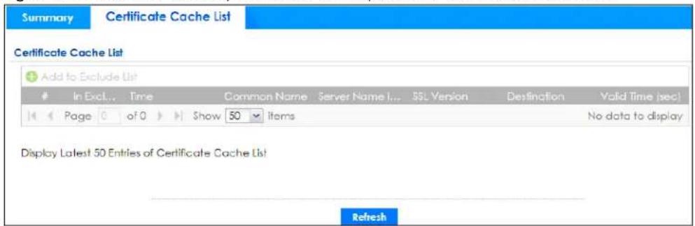
The following table describes the labels in this screen.
Table 92 Monitor > Security Statistics > SSL Inspection > Certificate Cache List
| LABEL DESCRIPTION | |
| Certificate Cache List | |
| Add to Exclude list | Select and item in the list and click this icon to add the common name (CN) to the Exclude List. |
| # | This field is a sequential value, and it is not associated with a specific entry. |
| In Exclude List | If any one of common name, DNS name, email address or IP address of the certificate is in the Exclude List, then traffic to the server identified by the certificate is excluded from inspection.The icons here are defined as follows:Gray: The identity of the certificate is not in the Exclude ListGreen: The common name of the certificate is in the Exclude ListYellow: The common name of certificate is not in the Exclude List but one of the DNS name, email address or IP address is. |
| Time | This is the latest date (yyyy-mm-dd) and time (hh-mm-ss) that the record in the certificate cache list was met. |
| Common Name | This displays the common name in the certificate of the SSL traffic destination server. |
| Server Name Indication | Server Name Indication (SNI) is the domain name entered in the browser, FTP client, etc. to begin the SSL session with the server. It allows multiple SSL sessions to the same IP address and port number with different certificates from different SNI. This field displays the SNI for this SSL session. |
| SSL Version | This field shows the SSL version. SSLv3/TLS1.0 is currently supported. |
| Destination | This displays the IP address and port number of the SSL traffic destination server. |
| Valid Time | This displays the cache item expiry time in seconds. The cache item is deleted when the remaining time expires. |
| Refresh | Click this button to update the information on the screen. |
6.45 Log Screens
Log messages are stored in two separate logs, one for regular log messages and one for debugging messages. In the regular log, you can look at all the log messages by selecting All Logs, or you can select a specific category of log messages (for example, security policy or user). You can also look at the debugging log by selecting Debug Log. All debugging messages have the same priority.
6.45.1 View Log
To access this screen, click Monitor > Log. The log is displayed on the following screen.
Note: When a log reaches the maximum number of log messages, new log messages automatically overwrite existing log messages, starting with the oldest existing log message first.
- The maximum possible number of log messages in the Zyxel Device varies by model.
Events that generate an alert (as well as a log message) display in red. Regular logs display in black. Click a column's heading cell to sort the table entries by that column's criteria. Click the heading cell again to reverse the sort order. The Web Configurator saves the filter settings if you leave the View Log screen and return to it later.
Figure 215 Monitor > Log > View Log
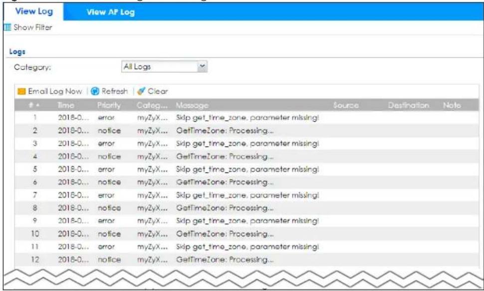
The following table describes the labels in this screen.
Table 93 Monitor > Log > View Log
| LABEL DESCRIPTION | |
| Show (Hide) Filter | Click this button to show or hide criteria that allow you to filter logs that will be displayed.If the filter settings are hidden, theCategory, Email Log Now, Refresh, andClearfields are available.If the filter settings are shown, theCategory,Priority, Source Address, Destination Address, Source Interface, Destination Interface, Service, Keyword, Protocol and Search fields are available. |
| Category | Select the type of log message(s) you want to view. You can also viewAll Logsat one time, or you can view theDebug Log. |
| Priority | This displays when you show the filter. Select the priority of log messages to display. The log displays the log messages with this priority or higher. Choices are:any, emerg, alert,crit, error, warn, notice, andinfo, from highest priority to lowest priority. This field is grayed out if theCategoryis Debug Log. |
| LABEL | DESCRIPTION |
| Source Address | This displays when you show the filter. Type the source IP address of the incoming packet that generated the log message. Do not include the port in this filter. |
| Destination Address | This displays when you show the filter. Type the IP address of the destination of the incoming packet when the log message was generated. Do not include the port in this filter. |
| Source Interface | This displays when you show the filter. Type the source interface of the incoming packet that generated the log message. |
| Destination Interface | This displays when you show the filter. Type the interface of the destination of the incoming packet when the log message was generated. |
| Service | This displays when you show the filter. Select the service whose log messages you would like to see. The Web Configurator uses the protocol and destination port number(s) of the service to select which log messages you see. |
| Keyword | This displays when you show the filter. Type a keyword to look for in the Message, Source, Destination and Note fields. If a match is found in any field, the log message is displayed. You can use up to 63 alphanumeric characters and the underscore, as well as punctuation marks ( )', ;:?! +-*/= #$% @; the period, double quotes, and brackets are not allowed. |
| Protocol | This displays when you show the filter. Select a service protocol whose log messages you would like to see. |
| Search | This displays when you show the filter. Click this button to update the log using the current filter settings. |
| Reset | Click Reset to return the screen to its last-saved settings. |
| Email Log Now | Click this button to send log messages to the Active email addresses specified in the Send Log To field on the Log Settings page. Please note that only the following log messages will be sent:Log messages that have not been sent before, andlog messages that match the categories you selected in Configuration > Log & Report > Log Settings > Edit > Active Log and Alert. |
| Refresh Click this button to | update the information on the screen. |
| Clear | Click this button to clear the whole log, regardless of what is currently displayed on the screen. |
| # This field is a sequential value, and it is not associated with a specific log message. | |
| Time This field displays the time the log message was recorded. | |
| Priority | This field displays the priority of the log message. It has the same range of values as the Priority field above. |
| Category | This field displays the log that generated the log message. It is the same value used in the Category field above. |
| Message | This field displays the reason the log message was generated. The text "[count=x]", where x is a number, appears at the end of the Message field if log consolidation is turned on and multiple entries were aggregated to generate into this one. |
| Source | This field displays the source IP address and the port number in the event that generated the log message. |
| Destination | This field displays the destination IP address and the port number of the event that generated the log message. |
| Note | This field displays any additional information about the log message. |
6.45.2 View AP Log
Click on Monitor > Log > View AP Log to open the following screen.
Figure 216 Monitor > Log > View AP Log
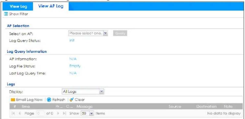
The following table describes the labels in this screen.
Table 94 Monitor > Log > View AP Log
| LABEL DESCRIPTION | |
| Show Filter Click this button | to show or hide the filter settings.If the filter settings are hidden, the Display, Email Log Now, Refresh, and Clear fields are available.If the filter settings are shown, the Display, Priority, Source Address, Destination Address, Source Interface, Destination Interface, Service, Keyword, Protocol, and Search fields are available. |
| Select an AP Click the | pull down menu to choose an AP. |
| Query Click Query to create a Query log. | |
| Log Query Status The field displays the | |
| AP Information This field displays the AP information. N/A is displayed when | |
| Log File Status | This field displays how many logs are available. It will display Empty if there's none. |
| Last Log Query Time | This field displays the most recent time a log query was solicited. |
| Display | Select the category of log message(s) you want to view. You can also view All Logs at one time, or you can view the Debug Log. |
| Priority | This displays when you show the filter. Select the priority of log messages to display. The log displays the log messages with this priority or higher. Choices are: any, emerg, alert, crit, error, warn, notice, and info, from highest priority to lowest priority. This field is read-only if the Category is Debug Log. |
| Source Address Type the IP address of the source AP. | |
| Destination Address | This displays when you show the filter. Type the IP address of the destination of the incoming packet when the log message was generated. Do not include the port in this filter. |
| Source Interface | This displays when you show the filter. Type the source interface of the incoming packet that generated the log message. |
| Destination Interface | This displays when you show the filter. Type the interface of the destination of the incoming packet when the log message was generated. |
| Service | Select a policy service available from Zyxel Device from the pull down menu. |
| Keyword | Type a keyword of the policy service available from Zyxel Device to search for a log. |
| Protocol | Select the protocol of the AP from the pull down menu. |
| Search Click this to start the search. | |
| Email Log Now | Click this button to send log messages to the Active email addresses specified in the Send Log To field on the Log Settings page. Please note that only the following log messages will be sent:Log messages that have not been sent before, andlog messages that match the categories you selected in Configuration > Log & Report > Log Settings > Edit > Active Log and Alert. |
| Refresh Click this button to update the information on the screen. | |
| Clear | Click this button to clear the whole log, regardless of what is currently displayed on the screen. |
| # This field is a sequential value, and it is not associated with a specific log message. | |
| Time This field displays the time the log message was recorded. | |
| Priority | This displays when you show the filter. Select the priority of log messages to display. The log displays the log messages with this priority or higher. Choices are: any, emerg, alert, crit, error, warn, notice, and info, from highest priority to lowest priority. This field is read-only if the Category is Debug Log. |
| Category | This field displays the log that generated the log message. It is the same value used in the Display and (other) Category fields. |
| Message This field displays the message of the log. | |
| Source | This displays the source IP address of the selected log message. |
| Destination | This displays the source IP address of the selected log message. |
| Note | This field displays any additional information about the log message. |
6.45.3 Dynamic Users Log
Use this screen to view the Zyxel Device's dynamic guest account log messages. Click Monitor > Log > Dynamic Users Log to access this screen.
Figure 217 Monitor > Log > Dynamic Users Log
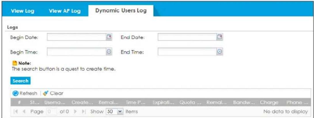
The following table describes the labels in this screen.
Table 95 Monitor > Log > Dynamic Users Log
| LABEL DESCRIPTION | |
| Begin/End Date | Select the first and last dates to specify a time period. The Zyxel Device displays log messages only for the accounts created during the specified time period after you click Search. |
| Begin/End Time | Select the begin time of the first date and the end time of the last date to specify a time period. The Zyxel Device displays log messages only for the accounts created during the specified time period after you click Search. |
| Search | Click this button to update the information on the screen using the filter criteria in the date and time fields. |
| Refresh Click this button to update the information in the screen. | |
| Clear | Click this button to delete the log messages for invalid accounts. |
| # This is the index number of the dynamic guest account in the list. | |
| Status This field displays whether an account expires or not. | |
| Username This field displays the user name of the account. | |
| Create Time This field displays when the account was created. | |
| Remaining Time | This field displays the amount of Internet access time remaining for each account. |
| Time Period | This field displays the total account of time the account can use to access the Internet through the Zyxel Device. |
| Expiration Time | This field displays the date and time the account becomes invalid.Note: Once the time allocated to a dynamic account is used up or a dynamic account remains un-used after the expiration time, the account is deleted from the account list. |
| Quota (T/U/D) | This field displays how much data in both directions (Total) or upstream data (Upload) and downstream data (Download) can be transmitted through the WAN interface before the account expires. |
| Remaining Quota (T/U/D) | This field displays the remaining amount of data that can be transmitted or received by each account. You can see the amount of either data in both directions (Total) or upstream data (Upload) and downstream data (Download). |
| Bandwidth (U/D) | This field displays the maximum upstream (Upload) and downstream (Download) bandwidth allowed for the user account in kilobits per second. |
| Real Name | This field displays the user's name of the account. |
| This field displays the email of the account. | |
| Charge | This field displays the total cost of the account. |
| Payment Info | This field displays the method of payment for each account. |
| Phone Num | This field displays the telephone number for the user account. |
CHAPTER 7 Licensing
7.1 Registration Overview
Use the Configuration > Licensing > Registration screens to register your Zyxel Device and manage its service subscriptions.
- Use the Registration screen (see Section 7.1.3 on page 260) to refresh Zyxel Device registration, go to portal.myZyxel.com to register your Zyxel Device and activate a service, such as content filtering.
- Use the Service screen (see Section 7.1.4 on page 261) to display the status of your service registrations and upgrade licenses.
- Use the Signature Update screen (see Section 7.2.2 on page 263) to download the latest signatures for your licensed services.
7.1.1 What you Need to Know
This section introduces the topics covered in this chapter.
Subscription Services Available
See Configuration > Licensing > Registration > Service for the subscription services that your Zyxel Device supports. Zyxel offers two types of security packs for your Zyxel Device. The subscription services you can use on the Zyxel Device vary depending on the security pack license you purchase. See the table below for services available in each pack.
You can purchase an iCard and enter its license key at myZyxel to extend a service.
License Update
Licenses are updated using port 443. Make sure TCP service port 443 is allowed on the router connected to the Zyxel Device.
Features Available Without a License
You can use the following Zyxel Device features without a license:
Table 96 Features Available Without a License
| MONITOR CONFIGURATION MAINTENANCE | ||
| Traffic Statistics Wireless File Manager | ||
| Wireless Network Diagnostics | ||
| VPN Monitor VPN Packet Flow Explore | ||
| Log BWM Shutdown/Reboot | ||
| Web Authentication | ||
Table 96 Features Available Without a License
| MONITOR CONFIGURATION MAINTENANCE | ||
| Security Policy | ||
| Object | ||
| System | ||
| Log & Report | ||
Please note that you cannot use the security services if your Zyxel Device does not have a license. Your Zyxel Device and network will be exposed to threats and attacks. We strongly recommend you to buy a license to better protect your Zyxel Device and network.
7.1.2 Gold Pack License and UTM Bundled License
The UTM bundled license includes the UTM security services listed below:
- Web Filtering
- IPS
- Application Patrol
• Anti-Malware - Email Security
• Collaborative Detection & Response - SecuReporter
- Network Premium
• Security Profile Sync
Note: You can renew the Anti-Malware and SecuReporter service licenses individually.
If you renew a UTM license, the Expiration Date in Configuration > Licensing > Registration > Service is extended by one, two or three years depending on the license or service you bought. See Section 7.1.2.3 on page 260 for more information on the expiration date.
The Status for each service in the renewed UTM license displays Queued in portal.myzyxel.com. These services will become active when the current UTM bundled license services expire. See Section 7.1.2.4 on page 260 for more information on the service status.
The Gold Pack license is the UTM license that comes with the Zyxel Device when you buy it and is good for 1 year. The Gold Pack license includes all security services in the default UTM bundled license, with the additional services listed below:
- Sandboxing
- DNS Threat Filter
- IP Reputation
- Secure WiFi
• Nebula Professional Pack
Note: You can renew the Secure WiFi and Nebula professional pack service licenses individually.
If you buy a gold pack license and renew a UTM license, the Expiration Date is not extended in Configuration > Licensing > Registration > Service as the Expiration Date of licenses with different services cannot be added together. See Section 7.1.2.3 on page 260 for more information on the expiration date.
The Status for each service in the Gold Pack license displays Queued in portal.myzyxel.com. The Status for each service in the renewed UTM license displays Deferred in portal.myzyxel.com. The Gold pack license services will become active when the current UTM bundled license services expire. See Section 7.1.2.4 on page 260 for more information on the service status.
7.1.2.1 Hospitality Pack License and Hotspot Management License
The hospitality pack license includes the licenses listed below:
- Hotspot management subscription service license
- Concurrent device upgrade license
The hotspot management license includes the license listed below:
• Hotspot management subscription service license
Hotspot management subscription service license is a license to manage hotspot functions such as billing, printer manager, free time, IPnP, walled garden and advertisement; see Chapter 25 on page 632 for more information.
Concurrent device upgrade license is a license to increase the number of devices (based on the MAC addresses) that can log in and use the Zyxel Device hotspot at the same time.
Please note that:
- Not all Zyxel Devices support hospitality pack license or hotspot management license.
- A Zyxel Device cannot support hospitality pack license and hotspot management license at the same time.
See Table 1 on page 29 for more information on the license each Zyxel Device supports.
7.1.2.2 License Priority
Please note that in On-Premises Mode, if you purchase a UTM license before a Gold Pack license expires, the UTM license services will only be available after the Gold Pack license expires.
Services within licenses become active in the following order:
1 Trial Gold Pack license
2 Default Gold Pack license
3 Gold Pack license
4 New UTM license
5 Individual service license
If your Zyxel Device is managed by Nebula in On Cloud Mode, you can use the gold pack security services, right after you purchase the gold pack license.
The hospitality pack license and hotspot management license will become active once you buy them. They are independent and will not be affected by the priority of the licenses listed above.
Contact customer support if you have a problem using your licenses.
7.1.2.3 Expiration Date
Only the Expiration Date for services that are currently running on the Zyxel Device are displayed in Configuration > Licensing > Registration > Service. The Expiration Date changes after you buy a new license.
For example, if you are currently using the default Gold Pack license, with expiration date of 2024/4/1, and then you purchase a new 1-year Gold Pack license, the new Expiration Date will be in 2025/4/1.
If you purchase a 1-year UTM license after purchasing a new Gold Pack license, a year will be deducted from the Expiration Date because:
- The Expiration Date of licenses with different services cannot be added together.
- The services in the Gold Pack license take priority over the new UTM license.
Go to portal.myzyxel.com to view the actual Amount/Time and Status for all services.
Table 97 Expiration Date Example
| Default Gold Pack License | +1-Year Gold Pack License +1 | -Year UTM License | |
| Expiration Date 2024/4/1 | 2025/4/1 2024/4/1 |
7.1.2.4 Service Status
Your service may show one of the following states.
- Consuming: The license service is active.
- Queued: This displays when you bought a new UTM license. Services are queued as they will become active when current UTM services expire.
- Deferred: This displays when you bought a gold pack license and a new UTM license. The new UTM license services are deferred as the gold pack license has priority, so the new UTM license services will not become active until the gold pack license services first become active, then expire.
- Expired: The license service expiry date (and grace period) is over.
7.1.3 Registration Screen
Click the link in this screen to register your Zyxel Device at myZyxel. Then click Refresh in this screen and wait a few moments for the registration information to update. If the page does not refresh, make sure the Internet connection is working and click Refresh again. The Zyxel Device should already have Internet access and be able to access myZyxel. Click Configuration > Licensing > Registration in the navigation panel to open the screen as shown next.
Click on the icon to go to the OneSecurity website where there is guidance on configuration walkthrough and other information.
Figure 218 Configuration > Licensing > Registration
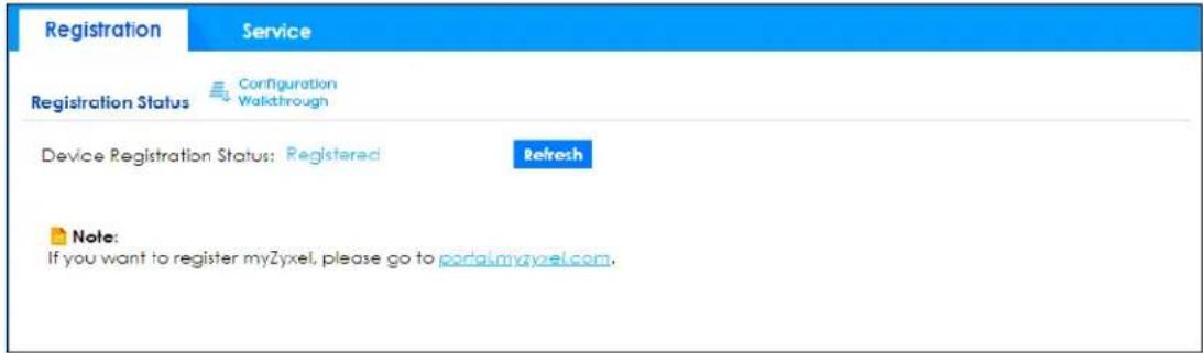
7.1.4 Service Screen
Use this screen to display the status of your service registrations and upgrade licenses. To activate or extend a standard service subscription, purchase an iCard and enter the iCard's PIN number (license key) at myZyxel.
Click Activate in this screen to enable both Trial and Standard services on this Zyxel Device. Click Configuration > Licensing > Registration > Service to open the screen as shown next.
Figure 219
The Service screen may show different services depending on the licenses you purchase or activate.
- Managed AP Service will be replaced by Secure WiFi when it's activated.
Figure 220 Configuration > Licensing > Registration > Service - USG FLEX Series
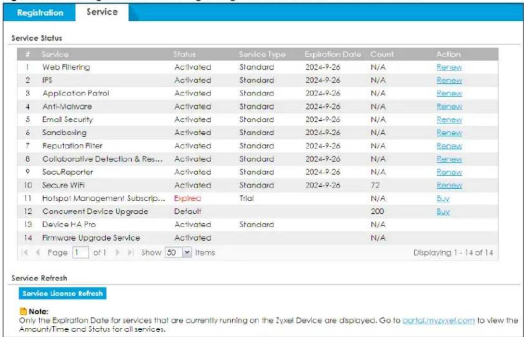
The following table describes the labels in this screen.
Table 98 Configuration > Licensing > Registration > Service
| LABEL DESCRIPTION | |
| Service Status | |
| # This is the entry's position in the list. | |
| Service | This lists the name of services or service modules that are available on the Zyxel Device. |
| Web Filtering | This is a license to a database that can block websites by category, such as Gambling. |
| IPS (IDP) | This is a license to detect Intrusion Detection and Prevention attacks. |
| Application Patrol | This is a license to use signatures for Application Patrol inspection to manage the use of various applications on the network. |
| Anti-Malware This is a license for signatures to detect malware patterns in files. | |
| Email Security | This is a license to use anti-spam signatures to mark or discard spam (unsolicited commercial or junk email). |
| Sandboxing | This is a license to provide a safe environment to separate running programs from your network and host devices. |
| Reputation Filter | This is a license to recognize packets coming from suspect IPv4 addresses. |
| Collaborative Detection & Response | This is a license to detect wired and wireless clients that have become infected in your network and to block or isolate traffic coming from them. |
| SecuReporter | This is a license that allows SecuReporter to collect and analyze logs from your Zyxel Device in order to identify anomalies, notify you of potential internal or external threats, and report on network usage. The Zyxel Device retains logs up to 1 year. |
| Managed AP Service | This is a license to manage more APs than the default for your Zyxel Device when the AP controller is enabled. |
| Secure WiFi This is a license to: Manage more than 8 APs. Enable Remote AP to allow an IPSec VPN tunnel from a supported remote AP to the Zyxel Device.The Secure WiFi license replaces the Managed AP Service license. If the Secure WiFi license expires, then the Managed AP Service license will reappear, but you cannot renew it. You can only renew a Secure WiFi license. | |
| Network Premium | This is a license to use Single-Sign On (SSO) that allows the Zyxel Device to communicate with an SSO agent. |
| Hotspot Management Subscription Service | This is a license to manage hotspot functions such as Billing, Printer Manager, Free Time, IPnP, Walled Garden and Advertisement. |
| Concurrent Device Upgrade | This is a license to increase the number of devices (based on unique MAC address) that can log in and use the Zyxel Device Hotspot at the same time. |
| Device HA Pro | This is a license for professional High Availability (HA) that lets a backup Zyxel Device automatically take over if the master Zyxel Device fails. |
| Firmware Upgrade Service | This is a free license to get Cloud Helper notifications when new firmware is available. You must register your Zyxel Device at myZyxel. |
| Status | This field displays whether a service license is enabled at myZyxel (Activated) or not (Not Activated) or expired (Expired). It displays the remaining Grace Period if your license has Expired. It displays Not Licensed if there isn't a license to be activated for this service.Default displays for quantity-based licenses when the Zyxel Device is currently using the allowed free number without a license. For example, if a Zyxel Device is allowed to manage x number of APs without a license and it is currently using that number, then Managed AP Service Status displays Default. |
| Service Type | This field displays whether you applied for a trial application (Trial) or registered a service with your iCard's PIN number (Standard). This field is blank when a service is not activated. |
| Expiration Date | This field displays the date your service license expires or the date the grace period expires if the license has already expired.You can continue to use IDP/AppPatrol, Anti-Malware, Content Filter, Email Security during the grace period. After the grace period ends, all of these features are disabled. |
| Count | This field displays how many instances of a service you can use with your current license. N/A means a count does not apply to this service. |
| Action | If you need a license or a trial license has expired, click Buy to buy a new one. If a Standard license has expired, click Renew to extend the license.Then, click Activate to connect with the myZyxel server to activate the new license. |
| Service License Refresh | Click this button to renew service license information (such as the registration status and expiration day).Note: It is recommended you use this button after you register for a new service. |
7.2 Signature Update
This section shows you how to update the signature packages of the Zyxel Device.
- Use the Configuration > Licensing > Signature Update screen (Section 7.2.2 on page 263) to update the signatures used for a service, such as IDP and application patrol.
7.2.1 What you Need to Know
- You need a valid service registration to update the anti-malware signatures, the URL Threat filter signatures, the IDP signatures and the App-Patrol signatures.
- You do not need a service registration to update the system-protection signatures.
- Schedule signature updates for a day and time when your network is least busy to minimize disruption to your network.
- Your custom signature configurations are not over-written when you download new signatures.
Note: The Zyxel Device does not have to reboot when you upload new signatures.
7.2.2 The Signature Screen
Click Configuration > Licensing > Signature Update to display the following screen.
Figure 221 Configuration > Licensing > Signature Update
| Feature | Type | Current Version | Released Date | Last Sync | Action |
| Anti-Malware | Anti-Malware Sig... | 2.1.2.2021030... | 2021-03-04 01:37:39 (UTC+08:00) | 2021-03-04 23:19:02 | |
| Threat Intelligenc... | 1.0.0.2021030... | 2021-03-03 18:15:04 (UTC+08:00) | |||
| App-Patrol | App-Patrol | 1.0.0.2021022... | 2021-02-23 15:59:20 (UTC+08:00) | 2021-02-28 00:16:01 | |
| IDP | IDP | 4.0.0.2021022... | 2021-02-23 10:10:00 (UTC+08:00) | 2021-02-28 01:45:01 | |
| URL Threat ... | URL Threat Filter | 1.0.0.2021030... | 2021-03-04 02:00:26 (UTC+08:00) | 2021-03-05 02:56:06 | |
| IP Reputation | IP Reputation | 1.0.0.2021030... | 2021-03-04 02:30:44 (UTC+08:00) | 2021-03-05 03:56:01 |
The following table describes the labels in this screen.
Table 99 Configuration > Licensing > Signature Update
| LABEL DESCRIPTION | |
| Service Status | The following fields display the status and information on the current signature set that the Zyxel Device is using. |
| Feature This field displays the name of the services available on the Zyxel Device. | |
| Type This field displays the type of service engine used by the Zyxel Device. | |
| Current Version | This field displays the signatures version number currently used by the Zyxel Device. This number gets larger as new signatures are added. |
| Released Date | This field displays the date and time the set was released. |
| Last Sync | This field displays the date and time the Zyxel Device last checked for new signatures at myZyxel. |
| Action | Click the Update icon to have the Zyxel Device immediately check for new signatures at myZyxel. If new signatures are found, they are then downloaded to the Zyxel Device.Click the Schedule icon to have the Zyxel Device automatically check for new signatures regularly at the time and day specified. You should select a time when your network is not busy for minimal interruption. |
7.2.3 Auto Update
Click the Schedule icon of a service to display the following screen.
Figure 222 Configuration > Licensing > Signature Update: Schedule > Auto Update
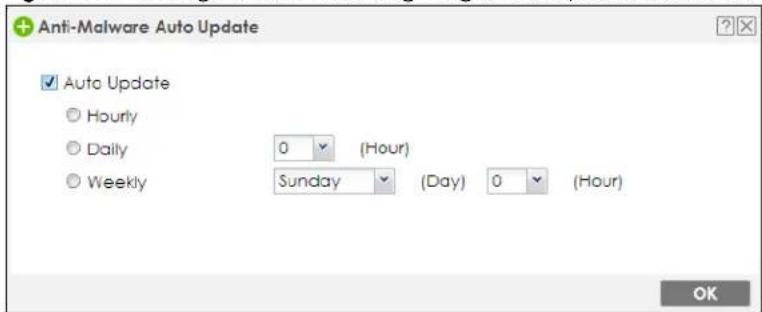
The following table describes the labels in this screen.
Table 100 Configuration > Licensing > Signature Update: Schedule > Auto Update
| LABEL DESCRIPTION | |
| Auto Update | Select this check box to have the Zyxel Device automatically check for new signatures regularly at the time and day specified.You should select a time when your network is not busy for minimal interruption. |
| Hourly | Select this option to have the Zyxel Device check for new signatures every hour. |
| Daily | Select this option to have the Zyxel Device check for new signatures every day at the specified time. The time format is the 24 hour clock, so '23' means 11 PM for example. |
| Weekly | Select this option to have the Zyxel Device check for new signatures once a week on the day and at the time specified. |
| OK Click this button to save your changes to the Zyxel Device. | |
CHAPTER 8 Wireless
8.1 Overview
Use the Wireless screens to configure how the Zyxel Device manages supported Access Points (APs). Supported APs should be in managed mode. See the product page Licenses tab for a list of supported APs.
8.1.1 What You Can Do in this Chapter
- Use the Built-in AP screen (Section 8.2 on page 270) to allow WiFi clients to access your Zyxel Device wirelessly to connect to the network.
- Use the Controller screen (Section 8.3 on page 281) to set how the Zyxel Device allows new APs to connect to the network and set the country code of APs that are connected to the Zyxel Device.
- Use the AP Management screens (Section 8.4 on page 284) to manage all of the APs connected to the Zyxel Device.
- Use the Rogue AP screen (Section 8.5 on page 309) to assign APs either to the rogue AP list or the friendly AP list.
- Use the Wireless Health (Section 8.6 on page 312) screen to improve the APs wireless network performance.
- Use the Auto Healing screen (Section 8.7 on page 313) to extend the wireless service coverage area of the managed APs when one of the APs fails.
- Use the RTLS screen (Section 8.8 on page 314) to allow managed APs with battery-powered Wi-Fi tags be part of Ekahau RTLS (Real Time Location Service). RTLS can track the location of APs managed by the Zyxel Device to create maps, alerts, and reports.
8.1.2 What You Need to Know
The following table shows the APs that support each feature.
Table 101 AP Features Comparison Table
| MODEL/ FEATURE | AIRTIME FAIRNESS | ETHERNET STORM CONTROL | WIRELESS STORM CONTROL | WIRELESS HEALTH | WIFI STANDARD |
| NWA5123AC-HD | NO | YES | NO | NO | WiFi 5 |
| WAC6303D-S | NO | YES | NO | NO | WiFi 5 |
| WAC5302-Sv2 | NO | YES | NO | NO | WiFi 5 |
| WAX630S YES YES YES WiFi 6 | |||||
| WAX650S YES YES YES WiFi 6 | |||||
| WAX510D YES YES YES WiFi 6 | |||||
| WAX610D YES YES YES WiFi 6 | |||||
| WAC500H NO YES YES YES WiFi 5 | |||||
| WAC500 NO YES YES YES WiFi 5 | |||||
| WAX640S-6E YES YES | YES YES WiFi 6E | ||||
| WAX620D-6E YES YES | YES YES WiFi 6E | ||||
| WBE660S YES YES YES | YES WiFi 7 | ||||
For more information on airtime fairness, see Section 8.4.1.1 on page 286.
For more information on storm control, see Section 8.4.1.1 on page 286.
For more information on wireless health, see Section 8.6 on page 312.
Note: Please see your AP product page at the Zyxel web site to see if it can be managed by the Zyxel Device.
WiFi 6 (IEEE 802.11ax)
WiFi 6 (802.11ax) is a WiFi standard that supports both 2.4GHz and 5GHz frequency bands and brings the following major improvements:
High Data Transmission Speed
WiFi 6 provides faster transmission data rate than its previous WiFi standards with the following features:
- 1024-QAM (Quadrature Amplitude Modulation)- enhances the data capacity of each transmission unit.
- 160 MHz Channel Bandwidth- extends the supported channel bandwidth to 160 MHz, providing higher data throughput.
Enhanced Air Time Utilization
WiFi 6 increases transmission performance in high-density environments that have multiple client devices with the following features:
- OFDMA (Orthogonal Frequency-Division Multiple Access)- divides channels into sub-channels that enables multiple transmissions in a single channel.
- BSS Coloring- tags traffic by BSS (Basic Server Set) and identifies traffic from overlapping BSSs. The AP can ignore traffic of unrelated BSSs and transmit data when a channel is occupied.
- MU-MIMO (Multiple User-Multiple Input Multiple Output)- enables multiple users to connect to the AP and download/upload traffic simultaneously.
Extended Signal Range
Beamforming forms the radiating signals into one direction. This enhances the signal strength and extends the signal transmission range.
Extended Battery Life
Target Wake Time (TWT) allows the AP to negotiate with client devices so client devices only wakes up and communicates with the AP in specific periods. This conserve client devices battery life.
WiFi 6E (IEEE 802.11ax - Extended Standard)
WiFi 6E is an extended standard of WiFi 6 (IEEE 802.11ax). WiFi 6E inherits all the WiFi 6 features and brings with an additional 6 GHz band. The 6 GHz band allows you to avoid possible congested traffic in the lower 2.4 GHz and 5 GHz bands. WiFi clients must support WiFi 6E to connect to an AP using the 6 GHz band.
You must use WPA3 for security with WiFi 6E.
Note: Check your client device's product specification to see if your client device supports the 6 GHz band (WiFi 6E). If not, you should still use the 2.4/5 GHz bands for connection.
WiFi 6E MBSSID Beacon Management
The AP supports MBSSID, which allows you to create multiple virtual WiFi networks (SSIDs) on the AP. With the WiFi 6E (802.11ax-extended) standard, the AP divides SSIDs into groups, and includes information of all SSIDs in a group in one SSID beacon. Therefore, the Zyxel Device doesn't need to send beacons for individual SSIDs, which improves air time efficiency.
Note: If you disable a virtual WiFi network (SSID) whose beacon contains the group SSID information, WiFi clients of that group will be disconnected until the AP reselects another SSID to send the beacon.
Out-of-Band Discovery
Out-of-band discovery allows the AP to include information of the 6 GHz band in management frames sent over the 2.4 GHz /5 GHz bands. WiFi 6E clients only need to scan the lower bands (2.4 GHz/5 GHz) to connect to the AP in the 6 GHz band, reducing the discovery time.
PSC Channel (In-Band Discovery)
PSCs (Preferred Scanning Channels) are dedicated channels for WiFi 6E clients to send probe requests on to discover a compatible AP, instead of scanning the entire 6 GHz band. In this way, WiFi 6E clients are able to efficiently discover and connect to the AP within the 6 GHz band.
Note: The available PSCs differ by country for the unlicensed use in the 6 GHz band.
Resource Unit
A resource unit is a portion of a channel bandwidth. For example, a 20 MHz channel can be divided into several resource units. Each resource unit can be allocated to a specified WiFi client, allowing simultaneous data transmission.
WiFi 7 (IEEE802.11be)
WiFi 7 (802.11be) is backward-s compatible with WiFi 6 and WiFi 6E. WiFi 7 is a WiFi standard that supports 2.4 GHz, 5 GHz and 6 GHz frequency bands with the following improvements over WiFi 6 and WiFi 6E.
Table 102 WiFi 6, WiFi 6E and WiFi 7 Comparison
| FEATURES WIFI 6 WIFI 6E WIFI 7 | |||
| Theoretical Maximum Speed (Up-to) | The same (9.6 Gbps). | 46 Gbps | |
| Supported Frequency Bands | 2.4 GHz/5 GHz | 2.4 GHz/5 GHz/6 GHz | 2.4 GHz/5 GHz/6 GHz |
| Supported Channel Bandwidth | 20/40/80/160 MHz | 20/40/80/160 MHz | 20/40/80/160/320 MHz |
Table 102 WiFi 6, WiFi 6E and WiFi 7 Comparison
| FEATURES WIFI 6 WIFI 6E WIFI 7 | ||||
| Total Spectrum (Up-to) 2.4 | GHz 80 MHz | 80 MHz | ||
| 5 GHz 500 | MHz 500 MHz | |||
| 6 GHz | Not supported. | 1200 MHz | 1200 MHz | |
| Other Features (OFDMA/BSS Coloring/TWT/Two-Way MU-MIMO/Beamforming/1024-QAM) | The same (WiFi 6E inherits all the features from WiFi 6). | WiFi 7 inherits all the features from WiFi 6 and WiFi 6E, with the addition of multi-link operation and preamble puncturing. | ||
Faster Data Transmission
WiFi 7 allows faster data transmission using:
- 4096 QAM (Quadrature Amplitude Modulation)- enhances the amount of data transmitted over the available bandwidth.
- 320 MHz Channel Bandwidth- enlarges the supported channel bandwidth to 320 MHz, allowing higher data throughput.
- Multiple Resource Units (RUs)- allows an AP to allocate multiple RUs to a WiFi client.
Multi-Link Operation (MLO)
An AP can support multiple frequency bands (2.4 GHz, 5 GHz and 6 GHz), but a WiFi client can only connect to the AP using one of these frequency bands. The other frequency bands are unused. The client's data transmission speed depends on the frequency band they are connected to.
Figure 223 Without Multi-Link Operation
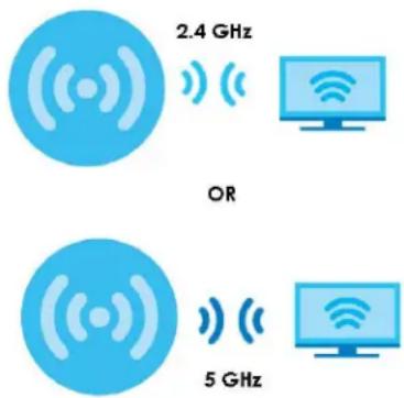
WiFi 7 MLO allows a WiFi client to connect to the AP using multiple frequency bands simultaneously. This increases speed and improves reliability of the WiFi connection. MLO makes WiFi 7 ideal for streaming 4K/8K videos, using augmented reality (AR), virtual reality (VR) applications and playing online games.
To use MLO, both the AP and the WiFi client have to support MLO.
Note: The Zyxel AP does not support MLO at the time of writing.
Figure 224 Multi-Link Operation Example
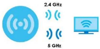
Preamble Puncturing
In WiFi 6 and earlier, any interference would cause the entire WiFi channel to become unavailable. In the figure below, if part of the WiFi channel (B) experiences interference, the rest of the WiFi channel (C) becomes unavailable.
Figure 225 Without Preamble Puncturing

WiFi 7 preamble puncturing allows you to block the specific portion of the channel that is experiencing interference while continuing to use the rest of the WiFi channel. In the figure below, if part of the WiFi channel (B) experiences interference, the rest of the WiFi channel (C) is still available.
Figure 226 Preamble Puncturing Example

8.2 Built-in AP
If your Zyxel Device has a built-in AP, then use this function to allow WiFi clients to access your Zyxel Device wirelessly to connect to the network. If your Zyxel Device is in AP Controller Mode, go to Configuration > Wireless > Built-in AP_General and click Switch to Built-in AP Mode.
Figure 227 Configuration > Wireless > General (Switch to Built-in Mode)
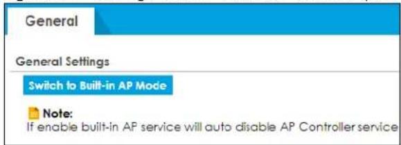
To go to AP Controller Mode from Built-in AP Mode, go to Configuration > Controller and click Switch to AP Controller Mode.
Your Zyxel Device configuration menu will look different in Built-in AP mode and AP Controller mode.
Figure 228 Configuration > Wireless > General (Switch to Built-in Mode)
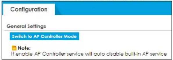
The Configuration > Wireless > Built-in AP displays showing AP information in Built-in AP Mode.
Figure 229 Configuration > Wireless > General
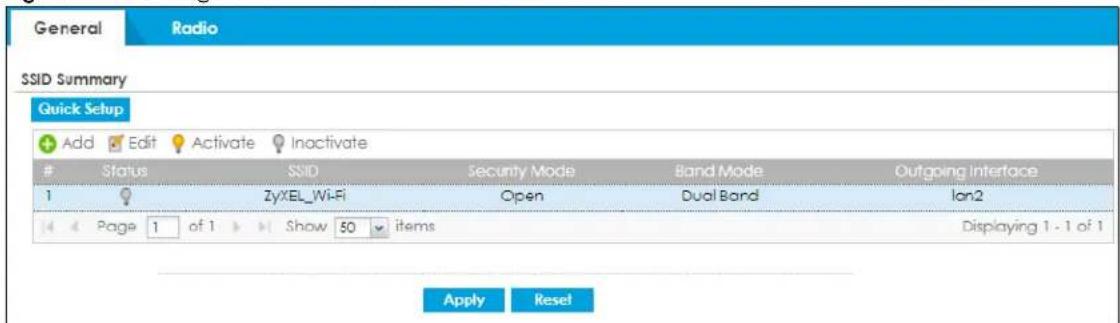
Each field is described in the following table.
Table 103 Configuration> Wireless> General
| LABEL DESCRIPTION | |
| SSID Summary | |
| Quick Setup | Click this to go to the Quick Setup Wireless Wizard to configure a wireless network. |
| Add Click this to configure a new wireless network.You can configure up to 4 SSID profiles. | |
| Edit | Double-click an entry or select it and click Edit to open a screen where you can modify the entry's settings. |
| Activate/Inactivate | To turn on an entry, select it and click Activate. To turn off an entry, select it and click Inactivate. |
| # This is the wireless network's index number in this list. | |
| Status This displays whether or not the wireless network is activated. | |
| SSID This shows the name of the wireless network. | |
| Security Mode | This shows the security used for this wireless network. No security allows any wireless client to associate with this network without authentication. |
| Band Mode | This shows the wireless band which this wireless network uses. 2.4 GHz is the frequency used by IEEE 802.11b/g/n/ax wireless clients. 5 GHz is the frequency used by IEEE 802.11ax/ac/a/n wireless clients. |
| Outgoing Interface | This is the outgoing interface that the wireless network uses to transmit packets. |
| Apply | Click Apply to save your changes back to the Zyxel Device. |
| Reset | Click Reset to return the screen to its last-saved settings. |
8.2.1 Wireless > Built-in AP > General > Add/Edit SSID
This screen allows you to create a new SSID profile or edit an existing one. An SSID, or Service Set Identifier, is the name of the wireless network to which a wireless client can connect. To access this screen, click the Add button or select an entry from the list in Configuration > Wireless > Built-in AP then and click the Edit button.
Figure 230 Configuration > Wireless > General > Add/Edit SSID Profile
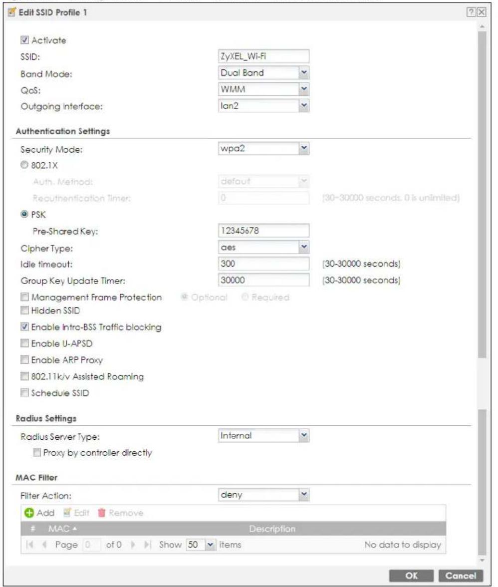
Each field is described in the following table.
Table 104 Configuration > Object > AP Profile > SSID > SSID List > Add/Edit SSID Profile
| LABEL DESCRIPTION | |
| Activate | To turn on an entry, selectActivate. To turn off an entry, select it and clickInactivate. |
| SSID | Enter the SSID name for this profile. This is the name visible on the network to wireless clients.Enter up to 32 characters, spaces and underscores are allowed. |
| Band Mode | This shows the wireless band which this wireless network uses. 2.4 GHz is the frequency used by IEEE 802.11b/g/n/ax wireless clients. 5 GHz is the frequency used by IEEE 802.11ax/ac/a/n wireless clients. |
| QoS | Select a Quality of Service (QoS) access category to associate with this SSID. Access categories minimize the delay of data packets across a wireless network. Certain categories, such as video or voice, are given a higher priority due to the time sensitive nature of their data packets.QoS access categories are as follows:disable:Turns off QoS for this SSID. All data packets are treated equally and not tagged with access categories.WMM:Enables automatic tagging of data packets. The Zyxel Device assigns access categories to the SSID by examining data as it passes through it and making a best guess effort. If something looks like video traffic, for instance, it is tagged as such.WMM_VOICE:All wireless traffic to the SSID is tagged as voice data. This is recommended if an SSID is used for activities like placing and receiving VoIP phone calls.WMM_VIDEO:All wireless traffic to the SSID is tagged as video data. This is recommended for activities like video conferencing.WMM_BEST_EFFORT:All wireless traffic to the SSID is tagged as “best effort,” meaning the data travels the best route it can without displacing higher priority traffic. This is good for activities that do not require the best bandwidth throughput, such as surfing the Internet.WMM_BACKGROUND:All wireless traffic to the SSID is tagged as low priority or “background traffic”, meaning all other access categories take precedence over this one. If traffic from an SSID does not have strict throughput requirements, then this access category is recommended. For example, an SSID that only has network printers connected to it. |
| Outgoing Interface | Select the outgoing interface that the wireless network uses to transmit packets. |
| Authentication Settings | |
| Security Mode | Select a security mode from the list:open, wep, wpa2, wpa2-mix or wpa3. |
| 802.1x | Select this to enable 802.1x secure authentication with a RADIUS server. |
| Auth. Method | This field is available only when you select theRADIUS Server Typeto Internal.Select an authentication method if you have created any on theConfiguration > Object >Auth.Methodscreen. |
| Reauthentication Timer | Enter the interval (in seconds) between authentication requests. Enter a 0 for unlimited requests. |
| PSK | Select this option to use a Pre-Shared Key with WPA encryption. |
| Pre-Shared Key | Enter a pre-shared key of between 8 and 63 case-sensitive ASCII characters (including spaces and symbols) or 64 hexadecimal characters. |
| Cipher Type Select | an encryption cipher type from the list.auto- This automatically chooses the best available cipher based on the cipher in use by the wireless client that is attempting to make a connection.aes- This is the Advanced Encryption Standard encryption method. It is a more recent development over TKIP and considerably more robust. Not all wireless clients may support this. |
| Idle Timeout | Enter the idle interval (in seconds) that a client can be idle before authentication is discontinued. |
| Group Key Update Timer | Enter the interval (in seconds) at which the AP updates the group WPA encryption key. |
| Pre-Authentication | This field is available only when you setSecurity Mode to wpa2 or wpa2-mixand enable 802.1x authentication.Enable or Disable pre-authentication to allow the AP to send authentication information to other APs on the network, allowing connected wireless clients to switch APs without having to re-authenticate their network connection. |
| Management Frame Protection | This field is available only when you selectwpa2in theSecurity Modefield and setCipher Type to aes.Data frames in 802.11 WLANs can be encrypted and authenticated with WEP, WPA or WPA2. But 802.11 management frames, such as beacon/probe response, association request, association response, de-authentication and disassociation are always unauthenticated and unencrypted. IEEE 802.11w Protected Management Frames allows APs to use the existing security mechanisms (encryption and authentication methods defined in IEEE 802.11i WPA/WPA2) to protect management frames. This helps prevent wireless DoS attacks.Select the check box to enable management frame protection (MFP) to add security to 802.11 management frames.SelectOptionalif you do not require the wireless clients to support MFP. Management frames will be encrypted if the clients support MFP.SelectRequiredand wireless clients must support MFP in order to join the Zyxel Device’s wireless network. |
| Hidden SSID | Select this if you want to “hide” your SSID from wireless clients. This tells any wireless clients in the vicinity of the AP using this SSID profile not to display its SSID name as a potential connection. Not all wireless clients respect this flag and display it anyway.When a SSID is “hidden” and a wireless client cannot see it, the only way you can connect to the SSID is by manually entering the SSID name in your wireless connection setup screen(s) (these vary by client, client connectivity software, and operating system). |
| Enable Intra-BSS Traffic Blocking | Select this option to prevent crossover traffic from within the same SSID on the Zyxel Device. |
| Enable U-APSD | Select this option to enable Unscheduled Automatic Power Save Delivery (U-APSD), which is also known as WMM-Power Save. This helps increase battery life for battery-powered wireless clients connected to the Zyxel Device using this SSID profile. |
| Enable ARP Proxy | The Address Resolution Protocol (ARP) is a protocol for mapping an IP address to a MAC address. An ARP broadcast is sent to all devices on the same Ethernet network to request the MAC address of a target IP address.Select this option to allow the Zyxel Device to answer ARP requests for an IP address on behalf of a client associated with this SSID. This can reduce broadcast traffic and improve network performance. |
| 802.11k/v Assisted Roaming | Select this option to enable IEEE 802.11k/v assisted roaming on the Zyxel Device. When the connected clients request 802.11k neighbor lists, the Zyxel Device will response with a list of neighbor APs that can be candidates for roaming. |
| Schedule SSID | Select this option and set whether the SSID is enabled or disabled on each day of the week. You also need to select the hour and minute (in 24-hour format) to specify the time period of each day during which the SSID is enabled/enabled. |
| Radius Settings | |
| Radius Server Type | Select Internal to use the Zyxel Device's internal authentication database, or External to use an external RADIUS server for authentication. |
| Proxy by controller directly | Select this to allow the Zyxel Device to answer authentication requests on behalf of an external RADIUS server. |
| MAC Filter | |
| Filter Action | Select allow to permit the wireless client with the MAC addresses in this profile to connect to the network through the associated SSID: select deny to block the wireless clients with the specified MAC addresses. |
| Add Click this to add a MAC address to the profile's list. | |
| Edit | Click this to edit the selected MAC address in the profile's list. |
| Remove Click this to remove the selected MAC address from the profile's list. | |
| # This field is a sequential value, and it is not associated with a specific user. | |
| MAC | This field specifies a MAC address associated with this profile. You can click the MAC address to make it editable. |
| Description | This field displays a description for the MAC address associated with this profile. You can click the description to make it editable. Enter up to 60 characters, spaces and underscores allowed. |
| OK | Click OK to save your changes back to the Zyxel Device. |
| Cancel | Click Cancel to exit this screen without saving your changes. |
8.2.2 Wireless > Built-in AP > Radio
This screen allows you to create radio profiles for the Zyxel Device. A radio profile is a list of settings that a Zyxel Device can use to configure its radio transmitter(s). To access this screen click Configuration > Wireless > Built-in AP > Radio.
Figure 231 Wireless > Built-in AP > Radio
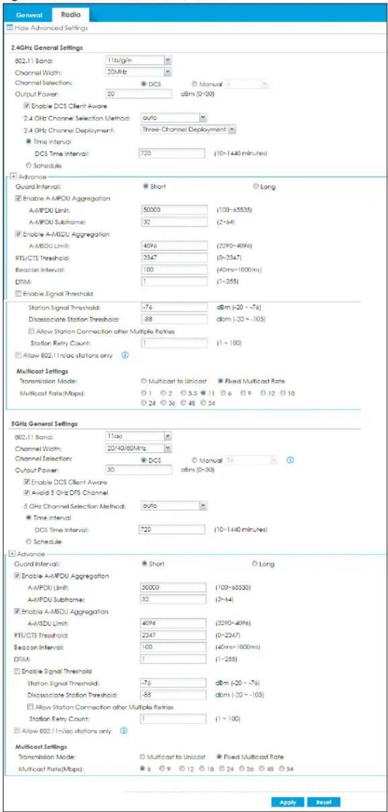
The following table describes the labels in this screen.
Table 105 Wireless > Built-in AP > Radio
| LABEL DESCRIPTION | |
| Hide / Show Advanced Settings | Click this to hide or show the Advanced Settings in this window. |
| 2.4GHz General Settings | |
| 802.11 Band Select | how to let wireless clients connect to the AP.11b/g: allows either IEEE 802.11b or IEEE 802.11g compliant WLAN devices to associate with the AP. The AP adjusts the transmission rate automatically according to the wireless standard supported by the wireless devices.11b/g/n: allows IEEE802.11b, IEEE802.11g and IEEE802.11n compliant WLAN devices to associate with the AP. The transmission rate of your AP might be reduced.11ax: allows IEEE802.11b, IEEE802.11g, IEEE802.11n, and IEEE802.11ax compliant WLAN devices to associate with the Zyxel Device. If the WLAN device isn't compatible with 802.11ax, the Zyxel Device will communicate with the WLAN device using 802.11n, and so on. |
| Channel Width | Select the wireless channel bandwidth you want the AP to use.A standard 20 MHz channel offers transfer speeds of up to 144Mbps (2.4GHz) or 217Mbps (5GHz) whereas a 40MHz channel uses two standard channels and offers speeds of up to 300Mbps (2.4GHz) or 450Mbps (5GHz).40 MHz (channel bonding or dual channel) bonds two adjacent radio channels to increase throughput. Because not all devices support all channels, select 20/40MHz to allow the AP to adjust the channel bandwidth automatically.Select 20MHz if you want to lessen radio interference with other wireless devices in your neighborhood or the wireless clients do not support channel bonding.Note: If the environment has poor signal-to-noise (SNR), the Zyxel Device will switch to a lower bandwidth. |
| Channel Selection | Select the wireless channel which this radio profile should use.It is recommended that you choose the channel least in use by other APs in the region where this profile will be implemented. This will reduce the amount of interference between wireless clients and the AP to which this profile is assigned.Select DCS to have the AP automatically select the radio channel upon which it broadcasts by scanning the area around it and determining what channels are currently being used by other devices.Note: If you change the country code later, Channel Selection is set to Manual automatically.Select Manual and specify the channels the AP uses. |
| Output Power | Enter the maximum output power of the Zyxel Device. If there is a high density of APs in an area, decrease the output power of the Zyxel Device to reduce interference with other APs. Reducing the output power also reduces the Zyxel Device's effective broadcast radius. |
| Enable DCS Client Aware | This field is available when you set Channel Selection to DCS.Select this to have the AP wait until all connected clients have disconnected before switching channels.If you disable this then the AP switches channels immediately regardless of any client connections. In this instance, clients that are connected to the AP when it switches channels are dropped. |
Table 105 Wireless > Built-in AP > Radio
| LABEL DESCRIPTION | |
| 2.4 GHz Channel Selection Method | This field is available when you set Channel Selection to DCS.Select auto to have the AP search for available channels automatically in the 2.4 GHz band. The available channels vary depending on what you select in the 2.4 GHz Channel Deployment field.Select manual and specify the channels the AP uses in the 2.4 GHz band. |
| Channel ID | This field is available only when you set Channel Selection to DCS and set 2.4 GHz Channel Selection Method to manual.Select the check boxes of the channels that you want the AP to use. |
| 2.4 GHz Channel Deployment | This field is available only when you set Channel Selection to DCS and set 2.4 GHz Channel Selection Method to auto.Select Three-Channel Deployment to limit channel switching to channels 1,6, and 11, the three channels that are sufficiently attenuated to have almost no impact on one another. In other words, this allows you to minimize channel interference by limiting channel-hopping to these three "safe" channels.Select Four-Channel Deployment to limit channel switching to four channels. Depending on the country domain, if the only allowable channels are 1-11 then the Zyxel Device uses channels 1, 4, 7, 11 in this configuration; otherwise, the Zyxel Device uses channels 1, 5, 9, 13 in this configuration. Four channel deployment expands your pool of possible channels while keeping the channel interference to a minimum. |
| Time Interval | Select this option to have the Zyxel Device survey the other APs within its broadcast radius at the end of the specified time interval. |
| DCS Time Interval | This field is available when you set Channel Selection to DCS.Enter a number of minutes. This regulates how often the AP surveys the other APs within its broadcast radius. If the channel on which it is currently broadcasting suddenly comes into use by another AP, the AP will then dynamically select the next available clean channel or a channel with lower interference. |
| Schedule | Select this option to have the Zyxel Device survey the other APs within its broadcast radius at a specific time on selected days of the week. |
| Start Time | Specify the time of the day (in 24-hour format) to have the Zyxel Device use DCS to automatically scan and find a less-used channel. |
| Week Days | Select each day of the week to have the Zyxel Device use DCS to automatically scan and find a less-used channel. |
| Advanced Settings | |
| Guard Interval | This field is available only when the channel width is 20/40MHz or 20/40/80MHz.Set the guard interval for this radio profile to either Short or Long.The guard interval is the gap introduced between data transmission from users in order to reduce interference. Reducing the interval increases data transfer rates but also increases interference. Increasing the interval reduces data transfer rates but also reduces interference. |
| Enable A-MPDU Aggregation | Select this to enable A-MPDU aggregation.Message Protocol Data Unit (MPDU) aggregation collects Ethernet frames along with their 802.11n headers and wraps them in a 802.11n MAC header. This method is useful for increasing bandwidth throughput in environments that are prone to high error rates. |
| A-MPDU Limit Enter | the maximum frame size to be aggregated. |
| A-MPDU Subframe | Enter the maximum number of frames to be aggregated each time. |
Table 105 Wireless > Built-in AP > Radio
| LABEL DESCRIPTION | |
| Enable A-MSDU Aggregation | Select this to enable A-MSDU aggregation.Mac Service Data Unit (MSDU) aggregation collects Ethernet frames without any of their 802.11n headers and wraps the header-less payload in a single 802.11n MAC header. This method is useful for increasing bandwidth throughput. It is also more efficient than A-MPDU except in environments that are prone to high error rates. |
| A-MSDU Limit Enter | the maximum frame size to be aggregated. |
| RTS/CTS Threshold | Use RTS/CTS to reduce data collisions on the wireless network if you have wireless clients that are associated with the same AP but out of range of one another. When enabled, a wireless client sends an RTS (Request To Send) and then waits for a CTS (Clear To Send) before it transmits. This stops wireless clients from transmitting packets at the same time (and causing data collisions).A wireless client sends an RTS for all packets larger than the number (of bytes) that you enter here. Set the RTS/CTS equal to or higher than the fragmentation threshold to turn RTS/CTS off. |
| Beacon Interval | When a wirelessly networked device sends a beacon, it includes with it a beacon interval. This specifies the time period before the device sends the beacon again. The interval tells receiving devices on the network how long they can wait in low-power mode before waking up to handle the beacon. A high value helps save current consumption of the access point. |
| DTIM | Delivery Traffic Indication Message (DTIM) is the time period after which broadcast and multicast packets are transmitted to mobile clients in the Active Power Management mode. A high DTIM value can cause clients to lose connectivity with the network. This value can be set from 1 to 255. |
| Enable Signal Threshold | Select the check box to use the signal threshold to ensure wireless clients receive good throughput. This allows only wireless clients with a strong signal to connect to the AP.Clear the check box to not require wireless clients to have a minimum signal strength to connect to the AP. |
| Station Signal Threshold | Set a minimum client signal strength. A wireless client is allowed to connect to the AP only when its signal strength is stronger than the specified threshold.-20 dBm is the strongest signal you can require and -76 is the weakest. |
| Disassociate Station Threshold | Set a minimum kick-off signal strength. When a wireless client's signal strength is lower than the specified threshold, the Zyxel Device disconnects the wireless client from the AP.-20 dBm is the strongest signal you can require and -90 is the weakest. |
| Allow Station Connection after Multiple Retries | Select this option to allow a wireless client to try to associate with the AP again after it is disconnected due to weak signal strength. |
| Station Retry Count | Set the maximum number of times a wireless client can attempt to re-connect to the AP. |
| Allow 802.11n/ac stations only | Only select this if you want to deny 802.11b/g/n clients access to the radio. |
| Multicast Settings | Use this section to set a transmission mode and maximum rate for multicast traffic. |
| Transmission Mode | Set how the AP handles multicast traffic.Select Multicast to Unicast to broadcast wireless multicast traffic to all of the wireless clients as unicast traffic. Unicast traffic dynamically changes the data rate based on the application's bandwidth requirements. The retransmit mechanism of unicast traffic provides more reliable transmission of the multicast traffic, although it also produces duplicate packets.Select Fixed Multicast Rate to send wireless multicast traffic at a single data rate. You must know the multicast application's bandwidth requirements and set it in the following field. |
Table 105 Wireless > Built-in AP > Radio
| LABEL DESCRIPTION | |
| Multicast Rate (Mbps) | If you set the multicast transmission mode to fixed multicast rate, set the data rate for multicast traffic here. For example, to deploy 4 Mbps video, select a fixed multicast rate higher than 4 Mbps. |
| 5GHz General Settings | |
| 802.11 Band Select how to let wireless clients connect to the AP.11a: allows only IEEE 802.11a compliant WLAN devices to associate with the Zyxel Device.11a/n: allows both IEEE802.11n and IEEE802.11a compliant WLAN devices to associate with the Zyxel Device.11ac: allows IEEE802.11n, IEEE802.11a, and IEEE802.11ac compliant WLAN devices to associate with the Zyxel Device. If the WLAN device isn't compatible with 802.11ac, the Zyxel Device will communicate with the WLAN device using 802.11n, and so on.11ax: allows IEEE802.11b, IEEE802.11g, IEEE802.11n, and IEEE802.11ax compliant WLAN devices to associate with the Zyxel Device. If the WLAN device isn't compatible with 802.11ax, the Zyxel Device will communicate with the WLAN device using 802.11n, and so on. | |
| Channel Width Select the channel bandwidth you want to use for your wireless network.Select 20 MHz if you want to lessen radio interference with other wireless devices in your neighborhood.Select 20/40 MHz to allow the Zyxel Device to choose the channel bandwidth (20 or 40 MHz) that has least interference.Select 20/40/80 MHz to allow the Zyxel Device to choose the channel bandwidth (20 or 40 or 80 MHz) that has least interference. This option is available only when you select 11ac or 11ax in the 802.11 Mode field.Note: If the environment has poor signal-to-noise ratio (SNR), the Zyxel Device will switch to a lower bandwidth. | |
| Channel Selection | Select the wireless channel which this radio profile should use.It is recommended that you choose the channel least in use by other APs in the region where this profile will be implemented. This will reduce the amount of interference between wireless clients and the AP to which this profile is assigned.Select DCS to have the AP automatically select the radio channel upon which it broadcasts by scanning the area around it and determining what channels are currently being used by other devices.Note: If you change the country code later, Channel Selection is set to Manual automatically.Select Manual and specify the channels the AP uses. |
| Output Power | Enter the maximum output power of the Zyxel Device. If there is a high density of APs in an area, decrease the output power of the Zyxel Device to reduce interference with other APs. Reducing the output power also reduces the Zyxel Device's effective broadcast radius. |
| Enable DCS Client Aware | This field is available when you set Channel Selection to DCS.Select this to have the AP wait until all connected clients have disconnected before switching channels.If you disable this then the AP switches channels immediately regardless of any client connections. In this instance, clients that are connected to the AP when it switches channels are dropped. |
Table 105 Wireless > Built-in AP > Radio
| LABEL DESCRIPTION | |
| Avoid 5 GHz DFS Channel | This field is available only when you set802.11 Band to 5G, Channel Selection to DCS and 5 GHz Channel Selection Method to auto.Dynamic Frequency Selection (DFS) is a channel WiFi allocation scheme that allows APs to use channels in the 5 Ghz band normally reserved for radar. Before using a DFS channel, an AP must ensure there is no radar present by performing a Channel Availability Check (CAC). This check takes 1-10 minutes, depending on the country in which the AP is located.Select this if you don't want to wait for the Zyxel Device to perform a CAC before using a channel by forcing the Zyxel Device to only use the non-DFS channels.Clear this to allow the Zyxel Device to use the DFS channels for more channel options. |
| 5 GHz Channel Selection Method | This field is available when you set Channel Selection to DCS.Select auto to have the AP search for available channels automatically in the 5 GHz band.The available channels vary depending on what you select in the 5 GHz Channel Deployment field.Select manual and specify the channels the AP uses in the 5 GHz band. |
| Channel ID | This field is available only when you set Channel Selection to DCS and set 5 GHz Channel Selection Method to manual.Select the check boxes of the channels that you want the AP to use. |
| Time Interval | Select this option to have the Zyxel Device survey the other APs within its broadcast radius at the end of the specified time interval. |
| DCS Time Interval | This field is available when you set Channel Selection to DCS.Enter a number of minutes. This regulates how often the AP surveys the other APs within its broadcast radius. If the channel on which it is currently broadcasting suddenly comes into use by another AP, the AP will then dynamically select the next available clean channel or a channel with lower interference. |
| Schedule | Select this option to have the Zyxel Device survey the other APs within its broadcast radius at a specific time on selected days of the week. |
| Start Time | Specify the time of the day (in 24-hour format) to have the Zyxel Device use DCS to automatically scan and find a less-used channel. |
| Week Days | Select each day of the week to have the Zyxel Device use DCS to automatically scan and find a less-used channel. |
| OK | Click OK to save your changes back to the Zyxel Device. |
| Cancel | Click Cancel to exit this screen without saving your changes. |
8.3 Controller Screen
Use this screen to set how the Zyxel Device allows new APs to connect to the network. Click Configuration > Wireless > Controller to access this screen.
Figure 232 Configuration > Wireless > Controller (without built-in AP)
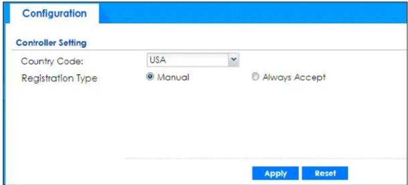
Figure 233 Configuration > Wireless > Controller (with built-in AP)
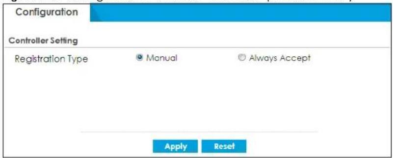
Each field is described in the following table.
Table 106 Configuration > Wireless > Controller
| LABEL DESCRIPTION | |
| Country Code | Select the country code of where the Zyxel Device is located/installed. The available channels vary depending on the country you selected.Please note that Zyxel Devices with built-in AP do not support country code, see Table 1.1.1 on page 29 for more information. |
| Registration Type | SelectManualto add each AP to the Zyxel Device for management, orAlways Acceptto automatically add APs to the Zyxel Device for management.If you selectManual, then go toMonitor > Wireless > AP Information > AP List, select an AP to be managed and then clickAdd to Mgmt AP List. That AP will then appear inConfiguration > Wireless >Controller > Mgmt. AP List.Note: Select theManualoption for managing a specific set of APs. This is recommended as the registration mechanism cannot automatically differentiate between friendly and rogue APs.APs must be connected to the Zyxel Device by a wired connection or network. |
| Apply | ClickApplyto save your changes back to the Zyxel Device. |
| Reset | ClickResetto return the screen to its last-saved settings. |
8.3.1 Connecting an AP to the Zyxel Device
- You can connect an AP directly to one of the Ethernet ports on the Zyxel Device. You can also connect an AP indirectly to the Zyxel Device through the local network.
- If an AP and the Zyxel Device are on the same subnet, the AP will automatically detect and connect to the Zyxel Device.
- If an AP and the Zyxel Device are on different subnets, then you can must configure the AP to connect to the Zyxel Device. You can do this manually or by configuring DHCP Option 138 on the AP's DHCP server.
- After an AP has successfully connected to the Zyxel Device, the AP appears in the AP List on MONITOR > Wireless > AP Information.
8.3.2 Connecting an AP to the Zyxel Device Manually
1 Ensure that the Zyxel Device has a static IP address.
2 Connect to and log on to the AP using a web browser.
3 On the AP, go to CONFIGURATION > Network > AC Discovery.
4 Under Discovery Setting, select Manual.
5 Under Primary static AC IP, enter the IP address of the Zyxel Device.
6 Click Apply.
The Zyxel Device can now manage the AP.
8.3.3 Connecting an AP to the Zyxel Device Using DHCP Option 138
1 Ensure that the Zyxel Device has a static IP address.
2 Log on to the DHCP server and configure settings for the network in which the AP is located.
3 Add a new DHCP option with the following values:
Name: Capwap AC
Code: 138
Type: IP Address
Value:
4 Restart the AP.
The AP picks up a new DCHP-assigned IP address. The Zyxel Device can now manage the AP.
Use the AP Management screens to manage all of the APs connected to the Zyxel Device.
8.4 AP Management Screens
Use these screens to manage all of the APs connected to the Zyxel Device. Click Configuration > Wireless > AP Management to access these screens.
Click on the icon to go to the OneSecurity website where there is guidance on configuration walkthroughs and other information.
8.4.1 Mgmt. AP List
Figure 234 Configuration > Wireless > AP Management > Mgmt. AP List
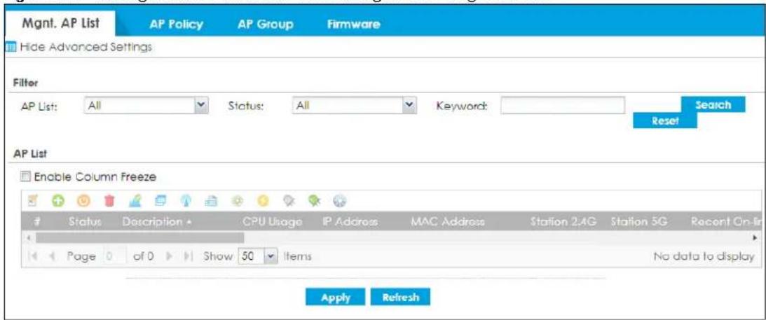
Each field is described in the following table.
Table 107 Configuration > Wireless > AP Management > Mgmt. AP List
| LABEL DESCRIPTION | |
| Filter | Click Show Advanced Settings to reveal Filter fields where you can display managed APs by status, keyword or those managed by the Nebula portal. |
| AP List Select the type | of APs you want to display.Select All to show all kinds of APs that are currently or used to be connected to the Zyxel Device.Select NebulaFlexPRO to show the APs that can work in Nebula cloud management mode. |
| Status Select the status | of APs you want to display. |
| Keyword | Enter a keyword to display the APs that include it in their AP information, such as model number, firmware version, MAC address and so on. This field is case-sensitive. |
| Search Click this to update | date the list of APs based on the search criteria.Your search criteria is retained when navigating between screens. |
| Reset | Click this to return the search criteria to the factory defaults and display all currently or previously connected APs without a filter. |
| Enable Column Freeze | Select this to lock the index columns in place while scrolling to the right. |
| Edit the selected rule | Select an AP and click this to change the selected AP's properties, such as its group, radio, VLAN and port settings. |
| Add to Mgmt AP List | Select an AP and click this to add the selected AP to the managed AP list. |
| Reboot device | Select one or multiple APs and click this button to force the AP(s) to restart. |
| Remove the selected rule | Select one or multiple APs and click this button to remove the AP(s) from the manged AP list.Note: If on theConfiguration > Wireless > Controllerscreen you set theRegistration Type to Always Accept, then as soon as you remove an AP from this list it reconnects. |
| DCS Now | Select one or multiple APs and click this button to use DCS (Dynamic Channel Selection) to allow the AP to automatically find a less-used channel in an environment where there are many APs and there may be interference.Note: You should have enabled DCS in the applied AP radio profile before the APs can use DCS.Note: DCS is not supported on the radio which is working in repeater AP mode. |
| More Information | Select an AP and click this to view a daily station count about the selected AP. The count records station activity on the AP over a consecutive 24 hour period. |
| Radio Information | Select an online AP and click this button to go to theMonitor > Wireless > AP Information > Radio Listscreen to view detailed information about the AP's radios. |
| Query Controller Log | Select one or multiple APs and click this button to go to theMonitor > Log > View Logscreen to view the selected AP's current log messages. |
| Nebula | Select an AP and click this to open a screen where you can set whether the AP's IP address and VLAN settings will be changed when it goes into Nebula cloud management mode.Note: The AP will be set to Nebula cloud management mode and removed from the managed AP list right after you clickOK. |
| Upgrade Firmware Now | Select one or more APs and click this button to update the APs' firmware version. |
| Suppression On | Select an AP and click this button to enable the AP's LED suppression mode. All the LEDs of the AP will turn off after the AP is ready. This button is not available if the selected AP doesn't support suppression mode. |
| Suppression Off | Select an AP and click this button to disable the AP's LED suppression mode. The AP LEDs stay lit after the AP is ready. This button is not available if the selected AP doesn't support suppression mode. |
| Locator On | Select an AP and click this button to run the locator feature. The AP's Locator LED will start to blink for 10 minutes by default. It will show the actual location of the AP between several devices on the network. |
| # This field is a sequential value, and it is not associated with any entry. | |
| Status This field displays the status of AP.• Online: The AP has a stable connection with the Zyxel Device.• Conflict: Settings that are not supported are applied to the AP. The AP WiFi is disabled.• Non Support: Settings that are not supported are applied to the AP. The AP has ignored these settings.• Updating: The Zyxel Device is sending the latest firmware to the AP.• Offline: No traffic is sent from the AP to the Zyxel Device for over 120 seconds.• Offline for Firmware Update: The AP has received the latest firmware from the Zyxel Device and is upgrading the firmware.• Un-Mgmt: The AP is requesting to be managed by the Zyxel Device. | |
| Description | This field displays the AP's description, which you can configure by selecting the AP's entry and clicking theEditbutton. |
| CPU Usage This field displays the CPU Usage of the AP. | |
| IP Address This field displays the IP address of the AP. | |
| MAC Address This field displays the MAC address of the AP. | |
| Station 2.4G | This field displays the number of 2.4G wireless clients connected to the AP. |
| Station 5G This field displays the number of 5G wireless clients connected to the AP. | |
| Recent Online Time | This displays the most recent time the AP came on-line.N/Adisplays if the AP has not come on-line since the Zyxel Device last started up. |
| LED Status This displays the AP LED status.N/Adisplays if the AP does not support LED suppression mode and/or have a locator LED to show the actual location of the AP.A gray LED icon signifies that the AP LED suppression mode is enabled. All the LEDs of the AP will turn off after the AP is ready.A green LED icon signifies that the AP LED suppression mode is disabled and the AP LEDs stay lit after the AP is ready.A sun icon signifies that the AP's locator LED is blinking.A circle signifies that the AP's locator LED is extinguished. | |
| Model | This field displays the AP's hardware model information. It displaysN/A(not applicable) only when the AP disconnects from the Zyxel Device and the information is unavailable as a result. |
| Apply | ClickApplyto save your changes back to the Zyxel Device. |
| Refresh | ClickRefreshto update the AP list. |
8.4.1.1 Edit AP List
Select an AP and click the Edit button in the Configuration > Wireless > AP Management table to display this screen.
Note: The settings in the screen will change when you select the Remote AP check box. See Section 8.4.1.2 on page 294 for more information.
Storm Control
Storm control prevents broadcast/multicast storms on AP interfaces. A broadcast/multicast storm occurs when broadcast/multicast packets flood devices in the same subnet, creating excessive traffic and degrading network performance.
When storm control is enabled on the Zyxel Device, the AP monitors packets received on the its interface and determines whether the packets are broadcast or multicast. The AP monitors the number of broadcast packets received within a one-second time interval. When the interface maximum packets per second threshold is met, incoming data traffic on the AP interface is dropped until the maximum packets per second falls below the threshold.
Airtime Fairness
Airtime is the time it takes for a client to receive packets from the AP it is associated with. The amount of time each client needs may vary depending on various reasons, such as the distance between the client and the AP, the client's operating system, or the IEEE standard the client is using.
Airtime fairness is a feature that makes sure all connected clients of an AP get the same amount of time to receive packets. Without airtime fairness, a client that needs more airtime will take up more time and bandwidth of an AP to receive packets. This will slow down your WiFi network overall.
For example, you have computer A and computer B at your house. They're both connected to the same AP. Here are the conditions in the scenario examples below:
• The example time period is 60 milliseconds.
• Computer A needs 5 milliseconds to receive a packet from the AP.
- Computer B needs 10 milliseconds to receive a packet from the AP.
Airtime Fairness Disabled
Computer A and computer B will take turn to receive packets from the AP. With airtime fairness disabled, the AP will not equally allocate the 60 milliseconds between A and B.
Table 108 Packets Received without Airtime Fairness
| PACKETS RECEIVED A B | ||
| 1 packet 10ms | ||
| 1 packet 5ms | ||
| 1 packet 10ms | ||
| 1 packet 5ms | ||
| 1 packet 10ms | ||
| 1 packet 5ms | ||
| 1 packet 10ms | ||
| 1 packet 5ms | ||
| Total Packets Received: 8 Total Time Period: 60ms | ||
A has 20 milliseconds to receive packets. B has 40 milliseconds to receive packets. In total, they can receive 8 packets in 60 milliseconds.
Figure 235 Airtime Fairness Example-Disabled
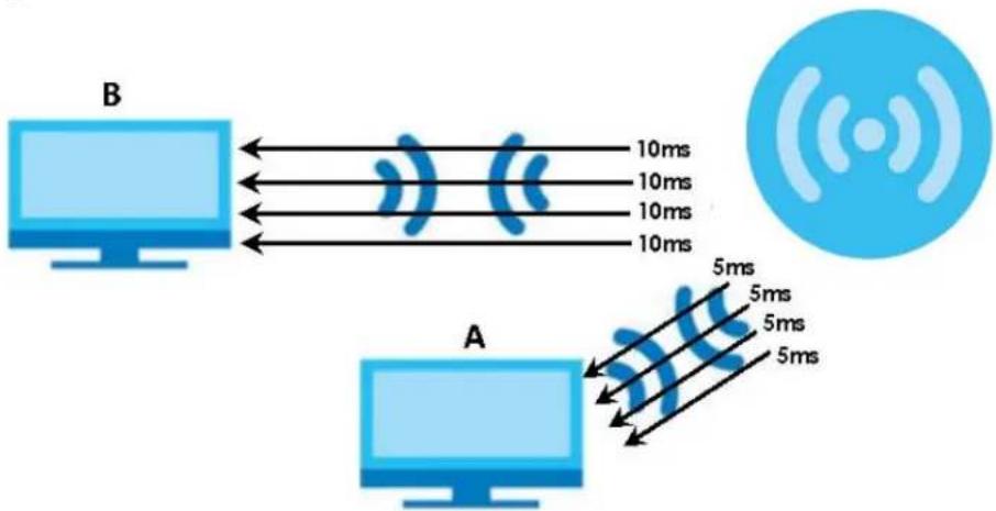
flowchart
graph LR
    A["Computer A"] -->|5ms| B["Computer B"]
    B -->|10ms| A
    style A fill:#cce5ff,stroke:#333
    style B fill:#cce5ff,stroke:#333
    note right of A: 5ms delay interval; 5ms delay interval; 10ms delay interval; 10ms delay interval; 10ms delay interval; 10ms delay interval; 5ms delay interval; 5ms delay interval; 5ms delay interval; 5ms delay interval; 5ms delay interval; 5ms delay interval; 5ms delay interval; 5ms delay interval; 5ms delay interval; 5ms delay interval; 5ms delay interval; 5ms delay interval; 5ms delay interval; 5ms delay interval; 5ms delay interval; 5ms delay interval; 5ms delay interval;
    Note right of A: Wireless icon
    Note right of B: Wi-Fi symbol
Airtime Fairness Enabled
With airtime fairness enabled, the AP will equally allocate the 60 milliseconds between computer A and computer B. After B uses 10 milliseconds to receive a packet, the AP will also allocate 10 milliseconds to A to receive packets.
Table 109 Packets Received without Airtime Fairness
| PACKETS RECEIVED A B | ||
| 1 packet 10ms | ||
| 1 packet 5ms | ||
| 1 packet 5ms | ||
| 1 packet 10ms | ||
| 1 packet 5ms | ||
| 1 packet 5ms | ||
| 1 packet 10ms | ||
| 1 packet 5ms | ||
| 1 packet 5ms | ||
| Total Packets Received: 9 Total Time Period: 60ms | ||
A and B both have 30 milliseconds to receive packets. In total, they can receive 9 packets in 60 milliseconds.
Figure 236 Airtime Fairness Example-Enabled
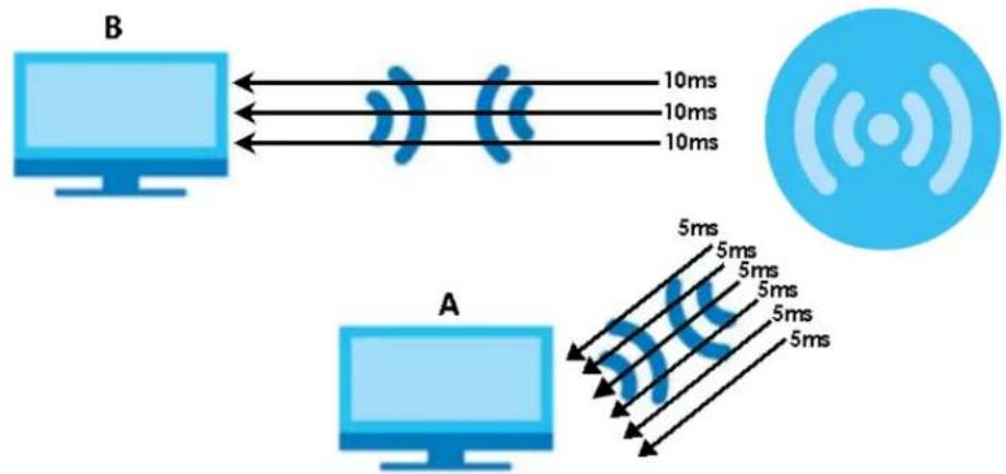
flowchart
graph TD
    A["Computer"] -->|10ms| B["Wireless Device"]
    B -->|5ms| C["Computer"]
    style A fill:#cce5ff,stroke:#333
    style B fill:#cce5ff,stroke:#333
    style C fill:#cce5ff,stroke:#333
Figure 237 Configuration > Wireless > AP Management > Mgmt. AP List > Edit AP List
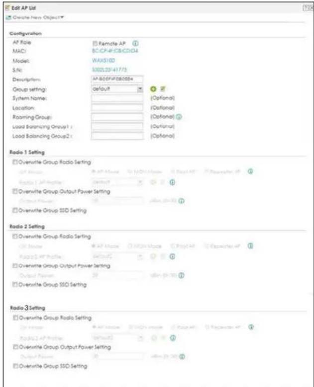
Figure 238 Configuration > Wireless > AP Management > Mgmt. AP List > Edit AP List (continued)
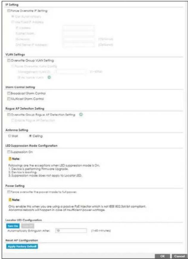
Each field is described in the following table.
Table 110 Configuration > Wireless > AP Management > Mgmt. AP List > Edit AP List
| LABEL DESCRIPTION | |
| Create new Object | Use this menu to create a new Radio Profile object to associate with this AP. |
| AP Role Select this to enable the remote AP feature. | |
| MAC This displays the MAC address of the selected AP. | |
| Model | This field displays the AP's hardware model information. It displays N/A (not applicable) only when the AP disconnects from the Zyxel Device and the information is unavailable as a result. |
| S/N This displays the serial number of the selected AP. | |
| Description | Enter a description for this AP. You can use up to 31 characters, spaces and underscores allowed. |
| Group Setting Select on AP group to which you want this AP to belong. | |
| System Name | Enter a name to identify the AP on a network. This is usually the AP's fully qualified domain name. |
| Location Specify the name of the place where the AP is located. | |
| Roaming Group | Specify the name of the roaming group to which the AP belongs. You can use up to 31 alphanumeric and @# characters. Dashes and underscores are also allowed. The name should start with a letter or digit.The 802.11k neighbor list a client requests from the AP is generated according to the roaming group and RCPI (Received Channel Power Indicator) value of its neighbor APs.When a client wants to roam from the current AP to another, other APs in the same roaming group or not in a roaming group will be candidates for roaming. Neighbor APs in a different roaming group will be excluded from the 802.11k neighbor lists even when the neighbor AP has the best signal strength.If the AP's roaming group is not configured, any neighbor APs can be candidates for roaming. |
| Load Balancing Group 1/2 | Load balancing is only applied to APs within the same group. If a load balancing group is not assigned to an AP, it will belong to a default group.Each AP can belong to up to two groups. |
| Radio 1/2/3 Setting | |
| Override Group Radio Setting | Select this option to overwrite the AP radio settings with the settings you configure here. |
| OP Mode Select the operating mode for radio 1, radio 2 or radio 3.AP Mode means the AP can receive connections from wireless clients and pass their data traffic through to the Zyxel Device to be managed (or subsequently passed on to an upstream gateway for managing).MON Mode means the AP monitors the broadcast area for other APs, then passes their information on to the Zyxel Device where it can be determined if those APs are friendly or rogue. If an AP is set to this mode it cannot receive connections from wireless clients.Root AP means the radio acts as an AP and also supports the wireless connections with other APs (in repeater mode) to form a ZyMesh to extend its wireless network.Repeater AP means the radio can establish a wireless connection with other APs (in either root AP or repeater mode).Note: To prevent bridge loops, do NOT set both radios on a managed AP to Repeater AP mode.Note: The root AP and repeater AP(s) in a ZyMesh must use the same country code and AP radio profile settings in order to communicate with each other.Note: Ensure you restart the managed AP after you change its operating mode. | |
| Override Group Output Power Setting | Select this option to overwrite the AP output power setting with the setting you configure here. |
| Output Power Set the output power of the AP. | |
| Override Group SSID Setting | Select this option to overwrite the AP SSID profile setting with the setting you configure here.This section allows you to associate an SSID profile with the radio. |
| Radio 1/2/3 AP Profile | Select an AP profile from the list. If no profile exists, you can create a new one through the Create new Object menu. |
| Radio 1/2/3 Profile | Select a monitor profile from the list. If no profile exists, you can create a new one through the Create new Object menu. |
| Radio 1/2/3 ZyMesh Profile | This field is available only when the radio is in Root AP or Repeater AP mode.Select the ZyMesh profile the radio uses to connect to a root AP or repeater. |
| Enable Wireless Bridging | This field is available only when the radio is in Repeater AP mode.Select this option to enable wireless bridging on the radio.The managed AP must support LAN provision and the radio should be in repeater mode.VLAN and bridge interfaces are created automatically according to the LAN port's VLAN settings. When wireless bridging is enabled, the managed repeater AP can still transmit data through its Ethernet port(s) after the ZyMesh link is up. Be careful to avoid bridge loops.The managed APs in the same ZyMesh must use the same static VLAN ID. |
| Edit | Select an SSID and click this button to reassign it. The selected SSID becomes editable immediately upon clicking. |
| # | This is the index number of the SSID profile. You can associate up to eight SSID profiles with an AP radio. |
| SSID Profile Indicates which SSID profile is associated with this radio profile. | |
| IP Setting | |
| Force Overwrite IP Setting | Select this to have the Zyxel Device change the AP's IP address setting to match the configuration in this screen. |
| Get Automatically | Select this to have the AP act as a DHCP client and automatically get the IP address, subnet mask, and gateway address from a DHCP server. |
| Use Fixed IP Address | Select this if you want to specify the IP address, subnet mask, gateway and DNS server address manually. |
| IP Address Enter the IP | address for the AP. |
| Subnet Mask | Enter the subnet mask of the AP in dot decimal notation. The subnet mask indicates what part of the IP address is the same for all devices in the network. |
| Gateway | Enter the IP address of the gateway. The AP sends packets to the gateway when it does not know how to route the packet to its destination. The gateway should be on the same network as the AP. |
| DNS Server IP Address | Enter the IP address of the DNS server. |
| VLAN Settings | |
| Override Group VLAN Setting | Select this option to overwrite the AP VLAN setting with the setting you configure here. |
| Force Overwrite VLAN Config | Select this to have the Zyxel Device change the AP's management VLAN to match the configuration in this screen. |
| Management VLAN ID | Enter a VLAN ID for this AP. |
| As Native VLAN | Select this option to treat this VLAN ID as a VLAN created on the Zyxel Device and not one assigned to it from outside the network. |
| Storm Control Setting | |
| Broadcast Storm Control | Enabling this will drop ingress broadcast traffic in the physical Ethernet port if it exceeds the maximum traffic rate. The maximum traffic rate can be changed using the CLI (see CLI Reference Guide).Ethernet storm control prevents WiFi clients from receiving excessive broadcast traffic sent from wired clients in the same subnet.Wireless storm control prevents wired clients from receiving excessive broadcast traffic sent from WiFi clients in the same subnet. |
| Multicast Storm Control | Enabling this will drop ingress multicast traffic in the physical Ethernet port if it exceeds the maximum traffic rate. The maximum traffic rate can be changed using the CLI (see CLI Reference Guide).Ethernet storm control prevents WiFi clients from receiving excessive multicast traffic sent from wired clients in the same subnet.Wireless storm control prevents wired clients from receiving excessive multicast traffic sent from WiFi clients in the same subnet. |
| Rogue AP Detection Setting | |
| Override Group Rogue AP Detection Setting | Select this option to overwrite the AP Rogue Detection Settings with the settings you configure here |
| Enable Rogue AP Detection | Select this option to detect Rogue APs in the network. |
| Antenna Setting | This section is available only when the AP has an antenna switch. The screen varies depending on whether the AP has a physical antenna switch or allows you to change antenna orientation settings on a per-radio basis or on a per-AP basis. |
| Wall/ Ceiling | This allows you to adjust coverage depending on the antenna orientation of the AP's radios for better coverage.Select Wall if you mount the AP to a wall. Select Ceiling if the AP is mounted on a ceiling. You can switch from Wall to Ceiling if there are still wireless dead zones, and vice versa. |
| LED Suppression Mode Configuration | This section is available only when the AP supports LED suppression mode. |
| Suppression On | Select this option to enable the AP's LED suppression mode. All the LEDs of the AP will turn off after the AP is ready.Clear the check box to have the LEDs stay lit after the AP is ready. |
| Power Setting | Enable Force override the power mode to full power if you are using a PoE injector that does not support PoE negotiation. Otherwise, the AP cannot draw full power from the power sourcing equipment. Enable this power mode to improve the AP's performance in this situation.Note: Ensure that the power sourcing equipment can supply enough power to the AP to avoid abnormal system reboots.Note: Only enable this if you are using a passive PoE injector that is not IEEE 802.3at/bt compliant but can still provide full power. |
| Airtime Fairness | Select Enabled Airtime Fairness Mode to have the AP allocate airtime equally between all connected clients. Airtime fairness makes sure clients that can receive packets faster will not be slowed down by clients that receive packets slower. Use this if clients that need less airtime in your wireless networks need priority to receive packets, such as clients that use real time traffic to stream videos or play games.Note that if you enable this feature, clients that originally need more time to receive packets will become slower than before. Clear the check box if you want better performance on slower clients in your network, such as a gaming computer that's far away from the AP.Note: When you disable or enable airtime fairness on an AP, all connected clients of the AP will be disconnected. |
| Locator LED Configuration | This section is available only when the AP has a locator LED. The locator LED will blink to show the actual location of the AP between several devices in the network. |
| Turn On/ Turn Off | When the locator LED is off, click theTurn Onbutton to activate the locator function. It will show the actual location of the AP between several devices in the network.If the locator LED is blinking, click theTurn Offbutton to stop the locator LED from blinking immediately. |
| Automatically Extinguish After | Enter a time interval between 1 and 60 minutes to stop the locator LED from blinking. The locator LED will start to blink for the number of minutes set here.If you make changes to the time default setting, it will be stored as the default when the AP restarts. |
| Reset AP Configuration | This section is available only when the AP is online. |
| Apply Factory Default | Click the button to reset all of the AP settings to the factory defaults. |
| OK | ClickOKto save your changes back to the Zyxel Device. |
| Cancel | Click Cancelto close the window with changes unsaved. |
8.4.1.2 Edit AP List (Remote AP Mode)
Select an AP and click the Edit button in the Configuration > Wireless > AP Management table, Select the Remote AP check box to display this screen.
Remote AP
Remote AP enables the Zyxel Device to connect to an Access Point (AP) through a secure VPN tunnel. This allows you to set up a VPN-enabled WiFi access points in remote locations, such as in a branch office or at home, which remote WiFi clients can connect to in order to access your network.
You can associate up to four Secure Tunnel SSID profiles and two Local Bridge SSID profiles with a remote AP radio.
Configure your AP using Secure Tunnel SSID profiles if you want to access the network behind the Zyxel Device or to access the Internet. Network traffic from clients connected to these SSIDs is sent through the RAP tunnel to the Zyxel Device. The Zyxel Device then sends the traffic out through the interface defined in the SSID profile.
Configure your AP using Local Bridge SSID profiles if you only want to access the Internet. Network traffic from clients connected to these SSIDs is sent directly to the network through the AP's local gateway.
Figure 239 AP Using Secure Tunnel SSID Profile
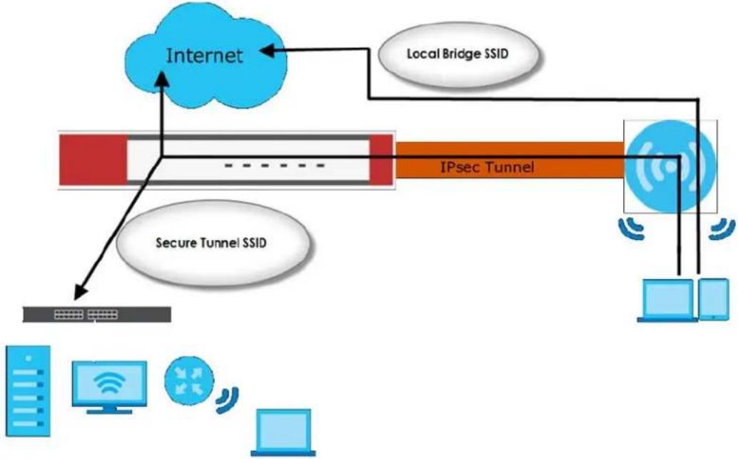
flowchart
graph TD
    A["Internet"] --> B["Local Bridge SSID"]
    B --> C["IPsec Tunnel"]
    C --> D["Secure Tunnel SSID"]
    D --> E["Data Bus"]
    C --> F["Computer"]
    C --> G["Desktop"]
    C --> H["Mobile Device"]
To enable the Remote AP role, the Zyxel Device needs 5.00 or later firmware and the managed AP needs 6.20 or later firmware. Go to AP Management> Firmware to check if the AP has the correct firmware.
To enable the Remote AP role, you need to have the Secure WiFi license. See Chapter 7 on page 257 for more information.
Figure 240 Configuration > Wireless > AP Management > Mgmt. AP List > Edit AP List (Remote AP Mode)
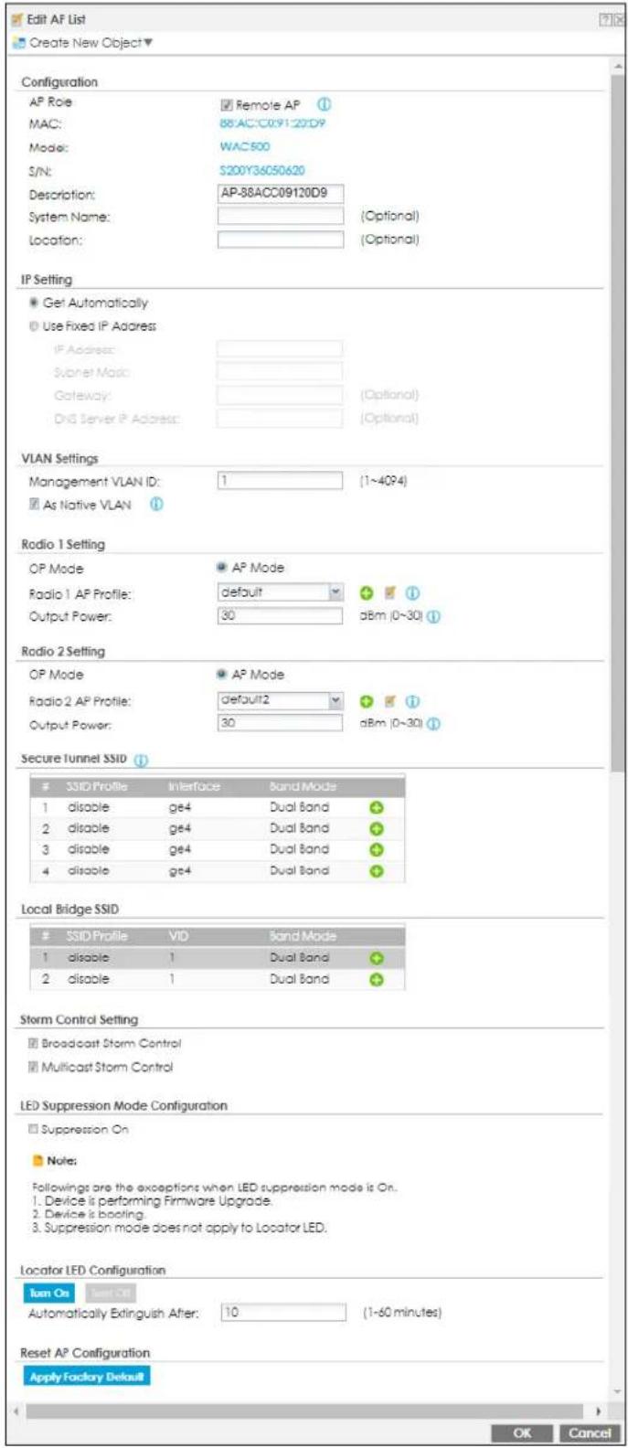
Each field is described in the following table.
Table 111 Configuration > Wireless > AP Management > Mgmt. AP List > Edit AP List (Remote AP Mode)
| LABEL DESCRIPTION | |
| Create new Object | Use this menu to create a new Radio Profile object to associate with this AP. |
| AP Role Select this to enable the remote AP feature. | |
| MAC This displays the MAC address of the selected AP. | |
| Model | This field displays the AP's hardware model information. It displays N/A (not applicable) only when the AP disconnects from the Zyxel Device and the information is unavailable as a result. |
| S/N This displays the serial number of the selected AP. | |
| Description | Enter a description for this AP. You can use up to 31 characters, spaces and underscores allowed. |
| Group Setting Select on AP group to which you want this AP to belong. | |
| System Name | Enter a name to identify the AP on a network. This is usually the AP's fully qualified domain name. |
| Location Specify the name of the place where the AP is located. | |
| IP Setting | |
| Get Automatically | Select this to have the AP act as a DHCP client and automatically get the IP address, subnet mask, and gateway address from a DHCP server. |
| Use Fixed IP Address | Select this if you want to specify the IP address, subnet mask, gateway and DNS server address manually. |
| IP Address Enter the IP address for the AP. | |
| Subnet Mask | Enter the subnet mask of the AP in dot decimal notation. The subnet mask indicates what part of the IP address is the same for all devices in the network. |
| Gateway | Enter the IP address of the gateway. The AP sends packets to the gateway when it does not know how to route the packet to its destination. The gateway should be on the same network as the AP. |
| DNS Server IP Address | Enter the IP address of the DNS server. |
| VLAN Settings | |
| Management VLAN ID | Enter a VLAN ID for this AP. |
| As Native VLAN | Select this option to treat this VLAN ID as a VLAN created on the Zyxel Device and not one assigned to it from outside the network. |
| Radio 1/2 Setting | |
| OP Mode | AP Mode means the AP can receive connections from wireless clients and pass their data traffic through to the Zyxel Device to be managed (or subsequently passed on to an upstream gateway for managing). |
| Radio 1/2 AP Profile | Select an AP profile from the list. If no profile exists, you can create a new one through the Create new Object menu. |
| Output Power | Set the output power of the AP. |
| Secure Tunnel SSID | Configure your AP using Secure Tunnel SSID profiles if you want to access the network behind the Zyxel Device or to access the Internet. |
| # | This field is a sequential value, and it is not associated with a specific entry. |
| SSID Profile | Click on the SSID profile to show the drop down list box. Select a pre-configured SSID profile you want to configure as the Secure Tunnel SSID. |
| Interface | Click on the interface to show the drop-down list box. Select an interface you want the AP traffic to go through on the Zyxel Device. The interface you select here will override the interface configured in the SSID profile. |
Table 111 Configuration > Wireless > AP Management > Mgmt. AP List > Edit AP List (Remote AP Mode)
| LABEL DESCRIPTION | |
| Band Mode | Click on the band mode to show the drop-down list box. Select the frequency band you want the AP to use. |
| Local Bridge SSID | |
| # This field is a sequential value, and it is not associated with a specific | |
| SSID Profile | Click on the SSID profile name to show the drop down list box. Select a pre-configured SSID profile you want to configure as the Local Bridge SSID. |
| VID | Click on the interface to configure the VID number. The VID you set here will override the VID configured in the SSID profile. |
| Band Mode | Click on the band mode to show the drop-down list box. Select the frequency band you want the AP to use. |
| Storm Control Setting | |
| Broadcast Storm Control | Enabling this will drop ingress broadcast traffic in the physical Ethernet port if it exceeds the maximum traffic rate. The maximum traffic rate can be changed using the CLI (see CLI Reference Guide).Ethernet storm control prevents WiFi clients from receiving excessive broadcast traffic sent from wired clients in the same subnet.Wireless storm control prevents wired clients from receiving excessive broadcast traffic sent from WiFi clients in the same subnet.See Section 8.4.1.1 on page 286 for more information on storm control. |
| Multicast Storm Control | Enabling this will drop ingress multicast traffic in the physical Ethernet port if it exceeds the maximum traffic rate. The maximum traffic rate can be changed using the CLI (see CLI Reference Guide).Ethernet storm control prevents WiFi clients from receiving excessive multicast traffic sent from wired clients in the same subnet.Wireless storm control prevents wired clients from receiving excessive multicast traffic sent from WiFi clients in the same subnet.See Section 8.4.1.1 on page 286 for more information on storm control. |
| Antenna Setting | This section is available only when the AP has an antenna switch. The screen varies depending on whether the AP has a physical antenna switch or allows you to change antenna orientation settings on a per-radio basis or on a per-AP basis. |
| Wall/ Ceiling | This allows you to adjust coverage depending on the antenna orientation of the AP's radios for better coverage.Select Wall if you mount the AP to a wall. Select Ceiling if the AP is mounted on a ceiling. You can switch from Wall to Ceiling if there are still wireless dead zones, and vice versa. |
| LED Suppression Mode Configuration | This section is available only when the AP supports LED suppression mode. |
| Suppression On | Select this option to enable the AP's LED suppression mode. All the LEDs of the AP will turn off after the AP is ready.If the check box is unchecked, it means the LEDs will stay lit after the AP is ready. |
Table 111 Configuration > Wireless > AP Management > Mgmt. AP List > Edit AP List (Remote AP Mode)
| LABEL DESCRIPTION | |
| Power Setting | EnableForce override the power mode to full power if you are using a PoE injector that does not support PoE negotiation. Otherwise, the AP cannot draw full power from the power sourcing equipment. Enable this power mode to improve the AP's performance in this situation.Note: Ensure that the power sourcing equipment can supply enough power to the AP to avoid abnormal system reboots.Note: Only enable this if you are using a passive PoE injector that is not IEEE 802.3at/bt compliant but can still provide full power. |
| Locator LED Configuration | This section is available only when the AP has a locator LED. |
| Turn On/ Turn Off | When the locator LED is off, click theTurn Onbutton to activate the locator function. It will show the actual location of the AP between several devices in the network.If the locator LED is blinking, click theTurn Offbutton to stop the locator LED from blinking immediately. |
| Automatically Extinguish After | Enter a time interval between 1 and 60 minutes to stop the locator LED from blinking. The locator LED will start to blink for the number of minutes set here.If you make changes to the time default setting, it will be stored as the default when the AP restarts. |
| Reset AP Configuration | This section is available only when the AP is online. |
| Apply Factory Default | Click the button to reset all of the AP settings to the factory defaults. |
| OK | ClickOKto save your changes back to the Zyxel Device. |
| Cancel | ClickCancelto close the window with changes unsaved. |
8.4.2 AP Policy
Use this screen to configure the AP controller's IP address on the managed APs and determine the action the managed APs take if the current AP controller fails. Click Configuration > Wireless > AP Management > AP Policy to access this screen.
Figure 241 Configuration > Wireless > AP Management > AP Policy
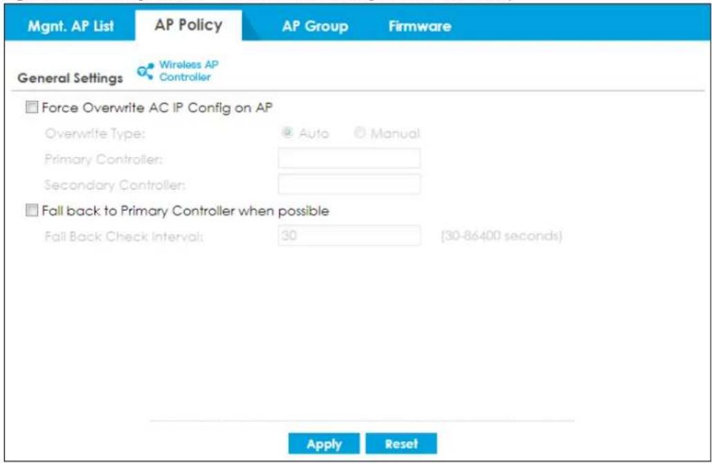
Each field is described in the following table.
Table 112 Configuration > Wireless > AP Management > AP Policy
| LABEL DESCRIPTION | |
| Force Override AC IP Config on AP | Select this to have the Zyxel Device change the AP controller's IP address on the managed AP(s) to match the configuration in this screen. |
| Override Type | Select Auto to have the managed AP(s) automatically send broadcast packets to find any other available AP controllers.Select Manual to replace the AP controller's IP address configured on the managed AP(s) with the one(s) you specified below. |
| Primary Controller | Specify the IP address of the primary AP controller if you set Override Type to Manual. |
| Secondary Controller | Specify the IP address of the secondary AP controller if you set Override Type to Manual. |
| Fall back to Primary Controller when possible | Select this option to have the managed AP(s) change back to associate with the primary AP controller as soon as the primary AP controller is available. |
| Fall Back Check Interval | Set how often the managed AP(s) check whether the primary AP controller is available. |
| Apply | Click Apply to save your changes back to the Zyxel Device. |
| Reset | Click Reset to return the screen to its last-saved settings. |
8.4.3 AP Group
Use this screen to configure AP groups, which define the radio, port, VLAN and load balancing settings and apply the settings to all APs in the group. An AP can belong to one AP group at a time. Click Configuration > Wireless > AP Management > AP Group to access this screen.
Figure 242 Configuration > Wireless > AP Management > AP Group
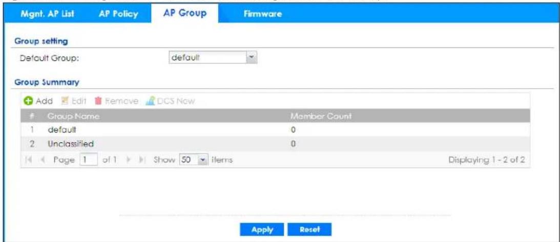
Each field is described in the following table.
Table 113 Configuration > Wireless > AP Management > AP Group
| LABEL DESCRIPTION | |
| Group Setting | |
| Default Group Select | a group that is used as the default group.Any AP that is not configured to associate with a specific AP group belongs to the default group automatically. |
| Group Summary | |
| Add Click this button to create a new AP group. | |
| Edit Select an entry and click this button to edit its properties. | |
| Remove | Select an entry and click this button to remove it from the list.Note: You cannot remove a group with which an AP is associated. |
| DCS Now | Select one or multiple groups and click this button to use DCS (Dynamic Channel Selection) to allow the APs in the group(s) to automatically find a less-used channel in an environment where there are many APs and there may be interference.Note: You should have enabled DCS in the applied AP radio profile before the APs can use DCS.Note: DCS is not supported on the radio which is working in repeater AP mode. |
| # This is the index number of the group in the list. | |
| Group Name This is the name of the group. | |
| Member Count This is the total number of APs which belong to this group. | |
| Apply | Click Apply to save your changes back to the Zyxel Device. |
| Reset | Click Reset to return the screen to its last-saved settings. |
8.4.3.1 Add/Edit AP Group
Click Add or select an AP group and click the Edit button in the Configuration > Wireless > AP Management > AP Group table to display this screen.
Figure 243 Configuration > Wireless > AP Management > AP Group > Add/Edit
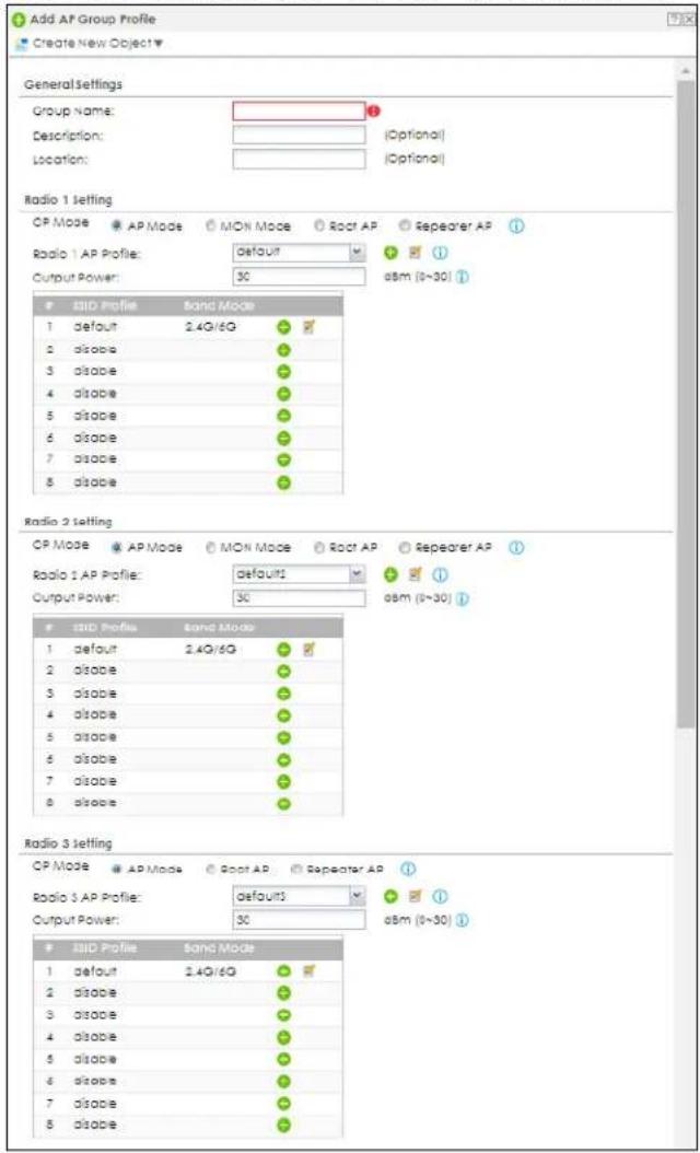
Figure 244 Configuration > Wireless > AP Management > AP Group > Add/Edit (continued)
![VLAN Settings Force Overwrite VLAN Config Management VLAN ID: 1-4024 At Native VLAN ① Port Settings Model Specific Setting: nw8123-as-ha Port Setting Add Activate inactivate Status Port PHD 1 uplink n/a 2 Ian1 1 Page 1 of 1 Show 50 items Displaying 1 - 2 of 2 VLAN Configuration Add Edit Remove Activate inactivate Status Name VID Member 1 Vian0 1 Ian1 Page 1 of 1 Show 50 items Displaying 1 - 1 of 1 Load Balancing Setting Enable Load Balancing Mode: By Station Number # Radio 1 Max Station: 127 [1~127] Radio 2 Max Station: 127 [1~127] Radio 3 Max station: 127 [1~127] Disassociate station when overloaded Rogue AP Detection Setting Enable Rogue AP Detection ① AP List Available Member OK Cancel Override Selling](/content/2026/05/878280/images/1377a983d98625f0d0f187b86382e598f30f73b00d3033f7ed92c0cc87361d08.jpg)
Each field is described in the following table.
Table 114 Configuration > Wireless > AP Management > AP Group > Add/Edit
| LABEL DESCRIPTION | |
| General Settings | |
| Group Name | Enter a name for this group. You can use up to 31 alphanumeric characters. Dashes and underscores are also allowed. The name should start with a letter. |
| Description | Enter a description for this group. You can use up to 31 characters, spaces and underscores allowed. |
| Location Specify the name of the place where the AP group is located. | |
| Radio 1/2/3 Setting Radio 1, radio 2 and radio 3 support different band modes.Radio 1 supports 2.4G.Radio 2 supports 5G and 6G.Radio 3 supports 6G.Check the following settings if you can't see 6G WiFi on the WiFi clients. Make sure:You have APs that support WiFi 6E in your Zyxel Device network; see Section 8.1.2 on page 266 for more information.You have created an SSID profile with 802.11 Band set to 6G.You have applied the 6G SSID profile to radio 2 or radio 3 in AP Group.OP Mode Select the operating mode for radio 1, radio 2 or radio 3.AP Mode means the AP can receive connections from wireless clients and pass their data traffic through to the Zyxel Device to be managed (or subsequently passed on to an upstream gateway for managing).MON Mode means the AP monitors the broadcast area for other APs, then passes their information on to the Zyxel Device where it can be determined if those APs are friendly or rogue. If an AP is set to this mode it cannot receive connections from wireless clients.Root AP means the radio acts as an AP and also supports the wireless connections with other APs (in repeater mode) to form a ZyMesh to extend its wireless network.Repeater AP means the radio can establish a wireless connection with other APs (in either root AP or repeater mode).Note: To prevent bridge loops, do NOT set both radios on a managed AP to Repeater AP mode.Note: The root AP and repeater AP(s) in a ZyMesh must use the same country code and AP radio profile settings in order to communicate with each other.Note: Ensure you restart the managed AP after you change its operating mode. | |
| Radio 1/2/3 AP Profile | Select an AP profile from the list. If no profile exists, you can create a new one through the Create new Object menu. |
| Radio 1/2/3 Profile | Select a monitor profile from the list. If no profile exists, you can create a new one through the Create new Object menu. |
| Radio 1/2/3 ZyMesh Profile | This field is available only when the radio is in Root AP or Repeater AP mode.Select the ZyMesh profile the radio uses to connect to a root AP or repeater. |
| Enable Wireless Bridging | This field is available only when the radio is in Repeater AP mode.Select this option to enable wireless bridging on the radio.The managed AP must support LAN provision and the radio should be in repeater mode.VLAN and bridge interfaces are created automatically according to the LAN port's VLAN settings. When wireless bridging is enabled, the managed repeater AP can still transmit data through its Ethernet port(s) after the ZyMesh link is up. Be careful to avoid bridge loops.The managed APs in the same ZyMesh must use the same static VLAN ID. |
| Output Power Set the maximum output power of the AP.If there is a high density of APs in an area, decrease the output power of the managed AP to reduce interference with other APs.Note: Reducing the output power also reduces the Zyxel Device's effective broadcast radius. | |
| Edit | Select an SSID and click this button to reassign it. The selected SSID becomes editable immediately upon clicking. |
| # | This is the index number of the SSID profile. You can associate up to eight SSID profiles with an AP radio. |
| SSID Profile Indicates which SSID profile is associated with this radio profile. | |
| VLAN Settings | |
| Force Overwrite VLAN Config | Select this to have the Zyxel Device change the AP's management VLAN to match the configuration in this screen. |
| Management VLAN ID | Enter a VLAN ID for this AP. |
| As Native VLAN | Select this option to treat this VLAN ID as a VLAN created on the Zyxel Device and not one assigned to it from outside the network. |
| Port Settings | |
| Model Specific Setting | Select the model of the managed AP to display the model-specific port and VLAN settings in the tables below. |
| Port Setting You can activate or deactivate a non-uplink port. | |
| Edit | Double-click an entry or select it and click Edit to open a screen where you can modify the entry's settings. |
| Activate/Inactivate | To turn on an entry, select it and click Activate. To turn off an entry, select it and click Inactivate. |
| # This is the port's index number in this list. | |
| Status This displays whether or not the port is activated. | |
| Port | This shows the name of the physical Ethernet port on the managed AP. |
| PVID This shows the port's PVID.A PVID (Port VLAN ID) is a tag that adds to incoming untagged frames received on a port so that the frames are forwarded to the VLAN group that the tag defines. | |
| VLAN Configuration | Use Add to create a new VLAN Configuration. Select a VLAN Configuration first to use the Edit, Remove, Activate and Inactivate buttons. |
| # This is the VLAN's index number in this list. | |
| Status This displays whether or not the VLAN is activated. | |
| Name This shows the name of the VLAN. | |
| VID This shows the VLAN ID number. | |
| Member This field displays the Ethernet port(s) that is a member of this VLAN. | |
| Load Balancing Setting | |
| Enable Load Balancing | Select this to enable load balancing on the Zyxel Device.Use this section to configure wireless network traffic load balancing between the managed APs in this group.Note: Load balancing is not supported on the radio which is working in root AP or repeater AP mode. |
| Mode Select a mode by which load balancing is carried out.Select By Station Number to balance network traffic based on the number of specified stations connected to an AP.Select By Traffic Level to balance network traffic based on the volume generated by the stations connected to an AP.Select By Smart Classroom to balance network traffic based on the number of specified stations connected to an AP. The AP ignores association request and authentication request packets from any new station when the maximum number of stations is reached.If you select By Station Number or By Traffic Level, once the threshold is crossed (either the maximum station numbers or with network traffic), the AP delays association request and authentication request packets from any new station that attempts to make a connection. This allows the station to automatically attempt to connect to another, less burdened AP if one is available. | |
| Radio 1/2 Max Station Number | Enter the threshold number of stations at which an AP begins load balancing its connections. |
| Disassociate station when overloaded | This function is enabled by default and the disassociation priority is always Signal Strength when you set Mode to By Station Number.Select this option to disassociate wireless clients connected to the AP when it becomes overloaded. If you do not enable this option, then the AP simply delays the connection until it can afford the bandwidth it requires, or it transfers the connection to another AP within its broadcast radius.The disassociation priority is determined automatically by the Zyxel Device and is as follows:Idle Timeout- Devices that have been idle the longest will be disassociated first. If none of the connected devices are idle, then the priority shifts to Signal Strength.Signal Strength- Devices with the weakest signal strength will be disassociated first.Note: If you enable this function, you should ensure that there are multiple APs within the broadcast radius that can accept any rejected or kicked wireless clients; otherwise, a wireless client attempting to connect to an overloaded AP will be kicked continuously and never be allowed to connect. |
| Radio 1/2 Traffic Level | Select the threshold traffic level at which the AP begins load balancing its connections (Low, Medium, High).The maximum bandwidth allowed for each level is:Low- 11 Mbps,Medium- 23 MbpsHigh- 35M bps |
| Rogue AP Detection Setting | |
| Enable Rogue AP Detection | Select this option to detect Rogue APs in the network. |
| AP List | |
| Available | This lists the APs that do not belong to this group. Select the APs that you want to add to the group you are editing, and click the right arrow button to add them. |
| Member | This lists the APs that belong to this group. Select any APs that you want to remove from the group, and click the left arrow button to remove them. |
| AP List | |
| Available | This lists the APs that do not belong to this group. Select the APs that you want to add to the group you are editing, and click the right arrow button to add them. |
| Member | This lists the APs that belong to this group. Select any APs that you want to remove from the group, and click the left arrow button to remove them. |
| OK | Click OK to save your changes back to the Zyxel Device. |
| Cancel | Click Cancel to close the window with changes unsaved. |
| Override Member AP Setting | Click this button to overwrite the settings of all managed APs in this group with the settings you configure here. All Override Group check boxes on the AP Management > Mgmt. AP List > Edit AP List screen for the APs in this group will be deselected. |
8.4.4 Firmware
The Zyxel Device stores an AP firmware in order to manage supported APs. This screen allows the Zyxel Device to check for and download new AP firmware when it becomes available on the firmware server. All APs managed by the Zyxel Device must have the same firmware version as the AP firmware on the Zyxel Device.
When an AP connects to the Zyxel Device wireless controller, the Zyxel Device will check if the AP has the same firmware version as the AP firmware on the Zyxel Device. If yes, then the Zyxel Device can manage it. If no, then the AP must upgrade (or downgrade) its firmware to be the same version as the AP firmware on the Zyxel Device (and reboot).
The Zyxel Device should always have the latest AP firmware so that:
- APs don't have to downgrade firmware in order to be managed
- All new APs are supported.
Use Check to see if the Zyxel Device has the latest AP firmware. Use Apply to have the Zyxel Device download the latest AP firmware (see More Details for more information on the firmware) from the firmware server. If the Zyxel Device does not have enough space for the latest AP firmware, then the Zyxel Device will delete an existing firmware that no AP is using before downloading the new AP firmware.
Click Configuration > Wireless > AP Management > Firmware to access this screen.
Figure 245 Configuration > Wireless > AP Management > Firmware
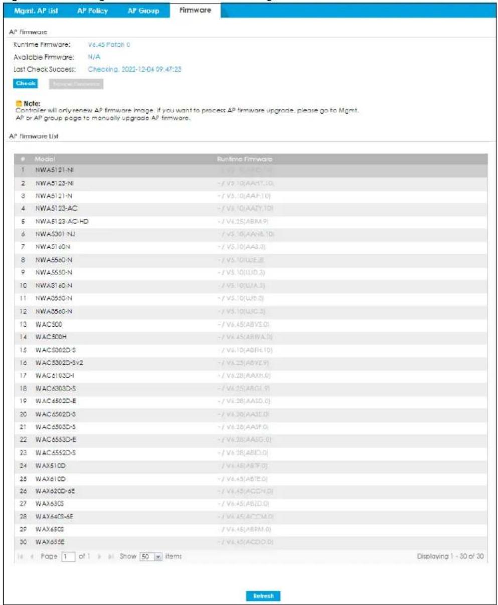
Each field is described in the following table.
Table 115 Configuration > Wireless > AP Management > Firmware
| LABEL DESCRIPTION | |
| AP Firmware | |
| Runtime Firmware | This displays the current AP firmware version on the Zyxel Device. The Zyxel Device must have the latest AP firmware to manage all supported APs. |
| Available Firmware | This field displays if there is a later AP firmware version available on the firmware server. It displays N/A if the Zyxel Device cannot connect with the firmware server. Check that the Zyxel Device has Internet access if N/A displays and then click the Check button below.If a newer Zyxel Device AP firmware is available, its version number and a More Details icon displays here. |
| Last Check Success | This displays the date and time the last check for new firmware was made and whether the check is in progress (checking), was successful (success), or has failed (fail). |
| Check | Click this button to have the Zyxel Device display the latest AP firmware version available on the firmware server. |
| Apply AP Firmware | Due to space limitations, the Zyxel Device only downloads and keeps AP firmware for APs it is currently managing. If you connect a new AP to the Zyxel Device, the Zyxel Device may need to download a new AP firmware. Please wait while downloading new firmware as the speed depends on your Internet connection speed. Make sure to maintain the Internet connection while downloading new firmware. |
| Apply | Click this to download newer Available Firmware from the firmware server and update the Runtime Firmware version. |
| # This is an index number of a managed AP. | |
| Model This displays the name of all manageable AP models. | |
| Runtime Firmware | This displays the firmware version that the managed AP must have in order to be managed by the Zyxel Device. Firmware for APs that the Zyxel Device already has displays in bold; firmware that the Zyxel Device doesn't have or is still downloading is grayed out. Firmware that is in the download queue will show To be downloaded. |
| Refresh Click this to update the model firmware table. | |
8.5 Rogue AP
Use this screen to assign APs either to the rogue AP list or the friendly AP list. A rogue AP is a wireless access point operating in a network's coverage area that is not under the control of the network administrator, and which can potentially open up holes in a network's security.
Click Configuration > Wireless > Rogue AP to access this screen.
Figure 246 Configuration > Wireless > Rogue AP
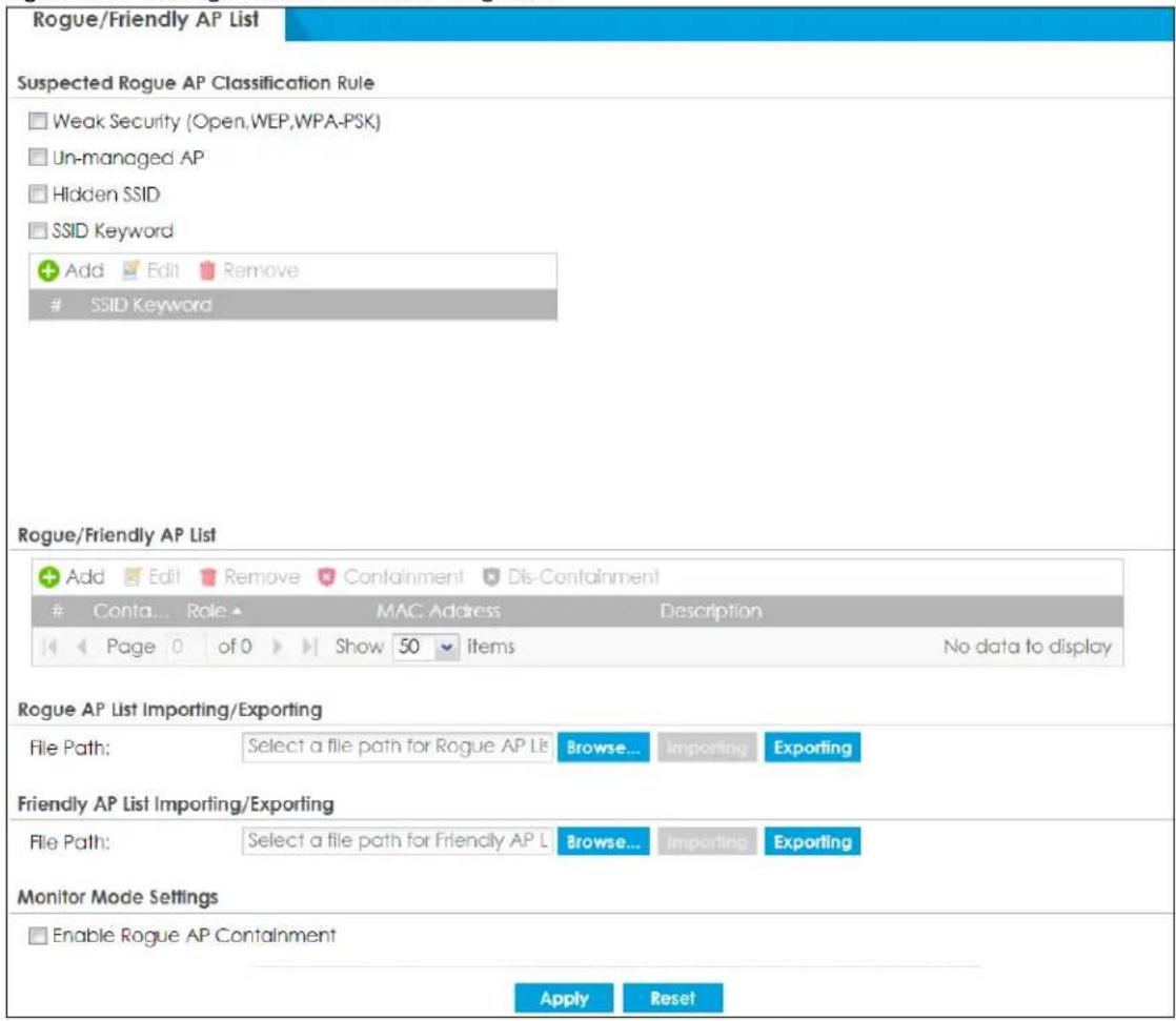
Each field is described in the following table.
Table 116 Configuration > Wireless > Rogue AP
| LABEL DESCRIPTION | |
| Suspected Rogue AP Classification Rule | Click the check boxes (Weak Security (Open, WEP, WPA-PSK), Un-managed AP, Hidden SSID, SSID Keyword) of the characteristics an AP should have for the Zyxel Device to rule it as a rogue AP. |
| Add Click this to add an SSID Keyword. | |
| Edit Select an SSID Keyword and click this button to modify it. | |
| Remove | Select an existing SSID keyword and click this button to delete it. |
| # This is the SSID Keyword's index number in this list. | |
| SSID Keyword This field displays the SSID Keyword. | |
| Rogue/Friendly AP List | |
| Add | Click this button to add an AP to the list and assign it either friendly or rogue status. |
| Edit Select an AP in the list to edit and reassign its status. | |
| Remove Select an AP in the list to remove. | |
| Containment Click this button to quarantine the selected AP.A quarantined AP cannot grant access to any network services. Any stations that attempt to connect to a quarantined AP are disconnected automatically. | |
| Dis-Containment | Click this button to take the selected AP out of quarantine.An unquarantined AP has normal access to the network. |
| # | This field is a sequential value, and it is not associated with any interface. |
| Containment | This field indicates the selected AP's containment status. |
| Role | This field indicates whether the selected AP is a rogue-ap or a friendly-ap. To change the AP's role, click the Edit button. |
| MAC Address This field indicates the AP's radio MAC address. | |
| Description | This field displays the AP's description. You can modify this by clicking the Edit button. |
| Rogue/Friendly AP List Importing/Exporting | These controls allow you to export the current list of rogue and friendly APs or import existing lists. |
| File Path / Browse / Importing | Enter the file name and path of the list you want to import or click the Browse button to locate it. Once the File Path field has been populated, click Importing to bring the list into the Zyxel Device. |
| Exporting | Click this button to export the current list of either rogue APs or friendly APS. |
| Monitor Mode Settings | |
| Enable Rogue AP Containment | Select this to enable rogue AP containment. |
| Apply | Click Apply to save your changes back to the Zyxel Device. |
| Reset | Click Reset to return the screen to its last-saved settings. |
8.5.1 Add/Edit Rogue/Friendly List
Select an AP and click the Edit button in the Configuration > Wireless > Rogue AP table to display this screen.
Figure 247 Configuration > Wireless > Rogue AP > Add/Edit Rogue/Friendly
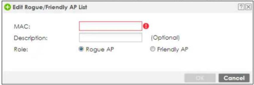
Each field is described in the following table.
Table 117 Configuration > Wireless > Rogue AP > Add/Edit Rogue/Friendly
| LABEL DESCRIPTION | |
| MAC | Enter the MAC address of the AP you want to add to the list. A MAC address is a unique hardware identifier in the following hexadecimal format: xx:xx:xx:xx:xx:xx where xx is a hexadecimal number separated by colons. |
| DescriptionRole | Enter up to 60 characters for the AP's description. Spaces and underscores are allowed.Select either Rogue AP or Friendly AP for the AP's role. |
| OK | Click OK to save your changes back to the Zyxel Device. |
| Cancel | Click Cancel to close the window with changes unsaved. |
8.6 Wireless Health
Wireless health is a way to measure the APs wireless network performance in Zyxel Device networks. Wireless health is defined by the number of times APs have to resend packets before the packets are sent out successfully. The more times an AP has to resend packets, the poorer the state of wireless health the AP is in.
The Zyxel Device improves the wireless network performance by doing the following:
- Change the channel bandwidth from 80MHz to 20MHz to reduce radio interference from other wireless devices.
- Select a radio channel with least interference (Dynamic Channel Selection).
- Direct clients to APs with a stronger WiFi signal.
Click Configuration > Wireless > Wireless Health to access this screen.
Figure 248 Configuration > Wireless > Wireless Health
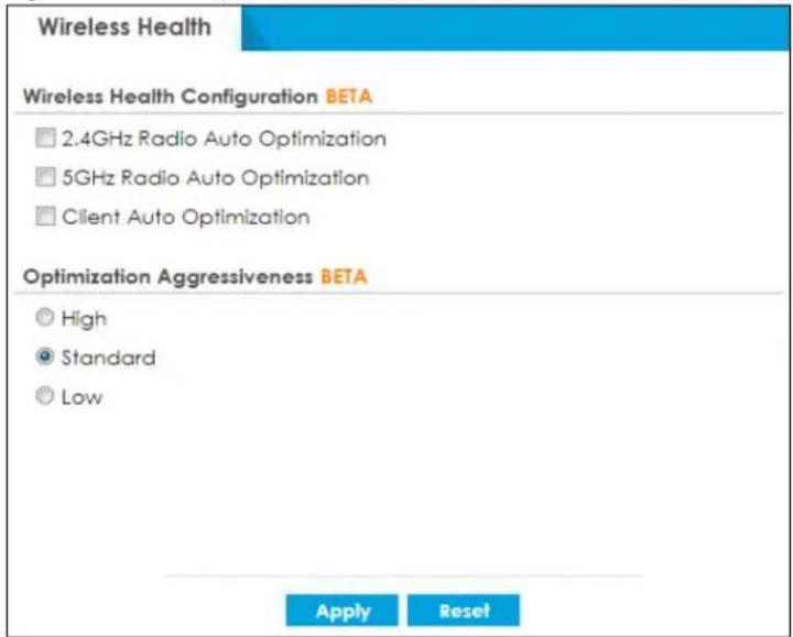
Each field is described in the following table.
Table 118 Configuration > Wireless > Wireless Health
| LABEL DESCRIPTION | |
| 2.4GHz/5GHz Radio Auto Optimization | Select this to have the AP change the channel bandwidth from 80MHz to 20 MHz to reduce the radio interference with other APs. If the AP wireless performance has not improved, the Zyxel Device will have the AP scan and choose a radio channel that has least interference. |
| Client Auto Optimization | Select this to have the AP try to steer the wireless clients in poor health to an AP or SSID with a strong signal every 30 minutes. |
| Optimization Aggressiveness | High.StandardandLowstand for different traffic rate threshold levels. The level you select here decides when the Zyxel Device takes actions to improve the APs wireless network performance. The Zyxel Device will postpone the actions implemented on APs until your network is less busy if the threshold is exceeded.Select a suitable traffic rate threshold level for your network.High: Select this if you want the Zyxel Device to postpone the action set when the AP network traffic is heavy.Standard: Select this if you want the Zyxel Device to postpone the action set when the AP network traffic is medium.Low: Select this if you want the Zyxel Device to postpone the action set when the AP network traffic is low. |
| Apply | ClickApplyto save your changes back to the Zyxel Device. |
| Reset | ClickResetto return the screen to its last-saved settings. |
8.7 Auto Healing
Use this screen to enable auto healing, which allows you to extend the wireless service coverage area of the managed APs when one of the APs fails. Click Configuration > Wireless > Auto Healing to access this screen.
Figure 249 Configuration > Wireless > Auto Healing
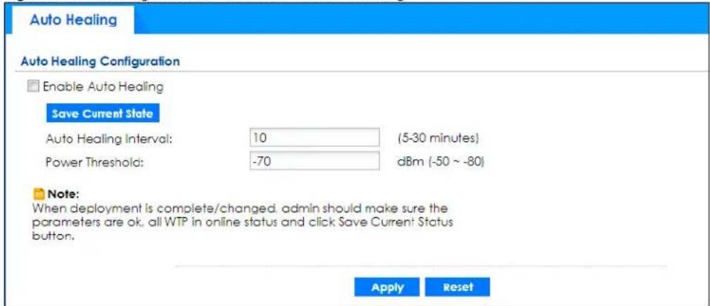
Each field is described in the following table.
Table 119 Configuration > Wireless > Auto Healing
| LABEL DESCRIPTION | |
| Enable Auto Healing | Select this option to turn on the auto healing feature. |
| Save Current State | Click this button to have all manged APs immediately scan their neighborhoods three times in a row and update their neighbor lists to the AP controller (Zyxel Device). |
| Auto Healing Interval | Set the time interval (in minutes) at which the managed APs scan their neighborhoods and report the status of neighbor APs to the AP controller (Zyxel Device).An AP is considered “failed” if the AP controller obtains the same scan result that the AP is missing from the neighbor list of other APs three times. |
| Power Threshold | Set the power level (in dBm) to which the neighbor APs of the failed AP increase their output power in order to extend their wireless service coverage areas.When the failed AP is working again, its neighbor APs return their output power to the original level. |
| Apply | Click Apply to save your changes back to the Zyxel Device. |
| Reset | Click Reset to return the screen to its last-saved settings. |
8.8 RTLS Overview
Ekahau RTLS (Real Time Location Service) tracks battery-powered Wi-Fi tags attached to APs managed by the Zyxel Device to create maps, alerts, and reports.
The Ekahau RTLS Controller is the centerpiece of the RTLS system. This server software runs on a Windows computer to track and locate Ekahau tags from Wi-Fi signal strength measurements. Use the Zyxel Device with the Ekahau RTLS system to take signal strength measurements at the APs (Integrated Approach / Blink Mode).
The following example shows the Ekahau RTLS Integrated Approach (Blink Mode).
1 The Wi-Fi tag sends blink packets at specified intervals (or triggered by something like motion or button presses).
2 The APs pick up the blink packets, measure the signal strength, and send it to the Zyxel Device.
3 The Zyxel Device forwards the signal measurements to the Ekahau RTLS Controller.
4 The Ekahau RTLS Controller calculates the tag positions.
Figure 250 RTLS Example
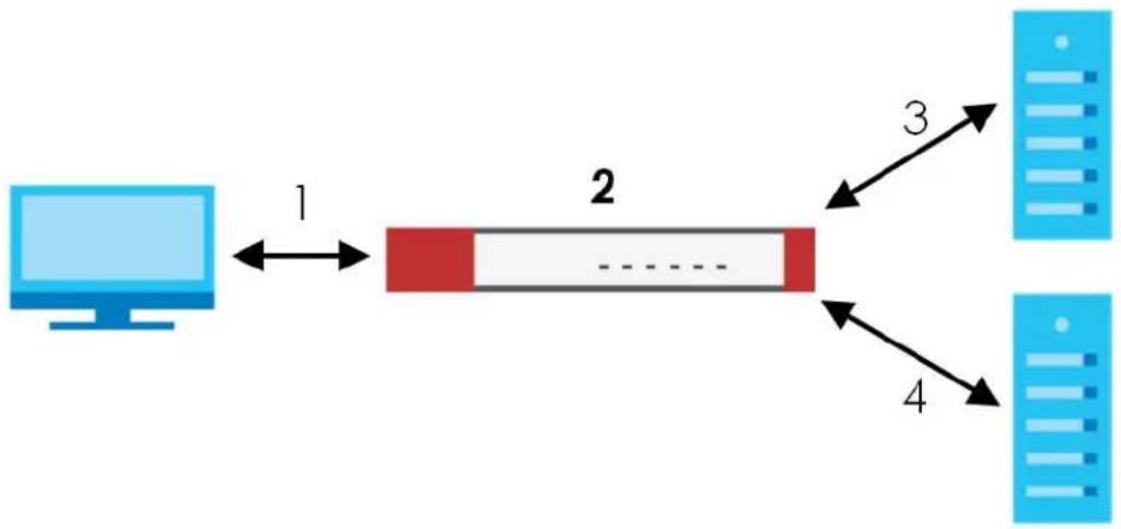
flowchart
graph LR
    A["Computer"] -->|1| B["Segment"]
    B -->|2| C["Server 2"]
    B -->|3| D["Server 3"]
    B -->|4| E["Server 4"]
8.8.1 What You Can Do in this Chapter
Use the RTLS screen (Section 8.8.3 on page 316) to use the managed APs as part of an Ekahau RTLS (Real Time Location Service) to track the location of Ekahau Wi-Fi tags.
8.8.2 Before You Begin
You need:
- At least three APs managed by the Zyxel Device (the more APs the better since it increases the amount of information the Ekahau RTLS Controller has for calculating the location of the tags)
• IP addresses for the Ekahau Wi-Fi tags
• A dedicated RTLS SSID is recommended - Ekahau RTLS Controller in blink mode with TZSP Updater enabled
- Security policies to allow RTLS traffic if the Zyxel Device security policy control is enabled or the Ekahau RTLS Controller is behind a firewall.
For example, if the Ekahau RTLS Controller is behind a firewall, open ports 8550, 8553, and 8569 to allow traffic the APs send to reach the Ekahau RTLS Controller.
The following table lists default port numbers and types of packets RTLS uses.
Table 120 RTLS Traffic Port Numbers
| PORT NUMBER TYPE DESCRIPTION | ||
| 8548 TCP Ekahau T201 location update. | ||
| 8549 UDP Ekahau T201 location update. | ||
| 8550 | TCP | Ekahau T201 tag maintenance protocol and Ekahau RTLS Controller user interface. |
| 8552 UDP Ekahau Location Protocol | ||
| 8553 UDP Ekahau Maintenance Protocol | ||
| 8554 UDP Ekahau T801 firmware update. | ||
| 8560 TCP Ekahau Vision web interface | ||
| 8562 UDP Ekahau T301W firmware update. | ||
| 8569 UDP Ekahau TZSP Listener Port | ||
8.8.3 Configuring RTLS
Click Configuration > Wireless > RTLS to open this screen. Use this screen to turn RTLS (Real Time Location System) on or off and specify the IP address and server port of the Ekahau RTLS Controller.
Figure 251 Configuration > Wireless > RTLS
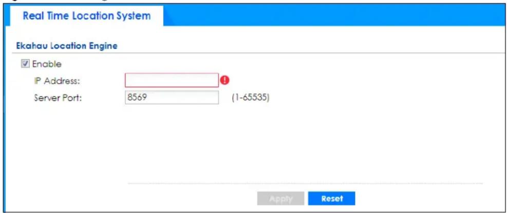
The following table describes the labels in this screen.
Table 121 Configuration > Wireless > RTLS
| LABEL DESCRIPTION | |
| Enable | Select this to use Wi-Fi to track the location of Ekahau Wi-Fi tags. |
| IP Address Specify | the IP address of the Ekahau RTLS Controller. |
| Server Port Specify | the server port number of the Ekahau RTLS Controller. |
| Apply | Click Apply to save your changes back to the Zyxel Device. |
| Reset | Click Reset to return the screen to its last-saved settings. |
8.9 Technical Reference
The following section contains additional technical information about wireless features.
8.9.1 Dynamic Channel Selection
When numerous APs broadcast within a given area, they introduce the possibility of heightened radio interference, especially if some or all of them are broadcasting on the same radio channel. If the interference becomes too great, then the network administrator must open his AP configuration options and manually change the channel to one that no other AP is using (or at least a channel that has a lower level of interference) in order to give the connected stations a minimum degree of interference. Dynamic channel selection frees the network administrator from this task by letting the AP do it
automatically. The AP can scan the area around it looking for the channel with the least amount of interference.
In the 2.4 GHz spectrum, each channel from 1 to 13 is broken up into discrete 22 MHz segments that are spaced 5 MHz apart. Channel 1 is centered on 2.412 GHz while channel 13 is centered on 2.472 GHz.
Figure 252 An Example Three-Channel Deployment
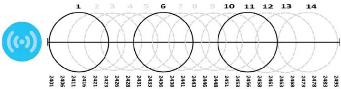
radar
| Category | Value | | -------- | ----- | | 1 | 2401 | | 2 | 2406 | | 3 | 2411 | | 4 | 2416 | | 5 | 2421 | | 6 | 2423 | | 7 | 2426 | | 8 | 2428 | | 9 | 2431 | | 10 | 2433 | | 11 | 2436 | | 12 | 2438 | | 13 | 2441 | | 14 | 2443 | | Other | 2446 | | Other | 2448 | | Other | 2451 | | Other | 2453 | | Other | 2456 | | Other | 2458 | | Other | 2461 | | Other | 2463 | | Other | 2468 | | Other | 2473 | | Other | 2478 | | Other | 2483 | | Other | 2495 |Three channels are situated in such a way as to create almost no interference with one another if used exclusively: 1, 6 and 11. When an AP broadcasts on any of these three channels, it should not interfere with neighboring APs as long as they are also limited to same trio.
Figure 253 An Example Four-Channel Deployment
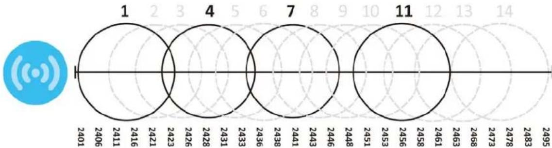
radar
| Label | Value | |-------|-------| | 1 | 2401 | | 2 | 2406 | | 3 | 2411 | | 4 | 2416 | | 5 | 2421 | | 6 | 2423 | | 7 | 2428 | | 8 | 2431 | | 9 | 2433 | | 10 | 2436 | | 11 | 2438 | | 12 | 2441 | | 13 | 2443 | | 14 | 2446 | | | 2448 | | | 2451 | | | 2453 | | | 2458 | | | 2461 | | | 2463 | | | 2468 | | | 2473 | | | 2478 | | | 2483 | | | 2495 |However, some regions require the use of other channels and often use a safety scheme with the following four channels: 1, 4, 7 and 11. While they are situated sufficiently close to both each other and the three so-called "safe" channels (1,6 and 11) that interference becomes inevitable, the severity of it is dependent upon other factors: proximity to the affected AP, signal strength, activity, and so on.
Finally, there is an alternative four channel scheme for ETSI, consisting of channels 1, 5, 9, 13. This offers significantly less overlap that the other one.
Figure 254 An Alternative Four-Channel Deployment
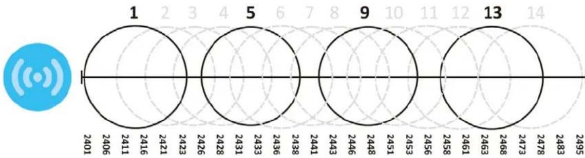
radar
| Label | Value | |-------|-------| | 1 | 2401 | | 2 | 2406 | | 3 | 2411 | | 4 | 2416 | | 5 | 2421 | | 6 | 2423 | | 7 | 2426 | | 8 | 2428 | | 9 | 2431 | | 10 | 2433 | | 11 | 2436 | | 12 | 2438 | | 13 | 2441 | | | 2443 | | | 2446 | | | 2448 | | | 2451 | | | 2453 | | | 2456 | | | 2458 | | | 2461 | | | 2463 | | | 2468 | | | 2473 | | | 2478 | | | 2483 | | | 2495 |8.9.2 Load Balancing
Because there is a hard upper limit on an AP's wireless bandwidth, load balancing can be crucial in areas crowded with wireless users. Rather than let every user connect and subsequently dilute the available bandwidth to the point where each connecting device receives a meager trickle, the load balanced AP instead limits the incoming connections as a means to maintain bandwidth integrity.
There are two kinds of wireless load balancing available on the Zyxel Device:
Load balancing by station number limits the number of devices allowed to connect to your AP. If you know exactly how many stations you want to let connect, choose this option.
For example, if your company's graphic design team has their own AP and they have 10 computers, you can load balance for 10. Later, if someone from the sales department visits the graphic design team's offices for a meeting and he tries to access the network, his computer's connection is delayed, giving it the opportunity to connect to a different, neighboring AP. If he still connects to the AP regardless of the delay, then the AP may boot other people who are already connected in order to associate with the new connection.
Load balancing by traffic level limits the number of connections to the AP based on maximum bandwidth available. If you are uncertain as to the exact number of wireless connections you will have then choose this option. By setting a maximum bandwidth cap, you allow any number of devices to connect as long as their total bandwidth usage does not exceed the configured bandwidth cap associated with this setting. Once the cap is hit, any new connections are rejected or delayed provided that there are other APs in range.
Imagine a coffee shop in a crowded business district that offers free wireless connectivity to its customers. The coffee shop owner can't possibly know how many connections his AP will have at any given moment. As such, he decides to put a limit on the bandwidth that is available to his customers but not on the actual number of connections he allows. This means anyone can connect to his wireless network as long as the AP has the bandwidth to spare. If too many people connect and the AP hits its bandwidth cap then all new connections must basically wait for their turn or get shunted to the nearest identical AP.
CHAPTER 9 Interfaces
9.1 Interface Overview
Use the Interface screens to configure the Zyxel Device's interfaces. You can also create interfaces on top of other interfaces.
- Ports are the physical ports to which you connect cables.
- Interfaces are used within the system operationally. You use them in configuring various features. An interface also describes a network that is directly connected to the Zyxel Device. For example, You connect the LAN network to the LAN interface.
- Zones are groups of interfaces used to ease security policy configuration.
9.1.1 What You Can Do in this Chapter
- Use the Port Role screen (Section 9.2 on page 324) to set the Zyxel Device's physical ports to ZONE interfaces.
- Use the Port Group screen (Section 9.3 on page 325) to create port groups and to assign port groups to Ethernet interfaces.
- Use the Port Configuration screen (Section 9.4 on page 326) to configure Zyxel Device port settings.
- Use the Ethernet screens (Section 9.5 on page 328) to configure the Ethernet interfaces. Ethernet interfaces are the foundation for defining other interfaces and network policies. RIP and OSPF are also configured in these interfaces.
- Use the PPP screens (Section 9.6 on page 352) for PPPoE, PPTP or L2TP Internet connections.
- Use the Cellular screens (Section 9.7 on page 359) to configure settings for interfaces for Internet connections through an installed mobile broadband card.
- Use the Tunnel screens (Section 9.8 on page 368) to configure tunnel interfaces to be used in Generic Routing Encapsulation (GRE), IPv6 in IPv4, and 6to4 tunnels.
- Use the VLAN screens (Section 9.9 on page 375) to divide the physical network into multiple logical networks. VLAN interfaces receive and send tagged frames. The Zyxel Device automatically adds or removes the tags as needed. Each VLAN can only be associated with one Ethernet interface.
- Use the Bridge screens (Section 9.10 on page 389) to combine two or more network segments into a single network.
- Use the LAG screens (Section 9.11 on page 402) to combine multiple physical Ethernet interfaces into a single logical interface.
- Use the VTI screens (Section 9.12 on page 414) to encrypt or decrypt IPv4 traffic from or to the interface according to the IP routing table.
- Use the Trunk screens (Section 9.13 on page 419) to configure load balancing.
9.1.2 What You Need to Know
Interface Characteristics
Interfaces generally have the following characteristics (although not all characteristics apply to each type of interface).
- An interface is a logical entity through which (layer-3) packets pass.
- An interface is bound to a physical port or another interface.
- Many interfaces can share the same physical port.
- An interface belongs to at most one zone.
- Many interfaces can belong to the same zone.
- Layer-3 virtualization (IP alias, for example) is a kind of interface.
Types of Interfaces
You can create several types of interfaces in the Zyxel Device.
- Setting interfaces to the same port role forms a port group. Port groups creates a hardware connection between physical ports at the layer-2 (data link, MAC address) level. Port groups are created when you use the Interface > Port Roles or Interface > Port Groups screen to set multiple physical ports to be part of the same interface.
- Ethernet interfaces are the foundation for defining other interfaces and network policies. RIP and OSPF are also configured in these interfaces.
- Tunnel interfaces send IPv4 or IPv6 packets from one network to a specific network through the Internet or a public network.
- VLAN interfaces receive and send tagged frames. The Zyxel Device automatically adds or removes the tags as needed. Each VLAN can only be associated with one Ethernet interface.
- Bridge interfaces create a software connection between Ethernet or VLAN interfaces at the layer-2 (data link, MAC address) level. Unlike port groups, bridge interfaces can take advantage of some security features in the Zyxel Device. You can also assign an IP address and subnet mask to the bridge.
- PPP interfaces support Point-to-Point Protocols (PPP). ISP accounts are required for PPPoE/PPTP/L2TP interfaces.
- Cellular interfaces are for mobile broadband WAN connections via a connected mobile broadband device.
- Virtual interfaces provide additional routing information in the Zyxel Device. There are three types: virtual Ethernet interfaces, virtual VLAN interfaces, and virtual bridge interfaces.
- Trunk interfaces manage load balancing between interfaces.
Port groups and trunks have a lot of characteristics that are specific to each type of interface. The other types of interfaces--Ethernet, PPP, cellular, VLAN, bridge, and virtual--have a lot of similar characteristics. These characteristics are listed in the following table and discussed in more detail below.
Table 122 Ethernet, PPP, Cellular, VLAN, Bridge, and Virtual Interface Characteristics
| CHARACTERISTICS | ETHERNET | ETHERNET | PPP | CELLULAR | VLAN | BRIDGE | VIRTUAL |
| Name* wan1, wan2 lan1, lan2, | dmz | pppx | cellularx | vlanx | brx | ** | |
| Configurable Zone | No | No | Yes | Yes | Yes | Yes | No |
| IP Address Assignment | |||||||
| Static IP address | Yes | Yes | Yes | Yes | Yes | Yes | Yes |
| DHCP client | Yes | No | Yes | Yes | Yes | Yes | No |
| Routing metric | Yes | Yes | Yes | Yes | Yes | Yes | Yes |
| Interface Parameters | |||||||
| Bandwidth restrictions | Yes Yes Yes Yes | Yes Yes Yes | |||||
| Packet size (MTU) | Yes Yes Yes Yes | Yes Yes No | |||||
| DHCP | |||||||
| DHCP server | No | Yes | No | No | Yes | Yes | No |
| DHCP relay | No | Yes | No | No | Yes | Yes | No |
| Connectivity Check | Yes | No | Yes | Yes | Yes | Yes | No |
Note: The format of interface names other than the Ethernet and ppp interface names is strict. Each name consists of 2-4 letters (interface type), followed by a number (x). For most interfaces, x is limited by the maximum number of the type of interface. For VLAN interfaces, x is defined by the number you enter in the VLAN name field. For example, Ethernet interface names are wan1, wan2, lan1, lan2, dmz; VLAN interfaces are vlan0, vlan1, vlan2...and so on.
The names of virtual interfaces are derived from the interfaces on which they are created. For example, virtual interfaces created on Ethernet interface wan1 are called wan1:1, wan1:2, and so on. Virtual interfaces created on VLAN interface vlan2 are called vlan2:1, vlan2:2, and so on. You cannot specify the number after the colon(:) in the Web Configurator; it is a sequential number. You can specify the number after the colon if you use the CLI to set up a virtual interface.
Relationships Between Interfaces
In the Zyxel Device, interfaces are usually created on top of other interfaces. Only Ethernet interfaces are created directly on top of the physical ports or port groups. The relationships between interfaces are explained in the following table.
Table 123 Relationships Between Different Types of Interfaces
| INTERFACE REQUIRED PORT / INTERFACE | |
| Ethernet interface | physical port |
| VLAN interface | Ethernet interface |
| bridge interface | Ethernet interface*VLAN interface* |
| PPP interface | Ethernet interface*VLAN interface*bridge interfaceWAN1, WAN2, OPT* |
| virtual interface(virtual Ethernet interface)(virtual VLAN interface)(virtual bridge interface) | Ethernet interface*VLAN interface*bridge interface |
| trunk Ethernet interface | Cellular interfaceVLAN interfacebridge interfacePPP interface |
Note: * You cannot set up a PPP interface, virtual Ethernet interface or virtual VLAN interface if the underlying interface is a member of a bridge. You also cannot add an Ethernet interface or VLAN interface to a bridge if the member interface has a virtual interface or PPP interface on top of it.
IPv6 Overview
IPv6 (Internet Protocol version 6), is designed to enhance IP address size and features. The increase in IPv6 address size to 128 bits (from the 32-bit IPv4 address) allows up to 3.4 × 10^38 IP addresses.
IPv6 Addressing
An 128-bit IPv6 address is written as eight 16-bit hexadecimal blocks separated by colons (:). This is an example IPv6 address 2001:0db8:1a2b:0015:0000:0000:1a2f:0000.
IPv6 addresses can be abbreviated in two ways:
- Leading zeros in a block can be omitted. So 2001:0db8:1a2b:0015:0000:0000:1a2f:0000 can be written as 2001:db8:1a2b:15:0:0:1a2f:0.
- Any number of consecutive blocks of zeros can be replaced by a double colon. A double colon can only appear once in an IPv6 address. So 2001:0db8:0000:0000:1a2f:0000:0000:0015 can be written as 2001:0db8::1a2f:0000:0000:0015, 2001:0db8:0000:0000:1a2f::0015, 2001:db8::1a2f:0:0:15 or 2001:db8:0:0:1a2f::15.
Prefix and Prefix Length
Similar to an IPv4 subnet mask, IPv6 uses an address prefix to represent the network address. An IPv6 prefix length specifies how many most significant bits (start from the left) in the address compose the network address. The prefix length is written as "/x" where x is a number. For example,
2001:db8:1a2b:15::1a2f:0/32
means that the first 32 bits (2001:db8) from the left is the network prefix.
Link-local Address
A link-local address uniquely identifies a device on the local network (the LAN). It is similar to a "private IP address" in IPv4. You can have the same link-local address on multiple interfaces on a device. A link-local unicast address has a predefined prefix of fe80::/10. The link-local unicast address format is as follows.
Table 124 Link-local Unicast Address Format
| 1111 1110 10 0 Interface ID | ||
| 10 bits 54 bits 64 bits |
Subnet Masking
Both an IPv6 address and IPv6 subnet mask compose of 128-bit binary digits, which are divided into eight 16-bit blocks and written in hexadecimal notation. Hexadecimal uses four bits for each character (1 \~ 10, A \~ F). Each block's 16 bits are then represented by four hexadecimal characters. For example, FFFF:FFFF:FFFF:FFFF:FC00:0000:0000:0000.
Stateless Autoconfiguration
With stateless autoconfiguration in IPv6, addresses can be uniquely and automatically generated. Unlike DHCPv6 (Dynamic Host Configuration Protocol version six) which is used in IPv6 stateful autoconfiguration, the owner and status of addresses don't need to be maintained by a DHCP server. Every IPv6 device is able to generate its own and unique IP address automatically when IPv6 is initiated on its interface. It combines the prefix and the interface ID (generated from its own Ethernet MAC address) to form a complete IPv6 address.
When IPv6 is enabled on a device, its interface automatically generates a link-local address (beginning with fe80).
When the Zyxel Device's WAN interface is connected to an ISP with a router and the Zyxel Device is set to automatically obtain an IPv6 network prefix from the router for the interface, it generates another address which combines its interface ID and global and subnet information advertised from the router. (In IPv6, all network interfaces can be associated with several addresses.) This is a routable global IP address.
Prefix Delegation
Prefix delegation enables an IPv6 router (the Zyxel Device) to use the IPv6 prefix (network address) received from the ISP (or a connected uplink router) for its LAN. The Zyxel Device uses the received IPv6 prefix (for example, 2001:db2::/48) to generate its LAN IP address. Through sending Router Advertisements (RAs) regularly by multicast, the router passes the IPv6 prefix information to its LAN hosts. The hosts then can use the prefix to generate their IPv6 addresses.
IPv6 Router Advertisement
An IPv6 router sends router advertisement messages periodically to advertise its presence and other parameters to the hosts on the same network.
DHCPv6
The Dynamic Host Configuration Protocol for IPv6 (DHCPv6, RFC 3315) is a server-client protocol that allows a DHCP server to assign and pass IPv6 network addresses, prefixes and other configuration information to DHCP clients. DHCPv6 servers and clients exchange DHCP messages using UDP.
Each DHCP client and server has a unique DHCP Unique IDentifier (DUID), which is used for identification when they are exchanging DHCPv6 messages. The DUID is generated from the MAC address, time, vendor assigned ID and/or the vendor's private enterprise number registered with the IANA. It should not change over time even after you reboot the device.
9.1.3 What You Need to Do First
For IPv6 settings, go to the Configuration > System > IPv6 screen to enable IPv6 support on the Zyxel Device first.
9.2 Port Role
To access this screen, click Configuration > Network > Interface > Port Role. Use the Port Role screen to set the Zyxel Device's physical ports to ZONE interfaces. This creates a hardware connection between the physical ports at the layer-2 (data link, MAC address) level. This provides wire-speed throughput but no security.
Note the following if you are configuring from a computer connected to a lan1, lan2, ext-wlan, ext-lan or dmz port and change the port's role:
- A port's IP address varies as its role changes, make sure your computer's IP address is on the same subnet as the Zyxel Device's interface IP address.
- Use the appropriate interface IP address to access the Zyxel Device.
The physical Ethernet ports are shown at the top and the Ethernet interfaces and zones are shown at the bottom of the screen. Use the radio buttons to select for which interface (network) you want to use each physical port. For example, select a port's LAN radio button to use the port as part of the LAN interface. The port will use the Zyxel Device's LAN IP address and MAC address.
Please note that not all Zyxel Device models support port role, see Section 1.1.1 on page 29 for more information.
Click Apply to save your changes and apply them to the Zyxel Device.
Click Reset to change the port groups to their current configuration (last-saved values).
Figure 255 Configuration > Network > Interface > Port Role
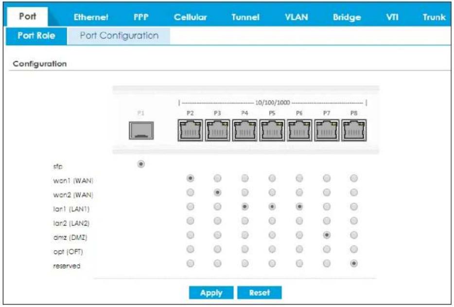
9.3 Port Group
To access this screen, click Configuration > Network > Interface > Port Group. When you assign more than one physical port to a network, you create a port group. Use the Port Group screen to create port groups and to assign port groups to Ethernet interfaces. Port groups have the following characteristics:
- There is a layer-2 Ethernet switch between physical ports in the port group. This provides wire-speed throughput but no security.
- It can increase the bandwidth between the port group and other interfaces.
- The port group uses a single MAC address.
Please note that not all Zyxel Device models support port role, see Section 1.1.1 on page 29 for more information.
Click Apply to save your changes and apply them to the Zyxel Device.
Click Reset to change the port groups to their current configuration (last-saved values).
Figure 256 Configuration > Network > Interface > Port Group
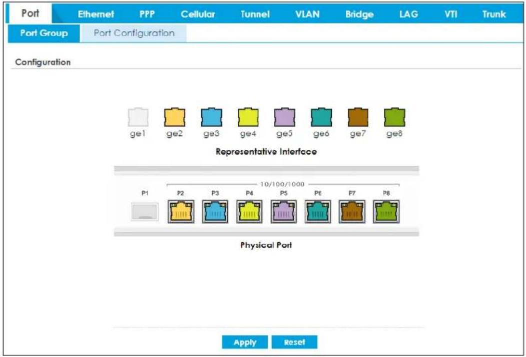
9.4 Port Configuration
Use this screen to configure port settings. Click Configuration > Network > Interface > Port Configuration in the navigation panel to display the configuration screen.
Note: You cannot configure the speed and duplex mode of fiber ports.
Figure 257 Configuration > Network > Interface > Port Configuration
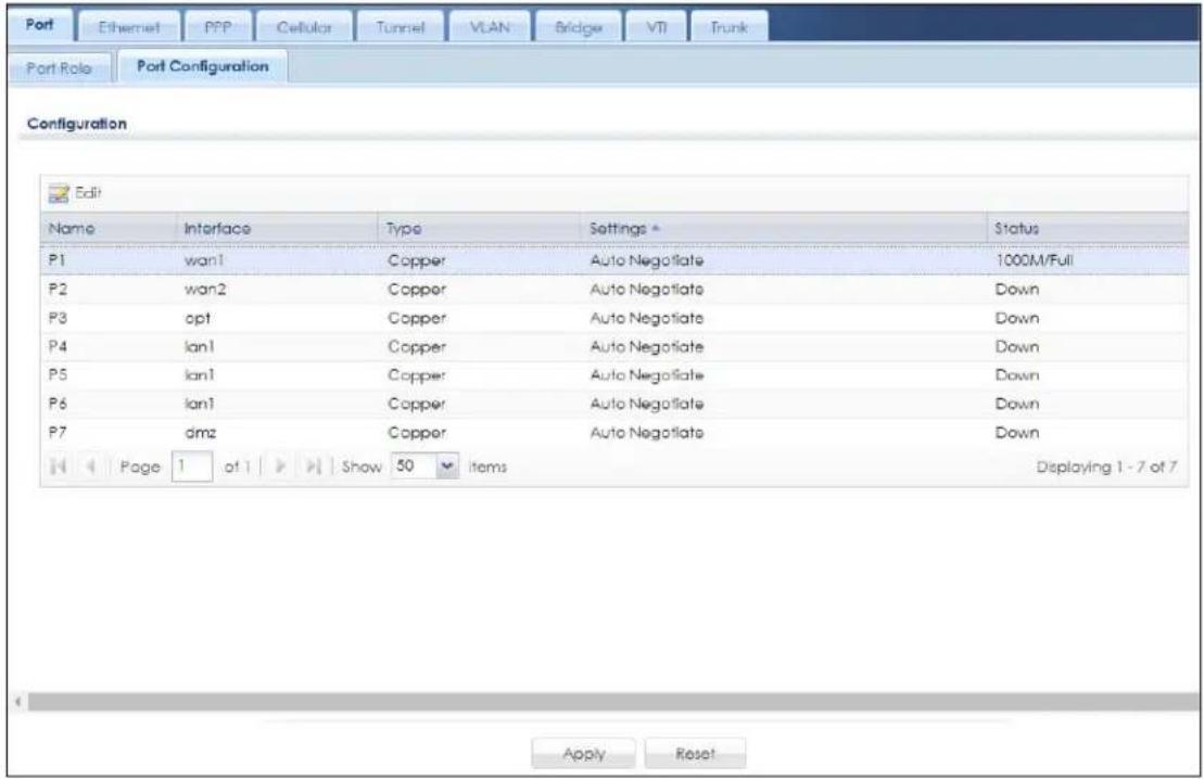
Each field is described in the following table.
Table 125 Configuration > Network > Interface > Port Configuration
| LABEL DESCRIPTION | |
| Edit | Select an entry, and click this button to configure the speed and the duplex mode of the Ethernet connection on this port. |
| Name This field displays the name of the port. | |
| Interface This field displays the interface for the port. | |
| Type | This field displays the cable type that is used on the port. |
| Settings | Select the speed and the duplex mode of the Ethernet connection on this port. Choices are Auto Negotiate, 1000Mbps-Full Duplex, 100Mbps-Full Duplex, 100Mbps-Half Duplex, 10Mbps-Full Duplex, and 10Mbps-Half Duplex.Selecting Auto Negotiate allows one port to negotiate with a peer port automatically to obtain the connection speed (of up to 1000M) and duplex mode that both ends support. When auto-negotiation is turned on, a port on the Zyxel Device negotiates with the peer automatically to determine the connection speed and duplex mode. If the peer port does not support auto-negotiation or turns off this feature, the Zyxel Device determines the connection speed by detecting the signal on the cable and using half duplex mode. When the Zyxel Device's auto-negotiation is turned off, a port uses the pre-configured speed and duplex mode when making a connection, thus requiring you to make sure that the settings of the peer port are the same in order to connect. |
| Status | This field displays the speed and the duplex mode of the Ethernet connection on the port. |
| Apply | Click Apply to save your changes back to the Zyxel Device. |
| Reset | Click Reset to return the screen to its last-saved settings. |
9.5 Ethernet Summary Screen
This screen lists every Ethernet interface and virtual interface created on top of Ethernet interfaces. If you enabled IPv6 on the Configuration > System > IPv6 screen, you can also configure Ethernet interfaces used for your IPv6 networks on this screen. To access this screen, click Configuration > Network > Interface > Ethernet.
Unlike other types of interfaces, you cannot create new Ethernet interfaces nor can you delete any of them. If an Ethernet interface does not have any physical ports assigned to it, the Ethernet interface is effectively removed from the Zyxel Device, but you can still configure it.
Ethernet interfaces are similar to other types of interfaces in many ways. They have an IP address, subnet mask, and gateway used to make routing decisions. They restrict the amount of bandwidth and packet size. They can provide DHCP services, and they can verify the gateway is available.
Use Ethernet interfaces to control which physical ports exchange routing information with other routers and how much information is exchanged through each one. The more routing information is exchanged, the more efficient the routers should be. However, the routers also generate more network traffic, and some routing protocols require a significant amount of configuration and management. The Zyxel Device supports the following routing protocols: RIP, OSPF and BGP. See Chapter 10 on page 444 for background information about these routing protocols.
The default IPv4 LAN subnet range starts from 192.168.1.0/24. If the Zyxel Device WAN IPv4 address conflicts with the LAN IPv4 address, clients on the LAN will not be able to access the Internet.
Figure 258 IP Address Conflict

flowchart
graph LR
    A["LAN Subnet"] --> B["LAN"]
    B --> C["WAN"]
    C --> D["IP: 192.168.1.1"]
    B --> E["IP: 192.168.1.33"]
    F["IP: 192.168.1.33/24"] --> B
    G["IP: 192.168.1.1"] --> H["Global Network"]
The following list shows some examples of what the IPv4 LAN subnet range will change to if it conflicts with the WAN IPv4 address.
• 192.168.1.0/24 will change to 192.168.10.0/24.
• 192.168.2.0/24 will change to 192.168.11.0/24.
• 192.168.3.0/24 will change to 192.168.12.0/24.
• 192.168.4.0/24 will change to 192.168.13.0/24.
Figure 259 IP Address Change
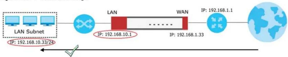
flowchart
graph LR
    A["LAN Subnet"] --> B["LAN"]
    B --> C["WAN"]
    C --> D["IP: 192.168.1.1"]
    B --> E["IP: 192.168.10.1"]
    B --> F["IP: 192.168.1.33"]
    G["Global Network"] --> H["✓"]
    style A fill:#cce5ff,stroke:#333
    style B fill:#ffcccc,stroke:#333
    style C fill:#ffcccc,stroke:#333
    style D fill:#ffcccc,stroke:#333
    style E fill:#cce5ff,stroke:#333
    style F fill:#cce5ff,stroke:#333
    style G fill:#cce5ff,stroke:#333
If you upgrade the Zyxel Device firmware version from 4.29 to 5.31, and your Ethernet settings in the Zyxel Device firmware version 4.29 meets the conditions listed below, the default LAN subnet will change
Chapter 9 Interfaces
when the IPv4 address the WAN interface gets from the DHCP server conflicts with any IPv4 address in the default LAN subnet:
- The WAN is using a static IPv4 address.
- The WAN is using a dynamically assigned IPv4 address.
- The WAN is using an IPv4 address assigned by the PPPoE server.
If the Zyxel Device is using firmware version 5.31, when the WAN IPv4 address conflicts with any IPv4 address in the default LAN subnet, the Zyxel Device will only change the default LAN subnet if it is in default settings.
When you configure the WAN or the LAN IPv4 networks, please note that they must not conflict with each other. The Zyxel Device will not automatically change the LAN IPv4 subnet if the WAN IPv4 address conflicts with the LAN IPv4 networks you configure.
Figure 260 Configuration > Network > Interface > Ethernet
Each field is described in the following table.
Table 126 Configuration > Network > Interface > Ethernet
LABEL DESCRIPTION
| Configuration / IPv6 Configuration | Use theConfigurationsection for IPv4 network settings. Use theIPv6Configurationsection for IPv6 network settings if you connect your Zyxel Device to an IPv6 network. Both sections have similar fields as described below. |
| Edit | Double-click an entry or select it and clickEditto open a screen where you can modify the entry's settings. |
| Remove | To remove a virtual interface, select it and clickRemove. The Zyxel Device confirms you want to remove it before doing so. |
| Activate | To turn on an interface, select it and clickActivate. |
| Inactivate | To turn off an interface, select it and clickInactivate. |
USG FLEX Series User's Guide
Table 126 Configuration > Network > Interface > Ethernet (continued)
| LABEL DESCRIPTION | |
| Create Virtual Interface | To open the screen where you can create a virtual Ethernet interface, select an Ethernet interface and click Create Virtual Interface. |
| References | Select an entry and click References to open a screen that shows which settings use the entry. See Section 9.5.4 on page 349 for an example. |
| # This field is a sequential value, and it is not associated with any interface. | |
| Status This icon is lit when the entry is active and dimmed when the entry is inactive. | |
| Name This field displays the name of the interface. | |
| Description This field displays the description of the interface. | |
| IP Address | This field displays the current IP address of the interface. If the IP address is 0.0.0.0 (on the IPv4 network) or :: (on the IPv6 network), the interface does not have an IP address yet.On the IPv4 network, this screen also shows whether the IP address is a static IP address (STATIC) or dynamically assigned (DHCP). IP addresses are always static in virtual interfaces.On the IPv6 network, this screen also shows whether the IP address is a static IP address (STATIC), link-local IP address (LINK LOCAL), dynamically assigned (DHCP), or an IPv6 StateLess Address AutoConfiguration IP address (SLAAC). See Section 9.1.2 on page 320 for more information about IPv6. |
| Mask | This field displays the interface's subnet mask in dot decimal notation. |
| Apply | Click Apply to save your changes back to the Zyxel Device. |
| Reset | Click Reset to return the screen to its last-saved settings. |
9.5.1 Ethernet Edit
The Ethernet Edit screen lets you configure IP address assignment, interface parameters, RIP settings, OSPF settings, DHCP settings, connectivity check, and MAC address settings. To access this screen, click an Edit icon on the Ethernet Summary screen. (See Section 9.5 on page 328.)
The OPT interface's Edit > Configuration screen is shown here as an example. The screens for other interfaces are similar and contain a subset to the OPT interface screen's fields.
Note: If you create IP address objects based on an interface's IP address, subnet, or gateway, the Zyxel Device automatically updates every rule or setting that uses the object whenever the interface's IP address settings change. For example, if you change the VLAN's IP address, the Zyxel Device automatically updates the corresponding interface-based, LAN subnet address object.
With RIP, you can use Ethernet interfaces to do the following things.
- Enable and disable RIP in the underlying physical port or port group.
- Select which direction(s) routing information is exchanged - The Zyxel Device can receive routing information, send routing information, or do both.
- Select which version of RIP to support in each direction - The Zyxel Device supports RIP-1, RIP-2, and both versions.
- Select the broadcasting method used by RIP-2 packets - The Zyxel Device can use subnet broadcasting or multicasting.
With OSPF, you can use Ethernet interfaces to do the following things.
- Enable and disable OSPF in the underlying physical port or port group.
- Select the area to which the interface belongs.
- Override the default link cost and authentication method for the selected area.
- Select in which direction(s) routing information is exchanged - The Zyxel Device can receive routing information, send routing information, or do both.
Set the priority used to identify the DR or BDR if one does not exist.
9.5.1.1 IGMP Proxy
Internet Group Management Protocol (IGMP) proxy is used for multicast routing. IGMP proxy enables the Zyxel Device to issue IGMP host messages on behalf of hosts that the Zyxel Device discovered on its IGMP-enabled interfaces. The Zyxel Device acts as a proxy for its hosts. Refer to the following figure.
• DS: Downstream traffic
• US: Upstream traffic
• R: Router
• MS: Multicast Server
- Enable IGMP Upstream (US) on the Zyxel Device interface that connects to a router (R) running IGMP that is closer to the multicast server (MS).
- Enable IGMP Downstream on the Zyxel Device interface which connects to the multicast hosts.
Figure 261 IGMP Proxy
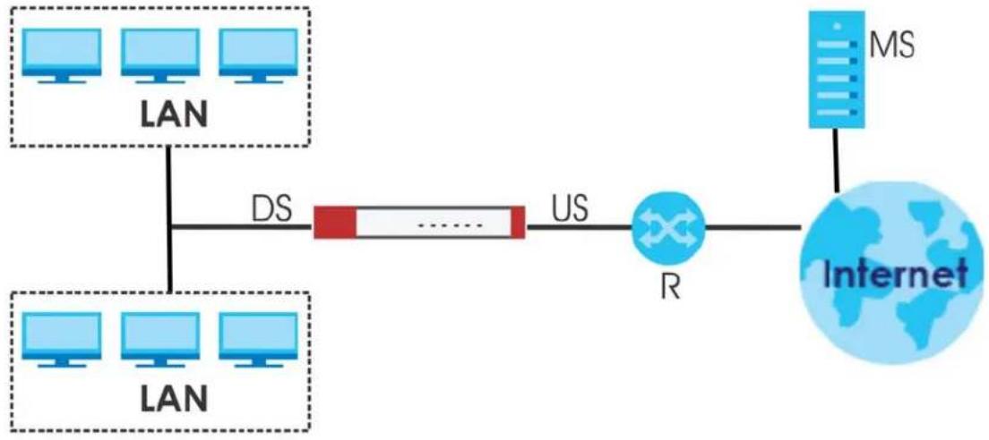
flowchart
graph LR
    A["LAN"] -->|DS| B["US"]
    C["LAN"] -->|DS| B
    B --> D["R"]
    D --> E["Internet"]
    F["MS"] --> E
Figure 262 Configuration > Network > Interface > Ethernet > Edit (External Type)
![Edit Ethernet IPv4 View ▼ Hide Advanced Settings ▼ Create New Object General Settings ■ Enable Interface Interface Properties Interface Type: external Interface Name: wan Port: P2 Zone: WAN MAC Address: BC:CF:4F:47:7A:43 Description: [Optional] IP Address Assignment ● Get Automatically 172.21.40.25 ■ Advance DHCP Option 60: [Optional] ● Use Fixed IP Address IP Address: Subnet Mask: Gateway: Metric: 0 (0-13) ■ Enable IGMP Support ● IGMP Upstream ● IGMP Downstream Interface Parameters Egress Bandwidth: 1048576 Kbps ? ■ Advance Ingress Bandwidth: 1048576 Kbps MTU: 1500 Bytes Connectivity Check ■ Enable Connectivity Check Check Method: icmp Check Period: 30 (5-600 seconds) Check Timeout: 5 (1-10 seconds) Check Fail Tolerance: 5 (1-10) ● Check Default Gateway 172.21.43.254 ○ Check These Addresses [Domain Name or IP Address] Probe Succeeds When: any one respond(s) ■ Advance RIP Setting ■ Enable RIP Direction: BIDr Send Version: 2 Receive Version: 2 ■ V2-Broadcast OSPF Setting Area: none Priority: 1 (0-255) Link Cost: 10 (1-65535) ■ Passive Interface Authentication: None MAC Address Setting](/content/2026/05/878280/images/0c675c7d451666d072790719cfd1f423f25daca9c8460d44bd0b788e54207def.jpg)
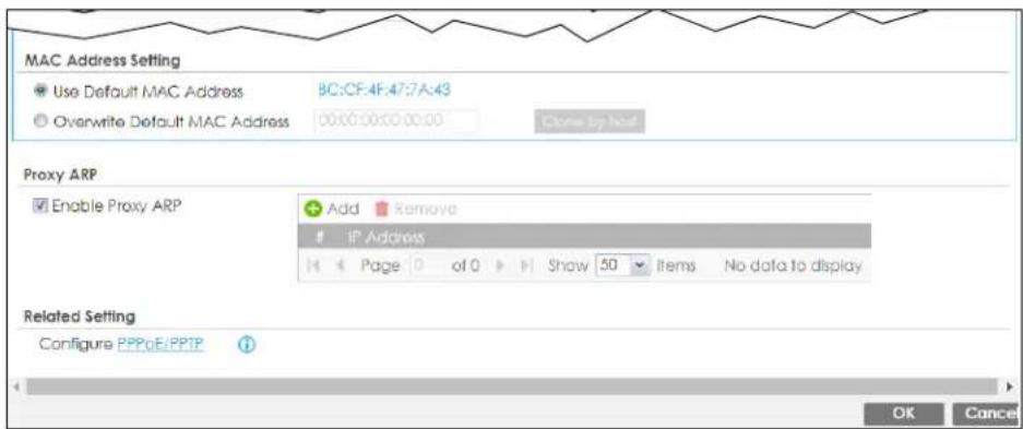
Figure 263 Configuration > Network > Interface > Ethernet > Edit (Internal Type)
![Edit Ethernet IPv4 View ▼ Hide Advanced Settings Create New Object General Settings Enable Interface Interface Properties Interface Type: Internal Interface Name: Ian1 Port: P3, P4, P5 Zone: IAN1 MAC Address: BC:CF:4F:47:7A:44 Description: [Optional] IP Address Assignment IP Address: 192.168.1.1 Subnet Mask: 255.255.255.0 Enable IGMP Support IGMP Upstream IGMP Downstream Interface Parameters Egress Bandwidth: 1048576 Kbps Advance Ingress Bandwidth: 1048576 Kbps MTU: 1500 Bytes Advance Connectivity Check Enable Connectivity Check Check Method: icmp Check Period: 30 (5-600 seconds) Check Timeout: 5 (1-10 seconds) Check Fall Tolerance: 5 (1-10) Check These Addresses: (Domain Name or IP Address) (Optional) Probe Succeeds When: any one respond(s) DHCP Setting DHCP: DHCP Server IP Pool Start Address: 192.168.1.33 Pool Size: 200 First DNS Server (Optional): ZyWALL Second DNS Server (Optional): None Third DNS Server (Optional): None First WINS Server (Optional): Second WINS Server (Optional): Default Router: Ian1 IP Lease Time: infinite 2 days 0 hours (Optional) 0 minutes (Optional) Advance Extended Options Add Edit Remove Name Code Type Value Page 0 of 0 Show 50 Items No data to display PXE Server: PXE Boot Loader File: Enable IP/MAC Binding Enable Logs for IP/MAC Binding Violation Static DHCP Table Add](/content/2026/05/878280/images/0bcc69ca59fa526a10af17cb8ea4c2b8e5897f8d5d519c39efe778121dc2a1b4.jpg)
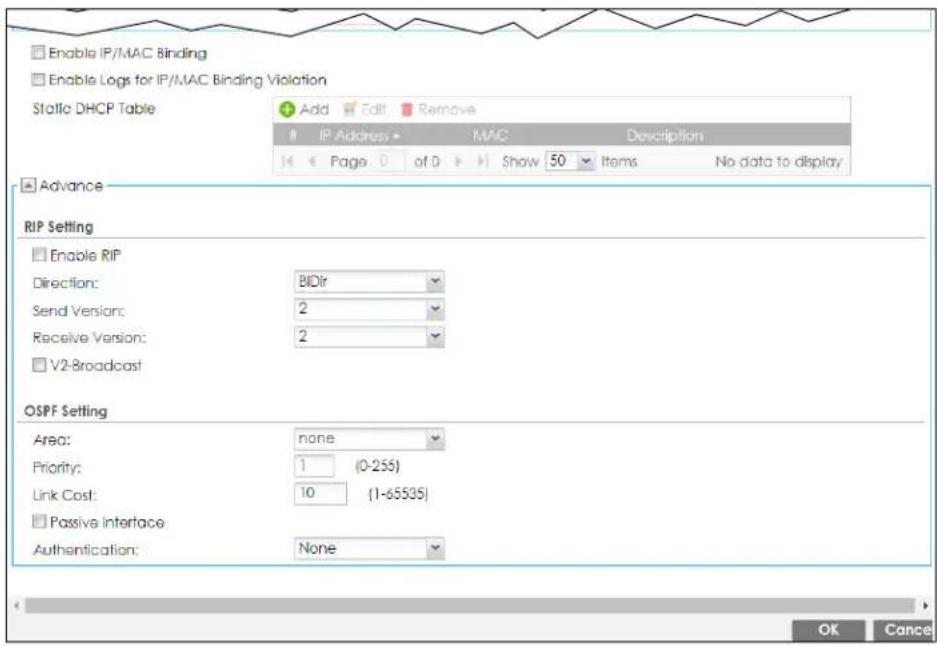
Figure 264 Configuration > Network > Interface > Ethernet > Edit (OPT)
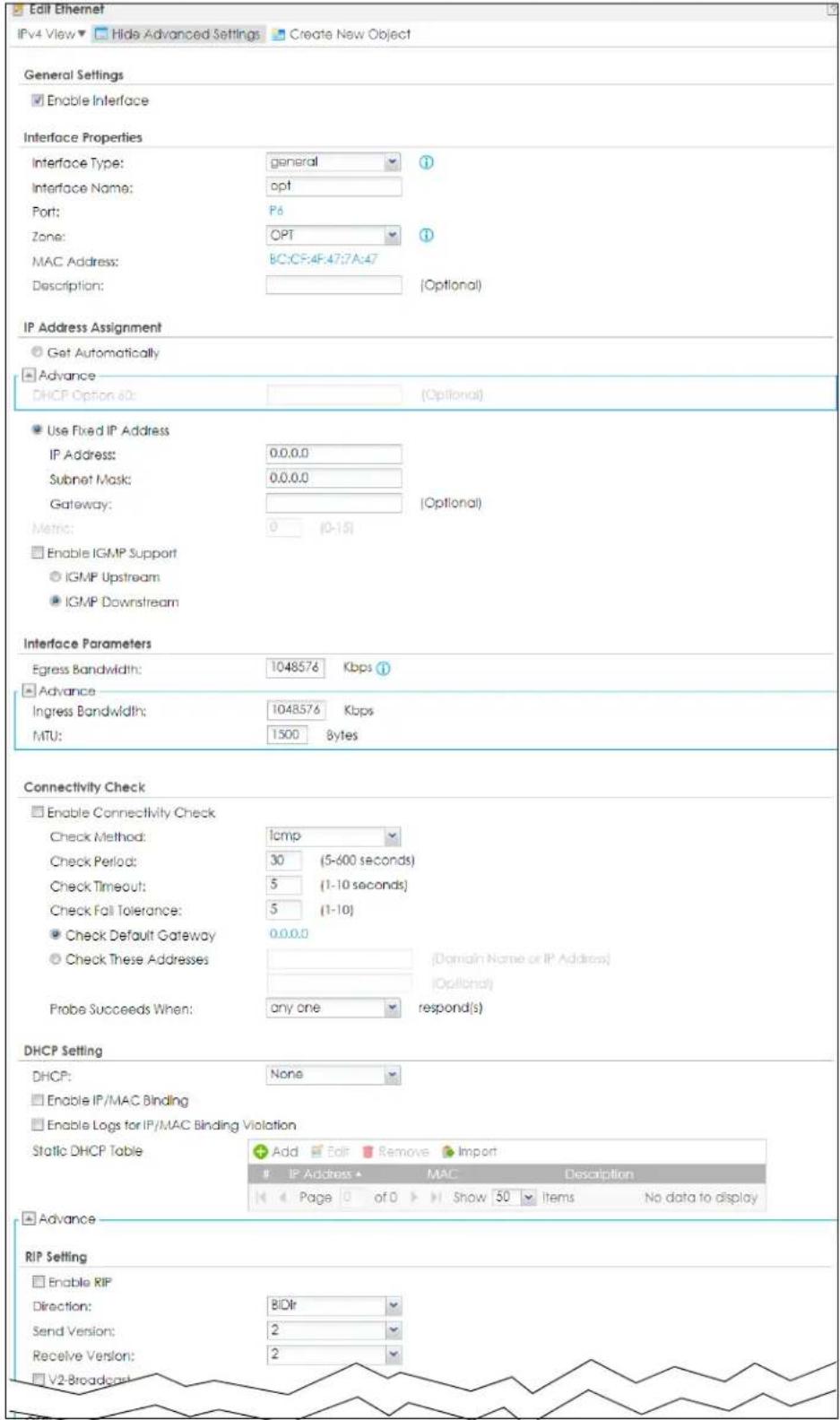
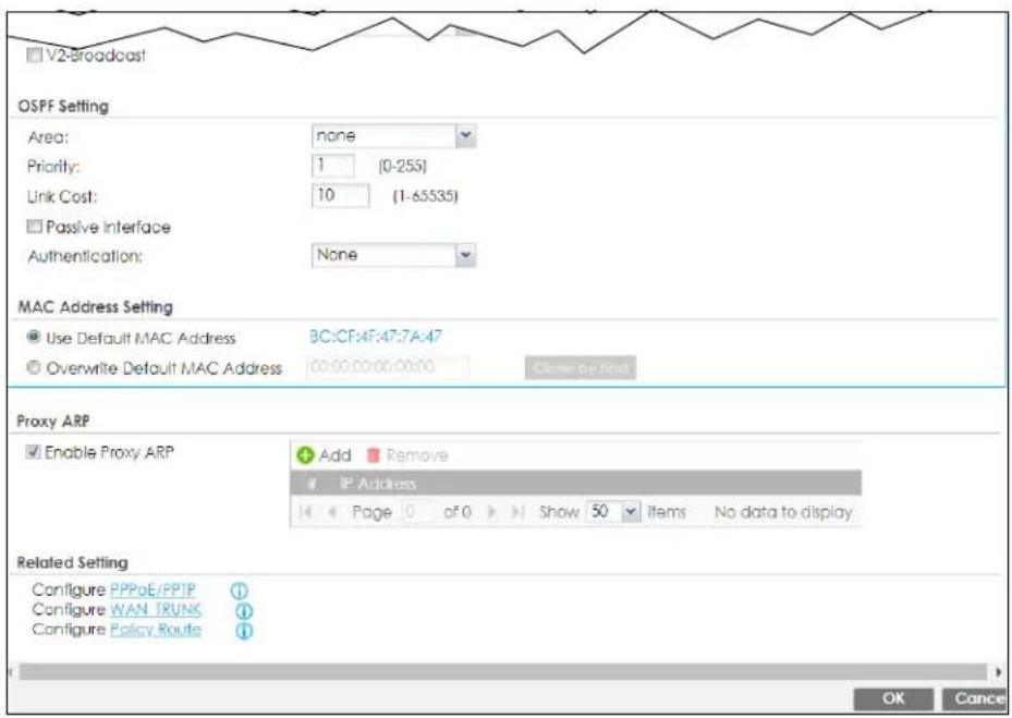
These screen's fields are described in the table below.
Table 127 Configuration > Network > Interface > Ethernet > Edit
| LABEL DESCRIPTION | |
| IPv4/IPv6 View / IPv4 View / IPv6 View | Use this button to display both IPv4 and IPv6, IPv4-only, or IPv6-only configuration fields. |
| Show Advanced Settings / Hide Advanced Settings | Click this button to display a greater or lesser number of configuration fields. |
| Create New Object | Click this button to create a DHCPv6 lease or DHCPv6 request object that you may use for the DHCPv6 settings in this screen. |
| General Settings | |
| Enable Interface | Select this to enable this interface. Clear this to disable this interface. |
| General IPv6 Setting | |
| Enable IPv6 | Select this to enable IPv6 on this interface. Otherwise, clear this to disable it. |
| Interface Properties | |
| Interface Type | This field is configurable for the OPT interface only. Select to which type of network you will connect this interface. When you select internal or external the rest of the screen's options automatically adjust to correspond. The Zyxel Device automatically adds default route and SNAT settings for traffic it routes from internal interfaces to external interfaces; for example LAN to WAN traffic.internal is for connecting to a local network. Other corresponding configuration options: DHCP server and DHCP relay. The Zyxel Device automatically adds default SNAT settings for traffic flowing from this interface to an external interface.external is for connecting to an external network (like the Internet). The Zyxel Device automatically adds this interface to the default WAN trunk.For general, the rest of the screen's options do not automatically adjust and you must manually configure a policy route to add routing and SNAT settings for the interface. |
| Interface Name | Specify a name for the interface. It can use alphanumeric characters, hyphens, and underscores, and it can be up to 11 characters long. |
| Port | This is the name of the Ethernet interface's physical port. |
| Zone | Select the zone to which this interface is to belong. You use zones to apply security settings such as security policy, IDP, remote management, anti-malware, and application patrol. Make sure to select the correct zone as otherwise traffic may be blocked by a security policy. |
| MAC Address | This field is read-only. This is the MAC address that the Ethernet interface uses. |
| Description | Enter a description of this interface. You can use alphanumeric and () +/ := ? ! * # @ _ % - characters, and it can be up to 60 characters long. Spaces are allowed, but the string can't start with a space. |
| IP Address Assignment | These IP address fields configure an IPv4 IP address on the interface itself. If you change this IP address on the interface, you may also need to change a related address object for the network connected to the interface. For example, if you use this screen to change the IP address of your LAN interface, you should also change the corresponding LAN subnet address object. |
| Get Automatically | This option appears when Interface Type is external or general. Select this to make the interface a DHCP client and automatically get the IP address, subnet mask, and gateway address from a DHCP server.You should not select this if the interface is assigned to a VRRP group. See Chapter 44 on page 1055. |
| DHCP Option 60 | DHCP Option 60 is used by the Zyxel Device for identification to the DHCP server using the VCI (Vendor Class Identifier) on the DHCP server. The Zyxel Device adds it in the initial DHCP discovery message that a DHCP client broadcasts in search of an IP address. The DHCP server can assign different IP addresses or options to clients with the specific VCI or reject the request from clients without the specific VCI.Type a string using up to 63 of these characters [a-zA-Z0-9!\"#%&\()*+,-./::<=>?@[\\\]\^_^{}] to identify this Zyxel Device to the DHCP server. For example, Zyxel-TW. |
| Use Fixed IP Address | This option appears when Interface Type is external or general. Select this if you want to specify the IP address, subnet mask, and gateway manually. |
| IP Address Enter the IP address for this interface. | |
| Subnet Mask | Enter the subnet mask of this interface in dot decimal notation. The subnet mask indicates what part of the IP address is the same for all computers on the network. |
| Gateway | This option appears when Interface Type is external or general. Enter the IP address of the gateway. The Zyxel Device sends packets to the gateway when it does not know how to route the packet to its destination. The gateway should be on the same network as the interface. |
| Metric | This option appears when Interface Type is external or general. Enter the priority of the gateway (if any) on this interface. The Zyxel Device decides which gateway to use based on this priority. The lower the number, the higher the priority. If two or more gateways have the same priority, the Zyxel Device uses the one that was configured first. |
| Enable IGMP Support | Select this to allow the Zyxel Device to act as an IGMP proxy for hosts connected on the IGMP downstream interface. |
| IGMP Upstream | Enable IGMP Upstream on the interface which connects to a router running IGMP that is closer to the multicast server. |
| IGMP Downstream | Enable IGMP Downstream on the interface which connects to the multicast hosts. |
| IPv6 Address Assignment | These IP address fields configure an IPv6 IP address on the interface itself. |
| Enable Stateless Address Auto-configuration (SLAAC) | Select this to enable IPv6 stateless auto-configuration on this interface. The interface will generate an IPv6 IP address itself from a prefix obtained from an IPv6 router on the network. |
| Link-Local Address | This displays the IPv6 link-local address and the network prefix that the Zyxel Device generates itself for the interface. |
| IPv6 Address/ Prefix Length | Enter the IPv6 address and the prefix length for this interface if you want to use a static IP address. This field is optional.The prefix length indicates what the left-most part of the IP address is the same for all computers on the network, that is, the network address. |
| Gateway | Enter the IPv6 address of the default outgoing gateway using colon (:) hexadecimal notation. |
| Metric | Enter the priority of the gateway (if any) on this interface. The Zyxel Device decides which gateway to use based on this priority. The lower the number, the higher the priority. If two or more gateways have the same priority, the Zyxel Device uses the one that was configured first. |
| Address from DHCPv6 Prefix Delegation | Use this table to have the Zyxel Device obtain an IPv6 prefix from the ISP or a connected uplink router for an internal network, such as the LAN or DMZ. You have to also enter a suffix address which is appended to the delegated prefix to form an address for this interface.See Prefix Delegation on page 323 for more information.To use prefix delegation, you must:Create at least one DHCPv6 request object before configuring this table.The external interface must be a DHCPv6 client. You must configure the DHCPv6 request options using a DHCPv6 request object with the type of prefix-delegation.Assign the prefix delegation to an internal interface and enable router advertisement on that interface. |
| Add Click this to create an entry. | |
| Edit Select an entry and click this to change the settings. | |
| Remove | Select an entry and click this to delete it from this table. |
| References | Select an entry and click References to check which settings use the entry. |
| # This field is a sequential value, and it is not associated with any entry. | |
| Delegated Prefix | Select the DHCPv6 request object to use from the drop-down list. |
| Suffix Address | Enter the ending part of the IPv6 address, a slash (/), and the prefix length. The Zyxel Device will append it to the delegated prefix.For example, you got a delegated prefix of 2003:1234:5678/48. You want to configure an IP address of 2003:1234:5678:1111::1/128 for this interface, then enter ::1111:0:0:0:1/128 in this field. |
| Address This field displays the combined IPv6 IP address for this interface.Note: This field displays the combined address after you click OK and reopen this screen. | |
| DHCPv6 Setting | |
| DHCPv6 | Select N/A to not use DHCPv6.Select Client to set this interface to act as a DHCPv6 client.Select Server to set this interface to act as a DHCPv6 server which assigns IP addresses and provides subnet mask, gateway, and DNS server information to clients.Select Relay to set this interface to route DHCPv6 requests to the DHCPv6 relay server you specify. The DHCPv6 server(s) may be on another network. |
| DUID | This field displays the DHCP Unique IDentifier (DUID) of the interface, which is unique and used for identification purposes when the interface is exchanging DHCPv6 messages with others. See DHCPv6 on page 324 for more information. |
| DUID as MAC | Select this if you want the DUID is generated from the interface's default MAC address. |
| Customized DUID If you want to use a customized DUID, enter it here for the interface. | |
| Enable Rapid Commit | Select this to shorten the DHCPv6 message exchange process from four to two steps. This function helps reduce heavy network traffic load.Note: Make sure you also enable this option in the DHCPv6 clients to make rapid commit work. |
| Information Refresh Time | Enter the number of seconds a DHCPv6 client should wait before refreshing information retrieved from DHCPv6. |
| Request Address | This field is available if you set this interface to DHCPv6 Client. Select this to get an IPv6 IP address for this interface from the DHCP server. Clear this to not get any IP address information through DHCPv6. |
| DHCPv6 Request Options / DHCPv6 Lease Options | If this interface is a DHCPv6 client, use this section to configure DHCPv6 request settings that determine what additional information to get from the DHCPv6 server. If the interface is a DHCPv6 server, use this section to configure DHCPv6 lease settings that determine what additional information to offer to the DHCPv6 clients. |
| Add | Click this to create an entry in this table. See Section 9.5.5 on page 349 for more information. |
| Remove | Select an entry and click this to delete it from this table. |
| References | Select an entry and click References to open a screen that shows which settings use the entry. See Section 9.5.4 on page 349 for an example. |
| # This field is a sequential value, and it is not associated with any entry. | |
| Name This field displays the name of the DHCPv6 request or lease object. | |
| Type This field displays the type of the object. | |
| Value | This field displays the IPv6 prefix that the Zyxel Device obtained from an uplink router (Server is selected) or will advertise to its clients (Client is selected). |
| Interface | When Relay is selected, select this check box and an interface from the drop-down list if you want to use it as the relay server. |
| Relay Server | When Relay is selected, select this check box and enter the IP address of a DHCPv6 server as the relay server. |
| IPv6 Router Advertisement Setting | |
| Enable Router Advertisement | Select this to enable this interface to send router advertisement messages periodically. See IPv6 Router Advertisement on page 323 for more information. |
| Advertised Hosts Get Network Configuration From DHCPv6 | Select this to have the Zyxel Device indicate to hosts to obtain network settings (such as prefix and DNS settings) through DHCPv6.Clear this to have the Zyxel Device indicate to hosts that DHCPv6 is not available and they should use the prefix in the router advertisement message. |
| Advertised Hosts Get Other Configuration From DHCPv6 | Select this to have the Zyxel Device indicate to hosts to obtain DNS information through DHCPv6.Clear this to have the Zyxel Device indicate to hosts that DNS information is not available in this network. |
| Router Preference | Select the router preference (Low, Medium or High) for the interface. The interface sends this preference in the router advertisements to tell hosts what preference they should use for the Zyxel Device. This helps hosts to choose their default router especially when there are multiple IPv6 router on the network.Note: Make sure the hosts also support router preference to make this function work. |
| MTU | The Maximum Transmission Unit. Type the maximum size of each IPv6 data packet, in bytes, that can move through this interface. If a larger packet arrives, the Zyxel Device discards the packet and sends an error message to the sender to inform this. |
| Hop Limit | Enter the maximum number of network segments that a packet can cross before reaching the destination. When forwarding an IPv6 packet, IPv6 routers are required to decrease the Hop Limit by 1 and to discard the IPv6 packet when the Hop Limit is 0. |
| Advertised Prefix Table | Configure this table only if you want the Zyxel Device to advertise a fixed prefix to the network. |
| Add Click this to create an IPv6 prefix address. | |
| Edit | Select an entry in this table and click this to modify it. |
| Remove | Select an entry in this table and click this to delete it. |
| # This field is a sequential value, and it is not associated with any entry. | |
| IPv6 Address/ Prefix Length | Enter the IPv6 network prefix address and the prefix length.The prefix length indicates what the left-most part of the IP address is the same for all computers on the network, that is, the network address. |
| Advertised Prefix from DHCPv6 Prefix Delegation | This table is available when the Interface Type is internal. Use this table to configure the network prefix if you want to use a delegated prefix as the beginning part of the network prefix. |
| Add Click this to create an entry in this table. | |
| Edit | Select an entry in this table and click this to modify it. |
| Remove | Select an entry in this table and click this to delete it. |
| # This field is a sequential value, and it is not associated with any entry. | |
| Delegated Prefix | Select the DHCPv6 request object to use for generating the network prefix for the network. |
| Suffix Address | Enter the ending part of the IPv6 network address plus a slash (/) and the prefix length. The Zyxel Device will append it to the selected delegated prefix. The combined address is the network prefix for the network.For example, you got a delegated prefix of 2003:1234:5678/48. You want to divide it into 2003:1234:5678:1111/64 for this interface and 2003:1234:5678:2222/64 for another interface. You can use ::1111/64 and ::2222/64 for the suffix address respectively. But if you do not want to divide the delegated prefix into subnetworks, enter ::0/48 here, which keeps the same prefix length (/48) as the delegated prefix. |
| Address | This is the final network prefix combined by the delegated prefix and the suffix.Note: This field displays the combined address after you click OK and reopen this screen. |
| Interface Parameters | |
| Egress Bandwidth | Enter the maximum amount of traffic, in kilobits per second, the Zyxel Device can send through the interface to the network. Allowed values are 0 - 1048576. |
| Ingress Bandwidth | This is reserved for future use.Enter the maximum amount of traffic, in kilobits per second, the Zyxel Device can receive from the network through the interface. Allowed values are 0 - 1048576. |
| MTU | Maximum Transmission Unit. Type the maximum size of each data packet, in bytes, that can move through this interface. If a larger packet arrives, the Zyxel Device divides it into smaller fragments. Allowed values are 576 - 1500. Usually, this value is 1500. |
| Connectivity Check | These fields appear when Interface Properties is External or General.The interface can regularly check the connection to the gateway you specified to make sure it is still available. You specify how often the interface checks the connection, how long to wait for a response before the attempt is a failure, and how many consecutive failures are required before the Zyxel Device stops routing to the gateway. The Zyxel Device resumes routing to the gateway the first time the gateway passes the connectivity check. |
| Enable Connectivity Check | Select this to turn on the connection check. |
| Check Method Select | The method that the gateway allows.Select icmp to have the Zyxel Device regularly ping the gateway you specify to make sure it is still available.Select tcp to have the Zyxel Device regularly perform a TCP handshake with the gateway you specify to make sure it is still available. |
| Check Period Enter | the number of seconds between connection check attempts. |
| Check Timeout | Enter the number of seconds to wait for a response before the attempt is a failure. |
| Check Fail Tolerance | Enter the number of consecutive failures before the Zyxel Device stops routing through the gateway. |
| Check Default Gateway | Select this to use the default gateway for the connectivity check. |
| Check this address | Select this to specify a domain name or IP address for the connectivity check. Enter that domain name or IP address on the field next to it. |
| Check Port | This field only displays when you set the Check Method to tcp. Specify the port number to use for a TCP connectivity check. |
| Check these addresses | Type one or two domain names or IP addresses for the connectivity check. |
| Probe Succeeds When | This field applies when you specify two domain names or IP addresses for the connectivity check.Select any one if you want the check to pass if at least one of the domain names or IP addresses responds.Select all if you want the check to pass only if both domain names or IP addresses respond. |
| DHCP Setting | This section appears when Interface Type is internal or general. |
| DHCP | Select what type of DHCP service the Zyxel Device provides to the network. Choices are: None - the Zyxel Device does not provide any DHCP services. There is already a DHCP server on the network.DHCP Relay - the Zyxel Device routes DHCP requests to one or more DHCP servers you specify. The DHCP server(s) may be on another network.DHCP Server - the Zyxel Device assigns IP addresses and provides subnet mask, gateway, and DNS server information to the network. The Zyxel Device is the DHCP server for the network. |
| These fields appear if the Zyxel Device is a DHCP Relay. | |
| Relay Server 1 Enter | the IP address of a DHCP server for the network. |
| Relay Server 2 | This field is optional. Enter the IP address of another DHCP server for the network. |
| These fields appear if the Zyxel Device is a DHCP Server. | |
| IP Pool Start Address | Enter the IP address from which the Zyxel Device begins allocating IP addresses. If you want to assign a static IP address to a specific computer, use the Static DHCP Table.If this field is blank, the Pool Size must also be blank. In this case, the Zyxel Device can assign every IP address allowed by the interface's IP address and subnet mask, except for the first address (network address), last address (broadcast address) and the interface's IP address. |
| Pool Size | Enter the number of IP addresses to allocate. This number must be at least one and is limited by the interface's Subnet Mask. For example, if the Subnet Mask is 255.255.255.0 and IP Pool Start Address is 10.10.10.10, the Zyxel Device can allocate 10.10.10.10 to 10.10.10.254, or 245 IP addresses.If this field is blank, the IP Pool Start Address must also be blank. In this case, the Zyxel Device can assign every IP address allowed by the interface's IP address and subnet mask, except for the first address (network address), last address (broadcast address) and the interface's IP address. |
| First DNS Server, Second DNS Server, Third DNS Server | Specify the IP addresses up to three DNS servers for the DHCP clients to use. Use one of the following ways to specify these IP addresses.Custom Defined - enter a static IP address.From ISP - select the DNS server that another interface received from its DHCP server.Zyxel Device - the DHCP clients use the IP address of this interface and the Zyxel Device works as a DNS relay. |
| First WINS Server, Second WINS Server | Type the IP address of the WINS (Windows Internet Naming Service) server that you want to send to the DHCP clients. The WINS server keeps a mapping table of the computer names on your network and the IP addresses that they are currently using. |
| Default Router | If you set this interface to DHCP Server, you can select to use either the interface's IP address or another IP address as the default router. This default router will become the DHCP clients' default gateway.To use another IP address as the default router, select Custom Defined and enter the IP address. |
| Lease time | Specify how long each computer can use the information (especially the IP address) before it has to request the information again. Choices are:infinite - select this if IP addresses never expire.days, hours, and minutes - select this to enter how long IP addresses are valid. |
| Extended Options | This table is available if you selected DHCP server.Configure this table if you want to send more information to DHCP clients through DHCP packets. |
| Add | Click this to create an entry in this table. See Section 9.5.6 on page 350. |
| Edit | Select an entry in this table and click this to modify it. |
| Remove | Select an entry in this table and click this to delete it. |
| # This field is a sequential value, and it is not associated with any entry. | |
| Name This is the name of the DHCP option. | |
| Code This is the code number of the DHCP option. | |
| Type This is the type of the set value for the DHCP option. | |
| Value This is the value set for the DHCP option. | |
| PXE Server | PXE (Preboot eXecution Environment) allows a client computer to use the network to boot up and install an operating system via a PXE-capable Network Interface Card (NIC).PXE is available for computers on internal interfaces to allow them to boot up using boot software on a PXE server. The Zyxel Device acts as an intermediary between the PXE server and the computers that need boot software.The PXE server must have a public IPv4 address. You must enable DHCP Server on the Zyxel Device so that it can receive information from the PXE server. |
| PXE Boot Loader File | A boot loader is a computer program that loads the operating system for the computer. Type the exact file name of the boot loader software file, including filename extension, that is on the PXE server. If the wrong filename is typed, then the client computers cannot boot. |
| Enable IP/MAC Binding | Select this option to have this interface enforce links between specific IP addresses and specific MAC addresses. This stops anyone else from manually using a bound IP address on another device connected to this interface. Use this to make use only the intended users get to use specific IP addresses. |
| Enable Logs for IP/MAC Binding Violation | Select this option to have the Zyxel Device generate a log if a device connected to this interface attempts to use an IP address that is bound to another device's MAC address. |
| Static DHCP Table | Configure a list of static IP addresses the Zyxel Device assigns to computers connected to the interface. Otherwise, the Zyxel Device assigns an IP address dynamically using the interface's IP Pool Start Address and Pool Size. |
| Add Click this to create a new entry. | |
| Edit | Select an entry and click this to be able to modify it. |
| Remove Select an entry and click this to delete it. | |
| Import | Click this to import a previously saved file (.csv) to the Zyxel Device. The IP/MAC binding settings and description to identify these settings in the file will be applied to the Zyxel Device.The previously saved csv file may be a file you configured, or a file you exported at Monitor> System Status> DHCP Table if you want to recover settings configured before.Configure your csv file in the order of IP address, MAC address and description. Spaces are allowed. Separate each item with a comma, for example, 1.1.1.1.22:22:33:44:55:02.test. Press enter to configure the next group in a new line.Your currently configured IP/MAC binding settings and entries description will be overwritten once you import the file. Make sure to click Export to export your settings as a file for backup in Monitor> System Status> DHCP Table first. |
| File Path | Type the file path and name of the DHCP settings file you want to import in the text box (or click Browse to find it on your computer) and then click Upload to transfer the file to the Zyxel Device. |
| # This field is a sequential value, and it is not associated with a specific entry. | |
| IP Address | Enter the IP address to assign to a device with this entry's MAC address. |
| MAC Enter the MAC address to which to assign this entry's IP address. | |
| Description | Enter a description to help identify this static DHCP entry. You can use alphanumeric and () +/ := ? ! * @ $ _% - characters, and it can be up to 60 characters long. |
| RIP Setting | See Section 10.6 on page 445 for more information about RIP. |
| Enable RIP Select this to enable RIP in this interface. | |
| Direction | This field is effective when RIP is enabled. Select the RIP direction from the drop-down list box.BiDir - This interface sends and receives routing information.In-Only - This interface receives routing information.Out-Only - This interface sends routing information. |
| Send Version | This field is effective when RIP is enabled. Select the RIP version(s) used for sending RIP packets. Choices are 1, 2, and 1 and 2. |
| Receive Version | This field is effective when RIP is enabled. Select the RIP version(s) used for receiving RIP packets. Choices are 1, 2, and 1 and 2. |
| V2-Broadcast | This field is effective when RIP is enabled. Select this to send RIP-2 packets using subnet broadcasting: otherwise, the Zyxel Device uses multicasting. |
| OSPF Setting | See Section 10.7 on page 447 for more information about OSPF. |
| Area | Select the area in which this interface belongs. Select None to disable OSPF in this interface. |
| Priority | Enter the priority (between 0 and 255) of this interface when the area is looking for a Designated Router (DR) or Backup Designated Router (BDR). The highest-priority interface identifies the DR, and the second-highest-priority interface identifies the BDR. Set the priority to zero if the interface can not be the DR or BDR. |
| Link Cost | Enter the cost (between 1 and 65,535) to route packets through this interface. |
| Passive Interface | Select this to stop forwarding OSPF routing information from the selected interface. As a result, this interface only receives routing information. |
| Authentication | Select an authentication method, or disable authentication. To exchange OSPF routing information with peer border routers, you must use the same authentication method that they use. Choices are:Same-as-Area - use the default authentication method in the areaNone - disable authenticationText - authenticate OSPF routing information using a plain-text passwordMD5 - authenticate OSPF routing information using MD5 encryption |
| Text Authentication Key | This field is available if the Authentication is Text. Type the password for text authentication. The key can consist of alphanumeric characters and the underscore, and it can be up to 16 characters long. |
| MD5 Authentication ID | This field is available if the Authentication is MD5. Type the ID for MD5 authentication. The ID can be between 1 and 255. |
| MD5 Authentication Key | This field is available if the Authentication is MD5. Type the password for MD5 authentication. The password can consist of alphanumeric characters and the underscore, and it can be up to 16 characters long. |
| MAC Address Setting | This section appears when Interface Properties is External or General. Have the interface use either the factory assigned default MAC address, a manually specified MAC address, or clone the MAC address of another device or computer. |
| Use Default MAC Address | Select this option to have the interface use the factory assigned default MAC address. By default, the Zyxel Device uses the factory assigned MAC address to identify itself. |
| Overwrite Default MAC Address | Select this option to have the interface use a different MAC address. Either enter the MAC address in the fields or click Clone by host and enter the IP address of the device or computer whose MAC you are cloning. Once it is successfully configured, the address will be copied to the configuration file. It will not change unless you change the setting or upload a different configuration file. |
| Proxy ARP | Proxy ARP is available for external or general interfaces on the Zyxel Device. See Section 9.5.2 on page 346 for more information on Proxy ARP. |
| Enable Proxy ARP | Select this to allow the Zyxel Device to answer external interface ARP requests on behalf of a device on its internal interface. Interfaces supported are: ·E t h e r n e t ·V L A N ·BridgeSee Section 9.5.2 on page 346 for more information. |
| Add | Click Add to create an IPv4 Address, an IPv4 CIDR (for example, 192.168.1.1/24) or an IPv4 Range (for example, 192.168.1.2-192.168.1.100) as the target IP address. The Zyxel Device answers external ARP requests only if they match one of these inputted target IP addresses. For example, if the IPv4 Address is 192.168.1.5, then the Zyxel Device will answer ARP requests coming from the WAN only if it contains 192.168.1.5 as the target IP address.Select an existing entry and click Remove to delete that entry. |
Proxy ARPEnable Proxy ARP 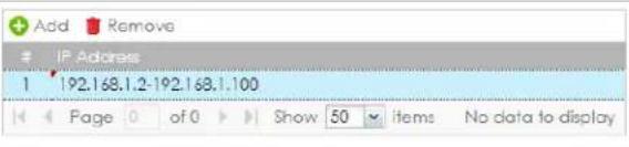 | |
| Related Setting | |
| Configure PPPoE/PPTP | Click PPPoE/PPTP if this interface's Internet connection uses PPPoE or PPTP or L2TP. |
| Configure VLAN | Click VLAN if you want to configure a VLAN interface for this Ethernet interface. |
| Configure WAN TRUNK | Click WAN TRUNK to go to a screen where you can set this interface to be part of a WAN trunk for load balancing. |
| Configure Policy Route | Click Policy Route to go to the policy route summary screen where you can manually associate traffic with this interface.You must manually configure a policy route to add routing and SNAT settings for an interface with the Interface Type set to general. You can also configure a policy route to override the default routing and SNAT behavior for an interface with an Interface Type of internal or external. |
| OK | Click OK to save your changes back to the Zyxel Device. |
| Cancel | Click Cancel to exit this screen without saving. |
9.5.2 Proxy ARP
An Address Resolution Protocol (ARP) is a protocol for mapping an IP address to a MAC address. An ARP broadcast is sent to all devices on the same Ethernet network to request the MAC address of a target IP address.
In the following figure, a host in a WAN subnet (A) broadcasts an ARP request to all devices within its network in order to find the MAC address of a target IP address (172.16.x.x). However, the target IP address may be in another subnet (B) that has the same network IP address (172.16.x.x). A router, such as the Zyxel Device, does not forward broadcasts, so the request will not reach its destination.
Enable Proxy ARP (RFC 1027) to allow the Zyxel Device to answer external interface ARP requests on behalf of a device on its internal interface. Interfaces supported are:
- Ethernet
• VLAN
- Bridge
The Zyxel Device sends its external MAC address to the WAN sender as the destination for the target IP address. From then on the sender will send packets containing that target IP address directly to the external interface of the Zyxel Device. The Zyxel Device then forwards the packet to the correct target IP address in its LAN.
Figure 265 Proxy ARP
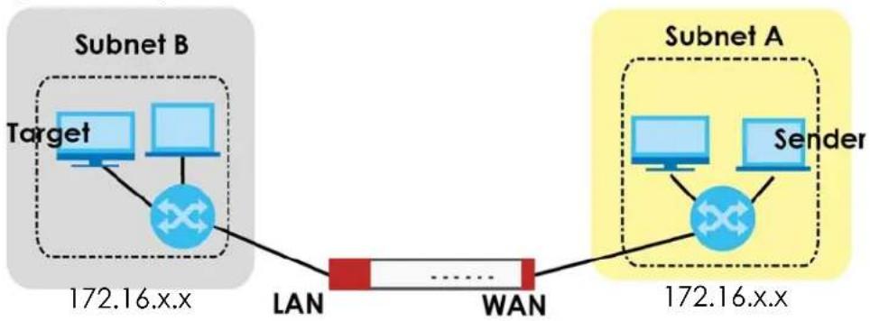
flowchart
graph LR
    A["Target"] --> B["Router"]
    C["Sender"] --> B
    B --> D["LAN"]
    D --> E["WAN"]
    E --> F["Subnet A"]
    style A fill:#f9f,stroke:#333
    style C fill:#f9f,stroke:#333
    style B fill:#ccf,stroke:#333
    style E fill:#ccf,stroke:#333
To allow the Zyxel Device to answer external interface ARP requests on behalf of a device on a supported interface, select the interface, click Add or Edit, then click Add in the Proxy ARP section of the screen.
Figure 266 Interface > Edit > Add Proxy ARP
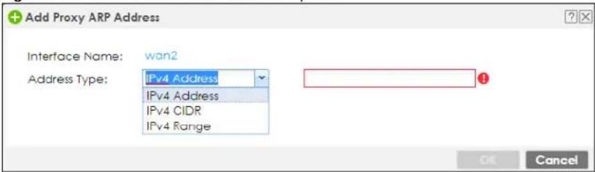
The following table describes labels that can appear in this screen.
Table 128 Interface > Edit > Add Proxy ARP
| LABEL DESCRIPTION | |
| Interface Name | This identifies the interface for which the configuration settings that use it are displayed. |
| Address Type | ChooseIPv4 Address, or IPv4 CIDR (for example, 192.168.1.1/24) or anIPv4 Range (for example, 192.168.1.2-192.168.1.100) and then enter the target IP address information. The Zyxel Device answers external ARP requests only if they match one of these inputted target IP addresses. For example, if theIPv4 Addressis 192.168.1.5, then the Zyxel Device will answer ARP requests coming from the WAN only if it contains 192.168.1.5 as the target IP address. |
| OK | Click OK to save your changes back to the Zyxel Device. |
| Cancel | Click Cancel to exit this screen without saving. |
9.5.3 Virtual Interfaces
Use virtual interfaces to tell the Zyxel Device where to route packets. Virtual interfaces can also be used in VPN gateways (see Chapter 19 on page 527) and VRRP groups (see Chapter 44 on page 1055).
Virtual interfaces can be created on top of Ethernet interfaces, VLAN interfaces, or bridge interfaces. Virtual VLAN interfaces recognize and use the same VLAN ID. Otherwise, there is no difference between each type of virtual interface. Network policies (for example, security policies) that apply to the underlying interface automatically apply to the virtual interface as well.
Like other interfaces, virtual interfaces have an IP address, subnet mask, and gateway used to make routing decisions. However, you have to manually specify the IP address and subnet mask; virtual interfaces cannot be DHCP clients. The virtual interface uses the same MTU and bandwidth settings that the underlying interface uses. Unlike other interfaces, virtual interfaces do not provide DHCP services, and they do not verify that the gateway is available.
This screen lets you configure IP address assignment and interface parameters for virtual interfaces. To access this screen, click the Create Virtual Interface icon on the Ethernet, VLAN, or bridge interface summary screen.
Figure 267 Configuration > Network > Interface > Create Virtual Interface
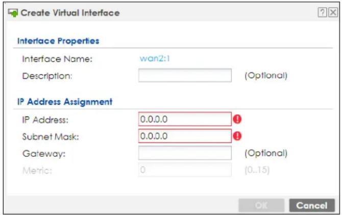
Each field is described in the table below.
Table 129 Configuration > Network > Interface > Create Virtual Interface
| LABEL DESCRIPTION | |
| Interface Properties | |
| Interface Name | This field is read-only. It displays the name of the virtual interface, which is automatically derived from the underlying Ethernet interface, VLAN interface, or bridge interface. |
| Description | Enter a description of this interface. It is not used elsewhere. You can use alphanumeric and () + / := ? ! * \# @ \ _ \% - characters,$ and it can be up to 60 characters long. |
| IP Address Assignment | |
| IP Address Enter the IP address for this interface. | |
| Subnet Mask | Enter the subnet mask of this interface in dot decimal notation. The subnet mask indicates what part of the IP address is the same for all computers on the network. |
| Gateway | Enter the IP address of the gateway. The Zyxel Device sends packets to the gateway when it does not know how to route the packet to its destination. The gateway should be on the same network as the interface. |
| Metric | Enter the priority of the gateway (if any) on this interface. The Zyxel Device decides which gateway to use based on this priority. The lower the number, the higher the priority. If two or more gateways have the same priority, the Zyxel Device uses the one that was configured first. |
| OK | Click OK to save your changes back to the Zyxel Device. |
| Cancel | Click Cancel to exit this screen without saving. |
9.5.4 References
When a configuration screen includes an References icon, select a configuration object and click References to open the References screen. This screen displays which configuration settings reference the selected object. The fields shown vary with the type of object.
Figure 268 References
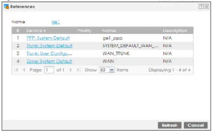
The following table describes labels that can appear in this screen.
Table 130 References
| LABEL DESCRIPTION | |
| Name | This identifies the object for which the configuration settings that use it are displayed. Click the object's name to display the object's configuration screen in the main window. |
| # | This field is a sequential value, and it is not associated with any entry. |
| Service | This is the type of setting that references the selected object. Click a service's name to display the service's configuration screen in the main window. |
| Priority | If it is applicable, this field lists the referencing configuration item's position in its list, otherwise N/A displays. |
| Name | This field identifies the configuration item that references the object. |
| Description | If the referencing configuration item has a description configured, it displays here. |
| Refresh | Click this to update the information in this screen. |
| Cancel | Click Cancel to close the screen. |
9.5.5 Add/Edit DHCPv6 Request/Release Options
When you configure an interface as a DHCPv6 server or client, you can additionally add DHCPv6 request or lease options which have the Zyxel Device to add more information in the DHCPv6 packets. To open the screen, click Configuration > Network > Interface > Ethernet > Edit, select DHCPv6 Server or DHCPv6 Client in the DHCPv6 Setting section, and then click Add in the DHCPv6 Request Options or DHCPv6 Lease Options table.
Figure 269 Configuration > Network > Interface > Ethernet > Edit > Add DHCPv6 Request/Lease Options
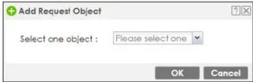
Select a DHCPv6 request or lease object in the Select one object field and click OK to save it. Click Cancel to exit without saving the setting.
9.5.6 Add/Edit DHCP Extended Options
When you configure an interface as a DHCPv4 server, you can additionally add DHCP extended options which have the Zyxel Device to add more information in the DHCP packets. The available fields vary depending on the DHCP option you select in this screen. To open the screen, click Configuration > Network > Interface > Ethernet > Edit, select DHCP Server in the DHCP Setting section, and then click Add or Edit in the Extended Options table.
Figure 270 Configuration > Network > Interface > Ethernet > Edit > Add/Edit Extended Options
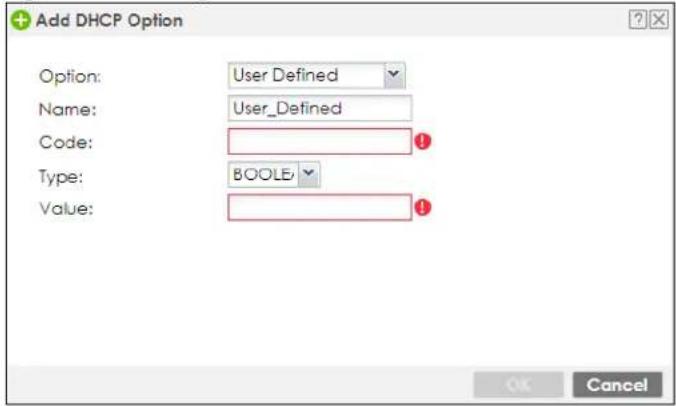
The following table describes labels that can appear in this screen.
Table 131 Configuration > Network > Interface > Ethernet > Edit > Add/Edit Extended Options
| LABEL DESCRIPTION | |
| Option | Select which DHCP option that you want to add in the DHCP packets sent through the interface. See the next table for more information. |
| Name | This field displays the name of the selected DHCP option. If you selectedUser Definedin theOptionfield, enter a descriptive name to identify the DHCP option. You can enter up to 16 characters ("a-z", "A-Z, "0-9", "-", and "_") with no spaces allowed. The first character must be alphabetical (a-z, A-Z). |
| Code | This field displays the code number of the selected DHCP option. If you selectedUser Definedin theOptionfield, enter a number for the option. This field is mandatory. |
| Type | This is the type of the selected DHCP option. If you selectedUser Definedin theOptionfield, select an appropriate type for the value that you will enter in the next field. Only advanced users should configureUser Defined. Misconfiguration could result in interface lockout. |
| Value | Enter the value for the selected DHCP option. For example, if you selectedTFTP Server Name(66)and the type isTEXT, enter the DNS domain name of a TFTP server here. This field is mandatory. |
Table 131 Configuration > Network > Interface > Ethernet > Edit > Add/Edit Extended Options
| LABEL | DESCRIPTION |
| First IP Address, Second IP Address, Third IP Address | If you selected Time Server (4), NTP Server (41), SIP Server (120), CAPWAP AC (138), or TFTP Server (150), you have to enter at least one IP address of the corresponding servers in these fields. The servers should be listed in order of your preference. |
| First Enterprise ID, Second Enterprise ID | If you selected VIVC (124) or VIVS (125), you have to enter at least one vendor's 32-bit enterprise number in these fields. An enterprise number is a unique number that identifies a company. |
| First Class, Second Class | If you selected VIVC (124), enter the details of the hardware configuration of the host on which the client is running, or of industry consortium compliance. |
| First Information, Second Information | If you selected VIVS (125), enter additional information for the corresponding enterprise number in these fields. |
| OK | Click this to close this screen and update the settings to the previous Edit screen. |
| Cancel | Click Cancel to close the screen. |
The following table lists the available DHCP extended options (defined in RFCs) on the Zyxel Device. See RFCs for more information.
Table 132 DHCP Extended Options
| OPTION NAME CODE DESCRIPTION | ||
| Time Offset | 2 | This option specifies the offset of the client's subnet in seconds from Coordinated Universal Time (UTC). |
| Time Server | 4 | This option specifies a list of Time servers available to the client. |
| NTP Server | 42 | This option specifies a list of the NTP servers available to the client by IP address. |
| TFTP Server Name | 66 | This option is used to identify a TFTP server when the “sname” field in the DHCP header has been used for DHCP options. The minimum length of the value is 1. |
| Bootfile | 67 | This option is used to identify a bootfile when the “file” field in the DHCP header has been used for DHCP options. The minimum length of the value is 1. |
| SIP Server | 120 | This option carries either an IPv4 address or a DNS domain name to be used by the SIP client to locate a SIP server. |
| VIVC | 124 | Vendor-Identifying Vendor Class optionA DHCP client may use this option to unambiguously identify the vendor that manufactured the hardware on which the client is running, the software in use, or an industry consortium to which the vendor belongs. |
| VIVS | 125 | Vendor-Identifying Vendor-Specific optionDHCP clients and servers may use this option to exchange vendor-specific information. |
| CAPWAP AC | 138 | CAPWAP Access Controller addresses optionThe Control And Provisioning of Wireless Access Points Protocol allows a Wireless Termination Point (WTP) to use DHCP to discover the Access Controllers to which it is to connect. This option carries a list of IPv4 addresses indicating one or more CAPWAP ACs available to the WTP. |
| TFTP Server | 150 | The option contains one or more IPv4 addresses that the client may use. The current use of this option is for downloading configuration from a VoIP server via TFTP; however, the option may be used for purposes other than contacting a VoIP configuration server. |
9.6 PPP Interfaces
Use PPPoE/PPTP/L2TP interfaces to connect to your ISP. This way, you do not have to install or manage PPPoE/PPTP/L2TP software on each computer on the network.
Figure 271 Example: PPPoE/PPTP/L2TP Interfaces
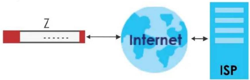
flowchart
graph LR
    A["Z"] --> B["Internet"]
    B --> C["ISP"]
PPPoE/PPTP/L2TP interfaces are similar to other interfaces in some ways. They have an IP address, subnet mask, and gateway used to make routing decisions; they restrict bandwidth and packet size; and they can verify the gateway is available. There are two main differences between PPPoE/PPTP/L2TP interfaces and other interfaces.
- You must also configure an ISP account object for the PPPoE/PPTP/L2TP interface to use.
Each ISP account specifies the protocol (PPPoE or PPTP or L2TP), as well as your ISP account information. If you change ISPs later, you only have to create a new ISP account, not a new PPPoE/PPTP/L2TP interface. You should not have to change any network policies.
- You do not set up the subnet mask or gateway.
PPPoE/PPTP/L2TP interfaces are interfaces between the Zyxel Device and only one computer. Therefore, the subnet mask is always 255.255.255.255. In addition, the Zyxel Device always treats the ISP as a gateway.
9.6.1 PPP Interface Summary
This screen lists every PPPoE/PPTP/L2TP interface. To access this screen, click Configuration > Network > Interface > PPP.
Figure 272 Configuration > Network > Interface > PPP
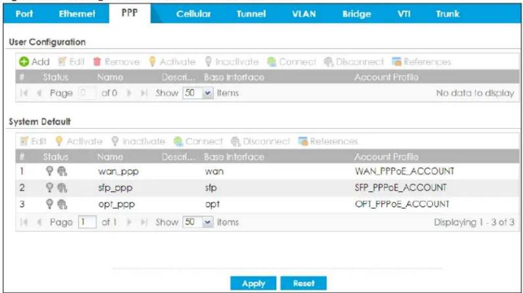
Each field is described in the table below.
Table 133 Configuration > Network > Interface > PPP
| LABEL DESCRIPTION | |
| User Configuration / System Default | The Zyxel Device comes with the (non-removable)System DefaultPPP interfaces pre-configured. You can create (and delete)User ConfigurationPPP interfaces.System DefaultPPP interfaces vary by model. |
| Add Click this to create | a new user-configured PPP interface. |
| Edit | Double-click an entry or select it and clickEditto open a screen where you can modify the entry's settings. |
| Remove | To remove a user-configured PPP interface, select it and clickRemove.The Zyxel Device confirms you want to remove it before doing so. |
| Activate | To turn on an entry, select it and clickActivate. |
| Inactivate | To turn off an entry, select it and clickInactivate. |
| Connect | To connect an interface, select it and clickConnect.You might use this in testing the interface or to manually establish the connection for aDial-on-Demand PPPoE/PPTP interface. |
| Disconnect | To disconnect an interface, select it and clickDisconnect.You might use this in testing the interface. |
| References | Select an entry and clickReferencesto open a screen that shows which settings use the entry. SeeSection 9.5.4 on page 349for an example. |
| # This field is a sequential value, and it is not associated with any interface. | |
| Status | The activate (light bulb) icon is lit when the entry is active and dimmed when the entry is inactive.The connect icon is lit when the interface is connected and dimmed when it is disconnected. |
| Name This field displays the name of the interface. | |
| Description This field displays the description of the interface. | |
| Base Interface | This field displays the interface on the top of which the PPPoE/PPTP/L2TP interface is. |
| Account Profile | This field displays the ISP account used by this PPPoE/PPTP interface. |
| Apply | Click Apply to save your changes back to the Zyxel Device. |
| Reset | Click Reset to return the screen to its last-saved settings. |
9.6.2 PPP Interface Add or Edit
Note: You have to set up an ISP account before you create a PPPoE/PPTP/L2TP interface.
This screen lets you configure a PPPoE or PPTP or L2TP interface. If you enabled IPv6 on the Configuration > System > IPv6 screen, you can also configure PPP interfaces used for your IPv6 networks on this screen. To access this screen, click the Add icon or an Edit icon on the PPP Interface screen.
Figure 273 Configuration > Network > Interface > PPP > Add
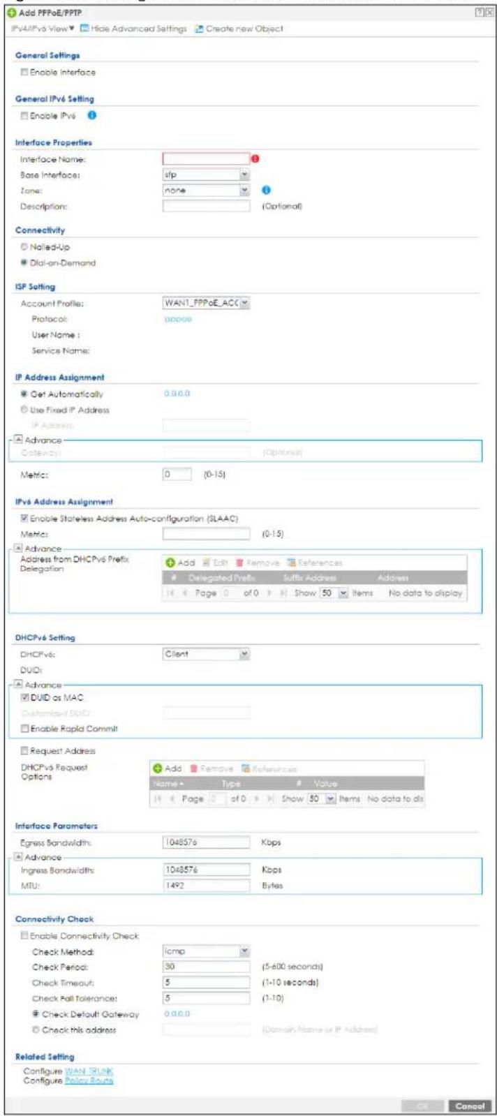
Each field is explained in the following table.
Table 134 Configuration > Network > Interface > PPP > Add
| LABEL DESCRIPTION | |
| IPv4/IPv6 View / IPv4View / IPv6 View | Use this button to display both IPv4 and IPv6, IPv4-only, or IPv6-only configuration fields. |
| Show Advanced Settings / Hide Advanced Settings | Click this button to display a greater or lesser number of configuration fields. |
| Create New Object | Click this button to create an ISP Account or a DHCPv6 request object that you may use for the ISP or DHCPv6 settings in this screen. |
| General Settings | |
| Enable Interface | Select this to enable this interface. Clear this to disable this interface. |
| General IPv6 Setting | |
| Enable IPv6 | Select this to enable IPv6 on this interface. Otherwise, clear this to disable it. |
| Interface Properties | |
| Interface Name | Specify a name for the interface. It can use alphanumeric characters, hyphens, and underscores, and it can be up to 11 characters long. |
| Base Interface | Select the interface upon which this PPP interface is built.Note: Multiple PPP interfaces can use the same base interface. |
| Zone | Select the zone to which this PPP interface belongs. The zone determines the security settings the Zyxel Device uses for the interface. |
| Description | Enter a description of this interface. You can use alphanumeric and ( ) + / : = ? ! * # @ $ _ % - characters, and it can be up to 60 characters long. Spaces are allowed, but the string can't start with a space. |
| Connectivity | |
| Nailed-Up | Select this if the PPPoE/PPTP/L2TP connection should always be up. Clear this to have the Zyxel Device establish the PPPoE/PPTP/L2TP connection only when there is traffic. You might use this option if a lot of traffic needs to go through the interface or it does not cost extra to keep the connection up all the time. |
| Dial-on-Demand | Select this to have the Zyxel Device establish the PPPoE/PPTP/L2TP connection only when there is traffic. You might use this option if there is little traffic through the interface or if it costs money to keep the connection available. |
| ISP Setting | |
| Account Profile | Select the ISP account that this PPPoE/PPTP/L2TP interface uses. The drop-down box lists ISP accounts by name. Use Create new Object if you need to configure a new ISP account (see Chapter 43 on page 1048 for details). |
| Protocol This field is read-only. It displays the protocol specified in the ISP account. | |
| User Name | This field is read-only. It displays the user name for the ISP account. |
| Service Name | This field is read-only. It displays the PPPoE service name specified in the ISP account. This field is blank if the ISP account uses PPTP. |
| IP Address Assignment | Click Show Advanced Settings to display more settings. Click Hide Advanced Settings to display fewer settings. |
| Get Automatically | Select this if this interface is a DHCP client. In this case, the DHCP server configures the IP address automatically. The subnet mask and gateway are always defined automatically in PPPoE/PPTP/L2TP interfaces. |
| Use Fixed IP Address | Select this if you want to specify the IP address manually. |
| IP Address | This field is enabled if you select Use Fixed IP Address.Enter the IP address for this interface. |
| Gateway | This field is enabled if you selectUse Fixed IP Address.Enter the IP address of the gateway. The Zyxel Device sends packets to the gateway when it does not know how to route the packet to its destination. The gateway should be on the same network as the interface. |
| Metric | Enter the priority of the gateway (the ISP) on this interface. The Zyxel Device decides which gateway to use based on this priority. The lower the number, the higher the priority. If two or more gateways have the same priority, the Zyxel Device uses the one that was configured first. |
| IPv6 Address Assignment | These IP address fields configure an IPv6 IP address on the interface itself. |
| Enable Stateless Address Auto-configuration (SLAAC) | Select this to enable IPv6 stateless auto-configuration on this interface. The interface will generate an IPv6 IP address itself from a prefix obtained from an IPv6 router on the network. |
| Metric | Enter the priority of the gateway (if any) on this interface. The Zyxel Device decides which gateway to use based on this priority. The lower the number, the higher the priority. If two or more gateways have the same priority, the Zyxel Device uses the one that was configured first. |
| Address from DHCPv6 Prefix Delegation | Use this table to have the Zyxel Device obtain an IPv6 prefix from the ISP or a connected uplink router for an internal network, such as the LAN or DMZ. You have to also enter a suffix address which is appended to the delegated prefix to form an address for this interface.SeePrefix Delegation on page 323for more information.To use prefix delegation, you must:Create at least one DHCPv6 request object before configuring this table.The external interface must be a DHCPv6 client. You must configure the DHCPv6 request options using a DHCPv6 request object with the type of prefix-delegation.Assign the prefix delegation to an internal interface and enable router advertisement on that interface. |
| Add Click this to create an entry. | |
| Edit Select an entry and click this to change the settings. | |
| Remove | Select an entry and click this to delete it from this table. |
| References | Select an entry and clickReferencesto open a screen that shows which settings use the entry. |
| # This field is a sequential value, and it is not associated with any entry. | |
| Delegated Prefix | Select the DHCPv6 request object to use from the drop-down list. |
| Suffix Address | Enter the ending part of the IPv6 address, a slash (/), and the prefix length. The Zyxel Device will append it to the delegated prefix.For example, you got a delegated prefix of 2003:1234:5678/48. You want to configure an IP address of 2003:1234:5678:1111::1/128 for this interface, then enter :1111:0:0:0:1/128 in this field. |
| Address This field displays the combined IPv6 IP address for this interface.Note: This field displays the combined address after you clickOKand reopen this screen. | |
| DHCPv6 Setting | |
| DHCPv6 | SelectClientto obtain an IP address and DNS information from the service provider for the interface. Otherwise, selectN/Ato disable the function. |
| DUID | This field displays the DHCP Unique IDentifier (DUID) of the interface, which is unique and used for identification purposes when the interface is exchanging DHCPv6 messages with others. SeeDHCPv6 on page 324for more information. |
| LABEL | DESCRIPTION |
| DUID as MAC | Select this if you want the DUID is generated from the interface's default MAC address. |
| Customized DUID If you want to use a customized DUID, enter it here for the interface. | |
| Enable Rapid Commit | Select this to shorten the DHCPv6 message exchange process from four to two steps. This function helps reduce heavy network traffic load.Note: Make sure you also enable this option in the DHCPv6 clients to make rapid commit work. |
| Request Address | Select this to get an IPv6 IP address for this interface from the DHCP server. Clear this to not get any IP address information through DHCPv6. |
| DHCPv6 Request Options | Use this section to configure DHCPv6 request settings that determine what additional information to get from the DHCPv6 server. |
| Add | Click this to create an entry in this table. See Section 9.5.6 on page 350 for more information. |
| Remove | Select an entry and click this to delete it from this table. |
| References | Select an entry and click References to open a screen that shows which settings use the entry. See Section 9.5.4 on page 349 for an example. |
| Name This field displays the name of the DHCPv6 request object. | |
| Type This field displays the type of the object. | |
| Value | This field displays the IPv6 prefix that the Zyxel Device will advertise to its clients. |
| Interface Parameters | |
| Egress Bandwidth | Enter the maximum amount of traffic, in kilobits per second, the Zyxel Device can send through the interface to the network. Allowed values are 0 - 1048576. |
| Ingress Bandwidth | This is reserved for future use.Enter the maximum amount of traffic, in kilobits per second, the Zyxel Device can receive from the network through the interface. Allowed values are 0 - 1048576. |
| MTU | Maximum Transmission Unit. Type the maximum size of each data packet, in bytes, that can move through this interface. If a larger packet arrives, the Zyxel Device divides it into smaller fragments. Allowed values are 576 - 1492. Usually, this value is 1492. |
| Connectivity Check | The interface can regularly check the connection to the gateway you specified to make sure it is still available. You specify how often the interface checks the connection, how long to wait for a response before the attempt is a failure, and how many consecutive failures are required before the Zyxel Device stops routing to the gateway. The Zyxel Device resumes routing to the gateway the first time the gateway passes the connectivity check. |
| Enable Connectivity Check | Select this to turn on the connection check. |
| Check Method Select the method that the gateway allows.Select icmp to have the Zyxel Device regularly ping the gateway you specify to make sure it is still available.Select tcp to have the Zyxel Device regularly perform a TCP handshake with the gateway you specify to make sure it is still available. | |
| Check Period Enter the number of seconds between connection check attempts. | |
| Check Timeout | Enter the number of seconds to wait for a response before the attempt is a failure. |
| Check Fail Tolerance | Enter the number of consecutive failures before the Zyxel Device stops routing through the gateway. |
| Check Default Gateway | Select this to use the default gateway for the connectivity check. |
| LABEL DESCRIPTION | |
| Check this address | Select this to specify a domain name or IP address for the connectivity check. Enter that domain name or IP address in the field next to it. |
| Check Port | This field only displays when you set the Check Method to tcp. Specify the port number to use for a TCP connectivity check. |
| Related Setting | |
| Configure WAN TRUNK | Click WAN TRUNK to go to a screen where you can configure the interface as part of a WAN trunk for load balancing. |
| Policy Route | Click Policy Route to go to the screen where you can manually configure a policy route to associate traffic with this interface. |
| OK | Click OK to save your changes back to the Zyxel Device. |
| Cancel | Click Cancel to exit this screen without saving. |
9.7 Cellular Configuration Screen
Mobile broadband is a digital, packet-switched wireless technology. Bandwidth usage is optimized as multiple users share the same channel and bandwidth is only allocated to users when they send data. It allows fast transfer of voice and non-voice data and provides broadband Internet access to mobile devices.
Note: The actual data rate you obtain varies depending on the mobile broadband device you use, the signal strength to the service provider's base station, and so on.
You can configure how the Zyxel Device's mobile broadband device connects to a network (refer to Section 9.7.1 on page 362):
- You can set the mobile broadband device to connect only to the home network, which is the network to which you are originally subscribed.
- You can set the mobile broadband device to connect to other networks if the signal strength of the home network is too low or it is unavailable.
3G
3G (Third Generation) is a digital, packet-switched wireless technology. Bandwidth usage is optimized as multiple users share the same channel and bandwidth is only allocated to users when they send data. It allows fast transfer of voice and non-voice data and provides broadband Internet access to mobile devices.
4G
4G is the fourth generation of the mobile telecommunications technology and a successor of 3G. Both the WiMAX and Long Term Evolution (LTE) standards are the 4G candidate systems. 4G only supports all-IP-based packet-switched telephony services and is required to offer Gigabit speed access.
Note: The actual data rate you obtain varies depending on your mobile environment. The environmental factors may include the number of mobile devices which are currently connected to the mobile network, the signal strength to the mobile network, and so on.
See the following table for a comparison between 2G, 2.5G, 2.75G, 3G and 4G wireless technologies.
Table 135 2G, 2.5G, 2.75G, 3G, 3.5G and 4G Wireless Technologies
| NAME TYPE | MOBILE PHONE AND DATA STANDARDS | DATA SPEED | ||
| GSM-BASED CDMA-BASED | ||||
| 2G Circuit-switched | GSM (Global System for Mobile Communications), Personal Handy-phone System (PHS), etc. | Interim Standard 95 (IS-95), the first CDMA-based digital cellular standard pioneered by Qualcomm. The brand name for IS-95 is cdmaOne. IS-95 is also known as TIA-EIA-95. | Slow | |
| 2.5G Packet-switched | GPRS (General Packet Radio Services), High-Speed Circuit-Switched Data (HSCSD), etc. | CDMA2000 is a hybrid 2.5G / 3G protocol of mobile telecommunications standards that use CDMA, a multiple access scheme for digital radio.CDMA2000 1xRTT (1 times Radio Transmission Technology) is the core CDMA2000 wireless air interface standard. It is also known as 1x, 1xRTT, or IS-2000 and considered to be a 2.5G or 2.75G technology. | ||
| 2.75G Packet-switched | Enhanced Data rates for GSM Evolution (EDGE), Enhanced GPRS (EGPRS), etc. | |||
| 3G Packet-switched | UMTS (Universal Mobile Telecommunications System), a third-generation (3G) wireless standard defined in ITU specification, is sometimes marketed as 3GSM. The UMTS uses GSM infrastructures and W-CDMA (Wideband Code Division Multiple Access) as the air interface. The International Telecommunication Union (ITU) is an international organization within which governments and the private sector coordinate global telecom networks and services. | CDMA2000 EV-DO (Evolution-Data Optimized, originally 1x Evolution-Data Only), also referred to as EV-DO, EVDO, or just EV, is an evolution of CDMA2000 1xRTT and enables high-speed wireless connectivity. It is also denoted as IS-856 or High Data Rate (HDR). | ||
| 3.5G Packet-switched | HSDPA (High-Speed Downlink Packet Access) is a mobile telephony protocol, used for UMTS-based 3G networks and allows for higher data transfer speeds. | |||
| 4G/LTE Packet-switched | The LTE (Long Term Evolution) standard is based on the GSM and UMTS network technologies. | |||
To change your mobile broadband WAN settings, click Configuration > Network > Interface > Cellular.
Note: Install (or connect) a compatible mobile broadband USB device to use a cellular connection.
Note: The WAN IP addresses of a Zyxel Device with multiple WAN interfaces must be on different subnets.
Figure 274 Configuration > Network > Interface > Cellular
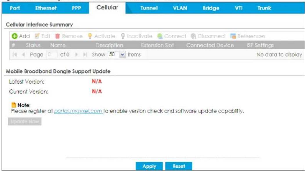
The following table describes the labels in this screen.
Table 136 Configuration > Network > Interface > Cellular
| LABEL DESCRIPTION | |
| Add Click this to create a new cellular interface. | |
| Edit | Double-click an entry or select it and click Edit to open a screen where you can modify the entry's settings. |
| Remove | To remove an entry, select it and click Remove. The Zyxel Device confirms you want to remove it before doing so. |
| Activate | To turn on an entry, select it and click Activate. |
| Inactivate | To turn off an entry, select it and click Inactivate. |
| Connect | To connect an interface, select it and click Connect. You might use this in testing the interface or to manually establish the connection. |
| Disconnect | To disconnect an interface, select it and click Disconnect. You might use this in testing the interface. |
| References | Select an entry and click References to open a screen that shows which settings use the entry. See Section 9.5.4 on page 349 for an example. |
| # This field is a sequential value, and it is not associated with any interface. | |
| Status | The activate (light bulb) icon is lit when the entry is active and dimmed when the entry is inactive.The connect icon is lit when the interface is connected and dimmed when it is disconnected. |
| Name This field displays the name of the interface. | |
| Description This field displays the description of the interface. | |
| Extension Slot | This field displays where the entry's cellular card is located. |
| Connected Device | This field displays the name of the cellular card. |
| ISP Settings | This field displays the profile of ISP settings that this cellular interface is set to use. |
| Mobile Broadband Dongle Support | You should have registered your Zyxel Device at myZyxel. myZyxel hosts a list of supported mobile broadband dongle devices. You should have an Internet connection to access this website. |
| LABEL DESCRIPTION | |
| Latest Version | This displays the latest supported mobile broadband dongle list version number. |
| Current Version | This displays the currently supported (by the Zyxel Device) mobile broadband dongle list version number. |
| Update Now | If the latest version number is greater than the current version number, then click this button to download the latest list of supported mobile broadband dongle devices to the Zyxel Device. |
| Apply | Click Apply to save your changes back to the Zyxel Device. |
| Reset | Click Reset to return the screen to its last-saved settings. |
9.7.1 Cellular Choose Slot
To change your mobile broadband settings, click Configuration > Network > Interface > Cellular > Add (or Edit). In the pop-up window that displays, select the slot that contains the mobile broadband device, then the Add Cellular configuration screen displays.
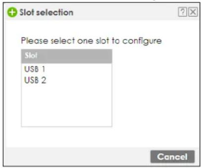
9.7.2 Add / Edit Cellular Configuration
This screen displays after you select the slot that contains the mobile broadband device in the previous pop-up window.
Figure 275 Configuration > Network > Interface > Cellular > Add / Edit
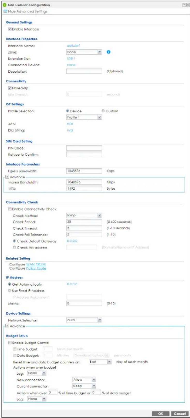
The following table describes the labels in this screen.
Table 137 Configuration > Network > Interface > Cellular > Add / Edit
| LABEL DESCRIPTION | |
| Show Advanced Settings / Hide Advanced Settings | Click this button to display a greater or lesser number of configuration fields. |
| General Settings | |
| Enable Interface Select this option to turn on this interface. | |
| Interface Properties | |
| Interface Name Select a name for the interface. | |
| Zone | Select the zone to which you want the cellular interface to belong. The zone determines the security settings the Zyxel Device uses for the interface. |
| Extension Slot | This is the USB slot that you are configuring for use with a mobile broadband card. |
| Connected Device | This displays the manufacturer and model name of your mobile broadband card if you inserted one in the Zyxel Device. Otherwise, it displays none. |
| Description | Enter a description of this interface. You can use alphanumeric and () +/ :=?! *#@_%- characters, and it can be up to 60 characters long. Spaces are allowed, but the string can't start with a space. |
| Connectivity | |
| Nailed-Up | Select this if the connection should always be up. Clear this to have the Zyxel Device to establish the connection only when there is traffic. You might not nail up the connection if there is little traffic through the interface or if it costs money to keep the connection available. |
| Idle timeout | This value specifies the time in seconds (0~360) that elapses before the Zyxel Device automatically disconnects from the ISP's server. Zero disables the idle timeout. |
| ISP Settings | |
| Profile Selection | Select Device to use one of the mobile broadband device's profiles of device settings. Then select the profile (use Profile 1 unless your ISP instructed you to do otherwise).Select Custom to configure your device settings yourself. |
| APN | This field is read-only if you selected Device in the profile selection. Select Custom in the profile selection to be able to manually input the APN (Access Point Name) provided by your service provider. This field applies with a GSM or HSDPA mobile broadband card. Enter the APN from your service provider. Connections with different APNs may provide different services (such as Internet access or MMS (Multi-Media Messaging Service)) and charge method.Enter 1 to 63 single-byte characters, including a-zA-Z0-9-./@_!"#%&'()*+,:;<=>?[^\]^{}~ and spaces are not allowed. |
| Dial String | Enter the dial string if your ISP provides a string, which would include the APN, to initialize the mobile broadband card.Enter 1 to 31 single-byte characters, including a-zA-Z0-9!#%&'()*+,-./;;<=>@^\_'~“[]?and spaces are not allowed.This field is available only when you insert a GSM mobile broadband card. |
| Authentication Type | The Zyxel Device supports PAP (Password Authentication Protocol) and CHAP (Challenge Handshake Authentication Protocol). CHAP is more secure than PAP; however, PAP is readily available on more platforms.Use the drop-down list box to select an authentication protocol for outgoing calls. Options are:None: No authentication for outgoing calls.CHAP - Your Zyxel Device accepts CHAP requests only.PAP - Your Zyxel Device accepts PAP requests only. |
| User Name | This field displays when you select an authentication type other than None. This field is read-only if you selectedDevicein the profile selection. If this field is configurable, enter the user name for this mobile broadband card exactly as the service provider gave it to you.You can use 1 ~ 64 alphanumeric and #:-@. / characters. The first character must be alphanumeric or -@./. Spaces are not allowed. |
| Password | This field displays when you select an authentication type other than None. This field is read-only if you selectedDevicein the profile selection and the password is included in the mobile broadband card's profile. If this field is configurable, enter the password for this SIM card exactly as the service provider gave it to you.You can use 0 ~ 63 alphanumeric and `~!@#$%^&*()_-+={}|;:'<,>./ characters.Spaces are not allowed. |
| Retype to Confirm | This field displays when you select an authentication type other than None. This field is read-only if you selectedDevicein the profile selection and the password is included in the mobile broadband card's profile. If this field is configurable, re-enter the password for this SIM card exactly as the service provider gave it to you. |
| SIM Card Setting | |
| PIN Code | This field displays with a GSM or HSDPA mobile broadband card. A PIN (Personal Identification Number) code is a key to a mobile broadband card. Without the PIN code, you cannot use the mobile broadband card.Enter the 4-digit PIN code (0000 for example) provided by your ISP. If you enter the PIN code incorrectly, the mobile broadband card may be blocked by your ISP and you cannot use the account to access the Internet.If your ISP disabled PIN code authentication, enter an arbitrary number. |
| Retype to Confirm | Type the PIN code again to confirm it. |
| Interface Parameters | |
| Egress Bandwidth | Enter the maximum amount of traffic, in kilobits per second, the Zyxel Device can send through the interface to the network. Allowed values are 0 - 1048576. This setting is used in WAN load balancing and bandwidth management. |
| Ingress Bandwidth | This is reserved for future use.Enter the maximum amount of traffic, in kilobits per second, the Zyxel Device can receive from the network through the interface. Allowed values are 0 - 1048576. |
| MTU | Maximum Transmission Unit. Type the maximum size of each data packet, in bytes, that can move through this interface. If a larger packet arrives, the Zyxel Device divides it into smaller fragments. Allowed values are 576 - 1492. Usually, this value is 1492. |
| Connectivity Check | The interface can regularly check the connection to the gateway you specified to make sure it is still available. You specify how often the interface checks the connection, how long to wait for a response before the attempt is a failure, and how many consecutive failures are required before the Zyxel Device stops routing to the gateway. The Zyxel Device resumes routing to the gateway the first time the gateway passes the connectivity check. |
| Enable Connectivity Check | Select this to turn on the connection check. |
| Check Method Select the method that the gateway allows.Select icmp to have the Zyxel Device regularly ping the gateway you specify to make sure it is still available.Select tcp to have the Zyxel Device regularly perform a TCP handshake with the gateway you specify to make sure it is still available. | |
| Check Period | Enter the number of seconds between connection check attempts. |
| Check Timeout | Enter the number of seconds to wait for a response before the attempt is a failure. |
| Check Fail Tolerance | Enter the number of consecutive failures before the Zyxel Device stops routing through the gateway. |
| Check Default Gateway | Select this to use the default gateway for the connectivity check. |
| Check this address | Select this to specify a domain name or IP address for the connectivity check. Enter that domain name or IP address in the field next to it. |
| Check Port | This field only displays when you set the Check Method to tcp. Specify the port number to use for a TCP connectivity check. |
| Related Setting | |
| Configure WAN TRUNK | Click WAN TRUNK to go to a screen where you can configure the interface as part of a WAN trunk for load balancing. |
| Configure Policy Route | Click Policy Route to go to the policy route summary screen where you can configure a policy route to override the default routing and SNAT behavior for the interface. |
| IP Address Assignment | |
| Get Automatically | Select this option If your ISP did not assign you a fixed IP address. This is the default selection. |
| Use Fixed IP Address | Select this option If the ISP assigned a fixed IP address. |
| IP Address Assignment | Enter the cellular interface's WAN IP address in this field if you selected Use Fixed IP Address. |
| Metric | Enter the priority of the gateway (if any) on this interface. The Zyxel Device decides which gateway to use based on this priority. The lower the number, the higher the priority. If two or more gateways have the same priority, the Zyxel Device uses the one that was configured first. |
| Device Settings | |
| Band Selection | This field appears if you selected a mobile broadband device that allows you to select the type of network to use. Select the type of mobile broadband service for your mobile broadband connection. If you are unsure what to select, check with your mobile broadband service provider to find the mobile broadband service available to you in your region.Select auto to have the card connect to an available network. Choose this option if you do not know what networks are available.You may want to manually specify the type of network to use if you are charged differently for different types of network or you only have one type of network available to you.Select GPRS / EDGE (GSM) only to have this interface only use a 2.5G or 2.75G network (respectively). If you only have a GSM network available to you, you may want to select this so the Zyxel Device does not spend time looking for a WCDMA network.Select UMTS / HSDPA (WCDMA) only to have this interface only use a 3G or 3.5G network (respectively). You may want to do this if you want to make sure the interface does not use the GSM network.Select LTE only to have this interface only use a 4G LTE network. This option only appears when a dongle for 4G technology is inserted. |
| Network Selection | Home network is the network to which you are originally subscribed.Select Home to have the mobile broadband device connect only to the home network. If the home network is down, the Zyxel Device's mobile broadband Internet connection is also unavailable.Select Auto (Default) to allow the mobile broadband device to connect to a network to which you are not subscribed when necessary, for example when the home network is down or another mobile broadband base station's signal is stronger. This is recommended if you need continuous Internet connectivity. If you select this, you may be charged using the rate of a different network. |
| Budget Setup | |
| Enable Budget Control | Select this to set a monthly limit for the user account of the installed mobile broadband card. You can set a limit on the total traffic and/or call time. The Zyxel Device takes the actions you specified when a limit is exceeded during the month. |
| Time Budget | Select this and specify the amount of time (in hours) that the mobile broadband connection can be used within one month. If you change the value after you configure and enable budget control, the Zyxel Device resets the statistics. |
| Data Budget | Select this and specify how much downstream and/or upstream data (in Mega bytes) can be transmitted via the mobile broadband connection within one month.Select Download to set a limit on the downstream traffic (from the ISP to the Zyxel Device).Select Upload to set a limit on the upstream traffic (from the Zyxel Device to the ISP).Select Download/Upload to set a limit on the total traffic in both directions.If you change the value after you configure and enable budget control, the Zyxel Device resets the statistics. |
| Reset time and data budget counters on | Select the date on which the Zyxel Device resets the budget every month. If the date you selected is not available in a month, such as 30th or 31st, the Zyxel Device resets the budget on the last day of the month. |
| Reset time and data budget counters | This button is available only when you enable budget control in this screen.Click this button to reset the time and data budgets immediately. The count starts over with the mobile broadband connection's full configured monthly time and data budgets. This does not affect the normal monthly budget restart; so if you configured the time and data budget counters to reset on the second day of the month and you use this button on the first, the time and data budget counters will still reset on the second. |
| Actions when over budget | Specify the actions the Zyxel Device takes when the time or data limit is exceeded. |
| Log | Select None to not create a log, Log to create a log, or Log-alert to create an alert log. If you select Log or Log-alert you can also select recurring every to have the Zyxel Device send a log or alert for this event periodically. Specify how often (from 1 to 65535 minutes) to send the log or alert. |
| New connection | Select Allow to permit new mobile broadband connections or Disallow to drop/block new mobile broadband connections. |
| Current connection | Select Keep to maintain an existing mobile broadband connection or Drop to disconnect it. You cannot set New connection to Allow and Current connection to Drop at the same time.If you set New connection to Disallow and Current connection to Keep, the Zyxel Device allows you to transmit data using the current connection, but you cannot build a new connection if the existing connection is disconnected. |
| Actions when over % of time budget or % of data budget | Specify the actions the Zyxel Device takes when the specified percentage of time budget or data limit is exceeded. Enter a number from 1 to 99 in the percentage fields. If you change the value after you configure and enable budget control, the Zyxel Device resets the statistics. |
| Log | Select None to not create a log when the Zyxel Device takes this action, Log to create a log, or Log-alert to create an alert log. If you select Log or Log-alert you can also select recurring every to have the Zyxel Device send a log or alert for this event periodically. Specify how often (from 1 to 65535 minutes) to send the log or alert. |
| OK | Click OK to save your changes back to the Zyxel Device. |
| Cancel | Click Cancel to exit this screen without saving. |
9.8 Tunnel Interfaces
The Zyxel Device uses tunnel interfaces in Generic Routing Encapsulation (GRE), IPv6 in IPv4, and 6to4 tunnels.
GRE Tunneling
GRE tunnels encapsulate a wide variety of network layer protocol packet types inside IP tunnels. A GRE tunnel serves as a virtual point-to-point link between the Zyxel Device and another router over an IPv4 network. At the time of writing, the Zyxel Device only supports GRE tunneling in IPv4 networks.
Figure 276 GRE Tunnel Example
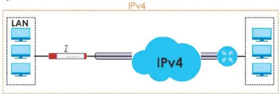
flowchart
graph LR
    A["LAN"] --> B["Router"]
    B --> C["IPv4"]
    C --> D["Client 1"]
    C --> E["Client 2"]
    C --> F["Client 3"]
    C --> G["Client 4"]
    style C fill:#90EE90,stroke:#333
IPv6 Over IPv4 Tunnels
To route traffic between two IPv6 networks over an IPv4 network, an IPv6 over IPv4 tunnel has to be used.
Figure 277 IPv6 over IPv4 Network

flowchart
graph LR
    A["IPv6"] --> B["IPv4"]
    B --> C["IPv6"]
    C -->|双向箭头| A
    style A fill:#blue,stroke:#333
    style B fill:#blue,stroke:#333
    style C fill:#blue,stroke:#333
On the Zyxel Device, you can either set up a manual IPv6-in-IPv4 tunnel or an automatic 6to4 tunnel. The following describes each method:
IPv6-in-IPv4 Tunneling
Use this mode on the WAN of the Zyxel Device if
- your Zyxel Device has a public IPv4 IP address given from your ISP,
and
- you want to transmit your IPv6 packets to one and only one remote site whose LAN network is also an IPv6 network.
With this mode, the Zyxel Device encapsulates IPv6 packets within IPv4 packets across the Internet. You must know the WAN IP address of the remote gateway device. This mode is normally used for a site-to-site application such as two branch offices.
Figure 278 IPv6-in-IPv4 Tunnel
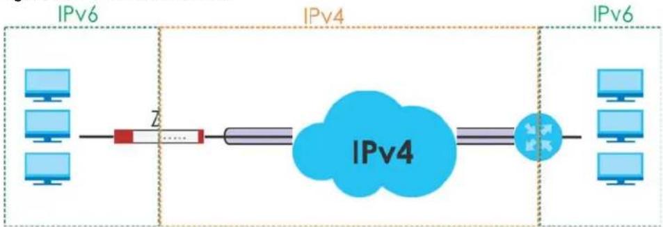
flowchart
graph LR
    A["IPv6"] --> B["Router"]
    B --> C["IPv4"]
    C --> D["IPv4"]
    D --> E["IPv6"]
    style A fill:#cce5ff,stroke:#333
    style B fill:#ffcccc,stroke:#333
    style C fill:#99ccff,stroke:#333
    style D fill:#66ccff,stroke:#333
    style E fill:#cce5ff,stroke:#333
In the Zyxel Device, you must also manually configure a policy route for an IPv6-in-IPv4 tunnel to make the tunnel work.
6to4 Tunneling
This mode also enables IPv6 packets to cross IPv4 networks. Unlike IPv6-in-IPv4 tunneling, you do not need to configure a policy route for a 6to4 tunnel. Through your properly pre-configuring the destination router's IP address in the IP address assignments to hosts, the Zyxel Device can automatically forward 6to4 packets to the destination they want to go. A 6to4 relay router is required to route 6to4 packets to a native IPv6 network if the packet's destination do not match your specified criteria.
In this mode, the Zyxel Device should get a public IPv4 address for the WAN. The Zyxel Device adds an IPv4 IP header to an IPv6 packet when transmitting the packet to the Internet. In reverse, the Zyxel Device removes the IPv4 header from an IPv6 packet when receiving it from the Internet.
An IPv6 address using the 6to4 mode consists of an IPv4 address, the format is as the following:
2002:[a public IPv4 address in hexadecimal]::/48
For example, a public IPv4 address is 202.156.30.41. The converted hexadecimal IP string is ca.9c.1Ee.29. The IPv6 address prefix becomes 2002:ca9c:1e29::/48.
Figure 279 6to4 Tunnel
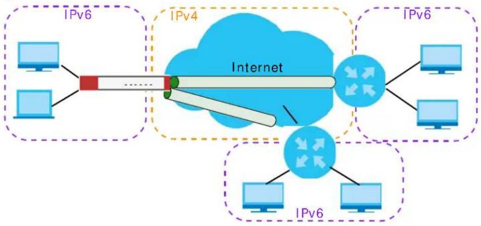
flowchart
graph TD
    subgraph IPv6
        A["Computer"] --> B["Internet"]
        C["Computer"] --> B
        D["Computer"] --> B
    end
    subgraph IPv4
        E["IPv4"] --> B
        F["IPv4"] --> B
        G["IPv4"] --> B
    end
    B --> H["IPv6"]
    style B fill:#f9f,stroke:#333,stroke-width:2px
    style H fill:#ccf,stroke:#333,stroke-width:2px
9.8.1 Configuring a Tunnel
This screen lists the Zyxel Device's configured tunnel interfaces. To access this screen, click Network > Interface > Tunnel.
Figure 280 Network > Interface > Tunnel
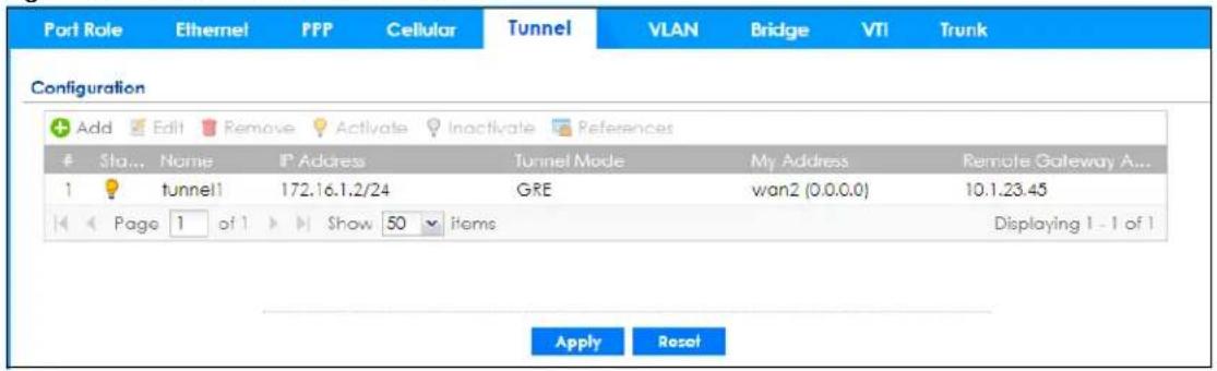
Each field is explained in the following table.
Table 138 Network > Interface > Tunnel
| LABEL DESCRIPTION | |
| Add Click this to create a new GRE tunnel interface. | |
| Edit | Double-click an entry or select it and click Edit to open a screen where you can modify the entry's settings. |
| Remove | To remove an entry, select it and click Remove. The Zyxel Device confirms you want to remove it before doing so. |
| Activate | To turn on an entry, select it and click Activate. |
| Inactivate | To turn off an entry, select it and click Inactivate. |
| References | Select an entry and click References to open a screen that shows which settings use the entry. See Section 9.5.4 on page 349 for an example. |
| # This field is a sequential value, and it is not associated with any interface. | |
| Status | The activate (light bulb) icon is lit when the entry is active and dimmed when the entry is inactive. |
| Name This field displays the name of the interface. | |
| IP Address | This is the IP address of the interface. If the interface is active (and connected), the Zyxel Device tunnels local traffic sent to this IP address to the Remote Gateway Address. |
| Tunnel Mode | This is the tunnel mode of the interface (GRE, IPv6-in-IPv4 or 6to4). This field also displays the interface's IPv4 IP address and subnet mask if it is a GRE tunnel. Otherwise, it displays the interface's IPv6 IP address and prefix length. |
| My Address | This is the interface or IP address uses to identify itself to the remote gateway. The Zyxel Device uses this as the source for the packets it tunnels to the remote gateway. |
| Remote Gateway Address | This is the IP address or domain name of the remote gateway to which this interface tunnels traffic. |
| Apply | Click Apply to save your changes back to the Zyxel Device. |
| Reset | Click Reset to begin configuring this screen afresh. |
9.8.2 Tunnel Add or Edit Screen
This screen lets you configure a tunnel interface. Click Configuration > Network > Interface > Tunnel > Add (or Edit) to open the following screen.
Figure 281 Network > Interface > Tunnel > Add/Edit
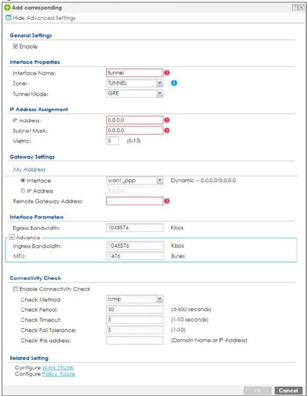
Each field is explained in the following table.
Table 139 Network > Interface > Tunnel > Add/Edit
| LABEL DESCRIPTION | |
| Show Advanced Settings / Hide Advanced Settings | Click this button to display a greater or lesser number of configuration fields. |
| General Settings | |
| Enable | Select this to enable this interface. Clear this to disable this interface. |
| Interface Properties | |
| Interface Name | This field is read-only if you are editing an existing tunnel interface. Enter the name of the tunnel interface. The format is tunnelx, where x is 0 - 3. For example, tunnel0. |
| Zone | Use this field to select the zone to which this interface belongs. This controls what security settings the Zykel Device applies to this interface. |
| Tunnel Mode | Select the tunneling protocol of the interface (GRE, IPv6-in-IPv4 or 6to4). See Section 9.8 on page 368 for more information. |
| IP Address Assignment | This section is available if you are configuring a GRE tunnel. |
| IP Address Enter the IP address for this interface. | |
| Subnet Mask | Enter the subnet mask of this interface in dot decimal notation. The subnet mask indicates what part of the IP address is the same for all computers on the network. |
| Metric | Enter the priority of the gateway (if any) on this interface. The Zykel Device decides which gateway to use based on this priority. The lower the number, the higher the priority. If two or more gateways have the same priority, the Zykel Device uses the one that was configured first. |
| IPv6 Address Assignment | This section is available if you are configuring an IPv6-in-IPv4 or a 6to4 tunnel. |
| IPv6 Address/ Prefix Length | Enter the IPv6 address and the prefix length for this interface if you want to use a static IP address. This field is optional.The prefix length indicates what the left-most part of the IP address is the same for all computers on the network, that is, the network address. |
| Metric | Enter the priority of the gateway (if any) on this interface. The Zykel Device decides which gateway to use based on this priority. The lower the number, the higher the priority. If two or more gateways have the same priority, the Zykel Device uses the one that was configured first. |
| 6to4 Tunnel Parameter | This section is available if you are configuring a 6to4 tunnel which encapsulates IPv6 to IPv4 packets. |
| 6to4 Prefix | Enter the IPv6 prefix of a destination network. The Zykel Device forwards IPv6 packets to the hosts on the matched network.If you enter a prefix starting with 2002, the Zykel Device will forward the matched packets to the IPv4 IP address converted from the packets' destination address. The IPv4 IP address can be converted from the next 32 bits after the prefix you specified in this field. See 6to4 Tunneling on page 369 for an example. The Zykel Device forwards the unmatched packets to the specified Relay Router. |
| Relay Router | Enter the IPv4 address of a 6to4 relay router which helps forward packets between 6to4 networks and native IPv6 networks. |
| Remote Gateway Prefix | Enter the IPv4 network address and network bits of a remote 6to4 gateway, for example, 14.15.0.0/16.This field works if you enter a 6to4 Prefix not starting with 2002 (2003 for example). The Zykel Device forwards the matched packets to a remote gateway with the network address you specify here, and the bits converted after the 6to4 Prefix in the packets.For example, you configure the 6to4 prefix to 2003:A0B::/32 and the remote gateway prefix to 14.15.0.0/16. If a packet's destination is 2003:A0B:1011:5::8, the Zykel Device forwards the packet to 14.15.16.17, where the network address is 14.15.0.0 and the host address is the remain bits converted from 1011 after the packet's 6to4 prefix (2003:A0B). |
| Gateway Settings | |
| My Address | Specify the interface or IP address to use as the source address for the packets this interface tunnels to the remote gateway. The remote gateway sends traffic to this interface or IP address. |
| Remote Gateway Address | Enter the IP address or domain name of the remote gateway to which this interface tunnels traffic.Automatic displays in this field if you are configuring a 6to4 tunnel. It means the 6to4 tunnel will help forward packets to the corresponding remote gateway automatically by looking at the packet's destination address. |
| Interface Parameters | |
| Egress Bandwidth | Enter the maximum amount of traffic, in kilobits per second, the Zyxel Device can send through the interface to the network. Allowed values are 0 - 1048576. This setting is used in WAN load balancing and bandwidth management. |
| Ingress Bandwidth | This is reserved for future use.Enter the maximum amount of traffic, in kilobits per second, the Zyxel Device can receive from the network through the interface. Allowed values are 0 - 1048576. |
| MTU | Maximum Transmission Unit. Type the maximum size of each data packet, in bytes, that can move through this interface. If a larger packet arrives, the Zyxel Device divides it into smaller fragments. Allowed values are 576 - 1500. Usually, this value is 1500. |
| Connectivity Check This section is available if you are configuring a GRE tunnel.The interface can regularly check the connection to the gateway you specified to make sure it is still available. You specify how often the interface checks the connection, how long to wait for a response before the attempt is a failure, and how many consecutive failures are required before the Zyxel Device stops routing to the gateway. The Zyxel Device resumes routing to the gateway the first time the gateway passes the connectivity check. | |
| Enable Connectivity Check | Select this to turn on the connection check. |
| Check Method Select the method that the gateway allows.Select icmp to have the Zyxel Device regularly ping the gateway you specify to make sure it is still available.Select tcp to have the Zyxel Device regularly perform a TCP handshake with the gateway you specify to make sure it is still available. | |
| Check Period Enter the number of seconds between connection check attempts. | |
| Check Timeout | Enter the number of seconds to wait for a response before the attempt is a failure. |
| Check Fail Tolerance | Enter the number of consecutive failures before the Zyxel Device stops routing through the gateway. |
| Check Default Gateway | Select this to use the default gateway for the connectivity check. |
| Check this address | Select this to specify a domain name or IP address for the connectivity check. Enter that domain name or IP address in the field next to it. |
| Check Port | This field displays when you set the Check Method to tcp. Specify the port number to use for a TCP connectivity check. |
| Related Setting | |
| WAN TRUNK | Click this link to go to a screen where you can configure WAN trunk load balancing. |
| Policy Route | Click this link to go to the screen where you can manually configure a policy route to associate traffic with this interface. |
| OK | Click OK to save your changes back to the Zyxel Device. |
| Cancel | Click Cancel to exit this screen without saving. |
9.9 VLAN Interfaces
A Virtual Local Area Network (VLAN) divides a physical network into multiple logical networks. The standard is defined in IEEE 802.1q.
Figure 282 Example: Before VLAN
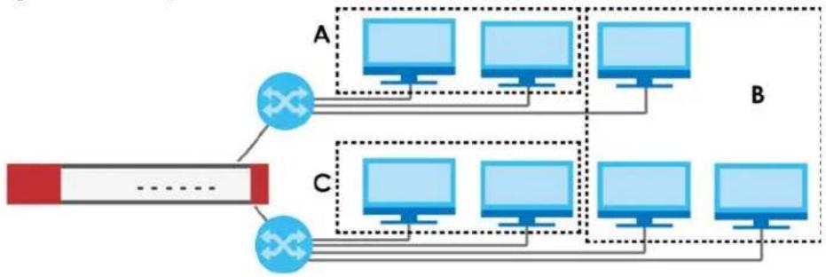
flowchart
graph TD
    A["Router"] -->|A| B["Computer 1"]
    A -->|A| C["Computer 2"]
    A -->|C| D["Computer 3"]
    B --> E["Computer 4"]
    C --> F["Computer 5"]
    D --> G["Computer 6"]
    E --> H["Computer 7"]
    F --> I["Computer 8"]
    G --> J["Computer 9"]
In this example, there are two physical networks and three departments A, B, and C. The physical networks are connected to hubs, and the hubs are connected to the router.
Alternatively, you can divide the physical networks into three VLANs.
Figure 283 Example: After VLAN
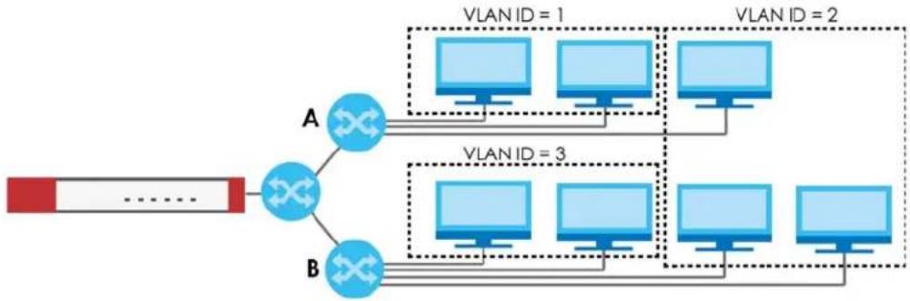
flowchart
graph TD
    A["Host A"] -->|VLAN ID = 1| B["Monitor 1"]
    A -->|VLAN ID = 2| C["Monitor 2"]
    A -->|VLAN ID = 3| D["Monitor 3"]
    A -->|VLAN ID = 4| E["Monitor 4"]
    B --> F["Computer 1"]
    B --> G["Computer 2"]
    C --> H["Computer 3"]
    C --> I["Computer 4"]
    D --> J["Computer 5"]
    D --> K["Computer 6"]
    E --> L["Computer 7"]
Each VLAN is a separate network with separate IP addresses, subnet masks, and gateways. Each VLAN also has a unique identification number (ID). The ID is a 12-bit value that is stored in the MAC header. The VLANs are connected to switches, and the switches are connected to the router. (If one switch has enough connections for the entire network, the network does not need switches A and B.)
- Traffic inside each VLAN is layer-2 communication (data link layer, MAC addresses). It is handled by the switches. As a result, the new switch is required to handle traffic inside VLAN 2. Traffic is only broadcast inside each VLAN, not each physical network.
- Traffic between VLANs (or between a VLAN and another type of network) is layer-3 communication (network layer, IP addresses). It is handled by the router.
This approach provides a few advantages.
- Increased performance - In VLAN 2, the extra switch should route traffic inside the sales department faster than the router does. In addition, broadcasts are limited to smaller, more logical groups of users.
- Higher security - If each computer has a separate physical connection to the switch, then broadcast traffic in each VLAN is never sent to computers in another VLAN.
- Better manageability - You can align network policies more appropriately for users. For example, you can create different content filtering rules for each VLAN (each department in the example above), and you can set different bandwidth limits for each VLAN. These rules are also independent of the physical network, so you can change the physical network without changing policies.
In this example, the new switch handles the following types of traffic:
- Inside VLAN 2.
- Between the router and VLAN 1.
- Between the router and VLAN 2.
- Between the router and VLAN 3.
VLAN Interfaces Overview
In the Zyxel Device, each VLAN is called a VLAN interface. As a router, the Zyxel Device routes traffic between VLAN interfaces, but it does not route traffic within a VLAN interface. All traffic for each VLAN interface can go through only one Ethernet interface, though each Ethernet interface can have one or more VLAN interfaces.
Note: Each VLAN interface is created on top of only one Ethernet interface.
Otherwise, VLAN interfaces are similar to other interfaces in many ways. They have an IP address, subnet mask, and gateway used to make routing decisions. They restrict bandwidth and packet size. They can provide DHCP services, and they can verify the gateway is available.
9.9.1 VLAN Summary Screen
This screen lists every VLAN interface and virtual interface created on top of VLAN interfaces. If you enabled IPv6 on the Configuration > System > IPv6 screen, you can also configure VLAN interfaces used for your IPv6 networks on this screen. To access this screen, click Configuration > Network > Interface > VLAN.
Figure 284 Configuration > Network > Interface > VLAN
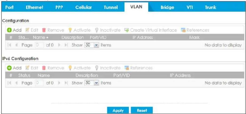
Each field is explained in the following table.
Table 140 Configuration > Network > Interface > VLAN
| LABEL DESCRIPTION | |
| Configuration / IPv6 Configuration | Use theConfigurationsection for IPv4 network settings. Use theIPv6Configurationsection for IPv6 network settings if you connect your Zyxel Device to an IPv6 network. Both sections have similar fields as described below. |
| Edit | Double-click an entry or select it and clickEditto open a screen where you can modify the entry's settings. |
| Remove | To remove an entry, select it and clickRemove.The Zyxel Device confirms you want to remove it before doing so. |
| Activate | To turn on an entry, select it and clickActivate. |
| Inactivate | To turn off an entry, select it and clickInactivate. |
| Create Virtual Interface | To open the screen where you can create a virtual interface, select an interface and clickCreateVirtual Interface. |
| References | Select an entry and clickReferencesto open a screen that shows which settings use the entry.SeeSection 9.5.4 on page 349for an example. |
| # | This field is a sequential value, and it is not associated with any interface. |
| Status | This icon is lit when the entry is active and dimmed when the entry is inactive. |
| Name This field | displays the name of the interface. |
| Description | This field displays the description of the interface. |
| Port/VID For VLAN interfaces, this field displaysthe Ethernet interface on which the VLAN interface is createdthe V LAN IDFor virtual interfaces, this field is blank. | |
| IP Address | This field displays the current IP address of the interface. If the IP address is 0.0.0.0, the interface does not have an IP address yet.This screen also shows whether the IP address is a static IP address (STATIC) or dynamically assigned (DHCP). IP addresses are always static in virtual interfaces. |
| Mask | This field displays the interface's subnet mask in dot decimal notation. |
| Apply | ClickApplyto save your changes back to the Zyxel Device. |
| Reset | ClickResetto return the screen to its last-saved settings. |
9.9.2 VLAN Add/Edit
Select an existing entry on the previous screen and click Edit or click Add to create a new entry. The following screen appears.
Figure 285 Configuration > Network > Interface > VLAN > Add /Edit
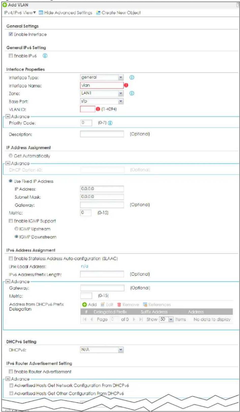
![Router Preference: Medium Advance MTU: 1480 (1280-1500) Hop Limit: 64 (1-255) Advertised Prefix Table Add Edit Remove IPv6 Address/Prefix Length Page 0 of 0 Show 50 Items No data to display Advance Advertised Prefix from DHCPv6 Prefix Delegation Add Edit Remove References Delegated Prefix Suffix Address Address Page 0 of 0 Show 50 Items No data to display Interface Parameters Egress Bandwidth: 1048576 Kbps Advance Ingress Bandwidth: 1048576 Kbps MTU: 1500 Bytes Connectivity Check Enable Connectivity Check Check Method: icmp Check Period: 30 (5-600 seconds) Check Timeout: 5 (1-10 seconds) Check Fall Tolerance: 5 (1-10) Check Default Gateway 0.0.0.0 Check These Addresses [Domain Name or IP Address] (Optional) Probe Succeeds When: any one respond(s) DHCP Setting DHCP: None Enable IP/MAC Binding Enable Logs for IP/MAC Binding Violation Static DHCP Table Add Edit Remove IP Address MAC Description Page 0 of 0 Show 50 Items No data to display Advance RIP Setting Enable RIP Direction: BIDir Send Version: 2 Receive Version: 2 V2-Broadcast OSPF Setting Area: none Priority: 1 (0-255) Link Cost: 10 (1-65535) Passive Interface Authentication: None](/content/2026/05/878280/images/8f212c7e148d2081f8688d8e6ca0bd60641e1070809228113ae9e6c64ccb2ae1.jpg)
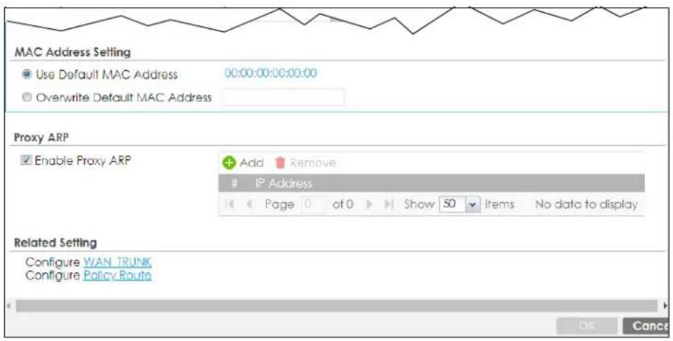
Each field is explained in the following table.
Table 141 Configuration > Network > Interface > VLAN > Add / Edit
| LABEL DESCRIPTION | |
| IPv4/IPv6 View / IPv4 View / IPv6 View | Use this button to display both IPv4 and IPv6, IPv4-only, or IPv6-only configuration fields. |
| Show Advanced Settings / Hide Advanced Settings | Click this button to display a greater or lesser number of configuration fields. |
| Create New Object | Click this button to create a DHCPv6 lease or DHCPv6 request object that you may use for the DHCPv6 settings in this screen. |
| General Settings | |
| Enable Interface Select this to turn this interface on. Clear this to disable this interface. | |
| General IPv6 Setting | |
| Enable IPv6 | Select this to enable IPv6 on this interface. Otherwise, clear this to disable it. |
| Interface Properties | |
| Interface Type | Select one of the following option depending on the type of network to which the Zyxel Device is connected or if you want to additionally manually configure some related settings.internalis for connecting to a local network. Other corresponding configuration options: DHCP server and DHCP relay. The Zyxel Device automatically adds default SNAT settings for traffic flowing from this interface to an external interface.externalis for connecting to an external network (like the Internet). The Zyxel Device automatically adds this interface to the default WAN trunk.For general, the rest of the screen's options do not automatically adjust and you must manually configure a policy route to add routing and SNAT settings for the interface. |
| Interface Name | This field is read-only if you are editing an existing VLAN interface. Enter the number of the VLAN interface. You can use a number from 0~4094. For example, use vlan0, vlan8, and so on. The total number of VLANs you can configure on the Zyxel Device depends on the model. |
| Zone Select the zone to which the VLAN interface belongs. | |
| Base Port | Select the Ethernet interface on which the VLAN interface runs. |
| VLAN ID | Enter the VLAN ID. This 12-bit number uniquely identifies each VLAN. Allowed values are 1 - 4094. (0 and 4095 are reserved.) |
| Priority Code | This is a 3-bit field within a 802.1Q VLAN tag that's used to prioritize associated outgoing VLAN traffic. "0" is the lowest priority level and "7" is the highest. See Table 218 on page 591. The setting configured inConfiguration > BWMoverwrites the priority setting here. |
| Description | Enter a description of this interface. You can use alphanumeric and ( ) +/ := ? ! * # @ _ %- characters, and it can be up to 60 characters long. Spaces are allowed, but the string can't start with a space. |
| IP Address Assignment | |
| Get Automatically | Select this if this interface is a DHCP client. In this case, the DHCP server configures the IP address, subnet mask, and gateway automatically.You should not select this if the interface is assigned to a VRRP group. |
| DHCP Option 60 | DHCP Option 60 is used by the Zyxel Device for identification to the DHCP server using the VCI (Vendor Class Identifier) on the DHCP server. The Zyxel Device adds it in the initial DHCP discovery message that a DHCP client broadcasts in search of an IP address. The DHCP server can assign different IP addresses or options to clients with the specific VCI or reject the request from clients without the specific VCI.Type a string using up to 63 of these characters [a-zA-Z0-9!\\"#%&\')*+,-./::<=>@[\\\]\^_{}] to identify this Zyxel Device to the DHCP server. For example, Zyxel-TW. |
| Use Fixed IP Address | Select this if you want to specify the IP address, subnet mask, and gateway manually. |
| IP Address | This field is enabled if you selectUse Fixed IP Address.Enter the IP address for this interface. |
| Subnet Mask | This field is enabled if you selectUse Fixed IP Address.Enter the subnet mask of this interface in dot decimal notation. The subnet mask indicates what part of the IP address is the same for all computers on the network. |
| Gateway | This field is enabled if you selectUse Fixed IP Address.Enter the IP address of the gateway. The Zyxel Device sends packets to the gateway when it does not know how to route the packet to its destination. The gateway should be on the same network as the interface. |
| Metric | Enter the priority of the gateway (if any) on this interface. The Zyxel Device decides which gateway to use based on this priority. The lower the number, the higher the priority. If two or more gateways have the same priority, the Zyxel Device uses the one that was configured first. |
| Enable IGMP Support | Select this to allow the Zyxel Device to act as an IGMP proxy for hosts connected on the IGMP downstream interface. |
| IGMP Upstream | EnableIGMP Upstreamon the interface which connects to a router running IGMP that is closer to the multicast server. |
| IGMP Downstream | EnableIGMP Downstreamon the interface which connects to the multicast hosts. |
| IPv6 Address Assignment | These IP address fields configure an IPv6 IP address on the interface itself. |
| Enable Stateless Address Auto-configuration (SLAAC) | Select this to enable IPv6 stateless auto-configuration on this interface. The interface will generate an IPv6 IP address itself from a prefix obtained from an IPv6 router on the network. |
| Link-Local address | This displays the IPv6 link-local address and the network prefix that the Zyxel Device generates itself for the interface. |
| IPv6 Address/ Prefix Length | Enter the IPv6 address and the prefix length for this interface if you want to configure a static IP address for this interface. This field is optional.The prefix length indicates what the left-most part of the IP address is the same for all computers on the network, that is, the network address. |
| Gateway Enter the | IPv6 address of the default outgoing gateway using colon (:) hexadecimal notation. |
| Metric | Enter the priority of the gateway (if any) on this interface. The Zyxel Device decides which gateway to use based on this priority. The lower the number, the higher the priority. If two or more gateways have the same priority, the Zyxel Device uses the one that was configured first. |
| Address from DHCPv6 Prefix Delegation | Use this table to have the Zyxel Device obtain an IPv6 prefix from the ISP or a connected uplink router for an internal network, such as the LAN or DMZ. You have to also enter a suffix address which is appended to the delegated prefix to form an address for this interface.See Prefix Delegation on page 323 for more information.To use prefix delegation, you must:Create at least one DHCPv6 request object before configuring this table.The external interface must be a DHCPv6 client. You must configure the DHCPv6 request options using a DHCPv6 request object with the type of prefix-delegation.Assign the prefix delegation to an internal interface and enable router advertisement on that interface. |
| Add Click this to create an entry. | |
| Edit | Select an entry and click this to change the settings. |
| Remove | Select an entry and click this to delete it from this table. |
| References | Select an entry and click References to open a screen that shows which settings use the entry. See Section 9.5.4 on page 349 for an example. |
| # This field is a sequential value, and it is not associated with any entry. | |
| Delegated Prefix | Select the DHCPv6 request object to use from the drop-down list. |
| Suffix Address | Enter the ending part of the IPv6 address, a slash (/), and the prefix length. The Zyxel Device will append it to the delegated prefix.For example, you got a delegated prefix of 2003:1234:5678/48. You want to configure an IP address of 2003:1234:5678:1111::1/128 for this interface, then enter :1111:0:0:0:1/128 in this field. |
| Address This field displays the combined IPv6 IP address for this interface.Note: This field displays the combined address after you click OK and reopen this screen. | |
| DHCPv6 Setting | |
| DHCPv6 | Select N/A to not use DHCPv6.Select Client to set this interface to act as a DHCPv6 client.Select Server to set this interface to act as a DHCPv6 server which assigns IP addresses and provides subnet mask, gateway, and DNS server information to clients.Select Relay to set this interface to route DHCPv6 requests to the DHCPv6 relay server you specify. The DHCPv6 server(s) may be on another network. |
| DUID | This field displays the DHCP Unique IDentifier (DUID) of the interface, which is unique and used for identification purposes when the interface is exchanging DHCPv6 messages with others. See DHCPv6 on page 324 for more information. |
| DUID as MAC | Select this to have the DUID generated from the interface's default MAC address. |
| Customized DUID if you want to use a customized DUID, enter it here for the interface. | |
| Enable Rapid Commit | Select this to shorten the DHCPv6 message exchange process from four to two steps. This function helps reduce heavy network traffic load.Note: Make sure you also enable this option in the DHCPv6 clients to make rapid commit work. |
| Information Refresh Time | Enter the number of seconds a DHCPv6 client should wait before refreshing information retrieved from DHCPv6. |
| Request Address | This field is available if you set this interface to DHCPv6 Client. Select this to get an IPv6 IP address for this interface from the DHCP server. Clear this to not get any IP address information through DHCPv6. |
| DHCPv6 Request Options / DHCPv6 Lease Options | If this interface is a DHCPv6 client, use this section to configure DHCPv6 request settings that determine what additional information to get from the DHCPv6 server.If this interface is a DHCPv6 server, use this section to configure DHCPv6 lease settings that determine what to offer to the DHCPv6 clients. |
| Add | Click this to create an entry in this table. See Section 9.5.5 on page 349 for more information. |
| Remove | Select an entry and click this to delete it from this table. |
| References | Select an entry and click References to open a screen that shows which settings use the entry. See Section 9.5.4 on page 349 for an example. |
| # This field is a sequential value, and it is not associated with any entry. | |
| Name This field displays the name of the DHCPv6 request or lease object. | |
| Type This field displays the type of the object. | |
| Value | This field displays the IPv6 prefix that the Zyxel Device obtained from an uplink router (Server is selected) or will advertise to its clients (Client is selected). |
| Interface | When Relay is selected, select this check box and an interface from the drop-down list if you want to use it as the relay server. |
| Relay Server | When Relay is selected, select this check box and enter the IP address of a DHCPv6 server as the relay server. |
| IPv6 Router Advertisement Setting | |
| Enable Router Advertisement | Select this to enable this interface to send router advertisement messages periodically. See IPv6 Router Advertisement on page 323 for more information. |
| Advertised Hosts Get Network Configuration From DHCPv6 | Select this to have the Zyxel Device indicate to hosts to obtain network settings (such as prefix and DNS settings) through DHCPv6.Clear this to have the Zyxel Device indicate to hosts that DHCPv6 is not available and they should use the prefix in the router advertisement message. |
| Advertised Hosts Get Other Configuration From DHCPv6 | Select this to have the Zyxel Device indicate to hosts to obtain DNS information through DHCPv6.Clear this to have the Zyxel Device indicate to hosts that DNS information is not available in this network. |
| Router Preference | Select the router preference (Low, Medium or High) for the interface. The interface sends this preference in the router advertisements to tell hosts what preference they should use for the Zyxel Device. This helps hosts to choose their default router especially when there are multiple IPv6 router on the network.Note: Make sure the hosts also support router preference to make this function work. |
| MTU | The Maximum Transmission Unit. Type the maximum size of each IPv6 data packet, in bytes, that can move through this interface. If a larger packet arrives, the Zyxel Device divides it into smaller fragments. |
| Hop Limit | Enter the maximum number of network segments that a packet can cross before reaching the destination. When forwarding an IPv6 packet, IPv6 routers are required to decrease the Hop Limit by 1 and to discard the IPv6 packet when the Hop Limit is 0. |
| Advertised Prefix Table | Configure this table only if you want the Zyxel Device to advertise a fixed prefix to the network. |
| Add Click this to create an IPv6 prefix address. | |
| Edit | Select an entry in this table and click this to modify it. |
| Remove | Select an entry in this table and click this to delete it. |
| # This field is a sequential value, and it is not associated with any entry. | |
| IPv6 Address/ Prefix Length | Enter the IPv6 network prefix address and the prefix length.The prefix length indicates what the left-most part of the IP address is the same for all computers on the network, that is, the network address. |
| Advertised Prefix from DHCPv6 Prefix Delegation | Use this table to configure the network prefix if you want to use a delegated prefix as the beginning part of the network prefix. |
| Add Click this to create an entry in this table. | |
| Edit | Select an entry in this table and click this to modify it. |
| Remove | Select an entry in this table and click this to delete it. |
| References | Select an entry and click References to open a screen that shows which settings use the entry. See Section 9.5.4 on page 349 for an example. |
| # This field is a sequential value, and it is not associated with any entry. | |
| Delegated Prefix | Select the DHCPv6 request object to use for generating the network prefix for the network. |
| Suffix Address | Enter the ending part of the IPv6 network address plus a slash (/) and the prefix length. The Zyxel Device will append it to the selected delegated prefix. The combined address is the network prefix for the network.For example, you got a delegated prefix of 2003:1234:5678/48. You want to divide it into 2003:1234:5678:1111/64 for this interface and 2003:1234:5678:2222/64 for another interface. You can use ::1111/64 and ::2222/64 for the suffix address respectively. But if you do not want to divide the delegated prefix into subnetworks, enter ::0/48 here, which keeps the same prefix length (/48) as the delegated prefix. |
| Address | This is the final network prefix combined by the delegated prefix and the suffix.Note: This field displays the combined address after you click OK and reopen this screen. |
| Interface Parameters | |
| Egress Bandwidth | Enter the maximum amount of traffic, in kilobits per second, the Zyxel Device can send through the interface to the network. Allowed values are 0 - 1048576. |
| Ingress Bandwidth | This is reserved for future use.Enter the maximum amount of traffic, in kilobits per second, the Zyxel Device can receive from the network through the interface. Allowed values are 0 - 1048576. |
| MTU | Maximum Transmission Unit. Type the maximum size of each data packet, in bytes, that can move through this interface. If a larger packet arrives, the Zyxel Device divides it into smaller fragments. Allowed values are 576 - 1500. Usually, this value is 1500. |
| Connectivity Check | The Zyxel Device can regularly check the connection to the gateway you specified to make sure it is still available. You specify how often to check the connection, how long to wait for a response before the attempt is a failure, and how many consecutive failures are required before the Zyxel Device stops routing to the gateway. The Zyxel Device resumes routing to the gateway the first time the gateway passes the connectivity check. |
| Enable Connectivity Check | Select this to turn on the connection check. |
| Check Method Select the method that the gateway allows.Select icmp to have the Zyxel Device regularly ping the gateway you specify to make sure it is still available.Select tcp to have the Zyxel Device regularly perform a TCP handshake with the gateway you specify to make sure it is still available. | |
| Check Period Enter the number of seconds between connection check attempts. | |
| Check Timeout | Enter the number of seconds to wait for a response before the attempt is a failure. |
| Check Fail Tolerance | Enter the number of consecutive failures before the Zyxel Device stops routing through the gateway. |
| Check Default Gateway | Select this to use the default gateway for the connectivity check. |
| Check this address | Select this to specify a domain name or IP address for the connectivity check. Enter that domain name or IP address in the field next to it. |
| Check Port | This field only displays when you set the Check Method to tcp. Specify the port number to use for a TCP connectivity check. |
| Check these addresses | Type one or two domain names or IP addresses for the connectivity check. |
| Probe Succeeds When | This field applies when you specify two domain names or IP addresses for the connectivity check.Select any one if you want the check to pass if at least one of the domain names or IP addresses responds.Select all if you want the check to pass only if both domain names or IP addresses respond. |
| DHCP Setting | The DHCP settings are available for the OPT, LAN and DMZ interfaces. |
| DHCP | Select what type of DHCP service the Zyxel Device provides to the network. Choices are: None - the Zyxel Device does not provide any DHCP services. There is already a DHCP server on the network.DHCP Relay - the Zyxel Device routes DHCP requests to one or more DHCP servers you specify. The DHCP server(s) may be on another network.DHCP Server - the Zyxel Device assigns IP addresses and provides subnet mask, gateway, and DNS server information to the network. The Zyxel Device is the DHCP server for the network. |
| These fields appear if the Zyxel Device is a DHCP Relay. | |
| Relay Server 1 Enter the IP address of a DHCP server for the network. | |
| Relay Server 2 | This field is optional. Enter the IP address of another DHCP server for the network. |
| These fields appear if the Zyxel Device is a DHCP Server. | |
| IP Pool Start Address | Enter the IP address from which the Zyxel Device begins allocating IP addresses. If you want to assign a static IP address to a specific computer, click Add Static DHCP.If this field is blank, the Pool Size must also be blank. In this case, the Zyxel Device can assign every IP address allowed by the interface's IP address and subnet mask, except for the first address (network address), last address (broadcast address) and the interface's IP address. |
| Pool Size | Enter the number of IP addresses to allocate. This number must be at least one and is limited by the interface's Subnet Mask. For example, if the Subnet Mask is 255.255.255.0 and IP Pool Start Address is 10.10.10.10, the Zyxel Device can allocate 10.10.10.10 to 10.10.10.254, or 245 IP addresses.If this field is blank, the IP Pool Start Address must also be blank. In this case, the Zyxel Device can assign every IP address allowed by the interface's IP address and subnet mask, except for the first address (network address), last address (broadcast address) and the interface's IP address. |
| First DNS Server Second DNS Server Third DNS Server | Specify the IP addresses up to three DNS servers for the DHCP clients to use. Use one of the following ways to specify these IP addresses.Custom Defined - enter a static IP address.From ISP - select the DNS server that another interface received from its DHCP server.Zyxel Device - the DHCP clients use the IP address of this interface and the Zyxel Device works as a DNS relay. |
| First WINS Server, Second WINS Server | Type the IP address of the WINS (Windows Internet Naming Service) server that you want to send to the DHCP clients. The WINS server keeps a mapping table of the computer names on your network and the IP addresses that they are currently using. |
| Default Router | If you set this interface to DHCP Server, you can select to use either the interface's IP address or another IP address as the default router. This default router will become the DHCP clients' default gateway.To use another IP address as the default router, select Custom Defined and enter the IP address. |
| Lease time | Specify how long each computer can use the information (especially the IP address) before it has to request the information again. Choices are:infinite - select this if IP addresses never expiredays, hours, and minutes - select this to enter how long IP addresses are valid. The default is 2 days. |
| Extended Options | This table is available if you selected DHCP server.Configure this table if you want to send more information to DHCP clients through DHCP packets. |
| Add | Click this to create an entry in this table. See Section 9.5.6 on page 350. |
| Edit | Select an entry in this table and click this to modify it. |
| Remove | Select an entry in this table and click this to delete it. |
| # This field is a sequential value, and it is not associated with any entry. | |
| Name This is the option's name. | |
| Code This is the option's code number. | |
| Type This is the option's type. | |
| Value This is the option's value. | |
| Enable IP/MAC Binding | Select this option to have the Zyxel Device enforce links between specific IP addresses and specific MAC addresses for this VLAN. This stops anyone else from manually using a bound IP address on another device connected to this interface. Use this to make use only the intended users get to use specific IP addresses. |
| Enable Logs for IP/MAC Binding Violation | Select this option to have the Zyxel Device generate a log if a device connected to this VLAN attempts to use an IP address that is bound to another device's MAC address. |
| Static DHCP Table | Configure a list of static IP addresses the Zyxel Device assigns to computers connected to the interface. Otherwise, the Zyxel Device assigns an IP address dynamically using the interface's IP Pool Start Address and Pool Size. |
| LABEL | DESCRIPTION |
| Add Click this to create a new entry. | |
| Edit Select an entry and click this to be able to modify it. | |
| Remove Select an entry and click this to delete it. | |
| Import | Click this to import a previously saved file (.csv) to the Zyxel Device. The IP/MAC binding settings and description to identify these settings in the file will be applied to the Zyxel Device.The previously saved csv file may be a file you configured, or a file you exported atMonitor> System Status> DHCP Table if you want to recover settings configured before.Configure your csv file in the order of IP address, MAC address and description. Spaces are allowed. Separate each item with a comma, for example, 1.1.1.1,22:22:33:44:55:02,test. Press enter to configure the next group in a new line.Your currently configured IP/MAC binding settings and entries description will be overwritten once you import the file. Make sure to click Export to export your settings as a file for backup in Monitor> System Status> DHCP Table first. |
| File Path | Type the file path and name of the DHCP settings file you want to import in the text box (or click Browse to find it on your computer) and then click Upload to transfer the file to the Zyxel Device. |
| # This field is a sequential value, and it is not associated with a specific entry. | |
| IP Address | Enter the IP address to assign to a device with this entry's MAC address. |
| MAC Enter the MAC address to which to assign this entry's IP address. | |
| Description | Enter a description to help identify this static DHCP entry. You can use alphanumeric and () + / : = ? ! * # @ $ _% - characters, and it can be up to 60 characters long. |
| RIP Setting | See Section 10.6 on page 445 for more information about RIP. |
| Enable RIP Select this to enable RIP on this interface. | |
| Direction | This field is effective when RIP is enabled. Select the RIP direction from the drop-down list box.BiDir - This interface sends and receives routing information.In-Only - This interface receives routing information.Out-Only - This interface sends routing information. |
| Send Version | This field is effective when RIP is enabled. Select the RIP version(s) used for sending RIP packets. Choices are 1, 2, and 1 and 2. |
| Receive Version | This field is effective when RIP is enabled. Select the RIP version(s) used for receiving RIP packets. Choices are 1, 2, and 1 and 2. |
| V2-Broadcast | This field is effective when RIP is enabled. Select this to send RIP-2 packets using subnet broadcasting; otherwise, the Zyxel Device uses multicasting. |
| OSPF Setting | See Section 10.7 on page 447 for more information about OSPF. |
| Area | Select the area in which this interface belongs. Select None to disable OSPF in this interface. |
| Priority | Enter the priority (between 0 and 255) of this interface when the area is looking for a Designated Router (DR) or Backup Designated Router (BDR). The highest-priority interface identifies the DR, and the second-highest-priority interface identifies the BDR. Set the priority to zero if the interface can not be the DR or BDR. |
| Link Cost | Enter the cost (between 1 and 65,535) to route packets through this interface. |
| Passive Interface | Select this to stop forwarding OSPF routing information from the selected interface. As a result, this interface only receives routing information. |
| LABEL DESCRIPTION | |
| Authentication | Select an authentication method, or disable authentication. To exchange OSPF routing information with peer border routers, you must use the same authentication method that they use. Choices are:Same-as-Area - use the default authentication method in the areaNone - disable authenticationText - authenticate OSPF routing information using a plain-text passwordMD5 - authenticate OSPF routing information using MD5 encryption |
| Text Authentication Key | This field is available if the Authentication is Text. Type the password for text authentication. The key can consist of alphanumeric characters and the underscore, and it can be up to 16 characters long. |
| MD5 Authentication ID | This field is available if the Authentication is MD5. Type the ID for MD5 authentication. The ID can be between 1 and 255. |
| MD5 Authentication Key | This field is available if the Authentication is MD5. Type the password for MD5 authentication. The password can consist of alphanumeric characters and the underscore, and it can be up to 16 characters long. |
| MAC Address Setting | This section appears when Interface Properties is External or General. Have the interface use either the factory assigned default MAC address, a manually specified MAC address, or clone the MAC address of another device or computer. |
| Use Default MAC Address | Select this option to have the interface use the factory assigned default MAC address. By default, the Zyxel Device uses the factory assigned MAC address to identify itself. |
| Overwrite Default MAC Address | Select this option to have the interface use a different MAC address. Either the MAC address in the field. Once it is successfully configured, the address will be copied to the configuration file. It will not change unless you change the setting or upload a different configuration file. |
| Proxy ARP | Proxy ARP is available for external or general interfaces on the Zyxel Device. See Section on page 337 for more information on Proxy ARP. |
| Enable Proxy ARP | Select this to allow the Zyxel Device to answer external interface ARP requests on behalf of a device on its internal interface. Interfaces supported are: · E t h e r n e t · V L A N · BridgeSee Section 9.5.2 on page 346 for more information. |
| Add | Click Add to create an IPv4 Address, an IPv4 CIDR (for example, 192.168.1.1/24) or an IPv4 Range (for example, 192.168.1.2-192.168.1.100) as the target IP address. The Zyxel Device answers external ARP requests only if they match one of these inputted target IP addresses. For example, if the IPv4 Address is 192.168.1.5, then the Zyxel Device will answer ARP requests coming from the WAN only if it contains 192.168.1.5 as the target IP address.Select an existing entry and click Remove to delete that entry. |
| Related Setting | |
| Configure WAN TRUNK | Click WAN TRUNK to go to a screen where you can set this VLAN to be part of a WAN trunk for load balancing. |
| Configure Policy Route | Click Policy Route to go to the screen where you can manually configure a policy route to associate traffic with this VLAN. |
| OK | Click OK to save your changes back to the Zyxel Device. |
| Cancel | Click Cancel to exit this screen without saving. |
9.10 Bridge Interfaces
This section introduces bridges and bridge interfaces and then explains the screens for bridge interfaces.
Bridge Overview
A bridge creates a connection between two or more network segments at the layer-2 (MAC address) level. In the following example, bridge X connects four network segments.
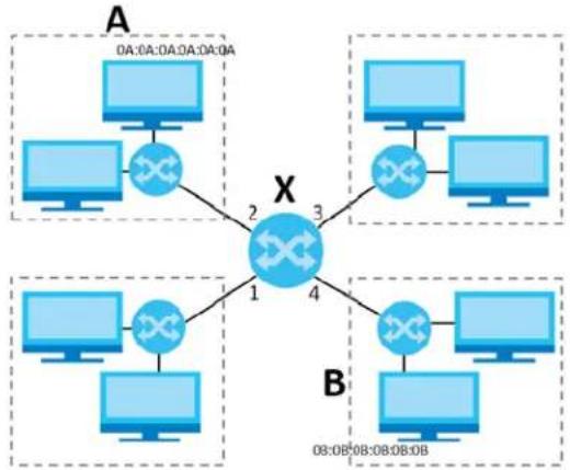
flowchart
graph TD
    subgraph A
        A1["Computer 0A:0A:0A:0A:0A"] --> X
        X -->|2| A2["Computer 1"]
        X -->|3| A3["Computer 2"]
        X -->|4| A4["Computer 3"]
    end
    subgraph B
        B1["Computer 0B:0B:0B:0B"] --> X
        X -->|1| B2["Computer 1"]
        X -->|4| B3["Computer 2"]
        X -->|5| B4["Computer 3"]
    end
    A2 --> X
    B2 --> X
    B3 --> X
    B4 --> X
When the bridge receives a packet, the bridge records the source MAC address and the port on which it was received in a table. It also looks up the destination MAC address in the table. If the bridge knows on which port the destination MAC address is located, it sends the packet to that port. If the destination MAC address is not in the table, the bridge broadcasts the packet on every port (except the one on which it was received).
In the example above, computer A sends a packet to computer B. Bridge X records the source address 0A:0A:0A:0A:0A and port 2 in the table. It also looks up 0B:0B:0B:0B:0B:0B in the table. There is no entry yet, so the bridge broadcasts the packet on ports 1, 3, and 4.
Table 142 Example: Bridge Table After Computer A Sends a Packet to Computer B
| MAC ADDRESS PORT | |
| 0A:0A:0A:0A:0A:0A 2 |
If computer B responds to computer A, bridge X records the source address 0B:0B:0B:0B:0B:0B and port 4 in the table. It also looks up 0A:0A:0A:0A:0A in the table and sends the packet to port 2 accordingly.
Table 143 Example: Bridge Table After Computer B Responds to Computer A
| MAC ADDRESS PORT | |
| 0A:0A:0A:0A:0A:0A 2 | |
| 0B:0B:0B:0B:0B:0B 4 |
Bridge Interface Overview
A bridge interface creates a software bridge between the members of the bridge interface. It also becomes the Zyxel Device's interface for the resulting network.
Unlike the device-wide bridge mode in ZyNOS-based Zyxel Devices, this Zyxel Device can bridge traffic between some interfaces while it routes traffic for other interfaces. The bridge interfaces also support more functions, like interface bandwidth parameters, DHCP settings, and connectivity check. To use the whole Zyxel Device as a transparent bridge, add all of the Zyxel Device's interfaces to a bridge interface.
A bridge interface may consist of the following members:
- Zero or one VLAN interfaces (and any associated virtual VLAN interfaces)
- Any number of Ethernet interfaces (and any associated virtual Ethernet interfaces)
When you create a bridge interface, the Zyxel Device removes the members' entries from the routing table and adds the bridge interface's entries to the routing table. For example, this table shows the routing table before and after you create bridge interface br0 (250.250.250.0/23) between lan1 and vlan1.
Table 144 Example: Routing Table Before and After Bridge Interface br0 Is Created
| IP ADDRESS(ES) DESTINATION | IP ADDRESS(ES) DE |
| 210.210.210.0/24 | lan1 |
| 210.211.1.0/24 | lan1:1 |
| 221.221.221.0/24 | vlan0 |
| 222.222.222.0/24 | vlan1 |
| 230.230.230.192/26 | wan2 |
| 241.241.241.241/32 dmz | |
| 242.242.242.242/32 dmz |
| ON | |
| 221.221.221.0/24 | vlan0 |
| 230.230.230.192/26 | wan2 |
| 241.241.241.241/32 | dmz |
| 242.242.242.242/32 | dmz |
| 250.250.250.0/23 | br0 |
In this example, virtual Ethernet interface lan1:1 is also removed from the routing table when lan1 is added to br0. Virtual interfaces are automatically added to or remove from a bridge interface when the underlying interface is added or removed.
9.10.1 Bridge Summary
This screen lists every bridge interface and virtual interface created on top of bridge interfaces. If you enabled IPv6 on the Configuration > System > IPv6 screen, you can also configure bridge interfaces used for your IPv6 network on this screen. To access this screen, click Configuration > Network > Interface > Bridge.
Figure 286 Configuration > Network > Interface > Bridge
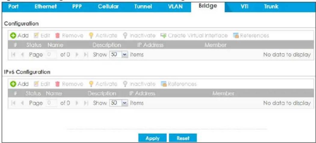
Each field is described in the following table.
Table 145 Configuration > Network > Interface > Bridge
| LABEL DESCRIPTION | |
| Configuration / IPv6 Configuration | Use theConfigurationsection for IPv4 network settings. Use theIPv6 Configurationsection for IPv6 network settings if you connect your Zyxel Device to an IPv6 network. Both sections have similar fields as described below. |
| Add Click this to create a new entry. | |
| Edit | Double-click an entry or select it and clickEditto open a screen where you can modify the entry's settings. |
| Remove | To remove an entry, select it and clickRemove.The Zyxel Device confirms you want to remove it before doing so. |
| Activate | To turn on an entry, select it and clickActivate. |
| Inactivate | To turn off an entry, select it and clickInactivate. |
| Create Virtual Interface | To open the screen where you can create a virtual interface, select an interface and clickCreate Virtual Interface. |
| References | Select an entry and clickReferencesto open a screen that shows which settings use the entry. SeeSection 9.5.4 on page 349for an example. |
| # This field is a sequential value, and it is not associated with any interface. | |
| Status This icon is lit when the entry is active and dimmed when the entry is inactive. | |
| Name This field displays the name of the interface. | |
| Description This field displays the description of the interface. | |
| IP Address | This field displays the current IP address of the interface. If the IP address is 0.0.0.0, the interface does not have an IP address yet.This screen also shows whether the IP address is a static IP address (STATIC) or dynamically assigned (DHCP). IP addresses are always static in virtual interfaces. |
| Member | This field displays the Ethernet interfaces and VLAN interfaces in the bridge interface. It is blank for virtual interfaces. |
| Apply | ClickApplyto save your changes back to the Zyxel Device. |
| Reset | ClickResetto return the screen to its last-saved settings. |
9.10.2 Bridge Add/Edit
This screen lets you configure IP address assignment, interface bandwidth parameters, DHCP settings, and connectivity check for each bridge interface. To access this screen, click the Add or Edit icon on the Bridge Summary screen. The following screen appears.
Figure 287 Configuration > Network > Interface > Bridge > Add / Edit
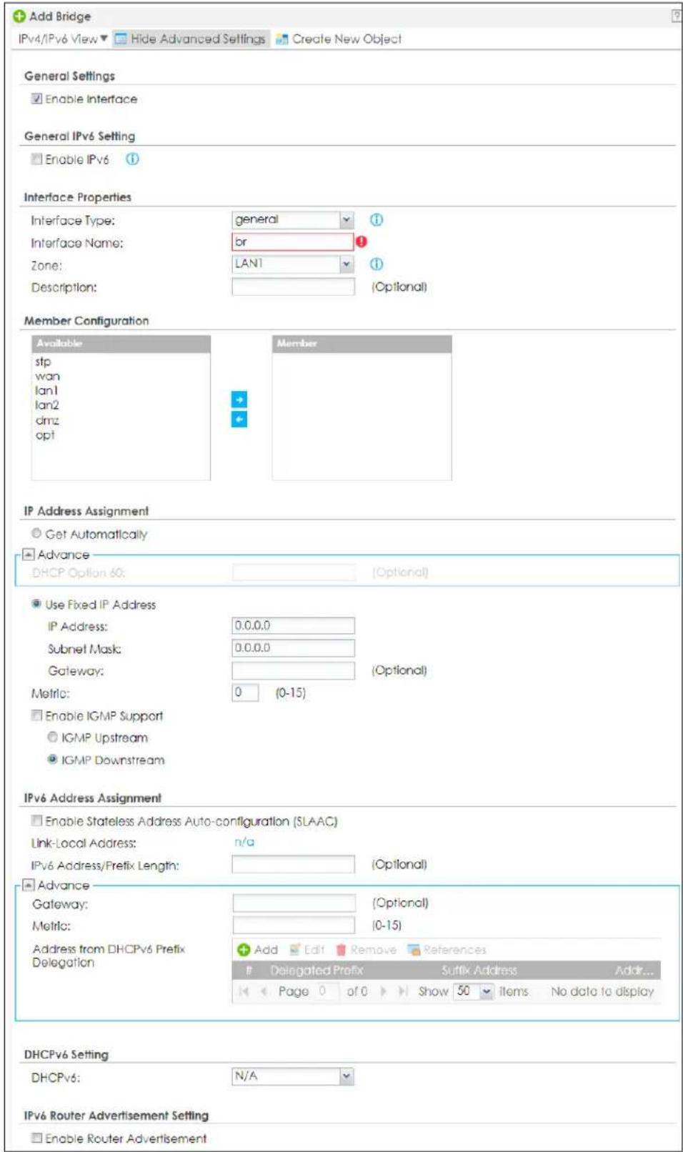
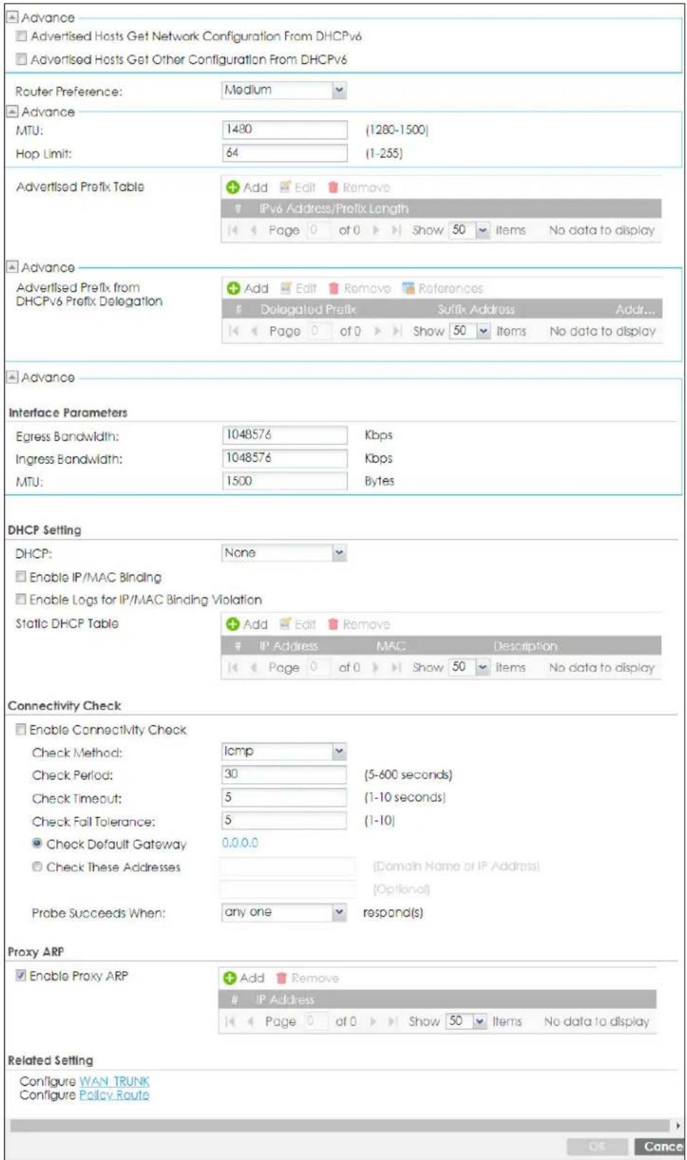
Each field is described in the table below.
Table 146 Configuration > Network > Interface > Bridge > Add / Edit
| LABEL DESCRIPTION | |
| IPv4/IPv6 View / IPv4View / IPv6 View | Use this button to display both IPv4 and IPv6, IPv4-only, or IPv6-only configuration fields. |
| Show Advanced Settings / Hide Advanced Settings | Click this button to display a greater or lesser number of configuration fields. |
| Create New Object | Click this button to create a DHCPv6 lease or DHCPv6 request object that you may use for the DHCPv6 settings in this screen. |
| General Settings | |
| Enable Interface | Select this to enable this interface. Clear this to disable this interface. |
| General IPv6 Setting | |
| Enable IPv6 | Select this to enable IPv6 on this interface. Otherwise, clear this to disable it. |
| Interface Properties | |
| Interface Type | Select one of the following option depending on the type of network to which the Zyxel Device is connected or if you want to additionally manually configure some related settings.internalis for connecting to a local network. Other corresponding configuration options: DHCP server and DHCP relay. The Zyxel Device automatically adds default SNAT settings for traffic flowing from this interface to an external interface.externalis for connecting to an external network (like the Internet). The Zyxel Device automatically adds this interface to the default WAN trunk.Forgeneral,the rest of the screen's options do not automatically adjust and you must manually configure a policy route to add routing and SNAT settings for the interface. |
| Interface Name | This field is read-only if you are editing the interface. Enter the name of the bridge interface. The format is brx, where x is 0 - 11. For example, br0, br3, and so on. |
| Zone | Select the zone to which the interface is to belong. You use zones to apply security settings such as security policy, IDP, remote management, anti-malware, and application patrol. |
| Description | Enter a description of this interface. You can use alphanumeric and () +/ := ? ! * # @ _% - characters, and it can be up to 60 characters long. Spaces are allowed, but the string can't start with a space. |
| Member Configuration | |
| Available | This field displays Ethernet interfaces and VLAN interfaces that can become part of the bridge interface. An interface is not available in the following situations:There is a virtual interface on top of itIt is already used in a different bridge interfaceSelect one, and click the >> arrow to add it to the bridge interface. Each bridge interface can only have one VLAN interface. |
| Member | This field displays the interfaces that are part of the bridge interface. Select one, and click the << arrow to remove it from the bridge interface. |
| IP Address Assignment | |
| Get Automatically | Select this if this interface is a DHCP client. In this case, the DHCP server configures the IP address, subnet mask, and gateway automatically. |
| DHCP Option 60 | DHCP Option 60 is used by the Zyxel Device for identification to the DHCP server using the VCI (Vendor Class Identifier) on the DHCP server. The Zyxel Device adds it in the initial DHCP discovery message that a DHCP client broadcasts in search of an IP address. The DHCP server can assign different IP addresses or options to clients with the specific VCI or reject the request from clients without the specific VCI.Type a string using up to 63 of these characters [a-zA-Z0-9!\"#%&\'()*+,-./::<=>@ \_ ^_^{}] to identify this Zyxel Device to the DHCP server. For example, Zyxel-TW. |
| Use Fixed IP Address | Select this if you want to specify the IP address, subnet mask, and gateway manually. |
| IP Address | This field is enabled if you select Use Fixed IP Address.Enter the IP address for this interface. |
| Subnet Mask | This field is enabled if you select Use Fixed IP Address.Enter the subnet mask of this interface in dot decimal notation. The subnet mask indicates what part of the IP address is the same for all computers on the network. |
| Gateway | This field is enabled if you select Use Fixed IP Address.Enter the IP address of the gateway. The Zyxel Device sends packets to the gateway when it does not know how to route the packet to its destination. The gateway should be on the same network as the interface. |
| Metric | Enter the priority of the gateway (if any) on this interface. The Zyxel Device decides which gateway to use based on this priority. The lower the number, the higher the priority. If two or more gateways have the same priority, the Zyxel Device uses the one that was configured first. |
| Enable IGMP Support | Select this to allow the Zyxel Device to act as an IGMP proxy for hosts connected on the IGMP downstream interface. |
| IGMP Upstream | Enable IGMP Upstream on the interface which connects to a router running IGMP that is closer to the multicast server. |
| IGMP Downstream | Enable IGMP Downstream on the interface which connects to the multicast hosts. |
| IPv6 Address Assignment | These IP address fields configure an IPv6 IP address on the interface itself. |
| Enable Stateless Address Auto-configuration (SLAAC) | Select this to enable IPv6 stateless auto-configuration on this interface. The interface will generate an IPv6 IP address itself from a prefix obtained from an IPv6 router on the network. |
| Link-Local address | This displays the IPv6 link-local address and the network prefix that the Zyxel Device generates itself for the interface. |
| IPv6 Address/ Prefix Length | Enter the IPv6 address and the prefix length for this interface if you want to use a static IP address. This field is optional.The prefix length indicates what the left-most part of the IP address is the same for all computers on the network, that is, the network address. |
| Gateway | Enter the IPv6 address of the default outgoing gateway using colon (:) hexadecimal notation. |
| Metric | Enter the priority of the gateway (if any) on this interface. The Zyxel Device decides which gateway to use based on this priority. The lower the number, the higher the priority. If two or more gateways have the same priority, the Zyxel Device uses the one that was configured first. |
| Address from DHCPv6 Prefix Delegation | Use this table to have the Zyxel Device obtain an IPv6 prefix from the ISP or a connected uplink router for an internal network, such as the LAN or DMZ. You have to also enter a suffix address which is appended to the delegated prefix to form an address for this interface.See Prefix Delegation on page 323 for more information.To use prefix delegation, you must:Create at least one DHCPv6 request object before configuring this table.The external interface must be a DHCPv6 client. You must configure the DHCPv6 request options using a DHCPv6 request object with the type of prefix-delegation.Assign the prefix delegation to an internal interface and enable router advertisement on that interface. |
| Add Click this to create an entry. | |
| Edit Select an entry and click this to change the settings. | |
| Remove | Select an entry and click this to delete it from this table. |
| References | Select an entry and click References to open a screen that shows which settings use the entry. See Section 9.5.4 on page 349 for an example. |
| # This field is a sequential value, and it is not associated with any entry. | |
| Delegated Prefix | Select the DHCPv6 request object to use from the drop-down list. |
| Suffix Address | Enter the ending part of the IPv6 address, a slash (/), and the prefix length. The Zyxel Device will append it to the delegated prefix.For example, you got a delegated prefix of 2003:1234:5678/48. You want to configure an IP address of 2003:1234:5678:1111:1/128 for this interface, then enter ::1111:0:0:0:1/128 in this field. |
| Address This field displays the combined IPv6 IP address for this interface.Note: This field displays the combined address after you click OK and reopen this screen. | |
| DHCPv6 Setting | |
| DHCPv6 | Select N/A to not use DHCPv6.Select Client to set this interface to act as a DHCPv6 client.Select Server to set this interface to act as a DHCPv6 server which assigns IP addresses and provides subnet mask, gateway, and DNS server information to clients.Select Relay to set this interface to route DHCPv6 requests to the DHCPv6 relay server you specify. The DHCPv6 server(s) may be on another network. |
| DUID | This field displays the DHCP Unique IDentifier (DUID) of the interface, which is unique and used for identification purposes when the interface is exchanging DHCPv6 messages with others. See DHCPv6 on page 324 for more information. |
| DUID as MAC | Select this if you want the DUID is generated from the interface's default MAC address. |
| Customized DUID If you want to use a customized DUID, enter it here for the interface. | |
| Enable Rapid Commit | Select this to shorten the DHCPv6 message exchange process from four to two steps. This function helps reduce heavy network traffic load.Note: Make sure you also enable this option in the DHCPv6 clients to make rapid commit work. |
| Information Refresh Time | Enter the number of seconds a DHCPv6 client should wait before refreshing information retrieved from DHCPv6. |
| Request Address | This field is available if you set this interface to DHCPv6 Client. Select this to get an IPv6 IP address for this interface from the DHCP server. Clear this to not get any IP address information through DHCPv6. |
| DHCPv6 Request Options / DHCPv6 Lease Options | If this interface is a DHCPv6 client, use this section to configure DHCPv6 request settings that determine what additional information to get from the DHCPv6 server.If the interface is a DHCPv6 server, use this section to configure DHCPv6 lease settings that determine what to offer to the DHCPv6 clients. |
| Add | Click this to create an entry in this table. See Section 9.5.5 on page 349 for more information. |
| Edit | Select an entry and click this to change the settings. |
| Remove | Select an entry and click this to delete it from this table. |
| References | Select an entry and click References to open a screen that shows which settings use the entry. See Section 9.5.4 on page 349 for an example. |
| # This field is a sequential value, and it is not associated with any entry. | |
| Name This field displays the name of the DHCPv6 request or lease object. | |
| Type This field displays the type of the object. | |
| Value | This field displays the IPv6 prefix that the Zyxel Device obtained from an uplink router (Server is selected) or will advertise to its clients (Client is selected). |
| Interface | When Relay is selected, select this check box and an interface from the drop-down list if you want to use it as the relay server. |
| Relay Server | When Relay is selected, select this check box and enter the IP address of a DHCPv6 server as the relay server. |
| IPv6 Router Advertisement Setting | |
| Enable Router Advertisement | Select this to enable this interface to send router advertisement messages periodically. See IPv6 Router Advertisement on page 323 for more information. |
| Advertised Hosts Get Network Configuration From DHCPv6 | Select this to have the Zyxel Device indicate to hosts to obtain network settings (such as prefix and DNS settings) through DHCPv6.Clear this to have the Zyxel Device indicate to hosts that DHCPv6 is not available and they should use the prefix in the router advertisement message. |
| Advertised Hosts Get Other Configuration From DHCPv6 | Select this to have the Zyxel Device indicate to hosts to obtain DNS information through DHCPv6.Clear this to have the Zyxel Device indicate to hosts that DNS information is not available in this network. |
| Router Preference | Select the router preference (Low, Medium or High) for the interface. The interface sends this preference in the router advertisements to tell hosts what preference they should use for the Zyxel Device. This helps hosts to choose their default router especially when there are multiple IPv6 router on the network.Note: Make sure the hosts also support router preference to make this function work. |
| MTU | The Maximum Transmission Unit. Type the maximum size of each IPv6 data packet, in bytes, that can move through this interface. If a larger packet arrives, the Zyxel Device divides it into smaller fragments. |
| Hop Limit | Enter the maximum number of network segments that a packet can cross before reaching the destination. When forwarding an IPv6 packet, IPv6 routers are required to decrease the Hop Limit by 1 and to discard the IPv6 packet when the Hop Limit is 0. |
| Advertised Prefix Table | Configure this table only if you want the Zyxel Device to advertise a fixed prefix to the network. |
| Add Click this to create an IPv6 prefix address. | |
| Edit | Select an entry in this table and click this to modify it. |
| Remove | Select an entry in this table and click this to delete it. |
| # This field is a sequential value, and it is not associated with any entry. | |
| IPv6 Address/ Prefix Length | Enter the IPv6 network prefix address and the prefix length.The prefix length indicates what the left-most part of the IP address is the same for all computers on the network, that is, the network address. |
| Advertised Prefix from DHCPv6 Prefix Delegation | Use this table to configure the network prefix if you want to use a delegated prefix as the beginning part of the network prefix. |
| Add Click this to create an entry in this table. | |
| Edit | Select an entry in this table and click this to modify it. |
| Remove | Select an entry in this table and click this to delete it. |
| References | Select an entry and clickReferencesto open a screen that shows which settings use the entry. SeeSection 9.5.4 on page 349for an example. |
| # This field is a sequential value, and it is not associated with any entry. | |
| Delegated Prefix | Select the DHCPv6 request object to use for generating the network prefix for the network. |
| Suffix Address | Enter the ending part of the IPv6 network address plus a slash (/) and the prefix length. The Zyxel Device will append it to the selected delegated prefix. The combined address is the network prefix for the network.For example, you got a delegated prefix of 2003:1234:5678/48. You want to divide it into 2003:1234:5678:1111/64 for this interface and 2003:1234:5678:2222/64 for another interface. You can use ::1111/64 and ::2222/64 for the suffix address respectively. But if you do not want to divide the delegated prefix into subnetworks, enter ::0/48 here, which keeps the same prefix length (/48) as the delegated prefix. |
| Address | This is the final network prefix combined by the selected delegated prefix and the suffix.Note: This field displays the combined address after you clickOKand reopen this screen. |
| Interface Parameters | |
| Egress Bandwidth | Enter the maximum amount of traffic, in kilobits per second, the Zyxel Device can send through the interface to the network. Allowed values are 0 - 1048576. |
| Ingress Bandwidth | This is reserved for future use.Enter the maximum amount of traffic, in kilobits per second, the Zyxel Device can receive from the network through the interface. Allowed values are 0 - 1048576. |
| MTU | Maximum Transmission Unit. Type the maximum size of each data packet, in bytes, that can move through this interface. If a larger packet arrives, the Zyxel Device divides it into smaller fragments. Allowed values are 576 - 1500. Usually, this value is 1500. |
| DHCP Setting | |
| DHCP | Select what type of DHCP service the Zyxel Device provides to the network. Choices are:None- the Zyxel Device does not provide any DHCP services. There is already a DHCP server on the network.DHCP Relay- the Zyxel Device routes DHCP requests to one or more DHCP servers you specify. The DHCP server(s) may be on another network.DHCP Server- the Zyxel Device assigns IP addresses and provides subnet mask, gateway, and DNS server information to the network. The Zyxel Device is the DHCP server for the network. |
| These fields appear if the Zyxel Device is aDHCP Relay. | |
| Relay Server 1 Enter | the IP address of a DHCP server for the network. |
| Relay Server 2 | This field is optional. Enter the IP address of another DHCP server for the network. |
| These fields appear if the Zyxel Device is a DHCP Server. | |
| IP Pool Start Address | Enter the IP address from which the Zyxel Device begins allocating IP addresses. If you want to assign a static IP address to a specific computer, click Add Static DHCP.If this field is blank, the Pool Size must also be blank. In this case, the Zyxel Device can assign every IP address allowed by the interface's IP address and subnet mask, except for the first address (network address), last address (broadcast address) and the interface's IP address. |
| Pool Size | Enter the number of IP addresses to allocate. This number must be at least one and is limited by the interface's Subnet Mask. For example, if the Subnet Mask is 255.255.255.0 and IP Pool Start Address is 10.10.10.10, the Zyxel Device can allocate 10.10.10.10 to 10.10.10.254, or 245 IP addresses.If this field is blank, the IP Pool Start Address must also be blank. In this case, the Zyxel Device can assign every IP address allowed by the interface's IP address and subnet mask, except for the first address (network address), last address (broadcast address) and the interface's IP address. |
| First DNS Server Second DNS Server Third DNS Server | Specify the IP addresses up to three DNS servers for the DHCP clients to use. Use one of the following ways to specify these IP addresses.Custom Defined - enter a static IP address.From ISP - select the DNS server that another interface received from its DHCP server.Zyxel Device - the DHCP clients use the IP address of this interface and the Zyxel Device works as a DNS relay. |
| First WINS Server, Second WINS Server | Type the IP address of the WINS (Windows Internet Naming Service) server that you want to send to the DHCP clients. The WINS server keeps a mapping table of the computer names on your network and the IP addresses that they are currently using. |
| Default Router | If you set this interface to DHCP Server, you can select to use either the interface's IP address or another IP address as the default router. This default router will become the DHCP clients' default gateway.To use another IP address as the default router, select Custom Defined and enter the IP address. |
| Lease time | Specify how long each computer can use the information (especially the IP address) before it has to request the information again. Choices are:infinite - select this if IP addresses never expiredays, hours, and minutes - select this to enter how long IP addresses are valid. |
| Extended Options | This table is available if you selected DHCP server.Configure this table if you want to send more information to DHCP clients through DHCP packets. |
| Add | Click this to create an entry in this table. See Section 9.5.6 on page 350. |
| Edit | Select an entry in this table and click this to modify it. |
| Remove | Select an entry in this table and click this to delete it. |
| # This field is a sequential value, and it is not associated with any entry. | |
| Name This is the option's name. | |
| Code This is the option's code number. | |
| Type This is the option's type. | |
| Value This is the option's value. | |
| PXE Server | PXE (Preboot eXecution Environment) allows a client computer to use the network to boot up and install an operating system via a PXE-capable Network Interface Card (NIC).PXE is available for computers on internal interfaces to allow them to boot up using boot software on a PXE server. The Zyxel Device acts as an intermediary between the PXE server and the computers that need boot software.The PXE server must have a public IPv4 address. You must enable DHCP Server on the Zyxel Device so that it can receive information from the PXE server. |
| PXE Boot Loader File | A boot loader is a computer program that loads the operating system for the computer. Type the exact file name of the boot loader software file, including filename extension, that is on the PXE server. If the wrong filename is typed, then the client computers cannot boot. |
| Enable IP/MAC Binding | Select this option to have this interface enforce links between specific IP addresses and specific MAC addresses. This stops anyone else from manually using a bound IP address on another device connected to this interface. Use this to make use only the intended users get to use specific IP addresses. |
| Enable Logs for IP/MAC Binding Violation | Select this option to have the Zyxel Device generate a log if a device connected to this interface attempts to use an IP address that is bound to another device's MAC address. |
| Static DHCP Table | Configure a list of static IP addresses the Zyxel Device assigns to computers connected to the interface. Otherwise, the Zyxel Device assigns an IP address dynamically using the interface's IP Pool Start Address and Pool Size. |
| Add Click this to create a new entry. | |
| Edit | Select an entry and click this to be able to modify it. |
| Remove Select an entry and click this to delete it. | |
| # This field is a sequential value, and it is not associated with a specific entry. | |
| IP Address | Enter the IP address to assign to a device with this entry's MAC address. |
| MAC Address Enter the MAC address to which to assign this entry's IP address. | |
| Description | Enter a description to help identify this static DHCP entry. You can use alphanumeric and () +/ := ? ! * # $ _% - characters, and it can be up to 60 characters long. |
| Connectivity Check | The interface can regularly check the connection to the gateway you specified to make sure it is still available. You specify how often the interface checks the connection, how long to wait for a response before the attempt is a failure, and how many consecutive failures are required before the Zyxel Device stops routing to the gateway. The Zyxel Device resumes routing to the gateway the first time the gateway passes the connectivity check. |
| Enable Connectivity Check | Select this to turn on the connection check. |
| Check Method Select the method that the gateway allows.Select icmp to have the Zyxel Device regularly ping the gateway you specify to make sure it is still available.Select tcp to have the Zyxel Device regularly perform a TCP handshake with the gateway you specify to make sure it is still available. | |
| Check Period Enter the number of seconds between connection check attempts. | |
| Check Timeout | Enter the number of seconds to wait for a response before the attempt is a failure. |
| Check Fail Tolerance | Enter the number of consecutive failures before the Zyxel Device stops routing through the gateway. |
| Check Default Gateway | Select this to use the default gateway for the connectivity check. |
| Check this address | Select this to specify a domain name or IP address for the connectivity check. Enter that domain name or IP address in the field next to it. |
| Check Port | This field only displays when you set the Check Method to tcp. Specify the port number to use for a TCP connectivity check. |
| Check these addresses | Type one or two domain names or IP addresses for the connectivity check. |
| Probe Succeeds When | This field applies when you specify two domain names or IP addresses for the connectivity check.Selectany oneif you want the check to pass if at least one of the domain names or IP addresses responds.Selectallif you want the check to pass only if both domain names or IP addresses respond. |
| Proxy ARP | Proxy ARP is available for external or general interfaces on the Zyxel Device. See Section on page 337for more information on Proxy ARP. |
| Enable Proxy ARP | Select this to allow the Zyxel Device to answer external interface ARP requests on behalf of a device on its internal interface. Interfaces supported are:EthernetVLANBridgeSee Section 9.5.2 on page 346for more information. |
| Add | ClickAddto create an IPv4 Address, an IPv4 CIDR (for example, 192.168.1.1/24) or anIPv4 Range (for example, 192.168.1.2-192.168.1.100) as the target IP address. The Zyxel Device answers external ARP requests only if they match one of these inputted target IP addresses. For example, if theIPv4 Addressis 192.168.1.5, then the Zyxel Device will answer ARP requests coming from the WAN only if it contains 192.168.1.5 as the target IP address.Select an existing entry and clickRemoveto delete that entry. |
Proxy ARPEnable Proxy ARP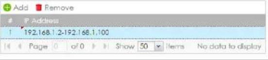 | |
| Related Setting | |
| Configure WAN TRUNK | Click WAN TRUNKto go to a screen where you can configure the interface as part of a WAN trunk for load balancing. |
| Configure Policy Route | ClickPolicy Routeto go to the screen where you can manually configure a policy route to associate traffic with this bridge interface. |
| OK | ClickOKto save your changes back to the Zyxel Device. |
| Cancel | ClickCancelto exit this screen without saving. |
9.11 LAG
Link Aggregation Group (LAG) is a way to combine multiple physical Ethernet interfaces into a single logical interface. This increases uplink bandwidth. It also increases availability as even if a member link goes down, LAG can continue to transmit and receive traffic over the remaining links.
To configure LAG, configure a link number and specify the member ports in the link. All ports must have the same speed and be in full-duplex mode. You must configure the LAG on both sides of the link and you must set the interfaces on either side of the link to be the same speed.
At the time of writing, up to 4 LAG interfaces can be configured on a Zyxel Device.
9.11.1 Available Interfaces for LAG
Ethernet and VLAN interfaces available to join a LAG interface must fulfill the following criteria.
1 The interface cannot be in another LAG. If an interface is in another LAG, it is not available to join the LAG interface until you remove the interface from the other LAG.
2 The port bound to the interface cannot be in a VLAN. If the port bound to an interface is in a VLAN, the interface is not available to join the LAG interface until you remove the port from the VLAN.
3 The selected interface must be bound to only 1 physical port.
- If you select an interface that has no ports bound to it, you must bind a port to this interface
- If you select an interface that has more than one port bound to it, you must remove all ports but one from this interface.
See Section 1.1.1 on page 29 to see which models support Link Aggregation Group (LAG).
9.11.2 LAG Summary Screen
This screen lists every LAG created on the Zyxel Device. To access this screen, click Configuration > Network > Interface > LAG.
Figure 288 Configuration > Network > Interface > LAG
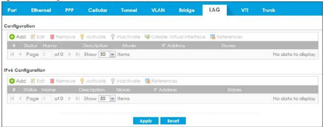
Each field is described in the following table.
Table 147 Configuration > Network > Interface > LAG
| LABEL DESCRIPTION | |
| Configuration | |
| Add Click this to create a new entry. | |
| Edit | Double-click an entry or select it and click Edit to open a screen where you can modify the entry's settings. |
| Remove | To remove an entry, select it and click Remove. The Zyxel Device confirms you want to remove it before doing so. |
| Activate | To turn on an entry, select it and click Activate. |
| Inactivate | To turn off an entry, select it and click Inactivate. |
| Create Virtual Interface | To open the screen where you can create a virtual interface, select an interface and click Create Virtual Interface. |
| References | Select an entry and click References to open a screen that shows which settings use the entry. |
| # This field is a sequential value, and it is not associated with any interface. | |
| Status This icon is lit when the entry is active and dimmed when the entry is inactive. | |
| Name This field displays the name of the LAG interface. | |
| Description This field displays the description of the LAG interface. | |
| Mode Mode refers to whether the LAG is acting as follows:active-backupwhere only one slave in the LAG interface is active and another slave becomes active only if the active slave fails.802.3ad (IEEE 802.3ad Dynamic link aggregation) where Link Aggregation Control Protocol (LACP) negotiates automatic combining of links and balances the traffic load across the LAG link by sending LACP packets to the directly connected device that also implements LACP. The slaves must have the same speed and duplex settings.balance-alb (adaptive load balancing) where traffic is distributed according to the current load on each slave by ARP negotiation. Incoming traffic is received by the current slave. If the receiving slave fails, another slave takes over the MAC address of the failed receiving slave. | |
| IP Address | This field displays the current IP address of the LAG interface. If the IP address is 0.0.0.0, the interface does not have an IP address yet.This screen also shows whether the IP address is a static IP address (STATIC) or dynamically assigned (DHCP). IP addresses are always static in virtual interfaces. |
| Slaves | A slave is a physical Ethernet interface that is a member of a LAG. Slaves do not have an IP Address and in some cases share the same MAC address. This field displays the member Ethernet interfaces and VLAN interfaces in the LAG. |
| Apply | Click Apply to save your changes back to the Zyxel Device. |
| Reset | Click Reset to return the screen to its last-saved settings. |
9.11.3 LAG Add/Edit
This screen lets you configure Interface and LAG parameters for each LAG interface. To access this screen, click the Add or Edit icon in the LAG screen. The following screen appears.
Figure 289 Configuration > Network > Interface > LAG > Add
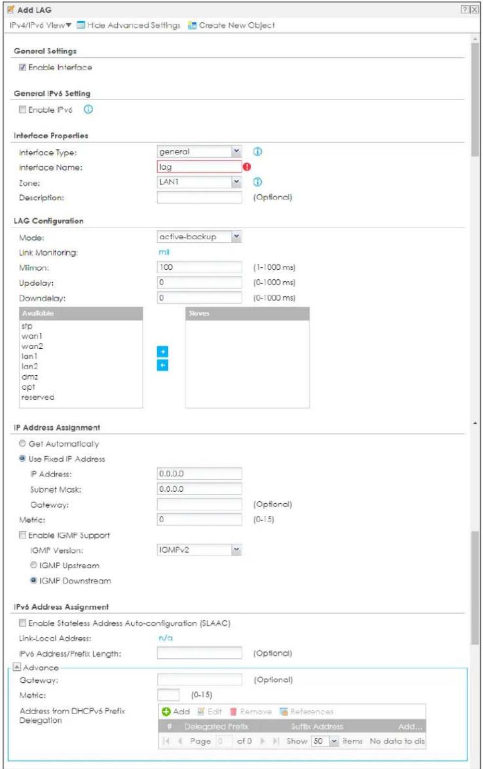
![DHCPv6 Setting DHCPv6: N/A IPv6 Router Advertisement Setting Enable Router Advertisement Advance Advertised Hosts Get Network Configuration From DHCPv6 Advertised Hosts Get Other Configuration From DHCPv6 Router Preference: Medium Advance MTU: 1480 (1280-1500) Hop Limit: 64 (1-255) Advertised Prefix Table Add Edit Remove IPv6 Address/Prefix Length Page 0 of 0 Show 50 items No data to dis Advance Advertised Prefix from DHCPv6 Prefix Delegation Add Edit Remove References Delegated Prefix Suffix Address Add... Page 0 of 0 Show 50 Items No data to dis Advance Interface Parameters Egress Bandwidth: 1048576 Kbps Ingress Bandwidth: 1048576 Kbps MTU: 1500 Bytes DHCP Setting DHCP: None Enable IP/MAC Binding Enable Logs for IP/MAC Binding Violation Static DHCP Table Add Edit Remove IP Address MAC Description Page 0 of 0 Show 50 items No data to display Connectivity Check Enable Connectivity Check Check Method: icmp Check Period: 30 (5-600 seconds) Check Timeout: 5 (1-10 seconds) Check Fall Tolerance: 5 (1-10) Check Default Gateway 0.0.0.0 Check this address [Domain Name or IP Address] Related Setting Configure WAN TRUNK Configure Policy Route OK Cancel](/content/2026/05/878280/images/e8547f076cd6de8e3424ae7ddfbf67cf5621f0dbed3a54aaeff7eced3daa2158.jpg)
Each field is described in the following table.
Table 148 Configuration > Network > Interface > LAG > Add
| LABEL DESCRIPTION | |
| General Settings | |
| Enable Interface | Select this to enable this interface. Clear this to disable this interface. |
| Interface Properties | |
| Interface Type | Select one of the following option depending on the type of network to which the Zyxel Device is connected or if you want to additionally manually configure some related settings.internalis for connecting to a local network. Other corresponding configuration options: DHCP server and DHCP relay. The Zyxel Device automatically adds default SNAT settings for traffic flowing from this interface to an external interface.externalis for connecting to an external network (like the Internet). The Zyxel Device automatically adds this interface to the default WAN trunk.Forgeneral, the rest of the screen's options do not automatically adjust and you must manually configure a policy route to add routing and SNAT settings for the interface. |
| Interface Name | This field is read-only if you are editing the interface. Enter the name of the LAG interface. The format is lagx, where x is 0 - 3. For example, lag0, lag1, and so on. |
| Zone | Select the zone to which the interface is to belong. You use zones to apply security settings such as security policy, IDP, remote management, anti-virus, and application patrol. |
| Description | Enter a description of this interface. You can use alphanumeric and () +/ :=?! *#@_%- characters, and it can be up to 60 characters long. Spaces are allowed, but the string can't start with a space. |
| LAG Configuration | |
| Mode | Select a Mode for this LAG interface. Choices are as follows:active-backupwhere only one slave in the LAG interface is active and another slave becomes active only if the active slave fails.802.3ad(IEEE 802.3ad Dynamic link aggregation) where Link Aggregation Control Protocol (LACP) negotiates automatic combining of links and balances the traffic load across the LAG link by sending LACP packets to the directly connected device that also implements LACP. The slaves must have the same speed and duplex settings.balance-alb(adaptive load balancing) where traffic is distributed according to the current load on each slave by ARP negotiation. Incoming traffic is received by the current slave. If the receiving slave fails, another slave takes over the MAC address of the failed receiving slave. |
| Link Monitoring | Select fromnone,miiorarp.nonemeans no link monitoring is done.milmonitoring monitors the state of the local interface: it can't tell if the link can transmit or receive packets.arpmonitoring sends ARP queries and uses the reply to know if the link is up and that traffic is flowing over the link. |
| Milmom | This field displays formilLink Monitoring. Set the link check interval in milliseconds that the system polls the Media Independent Interface (MII) to get status. |
| Updelay | This field displays formilLink Monitoring. Set the waiting time in milliseconds to confirm the slave interface status is up. |
| Downdelay | This field displays formilLink Monitoring. Set the waiting time in milliseconds to confirm the slave interface status is down. |
| Xmit Hash Policy | This field displays in802.3adMode. This field sets the algorithm for slave selection according to the selected TCP/IP layer. |
| LACP Rate | This field displays in802.3adMode. Select the preferred LACPDU packet transmission rate (slow/fast) to request from 802.3ad partner. |
| ARP Interval | This field displays forarplink Monitoring. Select the frequency of ARP requests sent to confirm a that slave interface is up. |
| ARP IP Target | This field displays for arp Link Monitoring. Set the IP address of the link to send ARP queries. |
| Available | This field displays Ethernet interfaces and VLAN interfaces that can become part of the LAG interface.Please see Section 9.11.1 on page 403 for criteria on available interfaces.Select one, and click the >> arrow to add it to the LAG interface.Note: Each LAG interface can only have one VLAN interface. There cannot be a virtual interface on top of a LAG interface.Note: Up to 4 interfaces can be added to a LAG interface. |
| Slaves | A slave is a physical Ethernet interface that is a member of a LAG. This field displays the interfaces that are part of the LAG interface. Select one, and click the << arrow to remove it from the LAG interface. |
| IP Address Assignment | |
| Get Automatically | Select this if this interface is a DHCP client. In this case, the DHCP server configures the IP address, subnet mask, and gateway automatically. |
| Use Fixed IP Address | Select this if you want to specify the IP address, subnet mask, and gateway manually. |
| IP Address | This field is enabled if you select Use Fixed IP Address.Enter the IP address for this interface. |
| Subnet Mask | This field is enabled if you select Use Fixed IP Address.Enter the subnet mask of this interface in dot decimal notation. The subnet mask indicates what part of the IP address is the same for all computers in the network. |
| Gateway | This field is enabled if you select Use Fixed IP Address.Enter the IP address of the gateway. The Zyxel Device sends packets to the gateway when it does not know how to route the packet to its destination. The gateway should be on the same network as the interface. |
| Metric | Enter the priority of the gateway (if any) on this interface. The Zyxel Device decides which gateway to use based on this priority. The lower the number, the higher the priority. If two or more gateways have the same priority, the Zyxel Device uses the one that was configured first. |
| Enable IGMP Support | Select this to allow the Zyxel Device to act as an IGMP proxy for hosts connected on the IGMP downstream interface. |
| IGMP Upstream | Enable IGMP Upstream on the interface which connects to a router running IGMP that is closer to the multicast server. |
| IGMP Downstream | Enable IGMP Downstream on the interface which connects to the multicast hosts. |
| IPv6 Address Assignment | These IP address fields configure an IPv6 IP address on the interface itself. |
| Enable Stateless Address Auto-configuration (SLAAC) | Select this to enable IPv6 stateless auto-configuration on this interface. The interface will generate an IPv6 IP address itself from a prefix obtained from an IPv6 router on the network. |
| Link-Local address | This displays the IPv6 link-local address and the network prefix that the Zyxel Device generates itself for the interface. |
| IPv6 Address/ Prefix Length | Enter the IPv6 address and the prefix length for this interface if you want to use a static IP address. This field is optional.The prefix length indicates what the left-most part of the IP address is the same for all computers on the network, that is, the network address. |
| Gateway Enter the | IPv6 address of the default outgoing gateway using colon (:) hexadecimal notation. |
| Metric | Enter the priority of the gateway (if any) on this interface. The Zyxel Device decides which gateway to use based on this priority. The lower the number, the higher the priority. If two or more gateways have the same priority, the Zyxel Device uses the one that was configured first. |
| Address from DHCPv6 Prefix Delegation | Use this table to have the Zyxel Device obtain an IPv6 prefix from the ISP or a connected uplink router for an internal network, such as the LAN or DMZ. You have to also enter a suffix address which is appended to the delegated prefix to form an address for this interface.To use prefix delegation, you must:Create at least one DHCPv6 request object before configuring this table.The external interface must be a DHCPv6 client. You must configure the DHCPv6 request options using a DHCPv6 request object with the type of prefix-delegation.Assign the prefix delegation to an internal interface and enable router advertisement on that interface. |
| Add Click this to create an entry. | |
| Edit Select an entry and click this to change the settings. | |
| Remove | Select an entry and click this to delete it from this table. |
| References | Select an entry and clickReferencesto open a screen that shows which settings use the entry. |
| # This field is a sequential value, and it is not associated with any entry. | |
| Delegated Prefix | Select the DHCPv6 request object to use from the drop-down list. |
| Suffix Address | Enter the ending part of the IPv6 address, a slash (/), and the prefix length. The Zyxel Device will append it to the delegated prefix.For example, you got a delegated prefix of 2003:1234:5678/48. You want to configure an IP address of 2003:1234:5678:1111:1/128 for this interface, then enter ::1111:0:0:0:1/128 in this field. |
| Address This field displays the combined IPv6 IP address for this interface.Note: This field displays the combined address after you clickOKand reopen this screen. | |
| DHCPv6 Setting | |
| DHCPv6 | SelectN/Ato not use DHCPv6.SelectClientto set this interface to act as a DHCPv6 client.SelectServerto set this interface to act as a DHCPv6 server which assigns IP addresses and provides subnet mask, gateway, and DNS server information to clients.SelectRelayto set this interface to route DHCPv6 requests to the DHCPv6 relay server you specify. The DHCPv6 server(s) may be on another network. |
| DUID | This field displays the DHCP Unique IDentifier (DUID) of the interface, which is unique and used for identification purposes when the interface is exchanging DHCPv6 messages with others. SeeDHCPv6 on page 324for more information. |
| DUID as MAC | Select this if you want the DUID is generated from the interface's default MAC address. |
| Customized DUID if you want to use a customized DUID, enter it here for the interface. | |
| Enable Rapid Commit | Select this to shorten the DHCPv6 message exchange process from four to two steps. This function helps reduce heavy network traffic load.Note: Make sure you also enable this option in the DHCPv6 clients to make rapid commit work. |
| Information Refresh Time | Enter the number of seconds a DHCPv6 client should wait before refreshing information retrieved from DHCPv6. |
| Request Address | This field is available if you set this interface to DHCPv6 Client. Select this to get an IPv6 IP address for this interface from the DHCP server. Clear this to not get any IP address information through DHCPv6. |
| DHCPv6 Request Options / DHCPv6 Lease Options | If this interface is a DHCPv6 client, use this section to configure DHCPv6 request settings that determine what additional information to get from the DHCPv6 server.If the interface is a DHCPv6 server, use this section to configure DHCPv6 lease settings that determine what to offer to the DHCPv6 clients. |
| Add | Click this to create an entry in this table. See Section 9.5.5 on page 349 for more information. |
| Edit | Select an entry and click this to change the settings. |
| Remove | Select an entry and click this to delete it from this table. |
| References | Select an entry and click References to open a screen that shows which settings use the entry. |
| # This field is a sequential value, and it is not associated with any entry. | |
| Name This field displays the name of the DHCPv6 request or lease object. | |
| Type This field displays the type of the object. | |
| Value | This field displays the IPv6 prefix that the Zyxel Device obtained from an uplink router (Server is selected) or will advertise to its clients (Client is selected). |
| Interface | When Relay is selected, select this check box and an interface from the drop-down list if you want to use it as the relay server. |
| Relay Server | When Relay is selected, select this check box and enter the IP address of a DHCPv6 server as the relay server. |
| IPv6 Router Advertisement Setting | |
| Enable Router Advertisement | Select this to enable this interface to send router advertisement messages periodically. |
| Advertised Hosts Get Network Configuration From DHCPv6 | Select this to have the Zyxel Device indicate to hosts to obtain network settings (such as prefix and DNS settings) through DHCPv6.Clear this to have the Zyxel Device indicate to hosts that DHCPv6 is not available and they should use the prefix in the router advertisement message. |
| Advertised Hosts Get Other Configuration From DHCPv6 | Select this to have the Zyxel Device indicate to hosts to obtain DNS information through DHCPv6.Clear this to have the Zyxel Device indicate to hosts that DNS information is not available in this network. |
| Router Preference | Select the router preference (Low, Medium or High) for the interface. The interface sends this preference in the router advertisements to tell hosts what preference they should use for the Zyxel Device. This helps hosts to choose their default router especially when there are multiple IPv6 router on the network.Note: Make sure the hosts also support router preference to make this function work. |
| MTU | The Maximum Transmission Unit. Type the maximum size of each IPv6 data packet, in bytes, that can move through this interface. If a larger packet arrives, the Zyxel Device divides it into smaller fragments. |
| Hop Limit | Enter the maximum number of network segments that a packet can cross before reaching the destination. When forwarding an IPv6 packet, IPv6 routers are required to decrease the Hop Limit by 1 and to discard the IPv6 packet when the Hop Limit is 0. |
| Advertised Prefix Table | Configure this table only if you want the Zyxel Device to advertise a fixed prefix to the network. |
| Add Click this to create an IPv6 prefix address. | |
| Edit | Select an entry in this table and click this to modify it. |
| Remove | Select an entry in this table and click this to delete it. |
| # This field is a sequential value, and it is not associated with any entry. | |
| IPv6 Address/ Prefix Length | Enter the IPv6 network prefix address and the prefix length.The prefix length indicates what the left-most part of the IP address is the same for all computers on the network, that is, the network address. |
| Advertised Prefix from DHCPv6 Prefix Delegation | Use this table to configure the network prefix if you want to use a delegated prefix as the beginning part of the network prefix. |
| Add Click this to create an entry in this table. | |
| Edit | Select an entry in this table and click this to modify it. |
| Remove | Select an entry in this table and click this to delete it. |
| References | Select an entry and click References to open a screen that shows which settings use the entry. |
| # This field is a sequential value, and it is not associated with any entry. | |
| Delegated Prefix | Select the DHCPv6 request object to use for generating the network prefix for the network. |
| Suffix Address | Enter the ending part of the IPv6 network address plus a slash (/) and the prefix length. The Zyxel Device will append it to the selected delegated prefix. The combined address is the network prefix for the network.For example, you got a delegated prefix of 2003:1234:5678/48. You want to divide it into 2003:1234:5678:1111/64 for this interface and 2003:1234:5678:2222/64 for another interface. You can use ::1111/64 and ::2222/64 for the suffix address respectively. But if you do not want to divide the delegated prefix into subnetworks, enter ::0/48 here, which keeps the same prefix length (/48) as the delegated prefix. |
| Address | This is the final network prefix combined by the selected delegated prefix and the suffix.Note: This field displays the combined address after you click OK and reopen this screen. |
| Interface Parameters | |
| Egress Bandwidth | Enter the maximum amount of traffic, in kilobits per second, the Zyxel Device can send through the interface to the network. Allowed values are 0 - 1048576. |
| Ingress Bandwidth | This is reserved for future use.Enter the maximum amount of traffic, in kilobits per second, the Zyxel Device can receive from the network through the interface. Allowed values are 0 - 1048576. |
| MTU | Maximum Transmission Unit. Type the maximum size of each data packet, in bytes, that can move through this interface. If a larger packet arrives, the Zyxel Device divides it into smaller fragments. Allowed values are 576 - 1500. Usually, this value is 1500. |
| DHCP Setting | |
| DHCP | Select what type of DHCP service the Zyxel Device provides to the network. Choices are: None - the Zyxel Device does not provide any DHCP services. There is already a DHCP server on the network.DHCP Relay - the Zyxel Device routes DHCP requests to one or more DHCP servers you specify. The DHCP server(s) may be on another network.DHCP Server - the Zyxel Device assigns IP addresses and provides subnet mask, gateway, and DNS server information to the network. The Zyxel Device is the DHCP server for the network. |
| These fields appear if the Zyxel Device is a DHCP Relay. | |
| Relay Server 1 Enter | the IP address of a DHCP server for the network. |
| Relay Server 2 | This field is optional. Enter the IP address of another DHCP server for the network. |
| These fields appear if the Zyxel Device is a DHCP Server. | |
| IP Pool Start Address | Enter the IP address from which the Zyxel Device begins allocating IP addresses. If you want to assign a static IP address to a specific computer, click Add Static DHCP.If this field is blank, the Pool Size must also be blank. In this case, the Zyxel Device can assign every IP address allowed by the interface's IP address and subnet mask, except for the first address (network address), last address (broadcast address) and the interface's IP address. |
| Pool Size | Enter the number of IP addresses to allocate. This number must be at least one and is limited by the interface's Subnet Mask. For example, if the Subnet Mask is 255.255.255.0 and IP Pool Start Address is 10.10.10.10, the Zyxel Device can allocate 10.10.10.10 to 10.10.10.254, or 245 IP addresses.If this field is blank, the IP Pool Start Address must also be blank. In this case, the Zyxel Device can assign every IP address allowed by the interface's IP address and subnet mask, except for the first address (network address), last address (broadcast address) and the interface's IP address. |
| First DNS Server Second DNS Server Third DNS Server | Specify the IP addresses up to three DNS servers for the DHCP clients to use. Use one of the following ways to specify these IP addresses.Custom Defined - enter a static IP address.From ISP - select the DNS server that another interface received from its DHCP server.Zyxel Device - the DHCP clients use the IP address of this interface and the Zyxel Device works as a DNS relay. |
| First WINS Server, Second WINS Server | Type the IP address of the WINS (Windows Internet Naming Service) server that you want to send to the DHCP clients. The WINS server keeps a mapping table of the computer names on your network and the IP addresses that they are currently using. |
| Default Router | If you set this interface to DHCP Server, you can select to use either the interface's IP address or another IP address as the default router. This default router will become the DHCP clients' default gateway.To use another IP address as the default router, select Custom Defined and enter the IP address. |
| Lease time | Specify how long each computer can use the information (especially the IP address) before it has to request the information again. Choices are:infinite - select this if IP addresses never expiredays, hours, and minutes - select this to enter how long IP addresses are valid. |
| Extended Options | This table is available if you selected DHCP server.Configure this table if you want to send more information to DHCP clients through DHCP packets. |
| Add Click this to create an entry in this table. | |
| LABEL | DESCRIPTION |
| Edit | Select an entry in this table and click this to modify it. |
| Remove | Select an entry in this table and click this to delete it. |
| # This field is a sequential value, and it is not associated with any entry. | |
| Name This is the option's name. | |
| Code This is the option's code number. | |
| Type This is the option's type. | |
| Value This is the option's value. | |
| Enable IP/MAC Binding | Select this option to have this interface enforce links between specific IP addresses and specific MAC addresses. This stops anyone else from manually using a bound IP address on another device connected to this interface. Use this to make use only the intended users get to use specific IP addresses. |
| Enable Logs for IP/MAC Binding Violation | Select this option to have the Zyxel Device generate a log if a device connected to this interface attempts to use an IP address that is bound to another device's MAC address. |
| Static DHCP Table | Configure a list of static IP addresses the Zyxel Device assigns to computers connected to the interface. Otherwise, the Zyxel Device assigns an IP address dynamically using the interface's IP Pool Start Address and Pool Size. |
| Add Click this to create a new entry. | |
| Edit | Select an entry and click this to be able to modify it. |
| Remove Select an entry and click this to delete it. | |
| # This field is a sequential value, and it is not associated with a specific entry. | |
| IP Address | Enter the IP address to assign to a device with this entry's MAC address. |
| MAC Address Enter the MAC address to which to assign this entry's IP address. | |
| Description | Enter a description to help identify this static DHCP entry. You can use alphanumeric and () +/ := ? ! * # @ _$ - characters, and it can be up to 60 characters long. |
| Connectivity Check | The interface can regularly check the connection to the gateway you specified to make sure it is still available. You specify how often the interface checks the connection, how long to wait for a response before the attempt is a failure, and how many consecutive failures are required before the Zyxel Device stops routing to the gateway. The Zyxel Device resumes routing to the gateway the first time the gateway passes the connectivity check. |
| Enable Connectivity Check | Select this to turn on the connection check. |
| Check Method | Select the method that the gateway allows.Select icmp to have the Zyxel Device regularly ping the gateway you specify to make sure it is still available.Select tcp to have the Zyxel Device regularly perform a TCP handshake with the gateway you specify to make sure it is still available. |
| Check Period Enter the number of seconds between connection check attempts. | |
| Check Timeout | Enter the number of seconds to wait for a response before the attempt is a failure. |
| Check Fail Tolerance | Enter the number of consecutive failures before the Zyxel Device stops routing through the gateway. |
| Check Default Gateway | Select this to use the default gateway for the connectivity check. |
| Check this address | Select this to specify a domain name or IP address for the connectivity check. Enter that domain name or IP address in the field next to it. |
| Check Port | This field only displays when you set the Check Method to tcp. Specify the port number to use for a TCP connectivity check. |
| LABEL DESCRIPTION | |
| Related Setting | |
| Configure WAN TRUNK | Click WAN TRUNK to go to a screen where you can configure the interface as part of a WAN trunk for load balancing. |
| Configure Policy Route | Click Policy Route to go to the screen where you can manually configure a policy route to associate traffic with this bridge interface. |
| OK | Click OK to save your changes back to the Zyxel Device. |
| Cancel | Click Cancel to exit this screen without saving. |
9.12 VTI
IPSec VPN Tunnel Interface (VTI) encrypts or decrypts IPv4 traffic from or to the interface according to the IP routing table.
VTI allows static routes to send traffic over the VPN. The IPSec tunnel endpoint is associated with an actual (virtual) interface. Therefore many interface capabilities such as Policy Route, Static Route, Trunk, and BWM can be applied to the IPSec tunnel as soon as the tunnel is active
IPSec VTI simplifies network management and load balancing. Create a trunk using VPN tunnel interfaces for load balancing. In the following example configure VPN tunnels with static IP addresses or DNS on both Zyxel Devices (or IPSec routers at the end of the tunnel). Also configure VTI and a trunk on both Zyxel Devices.
Figure 290 VTI and Trunk for VPN Load Balancing
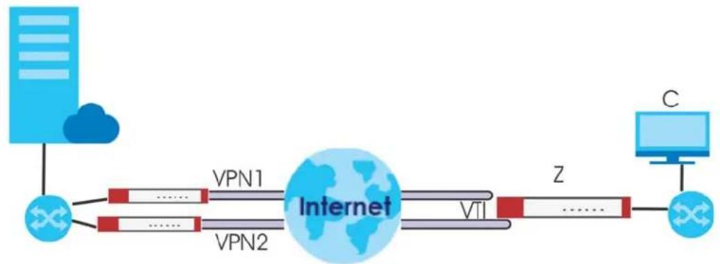
flowchart
graph LR
    A["Cloud"] --> B["Network"]
    B --> C["VPN1"]
    B --> D["VPN2"]
    C --> E["Internet"]
    D --> E
    E --> F["VTI"]
    F --> G["Z"]
    G --> H["C"]
9.12.1 Restrictions for IPSec Virtual Tunnel Interface
- IPv4 traffic only
- IPSec tunnel mode only. A shared keyword must not be configured when using tunnel mode.
- With a VTI VPN you do not add local or remote LANs to your VPN configuration.
- For a VTI VPN you should only have one local and one remote WAN.
• A dynamic peer is not supported - The IPSec VTI is limited to IP unicast and multicast traffic only.
9.12.2 VTI Screen
To access this screen, click Configuration > Network > Interface > VTI.
Figure 291 Configuration > Network > Interface > VTI
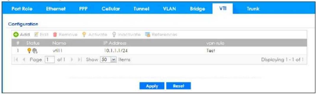
The following table describes the fields in this screen.
Table 149 Configuration > Network > Interface > VTI
| LABEL DESCRIPTION | |
| Configuration | |
| Add Click this to create a new entry. | |
| Edit | Double-click an entry or select it and click Edit to open a screen where you can modify the entry's settings. |
| Remove | To remove an entry, select it and click Remove. The Zyxel Device confirms you want to remove it before doing so. |
| Activate | To turn on an entry, select it and click Activate. |
| Inactivate | To turn off an entry, select it and click Inactivate. |
| References | Select an entry and click References to open a screen that shows which settings use the entry. |
| # This field is a sequential value, and it is not associated with any interface. | |
| Status This icon is lit when the entry is active and dimmed when the entry is inactive. | |
| Name This field displays the name of the VTI interface. | |
| IP Address | This field displays the current IP address of the virtual interface and subnet mask in bits. If the IP address is 0.0.0.0, the interface does not have an IP address yet. |
| vpn-rule | This shows the name of the associated IPSec VPN rule with VPN Tunnel Interface application scenario. |
| Apply | Click Apply to save your changes back to the Zyxel Device. |
| Reset | Click Reset to return the screen to its last-saved settings. |
9.12.3 VTI Add/Edit
This screen lets you configure IP address assignment and interface parameters for VTI.
Note: You should have created a VPN tunnel for a VPN Tunnel Interface scenario first.
To access this screen, click the Add or Edit icon in Network > Interface > VTI. The following screen appears.
Figure 292 Configuration > Network > Interface > VTI > Add
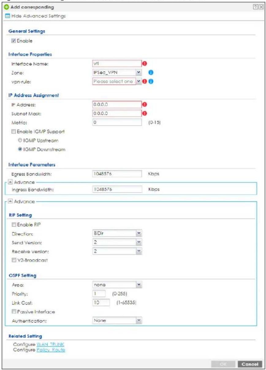
Each field is described in the table below.
Table 150 Configuration > Network > Interface > VTI > Add
| LABEL DESCRIPTION | |
| General Settings | |
| Enable Select this to enable VTI. Clear this to disable it. | |
| Interface Properties | |
| Interface Name | This field is read-only if you are editing an existing VPN tunnel interface. For a new VPN tunnel interface, enter the name of the VPN tunnel interface in vtix format, where x is a number from 0 to the maximum number of VPN connections allowed for this model. For example, enter vti10. |
| Zone | Select a zone. Make sure that the zone you select does not have traffic blocked by a security feature such as a security policy. |
| vpn-rule | You should have created a VPN tunnel first for aVPN Tunnel Interfacescenario. Select one of theVPN Tunnel Interfacescenario rules that you created. |
| IP Address Assignment | |
| IP Address | Enter the IP address for this interface. Please note that the IP address cannot conflict with any IP addresses that are already used. |
| Subnet Mask | Enter the subnet mask of this interface in dot decimal notation. The subnet mask indicates what part of the IP address is the same for all computers on the network. Please note that the subnet mask cannot conflict with any subnet masks that are already used. |
| Metric | Enter the priority of the gateway (if any) on this interface. The Zyxel Device decides which gateway to use based on this priority. The lower the number, the higher the priority. If two or more gateways have the same priority, the Zyxel Device uses the one that was configured first. |
| Enable IGMP Support | Select this to allow the Zyxel Device to act as an IGMP proxy for hosts connected on the IGMP downstream interface. |
| IGMP Upstream | EnableIGMP Upstreamon the interface which connects to a router running IGMP that is closer to the multicast server. |
| IGMP Downstream | EnableIGMP Downstreamon the interface which connects to the multicast hosts. |
| Interface Parameters | |
| Egress Bandwidth | Enter the maximum amount of traffic, in kilobits per second, the Zyxel Device can send through the interface to the network. Allowed values are 0 - 1048576. |
| Ingress Bandwidth | This is reserved for future use.Enter the maximum amount of traffic, in kilobits per second, the Zyxel Device can receive from the network through the interface. Allowed values are 0 - 1048576. |
| Connectivity Check | These fields appear when you select avpn-rule.The interface can regularly check the connection to the gateway you specified to make sure it is still available. You specify how often the interface checks the connection, how long to wait for a response before the attempt is a failure, and how many consecutive failures are required before the Zyxel Device stops routing to the gateway. The Zyxel Device resumes routing to the gateway the first time the gateway passes the connectivity check. |
| Enable Connectivity Check | Select this to turn on the connection check. |
| Check Method Select | Select the method that the gateway allows.Selecticmpto have the Zyxel Device regularly ping the gateway you specify to make sure it is still available.Selecttcpto have the Zyxel Device regularly perform a TCP handshake with the gateway you specify to make sure it is still available. |
| Check Period Enter | the number of seconds between connection check attempts. |
| Check Timeout | Enter the number of seconds to wait for a response before the attempt is a failure. |
| Check Fail Tolerance | Enter the number of consecutive failures before the Zyxel Device stops routing through the gateway. |
| Check this address | Select this to specify a domain name or IP address for the connectivity check. Enter that domain name or IP address in the field next to it. |
| Check Port | This field only displays when you set theCheck Method to tcp. Specify the port number to use for a TCP connectivity check. |
| RIP Setting | See Section 10.6 on page 445 for more information about RIP. |
| Enable RIP Select this to enable RIP in this interface. | |
| Direction | This field is effective when RIP is enabled. Select the RIP direction from the drop-down list box.BiDir - This interface sends and receives routing information.In-Only - This interface receives routing information.Out-Only - This interface sends routing information. |
| Send Version | This field is effective when RIP is enabled. Select the RIP version(s) used for sending RIP packets. Choices are 1, 2, and 1 and 2. |
| Receive Version | This field is effective when RIP is enabled. Select the RIP version(s) used for receiving RIP packets. Choices are 1, 2, and 1 and 2. |
| V2-Broadcast | This field is effective when RIP is enabled. Select this to send RIP-2 packets using subnet broadcasting; otherwise, the Zyxel Device uses multicasting. |
| OSPF Setting | See Section 10.7 on page 447 for more information about OSPF. |
| Area | Select the area in which this interface belongs. Select None to disable OSPF in this interface. |
| Priority | Enter the priority (between 0 and 255) of this interface when the area is looking for a Designated Router (DR) or Backup Designated Router (BDR). The highest-priority interface identifies the DR, and the second-highest-priority interface identifies the BDR. Set the priority to zero if the interface can not be the DR or BDR. |
| Link Cost | Enter the cost (between 1 and 65,535) to route packets through this interface. |
| Passive Interface | Select this to stop forwarding OSPF routing information from the selected interface. As a result, this interface only receives routing information. |
| Authentication | Select an authentication method, or disable authentication. To exchange OSPF routing information with peer border routers, you must use the same authentication method that they use. Choices are:Same-as-Area - use the default authentication method in the areaNone - disable authenticationText - authenticate OSPF routing information using a plain-text passwordMD5 - authenticate OSPF routing information using MD5 encryption |
| Text Authentication Key | This field is available if the Authentication is Text. Type the password for text authentication. The key can consist of alphanumeric characters and the underscore, and it can be up to 16 characters long. |
| MD5 Authentication ID | This field is available if the Authentication is MD5. Type the ID for MD5 authentication. The ID can be between 1 and 255. |
| MD5 Authentication Key | This field is available if the Authentication is MD5. Type the password for MD5 authentication. The password can consist of alphanumeric characters and the underscore, and it can be up to 16 characters long. |
| Related Setting | |
| Configure WAN TRUNK | Click WAN TRUNK to go to a screen where you can configure the interface as part of a WAN trunk for load balancing. |
| Configure Policy Route | Click Policy Route to go to the screen where you can manually configure a policy route to associate traffic with this bridge interface. |
| OK | Click OK to save your changes back to the Zyxel Device. |
| Cancel | Click Cancel to exit this screen without saving. |
9.13 Trunk Overview
Use trunks for WAN traffic load balancing to increase overall network throughput and reliability. Load balancing divides traffic loads between multiple interfaces. This allows you to improve quality of service and maximize bandwidth utilization for multiple ISP links.
Maybe you have two Internet connections with different bandwidths. You could set up a trunk that uses spillover or weighted round robin load balancing so time-sensitive traffic (like video) usually goes through the higher-bandwidth interface. For other traffic, you might want to use least load first load balancing to even out the distribution of the traffic load.
Suppose ISP A has better connections to Europe while ISP B has better connections to Australia. You could use policy routes and trunks to have traffic for your European branch office primarily use ISP A and traffic for your Australian branch office primarily use ISP B.
Or maybe one of the Zyxel Device's interfaces is connected to an ISP that is also your Voice over IP (VoIP) service provider. You can use policy routing to send the VoIP traffic through a trunk with the interface connected to the VoIP service provider set to active and another interface (connected to another ISP) set to passive. This way VoIP traffic goes through the interface connected to the VoIP service provider whenever the interface's connection is up.
- Use the Trunk summary screen (Section 9.14 on page 422) to view the list of configured trunks and which load balancing algorithm each trunk uses.
- Use the Add Trunk screen (Section 9.14.1 on page 423) to configure the member interfaces for a trunk and the load balancing algorithm the trunk uses.
- Use the Add System Default screen (Section 9.14.2 on page 425) to configure the load balancing algorithm for the system default trunk.
9.13.1 What You Need to Know
- Add WAN interfaces to trunks to have multiple connections share the traffic load.
- If one WAN interface's connection goes down, the Zyxel Device sends traffic through another member of the trunk.
- For example, you connect one WAN interface to one ISP and connect a second WAN interface to a second ISP. The Zyxel Device balances the WAN traffic load between the connections. If one interface's connection goes down, the Zyxel Device can automatically send its traffic through another interface.
You can also use trunks with policy routing to send specific traffic types through the best WAN interface for that type of traffic.
- If that interface's connection goes down, the Zyxel Device can still send its traffic through another interface.
- You can define multiple trunks for the same physical interfaces.
1 LAN user A logs into server B on the Internet. The Zyxel Device uses wan1 to send the request to server B.
2 The Zyxel Device is using active/active load balancing. So when LAN user A tries to access something on the server, the request goes out through wan2.
3 The server finds that the request comes from wan2's IP address instead of wan1's IP address and rejects the request.
If link sticking had been configured, the Zyxel Device would have still used wan1 to send LAN user A's request to the server and server would have given the user A access.
Load Balancing Algorithms
The following sections describe the load balancing algorithms the Zyxel Device can use to decide which interface the traffic (from the LAN) should use for a session. In the load balancing section, a session may refer to normal connection-oriented, UDP or SNMP2 traffic. The available bandwidth you configure on the Zyxel Device refers to the actual bandwidth provided by the ISP and the measured bandwidth refers to the bandwidth an interface is currently using.
Least Load First
The least load first algorithm uses the current (or recent) outbound bandwidth utilization of each trunk member interface as the load balancing index(es) when making decisions about to which interface a new session is to be distributed. The outbound bandwidth utilization is defined as the measured outbound throughput over the available outbound bandwidth.
Here the Zyxel Device has two WAN interfaces connected to the Internet. The configured available outbound bandwidths for WAN 1 and WAN 2 are 512K and 256K respectively.
Figure 293 Load Balancing Least Load First Example
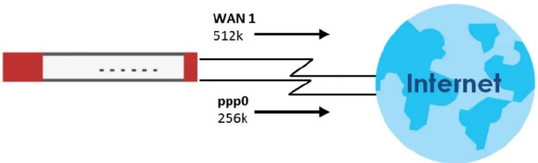
flowchart
graph LR
    A["..."] --> B["WAN 1\n512k"]
    C["ppp0\n256k"] --> D["Internet"]
The outbound bandwidth utilization is used as the load balancing index. In this example, the measured (current) outbound throughput of WAN 1 is 412K and WAN 2 is 198K. The Zyxel Device calculates the load balancing index as shown in the table below.
Since WAN 2 has a smaller load balancing index (meaning that it is less utilized than WAN 1), the Zyxel Device will send the subsequent new session traffic through WAN 2.
Table 151 Least Load First Example
| INTERFACE | OUTBOUND | LOAD BALANCING INDEX (M/A) | |
| AVAILABLE (A) MEASURED (M) | |||
| WAN 1 512 K 412 K 0.8 | |||
| WAN 2 256 K 198 K 0.77 | |||
Weighted Round Robin
Round Robin scheduling services queues on a rotating basis and is activated only when an interface has more traffic than it can handle. A queue is given an amount of bandwidth irrespective of the incoming
traffic on that interface. This queue then moves to the back of the list. The next queue is given an equal amount of bandwidth, and then moves to the end of the list; and so on, depending on the number of queues being used. This works in a looping fashion until a queue is empty.
The Weighted Round Robin (WRR) algorithm is best suited for situations when the bandwidths set for the two WAN interfaces are different. Similar to the Round Robin (RR) algorithm, the Weighted Round Robin (WRR) algorithm sets the Zyxel Device to send traffic through each WAN interface in turn. In addition, the WAN interfaces are assigned weights. An interface with a larger weight gets more chances to transmit traffic than an interface with a smaller weight.
For example, in the figure below, the configured available bandwidth of WAN1 is 1M and WAN2 is 512K. You can set the Zyxel Device to distribute the network traffic between the two interfaces by setting the weight of wan1 and wan2 to 2 and 1 respectively. The Zyxel Device assigns the traffic of two sessions to wan1 and one session's traffic to wan2 in each round of 3 new sessions.
Figure 294 Weighted Round Robin Algorithm Example
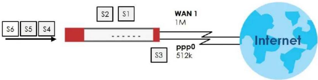
flowchart
graph LR
    S6 --> S4
    S5 --> S4
    S4 --> S2
    S2 --> S1
    S1 --> WAN1["1M"]
    WAN1 --> S3
    S3 --> PPP0["512k"]
    PPP0 --> Internet
Spillover
The spillover load balancing algorithm sends network traffic to the first interface in the trunk member list until the interface's maximum allowable load is reached, then sends the excess network traffic of new sessions to the next interface in the trunk member list. This continues as long as there are more member interfaces and traffic to be sent through them.
Suppose the first trunk member interface uses an unlimited access Internet connection and the second is billed by usage. Spillover load balancing only uses the second interface when the traffic load exceeds the threshold on the first interface. This fully utilizes the bandwidth of the first interface to reduce Internet usage fees and avoid overloading the interface.
In this example figure, the upper threshold of the first interface is set to 800K. The Zyxel Device sends network traffic of new sessions that exceed this limit to the secondary WAN interface.
Figure 295 Spillover Algorithm Example
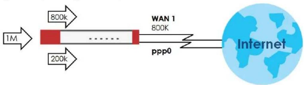
flowchart
graph LR
    A["1M"] --> B["800k"]
    A --> C["200k"]
    B --> D["WAN 1 800K"]
    C --> D
    D --> E["ppp0"]
    E --> F["Internet"]
9.14 The Trunk Summary Screen
Click Configuration > Network > Interface > Trunk to open the Trunk screen. The Trunk Summary screen lists the configured trunks and the load balancing algorithm that each is configured to use.
Figure 296 Configuration > Network > Interface > Trunk
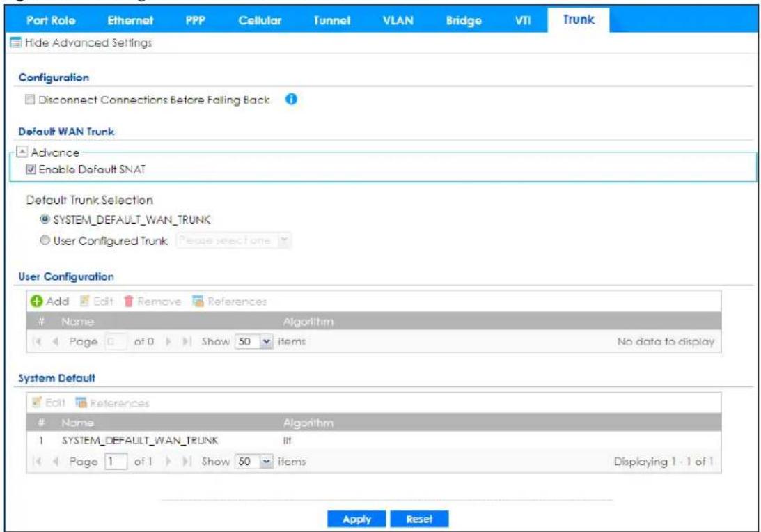
The following table describes the items in this screen.
Table 152 Configuration > Network > Interface > Trunk
| LABEL DESCRIPTION | |
| Show Advanced Settings / Hide Advanced Settings | Click this button to display a greater or lesser number of configuration fields. |
| Configuration | Configure what to do with existing passive mode interface connections when an interface set to active mode in the same trunk comes back up. |
| Disconnect Connections Before Falling Back | Select this to terminate existing connections on an interface which is set to passive mode when any interface set to active mode in the same trunk comes back up. |
| Enable Default SNAT | Select this to have the Zyxel Device use the IP address of the outgoing interface as the source IP address of the packets it sends out through its WAN trunks. The Zyxel Device automatically adds SNAT settings for traffic it routes from internal interfaces to external interfaces. |
| Default Trunk Selection | Select whether the Zyxel Device is to use the default system WAN trunk or one of the user configured WAN trunks as the default trunk for routing traffic from internal interfaces to external interfaces. |
| User Configuration / System Default | The Zyxel Device automatically adds all external interfaces into the pre-configured system default SYSTEM_DEFAULT_WAN_TRUNK. You cannot delete it. You can create your own User Configuration trunks and customize the algorithm, member interfaces and the active/passive mode. |
| Add Click this to create a new user-configured trunk. | |
| Edit | Double-click an entry or select it and click Edit to open a screen where you can modify the entry's settings. |
| Remove | To remove a user-configured trunk, select it and click Remove. The Zyxel Device confirms you want to remove it before doing so. |
| References | Select an entry and click References to open a screen that shows which settings use the entry. See Section 9.5.4 on page 349 for an example. |
| # This field is a sequential value, and it is not associated with any interface. | |
| Name This field displays the label that you specified to identify the trunk. | |
| Algorithm | This field displays the load balancing method the trunk is set to use. |
| Apply Click this button to save your changes to the Zyxel Device. | |
| Reset Click this button to return the screen to its last-saved settings. | |
9.14.1 Configuring a User-Defined Trunk
Click Configuration > Network > Interface > Trunk, in the User Configuration table click the Add (or Edit) icon to open the following screen. Use this screen to create or edit a WAN trunk entry.
Figure 297 Configuration > Network > Interface > Trunk > Add (or Edit)
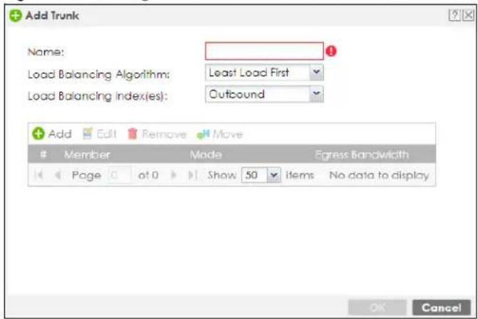
Each field is described in the table below.
Table 153 Configuration > Network > Interface > Trunk > Add (or Edit)
| LABEL DESCRIPTION | |
| Name | This is read-only if you are editing an existing trunk. When adding a new trunk, enter a descriptive name for this trunk. You may use 1-31 alphanumeric characters, underscores (_, or dashes (-), but the first character cannot be a number. This value is case-sensitive. |
| Load Balancing Algorithm | Select a load balancing method to use from the drop-down list box.SelectWeighted Round Robinto balance the traffic load between interfaces based on their respective weights. An interface with a larger weight gets more chances to transmit traffic than an interface with a smaller weight. For example, if the weight ratio of wan1 and wan2 interfaces is 2:1, the Zyxel Device chooses wan1 for 2 sessions' traffic and wan2 for 1 session's traffic in each round of 3 new sessions.SelectLeast Load Firstto send new session traffic through the least utilized trunk member.SelectSpilloverto send network traffic through the first interface in the group member list until there is enough traffic that the second interface needs to be used (and so on). |
| Load Balancing Index(es) | This field is available if you selected to use theLeast Load FirstorSpillovermethod.SelectOutbound, Inbound, orOutbound + Inboundto set the traffic to which the Zyxel Device applies the load balancing method. Outbound means the traffic traveling from an internal interface (ex. LAN) to an external interface (ex. WAN). Inbound means the opposite. |
| The table lists the trunk's member interfaces. You can add, edit, remove, or move entries for user configured trunks. | |
| Add | Click this to add a member interface to the trunk. Select an interface and clickAddto add a new member interface after the selected member interface. |
| Edit | Select an entry and clickEditto modify the entry's settings. |
| Remove | To remove a member interface, select it and clickRemove.The Zyxel Device confirms you want to remove it before doing so. |
| Move | To move an interface to a different number in the list, click theMoveicon. In the field that appears, specify the number to which you want to move the interface. |
| # | This column displays the priorities of the group's interfaces. The order of the interfaces in the list is important since they are used in the order they are listed. |
| Member | Click this table cell and select an interface to be a group member.If you select an interface that is part of another Ethernet interface, the Zyxel Device does not send traffic through the interface as part of the trunk. For example, if you have physical port 5 in the ge2 representative interface, you must select interface ge2 in order to send traffic through port 5 as part of the trunk. If you select interface ge5 as a member here, the Zyxel Device will not send traffic through port 5 as part of the trunk. |
| Mode | Click this table cell and selectActiveto have the Zyxel Device always attempt to use this connection.SelectPassiveto have the Zyxel Device only use this connection when all of the connections set to active are down. You can only set one of a group's interfaces to passive mode. |
| Weight | This field displays with the weighted round robin load balancing algorithm. Specify the weight (1~10) for the interface. The weights of the different member interfaces form a ratio. This ratio determines how much traffic the Zyxel Device assigns to each member interface. The higher an interface's weight is (relative to the weights of the interfaces), the more sessions that interface should handle. |
| Ingress Bandwidth This is reserved for future use.This field displays with the least load first load balancing algorithm. It displays the maximum number of kilobits of data the Zyxel Device is to allow to come in through the interface per second.Note: You can configure the bandwidth of an interface on the corresponding interface edit screen. | |
| Egress Bandwidth | This field displays with the least load first or spillover load balancing algorithm. It displays the maximum number of kilobits of data the Zyxel Device is to send out through the interface per second.Note: You can configure the bandwidth of an interface on the corresponding interface edit screen. |
| Spillover | This field displays with the spillover load balancing algorithm. Specify the maximum bandwidth of traffic in kilobits per second (1~1048576) to send out through the interface before using another interface. When this spillover bandwidth limit is exceeded, the Zyxel Device sends new session traffic through the next interface. The traffic of existing sessions still goes through the interface on which they started.The Zyxel Device uses the group member interfaces in the order that they are listed. |
| OK | Click OK to save your changes back to the Zyxel Device. |
| Cancel | Click Cancel to exit this screen without saving. |
9.14.2 Configuring the System Default Trunk
on the Configuration > Network > Interface > Trunk screen and the System Default section, select the default trunk entry and click Edit to open the following screen. Use this screen to change the load balancing algorithm and view the bandwidth allocations for each member interface.
Note: The available bandwidth is allocated to each member interface equally and is not allowed to be changed for the default trunk.
Figure 298 Configuration > Network > Interface > Trunk > Edit (System Default)
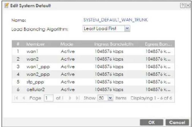
Each field is described in the table below.
Table 154 Configuration > Network > Interface > Trunk > Edit (System Default)
| LABEL DESCRIPTION | |
| Name This field displays | the name of the selected system default trunk. |
| Load Balancing Algorithm | Select the load balancing method to use for the trunk.SelectWeighted Round Robinto balance the traffic load between interfaces based on their respective weights. An interface with a larger weight gets more chances to transmit traffic than an interface with a smaller weight. For example, if the weight ratio of wan1 and wan2 interfaces is 2:1, the Zyxel Device chooses wan1 for 2 sessions' traffic and wan2 for 1 session's traffic in each round of 3 new sessions.SelectLeast Load Firstto send new session traffic through the least utilized trunk member.SelectSpilloverto send network traffic through the first interface in the group member list until there is enough traffic that the second interface needs to be used (and so on). |
| The table lists the trunk's member interfaces. This table is read-only. | |
| # | This column displays the priorities of the group's interfaces. The order of the interfaces in the list is important since they are used in the order they are listed. |
| Member This column displays the name of the member interfaces. | |
| Mode | This field displaysActiveif the Zyxel Device always attempt to use this connection.This field displaysPassiveif the Zyxel Device only use this connection when all of the connections set to active are down. Only one of a group's interfaces can be set to passive mode. |
| Weight | This field displays with the weighted round robin load balancing algorithm. Specify the weight (1~10) for the interface. The weights of the different member interfaces form a ratio.s |
| Ingress Bandwidth This is reserved for future use.This field displays with the least load first load balancing algorithm. It displays the maximum number of kilobits of data the Zyxel Device is to allow to come in through the interface per second. | |
| Egress Bandwidth | This field displays with the least load first or spillover load balancing algorithm. It displays the maximum number of kilobits of data the Zyxel Device is to send out through the interface per second. |
| Spillover | This field displays with the spillover load balancing algorithm. Specify the maximum bandwidth of traffic in kilobits per second (1~1048576) to send out through the interface before using another interface. When this spillover bandwidth limit is exceeded, the Zyxel Device sends new session traffic through the next interface. The traffic of existing sessions still goes through the interface on which they started.The Zyxel Device uses the group member interfaces in the order that they are listed. |
| OK | ClickOKto save your changes back to the Zyxel Device. |
| Cancel | ClickCancelto exit this screen without saving. |
9.15 Example: WAN Trunk Failover
In this example, you have two WAN connections: one fiber which is always active, and one DSL which becomes active only if the fiber WAN1 connection fails.
1 First arrange a connectivity check for WAN1 (fiber). Set up the ICMP connectivity check (ping) in Configuration > Network > Interface > Ethernet > WAN1 > Edit.
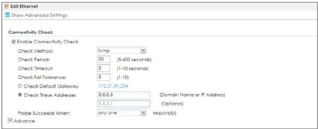
2 Then go to Configuration > Network > Interface > Trunk > User Configuration > Add to configure your own trunk connection. Add the WAN ports with one as Passive, then select Spillover in Load Balancing Algorithm, Outbound for the Load Balancing Index.
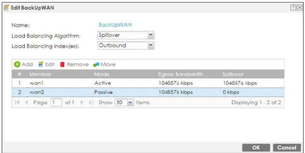
If WAN1 fails, then the Zyxel Device automatically uses the WAN2 connection and an alert report will be sent to the administer. When WAN1 is available again, the Zyxel Device returns to using WAN1.
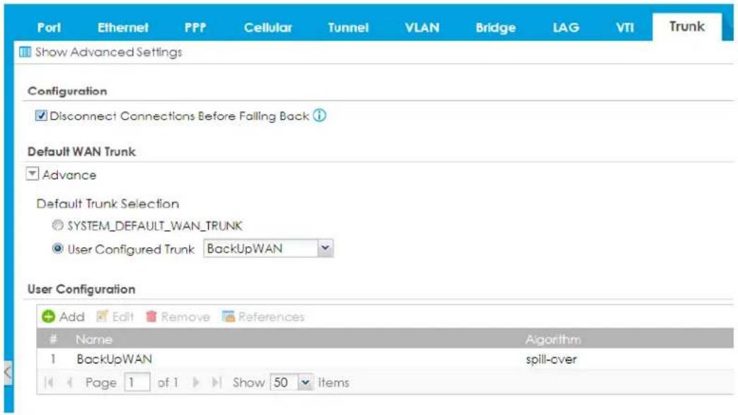
9.16 Example: Trunk Tagged VLAN Traffic to a Switch
Configure VLAN on the Zyxel Device and the connected VLAN switch so as a computer can access VLAN10 as shown in the following example:
Zyxel Device
• LAN1 192.168.1.1/24
• VLAN10, ge3/10, 192.168.10.1/24
• VLAN20, ge3/20, 192.168.20.2/24
Switch
- port 1 Tx VLAN10, VLAN20 PVID1 -> connect this port to Zyxel Device interface ge3
- port 2 Ux VLAN10 -> connect this port to a computer
9.17 Interface Technical Reference
Here is more detailed information about interfaces on the Zyxel Device.
IP Address Assignment
Most interfaces have an IP address and a subnet mask. This information is used to create an entry in the routing table.
Figure 299 Example: Entry in the Routing Table Derived from Interfaces
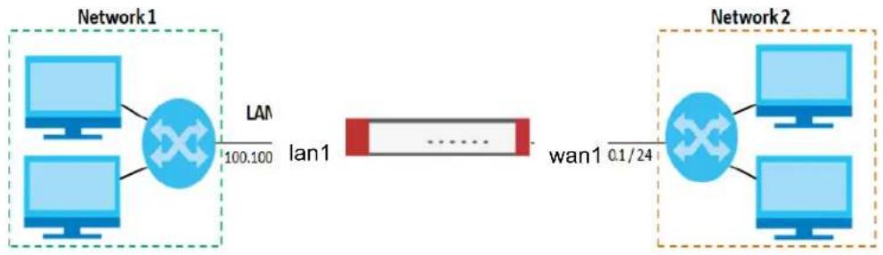
flowchart
graph LR
    subgraph Network1
        A["Computer"] --> B["Switch"]
        C["Computer"] --> B
        B -->|LAN 100.100| D["lan1"]
    end
    subgraph Network2
        E["Computer"] --> F["Switch"]
        G["Computer"] --> F
        F -->|0.1/24| D
    end
Table 155 Example: Routing Table Entries for Interfaces
| IP ADDRESS(ES) DESTINATION | |
| 100.100.1.1/16 lan1 | |
| 200.200.200.1/24 wan1 | |
For example, if the Zyxel Device gets a packet with a destination address of 100.100.25.25, it routes the packet to interface lan1. If the Zyxel Device gets a packet with a destination address of 200.200.200.200, it routes the packet to interface wan1.
In most interfaces, you can enter the IP address and subnet mask manually. In PPPoE/PPTP/L2TP interfaces, however, the subnet mask is always 255.255.255.255 because it is a point-to-point interface. For these interfaces, you can only enter the IP address.
In many interfaces, you can also let the IP address and subnet mask be assigned by an external DHCP server on the network. In this case, the interface is a DHCP client. Virtual interfaces, however, cannot be DHCP clients. You have to assign the IP address and subnet mask manually.
In general, the IP address and subnet mask of each interface should not overlap, though it is possible for this to happen with DHCP clients.
In the example above, if the Zyxel Device gets a packet with a destination address of 5.5.5.5, it might not find any entries in the routing table. In this case, the packet is dropped. However, if there is a default router to which the Zyxel Device should send this packet, you can specify it as a gateway in one of the interfaces. For example, if there is a default router at 200.200.200.100, you can create a gateway at 200.200.200.100 on ge2. In this case, the Zyxel Device creates the following entry in the routing table.
Table 156 Example: Routing Table Entry for a Gateway
| IP ADDRESS(ES) DESTINATION | |
| 0.0.0.0/0 200.200.200.100 | |
The gateway is an optional setting for each interface. If there is more than one gateway, the Zyxel Device uses the gateway with the lowest metric, or cost. If two or more gateways have the same metric, the Zyxel Device uses the one that was set up first (the first entry in the routing table). In PPPoE/PPTP/L2TP interfaces, the other computer is the gateway for the interface by default. In this case, you should specify the metric.
If the interface gets its IP address and subnet mask from a DHCP server, the DHCP server also specifies the gateway, if any.
Interface Parameters
The Zyxel Device restricts the amount of traffic into and out of the Zyxel Device through each interface.
- Egress bandwidth sets the amount of traffic the Zyxel Device sends out through the interface to the network.
- Ingress bandwidth sets the amount of traffic the Zyxel Device allows in through the interface from the network. At the time of writing, the Zyxel Device does not support ingress bandwidth management.
If you set the bandwidth restrictions very high, you effectively remove the restrictions.
The Zyxel Device also restricts the size of each data packet. The maximum number of bytes in each packet is called the maximum transmission unit (MTU). If a packet is larger than the MTU, the Zyxel Device divides it into smaller fragments. Each fragment is sent separately, and the original packet is re-assembled later. The smaller the MTU, the more fragments sent, and the more work required to re-assemble packets correctly. On the other hand, some communication channels, such as Ethernet over ATM, might not be able to handle large data packets.
DHCP Settings
Dynamic Host Configuration Protocol (DHCP, RFC 2131, RFC 2132) provides a way to automatically set up and maintain IP addresses, subnet masks, gateways, and some network information (such as the IP addresses of DNS servers) on computers on the network. This reduces the amount of manual configuration you have to do and usually uses available IP addresses more efficiently.
In DHCP, every network has at least one DHCP server. When a computer (a DHCP client) joins the network, it submits a DHCP request. The DHCP servers get the request; assign an IP address; and provide the IP address, subnet mask, gateway, and available network information to the DHCP client. When the DHCP client leaves the network, the DHCP servers can assign its IP address to another DHCP client.
In the Zyxel Device, some interfaces can provide DHCP services to the network. In this case, the interface can be a DHCP relay or a DHCP server.
As a DHCP relay, the interface routes DHCP requests to DHCP servers on different networks. You can specify more than one DHCP server. If you do, the interface routes DHCP requests to all of them. It is possible for an interface to be a DHCP relay and a DHCP client simultaneously.
As a DHCP server, the interface provides the following information to DHCP clients.
- IP address - If the DHCP client's MAC address is in the Zyxel Device's static DHCP table, the interface assigns the corresponding IP address. If not, the interface assigns IP addresses from a pool, defined by the starting address of the pool and the pool size.
Table 157 Example: Assigning IP Addresses from a Pool
| START IP ADDRESS POOL SIZE RANGE OF ASSIGNED IP ADDRESS | |
| 50.50.50.33 5 50.50.50.33 - 50.50.50.37 | |
| 75.75.75.1 200 75.75.75.1 - 75.75.75.200 | |
| 99.99.1.1 1023 99.99.1.1 - 99.99.4.255 | |
| 120.120.120.100 100 120.120.120.100 - 120.120.120.199 | |
The Zyxel Device cannot assign the first address (network address) or the last address (broadcast address) on the subnet defined by the interface's IP address and subnet mask. For example, in the first entry, if the subnet mask is 255.255.255.0, the Zyxel Device cannot assign 50.50.50.0 or 50.50.50.255. If the subnet mask is 255.255.0.0, the Zyxel Device cannot assign 50.50.0.0 or 50.50.255.255. Otherwise, it can assign every IP address in the range, except the interface's IP address.
If you do not specify the starting address or the pool size, the interface the maximum range of IP addresses allowed by the interface's IP address and subnet mask. For example, if the interface's IP address is 9.9.9.1 and subnet mask is 255.255.255.0, the starting IP address in the pool is 9.9.9.2, and the pool size is 253.
- Subnet mask - The interface provides the same subnet mask you specify for the interface. See IP Address Assignment on page 428.
- Gateway - The interface provides the same gateway you specify for the interface. See IP Address Assignment on page 428.
- DNS servers - The interface provides IP addresses for up to three DNS servers that provide DNS services for DHCP clients. You can specify each IP address manually (for example, a company's own DNS server), or you can refer to DNS servers that other interfaces received from DHCP servers (for example, a DNS server at an ISP). These other interfaces have to be DHCP clients.
It is not possible for an interface to be the DHCP server and a DHCP client simultaneously.
WINS
WINS (Windows Internet Naming Service) is a Windows implementation of NetBIOS Name Server (NBNS) on Windows. It keeps track of NetBIOS computer names. It stores a mapping table of your network's computer names and IP addresses. The table is dynamically updated for IP addresses assigned by DHCP. This helps reduce broadcast traffic since computers can query the server instead of broadcasting a request for a computer name's IP address. In this way WINS is similar to DNS, although WINS does not use a hierarchy (unlike DNS). A network can have more than one WINS server. Samba can also serve as a WINS server.
PPPoE/ PPTP/ L2TP Overview
Point-to-Point Protocol over Ethernet (PPPoE, RFC 2516) and Point-to-Point Tunneling Protocol (PPTP, RFC 2637) are usually used to connect two computers over phone lines or broadband connections. PPPoE is often used with cable modems and DSL connections. It provides the following advantages:
- The access and authentication method works with existing systems, including RADIUS.
- You can access one of several network services. This makes it easier for the service provider to offer the service
- PPPoE does not usually require any special configuration of the modem.
PPTP is used to set up virtual private networks (VPN) in unsecured TCP/IP environments. It sets up two sessions.
1 The first one runs on TCP port 1723. It is used to start and manage the second one.
2 The second one uses Generic Routing Encapsulation (GRE, RFC 2890) to transfer information between the computers.
PPTP is convenient and easy-to-use, but you have to make sure that firewalls support both PPTP sessions.
Layer 2 Tunneling Protocol (L2TP) was taken from PPTP of Microsoft and Cisco's L2F (Layer 2 Forwarding technology), so LT2P combines PPTP's control and runs over a faster transport protocol, UDP, although it may be a bit more complicated to set up.
It supports up to 256 bit session keys using the IPSec protocol. When security is a priority, L2TP is a good option as it requires certificates unlike PPTP.
It uses the following ports: UDP 500, Protocol 50, UDP 1701 and UDP 4500.
CHAPTER 10 Routing
10.1 Policy and Static Routes Overview
Use policy routes and static routes to override the Zyxel Device's default routing behavior in order to send packets through the appropriate interface or VPN tunnel.
For example, the next figure shows a computer (A) connected to the Zyxel Device's LAN interface. The Zyxel Device routes most traffic from A to the Internet through the Zyxel Device's default gateway (R1). You create one policy route to connect to services offered by your ISP behind router R2. You create another policy route to communicate with a separate network behind another router (R3) connected to the LAN.
Figure 300 Example of Policy Routing Topology
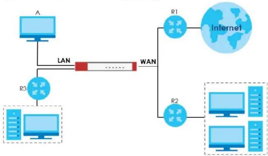
flowchart
graph TD
    A["A"] -->|LAN| LAN
    LAN -->|WAN| R1["R1"]
    LAN -->|WAN| R2["R2"]
    LAN -->|WAN| R3["R3"]
    R1 --> Internet["Internet"]
    R2 --> Internet
    R3 --> Internet
Note: You can generally just use policy routes. You only need to use static routes if you have a large network with multiple routers where you use RIP or OSPF to propagate routing information to other routers.
10.1.1 What You Can Do in this Chapter
- Use the Policy Route screens (see Section 10.2 on page 435) to list and configure policy routes.
- Use the Static Route screens (see Section 10.3 on page 442) to list and configure static routes.
10.1.2 What You Need to Know
Policy Routing
Traditionally, routing is based on the destination address only and the Zyxel Device takes the shortest path to forward a packet. IP Policy Routing (IPPR) provides a mechanism to override the default routing behavior and alter the packet forwarding based on the policy defined by the network administrator. Policy-based routing is applied to incoming packets on a per interface basis, prior to the normal routing.
How You Can Use Policy Routing
- Source-Based Routing – Network administrators can use policy-based routing to direct traffic from different users through different connections.
- Bandwidth Shaping – You can allocate bandwidth to traffic that matches routing policies and prioritize traffic (however the application patrol's bandwidth management is more flexible and recommended for TCP and UDP traffic). You can also use policy routes to manage other types of traffic (like ICMP traffic) and send traffic through VPN tunnels.
Note: Bandwidth management in policy routes has priority over application patrol bandwidth management.
- Cost Savings – IPPR allows organizations to distribute interactive traffic on high-bandwidth, high-cost paths while using low-cost paths for batch traffic.
- Load Sharing – Network administrators can use IPPR to distribute traffic among multiple paths.
- NAT - The Zyxel Device performs NAT by default for traffic going to or from the WAN interfaces. A routing policy's SNAT allows network administrators to have traffic received on a specified interface use a specified IP address as the source IP address.
Note: The Zyxel Device automatically uses SNAT for traffic it routes from internal interfaces to external interfaces. For example LAN to WAN traffic.
Static Routes
The Zyxel Device usually uses the default gateway to route outbound traffic from computers on the LAN to the Internet. To have the Zyxel Device send data to devices not reachable through the default gateway, use static routes. Configure static routes if you need to use RIP or OSPF to propagate the routing information to other routers. See Chapter 10 on page 444 for more on RIP and OSPF.
Policy Routes Versus Static Routes
- Policy routes are more flexible than static routes. You can select more criteria for the traffic to match and can also use schedules, NAT, and bandwidth management.
- Policy routes are only used within the Zyxel Device itself. Static routes can be propagated to other routers using RIP or OSPF.
- Policy routes take priority over static routes. If you need to use a routing policy on the Zyxel Device and propagate it to other routers, you could configure a policy route and an equivalent static route.
DiffServ
QoS is used to prioritize source-to-destination traffic flows. All packets in the same flow are given the same priority. CoS (class of service) is a way of managing traffic in a network by grouping similar types of
traffic together and treating each type as a class. You can use CoS to give different priorities to different packet types.
DiffServ (Differentiated Services) is a class of service (CoS) model that marks packets so that they receive specific per-hop treatment at DiffServ-compliant network devices along the route based on the application types and traffic flow. Packets are marked with DiffServ Code Points (DSCPs) indicating the level of service desired. This allows the intermediary DiffServ-compliant network devices to handle the packets differently depending on the code points without the need to negotiate paths or remember state information for every flow. In addition, applications do not have to request a particular service or give advanced notice of where the traffic is going.
DSCP Marking and Per-Hop Behavior
DiffServ defines a new DS (Differentiated Services) field to replace the Type of Service (TOS) field in the IP header. The DS field contains a 2-bit unused field and a 6-bit DSCP field which can define up to 64 service levels. The following figure illustrates the DS field.
DSCP (6 bits) Unused (2 bits)
DSCP is backward compatible with the three precedence bits in the ToS octet so that non-DiffServ compliant, ToS-enabled network device will not conflict with the DSCP mapping.
The DSCP value determines the forwarding behavior, the PHB (Per-Hop Behavior), that each packet gets across the DiffServ network. Based on the marking rule, different kinds of traffic can be marked for different kinds of forwarding. Resources can then be allocated according to the DSCP values and the configured policies.
10.2 Policy Route Screen
Click Configuration > Network > Routing to open the Policy Route screen. Use this screen to see the configured policy routes and turn policy routing based bandwidth management on or off.
A policy route defines the matching criteria and the action to take when a packet meets the criteria. The action is taken only when all the criteria are met. The criteria can include the user name, source address and incoming interface, destination address, schedule, IP protocol (ICMP, UDP, TCP, etc.) and port.
The actions that can be taken include:
- Routing the packet to a different gateway, outgoing interface, VPN tunnel, or trunk.
- Limiting the amount of bandwidth available and setting a priority for traffic.
IPPR follows the existing packet filtering facility of RAS in style and in implementation.
If you enabled IPv6 in the Configuration > System > IPv6 screen, you can also configure policy routes used for your IPv6 networks on this screen.
Click on the icons to go to the OneSecurity website where there is guidance on configuration walkthroughs, troubleshooting, and other information.
Figure 301 Configuration > Network > Routing > Policy Route
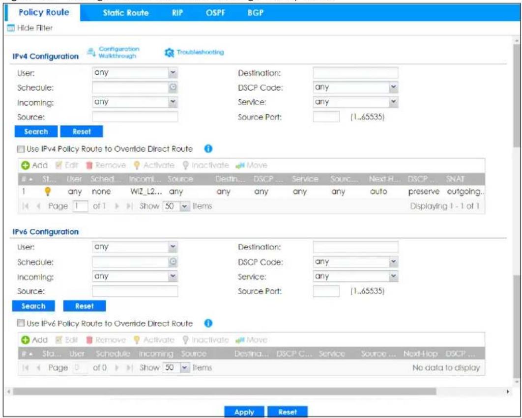
The following table describes the labels in this screen.
Table 158 Configuration > Network > Routing > Policy Route
| LABEL DESCRIPTION | |
| Show Filter / Hide Filter | Click this button to display a greater or lesser number of configuration fields. |
| IPv4 Configuration / IPv6 Configuration | Use theIPv4 Configurationsection for IPv4 network settings. Use theIPv6 Configurationsection for IPv6 network settings if you connect your Zyxel Device to an IPv6 network. Both sections have similar fields as described below. |
| Use IPv4/IPv6 Policy Route to Override Direct Route | Select this to have the Zyxel Device forward packets that match a policy route according to the policy route instead of sending the packets directly to a connected network. |
| Add | Click this to create a new entry. Select an entry and clickAddto create a new entry after the selected entry. |
| Edit | Double-click an entry or select it and clickEditto open a screen where you can modify the entry's settings. |
| Remove | To remove an entry, select it and clickRemove. The Zyxel Device confirms you want to remove it before doing so. |
| Activate | To turn on an entry, select it and clickActivate. |
| Inactivate | To turn off an entry, select it and clickInactivate. |
| Move | To change a rule's position in the numbered list, select the rule and clickMoveto display a field to type a number for where you want to put that rule and press [ENTER] to move the rule to the number that you typed.The ordering of your rules is important as they are applied in order of their numbering. |
| # This is the number of an individual policy route. | |
| Status | This icon is lit when the entry is active, red when the next hop's connection is down, and dimmed when the entry is inactive. |
| User | This is the name of the user (group) object from which the packets are sent.anymeans all users. |
| Schedule | This is the name of the schedule object. none means the route is active at all times if enabled. |
| Incoming This is the interface on which the packets are received. | |
| Source | This is the name of the source IP address (group) object, including geographic address and FQDN (group) objects.anymeans all IP addresses. |
| Destination | This is the name of the destination IP address (group) object, including geographic and FQDN (group) address objects.anymeans all IP addresses. |
| DSCP Code | This is the DSCP value of incoming packets to which this policy route applies.anymeans all DSCP values or no DSCP marker.defaultmeans traffic with a DSCP value of 0. This is usually best effort trafficThe “af” entries stand for Assured Forwarding. The number following the “af” identifies one of four classes and one of three drop preferences. See Assured Forwarding (AF) PHB for DiffServ for more details. |
| Service | This is the name of the service object.anymeans all services. |
| Source Port | This is the name of a service object. The Zyxel Device applies the policy route to the packets sent from the corresponding service port.anymeans all service ports. |
| Next-Hop | This is the next hop to which packets are directed. It helps forward packets to their destinations and can be a router, VPN tunnel, outgoing interface or trunk. |
| DSCP Marking | This is how the Zyxel Device handles the DSCP value of the outgoing packets that match this route. If this field displays a DSCP value, the Zyxel Device applies that DSCP value to the route's outgoing packets.preservemeans the Zyxel Device does not modify the DSCP value of the route's outgoing packets.defaultmeans the Zyxel Device sets the DSCP value of the route's outgoing packets to 0.The “af” choices stand for Assured Forwarding. The number following the “af” identifies one of four classes and one of three drop preferences. See Assured Forwarding (AF) PHB for DiffServ for more details. |
| SNAT This is the source IP address that the route uses.It displays none if the Zyxel Device does not perform NAT for this route. | |
| Apply | Click Apply to save your changes back to the Zyxel Device. |
| Reset | Click Reset to return the screen to its last-saved settings. |
10.2.1 Policy Route Edit Screen
Click Configuration > Network > Routing to open the Policy Route screen. Then click the Add or Edit icon in the IPv4 Configuration or IPv6 Configuration section. The Add Policy Route or Policy Route Edit screen opens. Use this screen to configure or edit a policy route. Both IPv4 and IPv6 policy route have similar settings except the Address Translation (SNAT) settings.
Figure 302 Configuration > Network > Routing > Policy Route > Add/Edit (IPv4 Configuration)
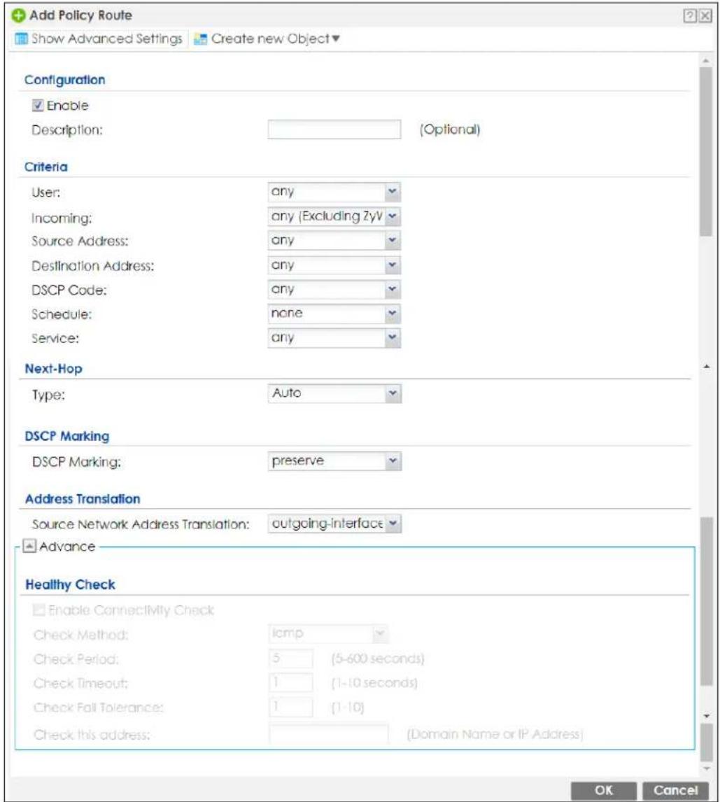
Figure 303 Configuration > Network > Routing > Policy Route > Add/Edit (IPv6 Configuration)
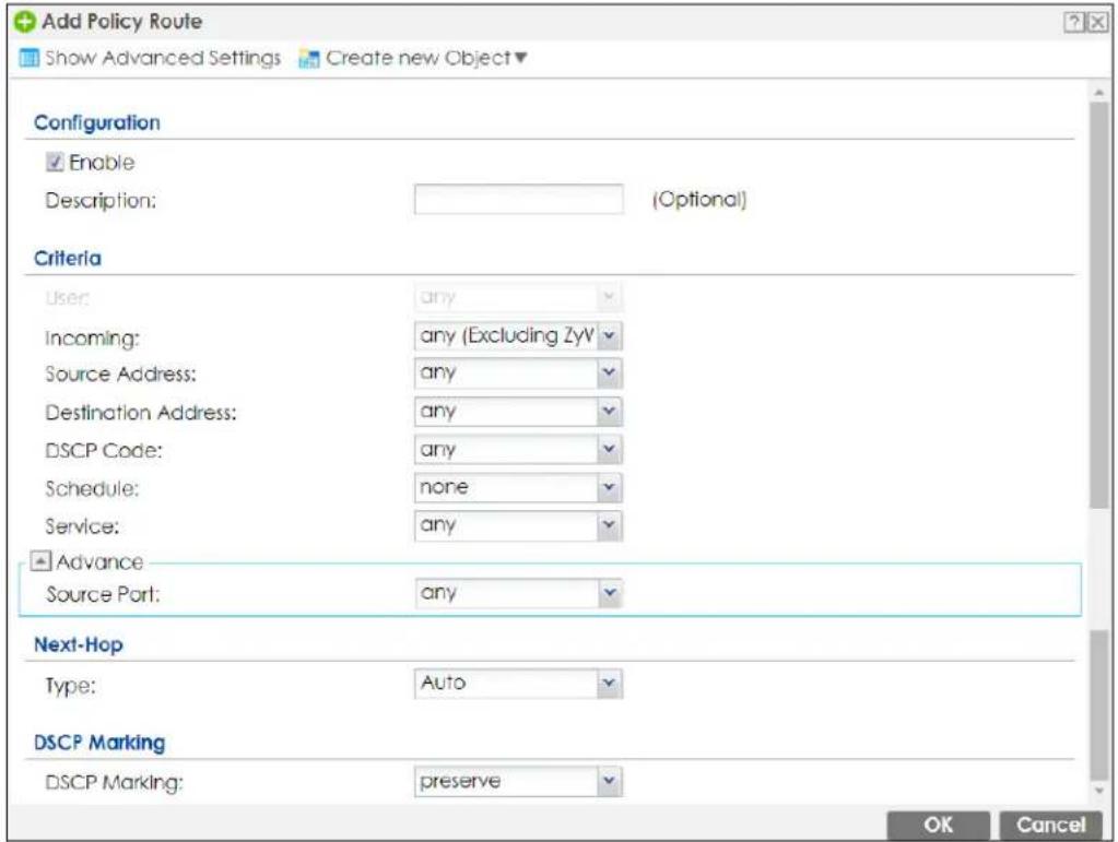
The following table describes the labels in this screen.
Table 159 Configuration > Network > Routing > Policy Route > Add/Edit
| LABEL DESCRIPTION | |
| Show Advanced Settings / Hide Advanced Settings | Click this button to display a greater or lesser number of configuration fields. |
| Create new Object | Use this to configure any new settings objects that you need to use in this screen. |
| Configuration | |
| Enable Select this to activate the policy. | |
| Description | Enter a descriptive name consists of 1 to 60 single-byte characters, including a-zA-Z0-9!''#$%'()*+,-/::=?@_&[.]<>^\‘{} are not allowed. |
| Criteria | |
| User | Select a user name or user group from which the packets are sent. |
| Incoming | Select where the packets are coming from; any, an interface, a tunnel, an SSL VPN, or the Zyxel Device itself. For an interface, a tunnel, or an SSL VPN, you also need to select the individual interface, VPN tunnel, or SSL VPN connection. |
| Source Address | Select a source IP address object, including geographic address and FQDN (group) objects, from which the packets are sent. |
| Destination Address | Select a destination IP address object, including geographic address and FQDN (group) objects, to which the traffic is being sent. If the next hop is a dynamic VPN tunnel and you enableAuto Destination Address, the Zyxel Device uses the local network of the peer router that initiated an incoming dynamic IPSec tunnel as the destination address of the policy instead of your configuration here. |
| DSCP Code | Select a DSCP code point value of incoming packets to which this policy route applies or selectUser Defineto specify another DSCP code point. The lower the number the higher the priority with the exception of 0 which is usually given only best-effort treatment.anymeans all DSCP value or no DSCP marker.defaultmeans traffic with a DSCP value of 0. This is usually best effort trafficThe "af" choices stand for Assured Forwarding. The number following the "af" identifies one of four classes and one of three drop preferences. SeeAssured Forwarding (AF) PHB for DiffServfor more details. |
| User-Defined DSCP Code | Use this field to specify a custom DSCP code point when you selectUser Definein the previous field. |
| Schedule | Select a schedule to control when the policy route is active. nonemeans the route is active at all times if enabled. |
| Service | Select a service or service group to identify the type of traffic to which this policy route applies. |
| Source Port | Select a service or service group to identify the source port of packets to which the policy route applies. |
| Next-Hop | |
| Type | SelectAutoto have the Zyxel Device use the routing table to find a next-hop and forward the matched packets automatically.SelectGatewayto route the matched packets to the next-hop router or switch you specified in theGatewayfield. You have to set up the next-hop router or switch as a HOST address object first.SelectVPN Tunnelto route the matched packets via the specified VPN tunnel.SelectTrunkto route the matched packets through the interfaces in the trunk group based on the load balancing algorithm.SelectInterfaceto route the matched packets through the specified outgoing interface to a gateway (which is connected to the interface). |
| Gateway | This field displays when you selectGatewayin theTypefield. Select a HOST address object. The gateway is an immediate neighbor of your Zyxel Device that will forward the packet to the destination. The gateway must be a router or switch on the same segment as your Zyxel Device's interface(s). |
| VPN Tunnel | This field displays when you selectVPN Tunnelin theTypefield. Select a VPN tunnel through which the packets are sent to the remote network that is connected to the Zyxel Device directly. |
| Auto Destination Address | This field displays when you selectVPN Tunnelin theTypefield. Select this to have the Zyxel Device use the local network of the peer router that initiated an incoming dynamic IPSec tunnel as the destination address of the policy.Leave this cleared if you want to manually specify the destination address. |
| Trunk | This field displays when you selectTrunkin theTypefield. Select a trunk group to have the Zyxel Device send the packets via the interfaces in the group. |
| Interface | This field displays when you selectInterfacein theTypefield. Select an interface to have the Zyxel Device send traffic that matches the policy route through the specified interface. |
| DSCP Marking | Set how the Zyxel Device handles the DSCP value of the outgoing packets that match this route.Select one of the pre-defined DSCP values to apply or selectUser Defineto specify another DSCP value. The "af" choices stand for Assured Forwarding. The number following the "af" identifies one of four classes and one of three drop preferences. SeeAssured Forwarding (AF) PHB for DiffServfor more details.Selectpreserveto have the Zyxel Device keep the packets' original DSCP value.Selectdefaultto have the Zyxel Device set the DSCP value of the packets to 0. |
| User-Defined DSCP Marking | Use this field to specify a custom DSCP value. |
| Address Translation | Use this section to configure NAT for the policy route. This section does not apply to policy routes that use a VPN tunnel as the next hop. |
| Source Network Address Translation | Selectnoneto not use NAT for the route.Selectoutgoing-interfaceto use the IP address of the outgoing interface as the source IP address of the packets that matches this route.To use SNAT for a virtual interface that is in the same WAN trunk as the physical interface to which the virtual interface is bound, the virtual interface and physical interface must be in different subnets.Otherwise, select a pre-defined address (group) to use as the source IP address(es) of the packets that match this route.UseCreate new Objectif you need to configure a new address (group) to use as the source IP address(es) of the packets that match this route. |
| Healthy Check | Use this part of the screen to configure a route connectivity check and disable the policy if the interface is down. |
| Disable policy route automatically while Interface link down | Select this to disable the policy if the interface is down or disabled. This is available forInterfaceand Trunkin theTypefield above. |
| Enable Connectivity Check | Select this to turn on the connection check. This is available forInterfaceand Gatewayin theTypefield above. |
| Check Method: Select | the method that the gateway allows.Select icmp to have the Zyxel Device regularly ping the gateway you specify to make sure it is still available.Select tcp to have the Zyxel Device regularly perform a TCP handshake with the gateway you specify to make sure it is still available. |
| Check Period: | Enter the number of seconds between connection check attempts (5-600 seconds). |
| Check Timeout: | Enter the number of seconds to wait for a response before the attempt is a failure (1-10 seconds). |
| Check Fail Tolerance: | Enter the number of consecutive failures before the Zyxel Device stops routing using this policy (1-10). |
| Check Port: | This field only displays when you set the Check Method to tcp. Specify the port number to use for a TCP connectivity check (1-65535). |
| Check this address: | Select this to specify a domain name or IP address for the connectivity check. Enter that domain name or IP address in the field next to it. |
| OK | ClickOKto save your changes back to the Zyxel Device. |
| Cancel | ClickCancelto exit this screen without saving. |
10.3 IP Static Route Screen
Click Configuration > Network > Routing > Static Route to open the Static Route screen. This screen displays the configured static routes. Configure static routes to be able to use RIP or OSPF to propagate the routing information to other routers. If you enabled IPv6 in the Configuration > System > IPv6 screen, you can also configure static routes used for your IPv6 networks on this screen.
Figure 304 Configuration > Network > Routing > Static Route
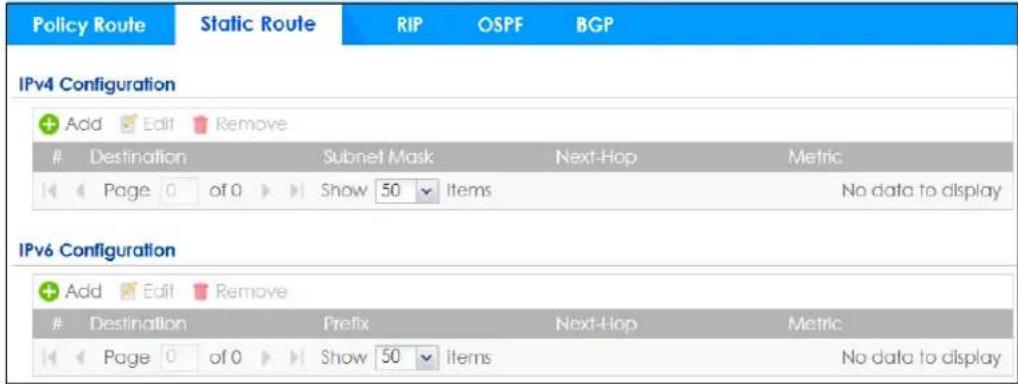
The following table describes the labels in this screen.
Table 160 Configuration > Network > Routing > Static Route
| LABEL DESCRIPTION | |
| IPv4 Configuration / IPv6 Configuration | Use theIPv4 Configurationsection for IPv4 network settings. Use theIPv6 Configurationsection for IPv6 network settings if you connect your Zyxel Device to an IPv6 network. Both sections have similar fields as described below. |
| Add Click this to create a new static route. | |
| Edit | Double-click an entry or select it and clickEditto open a screen where you can modify the entry's settings. |
| Remove | To remove an entry, select it and clickRemove. The Zyxel Device confirms you want to remove it before doing so. |
| # This is the number of an individual static route. | |
| Destination This is the destination IP address. | |
| Subnet Mask This is the IP subnet mask. | |
| Prefix This is the IPv6 prefix for the destination IP address. | |
| Next-Hop | This is the IP address of the next-hop gateway or the interface through which the traffic is routed. The gateway is a router or switch on the same segment as your Zyxel Device's interface(s). The gateway helps forward packets to their destinations. |
| Metric | This is the route's priority among the Zyxel Device's routes. The smaller the number, the higher priority the route has. |
10.3.1 Static Route Add/Edit Screen
Select a static route index number and click Add or Edit. The screen shown next appears. Use this screen to configure the required information for a static route.
Figure 305 Configuration > Network > Routing > Static Route > Add (IPv4 Configuration)
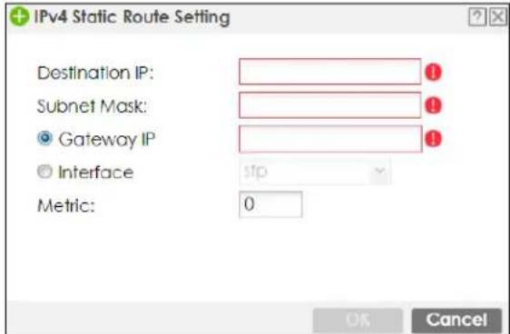
Figure 306 Configuration > Network > Routing > Static Route > Add (IPv6 Configuration)
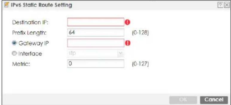
The following table describes the labels in this screen.
Table 161 Configuration > Network > Routing > Static Route > Add
| LABEL DESCRIPTION | |
| Destination IP | This parameter specifies the IP network address of the final destination. Routing is always based on network number.If you need to specify a route to a single host, enter the specific IP address here and use a subnet mask of 255.255.255.255 (for IPv4) in the Subnet Mask field or a prefix of 128 (for IPv6) in the Prefix Length field to force the network number to be identical to the host ID.For IPv6, if you want to send all traffic to the gateway or interface specified in the Gateway IP or Interface field, enter :: in this field and 0 in the Prefix Length field. |
| Subnet Mask Enter the IP subnet mask here. | |
| Prefix Length | Enter the number of left-most digits in the destination IP address, which indicates the network prefix. Enter :: in the Destination IP field and 0 in this field if you want to send all traffic to the gateway or interface specified in the Gateway IP or Interface field. |
| Gateway IP | Select the radio button and enter the IP address of the next-hop gateway. The gateway is a router or switch on the same segment as your Zyxel Device's interface(s). The gateway helps forward packets to their destinations. |
| Interface | Select the radio button and a predefined interface through which the traffic is sent. |
| Metric | Metric represents the “cost” of transmission for routing purposes. IP routing uses hop count as the measurement of cost, with a minimum of 1 for directly connected networks. Enter a number that approximates the cost for this link. The number need not be precise, but it must be 0~127. In practice, 2 or 3 is usually a good number. |
| OK | Click OK to save your changes back to the Zyxel Device. |
| Cancel | Click Cancel to exit this screen without saving. |
10.4 Policy Routing Technical Reference
Here is more detailed information about some of the features you can configure in policy routing.
NAT and SNAT
NAT (Network Address Translation - NAT, RFC 1631) is the translation of the IP address in a packet in one network to a different IP address in another network. Use SNAT (Source NAT) to change the source IP address in one network to a different IP address in another network.
Assured Forwarding (AF) PHB for DiffServ
Assured Forwarding (AF) behavior is defined in RFC 2597. The AF behavior group defines four AF classes. Inside each class, packets are given a high, medium or low drop precedence. The drop precedence determines the probability that routers on the network will drop packets when congestion occurs. If congestion occurs between classes, the traffic in the higher class (smaller numbered class) is generally given priority. Combining the classes and drop precedence produces the following twelve DSCP encodings from AF11 through AF43. The decimal equivalent is listed in brackets.
Table 162 Assured Forwarding (AF) Behavior Group
| CLASS 1 CLASS 2 CLASS 3 | CLASS 4 | |||
| Low Drop Precedence | AF11 (10) | AF21 (18) | AF31 (26) | AF41 (34) |
| Medium Drop Precedence | AF12 (12) | AF22 (20) | AF32 (28) | AF42 (36) |
| High Drop Precedence | AF13 (14) | AF23 (22) | AF33 (30) | AF43 (38) |
Maximize Bandwidth Usage
The maximize bandwidth usage option allows the Zyxel Device to divide up any available bandwidth on the interface (including unallocated bandwidth and any allocated bandwidth that a policy route is not using) among the policy routes that require more bandwidth.
When you enable maximize bandwidth usage, the Zyxel Device first makes sure that each policy route gets up to its bandwidth allotment. Next, the Zyxel Device divides up an interface's available bandwidth (bandwidth that is unbudgeted or unused by the policy routes) depending on how many policy routes require more bandwidth and on their priority levels. When only one policy route requires more bandwidth, the Zyxel Device gives the extra bandwidth to that policy route.
When multiple policy routes require more bandwidth, the Zyxel Device gives the highest priority policy routes the available bandwidth first (as much as they require, if there is enough available bandwidth), and then to lower priority policy routes if there is still bandwidth available. The Zyxel Device distributes the available bandwidth equally among policy routes with the same priority level.
10.5 Routing Protocols Overview
Routing protocols give the Zyxel Device routing information about the network from other routers. The Zyxel Device stores this routing information in the routing table it uses to make routing decisions. In turn, the Zyxel Device can also use routing protocols to propagate routing information to other routers.
Routing protocols are usually only used in networks using multiple routers like campuses or large enterprises.
- Use the RIP screen (see Section 10.6 on page 445) to configure the Zyxel Device to use RIP to receive and/or send routing information.
- Use the OSPF screen (see Section 10.7 on page 447) to configure general OSPF settings and manage OSPF areas.
- Use the OSPF Area Add/Edit screen (see Section 10.7.2 on page 451) to create or edit an OSPF area.
- Use the BGP screen (see Section 10.8 on page 454) to configure eBGP (exterior Border Gate Protocol).
10.5.1 What You Need to Know
The Zyxel Device supports two standards, RIP and OSPF, for routing protocols. RIP and OSPF are compared here and discussed further in the rest of the chapter.
Table 163 RIP vs. OSPF
| RIP OSPF | ||
| Network Size Small (with up to 15 routers) Large | ||
| Metric | Hop count | Bandwidth, hop count, throughput, round trip time and reliability. |
| Convergence Slow Fast | ||
10.6 The RIP Screen
RIP (Routing Information Protocol, RFC 1058 and RFC 1389) allows a device to exchange routing information with other routers. RIP is a vector-space routing protocol, and, like most such protocols, it uses hop count to decide which route is the shortest. Unfortunately, it also broadcasts its routes asynchronously to the network and converges slowly. Therefore, RIP is more suitable for small networks (up to 15 routers).
- In the Zyxel Device, you can configure two sets of RIP settings before you can use it in an interface.
- First, the Authentication field specifies how to verify that the routing information that is received is the same routing information that is sent.
- Second, the Zyxel Device can also redistribute routing information from non-RIP networks, specifically OSPF networks and static routes, to the RIP network. Costs might be calculated differently, however, so you use the Metric field to specify the cost in RIP terms.
- RIP uses UDP port 520.
Use the RIP screen to specify the authentication method and maintain the policies for redistribution.
Click Configuration > Network > Routing > RIP to open the following screen.
Figure 307 Configuration > Network > Routing > RIP
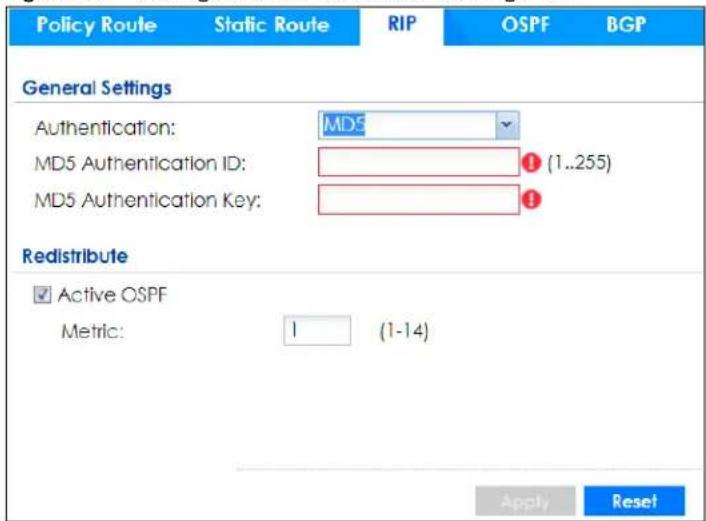
The following table describes the labels in this screen.
Table 164 Configuration > Network > Routing Protocol > RIP
| LABEL DESCRIPTION | |
| Authentication | The transmitting and receiving routers must have the same key.For RIP, authentication is not available in RIP version 1. In RIP version 2, you can only select one authentication type for all interfaces. |
| Authentication | Select the authentication method used in the RIP network. This authentication protects the integrity, but not the confidentiality, of routing updates.None uses no authentication.Text uses a plain text password that is sent over the network (not very secure).MD5 uses an MD5 password and authentication ID (most secure). |
| Text Authentication Key | This field is available if the Authentication is Text. Type the password for text authentication. The key can consist of alphanumeric characters and the underscore, and it can be up to 16 characters long. |
| MD5 Authentication ID | This field is available if the Authentication is MD5. Type the ID for MD5 authentication. The ID can be between 1 and 255. |
| MD5 Authentication Key | This field is available if the Authentication is MD5. Type the password for MD5 authentication. The password can consist of alphanumeric characters and the underscore, and it can be up to 16 characters long. |
| Redistribute | |
| Active OSPF | Select this to use RIP to advertise routes that were learned through OSPF. |
| Metric | Type the cost for routes provided by OSPF. The metric represents the “cost” of transmission for routing purposes. RIP routing uses hop count as the measurement of cost, with 1 usually used for directly connected networks. The number does not have to be precise, but it must be between 0 and 16. In practice, 2 or 3 is usually used. |
| Apply | Click this button to save your changes to the Zyxel Device. |
| Reset Click this button to | return the screen to its last-saved settings. |
10.7 The OSPF Screen
OSPF (Open Shortest Path First, RFC 2328) is a link-state protocol designed to distribute routing information within a group of networks, called an Autonomous System (AS). OSPF offers some advantages over vector-space routing protocols like RIP.
- OSPF supports variable-length subnet masks, which can be set up to use available IP addresses more efficiently.
- OSPF filters and summarizes routing information, which reduces the size of routing tables throughout the network.
- OSPF responds to changes on the network, such as the loss of a router, more quickly.
- OSPF considers several factors, including bandwidth, hop count, throughput, round trip time, and reliability, when it calculates the shortest path.
- OSPF converges more quickly than RIP.
Naturally, OSPF is also more complicated than RIP, so OSPF is usually more suitable for large networks.
OSPF uses IP protocol 89.
OSPF Areas
An OSPF Autonomous System (AS) is divided into one or more areas. Each area represents a group of adjacent networks and is identified by a 32-bit ID. In OSPF, this number may be expressed as an integer or as an IP address.
There are several types of areas.
- The backbone is the transit area that routes packets between other areas. All other areas are connected to the backbone.
- A normal area is a group of adjacent networks. A normal area has routing information about the OSPF AS, any networks outside the OSPF AS to which it is directly connected, and any networks outside the OSPF AS that provide routing information to any area in the OSPF AS.
- A stub area has routing information about the OSPF AS. It does not have any routing information about any networks outside the OSPF AS, including networks to which it is directly connected. It relies on a default route to send information outside the OSPF AS.
- A Not So Stubby Area (NSSA, RFC 1587) has routing information about the OSPF AS and networks outside the OSPF AS to which the NSSA is directly connected. It does not have any routing information about other networks outside the OSPF AS.
Each type of area is illustrated in the following figure.
Figure 308 OSPF: Types of Areas
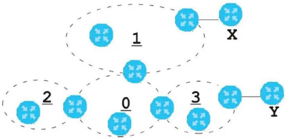
flowchart
graph TD
    A["0"] --> B["1"]
    B --> C["X"]
    A --> D["2"]
    D --> E["3"]
    E --> F["Y"]
This OSPF AS consists of four areas, areas 0-3. Area 0 is always the backbone. In this example, areas 1, 2, and 3 are all connected to it. Area 1 is a normal area. It has routing information about the OSPF AS and networks X and Y. Area 2 is a stub area. It has routing information about the OSPF AS, but it depends on a default route to send information to networks X and Y. Area 3 is a NSSA. It has routing information about the OSPF AS and network Y but not about network X.
OSPF Routers
Every router in the same area has the same routing information. They do this by exchanging Hello messages to confirm which neighbor (layer-3) devices exist, and then they exchange database descriptions (DDs) to create a synchronized link-state database. The link-state database contains records of router IDs, their associated links and path costs. The link-state database is then constantly updated through Link State Advertisements (LSA). Each router uses the link state database and the Dijkstra algorithm to compute the least cost paths to network destinations.
Like areas, each router has a unique 32-bit ID in the OSPF AS, and there are several types of routers. Each type is really just a different role, and it is possible for one router to play multiple roles at one time.
- An internal router (IR) only exchanges routing information with other routers in the same area.
- An Area Border Router (ABR) connects two or more areas. It is a member of all the areas to which it is connected, and it filters, summarizes, and exchanges routing information between them.
- An Autonomous System Boundary Router (ASBR) exchanges routing information with routers in networks outside the OSPF AS. This is called redistribution in OSPF.
Table 165 OSPF: Redistribution from Other Sources to Each Type of Area
| SOURCE\ TYPE OF AREA NORMAL NSSA STUB | ||
| Static routes Yes Yes No | ||
| RIP Yes Yes Yes |
- A backbone router (BR) has at least one interface with area 0. By default, every router in area 0 is a backbone router, and so is every ABR.
Each type of router is illustrated in the following example.
Figure 309 OSPF: Types of Routers

flowchart
graph TD
    subgraph Segment 1
        A["IR"] --> B["1"]
        C["ABR"] --> D["1"]
        E["0"] --> F["3"]
    end
    subgraph Segment 2
        G["IR"] --> H["2"]
        I["ABR"] --> J["0"]
        K["BR"] --> L["3"]
    end
    subgraph Segment 3
        M["ASBR"] --> N["X"]
        O["ASBR"] --> P["Y"]
    end
In order to reduce the amount of traffic between routers, a group of routers that are directly connected to each other selects a designated router (DR) and a backup designated router (BDR). All of the routers only exchange information with the DR and the BDR, instead of exchanging information with all of the other routers in the group. The DR and BDR are selected by priority; if two routers have the same priority, the highest router ID is used.
The DR and BDR are selected in each group of routers that are directly connected to each other. If a router is directly connected to several groups, it might be a DR in one group, a BDR in another group, and neither in a third group all at the same time.
Virtual Links
In some OSPF AS, it is not possible for an area to be directly connected to the backbone. In this case, you can create a virtual link through an intermediate area to logically connect the area to the backbone. This is illustrated in the following example.
Figure 310 OSPF: Virtual Link
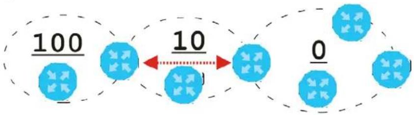
In this example, area 100 does not have a direct connection to the backbone. As a result, you should set up a virtual link on both ABR in area 10. The virtual link becomes the connection between area 100 and the backbone.
You cannot create a virtual link to a router in a different area.
OSPF Configuration
Follow these steps when you configure OSPF on the Zyxel Device.
1 Enable OSPF.
2 Set up the OSPF areas.
3 Configure the appropriate interfaces. See Section 9.5.1 on page 330.
4 Set up virtual links, as needed.
10.7.1 Configuring the OSPF Screen
Use the first OSPF screen to specify the OSPF router the Zyxel Device uses in the OSPF AS and maintain the policies for redistribution. In addition, it provides a summary of OSPF areas, allows you to remove them, and opens the OSPF Add/Edit screen to add or edit them.
Click Configuration > Network > Routing > OSPF to open the following screen.
Figure 311 Configuration > Network > Routing > OSPF
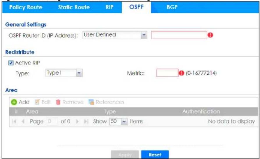
The following table describes the labels in this screen. See Section 10.7.2 on page 451 for more information as well.
Table 166 Configuration > Network > Routing Protocol > OSPF
| LABEL DESCRIPTION | |
| OSPF Router ID Select the 32-bit ID the Zyxel Device uses in the OSPF AS.Default - the first available interface IP address is the Zyxel Device's ID.User Defined - enter the ID (in IP address format) in the field that appears when you select User Define. | |
| Redistribute | |
| Active RIP | Select this to advertise routes that were learned from RIP. The Zyxel Device advertises routes learned from RIP to Normal and NSSA areas but not to Stub areas. |
| Type | Select how OSPF calculates the cost associated with routing information from RIP.Choices are: Type 1 and Type 2.Type 1 - cost = OSPF AS cost + external cost (Metric)Type 2 - cost = external cost (Metric); the OSPF AS cost is ignored. |
| Metric | Type the external cost for routes provided by RIP. The metric represents the “cost” of transmission for routing purposes. The way this is used depends on the Type field. This value is usually the average cost in the OSPF AS, and it can be between 1 and 16777214. |
| Area | This section displays information about OSPF areas in the Zyxel Device. |
| Add Click this to create a new OSPF area. | |
| Edit | Double-click an entry or select it and click Edit to open a screen where you can modify the entry’s settings. |
| Remove | To remove an entry, select it and click Remove. The Zyxel Device confirms you want to remove it before doing so. |
| References | Select an entry and click References to open a screen that shows which settings use the entry. Click Refresh to update information on this screen. |
| # | This field is a sequential value, and it is not associated with a specific area. |
| Area | This field displays the 32-bit ID for each area in IP address format. |
| Type | This field displays the type of area. This type is different from the Type field above. |
| Authentication | This field displays the default authentication method in the area. |
| Apply | Click this button to save your changes to the Zyxel Device. |
| Reset Click this button to | return the screen to its last-saved settings. |
10.7.2 OSPF Area Add/Edit Screen
The OSPF Area Add/Edit screen allows you to create a new area or edit an existing one. To access this screen, go to the OSPF summary screen (see Section 10.7 on page 447), and click either the Add icon or an Edit icon.
Figure 312 Configuration > Network > Routing > OSPF > Add
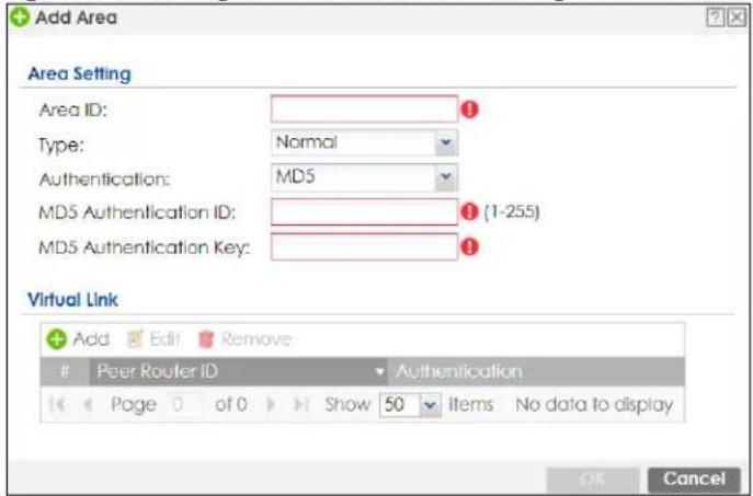
The following table describes the labels in this screen.
Table 167 Configuration > Network > Routing > OSPF > Add
| LABEL DESCRIPTION | |
| Area ID | Type the unique, 32-bit identifier for the area in IP address format. |
| Type Select the type of OSPF area.Normal- This area is a normal area. It has routing information about the OSPF AS and about networks outside the OSPF AS.Stub- This area is an stub area. It has routing information about the OSPF AS but not about networks outside the OSPF AS. It depends on a default route to send information outside the OSPF AS.NSSA- This area is a Not So Stubby Area (NSSA), per RFC 1587. It has routing information about the OSPF AS and networks that are outside the OSPF AS and are directly connected to the NSSA. It does not have information about other networks outside the OSPF AS. | |
| Authentication | Select the default authentication method used in the area. This authentication protects the integrity, but not the confidentiality, of routing updates.Noneuses no authentication.Textuses a plain text password that is sent over the network (not very secure).MD5uses an MD5 password and authentication ID (most secure). |
| Text Authentication Key | This field is available if the Authentication is Text. Type the password for text authentication. The key can consist of alphanumeric characters and the underscore, and it can be up to 16 characters long. |
| MD5 Authentication ID | This field is available if the Authentication is MD5. Type the default ID for MD5 authentication in the area. The ID can be between 1 and 255. |
| MD5 Authentication Key | This field is available if the Authentication is MD5. Type the default password for MD5 authentication in the area. The password can consist of alphanumeric characters and the underscore, and it can be up to 16 characters long. |
| Virtual Link | This section is displayed if the Type is Normal. Create a virtual link if you want to connect a different area (that does not have a direct connection to the backbone) to the backbone. You should set up the virtual link on the ABR that is connected to the other area and on the ABR that is connected to the backbone. |
| Add Click this to create a new virtual link. | |
| Edit | Double-click an entry or select it and click Edit to open a screen where you can modify the entry's settings. |
| Remove | To remove an entry, select it and click Remove. The Zyxel Device confirms you want to remove it before doing so. |
| # This field is a sequential value, and it is not associated with a specific area. | |
| Peer Router ID | This is the 32-bit ID (in IP address format) of the other ABR in the virtual link. |
| Authentication | This is the authentication method the virtual link uses. This authentication protects the integrity, but not the confidentiality, of routing updates.For OSPF, the Zyxel Device supports a default authentication type by area. If you want to use this default in an interface or virtual link, you set the associated Authentication Type field toSame as Area. As a result, you only have to update the authentication information for the area to update the authentication type used by these interfaces and virtual links. Alternatively, you can override the default in any interface or virtual link by selecting a specific authentication method. Please see the respective interface sections for more information.Noneuses no authentication.Textuses a plain text password that is sent over the network (not very secure). Hover your cursor over this label to display the password.MD5uses an MD5 password and authentication ID (most secure). Hover your cursor over this label to display the authentication ID and key.Same as Areahas the virtual link also use theAuthenticationsettings above. |
| OK | Click OKto save your changes back to the Zyxel Device. |
| Cancel | Click Cancelto exit this screen without saving. |
10.7.3 Virtual Link Add/Edit Screen
The Virtual Link Add/Edit screen allows you to create a new virtual link or edit an existing one. When the OSPF add or edit screen (see Section 10.7.2 on page 451) has the Type set to Normal, a Virtual Link table displays. Click either the Add icon or an entry and the Edit icon to display a screen like the following.
Figure 313 Configuration > Network > Routing > OSPF > Add > Add
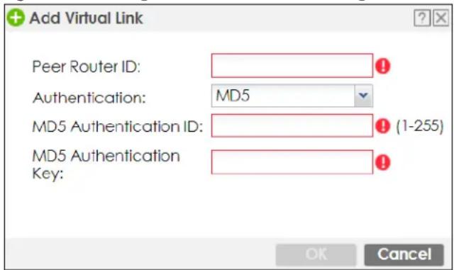
The following table describes the labels in this screen.
Table 168 Configuration > Network > Routing > OSPF > Add > Add
| LABEL DESCRIPTION | |
| Peer Router ID | Enter the 32-bit ID (in IP address format) of the other ABR in the virtual link. |
| Authentication | Select the authentication method the virtual link uses. This authentication protects the integrity, but not the confidentiality, of routing updates.For OSPF, the Zyxel Device supports a default authentication type by area. If you want to use this default in an interface or virtual link, you set the associated Authentication Type field toSame as Area. As a result, you only have to update the authentication information for the area to update the authentication type used by these interfaces and virtual links. Alternatively, you can override the default in any interface or virtual link by selecting a specific authentication method. Please see the respective interface sections for more information.Noneuses no authentication.Textuses a plain text password that is sent over the network (not very secure).MD5uses an MD5 password and authentication ID (most secure).Same as Areahas the virtual link also use theAuthenticationsettings above. |
| Text Authentication Key | This field is available if theAuthenticationist Text. Type the password for text authentication. The key can consist of alphanumeric characters and the underscore, and it can be up to 16 characters long. |
| MD5 Authentication ID | This field is available if theAuthenticationis MD5. Type the default ID for MD5 authentication in the area. The ID can be between 1 and 255. |
| MD5 Authentication Key | This field is available if theAuthenticationis MD5. Type the default password for MD5 authentication in the area. The password can consist of alphanumeric characters and the underscore, and it can be up to 16 characters long. |
| OK | ClickOKto save your changes back to the Zyxel Device. |
| Cancel | ClickCancelto exit this screen without saving. |
10.8 BGP (Border Gateway Protocol)
The Zyxel Device supports eBGP (exterior Border Gate Protocol) to route IPv4 traffic between routers in different Autonomous Systems (AS). An AS number is a number from 1 to 4294967295), that identifies an autonomous system. 420000000 – 4294967294 are private AS numbers.
See Section 10.7 on page 447 for more information on autonomous systems.
Figure 314 eBGP Concept
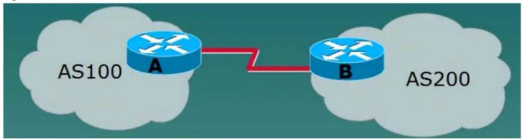
flowchart
graph LR
    AS100["AS100"] --> A["A"]
    A --> B["B"]
    B --> AS200["AS200"]
10.8.1 Allow BGP Packets to Enter the Zyxel Device
You must first allow BGP packets to enter the Zyxel Device from the WAN.
1 Go to Configuration > Object > Service > Service Group
2 Select the Default_Allow_WAN_To_ZyWALL rule and click Edit.
3 Move BGP from Available to Member.
4 Click OK.
Figure 315 Allow BGP to the Zyxel Device
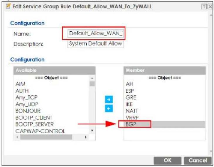
10.8.2 Configuring the BGP Screen
Use this screen to configure BGP information about the Zyxel Device and its peer BGP routers.
Click Configuration > Network > Routing > BGP to open the following screen.
Figure 316 Configuration > Network > Routing > BGP
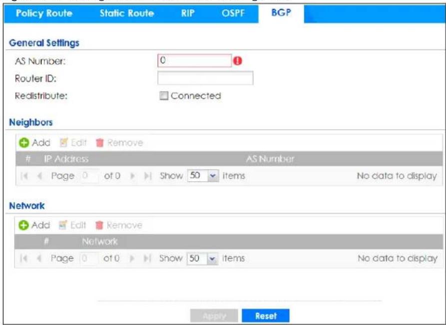
The following table describes the labels in this screen.
Table 169 Configuration > Network > Routing Protocol > BGP
| LABEL DESCRIPTION | |
| AS Number Type a number | from 1 to 4294967295 in this field.Note: The Zyxel Device can only belong to one AS at a time. |
| Router ID | Type the IP address of the interface on the Zyxel Device. This field is optional. |
| Redistribute | Select Connected to redistribute routes of directly attached devices to the Zyxel Device into the BGP Routing Information Base (RIB). |
| Neighbors | This section displays information about peer BGP routers in neighboring AS'.Note: The maximum number of neighboring BGP routers supported by the Zyxel Device is 5. |
| Add | Click this to configure BGP criteria for a new peer BGP router. |
| Edit | Double-click an entry or select it and click Edit to open a screen where you can modify the entry's settings. |
| Remove | To remove an entry, select it and click Remove. The Zyxel Device confirms you want to remove it before doing so. |
| # | This field is a sequential value, and it is not associated with a specific area. |
| IP Address | This displays the IPv4 address of the peer BGP router in a neighboring AS. |
| AS Number | This displays the AS Number of the peer BGP router in a neighboring AS. |
| Network | Use this section to add routes that will be announced to all BGP neighbors.Note: You may configure up to 16 network routes. |
| Add | Click this to configure network information for a new route. |
| Edit | Double-click an entry or select it and click Edit to open a screen where you can modify the entry's settings. |
| Remove | To remove an entry, select it and click Remove. The Zyxel Device confirms you want to remove it before doing so. |
| # | This field is a sequential value, and it is not associated with a specific area. |
| Network | This displays the IP address and the number of subnet mask bits for the peer BGP route. |
| Apply | Click this button to save your changes to the Zyxel Device. |
| Reset Click this button to | return the screen to its last-saved settings. |
10.8.3 The BGP Neighbors Screen
Use this screen to configure BGP information about a peer BGP router.
Click Configuration > Network > Routing > BGP > Add Neighbors to open the following screen.
Figure 317 Configuration > Network > Routing > BGP > Add Neighbors
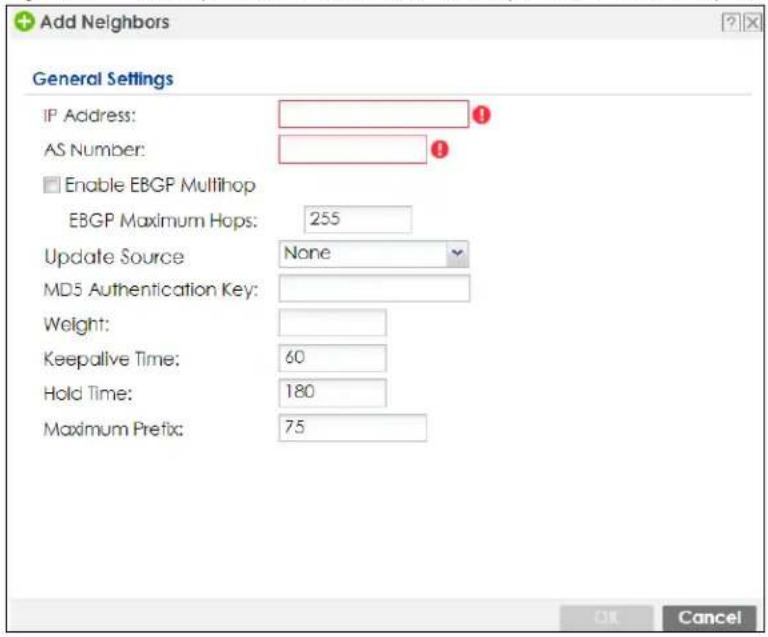
The following table describes the labels in this screen.
Table 170 Configuration > Network > Routing Protocol > BGP
| LABEL DESCRIPTION | |
| IP Address | Type the IP address of the interface on the peer BGP router. |
| AS Number | Type a number from 1 to 4294967295 in this field. Get the number from your service provider. |
| Enable EBGP Multihop | Select this to allow the Zyxel Device to attempt BGP connections to external peers on indirectly connected networks. eBGP neighbors must also perform multihop. Multihop is not established if the only route to the multihop peer is a default route. This avoids loop formation. |
| EBGP Maximum Hops | Enter a maximum hop count from <1-255>. The default is 255. |
| Update Source | Use this to allow BGP sessions use the selected interface for TCP connections.· C h o o s e Gateway and then enter the gateway IP address· Choose Interface and then select a Zyxel Device interface.· C h o o s e None to use the closest interface. |
| MD5 authentication key | Type the default password for MD5 authentication of communication between the Zyxel Device and the peer BGP router. The password can consist of alphanumeric characters and the underscore, and it can be up to 63 characters long. |
| Weight | Specify a weight value for all routes learned from this peer BGP router in the specified network. The route with the highest weight gets preference. |
| Keepalive Time | Keepalive messages are sent by the Zyxel Device to a peer BGP router to inform it that the BGP connection between the two is still active. The Keepalive Time is the interval between each Keepalive message sent by the Zyxel Device. We recommend Keepalive Time is 1/3 of the Hold Time time. |
| Hold Time | This is the maximum time the Zyxel Device waits to receive a Keepalive message from a peer BGP router before it declares that the peer BGP router is dead. Hold Time must be greater than the Keepalive Time. |
| Maximum Prefix | A prefix is a network address (IP/subnet mask) that a BGP router can reach and that it shares with its neighbors. Set the maximum number, from 1 to 4294967295, of prefixes that can be received from a neighbor. This limits the number of prefixes that the Zyxel Device is allowed to receive from a neighbor. If extra prefixes are received, the Zyxel Device ends the connection with the peer BGP router. You need to edit the peer BGP router configuration to bring the connection back. |
| OK | Click OK to save your changes back to the Zyxel Device. |
| Cancel | Click Cancel to exit this screen without saving. |
10.8.4 Example Scenario
This is an example scenario for using BGP on the Zyxel Device.
10.8.4.1 Scenario: CE - PE (MLPS)
In this scenario, you want to transmit BGP packets from a CE router (Zyxel Device) to a peer BGP PE router in an MPLS network.
- CE: The Zyxel Device is the customer edge router located on the customer premises and connects to a PE router in the service provider MPLS network.
- PE: The provider edge router is located at the edge of the service provider MPLS network.
- MPLS: MultiProtocol Label Switching (MPLS) forwards data from one network node to the next based on path labels rather than network addresses.
Figure 318 Scenario 1: CE Router - to - MPLS
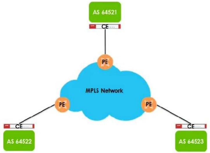
flowchart
graph TD
    A["AS 64521"] -->|CE| B["MPLS Network"]
    C["AS 64522"] -->|CE| B
    D["AS 64523"] -->|CE| B
    B --> E["PE"]
    B --> F["PE"]
10.8.4.2 CE - PE Configuration Process
The process for configuring BGP in this scenario is:
1 Configure the AS number for BGP on the Zyxel Device (CE) in Configuration > Network > Routing > BGP.
Note: The Zyxel Device can only belong to one AS at a time.
2 Configure the AS number and BGP criteria of the peer BGP routers (PE) in the neighboring AS in Configuration > Network > Routing > BGP > Add Neighbors.
Note: The maximum number of neighboring BGP routers supported by the Zyxel Device is 5.
3 Configure the network for BGP routes in the neighboring AS.
Note: You may configure up to 16 network routes.
CHAPTER 11 DDNS
11.1 DDNS Overview
Dynamic DNS (DDNS) services let you use a domain name with a dynamic IP address.
11.1.1 What You Can Do in this Chapter
- Use the DDNS screen (see Section 11.2 on page 461) to view a list of the configured DDNS domain names and their details.
- Use the DDNS Add/Edit screen (see Section 11.2.1 on page 462) to add a domain name to the Zyxel Device or to edit the configuration of an existing domain name.
11.1.2 What You Need to Know
DNS maps an FQDN (Fully Qualified Domain Name) to a corresponding IP address and vice versa. Similarly, Dynamic DNS (DDNS) maps a domain name to a dynamic IP address. As a result, anyone can use the domain name to contact you (in NetMeeting, CU-SeeMe, etc.) or to access your FTP server or Web site, regardless of the current (dynamic) IP address.
Note: You must have a public WAN IP address to use Dynamic DNS.
You must set up a dynamic DNS account with a supported DNS service provider before you can use Dynamic DNS services with the Zyxel Device. When registration is complete, the DNS service provider gives you a password or key. At the time of writing, the Zyxel Device supports the following DNS service providers. See the listed websites for details about the DNS services offered by each.
Table 171 DDNS Service Providers
| PROVIDER SERVICE | TYPES SUPPORTED WEBSITE | |
| DynDNS Dynamic DNS, Static DNS, and Custom DNS www.dyndns.com | ||
| Dynu Basic, Premium www.dynu.com | ||
| No-IP No-IP www.no-ip.com | ||
| Peanut Hull Peanut | Hull www.oray.cn | |
| 3322 3322 Dynamic | DNS, 3322 Static DNS www.3322.org | |
| Selfhost | Selfhost | selfhost.de |
Note: Record your DDNS account's user name, password, and domain name to use to configure the Zyxel Device.
After you configure the Zyxel Device, it automatically sends updated IP addresses to the DDNS service provider, which helps redirect traffic accordingly.
11.2 The DDNS Screen
The DDNS screen provides a summary of all DDNS domain names and their configuration. In addition, this screen allows you to add new domain names, edit the configuration for existing domain names, and delete domain names. Click Configuration > Network > DDNS to open the following screen.
Figure 319 Configuration > Network > DDNS
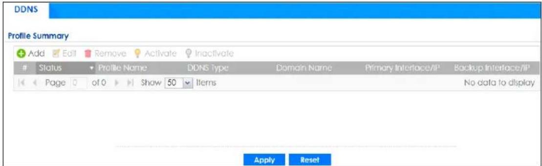
The following table describes the labels in this screen.
Table 172 Configuration > Network > DDNS
| LABEL DESCRIPTION | |
| Add Click this to create | a new entry. |
| Edit | Double-click an entry or select it and click Edit to open a screen where you can modify the entry's settings. |
| Remove | To remove an entry, select it and click Remove. The Zyxel Device confirms you want to remove it before doing so. |
| Activate | To turn on an entry, select it and click Activate. |
| Inactivate | To turn off an entry, select it and click Inactivate. |
| # This is the number of an individual DDNS profile. | |
| Status | This icon is lit when the entry is active and dimmed when the entry is inactive. |
| Profile Name | This field displays the descriptive profile name for this entry. |
| DDNS Type This field displays which DDNS service you are using. | |
| Domain Name This field displays each domain name the Zyxel Device can route. | |
| Primary Interface/IP | This field displays the interface to use for updating the IP address mapped to the domain name followed by how the Zyxel Device determines the IP address for the domain name.from interface - The IP address comes from the specified interface.auto detected -The DDNS server checks the source IP address of the packets from the Zyxel Device for the IP address to use for the domain name.custom - The IP address is static. |
| Backup Interface/IP | This field displays the alternate interface to use for updating the IP address mapped to the domain name followed by how the Zyxel Device determines the IP address for the domain name. The Zyxel Device uses the backup interface and IP address when the primary interface is disabled, its link is down or its connectivity check fails.from interface - The IP address comes from the specified interface.auto detected -The DDNS server checks the source IP address of the packets from the Zyxel Device for the IP address to use for the domain name.custom - The IP address is static. |
| Apply Click this button to save your changes to the Zyxel Device. | |
| Reset Click this button to return the screen to its last-saved settings. | |
11.2.1 The Dynamic DNS Add/Edit Screen
The DDNS Add/Edit screen allows you to add a domain name to the Zyxel Device or to edit the configuration of an existing domain name. Click Configuration > Network > DDNS and then an Add or Edit icon to open this screen.
Figure 320 Configuration > Network > DDNS > Add
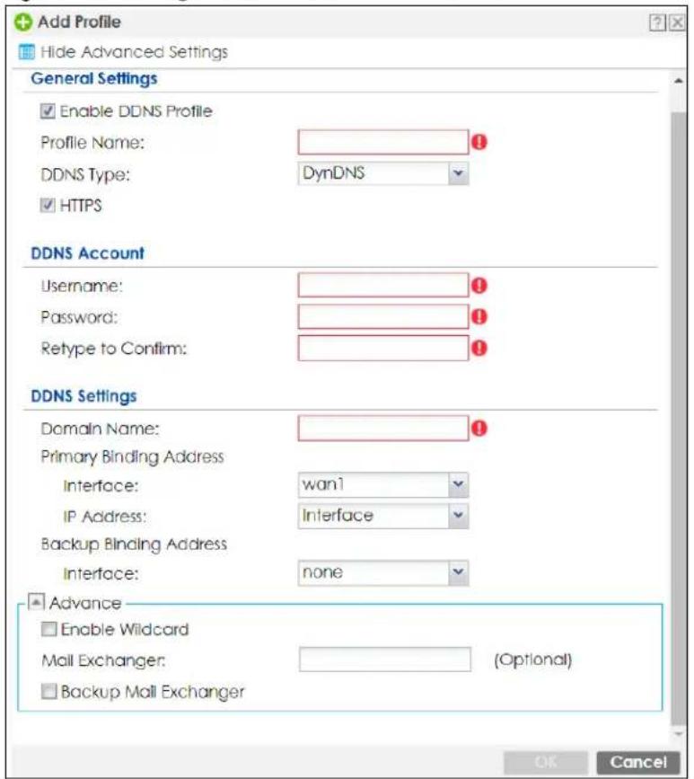
Figure 321 Configuration > Network > DDNS > Add - Custom
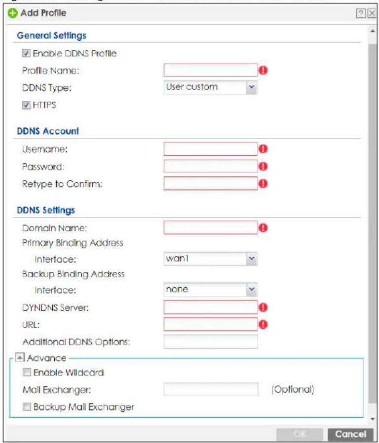
The following table describes the labels in this screen.
Table 173 Configuration > Network > DDNS > Add
| LABEL DESCRIPTION | |
| Show Advanced Settings / Hide Advanced Settings | Click this button to display a greater or lesser number of configuration fields. |
| Enable DDNS Profile | Select this check box to use this DDNS entry. |
| Profile Name | When you are adding a DDNS entry, type a descriptive name for this DDNS entry in the Zyxel Device. You may use 1-31 alphanumeric characters, underscores( ), or dashes (-), but the first character cannot be a number. This value is case-sensitive.This field is read-only when you are editing an entry. |
| DDNS Type Select the type of DDNS service you are using.Select User custom to create your own DDNS service and configure the DYNDNS Server, URL, and Additional DDNS Options fields below. | |
| HTTPS | Select this to encrypt traffic using SSL (port 443), including traffic with username and password, to the DDNS server. Not all DDNS providers support this option. |
| Username | Type the user name used when you registered your domain name. You can use up to 31 alphanumeric characters and the underscore. Spaces are not allowed.For a Dynu DDNS entry, this user name is the one you use for logging into the service, not the name recorded in your personal information in the Dynu website. |
| Password | Type the password provided by the DDNS provider. You can use up to 64 alphanumeric characters and the underscore. Spaces are not allowed.Your password will be encrypted when you configure this field. |
| Retype to Confirm Type | the password again to confirm it. |
| DDNS Settings | |
| Domain name | Type the domain name you registered. You can use up to 255 characters. |
| Primary Binding Address | Use these fields to set how the Zyxel Device determines the IP address that is mapped to your domain name in the DDNS server. The Zyxel Device uses the Backup Binding Address if the interface specified by these settings is not available. |
| Interface | Select the interface to use for updating the IP address mapped to the domain name.Select Any to let the domain name be used with any interface. |
| IP Address The options | ns available in this field vary by DDNS provider.Interface-The Zyxel Device uses the IP address of the specified interface. This option appears when you select a specific interface in the Primary Binding Address Interface field.Auto- If the interface has a dynamic IP address, the DDNS server checks the source IP address of the packets from the Zyxel Device for the IP address to use for the domain name. You may want to use this if there are one or more NAT routers between the Zyxel Device and the DDNS server.Note: The Zyxel Device may not determine the proper IP address if there is an HTTP proxy server between the Zyxel Device and the DDNS server.Custom- If you have a static IP address, you can select this to use it for the domain name. The Zyxel Device still sends the static IP address to the DDNS server. |
| Custom IP | This field is only available when the IP Address is Custom. Type the IP address to use for the domain name. |
| Backup Binding Address | Use these fields to set an alternate interface to map the domain name to when the interface specified by the Primary Binding Interface settings is not available. |
| Interface | Select the interface to use for updating the IP address mapped to the domain name. Select Any to let the domain name be used with any interface. Select None to not use a backup address. |
| IP Address The options | ns available in this field vary by DDNS provider.Interface-The Zyxel Device uses the IP address of the specified interface. This option appears when you select a specific interface in the Backup Binding Address Interface field.Auto- The DDNS server checks the source IP address of the packets from the Zyxel Device for the IP address to use for the domain name. You may want to use this if there are one or more NAT routers between the Zyxel Device and the DDNS server.Note: The Zyxel Device may not determine the proper IP address if there is an HTTP proxy server between the Zyxel Device and the DDNS server.Custom- If you have a static IP address, you can select this for the domain name. The Zyxel Device still sends the static IP address to the DDNS server. |
| Custom IP | This field is only available when the IP Address is Custom. Type the IP address to use for the domain name. |
| Enable Wildcard This option is only available with a DynDNS account. Enable the wildcard feature to alias subdomains to be aliased to the same IP address as your (dynamic) domain name. This feature is useful if you want to be able to use, for example, www.yourhost.dyndns.org and still reach your hostname. | |
| Mail Exchanger This option is only available with a DynDNS account. DynDNS can route email for your domain name to a mail server (called a mail exchanger). For example, DynDNS routes email for john-doe@yourhost.dyndns.org to the host record specified as the mail exchanger. If you are using this service, type the host record of your mail server here. Otherwise leave the field blank. See www.dyndns.org for more information about mail exchangers. | |
| Backup Mail Exchanger | This option is only available with a DynDNS account. Select this check box if you are using DynDNS's backup service for email. With this service, DynDNS holds onto your email if your mail server is not available. Once your mail server is available again, the DynDNS server delivers the mail to you. See www.dyndns.org for more information about this service. |
| DYNDNS Server | This field displays when you select User custom from the DDNS Type field above. Type the IP address of the server that will host the DDSN service. |
| URL | This field displays when you select User custom from the DDNS Type field above. Type the URL that can be used to access the server that will host the DDSN service. |
| Additional DDNS Options | This field displays when you select User custom from the DDNS Type field above. These are the options supported at the time of writing: · dyndns_system to specify the DYNDNS Server type - for example, dyndns@dyndns.org · ip_server_name which should be the URL to get the server's public IP address - for example, http://myip.easylife.tw/ |
| OK | Click OK to save your changes back to the Zyxel Device. |
| Cancel | Click Cancel to exit this screen without saving. |
CHAPTER 12 NAT
12.1 Overview
- Use the Network > NAT screen (Section 12.2 on page 466) to enable and configure network address translation.
- Use the Network > NAT > Virtual Server Load Balancing screen (Section 12.5 on page 474) to distribute local user connections over multiple servers, in order to reduce each server's workload and to decrease overall response times.
12.2 NAT Overview
NAT (Network Address Translation - NAT, RFC 1631) is the translation of the IP address of a host in a packet. For example, the source address of an outgoing packet, used within one network is changed to a different IP address known within another network. Use Network Address Translation (NAT) to make computers on a private network behind the Zyxel Device available outside the private network. If the Zyxel Device has only one public IP address, you can make the computers in the private network available by using ports to forward packets to the appropriate private IP address.
Suppose you want to assign ports 21-25 to one FTP, Telnet and SMTP server (A in the example), port 80 to another (B in the example) and assign a default server IP address of 192.168.1.35 to a third (C in the example). You assign the LAN IP addresses and the ISP assigns the WAN IP address. The NAT network appears as a single host on the Internet.
Figure 322 Multiple Servers Behind NAT Example
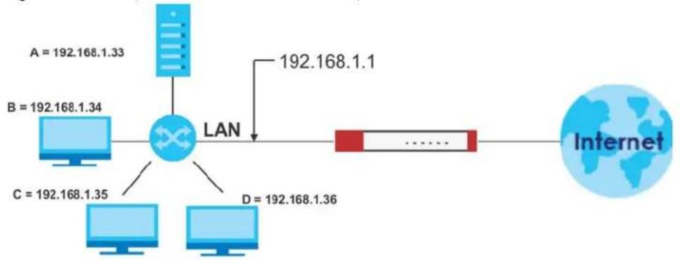
flowchart
graph LR
    A["Router"] -->|A = 192.168.1.33| B["Computer"]
    B --> C["LAN"]
    C --> D["Router"]
    D --> E["Internet"]
    C --> F["Computer"]
    C --> G["Computer"]
    C --> H["Computer"]
    C --> I["Computer"]
    style A fill:#cce5ff,stroke:#333
    style B fill:#cce5ff,stroke:#333
    style C fill:#cce5ff,stroke:#333
    style D fill:#ffcccc,stroke:#333
    style E fill:#ffffff,stroke:#333
    style F fill:#ffffff,stroke:#333
    style G fill:#ffffff,stroke:#333
    style H fill:#ffffff,stroke:#333
    style I fill:#ffffff,stroke:#333
12.2.1 What You Can Do in this Chapter
Use the NAT screens (see Section 12.3 on page 468) to view and manage the list of NAT rules and see their configuration details. You can also create new NAT rules and edit or delete existing ones.
12.2.2 What You Need to Know
NAT is also known as virtual server, port forwarding, or port translation.
Well-known Ports
Port numbers range from 0 to 65535, but only port numbers 0 to 1023 are reserved for privileged services and designated as well-known ports. The following list specifies the ports used by the server process as its contact ports. See Section 43.8 on page 1002 (Configuration > Object > Service) for more information about service objects.
• Well-known ports range from 0 to 1023.
- Registered ports range from 1024 to 49151.
• Dynamic ports (also called private ports) range from 49152 to 65535.
Table 174 Well-known Ports
| PORT TCP/UDP DESCRIPTION | ||
| 1 TCP TCP Port Service Multiplexer (TCPMUX) | ||
| 20 | TCP | FTP - Data |
| 21 TCP FTP - Control | ||
| 22 TCP SSH Remote Login Protocol | ||
| 23 TCP Telnet | ||
| 25 TCP Simple Mail Transfer Protocol (SMTP) | ||
| 42 UDP Host Name Server (Nameserv) | ||
| 43 TCP Whols | ||
| 53 TCP/UDP Domain Name System (DNS) | ||
| 67 UDP BOOTP/DHCP server | ||
| 68 UDP BOOTP/DHCP client | ||
| 69 UDP Trivial File Transfer Protocol (TFTP) | ||
| 79 TCP Finger | ||
| 80 TCP HTTP | ||
| 110 TCP POP3 | ||
| 119 TCP Newsgroup (NNTP) | ||
| 123 UDP Network Time Protocol (NTP) | ||
| 135 TCP/UDP RPC Locator service | ||
| 137 TCP/UDP NetBIOS Name Service | ||
| 138 UDP NetBIOS Datagram Service | ||
| 139 TCP NetBIOS Datagram Service | ||
| 143 TCP Interim Mail Access Protocol (IMAP) | ||
| 161 UDP SNMP | ||
| 179 TCP Border Gateway Protocol (BGP) | ||
| 389 | TCP/UDP | Lightweight Directory Access Protocol (LDAP) |
| 443 TCP HTTPS | ||
| 445 TCP Microsoft - DS | ||
| 636 TCP LDAP over TLS/SSL (LDAPS) | ||
| 953 TCP BIND DNS | ||
Table 174 Well-known Ports
| PORT TCP/UDP DESCRIPTION | ||
| 990 TCP | FTP over TLS/SSL (FTPS) | |
| 995 TCP | POP3 over TLS/SSL (POP3S) | |
12.3 The NAT Screen
The NAT summary screen provides a summary of all NAT rules and their configuration. In addition, this screen allows you to create new NAT rules and edit and delete existing NAT rules. To access this screen, login to the Web Configurator and click Configuration > Network > NAT. The following screen appears, providing a summary of the existing NAT rules.
Click on the icons to go to the OneSecurity website where there is guidance on configuration walkthroughs, troubleshooting, and other information.
Figure 323 Configuration > Network > NAT
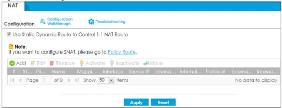
The following table describes the labels in this screen.
Table 175 Configuration > Network > NAT
| LABEL DESCRIPTION | |
| Use Static-Dynamic Route to Control 1-1 NAT Route | If you are using SiteToSite VPN and 1-1 SNAT, it's recommended that you select this check box. Otherwise, you'll need to create policy route rules for VPN and Destination NAT traffic.Note that the selection of this check box will change the priority of the routing flow (SiteToSite VPN, Static-Dynamic Route, and 1-1 SNAT). See Chapter 50 on page 1196 for more information about the routing flow. |
| Add Click this to create a new entry. | |
| Edit | Double-click an entry or select it and click Edit to open a screen where you can modify the entry's settings. |
| Remove | To remove an entry, select it and click Remove. The Zyxel Device confirms you want to remove it before doing so. |
| Activate | To turn on an entry, select it and click Activate. |
| Inactivate | To turn off an entry, select it and click Inactivate. |
| Move | To change a rule's position in the numbered list, select the rule and click Move to display a field to type a number for where you want to put that rule and press [ENTER] to move the rule to the number that you typed.The ordering of your rules is important as they are applied in order of their numbering. |
| # This field is a sequential value, and it is not associated with a specific entry. | |
| Status This icon is lit when the entry is active and dimmed when the entry is inactive. | |
| Priority | This field displays the priority for the entry. The smaller the number, the higher the priority. |
| Name This field displays the name of the entry. | |
| Mapping Type | This field displays what kind of NAT this entry performs:Virtual Server, 1:1 NAT, or Many 1:1 NAT. |
| Interface | This field displays the interface on which packets for the NAT entry are received. |
| Source IP | This field displays the source IP address (or address object) of traffic that matches this NAT entry. It displaysanyif there is no restriction on the source IP address. |
| External IP | This field displays the original destination IP address (or address object) of traffic that matches this NAT entry. It displaysanyif there is no restriction on the original destination IP address. |
| Internal IP This field displays the new destination IP address for the packet. | |
| Protocol | This field displays the service used by the packets for this NAT entry. It displaysanyif there is no restriction on the services. |
| External Port | This field displays the original destination port(s) of packets for the NAT entry. This field is blank if there is no restriction on the original destination port. |
| Internal Port | This field displays the new destination port(s) for the packet. This field is blank if there is no restriction on the original destination port. |
| Apply Click this button to save your changes to the Zyxel Device. | |
| Reset Click this button to return the screen to its last-saved settings. | |
12.3.1 The NAT Add/Edit Screen
The NAT Add/Edit screen lets you create new NAT rules and edit existing ones. To open this window, open the NAT summary screen. (See Section 12.3 on page 468.) Then, click on an Add icon or Edit icon to open the following screen.
Figure 324 Configuration > Network > NAT > Add
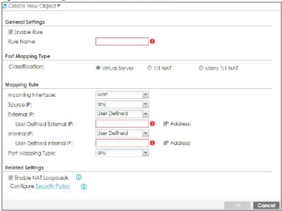
The following table describes the labels in this screen.
Table 176 Configuration > Network > NAT > Add
| LABEL DESCRIPTION | |
| Create new Object | Use to configure any new settings objects that you need to use in this screen. |
| Enable Rule Use this option to turn the NAT rule on or off. | |
| Rule Name | Type in the name of the NAT rule. The name is used to refer to the NAT rule. You may use 1-31 alphanumeric characters, underscores(____), or dashes (-), but the first character cannot be a number. This value is case-sensitive. |
| Classification Select what kind of NAT this rule is to perform. | |
| Source IP | Specify the source IP address of the packets received by this NAT rule's specified incoming interface.any- Select this to use all of the incoming interface's IP addresses including dynamic addresses or those of any virtual interfaces built upon the selected incoming interface.User Defined- Select this to manually enter an IP address in theUser Definedfield. For example, you could enter a static IP address.Host address - select a address object to use the IP address it specifies. |
| External IP | Specify the destination IP address of the packets received by this NAT rule's specified incoming interface. The specified IP address will be translated to theInternal IPaddress.any- Select this to use all of the incoming interface's IP addresses including dynamic addresses or those of any virtual interfaces built upon the selected incoming interface.User Defined- Select this to manually enter an IP address in theUser Definedfield. For example, you could enter a static public IP assigned by the ISP without having to create a virtual interface for it.Host address - select a host address object to use the IP address it specifies. The list also includes address objects based on interface IPs. So for example you could select an address object based on a WAN interface even if it has a dynamic IP address. |
| User Defined External IP | This field is available ifExternal IPis User Defined.Type the destination IP address that this NAT rule supports. |
| External IP Subnet/Range | This field displays forMany 1:1 NAT. Select the destination IP address subnet or IP address range that this NAT rule supports. The original and mapped IP address subnets or ranges must have the same number of IP addresses. |
| Internal IP | Select to which translated destination IP address this NAT rule forwards packets.User Defined- this NAT rule supports a specific IP address, specified in theUser Definedfield.HOST address - the drop-down box lists all the HOST address objects in the Zyxel Device. If you select one of them, this NAT rule supports the IP address specified by the address object. |
| User Defined Internal IP | This field is available ifInternal IPis User Defined.Type the translated destination IP address that this NAT rule supports. |
| Internal IP Subnet/Range | This field displays forMany 1:1 NAT. Select to which translated destination IP address subnet or IP address range this NAT rule forwards packets. The original and mapped IP address subnets or ranges must have the same number of IP addresses. |
| Port Mapping Type | Use the drop-down list box to select how many original destination ports this NAT rule supports for the selected destination IP address (Original IP). Choices are:Any- this NAT rule supports all the destination ports.Port- this NAT rule supports one destination port.Ports- this NAT rule supports a range of destination ports. You might use a range of destination ports for unknown services or when one server supports more than one service.Service- this NAT rule supports a service such as FTP (seeObject > Service > Service)Service-Group- this NAT rule supports a group of services such as all service objects related to DNS (seeObject > Service > Service Group) |
| Protocol Type | This field is available ifMapping Typeis Port or Ports. Select the protocol (TCP, UDP, or Any) used by the service requesting the connection. |
| External Port | This field is available ifMapping Typeis Port.Enter the external destination port this NAT rule supports. |
| Internal Port | This field is available ifMapping Typeis Port.Enter the translated destination port if this NAT rule forwards the packet. |
| External Start Port | This field is available ifMapping TypeisPorts.Enter the beginning of the range of original destination ports this NAT rule supports. |
| External End Port | This field is available ifMapping TypeisPorts.Enter the end of the range of original destination ports this NAT rule supports. |
| Internal Start Port | This field is available ifMapping TypeisPorts.Enter the beginning of the range of translated destination ports if this NAT rule forwards the packet. |
| Internal End Port | This field is available ifMapping TypeisPorts.Enter the end of the range of translated destination ports if this NAT rule forwards the packet. The original port range and the mapped port range must be the same size. |
| Enable NAT Loopback | Enable NAT loopback to allow users connected to any interface (instead of just the specifiedIncoming Interface) to use the NAT rule’s specifiedExternal IPaddress to access theInternal IPdevice. For users connected to the same interface as theInternal IPdevice, the Zyxel Device uses that interface’s IP address as the source address for the traffic it sends from the users to theInternal IPdevice.For example, if you configure a NAT rule to forward traffic from the WAN to a LAN server, enabling NAT loopback allows users connected to other interfaces to also access the server. For LAN users, the Zyxel Device uses the LAN interface’s IP address as the source address for the traffic it sends to the LAN server. SeeNAT Loopback on page 473for more details.If you do not enable NAT loopback, this NAT rule only applies to packets received on the rule’s specified incoming interface. |
| Security Policy | By default the security policy blocks incoming connections from external addresses. After you configure your NAT rule settings, click theSecurity Policylink to configure a security policy to allow the NAT rule’s traffic to come in.The Zyxel Device checks NAT rules before it applies To-Zyxel Device security policies, so To-Zyxel Device security policies, do not apply to traffic that is forwarded by NAT rules. The Zyxel Device still checks other security policies, according to the source IP address and mapped IP address. |
| OK | ClickOKto save your changes back to the Zyxel Device. |
| Cancel | ClickCancelto return to theNATsummary screen without creating the NAT rule (if it is new) or saving any changes (if it already exists). |
Note: If you set the User-Defined External IP to the IP address of the web configurator and set the External Port to 80 or 443, this rule will conflict with the Zyxel Device's default HTTP server port.
A warning message will pop out when you click OK. If you click No in the warning message, the rule will apply to the Zyxel Device. You will not be able to access the web configurator through this interface.
12.4 NAT Technical Reference
Here is more detailed information about NAT on the Zyxel Device.
NAT Loopback
Suppose an NAT 1:1 rule maps a public IP address to the private IP address of a LAN SMTP email server to give WAN users access. NAT loopback allows other users to also use the rule's original IP to access the mail server.
For example, a LAN user's computer at IP address 192.168.1.89 queries a public DNS server to resolve the SMTP server's domain name (xxx.LAN-SMTP.com in this example) and gets the SMTP server's mapped public IP address of 1.1.1.1.
Figure 325 LAN Computer Queries a Public DNS Server
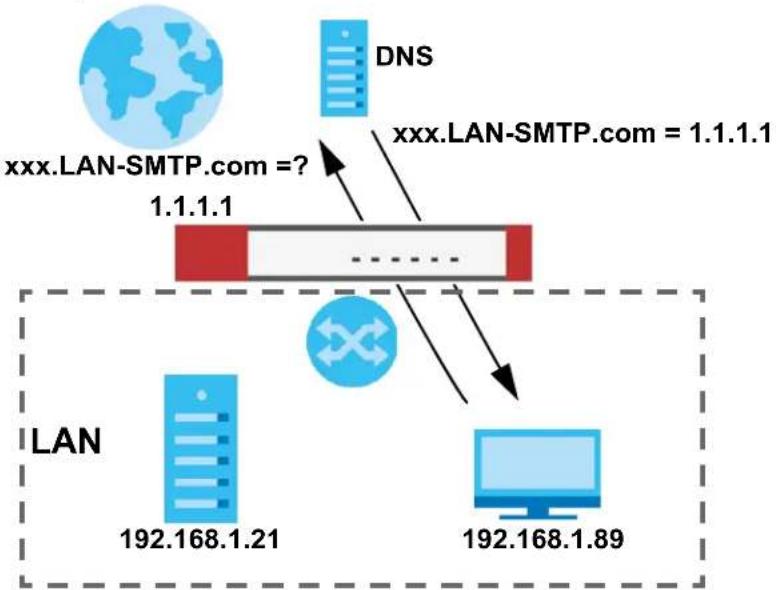
flowchart
graph TD
    A["LAN"] -->|192.168.1.21| B["DNS"]
    C["LAN-SMTP.com = ? 1.1.1.1"] --> D["..."]
    E["192.168.1.89"] --> F["Computer"]
    G["xxx.LAN-SMTP.com = 1.1.1.1"] --> H["DNS"]
The LAN user's computer then sends traffic to IP address 1.1.1.1. NAT loopback uses the IP address of the Zyxel Device's LAN interface (192.168.1.1) as the source address of the traffic going from the LAN users to the LAN SMTP server.
Figure 326 LAN to LAN Traffic
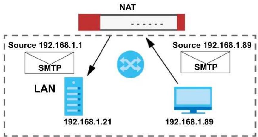
flowchart
graph TD
    A["NAT"] -->|Source 192.168.1.1\nSMTP| B["LAN"]
    A -->|Source 192.168.1.89\nSMTP| C["Computer"]
    B -->|192.168.1.21| C
    C -->|192.168.1.89| A
The LAN SMTP server replies to the Zyxel Device's LAN IP address and the Zyxel Device changes the source address to 1.1.1.1 before sending it to the LAN user. The return traffic's source matches the original destination address (1.1.1.1). If the SMTP server replied directly to the LAN user without the traffic going through NAT, the source would not match the original destination address which would cause the LAN user's computer to shut down the session.
Figure 327 LAN to LAN Return Traffic
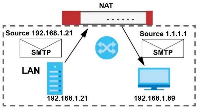
flowchart
graph TD
    A["NAT"] -->|Source 192.168.1.21| B["LAN"]
    A -->|Source 1.1.1| C["Computer"]
    B -->|192.168.1.21| A
    C -->|192.168.1.89| A
    B -->|SMTP| D["SMTP"]
    C -->|SMTP| E["SMTP"]
    style A fill:#f9f,stroke:#333
    style B fill:#bbf,stroke:#333
    style C fill:#bbf,stroke:#333
    style D fill:#dfd,stroke:#333
    style E fill:#dfd,stroke:#333
12.5 Virtual Server Load Balancing
Virtual Server Load balancing allows you to distribute incoming connection requests to a virtual server between multiple real (physical) servers. This helps reduce each server's workload and to decrease virtual server response times.
12.5.1 Load Balancing Example 1
You are hosting a very popular website on your network, which attracts a lot of traffic and causes problems with your HTTP web server. To resolve this, you set up three identical web servers on the DMZ behind the Zyxel Device (Figure 330 on page 476). The Zyxel Device device then distributes incoming HTTP requests between the three servers. External users only see one virtual web server with IP address 1.1.1.2.
Figure 328 Virtual Server on the WAN- Example 1
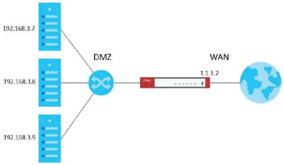
flowchart
graph LR
    A["192.168.3.7"] --> D["DMZ"]
    B["192.168.3.8"] --> D["DMZ"]
    C["192.168.3.9"] --> D["DMZ"]
    D["DMZ"] --> E["WAN"]
    E["1.1.1.2"] --> F["Global Network"]
12.5.2 Load Balancing Example 2
You have two internal networks, LAN 1 and LAN 2, that are restricted from accessing each other (Figure 329 on page 476). The LAN 2 network hosts two duplicate SMTP mail servers. You want clients on LAN 1 to be able to access the SMTP servers on LAN 2.
You create a virtual server load balancing rule using IP address 10.0.1.100 and port 25, and add two SMTP servers from LAN 2 to the rule. Now clients on LAN 1 can access the virtual server's SMTP service by connecting to 10.0.1.100 port 25. Clients see a single mail server.
Figure 329 Virtual Server on the LAN - Example 2

flowchart
graph TD
    A["192.168.1.10"] --> B["LAN 2"]
    C["192.168.1.11"] --> D["ZYXEL"]
    B --> E["10.0.1.100"]
    D --> F["10.0.1.100"]
    G["192.168.1.10"] --> H["LAN 2"]
    I["192.168.1.11"] --> J["LAN 2"]
    K["192.168.1.10"] --> L["LAN 1"]
    M["192.168.1.10"] --> N["LAN 1"]
    O["192.168.1.10"] --> P["LAN 1"]
12.5.3 Virtual Server Load Balancing Process
The following is an overview of how the Virtual Server Load Balancing process works.
Figure 330 Load Balancing Process
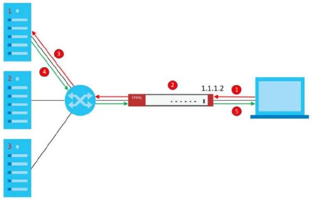
flowchart
graph TD
    A["Server 1"] -->|3| B((Central Network))
    C["Server 2"] -->|4| B
    D["Server 3"] -->|5| B
    B --> E["ZYXEL"]
    E --> F["1.1.1.2"]
    F --> G["Laptop"]
1 A client initiates a connection to the virtual server on a specific port.
2 The Zyxel Device matches the request to a set of servers (1, 2, and 3 in Figure 330 on page 476), and then determines which server will handle the request using a user-specified load balancing algorithm.
3 The Zyxel Device forwards the request to the chosen server using NAT.
4 The server processes the request, and then replies to the Zyxel Device.
5 The Zyxel Device forwards the reply to the client using SNAT.
12.5.4 Load Balancing Rules
In order to use load balancing, you must create a load balancing rule. Each load balancing rule consists of an incoming interface, an external IP address, a service type, a load balancing algorithm, and a list of real servers.
Note: One real server can belong to multiple load-balancing rules.
Note: You can only add one interface, IP address, and port to each load balancing rule.
Note: Virtual servers and real servers only support IPv4 addresses.
Only certain Zyxel Device models support virtual server load balancing. There are also limits on the maximum number of rules and real servers per Zyxel Device.
Table 177 Virtual Service Load Balancing Limits
| PARAMETER MODEL LIMIT | ||
| Maximum Number of Load Balancing Rules per Zyxel Device | USG FLEX 100, USG FLEX 100W 5 | |
| USG FLEX 200 10 | ||
| USG FLEX 500,USG FLEX 700 20 | ||
| Maximum Number of Real Servers Per Load Balancing Rule | All of the above models 4 |
12.5.5 Virtual Server Load Balancing Algorithms
A rule's load balancing algorithm determines which real server is assigned to an incoming connection request. When creating a load balancing rule, you can assign each server a weight, which indicates the server's processing capacity compared to other servers.
Table 178 Virtual Server Load Balancing Algorithms
| ALGORITHM DESCRIPTION | |
| Round-Robin | The Zyxel Device assigns servers in the reverse order they were added to the rule (Last In First Out). All servers are considered equal, regardless of their weight and current number of connections.For example, if you have three servers, A, B, C and nine requests, the servers are assigned in the following order: CBACBACBA. |
| Weighted Round-Robin | The Zyxel Device assigns servers based on a user-specified weight. Servers with a higher weight are assigned before servers with a lower weight. Each time a server is assigned a request, the server's weight decreases by one point until it finishes processing the request.The Zyxel Device assigns servers with equal weight in the reverse order they were added to the rule (Last In First Out). Servers with zero connections are given priority over all other servers.For example, if you have three servers A, B, C with weights 4, 3, 2 and nine requests, the servers are assigned in the following order: CBAABACBA.C (Weights: A4, B3, C2)CB (Weights: A4, B3, C1)CBA (Weights: A3, B2, C1)CBAA (Weights: A2, B2, C1)CBAAB (Weights: A2, B1, C1)CBAABA (Weights: A1, B1, C1)CBAABAC (Weights: A1, B1, C0)CBAABACB (Weights: A1, B0, C0)CBAABACBA (Weights: A0, B0, C0) |
| Least-Connection | The Zyxel Device assigns the server with the least number of current connections. |
| Source Hashing The Zyxel Devi | ce assigns a server by checking a static hash table, which permanently maps each client IP address to a specific real server.Servers are mapped to new client IP addresses in the reverse order the servers were added to the rule (Last In First Out). Each server is added N times during each sequence, where N is equal to the server's weight.For example, if you have two servers A, and B, with weights 1 and 2, the servers are mapped to new client IP addresses in the hash table in the following order:Source_IP_Hash1 = Server BSource_IP_Hash2 = Server BSource_IP_Hash3 = Server ASource_IP_Hash4 = Server BSource_IP_Hash5 = Server BSource_IP_Hash6 = Server A |
12.6 The Virtual Server Load Balancer Screen
Use this screen to view the summary of your virtual server load balancer rules. Click Configuration> Network>NAT> Virtual Server Load Balancer to open the following screen.
Figure 331 Configuration > Network > NAT > Virtual Server Load Balancing
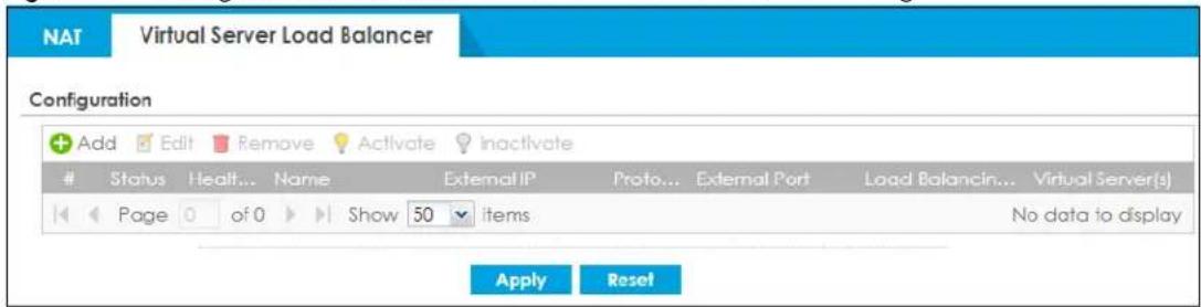
The following table describes the labels in this screen.
Table 179 Configuration > Network > NAT> Virtual Server Load Balancer
| LABEL DESCRIPTION | |
| Add Click this to create | a new entry. |
| Edit | Double-click an entry or select it and click Edit to open a screen where you can modify the entry's settings. |
| Remove | To remove an entry, select it and click Remove. The Zyxel Device confirms you want to remove it before doing so. |
| Activate | To turn on an entry, select it and click Activate. |
| Inactivate | To turn off an entry, select it and click Inactivate. |
| # This field is a sequential value, and it is not associated with a specific entry. | |
| Status This icon is lit when the entry is active and dimmed when the entry is inactive. | |
| Health Status | This field displays whether the real server is reachable for a particular service. |
| Name This field displays the name of the entry. | |
| External IP | This field displays the external destination IP address (or address object) of traffic that matches this entry. |
| Protocol This field displays the protocol used by the packets for this entry. | |
| External Port | This field displays the external destination port(s) of packets for the entry. |
| Load Balancing Algorithm | This field displays the load balancing algorithm for the entry. See Section 12.5.5 on page 478 for more information on load balancing algorithm. |
| Virtual Server(s) | This displays the number of real servers. Use MouseOver to see each real server IP. |
| Apply Click this button | to save your changes to the Zyxel Device. |
| Reset Click this button | to return the screen to its last-saved settings. |
12.6.1 Adding/Editing a Virtual Server Load Balancing Rule
Use this screen to configure settings for you virtual server load balancer rules. This screen's option change based on the Healthy Check Method selected. Only the PING method screen is displayed here.
Click Configuration> Network> NAT> Virtual Server Load Balancer> Add/ Edit to open the following screen.
Figure 332 Configuration > Network > NAT > Virtual Server Load Balancing > Add/Edit
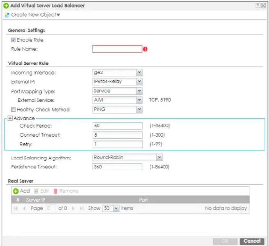
The following table describes the labels in this screen.
Table 180 Configuration > Network > NAT > Virtual Server Load Balancer> Add/Edit
| LABEL DESCRIPTION | |
| General Settings | |
| Create new Object | Use to configure any new settings objects that you need to use in this screen. |
| Enable Rule Use this option to turn the virtual server load balancer rule on or off. | |
| Rule Name | Type in the name of the virtual server load balancer rule. The name is used to refer to the virtual server load balancer rule. You may use 1-31 alphanumeric characters, underscores( ), or dashes (-), but the first character cannot be a number. This value is case-sensitive. |
| Virtual Server Rule | |
| Incoming Interface | Select the interface on which packets from the client to the virtual server load balancer rule must be received. It can be an Ethernet, VLAN, bridge, or PPPoE/PPTP interface. |
| External IP | This is the IP address of the virtual server. It may be different to the incoming interface IP address. Select a Host, Interface IP or Interface Gateway object already configured in Object> Address/ Geo IP> Address> IPv4 Address. or enter a User Defined IPv4 address for the virtual server. |
| User Defined External IP | This field is available if External IP is User Defined. Type the IPv4 address of the virtual server. |
| Port Mapping Type | Use the drop-down list box to select how many external destination ports this virtual server load balancer rule supports for the selected destination IP address (External IP). Choices are:Service- this virtual server load balancer rule supports a service such as FTP (see Object > Service > Service). For this type, you need to fill in External Service.External Service: Select a service from the drop down list box.Port- this virtual server load balancer rule supports one destination port. For this type, you need to fill in these fields.Protocol Type: TCP or UDPExternal Port: specify a port number for this ruleThe type of service or port selected automatically updates Healthy Check Method as follows:HTTP Request: 80, 8080HTTPS Request: 443SMTP Helo: 25DNS Query: 53(TCP/UDP)Default TCP if protocol is TCP, PING if protocol is UDPYou can still change the Healthy Check Method in the next field. |
| Healthy Check Method | Select this to periodically check if the real server is still online. The Zyxel Device periodically sends a request to each real server. This request ensures that the server is available, and optionally ensures that a specific service on the server is running.Use the drop-down list box to set the type of status request to send to each real server.For example, select HTTP and the Zyxel Device periodically sends an HTTP request to each real server, ensuring that the server is available and that its HTTP service is running.HTTP: Web serviceHTTPS: Secure web serviceTCP: A general network protocol that shows the server is accepting TCP connectionsSMTP: Mail serviceDNS: Dynamic Name ServicePING: A general network protocol that shows the server is reachable |
| PING | Check Period- Sets the health check time interval, in seconds. The default is 60.Connect Timeout- Sets the period of time in seconds that the Zyxel Device waits after sending a health check request before marking the health check as failed. The default is 5.Retry- Sets the number of times the Zyxel Device resends a health check request before marking the server as unavailable. The default is 1. |
| HTTP Request | Path- Sets the URL to request when the health check type is set to HTTP or HTTPS.Note: the Zyxel Device uses this checksum to verify that each HTTP health check request returns the correct webpage, and not an error page.Host- Sets the SNI to send to the real server when the health check type is set to HTTPS. A client sends a Server Name Indication (SNI) when they start an HTTPS session with the server. It allows multiple HTTPS sessions to the same IP address and port number with different certificates with different SNIs.Enable Hash Check- Enables or disables auto-hashing. When enabled, the Zyxel Device sends a HTTP request to each real server, and then calculates and stores the MD5 checksum of the returned webpage. The Zyxel Device uses this checksum to verify that each HTTP health check request returns the correct webpage, and not an error page.Status Code- Sets which status code indicates a successful reply when the health check type is set to HTTP or HTTPS. The default value is range 200–299 .Check Period- Sets the health check time interval, in seconds. The default is 60.Connect Timeout- Sets the period of time in seconds that the Zyxel Device waits after sending a health check request before marking the health check as failed. The default is 5.Retry- Sets the number of times the Zyxel Device resends a health check request before marking the server as unavailable. The default is 1. |
| HTTPS Request | Path- Sets the URL to request when the health check type is set to HTTP or HTTPS.Note: the Zyxel Device uses this checksum to verify that each HTTPS health check request returns the correct webpage, and not an error page.Host- Sets the SNI to send to the real server when the health check type is set to HTTPS. A client sends a Server Name Indication (SNI) when they start an HTTPS session with the server. It allows multiple HTTPS sessions to the same IP address and port number with different certificates with different SNIs.Enable Hash Check- Enables or disables auto-hashing. When enabled, the Zyxel Device sends a HTTP query to each real server, and then calculates and stores the MD5 checksum of the returned webpage. The Zyxel Device uses this checksum to verify that each HTTP health check request returns the correct webpage, and not an error page.Status Code- Sets which status code indicates a successful reply when the health check type is set to HTTP or HTTPS. The default value is range 200–299 .Enable SNI- Enables or disables sending a Server_Name Indication (SNI) as part of the health check request when health check type is set to HTTPS.Check Period- Sets the health check time interval, in seconds. The default is 60.Connect Timeout- Sets the period of time in seconds that the Zyxel Device waits after sending a health check request before marking the health check as failed. The default is 5.Retry- Sets the number of times the Zyxel Device resends a health check request before marking the server as unavailable. The default is 1. |
| SMTP Helo | Helo Name- Sets the HELO string to send to the real server, when the health check type is set to SMTP. Typically, the HELO string should contain the fully qualified domain name (FQDN) of the mail server.Check Period- Sets the health check time interval, in seconds. The default is 60.Connect Timeout- Sets the period of time in seconds that the Zyxel Device waits after sending a health check request before marking the health check as failed. The default is 5.Retry- Sets the number of times the Zyxel Device resends a health check request before marking the server as unavailable. The default is 1. |
| LABEL | DESCRIPTION |
| DNS Query | Query- Sets the fully qualified domain name (FQDN) to send to the real server when health check type is set to DNS.Check Period- Sets the health check time interval, in seconds. The default is 60.Connect Timeout- Sets the period of time in seconds that the Zyxel Device waits after sending a health check request before marking the health check as failed. The default is 5.Retry- Sets the number of times the Zyxel Device resends a health check request before marking the server as unavailable. The default is 1. |
| TCP Connection | Check Period- Sets the health check time interval, in seconds. The default is 60.Connect Timeout- Sets the period of time in seconds that the Zyxel Device waits after sending a health check request before marking the health check as failed. The default is 5.Retry- Sets the number of times the Zyxel Device resends a health check request before marking the server as unavailable. The default is 1. |
| Advance | |
| Check Period | Use this to set the health check time interval in seconds. The default is 60. |
| Connect Timeout | Use this to set the period of time in seconds that the Zyxel Device waits after sending a health check request before marking the health check as failed. The default is 5. |
| Retry | Use this to set the number of times the Zyxel Device resends a health check request before marking the server as unavailable. The default is 1. |
| Load Balancing Algorithm | Sets the load balancing algorithm for this rule. For information about each algorithm, see Section 12.5.5 on page 478. |
| Persistence Timeout | Sets how long a client/server session with no activity stays open. Timeout is measured in seconds, and the default value is 360.Multiple requests from a client within a short time period are directed to the same real server, as part of a persistent client/server session.If there are no incoming requests from a client within the specified timeout period, then the persistent client/server session is closed. Further requests from the client might be assigned to a different real server, determined by the load balancing algorithm. |
| Real Server | |
| Add Click this to create a new entry. | |
| Edit | Double-click an entry or select it and click Edit to modify the entry's settings. |
| Remove | To remove an entry, select it and click Remove. The Zyxel Device confirms you want to remove it before doing so. |
| # | This field is a sequential value, and it is not associated with a specific entry. |
| Server IP This field displays the IPv4 address of a server on the LAN. | |
| Port | This field displays the External Port or the port based on the External Service selected above. You may change the port here. |
| Weight | The weight represents the processing power of this server compared to other servers. A server with a weight of 2 is considered to be able to handle two times more requests than a server with a weight of 1. See Section 12.5.5 on page 478 for more information on weight in each load balancing algorithm. |
| OK | Click OK to save your changes back to the Zyxel Device. |
| Cancel | Click Cancel to return to the Virtual Server Load Balancer summary screen without creating the virtual server load balancer rule (if it is new) or saving any changes (if it already exists). |
CHAPTER 13
Redirect Service
13.1 Overview
Redirect Service redirects HTTP and SMTP traffic.
13.1.1 HTTP Redirect
HTTP redirect forwards the client's HTTP request (except HTTP traffic destined for the Zyxel Device) to a web proxy server. In the following example, proxy server A is connected to the DMZ interface. When a client connected to the LAN1 zone wants to open a web page, its HTTP request is redirected to proxy server A first. If proxy server A cannot find the web page in its cache, a policy route allows it to access the Internet to get them from a server. Proxy server A then forwards the response to the client.
Figure 333 HTTP Redirect Example
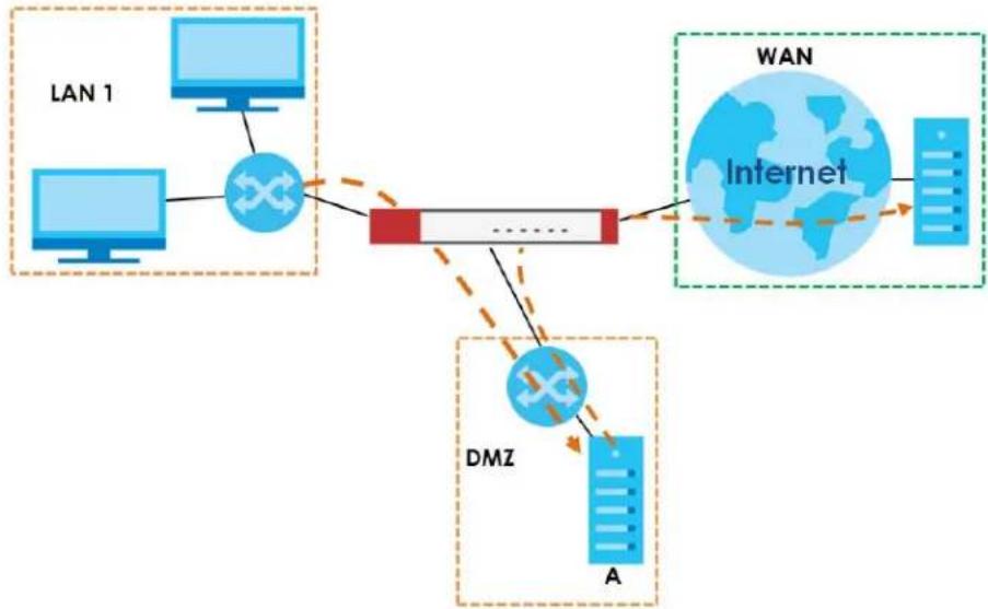
flowchart
graph TD
    A["LAN 1"] --> B["Computer"]
    C["Computer"] --> B
    B --> D["Network"]
    D --> E["WAN"]
    D --> F["Internet"]
    D --> G["DMZ"]
    G --> H["A"]
    style A fill:#cce5ff,stroke:#333
    style C fill:#cce5ff,stroke:#333
    style D fill:#ffcccc,stroke:#333
    style E fill:#e6f7ff,stroke:#333
    style F fill:#e6f7ff,stroke:#333
    style G fill:#e6f7ff,stroke:#333
    style H fill:#e6f7ff,stroke:#333
13.1.2 SMTP Redirect
SMTP redirect forwards the authenticated client's SMTP message to a SMTP server, that handles all outgoing email messages. In the following example, SMTP server A is connected to the lan2 interface in the LAN2 zone. When a client connected to the lan1 interface in the LAN1 zone logs into the Zyxel Device and wants to send an email, its SMTP message is redirected to SMTP server A. SMTP server A then sends it to a mail server, where the message will be delivered to the recipient.
The Zyxel Device forwards SMTP traffic using TCP port 25.
Figure 334 SMTP Redirect Example
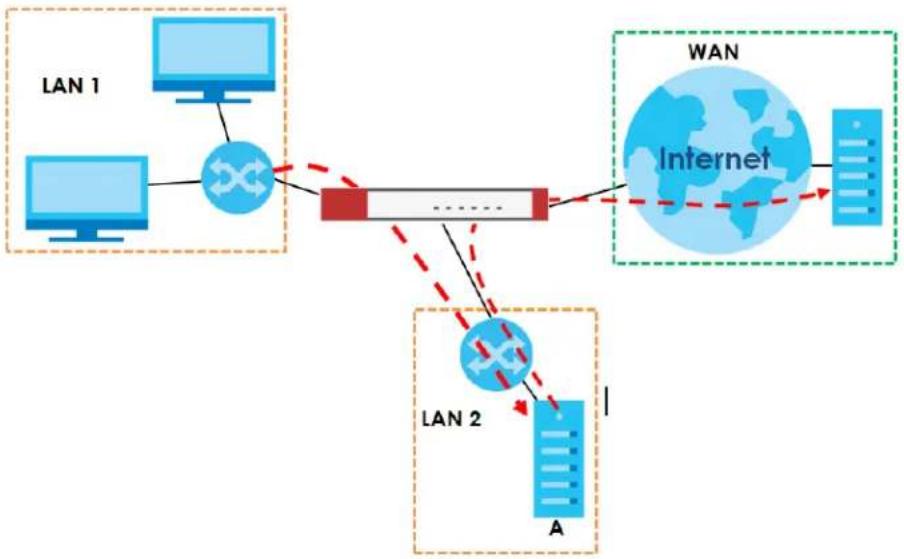
flowchart
graph TD
    subgraph_LAN_1["LAN 1"]
        A["Computer"] --> B["Switch"]
    end
    subgraph_LAN_2["LAN 2"]
        C["Computer"] --> D["Switch"]
    end
    B --> E["Router"]
    D --> E
    E --> F["Internet"]
    F --> G["WAN"]
    G --> H["Server"]
    style LAN_1 fill:#f9f,stroke:#333
    style LAN_2 fill:#bbf,stroke:#333
    style WAN fill:#dfd,stroke:#333
    style Internet fill:#ffd,stroke:#333
13.1.3 What You Can Do in this Chapter
Use the Redirect Service screens (see Section 13.2 on page 487) to display and edit the HTTP and SMTP redirect rules.
13.1.4 What You Need to Know
Web Proxy Server
A proxy server helps client devices make indirect requests to access the Internet or outside network resources/services. A proxy server can act as a security policy or an ALG (application layer gateway) between the private network and the Internet or other networks. It also keeps hackers from knowing internal IP addresses.
A client connects to a web proxy server each time he/she wants to access the Internet. The web proxy provides caching service to allow quick access and reduce network usage. The proxy checks its local cache for the requested web resource first. If it is not found, the proxy gets it from the specified server and forwards the response to the client.
HTTP Redirect, Security Policy and Policy Route
With HTTP redirect, the relevant packet flow for HTTP traffic is:
1 Security Policy
2 Application Patrol
3 HTTP Redirect
4 Policy Route
Even if you set a policy route to the same incoming interface and service as a HTTP redirect rule, the Zyxel Device checks the HTTP redirect rules first and forwards HTTP traffic to a proxy server if matched. You need to make sure there is no security policy blocking the HTTP requests from the client to the proxy server.
You also need to manually configure a policy route to forward the HTTP traffic from the proxy server to the Internet. To make the example in Figure 333 on page 484 work, make sure you have the following settings.
For HTTP traffic between lan1 and dmz:
- a from LAN1 to DMZ security policy (default) to allow HTTP requests from lan1 to dmz. Responses to this request are allowed automatically.
- a application patrol rule to allow HTTP traffic between lan1 and dmz.
- a HTTP redirect rule to forward HTTP traffic from lan1 to proxy server A.
For HTTP traffic between dmz and wan1:
- a from DMZ to WAN security policy (default) to allow HTTP requests from dmz to wan1. Responses to these requests are allowed automatically.
- a application patrol rule to allow HTTP traffic between dmz and wan1.
- a policy route to forward HTTP traffic from proxy server A to the Internet.
SMTP
Simple Mail Transfer Protocol (SMTP) is the Internet's message transport standard. It controls the sending of email messages between servers. Email clients (also called email applications) then use mail server protocols such as POP (Post Office Protocol) or IMAP (Internet Message Access Protocol) to retrieve email. Email clients also generally use SMTP to send messages to a mail server. The older POP2 requires SMTP for sending messages while the newer POP3 can be used with or without it. This is why many email applications require you to specify both the SMTP server and the POP or IMAP server (even though they may actually be the same server).
SMTP Redirect, Firewall and Policy Route
With SMTP redirect, the relevant packet flow for SMTP traffic is:
1 Firewall
2 SMTP Redirect
3 Policy Route
Even if you set a policy route to the same incoming interface and service as a SMTP redirect rule, the Zyxel Device checks the SMTP redirect rules first and forwards SMTP traffic to a SMTP server if matched. You need to make sure there is no firewall rule(s) blocking the SMTP traffic from the client to the SMTP server.
You also need to manually configure a policy route to forward the SMTP traffic from the SMTP server to the Internet. To make the example in Figure 334 on page 485 work, make sure you have the following settings.
For SMTP traffic between lan1 and lan2:
- a from LAN1 to LAN2 firewall rule to allow SMTP messages from lan1 to lan2. Responses to this request are allowed automatically.
- a SMTP redirect rule to forward SMTP traffic from lan1 to SMTP server A.
For SMTP traffic between lan2 and wan1:
- a from LAN2 to WAN firewall rule (default) to allow SMTP messages from lan2 to wan1. Responses to these requests are allowed automatically.
- a policy route to forward SMTP messages from SMTP server A to the Internet.
13.2 The Redirect Service Screen
To configure redirection of a HTTP or SMTP request, click Configuration > Network > HTTP Redirect. This screen displays the summary of the redirect rules.
Note: You can configure up to one HTTP redirect rule and one SMTP redirect rule for each (incoming) interface.
Figure 335 Configuration > Network > Redirect Service
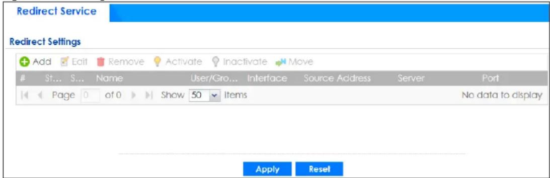
The following table describes the labels in this screen.
Table 181 Configuration > Network > Redirect Service
| LABEL DESCRIPTION | |
| Add Click this to create a new entry. | |
| Edit | Double-click an entry or select it and click Edit to open a screen where you can modify the entry's settings. |
| Remove | To remove an entry, select it and click Remove. The Zyxel Device confirms you want to remove it before doing so. |
| Activate | To turn on an entry, select it and click Activate. |
| Inactivate | To turn off an entry, select it and click Inactivate. |
| Move | To change a rule's position in the numbered list, select the rule and click Move to display a field to type a number for where you want to put that rule and press [ENTER] to move the rule to the number that you typed.The ordering of your rules is important as they are applied in order of their numbering. |
| # | This field is a sequential value, and it is not associated with a specific entry. |
| Status | This icon is lit when the entry is active and dimmed when the entry is inactive. |
| Service This is the name of the service: HTTP or SMTP. | |
| Name This is the descriptive name of a rule. | |
| User/Group This is the user account or user group name to which this rule is applied. | |
| Interface This is the interface on which the request must be received. | |
| Source Address | This is the name of the source IP address object from which the traffic should be sent. If any displays, the rule is effective for every source. |
| Server | This is the IP address of the HTTP proxy server or the SMTP server to which the matched traffic is forwarded. |
| Port | This is the service port number used by the HTTP proxy server or SMTP server. |
| Apply | Click Apply to save your changes back to the Zyxel Device. |
| Reset | Click Reset to return the screen to its last-saved settings. |
13.2.1 The Redirect Service Edit Screen
Click Network > Redirect Service to open the Redirect Service screen. Then click the Add or Edit icon to open the Redirect Service Edit screen where you can configure the rule.
Figure 336 Network > Redirect Service > Edit
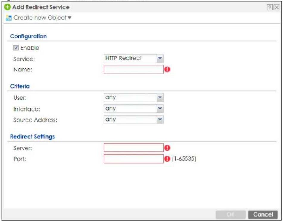
The following table describes the labels in this screen.
Table 182 Network > Redirect Service > Edit
| LABEL DESCRIPTION | |
| Enable Use this option to turn the Redirect Service rule on or off. | |
| Service | Select the service to be redirected: HTTP Redirect or SMTP redirect. |
| Name Enter a name to identify this rule. You may use 1-31 alphanumeric characters, underscores( ), or dashes (-), but the first character cannot be a number. This value is case-sensitive. | |
| Criteria | |
| User | Select the user account or user group name to which this rule is applied. |
| Interface | Select the interface on which the request must be received for the Zyxel Device to forward it to the specified server. |
| Source Address | Select the name of the source IP address object from which the traffic should be sent. Select any for the rule to be effective for every source. |
| Redirect Settings | |
| Server Enter the IP address of the HTTP proxy or SMTP server. | |
| Port Enter the port number that the HTTP proxy or SMTP server uses. | |
| OK | Click OK to save your changes back to the Zyxel Device. |
| Cancel | Click Cancel to exit this screen without saving. |
CHAPTER 14 ALG
14.1 ALG Overview
Application Layer Gateway (ALG) allows the following applications to operate properly through the Zyxel Device's NAT.
- SIP - Session Initiation Protocol (SIP) - An application-layer protocol that can be used to create voice and multimedia sessions over Internet.
• H.323 - A teleconferencing protocol suite that provides audio, data and video conferencing. - FTP - File Transfer Protocol - an Internet file transfer service.
The following example shows SIP signaling (1) and audio (2) sessions between SIP clients A and B and the SIP server.
Figure 337 SIP ALG Example
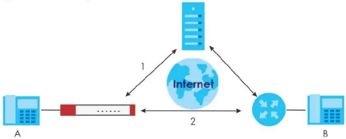
flowchart
graph TD
    A["A"] --> B["......"]
    B --> C["Internet"]
    C --> D["→"]
    D --> E["B"]
    style C fill:#cce5ff,stroke:#333
    style D fill:#cce5ff,stroke:#333
    note1["1"] --> C
    note2["2"] --> C
The ALG feature is only needed for traffic that goes through the Zyxel Device's NAT.
14.1.1 What You Need to Know
Application Layer Gateway (ALG), NAT and Security Policy
The Zyxel Device can function as an Application Layer Gateway (ALG) to allow certain NAT un-friendly applications (such as SIP) to operate properly through the Zyxel Device's NAT and security policy. The Zyxel Device dynamically creates an implicit NAT session and security policy session for the application's traffic from the WAN to the LAN. The ALG on the Zyxel Device supports all of the Zyxel Device's NAT mapping types.
FTP ALG
The FTP ALG allows TCP packets with a specified port destination to pass through. If the FTP server is located on the LAN, you must also configure NAT (port forwarding) and security policies if you want to allow access to the server from the WAN. Bandwidth management can be applied to FTP ALG traffic.
H.323 ALG
• The H.323 ALG supports peer-to-peer H.323 calls.
- The H.323 ALG handles H.323 calls that go through NAT or that the Zyxel Device routes. You can also make other H.323 calls that do not go through NAT or routing. Examples would be calls between LAN IP addresses that are on the same subnet.
- The H.323 ALG allows calls to go out through NAT. For example, you could make a call from a private IP address on the LAN to a peer device on the WAN.
- The H.323 ALG operates on TCP packets with a specified port destination.
- Bandwidth management can be applied to H.323 ALG traffic.
• The Zyxel Device allows H.323 audio connections.
- The Zyxel Device can also apply bandwidth management to traffic that goes through the H.323 ALG.
The following example shows H.323 signaling (1) and audio (2) sessions between H.323 devices A and B.
Figure 338 H.323 ALG Example
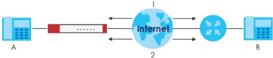
flowchart
graph LR
    A["A"] --> B["......"]
    B --> C["Internet"]
    C --> D["2"]
    D --> E["B"]
    style C fill:#cce5ff,stroke:#333
    style D fill:#cce5ff,stroke:#333
SIP ALG
- SIP phones can be in any zone (including LAN, DMZ, WAN), and the SIP server and SIP clients can be in the same network or different networks. The SIP server cannot be on the LAN. It must be on the WAN or the DMZ.
- There should be only one SIP server (total) on the Zyxel Device's private networks. Any other SIP servers must be on the WAN. So for example you could have a Back-to-Back User Agent such as the IPPBX x6004 or an asterisk PBX on the DMZ or on the LAN but not on both.
- Using the SIP ALG allows you to use bandwidth management on SIP traffic. Bandwidth management can be applied to FTP ALG traffic. Use the option in the Configuration > BWM screen to configure the highest bandwidth available for SIP traffic.
- The SIP ALG handles SIP calls that go through NAT or that the Zyxel Device routes. You can also make other SIP calls that do not go through NAT or routing. Examples would be calls between LAN IP addresses that are on the same subnet.
- The SIP ALG supports peer-to-peer SIP calls. The security policy (by default) allows peer to peer calls from the LAN zone to go to the WAN zone and blocks peer to peer calls from the WAN zone to the LAN zone.
- The SIP ALG allows UDP packets with a specified port destination to pass through.
-
The Zyxel Device allows SIP audio connections.
-
You do not need to use TURN (Traversal Using Relay NAT) for VoIP devices behind the Zyxel Device when you enable the SIP ALG.
- Configuring the SIP ALG to use custom port numbers for SIP traffic also configures the application patrol (see Chapter 32 on page 713) to use the same port numbers for SIP traffic. Likewise, configuring the application patrol to use custom port numbers for SIP traffic also configures SIP ALG to use the same port numbers for SIP traffic.
Peer-to-Peer Calls and the Zyxel Device
The Zyxel Device ALG can allow peer-to-peer VoIP calls for both H.323 and SIP. You must configure the security policy and NAT (port forwarding) to allow incoming (peer-to-peer) calls from the WAN to a private IP address on the LAN (or DMZ).
VoIP Calls from the WAN with Multiple Outgoing Calls
When you configure the security policy and NAT (port forwarding) to allow calls from the WAN to a specific IP address on the LAN, you can also use policy routing to have H.323 (or SIP) calls from other LAN or DMZ IP addresses go out through a different WAN IP address. The policy routing lets the Zyxel Device correctly forward the return traffic for the calls initiated from the LAN IP addresses.
For example, you configure the security policy and NAT to allow LAN IP address A to receive calls from the Internet through WAN IP address 1. You also use a policy route to have LAN IP address A make calls out through WAN IP address 1. Configure another policy route to have H.323 (or SIP) calls from LAN IP addresses B and C go out through WAN IP address 2. Even though only LAN IP address A can receive incoming calls from the Internet, LAN IP addresses B and C can still make calls out to the Internet.
Figure 339 VoIP Calls from the WAN with Multiple Outgoing Calls
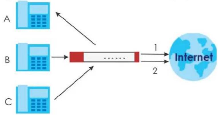
flowchart
graph LR
    A["Device A"] --> D["Processing Block"]
    B["Device B"] --> D
    C["Device C"] --> D
    D --> E["Internet"]
    style D fill:#f9f,stroke:#333
    style E fill:#bbf,stroke:#333
VoIP with Multiple WAN IP Addresses
With multiple WAN IP addresses on the Zyxel Device, you can configure different security policy and NAT (port forwarding) rules to allow incoming calls from each WAN IP address to go to a specific IP address on the LAN (or DMZ). Use policy routing to have the H.323 (or SIP) calls from each of those LAN or DMZ IP addresses go out through the same WAN IP address that calls come in on. The policy routing lets the Zyxel Device correctly forward the return traffic for the calls initiated from the LAN IP addresses.
For example, you configure security policy and NAT rules to allow LAN IP address A to receive calls through public WAN IP address 1. You configure different security policy and port forwarding rules to allow LAN IP address B to receive calls through public WAN IP address 2. You configure corresponding
policy routes to have calls from LAN IP address A go out through WAN IP address 1 and calls from LAN IP address B go out through WAN IP address 2.
Figure 340 VoIP with Multiple WAN IP Addresses
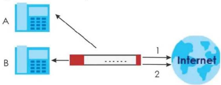
flowchart
graph LR
    A["Device A"] -->|Data Flow| B["Device B"]
    B -->|Data Flow| C["Internet"]
    style A fill:#cce5ff,stroke:#333
    style B fill:#cce5ff,stroke:#333
    style C fill:#cce5ff,stroke:#333
14.1.2 Before You Begin
You must also configure the security policy and enable NAT in the Zyxel Device to allow sessions initiated from the WAN.
14.2 The ALG Screen
Click Configuration > Network > ALG to open the ALG screen. Use this screen to turn ALGs off or on, configure the port numbers to which they apply, and configure SIP ALG time outs.
Note: If the Zyxel Device provides an ALG for a service, you must enable the ALG in order to use the application patrol on that service's traffic.
Figure 341 Configuration > Network > ALG
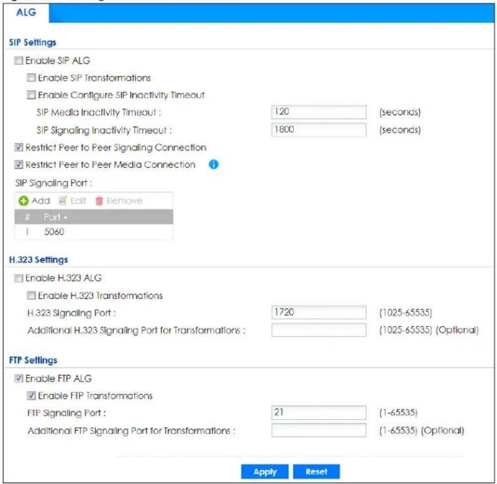
The following table describes the labels in this screen.
Table 183 Configuration > Network > ALG
| LABEL DESCRIPTION | |
| Enable SIP ALG | Turn on the SIP ALG to detect SIP traffic and help build SIP sessions through the Zyxel Device's NAT. Enabling the SIP ALG also allows you to use the application patrol to detect SIP traffic and manage the SIP traffic's bandwidth (see Chapter 32 on page 713). |
| Enable SIP Transformations | Select this to have the Zyxel Device modify IP addresses and port numbers embedded in the SIP data payload.You do not need to use this if you have a SIP device or server that will modify IP addresses and port numbers embedded in the SIP data payload. |
| Enable Configure SIP Inactivity Timeout | Select this option to have the Zyxel Device apply SIP media and signaling inactivity time out limits. These timeouts will take priority over the SIP session time out “Expires” value in a SIP registration response packet. |
| SIP Media Inactivity Timeout | Use this field to set how many seconds (1~86400) the Zyxel Device will allow a SIP session to remain idle (without voice traffic) before dropping it.If no voice packets go through the SIP ALG before the timeout period expires, the Zyxel Device deletes the audio session. You cannot hear anything and you will need to make a new call to continue your conversation. |
| SIP Signaling Inactivity Timeout | Most SIP clients have an “expire” mechanism indicating the lifetime of signaling sessions. The SIP user agent sends registration packets to the SIP server periodically and keeps the session alive in the Zyxel Device.If the SIP client does not have this mechanism and makes no calls during the Zyxel Device SIP timeout, the Zyxel Device deletes the signaling session after the timeout period. Enter the SIP signaling session timeout value (1~86400). |
| Restrict Peer to Peer Signaling Connection | A signaling connection is used to set up the SIP connection.Enable this if you want signaling connections to only arrive from the IP address(es) you registered with. Signaling connections from other IP addresses will be dropped. |
| Restrict Peer to Peer Media Connection | A media connection is the audio transfer in a SIP connection.Enable this if you want media connections to only arrive from the IP address(es) you registered with. Media connections from other IP addresses will be dropped.You should disable this if have registered for cloud VoIP services. |
| SIP Signaling Port | If you are using a custom UDP port number (not 5060) for SIP traffic, enter it here. Use the Add icon to add fields if you are also using SIP on additional UDP port numbers. |
| Enable H.323 ALG | Turn on the H.323 ALG to detect H.323 traffic (used for audio communications) and help build H.323 sessions through the Zyxel Device’s NAT. Enabling the H.323 ALG also allows you to use the application patrol to detect H.323 traffic and manage the H.323 traffic's bandwidth (see Chapter 32 on page 713). |
| Enable H.323 Transformations | Select this to have the Zyxel Device modify IP addresses and port numbers embedded in the H.323 data payload.You do not need to use this if you have a H.323 device or server that will modify IP addresses and port numbers embedded in the H.323 data payload. |
| H.323 Signaling Port | If you are using a custom TCP port number (not 1720) for H.323 traffic, enter it here. |
| Additional H.323 Signaling Port for Transformations | If you are also using H.323 on an additional TCP port number, enter it here. |
| Enable FTP ALG | Turn on the FTP ALG to detect FTP (File Transfer Program) traffic and help build FTP sessions through the Zyxel Device’s NAT. Enabling the FTP ALG also allows you to use the application patrol to detect FTP traffic and manage the FTP traffic's bandwidth (see Chapter 32 on page 713). |
| Enable FTP Transformations | Select this option to have the Zyxel Device modify IP addresses and port numbers embedded in the FTP data payload to match the Zyxel Device's NAT environment.Clear this option if you have an FTP device or server that will modify IP addresses and port numbers embedded in the FTP data payload to match the Zyxel Device’s NAT environment. |
| FTP Signaling Port | If you are using a custom TCP port number (not 21) for FTP traffic, enter it here. |
| Additional FTP Signaling Port for Transformations | If you are also using FTP on an additional TCP port number, enter it here. |
| Apply | Click Apply to save your changes back to the Zyxel Device. |
| Reset | Click Reset to return the screen to its last-saved settings. |
14.3 ALG Technical Reference
Here is more detailed information about the Application Layer Gateway.
ALG
Some applications cannot operate through NAT (are NAT unfriendly) because they embed IP addresses and port numbers in their packets' data payload. The Zyxel Device examines and uses IP address and port number information embedded in the VoIP traffic's data stream. When a device behind the Zyxel Device uses an application for which the Zyxel Device has VoIP pass through enabled, the Zyxel Device translates the device's private IP address inside the data stream to a public IP address. It also records session port numbers and allows the related sessions to go through the security policy so the application's traffic can come in from the WAN to the LAN.
ALG and Trunks
If you send your ALG-managed traffic through an interface trunk and all of the interfaces are set to active, you can configure routing policies to specify which interface the ALG-managed traffic uses.
You could also have a trunk with one interface set to active and a second interface set to passive. The Zyxel Device does not automatically change ALG-managed connections to the second (passive) interface when the active interface's connection goes down. When the active interface's connection fails, the client needs to re-initialize the connection through the second interface (that was set to passive) in order to have the connection go through the second interface. VoIP clients usually re-register automatically at set intervals or the users can manually force them to re-register.
FTP
File Transfer Protocol (FTP) is an Internet file transfer service that operates on the Internet and over TCP/IP networks. A system running the FTP server accepts commands from a system running an FTP client. The service allows users to send commands to the server for uploading and downloading files.
H.323
H.323 is a standard teleconferencing protocol suite that provides audio, data and video conferencing. It allows for real-time point-to-point and multipoint communication between client computers over a packet-based network that does not provide a guaranteed quality of service. NetMeeting uses H.323.
SIP
The Session Initiation Protocol (SIP) is an application-layer control (signaling) protocol that handles the setting up, altering and tearing down of voice and multimedia sessions over the Internet. SIP is used in VoIP (Voice over IP), the sending of voice signals over the Internet Protocol.
SIP signaling is separate from the media for which it handles sessions. The media that is exchanged during the session can use a different path from that of the signaling. SIP handles telephone calls and can interface with traditional circuit-switched telephone networks.
RTP
When you make a VoIP call using H.323 or SIP, the RTP (Real time Transport Protocol) is used to handle voice data transfer. See RFC 1889 for details on RTP.
CHAPTER 15 UPnP
15.1 UPnP and NAT-PMP Overview
The Zyxel Device supports both UPnP and NAT-PMP to permit networking devices to discover each other and connect seamlessly.
Universal Plug and Play (UPnP) is a distributed, open networking standard that uses TCP/IP for simple peer-to-peer network connectivity between devices. A UPnP device can dynamically join a network, obtain an IP address, convey its capabilities and learn about other devices on the network. In turn, a device can leave a network smoothly and automatically when it is no longer in use. A gateway that supports UPnP is called Internet Gateway Device (IGD). The standardized Device Control Protocol (DCP) is defined by the UPnP Forum for IGDs to configure port mapping automatically.
NAT Port Mapping Protocol (NAT-PMP), introduced by Apple and implemented in current Apple products, is used as an alternative NAT traversal solution to the UPnP IGD protocol. NAT-PMP runs over UDP port 5351. NAT-PMP is much simpler than UPnP IGD and mainly designed for small home networks. It allows a client behind a NAT router to retrieve the router's public IP address and port number and make them known to the peer device with which it wants to communicate. The client can automatically configure the NAT router to create a port mapping to allow the peer to contact it.
15.2 What You Need to Know
UPnP hardware is identified as an icon on the network folder (Windows 7). Each UPnP compatible device installed on your network will appear as a separate icon. Selecting the icon of a UPnP device will allow you to access the information and properties of that device.
15.2.1 NAT Traversal
UPnP NAT traversal automates the process of allowing an application to operate through NAT. UPnP network devices can automatically configure network addressing, announce their presence on the network to other UPnP devices and enable exchange of simple product and service descriptions. NAT traversal allows the following:
• Dynamic port mapping
- Learning public IP addresses
- Assigning lease times to mappings
Windows Messenger is an example of an application that supports NAT traversal and UPnP.
See the NAT chapter for more information on NAT.
15.2.2 Cautions with UPnP and NAT-PMP
The automated nature of NAT traversal applications in establishing their own services and opening security policy ports may present network security issues. Network information and configuration may also be obtained and modified by users in some network environments.
When a UPnP or NAT-PMP device joins a network, it announces its presence with a multicast message. For security reasons, the Zyxel Device allows multicast messages on the LAN only.
All UPnP-enabled or NAT-PMP-enabled devices may communicate freely with each other without additional configuration. Disable UPnP or NAT-PMP if this is not your intention.
15.3 UPnP Screen
Use this screen to enable UPnP and NAT-PMP on your Zyxel Device.
Click Configuration > Network > UPnP to display the screen shown next.
Figure 342 Configuration > Network > UPnP
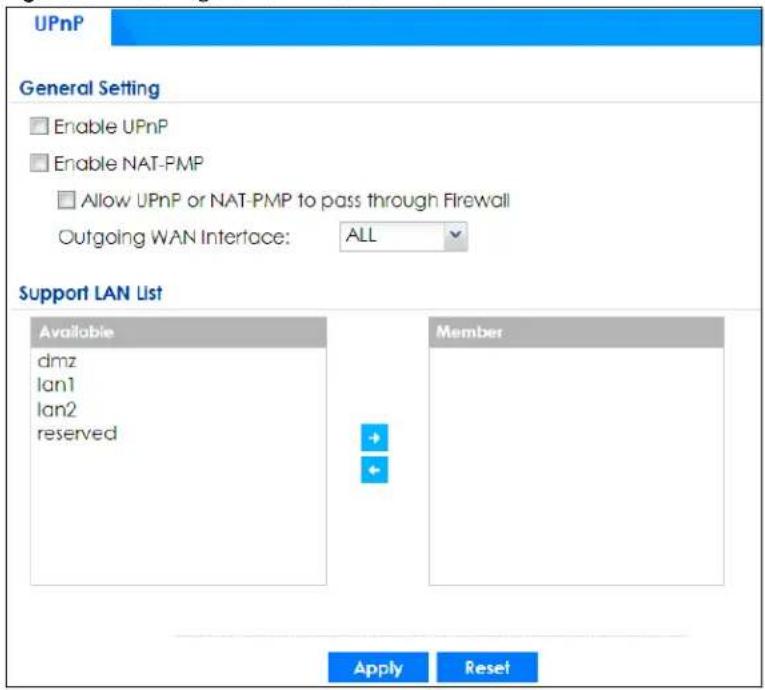
The following table describes the fields in this screen.
Table 184 Configuration > Network > UPnP
| LABEL DESCRIPTION | |
| Enable UPnP | Select this check box to activate UPnP on the Zyxel Device. Be aware that anyone could use a UPnP application to open the web configurator's login screen without entering the Zyxel Device's IP address (although you must still enter the password to access the web configurator). |
| Enable NAT-PMP | NAT Port Mapping Protocol (NAT-PMP) automates port forwarding to allow a computer in a private network (behind the Zyxel Device) to automatically configure the Zyxel Device to allow computers outside the private network to contact it.Select this check box to activate NAT-PMP on the Zyxel Device. Be aware that anyone could use a NAT-PMP application to open the web configurator's login screen without entering the Zyxel Device's IP address (although you must still enter the password to access the web configurator). |
| Allow UPnP or NAT-PMP to pass through Firewall | Select this check box to allow traffic from UPnP-enabled or NAT-PMP-enabled applications to bypass the security policy.Clear this check box to have the security policy block all UPnP or NAT-PMP application packets (for example, MSN packets). |
| Outgoing WAN Interface | Select through which WAN interface(s) you want to send out traffic from UPnP-enabled or NAT-PMP-enabled applications. If the WAN interface you select loses its connection, the Zyxel Device attempts to use the other WAN interface. If the other WAN interface also does not work, the Zyxel Device drops outgoing packets from UPnP-enabled or NAT-PMP-enabled applications. |
| Support LAN List | The Available list displays the name(s) of the internal interface(s) on which the Zyxel Device supports UPnP and/or NAT-PMP.To enable UPnP and/or NAT-PMP on an interface, you can double-click a single entry to move it or use the [Shift] or [Ctrl] key to select multiple entries and click the right arrow button to add to the Member list. To remove an interface, select the name(s) in the Member list and click the left arrow button. |
| Apply | Click Apply to save your changes back to the Zyxel Device. |
| Reset | Click Reset to return the screen to its last-saved settings. |
15.4 Technical Reference
The sections show examples of using UPnP.
15.4.1 Turning on UPnP in Windows 7 Example
This section shows you how to use the UPnP feature in Windows 7. UPnP server is installed in Windows 7. Activate UPnP on the Zyxel Device.
Make sure the computer is connected to a LAN port of the Zyxel Device. Turn on your computer and the Zyxel Device.
1 Click the start icon, Control Panel and then the Network and Sharing Center.
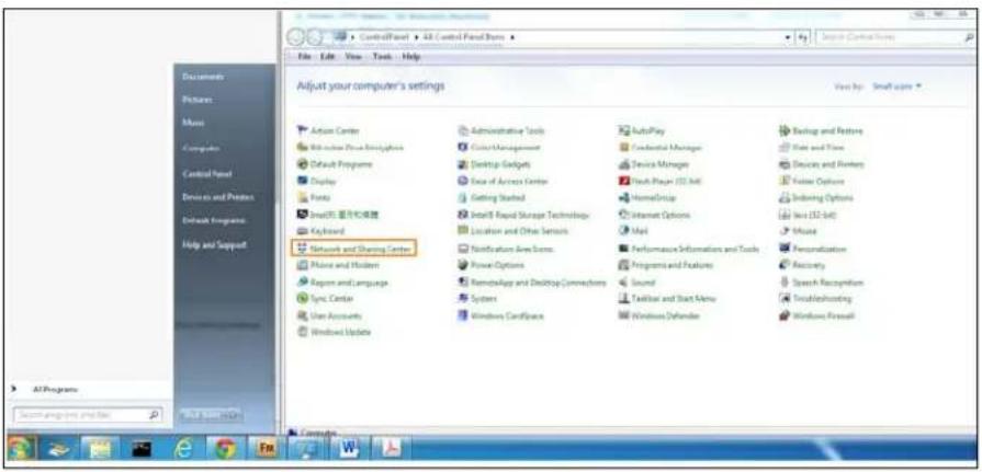
2 Click Change Advanced Sharing Settings.
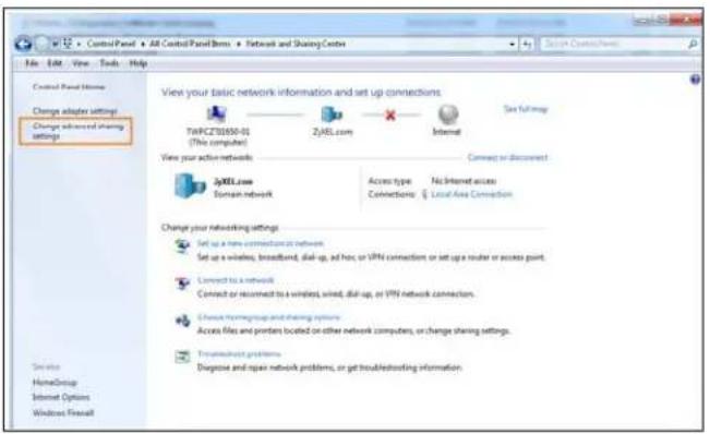
3 Select Turn on network discovery and click Save Changes. Network discovery allows your computer to find other computers and devices on the network and other computers on the network to find your computer. This makes it easier to share files and printers.
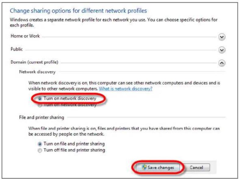
15.4.1.1 Auto-discover Your UPnP-enabled Network Device
Before you follow these steps, make sure you already have UPnP activated on the Zyxel Device and in your computer.
Make sure your computer is connected to a LAN port of the Zyxel Device.
1 Open the Windows Explorer and click Network.
2 Right-click the device icon and select Properties.
Figure 343 Network Connections
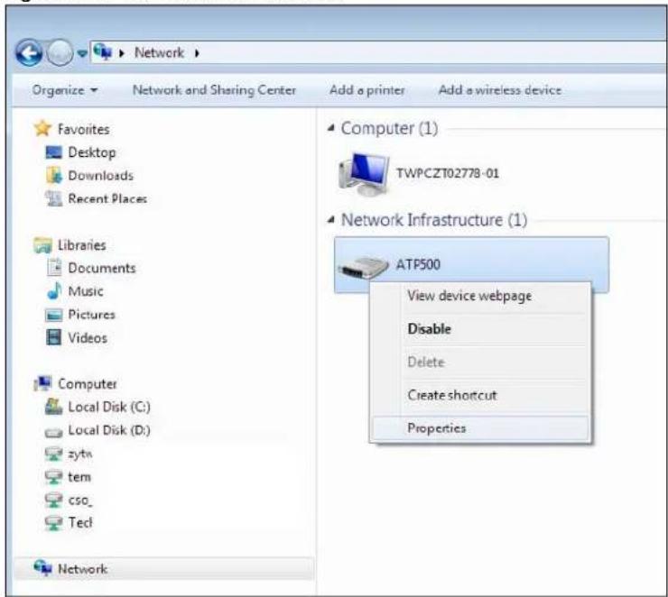
3 In the Internet Connection Properties window, click Settings to see port mappings.
Figure 344 Internet Connection Properties
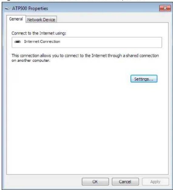
4 You may edit or delete the port mappings or click Add to manually add port mappings.
Figure 345 Internet Connection Properties: Advanced Settings
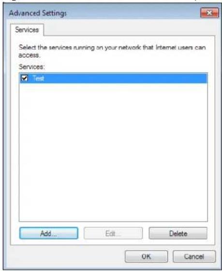
Figure 346 Internet Connection Properties: Advanced Settings: Add
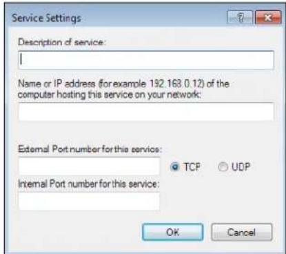
Note: When the UPnP-enabled device is disconnected from your computer, all port mappings will be deleted automatically.
5 Click OK. Check the network icon on the system tray to see your Internet connection status.
Figure 347 System Tray Icon
6 To see more details about your current Internet connection status, right click on the network icon in the system tray and click Open Network and Sharing Center. Click Local Area Network.
Figure 348 Internet Connection Status
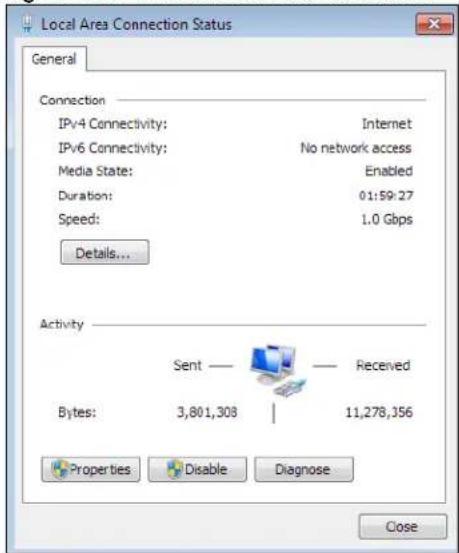
15.4.2 Turn on UPnP in Windows 10 Example
This section shows you how to use the UPnP feature in Windows 10. UPnP server is installed in Windows 10. Activate UPnP on the Zyxel Device by clicking Network Setting > Home Networking > UPnP.
Make sure the computer is connected to the LAN port of the Zyxel Device. Turn on your computer and the Zyxel Device.
1 Click the start icon, Settings and then Network & Internet.
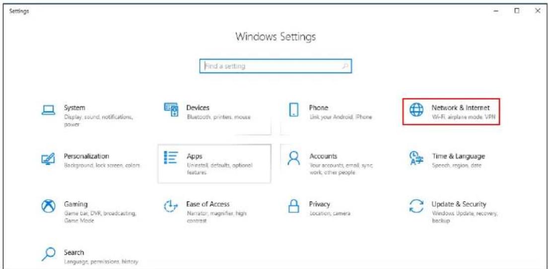
2 Click Network and Sharing Center.
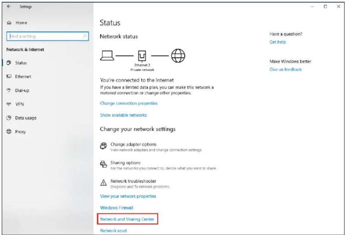
3 Click Change advanced sharing settings.
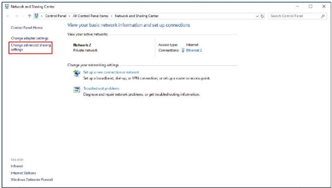
4 Under Domain, select Turn on network discovery and click Save Changes. Network discovery allows your computer to find other computers and devices on the network and other computers on the network to find your computer. This makes it easier to share files and printers.
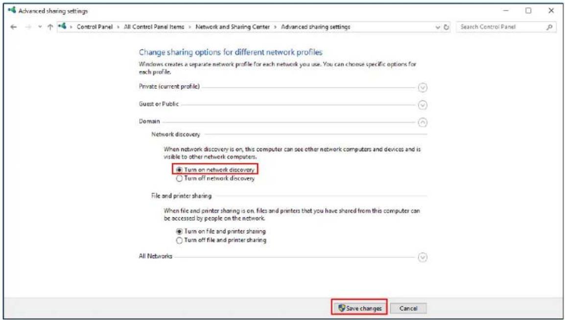
15.4.3 Auto-discover Your UPnP-enabled Network Device
Before you follow these steps, make sure you already have UPnP activated on the Zyxel Device and in your computer.
Make sure your computer is connected to the LAN port of the Zyxel Device.
1 Open File Explorer and click Network.
2 Right-click the Zyxel Device icon and select Properties.
Figure 349 Network Connections
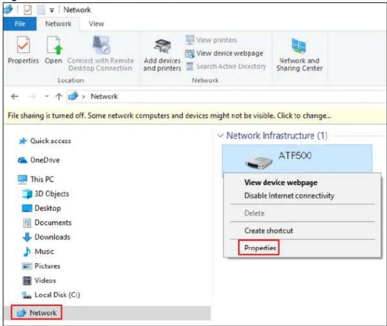
3 In the Internet Connection Properties window, click Settings to see port mappings.
Figure 350 Internet Connection Properties
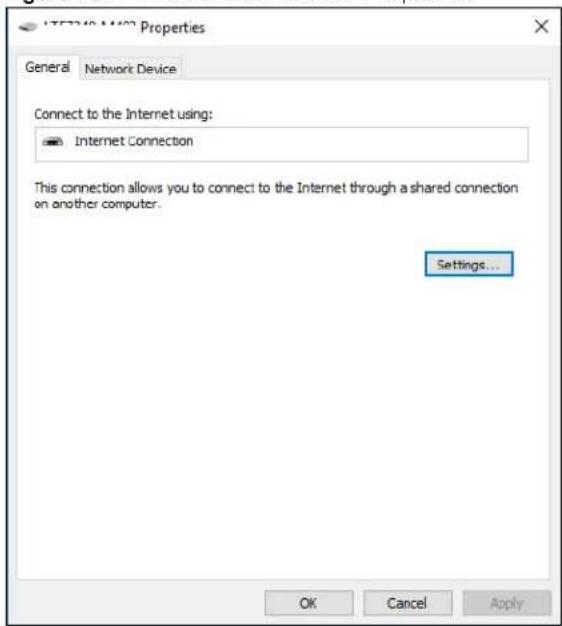
4 You may edit or delete the port mappings or click Add to manually add port mappings.
Figure 351 Internet Connection Properties: Advanced Settings
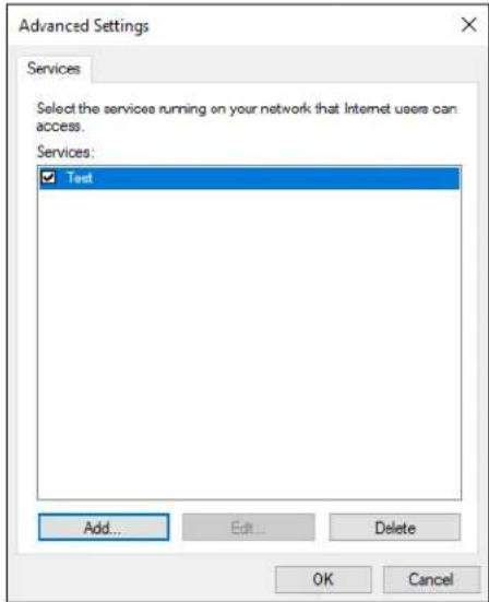
Figure 352 Internet Connection Properties: Advanced Settings: Add
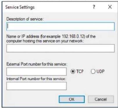
Note: When the UPnP-enabled device is disconnected from your computer, all port mappings will be deleted automatically.
5 Click OK. Check the network icon on the system tray to see your Internet connection status.
Figure 353 System Tray Icon

6 To see more details about your current Internet connection status, right click the network icon in the system tray and click Open Network & Internet settings. Click Network and Sharing Center and click the Connections.
Figure 354 Internet Connection Status
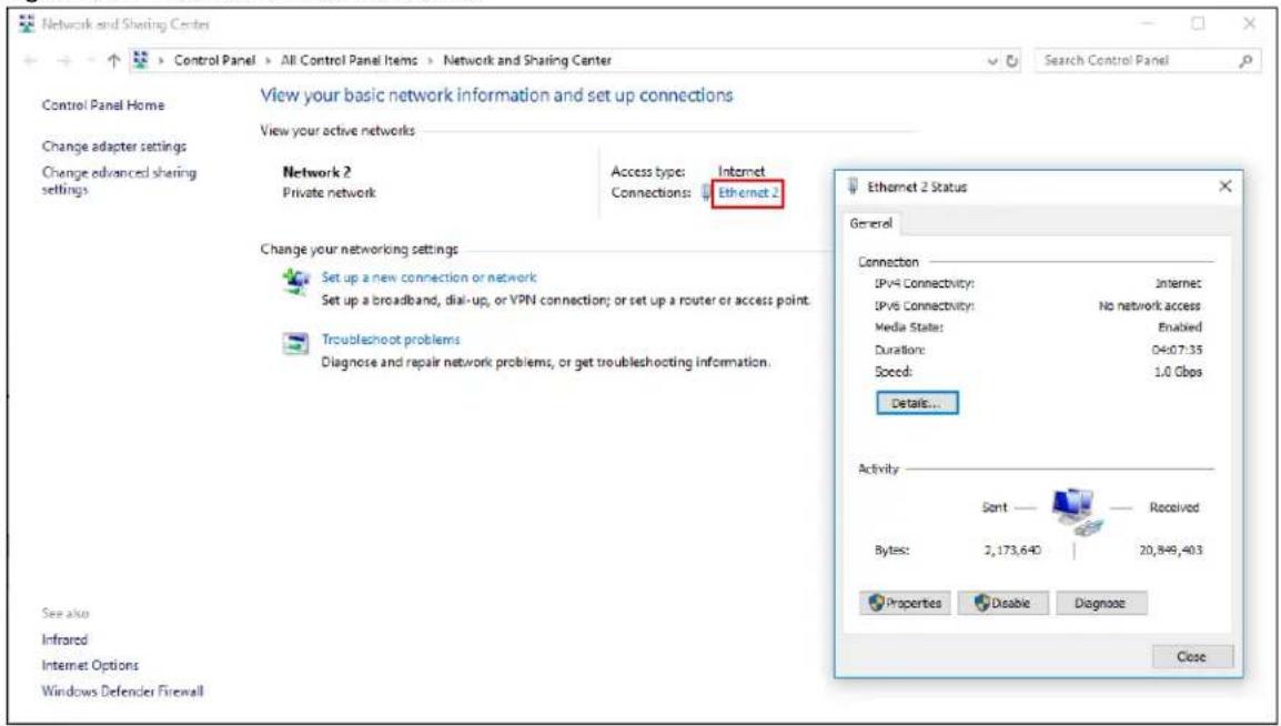
15.4.4 Web Configurator Easy Access in Windows 7
With UPnP, you can access the web-based configurator on the Zyxel Device without finding out the IP address of the Zyxel Device first. This comes helpful if you do not know the IP address of the Zyxel Device.
Follow the steps below to access the web configurator.
1 Open Windows Explorer.
2 Click Network.
Figure 355 Network Connections
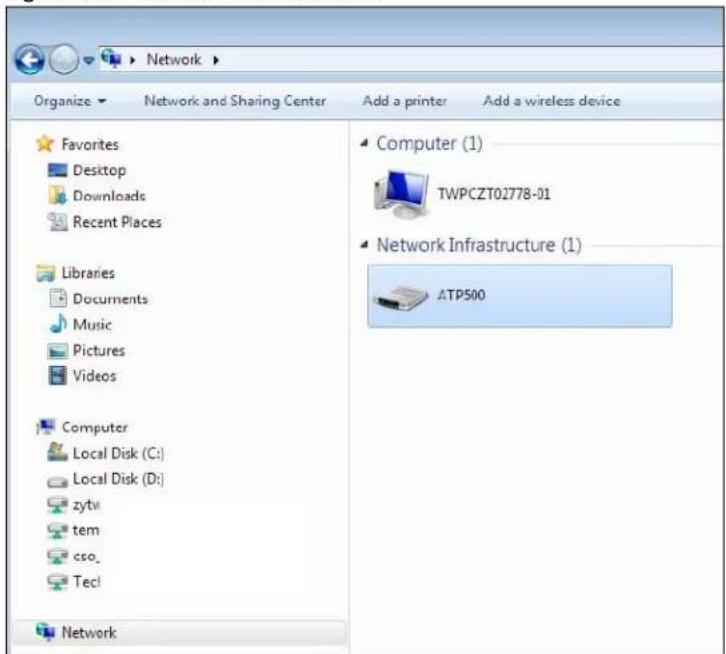
3 An icon with the description for each UPnP-enabled device displays under Network Infrastructure.
4 Right-click on the icon for your Zyxel Device and select View device webpage. The web configurator login screen displays.
Figure 356 Network Connections: My Network Places
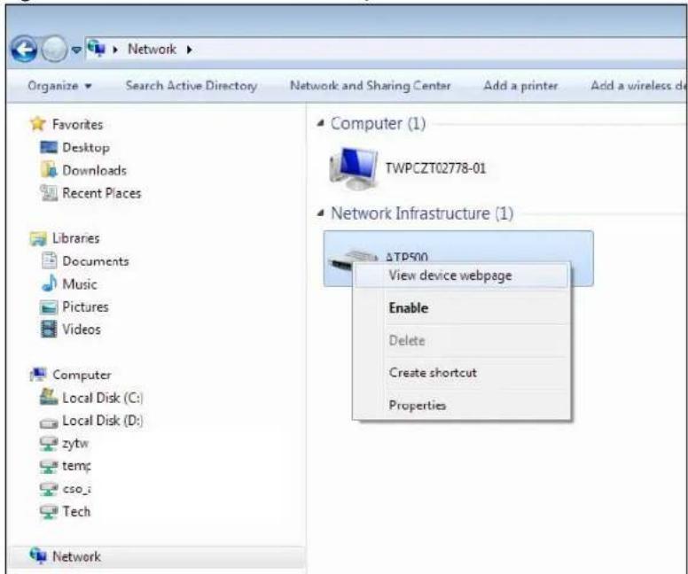
5 Right-click on the icon for your Zyxel Device and select Properties. Click the Network Device tab. A window displays with information about the Zyxel Device.
Figure 357 Network Connections: My Network Places: Properties: Example
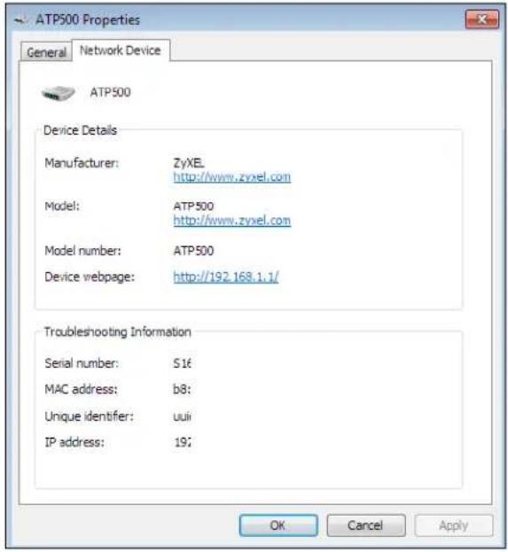
15.4.5 Web Configurator Easy Access in Windows 10
Follow the steps below to access the Web Configurator.
1 Open File Explorer.
2 Click Network.
Figure 358 Network Connections
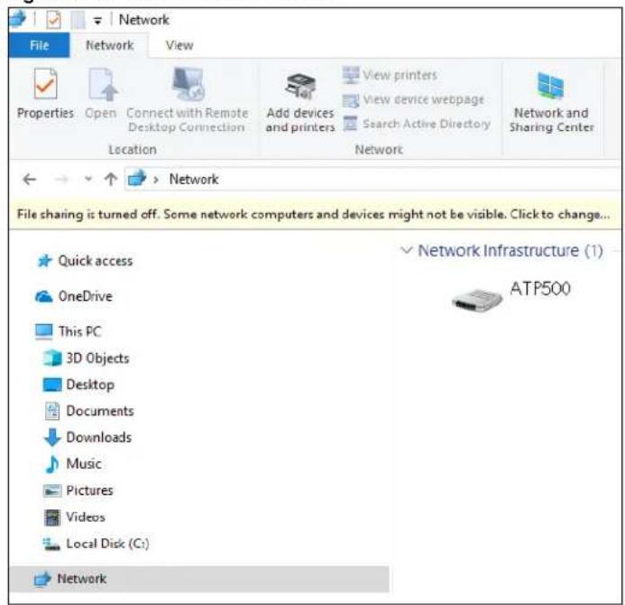
3 An icon with the description for each UPnP-enabled device displays under Network Infrastructure.
4 Right-click the icon for your Zyxel Device and select View device webpage. The Web Configurator login screen displays.
Figure 359 Network Connections: Network Infrastructure
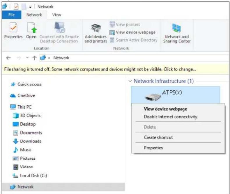
5 Right-click the icon for your Zyxel Device and select Properties. Click the Network Device tab. A window displays information about the Zyxel Device.
Figure 360 Network Connections: Network Infrastructure: Properties: Example
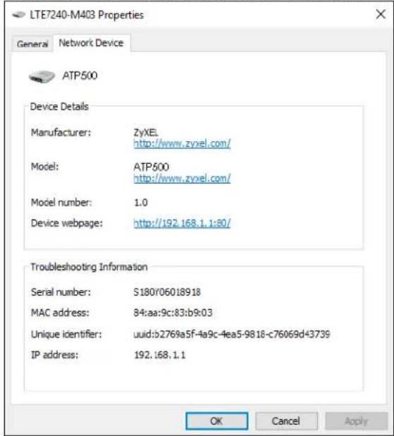
CHAPTER 16
IP/ MAC Binding
16.1 IP/MAC Binding Overview
IP address to MAC address binding helps ensure that only the intended devices get to use privileged IP addresses. The Zyxel Device uses DHCP to assign IP addresses and records the MAC address it assigned to each IP address. The Zyxel Device then checks incoming connection attempts against this list. A user cannot manually assign another IP to his computer and use it to connect to the Zyxel Device.
Suppose you configure access privileges for IP address 192.168.1.27 and use static DHCP to assign it to Tim's computer's MAC address of 12:34:56:78:90:AB. IP/MAC binding drops traffic from any computer trying to use IP address 192.168.1.27 with another MAC address.
Figure 361 IP/MAC Binding Example
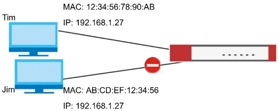
flowchart
graph TD
    A["Tim"] -->|MAC: 12:34:56:78:90:AB\nIP: 192.168.1.27| B["Red Box"]
    C["Jim"] -->|MAC: AB:CD:EF:12:34:56\nIP: 192.168.1.27| B
16.1.1 What You Can Do in this Chapter
- Use the Summary and Edit screens (Section 16.2 on page 513) to bind IP addresses to MAC addresses.
- Use the Exempt List screen (Section 16.3 on page 516) to configure ranges of IP addresses to which the Zyxel Device does not apply IP/MAC binding.
16.1.2 What You Need to Know
DHCP
IP/MAC address bindings are based on the Zyxel Device's dynamic and static DHCP entries.
Interfaces Used With IP/MAC Binding
IP/MAC address bindings are grouped by interface. You can use IP/MAC binding with Ethernet, bridge, VLAN, and WLAN interfaces. You can also enable or disable IP/MAC binding and logging in an interface's configuration screen.
16.2 IP/MAC Binding Summary
Click Configuration > Network > IP/MAC Binding to open the IP/MAC Binding Summary screen. This screen lists the total number of IP to MAC address bindings for devices connected to each supported interface.
Figure 362 Configuration > Network > IP/MAC Binding > Summary
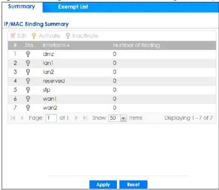
The following table describes the labels in this screen.
Table 185 Configuration > Network > IP/MAC Binding > Summary
| LABEL DESCRIPTION | |
| Edit | Double-click an entry or select it and click Edit to open a screen where you can modify the entry's settings. |
| Activate | To turn on an entry, select it and click Activate. |
| Inactivate | To turn off an entry, select it and click Inactivate. |
| # This field is a sequential value, and it is not associated with a specific entry. | |
| Status | This icon is lit when the entry is active and dimmed when the entry is inactive. |
| Interface This is the name of an interface that supports IP/MAC binding. | |
| Number of Binding | This field displays the interface's total number of IP/MAC bindings and IP addresses that the interface has assigned by DHCP. |
| Apply | Click Apply to save your changes back to the Zyxel Device. |
| Reset | Click Reset to return the screen to its last-saved settings. |
16.2.1 IP/MAC Binding Edit
Click Configuration > Network > IP/MAC Binding > Edit to open the IP/MAC Binding Edit screen. Use this screen to configure an interface's IP to MAC address binding settings.
Figure 363 Configuration > Network > IP/MAC Binding > Edit
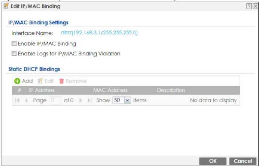
The following table describes the labels in this screen.
Table 186 Configuration > Network > IP/MAC Binding > Edit
| LABEL DESCRIPTION | |
| IP/MAC Binding Settings | |
| Interface Name | This field displays the name of the interface within the Zyxel Device and the interface's IP address and subnet mask. |
| Enable IP/MAC Binding | Select this option to have this interface enforce links between specific IP addresses and specific MAC addresses. This stops anyone else from manually using a bound IP address on another device connected to this interface. Use this to make use only the intended users get to use specific IP addresses. |
| Enable Logs for IP/MAC Binding Violation | Select this option to have the Zyxel Device generate a log if a device connected to this interface attempts to use an IP address not assigned by the Zyxel Device. |
| Static DHCP Bindings | This table lists the bound IP and MAC addresses. The Zyxel Device checks this table when it assigns IP addresses. If the computer's MAC address is in the table, the Zyxel Device assigns the corresponding IP address. You can also access this table from the interface's edit screen. |
| Add Click this to create a new entry. | |
| Edit | Double-click an entry or select it and click Edit to open a screen where you can modify the entry's settings. |
| Remove | To remove an entry, select it and click Remove. The Zyxel Device confirms you want to remove it before doing so. |
| # This is the index number of the static DHCP entry. | |
| IP Address | This is the IP address that the Zyxel Device assigns to a device with the entry's MAC address. |
| MAC Address | This is the MAC address of the device to which the Zyxel Device assigns the entry's IP address. |
| Description This helps identify the entry. | |
| OK | Click OK to save your changes back to the Zyxel Device. |
| Cancel | Click Cancel to exit this screen without saving. |
16.2.2 Static DHCP Edit
Click Configuration > Network > IP/MAC Binding > Edit to open the IP/MAC Binding Edit screen. Click the Add or Edit icon to open the following screen. Use this screen to configure an interface's IP to MAC address binding settings.
Figure 364 Configuration > Network > IP/MAC Binding > Edit > Add
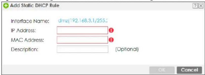
The following table describes the labels in this screen.
Table 187 Configuration > Network > IP/MAC Binding > Edit > Add
| LABEL DESCRIPTION | |
| Interface Name | This field displays the name of the interface within the Zyxel Device and the interface's IP address and subnet mask. |
| IP Address | Enter the IP address that the Zyxel Device is to assign to a device with the entry's MAC address. |
| MAC Address | Enter the MAC address of the device to which the Zyxel Device assigns the entry's IP address. |
| Description | Enter a descriptive name consists of 1 to 60 single-byte characters, including a-zA-Z0-9!'#$%'()*+,-/::=?@_&[.]<>^\‘{} are not allowed. |
| OK Click OK to save your changes back to the Zyxel Device. | |
| Cancel | Click Cancel to exit this screen without saving. |
16.3 IP/MAC Binding Exempt List
Click Configuration > Network > IP/MAC Binding > Exempt List to open the IP/MAC Binding Exempt List screen. Use this screen to configure ranges of IP addresses to which the Zyxel Device does not apply IP/MAC binding.
Figure 365 Configuration > Network > IP/MAC Binding > Exempt List
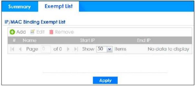
The following table describes the labels in this screen.
Table 188 Configuration > Network > IP/MAC Binding > Exempt List
| LABEL DESCRIPTION | |
| Add Click this to | create a new entry. |
| Edit | Click an entry or select it and click Edit to modify the entry's settings. |
| Remove | To remove an entry, select it and click Remove. The Zyxel Device confirms you want to remove it before doing so. |
| # This is the index | number of the IP/MAC binding list entry. |
| Name Enter a name to help identify this entry. | |
| Start IP | Enter the first IP address in a range of IP addresses for which the Zyxel Device does not apply IP/MAC binding. |
| End IP | Enter the last IP address in a range of IP addresses for which the Zyxel Device does not apply IP/MAC binding. |
| Add icon | Click the Add icon to add a new entry.Click the Remove icon to delete an entry. A window displays asking you to confirm that you want to delete it. |
| Apply | Click Apply to save your changes back to the Zyxel Device. |
CHAPTER 17
Layer 2 Isolation
17.1 Overview
Layer-2 isolation is used to prevent connected devices from communicating with each other in the Zyxel Device's local network(s), except for the devices in the white list, when layer-2 isolation is enabled on the Zyxel Device and the local interface(s).
Note: The security policy control must be enabled before you can use layer-2 isolation.
In the following example, layer-2 isolation is enabled on the Zyxel Device's interface Vlan1. A printer, PC and AP are in the Vlan1. The IP address of network printer (C) is added to the white list. With this setting, the connected AP then cannot communicate with the PC (D), but can access the network printer (C), server (B), wireless client (A) and the Internet.
Figure 366 Layer-2 Isolation Application
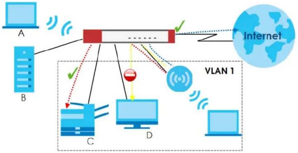
flowchart
graph TD
    subgraph_Server_A["Server A"]
        A1["Computer"] -->|Wireless Signal| A2["Red Box"]
        A3["Computer"] -->|Wireless Signal| A2
        A4["Computer"] -->|Wireless Signal| A2
        A5["Computer"] -->|Wireless Signal| A2
    end

    subgraph_Server_B["Server B"]
        B1["Computer"] -->|Wireless Signal| B2["Red Box"]
        B3["Computer"] -->|Wireless Signal| B2
        B4["Computer"] -->|Wireless Signal| B2
        B5["Computer"] -->|Wireless Signal| B2
    end

    subgraph_VLAN_1["VLAN 1"]
        C1["Computer"] -->|Wireless Signal| C2["Red Dot"]
        C3["Computer"] -->|Wireless Signal| C2
        C4["Computer"] -->|Wireless Signal| C2
        C5["Computer"] -->|Wireless Signal| C2
    end

    A2 --> VLAN_1
    B2 --> VLAN_1
    C2 --> VLAN_1
    D2 --> VLAN_1
    VLAN_1 --> Internet["Internet"]
    style VLAN_1 fill:#f9f,stroke:#333
17.1.1 What You Can Do in this Chapter
- Use the General screen (Section 17.2 on page 517) to enable layer-2 isolation on the Zyxel Device and the internal interface(s).
- Use the Allow List screen (Section 17.3 on page 518) to enable and configures the allow list.
17.2 Layer-2 Isolation General Screen
This screen allows you to enable Layer-2 isolation on the Zyxel Device and specific internal interface(s). To access this screen click Configuration > Network > Layer 2 Isolation.
Figure 367 Configuration > Network > Layer 2 Isolation
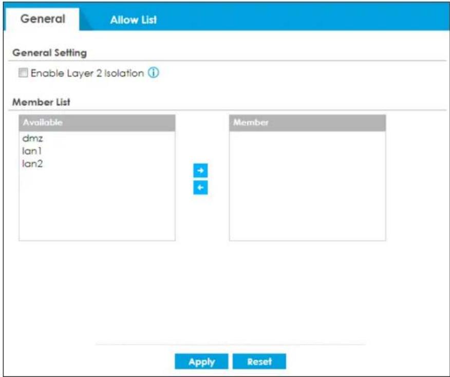
The following table describes the labels in this screen.
Table 189 Configuration > Network > Layer 2 Isolation
| LABEL DESCRIPTION | |
| Enable Layer2 Isolation | Select this option to turn on the layer-2 isolation feature on the Zyxel Device.Note: You can enable this feature only when the security policy is enabled. |
| Member List | The Available list displays the name(s) of the internal interface(s) on which you can enable layer-2 isolation.To enable layer-2 isolation on an interface, you can double-click a single entry to move it or use the [Shift] or [Ctrl] key to select multiple entries and click the right arrow button to add to the Member list. To remove an interface, select the name(s) in the Member list and click the left arrow button. |
| Apply | Click Apply to save your changes back to the Zyxel Device. |
| Reset | Click Reset to return the screen to its last-saved settings. |
17.3 Allow List Screen
IP addresses that are not listed in the allow list are blocked from communicating with other devices in the layer-2-isolation-enabled internal interface(s) except for broadcast packets.
To access this screen click Configuration > Network > Layer 2 Isolation > Allow List.
Figure 368 Configuration > Network > Layer 2 Isolation > Allow List
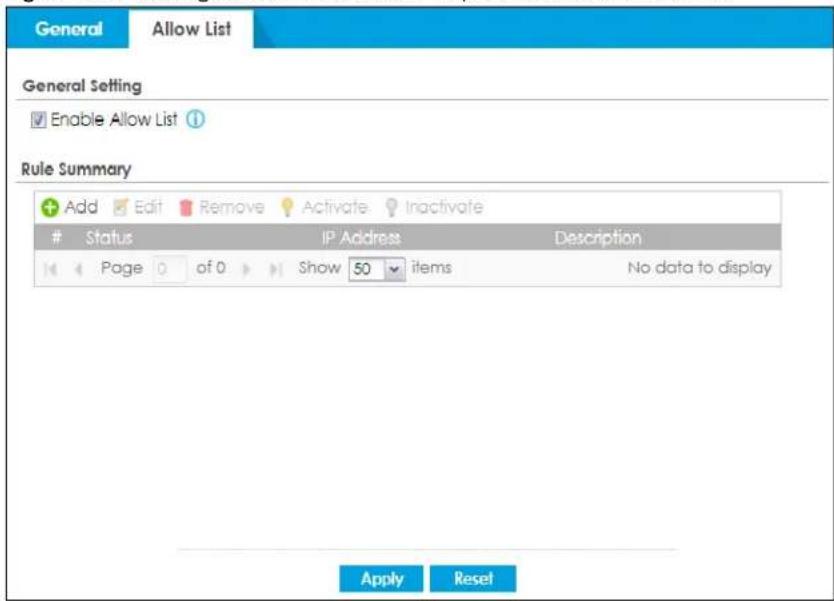
The following table describes the labels in this screen.
Table 190 Configuration > Network > Layer 2 Isolation > Allow List
| LABEL DESCRIPTION | |
| Enable Allow List | Select this option to turn on the white list on the Zyxel Device.Note: You can enable this feature only when the security policy is enabled. |
| Add Click this to add a new rule. | |
| Edit Click this to edit the selected rule. | |
| Remove Click this to remove the selected rule. | |
| Activate | To turn on an entry, select it and click Activate. |
| Inactivate | To turn off an entry, select it and click Inactivate. |
| # This field is a sequential value, and it is not associated with a specific rule. | |
| Status | This icon is lit when the rule is active and dimmed when the rule is inactive. |
| IP Address | This field displays the IP address of device that can be accessed by the devices connected to an internal interface on which layer-2 isolation is enabled. |
| Description This field displays the description for the IP address in this rule. | |
| Apply | Click Apply to save your changes back to the Zyxel Device. |
| Reset | Click Reset to return the screen to its last-saved settings. |
17.3.1 Add/Edit Allow List Rule
This screen allows you to create a new rule in the allow list or edit an existing one. To access this screen, click the Add button or select an entry from the list and click the Edit button.
Note: You can configure up to 100 allow list rules on the Zyxel Device.
Note: You need to know the IP address of each connected device that you want to allow to be accessed by other devices when layer-2 isolation is enabled.
Figure 369 Configuration > Network > Layer 2 Isolation > White List > Add/Edit
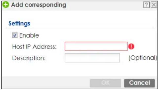
The following table describes the labels in this screen.
Table 191 Configuration > Network > Layer 2 Isolation > Allow List > Add/Edit
| LABEL DESCRIPTION | |
| Enable Select this option to turn on the rule. | |
| Host IP Address Enter an IPv4 address associated with this rule. | |
| Description | Specify a description for the IP address associated with this rule. Enter up to 60 characters, spaces and underscores allowed. |
| OK | Click OK to save your changes back to the Zyxel Device. |
| Cancel | Click Cancel to exit this screen without saving your changes. |
CHAPTER 18
DNS Inbound LB
18.1 DNS Inbound Load Balancing Overview
Inbound load balancing enables the Zyxel Device to respond to a DNS query message with a different IP address for DNS name resolution. The Zyxel Device checks which member interface has the least load and responds to the DNS query message with the interface's IP address.
In the following figure, an Internet host (A) sends a DNS query message to the DNS server (D) in order to resolve a domain name of www.example.com. DNS server D redirects it to the Zyxel Device (Z)'s WAN1 with an IP address of 1.1.1.1. The Zyxel Device receives the DNS query message and responds to it with the WAN2's IP address, 2.2.2.2, because the WAN2 has the least load at that moment.
Another Internet host (B) also sends a DNS query message to ask where www.example.com is. The Zyxel Device responds to it with the WAN1's IP address, 1.1.1.1, since WAN1 has the least load this time.
Figure 370 DNS Load Balancing Example
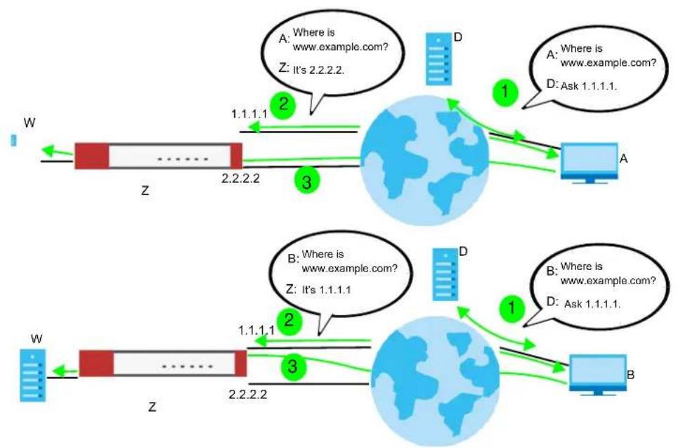
flowchart
graph TD
    subgraph_System_1["Network"]
        W1["W"] -->|1.1.1.1| Z1["Z"]
        Z1 -->|2.2.2.2| Z2["Z"]
        Z2 -->|3| Z3["Z"]
    end
    subgraph_System_2["Network"]
        A1["A"] -->|1| D1["D"]
        D1 -->|Ask 1.1.1.1.| A2["A"]
        A2 -->|1| D2["D"]
        D2 -->|Ask 1.1.1.1.| B2["B"]
        B2 -->|1| D3["D"]
        D3 -->|Ask 1.1.1.1.| B3["B"]
    end
    System_1 -->|2| Z4["Z"]
    System_2 -->|3| Z5["Z"]
    Z1 -->|2| Z6["Z"]
    Z6 -->|3| Z7["Z"]
    Z7 -->|2| Z8["Z"]
    Z8 -->|3| Z9["Z"]
    Z9 -->|2| Z10["Z"]
    Z10 -->|3| Z11["Z"]
    Z11 -->|2| Z12["Z"]
    Z12 -->|3| Z13["Z"]
    Z13 -->|2| Z14["Z"]
    Z14 -->|3| Z15["Z"]
    Z15 -->|2| Z16["Z"]
    Z16 -->|3| Z17["Z"]
    Z17 -->|2| Z18["Z"]
    Z18 -->|3| Z19["Z"]
18.1.1 What You Can Do in this Chapter
- Use the Inbound LB screen (see Section 18.2 on page 522) to view a list of the configured DNS load balancing rules.
- Use the Inbound LB Add/Edit screen (see Section 18.2.1 on page 523) to add or edit a DNS load balancing rule.
18.2 The DNS Inbound LB Screen
The Inbound LB screen provides a summary of all DNS load balancing rules and the details. You can also use this screen to add, edit, or remove the rules. Click Configuration > Network > Inbound LB to open the following screen.
Note: After you finish the inbound load balancing settings, go to security policy and NAT screens to configure the corresponding rule and virtual server to allow the Internet users to access your internal servers.
Figure 371 Configuration > Network > DNS Inbound LB
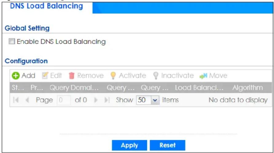
The following table describes the labels in this screen.
Table 192 Configuration > Network > DNS Inbound LB
| LABEL DESCRIPTION | |
| Global Setting | |
| Enable DNS Load Balancing | Select this to enable DNS load balancing. |
| Configuration | |
| Add Click this to create a new entry. | |
| Edit | Double-click an entry or select it and click Edit to open a screen where you can modify the entry's settings. |
| Remove | To remove an entry, select it and click Remove. The Zyxel Device confirms you want to remove it before doing so. |
| Activate | To turn on an entry, select it and click Activate. |
| Inactivate | To turn off an entry, select it and click Inactivate. |
| Move | To move an entry to a different number in the list, click the Move icon. In the field that appears, specify the number to which you want to move the entry. |
| Status | This icon is lit when the entry is active and dimmed when the entry is inactive. |
| Priority | This field displays the order in which the Zyxel Device checks the member interfaces of this DNS load balancing rule. |
| Query Domain Name | This field displays the domain name for which the Zyxel Device manages load balancing between the specified interfaces. |
| Query From Address | This field displays the source IP address of the DNS query messages to which the Zyxel Device applies the DNS load balancing rule. |
| Query From Zone | The Zyxel Device applies the DNS load balancing rule to the query messages received from this zone. |
| Load Balancing Member | This field displays the member interfaces which the Zyxel Device manages for load balancing. |
| Algorithm | This field displays the load balancing method the Zyxel Device uses for this DNS load balancing rule.Weighted Round Robin- Each member interface is assigned a weight. An interface with a larger weight gets more chances to transmit traffic than an interface with a smaller weight. For example, if the weight ratio of wan1 and wan2 interfaces is 2:1, the Zyxel Device chooses wan1 for 2 sessions' traffic and wan2 for 1 session's traffic in each round of 3 new sessions.Least Connection- The Zyxel Device chooses choose a member interface which is handling the least number of sessions.Least Load - Outbound- The Zyxel Device chooses a member interface which is handling the least amount of outgoing traffic.Least Load - Inbound- The Zyxel Device chooses a member interface which is handling the least amount of incoming traffic.Least Load - Total- The Zyxel Device chooses a member interface which is handling the least amount of outgoing and incoming traffic. |
| Apply Click this button to save your changes to the Zyxel Device. | |
| Reset | Click this button to return the screen to its last-saved settings. |
18.2.1 The DNS Inbound LB Add/Edit Screen
The Add DNS Load Balancing screen allows you to add a domain name for which the Zyxel Device manages load balancing between the specified interfaces. You can configure the Zyxel Device to apply DNS load balancing to some specific hosts only by configuring the Query From settings. Click Configuration > Network > Inbound LB and then the Add or Edit icon to open this screen.
Figure 372 Configuration > Network > DNS Inbound LB > Add
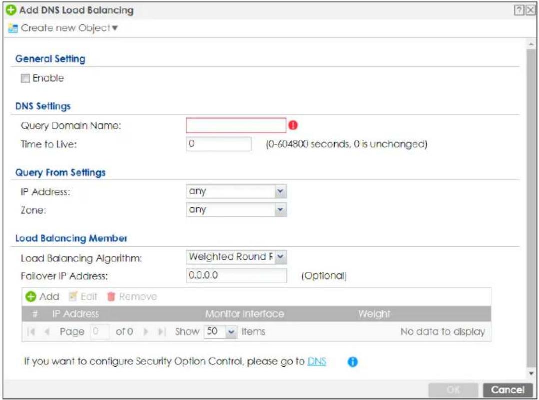
The following table describes the labels in this screen.
Table 193 Configuration > Network > DNS Inbound LB > Add/Edit
| LABEL DESCRIPTION | |
| Create New Object | Use this to configure any new setting objects that you need to use in this screen. |
| General Settings | |
| Enable Select this to enable this DNS load balancing rule. | |
| DNS Settings | |
| Query Domain Name | Type up to 255 characters for a domain name for which you want the Zyxel Device to manage DNS load balancing. You can use a wildcard (*) to let multiple domains match the name. For example, use *.example.com to specify any domain name that ends with “example.com” would match. |
| Time to Live | Enter the number of seconds the Zyxel Device recommends DNS request hosts to keep the DNS entry in their caches before removing it. Enter 0 to have the Zyxel Device not recommend this so the DNS request hosts will follow their DNS server’s TTL setting. |
| Query From Setting | |
| IP Address | Select the name of an P address object, including geographic address object, of a computer or a DNS server which makes the DNS queries upon which to apply this rule.DNS servers process client queries using recursion or iteration:In recursion, DNS servers make recursive queries on behalf of clients. So you have to configure this field to the DNS server’s IP address when recursion is used.In iteration, a client asks the DNS server and expects the best and immediate answer without the DNS server contacting other DNS servers. If the primary DNS server cannot provide the best answer, the client makes iteration queries to other configured DNS servers to resolve the name. You have to configure this field to the client’s IP address when iteration is used. |
| Zone | Select the zone of DNS query messages upon which to apply this rule. |
| Load Balancing Member | |
| Load Balancing Algorithm | Select a load balancing method to use from the drop-down list box.SelectWeighted Round Robinto balance the traffic load between interfaces based on their respective weights. An interface with a larger weight gets more chances to transmit traffic than an interface with a smaller weight. For example, if the weight ratio of wan1 and wan2 interfaces is 2:1, the Zyxel Device chooses wan1 for 2 sessions' traffic and wan2 for every session's traffic in each round of 3 new sessions.SelectLeast Connectionto have the Zyxel Device choose the member interface which is handling the least number of sessions.SelectLeast Load - Outboundto have the Zyxel Device choose the member interface which is handling the least amount of outgoing traffic.SelectLeast Load - Inboundto have the Zyxel Device choose the member interface which is handling the least amount of incoming traffic.SelectLeast Load - Totalto have the Zyxel Device choose the member interface which is handling the least amount of outgoing and incoming traffic. |
| Failover IP Address | Enter an alternate IP address with which the Zyxel Device will respond to a DNS query message when the load balancing algorithm cannot find any available interface. |
| Add Click this to create a new member interface for this rule. | |
| Edit | Double-click an entry or select it and clickEditto open a screen where you can modify the entry's settings. |
| Remove | To remove an entry, select it and clickRemove. The Zyxel Device confirms you want to remove it before doing so. |
| # | This field displays the order in which the Zyxel Device checks this rule's member interfaces. |
| IP Address This field displays the IP address of the member interface. | |
| Monitor Interface | This field displays the name of the member interface. The Zyxel Device manages load balancing between the member interfaces. |
| Weight | This field is available if you selectedWeighted Round Robinas the load balancing algorithm. This field displays the weight of the member interface. An interface with a larger weight gets more chances to transmit traffic than an interface with a smaller weight. |
| OK | ClickOKto save your changes back to the Zyxel Device. |
| Cancel | ClickCancelto exit this screen without saving. |
18.2.2 The DNS Inbound LB Add/Edit Member Screen
The Add Load Balancing Member screen allows you to add a member interface for the DNS load balancing rule. Click Configuration > Network > DNS Inbound LB > Add or Edit and then an Add or Edit icon to open this screen.
Figure 373 Configuration > Network > DNS Inbound LB > Add/Edit > Add
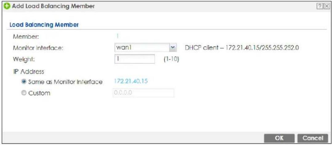
The following table describes the labels in this screen.
Table 194 Configuration > Network > DNS Inbound LB > Add/Edit > Add/Edit
| LABEL DESCRIPTION | |
| Member | The Zyxel Device checks each member interface's loading in the order displayed here. |
| Monitor Interface | Select an interface to associate it with the DNS load balancing rule. This field also displays whether the IP address is a static IP address (Static), dynamically assigned (Dynamic) or obtained from a DHCP server (DHCP Client), as well as the IP address and subnet mask. |
| Weight | This field is available if you selected Weighted Round Robin for the load balancing algorithm.Specify the weight of the member interface. An interface with a larger weight gets more chances to transmit traffic than an interface with a smaller weight. |
| IP Address | |
| Same as Monitor Interface | Select this to send the IP address displayed in the Monitor Interface field to the DNS query senders. |
| Custom | Select this and enter another IP address to send to the DNS query senders. |
| OK | Click OK to save your changes back to the Zyxel Device. |
| Cancel | Click Cancel to exit this screen without saving. |
CHAPTER 19 IPSec VPN
19.1 Virtual Private Networks (VPN) Overview
A virtual private network (VPN) provides secure communications between sites without the expense of leased site-to-site lines. A secure VPN is a combination of tunneling, encryption, authentication, access control and auditing. It is used to transport traffic over the Internet or any insecure network that uses TCP/IP for communication.
IPSec VPN
Internet Protocol Security (IPSec) VPN connects IPSec routers or remote users using IPSec client software. This standards-based VPN offers flexible solutions for secure data communications across a public network. IPSec is built around a number of standardized cryptographic techniques to provide confidentiality, data integrity and authentication at the IP layer. The Zyxel Device can also combine multiple IPSec VPN connections into one secure network. Here local Zyxel Device X uses an IPSec VPN tunnel to remote (peer) Zyxel Device Y to connect the local (A) and remote (B) networks.
Figure 374 IPSec VPN Example
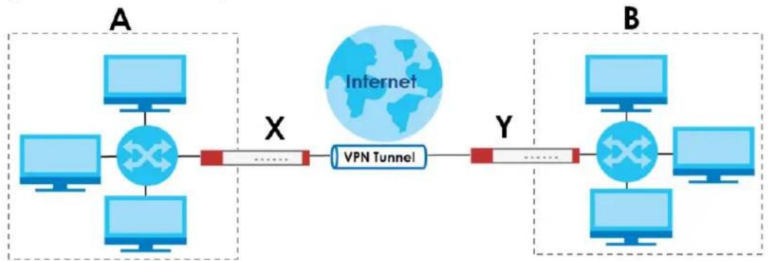
flowchart
graph LR
    subgraph A
        A1["Computer"] --> X((X))
        A2["Computer"] --> X
        A3["Computer"] --> X
    end
    subgraph X
        X -->|X| VPN["Tunnel"]
        X -->|X| Y
    end
    subgraph B
        B1["Computer"] --> X2((X))
        B2["Computer"] --> X2
        B3["Computer"] --> X2
        B4["Computer"] --> X2
    end
    X -->|X| X2
    X2 -->|X| Y
    style X fill:#f9f,stroke:#333
    style Y fill:#ccf,stroke:#333
Internet Key Exchange (IKE): IKEv1 and IKEv2
The Zyxel Device supports IKEv1 and IKEv2 for IPv4 and IPv6 traffic. IKE (Internet Key Exchange) is a protocol used in setting up security associations that allows two parties to send data securely.
IKE uses certificates or pre-shared keys for authentication and a Diffie-Hellman key exchange to set up a shared session secret from which encryption keys are derived. A security policy for each peer must be manually created.
IPSec VPN consists of two phases: Phase 1 and Phase 2. Phase 1's purpose is to establish a secure authenticated communication channel by using the Diffie-Hellman key exchange algorithm to generate a shared secret key to encrypt IKE communications. This negotiation results in one single bidirectional ISAKMP Security Association (SA). The authentication can be performed using either pre-
shared key (shared secret), signatures, or public key encryption. Phase 1 operates in either Main Mode or Aggressive Mode. Main Mode protects the identity of the peers, but Aggressive Mode does not.
During Phase 2, the remote IPSec routers use the secure channel established in Phase 1 to negotiate Security Associations for IPSec. The negotiation results in a minimum of two unidirectional security associations (one inbound and one outbound). Phase 2 uses Quick Mode (only). Quick mode occurs after IKE has established the secure tunnel in Phase 1. It negotiates a shared IPSec policy, derives shared secret keys used for the IPSec security algorithms, and establishes IPSec SAs. Quick mode is also used to renegotiate a new IPSec SA when the IPSec SA lifetime expires.
In the Zyxel Device, use the VPN Connection tab to set up Phase 2 and the VPN Gateway tab to set up Phase 1.
Some differences between IKEv1 and IKEv2 include:
- IKEv2 uses less bandwidth than IKEv1. IKEv2 uses one exchange procedure with 4 messages. IKEv1 uses two phases with Main Mode (9 messages) or Aggressive Mode (6 messages) in phase 1.
- IKEv2 supports Extended Authentication Protocol (EAP) authentication, and IKEv1 supports X-Auth. EAP is important when connecting to existing enterprise authentication systems.
- IKEv2 always uses NAT traversal and Dead Peer Detection (DPD), but they can be disabled in IKEv1 using Zyxel Device firmware (the default is on).
- Configuration payload (includes the IP address pool in the VPN setup data) is supported in IKEv2 (off by default), but not in IKEv1.
- Narrowed is supported in IKEv2, but not in IKEv1. Narrowed has the SA apply only to IP addresses in common between the Zyxel Device and the remote IPSec router.
- The IKEv2 protocol supports connectivity checks which is used to detect whether the tunnel is still up or not. If the check fails (the tunnel is down), IKEv2 can re-establish the connection automatically. The Zyxel Device uses firmware to perform connectivity checks when using IKEv1.
SSL VPN
SSL VPN uses remote users' web browsers to provide the easiest-to-use of the Zyxel Device's VPN solutions. A user just browses to the Zyxel Device's web address and enters his user name and password to securely connect to the Zyxel Device's network. Remote users do not need to configure security settings. Here a user uses his browser to securely connect to network resources in the same way as if he were part of the internal network. See Chapter 20 on page 566 for more on SSL VPN.
Figure 375 SSL VPN
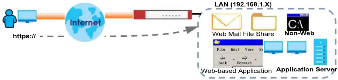
flowchart
graph LR
    A["User"] -->|https://| B["Internet"]
    B --> C["LAN (192.168.1.X)"]
    C --> D["Web Mail File Share"]
    C --> E["Non-Web"]
    D --> F["Application Server"]
    E --> F
    F --> G["Web-based Application"]
    G --> H["Back Forward"]
    G --> I["Edit View Fe"]
L2TP VPN
L2TP VPN uses the L2TP and IPSec client software included in remote users' Android, iOS, or Windows operating systems for secure connections to the network behind the Zyxel Device. The remote users do not need their own IPSec gateways or third-party VPN client software. For example, configure sales representatives' laptops, tablets, or smartphones to securely connect to the Zyxel Device's network. See Chapter 21 on page 572 for more on L2TP over IPSec.
Figure 376 L2TP VPN
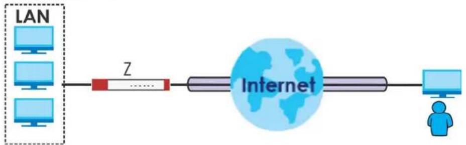
flowchart
graph LR
    A["LAN"] --> B["Z"]
    B --> C["Internet"]
    C --> D["User Icon"]
19.1.1 What You Can Do in this Chapter
- Use the VPN Connection screens (see Section 19.2 on page 532) to specify which IPSec VPN gateway an IPSec VPN connection policy uses, which devices behind the IPSec routers can use the VPN tunnel, and the IPSec SA settings (phase 2 settings). You can also activate or deactivate and connect or disconnect each VPN connection (each IPSec SA).
- Use the VPN Gateway screens (see Section 19.2.1 on page 534) to manage the Zyxel Device's VPN gateways. A VPN gateway specifies the IPSec routers at either end of a VPN tunnel and the IKE SA settings (phase 1 settings). You can also activate and deactivate each VPN gateway.
- Use the VPN Concentrator screens (see Section 19.4 on page 550) to combine several IPSec VPN connections into a single secure network.
- Use the Configuration Provisioning screen (see Section 19.5 on page 553) to set who can retrieve VPN rule settings from the Zyxel Device using the Zyxel Device IPSec VPN Client.
19.1.2 What You Need to Know
An IPSec VPN tunnel is usually established in two phases. Each phase establishes a security association (SA), a contract indicating what security parameters the Zyxel Device and the remote IPSec router will use. The first phase establishes an Internet Key Exchange (IKE) SA between the Zyxel Device and remote IPSec router. The second phase uses the IKE SA to securely establish an IPSec SA through which the Zyxel Device and remote IPSec router can send data between computers on the local network and remote network. This is illustrated in the following figure.
Figure 377 VPN: IKE SA and IPSec SA
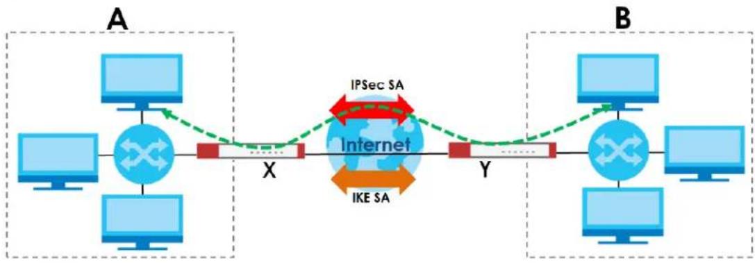
flowchart
graph LR
    subgraph A
        A1["Computer"] --> A2["Switch"]
        A2 --> X["X"]
        X --> Y["Y"]
        Y --> X
        X --> Xb["X"]
        Xb --> Xc["X"]
        Xc --> Xd["X"]
        Xd --> Xe["X"]
        Xe --> Xf["X"]
    end
    subgraph B
        B1["Computer"] --> B2["Switch"]
        B2 --> B3["X"]
        B3 --> Y["Y"]
        Y --> Yb["Y"]
        Yb --> Yc["Y"]
        Yc --> Yd["X"]
        Yd --> Ye["X"]
        Ye --> Yf["X"]
        Yf --> Yg["Y"]
        Yg --> Yh["Y"]
        Yh --> Yi["Y"]
        Yi --> Yj["Y"]
        Yj --> Yk["Y"]
        Yk --> Yl["Y"]
        Yl --> Ym["Y"]
        Ym --> Yn["Y"]
        Yn --> Yo["Y"]
        Yo --> Yp["Y"]
        Yp --> Yq["Y"]
        Yq --> Yr["Y"]
        Yr --> Ys["Y"]
        Ys --> Yt["Y"]
        Yt --> Yu["Y"]
        Yu --> Yv["Y"]
        Yv --> Yw["Y"]
        Yw --> Yx["Y"]
        Yx --> Yy["Y"]
        Yy --> Yz["Y"]
        Yz --> Yw
    end
    style A fill:#cce5ff,stroke:#333
    style B fill:#cce5ff,stroke:#333
    style B fill:#cce5ff,stroke:#333
    style A fill:#cce5ff,stroke:#333
    style X fill:#cce5ff,stroke:#333
    style Y fill:#cce5ff,stroke:#333
    style Yb fill:#cce5ff,stroke:#333
    style Yc fill:#cce5ff,stroke:#333
    style Yd fill:#cce5ff,stroke:#333
    style Ye fill:#cce5ff,stroke:#333
    style Yf fill:#cce5ff,stroke:#333
    style Yg fill:#cce5ff,stroke:#333
    style Yh fill:#cce5ff,stroke:#333
    style Yi fill:#cce5ff,stroke:#333
    style Yj fill:#cce5ff,stroke:#333
    style Yk fill:#cce5ff,stroke:#333
    style X fill:#cce5ff,stroke:#333
    style Xb fill:#cce5ff,stroke:#333
    style Xc fill:#cce5ff,stroke:#333
    style Xd fill:#cce5ff,stroke:#333
    style Xe fill:#cce5ff,stroke:#333
    style Xf fill:#cce5ff,stroke:#333
    style Xg fill:#cce5ff,stroke:#333
    style Xh fill:#cce5ff,stroke:#333
    style Xi fill:#cce5ff,stroke:#333
    style Xib fill:#cce5ff,stroke:#333
    style Yi fill:#cce5ff,stroke:#333
    style Yib fill:#cce5ff,stroke:#333
    style Yic fill:#cce5ff,stroke:#333
    style Yid fill:#cce5ff,stroke:#333
In this example, a computer in network A is exchanging data with a computer in network B. Inside networks A and B, the data is transmitted the same way data is normally transmitted in the networks. Between routers X and Y, the data is protected by tunneling, encryption, authentication, and other security features of the IPSec SA. The IPSec SA is secure because routers X and Y established the IKE SA first.
Application Scenarios
The Zyxel Device's application scenarios make it easier to configure your VPN connection settings.
Table 195 IPSec VPN Application Scenarios
| SITE-TO-SITE | SITE-TO-SITE WITH DYNAMIC PEER | REMOTE ACCESS (SERVER ROLE) | REMOTE ACCESS (CLIENT ROLE) | VPN TUNNEL INTERFACE |
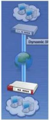 | 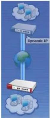 | 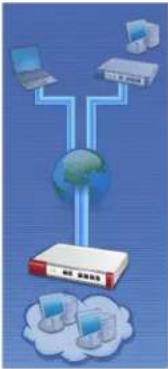 | 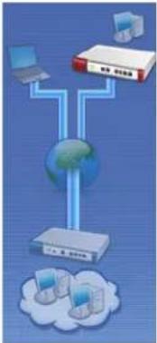 | 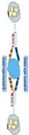 |
| Choose this if the remote IPSec router has a static IP address or a domain name.This Zyxel Device can initiate the VPN tunnel.The remote IPSec router can also initiate the VPN tunnel if this Zyxel Device has a static IP address or a domain name. | Choose this if the remote IPSec router has a dynamic IP address.You don't specify the remote IPSec router's address, but you specify the remote policy (the addresses of the devices behind the remote IPSec router).This Zyxel Device must have a static IP address or a domain name.Only the remote IPSec router can initiate the VPN tunnel. | Choose this to allow incoming connections from IPSec VPN clients.The clients have dynamic IP addresses and are also known as dial-in users.You don't specify the addresses of the client IPSec routers or the remote policy.This creates a dynamic IPSec VPN rule that can let multiple clients connect.Only the clients can initiate the VPN tunnel. | Choose this to connect to an IPSec server.This Zyxel Device is the client (dial-in user).Client role Zyxel Devices initiate IPSec VPN connections to a server role Zyxel Device.This Zyxel Device can have a dynamic IP address.The IPSec server doesn't configure this Zyxel Device's IP address or the addresses of the devices behind it.Only this Zyxel Device can initiate the VPN tunnel. | Choose this to set up a VPN tunnel interface to bind with a VPN connection.The Zyxel Device can use the interface to do load balancing using a specific Trunk. The remote IPSec router should have a static IP address or a domain name. |
Finding Out More
• See Section 19.7 on page 557 for IPSec VPN background information.
• See the help in the IPSec VPN quick setup wizard screens.
19.1.3 Before You Begin
This section briefly explains the relationship between VPN tunnels and other features. It also gives some basic suggestions for troubleshooting.
You should set up the following features before you set up the VPN tunnel.
- In any VPN connection, you have to select address objects to specify the local policy and remote policy. You should set up the address objects first.
- In a VPN gateway, you can select an Ethernet interface, virtual Ethernet interface, VLAN interface, or virtual VLAN interface to specify what address the Zyxel Device uses as its IP address when it establishes the IKE SA. You should set up the interface first.
- In a VPN gateway, you can enable extended authentication. If the Zyxel Device is in server mode, you should set up the authentication method (AAA server) first. The authentication method specifies how the Zyxel Device authenticates the remote IPSec router.
- In a VPN gateway, the Zyxel Device and remote IPSec router can use certificates to authenticate each other. Make sure the Zyxel Device and the remote IPSec router will trust each other's certificates.
19.2 The VPN Connection Screen
Click Configuration > VPN > IPSec VPN to open the VPN Connection screen. The VPN Connection screen lists the VPN connection policies and their associated VPN gateway(s), and various settings. In addition, it also lets you activate or deactivate and connect or disconnect each VPN connection (each IPSec SA). Click a column's heading cell to sort the table entries by that column's criteria. Click the heading cell again to reverse the sort order.
Click on the icons to go to the OneSecurity website where there is guidance on configuration walkthroughs, troubleshooting and other information.
Figure 378 Configuration > VPN > IPSec VPN > VPN Connection
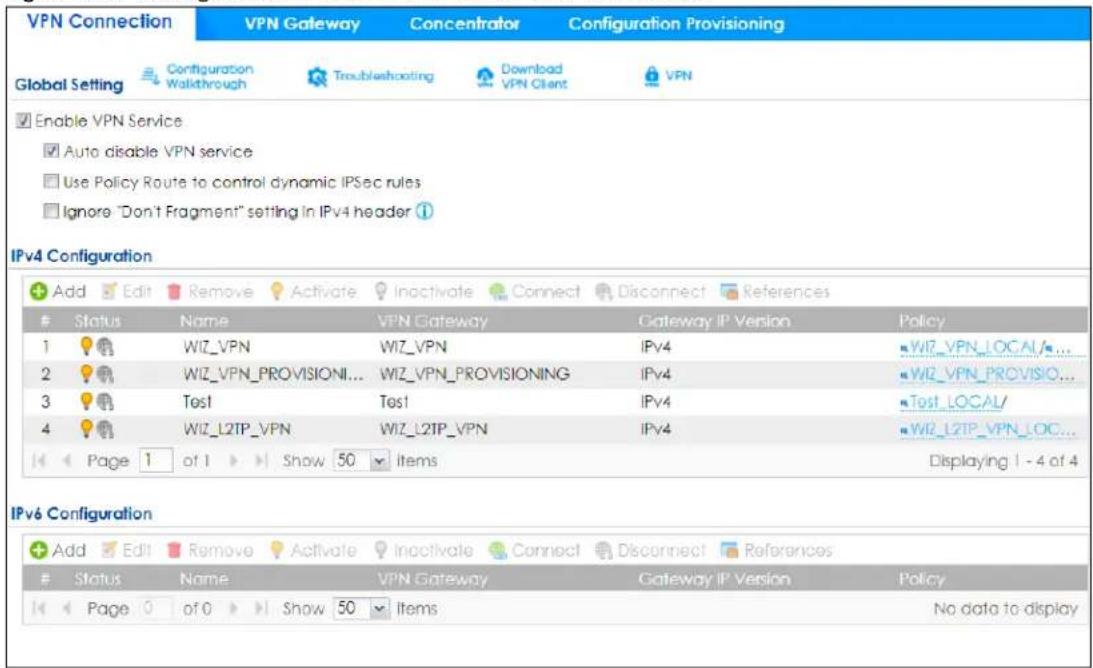
Each field is discussed in the following table.
Table 196 Configuration > VPN > IPSec VPN > VPN Connection
| LABEL DESCRIPTION | |
| Enable VPN Service | Select this to enable IPSec VPN on the Zyxel Device. |
| Auto disable VPN service | Select this to disable UDP ports 500 and 4500 when no IPSec VPN rules are configured on the Zyxel Device. Use this to prevent hackers from attacking the Zyxel Device through UDP 500 and 4500 when you're not using IPSec VPN. |
| Use Policy Route to control dynamic IPSec rules | Select this to be able to use policy routes to manually specify the destination addresses of dynamic IPSec rules. You must manually create these policy routes. The Zyxel Device automatically obtains source and destination addresses for dynamic IPSec rules that do not match any of the policy routes.Clear this to have the Zyxel Device automatically obtain source and destination addresses for all dynamic IPSec rules. |
| Ignore "Don't Fragment" setting in packet header | Select this to fragment packets larger than the MTU (Maximum Transmission Unit) that have the "Don't Fragment" bit in the IP header turned on. When you clear this the Zyxel Device drops packets larger than the MTU that have the "Don't Fragment" bit in the header turned on. |
| IPv4 / IPv6 Configuration | |
| Add Click this to create a new entry. | |
| Edit | Double-click an entry or select it and click Edit to open a screen where you can modify the entry's settings. |
| Remove | To remove an entry, select it and click Remove. The Zyxel Device confirms you want to remove it before doing so. |
| Activate | To turn on an entry, select it and click Activate. |
| Inactivate | To turn off an entry, select it and click Inactivate. |
| Connect | To connect an IPSec SA, select it and click Connect. |
| Disconnect | To disconnect an IPSec SA, select it and click Disconnect. |
| References | Select an entry and click References to open a screen that shows which settings use the entry.See Section 9.5.4 on page 349 for an example. |
| # | This field is a sequential value, and it is not associated with a specific connection. |
| Status | The activate (light bulb) icon is lit when the entry is active and dimmed when the entry is inactive.The connect icon is lit when the interface is connected and dimmed when it is disconnected. |
| Name This field displays the name of the IPSec SA. | |
| VPN Gateway | This field displays the VPN gateway in use for this VPN connection. |
| Gateway IP Version | This field displays what IP version the associated VPN gateway(s) is using. An IPv4 gateway may use an IKEv1 or IKEv2 SA. An IPv6 gateway may use IKEv2 only. |
| Policy | This field displays the local policy and the remote policy, respectively. |
| Apply | Click Apply to save your changes back to the Zyxel Device. |
| Reset | Click Reset to return the screen to its last-saved settings. |
19.2.1 The VPN Connection Add/Edit Screen
The VPN Connection Add/ Edit Gateway screen allows you to create a new VPN connection policy or edit an existing one. To access this screen, go to the Configuration >VPN Connection screen (see Section 19.2 on page 532), and click either the Add icon or an Edit icon.
Figure 379 Configuration > VPN > IPSec VPN > VPN Connection > Add/Edit
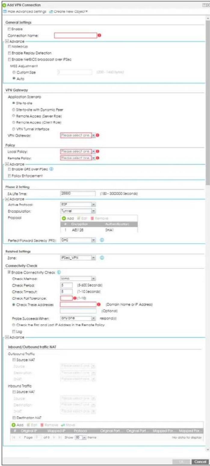
Each field is described in the following table.
Table 197 Configuration > VPN > IPSec VPN > VPN Connection > Add/Edit
| LABEL DESCRIPTION | |
| Show Advanced Settings / Hide Advanced Settings | Click this button to display a greater or lesser number of configuration fields. |
| Create new Object | Use to configure any new settings objects that you need to use in this screen. |
| General Settings | |
| Enable Select this check | box to activate this VPN connection. |
| Connection Name | Type the name used to identify this IPSec SA. You may use 1-31 alphanumeric characters, underscores (—), or dashes (-), but the first character cannot be a number. This value is case-sensitive. |
| Nailed-Up | Select this if you want the Zyxel Device to automatically renegotiate the IPSec SA when the SA life time expires. |
| Enable Replay Detection | Select this check box to detect and reject old or duplicate packets to protect against Denial-of-Service attacks. |
| Enable NetBIOS Broadcast over IPSec | Select this check box if you the Zyxel Device to send NetBIOS (Network Basic Input/Output System) packets through the IPSec SA.NetBIOS packets are TCP or UDP packets that enable a computer to connect to and communicate with a LAN. It may sometimes be necessary to allow NetBIOS packets to pass through IPSec SAs in order to allow local computers to find computers on the remote network and vice versa. |
| MSS Adjustment | Select Custom Size to set a specific number of bytes for the Maximum Segment Size (MSS) meaning the largest amount of data in a single TCP segment or IP datagram for this VPN connection.Some VPN clients may not be able to use a custom MSS size if it is set too small. In that case those VPN clients will ignore the size set here and use the minimum size that they can use.Select Auto to have the Zyxel Device automatically set the MSS for this VPN connection. |
| Narrowed | This is visible when you select any options in the VPN Gateway section except for VPN Tunnel Interface.If the IP range on the Zyxel Device (local policy) and the local IP range on the remote IPSec router overlap in an IKEv2 SA, then you may select Narrowed to have the SA only apply to the IP addresses in common.Here are some examples.Zyxel Device (local policy) Remote IPSec routerIKEv2 SA-1 192.168.20.0/24 192.168.20.1 ~ 192.168.20.20Narrowed 192.168.20.1 ~ 192.168.20.20IKEv2 SA-2 192.168.30.50 ~ 192.168.30.70 192.168.30.60 ~ 192.168.30.80Narrowed 192.168.30.60 ~ 192.168.30.70 |
| VPN Gateway | |
| Application Scenario | Select the scenario that best describes your intended VPN connection.Site-to-site - Choose this if the remote IPSec router has a static IP address or a domain name. This Zyxel Device can initiate the VPN tunnel.Site-to-site with Dynamic Peer - Choose this if the remote IPSec router has a dynamic IP address. Only the remote IPSec router can initiate the VPN tunnel.Remote Access (Server Role) - Choose this to allow incoming connections from IPSec VPN clients. The clients have dynamic IP addresses and are also known as dial-in users. Only the clients can initiate the VPN tunnel.Remote Access (Client Role) - Choose this to connect to an IPSec server. This Zyxel Device is the client (dial-in user) and can initiate the VPN tunnel.VPN Tunnel Interface - Choose this to set up a VPN tunnel interface to bind with a VPN connection. The Zyxel Device can use the interface to do load balancing using a specific Trunk. The remote IPSec router should have a static IP address or a domain name. SeeConfiguration > Network > Interface > VTI. |
| VPN Gateway | Select the VPN gateway this VPN connection is to use or selectCreate Objectto add another VPN gateway for this VPN connection to use. |
| Policy | |
| Local Policy | Select the address corresponding to the local network. UseCreate new Objectif you need to configure a new one. |
| Remote Policy | Select the address corresponding to the remote network. UseCreate new Objectif you need to configure a new one. |
| Enable GRE over IPSec | Select this to allow traffic using the Generic Routing Encapsulation (GRE) tunneling protocol through an IPSec tunnel. |
| Policy Enforcement | Clear this to allow traffic with source and destination IP addresses that do not match the local and remote policy to use the VPN tunnel. Leave this cleared for free access between the local and remote networks.Selecting this restricts who can use the VPN tunnel. The Zyxel Device drops traffic with source and destination IP addresses that do not match the local and remote policy. |
| Mode Config | This is visible when you selectRemote Access (Server Role) and a VPN Gateway. |
| Enable Mode Config | Select this to have the IPSec VPN client receive an IP address, DNS and WINS information from the Zyxel Device. |
| IP Address Pool Select | an address object from the drop-down list box. |
| First DNS Server (Optional) | The Domain Name System (DNS) maps a domain name to an IP address and vice versa. The Zyxel Device uses these (in the order you specify here) to resolve domain names for VPN. Enter a DNS server's IP address. |
| Second DNS Server (Optional) | Enter a secondary DNS server's IP address that is checked if the first one is unavailable. |
| First WINS Server (Optional) | Type the IP address of the WINS (Windows Internet Naming Service) server that you want to send to the DHCP clients. The WINS server keeps a mapping table of the computer names on your network and the IP addresses that they are currently using. |
| Second WINS Server (Optional) | Enter a secondary WINS server's IP address that is checked if the first one is unavailable. |
| Configuration Payload | This is only available when you have created an IKEv2 Gateway and are usingRemote Access (Server Role). |
| Enable Configuration Payload | Select this to have at least have the IP address pool included in the VPN setup data. |
| IP Address Pool: Select | an address object from the drop-down list box. |
| First DNS Server (optional) | The Domain Name System (DNS) maps a domain name to an IP address and vice versa. The Zyxel Device uses these (in the order you specify here) to resolve domain names for VPN. Enter a DNS server's IP address. |
| Second DNS Server (Optional) | Enter a secondary DNS server's IP address that is checked if the first one is unavailable. |
| First WINS Server (Optional) | Type the IP address of the WINS (Windows Internet Naming Service) server that you want to send to the DHCP clients. The WINS server keeps a mapping table of the computer names on your network and the IP addresses that they are currently using. |
| Second WINS Server (Optional) | Enter a secondary WINS server's IP address that is checked if the first one is unavailable. |
| Phase 2 Settings | |
| SA Life Time | Type the maximum number of seconds the IPSec SA can last. Shorter life times provide better security. The Zyxel Device automatically negotiates a new IPSec SA before the current one expires, if there are users who are accessing remote resources. |
| Active Protocol Select which protocol you want to use in the IPSec SA. Choices are:AH (RFC 2402) - provides integrity, authentication, sequence integrity (replay resistance), and non-repudiation but not encryption. If you select AH, you must select an Authentication algorithm.ESP (RFC 2406) - provides encryption and the same services offered by AH, but its authentication is weaker. If you select ESP, you must select an Encryption algorithm and Authentication algorithm.Both AH and ESP increase processing requirements and latency (delay).The Zyxel Device and remote IPSec router must use the same active protocol. | |
| Encapsulation Select which type of encapsulation the IPSec SA uses. Choices areTunnel - this mode encrypts the IP header information and the data.Transport - this mode only encrypts the data.The Zyxel Device and remote IPSec router must use the same encapsulation. | |
| Proposal | Use this section to manage the encryption algorithm and authentication algorithm pairs the Zyxel Device accepts from the remote IPSec router for negotiating the IPSec SA. |
| Add Click this to create a new entry. | |
| Edit Select an entry and click this to be able to modify it. | |
| Remove Select an entry and click this to delete it. | |
| # This field is a sequential value, and it is not associated with a specific proposal. The sequence of proposals should not affect performance significantly. | |
| Encryption | This field is applicable when the Active Protocol is ESP. Select which key size and encryption algorithm to use in the IPSec SA. Choices are:NULL - no encryption key or algorithmDES - a 56-bit key with the DES encryption algorithm3DES - a 168-bit key with the DES encryption algorithmAES128 - a 128-bit key with the AES encryption algorithmAES192 - a 192-bit key with the AES encryption algorithmAES256 - a 256-bit key with the AES encryption algorithmThe Zyxel Device and the remote IPSec router must both have at least one proposal that uses use the same encryption and the same key.Longer keys are more secure, but require more processing power, resulting in increased latency and decreased throughput. |
| Authentication | Select which hash algorithm to use to authenticate packet data in the IPSec SA. Choices are SHA1, SHA256, SHA512 and MD5. SHA is generally considered stronger than MD5, but it is also slower.The Zyxel Device and the remote IPSec router must both have a proposal that uses the same authentication algorithm. |
| Perfect Forward Secrecy (PFS) | Select whether or not you want to enable Perfect Forward Secrecy (PFS) and, if you do, which Diffie-Hellman key group to use for encryption. Choices are:none - disable PFSDH1 - enable PFS and use a 768-bit random numberDH2 - enable PFS and use a 1024-bit random numberDH5 - enable PFS and use a 1536-bit random numberDH14 - enable PFS and use a 2048 bit random numberPFS changes the root key that is used to generate encryption keys for each IPSec SA. The longer the key, the more secure the encryption, but also the longer it takes to encrypt and decrypt information. Both routers must use the same DH key group.PFS is ignored in initial IKEv2 authentication but is used when re-authenticating. |
| Related Settings | |
| Zone | Select the security zone into which to add this VPN connection policy. Any security rules or settings configured for the selected zone apply to this VPN connection policy. |
| Connectivity Check | The Zyxel Device can regularly check the VPN connection to the gateway you specified to make sure it is still available. |
| Enable Connectivity Check | Select this to turn on the VPN connection check. |
| Check Method | Select how the Zyxel Device checks the connection. The peer must be configured to respond to the method you select.Select icmp to have the Zyxel Device regularly ping the address you specify to make sure traffic can still go through the connection. You may need to configure the peer to respond to pings.Select tcp to have the Zyxel Device regularly perform a TCP handshake with the address you specify to make sure traffic can still go through the connection. You may need to configure the peer to accept the TCP connection. |
| Check Port | This field displays when you set the Check Method to tcp. Specify the port number to use for a TCP connectivity check. |
| Check Period | Enter the number of seconds between connection check attempts. |
| Check Timeout | Enter the number of seconds to wait for a response before the attempt is a failure. |
| Check Fail Tolerance | Enter the number of consecutive failures allowed before the Zyxel Device disconnects the VPN tunnel. The Zyxel Device resumes using the first peer gateway address when the VPN connection passes the connectivity check. |
| Check These Addresses | Type one or two domain names or IPv4 addresses for the connectivity check.You can type an IPv4 address in one field and a domain name in the other. For example, type “192.168.1.2” in the top field and “www.zyxel.com” in the bottom field. |
| Probe Succeeds When | This field applies when you specify two domain names or IP addresses for the connectivity check.Select any one if you want the check to pass if at least one of the domain names or IP addresses responds.Select all if you want the check to pass only if both domain names or IP addresses respond. |
| Check the First and Last IP Address in the Remote Policy | Select this to have the Zyxel Device check the connection to the first and last IP addresses in the connection’s remote policy. Make sure one of these is the peer gateway’s LAN IP address. |
| Log | Select this to have the Zyxel Device generate a log every time it checks this VPN connection. |
| Inbound/Outbound traffic NAT | |
| Outbound Traffic | |
| Source NAT | This translation hides the source address of computers in the local network. It may also be necessary if you want the Zyxel Device to route packets from computers outside the local network through the IPSec SA. |
| Source | Select the address object that represents the original source address (or select Create Object to configure a new one). This is the address object for the computer or network outside the local network. |
| Destination | Select the address object that represents the original destination address (or select Create Object to configure a new one). This is the address object for the remote network. |
| SNAT | Select the address object that represents the translated source address (or select Create Object to configure a new one). This is the address object for the local network. The size of the original source address range (Source) must be equal to the size of the translated source address range (SNAT). |
| Inbound Traffic | |
| Source NAT This translation hides the source address of computers in the remote network. | |
| Source | Select the address object that represents the original source address (or select Create Object to configure a new one). This is the address object for the remote network. The size of the original source address range (Source) must be equal to the size of the translated source address range (SNAT). |
| Destination | Select the address object that represents the original destination address (or select Create Object to configure a new one). This is the address object for the local network. |
| SNAT | Select the address object that represents the translated source address (or select Create Object to configure a new one). This is the address that hides the original source address. The size of the original source address range (Source) must be equal to the size of the translated source address range (SNAT). |
| Destination NAT | This translation forwards packets (for example, mail) from the remote network to a specific computer (for example, the mail server) in the local network. |
| Add | Click this to create a new entry. Select an entry and click Add to create a new entry after the selected entry. |
| Edit Select an entry and click this to be able to modify it. | |
| Remove Select an entry and click this to delete it. | |
| Move | To change an entry's position in the numbered list, select it and click Move to display a field to type a number for where you want to put that entry and press [ENTER] to move the entry to the number that you typed. |
| # This field is a sequential value, and it is not associated with a specific NAT record.However, the order of records is the sequence in which conditions are checked and executed. | |
| Original IP | Select the address object that represents the original destination address. This is the address object for the remote network. |
| Mapped IP | Select the address object that represents the desired destination address. For example, this is the address object for the mail server. |
| Protocol | Select the protocol required to use this translation. Choices are: TCP, UDP, or All. |
| Original Port Start / Original Port End | These fields are available if the protocol is TCP or UDP. Enter the original destination port or range of original destination ports. The size of the original port range must be the same size as the size of the mapped port range. |
| Mapped Port Start / Mapped Port End | These fields are available if the protocol is TCP or UDP. Enter the translated destination port or range of translated destination ports. The size of the original port range must be the same size as the size of the mapped port range. |
| OK Click OK to save the changes. | |
| Cancel | Click Cancel to discard all changes and return to the main VPN screen. |
19.3 The VPN Gateway Screen
The VPN Gateway summary screen displays the IPSec VPN gateway policies in the Zyxel Device, as well as the Zyxel Device's address, remote IPSec router's address, and associated VPN connections for each one. In addition, it also lets you activate and deactivate each VPN gateway. To access this screen, click Configuration >VPN >Network >IPSec VPN >VPN Gateway. The following screen appears.
Figure 380 Configuration > VPN > IPSec VPN > VPN Gateway
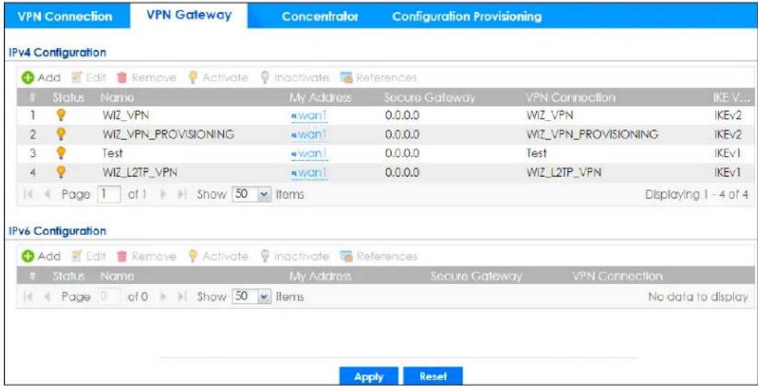
Each field is discussed in the following table. See Section 19.3.1 on page 543 for more information.
Table 198 Configuration > VPN > IPSec VPN > VPN Gateway
| LABEL DESCRIPTION | |
| Add Click this to create a new entry. | |
| Edit | Double-click an entry or select it and click Edit to open a screen where you can modify the entry's settings. |
| Remove | To remove an entry, select it and click Remove. The Zyxel Device confirms you want to remove it before doing so. |
| Activate | To turn on an entry, select it and click Activate. |
| Inactivate | To turn off an entry, select it and click Inactivate. |
| References | Select an entry and click References to open a screen that shows which settings use the entry. See Section 9.5.4 on page 349 for an example. |
| # This field is a sequential value, and it is not associated with a specific VPN gateway. | |
| Status | The activate (light bulb) icon is lit when the entry is active and dimmed when the entry is inactive. |
| Name This field displays the name of the VPN gateway | |
| My address | This field displays the interface or a domain name the Zyxel Device uses for the VPN gateway. |
| Secure Gateway | This field displays the IP address(es) of the remote IPSec routers. |
| VPN Connection This field displays VPN connections that use this VPN gateway. | |
| IKE Version | This field displays whether the gateway is using IKEv1 or IKEv2. IKEv1 applies to IPv4 traffic only. IKEv2 applies to both IPv4 and IPv6 traffic. IKE (Internet Key Exchange) is a protocol used in setting up security associations that allows two parties to send data securely. See Section 19.1 on page 527 for more information on IKEv1 and IKEv2. |
| Apply | Click Apply to save your changes back to the Zyxel Device. |
| Reset | Click Reset to return the screen to its last-saved settings. |
19.3.1 The VPN Gateway Add/Edit Screen
The VPN Gateway Add/Edit screen allows you to create a new VPN gateway policy or edit an existing one. To access this screen, go to the VPN Gateway summary screen (see Section 19.3 on page 541), and click either the Add icon or an Edit icon.
Figure 381 Configuration > VPN > IPSec VPN > VPN Gateway > Add/Edit
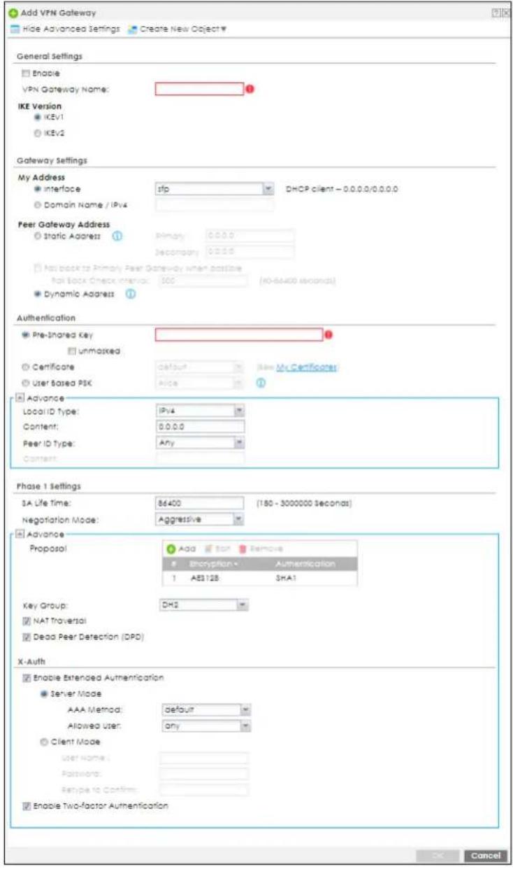
Each field is described in the following table.
Table 199 Configuration > VPN > IPSec VPN > VPN Gateway > Add/Edit
| LABEL DESCRIPTION | |
| Show Advanced Settings / Hide Advanced Settings | Click this button to display a greater or lesser number of configuration fields. |
| Create New Object | Use to configure any new settings objects that you need to use in this screen. |
| General Settings | |
| Enable Select this to activate the VPN Gateway policy. | |
| VPN Gateway Name | Type the name used to identify this VPN gateway. You may use 1-31 alphanumeric characters, underscores(____), or dashes (-), but the first character cannot be a number. This value is case-sensitive. |
| IKE Version | |
| IKEv1 / IKEv2 | Select IKEv1 or IKEv2. IKEv1 applies to IPv4 traffic only. IKEv2 applies to both IPv4 and IPv6 traffic. IKE (Internet Key Exchange) is a protocol used in setting up security associations that allows two parties to send data securely. See Section 19.1 on page 527 for more information on IKEv1 and IKEv2. |
| Gateway Settings | |
| My Address Select how the IP address of the Zyxel Device in the IKE SA is defined.If you select Interface, select the Ethernet interface, VLAN interface, virtual Ethernet interface, virtual VLAN interface or PPPoE/PPTP interface. The IP address of the Zyxel Device in the IKE SA is the IP address of the interface.If you select Domain Name / IP, enter the domain name or the IP address of the Zyxel Device. The IP address of the Zyxel Device in the IKE SA is the specified IP address or the IP address corresponding to the domain name. 0.0.0.0 is not generally recommended as it has the Zyxel Device accept IPSec requests destined for any interface address on the Zyxel Device. | |
| Peer Gateway Address | Select how the IP address of the remote IPSec router in the IKE SA is defined.Select Static Address to enter the domain name or the IP address of the remote IPSec router. You can provide a second IP address or domain name for the Zyxel Device to try if it cannot establish an IKE SA with the first one.Fall back to Primary Peer Gateway when possible: When you select this, if the connection to the primary address goes down and the Zyxel Device changes to using the secondary connection, the Zyxel Device will reconnect to the primary address when it becomes available again and stop using the secondary connection. Users will lose their VPN connection briefly while the Zyxel Device changes back to the primary connection. To use this, the peer device at the secondary address cannot be set to use a nailed-up VPN connection. In the Fallback Check Interval field, set how often to check if the primary address is available.Select Dynamic Address if the remote IPSec router has a dynamic IP address (and does not use DDNS). |
| Authentication | Note: The Zyxel Device and remote IPSec router must use the same authentication method to establish the IKE SA. |
| Pre-Shared Key | Select this to have the Zyxel Device and remote IPSec router use a pre-shared key (password) of up to 128 characters to identify each other when they negotiate the IKE SA. Type the pre-shared key in the field to the right. The pre-shared key can be:8 to 128 single-byte characters, including a-zA-Z0-9,.; | `~!@#%^&*_^+\'::/<>="[] are not allowed.pairs of hexadecimal (a-zA-Z0-9) characters, preceded by "0x".Type "0x" at the beginning of a hexadecimal key. For example, "0x0123456789ABCDEF" is in hexadecimal format; "0123456789ABCDEF" is in ASCII format. If you use hexadecimal, you must enter twice as many characters since you need to enter pairs.The Zyxel Device and remote IPSec router must use the same pre-shared key.Select unmasked to see the pre-shared key in readable plain text. |
| Certificate | Select this to have the Zyxel Device and remote IPSec router use certificates to authenticate each other when they negotiate the IKE SA. Then select the certificate the Zyxel Device uses to identify itself to the remote IPSec router.This certificate is one of the certificates in My Certificates. If this certificate is self-signed, import it into the remote IPSec router. If this certificate is signed by a CA, the remote IPSec router must trust that CA.Note: The IPSec routers must trust each other's certificates.The Zyxel Device uses one of its Trusted Certificates to authenticate the remote IPSec router's certificate. The trusted certificate can be a self-signed certificate or that of a trusted CA that signed the remote IPSec router's certificate. |
| User-based PSK | User-based PSK (IKEv1 only) generates and manages separate pre-shared keys for every user. This enables multiple users, each with a unique key, to access the same VPN gateway policy with one-to-one authentication and strong encryption. Access can be denied on a per-user basis thus allowing VPN SA user-based policies. Click User-Based PSK then select a user or group object who is allowed VPN SA access using this VPN gateway policy. This is for IKEv1 only. |
| Local ID Type | This field is read-only if the Zyxel Device and remote IPSec router use certificates to identify each other. Select which type of identification is used to identify the Zyxel Device during authentication. Choices are:IPv4 or IPv6 - the Zyxel Device is identified by an IP addressDNS - the Zyxel Device is identified by a domain nameE-mail - the Zyxel Device is identified by the string specified in this field |
| Content | This field is read-only if the Zyxel Device and remote IPSec router use certificates to identify each other. Type the identity of the Zyxel Device during authentication. The identity depends on theLocal ID Type.IP - type an IP address; if you type 0.0.0.0, the Zyxel Device uses the IP address specified in theMy Addressfield. This is not recommended in the following situations:There is a NAT router between the Zyxel Device and remote IPSec router.You want the remote IPSec router to be able to distinguish between IPSec SA requests that come from IPSec routers with dynamic WAN IP addresses.In these situations, use a different IP address, or use a differentLocal ID Type.DNS - type the fully qualified domain name (FQDN). This value is only used for identification and can be any string that matches the peer ID string.E-mail - the Zyxel Device is identified by the string you specify here; you can use 1 to 63 single-byte characters, including a-zA-Z0-9_-!"#%&'()*+,/;:==>?[\]^{}|} are not allowed. This value is only used for identification and can be any string. |
| Peer ID Type | Select which type of identification is used to identify the remote IPSec router during authentication. Choices are:IP - the remote IPSec router is identified by an IP addressDNS - the remote IPSec router is identified by a domain nameE-mail - the remote IPSec router is identified by the string specified in this fieldAny - the Zyxel Device does not check the identity of the remote IPSec routerIf the Zyxel Device and remote IPSec router use certificates, there is one more choice.Subject Name - the remote IPSec router is identified by the subject name in the certificate |
| Content | This field is disabled if the Peer ID Type is Any. Type the identity of the remote IPSec router during authentication. The identity depends on the Peer ID Type.If the Zyxel Device and remote IPSec router do not use certificates,IP - type an IP address; see the note at the end of this description.DNS - type the fully qualified domain name (FQDN). This value is only used for identification and can be any string that matches the peer ID string.E-mail - the remote IPSec router is identified by the string you specify here; you can use up to 31 ASCII characters including spaces, although trailing spaces are truncated. This value is only used for identification and can be any string.If the Zyxel Device and remote IPSec router use certificates, type the following fields from the certificate used by the remote IPSec router.IP - subject alternative name field; see the note at the end of this description.DNS - subject alternative name fieldE-mail - subject alternative name field.Subject Name - subject name (maximum 255 ASCII characters, including spaces)Note: If Peer ID Type is IP, please read the rest of this section.If you type 0.0.0.0, the Zyxel Device uses the IP address specified in the Secure Gateway Address field. This is not recommended in the following situations:There is a NAT router between the Zyxel Device and remote IPSec router.You want the remote IPSec router to be able to distinguish between IPSec SA requests that come from IPSec routers with dynamic WAN IP addresses.In these situations, use a different IP address, or use a different Peer ID Type. |
| Phase 1 Settings | |
| SA Life Time (Seconds) | Type the maximum number of seconds the IKE SA can last. When this time has passed, the Zyxel Device and remote IPSec router have to update the encryption and authentication keys and re-negotiate the IKE SA. This does not affect any existing IPSec SAs, however. |
| Negotiation Mode | Select the negotiation mode to use to negotiate the IKE SA. Choices areMain - this encrypts the Zyxel Device's and remote IPSec router's identities but takes more time to establish the IKE SAAggressive - this is faster but does not encrypt the identitiesThe Zyxel Device and the remote IPSec router must use the same negotiation mode. |
| Proposal | Use this section to manage the encryption algorithm and authentication algorithm pairs the Zyxel Device accepts from the remote IPSec router for negotiating the IKE SA. |
| Add Click this to create a new entry. | |
| Edit Select an entry and click this to be able to modify it. | |
| Remove Select an entry and click this to delete it. | |
| # | This field is a sequential value, and it is not associated with a specific proposal. The sequence of proposals should not affect performance significantly. |
| Encryption | Select which key size and encryption algorithm to use in the IKE SA. Choices are:DES- a 56-bit key with the DES encryption algorithm3DES- a 168-bit key with the DES encryption algorithmAES128- a 128-bit key with the AES encryption algorithmAES192- a 192-bit key with the AES encryption algorithmAES256- a 256-bit key with the AES encryption algorithmThe Zyxel Device and the remote IPSec router must use the same key size and encryption algorithm. Longer keys require more processing power, resulting in increased latency and decreased throughput. |
| Authentication | Select which hash algorithm to use to authenticate packet data in the IPSec SA. Choices areSHA1, SHA256, SHA512andMD5. SHA is generally considered stronger than MD5, but it is also slower.The remote IPSec router must use the same authentication algorithm. |
| Key Group | Select which Diffie-Hellman key group (DHx) you want to use to create encryption keys.Choices are:DH1- uses a 768-bit random number to create an encryption keyDH2- uses a 1024-bit random number to create an encryption keyDH5- uses a 1536-bit random number to create an encryption keyDH14- uses a 2048 bit random number to create an encryption keyThe longer the key, the more secure the encryption, but also the longer it takes to encrypt and decrypt information. The Zyxel Device and the remote IPSec router must use the same DH key group. SeeSection 19.7 on page 557for more information on DH key group.Different operating systems may support different DH key groups. Check your operating system documentation.For Windows VPN clients, Zyxel SecuExtender perpetual VPN clients versions 3.8.203.61.32 and earlier support DH1 to DH14.For macOS VPN clients, Zyxel SecuExtender subscription VPN clients versions 1.2.0.7 and later support DH14 to DH21. For Windows VPN clients, Zyxel SecuExtender subscription VPN clients versions 5.6.80.007 and later support DH14 to DH21.Windows versions 7, 10, 11 built-in IKEv2 VPN clients support DH2 by default.macOS versions 14.2 and later built-in IKEv2 VPN clients support DH14 by default.iOS versions 10.15 and later built-in IKEv2 VPN clients support DH14 by default. |
| NAT Traversal Select this if any of these conditions are satisfied.This IKE SA might be used to negotiate IPSec SAs that use ESP as the active protocol.There are one or more NAT routers between the Zyxel Device and remote IPSec router, and these routers do not support IPSec pass-thru or a similar feature.The remote IPSec router must also enable NAT traversal, and the NAT routers have to forward packets with UDP port 500 and UDP 4500 headers unchanged.This field applies for IKEv1 only. NAT Traversal is always performed when you use IKEv2. | |
| Dead Peer Detection (DPD) | Select this check box if you want the Zyxel Device to make sure the remote IPSec router is there before it transmits data through the IKE SA. The remote IPSec router must support DPD. If there has been no traffic for at least 15 seconds, the Zyxel Device sends a message to the remote IPSec router. If the remote IPSec router responds, the Zyxel Device transmits the data. If the remote IPSec router does not respond, the Zyxel Device shuts down the IKE SA. If the remote IPSec router does not support DPD, see if you can use the VPN connection connectivity check (see Section 19.2.1 on page 534). This field applies for IKEv1 only. Dead Peer Detection (DPD) is always performed when you use IKEv2. |
| X Auth / Extended Authentication Protocol | This part of the screen displays X-Auth when using IKEv1 and Extended Authentication Protocol when using IKEv2. |
| X-Auth | This displays when using IKEv1. When different users use the same VPN tunnel to connect to the Zyxel Device (telecommuters sharing a tunnel for example), use X-auth to enforce a user name and password check. This way even though telecommuters all know the VPN tunnel's security settings, each still has to provide a unique user name and password. |
| Enable Extended Authentication | Select this if one of the routers (the Zyxel Device or the remote IPSec router) verifies a user name and password from the other router using the local user database and/or an external server. |
| Server Mode | Select this if the Zyxel Device authenticates the user name and password from the remote IPSec router. You also have to select the authentication method, which specifies how the Zyxel Device authenticates this information. |
| AAA Method | Select the authentication method, which specifies how the Zyxel Device authenticates this information. |
| Allowed User | Extended authentication now supports an allowed user. Select what users should be authenticated. |
| Client Mode | Select this radio button if the Zyxel Device provides a username and password to the remote IPSec router for authentication. You also have to provide the User Name and the Password. |
| User Name | This field is required if the Zyxel Device is in Client Mode for extended authentication. Type the user name the Zyxel Device sends to the remote IPSec router. This is case-sensitive. Enter 1-31 single-byte characters, including a-zA-Z.-0-9!'"#%&'()*+/::<>?[\]^' and spaces are not allowed. |
| Password | This field is required if the Zyxel Device is in Client Mode for extended authentication. Type the password the Zyxel Device sends to the remote IPSec router. Enter 1 to 63 single-byte characters, including 0-9a-zA-Z!"#%&'()*+,-./::<=>@\^_'{}?[] and spaces are not allowed. |
| Retype to Confirm | Type the exact same password again here to make sure an error was not made when typing it originally. |
| Extended Authentication Protocol | This displays when using IKEv2. EAP uses a certificate for authentication. |
| Enable Extended Authentication Protocol | Select this if one of the routers (the Zyxel Device or the remote IPSec router) verifies a user name and password from the other router using the local user database and/or an external server or a certificate. |
| Allowed Auth Method | This field displays the authentication method that is used to authenticate the users. |
| Server Mode | Select this if the Zyxel Device authenticates the user name and password from the remote IPSec router. You also have to select an AAA method, which specifies how the Zyxel Device authenticates this information and who may be authenticated (Allowed User). |
| Client Mode | Select this radio button if the Zyxel Device provides a username and password to the remote IPSec router for authentication. You also have to provide theUser Nameand the Password. |
| User Name | This field is required if the Zyxel Device is inClient Modefor extended authentication. Type the user name the Zyxel Device sends to the remote IPSec router. The user name can be 1-31 ASCII characters. It is case-sensitive, but spaces are not allowed. |
| Password | This field is required if the Zyxel Device is inClient Modefor extended authentication. Type the password the Zyxel Device sends to the remote IPSec router. The password can be 1-31 ASCII characters. It is case-sensitive, but spaces are not allowed. |
| Retype to Confirm | Type the exact same password again here to make sure an error was not made when typing it originally. |
| Enable Two-Factor Authentication | Select this to enable two-factor authentication for this VPN gateway policy. Make sure to enable two-factor authentication inObject >Auth.Method >Two-factor Authentication>VPN Access. You will also need to do one of the following:Click Show Advanced Settings. If you select IKEv1 in IKE Version, enable X-Auth in IPSec VPN >Add VPN Gateway. Enable Mode Config in IPSec VPN >Add VPN Connection.Click Show Advanced Settings. If you select IKEv2 in IKE Version, enable Extended Authentication Protocol in IPSec VPN >Add VPN Gateway. Enable Configuration Payload in IPSec VPN >Add VPN Connection.Enable L2TP over IPSec VPN inConfiguration >VPN >L2TP VPN.SeeSection 43.11.4 on page 1024for more information on two-factor authentication. |
| OK | Click OKto save your settings and exit this screen. |
| Cancel | Click Cancelto exit this screen without saving. |
19.4 VPN Concentrator
A VPN concentrator combines several IPSec VPN connections into one secure network.
Figure 382 VPN Topologies (Fully Meshed and Hub and Spoke)
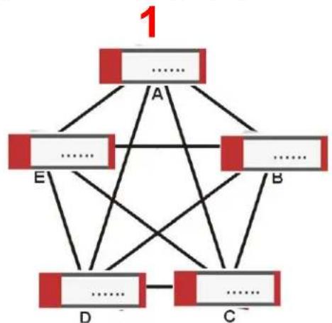
flowchart
graph TD
    A["...."] --> A
    A --> B["...."]
    A --> C["...."]
    A --> D["...."]
    A --> E["...."]
    B --> D
    B --> C
    B --> E
    C --> D
    C --> E
    D --> E
    E --> A
    style 1 fill:#f9f,stroke:#333
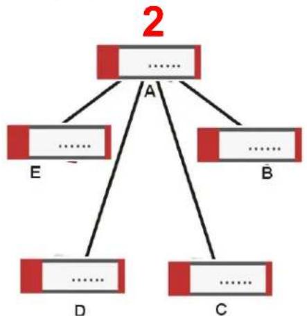
flowchart
graph TD
    A["...."] --> B["E"]
    A --> C["B"]
    A --> D["...."]
    A --> E["...."]
    A --> F["C"]
    style A fill:#f9f,stroke:#333
    style B fill:#ccf,stroke:#333
    style C fill:#ccf,stroke:#333
    style D fill:#ccf,stroke:#333
    style E fill:#ccf,stroke:#333
    style F fill:#ccf,stroke:#333
In a fully-meshed VPN topology (1 in the figure), there is a VPN connection between every pair of routers. In a hub-and-spoke VPN topology (2 in the figure), there is a VPN connection between each
spoke router (B, C, D, and E) and the hub router (A), which uses the VPN concentrator. The VPN concentrator routes VPN traffic between the spoke routers and itself.
A VPN concentrator reduces the number of VPN connections that you have to set up and maintain on the network. You might also be able to consolidate the policy routes in each spoke router, depending on the IP addresses and subnets of each spoke.
However a VPN concentrator is not for every situation. The hub router is a single failure point, so a VPN concentrator is not as appropriate if the connection between spoke routers cannot be down occasionally (maintenance, for example). There is also more burden on the hub router. It receives VPN traffic from one spoke, decrypts it, inspects it to find out to which spoke to route it, encrypts it, and sends it to the appropriate spoke. Therefore, a VPN concentrator is more suitable when there is a minimum amount of traffic between spoke routers.
19.4.1 VPN Concentrator Requirements and Suggestions
Consider the following when using the VPN concentrator.
- The local IP addresses configured in the VPN rules should not overlap.
- The concentrator must have at least one separate VPN rule for each spoke. In the local policy, specify the IP addresses of the networks with which the spoke is to be able to have a VPN tunnel. This may require you to use more than one VPN rule for each spoke.
- To have all Internet access from the spoke routers go through the VPN tunnel, set the VPN rules in the spoke routers to use 0.0.0.0 (any) as the remote IP address.
- Your security policies can still block VPN packets.
19.4.2 VPN Concentrator Screen
The VPN Concentrator summary screen displays the VPN concentrators in the Zyxel Device. To access this screen, click Configuration > VPN > IPSec VPN > Concentrator.
Figure 383 Configuration > VPN > IPSec VPN > Concentrator
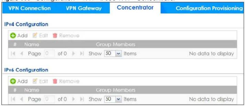
Each field is discussed in the following table. See Section 19.4.3 on page 552 for more information.
Table 200 Configuration > VPN > IPSec VPN > Concentrator
| LABEL DESCRIPTION | |
| IPv4/IPv6Configuration | Choose to configure for IPv4 or IPv6 traffic. |
| Add Click this to create a new entry. | |
| Edit | Select an entry and click this to be able to modify it. |
| Remove Select an | entry and click this to delete it. |
| # | This field is a sequential value, and it is not associated with a specific concentrator. |
| Name This field displays the name of the VPN concentrator. | |
| Group Members | These are the VPN connection policies that are part of the VPN concentrator. |
19.4.3 The VPN Concentrator Add/Edit Screen
Use the VPN Concentrator Add/Edit screen to create or edit a VPN concentrator. To access this screen, go to the VPN Concentrator summary screen (see Section 19.4 on page 550), and click either the Add icon or an Edit icon.
Figure 384 Configuration > VPN > IPSec VPN > Concentrator > Add/Edit
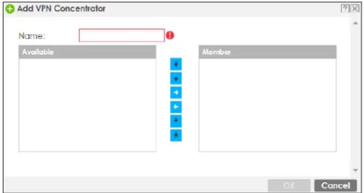
Each field is described in the following table.
Table 201 VPN > IPSec VPN > Concentrator > Add/Edit
| LABEL DESCRIPTION | |
| Name | Enter the name of the concentrator. You may use 1-31 alphanumeric characters, underscores( ), or dashes (-), but the first character cannot be a number. This value is case-sensitive. |
| Member | Select the concentrator's IPSec VPN connection policies.Note: You must disable policy enforcement in each member. See Section 19.2.1 on page 534.IPSec VPN connection policies that do not belong to a VPN concentrator appear under Available.Select any VPN connection policies that you want to add to the VPN concentrator and click the right arrow button to add them.The VPN concentrator's member VPN connections appear under Member. Select any VPN connections that you want to remove from the VPN concentrator, and click the left arrow button to remove them. |
| OK | Click OK to save your changes in the Zyxel Device. |
| Cancel | Click Cancel to exit this screen without saving. |
19.5 Zyxel Device IPSec VPN Client Configuration Provisioning
Use the Configuration > VPN > IPSec VPN > Configuration Provisioning screen to configure who can retrieve VPN rule settings from the Zyxel Device using the Zyxel Device IPSec VPN Client. In the Zyxel Device IPSec VPN Client, you just need to enter the IP address of the Zyxel Device to get all the VPN rule settings automatically. You do not need to manually configure all rule settings in the Zyxel Device IPSec VPN client.
VPN rules for the Zyxel Device IPSec VPN Client have certain restrictions. They must not contain the following settings:
- AH active protocol
- NULL encryption
• SHA512 authentication
• A subnet or range remote policy
The following VPN Gateway rules configured on the Zyxel Device cannot be provisioned to the IPSec VPN Client:
• IPv4 rules with IKEv2 version
- IPv4 rules with User-based PSK authentication
Note: You must enable IPv6 in System > IPv6 to activate IPv6 VPN tunneling rules.
In the Zyxel Device Quick Setup wizard, you can use the VPN Settings for Configuration Provisioning wizard to create a VPN rule that will not violate these restrictions.
Figure 385 Configuration > VPN > IPSec VPN > Configuration Provisioning
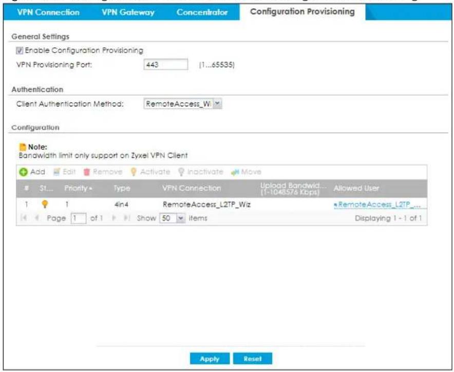
Each field is discussed in the following table.
Table 202 Configuration > VPN > IPSec VPN > Configuration Provisioning
| LABEL DESCRIPTION | |
| Enable Configuration Provisioning | Select this for users to be able to retrieve VPN rule settings using the Zyxel Device IPSec VPN client. |
| VPN Provisioning Port | Change the default port that IPSec VPN clients use to retrieve VPN rule settings from the Zyxel Device. The default is 443 which is already in use for remote management by default. If you change the default IPSec VPN port on the Zyxel Device, make sure to make the same change to the Zyxel IPSec VPN client. See Section 1.8.2 on page 46 for more information.Configure a new port between 1024 to 65535 that is not in use by other services. |
| Client Authentication Method | Choose how users should be authenticated. They can be authenticated using the local database on the Zyxel Device or an external authentication database such as LDAP, Active Directory or RADIUS.defaultis a method you configured inObject > Auth Method. You may configure multiple methods there. If you choose the local database on the Zyxel Device, then configure users using theObject > User/Groupscreen. If you choose LDAP, Active Directory or RADIUS authentication servers, then configure users on the respective server. |
| Configuration | When you add or edit a configuration provisioning entry, you are allowed to set theVPN Connectionand Allowed Userfields.Duplicate entries are not allowed. You cannot select the sameVPN Connectionand Allowed Userpair in a new entry if the same pair exists in a previous entry.You can bind different rules to the same user, but the Zyxel Device will only allow VPN rule setting retrieval for the first match found. |
| Add | Click Add to bind a configured VPN rule to a user or group. Only that user or group may then retrieve the specified VPN rule settings.If you click Add without selecting an entry in advance then the new entry appears as the first entry. Entry order is important as the Zyxel Device searches entries in the order listed here to find a match. After a match is found, the Zyxel Device stops searching. If you want to add an entry as number three for example, then first select entry 2 and click Add. To reorder an entry, use Move. |
| Edit | Select an existing entry and click Edit to change its settings. |
| Remove | To remove an entry, select it and click Remove. The Zyxel Device confirms you want to remove it before doing so. |
| Activate | To turn on an entry, select it and click Activate. Make sure that Enable Configuration Provisioning is also selected. |
| Inactivate | To turn off an entry, select it and click Inactivate. |
| Move | Use Move to reorder a selected entry. Select an entry, click Move, type the number where the entry should be moved, press, then click Apply. |
| Status | This icon shows if the entry is active (yellow) or not (gray). VPN rule settings can only be retrieved when the entry is activated (and Enable Configuration Provisioning is also selected). |
| Priority | Priority shows the order of the entry in the list. Entry order is important as the Zyxel Device searches entries in the order listed here to find a match. After a match is found the Zyxel Device stops searching. |
| VPN Connection | This field shows all configured VPN rules that match the rule criteria for the Zyxel Device IPSec VPN client. Select a rule to bind to the associated user or group. |
| Upload Bandwidth Limit | Upload Bandwidth Limit is only available for Zyxel subscription-based SecuExtender IPSec VPN clients. Windows VPN clients support Zyxel SecuExtender versions 5.6.80.007 or later. macOS VPN clients support Zyxel SecuExtender versions 1.2.0.7 or later.Use Upload Bandwidth Limit to set the maximum bandwidth for uploading traffic from Zyxel IPSec VPN clients over IPSec VPN tunnels. |
| Allowed User | Select which user or group of users is allowed to retrieve the associated VPN rule settings using the Zyxel Device IPSec VPN client. A user may belong to a number of groups. If entries are configured for different groups, the Zyxel Device will allow VPN rule setting retrieval based on the first match found.Users of type admin or limited-admin are not allowed. |
| Type | This field shows how traffic is tunneled from the Zyxel Device to the Zyxel VPN client:6in4 (tunnel IPv6 traffic from the Zyxel Device to the Zyxel client in an IPv4 network);4in6 (tunnel IPv4 traffic from the Zyxel Device to the Zyxel VPN client in an IPv6 network);4in4 (tunnel IPv4 traffic from the Zyxel Device to the Zyxel VPN client in an IPv4 network). |
| Apply | Click Apply to save your changes back to the Zyxel Device. |
| Reset | Click Reset to return the screen to its last-saved settings. |
19.6 Example: IPSec VPN with IKEv2 on a Mobile Phone
This section shows you how to connect your mobile phone to the Zyxel Device using IPSec VPN with and a pre-shared key.
19.6.1 Configuration on Android
This example uses Android software version 13.
1 Go to Settings, search for "VPN", open the VPN settings screen, and then tap Add.
2 Enter a name for the VPN rule in the Name field.
3 Select IKEv2 as Type.
4 Enter the WAN IP address your Zyxel Device is currently using in the Server address field.
5 Enter the IPSec identifier. By default, it is 0.0.0.0.
6 Enter the pre-shared key in the IPSec pre-shared key field. You can find the pre-shared key on the VPN Gateway screen in the Web Configurator.
7 Tap Save to create the VPN rule.
8 Select the VPN rule you created and tap Connect.
9 To check the connection status, go to Configuration >VPN >IPSec VPN in the Web Configurator.
19.6.2 Configuration on iOS
This example uses iOS software version 17.
1 Go to Settings, search for "VPN", open the VPN & Device Management screen, and then tap Add VPN Configuration.
2 Select IKEv2 as Type.
3 Enter a name for the VPN rule in the Name field.
4 Enter the WAN IP address your Zyxel Device is currently using in the Server field.
5 Enter the Remote ID. By default, it is 0.0.0.0.
6 Select None as User Authentication.
7 Disable Use Certificate.
8 Enter the pre-shared key in the Password field. You can find the pre-shared key on the VPN Gateway screen in the Web Configurator.
9 Tap Done to create the VPN rule.
10 Select the VPN rule you created and tap Connect.
11 To check the connection status, go to Configuration > VPN > IPSec VPN in the Web Configurator.
19.7 IPSec VPN Background Information
Here is some more detailed IPSec VPN background information.
IKE SA Overview
The IKE SA provides a secure connection between the Zyxel Device and remote IPSec router.
It takes several steps to establish an IKE SA. The negotiation mode determines how many. There are two negotiation modes--main mode and aggressive mode. Main mode provides better security, while aggressive mode is faster.
Note: Both routers must use the same negotiation mode.
These modes are discussed in more detail in Negotiation Mode. Main mode is used in various examples in the rest of this section.
The Zyxel Device supports IKEv1 and IKEv2. See Section 19.1 on page 527 for more information.
IP Addresses of the Zyxel Device and Remote IPSec Router
To set up an IKE SA, you have to specify the IP addresses of the Zyxel Device and remote IPSec router. You can usually enter a static IP address or a domain name for either or both IP addresses. Sometimes, your Zyxel Device might offer another alternative, such as using the IP address of a port or interface, as well.
You can also specify the IP address of the remote IPSec router as 0.0.0.0. This means that the remote IPSec router can have any IP address. In this case, only the remote IPSec router can initiate an IKE SA because the Zyxel Device does not know the IP address of the remote IPSec router. This is often used for telecommuters.
IKE SA Proposal
The IKE SA proposal is used to identify the encryption algorithm, authentication algorithm, and Diffie-Hellman (DH) key group that the Zyxel Device and remote IPSec router use in the IKE SA. In main mode, this is done in steps 1 and 2, as illustrated next.
Figure 386 IKE SA: Main Negotiation Mode, Steps 1 - 2: IKE SA Proposal
One or more proposals, each one consisting of:
- encryption algorithm
- authentication algorithm
- Diffie-Hellman key group
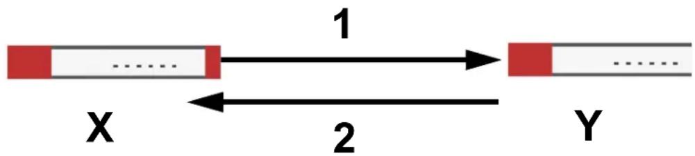
flowchart
graph LR
    A["Red Segment X"] -->|1| B["White Segment Y"]
    B -->|2| A
The Zyxel Device sends one or more proposals to the remote IPSec router. (In some devices, you can only set up one proposal.) Each proposal consists of an encryption algorithm, authentication algorithm, and DH key group that the Zyxel Device wants to use in the IKE SA. The remote IPSec router selects an acceptable proposal and sends the accepted proposal back to the Zyxel Device. If the remote IPSec router rejects all of the proposals, the Zyxel Device and remote IPSec router cannot establish an IKE SA.
Note: Both routers must use the same encryption algorithm, authentication algorithm, and DH key group.
In most Zyxel Devices, you can select one of the following encryption algorithms for each proposal. The algorithms are listed in order from weakest to strongest.
- Data Encryption Standard (DES) is a widely used method of data encryption. It applies a 56-bit key to each 64-bit block of data.
- Triple DES (3DES) is a variant of DES. It iterates three times with three separate keys, effectively tripling the strength of DES.
- Advanced Encryption Standard (AES) is a newer method of data encryption that also uses a secret key. AES applies a 128-bit key to 128-bit blocks of data. It is faster than 3DES.
Some Zyxel Devices also offer stronger forms of AES that apply 192-bit or 256-bit keys to 128-bit blocks of data.
In most Zyxel Devices, you can select one of the following authentication algorithms for each proposal. The algorithms are listed in order from weakest to strongest.
- MD5 (Message Digest 5) produces a 128-bit digest to authenticate packet data.
- SHA1 (Secure Hash Algorithm) produces a 160-bit digest to authenticate packet data.
- SHA256 (Secure Hash Algorithm) produces a 256-bit digest to authenticate packet data.
- SHA512 (Secure Hash Algorithm) produces a 512-bit digest to authenticate packet data.
See Diffie-Hellman (DH) Key Exchange on page 558 for more information about DH key groups.
Diffie-Hellman (DH) Key Exchange
The Zyxel Device and the remote IPSec router use DH public-key cryptography to establish a shared secret. The shared secret is then used to generate encryption keys for the IKE SA and IPSec SA. In main mode, this is done in steps 3 and 4, as illustrated next.
Figure 387 IKE SA: Main Negotiation Mode, Steps 3 - 4: DH Key Exchange
Diffie-Hellman key exchange
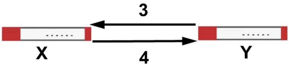
DH public-key cryptography is based on DH key groups. Each key group is a fixed number of bits long. The longer the key, the more secure the encryption, but also the longer it takes to encrypt and decrypt
information. For example, DH2 keys (1024 bits) are more secure than DH1 keys (768 bits), but DH2 keys take longer to encrypt and decrypt.
Authentication
Before the Zyxel Device and remote IPSec router establish an IKE SA, they have to verify each other's identity. This process is based on pre-shared keys and router identities.
In main mode, the Zyxel Device and remote IPSec router authenticate each other in steps 5 and 6, as illustrated below. The identities are also encrypted using the encryption algorithm and encryption key the Zyxel Device and remote IPSec router selected in previous steps.
Figure 388 IKE SA: Main Negotiation Mode, Steps 5 - 6: Authentication (continued)
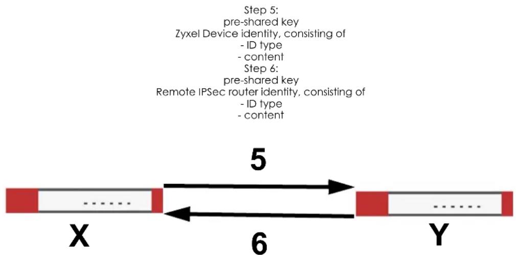
flowchart
graph LR
    A["Step 5: pre-shared key\nZyxel Device identity, consisting of - ID type - content\nStep 6: pre-shared key\nRemote IPSec router identity, consisting of - ID type - content"] --> B["Step 6: Remote IPSec router identity, consisting of - ID type - content"]
    B --> C["X"]
    B --> D["Y"]
    style A fill:#f9f,stroke:#333
    style B fill:#ccf,stroke:#333
    style C fill:#cfc,stroke:#333
    style D fill:#fcc,stroke:#333
You have to create (and distribute) a pre-shared key. The Zyxel Device and remote IPSec router use it in the authentication process, though it is not actually transmitted or exchanged.
Note: The Zyxel Device and the remote IPSec router must use the same pre-shared key.
Router identity consists of ID type and content. The ID type can be domain name, IP address, or email address, and the content is a (properly-formatted) domain name, IP address, or email address. The content is only used for identification. Any domain name or email address that you enter does not have to actually exist. Similarly, any domain name or IP address that you enter does not have to correspond to the Zyxel Device's or remote IPSec router's properties.
The Zyxel Device and the remote IPSec router have their own identities, so both of them must store two sets of information, one for themselves and one for the other router. Local ID type and content refers to the ID type and content that applies to the router itself, and peer ID type and content refers to the ID type and content that applies to the other router.
Note: The Zyxel Device's local and peer ID type and content must match the remote IPSec router's peer and local ID type and content, respectively.
For example, in the next table, the Zyxel Device and the remote IPSec router authenticate each other successfully. In contrast, in the following table, the Zyxel Device and the remote IPSec router cannot authenticate each other and, therefore, cannot establish an IKE SA.
Table 203 VPN Example: Matching ID Type and Content
| ZYXEL DEVICE REMOTE IPSEC ROUTER | |
| Local ID type: E-mail Local ID type: IP | |
| Local ID content: tom@yourcompany.com Local ID content: 1.1.1.2 | |
| Peer ID type: IP Peer ID type: E-mail | |
| Peer ID content: 1.1.1.2 Peer ID content: tom@yourcompany.com | |
Table 204 VPN Example: Mismatching ID Type and Content
| ZYXEL DEVICE REMOTE IPSEC ROUTER | |
| Local ID type: E-mail Local ID type: IP | |
| Local ID content: tom@yourcompany.com Local ID content: 1.1.1.2 | |
| Peer ID type: IP Peer ID type: E-mail | |
| Peer ID content: 1.1.1.20 Peer ID content: tom@yourcompany.com | |
It is also possible to configure the Zyxel Device to ignore the identity of the remote IPSec router. In this case, you usually set the peer ID type to Any. This is less secure, so you should only use this if your Zyxel Device provides another way to check the identity of the remote IPSec router (for example, extended authentication) or if you are troubleshooting a VPN tunnel.
Additional Topics for IKE SA
This section provides more information about IKE SA.
Negotiation Mode
There are two negotiation modes--main mode and aggressive mode. Main mode provides better security, while aggressive mode is faster.
Main mode takes six steps to establish an IKE SA.
Steps 1 - 2: The Zyxel Device sends its proposals to the remote IPSec router. The remote IPSec router selects an acceptable proposal and sends it back to the Zyxel Device.
Steps 3 - 4: The Zyxel Device and the remote IPSec router exchange pre-shared keys for authentication and participate in a Diffie-Hellman key exchange, based on the accepted DH key group, to establish a shared secret.
Steps 5 - 6: Finally, the Zyxel Device and the remote IPSec router generate an encryption key (from the shared secret), encrypt their identities, and exchange their encrypted identity information for authentication.
In contrast, aggressive mode only takes three steps to establish an IKE SA. Aggressive mode does not provide as much security because the identity of the Zyxel Device and the identity of the remote IPSec router are not encrypted. It is usually used in remote-access situations, where the address of the initiator is not known by the responder and both parties want to use pre-shared keys for authentication. For example, the remote IPSec router may be a telecommuter who does not have a static IP address.
VPN, NAT, and NAT Traversal
In the following example, there is another router (A) between router X and router Y.
Figure 389 VPN/NAT Example
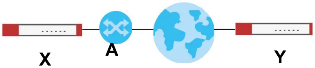
flowchart
graph LR
    X["Red Bar"] --> A["A"]
    A --> Y["Y"]
    style A fill:#000,stroke:#fff,color:#fff
    style Y fill:#000,stroke:#fff,color:#fff
    classDef red fill:none,stroke:none
    class X,A,B,Y label;
If router A does NAT, it might change the IP addresses, port numbers, or both. If router X and router Y try to establish a VPN tunnel, the authentication fails because it depends on this information. The routers cannot establish a VPN tunnel.
Most routers like router A now have an IPSec pass-thru feature. This feature helps router A recognize VPN packets and route them appropriately. If router A has this feature, router X and router Y can establish a VPN tunnel as long as the active protocol is ESP. (See Active Protocol on page 562 for more information about active protocols.)
If router A does not have an IPSec pass-thru or if the active protocol is AH, you can solve this problem by enabling NAT traversal. In NAT traversal, router X and router Y add an extra header to the IKE SA and IPSec SA packets. If you configure router A to forward these packets unchanged, router X and router Y can establish a VPN tunnel.
You have to do the following things to set up NAT traversal.
- Enable NAT traversal on the Zyxel Device and remote IPSec router.
- Configure the NAT router to forward packets with the extra header unchanged. (See the field description for detailed information about the extra header.)
The extra header may be UDP port 500 or UDP port 4500, depending on the standard(s) the Zyxel Device and remote IPSec router support.
X-Auth / Extended Authentication
X-Auth / Extended authentication is often used when multiple IPSec routers use the same VPN tunnel to connect to a single IPSec router. For example, this might be used with telecommuters.
In extended authentication, one of the routers (the Zyxel Device or the remote IPSec router) provides a user name and password to the other router, which uses a local user database and/or an external server to verify the user name and password. If the user name or password is wrong, the routers do not establish an IKE SA.
You can set up the Zyxel Device to provide a user name and password to the remote IPSec router, or you can set up the Zyxel Device to check a user name and password that is provided by the remote IPSec router.
If you use extended authentication, it takes four more steps to establish an IKE SA. These steps occur at the end, regardless of the negotiation mode (steps 7-10 in main mode, steps 4-7 in aggressive mode).
Certificates
It is possible for the Zyxel Device and remote IPSec router to authenticate each other with certificates. In this case, you do not have to set up the pre-shared key, local identity, or remote identity because the certificates provide this information instead.
- Instead of using the pre-shared key, the Zyxel Device and remote IPSec router check the signatures on each other's certificates. Unlike pre-shared keys, the signatures do not have to match.
- The local and peer ID type and content come from the certificates.
Note: You must set up the certificates for the Zyxel Device and remote IPSec router first.
IPSec SA Overview
Once the Zyxel Device and remote IPSec router have established the IKE SA, they can securely negotiate an IPSec SA through which to send data between computers on the networks.
Note: The IPSec SA stays connected even if the underlying IKE SA is not available anymore.
This section introduces the key components of an IPSec SA.
Local Network and Remote Network
In an IPSec SA, the local network, the one(s) connected to the Zyxel Device, may be called the local policy. Similarly, the remote network, the one(s) connected to the remote IPSec router, may be called the remote policy.
Active Protocol
The active protocol controls the format of each packet. It also specifies how much of each packet is protected by the encryption and authentication algorithms. IPSec VPN includes two active protocols, AH (Authentication Header, RFC 2402) and ESP (Encapsulating Security Payload, RFC 2406).
Note: The Zyxel Device and remote IPSec router must use the same active protocol.
Usually, you should select ESP. AH does not support encryption, and ESP is more suitable with NAT.
Encapsulation
There are two ways to encapsulate packets. Usually, you should use tunnel mode because it is more secure. Transport mode is only used when the IPSec SA is used for communication between the Zyxel Device and remote IPSec router (for example, for remote management), not between computers on the local and remote networks.
Note: The Zyxel Device and remote IPSec router must use the same encapsulation.
These modes are illustrated below.
Figure 390 VPN: Transport and Tunnel Mode Encapsulation
Original Packet

Figure 390 VPN: Transport and Tunnel Mode Encapsulation
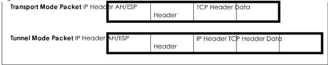
In tunnel mode, the Zyxel Device uses the active protocol to encapsulate the entire IP packet. As a result, there are two IP headers:
- Outside header: The outside IP header contains the IP address of the Zyxel Device or remote IPSec router, whichever is the destination.
- Inside header: The inside IP header contains the IP address of the computer behind the Zyxel Device or remote IPSec router. The header for the active protocol (AH or ESP) appears between the IP headers.
In transport mode, the encapsulation depends on the active protocol. With AH, the Zyxel Device includes part of the original IP header when it encapsulates the packet. With ESP, however, the Zyxel Device does not include the IP header when it encapsulates the packet, so it is not possible to verify the integrity of the source IP address.
IPSec SA Proposal and Perfect Forward Secrecy
An IPSec SA proposal is similar to an IKE SA proposal (see IKE SA Proposal), except that you also have the choice whether or not the Zyxel Device and remote IPSec router perform a new DH key exchange every time an IPSec SA is established. This is called Perfect Forward Secrecy (PFS).
If you enable PFS, the Zyxel Device and remote IPSec router perform a DH key exchange every time an IPSec SA is established, changing the root key from which encryption keys are generated. As a result, if one encryption key is compromised, other encryption keys remain secure.
If you do not enable PFS, the Zyxel Device and remote IPSec router use the same root key that was generated when the IKE SA was established to generate encryption keys.
The DH key exchange is time-consuming and may be unnecessary for data that does not require such security.
PFS is ignored in initial IKEv2 authentication but is used when re-authenticating.
Additional Topics for IPSec SA
This section provides more information about IPSec SA in your Zyxel Device.
Authentication and the Security Parameter Index (SPI)
For authentication, the Zyxel Device and remote IPSec router use the SPI, instead of pre-shared keys, ID type and content. The SPI is an identification number.
Note: The Zyxel Device and remote IPSec router must use the same SPI.
NAT for Inbound and Outbound Traffic
The Zyxel Device can translate the following types of network addresses in IPSec SA.
- Source address in outbound packets - this translation is necessary if you want the Zyxel Device to route packets from computers outside the local network through the IPSec SA.
- Source address in inbound packets - this translation hides the source address of computers in the remote network.
- Destination address in inbound packets - this translation is used if you want to forward packets (for example, mail) from the remote network to a specific computer (like the mail server) in the local network.
Each kind of translation is explained below. The following example is used to help explain each one.
Figure 391 VPN Example: NAT for Inbound and Outbound Traffic
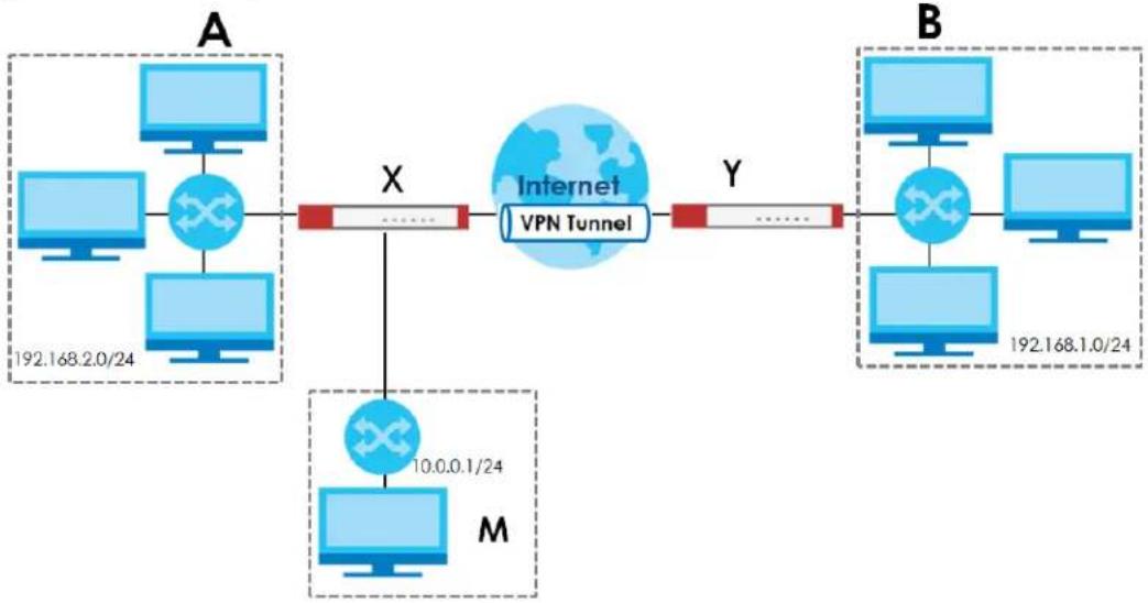
flowchart
graph LR
    subgraph A
        A1["Computer 192.168.2.0/24"] --> X
        X --> Y
        X --> M
    end
    subgraph B
        B1["Computer 192.168.1.0/24"] --> Y
        Y --> M
    end
    X -->|X| Internet
    X -->|M| Internet
    X -->|X| VPN Tunnel
    style Internet fill:#cce5ff,stroke:#333
    style X stroke-dasharray: 5 5
    style Y stroke-dasharray: 5 5
    style M stroke-dasharray: 5 5
Source Address in Outbound Packets (Outbound Traffic, Source NAT)
This translation lets the Zyxel Device route packets from computers that are not part of the specified local network (local policy) through the IPSec SA. For example, in Figure 391 on page 564, you have to configure this kind of translation if you want computer M to establish a connection with any computer in the remote network (B). If you do not configure it, the remote IPSec router may not route messages for computer M through the IPSec SA because computer M's IP address is not part of its local policy.
To set up this NAT, you have to specify the following information:
- Source - the original source address; most likely, computer M's network.
- Destination - the original destination address; the remote network (B).
• SNAT - the translated source address; the local network (A).
Source Address in Inbound Packets (Inbound Traffic, Source NAT)
You can set up this translation if you want to change the source address of computers in the remote network. To set up this NAT, you have to specify the following information:
- Source - the original source address; the remote network (B).
- Destination - the original destination address; the local network (A).
- SNAT - the translated source address; a different IP address (range of addresses) to hide the original source address.
Destination Address in Inbound Packets (Inbound Traffic, Destination NAT)
You can set up this translation if you want the Zyxel Device to forward some packets from the remote network to a specific computer in the local network. For example, in Figure 391 on page 564, you can configure this kind of translation if you want to forward mail from the remote network to the mail server in the local network (A).
You have to specify one or more rules when you set up this kind of NAT. The Zyxel Device checks these rules similar to the way it checks rules for a security policy. The first part of these rules define the conditions in which the rule apply.
- Original IP - the original destination address; the remote network (B).
- Protocol - the protocol [TCP, UDP, or both] used by the service requesting the connection.
- Original Port - the original destination port or range of destination ports; in Figure 391 on page 564, it might be port 25 for SMTP.
The second part of these rules controls the translation when the condition is satisfied.
- Mapped IP - the translated destination address; in Figure 391 on page 564, the IP address of the mail server in the local network (A).
- Mapped Port - the translated destination port or range of destination ports.
The original port range and the mapped port range must be the same size.
IPSec VPN Example Scenario
Here is an example site-to-site IPSec VPN scenario.
Figure 392 Site-to-site IPSec VPN Example
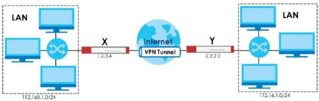
flowchart
graph LR
    subgraph LAN
        A["Computer 192.168.1.0/24"] --> B["Router X"]
        C["Computer 192.168.1.0/24"] --> D["Router X"]
        E["Computer 192.168.1.0/24"] --> F["Router X"]
        G["Computer 192.168.1.0/24"] --> H["Router X"]
    end

    subgraph Internet
        I["Internet VPN Tunnel"] --> J["Router X"]
        J --> K["Router Y"]
        L["Internet VPN Tunnel"] --> M["Router X"]
        N["Internet VPN Tunnel"] --> O["Router Y"]
        P["Internet VPN Tunnel"] --> Q["Router X"]
        R["Internet VPN Tunnel"] --> S["Router Y"]
        T["Internet VPN Tunnel"] --> U["Router X"]
        V["Internet VPN Tunnel"] --> W["Router Y"]
        X["Internet VPN Tunnel"] --> Y["Router Y"]
    end

    style LAN fill:#f9f,stroke:#333
    style Internet fill:#ccf,stroke:#333
CHAPTER 20 SSL VPN
20.1 Overview
Use SSL VPN to allow users to use a web browser for secure remote user login. The remote users do not need a VPN router or VPN client software.
20.1.1 What You Can Do in this Chapter
- Use the VPN > SSL VPN > Access Privilege screens (see Section 20.2 on page 567) to configure SSL access policies.
- Use the Click VPN > SSL VPN > Global Setting screen (see Section 20.3 on page 571) to set the IP address of the Zyxel Device (or a gateway device) on your network for full tunnel mode access, enter access messages or upload a custom logo to be displayed on the remote user screen.
20.1.2 What You Need to Know
Full Tunnel Mode
In full tunnel mode, a virtual connection is created for remote users with private IP addresses in the same subnet as the local network. This allows them to access network resources in the same way as if they were part of the internal network.
Figure 393 Network Access Mode: Full Tunnel Mode
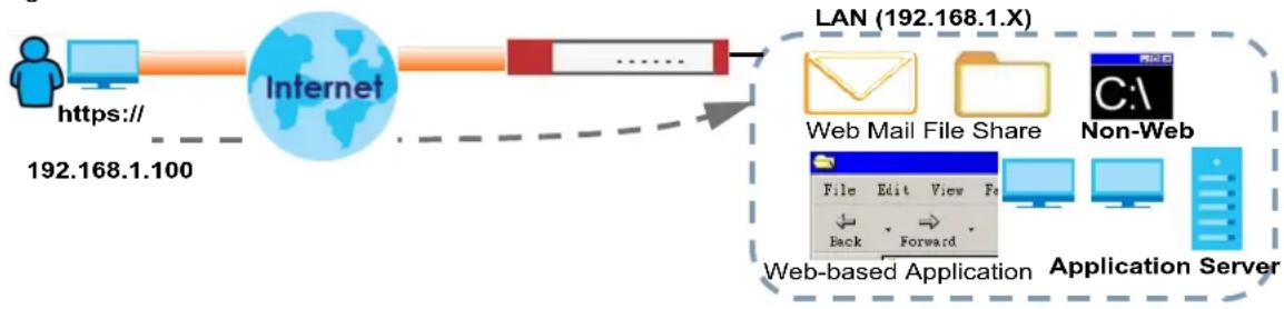
flowchart
graph LR
    A["User"] -->|https://192.168.1.100| B["Internet"]
    B --> C["LAN (192.168.1.X)"]
    C --> D["Web Mail File Share"]
    C --> E["Non-Web"]
    D --> F["Application Server"]
    E --> F
    style A fill:#f9f,stroke:#333
    style B fill:#ccf,stroke:#333
    style C fill:#cfc,stroke:#333
    style D fill:#fcc,stroke:#333
    style E fill:#cff,stroke:#333
    style F fill:#ffc,stroke:#333
SSL Access Policy
An SSL access policy allows the Zyxel Device to perform the following tasks:
- limit user access to specific applications or file sharing server on the network.
- allow user access to specific networks.
- assign private IP addresses and provide DNS/WINS server information to remote users to access internal networks.
SSL Access Policy Objects
The SSL access policies reference the following objects. If you update this information, in response to changes, the Zyxel Device automatically propagates the changes through the SSL policies that use the object(s). When you delete an SSL policy, the objects are not removed.
Table 205 Objects
| OBJECT TYPE | OBJECT SCREEN | DESCRIPTION |
| User Accounts User Account/User Group | Configure a user account or user group to which you want to apply this SSL access policy. | |
| Application SSL | Application | Configure an SSL application object to specify the type of application and the address of the local computer, server, or web site SSL users are to be able to access. |
| IP Pool | Address | Configure an address object that defines a range of private IP addresses to assign to user computers so they can access the internal network through a VPN connection. |
| Server Addresses | Address | Configure address objects for the IP addresses of the DNS and WINS servers that the Zyxel Device sends to the VPN connection users. |
| VPN Network | Address | Configure an address object to specify which network segment users are allowed to access through a VPN connection. |
You cannot delete an object that is referenced by an SSL access policy. To delete the object, you must first unassociate the object from the SSL access policy.
Multiple WAN Connections
You can connect VPN for different ports (wan1, wan2) after you enable SSL VPN.
20.2 The SSL Access Privilege Screen
Click VPN > SSL VPN to open the Access Privilege screen. This screen lists the configured SSL access policies.
Click on the icons to go to the OneSecurity website where there is guidance on configuration walkthroughs, troubleshooting and other information.
Figure 394 VPN > SSL VPN > Access Privilege
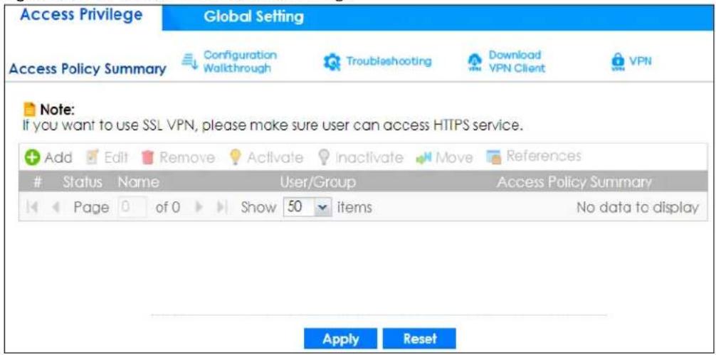
The following table describes the labels in this screen.
Table 206 VPN > SSL VPN > Access Privilege
| LABEL DESCRIPTION | |
| Access Policy Summary | This screen shows a summary of SSL VPN policies created.Click on the VPN icon to go to the Zyxel VPN Client product page at the Zyxel website. |
| Add | Click this to create a new entry. Select an entry and click Add to create a new entry after the selected entry. |
| Edit | Double-click an entry or select it and click Edit to open a screen where you can modify the entry's settings. |
| Remove | To remove an entry, select it and click Remove. The Zyxel Device confirms you want to remove it before doing so. |
| Activate | To turn on an entry, select it and click Activate. |
| Inactivate | To turn off an entry, select it and click Inactivate. |
| Move | To move an entry to a different number in the list, click the Move icon. In the field that appears, specify the number to which you want to move the interface. |
| References | Select an entry and click References to open a screen that shows which settings use the entry. Click Refresh to update information on this screen. |
| # This field displays the index number of the entry. | |
| Status | This icon is lit when the entry is active and dimmed when the entry is inactive. |
| Name | This field displays the descriptive name of the SSL access policy for identification purposes. |
| User/Group | This field displays the user account or user group name(s) associated to an SSL access policy.This field displays up to three names. |
| Access Policy Summary | This field displays details about the SSL application object this policy uses including its name, type, and address. |
| Apply | Click Apply to save the settings. |
| Reset | Click Reset to discard all changes. |
20.2.1 The SSL Access Privilege Policy Add/Edit Screen
To create a new or edit an existing SSL access policy, click the Add or Edit icon in the Access Privilege screen.
Figure 395 VPN > SSL VPN > Add/Edit
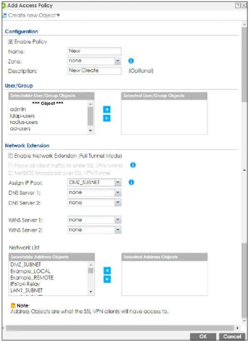
The following table describes the labels in this screen.
Table 207 VPN > SSL VPN > Access Privilege > Add/Edit
| LABEL DESCRIPTION | |
| Create new Object | Use to configure any new settings objects that you need to use in this screen. |
| Configuration | |
| Enable Policy Select | this option to activate this SSL access policy. |
| Name | Enter a descriptive name to identify this policy. You can enter up to 31 characters ("a-z", A-Z", "0-9") with no spaces allowed. |
| Zone | Select the zone to which to add this SSL access policy. You use zones to apply security settings such as security policy and remote management. |
| Description | Enter additional information about this SSL access policy. You can enter up to 60 characters ("0-9", "a-z", "A-Z", "-" and "_"). |
| User/Group | The Selectable User/Group Objects list displays the name(s) of the user account and/or user group(s) to which you have not applied an SSL access policy yet.To associate a user or user group to this SSL access policy, select a user account or user group and click the right arrow button to add to the Selected User/Group Objects list. You can select more than one name.To remove a user or user group, select the name(s) in the Selected User/Group Objects list and click the left arrow button.Note: Although you can select admin and limited-admin accounts in this screen, they are reserved for device configuration only. You cannot use them to access the SSL VPN portal. |
| Network Extension (Optional) | |
| Enable Network Extension | Select this option to create a VPN tunnel between the authenticated users and the internal network. This allows the users to access the resources on the network as if they were on the same local network. This includes access to resources not supported by SSL application objects. For example this lets users Telnet to the internal network even though the Zyxel Device does not have SSL application objects for Telnet.Clear this option to disable this feature. Users can only access the applications as defined by the VPN tunnel's selected SSL application settings and the remote user computers are not made to be a part of the local network. |
| Force all client traffic to SSL VPN tunnel | Select this to send all traffic from the SSL VPN clients through the SSL VPN tunnel. This replaces the default gateway of the SSL VPN clients with the SSL VPN gateway. |
| NetBIOS broadcast over SSL VPN Tunnel | Select this to search for a remote computer and access its applications as if it was in a Local Area Network. The user can find a computer not only by its IP address but also by computer name. |
| Assign IP Pool | Define a separate pool of IP addresses to assign to the SSL users. Select it here.The SSL VPN IP pool should not overlap with IP addresses on the Zyxel Device's local networks (LAN and DMZ for example), the SSL user's network, or the networks you specify in the SSL VPN Network List. |
| DNS/WINS Server 1..2 | Select the name of the DNS or WINS server whose information the Zyxel Device sends to the remote users. This allows them to access devices on the local network using domain names instead of IP addresses. |
| Network List | To allow user access to local network(s), select a network name in the Selectable Address Objects list and click the right arrow button to add to the Selected Address Objects list. You can select more than one network.To block access to a network, select the network name in the Selected Address Objects list and click the left arrow button. |
| OK | Click OK to save the changes and return to the main Access Privilege screen. |
| Cancel | Click Cancel to discard all changes and return to the main Access Privilege screen. |
20.3 The SSL Global Setting Screen
Click VPN > SSL VPN and click the Global Setting tab to display the following screen. Use this screen to set the IP address of the Zyxel Device (or a gateway device) on your network for full tunnel mode access.
Figure 396 VPN > SSL VPN > Global Setting
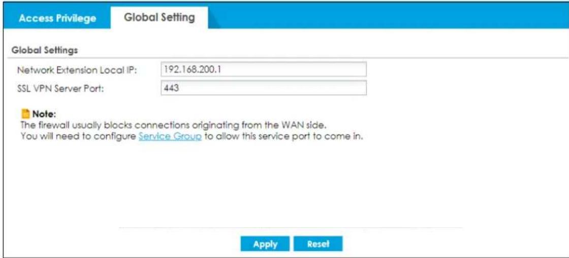
The following table describes the labels in this screen.
Table 208 VPN > SSL VPN > Global Setting
| LABEL DESCRIPTION | |
| Global Setting | |
| Network Extension Local IP | Specify the IP address of the Zyxel Device (or a gateway device) for full tunnel mode SSL VPN access.Leave this field to the default settings unless it conflicts with another interface. |
| SSL VPN Server Port | Specify the SSL VPN server port of the Zyxel Device for full tunnel mode SLL VPN access.Leave this field to default settings unless it conflicts with another interface. |
| Apply | Click Apply to save the changes and/or start the logo file upload process. |
| Reset | Click Reset to return the screen to its last-saved settings. |
CHAPTER 21 L2TP VPN
21.1 Overview
L2TP VPN uses the L2TP and IPSec client software included in remote users' Android, iOS, Windows or Mac OS X operating systems for secure connections to the network behind the Zyxel Device. The remote users do not need their own IPSec gateways or third-party VPN client software.
Figure 397 L2TP VPN Overview
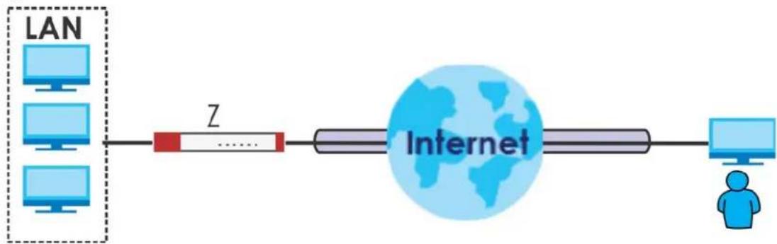
flowchart
graph LR
    A["LAN"] --> B["Z"]
    B --> C["Internet"]
    C --> D["User Icon"]
21.1.1 What You Can Do in this Chapter
- Use the L2TP VPN screen (see Section 21.2 on page 573) to configure the Zyxel Device's L2TP VPN settings.
- Use the VPN Setup Wizard screen in Quick Setup (Chapter 4 on page 107) to configure the Zyxel Device's L2TP VPN settings.
21.1.2 What You Need to Know
The Layer 2 Tunneling Protocol (L2TP) works at layer 2 (the data link layer) to tunnel network traffic between two peers over another network (like the Internet). In L2TP VPN, an IPSec VPN tunnel is established first and then an L2TP tunnel is built inside it. See Chapter 19 on page 527 for information on IPSec VPN.
IPSec Configuration Required for L2TP VPN
You must configure an IPSec VPN connection prior to proper L2TP VPN usage(see Chapter 21 on page 572 for details). The IPSec VPN connection must meet the following requirements:
• VPN Connection is enabled.
• VPN Gateway is enabled.
- Set VPN Connection > VPN Gateway to Remote Access (Server Role).
- Set VPN Connection > Encapsulation to Transport mode.
- Configuration Payload is disabled in the VPN Gateway settings.
• X-Auth is disabled in the VPN Gateway settings. - VPN Gateway authentication method is using Pre-Shared Key.
Using the Quick Setup VPN Setup Wizard
The VPN Setup Wizard is an easy and convenient way to configure the L2TP VPN settings. Click Configuration > Quick Setup > VPN Setup > VPN Settings for L2TP VPN Settings to get started.
Policy Route
The Policy Route for return traffic (from LAN to L2TP clients) is automatically created when Zyxel Device adds a new L2TP connection, allowing users access the resources on a network without additional configuration. However, if some of the traffic from the L2TP clients needs to go to the Internet, you will need to create a policy route to send that traffic from the L2TP tunnels out through a WAN trunk. This task can be easily performed by clicking the Allow L2TP traffic through WAN checkbox at Quick Setup >VPN Setup >Allow L2TP traffic through WAN.
Figure 398 Policy Route for L2TP VPN
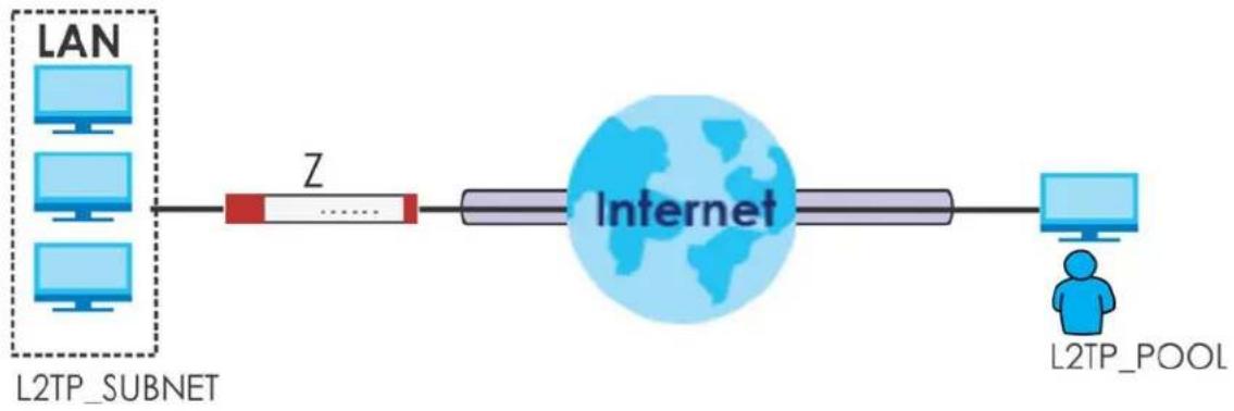
flowchart
graph LR
    A["LAN"] --> B["Z"]
    B --> C["Internet"]
    C --> D["L2TP_POOL"]
    style A fill:#cce5ff,stroke:#333
    style B fill:#ffcccc,stroke:#333
    style C fill:#e6f7ff,stroke:#333
    style D fill:#e6f7ff,stroke:#333
21.2 L2TP VPN Screen
Click Configuration > VPN > L2TP VPN to open the following screen. Use this screen to configure the Zyxel Device's L2TP VPN settings.
Note: Disconnect any existing L2TP VPN sessions before modifying L2TP VPN settings. The remote users must make any needed matching configuration changes and re-establish the sessions using the new settings.
Click on the icons to go to the OneSecurity website where there is guidance on configuration walkthroughs, troubleshooting, and other information.
Figure 399 Configuration > VPN > L2TP VPN
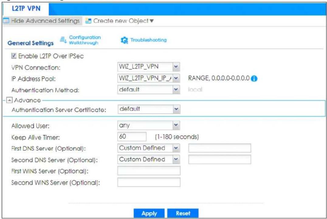
The following table describes the fields in this screen.
Table 209 Configuration > VPN > L2TP VPN
| LABEL DESCRIPTION | |
| Show Advanced Settings / Hide Advanced Settings | Click this button to display a greater or lesser number of configuration fields. |
| Create new Object | Use to configure any new settings objects that you need to use in this screen. |
| Enable L2TP Over IPSec | Use this field to turn the Zyxel Device's L2TP VPN function on or off. |
| VPN Connection | Select the IPSec VPN connection the Zyxel Device uses for L2TP VPN. Only the configured VPN connections inConfiguration>VPN>IPSec VPN>VPN Connectionthat meet the following requirements are displayed here.Remote Access (Server Role)Use transport modeConfiguration Payloadis disabledX-Authis disabledYour VPN settings must also meet the requirements listed in IPSec Configuration Required for L2TP VPN.Note: Selecting a different VPN connection (or modifying the VPN gateway that it uses) disconnects any existing L2TP VPN sessions. |
| IP Address Pool | Select the pool of IP addresses that the Zyxel Device uses to assign to the L2TP VPN clients. UseCreate new Objectif you need to configure a new pool of IP addresses.This should not conflict with any WAN, LAN, DMZ or WLAN subnet even if they are not in use. |
| LABEL DESCRIPTION | |
| Authentication Method | Select how the Zyxel Device authenticates a remote user before allowing access to the L2TP VPN tunnel.The authentication method has the Zyxel Device check a user's user name and password against the Zyxel Device's local database, a remote LDAP, RADIUS, a Active Directory server, or more than one of these. |
| Authentication Server Certificate | Select the certificate to use to identify the Zyxel Device for L2TP VPN connections. You must have certificates already configured in theMy Certificates screen. The certificate is used with the EAP, PEAP, and MSCHAPv2 authentication protocols. |
| Allowed User | The remote user must log into the Zyxel Device to use the L2TP VPN tunnel.Select a user or user group that can use the L2TP VPN tunnel. UseCreate new Objectif you need to configure a new user account. Otherwise, selectanyto allow any user with a valid account and password on the Zyxel Device to log in. |
| Keep Alive Timer | The Zyxel Device sends a Hello message after waiting this long without receiving any traffic from the remote user. The Zyxel Device disconnects the VPN tunnel if the remote user does not respond. |
| First DNS Server, Second DNS Server | Specify the IP addresses of DNS servers to assign to the remote users. You can specify these IP addresses two ways.Custom Defined- enter a static IP address.From ISP-use the IP address of a DNS server that another interface received from its DHCP server. |
| First WINS Server, Second WINS Server | The WINS (Windows Internet Naming Service) server keeps a mapping table of the computer names on your network and the IP addresses that they are currently using.Type the IP addresses of up to two WINS servers to assign to the remote users. You can specify these IP addresses two ways. |
| Apply | ClickApplyto save your changes in the Zyxel Device. |
| Reset | ClickResetto return the screen to its last-saved settings. |
21.2.1 Example: L2TP and Zyxel Device Behind a NAT Router
If the Zyxel Device (Z) is behind a NAT router (N), then do the following for remote clients (C) to access the network behind the Zyxel Device (Z) using L2TP over IPv4.
Figure 400 L2TP and Zyxel Device Behind a NAT Router
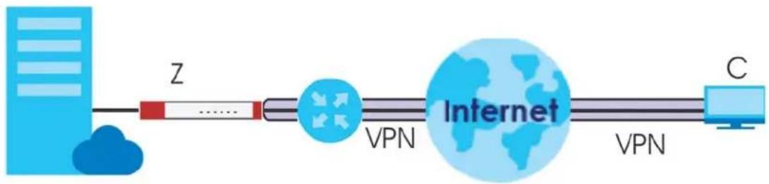
flowchart
graph LR
    A["Server"] -->|Z| B["Network"]
    B -->|VPN| C["Internet"]
    C -->|VPN| D["C"]
1 Create an address object in Configuration > Object > Address/ GEO IP > Address for the WAN IP address of the NAT router.
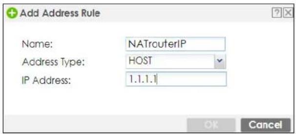
2 Go to Configuration >VPN > IPSec VPN >VPN Connection and click Add for IPv4 Configuration to create a new VPN connection.
3 Select Remote Access (Server Role) as the VPN scenario for the remote client.
4 Select the NAT router WAN IP address object as the Local Policy.
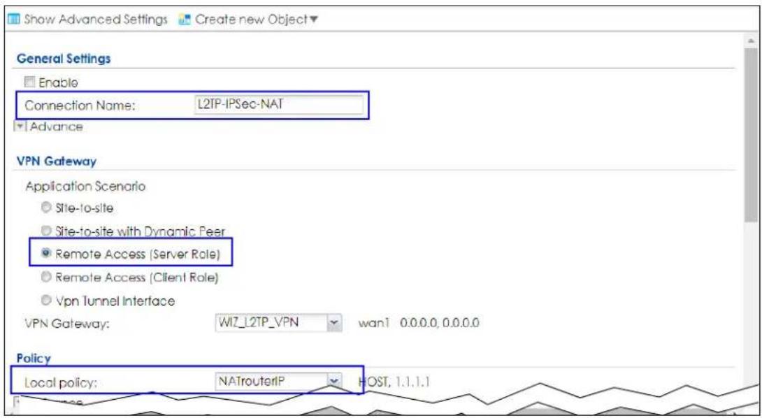
5 Go to Configuration > VPN > L2TP VPN and select the VPN Connection just configured.
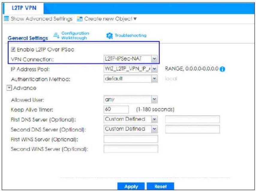
CHAPTER 22
Remote AP VPN
22.1 Overview
Remote AP allows users connected to an off-site (remote) AP to connect to on-site resources behind the Zyxel Device through a secure IPSec VPN tunnel.
- With a IPSec VPN tunnel, the encrypted IPSec tunnel is from the Zyxel Device to another Zyxel Device or the Zyxel Device to a client with IPSec client software installed.
- With a Managed AP license, the connection is from the Zyxel Device to a managed AP using GRE which encapsulates traffic, but does not encrypt it.
- With the Remote AP feature (in the Secure WiFi license) the connection is from the Zyxel Device to a managed AP using NVGRE (Network Virtualization using Generic Routing Encapsulation) over IPSec tunnel. This encapsulates and encrypts traffic from the remote AP to the Zyxel Device. The clients connected to the remote AP don't need IPSec client software installed.
You can associate Secure Tunnel SSID profiles and Local Bridge SSID profiles with a remote AP.
Configure your AP using a Secure Tunnel SSID profiles if you want to access the network behind the Zyxel Device or to access the Internet. Network traffic from clients connected to these SSIDs is sent through the RAP tunnel to the Zyxel Device. The Zyxel Device then sends the traffic out through the interface defined in the SSID profile.
Configure your AP using Local Bridge SSID profiles if you only want to access the Internet. Network traffic from clients connected to these SSIDs is sent directly to the network through the AP's local gateway.
When you have multiple clients connected to the AP with different purposes, set the Secure Tunnel SSIDs for clients that want to access the network behind the Zyxel Device. Set the Local Bridge SSIDs for clients that want to access the Internet, but you don't want them to access the network behind the Zyxel Device.
Figure 401 AP Using Secure Tunnel SSID Profile
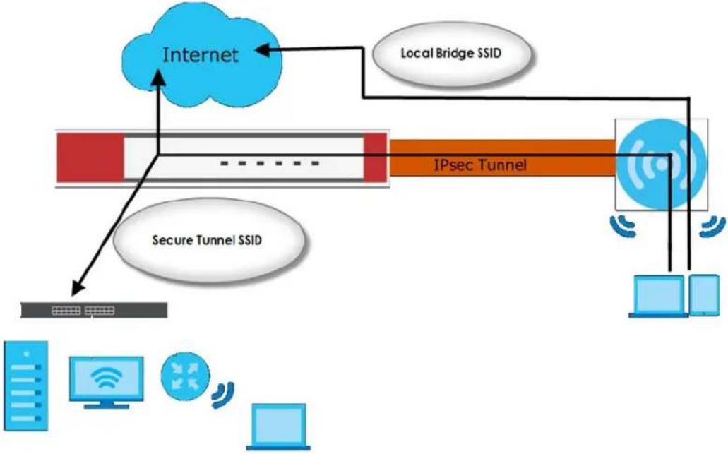
flowchart
graph TD
    A["Internet"] --> B["Local Bridge SSID"]
    B --> C["IPsec Tunnel"]
    C --> D["Secure Tunnel SSID"]
    D --> E["Data Bus"]
    C --> F["Computer"]
    C --> G["Desktop"]
    C --> H["Mobile Device"]
22.2 Configuring a Remote AP
Follow the steps below to access your company network from home through a remote AP.
1 Go to Configuration> Wireless> AP Management. In the Mgmt. AP List screen, click Show Advanced Settings.
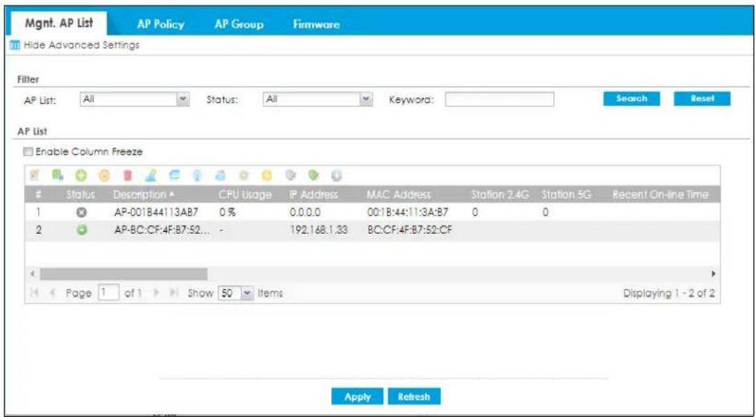
2 Remote AP is only supported on certain AP models. Make sure the AP you want to configure as remote AP shows Remote AP under the AP Role Capability column in the table.
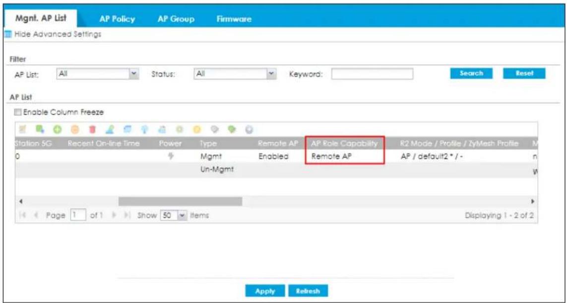
3 Double click on the AP you want to configure to show the Edit AP List screen. Select a pre-configured SSID Profile under Secure Tunnel SSID to access the company network behind the Zyxel Device.
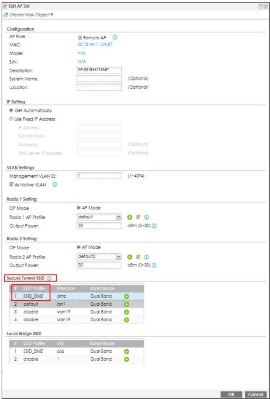
4 Click on the interface to show the drop-down list box. Select an interface you want the AP traffic to go through on the Zyxel Device. The interface you select here will override the interface configured in the SSID Profile.
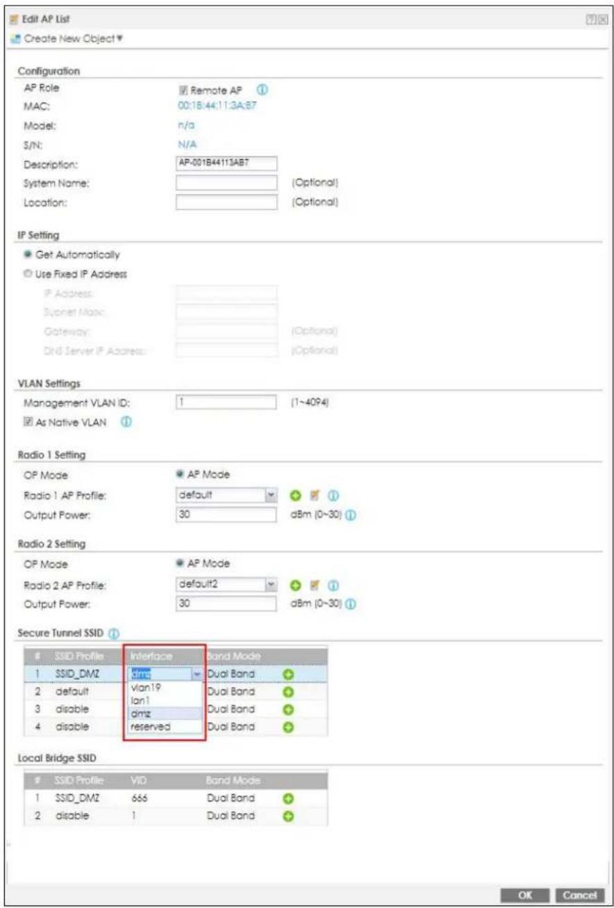
5 Click OK to save your settings. A secure NVGRE over IPSec tunnel is now created between the Zyxel Device and the AP. Users connected to the off-site AP can access the company network through this tunnel.
22.3 Remote AP VPN Screen
Click Configuration>VPN>Remote AP VPN to open the following screen. Use this screen to assign an IP address to the outgoing interface of each RAP IPSec tunnel from this pool so each RAP IPSec tunnel interface IP address doesn't conflict with each other.
Note: Clients connected to the remote AP use the destination IP address of the network behind the Zyxel Device. The Zyxel Device uses the IP address of the AP as the IPSec tunnel destination address.
Figure 402 Configuration > VPN > Remote AP VPN
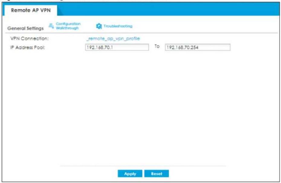
The following table describes the fields in this screen.
Table 210 Configuration > VPN > Remote AP VPN
| LABEL DESCRIPTION | |
| VPN Connection | This field shows the default VPN profile the Zyxel Device uses to create a secure tunnel between itself and the AP. |
| IP Address Pool | Enter the start and end IPv4 addresses for the shared Remote AP IP address pool.The outgoing interface of each RAP IPSec tunnel is assigned an IP address from this pool. Also, WiFi clients are assigned addresses from the pool if the SSID is set to Local Bridge mode. |
| Apply | Click Apply to save your changes in the Zyxel Device. |
| Reset | Click Reset to return the screen to its last-saved settings. |
CHAPTER 23
BWM (Bandwidth
Management)
23.1 Overview
Bandwidth management provides a convenient way to manage the use of various services on the network. It manages general protocols (for example, HTTP and FTP) and applies traffic prioritization to enhance the performance of delay-sensitive applications like voice and video.
23.1.1 What You Can Do in this Chapter
Use the BWM screens (see Section 23.2 on page 588) to control bandwidth for services passing through the Zyxel Device, and to identify the conditions that define the bandwidth control.
23.1.2 What You Need to Know
When you allow a service, you can restrict the bandwidth it uses. It controls TCP and UDP traffic. Use policy routes to manage other types of traffic (like ICMP).
Note: Bandwidth management in policy routes has priority over TCP and UDP traffic policies.
If you want to use a service, make sure both the security policy allow the service's packets to go through the Zyxel Device.
Note: The Zyxel Device checks security policies before it checks bandwidth management rules for traffic going through the Zyxel Device.
Bandwidth management examines every TCP and UDP connection passing through the Zyxel Device. Then, you can specify, by port, whether or not the Zyxel Device continues to route the connection.
BWM Type
The Zyxel Device supports three types of bandwidth management: Shared, Per user and Per-Source-IP.
The Shared BWM type is selected by default in a bandwidth management rule. All matched traffic shares the bandwidth configured in the rule.
If the BWM type is set to Per user in a rule, each user that matches the rule can use up to the configured bandwidth by his/her own.
Select the Per-Source-IP type when you want to set the maximum bandwidth for traffic from an individual source IP address.
In the following example, you configure a Per user bandwidth management rule for radius-users to limit outgoing traffic to 300 kbs. Then all radius-users (A, B and C) can send 300 kbps of traffic.
Figure 403 Bandwidth Management Per User Type
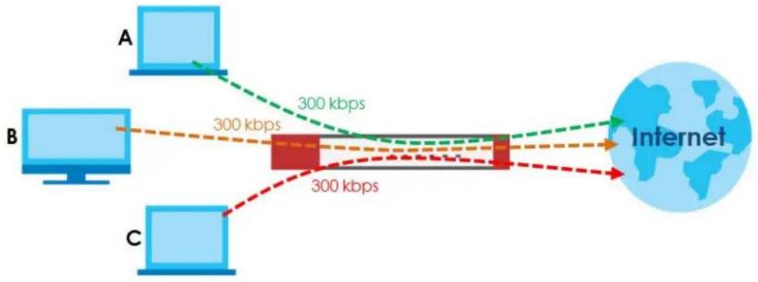
flowchart
graph LR
    A["Computer A"] -->|300 kbps| B["Computer B"]
    B -->|300 kbps| C["Computer C"]
    C -->|300 kbps| B
    B -->|300 kbps| D["Internet"]
DiffServ and DSCP Marking
QoS is used to prioritize source-to-destination traffic flows. All packets in the same flow are given the same priority. CoS (class of service) is a way of managing traffic in a network by grouping similar types of traffic together and treating each type as a class. You can use CoS to give different priorities to different packet types.
DiffServ (Differentiated Services) is a class of service (CoS) model that marks packets so that they receive specific per-hop treatment at DiffServ-compliant network devices along the route based on the application types and traffic flow. Packets are marked with DiffServ Code Points (DSCPs) indicating the level of service desired. This allows the intermediary DiffServ-compliant network devices to handle the packets differently depending on the code points without the need to negotiate paths or remember state information for every flow. In addition, applications do not have to request a particular service or give advanced notice of where the traffic is going.
Connection and Packet Directions
Bandwidth management looks at the connection direction, that is, from which interface the connection was initiated and to which interface the connection is going.
A connection has outbound and inbound packet flows. The Zyxel Device controls the bandwidth of traffic of each flow as it is going out through an interface or VPN tunnel.
- The outbound traffic flows from the connection initiator to the connection responder.
- The inbound traffic flows from the connection responder to the connection initiator.
For example, a LAN1 to WAN connection is initiated from LAN1 and goes to the WAN.
- Outbound traffic goes from a LAN1 device to a WAN device. Bandwidth management is applied before sending the packets out a WAN interface on the Zyxel Device.
- Inbound traffic comes back from the WAN device to the LAN1 device. Bandwidth management is applied before sending the traffic out a LAN1 interface.
Figure 404 LAN1 to WAN Connection and Packet Directions
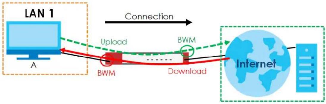
flowchart
graph LR
    A["LAN 1"] -->|Connection| B["BWM"]
    B --> C["Download"]
    C --> D["Internet"]
    style A fill:#f9f,stroke:#333
    style B fill:#ccf,stroke:#333
    style C fill:#cfc,stroke:#333
    style D fill:#fcc,stroke:#333
Outbound and Inbound Bandwidth Limits
You can limit an application's outbound or inbound bandwidth. This limit keeps the traffic from using up too much of the out-going interface's bandwidth. This way you can make sure there is bandwidth for other applications. When you apply a bandwidth limit to outbound or inbound traffic, each member of the out-going zone can send up to the limit. Take a LAN1 to WAN policy for example.
- Outbound traffic is limited to 200 kbps. The connection initiator is on the LAN1 so outbound means the traffic traveling from the LAN1 to the WAN. Each of the WAN zone's two interfaces can send the limit of 200 kbps of traffic.
- Inbound traffic is limited to 500 kbs. The connection initiator is on the LAN1 so inbound means the traffic traveling from the WAN to the LAN1.
Figure 405 LAN1 to WAN, Outbound 200 kbps, Inbound 500 kbps
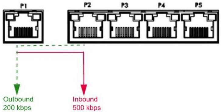
Bandwidth Management Priority
- The Zyxel Device gives bandwidth to higher-priority traffic first, until it reaches its configured bandwidth rate.
- Then lower-priority traffic gets bandwidth.
- The Zyxel Device uses a fairness-based (round-robin) scheduler to divide bandwidth among traffic flows with the same priority.
- The Zyxel Device automatically treats traffic with bandwidth management disabled as priority 7 (the lowest priority).
Maximize Bandwidth Usage
Maximize bandwidth usage allows applications with maximize bandwidth usage enabled to "borrow" any unused bandwidth on the out-going interface.
After each application gets its configured bandwidth rate, the Zyxel Device uses the fairness-based scheduler to divide any unused bandwidth on the out-going interface amongst applications that need more bandwidth and have maximize bandwidth usage enabled.
Unused bandwidth is divided equally. Higher priority traffic does not get a larger portion of the unused bandwidth.
Bandwidth Management Behavior
The following sections show how bandwidth management behaves with various settings. For example, you configure DMZ to WAN policies for FTP servers A and B. Each server tries to send 1000 kbps, but the WAN is set to a maximum outgoing speed of 1000 kbps. You configure policy A for server A's traffic and policy B for server B's traffic.
Figure 406 Bandwidth Management Behavior
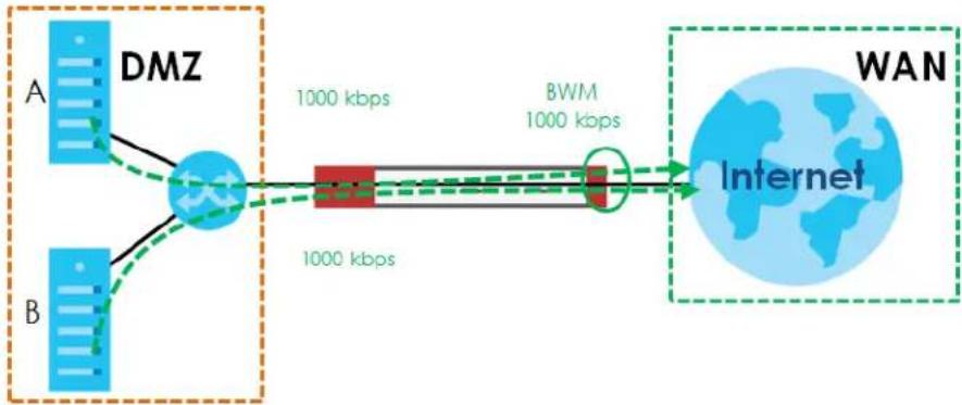
flowchart
graph LR
    A["DMZ"] -->|1000 kbps| B["BWM"]
    B -->|1000 kbps| C["Internet"]
    D["A"] --> A
    E["B"] --> A
    style A fill:#4CAF50,stroke:#388E3C
    style B fill:#4CAF50,stroke:#388E3C
    style C fill:#2196F3,stroke:#388E3C
    style D fill:#FFA500,stroke:#388E3C
    style E fill:#FFA500,stroke:#388E3C
Configured Rate Effect
In the following table the configured rates total less than the available bandwidth and maximize bandwidth usage is disabled, both servers get their configured rate.
Table 211 Configured Rate Effect
| POLICY CONFIGURED RATE MAX. B. | U. PRIORITY ACTUAL RATE | |
| A 300 kbps No 1 300 kbps | ||
| B 200 kbps No 1 200 kbps |
Priority Effect
Here the configured rates total more than the available bandwidth. Because server A has higher priority, it gets up to its configured rate (800 kbps), leaving only 200 kbps for server B.
Table 212 Priority Effect
| POLICY | CONFIGURED RATE | MAX. B. U. | PRIORITY | ACTUAL RATE |
| A 800 kbps Yes 1 800 kbps | ||||
| B 1000 kbps Yes 2 200 kbps | ||||
Maximize Bandwidth Usage Effect
With maximize bandwidth usage enabled, after each server gets its configured rate, the rest of the available bandwidth is divided equally between the two. So server A gets its configured rate of 300 kbps and server B gets its configured rate of 200 kbps. Then the Zyxel Device divides the remaining bandwidth (1000 - 500 = 500) equally between the two (500 / 2 = 250 kbps for each). The priority has no effect on how much of the unused bandwidth each server gets.
So server A gets its configured rate of 300 kbps plus 250 kbps for a total of 550 kbps. Server B gets its configured rate of 200 kbps plus 250 kbps for a total of 450 kbps.
Table 213 Maximize Bandwidth Usage Effect
| POLICY | CONFIGURED RATE MAX. B. | U. PRIORITY A | ACTUAL RATE | |
| A 300 kbps | Yes 1 550 kbps | |||
| B | 200 kbps | Yes | 2 | 450 kbps |
Priority and Over Allotment of Bandwidth Effect
Server A has a configured rate that equals the total amount of available bandwidth and a higher priority. You should regard extreme over allotment of traffic with different priorities (as shown here) as a configuration error. Even though the Zyxel Device still attempts to let all traffic get through and not be lost, regardless of its priority, server B gets almost no bandwidth with this configuration.
Table 214 Priority and Over Allotment of Bandwidth Effect
| POLICY | CONFIGURED RATE | MAX. B. U. | PRIORITY | ACTUAL RATE |
| A | 1000 kbps | Yes | 1 | 999 kbps |
| B | 1000 kbps | Yes | 2 | 1 kbps |
Limit the Bandwidth for a Specific VLAN
If you want to limit the bandwidth for a specific VLAN, set the VLAN as the incoming interface and VPN as the outgoing interface. Then, set the bandwidth limit for this BWM rule.
23.2 The Bandwidth Management Configuration
The Bandwidth management screens control the bandwidth allocation for TCP and UDP traffic. You can use source interface, destination interface, destination port, schedule, user, source, destination information, DSCP code and service type as criteria to create a sequence of specific conditions, similar
to the sequence of rules used by firewalls, to specify how the Zyxel Device handles the DSCP value and allocate bandwidth for the matching packets.
Click Configuration > BWM to open the following screen. This screen allows you to enable/disable bandwidth management and add, edit, and remove user-defined bandwidth management policies.
The default bandwidth management policy is the one with the priority of "default". It is the last policy the Zyxel Device checks if traffic does not match any other bandwidth management policies you have configured. You cannot remove, activate, deactivate or move the default bandwidth management policy.
Figure 407 Configuration > Bandwidth Management
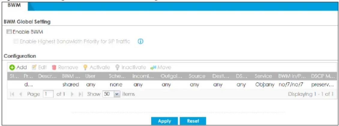
The following table describes the labels in this screen. See Section 23.2.1 on page 591 for more information as well.
Table 215 Configuration > Bandwidth Management
| LABEL DESCRIPTION | |
| Enable BWM Select this | check box to activate management bandwidth. |
| Enable Highest Bandwidth Priority for SIP Traffic | Select this to maximize the throughput of SIP traffic to improve SIP-based VoIP call sound quality. This has the Zyxel Device immediately send SIP traffic upon identifying it. When this option is enabled the Zyxel Device ignores any other application patrol rules for SIP traffic (so there is no bandwidth control for SIP traffic) and does not record SIP traffic bandwidth usage statistics. |
| Add | Click this to create a new entry. Select an entry and click Add to create a new entry after the selected entry. |
| Edit | Select an entry and click this to be able to modify it. |
| Remove Select an entry | and click this to delete it. |
| Activate | To turn on an entry, select it and click Activate. |
| Inactivate | To turn off an entry, select it and click Inactivate. |
| Move | To change an entry's position in the numbered list, select it and click Move to display a field to type a number for where you want to put that entry and press [ENTER] to move the entry to the number that you typed. |
| Status | The activate (light bulb) icon is lit when the entry is active and dimmed when the entry is inactive. The status icon is not available for the default bandwidth management policy. |
| Priority | This field displays a sequential value for each bandwidth management policy and it is not associated with a specific setting.This field displays default for the default bandwidth management policy. |
| Description This field displays additional information about this policy. | |
Table 215 Configuration > Bandwidth Management
| LABEL DESCRIPTION | |
| BWM Type This field displays the below types of BWM:Shared, when the policy is set for all matched trafficPer User, when the policy is set for an individual user or a user groupPer-Source-IP, when the policy is set for a source IP | |
| User | This is the type of user account to which the policy applies. If any displays, the policy applies to all user accounts. |
| Schedule | This is the schedule that defines when the policy applies. none means the policy always applies. |
| Incoming Interface | This is the source interface of the traffic to which this policy applies. |
| Outgoing Interface | This is the destination interface of the traffic to which this policy applies. |
| Source | This is the source address or address group, including geographic address and FQDN (group) objects, for whom this policy applies. If any displays, the policy is effective for every source. |
| Destination | This is the destination address or address group, including geographic address and FQDN (group) objects, for whom this policy applies. If any displays, the policy is effective for every destination. |
| DSCP Code | These are the DSCP code point values of incoming and outgoing packets to which this policy applies. The lower the number the higher the priority with the exception of 0 which is usually given only best-effort treatment.any means all DSCP value or no DSCP marker.default means traffic with a DSCP value of 0. This is usually best effort trafficThe "af" options stand for Assured Forwarding. The number following the "af" identifies one of four classes and one of three drop preferences. |
| Service | App and the service name displays if you selected Application Object for the service type. An Application Object is a pre-defined service.Obj and the service name displays if you selected Service Object for the service type. A Service Object is a customized pre-defined service or another service. Mouse over the service object name to view the corresponding IP protocol number. |
| BWM In/Pri/Out/Pri This field shows the inbound/outbound bandwidth and traffic priority.In - This is how much inbound bandwidth, in kilobits per second, this policy allows the matching traffic to use. Inbound refers to the traffic that the Zyxel Device sends to a connection's initiator. If no displays here, this policy does not apply bandwidth management for the inbound traffic.Out - This is how much outbound bandwidth, in kilobits per second, this policy allows the matching traffic to use. Outbound refers to the traffic the Zyxel Device sends out from a connection's initiator. If no displays here, this policy does not apply bandwidth management for the outbound traffic.Pri - This is the priority for the inbound (the first Pri value) or outbound (the second Pri value) traffic that matches this policy. The smaller the number, the higher the priority. Traffic with a higher priority is given bandwidth before traffic with a lower priority. If the inbound or outbound limit is set to 0, the traffic is assigned to the lowest priority (7) regardless of this field's configuration. | |
Table 215 Configuration > Bandwidth Management
| LABEL DESCRIPTION | |
| DSCP Marking | This is how the Zyxel Device handles the DSCP value of the incoming and outgoing packets that match this policy.In - Inbound, the traffic the Zyxel Device sends to a connection's initiator.Out - Outbound, the traffic the Zyxel Device sends out from a connection's initiator.If this field displays a DSCP value, the Zyxel Device applies that DSCP value to the route's outgoing packets.preserve means the Zyxel Device does not modify the DSCP value of the route's outgoing packets.default means the Zyxel Device sets the DSCP value of the route's outgoing packets to 0.The "af" choices stand for Assured Forwarding. The number following the "af" identifies one of four classes and one of three drop preferences. |
| Apply | Click Apply to save your changes back to the Zyxel Device. |
| Reset | Click Reset to return the screen to its last-saved settings. |
23.2.1 The Bandwidth Management Add/Edit Screen
The Configuration > Bandwidth Management Add/Edit screen allows you to create a new condition or edit an existing one.
802.1P Marking
Use 802.1P to prioritize outgoing traffic from a VLAN interface. The Priority Code is a 3-bit field within a 802.1Q VLAN tag that's used to prioritize associated outgoing VLAN traffic. "0" is the lowest priority level and "7" is the highest.
Table 216 Single Tagged 802.1Q Frame Format
| DA | SA | TPID | Priority | VID | Len/Etype | Data | FCS | IEEE 802.1Q customer tagged frame |
Table 217 802.1Q Frame
| DA | Destination Address | Priority | 802.1p Priority |
| SA | Source Address | Len/Etype | Length and type of Ethernet frame |
| TPID | Tag Protocol IDentifier | Data | Frame data |
| VID | VLAN ID | FCS | Frame Check Sequence |
The following table is a guide to types of traffic for the priority code.
Table 218 Priority Code and Types of Traffic
| PRIORITY | TRAFFIC TYPES |
| 0 (lowest) Background | |
| 1 | Best Effort |
| 2 | Excellent Effort |
| 3 | Critical Applications |
| 4 | Video, less than 100 ms latency and jitter |
| 5 | Voice, less than 10 ms latency and jitter |
Table 218 Priority Code and Types of Traffic
| PRIORITY TRAFFIC TYPES | |
| 6 Internetwork Control | |
| 7 (highest) Network Control | |
To access this screen, go to the Configuration > Bandwidth Management screen (see Section 23.2 on page 588), and click either the Add icon or an Edit icon.
Figure 408 Configuration > Bandwidth Management > Edit (For the Default Policy)
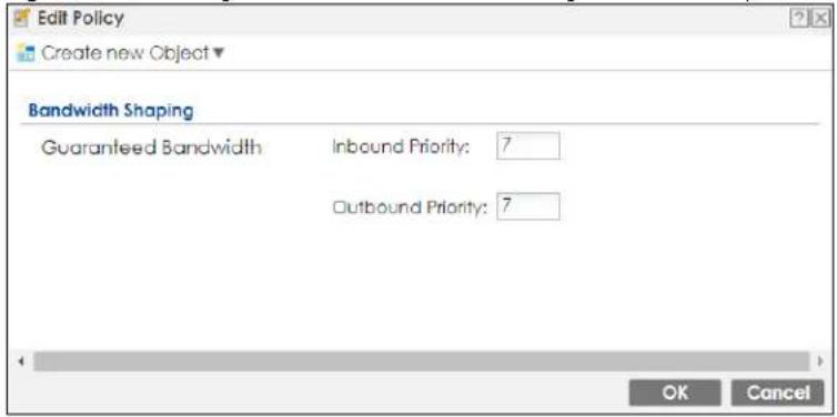
Figure 409 Configuration > Bandwidth Management > Add/Edit
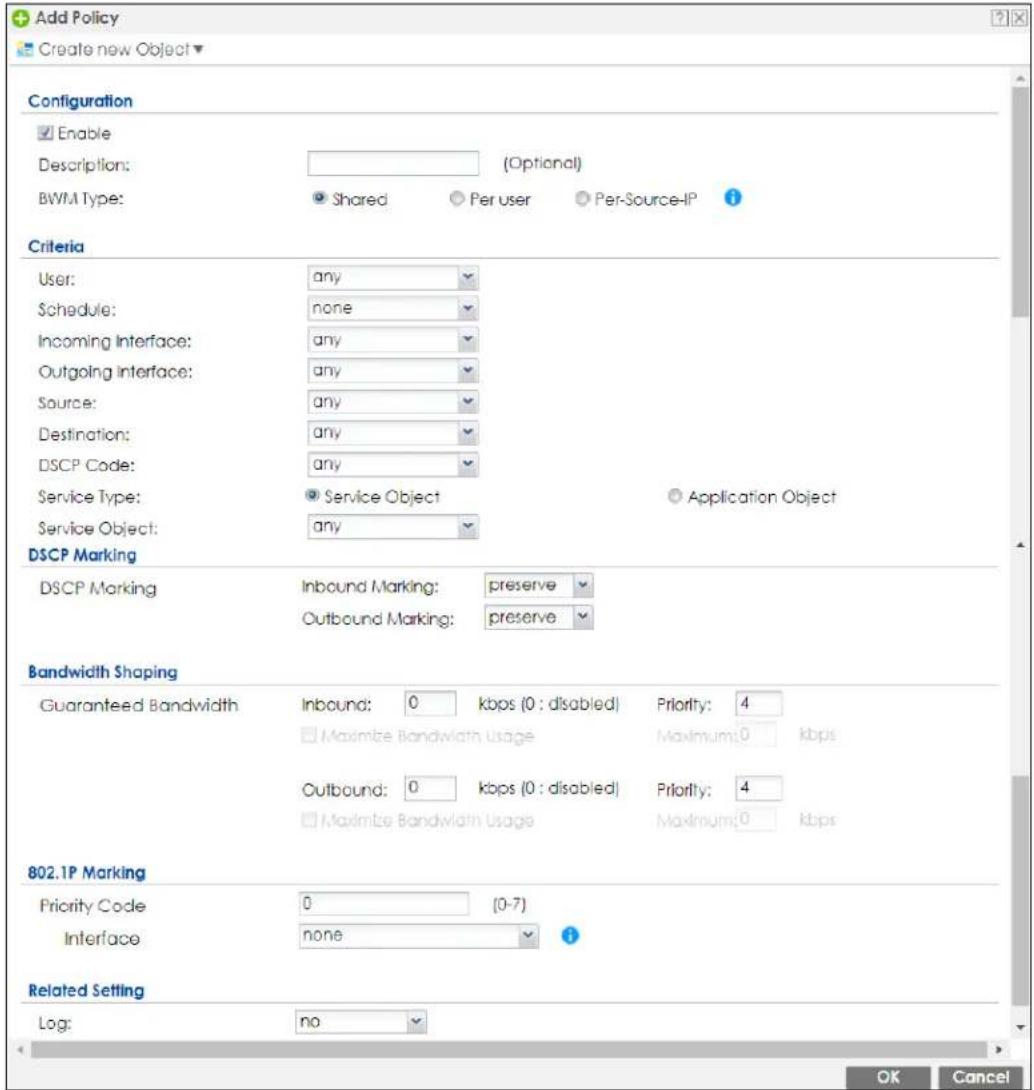
The following table describes the labels in this screen.
Table 219 Configuration > Bandwidth Management > Add/Edit
| LABEL DESCRIPTION | |
| Create new Object | Use to configure any new settings objects that you need to use in this screen. |
| Configuration | |
| Enable Select this check | box to turn on this policy. |
| Description | Enter a description of this policy. It is not used elsewhere. You can use alphanumeric and (+/:+?!*#@$_%- characters, and it can be up to 60 characters long. |
| Criteria | Use this section to configure the conditions of traffic to which this policy applies. |
| BWM Type This field displays the below types of BWM rule:Shared, when the policy is set for all usersPer User, when the policy is set for an individual user or a user groupPer Source IP, when the policy is set for a source IP | |
Table 219 Configuration > Bandwidth Management > Add/Edit
| LABEL DESCRIPTION | |
| User | Select a user name or user group to which to apply the policy. UseCreate new Objectif you need to configure a new user account. Selectanyto apply the policy for every user. |
| Schedule | Select a schedule that defines when the policy applies or selectCreate Objectto configure a new one. Otherwise, selectnoneto make the policy always effective. |
| Incoming Interface | Select the source interface of the traffic to which this policy applies. |
| Outgoing Interface | Select the destination interface of the traffic to which this policy applies. |
| Source | Select a source address or address group, including geographic address and FQDN (group) objects, for whom this policy applies. UseCreate new Objectif you need to configure a new one. Selectanyif the policy is effective for every source. |
| Destination | Select a destination address or address group, including geographic address and FQDN (group) objects, for whom this policy applies. UseCreate new Objectif you need to configure a new one. Selectanyif the policy is effective for every destination. |
| DSCP Code | Select a DSCP code point value of incoming packets to which this policyroute applies or selectUser Definedto specify another DSCP code point. The lower the number the higher the priority with the exception of 0 which is usually given only best-effort treatment.anymeans all DSCP value or no DSCP marker.defaultmeans traffic with a DSCP value of 0. This is usually best effort trafficThe “af” choices stand for Assured Forwarding. The number following the “af” identifies one of four classes and one of three drop preferences. |
| User-Defined DSCP Code | Use this field to specify a custom DSCP code point. |
| Service Type | SelectService ObjectorApplication Objectif you want a specific service (defined in a service object) or application patrol service to which the policy applies. |
| Service Object | This field is available if you selectedService Objectas the service type.Select a service or service group to identify the type of traffic to which this policy applies.anymeans all services. |
| Application Object | This field is available if you selectedApplication Objectas the service type.Click on the blank field to show the available options.[IMAGE]Select application patrol services to identify the specific traffic to which this policy applies.If you selectBitTorrent, it includes the services listed below at the time of writing:BitTorrentBitTorrent_FileTransferBitTorrent_ApplicationBitTorrent_Bundle |
Table 219 Configuration > Bandwidth Management > Add/Edit
| LABEL DESCRIPTION | |
| DSCP Marking | Set how the Zyxel Device handles the DSCP value of the incoming and outgoing packets that match this policy. Inbound refers to the traffic the Zyxel Device sends to a connection's initiator. Outbound refers to the traffic the Zyxel Device sends out from a connection's initiator.Select one of the pre-defined DSCP values to apply or selectUser Definedto specify another DSCP value. The "af" choices stand for Assured Forwarding. The number following the "af" identifies one of four classes and one of three drop preferences.Selectpreserveto have the Zyxel Device keep the packets' original DSCP value.Selectdefaultto have the Zyxel Device set the DSCP value of the packets to 0. |
| Bandwidth Shaping | Configure these fields to set the amount of bandwidth the matching traffic can use. |
| Inbound kbps | Type how much inbound bandwidth, in kilobits per second, this policy allows the traffic to use. Inbound refers to the traffic the Zyxel Device sends to a connection's initiator.If you enter0here, this policy does not apply bandwidth management for the matching traffic that the Zyxel Device sends to the initiator. Traffic with bandwidth management disabled (inbound and outbound are both set to 0) is automatically treated as the lowest priority (7).If the sum of the bandwidths for routes using the same next hop is higher than the actual transmission speed, lower priority traffic may not be sent if higher priority traffic uses all of the actual bandwidth. |
| Outbound kbps | Type how much outbound bandwidth, in kilobits per second, this policy allows the traffic to use. Outbound refers to the traffic the Zyxel Device sends out from a connection's initiator.If you enter0here, this policy does not apply bandwidth management for the matching traffic that the Zyxel Device sends out from the initiator. Traffic with bandwidth management disabled (inbound and outbound are both set to 0) is automatically treated as the lowest priority (7).If the sum of the bandwidths for routes using the same next hop is higher than the actual transmission speed, lower priority traffic may not be sent if higher priority traffic uses all of the actual bandwidth. |
| Priority | This field displays when the inbound or outbound bandwidth management is not set to 0.Enter a number between 1 and 7 to set the priority for traffic that matches this policy. The smaller the number, the higher the priority.Traffic with a higher priority is given bandwidth before traffic with a lower priority. When traffic with higher priority has reached the full bandwidth, the traffic with lower priority can use the remaining bandwidth.The Zyxel Device uses a fairness-based (round-robin) scheduler to divide bandwidth between traffic flows with the same priority.If the inbound or outbound limit is set to 0, the traffic is assigned to the lowest priority (7) regardless of this field's configuration. |
| Maximize Bandwidth Usage | This field displays when the inbound or outbound bandwidth management is not set to 0 and theBWM Typeis set toShared. Enable maximize bandwidth usage to let the traffic matching this policy "borrow" all unused bandwidth on the out-going interface.After each application or type of traffic gets its configured bandwidth rate, the Zyxel Device uses the fairness-based scheduler to divide any unused bandwidth on the outgoing interface among applications and traffic types that need more bandwidth and have maximize bandwidth usage enabled. |
| Maximum | If you did not enableMaximize Bandwidth Usage, then type the maximum unused bandwidth that traffic matching this policy is allowed to "borrow" on the out-going interface (in Kbps), here. |
| 802.1P Marking Use 802. | 1P to prioritize outgoing traffic from a VLAN interface. |
Table 219 Configuration > Bandwidth Management > Add/Edit
| LABEL DESCRIPTION | |
| Priority Code | This is a 3-bit field within a 802.1Q VLAN tag that's used to prioritize associated outgoing VLAN traffic. "0" is the lowest priority level and "7" is the highest. See Table 218 on page 591. The setting configured here overwrites existing priority settings. |
| Interface | Choose a VLAN interface to which to apply the priority level for matching frames. |
| Related Setting | |
| Log | Select whether to have the Zyxel Device generate a log (log), log and alert (log alert) or neither (no) when any traffic matches this policy. |
| OK | Click OK to save your changes back to the Zyxel Device. |
| Cancel | Click Cancel to exit this screen without saving your changes. |
23.2.1.1 Adding Objects for the BWM Policy
Objects are parameters to which the Policy rules are built upon. There are three kinds of objects you can add/edit for the BWM policy, they are User, Schedule and Address objects. Click Configuration >BWM >Add >Create New Object >Add User to see the following screen.
Figure 410 Configuration >BWM > Create New Object > Add User
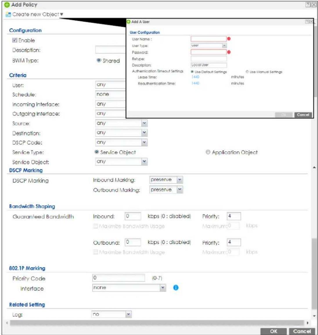
The following table describes the fields in the above screen.
Table 220 Configuration > BWM > Create New Object > Add User
| LABEL DESCRIPTION | |
| User Name Type a user or user group object name of the rule. | |
| User Type | Select a user type from the drop down menu. The user types are Admin, Limited admin, User, Guest, Ext-user, Ext-group-user. |
| Password Type a password for the user object. The password can consist of alphanumeric characters, the underscore, and some punctuation marks (+/-/*=::!@&%#~' ( ) ), and it can be up to eight characters long. | |
| Retype Retype the password to confirm. | |
| Description | Enter a description of this policy. It is not used elsewhere. You can use alphanumeric and ()+/:+?!*#@_%- characters, and it can be up to 60 characters long. |
Table 220 Configuration > BWM > Create New Object > Add User
| LABEL DESCRIPTION | |
| AuthenticationTimeout Settings | Choose either Use Default setting option, which shows the default Lease Time of 1,440 minutes and Reauthentication Time of 1,440 minutes or you can enter them manually by choosing Use Manual Settings option. |
| Lease Time | This shows the Lease Time setting for the user, by default it is 1,440 minutes. |
| Reauthentication Time | This shows the Reauthentication Time for the user, by default it is 1,440 minutes. |
| OK Click OK to save the | setting. |
| Cancel Click Cancel to | abandon this screen. |
Figure 411 Configuration > BWM > Create New Object > Add Schedule
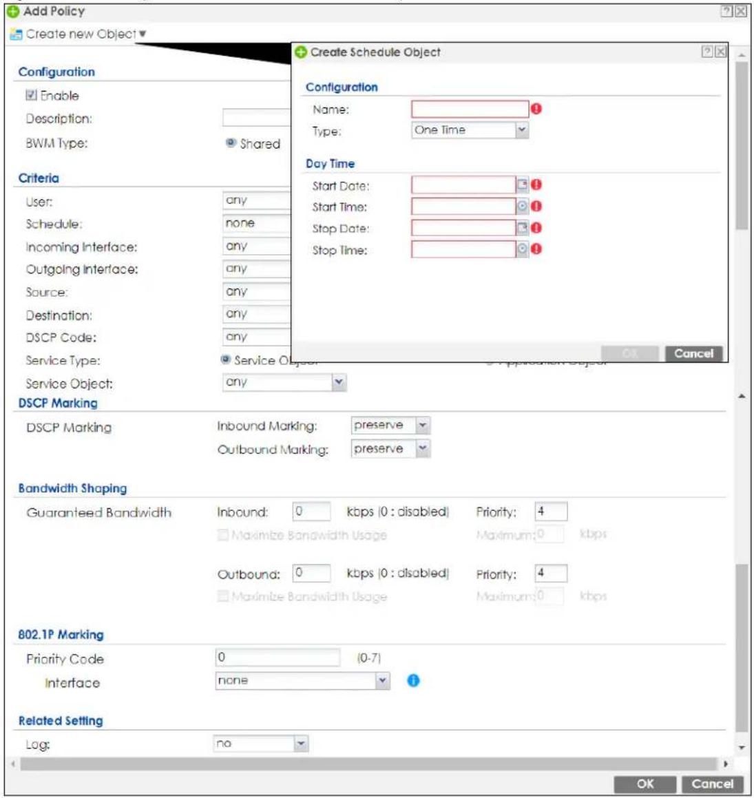
The following table describes the fields in the above screen.
Table 221 Configuration > BWM > Create New Object > Add Schedule
| LABEL DESCRIPTION | |
| Name Enter a name for | the schedule object of the rule. |
| Type | Select an option from the drop down menu for the schedule object. It will show One Time or Recurring. |
| Start Date | Click the icon menu on the right to choose a Start Date for the schedule object. |
| Start Time | Click the icon menu on the right to choose a Start Time for the schedule object. |
| Stop Date | Click the icon menu on the right to choose a Stop Date for schedule object. |
| Stop Time | Click the icon menu on the right to choose a Stop Time for the schedule object. |
Figure 412 Configuration > BWM > Create New Object > Add Address
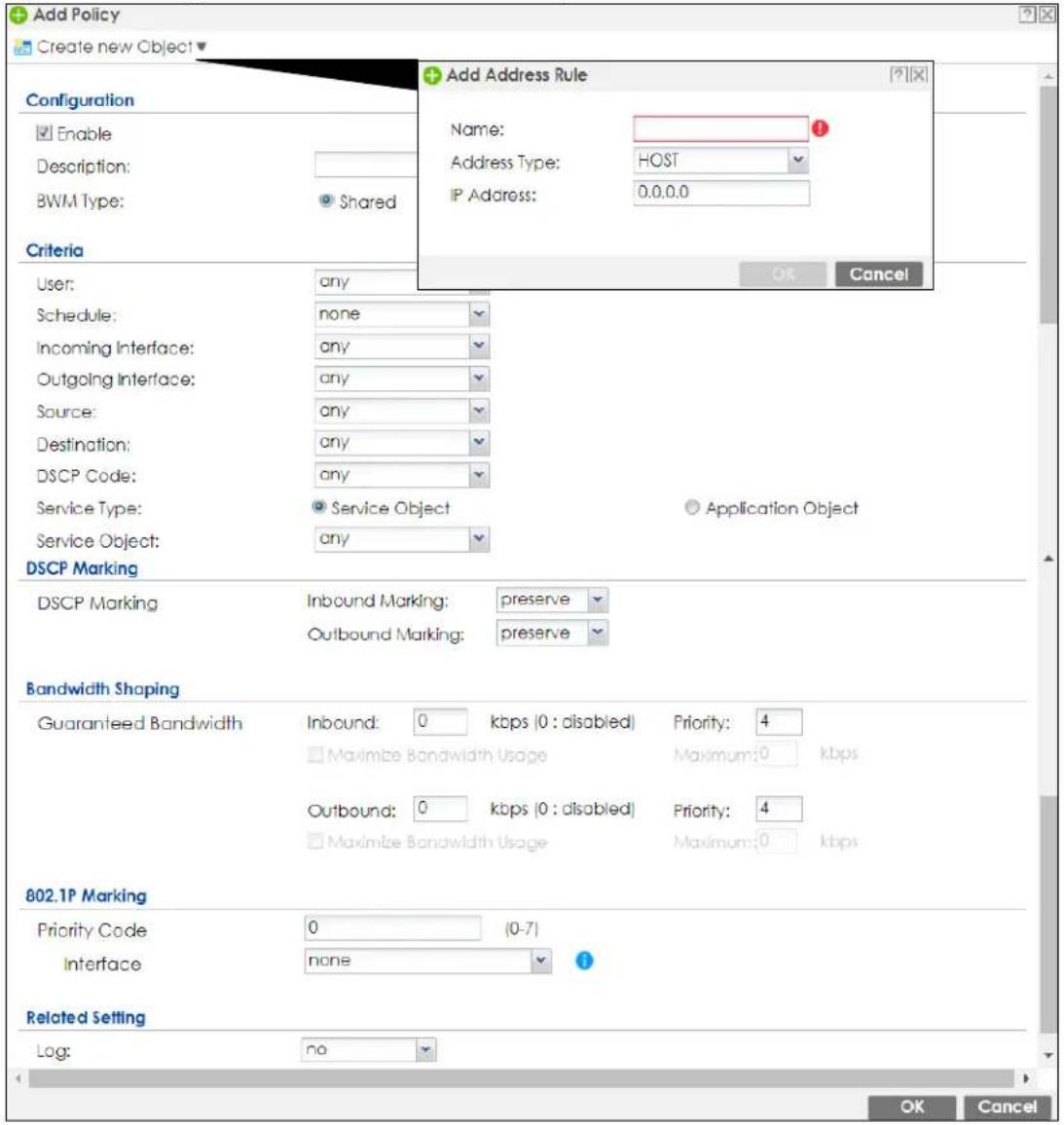
The following table describes the fields in the above screen.
Table 222 Configuration > BWM > Create New Object > Add Address
| LABEL DESCRIPTION | |
| Name Enter a name for | the Address object of the rule. |
| Address Type | Select an Address Type from the drop down menu on the right. The Address Types are Host, Range, Subnet, Interface IP, Interface Subnet, and Interface Gateway. |
| IP Address Enter an IP address for the Address object. | |
| OK Click OK to save the setting. | |
| Cancel Click Cancel to | abandon the setting. |
23.3 Example: Prioritize a Specific Application
You are a client on the Zyxel Device LAN1. You use Teams to communicate with your colleagues and have video meetings often at work. You want to create a bandwidth management rule to prioritize traffic for Teams so that you can always use Teams without any delay.
Set the BWM Type to Shared to apply the BWM rule to all matched traffic.
This example uses the parameters given below.
Table 223 BWM Example
| DESCRIPTION | BWM TYPE | SERVICE TYPE | SERVICE OBJECT | GUARANTEED BANDWIDTH |
| Teams | Shared | Service Object | Teams | Inbound: 20000 kbps/ Priority: 1Outbound: 20000 kbps/ Priority: 1 |
1 Go to Configuration > BWM. Click Add to create a bandwidth management rule using the parameters given in Table 223 on page 600.
2 Select Maximize Bandwidth Usage to allow the traffic that matches this rule borrow all unused bandwidth on the outgoing interface.
3 Select Teams under Application Group.
4 Click OK to save your changes.
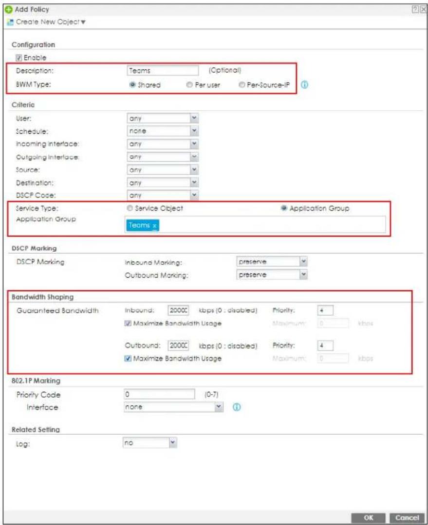
5 The traffic for Teams is now at the highest priority to use the Zyxel Device bandwidth.
CHAPTER 24
Web Authentication
24.1 Web Auth Overview
Web authentication can intercept network traffic, according to the authentication policies, until the user authenticates his or her connection, usually through a specifically designated login web page. This means all web page requests can initially be redirected to a special web page that requires users to authenticate their sessions. Once authentication is successful, they can then connect to the rest of the network or Internet.
As soon as a user attempt to open a web page, the Zyxel Device reroutes his/her browser to a web portal page that prompts him/her to log in.
Figure 413 Web Authentication Example
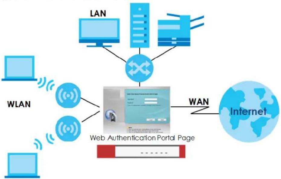
The web authentication page only appears once per authentication session. Unless a user session times out or he/she closes the connection, he or she generally will not see it again during the same session.
24.1.1 What You Can Do in this Chapter
- Use the Configuration > Web Authentication screens (Section 24.2 on page 604) to create and manage web authentication policies.
- Use the Configuration > Web Authentication > SSO screen (Section 24.3 on page 620) to configure how the Zyxel Device communicates with a Single Sign-On agent.
24.1.2 What You Need to Know
Single Sign-On
A SSO (Single Sign On) agent integrates Domain Controller and Zyxel Device authentication mechanisms, so that users just need to log in once (single) to get access to permitted resources.
Forced User Authentication
Instead of making users for which User-Authentication policies have been configured go to the Zyxel Device Login screen manually, you can configure the Zyxel Device to display the Login screen automatically whenever it routes HTTP traffic for anyone who has not logged in yet.
Note: This works with HTTP traffic only. The Zyxel Device does not display the Login screen when users attempt to send other kinds of traffic.
The Zyxel Device does not automatically route the request that prompted the login, however, so users have to make this request again.
Google Authentication
Please see authentication method objects in Section 43.11.3 on page 1022.
Summary of User Authentication Methods
The following table summarizes how users authenticate with the Zyxel Device when web authentication is enabled.
Table 224 User Authentication Methods
| CLIENT | GOOGLE AUTHENTICATOR | USER AUTHENTICATION STEPS |
| 802.1X | No | 1. 802.1X - Username/password2. Web Authentication Portal - Username/password |
| Yes 1. 802.1X - Username/password | 2. Web Authentication Portal - Username/password3. Web Authentication Portal - Google Authenticator code | |
| No 1. 802.1X - Username/password | ||
| Yes 1. 802.1X - Username/password | 2. Web Authentication Portal - Google Authenticator code | |
| Non-802.1X No 1. | Web Authentication Portal - Username/password | |
| Yes 1. Web Authentication Portal - Username/password | 2. Web Authentication Portal - Google Authenticator code | |
| No None needed (if user is using Windows) | ||
| Yes None needed (if user is using Windows) |
24.2 Web Authentication General Screen
The Web Authentication General screen displays the general web portal settings and web authentication policies you have configured on the Zyxel Device. Use this screen to enable web authentication on the Zyxel Device.
Figure 414 Configuration > Web Authentication > General
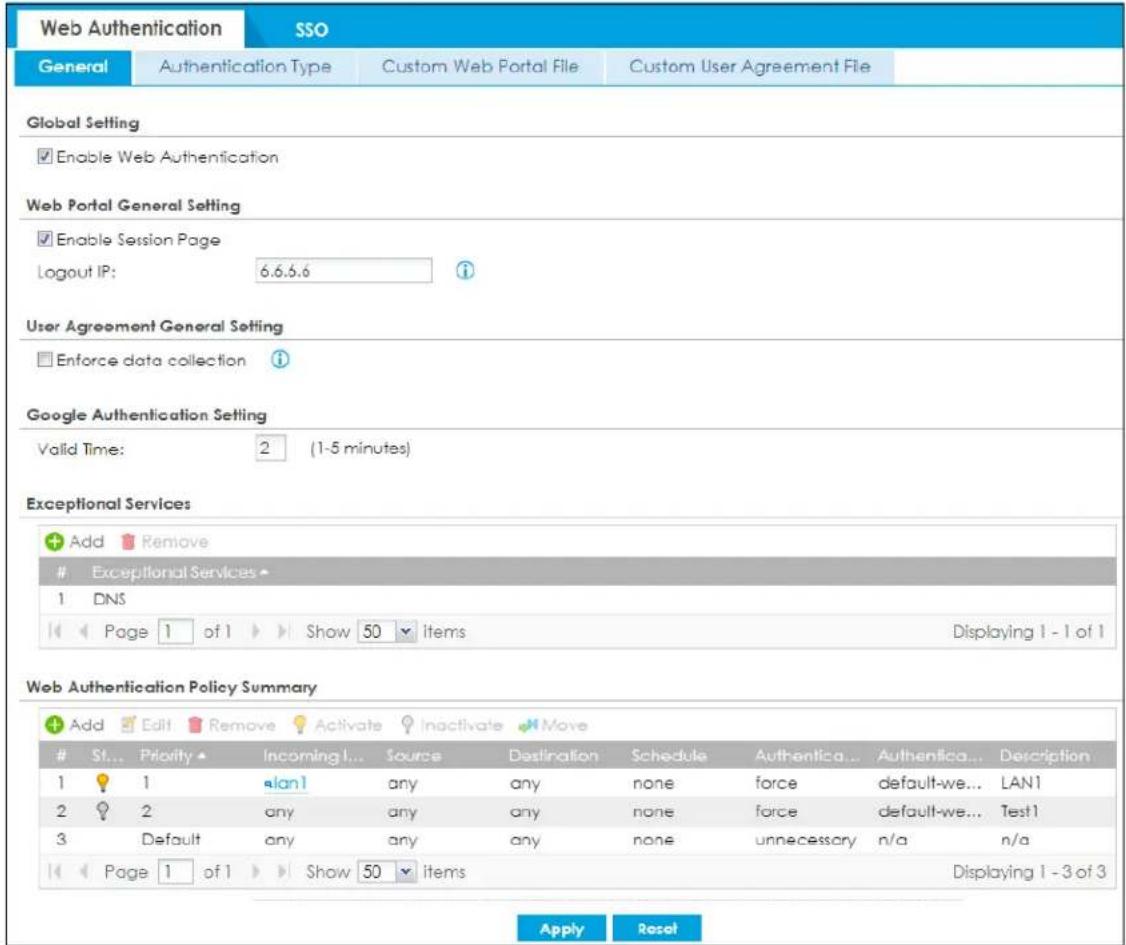
The following table gives an overview of the objects you can configure.
Table 225 Configuration > Web Authentication > General
| LABEL DESCRIPTION | |
| Global Setting | |
| Enable Web Authentication | Select the check box to turn on the web authentication feature. Otherwise, clear the check box to turn it off.Once enabled, all network traffic is blocked until a client authenticates with the Zyxel Device through the specifically designated web portal or user agreement page. |
| Web Portal General Setting | |
| Enable Session Page | Select this to display a page showing information on the user session after s/he logs in. It displays remaining time with an option to renew or log out immediately. |
| Logout IP | Specify an IP address that users can use to terminate their sessions manually by entering the IP address in the address bar of the web browser. |
| User Agreement General Setting | |
| Enforce data collection | Select this to require users to fill in their registration information (name, telephone number, address and email address) on the User Agreement (PC or mobile) page. |
| Google Authentication Setting | Web authentication supports two-factor authentication using Google Authenticator. When enabled, the web authentication page first prompts the user to enter their username and password (factor 1), and then prompts them to enter a time-limited code from the Google Authenticator app (factor 2).It is also possible to configure two-factor authentication for VPN and admin users.The admin two-factor authentication settings override the web authentication two-factor authentication settings if both are configured. |
| Valid Time | Enter the time limit (1-5 minutes) for the code from the Google Authenticator app to be used for login. |
| Exceptional Services | Use this table to list services that users can access without logging in.Click Add to change the list's membership. A screen appears. Available services appear on the left. Select any services you want users to be able to access without logging in and click the right arrow button to add them. The member services are on the right. Select any service that you want to remove from the member list, and click the left arrow button to remove them.Keeping DNS as a member allows users' computers to resolve domain names into IP addresses.Figure 415 Configuration > Web Authentication > Add Exceptional Service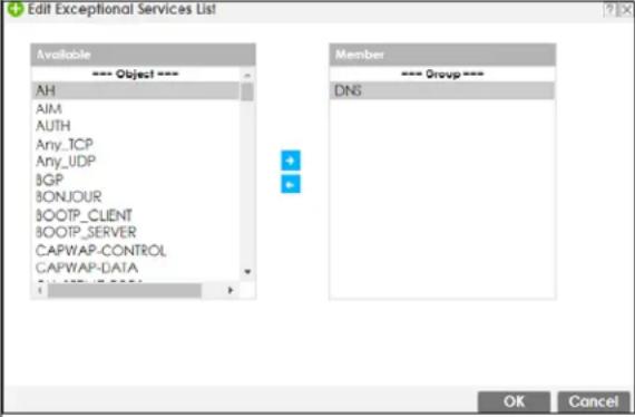 In the table, select one or more entries and click Remove to delete it or them. In the table, select one or more entries and click Remove to delete it or them. |
| Web Authentication Policy Summary | Use this table to manage the Zyxel Device's list of web authentication policies. |
| Add | Click this to create a new entry. Select an entry and click Add to create a new entry after the selected entry. |
| Edit | Double-click an entry or select it and click Edit to open a screen where you can modify the entry's settings. |
| Remove | To remove an entry, select it and click Remove. The Zyxel Device confirms you want to remove it before doing so. |
| Activate | To turn on an entry, select it and click Activate. |
| Inactivate | To turn off an entry, select it and click Inactivate. |
| Move | To move an entry to a different number in the list, click the Move icon. In the field that appears, specify the number to which you want to move the interface. |
| # | This field is a sequential value showing the number of the profile. The profile order is not important. |
| Status | This icon is lit when the entry is active and dimmed when the entry is inactive. |
| Priority | This is the position of the authentication policy in the list. The priority is important as the policies are applied in order of priority. Default displays for the default authentication policy that the Zyxel Device uses on traffic that does not match any exceptional service or other authentication policy. You can edit the default rule but not delete it. |
| Incoming Interface | This field displays the interface on which packets for this policy are received. |
| Source | This displays the source address object, including geographic address and FQDN (group) objects, to which this policy applies. |
| Destination | This displays the destination address object, including geographic address and FQDN (group) objects, to which this policy applies. |
| Schedule | This field displays the schedule object that dictates when the policy applies. none means the policy is active at all times if enabled. |
| Authentication | This field displays the authentication requirement for users when their traffic matches this policy. unnecessary - Users do not need to be authenticated.required - Users need to be authenticated. They must manually go to the login screen or user agreement page. The Zyxel Device will not redirect them to the login screen.force - Users need to be authenticated. The Zyxel Device automatically displays the login screen or user agreement page whenever it routes HTTP traffic for users who have not logged in yet. |
| Authentication Type | This field displays the name of the authentication type profile used in this policy to define how users authenticate their sessions. It shows n/a if Authentication is set to unnecessary. |
| Description | If the entry has a description configured, it displays here. This is n/a for the default policy. |
| Apply | Click this button to save your changes to the Zyxel Device. |
| Reset Click this button to return the screen to its last-saved settings. | |
Creating Exceptional Services
This screen lists services that users can access without logging in. Click Add under Exceptional Services in the previous screen to display this screen. You can change the list's membership here. Available services appear on the left. Select any services you want users to be able to access without logging in and click the right arrow button -> to add them. The member services are on the right. Select any service that you want to remove from the member list, and click the left arrow <- button to remove them. Then click OK to apply the changes and return to the main Web Authentication screen. Alternatively, click Cancel to discard the changes and return to the main Web Authentication screen.
Figure 416 Configuration > Web Authentication > General > Add Exceptional Service
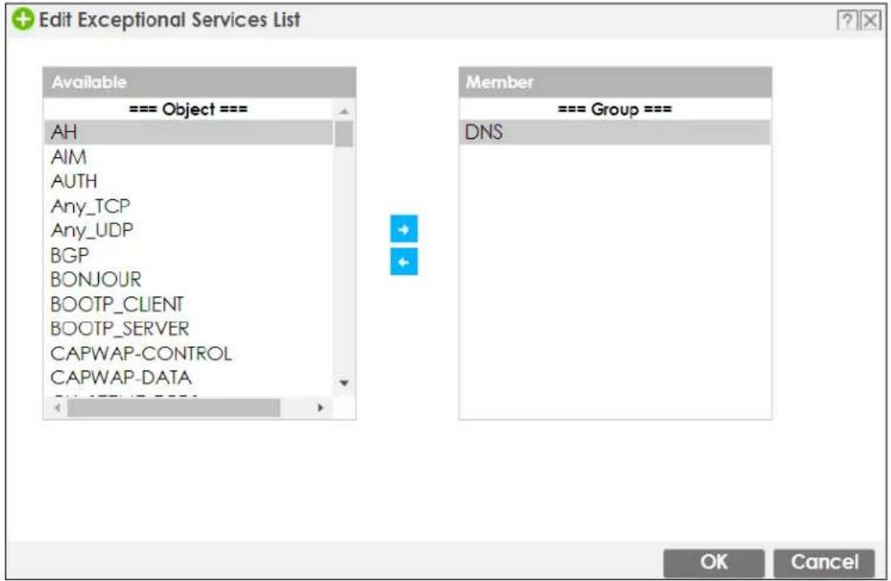
Creating/Editing an Authentication Policy
Open the Configuration > Web Authentication > General screen, then click the Add icon or select an entry and click the Edit icon in the Web Authentication Policy Summary section to open the Auth. Policy Add/Edit screen. Use this screen to configure an authentication policy.
Figure 417 Configuration > Web Authentication > General > Add Authentication Policy
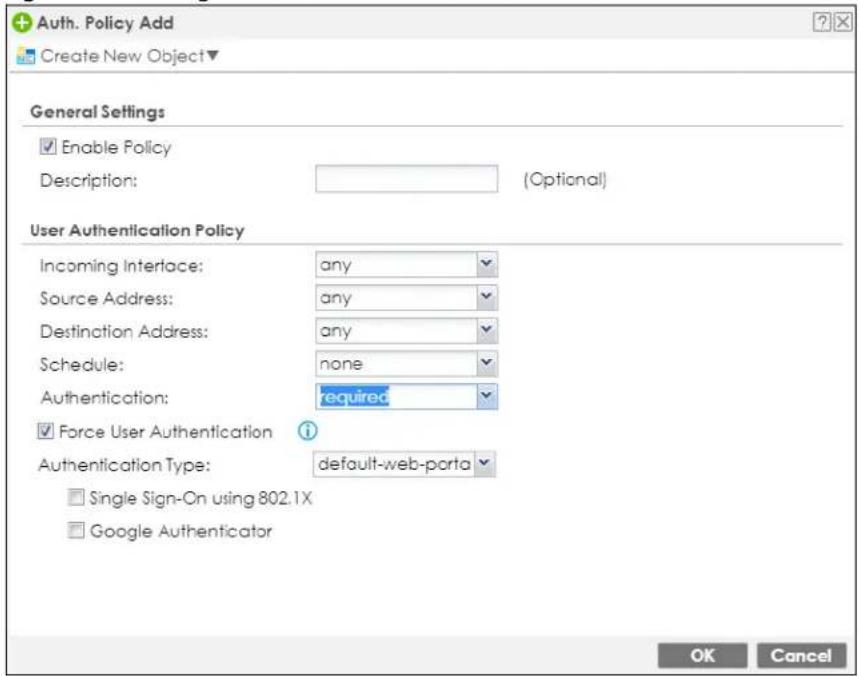
The following table gives an overview of the objects you can configure.
Table 226 Configuration > Web Authentication > General > Add Authentication Policy
| LABEL DESCRIPTION | |
| Create new Object | Use to configure any new settings objects that you need to use in this screen. Select Address or Schedule. |
| Enable Policy | Select this check box to activate the authentication policy. This field is available for user-configured policies. |
| Description | Enter a descriptive name with 1 to 63 single-byte characters, including a-zA-Z0-9!"#$%&'()*+,-/::=?@_ and spaces.<>\)^{' } are not allowed. This field is available for user-configured policies. |
| User Authentication Policy | Use this section of the screen to determine which traffic requires (or does not require) the senders to be authenticated in order to be routed. |
| Incoming Interface | Select the interface on which packets for this policy are received. |
| Source Address | Select a source address or address group, including geographic address and FQDN (group) objects, for whom this policy applies. Selectanyif the policy is effective for every source. This isanyand not configurable for the default policy. |
| Destination Address | Select a destination address or address group, including geographic address and FQDN (group) objects, for whom this policy applies. Selectanyif the policy is effective for every destination. This isanyand not configurable for the default policy. |
| Schedule | Select a schedule that defines when the policy applies. Otherwise, selectnoneand the rule is always effective. This isnoneand not configurable for the default policy. |
| Authentication | Select the authentication requirement for users when their traffic matches this policy.unnecessary- Users do not need to be authenticated.required- Users need to be authenticated. IfForce User Authenticationis selected, all HTTP traffic from unauthenticated users is redirected to a default or user-defined login page. Otherwise, they must manually go to the login screen. The Zyxel Device will not redirect them to the login screen. |
| Force User Authentication | This field is available for user-configured policies that require authentication. Select this to have the Zyxel Device automatically display the login screen when users who have not logged in yet try to send HTTP traffic. |
| Authentication Type | Select an authentication method.default-web-portal: the default login page built into the Zyxel Device.default-user-agreement: the default user agreement page built into the Zyxel Device. |
| Single Sign-On using 802.1X | 802.1X Single Sign-On allows the Zyxel Device to use the same username and password for 802.1X WiFi authentication and web authentication. When enabled, a user logs into a WiFi network on the Zyxel Device that has 802.1X (WPA Enterprise) enabled. The Zyxel Device then reuses the 802.1X username and password for web authentication, preventing the user from having to log in twice.Active Directory Single Sign-On takes priority over 802.1X Single Sign-On, if both are enabled. |
| Google Authenticator | Select Google Authenticator to first prompt a user to enter their username and password (factor 1), and then prompt the user to enter a time-limited code from the Google Authenticator app (factor 2). |
| OK | ClickOKto save your changes back to the Zyxel Device. |
| Cancel | ClickCancelto exit this screen without saving. |
24.2.1 User-Authentication Access Control Example
You can configure many policies and security settings for specific users or groups of users. Users can be authenticated locally by the Zyxel Device or by an external (RADIUS) authentication server.
In this example the users are authenticated by an external RADIUS server at 172.16.1.200. First, set up the user accounts and user groups in the Zyxel Device. Then, set up user authentication using the RADIUS server. Finally, set up the policies in the table above.
24.2.1.1 Set Up User Accounts
Set up user accounts in the RADIUS server. This example uses the Web Configurator. If you can export user names from the RADIUS server to a text file, then you might configure a script to create the user accounts instead.
1 Click Configuration > Object > User/Group > User. Click the Add icon.
2 Enter the same user name that is used in the RADIUS server, and set the User Type to ext-user because this user account is authenticated by an external server. Click OK.
Figure 418 Configuration > Object > User/Group > User > Add
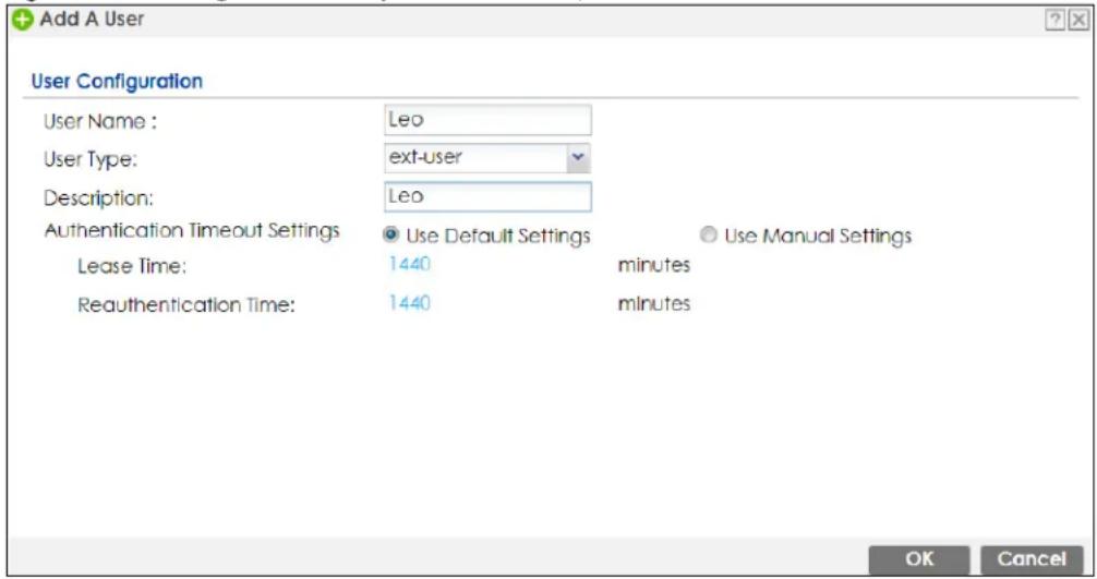
3 Repeat this process to set up the remaining user accounts.
24.2.1.2 Set Up User Groups
Set up the user groups and assign the users to the user groups.
1 Click Configuration > Object > User/Group > Group. Click the Add icon.
2 Enter the name of the group. In this example, it is "Finance". Then, select Object/Leo and click the right arrow to move him to the Member list. This example only has one member in this group, so click OK. Of course you could add more members later.
Figure 419 Configuration > Object > User/Group > Group > Add
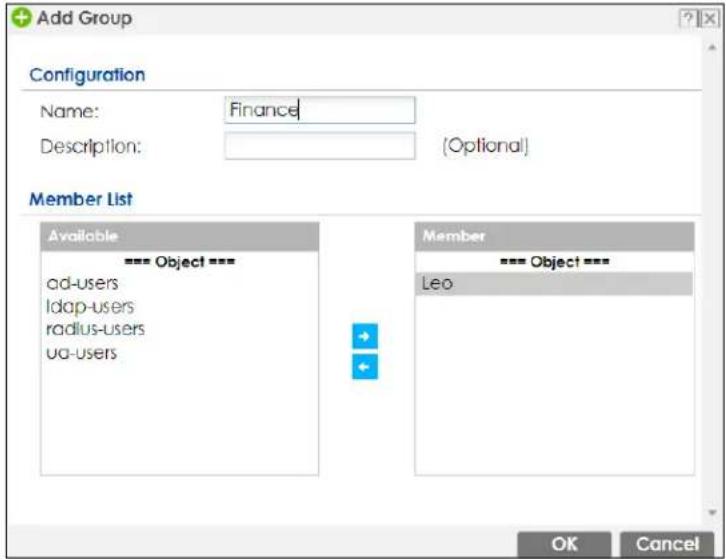
3 Repeat this process to set up the remaining user groups.
24.2.1.3 Set Up User Authentication Using the RADIUS Server
This step sets up user authentication using the RADIUS server. First, configure the settings for the RADIUS server. Then, set up the authentication method, and configure the Zyxel Device to use the authentication method. Finally, force users to log into the Zyxel Device before it routes traffic for them.
1 Click Configuration > Object > AAA Server > RADIUS. Double-click the radius entry. Configure the RADIUS server's address, authentication port (1812 if you were not told otherwise), and key. Click OK.
Figure 420 Configuration > Object > AAA Server > RADIUS > Add
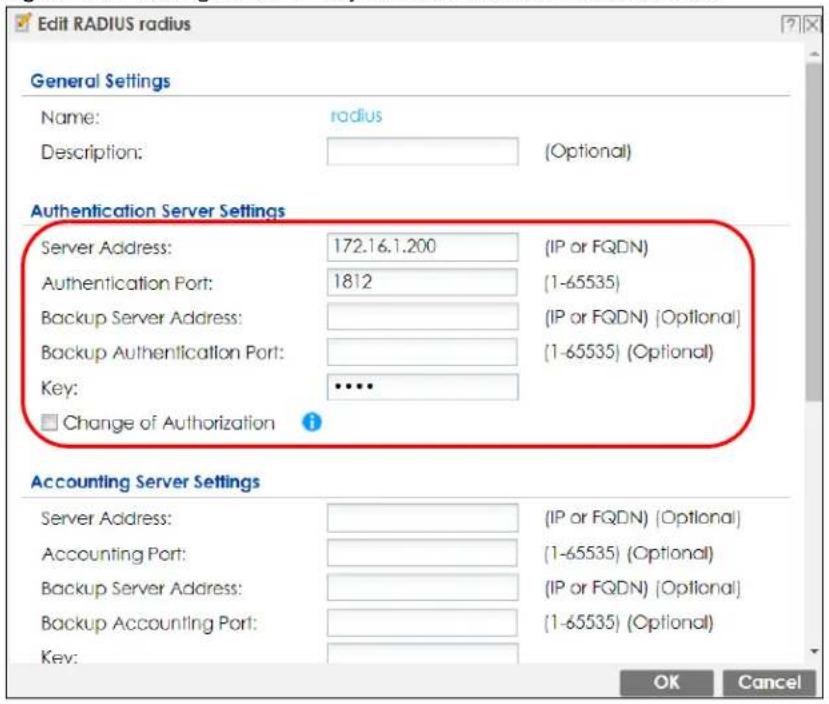
2 Click Configuration > Object > Auth. Method. Double-click the default entry. Click the Add icon. Select group radius because the Zyxel Device should use the specified RADIUS server for authentication. Click OK.
Figure 421 Configuration > Object > Auth. method > Edit
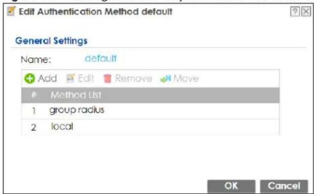
3 Click Configuration > Web Authentication. In the Web Authentication > General screen, select Enable Web Authentication to turn on the web authentication feature and click Apply.
Figure 422 Configuration > Web Authentication
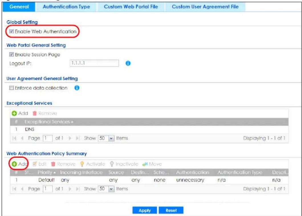
4 In the Web Authentication Policy Summary section, click the Add icon to set up a default policy that has priority over other policies and forces every user to log into the Zyxel Device before the Zyxel Device routes traffic for them.
5 Select Enable Policy. Enter a descriptive name, "default_policy" for example. Set the Authentication field to required, and make sure Force User Authentication is selected. Select an authentication type profile ("default-web-portal" in this example). Keep the rest of the default settings, and click OK.
Note: The users must log in at the Web Configurator login screen before they can use HTTP or MSN.
Figure 423 Configuration > Web Authentication: General: Add
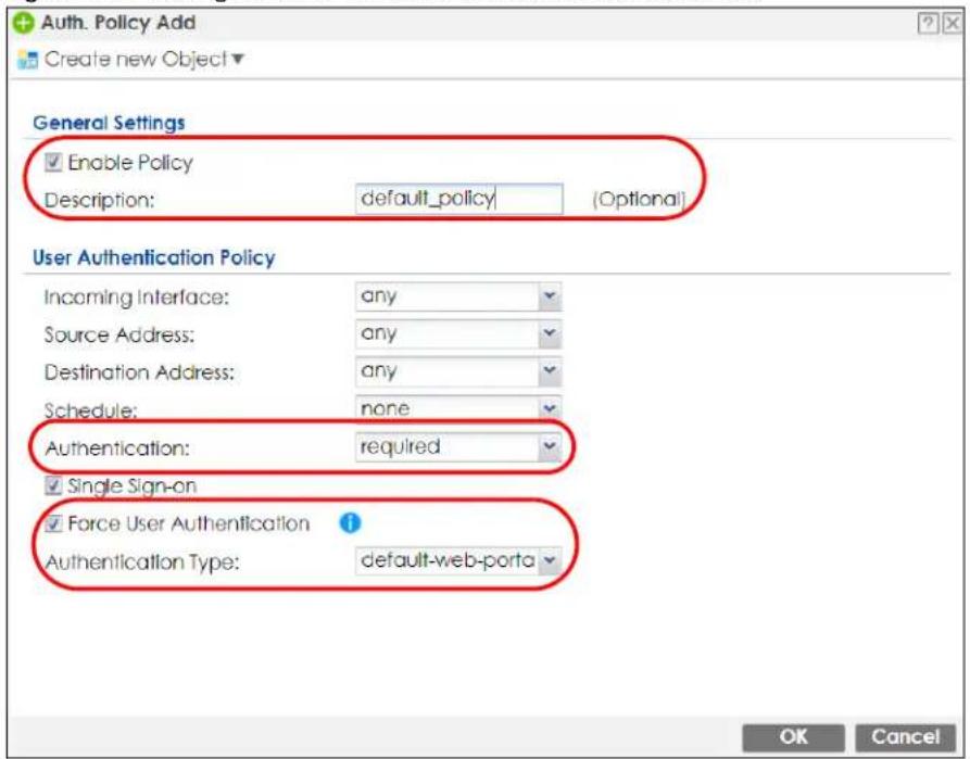
When the users try to browse the web (or use any HTTP application), the login screen appears. They have to log in using the user name and password in the RADIUS server.
24.2.1.4 User Group Authentication Using the RADIUS Server
The previous example showed how to have a RADIUS server authenticate individual user accounts. If the RADIUS server has different user groups distinguished by the value of a specific attribute, you can make a couple of slight changes in the configuration to have the RADIUS server authenticate groups of user accounts defined in the RADIUS server.
1 Click Configuration > Object > AAA Server > RADIUS. Double-click the radius entry. Besides configuring the RADIUS server's address, authentication port, and key; set the Group Membership Attribute field to the attribute that the Zyxel Device is to check to determine to which group a user belongs. This example uses Class. This attribute's value is called a group identifier; it determines to which group a user belongs. In this example the values are Finance, Engineer, Sales, and Boss.
Figure 424 Configuration > Object > AAA Server > RADIUS > Add
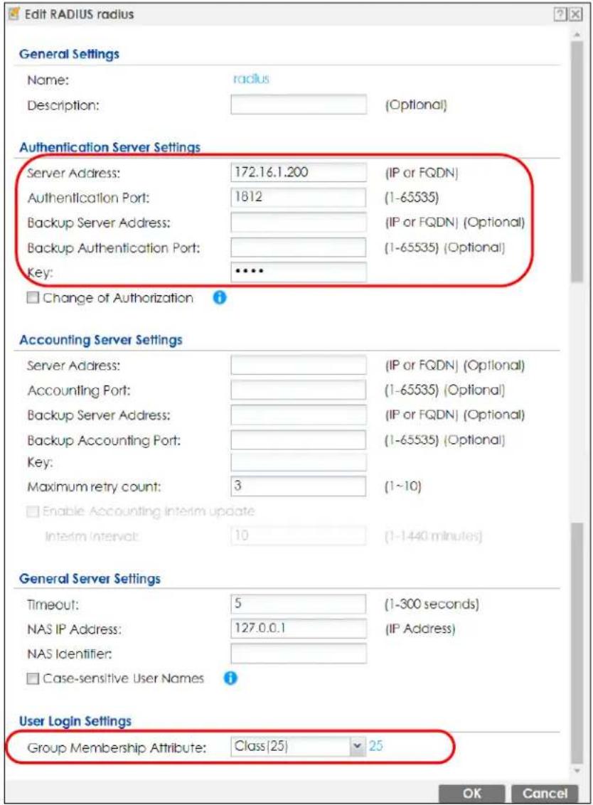
2 Now you add ext-group-user objects to identify groups based on the group identifier values. Set up one user account for each group of user accounts in the RADIUS server. Click Configuration > Object > User/Group > User. Click the Add icon.
3 Enter a user name and set the User Type to ext-group-user. In the Group Identifier field, enter Finance, Engineer, Sales, or Boss and set the Associated AAA Server Object to radius.
Figure 425 Configuration > Object > User/Group > User > Add
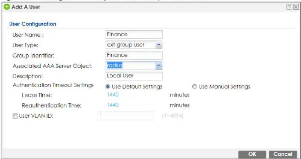
4 Repeat this process to set up the remaining groups of user accounts.
24.2.2 Authentication Type Screen
Use this screen to view, create and manage the authentication type profiles on the Zyxel Device. An authentication type profile decides which type of web authentication pages to be used for user authentication. Go to Configuration > Web Authentication and then select the Authentication Type tab to display the screen.
Figure 426 Configuration > Web Authentication > Authentication Type
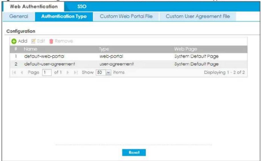
The following table describes the labels in this screen.
Table 227 Configuration > Web Authentication > Authentication Type
| LABEL DESCRIPTION | |
| Add | Click this to create a new entry. Select an entry and click Add to create a new entry after the selected entry. |
| Edit | Double-click an entry or select it and click Edit to open a screen where you can modify the entry's settings. |
| Remove | To remove an entry, select it and click Remove. The Zyxel Device confirms you want to remove it before doing so. |
| # This field is a sequential value, and it is not associated with a specific entry. | |
| Name This field displays the name of the profile.default-web-portal: the default login page built into the Zyxel Device.Note: You can also customize the default login page built into the Zyxel Device in the System > WWW > Login Page screen.default-user-agreement: the default user agreement page built into the Zyxel Device. | |
| Type | This field displays the type of the web authentication page used by this profile. |
| Web Page | This field displays whether this profile uses the default web authentication page built into the Zyxel Device (System Default Page) or custom web authentication pages from an external web server (External Page). |
| Reset | Click Reset to return the screen to its last-saved settings. |
Add/ Edit an Authentication Type Profile
Click the Add icon or select an entry in the Web Authentication > Authentication Type screen and click the Edit icon to display the screen. The screen differs depending on what you select in the Type field.
Figure 427 Configuration > Web Authentication > Authentication Type: Add/Edit (Web Portal)
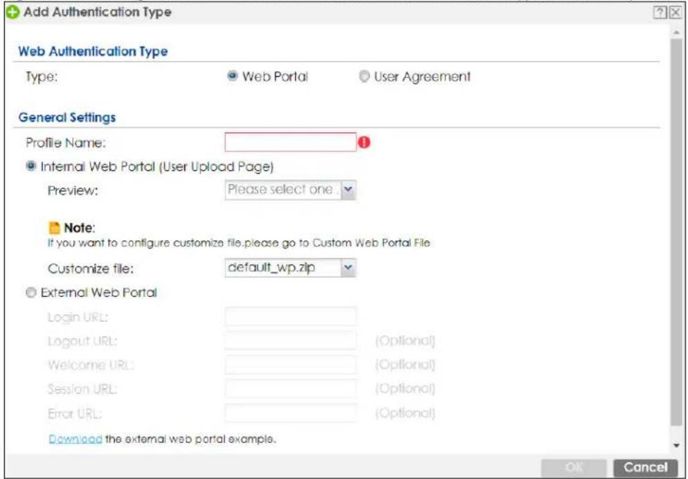
Figure 428 Configuration > Web Authentication > Authentication Type: Add/Edit (User Agreement)
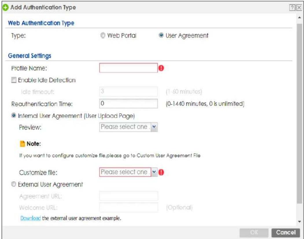
The following table describes the labels in this screen.
Table 228 Configuration > Web Authentication > Authentication Type: Add/Edit
| LABEL DESCRIPTION | |
| Type | Select the type of the web authentication page through which users authenticate their connections.If you selectUser Agreement, by agreeing to the policy of user agreement, users can access the Internet without a guest account. |
| Profile Name Enter | a name for the profile.You can use up to 31 alphanumeric characters (A-Z, a-z, 0-9) and underscores (_). Spaces are not allowed. The first character must be a letter. |
| The following fields are available if you setType to Web Portal. | |
| Internal Web Portal | Select this to use the web portal pages uploaded to the Zyxel Device.The login page appears whenever the web portal intercepts network traffic, preventing unauthorized users from gaining access to the network. |
| Preview | Select to display the page you uploaded to the Zyxel Device in a new frame.Note: You must select a custom file uploaded to the Zyxel Device before you can preview the pages. |
| Customize file | Select the file name of the web portal file in the Zyxel Device.Note: You can upload zipped custom web portal files to the Zyxel Device using theConfiguration > Web Authentication > Web Portal Customize File screen. |
| LABEL DESCRIPTION | |
| External Web Portal | Select this to use a custom login page from an external web portal instead of the one uploaded to the Zyxel Device. You can configure the look and feel of the web portal page. |
| Login URL | Specify the login page's URL; for example, http://IIS server IP Address/login.html.The Internet Information Server (IIS) is the web server on which the web portal files are installed. |
| Logout URL | Specify the logout page's URL; for example, http://IIS server IP Address/logout.html.The Internet Information Server (IIS) is the web server on which the web portal files are installed. |
| Welcome URL | Specify the welcome page's URL; for example, http://IIS server IP Address/welcome.html.Users will be redirected to the welcome page after authentication. This field is optional.The Internet Information Server (IIS) is the web server on which the web portal files are installed. |
| Session URL | Specify the session page's URL; for example, http://IIS server IP Address/session.html.The Internet Information Server (IIS) is the web server on which the web portal files are installed. |
| Error URL | Specify the error page's URL; for example, http://IIS server IP Address/error.html.The Internet Information Server (IIS) is the web server on which the web portal files are installed. |
| Download Click | this to download an example external web portal file for your reference. |
| The following fields are available if you set Type to User Agreement. | |
| Enable Idle Detection | This is applicable for access users.Select this check box if you want the Zyxel Device to monitor how long each access user is logged in and idle (in other words, there is no traffic for this access user). The Zyxel Device automatically logs out the access user once the Idle timeout has been reached. |
| Idle timeout This is applicable for access users.This field is effective when Enable Idle Detection is checked. Type the number of minutes each access user can be logged in and idle before the Zyxel Device automatically logs out the access user. | |
| Reauthentication Time | Enter the number of minutes the user can be logged into the Zyxel Device in one session before having to log in again. |
| Internal User Agreement | Select this to use the user agreement pages in the Zyxel Device. The user agreement page appears whenever the Zyxel Device intercepts network traffic, preventing unauthorized users from gaining access to the network. |
| Preview | Select to display the page you uploaded to the Zyxel Device in a new frame.Note: You must select a custom file uploaded to the Zyxel Device before you can preview the pages. |
| Customize file Select the file name of the user agreement file in the Zyxel Device.Note: You can upload zipped custom user agreement files to the Zyxel Device using the Configuration >Web Authentication >User Agreement Customize File screen. | |
| External User Agreement | Select this to use custom user agreement pages from an external web server instead of the default one built into the Zyxel Device. You can configure the look and feel of the user agreement page. |
| Agreement URL | Specify the user agreement page's URL; for example, http://IIS server IP Address/logout.html.The Internet Information Server (IIS) is the web server on which the user agreement files are installed. |
| Welcome URL | Specify the welcome page's URL: for example, http://IIS server IP Address/welcome.html.The Internet Information Server (IIS) is the web server on which the user agreement files are installed.If you leave this field blank, the Zyxel Device will use the welcome page of internal user agreement file. |
| Download Click | this to download an example external user agreement file for your reference. |
| OK | Click OK to save your changes back to the Zyxel Device. |
| Cancel | Click Cancel to exit this screen without saving. |
24.2.3 Custom Web Portal / User Agreement File Screen
Use this screen to upload the zipped custom web portal or user agreement files to the Zyxel Device. You can also download the custom files to your computer.
Click Configuration > Web Authentication and then select the Custom Web Portal File or Custom User Agreement File tab to display the screen.
Figure 429 Configuration > Web Authentication > Custom Web Portal File
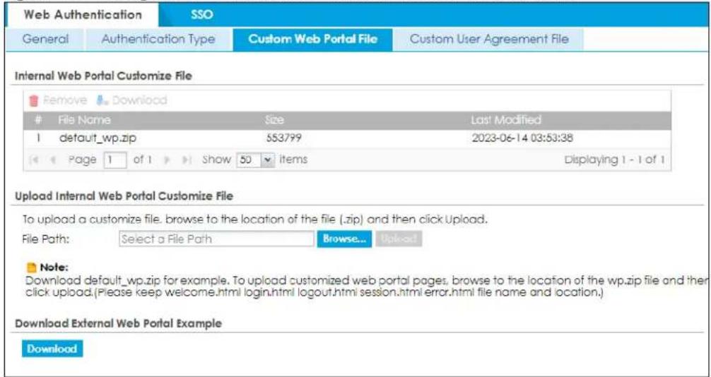
Figure 430 Configuration > Web Authentication > Custom User Agreement File
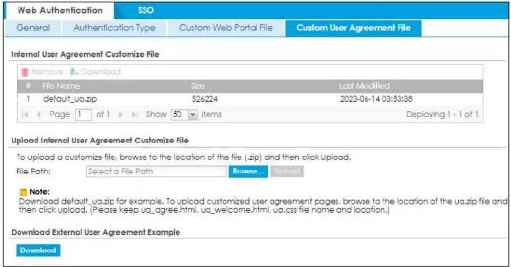
The following table describes the labels in this screen.
Table 229 Configuration > Web Authentication > Custom Web Portal / User Agreement File
| LABEL DESCRIPTION | |
| Remove | Click a file’s row to select it and click Remove to delete it from the Zyxel Device. |
| Download | Click a file’s row to select it and click Download to save the zipped file to your computer. |
| # | This column displays the index number for each file entry. This field is a sequential value, and it is not associated with a specific entry. |
| File Name | This column displays the label that identifies a web portal or user agreement file. |
| Size This column displays the size (in KB) of a file. | |
| Last Modified | This column displays the date and time that the individual files were last changed or saved. |
| Browse / Upload | Click Browse... to find the zipped file you want to upload, then click the Upload button to put it on the Zyxel Device. |
| Download | Click this to download an example external web portal or user agreement file for your reference. |
24.3 SSO Overview
The SSO (Single Sign-On) function integrates Domain Controller and Zyxel Device authentication mechanisms, so that users just need to log in once (single login) to get access to permitted resources.
In the following figure, U user logs into a Domain Controller (DC) which passes the user's login credentials to the SSO agent. The SSO agent checks that these credentials are correct with the AD server, and if the AD server confirms so, the SSO then notifies the Zyxel Device to allow access for the user to the permitted resource (Internet access, for example).
Note: The Zyxel Device, the DC, the SSO agent and the AD server must all be in the same domain and be able to communicate with each other.
SSO does not support IPv6, LDAP or RADIUS; you must use it in an IPv4 network environment with Windows AD (Active Directory) authentication database.
You must enable Web Authentication in the Configuration > Web Authentication screen.
Figure 431 SSO Overview
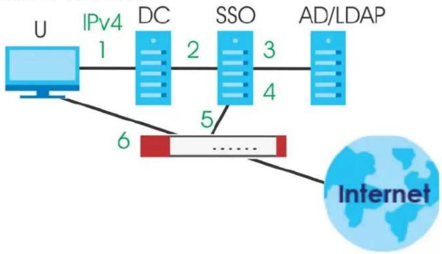
flowchart
graph LR
    U["User"] -->|IPv4 1| DC["DC"]
    DC -->|2| SSO["SSO"]
    SSO -->|3| AD/LDAP["AD/LDAP"]
    SSO -->|4| AD/LDAP
    U -->|6| Internet["Internet"]
| U User | |
| DC Domain Controller | |
| SSO Single Sign-On agent | |
| AD Active Directory | |
Install the SSO Agent on one of the following platforms:
• Windows 7 Professional (32-bit and 64-bit)
• Windows Server 2008 Enterprise (32-bit and 64-bit)
• Windows 2008 R2 (64-bit)
• Windows Server 2012 (64-bit)
24.4 SSO - Zyxel Device Configuration
This section shows what you have to do on the Zyxel Device in order to use SSO.
Table 230 Zyxel Device - SSO Agent Field Mapping
| ZYXEL DEVICE SSO | |||
| SCREEN FIELD SCREEN FIELD | |||
| Web Authentication > SSO | Listen Port | Agent Configuration Page > Gateway Setting | Gateway Port |
| Web Authentication > SSO | Primary Agent Port | Agent Configuration Page | Agent Listening Port |
| Object > User/Group > User > Add | Group Identifier Agent Configuration Page > Configure LDAP/AD Server | Configure LDAP/AD Server | Group Membership |
| Object > AAA Server > Active Directory > Add | Base DN Agent Configuration Page > Configure LDAP/AD Server | Configure LDAP/AD Server | Base DN |
| Object > AAA Server > Active Directory > Add | Bind DN Agent Configuration Page > Configure LDAP/AD Server | Configure LDAP/AD Server | Bind DN |
| Object > User/Group > User > Add | User Name Agent Configuration Page > Configure LDAP/AD Server | Configure LDAP/AD Server | Login Name Attribute |
| Object > AAA Server > Active Directory > Add | Server Address Agent Configuration Page > Configure LDAP/AD Server | Configure LDAP/AD Server | Server Address |
| Network > Interface > Ethernet > wan (IPv4) | IP address Agent Configuration Page > Gateway Setting | Gateway Setting | Gateway IP |
24.4.1 Configuration Overview
These are the screens you need to configure:
- Configure the Zyxel Device to Communicate with SSO on page 622
- Enable Web Authentication on page 623
• Create a Security Policy on page 625 - Configure User Information on page 626
- Configure an Authentication Method on page 627
- Configure Active Directory on page 628
24.4.2 Configure the Zyxel Device to Communicate with SSO
Use Configuration > Web Authentication > SSO to configure how the Zyxel Device communicates with the Single Sign-On (SSO) agent.
Figure 432 Configuration > Web Authentication > SSO
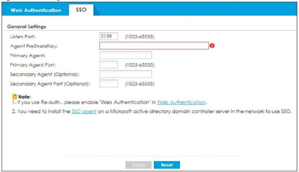
The following table gives an overview of the objects you can configure.
Table 231 Configuration > Web Authentication > SSO
| LABEL DESCRIPTION | |
| Listen Port | The default agent listening port is 2158. If you change it on the Zyxel Device, then change it to the same number in the Gateway Port field on the SSO agent too. Type a number ranging from 1025 to 65535. |
| Agent PreShareKey | Type 8-32 single-byte characters, including 0-9a-zA_Z!"#$%&'()*+,-./;<=>?@\^_'[] are not allowed. The Agent PreShareKey is used to encrypt communications between the Zyxel Device and the SSO agent. |
| Primary Agent | Type the IPv4 address of the SSO agent. The Zyxel Device and the SSO agent must be in the same domain and be able to communicate with each other. |
| Primary Agent Port | Type the same port number here as in the Agent Listening Port field on the SSO agent. Type a number ranging from 1025 to 65535. |
| Secondary Agent Address (Optional) | Type the IPv4 address of the backup SSO agent if there is one. The Zyxel Device and the backup SSO agent must be in the same domain and be able to communicate with each other. |
| Secondary Agent Port (Optional) | Type the same port number here as in the Agent Listening Port field on the backup SSO agent if there is one. Type a number ranging from 1025 to 65535. |
| Apply | Click this button to save your changes to the Zyxel Device. |
| Reset Click this button to return | the screen to its last-saved settings |
24.4.3 Enable Web Authentication
Enable Web Authentication and add a web authentication policy.
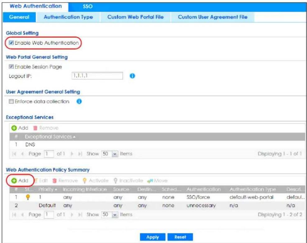
Make sure you select Enable Policy, Single Sign-On and choose required in Authentication.
Do NOT select any as the source address unless you want all incoming connections to be authenticated!
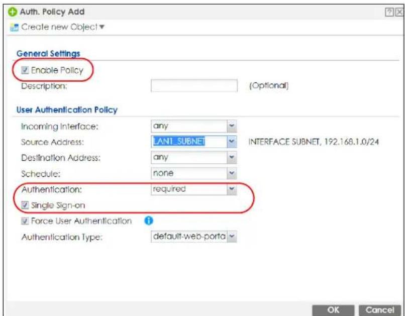
See Table 225 on page 604 and Table 226 on page 608 for more information on configuring these screens.
24.4.4 Create a Security Policy
Configure a Security Policy for SSO traffic source and destination direction in order to prevent the security policy from blocking this traffic. Go to Configuration > Security Policy > Policy Control and add a new policy if a default one does not cover the SSO web authentication traffic direction.
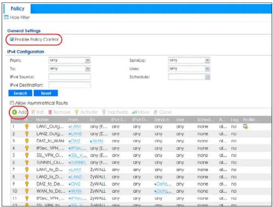
Configure the fields as shown in the following screen. Configure the source and destination addresses according to the SSO web authentication traffic in your network.
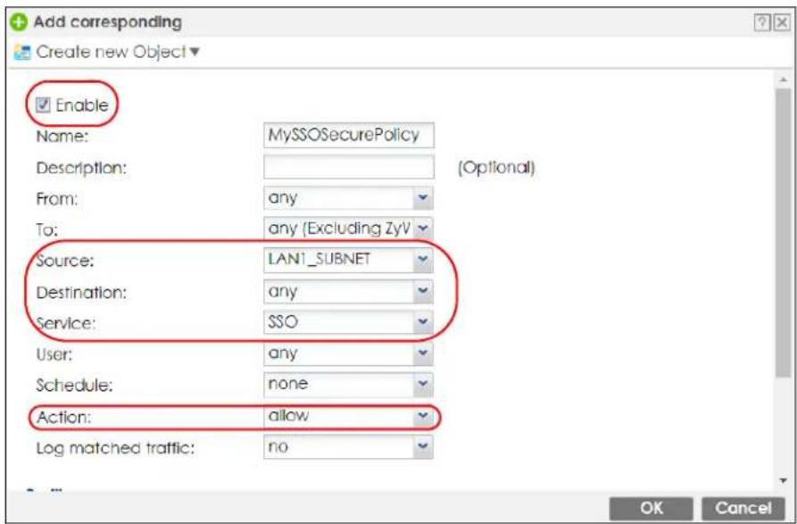
24.4.5 Configure User Information
Configure a User account of the ext-group-user type.
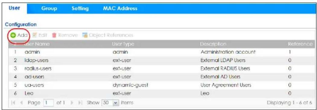
Configure Group Identifier to be the same as Group Membership on the SSO agent.
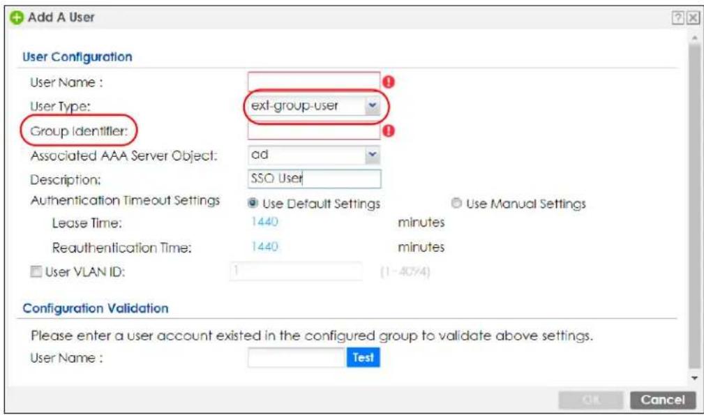
24.4.6 Configure an Authentication Method
Configure Active Directory (AD) for authentication with SSO.
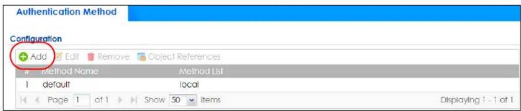
Choose group ad as the authentication server for SSO.
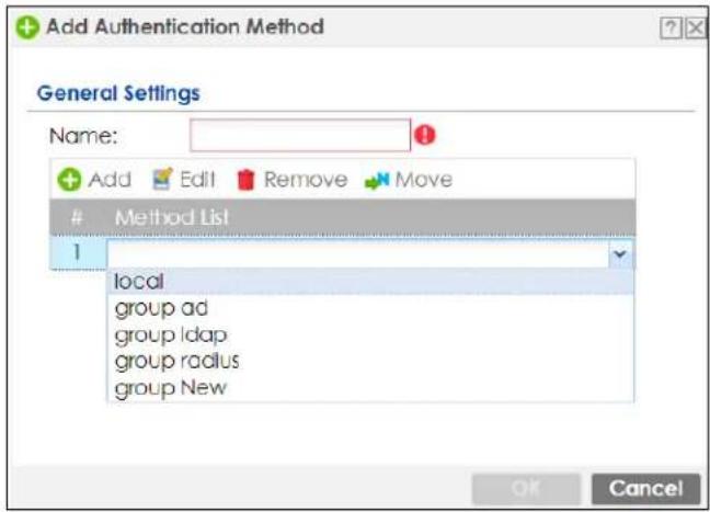
24.4.7 Configure Active Directory
You must configure an Active Directory (AD) server in AAA Setup to be the same as AD configured on the SSO agent.
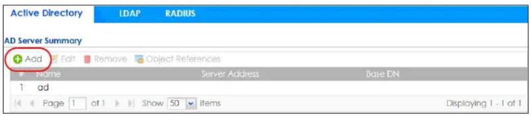
The default AD server port is 389. If you change this, make sure you make the same changes on the SSO. Configure the Base DN exactly the same as on the Domain Controller and SSO. Bind DN is a user name and password that allows the Zyxel Device to join the domain with administrative privileges. It is a required field.

24.5 SSO Agent Configuration
This section shows what you have to do on the SSO agent in order to work with the Zyxel Device.
After you install the SSO agent, you will see an icon in the system tray (bottom right of the screen)
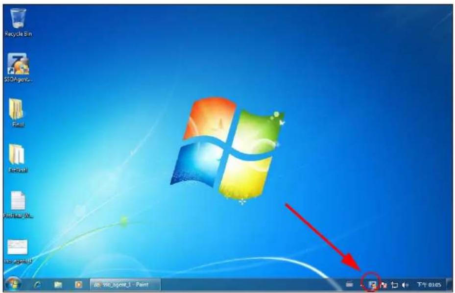
Right-click the SSO icon and select Configure Zyxel SSO Agent.
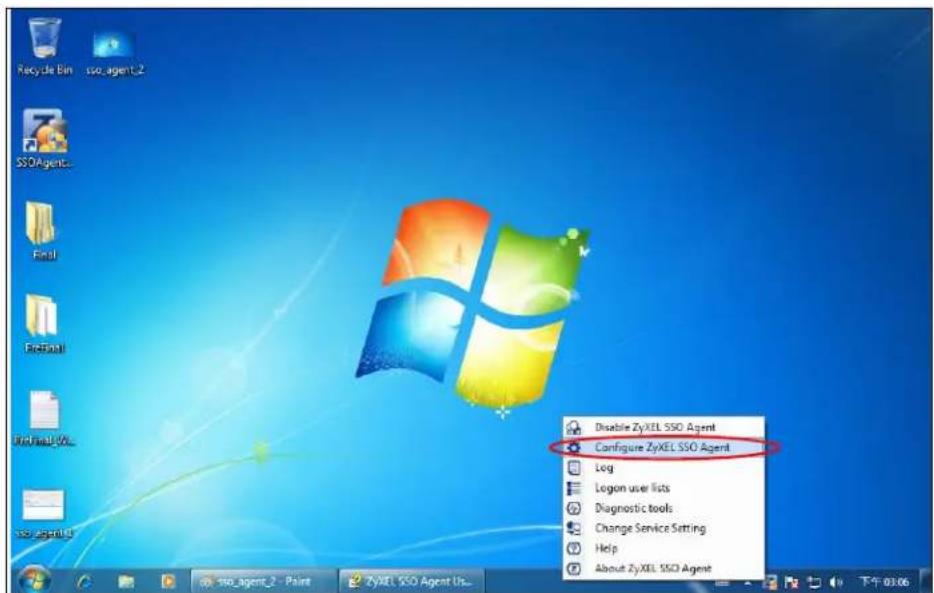
Configure the Agent Listening Port, AD server exactly as you have done on the Zyxel Device. Add the Zyxel Device IP address as the Gateway. Make sure the Zyxel Device and SSO agent are able to communicate with each other.
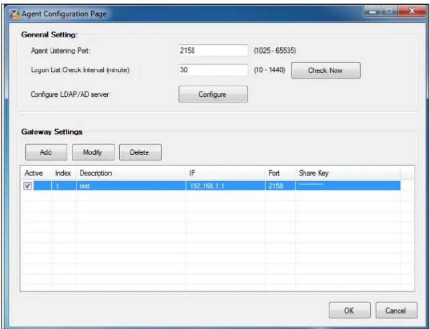
Configure the Server Address, Port, Base DN, Bind DN, Login Name Attribute and Group Membership for the AD server settings exactly as you have done on the Zyxel Device. Group Membership is called Group Identifier on the Zyxel Device.
LDAP/AD Server Configuration
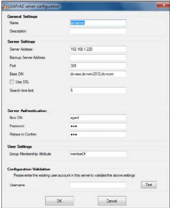
Configure the Gateway IP address, Gateway Port and PreShareKey exactly as you have done in the Zyxel Device Configuration > Web Authentication > SSO screen. If you want to use Generate Key to have the SSO create a random password, select Check to show PreShareKey as clear Text so as to see the password, then copy and paste it to the Zyxel Device.
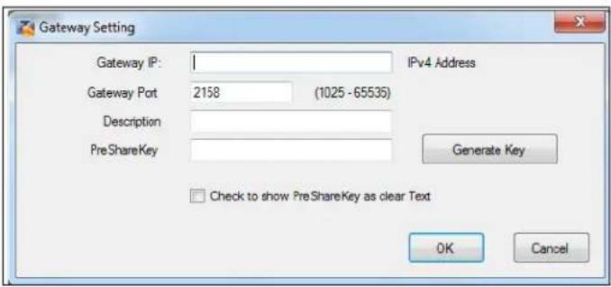
After all SSO agent configurations are done, right-click the SSO icon in the system tray and select Enable Zyxel SSO Agent.
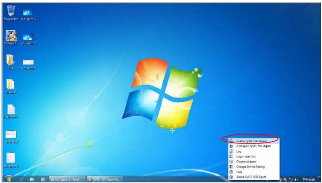
CHAPTER 25 Hotspot
25.1 Overview
See Section 1.1.1 on page 29 to see which models support Hotspot management.
25.2 Billing Overview
You can use the built-in billing function to setup billing profiles. A billing profile describes how to charge users. This chapter also shows you how to select an accounting method, configure a discount price plan or use an online payment service by credit card.
- Use the General screen (see Section 25.3 on page 633) to configure the general billing settings, such as the accounting method, currency unit and the SSID profiles to which the settings are applied.
- Use the Billing Profile screen (see Section 25.4 on page 635) to configure the billing profiles for the web-based account generator and each button on the connected statement printer.
- Use the Discount screen (see Section 25.5 on page 642) to enable and configure discount price plans.
- Use the Payment Service screen (see Section 25.6 on page 644) to enable online payment service and configure the service pages.
25.2.1 What You Need to Know
Accumulation Accounting Method
The accumulation accounting method allows multiple re-logins until the allocated time period or until the user account is expired. The Zyxel Device accounts the time that the user is logged in for Internet access.
Time-to-finish Accounting Method
The time-to-finish accounting method is good for one-time logins. Once a user logs in, the Zyxel Device stores the IP address of the user's computer for the duration of the time allocated. Thus the user does not have to enter the user name and password again for re-login within the allocated time. Once activated, the user account is valid until the allocated time is reached even if the user disconnects Internet access for a certain period within the allocated time. For example, Joe purchases a one-hour time-to-finish account. He starts using the Internet for the first 20 minutes and then disconnects his Internet access to go to a 20-minute meeting. After the meeting, he only has 20 minutes left on his account.
25.3 The Billing > General Screen
Use this screen to configure the general billing settings, such as the accounting method, currency unit and the SSID profiles to which the settings are applied. Click Configuration > Hotspot > Billing > General to open the following screen.
Figure 433 Configuration > Hotspot > Billing > General
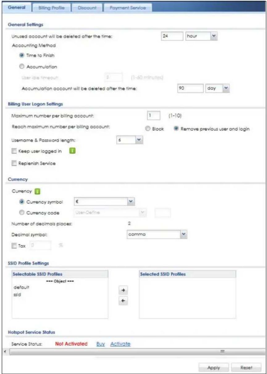
The following table describes the labels in this screen.
Table 232 Configuration > Hotspot > Billing > General
| LABEL DESCRIPTION | |
| General Settings | |
| Unused account will be deleted after the time: | Enter the number and select a time unit from the drop-down list box to specify how long to wait before the Zyxel Device deletes an account that has not been used. |
| Accounting Method | Select Time to Finish to allow each user a one-time login. Once the user logs in, the system starts counting down the pre-defined usage even if the user stops the Internet access before the time period is finished. If a user disconnects and reconnects before the allocated time expires, the user does not have to enter the user name and password to access the Internet again.Select Accumulation to allow each user multiple re-login until the time allocated is used up. The Zyxel Device accounts the time that the user is logged in for Internet access. |
| User idle timeout | The Zyxel Device automatically disconnects a computer from the network after a period of inactivity. The user may need to enter the username and password again before access to the network is allowed.If you select Accumulation, specify the idle timeout between 1 and 60 minutes. |
| Accumulation account will be deleted after the time: | Enter the number and select a time unit from the drop-down list box to specify how long to wait before the Zyxel Device deletes the account.This is for use with accumulation accounting. |
| Billing User Logon Settings | |
| Maximum number per billing account | Enter the maximum number of the users that are allowed to log in with the same account. |
| Reach maximum number per billing account | Select Block to stop new users from logging in when the Maximum number per billing account is reached.Select Remove previous user and login to disassociate the first user that logged in and allow new user to log in when the Maximum number per billing account is reached. |
| Username & Password length | Select to specify how many characters the username and password of a newly-created dynamic guest account will have after you click Apply. |
| Keep user logged in | Select to let the users automatically log in without entering their user name and password if the Zyxel Device restarts.Note: This works only for free guest accounts or when the accounting method is Time to Finish. |
| Currency | Select the appropriate currency symbol or currency unit.If you set Currency code to User-Define, enter a three-letter alphabetic code manually. |
| Number of decimals places | This shows the number of decimal places to be used for billing. |
| Decimal symbol | Select whether you would like to use a dot (.) or a comma (.) for the decimal point. |
| Tax | Select this option to charge sales tax for the account. Enter the tax rate (a 6% sales tax is entered as 6). |
| SSID Profile Settings | The Selectable SSID Profiles list displays the name(s) of the SSID profile(s) to which you can apply the general billing settings.To apply settings to an SSID profile, you can double-click a single entry to move it or use the [Shift] or [Ctrl] key to select multiple entries and click the right arrow button to add to the Selected SSID Profiles list. To remove an SSID profile, select the name(s) in the Selected SSID Profiles list and click the left arrow button. |
| Hotspot Service Status | |
| Service Status | This field displays whether a service license is enabled at myZyxel (Activated) or not (Not Activated) or expired (Expired). It displays the remaining Grace Period if your license has Expired. It displays Not Licensed if there isn't a license to be activated for this service.If you need a license or a trial license has expired, click Buy to buy a new one. If a Standard license has expired, click Renew to extend the license.Then, click Activate to connect with the myZyxel server to activate the new license. |
| Service Type | This shows whether you have a trial or standard license or none (Trial, Standard, None). |
| Expiration Date | This shows when your hotspot license will expire. |
| Apply Click this button to save your changes to the Zyxel Device. | |
| Reset Click this button to return the screen to its last-saved settings. | |
25.4 The Billing > Billing Profile Screen
Use this screen to configure the billing profiles that defines the maximum Internet access time and charge per time unit. Click Configuration > Hotspot > Billing > Billing Profile to open the following screen.
Figure 434 Configuration > Hotspot > Billing > Billing Profile
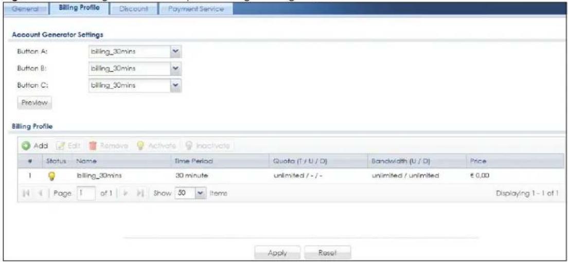
The following table describes the labels in this screen.
Table 233 Configuration > Hotspot > Billing > Billing Profile
| LABEL DESCRIPTION | |
| Account Generator Settings | |
| Button A ~ C | Select a billing profile for each button of the web-based account generator. The buttons correspond to the buttons on a connected statement printer. |
| LABEL | DESCRIPTION |
| Preview | Click this button to open the Account Generator screen, where you can generate a dynamic guest account and print the account information using a statement printer connected to the Zyxel Device (see Section 25.4.1 on page 636 for more information). |
| Billing Profile | |
| Add Click this to create a new entry. | |
| Edit | Double-click an entry or select it and click Edit to open a screen where you can modify the entry's settings. |
| Remove | To remove an entry, select it and click Remove. The Zyxel Device confirms you want to remove it before doing so. |
| Activate | To turn on an entry, select it and click Activate. |
| Inactivate | To turn off an entry, select it and click Inactivate. |
| # This field is a sequential value, and it is not associated with a specific entry. | |
| Status This icon is lit when the entry is active and dimmed when the entry is inactive. | |
| Name This field displays the descriptive profile name for this entry. | |
| Time Period This field displays the duration of the billing period. | |
| Quota (T/U/D) | This field is NOT available when you set Accounting Method to Time to Finish in the Billing > General screen.This field displays how much data in both directions (Total) or upstream data (Upload) and downstream data (Download) can be transmitted through the WAN interface before the account expires. |
| Bandwidth (U/D) | This field displays the maximum upstream (Upload) and downstream (Download) bandwidth allowed for the user account in kilobits per second. |
| Price This field displays each profile's price per time unit. | |
| Apply Click this button to save your changes to the Zyxel Device. | |
| Reset Click this button to return the screen to its last-saved settings. | |
25.4.1 The Account Generator Screen
The Account Generator screen allows you to automatically create dynamic guest accounts (see Dynamic-Guest Accounts for more information on dynamic guest accounts).
Click Configuration > Hotspot > Billing > Billing Profile and then the Preview button to open this screen. You can also open this screen by logging into the Web Configurator with the guest-manager account.
Figure 435 Account Generator
![Account Generator Account Generator Account Redemption Account Generator Settings Button... Selection Service Name Time Period Quota (T / U / D) Bandwidth (U / D) Price A billing_30mins 30 minute unlimited / - / - unlimited / unlimited € 0.00 B billing_30mins 30 minute unlimited / - / - unlimited / unlimited € 0.00 C billing_30mins 30 minute unlimited / - / - unlimited / unlimited € 0.00 Button A Unit: 1 Customer Information Real Name: [Optional] Email: [Optional] Phone Number: (Optional) Default Thermal Printer Printer: Local Printer Summary Total: € 0.00 Tax: 0% Grand Total: € 0.00 Quantity: 1 (1-50) Generate Cancel](/content/2026/05/878280/images/9d09ff6a74abf6219e2dfc3a93fc916cb3a85e34436548b5a950069c52658dea.jpg)
The following table describes the labels in this screen.
Table 234 Account Generator
| LABEL DESCRIPTION | |
| Account Generator Settings | Select a button and specify how many units of billing period to be charged for new account in the Button x Unit field. |
| Discount plan for Button x | This section displays only when you enable the discount price plan in the Billing > Discount screen. |
| # This is the number | of each discount level.The default (first) level cannot be edited or deleted. It is created automatically according to the billing profile of the button you select. |
| Name | This field displays the conditions of each discount level. |
| Unit | This field displays the duration of the billing period that should be reached before the Zyxel Device charges users at this level. |
| Price This field displays the price per time unit for each level. | |
| Customer Information | |
| Real Name Enter the user's name. | |
| Email Enter the user's email address. | |
| Phone Number | Enter the user's phone number. |
| LABEL DESCRIPTION | |
| Default Thermal Printer | Select a statement printer that is attached to the Zyxel Device. It displays n/a if there is no printer attached. |
| Summary | |
| Total | This shows the total price for the account before sales tax is added. |
| Tax This shows the tax rate. | |
| Grand Total This shows the total price including tax. | |
| Quantity Specify the number of account to be created. | |
| Generate | Click Generate to generate an account based on the billing settings you configure for the selected button in the Billing Profile screen. A window displays showing the SMS message and/or a printout preview of the account generated. |
| Cancel | Click Cancel to exit this screen without saving. |
| Logout | Click Logout to log out of the web configurator. This button is available only when you open this screen by logging in with the guest-manager account. |
The following figure shows an example SMS message with account information. The SMS screen displays only when you enable SMS in the Configuration > System > Notification > SMS screen. You can enter the user's mobile phone number and click Send SMS to send the account information in an SMS text message to the user's mobile phone. Click Cancel to close this window when you are finished viewing it.
![Account Generator SMS Printer SMS Content Username:g7kqua Password:nhj7mr Activate account before 2014-04-17 09:24 Send SMS Country Code: 886 Mobile Number: 0912345678 Example: [886][0910123456] (for Taiwan) Send SMS Cancel Printer](/content/2026/05/878280/images/d92ff0a5df756f7a3393c27b2a671b07fb88676e0a7a494f869c0f69a72cbf79.jpg)
The Printer screen shows a printout preview example. Click Printer to print this subscriber statement. Click Cancel to close this window when you are finished viewing it.
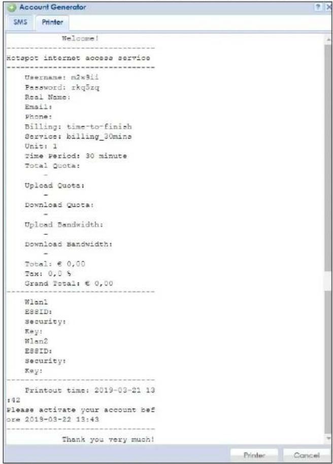
25.4.2 The Account Redeem Screen
The Account Redeem screen allows you to send SMS messages for certain accounts. Click the Account Redeem tab in the Account Generator screen to open this screen.
Figure 436 Account Redeem
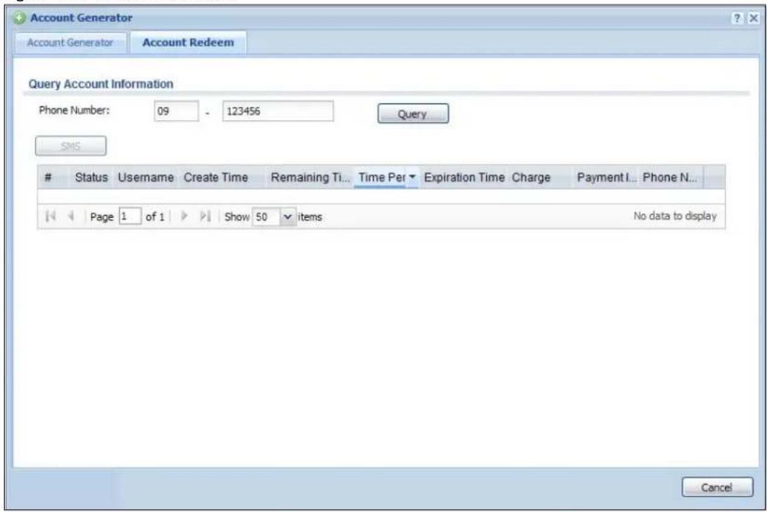
The following table describes the labels in this screen.
Table 235 Account Redeem
| LABEL DESCRIPTION | |
| Query Account Information | |
| Phone Number | Enter the country code and mobile phone number and click Query to display only the account(s) that has the specified phone number. |
| SMS | Click this button to send text messages for the accounts in the list below.You can use this button only when SMS is enabled and there is at least one account in the list. |
| # This is the index number of the dynamic guest account in the list. | |
| Status This field displays whether an account expires or not. | |
| Username This field displays the user name of the account. | |
| Create Time This field displays when the account was created. | |
| Remaining Time | This field displays the amount of Internet access time remaining for each account. |
| Time Period | This field displays the total account of time the account can use to access the Internet through the Zyxel Device. |
| Expiration Time | This field displays the date and time the account becomes invalid.Note: Once the time allocated to a dynamic account is used up or a dynamic account remains unused after the expiration time, the account is deleted from the account list. |
| Charge This field displays the total cost of the account. | |
| Payment Info This field displays the method of payment for each account. | |
| Phone Num | This field displays the mobile phone number for the account. |
| Cancel | Click Cancel to exit this screen without saving. |
| Logout | Click Logout to log out of the web configurator. This button is available only when you open this screen by logging in with the guest-manager account. |
25.4.3 The Billing Profile Add/Edit Screen
The Billing Profile Add/Edit screen allows you to create a new billing profile or edit an existing one. Click Configuration > Hotspot > Billing > Billing Profile and then an Add or Edit icon to open this screen.
Figure 437 Configuration > Hotspot > Billing > Billing Profile > Add/Edit
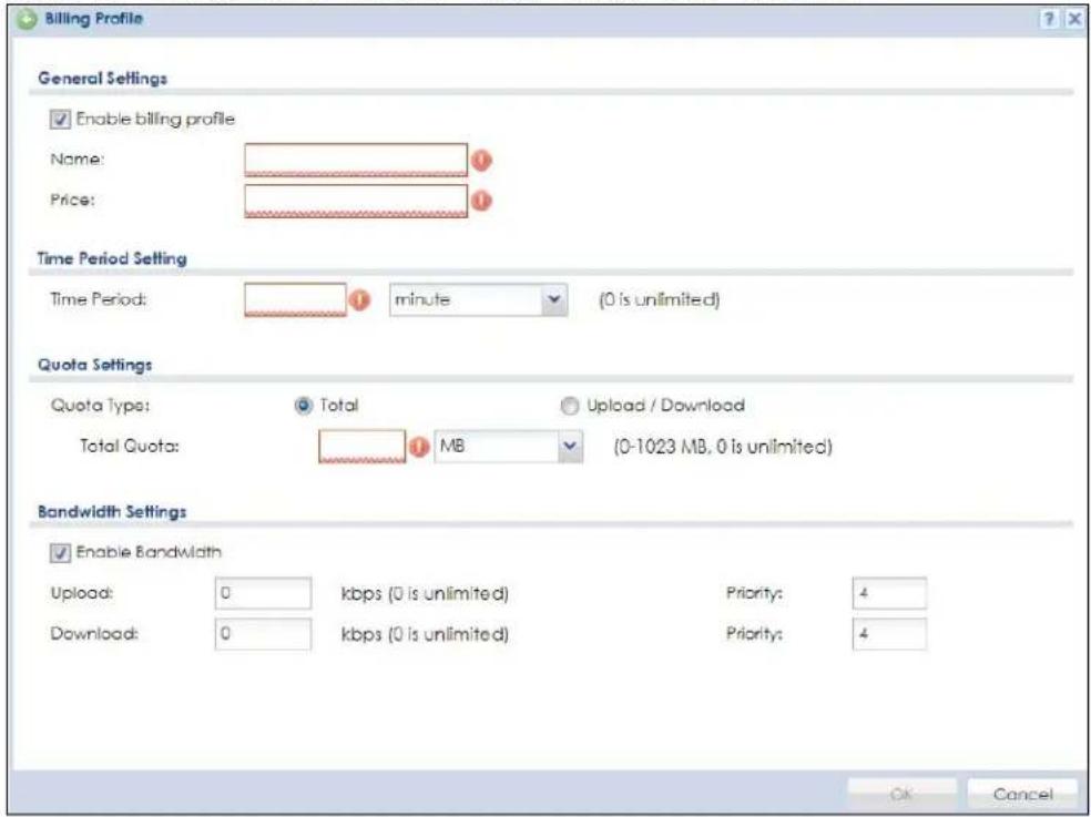
The following table describes the labels in this screen.
Table 236 Configuration > Hotspot > Billing > Billing Profile > Add/Edit
| LABEL DESCRIPTION | |
| Enable billing profile | Select this option to activate the profile. |
| Name Enter a name for the billing profile.You can use up to 31 alphanumeric characters (A-Z, a-z, 0-9) and underscores (_). Spaces are not allowed. The first character must be a letter. | |
| Price Define each profile's price, up to 999999.99, per time unit. | |
| Time Period | Set the duration of the billing period (minute, hour, or day). When this period expires, the user's access will be stopped. The allowed time period ranges are 10 to 60 minutes, 0 to 24 hours, or 0 to 365 days. |
| Quota Type | The quota settings section is NOT available when you set Accounting Method to Time to Finish in the Billing > General screen.Set a limit for the user accounts. This only applies to user's traffic that is received or transmitted through the WAN interface.Note: When the limit is exceeded, the user is not allowed to access the Internet through the Zyxel Device.Select Total to set a limit on the total traffic in both directions.Select Upload/ Download to set a limit on the upstream traffic and downstream traffic respectively. |
| Total Quota | If you select Total, specify how much downstream and/or upstream data (in MB (Megabytes) or GB (Gigabytes)) can be transmitted through the WAN interface before the account expires.0 means there is no data limit for the user account. |
| Upload Quota | If you select Upload/Download, specify how much upstream data (in MB (Megabytes) or GB (Gigabytes)) can be transmitted through the WAN interface before the account expires.0 means there is no data limit for the user account. |
| Download Quota | If you select Upload/Download, specify how much downstream data (in MB (Megabytes) or GB (Gigabytes)) can be transmitted through the WAN interface before the account expires.0 means there is no data limit for the user account. |
| Enable Bandwidth | Select this option to turn on bandwidth management for the user accounts. |
| Upload | Specify the maximum outgoing bandwidth allowed for the user account in kilobits per second. Upload refers to the traffic the Zyxel Device sends out from a user. |
| Download | Specify the maximum incoming bandwidth allowed for the user account in kilobits per second. Download refers to the traffic the Zyxel Device sends to a user. |
| Priority | Enter a number between 1 and 7 to set the priority for the user's traffic. The smaller the number, the higher the priority.Traffic with a higher priority is given bandwidth before traffic with a lower priority.Note: The priority setting here has priority over the priority setting in a bandwidth management rule. |
| OK | Click OK to save your changes back to the Zyxel Device. |
| Cancel | Click Cancel to exit this screen without saving. |
25.5 The Billing > Discount Screen
Use this screen to configure a custom discount pricing plan. This is useful for providing reduced rates for purchases of longer periods of time. You can charge higher rates per unit at lower levels (fewer units purchased) and lower rates per unit at higher levels (more units purchased). Click Configuration > Hotspot > Billing > Discount to open the following screen.
Note: The discount price plan does not apply to users who purchase access time online with a credit card.
Figure 438 Configuration > Hotspot > Billing > Discount
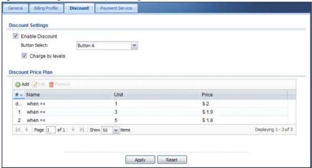
The following table describes the labels in this screen.
Table 237 Configuration > Hotspot > Billing > Discount
| LABEL DESCRIPTION | |
| Discount Settings | |
| Enable Discount Select the check box to activate the discount price plan. | |
| Button Select | Select a button from the drop-down list box to assign the base charge. |
| Charge by levels | Select this to charge the rate at each successive level from the first level (most expensive per unit) to the highest level (least expensive per unit) that the total purchase reaches.Otherwise, clear this to charge all of the user's time units only at the highest level (least expensive) that their total purchase reaches. |
| Discount Price Plan | |
| Add Click this to create a new entry. | |
| Edit | Double-click an entry or select it and click Edit to open a screen where you can modify the entry's settings. |
| Remove | To remove an entry, select it and click Remove. The Zyxel Device confirms you want to remove it before doing so. |
| # This is the number of each discount level.The default (first) level cannot be edited or deleted. It is created automatically according to the billing profile of the button you select. | |
| Name | This field displays the conditions of each discount level. |
| Unit | This field displays the duration of the billing period that should be reached before the Zyxel Device charges users at this level. |
| Price This field displays the price per time unit for each level. | |
| Apply Click this button to save your changes to the Zyxel Device. | |
| Reset Click this button to return the screen to its last-saved settings. | |
25.5.1 The Discount Add/Edit Screen
The Discount Add/ Edit screen allows you to create a new discount level or edit an existing one. Click Configuration > Hotspot > Billing > Discount and then an Add or Edit icon to open this screen.
Figure 439 Configuration > Hotspot > Billing > Discount > Add/Edit
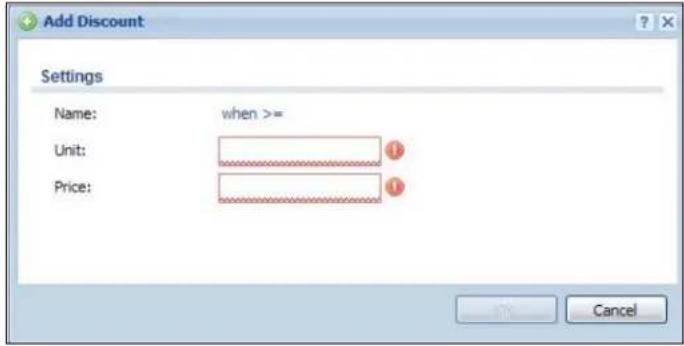
The following table describes the labels in this screen.
Table 238 Configuration > Hotspot > Billing > Discount > Add/Edit
| LABEL DESCRIPTION | |
| Name | This field displays the conditions of each discount level. |
| Unit | Set the duration of the billing period that should be reached before the Zyxel Device charges users at this level. |
| Price Define this level's charge per time unit. | |
| OK | Click OK to save your changes back to the Zyxel Device. |
| Cancel | Click Cancel to exit this screen without saving. |
25.6 The Billing > Payment Service Screen
Use this screen to use a credit card service to authorize, process, and manage credit card transactions directly through the Internet. You must register with the supported credit card service before you can configure the Zyxel Device to handle credit card transactions. Click Configuration > Hotspot > Billing > Payment Service to open the following screen.
Figure 440 Configuration > Hotspot > Billing > Payment Service > General
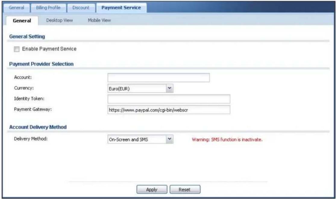
The following table describes the labels in this screen.
Table 239 Configuration > Hotspot > Billing > Payment Service > General
| LABEL DESCRIPTION | |
| General Setting | |
| Enable Payment Service | Select the check box to use PayPal to authorize credit card payments.Note: After you set up web authentication policies and enable the online payment service on the Zyxel Device, a link displays in the login screen when users try to access the Internet. The link redirects users to a screen where they can make online payments by credit card to purchase access time and get dynamic guest account information. |
| Payment Provider Selection | |
| Account You should already have a PayPal account to receive credit card payments.Enter your PayPal account name. | |
| Currency | Select the currency in which payments are made. The available options depend on currencies that PayPal supports. |
| Identity Token | Enter the ID token provided to you by PayPal after successfully applying for your PayPal account. |
| Payment Gateway | Enter the address of the PayPal gateway provided to you by PayPal after applying for your PayPal account. |
| Account Delivery Method | |
| LABEL DESCRIPTION | |
| Delivery Method | Specify how the Zyxel Device provides dynamic guest account information after the user's online payment is done.Select On-Screen to display the user account information in the web screen.Select SMS to use Short Message Service (SMS) to send account information in a text message to the user's mobile device.Select On-Screen and SMS to provide the account information both in the web screen and via SMS text messages.Note: You should have enabled SMS in theConfiguration > System > Notification > SMS screen to send text messages to the user's mobile device. |
| Apply Click this button to save your changes to the Zyxel Device. | |
| Reset Click this button to return the screen to its last-saved settings. | |
25.6.1 The Payment Service > Desktop / Mobile View Screen
Use this screen to customize the online payment service pages that displays after an unauthorized user clicks the link in the Web Configurator login screen to purchase access time. You can configure both the desktop and mobile versions of the service pages. Users click a link in the pages to switch between the two versions.
Click Configuration > Hotspot > Billing > Payment Service > Desktop View or Mobile View to open the following screen.
Figure 441 Configuration > Hotspot > Billing > Payment Service > Desktop View
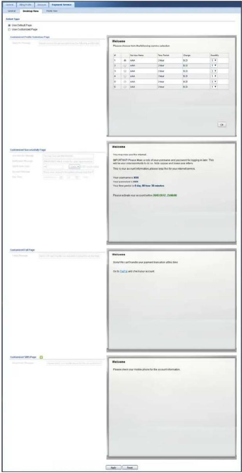
Figure 442 Configuration > Hotspot > Billing > Payment Service > Mobile View
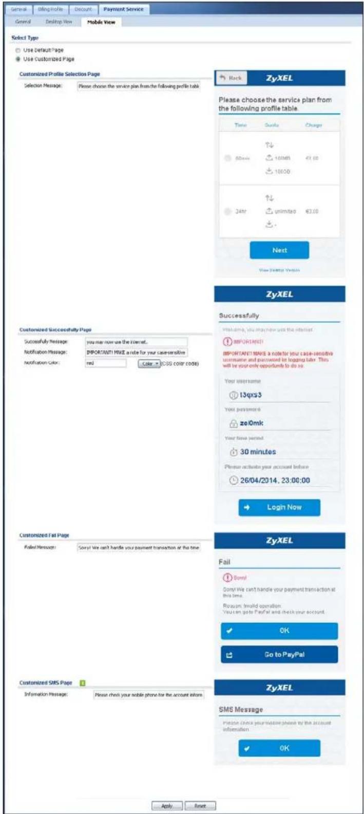
The following table describes the labels in this screen.
Table 240 Configuration > Hotspot > Billing > Payment Service > Desktop View or Mobile View
| LABEL DESCRIPTION | |
| Select Type | |
| Use Default Page | Select this to use the default online payment service page built into the device. If you later create a custom online payment service page, you can still return to the Zyxel Device's default page as it is saved indefinitely. |
| Use Customized Page | Select this to use a custom online payment service page instead of the default one built into the Zyxel Device. Once this option is selected, the custom page controls below become active. |
| Customized Profile Selection Page | |
| Selection Message | Enter a note to display in the first welcome page that allows users to choose a billing period they want. Use up to 256 printable ASCII characters. Spaces are allowed. |
| Customized Successfully Page | |
| Successfully Message | Enter a note to display in the second page after the user's online payment is made successfully. Use up to 256 printable ASCII characters. Spaces are allowed. |
| Notification Message | Enter the important information you want to display. Use up to 256 printable ASCII characters. Spaces are allowed. |
| Notification Color | Specify the font color of the important information. You can use the color palette chooser, or enter a color value of your own. |
| Account Message | Enter a note to display above the user account information. Use up to 256 printable ASCII characters. Spaces are allowed. |
| Day Time | Select the format in which you want to display the date and how long an account is allowed to stay unused before it expires. |
| Customized Fail Page | |
| Failed Message | Enter a note to display when the user's online payment failed. Use up to 256 printable ASCII characters. Spaces are allowed. |
| Customized SMS Page | |
| Information Message | Enter a note to display when you set the Zyxel Device to send account information via SMS text messages. Use up to 256 printable ASCII characters. Spaces are allowed. |
| Apply Click this button to save your changes to the Zyxel Device. | |
| Reset Click this button to return the screen to its last-saved settings. | |
CHAPTER 26
Printer Manager
26.1 Printer Manager Overview
You can create dynamic guest accounts and print guest account information by pressing the button on an external statement printer, such as SP350E.
Make sure that the printer is connected to the appropriate power and the Zyxel Device, and that there is printing paper in the printer. Refer to the printer's documentation for details.
26.1.1 What You Can Do in this Chapter
- Use the Printer Manager > General screen (see Section 25.3 on page 633) to configure the printer list and enable printer management.
- Use the Printer Manager > Printout Configuration screen (see Section 26.3 on page 657) to customize the account printout.
26.2 The Printer Manager > General Screen
Use this screen to configure a printer list and allow the Zyxel Device to monitor the printer status. Click Configuration > Hotspot > Printer Manager > General to open the following screen.
Figure 443 Configuration > Hotspot > Printer Manager > General
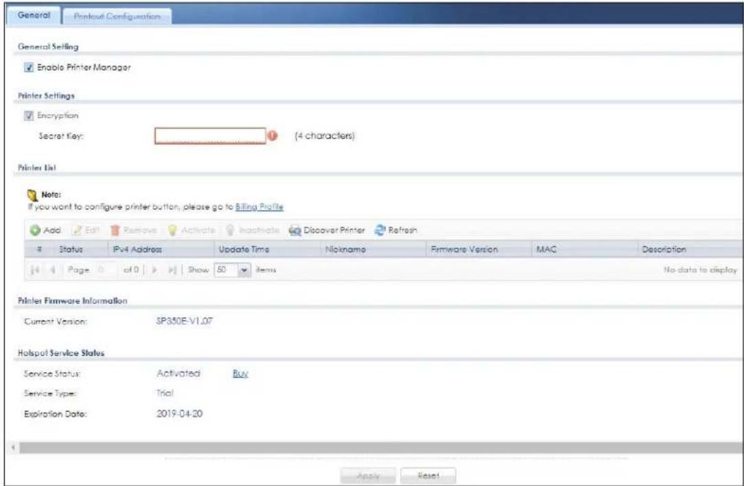
The following table describes the labels in this screen.
Table 241 Configuration > Hotspot > Printer Manager > General
| LABEL DESCRIPTION | |
| General Setting | |
| Enable Printer Manager | Select the check box to allow the Zyxel Device to manage and monitor the printer status. |
| Printer Settings | |
| Encryption | Select the check box to turn on data encryption. Data transmitted between the Zyxel Device and the printer will be encrypted with a secret key |
| Secret Key | Enter four alphanumeric characters (A-Z, a-z, 0-9) to specify a key for data encryption. |
| Printer List | Use this section to add the printer(s) that can be managed by the Zyxel Device. |
| Add Click this to create a new entry. | |
| Edit | Double-click an entry or select it and click Edit to open a screen where you can modify the entry's settings. |
| Remove | To remove an entry, select it and click Remove. The Zyxel Device confirms you want to remove it before doing so. |
| Activate | To turn on an entry, select it and click Activate. |
| Inactivate | To turn off an entry, select it and click Inactivate. |
| Discover Printer | Click this to discover the printer(s) that is connected to the Zyxel Device and display the printer information in a pop-up window. IPnP is enabled while discovering the printer and disabled when the discovering process has finished.Note: You need a Hotspot license to use this feature.Use Printer Manager > General > Add to manually configure a printer's IP address and add it to the managed printer list when the printer is not detected or connected to the Zyxel Device. |
| Refresh Click this | to update the printer list table. |
| # This field is a sequential value, and it is not associated with any entry. | |
| Status | This icon is lit when the entry is active and dimmed when the entry is inactive. Click the Connection icon for the Zyxel Device connect to the printer. |
| IPv4 Address This field displays the IP address of the printer. | |
| Update Time | This field displays the date and time the Zyxel Device last synchronized with the printer.This shows n/a when the printer is not in the managed printer list or the printer status is sync fail or sync progressing. |
| Status | This field is hidden by default. It displays whether the Zyxel Device can connect to the printer and update the printer information.This shows n/a when the printer is not in the managed printer list. |
| Nickname | This shows an optional friendly name for the printer that you configured. |
| Firmware Version | This field displays the model number and firmware version of the printer.This shows n/a when the printer is not in the managed printer list or the printer status is sync fail. |
| MAC This shows the hardware MAC address of the printer. | |
| Description | This field displays the descriptive name for the printer that you configured. |
| Printer Firmware Information | |
| Current Version | This is the version of the printer firmware currently uploaded to the Zyxel Device. The Zyxel Device automatically installs it in the connected printers to make sure the printers are upgraded to the same version. |
| Hotspot Service Status | The hotspot license must be registered in order to be activated. |
| Service Status | This field displays whether a service license is enabled at myZyxel (Activated) or not (Not Activated) or expired (Expired). It displays the remaining Grace Period if your license has Expired. It displays Not Licensed if there isn't a license to be activated for this service.If you need a license or a trial license has expired, click Buy to buy a new one. If a Standard license has expired, click Renew to extend the license.Then, click Activate to connect with the myZyxel server to activate the new license. |
| Service Type | This shows whether you have a trial or standard license or none (Trial, Standard, None). |
| Expiration Date | This shows when your hotspot license will expire. |
| Apply Click this button to save your changes to the Zyxel Device. | |
| Reset Click this button to return the screen to its last-saved settings. | |
26.2.1 Add Printer Rule
Click the Add icon to open the following screen. Use this screen to add a new printer.
Figure 444 Configuration > Hotspot > Printer Manager > General: Add
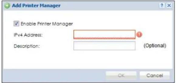
The following table describes the labels in this screen.
Table 242 Configuration > Hotspot > Printer Manager > General: Add
| LABEL DESCRIPTION | |
| Enable Printer Manager | Select this option to turn on this entry in order to allow the Zyxel Device to manage this printer. |
| IPv4 Address Enter | an IPv4 address for the printer. |
| Description | Enter a description of this printer. You can use alphanumeric and ( ) + , / : = ? ! * # @ $ _ % - " characters, and it can be up to 60 characters long. |
| OK | Click OK to save your changes back to the Zyxel Device. |
| Cancel | Click Cancel to exit this screen without saving. |
26.2.2 Edit Printer Rule
Select an entry in the Printer Manager > General screen and click the Edit icon to open the following screen. Use this screen to modify the printer's settings. You can't click the Edit icon when the printer status is sync fail or sync progressing.
Figure 445 Configuration > Hotspot > Printer Manager > General: Edit
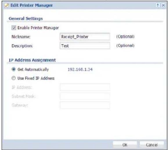
The following table describes the labels in this screen.
Table 243 Configuration > Hotspot > Printer Manager > General: Edit
| LABEL DESCRIPTION | |
| Enable Printer Manager | Select this option to turn on this entry in order to allow the Zyxel Device to manage this printer. |
| Nickname | Type an optional friendly name for the printer. A nickname must begin with a letter and cannot exceed 15 characters. Valid characters are [a-zA-Z0-9_-]. |
| Description | Enter a description of this printer. You can use alphanumeric and ( ) + , / : = ? ! * # @ $ _% - " characters, and it can be up to 60 characters long. |
| IP Address Assignment | |
| Get Automatically | Select this to make the printer a DHCP client and automatically get the IP address, subnet mask, and gateway address from a DHCP server. |
| Use Fixed IP Address | Select this if you want to specify the IP address, subnet mask, and gateway manually. |
| IP Address | This field is enabled if you select Use Fixed IP Address.Enter the IP address for the printer. |
| Subnet Mask | This field is enabled if you select Use Fixed IP Address.Enter the subnet mask of the printer in dot decimal notation. The subnet mask indicates what part of the IP address is the same for all computers on the network. |
| Gateway | This field is enabled if you select Use Fixed IP Address.Enter the IP address of the gateway. The Zyxel Device sends packets to the gateway when it does not know how to route the packet to its destination. The gateway should be on the same network as the printer. |
| OK | Click OK to save your changes back to the Zyxel Device. |
| Cancel | Click Cancel to exit this screen without saving. |
26.2.3 Discover Printer
Click the Discover Printer icon in the Printer Manager > General screen to open the following screen. Use this screen to find connected printers or edit a connected printer's settings. Use Printer Manager > General > Add to manually configure a printer's IP address and add it to the managed printer list when the printer is not detected or connected to the Zyxel Device.
Figure 446 Configuration > Hotspot > Printer Manager > General: Discover Printer
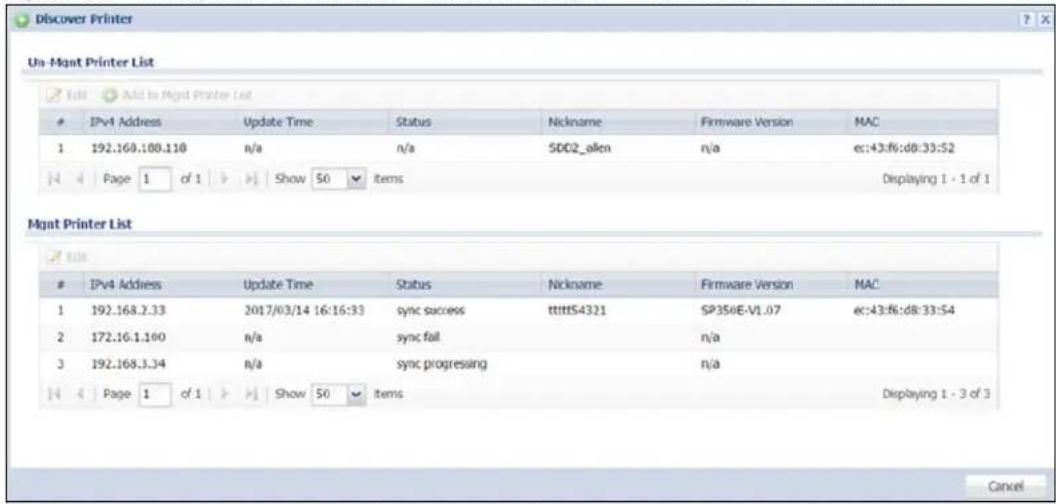
The following table describes the labels in this screen.
Table 244 Configuration > Hotspot > Printer Manager > General > Discover Printer
| LABEL DESCRIPTION | |
| Un-Mgmt Printer List / Mgmt Printer List | The tables displays according to whether the printer is in the unmanaged printer list (Un-Mgmt Printer List) or the managed printer list (Mgmt Printer List). |
| Edit | Double-click an entry or select it and click Edit to open a screen where you can modify the entry's settings.Note: You cannot edit an entry's settings when the printer status is sync fail or sync progressing. |
| Add to Mgmt Printer List | Click this to add the selected printer to the managed printer list. |
| # This is the index number of the printer in the list. | |
| Registration | This field displays whether the printer is added to the managed printer list (Mgmt Printer) or not (Un-Mgmt Printer). |
| IPv4 Address This field displays the IP address of the printer. | |
| Update Time | This field displays the date and time the Zyxel Device last synchronized with the printer.This shows n/a when the printer is not in the managed printer list or the printer status is sync fail or sync progressing. |
| Status | This field displays whether the Zyxel Device can connect to the printer and update the printer information.This shows n/a when the printer is not in the managed printer list. |
| Nickname | This field displays the optional friendly name of the printer that you configured. |
| Firmware Version | This field displays the model number and firmware version of the printer.This shows n/a when the printer is not in the managed printer list or the printer status is sync fail. |
| MAC This field displays the MAC address of the printer. | |
26.2.4 Edit Printer Manager (Discover Printer)
Select an entry in the Printer Manager > General > Discover Printer screen and click the Edit icon to open the following screen. Use this screen to modify the printer's nickname and IP address.
Figure 447 Configuration > Hotspot > Printer Manager > General > Discover Printer: Edit
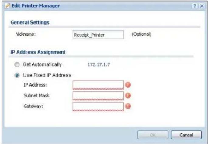
The following table describes the labels in this screen.
Table 245 Configuration > Hotspot > Printer Manager > General > Discover Printer: Edit
| LABEL DESCRIPTION | |
| General Settings | |
| Nickname | Type an optional friendly name for the printer. A nickname must begin with a letter and cannot exceed 15 characters. Valid characters are [a-zA-Z0-9_-]. |
| IP Address Assignment | |
| Get Automatically | Select this to make the printer a DHCP client and automatically get the IP address, subnet mask, and gateway address from a DHCP server. |
| Use Fixed IP Address | Select this if you want to specify the IP address, subnet mask, and gateway manually. |
| IP Address | This field is enabled if you select Use Fixed IP Address.Enter the IP address for the printer. |
| Subnet Mask | This field is enabled if you select Use Fixed IP Address.Enter the subnet mask of the printer in dot decimal notation. The subnet mask indicates what part of the IP address is the same for all computers on the network. |
| Gateway | This field is enabled if you select Use Fixed IP Address.Enter the IP address of the gateway. The Zyxel Device sends packets to the gateway when it does not know how to route the packet to its destination. The gateway should be on the same network as the printer. |
| OK | Click OK to save your changes back to the Zyxel Device. |
| Cancel | Click Cancel to exit this screen without saving. |
26.3 The Printout Configuration Screen
Use this screen to customize the account printout. Click Configuration > Hotspot > Printer Manager > Printout Configuration to open the following screen.
Figure 448 Configuration > Hotspot > Printer Manager > Printout Configuration
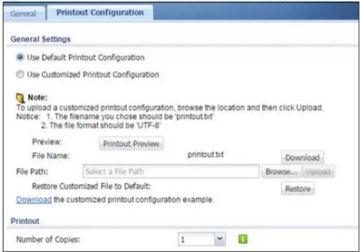
The following table describes the labels in this screen.
Table 246 Configuration > Hotspot > Printer Manager > Printout Configuration
| LABEL DESCRIPTION | |
| Use Default Printout Configuration | Select this to use the default account printout format built into the device. If you later create a custom account printout format, you can still return to the Zyxel Device's default format as it is saved indefinitely. |
| Use Customized Printout Configuration | Select this to use a custom account printout format instead of the default one built into the Zyxel Device. Once this option is selected, the custom format controls below become active. |
| Preview | Click the button to display a preview of account printout format you uploaded to the Zyxel Device. |
| File Name | This shows the file name of account printout format file in the Zyxel Device.Click Download to download the account printout format file from the Zyxel Device to your computer. |
| File Path /Browse /Upload | Browse for the account printout format file or enter the file path in the available input box, then click the Upload button to put it on the Zyxel Device. |
| Restore Customized File to Default | Click Restore to set the Zyxel Device back to use the default built-in account printout format. |
| Download | Click this to download an example account printout format file from the Zyxel Device for your reference. |
| Printout | |
| Number of Copies | Select how many copies of subscriber statements you want to print (1 is the default). |
| Apply Click this button to save your changes to the Zyxel Device. | |
| Reset Click this button to return the screen to its last-saved settings. | |
26.4 Printer Reports Overview
The SP350E allows you to print status reports about the guest accounts and general Zyxel Device system information. Simply press a key combination on the SP350E to print a report instantly without accessing the web configurator.
The following lists the reports that you can print using the SP300E.
• Daily account summary
• Monthly account summary
- Last month account summary
- System status
26.4.1 Key Combinations
The following table lists the key combination to print each report.
Note: You must press the key combination on the SP350E within five seconds to print.
Table 247 Report Printing Key Combinations
| REPORT TYPE KEY COMBINATION | |
| Daily Account Summary A B C A A | |
| Monthly Account Summary A B C B A | |
| Last Month Account Summary A B C B B | |
| System Status A B C C A |
The following sections describe each report printout in detail.
26.4.2 Daily Account Summary
The daily account report lists the accounts printed during the current day, the current day's total number of accounts and the total charge. It covers the accounts that have been printed during the current day starting from midnight (not the past 24 hours). For example, if you press the daily account key combination on 2013/05/10 at 20:00:00, the daily account report includes the accounts created on 2013/05/10 between 00:00:01 and 19:59:59.
Key combination: A B C A A
The following figure shows an example.
Figure 449 Daily Account Example
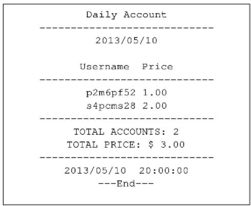
26.4.3 Monthly Account Summary
The monthly account report lists the accounts printed during the current month, the current month's total number of accounts and the total charge. It covers the accounts that have been printed during the current month starting from midnight of the first day of the current month (not the past one month period). For example, if you press the monthly account key combination on 2013/05/17 at 20:00:00, the monthly account report includes the accounts created from 2013/05/01 at 00:00:01 to 2013/05/17 at 19:59:59.
Key combination: A B C B A
The following figure shows an example.
Figure 450 Monthly Account Example
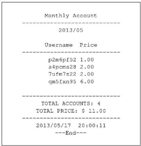
26.4.4 Account Report Notes
The daily, monthly or last month account report holds up to 2000 entries. If there are more than 2000 accounts created in the same month or same day, the account report's calculations only include the latest 2000.
For example, if 2030 accounts (each priced at \1) have been created from 2013/05/01 00:00:00 to 2013/05/31 19:59:59, the monthly account report includes the latest 2000 accounts, so the total would be \2,000 instead of \$2,030.
Use the Monitor > System Status > Dynamic Guest screen to see the accounts generated on another day or month (up to 2000 entries total).
26.4.5 System Status
This report shows the current system information such as the host name and WAN IP address.
Key combination: A B C C A
The following figure shows an example.
Figure 451 System Status Example
| System Status | |
| Item | Description |
| SYST | 02:02:35 |
| WAST | Link up |
| WLST | Activate |
| FWVR | 2.50 (AACG.0) |
| BTVR | 1.22 |
| WAMA | 00-90-0E-00-4A-29 |
| LAMA | 00-90-0E-00-4A-30 |
| WAIP | 10.21.2.267 |
| LAIP | 172.16.0.1 |
| WLIP | 10.59.1.1 |
| DHSP | 10.59.1.33 |
| DHEP | 10.59.1.254 |
| CPUS | 5% |
| MEMS | 40% |
| DKST | 5% |
| 2012/04/12 17:10:22 ---End--- | |
The following table describes the labels in this report.
Table 248 System Status
| LABEL DESCRIPTION |
| SYST This field displays the time since the system was last restarted. |
| WAST This field displays the WAN connection status. |
| WLST This field displays the status of the Zyxel Device's wireless LAN. |
| FWVR This field displays the version of the firmware on the Zyxel Device. |
| BTVR This field displays the version of the bootrom. |
| WAMA This field displays the MAC address of the Zyxel Device on the WAN. |
| LAMA This field displays the MAC address of the Zyxel Device on the LAN. |
Table 248 System Status (continued)
| LABEL DESCRIPTION | |
| WAIP | This field displays the IP address of the WAN port on the Zyxel Device. |
| LAIP This field displays the IP address of the LAN port on the Zyxel Device. | |
| WLIP | This field displays the IP address of the wireless LAN interface on the Zyxel Device. |
| DHSP | This field displays the first of the continuous addresses in the IP address pool. |
| DHEP | This field displays the end of the continuous addresses in the IP address pool. |
| CPUS This field displays the Zyxel Device's recent CPU usage. | |
| MEMS This field displays the Zyxel Device's recent memory usage. | |
| DKST | This field displays what percentage of the Zyxel Device's on-board flash memory is currently being used. |
CHAPTER 27 Free Time
27.1 Free Time Overview
With Free Time, the Zyxel Device can create dynamic guest accounts that allow users to browse the Internet free of charge for a specified period of time.
27.1.1 What You Can Do in this Chapter
Use the Free Time screen (see Section 27.2 on page 662) to turn on this feature to allow users to get a free account for Internet surfing during the specified time period.
27.2 The Free Time Screen
Use this screen to enable and configure the free time settings.. Click Configuration > Hotspot > Free Time to open the following screen.
Figure 452 Configuration > Hotspot > Free Time
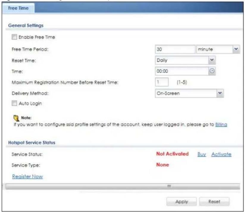
The following table describes the labels in this screen.
Table 249 Configuration > Hotspot > Free Time
| LABEL DESCRIPTION | |
| Enable Free Time Select the check box to turn on the free time feature. Note: After you set up web authentication policies and enable the free time feature on the Zyxel Device, a link displays in the login screen when users try to access the Internet. The link redirects users to a screen where they can get a free account. | |
| Free Time Period | Select the duration of time period for which the free time account is allowed to access the Internet. |
| Reset Time | SelectDailyto have the Zyxel Device allow free account access every day at the specified time.SelectWeeklyto have the Zyxel Device allow free account access once a week on the day you select.SelectMonthlyto have the Zyxel Device allow free account access once a month on a set date.When your free period ends, you will see a message telling you when you can use free time again. This depends on theReset Timeperiod chosen. |
| Time | If you selectDaily, select the time in 24-hour format at which the new free time account is allowed to access the Internet. |
| Day | If you selectWeekly, select the day on which the new free time account is allowed to access the Internet.If you selectMonthly, enter the date on which the new free time account is allowed to access the Internet. If the date you selected is not available in a month, such as 30th or 31th, the Zyxel Device allows the free account access on the last day of the month. |
| Maximum Registration Number Before Reset Time | Enter the maximum number of users that are allowed to log in for Internet access with a free guest account before the time specified in theReset Timefield. This also sets how many free guest accounts a user can get.For example, if you set theMaximum Registration Number Before Reset Timeto 1, theReset Time toDailyand theReset Timeto 13:00, even the first free guest account has expired at 11:30, the user cannot get a second account and/or access the Internet until 13:00. |
| Delivery Method | Specify how the Zyxel Device provides dynamic guest account information.SelectOn-Screento display the user account information in the web screen.SelectSMSto use Short Message Service (SMS) to send account information in a text message to the user's mobile device.SelectOn-Screen and SMSto provide the account information both in the web screen and via SMS text messages.Note: You should have enabled SMS in theConfiguration > System > Notification >SMSscreen to send text messages to the user's mobile device. |
| Auto Login | Select this to allow users to log into their free account directly without having to enter their user name and password.Clearing this requires users to enter their user name and password, and click login to access their free account. |
| Hotspot Service Status | |
| Service Status | This field displays whether a service license is enabled at myZyxel (Activated) or not (Not Activated) or expired (Expired). It displays the remaining Grace Period if your license has Expired. It displays Not Licensed if there isn't a license to be activated for this service.If you need a license or a trial license has expired, click Buy to buy a new one. If a Standard license has expired, click Renew to extend the license.Then, click Activate to connect with the myZyxel server to activate the new license. |
| Service Type | This shows whether you have a trial or standard license or none (Trial, Standard, None). |
| Expiration Date | This shows when your hotspot license will expire. |
| Apply Click this button to save your changes to the Zyxel Device. | |
| Reset Click this button to return the screen to its last-saved settings. | |
The following figure shows an example login screen with a link to create a free guest account.
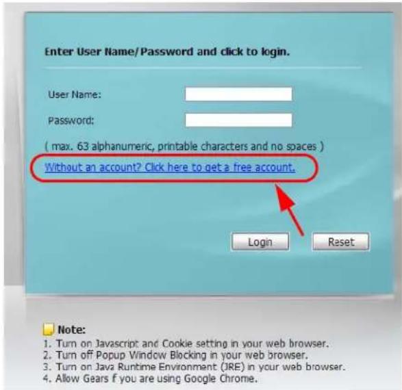
If you enable both online payment service and free time feature on the Zyxel Device, the link description in the login screen will be mainly for online payment service. You can still click the link to get a free account.
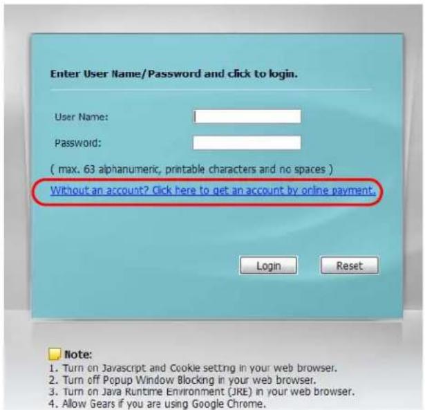
If SMS is enabled on the Zyxel Device, you have to enter your mobile phone number before clicking OK to get a free guest account.
![Welcome Please choose the service plan from the following profile table. # Service Name Service Time Charge Unit 1 Free Time 30 minutes Free 1 Country Code: 896 Mobile Number: Example: [886][0910123456](for Taiwan) OK](/content/2026/05/878280/images/1fa7993a8911de492ea327ad083cf3582609897c0ffeddff8f619bb38fde61c0.jpg)
The guest account information then displays on the screen and/or is sent to the configured mobile phone number.
Welcome
You may now use the internet.
IMPORTANT! MAKE a note for your case-sensitive username and password for logging later. This will be your only opportunity to do so.
This is your account information, please keep this for your internet service.
Your username is uz39
Your password is 4vmbdm
Your time period is 30 minutes
OK
CHAPTER 28 IPnP
28.1 IPnP Overview
IP Plug and Play (IPnP) allows a computer to access the Internet without changing the network settings (such as IP address and subnet mask) of the computer, even when the IP addresses of the computer and the Zyxel Device are not in the same subnet.
When you disable the IPnP feature, only computers with dynamic IP addresses or static IP addresses in the same subnet as the Zyxel Device's LAN IP address can connect to the Zyxel Device or access the Internet through the Zyxel Device.
The IPnP feature does not apply to a computer using either a dynamic IP address or a static IP address that is in the same subnet as the Zyxel Device's IP address.
Note: You must enable NAT to use the IPnP feature.
The following figure depicts a scenario where a computer is set to use a static private IP address in the corporate environment. In a residential house where a Zyxel Device is installed, you can still use the computer to access the Internet without changing the network settings, even when the IP addresses of the computer and the Zyxel Device are not in the same subnet.
Figure 453 IPnP Application
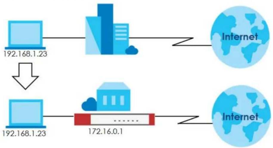
flowchart
graph TD
    A["Computer 192.168.1.23"] --> B["Network"]
    B --> C["Internet"]
    D["Computer 192.168.1.23"] --> E["Network"]
    E --> F["Internet"]
    style A fill:#cce5ff,stroke:#333
    style D fill:#cce5ff,stroke:#333
    style B fill:#e6f3ff,stroke:#333
    style E fill:#e6f3ff,stroke:#333
    style F fill:#e6f3ff,stroke:#333
28.1.1 What You Can Do in this Chapter
Use the IP screen (Section 28.1.2 on page 668) to enable IPnP on the Zyxel Device and the internal interface(s).
28.1.2 IPnP Screen
This screen allows you to enable IPnP on the Zyxel Device and specific internal interface(s). To access this screen click Configuration > Hotspot > IPnP.
Figure 454 Configuration > Hotspot > IPnP
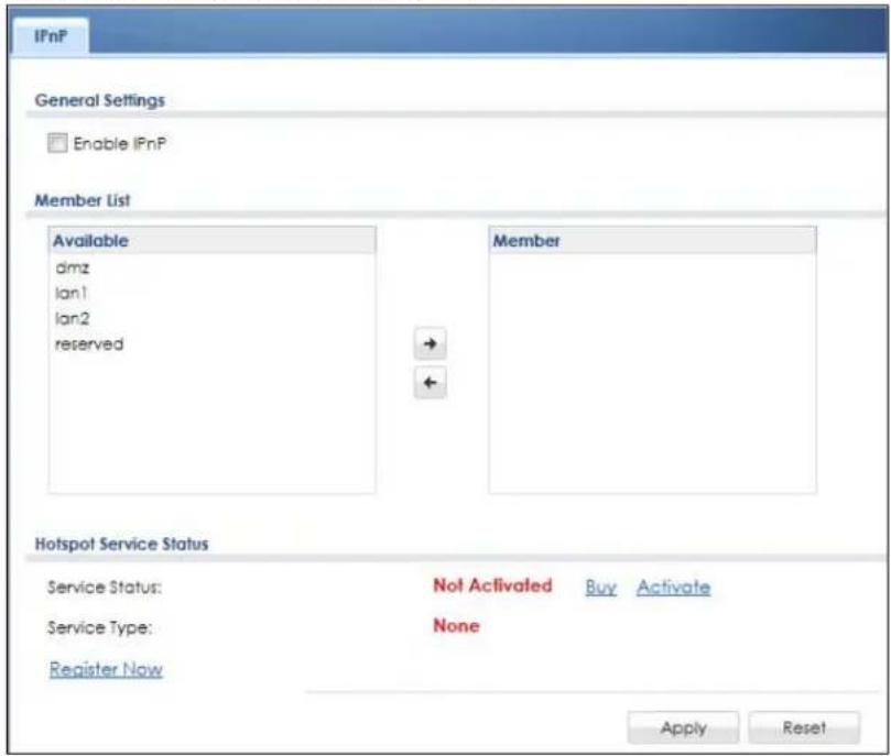
The following table describes the labels in this screen.
Table 250 Configuration > Hotspot > IPnP
| LABEL DESCRIPTION | |
| Enable IPnP | Select this option to turn on the IPnP feature on the Zyxel Device.Note: You can enable this feature only when the security policy is enabled. |
| Member List | The Available list displays the name(s) of the internal interface(s) on which you can enable IPnP.To enable IPnP on an interface, you can double-click a single entry to move it or use the [Shift] or [Ctrl] key to select multiple entries and click the right arrow button to add to the Member list.To remove an interface, select the name(s) in the Member list and click the left arrow button. |
| Hotspot Service Status | |
| Service Status | This field displays whether a service license is enabled at myZyxel (Activated) or not (Not Activated) or expired (Expired). It displays the remaining Grace Period if your license has Expired. It displays Not Licensed if there isn't a license to be activated for this service.If you need a license or a trial license has expired, click Buy to buy a new one. If a Standard license has expired, click Renew to extend the license.Then, click Activate to connect with the myZyxel server to activate the new license. |
| Service Type | This shows whether you have a trial or standard license or none (Trial, Standard, None). |
| Expiration Date | This shows when your hotspot license will expire. |
| Register Now | Click the link to go to myZyxel where you can register your Zyxel Device and activate the service.This link is available only when the service is not activated yet. |
| Apply | Click Apply to save your changes back to the Zyxel Device. |
| Reset | Click Reset to return the screen to its last-saved settings. |
CHAPTER 29
Walled Garden
29.1 Walled Garden Overview
A user must log in before the Zyxel Device allows the user's access to the Internet. However, with a walled garden, you can define one or more web site addresses that all users can access without logging in. These can be used for advertisements for example.
29.2 Walled Garden > General Screen
Use this screen to turn on the walled garden feature.
Note: You must enable web authentication before you can access the Walled Garden screens.
Note: You can configure up to 50 walled garden web site links.
Click Configuration > Hotspot > Walled Garden to display the screen.
Figure 455 Configuration > Hotspot > Walled Garden: General
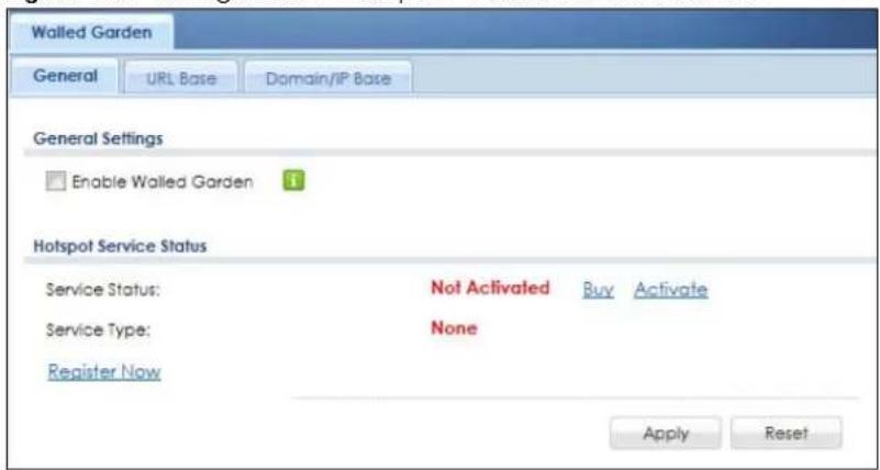
The following table describes the labels in this screen.
Table 251 Configuration > Hotspot > Walled Garden: General
| LABEL DESCRIPTION | |
| Enable Walled Garden | Select this to turn on the walled garden feature.Note: This feature works only with the web portal authentication type. |
| Hotspot Service Status | |
| Service Status | This field displays whether a service license is enabled at myZyxel (Activated) or not (Not Activated) or expired (Expired). It displays the remaining Grace Period if your license has Expired. It displays Not Licensed if there isn't a license to be activated for this service.If you need a license or a trial license has expired, click Buy to buy a new one. If a Standard license has expired, click Renew to extend the license.Then, click Activate to connect with the myZyxel server to activate the new license. |
| Service Type | This shows whether you have a trial or standard license or none (Trial, Standard, None). |
| Expiration Date | This shows when your hotspot license will expire. |
| Register Now | Click the link to go to myZyxel where you can register your Zyxel Device and activate the service.This link is available only when the service is not activated yet. |
| Apply | Click this button to save your changes to the Zyxel Device. |
| Reset Click this button to return the screen to its last-saved settings. | |
29.3 Walled Garden > URL Base Screen
Use this screen to configure the walled garden web addresses (URLs that use the HTTP or HTTPS protocol) for web sites that all users are allowed to access without logging in. The web site link(s) displays in the user login screen by default.
Click Configuration > Hotspot > Walled Garden and then select the URL Base tab to display the screen.
Figure 456 Configuration > Hotspot > Walled Garden: URL Base
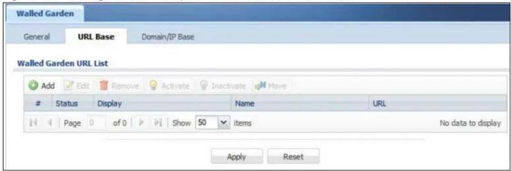
The following table describes the labels in this screen.
Table 252 Configuration > Hotspot > Walled Garden: URL Based
| LABEL DESCRIPTION | |
| Walled Garden URL List | Use this table to manage the list of walled garden web site links. |
| Add | Click this to create a new entry. Select an entry and click Add to create a new entry after the selected entry. |
| Edit | Double-click an entry or select it and click Edit to open a screen where you can modify the entry's settings. |
| Remove | To remove an entry, select it and click Remove. The Zyxel Device confirms you want to remove it before doing so. |
| Activate | To turn on an entry, select it and click Activate. |
| Inactivate | To turn off an entry, select it and click Inactivate. |
| Move | To move an entry to a different number in the list, click the Move icon. In the field that appears, specify the number to which you want to move the interface. |
| # This field is a sequential value, and it is not associated with any entry. | |
| Status | This icon is lit when the entry is active and dimmed when the entry is inactive. |
| Display | This icon is lit when the web site link is set to display in the user login screen. |
| Name | This field displays the descriptive name of the web site. |
| URL This field displays the URL of the web site. | |
| Apply | Click this button to save your changes to the Zyxel Device. |
| Reset Click this button to return the screen to its last-saved settings. | |
29.3.1 Adding/Editing a Walled Garden URL
Go to the Configuration > Web Authentication > Walled Garden > URL Base screen. Click Add or select an entry and click the Edit to open the Add/Edit Walled Garden URL screen. Use this screen to configure a walled garden web site URL entry.
Figure 457 Configuration > Hotspot > Walled Garden: URL Base: Add/Edit
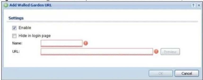
The following table describes the labels in this screen.
Table 253 Configuration > Hotspot > Walled Garden: URL Base: Add/Edit
| LABEL DESCRIPTION | |
| Enable Select this to activate the entry. | |
| Hide in login page | Select this to not display the web site link in the user login screen.This is helpful if a user's access to a specific web site is required to stay connected but he or she doesn't need to visit that web site. |
| Name | Enter a descriptive name for the walled garden link to be displayed in the login screen.You can use up to 31 alphanumeric characters (A-Z, a-z, 0-9) and underscores (_). Spaces are also allowed. The first character must be a letter. |
| URL Enter the URL of the web site. Use "http://" or "https://" followed by up to 262 characters (0-9a-zA-Z;/?:@&=+$\._1~*')%). For example, http://www.example.com or http://172.16.1.35. | |
| Preview | Click this button to open the specified web site in a new frame. |
| OK | Click OK to save your changes back to the Zyxel Device. |
| Cancel | Click Cancel to exit this screen without saving. |
29.4 Walled Garden > Domain/IP Base Screen
Use this screen to configure walled garden web site links, which use a (wildcard) domain name or an IP address. These links will not display in the login page.
Click Configuration > Hotspot > Walled Garden and then select the Domain/IP Base tab to display the screen.
Figure 458 Configuration > Hotspot > Walled Garden: Domain/IP Base
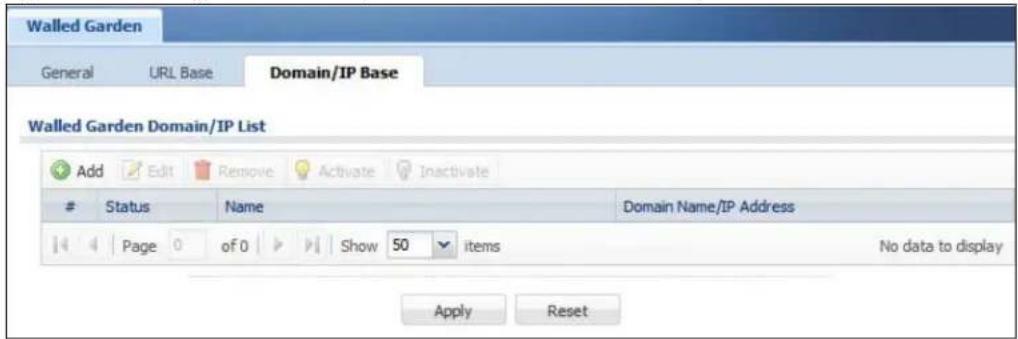
The following table describes the labels in this screen.
Table 254 Configuration > Hotspot > Walled Garden: Domain/IP Based
| LABEL DESCRIPTION | |
| Walled Garden Domain/IP List | Use this table to manage the list of walled garden web site links. |
| Add | Click this to create a new entry. Select an entry and click Add to create a new entry after the selected entry. |
| Edit | Double-click an entry or select it and click Edit to open a screen where you can modify the entry's settings. |
| Remove | To remove an entry, select it and click Remove. The Zyxel Device confirms you want to remove it before doing so. |
| Activate | To turn on an entry, select it and click Activate. |
| Inactivate | To turn off an entry, select it and click Inactivate. |
| # This field is a sequential value, and it is not associated with any entry. | |
| Status | This icon is lit when the entry is active and dimmed when the entry is inactive. |
| Name | This field displays the descriptive name of the web site. |
| Domain Name/IP Address | This field displays the domain name or IP address and subnet mask of the web site. |
| Apply | Click this button to save your changes to the Zyxel Device. |
| Reset Click this button to return the screen to its last-saved settings. | |
29.4.1 Adding/Editing a Walled Garden Domain or IP
Go to the Configuration > Hotspot > Walled Garden > Domain/IP Base screen. Click Add or select an entry and click the Edit to open the Add/Edit Walled Garden Domain/IP screen. Use this screen to configure the domain name or IP address entry for a walled garden web site.
Figure 459 Configuration > Hotspot > Walled Garden: Domain/IP Base: Add/Edit
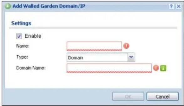
The following table describes the labels in this screen.
Table 255 Configuration > Hotspot > Walled Garden: Domain/IP Base: Add/Edit
| LABEL DESCRIPTION | |
| Enable Select this to activate the entry. | |
| Name | Enter a descriptive name for the walled garden link.You can use up to 31 alphanumeric characters (A-Z, a-z, 0-9) and underscores (_). Spaces are also allowed. The first character must be a letter. |
| Type | Select whether you want to create the link by entering a domain name or an IP address. |
| Domain Name / IP Address | If you select Domain, type a Fully-Qualified Domain Name (FQDN) of a web site. An FQDN starts with a host name and continues all the way up to the top-level domain name. For example, www.zyxel.com.tw is a fully qualified domain name, where “www” is the host, “zyxel” is the third-level domain, “com” is the second-level domain, and “tw” is the top level domain.Underscores are not allowed. Use “*.” as a prefix in the FQDN for a wildcard domain name (for example, *.example.com).If you select IP, enter the IP address and subnet mask of the web site. |
| OK | Click OK to save your changes back to the Zyxel Device. |
| Cancel | Click Cancel to exit this screen without saving. |
29.4.2 Walled Garden Login Example
The following figure shows the user login screen with two walled garden links. The links are named WalledGardenLink1 through 2 for demonstration purposes.
Figure 460 Walled Garden Login Example
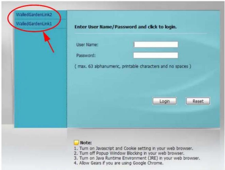
CHAPTER 30
Advertisement Screen
30.1 Advertisement Overview
Use this screen to set the Zyxel Device to display an advertisement web page as the first web page whenever the user connects to the Internet.
Click Configuration > Hotspot > Advertisement to display the screen.
Figure 461 Configuration > Hotspot > Advertisement
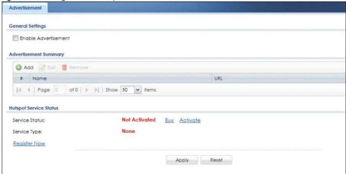
The following table gives an overview of the objects you can configure.
Table 256 Configuration > Hotspot > Advertisement
| LABEL DESCRIPTION | |
| Enable Advertisement | Select this to turn on the advertisement feature.Note: This feature works only when you enable web authentication. |
| Advertisement Summary | Use this table to manage the list of advertisement web pages. |
| Add | Click this to create a new entry. Select an entry and click Add to create a new entry after the selected entry. |
| Edit | Double-click an entry or select it and click Edit to open a screen where you can modify the entry's settings. |
| Remove | To remove an entry, select it and click Remove. The Zyxel Device confirms you want to remove it before doing so. |
| # This field is a sequential value, and it is not associated with any entry. | |
| Name This field displays the descriptive name of web site. | |
| URL This field displays the address of web site. | |
| Hotspot Service Status | |
| Service Status | This field displays whether a service license is enabled at myZyxel (Activated) or not (Not Activated) or expired (Expired). It displays the remaining Grace Period if your license has Expired. It displays Not Licensed if there isn't a license to be activated for this service.If you need a license or a trial license has expired, click Buy to buy a new one. If a Standard license has expired, click Renew to extend the license.Then, click Activate to connect with the myZyxel server to activate the new license. |
| Service Type | This shows whether you have a trial or standard license or none (Trial, Standard, None). |
| Expiration Date | This shows when your hotspot license will expire. |
| Register Now | Click the link to go to myZyxel where you can register your Zyxel Device and activate the service.This link is available only when the service is not activated yet. |
| Apply | Click this button to save your changes to the Zyxel Device. |
| Reset Click this button to return the screen to its last-saved settings. | |
30.1.1 Adding/Editing an Advertisement URL
Click Configuration > Hotspot > Advertisement and then the Add (or Edit) icon in the Advertisement Summary section to open the Add/Edit Advertisement URL screen. Use this screen to configure an advertisement address entry.
Note: You can create up to 20 advertisement URL entries. The Zyxel Device randomly picks one and open the specified web site in a new frame when an authenticated user is attempts to access the Internet.
Figure 462 Configuration > Hotspot > Advertisement > Add/Edit
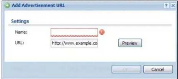
The following table gives an overview of the objects you can configure.
Table 257 Configuration > Hotspot > Advertisement > Add/Edit
| LABEL DESCRIPTION | |
| Name | Enter a descriptive name for the advertisement web site.You can use up to 31 alphanumeric characters (A-Z, a-z, 0-9) and underscores (_). Spaces are not allowed. The first character must be a letter. |
| URL Enter the URL or IP address of the web site.Use "http://" followed by up to 262 characters (0-9a-zA-Z;/?:@&+$\._!~*')%). For example, http://www.example.com or http://172.16.1.35. | |
| Preview | Click this button to open the specified web site in a new frame. |
| OK | Click OK to save your changes back to the Zyxel Device. |
| Cancel | Click Cancel to exit this screen without saving. |
CHAPTER 31
Security Policy
31.1 Overview
A security policy is a template of security settings that can be applied to specific traffic at specific times. The policy can be applied:
• to a specific direction of travel of packets (from / to)
• to a specific source and destination address objects
• to a specific type of traffic (services)
• to a specific user or group of users
• at a specific schedule
Note: Make sure to choose the correct direction of traffic for the security policy.
The policy can be configured:
• to allow or deny traffic that matches the criteria above
- send a log or alert for traffic that matches the criteria above
- to apply the actions configured in the profiles (application patrol, content filter, IPS, anti-malware, email security) to traffic that matches the criteria above
Note: Security policies can be applied to both IPv4 and IPv6 traffic.
The security policies can also limit the number of user sessions.
The following example shows the Zyxel Device's default security policies behavior for a specific direction of travel of packets. WAN to LAN traffic and how stateful inspection works. A LAN user can initiate a Telnet session from within the LAN zone and the Zyxel Device allows the response. However, the Zyxel Device blocks incoming Telnet traffic initiated from the WAN zone and destined for the LAN zone.
Figure 463 Default Directional Security Policy Example
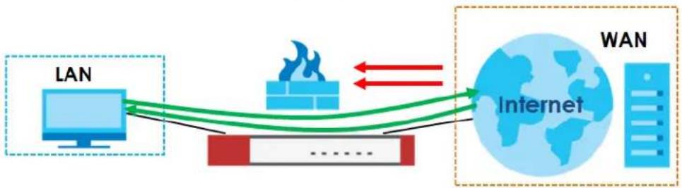
flowchart
graph LR
    A["LAN"] --> B["Internet"]
    B --> C["WAN"]
    B --> D["Data Flow Arrow"]
    D --> A
    style A fill:#f9f,stroke:#333
    style B fill:#ccf,stroke:#333
    style C fill:#cfc,stroke:#333
    style D fill:#fcc,stroke:#333
31.2 One Security
OneSecurity is a website with guidance on configuration walkthroughs, troubleshooting, and other information. This is an example of a port forwarding configuration walkthrough.
Figure 464 Example of a Port Forwarding Configuration Walkthrough.
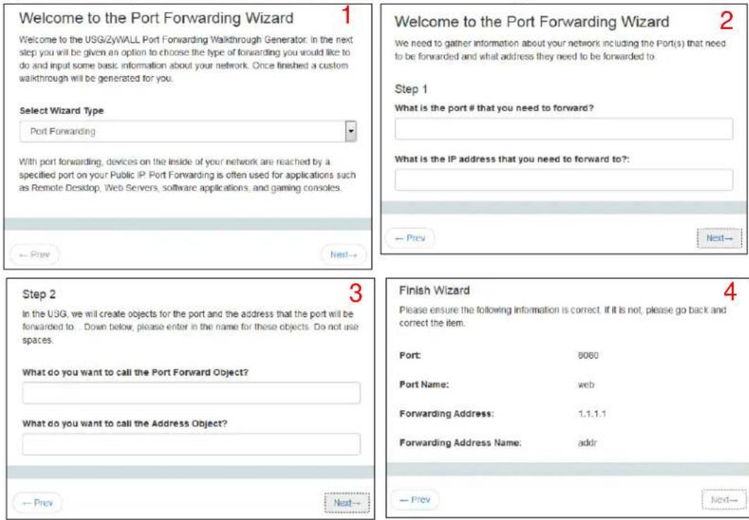
This is an example of L2TP over IPSec VPN Troubleshooting troubleshooting.
Figure 465 Example of L2TP over IPSec Troubleshooting - 1
L2TP over IPSec VPN Troubleshooting
Is the VPN established?
Yes 1
No - I receive an error 2
My connection is intermittent 3
No Connection
2
Common Configuration Issues
- Verify that the USG has default settings for the Default_LTCP_VPN rules in the IPSec VPN menu
- VPN Gateway ensure your settings match below. You will also need to click the Show Advanced Settings option at the top:
Phase 1 Settings
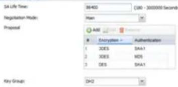
Key Group
NAT Traversal
Dead Peer Detection (DPO)
Please note that you will not be able to establish the L2TP connection if your WAN connection is assigned a private IP. You must have a public IP address assigned directly to the WAN port.
- VPN Connection, ensure your settings match below. You will also need to click the Show Advanced Settings option at the top;
Phase 2 Setting
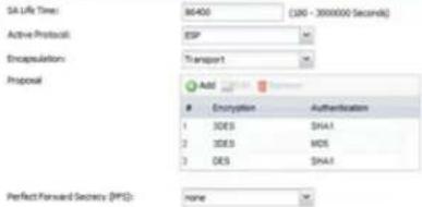
You will need to create an address object for your WAN (outside/public) IP, and select this object for the Local Policy;
• Alternatively you can SSH into the USB and issue a series of commands to default the LCTP Settings;
Once you have the session established you#TM need to enter #configure terminal## and press enter. Then type the command #12p-over-ipsec recover default-ipsec-policy## to default the rules.
- Verify the firewall is setup properly to allow traffic from IPSec zone to allany).
Logs To Look For
• LZIP Connected
• LOTP Disconnected
• Incorrect username/password
• No proposal chose
• Phase 1 proposal mismatch
- Incorrect PSK
Go Back To Start
Figure 466 Example of L2TP over IPSec Troubleshooting - 2
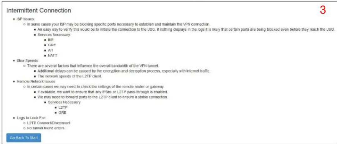
In the Zyxel Device, you will see icons that link to OneSecurity walkthroughs, troubleshooting and so on in certain screens.
For example, at the time of writing, these are the OneSecurity icons you can see.
Table 258 OneSecurity Icons
| ONESECURITY ICON SCREEN | |
  | Click this icon to go to a series of screens that guide you how to configure the feature. Note that the walkthroughs do not perform the actual configuring, but just show you how to do it.Device HA > GeneralLicensing > RegistrationNetwork > NATNetwork > Routing > Policy RouteSecurity Service > Content FilterV P N > I P S e c V P NV P N> S S L V P NV P N> L 2 T P V P N |
  | Click this icon to go to a series of screens that guide you how to fix problems with the feature.Device HA > GeneralNetwork > NATNetwork > Routing > Policy RouteSecurity Service > Content FilterV P N > I P S e c V P NV P N> S S L V P NV P N> L 2 T P V P N |
[8D26]  | Click this icon for more information on Application Patrol, which identifies traffic that passes through the Zyxel Device, so you can decide what to do with specific types of traffic. Traffic not recognized by application patrol is ignored.Security Service > Application Patrol |
[0D8A]  | Click this icon for more information on Content Filter, which controls access to specific web sites or web content.Security Service > Content Filter |
| [ZXBC]VPN | Click this icon for more information on IPSec and SSL VPN. Internet Protocol Security (IPSec) VPN connects IPSec routers or remote users using IPSec client software. SSL VPN allows users to use a web browser for secure remote user login without need of a VPN router or VPN client software.V P N > I P S e c V P NV P N> S S L V P N |
 DownloadVPN Client DownloadVPN Client | Click this icon to download VPN client software.V P N > I P S e c V P NV P N> S S L V P N |
| [AKKB]Wireless APController | Click this icon for more information on the Wireless AP Controller which sets how the Zyxel Device allows APs to connect to the wireless network.Wireless > AP Management > Mgmt. AP List |
31.3 What You Can Do in this Chapter
- Use the Security Policy Control screens (Section 31.4 on page 685) to enable or disable policies, asymmetrical routes, and manage and configure policies.
- Use the Anomaly Detection and Prevention (ADP) screens (Section 31.5 on page 697) to detect traffic with protocol anomalies and take appropriate action.
- Use the Session Control screens (see Section 31.6 on page 707) to limit the number of concurrent NAT/security policies traffic sessions a client can use.
31.3.1 What You Need to Know
Stateful Inspection
The Zyxel Device uses stateful inspection in its security policies. The Zyxel Device restricts access by screening data packets against defined access rules. It also inspects sessions. For example, traffic from one zone is not allowed unless it is initiated by a computer in another zone first.
Zones
A zone is a group of interfaces. Group the Zyxel Device's interfaces into different zones based on your needs. You can configure security policies for data passing between zones or even between interfaces.
Default Directional Security Policy Behavior
Security Policies can be grouped based on the direction of travel of packets to which they apply. Here is the The Zyxel Device has default Security Policy behavior for traffic going through the Zyxel Device in various directions.
Table 259 Directional Security Policy Behavior
| FROM ZONE TO ZONE BEHAVIOR | |
| From any to Device | DHCP traffic from any interface to the Zyxel Device is allowed. |
| From LAN1 to any (other than the Zyxel Device) | Traffic from the LAN1 to any of the networks connected to the Zyxel Device is allowed. |
| From LAN2 to any (other than the Zyxel Device) | Traffic from the LAN2 to any of the networks connected to the Zyxel Device is allowed. |
| From LAN1 to Device Traffic from | the LAN1 to the Zyxel Device itself is allowed. |
| From LAN2 to Device Traffic from | the LAN2 to the Zyxel Device itself is allowed. |
| From WAN to Device | The default services listed inTo-Device Policiesare allowed from the WAN to the Zyxel Device itself. All other WAN to Zyxel Device traffic is dropped. |
| From any to any | Traffic that does not match any Security policy is dropped. This includes traffic from the WAN to any of the networks behind the Zyxel Device.This also includes traffic to or from interfaces that are not assigned to a zone (extra-zone traffic). |
To-Device Policies
Policies with Device as the To Zone apply to traffic going to the Zyxel Device itself. By default:
- The Security Policy allows only LAN, or WAN computers to access or manage the Zyxel Device.
- The Zyxel Device allows DHCP traffic from any interface to the Zyxel Device.
- The Zyxel Device drops most packets from the WAN zone to the Zyxel Device itself and generates a log except for AH, ESP, GRE, HTTPS, IKE, NATT.
When you configure a Security Policy rule for packets destined for the Zyxel Device itself, make sure it does not conflict with your service control rule. The Zyxel Device checks the security policy before the service control rules for traffic destined for the Zyxel Device.
A From Any To Device direction policy applies to traffic from an interface which is not in a zone.
Global Security Policies
Security Policies with from any and/or to any as the packet direction are called global Security Policies. The global Security Policies are the only Security Policies that apply to an interface that is not included in a zone. The from any policies apply to traffic coming from the interface and the to any policies apply to traffic going to the interface.
Security Policy Rule Criteria
The Zyxel Device checks the schedule, user name (user's login name on the Zyxel Device), source IP address and object, destination IP address and object, IP protocol type of network traffic (service) and Security Service profile criteria against the Security Policies (in the order you list them). When the traffic matches a policy, the Zyxel Device takes the action specified in the policy.
User Specific Security Policies
You can specify users or user groups in Security Policies. For example, to allow a specific user from any computer to access a zone by logging in to the Zyxel Device, you can set up a policy based on the user name only. If you also apply a schedule to the Security Policy, the user can only access the network at the scheduled time. A user-authentication Security Policy is activated whenever the user logs in to the Zyxel Device and will be disabled after the user logs out of the Zyxel Device.
Session Limits
Accessing the Zyxel Device or network resources through the Zyxel Device requires a NAT session and corresponding Security Policy session. Peer to peer applications, such as file sharing applications, may use a large number of NAT sessions. A single client could use all of the available NAT sessions and prevent others from connecting to or through the Zyxel Device. The Zyxel Device lets you limit the number of concurrent NAT/Security Policy sessions a client can use.
31.4 The Security Policy Screen
Asymmetrical Routes
If an alternate gateway on the LAN has an IP address in the same subnet as the Zyxel Device's LAN IP address, return traffic may not go through the Zyxel Device. This is called an asymmetrical or "triangle" route. This causes the Zyxel Device to reset the connection, as the connection has not been acknowledged.
You can have the Zyxel Device permit the use of asymmetrical route topology on the network (not reset the connection). However, allowing asymmetrical routes may let traffic from the WAN go directly to the LAN without passing through the Zyxel Device. A better solution is to use virtual interfaces to put the Zyxel Device and the backup gateway on separate subnets. Virtual interfaces allow you to partition your network into logical sections over the same interface. See the chapter about interfaces for more information.
By putting LAN 1 and the alternate gateway (A in the figure) in different subnets, all returning network traffic must pass through the Zyxel Device to the LAN. The following steps and figure describe such a scenario.
1 A computer on the LAN1 initiates a connection by sending a SYN packet to a receiving server on the WAN.
2 The Zyxel Device reroutes the packet to gateway A, which is in Subnet 2.
3 The reply from the WAN goes to the Zyxel Device.
4 The Zyxel Device then sends it to the computer on the LAN1 in Subnet 1.
Figure 467 Using Virtual Interfaces to Avoid Asymmetrical Routes
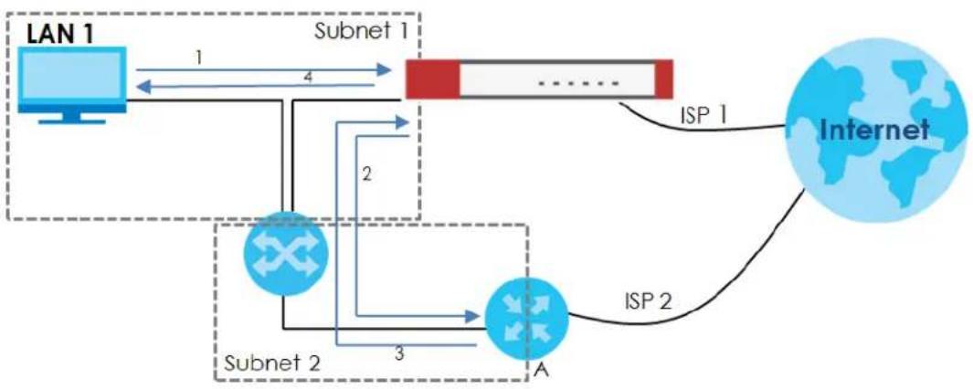
flowchart
graph TD
    A["LAN 1"] -->|1| B["Subnet 1"]
    B --> C["Internet"]
    C -->|ISP 2| D["A"]
    D -->|ISP 1| B
    B -->|2| E["Subnet 2"]
    E -->|3| D
    style A fill:#cce5ff,stroke:#333
    style B fill:#ffcccc,stroke:#333
    style C fill:#ffffff,stroke:#333
    style D fill:#0066cc,stroke:#333
    style E fill:#0066cc,stroke:#333
31.4.1 Configuring the Security Policy Control Screen
Click Configuration > Security Policy > Policy Control to open the Security Policy screen. Use this screen to enable or disable the Security Policy and asymmetrical routes, set a maximum number of sessions per host, and display the configured Security Policies. Specify from which zone packets come and to which zone packets travel to display only the policies specific to the selected direction. Note the following.
- Besides configuring the Security Policy, you also need to configure NAT rules to allow computers on the WAN to access LAN devices.
- The Zyxel Device applies NAT (Destination NAT) settings before applying the Security Policies. So for example, if you configure a NAT entry that sends WAN traffic to a LAN IP address, when you configure a corresponding Security Policy to allow the traffic, you need to set the LAN IP address as the destination.
- The ordering of your policies is very important as policies are applied in sequence.
The following screen shows the Security Policy summary screen.
Figure 468 Configuration > Security Policy > Policy Control
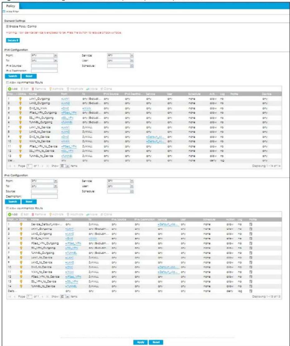
The following table describes the labels in this screen.
Table 260 Configuration > Security Policy > Policy Control
| LABEL DESCRIPTION | |
| Show Filter/Hide Filter | Click Show Filter to display IPv4 and IPv6 (if enabled) security policy search filters. |
| General Settings | Enable or disable the Security Policy feature on the Zyxel Device. |
| Enable Policy Control | Select this to activate Security Policy on the Zyxel Device to perform access control. |
| Secure it | You have a WAN_to_Device rule that allows traffic such as HTTP, HTTPS, SSL and so on to access to your Zyxel Device from any IPv4 source on the WAN. Click this button to secure WAN_to_Device traffic. See Section 1.8.2 on page 46 for more information. |
| IPv4 / IPv6 Configuration | Use IPv4 / IPv6 search filters to find specific IPv4 and IPv6 (if enabled) security policies based on direction, application, user, source, destination and/or schedule. |
| From / To | Select a zone to view all security policies from a particular zone and/or to a particular zone.any means all zones. |
| IPv4 / IPv6 Source | Type an IPv4 or IPv6 IP address to view all security policies based on the IPv4 / IPv6 source address object used.An IPv4 IP address is written as four integer blocks separated by periods. This is an example IPv4 address: 172.16.6.7.An 128-bit IPv6 address is written as eight 16-bit hexadecimal blocks separated by colons (:). This is an example IPv6 address: 2001:0db8:1a2b:0015:0000:0000:1a2f:0000. |
| IPv4 / IPv6 Destination | Type an IPv4 or IPv6 IP address to view all security policies based on the IPv4 / IPv6 destination address object used.An IPv4 IP address is written as four integer blocks separated by periods. This is an example IPv4 address: 172.16.6.7.An 128-bit IPv6 address is written as eight 16-bit hexadecimal blocks separated by colons (:). This is an example IPv6 address: 2001:0db8:1a2b:0015:0000:0000;1a2f:0000. |
| Service View all security policies based the service object used. | |
| User View all security policies based on user or user group object used. | |
| Schedule View all security policies based on the schedule object used. | |
| IPv4/IPv6 Policy Management | Use the following items to manage IPv4 and IPv6 policies. |
| Allow Asymmetrical Route | If an alternate gateway on the LAN has an IP address in the same subnet as the Zyxel Device's LAN IP address, return traffic may not go through the Zyxel Device. This is called an asymmetrical or "triangle" route. This causes the Zyxel Device to reset the connection, as the connection has not been acknowledged.Select this check box to have the Zyxel Device permit the use of asymmetrical route topology on the network (not reset the connection).Note: Allowing asymmetrical routes may let traffic from the WAN go directly to the LAN without passing through the Zyxel Device. A better solution is to use virtual interfaces to put the Zyxel Device and the backup gateway on separate subnets. |
| Add | Click this to create a new entry. Select an entry and click Add to create a new entry after the selected entry. |
| Edit | Double-click an entry or select it and click Edit to open a screen where you can modify the entry's settings. |
| Remove | To remove an entry, select it and click Remove. The Zyxel Device confirms you want to remove it before doing so. |
| Activate | To turn on an entry, select it and click Activate. |
| Inactivate | To turn off an entry, select it and click Inactivate. |
| Move | To change a policy's position in the numbered list, select the policy and click Move to display a field to type a number for where you want to put that policy and press [ENTER] to move the policy to the number that you typed.The ordering of your policies is important as they are applied in order of their numbering. |
| Clone | Use Clone to create a new entry by modifying an existing one.Select an existing entry.Click Clone, type a number where the new entry should go and then press [ENTER].A configuration copy of the selected entry pops up. You must at least change the name as duplicate entry names are not allowed. |
| The following read-only fields summarize the policies you have created that apply to traffic traveling in the selected packet direction. | |
| Priority | This is the position of your Security Policy in the global policy list (including all through-Zyxel Device and to-Zyxel Device policies). The ordering of your policies is important as policies are applied in sequence. Default displays for the default Security Policy behavior that the Zyxel Device performs on traffic that does not match any other Security Policy. |
| Status This icon is lit | when the entry is active and dimmed when the entry is inactive. |
| Name This is the name of the Security policy. | |
| From / To | This is the direction of travel of packets. Select from which zone the packets come and to which zone they go.Security Policies are grouped based on the direction of travel of packets to which they apply. For example, from LAN to LAN means packets traveling from a computer or subnet on the LAN to either another computer or subnet on the LAN.From any displays all the Security Policies for traffic going to the selected To Zone.To any displays all the Security Policies for traffic coming from the selected From Zone.From any to any displays all of the Security Policies.To ZyWALL policies are for traffic that is destined for the Zyxel Device and control which computers can manage the Zyxel Device. |
| IPv4 / IPv6 Source | This displays the IPv4 / IPv6 source address object, including geographic address and FQDN (group) objects, to which this Security Policy applies. |
| IPv4 / IPv6 Destination | This displays the IPv4 / IPv6 destination address object, including geographic address and FQDN (group) objects, to which this Security Policy applies. |
| Service | This displays the service object to which this Security Policy applies. |
| User | This is the user name or user group name to which this Security Policy applies. |
| Schedule | This field tells you the schedule object that the policy uses. none means the policy is active at all times if enabled. |
| Action | This field displays whether the Security Policy silently discards packets without notification (deny), permits the passage of packets (allow) or drops packets with notification (reject) |
| Log | Select whether to have the Zyxel Device generate a log (log), log and alert (log alert) or not (no) when the policy is matched to the criteria listed above. |
| Profile | This field shows you which Security Service profiles (application patrol, content filter, IPS, anti-malware, email security) apply to this Security policy. Click an applied Security Service profile icon to edit the profile directly. |
| Apply | Click Apply to save your changes back to the Zyxel Device. |
| Reset | Click Reset to return the screen to its last-saved settings. |
31.4.2 The Security Check for Web Interface Screen
Click the Secure It button to show the following screen. Use this screen to configure settings to secure your Zyxel Device. You can configure:
- Secure SSL access from the Internet to the Zyxel Device.
- Secure SSL access from the Internet to the network behind the Zyxel Device.
- The default port that IPSec VPN clients use to retrieve VPN rule settings from the Zyxel Device.
- The default port for two-factor authentication for VPN clients to access the network behind the Zyxel Device.
See Section 1.8.2 on page 46 for more information.
Figure 469 Configuration > Security Policy > Policy Control > Secure It > Security Check for Web Interface
![Security Check for Web Interface You have a rule that allows anyone from the Internet to access the Device web configurator and SSL VPN service. To reduce risk, please restrict access by source IP address and geolocation respectively. Strongly suggest to update your device and change passwords regularly. ■ Restrict Device management from the WAN Port: 443 (1...65535) Restrict access only to trusted host Trusted Host 1: [IP or FQDN] Trusted Host 2: [IP or FQDN] (Optional) Trusted Host 3: [IP or FQDN] (Optional) ■ Restrict SSL VPN access from the WAN Port: 443 (1...65535) Restrict access by GealP Trusted Geolocation 1: [Optional] Trusted Geolocation 2: [Optional] Trusted Geolocation 3: [Optional] ■ Change Two-Factor Authentication Port Port: 8008 (1...65535) ■ Change the Zyxel IPSec VPN Client Provisioning Port Port: 443 (1...65535) Please remind me: every time OK Cancel](/content/2026/05/878280/images/e1c910d3f8f6ec0eccbcd2134766b309d70b4c6594345929dd0f97f292433202.jpg)
The following table describes the labels in this screen.
Table 261 Security Check for Web Interface
| LABEL DESCRIPTION | |
| Allow secure remote management from WAN | Select this to allow access to the Zyxel Device remotely only from specified IP addresses or Fully Qualified Domain Names (FQDNs), such as 1.1.1.1 or www.zyxel.com. See Section 1.8.2.1 on page 47 for more information. |
| Port Configure a new port between | 1024 to 65535 to use it to access the web configurator. Do not use a port number that has been used.For example, use https://1.1.1.1:8800 if you changed the default HTTPS port to 8800. |
| Trusted Host 1-3 | Configure the IP addresses or FQDNs that are allowed to access the Zyxel Device. |
| Allow SSL VPN access from WAN | Select this to allow SSL VPN clients to access the Zyxel Device only from specified regions. See Section 1.8.2.2 on page 47 for more information. |
| Port Configure a new port between | 1024 to 65535 to use it to access the web configurator using SSL VPN. Do not use a port number that has been used.The port you configure here must be the same as the port you use in SecuExtender. See Section 1.8.2.2 on page 47 for more information on SecuExtender. |
| Trusted Geolocation 1-3 | Select the regions that are allowed to access the Zyxel Device from the drop-down list box. |
| Change Two-Factor Authentication Port | Select this to change the port VPN clients use to access the Zyxel Device LAN with two-factor authentication. See Section 1.8.2.4 on page 48 for more information.Configure a new port between 1024 to 65535. Do not use a port number that has been used. |
| Change Zyxel IPSec VPN Client Provisioning Port | Select this to change the port IPSec VPN clients use to retrieve VPN rule settings from the Zyxel Device. See Section 1.8.2.3 on page 48 for more information.Configure a new port between 1024 to 65535. Do not use a port number that has been used.The port you configure here must be the same as the port you use when logging in as a Zyxel IPSec VPN client. |
| Please remind me | Select how often to display the screen from the drop-down list box. |
| OK | Click OK to save your changes back to the Zyxel Device. |
| Cancel | Click Cancel to exit this screen without saving your changes. |
31.4.3 The Security Policy Control Add/ Edit Screen
In the Security Policy Control screen, click the Edit or Add icon to display the Security Policy Edit or Add screen.
Figure 470 Configuration > Security Policy > Policy Control > Add
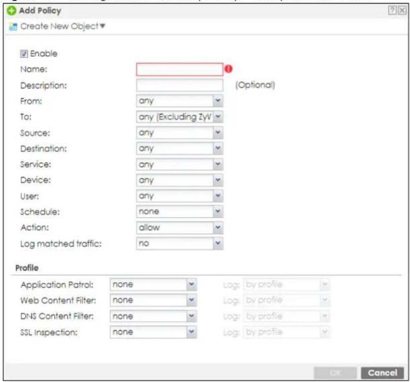
The following table describes the labels in this screen.
Table 262 Configuration > Security Policy > Policy Control > Add
| LABEL DESCRIPTION | |
| Create new Object | Use to configure any new settings objects that you need to use in this screen. |
| Enable Select this | check box to activate the Security policy. |
| Name | Type a name with 1 to 30 single-byte characters to identify the policy, including a-zA-Z.0-9!"#%&'()*+,-./::<=>?@[\]^_' and spaces are not allowed. |
| Description | Enter a descriptive name of 1 to 63 single-byte characters for the Policy, including spaces and 0-9a-zA-Z!"#%()*+,-./::=?@_.&.<>[\]^{'{} are not allowed. |
| From To | For through-Zyxel Device policies, select the direction of travel of packets to which the policy applies.any means all interfaces.Device means packets destined for the Zyxel Device itself. |
| Source | Select an IPv4 / IPv6 address or address group object, including geographic address and FQDN (group) objects, to apply the policy to traffic coming from it. Selectanyto apply the policy to all traffic coming from IPv4 / IPv6 addresses. |
| Destination | Select an IPv4 / IPv6 address or address group, including geographic address and FQDN (group) objects, to apply the policy to traffic going to it. Selectanyto apply the policy to all traffic going to IPv4 / IPv6 addresses. |
| Service Select a service or service group from the drop-down list box. | |
| Device | Select a profile you created inConfiguration>Object>Device Insightto apply the policy to clients specified in the Device Insight profile from the drop-down list box. Selectanyto apply the policy to all clients. |
| User | This field is not available when you are configuring a to-Zyxel Device policy.Select a user name or user group to which to apply the policy. The Security Policy is activated only when the specified user logs into the system and the policy will be disabled when the user logs out.Otherwise, selectanyand there is no need for user logging.Note: If you specified a source IP address (group) instead ofanyin the field below, the user's IP address should be within the IP address range. |
| Schedule | Select a schedule that defines when the policy applies. Otherwise, selectnoneand the policy is always effective. |
| Action | Use the drop-down list box to select what the Security Policy is to do with packets that match this policy.Selectdenyto silently discard the packets without sending a TCP reset packet or an ICMP destination-unreachable message to the sender.Selectrejectto discard the packets and send a TCP reset packet or an ICMP destination-unreachable message to the sender.Selectallowto permit the passage of the packets. |
| Log matched traffic | Select whether to have the Zyxel Device generate a log(log), log and alert(log alert) or not(no) when the policy is matched to the criteria listed above. |
| Profile | Use this section to apply anti- x profiles (created in theConfiguration > Security Service screens) to traffic that matches the criteria above. You must have created a profile first; otherwisenone displays.UseLogto generate a log (log), log and alert (log alert) or not (no) for all traffic that matches criteria in the profile. |
| Application Patrol | Select an Application Patrol profile from the list box;nonedisplays if no profiles have been created in theConfiguration > Security Service > App Patrol screen. |
| Content Filter | Select a Content Filter profile from the list box;nonedisplays if no profiles have been created in theConfiguration > Security Service > Content Filter screen. |
| SSL Inspection | Select an SSL Inspection profile from the list box;nonedisplays if no profiles have been created in theConfiguration > Security Service > SSL Inspection screen. |
| OK | ClickOKto save your customized settings and exit this screen. |
| Cancel | ClickCancelto exit this screen without saving. |
31.4.4 Example: Allow a Server to Ping the Zyxel Device Without Creating Logs
A server on the LAN pings the Zyxel Device every 15 seconds to check if the Zyxel Device is connected to the Internet. The Zyxel Device creates a log every time the server pings it. You want to allow the server to ping the Zyxel Device without creating so many logs.
This example uses the parameters given below.
Table 263 Address Object Configuration Example
| NAME ADDRESS TYPE IP ADDRESS | ||
| Server Host 2.2.2.2 |
Table 264 Security Policy Configuration Example
| NAME SOURCE SERVICE ACTION LOG | ||||
| LAN1_to_Device | Server | Ping | Allow | No |
| LAN2_to_Device | Server | Ping | Allow | No |
1 Go to Configuration > Object > Address/Geo IP > Address and click Add.
2 Configure the settings using the parameters given in Table 263 on page 693. Click OK to save your changes.
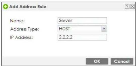
3 Go to Configuration > Security Policy > Policy Control. Select LAN1_to_Device then click Edit.
4 Configure the settings using the parameters given in Table 264 on page 693. Set Log to no so when the server pings the Zyxel Device, the Zyxel Device will not create logs. Click OK to save your changes.
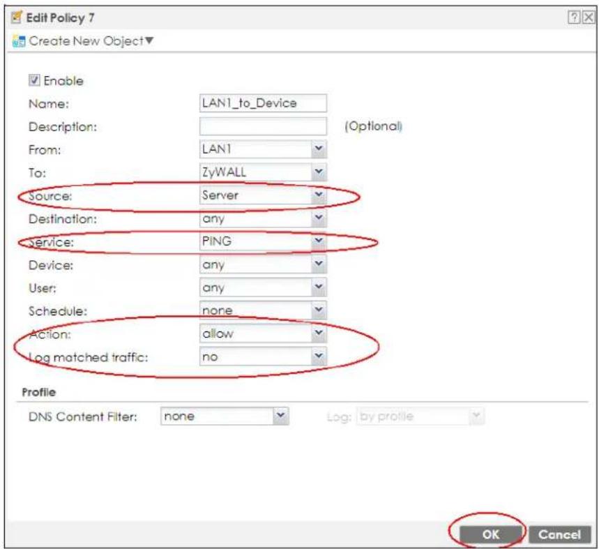
5 Repeat Step 3 and Step 4 to configure the LAN2_to_Device policy so that when the sever pings the Zyxel Device, the Zyxel Device will not create logs.
31.4.5 Example: Create a Guest Network with Internet Access Only
The Zyxel Device LAN1 is your private network. LAN1 clients have access to all resources in the network, such as private servers, as well as access to the Internet. You want to create a guest network on LAN2 where clients can connect to only the Internet through the Zyxel Device. Clients on LAN2 cannot access your private network on LAN1.
This example uses the parameters given below.
Table 265 Guest Network Policy Example
| NAME FROM TO ACTION | ||
| LAN2_To_LAN1 ALN2 LAN1 reject |
1 Go to Configuration > Network > Interface > Port > Port Role. Set Ian2 (LAN2) to use P5. Click Apply to save your changes. Connect LAN1 clients to P3 and guest clients to P5.
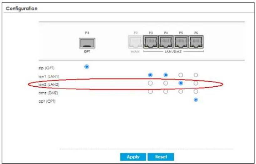
2 In Configuration > Security Policy > Policy Control, select LAN2_Outgoing and click Edit. Set To to WAN to allow LAN2 clients to access the Internet. Click OK to save your changes.
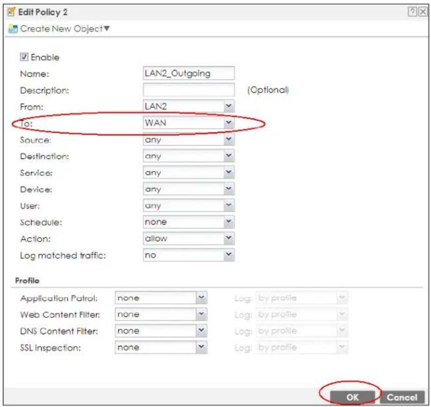
3 In Configuration > Security Policy > Policy Control, click Add to add a new rule. Configure the settings using the parameters given in Table 265 on page 694 to block LAN2 clients from accessing LAN1 and it resources. Click OK to save your changes.
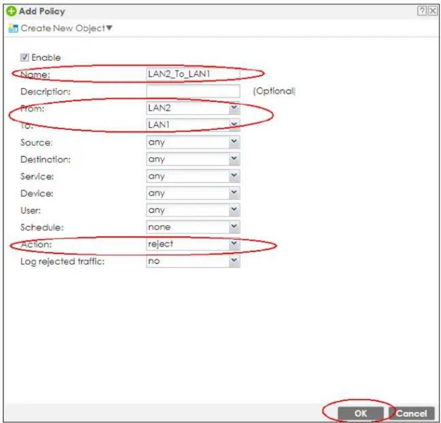
4 You can check the result in the Policy Control screen. Clients on LAN2 can now access the Internet through the Zyxel Device without accessing the private network on LAN1.
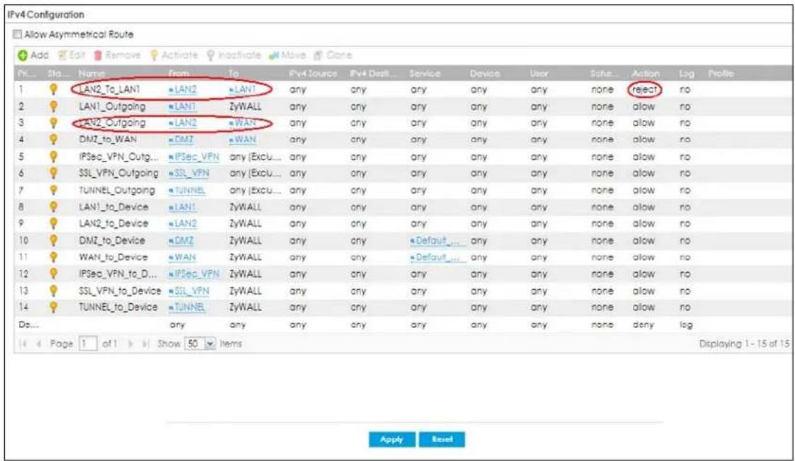
31.5 Anomaly Detection and Prevention Overview
Anomaly Detection and Prevention (ADP) protects against anomalies based on violations of protocol standards (RFCs – Requests for Comments) and abnormal flows such as port scans. This section introduces ADP, anomaly profiles and applying an ADP profile to a traffic direction.
Traffic Anomalies
Traffic anomaly policies look for abnormal behavior or events such as port scanning, sweeping or network flooding. They operate at OSI layer-2 and layer-3. Traffic anomaly policies may be updated when you upload new firmware.
Protocol Anomalies
Protocol anomalies are packets that do not comply with the relevant RFC (Request For Comments). Protocol anomaly detection includes:
- TCP Decoder
- UDP Decoder
• ICMP Decoder
Protocol anomaly policies may be updated when you upload new firmware.
Note: First, create an ADP profile in the In the Configuration > Security Policy > ADP > Profile screen. Then, apply the profile to traffic originating from a specific zone in the Configuration > Security Policy > ADP > General screen.
31.5.1 The Anomaly Detection and Prevention General Screen
Click Configuration > Security Policy > ADP > General to display the next screen.
Figure 471 Configuration > Security Policy > ADP > General
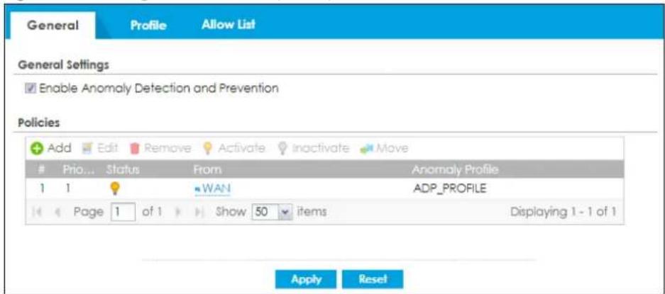
The following table describes the labels in this screen.
Table 266 Configuration > Security Policy > ADP > General
| LABEL DESCRIPTION | |
| General Settings | |
| Enable Anomaly Detection and Prevention | Select this to enable traffic anomaly and protocol anomaly detection and prevention. |
| Add | Select an entry and click Add to append a new row beneath the one selected. ADP policies are applied in order (Priority) shown in this screen |
| Edit Select an entry and click this to be able to modify it. | |
| Remove Select an entry and click this to delete it. | |
| Activate | To turn on an entry, select it and click Activate. |
| Inactivate | To turn off an entry, select it and click Inactivate. |
| Move | To change an entry's position in the numbered list, select it and click Move to display a field to type a number for where you want to put that entry and press [ENTER] to move the entry to the number that you typed. |
| # This is the entry's index number in the list. | |
| Priority | This is the rank in the list of anomaly profile policies. The list is applied in order of priority. |
| Status | The activate (light bulb) icon is lit when the entry is active and dimmed when the entry is inactive. |
| From | This is the direction of travel of packets to which an anomaly profile is bound. Traffic direction is defined by the zone the traffic is coming from.Use the From field to specify the zone from which the traffic is coming. Select ZyWALL to specify traffic coming from the Zyxel Device itself.From LAN means packets traveling from a computer on one LAN subnet to a computer on another subnet via the Zyxel Device's LAN1 zone interfaces. The Zyxel Device does not check packets traveling from a LAN computer to another LAN computer on the same subnet.From WAN means packets that come in from the WAN zone and the Zyxel Device routes back out through the WAN zone.Note: Depending on your network topology and traffic load, applying every packet direction to an anomaly profile may affect the Zyxel Device's performance. |
| Anomaly Profile | An anomaly profile is a set of anomaly policies with configured activation, log and action settings. This field shows which anomaly profile is bound to which traffic direction. Select an ADP profile to apply to the entry's traffic direction. Configure the ADP profiles in the ADP profile screens. |
31.5.2 Creating New ADP Profiles
Create new ADP profiles in the Configuration > Security Policy > ADP > Profile screens.
When creating ADP profiles. you may find that certain policies are triggering too many false positives or false negatives. A false positive is when valid traffic is flagged as an attack. A false negative is when invalid traffic is wrongly allowed to pass through the Zyxel Device. As each network is different, false positives and false negatives are common on initial ADP deployment.
To counter this, you could create a 'monitor profile' that creates logs, but all actions are disabled. Observe the logs over time and try to eliminate the causes of the false alarms. When you're satisfied that
they have been reduced to an acceptable level, you could then create an 'in-line profile' whereby you configure appropriate actions to be taken when a packet matches a policy.
ADP profiles consist of traffic anomaly profiles and protocol anomaly profiles. To create a new profile, select a base profile and then click OK to go to the profile details screen. Type a new profile name, enable or disable individual policies and then edit the default log options and actions.
Click Configuration > Security Policy > ADP > Profile to view the following screen.
Figure 472 Configuration > Security Policy > ADP > Profile
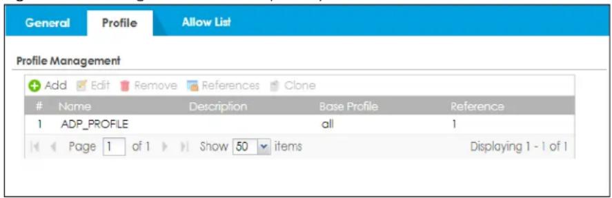
The following table describes the labels in this screen.
Table 267 Configuration > Security Policy > ADP > Profile
| LABEL DESCRIPTION | |
| Profile Management | Create ADP profiles here and then apply them in theConfiguration > Security Policy>ADP > Profilescreen. |
| Add | Click Addand first choose anononeor all Base Profile.nonebase profile sets all ADP entries to haveLogset tonoandActionset tononeby default.allbase profile sets all ADP entries to haveLogset tologandActionset toblockby default. |
| Edit Select an entry and click this to be able to modify it. | |
| Remove Select an entry and click this to delete it. | |
| References | Select an entry and clickReferencesto open a screen that shows which settings usethe entry. ClickRefreshto update information on this screen. |
| Clone | UseCloneto create a new entry by modifying an existing one.Select an existing entry.ClickClone.A configuration copy of the selected entry pops up. You must at least changethe name as duplicate entry names are not allowed. |
| # This is the entry's index number in the list. | |
| Name This is the name of the profile you created. | |
| Description | This is the description of the profile you created. |
| Base Profile This is the name of the base profile used to create this profile. | |
| Reference This is the number of object references used to create this profile. | |
31.5.3 Traffic Anomaly Profiles
Traffic anomaly detection looks for abnormal behavior such as scan or flooding attempts. In the
Table 268 Configuration > Security Policy > ADP > Profile > Add-Traffic-Anomaly
| LABEL DESCRIPTION | |
| Name A name is automatically generated that you can edit. The name must be the same in the Traffic Anomaly and Protocol Anomaly screens for the same ADP profile. You may use 1-31 alphanumeric characters, underscores( ), or dashes (-), but the first character cannot be a number. This value is case-sensitive. These are valid, unique profile names:My ProfilemYProfileMymy12_3-4These are invalid profile names:1 m Y ProfileMy Profile?Whatalongprofilename123456789012 | |
| Description | In addition to the name, type additional information to help you identify this ADP profile. |
| Scan/Flood Detection | Scan detection, such as port scanning, tries to find attacks where an attacker scans device(s) to determine what types of network protocols or services a device supports.Flood detection tries to find attacks that saturate a network with useless data, use up all available bandwidth, and so aim to make communications on the network impossible. |
| Sensitivity | (Scan detection only.) Select a sensitivity level so as to reduce false positives in your network. If you choose low sensitivity, then scan thresholds and sample times are set low, so you will have fewer logs and false positives; however some traffic anomaly attacks may not be detected.If you choose high sensitivity, then scan thresholds and sample times are set high, so most traffic anomaly attacks will be detected; however you will have more logs and false positives. |
| Block Period | Specify for how many seconds the Zyxel Device blocks all packets from being sent to the victim (destination) of a detected anomaly attack. Flood Detection applies blocking to the destination IP address and Scan Detection applies blocking to the source IP address. |
| Edit (Flood Detection only) | Select an entry and click this to be able to modify it. |
| Activate | To turn on an entry, select it and click Activate. |
| Inactivate | To turn off an entry, select it and click Inactivate. |
| Log | To edit an item's log option, select it and use the Log icon. Select whether to have the Zyxel Device generate a log (log), log and alert (log alert) or neither (no) when traffic matches this anomaly policy. |
| Action | To edit what action the Zyxel Device takes when a packet matches a policy, select the policy and use the Action icon none: The Zyxel Device takes no action when a packet matches the policy.block: The Zyxel Device silently drops packets that matches the policy. Neither sender nor receiver are notified. |
| # This is the entry's index number in the list. | |
| Status | The activate (light bulb) icon is lit when the entry is active and dimmed when the entry is inactive. |
| Name | This is the name of the anomaly policy. Click the Name column heading to sort in ascending or descending order according to the protocol anomaly policy name. |
| Log | These are the log options. To edit this, select an item and use the Log icon. |
| Action | This is the action the Zyxel Device should take when a packet matches a policy. To edit this, select an item and use the Action icon. |
| Threshold (pkt/sec) | (Flood detection only.) Select a suitable threshold level (the number of packets per second that match the flood detection criteria) for your network. If you choose a low threshold, most traffic anomaly attacks will be detected, but you may have more logs and false positives.If you choose a high threshold, some traffic anomaly attacks may not be detected, but you will have fewer logs and false positives. |
| OK | Click OK to save your settings to the Zyxel Device, complete the profile and return to the profile summary page. |
| Cancel | Click Cancel to return to the profile summary page without saving any changes. |
| Save | Click Save to save the configuration to the Zyxel Device but remain in the same page. You may then go to the another profile screen (tab) in order to complete the profile. Click OK in the final profile screen to complete the profile. |
Configuration > Security Policy > ADP > Profile screen, click the Edit or Add icon and choose a base profile. Traffic Anomaly is the first tab in the profile.
Figure 473 Configuration > Security Policy > ADP > Profile > Add-Traffic-Anomaly
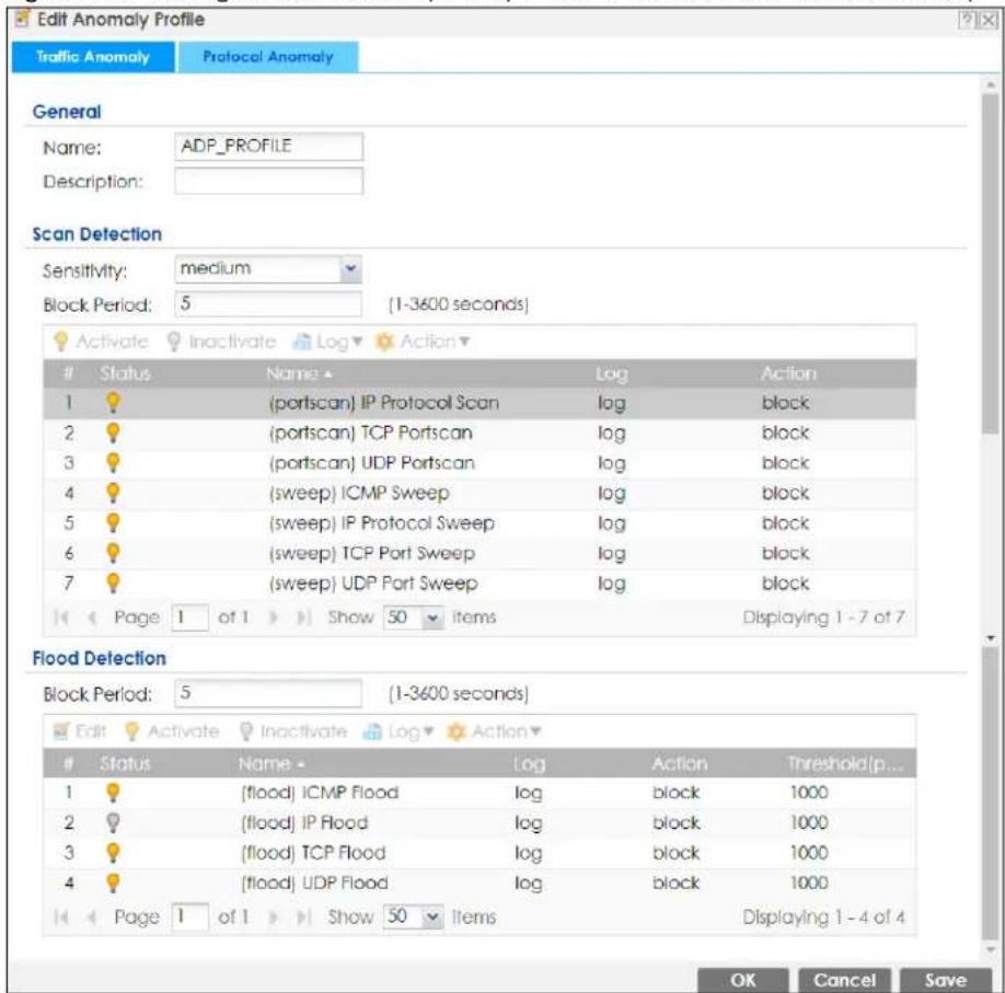
The following table describes the labels in this screen.
31.5.4 Protocol Anomaly Profiles
Protocol anomalies are packets that do not comply with the relevant RFC (Request For Comments). Protocol anomaly detection includes:
- TCP Decoder
- UDP Decoder
• ICMP Decoder - IP Decoder
Teardrop
When an IP packet is larger than the Maximum Transmission Unit (MTU) configured in the Zyxel Device, it is fragmented using the TCP or ICMP protocol.
A Teardrop attack falsifies the offset which defines the size of the fragment and the original packet. A series of IP fragments with overlapping offset fields can cause some systems to crash, hang, or reboot when fragment reassembling is attempted at the destination.
IP Spoofing
IP Spoofing is used to gain unauthorized access to network devices by modifying packet headers so that it appears that the packets originate from a host within a trusted network.
- In an IP Spoof from the WAN, the source address appears to be in the same subnet as a Zyxel Device LAN interface.
- In an IP Spoof from a LAN interface, the source address appears to be in a different subnet from that Zyxel Device LAN interface.
Table 269 Configuration > Security Policy > ADP > Profile > Add-Protocol-Anomaly
| LABEL DESCRIPTION | |
| Name A name is automatically generated that you can edit. The name must be the same in the Traffic Anomaly and Protocol Anomaly screens for the same ADP profile. You may use 1-31 alphanumeric characters, underscores(_, or dashes (-), but the first character cannot be a number. This value is case-sensitive. These are valid, unique profile names:My ProfileMYProfileMymy12_3-4These are invalid profile names:I m Y P ro f i eMy Profile?Whatalongprofilename123456789012 | |
| Description | In addition to the name, type additional information to help you identify this ADP profile. |
| TCP Decoder/UDP Decoder/ICMP Decoder/IP Decoder | Perform the following actions for each type of encoder. |
| Activate | To turn on an entry, select it and clickActivate. |
| Inactivate | To turn off an entry, select it and click Inactivate. |
| Log | To edit an item's log option, select it and use the Log icon. Select whether to have the Zyxel Device generate a log (log), log and alert (log alert) or neither (no) when traffic matches this anomaly policy. |
| Action | To edit what action the Zyxel Device takes when a packet matches a policy, select the policy and use theActionicon.original setting: Select this action to return each rule in a service group to its previously saved configuration none: Select this action to have the Zyxel Device take no action when a packet matches a policy.drop: Select this action to have the Zyxel Device silently drop a packet that matches a policy. Neither sender nor receiver are notified,reject-sender: Select this action to have the Zyxel Device send a reset to the sender when a packet matches the policy. If it is a TCP attack packet, the Zyxel Device will send a packet with a 'RST' flag. If it is an ICMP or UDP attack packet, the Zyxel Device will send an ICMP unreachable packet,reject-receiver: Select this action to have the Zyxel Device send a reset to the receiver when a packet matches the policy. If it is a TCP attack packet, the Zyxel Device will send a packet with an a 'RST' flag. If it is an ICMP or UDP attack packet, the Zyxel Device will do nothing,reject-both: Select this action to have the Zyxel Device send a reset to both the sender and receiver when a packet matches the policy. If it is a TCP attack packet, the Zyxel Device will send a packet with a 'RST' flag to the receiver and sender. If it is an ICMP or UDP attack packet, the Zyxel Device will send an ICMP unreachable packet. |
| # This is the entry's index number in the list. | |
| Status | The activate (light bulb) icon is lit when the entry is active and dimmed when the entry is inactive. |
| Name | This is the name of the anomaly policy. Click theNamecolumn heading to sort in ascending or descending order according to the protocol anomaly policy name. |
| Log | These are the log options. To edit this, select an item and use theLogicon. |
| Action | This is the action the Zyxel Device should take when a packet matches a policy. To edit this, select an item and use theActionicon. |
| OK | ClickOKto save your settings to the Zyxel Device, complete the profile and return to the profile summary page. |
| Cancel | ClickCancelto return to the profile summary page without saving any changes. |
| Save | ClickSaveto save the configuration to the Zyxel Device but remain in the same page. You may then go to the another profile screen (tab) in order to complete the profile. ClickOKin the final profile screen to complete the profile. |
Figure 474 Configuration > Security Policy > ADP > Profile > Add-Protocol-Anomaly
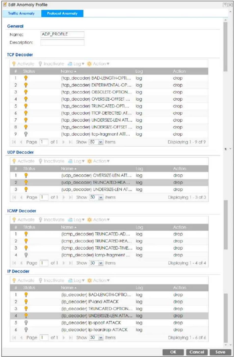
The following table describes the labels in this screen.
31.5.5 The ADP Allow List Screen
Click Configuration> Security Policy> ADP> Allow List to display the following screen. Use this screen to configure allow list rules to let certain IP addresses or services bypass port scanning, port sweeping and flood detection.
Figure 475 Configuration > Security Policy > ADP> Allow List
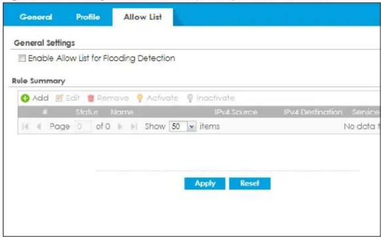
The following table describes the labels in this screen.
Table 270 Configuration > Security Policy > ADP> Allow List
| LABEL DESCRIPTION | |
| General Settings | |
| Enable allow list for all traffic anomaly detection | Select this to allow certain IP addresses or services bypass port scanning, port sweeping and flood detection. |
| Rule Summary | |
| Add | Click this to create a new entry. Select an entry and click Add to create a new entry after the selected entry. |
| Edit | Double-click an entry or select it and click Edit to open a screen where you can modify the entry's settings. |
| Remove | To remove an entry, select it and click Remove. The Zyxel Device confirms you want to remove it before doing so. |
| Activate | To turn on an entry, select it and click Activate. |
| Inactivate | To turn off an entry, select it and click Inactivate. |
| # | This field is a sequential value showing the number of the profile. The profile order is not important. |
| Status | This icon is lit when the entry is active and dimmed when the entry is inactive. |
| Name This field displays the name of the rule. | |
| IPv4 Source | This field displays the IPv4 source address object to which the ADP white list rule applies. |
| IPv4 Destination | This field displays the IPv4 destination address object to which the ADP white list rule applies. |
| Service | This displays the service object to which the ADP white list rule applies. |
| Apply | Click Apply to save your changes back to the Zyxel Device. |
| Reset | Click Reset to return the screen to its last-saved settings. |
31.5.6 Creating New ADP Allow List Rule
Create new ADP allow list rules in this screen. Click Configuration > Security Policy > ADP > Allow List to view the following screen.
Figure 476 Configuration > Security Policy > ADP > Allow List
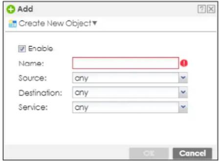
The following table describes the labels in this screen.
Table 271 Configuration > Security Policy > ADP > Allow List > Add
| LABEL DESCRIPTION | |
| Enable Select this to enable this allow list rule. | |
| Name | Enter a name to help you identify this rule. Use up to 60 printable ASCII characters. Spaces are allowed. |
| Source | Select a source address or address group, including geographic address and FQDN (group) objects, to which this rule applies. Select any to make the rule apply to every source address. |
| Destination | Select a destination address or address group, including geographic address and FQDN (group) objects, for whom this rule applies. Select any to make the rule apply to every destination address. |
| Service | Select the service or service group to which this rule applies. Select any to white list all traffic between the source and destination addresses. |
| OK | Click OK to save your customized settings and exit this screen. |
| Cancel | Click Cancel to exit this screen without saving. |
31.6 The Session Control Screen
Click Configuration > Security Policy > Session Control to display the Security Policy Session Control screen. Use this screen to limit the number of concurrent NAT/Security Policy sessions a client can use. You can apply a default limit for all users and individual limits for specific users, addresses, or both. The individual limit takes priority if you apply both.
Figure 477 Configuration > Security Policy > Session Control
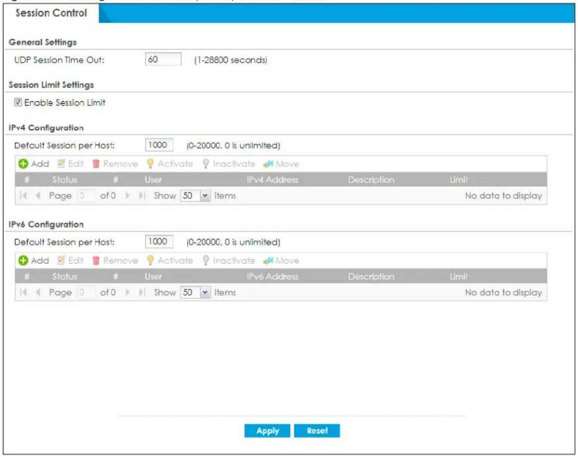
The following table describes the labels in this screen.
Table 272 Configuration > Security Policy > Session Control
| LABEL DESCRIPTION | |
| General Settings | |
| UDP Session Time Out | Set how many seconds the Zyxel Device will allow a UDP session to remain idle (without UDP traffic) before closing it. |
| Session Limit Settings | |
| Enable Session limit | Select this check box to control the number of concurrent sessions hosts can have. |
| IPv4 / IPv6 Configuration | This table lists the rules for limiting the number of concurrent sessions hosts can have. |
| Default Session per Host | This field is configurable only when you enable session limit.Use this field to set a common limit to the number of concurrent NAT/Security Policy sessions each client computer can have.If only a few clients use peer to peer applications, you can raise this number to improve their performance. With heavy peer to peer application use, lower this number to ensure no single client uses too many of the available NAT sessions.Create rules below to apply other limits for specific users or addresses. |
| Add | Click this to create a new entry. Select an entry and click Add to create a new entry after the selected entry. |
| Edit | Double-click an entry or select it and click Edit to open a screen where you can modify the entry's settings. |
| Remove | To remove an entry, select it and click Remove. The Zyxel Device confirms you want to remove it before doing so. |
| Activate | To turn on an entry, select it and click Activate. |
| Inactivate | To turn off an entry, select it and click Inactivate. |
| Move | To change a rule's position in the numbered list, select the rule and click Move to display a field to type a number for where you want to put that rule and press [ENTER] to move the rule to the number that you typed.The ordering of your rules is important as they are applied in order of their numbering. |
| # | This field is a sequential value showing the number of the profile. The profile order is not important. |
| Status | This icon is lit when the entry is active and dimmed when the entry is inactive. |
| # | This is the index number of a session limit rule. It is not associated with a specific rule. |
| User | This is the user name or user group name to which this session limit rule applies. |
| IPv4 / IPv6 Address | This is the IPv4 / IPv6 address object, including geographic address (group) objects to which this session limit rule applies. |
| Description | This is the information configured to help you identify the rule. |
| Limit | This is how many concurrent sessions this user or address is allowed to have. |
| Apply | Click Apply to save your changes back to the Zyxel Device. |
| Reset | Click Reset to return the screen to its last-saved settings. |
31.6.1 The Session Control Add/Edit Screen
Click Configuration > Security Policy > Session Control and the Add or Edit icon to display the Add or Edit screen. Use this screen to configure rules that define a session limit for specific users or addresses.
Figure 478 Configuration > Security Policy > Session Control > Edit
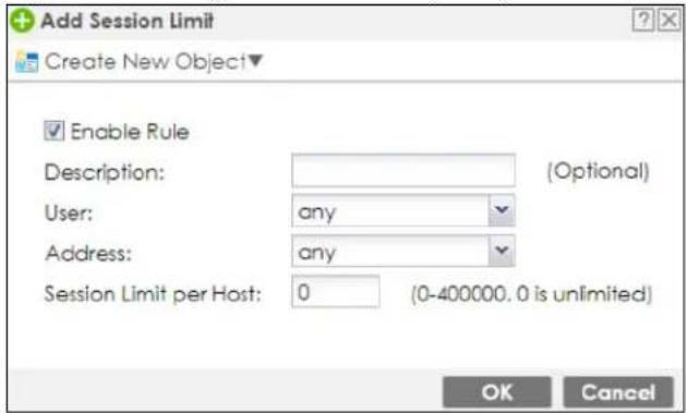
The following table describes the labels in this screen.
Table 273 Configuration > Security Policy > Session Control > Add / Edit
| LABEL DESCRIPTION | |
| Create new Object | Use to configure new settings for User or Address objects that you need to use in this screen.Click on the down arrow to see the menu. |
| Enable Rule Select | this check box to turn on this session limit rule. |
| Description | Enter information to help you identify this rule. Use up to 60 printable ASCII characters. Spaces are allowed. |
| User | Select a user name or user group to which to apply the rule. The rule is activated only when the specified user logs into the system and the rule will be disabled when the user logs out.Otherwise, select any and there is no need for user logging.Note: If you specified an IP address (or address group) instead of any in the field below, the user's IP address should be within the IP address range. |
| Address | Select the IPv4 source address or address group, including geographic address (group) object, to which this rule applies. Select any to apply the rule to all IPv4 source addresses. |
| IPv6 Address | Select the IPv6 source address or address group, including geographic address (group) object, to which this rule applies. Select any to apply the rule to all IPv6 source addresses. |
| Session Limit per Host | Use this field to set a limit to the number of concurrent NAT/Security Policy sessions this rule's users or addresses can have.For this rule's users and addresses, this setting overrides the Default Session per Host setting in the general Security Policy Session Control screen. |
| OK | Click OK to save your customized settings and exit this screen. |
| Cancel | Click Cancel to exit this screen without saving. |
31.7 Security Policy Example Applications
Suppose you decide to block LAN users from using IRC (Internet Relay Chat) through the Internet. To do this, you would configure a LAN to WAN Security Policy that blocks IRC traffic from any source IP address from going to any destination address. You do not need to specify a schedule since you need the Security Policy to always be in effect. The following figure shows the results of this policy.
Figure 479 Blocking All LAN to WAN IRC Traffic Example
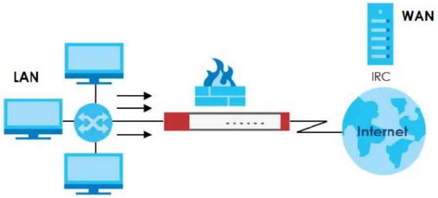
flowchart
graph LR
    A["LAN"] --> B["Router"]
    C["Internet"] --> D["Router"]
    B --> E["WAN"]
    D --> F["IRC"]
    style B fill:#f9f,stroke:#333
    style D fill:#bbf,stroke:#333
Your Security Policy would have the following settings.
Table 274 Blocking All LAN to WAN IRC Traffic Example
| # | USER | SOURCE | DESTINATION | SCHEDULE | SERVICE | ACTION |
| 1 Any Any Any IRC Deny | ||||||
| 2 | Any | Any | Any | Any | Any | Allow |
• The first row blocks LAN access to the IRC service on the WAN.
• The second row is the Security Policy's default policy that allows all LAN1 to WAN traffic.
The Zyxel Device applies the security policies in order. So for this example, when the Zyxel Device receives traffic from the LAN, it checks it against the first policy. If the traffic matches (if it is IRC traffic) the security policy takes the action in the policy (drop) and stops checking the subsequent security policies. Any traffic that does not match the first security policy will match the second security policy and the Zyxel Device forwards it.
Now suppose you need to let the CEO use IRC. You configure a LAN1 to WAN security policy that allows IRC traffic from the IP address of the CEO's computer. You can also configure a LAN to WAN policy that allows IRC traffic from any computer through which the CEO logs into the Zyxel Device with his/her user name. In order to make sure that the CEO's computer always uses the same IP address, make sure it either:
- Has a static IP address,
or
- You configure a static DHCP entry for it so the Zyxel Device always assigns it the same IP address.
Now you configure a LAN1 to WAN security policy that allows IRC traffic from the IP address of the CEO's computer (172.16.1.7 for example) to go to any destination address. You do not need to specify a schedule since you want the security policy to always be in effect. The following figure shows the results of your two custom policies.
Figure 480 Limited LAN to WAN IRC Traffic Example
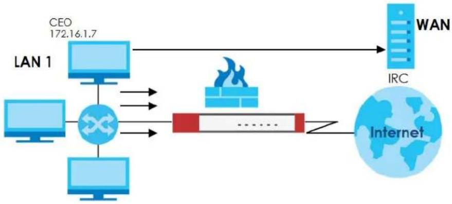
flowchart
graph LR
    A["LAN 1"] --> B["CEO 172.16.1.7"]
    A --> C["Computer"]
    A --> D["Computer"]
    B --> E["IRC"]
    C --> E
    D --> E
    E --> F["Internet"]
    G["WAN"] --> E
    H["Fire Icon"] --> I["Red Box"]
    I --> J["......"]
Your security policy would have the following configuration.
Table 275 Limited LAN1 to WAN IRC Traffic Example 1
| # | USER | SOURCE | DESTINATION | SCHEDULE | SERVICE | ACTION |
| 1 | Any | 172.16.1.7 | Any | Any | IRC | Allow |
| 2 | Any | Any | Any | Any | IRC | Deny |
| 3 Any Any | Any Any | Any Allow |
- The first row allows the LAN1 computer at IP address 172.16.1.7 to access the IRC service on the WAN.
- The second row blocks LAN1 access to the IRC service on the WAN.
- The third row is the default policy of allowing all traffic from the LAN1 to go to the WAN.
Alternatively, you configure a LAN1 to WAN policy with the CEO's user name (say CEO) to allow IRC traffic from any source IP address to go to any destination address.
Your Security Policy would have the following settings.
Table 276 Limited LAN1 to WAN IRC Traffic Example 2
| # USER SOURCE DESTINATION SCHEDULE SERVICE ACTION | ||||||
| 1 | CEO | Any | Any | Any | IRC | Allow |
| 2 | Any | Any | Any | Any | IRC | Deny |
| 3 | Any | Any | Any | Any | Any | Allow |
- The first row allows any LAN1 computer to access the IRC service on the WAN by logging into the Zyxel Device with the CEO's user name.
- The second row blocks LAN1 access to the IRC service on the WAN.
- The third row is the default policy of allowing allows all traffic from the LAN1 to go to the WAN.
The policy for the CEO must come before the policy that blocks all LAN1 to WAN IRC traffic. If the policy that blocks all LAN1 to WAN IRC traffic came first, the CEO's IRC traffic would match that policy and the Zyxel Device would drop it and not check any other security policies.
CHAPTER 32
Application Patrol
32.1 Overview
Application patrol provides a convenient way to manage the use of various applications on the network. It manages general protocols (for example, HTTP and FTP) and instant messenger (IM), peer-to-peer (P2P), Voice over IP (VoIP), and streaming (RSTP) applications. You can even control the use of a particular application's individual features (like text messaging, voice, video conferencing, and file transfers).
32.1.1 What You Can Do in this Chapter
- Use the App Patrol summary screen (see Section 32.2 on page 714) to manage the application patrol profiles. You can also view license registration and signature information.
- Use the App Patrol Add/Edit screens (see Section 32.2.2 on page 718 & Section 32.2.3 on page 719) to set actions for application categories and for specific applications within the category.
32.1.2 What You Need to Know
If you want to use a service, make sure both the Security Policy and application patrol allow the service's packets to go through the Zyxel Device.
Note: The Zyxel Device checks secure policies before it checks application patrol rules for traffic going through the Zyxel Device.
Application patrol examines every TCP and UDP connection passing through the Zyxel Device and identifies what application is using the connection. Then, you can specify whether or not the Zyxel Device continues to route the connection. Traffic not recognized by the application patrol signatures is ignored.
Application Profiles & Policies
An application patrol profile is a group of categories of application patrol signatures. For each profile, you can specify the default action the Zyxel Device takes once a packet matches a signature (forward, drop, or reject a service's connections and/or create a log alert).
Use policies to link profiles to traffic flows based on criteria such as source zone, destination zone, source address, destination address, schedule, user.
Classification of Applications
There are two ways the Zyxel Device can identify the application. The first is called auto. The Zyxel Device looks at the IP payload (OSI level-7 inspection) and attempts to match it with known patterns for specific applications. Usually, this occurs at the beginning of a connection, when the payload is more consistent across connections, and the Zyxel Device examines several packets to make sure the match
is correct. Before confirmation, packets are forwarded by App Patrol with no action taken. The number of packets inspected before confirmation varies by signature.
Note: The Zyxel Device allows the first eight packets to go through the security policy, regardless of the application patrol policy for the application. The Zyxel Device examines these first eight packets to identify the application.
The second approach is called service ports. The Zyxel Device uses only OSI level-4 information, such as ports, to identify what application is using the connection. This approach is available in case the Zyxel Device identifies a lot of "false positives" for a particular application.
Custom Ports for SIP and the SIP ALG
Configuring application patrol to use custom port numbers for SIP traffic also configures the SIP ALG to use the same port numbers for SIP traffic. Likewise, configuring the SIP ALG to use custom port numbers for SIP traffic also configures application patrol to use the same port numbers for SIP traffic.
32.2 Application Patrol Profile
Use the application patrol screens to customize action and log settings for a group of application patrol signatures. You then link a profile to a policy. Use this screen to create an application patrol profile, and view signature information. It also lists the registration status and details about the signature set the Zyxel Device is using.
Note: You must register for the AppPatrol signature service (at least the trial) before you can use it.
A profile is an application object(s) or application group(s) that has customized action and log settings.
Click Configuration > Security Service > App Patrol to open the following screen.
Click the Application Patrol icon for more information on the Zyxel Device's security features.
Figure 481 Configuration > Security Service > App Patrol
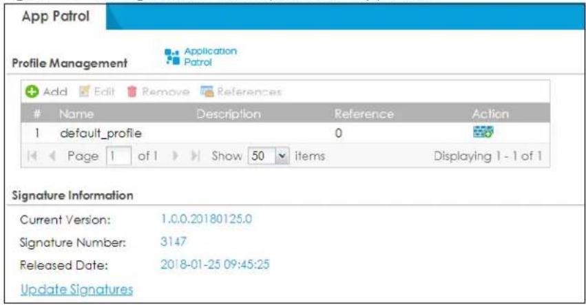
The following table describes the labels in this screen.
Table 277 Configuration > Security Service > App Patrol
| LABEL DESCRIPTION | |
| Add | Click this to create a new entry. Select an entry and click Add to create a new entry after the selected entry. |
| Edit | Double-click an entry or select it and click Edit to open a screen where you can modify the entry's settings. |
| Remove | Select an entry and click Remove to delete the selected entry. |
| References | Select an entry and click References to open a screen that shows which settings use the entry. Click Refresh to update information on this screen. |
| # | This field is a sequential value showing the number of the profile. The profile order is not important. |
| Name This displays the name of the profile created. | |
| Description This displays the description of the App Patrol Profile. | |
| Scan Option | This field displays the scan options from the App Patrol profile. |
| Reference | This displays the number of times an object reference is used in a profile. |
| Action | Click this icon to apply the entry to a security policy.Go to theConfiguration > Security Policy > Policy Controlscreen to check the result. |
| Signature Information | The following fields display information on the current signature set that the Zyxel Device is using. |
| Current Version | This field displays the App Patrol signature set version number. This number gets larger as the set is enhanced. |
| Signature Number | This field displays the number of IPS signatures in this set. This number usually gets larger as the set is enhanced. Older signatures and rules may be removed if they are no longer applicable or have been supplanted by newer ones. |
| Released Date | This field displays the date and time the set was released. |
| Update Signatures | Click this link to go to the screen you can use to download signatures from the update server. |
32.2.1 Profile Action: Apply to a Security Policy
Click the icon in the Action field of an existing application patrol file to apply the profile to a security policy.
Go to the Configuration > Security Policy > Policy Control screen to check the result.
Figure 482 Configuration > Security Service > App Patrol > Action
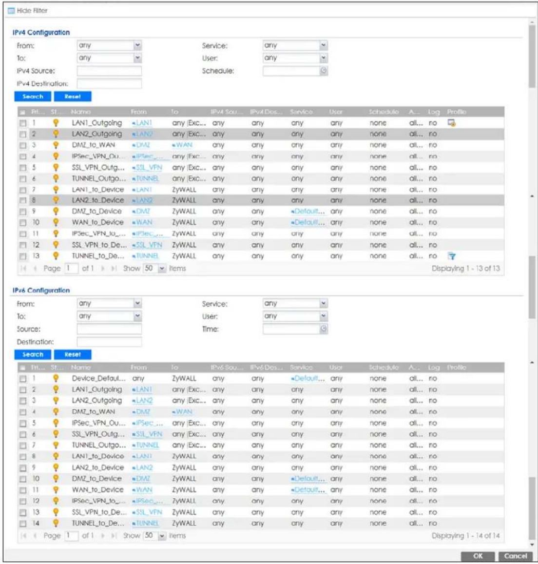
The following table describes the labels in this screen.
Table 278 Configuration > Security Service > App Patrol > Action
| LABEL DESCRIPTION | |
| Show Filter/Hide Filter | Click Show Filter to display IPv4 and IPv6 (if enabled) security policy search filters. |
| IPv4 / IPv6Configuration | Use IPv4 / IPv6 search filters to find specific IPv4 and IPv6 (if enabled) security policies based on direction, application, user, source, destination and/or schedule. |
| From / To | Select a zone to view all security policies from a particular zone and/or to a particular zone.anymeans all zones. |
Table 278 Configuration > Security Service > App Patrol > Action
| LABEL | DESCRIPTION |
| IPv4 / IPv6 Source | Type an IPv4 or IPv6 IP address to view all security policies based on the IPv4 / IPv6 source address object used.An IPv4 IP address is written as four integer blocks separated by periods. This is an example IPv4 address: 172.16.6.7.An 128-bit IPv6 address is written as eight 16-bit hexadecimal blocks separated by colons (:). This is an example IPv6 address: 2001:0db8:1a2b:0015:0000:0000:1a2f:0000. |
| IPv4 / IPv6 Destination | Type an IPv4 or IPv6 IP address to view all security policies based on the IPv4 / IPv6 destination address object used.An IPv4 IP address is written as four integer blocks separated by periods. This is an example IPv4 address: 172.16.6.7.An 128-bit IPv6 address is written as eight 16-bit hexadecimal blocks separated by colons (:). This is an example IPv6 address: 2001:0db8:1a2b:0015:0000:0000;1a2f:0000. |
| Service View all security policies based the service object used. | |
| User View all security policies based on user or user group object used. | |
| Schedule View all security policies based on the schedule object used. | |
| Priority | This is the position of your Security Policy in the global policy list (including all through-Zyxel Device and to-Zyxel Device policies). The ordering of your policies is important as policies are applied in sequence.Defaultdisplays for the default Security Policy behavior that the Zyxel Device performs on traffic that does not match any other Security Policy. |
| Status | This icon is lit when the entry is active and dimmed when the entry is inactive. |
| Name This is the name of the Security policy. | |
| From / To | This is the direction of travel of packets. Select from which zone the packets come and to which zone they go.Security Policies are grouped based on the direction of travel of packets to which they apply. For example, fromLANtoLANmeans packets traveling from a computer or subnet on the LAN to either another computer or subnet on the LAN.Fromanydisplays all the Security Policies for traffic going to the selectedToZone.Toanydisplays all the Security Policies for traffic coming from the selectedFromZone.Fromanytoanydisplays all of the Security Policies.ToZyWALLpolicies are for traffic that is destined for the Zyxel Device and control which computers can manage the Zyxel Device. |
| IPv4 / IPv6 Source | This displays the IPv4 / IPv6 source address object, including geographic address and FQDN (group) objects, to which this Security Policy applies. |
| IPv4 / IPv6 Destination | This displays the IPv4 / IPv6 destination address object, including geographic address and FQDN (group) objects, to which this Security Policy applies. |
| Service | This displays the service object to which this Security Policy applies. |
| User | This is the user name or user group name to which this Security Policy applies. |
| Schedule | This field tells you the schedule object that the policy uses nonemeans the policy is active at all times if enabled. |
| Action | This field displays whether the Security Policy silently discards packets without notification (deny), permits the passage of packets (allow) or drops packets with notification (reject) |
| Log | Select whether to have the Zyxel Device generate a log (log), log and alert (log alert) or not (no) when the policy is matched to the criteria listed above. |
| Profile | This field shows you which Security Service profiles apply to this security policy. Click an applied Security Service profile icon to edit the profile directly. |
| OK | Click OKto save your changes back to the Zyxel Device. |
| Cancel | Click Cancelto exit this screen without saving. |
32.2.2 Application Patrol Profile > Add/Edit - My Application
Use this screen to configure profile settings. Click Configuration > Security Service > App Patrol > Add/Edit, then click My Application to open the following screen.
Figure 483 Configuration > Security Service > App Patrol > Add/Edit > My Application
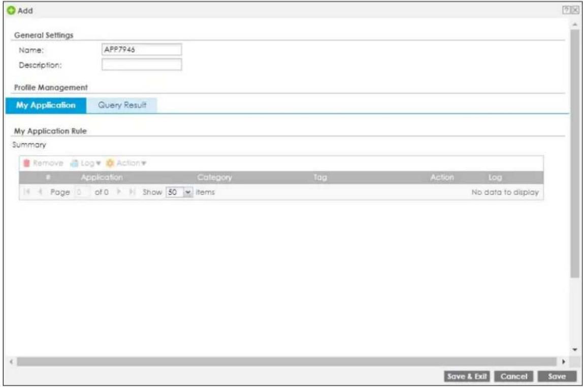
The following table describes the labels in this screen.
Table 279 Configuration > Security Service > App Patrol > Add/Edit > My Application
| LABEL DESCRIPTION | |
| General Settings | |
| Name | Type the name of the profile. You may use 1-31 alphanumeric characters, underscores( ), or dashes (-), but the first character cannot be a number. This value is case-sensitive. These are valid, unique profile names:My Profilem Y ProfileM y m y 1 2 _ 3 - 4These are invalid profile names:1mYProfileMy ProfileMyProfile?Whatalongprofilename123456789012 |
| Description | Type a description for the profile rule to help identify the purpose of rule. You may use 1-31 alphanumeric characters, underscores ( ), or dashes (-), but the first character cannot be a number. This value is case-sensitive. This field is optional. |
| Total Category(s) | This field displays the total number of the selected category(ies) in the Query Result screen. |
Table 279 Configuration > Security Service > App Patrol > Add/Edit > My Application
| LABEL DESCRIPTION | |
| Total Application(s) | This field displays the total number of the selected applications in the Query Result screen. |
| Remove | Select an entry and click Remove to delete the selected entry. |
| Log | Select whether to have the Zyxel Device generate a log (log), log and alert (log alert) or neither (no) by default when traffic matches a signature in this category. |
| Action Select the default | Action for all signatures in this category.forward - the Zyxel Device routes packets that matches these signatures.drop - the Zyxel Device silently drops packets that matches these signatures without notification.reject - the Zyxel Device drops packets that matches these signatures and sends notification. |
| # | This field is a sequential value showing the number of the profile. The profile order is not important. |
| Application This field displays the application name of the policy. | |
| Category | This field displays the category type of the application. |
| Tag This field displays the tag information of the application. | |
| Action Select the default action for all signatures in this category.forward - the Zyxel Device routes packets that matches these signatures.drop - the Zyxel Device silently drops packets that matches these signatures without notification.reject - the Zyxel Device drops packets that matches these signatures and sends notification. | |
| Log | Select whether to have the Zyxel Device generate a log (log), log and alert (log alert) or neither (no) by default when traffic matches a signature in this category. |
| Save & Exit | A profile consists of separate category editing screens. If you want to configure just one category for a profile, click OK to save your settings to the Zyxel Device, complete the profile and return to the profile summary page. |
| Cancel | Click Cancel to return to the profile summary page without saving any changes. |
| Save | If you want to configure more than one category for a profile, click Save to save your settings to the Zyxel Device without leaving this page. |
32.2.3 Application Patrol Profile > Add/Edit - Query Result
Click Configuration > Security Service > App Patrol > Add, then click Query Result to search for certain applications within a specific category, and the selected applications will be added to My Application screen. You can also click an existing profile, click Edit (or double-click it), then click Query Result to open the following screen.
Figure 484 Configuration > Security Service > App Patrol > Add/Edit > Query Result
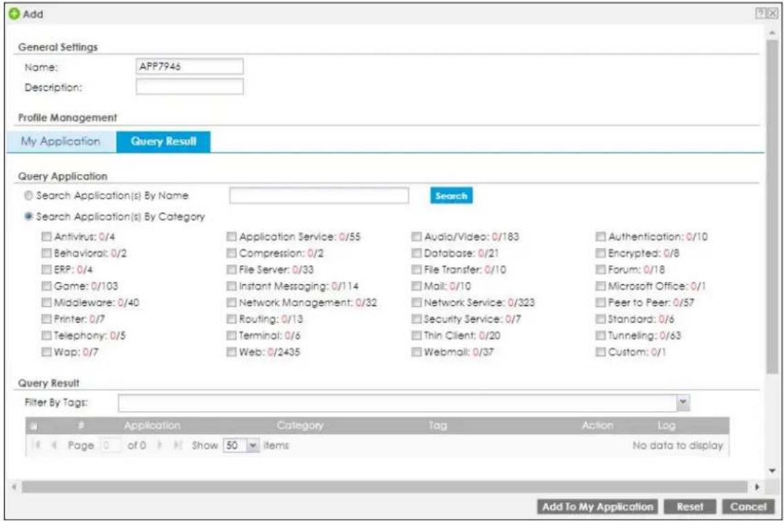
The following table describes the labels in this screen.
Table 280 Configuration > Security Service > App Patrol > Add/Edit > Query Result
| LABEL DESCRIPTION | |
| General Settings | |
| Name | Type the name of the profile. You may use 1-31 alphanumeric characters, underscores( ), or dashes (-), but the first character cannot be a number. This value is case-sensitive. These are valid, unique profile names:My Profilem Y ProfileM y m y 1 2 _ 3 - 4These are invalid profile names:1mYProfileMy ProfileMyProfile?Whatalongprofilename123456789012 |
| Description | Type a description for the profile rule to help identify the purpose of rule. You may use 1-31 alphanumeric characters, underscores ( ), or dashes (-), but the first character cannot be a number. This value is case-sensitive. This field is optional. |
| Search Application(s) By Name | Enter a name to search for relevant applications. |
| Search Application(s) By Category | Select a category(ies) below to search for relevant applications. |
| Filter by Tags | Add or delete a tag(s) to display or not display an application(s). |
| # | This field is a sequential value showing the number of the profile. The profile order is not important. |
Table 280 Configuration > Security Service > App Patrol > Add/Edit > Query Result
| LABEL DESCRIPTION | |
| Application This field displays the application name of the policy. | |
| Category | This field displays the category type of the application. |
| Tag This field displays the tag information of the policy. | |
| Action Select the default action for all signatures in this category.forward - the Zyxel Device routes packets that matches these signatures.drop - the Zyxel Device silently drops packets that matches these signatures without notification.reject - the Zyxel Device drops packets that matches these signatures and sends notification. | |
| Log | Select whether to have the Zyxel Device generate a log (log), log and alert (log alert) or neither (no) by default when traffic matches a signature in this category. |
| Add to My Application | Select an application(s) to show in theMy Applicationprofile screen. |
| Reset | Click this button to reset the fields to default settings. |
| Cancel | Click Cancelto return to the profile summary page without saving any changes. |
32.3 Example: Block an Application
To block an application, you need to:
1 Create an app patrol profile of applications to block.
2 Apply the profile to a traffic flow in a security policy.
3 Create a schedule profile, and apply the profile to a traffic flow in a security policy.
In this example, you want to block clients on the Zyxel Device LAN from accessing a specific application (for example, TikTok). You also want to receive a log and an alert when traffic going out from the LAN tries to access TikTok.
Create an App Patrol profile that includes TikTok. Then apply it to the LAN1_Outgoing and LAN2_Outgoing security policy. Clients on the Zyxel Device LAN will be blocked from accessing TikTok.
Figure 485 App Patrol Tutorial Example
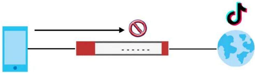
flowchart
graph LR
    A["Smartphone"] --> B["Barrier"]
    B --> C["Global"]
    D["No Signal"] --> B
This example uses the parameters listed below.
Table 281 App Patrol Profile Configuration Example
| PROFILE NAME APPLICATION ACTION LOG | ||
| BlockMedia TikTok Reject Log Alert |
1 Go to Configuration > Security Service > App Patrol and click Add.
2 In the following screen, enter the profile name using the parameter given in Table 281 on page 722.
| General Settings | |
| Name: | BlockMedia |
| Description: | |
3 Search for TikTok in Search Application(s) by Name.
4 The search result will display in Query Result. Select the result check box and click Add To My Application.
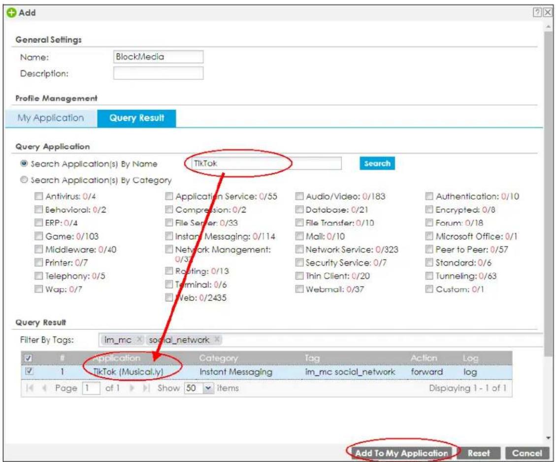
5 In My Application, set Action to reject and Log to log alert. Click Save & Exit to save your changes.
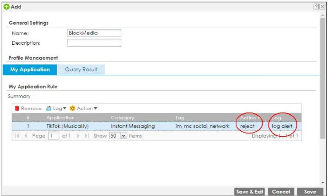
6 A pop-up message displays after you click Save & Exit. Click Yes to open the Apply BlockMedia to a security policy screen to apply the app patrol profile to the security policies you selected.
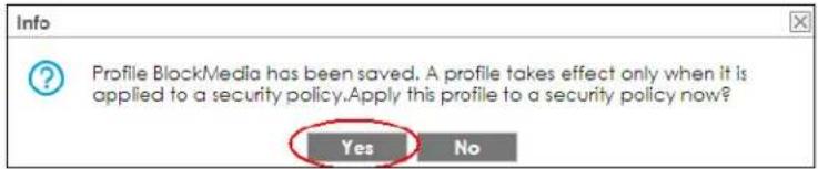
7 Select LAN1_Outgoing and LAN2_Outgoing. Click OK to save your changes.
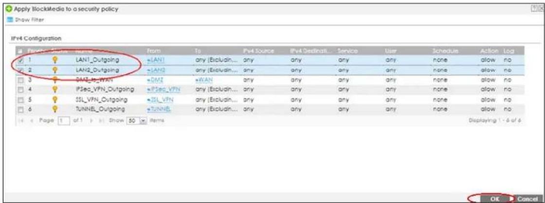
8 You can check the result in the Policy Control screen. Mouse-over the icon under the Profile column to check that the BlockMedia profile has been applied to the LAN1_Outgoing and LAN2_Outgoing security policy. You can also check the logs in Monitor > Log > View Log. The Zyxel Device will create logs if the clients on the Zyxel Device LAN try to access TikTok.
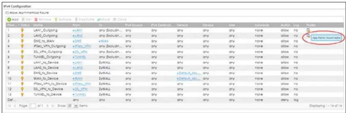
32.3.1 Block an Application At a Specified Time
In this example, you want to apply the app patrol profile you created in Section 32.3 on page 721 only during work time using a recurring schedule.
This example uses the parameters listed below.
Table 282 Schedule Example
| SCHEDULE NAME START TIME STOP TIME WEEK DAYS | ||
| Work 8:00 17:00 Monday, Tuesday, Wednesday. | Thursday, Friday | |
1 Go to Configuration > Object > Schedule. Create a recurring schedule rule using the parameters given in Table 282 on page 724.
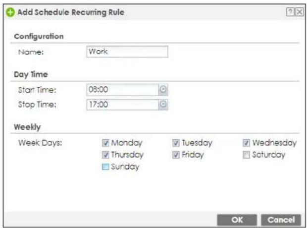
2 Go to Configuration > Security Policy > Policy Control and select LAN1_Outgoing. Click Edit to edit the policy control rule. Set Schedule to Work to apply the BlockMedia profile during the time you set in the recurring schedule. Click OK to save your changes.
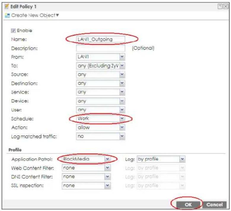
3 Select LAN2_Outgoing and click Edit to edit the policy control rule. Set Schedule to Work to block the BlockMedia profile during the time you set in the recurring schedule. Click OK to save your changes.
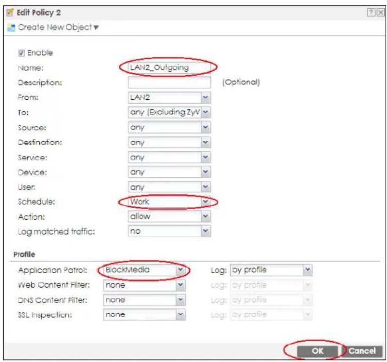
4 You can check the result in the Policy Control screen.
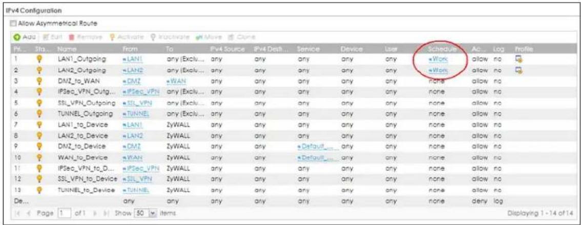
32.3.2 Block YouTube
App patrol is mainly for application performance using TCP. YouTube uses the QUIC UDP protocol. Configure a security policy to block UDP 443 protocol and move the YouTube rule up before other rules that may conflict with this rule.
CHAPTER 33
Content Filter
33.1 Overview
Use the content filtering feature to control access to specific web sites or web content.
33.1.1 What You Can Do in this Chapter
- Use the Web Content Filter General screens (Section 33.2 on page 730) to set up web content filtering profiles.
- Use the Web Content Filter Trusted Web Sites screens (Section 33.3 on page 750) to create a common list of good (allowed) web site addresses.
- Use the Web Content Filter Forbidden Web Sites screens (Section 33.4 on page 751) to create a common list of bad (blocked) web site addresses.
- Use the DNS Content Filter General screens (Section 33.5 on page 752) to set up DNS content filtering profiles.
- Use the DNS Content Filter Allow List screen (Section 33.6 on page 767) to create a list of good (allowed) web site addresses.
- Use the DNS Content Filter Block List screen (Section 33.7 on page 768) to create a list of bad (blocked) web site addresses.
33.1.2 What You Need to Know
Web Content Filter
The Web Content Filter allows the Zyxel Device to block specific web features, such as cookies or ActiveX, by inspecting the web pages that users are visiting. The Zyxel Device can also block access to specific websites, by inspecting the URL or Server Name Indication (SNI) that the user's web browser sends to the web server.
Web Content Filtering Process
1 A user enters a URL into their web browser.
2 The user's computer sends a DNS query for the URL.
3 The DNS server returns an IP address for the URL.
4 The user's web browser connects to the IP address.
5 The Web Content Filter detects an HTTP connection, and inspects the website send using Server Name Indication (SNI).
6 If the website contains prohibited material, the HTTP request is redirected to a block page.
Note: If the user's web browser is using encryption, then you must enable SSL Inspection for Web Content Filter to work.
If the user's web browser is using Encrypted Server Name Indication (ESNI), DNS Content Filter will not work.
Web Content Filtering Policies
A web content filtering policy allows you to do the following.
- Use schedule objects to define when to apply a content filter profile.
- Use address and/or user/group objects to define to whose web access to apply the content filter profile.
- Apply a content filter profile that you have custom-tailored.
Web Content Filtering Profiles
A web content filtering profile conveniently stores your custom settings for the following features.
- Category-based Blocking
The Zyxel Device can block access to particular categories of web site content, such as pornography or racial intolerance. - Restrict Web Features
The Zyxel Device can disable web proxies and block web features such as ActiveX controls, Java applets and cookies. - Customize Web Site Access
You can specify URLs to which the Zyxel Device blocks access. You can alternatively block access to all URLs except ones that you specify. You can also have the Zyxel Device block access to URLs that contain particular keywords.
Web Content Filtering Configuration Guidelines
When the Zyxel Device receives an HTTP request, the content filter searches for a policy that matches the source address and time (schedule). The content filter checks the policies in order (based on the policy numbers). When a matching policy is found, the content filter allows or blocks the request depending on the settings of the filtering profile specified by the policy. Some requests may not match any policy. The Zyxel Device allows the request if the default policy is not set to block. The Zyxel Device blocks the request if the default policy is set to block.
External Web Filtering Service
When you register for and enable the external web filtering service, your Zyxel Device accesses an external database that has millions of web sites categorized based on content. You can have the Zyxel Device block, block and/or log access to web sites based on these categories.
HTTPS Domain Filter
HTTPS Domain Filter works with the Content Filter category feature to identify HTTPS traffic and take appropriate action. SSL Inspection identifies HTTPS traffic for all Security Service traffic and has higher priority than HTTPS Domain Filter. HTTPS Domain Filter only identifies keywords in the domain name of an URL and matches it to a category. For example, if the keyword is 'picture' and the URL is http://www.google.com/picture/index.htm, then HTTPS Domain Filter cannot identify 'picture' because that keyword in not in the domain name 'www.google.com'. However, SSL Inspection can identify 'picture' in the URL http://www.google.com/picture/index.htm.
Keyword Blocking URL Checking
The Zyxel Device checks the URL's domain name (or IP address) and file path separately when performing keyword blocking.
The URL's domain name or IP address is the characters that come before the first slash in the URL. For example, with the URL www.zyxel.com.tw/news/pressroom.php, the domain name is www.zyxel.com.tw.
The file path is the characters that come after the first slash in the URL. For example, with the URL www.zyxel.com.tw/news/pressroom.php, the file path is news/pressroom.php.
Since the Zyxel Device checks the URL's domain name (or IP address) and file path separately, it will not find items that go across the two. For example, with the URL www.zyxel.com.tw/news/pressroom.php, the Zyxel Device would find "tw" in the domain name (www.zyxel.com.tw). It would also find "news" in the file path (news/pressroom.php) but it would not find "tw/news".
DNS Content Filter
The DNS Content Filter allows the Zyxel Device to block access to specific websites by inspecting DNS queries made by users on your network. If the website in the DNS query contains prohibited material, then the Zyxel Device replies to the DNS query with a IP address that points to the block page. Unlike the Web Content Filter, the DNS Content Filter works if the user is using TLS 1.3 with ESNI.
DNS Content Filter Process
1 A user enters a URL into their web browser.
2 The user's computer sends a DNS query for the URL.
3 The DNS Content Filter inspects the website in the DNS query packet.
4 If the website contains prohibited material, the DNS reply is redirected to a block page.
Finding Out More
• See Section 33.9 on page 770 for content filtering background/technical information.
33.1.3 Before You Begin
- You must configure an address object, a schedule object and a filtering profile before you can set up a content security policy.
- You must have Content Filtering license in order to use the function. Subscribe to use the external database content filtering (see the Licensing > Registration screens).
33.2 Web Content Filter General Screen
Click Configuration > Security Service> Content Filter > Web Content Filter> General to open the Web Content Filter General screen. Use this screen to enable content filtering, view and order your list of content filter policies, create a denial of access message or specify a redirect URL and check your external web filtering service registration status.
Click the Content Filter icon for more information on the Zyxel Device's security features.
Figure 486 Configuration > Security Service > Content Filter > Web Content Filter > General
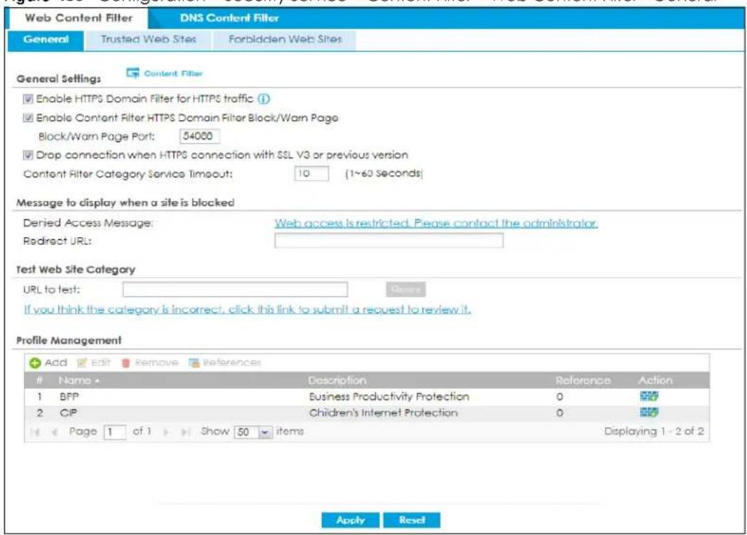
The following table describes the labels in this screen.
Table 283 Configuration > Security Service > Content Filter > Web Content Filter > General
| LABEL DESCRIPTION | |
| General Settings | |
| Enable HTTPS Domain Filter for HTTPS traffic | Select this check box to have the Zyxel Device block HTTPS web pages using the cloud category service.In an HTTPS connection, the Zyxel Device can extract the Server Name Indication (SNI) from a client request, check if it matches a category in the cloud content filter and then take appropriate action. The keyword match is for the domain name only. |
| Enable Content Filter HTTPS Domain Filter Block/Warn Page | Use this field to have the Zyxel Device display a warning page instead of a blank page when an HTPPS connection is redirected. |
| LABEL | DESCRIPTION |
| Block/Warn Page Port | Use the default port number as displayed for the warning page. If you change it, the new port number should be unique. |
| Drop connection when HTTPS connection with SSL V3 or previous version | Select this check box to have the Zyxel Device block HTTPS web pages using SSL V3 or a previous version. |
| Content Filter Category Service Timeout | Specify the allowable time period in seconds for accessing the external web filtering service's server. |
| Denied Access Message | Enter a message to be displayed when content filter blocks access to a web page. Use up to 127 characters (0-9a-zA-Z;/?:@&+\._!~*')%),". For example, "Access to this web page is not allowed. Please contact the network administrator".It is also possible to leave this field blank if you have a URL specified in the Redirect URL field. In this case if the content filter blocks access to a web page, the Zyxel Device just opens the web page you specified without showing a denied access message. |
| Redirect URL | Enter the URL of the web page to which you want to send users when their web access is blocked by content filter. The web page you specify here opens in a new frame below the denied access message.Use "http://" or "https://" followed by up to 262 characters (0-9a-zA-Z;/?:@&+\._!~*')%). For example, http://192.168.1.17/blocked access. |
| Test Web Site Category | |
| URL to test | You can check which category a web page belongs to. Enter a web site URL in the text box.When the content filter is active, you should see the web page's category. The query fails if the content filter is not active.Content Filtering can query a category by full URL string (for example, http://www.google.com/picture/index.htm), but HTTPS Domain Filter can only query a category by domain name ('www.google.com'), so the category may be different in the query result. URL to test displays both results in the test. |
| If you think the category is incorrect, click this link to submit a request to review it | Click this link to see the category recorded in the Zyxel Device's content filtering database for the web page you specified (if the database has an entry for it). |
| Profile Management | |
| Add Click Add to create | a new content filter rule. |
| Edit Click Edit to make changes to a content filter rule. | |
| Remove Click Remove the delete a content filter rule. | |
| References | Select an entry and click References to open a screen that shows which settings use the entry. . Click Refresh to update information on this screen. |
| # | This column lists the index numbers of the content filter profile. |
| Name This column lists the names of the content filter profile rule. | |
| Description | This column lists the description of the content filter profile rule. |
| Reference This displays the number of times an Object Reference is used in a rule. | |
| Action | Click this icon to apply the content filter profile with a security policy.Go to theConfiguration > Security Policy > Policy Controlscreen to check the result. |
| Apply | Click Apply to save your changes back to the Zyxel Device. |
| Reset | Click Reset to return the screen to its last-saved settings. |
33.2.1 Apply to a Security Policy
Click the icon in the Action field to apply the entry to a security policy.
Go to the Configuration > Security Policy > Policy Control screen to check the result.
Figure 487 Configuration > Security Service > Content Filter > Action
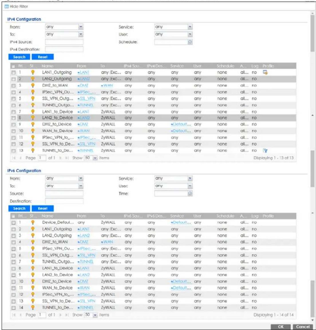
The following table describes the labels in this screen.
Table 284 Configuration > Security Service > Content Filter > Action
| LABEL DESCRIPTION | |
| Show Filter/Hide Filter | Click Show Filter to display IPv4 and IPv6 (if enabled) security policy search filters. |
| IPv4 / IPv6 Configuration | Use IPv4 / IPv6 search filters to find specific IPv4 and IPv6 (if enabled) security policies based on direction, application, user, source, destination and/or schedule. |
Table 284 Configuration > Security Service > Content Filter > Action
| LABEL | DESCRIPTION |
| From / To | Select a zone to view all security policies from a particular zone and/or to a particular zone.anymeans all zones. |
| IPv4 / IPv6 Source | Type an IPv4 or IPv6 IP address to view all security policies based on the IPv4 / IPv6 source address object used.An IPv4 IP address is written as four integer blocks separated by periods. This is an example IPv4 address: 172.16.6.7.An 128-bit IPv6 address is written as eight 16-bit hexadecimal blocks separated by colons (:) . This is an example IPv6 address: 2001:0db8:1a2b:0015:0000:0000:1a2f:0000. |
| IPv4 / IPv6 Destination | Type an IPv4 or IPv6 IP address to view all security policies based on the IPv4 / IPv6 destination address object used.An IPv4 IP address is written as four integer blocks separated by periods. This is an example IPv4 address: 172.16.6.7.An 128-bit IPv6 address is written as eight 16-bit hexadecimal blocks separated by colons (:) . This is an example IPv6 address: 2001:0db8:1a2b:0015:0000:000:1a2f:0000. |
| Service View all security policies based the service object used. | |
| User View all security policies based on user or user group object used. | |
| Schedule View all security policies based on the schedule object used. | |
| Priority | This is the position of your Security Policy in the global policy list (including all through-Zyxel Device and to-Zyxel Device policies). The ordering of your policies is important as policies are applied in sequence.Defaultdisplays for the default Security Policy behavior that the Zyxel Device performs on traffic that does not match any other Security Policy. |
| Status This icon is lit when the entry is active and dimmed when the entry is inactive. | |
| Name This is the name of the Security policy. | |
| From / To | This is the direction of travel of packets. Select from which zone the packets come and to which zone they go.Security Policies are grouped based on the direction of travel of packets to which they apply. For example, fromLANtoLANmeans packets traveling from a computer or subnet on the LAN to either another computer or subnet on the LAN.Fromanydisplays all the Security Policies for traffic going to the selectedTo Zone.Toanydisplays all the Security Policies for traffic coming from the selectedFrom Zone.Fromanytoanydisplays all of the Security Policies.ToZyWALLpolicies are for traffic that is destined for the Zyxel Device and control which computers can manage the Zyxel Device. |
| IPv4 / IPv6 Source | This displays the IPv4 / IPv6 source address object, including geographic address and FQDN (group) objects, to which this Security Policy applies. |
| IPv4 / IPv6 Destination | This displays the IPv4 / IPv6 destination address object, including geographic address and FQDN (group) objects, to which this Security Policy applies. |
| Service | This displays the service object to which this Security Policy applies. |
| User | This is the user name or user group name to which this Security Policy applies. |
| Schedule | This field tells you the schedule object that the policy uses nonemeans the policy is active at all times if enabled. |
| Action | This field displays whether the Security Policy silently discards packets without notification (deny), permits the passage of packets (allow) or drops packets with notification (reject) |
| Log | Select whether to have the Zyxel Device generate a log (log), log and alert (log alert) or not (no) when the policy is matched to the criteria listed above. |
Table 284 Configuration > Security Service > Content Filter > Action
| LABEL DESCRIPTION | |
| Profile | This field shows you which Security Service profiles apply to this security policy. Click an applied Security Service profile icon to edit the profile directly. |
| OK | Click OK to save your changes back to the Zyxel Device. |
33.2.2 Web Content Filter Add Category Service
Click Configuration > Security Service > Content Filter > Web Content Filter > General > Add or Edit to open the Add screen.
Figure 488 Configuration > Security Service > Content Filter > Web Content Filter > General > Add > Category Service
![Add Category Service Custom Service General Settings Name: 1 Description: (Optional) Enable Salessearch Enable Content Filter Category Service Log on web pages Action for Managed Web Pages: Sock Action for Unrated Web Pages: Wam Action When Category Server is unavailable: Wam Log-start for Stock/Wam action ① Log-start for stock/wam action ① Select Categories Select All Categories Clear All Categories Managed Categories Adult Topics Alcozol Anonymizing Utilities Art Culture Heritage Auctions Classifieds Blogs/Wiki Business Chat Computing Internet Consumer Protection Content Server Controversial Opinions Cut Circuit Dating Personals Dating Social Networking digital Postcards Discrimination Drugs Education Reference Entertainment Extreme Fashion Beauty Finance Banking For Kids Forum Bulletin Board! Game Cartoon Violence Gaming Gambling Related Government Military Games General News Historical Revisionism Grossome Content Hearn Illegal UK History Humor Comics Information Security New Incidental Nudry Information Security Internet Radio TV Instant Messaging Interactive Web Applications Major Global Belgians Internet Services Employment Media Downloads Media Sharing Marketing Merchant analizing Media Downloads Moderated Messaging Mobile Phone Nudity Motor Vehicles Non Profit Advocacy NGO Pubs Online Snapping P2IP File Snaring Personal Page Radio Parked Domain Personal Network Storage Pomography Pharmacy Politics Opinion Potential Tracking Computer Crime Potential illegal software Potential Criminal Activities Crime Professional Networking Private IP Addresses Profanity Real Estate Provocative Attire Public Information Remote Access Recreation Hobbies Religion Ideology Resource Sharing Reserved Residential IP Addresses Speech Engines Restaurants School Cheating Information Social Networking Sexual Materials Shareware Freeware Stock Trading Software Hardware Sports Tobacco Streaming Media Technical Business Forum Media Twoak's Text Spoken Only Text Translators[Tobacco] Travel Usenet News Violence Visual Search Engine Weapons Web Ads Web Mail Web Meetings Web Phone Test Web Site Category URL to test: If you think the category is incorrect, click this link to submit a request to review it. OK Cancel](/content/2026/05/878280/images/fb94b07d789b9785e221b5d2bb2b6336acf6c0616cc08ecd96c52685cd14c356.jpg)
The following table describes the labels in this screen.
Table 285 Configuration > Security Service > Content Filter > Web Content Filter > General > Add > Category Service
| LABEL DESCRIPTION | |
| Name | Enter a descriptive name for this content filtering profile name. You may use 1-31 alphanumeric characters, underscores(____), or dashes (-), but the first character cannot be a number. This value is case-sensitive. |
| Description | Enter a description for the content filtering profile rule to help identify the purpose of rule. You may use 1-31 alphanumeric characters, underscores(____), or dashes (-), but the first character cannot be a number. This value is case-sensitive.This field is optional. |
| Enable SafeSearch | SafeSearch is a search engine that can automatically filter sexually explicit videos and images from the search result without overloading the Zyxel Device.Supported search engines at the time of writing are:Yahoo, Google, MSN Live Bing, Yandex |
| Enable Content Filter Category Service | Enable external database content filtering to have the Zyxel Device check an external database to find to which category a requested web page belongs. The Zyxel Device then blocks or forwards access to the web page depending on the configuration of the rest of this page. |
| Log all web pages | Select this to record attempts to access web pages when:They match the other categories that you select below.They are not categorized.The external content filtering database is unavailable. |
| Action for Managed Web Pages | SelectPassto allow users to access web pages that match the other categories that you select below.SelectBlockto prevent users from accessing web pages that match the other categories that you select below. When external database content filtering blocks access to a web page, it displays the denied access message that you configured in theContent Filter Generalscreen along with the category of the blocked web page.If a web page matches multiple categories, and at least one of those categories is blocked, that web page will be blocked.If a web page matches multiple categories, and at least one of those categories is blocked, that web page will be blocked.If a web page matches multiple categories, and at least one of those categories is blocked, that web page will be blocked.SelectLogto record attempts to access web pages that match the other categories that you select below. |
| Action for Unrated Web Pages | SelectPassto allow users to access web pages that the external web filtering service has not categorized.SelectBlockto prevent users from accessing web pages that the external web filtering service has not categorized. When the external database content filtering blocks access to a web page, it displays the denied access message that you configured in theContent Filter Generalscreen along with the category of the blocked web page.SelectWarnto display a warning message before allowing users to access web pages that the external web filtering service has not categorized.SelectLogto record attempts to access web pages that are not categorized. |
| Action When Category Server Is Unavailable | SelectPassto allow users to access any requested web page if the external content filtering database is unavailable.SelectBlockto block access to any requested web page if the external content filtering database is unavailable.SelectWarnto display a warning message before allowing users to access any requested web page if the external content filtering database is unavailable.The following are possible causes for the external content filtering server not being available:There is no response from the external content filtering server within the time period specified in theContent Filter Server Unavailable Timeout field.The Zyxel Device is not able to resolve the domain name of the external content filtering database.There is an error response from the external content filtering database. This can be caused by an expired content filtering registration (External content filtering's license key is invalid").SelectLogto record attempts to access web pages that occur when the external content filtering database is unavailable. |
| Log-alert for Block/Warn action | A log at the alert level is a log for serious events that may need more immediate attention. For example, you may want to know right away if there are clients in your networks that try to access adult topics or drugs related web pages.Set the action toBlockor Warnand selectLogfor Action for Managed Web Pages, Action for Unrated Web Pages or Action When Category Server is Unavailable.Then enable this to have the Zyxel Device generate logs at the alert level instead of the info level. You can check the priority of log messages inMonitor > Log > View Log > Priority. |
| Select Categories | |
| Select All Categories | Select this check box to restrict access to all site categories listed below. |
| Clear All Categories | Select this check box to clear the selected categories below. |
| Managed Categories | These are categories of web pages based on their content. Select categories in this section to control access to specific types of Internet content.You must have the Category Service content filtering license to filter these categories. See the next table for category details. |
| Test Web Site Category | |
| URL to test | You can check which category a web page belongs to. Enter a web site URL in the text box.When the content filter is active, you should see the web page's category. The query fails if the content filter is not active.Content Filtering can query a category by full URL string (for example, http://www.google.com/picture/index.htm), but HTTPS Domain Filter can only query a category by domain name ('www.google.com'), so the category may be different in the query result.URL to testdisplays both results in the test. |
| If you think the category is incorrect | Click this link to see the category recorded in the Zyxel Device's content filtering database for the web page you specified (if the database has an entry for it). |
| Test Against Content Filter Category Server | Click this button to see the category recorded in the external content filter server's database for the web page you specified. |
| OK | ClickOKto save your changes back to the Zyxel Device. |
| Cancel | ClickCancelto exit this screen without saving your changes. |
The following table describes the managed categories.
Table 286 Managed Category Descriptions
| CATEGORY DESCRIPTION | |
| Adult Topics | Web pages that contain content or themes that are generally considered unsuitable for children. |
| Alcohol | Web pages that mainly sell, promote, or advocate the use of alcohol, such as beer, wine, and liquor.This category also includes cocktail recipes and home-brewing instructions. |
| Anonymizing Utilities | Web pages that result in anonymous web browsing without the explicit intent to provide such a service.This category includes URL translators, web-page caching, and other utilities that might function as anonymizers, but without the express purpose of bypassing filtering software.This category does not include text translation. |
| Art Culture Heritage | Web pages that contain virtual art galleries, artist sites (including sculpture and photography), museums, ethnic customs, and country customs.This category does not include online photograph albums. |
| Auctions Classifieds | Web pages that provide online bidding and selling of items or services.This category includes web pages that focus on bidding and sales.This category does not include classified advertisements such as real estate postings, personal ads, or companies marketing their auctions. |
| Blogs/Wiki | Web pages containing dynamic content, which often changes because users can post or edit content at any time.This category covers the risks with dynamic content that might range from harmless to offensive. |
| Business | Web pages that provide business-related information, such as corporate overviews or business planning and strategies.This category also includes information, services, or products that help other businesses plan, manage, and market their enterprises, and multi-level marketing.This category does not include personal pages and web-hosting web pages. |
| Chat Web pages that provide web-based, real-time social messaging in public and private chat rooms. This category includes IRC.This category does not include instant messaging. | |
| Computing Internet | Web pages containing reviews, information, buyer's guides of computers, computer parts and accessories, computer software and internet companies, industry news and magazines, and pay-to-surf sites. |
| Consumer Protection Websites | that try to rob or cheat consumers.Some examples of their activities include selling counterfeit products, selling products that were originally provided for free, or improperly using the brand of another company. This category also includes sites where many consumers reported being cheated or not receiving services.This category does not include phishing, which tries to perpetrate fraud or theft by stealing account information. To check for phishing, go to Security Service > Reputation Filter > IP Reputation and select Phishing . |
| Content Server | URLs for servers that host images, media files, or JavaScript for one or more sites and are intended to speed up content retrieval for existing web servers, such as Apache.This category includes domain-level and sub-domain-level URLs that function as content servers.This category does not include:Web pages for businesses that provide the content serversWeb pages that allow users to browse photographs. See the Media Sharing category.URLs for servers that serve only advertisements. See the Web Ads category. |
| Controversial Opinions | Web pages that contain opinions that are likely to offend political or social sensibilities and incite controversy. Much of this content is at the extremes of public opinion.This category does not include opinion or language clearly intended to promote hate or discrimination. |
| Cult Occult | Sites relating to non-traditional religious practices considered to be false, unorthodox, extremist, or coercive. |
| Dating Personals Web pages | that provide networking for online dating, matchmaking, escort services, or introductions to potential spouses.This category does not include sites that provide social networking that might include dating, but are not specific to dating. |
| Dating Social Networking | Web pages that focus on social interaction such as online dating, friendship, school reunions, pen-pals, escort services, or introductions to potential spouses.This category does not include wedding-related content, dating tips, or related marketing. |
| Digital Postcards | Web pages that allow people to send and receive digital postcards and greeting cards via the Internet. |
| Discrimination | Web pages, which provide information that explicitly encourages the oppression or discrimination of a specific group of individuals.This category does not include jokes and humor, unless the focus of the entire site is considered discriminatory. |
| Drugs | Websites that provide information on the purchase, manufacture, and use of illegal or recreational drugs.This category does not include sites with exclusive health or political themes. |
| Education Reference | Web pages devoted to academic-related content such as academic subjects (mathematics, history), school or university web pages, and education administration pages (school boards, teacher curriculum). |
| Entertainment | Web pages that provide information about cinema, theater, music, television, infotainment, entertainment industry gossip-news, and sites about celebrities such as actors and musicians.This category also includes sites where the content is devoted to providing entertainment on the web, such as horoscopes or fan clubs. |
| Extreme Web pages that provide content considered gory, perverse, or horrific. | |
| Fashion Beauty | Web pages that market clothing, cosmetics, jewelry, and other fashion-oriented products, accessories, or services.This category also includes product reviews, comparisons, and general consumer information, and services such as hair salons, tanning salons, tattoo studios, and body-piercing studios.This category does not include fashion-related content such as modeling or celebrity fashion unless the site focuses on marketing the product line. |
| Finance Banking | Web pages that provide financial information or access to online financial accounts.This category includes stock information (but not stock trading), home finance, and government-related financial information. |
| For Kids | Web pages that are family-safe, specifically for children of approximate ages ten and under.This category can also be used as an exception to allow web pages that do not pose a risk to children, or to access sites that have a primary educational or recreational focus for children, but are in other categories such as Games, Humor/ Comics, Recreation/Hobbies, or Entertainment. |
| Forum Bulletin Boards | Web pages that provide access (http://) to Usenet newsgroups or hold discussions and post user-generated content, such as real-time message posting for an interest group. This category also includes archives of files uploaded to newsgroups.This category does not include message forums with a business or technical support focus. |
| Gambling | Web pages that allow users to wager or place bets online, or provide gambling software that allows online betting, such as casino games, betting pools, sports betting, and lotteries.This category does not include web pages related to gambling that do not allow betting online. |
| Gambling Related | Web pages that offer information about gambling, without providing the means to gamble.This category includes casino-related web pages that do not offer online gambling, gambling links, tips, sports picks, lottery results, and horse, car, or boat racing. |
| Game Cartoon Violence | Web pages that provide fantasy or fictitious representations of violence within the context of games, comics, cartoons, or graphic novels.This category includes images and textual descriptions of physical assaults or hand-to-hand combat, and grave injury and destruction caused by weapons or explosives. |
| Games | Web pages that offer online games and related information such as cheats, codes, demos, emulators, online contests or role-playing games, gaming clans, game manufacturer sites, fantasy or virtual sports leagues, and other gaming sites without chances of profit.This category includes gaming consoles. |
| General News | Web pages that provide online news media, such as international or regional news broadcasting and publication.This category includes portal sites that provide news content. |
| Government Military | Web pages that contain content maintained by governmental or military organizations, such as government branches or agencies, police departments, fire departments, civil defense, counter-terrorism organizations, or supranational organizations, such as the United Nations or the European Union.This category includes military and veterans' medical facilities. |
| Gruesome Content | Web pages with content that can be considered tasteless, gross, shocking, or gruesome.This category does not include web pages with content pertaining to physical assault. |
| Health | Web pages that cover all health-related information and health care services.This category does not include cosmetic surgery, marketing/selling pharmaceuticals, or animal-related medical services. |
| Historical Revisionism | Web pages that denounce, or offer different interpretations of, significant historical facts, such as holocaust denial.This category does not include all re-examination of historical facts, only historical events that are highly sensitive. |
| History Web pages that provide content about historical facts.This category includes content suitable for higher education, but the Education category includes content for primary education. For example, a site with Holocaust photographs might be offensive, but have academic value. | |
| Humor Comics Web pages that provide comical or funny content.This category includes sites with jokes, sketches, comics, and satire pages. This category might also include graphic novel content, which is often associated with comics. | |
| Illegal UK | Web pages that contain child sexual abuse content hosted anywhere in the world, and criminally obscene and incitement to racial hatred content hosted in the UK. |
| Incidental Nudity | Web pages that contain non-pornographic images of the bare human body like those in classic sculpture and paintings, or medical images.This category enables you to allow or block sites in order to address cultural or geographic differences in opinion about nudity. For example, you can use this category to block access to nudity, but allow access when nudity is not the primary focus of a site, such as news sites or major portals. |
| Information Security | Web pages that legitimately provide information about data protection. This category includes detailed information for safeguarding business or personal data, intellectual property, privacy, and infrastructure on the Internet, private networks, or in other bandwidth services such as telecommunications.This category does not include:Legitimate information security companies and security software providers, such as virus protection companies.Sites that intend to exploit security or teach how to bypass security. |
| Information Security New | Web pages that legitimately provide information about data protection. This category includes detailed information for safeguarding business or personal data, intellectual property, privacy, and infrastructure on the Internet, private networks, or in other bandwidth services such as telecommunications.This category does not include:Legitimate information security companies and security software providers, such as virus protection companies.Sites that intend to exploit security or teach how to bypass security. |
| Instant Messaging | Web pages that provide software for real-time communication over a network exclusively for users who joined a member's contact list or an instant-messaging session.Most instant-messaging software includes features such as file transfer, PC-to-PC phone calls, and can track when other people log on and off. |
| Interactive Web Applications | Web pages that provide access to live or interactive web applications, such as browser-based office suites and groupware. This category includes sites with business, academic, or individual focus.This category does not include sites providing access to interactive web applications that do not take critical user data or offer security risks, such as Google Maps. |
| Internet Radio TV | Web pages that provide software or access to continuous audio or video broadcasting, such as Internet radio, TV programming, or podcasting.Quick downloads and shorter streams that consume less bandwidth are in the Streaming Media or Media Downloads categories. |
| Internet Services | Web pages that provide services for publication and maintenance of Internet sites such as web design, domain registration, Internet Service Providers, and broadband and telecommunications companies that provide web services.This category includes web utilities such as statistics and access logs, and web graphics like clip art. |
| Job Search | Web pages related to a job search including sites concerned with resume writing, interviewing, changing careers, classified advertising, and large job databases. This category also includes corporate web pages that list job openings, salary comparison sites, temporary employment, and company job-posting sites.This category does not include make-money-at-home sites. |
| Major Global Religions | Web pages with content about religious topics and information related to major religions. This category includes sites that cover religious content such as discussion, beliefs, non-controversial commentary, articles, and information for local congregations such as a church or synagogue homepage.The religions in this category are Baha'i, Buddhism, Chinese Traditional, Christianity, Hinduism, Islam, Jainism, Judaism, Shinto, Sikhism, Tenrikyo, Zoroastrianism. |
| Marketing Merchandising | Web pages that promote individual or business products or services on the web, but do not sell their products or services online.This category includes websites that are generally a company overview, describing services or products that cannot be purchased directly from these sites. Examples include automobile manufacturer sites, wedding photography services, or graphic design services.This category does not include:Other categories that imply marketing such as Alcohol, Auctions/Classifieds, Drugs, Finance/Banking, Mobile Phone, Online Shopping, Real Estate, School Cheating Information, Software/Hardware, Stock Trading, Tobacco, Travel, and Weapons.Sites that market their services only to other businesses. See the Business category.Sites that rob or cheat consumers. See the Consumer Protection category. |
| Media Downloads | Web pages that provide audio or video files for download such as MP3, WAV, AVI, and MPEG formats. The files are saved to, and played from, the user's computer.This category does not include audio or video files that are played directly through a browser window. See the Streaming Media category. |
| Media Sharing | Web pages that allow users to upload, search for, and share media files and photographs, such as online photograph albums. |
| Messaging Examples include text messaging to mobile phones, PDAs, fax machines, and internal website user-to-user messaging or site-to-site messaging.This category does not include real-time chat or instant messaging, or message posts that can be viewed by anyone but the intended recipient. | |
| Mobile Phone | Web pages that sell media, software, or utilities for mobile phones that can be downloaded and delivered to mobile phones.Examples include ringtones, logos/skins, games, screen-savers, text-based tunes, and software for SMS, MMS, WAP, and other mobile phone protocols. |
| Moderated | Bulletin boards, chat rooms, search engines, or web mail sites that are monitored by an individual or group who has the authority to block messages or content considered inappropriate.This category does not include sites with posted rules against offensive content. See the Forum/Bulletin Boards category. |
| Motor Vehicles | Websites for manufacturers and dealerships of consumer transportation vehicles, such as cars, vans, trucks, SUVs, motorcycles, and scooters. This category also includes sites that provide product marketing, reviews, comparisons, pricing information, auto fairs, auto expos, and general consumer information about motor vehicles.This category does not include automotive accessories, mechanics, auto-body shops, and recreational hobby pages. This category does not include sites that provide business-to-business-only content regarding motor vehicles. |
| Non Profit Advocacy NGO | Web pages from charitable or educational groups that fulfill a stated mission, benefiting the larger community, such as clubs, lobbies, communities, non-profit organizations, labor unions, and advocacy groups.Examples are Masons, Elks, Boy and Girl Scouts, or Big Brothers. |
| Nudity | Web pages that have non-pornographic images of the bare human body. This category includes classic sculpture and paintings, artistic nude photographs, some naturism pictures, and detailed medical illustrations.This category does not include high-profile sites where nudity is not a concern for visitors. See the Incidental Nudity category. |
| Online Shopping Web pages | that sell products or services online.Web pages selling a broad range of products might pose a risk to users by offering access to items that are normally in other categories such as Pornography, Weapons, Nudity, or Violence. Web pages selling such content exclusively are in their respective categories. |
| P2P File Sharing | Web pages that allow the exchange of files between computers and users for business or personal use, such as downloadable music.P2P clients allow users to search for and exchange files from a peer-user network. They often include spyware or real-time chat capabilities. This category includes BitTorrent web pages. |
| Parked Domain | Web pages that once served content, but their domains have been sold or abandoned and are no longer registered.Parked domains do not host their own content, but usually redirect users to a generic page that states the domain name is for sale, or redirect users to a generic search engine and portal page, some of which provide valid search engine results. |
| Personal Network Storage | Web pages that allow users to upload folders and files to an online network server in order to backup, share, edit, or retrieve files or folders from any web browser. |
| Personal Pages | Personal home pages that share a common domain such as those hosted by ISPs, university/education servers, or free web page hosts.This category also includes unique domains that contain personal information, such as a personal home page. This category does not include home pages of public figures. |
| Pharmacy | Web pages that provide reviews, descriptions, and market or sell prescription-based drugs, over-the-counter drugs, birth control, or dietary supplements. |
| Politics Opinion | Web pages covering political parties, individuals in political life, and opinion on various topics.This category might also cover laws and political opinion about drugs. This category includes URLs for political parties, political campaigning, and opinions on various topics, including political debates. |
| Pornography | Web pages that contain materials intended to be sexually arousing or erotic.This category includes fetish pages, animation, cartoons, stories, and illegal pornography. |
| Portal Sites | Web pages that serve as major gateways or directories to content on the web.Many portal sites also provide a variety of internal site features or services such as search engines, email, news, and entertainment. Mailing list sites with a variety of content are in this category.This category does not include sites with topic-specific content. |
| Potential Criminal Activities | Web pages that provide instructions to commit illegal or criminal activities.Instructions include committing murder or suicide, sabotage, bomb-making, lock-picking, service theft, evading law enforcement, or spoofing drug tests. This category might also include information on how to distribute illegal content, perpetrate fraud, or consumer scams.This category does not include computer-related fraud. |
| Potential Hacking Computer Crime | Web pages that provide instructions, or otherwise enable, fraud, crime, or malicious activity that is computer-oriented.This category includes web pages related to computer crime include malicious hacking information or tools that help individuals gain unauthorized access to computers and networks (root kits, kiddy scripts). This category also includes other areas of electronic fraud such as dialer scams and illegal manipulation of electronic devices.This category does not include illegal software. |
| Potential Illegal Software | Web pages, which the filter believes offer information to potentially 'pirated' or illegally distribute software or electronic media, such as copyrighted music or film, distribution of illegal license key generators, software cracks, and serial numbers.This category does not include peer-to-peer web pages. |
| Private IP Addresses | Sites that are private IP addresses as defined in RFC 1918, that is, hosts that do not require access to hosts in other enterprises (or require just limited access) and whose IP address may be ambiguous between enterprises but are well defined within a certain enterprise. |
| Profanity | Web pages that contain crude, vulgar, or obscene language or gestures. |
| Professional Networking | Web pages that provide social networking exclusively for professional or business purposes.This category includes sites that provide personal or group profiles, and enable their members to interact through real-time communication, message posting, public bulletins, and media sharing. This category also contains alumni sites that have a networking function.This category does not include social networking sites where the focus might vary, but include friendship, dating, or professional focuses. |
| Provocative Attire | Web pages with pictures that include alluring or revealing attire, lingerie and swimsuits, or supermodel or celebrity photograph collections, but do not involve nudity.This category does not include sites with swimwear or similar attire that is not intended to be provocative. For example, Olympic swimming sites are not in this category. |
| Public Information | Web pages that provide general reference information such as public service providers, regional information, transportation schedules, maps, or weather reports. |
| PUPs Web pages that contain | Potentially Unwanted Programs (PUPs).PUPs are often made for a beneficial purpose but they alter the security of a computer or the computer user's privacy. Computer users who are concerned about security or privacy might want to be informed about this software, and in some cases, they might want to remove this software from their computers. |
| Real Estate | Web pages that provide commercial or residential real estate services and information.Service and information includes sales and rental of living space or retail space and guides for apartments, housing, and property, and information on appraisal and brokerage. This category includes sites that allow you to browse model homes.This category does not include content related to personal finance, such as credit applications. |
| Recreation Hobbies | Web pages for recreational organizations and facilities that include content devoted to recreational activities and hobbies.This category includes information about public swimming pools, zoos, fairs, festivals, amusement parks, recreation guides, hiking, fishing, bird watching, or stamp collecting.This category does not include activities that need no active participation, such as watching a movie or reading celebrity gossip. |
| Religion Ideology | Web pages with content related to religious topics and beliefs in human spirituality that are not within the major religions.This category includes religious discussion, beliefs, articles, and information for local congregations or groups such as a church homepage, unless the site is already in the Major Global Religions category. This category also includes comparative religion, or sites that include religions and ideologies.This category does not include astrology and horoscope sites |
| Remote Access | Web pages that provide remote access to a program, online service, or an entire computer system.Although remote access is often used legitimately to run a computer from a remote location, it creates a security risk, such as backdoor access. Backdoor access, written by the original programmer, allows the system to be controlled by another party without the user's knowledge. |
| Reserved This category is reserved for future use. | |
| Residential IP Addresses | IP addresses (and any domains associated with them) that access the Internet by DSL modems or cable modems.Because this content is not generally intended for Internet access via HTTP, access to the Internet through these IP addresses can indicate suspicious behavior. This behavior might be related to malware located on the home computer or homegrown gateways set up to allow anonymous Internet access. |
| Resource Sharing | Web pages that harness idle or unused computer resources to focus on a common task.The task can be on a company or an international basis. Well known examples are the SETI program and the Human Genome Project, which use the idle time of thousands of volunteered computers to analyze data. |
| Restaurants | Web pages that provide information about restaurants, bars, catering, take-out and delivery, including online ordering.This category includes sites that provide information about location, hours, prices, menus and related dietary information. This category also includes restaurant guides and reviews, and cafes and coffee shops.This category does not include groceries, wholesale food, non-profit and charitable food organizations, or bars that do not focus on serving food. |
| School Cheating Information | Web pages that promote plagiarism or cheating by providing free or fee-based term papers, written essays, or exam answers.This category does not include sites that offer student help, discuss literature, films, or books, or other content that is often the subject of research papers. |
| Search Engines | Web pages that provide search results that enable users to find information on the Internet based on key words.This category does not include site-specific search engines. |
| Sexual Materials | Web pages that describe or depict sexual acts, but are not intended to be arousing or erotic.Examples of sexual materials include sex education, sexual innuendo, humor, or sex related merchandise.This category does not include web pages with content intended to arouse. |
| Shareware Freeware | Web pages that are repositories of downloadable copies of shareware and freeware.This category does not include subscription-based software. |
| Social Networking | Web pages that enable social networking for a variety of purposes, such as friendship, dating, professional, or topics of interest.These sites provide personal or group profiles and enable interaction among their members through real-time communication, message posting, public bulletins, and media sharing.This category does not include sites that are exclusive to dating, matchmaking, or a specific professional networking focus. |
| Software Hardware | Web pages related to computing software and hardware, including vendors, product marketing and reviews, deployment and maintenance of software and hardware, and software updates and add-ons such as scripts, plug-ins, or drivers. Hardware includes computer parts, accessories, and electronic equipment used with computers and networks.This category includes the marketing of software and hardware, and magazines focused on software or hardware product reviews or industry trends. |
| Sports Web pages related to | professional or organized recreational sports.This category includes sporting news, events, and information such as playing tips, strategies, game scores, or player trades.This category does not include fantasy leagues, sports centers, athletic clubs, fitness or martial arts clubs, and non-league billiards, darts, or other such activities. |
| Stock Trading Web pages that offer purchasing, selling, or trading of shares online.This category also includes ticker-tape information that enables viewing of real-time stock prices and financial spread betting in the stock market. Other betting is in the Gambling category.This category does not include sites that offer information about stocks, but do not offer purchasing, selling, or trading of shares. | |
| Streaming Media | Web pages that provide streaming media, or contain software plug-ins for displaying audio and visual data before the entire file has been transmitted.This category does not include audio or video files that are downloaded to a user's computer before being played. |
| Technical Business Forums | Web pages with a technical or business focus that provide online message posting or real-time chatting, such as technical support or interactive business communication.Although users can post any type of content, these forums tend to present less risk of containing offensive content.Sites that offer a variety of forums with themes, including technical and business content, are only in the categories of Forum/Bulletin Boards or Chat. |
| Technical Information | Web pages that provide computing information with an educational focus in areas such as Information Technology, computer programming, and certification.Examples include Linux user groups, UNIX commands, software tutorials, or dictionaries of technical terms. Most sites in this category might be subdirectories of larger domains. For example, a software site with a tutorial page is in this category only at the tutorial page URL.This category does not include content about information security. |
| Text Spoken Only Content that is text or audio only, and does not contain pictures.This category can be used as an exception to allow explicit text and recorded material to be accessed when you want pictures blocked using the Pornography, Violence, or Sexual Materials categories. Libraries or universities can use this category to prevent the display of offensive graphics in their public facilities. | |
| Text Translators | Web pages that allow users to type phrases or a block of text to translate it from one language into another.This category also includes language identifier web pages. URL translation is in the Anonymizing Utilities category. |
| Tobacco | Web pages that sell, promote, or advocate the use of tobacco products, tobacco paraphernalia, including cigarettes, cigars, pipes, snuff and chewing tobacco. |
| Travel | Web pages that promote personal or business travel, such as hotels, resorts, airlines, ground transportation, car rentals, travel agencies, and general tourist and travel information.This category also includes sites for buying tickets or accommodation.This category does not include personal vacation photographs. |
| Usenet News | Web pages that provide access (http://) to Usenet newsgroups and archives of files uploaded to newsgroups.This category also includes online groups that offer similar community-oriented content posting. |
| Violence | Web pages that contain real or lifelike images or text that portray, describe, or advocate physical assaults against people, animals, or institutions, such as depictions of war, suicide, mutilation, or dismemberment. |
| Visual Search Engine | Web pages that provide image-specific search results such as thumbnail pictures.This category does not include sites that offer site-specific visual search engines. |
| Weapons Web pages that provide information about buying, making, modifying, or using weapons, such as guns, knives, swords, paintball guns, and ammunition, explosives, and weapon accessories.This category also includes sites that contain content for: weapons for personal or military use, homemade weapons, non-lethal weapons such as mace, pepper spray, or Taser guns, weapons facilities, such as shooting ranges, and government or military oriented weapons.This category does not include political action groups, such as the NRA. | |
| Web Ads | Web pages that provide advertisement-hosting or programs that create advertisements.Examples include links, source code or applets for banners, popups, and other kinds of static or dynamically generated advertisements that appear on web pages. This category is intended to block advertisements on web pages, not the companies that provide the advertisements or advertising services.This category does not include aggressive advertising adware. See the Spyware/Adware category. |
| Web Mail | Web pages that enable users to send or receive email through the Internet. |
| Web Meetings | Web pages that host live meetings, video conferences, and interactive presentations mainly for businesses.Web meetings generally include streaming audio and video, and allow data transfer or office-oriented application sharing, such as online presentations. |
| Web Phone | Web pages that enable users to make telephone calls via the Internet or obtain information or software for this purpose.Web Phone service is also called Internet Telephony, or VoIP. Web phone service includes PC-to-PC, PC-to-phone, and phone-to-phone services connecting via TCP/IP networks. |
33.2.3 Content Filter Add Filter Profile Custom Service
Click Configuration > Security Service > Content Filter > Web Content Filter> General > Add or Edit > Custom Service to open the Custom Service screen. You can create a list of good (allowed) web site addresses and a list of bad (blocked) web site addresses. You can also block web sites based on whether the web site's address contains a keyword. Use this screen to add or remove specific sites or keywords from the filter list.
Figure 489 Configuration > Security Service > Content Filter > Web Content Filter > General > Custom Service
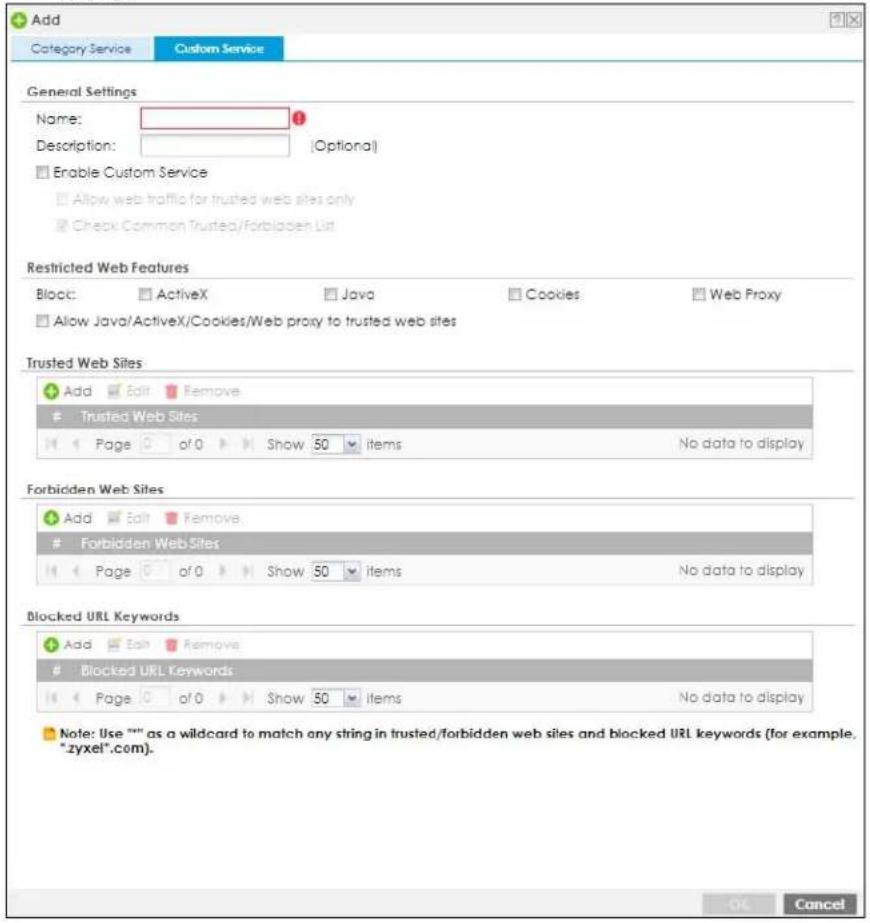
The following table describes the labels in this screen.
Table 287 Configuration > Security Service > Content Filter > Web Content Filter > General > Custom Service
| LABEL DESCRIPTION | |
| Name Enter a descriptive name for | this content filtering profile name. You may use 1-31 alphanumeric characters, underscores( ), or dashes (-), but the first character cannot be a number. This value is case-sensitive. |
| Description | Enter a description for the content filtering profile rule to help identify the purpose of rule. You may use 1-31 alphanumeric characters, underscores( ), or dashes (-), but the first character cannot be a number. This value is case-sensitive.This field is optional. |
| Enable Custom Service | Select this check box to allow trusted web sites and block forbidden web sites. Content filter list customization may be enabled and disabled without re-entering these site names. |
| Allow Web traffic for trusted web sites only | When this box is selected, the Zyxel Device blocks Web access to sites that are not on the Trusted Web Sites list. If they are chosen carefully, this is the most effective way to block objectionable material. |
| Check Common Trusted/ Forbidden List | Select this check box to check the common trusted and forbidden web sites lists. See Section 33.3 on page 750 and Section 33.4 on page 751 for information on configuring these lists. |
| Restricted Web Features | Select the check box(es) to restrict a feature. Select the check box(es) to restrict a feature.When you download a page containing ActiveX or Java, that part of the web page will be blocked with an X.When you download a page coming from a Web Proxy, the whole web page will be blocked.When you download a page containing cookies, the cookies will be removed, but the page will not be blocked. |
| Block ActiveX | ActiveX is a tool for building dynamic and active web pages and distributed object applications. When you visit an ActiveX web site, ActiveX controls are downloaded to your browser, where they remain in case you visit the site again. |
| Java Java is a programming language and development environment for building downloadable Web components or Internet and intranet business applications of all kinds. | |
| Cookies | Cookies are files stored on a computer's hard drive. Some web servers use them to track usage and provide service based on ID. |
| Web Proxy | A server that acts as an intermediary between a user and the Internet to provide security, administrative control, and caching service. When a proxy server is located on the WAN it is possible for LAN users to circumvent content filtering by pointing to this proxy server. |
| Allow Java/ActiveX/Cookies/Web proxy to trusted web sites | When this box is selected, the Zyxel Device will permit Java, ActiveX and Cookies from sites on the Trusted Web Sites list to the LAN. In certain cases, it may be desirable to allow Java, ActiveX or Cookies from sites that are known and trusted. |
| Trusted Web Sites | These are sites that you want to allow access to, regardless of their content rating, can be allowed by adding them to this list. |
| Add Click this to create a new entry. | |
| Edit | Select an entry and click this to be able to modify it. |
| Remove Select an entry and click this to delete it. | |
| # This displays the index number of the trusted web sites. | |
| Trusted Web Site | This column displays the trusted web sites already added.Enter host names such as www.good-site.com into this text field. Do not enter the complete URL of the site – that is, do not include "http://". All subdomains are allowed. For example, entering "*zyxel.com" also allows "www.zyxel.com", "partner.zyxel.com", "press.zyxel.com", and so on. You can also enter just a top level domain. For example, enter "*.com" to allow all .com domains.Use up to 127 characters (0-9a-z-). The casing does not matter. "*" can be used as a wildcard to match any string. The entry must contain at least one "." or it will be invalid. |
| Add Click this to create a new entry. | |
| Edit | Select an entry and click this to be able to modify it. |
| Remove Select an entry and click this to delete it. | |
| # This displays the index number of the forbidden web sites. | |
| Forbidden Web Sites This list displays the forbidden web sites already added.Enter host names such as www.bad-site.com into this text field. Do not enter the complete URL of the site – that is, do not include “http://”. All subdomains are also blocked. For example, entering “*bad-site.com” also blocks “www.bad-site.com”, “partner.bad-site.com”, “press.bad-site.com”, and do on. You can also enter just a top level domain. For example, enter “*.com” to block all .com domains.Use up to 127 characters (0-9a-z-). The casing does not matter. “*” can be used as a wildcard to match any string. The entry must contain at least one “.” or it will be invalid. | |
| Blocked URL Keywords | This section allows you to block Web sites with URLs that contain certain keywords in the domain name or IP address. |
| Add Click this to create a new entry. | |
| Edit | Select an entry and click this to be able to modify it. |
| Remove Select an entry and click | this to delete it. |
| # This displays the index number of the blocked URL keywords. | |
| Blocked URL Keywords This list displays the keywords already added.Enter a keyword or a numerical IP address to block. You can also enter a numerical IP address.Use up to 127 case-insensitive characters (0-9a-zA-Z:/?:@&=+$\._!~*(%)”. “*” can be used as a wildcard to match any string. Use “|*” to indicate a single wildcard character.For example enter *Bad_Site* to block access to any web page that includes the exact phrase Bad_Site. This does not block access to web pages that only include part of the phrase (such as Bad for example). | |
| OK | Click OK to save your changes back to the Zyxel Device. |
| Cancel | Click Cancel to exit this screen without saving your changes. |
33.3 Web Content Filter Trusted Web Sites Screen
Click Configuration > Security Service > Content Filter > Web Content Filter > Trusted/Forbidden Web Sites> Trusted Web Sites to open the Trusted Web Sites screen. You can create a common list of good (allowed) web site addresses. When you configure Web Content Filter Profiles, you can select the option to check the Common Trusted Web Sites list. Use this screen to add or remove specific sites from the filter list.
Figure 490 Configuration > Security Service > Content Filter > Web Content Filter > Trusted/Forbidden Web Sites> Trusted Web Sites
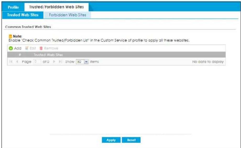
The following table describes the labels in this screen.
Table 288 Configuration > Security Service > Content Filter > Web Content Filter > Trusted/Forbidden Web Sites> Trusted Web Sites
| LABEL DESCRIPTION | |
| Common Trusted Web Sites | These are sites that you want to allow access to, regardless of their content rating, can be allowed by adding them to this list. |
| Add Click this to create a new entry. | |
| Edit | Select an entry and click this to be able to modify it. |
| Remove Select an entry and click | this to delete it. |
| # This displays the index number of the trusted web sites. | |
| Trusted Web Site | This column displays the trusted web sites already added.Enter host names such as www.good-site.com into this text field. Do not enter the complete URL of the site – that is, do not include "http://". All subdomains are allowed. For example, entering "zyxel.com" also allows "www.zyxel.com", "partner.zyxel.com", "press.zyxel.com", and so on. You can also enter just a top level domain. For example, enter .com to allow all .com domains.Use up to 127 characters (0-9a-z-). The casing does not matter. |
| Apply | Click Apply to save your changes back to the Zyxel Device. |
| Reset | Click Reset to return the screen to its last-saved settings. |
33.4 Web Content Filter Forbidden Web Sites Screen
Click Configuration > Security Service > Content Filter > Web Content Filter > Trusted/Forbidden Web Sites> Forbidden Web Sites to open the Forbidden Web Sites screen. You can create a common list of bad (blocked) web site addresses. When you configure Filter Profiles, you can select the option to check the Common Forbidden Web Sites list. Use this screen to add or remove specific sites from the filter list.
Figure 491 Configuration > Security Service > Content Filter > Web Content Filter > Trusted/Forbidden Web Sites> Forbidden Web Sites
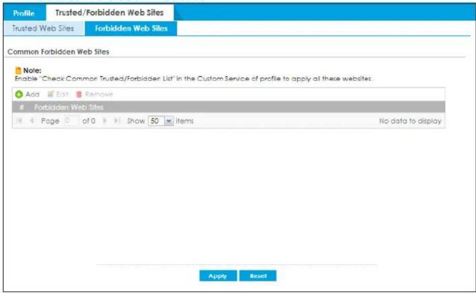
The following table describes the labels in this screen.
Table 289 Configuration > Security Service > Content Filter > Web Content Filter > Trusted/Forbidden Web Sites> Forbidden Web Sites
| LABEL DESCRIPTION | |
| Forbidden Web Site List | Sites that you want to block access to, regardless of their content rating, can be allowed by adding them to this list. |
| Add Click this to create a new entry. | |
| Edit | Select an entry and click this to be able to modify it. |
| Remove Select an entry and click | this to delete it. |
| # This displays the index number of the forbidden web sites. | |
| Forbidden Web Sites This list displays the forbidden web sites already added.Enter host names such as www.bad-site.com into this text field. Do not enter the complete URL of the site – that is, do not include "http://". All subdomains are also blocked. For example, entering "bad-site.com" also blocks "www.bad-site.com", "partner.bad-site.com", "press.bad-site.com", and do on. You can also enter just a top level domain. For example, enter .com to block all .com domains.Use up to 127 characters (0-9a-z-). The casing does not matter. | |
| Apply | Click Apply to save your changes back to the Zyxel Device. |
| Cancel | Click Reset to return the screen to its last-saved settings. |
33.5 DNS Content Filter General Screen
Click Configuration > Security Service> Content Filter > DNS Content Filter> General to open the DNS Content Filter General screen. Use this screen to view and order your list of DNS content filter policies, specify a redirect URL and check your external web filtering service registration status. See Section 33.1.2 on page 727 for more information on DNS content filter.
Click the Content Filter icon for more information on the Zyxel Device's security features.
Figure 492 Configuration > Security Service > Content Filter > DNS Content Filter > General
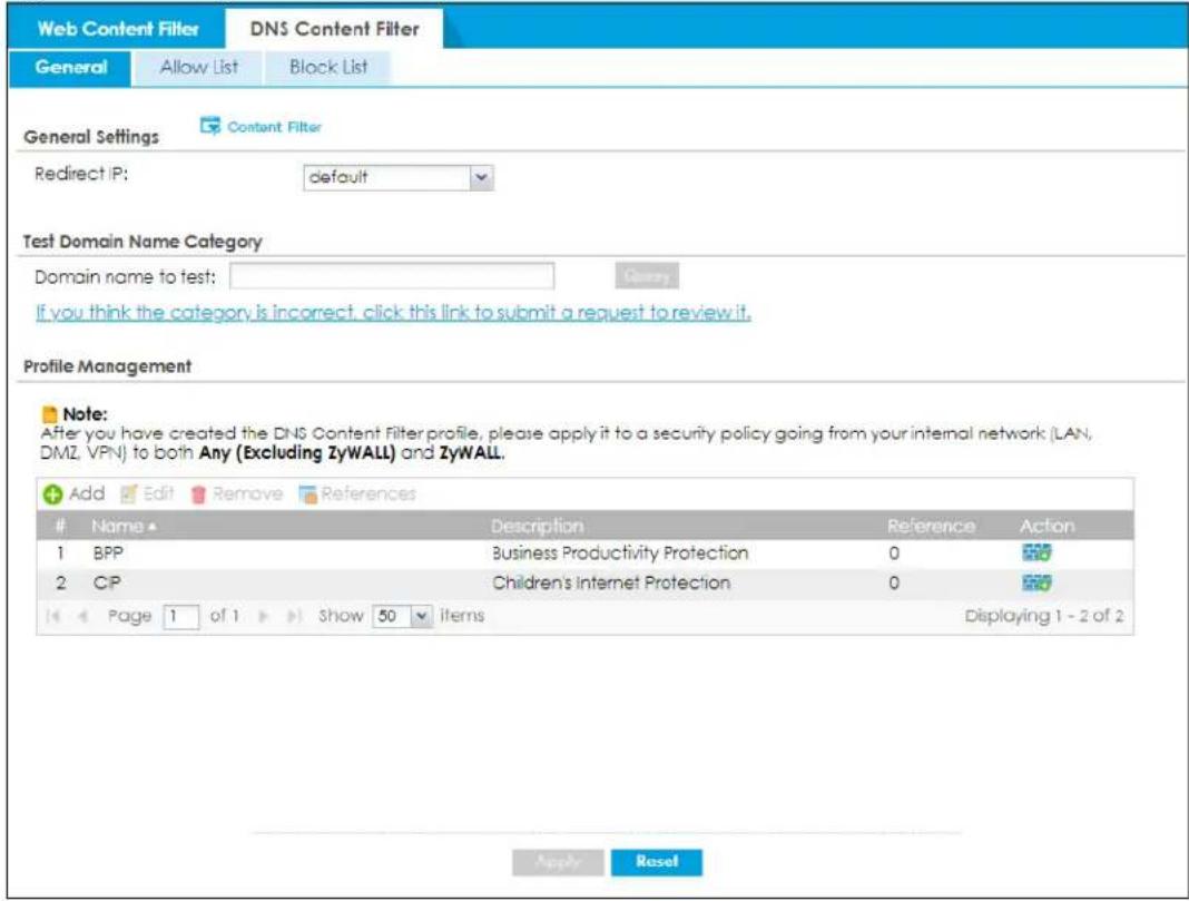
The following table describes the labels in this screen.
Table 290 Configuration > Security Service > Content Filter > DNS Content Filter > General
| LABEL DESCRIPTION | |
| General Settings | |
| Redirect IP | The URL of the web page to which you want to send users when their web access is blocked by DNS content filtering. The web page you specify here opens in a new frame below the denied access message.Selectdefaultto send users to the default web page when their web access is blocked by DNS content filter.Selectcustom definedto send users to the web page you set when their web access is blocked by DNS content filter. Use "http://" followed by up to 255 characters (0-9 a-z A-Z;/?:@&+$\._!~*')%) in quotes. For example, "http://192.168.2.17/blocked access".IPv6 format support:http://[2001::1]/blocked_access |
| Test Web Site Category | |
| URL to test | You can check which category a web page belongs to. Enter a web site URL in the text box.When the content filter is active, you should see the web page's category. The query fails if the content filter is not active.Content Filtering can query a category by full URL string (for example, http://www.google.com/picture/index.htm), but HTTPS Domain Filter can only query a category by domain name ('www.google.com'), so the category may be different in the query result. URL to test displays both results in the test. |
| If you think the category is incorrect, click this link to submit a request to review it | Click this link to see the category recorded in the Zyxel Device's content filtering database for the web page you specified (if the database has an entry for it). |
| Profile Management | |
| Add Click Add to create | a new content filter profile. |
| Edit Click Edit to make changes to a content filter profile. | |
| Remove Click Remove the delete a content filter profile. | |
| References | Select an entry and click References to open a screen that shows which settings use the entry.. Click Refresh to update information on this screen. |
| # | This column lists the index numbers of the content filter profile. |
| Name This column lists the names of the content filter profile. | |
| Description | This column lists the description of the content filter profile. |
| Reference This displays the number of times an Object Reference is used in a rule. | |
| Action | Click this icon to apply the content filter profile with a security policy.Go to theConfiguration > Security Policy > Policy Controlscreen to check the result. |
| Apply | Click Apply to save your changes back to the Zyxel Device. |
| Reset | Click Reset to return the screen to its last-saved settings. |
33.5.1 DNS Content Filter Add Profile
Click Configuration > Security Service > Content Filter > DNS Content Filter > General > Add or Edit to open the Add screen.
Figure 493 Configuration > Security Service > Content Filter > DNS Content Filter > General > Add
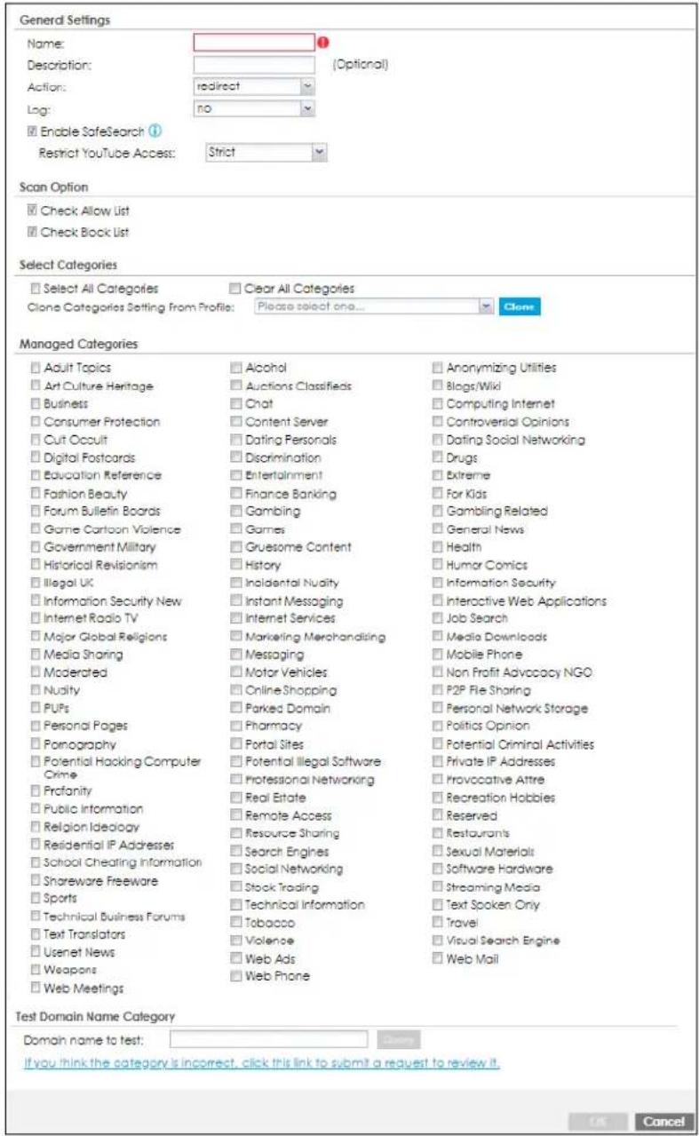
The following table describes the labels in this screen.
Table 291 Configuration > Security Service > Content Filter > DNS Content Filter > General > Add
| LABEL DESCRIPTION | |
| Name | Enter a descriptive name for this content filtering profile name. You may use 1-31 alphanumeric characters, underscores(_, or dashes (-), but the first character cannot be a number. This value is case-sensitive. |
| Description | Enter a description for the content filtering profile rule to help identify the purpose of rule. You may use 1-31 alphanumeric characters, underscores(_, or dashes (-), but the first character cannot be a number. This value is case-sensitive.This field is optional. |
| Action | Select pass to allow users to access web pages that match the other categories that you select below.Select redirect to send users to the default redirect web page or the web page you set |
| Log | Select log if you want the Zyxel Deviceto create a log recording the attempts to access web pages that match the categories you select below.Select alert if you want the Zyxel Device to create an alert log recording the attempts to access web pages that match the categories you select below.Select none if you don't want the Zyxel Device to create a log. |
| Enable SafeSearch | SafeSearch is a search engine that can automatically filter sexually explicit videos and images from the search result without overloading the Zyxel Device.Supported search engines at the time of writing are:· Y o u T u b e· G o o g l e· M S N L i v e B i n g |
| Restrict YouTube Access | Select Strict to better protect the Zyxel Device clients from seeing pornography, potentially offensive and inappropriate videos.Select Moderate to allow YouTube to display more videos in the search result. |
| Scan Option | |
| Check White List | Select this to check if the IP addresses of the web pages users try to access are listed in the DNS content filter white list. |
| Check Black List | Select this to check if the IP addresses of the web pages users try to access are listed in the DNS content filter black list. |
| Select Categories | |
| Select All Categories | Select this check box to restrict access to all site categories listed below. |
| Clear All Categories | Select this check box to clear the selected categories below. |
| Clone Categories Setting From Profile | Choose an existing profile from the drop down list if you want the profile you are currently configuring to use the same categories setting as one of the existing profile. |
| OK | Click OK to save your changes back to the Zyxel Device. |
| Cancel | Click Cancel to exit this screen without saving your changes. |
The following table describes the managed categories.
Table 292 Managed Category Descriptions
| CATEGORY DESCRIPTION | |
| Adult Topics | Web pages that contain content or themes that are generally considered unsuitable for children. |
| Alcohol | Web pages that mainly sell, promote, or advocate the use of alcohol, such as beer, wine, and liquor.This category also includes cocktail recipes and home-brewing instructions. |
| Anonymizing Utilities | Web pages that result in anonymous web browsing without the explicit intent to provide such a service.This category includes URL translators, web-page caching, and other utilities that might function as anonymizers, but without the express purpose of bypassing filtering software.This category does not include text translation. |
| Art Culture Heritage | Web pages that contain virtual art galleries, artist sites (including sculpture and photography), museums, ethnic customs, and country customs.This category does not include online photograph albums. |
| Auctions Classifieds | Web pages that provide online bidding and selling of items or services.This category includes web pages that focus on bidding and sales.This category does not include classified advertisements such as real estate postings, personal ads, or companies marketing their auctions. |
| Blogs/Wiki | Web pages containing dynamic content, which often changes because users can post or edit content at any time.This category covers the risks with dynamic content that might range from harmless to offensive. |
| Business | Web pages that provide business-related information, such as corporate overviews or business planning and strategies.This category also includes information, services, or products that help other businesses plan, manage, and market their enterprises, and multi-level marketing.This category does not include personal pages and web-hosting web pages. |
| Chat Web pages that provide web-based, real-time social messaging in public and private chat rooms. This category includes IRC.This category does not include instant messaging. | |
| Computing Internet | Web pages containing reviews, information, buyer's guides of computers, computer parts and accessories, computer software and internet companies, industry news and magazines, and pay-to-surf sites. |
| Consumer Protection Websites | that try to rob or cheat consumers.Some examples of their activities include selling counterfeit products, selling products that were originally provided for free, or improperly using the brand of another company. This category also includes sites where many consumers reported being cheated or not receiving services.This category does not include phishing, which tries to perpetrate fraud or theft by stealing account information. To check for phishing, go to Security Service > Reputation Filter > IP Reputation and select Phishing . |
| Content Server | URLs for servers that host images, media files, or JavaScript for one or more sites and are intended to speed up content retrieval for existing web servers, such as Apache.This category includes domain-level and sub-domain-level URLs that function as content servers.This category does not include:Web pages for businesses that provide the content serversWeb pages that allow users to browse photographs. See the Media Sharing category.URLs for servers that serve only advertisements. See the Web Ads category. |
| Controversial Opinions | Web pages that contain opinions that are likely to offend political or social sensibilities and incite controversy. Much of this content is at the extremes of public opinion.This category does not include opinion or language clearly intended to promote hate or discrimination. |
| Cult Occult | Sites relating to non-traditional religious practices considered to be false, unorthodox, extremist, or coercive. |
| Dating Personals Web pages | that provide networking for online dating, matchmaking, escort services, or introductions to potential spouses.This category does not include sites that provide social networking that might include dating, but are not specific to dating. |
| Dating Social Networking | Web pages that focus on social interaction such as online dating, friendship, school reunions, pen-pals, escort services, or introductions to potential spouses.This category does not include wedding-related content, dating tips, or related marketing. |
| Digital Postcards | Web pages that allow people to send and receive digital postcards and greeting cards via the Internet. |
| Discrimination | Web pages, which provide information that explicitly encourages the oppression or discrimination of a specific group of individuals.This category does not include jokes and humor, unless the focus of the entire site is considered discriminatory. |
| Drugs | Websites that provide information on the purchase, manufacture, and use of illegal or recreational drugs.This category does not include sites with exclusive health or political themes. |
| Education Reference | Web pages devoted to academic-related content such as academic subjects (mathematics, history), school or university web pages, and education administration pages (school boards, teacher curriculum). |
| Entertainment | Web pages that provide information about cinema, theater, music, television, infotainment, entertainment industry gossip-news, and sites about celebrities such as actors and musicians.This category also includes sites where the content is devoted to providing entertainment on the web, such as horoscopes or fan clubs. |
| Extreme Web pages that provide content considered gory, perverse, or horrific. | |
| Fashion Beauty | Web pages that market clothing, cosmetics, jewelry, and other fashion-oriented products, accessories, or services.This category also includes product reviews, comparisons, and general consumer information, and services such as hair salons, tanning salons, tattoo studios, and body-piercing studios.This category does not include fashion-related content such as modeling or celebrity fashion unless the site focuses on marketing the product line. |
| Finance Banking | Web pages that provide financial information or access to online financial accounts.This category includes stock information (but not stock trading), home finance, and government-related financial information. |
| For Kids | Web pages that are family-safe, specifically for children of approximate ages ten and under.This category can also be used as an exception to allow web pages that do not pose a risk to children, or to access sites that have a primary educational or recreational focus for children, but are in other categories such as Games, Humor/ Comics, Recreation/Hobbies, or Entertainment. |
| Forum Bulletin Boards | Web pages that provide access (http://) to Usenet newsgroups or hold discussions and post user-generated content, such as real-time message posting for an interest group. This category also includes archives of files uploaded to newsgroups.This category does not include message forums with a business or technical support focus. |
| Gambling | Web pages that allow users to wager or place bets online, or provide gambling software that allows online betting, such as casino games, betting pools, sports betting, and lotteries.This category does not include web pages related to gambling that do not allow betting online. |
| Gambling Related | Web pages that offer information about gambling, without providing the means to gamble.This category includes casino-related web pages that do not offer online gambling, gambling links, tips, sports picks, lottery results, and horse, car, or boat racing. |
| Game Cartoon Violence | Web pages that provide fantasy or fictitious representations of violence within the context of games, comics, cartoons, or graphic novels.This category includes images and textual descriptions of physical assaults or hand-to-hand combat, and grave injury and destruction caused by weapons or explosives. |
| Games | Web pages that offer online games and related information such as cheats, codes, demos, emulators, online contests or role-playing games, gaming clans, game manufacturer sites, fantasy or virtual sports leagues, and other gaming sites without chances of profit.This category includes gaming consoles. |
| General News | Web pages that provide online news media, such as international or regional news broadcasting and publication.This category includes portal sites that provide news content. |
| Government Military | Web pages that contain content maintained by governmental or military organizations, such as government branches or agencies, police departments, fire departments, civil defense, counter-terrorism organizations, or supranational organizations, such as the United Nations or the European Union.This category includes military and veterans' medical facilities. |
| Gruesome Content | Web pages with content that can be considered tasteless, gross, shocking, or gruesome.This category does not include web pages with content pertaining to physical assault. |
| Health | Web pages that cover all health-related information and health care services.This category does not include cosmetic surgery, marketing/selling pharmaceuticals, or animal-related medical services. |
| Historical Revisionism | Web pages that denounce, or offer different interpretations of, significant historical facts, such as holocaust denial.This category does not include all re-examination of historical facts, only historical events that are highly sensitive. |
| History Web pages that provide content about historical facts.This category includes content suitable for higher education, but the Education category includes content for primary education. For example, a site with Holocaust photographs might be offensive, but have academic value. | |
| Humor Comics Web pages that provide comical or funny content.This category includes sites with jokes, sketches, comics, and satire pages. This category might also include graphic novel content, which is often associated with comics. | |
| Illegal UK | Web pages that contain child sexual abuse content hosted anywhere in the world, and criminally obscene and incitement to racial hatred content hosted in the UK. |
| Incidental Nudity | Web pages that contain non-pornographic images of the bare human body like those in classic sculpture and paintings, or medical images.This category enables you to allow or block sites in order to address cultural or geographic differences in opinion about nudity. For example, you can use this category to block access to nudity, but allow access when nudity is not the primary focus of a site, such as news sites or major portals. |
| Information Security | Web pages that legitimately provide information about data protection. This category includes detailed information for safeguarding business or personal data, intellectual property, privacy, and infrastructure on the Internet, private networks, or in other bandwidth services such as telecommunications.This category does not include:Legitimate information security companies and security software providers, such as virus protection companies.Sites that intend to exploit security or teach how to bypass security. |
| Information Security New | Web pages that legitimately provide information about data protection. This category includes detailed information for safeguarding business or personal data, intellectual property, privacy, and infrastructure on the Internet, private networks, or in other bandwidth services such as telecommunications.This category does not include:Legitimate information security companies and security software providers, such as virus protection companies.Sites that intend to exploit security or teach how to bypass security. |
| Instant Messaging | Web pages that provide software for real-time communication over a network exclusively for users who joined a member's contact list or an instant-messaging session.Most instant-messaging software includes features such as file transfer, PC-to-PC phone calls, and can track when other people log on and off. |
| Interactive Web Applications | Web pages that provide access to live or interactive web applications, such as browser-based office suites and groupware. This category includes sites with business, academic, or individual focus.This category does not include sites providing access to interactive web applications that do not take critical user data or offer security risks, such as Google Maps. |
| Internet Radio TV | Web pages that provide software or access to continuous audio or video broadcasting, such as Internet radio, TV programming, or podcasting.Quick downloads and shorter streams that consume less bandwidth are in the Streaming Media or Media Downloads categories. |
| Internet Services | Web pages that provide services for publication and maintenance of Internet sites such as web design, domain registration, Internet Service Providers, and broadband and telecommunications companies that provide web services.This category includes web utilities such as statistics and access logs, and web graphics like clip art. |
| Job Search | Web pages related to a job search including sites concerned with resume writing, interviewing, changing careers, classified advertising, and large job databases. This category also includes corporate web pages that list job openings, salary comparison sites, temporary employment, and company job-posting sites.This category does not include make-money-at-home sites. |
| Major Global Religions | Web pages with content about religious topics and information related to major religions. This category includes sites that cover religious content such as discussion, beliefs, non-controversial commentary, articles, and information for local congregations such as a church or synagogue homepage.The religions in this category are Baha'i, Buddhism, Chinese Traditional, Christianity, Hinduism, Islam, Jainism, Judaism, Shinto, Sikhism, Tenrikyo, Zoroastrianism. |
| Marketing Merchandising | Web pages that promote individual or business products or services on the web, but do not sell their products or services online.This category includes websites that are generally a company overview, describing services or products that cannot be purchased directly from these sites. Examples include automobile manufacturer sites, wedding photography services, or graphic design services.This category does not include:Other categories that imply marketing such as Alcohol, Auctions/Classifieds, Drugs, Finance/Banking, Mobile Phone, Online Shopping, Real Estate, School Cheating Information, Software/Hardware, Stock Trading, Tobacco, Travel, and Weapons.Sites that market their services only to other businesses. See the Business category.Sites that rob or cheat consumers. See the Consumer Protection category. |
| Media Downloads | Web pages that provide audio or video files for download such as MP3, WAV, AVI, and MPEG formats. The files are saved to, and played from, the user's computer.This category does not include audio or video files that are played directly through a browser window. See the Streaming Media category. |
| Media Sharing | Web pages that allow users to upload, search for, and share media files and photographs, such as online photograph albums. |
| Messaging Examples include text messaging to mobile phones, PDAs, fax machines, and internal website user-to-user messaging or site-to-site messaging.This category does not include real-time chat or instant messaging, or message posts that can be viewed by anyone but the intended recipient. | |
| Mobile Phone | Web pages that sell media, software, or utilities for mobile phones that can be downloaded and delivered to mobile phones.Examples include ringtones, logos/skins, games, screen-savers, text-based tunes, and software for SMS, MMS, WAP, and other mobile phone protocols. |
| Moderated | Bulletin boards, chat rooms, search engines, or web mail sites that are monitored by an individual or group who has the authority to block messages or content considered inappropriate.This category does not include sites with posted rules against offensive content. See the Forum/Bulletin Boards category. |
| Motor Vehicles | Websites for manufacturers and dealerships of consumer transportation vehicles, such as cars, vans, trucks, SUVs, motorcycles, and scooters. This category also includes sites that provide product marketing, reviews, comparisons, pricing information, auto fairs, auto expos, and general consumer information about motor vehicles.This category does not include automotive accessories, mechanics, auto-body shops, and recreational hobby pages. This category does not include sites that provide business-to-business-only content regarding motor vehicles. |
| Non Profit Advocacy NGO | Web pages from charitable or educational groups that fulfill a stated mission, benefiting the larger community, such as clubs, lobbies, communities, non-profit organizations, labor unions, and advocacy groups.Examples are Masons, Elks, Boy and Girl Scouts, or Big Brothers. |
| Nudity | Web pages that have non-pornographic images of the bare human body. This category includes classic sculpture and paintings, artistic nude photographs, some naturism pictures, and detailed medical illustrations.This category does not include high-profile sites where nudity is not a concern for visitors. See the Incidental Nudity category. |
| Online Shopping Web pages | that sell products or services online.Web pages selling a broad range of products might pose a risk to users by offering access to items that are normally in other categories such as Pornography, Weapons, Nudity, or Violence. Web pages selling such content exclusively are in their respective categories. |
| P2P File Sharing | Web pages that allow the exchange of files between computers and users for business or personal use, such as downloadable music.P2P clients allow users to search for and exchange files from a peer-user network. They often include spyware or real-time chat capabilities. This category includes BitTorrent web pages. |
| Parked Domain | Web pages that once served content, but their domains have been sold or abandoned and are no longer registered.Parked domains do not host their own content, but usually redirect users to a generic page that states the domain name is for sale, or redirect users to a generic search engine and portal page, some of which provide valid search engine results. |
| Personal Network Storage | Web pages that allow users to upload folders and files to an online network server in order to backup, share, edit, or retrieve files or folders from any web browser. |
| Personal Pages | Personal home pages that share a common domain such as those hosted by ISPs, university/education servers, or free web page hosts.This category also includes unique domains that contain personal information, such as a personal home page. This category does not include home pages of public figures. |
| Pharmacy | Web pages that provide reviews, descriptions, and market or sell prescription-based drugs, over-the-counter drugs, birth control, or dietary supplements. |
| Politics Opinion | Web pages covering political parties, individuals in political life, and opinion on various topics.This category might also cover laws and political opinion about drugs. This category includes URLs for political parties, political campaigning, and opinions on various topics, including political debates. |
| Pornography | Web pages that contain materials intended to be sexually arousing or erotic.This category includes fetish pages, animation, cartoons, stories, and illegal pornography. |
| Portal Sites | Web pages that serve as major gateways or directories to content on the web.Many portal sites also provide a variety of internal site features or services such as search engines, email, news, and entertainment. Mailing list sites with a variety of content are in this category.This category does not include sites with topic-specific content. |
| Potential Criminal Activities | Web pages that provide instructions to commit illegal or criminal activities.Instructions include committing murder or suicide, sabotage, bomb-making, lock-picking, service theft, evading law enforcement, or spoofing drug tests. This category might also include information on how to distribute illegal content, perpetrate fraud, or consumer scams.This category does not include computer-related fraud. |
| Potential Hacking Computer Crime | Web pages that provide instructions, or otherwise enable, fraud, crime, or malicious activity that is computer-oriented.This category includes web pages related to computer crime include malicious hacking information or tools that help individuals gain unauthorized access to computers and networks (root kits, kiddy scripts). This category also includes other areas of electronic fraud such as dialer scams and illegal manipulation of electronic devices.This category does not include illegal software. |
| Potential Illegal Software | Web pages, which the filter believes offer information to potentially 'pirated' or illegally distribute software or electronic media, such as copyrighted music or film, distribution of illegal license key generators, software cracks, and serial numbers.This category does not include peer-to-peer web pages. |
| Private IP Addresses | Sites that are private IP addresses as defined in RFC 1918, that is, hosts that do not require access to hosts in other enterprises (or require just limited access) and whose IP address may be ambiguous between enterprises but are well defined within a certain enterprise. |
| Profanity | Web pages that contain crude, vulgar, or obscene language or gestures. |
| Professional Networking | Web pages that provide social networking exclusively for professional or business purposes.This category includes sites that provide personal or group profiles, and enable their members to interact through real-time communication, message posting, public bulletins, and media sharing. This category also contains alumni sites that have a networking function.This category does not include social networking sites where the focus might vary, but include friendship, dating, or professional focuses. |
| Provocative Attire | Web pages with pictures that include alluring or revealing attire, lingerie and swimsuits, or supermodel or celebrity photograph collections, but do not involve nudity.This category does not include sites with swimwear or similar attire that is not intended to be provocative. For example, Olympic swimming sites are not in this category. |
| Public Information | Web pages that provide general reference information such as public service providers, regional information, transportation schedules, maps, or weather reports. |
| PUPs Web pages that contain | Potentially Unwanted Programs (PUPs).PUPs are often made for a beneficial purpose but they alter the security of a computer or the computer user's privacy. Computer users who are concerned about security or privacy might want to be informed about this software, and in some cases, they might want to remove this software from their computers. |
| Real Estate | Web pages that provide commercial or residential real estate services and information.Service and information includes sales and rental of living space or retail space and guides for apartments, housing, and property, and information on appraisal and brokerage. This category includes sites that allow you to browse model homes.This category does not include content related to personal finance, such as credit applications. |
| Recreation Hobbies | Web pages for recreational organizations and facilities that include content devoted to recreational activities and hobbies.This category includes information about public swimming pools, zoos, fairs, festivals, amusement parks, recreation guides, hiking, fishing, bird watching, or stamp collecting.This category does not include activities that need no active participation, such as watching a movie or reading celebrity gossip. |
| Religion Ideology | Web pages with content related to religious topics and beliefs in human spirituality that are not within the major religions.This category includes religious discussion, beliefs, articles, and information for local congregations or groups such as a church homepage, unless the site is already in the Major Global Religions category. This category also includes comparative religion, or sites that include religions and ideologies.This category does not include astrology and horoscope sites |
| Remote Access | Web pages that provide remote access to a program, online service, or an entire computer system.Although remote access is often used legitimately to run a computer from a remote location, it creates a security risk, such as backdoor access. Backdoor access, written by the original programmer, allows the system to be controlled by another party without the user's knowledge. |
| Reserved This category is reserved for future use. | |
| Residential IP Addresses | IP addresses (and any domains associated with them) that access the Internet by DSL modems or cable modems.Because this content is not generally intended for Internet access via HTTP, access to the Internet through these IP addresses can indicate suspicious behavior. This behavior might be related to malware located on the home computer or homegrown gateways set up to allow anonymous Internet access. |
| Resource Sharing | Web pages that harness idle or unused computer resources to focus on a common task.The task can be on a company or an international basis. Well known examples are the SETI program and the Human Genome Project, which use the idle time of thousands of volunteered computers to analyze data. |
| Restaurants | Web pages that provide information about restaurants, bars, catering, take-out and delivery, including online ordering.This category includes sites that provide information about location, hours, prices, menus and related dietary information. This category also includes restaurant guides and reviews, and cafes and coffee shops.This category does not include groceries, wholesale food, non-profit and charitable food organizations, or bars that do not focus on serving food. |
| School Cheating Information | Web pages that promote plagiarism or cheating by providing free or fee-based term papers, written essays, or exam answers.This category does not include sites that offer student help, discuss literature, films, or books, or other content that is often the subject of research papers. |
| Search Engines | Web pages that provide search results that enable users to find information on the Internet based on key words.This category does not include site-specific search engines. |
| Sexual Materials | Web pages that describe or depict sexual acts, but are not intended to be arousing or erotic.Examples of sexual materials include sex education, sexual innuendo, humor, or sex related merchandise.This category does not include web pages with content intended to arouse. |
| Shareware Freeware | Web pages that are repositories of downloadable copies of shareware and freeware.This category does not include subscription-based software. |
| Social Networking | Web pages that enable social networking for a variety of purposes, such as friendship, dating, professional, or topics of interest.These sites provide personal or group profiles and enable interaction among their members through real-time communication, message posting, public bulletins, and media sharing.This category does not include sites that are exclusive to dating, matchmaking, or a specific professional networking focus. |
| Software Hardware | Web pages related to computing software and hardware, including vendors, product marketing and reviews, deployment and maintenance of software and hardware, and software updates and add-ons such as scripts, plug-ins, or drivers. Hardware includes computer parts, accessories, and electronic equipment used with computers and networks.This category includes the marketing of software and hardware, and magazines focused on software or hardware product reviews or industry trends. |
| Sports Web pages related to | professional or organized recreational sports.This category includes sporting news, events, and information such as playing tips, strategies, game scores, or player trades.This category does not include fantasy leagues, sports centers, athletic clubs, fitness or martial arts clubs, and non-league billiards, darts, or other such activities. |
| Stock Trading Web pages that offer purchasing, selling, or trading of shares online.This category also includes ticker-tape information that enables viewing of real-time stock prices and financial spread betting in the stock market. Other betting is in the Gambling category.This category does not include sites that offer information about stocks, but do not offer purchasing, selling, or trading of shares. | |
| Streaming Media | Web pages that provide streaming media, or contain software plug-ins for displaying audio and visual data before the entire file has been transmitted.This category does not include audio or video files that are downloaded to a user's computer before being played. |
| Technical Business Forums | Web pages with a technical or business focus that provide online message posting or real-time chatting, such as technical support or interactive business communication.Although users can post any type of content, these forums tend to present less risk of containing offensive content.Sites that offer a variety of forums with themes, including technical and business content, are only in the categories of Forum/Bulletin Boards or Chat. |
| Technical Information | Web pages that provide computing information with an educational focus in areas such as Information Technology, computer programming, and certification.Examples include Linux user groups, UNIX commands, software tutorials, or dictionaries of technical terms. Most sites in this category might be subdirectories of larger domains. For example, a software site with a tutorial page is in this category only at the tutorial page URL.This category does not include content about information security. |
| Text Spoken Only Content that is text or audio only, and does not contain pictures.This category can be used as an exception to allow explicit text and recorded material to be accessed when you want pictures blocked using the Pornography, Violence, or Sexual Materials categories. Libraries or universities can use this category to prevent the display of offensive graphics in their public facilities. | |
| Text Translators | Web pages that allow users to type phrases or a block of text to translate it from one language into another.This category also includes language identifier web pages. URL translation is in the Anonymizing Utilities category. |
| Tobacco | Web pages that sell, promote, or advocate the use of tobacco products, tobacco paraphernalia, including cigarettes, cigars, pipes, snuff and chewing tobacco. |
| Travel | Web pages that promote personal or business travel, such as hotels, resorts, airlines, ground transportation, car rentals, travel agencies, and general tourist and travel information.This category also includes sites for buying tickets or accommodation.This category does not include personal vacation photographs. |
| Usenet News | Web pages that provide access (http://) to Usenet newsgroups and archives of files uploaded to newsgroups.This category also includes online groups that offer similar community-oriented content posting. |
| Violence | Web pages that contain real or lifelike images or text that portray, describe, or advocate physical assaults against people, animals, or institutions, such as depictions of war, suicide, mutilation, or dismemberment. |
| Visual Search Engine | Web pages that provide image-specific search results such as thumbnail pictures.This category does not include sites that offer site-specific visual search engines. |
| Weapons Web pages that provide information about buying, making, modifying, or using weapons, such as guns, knives, swords, paintball guns, and ammunition, explosives, and weapon accessories.This category also includes sites that contain content for: weapons for personal or military use, homemade weapons, non-lethal weapons such as mace, pepper spray, or Taser guns, weapons facilities, such as shooting ranges, and government or military oriented weapons.This category does not include political action groups, such as the NRA. | |
| Web Ads | Web pages that provide advertisement-hosting or programs that create advertisements.Examples include links, source code or applets for banners, popups, and other kinds of static or dynamically generated advertisements that appear on web pages. This category is intended to block advertisements on web pages, not the companies that provide the advertisements or advertising services.This category does not include aggressive advertising adware. See the Spyware/Adware category. |
| Web Mail | Web pages that enable users to send or receive email through the Internet. |
| Web Meetings | Web pages that host live meetings, video conferences, and interactive presentations mainly for businesses.Web meetings generally include streaming audio and video, and allow data transfer or office-oriented application sharing, such as online presentations. |
| Web Phone | Web pages that enable users to make telephone calls via the Internet or obtain information or software for this purpose.Web Phone service is also called Internet Telephony, or VoIP. Web phone service includes PC-to-PC, PC-to-phone, and phone-to-phone services connecting via TCP/IP networks. |
33.6 DNS Content Filter Allow List Screen
Click Configuration > Security Service > Content Filter > DNS Content Filter > Allow List to open the Allow List screen. You can create a list of good (allowed) web site addresses. When you configure DNS Content Filter Profiles, you can select the option to check the allow list. Use this screen to add or remove specific sites from the allow list.
Figure 494 Configuration > Security Service > Content Filter > DNS Content Filter> Allow List
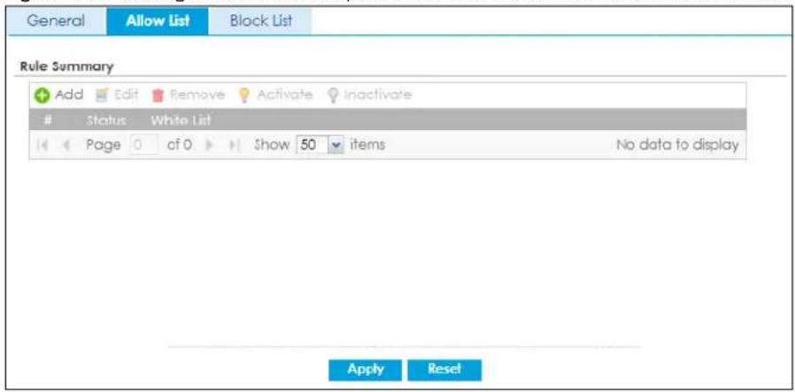
The following table describes the labels in this screen.
Table 293 Configuration > Security Service > Content Filter > DNS Content Filter> Allow List
| LABEL DESCRIPTION | |
| Add Click this to add a new rule. Enter an IPv4 address associated with this rule. | |
| Edit Click this to edit the selected rule. | |
| Remove Click this to remove the selected rule. | |
| Activate | To turn on an entry, select it and click Activate. |
| Inactivate | To turn off an entry, select it and click Inactivate. |
| # This field is a sequential value, and it is not associated with a specific rule. | |
| Status | This icon is lit when the rule is active and dimmed when the rule inactive |
| White List This field displays the IP address associated with this rule. | |
33.7 DNS Content Filter Block List Screen
Click Configuration > Security Service > Content Filter > DNS Content Filter > Block List to open the Block List screen. You can create a list of bad (blocked) web site addresses. When you configure DNS Content Filter Profiles, you can select the option to check the block list. Use this screen to add or remove specific sites from the block list.
Figure 495 Configuration > Security Service > Content Filter > DNS Content Filter> Block List
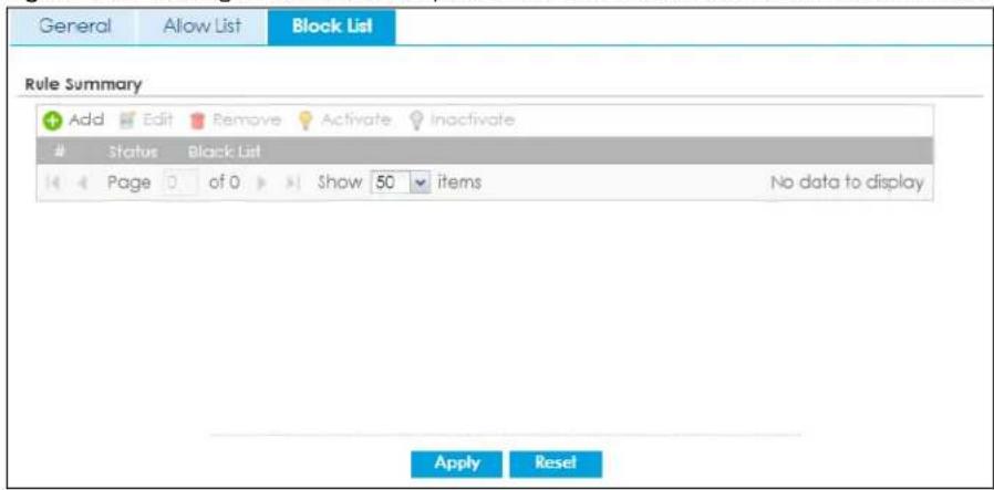
The following table describes the labels in this screen.
Table 294 Configuration > Security Service > Content Filter > DNS Content Filter> Block List
| LABEL DESCRIPTION | |
| Add Click this to add a new rule. Enter an IPv4 address associated with this rule. | |
| Edit Click this to edit the selected rule. | |
| Remove Click this to remove the selected rule. | |
| Activate | To turn on an entry, select it and click Activate.The Zyxel Device treats all FQDNs in the blacklist as prohibited, and applies DNS Content Filter rules when they are queried. |
| Inactivate | To turn off an entry, select it and click Inactivate. |
| # This field is a sequential value, and it is not associated with a specific rule. | |
| Status | This icon is lit when the rule is active and dimmed when the rule inactive |
| White List This field displays the IP address associated with this rule. | |
33.8 Content Filter Technical Reference
This section provides content filtering background information.
External Content Filter Server Lookup Procedure
The content filter lookup process is described below.
Figure 496 Content Filter Lookup Procedure
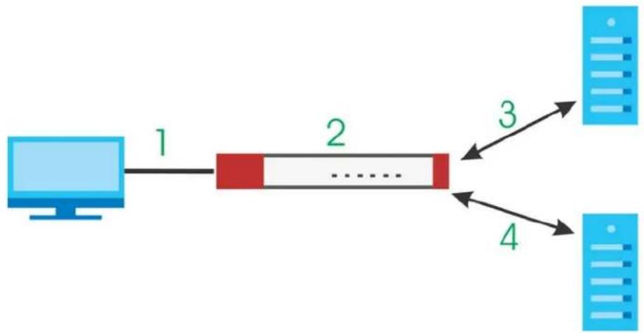
flowchart
graph LR
    A["Computer"] -->|1| B["Red Block"]
    B -->|2| C["..."]
    C -->|3| D["Server 1"]
    C -->|4| E["Server 2"]
1 A computer behind the Zyxel Device tries to access a web site.
2 The Zyxel Device looks up the web site in its cache. If an attempt to access the web site was made in the past, a record of that web site's category will be in the Zyxel Device's cache. The Zyxel Device blocks, blocks and logs or just logs the request based on your configuration.
3 Use the Content Filter Cache screen to configure how long a web site address remains in the cache as well as view those web site addresses. All of the web site address records are also cleared from the local cache when the Zyxel Device restarts.
4 If the Zyxel Device has no record of the web site, it queries the external content filter database and simultaneously sends the request to the web server.
5 The external content filter server sends the category information back to the Zyxel Device, which then blocks and/or logs access to the web site based on the settings in the content filter profile. The web site's address and category are then stored in the Zyxel Device's content filter cache.
33.9 Example: Block LAN Users From Using a Remote WAN Application
This example shows you how to block LAN users from using a remote WAN application such as TeamViewer.
Client C1 on the Zyxel Device LAN uses computer A. Client C2 on the WAN uses computer B. Computer A and computer B are connected to the TeamViewer server (S). Client C1 could access computer B using TeamViewer. Client C2 could access computer A using TeamViewer. TeamViewer only works if computer A and computer B are both connected to the TeamViewer server (S).
Figure 497 Content Filter Tutorial Example
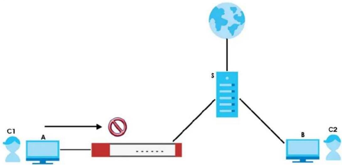
flowchart
graph TD
    C1["C1"] --> A["A"]
    A --> B["Red Block"]
    B --> S["S"]
    S --> B2["B"]
    B2 --> C2["C2"]
    S --> G[" globe "]
    style S fill:#333,stroke:#000,color:#fff
    style A fill:#fff,stroke:#000
    style B fill:#fff,stroke:#000
    style C2 fill:#fff,stroke:#000
    note right of B "no"
You want to block all LAN clients from using TeamViewer. Create a Content Filtering profile that includes the remote access category. Create a Forbidden Web Sites rule with TeamViewer as the keyword. Then apply the profile to the LAN_Outgoing security policy.
All LAN clients are now blocked from using TeamViewer.
This example uses the parameters listed below.
Table 295 Content Filtering Profile Configuration Example
| PROFILE NAME | ENABLE CONTENT FILTER CATEGORY SERVICE | ACTION LOG | MANAGED CATEGORIES | LOG-ALERT FOR BLOCK/WARN ACTION |
| NoRemoteAccess | Enabled | Block | Log | Remote Access |
Table 296 Forbidden Web Sites Configuration Example
| ENABLE CUSTOM SERVICE | FORBIDDEN WEB SITES KEYWORD |
| Enabled *.*teamviewer*.* |
Table 297 Security Policy Configuration Example
| TO FROM LOG CONTENT FILTERING PROFILE | |||
| WAN | LAN1/LAN2 | By Profile | NoRemoteAccess |
1 Go to Configuration > Security Service > Content Filter > Web Content Filter > General and click Add.
2 Configure the profile settings using the parameters given in Table 295 on page 771.
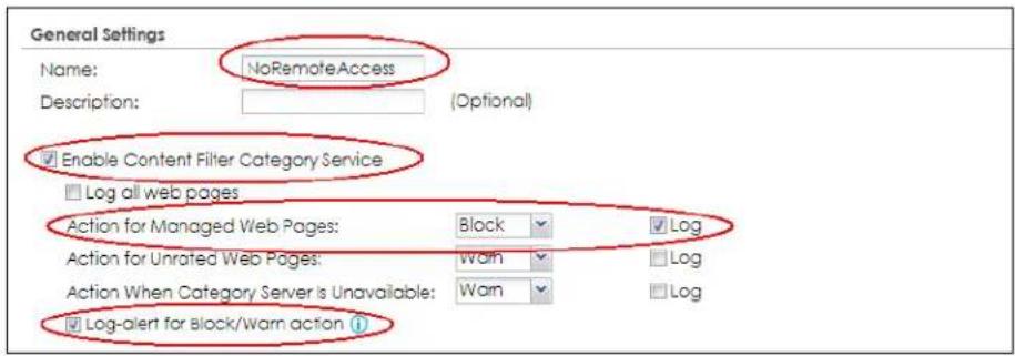
3 Select the Remote Access checkbox under Managed Categories.
| Managed Categories | ||
| □ Adult Topics | □ Alcohol | □ Anonymizing Utilities |
| □ Art Culture Heritage | □ Auctions Classifieds | □ Blogs/Wiki |
| □ Business | □ Chat | □ Computing Internet |
| □ Consumer Protection | □ Content Server | □ Controversial Opinions |
| □ Cult Occult | □ Dating Personals | □ Dating Social Networking |
| □ Digital Postcards | □ Discrimination | □ Drugs |
| □ Education Reference | □ Entertainment | □ Extreme |
| □ Fashion Beauty | □ Finance Banking | □ For Kids |
| □ Forum Bulletin Boards | □ Gambling | □ Gambling Related |
| □ Game Cartoon Violence | □ Games | □ General News |
| □ Government Military | □ Grussome Content | □ Health |
| □ Historical Revisionism | □ History | □ Humor Comics |
| □ Illegal UK | □ Incidental Nudity | □ Information Security |
| □ Information Security New | □ Instant Messaging | □ Interactive Web Applications |
| □ Internet Radio TV | □ Internet Services | □ Job Search |
| □ Major Global Religions | □ Marketing Merchandising | □ Media Downloads |
| □ Media Sharing | □ Messaging | □ Mobile Phone |
| □ Moderated | □ Motor Vehicles | □ Non Profit Advocacy NGO |
| □ Nudity | □ Online Shopping | □ P2P File Sharing |
| □ PUPs | □ Parked Domain | □ Personal Network Storage |
| □ Personal Pages | □ Pharmacy | □ Politics Opinion |
| □ Pornography | □ Portal Sites | □ Potential Criminal Activities |
| □ Potential Hacking Computer Crime | □ Potential Illegal Software | □ Private IP Addresses |
| □ Profanity | □ Professional Networking | □ Provocative Attre |
| ■ Real Estate. | ■ Recreation Hobbies | |
| □ Public Information □ Remote Access | □ Reserved | |
| □ Religion Ideology □ Resource Sharing | □ Restaurants | |
| □ Residential IP Addresses □ Search Engines | □ Sexual Materials | |
| □ School Cheating Information □ Social Networking | □ Software Hardware | |
| □ Shareware Freeware □ Stock Trading | □ Streaming Media | |
| □ Sports □ Technical Information | □ Text Spoken Only | |
| □ Technical Business Forums □ Tobacco | □ Travel | |
| □ Text Translators □ Violence | □ Visual Search Engine | |
| □ Usenet News □ Web Ads | □ Web Mail | |
| □ Weapons □ Web Phone | ||
4 Go to Custom Service. Select Enable Custom Service.
5 Click Add under Forbidden Web Sites to add a rule using the parameters given in Table 296 on page 771.
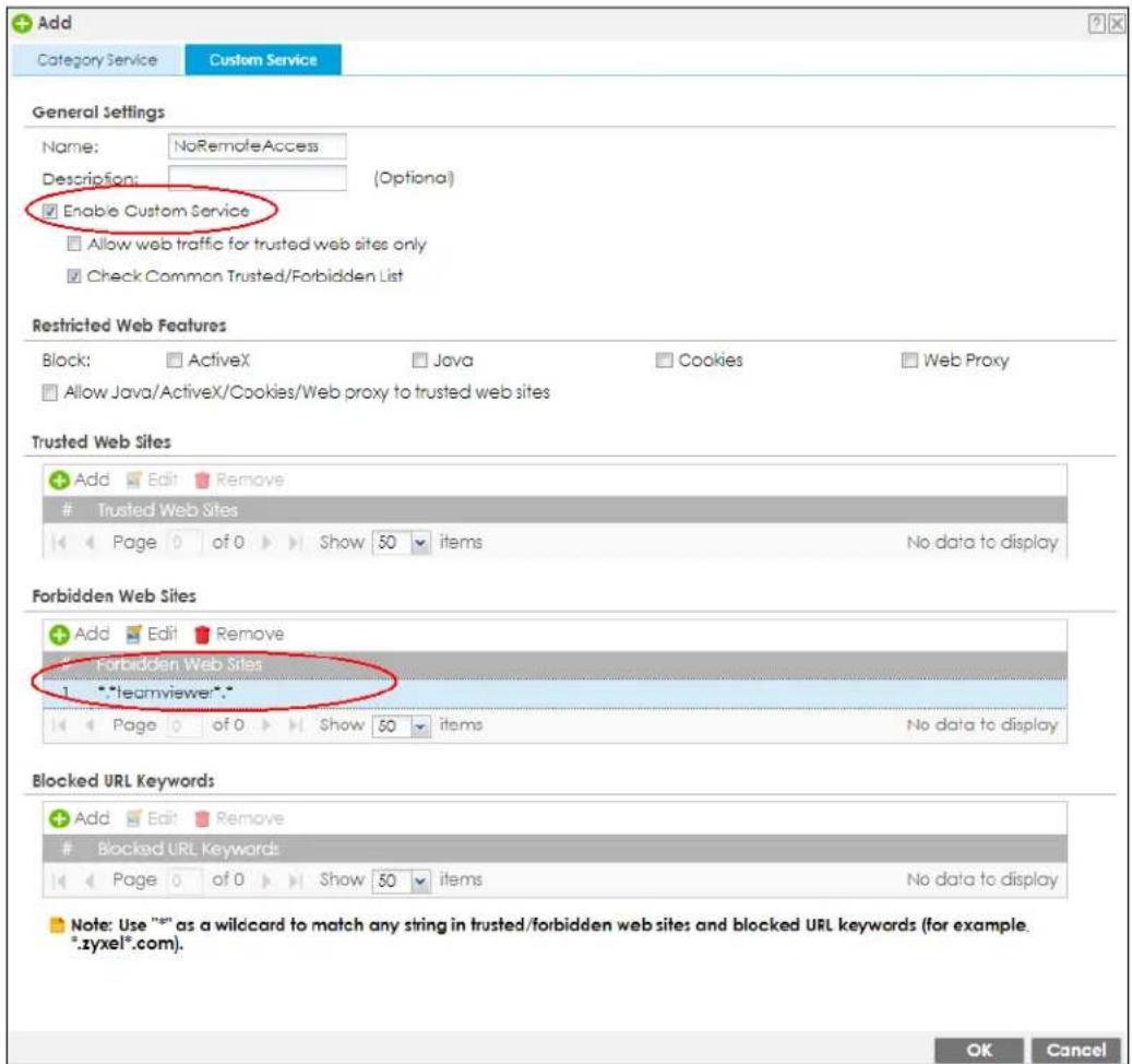
6 Click OK to save your changes.
7 Go to Configuration > Security Policy > Policy Control. Select LAN1_Outgoing then click Edit.
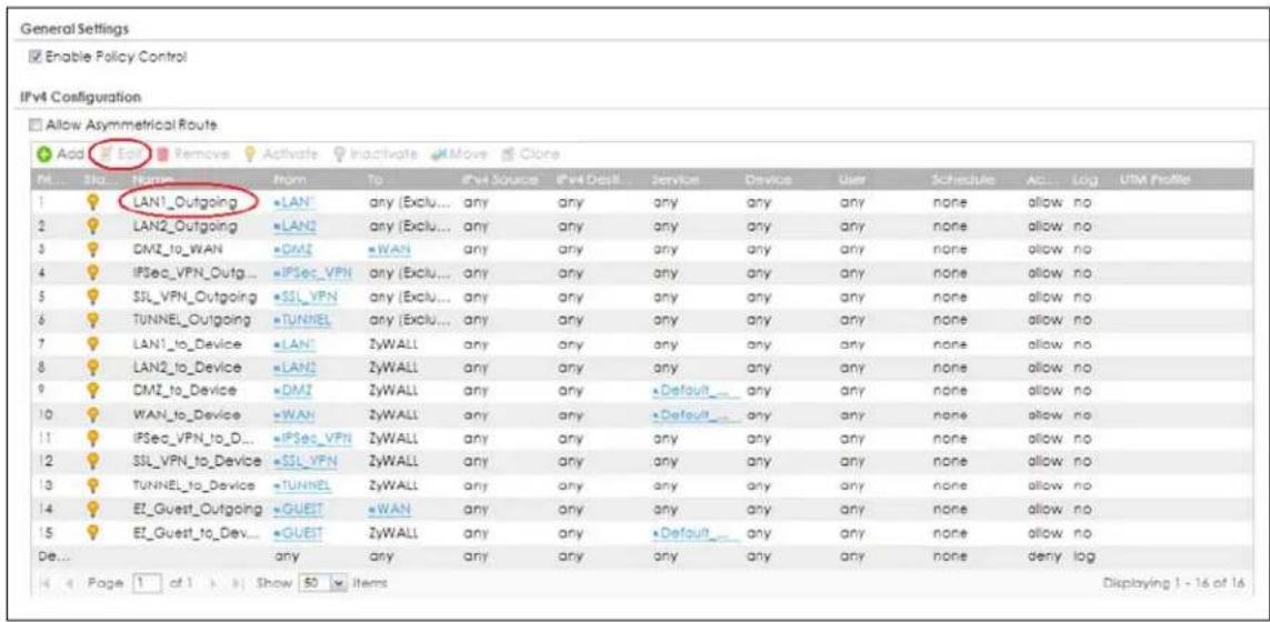
8 Set Web Content Filter to NoRemoteAccess and Log to by profile. Click OK to save your changes.
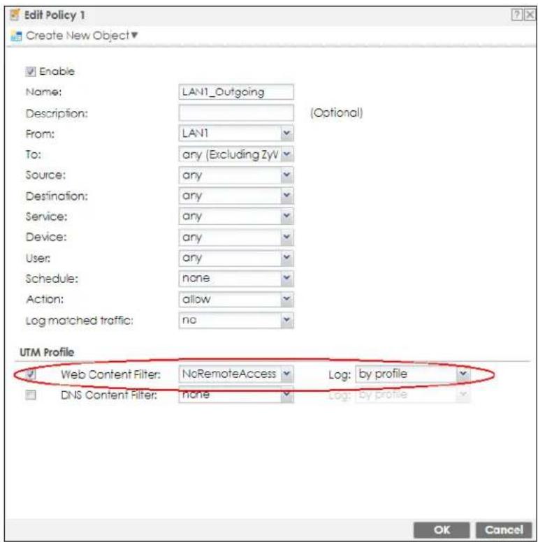
9 Repeat Step 7 and Step 8 to apply the NoRemoteAccess web content filter profile to LAN2_Outgoing.
10 You can check the result in the Policy Control screen. Mouse-over the icon under the UTM Profile column to check that the NoRemoteAccess profile has been applied to the LAN1_Outgoing and LAN2_Outgoing security policies. You can also check the logs in Monitor > Log > View Log. The Zyxel Device will create logs if the clients on the Zyxel Device LAN try to access TeamViewer.
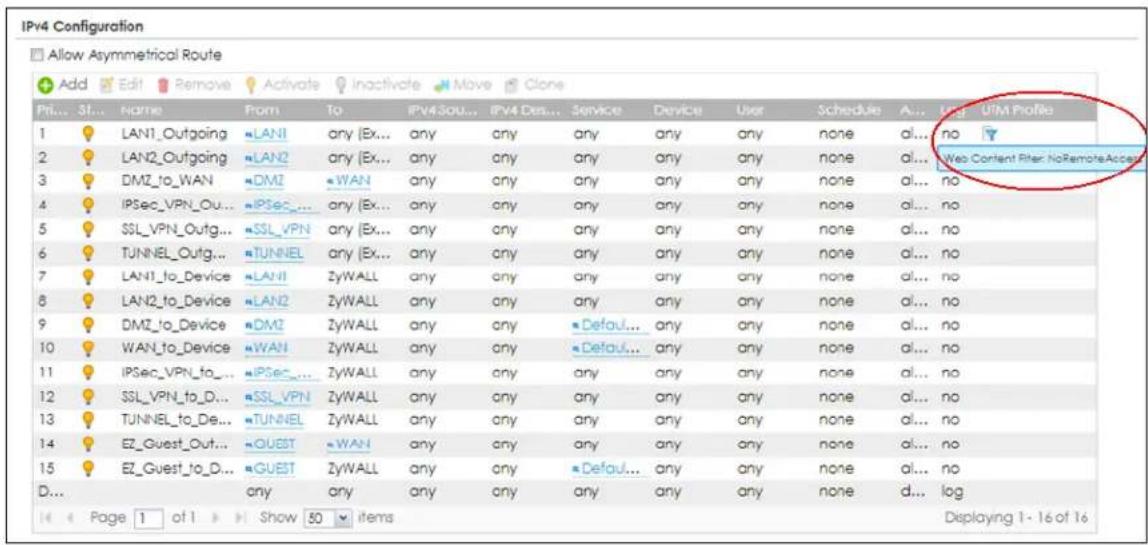
CHAPTER 34
Anti-Malware
34.1 Overview
Use the Zyxel Device's anti-malware feature to protect your connected network from malware (malicious software) infection, such as computer virus, worms, and spyware. The Zyxel Device scans traffic going in both directions for malware signature matches. In the following figure, the Zyxel Device scans traffic coming from the WAN zone (which includes two interfaces) to the LAN zone.
Figure 498 Zyxel Device Anti-Malware Example
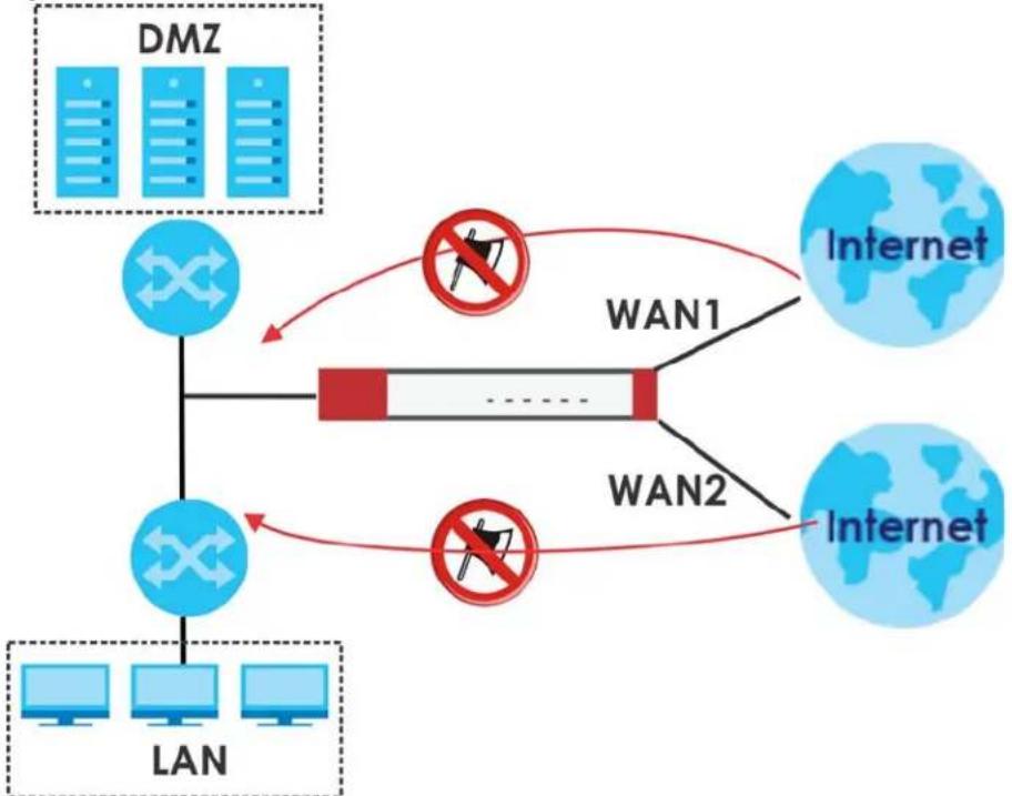
flowchart
graph TD
    A["DMZ"] --> B["LAN"]
    B --> C["WAN1"]
    B --> D["WAN2"]
    C --> E["Internet"]
    D --> F["Internet"]
    style A fill:#cce5ff,stroke:#333
    style B fill:#cce5ff,stroke:#333
    style C fill:#ffcccc,stroke:#333
    style D fill:#ffcccc,stroke:#333
    style E fill:#cce5ff,stroke:#333
    style F fill:#cce5ff,stroke:#333
The anti-malware matches a file with those in a malware database. This is done as files go through the Zyxel Device.
Virus, Worm, and Spyware
A computer virus is a type of malicious software designed to corrupt and/or alter the operation of other legitimate programs. A worm is a self-replicating virus that resides in active memory and duplicates itself. The effect of a virus attack varies from doing so little damage that you are unaware your computer is infected to wiping out the entire contents of a hard drive to rendering your computer inoperable. Spyware infiltrate your device and secretly gathers information about you, such as your network activity, passwords, bank details, and so on.
Hash Value
A hash function is an algorithm that maps data of arbitrary size to data of fixed size. The value returned by a hash function is a hash value. Hash values can be used to identify if the contents of a file have changed. At the time of writing, the MD5 (Message Digest 5) hash algorithm is supported.
Local Signature Databases
The Zyxel Device downloads the signature(s) after it is registered and the anti-malware license is activated at myZyxel. A signature is a unique string of bits, or binary pattern, of a malware. A signature acts as a fingerprint that can be used to detect and identify specific malware. The Zyxel Device downloads the following signatures:
• Anti-malware signature
These signatures are periodically updated if you have a valid license. See Section 34.2 on page 781 for how the Zyxel Device updates these signatures for the anti-malware license.
Cloud Query
Another method of malware protection is through cloud query. This process is illustrated in the next figure. With Cloud Query, the Zyxel Device queries the Defend Center database by sending the file's hash value (A) and receiving the scan results (B) through the Defend Center (DC).
Figure 499 Cloud Query
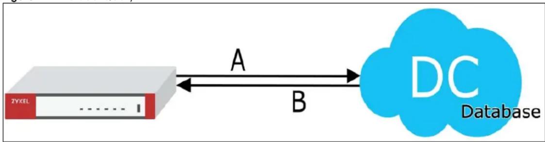
flowchart
graph LR
    A["ZYKEL"] -->|A| B["DC Database"]
    B -->|B| A
Threat Intelligence Machine Learning
Threat Intelligence Machine Learning is a master cloud database containing malware patterns learned from all Zyxel Devices. This allows Zyxel Devices to learn from each other in order to better defend against malware using patterns previously unknown to a single Zyxel Device.
Please note that your Zyxel Device does not support IP reputation and DNS threat filter by default. You need to purchase a gold pack license; see Section 7.1.2 on page 258 for more information.
Anti-Malware Licensing
Having extensive, up-to-date signatures with the most common malware is critical to making the anti-malware service work effectively. Section 7.2 on page 263 shows licensing information for the different signature databases that can be used by the Zyxel Device.
After the anti-malware license expires, you need to purchase an iCard to update your local signature database and use cloud query. Extend your license in the Registration > Service screen.
Anti-Malware Scan Process
Before going through the Anti-Malware scan, the Zyxel Device first identifies the packets sent by the following four major protocols with corresponding standard ports:
- FTP (File Transfer Protocol)
- HTTP (Hyper Text Transfer Protocol)
- SMTP (Simple Mail Transfer Protocol)
• POP3 (Post Office Protocol version 3)
The Zyxel Device records the order of packets in TCP connection-oriented sessions to check for matching malware signatures. The order of non-setup packets such as SYN, ACK and FIN is ignored.
Anti-Malware Scanning Procedure:
1 The Zyxel Device checks every packet of the file for matches with the local signature databases.
If a malware pattern signature is matched, the actions you specify for identified malware will be applied. If Destroy infected file is enabled, the file will be modified. Logs/alerts will be sent according to your settings.
Note: The receiver is not notified if a file is modified by the Zyxel Device. If the file cannot be used, the receiver should contact the Zyxel Device administrator to confirm if the Zyxel Device modified the file by checking the logs.
2 If no match is found with the local databases, the Zyxel Device uses Cloud Query to forward the file's hash value to Defend Center.
3 Defend Center checks its database for malware signature matches and sends the results back to the Zyxel Device.
If a malware signature is matched, the actions you specify for identified malware will be applied. If Destroy infected file is enabled, the file will be modified. Logs/alerts will be sent according to your settings.
The next figure shows a flow chart detailing the anti-malware scan.
Figure 500 Anti-Malware Flowchart
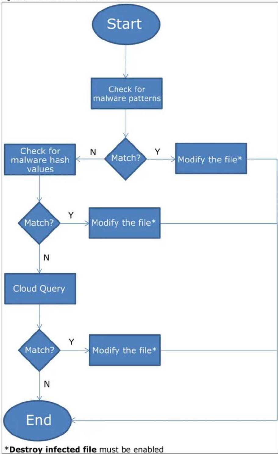
flowchart
graph TD
    A["Start"] --> B["Check for malware patterns"]
    B --> C{Match?}
    C -->|Y| D["Modify the file*"]
    C -->|N| E["Check for malware hash values"]
    E --> F{Match?}
    F -->|Y| G["Modify the file*"]
    F -->|N| H["Cloud Query"]
    G --> I["End"]
    H --> I
    I --> J{Match?}
    J -->|Y| K["Modify the file*"]
    J -->|N| L["*Destroy infected file must be enabled"]
File Scanning Cloud Query Supported File Types
At the time of writing, the following file types are supported:
Table 298 File Scanning Cloud Query Supported File Types
| • 7z Archive (7z) | • AVI Video (avi) | • BMP Image (bmp) | • BZ2 Archive (bz2) |
| • Executables (exe) • | Macromedia Flash Data (swf) | • GIF Image (gif) • G | Z Archive (gz) |
| • JPG Image (jpg) | • MOV Video (mov) | • MP3 Audio (mp3) | • MPG Video (mpg) |
| • MS Office Document (doc...) | • PDF Document (pdf) | • P N G I m a g e (png) • RAR Archive (rar) | |
| • RM Video (rm) | • RTF Document (rtf) | • TIFF Image (tif) | • WAV Audio (wav) |
| • ZIP Archive (zip) | |||
Notes About the Zyxel Device Anti-Malware
The following lists important notes about the Zyxel Device's anti-malware feature:
1 Zyxel's anti-malware feature can detect polymorphic malware (see Section 34.5 on page 787).
2 When malware is detected, a log is created or an alert message is sent to the administrator depending on your log settings.
3 Changes to the Zyxel Device's anti-malware settings only affect new sessions, not sessions that already existed before you applied the changed settings.
4 Enabling Cloud Query may affect file transfer speeds.
5 The Zyxel Device does not scan the following file/traffic types:
- Simultaneous downloads of a file using multiple connections. For example, when you use FlashGet to download sections of a file simultaneously.
- Encrypted traffic. This could be password-protected files or VPN traffic where the Zyxel Device is not the endpoint (pass-through VPN traffic).
- Traffic through custom (non-standard) ports. The Zyxel Device scans whatever port number is specified for FTP in the ALG screen.
- All compressed files within a compressed file. Note that a single file can still be decompressed and scanned if you select Enable file decompression (ZIP and RAR).
- Traffic compressed or encoded using a method the Zyxel Device does not support.
Finding Out More
• See Section 34.7 on page 795 for anti-malware background information.
34.1.1 What You Can Do in this Chapter
- Use the Anti-Malware screen (Section 34.2 on page 781) to turn anti-malware on or off, and check the anti-malware signature status. In addition, you can set up anti-malware black (blocked) and white (allowed) lists of malware patterns.
- Use the White List screen (Section 34.3 on page 785) to specify the file or encryption pattern to allow in order to avoid false positives. False positives occur when a non-infected file matches a malware signature.
- Use the Black List screen (Section 34.4 on page 786) to specify the file or encryption pattern that you want to block.
- Use the Signature screen (Section 34.5 on page 787) to search for particular signatures and get more information about them.
34.2 Anti-Malware Screen
Click Configuration > Security Service > Anti-Malware to display the configuration screen as shown next.
Click the Anti-Malware icon for more information on the Zyxel Device's security features.
Note: Threat Intelligence Machine Learning (TIML) is not available if the gold security pack has expired.
See Subscription Services Available on page 257 for more information on the subscription services for the two types of security packs.
Note: If Destroy infected file is disabled and log is set to no, the Zyxel Device will still perform the scan but will not do anything else. It is recommended to enable at least one of the two functions.
If Destroy infected file is disabled, any malicious file found can still be executed by the end user after it is forwarded. The administrator would have to inform the user if there is an infected file.
Figure 501 Configuration > Security Service > Anti-Malware
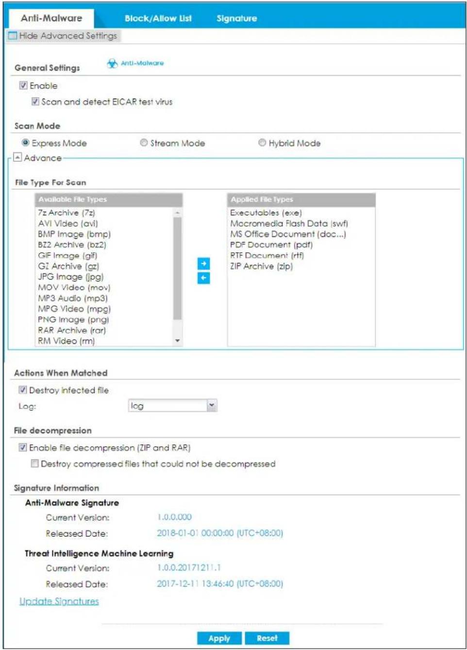
The following table describes the labels in this screen.
Table 299 Configuration > Security Service > Anti-Malware
| LABEL DESCRIPTION | |
| General Setting | |
| Enable | Select this checkbox to activate the anti-malware feature to protect your connected network from infection and the installation of malicious software.Selecting this checkbox also activates Threat Intelligence Machine Learning (TIML). TIML signatures come from the sandboxing inspection results and helps the Zyxel Device block possible malicious or suspicious files. |
| Scan and detect EICAR test virus | Select this option to have the Zyxel Device check for an EICAR test file and treat it in the same way as a real malware file.The EICAR test file is a standardized test file for signature based anti-malware scanners.When the scanner detects the EICAR file, it responds in the same way as if it found real malware. The EICAR file can also be compressed to test whether the anti-malware software can detect it in a compressed file. The EICAR test string consists of the following human-readable ASCII characters.X5O!P%@AP[4\PZX54(P^)7CC]7)EICAR-STANDARD-ANTIVIRUS-TEST-FILE!H+H* |
| Scan Mode | |
| Express Mode | In this mode you can define which types of files are scanned using the File Type For Scan fields. The Zyxel Device then scans files by sending each file's hash value to a cloud database using cloud query. This is the fastest scan mode. |
| Stream Mode | In this mode the Zyxel Device scans all files for viruses using anti-malware signatures to detect known virus pattens, and Threat Intelligence Machine Learning. Threat Intelligence Machine Learning is a master cloud database containing malware patterns learned from all Zyxel Devices. This is the deepest scan mode. |
| File Type For Scan | |
| Available File Types | File types that can be checked by the Zyxel Device are listed here. Note that the files on this list are currently bypassed. To use this feature on a specific file type, click this file type and then click the right arrow button.See available file types in Table 298 on page 780. |
| Applied File Types | File types that will be checked are listed here. If you don't want a file type to be checked, click this file type and then click the left arrow button. |
| Destroy infected file | When you select this check box, if a malware signature is matched, the Zyxel Device overwrites the infected portion of the file with zeros before being forwarded to the user. The uninfected portion of the file will pass through unmodified. |
| Log These are the log options:no: Do not create a log when a packet matches a signature.log: Create a log on the Zyxel Device when a packet matches a signature.log alert: An alert is an emailed log for more serious events that may need more immediate attention. Select this option to have the Zyxel Device send an alert when a packet matches a signature(s). | |
| Check White List | Select this check box to have the Zyxel Device not perform the anti-malware check on files with names that match the white list patterns. |
| Add Click this to create a new entry. | |
| Edit Select an entry and click this to be able to modify it. | |
| Remove Select an entry and click this to delete it. | |
| Activate | To turn on an entry, select it and click Activate. |
| Inactivate | To turn off an entry, select it and click Inactivate. |
| Status | The activate (light bulb) icon is lit when the entry is active and dimmed when the entry is inactive. |
| LABEL | DESCRIPTION |
| # This is the entry's index number in the list. | |
| File Pattern | This is the file name pattern. If a file's name matches this pattern, the Zyxel Device does not check the file for malware. |
| Check Black List | Select this check box to log and delete files with names that match the black list patterns. |
| Add Click this to create a new entry. | |
| Edit Select an entry and click this to be able to modify it. | |
| Remove Select an entry and click this to delete it. | |
| Activate | To turn on an entry, select it and click Activate. |
| Inactivate | To turn off an entry, select it and click Inactivate. |
| Status | The activate (light bulb) icon is lit when the entry is active and dimmed when the entry is inactive. |
| # This is the entry's index number in the list. | |
| File Pattern | This is the file name pattern. If a file's name that matches this pattern, the Zyxel Device logs and then destroys the file. |
| File decompression | |
| Enable file decompression (ZIP and RAR) | Select this check box to have the Zyxel Device scan a compressed file (the file does not need to have a "zip" or "rar" file extension). The Zyxel Device first decompresses the file and then scans the contents for malware.Note: The Zyxel Device decompresses a compressed file once. The Zyxel Device does NOT decompress any file(s) within a compressed file. |
| Destroy compressed files that could not be decompressed | When you select this check box, the Zyxel Device deletes compressed files that use password encryption.Select this check box to have the Zyxel Device delete any compressed files that it cannot decompress. The Zyxel Device cannot decompress password protected files or a file within another compressed file. There are also limits to the number of compressed files that the Zyxel Device can concurrently decompress.Note: The Zyxel Device's firmware package cannot go through the Zyxel Device with this check box enabled. The Zyxel Device classifies the firmware package as a file that cannot be decompressed and then deletes it. Clear this check box when you download a firmware package from the Zyxel website. It's OK to upload a firmware package to the Zyxel Device with the check box selected. |
| Signature Information | The following fields display information on the current signature set that the Zyxel Device is using. |
| Current Version | This field displays the signature set version number currently used by the Zyxel Device. This number gets larger as the set is enhanced. |
| Released Date This field displays the date and time the set was released. | |
| Threat Intelligence Machine Learning | The following fields display information on the Threat Intelligence Machine Learning signatures that the Zyxel Device is using. |
| Current Version | This field displays the TIML version number currently used by the Zyxel Device. |
| Released Date This field displays the date and time this version was released. | |
| Update Signatures | Click this link to go to the screen you can use to download signatures from the update server. |
| Apply | Click Apply to save your changes. |
| Reset | Click Reset to return the screen to its last-saved settings. |
34.3 The Allow List Screen
A allow list allows you to specify the file or encryption pattern to allow in order to avoid false positives. False positives occur when a non-infected file matches a malware signature.
Enter a file or encryption pattern that would cause the Zyxel Device to allow this file.
Click Configuration > Security Service > Anti-Malware > Block/ Allow List > Allow List to display the following screen. Use Add to put a new entry in the list or Edit to change an existing one or Remove to delete an existing entry.
Figure 502 Configuration > Security Service > Anti-Malware > Block/Allow List > Allow List
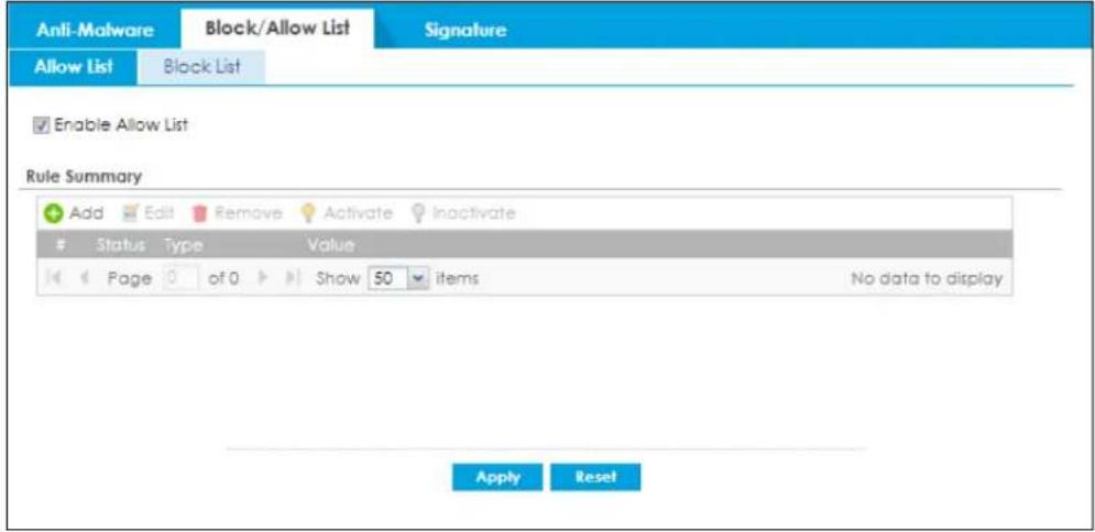
The following table describes the fields in this screen.
Table 300 Configuration > Security Service > Anti-Malware > Block/Allow List > Allow List
| LABEL DESCRIPTION | |
| Enable Allow List | Select this to bypass checking by this feature (if enabled) and automatically allow incoming files with names or algorithm (MD5 Hash) that match the white list patterns. |
| Add Click this to create a new entry. | |
| Edit Select an entry and click this to be able to modify it. | |
| Remove Select an entry and click this to delete it. | |
| Activate | To turn on an entry, select it and click Activate. |
| Inactivate To turn off an entry, select it and click Inactivate. | |
| # This is the entry's index number in the list. | |
| Status | The activate (light bulb) icon is lit when the entry is active and dimmed when the entry is inactive. |
| Type | This field displays the type (MD5 Hash or File Pattern) used to distinguish whether a file should be allowed.Select the type (MD5 Hash or File Pattern) that you want to use to distinguish whether a file should be allowed. |
Table 300 Configuration > Security Service > Anti-Malware > Block/Allow List > Allow List
| LABEL DESCRIPTION | |
| Value | This field displays the file or encryption pattern of the entry.Enter the file or encryption pattern for this entry. Specify a pattern to identify the names of files that the Zyxel Device should not scan for viruses.Use up to 80 characters, Alphanumeric characters, underscores ( ), dashes (-), question marks (?) and asterisks (*) are allowed.A question mark (?) lets a single character in the file name vary. For example, use "a? .zip" (without the quotation marks) to specify aa.zip, ab.zip and so on.Wildcards (*) let multiple files match the pattern. For example, use "*a.zip" (without the quotation marks) to specify any file that ends with "a.zip". A file named "testa.zip would match. There could be any number (of any type) of characters in front of the "a.zip" at the end and the file name would still match. A file named "test.zipa" for example would not match.A * in the middle of a pattern has the Zyxel Device check the beginning and end of the file name and ignore the middle. For example, with "abc*.zip", any file starting with "abc" and ending in ".zip" matches, no matter how many characters are in between.The whole file name has to match if you do not use a question mark or asterisk.If you do not use a wildcard, the Zyxel Device checks up to the first 80 characters of a file name. |
| Apply | Click Apply to save your changes back to the Zyxel Device. |
| Reset | Click Reset to return the screen to its last-saved settings. |
34.4 The Block List Screen
A block list allows you to specify the file or encryption pattern that you want to block.
Enter a file or encryption pattern that would cause the Zyxel Device to log and then destroy this file.
Click Configuration > Security Service > Anti-Malware > Block/ Allow List > Block List to display the following screen. Use Add to put a new entry in the list or Edit to change an existing one or Remove to delete an existing entry.
Figure 503 Configuration > Security Service > Anti-Malware > Block/Allow List > Block List
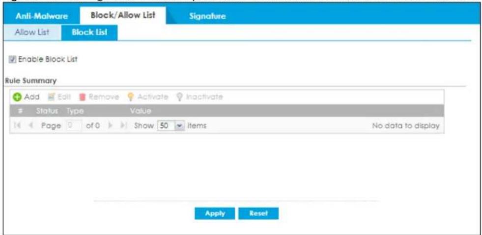
The following table describes the fields in this screen.
Table 301 Configuration > Security Service > Anti-Malware > Block/Allow List > Block List
| LABEL DESCRIPTION | |
| Enable Block List | Select this to bypass checking by this feature (if enabled) and automatically block incoming files with names or encryption algorithm (MD5 Hash) that match the black list patterns. |
| Add Click this to create a new entry. | |
| Edit Select an entry and click this to be able to modify it. | |
| Remove Select an entry and click this to delete it. | |
| Activate | To turn on an entry, select it and click Activate. |
| Inactivate To turn off an entry, select it and click Inactivate. | |
| # This is the entry's index number in the list. | |
| Status | The activate (light bulb) icon is lit when the entry is active and dimmed when the entry is inactive. |
| Type | This field displays the type (MD5 Hash or File Pattern) used to distinguish whether a file should be blocked.Select the type (MD5 Hash or File Pattern) that you want to use to distinguish whether a file should be blocked. |
| Value | This field displays the file or encryption pattern of the entry. Enter a file pattern that would cause the Zyxel Device to log and modify this file.Use up to 80 characters. Alphanumeric characters, underscores ( ), dashes (-), question marks (?) and asterisks (*) are allowed.A question mark (?) lets a single character in the file name vary. For example, use “a?.zip” (without the quotation marks) to specify aa.zip, ab.zip and so on.Wildcards (*) let multiple files match the pattern. For example, use “*a.zip” (without the quotation marks) to specify any file that ends with “a.zip”. A file named “testa.zip would match. There could be any number (of any type) of characters in front of the “a.zip” at the end and the file name would still match. A file named “test.zipa” for example would not match.A * in the middle of a pattern has the Zyxel Device check the beginning and end of the file name and ignore the middle. For example, with “abc*.zip”, any file starting with “abc” and ending in “.zip” matches, no matter how many characters are in between.The whole file name has to match if you do not use a question mark or asterisk.If you do not use a wildcard, the Zyxel Device checks up to the first 80 characters of a file name. |
| Apply | Click Apply to save your changes back to the Zyxel Device. |
| Reset | Click Reset to return the screen to its last-saved settings. |
34.5 Anti-Malware Signature Searching
Click Configuration > Security Service > Anti-Malware > Signature to display this screen. Use this screen to locate signatures and display details about them.
If your web browser opens a warning screen about a script making the web browser run slowly and the computer unresponsive, just click No to continue.
Click a column's heading cell to sort the table entries by that column's criteria. Click the heading cell again to reverse the sort order.
Figure 504 Configuration > Security Service > Anti-Malware > Signature
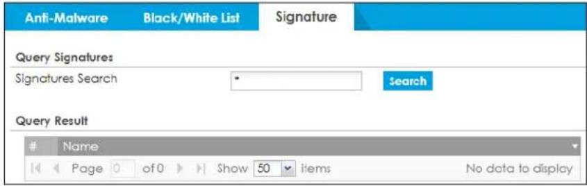
The following table describes the labels in this screen.
Table 302 Configuration > Security Service > Anti-Malware > Signature
| LABEL DESCRIPTION | |
| Signatures Search | Enter the name, part of the name or keyword of the signature(s) you want to find and click Search. This search is not case-sensitive and accepts numerical strings. |
| Query Result | |
| # This is the entry's index number in the list. | |
| Name | This is the name of the anti-malware signature. Click the Name column heading to sort your search results in ascending or descending order according to the signature name. |
34.6 Anti-Malware Profile
To use multiple profiles for this feature, run the following commands in the Zyxel Device Command Line Interface (CLI).
Router# configure terminal
Router(config)# secure-policy-style advance
Router(config)# show secure-policy-style status
secure-policy-style: advance
After you run these command, go to the feature screen again in the web configurator. You will be prompted to log out and then log in again.
Figure 505 Logout Prompt
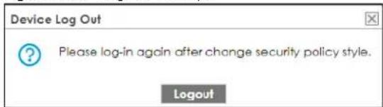
After you log in again, you will see the new profile screen for this feature.
Figure 506 Configuration > Security Service > Anti-Malware > Profile
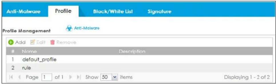
The following table describes the labels in this screen.
Table 303 Configuration > Security Service > Anti-Malware > Profile
| LABEL DESCRIPTION | |
| Add | Click this to create a new entry. Select an entry and click Add to create a new entry after the selected entry. |
| Edit | Double-click an entry or select it and click Edit to open a screen where you can modify the entry's settings. |
| Remove | Select an entry and click Remove to delete the selected entry. |
| # | This field is a sequential value showing the number of the profile. The profile order is not important. |
| Name This displays the name of the profile created. | |
| Description This displays the description of the profile. | |
34.6.1 Add or Edit an Anti-Malware Profile
Click Add to create a new entry or select an existing entry and click Edit to open the following screen where you can create or modify the entry's settings.
Figure 507 Configuration > Security Service > Anti-Malware > Profile > Add/Edit
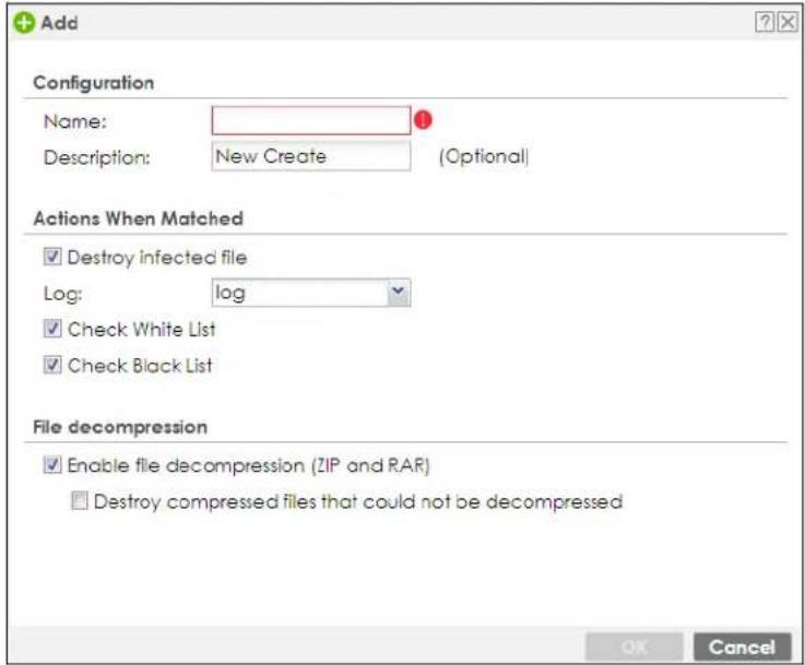
The following table describes the labels in this screen.
Table 304 Configuration > Security Service > Anti-Malware > Profile > Add/Edit
| LABEL DESCRIPTION | |
| General Setting | |
| Name | Type the name of the profile. You may use 1-31 alphanumeric characters, underscores( ), or dashes (-), but the first character cannot be a number. This value is case-sensitive. These are valid, unique profile names:My Profilem Y ProfileMymy12_3-4These are invalid profile names:1mYProfileMy ProfileM y Profile?Whatalongprofilename123456789012 |
| Description | Type a description for the profile rule to help identify the purpose of rule. You may use 1-31 alphanumeric characters, underscores ( ), or dashes (-), but the first character cannot be a number. This value is case-sensitive. This field is optional. |
| Actions When Matched | |
| Destroy infected file | When you select this check box, if a malware signature is matched, the Zyxel Device overwrites the infected portion of the file with zeros before being forwarded to the user. The uninfected portion of the file will pass through unmodified. |
| Log These are the log options:no: Do not create a log when a packet matches a signature.log: Create a log on the Zyxel Device when a packet matches a signature.log alert: An alert is an emailed log for more serious events that may need more immediate attention. Select this option to have the Zyxel Device send an alert when a packet matches a signature(s). | |
| Scan Options | |
| Check White List | Select this check box to have the Zyxel Device not perform the anti-malware check on files with names that match the white list patterns. |
| Check Black List | Select this check box to log and delete files with names that match the black list patterns. |
| File decompression | |
| Enable file decompression (ZIP and RAR) | Select this check box to have the Zyxel Device scan a compressed file (the file does not need to have a "zip" or "rar" file extension). The Zyxel Device first decompresses the file and then scans the contents for malware.Note: The Zyxel Device decompresses a compressed file once. The Zyxel Device does NOT decompress any file(s) within a compressed file. |
| Destroy compressed files that could not be decompressed | When you select this check box, the Zyxel Device deletes compressed files that use password encryption.Select this check box to have the Zyxel Device delete any compressed files that it cannot decompress. The Zyxel Device cannot decompress password protected files or a file within another compressed file. There are also limits to the number of compressed files that the Zyxel Device can concurrently decompress.Note: The Zyxel Device's firmware package cannot go through the Zyxel Device with this check box enabled. The Zyxel Device classifies the firmware package as a file that cannot be decompressed and then deletes it. Clear this check box when you download a firmware package from the Zyxel website. It's OK to upload a firmware package to the Zyxel Device with the check box selected. |
| OK | Click OK to save your changes back to the Zyxel Device. |
| Cancel | Click Cancel to exit this screen without saving. |
34.6.2 Link a Profile
To link a profile to a policy, go to the Configuration > Security Policy > Policy Control screen, select a policy, and then click Edit. In the Edit Policy screen under Profile, select which profile you want to use for each security service.
Figure 508 Configuration > Security Service > Policy Control > Profile
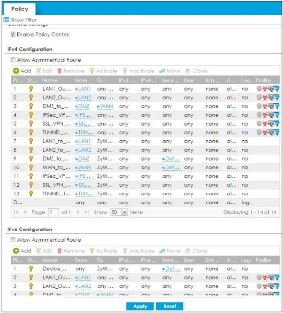
34.6.3 Anti-Malware Advance Screen
The Security Service > Anti-Malware > Anti-Malware screen changes when using profiles.
Figure 509 Configuration > Security Service > Anti-Malware Advance
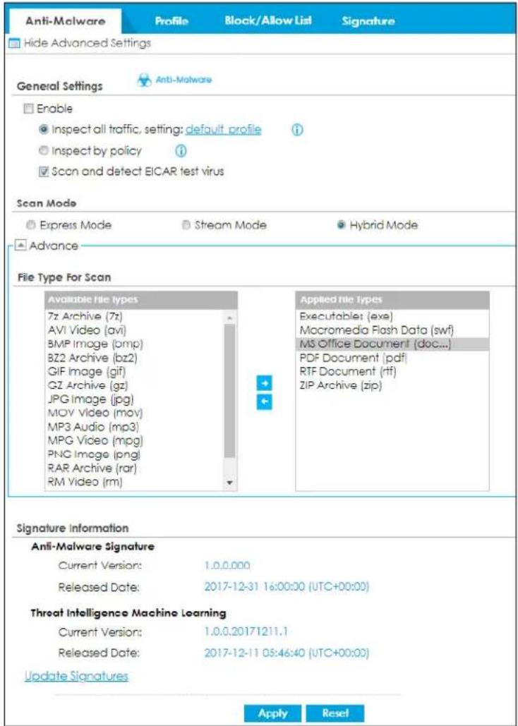
The following table describes the labels in this screen.
Table 305 Configuration > Security Service > Anti-Malware Advance
| LABEL DESCRIPTION | |
| General Setting | |
| Enable | Select this checkbox to activate the anti-malware feature to protect your connected network from infection and the installation of malicious software.Selecting this checkbox also activates Threat Intelligence Machine Learning (TIML). TIML signatures come from the sandboxing inspection results and helps the Zyxel Device block possible malicious or suspicious files. |
| Inspect all traffic, setting: | Select this to have all traffic inspected by thedefault_profile. You cannot rename or delete thedefault_profileprofile, but you can edit it by clicking the link here. |
| Inspect by policy | If you configured a specific profile in theProfiletab for this service, select this to have specific traffic inspected by that profile. You must bind the profile to a policy inSecurity Policy >Policy Control. |
| Scan and detect EICAR test virus | Select this option to have the Zyxel Device check for an EICAR test file and treat it in the same way as a real malware file.The EICAR test file is a standardized test file for signature based anti-malware scanners.When the scanner detects the EICAR file, it responds in the same way as if it found real malware. The EICAR file can also be compressed to test whether the anti-malware software can detect it in a compressed file. The EICAR test string consists of the following human-readable ASCII characters.X5O!P%@AP[4\PZX54(P^)7CC]7)EICAR-STANDARD-ANTIVIRUS-TEST-FILE!H+H* |
| Scan Mode | |
| Express Mode | In this mode you can define which types of files are scanned using the File Type For Scan fields. The Zyxel Device then scans files by sending each file's hash value to a cloud database using cloud query. This is the fastest scan mode. |
| Stream Mode | In this mode the Zyxel Device scans all files for viruses using anti-malware signatures to detect known virus pattens, and Threat Intelligence Machine Learning. Threat Intelligence Machine Learning is a master cloud database containing malware patterns learned from all Zyxel Devices. This is the deepest scan mode. |
| File Type For Scan | |
| Available File Types | File types that can be checked by the Zyxel Device are listed here. Note that the files on this list are currently bypassed. To use this feature on a specific file type, click this file type and then click the right arrow button.See available file types in Table 298 on page 780. |
| Applied File Types | File types that will be checked are listed here. If you don't want a file type to be checked, click this file type and then click the left arrow button. |
| Signature Information | The following fields display information on the current signature set that the Zyxel Device is using. |
| Current Version | This field displays the signature set version number currently used by the Zyxel Device. This number gets larger as the set is enhanced. |
| Released Date This | field displays the date and time the set was released. |
| Threat Intelligence Machine Learning | The following fields display information on the Threat Intelligence Machine Learning signatures that the Zyxel Device is using. |
| Current Version | This field displays the TIML version number currently used by the Zyxel Device. |
| Released Date This | field displays the date and time this version was released. |
| Update Signatures | Click this link to go to the screen you can use to download signatures from the update server. |
| Apply | Click Apply to save your changes. |
| Reset | Click Reset to return the screen to its last-saved settings. |
34.6.4 Remove Profiles
To remove profiles and revert to the default general security policy style, you must first make sure to change Inspect by policy to Inspect all traffic in the following security services: Anti-Malware, DNS Threat Filter, IPS, Email Security.
Note: All profiles that you created will be removed from Security Policy > Policy Control.
Run the following commands in the Zyxel Device Command Line Interface (CLI).
Router# configure terminal
Router(config)# secure-policy-style general
Router(config)# show secure-policy-style status
secure-policy-style: general
Wait a minute and then go to the feature screen again in the web configurator. You will be prompted to log out and then log in again.
Figure 510 Logout Prompt
After you log in again, you will not see the profile screen for this feature.
34.7 Anti-Malware Technical Reference
Types of Malware
The following table describes some of the common malware.
Table 306 Common Malware Types
| TYPE DESCRIPTION | |
| File Infector | This is a small program that embeds itself in a legitimate program. A file infector is able to copy and attach itself to other programs that are executed on an infected computer. |
| Boot Sector Virus | This type of virus infects the area of a hard drive that a computer reads and executes during startup. The virus causes computer crashes and to some extend renders the infected computer inoperable. |
| Macro Virus | Macro viruses or Macros are small programs that are created to perform repetitive actions. Macros run automatically when a file to which they are attached is opened. Macros spread more rapidly than other types of viruses as data files are often shared on a network. |
| Email Virus Email viruses | are malicious programs that spread through email. |
| Polymorphic Virus | A polymorphic virus (also known as a mutation virus) tries to evade detection by changing a portion of its code structure after each execution or self replication. This makes it harder for an anti-malware scanner to detect or intercept it.A polymorphic virus can also belong to any of the virus types discussed above. |
Malware Infection and Prevention
The following describes a simple life cycle of malware.
1 A computer gets a copy of malware from a source such as the Internet, email, file sharing or any removable storage media. The malware is harmless until the execution of an infected program.
2 The malware spreads to other files and programs on the computer.
3 The infected files are unintentionally sent to another computer thus starting the spread of the malware.
4 Once the malware is spread through the network, the number of infected networked computers can grow exponentially.
Types of Anti-Malware Scanner
The section describes two types of anti-malware scanner: host-based and network-based.
A host-based anti-malware (HAM) scanner is often software installed on computers and/or servers on the network. It inspects files for malware patterns as they are moved in and out of the drive. However, host-based anti-malware scanners cannot eliminate all malware for a number of reasons:
- HAM scanners are slow in stopping malware threats through real-time traffic (such as from the Internet).
- HAM scanners may reduce computing performance as they also share resources (such as CPU time) on the computer for file inspection.
- You have to update the malware signatures and/or perform malware scans on all computers on the network regularly.
A network-based anti-malware (NAM) scanner is often deployed as a dedicated security device (such as your Zyxel Device) on the network edge. NAM scanners inspect real-time data traffic (such as email messages or web) that tends to bypass HAM scanners. The following lists some of the benefits of NAM scanners.
- NAM scanners stop malware threats at the network edge before they enter or exit a network.
- NAM scanners reduce computing loading on computers as the read-time data traffic inspection is done on a dedicated security device.
CHAPTER 35
Reputation Filter
35.1 Overview
Use the Reputation Filter screens to configure settings for IP Reputation, DNS Threat Filter and URL Threat filtering.
Please note that your Zyxel Device does not support IP reputation and DNS threat filter by default. You need to purchase a gold pack license; see Section 7.1.2 on page 258 for more information.
35.1.1 What You Need to Know
IP Reputation
IP reputation checks the reputation of an IP address from a database. An IP address with bad reputation associates with suspicious activities, such as spam, virus, and/or phishing. The Zyxel Device will respond when there are packets coming from an IPv4 address with bad reputation.
DNS Threat Filter
DNS threat filtering inspects DNS queries made by clients on your network and compares the queries against a database of blocked or allowed Fully Qualified Domain Names (FQDNs). The Zyxel Device DNS Threat Filter will either drop the DNS query or reply to the user with a fake DNS response.
URL Threat Filter
URL filtering compares access to specific URLs against a database of blocked or allowed sites. Sites on the database are sorted into categories such as:
| • A non y m i ze | r s • B ro | w s e r E x p l o i t s • Malicious Downloads |
| • Malicious Sites • Phishing • S p a m U R L s | ||
| • Spyware Adware Keyloggers |
35.1.2 What You Can Do in this Chapter
- Use the IP Reputation screen (Section 35.2 on page 798) to enable IP reputation and specify what action the Zyxel Device takes when any IP address with bad reputation is detected.
- Use the DNS Threat Filter screen (Section 35.3 on page 806) to allow the Zyxel Device to inspect DNS queries made by clients on your network and specify what action the Zyxel Device takes when a DNS query packet contains an FQDN with a bad reputation.
- Use the URL Threat Filter screen (Section 35.5 on page 819) to enable URL Threat filtering and specify what action the Zyxel Device takes when any suspicious activity is detected.
35.2 IP Reputation Screen
When you register for and enable the IP reputation service, your Zyxel Device downloads signature files that identifies reputation of IPv4 addresses. You can have the Zyxel Device forward, block, and/or log packets from IPv4 addresses based on these signatures and categories.
Use this screen to enable IP reputation and specify the action the Zyxel Device takes when it detects a suspicious activity or a connection attempt to or from an IPv4 address with bad reputation.
The priority for IP Reputation checking is as follows:
1 Allow List
2 Block List
3 External Block List
4 Local Zyxel Device Signatures
Click Configuration > Security Service > Reputation Filter > IP Reputation > General to display the configuration screen as shown next.
Figure 511 Configuration > Security Service > Reputation Filter > IP Reputation > General
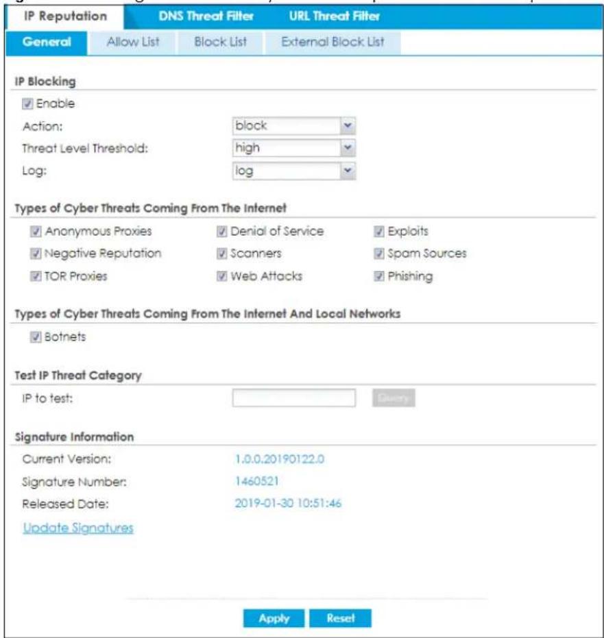
The following table describes the labels in this screen.
Table 307 Configuration > Security Service > Reputation Filter > IP Reputation > General
| LABEL DESCRIPTION | |
| IP Blocking | |
| Enable | Select this option to turn on IP blocking on the Zyxel Device. Otherwise, clear it. |
| Action | Set what action the Zyxel Device takes when packets come from an IPv4 address with bad reputation.forward: Select this action to have the Zyxel Device allow the packet to go through.block: Select this action to have the Zyxel Device deny the packets and send a TCP RST to both the sender and receiver when a packet comes from an IPv4 address with bad reputation. |
| Threat Level Threshold | Select the threshold threat level to which the Zyxel Device will take action (high, medium and above, Low and above).The threat level is determined by the IP reputation engine. It grades IPv4 addresses.high: An IPv4 address that scores 0 to 20 points.medium and above: An IPv4 address that scores 0-60 points.Low and above: An IPv4 address that scores 0-80 points. |
| Log These are the log | options:no: Do not create a log when the packet comes from an IPv4 address with bad reputation.log: Create a log on the Zyxel Device when the packet comes from an IPv4 address with bad reputation.log alert: An alert is an emailed log for more serious events that may need more immediate attention. Select this option to have the Zyxel Device send an alert when the packet comes from an IPv4 address with bad reputation. |
| Types of Cyber Threats Coming From The Internet | Select the categories of packets that come from the Internet and are known to pose a security threat to users or their computers. Otherwise, deselect it. |
| Anonymous Proxies | These are sites and proxies that act as an intermediary for surfing to other websites in an anonymous fashion, whether to circumvent Web filtering or for other reasons. |
| Denial of Service | These are sites that issue Denial of Service (DoS) attacks, such as DoS, DDoS, SYN flood, and anomalous traffic detection.DoS attacks can flood your Internet connection with invalid packets and connection requests, using so much bandwidth and so many resources that Internet access becomes unavailable. The goal of DoS attacks is not to steal information, but to disable a device or network on the Internet.A Distributed Denial of Service (DDoS) attack is one in which multiple compromised systems attack a single target, thereby causing denial of service for users of the targeted system.SYN flood is an attack that attackers flood SYN packets to a server in TCP handshakes, and not respond with ACK packets on purpose. This keeps the server waiting for attackers' responses to establish TCP connections, and make the server unavailable.Anomalous traffic detection could be malicious activities, such as malware outbreaks or hacking attempts. |
| Exploits | These are sites that distribute exploits or exploit kits to infect website visitors' devices. Exploits include shellcode, root kits, worms, or viruses that download additional malware to infect devices. An exploit kit consists of different exploits. |
| Negative Reputation | These are sites that have bad reputation and associate with suspicious activities, such as spam, virus, and/or phishing. |
| Scanners | These are sites that run unauthorized system vulnerabilities scan to look for vulnerabilities in website visitors' devices. |
| Spam Sources These are sites that have been promoted through spam techniques. | |
| TOR Proxies These are sites that act as the exit nodes in a Tor (The Onion Router) network.Tor is a service that keep users anonymous in the Internet and make users' Internet activities untraceable. Tor hides user's real IP addresses by encrypting data and transmitting the encrypted data in a chain of selected nodes acting as intermediaries. Each node can only decrypt the data sent from the node before it. The first node that receives the encrypted data is called the entry node. The last node is the last intermediary that the encrypted data will go through before it arrives at the destination. | |
| Web Attacks | These are sites that launch web attacks, such as SQL injection, cross site scripting, iframe injection, and brute force attack.SQL injection (SQLI) is an attack that attackers insert malicious SQL (Structured Query Language) code into a web application database query. Attackers can then access, add, modify, or delete data in users' databases.Cross site scripting (XSS) is an attack that attackers injects malicious scripts to websites or web applications in the form of HTML or JavaScript code. The scripts execute when users visit the infected web page or perform the infected web applications. XSS will cause failures to encrypt traffic, cookie stealing, identity impersonation, and phishing.Iframe injection is an attack that attackers injects malicious iframe (inline frame) tags to websites. The malicious iframe tag downloads malware to the devices of the infected websites' visitors, and steal users' sensitive information. An iframe tag is an HTML tag that is used to embed contents from another source in a website, but attackers misuse this feature.Brute force attack is an attack that attackers attempt to gain access to websites or device via a succession of different passwords. |
| Phishing | These are sites that are used for deceptive or fraudulent purposes (e.g. phishing), such as stealing financial or other user account information. These sites are most often designed to appear as legitimate sites in order to mislead users into entering their credentials. |
| Types of Cyber Threats Coming From The Internet And Local Networks | Select the categories of packets that come from the Internet and local network. The categories of packets are known to pose a security threat to users or their computers. Otherwise, clear it. |
| Botnets | A botnet is a network consisting of computers that are infected with malware and remotely controlled. The infected computers will contact and wait for instructions from a command and control (C&C) server. An attacker can control the botnet by setting up a C&C server and then sending commands to the infected computers. Alternatively, a peer-to-peer network approach is used. The infected computer scans and communicates with the peer devices in the same botnet to share commands or malware sent by the C&C server. These are botnet sites including command-and-control (C&C) servers.IP reputation only blocks incoming and outgoing traffic coming from an IP address that is defined as botnet. If an IP address is not defined as botnet, only incoming traffic is blocked. |
| Test IP Threat Category | |
| IP to test | Enter an IPv4 address of a website, and click theQuerybutton to check if the website associates with suspicious activities that could pose a security threat to users or their computers. |
| Signature Information | The Zyxel Device comes with signatures for IP reputation. These signatures are continually updated as new malware evolves. New signatures can be downloaded to the Zyxel Device periodically if you have subscribed for the IP reputation signatures service.You need to create an account at myZyxel, register your Zyxel Device and then subscribe for IP reputation service in order to be able to download new signatures from myZyxel (see theRegistrationscreens).The following fields display information on the current signature set that the Zyxel Device is using. |
| Current Version | This field displays the signature set version number currently used by the Zyxel Device. This number gets larger as new signatures are added. |
| Signature Number This field displays the number of signatures in this set. | |
| Released Date This field displays the date and time the set was released. | |
| Update Signatures | Click this to go to theConfiguration > Licensing > Signature Updatescreen to check for new signatures at myZyxel. You can schedule or immediately download signatures. |
| Apply | ClickApplyto save your changes. |
| Reset | ClickResetto return the screen to its last-saved settings. |
35.2.1 IP Reputation Allow List Screen
Use this screen to create allow list entries. The Zyxel Device will allow the incoming and outgoing packets from the listed IPv4 addresses.
You can add up to 256 entries in the IP reputation white list.
Figure 512 Configuration > Security Service > Reputation Filter > IP Reputation > Allow List
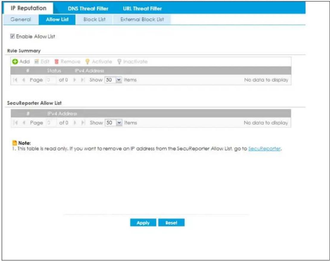
The following table describes the labels in this screen.
Table 308 Configuration > Security Service > Reputation Filter > IP Reputation > Allow List
| LABEL DESCRIPTION | |
| Enable Allow List | Select this to bypass checking by this feature (if enabled) and automatically allow incoming packets from the listed IPv4 addresses. |
| Rule Summary | |
| Add Click this to create a new IP reputation allow list entry. | |
| Edit Select an entry and click this to be able to modify it. | |
| Remove Select an entry and click this to delete it. | |
| Activate | To turn on an entry, select it and click Activate. |
| Inactivate | To turn off an entry, select it and click Inactivate. |
| # This is the entry's index number in the list. | |
| Status | The activate (light bulb) icon is lit when the entry is active and dimmed when the entry is inactive. |
| IPv4 Address | This field displays the IPv4 address of this entry. |
| SecuReporter Allow List | This table displays the IP reputation allow list you set in SecuReporter. Please note that this table is read-only. If you want to change the SecuReporter IP reputation allow list settings, go to SecuReporter.For example, if you add 1.1.1.1 to the SecuReporter IP reputation allow list, the Zyxel Device IP reputation will allow incoming packets from 1.1.1.1 and outgoing packets to 1.1.1.1. |
| # This is the entry's index number in the list. | |
| IPv4 Address | This field displays the IPv4 address of the SecuReporter IP reputation allow list entry. |
| Apply | Click Apply to save your changes back to the Zyxel Device. |
| Reset | Click Reset to return the screen to its last-saved settings. |
35.2.2 IP Reputation Block List Screen
Use this screen to create block list entries. The Zyxel Device will block the incoming and outgoing packets from the listed IPv4 addresses.
You can add up to 256 entries in the IP reputation block list.
Figure 513 Configuration > Security Service > Reputation Filter > IP Reputation > Block List
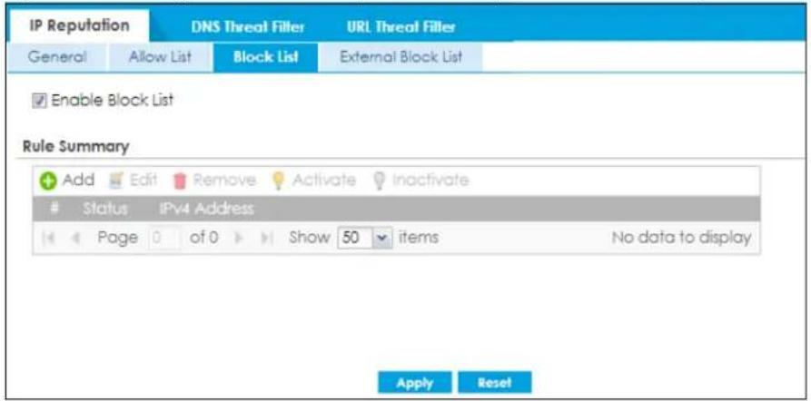
The following table describes the labels in this screen.
Table 309 Configuration > Security Service > Reputation Filter > IP Reputation > Block List
| LABEL DESCRIPTION | |
| Enable Block List | Select this to bypass checking by this feature (if enabled) and automatically block incoming packets from the listed IPv4 addresses. |
| Add Click this to create | a new IP reputation block list entry. |
| Edit Select an entry and | click this to be able to modify it. |
| Remove Select an entry | and click this to delete it. |
| Activate | To turn on an entry, select it and click Activate. |
| Inactivate | To turn off an entry, select it and click Inactivate. |
| # This is the entry's index | number in the list. |
| Status | The activate (light bulb) icon is lit when the entry is active and dimmed when the entry is inactive. |
| IPv4 Address | This field displays the IPv4 address of this entry. |
| Apply | Click Apply to save your changes back to the Zyxel Device. |
| Reset | Click Reset to return the screen to its last-saved settings. |
35.2.3 IP Reputation External Block List Screen
Use this screen to use block list entries stored in a file on a web server that supports HTTP or HTTPS and is reachable from the Zyxel Device. The Zyxel Device will bypass checking by this feature (if enabled) and block incoming and outgoing packets from the black list entries in this file. In this way, different Zyxel Devices can use the same black list.
- The external block list file must be in text format (*.txt) with each entry separated by a new line.
- External block list entries can consist of single IPv4 / IPv6 IP addresses, IP address ranges, CIDR (Classless Inter-Domain Routing entries such as 192.168.1.1/24, 2001:7300:3500::1/64. These are some examples for your reference only:
• 4.4.4.4
• 192.168.1.0/32
- If the external block list file contains any invalid entries, the Zyxel Device will not use the file.
- The external block list file can contain up to 50,000 entries. A warning message displays when the maximum is reached.
Figure 514 Configuration > Security Service > Reputation Filter > IP Reputation > External Block List
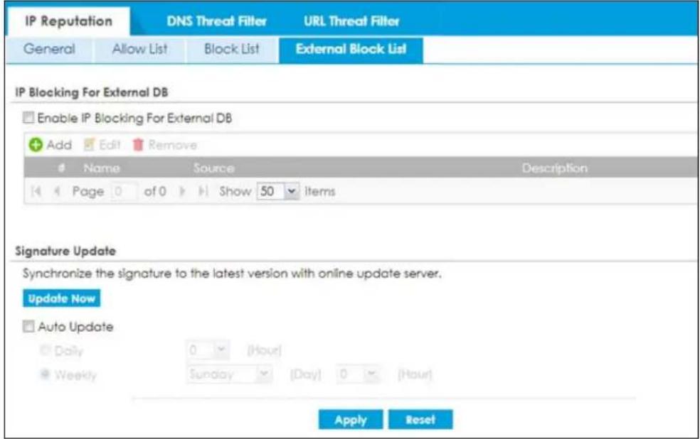
The following table describes the labels in this screen.
Table 310 Configuration > Security Service > Reputation Filter > IP Reputation > External Block List
| LABEL DESCRIPTION | |
| URL Blocking For External DB | |
| Enable URL Blocking For External DB | Select this to have the Zyxel Device bypass checking by this feature (if enabled) and block packets that come from the listed addresses in the black list file on the server.Note: Select Enable under IP Blocking in the Configuration > Security Service > Reputation Filter > IP Reputation > General screen for the black list to take effect. |
| Add | Click this to create a new IP reputation external block list entry. |
| Edit Select an entry and | click this to be able to modify it. |
| Remove Select an entry | and click this to delete it. |
| # This is the entry's index | number in the list. |
| Name | This displays the identifying name for the black list file. You can use alphanumeric and () +/ :=?! *#@_-%- characters, and it can be up to 60 characters long. |
| Source | This displays the file name, path and IP address of the server containing the black list file.For example, http://172.16.107.20/blacklist-files/myip-ebl.txt |
| Description | This displays the a description of the black list file. You can use alphanumeric and () +/ :=?! *#@_-%- characters, and it can be up to 60 characters long. |
| New IP reputation signatures can be downloaded to the Zyxel Device periodically if you have subscribed for the IP reputation signatures service.You need to create an account at myZyxel, register your Zyxel Device and then subscribe for IP reputation service in order to be able to download new signatures from myZyxel (see the Registration screens).Schedule signature updates for a day and time when your network is least busy to minimize disruption to your network. | |
Table 310 Configuration > Security Service > Reputation Filter > IP Reputation > External Block List
| LABEL DESCRIPTION | |
| Update Now | Click this to have the Zyxel Device immediately check for new signatures at myZyxel. If new signatures are found, they are then downloaded to the Zyxel Device. |
| Auto Update | Click this to have the Zyxel Device automatically check for new signatures regularly at the time and day specified. You should select a time when your network is not busy for minimal interruption. |
| Daily | Select this to have the Zyxel Device check for new signatures every day at the specified time. The time format is the 24 hour clock, so '23' means 11 PM for example. |
| Weekly | Select this option to have the Zyxel Device check for new signatures once a week on the day and at the time specified. |
| Apply | Click Apply to save your changes back to the Zyxel Device. |
| Reset | Click Reset to return the screen to its last-saved settings. |
35.2.4 IP Reputation External Block List Screen Add/Edit
Use this screen to define a black list file on a web server that supports HTTP or HTTPS. Go to Configuration > Security Service > Reputation Filter > IP Reputation > External Block List > Add to display the following screen.
Figure 515 Configuration > Security Service > Reputation Filter > IP Reputation > External Block List > Add
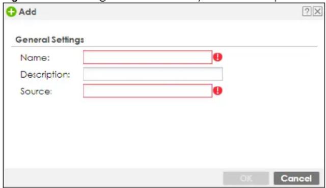
The following table describes the labels in this screen.
Table 311 Configuration > Security Service > Reputation Filter > IP Reputation > External Block List > Add
| LABEL DESCRIPTION | |
| Name | Enter an identifying name for the black list file. You can use alphanumeric and ( ) +/ := ? ! * #@ _% - characters, and it can be up to 60 characters long. |
| Source | Enter the exact file name, path and IP address of the server containing the black list file.For example, http://172.16.107.20/blacklist-files/myip-ebl.txtThe server must be reachable from the Zyxel Device. |
| Description | Enter a description of the black list file. You can use alphanumeric and ( ) +/ := ? ! * #@ _% - characters, and it can be up to 60 characters long. |
| OK | Click OK to save your changes back to the Zyxel Device. |
| Cancel | Click Cancel to exit this screen without saving. |
35.3 DNS Threat Filter Screen
A Domain Name System (DNS) server records mappings of FQDN (Fully Qualified Domain Names) to IP addresses. A FQDN consists of a host and domain name. For example, www.zyxel.com is a fully qualified domain name, where "www" is the host, "zyxel" is the second-level domain, and "com" is the top level domain.
DNS threat filtering inspects DNS queries made by clients on your network and compares the queries against a database of blocked or allowed Fully Qualified Domain Names (FQDNs).
If a user attempts to connect to a suspect site, where the DNS query packet contains an FQDN with a bad reputation, then a DSN query is sent from the user's computer and detected by the DNS Threat Filter.
The Zyxel Device DNS Threat Filter will either drop the DNS query or reply to the user with a fake DNS response using the default dnsft.cloud.zyxel.com IP address (where the user will see a "Web Page Blocked!" page) or a custom IP address.
The following types of DNS queries are allowed by the Zyxel Device:
- Type "A" for IPv4 addresses
The Zyxel Device replies with a DNS server error for the following types of DNS queries:
- Type "AAAA" for IPv6 addresses
- Type "NS" (Name Server) to get information about the authoritative name server
- Type "MX" (Mail eXchange) to request information about the mail exchange server for a specific DNS domain name.
- Type "CNAME" (Canonical Names) that specifies a domain name that has to be queried in order to resolve the original DNS query
- Type "PTR" (Pointer) that specifies a reverse query (requesting the FQDN corresponding to the IP address you provided)
- Type "SOA" (Start Of zone Authority) used when transferring zones
The priority for DNS Threat Filter checking is as follows:
1 Allow List
2 Block List
3 Local Zyxel Device Signatures
4 Cloud Query Cache
5 Cloud Query
Click Configuration > Security Service > Reputation Filter > DNS Threat Filter > General to display the configuration screen as shown next.
Figure 516 Configuration > Security Service > Reputation Filter > DNS Threat Filter > General
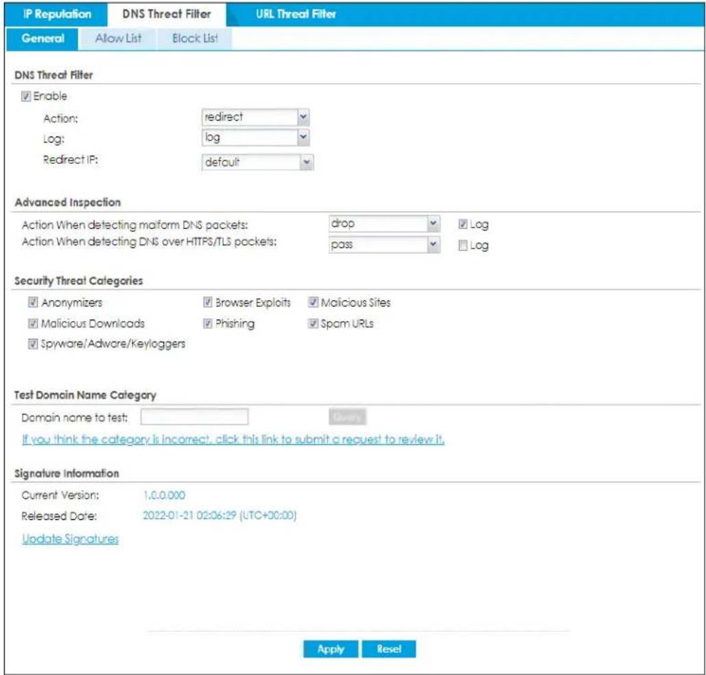
The following table describes the labels in this screen.
Table 312 Configuration > Security Service > Reputation Filter > DNS Threat Filter > General
| LABEL DESCRIPTION | |
| DNS Threat Filter | |
| Enable | Select this option to turn on DNS threat filtering on the Zyxel Device. Otherwise, clear it.Action and Log settings apply to DNS query packets triggered by the security threat categories. |
| Action | Set what action the Zyxel Device takes when there is a DNS query packet containing an FQDN with a bad reputation.redirect: Select this action to have the Zyxel Device reply with a DNS reply packet containing a default or custom-defined IP address.pass: Select this action to have the Zyxel Device allow the DNS query packet and not reply with a DNS reply packet containing a default or custom-defined IP address. |
| Log These are the | log options:no: Do not create a log when there is a DNS query packet containing an FQDN with a bad reputation.log: Create a log on the Zyxel Device when there is a DNS query packet containing an FQDN with a bad reputation.log alert: An alert is an emailed log for more serious events that may need more immediate attention. Select this to have the Zyxel Device send an alert when there is a DNS query packet containing an FQDN with a bad reputation. |
| Redirect IP | Select this action to have the Zyxel Device reply with a DNS reply packet containing a default or custom-defined IP address when a DNS query packet contains an FQDN with a bad reputation. The default IP is thednsft.cloud.zyxel.comIP address. If you selectcustom-defined IP, then enter a valid IPv4 address in the text box. |
| Advanced Inspection | |
| Action When detecting malform DNS packets | Set what action the Zyxel Device takes when there is an abnormal DNS query packet. A DNS packet is defined as malformed when:The number of entries in the question count field in the DNS header is 0An error occurs when parsing the domain name in the question fieldThe length of the domain name exceeds 255 characters.pass: Select this action to have the Zyxel Device allow the DNS query packet through the Zyxel Device.drop: Select this action to have the Zyxel Device discard the abnormal DNS query packetSelect Logto create a log on the Zyxel Device when there is an abnormal DNS query packet. |
| Action When detecting DNS over HTTPS/TLS packets | Set what action the Zyxel Device takes when there is an encrypted DNS query packet. An encrypted DNS query packet might endanger your network because the Zyxel Device cannot inspect it to check if a user on your network is trying to access a suspect site.pass: Select this action to have the Zyxel Device allow the DNS query packet through the Zyxel Device.drop: Select this action to have the Zyxel Device discard the encrypted DNS query packet. If you try to access the site after the Zyxel Device discards the associated DNS query packet, your browser will show that you do not have access to the site.Select Logto create a log on the Zyxel Device when there is an encrypted DNS query packet. |
| Security Threat Categories | Select the categories of FQDNs that may pose a security threat to network devices behind the Zyxel Device. |
| Anonymizers | Sites and proxies that act as an intermediary for surfing to other Web sites in an anonymous fashion, whether to circumvent Web filtering or for other reasons. |
| Browser Exploits | Sites that contain browser exploits. A browser exploit is any content that forces a web browser to perform operations that you do not explicitly intend. |
| Malicious Downloads | Sites that have been identified as containing malicious downloads or malware harmful to a user's computer. |
| Malicious Sites | Sites that install unwanted software on a user's computer with the intent to enable third-party monitoring or make system changes without the user's consent. |
| Phishing | Sites that are used for deceptive or fraudulent purposes, such as stealing financial or other user account information. These sites are most often designed to appear as legitimate sites in order to mislead users into entering their credentials. |
| Spam URLs Sites that have been promoted through spam techniques. | |
| Spyware Adware Keyloggers | Sites that contain spyware, adware or keyloggers.Spyware is a program installed on your computer, usually without your explicit knowledge, that captures and transmits personal information or Internet browsing habits and details to companies. Companies use this information to analyze browsing habits, to gather marketing data, and to sell your information to others.Key logger programs try to capture and steal your passwords and watch and record everything you do on your computer.Adware programs typically display blinking advertisements or pop-up windows when you perform a certain action. Adware programs are often installed in exchange for another service, such as the right to use a program without paying for it. |
| Test Domain Name Category | |
| Domain name to test | Enter an FQDN and click theQuerybutton to check if the domain name is associated with suspicious activities that could pose a security threat to users or their computers. |
| Signature Information | The signatures for DNS Threat Filter and URL Threat Filter are the same. These signatures are continually updated as new malware evolves. New signatures can be downloaded to the Zyxel Device periodically if you have subscribed for the IP reputation signatures service.You need to create an account at myZyxel, register your Zyxel Device and then subscribe for IP reputation service in order to be able to download new signatures from myZyxel (see theRegistrationscreens).The following fields display information on the current signature set that the Zyxel Device is using. |
| Current Version | This field displays the signature set version number currently used by the Zyxel Device. This number gets larger as new signatures are added. |
| Signature Number | This field displays the number of signatures in this set. |
| Released Date This | field displays the date and time the set was released. |
| Update Signatures | Click this to go to theConfiguration > Licensing > Signature Updatescreen to check for new signatures at myZyxel. You can schedule or immediately download signatures. |
| Apply | ClickApplyto save your changes. |
| Reset | ClickResetto return the screen to its last-saved settings. |
35.3.1 DNS Threat Filter Allow List Screen
Use this screen to create allow list entries. The Zyxel Device will not reply with a DNS reply packet containing a default or custom-defined IP address when a DNS query packet contains an FQDN in the white list.
You can add up to 1,024 entries in this allow list.
Figure 517 Configuration > Security Service > Reputation Filter > DNS Threat Filter > Allow List
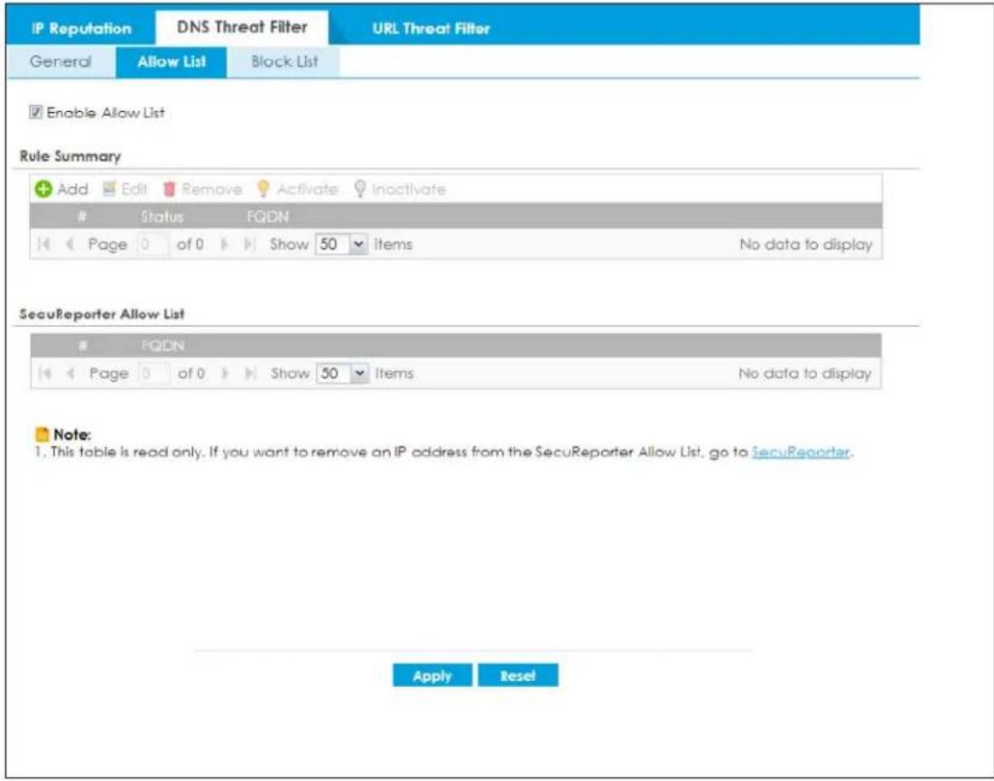
The following table describes the labels in this screen.
Table 313 Configuration > Security Service > Reputation Filter > DNS Threat Filter > Allow List
| LABEL DESCRIPTION | |
| Enable Allow List | Select this check box and the Zyxel Device will not reply with a DNS reply packet containing a default or custom-defined IP address when a DNS query packet contains an FQDN in the white list.Note: Select Enable under DNS Threat Filter in the Configuration > Security Service > Reputation Filter > DNS Threat Filter > General screen for the allow list to take effect. |
| Rule Summary | |
| Add | Click this to create a new DNS threat filter allow list entry. To add an FQDN, type a Fully-Qualified Domain Name (FQDN) of a web site. An FQDN starts with a host name and continues all the way up to the top-level domain name. For example, www.zyxel.com.tw is a fully qualified domain name, where “www” is the host, “zyxel” is the third-level domain, “com” is the second-level domain, and “tw” is the top level domain. Underscores are not allowed. Use “*.” as a prefix in the FQDN for a wildcard domain name (for example, *.example.com). |
| Edit Select an entry and click this to be able to modify it. | |
| Remove Select an entry and click this to delete it. | |
| Activate | To turn on an entry, select it and click Activate. |
| Inactivate | To turn off an entry, select it and click Inactivate. |
| # This is the entry's index number in the list. | |
| Status | The activate (light bulb) icon is lit when the entry is active and dimmed when the entry is inactive. |
| FQDN This field displays the FQDN of this entry. | |
| SecuReporter Allow List | This table displays the DNS threat filter allow list you set in SecuReporter. Please note that this table is read-only. If you want to change the SecuReporter DNS threat filter allow list settings, go to SecuReporter.For example, if you add www.zyxel.com.tw to the SecuReporter DNS threat filter allow list, the Zyxel Device DNS threat filter will allow incoming packets from www.zyxel.com.tw and outgoing packets to www.zyxel.com.tw. |
| # This is the entry's index number in the list. | |
| FQDN | This field displays the FQDN of the SecuReporter DNS threat filter allow list entry. |
| Apply | Click Apply to save your changes back to the Zyxel Device. |
| Reset | Click Reset to return the screen to its last-saved settings. |
35.3.2 DNS Threat Filter Block List Screen
Use this screen to create block list entries. The Zyxel Device will reply with a DNS reply packet containing a default or custom-defined IP address when a DNS query packet contains an FQDN in the black list. For matched items in the black list, the action is always Redirect IP and log is always log alert.
You can add up to 1,024 entries in this block list.
Figure 518 Configuration > Security Service > Reputation Filter > DNS Threat Filter > Block List
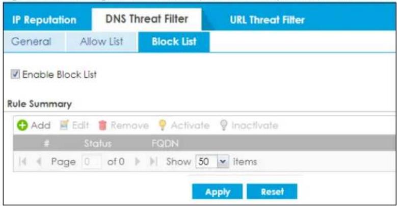
The following table describes the labels in this screen.
Table 314 Configuration > Security Service > Reputation Filter > DNS Threat Filter > Block List
| LABEL DESCRIPTION | |
| Block List | |
| Enable Block List | Select this check box and the Zyxel Device will reply with a DNS reply packet containing a default or custom-defined IP address when a DNS query packet contains an FQDN in the black list.Note: Select Enable under DNS Threat Filter in the Configuration > Security Service > Reputation Filter > DNS Threat Filter > General screen for the block list to take effect. |
| Add | Click this to create a new DNS threat filter block list entry. To add an FQDN, type a Fully-Qualified Domain Name (FQDN) of a web site. An FQDN starts with a host name and continues all the way up to the top-level domain name. For example, www.zyxel.com.tw is a fully qualified domain name, where “www” is the host, “zyxel” is the third-level domain, “com” is the second-level domain, and “tw” is the top level domain. Underscores are not allowed. Use “*.” as a prefix in the FQDN for a wildcard domain name (for example, *.example.com). |
| Edit Select an entry and | click this to be able to modify it. |
| Remove Select an entry | and click this to delete it. |
| Activate | To turn on an entry, select it and click Activate. |
| Inactivate | To turn off an entry, select it and click Inactivate. |
| # This is the entry's index | number in the list. |
| Status | The activate (light bulb) icon is lit when the entry is active and dimmed when the entry is inactive. |
| FQDN This field displays the FQDN of this entry. | |
| Apply | Click Apply to save your changes back to the Zyxel Device. |
| Reset | Click Reset to return the screen to its last-saved settings. |
35.4 DNS Threat Filter Profile
To use multiple profiles for this feature, run the following commands in the Zyxel Device Command Line Interface (CLI).
Router# configure terminal
Router(config)# secure-policy-style advance
Router(config)# show secure-policy-style status
secure-policy-style: advance
After you run these command, go to the feature screen again in the web configurator. You will be prompted to log out and then log in again.
Figure 519 Logout Prompt
After you log in again, you will see the new profile screen for this feature.
Figure 520 Configuration > Security Service > Reputation Filter > DNS Threat Filter > Profile
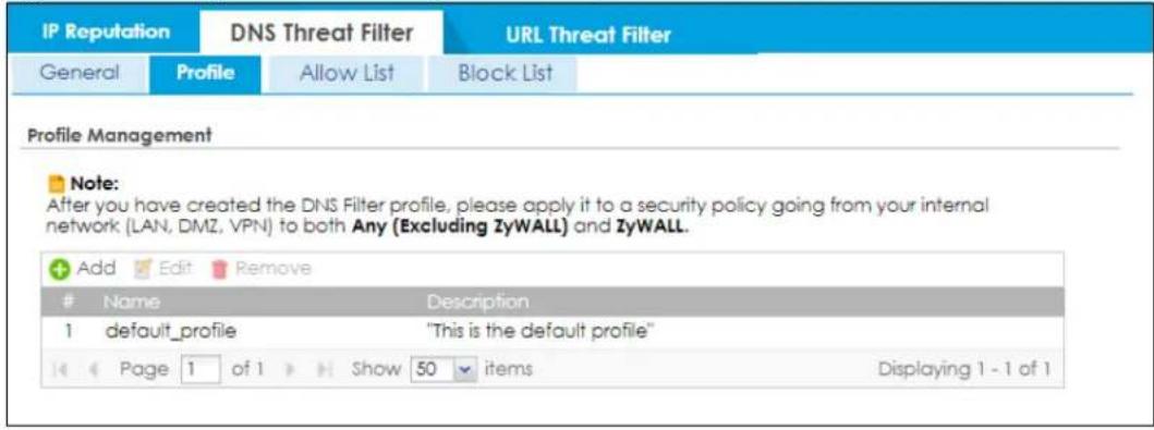
The following table describes the labels in this screen.
Table 315 Configuration > Security Service > Reputation Filter > DNS Threat Filter > Profile
| LABEL DESCRIPTION | |
| Add | Click this to create a new entry. Select an entry and click Add to create a new entry after the selected entry. |
| Edit | Double-click an entry or select it and click Edit to open a screen where you can modify the entry's settings. |
| Remove | Select an entry and click Remove to delete the selected entry. |
| # | This field is a sequential value showing the number of the profile. The profile order is not important. |
| Name This displays the name of the profile created. | |
| Description This displays the description of the profile. | |
35.4.1 Add or Edit a DNS Threat Filter Profile
Click Add to create a new entry or select an existing entry and click Edit to open the following screen where you can create or modify the entry's settings.
Figure 521 Configuration > Security Service > Reputation Filter > DNS Threat Filter > Profile > Add/Edit
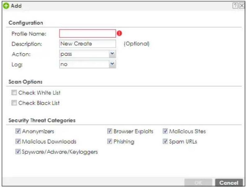
The following table describes the labels in this screen.
Table 316 Configuration > Security Service > Reputation Filter > DNS Threat Filter > Profile > Add/Edit
| LABEL DESCRIPTION | |
| Configuration | |
| Profile Name | Type the name of the profile. You may use 1-31 alphanumeric characters, underscores( ), or dashes (-), but the first character cannot be a number. This value is case-sensitive. These are valid, unique profile names:My Profilem Y ProfileMymy12_3-4These are invalid profile names:1mYProfileMy ProfileM y Profile?Whatalongprofilename123456789012 |
| Description | Type a description for the profile rule to help identify the purpose of rule. You may use 1-31 alphanumeric characters, underscores ( ), or dashes (-), but the first character cannot be a number. This value is case-sensitive. This field is optional. |
| Action | Set what action the Zyxel Device takes when there is a DNS query packet containing an FQDN with a bad reputation.redirect: Select this action to have the Zyxel Device reply with a DNS reply packet containing a default or custom-defined IP address when a DNS query packet contains an FQDN with a bad reputation.pass: Select this action to have the Zyxel Device not reply with a DNS reply packet containing a default or custom-defined IP address. |
Table 316 Configuration > Security Service > Reputation Filter > DNS Threat Filter > Profile > Add/Edit
| LABEL DESCRIPTION | |
| Log These are the | log options:no: Do not create a log when there is a DNS query packet containing an FQDN with a bad reputation.log: Create a log on the Zyxel Device when there is a DNS query packet containing an FQDN with a bad reputation.log alert: An alert is an emailed log for more serious events that may need more immediate attention. Select this to have the Zyxel Device send an alert when there is a DNS query packet containing an FQDN with a bad reputation. |
| Scan Options | |
| Check White List | Select this check box to have the Zyxel Device not perform the DNS Threat Filter check on DNS query packets that match the white list entries. |
| Check Black List | Select this check box to have the Zyxel Device perform the DNS Threat Filter check on DNS query packets that match the black list entries. |
| Check Black List | Select this check box to log and delete files with names that match the black list patterns. |
| Security Threat Categories | Select the categories of FQDNs that may pose a security threat to network devices behind the Zyxel Device. |
| Anonymizers | Sites and proxies that act as an intermediary for surfing to other Web sites in an anonymous fashion, whether to circumvent Web filtering or for other reasons. |
| Browser Exploits | Sites that contain browser exploits. A browser exploit is any content that forces a web browser to perform operations that you do not explicitly intend. |
| Malicious Downloads | Sites that have been identified as containing malicious downloads or malware harmful to a user's computer. |
| Malicious Sites | Sites that install unwanted software on a user's computer with the intent to enable third-party monitoring or make system changes without the user's consent. |
| Phishing | Sites that are used for deceptive or fraudulent purposes, such as stealing financial or other user account information. These sites are most often designed to appear as legitimate sites in order to mislead users into entering their credentials. |
| Spam URLs Sites that have been promoted through spam techniques. | |
| Spyware Adware Keyloggers | Sites that contain spyware, adware or keyloggers.Spyware is a program installed on your computer, usually without your explicit knowledge, that captures and transmits personal information or internet browsing habits and details to companies. Companies use this information to analyze browsing habits, to gather marketing data, and to sell your information to others.Key logger programs try to capture and steal your passwords and watch and record everything you do on your computer.Adware programs typically display blinking advertisements or pop-up windows when you perform a certain action. Adware programs are often installed in exchange for another service, such as the right to use a program without paying for it. |
| OK | Click OK to save your changes back to the Zyxel Device. |
| Cancel | Click Cancel to exit this screen without saving. |
35.4.2 Link a Profile
To link a profile to a policy, go to the Configuration > Security Policy > Policy Control screen, select a policy, and then click Edit. In the Edit Policy screen under Profile, select which profile you want to use for each security service.
Figure 522 Configuration > Security Service > Policy Control > Profile
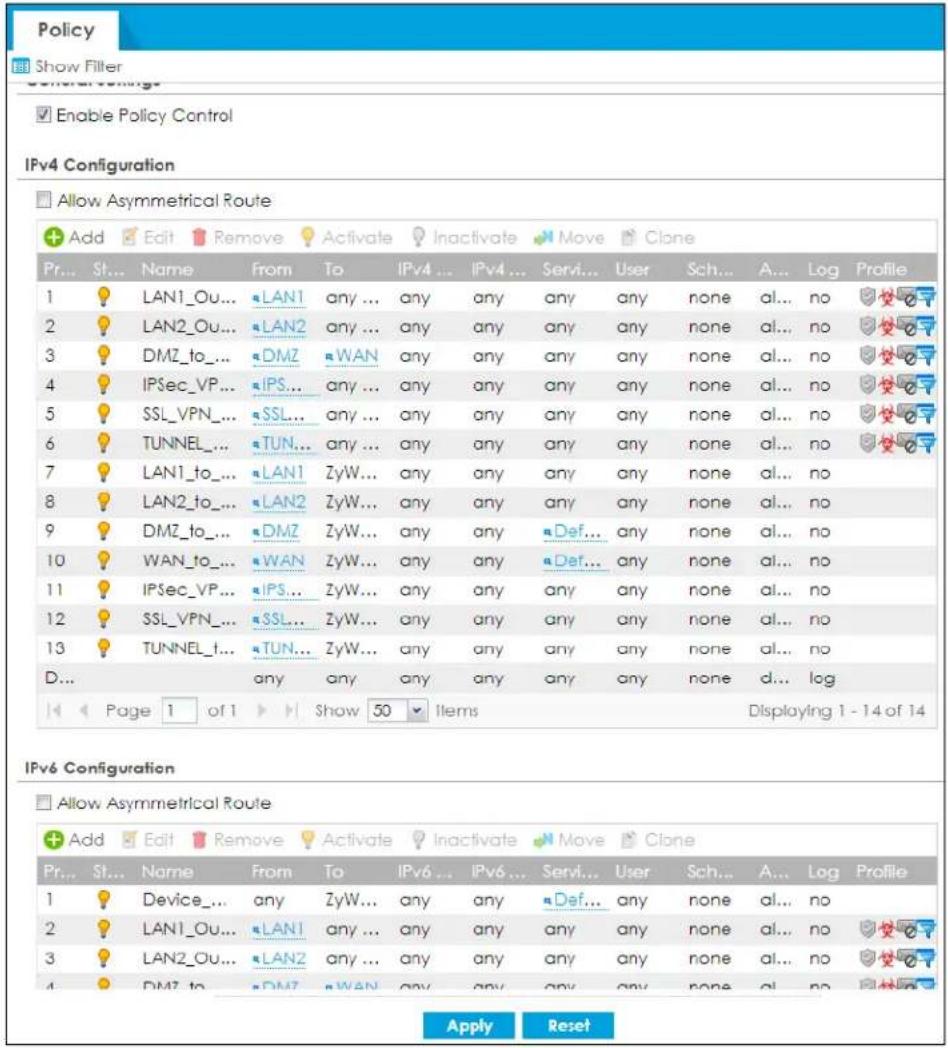
35.4.3 DNS Threat Filter Advance Screen
The Configuration > Security Service > Reputation Filter > DNS Threat Filter > General screen also changes when using profiles.
Figure 523 Configuration > Security Service > Reputation Filter > DNS Threat Filter > General Advance
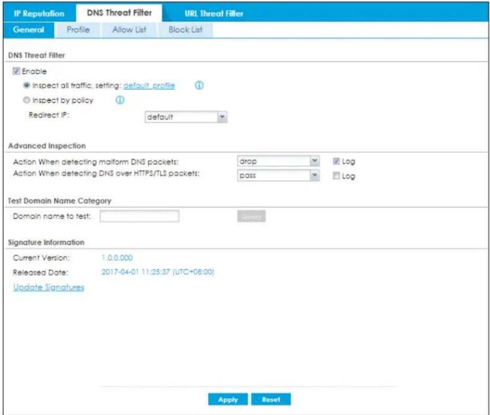
The following table describes the labels in this screen.
Table 317 Configuration > Security Service > Reputation Filter > DNS Threat Filter > General Advance
| LABEL DESCRIPTION | |
| DNS Threat Filter | |
| Enable | Select this option to turn on DNS threat filtering on the Zyxel Device. Otherwise, clear it.Action and Log settings apply to DNS query packets triggered by the security threat categories. |
| Inspect all traffic, setting: | Select this to have all traffic inspected by the default_profile. You cannot rename or delete the default_profile profile, but you can edit it by clicking the link here. |
| Inspect by policy | If you configured a specific profile in the Profile tab for this service, select this to have specific traffic inspected by that profile. You must bind the profile to a policy in Security Policy > Policy Control. |
| Redirect IP | Select this action to have the Zyxel Device reply with a DNS reply packet containing a default or custom-defined IP address when a DNS query packet contains an FQDN with a bad reputation. The default IP is the dnsft.cloud.zyxel.com IP address. If you select custom-defined IP, then enter a valid IPv4 address in the text box. |
| Advanced Inspection | |
Table 317 Configuration > Security Service > Reputation Filter > DNS Threat Filter > General Advance
| LABEL DESCRIPTION | |
| Action When detecting malform DNS packets | Set what action the Zyxel Device takes when there is an abnormal DNS query packet. A DNS packet is defined as malformed when:The number of entries in the question count field in the DNS header is 0An error occurs when parsing the domain name in the question fieldThe length of the domain name exceeds 255 characters.pass: Select this action to have the Zyxel Device allow the DNS query packet through the Zyxel Device.drop: Select this action to have the Zyxel Device discard the abnormal DNS query packetSelect Log to create a log on the Zyxel Device when there is an abnormal DNS query packet. |
| Action When detecting DNS over HTTPS/TLS packets | Set what action the Zyxel Device takes when there is an encrypted DNS query packet. An encrypted DNS query packet might endanger your network because the Zyxel Device cannot inspect it to check if a user on your network tries to access a suspect site.pass: Select this action to have the Zyxel Device allow the DNS query packet through the Zyxel Device.drop: Select this action to have the Zyxel Device discard the abnormal DNS query packetSelect Log to create a log on the Zyxel Device when there is an encrypted DNS query packet. |
| Test Domain Name Category | |
| Domain name to test | Enter an FQDN and click the Query button to check if the domain name is associated with suspicious activities that could pose a security threat to users or their computers. |
| Signature Information | The signatures for DNS Threat Filter and URL Threat Filter are the same. These signatures are continually updated as new malware evolves. New signatures can be downloaded to the Zyxel Device periodically if you have subscribed for the IP reputation signatures service.You need to create an account at myZyxel, register your Zyxel Device and then subscribe for IP reputation service in order to be able to download new signatures from myZyxel (see the Registration screens).The following fields display information on the current signature set that the Zyxel Device is using. |
| Current Version | This field displays the signature set version number currently used by the Zyxel Device. This number gets larger as new signatures are added. |
| Signature Number | This field displays the number of signatures in this set. |
| Released Date This | field displays the date and time the set was released. |
| Update Signatures | Click this to go to the Configuration > Licensing > Signature Update screen to check for new signatures at myZyxel. You can schedule or immediately download signatures. |
| Apply | Click Apply to save your changes. |
| Reset | Click Reset to return the screen to its last-saved settings. |
35.4.4 Remove Profiles
To remove profiles and revert to the default general security policy style, you must first make sure to change Inspect by policy to Inspect all traffic in the following security services: Anti-Malware, DNS Threat Filter, URL Threat Filter, IPS, Email Security.
Note: All profiles that you created will be removed from Security Policy > Policy Control.
Run the following commands in the Zyxel Device Command Line Interface (CLI).
Router# configure terminal
Router(config)# secure-policy-style general
Router(config)# show secure-policy-style status
secure-policy-style: general
Wait a minute and then go to the feature screen again in the web configurator. You will be prompted to log out and then log in again.
Figure 524 Logout Prompt
After you log in again, you will not see the profile screen for this feature.
35.5 URL Threat Filter Screen
When you enable the URL Threat filtering service, your Zyxel Device downloads signature files that contain known URL Threat domain names and IP addresses. The Zyxel Device will also access an external database, Cloud Query, that has millions of web sites categorized based on content. You can have the Zyxel Device allow, block, warn and/or log access to web sites or hosts based on these signatures and categories.
The priority for URL Threat checking is as follows:
1 Allow List
2 Block List
3 External Block List
4 Local Zyxel Device Signatures
5 Cloud Query Cache
6 Cloud Query
Use this screen to enable URL Threat filtering and specify the action the Zyxel Device takes when it detects a suspicious activity or a connection attempt to or from a site in a selected category.
Click the URL Threat Filter icon for more information on the Zyxel Device's security features.
Click Configuration > Security Service > Reputation Filter > URL Threat Filter to display the configuration screen as shown next.
Figure 525 Configuration > Security Service > Reputation Filter > URL Threat Filter > General
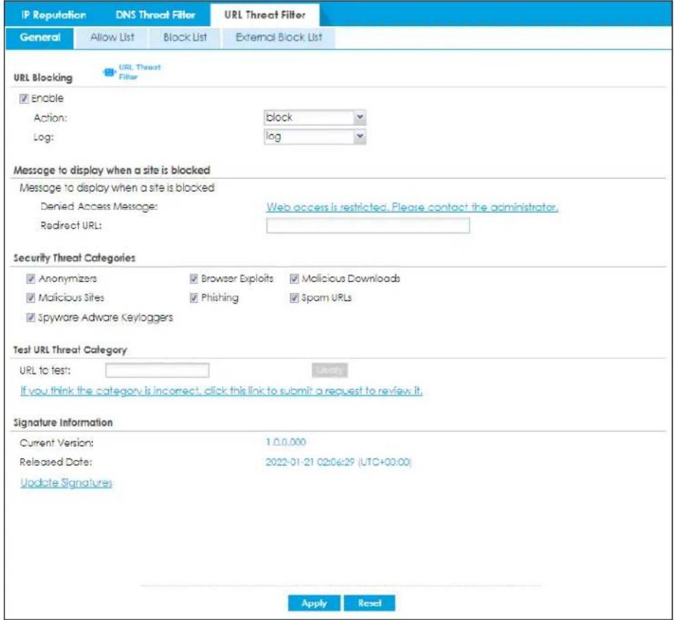
The following table describes the labels in this screen.
Table 318 Configuration > Security Service > Reputation Filter > URL Threat Filter > General
| LABEL DESCRIPTION | |
| URL Blocking | |
| Enable | Select this option to turn on URL blocking on the Zyxel Device. |
| Action | Set what action the Zyxel Device takes when it detects a connection attempt to or from the web pages of the specified categories.block: Select this action to have the Zyxel Device block access to the web pages that match the categories that you select above.warn: Select this action to have the Zyxel Device display a warning message to the access requesters for the web pages before allowing users to access web pages that match the categories that you select above.pass: Select this action to have the Zyxel Device allow access to the web pages that match the categories that you select above. |
| Log These are the log | options:no: Do not create a log when it detects a connection attempt to or from the web pages of the specified categories.log: Create a log on the Zyxel Device when it detects a connection attempt to or from the web pages of the specified categories.log alert: An alert is an emailed log for more serious events that may need more immediate attention. Select this option to have the Zyxel Device send an alert when a connection matches web pages of the specified categories. |
| Message to display when a site is blocked | |
| Denied Access Message | Enter a message to be displayed when the URL Threat filter blocks access to a web page. Use up to 127 characters (0-9a-zA-Z:/?:@&+\._!~*('%)%,"). For example, "Access to this web page is not allowed. Please contact the network administrator".It is also possible to leave this field blank if you have a URL specified in the Redirect URL field. In this case if the URL Threat filter blocks access to a web page, the Zyxel Device just opens the web page you specified without showing a denied access message. |
| Redirect URL | Enter the URL of the web page to which you want to send users when their web access is blocked by the URL Threat filter. The web page you specify here opens in a new frame below the denied access message.Use "http://" or "https://" followed by up to 262 characters (0-9a-zA-Z:/?:@&+\._!~*('%)%). For example, http://192.168.1.17/blocked access. |
| Security Threat Categories | Select the categories of web pages that may pose a security threat to network devices behind the Zyxel Device. |
| Anonymizers | Sites and proxies that act as an intermediary for surfing to other Web sites in an anonymous fashion, whether to circumvent Web filtering or for other reasons. |
| Browser Exploits | Sites that contain browser exploits. A browser exploit is any content that forces a web browser to perform operations that you do not explicitly intend. |
| Malicious Downloads | Sites that have been identified as containing malicious downloads or malware harmful to a user's computer. |
| Malicious Sites | Sites that install unwanted software on a user's computer with the intent to enable third-party monitoring or make system changes without the user's consent. |
| Phishing | Sites that are used for deceptive or fraudulent purposes, such as stealing financial or other user account information. These sites are most often designed to appear as legitimate sites in order to mislead users into entering their credentials. |
| Spam URLs Sites that have been promoted through spam techniques. | |
| Spyware Adware Keyloggers | Sites that contain spyware, adware or keyloggers.Spyware is a program installed on your computer, usually without your explicit knowledge, that captures and transmits personal information or Internet browsing habits and details to companies. Companies use this information to analyze browsing habits, to gather marketing data, and to sell your information to others.Key logger programs try to capture and steal your passwords and watch and record everything you do on your computer.Adware programs typically display blinking advertisements or pop-up windows when you perform a certain action. Adware programs are often installed in exchange for another service, such as the right to use a program without paying for it. |
| Test URL Threat Category | |
| URL to test | Enter a URL using http://domain or https://domain and click the Query button to check if the domain belongs to a URL threat category. |
| Signature Information | The signatures for DNS Threat Filter and URL Threat Filter are the same. These signatures are continually updated as new malware evolves. New signatures can be downloaded to the Zyxel Device periodically if you have subscribed for the URL Threat filter signatures service.You need to create an account at myZyxel, register your Zyxel Device and then subscribe for URL Threat filter service in order to be able to download new signatures from myZyxel (see the Registration screens).The following fields display information on the current signature set that the Zyxel Device is using. |
| Current Version | This field displays the signature set version number currently used by the Zyxel Device. This number gets larger as new signatures are added. |
| Signature Number This field displays the number of signatures in this set. | |
| Released Date This field displays the date and time the set was released. | |
| Update Signatures | Click this to go to theConfiguration > Licensing > Signature Updatescreen to check for new signatures at myZyxel. You can schedule or immediately download signatures. |
| Apply | Click Applyto save your changes. |
| Reset | Click Resetto return the screen to its last-saved settings. |
35.5.1 URL Threat Filter Allow List Screen
Use this screen to create white list entries. The Zyxel Device will allow incoming packets from the listed IPv4 addresses and URLs.
Figure 526 Configuration > Security Service > Reputation Filter > URL Threat Filter > Allow List
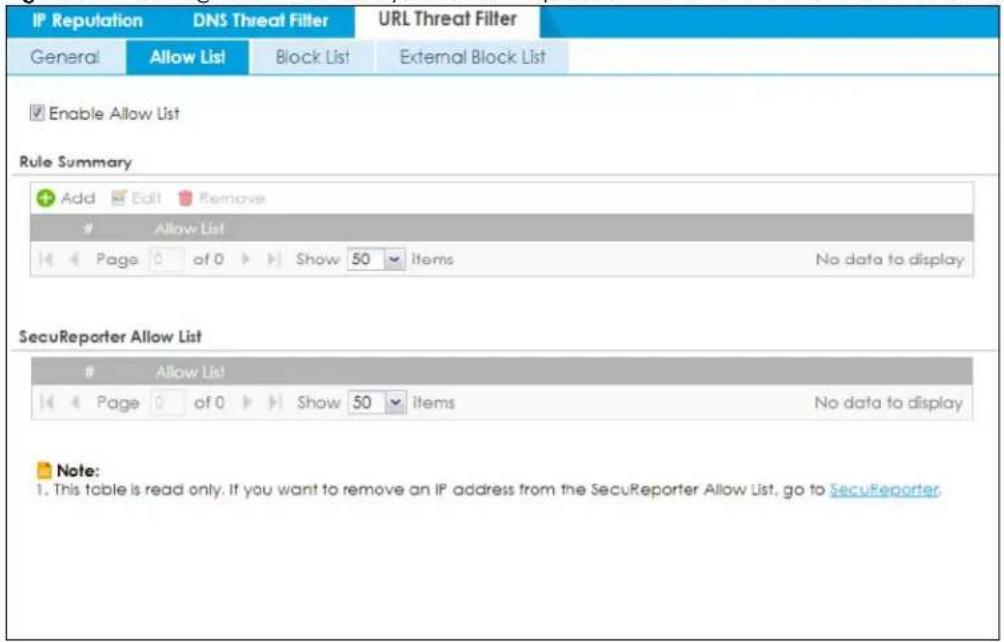
The following table describes the labels in this screen.
Table 319 Configuration > Security Service > Reputation Filter > URL Threat Filter > Allow List
| LABEL DESCRIPTION | |
| Enable Allow List | Select this to bypass checking by this feature (if enabled) and automatically allow packets from the listed IPv4 addresses and URLs. |
| Rule Summary | |
| Add | Click this to create a new URL threat filter allow list entry. |
| Edit Select an entry and click this to be able to modify it. | |
| Remove Select an entry and click this to delete it. | |
| # This is the entry's index number in the list. | |
| Allow List This field displays the URL of this entry. | |
| SecuReporter Allow List | This table displays the URL threat filter allow list you set in SecuReporter. Please note that this table is read-only. If you want to change the SecuReporter URL threat filter allow list settings, go to SecuReporter.For example, if you add http://www.example.com to the SecuReporter URL threat filter allow list, the Zyxel Device URL threat filter will allow incoming packets from http://www.example.com and outgoing packets to http://www.example.com. |
| # This is the entry's index number in the list. | |
| Allow List | This field displays the URL of the SecuReporter URL threat filter allow list entry. |
| Apply | Click Apply to save your changes back to the Zyxel Device. |
| Reset | Click Reset to return the screen to its last-saved settings. |
35.5.2 URL Threat Filter Block List Screen
Use this screen to create block list entries. The Zyxel Device will block incoming packets from the listed IPv4 addresses and URLs.
Figure 527 Configuration > Security Service > Reputation Filter > URL Threat Filter > Block List
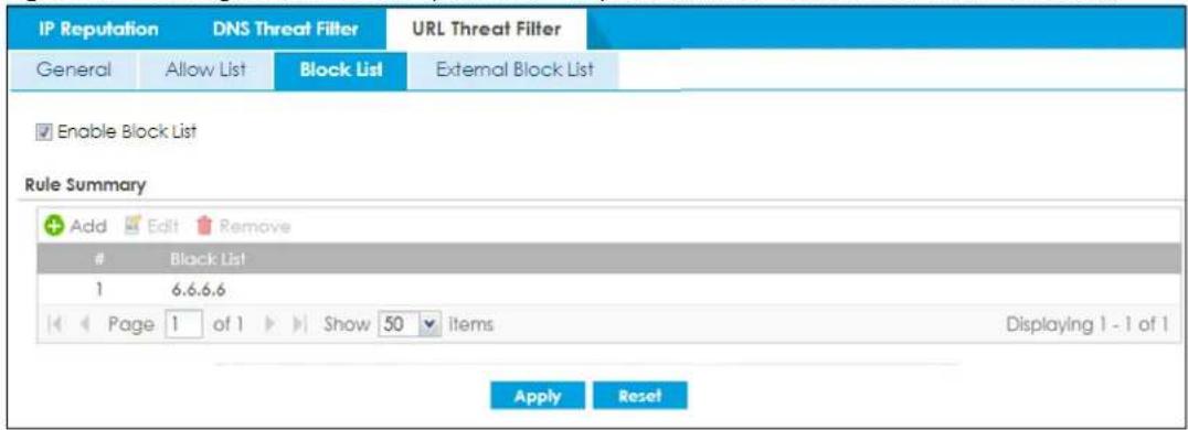
The following table describes the labels in this screen.
Table 320 Configuration > Security Service > Reputation Filter > URL Threat Filter > Block List
| LABEL DESCRIPTION | |
| Enable Block List | Select this to bypass checking by this feature (if enabled) and automatically block packets from the listed IPv4 addresses and URLs. |
| Add | Click this to create a new URL threat filter block list entry. |
| Edit Select an entry and | click this to be able to modify it. |
| Remove Select an entry | and click this to delete it. |
| # This is the entry's index | number in the list. |
| Black List This field displays the URL of this entry. | |
| Apply | ClickApplyto save your changes back to the Zyxel Device. |
| Reset | ClickResetto return the screen to its last-saved settings. |
35.5.3 URL Threat Filter External Block List Screen
Use this screen to use block list entries stored in a file on a web server that supports HTTP or HTTPS. The Zyxel Device will block incoming and outgoing packets from the black list entries in this file.
- The external block list file must be in text format (*.txt) with each entry separated by a new line. External block list entries can consist of a complete URL or a hostname and may contain wildcards. There are some examples for your reference only:
- https://www.zyxel.com/products_services/smb.shtml?t=s (complete URL)
• www.zyxel.com (hostname) - *.zyxel.* (hostname with wildcards)
- If the external block list file contains any invalid entries, the Zyxel Device will not use the file.
- The external block list file can contain up to 50,000 entries. A warning message displays when the maximum is reached.
Figure 528 Configuration > Security Service > Reputation Filter > URL Threat Filter > External Block List
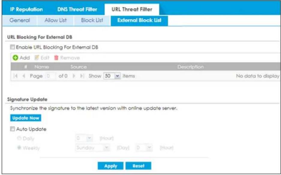
The following table describes the labels in this screen.
Table 321 Configuration > Security Service > Reputation Filter > URL Threat Filter > External Block List
| LABEL DESCRIPTION | |
| URL Blocking For External DB | |
| Enable URL Blocking For External DB | Select this check box to have the Zyxel Device bypass checking by this feature (if enabled) and automatically block packets that come from the listed addresses in the black list file on the server.Note: Select Enable under URL Blocking in the Configuration > Security Service > Reputation Filter > URL Threat Filter > General screen for the black list to take effect. |
| Add | Click this to create a new URL threat filter external block list entry. |
| Edit Select an entry and | click this to be able to modify it. |
| Remove Select an entry | and click this to delete it. |
| # This is the entry's index | number in the list. |
| Name | Enter an identifying name for the black list file. You can use alphanumeric and () +/ := ? ! * #@_-%- characters, and it can be up to 60 characters long. |
| Source | Enter the exact file name, path and IP address of the server containing the black list file.For example, http://172.16.107.20/blacklist-files/myip-ebl.txtThe server must be reachable from the Zyxel Device. |
| Description | Enter a description of the black list file. You can use alphanumeric and () +/ := ? ! * #@_-%- characters, and it can be up to 60 characters long. |
| New IP reputation signatures can be downloaded to the Zyxel Device periodically if you have subscribed for the IP reputation signatures service.You need to create an account at myZyxel, register your Zyxel Device and then subscribe for IP reputation service in order to be able to download new signatures from myZyxel (see the Registration screens).Schedule signature updates for a day and time when your network is least busy to minimize disruption to your network. | |
| Update Now | Click this to have the Zyxel Device immediately check for new signatures at myZyxel. If new signatures are found, they are then downloaded to the Zyxel Device. |
| Auto Update | Click this to have the Zyxel Device automatically check for new signatures regularly at the time and day specified. You should select a time when your network is not busy for minimal interruption. |
| Daily | Select this to have the Zyxel Device check for new signatures every day at the specified time. The time format is the 24 hour clock, so '23' means 11 PM for example. |
| Weekly | Select this option to have the Zyxel Device check for new signatures once a week on the day and at the time specified. |
| Apply | Click Apply to save your changes back to the Zyxel Device. |
| Reset | Click Reset to return the screen to its last-saved settings. |
35.6 URL Threat Filter Profile
To use multiple profiles for this feature, run the following commands in the Zyxel Device Command Line Interface (CLI).
Router# configure terminal
Router(config)# secure-policy-style advance
Router(config)# show secure-policy-style status
secure-policy-style: advance
After you run these command, go to the feature screen again in the web configurator. You will be prompted to log out and then log in again.
Figure 529 Logout Prompt
After you log in again, you will see the new profile screen for this feature.
Figure 530 Configuration > Security Service > Reputation Filter > URL Threat Filter > Profile
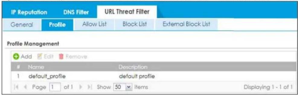
The following table describes the labels in this screen.
Table 322 Configuration > Security Service > Reputation Filter > URL Threat Filter > Profile
| LABEL DESCRIPTION | |
| Add | Click this to create a new entry. Select an entry and click Add to create a new entry after the selected entry. |
| Edit | Double-click an entry or select it and click Edit to open a screen where you can modify the entry's settings. |
| Remove | Select an entry and click Remove to delete the selected entry. |
| # | This field is a sequential value showing the number of the profile. The profile order is not important. |
| Name This displays the name of the profile created. | |
| Description This displays the description of the profile. | |
35.6.1 Add or Edit a URL Threat Filter Profile
Click Add to create a new entry or select an existing entry and click Edit to open the following screen where you can create or modify the entry's settings.
Figure 531 Configuration > Security Service > Reputation Filter > URL Threat Filter > Profile > Add/Edit
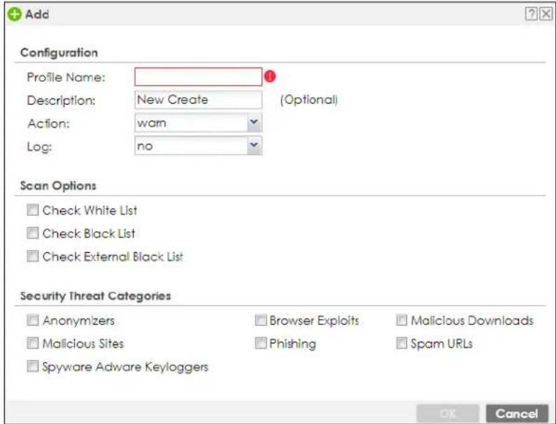
The following table describes the labels in this screen.
Table 323 Configuration > Security Service > Reputation Filter > URL Threat Filter > Profile > Add/Edit
| LABEL DESCRIPTION | |
| Configuration | |
| Profile Name | Type the name of the profile. You may use 1-31 alphanumeric characters, underscores( ), or dashes (-), but the first character cannot be a number. This value is case-sensitive. These are valid, unique profile names:My Profilem Y ProfileMymy12_3-4These are invalid profile names:1mYProfileMy ProfileM y Profile?Whatalongprofilename123456789012 |
| Description | Type a description for the profile rule to help identify the purpose of rule. You may use 1-31 alphanumeric characters, underscores ( ), or dashes (-), but the first character cannot be a number. This value is case-sensitive. This field is optional. |
Table 323 Configuration > Security Service > Reputation Filter > URL Threat Filter > Profile > Add/Edit
| LABEL DESCRIPTION | |
| Action | Set what action the Zyxel Device takes when it detects a connection attempt to or from the web pages of the specified categories.block: Select this action to have the Zyxel Device block access to the web pages that match the categories that you select above.warn: Select this action to have the Zyxel Device display a warning message to the access requesters for the web pages before allowing users to access web pages that match the categories that you select above.pass: Select this action to have the Zyxel Device allow access to the web pages that match the categories that you select above. |
| Log These are the log options:no: Do not create a log when it detects a connection attempt to or from the web pages of the specified categories.log: Create a log on the Zyxel Device when it detects a connection attempt to or from the web pages of the specified categories.log alert: An alert is an emailed log for more serious events that may need more immediate attention. Select this option to have the Zyxel Device send an alert when a connection matches web pages of the specified categories. | |
| Scan Options | |
| Check White List | Select this check box to have the Zyxel Device not perform the URL Threat filter check on URLs that match the white list entries. |
| Check Black List | Select this check box to have the Zyxel Device perform the URL Threat filter check on URLs that match the black list entries. |
| Check External Black List | Select this check box to have the Zyxel Device perform the URL Threat filter check on URLs that match the external black list entries. |
| Security Threat Categories | Select the categories of FQDNs that may pose a security threat to network devices behind the Zyxel Device. |
| Anonymizers | Sites and proxies that act as an intermediary for surfing to other Web sites in an anonymous fashion, whether to circumvent Web filtering or for other reasons. |
| Browser Exploits | Sites that contain browser exploits. A browser exploit is any content that forces a web browser to perform operations that you do not explicitly intend. |
| Malicious Downloads | Sites that have been identified as containing malicious downloads or malware harmful to a user's computer. |
| Malicious Sites | Sites that install unwanted software on a user's computer with the intent to enable third-party monitoring or make system changes without the user's consent. |
| Phishing | Sites that are used for deceptive or fraudulent purposes, such as stealing financial or other user account information. These sites are most often designed to appear as legitimate sites in order to mislead users into entering their credentials. |
| Spam URLs Sites that have been promoted through spam techniques. | |
| Spyware Adware Keyloggers | Sites that contain spyware, adware or keyloggers.Spyware is a program installed on your computer, usually without your explicit knowledge, that captures and transmits personal information or Internet browsing habits and details to companies. Companies use this information to analyze browsing habits, to gather marketing data, and to sell your information to others.Key logger programs try to capture and steal your passwords and watch and record everything you do on your computer.Adware programs typically display blinking advertisements or pop-up windows when you perform a certain action. Adware programs are often installed in exchange for another service, such as the right to use a program without paying for it. |
| OK | Click OK to save your changes back to the Zyxel Device. |
| Cancel | Click Cancel to exit this screen without saving. |
35.6.2 Link a Profile
To link a profile to a policy, go to the Configuration > Security Policy > Policy Control screen, select a policy, and then click Edit. In the Edit Policy screen under Profile, select which profile you want to use for each security service.
Figure 532 Configuration > Security Service > Policy Control > Profile
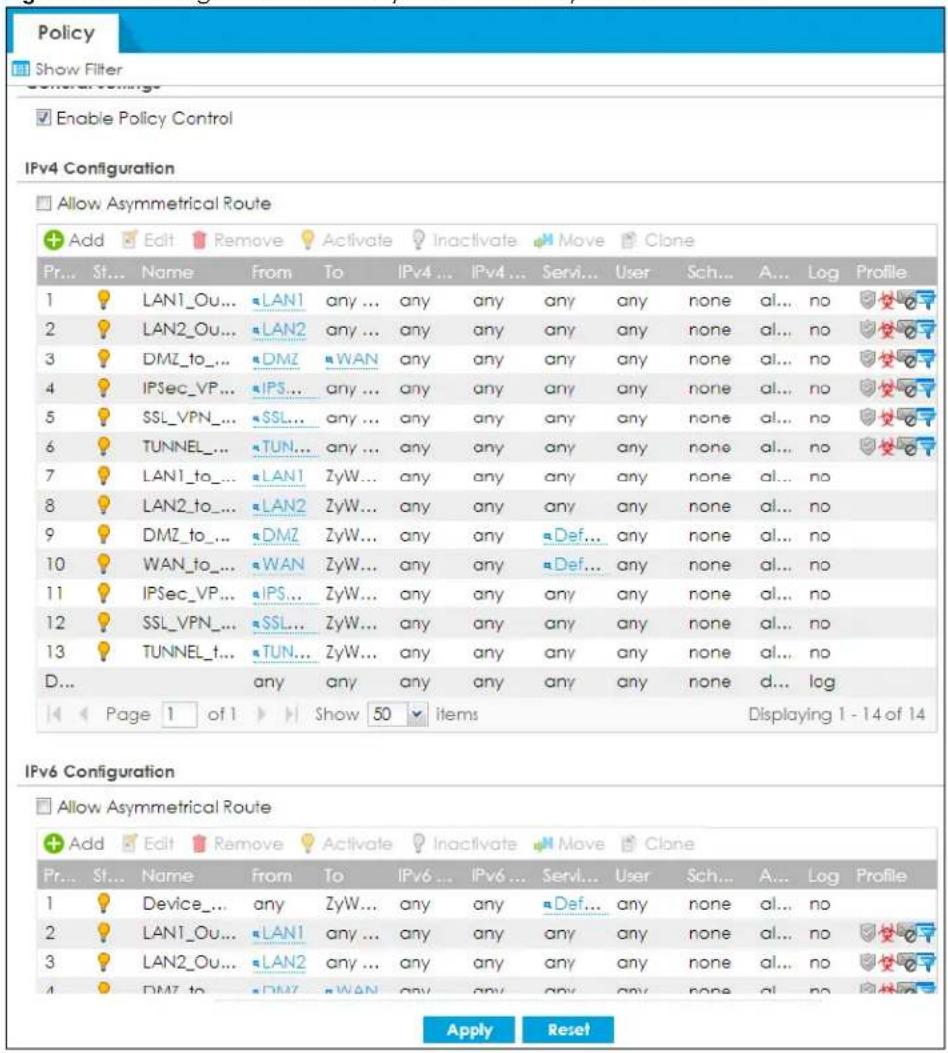
35.6.3 URL Threat Filter Advance Screen
The Configuration > Security Service > Reputation Filter > URL Threat Filter screen also changes when using profiles.
Figure 533 Configuration > Security Service > Reputation Filter > URL Threat Filter > General
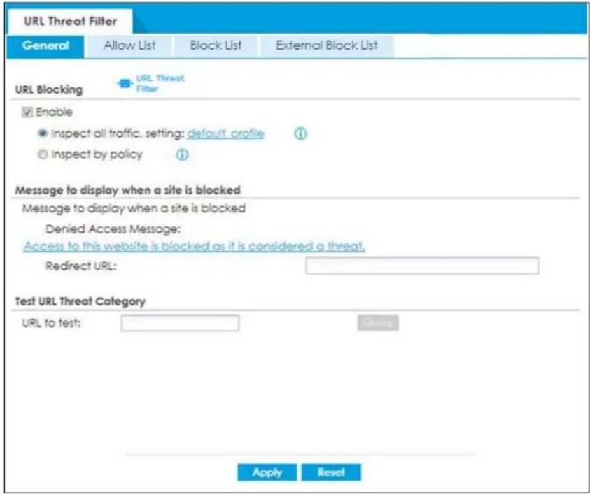
The following table describes the labels in this screen.
Table 324 Configuration > Security Service > Reputation Filter > URL Threat Filter > General
| LABEL DESCRIPTION | |
| URL Blocking | |
| Enable | Select this option to turn on URL blocking on the Zyxel Device. |
| Inspect all traffic, setting: | Select this to have all traffic inspected by thedefault_profile. You cannot rename or delete thedefault_profileprofile, but you can edit it by clicking the link here. |
| Inspect by policy | If you configured a specific profile in theProfiletab for this service, select this to have specific traffic inspected by that profile. You must bind the profile to a policy inSecurity Policy >Policy Control. |
| Message to display when a site is blocked | |
| Denied Access Message | Enter a message to be displayed when the URL Threat filter blocks access to a web page. Use up to 127 characters (0-9a-zA-Z;/?:@&+\._!~*')%."). For example, "Access to this web page is not allowed. Please contact the network administrator".It is also possible to leave this field blank if you have a URL specified in theRedirect URLfield. In this case if the URL Threat filter blocks access to a web page, the Zyxel Device just opens the web page you specified without showing a denied access message. |
| Redirect URL | Enter the URL of the web page to which you want to send users when their web access is blocked by the URL Threat filter. The web page you specify here opens in a new frame below the denied access message.Use "http://" or "https://" followed by up to 262 characters (0-9a-zA-Z;/?:@&+\._!~*')%). For example, http://192.168.1.17/blocked access. |
| Test URL Threat Category | |
| URL to test | Enter a URL using http://domain or https://domain and click theQuerybutton to check if the domain belongs to a URL threat category. |
| Apply | Click Apply to save your changes. |
| Reset | Click Reset to return the screen to its last-saved settings. |
35.6.4 Remove Profiles
To remove profiles and revert to the default general security policy style, you must first make sure to change Inspect by policy to Inspect all traffic in the following security services: Anti-Malware, DNS Threat Filter, URL Threat Filter, IPS, Email Security.
Note: All profiles that you created will be removed from Security Policy > Policy Control.
Run the following commands in the Zyxel Device Command Line Interface (CLI).
Router# configure terminal
Router(config)# secure-policy-style general
Router(config)# show secure-policy-style status
secure-policy-style: general
Wait a minute and then go to the feature screen again in the web configurator. You will be prompted to log out and then log in again.
Figure 534 Logout Prompt
After you log in again, you will not see the profile screen for this feature.
CHAPTER 36 IPS
36.1 Overview
This chapter introduces packet inspection IPS (Intrusion Prevention System), custom signatures, and updating signatures. An IPS system can detect malicious or suspicious packets and respond instantaneously. IPS on the Zyxel Device protects against network-based intrusions.
36.1.1 What You Can Do in this Chapter
- Use the Security Service > IPS screen (Section 36.2 on page 833) to view registration and signature information.
- Use the Security Service > IPS > Custom Signature > Add screens (Section 36.3 on page 841) to create a new custom signature, edit an existing signature, delete existing signatures or save signatures to your computer.
- Use the Security Service > IPS > Allow List screen (Section 36.4 on page 849) to list signatures that will be exempted from IPS inspection.
36.1.2 What You Need To Know
Packet Inspection Signatures
A signature is a pattern of malicious or suspicious packet activity. You can specify an action to be taken if the system matches a stream of data to a malicious signature. You can change the action in the profile screens. Packet inspection examine OSI (Open System Interconnection) layer-4 to layer-7 packet contents for malicious data. Generally, packet inspection signatures are created for known attacks while anomaly detection looks for abnormal behavior.
Rate Based Signatures
Rate based signatures are IPS signatures that allow the Zyxel Device to just respond when a certain number of malicious packets are identified within a specific time, by the IPS signatures specified in the Rate Based Signature table.
Figure 535 IPS Signatures Example
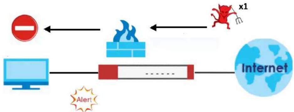
flowchart
graph LR
    A["Red Circle"] --> B["Firecracker"]
    B --> C["Internet"]
    D["Computer"] --> E["Firecracker"]
    E --> F["Internet"]
    G["Alert"] --> E
    H["x1"] --> B
Figure 536 Rate Based Signatures Example
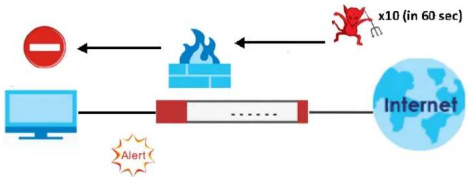
flowchart
graph LR
    A["Computer"] --> B["Fire"]
    B --> C["Brick"]
    C --> D["Internet"]
    D --> E["x10 (in 60 sec)"]
    F["Alert"] --> B
    G["Red Dog Icon"] --> H["Red Dog Icon"]
Applying Your IPS Configuration
Changes to the Zyxel Device's IPS settings affect new sessions, but not the sessions that already existed before you applied the new settings.
36.1.3 Before You Begin
- Register for a trial IPS subscription in the Registration screen. This gives you access to free signature updates. This is important as new signatures are created as new attacks evolve. When the trial subscription expires, purchase and enter a license key using the same screens to continue the subscription.
36.2 The IPS Screen
An IPS profile is a set of packet inspection signatures.
Click Configuration > Security Service > IPS to open this screen. Use this screen to view registration and signature information.
Note: You must register in order to update packet inspection signatures. See the Registration screens.
If you try to enable IPS when the IPS service has not yet been registered, a warning screen displays and IPS is not enabled.
Click the IPS icon for more information on the Zyxel Device's security features.
Figure 537 Configuration > Security Service > IPS
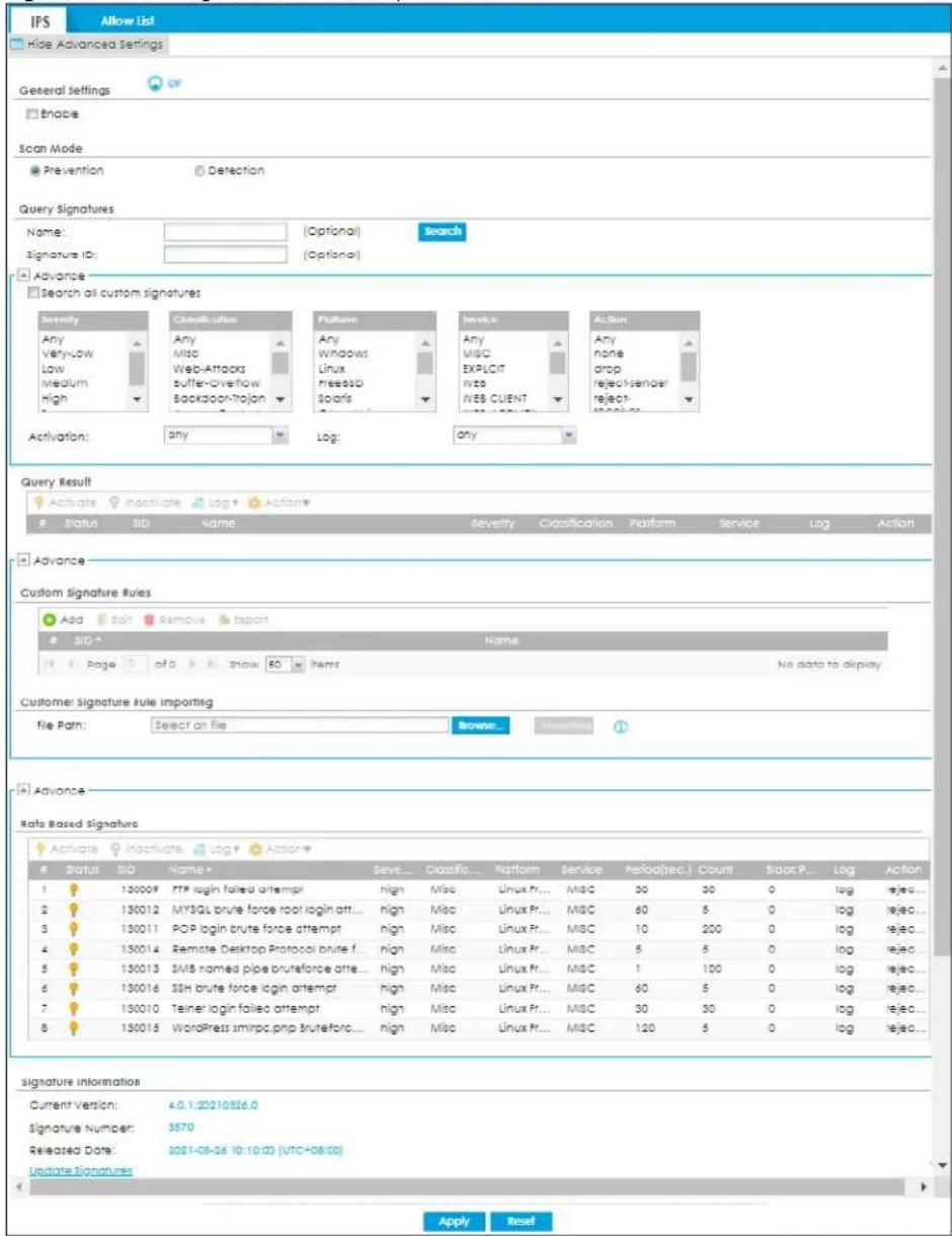
The following table describes the fields in this screen.
Table 325 Configuration > Security Service > IPS
| LABEL DESCRIPTION | |
| General Settings | |
| Enable | Select this check box to activate the IPS feature which detects and prevents malicious or suspicious packets and responds instantaneously. |
| Scan Mode | |
| Prevention | Select this to have the Zyxel Device perform a user-specified action when a stream of data matches a malicious signature. |
| Detection | Select this to have the Zyxel Device only create a log message when a stream of data matches a malicious signature. |
| Query Signatures | |
| Name | Type the name or part of the name of the signature(s) you want to find. |
| Signature ID Type the | ID or part of the ID of the signature(s) you want to find. |
| Search all custom signatures | Select this check box to include signatures you created or imported in the Custom Signatures screen in the search. You can search for specific signatures by name or ID. If the name and ID fields are left blank, then all signatures are searched according to the criteria you select. |
| Severity | Search for signatures by severity level(s). Hold down the [Ctrl] key if you want to make multiple selections.These are the severities as defined in the Zyxel Device. The number in brackets is the number you use if using commands.Severe (5): These denote attacks that try to run arbitrary code or gain system privileges.High (4): These denote known serious vulnerabilities or attacks that are probably not false alarms.Medium (3): These denote medium threats, access control attacks or attacks that could be false alarms.Low (2): These denote mild threats or attacks that could be false alarms.Very-Low (1): These denote possible attacks caused by traffic such as Ping, trace route, ICMP queries etc. |
| Classification Type | Search for signatures by attack type(s)(see Table 326 on page 839). Attack types are known as policy types in the group view screen. Hold down the [Ctrl] key if you want to make multiple selections. |
| Platform | Search for signatures created to prevent intrusions targeting specific operating system(s). Hold down the [Ctrl] key if you want to make multiple selections. |
| Service | Search for signatures by IPS service group(s). See Table 326 on page 839 for group details.Hold down the [Ctrl] key if you want to make multiple selections. |
| Action | Search for signatures by the response the Zyxel Device takes when a packet matches a signature.Hold down the [Ctrl] key if you want to make multiple selections. |
| Activation Search for | activated and/or inactivated signatures here. |
| Log Search for signatures by log option here. | |
| Query Result | The results are displayed in a table showing the SID, Name, Severity, Classification Type, Platform, Service, Log, and Action criteria as selected in the search. Click the SID column header to sort search results by signature ID. |
| Custom Signature Rules | Use this part of the screen to create, edit, delete or export (save to your computer) custom signatures. |
| Add | Click this to create a new entry. |
| Edit Select an entry and click this to be able to modify it. | |
| Remove Select an entry | try and click this to delete it. |
| Export | To save an entry or entries as a file on your computer, select them and click Export. Click Save in the file download dialog box and then select a location and name for the file.Custom signatures must end with the 'rules' file name extension, for example, MySig.rules. |
| # This is the entry's index | ex number in the list. |
| SID | SID is the signature ID that uniquely identifies a signature. Click the SID header to sort signatures in ascending or descending order. It is automatically created when you click the Add icon to create a new signature. You can edit the ID, but it cannot already exist and it must be in the 900000 to 999999 range. |
| Name | This is the name of your custom signature. Duplicate names can exist, but it is advisable to use unique signature names that give some hint as to intent of the signature and the type of attack it is supposed to prevent. |
| Customer Signature Rule Importing | Use this part of the screen to import custom signatures (previously saved to your computer) to the Zyxel Device.Note: The name of the complete custom signature file on the Zyxel Device is 'custom.rules'. If you import a file named 'custom.rules', then all custom signatures on the Zyxel Device are overwritten with the new file. If this is not your intention, make sure that the files you import are not named 'custom.rules'. |
| File Path | Type the file path and name of the custom signature file you want to import in the text box (or click Browse to find it on your computer) and then click Importing to transfer the file to the Zyxel Device.New signatures then display in the Zyxel Device IPS > Custom Signatures screen. |
| Rate Based Signature | IPS signatures identify traffic packets with suspicious malicious patterns. The Zyxel Device can then respond instantaneously according to the action you define.If you do not want the Zyxel Device to respond instantaneously for each suspicious packet detected, use rate based signatures. See Section 36.1.2 on page 832 for more information on rate based signatures. |
| Activate | To turn on an entry, select it and click Activate. |
| Inactivate | To turn off an entry, select it and click Inactivate. |
| Log | To edit an item's log option, select it and use the Log icon. Select whether to have the Zyxel Device generate a log (log), log and alert (log alert) or neither (no) when a packet matches a signature. |
| Action | To edit what action the Zyxel Device takes when a packet matches a signature, select the entry and use the Action icon. none: Select this action to have the Zyxel Device take no action when a packet matches a signature. drop: Select this action to have the Zyxel Device silently drop a packet that matches a signature. Neither sender nor receiver are notified. reject-sender: Select this action to have the Zyxel Device send a reset to the sender when a packet matches the signature. If it is a TCP attack packet, the Zyxel Device will send a packet with a 'RST' flag. If it is an ICMP or UDP attack packet, the Zyxel Device will send an ICMP unreachable packet. reject-receiver: Select this action to have the Zyxel Device send a reset to the receiver when a packet matches the signature. If it is a TCP attack packet, the Zyxel Device will send a packet with an a 'RST' flag. If it is an ICMP or UDP attack packet, the Zyxel Device will do nothing. reject-both: Select this action to have the Zyxel Device send a reset to both the sender and receiver when a packet matches the signature. If it is a TCP attack packet, the Zyxel Device will send a packet with a 'RST' flag to the receiver and sender. If it is an ICMP or UDP attack packet, the Zyxel Device will send an ICMP unreachable packet. |
| # This is the entry's index number in the list. | |
| Status | The activate (light bulb) icon is lit when the entry is active and dimmed when the entry is inactive. |
| SID | SID is the signature ID that uniquely identifies a signature. Click the SID header to sort signatures in ascending or descending order. |
| Name | This is the name of your rate-based signature. The name is the type of attack the Zyxel Device can identify. |
| Severity | This field displays signatures by severity level(s). Hold down the [Ctrl] key if you want to make multiple selections. These are the severities as defined in the Zyxel Device. The number in brackets is the number you use if using commands. Severe (5): These denote attacks that try to run arbitrary code or gain system privileges. High (4): These denote known serious vulnerabilities or attacks that are probably not false alarms. Medium (3): These denote medium threats, access control attacks or attacks that could be false alarms. Low (2): These denote mild threats or attacks that could be false alarms. Very-Low (1): These denote possible attacks caused by traffic such as Ping, trace route, ICMP queries etc. |
| Classification | This field displays signatures by attack type(s)(see Table 326 on page 839). Attack types are known as policy types in the group view screen. Hold down the [Ctrl] key if you want to make multiple selections. |
| Platform | This field displays signatures created to prevent intrusions targeting specific operating system(s). Hold down the [Ctrl] key if you want to make multiple selections. |
| Service | This field displays signatures by IPS service group(s). See Table 326 on page 839 for group details.Hold down the [Ctrl] key if you want to make multiple selections. |
| Period (1-120) | Type the length of time in seconds the event should occur from a client the Count number of times to trigger an IPS Action.For example, Count is set to 5, and Period is set to 60. If the Zyxel Device detects more than 5 occurrences of malicious traffic in less than 60 seconds, then IPS Action is triggered. |
| Count (1-300) | Type the number of security events that need to occur within the defined Period to trigger an IPS Action. |
| Block Period (0-86400) | This field displays the time period the attacker's IP will be blocked.Click on the number in this column to set the value from 0 to 86400 seconds. 0 means that the IP will not be blocked. |
| Log | This fields displays the log action the Zyxel Device takes when a packet matches a signature.log- The Zyxel Device generates a log.log an alert- The Zyxel Device generates a log and alerts the users.no- The Zyxel Device will neither generate a log nor alert the users. |
| Action This field displays the response the Zyxel Device takes when a packet matches a signature. Hold down the [Ctrl] key if you want to make multiple selections none: Select this action to have the Zyxel Device take no action when a packet matches a signature.drop: Select this action to have the Zyxel Device silently drop a packet that matches a signature. Neither sender nor receiver are notified,reject-sender: Select this action to have the Zyxel Device send a reset to the sender when a packet matches the signature. If it is a TCP attack packet, the Zyxel Device will send a packet with a 'RST' flag. If it is an ICMP or UDP attack packet, the Zyxel Device will send an ICMP unreachable packet,reject-receiver: Select this action to have the Zyxel Device send a reset to the receiver when a packet matches the signature. If it is a TCP attack packet, the Zyxel Device will send a packet with an a 'RST' flag. If it is an ICMP or UDP attack packet, the Zyxel Device will do nothing,reject-both: Select this action to have the Zyxel Device send a reset to both the sender and receiver when a packet matches the signature. If it is a TCP attack packet, the Zyxel Device will send a packet with a 'RST' flag to the receiver and sender. If it is an ICMP or UDP attack packet, the Zyxel Device will send an ICMP unreachable packet. | |
| Signature Information | The following fields display information on the current signature set that the Zyxel Device is using. |
| Current Version | This field displays the IPS signature set version number. This number gets larger as the set is enhanced. |
| Signature Number | This field displays the number of IPS signatures in this set. This number usually gets larger as the set is enhanced. Older signatures and rules may be removed if they are no longer applicable or have been supplanted by newer ones. |
| Released Date | This field displays the date and time the set was released. |
| Update Signatures | Click this link to go to the screen you can use to download signatures from the update server. |
| Apply | Click Apply to save your changes back to the Zyxel Device. |
| Reset | Click Reset to return the screen to its last-saved settings. |
Policy Types
This table describes Policy Types as categorized in the Zyxel Device.
Table 326 Policy Types
| POLICY TYPE DESCRIPTION | |
| Access Control | Access control refers to procedures and controls that limit or detect access. Access control attacks try to bypass validation checks in order to access network resources such as servers, directories, and files. |
| Any | Any attack includes all other kinds of attacks that are not specified in the policy such as password, spoof, hijack, phishing, and close-in. |
| Backdoor/Trojan Horse | A backdoor (also called a trapdoor) is hidden software or a hardware mechanism that can be triggered to gain access to a program, online service or an entire computer system. A Trojan horse is a harmful program that is hidden inside apparently harmless programs or data.Although a virus, a worm and a Trojan are different types of attacks, they can be blended into one attack. For example, W32/Blaster and W32/Sasser are blended attacks that feature a combination of a worm and a Trojan. |
| BotNet A Botnet is a number of Internet computers that have been set up to forward transmissions including spam or viruses to other computers on the Internet though their owners are unaware of it. It is also a collection of Internet-connected programs communicating with other similar programs in order to perform tasks and participate in distributed Denial-Of-Service attacks. | |
| Buffer Overflow | A buffer overflow occurs when a program or process tries to store more data in a buffer (temporary data storage area) than it was intended to hold. The excess information can overflow into adjacent buffers, corrupting or overwriting the valid data held in them.Intruders could run codes in the overflow buffer region to obtain control of the system, install a backdoor or use the victim to launch attacks on other devices. |
| DoS/DDoS | The goal of Denial of Service (DoS) attacks is not to steal information, but to disable a device or network on the Internet.A Distributed Denial of Service (DDoS) attack is one in which multiple compromised systems attack a single target, thereby causing denial of service for users of the targeted system. |
| Instant Messenger | IM (Instant Messenger) refers to chat applications. Chat is real-time, text-based communication between two or more users via networks-connected computers. After you enter a chat (or chat room), any room member can type a message that will appear on the monitors of all the other participants. |
| A Mail or email bombing attack involves sending several thousand identical messages to an electronic mailbox in order to overflow it, making it unusable. | |
| Misc | Miscellaneous attacks takes advantage of vulnerable computer networks and web servers by forcing cache servers or web browsers into disclosing user-specific information that might be sensitive and confidential. The most common type of Misc. attacks are HTTP Response Smuggling, HTTP Response Splitting and JSON Hijacking. |
| P2P | Peer-to-peer (P2P) is where computing devices link directly to each other and can directly initiate communication with each other; they do not need an intermediary. A device can be both the client and the server. In the Zyxel Device, P2P refers to peer-to-peer applications such as e-Mule, e-Donkey, BitTorrent, iMesh, etc. |
| POLICY TYPE | DESCRIPTION |
| Scan A scan describes the action of searching a network for an exposed service. An attack may then occur once a vulnerability has been found. Scans occur on several network levels.A network scan occurs at layer-3. For example, an attacker looks for network devices such as a router or server running in an IP network.A scan on a protocol is commonly referred to as a layer-4 scan. For example, once an attacker has found a live end system, he looks for open ports.A scan on a service is commonly referred to a layer-7 scan. For example, once an attacker has found an open port, say port 80 on a server, he determines that it is a HTTP service run by some web server application. He then uses a web vulnerability scanner (for example, Nikto) to look for documented vulnerabilities. | |
| SPAM | Spam is unsolicited “junk” email sent to large numbers of people to promote products or services. |
| Stream Media A Stream | Media attack occurs when a malicious network node downloads an overwhelming amount of media stream data that could potentially exhaust the entire system. This method allows users to send small requests messages that result in the streaming of large media objects, providing an opportunity for malicious users to exhaust resources in the system with little effort expended on their part. |
| Tunnel | A Tunneling attack involves sending IPv6 traffic over IPv4, slipping viruses, worms and spyware through the network using secret tunnels. This method infiltrates standard security measures through IPv6 tunnels, passing through IPv4 undetected. An external signal then triggers the malware to spring to life and wreak havoc from inside the network. |
| Virus/Worm | A computer virus is a small program designed to corrupt and/or alter the operation of other legitimate programs. A worm is a program that is designed to copy itself from one computer to another on a network. A worm's uncontrolled replication consumes system resources, thus slowing or stopping other tasks. |
| Web Attack | Web attacks refer to attacks on web servers such as IIS (Internet Information Services). |
IPS Service Groups
An IPS service group is a set of related packet inspection signatures.
Table 327 IPS Service Groups
| WEB_PHP WEB_MISC | WEB_IIS WEB_FRON | TPAGE | |
| WEB_CGI | WEB_ATTACKS | TFTP | TELNET |
| SQL | SNMP | SMTP | RSERVICES |
| RPC | POP3 | POP2 | P2P |
| ORACLE | NNTP | NETBIOS | MYSQL |
| MISC_EXPLOIT | MISC_DDOS | MISC_BACKDOOR | MISC |
| IMAP | IM | ICMP | FTP |
| FINGER | DNS | n/a |
36.2.1 Query Example
This example shows a search with these criteria:
-
Severity: Severe
• Classification Type: Misc -
Platform: Windows
• Service: Any - Actions: Any
Figure 538 Query Example Search
![Query Signatures Name: [Optional] Signature ID: [Optional] Search Advance Search all custom signatures Severity Any Very-Low Low Medium High Severe Classification Type Any Misc Web-Attacks Buffer-Overtlow Backdoor-Trojan Platform Any Windows Linux FreeBSD Solaris Service Any MISC EXPLOIT WEB WEB CLIENT Action Any none drop reject-sender reject-receiver Activation: any Log: any Query Result Activate Inactivate Log Action Status SID Name Severity Classification Platform Service Log Action 1 110001 ATTACK-110001 severe Misc Windows Fr... WEB log reject-r... 2 110002 ATTACK-110002 severe Misc Windows MSC log reject-r... 3 110114 ATTACK-110114 severe Misc Windows Fr... MSC log reject-r... 4 110170 ATTACK-110170 severe Misc Windows Li... FTP log reject-r... 5 110200 ATTACK-110200 severe Misc Windows MSC log reject-r... 6 110202 ATTACK-110202 severe Misc Windows Fr... DNS log reject-r... 7 110204 ATTACK-110204 severe Misc Windows Fr... IMAP log reject-r... 8 110217 ATTACK-110217 severe Misc Windows Fr... SCADA log reject-r... Apply Reset](/content/2026/05/878280/images/bab67537f2f35edd0584f4f934d74d09f4b66ab2911e819411d1ae57667e7cc0.jpg)
36.3 IPS Custom Signatures
Create custom signatures for new attacks or attacks peculiar to your network. Custom signatures can also be saved to/from your computer so as to share with others.
You need some knowledge of packet headers and attack types to create your own custom signatures.
IP Packet Header
These are the fields in an Internet Protocol (IP) version 4 packet header.
Figure 539 IP v4 Packet Headers
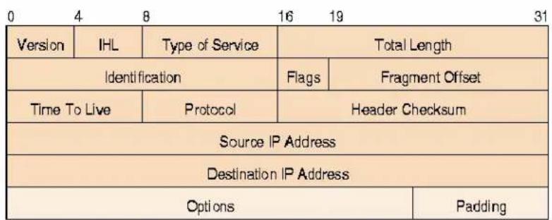
The header fields are discussed in the following table.
Table 328 IP v4 Packet Headers
| HEADER DESCRIPTION | |
| Version The value 4 indicates IP version 4. | |
| IHL | IP Header Length is the number of 32 bit words forming the total length of the header (usually five). |
| Type of Service | The Type of Service, (also known as Differentiated Services Code Point (DSCP)) is usually set to 0, but may indicate particular quality of service needs from the network. |
| Total Length | This is the size of the datagram in bytes. It is the combined length of the header and the data. |
| Identification | This is a 16-bit number, which together with the source address, uniquely identifies this packet. It is used during reassembly of fragmented datagrams. |
| Flags | Flags are used to control whether routers are allowed to fragment a packet and to indicate the parts of a packet to the receiver. |
| Fragment Offset This is a byte count from the start of the original sent packet. | |
| Time To Live | This is a counter that decrements every time it passes through a router. When it reaches zero, the datagram is discarded. It is used to prevent accidental routing loops. |
| Protocol | The protocol indicates the type of transport packet being carried, for example, 1 = ICMP; 2= IGMP; 6 = TCP; 17= UDP. |
| Header Checksum | This is used to detect processing errors introduced into the packet inside a router or bridge where the packet is not protected by a link layer cyclic redundancy check. Packets with an invalid checksum are discarded by all nodes in an IP network. |
| Source IP Address This is the IP address of the original sender of the packet. | |
| Destination IP Address | This is the IP address of the final destination of the packet. |
| Options | IP options is a variable-length list of IP options for a datagram that define IP Security Option, IP Stream Identifier, (security and handling restrictions for the military), Record Route (have each router record its IP address), Loose Source Routing (specifies a list of IP addresses that must be traversed by the datagram), Strict Source Routing (specifies a list of IP addresses that must ONLY be traversed by the datagram), Timestamp (have each router record its IP address and time), End of IP List and No IP Options. |
| Padding | Padding is used as a filler to ensure that the IP packet is a multiple of 32 bits. |
Select Configuration > Security Service. The Custom Signature Rules section shows a summary of all custom signatures created. Click the SID or Name heading to sort. Click the Add icon to create a new signature or click the Edit icon to edit an existing signature. You can also delete custom signatures here or save them to your computer.
Note: The Zyxel Device checks all signatures and continues searching even after a match is found. If two or more rules have conflicting actions for the same packet, then the Zyxel Device applies the more restrictive action (reject-both, reject-receiver or reject-sender, drop, none in this order). If a packet matches a rule for reject-receiver and it also matches a rule for reject-sender, then the Zyxel Device will reject-both.
36.3.1 Add / Edit Custom Signatures
Click the Add icon to create a new signature or click the Edit icon to edit an existing signature on the screen as shown in Figure 537 on page 834.
A packet must match all items you configure in this screen before it matches the signature. The more specific your signature (including packet contents), then the fewer false positives the signature will trigger.
Try to write signatures that target a vulnerability, for example a certain type of traffic on certain operating systems, instead of a specific exploit.
Figure 540 Configuration > Security Service > IPS > Custom Signatures > Add/Edit
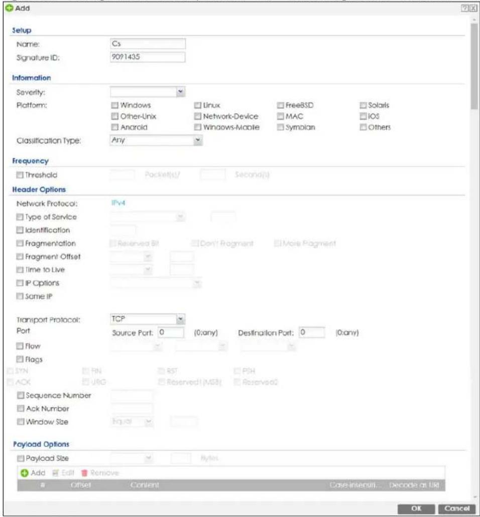
The following table describes the fields in this screen.
Table 329 Configuration > Security Service > IPS > Custom Signatures > Add/Edit
| LABEL DESCRIPTION | |
| Name | Type the name of this custom signature. You may use 1-31 alphanumeric characters, underscores(____), or dashes (-), but the first character cannot be a number. This value is case-sensitive.Duplicate names can exist but it is advisable to use unique signature names that give some hint as to intent of the signature and the type of attack it is supposed to prevent. Refer to (but do not copy) the packet inspection signature names for hints on creating a naming convention. |
| Signature ID | A signature ID is automatically created when you click the Add icon to create a new signature. You can edit the ID to create a new one (in the 900000 to 999999 range), but you cannot use one that already exists. You may want to do that if you want to order custom signatures by SID. |
| Information | Use the following fields to set general information about the signature as denoted below. |
| Severity | The severity level denotes how serious the intrusion is. Categorize the seriousness of the intrusion here. |
| Platform | Some intrusions target specific operating systems only. Select the operating systems that the intrusion targets, that is, the operating systems you want to protect from this intrusion. SGI refers to Silicon Graphics Incorporated, who manufactures multi-user Unix workstations that run the IRIX operating system (SGI's version of UNIX). A router is an example of a network device. |
| Classification Type | Categorize the attack type here. See Table 326 on page 839 as a reference. |
| Frequency | Recurring packets of the same type may indicate an attack. Use the following field to indicate how many packets per how many seconds constitute an intrusion |
| Threshold | Select Threshold and then type how many packets (that meet the criteria in this signature) per how many seconds constitute an intrusion. |
| Header Options | |
| Network Protocol Configure signatures for IP version 4. | |
| Type Of Service | Type of service in an IP header is used to specify levels of speed and/or reliability. Some intrusions use an invalid Type Of Service number. Select the check box, then select Equal or Not-Equal and then type in a number. |
| Identification | The identification field in a datagram uniquely identifies the datagram. If a datagram is fragmented, it contains a value that identifies the datagram to which the fragment belongs. Some intrusions use an invalid Identification number. Select the check box and then type in the invalid number that the intrusion uses. |
| Fragmentation | A fragmentation flag identifies whether the IP datagram should be fragmented, not fragmented or is a reserved bit. Some intrusions can be identified by this flag. Select the check box and then select the flag that the intrusion uses. |
| Fragment Offset | When an IP datagram is fragmented, it is reassembled at the final destination. The fragmentation offset identifies where the fragment belongs in a set of fragments. Some intrusions use an invalid Fragment Offset number. Select the check box, select Equal, Smaller or Greater and then type in a number |
| Time to Live | Time to Live is a counter that decrements every time it passes through a router. When it reaches zero, the datagram is discarded. Usually it's used to set an upper limit on the number of routers a datagram can pass through. Some intrusions can be identified by the number in this field. Select the check box, select Equal, Smaller or Greater and then type in a number. |
| IP Options | IP options is a variable-length list of IP options for a datagram that define IP Security Option, IP Stream Identifier, (security and handling restrictions for the military), Record Route (have each router record its IP address), Loose Source Routing (specifies a list of IP addresses that must be traversed by the datagram), Strict Source Routing (specifies a list of IP addresses that must ONLY be traversed by the datagram), Timestamp (have each router record its IP address and time), End of IP List and No IP Options. IP Options can help identify some intrusions. Select the check box, then select an item from the list box that the intrusion uses |
| Same IP | Select the check box for the signature to check for packets that have the same source and destination IP addresses. |
| Transport Protocol | The following fields vary depending on whether you choose TCP, UDP or ICMP. |
| Transport Protocol: TCP | |
| Port Select the check | box and then enter the source and destination TCP port numbers that will trigger this signature. |
| Flow | The selected keyword sets the criteria as to which traffic is matched. You can match traffic based on direction or whether the connection is established or not. You can also specify whether you want to match signatures per packet or in a stream of packets.Established: Match established connections.Stateless: Match packets that are not part of an established connection.To Client: Match packets that flow from server to client.To Server: Match packets that flow from client to server.From Client: Match packets that flow from client to server.From Servers: Match packets that flow from server to client.No Stream: Match packets that have not been reassembled by the stream engine. It will not match packets that have been reassembled.Only Stream: Match packets that have been reassembled. |
| Flags Select what TCP | flag bits the signature should check. |
| Sequence Number Use this field to check for a specific TCP sequence number. | |
| Ack Number Use this field to check for a specific TCP acknowledgment number. | |
| Window Size Use this field to check for a specific TCP window size. | |
| Transport Protocol: UDP | |
| Port | Select the check box and then enter the source and destination UDP port numbers that will trigger this signature. |
| Transport Protocol: ICMP | |
| Type Use this field to check for a specific ICMP type value. | |
| Code Use this field to check for a specific ICMP code value. | |
| ID | Use this field to check for a specific ICMP ID value. This is useful for covert channel programs that use static ICMP fields when they communicate. |
| Sequence Number | Use this field to check for a specific ICMP sequence number. This is useful for covert channel programs that use static ICMP fields when they communicate. |
| Payload Options | The longer a payload option is, the more exact the match, the faster the signature processing. Therefore, if possible, it is recommended to have at least one payload option in your signature. |
| Payload Size | This field may be used to check for abnormally sized packets or for detecting buffer overflows.Select the check box, then select Equal, Smaller or Greater and then type the payload size.Stream rebuilt packets are not checked regardless of the size of the payload. |
| Add Click this to create a new entry. | |
| Edit Select an entry and click this to be able to modify it. | |
| Remove Select an entry and click this to delete it. | |
| # This is the entry's index number in the list. | |
| Offset | This field specifies where to start searching for a pattern within a packet. For example, an offset of 5 would start looking for the specified pattern after the first five bytes of the payload. |
| Content Type the content that the signature should search for in the packet payload.Hexadecimal code entered between pipes is converted to ASCII. For example, you could represent the ampersand as either & or |26| (26 is the hexadecimal code for the ampersand).Use 1 to 63 single-byte characters, including 0-9a-zA-Z!#$%&'()*+,-./<=>?@[]^_{|}``:\`are not allowed. | |
| Case-insensitive | Select Yes if content casing does NOT matter. |
| Decode as URI | A Uniform Resource Identifier (URI) is a string of characters for identifying an abstract or physical resource (RFC 2396). A resource can be anything that has identity, for example, an electronic document, an image, a service ("today's weather report for Taiwan"), a collection of other resources. An identifier is an object that can act as a reference to something that has identity. Example URLs are:ftp://ftp.is.co.za/rfc/rfc1808.txt; ftp scheme for File Transfer Protocol serviceshttp://www.math.uio.no/faq/compression-faq/part1.html; http scheme for Hypertext Transfer Protocol servicesmailto:mduerst@ifi.unizh.ch; mailto scheme for electronic mail addressestelnet://melvyl.ucop.edu/: telnet scheme for interactive services via the TELNET ProtocolSelect Yes for the signature to search for normalized URI fields. This means that if you are writing signatures that includes normalized content, such as %2 for directory traversals, these signatures will not be triggered because the content is normalized out of the URI buffer.For example, the URI:/scripts/..%c0%af../winnt/system32/cmd.exe?/c+verwill get normalized into:/winnt/system32/cmd.exe?/c+ver |
| OK | Click this button to save your changes to the Zyxel Device and return to the summary screen. |
| Cancel | Click this button to return to the summary screen without saving any changes. |
36.3.2 Custom Signature Example
Before creating a custom signature, you must first clearly understand the vulnerability.
36.3.2.1 Understand the Vulnerability
Check the Zyxel Device logs when the attack occurs. Use web sites such as Google or Security Focus to get as much information about the attack as you can. The more specific your signature, the less chance it will cause false positives.
As an example, say you want to check if your router is being overloaded with DNS queries so you create a signature to detect DNS query traffic.
36.3.2.2 Analyze Packets
Use the packet capture screen and a packet analyzer (also known as a network or protocol analyzer) such as Wireshark or Ethereal to investigate some more.
Figure 541 DNS Query Packet Details
![46348 3921.079709 192.168.1.1 46349 3921.079720 192.168.1.33 46350 3921.079725 192.168.1.1 46351 3921.079736 192.168.1.33 46352 3923.770412 192.168.1.33 46353 3923.810622 192.168.1.1 46354 3923.810663 192.168.1.33 46355 3923.810711 192.168.1.1 46356 3923.810722 192.168.1.33 46357 3923.810729 192.168.1.1 46358 3923.810739 192.168.1.33 46359 3923.811730 192.168.1.1 46360 3923.811740 192.168.1.33 46361 3923.811745 192.168.1.1 46362 3923.811755 192.168.1.33 46363 3923.811761 192.168.1.1 DNS Standard query respons ICMP Destination unreachable DNS Standard query respons ICMP Destination unreachable DNS Standard query respons ICMP Destination unreachable DNS Standard query respons ICMP Destination unreachable DNS Standard query respons ICMP Destination unreachable DNS Standard query respons ICMP Destination unreachable DNS Standard query respons ICMP Destination unreachable DNS Standard query respons ICMP Destination unreachable DNS Standard query respons ICMP Destination unreachable DNS Standard query respons ICMP Destination unreachable DNS Standard query respons ICMP Destination reachable DNS Standard query respons ICMP Destination unreachable DNS Standard query respons ICMP Destination unreachable DNS Standard query respons ICMP Destination unreachable DNS Standard query respons ICMP Destination unreachable DNS Standard query respons ICMP Destination unreachable DNS Standard query respons ICMP Destination unreachable DNS Standard query respons ICMP Destination unreachable DNS Standard query respons ICMP Destination unreachable DNS Standard query respons ICMP Destination unreachable DNS Standard query respons ICMP Destination reachable DNS Standard query respons ICMP Destination unreachable DNS Standard query respons ICMP Destination unreachable DNS Standard query respons ICMP Destination unreachable DNS Standard query respons ICMP Destination unreachable DNS Standard query respons ICMP Destination unreachable DNS Standard query respons ICMP Destination unreachable DNS Standard query respons ICMP Destination unreachable DNS Standard query respons ICMP Destination unreachable DNS Standard query respons ICMP Destination unreachable DNS Standard query respons ICMP Destination距離域 (0x1) Protocol: UDP (0x1) Header checksum: 0xce07 [correct] Source: 192.168.1.33 (192.168.1.33) Destination: 192.168.1.1 (192.168.1.1) User Datagram Protocol, Src Port: 25301 (25301), Dst Port: domain (53) Domain Name System (query) Transaction ID: 0x9d13 Flags: 0x0100 (Standard query) 0... .... .... .... = Response: Message is a query .000 0... .... .... = Opcode: Standard query (0) .... ...0... .... = Truncated: Message is not truncated .... ...1 ... .... = Recursion desired: Do query recursively .... ...0... .... = Z: reserved (0) .... ...0... = Non-authenticated data OK: Non-authenticated data is unacc Questions: 1 Answer RRs: 0 Authority RRs: 0 Additional RRs: 0 Queries www.gravatar.com: type A, class IN 0000 00 00 aa 78 57 43 00 of 3d ec 5e c3 08 00 45 00 ...xwc... =A...E. 0010 00 3e e9 34 00 00 80 11 ce 07 c0 a8 01 21 c0 a8 .>.4... ....!.. 0020 01 01 62 d5 00 35 00 2a 58 19 yd 13 01 00 00 01 ..b..5.* X....... 0030 00 00 00 00 00 03 77 77 77 08 67 72 61 76 61 .....w ww.grava 0040 74 61 72 03 63 6f 6d 00 00 01 wv. tar.com....](/content/2026/05/878280/images/d7a75685985ac325462dd1a3cde9abea6e31ff68da9c2d45b577a8e0f396751c.jpg)
From the details about DNS query you see that the protocol is UDP and the port is 53. The type of DNS packet is standard query and the Flag is 0x0100 with an offset of 2. Therefore enter |010| as the first pattern.
The final custom signature should look like as shown in the following figure.
Figure 542 Example Custom Signature
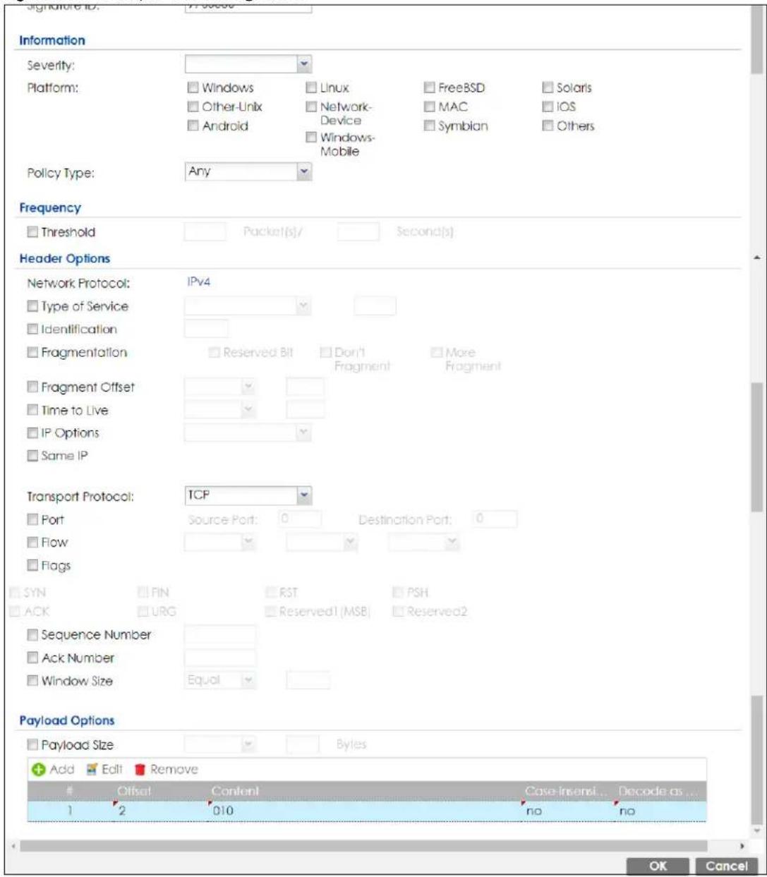
36.3.3 Applying Custom Signatures
After you create your custom signature, it becomes available in an IPS profile (Configuration > Security Service > IPS > Profile > Edit screen). Custom signatures have an SID from 9000000 to 9999999.
Search for, then activate the signature, configure what action to take when a packet matches it and if it should generate a log or alert in a profile. Then bind the profile to a zone.
36.3.4 Verifying Custom Signatures
Configure the signature to create a log when traffic matches the signature. (You may also want to configure an alert if it is for a serious attack and needs immediate attention.) After you apply the signature to a zone, you can see if it works by checking the logs (Monitor > Log).
The Priority column shows warn for signatures that are configured to generate a log only. It shows critical for signatures that are configured to generate a log and alert. All IPS signatures come under the IPS category. The Note column displays ACCESS FORWARD when no action is configured for the signature. It displays ACCESS DENIED if you configure the signature action to drop the packet. The destination port is the service port (53 for DNS in this case) that the attack tries to exploit.
Figure 543 Custom Signature Log
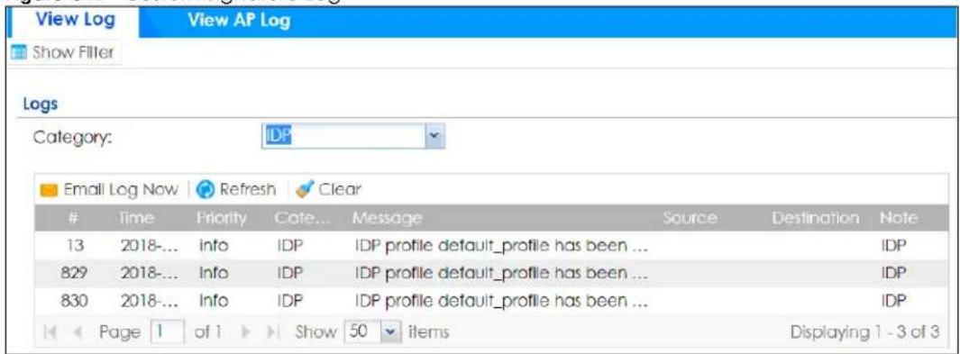
36.4 The Allow List Screen
Use this screen to list signatures that will be exempted from IPS inspection. The Zyxel Device will exclude incoming packets with the listed signature(s) from being intercepted and inspected.
Click Configuration > Security Service > IPS > Allow List to display the following screen. Use Add to put a new item in the list or Edit to change an existing one or Remove to delete an existing entry.
Figure 544 Configuration > Security Service > IPS > Allow List
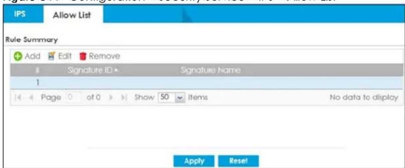
The following table describes the fields in this screen.
Table 330 Configuration > Security Service > IPS > Allow List
| LABEL DESCRIPTION | |
| Rule Summary | |
| Add Click this to create a new entry. | |
| Edit Select an entry and click this to be able to modify it. | |
| Remove Select an entry and click this to delete it. | |
| # This is the entry's index number in the list. | |
| Signature ID This field displays the signature ID of this entry. | |
| Signature Name This field displays the signature name of this entry. | |
| Apply | Click Apply to save your changes back to the Zyxel Device. |
| Reset | Click Reset to return the screen to its last-saved settings. |
36.5 IPS Profile
To use multiple profiles for this feature, run the following commands in the Zyxel Device Command Line Interface (CLI).
Router# configure terminal
Router(config)# secure-policy-style advance
Router(config)# show secure-policy-style status
secure-policy-style: advance
After you run these command, go to the feature screen again in the web configurator. You will be prompted to log out and then log in again.
Figure 545 Logout Prompt
After you log in again, you will see the new profile screen for this feature.
Figure 546 Configuration > Security Service > IPS> Profile
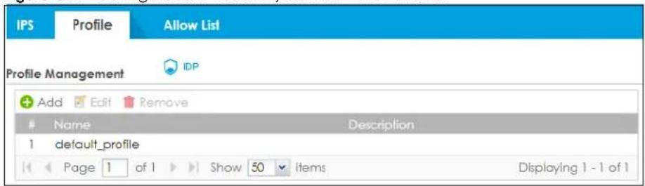
The following table describes the labels in this screen.
Table 331 Configuration > Security Service > IPS > Profile
| LABEL DESCRIPTION | |
| Add | Click this to create a new entry. Select an entry and click Add to create a new entry after the selected entry. |
| Edit | Double-click an entry or select it and click Edit to open a screen where you can modify the entry's settings. |
| Remove | Select an entry and click Remove to delete the selected entry. |
| # | This field is a sequential value showing the number of the profile. The profile order is not important. |
| Name This displays the name of the profile created. | |
| Description This displays the description of the profile. | |
36.5.1 Add or Edit an IPS Profile
Click Add to create a new entry or select an existing entry and click Edit to open the following screen where you can create or modify the entry's settings.
Figure 547 Configuration > Security Service > IPS > Profile > Add/Edit
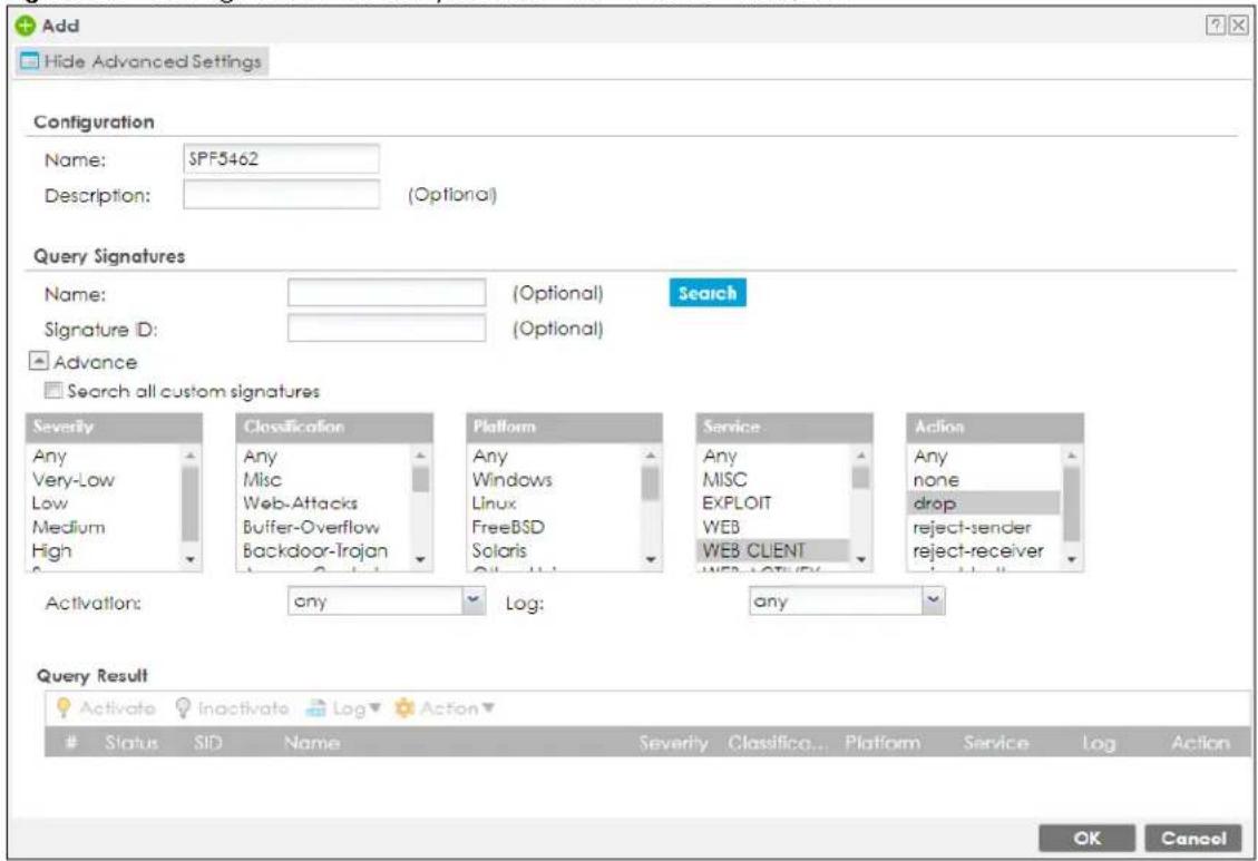
The following table describes the labels in this screen.
Table 332 Configuration > Security Service > IPS
| LABEL DESCRIPTION | |
| Configuration | |
| Profile Name Type the | name of the profile. You may use 1-31 alphanumeric characters, underscores(_, or dashes (-), but the first character cannot be a number. This value is case-sensitive. These are valid, unique profile names:My ProfilemYProfileMymy12_3-4These are invalid profile names:1mYProfileMy ProfileMyProfile?Whatalongprofilename123456789012 |
| Description | Type a description for the profile rule to help identify the purpose of rule. You may use 1-31 alphanumeric characters, underscores Luxury, or dashes (-), but the first character cannot be a number. This value is case-sensitive. This field is optional. |
| Query Signatures | |
| Name | Type the name or part of the name of the signature(s) you want to find. |
| Signature ID Type the | ID or part of the ID of the signature(s) you want to find. |
| Search all custom signatures | Select this check box to include signatures you created or imported in theCustom Signatures screen in the search. You can search for specific signatures by name or ID. If the name and ID fields are left blank, then all signatures are searched according to the criteria you select. |
| Severity | Search for signatures by severity level(s). Hold down the [Ctrl] key if you want to make multiple selections.These are the severities as defined in the Zyxel Device. The number in brackets is the number you use if using commands.Severe(5): These denote attacks that try to run arbitrary code or gain system privileges.High(4): These denote known serious vulnerabilities or attacks that are probably not false alarms.Medium(3): These denote medium threats, access control attacks or attacks that could be false alarms.Low(2): These denote mild threats or attacks that could be false alarms.Very-Low(1): These denote possible attacks caused by traffic such as Ping, trace route, ICMP queries etc. |
| Classification Type | Search for signatures by attack type(s)(seeTable 326 on page 839). Attack types are known as policy types in the group view screen. Hold down the [Ctrl] key if you want to make multiple selections. |
| Platform | Search for signatures created to prevent intrusions targeting specific operating system(s). Hold down the [Ctrl] key if you want to make multiple selections. |
| Service | Search for signatures by IPS service group(s). SeeTable 326 on page 839for group details.Hold down the [Ctrl] key if you want to make multiple selections. |
| Action | Search for signatures by the response the Zyxel Device takes when a packet matches a signature.Hold down the [Ctrl] key if you want to make multiple selections. |
| Activation Search for | activated and/or inactivated signatures here. |
| Log | Search for signatures by log option here. |
| Query Result | The results are displayed in a table showing the SID, Name, Severity, Classification Type, Platform, Service, Log, and Action criteria as selected in the search. Click the SID column header to sort search results by signature ID. |
| OK | Click OK to save your changes back to the Zyxel Device. |
| Cancel | Click Cancel to exit this screen without saving. |
36.5.2 Link a Profile
To link a profile to a policy, go to the Configuration > Security Policy > Policy Control screen, select a policy, and then click Edit. In the Edit Policy screen under Profile, select which profile you want to use for each security service.
Figure 548 Configuration > Security Service > Policy Control > Profile
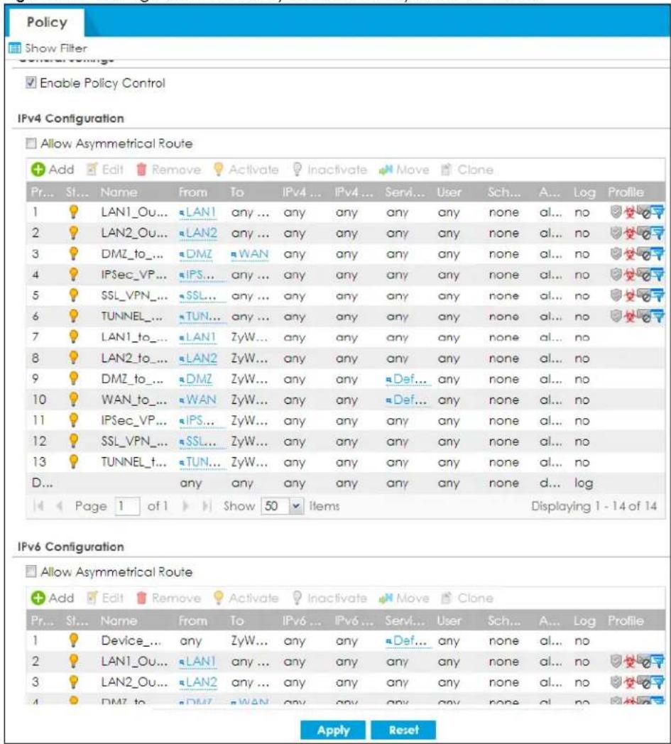
36.5.3 The IPS Advance Screen
The Configuration > Security Service > IPS screen changes when using profiles.
Figure 549 Configuration > Security Service > IPS Advance
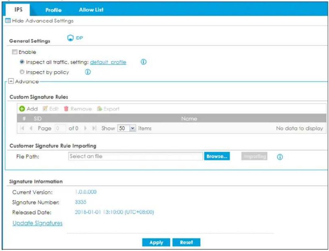
The following table describes the fields in this screen.
Table 333 Configuration > Security Service > IPS Advance
| LABEL DESCRIPTION | |
| General Settings | |
| Enable | Select this check box to activate the IPS feature which detects and prevents malicious or suspicious packets and responds instantaneously. |
| Inspect all traffic, setting: | Select this to have all traffic inspected by thedefault_profileordefault_detect_only.Use thedefault_profileprofile to set the Zyxel Device to IPS prevention mode. Use thedefault_detect_onlyprofile to set the Zyxel Device to IPS detection mode. For more information on IPS prevention and detection mode, seeTable 325 on page 835.You cannot rename or delete thedefault_profileordefault_detect_onlyprofile, but you can edit it by clicking on the profile name. |
| Inspect by policy | If you configured a specific profile in theProfiletab for this service, select this to have specific traffic inspected by that profile. You must bind the profile to a policy inSecurity Policy > Policy Control. |
| Custom Signature Rules | Use this part of the screen to create, edit, delete or export (save to your computer) custom signatures. |
| Add Click this to create a new entry. | |
| Edit Select an entry and click this to be able to modify it. | |
| Remove Select an entry and click this to delete it. | |
| Export | To save an entry or entries as a file on your computer, select them and click Export. Click Save in the file download dialog box and then select a location and name for the file.Custom signatures must end with the 'rules' file name extension, for example, MySig.rules. |
| # This is the entry's index number in the list. | |
| SID | SID is the signature ID that uniquely identifies a signature. Click the SID header to sort signatures in ascending or descending order. It is automatically created when you click the Add icon to create a new signature. You can edit the ID, but it cannot already exist and it must be in the 9000000 to 9999999 range. |
| Name | This is the name of your custom signature. Duplicate names can exist, but it is advisable to use unique signature names that give some hint as to intent of the signature and the type of attack it is supposed to prevent. |
| Customer Signature Rule Importing | Use this part of the screen to import custom signatures (previously saved to your computer) to the Zyxel Device.Note: The name of the complete custom signature file on the Zyxel Device is 'custom.rules'. If you import a file named 'custom.rules', then all custom signatures on the Zyxel Device are overwritten with the new file. If this is not your intention, make sure that the files you import are not named 'custom.rules'. |
| File Path | Type the file path and name of the custom signature file you want to import in the text box (or click Browse to find it on your computer) and then click Importing to transfer the file to the Zyxel Device.New signatures then display in the Zyxel Device IPS > Custom Signatures screen. |
| Signature Information | The following fields display information on the current signature set that the Zyxel Device is using. |
| Current Version | This field displays the IPS signature set version number. This number gets larger as the set is enhanced. |
| Signature Number | This field displays the number of IPS signatures in this set. This number usually gets larger as the set is enhanced. Older signatures and rules may be removed if they are no longer applicable or have been supplanted by newer ones. |
| Released Date | This field displays the date and time the set was released. |
| Update Signatures | Click this link to go to the screen you can use to download signatures from the update server. |
| Apply | Click Apply to save your changes back to the Zyxel Device. |
| Reset | Click Reset to return the screen to its last-saved settings. |
36.5.4 Remove Profiles
To remove profiles and revert to the default general security policy style, you must first make sure to change Inspect by policy to Inspect all traffic in the following security services: Anti-Malware, DNS Threat Filter, IPS, Email Security.
Note: All profiles that you created will be removed from Security Policy > Policy Control.
Run the following commands in the Zyxel Device Command Line Interface (CLI).
Router# configure terminal
Router(config)# secure-policy-style general
Router(config)# show secure-policy-style status
secure-policy-style: general
Wait a minute and then go to the feature screen again in the web configurator. You will be prompted to log out and then log in again.
Figure 550 Logout Prompt
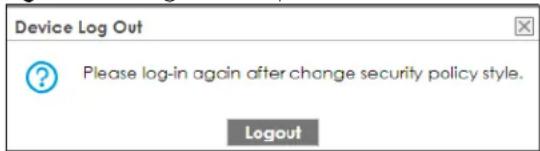
After you log in again, you will not see the profile screen for this feature.
36.6 IPS Technical Reference
This section contains some background information on IPS.
Host Intrusions
The goal of host-based intrusions is to infiltrate files on an individual computer or server in with the goal of accessing confidential information or destroying information on a computer.
You must install a host IPS directly on the system being protected. It works closely with the operating system, monitoring and intercepting system calls to the kernel or APIs in order to prevent attacks as well as log them.
Disadvantages of host IPSs are that you have to install them on each device (that you want to protect) in your network and due to the necessarily tight integration with the host operating system, future operating system upgrades could cause problems.
Network Intrusions
Network-based intrusions have the goal of bringing down a network or networks by attacking computer(s), switch(es), router(s) or modem(s). If a LAN switch is compromised for example, then the whole LAN is compromised. Host-based intrusions may be used to cause network-based intrusions when the goal of the host virus is to propagate attacks on the network, or attack computer/server operating system vulnerabilities with the goal of bringing down the computer/server. Typical “network-based intrusions” are SQL slammer, Blaster, Nimda MyDoom etc.
Snort Signatures
You may want to refer to open source Snort signatures when creating custom Zyxel Device ones. Most Snort rules are written in a single line. Snort rules are divided into two logical sections, the rule header and the rule options as shown in the following example:
alert tcp any any -> 192.168.1.0/24 111 (content:"|00 01 a5|"; msg:"mountd access");
The text up to the first parenthesis is the rule header and the section enclosed in parenthesis contains the rule options. The words before the colons in the rule options section are the option keywords.
The rule header contains the rule's:
- Action
- Protocol
- Source and destination IP addresses and netmasks
- Source and destination ports information.
The rule option section contains alert messages and information on which parts of the packet should be inspected to determine if the rule action should be taken.
These are some equivalent Snort terms in the Zyxel Device.
Table 334 Zyxel Device - Snort Equivalent Terms
| ZYXEL DEVICE TERM SNORT EQUIVALENT | TERM |
| Type Of Service tos | |
| Identification id | |
| Fragmentation fragbits | |
| Fragmentation Offset fragoffset | |
| Time to Live ttl | |
| IP Options ipopts | |
| Same IP sameip | |
| Transport Protocol | |
| Transport Protocol: TCP | |
| Port (In Snort rule header) | |
| Flow flow | |
| Flags flags | |
| Sequence Number seq | |
| Ack Number | ack |
| Window Size | window |
| Transport Protocol: UDP | (In Snort rule header) |
| Port (In Snort rule header) | |
| Transport Protocol: ICMP | |
| Type | itype |
| Code | icode |
| ID | icmp_id |
| Sequence Number icmp_seq | |
| Payload Options | (Snort rule options) |
| Payload Size | dsize |
| Offset (relative to start of payload) | offset |
| Relative to end of last match | distance |
| Content | content |
| Case-insensitive nocase | |
| Decode as URI uricontent |
Note: Not all Snort functionality is supported in the Zyxel Device.
CHAPTER 37 Sandboxing
37.1 Overview
Zyxel cloud sandboxing is a security mechanism which provides a safe environment to separate running programs from your network and host devices. Unknown or untrusted programs/codes are uploaded to the Defend Center and executed within an isolated virtual machine (VM) to monitor and analyze the zero-day malware and advanced persistent threats (APTs) that may evade the Zyxel Device's detection, such as anti-malware. Results of cloud sandboxing are sent from the server to the Zyxel Device.
By default, the Zyxel Device sandbox forwards all unknown files and uploads a copy of the files for inspection after checking the received files against its local cache. The scan result from the Defend Center (DC) is added to the Zyxel Device cache and used for future inspection. When a file with malicious or suspicious codes is detected, the Zyxel Device can take specific actions on the threats.
Note: The scan result will be removed from the Zyxel Device cache after the Zyxel Device restarts.
Figure 551 General Zyxel Sandbox Inspection
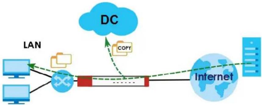
flowchart
graph TD
    A["Computer"] --> B["LAN"]
    C["Computer"] --> B
    B --> D["Server"]
    D --> E["Internet"]
    F["DC"] --> G["COPY"]
    G --> D
    style F fill:#f9f,stroke:#333
    style G fill:#ccf,stroke:#333
Alternatively, you can select to hold and inspect the downloaded files for up to two seconds if the downloaded files have never been inspected before.
Figure 552 Advanced Zyxel Sandbox Inspection
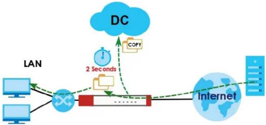
flowchart
graph LR
    A["LAN"] --> B["Internet"]
    B --> C["DC"]
    C --> D["2 Seconds"]
    D --> E["TCP"]
    E --> F["100%"]
    F --> G["Server"]
    style A fill:#f9f,stroke:#333
    style B fill:#ccf,stroke:#333
    style C fill:#cfc,stroke:#333
    style D fill:#fcc,stroke:#333
    style E fill:#cff,stroke:#333
    style F fill:#ffc,stroke:#333
    style G fill:#cfc,stroke:#333
Please note that your Zyxel Device does not support sandboxing by default. You need to purchase a gold pack license; see Section 7.1.2 on page 258 for more information.
37.1.1 What You Need to Know
The Zyxel Device may forward files with attachments before Sandbox has completed checking. If Sandbox discovers a suspect file, please contact the receiver of the suspect file and advise him/her not to open it. If he/she already opened it, then please urge him/her to run an up-to-date anti-malware scanner.
If the receiver of a suspect file cannot open a file, Sandbox may have already modified the file by deleting the infected portion. Please check the logs and let the receiver know if this is so.
Sandbox can only check the types of files listed under File Submission Options in the Sandboxing screen. If you disabled Scan and detect EICAR test virus in the Anti-Malware screen, then EICAR test files will be sent to Sandbox.
To use the sandbox, you need to register your Zyxel Device and activate the service license at myZyxel, and then turn on the sandboxing function on the Zyxel Device. See Licensing for more information about registration and service licenses.
37.2 Sandboxing Screen
Click Configuration > Security Service > Sandboxing to display the configuration screen as shown next.
Use this screen to enable sandboxing and specify the actions the Zyxel Device takes when malicious or suspicious files are detected.
Click the Sandboxing icon for more information on the Zyxel Device's security features.
Figure 553 Configuration > Security Service > Sandboxing
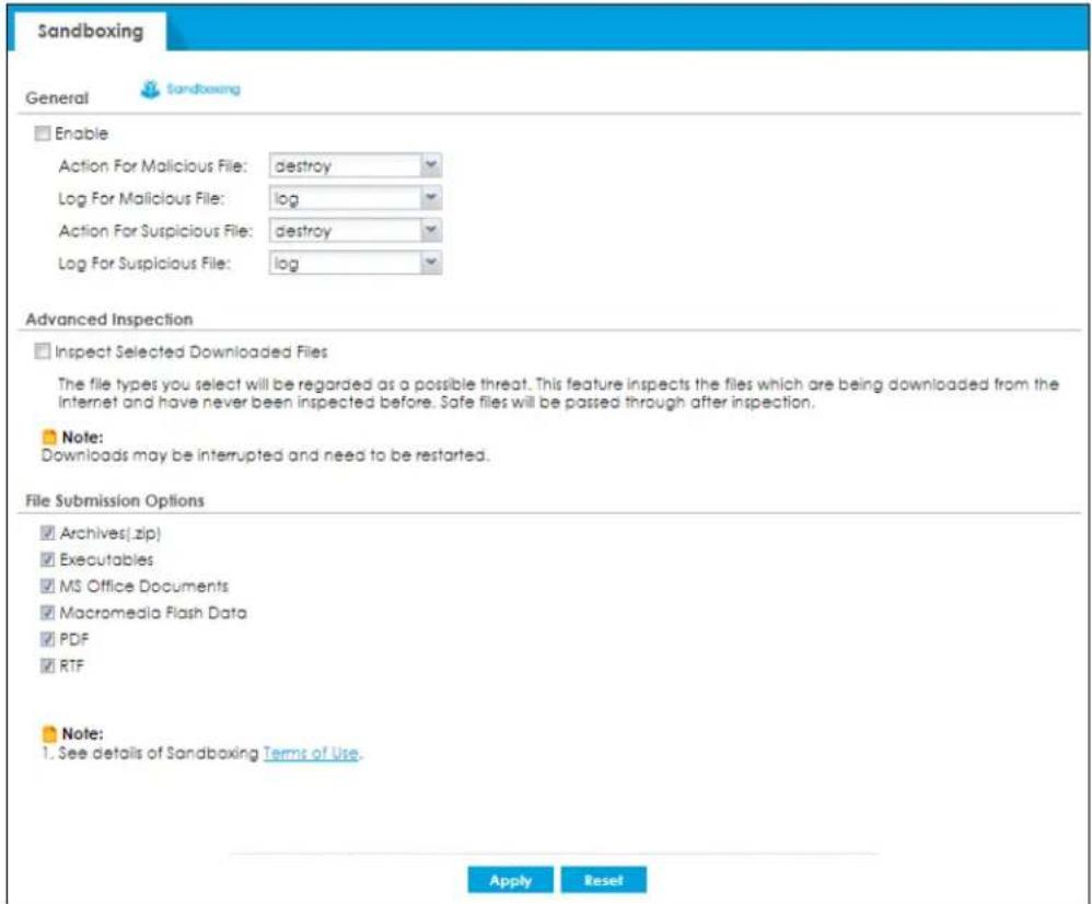
The following table describes the labels in this screen.
Table 335 Configuration > Security Service > Sandboxing
| LABEL DESCRIPTION | |
| General | |
| Enable Sandboxing | Select this option to turn on sandboxing on the Zyxel Device. Otherwise, deselect it. |
| Action For Malicious File | Specify whether the Zyxel Device deletes (destroy) or forwards (allow) malicious files.Malicious files are files given a high score for malware characteristics by the Defend Center. |
| Log For Malicious File | These are the log options for malicious files:no: Do not create a log when a malicious file is detected.log: Create a log on the Zyxel Device when a malicious file is detected.log alert: An alert is an emailed log for more serious events that may need more immediate attention. Select this option to have the Zyxel Device send an alert when a malicious file is detected. |
| Action For Suspicious File | Specify whether the Zyxel Device deletes (destroy) or forwards (allow) suspicious files.Suspicious files are files given a medium score for malware characteristics by the Defend Center. |
| Log For Suspicious File | These are the log options for suspicious files:no: Do not create a log when a suspicious file is detected.log: Create a log on the Zyxel Device when a suspicious file is detected.log alert: An alert is an emailed log for more serious events that may need more immediate attention. Select this option to have the Zyxel Device send an alert when a suspicious file is detected. |
| Advanced Inspection | |
| Inspect Selected Downloaded Files | Select the check box to have the Zyxel Device hold the downloaded file for up to two seconds if the downloaded file has never been inspected before. The Zyxel Device will wait for the Defend Center's result and forward the file in two seconds. Sandbox detection may take longer than two seconds, so infected files could still possibly be forwarded to the user.Note: The Zyxel Device only checks the file types you selected for sandbox inspection.The scan result will be removed from the Zyxel Device cache after the Zyxel Device restarts. |
| File Submission Options | Specify the type of files to be sent for sandbox inspection. |
| Terms of Use | Click this link to see what data Zyxel collects from you and how it is used. |
| Apply | ClickApplyto save your changes. |
| Reset | Click Resetto return the screen to its last-saved settings. |
CHAPTER 38
Email Security
38.1 Overview
The email security feature can mark or discard spam (unsolicited commercial or junk email). Use the white list to identify legitimate email. Use the black list to identify spam email. The Zyxel Device can also check email against a DNS black list (DNSBL) of IP addresses of servers that are suspected of being used by spammers. Email Security scans SMTP/POP3 email headers to see if the sender is in the DNSBL block list, and blocks the sender if yes. If an incoming mail is encrypted or includes unsafe content, outgoing attempts trying to access the unsafe content are blocked.
38.1.1 What You Can Do in this Chapter
- Use the Email Security screens (Section 38.3 on page 865) to turn email security on or off and manage email security policies. Also, you can enable and configure the mail scan functions and have the Zyxel Device check email against DNS Black Lists.
- Use the Block/ Allow List screens (Section 38.4 on page 867) to set up a block list to identify spam and a allow list to identify legitimate email.
38.1.2 What You Need to Know
Allow List
Configure allow list entries to identify legitimate email. The allow list entries have the Zyxel Device classify any email that is from a specified sender or uses a specified header field and header value as being legitimate (see Email Headers for more on mail headers). The email security feature checks an email against the allow list entries before doing any other email security checking. If the email matches a allow list entry, the Zyxel Device classifies the email as legitimate and does not perform any more email security checking on that individual email. A properly configured allow list helps keep important email from being incorrectly classified as spam. The allow list can also increases the Zyxel Device's email security speed and efficiency by not having the Zyxel Device perform the full email security checking process on legitimate email.
Block List
Configure block list entries to identify spam. The block list entries have the Zyxel Device classify any email that is from or forwarded by a specified IP address or uses a specified header field and header value as being spam. If an email does not match any of the allow list entries, the Zyxel Device checks it against the block list entries. The Zyxel Device classifies an email that matches a block list entry as spam and immediately takes the configured action for dealing with spam. If an email matches a block list entry, the Zyxel Device does not perform any more email security checking on that individual email. A properly configured block list helps catch spam email and increases the Zyxel Device's email security speed and efficiency.
SMTP and POP3
Simple Mail Transfer Protocol (SMTP) is the Internet's message transport standard. It controls the sending of email messages between servers. Email clients (also called email applications) then use mail server protocols such as POP (Post Office Protocol) or IMAP (Internet Message Access Protocol) to retrieve email. Email clients also generally use SMTP to send messages to a mail server. The older POP2 requires SMTP for sending messages while the newer POP3 can be used with or without it. This is why many email applications require you to specify both the SMTP server and the POP or IMAP server (even though they may actually be the same server).
The Zyxel Device's email security feature checks SMTP (TCP port 25) and POP3 (TCP port 110) emails by default. You can also specify custom SMTP and POP3 ports for the Zyxel Device to check.
Email Headers
Every email has a header and a body. The header is structured into fields and includes the addresses of the recipient and sender, the subject, and other information about the email and its journey. The body is the actual message text and any attachments. You can have the Zyxel Device check for specific header fields with specific values.
Email programs usually only show you the To:, From:, Subject:, and Date: header fields but there are others such as Received: and Content-Type:. To see all of an email's header, you can select an email in your email program and look at its properties or details. For example, in Microsoft's Outlook Express, select a mail and click File > Properties > Details. This displays the email's header. Click Message Source to see the source for the entire mail including both the header and the body.
Email Header Buffer Size
The Zyxel Device has a 5 K buffer for an individual email header. If an email's header is longer than 5 K, the Zyxel Device only checks up to the first 5 K.
DNSBL
A DNS Black List (DNSBL) is a server that hosts a list of IP addresses known or suspected of having sent or forwarded spam. A DNSBL is also known as a DNS spam blocking list. The Zyxel Device can check the routing addresses of email against DNSBLs and classify an email as spam if it was sent or forwarded by a computer with an IP address in the DNSBL.
Finding Out More
See Section 38.7 on page 878 for more background information on email security.
38.2 Before You Begin
- Before using the email security features (IP Reputation, Mail Content Analysis and Virus Outbreak Detection) you must activate your email security Service license.
- Configure your zones before you configure email security.
38.3 The Email Security Screen
Click Configuration > Security Service > Email Security to open the Email Security screen. Use this screen to turn the email security feature on or off and manage email security policies. You can also select the action the Zyxel Device takes when the mail sessions threshold is reached.
Figure 554 Configuration > Security Service > Email Security
![Email Security Block/Allow List Hide Advanced Settings General Settings Email Security Enable Enable Malicious Mail Malicious Mail Tag: [Malicious] (Optional) Enable DNSBL DNSBL Spam Tag: [Spam] (Optional) DNSBL Domain List Add Edit Remove Activate Inactivate Status # DNSBL Domain Page 0 of 0 Show 50 Items No data to display Action Actions For Spam Mail SMTP: forward with tag POP3: forward with tag Log: log Action taken when mail session threshold is reached Forward Session Drop Session Advance Query Timeout Settings SMTP: forward with tag POP3: forward with tag Timeout Value: 5 (1-10 Seconds) Timeout Tag: [Timeout] (Optional) Timeout X-Header: X- : (Optional) DNSBL Settings Max. IPs Checking Per Mail: 3 (1-5) IP Selection Per Mail: last N IPs Apply Reset](/content/2026/05/878280/images/635cbeff9ca22c2af43cb3d1b98a176b1deaa38fcc847f95334b657da9ded895.jpg)
The following table describes the labels in this screen.
Table 336 Configuration > Security Service > Email Security
| LABEL DESCRIPTION | |
| General Settings | |
| Enable | Select this check box to activate the settings in this section. |
| Enable Malicious Mail | Select this to identify spam email by content, such as malicious content. |
| LABEL | DESCRIPTION |
| Malicious Mail Tag | Enter a message or label using up to 15 single-byte characters to add to the beginning of the mail subject of emails that are determined to spam based on the mail content analysis. Accepted characters are 0-9a-zA-Z-.[]_!"#%&'()*+./;<=>?@\^'|) are not allowed. This tag is only added if the email security policy is configured to forward spam mail with a spam tag. |
| Enable DNSBL | Select this check box to check email against the Zyxel Device's configured DNSBL domains. The Zyxel Device classifies email that matches a DNS black list as spam. |
| DNSBL Spam Tag | Enter a message or label using up to 15 single-byte characters to add to the beginning of the mail subject of emails that have a sender or relay IP address in the header that matches a black list maintained by one of the DNSBL domains listed in the Zyxel Device.Accepted characters are 0-9a-zA-Z-.[]_!"#%&'()*+./;<=>?@\^{'}|) are not allowed. This tag is only added if the email security policy is configured to forward spam mail with a spam tag. |
| DNSBL Domain List | |
| Add Click this to create | a new entry. |
| Edit Select an entry and | click this to be able to modify it. |
| Remove Select an entry | and click this to delete it. |
| Activate | To turn on an entry, select it and click Activate. |
| Inactivate | To turn off an entry, select it and click Inactivate. |
| Status | The activate (light bulb) icon is lit when the entry is active and dimmed when the entry is inactive. |
| # This is the entry's index | number in the list. |
| DNSBL Domain | This is the name of a domain that maintains DNSBL servers. Enter the domain that is maintaining a DNSBL. |
| Actions for Spam Mail | Use this section to set how the Zyxel Device is to handle spam mail. |
| SMTP Select how the | Zyxel Device is to handle spam SMTP mail.Select drop to discard spam SMTP mail.Select forward to allow spam SMTP mail to go through.Select forward with tag to add a spam tag to an SMTP spam mail's mail subject and send it on to the destination. |
| POP3 Select how the | Zyxel Device is to handle spam POP3 mail.Select forward to allow spam POP3 mail to go through.Select forward with tag to add a spam tag to an POP3 spam mail's mail subject and send it on to the destination. |
| Log | Select whether to have the ZyXEL device generate a log (log), log and alert (log alert) or neither (no) by default when traffic matches a signature in this category. |
| Action taken when mail sessions threshold is reached | An email session is when an email client and email server (or two email servers) connect through the Zyxel Device. Select how to handle concurrent email sessions that exceed the maximum number of concurrent email sessions that the email security feature can handle. See the chapter of product specifications for the threshold.Select Forward Session to have the Zyxel Device allow the excess email sessions without any spam filtering.Select Drop Session to have the Zyxel Device drop mail connections to stop the excess email sessions. The email client or server will have to re-attempt to send or receive email later when the number of email sessions is under the threshold. |
| Query Timeout Settings | |
| LABEL DESCRIPTION | |
| SMTP Select how the Zyxel | Device is to handle SMTP mail query timeout.Select drop to discard SMTP mail.Select forward to allow SMTP mail to go through.Select forward with tag to add a tag to an SMTP query timeout mail's mail subject and send it on to the destination. |
| POP3 Select how the Zyxel | Device is to handle POP3 mail query timeout.Select forward to allow POP3 mail to go through.Select forward with tag to add a tag to an POP3 query timeout mail's mail subject and send it on to the destination. |
| Timeout Value | Set how long the Zyxel Device waits for a reply from the mail scan server. If there is no reply before this time period expires, the Zyxel Device takes the action defined in the relevantActions when Query Timeout field. |
| Timeout Tag | Enter a message or label using up to 15 single-byte characters to add to the mail subject of emails that the Zyxel Device forwards if queries to the mail scan servers time out.Accepted characters are 0-9a-zA-Z-.[]_!"#$%&'()*+./;<=>?@^\'^{} are not allowed. |
| Timeout X-Header | Specify the name and value for the X-Header to be added when queries to the mail scan servers time out. |
| DNSBL Settings | |
| Max. IPs Checking Per Mail | Set the maximum number of sender and relay server IP addresses in the mail header to check against the DNSBL domain servers. |
| IP Selection Per Mail | Select first N IPs to have the Zyxel Device start checking from the first IP address in the mail header. This is the IP of the sender or the first server that forwarded the mail.Select last N IPs to have the Zyxel Device start checking from the last IP address in the mail header. This is the IP of the last server that forwarded the mail. |
| Apply | Click Apply to save your changes back to the Zyxel Device. |
| Reset | Click Reset to return the screen to its last-saved settings. |
38.4 The Allow List Screen
Use this screen to create white list entries. Click Configuration > Security Service > Email Security > Block /Allow List> Allow List to display the Allow List screen.
Figure 555 Configuration > Security Service > Email Security > Block/Allow List> Allow List
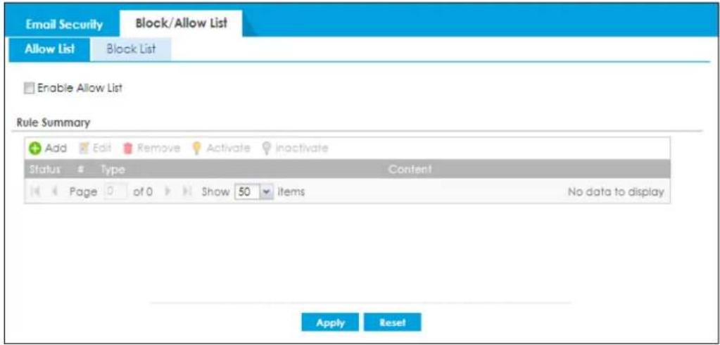
The following table describes the labels in this screen.
Table 337 Configuration > Security Service > Email Security > Block/Allow List> Allow List
| LABEL DESCRIPTION | |
| Enable Allow List | Select this to bypass checking by this feature (if enabled) and automatically classifies email that matches a white list entry as legitimate (not spam). |
| Rule Summary | |
| Add Click this to create | a new entry. |
| Edit Select an entry and | click this to be able to modify it. |
| Remove Select an entry | and click this to delete it. |
| Activate | To turn on an entry, select it and click Activate. |
| Inactivate | To turn off an entry, select it and click Inactivate. |
| Status | The activate (light bulb) icon is lit when the entry is active and dimmed when the entry is inactive. |
| # This is the entry's index | number in the list. |
| Type | This field displays whether the entry is based on the email's subject, source or relay IP address, source email address, or header. |
| Content | This field displays the subject content, source or relay IP address, source email address, or header value for which the entry checks. |
| Apply | Click Apply to save your changes back to the Zyxel Device. |
| Reset | Click Reset to return the screen to its last-saved settings. |
38.5 The Block List Screen
Configure the block list to identify spam email. You can create block list entries based on the sender's or relay server's IP address or email address. You can also create entries that check for particular email header fields with specific values or specific subject text. Click a column's heading cell to sort the table entries by that column's criteria. Click the heading cell again to reverse the sort order.
Click Configuration > Security Service > Email Security > Block /Allow List> Black List to display the Block List screen.
Figure 556 Configuration > Security Service > Email Security > Block/Allow List> Block List
![Email Security Block/Allow List Allow List Block List Enable Block List Block List Spam Tag: [Spam] (Optional) Rule Summary Add Edit Remove Activate inactivate Status Type Content Page of 0 Show 50 Items No data to display Apply Reset](/content/2026/05/878280/images/d2d99f47bb849f90a81ad63b9e884ab009b69b6cd59b2a287b60d719b8b7abc7.jpg)
The following table describes the labels in this screen.
Table 338 Configuration > Security Service > Email Security > Block/Allow List> Block List
| LABEL DESCRIPTION | |
| Enable Block List | Select this to bypass checking by this feature (if enabled) and automatically classifies email that matches a block list entry as spam. |
| Block List Spam Tag | Enter a message or label using up to 15 single-byte characters to add to the mail subject of emails that match the Zyxel Device's spam block list.Accepted characters are 0-9a-zA-Z-.[]!"#$%&'()*+,/;<=>?@^\'^{} are not allowed. |
| Rule Summary | |
| Add Click this to create | a new entry. |
| Edit Select an entry and | click this to be able to modify it. |
| Remove Select an entry | and click this to delete it. |
| Activate | To turn on an entry, select it and click Activate. |
| Inactivate | To turn off an entry, select it and click Inactivate. |
| Status | The activate (light bulb) icon is lit when the entry is active and dimmed when the entry is inactive. |
| # This is the entry's index | number in the list. |
| Type | This field displays whether the entry is based on the email's subject, source or relay IP address, source email address, or header. |
| Content | This field displays the subject content, source or relay IP address, source email address, or header value for which the entry checks. |
| Apply | Click Apply to save your changes back to the Zyxel Device. |
| Reset | Click Reset to return the screen to its last-saved settings. |
38.5.1 The Block or Allow List Add/Edit Screen
In the Block List or Allow List screen, click the Add icon or an Edit icon to display the following screen.
Use this screen to configure an email security block list entry to identify spam email. You can create entries based on specific subject text, or the sender's or relay's IP address or email address. You can also create entries that check for particular header fields and values.
Figure 557 Configuration > Security Service > Email Security > Block/Allow List > Block List (or Allow List) > Add
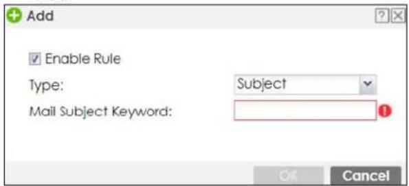
The following table describes the labels in this screen.
Table 339 Configuration > Security Service > Email Security > Block/Allow List > Block (or Allow) List > Add
| LABEL DESCRIPTION | |
| Enable Rule | Select this to have the Zyxel Device use this entry as part of the block or allowed list.To actually use the entry, you must also turn on the use of the list in the corresponding list screen, enable the email security feature in the email security general screen, and configure an email security policy to use the list. |
| Type | Use this field to base the entry on the email's subject, source or relay IP address, source email address, or header.SelectSubjectto have the Zyxel Device check email for specific content in the subject line.SelectIP Addressto have the Zyxel Device check email for a specific source or relay IP address.SelectIPv6 Addressto have the Zyxel Device check email for a specific source or relay IPv6 address.SelectE-Mail Addressto have the Zyxel Device check email for a specific source email address or domain name.SelectMail Headerto have the Zyxel Device check email for specific header fields and values. Configure black list header entries to check for email from bulk mail programs or with content commonly used in spam. Configure white list header entries to allow certain header values that identify the email as being from a trusted source. |
| Mail Subject Keyword | This field displays when you select theSubjecttype. Enter 1 to 63 single-byte characters of text to check for in email headers. 0-9a-zA-Z!#%'()*+,-./:=#@_"&<>\]^ and spaces are not allowed, although you could substitute a question mark (?). SeeSection 38.5.2 on page 871 for more details. |
| Sender or Mail Relay IP Address | This field displays when you select theIP Addresstype. Enter an IP address in dotted decimal notation. |
| Sender or Mail Relay IPv6 Address | This field displays when you select theIPv6 Addresstype. Enter an IPv6 address with prefix. |
| Netmask | This field displays when you select theIP type. Enter the subnet mask here, if applicable. |
| Sender E-Mail Address | This field displays when you select theE-Mailtype. Enter a keyword with 1 to 63 single-byte characters. Accepted characters are 0-9a-zA-Z*-/?@_!"#%&'()+:,,<=>[\]^{} and spaces are not allowed.SeeSection 38.5.2 on page 871 for more details. |
| Mail Header Field Name | This field displays when you select the Mail Header type.Type the name part of an email header (the part that comes before the colon). Use 1 to 63 single-byte characters, including 0-9a-zA-Z-._!"#%&'()*+,/;;<=>?@[\]^ and spaces are not allowed.For example, if you want the entry to check the "Received:" header for a specific mail server's domain, enter "Received" here. |
| Field Value Keyword | This field displays when you select the Mail Header type.Type the value part of an email header (the part that comes after the colon). Use 1 to 63 single-byte characters, including 0-9a-zA-Z!#%'()*+,-./;:=?@_"&<>[\]^{} and spaces are not allowed.For example, if you want the entry to check the "Received:" header for a specific mail server's domain, enter the mail server's domain here.See Section 38.5.2 on page 871 for more details. |
| OK | Click OK to save your changes. |
| Cancel | Click Cancel to exit this screen without saving your changes. |
38.5.2 Regular Expressions in Block or Allow List Entries
The following applies for a block or allow list entry based on an email subject, email address, or email header value.
- Use a question mark (?) to let a single character vary. For example, use "a?c" (without the quotation marks) to specify abc, acc and so on.
- You can also use a wildcard (*). For example, if you configure *def.com, any email address that ends in def.com matches. So "mail.def.com" matches.
- The wildcard can be anywhere in the text string and you can use more than one wildcard. You cannot use two wildcards side by side, there must be other characters between them.
- The Zyxel Device checks the first header with the name you specified in the entry. So if the email has more than one "Received" header, the Zyxel Device checks the first one.
38.6 Email Security Profile
To use multiple profiles for this feature, run the following commands in the Zyxel Device Command Line Interface (CLI).
Router# configure terminal
Router(config)# secure-policy-style advance
Router(config)# show secure-policy-style status
secure-policy-style: advance
After you run these command, go to the feature screen again in the web configurator. You will be prompted to log out and then log in again.
Figure 558 Logout Prompt
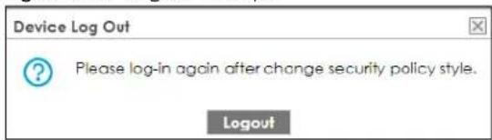
After you log in again, you will see the new profile screen for this feature.
Figure 559 Configuration > Security Service > Email Security > Profile
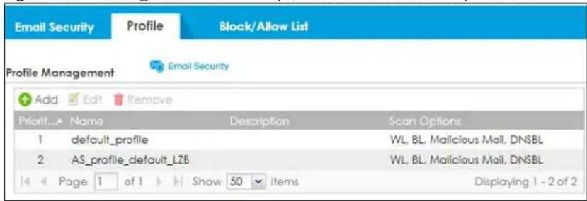
The following table describes the labels in this screen.
Table 340 Configuration > Security Service > Email Security > Profile
| LABEL DESCRIPTION | |
| Add | Click this to create a new entry. Select an entry and click Add to create a new entry after the selected entry. |
| Edit | Double-click an entry or select it and click Edit to open a screen where you can modify the entry's settings. |
| Remove | Select an entry and click Remove to delete the selected entry. |
| # | This field is a sequential value showing the number of the profile. The profile order is not important. |
| Name This displays the name of the profile created. | |
| Description This displays the description of the profile. | |
| Scan Options | This displays which lists are checked for email security: White List (WL), Black List (BL), Malicious Mail, DNSBL. |
38.6.1 Add or Edit Email Security Profile
Click Add to create a new entry or select an existing entry and click Edit to open the following screen where you can create or modify the entry's settings.
Figure 560 Configuration > Security Service > Email Security > Profile > Add/Edit
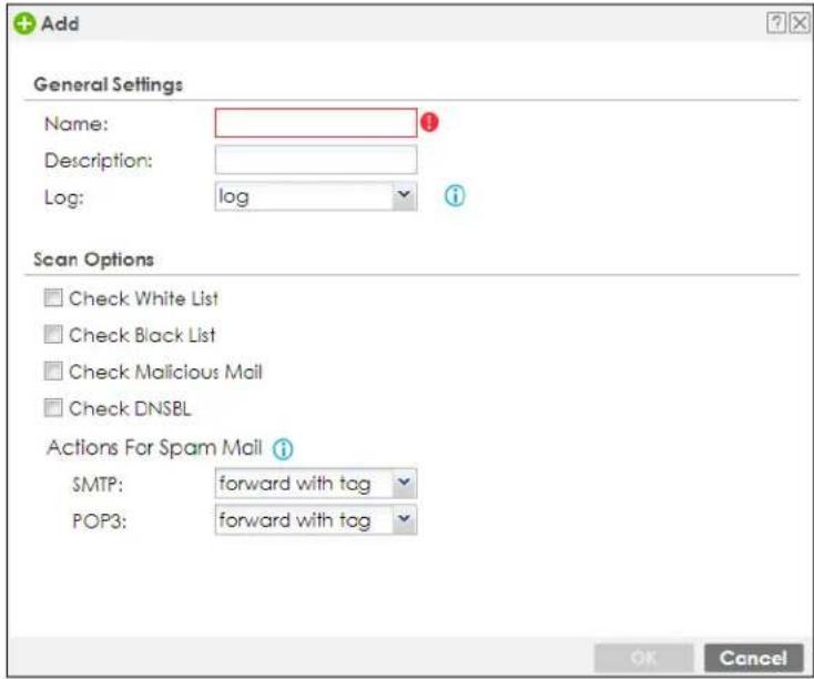
The following table describes the labels in this screen.
Table 341 Configuration > Security Service > Email Security Profile > Add/Edit
| LABEL DESCRIPTION | |
| General Settings | |
| Name Type the name of the profile. You may use 1-31 alphanumeric characters, underscores(_, or dashes (-), but the first character cannot be a number. This value is case-sensitive. These are valid, unique profile names:My ProfilemYProfileMymy12_3-4These are invalid profile names:1mYProfileMy ProfileMyProfile?Whatalongprofilename123456789012 | |
| Description | Type a description for the profile rule to help identify the purpose of rule. You may use 1-31 alphanumeric characters, underscores (_, or dashes (-), but the first character cannot be a number. This value is case-sensitive. This field is optional. |
| Log | Select whether to have the ZyXEL device generate a log (log), log and alert (log alert) or neither (no) by default when traffic matches a signature in this category. |
| Scan Options | |
| Check White List | Select this check box to check email against the white list. The Zyxel Device classifies email that matches a white list entry as legitimate (not spam). |
| Check Black List | Select this check box to check email against the black list. The Zyxel Device classifies email that matches a black list entry as spam. |
| Check Malicious Mail | Select this to identify spam email by content, such as malicious content. |
| Check DNSBL | Select this check box to check email against the Zyxel Device's configured DNSBL domains. The Zyxel Device classifies email that matches a DNS black list as spam. |
| Actions for Spam Mail | Use this section to set how the Zyxel Device is to handle spam mail. |
| SMTP Select how the | Zyxel Device is to handle spam SMTP mail.Select drop to discard spam SMTP mail.Select forward to allow spam SMTP mail to go through.Select forward with tag to add a spam tag to an SMTP spam mail's mail subject and send it on to the destination. |
| POP3 Select how the | Zyxel Device is to handle spam POP3 mail.Select forward to allow spam POP3 mail to go through.Select forward with tag to add a spam tag to an POP3 spam mail's mail subject and send it on to the destination. |
| OK | Click OK to save your changes back to the Zyxel Device. |
| Cancel | Click Cancel to exit this screen without saving. |
| Add | Click this to create a new entry. Select an entry and click Add to create a new entry after the selected entry. |
38.6.2 Link a Profile
To link a profile to a policy, go to the Configuration > Security Policy > Policy Control screen, select a policy, and then click Edit. In the Edit Policy screen under Profile, select which profile you want to use for each security service.
Figure 561 Configuration > Security Service > Policy Control > Profile

38.6.3 The Email Security Advance Screen
The Configuration > Security Service > Email Security screen changes when using profiles.
Figure 562 Configuration > Security Service > Email Security Advance
![Email Security Profile Block/Allow List Hide Advanced Settings General Settings Email Security Enable Inspect all traffic, setting: default_profile Inspect by policy Enable Malicious Mail Malicious Mail Tag: [Malicious] (Optional) Enable DNSBL DNSBL Spam Tag: [Spam] (Optional) DNSBL Domain List Add Edit Remove Activate Inactivate Status #, DNSBL Domain Page 0 of 0 Show 50 items No data to display Action Action taken when mail session threshold is reached Forward Session Drop Session Advance Query Timeout Settings $MTP: forward with tag POP3: forward with tag Timeout Value: 5 (1-10 Seconds) Timeout Tag: [Timeout] (Optional) Timeout X-Header: X- : (Optional) DNSBL Settings Max. IPs Checking Per Mail: 3 (1-5) IP Selection Per Mail: last N IPs Apply Reset](/content/2026/05/878280/images/0539f710f33875439acde257e8dc97ca929dce00b7b5ea287689402b6599081d.jpg)
The following table describes the labels in this screen.
Table 342 Configuration > Security Service > Email Security Advanced
| LABEL DESCRIPTION | |
| General Settings | |
| Enable | Select this check box to activate the settings in this section. |
| Inspect all traffic, setting: | Select this to have all traffic inspected by thedefault_profile. You cannot rename or delete thedefault_profileprofile, but you can edit it by clicking the link here. |
| Inspect by policy | If you configured a specific profile in theProfiletab for this service, select this to have specific traffic inspected by that profile. You must bind the profile to a policy inSecurity Policy > Policy Control. |
| Enable Malicious Mail | Select this to identify spam email by content, such as malicious content. |
| Malicious Mail Tag | Enter a message or label using up to 15 single-byte characters to add to the beginning of the mail subject of emails that are determined to spam based on the mail content analysis. Accepted characters are 0-9a-zA-Z-.[]_!"#$%&'()*+./;<=>?@^\'^{} are not allowed. This tag is only added if the email security policy is configured to forward spam mail with a spam tag. |
| Enable DNSBL | Select this check box to check email against the Zyxel Device's configured DNSBL domains. The Zyxel Device classifies email that matches a DNS black list as spam. |
Table 342 Configuration > Security Service > Email Security Advanced
| LABEL | DESCRIPTION |
| DNSBL Spam Tag | Enter a message or label using up to 15 single-byte characters to add to the beginning of the mail subject of emails that have a sender or relay IP address in the header that matches a black list maintained by one of the DNSBL domains listed in the Zyxel Device.Accepted characters are 0-9a-zA-Z-.[]_.!"#%&'()*+./;<=>?@\^'|) are not allowed. This tag is only added if the email security policy is configured to forward spam mail with a spam tag. |
| DNSBL Domain List | |
| Add Click this to create a new entry. | |
| Edit Select an entry and click this to be able to modify it. | |
| Remove Select an entry and click this to delete it. | |
| Activate | To turn on an entry, select it and click Activate. |
| Inactivate | To turn off an entry, select it and click Inactivate. |
| Status | The activate (light bulb) icon is lit when the entry is active and dimmed when the entry is inactive. |
| # This is the entry's index number in the list. | |
| DNSBL Domain | This is the name of a domain that maintains DNSBL servers. Enter the domain that is maintaining a DNSBL. |
| Action | |
| Action taken when mail sessions threshold is reached | An email session is when an email client and email server (or two email servers) connect through the Zyxel Device. Select how to handle concurrent email sessions that exceed the maximum number of concurrent email sessions that the email security feature can handle. See the chapter of product specifications for the threshold.Select Forward Session to have the Zyxel Device allow the excess email sessions without any spam filtering.Select Drop Session to have the Zyxel Device drop mail connections to stop the excess email sessions. The email client or server will have to re-attempt to send or receive email later when the number of email sessions is under the threshold. |
| Query Timeout Settings | |
| SMTP Select how the Zyxel Device is to handle SMTP mail query timeout.Select drop to discard SMTP mail.Select forward to allow SMTP mail to go through.Select forward with tag to add a tag to an SMTP query timeout mail's mail subject and send it on to the destination. | |
| POP3 Select how the Zyxel Device is to handle POP3 mail query timeout.Select forward to allow POP3 mail to go through.Select forward with tag to add a tag to an POP3 query timeout mail's mail subject and send it on to the destination. | |
| Timeout Value | Set how long the Zyxel Device waits for a reply from the mail scan server. If there is no reply before this time period expires, the Zyxel Device takes the action defined in the relevant Actions when Query Timeout field. |
| Timeout Tag | Enter a message or label using up to 15 single-byte characters to add to the mail subject of emails that the Zyxel Device forwards if queries to the mail scan servers time out.Accepted characters are 0-9a-zA-Z-.[]_.!"#%&'()*+./;<=>?@\^{'}|) are not allowed. |
| Timeout X-Header | Specify the name and value for the X-Header to be added when queries to the mail scan servers time out. |
Table 342 Configuration > Security Service > Email Security Advanced
| LABEL DESCRIPTION | |
| DNSBL Settings | |
| Max. IPs Checking Per Mail | Set the maximum number of sender and relay server IP addresses in the mail header to check against the DNSBL domain servers. |
| IP Selection Per Mail | Select first N IPs to have the Zyxel Device start checking from the first IP address in the mail header. This is the IP of the sender or the first server that forwarded the mail.Select last N IPs to have the Zyxel Device start checking from the last IP address in the mail header. This is the IP of the last server that forwarded the mail. |
| Apply | Click Apply to save your changes back to the Zyxel Device. |
| Reset | Click Reset to return the screen to its last-saved settings. |
38.6.4 Remove Profiles
To remove profiles and revert to the default general security policy style, you must first make sure to change Inspect by policy to Inspect all traffic in the following security services: Anti-Malware, DNS Threat Filter, IPS, Email Security.
Note: All profiles that you created will be removed from Security Policy > Policy Control.
Run the following commands in the Zyxel Device Command Line Interface (CLI).
Router# configure terminal
Router(config)# secure-policy-style general
Router(config)# show secure-policy-style status
secure-policy-style: general
Wait a minute and then go to the feature screen again in the web configurator. You will be prompted to log out and then log in again.
Figure 563 Logout Prompt
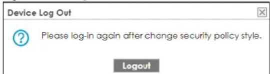
After you log in again, you will not see the profile screen for this feature.
38.7 Email Security Technical Reference
Here is more detailed email security information.
DNSBL
- The Zyxel Device checks only public sender and relay IP addresses, it does not check private IP addresses.
-
The Zyxel Device sends a separate query (DNS lookup) for each sender or relay IP address in the email's header to each of the Zyxel Device's DNSBL domains at the same time.
-
The DNSBL servers send replies as to whether or not each IP address matches an entry in their list. Each IP address has a separate reply.
- As long as the replies are indicating the IP addresses do not match entries on the DNSBL lists, the Zyxel Device waits until it receives at least one reply for each IP address.
- If the Zyxel Device receives a DNSBL reply that one of the IP addresses is in the DNSBL list, the Zyxel Device immediately classifies the email as spam and takes the email security policy's configured action for spam. The Zyxel Device does not wait for any more DNSBL replies.
- If the Zyxel Device receives at least one non-spam reply for each of an email's routing IP addresses, the Zyxel Device immediately classifies the email as legitimate and forwards it.
- Any further DNSBL replies that come after the Zyxel Device classifies an email as spam or legitimate have no effect.
- The Zyxel Device records DNSBL responses for IP addresses in a cache for up to 72 hours. The Zyxel Device checks an email's sender and relay IP addresses against the cache first and only sends DNSBL queries for IP addresses that are not in the cache.
Here is an example of an email classified as spam based on DNSBL replies.
Figure 564 DNSBL Spam Detection Example
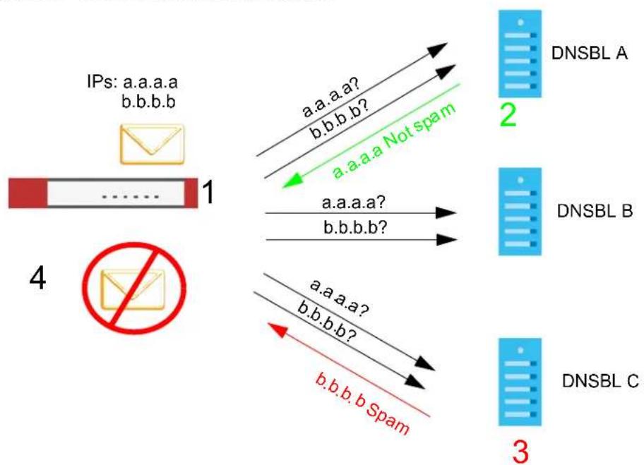
flowchart
graph TD
    A["IPs: a.a.a.a\nb.b.b.b"] -->|1| B["DNSBL A"]
    B -->|2| C["DNSBL B"]
    C -->|3| D["DNSBL C"]
    B -->|a.a.a.a? b.b.b.b?| E["Not spam"]
    C -->|a.a.a.a? b.b.b.b?| F["Not spam"]
    D -->|a.a.a.a? b.b.b.b?| G["Not spam"]
    H["No Error Message"] --> I["Image with red circle"]
1 The Zyxel Device receives an email that was sent from IP address a.a.a.a and relayed by an email server at IP address b.b.b.b. The Zyxel Device sends a separate query to each of its DNSBL domains for IP address a.a.a.a. The Zyxel Device sends another separate query to each of its DNSBL domains for IP address b.b.b.b.
2 DNSBL A replies that IP address a.a.a.a does not match any entries in its list (not spam).
3 DNSBL C replies that IP address b.b.b.b matches an entry in its list.
4 The Zyxel Device immediately classifies the email as spam and takes the action for spam that you defined in the email security policy. In this example it was an SMTP mail and the defined action was to drop the mail. The Zyxel Device does not wait for any more DNSBL replies.
Here is an example of an email classified as legitimate based on DNSBL replies.
Figure 565 DNSBL Legitimate Email Detection Example
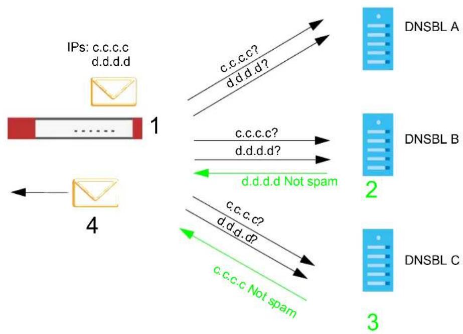
flowchart
graph TD
    A["IPs: c.c.c.c d.d.d.d"] --> B["1"]
    B --> C["4"]
    C --> D["2"]
    D --> E["DNSBL A"]
    D --> F["DNSBL B"]
    D --> G["DNSBL C"]
    B --> H["c.c.c.c? d.d.d.d?"]
    H --> I["d.d.d.d Not spam"]
    I --> J["c.c.c.c? d.d.d.d?"]
    J --> K["c.c.c.c? d.d.d.d?"]
    K --> L["c.c.c.c Not spam"]
1 The Zyxel Device receives an email that was sent from IP address c.c.c.c and relayed by an email server at IP address d.d.d.d. The Zyxel Device sends a separate query to each of its DNSBL domains for IP address c.c.c.c. The Zyxel Device sends another separate query to each of its DNSBL domains for IP address d.d.d.d.
2 DNSBL B replies that IP address d.d.d.d does not match any entries in its list (not spam).
3 DNSBL C replies that IP address c.c.c.c does not match any entries in its list (not spam).
4 Now that the Zyxel Device has received at least one non-spam reply for each of the email's routing IP addresses, the Zyxel Device immediately classifies the email as legitimate and forwards it. The Zyxel Device does not wait for any more DNSBL replies.
If the Zyxel Device receives conflicting DNSBL replies for an email routing IP address, the Zyxel Device classifies the email as spam. Here is an example.
Figure 566 Conflicting DNSBL Replies Example
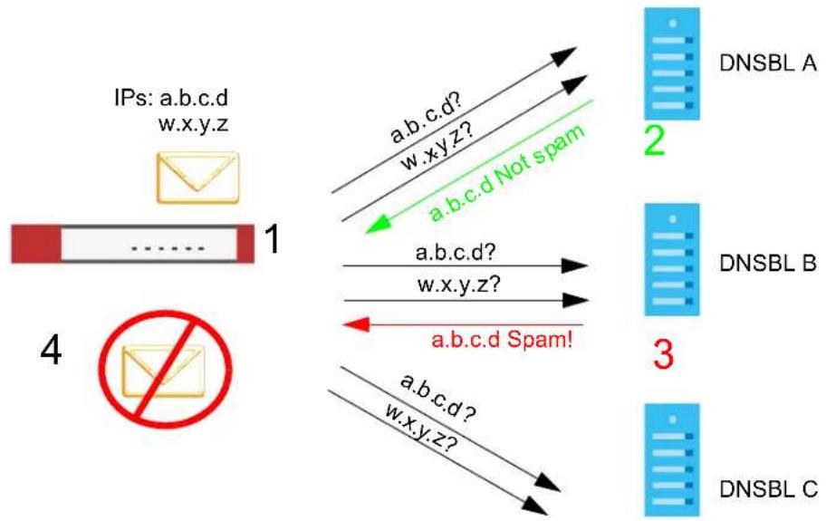
flowchart
graph TD
    A["IPs: a.b.c.d w.x.y.z"] -->|1| B["DNSBL A"]
    A -->|1| C["DNSBL B"]
    A -->|1| D["DNSBL C"]
    B -->|2| E["a.b.c.d? w.xy.z?"]
    C -->|3| F["a.b.c.d? w.x.y.z?"]
    D -->|4| G["a.b.c.d? w.xy.z?"]
    E -->|a.b.c.d Not spam| H
    F -->|a.b.c.d Spam!| I
1 The Zyxel Device receives an email that was sent from IP address a.b.c.d and relayed by an email server at IP address w.x.y.z. The Zyxel Device sends a separate query to each of its DNSBL domains for IP address a.b.c.d. The Zyxel Device sends another separate query to each of its DNSBL domains for IP address w.x.y.z.
2 DNSBL A replies that IP address a.b.c.d does not match any entries in its list (not spam).
3 While waiting for a DNSBL reply about IP address w.x.y.z, the Zyxel Device receives a reply from DNSBL B saying IP address a.b.c.d is in its list.
4 The Zyxel Device immediately classifies the email as spam and takes the action for spam that you defined in the email security policy. In this example it was an SMTP mail and the defined action was to drop the mail. The Zyxel Device does not wait for any more DNSBL replies.
CHAPTER 39
Collaborative Detection & Response
39.1 Overview
Collaborative Detection & Response (CDR) allows you to detect wired and WiFi clients that are sending malicious traffic in your network and then block or quarantine traffic coming from them. In this way, malicious traffic is not spread throughout the network. Secure policies can block malicious traffic for specific traffic flows, but CDR can block malicious traffic from the sender. Malicious traffic is identified using a combination of Web Filtering, Anti-Malware and IPS (IDP) signatures.
In the following example scenario, clients C1 to C6 are connected to the network. Intrusion Prevention (IPS) or Anti-Malware signatures have identified malicious traffic coming from clients C1, C2, C4 and C5.
You have configured CDR to take the following actions.
Table 343 CDR Example Settings
| KEY CDR SETTING RESULT | |
| Block wireless client is selected in Configuration > Security Service > CDR > Collaborative Detection & Response. | Traffic from WiFi client C1 is blocked at the AP. |
| Block wireless client is not selected in Configuration > Security Service > CDR > Collaborative Detection & Response. | Traffic from WiFi client C2 is blocked at the Zyxel Device. |
| Block wireless client is not selected in Configuration > Security Service > CDR > Collaborative Detection & Response. | Traffic from wired client C5 is blocked at the Zyxel Device. This traffic can still be broadcast to other clients in the same subnet, such as C6. |
| Quarantine VLAN ID is selected in Configuration > Security Service > CDR > Collaborative Detection & Response. | Traffic from WiFi client C4 is isolated from the network through a quarantine VLAN. Quarantined traffic in a VLAN isolates traffic from other clients in the same subnet, and only broadcasts to other clients in that same VLAN. |
Figure 567 CDR Example Scenario
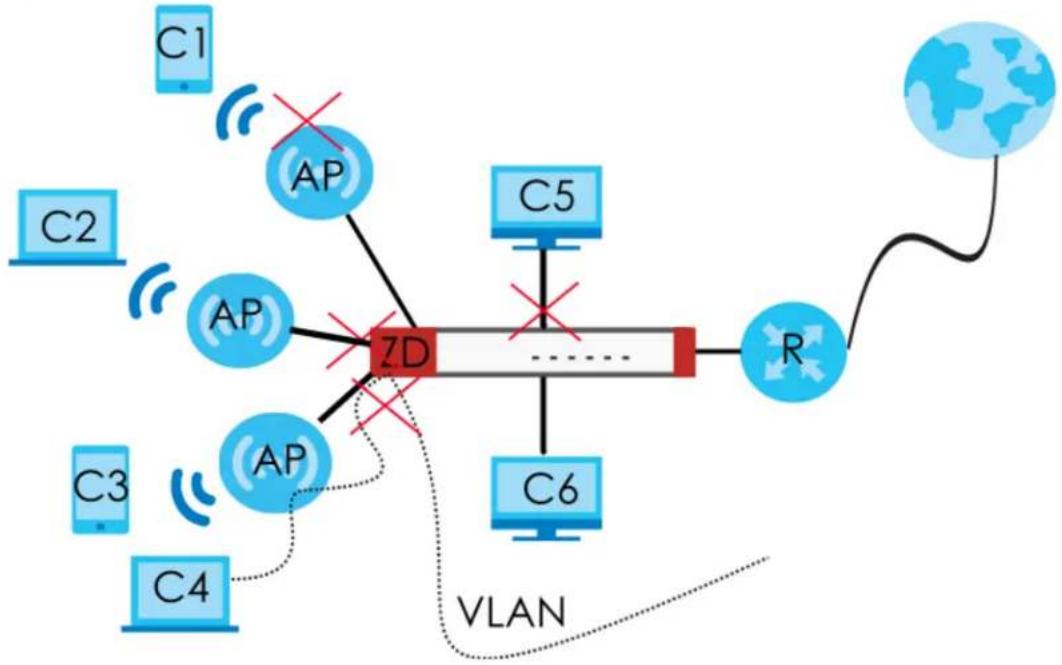
flowchart
graph TD
    C1["CP"] --> AP1["AP"]
    AP1 --> ZD["7D"]
    C2["C2"] --> AP2["AP"]
    AP2 --> ZD
    C3["C3"] --> AP3["AP"]
    AP3 --> ZD
    C4["C4"] --> AP4["AP"]
    AP4 --> ZD
    AP1 --> C5["C5"]
    C5 --> R["R"]
    C6["C6"] --> R
    R --> World["地球"]
    AP1 -->|X| AP2
    AP2 -->|X| AP3
    AP3 -->|X| AP4
    AP4 -->|X| AP1
    AP1 -.->|X| ZD
    AP2 -.->|X| ZD
    AP3 -.->|X| ZD
    AP4 -.->|X| ZD
    ZD -.->|VLAN| World
    style ZD fill:#ff0000,stroke:#333
    style World stroke-dasharray: 5 5
This the graphic key.
Table 344 CDR Example Scenario Graphic Key
| LABEL DEFINITION | |
| C1 to C4 WiFi clients | |
| C5 to C6 Wired clients | |
| AP Access Point | |
| S VLAN-aware Switch | |
| ZD Zyxel Device | |
| R Router giving access to the Internet | |
| VLAN VLAN configured to isolate traffic from a quarantined client |
39.1.1 What You Can Do in this Chapter
- Use the Collaborative Detection & Response screen (Section 39.3 on page 885) to configure CDR triggering policies and containment actions.
- Use the Exempt List screens (Section 39.4 on page 894) to set up a list of devices that are exempt from Collaborative Detection & Response checking.
39.2 Before You Begin
- You must have active and up-to-date Web Filtering, Anti-Malware, IPS (Intrusion Prevention System), and CDR (Collaborative Detection & Response) licenses.
-
Malicious traffic is detected in two phases.
-
Web Filtering (ing), Anti-Malware (Anti-Virus) and IPS (IDP) signatures first identify malicious traffic and inform the CDR daemon. If these licenses have expired or are not active, then no checking for malicious traffic is done.
- CDR signatures are a subset of the above license signatures. If a specific number of signature matches are detected within a defined time period, then the CDR containment policy is triggered. These are the signatures that apply to CDR at the time of writing:
Table 345 Security Signatures Applied to CDR
| SECURITY SIGNATURES SIGNATURES APPLIED TO CDR | |
| Web Filtering | Categories: Browser Exploits, Malicious Downloads, Malicious Sites, Phishing |
| IPS (IDP) IPS (IDP) Signatures: | CVE-2019-0708 (117760, 130797, 130801)CVE-2020-0796 (130822, 130823, 130824, 130825)117723, 117724, 117726 |
| Anti-Malware All signatures | |
- Blocking traffic from an infected client causes the Zyxel Device to drop all traffic received from the client. This traffic can still be broadcast to other clients in the same subnet as the infected client.
- Blocking traffic from an infected WiFi client causes the AP it is connected with to drop all traffic received from the client if Block wireless client is selected in Configuration > Security Service > CDR > Collaborative Detection & Response.
- The Zyxel Device can only block traffic from Nebula-managed APs in your network using CDR.
- Quarantining traffic from an infected WiFi client blocks traffic at the Zyxel Device or AP and also isolates traffic from other clients in the same subnet. Traffic from the infected WiFi is only broadcast to other clients in the quarantine VLAN. You must configure the quarantine VLAN on the Zyxel Device and any switches or routers in your network through which you want to route the VLAN traffic.
- There are 2 requirements to block or quarantine WiFi clients:
- The AP must be managed by the Zyxel Device.
- The AP must be in the Zyxel Device's supported list. At the time of writing, there are 5 supported AP models:
Table 346 Zyxel Device Manged APs
| MANAGED AP MODELS |
| WAX630S |
| WAX650S |
| WAX610D |
| WAX510D |
| WAC500 |
| WAC500H |
| WAX640S-AE |
| WAX620D-6E |
Note: Please see your AP product page at the Zyxel web site to see if it can be managed by the Zyxel Device.
- You must decide how long to contain (block or quarantine) a suspect client, before allowing traffic to be sent from it again. This will depend on how quickly you can contact the owner of the suspect client and how long they need to remove the malicious software from their device.
-
You must also decide if there are trusted clients in your network that are exempt from CDR and never have their traffic blocked or quarantined.
-
You can use the Monitor > CDR > Containment List screen to prematurely release a blocked or quarantined client, or add a client to a list exempted from CDR checking.
- If you disable CDR or your CDR license expires, then all blocked and quarantined clients are released.
- If you restart the Zyxel Device or restart an AP connected to the Zyxel Device, blocked and quarantined clients are still blocked until the Containment Period expires.
- Wired clients are blocked based on IP address by default. You can change that to blocking based on MAC address using the cdr blocked-by mac command in configuration mode in the Command Line Interface (CLI). Note that if you have a switch between the client and the Zyxel Device, then blocking by MAC address could block all traffic from the switch if the client MAC address is not forwarded through the switch.
- WiFi clients are blocked or quarantined based on MAC address by default.
39.3 The Collaborative Detection & Response Screen
Click Configuration > Security Service > Collaborative Detection & Response to open the following screen. Use this screen to turn CDR on or off, manage CDR policies, and select the containment action the Zyxel Device takes when an event occurs more than the threshold within a defined duration.
Figure 568 Configuration > Security Service > CDR> Collaborative Detection & Response
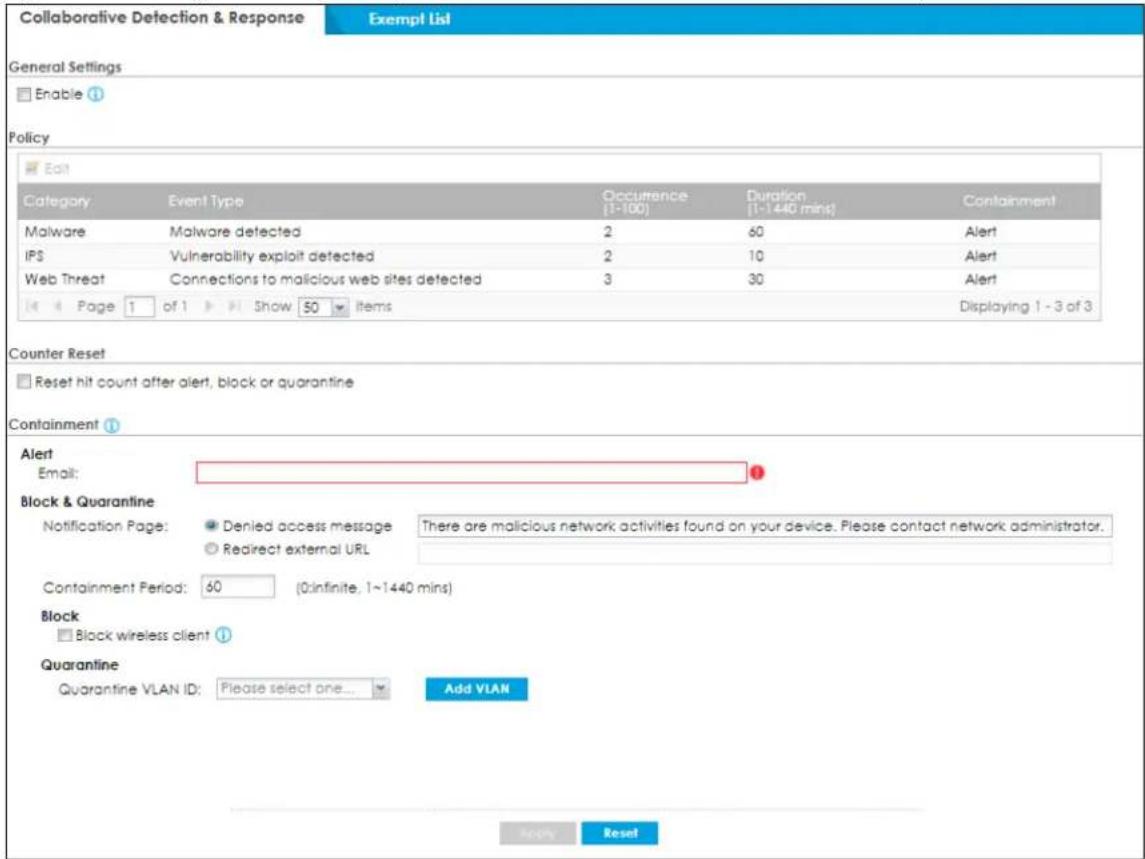
The following table describes the labels in this screen.
Table 347 Configuration > Security Service > CDR > Collaborative Detection & Response
| LABEL DESCRIPTION | |
| General Settings | |
| Enable | Select this check box to activate Collaborative Detection & Response. Make sure you have active Web Filtering, Anti-Malware, IPS (Intrusion Prevention System), and CDR (Collaborative Detection & Response) licenses. |
| Policy | Select a heading to order entries by the heading type. |
| Edit | Select a policy and then click this button to change theOccurrence, DurationorContainmentsettings. |
| Category | Category refers to the signature type that identified the malicious traffic:Web Threat(ing),Malware(Anti-Malware, Anti-Virus) andIDP(IPS). |
| Event Type This displays some details on the category of malicious traffic detected. | |
| Occurrence (1-100) | Type the number of security events that need to occur within the definedDurationto trigger a CDRContainmentaction. |
| Duration (1-1440) | Type the length of time in minutes the event should occur from a client theOccurrencenumber of times to trigger a CDRContainmentaction.For example,Occurrenceis set to 10, andDurationis set to 100. If the Zyxel Device detects 10 or more occurrences of malicious traffic in less than 100 minutes, thenCDRContainmentis triggered. |
| Containment | A suspect client is the wired or WiFi device that is sending malicious traffic in your network.A suspect client owner is the person who owns the wired or WiFi device that is sending malicious traffic in your network.Select the action to be taken when the number of security events exceed the threshold within the defined duration.Alert: Select this if you just want to send an email to a suspect client owner with a registered email or a Zyxel Device admin. Please note that traffic from the suspect client will not be blocked when this action is triggered.The alert email includes the name of the security event triggered, hit count and client device information. Go toMonitor>Log>View Logto see more details on the security event that triggered the alert.Block: Select this if you want to block traffic from a suspect client at the Zyxel Device, or from a suspect WiFi client at the AP connected to the Zyxel Device. Please note that no alert will be sent to the suspect client owner when the suspect client is blocked. Traffic is still broadcast to other clients in the same subnet. A 'notification' web page is displayed when this action is triggered.Quarantine: Select this if you want to isolate traffic from a suspect client at the Zyxel Device in a quarantine VLAN. Please note that no alert will be sent to the suspect client owner when the suspect client is blocked. Traffic is not broadcast to other clients in the same subnet. A 'notification' web page is displayed to the client when this action is triggered.Block & Alert: Select this if you want to bothBlockandAlert.Quarantine & Alert: Select this if you want to bothQuarantineandAlert. |
Table 347 Configuration > Security Service > CDR > Collaborative Detection & Response
| LABEL DESCRIPTION | |
| Counter Reset | Enable this to automatically reset the number of security even occurrences within the defined duration when it reaches the threshold value.For example, if you set the CDR settings for a security event as below:Occurrence: 10Duration: 60Containment: AlertCounter Reset: EnableYou will only receive one alert email every hour if the security event hit count reaches ten times within 60 minutes. |
| Containment | Use this section to configure the selection containment action. |
| Alert | |
| Type a valid email address in the user@domain.com format of the owner of the suspect client or another person who should be informed that CDR was triggered. | |
| Block & Quarantine | |
| Notification Page | This is the notification web page that is displayed when a Block or Quarantine action is triggered.Denied access message: Type the message that is displayed on the default Zyxel Device notification page. The client is redirected here when a Block or Quarantine action is triggered. For example, "Malicious traffic is coming from your device so traffic is temporarily stopped. Please contact the network administrator."Redirect external URL: Type a URL in "http://domain" or "https://domain" format to an external notification page. The client is redirected here when a Block or Quarantine action is triggered. Make sure the external notification page is accessible from the Zyxel Device. |
| Containment Period | Enter how long the client should be blocked or quarantined. This should be at least twice the DHCP server lease time in order to prevent false positives. |
| Block | Type how long a suspect client should be blocked or quarantined. You can type from 1 minute to 1 day (1,440 minutes). 0 means the suspect is blocked forever until released in Monitor > CDR > Containment List. |
| Block wireless client | Select this to have traffic from the suspect client blocked at the AP. Clear this to have traffic from the suspect client blocked at the Zyxel Device. |
| Quarantine | |
| Quarantine VLAN ID | Select a previously configured VLAN that was created to isolate traffic from suspect clients. Traffic from a suspect client is broadcast to all members in the VLAN. |
| Add VLAN | Click this to create a quarantine VLAN to specifically isolate traffic from suspect clients. |
| Apply | Click Apply to save your changes back to the Zyxel Device. |
| Reset | Click Reset to return the screen to its last-saved settings. |
39.3.1 Add VLAN
Click Add VLAN to create a new entry. The following screen appears.
Note: Only IPv4 addresses can be used in quarantine VLANs.
Figure 569 Configuration > Security Service > CDR > Add VLAN
![Add VLAN Hide Advanced Settings General Settings Enable Interface Interface Properties Interface Type: general ① Interface Name: vlan ② Zone: LAN1 ③ Base Port: tfp VLAN ID: ④ (1-40K4) Advance Priority Code: 0 (0-7) ④ Description: [Optional] IP Address Assignment Get Automatically. Advance DHCP Option ID: [Optional] Use Fixed IP Address IP Address: 0.0.0.0 Subset Mask: 0.0.0.0 Gateway: [Optional] Metric: 0 (0-15) Enable IGMP Support IGMP Upstream IGMP Downstream Interface Parameters Egress Bandwidth: 1048576 Kbps Advance Ingress Bandwidth: 1048576 Kbps MTU: 1500 Bytes Connectivity Check Enable Connectivity Check Check Method: icmp Check Period: 30 (5-600 seconds) Check Timeout: 5 (1-10 seconds) Check Fail Tolerance: 5 (1-10) Check Default Gateway: 0.0.0.0 Check These Addresses [Confirm Name or IP Address] Probe Succeeds When: any one respond(s) DHCP Setting DHCP: None Enable IP/MAC Binding Enable Logs for IP/MAC Binding Violation Static DHCP Table Add Edit Remove IP Address MAC Description 1 0.0.0.0 00:00:00:00:00 add description Page #0 Show 50 Items No data to display Advance RIP Setting Enable RIP Direction: BCr Send Version: 2 Receive Version: 2 V2 Broadcast OSFP Setting Alias: none Priority: 1 (0-255) Link Cost: 19 (1-3333) Passive Interface Authentication: None MAC Address Setting Use Default MAC Address 000000000000 Overwrite Default MAC Address Proxy ARP Enable Proxy ARP Add Remove IP Address 4 6 Page 7 of 8 Shaw 9 Items No data to display Related Setting Configure WAN Truck Configure Policy Route Cancel](/content/2026/05/878280/images/ebde9094405448567e7b5b9fcc53e8983d112809bfed0bad68f0412f4155497b.jpg)
Each field is explained in the following table.
Table 348 Configuration > Security Service > CDR > Add VLAN
| LABEL DESCRIPTION | |
| Show Advanced Settings / Hide Advanced Settings | Click this button to display a greater or lesser number of configuration fields. |
| General Settings | |
| Enable Interface Select this to turn this interface on. Clear this to disable this interface. | |
| Interface Properties | |
| Interface Type | Select one of the following options depending on the type of network to which the Zyxel Device is connected.internalis for connecting to a local network. Other corresponding configuration options: DHCP server and DHCP relay. The Zyxel Device automatically adds default SNAT settings for traffic flowing from this interface to an external interface.externalis for connecting to an external network (like the Internet). The Zyxel Device automatically adds this interface to the default WAN trunk.Forgeneral, the rest of the screen's options do not automatically adjust and you must manually configure a policy route to add routing and SNAT settings for the interface. |
| Interface Name | This field is read-only if you are editing an existing VLAN interface. Enter the number of the VLAN interface. You can use a number from 0~4094. For example, use vlan0, vlan8, and so on. The total number of VLANs you can configure on the Zyxel Device depends on the model. |
| Zone Select the zone to which the VLAN interface belongs. | |
| Base Port | Select the Ethernet interface on which the VLAN interface runs. |
| VLAN ID | Enter the VLAN ID. This 12-bit number uniquely identifies each VLAN. Allowed values are 1 - 4094. (0 and 4095 are reserved.) |
| Priority Code | This is a 3-bit field within a 802.1Q VLAN tag that's used to prioritize associated outgoing VLAN traffic. "0" is the lowest priority level and "7" is the highest. SeeTable 218 on page 591The setting configured inConfiguration >BWMoverwrites the priority setting here. |
| Description | Enter a description of this interface. You can use alphanumeric and () +/ := ? ! * # _ % - characters, and it can be up to 60 characters long. Spaces are allowed, but the string can't start with a space. |
| IP Address Assignment | |
| Get Automatically | Select this if this interface is a DHCP client. In this case, the DHCP server configures the IP address, subnet mask, and gateway automatically.You should not select this if the interface is assigned to a VRRP group. |
| DHCP Option 60 | DHCP Option 60 is used by the Zyxel Device for identification to the DHCP server using the VCI (Vendor Class Identifier) on the DHCP server. The Zyxel Device adds it in the initial DHCP discovery message that a DHCP client broadcasts in search of an IP address. The DHCP server can assign different IP addresses or options to clients with the specific VCI or reject the request from clients without the specific VCI.Type a string using up to 63 of these characters [a-zA-Z0-9!\"#%&\'()*+,-./::<=>?@ \\ \^_{}] to identify this Zyxel Device to the DHCP server. For example, Zyxel-TW. |
| Use Fixed IP Address | Select this if you want to specify the IP address, subnet mask, and gateway manually. |
| IP Address | This field is enabled if you selectUse Fixed IP Address.Enter the IP address for this interface. |
| Subnet Mask | This field is enabled if you select Use Fixed IP Address.Enter the subnet mask of this interface in dot decimal notation. The subnet mask indicates what part of the IP address is the same for all computers on the network. |
| Gateway | This field is enabled if you select Use Fixed IP Address.Enter the IP address of the gateway. The Zyxel Device sends packets to the gateway when it does not know how to route the packet to its destination. The gateway should be on the same network as the interface. |
| Metric | Enter the priority of the gateway (if any) on this interface. The Zyxel Device decides which gateway to use based on this priority. The lower the number, the higher the priority. If two or more gateways have the same priority, the Zyxel Device uses the one that was configured first. |
| Enable IGMP Support | Select this to allow the Zyxel Device to act as an IGMP proxy for hosts connected on the IGMP downstream interface. |
| IGMP Upstream | Enable IGMP Upstream on the interface which connects to a router running IGMP that is closer to the multicast server. |
| IGMP Downstream | Enable IGMP Downstream on the interface which connects to the multicast hosts. |
| Interface Parameters | |
| Egress Bandwidth | Enter the maximum amount of traffic, in kilobits per second, the Zyxel Device can send through the interface to the network. Allowed values are 0 - 1048576. |
| Ingress Bandwidth | This is reserved for future use.Enter the maximum amount of traffic, in kilobits per second, the Zyxel Device can receive from the network through the interface. Allowed values are 0 - 1048576. |
| MTU | Maximum Transmission Unit. Type the maximum size of each data packet, in bytes, that can move through this interface. If a larger packet arrives, the Zyxel Device divides it into smaller fragments. Allowed values are 576 - 1500. Usually, this value is 1500. |
| Connectivity Check | The Zyxel Device can regularly check the connection to the gateway you specified to make sure it is still available. You specify how often to check the connection, how long to wait for a response before the attempt is a failure, and how many consecutive failures are required before the Zyxel Device stops routing to the gateway. The Zyxel Device resumes routing to the gateway the first time the gateway passes the connectivity check. |
| Enable Connectivity Check | Select this to turn on the connection check. |
| Check Method Select | Select the method that the gateway allows.Select icmp to have the Zyxel Device regularly ping the gateway you specify to make sure it is still available.Select tcp to have the Zyxel Device regularly perform a TCP handshake with the gateway you specify to make sure it is still available. |
| Check Period Enter | the number of seconds between connection check attempts. |
| Check Timeout | Enter the number of seconds to wait for a response before the attempt is a failure. |
| Check Fail Tolerance | Enter the number of consecutive failures before the Zyxel Device stops routing through the gateway. |
| Check Default Gateway | Select this to use the default gateway for the connectivity check. |
| Check these addresses | Select this to specify one or two domain names or IP addresses for the connectivity check.Enter that domain name or IP address in the field next to it. |
| Check Port | This field only is displayed when you set the Check Method to tcp. Specify the port number to use for a TCP connectivity check. |
| Probe Succeeds When | This field applies when you specify two domain names or IP addresses for the connectivity check.Selectany oneif you want the check to pass if at least one of the domain names or IP addresses responds.Selectallif you want the check to pass only if both domain names or IP addresses respond. |
| DHCP Setting | The DHCP settings are available for the OPT, LAN and DMZ interfaces. |
| DHCP | Select what type of DHCP service the Zyxel Device provides to the network. Choices are:None- the Zyxel Device does not provide any DHCP services. There is already a DHCP server on the network.DHCP Relay- the Zyxel Device routes DHCP requests to one or more DHCP servers you specify. The DHCP server(s) may be on another network.DHCP Server- the Zyxel Device assigns IP addresses and provides subnet mask, gateway, and DNS server information to the network. The Zyxel Device is the DHCP server for the network. |
| These fields appear if the Zyxel Device is aDHCP Relay. | |
| Relay Server 1 Enter | the IP address of a DHCP server for the network. |
| Relay Server 2 | This field is optional. Enter the IP address of another DHCP server for the network. |
| These fields appear if the Zyxel Device is aDHCP Server. | |
| IP Pool Start Address | Enter the IP address from which the Zyxel Device begins allocating IP addresses. If you want to assign a static IP address to a specific computer, clickAdd Static DHCP.If this field is blank, thePool Sizemust also be blank. In this case, the Zyxel Device can assign every IP address allowed by the interface's IP address and subnet mask, except for the first address (network address), last address (broadcast address) and the interface's IP address. |
| Pool Size | Enter the number of IP addresses to allocate. This number must be at least one and is limited by the interface'sSubnet Mask. For example, if theSubnet Maskis 255.255.255.0 and IP Pool Start Addressis 10.10.10.10, the Zyxel Device can allocate 10.10.10.10 to 10.10.10.254, or 245 IP addresses.If this field is blank, theIP Pool Start Addressmust also be blank. In this case, the Zyxel Device can assign every IP address allowed by the interface's IP address and subnet mask, except for the first address (network address), last address (broadcast address) and the interface's IP address. |
| First DNS Server Second DNS Server Third DNS Server | Specify the IP addresses up to three DNS servers for the DHCP clients to use. Use one of the following ways to specify these IP addresses.Custom Defined-enter a static IP address.From ISP-select the DNS server that another interface received from its DHCP server.Zyxel Device-the DHCP clients use the IP address of this interface and the Zyxel Device works as a DNS relay. |
| First WINS Server, Second WINS Server | Type the IP address of the WINS (Windows Internet Naming Service) server that you want to send to the DHCP clients. The WINS server keeps a mapping table of the computer names on your network and the IP addresses that they are currently using. |
| Default Router | If you set this interface toDHCP Server, you can select to use either the interface's IP address or another IP address as the default router. This default router will become the DHCP clients' default gateway.To use another IP address as the default router, selectCustom Definedand enter the IP address. |
| LABEL | DESCRIPTION |
| Lease time | Specify how long each computer can use the information (especially the IP address) before it has to request the information again. Choices are:infinite- select this if IP addresses never expiredays, hours, and minutes-select this to enter how long IP addresses are valid. The default is 2 days. |
| Extended Options | This table is available if you selected DHCP server.Configure this table if you want to send more information to DHCP clients through DHCP packets. |
| Add | Click this to create an entry in this table. See Section 9.5.6 on page 350. |
| Edit | Select an entry in this table and click this to modify it. |
| Remove | Select an entry in this table and click this to delete it. |
| # This field is a sequential value, and it is not associated with any entry. | |
| Name This is the option's name. | |
| Code This is the option's code number. | |
| Type This is the option's type. | |
| Value This is the option's value. | |
| PXE Server | PXE (Preboot eXecution Environment) allows a client computer to use the network to boot up and install an operating system via a PXE-capable Network Interface Card (NIC).PXE is available for computers on internal interfaces to allow them to boot up using boot software on a PXE server. The Zyxel Device acts as an intermediary between the PXE server and the computers that need boot software.The PXE server must have a public IPv4 address. You must enable DHCP Server on the Zyxel Device so that it can receive information from the PXE server. |
| PXE Boot Loader File | A boot loader is a computer program that loads the operating system for the computer. Type the exact file name of the boot loader software file, including filename extension, that is on the PXE server. If the wrong filename is typed, then the client computers cannot boot. |
| Enable IP/MAC Binding | Select this option to have the Zyxel Device enforce links between specific IP addresses and specific MAC addresses for this VLAN. This stops anyone else from manually using a bound IP address on another device connected to this interface. Use this to make use only the intended users get to use specific IP addresses. |
| Enable Logs for IP/ MAC Binding Violation | Select this option to have the Zyxel Device generate a log if a device connected to this VLAN attempts to use an IP address that is bound to another device's MAC address. |
| Static DHCP Table | Configure a list of static IP addresses the Zyxel Device assigns to computers connected to the interface. Otherwise, the Zyxel Device assigns an IP address dynamically using the interface's IP Pool Start Address and Pool Size. |
| Add Click this to create a new entry. | |
| Edit | Select an entry and click this to be able to modify it. |
| Remove | Select an entry and click this to delete it. |
| # | This field is a sequential value, and it is not associated with a specific entry. |
| IP Address | Enter the IP address to assign to a device with this entry's MAC address. |
| MAC Address | Enter the MAC address to which to assign this entry's IP address. |
| Description | Enter a description to help identify this static DHCP entry. You can use alphanumeric and () + / : = ? ! * # @ $ _8- characters, and it can be up to 60 characters long. |
| RIP Setting | See Section 10.6 on page 445 for more information about RIP. |
| Enable RIP | Select this to enable RIP on this interface. |
| LABEL DESCRIPTION | |
| Direction | This field is effective when RIP is enabled. Select the RIP direction from the drop-down list box.BiDir - This interface sends and receives routing information.In-Only - This interface receives routing information.Out-Only - This interface sends routing information. |
| Send Version | This field is effective when RIP is enabled. Select the RIP version(s) used for sending RIP packets. Choices are 1, 2, and 1 and 2. |
| Receive Version | This field is effective when RIP is enabled. Select the RIP version(s) used for receiving RIP packets. Choices are 1, 2, and 1 and 2. |
| V2-Broadcast | This field is effective when RIP is enabled. Select this to send RIP-2 packets using subnet broadcasting: otherwise, the Zyxel Device uses multicasting. |
| OSPF Setting | See Section 10.7 on page 447 for more information about OSPF. |
| Area | Select the area in which this interface belongs. Select None to disable OSPF in this interface. |
| Priority | Enter the priority (between 0 and 255) of this interface when the area is looking for a Designated Router (DR) or Backup Designated Router (BDR). The highest-priority interface identifies the DR, and the second-highest-priority interface identifies the BDR. Set the priority to zero if the interface can not be the DR or BDR. |
| Link Cost | Enter the cost (between 1 and 65,535) to route packets through this interface. |
| Passive Interface | Select this to stop forwarding OSPF routing information from the selected interface. As a result, this interface only receives routing information. |
| Authentication | Select an authentication method, or disable authentication. To exchange OSPF routing information with peer border routers, you must use the same authentication method that they use. Choices are:Same-as-Area - use the default authentication method in the areaNone - disable authenticationText - authenticate OSPF routing information using a plain-text passwordMD5 - authenticate OSPF routing information using MD5 encryption |
| Text Authentication Key | This field is available if the Authentication is Text. Type the password for text authentication. The key can consist of alphanumeric characters and the underscore, and it can be up to 16 characters long. |
| MD5 Authentication ID | This field is available if the Authentication is MD5. Type the ID for MD5 authentication. The ID can be between 1 and 255. |
| MD5 Authentication Key | This field is available if the Authentication is MD5. Type the password for MD5 authentication. The password can consist of alphanumeric characters and the underscore, and it can be up to 16 characters long. |
| MAC Address Setting | This section appears when Interface Properties is External or General. Have the interface use either the factory assigned default MAC address, a manually specified MAC address, or clone the MAC address of another device or computer. |
| Use Default MAC Address | Select this option to have the interface use the factory assigned default MAC address. By default, the Zyxel Device uses the factory assigned MAC address to identify itself. |
| Overwrite Default MAC Address | Select this option to have the interface use a different MAC address. Either the MAC address in the field. Once it is successfully configured, the address will be copied to the configuration file. It will not change unless you change the setting or upload a different configuration file. |
| Proxy ARP | Proxy ARP is available for external or general interfaces on the Zyxel Device. See Section 9.5.2 on page 346 for more information on Proxy ARP. |
| Enable Proxy ARP | Select this to allow the Zyxel Device to answer external interface ARP requests on behalf of a device on its internal interface. Interfaces supported are: · E t h e r n e t · V L A N · BridgeSee Section 9.5.2 on page 346 for more information. |
| Add | Click Add to create an IPv4 Address, an IPv4 CIDR (for example, 192.168.1.1/24) or an IPv4 Range (for example, 192.168.1.2-192.168.1.100) as the target IP address. The Zyxel Device answers external ARP requests only if they match one of these inputted target IP addresses. For example, if the IPv4 Address is 192.168.1.5, then the Zyxel Device will answer ARP requests coming from the WAN only if it contains 192.168.1.5 as the target IP address.Select an existing entry and click Remove to delete that entry.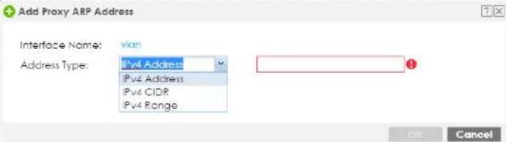 |
| Related Setting | |
| Configure WAN TRUNK | Click WAN TRUNK to go to a screen where you can set this VLAN to be part of a WAN trunk for load balancing. |
| Configure Policy Route | Click Policy Route to go to the screen where you can manually configure a policy route to associate traffic with this VLAN. |
| OK | Click OK to save your changes back to the Zyxel Device. |
| Cancel | Click Cancel to exit this screen without saving. |
39.4 The Exempt List Screen
Click Configuration > Security Service > CDR > Exempt List to display IPv4 and /or MAC addresses of devices that are exempt from CDR checking.
Click a column's heading cell to sort the table entries by that column's criteria. Click the heading cell again to reverse the sort order.
Figure 570 Configuration > Security Service > CDR > Exempt List
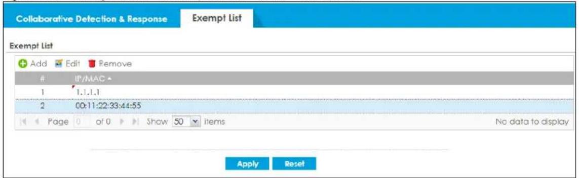
The following table describes the labels in this screen.
Table 349 Configuration > Security Service > CDR > Exempt List
| LABEL DESCRIPTION | |
| Exempt List | This is a list of trusted clients in your network that are not subject to CDR checking and never have their traffic blocked or isolated. |
| Add Click this to create a new entry. | |
| Edit Select an entry and click this to be able to modify it. | |
| Remove Select an entry and click this to delete it. | |
| # This is the entry's index | number in the list. |
| IP/MAC | Click Add to create a new entry or select an existing entry, and then click Edit to modify it. Type a valid IPv4 Address, such as 192.168.1.5, or a valid MAC address of an IPv4 client, such as 0A:0A:0A:0A:0A:0A. |
| Apply | Click Apply to save your changes back to the Zyxel Device. |
| Reset | Click Reset to return the screen to its last-saved settings. |
CHAPTER 40
SSL Inspection
40.1 Overview
Secure Socket Layer (SSL) traffic, such as https://www.google.com/HTTPS, FTPs, POP3s, SMTPs, etc. is encrypted, and cannot be inspected using Security Service profiles such as App Patrol, Content Filter, Intrusion Prevention System (IPS), or Anti-Malware. The Zyxel Device uses SSL Inspection to decrypt SSL traffic, sends it to the Security Service engines for inspection, then encrypts traffic that passes inspection and forwards it to the destination server, such as Google.
An example process is shown in the following figure. User U sends a HTTPS request (SSL) to destination server D, via the Zyxel Device, Z. The traffic matches an SSL Inspection profile in a security policy, so the Zyxel Device decrypts the traffic using SSL Inspection. The decrypted traffic is then inspected by the Security Service profiles in the same security profile that matched the SSL Inspection profile. If all is OK, then the Zyxel Device re-encrypts the traffic using SSL Inspection and forwards it to the destination server D. SSL traffic could be in the opposite direction for other examples.
Figure 571 SSL Inspection Overview
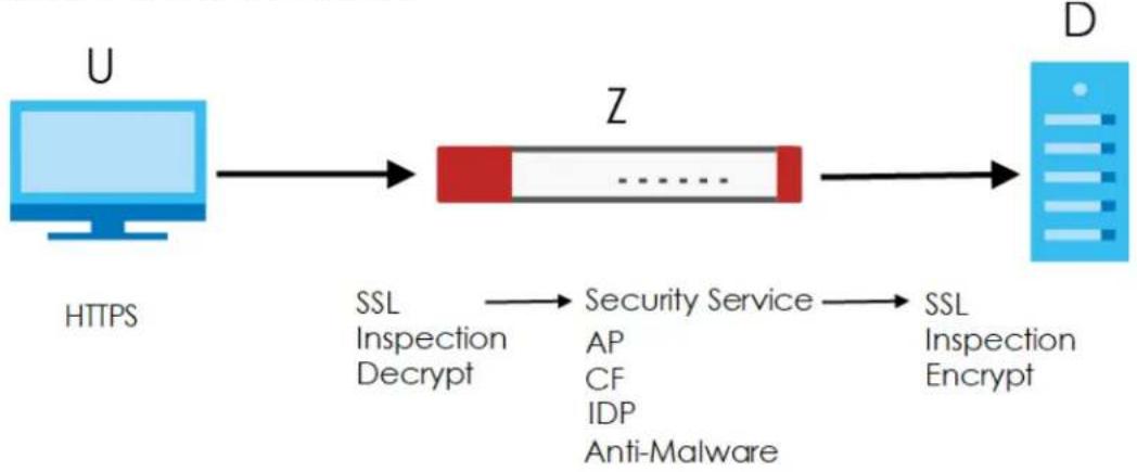
flowchart
graph LR
    U["User"] -->|HTTPS| Z["Data Block"]
    Z -->|SSL Inspection Decrypt| Z
    Z -->|Security Service AP, CF, IDP Anti-Malware| D["Data Server"]
    D -->|SSL Inspection Encrypt| D
Note: Email security cannot be applied to traffic decrypted by SSL Inspection.
40.1.1 What You Can Do in this Chapter
- Use the Security Service > SSL Inspection > Profile screen (Section 40.2 on page 897) to view SSL Inspection profiles. Click the Add or Edit icon in this screen to configure the CA certificate, action and log in an SSL Inspection profile.
- Use the Security Service > SSL Inspection > Exclude List screens (Section 40.3 on page 904) to create a whitelist of destination servers to which traffic is passed through uninspected.
- Use the Security Service > SSL Inspection > Certificate Update screens (Section 40.4 on page 917) to update the latest certificates of servers using SSL connections to the Zyxel Device network
40.1.2 What You Need To Know
SSL Inspection supports the following TLS protocols and encryption algorithms
- SSLv3 AES-CBC
- TLS1.0 AES-CBC
• TLS1.2 AES-CBC/AES-GCM - TLS1.3 AES-GCM (no key update support nor 0-RTT)
- SSL Inspection does not support the following:
- Compression Support
- Client Authentication
40.1.3 What You Can Do in this Chapter
- See Configuration > Object > Certificate > My Certificates for information on creating certificates on the Zyxel Device.
- See Monitor > Security Statistics > SSL Inspection to get usage data and easily add a destination server to the whitelist of exclusion servers.
- See Configuration > Security Policy > Policy Control > Policy to bind an SSL Inspection profile to a traffic flow(s).
40.1.4 Before You Begin
- If you don't want to use the default Zyxel Device certificate, then create a new certificate in Object > Certificate > My Certificates.
- Decide what destination servers to which traffic is sent directly without inspection. This may be a matter of privacy and legality regarding inspecting an individual's encrypted session, such as financial websites. This may vary by locale.
40.2 The SSL Inspection Profile Screen
An SSL Inspection profile is a template with pre-configured certificate, action and log.
Click Configuration > Security Service > SSL Inspection > Profile to open this screen.
Figure 572 Configuration > Security Service > SSL Inspection > Profile
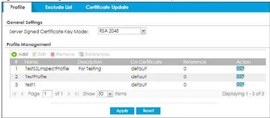
The following table describes the fields in this screen.
Table 350 Configuration > Security Service > SSL Inspection > Profile
| LABEL DESCRIPTION | |
| General Settings | |
| Server Signed Certificate Key Mode | With SSL inspection, the Zyxel Device acts as a 'man-in-the-middle' between a client and a remote server, when the client and server are communicating using an SSL-encrypted session. Every time the client and server send data to each other, the Zyxel Device decrypts the sender's encrypted data, scans the plain data for threats, re-encrypts the data, and then sends the encrypted data to the receiver.For outgoing sessions from the client to the remote server, the Zyxel Device creates a virtual server to decrypt data and a virtual client to re-encrypt data.For incoming sessions from the remote server to the client, the Zyxel Device creates a virtual client to decrypt data, and a virtual server to re-encrypt data.To perform SSL Inspection for clients using SSL (HTTPS, SSH, SMTP) through the Zyxel Device, the Zyxel Device must check that the server's certificate with corresponding public key are valid and were issued by a Certificate Authority (CA) listed in the Zyxel Device's list of trusted CAs. According to the selected key mode RSA 1024, RSA 2048, ECDSA-RSA-1024 or ECDSA-RSA-2048, the Zyxel Device will construct the corresponding self-signed certificate for the virtual server.RSA is a public-key cryptosystem used for data encryption or signing messages. For data encryption, the encryption key is public and the decryption key is private. For signing messages, the signing key is private and the verification key is public. Elliptic Curve Cryptography (ECC) is a public-key cryptosystem based on elliptic curve theory, and more efficient than RSA. ECC allows smaller keys compared to RSA to provide equivalent security. For example, a 224-bit elliptic curve public key should provide comparable security to a 2048-bit RSA public key.ECDSA-RSA-1024 indicates Zyxel Device support for clients that support both ECDSA-256 and RSA-1024 with ECDSA-256 having higher priority, that is ECDSA-256 is used by the virtual server, if a client supports both ECDSA-256 and RSA-1024.ECDSA-RSA-2048 indicates Zyxel Device support for clients that support both ECDSA-256 and RSA-2048 with ECDSA-256 having higher priority, that is ECDSA-256 is used by the virtual server, if a client supports both ECDSA-256 and RSA-2048.Select a mode that the client's browser, FTP client, or mail client supports. The Zyxel Device will use different keys (cryptosystems) for each client according to the client's support list.For example, if there are three clients behind a Zyxel Device with the following key mode support:Client 1 - RSA-1024Client 2 - RSA-2048 and RSA-1024Client 3 - ECDSA-256 and RSA-2048.If you set the key mode to ECDSA-RSA-1024, then the following will be used by each client:Client 1 - RSA-1024Client 2 - RSA-1024Client 3 - ECDSA-256.If you set the key mode to ECDSA-RSA-2048, then the following will be used by each client:Client 1 - sessions will not be processed (pass) by SSL inspectionClient 2 - RSA-2048Client 3 - ECDSA-256. |
| Profile Management | |
| Add | Click Add to create a new profile. |
| Edit Select an entry and click this to be able to modify it. | |
| Remove Select an entry and click this to delete it. | |
| References | Select an entry and clickReferencesto open a screen that shows which settings use the entry. Click Refresh to update information on this screen. |
| # This is the entry's index number in the list. | |
| Name This displays the name of the profile. | |
| Description This displays the description of the profile. | |
| CA Certificate | This displays the CA certificate being used in this profile. |
| Reference This displays the number of times an object reference is used in a profile. | |
| Action | Click this icon to apply the entry to a security policy.Go to theConfiguration > Security Policy > Policy Controlscreen to check the result. |
40.2.1 Apply to a Security Policy
Click the icon in the Action field to apply the entry to a security policy.
Go to the Configuration > Security Policy > Policy Control screen to check the result.
Figure 573 Configuration > Security Service > SSL Inspection > Action
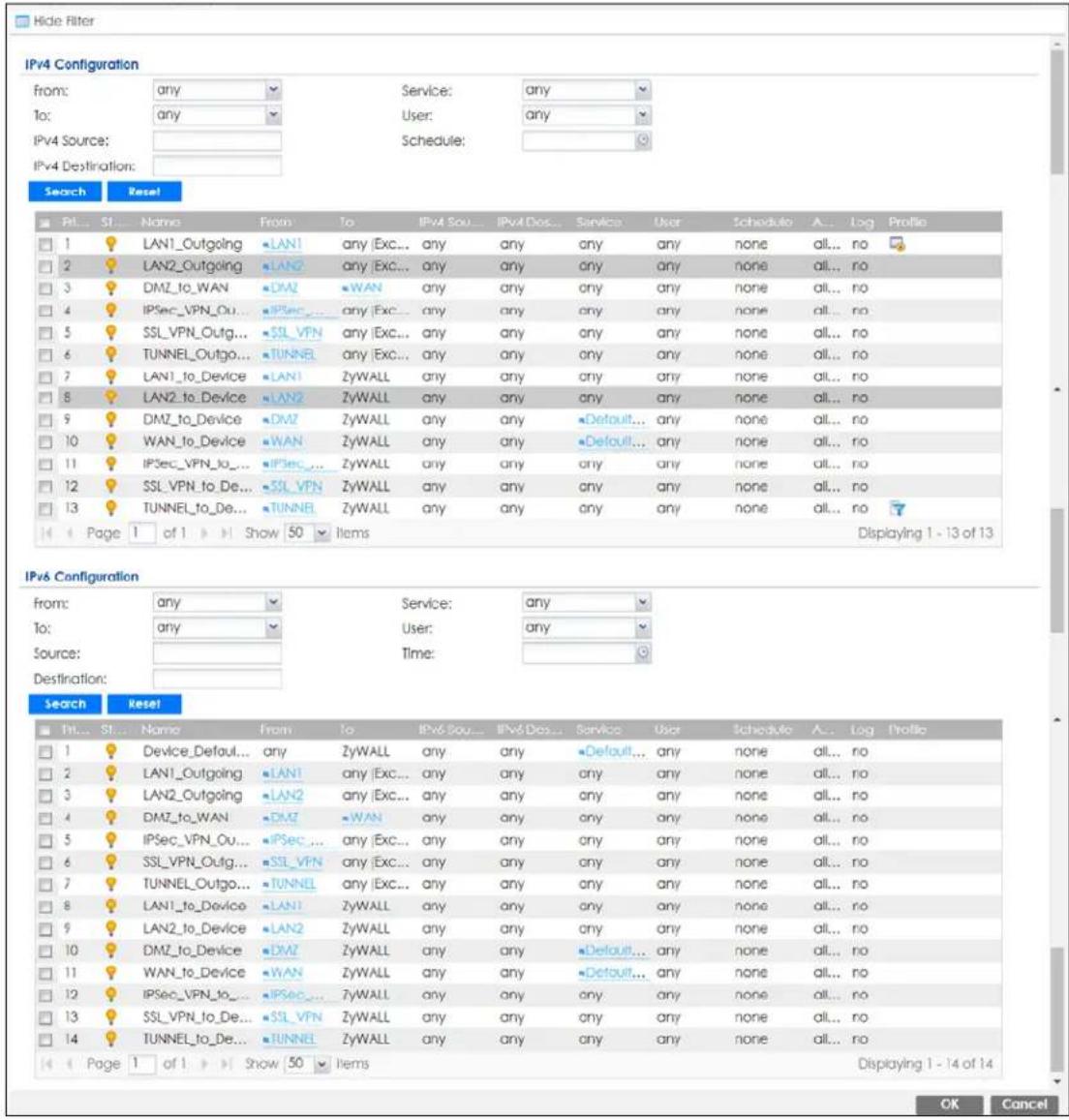
The following table describes the labels in this screen.
Table 351 Configuration > Security Service > SSL Inspection > Action
| LABEL DESCRIPTION | |
| Show Filter/Hide Filter | Click Show Filter to display IPv4 and IPv6 (if enabled) security policy search filters. |
| IPv4 / IPv6 Configuration | Use IPv4 / IPv6 search filters to find specific IPv4 and IPv6 (if enabled) security policies based on direction, application, user, source, destination and/or schedule. |
| From / To | Select a zone to view all security policies from a particular zone and/or to a particular zone.any means all zones. |
Table 351 Configuration > Security Service > SSL Inspection > Action
| LABEL | DESCRIPTION |
| IPv4 / IPv6 Source | Type an IPv4 or IPv6 IP address to view all security policies based on the IPv4 / IPv6 source address object used.An IPv4 IP address is written as four integer blocks separated by periods. This is an example IPv4 address: 172.16.6.7.An 128-bit IPv6 address is written as eight 16-bit hexadecimal blocks separated by colons (:). This is an example IPv6 address: 2001:0db8:1a2b:0015:0000:0000:1a2f:0000. |
| IPv4 / IPv6 Destination | Type an IPv4 or IPv6 IP address to view all security policies based on the IPv4 / IPv6 destination address object used.An IPv4 IP address is written as four integer blocks separated by periods. This is an example IPv4 address: 172.16.6.7.An 128-bit IPv6 address is written as eight 16-bit hexadecimal blocks separated by colons (:). This is an example IPv6 address: 2001:0db8:1a2b:0015:0000:0000;1a2f:0000. |
| Service View all security policies based the service object used. | |
| User View all security policies based on user or user group object used. | |
| Schedule View all security policies based on the schedule object used. | |
| Priority | This is the position of your Security Policy in the global policy list (including all through-Zyxel Device and to-Zyxel Device policies). The ordering of your policies is important as policies are applied in sequence.Default displays for the default Security Policy behavior that the Zyxel Device performs on traffic that does not match any other Security Policy. |
| Status This icon is lit when the entry is active and dimmed when the entry is inactive. | |
| Name This is the name of the Security policy. | |
| From / To | This is the direction of travel of packets. Select from which zone the packets come and to which zone they go.Security Policies are grouped based on the direction of travel of packets to which they apply. For example, from LAN to LAN means packets traveling from a computer or subnet on the LAN to either another computer or subnet on the LAN.From any displays all the Security Policies for traffic going to the selected To Zone.To any displays all the Security Policies for traffic coming from the selected From Zone.From any to any displays all of the Security Policies.To ZyWALL policies are for traffic that is destined for the Zyxel Device and control which computers can manage the Zyxel Device. |
| IPv4 / IPv6 Source | This displays the IPv4 / IPv6 source address object, including geographic address and FQDN (group) objects, to which this Security Policy applies. |
| IPv4 / IPv6 Destination | This displays the IPv4 / IPv6 destination address object, including geographic address and FQDN (group) objects, to which this Security Policy applies. |
| Service | This displays the service object to which this Security Policy applies. |
| User | This is the user name or user group name to which this Security Policy applies. |
| Schedule | This field tells you the schedule object that the policy uses. none means the policy is active at all times if enabled. |
| Action | This field displays whether the Security Policy silently discards packets without notification (deny), permits the passage of packets (allow) or drops packets with notification (reject) |
| Log | Select whether to have the Zyxel Device generate a log (log), log and alert (log alert) or not (no) when the policy is matched to the criteria listed above. |
| Profile | This field shows you which Security Service profiles (application patrol, content filter, IPS, anti-malware, email security) apply to this Security policy. Click an applied Security Service profile icon to edit the profile directly. |
| OK | Click OK to save your changes back to the Zyxel Device. |
| Cancel | Click Cancel to exit this screen without saving. |
40.2.2 Add / Edit SSL Inspection Profiles
Click Configuration > Security Service > SSL Inspection > Profile > Add to create a new profile or select an existing profile and click Edit to change its settings.
Figure 574 Configuration > Security Service > SSL Inspection > Profile > Add / Edit
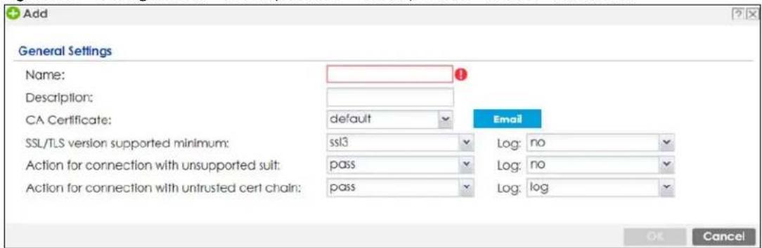
The following table describes the fields in this screen.
Table 352 Configuration > Security Service > SSL Inspection > Profile > Add / Edit
| LABEL DESCRIPTION | |
| Name | This is the name of the profile. You may use 1-31 alphanumeric characters, underscores(_, or dashes (-), but the first character cannot be a number. This value is case-sensitive. These are valid, unique profile names:MyProfilemYProfileMymy12_3-4These are invalid profile names:1mYProfileMy ProfileMyProfile?Whatalongprofilename123456789012 |
| Description | Enter additional information about this SSL Inspection entry. You can enter up to 60 characters ("0-9", "a-z", "A-Z", "-" and "_"). |
| CA Certificate | This contains the default certificate and the certificates created inObject > Certificate > My Certificates.Choose the certificate for this profile. |
| SSL/TLS version supported minimum | SSL / TLS connections using versions lower than this setting are blocked. |
| Log | These are the log options for unsupported traffic that matches traffic bound to this policy:no:Select this option to have the Zyxel Device create no log for unsupported traffic that matches traffic bound to this policy.log:Select this option to have the Zyxel Device create a log for unsupported traffic that matches traffic bound to this policy.log alert:An alert is an emailed log for more serious events that may need more immediate attention. They also appear in red in theMonitor > Log screen. Select this option to have the Zyxel Device send an alert for unsupported traffic that matches traffic bound to this policy. |
| Action for Connection with unsupported suit | SSL Inspection supports these cipher suites:DES3 D E SAESSelect topass or blockunsupported traffic (such as other cipher suites, compressed traffic, client authentication requests, and so on) that matches traffic bound to this policy here. |
| Log | These are the log options for unsupported traffic that matches traffic bound to this policy:no: Select this option to have the Zyxel Device create no log for unsupported traffic that matches traffic bound to this policy.log: Select this option to have the Zyxel Device create a log for unsupported traffic that matches traffic bound to this policylog alert: An alert is an emailed log for more serious events that may need more immediate attention. They also appear in red in theMonitor > Logscreen. Select this option to have the Zyxel Device send an alert for unsupported traffic that matches traffic bound to this policy. |
| Action for connection with untrusted cert chain | A certificate chain is a certification process that involves the following certificates between the SSL/TLS server and a client. A certificate chain will fail if one of the following certificates is not correct.A certificate owned by a userThe certificate signed by a certification authorityA root certificateSelect topass, inspect, orblockan untrusted certification chain. |
| Log | These are the log options for unsupported traffic that matches traffic bound to this policy:no: Select this option to have the Zyxel Device create no log for unsupported traffic that matches traffic bound to this policy.log: Select this option to have the Zyxel Device create a log for unsupported traffic that matches traffic bound to this policylog alert: An alert is an emailed log for more serious events that may need more immediate attention. They also appear in red in theMonitor> Logscreen. Select this option to have the Zyxel Device send an alert for unsupported traffic that matches traffic bound to this policy. |
| OK | ClickOKto save your settings to the Zyxel Device, and return to the profile summary page. |
| Cancel | ClickCancelto return to the profile summary page without saving any changes. |
40.3 Exclude List Screen
There may be privacy and legality issues regarding inspecting a user's encrypted session. The legal issues may vary by locale, so it's important to check with your legal department to make sure that it's OK to intercept SSL traffic from your Zyxel Device users.
To ensure individual privacy and meet legal requirements, you can configure an exclusion list to exclude matching sessions to destination servers. This traffic is not intercepted and is passed through uninspected.
Click Configuration > Security Service > SSL Inspection > Exclude List to display the following screen. Use Add to put a new item in the list or Edit to change an existing one or Remove to delete an existing entry.
Figure 575 Configuration > Security Service > SSL Inspection > Exclude List (Add/Edit)
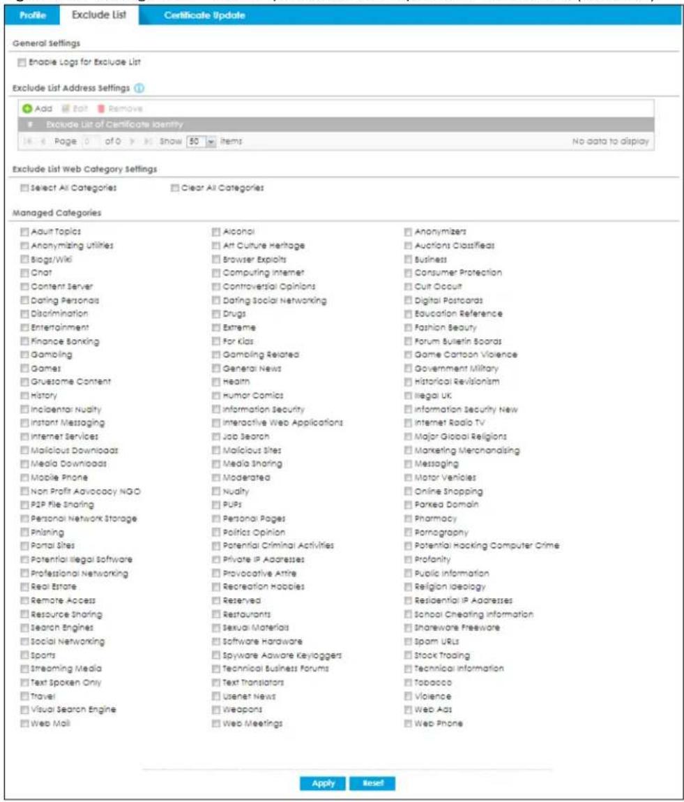
The following table describes the fields in this screen.
Table 353 Configuration > Security Service > SSL Inspection > Exclude List
| LABEL DESCRIPTION | |
| General Settings | |
| Enable Logs for Exclude List | Click this to create a log for traffic that bypasses SSL Inspection. |
| Exclude List Address Settings | Use this part of the screen to create, edit, or delete items in the SSL Inspection exclusion list. |
| Add Click this to | create a new entry. |
| Edit Select an entry and click this to be able to modify it. | |
| Remove Select an entry and click this to delete it. | |
| # This is the entry's index number in the list. | |
| LABEL DESCRIPTION | |
| Exclude List of Certificate Identity | SSL traffic to a server to be excluded from SSL Inspection is identified by its certificate. Identify the certificate in one of the following ways:The Common Name (CN) of the certificate. The common name of the certificate can be created in theObject > Certificate > My Certificates screen.Type an IPv4 or IPv6 address. For example, type 192.168.1.35, or 2001:7300:3500::1Type an IPv4/IPv6 in CIDR notation. For example, type 192.168.1.1/24, or 2001:7300:3500::1/64Type an IPv4/IPv6 address range. For example, type 192.168.1.1-192.168.1.35, or 2001:7300:3500::1-2001:7300:3500::35Type an email address. For example, type abc@zyxel.com.twType a DNS name or a common name (wildcard char: '*', escape char: '\\'). Use up to 127 case-insensitive characters (0-9a-zA-Z`~!@#$%^&*()-_=_+[]{}\|::',<>/?). '*' can be used as a wildcard to match any string. Use '\*' to indicate a single wildcard character.Alternatively, to automatically add an entry for existing SSL traffic to a destination server, go toMonitor > Security Statistics > SSL Inspection > Certificate Cache List, select an item and then click Add to Exclude List. The item will then appear here. |
| Exclude List Web Category Settings | Use this section to let SSL traffic destined for websites in the selected web categories to pass through the Zyxel Device without been inspected. |
| Select All Categories | Select this to allow SSL traffic to all sites belonging to the categories below pass through without been inspected. |
| Clear All Categories | Select this to clear the selected categories below. The Zyxel Device will inspect SSL traffic going to all web pages unless the destination servers are excluded inExclude List Address Settings. |
| Managed Categories | These are categories of web pages based on their content. For example, a web page that sells wine will be classified as theAlcoholcategory.Select categories in this section to allow traffic to specific types of Internet content pass through without been intercepted.You must have the Category Service Web Filtering license to filter these categories. See the next table for category details. |
| Apply | ClickApplyto save your settings to the Zyxel Device. |
| Reset | ClickResetto return to the profile summary page without saving any changes. |
The following table describes the managed categories.
Table 354 Managed Category Descriptions
| CATEGORY DESCRIPTION | |
| Adult Topics | Web pages that contain content or themes that are generally considered unsuitable for children. |
| Alcohol | Web pages that mainly sell, promote, or advocate the use of alcohol, such as beer, wine, and liquor.This category also includes cocktail recipes and home-brewing instructions. |
| Anonymizing Utilities | Web pages that result in anonymous web browsing without the explicit intent to provide such a service.This category includes URL translators, web-page caching, and other utilities that might function as anonymizers, but without the express purpose of bypassing filtering software.This category does not include text translation. |
| Art Culture Heritage | Web pages that contain virtual art galleries, artist sites (including sculpture and photography), museums, ethnic customs, and country customs.This category does not include online photograph albums. |
| Auctions Classifieds | Web pages that provide online bidding and selling of items or services.This category includes web pages that focus on bidding and sales.This category does not include classified advertisements such as real estate postings, personal ads, or companies marketing their auctions. |
| Blogs/Wiki | Web pages containing dynamic content, which often changes because users can post or edit content at any time.This category covers the risks with dynamic content that might range from harmless to offensive. |
| Business | Web pages that provide business-related information, such as corporate overviews or business planning and strategies.This category also includes information, services, or products that help other businesses plan, manage, and market their enterprises, and multi-level marketing.This category does not include personal pages and web-hosting web pages. |
| Chat Web pages that provide web-based, real-time social messaging in public and private chat rooms. This category includes IRC.This category does not include instant messaging. | |
| Computing Internet | Web pages containing reviews, information, buyer's guides of computers, computer parts and accessories, computer software and internet companies, industry news and magazines, and pay-to-surf sites. |
| Consumer Protection Websites | that try to rob or cheat consumers.Some examples of their activities include selling counterfeit products, selling products that were originally provided for free, or improperly using the brand of another company. This category also includes sites where many consumers reported being cheated or not receiving services.This category does not include phishing, which tries to perpetrate fraud or theft by stealing account information. To check for phishing, go to Security Service > Reputation Filter > IP Reputation and select Phishing . |
| Content Server | URLs for servers that host images, media files, or JavaScript for one or more sites and are intended to speed up content retrieval for existing web servers, such as Apache.This category includes domain-level and sub-domain-level URLs that function as content servers.This category does not include:Web pages for businesses that provide the content serversWeb pages that allow users to browse photographs. See the Media Sharing category.URLs for servers that serve only advertisements. See the Web Ads category. |
| Controversial Opinions | Web pages that contain opinions that are likely to offend political or social sensibilities and incite controversy. Much of this content is at the extremes of public opinion.This category does not include opinion or language clearly intended to promote hate or discrimination. |
| Cult Occult | Sites relating to non-traditional religious practices considered to be false, unorthodox, extremist, or coercive. |
| Dating Personals Web pages | that provide networking for online dating, matchmaking, escort services, or introductions to potential spouses.This category does not include sites that provide social networking that might include dating, but are not specific to dating. |
| Dating Social Networking | Web pages that focus on social interaction such as online dating, friendship, school reunions, pen-pals, escort services, or introductions to potential spouses.This category does not include wedding-related content, dating tips, or related marketing. |
| Digital Postcards | Web pages that allow people to send and receive digital postcards and greeting cards via the Internet. |
| Discrimination | Web pages, which provide information that explicitly encourages the oppression or discrimination of a specific group of individuals.This category does not include jokes and humor, unless the focus of the entire site is considered discriminatory. |
| Drugs | Websites that provide information on the purchase, manufacture, and use of illegal or recreational drugs.This category does not include sites with exclusive health or political themes. |
| Education Reference | Web pages devoted to academic-related content such as academic subjects (mathematics, history), school or university web pages, and education administration pages (school boards, teacher curriculum). |
| Entertainment | Web pages that provide information about cinema, theater, music, television, infotainment, entertainment industry gossip-news, and sites about celebrities such as actors and musicians.This category also includes sites where the content is devoted to providing entertainment on the web, such as horoscopes or fan clubs. |
| Extreme Web pages that provide content considered gory, perverse, or horrific. | |
| Fashion Beauty | Web pages that market clothing, cosmetics, jewelry, and other fashion-oriented products, accessories, or services.This category also includes product reviews, comparisons, and general consumer information, and services such as hair salons, tanning salons, tattoo studios, and body-piercing studios.This category does not include fashion-related content such as modeling or celebrity fashion unless the site focuses on marketing the product line. |
| Finance Banking | Web pages that provide financial information or access to online financial accounts.This category includes stock information (but not stock trading), home finance, and government-related financial information. |
| For Kids Web pages that are family-safe, specifically for children of approximate ages ten and under.This category can also be used as an exception to allow web pages that do not pose a risk to children, or to access sites that have a primary educational or recreational focus for children, but are in other categories such as Games, Humor/ Comics, Recreation/Hobbies, or Entertainment. | |
| Forum Bulletin Boards | Web pages that provide access (http://) to Usenet newsgroups or hold discussions and post user-generated content, such as real-time message posting for an interest group. This category also includes archives of files uploaded to newsgroups.This category does not include message forums with a business or technical support focus. |
| Gambling | Web pages that allow users to wager or place bets online, or provide gambling software that allows online betting, such as casino games, betting pools, sports betting, and lotteries.This category does not include web pages related to gambling that do not allow betting online. |
| Gambling Related | Web pages that offer information about gambling, without providing the means to gamble.This category includes casino-related web pages that do not offer online gambling, gambling links, tips, sports picks, lottery results, and horse, car, or boat racing. |
| Game Cartoon Violence | Web pages that provide fantasy or fictitious representations of violence within the context of games, comics, cartoons, or graphic novels.This category includes images and textual descriptions of physical assaults or hand-to-hand combat, and grave injury and destruction caused by weapons or explosives. |
| Games | Web pages that offer online games and related information such as cheats, codes, demos, emulators, online contests or role-playing games, gaming clans, game manufacturer sites, fantasy or virtual sports leagues, and other gaming sites without chances of profit.This category includes gaming consoles. |
| General News | Web pages that provide online news media, such as international or regional news broadcasting and publication.This category includes portal sites that provide news content. |
| Government Military | Web pages that contain content maintained by governmental or military organizations, such as government branches or agencies, police departments, fire departments, civil defense, counter-terrorism organizations, or supranational organizations, such as the United Nations or the European Union.This category includes military and veterans' medical facilities. |
| Gruesome Content | Web pages with content that can be considered tasteless, gross, shocking, or gruesome.This category does not include web pages with content pertaining to physical assault. |
| Health | Web pages that cover all health-related information and health care services.This category does not include cosmetic surgery, marketing/selling pharmaceuticals, or animal-related medical services. |
| Historical Revisionism | Web pages that denounce, or offer different interpretations of, significant historical facts, such as holocaust denial.This category does not include all re-examination of historical facts, only historical events that are highly sensitive. |
| History Web pages that provide content about historical facts.This category includes content suitable for higher education, but the Education category includes content for primary education. For example, a site with Holocaust photographs might be offensive, but have academic value. | |
| Humor Comics Web pages that provide comical or funny content.This category includes sites with jokes, sketches, comics, and satire pages. This category might also include graphic novel content, which is often associated with comics. | |
| Illegal UK | Web pages that contain child sexual abuse content hosted anywhere in the world, and criminally obscene and incitement to racial hatred content hosted in the UK. |
| Incidental Nudity | Web pages that contain non-pornographic images of the bare human body like those in classic sculpture and paintings, or medical images.This category enables you to allow or block sites in order to address cultural or geographic differences in opinion about nudity. For example, you can use this category to block access to nudity, but allow access when nudity is not the primary focus of a site, such as news sites or major portals. |
| Information Security | Web pages that legitimately provide information about data protection. This category includes detailed information for safeguarding business or personal data, intellectual property, privacy, and infrastructure on the Internet, private networks, or in other bandwidth services such as telecommunications.This category does not include:Legitimate information security companies and security software providers, such as virus protection companies.Sites that intend to exploit security or teach how to bypass security. |
| Information Security New | Web pages that legitimately provide information about data protection. This category includes detailed information for safeguarding business or personal data, intellectual property, privacy, and infrastructure on the Internet, private networks, or in other bandwidth services such as telecommunications.This category does not include:Legitimate information security companies and security software providers, such as virus protection companies.Sites that intend to exploit security or teach how to bypass security. |
| Instant Messaging | Web pages that provide software for real-time communication over a network exclusively for users who joined a member's contact list or an instant-messaging session.Most instant-messaging software includes features such as file transfer, PC-to-PC phone calls, and can track when other people log on and off. |
| Interactive Web Applications | Web pages that provide access to live or interactive web applications, such as browser-based office suites and groupware. This category includes sites with business, academic, or individual focus.This category does not include sites providing access to interactive web applications that do not take critical user data or offer security risks, such as Google Maps. |
| Internet Radio TV | Web pages that provide software or access to continuous audio or video broadcasting, such as Internet radio, TV programming, or podcasting.Quick downloads and shorter streams that consume less bandwidth are in the Streaming Media or Media Downloads categories. |
| Internet Services | Web pages that provide services for publication and maintenance of Internet sites such as web design, domain registration, Internet Service Providers, and broadband and telecommunications companies that provide web services.This category includes web utilities such as statistics and access logs, and web graphics like clip art. |
| Job Search | Web pages related to a job search including sites concerned with resume writing, interviewing, changing careers, classified advertising, and large job databases. This category also includes corporate web pages that list job openings, salary comparison sites, temporary employment, and company job-posting sites.This category does not include make-money-at-home sites. |
| Major Global Religions | Web pages with content about religious topics and information related to major religions. This category includes sites that cover religious content such as discussion, beliefs, non-controversial commentary, articles, and information for local congregations such as a church or synagogue homepage.The religions in this category are Baha'i, Buddhism, Chinese Traditional, Christianity, Hinduism, Islam, Jainism, Judaism, Shinto, Sikhism, Tenrikyo, Zoroastrianism. |
| Marketing Merchandising | Web pages that promote individual or business products or services on the web, but do not sell their products or services online.This category includes websites that are generally a company overview, describing services or products that cannot be purchased directly from these sites. Examples include automobile manufacturer sites, wedding photography services, or graphic design services.This category does not include:Other categories that imply marketing such as Alcohol, Auctions/Classifieds, Drugs, Finance/Banking, Mobile Phone, Online Shopping, Real Estate, School Cheating Information, Software/Hardware, Stock Trading, Tobacco, Travel, and Weapons.Sites that market their services only to other businesses. See the Business category.Sites that rob or cheat consumers. See the Consumer Protection category. |
| Media Downloads | Web pages that provide audio or video files for download such as MP3, WAV, AVI, and MPEG formats. The files are saved to, and played from, the user's computer.This category does not include audio or video files that are played directly through a browser window. See the Streaming Media category. |
| Media Sharing | Web pages that allow users to upload, search for, and share media files and photographs, such as online photograph albums. |
| Messaging Examples include | text messaging to mobile phones, PDAs, fax machines, and internal website user-to-user messaging or site-to-site messaging.This category does not include real-time chat or instant messaging, or message posts that can be viewed by anyone but the intended recipient. |
| Mobile Phone | Web pages that sell media, software, or utilities for mobile phones that can be downloaded and delivered to mobile phones.Examples include ringtones, logos/skins, games, screen-savers, text-based tunes, and software for SMS, MMS, WAP, and other mobile phone protocols. |
| Moderated | Bulletin boards, chat rooms, search engines, or web mail sites that are monitored by an individual or group who has the authority to block messages or content considered inappropriate.This category does not include sites with posted rules against offensive content. See the Forum/Bulletin Boards category. |
| Motor Vehicles | Websites for manufacturers and dealerships of consumer transportation vehicles, such as cars, vans, trucks, SUVs, motorcycles, and scooters. This category also includes sites that provide product marketing, reviews, comparisons, pricing information, auto fairs, auto expos, and general consumer information about motor vehicles.This category does not include automotive accessories, mechanics, auto-body shops, and recreational hobby pages. This category does not include sites that provide business-to-business-only content regarding motor vehicles. |
| Non Profit Advocacy NGO | Web pages from charitable or educational groups that fulfill a stated mission, benefiting the larger community, such as clubs, lobbies, communities, non-profit organizations, labor unions, and advocacy groups.Examples are Masons, Elks, Boy and Girl Scouts, or Big Brothers. |
| Nudity | Web pages that have non-pornographic images of the bare human body. This category includes classic sculpture and paintings, artistic nude photographs, some naturism pictures, and detailed medical illustrations.This category does not include high-profile sites where nudity is not a concern for visitors. See the Incidental Nudity category. |
| Online Shopping Web pages | that sell products or services online.Web pages selling a broad range of products might pose a risk to users by offering access to items that are normally in other categories such as Pornography, Weapons, Nudity, or Violence. Web pages selling such content exclusively are in their respective categories. |
| P2P File Sharing | Web pages that allow the exchange of files between computers and users for business or personal use, such as downloadable music.P2P clients allow users to search for and exchange files from a peer-user network. They often include spyware or real-time chat capabilities. This category includes BitTorrent web pages. |
| Parked Domain | Web pages that once served content, but their domains have been sold or abandoned and are no longer registered.Parked domains do not host their own content, but usually redirect users to a generic page that states the domain name is for sale, or redirect users to a generic search engine and portal page, some of which provide valid search engine results. |
| Personal Network Storage | Web pages that allow users to upload folders and files to an online network server in order to backup, share, edit, or retrieve files or folders from any web browser. |
| Personal Pages | Personal home pages that share a common domain such as those hosted by ISPs, university/education servers, or free web page hosts.This category also includes unique domains that contain personal information, such as a personal home page. This category does not include home pages of public figures. |
| Pharmacy | Web pages that provide reviews, descriptions, and market or sell prescription-based drugs, over-the-counter drugs, birth control, or dietary supplements. |
| Politics Opinion | Web pages covering political parties, individuals in political life, and opinion on various topics.This category might also cover laws and political opinion about drugs. This category includes URLs for political parties, political campaigning, and opinions on various topics, including political debates. |
| Pornography | Web pages that contain materials intended to be sexually arousing or erotic.This category includes fetish pages, animation, cartoons, stories, and illegal pornography. |
| Portal Sites | Web pages that serve as major gateways or directories to content on the web.Many portal sites also provide a variety of internal site features or services such as search engines, email, news, and entertainment. Mailing list sites with a variety of content are in this category.This category does not include sites with topic-specific content. |
| Potential Criminal Activities | Web pages that provide instructions to commit illegal or criminal activities.Instructions include committing murder or suicide, sabotage, bomb-making, lock-picking, service theft, evading law enforcement, or spoofing drug tests. This category might also include information on how to distribute illegal content, perpetrate fraud, or consumer scams.This category does not include computer-related fraud. |
| Potential Hacking Computer Crime | Web pages that provide instructions, or otherwise enable, fraud, crime, or malicious activity that is computer-oriented.This category includes web pages related to computer crime include malicious hacking information or tools that help individuals gain unauthorized access to computers and networks (root kits, kiddy scripts). This category also includes other areas of electronic fraud such as dialer scams and illegal manipulation of electronic devices.This category does not include illegal software. |
| Potential Illegal Software | Web pages, which the filter believes offer information to potentially 'pirated' or illegally distribute software or electronic media, such as copyrighted music or film, distribution of illegal license key generators, software cracks, and serial numbers.This category does not include peer-to-peer web pages. |
| Private IP Addresses | Sites that are private IP addresses as defined in RFC 1918, that is, hosts that do not require access to hosts in other enterprises (or require just limited access) and whose IP address may be ambiguous between enterprises but are well defined within a certain enterprise. |
| Profanity | Web pages that contain crude, vulgar, or obscene language or gestures. |
| Professional Networking | Web pages that provide social networking exclusively for professional or business purposes.This category includes sites that provide personal or group profiles, and enable their members to interact through real-time communication, message posting, public bulletins, and media sharing. This category also contains alumni sites that have a networking function.This category does not include social networking sites where the focus might vary, but include friendship, dating, or professional focuses. |
| Provocative Attire | Web pages with pictures that include alluring or revealing attire, lingerie and swimsuits, or supermodel or celebrity photograph collections, but do not involve nudity.This category does not include sites with swimwear or similar attire that is not intended to be provocative. For example, Olympic swimming sites are not in this category. |
| Public Information | Web pages that provide general reference information such as public service providers, regional information, transportation schedules, maps, or weather reports. |
| PUPs Web pages that contain | Potentially Unwanted Programs (PUPs).PUPs are often made for a beneficial purpose but they alter the security of a computer or the computer user's privacy. Computer users who are concerned about security or privacy might want to be informed about this software, and in some cases, they might want to remove this software from their computers. |
| Real Estate | Web pages that provide commercial or residential real estate services and information.Service and information includes sales and rental of living space or retail space and guides for apartments, housing, and property, and information on appraisal and brokerage. This category includes sites that allow you to browse model homes.This category does not include content related to personal finance, such as credit applications. |
| Recreation Hobbies | Web pages for recreational organizations and facilities that include content devoted to recreational activities and hobbies.This category includes information about public swimming pools, zoos, fairs, festivals, amusement parks, recreation guides, hiking, fishing, bird watching, or stamp collecting.This category does not include activities that need no active participation, such as watching a movie or reading celebrity gossip. |
| Religion Ideology | Web pages with content related to religious topics and beliefs in human spirituality that are not within the major religions.This category includes religious discussion, beliefs, articles, and information for local congregations or groups such as a church homepage, unless the site is already in the Major Global Religions category. This category also includes comparative religion, or sites that include religions and ideologies.This category does not include astrology and horoscope sites |
| Remote Access | Web pages that provide remote access to a program, online service, or an entire computer system.Although remote access is often used legitimately to run a computer from a remote location, it creates a security risk, such as backdoor access. Backdoor access, written by the original programmer, allows the system to be controlled by another party without the user's knowledge. |
| Reserved This category is reserved for future use. | |
| Residential IP Addresses | IP addresses (and any domains associated with them) that access the Internet by DSL modems or cable modems.Because this content is not generally intended for Internet access via HTTP, access to the Internet through these IP addresses can indicate suspicious behavior. This behavior might be related to malware located on the home computer or homegrown gateways set up to allow anonymous Internet access. |
| Resource Sharing | Web pages that harness idle or unused computer resources to focus on a common task.The task can be on a company or an international basis. Well known examples are the SETI program and the Human Genome Project, which use the idle time of thousands of volunteered computers to analyze data. |
| Restaurants | Web pages that provide information about restaurants, bars, catering, take-out and delivery, including online ordering.This category includes sites that provide information about location, hours, prices, menus and related dietary information. This category also includes restaurant guides and reviews, and cafes and coffee shops.This category does not include groceries, wholesale food, non-profit and charitable food organizations, or bars that do not focus on serving food. |
| School Cheating Information | Web pages that promote plagiarism or cheating by providing free or fee-based term papers, written essays, or exam answers.This category does not include sites that offer student help, discuss literature, films, or books, or other content that is often the subject of research papers. |
| Search Engines | Web pages that provide search results that enable users to find information on the Internet based on key words.This category does not include site-specific search engines. |
| Sexual Materials | Web pages that describe or depict sexual acts, but are not intended to be arousing or erotic.Examples of sexual materials include sex education, sexual innuendo, humor, or sex related merchandise.This category does not include web pages with content intended to arouse. |
| Shareware Freeware | Web pages that are repositories of downloadable copies of shareware and freeware.This category does not include subscription-based software. |
| Social Networking | Web pages that enable social networking for a variety of purposes, such as friendship, dating, professional, or topics of interest.These sites provide personal or group profiles and enable interaction among their members through real-time communication, message posting, public bulletins, and media sharing.This category does not include sites that are exclusive to dating, matchmaking, or a specific professional networking focus. |
| Software Hardware | Web pages related to computing software and hardware, including vendors, product marketing and reviews, deployment and maintenance of software and hardware, and software updates and add-ons such as scripts, plug-ins, or drivers. Hardware includes computer parts, accessories, and electronic equipment used with computers and networks.This category includes the marketing of software and hardware, and magazines focused on software or hardware product reviews or industry trends. |
| Sports Web pages related to | professional or organized recreational sports.This category includes sporting news, events, and information such as playing tips, strategies, game scores, or player trades.This category does not include fantasy leagues, sports centers, athletic clubs, fitness or martial arts clubs, and non-league billiards, darts, or other such activities. |
| Stock Trading Web pages that | offer purchasing, selling, or trading of shares online.This category also includes ticker-tape information that enables viewing of real-time stock prices and financial spread betting in the stock market. Other betting is in the Gambling category.This category does not include sites that offer information about stocks, but do not offer purchasing, selling, or trading of shares. |
| Streaming Media | Web pages that provide streaming media, or contain software plug-ins for displaying audio and visual data before the entire file has been transmitted.This category does not include audio or video files that are downloaded to a user's computer before being played. |
| Technical Business Forums | Web pages with a technical or business focus that provide online message posting or real-time chatting, such as technical support or interactive business communication.Although users can post any type of content, these forums tend to present less risk of containing offensive content.Sites that offer a variety of forums with themes, including technical and business content, are only in the categories of Forum/Bulletin Boards or Chat. |
| Technical Information | Web pages that provide computing information with an educational focus in areas such as Information Technology, computer programming, and certification.Examples include Linux user groups, UNIX commands, software tutorials, or dictionaries of technical terms. Most sites in this category might be subdirectories of larger domains. For example, a software site with a tutorial page is in this category only at the tutorial page URL.This category does not include content about information security. |
| Text Spoken Only Content that is text or audio only, and does not contain pictures.This category can be used as an exception to allow explicit text and recorded material to be accessed when you want pictures blocked using the Pornography, Violence, or Sexual Materials categories. Libraries or universities can use this category to prevent the display of offensive graphics in their public facilities. | |
| Text Translators | Web pages that allow users to type phrases or a block of text to translate it from one language into another.This category also includes language identifier web pages. URL translation is in the Anonymizing Utilities category. |
| Tobacco | Web pages that sell, promote, or advocate the use of tobacco products, tobacco paraphernalia, including cigarettes, cigars, pipes, snuff and chewing tobacco. |
| Travel | Web pages that promote personal or business travel, such as hotels, resorts, airlines, ground transportation, car rentals, travel agencies, and general tourist and travel information.This category also includes sites for buying tickets or accommodation.This category does not include personal vacation photographs. |
| Usenet News | Web pages that provide access (http://) to Usenet newsgroups and archives of files uploaded to newsgroups.This category also includes online groups that offer similar community-oriented content posting. |
| Violence | Web pages that contain real or lifelike images or text that portray, describe, or advocate physical assaults against people, animals, or institutions, such as depictions of war, suicide, mutilation, or dismemberment. |
| Visual Search Engine | Web pages that provide image-specific search results such as thumbnail pictures.This category does not include sites that offer site-specific visual search engines. |
| Weapons Web pages that provide information about buying, making, modifying, or using weapons, such as guns, knives, swords, paintball guns, and ammunition, explosives, and weapon accessories.This category also includes sites that contain content for: weapons for personal or military use, homemade weapons, non-lethal weapons such as mace, pepper spray, or Taser guns, weapons facilities, such as shooting ranges, and government or military oriented weapons.This category does not include political action groups, such as the NRA. | |
| Web Ads | Web pages that provide advertisement-hosting or programs that create advertisements.Examples include links, source code or applets for banners, popups, and other kinds of static or dynamically generated advertisements that appear on web pages. This category is intended to block advertisements on web pages, not the companies that provide the advertisements or advertising services.This category does not include aggressive advertising adware. See the Spyware/Adware category. |
| Web Mail | Web pages that enable users to send or receive email through the Internet. |
| Web Meetings | Web pages that host live meetings, video conferences, and interactive presentations mainly for businesses.Web meetings generally include streaming audio and video, and allow data transfer or office-oriented application sharing, such as online presentations. |
| Web Phone | Web pages that enable users to make telephone calls via the Internet or obtain information or software for this purpose.Web Phone service is also called Internet Telephony, or VoIP. Web phone service includes PC-to-PC, PC-to-phone, and phone-to-phone services connecting via TCP/IP networks. |
40.4 Certificate Update Screen
Use this screen to update the latest certificates of servers using SSL connections to the Zyxel Device network. User U sends an SSL request to destination server D (1), via the Zyxel Device, Z. D replies (2); Z intercepts the response from D and checks if the certificate has been previously signed. Z then replies to D (3) and also to U (4). D's latest certificate is stored at myZyxel (M) along with other server certificates and can be downloaded to the Zyxel Device.
Figure 576 SSL Inspection Certificate Update Overview
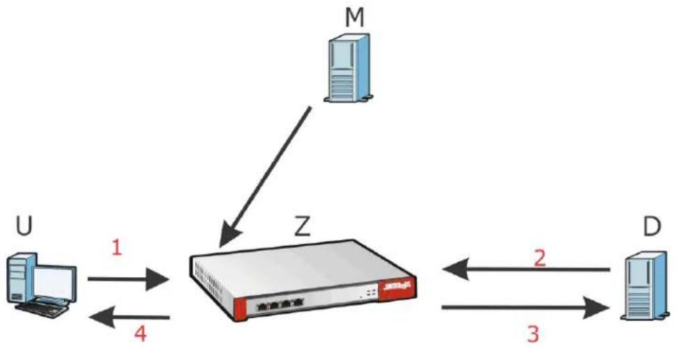
Click Configuration > Security Service > SSL Inspection > Certificate Update to display the following screen.
Figure 577 Configuration > Security Service > SSL Inspection > Certificate Update
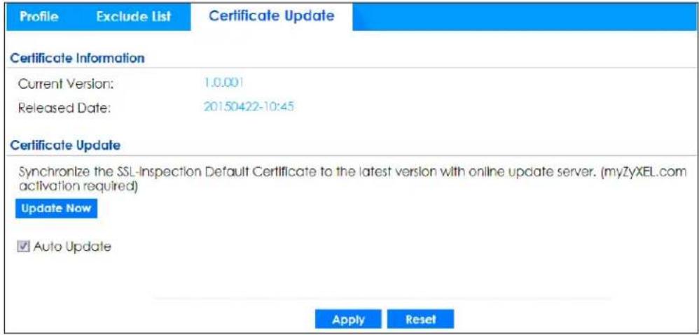
The following table describes the fields in this screen.
Table 355 Configuration > Security Service > SSL Inspection > Certificate Update
| LABEL DESCRIPTION | |
| Certificate Information | |
| Current Version This displays the current certificate set version. | |
| Released Date | This field displays the date and time the current certificate set was released. |
| Certificate Update | You should have Internet access and have activated SSL Inspection on the Zyxel Device at myZyxel. |
| Update Now | Click this button to download the latest certificate set (Windows, MAC OS X, and Android) from the Zyxel cloud server and update it on the Zyxel Device. |
| Auto Update | Select this to automatically have the Zyxel Device update the certificate set when a new one becomes available on the Zyxel cloud sever. |
| Apply | Click Apply to save your settings to the Zyxel Device. |
| Reset | Click Reset to return to the profile summary page without saving any changes. |
40.5 Install a CA Certificate in a Browser
Certificates used in SSL Inspection profiles should be installed in user web browsers. Do the following steps to install a certificate in a computer with a Windows operating system (PC). First, save the certificate to your computer.
1 Run the certificate manager using certmgr.msc.
![certmgr - [Certificates - Current User/Trusted Root Certification Author] File Action View Help Certificates - Current User Personal Trusted Root Certification Au Certificates Issued To AddTrust External CA Root America Online Root Certificati... Baltimore CyberTrust Root](/content/2026/05/878280/images/d1f4b9b09693d40992c10212fc7a3cb946a6329e373475f77f31d3c8bf057a43.jpg)
2 Go to Trusted Root Certification Authorities > Certificates.
![certmgr - [Certificates - Current User\Trusted Root Certification Authorities\Certificates] File Action View Help Certificates - Current User Personal Trusted Root Certification Au Certificates Enterprise Trust Intermediate Certification Au Active Directory User Object Trusted Publishers Untrusted Certificates Third-Party Root Certification Trusted People Other People Smart Card Trusted Roots Issued To AddTrust External CA Root America Online Root Certificati... Baltimore CyberTrust Root Certum CA Class 3 Public Primary Certificatio... Class 3 Public Primary Certificatio... Copyright (c) 1997 Microsoft C... DigiCert High Assurance EV Ro... DST Root CA X3 Entrust.net Certification Author... Entrust.net Secure Server Certifi... Equifax Secure Certificate Auth... GeoTrust Global CA GlobalSign Root CA Go Daddy Class 2 Certification ... Go Daddy Class 2 Certification Au...](/content/2026/05/878280/images/77beabc57d4f5a86e0c69db8e457f8724a0a33e01fd56f465664646a7a4e493c.jpg)
3 From the main menu, select Action > All Tasks > Import and run the Certificate Import Wizard to install the certificate on the PC.
![certmgr - [Certificates - Current User\Trusted Root Certification Authorities\Certificates] File Action View Help All Tasks Import... Refresh Export List... Help Enterprise Trust Intermediate Certification Au Active Directory User Object Trusted Publishers Untrusted Certificates Third-Party Root Certification Trusted People Other People Smart Card Trusted Roots Add a certificate to a store Certificate Import Wizard Welcome to the Certificate Import Wizard This wizard helps you copy certificates, certificate trust lists, and certificate revocation lists from your disk to a certificate store. A certificate, which is issued by a certification authority, is a confirmation of your identity and contains information used to protect data or to establish secure network connections. A certificate store is the system area where certificates are kept. To continue, click Next. < Back Next > Cancel Certificate Import Wizard File to Import Specify the file you want to import. File name: Browse... Note: More than one certificate can be stored in a single file in the following formats: Personal Information Exchange- PKCS #12 (.PFX,.P12) Cryptographic Message Syntax Standard- PKCS #7 Certificates (.P7B) Microsoft Serialized Certificate Store (.SST) Learn more about certificate file formats < Back Next > Cancel](/content/2026/05/878280/images/15ae710ac78f57c01264dd6cb86c181361c832b7047d23af6836fbc87f1d5925.jpg)
40.5.0.1 Firefox Browser
If you're using a Firefox browser, in addition to the above you need to do the following to import a certificate into the browser.
Click Tools > Options > Advanced > Encryption > View Certificates, click Import and enter the filename of the certificate you want to import. See the browser's help for further information.
CHAPTER 41 IP Exception
41.1 Overview
IP Exception allows incoming IP packets to bypass specific security services based on the packet's source or destination address. Bypassing a security service means the security service does not intercept nor inspect the packet. IP Exception supports bypassing the following security services:
• Anti-Malware (including sandboxing)
- URL Threat Filter
• IPS (Intrusion Prevention System)
- IP Reputation.
- DNS Threat Filter
Please note that your Zyxel Device does not support sandboxing and IP reputation by default. You need to purchase a gold pack license; see Section 7.1.2 on page 258 for more information.
41.2 The IP Exception Screen
Use this screen to view the IP exception list for the specified services. The Zyxel Device will not inspect incoming packets that match the listed source and destination IP address(es) with the specified services.
Click Configuration > Security Service > IP Exception to display the following screen. Use Add to put a new entry in the list or Edit to change an existing one or Remove to delete an existing entry.
Figure 578 Configuration > Security Service > IP Exception
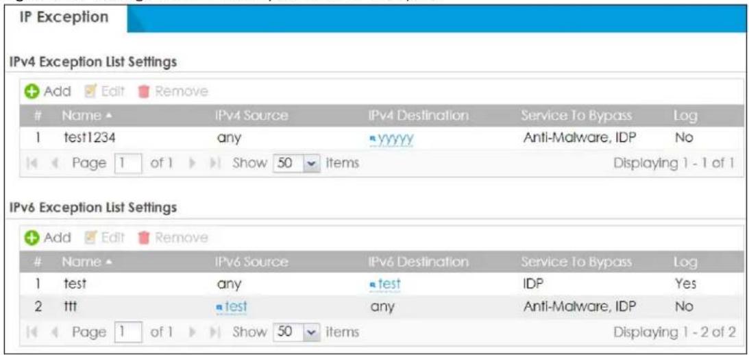
The following table describes the fields in this screen.
Table 356 Configuration > Security Service > IP Exception
| LABEL DESCRIPTION | |
| IPv4/IPv6 Exception List Settings | |
| Add Click this to create a new entry. | |
| Edit Select an entry and click this to be able to modify it. | |
| Remove Select an entry and click this to delete it. | |
| # This is the entry's index number in the list. | |
| Name This field displays the descriptive name of this entry. | |
| IPv4/IPv6 Source | This field displays the source IP address (or address object) of incoming traffic. It displays any if there is no restriction on the source IP address. |
| IPv4/IPv6 Destination | This field displays the destination IP address (or address object) of incoming traffic. It displays any if there is no restriction on the destination IP address. |
| Service to Bypass This field displays which services will not inspect matched packets. | |
| Log | This field displays if the Zyxel Device will generate a log when the incoming traffic is in the exception list. |
41.2.1 The IP Exception Add/Edit Screen
Use this screen to add or edit entries of IPv4 or IPv6 address in the IP exception list.
Click Configuration > Security Service > IP Exception > Add/Edit to display the following screen.
Figure 579 Configuration > Security Service > IP Exception > Add/Edit
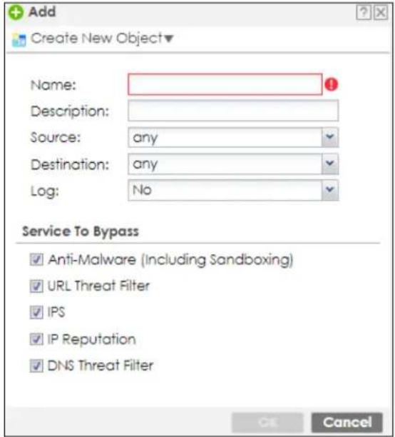
The following table describes the fields in this screen.
Table 357 Configuration > Security Service > IP Exception > Add/Edit
| LABEL DESCRIPTION | |
| Create New Object | Use this to configure any new settings objects that you need to use in this screen. |
| Name Enter a descriptive name of this entry. | |
| Description | Enter the description for this entry. You can use 1 to 63 single-byte characters, including 0-9a-zA-Z!'"#$%'()*+,-/::=?@_.&.<>\]^{} are not allowed. |
| Source | Selectanyor an address object of the source IP address for this entry. Selectanyso there's no restriction on the source IP address. |
| Destination | Selectanyor an address object of the destination IP address for this entry. Selectanyso there's no restriction on the destination IP address. |
| Log | SelectYesto have the Zyxel Device generate a log when the incoming traffic is in the exception list. Otherwise, selectNo. |
| Service to Bypass | Selected services do not inspect packets that match source/destination criteria above. Non-selected services do inspect packets that match source/destination criteria above. |
| OK | ClickOKto save your customized settings and exit this screen. |
| Cancel | ClickCancelto exit this screen without saving. |
41.3 Example: Bypass a Website
You often access a website 1.1.1.1 that you are sure is safe. Every time you access the website, the packets sent by the website will be inspected by the Zyxel Device security services, such as anti-malware, reputation filter and IPS.
This not only causes your web browser to take more time to load the website, but also takes up more Zyxel Device resources than necessary.
In the figure below, you create an IP Exception profile for the website 1.1.1.1. IP exception allows incoming IP packets from the website 1.1.1.1 (A) to bypass specific security services. Bypassing a security service means the security service does not intercept nor inspect the packet.
Figure 580 Bypass Security Services Flow
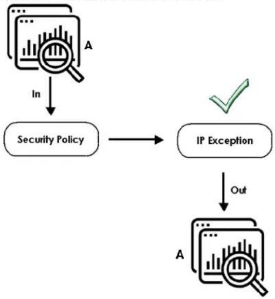
flowchart
graph TD
    A["Security Policy"] --> B["IP Exception"]
    B --> C["Out"]
    D["In"] --> A
    style D fill:#f9f,stroke:#333
    style B fill:#ccf,stroke:#333
    style C fill:#cfc,stroke:#333
This example uses the parameters given below.
Table 358 Address Object Configuration Example
| NAME ADDRESS TYPE IP ADDRESS | ||
| TrustedWebsite Host 1.1.1.1 |
Table 359 IP Exception Configuration Example
| NAME | SOURCE | DESTINATION | LOG | SERVICES TO BYPASS |
| ForTrustedWebsite | TrustedWebsite | Any | No | Anti-MalwareURL Threat filterIPS |
1 Go to Configuration > Object > Address/ Geo IP > Address and click Add.
2 Configure the settings using the parameters given in Table 358 on page 924. Click OK to save your changes.
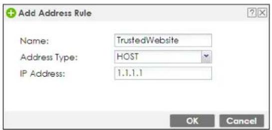
3 Go to Configuration > Security Service > IP Exception and click Add.
4 Configure the settings using the parameters given in Table 359 on page 924. Click OK to save your changes.
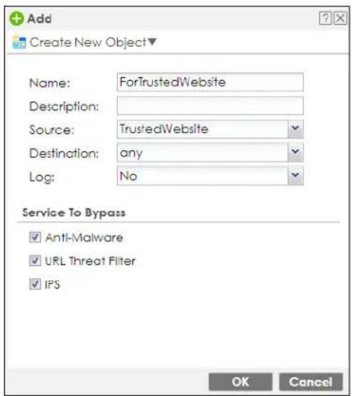
CHAPTER 42
Astra Cloud Security
42.1 Overview
The Astra web portal is a platform that provides security services to mobile devices. It is managed by an admin. You can configure security services such as content filter and URL blocking to protect mobile devices that install the Astra app.
See the Astra web portal online help at http://www.zyxel.com/web-help-compact/AstraPortal/index.html for more information.
The Astra app protects traffic on the members mobile devices that install this app. A member is a person whose mobile device the admin wishes to protect. You can also enable email leakage detection to receive an email from the Astra app if your email address was illegally or unknowingly used to access certain websites.
Please note that only two mobile devices can use the same account to log into the Astra app at a time. You need to contact your admin to remove one of your device first if you wish to log into the Astra app on a third mobile device.
See the Astra app online help at http://www.zyxel.com/web-help-app/Astra/index.html for more information.
Figure 581 Astra Network Overview
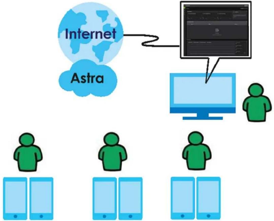
flowchart
graph TD
    A["Internet"] --> B["Astra"]
    B --> C["Computer"]
    C --> D["User 1"]
    C --> E["User 2"]
    C --> F["User 3"]
    C --> G["User 4"]
    C --> H["User 5"]
42.2 Astra Cloud Security Screen
Click Security Service > Astra Cloud Security to open the following screen.
Click Learn More to go to the Astra product page.
If you are an admin, click https://console.astra.cloud.zyxel.com to go to the Astra web portal.
If you are a member, scan one of the QR codes to download the Astra app from Google Play (Android) or Apple App Store (iOS).
Figure 582 Astra Cloud Security
Astra Cloud Security
Astra Cloud-Based Engineless Endpoint
Borderless Perimeter Security
Astro service secures your remote users even when they're roaming outside your existing perimeter. It puts all aspects of security protection back into the hands of the network administrators and allows them to monitor and secure users regardless of their locations. Learn More
Astra portal (https://console.astra.cloud.zyxel.com)
Astra app:
CHAPTER 43 Object
43.1 The Device Insight Screen
Use this screen to configure profiles to block specified clients from accessing the Internet or the Zyxel Device in Configuration > Security Policy > Policy Control. Configure profiles for WiFi and wired clients connected to the Zyxel Device according to the types of devices they use or operating systems their devices use.
Note: To collect clients' information using Device Insight, the clients must be in the same IP subnet in the LAN/VLAN/DMZ networks behind the Zyxel Device. Information from clients that are in different IP subnets in the LAN/VLAN/DMZ networks might not be collected correctly as traffic must pass through another router or a layer-2 switch to the Zyxel Device.
Here's the process for the Zyxel Device to block a profile in this screen:
1 Create a profile in the Device Insight screen to block specific clients.
2 Add the created device insight profile to one of the rules in Policy Control.
3 The Zyxel Device will block clients if they match the settings you configure in the Device Insight profile.
To access this screen, go to Configuration > Object > Device Insight.
Figure 583 Configuration > Object > Device Insight
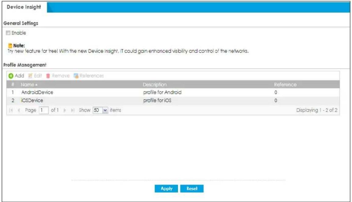
The following table describes the labels in this screen.
Table 360 Configuration > Object > Device Insight
| LABEL DESCRIPTION | |
| General Settings | |
| Enable Select this to enable device insight. Clear this to disable it. | |
| Add Click this to create a new, user-configured zone. | |
| Edit | Double-click an entry or select it and click Edit to open a screen where you can modify the entry's settings. |
| Remove | To remove a user-configured trunk, select it and click Remove. The Zyxel Device confirms you want to remove it before doing so. |
| References | Select an entry and click References to open a screen that shows which settings use the entry. Click Refresh to update information in this screen. |
| # This field is a sequential value, and it is not associated with any interface. | |
| Name This field displays the name of the device. | |
| Description If the device insight profile has a description configured, it displays here. | |
| Reference | This field displays the number of times an Object Reference is used in a policy. |
43.1.1 Device Insight Add/Edit Screen
The Device Insight Add/Edit screen allows you to add a new device insight profile or edit and existing one. To access this screen, go to Configuration > Object > Device Insight > Add/Edit.
Figure 584 Configuration > Object > Device Insight> Add/Edit
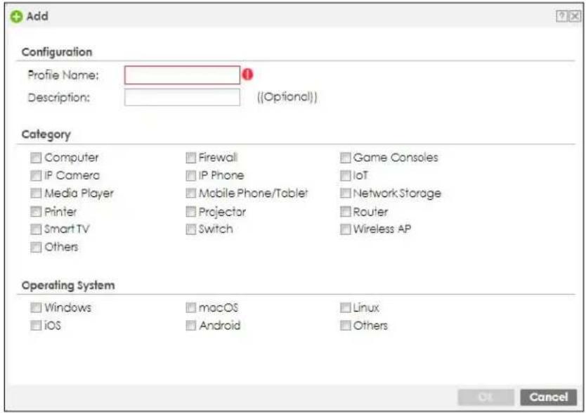
The following table describes the labels in this screen.
Table 361 Configuration > Object > Device Insight> Add/Edit
| LABEL DESCRIPTION | |
| Profile Name | Type a name for this device insight profile. You may use 1-31 alphanumeric character, underscores (_, or dashes (-), but the first character cannot be a number. Spaces and duplicate names are not allowed. This value is case-sensitive. |
| Description | Enter the description of each device insight profile. You can use 1 to 63 single-byte characters, including 0-9a-zA-Z!"#$%')*+,-;=?@_&.<>[\]^{} are not allowed. |
| Category | Select the type of device used by the connected client for this profile.IoT (Internet of Things) is a device with sensors and software that collects and analyzes data. It exchanges the data it collects with other devices over the Internet. IoT is used in many places, such as home assistant, personal care or toys.For example, a smart watch that your grandparents wear is an IoT. It can detects the heart rate and blood pressure of the person wearing it. It sends out warning to other devices, such as your parents phones, if it detects something wrong. |
| Operating System | Select the device operating system used by the connected client for this profile. |
| OK | Click this button to save your changes to the Zyxel Device and return to the summary screen. |
| Cancel | Click this button to return to the summary screen without saving any changes. |
43.1.2 Example: Block a Profile
In this example, company A on the Zyxel Device LAN1 wants to block its subsidiary employees on LAN2 from accessing the company A local networks with their mobile phones. Company A can create a profile that includes all operating systems mobile phones, and then apply it to the LAN2_To_LAN1 policy you created. Clients using mobile phones on the Zyxel Device LAN2 will be blocked from accessing the Zyxel Device LAN1.
Here's the process to use a Device Insight profile in a Zyxel Device security policy. The example below uses the parameters in this table.
Table 362 Device Insight Profile Configurations Example
| PROFILE NAME DES | CRIPTION CATEGORY | OPERATING SYSTEM | APPLIED POLICY | |
| MobilePhone profile | for mobile clients | Mobile Phone/Tablet • | W i n d o w• m a c O• L i n u x• OS• A n d r o i d• O t h e r s | lsAN2_To_LAN1S |
The security policy LAN2_To_LAN1 uses the parameters in this table
Table 363 Device Insight Profile Configurations Example
| TO FROM ACTION | DEVICE INSIGHT PROFILE | |
| LAN1 LAN2 deny MobilePhone |
1 Go to Object > Device Insight and click Add. Follow the parameters in the table above to configure a profile for clients using mobile phones. Click OK to save your changes.
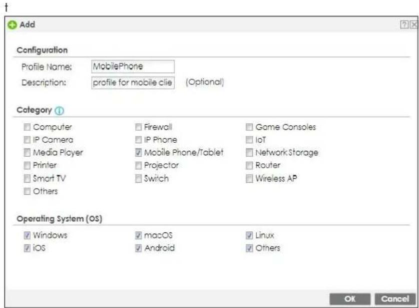
2 Go to Configuration> Security Policy> Policy Control. Click Add to create a rule and name it as LAN2_To_LAN1.
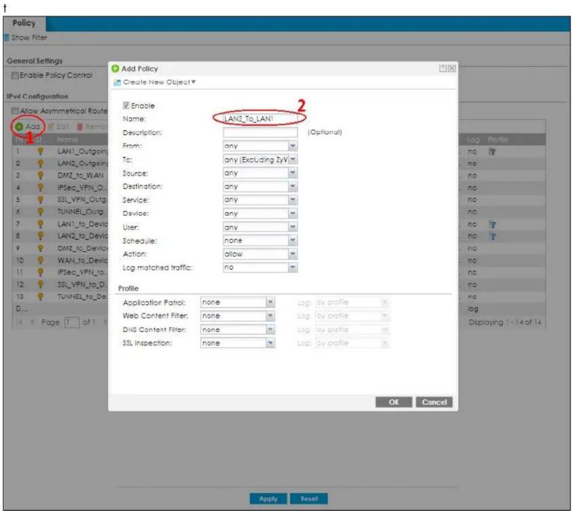
3 In the Add Policy screen, set From to LAN2 and To to LAN1 to configure the traffic direction for the security policy. Add the created Device Insight (MobilePhone) profile to the security policy.
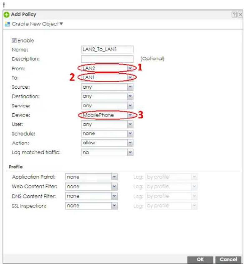
4 Set the Action to deny then click OK to save your changes. Check that the Device Insight profile name (MobilePhone) shows under the Device column to make sure clients using mobile phones are blocked from accessing the Zyxel Device LAN1 from LAN2.
Note: Make sure to configure a security policy to ensure your access to the Zyxel Device before blocking a Device Insight profile. Reset the Zyxel Device if you're blocked from accessing the Zyxel Device.
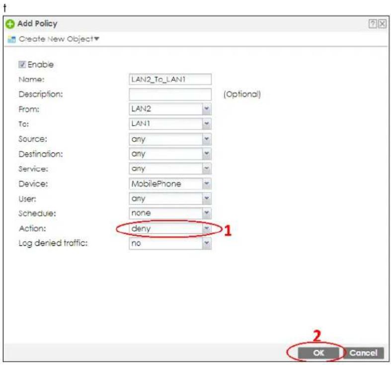
43.2 Zones Overview
Set up zones to configure network security and network policies in the Zyxel Device. A zone is a group of interfaces and/or VPN tunnels. The Zyxel Device uses zones instead of interfaces in many security and policy settings, such as Secure Policies rules, Security Service, and remote management.
Zones cannot overlap. Each Ethernet interface, VLAN interface, bridge interface, PPPoE/PPTP interface and VPN tunnel can be assigned to at most one zone. Virtual interfaces are automatically assigned to the same zone as the interface on which they run.
Figure 585 Example: Zones
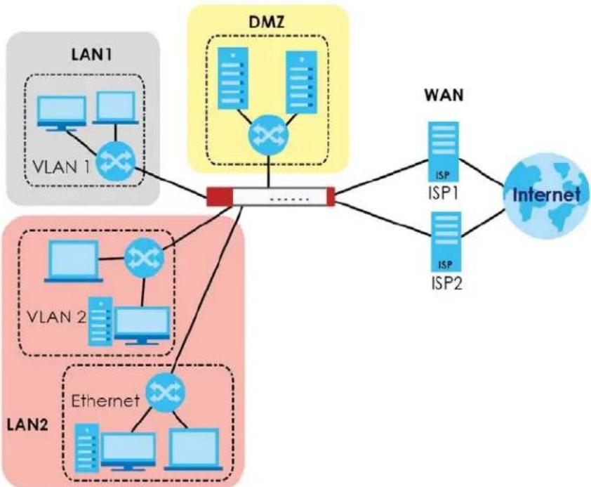
flowchart
graph TD
    subgraph LAN1
        A1["Computer 1"] --> B1["VLAN 1"]
        A2["Computer 1"] --> B2["VLAN 1"]
        A3["Computer 1"] --> B3["VLAN 1"]
        B1 --> C["Red Box"]
        B2 --> C
        B3 --> C
    end
    subgraph LAN2
        D1["Computer 2"] --> E1["VLAN 2"]
        D2["Computer 2"] --> E2["VLAN 2"]
        D3["Computer 2"] --> E3["VLAN 2"]
        E1 --> F["Ethernet"]
        E2 --> F
        E3 --> F
    end
    subgraph DMZ
        G1["Server 1"] --> H1["Server 2"]
        G2["Server 2"] --> H2["Server 2"]
        H1 --> I["Internet"]
        H2 --> I
        H3 --> I
    end
    subgraph WAN
        J1["ISP 1"] --> K1["ISP 2"]
        K1 --> L["Internet"]
    end
Use the Zone screens (see Section 43.9.2 on page 1007) to manage the Zyxel Device's zones.
43.2.1 What You Need to Know
Zones effectively divide traffic into three types--intra-zone traffic, inter-zone traffic, and extra-zone traffic.
Intra-zone Traffic
- Intra-zone traffic is traffic between interfaces or VPN tunnels in the same zone. For example, in Figure 585 on page 936, traffic between VLAN 2 and the Ethernet is intra-zone traffic.
Inter-zone Traffic
Inter-zone traffic is traffic between interfaces or VPN tunnels in different zones. For example, in Figure 585 on page 936, traffic between VLAN 1 and the Internet is inter-zone traffic. This is the normal case when zone-based security and policy settings apply.
Extra-zone Traffic
- Extra-zone traffic is traffic to or from any interface or VPN tunnel that is not assigned to a zone. For example, in Figure 585 on page 936, traffic to or from computer C is extra-zone traffic.
- Some zone-based security and policy settings may apply to extra-zone traffic, especially if you can set the zone attribute in them to Any or All. See the specific feature for more information.
43.2.2 The Zone Screen
The Zone screen provides a summary of all zones. In addition, this screen allows you to add, edit, and remove zones. To access this screen, click Configuration > Object > Zone.
Figure 586 Configuration > Object > Zone
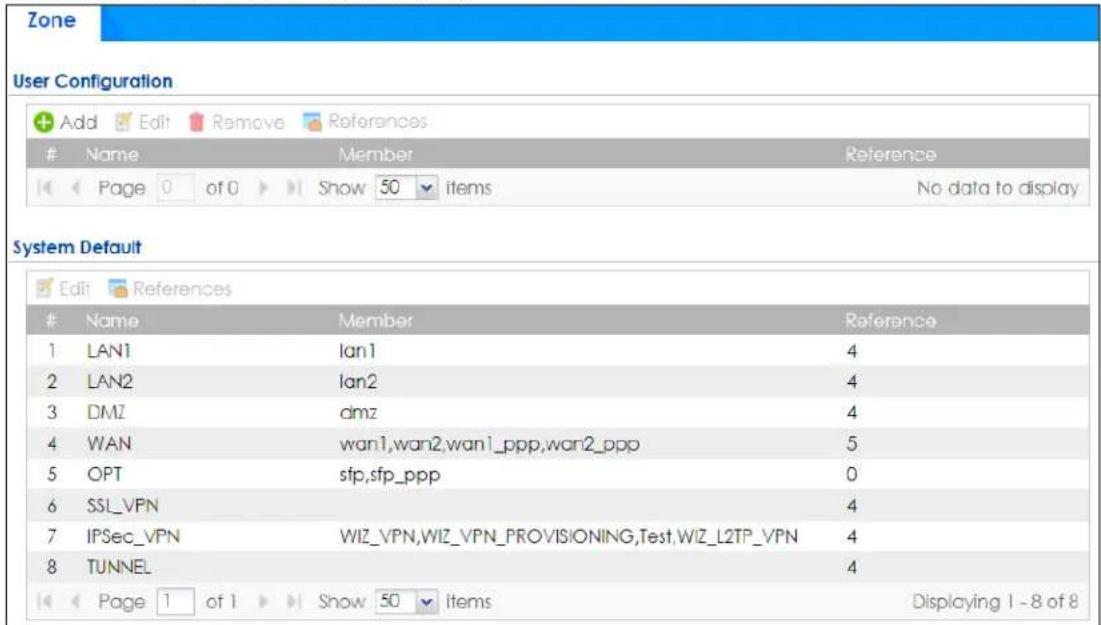
The following table describes the labels in this screen.
Table 364 Configuration > Object > Zone
| LABEL DESCRIPTION | |
| User Configuration / System Default | The Zyxel Device comes with pre-configuredSystem Defaultzones that you cannot delete. You can create your ownUser Configurationzones |
| Add Click this to create a | new, user-configured zone. |
| Edit | Double-click an entry or select it and clickEditto open a screen where you can modify the entry's settings. |
| Remove | To remove a user-configured trunk, select it and clickRemove. The Zyxel Device confirms you want to remove it before doing so. |
| References | Select an entry and clickReferencesto open a screen that shows which settings use the entry. Click Refresh to update information in this screen. |
| # This field is a sequential | value, and it is not associated with any interface. |
| Name This field displays the name of the zone. | |
| Member | This field displays the names of the interfaces that belong to each zone. |
| Reference | This field displays the number of times an Object Reference is used in a policy. |
43.2.2.1 Zone Edit
The Zone Edit screen allows you to add or edit a zone. To access this screen, go to the Zone screen (see Section 43.9.2 on page 1007), and click the Add icon or an Edit icon.
Figure 587 Configuration > Object > Zone > Add
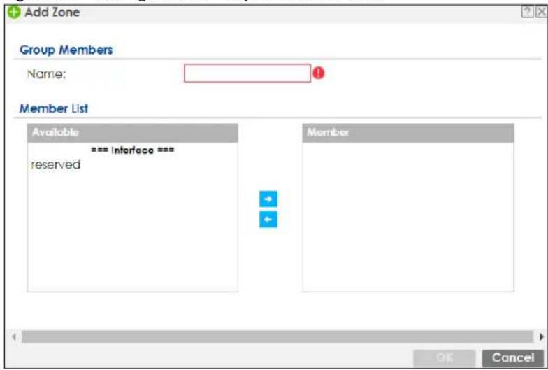
The following table describes the labels in this screen.
Table 365 Configuration > Object > Zone > Add/Edit
| LABEL DESCRIPTION | |
| Name For a system default zone, the name is read only.For a user-configured zone, type the name used to refer to the zone. You may use 1-31 alphanumeric characters, underscores ( ), or dashes (-), but the first character cannot be a number. This value is case-sensitive. | |
| Member List | Available lists the interfaces and VPN tunnels that do not belong to any zone. Select the interfaces and VPN tunnels that you want to add to the zone you are editing, and click the right arrow button to add them.Member lists the interfaces and VPN tunnels that belong to the zone. Select any interfaces that you want to remove from the zone, and click the left arrow button to remove them. |
| OK | Click OK to save your customized settings and exit this screen. |
| Cancel | Click Cancel to exit this screen without saving. |
43.3 User/Group Overview
This section describes how to set up user accounts, user groups, and user settings for the Zyxel Device. You can also set up rules that control when users have to log in to the Zyxel Device before the Zyxel Device routes traffic for them.
- The User screen (see Section 43.14.1 on page 1051) provides a summary of all user accounts.
- The Group screen (see Section 43.3.5 on page 949) provides a summary of all user groups. In addition, this screen allows you to add, edit, and remove user groups. User groups may consist of access users and other user groups. You cannot put admin users in user groups.
- The Setting screen (see Section 43.3.6 on page 950) controls default settings, login settings, lockout settings, and other user settings for the Zyxel Device. You can also use this screen to specify when users must log in to the Zyxel Device before it routes traffic for them.
- The MAC Address screen (see Section 43.3.7 on page 955) allows you to configure the MAC addresses or OUI (Organizationally Unique Identifier) of wireless clients for MAC authentication using the local user database. The OUI is the first three octets in a MAC address and uniquely identifies the manufacturer of a network device.
43.3.1 What You Need To Know
User Account
A user account defines the privileges of a user logged into the Zyxel Device. User accounts are used in security policies and application patrol, in addition to controlling access to configuration and services in the Zyxel Device.
User Types
These are the types of user accounts the Zyxel Device uses.
Table 366 Types of User Accounts
| TYPE ABILITIES LOGIN METHOD(S) | ||
| Admin Users | ||
| admin | Change Zyxel Device configuration (web, CLI) | WWW, TELNET, SSH, FTP, Console |
| Access Users | ||
| limited-admin Look | at Zyxel Device configuration (web, CLI)Perform basic diagnostics (CLI)Cannot execute commands such as 'show running-config' | WWW, TELNET, SSH, Console |
| user Access network servicesBrowse user-mode commands (CLI) | WWW, TELNET, SSH | |
| guest Access network services WWW | ||
| ext-user External user account WWW | ||
| ext-group-user External group user account WWW | ||
| guest-manager | Create dynamic guest accounts | WWW |
| dynamic-guest | Access network services | Hotspot Portal |
Note: The default admin account is always authenticated locally, regardless of the authentication method setting. (See Chapter 43 on page 1021 for more information about authentication methods.)
Ext-User Accounts
Set up an ext-user account if the user is authenticated by an external server and you want to set up specific policies for this user in the Zyxel Device. If you do not want to set up policies for this user, you do not have to set up an ext-user account.
All ext-user users should be authenticated by an external server, such as AD, LDAP or RADIUS. If the Zyxel Device tries to use the local database to authenticate an ext-user, the authentication attempt always fails. (This is related to AAA servers and authentication methods, which are discussed in those chapters in this guide.)
Note: If the Zyxel Device tries to authenticate an ext-user using the local database, the attempt always fails.
Once an ext-user user has been authenticated, the Zyxel Device tries to get the user type (see Table 366 on page 939) from the external server. If the external server does not have the information, the Zyxel Device sets the user type for this session to User.
For the rest of the user attributes, such as reauthentication time, the Zyxel Device checks the following places, in order.
1 User account in the remote server.
2 User account (Ext-User) in the Zyxel Device.
3 Default user account for AD users (ad-users), LDAP users (ldap-users) or RADIUS users (radius-users) in the Zyxel Device.
See Setting up User Attributes in an External Server for a list of attributes and how to set up the attributes in an external server.
Ext-Group-User Accounts
Ext-Group-User accounts work are similar to ext-user accounts but allow you to group users by the value of the group membership attribute configured for the AD or LDAP server. See Section 43.10.5.1 on page 1016 for more on the group membership attribute.
Dynamic-Guest Accounts
Dynamic guest accounts are guest accounts, but are created dynamically and stored in the Zyxel Device's local user database. A dynamic guest account has a dynamically-created user name and password. A dynamic guest account user can access the Zyxel Device's services only within a given period of time and will become invalid after the expiration date/time.
There are three types of dynamic guest accounts depending on how they are created or authenticated: billing-users, ua-users and trial-users.
billing-users are guest account created with the guest manager account or an external printer and paid by cash or created and paid via the on-line payment service. ua-users are users that log in from the user agreement page. trial-users are free guest accounts that are created with the Free Time function.
User Groups
User groups may consist of user accounts or other user groups. Use user groups when you want to create the same rule for several user accounts, instead of creating separate rules for each one.
Note: You cannot put access users and admin users in the same user group.
Note: You cannot put the default admin account into any user group.
The sequence of members in a user group is not important.
User Awareness
By default, users do not have to log into the Zyxel Device to use the network services it provides. The Zyxel Device automatically routes packets for everyone. If you want to restrict network services that certain users can use via the Zyxel Device, you can require them to log in to the Zyxel Device first. The Zyxel Device is then 'aware' of the user who is logged in and you can create 'user-aware policies' that define what services they can use. See Section 43.3.8 on page 957 for a user-aware login example.
Finding Out More
• See Section 43.3.8 on page 957 for some information on users who use an external authentication server in order to log in.
- The Zyxel Device supports TTLS using PAP so you can use the Zyxel Device's local user database to authenticate users with WPA or WPA2 instead of needing an external RADIUS server.
43.3.2 User/Group User Summary Screen
The User screen provides a summary of all user accounts. To access this screen, login to the Web Configurator, and click Configuration > Object > User/Group.
Figure 588 Configuration > Object > User/Group > User
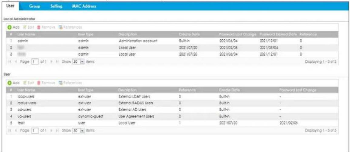
The following table describes the labels in this screen.
Table 367 Configuration > Object > User/Group > User
| LABEL DESCRIPTION | |
| Add Click this to create a new entry. | |
| Edit | Double-click an entry or select it and click Edit to open a screen where you can modify the entry's settings. |
| Remove | To remove an entry, select it and click Remove. The Zyxel Device confirms you want to remove it before doing so. |
| References | Select an entry and click References to open a screen that shows which settings use the entry. |
| Local Administrator | Use this table to view and configure the Zyxel Device admin accounts. |
| # This field is a sequential value, and it is not associated with a specific user. | |
| User Name This | field displays the user name of each user. |
| User Type | This field displays the admin accounts the Zyxel Device uses. Admin accounts are users that can look at and change the configuration of the Zyxel Device |
| Description This | field displays the description for each user. |
| Created Date | This field displays the date the account is created.This field displays - if the account is created before the Zyxel Device upgrades firmware to version 5.10 or later. |
| Password Last Change | This field displays the last time the user changed the account password. |
| Password Expired Date | This field displays the account password expiry date. The user should change the password before it expires. |
| Reference This | displays the number of times an object reference is used in a profile. |
| User Use this table | to configure the Zyxel Device:Limited-admin accounts.User accounts.Guest accounts.Ext-user accounts.Ext-group-user accounts. |
| # This field is a sequential value, and it is not associated with a specific user. | |
| User Name This | field displays the user name of each user. |
| User Type | This field displays the types of user accounts the Zyxel Device uses:limited-admin- this user can look at the configuration of the Zyxel Device but not to change itdynamic-guest- this user has access to the Zyxel Device's services but cannot look at the configuration.user- this user has access to the Zyxel Device's services and can also browse user-mode commands (CLI).guest- this user has access to the Zyxel Device's services but cannot look at the configurationext-user- this user account is maintained in a remote server, such as RADIUS or LDAP. See Ext-User Accounts on page 939 for more information about this type.ext-group-user- this user account is maintained in a remote server, such as RADIUS or LDAP. See Ext-Group-User Accounts on page 940 for more information about this type.guest-manager- this user can log in via the web configurator login screen and create dynamic guest accounts using the Account Generator screen that pops up. |
| Description This | field displays the description for each user. |
| Create Date This | field displays the date the account is created. |
| Password Last Change | This field displays the last time the user changes the account password. |
| Reference This | displays the number of times an object reference is used in a profile. |
43.3.3 User Add/Edit General Screen
The User Add/Edit General screen allows you to create a new user account or edit an existing one.
43.3.3.1 Rules for User Names
Enter a user name from 1 to 31 characters.
The user name can only contain the following characters:
• Alphanumeric A-z 0-9 (there is no unicode support)
- _ [underscores]
- [dashes]
The first character must be alphabetical (A-Z a-z), an underscore (_), or a dash (-). Other limitations on user names are:
- User names are case-sensitive. If you enter a user 'bob' but use 'BOB' when connecting via CIFS or FTP, it will use the account settings used for 'BOB' not 'bob'.
- User names have to be different than user group names.
• Here are the reserved user names:

To access this screen, go to the User screen (see Section 43.14.1 on page 1051), and click either the Add icon or an Edit icon.
Figure 589 Configuration > Object > User/Group > User > Add/Edit_General (Local Administrator)
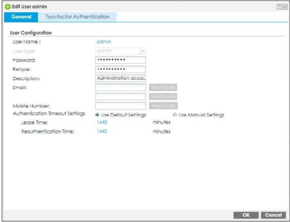
Figure 590 Configuration > Object > User/Group > User > Add/Edit_General (User)
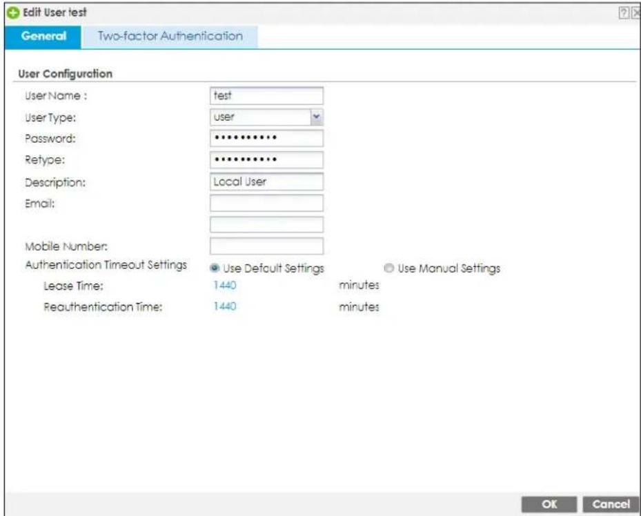
The following table describes the labels in this screen.
Table 368 Configuration > Object > User/Group > User > Add/Edit_General
| LABEL DESCRIPTION | |
| User Name | Type the user name for this user account. You may use 1-31 alphanumeric characters, underscores( ), or dashes (-), but the first character cannot be a number. This value is case-sensitive. User names have to be different than user group names, and some words are reserved. See Section 43.3.3.1 on page 942. |
| User Type | This field is not available if you're adding an account to theLocal Administratortable.Select the types of user accounts the Zyxel Device uses from the drop-down list box:limited-admin- this user can look at the configuration of the Zyxel Device but not to change ituser- this user has access to the Zyxel Device's services and can also browse user-mode commands (CLI).guest- this user has access to the Zyxel Device's services but cannot look at the configuration.ext-user- this user account is maintained in a remote server, such as RADIUS or LDAP. SeeExt-User Accounts on page 939 for more information about this type.ext-group-user- this user account is maintained in a remote server, such as RADIUS or LDAP. SeeExt-Group-User Accounts on page 940 for more information about this type. |
| Password | This field is not available if you select theext-userorext-group-usertype.Enter a password of from 1 to 64 characters for this user account. If you selectedEnable Password ComplexityinConfiguration>Object>User/Group>Setting, it must consist of at least 8 characters and at most 64. At least 1 character must be a number, at least 1 a lower case letter, at least 1 an upper case letter and at least 1 a special character from the keyboard, such as !@#%^&*()_+.Note: After the first login, you are not allowed to set the password to 1234. |
| Retype | This field is not available if you select theext-userorext-group-usertype. |
| Group Identifier | This field is available for aext-group-usertype user account.Specify the value of the AD or LDAP server'sGroup Membership Attributethat identifies the group to which this user belongs. |
| Associated AAA Server Object | This field is available for aext-group-usertype user account. Select the AAA server to use to authenticate this account's users. |
| Description | Enter the description of each user, if any. You can use 1 to 63 single-byte characters, including 0-9a-zA-Z!"#%')*+,-/::=?@_.&.<>[\]{}^'are not allowed. Default descriptions are provided. |
| Type one or more valid email addresses for this user so that email messages can be sent to this user if required. A valid email address must contain the @ character. For example, this is a valid email address: abc@example.com. | |
| Mobile Number | Type a valid mobile telephone number for this user so that SMS messages can be sent to this user if required. A valid mobile telephone number can be up to 20 characters in length, including the numbers 1~9 and the following characters in the square brackets [+*#()-]. |
| Send Code | This button is available when the user type isadminorlimited-admin.Click this and an authorization email or SMS message with a code of six digits will be sent to the email addresses or mobile telephone number you put in.Enter the verification code to verify your email addresses or mobile telephone number.Figure 591Verification Code for Email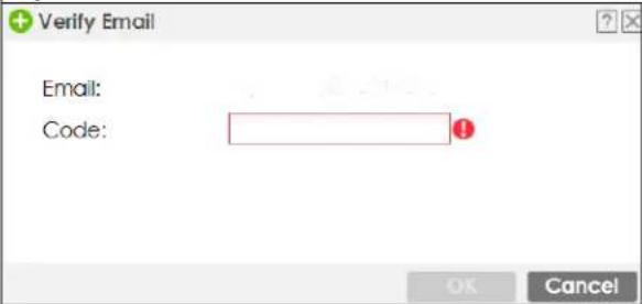 Figure 592Verification Code for Mobile Telephone Number Figure 592Verification Code for Mobile Telephone Number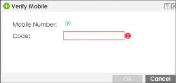 |
| Authentication Timeout Settings | If you want the system to use default settings, selectUse Default Settings. If you want to set authentication timeout to a value other than the default settings, selectUse Manual Settings then fill your preferred values in the fields that follow. |
| Lease Time | If you selectUse Default Settingsin theAuthentication Timeout Settingsfield, the default lease time is shown.If you selectUse Manual Settings, you need to enter the number of minutes this user has to renew the current session before the user is logged out. You can specify 1 to 1440 minutes. You can enter 0 to make the number of minutes unlimited. Admin users renew the session every time the main screen refreshes in the Web Configurator. Access users can renew the session by clicking therenewbutton on their screen. If you allow access users to renew time automatically (seeSection 43.3.6 on page 950), the users can select this check box on their screen as well. In this case, the session is automatically renewed before the lease time expires. |
| Reauthentication Time | If you selectUse Default Settingsin theAuthentication Timeout Settingsfield, the default reauthentication time is shown.If you selectUse Manual Settings, you need to type the number of minutes this user can be logged into the Zyxel Device in one session before the user has to log in again. You can specify 1 to 1440 minutes. You can enter 0 to make the number of minutes unlimited. UnlikeLeasetime, the user has no opportunity to renew the session without logging out. |
| User VLAN ID | This field is available for aext-group-usertype user account.Select this option to enable dynamic VLAN assignment on the Zyxel Device. When a user is authenticated successfully, all data traffic from this user is tagged with the VLAN ID number you specify here.This allows you to assign a user of theext-group-usertype to a specific VLAN based on the user credentials instead of using an AAA server. |
| Configuration Validation | Use a user account from the group specified above to test if the configuration is correct. Enter the account's user name in theUser Namefield and clickTest. |
| OK | ClickOKto save your changes back to the Zyxel Device and close the screen. |
| Cancel | ClickCancelto exit this screen without saving your changes. |
| Save | This button is only available when adding a new user. ClickSaveto save your changes back to the Zyxel Device and then go to theTwo-factor Authenticationscreen. |
43.3.4 User Add/Edit Two-factor Authentication Screen
The User Add/Edit Two-factor Authentication screen allows you to create two-factor security for VPN access or admin access for this user to the Zyxel Device.
Two-factor authentication adds an extra layer of security for users logging into the Zyxel Device. When two-factor authentication is enabled, a user has to first enter their username and password, and then click on a temporary link or enter a one-time password when logging in.
You can enable two-factor authentication for users who are logging into the Zyxel Device to create a VPN tunnel (VPN access), and for administrator and limited admin users who are logging into the Web Configurator or CLI (admin access) to configure the Zyxel Device.
Table 369 Two Factor Authentication Methods
| ACCESS TYPE TWO-FACTOR AUTHENTICATION METHODS FACTOR 2 PASSWORD | ||
| VPN SMS Code | ||
| VPN Email Link | ||
| VPN Google Authenticator app Code | ||
| Admin SMS Code | ||
| ACCESS TYPE TWO-FACTOR | AUTHENTICATION METHODS FACTOR 2 PASSWORD | |
| Admin Email Link | ||
| Admin Google Authenticator | app Code | |
You must first enable two-factor authentication on the Zyxel Device in Object > Auth. Method > Two-factor Authentication > VPN Access and Object > Auth. Method > Two-factor Authentication > Admin Access. See Section 43.11.4 on page 1024 and Section 43.11.6 on page 1029 for more prerequisites and other information.
In Object > User/Group > User, click Add to create a new entry or select an entry and click Edit to modify the entry. You must create a user account first before you can edit the two-factor authentication settings.
You can configure two-factor authentication for non-VPN and non-admin users in web authentication.
Note: The admin two-factor authentication settings override the web authentication two-factor authentication settings.
Figure 593 Configuration > Object > User/Group > User > Add/Edit_Two-factor Authentication
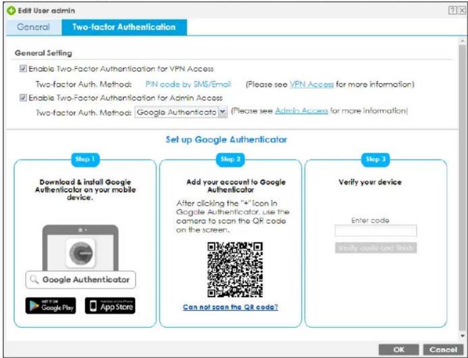
Figure 594 Configuration > Object > User/Group > User > Add/Edit_Two-factor Authentication_Verified
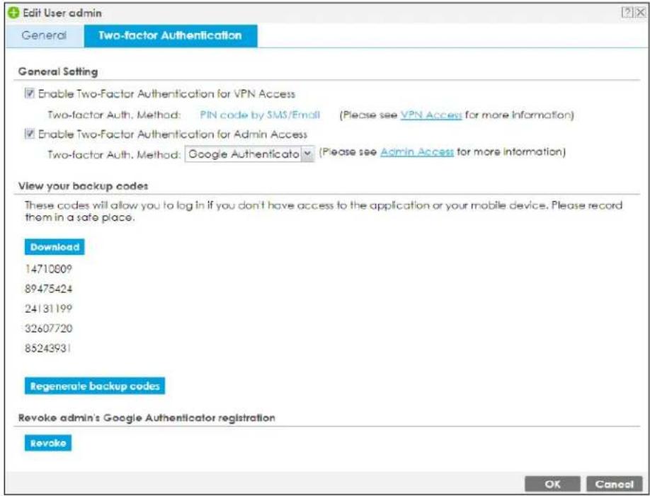
The following table describes the labels in this screen.
Table 370 Configuration > Object > User/Group > User > Add_Two-factor Authentication
| LABEL DESCRIPTION | |
| Enable Two-factor Authentication for VPN Access | Select this to require two-factor authentication for this user to use a pre-configured VPN tunnel for secure access to a network behind the Zyxel Device. Select the types of VPN allowed in Object > Auth. Method > Two-factor Authentication > VPN Access. You may choose from:SSL VPN AccessIPSec VPN AccessL2TP/IPSec VPN Access |
| Enable Two-factor Authentication for Admin Access | Select this to require two-factor authentication for an admin user to access the Zyxel Device. Select the types of access allowed in Object > Auth. Method > Two-factor Authentication > Admin Access. You may choose from:WebSSHTELNET |
| Two-factor Auth. Method | Select Default or User Defined and select from PIN code by SMS/Email or Google Authenticator |
| Set up Google Authenticator | If you chose Google Authenticator for offline two-factor authentication, on your mobile device, go to an app store to download Google Authenticator. To add your account to Google Authenticator, press the plus (+) icon, select Scan Barcode, then use your mobile device's camera to scan the barcode. Finally enter the verification code you receive on your mobile device in Verify your device. |
| View your backup codes | You see this after successful Google authentication. In the event that you do not have access to email or your mobile device, click Download to create backup codes as second-factor authentication. Make sure to put them in a safe place. |
| Verify your device | In the event that you do not have access to email or your mobile device, enter a backup code here as second factor authentication. You can use each code only once. If you generate a new set of backup codes (Regenerate backup codes), the old set become obsolete. |
| Revoke | Click this to cancel Google authentication as second-factor authentication for Admin Access. You must then use a PIN code by SMS or email as second-factor authentication instead. |
| OK | Click OK to save your changes back to the Zyxel Device and close the screen. |
| Cancel | Click Cancel to exit this screen without saving your changes. |
43.3.5 User/Group Group Summary Screen
User groups consist of access users and other user groups. You cannot put admin users in user groups. The Group screen provides a summary of all user groups. In addition, this screen allows you to add, edit, and remove user groups. To access this screen, login to the Web Configurator, and click Configuration > Object > User/Group > Group.
Figure 595 Configuration > Object > User/Group > Group

The following table describes the labels in this screen. See Section 43.3.5.1 on page 949 for more information as well.
Table 371 Configuration > Object > User/Group > Group
| LABEL DESCRIPTION | |
| Add Click this to create a new entry. | |
| Edit | Double-click an entry or select it and click Edit to open a screen where you can modify the entry's settings. |
| Remove | To remove an entry, select it and click Remove. The Zyxel Device confirms you want to remove it before doing so. Removing a group does not remove the user accounts in the group. |
| References | Select an entry and click References to open a screen that shows which settings use the entry. |
| # This field is a sequential value, and it is not associated with a specific user group. | |
| Group Name This field displays the name of each user group. | |
| Description This field displays the description for each user group. | |
| Member | This field lists the members in the user group. Each member is separated by a comma. |
| Reference This displays the number of times an object reference is used in a profile. | |
43.3.5.1 Group Add/Edit Screen
The Group Add/Edit screen allows you to create a new user group or edit an existing one. To access this screen, go to the Group screen (see Section 43.3.5 on page 949), and click either the Add icon or an Edit icon.
Figure 596 Configuration > Object > User/Group > Group > Add
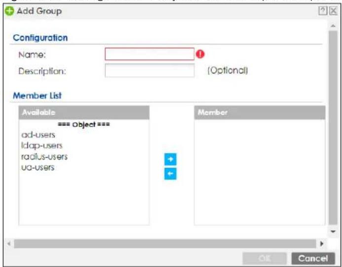
The following table describes the labels in this screen.
Table 372 Configuration > Object > User/Group > Group > Add
| LABEL DESCRIPTION | |
| Name Type the name for this user group. You may use 1-31 alphanumeric characters, underscores( ), or dashes (-), but the first character cannot be a number. This value is case-sensitive. User group names have to be different than user names. | |
| Description | Enter the description of the user group, if any. You can use up to 60 characters, punctuation marks, and spaces. |
| Member List | The Member list displays the names of the users and user groups that have been added to the user group. The order of members is not important. Select users and groups from the Available list that you want to be members of this group and move them to the Member list. You can double-click a single entry to move it or use the [Shift] or [Ctrl] key to select multiple entries and use the arrow button to move them.Move any members you do not want included to the Available list. |
| OK | Click OK to save your changes back to the Zyxel Device. |
| Cancel | Click Cancel to exit this screen without saving your changes. |
43.3.6 User/Group Setting Screen
The Setting screen controls default settings, login settings, lockout settings, and other user settings for the Zyxel Device. You can also use this screen to specify when users must log in to the Zyxel Device before it routes traffic for them.
To access this screen, login to the Web Configurator, and click Configuration > Object > User/Group > Setting.
Figure 597 Configuration > Object > User/Group > Setting
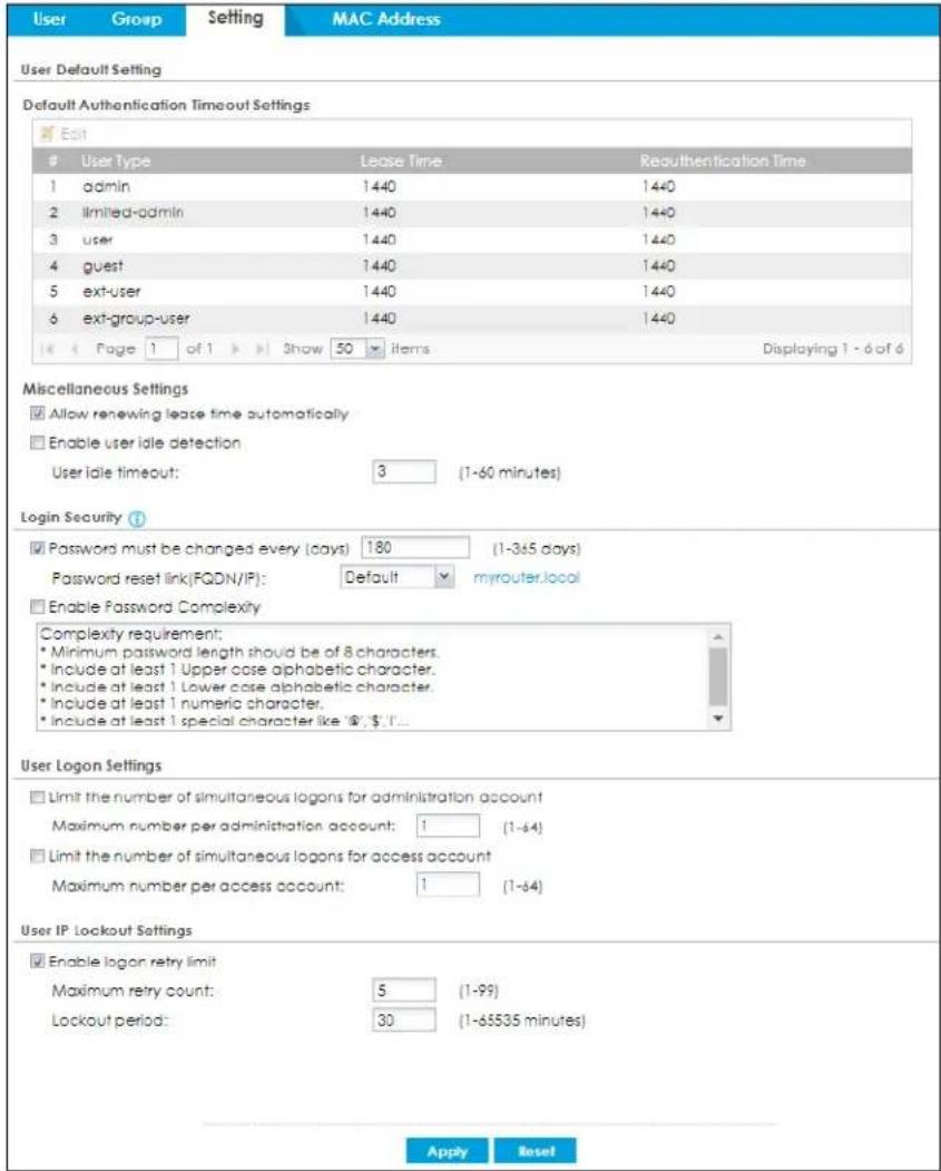
The following table describes the labels in this screen.
Table 373 Configuration > Object > User/Group > Setting
| LABEL DESCRIPTION | |
| User Authentication Timeout Settings | |
| Default Authentication Timeout Settings | These authentication timeout settings are used by default when you create a new user account. They also control the settings for any existing user accounts that are set to use the default settings. You can still manually configure any user account's authentication timeout settings. |
| Edit | Double-click an entry or select it and click Edit to open a screen where you can modify the entry's settings. |
| # | This field is a sequential value, and it is not associated with a specific entry. |
| User Type These are the kinds of user account the Zyxel Device supports.admin- this user can look at and change the configuration of the Zyxel Devicelimited-admin- this user can look at the configuration of the Zyxel Device but not to change ituser- this user has access to the Zyxel Device's services but cannot look at the configurationguest- this user has access to the Zyxel Device's services but cannot look at the configurationext-user- this user account is maintained in a remote server, such as RADIUS or LDAP. SeeExt-User Accounts on page 939 for more information about this type.ext-group-user- this user account is maintained in a remote server, such as RADIUS or LDAP. SeeExt-Group-User Accounts on page 940 for more information about this type. | |
| Lease Time | This is the default lease time in minutes for each type of user account. It defines the number of minutes the user has to renew the current session before the user is logged out.Admin users renew the session every time the main screen refreshes in the Web Configurator. Access users can renew the session by clicking theRenewbutton on their screen. If you allow access users to renew time automatically (see Section 43.3.6 on page 950), the users can select this check box on their screen as well. In this case, the session is automatically renewed before the lease time expires. |
| Reauthentication Time | This is the default reauthentication time in minutes for each type of user account. It defines the number of minutes the user can be logged into the Zyxel Device in one session before having to log in again. UnlikeLease Time, the user has no opportunity to renew the session without logging out. |
| Miscellaneous Settings | |
| Allow renewing lease time automatically | Select this check box if access users can renew lease time automatically, as well as manually, simply by selecting theUpdating lease time automaticallycheck box on their screen. |
| Enable user idle detection This is applicable for access users.Select this check box if you want the Zyxel Device to monitor how long each access user is logged in and idle (in other words, there is no traffic for this access user). The Zyxel Device automatically logs out the access user once theUser idle timeouthas been reached. | |
| User idle timeout This is applicable for access users.This field is effective whenEnable user idle detectionis checked. Type the number of minutes each access user can be logged in and idle before the Zyxel Device automatically logs out the access user. | |
| Login Security | |
| Password must changed every (days): | Enter how often local users ofUser Type'admin' must change their login passwords. You can choose from once a day to once a year. |
| Password reset link (FQDN/IP): | Associate the password expiration to a specific Zyxel Device.Defaultis this Zyxel Device (myrouter) or selectCustomand enter the IP address or Fully Qualified Domain Name (FQDN). |
| Enable Password Complexity | Select this to enforce the following conditions in a user password. Requiring a strong password is good for security. The conditions are that the password must consist of at least 8 characters and at most 64. At least 1 character must be a number, at least 1 a lower case letter, at least 1 an upper case letter and at least 1 a special character from the keyboard, such as !@#$%^&*()_.+ . |
| User Logon Settings | |
| Limit the number of simultaneous logons for administration account | Select this check box if you want to set a limit on the number of simultaneous logins by admin users. If you do not select this, admin users can login as many times as they want at the same time using the same or different IP addresses. |
| Maximum number per administration account | This field is effective when Limit ... for administration account is checked. Type the maximum number of simultaneous logins by each admin user. |
| Limit the number of simultaneous logons for access account | Select this check box if you want to set a limit on the number of simultaneous logins by non-admin users. If you do not select this, access users can login as many times as they want as long as they use different IP addresses. |
| Maximum number per access account | This field is effective when Limit ... for access account is checked. Type the maximum number of simultaneous logins by each access user. |
| User IP Lockout Settings | |
| Enable logon retry limit | Select this check box to set a limit on the number of times each user can login unsuccessfully (for example, wrong password) before the IP address is locked out for a specified amount of time. |
| Maximum retry count | This field is effective when Enable logon retry limit is checked. Type the maximum number of times each user can login unsuccessfully before the IP address is locked out for the specified lockout period. The number must be between 1 and 99. |
| Lockout period | This field is effective when Enable logon retry limit is checked. Type the number of minutes the user must wait to try to login again, if logon retry limit is enabled and the maximum retry count is reached. This number must be between 1 and 65,535 (about 45.5 days). |
| Apply | Click Apply to save the changes. |
| Reset | Click Reset to return the screen to its last-saved settings. |
43.3.6.1 Default User Authentication Timeout Settings Edit Screens
The Default Authentication Timeout Settings Edit screen allows you to set the default authentication timeout settings for the selected type of user account. These default authentication timeout settings also control the settings for any existing user accounts that are set to use the default settings. You can still manually configure any user account's authentication timeout settings.
To access this screen, go to the Configuration > Object > User/Group > Setting screen (see Section 43.3.6 on page 950), and click one of the Default Authentication Timeout Settings section's Edit icons.
Figure 598 Configuration > Object > User/Group > Setting > Edit
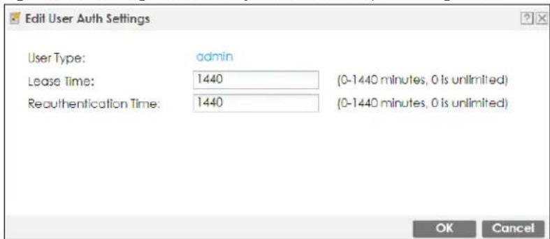
The following table describes the labels in this screen.
Table 374 Configuration > Object > User/Group > Setting > Edit
| LABEL DESCRIPTION | |
| User Type | This read-only field identifies the type of user account for which you are configuring the default settings.admin- this user can look at and change the configuration of the Zyxel Devicelimited-admin- this user can look at the configuration of the Zyxel Device but not to change it.dynamic-guest- this user has access to the Zyxel Device's services but cannot look at the configuration.user- this user has access to the Zyxel Device's services but cannot look at the configuration.guest- this user has access to the Zyxel Device's services but cannot look at the configuration.ext-user- this user account is maintained in a remote server, such as RADIUS or LDAP. See Ext-User Accounts on page 939 for more information about this type.ext-group-user- this user account is maintained in a remote server, such as RADIUS or LDAP. See Ext-Group-User Accounts on page 940 for more information about this type.guest-manager- this user can log in via the web configurator login screen and create dynamic guest accounts using the Account Generator screen that pops up. |
| Lease Time | Enter the number of minutes this type of user account has to renew the current session before the user is logged out. You can specify 1 to 1440 minutes. You can enter 0 to make the number of minutes unlimited.Admin users renew the session every time the main screen refreshes in the Web Configurator. Access users can renew the session by clicking the Renew button on their screen. If you allow access users to renew time automatically (see Section 43.3.6 on page 950), the users can select this check box on their screen as well. In this case, the session is automatically renewed before the lease time expires. |
| Reauthentication Time | Type the number of minutes this type of user account can be logged into the Zyxel Device in one session before the user has to log in again. You can specify 1 to 1440 minutes. You can enter 0 to make the number of minutes unlimited. Unlike Lease Time, the user has no opportunity to renew the session without logging out. |
| OK | Click OK to save your changes back to the Zyxel Device. |
| Cancel | Click Cancel to exit this screen without saving your changes. |
43.3.6.2 User Aware Login Example
Access users cannot use the Web Configurator to browse the configuration of the Zyxel Device. Instead, after access users log into the Zyxel Device, the following screen appears.
Figure 599 Web Configurator for Non-Admin Users
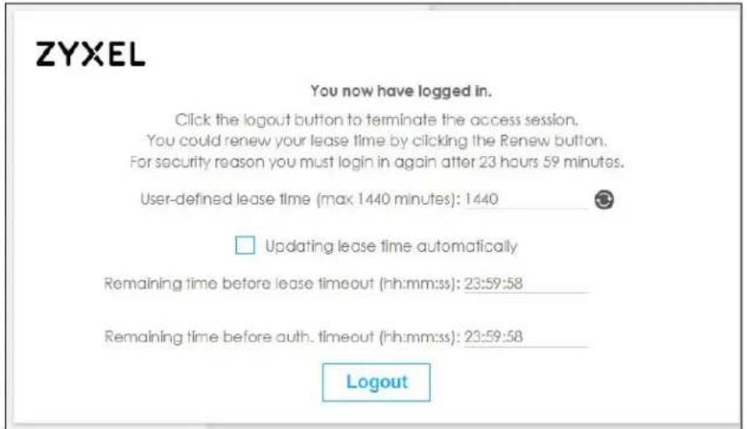
The following table describes the labels in this screen.
Table 375 Web Configurator for Non-Admin Users
| LABEL DESCRIPTION | |
| User-defined lease time (max ... minutes) | Access users can specify a lease time shorter than or equal to the one that you specified. The default value is the lease time that you specified. |
| Renew | Access users can click this button to reset the lease time, the amount of time remaining before the Zyxel Device automatically logs them out. The Zyxel Device sets this amount of time according to the:User-defined lease time field in this screenLease time field in the User Add/ Edit screen (see Section 43.14.1.1 on page 1052)Lease time field in the Setting screen (see Section 43.3.6 on page 950). |
| Updating lease time automatically | This box appears if you checked the Allow renewing lease time automatically box in the Setting screen. (See Section 43.3.6 on page 950.) Access users can select this check box to reset the lease time automatically 30 seconds before it expires. Otherwise, access users have to click the Renew button to reset the lease time. |
| Remaining time before lease timeout | This field displays the amount of lease time that remains, though the user might be able to reset it. |
| Remaining time before auth. timeout | This field displays the amount of time that remains before the Zyxel Device automatically logs the access user out, regardless of the lease time. |
43.3.7 User/Group MAC Address Summary Screen
This screen shows the MAC addresses of wireless clients, which can be authenticated by their MAC addresses using the local user database. Click Configuration > Object > User/Group > MAC Address to open this screen.
Note: You need to configure an SSID security profile's MAC authentication settings to have the AP use the Zyxel Device's local database to authenticate wireless clients by their MAC addresses.
Figure 600 Configuration > Object > User/Group > MAC Address
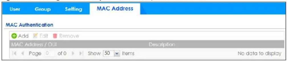
The following table describes the labels in this screen.
Table 376 Configuration > Object > User/Group > MAC Address
| LABEL DESCRIPTION | |
| Add Click this to create a new entry. | |
| Edit | Double-click an entry or select it and click Edit to open a screen where you can modify the entry's settings. |
| Remove | To remove an entry, select it and click Remove. The Zyxel Device confirms you want to remove it before doing so. |
| MAC Address/ OUI | This field displays the MAC address or OUI (Organizationally Unique Identifier of computer hardware manufacturers) of wireless clients using MAC authentication with the Zyxel Device local user database. |
| Description | This field displays a description of the device identified by the MAC address or OUI. |
43.3.7.1 MAC Address Add/Edit Screen
This screen allows you to create a new allowed device or edit an existing one. To access this screen, go to the MAC Address screen (see Section 43.3.7 on page 955), and click either the Add icon or an Edit icon.
Figure 601 Configuration > Object > User/Group > MAC Address > Add
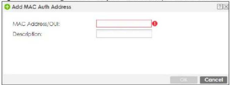
The following table describes the labels in this screen.
Table 377 Configuration > Object > User/Group > MAC Address > Add
| LABEL DESCRIPTION | |
| MAC Address/ OUI | Type the MAC address (six hexadecimal number pairs separated by colons or hyphens) or OUI (three hexadecimal number pairs separated by colons or hyphens) to identify specific wireless clients for MAC authentication using the Zyxel Device local user database. The OUI is the first three octets in a MAC address and uniquely identifies the manufacturer of a network device. |
| Description | Enter an optional description of the wireless device(s) identified by the MAC or OUI. You can use up to 60 characters, punctuation marks, and spaces. |
| OK | Click OK to save your changes back to the Zyxel Device. |
| Cancel | Click Cancel to exit this screen without saving your changes. |
43.3.8 User / Group Technical Reference
This section provides some information on users who use an external authentication server in order to log in.
Setting up User Attributes in an External Server
To set up user attributes, such as reauthentication time, in LDAP or RADIUS servers, use the following keywords in the user configuration file.
Table 378 LDAP/RADIUS: Keywords for User Attributes
| KEYWORD CORRESPONDING ATTRIBUTE IN WEB CONFIGURATOR | |
| type | User Type. Possible Values: admin, limited-admin, dynamic-guest, user, guest. |
| leaseTime | Lease Time. Possible Values: 1-1440 (minutes). |
| reauthTime | Reauthentication Time. Possible Values: 1-1440 (minutes). |
The following examples show you how you might set up user attributes in LDAP and RADIUS servers.
Figure 602 LDAP Example: Keywords for User Attributes
| type: admin leaseTime: 99 reauthTime: 199 |
Figure 603 RADIUS Example: Keywords for User Attributes
| type=user;leaseTime=222;reauthTime=222 |
Creating a Large Number of Ext-User Accounts
If you plan to create a large number of Ext-User accounts, you might use CLI commands, instead of the Web Configurator, to create the accounts. Extract the user names from the LDAP or RADIUS server, and create a shell script that creates the user accounts.
Built-in System Accounts
The following built-in system accounts are disabled by default.
Table 379 Built-in System Accounts
| ACCOUNT NAME | ACTIVATION | PURPOSE | SUPPORTED MODELS | USER NAME / PASSWORD |
| debug The Zyxel Device owner must create an account with admin privileges to allow access to the Zyxel Device using CLI remotely (Telnet or SSH).The debug account cannot be used to log into the Zyxel Device using WWW or FTP. | RD can use this account to collect information for troubleshooting. | ZyWALL ATP, USG Flex (On-Premise / On-Cloud mode), VPN (standalone and Nebula Orchestrator managed) | debug / Authentication PhraseThe Authentication Phrase is generated internally in Zyxel.It must be used within 10 minutes of being generated.Each generated Authentication Phrase can be used just once. | |
| devicehaecived This account is activated when Device HA is enabled. This account cannot be used to log into the Zyxel Device using WWW, SSH, or FTP. | The Zyxel Device can use this account to synchronize configuration, firmware and licenses on a backup Device HA Zyxel Device. | ZyWALL ATP, USG Flex (On-Premise mode), and VPN models that support Device HA. | devicehaecived / Zyxel Device HA Pro PasswordThe Device HA password is configured in the Web Configurator [Configuration > Device HA> Device HA Pro > Password] or CLI (device-ha2 sync password). | |
| support This account is activated when you configure a Zyxel Device from factory default using Nebula Cloud Center ZTP. | An administrator can use this account to access a managed Zyxel Device using WWW, SSH or FTP for troubleshooting. | ZyWALL USG Flex (On-Cloud mode) | support / Zyxel Device serial numberThe default password (serial number) is automatically changed when the Zyxel Device is managed by Nebula Control Center (NCC).You can change the password using NCC. | |
| sdwan This account is activated when the Zyxel Device is managed by Nebula Orchestrator. | An administrator can use this account to access a managed Zyxel Device using WWW, SSH or FTP for troubleshooting. | ZyWALL VPN (Nebula Orchestrator managed) | sdwan / Zyxel Device serial numberYou can change the password using Nebula Orchestrator. |
43.4 AP Profile Overview
This section shows you how to configure preset profiles for the Access Points (APs) connected to your Zyxel Device's wireless network. This screen is not available when your Zyxel Device is in Built-in AP mode.
- The Radio screen (Section 43.4.1 on page 960) creates radio configurations that can be used by the APs.
- The SSID screen (Section 43.4.2 on page 966) configures three different types of profiles for your networked APs.
43.4.0.1 What You Need To Know
The following terms and concepts may help as you read this section.
Wireless Profiles
At the heart of all wireless AP configurations on the Zyxel Device are profiles. A profile represents a group of saved settings that you can use across any number of connected APs. You can set up the following wireless profile types:
- Radio - This profile type defines the properties of an AP's radio transmitter. You can have a maximum of 32 radio profiles on the Zyxel Device.
- SSID - This profile type defines the properties of a single wireless network signal broadcast by an AP. Each radio on a single AP can broadcast up to 8 SSIDs. You can have a maximum of 32 SSID profiles on the Zyxel Device.
- Security - This profile type defines the security settings used by a single SSID. It controls the encryption method required for a wireless client to associate itself with the SSID. You can have a maximum of 32 security profiles on the Zyxel Device.
- MAC Filtering - This profile provides an additional layer of security for an SSID, allowing you to block access or allow access to that SSID based on wireless client MAC addresses. If a client's MAC address is on the list, then it is either allowed or denied, depending on how you set up the MAC Filter profile. You can have a maximum of 32 MAC filtering profiles on the Zyxel Device.
SSID
The SSID (Service Set IDentifier) is the name that identifies the Service Set with which a wireless station is associated. Wireless stations associating to the access point (AP) must have the same SSID. In other words, it is the name of the wireless network that clients use to connect to it.
WEP
WEP (Wired Equivalent Privacy) encryption scrambles all data packets transmitted between the AP and the wireless stations associated with it in order to keep network communications private. Both the wireless stations and the access points must use the same WEP key for data encryption and decryption.
WPA and WPA2
Wi-Fi Protected Access (WPA) is a subset of the IEEE 802.11i standard. WPA2 (IEEE 802.11i) is a wireless security standard that defines stronger encryption, authentication and key management than WPA. Key differences between WPA(2) and WEP are improved data encryption and user authentication.
IEEE 802.1x
The IEEE 802.1x standard outlines enhanced security methods for both the authentication of wireless stations and encryption key management. Authentication is done using an external RADIUS server.
WiFi6 / IEEE 802.11ax
WiFi6 is backwards compatible with IEEE 802.11a/b/g/n/ac and is most suitable in areas with a high concentration of users. WiFi6 devices support Target Wakeup Time (TWT) allowing them to automatically power down when they are inactive.
The following table displays the comparison of the different WiFi standards. The maximum link rate is for reference under ideal conditions only.
Table 380 WiFi Standards Comparison
| WIFI STANDARD MAXIMUM LINK RATE BAND SIMULTANEOUS CONNECTIONS | ||
| 802.11b 11 Mbps 2.4 GHz 1 | ||
| 802.11a/g 54 Mbps 2.4 GHz and 5 GHz 1 | ||
| 802.11n 600 Mbps 2.4 GHz and 5 GHz 1 | ||
| 802.11ac 6.93 Gbps 5 GHz 4 | ||
| 802.11ax 2.4 Gbps 2.4 GHz 128 | ||
43.4.1 Radio Screen
This screen allows you to create radio profiles for the APs on your network. A radio profile is a list of settings that a supported managed AP (NWA5121-N for example) can use to configure either one of its two radio transmitters. To access this screen click Configuration > Object > AP Profile.
Note: You can have a maximum of 32 radio profiles on the Zyxel Device.
Figure 604 Configuration > Object > AP Profile > Radio
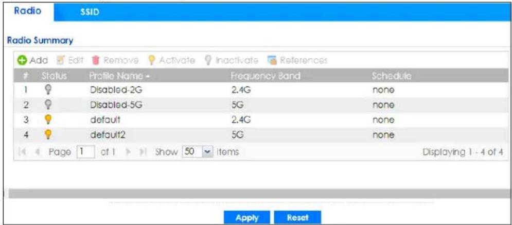
The following table describes the labels in this screen.
Table 381 Configuration > Object > AP Profile > Radio
| LABEL | DESCRIPTION |
| Add | Click this to add a new radio profile. |
| Edit Click this to edit the selected radio profile. | |
| Remove | Click this to remove the selected radio profile. |
| Activate | To turn on an entry, select it and click Activate. |
| Inactivate | To turn off an entry, select it and click Inactivate. |
| References | Click this to view which other objects are linked to the selected radio profile. |
| # | This field is a sequential value, and it is not associated with a specific profile. |
| Status | This icon is lit when the entry is active and dimmed when the entry is inactive. |
| Profile Name | This field indicates the name assigned to the radio profile. |
| Frequency Band | This field indicates the frequency band which this radio profile is configured to use. |
| LABEL DESCRIPTION | |
| Schedule | This field displays the schedule object which defines when this radio profile can be used. |
| Apply | Click Apply to save your changes back to the Zyxel Device. |
| Reset | Click Reset to return the screen to its last-saved settings. |
43.4.1.1 Add/Edit Radio Profile
This screen allows you to create a new radio profile or edit an existing one. Your screen may differ from your product due to differences in product features. To access this screen, click the Add button or select a radio profile from the list and click the Edit button.
Figure 605 Configuration > Object > AP Profile > Add/Edit Radio Profile
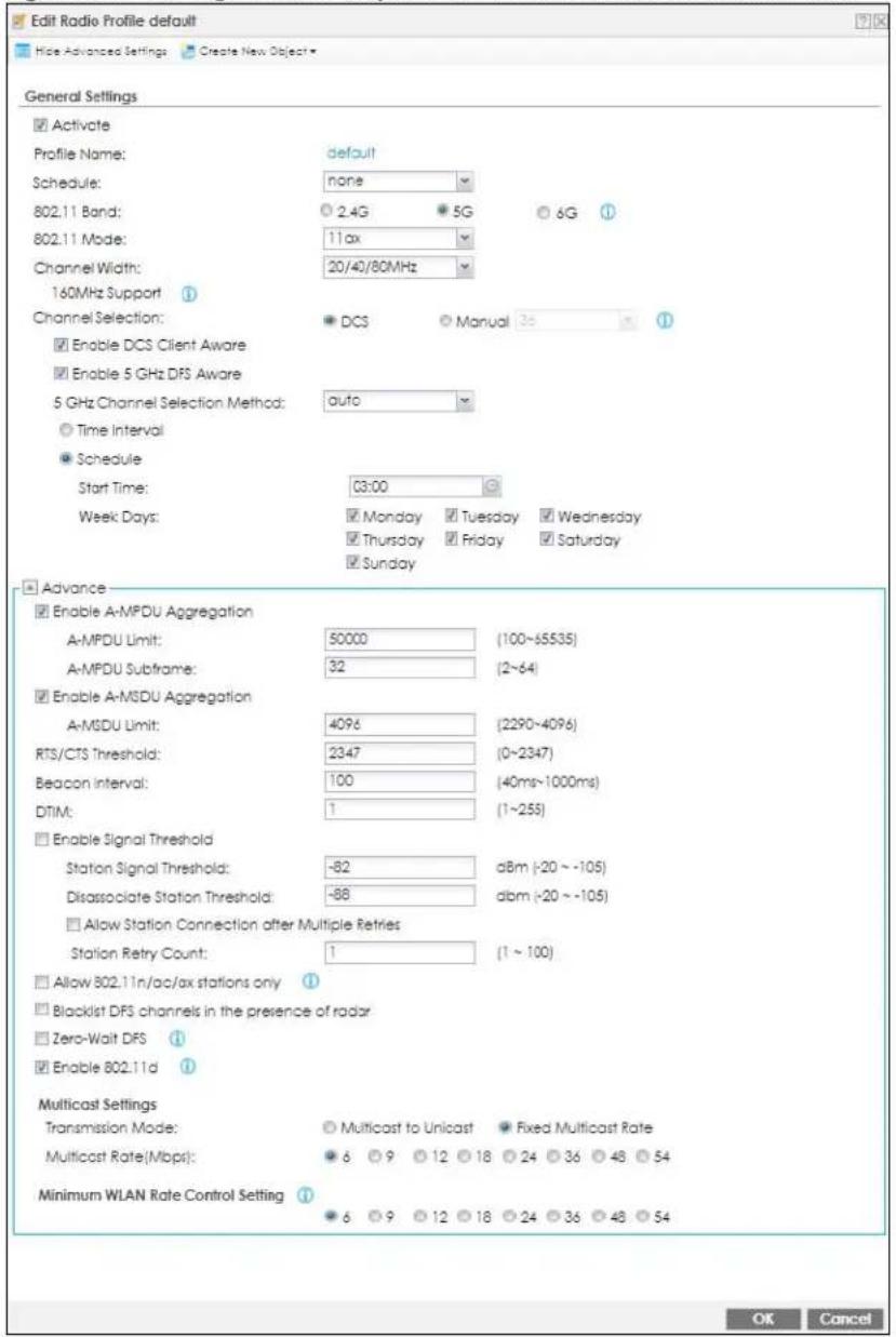
The following table describes the labels in this screen.
Table 382 Configuration > Object > AP Profile > Add/Edit Radio Profile
| LABEL DESCRIPTION | |
| Hide / Show Advanced Settings | Click this to hide or show the Advanced Settings in this window. |
| Create New Object | Use this to configure any new settings objects that you need to use in this screen. |
| General Settings | |
| Activate Select this | option to make this profile active. |
| Profile Name | Enter up to 31 alphanumeric characters to be used as this profile's name. Spaces and underscores are allowed. |
| Schedule | This field displays the schedule object which defines when this radio profile can be used. |
| 802.11 Band Select | how to let wireless clients connect to the AP.If 802.11 Band is set to 2.4G:11b/g: allows either IEEE 802.11b or IEEE 802.11g compliant WLAN devices to associate with the AP. The AP adjusts the transmission rate automatically according to the wireless standard supported by the wireless devices.11n: allows IEEE802.11b, IEEE802.11g and IEEE802.11n compliant WLAN devices to associate with the AP.If 802.11 Band is set to 5G:11a: allows only IEEE 802.11a compliant WLAN devices to associate with the AP.11a/n: allows both IEEE802.11n and IEEE802.11a compliant WLAN devices to associate with the AP. The transmission rate of your AP might be reduced.11ac: allows only IEEE802.11ac compliant WLAN devices to associate with the AP.11ax: allows IEEE802.11n, IEEE802.11a, IEEE802.11ac, and IEEE802.11ax compliant WLAN devices to associate with the AP. If the WLAN device isn't compatible with 802.11ax, the AP will communicate with the WLAN device using 802.11ac, and so onIf 802.11 Band is set to 6G:11ax: allows only IEEE 802.11ax compliant WLAN devices to associate with the AP.Note: If you select 11ac but the WLAN devices in the network do not support IEEE 802.11ac, the Zyxel Device automatically sets the AP to use 11a/n. |
| Channel Width | Select the wireless channel bandwidth you want the AP to use.A standard 20 MHz channel offers transfer speeds of up to 144Mbps (2.4GHz) or 217Mbps (5GHz) whereas a 40MHz channel uses two standard channels and offers speeds of up to 300Mbps (2.4GHz) or 450Mbps (5GHz). An IEEE 802.11ac-specific 80MHz channel offers speeds of up to 1.3Gbps.40 MHz (channel bonding or dual channel) bonds two adjacent radio channels to increase throughput. A 80 MHz channel consists of two adjacent 40 MHz channels. The wireless clients must also support 40 MHz or 80 MHz. It is often better to use the 20 MHz setting in a location where the environment hinders the wireless signal.Select 20MHz if you want to lessen radio interference with other wireless devices in your neighborhood or the wireless clients do not support channel bonding.Select 20/40MHz or 20/40/80MHz to allow the AP to adjust the channel bandwidth automatically. This option is available only when you set 802.11 Mode to 11ac or 11ax.Select 20/40/80/160MHz to allow the AP to adjust the channel bandwidth automatically. This option is available only when you set 802.11 Band to 5G or 6G and 802.11 Mode to 11ax.Note: If the environment has poor signal-to-noise (SNR), the Zyxel Device will switch to a lower bandwidth. |
| Channel Selection | Select the wireless channel which this radio profile should use.It is recommended that you choose the channel least in use by other APs in the region where this profile will be implemented. This will reduce the amount of interference between wireless clients and the AP to which this profile is assigned.SelectDCSto have the AP automatically select the radio channel upon which it broadcasts by scanning the area around it and determining what channels are currently being used by other devices.SelectManualand specify the channels the AP uses. |
| Blacklist DFS channels in presence of radar | This field is available if802.11Bandis set to5GandChannel Selectionis set toDCS.Enable this to temporarily blacklist the wireless channels in the Dynamic Frequency Selection (DFS) range whenever a radar signal is detected by the AP. |
| Enable DCS Client Aware | This field is available when you setChannel SelectiontoDCS.Select this to have the AP wait until all connected clients have disconnected before switching channels.If you disable this then the AP switches channels immediately regardless of any client connections. In this instance, clients that are connected to the AP when it switches channels are dropped. |
| 2.4 GHz Channel Selection Method | This field is available when you setChannel SelectiontoDCS.Selectautoto have the AP search for available channels automatically in the 2.4 GHz band. The available channels vary depending on what you select in the2.4 GHz Channel Deploymentfield.Selectmanualand specify the channels the AP uses in the 2.4 GHz band. |
| Channel ID | This field is available only when you setChannel SelectiontoDCSand set2.4 GHz Channel Selection Methodto manual.Select the check boxes of the channels that you want the AP to use. |
| Time Interval | Select this option to have the AP survey the other APs within its broadcast radius at the end of the specified time interval. |
| 2.4 GHz Channel Deployment | This field is available only when you setChannel SelectiontoDCSand set2.4 GHz Channel Selection Methodto auto.SelectThree-Channel Deploymentto limit channel switching to channels 1,6, and 11, the three channels that are sufficiently attenuated to have almost no impact on one another. In other words, this allows you to minimize channel interference by limiting channel-hopping to these three “safe” channels.SelectFour-Channel Deploymentto limit channel switching to four channels. Depending on the country domain, if the only allowable channels are 1-11 then the Zyxel Device uses channels 1, 4, 7, 11 in this configuration; otherwise, the Zyxel Device uses channels 1, 5, 9, 13 in this configuration. Four channel deployment expands your pool of possible channels while keeping the channel interference to a minimum.Note: For US and Canada models, country code is fixed to US or Canada respectively and is not user selectable. |
| DCS Time Interval | This field is available when you setChannel SelectiontoDCS.Enter a number of minutes. This regulates how often the AP surveys the other APs within its broadcast radius. If the channel on which it is currently broadcasting suddenly comes into use by another AP, the AP will then dynamically select the next available clean channel or a channel with lower interference. |
| Channel ID | This field is available only when you set Channel Selection to DCS and set 2.4 GHz Channel Selection Method to manual.Select the check boxes of the channels that you want the AP to use. |
| Schedule | Select this option to have the AP survey the other APs within its broadcast radius at a specific time on selected days of the week. |
| Start Time | Specify the time of the day (in 24-hour format) to have the AP use DCS to automatically scan and find a less-used channel. |
| Week Days | Select each day of the week to have the AP use DCS to automatically scan and find a less-used channel. |
| Enable 5 GHz DFS Aware | This field is available only when you select 11a, 11a/n or 11ac in the 802.11 Band field.Select this if your APs are operating in an area known to have RADAR devices. This allows the device to downgrade its frequency to below 5 GHz in the event a RADAR signal is detected, thus preventing it from interfering with that signal.Enabling this forces the AP to select a non-DFS channel. |
| 5 GHz Channel Selection Method | This shows auto and allows the AP to search for available channels automatically in the 5 GHz band. |
| Advanced Settings | |
| Country Code | Select the country code of where the Zyxel Device is located/installed.The available channels vary depending on the country you select. Be sure to select the correct/same country for both radios on an AP and all connected APs, in order to prevent roaming failure and interference to other systems.Note: For US and Canada models, country code is fixed to US or Canada respectively and is not user selectable. |
| Guard Interval | This field is available only when the 802.11 Band is set to 5G and 802.11 Mode is set to 11n or 11ac.Set the guard interval for this radio profile to either Short or Long.The guard interval is the gap introduced between data transmission from users in order to reduce interference. Reducing the interval increases data transfer rates but also increases interference. Increasing the interval reduces data transfer rates but also reduces interference. |
| Enable A-MPDU Aggregation | Select this to enable A-MPDU aggregation.Message Protocol Data Unit (MPDU) aggregation collects Ethernet frames along with their 802.11n headers and wraps them in a 802.11n MAC header. This method is useful for increasing bandwidth throughput in environments that are prone to high error rates. |
| A-MPDU Limit Enter | the maximum frame size to be aggregated. |
| A-MPDU Subframe | Enter the maximum number of frames to be aggregated each time. |
| Enable A-MSDU Aggregation | Select this to enable A-MSDU aggregation.Mac Service Data Unit (MSDU) aggregation collects Ethernet frames without any of their 802.11n headers and wraps the header-less payload in a single 802.11n MAC header. This method is useful for increasing bandwidth throughput. It is also more efficient than A-MPDU except in environments that are prone to high error rates. |
| A-MSDU Limit Enter | the maximum frame size to be aggregated. |
| RTS/CTS Threshold | Use RTS/CTS to reduce data collisions on the wireless network if you have wireless clients that are associated with the same AP but out of range of one another. When enabled, a wireless client sends an RTS (Request To Send) and then waits for a CTS (Clear To Send) before it transmits. This stops wireless clients from transmitting packets at the same time (and causing data collisions).A wireless client sends an RTS for all packets larger than the number (of bytes) that you enter here. Set the RTS/CTS equal to or higher than the fragmentation threshold to turn RTS/CTS off. |
| Beacon Interval | When a wirelessly networked device sends a beacon, it includes with it a beacon interval. This specifies the time period before the device sends the beacon again. The interval tells receiving devices on the network how long they can wait in low-power mode before waking up to handle the beacon. A high value helps save current consumption of the access point. |
| DTIM | Delivery Traffic Indication Message (DTIM) is the time period after which broadcast and multicast packets are transmitted to mobile clients in the Active Power Management mode. A high DTIM value can cause clients to lose connectivity with the network. This value can be set from 1 to 255. |
| Enable Signal Threshold | Select the check box to use the signal threshold to ensure wireless clients receive good throughput. This allows only wireless clients with a strong signal to connect to the AP.Clear the check box to not require wireless clients to have a minimum signal strength to connect to the AP. |
| Station Signal Threshold | Set a minimum client signal strength. A wireless client is allowed to connect to the AP only when its signal strength is stronger than the specified threshold.-20 dBm is the strongest signal you can require and -76 is the weakest. |
| Disassociate Station Threshold | Set a minimum kick-off signal strength. When a wireless client's signal strength is lower than the specified threshold, the Zyxel Device disconnects the wireless client from the AP.-20 dBm is the strongest signal you can require and -90 is the weakest. |
| Allow Station Connection after Multiple Retries | Select this option to allow a wireless client to try to associate with the AP again after it is disconnected due to weak signal strength. |
| Station Retry Count | Set the maximum number of times a wireless client can attempt to re-connect to the AP |
| Allow 802.11n/ac/ax stations only | Select this option to allow only 802.11 n/ac/ax stations to connect, and reject 802.11a/b/g stations. |
| Blacklist DFS channels in the presence of radar | This field is available if 802.11 Band is set to 5G and Channel Selection is set to DCS.Enable this to temporarily blacklist the wireless channels in the Dynamic Frequency Selection (DFS) range whenever a radar signal is detected by the Zyxel Device. |
| Zero-Wait DFS | Select this option to enable zero-wait DFS (Dynamic Frequency Selection) o the AP.Zero-wait DFS is only supported on certain AP models, such as the WAX650S.DFS is a channel WiFi allocation scheme that allows APs to use channels in the 5Ghz band normally reserved for radar. Before using a DFS channel, an AP must ensure there is no radar present by performing a Channel Availability Check (CAC). This check takes 1-10 minutes, depending on the country in which the AP is located.Zero-Wait DFS allows an AP to provide network services to WiFi clients using a primary 5Ghz radio, while simultaneously checking DFS channels for the presence of radar using a secondary 5Ghz radio. If no radar is detected on a DFS channel, the AP adds it to a list of cleared channels. The AP can then switch the primary radio to any cleared DFS channel without having to wait 1-10 minutes for a Channel Availability Check.When zero-wait DFS is enabled, 5Ghz Aware and Blacklist DFS Channels are automatically disabled on the AP. |
| Enable 802.11d | Clear the checkbox to prevent the AP from broadcasting a country code, also called a country Information Element (IE), in beacon frames. This makes the AP incompatible with 802.11d networks and devices.802.11d is a 2.4 GHz WiFi network specification that allows the AP to broadcast a country code to WiFi client. The country code indicates where the AP is located. If WiFi clients are unable to connect to the AP due to an incompatible country code, you should disable 802.11d. |
| Multicast Settings | Use this section to set a transmission mode and maximum rate for multicast traffic. |
| Transmission Mode | Set how the AP handles multicast traffic.Select Multicast to Unicast to broadcast wireless multicast traffic to all of the wireless clients as unicast traffic. Unicast traffic dynamically changes the data rate based on the application's bandwidth requirements. The retransmit mechanism of unicast traffic provides more reliable transmission of the multicast traffic, although it also produces duplicate packets.Select Fixed Multicast Rate to send wireless multicast traffic at a single data rate. You must know the multicast application's bandwidth requirements and set it in the following field. |
| Multicast Rate (Mbps) | If you set the multicast transmission mode to fixed multicast rate, set the data rate for multicast traffic here. For example, to deploy 4 Mbps video, select a fixed multicast rate higher than 4 Mbps. |
| Minimum WLAN Rate Control Setting | Sets the minimum data rate that 2.4Ghz WiFi clients can connect at, in Mbps. At the time of write, allowed values are: 1, 2,5, 5, 6, 9, 11, 12, 18, 24, 36, 48, 54.Sets the minimum data rate that 5Ghz WiFi clients can connect at, in Mbps. At the time of write, allowed values are: 6,9, 12, 18, 24, 36, 48, 54.Increasing the minimum data rate can reduce network overhead and improve WiFi network performance in high density environments. However, WiFi clients that do not support the minimum data rate will not be able to connect to the AP. |
| OK | Click OK to save your changes back to the Zyxel Device. |
| Cancel | Click Cancel to exit this screen without saving your changes. |
43.4.2 SSID Screen
The SSID screens allow you to configure three different types of profiles for your networked APs: an SSID list, which can assign specific SSID configurations to your APs; a security list, which can assign specific encryption methods to the APs when allowing wireless clients to connect to them; and a MAC filter list, which can limit connections to an AP based on wireless clients MAC addresses.
43.4.2.1 SSID List
This screen allows you to create and manage SSID configurations that can be used by the APs. An SSID, or Service Set IDentifier, is basically the name of the wireless network to which a wireless client can connect. The SSID appears as readable text to any device capable of scanning for wireless frequencies (such as the WiFi adapter in a laptop), and is displayed as the wireless network name when a person makes a connection to it.
To access this screen click Configuration > Object > AP Profile > SSID.
Note: You can have a maximum of 32 SSID profiles on the Zyxel Device.
Figure 606 Configuration > Object > AP Profile > SSID List
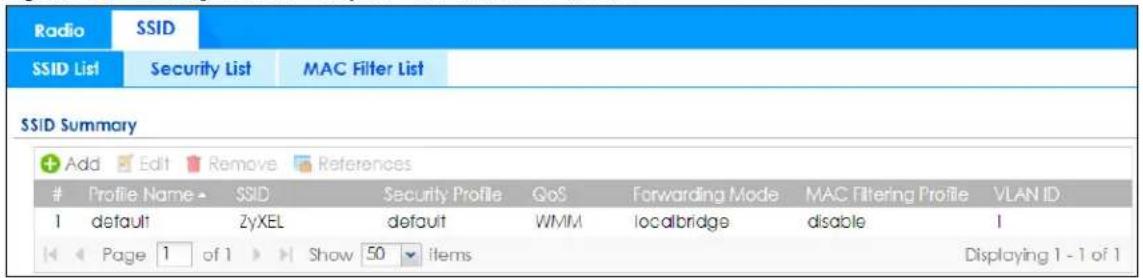
The following table describes the labels in this screen.
Table 383 Configuration > Object > AP Profile > SSID List
| LABEL DESCRIPTION | |
| Add Click this to add a new SSID profile. | |
| Edit Click this to edit the selected SSID profile. | |
| Remove Click this to remove the selected SSID profile. | |
| References | Click this to view which other objects are linked to the selected SSID profile (for example, radio profile). |
| # This field is a sequential value, and it is not associated with a specific profile. | |
| Profile Name This field indicates the name assigned to the SSID profile. | |
| SSID This field indicates the SSID name as it appears to wireless clients. | |
| Security Profile | This field indicates which (if any) security profile is associated with the SSID profile. |
| QoS | This field indicates the QoS type associated with the SSID profile. |
| MAC Filtering Profile | This field indicates which (if any) MAC Filter Profile is associated with the SSID profile. |
| VLAN ID | This field indicates the VLAN ID associated with the SSID profile. |
43.4.2.2 Add/Edit SSID Profile
This screen allows you to create a new SSID profile or edit an existing one. To access this screen, click the Add button or select an SSID profile from the list and click the Edit button.
Figure 607 Configuration > Object > AP Profile > SSID > Add/Edit SSID Profile
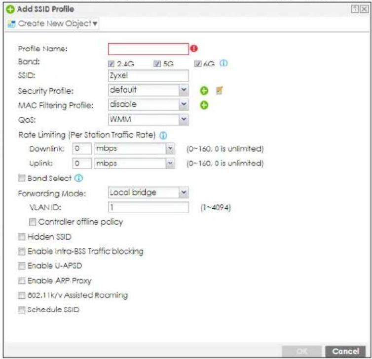
The following table describes the labels in this screen.
Table 384 Configuration > Object > AP Profile > SSID > Add/Edit SSID Profile
| LABEL DESCRIPTION | |
| Create new Object | Select an object type from the list to create a new one associated with this SSID profile. |
| Profile Name | Enter up to 31 alphanumeric characters for the profile name. This name is only visible in the Web Configurator and is only for management purposes. Spaces and underscores are allowed. |
| Band | Select the band according to the bands that APs or WiFi clients support. |
| SSID | Enter the SSID name for this profile. This is the name visible on the network to wireless clients. Enter up to 32 characters, spaces and underscores are allowed. |
| Security Profile | Select a security profile from this list to associate with this SSID. If none exist, you can use the Create new Object menu to create one.Note: It is highly recommended that you create security profiles for all of your SSIDs to enhance your network security. |
| MAC Filtering Profile | Select a MAC filtering profile from the list to associate with this SSID. If none exist, you can use theCreate new Objectmenu to create one.MAC filtering allows you to limit the wireless clients connecting to your network through a particular SSID by wireless client MAC addresses. Any clients that have MAC addresses not in the MAC filtering profile of allowed addresses are denied connections.The disable setting means no MAC filtering is used. |
| QoS | Select a Quality of Service (QoS) access category to associate with this SSID. Access categories minimize the delay of data packets across a wireless network. Certain categories, such as video or voice, are given a higher priority due to the time sensitive nature of their data packets.QoS access categories are as follows:disable:Turns off QoS for this SSID. All data packets are treated equally and not tagged with access categories.WMM:Enables automatic tagging of data packets. The Zyxel Device assigns access categories to the SSID by examining data as it passes through it and making a best guess effort. If something looks like video traffic, for instance, it is tagged as such.WMM_VOICE:All wireless traffic to the SSID is tagged as voice data. This is recommended if an SSID is used for activities like placing and receiving VoIP phone calls.WMM_VIDEO:All wireless traffic to the SSID is tagged as video data. This is recommended for activities like video conferencing.WMM_BEST_EFFORT:All wireless traffic to the SSID is tagged as “best effort,” meaning the data travels the best route it can without displacing higher priority traffic. This is good for activities that do not require the best bandwidth throughput, such as surfing the Internet.WMM_BACKGROUND:All wireless traffic to the SSID is tagged as low priority or “background traffic”, meaning all other access categories take precedence over this one. If traffic from an SSID does not have strict throughput requirements, then this access category is recommended. For example, an SSID that only has network printers connected to it. |
| Rate Limiting (Per Station Traffic Rate) | Define the maximum incoming and outgoing transmission data rate per wireless station |
| Downlink: | Define the maximum incoming transmission data rate (either in Mbps or Kbps) on a per-station basis. |
| Uplink: | Define the maximum outgoing transmission data rate (either in Mbps or Kbps) on a per-station basis. |
| Band Select: | To improve network performance and avoid interference in the 2.4 GHz frequency band, you can enable this feature to use the 5 GHz band first. You should set 2.4GHz and 5 GHz radio profiles to use the same SSID and security settings.Select the checkbox to have the AP try to connect the wireless clients to the same SSID using the 5 GHZ band. Connections to an SSID using the 2.4GHz band are still allowed.Otherwise, clear the checkbox to turn off this feature. |
| Stop Threshold | This field is not available when you disable Band Select.Select this option and set the threshold number of the connected wireless clients at which the Zyxel Device disables the band select feature. |
| Balance Ratio | This field is not available when you disable Band Select.Select this option and set a ratio of the wireless clients using the 5 GHz band to the wireless clients using the 2.4 GHz band. |
| Forwarding Mode | Select a forwarding mode (Tunnel or Local bridge) for traffic from wireless stations in this wireless network (SSID). In earlier firmware, you could only forward traffic from this wireless network with a tunnel using an existing VLAN interface in Network > Interface > VLAN > Add.From firmware version 4.60, you can select an existing VLAN interface or a local Ethernet interface (lan1, lan2) for forwarding traffic from wireless stations in this wireless network using a tunnel. These interfaces cannot be bridge members (Network > Interface > Bridge). |
| VLAN ID | If you selected Local Bridge forwarding mode, enter the VLAN ID that will be used to tag all traffic originating from this SSID if the VLAN is different from the native VLAN. All the wireless station's traffic goes through the associated AP's gateway. |
| VLAN Interface | If you selected the Tunnel forwarding mode, select a VLAN interface. All the wireless station's traffic is forwarded to the Zyxel Device first. |
| Hidden SSID | Select this if you want to "hide" your SSID from wireless clients. This tells any wireless clients in the vicinity of the AP using this SSID profile not to display its SSID name as a potential connection. Not all wireless clients respect this flag and display it anyway.When an SSID is "hidden" and a wireless client cannot see it, the only way you can connect to the SSID is by manually entering the SSID name in your wireless connection setup screen(s) (these vary by client, client connectivity software, and operating system). |
| Enable Intra-BSS Traffic Blocking | Select this option to prevent crossover traffic from within the same SSID. |
| Enable U-APSD | Select this option to enable Unscheduled Automatic Power Save Delivery (U-APSD), which is also known as WMM-Power Save. This helps increase battery life for battery-powered wireless clients connected to the Zyxel Device using this SSID profile. |
| Enable ARP Proxy | The Address Resolution Protocol (ARP) is a protocol for mapping an IP address to a MAC address. An ARP broadcast is sent to all devices on the same Ethernet network to request the MAC address of a target IP address.Select this option to allow the Zyxel Deviceto answer ARP requests for an IP address on behalf of a client associated with this SSID. This can reduce broadcast traffic and improve network performance. |
| 802.11 k/v Assisted Roaming | Select this option to enable IEEE 802.11k/v assisted roaming on the Zyxel Device. When the connected clients request 802.11k neighbor lists, the Zyxel Device will response with a list of neighbor APs that can be candidates for roaming. |
| Schedule SSID | Select this option and set whether the SSID is enabled or disabled on each day of the week. You also need to select the hour and minute (in 24-hour format) to specify the time period of each day during which the SSID is enabled/enabled. |
| OK | Click OK to save your changes back to the Zyxel Device. |
| Cancel | Click Cancel to exit this screen without saving your changes. |
43.4.2.3 Security List
This screen allows you to manage wireless security configurations that can be used by your SSIDs. Wireless security is implemented strictly between the AP broadcasting the SSID and the stations that are connected to it.
To access this screen click Configuration > Object > AP Profile > SSID > Security List.
Note: You can have a maximum of 32 security profiles on the Zyxel Device.
Figure 608 Configuration > Object > AP Profile > SSID > Security List
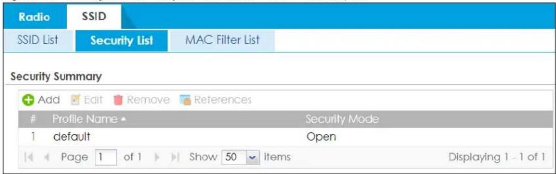
The following table describes the labels in this screen.
Table 385 Configuration > Object > AP Profile > SSID > Security List
| LABEL DESCRIPTION | |
| Add Click this to add a new security profile. | |
| Edit Click this to edit the selected security profile. | |
| Remove Click this to remove the selected security profile. | |
| References | Click this to view which other objects are linked to the selected security profile (for example, SSID profile). |
| # This field is a sequential value, and it is not associated with a specific profile. | |
| Profile Name This field indicates the name assigned to the security profile. | |
| Security Mode This field indicates this profile's security mode (if any). | |
43.4.2.4 Add/Edit Security Profile
This screen allows you to create a new security profile or edit an existing one. To access this screen, click the Add button or select a security profile from the list and click the Edit button.
Note: This screen's options change based on the Security Mode selected.
Figure 609 Configuration > Object > AP Profile > SSID > Security Profile > Add/Edit Security Profile> Security Mode: open
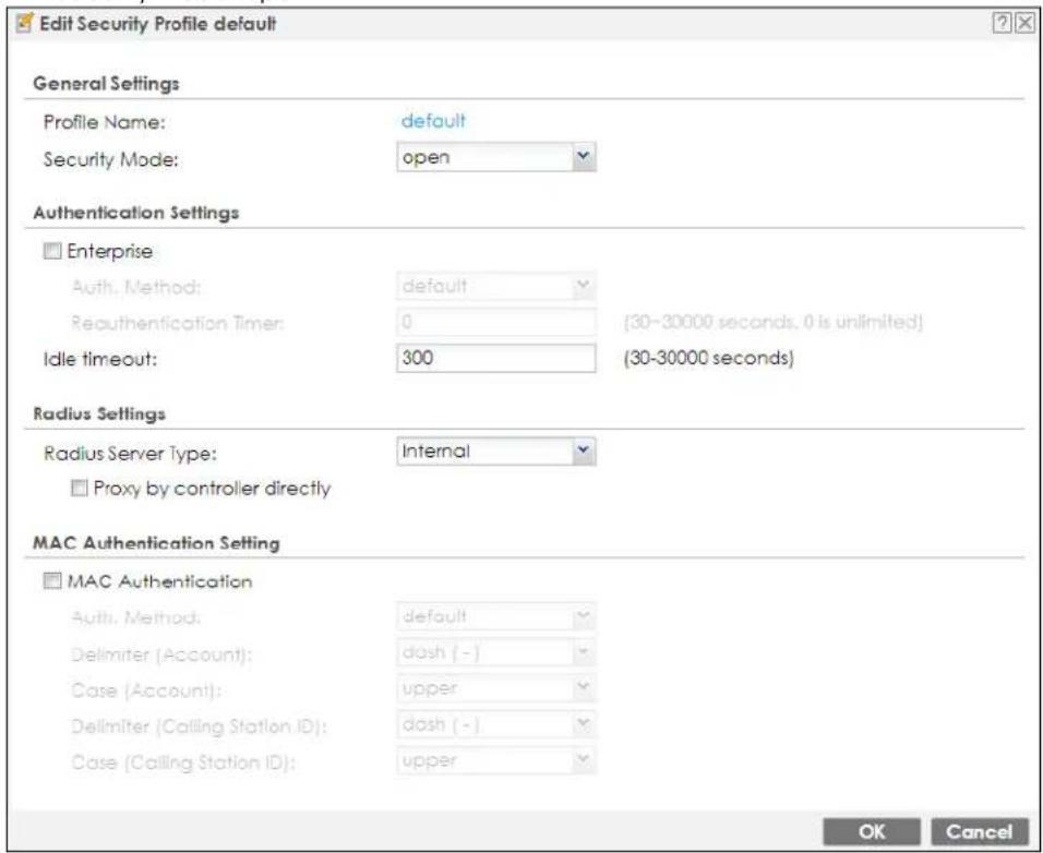
The following table describes the labels in this screen.
Table 386 Configuration > Object > AP Profile > SSID > Security Profile > Add/Edit Security Profile> Security Mode: open
| LABEL DESCRIPTION | |
| Profile Name | Enter up to 31 alphanumeric characters for the profile name. This name is only visible in the Web Configurator and is only for management purposes. Spaces and underscores are allowed. |
| Security Mode | Select a security mode from the list: open, enhanced open, wep, wpa2, or wpa2-mix, wpa3. |
| Authentication Settings | |
| Enterprise | Select this to enable 802.1x secure authentication with a RADIUS server. |
| Reauthentication Timer | Enter the interval (in seconds) between authentication requests. Enter a 0 for unlimited time. |
| Idle Timeout | Enter the idle interval (in seconds) that a client can be idle before authentication is discontinued. |
| Radius Settings | |
| Primary / Secondary Radius Server Activate | Select this to have the Zyxel Device use the specified RADIUS server. |
| Radius Server IP Address | Enter the IP address of the RADIUS server to be used for authentication. |
| Radius Server Port | Enter the port number of the RADIUS server to be used for authentication. |
| Radius Server Secret | Enter the shared secret password of the RADIUS server to be used for authentication. |
| Primary / Secondary Accounting Server Activate | Select the check box to enable user accounting through an external authentication server. |
| Accounting Server IP Address | Enter the IP address of the external accounting server in dotted decimal notation. |
| Accounting Server Port | Enter the port number of the external accounting server. The default port number is 1813. You need not change this value unless your network administrator instructs you to do so with additional information. |
| Accounting Share Secret | Enter a password (up to 128 alphanumeric characters) as the key to be shared between the external accounting server and the Zyxel Device. The key must be the same on the external accounting server and your Zyxel Device. The key is not sent over the network. |
| Accounting Interim Update | This field is available only when you enable user accounting through an external authentication server.Select this to have the Zyxel Device send subscriber status updates to the accounting server at the interval you specify. |
| Interim Update Interval | Specify the time interval for how often the Zyxel Device is to send a subscriber status update to the accounting server. |
| MAC Authentication | Select this to use an external server or the Zyxel Device's local database to authenticate wireless clients by their MAC addresses. Users cannot get an IP address if the MAC authentication fails.An external server can use the wireless client's account (username/password) or Calling Station ID for MAC authentication. Configure the ones the external server uses. |
| Delimiter (Account) | Select the separator the external server uses for the two-character pairs within account MAC addresses. |
| Case (Account) | Select the case (upper or lower) the external server requires for letters in the account MAC addresses. |
| Delimiter (Calling Station ID) | RADIUS servers can require the MAC address in the Calling Station ID RADIUS attribute.Select the separator the external server uses for the pairs in calling station MAC addresses. |
| Case (Calling Station ID) | Select the case (upper or lower) the external server requires for letters in the calling station MAC addresses. |
| OK | Click OK to save your changes back to the Zyxel Device. |
| Cancel | Click Cancel to exit this screen without saving your changes. |
Figure 610 Configuration > Object > AP Profile > SSID > Security Profile > Add/Edit Security Profile> Security Mode: enhanced-open
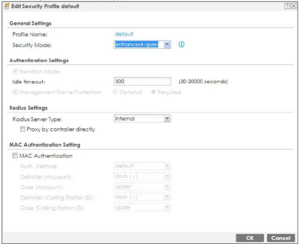
The following table describes the labels in this screen.
Table 387 Configuration > Object > AP Profile > SSID > Security Profile > Add/Edit Security Profile> Security Mode: enhanced-open
| LABEL DESCRIPTION | |
| Profile Name | Enter up to 31 alphanumeric characters for the profile name. This name is only visible in the Web Configurator and is only for management purposes. Spaces and underscores are allowed. |
| Security Mode | Select a security mode from the list: open, enhanced open, wep, wpa2, or wpa2-mix, wpa3. |
| Authentication Settings | |
| Transition Mode | Enable this for backwards compatibility. This option is only available if the Security Mode is wpa3 or enhanced-open. This creates two virtual APs (VAPs) with a primary (wpa3 or enhanced-open) and fallback (wpa2 or none) security method.If the Security Mode is wpa3, enabling this will force Management Frame Protection to be set to Optional. If this is disabled or if the Security Mode is enhanced-open, Management Frame Protection will be set to Required. |
| Idle Timeout | Enter the idle interval (in seconds) that a client can be idle before authentication is discontinued. |
| Radius Settings | |
| Primary / Secondary Radius Server Activate | Select this to have the Zyxel Device use the specified RADIUS server. |
| Radius Server IP Address | Enter the IP address of the RADIUS server to be used for authentication. |
| Radius Server Port | Enter the port number of the RADIUS server to be used for authentication. |
| Radius Server Secret | Enter the shared secret password of the RADIUS server to be used for authentication. |
| Primary / Secondary Accounting Server Activate | Select the check box to enable user accounting through an external authentication server. |
| Accounting Server IP Address | Enter the IP address of the external accounting server in dotted decimal notation. |
| Accounting Server Port | Enter the port number of the external accounting server. The default port number is 1813. You need not change this value unless your network administrator instructs you to do so with additional information. |
| Accounting Share Secret | Enter a password (up to 128 alphanumeric characters) as the key to be shared between the external accounting server and the Zyxel Device. The key must be the same on the external accounting server and your Zyxel Device. The key is not sent over the network. |
| Accounting Interim Update | This field is available only when you enable user accounting through an external authentication server.Select this to have the Zyxel Device send subscriber status updates to the accounting server at the interval you specify. |
| Interim Update Interval | Specify the time interval for how often the Zyxel Device is to send a subscriber status update to the accounting server. |
| MAC Authentication | Select this to use an external server or the Zyxel Device's local database to authenticate wireless clients by their MAC addresses. Users cannot get an IP address if the MAC authentication fails.An external server can use the wireless client's account (username/password) or Calling Station ID for MAC authentication. Configure the ones the external server uses. |
| Delimiter (Account) | Select the separator the external server uses for the two-character pairs within account MAC addresses. |
| Case (Account) | Select the case (upper or lower) the external server requires for letters in the account MAC addresses. |
| Delimiter (Calling Station ID) | RADIUS servers can require the MAC address in the Calling Station ID RADIUS attribute.Select the separator the external server uses for the pairs in calling station MAC addresses. |
| Case (Calling Station ID) | Select the case (upper or lower) the external server requires for letters in the calling station MAC addresses. |
| OK | Click OK to save your changes back to the Zyxel Device. |
| Cancel | Click Cancel to exit this screen without saving your changes. |
Figure 611 Configuration > Object > AP Profile > SSID > Security Profile > Add/Edit Security Profile> Security Mode: wep
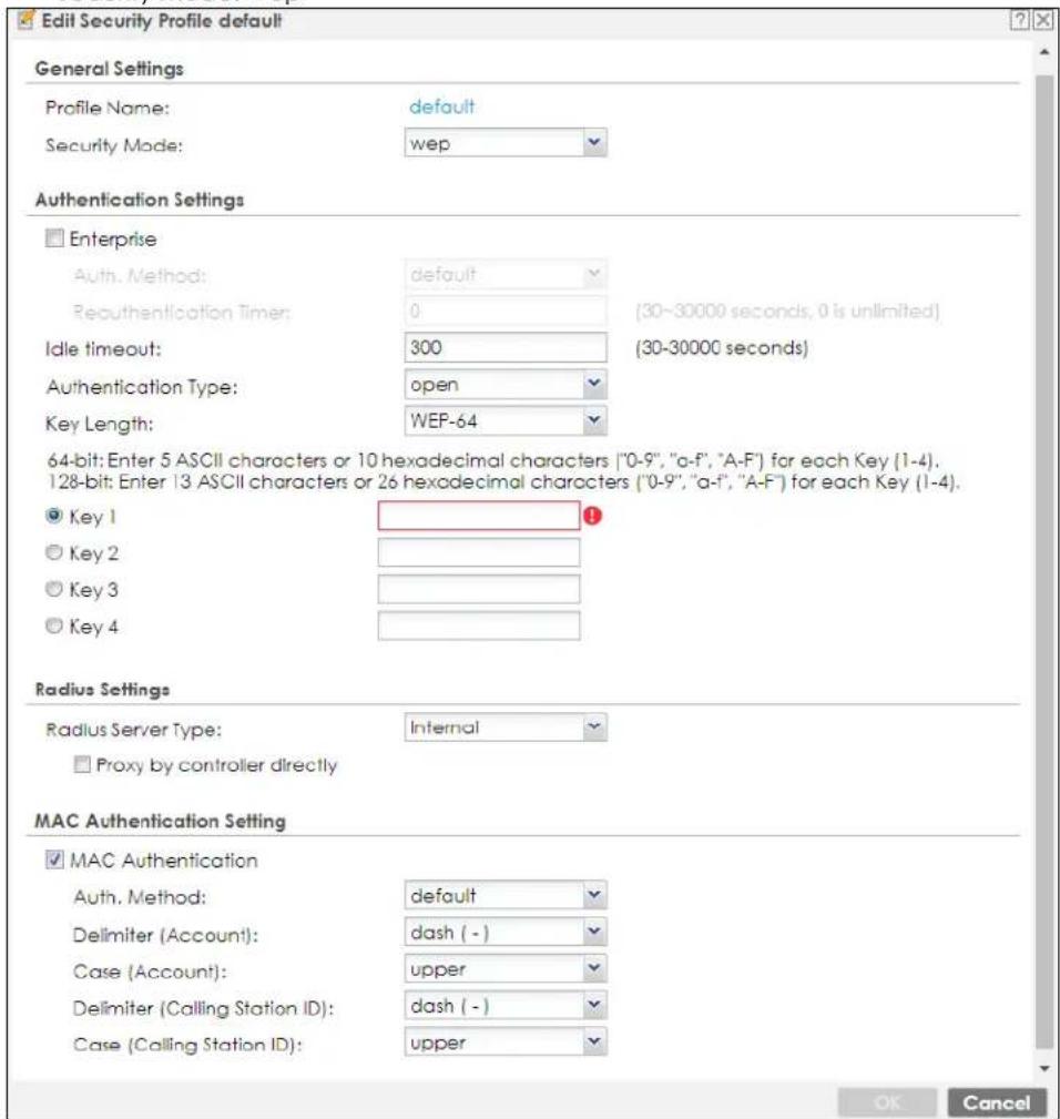
The following table describes the labels in this screen.
Table 388 Configuration > Object > AP Profile > SSID > Security Profile > Add/Edit Security Profile> Security Mode: wep
| LABEL DESCRIPTION | |
| Profile Name | Enter up to 31 alphanumeric characters for the profile name. This name is only visible in the Web Configurator and is only for management purposes. Spaces and underscores are allowed. |
| Security Mode | Select a security mode from the list: open, enhanced open, wep, wpa2, or wpa2-mix, wpa3. |
| Authentication Settings | |
| Enterprise | Select this to enable 802.1x secure authentication with a RADIUS server. |
| Reauthentication Timer | Enter the interval (in seconds) between authentication requests. Enter a 0 for unlimited time. |
| Idle Timeout | Enter the idle interval (in seconds) that a client can be idle before authentication is discontinued. |
| Authentication Type | Select a WEP authentication method. Choices are Open or Share key. |
| Key Length | Select the bit-length of the encryption key to be used in WEP connections.If you select WEP-64:Enter 10 hexadecimal digits in the range of "A-F", "a-f" and "0-9" (for example, 0x11AA22BB33) for each Key used.orEnter 5 ASCII characters (case sensitive) ranging from "a-z", "A-Z" and "0-9" (for example, MyKey) for each Key used.If you select WEP-128:Enter 26 hexadecimal digits in the range of "A-F", "a-f" and "0-9" (for example, 0x00112233445566778899AABBCC) for each Key used.orEnter 13 ASCII characters (case sensitive) ranging from "a-z", "A-Z" and "0-9" (for example, MyKey12345678) for each Key used. |
| Key 1~4 | Based on your Key Length selection, enter the appropriate length hexadecimal or ASCII key. |
| Radius Settings | |
| Primary / Secondary Radius Server Activate | Select this to have the Zyxel Device use the specified RADIUS server. |
| Radius Server IP Address | Enter the IP address of the RADIUS server to be used for authentication. |
| Radius Server Port | Enter the port number of the RADIUS server to be used for authentication. |
| Radius Server Secret | Enter the shared secret password of the RADIUS server to be used for authentication. |
| Primary / Secondary Accounting Server Activate | Select the check box to enable user accounting through an external authentication server. |
| Accounting Server IP Address | Enter the IP address of the external accounting server in dotted decimal notation. |
| Accounting Server Port | Enter the port number of the external accounting server. The default port number is 1813. You need not change this value unless your network administrator instructs you to do so with additional information. |
| Accounting Share Secret | Enter a password (up to 128 alphanumeric characters) as the key to be shared between the external accounting server and the Zyxel Device. The key must be the same on the external accounting server and your Zyxel Device. The key is not sent over the network. |
| Accounting Interim Update | This field is available only when you enable user accounting through an external authentication server.Select this to have the Zyxel Device send subscriber status updates to the accounting server at the interval you specify. |
| Interim Update Interval | Specify the time interval for how often the Zyxel Device is to send a subscriber status update to the accounting server. |
| MAC Authentication | Select this to use an external server or the Zyxel Device's local database to authenticate wireless clients by their MAC addresses. Users cannot get an IP address if the MAC authentication fails.An external server can use the wireless client's account (username/password) or Calling Station ID for MAC authentication. Configure the ones the external server uses. |
| Delimiter (Account) | Select the separator the external server uses for the two-character pairs within account MAC addresses. |
| Case (Account) | Select the case (upper or lower) the external server requires for letters in the account MAC addresses. |
| Delimiter (Calling Station ID) | RADIUS servers can require the MAC address in the Calling Station ID RADIUS attribute.Select the separator the external server uses for the pairs in calling station MAC addresses. |
| Case (Calling Station ID) | Select the case (upper or lower) the external server requires for letters in the calling station MAC addresses. |
| OK | Click OK to save your changes back to the Zyxel Device. |
| Cancel | Click Cancel to exit this screen without saving your changes. |
Figure 612 Configuration > Object > AP Profile > SSID > Security Profile > Add/Edit Security Profile> Security Mode: wpa2/ wpa2-mix
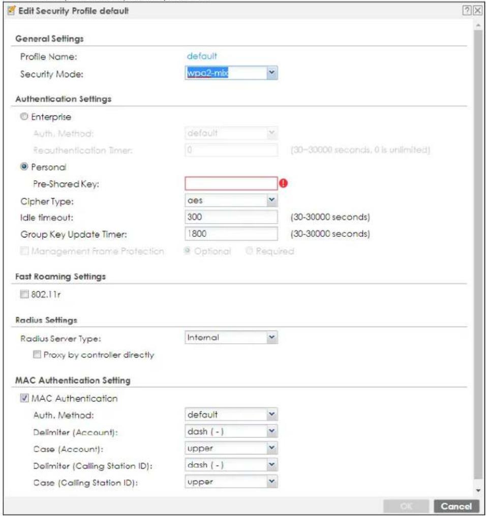

Table 389 Configuration > Object > AP Profile > SSID > Security Profile > Add/Edit Security Profile> Security Mode: wpa2/ wpa2-mix (continued)
| LABEL DESCRIPTION | |
| 802.11r | Select this to turn on IEEE 802.11r fast roaming on the AP (Zyxel Device). This is good for wireless clients that transport a lot of real-time interactive traffic, such as voice and video. Wireless clients should also support WPA2 and fast roaming to associate with the AP (Zyxel Device) and roam seamlessly. |
| Radius Settings | |
| Primary / Secondary Radius Server Activate | Select this to have the Zyxel Device use the specified RADIUS server. |
| Radius Server IP Address | Enter the IP address of the RADIUS server to be used for authentication. |
| Radius Server Port | Enter the port number of the RADIUS server to be used for authentication. |
| Radius Server Secret | Enter the shared secret password of the RADIUS server to be used for authentication. |
| Primary / Secondary Accounting Server Activate | Select the check box to enable user accounting through an external authentication server. |
| Accounting Server IP Address | Enter the IP address of the external accounting server in dotted decimal notation. |
| Accounting Server Port | Enter the port number of the external accounting server. The default port number is 1813. You need not change this value unless your network administrator instructs you to do so with additional information. |
| Accounting Share Secret | Enter a password (up to 128 alphanumeric characters) as the key to be shared between the external accounting server and the Zyxel Device. The key must be the same on the external accounting server and your Zyxel Device. The key is not sent over the network. |
| Accounting Interim Update | This field is available only when you enable user accounting through an external authentication server.Select this to have the Zyxel Device send subscriber status updates to the accounting server at the interval you specify. |
| Interim Update Interval | Specify the time interval for how often the Zyxel Device is to send a subscriber status update to the accounting server. |
| MAC Authentication | Select this to use an external server or the Zyxel Device's local database to authenticate wireless clients by their MAC addresses. Users cannot get an IP address if the MAC authentication fails.An external server can use the wireless client's account (username/password) or Calling Station ID for MAC authentication. Configure the ones the external server uses. |
| Delimiter (Account) | Select the separator the external server uses for the two-character pairs within account MAC addresses. |
| Case (Account) | Select the case (upper or lower) the external server requires for letters in the account MAC addresses. |
| Delimiter (Calling Station ID) | RADIUS servers can require the MAC address in the Calling Station ID RADIUS attribute.Select the separator the external server uses for the pairs in calling station MAC addresses. |
| Case (Calling Station ID) | Select the case (upper or lower) the external server requires for letters in the calling station MAC addresses. |
| OK | Click OK to save your changes back to the Zyxel Device. |
| Cancel | Click Cancel to exit this screen without saving your changes. |
Figure 613 Configuration > Object > AP Profile > SSID > Security Profile > Add/Edit Security Profile> Security Mode: wpa3
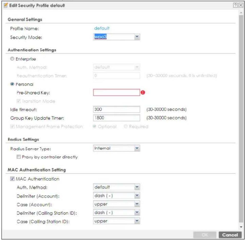
The following table describes the labels in this screen.
Table 390 Configuration > Object > AP Profile > SSID > Security Profile > Add/Edit Security Profile> Security Mode: wpa3
| LABEL DESCRIPTION | |
| Profile Name | Enter up to 31 alphanumeric characters for the profile name. This name is only visible in the Web Configurator and is only for management purposes. Spaces and underscores are allowed. |
| Security Mode | Select a security mode from the list: open, enhanced open, wep, wpa2, or wpa2-mix, wpa3. |
| Authentication Settings | |
| Enterprise | Select this to enable 802.1x secure authentication with a RADIUS server. |
| Reauthentication Timer | Enter the interval (in seconds) between authentication requests. Enter a 0 for unlimited time. |
| Personal | This field is available when you select the wpa2, wpa2-mix or wpa3 security mode.Select this option to use a Pre-Shared Key (PSK) with WPA2 encryption or Simultaneous Authentication of Equals (SAE) with WPA3 encryption. |
| Pre-Shared Key | Enter a pre-shared key of between 8 and 63 case-sensitive ASCII characters (including spaces and symbols) or 64 hexadecimal characters. |
| Transition Mode | Enable this for backwards compatibility. This option is only available if the Security Mode is wpa3 or enhanced-open. This creates two virtual APs (VAPs) with a primary (wpa3 or enhanced-open) and fallback (wpa2 or none) security method.If the Security Mode is wpa3, enabling this will force Management Frame Protection to be set to Optional. If this is disabled or if the Security Mode is enhanced-open, Management Frame Protection will be set to Required. |
| Idle Timeout | Enter the idle interval (in seconds) that a client can be idle before authentication is discontinued. |
| Group Key Update Timer | Enter the interval (in seconds) at which the AP updates the group WPA2 encryption key. |
| Management Frame Protection | This field is available only when you select wpa2 in the Security Mode field and set Cipher Type to aes.Data frames in 802.11 WLANs can be encrypted and authenticated with WEP, WPA or WPA2. But 802.11 management frames, such as beacon/probe response, association request, association response, de-authentication and disassociation are always unauthenticated and unencrypted. IEEE 802.11w Protected Management Frames allows APs to use the existing security mechanisms (encryption and authentication methods defined in IEEE 802.11i WPA/WPA2) to protect management frames. This helps prevent wireless DoS attacks.Select the check box to enable management frame protection (MFP) to add security to 802.11 management frames.Select Optional if you do not require the wireless clients to support MFP. Management frames will be encrypted if the clients support MFP.Select Required and wireless clients must support MFP in order to join the Zyxel Device's wireless network. |
| Radius Settings | |
| Primary / Secondary Radius Server Activate | Select this to have the Zyxel Device use the specified RADIUS server. |
| Radius Server IP Address | Enter the IP address of the RADIUS server to be used for authentication. |
| Radius Server Port | Enter the port number of the RADIUS server to be used for authentication. |
| Radius Server Secret | Enter the shared secret password of the RADIUS server to be used for authentication. |
| Primary / Secondary Accounting Server Activate | Select the check box to enable user accounting through an external authentication server. |
| Accounting Server IP Address | Enter the IP address of the external accounting server in dotted decimal notation. |
| Accounting Server Port | Enter the port number of the external accounting server. The default port number is 1813. You need not change this value unless your network administrator instructs you to do so with additional information. |
| Accounting Share Secret | Enter a password (up to 128 alphanumeric characters) as the key to be shared between the external accounting server and the Zyxel Device. The key must be the same on the external accounting server and your Zyxel Device. The key is not sent over the network. |
| Accounting Interim Update | This field is available only when you enable user accounting through an external authentication server.Select this to have the Zyxel Device send subscriber status updates to the accounting server at the interval you specify. |
| Interim Update Interval | Specify the time interval for how often the Zyxel Device is to send a subscriber status update to the accounting server. |
| MAC Authentication | Select this to use an external server or the Zyxel Device's local database to authenticate wireless clients by their MAC addresses. Users cannot get an IP address if the MAC authentication fails.An external server can use the wireless client's account (username/password) or Calling Station ID for MAC authentication. Configure the ones the external server uses. |
| Delimiter (Account) | Select the separator the external server uses for the two-character pairs within account MAC addresses. |
| Case (Account) | Select the case (upper or lower) the external server requires for letters in the account MAC addresses. |
| Delimiter (Calling Station ID) | RADIUS servers can require the MAC address in the Calling Station ID RADIUS attribute.Select the separator the external server uses for the pairs in calling station MAC addresses. |
| Case (Calling Station ID) | Select the case (upper or lower) the external server requires for letters in the calling station MAC addresses. |
| OK | Click OK to save your changes back to the Zyxel Device. |
| Cancel | Click Cancel to exit this screen without saving your changes. |
43.4.2.5 MAC Filter List
This screen allows you to create and manage security configurations that can be used by your SSIDs. To access this screen click Configuration > Object > AP Profile > SSID > MAC Filter List.
Note: You can have a maximum of 32 MAC filtering profiles on the Zyxel Device.
Figure 614 Configuration > Object > AP Profile > SSID > MAC Filter List
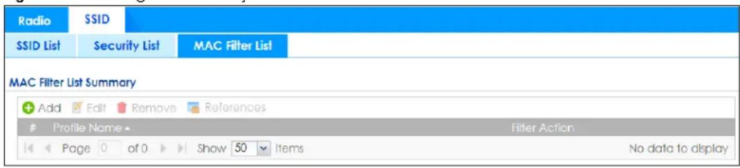
The following table describes the labels in this screen.
Table 391 Configuration > Object > AP Profile > SSID > MAC Filter List
| LABEL DESCRIPTION | |
| Add Click this to add a new MAC filtering profile. | |
| Edit Click this to edit the selected MAC filtering profile. | |
| Remove Click this to remove the selected MAC filtering profile. | |
| References | Click this to view which other objects are linked to the selected MAC filtering profile (for example, SSID profile). |
| # This field is a sequential value, and it is not associated with a specific profile. | |
| Profile Name | This field indicates the name assigned to the MAC filtering profile. |
| Filter Action This field indicates this profile's filter action (if any). | |
43.4.2.6 Add/Edit MAC Filter Profile
This screen allows you to create a new MAC filtering profile or edit an existing one. To access this screen, click the Add button or select a MAC filter profile from the list and click the Edit button.
Figure 615 SSID > MAC Filter List > Add/Edit MAC Filter Profile
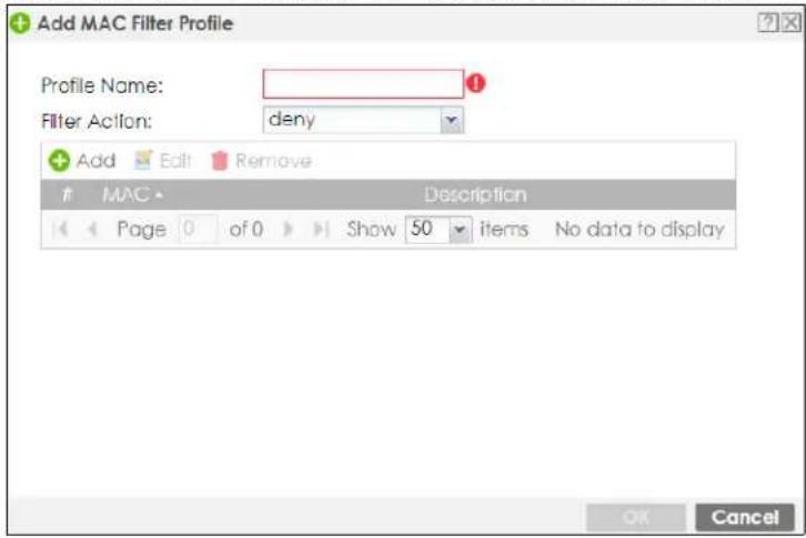
The following table describes the labels in this screen.
Table 392 SSID > MAC Filter List > Add/Edit MAC Filter Profile
| LABEL DESCRIPTION | |
| Profile Name | Enter up to 31 alphanumeric characters for the profile name. This name is only visible in the Web Configurator and is only for management purposes. Spaces and underscores are allowed. |
| Filter Action | Select allow to permit the wireless client with the MAC addresses in this profile to connect to the network through the associated SSID; select deny to block the wireless clients with the specified MAC addresses. |
| Add Click this to add a MAC address to the profile's list. | |
| Edit | Click this to edit the selected MAC address in the profile's list. |
| Remove | Click this to remove the selected MAC address from the profile's list. |
| # | This field is a sequential value, and it is not associated with a specific profile. |
| MAC | This field specifies a MAC address associated with this profile. |
| Description | This field displays a description for the MAC address associated with this profile. You can click the description to make it editable. Enter up to 60 characters, spaces and underscores allowed. |
| OK | Click OK to save your changes back to the Zyxel Device. |
| Cancel | Click Cancel to exit this screen without saving your changes. |
43.5 MON Profile
This screen allows you to set up monitor mode configurations that allow your connected APs to scan for other wireless devices in the vicinity. Once detected, you can use the Rogue AP screen (Section 8.5 on page 309) to classify them as either rogue or friendly and then manage them accordingly.
The MON Profile screen (Section 43.5.1 on page 986) creates preset monitor mode configurations that can be used by the APs.
43.5.0.1 What You Need To Know
The following terms and concepts may help as you read this chapter.
Active Scan
An active scan is performed when an 802.11-compatible wireless monitoring device is explicitly triggered to scan a specified channel or number of channels for other wireless devices broadcasting on the 802.11 frequencies by sending probe request frames.
Passive Scan
A passive scan is performed when an 802.11-compatible monitoring device is set to periodically listen to a specified channel or number of channels for other wireless devices broadcasting on the 802.11 frequencies.
43.5.1 Configuring MON Profile
This screen allows you to create monitor mode configurations that can be used by the APs. To access this screen, login to the Web Configurator, and click Configuration > Object > MON Profile.
Figure 616 Configuration > Object > MON Profile
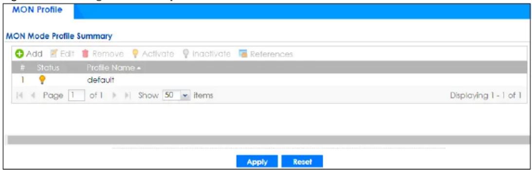
The following table describes the labels in this screen.
Table 393 Configuration > Object > MON Profile
| LABEL DESCRIPTION | |
| Add Click this to add a new monitor mode profile. | |
| Edit Click this to edit the selected monitor mode profile. | |
| Remove | Click this to remove the selected monitor mode profile. |
| Activate | To turn on an entry, select it and click Activate. |
| Inactivate | To turn off an entry, select it and click Inactivate. |
| References | Click this to view which other objects are linked to the selected monitor mode profile (for example, an AP management profile). |
| # This field is a sequential value, and it is not associated with a specific user. | |
| Status This icon is lit | when the entry is active and dimmed when the entry is inactive. |
| Profile Name | This field indicates the name assigned to the monitor profile. |
| Apply | Click Apply to save your changes back to the Zyxel Device. |
| Reset | Click Reset to return the screen to its last-saved settings. |
43.5.2 Add/Edit MON Profile
This screen allows you to create a new monitor mode profile or edit an existing one. To access this screen, click the Add button or select and existing monitor mode profile and click the Edit button.
Figure 617 Configuration > Object > MON Profile > Add/Edit MON Profile
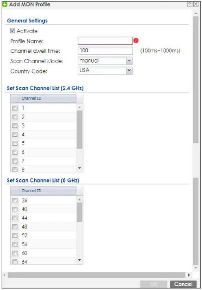
The following table describes the labels in this screen.
Table 394 Configuration > Object > MON Profile > Add/Edit MON Profile
| LABEL DESCRIPTION | |
| Activate Select this to | activate this monitor mode profile. |
| Profile Name | This field indicates the name assigned to the monitor mode profile. |
| Channel dwell time | Enter the interval (in milliseconds) before the AP switches to another channel for monitoring. |
| Scan Channel Mode | Select auto to have the AP switch to the next sequential channel once the Channel dwell time expires.Select manual to set specific channels through which to cycle sequentially when the Channel dwell time expires. Selecting this options makes the Scan Channel List options available. |
| Country Code | Select the country code of where the Zyxel Device is located/installed.The available channels vary depending on the country you selected. Be sure to select the correct/same country for both radios on an AP and all connected APs, in order to prevent roaming failure and interference to other systems.Note: For US and Canada models, country code is fixed to US or Canada respectively and is not user selectable. |
| Set Scan Channel List (2.4 GHz) | Move a channel from the Available channels column to the Channels selected column to have the APs using this profile scan that channel when Scan Channel Mode is set to manual.These channels are limited to the 2 GHz range (802.11 b/g/n). |
| Set Scan Channel List (5 GHz) | Move a channel from the Available channels column to the Channels selected column to have the APs using this profile scan that channel when Scan Channel Mode is set to manual.These channels are limited to the 5 GHz range (802.11 a/n). |
| OK | Click OK to save your changes back to the Zyxel Device. |
| Cancel | Click Cancel to exit this screen without saving your changes. |
43.5.3 Technical Reference
The following section contains additional technical information about the features described in this chapter.
Rogue APs
Rogue APs are wireless access points operating in a network's coverage area that are not under the control of the network's administrators, and can open up holes in a network's security. Attackers can take advantage of a rogue AP's weaker (or non-existent) security to gain access to the network, or set up their own rogue APs in order to capture information from wireless clients. If a scan reveals a rogue AP, you can use commercially-available software to physically locate it.
Figure 618 Rogue AP Example
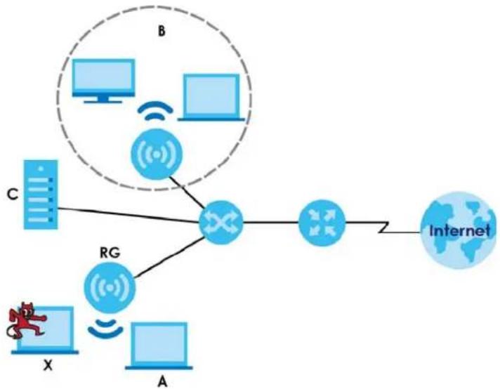
flowchart
graph TD
    A["Device X"] -->|Wireless| RG["RG"]
    B["Device B"] -->|Wireless| RG
    C["Device C"] -->|Wireless| RG
    A -->|Internet| Internet
    B -->|Internet| Internet
    C -->|Internet| Internet
In the example above, a corporate network's security is compromised by a rogue AP (RG) set up by an employee at his workstation in order to allow him to connect his notebook computer wirelessly (A). The company's legitimate wireless network (the dashed ellipse B) is well-secured, but the rogue AP uses inferior security that is easily broken by an attacker (X) running readily available encryption-cracking software. In this example, the attacker now has access to the company network, including sensitive data stored on the file server (C).
Friendly APs
If you have more than one AP in your wireless network, you should also configure a list of "friendly" APs. Friendly APs are other wireless access points that are detected in your network, as well as any others that you know are not a threat (those from recognized networks, for example). It is recommended that you export (save) your list of friendly APs often, especially if you have a network with a large number of access points.
43.6 ZyMesh Overview
This section shows you how to configure ZyMesh profiles for the Zyxel Device to apply to the managed APs.
ZyMesh is a Zyxel proprietary protocol that creates wireless mesh links between managed APs to expand the wireless network. Managed APs can provide services or forward traffic between the Zyxel Device and wireless clients. ZyMesh also allows the Zyxel Device to use CAPWAP to automatically update the configuration settings on the managed APs (in repeater mode) through wireless connections. The managed APs (in repeater mode) are provisioned hop by hop.
The managed APs in a ZyMesh must use the same SSID, channel number and pre-shared key. A manged AP can be either a root AP or repeater in a ZyMesh.
Note: All managed APs should be connected to the Zyxel Device directly to get the configuration file before being deployed to build a ZyMesh. Ensure you restart the managed AP after you change its operating mode using the Configuration > Wireless > AP Management screen (see Section 8.4 on page 284).
- Root AP: a managed AP that can transmit and receive data from the Zyxel Device via a wired Ethernet connection.
- Repeater: a managed AP that transmits and/or receives data from the Zyxel Device via a wireless connection through a root AP.
Note: When managed APs are deployed to form a ZyMesh for the first time, the root AP must be connected to an AP controller (the Zyxel Device).
In the following example, managed APs 1 and 2 act as a root AP and managed APs A, B and C are repeaters.
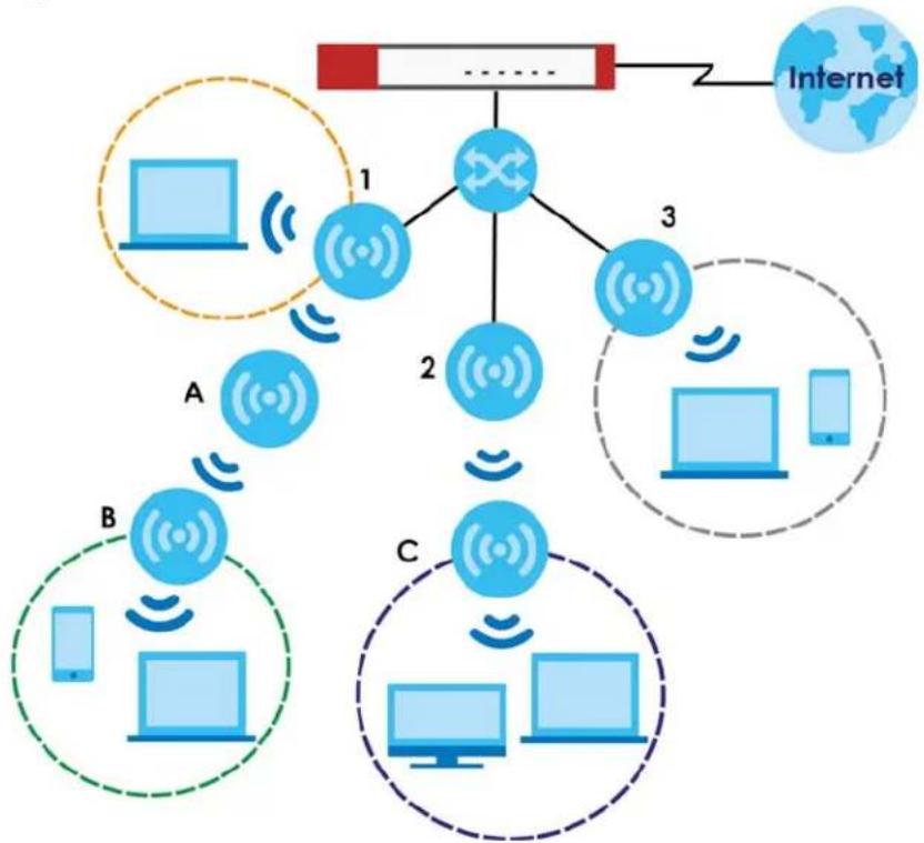
flowchart
graph TD
    A["Internet"] --> B["Central Network Node"]
    B --> C["Component 1: Wireless/Signal"]
    B --> D["Component 2: Wireless/Signal"]
    B --> E["Component 3: Wireless/Signal"]
    C --> F["Component A: Cloud/Smartphone"]
    D --> G["Component B: Smartphone"]
    E --> H["Component C: Smartphone"]
The maximum number of hops (the repeaters between a wireless client and the root AP) you can have in a ZyMesh varies according to how many wireless clients a managed AP can support.
Note: A ZyMesh link with more hops has lower throughput.
Note: When the wireless connection between the root AP and the repeater is up, in order to prevent bridge loops, the repeater would not be able to transmit data through its Ethernet port(s). The repeater then could only receive power from a PoE device if you use PoE to provide power to the managed AP via an 8-ping Ethernet cable.
43.6.1 ZyMesh Profile
This screen allows you to manage and create ZyMesh profiles that can be used by the APs. To access this screen, click Configuration > Object > ZyMesh Profile.
Figure 619 Configuration > Object > ZyMesh Profile
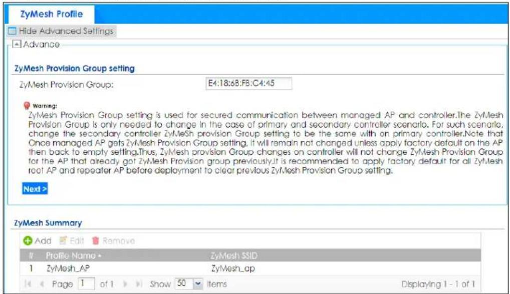
The following table describes the labels in this screen.
Table 395 Configuration > Object > ZyMesh Profile
| LABEL DESCRIPTION | |
| Hide / Show Advanced Settings | Click this to display a greater or lesser number of configuration fields. |
| ZyMesh Provision Group | By default, this shows the MAC address used by the Zyxel Device's first Ethernet port.Say you have two AP controllers (Zyxel Devices) in your network and the primary AP controller is not reachable. You may want to deploy the second/backup AP controller in your network to replace the primary AP controller. In this case, it is recommended that you enter the primary AP controller's ZyMesh Provision Group MAC address in the second AP controller's ZyMesh Provision Group field.If you didn't change the second AP controller's MAC address, managed APs in an existing ZyMesh can still access the networks through the second AP controller and communicate with each other. But new managed APs will not be able to communicate with the managed APs in the existing ZyMesh, which is set up with the primary AP controller's MAC address.To allow all managed APs to communicate in the same ZyMesh, you can just set the second AP controller to use the primary AP controller's MAC address. Otherwise, reset all managed APs to the factory defaults and set up a new ZyMesh with the second AP controller's MAC address. |
| Next | Click this button and follow the on-screen instructions to update the AP controller's MAC address. |
| Add Click this to add a new profile. | |
| Edit Click this to edit the selected profile. | |
| Remove Click this to remove the selected profile. | |
| # This field is a sequential value, and it is not associated with a specific profile. | |
| Profile Name This field indicates the name assigned to the profile. | |
| ZyMesh SSID This field shows the SSID specified in this ZyMesh profile. | |
43.6.2 Add/Edit ZyMesh Profile
This screen allows you to create a new ZyMesh profile or edit an existing one. To access this screen, click the Add button or select and existing profile and click the Edit button.
Figure 620 Configuration > Object > ZyMesh Profile > Add/Edit ZyMesh Profile
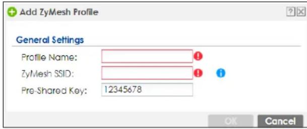
The following table describes the labels in this screen.
Table 396 Configuration > Object > ZyMesh Profile > Add/Edit ZyMesh Profile
| LABEL DESCRIPTION | |
| Profile Name Enter up to 31 alphanumeric characters for the profile name. | |
| ZyMesh SSID | Enter the SSID with which you want the managed AP to connect to a root AP or repeater to build a ZyMesh link.Note: The ZyMesh SSID is hidden in the outgoing beacon frame so a wireless device cannot obtain the SSID through scanning using a site survey tool. |
| Pre-Shared Key | Enter a pre-shared key of between 8 and 63 case-sensitive single-byte characters or 64 hexadecimal characters. Accepted characters are 0-9a-zA-Z!""#$%&'()*+,-./::<=>?@[^\]^_{|} and spaces. ' is not allowed.The key is used to encrypt the wireless traffic between the APs. |
| OK | Click OK to save your changes back to the Zyxel Device. |
| Cancel | Click Cancel to exit this screen without saving your changes. |
43.7 Address/ Geo IP Overview
Address objects can represent a single IP address or a range of IP addresses. Address groups are composed of address objects and other address groups.
- The Address screen (Section 43.7.2 on page 993) provides a summary of all addresses in the Zyxel Device. Use the Address Add/Edit screen to create a new address or edit an existing one.
- Use the Address Group summary screen (Section 43.7.3 on page 997) and the Address Group Add/Edit screen, to maintain address groups in the Zyxel Device.
- Use the Geo IP screen (Section 43.7.4 on page 999) to update the database of country-to-IP address mappings and to manually configure country-to-IP address mappings.
43.7.1 What You Need To Know
Address objects and address groups are used in dynamic routes, security policies, application patrol, content filtering, and VPN connection policies. For example, addresses are used to specify where content restrictions apply in content filtering. Please see the respective sections for more information about how address objects and address groups are used in each one.
Address groups are composed of address objects and address groups. The sequence of members in the address group is not important.
43.7.2 Address Summary Screen
The address screens are used to create, maintain, and remove addresses. There are the types of address objects:
- HOST - the object uses an IP Address to define a host address
- RANGE - the object uses a range address defined by a Starting IP Address and an Ending IP Address
- SUBNET - the object uses a network address defined by a Network IP address and Netmask subnet mask
- INTERFACE IP - the object uses the IP address of one of the Zyxel Device's interfaces
- INTERFACE SUBNET - the object uses the subnet mask of one of the Zyxel Device's interfaces
- INTERFACE GATEWAY - the object uses the gateway IP address of one of the Zyxel Device's interfaces
- GEOGRAPHY - the object uses the IP addresses of a country to represent a country
FQDN - the object uses a FQDN (Fully Qualified Domain Name). An FQDN consists of a host and domain name. For example, www.zyxel.com is a fully qualified domain name, where "www" is the host, "zyxel" is the second-level domain, and "com" is the top level domain. mail.myZyxel.com.tw is also an FQDN, where "mail" is the host, "myZyxel" is the third-level domain, "com" is the second-level domain, and "tw" is the top level domain.
Table 397 FQDN Example
| HTTP://WWW.ZY | XEL.COM | ||
| host name second- | level domain name | top-level domain name | |
| FQDN | |||
| Uniform Resource Locator (URL) | |||
In an address FQDN object, you can also use one wildcard. For example, *.zyxel.com. An FQDN is resolved to its IP address using the DNS server configured on the Zyxel Device.
The Address screen provides a summary of all addresses in the Zyxel Device. To access this screen, click Configuration > Object > Address > Address. Click a column's heading cell to sort the table entries by that column's criteria. Click the heading cell again to reverse the sort order.
Figure 621 Configuration > Object > Address/Geo IP > Address
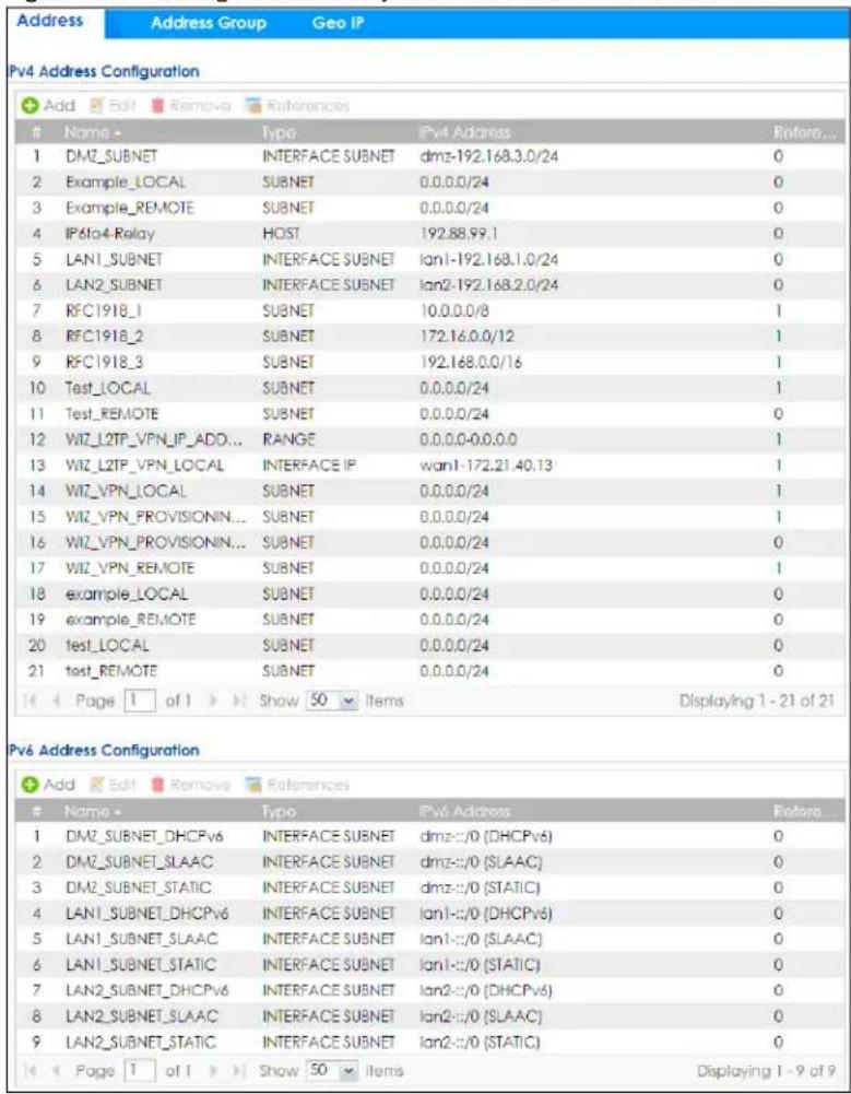
The following table describes the labels in this screen. See Section 43.7.2.1 on page 995 for more information as well.
Table 398 Configuration > Object > Address/Geo IP > Address
| LABEL DESCRIPTION | |
| IPv4 Address Configuration | |
| Add Click this to create a new entry. | |
| Edit | Double-click an entry or select it and click Edit to be able to modify the entry's settings. |
| Remove | To remove an entry, select it and click Remove. The Zyxel Device confirms you want to remove it before doing so. |
| References | Select an entry and click References to open a screen that shows which settings use the entry. |
| # | This field is a sequential value, and it is not associated with a specific address. |
| Name This field displays the configured name of each address object. | |
| Type | This field displays the type of each address object. "INTERFACE" means the object uses the settings of one of the Zyxel Device's interfaces. |
| IPv4 Address | This field displays the IPv4 addresses represented by each address object. If the object's settings are based on one of the Zyxel Device's interfaces, the name of the interface displays first followed by the object's current address settings. |
| Reference This displays the number of times an object reference is used in a profile. | |
| IPv6 Address Configuration | |
| Add Click this to create a new entry. | |
| Edit | Double-click an entry or select it and click Edit to be able to modify the entry's settings. |
| Remove | To remove an entry, select it and click Remove. The Zyxel Device confirms you want to remove it before doing so. |
| References | Select an entry and click References to open a screen that shows which settings use the entry. |
| # | This field is a sequential value, and it is not associated with a specific address. |
| Name This field displays the configured name of each address object. | |
| Type | This field displays the type of each address object. "INTERFACE" means the object uses the settings of one of the Zyxel Device's interfaces. |
| IPv6 Address | This field displays the IPv6 addresses represented by each address object. If the object's settings are based on one of the Zyxel Device's interfaces, the name of the interface displays first followed by the object's current address settings. |
| Reference This displays the number of times an object reference is used in a profile. | |
43.7.2.1 IPv4 Address Add/Edit Screen
The Configuration > Object > Address/ GeoIP > Address > Add/ Edit (IPv4) screen allows you to create a new address or edit an existing one. To access this screen, go to the Address screen (see Section 43.7.2 on page 993), and click either the Add icon or an Edit icon in the IPv4 Address Configuration section.
Figure 622 Configuration > Object > Address/GeoIP > Address > Add/Edit (IPv4) t
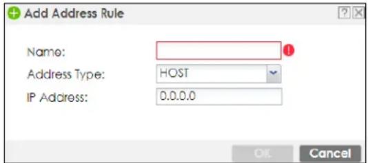
The following table describes the labels in this screen.
Table 399 Configuration > Object > Address/GeoIP > Address > Add/Edit (IPv4)
| LABEL DESCRIPTION | |
| Name | Type the name used to refer to the address. You may use 1-31 alphanumeric characters, underscores(____), or dashes (-), but the first character cannot be a number. This value is case-sensitive. |
| Address Type Select | the type of address you want to create.Note: The Zyxel Device automatically updates address objects that are based on an interface's IP address, subnet, or gateway if the interface's IP address settings change. For example, if you change 1's IP address, the Zyxel Device automatically updates the corresponding interface-based, LAN subnet address object. |
| IP Address | This field is only available if the Address Type is HOST. This field cannot be blank. Enter the IP address that this address object represents. |
| Starting IP Address | This field is only available if the Address Type is RANGE. This field cannot be blank. Enter the beginning of the range of IP addresses that this address object represents. |
Table 399 Configuration > Object > Address/GeoIP > Address > Add/Edit (IPv4)
| LABEL DESCRIPTION | |
| Ending IP Address | This field is only available if theAddress Typeis RANGE. This field cannot be blank. Enter the end of the range of IP address that this address object represents. |
| Network | This field is only available if theAddress Typeis SUBNET, in which case this field cannot be blank.Enter the IP address of the network that this address object represents. |
| Netmask | This field is only available if theAddress Typeis SUBNET, in which case this field cannot be blank.Enter the subnet mask of the network that this address object represents. Use dotted decimal format. |
| Interface | If you selectedINTERFACE IP, INTERFACE SUBNET, or INTERFACE GATEWAY as theAddress Type, use this field to select the interface of the network that this address object represents. |
| Region | If you selectedGEOGRAPHYas theAddress Type, use this field to select a country or continent.A GEOGRAPHYobject uses the data from the country-to-IP/continent-to-IP address database.Go to theConfiguration>Object>Address/Geo IP>Geo IPscreen to configure the custom country-to-IP/continent-to-IP address mappings for a GEOGRAPHYobject. |
| Country | If you selectedGeographyas theAddress Type, use this field to select a country. |
| FQDN | If you selectedFQDNas theAddress Type, use this field to enter a fully qualified domain name. |
| OK | ClickOKto save your changes back to the Zyxel Device. |
| Cancel | ClickCancelto exit this screen without saving your changes. |
43.7.2.2 IPv6 Address Add/Edit Screen
The Configuration > Object > Address/ GeoIP > Address > Add/ Edit (IPv6) screen allows you to create a new address or edit an existing one. To access this screen, go to the Address screen (see Section 43.7.2 on page 993), and click either the Add icon or an Edit icon in the IPv6 Address Configuration section.
Figure 623 Configuration > Object > Address/GeoIP > Address > Add/Edit (IPv6)
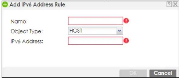
The following table describes the labels in this screen.
Table 400 Configuration > Object > Address/GeoIP > Address > Add/Edit (IPv6)
| LABEL DESCRIPTION | |
| Name | Type the name used to refer to the address. You may use 1-31 alphanumeric characters, underscores( ), or dashes (-), but the first character cannot be a number. This value is case-sensitive. |
| Object Type Select | the type of address you want to create.Note: The Zyxel Device automatically updates address objects that are based on an interface's IP address, subnet, or gateway if the interface's IP address settings change. For example, if you change 1's IP address, the Zyxel Device automatically updates the corresponding interface-based, LAN subnet address object. |
| IPv6 Address | This field is only available if theAddress Typeis HOST. This field cannot be blank. Enter the IP address that this address object represents. |
Table 400 Configuration > Object > Address/GeoIP > Address > Add/Edit (IPv6)
| LABEL DESCRIPTION | |
| IPv6 Starting Address | This field is only available if theAddress Typeis RANGE. This field cannot be blank. Enter the beginning of the range of IP addresses that this address object represents. |
| IPv6 Ending Address | This field is only available if theAddress Typeis RANGE. This field cannot be blank. Enter the end of the range of IP address that this address object represents. |
| IPv6 Address Prefix | This field is only available if theAddress Typeis SUBNET. This field cannot be blank. Enter the IPv6 address prefix that the Zyxel Device uses for the LAN IPv6 address. |
| Interface | If you selectedINTERFACE IP, INTERFACE SUBNET, or INTERFACE GATEWAYas theAddress Type, use this field to select the interface of the network that this address object represents. |
| IPv6 Address Type | Select whether the IPv6 address is a link-local IP address (LINK LOCAL), static IP address (STATIC), an IPv6 StateLess Address Auto Configuration IP address (SLAAC), or is obtained from a DHCPv6 server (DHCPv6). |
| Region | If you selectedGeographyas theAddress Type, use this field to select a country or continent. |
| FQDN | If you selectedFQDNas theAddress Type, use this field to enter a fully qualified domain name. |
| OK | Click OKto save your changes back to the Zyxel Device. |
| Cancel | Click Cancelto exit this screen without saving your changes. |
43.7.3 Address Group Summary Screen
The Address Group screen provides a summary of all address groups. To access this screen, click Configuration > Object > Address/Geo IP > Address Group. Click a column's heading cell to sort the table entries by that column's criteria. Click the heading cell again to reverse the sort order.
Figure 624 Configuration > Object > Address/Geo IP > Address Group
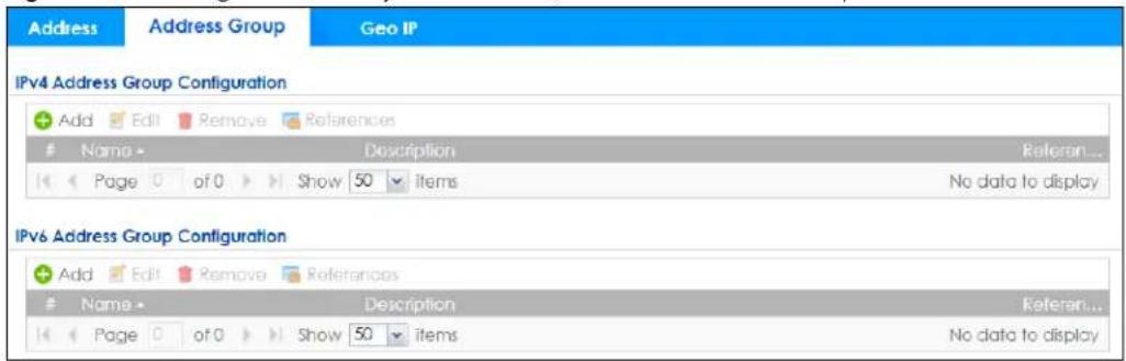
The following table describes the labels in this screen. See Section 43.7.3.1 on page 998 for more information as well.
Table 401 Configuration > Object > Address/Geo IP > Address Group
| LABEL DESCRIPTION | |
| IPv4 Address Group Configuration | |
| Add Click this to create a new entry. | |
| Edit | Double-click an entry or select it and click Edit to be able to modify the entry's settings. |
| Remove | To remove an entry, select it and click Remove. The Zyxel Device confirms you want to remove it before doing so. |
| References | Select an entry and click References to open a screen that shows which settings use the entry. |
| # | This field is a sequential value, and it is not associated with a specific address group. |
| Name This field displays the name of each address group. | |
| Description This field displays the description of each address group, if any. | |
| Reference This displays the number of times an object reference is used in a profile. | |
| IPv6 Address Group Configuration | |
| Add Click this to create a new entry. | |
| Edit | Double-click an entry or select it and click Edit to be able to modify the entry's settings. |
| Remove | To remove an entry, select it and click Remove. The Zyxel Device confirms you want to remove it before doing so. |
| References | Select an entry and click References to open a screen that shows which settings use the entry. |
| # | This field is a sequential value, and it is not associated with a specific address group. |
| Name This field displays the name of each address group. | |
| Description This field displays the description of each address group, if any. | |
| Reference This displays the number of times an object reference is used in a profile. | |
43.7.3.1 Address Group Add/Edit Screen
The Address Group Add/Edit screen allows you to create a new address group or edit an existing one. To access this screen, go to the Address Group screen (see Section 43.7.3 on page 997), and click either the Add icon or an Edit icon in the IPv4 Address Group Configuration or IPv6 Address Group Configuration section.
Figure 625 IPv4/IPv6 Address Group Configuration > Add
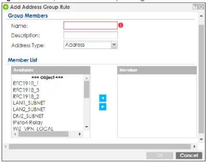
The following table describes the labels in this screen.
Table 402 IPv4/IPv6 Address Group Configuration > Add
| LABEL DESCRIPTION | |
| Name Enter a name | for the address group. You may use 1-31 alphanumeric characters, underscores( ), or dashes (-), but the first character cannot be a number. This value is case-sensitive. |
| Description | This field displays the description of each address group, if any. You can use up to 60 characters, punctuation marks, and spaces. |
| LABEL DESCRIPTION | |
| Address Type Select | the type of address you want to create. |
| Note: The Zyxel Device automatically updates address objects that are based on an interface's IP address, subnet, or gateway if the interface's IP address settings change. For example, if you change 1's IP address, the Zyxel Device automatically updates the corresponding interface-based, LAN subnet address object. | |
| Member List | The Member list displays the names of the address and address group objects that have been added to the address group. The order of members is not important.Select items from the Available list that you want to be members and move them to the Member list. You can double-click a single entry to move it or use the [Shift] or [Ctrl] key to select multiple entries and use the arrow button to move them.Move any members you do not want included to the Available list.Note: Only objects of the same address type can be added to a address group. |
| OK | Click OK to save your changes back to the Zyxel Device. |
| Cancel | Click Cancel to exit this screen without saving your changes. |
43.7.4 Geo IP Summary Screen
Use this screen to update the database of country-to-IP and continent-to-IP address mappings and manually configure custom country-to-IP and continent-to-IP address mappings in geographic address objects. You can then use geographic address objects in security policies to forward or deny traffic to whole countries or regions.
Click a column's heading cell to sort the table entries by that column's criteria. Click the heading cell again to reverse the sort order.

- ZyWALL USG FLEX Series
- IMPORTANT!
- READ CAREFULLY BEFORE USE.
- KEEP THIS GUIDE FOR FUTURE REFERENCE.
- Related Documentation
- Document Conventions
- Warnings and Notes
- Warnings tell you about things that could harm you or your device.
- Syntax Conventions
- Icons Used in Figures
- Contents Overview
- Table of Contents
- Chapter 3 Hardware, Interfaces and Zones......96
- Chapter 4 Quick Setup Wizards....107
- Chapter 5
- Dashboard 154
- Part II: Technical Reference....164
- Chapter 6
- Monitor 165
- Chapter 7 Licensing ....257
- Chapter 8 Wireless ....266
- Chapter 9 Interfaces......319
- Chapter 10
- Routing 433
- Chapter 11
- DDNS 460
- Chapter 12
- NAT 466
- Chapter 13
- Redirect Service 484
- Chapter 14
- ALG 490
- Chapter 15
- UPnP 497
- Chapter 16
- IP/ MAC Binding 512
- Chapter 17
- Layer 2 Isolation....517
- Chapter 18
- DNS Inbound LB....521
- Chapter 19
- IPSec VPN 527
- Chapter 20
- SSL VPN....566
- Chapter 21
- L2TP VPN 572
- Chapter 22
- Remote AP VPN....578
- Chapter 23
- BWM (Bandwidth Management) 584
- Chapter 24
- Web Authentication 602
- Chapter 25
- Hotspot....632
- Chapter 26
- Printer Manager 650
- Chapter 27
- Free Time....662
- Chapter 28
- IPnP 667
- Chapter 29
- Walled Garden....670
- Chapter 30
- Advertisement Screen....676
- Chapter 31
- Security Policy 679
- Chapter 32
- Application Patrol 713
- Chapter 33
- Content Filter 727
- Chapter 34
- Anti-Malware 776
- Chapter 35
- Reputation Filter 797
- Chapter 36
- IPS 832
- Chapter 37
- Sandboxing 859
- Chapter 38
- Email Security 863
- Chapter 39
- Collaborative Detection & Response 882
- Chapter 40
- SSL Inspection....896
- Chapter 41
- IP Exception....921
- Chapter 42
- Astra Cloud Security 926
- Chapter 43
- Object 929
- Chapter 44
- Device HA....1055
- Chapter 45
- Mgmt. & Analytics....1062
- Chapter 46
- System....1076
- Chapter 47
- Log and Report....1139
- Chapter 48
- File Manager 1153
- Chapter 49
- Diagnostics 1174
- Chapter 50
- Packet Flow Explore 1196
- Chapter 51
- Shutdown 1203
- Part III: Appendices and Troubleshooting.... 1205
- Chapter 52
- Troubleshooting....1206
- PART I
- User's Guide
- CHAPTER 1 Introduction
- Overview
- Model Feature Differences
- On Premises Mode
- Monitor Mode
- Nebula Mode
- NCC Portal
- Your Zyxel Device
- Activation Email
- Changing the Mode
- From Nebula Mode to On Premises Mode
- From On Premises Mode to Nebula Mode
- From Nebula Mode to Cloud Monitoring Mode
- Registration at Zyxel
- Grace Period
- Applications
- Security Router
- IPv6 Routing
- VPN Connectivity
- SSL VPN Network Access
- User-Authentication Access Control
- Load Balancing
- Management Overview
- Web Configurator
- Time Priority Category Message Source Destination
- Command-Line Interface (CLI)
- FTP
- SNMP
- CloudCNM
- Management Authentication
- Web Configurator
- Web Configurator Access
- User Name User Type Last Password Change Expired
- Security Check for Web Interface Overview
- Secure SSL Access from the Internet to the Zyxel Device
- Secure SSL VPN Access from the Internet to the Network Behind the Zyxel Device
- Change the Default IPSec VPN Provisioning Port
- Change the Default Port for Two-Factor VPN Access Authentication
- Overall Port Configuration Example
- Other Security Measures
- The Security Check for Web Interface Screen
- Remote Access to the Zyxel Device Networks
- Web Configurator Screens Overview
- Title Bar
- About
- Site Map
- Web Console
- Reference
- Service Priority Name Description
- CLI Messages
- Navigation Panel
- Dashboard
- Monitor Menu
- Configuration Menu
- Maintenance Menu
- Tables and Lists
- Status Name IP Address Mask
- Status Name Address
- Name Status IP Address Mask
- Status Name Base Interface Account Profile
- Working with Lists
- CHAPTER 2
- Initial Setup Wizard
- Initial Setup Wizard: Select Management Mode
- Welcome Screen
- Internet Access Setup - WAN Interface
- Internet Access: Ethernet
- Possible Errors
- Internet Access: PPPoE
- Internet Access - First WAN Interface
- ISP Parameters
- WAN IP Address Assignments
- Possible Errors
- Internet Access: PPTP
- ISP Parameters
- PPTP Configuration
- WAN IP Address Assignments
- Possible Errors
- Internet Access: L2TP
- ISP Parameters
- L2TP Configuration
- WAN IP Address Assignments
- Possible Errors
- Internet Access Setup - Second WAN Interface
- Internet Access: Congratulations
- Date and Time Settings
- Register Device
- Activate Service
- Service Settings
- Service Settings: SecuReporter
- Wireless Settings: Management Mode
- Wireless Settings: AP Controller
- Wireless Settings: SSID & Security
- SSID Setting
- For Zyxel Devices with Built - in AP Only
- Remote Management
- Nebula Mode Initial Setup Wizard
- Connect to Internet (WAN)
- Internet Access: Ethernet
- Possible Errors
- Internet Access: PPPoE
- Internet Access - First WAN Interface
- ISP Parameters
- IP Address Assignments
- Possible Errors
- Internet Access: Congratulations
- QR Code
- CHAPTER 3
- Hardware, Interfaces and Zones
- Hardware Overview
- Front Panels
- Rear Panels
- Installation Scenarios
- Desktop Installation Procedure
- Rack-mounting
- Wall-mounting
- Default Zones, Interfaces, and Ports
- Stopping the Zyxel Device
- CHAPTER 4
- Quick Setup Wizards
- Quick Setup Overview
- - Wizard Help
- WAN Interface Quick Setup
- Choose an Ethernet Interface
- Select WAN Type
- Configure WAN IP Settings
- ISP and WAN and ISP Connection Settings
- IP Address Assignment
- Quick Setup Interface Wizard: Summary
- Remote Access VPN Setup-Scenario
- IKEv2 IPSec Client- VPN Configuration
- IKEv2 IPSec Client- User Authentication
- IKEv2 IPSec Client- Summary
- IKEv2 IPSec Client-Config Provision
- L2TP over IPSec Client-VPN Configuration
- L2TP over IPSec Client- User Authentication
- L2TP over IPSec Client- Summary
- L2TP over IPSec Client-Config Provision
- VPN Setup Wizard
- Welcome
- VPN Setup Wizard: Wizard Type
- VPN Express Wizard - Scenario
- IKE (Internet Key Exchange) Version: IKEv1 and IKEv2
- Scenario
- VPN Express Wizard - Configuration
- VPN Express Wizard - Summary
- Edit this shell script according to
- the comments before using it in the remote
- Check the peer-ip interface.
- Check the local-ip interface.
- Edit the WIZ_VPN_LOCAL address-object.
- Then remove the following line.
- PLEASE REMOVE THIS LINE
- If this device's won! IP is dynamic,
- consider using DDNS and changing
- VPN Express Wizard - Finish
- VPN Advanced Wizard - Scenario
- VPN Advanced Wizard - Phase 1 Settings
- VPN Advanced Wizard - Phase 2
- VPN Advanced Wizard - Summary
- the comments before using it in the remote gateway.
- Edit the Test_LOCAL address-object.
- Use the correct Interface name in the
- Phase 1
- VPN Advanced Wizard - Finish
- VPN Settings for Configuration Provisioning Wizard: Wizard Type
- Configuration Provisioning Express Wizard - VPN Settings
- Configuration Provisioning VPN Express Wizard - Configuration
- VPN Settings for Configuration Provisioning Express Wizard - Summary
- Check the peer-lp interface.
- Check the local-lp interface.
- Edit the WIZ_VPN_PROVISIONING_LOCAL address-
- If this device's want IP is dynamic.
- VPN Settings for Configuration Provisioning Express Wizard - Finish
- VPN Settings for Configuration Provisioning Advanced Wizard - Scenario
- VPN Settings for Configuration Provisioning Advanced Wizard - Phase 1 Settings
- VPN Settings for Configuration Provisioning Advanced Wizard - Phase 2
- VPN Settings for Configuration Provisioning Advanced Wizard - Summary
- If this device's wan1 IP is dynamic,
- Summary
- VPN Settings for Configuration Provisioning Advanced Wizard - Finish
- VPN Settings for L2TP VPN Settings Wizard
- L2TP VPN Settings
- L2TP VPN Settings
- VPN Settings for L2TP VPN Setting Wizard - Summary
- VPN Settings for L2TP VPN Setting Wizard - Completed
- Wireless Setup Wizard
- Management Mode
- SSID
- Status SSID Security Mode Band Mode VLAN ID/Bridge Interface
- Status SSID Security Mode Band Mode Outgoing Interface
- Radio
- Summary
- Status SSID Security Mo... Pre-Shared ... Band Mode VLAN ID/Bridge Inte...
- Wizard Completed
- CHAPTER 5 Dashboard
- Overview
- What You Can Do in this Chapter
- The General Screen
- Device Information Screen
- System Status Screen
- Tx/Rx Statistics
- The Latest Logs Screen
- System Resources Screen
- System Resources Chart
- DHCP Table Screen
- Interface IP Address Host No... MAC Address Expiratio... Descript... Re...
- Number of Login Users Screen
- Current Login User
- VPN Status
- Name ▲
- SSL VPN Status
- The Advanced Threat Protection Screen
- PART II
- Technical Reference
- CHAPTER 6 Monitor
- Overview
- What You Can Do in this Chapter
- The Port Statistics Screen
- Port+ Status TxPcks RxPcks Collisions Tx B/s Rx B/s Up Time
- The Port Statistics Graph Screen
- Interface Status Screen
- The Traffic Statistics Screen
- Direction IP Address/User Amount
- The Session Monitor Screen
- User Service Source Source C... Destination Destination Coun... Rx Tx Duration
- The DHCP Table Screen
- Interface * # Address High Income MACs/Address Description Unit Access Description Status
- The Device Insight Screen
- St... MAC Address IP Address Ho... M... Co... OS Type La... User C... De...
- The Device Insight Edit Screen
- The Device Insight Feedback Screen
- The Login Users Screen
- U... Reauth/Lease Time Session Timeout Type IP... County M... Us... Acct. Status PADIUS Profile Name
- Dynamic Guest
- St... Userm... Crea... Rem... Time ... Expir... Quot... Rem... Band... Char... Phon...
- IGMP Statistics
- Group Source IP Incoming int... Packet Count Bytes Outgoing Interface
- The DDNS Status Screen
- Profile Name Domain Name Effective IP Last update Last Update Time
- IP/MAC Binding
- IP Address Host Name MAC Address Last Access Description
- Cellular Status Screen
- Extension Slot Connected Device Status Service Provider Cellular System Signal Quality
- More Information
- The UPnP Port Status Screen
- Remote ... External Port Protocol Internal Port Internal Client Internal Client T... Description
- USB Storage Screen
- Ethernet Neighbor Screen
- FQDN Object Screen
- Name FQDN IP Address TTL
- Name FQDN IP Address TTL
- Virtual Server Load Balancing
- Server IP Server ... Status Active Conn... Inactive Con... Incoming Pa... Outgoing Pa... Incoming Bytes Outgoing Bytes
- AP Information: AP List
- AP List: More Information
- AP List: Edit AP
- AP Information: Radio List
- Radio List: More Information
- AP Information: Built-in AP
- AP Information: Top N APs
- AP Information: Single AP
- ZyMesh
- Descrit... IP Add... Ch... Hop Uplink ... SSID N... Signal Str... Link U... MAC ... Tx ... Root AP Tx ... Rx ...
- SSID Info
- SSID 2.4GHz 6GHz 4GHz SSID Profile Name Security Mode
- Station Info: Station List
- MAC Address
- Station Info: Top N Stations
- Station Info: Single Station
- Detected Device
- Slot... Dev... Role MAC Address SSD Name Chann... 602... Sec... Descrip... Last Seen
- Wireless Health
- The Printer Status Screen
- IPv4 Address Update Time Status Description Nickname Firmware Ve... MAC
- The IPSec Screen
- Regular Expressions in Searching IPSec SAs
- The SSL Screen
- User ▲ Access Login Address Connected Ti... Inbound(Bytes) Outbound(By...
- The L2TP over IPSec Screen
- User Name Hostname Assigned IP Public IP
- The Remote AP VPN Screen
- The App Patrol Screen
- Application Forwarded ... Dropped Da... Rejected Da... Matched Au... Inbound Kbps Outbound K...
- The Content Filter Screen
- Web Content Filter
- DNS Content Filter
- The Anti-Malware Screen
- Virus Name Hash Occurrence Allow List
- Source IP Occurrence
- Source IPv6 Occurrence
- Destination IP Occurrence
- Destination IPv6 Occurrence
- The Reputation Filter Screen
- IP Reputation
- DNS Threat Filter
- URL Threat Filter
- The IPS Screen
- Signature Name Signature... Type Seventy Occurrence White List
- Time Signature ID Signature Name Blocked IP Infected/Victi... Time Remaining
- Sandboxing
- File Name Hash Type Occurrence Update Time
- The Email Security Screens
- Email Security Summary
- The Email Security Status Screen
- Service Total Queries Avg. Response (sec) No Response
- DNSBL Domain Total Queries Avg. Response Time ... No Response
- Collaborative Detection & Response (CDR)
- CDR History
- The SSL Inspection Screens
- Certificate Cache List
- In Excl... Time Common Name Server Name I... SSL Version Destination Valid Time (sec)
- Log Screens
- View Log
- View AP Log
- time Pr... C... Message Source Destination Note
- Dynamic Users Log
- St... Userna... Create... Remal... Time P... Expirati... Quota ... Remal... Bandw... Charge Phone ...
- CHAPTER 7 Licensing
- Registration Overview
- What you Need to Know
- Subscription Services Available
- License Update
- Features Available Without a License
- Gold Pack License and UTM Bundled License
- Hospitality Pack License and Hotspot Management License
- License Priority
- Expiration Date
- Service Status
- Registration Screen
- Service Screen
- Figure 219
- Service Status Service Type Expiration Date Count Action
- Signature Update
- What you Need to Know
- The Signature Screen
- Auto Update
- CHAPTER 8 Wireless
- Overview
- What You Can Do in this Chapter
- What You Need to Know
- WiFi 6 (IEEE 802.11ax)
- High Data Transmission Speed
- Enhanced Air Time Utilization
- Extended Signal Range
- Extended Battery Life
- WiFi 6E (IEEE 802.11ax - Extended Standard)
- WiFi 6E MBSSID Beacon Management
- Out-of-Band Discovery
- PSC Channel (In-Band Discovery)
- Resource Unit
- WiFi 7 (IEEE802.11be)
- Faster Data Transmission
- Multi-Link Operation (MLO)
- Preamble Puncturing
- Built-in AP
- Wireless > Built-in AP > General > Add/Edit SSID
- Wireless > Built-in AP > Radio
- Controller Screen
- Connecting an AP to the Zyxel Device
- Connecting an AP to the Zyxel Device Manually
- Connecting an AP to the Zyxel Device Using DHCP Option 138
- AP Management Screens
- Mgmt. AP List
- Status Description CPU Usage IP Address MAC Address Station 2.4G Station 5G Recent On-In
- Edit AP List
- Storm Control
- Airtime Fairness
- Airtime Fairness Disabled
- Airtime Fairness Enabled
- Edit AP List (Remote AP Mode)
- Remote AP
- AP Policy
- AP Group
- Group Name Member Count
- Add/Edit AP Group
- SIO Profile Band Mode
- Firmware
- Rogue AP
- SSID Keyword
- Conta... Role MAC Address Description
- Add/Edit Rogue/Friendly List
- Wireless Health
- Auto Healing
- RTLS Overview
- What You Can Do in this Chapter
- Before You Begin
- Configuring RTLS
- Technical Reference
- Dynamic Channel Selection
- Load Balancing
- CHAPTER 9 Interfaces
- Interface Overview
- What You Can Do in this Chapter
- What You Need to Know
- Interface Characteristics
- Types of Interfaces
- Relationships Between Interfaces
- IPv6 Overview
- IPv6 Addressing
- Prefix and Prefix Length
- Link-local Address
- Subnet Masking
- Stateless Autoconfiguration
- Prefix Delegation
- IPv6 Router Advertisement
- DHCPv6
- What You Need to Do First
- Port Role
- Port Group
- Port Configuration
- Ethernet Summary Screen
- Ethernet Edit
- IGMP Proxy
- IP Address
- Name Code Type Value
- IP Address ▲ MAC Description
- Proxy ARP
- Virtual Interfaces
- References
- Service ▲ Priority Name Description
- Add/Edit DHCPv6 Request/Release Options
- Add/Edit DHCP Extended Options
- PPP Interfaces
- PPP Interface Summary
- Status Name Descri... Base Interface Account Profile
- PPP Interface Add or Edit
- Delegated Prefix Suffix Address Address
- Cellular Configuration Screen
- 3G
- 4G
- Status Name Description Extension Slot Connected Device ISP Settings
- Cellular Choose Slot
- Add / Edit Cellular Configuration
- Tunnel Interfaces
- GRE Tunneling
- IPv6 Over IPv4 Tunnels
- IPv6-in-IPv4 Tunneling
- 6to4 Tunneling
- Configuring a Tunnel
- Sta... Name IP Address Tunnel Mode My Address Remote Gateway A...
- Tunnel Add or Edit Screen
- VLAN Interfaces
- VLAN Interfaces Overview
- VLAN Summary Screen
- Sta...
- Status Name Description Port/VID IP Address
- VLAN Add/Edit
- IPv6 Address/Prefix Length
- IP Address MAC Description
- Bridge Interfaces
- Bridge Overview
- Bridge Interface Overview
- Bridge Summary
- Status Name Description IP Address Member
- Bridge Add/Edit
- Delegated Prefix Suffix Address Addr...
- LAG
- Available Interfaces for LAG
- LAG Summary Screen
- Status Name Description Mode IP Address Slaves
- LAG Add/Edit
- Delegated Prefix Suffix Address Add...
- VTI
- Restrictions for IPSec Virtual Tunnel Interface
- VTI Screen
- Status Namen IP Address vpn-rule
- VTI Add/Edit
- Trunk Overview
- What You Need to Know
- Load Balancing Algorithms
- Least Load First
- Weighted Round Robin
- Spillover
- The Trunk Summary Screen
- Name Algorithm
- Configuring a User-Defined Trunk
- Member Mode Egress Bandwidth
- Configuring the System Default Trunk
- Member Mode Ingress Bandwidth Express Ban...
- Example: WAN Trunk Failover
- Member Mode Egress Bandwidth Spillover
- Example: Trunk Tagged VLAN Traffic to a Switch
- Zyxel Device
- Switch
- Interface Technical Reference
- Interface Parameters
- DHCP Settings
- WINS
- PPPoE/ PPTP/ L2TP Overview
- CHAPTER 10 Routing
- Policy and Static Routes Overview
- What You Can Do in this Chapter
- What You Need to Know
- Policy Routing
- How You Can Use Policy Routing
- Static Routes
- Policy Routes Versus Static Routes
- DiffServ
- DSCP Marking and Per-Hop Behavior
- Policy Route Screen
- St...
- Policy Route Edit Screen
- IP Static Route Screen
- Destination Subnet Mask Next-Hop Metric
- Destination Prefix Next-Hop Metric
- Static Route Add/Edit Screen
- Policy Routing Technical Reference
- NAT and SNAT
- Assured Forwarding (AF) PHB for DiffServ
- Maximize Bandwidth Usage
- Routing Protocols Overview
- What You Need to Know
- The RIP Screen
- The OSPF Screen
- OSPF Areas
- OSPF Routers
- Virtual Links
- OSPF Configuration
- Configuring the OSPF Screen
- Area Type Authentication
- OSPF Area Add/Edit Screen
- Virtual Link Add/Edit Screen
- BGP (Border Gateway Protocol)
- Allow BGP Packets to Enter the Zyxel Device
- Configuring the BGP Screen
- IP Address AS Number
- Network
- The BGP Neighbors Screen
- Example Scenario
- Scenario: CE - PE (MLPS)
- CE - PE Configuration Process
- CHAPTER 11 DDNS
- DDNS Overview
- What You Can Do in this Chapter
- What You Need to Know
- The DDNS Screen
- Status Profile Name DDNS Type Domain Name Primary Interface/IP Backup Interface/IP
- The Dynamic DNS Add/Edit Screen
- CHAPTER 12 NAT
- Overview
- NAT Overview
- What You Can Do in this Chapter
- What You Need to Know
- Well-known Ports
- The NAT Screen
- St... Pri... Name Mappi... Interface Source IP Externa... Internal... Protocol Externa... Interna...
- The NAT Add/Edit Screen
- NAT Technical Reference
- NAT Loopback
- Virtual Server Load Balancing
- Load Balancing Example 1
- Load Balancing Example 2
- Virtual Server Load Balancing Process
- Load Balancing Rules
- Virtual Server Load Balancing Algorithms
- The Virtual Server Load Balancer Screen
- Status Health Name External IP Proto... External Port Load Balancin... Virtual Server(s)
- Adding/Editing a Virtual Server Load Balancing Rule
- Server IP Port
- Redirect Service
- Overview
- HTTP Redirect
- SMTP Redirect
- What You Can Do in this Chapter
- What You Need to Know
- Web Proxy Server
- HTTP Redirect, Security Policy and Policy Route
- SMTP
- SMTP Redirect, Firewall and Policy Route
- The Redirect Service Screen
- St... S... Name User/Gro... Interface Source Address Server Port
- The Redirect Service Edit Screen
- CHAPTER 14 ALG
- ALG Overview
- What You Need to Know
- Application Layer Gateway (ALG), NAT and Security Policy
- FTP ALG
- H.323 ALG
- SIP ALG
- Peer-to-Peer Calls and the Zyxel Device
- VoIP Calls from the WAN with Multiple Outgoing Calls
- VoIP with Multiple WAN IP Addresses
- Before You Begin
- The ALG Screen
- Port
- ALG Technical Reference
- ALG
- ALG and Trunks
- H.323
- SIP
- RTP
- CHAPTER 15 UPnP
- UPnP and NAT-PMP Overview
- What You Need to Know
- NAT Traversal
- Cautions with UPnP and NAT-PMP
- UPnP Screen
- Technical Reference
- Turning on UPnP in Windows 7 Example
- Click Change Advanced Sharing Settings.
- Select Turn on network discovery and click Save Changes. Network discovery allows your computer to find other computers and devices on the network and other computers on the network to find your computer. This makes it easier to share files and printers.
- Auto-discover Your UPnP-enabled Network Device
- Turn on UPnP in Windows 10 Example
- Auto-discover Your UPnP-enabled Network Device
- Web Configurator Easy Access in Windows 7
- Web Configurator Easy Access in Windows 10
- IP/ MAC Binding
- IP/MAC Binding Overview
- What You Can Do in this Chapter
- What You Need to Know
- Interfaces Used With IP/MAC Binding
- IP/MAC Binding Summary
- Sta... Interface Number of Binding
- IP/MAC Binding Edit
- IP Address MAC Address Description
- Static DHCP Edit
- IP/MAC Binding Exempt List
- Name Start IP End IP
- Layer 2 Isolation
- Overview
- What You Can Do in this Chapter
- Layer-2 Isolation General Screen
- Allow List Screen
- Status IP Address Description
- Add/Edit Allow List Rule
- DNS Inbound LB
- DNS Inbound Load Balancing Overview
- What You Can Do in this Chapter
- The DNS Inbound LB Screen
- The DNS Inbound LB Add/Edit Screen
- IP Address Monitor Interface Weight
- The DNS Inbound LB Add/Edit Member Screen
- CHAPTER 19 IPSec VPN
- Virtual Private Networks (VPN) Overview
- IPSec VPN
- Internet Key Exchange (IKE): IKEv1 and IKEv2
- SSL VPN
- L2TP VPN
- What You Can Do in this Chapter
- What You Need to Know
- Application Scenarios
- Finding Out More
- Before You Begin
- The VPN Connection Screen
- Status Name VPN Gateway Gateway IP Version Policy
- The VPN Connection Add/Edit Screen
- Encryption Authentication
- The VPN Gateway Screen
- Status Name My Address Secure Gateway VPN Connection IKEV...
- Status Name My Address Secure Gateway VPN Connection
- The VPN Gateway Add/Edit Screen
- VPN Concentrator
- VPN Concentrator Requirements and Suggestions
- VPN Concentrator Screen
- Name Group Members
- The VPN Concentrator Add/Edit Screen
- Zyxel Device IPSec VPN Client Configuration Provisioning
- S1... Priority Type VPN Connection Upload Bandwidth...
- Example: IPSec VPN with IKEv2 on a Mobile Phone
- Configuration on Android
- Configuration on iOS
- IPSec VPN Background Information
- IKE SA Overview
- IP Addresses of the Zyxel Device and Remote IPSec Router
- IKE SA Proposal
- Diffie-Hellman (DH) Key Exchange
- Authentication
- Additional Topics for IKE SA
- Negotiation Mode
- VPN, NAT, and NAT Traversal
- X-Auth / Extended Authentication
- Certificates
- IPSec SA Overview
- Local Network and Remote Network
- Active Protocol
- Encapsulation
- IPSec SA Proposal and Perfect Forward Secrecy
- Additional Topics for IPSec SA
- Authentication and the Security Parameter Index (SPI)
- NAT for Inbound and Outbound Traffic
- Source Address in Outbound Packets (Outbound Traffic, Source NAT)
- Source Address in Inbound Packets (Inbound Traffic, Source NAT)
- Destination Address in Inbound Packets (Inbound Traffic, Destination NAT)
- IPSec VPN Example Scenario
- CHAPTER 20 SSL VPN
- Overview
- What You Can Do in this Chapter
- What You Need to Know
- Full Tunnel Mode
- SSL Access Policy
- SSL Access Policy Objects
- Multiple WAN Connections
- The SSL Access Privilege Screen
- Status Name User/Group Access Policy Summary
- The SSL Access Privilege Policy Add/Edit Screen
- The SSL Global Setting Screen
- CHAPTER 21 L2TP VPN
- Overview
- What You Can Do in this Chapter
- What You Need to Know
- IPSec Configuration Required for L2TP VPN
- Using the Quick Setup VPN Setup Wizard
- Policy Route
- L2TP VPN Screen
- Example: L2TP and Zyxel Device Behind a NAT Router
- Remote AP VPN
- Overview
- Configuring a Remote AP
- Status Description CPU Usage IP Address MAC Address Station 2.4G Station 5G Recent On-line Time
- SSID Profile Interface Band Mode
- SSID Profile VID Band Mode
- Remote AP VPN Screen
- BWM (Bandwidth
- Management)
- Overview
- What You Can Do in this Chapter
- What You Need to Know
- BWM Type
- DiffServ and DSCP Marking
- Connection and Packet Directions
- Outbound and Inbound Bandwidth Limits
- Bandwidth Management Priority
- Bandwidth Management Behavior
- Configured Rate Effect
- Priority Effect
- Maximize Bandwidth Usage Effect
- Priority and Over Allotment of Bandwidth Effect
- Limit the Bandwidth for a Specific VLAN
- The Bandwidth Management Configuration
- The Bandwidth Management Add/Edit Screen
- 802.1P Marking
- Adding Objects for the BWM Policy
- Example: Prioritize a Specific Application
- Web Authentication
- Web Auth Overview
- What You Can Do in this Chapter
- What You Need to Know
- Single Sign-On
- Forced User Authentication
- Google Authentication
- Summary of User Authentication Methods
- Web Authentication General Screen
- Exceptional Services
- St... Priority Incoming I... Source Destination Schedule Authentica... Authentica... Description
- Creating Exceptional Services
- Creating/Editing an Authentication Policy
- User-Authentication Access Control Example
- Set Up User Accounts
- Set Up User Groups
- Set Up User Authentication Using the RADIUS Server
- Method List
- St... Priority ▲ Incoming Interface Source Destin... Sche... Authentication Authentication Type Descri...
- User Group Authentication Using the RADIUS Server
- Authentication Type Screen
- Name Type Web Page
- Add/ Edit an Authentication Type Profile
- Custom Web Portal / User Agreement File Screen
- File Name Size Last Modified
- SSO Overview
- SSO - Zyxel Device Configuration
- Configuration Overview
- Configure the Zyxel Device to Communicate with SSO
- Enable Web Authentication
- ST... Priority • Incoming Interface Source Destin... Sched... Authentication Authentication Type Descrl...
- Create a Security Policy
- Configure User Information
- Configure an Authentication Method
- Method Name Method List
- Configure Active Directory
- Name Server Address Base DN
- SSO Agent Configuration
- LDAP/AD Server Configuration
- CHAPTER 25 Hotspot
- Overview
- Billing Overview
- What You Need to Know
- Accumulation Accounting Method
- Time-to-finish Accounting Method
- The Billing > General Screen
- The Billing > Billing Profile Screen
- Status Name Time Period Quota (T / U / D) Bandwidth (U / D) Price
- The Account Generator Screen
- The Account Redeem Screen
- Status Username Create Time Remaining Ti... Time Per Expiration Time Charge Payment I... Phone N...
- The Billing Profile Add/Edit Screen
- The Billing > Discount Screen
- Name Unit Price
- The Discount Add/Edit Screen
- The Billing > Payment Service Screen
- The Payment Service > Desktop / Mobile View Screen
- Service Name Time Period Charge Quantity
- Printer Manager
- Printer Manager Overview
- What You Can Do in this Chapter
- The Printer Manager > General Screen
- Status IPv4 Address Update Time Nickname Firmware Version MAC Desorption
- Add Printer Rule
- Edit Printer Rule
- Discover Printer
- IPv4 Address Update Time Status Nickname Firmware Version MAC
- Edit Printer Manager (Discover Printer)
- The Printout Configuration Screen
- Printer Reports Overview
- Key Combinations
- Daily Account Summary
- Monthly Account Summary
- Account Report Notes
- System Status
- CHAPTER 27 Free Time
- Free Time Overview
- What You Can Do in this Chapter
- The Free Time Screen
- Welcome
- CHAPTER 28 IPnP
- IPnP Overview
- What You Can Do in this Chapter
- IPnP Screen
- Walled Garden
- Walled Garden Overview
- Walled Garden > General Screen
- Walled Garden > URL Base Screen
- Status Display Name URL
- Adding/Editing a Walled Garden URL
- Walled Garden > Domain/IP Base Screen
- Status Name Domain Name/IP Address
- Adding/Editing a Walled Garden Domain or IP
- Walled Garden Login Example
- Advertisement Screen
- Advertisement Overview
- Name URL
- Adding/Editing an Advertisement URL
- Security Policy
- Overview
- One Security
- L2TP over IPSec VPN Troubleshooting
- No Connection
- Common Configuration Issues
- Logs To Look For
- What You Can Do in this Chapter
- What You Need to Know
- Stateful Inspection
- Zones
- Default Directional Security Policy Behavior
- To-Device Policies
- Global Security Policies
- Security Policy Rule Criteria
- User Specific Security Policies
- Session Limits
- The Security Policy Screen
- Asymmetrical Routes
- Configuring the Security Policy Control Screen
- The Security Check for Web Interface Screen
- The Security Policy Control Add/ Edit Screen
- Example: Allow a Server to Ping the Zyxel Device Without Creating Logs
- Example: Create a Guest Network with Internet Access Only
- Anomaly Detection and Prevention Overview
- Traffic Anomalies
- Protocol Anomalies
- The Anomaly Detection and Prevention General Screen
- Prio... Status From Anomaly Profile
- Creating New ADP Profiles
- Name Description Base Profile Reference
- Traffic Anomaly Profiles
- Status Name Log Action
- Status Name Log Action Threshold(p...
- Protocol Anomaly Profiles
- Teardrop
- IP Spoofing
- Status Name Log Action
- Active Inactivate Log▼ Action▼
- Active Inactivate Log▼ Action▼
- The ADP Allow List Screen
- Status Name IPv4 Source IPv4 Destination Service
- Creating New ADP Allow List Rule
- The Session Control Screen
- Status # User IPv4 Address Description Limit
- Status # User IPv6 Address Description Limit
- The Session Control Add/Edit Screen
- Security Policy Example Applications
- Application Patrol
- Overview
- What You Can Do in this Chapter
- What You Need to Know
- Application Profiles & Policies
- Classification of Applications
- Custom Ports for SIP and the SIP ALG
- Application Patrol Profile
- Name Description Reference Action
- Profile Action: Apply to a Security Policy
- Application Patrol Profile > Add/Edit - My Application
- Application Category Tag Action Log
- Application Patrol Profile > Add/Edit - Query Result
- Example: Block an Application
- Block an Application At a Specified Time
- Block YouTube
- Content Filter
- Overview
- What You Can Do in this Chapter
- What You Need to Know
- Web Content Filter
- Web Content Filtering Process
- Web Content Filtering Policies
- Web Content Filtering Profiles
- Web Content Filtering Configuration Guidelines
- External Web Filtering Service
- HTTPS Domain Filter
- Keyword Blocking URL Checking
- DNS Content Filter
- DNS Content Filter Process
- Before You Begin
- Web Content Filter General Screen
- Apply to a Security Policy
- Web Content Filter Add Category Service
- Content Filter Add Filter Profile Custom Service
- Trusted Web Sites
- Forbidden Web Sites
- Blocked URL Keywords
- Web Content Filter Trusted Web Sites Screen
- Web Content Filter Forbidden Web Sites Screen
- DNS Content Filter General Screen
- DNS Content Filter Add Profile
- DNS Content Filter Allow List Screen
- Status White List
- DNS Content Filter Block List Screen
- Content Filter Technical Reference
- External Content Filter Server Lookup Procedure
- Example: Block LAN Users From Using a Remote WAN Application
- Select the Remote Access checkbox under Managed Categories.
- Anti-Malware
- Overview
- Virus, Worm, and Spyware
- Hash Value
- Local Signature Databases
- Cloud Query
- Threat Intelligence Machine Learning
- Anti-Malware Scan Process
- Anti-Malware Scanning Procedure:
- File Scanning Cloud Query Supported File Types
- Notes About the Zyxel Device Anti-Malware
- What You Can Do in this Chapter
- Anti-Malware Screen
- The Allow List Screen
- Status Type Value
- The Block List Screen
- Anti-Malware Signature Searching
- Name
- Anti-Malware Profile
- Add or Edit an Anti-Malware Profile
- Link a Profile
- Anti-Malware Advance Screen
- Remove Profiles
- Anti-Malware Technical Reference
- Types of Malware
- Malware Infection and Prevention
- Types of Anti-Malware Scanner
- Reputation Filter
- Overview
- What You Need to Know
- IP Reputation
- DNS Threat Filter
- URL Threat Filter
- What You Can Do in this Chapter
- IP Reputation Screen
- IP Reputation Allow List Screen
- IP Reputation Block List Screen
- Status IPv4 Address
- IP Reputation External Block List Screen
- IP Reputation External Block List Screen Add/Edit
- DNS Threat Filter Screen
- DNS Threat Filter Allow List Screen
- DNS Threat Filter Block List Screen
- DNS Threat Filter Profile
- Name Description
- Add or Edit a DNS Threat Filter Profile
- Link a Profile
- DNS Threat Filter Advance Screen
- Remove Profiles
- URL Threat Filter Screen
- URL Threat Filter Allow List Screen
- Allow List
- URL Threat Filter Block List Screen
- Black List
- URL Threat Filter External Block List Screen
- URL Threat Filter Profile
- Name Description
- Add or Edit a URL Threat Filter Profile
- Link a Profile
- URL Threat Filter Advance Screen
- Remove Profiles
- CHAPTER 36 IPS
- Overview
- What You Can Do in this Chapter
- What You Need To Know
- Packet Inspection Signatures
- Rate Based Signatures
- Applying Your IPS Configuration
- Before You Begin
- The IPS Screen
- Policy Types
- IPS Service Groups
- Query Example
- Status SID Name Severity Classification Platform Service Log Action
- IPS Custom Signatures
- IP Packet Header
- Add / Edit Custom Signatures
- Custom Signature Example
- Understand the Vulnerability
- Analyze Packets
- Offset Content Case Inserti... Decode as...
- Applying Custom Signatures
- Verifying Custom Signatures
- Time Priority Cate... Message Source Destination Note
- The Allow List Screen
- Signature ID ▶ Signature Name
- IPS Profile
- Add or Edit an IPS Profile
- Status SID Name Severity Classifica... Platform Service Log Action
- Link a Profile
- The IPS Advance Screen
- SID Name
- Remove Profiles
- IPS Technical Reference
- Host Intrusions
- Network Intrusions
- Snort Signatures
- CHAPTER 37 Sandboxing
- Overview
- What You Need to Know
- Sandboxing Screen
- Email Security
- Overview
- What You Can Do in this Chapter
- What You Need to Know
- Block List
- SMTP and POP3
- Email Headers
- Email Header Buffer Size
- DNSBL
- Before You Begin
- The Email Security Screen
- The Allow List Screen
- The Block List Screen
- The Block or Allow List Add/Edit Screen
- Regular Expressions in Block or Allow List Entries
- Email Security Profile
- Add or Edit Email Security Profile
- Link a Profile
- The Email Security Advance Screen
- Remove Profiles
- Email Security Technical Reference
- Collaborative Detection & Response
- Overview
- What You Can Do in this Chapter
- Before You Begin
- The Collaborative Detection & Response Screen
- Add VLAN
- Page #0 Show 50 Items No data to display
- The Exempt List Screen
- IP/MAC
- SSL Inspection
- Overview
- What You Can Do in this Chapter
- What You Need To Know
- What You Can Do in this Chapter
- Before You Begin
- The SSL Inspection Profile Screen
- Name Description CA Certificate Reference Action
- Apply to a Security Policy
- Add / Edit SSL Inspection Profiles
- Exclude List Screen
- Certificate Update Screen
- Install a CA Certificate in a Browser
- Firefox Browser
- CHAPTER 41 IP Exception
- Overview
- The IP Exception Screen
- Name IPv4 Source IPv4 Destination Service To Bypass Log
- Name IPv6 Source IPv6 Destination Service To Bypass Log
- The IP Exception Add/Edit Screen
- Example: Bypass a Website
- Astra Cloud Security
- Overview
- Astra Cloud Security Screen
- Borderless Perimeter Security
- CHAPTER 43 Object
- The Device Insight Screen
- Name Description Reference
- Device Insight Add/Edit Screen
- Example: Block a Profile
- Zones Overview
- What You Need to Know
- Intra-zone Traffic
- Inter-zone Traffic
- Extra-zone Traffic
- The Zone Screen
- Name Member Reference
- Zone Edit
- User/Group Overview
- What You Need To Know
- User Account
- User Types
- Ext-User Accounts
- Ext-Group-User Accounts
- Dynamic-Guest Accounts
- User Groups
- User Awareness
- User/Group User Summary Screen
- User Name User Type Description Create Date Password Last Change Password Checked Date Reference
- User Name User Type Description Reference Create Date Password Last Change
- User Add/Edit General Screen
- Rules for User Names
- User Add/Edit Two-factor Authentication Screen
- User/Group Group Summary Screen
- Group Name ▲
- Group Add/Edit Screen
- User/Group Setting Screen
- User Type Lease Time Reauthentication Time
- Default User Authentication Timeout Settings Edit Screens
- User Aware Login Example
- User/Group MAC Address Summary Screen
- MAC Address Add/Edit Screen
- User / Group Technical Reference
- Setting up User Attributes in an External Server
- Creating a Large Number of Ext-User Accounts
- Built-in System Accounts
- AP Profile Overview
- What You Need To Know
- Wireless Profiles
- SSID
- WEP
- WPA and WPA2
- IEEE 802.1x
- WiFi6 / IEEE 802.11ax
- Radio Screen
- Status Profile Name Frequency Band Schedule
- Add/Edit Radio Profile
- SSID Screen
- SSID List
- Profile Name SSID Security Profile GoS Forwarding Mode MAC Filtering Profile VLAN ID
- Add/Edit SSID Profile
- Security List
- Profile Name ▲ Security Mode
- Add/Edit Security Profile
- MAC Filter List
- Profile Name Filter Action
- Add/Edit MAC Filter Profile
- MON Profile
- What You Need To Know
- Active Scan
- Passive Scan
- Configuring MON Profile
- Status Profile Name
- Add/Edit MON Profile
- Technical Reference
- Rogue APs
- Friendly APs
- ZyMesh Overview
- ZyMesh Profile
- Profile Name ZyMesh SSID
- Add/Edit ZyMesh Profile
- Address/ Geo IP Overview
- What You Need To Know
- Address Summary Screen
- Name - Type IPv4 Address Retaro...
- Name - Type IPv6 Address Retaro...
- IPv4 Address Add/Edit Screen
- IPv6 Address Add/Edit Screen
- Address Group Summary Screen
- Name Description Referen...
- Address Group Add/Edit Screen
- Geo IP Summary Screen
Brand : ZYXEL
Model : USG Flex 200
Category : Hardware firewall