
OL10KSTF - Electrical Transformer CyberPower - Free user manual and instructions
Find the device manual for free OL10KSTF CyberPower in PDF.


| Product Type | Line-Interactive UPS |
| Model | OL10KSTF |
| Brand | CyberPower |
| Power Capacity | 10 kVA / 9 kW |
| Input Voltage | 208V / 220V / 240V (selectable) |
| Output Voltage | 208V / 220V / 240V (selectable) |
| Frequency | 50/60 Hz (auto-sensing) |
| Waveform Type | Pure Sine Wave |
| Number of Outlets | 8 (IEC C13) + 1 (IEC C19) + Hardwire terminal |
| Battery Type | Sealed Lead-Acid, replaceable |
| Battery Quantity | 16 x 12V/9Ah |
| Typical Backup Time | 10 minutes at full load |
| Transfer Time | 4 ms typical |
| Dimensions (W x H x D) | 17.2 x 5.2 x 17.5 in (437 x 132 x 445 mm) |
| Weight | 86.5 lb (39.2 kg) |
| Operating Temperature | 32°F to 104°F (0°C to 40°C) |
| Management | SNMP/HTTP (optional), USB, Serial |
| Certifications | UL, cUL, FCC, NOM |
| Warranty | 3 years (electronics), 3 years (battery) |
Frequently Asked Questions - OL10KSTF CyberPower
User questions about OL10KSTF CyberPower
0 question about this device. Answer the ones you know or ask your own.
Ask a new question about this device
Download the instructions for your Electrical Transformer in PDF format for free! Find your manual OL10KSTF - CyberPower and take your electronic device back in hand. On this page are published all the documents necessary for the use of your device. OL10KSTF by CyberPower.
USER MANUAL OL10KSTF CyberPower
SAVE THESE INSTRUCTIONS
Please read this manual and follow the instructions for installation and operation.
SAFETY INSTRUCTIONS
SAVE THESE INSTRUCTIONS
This manual contains important instructions that should be followed during installation and maintenance of the STEP-DOWN TRANSFORMER
The Smart App Online OL6KSTF and OL10KSTF step-down transformer models that are covered in this manual are intended for installation in an environment within 32°F to 104°F (0°C to 40°C), free of conductive contaminants.
SPECIAL SYMBOLS

Warning: High voltage - Risk of Electric Shock

Caution - Important Instructions: must always be followed.

Do Not Discard: the UPS or UPS batteries in trash. The batteries contain lead acid. For more information, contact your local recycling or hazardous waste facility.

Information, advice, help

See applicable user manual
SAFETY INSTRUCTIONS CONT.
PERSONAL SAFETY
CAUTION

The AC electrical service where the step-down transformer is connected should be close to the unit and easily accessible.
Please use only UL-marked mains cable, (e.g. the mains cable of your equipment), to connect the step-down transformer to the AC outlet.
Please use only UL-marked power cables to connect any equipment to the step-down transformer.
Do not unplug the unit from AC power during operation, as this will disconnect the protective ground insulation.
Do not use an improper size power cord as it may cause damage to your equipment and cause fire hazards.
Make sure everything is turned off and disconnected completely before conducting any maintenance, repairs or shipment.
Installation environment should be in a temperature and humidity controlled indoor area free of conductive contaminants. Do not install this step-down transformer where excessive moisture or heat is present (Please see specifications for acceptable temperature and humidity range).
Never install a step-down transformer, or associated wiring or equipment, during a lightning storm.
Do not work alone under hazardous conditions.
Input circuit breaker must be "OFF" during the building installation.
Only qualified maintenance personnel should perform this task.
Before connecting to the step-down transformer, check that the input voltage into the step-down transformer is within specifications.
DO NOT INSTALL THE STEP-DOWN TRANSFORMER WHERE IT WOULD BE EXPOSED TO DIRECT SUNLIGHT OR NEAR A STRONG HEAT SOURCE!
To prevent the risk of fire or electric shock, only use the supplied hardware to attach the mounting brackets.
Remove watches, rings or other metal objects. Use tools with insulated handles.
Use tools with insulated handles.
SAFETY INSTRUCTIONS CONT.
PERSONAL SAFETY CONT.
RISK OF ELECTRIC SHOCK CONT.

The step-down transformer must be connected to a grounded AC power source with fuse or circuit breaker protection. DO NOT plug the step-down transformer into an outlet that is not grounded. If you need to power-drain this equipment, turn off and unplug the unit.
(No User Serviceable Parts): Risk of electric shock, do not remove cover. No user serviceable parts inside. Refer servicing to qualified service personnel.
To prevent the risk of fire or electric shock, install in a temperature and humidity controlled indoor area, free of conductive contaminants. (Please see specifications for acceptable temperature and humidity range).
To avoid electric shock, turn off and unplug the unit before installing the input/output power cord with a ground wire. Connect the ground wire prior to connecting the line wires!
Connect the Protection Earth (PE) safety conductor before any other cables are connected.
PRODUCT SAFETY
RISK OF ELECTRIC SHOCK

The step-down transformer should be placed near the connected equipment and easily accessible.
All step-down transformer models covered in this document are permanently-connected equipment and only qualified maintenance personnel may carry out installations.
Wiring must be done by qualified personnel.
DO NOT USE FOR MEDICAL OR LIFE SUPPORT EQUIPMENT! Under no circumstances should this unit be used for medical applications involving life support equipment and/or patient care.
DO NOT USE WITH OR NEAR AQUARIUMS! To reduce the risk of fire, do not use with or near aquariums. Condensation from the aquarium can come in contact with metal electrical contacts and cause equipment to short out.
The unit has a dangerous amount of voltage.
TABLE OF CONTENTS
SAFETY INSTRUCTIONS......II
Special Symbols....II
Personal Safety....III
Product Safety IV
INTRODUCTION....1
Unpacking Procedures....1
Whats In The Box....2
OVERVIEW....3
Step-Down Transformer....3
HARDWARE INSTALLATION ....4
Rackmount Installation 4
Vertical/Tower Installation....6
ELECTRICAL INSTALLATION....7
Hardwiring the Input/Output Terminals....7
Connecting a Step-Down Transformer to a UPS Power Module....9
TECHNICAL SPECIFICATIONS....10
PRODUCT REGISTRATION....10
LIMITED WARRANTY AND CONNECTED EQUIPMENT GUARANTEE....11
CONFORMANCE APPROVAL....15
INTRODUCTION
The CyberPower Step-Down and Isolation Transformers support hardwire installations (OL6KSTF/ OL10K-STF) and are designed for a variety of CyberPower UPS systems. When connected to a UPS, the step-down transformer converts voltage from 200-240V down to 100-120V.
UNPACKING PROCEDURES

Information, advice, help
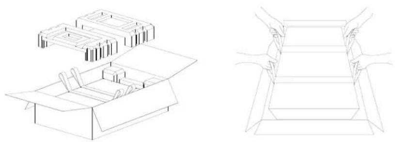
The UPS system is very heavy, please handle with care. Wear safety shoes and use a hydraulic equipment lift if one is available. At least two people are required for all handling operations, including unpacking, lifting, and installation in a rack system. Do not use the lifting straps to carry the unit around; they are provided to manually unpack the unit only.
USE LIFTING STRAPS TO REMOVE UNIT FROM THE BOX.
natural_image
Technical line drawings of two open box designs, one with internal components and the other showing hands holding a tray (no text or symbols)INTRODUCTION CONT.
WHATS IN THE BOX

REGISTRATION CARD x1

QUICK START GUIDE x1

SAFETY INSTRUCTION CARD x1
natural_image
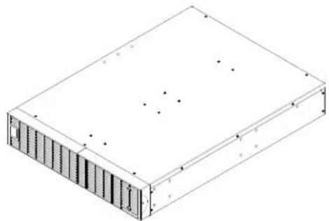
Isometric line drawing of a rectangular electronic device with internal components and mounting holes (no text or symbols)OL6KSTF 6,000 VA/6,000 W STEP-DOWN AND ISOLATION TRANSFORMER OR OL10KSTF 10,000 VA/10,000 W STEP-DOWN AND ISOLATION TRANSFORMER x1

natural_image
Pure electrical circuit lines without any symbols6 FT NEMA L6-30 LOCKING MALE PLUG TO 3-WIRE ROJ (REMOVE OUTER JACKET) POWER CABLE (L630PHW6FT INCLUDED WITH OL6KSTF) x1
natural_image
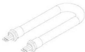
Line drawing of two U-shaped electronic components with leads (no text or symbols)3 FT 10/3 AWG CONDUCTOR WIRE ROJ (REMOVE OUTER JACKET) WITH CONDUIT (6AWGHW3FT INCLUDED WITH OL10KSTF) x1

TERMINAL
BLOCK CABLE
GLANDS x2

natural_image
Technical line drawing of two parallel metal beams with mounting holes (no text or symbols)LEFT & RIGHT HANGING BRACKETS x1

natural_image
Pure technical line drawing of two parallel metal beams with mounting holes (no text or symbols)LEFT & RIGHT RACKMOUNT RAILS x1

natural_image
Isometric line drawing of a rectangular box with three circular cutouts (no text or symbols)INPUT/OUTPUT TERMINAL BLOCK COVER x1
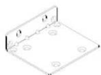
2U RACK MOUNT
EARS (TOWER
STANDS) x2

TOWER
INSTALLATION
TIE PLATE x1

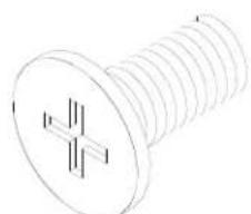
BLACK M5X7L
FLAT HEAD
SCREWS x8
natural_image
Technical line drawing of a screw with threaded base and central cross symbol (no text or labels)BLACK M5X12L PAN HEAD SCREWS x12

SILVER M5X6L PAN
HEAD SCREWS x6

PLASTIC
WASHERS x8

SCREW HOLE
DUST COVERS x12

RUBBER PADS x12
OVERVIEW
STEP-DOWN TRANSFORMER

FRONT: OL6KSTF/OL10KSTF BACK: OL6KSTF/OL10KSTF
- Input Circuit Breaker
Provides input overload and fault protection.
- Input/Output Terminal Block
Connect to input power source / output to equipment load.
- 6x NEMA 5-20R Outlets (120Vac)
Output receptacles to connect equipment load.
- Output Circuit Breaker (120Vac)
Provides output overload and fault protection.
HARDWARE INSTALLATION
RACKMOUNT INSTALLATION

Caution: Important Instructions
To prevent the risk of fire or electric shock, only use the supplied hardware to attach the mounting brackets.
Step 1: Remove the dust covers
Remove five dust covers from the screw holes as shown below.
Step 2: Rackmount ear & hanging bracket installation
Attach two rack mount ears to the step-down transformer using eight black M5X7L flat head screws. Install hanging brackets using six silver M5X6L pan head screws.
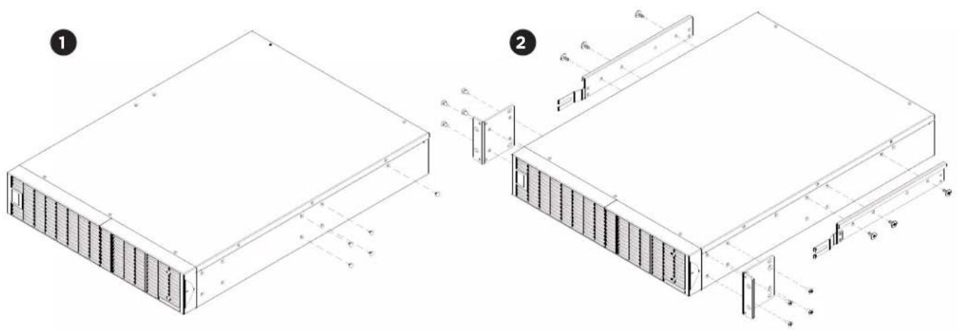
Step 3: Rackmount rail Installation
The rails adjust to mount in 19 in (48 cm) racks from 20.5 in to 36 in (52 cm to 91.5 cm) deep. Select the proper holes in the rack for positioning the step-down transformer in the rack. The step-down transformer takes up 2 rack units: rack hole positions 1 through 6.
Position the guide screws on the back of the rackmount rails into the rear rack square holes to temporarily support the rails in place.
Step 4: Adjust rackmount rails to fit your rack
Adjust the rail depth to match your rack depth. Attach the rackmount rail to your rack with two black M5X6L pan head screws and two plastic washers at the front of the rack (square holes 1 and 4 as shown below). Secure the rail to the rear of the rack with two black M5X12L screws and two plastic washers.
HARDWARE INSTALLATION CONT.
RACKMOUNT INSTALLATION: RACKMOUNT EARS INSTALLATION CONT.


Step 5: Place and secure the step-down transformer on the rails
Slide the hanging brackets on the step-down transformer on to the rails mounted in the rack with the front of the unit facing toward you. Secure the step-down transformer to your rack with four black M5X12L pan head screws at the front of the rack (square holes 1 and 4 as shown above).
NOTE: To slide the step-down transformer out from the rack
The step-down transformer will be secured by a safety locking mechanism midway of pulling it out of the rack. Use both hands to hold the step-down transformer and press the safety locking tab to pull the step-down transformer out.

natural_image
Technical line drawing of a structural frame assembly with inset views (no text or symbols)HARDWARE INSTALLATION CONT.
VERTICAL/TOWER INSTALLATION
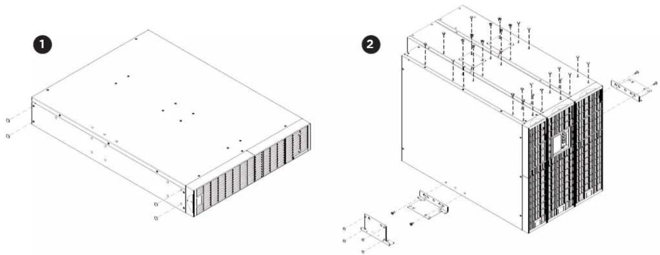
Step 1: Adhere rubber pads
Adhere the protective rubber pads to the left hand side of the step-down transformer.
Step 2: Attach the base stands and attach the dust covers
Stand the step-down transformer on its side with the rubber pads facing down. Install dust covers on open screw holes. If installing the step-down transformer together with a UPS and Extended Battery Module (EBM) secure the tie plate between the UPS, EBM and the step-down transformer using four black M5X7L flat head screws. Optionally adhere four circular rubber pads to each rack mount ear to use as tower stands and screw them on to the EBM and the step-down transformer using four silver M5X6L pan head screws for added stability as shown below.
natural_image
Technical line drawings of a server rack and server unit with internal components and structural details (no text or symbols)ELECTRICAL INSTALLATION
Check wiring dimensions with the following table.
| STEP-DOWN AND ISOLATION TRANSFORMERS WITH HARDWIRE INPUT TERMINAL BLOCK | WIRING AWG WIRING mm | 2 |
| OL6KSTF 10 AWG 5.5 mm | 2 | |
| OL10KSTF 6 AWG 14.0 mm | 2 |
HARDWIRING THE INPUT/OUTPUT TERMINALS
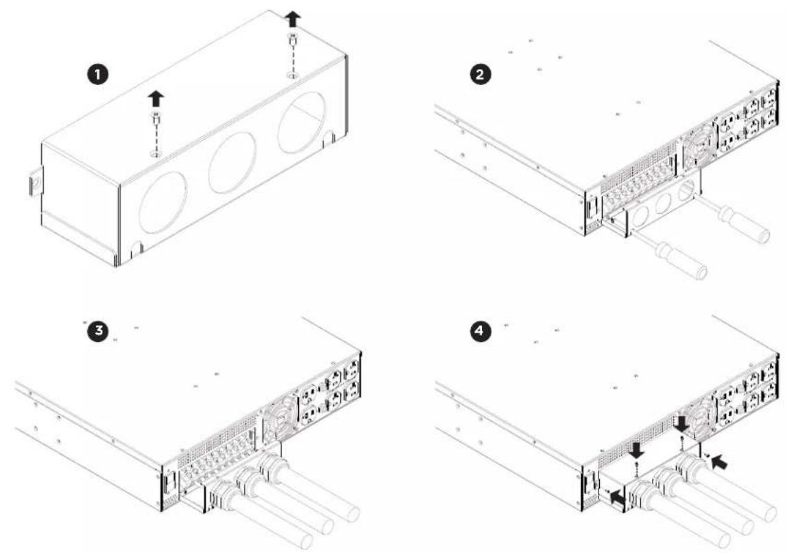
Step 1: Separate the terminal block cover
Loosen the two screws joining the top and bottom terminal block covers to separate them.
Step 2: Secure the bottom cover on to the step-down transformer
Tighten the two screws to secure the bottom cover on to the step-down transformer terminal block.
Step 3: Input/Output configuration
Insert the input/output cables through the appropriate cable gland. Hardwire the input/output wiring to their respective terminals as shown in the terminal block identification and configuration table.
Step 4: Secure the top cover
Use four screws to secure the top terminal block cover on to the step-down transformer.
ELECTRICAL INSTALLATION CONT.
Terminal Block Identification

Terminal Block Configuration
| INPUT VOLTAGE AC OUTPUT CONNECTION OUTPUT VOLTAGE | ||
| L1 → L2 = 200 Vac | L1 → N ← L2 | 100 Vac → 0 ← 100 Vac |
| L1 → L2 200 Vac | ||
| L1 → L2 = 220 Vac | L1 → N ← L2 | 110 Vac → 0 ← 110 Vac |
| L1 → L2 220 Vac | ||
| L1 → L2 = 230 Vac | L1 → N ← L2 | 115 Vac → 0 ← 115 Vac |
| L1 → L2 230 Vac | ||
| INPUT VOLTAGE AC OUTPUT CONNECTION OUTPUT VOLTAGE | ||
| L1T → L2 = 208 Vac | L1 → N ← L2 | 120 Vac → 0 ← 120 Vac |
| L1 → L2 240 Vac | ||
| L1 → L2T | 208 Vac | |
| INPUT VOLTAGE AC OUTPUT CONNECTION OUTPUT VOLTAGE | ||
| L1 → L2 = 240 Vac | L1 → N ← L2 | 120 Vac → 0 ← 120 Vac |
| L1 → L2 240 Vac | ||
| L1 → L2T | 208 Vac | |
ELECTRICAL INSTALLATION CONT.
CONNECTING A STEP-DOWN TRANSFORMER TO A UPS POWER MODULE
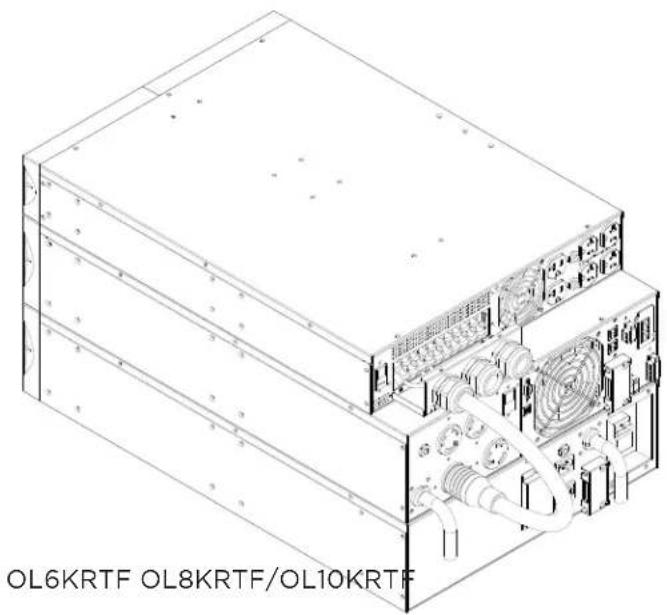
The following illustrations provide the recommended connections between a step-down transformer and a CyberPower Smart App Online UPS System.

natural_image
Technical line drawing of a server rack with internal components and cable (no text or symbols)
natural_image
Technical line drawing of an electronic device chassis with internal components and wiring (no text or symbols)
natural_image
Technical line drawing of an electronic device chassis with internal components and wiring (no text or labels)OL6KRTMBTF OL8KRTMBTF/OL10KRTMBTF
TECHNICAL SPECIFICATIONS
| MODELS OL6KSTF OL10KRT | ||
| CONFIGURATION | ||
| Maximum Output Power (VA)* | 6,000 VA 10,000 VA | |
| Maximum Output Power (W)* | 6,000 W 10,000 W | |
| Form Factor Rackmount/Tower | ||
| INPUT | ||
| Nominal Input Voltage 200/208/220/230/240 Vac | ||
| Input Voltage Range 200-240 Vac | ||
| Input Current Rating 30 A 50 A | ||
| Input Frequency 50/60 Hz | ||
| OUTPUT | ||
| Nominal Output Voltage* | 100/110/115/120 Vac or 200/208/220/230/240 Vac | |
| UPS Outlets | (6) NEMA 5-20R(1) Terminal block | (6) NEMA 5-20R(1) Terminal block |
| PHYSICAL | ||
| Dimensions | L x W x H = 23.6 x 17 x 3.46in. (60 x 43.3 x 8.8cm) | |
| Net Weight | 95.5 lb (43.4 kg) | 119.7 lb (54.4 kg) |
| ENVIRONMENTAL | ||
| Operating Temperature | 32°F to 104°F (0°C to 40°C) | |
| Operating Relative Humidity | 0 to 90% Non-condensing | |
| SAFETY | ||
| Conformance Approvals | UL | |
*200V are derated by 20%, 208 V are derated by 10% for OL10KSTF
PRODUCT REGISTRATION
CyberPower requests that you complete and return the Warranty Registration Card enclosed with the Product or register the Product at its website (www.cyberpowersystems.com/registration) to establish that you are the Initial Customer of the Product, and therefore entitled coverage under the Limited Warranty and the Connected Equipment Guarantee. (Registration is not required for coverage, but note: if you do not register your purchase, you will be required to provide proof of purchase.)
LIMITED WARRANTY AND CONNECTED EQUIPMENT GUARANTEE
Please visit www.CyberPowerSystems.com for a copy of the Limited Warranty and Connected Equipment Guarantee.
Where Can I Get More Information?
The application of the United Nations Convention of Contracts for the International Sale of Goods is expressly excluded. CyberPower is the warrantor under this Limited Warranty. For further information please feel free to contact CyberPower at:
Cyber Power Systems (USA), Inc.
4241 12th Ave E., STE 400, Shakopee, MN 55379;
call us at (877) 297-6937; or submit a web ticket online at cyberpowersystems.com/support.
Cyber Power Systems (USA), Inc. encourages environmentally sound methods for disposal and recycling of its UPS products. Please dispose and/or recycle your UPS and batteries in accordance to the local regulations of your state.
WARNING: This product can expose you to chemicals including bisphenol A (BPA) and styrene, which is known to the State of California to cause reproductive harm and cancer. For more information, go to www.P65Warnings.ca.gov.
CONFORMANCE APPROVAL

FCC NOTICE
This device complies with part 15 of the FCC Rules. Operation is subject to the following two conditions: (1) This device may not cause harmful interference, and (2) this device must accept any interference that may cause undesired operation.
WARNING!! This equipment has been tested and found to comply with the limits for a Class A digital device, pursuant to part 15 of the FCC Rules. These limits are designed to provide reasonable protection against harmful interference when the equipment is operated in a commercial environment. This equipment generates, uses, and can radiate radio frequency energy and, if not installed and used in accordance with the instruction manual, may cause harmful interference to radio communications. Operation of this equipment in a residential area is likely to cause harmful interference in which case the user will be required to correct the interference at his own expense. Shielded signal cables must be used with this product to ensure compliance with the Class A FCC limits.
The Class A digital apparatus meets all requirements of the Canadian Interference-Causing Equipment Regulation.
This document is believed to be accurate, but CyberPower reserves the right to change or correct the contents and does not assume any responsibility for omissions or errors.
Need Additional Help?
Feel free to contact our Tech Support department with installation, troubleshooting, or general product questions.
CyberPower Technical Support
Phone: 1.877.297.6937
Email: tech@cpsww.com
Web: www.CyberPowerSystems.com
Address: 4241 12th Avenue E, Suite 400 Shakopee, MN 55379, USA
Hours of Operation:
Monday - Friday, 7:00am - 6:00pm (CST)
CyberPower
Cyber Power Systems, Inc. | www.CyberPowerSystems.com
For USA and Canada | 4241 12th Ave East, Suite 400, Shakopee, MN 55379 | Toll-free: 877.297.6937
For all other regions | Please visit our website for local contact information.
Copyright ©2018 Cyber Power Systems, Inc. All rights reserved.
- SAFETY INSTRUCTIONS
- SAVE THESE INSTRUCTIONS
- SPECIAL SYMBOLS
- SAFETY INSTRUCTIONS CONT.
- PERSONAL SAFETY
- CAUTION
- RISK OF ELECTRIC SHOCK CONT.
- PRODUCT SAFETY
- RISK OF ELECTRIC SHOCK
- TABLE OF CONTENTS
- SAFETY INSTRUCTIONS......II
- INTRODUCTION....1
- OVERVIEW....3
- HARDWARE INSTALLATION ....4
- ELECTRICAL INSTALLATION....7
- TECHNICAL SPECIFICATIONS....10
- LIMITED WARRANTY AND CONNECTED EQUIPMENT GUARANTEE....11
- CONFORMANCE APPROVAL....15
- INTRODUCTION
- UNPACKING PROCEDURES
- INTRODUCTION CONT.
- OVERVIEW
- STEP-DOWN TRANSFORMER
- HARDWARE INSTALLATION
- RACKMOUNT INSTALLATION
- Caution: Important Instructions
- Step 1: Remove the dust covers
- Step 2: Rackmount ear & hanging bracket installation
- Step 3: Rackmount rail Installation
- Step 4: Adjust rackmount rails to fit your rack
- HARDWARE INSTALLATION CONT.
- RACKMOUNT INSTALLATION: RACKMOUNT EARS INSTALLATION CONT.
- Step 5: Place and secure the step-down transformer on the rails
- NOTE: To slide the step-down transformer out from the rack
- VERTICAL/TOWER INSTALLATION
- Step 1: Adhere rubber pads
- Step 2: Attach the base stands and attach the dust covers
- ELECTRICAL INSTALLATION
- HARDWIRING THE INPUT/OUTPUT TERMINALS
- Step 1: Separate the terminal block cover
- Step 2: Secure the bottom cover on to the step-down transformer
- Step 3: Input/Output configuration
- Step 4: Secure the top cover
- ELECTRICAL INSTALLATION CONT.
- CONNECTING A STEP-DOWN TRANSFORMER TO A UPS POWER MODULE
- TECHNICAL SPECIFICATIONS
- PRODUCT REGISTRATION
- LIMITED WARRANTY AND CONNECTED EQUIPMENT GUARANTEE
- Where Can I Get More Information?
- CONFORMANCE APPROVAL
- FCC NOTICE
- Need Additional Help?
- CyberPower Technical Support
- Hours of Operation:
- CyberPower
Brand : CyberPower
Model : OL10KSTF
Category : Electrical Transformer