
ED707FQ25E - Cooker SIEMENS - Free user manual and instructions
Find the device manual for free ED707FQ25E SIEMENS in PDF.


| Product type | Electric cooker |
| Brand | Siemens |
| Model | ED707FQ25E |
| Dimensions (H x W x D) | 85 cm x 60 cm x 60 cm |
| Weight | Approximately 55 kg |
| Power supply | 230 V / 50 Hz, 11 kW |
| Cooktop type | Ceramic glass cooktop with 4 burners |
| Oven type | Multi-function oven with convection |
| Oven capacity | 71 liters |
| Main functions | Baking, roasting, grilling, convection, defrosting |
| Automatic programs | Yes, 10 automatic programs |
| Cleaning | Pyrolytic |
| Safety | Child lock, automatic shut-off, glass safety |
| Repairability index | 8.0/10 |
| Spare parts available | Yes, via Siemens or authorized dealers |
| Energy class | A+ |
| Noise level | 45 dB (oven) |
Frequently Asked Questions - ED707FQ25E SIEMENS
User questions about ED707FQ25E SIEMENS
0 question about this device. Answer the ones you know or ask your own.
Ask a new question about this device
Download the instructions for your Cooker in PDF format for free! Find your manual ED707FQ25E - SIEMENS and take your electronic device back in hand. On this page are published all the documents necessary for the use of your device. ED707FQ25E by SIEMENS.
USER MANUAL ED707FQ25E SIEMENS
natural_image
Technical line drawing of a mechanical assembly with a tray, housing, and a cylindrical component (no text or symbols)1
2
3
4

5

6

7

natural_image
Illustration of shipping containers and a backpack with a crossed-out symbol (no text or labels)8
natural_image
Technical illustration of a mechanical component with cross symbol and side view (no text or labels)9
natural_image
Illustration of stacked shipping containers with a box and a circular component, no text or symbols present10
The image is too blurry to recognize any text content.

12

13

The image is too blurry to recognize any text content.

natural_image
Diagram of an electronic device internal structure showing ports, buttons, and a door (no text or symbols)16

The image is too blurry to recognize any text content.

natural_image
Diagram of a device internal structure with an arrow indicating direction, showing no text or symbols.18
The image is too blurry to recognize any text content.

20
The image is too blurry to recognize any text content.
22

The image is too blurry to recognize any text content.
24

25

26

The image is too blurry to recognize any text content.
28

natural_image
Diagram showing a device inside a container with an arrow indicating flow or movement, no text or symbols present.The image is too blurry to recognize any text content.
natural_image
Diagram of a device interior with a blue frame and black arrow indicating rotation or movement (no text or symbols)30
natural_image
Diagram of a mechanical assembly with a blue box and internal components, no text or symbols presentThe image is too blurry to recognize any text content.

natural_image
Pure architectural floor plan lines without any text, numbers, or symbols
natural_image
Technical diagram showing a ventilation duct inside a cabinet with an arrow indicating airflow direction (no text or symbols)32

natural_image
Diagram of a device with a blue box and internal air vent, showing airflow direction (no text or symbols)34


natural_image
3D diagram of a mechanical assembly with directional arrows indicating movement or force (no text or symbols)36

natural_image
Diagram of a mechanical device with arrows indicating motion or force, no text or symbols presentThe image is too blurry to recognize any text content.
natural_image
Mechanical assembly diagram showing a lever mechanism with directional arrows indicating motion (no text or symbols present)38

natural_image
Isometric diagram of a mechanical assembly with two blue blocks mounted on a base plate (no text or symbols)40

natural_image
3D diagram of a mechanical assembly with blue blocks and a dashed outline, no visible text or symbolsThe image is too blurry to recognize any text content.

natural_image
Illustration of a blue tool kit being inserted into a slot on a flat surface (no text or symbols)42
The image is too blurry to recognize any text content.

44
F
46

47

48

49

natural_image
Illustration of a blue syringe on a flat surface (no text or symbols)50
es

natural_image
Simple line drawing of a house with airflow and fire symbol, no text or labels presentAfter unpacking all parts, check for any damage in transit and completeness of the delivery.
→ Fig. 1
QR code for the installation video
This is were you will find the QR code for the installation video.
→ Fig. 2
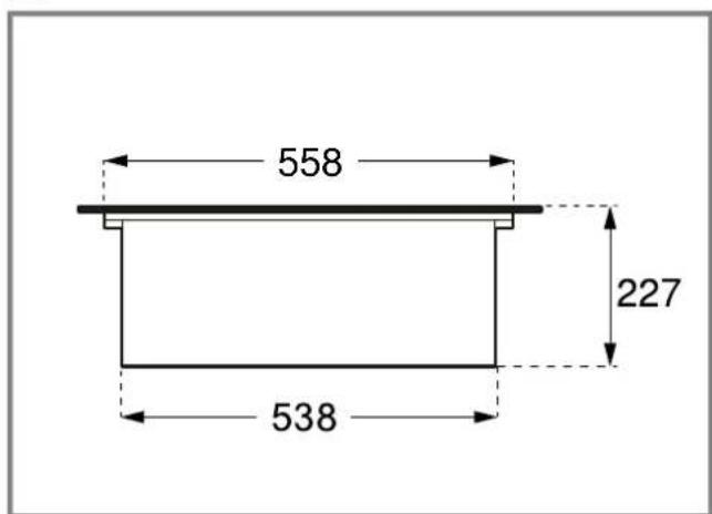
Appliance dimensions
You will find the dimensions of the appliance here → Fig. 3
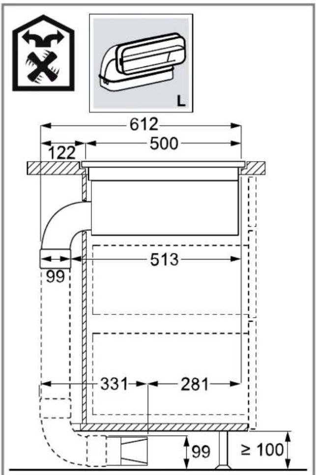
Installation dimensions for flat duct bends
This is where you can find an overview of the installation dimensions for the flat duct bends.
Side view:
→ Fig. 4
→ Fig. 5
→ Fig. 6
Front view:
→ Fig. 7
Installation variants
This is where you can find an overview of the different installation variants.
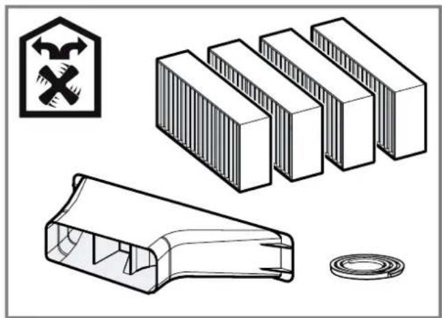
Odour filter and adapter for circulating-air mode:
→ Fig. 8
Odour filter, diffuser and seal for circulating-air mode:
→ Fig. 9
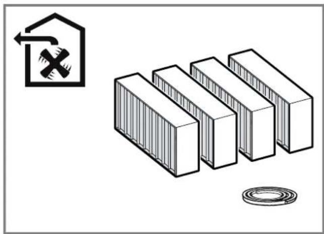
Acoustics filter and seal for air extraction mode: → Fig. 10
Note: Channels suitable for installation can be obtained from customer service, our website or from specialist retailers.
Safety clearances
Comply with the safety clearances for the appliance.
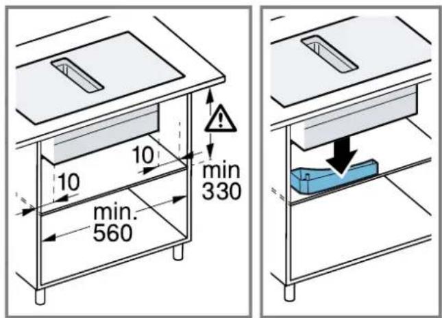
Clearances to the overflow container:
→ Fig. 11
Position of the overflow container:
→ Fig. 12
The performance is optimal at a clearance of 50 mm between the unit back panel and the wall. The performance is reduced at a smaller clearance.
→ Fig. 13
Observe the safety clearances for the worktop cut-out.
Do not place any objects in the drawer which exceed the maximum height of the drawer. The objects may come into contact with the base of the appliance and thus disrupt the functions.
→ Fig. 14

General information
- Read this instruction manual carefully.
■ Only a licensed expert may connect the appliance.
■ Switch off the power supply before carrying out any work.
■ Never use this appliance in boats or in vehicles.
■ Follow the worktop manufacturer's recommendations.
Safe installation
Follow these safety instructions when installing the appliance.
The appliance can only be used safely if it is correctly installed according to the safety instructions. The installer is responsible for ensuring that the appliance works perfectly at its installation location.

WARNING – Danger: Magnetism!
The appliance contains permanent magnets. They may affect electronic implants, e.g. pacemakers or insulin pumps.
▶ Persons with electronic implants must stand at least 10 cm away from the appliance.

WARNING – Risk of poisoning!
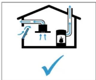
Risk of poisoning from flue gases being drawn back in. Room-air-dependent heat-producing appliances (e.g. gas, oil, wood or coal-operated heaters, continuous flow heaters or water heaters) obtain combustion air from the room in which they are installed and discharge the exhaust gases into the open through an exhaust gas system (e.g. a chimney). With the extractor hood switched on, air is extracted from the kitchen and the adjacent rooms. Without an adequate supply of air, the air pressure falls below atmospheric pressure. Toxic gases from the flue or the extraction shaft are sucked back into the living space.

natural_image
Simple line drawing of a house with airflow and fire, no text or symbols present▶ Always ensure adequate fresh air in the room if the appliance is being operated in exhaust air mode at the same time as a room-air-dependent heat-producing appliance is being operated.
It is only possible to safely operate the appliance if the pressure in the room in which the heating appliance is installed does not drop more than 4 Pa (0.04 mbar) below atmospheric pressure. This can be achieved whenever the air needed for combustion is able to enter through openings that cannot be sealed, for example in doors, windows, incoming/exhaust air wall boxes or by other technical means. An incoming/exhaust air wall box alone does not ensure compliance with the limit.
▶ In any case, consult your responsible chimney sweep. They are able to assess the house's entire ventilation setup and will suggest the suitable ventilation measures to you.
- Unrestricted operation is possible if the appliance is operated exclusively in circulating-air mode.

WARNING – Risk of fire!
Grease deposits in the grease filter may catch fire.
▶ Never work with naked flames close to the appliance (e.g. flambéing).
- Do not install the appliance near a heat-producing appliance for solid fuel (e.g. wood or coal) unless a closed, non-removable cover is available. There must be no flying sparks.

WARNING – Risk of injury!
Changes to the electrical or mechanical assembly are dangerous and may lead to malfunctions.
- Do not make any changes to the electrical or mechanical assembly.
Parts that are accessible during installation may have sharp edges and may lead to cutting injuries.
▶ Wear protective gloves
The appliance is heavy.
▶ To move the appliance, two people are required.
▶ Use only suitable tools and equipment.

WARNING – Risk of suffocation!
Children may put packaging material over their heads or wrap themselves up in it and suffocate.
- Keep packaging material away from children.
- Do not let children play with packaging material.

WARNING – Risk of poisoning!
Risk of poisoning from flue gases being drawn back in.
- Do not emit the exhaust air into a smoke or exhaust gas flue that is in operation.
- Do not emit the exhaust air into a shaft that is used to ventilate installation rooms for heat-producing appliances.
If the exhaust air is to be conveyed into a smoke or exhaust gas flue, you must obtain the consent of the heating engineer responsible.
Risk of poisoning from flue gases being drawn back in.
▶ If an extractor hood with an open-flued heat production source is installed, the power supply for the extractor hood must be provided with a suitable safety switch.
Information about the electrical connection
In order to safely connect the appliance to the electrical system, follow these instructions.

WARNING – Risk of electric shock!
It must always be possible to disconnect the appliance from the electricity supply. The appliance must only be connected to a mains socket that has been installed correctly.
▶ An all-pole isolating switch must be integrated into the permanent electrical installation in accordance with the conditions of overvoltage category III and in accordance with the installation regulations.
The permanent electrical installation must only be wired by a professional electrician. We recommend installing a residual-current circuit breaker (RCCB) in the appliance's power supply circuit.
- Do not kink or trap the connection cable, and keep it away from sharp edges.
■ Route the connection cable in such a way that it does not touch the hot casing.
■ Use only the connection cable that is supplied with the appliance or is provided by technical after-sales service.
■ This appliance complies with the EC interference suppression regulations.
■ The appliance corresponds to protection class 1. You should therefore only use the appliance with a protective earth connection.
■ The manufacturer shall assume no liability for malfunctions or damage resulting from incorrect electrical wiring.
Preparing the electrical connection
Requirement: Only after-sales service staff who have been trained accordingly may carry out work on the inside of the appliance or replace the power cord.
- Observe the information about the electrical connection.
An incorrect installation, an improper installation or connection invalidates the warranty.
- If a longer mains power cable is required, contact the after-sales service. Connecting cables up to 2.20 m are available.
- On appliances without a preinstalled cable, insert the power cable into the mains socket.
Opening the mains socket
- Use a screwdriver to lift the cover of the mains outlet.
$$ \rightarrow \text { Fig. } 1 5 $$
Preparing the mains socket
-
Undo the screw.
-
Use a screwdriver to lift the hose clamp.
-
Undo the hose clamp.
$$ \begin{array}{l} \rightarrow \text { Fig. } 1 6 \ \rightarrow \text { Fig. } 1 7 \ \rightarrow \text { Fig. } 1 8 \ \end{array} $$
Connecting the cable to the mains socket
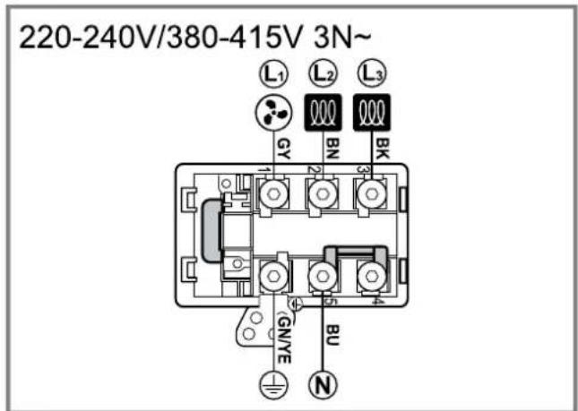
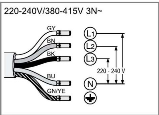
- For 3 N, connect the cable to the mains socket in accordance with the following figure.
$$ \rightarrow \text { Fig. } 1 9 $$
- For 2 N, connect the cable to the mains socket in accordance with the following figure.
$$ \rightarrow \text { Fig. } \boxed {2 0} $$
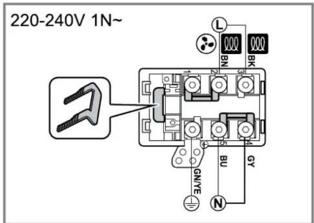
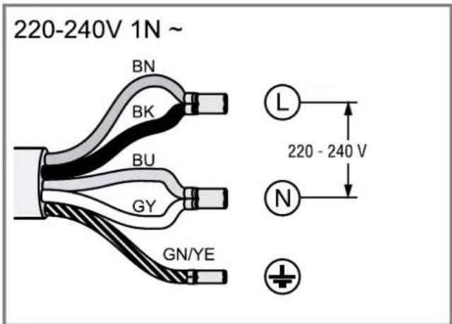
- For 1 N, connect the cable to the mains socket in accordance with the following figure.
$$ \rightarrow \text { Fig. } \boxed {2 1} $$
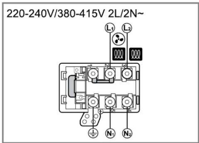
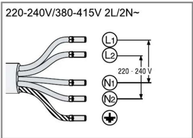
- For 2 L/2 N, connect the cable to the mains socket in accordance with the following figure.
$$ \rightarrow \text { Fig. } \boxed {2 2} $$
-
Note the colours of the cables.
-
BN: Brown
- BU: Blue
– GN/YE: Yellow and green - BK: Black
-
GY: Grey
-
If required, install the enclosed copper bridges in accordance with the connection diagram.
-
Connect the cables and then tighten the screws of the mains socket.
-
For a 1 N\~ or 2 L/2 N connection in accordance with the connection diagram, 1 corresponds to the fan motor.
- For a 2 N\~/3 N\~ connection, phase L1 (grey) corresponds to the fan motor.
Secure the cable in the mains socket
- Use the hose clamp to secure the power cord.
-
Tighten the screw at the correct position.
-
Do not use a cordless screwdriver.
→ Fig. 23 -
To facilitate closing the mains socket, arrange the cables in the central area of the mains socket.
- Close the cover of the mains socket.
Instructions for the exhaust air pipe
The appliance manufacturer does not provide any warranty for faults attributable to the pipeline.
■ Use a short, straight exhaust air pipe with as large a pipe diameter as possible.
- Long, rough exhaust air pipes, many pipe bends or small pipe diameters reduce the suction power and increase the fan noise.
■ Use an exhaust pipe that is made of non-combustible material.
■ To prevent condensate from returning, fit the exhaust pipe with a 1° gradient from the appliance.
Flat ducts
Use flat ducts with an inner cross-section that corresponds to the diameter of the round pipes:
■ Diameter of 150 mm corresponds to approx. 177 cm ^4 .
■ Use sealing strips for different pipe diameters.
■ Do not use any flat ducts with sharp bends.
Round pipes
Round pipes with an inner diameter of 150 mm.
Instructions for the air extraction mode
For air extraction mode, a one-way flap should be installed.
Notes
If a one-way flap is not included with the appliance, one can be ordered from a specialist retailer.
■ If the exhaust air is conveyed through the external wall, a telescopic duct should be used.
Checking the units
- Check whether the fitted unit is level and has sufficient load-bearing capacity.
The maximum weight of the appliance is approx. 25 kg.
The worktop into which you are fitting the appliance must be able to withstand loads of approx. 60 kg.
- Ensure that the stability of the fitted unit is also guaranteed following cut-out work.
-
Use suitable substructures to ensure the load-bearing capacity and the stability, particularly in the case of thin worktops.
-
Take the appliance weight, including additional load, into consideration.
-
Use heat-resistant and moisture-resistant reinforcement material.
-
Ensure that the fitted unit is heat-resistant up to 90 °C.
- Do not support any other appliances, e.g. ovens, refrigerators, dishwashers or washing machines.
- Only check that the appliance is level once it has been installed in the installation opening.
Flush installation
With the flush installation, the appliance and worktop are on one level. There is no unattractive stepping between the appliance and the worktop.
You can install the appliance in the following temperature-resistant and waterproof worktops:
■ Stone worktops
■ Plastic worktops, e.g. Corian®
■ Solid wood worktops
Installation in compressed-wood worktops is not possible.
Preparing the units
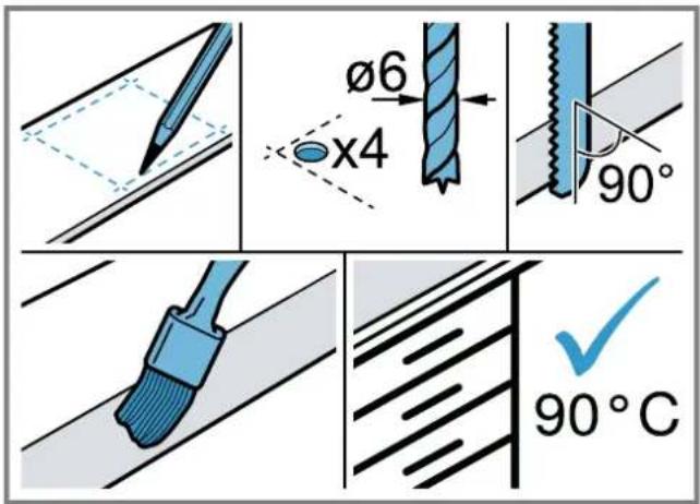
Requirement: The fitted units must be heat-resistant up to 90 °C.
- Mark the unit cut-out in accordance with the installation diagram.
- Drill four holes with a diameter of 6 mm.
- Ensure that the angle of the cut surface to the worktop is 90^ .
$$ \rightarrow \text { Fig. } 1 4 $$
$$ \rightarrow \text { Fig. } \boxed {2 4} $$
$$ \rightarrow \text { Fig. } 2 4 $$
Observing the minimum clearances when installing above a drawer
- When removing the overflow container on integrated appliances, take the minimum clearances into consideration.
$$ \rightarrow \text { Fig. } 1 1 $$
- Observe the position of the overflow container.
$$ \rightarrow \text { Fig. } \boxed {1 2} $$
Preparing the unit for circulating-air mode with the adapter
- Observe the relevant dimensions when combining with the adapter for the cut-out in the back wall.
$$ \rightarrow \text { Fig. } \boxed {2 5} $$
-
Use the template to create the cut-out in the back wall.
-
In circulating-air mode, establish an air outlet in the unit's plinth.
-
Provide a minimum air outlet cross-section of approx. 440~cm^2 .
-
To keep the draught and noise low, ensure that the outlet opening in the base panel is as large as possible.
-
To guarantee that the appliance works correctly, ventilate the hob appropriately via an air outlet with a minimum cross-section of 200 cm ^2 in the base unit.
-
After making the cut-outs, remove any shavings.
-
Seal the cut surfaces so that they are heat-resistant and waterproof.
$$ \rightarrow \text { Fig. } \boxed {2 4} $$
Preparing the unit for circulating-air mode with a circulating-air duct
- If required, remove the unit's back wall.
- Observe the relevant dimensions when combining with the flat duct elbow for the cut-out in the back wall.
$$ \rightarrow \text { Fig. } \boxed {2 6} $$
- In circulating-air mode, establish an air outlet in the unit's plinth.
- Provide a minimum air outlet cross-section of approx. 440~cm^2 .
- To keep the draught and noise low, ensure that the outlet opening in the base panel is as large as possible.
- To guarantee that the appliance works correctly, ventilate the hob appropriately via an air outlet with a minimum cross-section of 200 cm ^2 in the base unit.
- After making the cut-outs, remove any shavings.
- Seal the cut surfaces so that they are heat-resistant and waterproof.
$$ \rightarrow \text { Fig. } \boxed {2 4} $$
Preparing the unit for air extraction mode
- If required, remove the unit's back wall.
- Observe the relevant dimensions when combining with a flat duct elbow for the cut-out in the back wall.
$$ \rightarrow \text { Fig. } \boxed {2 7} $$
-
After making the cut-outs, remove any shavings.
-
Seal the cut surfaces so that they are heat-resistant and waterproof.
$$ \rightarrow \text { Fig. } \boxed {2 4} $$
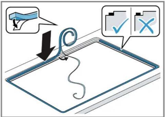
Attaching adhesive tape
- Attach the enclosed adhesive tape to the worktop section.
$$ \rightarrow \text { Fig. } \boxed {2 8} $$
Installing the appliance
⚠ WARNING – Risk of injury!
Parts that are accessible during installation may have sharp edges and may lead to cutting injuries.
▶ Wear protective gloves
The appliance is heavy.
▶ To move the appliance, two people are required.
▶ Use only suitable tools and equipment.
▶ Install the appliance for air extraction mode → Page 23, circulating-air mode → Page 22 or circulating-air mode with circulating-air duct → Page 23.
Note: The appliance is only intended for flush installation.
Installing the appliance for circulating-air mode with adapter
Note: When installing directly on a non-insulated outer wall ( ≥ 0.5 W/m ^2 °C), we recommend a configuration with circulating-air duct.
- For the circulating-air mode, use the adapter and the odour filter.
- Ensure that the clearance between the appliance and the rear panel of the unit is between 10 and 80 mm.
Attaching the adapter
- Clean and degrease the adhesive surface around the cut-out in the unit's back panel.
- Insert the adapter into the outlet opening on the rear of the hob.
- Remove the adhesive tape's protective film from the adapter.
$$ \rightarrow \text { Fig. } \boxed {2 9} $$
$$ \rightarrow \text { Fig. } \boxed {3 0} $$
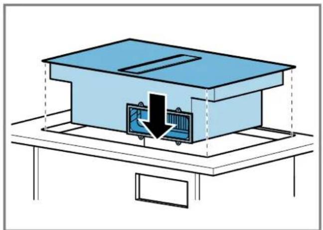
Inserting the appliance into the worktop cut-out
- Ensure that the connection cable is connected to the appliance.
- Carefully insert the appliance into the worktop cut-out.
$$ \rightarrow \text { Fig. } \boxed {3 1} $$
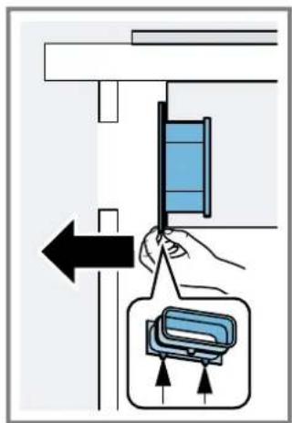
Securing the adapter
- Hold the adapter at the central holder and use the side holders to slide it towards the unit's back panel in the base unit, then affix it.
$$ \rightarrow \text { Fig. } \boxed {3 2} $$
- If required, also use screws to secure it. → Fig. 33
Installing the appliance for air recirculation mode with circulating-air duct
- For circulating-air mode, use the seal, the circulating-air duct, the diffuser and the odour filter.
- Observe the dimensions for the different flat duct bends. → Page 19
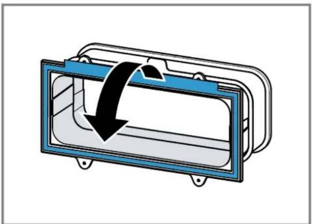
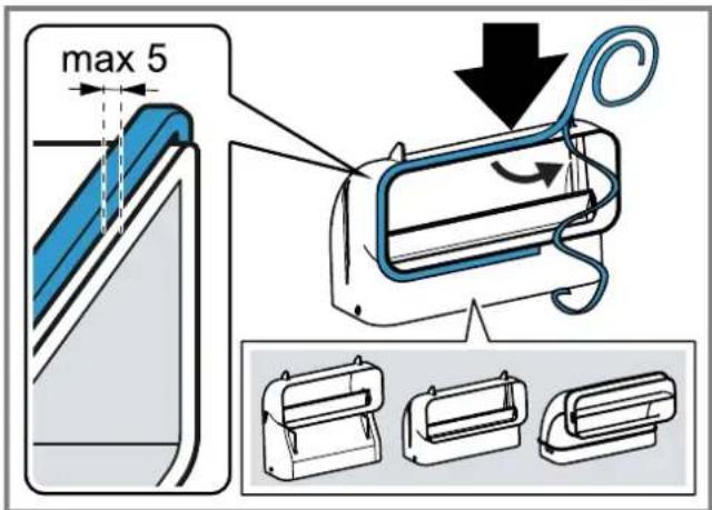
Securing the seal
- Secure the seal on the flat duct elbow at a maximum of 5 mm from the edge. → Fig. 34
Inserting the flat duct elbow
- Insert the flat duct elbow into the outlet opening on the rear of the appliance.
$$ \rightarrow \text { Fig. } \boxed {3 5} $$
Inserting the appliance into the worktop cut-out
- Ensure that the connection cable is connected to the appliance.
- Carefully insert the appliance into the worktop cut-out. → Fig. 36
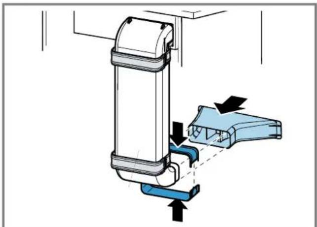
Establishing the pipework between the appliance and the diffuser
- Connect the components of the circulating-air duct to each other.
- Connect the circulating-air duct to the flat duct elbow on the rear of the hob.
- Connect the diffuser to the circulating-air duct. → Fig. 39
$$ \rightarrow \text { Fig. } \boxed {3 7} $$
$$ \rightarrow \text { Fig. } \boxed {3 8} $$
Install the appliance for air extraction mode
- For air extraction mode, use the seal and the acoustics filters.
- Observe the instructions for the exhaust air pipe. → Page 21
- Secure the seal on the flat duct elbow at a maximum of 5 mm from the edge.
Securing the seal
$$ \rightarrow \text { Fig. } \boxed {3 4} $$
Establishing the piping
- Insert the flat duct elbow into the outlet opening on the rear of the appliance.
$$ \rightarrow \text { Fig. } \boxed {3 5} $$
- If required, install additional piping elements.
Inserting the appliance into the worktop cut-out
- Ensure that the connection cable is connected to the appliance.
- Carefully insert the appliance into the worktop cut-out.
$$ \rightarrow \text { Fig. } \boxed {3 6} $$
Connecting the exhaust air pipe
- Secure the exhaust air pipe to the flat duct bend.
- Establish the connection to the exhaust air opening.
- Seal the joints appropriately.
Inserting filters
Note: For circulating-air mode, insert the odour filters.
For air extraction mode, insert the acoustics filters.
-
Observe the filters' air flow direction.
-
Insert two of the filters into the left and right of the appliance, and slide them forwards.
$$ \rightarrow \text { Fig. } 4 0 $$
- Insert the other filters into the left and right of the appliance.
$$ \rightarrow \text { Fig. } 4 1 $$
Inserting grease filters
- Insert the grease filter.
$$ \rightarrow \text { Fig. } 4 2 $$
Establishing the connection to the power supply
- Observe the connection data on the rating plate.
- For 3 N, connect the cable to the mains socket in accordance with the figure.
- For 2 N, connect the cable to the mains socket in accordance with the figure.
- For 1 N, connect the cable to the mains socket in accordance with the figure.
- For 2 L/2 N, connect the cable to the mains socket in accordance with the figure.
$$ \rightarrow \text { Fig. } \boxed {4 3} $$
$$ \rightarrow \text { Fig. } \boxed {4 4} $$
$$ \rightarrow \text { Fig. } \boxed {4 5} $$
$$ \rightarrow \text { Fig. } 4 6 $$
-
Note the colours of the cables.
-
BN: Brown
- BU: Blue
- GN/YE: Yellow and green
- BK: Black
-
GY: Grey
-
If required, arrange the supplied wire end ferrules differently depending on the type of connection.
-
To connect two cables, if required, use a wire end ferrule.
-
Shorten the wires.
- Remove the insulation.
Checking the function
- Switch on the appliance.
- If 0400 805 is up the appliance is not connected correctly.
→ "Checking and correcting the electrical connection", Page 23 - If no faults appear in the appliance's display, use the operating instructions to check that the ventilation is working.
Checking and correcting the electrical connection
- Disconnect the appliance from the power supply.
- Check whether the connection to the appliance (fig. 4) and the building-side connection (fig. 8) correspond to the connection diagram in these installation instructions.
→ "Preparing the electrical connection", Page 21
→ "Establishing the connection to the power supply", Page 23 - For 3 N, observe the following figure. → Fig. 47
- For 2 N, observe the following figure.
- For 1 N, observe the following figure.
$$ \rightarrow \text { Fig. } \boxed {4 8} $$
$$ \rightarrow \text {Fig.} \boxed {4 9} $$
Sealing crevices
Requirement: You must carry out a function test before sealing the joint.
- Seal the gap around it using suitable, heat-resistant silicone, e.g. Novasil® S70 or Ottoseal® S70.
Unsuitable silicone adhesive causes permanent discoloration to natural stone worktops.
$$ \rightarrow \text { Fig. } 5 0 $$
- Use the smoothing agent recommended by the manufacturer to smooth the crevice.
- Observe the usage instructions for the silicone adhesive.
- Leave the silicone adhesive to dry for at least 24 hours.
The drying time depends on the ambient temperature.
- Do not operate the appliance until the silicone has dried completely.
Switching the display for air extraction mode
- If required for the air extraction mode and the air recirculation mode, change the display of the electronic control in the basic settings.
- Observe the basic settings section in the instruction manual.
Removing the appliance ATTENTION!
Tools may damage the appliance frame.
- Do not prise out the appliance from above.
- Disconnect the appliance from the power supply.
- Remove the exhaust air duct or undo the circulating-air connections.
- Remove the silicone joint.
- Push out the appliance from below.
fr

natural_image
Simple line drawing of a house with airflow and a checkmark (no text or symbols)⚠ WAARSCHUWING – Kans op brand!
⚠ WAARSCHUWING – Kans op letsel!
⚠ WAARSCHUWING – Kans op verstikking!
⚠ WAARSCHUWING – Kans op vergiftiging!
⚠ WAARSCHUWING – Kans op letsel!
ADVARSEL – Fare for forgiftning!

natural_image
Simple line drawing of a house with airflow and fire symbol, no text or labels presentADVARSEL – Brandfare!
ADVARSEL – Fare for forgiftning!
⚠ ADVARSEL – Fare for forgiftning!
⚠️ ADVARSEL – Fare for forgiftning!
Tilbakesugde forbrenningsgasser kan føre til forgiftning.
Sette inn flatt rørbend
$$ \rightarrow E _ {I K}. \textcircled {9} $$

natural_image
Simple line drawing of a house with airflow and a fire symbol, no text or labels present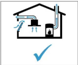
natural_image
Simple line drawing of a house with airflow and a fire extinguisher, no text or symbols present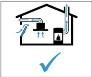
natural_image
Simple line drawing of a house with airflow and a fire symbol, no text or labels present- es
- QR code for the installation video
- Appliance dimensions
- Installation dimensions for flat duct bends
- Installation variants
- Safety clearances
- General information
- Safe installation
- WARNING – Danger: Magnetism!
- WARNING – Risk of poisoning!
- WARNING – Risk of fire!
- WARNING – Risk of injury!
- WARNING – Risk of suffocation!
- Information about the electrical connection
- WARNING – Risk of electric shock!
- Preparing the electrical connection
- Opening the mains socket
- Preparing the mains socket
- Connecting the cable to the mains socket
- Secure the cable in the mains socket
- Instructions for the exhaust air pipe
- Flat ducts
- Round pipes
- Instructions for the air extraction mode
- Notes
- Checking the units
- Flush installation
- Preparing the units
- Observing the minimum clearances when installing above a drawer
- Preparing the unit for circulating-air mode with the adapter
- Preparing the unit for circulating-air mode with a circulating-air duct
- Preparing the unit for air extraction mode
- Attaching adhesive tape
- Installing the appliance
- ⚠ WARNING – Risk of injury!
- Installing the appliance for circulating-air mode with adapter
- Attaching the adapter
- Inserting the appliance into the worktop cut-out
- Securing the adapter
- Installing the appliance for air recirculation mode with circulating-air duct
- Securing the seal
- Inserting the flat duct elbow
- Establishing the pipework between the appliance and the diffuser
- Install the appliance for air extraction mode
- Establishing the piping
- Connecting the exhaust air pipe
- Inserting filters
- Inserting grease filters
- Establishing the connection to the power supply
- Checking the function
- Checking and correcting the electrical connection
- Sealing crevices
- Switching the display for air extraction mode
- Removing the appliance ATTENTION!
- fr
- ⚠ WAARSCHUWING – Kans op brand!
- ⚠ WAARSCHUWING – Kans op letsel!
- ⚠ WAARSCHUWING – Kans op verstikking!
- ⚠ WAARSCHUWING – Kans op vergiftiging!
- ADVARSEL – Fare for forgiftning!
- ADVARSEL – Brandfare!
- ⚠ ADVARSEL – Fare for forgiftning!
- ⚠️ ADVARSEL – Fare for forgiftning!
- Sette inn flatt rørbend
Brand : SIEMENS
Model : ED707FQ25E
Category : Cooker