DM-810 - Audio/video converter AudioControl - Free user manual and instructions
Find the device manual for free DM-810 AudioControl in PDF.


| Product Type | Audio/Video Converter |
| Brand | AudioControl |
| Model | DM-810 |
| Dimensions (W x H x D) | 19 x 1.75 x 8 inches (rackmount, 1U) |
| Weight | 8 lbs (3.6 kg) |
| Power Supply | 100-240V AC, 50/60 Hz |
| Power Consumption | 30 W max |
| Video Input Formats | HDMI, Component, Composite, S-Video |
| Video Output Formats | HDMI, HDBaseT |
| Audio Input Formats | HDMI, Optical, Coaxial, Analog RCA |
| Audio Output Formats | HDMI, Optical, Coaxial, Analog RCA |
| HDCP Support | HDCP 2.2 and 1.4 compliant |
| Maximum Resolution | 3840 x 2160 @ 60Hz (4K UHD) |
| Front Panel Indicators | Power, Input selector, Output status LEDs |
| Rear Panel Connectors | HDMI in/out, HDBaseT out, optical/coaxial/analog audio, RS-232, Ethernet |
| Mounting | Rackmount ears included, 1U |
| Operating Temperature | 32°F to 104°F (0°C to 40°C) |
| Storage Temperature | -4°F to 140°F (-20°C to 60°C) |
| Certifications | CE, FCC, RoHS |
| Included Accessories | Power cord, rackmount hardware, remote control |
| Cleaning Instructions | Wipe with a soft, dry cloth; avoid liquids and abrasives |
| Safety Warnings | Do not expose to moisture; ensure proper ventilation; unplug when not in use |
| Spare Parts Availability | Contact AudioControl customer service |
| Repair Information | Authorized service centers; user-replaceable power supply module |
| Warranty | Limited 5-year warranty |
Frequently Asked Questions - DM-810 AudioControl
User questions about DM-810 AudioControl
0 question about this device. Answer the ones you know or ask your own.
Ask a new question about this device
Download the instructions for your Audio/video converter in PDF format for free! Find your manual DM-810 - AudioControl and take your electronic device back in hand. On this page are published all the documents necessary for the use of your device. DM-810 by AudioControl.
USER MANUAL DM-810 AudioControl
DM-608
Six by Eight Channel DSP Matrix Processor
AudioControl®
Making Good Sound Great™
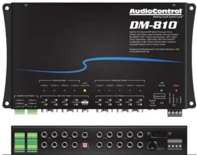
DM-810 ^TM
Eight by Ten Channel DSP Matrix Processor
Installation Manual
Important Safety Instructions
DM-608/DM-810
- Read these instructions.
- Keep these instructions.
- Heed all warnings.
- Follow all instructions.
- Do not use this apparatus near water.
- Clean only with a dry cloth.
- Do not block any ventilation openings. Install in accordance with the manufacturer's instructions.
- Do not install near any heat sources such as mufflers, silencers, exhaust pipes, or other apparatus (including amplifiers) that produce heat.
- WARNING: Improper installation may lead to permanent injury or death. Installation of the apparatus must be done with great care by qualified personnel, to prevent damage to fuel lines, power, and other electrical wiring, hydraulic brake lines, and other systems, that might compromise vehicle safety.
- Provide +12V and Ground wiring of a suitable thickness/gauge to ensure adequate current to the apparatus.
- Use rubber grommets to protect wiring whenever passing wires through metal openings or bulkheads.
- Only use attachments/accessories specified by the manufacturer.
-
Refer all servicing to qualified service personnel. Servicing is required when the apparatus has been damaged in any way, such as the power input terminals are damaged, liquid has been spilled or objects have fallen into the apparatus, the apparatus has been exposed to rain or moisture, does not operate normally, or has been dropped.
-
This apparatus shall not be exposed to dripping or splashing, and no object filled with liquids, shall be placed on the apparatus.
- Fuses shall be replaced only with the correct type and fuse value, and only when the apparatus is powered off.
- Exposure to high sound pressure levels may lead to permanent hearing loss. Take every precaution to protect your hearing.

The lightning flash with arrowhead symbol within an equilateral triangle is intended to alert the user to the presence of uninsulated "dangerous voltage" within the product's enclosure, that may be of sufficient magnitude to constitute a risk of electric shock to persons.

The exclamation point within an equilateral triangle is intended to alert the user of the presence of important operating and maintenance (servicing) instructions in the literature accompanying the appliance.
Caution: to reduce the risk of electric shock, do not disassemble the apparatus, other than to remove the top panel to access the controls.
There are no user-serviceable parts inside. Refer servicing to qualified personnel.

Recycling notice: If the time comes and this apparatus has fulfilled its destiny, do not throw it out into the trash. It has to be carefully recycled for the good of mankind, by a facility specially equipped for the safe recycling of electronic apparatii. Please contact your local or state recycling leaders for assistance in locating a suitable nearby recycling facility. Or, contact us and we might be able to repair it for you.
Table of Contents
Important Safety Instructions 2
Chapter 1: Introduction....4
Chapter 2: Quick Start Guide ....5
Chapter 3: Hookup Diagrams....7
Chapter 4: Installation....11
Chapter 5: Features....13
Chapter 6: Installing the Application .....16
Chapter 7: Updating the Firmware....20
Chapter 8: The Display....22
Chapter 9: Troubleshooting .....38
Chapter 10: Specifications....39
Chapter 11: Service ....44
Chapter 12: The Warranty....45
Salsa! 48
AudioControl®
Making Good Sound Great™
Congratulations on your purchase of a fine AudioControl product. You have chosen wisely. We hope that it will give you many years of super audio enjoyment and larks.
When you require total control and optimization to achieve great sound quality, AudioControl's DM-608 and DM-810 digital signal processors are the ideal solution.
These powerful processors allow you to truly optimize the performance of your audio system, regardless of whether you are using a factory or aftermarket source, and to achieve the goal of "Making Good Sound Great."
These processors are equipped with key features, such as active speaker-level inputs, line-level and digital audio inputs, providing up to 10 channels of output for the DM-810, and 8 channels for the DM-608.
Connect your laptop using our smart user Interface, which is a fully-featured matrix DSP interface designed to give you instant and clear control over every aspect of your processor.
Route any input to any output, configure signal summing, adjust input and output gain, delay phase correction and polarity, then precisely tune the processor using a 30 band EQ. High-pass, low-pass and band-pass can be set up for any output using 12 or 24 dB/octave Linkwitz-Riley crossovers.
For OEM integration, take advantage of the input and output Real Time Analyzers (RTA), available for every input and output, to easily identify and sum factory speaker-level signals.
The processors also include AudioControl's proprietary features such as AccuBASS®, GTO™ Signal Sense, and MILC™.
The built-in Option Port is our nod to the future of car audio and will allow hi-res streaming directly into the DSP. It also opens up future proprietary connections for additional inputs, controllers and interface solutions. Watch our website www.audio-control.com for future Option Port expansion options.
Please visit our fine and new, bold and lovely knowledge base at:
www.audiocontrol.com/knowledge-base for all manner of helpful tips and wisdom gathered from the collective noodles of our fine technical support engineers and audio chaps.
DM-608/DM-810
FEATURES
- Smart User Interface software included
- Input and Output RTA for precise and informed tuning
• GTO™ Signal Sensing (ch 1-2)
• MILC™ Clip Detection (ch 1-2)
AccuBASS® - Signal Summing
- Signal Delay
• 12 and 24 dB/octave crossovers - 30 band equalizer
- Optional ACR-3 remote for preset recall and level control
- Optional Bluetooth interface
- Bulletproof 5 year warranty (when installed by an authorized AudioControl dealer)
- Engineered, designed, and manufactured in our leafy, shaded and secluded audio-goodness technodrome in beautiful Mountlake Terrace, WA.
Quick View
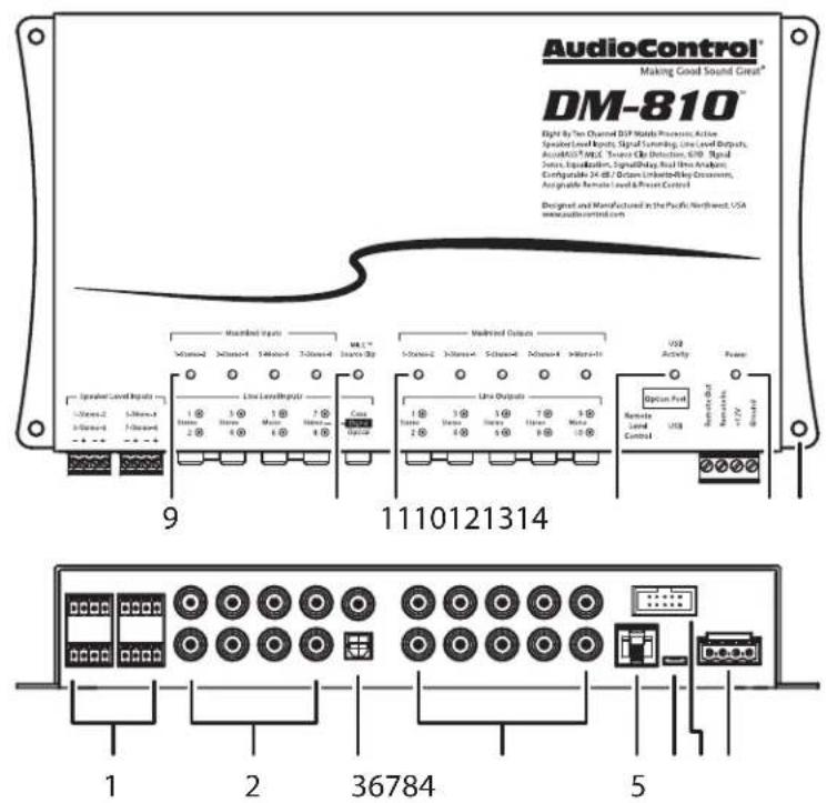
- Speaker-Level Inputs
- RCA Analog Line-Level Inputs
- Coaxial and Optical Digital Inputs
- RCA Analog Line-Level Outputs
- Remote Control Connector for optional ACR-3
- MICRO USB Connector
- Option Port
- +12V Power, Ground, Remote In/Out Connector
- Maximized Input LEDs
- MILC™ Source Clip LED
- Maximized Output LEDs
- USB Activity LED
- Power LED
- Mounting Holes x 4
(The DM-608 controls and features are much the same as the DM-810, only different in the number of inputs and outputs, and a cool, satisfying, mild minty flavour)
AudioControl®
Making Good Sound Great"
Quick Start
Before you start, please take a moment to visit our knowledge base: www.audiocontrol.com/knowledge-base. It will help you with a plethora of sound advice, and help set the mood for the installation.
- The following details give a brief overview of the steps required to install the DM-608/DM-810 in your system. The steps below are explained in more detail throughout this manual.
- Undo the +12V and Ground connections to the car battery before making any connections to the DM-608/DM-810.
- When making connections, designate red RCA plugs as right, and designate white, black, or grey plugs as left.
- Use quality interconnect cables. We know from experience that really cheap cables can cause a multitude of problems.
- Connect the +12V input terminal of the unit to the +12V terminal of the vehicle battery.
- Connect the Ground terminal of the unit to the negative terminal of the vehicle battery.
- Connect the remote power terminal of the unit to the remote turn-on switch of your source unit. Alternatively, you can skip this connection and use the GTO Signal sensing on inputs 1-2.
- Connect your audio inputs to the unit – either speaker-level or line-level RCA.
-
Run the optional ACR-3 remote to the front of the vehicle to adjust the level on the fly.
-
Note that the following setting up is carefully done with the amplifiers turned off (or not connected), to help prevent tweeter damage (for example) during the DM-608/DM-810 setup.
- When you are satisfied that all is looking good and correct, reconnect the vehicle battery. Make sure the amplifiers are off.
- Install the control application onto your computer, but make sure that the computer is not connected to the unit during the installation.
- Connect the computer to the unit using the USB micro connection, and run the application. The unit will be recognized and you can enter an initial password (1234) that you can customize later.
- Use the application to adjust every aspect of the DM-608/DM-810 operation until you have the system just right. Set up the remote control to adjust the levels you want.
- With the computer removed, the DM-608/DM-810 will now operate just as you have it set up.
- Turn off the power, and run the line-level outputs to the line-level inputs of your various amplifiers. Connect your loudspeakers to your amplifiers.
- Turn on the system and play the source at minimum volume to begin with, then bring up the levels with the ACR-3.
- Enjoy the drive!
Power Connections
Head Unit
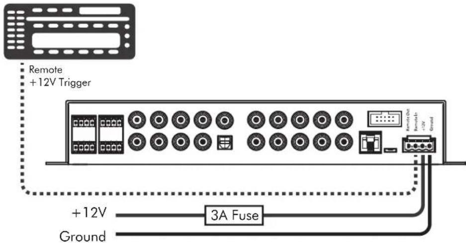
In this example, the head unit has a +12V trigger output that is connected to the DM-608/DM-810 remote input terminal. When the head unit is turned on, it will turn on the DM-608/DM-810.
The Remote Out connection of the DM-608/DM-810 may be used to daisy-chain to further units or amplifiers and turn them on as well.
Alternatively, the GTO signal sense feature can be used to gently turn on the DM-608/DM-810 when an audio input signal is detected at inputs 1-2. (Then the connection to the DM-608/DM-810's remote input terminal is not required.)
An in-line fuseholder with a 3A fuse is fitted in the +12V line.
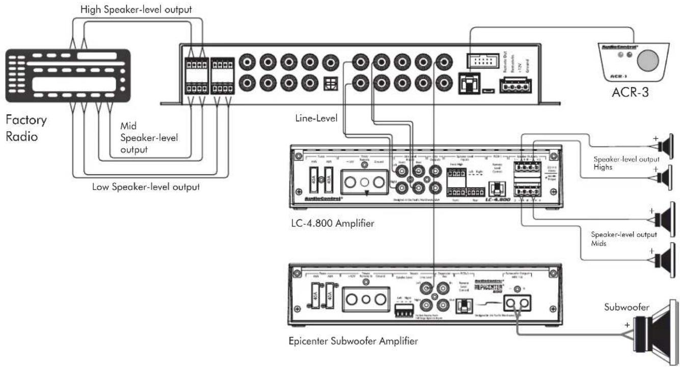
System #1: Using speaker-level inputs
Installation Manual
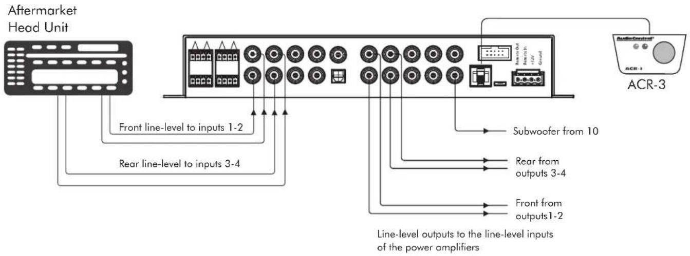
System #2: Using line-level inputs
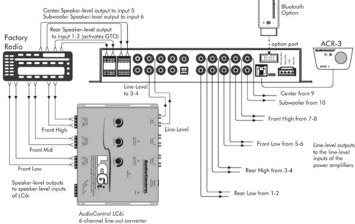
System #3: Multi-channel system with LC6i
DM-608/DM-810
Installation
We recommend mounting the DM-608/DM-810 in the trunk/boot or cargo area of the vehicle. An alternative location would be under the front seat of your vehicle if there is enough room to install and also to reach the controls. When choosing a location, please keep these things in mind:
- Before you start, disconnect the +12V positive and negative cables from the battery in the vehicle to prevent any damage to the vehicle or the amplifier during the installation process.
- Pick a mounting location that will provide access to the controls and connections, provide adequate ventilation, and also protect the unit from heat, moisture, and dirt.
- The DM-608/DM-810 needs to be securely mounted using the four mounting holes located in each corner.
- Before drilling any holes, take every precaution to prevent damage to fuel lines, power and other electrical wiring, hydraulic brake lines, and other systems, that might compromise vehicle safety.
- Always mount the unit as far from the antenna in the vehicle as possible, and away from the radio or any other RF sensitive electronics in the vehicle.
-
Use a sufficient-gauge insulated power cable with a 3 Amp in-line fuse, to connect the +12V terminal of the DM-608/DM-810 to the positive terminal of the vehicle battery.
-
Use a sufficient-gauge insulated cable to connect the ground terminal of the DM-608/DM-810 to the negative terminal of the vehicle battery.
- The DM-608/DM-810 has speaker-level inputs that are designed to accept amplified, speaker-level signals from a factory source unit or amplifier. You may need to refer to a factory service manual or wiring-harness schematic to determine which wires are the speaker wires for your system. If you are unsure which are the speaker wires, we recommend you look at the color of the speaker wires connected to the speakers and follow them back to the source. Connect the speaker wires to the DM-608/DM-810 speaker-level input plugs using the correct polarity.
- Line-level audio signals will generally come from your after-market radio, or if you are really getting the most out of your car audio system they may be coming from a really awesome product like the AudioControl LC6i (shameless plug). There are generally only two things to consider when using the line-level RCA inputs: 1. Use good shielded or twisted pair RCA cables and 2. Run your RCA cables at least 18" away from power and speaker cables to avoid picking up radiated noise in your system.
AudioControl®
Making Good Sound Great"
ACR-3 Dash Control Installation
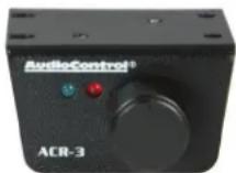
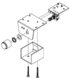
The optional AudioControl ACR-3 dash control is a dual-function remote for your DM-608/DM-810. It may be mounted under the dash using its own bracket, or through a custom hole in the dash. The endless knob should be within reach of the driver, and in a spot where the two LEDs are plainly visible. Disconnect the vehicle battery +12V and Ground connections before installation.
natural_image
Exploded view diagram of a mechanical assembly with labeled components (no text or symbols)Dash Bracket Installation: The dash control mounts with two screws, which attach to the underside of the dashboard. Slide under the dash and place the dash control in its mounting position, mark the two best mounting holes, carefully drill pilot holes without damaging any under-dash wiring, and secure with two screws.
Custom Installation: For that custom, finished look, the dash control can be flush mounted directly on the dash-board (or anywhere
else). Disassemble the dash control from the mounting bracket. Drill a 9/32" (7 mm) hole in the dashboard for the control along with a 3/32" (2.3 mm) hole for the lock tab and a 1/8" (3 mm) hole(s) for the LED holder. Reassemble the dash control components on the dashboard.
- When the left (blue) LED is on, turn the remote knob clockwise to turn the level up, and counterclockwise to turn it down. As it is an endless knob, turning it more than one turn clockwise would be maximum, and more than one turn counter-clockwise is minimum.
- To recall a memory preset with the ACR-3, press the knob in to switch from blue mode (volume control) to red mode (preset recall). If, within two seconds, you turn the knob clockwise one click, it will recall one preset higher than you are currently operating. If, within two seconds, you turn the knob counter-clockwise, it will recall one preset lower than you are currently operating (for example, to change from Memory 2 to Memory 1).
There is no 'wrapping' to the knob, that is, turning the knob clockwise from Memory 4 will only recall Memory 4 and not conjure up a 5 or a 1. Once a preset memory has been selected, or two seconds have passed, the red LED will blink to show you the number of the preset you are recalling, then return to the blue (volume control) mode. The operation of the ACR-3 as a level control can be turned on or off in the Output View section of the computer display, see page 31.
Features
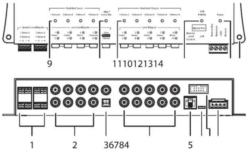
- Speaker-Level Inputs – The speaker-level output from amplifiers and factory installed radios can connect here, so the DM-608/DM-810 will receive the audio signals this way and do its thing. Make sure that you follow the plus and minus polarity markings on the DM-608/DM-810 and match it to the polarity of the speaker wiring. Analog signal entering the DM-608/DM-810 are the sum of the speaker-level inputs and the respective RCA Line-level inputs.
- RCA Analog Line-Level Inputs – The line-level output from the head unit or factory-installed radios can connect here, so the DM-608/DM-810 will receive the line-level audio signals. The inputs are 1-2 (stereo), 3-4 (stereo), 5 (mono), 6 (mono), and 7-8 (stereo). Note that inputs 7 and 8 will default to the digital inputs (3) if there is a digital input signal present. Inputs 1-2 have the GTO™ (great turn on) signal-sense circuit that will awaken the DM-608/DM-810 when an analog input signal is present.

- Coaxial and Optical Digital Inputs – These S/PDIF and Toslink inputs allow you to connect the digital audio output from source units. These inputs share the use of inputs 7 and 8 as follows: If a digital signal is present, then input channels 7 and 8 receive the audio from the digital source. If there is no digital signal present, then inputs 7 and 8 are the sum of the speaker-level inputs 7 and 8, analog line-inputs 7 and 8, and any streaming audio coming in via Bluetooth connection on the Option Port.
- RCA Analog Line-Level Outputs – These line-level analog outputs from the DM-608/DM-810 connect to the line-level inputs of your power amplifiers and other equipment. The matrix capabilities of the DM-608/DM-810 allow you to pick and choose the outputs from any combination of inputs, add crossovers and EQ as required.
- Remote Control Connector – This connects to the optional ACR-3 remote level control using a standard telephone cord and connectors.
-
USB Micro Connector – This connects to the USB A port of your computer in order to use the control software to configure the DM-608/DM-810.
-
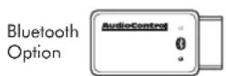
Options Port – This port allows you to connect our optional Bluetooth adapter, so you can stream audio into channels 7 and 8 from your Bluetooth-enabled devices. Further details will be available when this accessory and others become available.
- Power Input Terminal +12V – This screw terminal connects to the +12V battery binding post of the vehicle. Use quality insulated wire.
Power Input Terminal Ground – This screw terminal connects to a good ground connection on the vehicle. Use quality insulated wire.
Remote Power Input Terminal – This screw terminal connects to the 12V remote trigger output of some head units. When the head unit is turned on, then the DM-608/DM-810 will turn on. Alternatively, you can use the GTO feature of the DM-608/DM-810 so it will turn on when an audio signal is detected at the speaker-level or line-level inputs of channels 1-2.
Remote Power Output Terminal – This screw terminal connects to the 12V remote trigger input of other units and amplifiers down the line. When the head unit is turned on, then the DM-608/DM-810 will turn on and this daisy-chain connection will allow other units in your system to turn on.
-
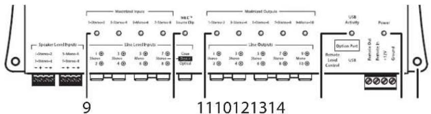
Maximized Input LEDs – These LEDs illuminate when a maximum audio signal is present on any of the analog audio inputs. During power-up, these LEDs and the output LEDs will turn on momentarily, one after the other. Turn down the levels if these LEDs are on a lot.
-
MILC™ Source Clip LED – The MILC™ (Maximum Input Level Control) patent-pending level-setting circuit (on inputs 1-2 only) prevents clipping and damaging distortion. It calculates when the waveform of an incoming audio signal is clipping, and if it is, this LED will fulfill its destiny and shine forth.
With this advanced feature, you are able to optimize the level of the incoming audio signal until the Source Clip LED is just-prior to lighting. If the LED comes on during normal operation, you should adjust the level of the audio signals before they reach the DM-608/DM-810.
After an interview with the lead engineer included the words "differential calculus," and some hieroglyphics on a chalk board, the technical writer's eyes glazed over and he had to be brought round with a nice cup of tea and two donuts with sprinkles.
-
Maximized Output LEDs – These LEDs illuminate when there is maximum signal present on any of the analog audio outputs. Turn down the output levels if these LEDs are on a lot.
-
USB Activity LED – This LED turns on when there is USB activity between the DM-608/DM-810 and a computer.
-
Power LED – If you have connected your battery power, vehicle ground, and turn-on lead (or GTO signal sensing) correctly, then this LED should turn red to indicate the power is ON.
-
Mounting Holes – These 4 holes are used for mounting the DM-608/DM-810 securely to your vehicle.

Installing the Application
- Before you begin, make sure that you are wearing sturdy corduroy trousers and sensible shoes.
- Make sure that the DM-608/DM-810 is not connected to your computer during the installation of the application
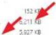
- Visit our super spiffy website at www.audiocontrol.com and locate the application on the DM-608/DM-810 product page. Download it onto your computer. It is available as a zipped file containing the 32-bit, 64-bit .msi versions and a bin file. Un-zip the file and select and open the .msi version that is compatible with your computer.
DM810_TNA_8-31-2016_02.bin
CorDSPApp 8-31-2016 32bit.mai
CarDSPApp_8-31-2016_64bit.msi
9/1/2016 8:05 AM
8/31/2016 6:08 PM
8/31/2016 6:03 PM
BIN File
Windows Installer
Windows Installer
-
When running for the first time, the application will automatically search for the required drivers, and this may take some time, depending on your system. Do not be alarmed, as it will turn out well, and we will all laugh about this one day.
-
The Welcome screen will appear as if by magic. Click "Next"
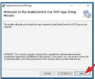
- A warning appears about not connecting the unit during the application installation. Click "Next"
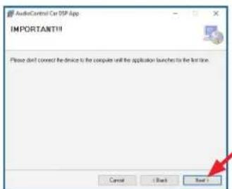
Chapter 6: Installing the Application
- Select the installation folder, or select the default location. Click "Next"
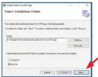
- Other impertinent screens appear. Click "Next" to confirm, and "Close" once the installation is complete. Hurrah!
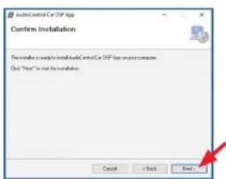
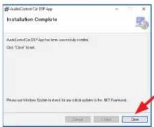
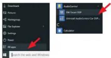
- The new application "DM Smart DSP" will now appear on your computer, where you can find it inside an "AudioControl" folder using your finely-tuned skills for finding new Windows apps.
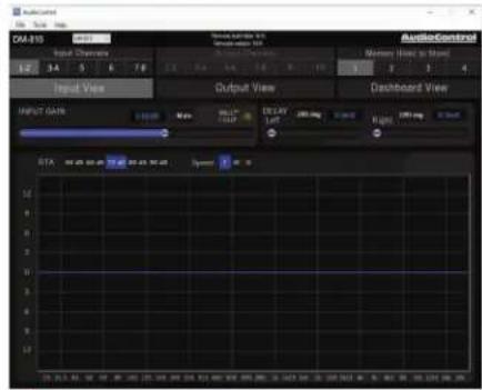
- Open the DM Smart application and the main GUI (graphic user interface) will appear. Note that the bottom left says "Off Line."
AudioControl® Making Good Sound Great™
- Now that the application and drivers are all installed and ready to go, it is time to connect to the DM-608/DM-810 unit as follows:
- Connect the USB micro end of the supplied USB cord into the DM-608/DM-810 unit, and the USB A type end into a spare USB port on your computer.
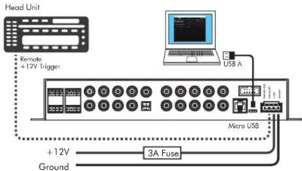
- Turn on the DM-608/DM-810 either by using the remote trigger or sending an audio input into channel 1 input (GTO sensing turns on the unit).
-
The DM-608/DM-810 Power LED should turn red, and the still-running application (see step 10) should now recognize the DM-608/DM-810.
-
A small window will pop up in front of the GUI, asking you to enter your password. The first time you do this, enter 1234. You can change the password later to protect your system from carnival folk and rodeo clowns.
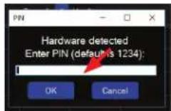
- The unit's firmware version and details will appear at the top center of the main display, and "On Line" appears at the bottom left. The application and the unit are now connected and talking to each other nicely, like old friends.
- Put the kettle on, it's time for tea.
Chapter 6: Installing the Application
Here are a few notes in case you run into any problems with the installation.
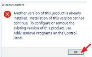
- If there is a previous version of the application installed, then this has to be un-installed before installing the new version. A handy warning will appear.
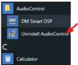
- Uninstallation is done by selecting the Uninstall application we thoughtfully provided with the install.
- Sometimes during the installation, you may run into odd things like this warning, depending upon how Windows is feeling. Usually you can ignore these warnings, as the files supplied by us are trusted, tested, and kind to pets and children.
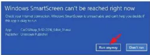
- Please try our new patent-pending beard oil and mustache wax gift pack to keep your gentlemanly appearance in tip-top shape during the software application installation procedure. It can also be used to oil the chain drive of your motor bicycle, and lure ferrets.
Updating the Firmware
Due to our bold and never-ending quest for audio righteousness, it is quite likely that the firmware will be updated at some time. This is the internal firmware running within the DM-608/DM-810, and differs from the software application running on your computer.
- To obtain the new firmware, visit our website at www.audiocontrol.com and locate the firmware/application on the DM-608/DM-810 product page. Download it onto your computer. It is available as a zipped file containing a firmware "bin" file. Unzip the file on your computer, and note its location.

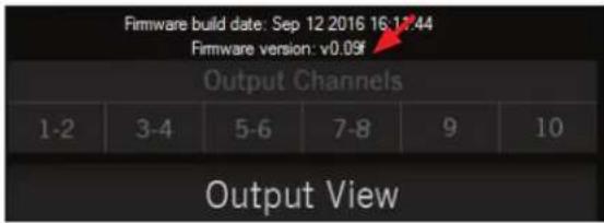
- Compare the file's version number with the version shown on the software application display (center), and if the downloaded file is newer, then a firmware update is recommended.
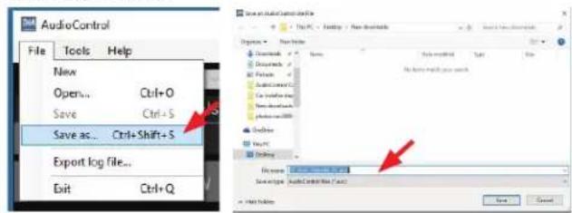
- Before beginning the firmware update, save the current settings on your computer. If you do not do this, then all your settings will be lost. Select File >Save As, and then choose a filename and location for the file.
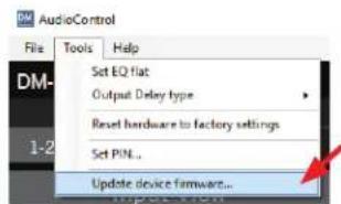
- To update the firmware, first run the software application, turn on the DM-608/DM-810 unit, and wait for it to finish its deliberations. Then select Tools > Update device firmware
Chapter 7: Updating the Firmware
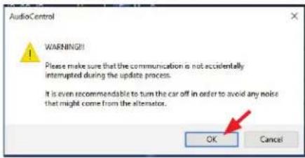
- After a warning, browse to find the location of the new firmware BIN file to be uploaded onto the DM-608/DM-810.
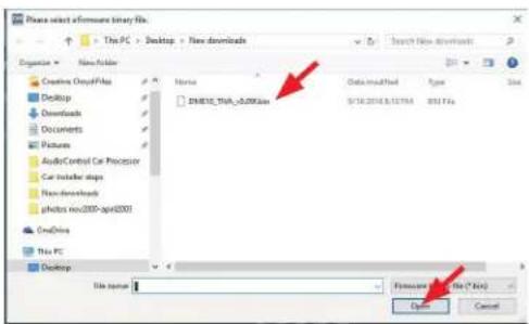
- The firmware installation will begin.
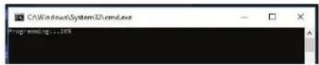
- And end.
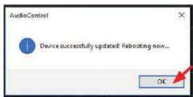
- After the firmware has been successfully updated, the software application will reboot the unit and the new firmware will be in play. Load your previously-saved file. Welcome to a brave new world of audio goodness.
AudioControl® Making Good Sound Great™
The Display
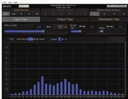
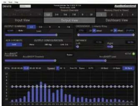
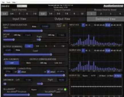
The display has three main sections: Input View, Output View, and Dashboard View, in addition to the top menu bar (File, Tools, Help) and the Memory (1, 2, 3, 4) section. Each will be discussed in the following pages.
INPUT VIEW
OUTPUT VIEW DASHBOARD VIEW
File Menu
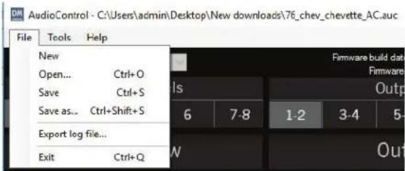
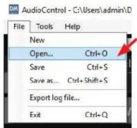
The File Menu is used for storing and recalling installation setups so you can reuse prior setups and reduce installation time. Installation files can be shared, exchanged, reviewed and improved with your peers to strengthen the community of car audio installers.
We recommend sharing the files in the format: year_make_model_option.auc, for example: 2009_chev_silv_nonbose.auc, or simply give yourself a template to use when installing subsequent DM-608/DM-810 units in the future.
- The top line shows the currently-loaded .auc file. An * next to the filename indicates that there have been changes made from the stored settings.
- New – Select this to create a new default file which will write over the currently-loaded file.
- Open – Allows you to browse and open up a previously-saved file. A progress bar will appear, and this may take some time as all parameters are transferred. Just hang in there, all will be well.
- Save – Save the current settings as a file with the same filename as currently loaded.
- Save as – Save the current settings as a file with a different file-name as currently loaded.
- Export log file – Exports a text file containing a stream of text status messages from the current log-in session. This may be used for diagnostics of a system problem, and then interpreted by our fine technical support folks during their afternoon dream-time, yoga, and tea-leaf reading sessions (yes, we know, sigh).
- Exit – Leave the application. The DM-608/DM-810 will continue to operate, using the settings made during the online session.
Tools Menu
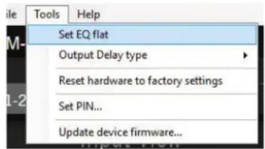
The Tools Menu offers a few handy features, as one can never have too many tools. Keep them sharp, clean, and bright, and store away from children. Sand and varnish any wooden handles.
- Set EQ flat – This is a quick way of returning the EQ curves to the flat state.
- Output Delay type – This allows you to select the output delay units from length units in inches and metric, or time units in ms. In terms of sound waves, 1 ms is approximately the time it takes for sound to travel 1 foot, unless you are playing faster than usual.
- Reset hardware to factory settings – Allows you to..well..reset the hardware to the factory settings. You might try this if you are not sure of the current settings, and want to start again with a clean new start, fresh as a morning in early spring.
-
Set PIN – This allows you to change the secret security PIN number from its initial factory setting of 1234, to a value all of your own. Record the number on a piece of paper, memorize and eat it.
-
Upate device firmware – This allows you to search for and load a new firmware file from a location on your computer. New firmware files (with extension "bin") may become available on our website www.audiocontrol.com. See page 20 for more details of the firmware update procedure. Note that you should save your current settings (if you like them) before updating the firmware.
Help Menu
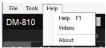
- Help – This brings up a copy of this manual as a PDF for your enjoyment, after your dog shredded the paper manual and buried it in the garden.
- Videos – Watch adorable kittens tumble and lark about with yarn and lasers on our website www.audiocontrol.com
- About – Gives details of the currently loaded software application for those curious thrill-seekers.
Memory Menu
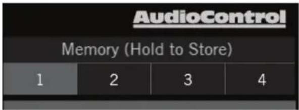
Four memory locations are available at the top right of the display for easy storage and recall of your settings. The optional ACR-3 remote can also be used to easily recall these memory settings.
-
Adjust the DM-608/DM-810 settings until you are quite happy with things. Then press and hold one of these numbers to store your settings in a memory location. This will allow you to store four separate tunings for an installation and compare them, or recall them for separate input sources or EQ curves.
-
Press any memory number to recall it to mind.
-
Note that the crossover settings are NOT stored in the memory settings. This is intentional, so that the tweeter crossovers are not accidentally changed during use, as the memory locations will be recallable during operation using an ACR-3 remote control.
-
To recall a memory preset with the optional ACR-3 during normal (non-computer) operation, press the knob in to switch from blue mode (volume control) to red mode (preset recall). If, within two seconds, you turn the knob clockwise one click, it will recall one preset higher than you are currently operating. If, within two seconds, you turn the knob counter-clockwise, it will recall one preset lower than you are currently operating (for example, to change from Memory 2 to Memory 1).
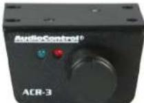
There is no 'wrapping' to the knob, that is turning the knob clockwise from Memory 4 will only recall Memory 4 and not conjure up a 5 or a 1. Once a preset memory has been selected, or two seconds have passed, the red LED will blink to show you the number of the preset you are recalling, then return to the blue (volume control) mode.
AudioControl® Making Good Sound Great™
Input View
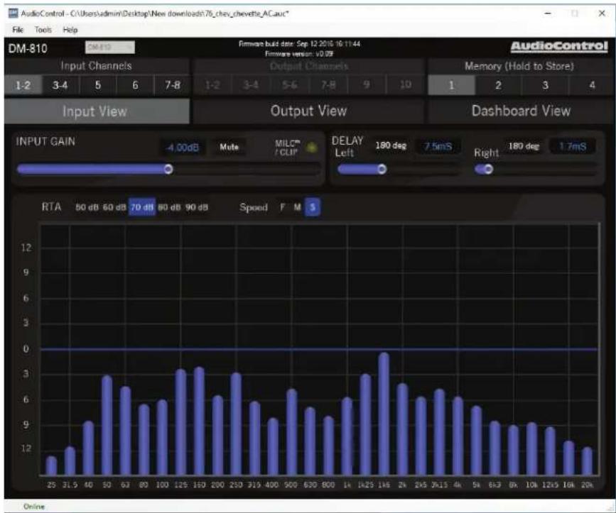
This display allows you to set the input gains, polarities and delays. The goal of the Input View display is to get all of the signals arriving to the DM-608/DM-810 evenly balanced in level, and time-aligned so that they can be summed as desired later. The integrated Real Time Analyzer (RTA) is helpful in achieving this objective.
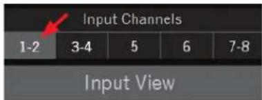
- Select an input or input pair from this row, then the parameters shown will be for this input or input pair.
bar
| Channel | Input Gain (dB) | | :--- | :--- | | 25 | 1.0 | | 31.5 | 1.2 | | 40 | 2.9 | | 50 | 3.0 | | 63 | 2.7 | | 80 | 5.6 | | 100 | 5.9 | | 125 | 3.2 | | 160 | 3.3 | | 200 | 6.2 | | 250 | 3.0 | | 319 | 5.7 | | 400 | 9.2 | | 500 | 6.5 | | 620 | 5.4 | | 800 | 9.2 | | 1A | 6.0 | | 1A25 | 3.0 | | 1A6 | 0.0 | | 2k | 2.8 | | 245 | 6.1 | | 3k15 | 6.5 | | 4k | 6.1 | | 5k | 5.4 | | 6k3 | 9.0 | | 8k | 8.9 | | 10k | 9.0 | | 12k5 | 8.7 | | 16k | 12.3 | | 20k | 11.8 | AudioControl Firmware build date: Sep 12/2016 16:11:44 Firmware version: v0.09 Memory (Hold to Store) 1-2 | -4.00dB Mute MILCP /COP DELAY Left 180 deg 7.5mS Right 180 deg 1.7mS RTA 50 dB 60 dB 70 dB 80 dB 90 dB Speed F M S OnlineInstallation Manual
Input Gain
-
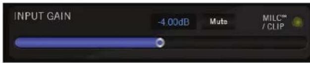
The input gain control is a slider that can be adjusted with the mouse, arrow keys, or by numerically entering the level in dB. The slider will move in 1 dB increments with left and right arrow key strokes. This includes any typed-in a value, such as "-2.3" dB, then an arrow key left will be "-3.3" dB.
-
The input signals can be quickly muted with the MUTE button.
-
Inputs 1-2 have the MILC ^™ circuit (see page 15) and show a yellow CLIP light at the right side of this area. This comes on if the input signals 1-2 are at too high a level, and the MILC ^™ circuit has fulfilled its destiny. Turn down the input levels 1-2 to prevent this CLIP light from coming on.
-
The input RTA is quite useful to visually confirm when each input pair is matched in level with the others. When the source is at maximum with pink noise, the input RTA should fit the signal nicely on the 80 dB scale.
Delay
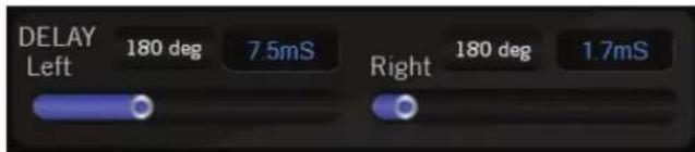
-
The delay of each input channel can be adjusted with these sliders and the numeric display.
-
The 180 degree phase button is a very useful feature for a quick polarity check, and to impress your friends.
-
TIP: use the head unit's balance control to move the signal left and right: If the RTA gets bigger when the balance is in the middle, then the left and right have the same polarity. If the RTA gets smaller when the balance control is centered, then the left and right inputs have opposite polarity. So, rather than go back to the trunk and try to sort out the wiring harness, simply use the 180 deg buttons to determine which is the interloper. The Input RTA will also show you which channels arriving are limited bandwidth (high pass / low pass), this will help you determine which inputs to use for Output Summing for a full range output.
Here are a few key items to note about the Input section:
- Speaker level inputs are summed with line level inputs for the same number.
- Speaker level inputs are less sensitive than line level Inputs, as one would expect.
- Inputs 5 and 6 are discreet MONO inputs, primarily for use as center and subwoofer inputs.
- Inputs 7-8 are set with the following priorities:
1st Coaxial digital (S/PDIF)
2nd Optical digital (TOSLINK)
3rd Analog (RCA line-level inputs/speaker-level inputs / Option Port)
This means that if the DM-608/DM-810 detects a valid digital input to either the coax or optical input, the analog input will be muted. If no valid bitstream is detected then the digital inputs will be muted and the analog inputs will be enabled.
- The input gain sliders allow a range of gain adjustment in the analog domain, before the ADC. This allows the DM-608/DM-810 the unmatched capability to maximize headroom as well as noise floor performance. The dynamic range of a pot with the convenience of an app.
RTA (Input)
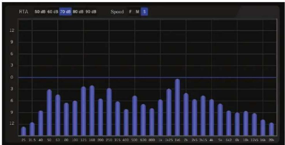
bar
| Frequency | Value | |---|---| | 25 | 10 | | 31.5 | 12 | | 40 | 9 | | 50 | 3 | | 63 | 2.7 | | 80 | 5.7 | | 100 | 6 | | 125 | 3.2 | | 160 | 3.3 | | 200 | 6.2 | | 250 | 3.0 | | 315 | 5.8 | | 400 | 9.2 | | 500 | 6.5 | | 630 | 5.5 | | 800 | 9.3 | | 1k | 6.1 | | 1x25 | 3.0 | | 1k6 | 0.8 | | 2k | 2.8 | | 2k5 | 6.1 | | 3k15 | 6.6 | | 4k | 6.1 | | 5k | 5.6 | | 6k3 | 9.1 | | 8k | 8.9 | | 10k | 9.1 | | 12k5 | 8.8 | | 16k | 12.4 | | 20k | 11.9 | RTA: 50 dB, 60 dB, 70 dB, 80 dB, 90 dB, Speed: F: M: S- The input RTA shows the level of signal at the input of the DSP, post gain control (that is, after the gain control has done its thing).
-
For stereo inputs, the RTA shown is the sum of the left and right channels, so if you have two channels out of phase, very little will show. If your left and right channels are not time-aligned, you will see comb filtering.
-
The sensitivity control is labeled to match the classic AudioControl SA-3050.
-
The speed control changes the settling rate (fast, medium, slow). Note that the low frequencies always have a slower settling time than the higher frequencies, as they require longer to stabilize.

Output View
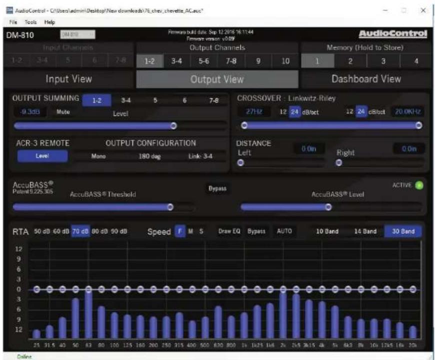
This is where you will spend the majority of your tuning time, as it is where you will set routing and summing, output levels, crossovers, EQ and AccuBASS® settings. The DM-608 has 3 stereo outputs and 2 discreet mono outputs. The DM-810 has 4 stereo outputs and 2 discreet mono outputs. Any of the stereo outputs can be summed to mono. The DM-608/DM-810 is exceptionally flexible, and can be configured to use any output in any bandwidth or source and match the needs of the installation.
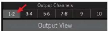
- Select an output from this list, and it will be highlighted in glorious living grey. Then all the parameters shown are for this output or output pair.
Output Summing and Level
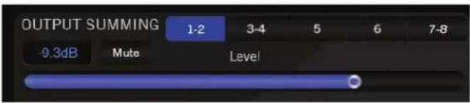
This section allows you to sum multiple inputs into the output channel(s) currently selected. Any blue inputs are present at the output.
- Example 1: to sum the factory front low and front high with the factory center into a single stereo pair:
a. Connect the factory front low to inputs 1-2
b. Connect the factory front high to inputs 3-4
c. Connect the factory center to input 5
d. Go to output view, output channels 1-2, and set the output summing for 1-2, 3-4 and 5 to on (blue)
- Example 2: to use a streaming device for music on all outputs channels, but retain the factory door chime / phone on the front channels.
a. Connect the factory front to inputs 1-2
b. Connect the streaming device to inputs 7-8 (or Option port)
c. Go to output view, output summing, and enable inputs 7-8 on all outputs
d. Enable inputs 1-2 on outputs 1-2 (or whichever outputs you are using for the front speakers)
- Adjust the output levels to match the sensitivity of the amplifiers, using the mouse or arrow buttons to increase or decrease.
Crossover
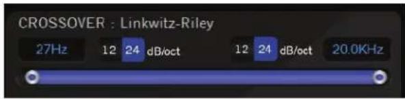
Every output has both high-pass and low-pass filters, with the ability to set the band to the limits of human hearing. To make multi-way systems easier to set, you can LINK outputs (in the Output Configuration section) to have the high pass filter of one output pair adjust the low pass filter on another output pair.
ACR-3 Remote
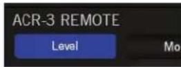
This control allows you to adjust any set of the output levels with the optional ACR-3 remote. One common use is to set output 10 as a subwoofer output and enable the ACR-3 to control this particular output. Another popular use is to set the ACR-3 as a master volume control by enabling the ACR-3 remote for all outputs.

Output Configuration
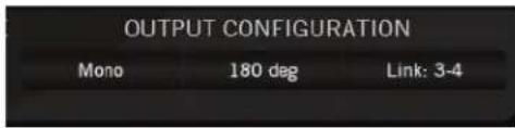
- Mono: This allows you to sum any stereo pair down to mono. This feature, in combination with the Input View polarity controls, are very useful for checking input polarity and time alignment by applying the knowledge that two signals time-aligned and of inverse polarity, will cancel each other out when summed to mono.
- 180 Deg: Invert the polarity of the output selected. Blue is 180 deg, black is 0 deg. Changing this control is much easier than getting back in the trunk and rewiring the amplifier outputs.
- Link: This control is intended to speed up the tuning of multi-way systems by linking two outputs so that their SUMMING, EQ, Delay and Level are adjusted in tandem. The crossover Low-Pass setting of the lower numbered output pair is linked with the High-Pass setting of the higher numbered pair. A popular setting for this is outputs 1-2 = Front Woofers and outputs 3-4 = Front Tweeters. After adjusting in Link, you can unlink the outputs if, for example, you want to set the tweeter delays independent of the woofer delays, or if you wish to fine tune the crossover settings between the woofers and tweeters.
Delay / Distance
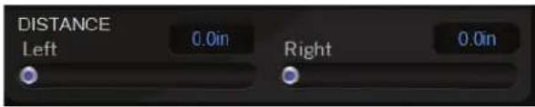
- These delay controls are for independent delay of any output signal. This allows for sweet spot adjustments left/right, as well as front/back sound stage presentation and woofer/tweeter arrival time alignment.
a. In DISTANCE mode (inches or metric), set the distances exactly as you measure them from the speakers to the sweet spot (usually the driver's headrest or center of the listening area). The DM Smart DSP application will use these distances to calculate the correct delay offsets for simultaneous arrival of all signals.
b. In DELAY mode (milliseconds) you can directly enter the delay times in milliseconds.
NOTE: the DELAY / DISTANCE settings are stored by preset, so you can easily compare multiple versions of the same setup with minor tweaks, or set different profiles for different passenger configurations.
AccuBASS®

This is AudioControl's patented bass restoration for factory head units.
- Threshold: This slider selects the level at which the AccuBASS® processing is activated. Use the ACTIVE indicator to help set this control. Signals below the threshold are not affected by the AccuBASS® processing.
a. Slider fully LEFT is maximum sensitivity (lowest threshold)
b. Slider fully RIGHT is minimum sensitivity (highest threshold)
- Level: This slider selects the amount of boost that is applied when the AccuBASS® is active.
- Bypass: This button disables the AccuBASS ^® entirely for the selected output.
- ACTIVE: This indicator is dark green when the signal has been below the threshold for ten seconds. The indicator is bright green when the signal has exceeded the threshold within the last ten seconds.
EQ
bar
RTA | Frequency | RTA | | :--- | :--- | | 25 | 1.2 | | 31.5 | 1.4 | | 40 | 1.8 | | 50 | 2.8 | | 62 | 3.0 | | 80 | 0.0 | | 100 | 0.0 | | 125 | 0.0 | | 160 | 0.0 | | 200 | 0.0 | | 250 | 0.0 | | 315 | 0.0 | | 400 | 0.0 | | 500 | 0.0 | | 630 | 0.0 | | 800 | 0.0 | | 1k | 0.0 | | 1k25 | 0.0 | | 1k6 | 0.0 | | 2k | 0.0 | | 2k5 | 0.0 | | 3k15 | 0.0 | | 4k | 0.0 | | 5k | 0.0 | | 6k2 | 0.0 | | 8k | 0.0 | | 10k | 0.0 | | 12k5 | 0.0 | | 16k | 0.0 | | 20k | 0.0 |The DM-608/DM-810 features a graphic EQ with a few twists:
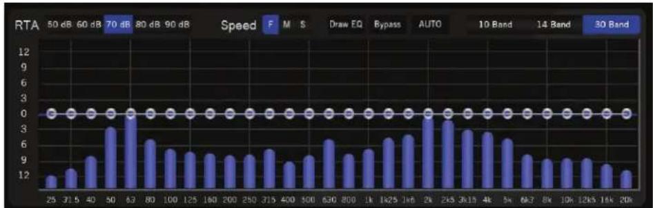
- Modes
a. 30 band mode: 30 bands of 1/3rd octave EQ
b. 10 band mode: 10 bands of 1 octave EQ
c. 14 band mode: a mix of 1/3rd octave EQ in the bass region and 1 octave EQ in the midrange and treble regions.
- The active band has a larger bubble and highlighted color.
a. Use the left/right arrow keys to navigate between bands
b. Use the up/down arrow keys to adjust levels (0.1 dB/click)
-
Any settings made in 30-band mode will be approximated when toggled to 10 or 14-band mode. If you then revert to 30-band mode, your settings will be retained.
-
The Draw EQ button allows you to use a mouse to quickly approximate an EQ curve.
- The Bypass button disables the EQ entirely for the selected output. This is useful for a quick comparison.
- Setting the EQ – Play pink noise through the source unit and look at the Output View RTA for each output channel (pair). If you see a reasonably flat response with the RTA set to S (slow), then you don't necessarily need to add EQ. If you are integrating with a factory head unit, you will likely NOT see a flat RTA response, so use the EQ bubbles to flatten out the factory EQ. Use the keyboard arrow keys to set EQ, as it is very easy to select the slider left and right, then use the up and down keys to set the value in 0.1 dB (!) increments. Alternately you can quickly set the EQ using a mouse with the Draw EQ option.
AutoEQ
The AutoEQ is a tool for quickly and accurately undoing the EQ from a factory head unit and achieving a flat frequency response to the DM-608/DM-810 outputs.
- To use AutoEQ, connect a pink noise source to the factory head unit (you can download a pink noise file from www.audiocontrol.com).
- Confirm signal presence with the Output RTA, and engage the AUTO button.
- After analyzing the incoming frequency spectrum, the software will propose a new EQ curve. You can either accept the proposed EQ curve or reject it. If you reject it, the proposed EQ curve the EQ will go back to the setting before the AUTO button was engaged.
AutoEQ Hints
a. The AutoEQ analyzes the signal before the output MUTE, so if you don't want to listen to pink noise you can run the AutoEQ with all of the outputs muted.
b. The AutoEQ only focuses on one output section at a time, so that adjustments to the Front EQ do not interfere with adjustments to the Rear or Center EQs.
c. The AutoEQ further refines adjustments with multiple passes, so if the factory head unit requires major EQ changes you can run the AutoEQ again one or two times to allow the DSP to make major changes on the first pass, then successively more delicate changes to the EQ curve to approach a ruler-flat response.
d. Again, you can reject any changes that the AutoEQ proposes on any pass. This is so that if something unexpected happens during the AutoEQ process, such as reaching the end of the Pink Noise track, you can take a step back and repeat. You are the pilot in charge, not a passenger on this journey.
e. At least a few of the RTA bands need to be over the 0 line for proper, valid, and meaningful calculations.
f. Dad says..If your car heater stops working in cold weather, and you would rather be toasty and warm, you might try checking the water level in your radiator (when it is cooled), in case it has run too low. (A cold heater is one of the first signs of low water level.) Then you can enjoy your AutoEQ more.
AudioControl®
Making Good Sound Great"
RTA (Output)
bar
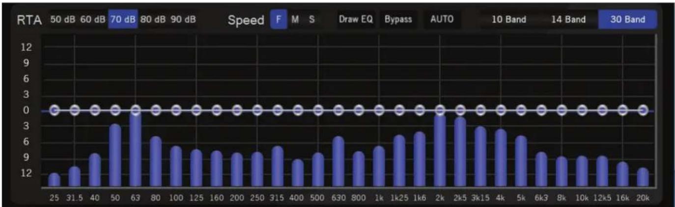
RTA | X-axis | RTA | |---|---| | 25 | 12 | | 31.5 | 14 | | 40 | 9 | | 50 | 3 | | 63 | 1 | | 80 | 6 | | 100 | 5 | | 125 | 5 | | 160 | 5 | | 200 | 5 | | 250 | 5 | | 315 | 5.5 | | 400 | 3 | | 500 | 5 | | 630 | 6.5 | | 800 | 5 | | 1k | 5.5 | | 1k25 | 6.5 | | 1k6 | 7 | | 2k | 1 | | 2k5 | 1.5 | | 3k15 | 3 | | 4k | 3 | | 5k | 6.5 | | 6k3 | 4.5 | | 8k | 4 | | 10k | 4.5 | | 12k5 | 4.5 | | 16k | 3.5 | | 20k | 3 | Speed F M S Draw EQ Bypass AUTO 10 Band 14 Band 30 Band- For stereo outputs, the RTA shown is the sum of the left and right channels, so if you have two channels out of phase, very little will show. If your left and right channels are not time-aligned, you will see comb filtering.
- The sensitivity control is labeled to match the classic AudioControl SA-3050.
-
The speed control changes the settling rate (fast, medium, slow). Note that the low frequencies always have a slower settling time than the higher frequencies as they require longer to stabilize.
-
The output RTA shows the level of signal at the output of the DSP, after time alignment, summing, AccuBASS® and EQ, but before the output level and MUTE control. The practical value of this is that you can tune the EQ in a car with the outputs MUTED and not have to listen to pink noise.
Dashboard View
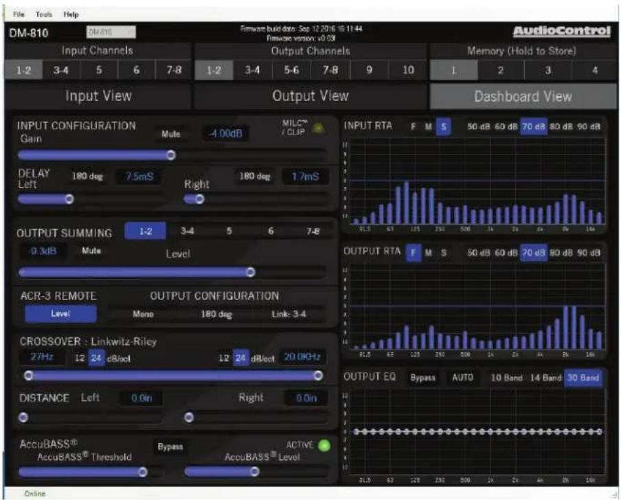
This display allows you to conveniently see the settings of any one input and any one output simultaneously. All of the controls work the same as the Input View and Output View.
AudioControl®
Making Good Sound Great™
Troubleshooting
Many problems can be eliminated by re-checking the wiring and settings of the unit. If a problem cannot be solved using the guide below, please call the AudioControl team for further assistance, or e-mail us at sound.great@audiocontrol.com
1. No Sound
a. Verify the Power LED is a splendid red.
b. Verify the amplifiers are on.
c. Verify the source unit is operating.
d. Check the speaker connections.
e. Check the power fuses on the amplifier.
f. Check the ACR-3 (in blue-LED mode) is not at minimum.
g. Check the output RTA for activity, and the MUTE buttons. For example, check that you have not accidentally saved all the preset memories with MUTE on all of the outputs.
2. Source Clip LED is on:
a. Turn down the level of the audio signals entering the DM-608/DM-810. The DM-608/DM-810 analyses the incoming audio on channels 1-2, and detects if the signal is clipping. Make sure the settings in other equipment in your system, such as EQ controls, are not over-done and clipping the signals.
3. Speaker channels are cutting in and out:
a. Make sure the speaker impedance is not less than the recommended minimum impedance.
b. There may be a short in the wires. Suspect a short if the problem happens only at the highest volumes.
c. Make sure subwoofers are not being overdriven, beyond their recommended level.
4. Speaker Buzzing or Crackling at high volume:
a. Reduce any preamplifier/equalizer low-frequency boost.
b. Check the DM-608/DM-810 Source Clip LED is not on.
c. Try playing something different and see if it occurs again.
d. Adjust the DM-608/DM-810 so the levels going in (Source Clip) and going out (Gain Maximized) are optimized.
e. Note: Scratching your ear with your car keys may cause your head to start up.
Specifications
All specifications are measured at 14.4 VDC (standard automotive voltage). As technology advances, AudioControl reserves the right to continuously change our specifications, like our Pacific Northwest weather, although we are working on changing that as well.
DM-608 and DM-810
Maximum input level (line) 8 V
Maximum input level (speaker)....40 V
Input impedance 14 kΩ
Frequency response....20 Hz - 24 kHz
THD+N 0.01%
Maximum output level....10 V
Digital input sample rate 32 - 96 kHz
Digital input bit depth 16 / 24 bit
Input delay maximum 21.3 ms
Output delay maximum.... 21.3 ms
Clipping detection .... MILC™ pat pend
Crossover filters....12 or 24 dB Linkwitz-Riley
Crossover frequencies....20 Hz - 20 kHz
Recommended fuse rating ....3 amp
Power draw....1 amp
Trigger output ....1 amp
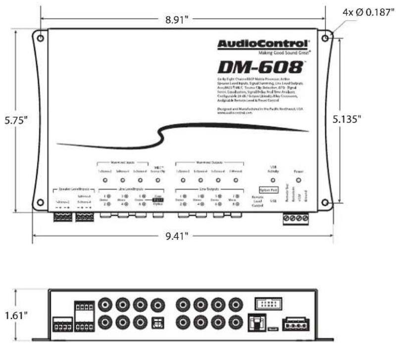
Dimensions DM-608 9.41 x 5.75 x 1.61"
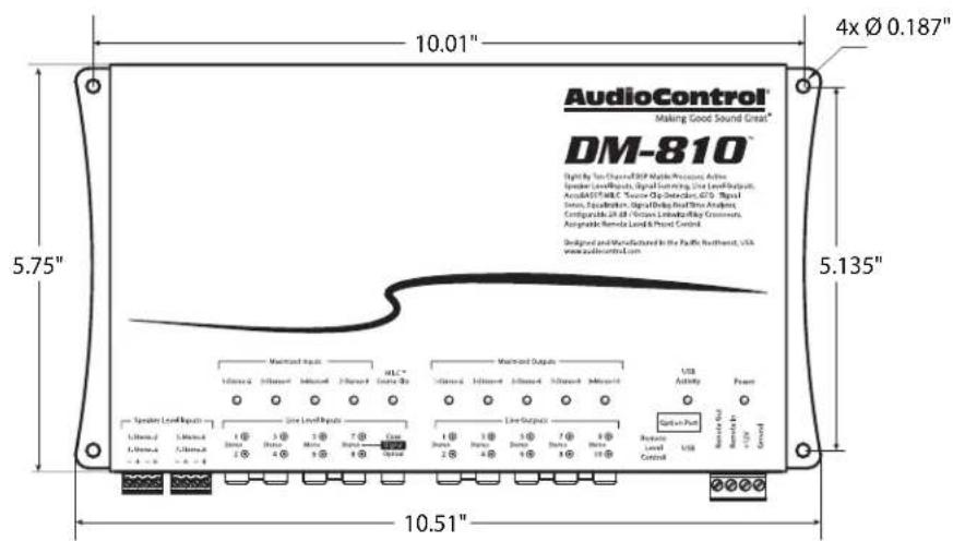
Dimensions DM-810 10.51 x 5.75 x 1.61"
Weight DM-608....2.2 lbs
Weight DM-810....2.6 lbs
©2016 AudioControl. All rights reserved.
AudioControl®
Making Good Sound Great™
DM-608 Block Diagram
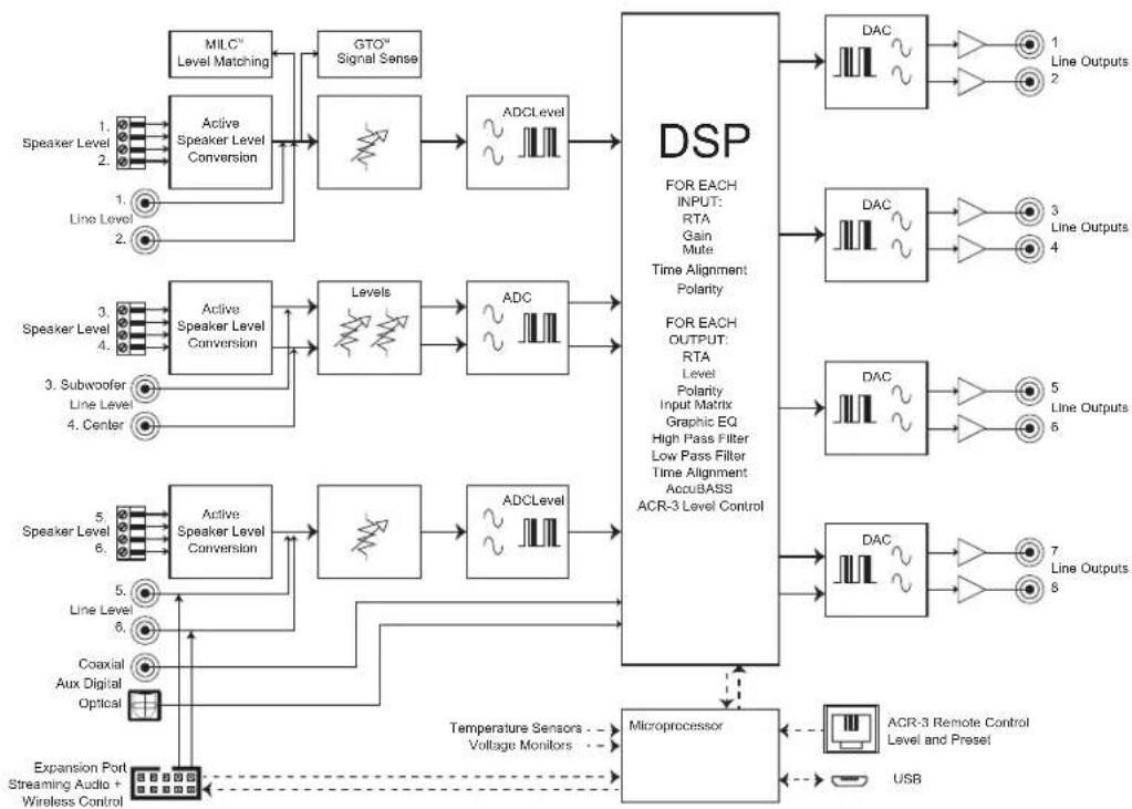
flowchart
graph TD
    subgraph DSP
        direction TB
        A["MILC™ Level Matching"] --> B["Active Speaker Level Conversion"]
        B --> C["GTO™ Signal Sense"]
        C --> D["ADCLevel"]
        D --> E["DSP FOR EACH INPUT: RTA Gain Mute Time Alignment Polarity"]
        E --> F["DAC"]
        F --> G["Line Outputs 1"]
        F --> H["Line Outputs 2"]
        I["Speaker Level 1, 2"] --> B
        J["Line Level 1, 2"] --> B
        K["Speaker Level 3, 4"] --> L["Active Speaker Level Conversion"]
        L --> M["Levels"]
        M --> N["ADC"]
        N --> O["DAC"]
        O --> P["Line Outputs 3"]
        O --> Q["Line Outputs 4"]
        R["Speaker Level 5, 6"] --> S["Active Speaker Level Conversion"]
        S --> T["Levels"]
        T --> U["ADCLevel"]
        U --> V["DAC"]
        V --> W["Line Outputs 5"]
        V --> X["Line Outputs 6"]
        Y["Speaker Level 5, 6"] --> Z["Line Level 5"]
        AA["Line Level 6"] --> Z
        AB["Coaxial Aux Digital Optical"] --> AC["Expansion Port Streaming Audio + Wireless Control"]
    end

    subgraph Microprocessor
        AD["Microprocessor"] --> AE["Temperature Sensors -- Voltage Monitors --"]
        AE --> AF["USB"]
        AG["ACR-3 Remote Control Level and Preset"] --> AH["Line Outputs 7, 8"]
    end
Installation Manual
DM-810 Block Diagram
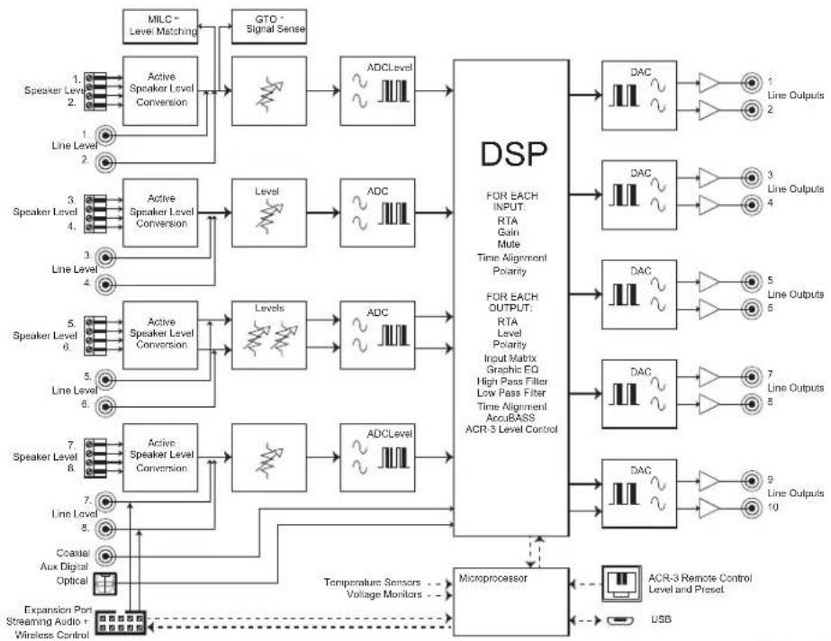
flowchart
graph TD
    A["Speaker Level 1: Active Speaker Level Conversion"] --> B["Active Speaker Level Conversion"]
    B --> C["Level"]
    C --> D["ADC Level"]
    D --> E["DSP FOR EACH INPUT: RTA Gain Mute Time Alignment Polarity"]
    E --> F["DAC"]
    F --> G["Line Outputs 1"]
    E --> H["DAC"]
    H --> I["Line Outputs 2"]
    E --> J["DAC"]
    J --> K["Line Outputs 3"]
    E --> L["DAC"]
    L --> M["Line Outputs 4"]
    E --> N["DAC"]
    N --> O["Line Outputs 5"]
    E --> P["DAC"]
    P --> Q["Line Outputs 6"]
    E --> R["DAC"]
    R --> S["Line Outputs 7"]
    E --> T["DAC"]
    T --> U["Line Outputs 8"]
    E --> V["DAC"]
    V --> W["Line Outputs 9"]
    E --> X["DAC"]
    X --> Y["Line Outputs 10"]
    E --> Z["Microprocessor"]
    Z --> AA["USB"]
    AA --> AB["ACR-3 Remote Control Level and Preset"]
    AB --> AC["Temperature Sensors -- Voltage Monitors -- Expansion Port Streaming Audio + Wireless Control"]
    AC --> AD["Speaker Level 7: Active Speaker Level Conversion"]
    AD --> AE["Levels"]
    AE --> AF["ADC Level"]
    AF --> AG["DSP FOR EACH OUTPUT: RTA Level Polarity Input Matrix Graphic EQ High Pass Filter Low Pass Filter Time Alignment AccuBASS ACR-3 Level Control"]
    AG --> AH["DAC"]
    AH --> AI["Line Outputs 10"]
AudioControl®
Making Good Sound Great™
DM-608 Dimensions
DM-608/DM-810
Installation Manual
DM-810 Dimensions

AudioControl®
Making Good Sound Great™
Service
First, if you need service, it is probably best to go and see a trained health care professional.
Please visit our AudioControl knowledge base at web address: www.audiocontrol.com/knowledge-base. This may help you find a solution to your problem.
If you are fairly sure that the DM-608/DM-810 needs service, then please contact AudioControl, either by e-mail or phone. We will verify if there is anything wrong in the system that you can correct yourself, or if it needs to be sent back to our factory for repair.
Please include the following items when returning the unit:
- A copy of your proof of purchase. No originals please. We cannot guarantee returning them to you.
- A brief explanation of the trouble you are having with the unit. (You'd be surprised how many people forget this.) If you can supply a really detailed description of the problem, this would be so much better, and our service technicians may add you to their Christmas Card list. Please include any notes about the system and other components you are using. Is it an intermittent problem, or all the time?
-
A return street address. (No PO Boxes, please).
-
A daytime phone number in case our technicians have a question about the problem you are having, or if they are just feeling lonely.
- Package the unit in the original packaging if you still have it, and if the kids are not using it for art supplies. Use great care and plenty of good packing materials to protect the unit and prevent it from moving about inside the box. Do not use loose materials like packing peanuts or real peanuts.
You are responsible for the freight charges to us, but we'll pay the return freight back as long as the unit is under warranty. We match whatever shipping method you use to send it to us, so if you return the unit overnight freight, we send it back overnight. We recommend United Parcel Service (UPS) for most shipments.
Repair service is available at:
Attention: Service Department
22410 70th Avenue West,
Mountlake Terrace,
WA 98043 USA
Phone 425-775-8461
FAX 425-778-3166
e-mail: sound.great@audiocontrol.com
The Warranty
People are confused by warranties! Lots of fine print. Months of waiting around. Well, fear no more AudioControl is here. Our warranty is designed to make you rave about AudioControl. It's a warranty that looks out for our customers, plus helps you resist the temptation to have your friend, "who is good with electronics", try to repair your AudioControl product. So go ahead, read this warranty, then register your AudioControl product at www.audiocontrol.com/product-registration.
Our warranty has conditional conditions! "Conditional" doesn't mean anything ominous. The Federal Trade Commission tells all manufacturers to use the term to indicate that certain conditions have to be met before they'll honor the warranty. If you meet all of these conditions, AudioControl will, at its discretion, repair or replace any AudioControl products that exhibit defects in materials and/or workmanship during the warranty on your product for five (5) years from the date you bought it, and we will fix or replace it, at our option, during that time.
Here are the conditional conditions:
- You must fully register your purchase within 15 days of the purchase date by going to the AudioControl product registration page at www.audiocontrol.com/product-registration. Failure to register your product will negate the warranty.
-
You need to hold on to your sales receipt! All warranty service requires original sales receipt documentation. The warranty only applies to the original purchaser from an authorized AudioControl dealer. Note: Products purchased from unauthorized dealers are not covered under warranty.
-
If an authorized AudioControl dealer installs your AudioControl product, the warranty is five years, otherwise the warranty is limited to one year.
- Our warranty covers AudioControl products that have been installed according to the instructions in the owner's manual.
- You cannot let anybody who isn't: (A) the AudioControl factory; or (B) somebody authorized in writing by AudioControl service your AudioControl product. If anyone other than (A), or (B) messes with your AudioControl product, the warranty is void.
- The warranty is void if the serial number is altered, defaced or removed, or if your product has been used improperly. Now that may sound like a big loophole, but here is what we mean by this: Unwarranted abuse is: (A) physical damage (don't use your product to level your dining room table); (B) improper connections (120 volts into the RCA jacks can fry the poor thing); (C) sadistic things! This is the best product we know how to build, but for example if you mount it to the front bumper of your car, drop it over the Niagara Falls or use it for Clay Pigeon shooting practice, something will go wrong.
Assuming you conform to 1 through 6, and it really isn't all that hard to do, we get the option of fixing your product or replacing it with a new one at our discretion.
In the event that your product is out of warranty or not covered under our warranty you may request to have any damage repaired at our normal "Out of Warranty" repair cost.
AudioControl®
Making Good Sound Great"
Legalese Section
This is the only warranty issued by AudioControl. This warranty gives you specific legal rights, and you may also have rights that vary from state to state. Promises of how well your AudioControl product will work are not implied by this warranty. Other than what we've said we'll do in this warranty, we have no obligation, express or implied. We make no warranty of merchantability or fitness for any particular purpose. Also neither we nor anyone else who has been involved in the development or manufacture of the unit will have any liability of any incidental, consequential, special or punitive damages, including but not limited to any lost profits or damage to other parts of your system by hooking up to the unit (whether the claim is one for breach of warranty, negligence of other tort, or any other kind of claim). Some states do not allow limitations of consequential damages.
Complimentary Notes page (filled with horizontal lines that may be used for notes, sonnets, poems, shopping lists, and complex crossover equations)
AudioControl®
Making Good Sound Great™
Salsa!
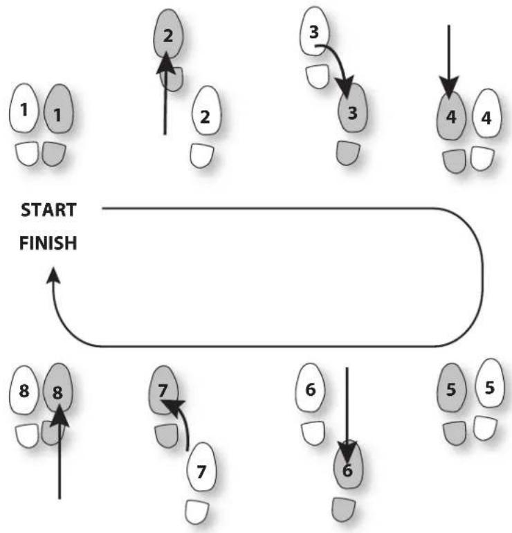
flowchart
graph TD
    A["1 1"] --> B["2"]
    B --> C["3"]
    C --> D["4"]
    D --> E["5"]
    E --> F["6"]
    F --> G["7"]
    G --> H["8"]
    H --> I["START FINISH"]
    style A fill:#f9f,stroke:#333
    style B fill:#ccf,stroke:#333
    style C fill:#cfc,stroke:#333
    style D fill:#fcc,stroke:#333
    style E fill:#cff,stroke:#333
    style F fill:#ffc,stroke:#333
    style G fill:#cfc,stroke:#333
    style H fill:#fcc,stroke:#333
    style I fill:#ffc,stroke:#333
- Important Safety Instructions
- DM-608/DM-810
- Table of Contents
- FEATURES
- Quick Start
- Power Connections
- System #2: Using line-level inputs
- Installation
- ACR-3 Dash Control Installation
- Installing the Application
- Chapter 6: Installing the Application
- Updating the Firmware
- Chapter 7: Updating the Firmware
- The Display
- File Menu
- Tools Menu
- Help Menu
- Memory Menu
- Input View
- Input Gain
- Delay
- Output View
- Output Summing and Level
- Crossover
- ACR-3 Remote
- Output Configuration
- Delay / Distance
- AccuBASS®
- EQ
- AutoEQ
- AutoEQ Hints
- Dashboard View
- Troubleshooting
- No Sound
- Source Clip LED is on:
- Speaker channels are cutting in and out:
- Speaker Buzzing or Crackling at high volume:
- Specifications
- DM-608 and DM-810
- Service
- Repair service is available at:
- The Warranty
- Here are the conditional conditions:
- Legalese Section
Brand : AudioControl
Model : DM-810
Category : Audio/video converter