LC5iPRO - Audio/video converter AudioControl - Free user manual and instructions
Find the device manual for free LC5iPRO AudioControl in PDF.


| Product Type | Audio/Video Converter (Line Output Converter) |
| Brand | AudioControl |
| Model | LC5iPRO |
| Category | Audio/Video Converter |
| Dimensions (W x H x D) | 5.5 x 1.2 x 3.5 inches |
| Weight | 0.5 lbs (0.23 kg) |
| Power Supply | 12V DC (vehicle electrical system) |
| Input Channels | 4 high-level speaker inputs |
| Output Channels | 6 RCA line outputs (front, rear, subwoofer) |
| Frequency Response | 20 Hz – 20 kHz ±0.5 dB |
| Signal-to-Noise Ratio | >100 dB |
| Total Harmonic Distortion | <0.01% |
| Input Impedance | 10 kΩ |
| Output Impedance | 100 Ω |
| Maximum Input Voltage | 40V peak-to-peak |
| Gain Adjustment Range | 0.1V – 8V |
| Bass Boost | 0 to +12 dB at 40 Hz |
| Crossover | Built-in 12 dB/octave low-pass filter for subwoofer output |
| Remote Turn-On | DC offset or signal-sensing trigger |
| Mounting | Included brackets for secure installation |
| Maintenance | Keep unit dry and dust-free; clean with dry cloth |
| Safety | Install in a well-ventilated area; disconnect battery before wiring |
| Spare Parts / Repairability | Contact AudioControl for service; no user-serviceable parts |
| General Information | Designed for use with factory stereo systems; integrates with aftermarket amplifiers |
Frequently Asked Questions - LC5iPRO AudioControl
User questions about LC5iPRO AudioControl
0 question about this device. Answer the ones you know or ask your own.
Ask a new question about this device
Download the instructions for your Audio/video converter in PDF format for free! Find your manual LC5iPRO - AudioControl and take your electronic device back in hand. On this page are published all the documents necessary for the use of your device. LC5iPRO by AudioControl.
USER MANUAL LC5iPRO AudioControl
AudioControl®
Making Good Sound Great™
Features
- Four channels of active speaker level inputs (up to 40V input handling)
• Variable outputs with discrete level controls - AccuBASS® processing for correction of bass roll-off
- Internal channel summing
- Load Selection Switch
• GTO ^TM Signal Sensing
• Audio Sense turn-on
• Ground Isolation Switch
• ACR-1 dash remote included - Fun for all ages

FIVE CHANNEL LINE OUTPUT CONVERTER WITH ACCUBASS®

Important Safety Instructions
- Read these instructions.
- Keep these instructions.
- Heed all warnings.
- Follow all instructions.
- Do not submerge this apparatus in water.
- Clean only with a dry cloth.
- Do not block any ventilation openings. Install in accordance with the manufacturer's instructions.
- Do not install near any heat sources such as mufflers, silencers, exhaust pipes, or other apparatus (including amplifiers) that produce heat.
- WARNING: Improper installation may lead to permanent injury or death. Installation of the apparatus must be done with great care by qualified personnel, to prevent damage to fuel lines, power and other electrical wiring, hydraulic brake lines, and other systems, that might compromise vehicle safety.
- Provide +12V and ground wiring of sufficient size to ensure adequate current to the device. For the LC5i PRO, this means 16-14 gauge wire.
- Use rubber grommets to protect wiring whenever passing wires through metal openings or bulkheads.
- Only use attachments/accessories specified by the manufacturer.
-
Refer all servicing to qualified service personnel. Servicing is required when the apparatus has been damaged in any way, such as the power input terminals are damaged, objects have fallen into the apparatus, does not operate normally, or has been dropped.
-
A 2 amp fuse is recommended on the +12V power wire.
- Not tested for use in outer space.
- Exposure to high sound pressure levels may lead to permanent hearing loss. Take every precaution to protect your hearing.

The lightning flash with arrowhead symbol within an equilateral triangle is intended to alert the user to the presence of uninsulated "dangerous voltage" within the product's enclosure, that may be of sufficient magnitude to constitute a risk of electric shock to persons.
The exclamation point within an equilateral triangle is intended to alert the user of the presence of important operating and maintenance (servicing) instructions in the literature accompanying the appliance.
Caution: to reduce the risk of electric shock, do not disassemble the apparatus. There are no user-serviceable parts inside. Refer servicing to qualified personnel.

Recycling notice: If the time comes and this apparatus has fulfilled its destiny, do not throw it out into the trash. It has to be carefully recycled for the good of mankind, by a facility specially equipped for the safe recycling of electronic apparatii. Please contact your local or state recycling leaders for assistance in locating a suitable nearby recycling facility. Or, contact us and we might be able to repair it for you.

Quick Start
Since some of you hyper-excited enthusiasts will want to install your LC5i PRO on your own, here are a few general steps to get you up and running. You should also refer to the additional sections of this manual for more information and installation examples.
- LC5i PRO is active and REQUIRES CONSTANT +12V POWER
- Pick a suitable mounting location that will provide access to the controls and connections. Protect the LC5i PRO from heat, moisture, and dirt.
- Use the integrated mounting brackets to mount the LC5i PRO.
- Before drilling holes, take every precaution to prevent damage to fuel lines, power and other electrical wiring, hydraulic brake lines, and other systems that might compromise vehicle safety.
- When making connections, designate red RCA plugs as right, and designate white, black, or gray plugs as left.
- Connect the +12V input terminal of the unit to the +12V terminal on the vehicle battery (or distribution block) using 16 to 14 AWG.
- Connect the Ground terminal of the unit to the Ground/Negative terminal of the battery (or distribution block) using the same gauge wire as the +12V power wire.
- For +12V remote turn on the Trigger Mode switch must be set to "Rmt In". Connect the Remote In (Rmt In) terminal of the unit to a remote turn-on switch. Alternately, use GTO™ Signal Sense or Audio Sense to trigger the unit on without a remote wire.
-
Connect the speaker outputs of your factory head unit or amplifier to the Speaker Level Inputs on the LC5i PRO.
-
Run the ACR-1 remote wire to the front of your vehicle.
- Connect the Channel Output RCAs to your aftermarket amplifier.
- Connect the Remote Out (Rmt Out) to your aftermarket amplifier.
- Adjust the input gain using the Output Level knobs.
-
Adjust AccuBASS using the AccuBASS Threshold and Level knobs.
-
Enjoy the drive!
Power, Ground and Remote Trigger
- Power Connector – The LC5i PRO requires constant +12V power and a good ground to operate properly. Connections should be made with 16 to 14 gauge wire.
+12V - Connect this to a constant +12V source, like the positive battery terminal. Fuse at 2 amps.
Ground - Connect to the negative terminal of the battery, a ground bus, or a verified ground.
Rmt Out - Connect the LC5i PRO +12V remote output to your amplifier's remote input.
Rmt In - When Trigger Mode, explained below, is set to Rmt In, connect this to your +12V remote trigger. When using GTO or Audio trigger, no Rmt In connection is necessary.
- Trigger Mode – The Trigger Mode switch controls how the LC5i PRO turns on and off. The default and favorite position is GTO.
Rmt In - This is the traditional way to turn on the LC5i PRO and gives you more control of exactly when the unit will turn on. Most common places to connect the remote input are from the ignition of the vehicle, fuse box, or some other +12V source that turns on and off with the key.
GTO™ - DC offset and Class D switching frequencies are high-falutin technical terms that mean the LC5i PRO can sense when the head unit or amplifier is on, not necessarily when audio is being sent to the LC5i PRO. Use GTO Signal Sense mode when your factory sound system outputs a DC offset or has a Class D amplifier.
Audio - When this mode is selected, the LC5i PRO will ONLY turn on when you start playing an audio source from the head unit. If you turn the head unit on, but DON'T play audio, the LC5i PRO will not turn on.
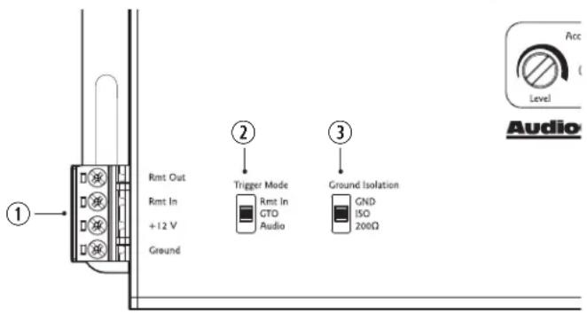
- Ground Isolation – This handy switch allows the you to change how the LC5i PRO is grounded. Sometimes when installing car audio equipment, "ground buzz" or "alternator whine" will creep into the audio path, wreaking havoc on your listening experience. There are 3 positions; GND, ISO, and 200 ohms. The unit ships from the factory in the ISO position.
GND - Power ground and audio ground are tied together.
ISO - Power ground and audio ground are separate.
200Ω - There is 200 ohms of resistance between power ground and audio ground.
Channel Inputs
- Channel Inputs (1-2) – The LC5i PRO has four speaker-level inputs. This is where you connect the speaker-level outputs of your factory-installed source unit or amplifier.
If your source unit has front and rear full range speaker-level outputs, connect them to the Channel 1 and 2 inputs on the LC5i PRO. If the source unit only has front and rear outputs, connect them to the Channel 1 and 2 Inputs and visit the Signal Bus section on page 8 if you want to route audio to the Channel 3 outputs.
Be careful with the speaker wire polarity (+/-), so your new audio system is not out-of-phase and sounding "wonky". If you're not sure which speaker wires to use or the correct polarity, you have a few options: A) find the wiring diagram for your vehicle, B) get an audio T-Harness that is pre-wired and plugs into the factory harness, or C) have your LC5i PRO professionally installed by an authorized AudioControl Dealer.
- Load Select – The LC5i PRO is designed to present NO load to the output of the factory amp, which can make some factory amps upset and stop passing audio. The Load Select feature tricks the factory amp in to detecting a speaker load so it will continue to pass audio.
20 Ω - Best suited for late model Dodge/Chrysler/Jeep/Ram/Fiat vehicles equipped with OEM base sound system. (no separate factory amplifier)
60 Ω - Best suited for late model Dodge/Chrysler/Jeep/Ram/Fiat vehicles equipped with a separately amplified OEM "premium" sound system.
20 kΩ - Best suited for all other applications.
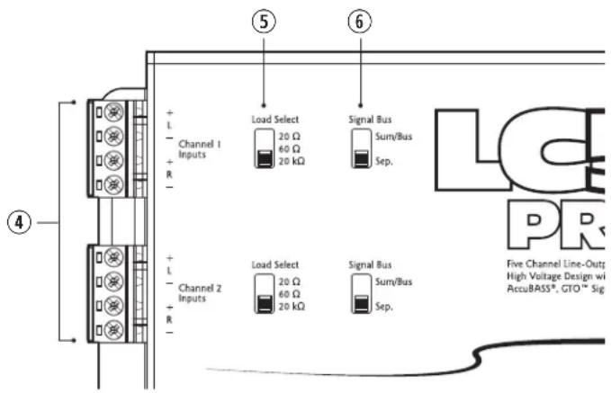
- Signal Bus – The Signal Bus switch provides an easy way to combine (sum), route or keep audio channels separate (see page 8 for more details).
Separate (Sep.) - Sep. is the default option. All audio Inputs and Outputs are separate. For example, audio coming in on Channel 1 Inputs is only routed to Channel 1 Outputs.
Sum/Bus - This setting allows you to combine (sum) two channels of audio inputs into a single combined output (see page 8 for more details).
AudioControl®
Making Good Sound Great"
Channel Outputs

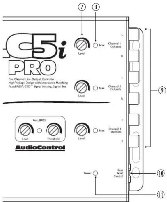
- Level – The Level dials allow you to adjust the signal level from your source unit to match the inputs of your aftermarket amplifier.
- Maximized Light (Max) – The Maximized Light can be used to help achieve optimal output level and will let you know if you are getting close to clipping the output of the LC5i PRO.
With the factory system set to its maximum undistorted volume, match the output level of the LC5i PRO to the input maximum of your after market amplifier. If the Maximized Light turns on, the LC5i PRO output is distorting. Turn the output level down until the Maximized Light turns off. IF THE MAXIMIZED LIGHT NEVER TURNS ON, don't panic. This just means the output of the LC5i PRO is not clipping/distorting.
- Channel Outputs (1-2-3) – These RCA outputs are connected to the inputs of your amplifier or sound processor. When making connections, designate red RCA plugs as right, and designate white, black, or gray plugs as left.
- Bass Level Control – Connect the ACR-1 to remotely control the output level of the Channel 3 Outputs, ideally controlling the level of a subwoofer. The ACR-1 is strictly an attenuator knob and will NEVER increase the output level past where the Level dial is set.
- Power – If you have connected all of your power wires correctly, this light while shine bright red when your system turns on.
Setting AccuBASS®
AccuBASS is a feature that restores bass frequencies on factory systems that roll off the bass as you increase volume. If you can hear that the bass does not increase as you continue to turn up the volume on the head unit, then your factory system is most likely rolling off bass.
AccuBASS only affects the Channel 3 outputs.
There are two AccuBASS controls and a status LED used during initial setup: AccuBASS Threshold determines when AccuBASS turns on, and AccuBASS Level adjusts how much bass is restored. The status LED will illuminate when AccuBASS is active.
- Turn AccuBASS Threshold all the way down (counterclockwise).
- Set AccuBASS Level at the 12 o'clock position.
- Play some bass-heavy music you are familiar with.
- Slowly turn up head unit volume until you start to hear bass dropping out (roll off). Stop turning up the head unit volume.
- Slowly turn AccuBASS Threshold to the right (clockwise) until the status LED illuminates and you hear bass being restored. Stop adjusting AccuBASS Threshold.
- With AccuBASS Threshold set you can now adjust AccuBASS Level to your liking.
If the sound system in your vehicle does not reduce bass output at higher volumes, AccuBASS may be defeated, or used without the threshold setting (on all of the time). To defeat (turn off) AccuBASS, turn AccuBASS Threshold all the way down (counterclockwise), and turn AccuBASS Level all the way down (counterclockwise).
To keep AccuBASS on all of the time so it does not turn on/off at a set threshold, turn AccuBASS Threshold all the way up (clockwise). Now, regardless of the head unit volume, AccuBASS will always be on. Adjust AccuBASS Level to your liking.
ACR-1 Dash Control
The ACR-1 dash control may be mounted under the dash using its own bracket or custom mounted in the dash (or anywhere else). It should be within reach of the driver and in a spot where the LED is plainly visible.
Bracket Installation
Slide under the dash and place the dash control in the desired position, mark the two mounting holes, drill pilot holes and secure with two screws.
Custom Installation
Remove the dash control from the mounting bracket by pushing the LED from its holder and then removing the circuit board and rotary control from the bracket. Choose a suitable location and drill a 9/32" hole for the control shaft along with a 1/8" hole for the lock tab and a 13/64" hole for the LED holder. Reassemble the ACR-1 components in their new custom location.
AudioControl®
Making Good Sound Great"
Signal Bus

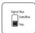
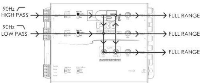
The Signal Bus switch allows you to combine multiple input signals to a single channel output. It is typically used when connecting to a "premium" factory system that has crossed-over speaker outputs for various speakers. You can use the Sum/Bus function to sum signals together to create a full range
output. Or, if the factory source only has front and rear full range output, the Signal Bus can be set to route (bus) the audio signal from Channel 2 to Channel 3 for that much-needed subwoofer channel.
Below are some diagrams of typical scenarios of how you can setup your LC5i PRO
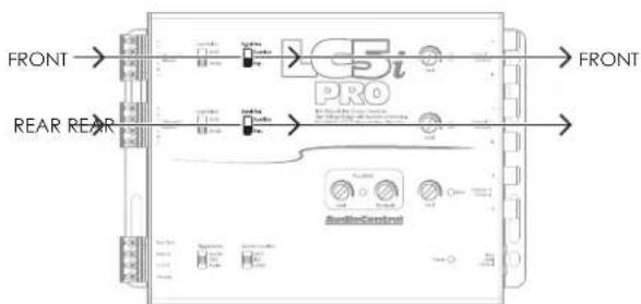
In this example both Signal Bus switches are set to the default setting of Sep. (separate). There is no combining or routing of signals. What goes into the Channel Input comes out the corresponding Channel Output.
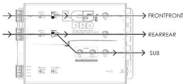
Add a sub channel to a 4 channel system by setting Channel 2 to Sum/Bus. This will split and route the signal on Channel 2 to the Channel 3 Outputs.
flowchart
graph LR
    A["90Hz HIGH PASS"] --> B["Input"]
    C["90Hz LOW PASS"] --> D["Input"]
    B --> E["FULL RANGE"]
    D --> F["FULL RANGE"]
    E --> G["Output"]
    F --> H["Output"]
To sum a high pass and low pass signals to get a full range signal, set both channels to Sum/Bus. (Looks confusing on paper, but trust us, it will sound great)
System Examples
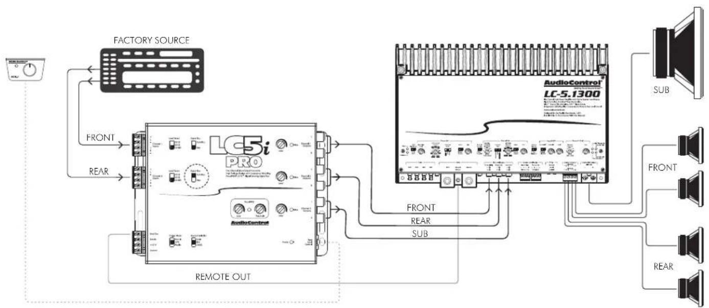
System #1: Basic Factory Upgrade System
flowchart
graph TD
    A["Factory Source"] --> B["LC5i PRO"]
    B --> C["AudioControl"]
    C --> D["Sub"]
    D --> E["AudioControl LC-5.1300"]
    E --> F["FRONT"]
    E --> G["REAR"]
    B --> H["REMOTE OUT"]
    H --> I["FRONT"]
    H --> J["REAR"]
    H --> K["SUB"]
    style A fill:#f9f,stroke:#333
    style E fill:#ccf,stroke:#333
    style F fill:#cfc,stroke:#333
    style G fill:#fcc,stroke:#333
    style H fill:#ffc,stroke:#333
    style I fill:#fff,stroke:#333
    style J fill:#fff,stroke:#333
    style K fill:#fff,stroke:#333
Notes:
Channel 2 Signal Bus switch set to Sum/Bus to route (bus) Channel 2's signal to Channel 3 Outputs.
AudioControl®
Making Good Sound Great™
System #2: Factory Amplified Upgrade System
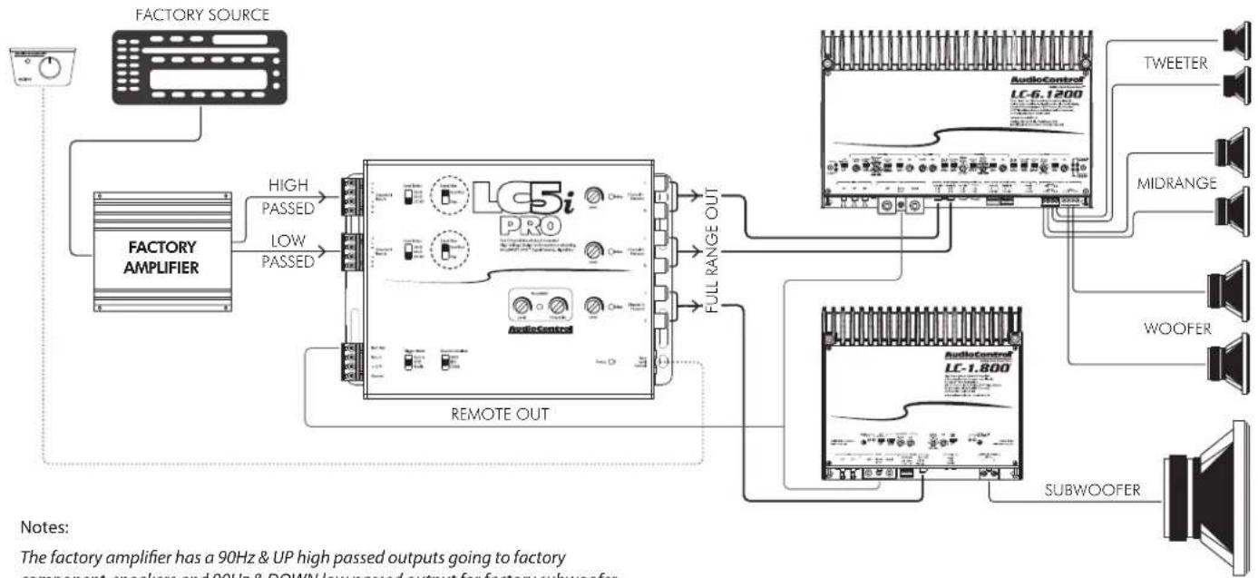
flowchart
graph TD
    A["FACTORY SOURCE"] --> B["FACTORY AMPLIFIER"]
    B --> C["High PASSED"]
    B --> D["LOW PASSED"]
    C --> E["LC5i PRO"]
    D --> E
    E --> F["FULL RANGE OUT"]
    F --> G["AudioControl LC-6.1200"]
    G --> H["TWEETER"]
    G --> I["MIDRANGE"]
    G --> J["WOOFER"]
    G --> K["SUBWOOFER"]
    E --> L["REMOTE OUT"]
    L --> M["AudioControl LC-1.800"]
    M --> N["SUBWOOFER"]
    style A fill:#f9f,stroke:#333
    style B fill:#ccf,stroke:#333
    style C fill:#cfc,stroke:#333
    style D fill:#fcc,stroke:#333
    style E fill:#cff,stroke:#333
    style F fill:#ffc,stroke:#333
    style G fill:#fcf,stroke:#333
    style H fill:#cff,stroke:#333
    style I fill:#ffc,stroke:#333
    style J fill:#ffc,stroke:#333
    style K fill:#ffc,stroke:#333
Notes:
The factory amplifier has a 90Hz & UP high passed outputs going to factory
component speakers and 90Hz & DOWN low passed output for factory subwoofer.
Channel 1 and 2 Signal Bus switches set to Sum/Bus to combine (sum) both signals.
Specifications
All specifications are measured at 14.4 VDC (standard automotive voltage). As technology advances, AudioControl reserves the right to continuously change our specifications, like our Pacific Northwest weather, although we are working on changing that as well.
Maximum Input Handling 40V / 400W
Maximum Output Level 9.5 Vrms
Output Gain +/- 15 dB
ACR-1 Attenuation Range 0 dB to -21 dB
Frequency Response 20 Hz to 20 kHz
Total Harmonic Distortion .... <0.1%
Signal to Noise....>124 dB
Input Impedance ...... Selectable (20Ω, 60Ω, 20 kΩ)
Output Impedance....150 Ω
Power Draw....330 mA
Recommended Fuse Rating 2 Amp
Weight & Dims.... 1.10 lbs. / 7"L x 5.1"W x 1.14"H
Warranty ....5 Year Warranty (www.audiocontrol.com/warranty/)
For more information about this fine product, and for details of the limited warranty and repair services, please visit www.audiocontrol.com
For technical questions, please visit www.audiocontrol.com/knowledge-base/
AudioControl, Inc.
22410 70th Avenue West
Mountlake Terrace, WA 98043 USA
Phone: 425-775-8461
email: sound.great@audiocontrol.com
©2022 AudioControl. All rights reserved.
All specifications are subject to being drizzled with caramel without notice.
AudioControl®
Making Good Sound Great™
The End ( This page is an easy read)

Quick Start Guide PN 915-037-0 Rev D
Brand : AudioControl
Model : LC5iPRO
Category : Audio/video converter