EGH20AW - Heating appliance ElectriQ - Free user manual and instructions
Find the device manual for free EGH20AW ElectriQ in PDF.


| Product Type | Designer Glass Panel Heater |
| Model Numbers | EGH20AW (White) / EGH20AWB (Black) |
| Power Supply | 220-240V ~ 50/60Hz |
| Power Consumption | 1800-2000W (High: 2.0kW, Low: 1.0kW) |
| Dimensions (W x D x H) | 830 x 85 x 460 mm |
| Weight | 8 kg |
| IP Rating | IP24 (suitable for bathroom zones 2 and 3) |
| Heating Modes | High Heat (2.0kW), Low Heat (1.0kW), Anti-Frost (5-9°C) |
| Temperature Control | Electronic thermostat with adjustable setpoint (10-49°C in High/Low modes) |
| Display | LED display with brightness dimming and full off option |
| Timer | 24-hour countdown timer and 7-day programmable weekly timer (6 periods per day) |
| Connectivity | Wi-Fi via Tuya Smart app (2.4GHz only) |
| Remote Control | Infrared remote control (battery not included) |
| Safety Features | Double overheat protection, child lock, open window detection, thermal cut-out |
| Installation | Wall-mountable or freestanding with included castors |
| Minimum Clearances | 50cm from walls/objects; 15cm from floor; 50cm from ceiling |
| Bathroom Zoning | Must be installed outside Zones 0-2; RCD protection recommended |
| Cleaning | Wipe with soft damp cloth; do not use chemicals or immerse in water |
| Frost Protection | Maintains room temperature between 5-9°C to prevent freezing |
| Memory Function | Restores previous settings after power interruption |
| Warranty | Standard manufacturer warranty; contact support for details |
Frequently Asked Questions - EGH20AW ElectriQ
User questions about EGH20AW ElectriQ
0 question about this device. Answer the ones you know or ask your own.
Ask a new question about this device
Download the instructions for your Heating appliance in PDF format for free! Find your manual EGH20AW - ElectriQ and take your electronic device back in hand. On this page are published all the documents necessary for the use of your device. EGH20AW by ElectriQ.
USER MANUAL EGH20AW ElectriQ
natural_image
Exterior view of a black rectangular electronic device with wheels and a digital display (no visible text or symbols)2.0 KW DESIGNER GLASS PANEL HEATER
EGH20AW / EGH20AWB
Thank you for choosing electriQ
Please read this user manual before using this heater and keep it safe for future reference.
Visit our page www.electriQ.co.uk for our entire range of Intelligent Electricals
SETTLING IN OK?
We hope this has been helpful to you.
We would love to see how you're getting on with your new purchase, so please share any snaps you have on the platform of your choice below.
Our community awaits your uploads - Snap, tag and hashtag away!

@electriQUK
electriQUK
WE'RE HERE TO HELP
Should you have any problems or questions with your purchase, please contact a member of our customer service team.
0330 390 3061
support@electriQ.co.uk
Mon-Fri | 9am to 5pm
Unit 2A, Trident Business Park, Neptune Way, Leeds Road, Huddersfield, HD2 1UA
CONTENTS
SAFETY INSTRUCTIONS 4
SETTING THE UNIT UP 7
INSTALLATION 8
PRODUCT OVERVIEW 9
QUICK USE GUIDE 9
SETTING THE DAY AND TIME 9
OPERATION 10
TIMER 10
SETTING UP THE APP 12
USING THE APP 17
CLEANING AND MAINTENANCE 22
TROUBLESHOOTING 22
TECHNICAL SPECIFICATIONS 23
SUPPORT 23
PRODUCT FICHE 24
PSTI AND DECLARATION OF CONFORMITY 25
SAFETY INSTRUCTIONS IMPORTANT
- Carefully read the instructions before operating the unit
- This appliance is for indoor use only.
- Rating: This unit must be only connected to a 220-240V\~50/60 Hz earthed outlet.
- Installation must be in accordance with the regulations of the country where the unit is used.
- All national regulations concerning the discharge of air must be fulfilled.
- If you have any doubt about the suitability of your electrical supply, have it checked and, if necessary, modified by a qualified electrician.
- This heater has been tested and is safe to use. However, as with any electrical appliance - use it with care.
- Joists, beams and rafters shall not be cut or notched to install the appliance.
- Disconnect the power from the unit before dismantling, assembling or cleaning.
- Avoid touching any moving parts within the appliance.
- Never insert fingers, pencils or any other objects through the guard or ventilation openings.
- WARNING: The heater must not be used if the glass panels are damaged.
- This appliance is not intended for use by persons (including children) with reduced physical, sensory or mental capabilities or lack of experience and knowledge unless they have been given supervision or instruction concerning the use of the appliance by a person responsible for their safety.
- Children aged from 3 years and less than 8 years shall only switch on/off the appliance provided that it has been placed or installed in its intended normal operating position and they have been given supervision or instruction concerning the use of the appliance in a safe way and understand the hazards involved. Children aged from 3 years and less than 8 years shall not plug in, regulate and clean the appliance or perform user maintenance.
- Children under 3 years should be kept away unless continuously supervised.
- Children should be supervised to ensure that they do not play with the appliance.
- CAUTION: Some parts of this product can become very hot and cause burns. Particular attention has to be given where children and vulnerable people are present.
- Do not clean the unit by spraying it or immersing it in water.
- Never connect the unit to an electrical outlet using an extension cord. If an outlet is not available, a qualified electrician should install one.
- If the supply cord is damaged, it must be replaced by the manufacturer, its service agent, or similarly qualified persons to avoid a hazard.
- Ensure the power cord is not stretched, exposed to sharp objects/edges, or routed under the unit.
- Do not use this heater in the immediate vicinity of a bath, shower, or swimming pool. When using these areas, follow the diagram supplied.
- Install the heater in a place where switches and sockets are not accessible by persons in a shower, bath, or pool.
- Do not use this heater if it has been dropped.
- Do not use if there are visible signs of damage to the heater.
- Always ensure the heater is used on a flat-level surface or mount as per the instructions.
- An authorised service representative should perform any service other than regular cleaning. Failure to comply could result in a voided warranty.
- Never use the plug as a switch to start and turn off the heater. Use the provided power switch on the rear of the unit.
- CAUTION: In order to avoid a hazard due to inadvertent resetting of the thermal cut-out, this appliance must not be supplied through an external switching device, such as a timer,
or connected to a circuit that is regularly switched on and off by the utility.
- WARNING: In order to avoid overheating, do not cover the heater. Do not cover the air inlet or outlet or place items close to the unit, which may restrict airflow, as this may present a fire risk.
- The heater must not be located immediately below a socket outlet.
- Always ensure the unit is secure before operation. Do not use it on unstable or uneven surfaces, and if it is wall-mounted, it must be securely attached to a suitable wall.
- Do not move or tilt the unit.
- Avoid keeping the unit in direct sunlight for a long period of time.
- The heater is designed to be used at temperatures above -20^ . If it is exposed to temperatures below this, it must be allowed to warm above this level before operation.
- Do not attempt to repair, disassemble or modify the appliance. This unit contains no user-serviceable parts.
- Always unplug or disconnect the appliance from the mains power supply when not in use or when moving or cleaning it. Do not pull the cord to unplug the heater.
- Keep the heater clean. Do not allow any object to enter the ventilation or exhaust opening, as this may cause electric shock, fire, or damage to the heater.
- Do not use the appliance for anything other than its intended use. It is designed for domestic indoor use only.
- WARNING: Do not use this heater in small rooms when they are occupied by persons not capable of leaving the room on their own unless constant supervision is provided.
- WARNING: To reduce the risk of fire, keep textiles, curtains, or any other flammable material at least 1 m from the air outlet.
- There may be a trace of odour during the first few minutes of initial use or after a period of storage. This is normal and will quickly disappear.
- This appliance has hot and arcing or sparking parts inside. Do not use it in areas where gasoline, paint, or any flammable liquids are used or stored.
- This appliance is not intended for use in bathrooms, laundry areas, or similar humid locations. Never place it where it may fall into a bathtub or otherwise become exposed to water.
- This appliance is IP24 rated, and so can be used or installed within a bathroom as long as the appliance and its cables are not within Zones 0-2.
- If the unit is wall-mounted, it must be installed in accordance with current regulations for the area where it is installed. If unsure, professional advice should be sought.
- WARNING: To reduce the risk of fire or electrical shock, DO NOT use this appliance with any solid-state Speed Control Device or any variable speed controllers.
- Do not allow the appliance to be submerged or sprayed with water.
- IMPORTANT: The remote for this appliance uses an alkaline battery (not supplied).
- Do not use the remote if the battery compartment is loose or broken.
- Keep it out of the reach of children and pet. Seek medical advice if swallowed.
- To prevent battery leakage, remove the battery from the remote if it is exhausted or before long periods of storage.
- Do not obstruct any of the heat outlet grilles or air intake opening of the heater to avoid overheating.
ENERGY SAVING AND UNIT SAFETY PROTECTION TIP
- Do not cover or restrict the airflow. Do not use it in a dusty environment.
- For safety and maximum performance, when used as a portable unit, the minimum distance from a wall or objects should be 50cm.
INSTALLING WITHIN A BATHROOM
If the appliance is to be fitted within a bathroom, a good understanding of the zoning within bathrooms is required to ensure the unit is mounted in a safe position. The appliance is rated as IP24 and should be installed outside of Zones 0-2. We would advise when the unit is fitted within a bathroom, the plug is removed from the unit, and a suitable fused spur is installed in accordance with BS 7671. In addition, when used in a bathroom, it must be protected by a suitable RCD to prevent the risk of electric shock and must not be immersed in water when cleaning.
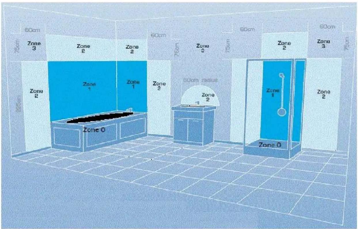
| Zone 0: | The interior of the bathtub or shower basin. |
| Zone 1: | The area around the bathtub or shower basin is up to a height of 2.25m above the floor. |
| Zone 2: | The area stretching to 0.6m outside the bath or shower and above the bath or shower is over 2.25m. |
FEATURES
- 3 Heating Modes
- Tempered Glass Panel
- Easy to Read LED Display
- 24 Hour Timer
• Wi-Fi Enabled with App Control - Remote Control
• Electronic Sensor Thermostat with Frost Protection Function - Double Overheat Protection
• Room Temperature Sensor Adjustment
• Wall Mountable or Portable Using Supplied Castors
• Waterproof Rating of IP24
PARTS LIST
2 x Legs + 4 Castors
Wall plugs
X3
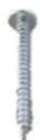
Screws 4x12
X6
Screws 4x35
X3
SETTING THE UNIT UP FOR USE
The appliance can be wall-mounted using the pre-attached mounting brackets, or alternatively can be set up as a portable heater using the supplied legs with castors. It is important that the unit is only operated if it is wall-mounted or has the castors fitted.
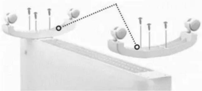
ATTACHING THE FEET
- Turn the heater upside down and place it on a soft surface.
- Put the leg assembly in position and align the screws ( 4×12 ) with the 3 holes on the underside of each leg, and loosely fit.
- Once all screws are in place, they should be fully tightened.
- After the installation is complete, turn the heater the right way up.
natural_image
Diagram of a balance scale with balls on both sides and a dotted line connecting them (no text or symbols)Feet assembly
WALL MOUNTING
The heater must be installed at least 15cm from the floor and 50cm from the ceiling.
IMPORTANT: Before drilling, ensure that no wires or pipelines are behind the wall to prevent damage.
INSTALLATION
-
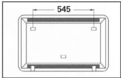
Measure the distance between the 3 wall-hanging holes on the rear of the heater.
-
After double-checking the measurements, mark their position on the wall, using a pencil. We would advise using a spirit level to ensure all markings are square and level.
-
Once you are happy with the marks' position, drill 8 mm-diameter holes using a suitable drill bit.
-
Insert the wall plugs into the holes. Please note that alternative fixings may be required depending on the wall type. Ask for professional advice if unsure.
-
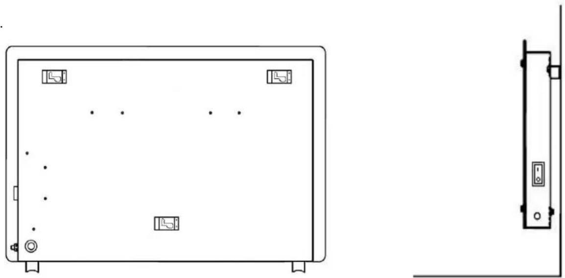
Fix the 3 4 × 35 screws into the wall plugs and leave these protruding around 5-10mm for the heater to hang onto.
-
Push the heater to the side so that screws move through the channel on the brackets to secure it in position.
natural_image
Technical line drawing of a front panel with mounting holes and internal components, shown in two orthogonal views (no text or symbols)PRODUCT OVERVIEW CONTROL PANEL
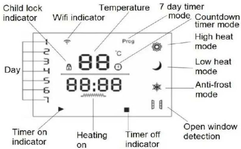
REMOTE CONTROL
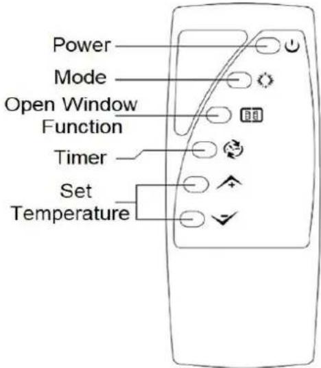
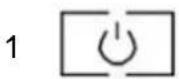
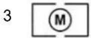
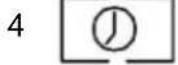
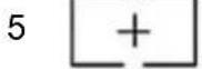
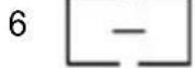
| 1 | Power / Standby button |
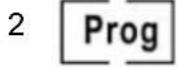
| 2 | Program button |
| 3 | Mode button |
| 4 | Timer button |
| 5 | Up button |
| 6 | Down button |
SWITCHING ON THE HEATER
Plug the heater into the power supply and turn on the power switch (on the side of the unit). You will hear a sound, and the display will show the current ambient temperature. This indicates that the power supply is now connected.
The LED display will illuminate when the POWER button is pressed.
QUICK USE GUIDE
- Switch the unit on using the main power switch on the side of the unit. The heater will make a sound, and the display will flash.
- Press the STANDBY button to turn on the heater. The display panel will light up, and the unit will start to operate with the default settings.
- Set the current day and time.
- Use the UP and DOWN buttons to change the desired temperature and the MODE button to switch between High Heat, Low Heat, and Anti Frost modes.
SETTING THE DAY AND TIME
- With the appliance turned on, hold the TIMER button for 3 seconds until the hour value starts to flash.
- Change the hour value using the UP and DOWN buttons.
-
Hold the TIMER button for 3 seconds to confirm the hour value.
-
Change the minute value using the UP and DOWN buttons.
- Hold the TIMER button for 3 seconds to confirm the minute value.
- Change the day shown on the day indicator using the UP and DOWN buttons.
- Leave the unit for 5 seconds, and the day and time will be saved.
TURNING ON AND OFF
The STANDBY button can be pressed to enter and exit standby mode. If the unit is not to be used for a while, we would advise for it to be turned off using the switch on the side and unplugged.
CHANGING THE DESIRED ROOM TEMPERATURE
The desired room temperature can be adjusted in both High heat and Low Heat modes, using the UP and DOWN buttons. After the UP or DOWN button has been pressed, the temperature display will show the desired temperature. The desired temperature can be adjusted between 10°C and 49°C.
CHILD LOCK
Press and hold the UP and DOWN buttons for 3 seconds to activate and deactivate the child lock. When the child lock is activated the Child lock symbol will be shown on the display and the buttons are disabled on the control panel until the child lock is deactivated.
Repeatedly press the MODE button to change between the 3 available power modes:
High Heat | The heater will operate at High Power (2KW), the desired temperature can be specified between 10°C and 49°C. |
Low Heat | The heater will operate at Low Power (1KW), the desired temperature can be specified between 10°C and 49°C. |
Anti-Frost | The heater will operate to keep the room temperature between 5°C and 9°C in order to prevent freezing within the room. The desired temperature cannot be changed. |
OPEN WINDOW DETECTION
Hold MODE for 3 seconds to select Open Window Detection Mode. In this mode, when the ambient temperature drops by 5°C within 10 minutes, the heater will register the possibility of an open window in the room. If this happens, it will stop heating and enter standby mode.
STANDBY TIMER
With the unit running with the desired settings, press the TIMER button. The countdown timer symbol will illuminate and the unit will flash 00:00.
Repeatedly press the TIMER button to increase the duration of the timer (upto a maximum of 24 hours).
Once the chosen timer length is selected, leave the unit, and after 10 seconds the timer will start. After the chosen time period the heater will enter standby mode.
WEEKLY TIMER
Hold the PROGRAM button for 3 seconds to start the weekly timer. "Prog" will appear on the display, signalling that the timer is active.
Press the TIMER button once, and the number "1" will begin to flash on the display to show that the first day is selected. Use the UP and DOWN buttons to select the weekday to edit.
When you have selected the day to amend, press the TIMER button to confirm.
Each day has 6 time periods that can be programmed. Use the UP and DOWN buttons to select the time period to adjust. Press the TIMER button to confirm the chosen time period.
The hours will begin to flash, and the ▶ symbol will be displayed. Adjust this using the UP and DOWN buttons. Once the start hour is set, press the TIMER button and the minute value will start to flash. Set this using the UP and DOWN buttons, before pressing the TIMER button to confirm.
Once the start time has been set for the period of operation, the unit will then move onto setting the finishing time. This will be indicated by the ■ symbol on the display. This is set in exactly the same way as the start time.
Once the TIMER button has been pressed to confirm the stop time the temperature display will start to flash. Use the UP and DOWN buttons to confirm the desired temperature during the period specified. The heater will only operate when the temperature is below this value.
The above steps can then be repeated to set other time periods throughout the week.
The timer settings will be saved, and will not change as long as power is not disconnected from the unit.
ADDITIONAL FEATURES
DISPLAY:
After any no operation for 30 seconds, the light on the display will become dim, but not turn off. Press any button to return the screen to full brightness. Press and hold the DOWN button for 3 seconds to turns off the display completely, leaving only the ON/OFF button on, but dimmed, the unit will still function as normal. Press any button to turn the display back on to its normal working state.
MEMORY FUNCTION:
In case of power failure or after turning the unit off, when turned back on the unit will start in the previously used settings.
FACTORY RESET:
Press and hold the UP and DOWN buttons for 3 seconds to reset the unit back to its factory settings. A beep will sound and the unit will start in COMFORT mode.
CONNECTING THE APPLIANCE TO WIFI DOWNLOAD THE APP TO YOUR PHONE
Download the "TUYA SMART" app, from your chosen app store, using the QR codes below, or by searching for the app in your chosen store.
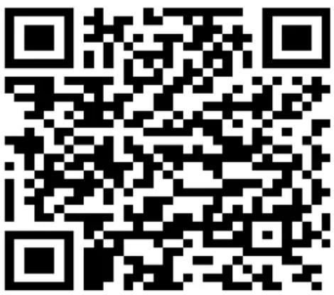
Android
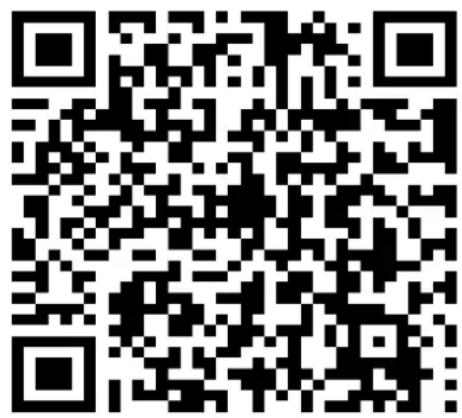
IOS
MODES AVAILABLE FOR SETUP
The heater has two different setup modes, Quick Connection and AP (Access Point). The quick connection is a quick and simple way to set the unit up. The AP connection uses a direct local WiFi connection between your phone and the heater to upload the network details.
When first turned on using the switch on the rear of the unit, the WiFi will be turned off. To turn on the WiFi, press and hold the UP button for 3 seconds. The WiFi symbol will flash quickly to indicate the unit is in quick connection mode. Please ensure your device is in the correct WiFi connection mode for the connection type you are attempting, the flashing WiFi indicator on your heater will indicate this.
CONNECTION
After plugging in, the WiFi icon flashes and automatically enters the distribution network state. After the distribution network is successfully connected. The WiFi indicator light
remains on. Press and hold the on/off button Ⓗ for 3 seconds to reset WiFi and reconfigure the network.
TURNING THE WIFI OFF
To turn the WiFi off, the appliance must be turned off using the switch on the rear. When the unit is turned back on it will start with the WiFi turned off, until reactivated following the steps above.
REGISTER THE APP
- Press on the register button at the bottom of the screen.
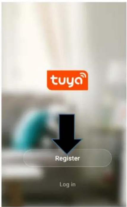
- Read the Privacy policy and press the Agree Button.

Privacy Policy
Privacy Policy of Tuya Smart Platform
Update date: 2018.4
Come into force date: 2018.5
So you have purchased our TuyaSmart device hardware and are starting to use the
TuyaSmart device software and all its
functionalities! Any information you share with us (e.g. for creating a Tuya Account) will
help us to provide you with services related to
TuyaSmart device and to improve them to
make them even better. We explain here our ways of collecting and using information, and
how we protect your privacy. In th
policy, "personal data" means info
that can be used to identify an ind
either from that information alone
that information and other inform
Disagree
Agree
- Enter your email address or phone number and press continue to register.

Register
United Kingdom +44
Mobile number/Email
Continue
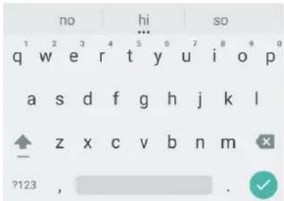
- A verification code will be sent by the method selected in step 3. Enter the code into the app.

Verification Code
Verification code has been sent to Resend(57s)
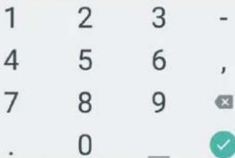
- Type in the password you would like to create. This needs to be 6-20 characters, with letters and numbers.

Set Password
Password must contain 6-20 letters and numbers
5.6.18
- The app is now registered. It will automatically log you in following registration.

natural_image
Illustration of a person sitting on a blue cushion with a potted plant nearby (no text or symbols)Enjoy your smart life
Add Home
Log out
SETTING UP YOUR HOME WITHIN THE APP
TUYA is designed so it can work with a large number of compatible smart devices within your home. It can also be set up to work with multiple devices within different houses as such during the setup process the app requires that different areas are created and named to allow easy management of all your devices. When new devices are added, they are assigned to one of the rooms you have created.
CREATING ROOMS
- Press on the ADD HOME button.

natural_image
Illustration of a person using a laptop with a potted plant beside her, set against a light blue abstract background (no text or symbols)Enjoy your smart life
- Type in a name for your home.
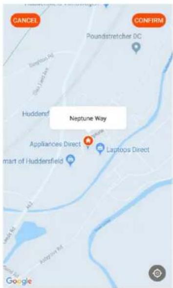
- Press on the location button to select the location of your home. (See SETTING YOUR LOCATION below)
- New rooms can be added by pressing the ADD ANOTHER ROOM option at the bottom. (See ADD ANOTHER ROOM below)
- Untick any rooms that are not required on the app.
- Press DONE in the top right corner.

Add Home

Name
Enter your home name
Location
Set geographic location
Smart devices in:
Living Room

Bedroom

Second Bedroom

Dining Room

Kitchen

Study Room

Add another room
Use your finger to move the orange HOME symbol.
When the symbol is in the approximate location of your home, press the confirm button in the top right corner.
Location details allows the app to be set up later to respond to weather conditions in your area.
ADD ANOTHER ROOM
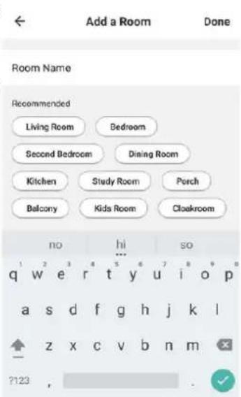
Type in the name of the room, and press Done in the top right corner.
CONNECTING USING THE QUICK CONNECTION METHOD
Before initiating the connection, make sure the unit is in standby mode (Power switch ON, but unit turned off), with the WiFi indicator flashing twice per second. If not follow the instructions for changing the connection mode. Also ensure your phone is connected to the WiFi network. (We advise turning mobile data off during setup)
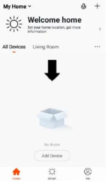
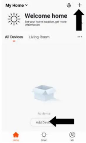
- Open app and press "+" to add device, or use the add device button.
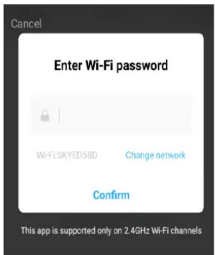
- Enter your WiFi password and press confirm.
- Select the type of device as "Heater" within the Home Appliance tab.
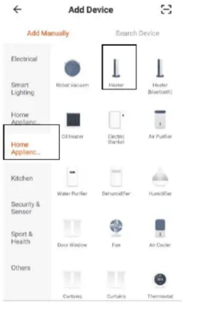
- This will then transfer the settings to the heater. Wait for this to complete. If this fails, retry. If still unsuccessful please review the troubleshooting section for further help.
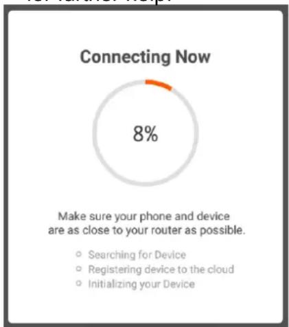
pie
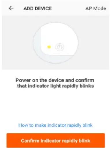
Connecting Now | Category | Value (%) | |---|---| | Searching for Device | 0 | | Registering device to the cloud | 0 | | Initializing your Device | 0 | Make sure your phone and device are as close to your router as possible.- Ensure the Ambient Light indicator on the heater is flashing twice per second, then press on the orange button at the bottom of the screen.
CONNECTING USING THE APP MODE ALTERNATIVE METHOD
Before initiating the connection, make sure the unit is in standby mode, with the WiFi Light Indicator flashing once per second. If not, follow the instructions for changing the WiFi connection mode. Also, ensure your phone is connected to the WiFi network. (We advise turning mobile data off during setup)
- Open app and press “+” to add device, or use the add device button.
- Select the type of device as "Heater" within the Home Appliance tab.
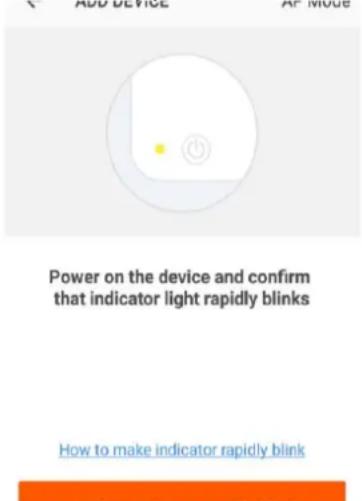
- Press on the AP mode button in the top right of the screen.
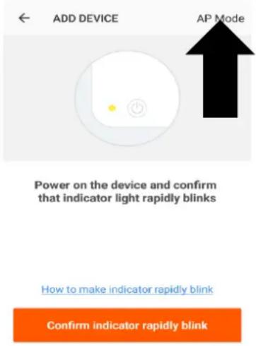
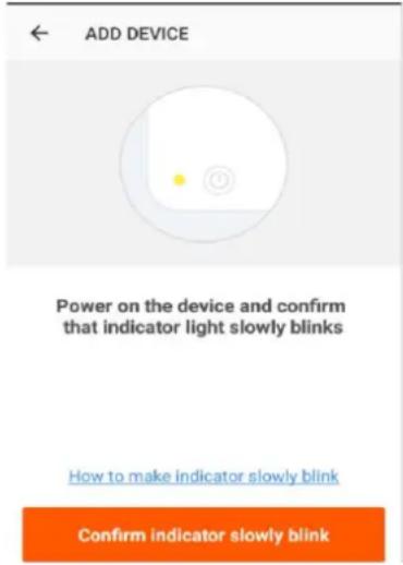
- Ensure the WiFi indicator on the heater is slowly flashing (once per second), then press on the orange button at the bottom of the screen to confirm.
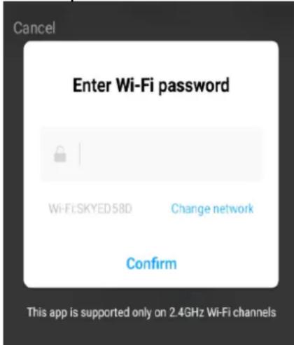
- Enter your WiFi password and press confirm.
- Go to network settings in your phone and connect to the "SmartLife xxx" connection. There is no password to enter. Then return back to the app to complete setup.
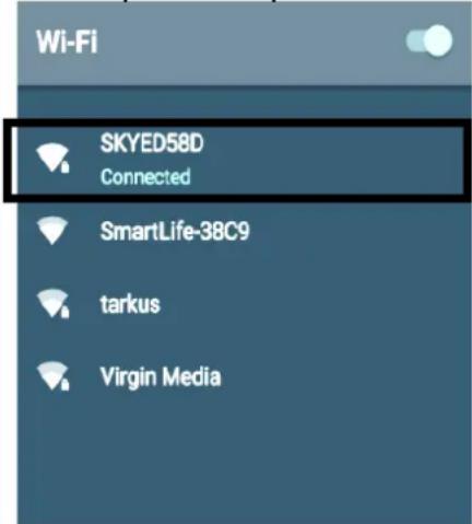
This will then transfer the settings to the heater.
Once the connection process has completed, go back to the network settings on your phone to ensure your phone has reconnected to your WiFi router.
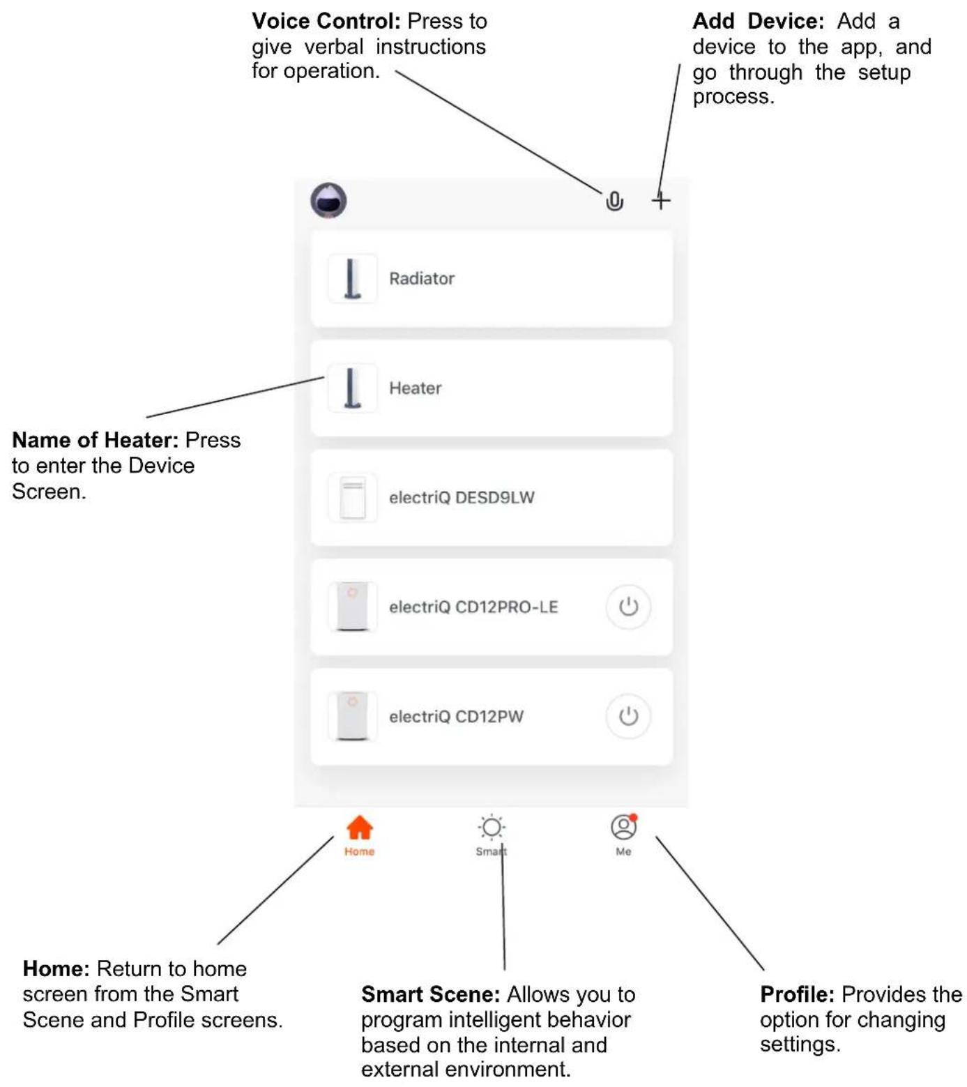
CONTROLLING YOUR APPLIANCE THROUGH THE APP THE HOME SCREEN
Each device has its own entry on the home screen, which allows the user to quickly turn the unit on or off or to enter the device screen to make other changes.
DEVICE SCREEN
The device screen is the main control screen for the heater, providing access to the controls to amend the functions and settings.
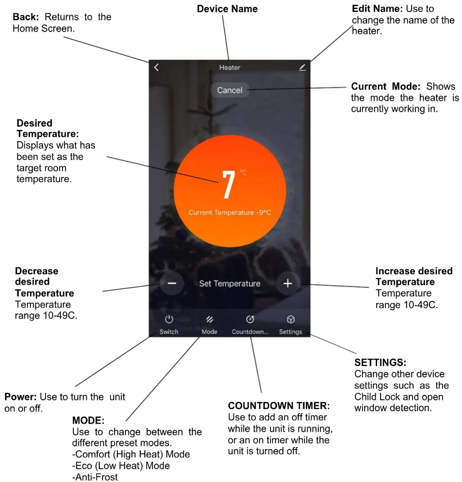
NOTE: The app's layout and available features may change due to continuous development.
SMART SCENES
Smart Scenes is a powerful tool that allows the user to customize the operation of the air heater based on conditions within the room and outside influences. This gives the user the option of specifying much more intelligent actions. These are split into two categories: Scene and Automation.
SCENE
Scene allows for the addition of a one-touch button to the Home Screen. The button can be used to change several settings in one go and can change all the settings within the unit. A number of scenes can easily be set up, allowing the user to easily change between a number of preset configurations.
Below is an example of how to set up a scene:
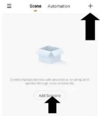
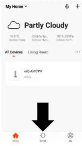
- Press on the Smart tab at the bottom of the Home screen.
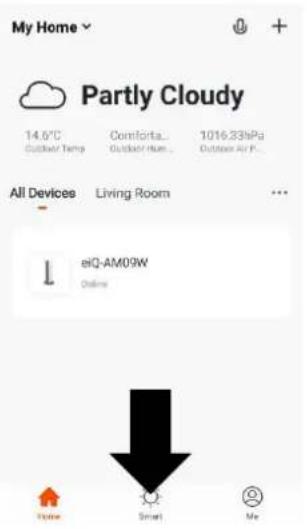
- Press on the Plus in the top right corner or on Add Scenario to add a smart scene.
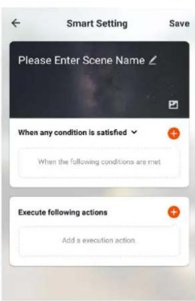
- Press the Pen next to "Please Enter Scene Name" to input the name for your Scene.
Show on Dashboard: Leave this on if you require the scene to be displayed as a button on the Home Screen Press the Red Plus to add the action required. Then select the heater from the list of devices.
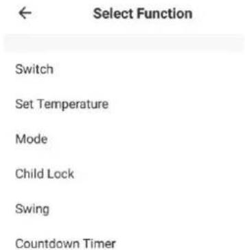
- Choose the function, set the value for the function, and then press the back button in the top right corner, to return to the previous screen.
- Once all the functions required have been added, press the Save button in the top right corner to finalize and save your new Scene. It will then be saved to the home screen
AUTOMATION
Automation allows an automatic action to be set up for the device. This can be triggered by the Time and a range of other influences, depending on what other TUYA-enabled devices you have on the network.
- Press on the Scene tab at the bottom of the Home screen.
- Press on the Automation tab at the top of the screen.
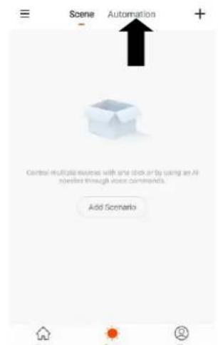
- Press on the + at the top of the screen or press on Add Automatic Action.
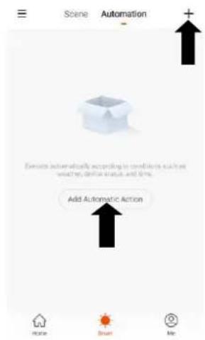
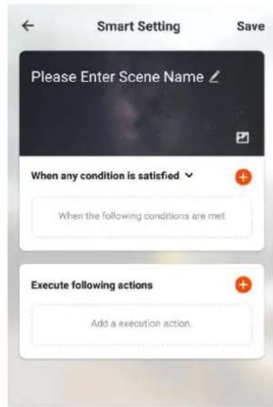
- Setup is very similar to the scene setup on the previous page, and includes an extra section for specifying a trigger for the scene to start.
Press the Pen next to "Please Enter Scene Name" to input the name for your Scene
Press the Red Plus next to "When any condition is satisfied" to add the trigger
Press the Red Plus next to "Execute following actions" to add the action required. Then select the heater from the list of devices.
- Select the condition when the automation should start. A number of triggers can be combined.
← Select Function
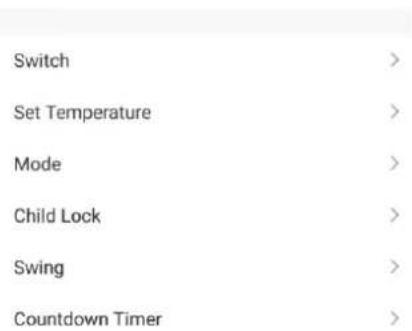
- Chose the function, set the value for the function, and then press the back button in the top right corner, to return to the previous screen.
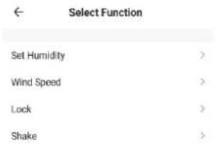
- Once all the functions required have bee added, press the Save button in the top right corner to finalize and save your new scene.
The automation is now set up; it can be turned on and off using the toggle on the home page.

Click here to set ni...

Home Management

Message Center

Help Center

More Services

Settings


PROFILE TAB
The profile tab gives you the option to edit both your detail, and use the added features of the unit.
HOME MANAGEMENT
Home Management provides options for managing your TUYA account, giving options such as adding a home, adding and removing rooms, and sharing devices with family.
MESSAGE CENTRE
View notifications from devices if alarms are set up (dependent on the device).
HELP CENTRE
Provides assistance using the features provided within the app.
MORE SERVICES
This allows the unit to be integrated with your favourite home automation hardware, such as Google Home and the Amazon Echo.
CONNECTION TROUBLESHOOTING
- Check whether the device is powered on and is in the correct WiFi connection mode; if not, please refer to the CHANGING BETWEEN CONNECTION MODES section.
- Ensure the WiFi password has been entered into the app correctly (Case sensitive)
- Check that the phone is connected to the WiFi you are connecting the device to.
- Ensure the network you are connecting it to is 2.4 GHz (5 GHz WiFi networks are not supported) and that there is a strong WiFi signal to the item.
- If your router is dual band, ensure that the 2.4ghz network has a different network name (SSID). Further advice on changing router settings will be available from your Internet service provider / Router manufacturer.
- Check the settings on the router. Encryption should be WPA2-PSK, and the authorisation type should be set to AES
- Try using the alternative connection method. i.e. If connection is failing when attempting to connect through CF mode, try AP mode.
MAINTENANCE
CLEANING AND STORAGE
ATTENTION: Please shut off the unit and unplug from the mains before cleaning or performing any maintenance.
Cleaning the surface
- Clean the heater with a duster or a soft wet cloth.
- Do not use chemical solvents (such as benzene, alcohol or gasoline) as they may cause irreversible damage. Make sure no water enters the control panel or gaps in the casing.
- Do not run the unit until completely dry.
- Place the heater in its original box or cover to protect it from dust when not in use.
- Store it in a cool, dry place.
TROUBLESHOOTING
Do not repair or disassemble the unit by yourself; unauthorized repair attempts will invalidate the warranty and may cause bodily harm.
| Issue | Possible Reason | Solution |
| No power | 1. The power cord is unconnected2. There is no power from the socket3. The power switch on the rear of the unit is turned off. | 1. Connect the power cord2. Check socket is turned on3. Ensure the power switch on the rear of the unit is in the on position |
| Odour emission from the unit | 1. New unit. When the unit is used for the first time, the fan motor may produce an odour which will dissipate within a week of use | 1. No action required |
| Strong vibrations and noise | 1. The Unit is not placed on a flat surface2. The unit may be damaged | 1. Place on a flat surface. May put an anti-vibration mat underneath2. If the heater is damaged, discontinue use and contact the service centre. |
If the above solutions do not resolve the problem, please contact the service centre.
TECHNICAL DATA
| Model no. | EGH20AWB / EGH20AW |
| Voltage | 220V-240V 2.0kW |
| Frequency | 50 / 60 Hz |
| Max power | 1800-2000W |
| IP Rating | IP24 |
| Model colour | White/ Black |
| Product dimensions | 830x85x460 |
| Product weight | 8kg |
electriQ UK SUPPORT
www.electriQ.co.uk/support
For your convenience, please make these simple checks before calling the service line.
If the unit still fails to operate, call 0330 390 3061 or complete the online form.
- Is the unit plugged into the mains?
- Is the fuse OK?
- Switch the unit off and wait three minutes to see if the issue is resolved. Restart the unit.
Office hours: 9 AM - 5 PM, Monday to Friday
www.electriQ.co.uk
Unit 2A, Trident Business Park,
Neptune Way, Huddersfield,
HD2 1UA
Disposal: Do not dispose of this product as unsorted municipal waste. Collection of such waste must be handled separately as special treatment is necessary.
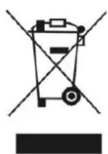
Recycling facilities are now available for all customers at which you can deposit your old electrical products. Customers will be able to take any old electrical equipment to participating civic amenity sites run by their local councils. Please remember that this equipment will be further handled during the recycling process, so please be considerate when depositing your equipment. Please get in touch with the local council for details of your local household waste recycling centres.
| Model Identifier: EGH20AWB (BLACK) / EGH20AW (WHITE) | ||||||
| Item | Symbol | Value | Unit | Item | Unit | |
| Heat Output | Type of heat input, for electric storage local space heaters only (select one) | |||||
| Nominal heat output | Phnom | 1.8-2.0 | kW | manual heat charge control, with integrated thermostat | No | |
| Minimal heat output | P_min | 1.0 | kW | manual heat charge control with room and/or outdoor temperature feedback | No | |
| Maximum continuous heat output | P_max | 2.0 | kW | electronic heat charge control with room and/or outdoor temperature feedback | No | |
| Auxiliary electricity consumption | fan-assisted heat output | No | ||||
| At nominal heat output | eI_max | N/A | kW | Type of heat output/room temperature control (select one) | ||
| At minimum heat output | eI_min | N/A | kW | single-stage heat output and no room temperature control | No | |
| In standby mode | eI_SB | 0.00043 | W | two or more manual stages, no room temperature control | No | |
| with mechanical thermostat room temperature control | No | |||||
| with electronic room temperature control | No | |||||
| with electronic room temperature control plus day timer | No | |||||
| with electronic room temperature control plus week timer | Yes | |||||
| Other control options (multiple selections possible) | ||||||
| room temperature control with presence detection | No | |||||
| room temperature control, with open window detection | Yes | |||||
| with distance control option | No | |||||
| with adaptive start control | No | |||||
| with working time limitation | Yes | |||||
| with black bulb sensor | No | |||||
| Contact Details | electriQ, Unit 2A, Trident Business Park, Neptune Way, Huddersfield, HD2 1UA Buy It Direct, The Black Church, St Mary's Place, Dublin 7 | |||||
PSTI STATEMENT OF COMPLIANCE
Description:2000W Designer glass heater
Model Number: EGH20AWB / EGH20AW
Manufacturer: electriQ, 2A Trident Business Park, Leeds Road, Huddersfield, HD2 1UA
PSTI Contact: TiSecurity@buyitdirect.co.uk
We have prepared this statement of compliance and can confirm that this product is compliant with the deemed compliance conditions in Schedule 2 of The Product Security and Telecommunications Infrastructure (Security Requirements for Relevant Connectable Products) Regulations 2023.
Duration of security updates: 31 ^st December 2029. This date is correct at the time of printing, but we may be extended. Please visit www.electriQ.co.uk for the latest information and details of our PSTI compliance.
Richard Leach
Compliance and Quality Manager, Buy It Direct, Huddersfield
26 ^th August 2024
EU DECLARATION OF CONFORMITY
Hereby, electriQ declares that these air conditioners are in compliance with Directive 2014/53/EU. The full text of the EU Declaration of Conformity is available at the following internet addresses:
https://www.electriq.co.uk/content/DOC/EU/EGH20AW.pdf
https://www.electriq.co.uk/content/DOC/EU/EGH20AWB.pdf
UK DECLARATION OF CONFORMITY
Hereby, electriQ declares that these air conditioners are in compliance with Radio Equipment Regulations 2017. The full text of the UK Declaration of Conformity is available at the following internet addresses:
https://www.electriq.co.uk/content/DOC/UK/EGH20AW.pdf
https://www.electriq.co.uk/content/DOC/UK/EGH20AWB.pdf
- KW DESIGNER GLASS PANEL HEATER
- EGH20AW / EGH20AWB
- SETTLING IN OK?
- electriQUK
- WE'RE HERE TO HELP
- CONTENTS
- SAFETY INSTRUCTIONS IMPORTANT
- ENERGY SAVING AND UNIT SAFETY PROTECTION TIP
- INSTALLING WITHIN A BATHROOM
- FEATURES
- PARTS LIST
- SETTING THE UNIT UP FOR USE
- ATTACHING THE FEET
- WALL MOUNTING
- INSTALLATION
- PRODUCT OVERVIEW CONTROL PANEL
- SWITCHING ON THE HEATER
- QUICK USE GUIDE
- SETTING THE DAY AND TIME
- TURNING ON AND OFF
- CHANGING THE DESIRED ROOM TEMPERATURE
- CHILD LOCK
- OPEN WINDOW DETECTION
- STANDBY TIMER
- WEEKLY TIMER
- ADDITIONAL FEATURES
- DISPLAY:
- MEMORY FUNCTION:
- FACTORY RESET:
- CONNECTING THE APPLIANCE TO WIFI DOWNLOAD THE APP TO YOUR PHONE
- MODES AVAILABLE FOR SETUP
- CONNECTION
- TURNING THE WIFI OFF
- REGISTER THE APP
- Privacy Policy of Tuya Smart Platform
- Verification Code
- Set Password
- SETTING UP YOUR HOME WITHIN THE APP
- CREATING ROOMS
- ADD ANOTHER ROOM
- CONNECTING USING THE QUICK CONNECTION METHOD
- CONNECTING USING THE APP MODE ALTERNATIVE METHOD
- CONTROLLING YOUR APPLIANCE THROUGH THE APP THE HOME SCREEN
- DEVICE SCREEN
- SMART SCENES
- SCENE
- AUTOMATION
- Click here to set ni...
- PROFILE TAB
- HOME MANAGEMENT
- MESSAGE CENTRE
- HELP CENTRE
- MORE SERVICES
- CONNECTION TROUBLESHOOTING
- MAINTENANCE
- CLEANING AND STORAGE
- Cleaning the surface
- TROUBLESHOOTING
- TECHNICAL DATA
- electriQ UK SUPPORT
- PSTI STATEMENT OF COMPLIANCE
- EU DECLARATION OF CONFORMITY
- UK DECLARATION OF CONFORMITY
Brand : ElectriQ
Model : EGH20AW
Category : Heating appliance