Delphi 2.0 - Bike computer Blackburn - Free user manual and instructions
Find the device manual for free Delphi 2.0 Blackburn in PDF.


| Product Type | Bicycle computer with wireless speed and optional cadence |
| Brand | Blackburn |
| Model | Delphi 2.0 |
| Power Source | CR2032 3V Lithium battery (approx. 1 year life) |
| Display | LCD with multiple data windows (Speed, Upper Data, Chronograph, Lower Data) |
| Speed Range | 0-199.9 mph or km/h (0.1 resolution) |
| Average Speed Range | Same as speed range |
| Maximum Speed Range | Same as speed range |
| Trip Distance Range | 0-999.99 miles or km (0.01 resolution) |
| Odometer Range | 0-99,999 miles or km per bike (1.0 resolution); combined odometer for both bikes |
| Cadence Range | 0-250 rpm (1 rpm resolution); requires optional cadence bracket |
| Chronograph | Ride Time (auto start/stop with wheel motion) or Total Time (manual start/stop); up to 99h59m59s |
| Clock | 12/24 hour format with option to turn off display |
| Wheel Size Settings | 11 presets plus manual entry (up to 9999 mm circumference) |
| Bike Profiles | Two independent profiles (Bike 1 and Bike 2) with separate settings |
| Sensor Type | Wired speed sensor (front fork); optional wired cadence sensor (rear chainstay) |
| Water Resistance | Water resistant under normal riding conditions; do not immerse |
| Weight (approx.) | 50 g (with battery) |
| Dimensions (approx.) | 5.5 x 4 x 2 cm |
| Warranty | Limited lifetime warranty against defects in materials and workmanship |
| Care | Avoid extreme heat; store in breathable container; clean with damp cloth; replace O-ring if damaged |
Frequently Asked Questions - Delphi 2.0 Blackburn
User questions about Delphi 2.0 Blackburn
0 question about this device. Answer the ones you know or ask your own.
Ask a new question about this device
Download the instructions for your Bike computer in PDF format for free! Find your manual Delphi 2.0 - Blackburn and take your electronic device back in hand. On this page are published all the documents necessary for the use of your device. Delphi 2.0 by Blackburn.
USER MANUAL Delphi 2.0 Blackburn
Blackburn_2/3_Manual 8/3/05 10:00 AM Page


TABLE OF CONTENTS TABLE OF CONTENTS
Introduction 1
Warnings and Cautions 2
Care and Maintenance 3
Parts of your Blackburn Delphi Cycle Computer 4
Resetting the Computer to its Default Settings 5
Shipping and Sleep Modes 6
Changing the Battery in the Blackburn Delphi Cycle Computer 7
Installing the Computer on your Bike 9
Keys and their Functions 15
Sections of LCD Display 18
Basic Operation 23
Bike One/Bike Two Setting 27
Program Wheel Size, Units and Chronograph 28
Program Odometers 36
Program Time of Day 38
Operating the Ride Time and Total Time Chronographs 41
Starting Stopping and Clearing the Chronograph and Memory 42
Clearing Maximum Speed or Maximum Cadence Only 43
Technical Data 44
Warranty and Repair 46

Blackburn_2/3_Manual 8/3/05 10:00 AM Page


INTRODUCTION WARNINGS AND CAUTIONS
Congratulations on your purchase of a new Blackburn Delphi Cycle Computer. Blackburn Delphi computers are among the most advanced cycle computers available in the market today.
Designed to meet the needs of serious cyclists, Delphi cycle computers offer a wide range of advanced features including wireless operation, ECG accurate wireless heart rate and ultra-accurate altimeter functionality. Blackburn has gone to great expense to assure these are the best cycle computers you can buy. We are so sure of this, each unit we make is covered by a limited LIFETIME WARRANTY against any defects in materials or workmanship. See Page 46 for a complete description of the Bell Sports Limited Warranty.
This manual is an integral part of your Blackburn cycle computer. Please read it carefully and use it while performing the initial programming and operating of the unit. After you are fully familiar with all of the features and functions of your Blackburn cycle computer, put this manual in a safe location for future reference.


WARNING—Blackburn cycle computers and heart rate monitors are training and fitness tools. Before beginning any exercise program, consult your doctor to discuss your exercise plans.
WARNING—Do Not divert your attention from the road ahead to operate your cycle computer at any time. We also strongly suggest you wear a Bell or Giro helmet any time you ride your bike.
CAUTION—Blackburn cycle computers are sophisticated electronic instruments. Blackburn recommends this unit only be installed by a qualified Blackburn retailer. Failure to read the instructions may result in damage caused by improper installation and may void the warranty. If you are unsure about how to properly perform any aspect of the assembly, installation or operation of your Blackburn cycle computer, please contact your local Blackburn retailer. CAUTION—This unit is designed to be water resistant under normal riding conditions. It should not be immersed in water. It should not be left attached to the bike if the bike is being transported on an automobile.
Delphi Blackburn
CYCLE COMPUTER 2
Blackburn_2/3_Manual
8/3/05
10:00 AM
Page


CARE AND MAINTENANCE
Blackburn cycle computers contain many delicate electronic components which may be damaged by excessive exposure to heat, shock or general abuse. Treated with care, your cycle computer is capable of delivering many years of reliable service. Improper care and handling, or damage caused by abuse or neglect, will void your Blackburn Warranty.
NEVER—Leave your computer in your car on hot days.
NEVER—Store your Blackburn cycle computer in a plastic or other non-breathable container.
PARTS OF YOUR BLACKBURN DELPHI CYCLE COMPUTER


1 FACE OF COMPUTER
2 WHEEL MAGNET
3 ZIP-TIES
4 WIRED SPEED BRACKET
5 WIRED SPEED & CADENCE
BRACKET WITH CADENCE SENSOR
BRACKET SLEEVE
3 DELPH Blackburn
CYCLE COMPUTER
4
Blackburn_2/3_Manual
8/3/05
10:00 AM
Page

ENGLISH

RESETTING THE COMPUTER TO ITS DEFAULT SETTINGS
On the bottom of the computer unit, to the upper right of the battery door is a small hidden RESET key. Pressing this key with a toothpick or other small pointed object will reset all programmed values to their default values and reset the microprocessor. This may also be accomplished by removing and reinstalling the battery.
CAUTION—Pressing the RESET key will automatically clear any information from the units' memory.

SHIPPING AND SLEEP MODES

ENGLISH
SHIPPING MODE Your new Blackburn Delphi computer comes to the dealer in SHIPPING MODE. In this mode the LCD display is totally blank. This is done to extend the battery life. Press any key to wake the unit up and advance to the default display mode.
NOTE: It is possible the unit will not come to you in SHIPPING MODE if it has been previously activated. This should not have an adverse impact on the life of the battery.
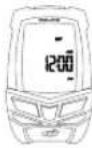
SLEEP MODE—If no speed information is seen for a period of approximately 5-minutes the unit goes into its SLEEP MODE. In SLEEP MODE the display will show the current Time of Day, Chronograph (RT or TT) and Units (Miles or Kilometers) settings.

DELPH Blackburn
CYCLE COMPUTER

Blackburn_2/3_Manual
8/3/05
10:00 AM
Page
10


CHANGING THE BATTERY IN THE BLACKBURN DELPHI CYCLE COMPUTER
Blackburn Delphi computers are powered by a CR2032 3v Lithium Battery. Under normal conditions, this battery should last approximately one year.
REPLACING THE COMPUTER BATTERY
-
Using a coin, turn the battery door counter clockwise until the door comes free.
-
Take care not to damage the O-ring seal for the battery compartment and carefully remove the old battery.
- Place a new battery in the battery compartment with the positive (+) side toward the battery door. Be extremely careful not to bend the battery contact when inserting a new battery.
- Place the battery door over the opening and tighten it down by using a coin and turning in a clockwise direction.
- If the O-ring has been damaged, replace it before reinstalling the battery door.
CHANGING THE BATTERY IN THE BLACKBURN DELPHI CYCLE COMPUTER


natural_image
Technical line drawing of a mechanical component with a circular inset showing a cross-section (no text or symbols)CAUTION—Extreme care should be taken when replacing the battery to ensure the unit remains fully water resistant. Failure to properly replace the battery and correctly seal the unit may cause the unit to become damaged and may void the warranty.
ALWAYS Check the batteries if you are experiencing problems with your computer. Most problems experienced with the operation of this unit are the result of dead or dying batteries.
7 DELPH Blackburn
CYCLE COMPUTER
8
Blackburn_2/3_Manual 8/3/05 10:00 AM Page


INSTALLING THE COMPUTER ON YOUR BIKE INST
INSTALLING WIRED FRONT WHEEL SPEED SENSOR AND BRACKET
The Delphi 2.0 uses a single wired sensor attached to the front fork.
- Attach the front wheel sensor to either fork blade using the zip-ties provided. Snug up the zip-ties but do not fully tighten them.
- Attach the spoke magnet to a spoke on the same side of the wheel as the sensor. Tighten the attachment screw just enough to hold the magnet in place but loose enough so that it is still movable.
- Adjust the position of the sensor and magnet so they are in proper alignment as shown in the drawing and tighten the zip-ties and magnet.
NOTE: The magnet should pass 1-3mm away from the sensor. The closer you can get the magnet to the sensor the better.


INSTALLING WIRED FRONT WHEEL SPEED SENSOR AND BRACKET (CONTINUED)
- Route the remaining wire and bracket up the fork securing it with tape. Excess wire should be wrapped around the brake cable housing until there is just enough slack remaining to allow the bracket to be attached to the handlebars. Attach the bracket to the handlebars and tighten the mounting screw.
NOTE: There are two molded plastic shims supplied with the Delphi computer brackets. The THIN shim allows the bracket to fit Oversized 31.8 mm handlebars. The THICK shim allows the bracket to fit standard 26.0mm handlebars.
CAUTION—When installing the system on a bicycle with front suspension, be sure to leave enough slack for the action of the fork.
9 DELPH Blackburn
CYCLE COMPUTER 10
Blackburn_2/3_Manual 8/3/05 10:00 AM Page
14


INSTALLING THE COMPUTER ON YOUR BIKE INST
INSTALLING WIRED REAR WHEEL SPEED AND CADENCE SENSORS AND BRACKET
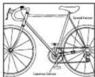
On the Delphi 3.0, both speed and cadence are picked up from the rear wheel using a special bracket, which has two sensors at the end of a long wire. One sensor picks up speed and distance information from the rear wheel and the other picks up cadence information from the crank. The cadence sensor is marked with a C.
-
Attach the cadence sensor to the LEFT chain stay near where the crank/pedal pass the stay using the zip-lies provided. Snug up the zip-lies but do not fully tighten them. It is recommended the cadence and rear wheel sensors be mounted on the top of the stay. NOTE: The wires exiting the sensors should be pointing toward the front of the bike.
-
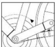
Attach the cadence magnet to the back side of the LEFT crank arm using the zip-tie provided. The cadence magnet should be attached as closely to the pedal spindle as possible.
INSTALLING WIRED REAR WHEEL SPEED AND CADENCE SENSORS AND BRACKET (CONTINUED)
- Adjust and position the sensor as closely as possible to the magnet and rotate the sensor so the magnet passes within 1-3mm. Fully tighten the zip-ties once you have everything properly aligned.
- Depending on the length of your chainstays and where you want to position the sensor, wrap the speed sensor wire once or twice around the chainstay and attach the speed sensor using the zip-lies provided.
- Attach the spoke magnet to a spoke on the same side of the wheel as the sensor. Tighten the attachment screw just enough to hold the magnet in place but loose enough so that it is still movable.
- Adjust the position of the sensor and magnet so they are in proper alignment as shown in the drawing tighten the zip-ties and magnet.
11 DELPH Blackburn
CYCLE COMPUTER 12
Blackburn_2/3_Manual
8/3/05
10:00 AM
Page
16


INSTALLING THE COMPUTER ON YOUR BIKE INST
INSTALLING WIRED REAR WHEEL SPEED AND CADENCE SENSORS AND BRACKET (CONTINUED)
- Route the sensor wire forward and under the bottom bracket and along the bottom of the down tube securing it occasionally with tape. Once you are near the head tube the sensor wire should be wrapped around the front or rear derailleur cable housing and the around the front brake cable housing.
CAUTION—Make sure you leave enough slack in the sensor wire so the handle bars can turn fully from side to side without creating any stress.
- Attach the bracket to the handlebars and tighten the mounting screw.


13 DELPH Blackburn
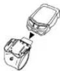
When the bracket and sensors are completely installed on the bike, slide the Delphi computer unit into the handlebar bracket. The computer should LOCK into the bracket with an AUDIBLE 'CLICK'. If you do not hear a click or if the Delphi computer body is not flush with the back edge of the bracket the computer is not locked in place and may come out.
Once everything is assembled spin the wheel and turn the crank and make sure speed and cadence are being displayed on the screen. If you are not receiving one or both pieces of information, check the magnet and sensor alignment and make sure the magnets are passing the proper point on the sensor and that they are within 1-3mm. If they are closer to 3mm than to 1mm try reducing the gap and test the system again.
CYCLE COMPUTER
14

Blackburn_2/3_Manual
8/3/05
10:00 AM
Page
18


KEYS AND THEIR FUNCTIONS KEYS AND THEIR
QUICK PRESS VS. PRESS & HOLD
There are two key actions used to program and operate the Delphi computer.
QUICK PRESS—The key is pressed quickly and then immediately released. This is the most common key action and is used for most operations. Throughout this manual, QUICK PRESS will be indicated in BLUE.
PRESS & HOLD—The key is pressed and held for a period of 2-seconds until the desired action takes place. This key action is generally used to enter a programming sequence or to clear information from the display. Throughout this manual, PRESS & HOLD will be indicated in RED.


15 DELPH Blackburn
DNS

ENGLISH
UPPER DISPLAY/EL KEY
Primary Function
- PRESS & HOLD to Change the Upper Display Window view.
OPTION KEY
Primary Function
- QUICK PRESS to change between OPTIONS within MODES.
Secondary Functions
- QUICK PRESS to Change a Variable in a Setting Sequence Upward. HOLD for FAST ADVANCE

natural_image
Line drawing of a car's front dashboard and grille (no text or symbols)CYCLE COMPUTER

...
Blackburn_2/3_Manual
8/3/05
10:00 AM
Page
20
ENGLISH

KEYS AND THEIR FUNCTIONS

natural_image
Line drawing of a car front panel with a diagonal line and a small logo at the bottom (no text or symbols)START/STOP KEY
Primary Function
- QUICK PRESS to Start/Stop TT Chronograph. - PRESS & HOLD to Clear ALL Ride Data.
Secondary Functions
- QUICK PRESS to Change a Variable in a Setting Sequence Downward. HOLD for FAST ADVANCE - PRESS & HOLD to Clear Maximum Speed or Maximum Cadence when in these Screens.
MODE KEY
Primary Function
• QUICK PRESS to change between MODES.
Secondary Functions
- PRESS & HOLD to Enter Setting Sequences. - QUICK PRESS to Select a Variable in a Setting Sequence.

17 DELPH Blackburn
SECTIONS OF LCD DISPLAY

ENGLISH
SPEED WINDOW
Current Speed is always visible in the upper left corner of the LCD display.

KM/H AND M/H
These icons indicate if the unit is programmed to display speed and distance in Miles or Kilometers.
CYCLE COMPUTER
18
***
Blackburn_2/3_Manual
8/3/05
10:00 AM
Page
22
ENGLISH

SECTIONS OF LCD DISPLAY SECTIONS OF LCD
UPPER DATA WINDOW
The Upper Data Window located at the top right corner of the LCD Display is one of the unique features of Blackburn Delphi computers. You can choose to display Current Cadence or leave this window blank
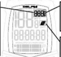
CAD
This icon indicates Cadence is currently being shown in the Upper Data Window.
COMPARISON ARROWS
The arrows will indicate if your current speed is above, below or equal to your current average speed.
Y
CHRONOGRAPH WINDOW
The center line of the LCD display shows the primary chronograph for the unit.
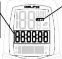

ENGLISH
These icons indicate if the primary chronograph is programmed to display Ride Time (RT) with the chronograph starting and stopping with the turning of the wheel. Or Total Time (TT) with the chronograph running continually.
NOTE: Cadence displays only function if the Delphi unit is attached to a cadence bracket.

19 DELPH Blackburn
CYCLE COMPUTER
20
• • • • • •
Blackburn_2/3_Manual
8/3/05
10:00 AM
Page
24
ENGLISH

SECTIONS OF LCD DISPLAY SECTIONS OF LCD
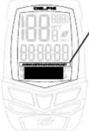
LOWER DATA WINDOW
The Lower Data Window shows a wide range of secondary functions. This window is controlled by the MODE and OPTION keys. Pressing the MODE key scrolls through the following information:
Speed Information
Distance Information
Cadence Information (If Active)
Time of Day (If Active)
Pressing the OPTION key scrolls through the sub functions in each category.
BIKE 1/BIKE 2
To the left of the Lower Data Window are the Bike 1 and Bike 2 Icons. Press and Hold both the MODE and OPTION key to change the Bike Settings at any time.

AM
This icon is located to the right of the Lower Data Window and indicates when the 12-hr clock is showing AM time. PM and 24-hr clock time are indicated by the lack of any icon.

2 | DELPH Blackburn
CYCLE COMPUTER
22
• • • • • •
Blackburn_2/3_Manual
8/3/05
10:00 AM
Page
26


BASIC OPERATION
MODE AND OPTION FLOW SEQUENCES
This diagram shows the information which is displayed in the Lower Data Window in response to QUICK PRESSES of the MODE and OPTION keys.

23 DELPH Blackburn

flowchart
graph TD
    A["AVERAGE SPEED"] --> B["TRI P DISTANCE"]
    B --> C["CURRENT CADENCE"]
    C --> D["AVERAGE CADENCE"]
    D --> E["MAXIMUM CADENCE"]
    E --> F["ODOMETER BIKE 1 & 2"]
    F --> G["ODOMETER BIKE 2"]
    G --> H["MAXIMUM SPEED"]
    H --> I["AVERAGE SPEED"]
CYCLE COMPUTER
24
...
Blackburn_2/3_Manual
8/3/05
10:00 AM
Page
28


This diagram shows the information which is displayed in the Upper Data Window. You may choose to show Blank or Cadence in this line.
EL KEY


STEP BY STEP—CHANGING THE UPPER DATA WINDOW INFORMATION
- By Default the Upper Data Window is Blank (no display data) when you install a new battery. Any time a Delphi unit is attached to a cadence bracket, CADENCE can be displayed in the Upper Data Window.
- To change the Upper Data Window PRESS & HOLD the Upper Display/EL key for approximately 2-seconds until the value changes.
NOTE: When Cadence is displayed in the Upper Data Window, it is not displayed in the Cadence sequences of the Lower Data Window.
NOTE: On the Delphi 2.0 cadence will only be displayed if the unit is attached to an accessory cadence bracket.

25
DO


CYCLE COMPUTER
26
***
Blackburn_2/3_Manual
8/3/05
10:00 AM
Page
30


BIKE ONE/BIKE TWO SETTING
Blackburn Delphi Computers allow you to program two separate bike functions. Most functions are totally independent. For example, you can program Bike One for Ride Time in Miles and Bike Two for Total Time in Kilometers.
NOTE: Before you can program any computer settings, the primary chronograph must be cleared to zero using a 2-second PRESS & HOLD of the S/S key while in the Ride Distance (DST) screen.
CHANGE BIKE 1/BIKE 2 SETTING
PRESS & HOLD both the MODE and OPTION keys at the same time. When Bike 1-2 icon changes, release the keys.
PROGRAM WHEEL SIZE, UNITS AND CHRONOGRAPH


Blackburn Delphi Computers use the rolling circumference of your wheel and tire combination to determine speed and distance. The more accurate this setting, the more accurate your ride information will be. However, variations of less than 30mm from the actual circumference will have very little impact on the overall accuracy of the unit.
PRESET WHEEL SIZES
For easy setup, Blackburn Delphi Computers come with 11 of the most popular wheel/tire sizes pre-programmed into the unit. Simply select the size of your tire as you scroll through the list in the programming sequence and you are done.
The following are the pre-set wheel sizes programmed into the unit. Follow the steps on Page 31 to enter a preset wheel size into the Delphi unit.
| PRESO WHEEL SEES | WHEEL CIRCUMBERG |
| 700 x 2.3c | 200mm |
| 700 x 20c | 205mm |
| 700 x 25c | 210mm |
| 700 x 28c | 213mm |
| 700 x 32c | 215mm |
| 700 x 38c | 2180mm |
| 650 x 20c | 1945mm |
| 650 x 23c | 1960mm |
| 26 x 19 | 2030mm |
| 26 x 2.0 | 2055mm |
| 26 x 2.1 | 2060mm |
27 DELPH Blackburn
CYCLE COMPUTER
28
• • • • • •
Blackburn_2/3_Manual
8/3/05
10:00 AM
Page
32


PROGRAM WHEEL SIZE, UNITS AND CHRONOGRAPH
MEASURED WHEEL SIZE
If your wheel/tire size is not one of the pre-programmed sizes, or if you desire absolute accuracy, you may enter an exact wheel circumference into the system. Use one of the two following methods for measuring the circumference of your wheel/tire combination.
MEASURING WHEEL SIZE USING RADIUS METHOD
The wheel radius method is quick, easy and very accurate.
-
With your bike standing vertically on a flat surface, measure the distance in millimeters from the center of the front axle or quick release to the floor. If your measurement is in inches, multiply by 25.4 to convert to millimeters.
-
Multiply the measurement in millimeters by 6.28 and enter the resulting number into your computer using the steps on Page 32.


29 DELPH Blackburn
PROGRAM WHEEL SIZE, UNITS AND CHRONOGRAPH


MEASURING WHEEL SIZE USING ROLLOUT METHOD
The roll-out method is the most accurate method for determining the circumference of your wheel/tire combination.
- On a flat open surface make a mark on your tire and the floor exactly where they meet.
- Roll your bike forward one full revolution of the front wheel and mark the point on the floor where the revolution is complete. For maximum accuracy be sitting on the bike while someone rolls you and the bike forward.
- Measure the distance from the first mark to the second in millimeters and enter the resulting number into your computer using the steps on Page 32.

CYCLE COMPUTER
30
...
Blackburn_2/3_Manual 8/3/05 10:00 AM Page
34


PROGRAM WHEEL SIZE, UNITS AND CHRONOGRAPH
STEP BY STEP—ENTER A PRE-PROGRAMMED WHEEL SIZE
-
Choose Bike 1 or Bike 2. (Page 27)
-
Starting in the Distance (DST) screen of the Lower Display Window.
- PRESS & HOLD the MODE key for approximately 2-seconds.
- QUICK PRESS the OPTION or START/STOP keys to scroll through the 11 pre-programmed wheel sizes. "WHEEL" will be shown in the lower line of the display with the pre-programmed wheel size shown in the center line of the display.
- Select your choice using a QUICK PRESS of the MODE key and advance to the SET Speed and Distance units display (Page 34).

STEP 2 & 3

STEP 4

STEP 5
PROGRAM WHEEL SIZE, UNITS AND CHRONOGRAPH


STEP BY STEP—ENTER AN EXACT WHEEL SIZE
- Choose Bike 1 or Bike 2. (Page 27)
- Starting in the Distance (DST) screen of the Lower Display Window.
- PRESS & HOLD the MODE key for approximately 2 seconds.
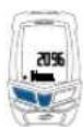
- QUICK PRESS the OPTION or START/STOP keys until the display shows 2096 flashing in the center line of the display.
- QUICK PRESS the MODE key once. The ones digit will begin to flash.
- Adjust the digit using QUICK PRESSES of the OPTION and START/STOP keys and enter your choice into memory using a QUICK PRESS of the MODE key.
- Repeat until all four digits are entered.
- A final QUICK PRESS of the MODE key will exit the Wheel Size setting sequence and advance to the SET Speed and Distance units Display (Page 34).
NOTE: Before you can program any computer settings, the primary chronograph must be cleared to zero using a 2-second PRESS & HOLD of the S/S key while in the Ride Distance (DST) screen.
31 DELPH Blackburn
CYCLE COMPUTER 32
Blackburn_2/3_Manual
8/3/05
10:00 AM
Page
36


PROGRAM WHEEL SIZE, UNITS AND CHRONOGRAPH
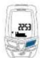
STEP BY STEP—ENTER AN EXACT WHEEL SIZE STEP BY STEP—SET SPEED AND DISTANCE UNITS

STEPS 2 & 3
STEP 4

STEP 5

STEP 6
STEPS 7 & 8
PROGRAM WHEEL SIZE, UNITS AND CHRONOGRAPH


- Upon entering the SET Speed and Distance units display, M/H (Miles per Hour) or KM/H (Kilometers per Hour) will flash in the upper right hand corner of the display.
- QUICK PRESS the OPTION key to cycle between M/H and KM/H settings.
- Select your choice using a QUICK PRESS of the MODE key and advance to the SET Chronograph display (Page 35).

STEP 2

33 DELPH Blackburn
CYCLE COMPUTER
34


PROGRAM WHEEL SIZE, UNITS AND CHRONOGRAPH
STEP BY STEP—SET CHRONOGRAPH FUNCTION
-
Upon entering the SET Chronograph function display, RT (Ride Time) or TT (Total Time) will flash in the upper right hand corner of the display.
-
QUICK PRESS the OPTION key to cycle between RT and TT (Total Time) settings.
- Select your choice using a QUICK PRESS of the MODE key and exit the setting sequence.
RIDE TIME (RT)—When RT is selected the Delphi's Chronograph will start and stop with the motion of the wheel. This setting tracks the actual time you are riding your bike.
TOTAL TIME (TT)—When TT is selected the Delphi's Chronograph will initially start with the first rotation of the wheel. However, it will continue to run from that point, until the timing is stopped, using a QUICK PRESS of the START/STOP key.

STEP 2

STEP 3
PROGRAM ODOMETERS


Blackburn Delphi Computers are equipped with Separate Odometers for Bike 1 and Bike 2 and a Combined Odometer showing the total for both bikes. Bike 1 and Bike 2 Odometers may be reprogrammed with an existing mileage following a battery change.
NOTE: If Odometer 1 and Odometer 2 are set for different units (Miles or Kilometers) as defined by the Speed and Distance Units settings for Bike 1 and Bike 2, the Combined Odometer (ODO 1/2) will display in the units set for Bike 1.
NOTE: Make sure you write down your mileage for each Odometer prior to removing the battery if you wish to reprogram the odometers.
NOTE: If the total capacity of any odometer is exceeded, the lower display line will display 5-dashes.
NOTE: Before you can program any computer settings, the primary chronograph must be cleared to zero using a 2-second PRESS & HOLD of the S/S key while in the Ride Distance (DST) screen.

35 DELPH Blackburn
CYCLE COMPUTER
Blackburn_2/3_Manual 8/3/05 10:00 AM Page
40


PROGRAM ODOMETERS PROGRAM TIME OF DAY
STEP BY STEP—SETTING THE PROGRAMMABLE ODOMETERS
- Starting in ANY Odometer screen (Odo 1, Odo 2 or Odo 1/2) in either Bike 1 or Bike 2.
- PRESS & HOLD the MODE key for approximately 2-seconds.
- ODO 1 will appear in the Lower Data Window with "00,000" in the Center Display Line.
- Adjust the Odometer 1 setting using QUICK PRESSES of the OPTION and START/STOP keys. Fast advance using a PRESS & HOLD.
- When Odo 1 is set to the desired value, QUICK PRESS the MODE key to enter the value and Advance to setting Odo 2.
- Repeat steps 3 and 4.
- QUICK PRESS the MODE key to enter the Odo 2 value and exit the setting sequence.

STEP 3 & 4

STEP 5 & 7
Blackburn Delphi Computers are equipped with a clock which shows time of day in either 12 or 24 hour formats. There is also a programming option which allows you to turn the clock off so it does not show up in the normal operation sequence, reducing the number of key strokes needed to move through the displays.


37 DELPH Blackburn
CYCLE COMPUTER 38
Blackburn_2/3_Manual 8/3/05 10:00 AM Page
42


PROGRAM TIME OF DAY PROGRAM TIME OF DAY
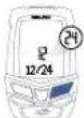
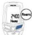
STEP BY STEP—SETTING THE TIME OF DAY
- Starting in the Time of Day display in the Lower Data Window if Time of Day is Active; or Starting in the Average or Maximum Speed displays if Time of Day is Inactive.
- PRESS & HOLD the MODE key for approximately 2-seconds.
- VIEW will appear in the Lower Data Window with ON or OFF in the Center Display Line.
- Select ON or OFF using QUICK PRESSES of the OPTION key. QUICK PRESS the MODE key to enter the value and advance to 12/24 Hour setting.
a. Select ON if you wish Time of Day to be part of the display sequence in the Lower Display Window.
b. Select OFF if you do not wish to view Time of Day on the display.
- Repeat steps 3 and 4 to Set Hours and Minutes and QUICK PRESS the MODE key to exit the Time of Day programming sequence.
NOTE: Before you can program any computer settings, the primary chronograph must be cleared to zero using a 2-second PRESS & HOLD of the S/S key while in the Ride Distance (DST) screen.
39 DELPH Blackburn

STEP BY STEP—SETTING THE TIME OF DAY

STEP 1 & 2

STEP 3 & 4
STEP 4
STEP 5
CYCLE COMPUTER 40
Blackburn_2/3_Manual 8/3/05 10:00 AM Page
44


OPERATING THE RIDE TIME AND TOTAL TIME CHRONOGRAPHS
All data acquisition is controlled by the primary Ride Time or Total Time Chronograph. Ride data such as Average and Maximum values and Memory Information are only tracked if the primary chronograph is running. At any time, clearing the Ride Time or Total Time chronograph will also clear ALL data and memory values.
STARTING STOPPING AND CLEARING THE CHRONOGRAPH AND MEMORY


STARTING AND STOPPING THE RIDE TIME CHRONOGRAPH
The operation of the Ride Time Chronograph is totally automatic and is controlled by speed input. If the unit is receiving a speed input, the Ride Time Chronograph will run, if the speed stops, the Ride Time Chronograph will stop.
STARTING AND STOPPING THE TOTAL TIME CHRONOGRAPH
From an initial reading of zero, the Total Time Chronograph starts automatically as soon as it sees a speed input or is manually started using a QUICK PRESS of the START/STOP key. Once it has started, the Total Time Chronograph will continue to run until it is stopped using the START/STOP key.
CLEARING ALL RIDE DATA
To clear the chronograph and all data and memories to zero PRESS & HOLD the START/STOP key for approximately 2 seconds in the Ride Distance (DST) screen until the chronograph line shows all zeros.
4 | DELPH Blackburn
CYCLE COMPUTER 42
Blackburn_2/3_Manual
8/3/05
10:00 AM
Page
46


CLEARING MAXIMUM SPEED OR MAXIMUM CADENCE ONLY
The Delphi computers allow you to clear the Maximum Speed and Cadence values independently of all other information. This feature is helpful if you are doing sprint workouts and wish to review your maximum values for each sprint. To clear Maximum Speed and Maximum Cadence, PRESS & HOLD the START/STOP key while in either of these two displays.
TECHNICAL DATA


BATTERY
Computer Battery—CR 2032 3v Lithium
FUNCTIONS AND OPERATIONAL RANGES
Bike Functions
Speed—0-199.9 Miles or Kilometers/Hr—0.1 Mi or Km/Hr Average Speed—same Maximum Speed—same
Trip Distance—0-999.99 Miles or Kilometers—0.01 Mi or Km Odometer 1—0-99,999 Miles or Kilometers—1.0 Mi or Km Odometer 2—same
Odometer 1+2—same
Cadence-0-250 rpm—1rpm
Average Cadence—same Maximum Cadence—same

43 DELPH Blackburn
CYCLE COMPUTER
44
...
Blackburn_2/3_Manual 8/3/05 10:00 AM Page
48


TECHNICAL DATA WARRANTY AND REPAIR
FUNCTIONS AND OPERATIONAL RANGES (CONTINUED)
Chronograph Functions
Ride Time Chronograph—0-99h59m59s—1.0 Sec
Total Time Chronograph—same
Other Functions
Auto Start/Stop
12/24 Time of Day
11 Pre-programmed Wheel Sizes
If you are having problems with your Blackburn Delphi computer please visit www.blackburndesign.com/support for instructions.


45 DELPH Blackburn
CYCLE COMPUTER 46

- TABLE OF CONTENTS TABLE OF CONTENTS
- INTRODUCTION WARNINGS AND CAUTIONS
- CARE AND MAINTENANCE
- PARTS OF YOUR BLACKBURN DELPHI CYCLE COMPUTER
- DELPH Blackburn
- RESETTING THE COMPUTER TO ITS DEFAULT SETTINGS
- SHIPPING AND SLEEP MODES
- CHANGING THE BATTERY IN THE BLACKBURN DELPHI CYCLE COMPUTER
- DELPH Blackburn
- INSTALLING THE COMPUTER ON YOUR BIKE INST
- INSTALLING WIRED FRONT WHEEL SPEED SENSOR AND BRACKET
- DELPH Blackburn
- INSTALLING WIRED REAR WHEEL SPEED AND CADENCE SENSORS AND BRACKET
- INSTALLING WIRED REAR WHEEL SPEED AND CADENCE SENSORS AND BRACKET (CONTINUED)
- KEYS AND THEIR FUNCTIONS KEYS AND THEIR
- QUICK PRESS VS. PRESS & HOLD
- DNS
- UPPER DISPLAY/EL KEY
- OPTION KEY
- KEYS AND THEIR FUNCTIONS
- START/STOP KEY
- MODE KEY
- DELPH Blackburn
- SECTIONS OF LCD DISPLAY
- SPEED WINDOW
- KM/H AND M/H
- SECTIONS OF LCD DISPLAY SECTIONS OF LCD
- UPPER DATA WINDOW
- CAD
- COMPARISON ARROWS
- CHRONOGRAPH WINDOW
- DELPH Blackburn
- LOWER DATA WINDOW
- BIKE 1/BIKE 2
- AM
- | DELPH Blackburn
- BASIC OPERATION
- STEP BY STEP—CHANGING THE UPPER DATA WINDOW INFORMATION
- BIKE ONE/BIKE TWO SETTING
- CHANGE BIKE 1/BIKE 2 SETTING
- PROGRAM WHEEL SIZE, UNITS AND CHRONOGRAPH
- PRESET WHEEL SIZES
- DELPH Blackburn
- MEASURED WHEEL SIZE
- MEASURING WHEEL SIZE USING RADIUS METHOD
- DELPH Blackburn
- MEASURING WHEEL SIZE USING ROLLOUT METHOD
- STEP BY STEP—SET CHRONOGRAPH FUNCTION
- PROGRAM ODOMETERS
- DELPH Blackburn
- PROGRAM ODOMETERS PROGRAM TIME OF DAY
- STEP BY STEP—SETTING THE PROGRAMMABLE ODOMETERS
- PROGRAM TIME OF DAY PROGRAM TIME OF DAY
- STEP BY STEP—SETTING THE TIME OF DAY
- OPERATING THE RIDE TIME AND TOTAL TIME CHRONOGRAPHS
- STARTING STOPPING AND CLEARING THE CHRONOGRAPH AND MEMORY
- STARTING AND STOPPING THE RIDE TIME CHRONOGRAPH
- STARTING AND STOPPING THE TOTAL TIME CHRONOGRAPH
- CLEARING ALL RIDE DATA
- CLEARING MAXIMUM SPEED OR MAXIMUM CADENCE ONLY
- TECHNICAL DATA
- BATTERY
- FUNCTIONS AND OPERATIONAL RANGES
- Bike Functions
- TECHNICAL DATA WARRANTY AND REPAIR
Brand : Blackburn
Model : Delphi 2.0
Category : Bike computer