
MDB4949SKZ - Dishwasher MAYTAG - Free user manual and instructions
Find the device manual for free MDB4949SKZ MAYTAG in PDF.

| Product Type | Built-in Dishwasher |
| Brand | Maytag |
| Model | MDB4949SKZ |
| Category | Dishwasher |
| Width | 23 7/8 inches |
| Height (Minimum) | 33 1/2 inches |
| Depth (Excluding Handles) | 24 1/2 inches |
| Power Requirements | 120 V, 60 Hz, 15 A |
| Water Supply | Hot water (120°F recommended), 20-120 psi |
| Tub Material | Stainless Steel |
| Number of Racks | 2 (Upper and Lower) |
| Number of Spray Arms | 3 |
| Number of Wash Cycles | 5 |
| Wash Cycles | Auto, Normal, Quick, PowerBlast, Rinse |
| Options | High Temp, Sani Rinse, Heated Dry (Short/Long), 4-Hour Delay, Control Lock |
| Filtration System | Dual Power Microfiltration |
| Sound Level (dBA) | 50 |
| Control Type | Electronic Touch with Display |
| Leak Detection | Yes (Drip tray and float switch) |
| Drying System | Vent Dry with Heating Element |
Frequently Asked Questions - MDB4949SKZ MAYTAG
User questions about MDB4949SKZ MAYTAG
0 question about this device. Answer the ones you know or ask your own.
Ask a new question about this device
Download the instructions for your Dishwasher in PDF format for free! Find your manual MDB4949SKZ - MAYTAG and take your electronic device back in hand. On this page are published all the documents necessary for the use of your device. MDB4949SKZ by MAYTAG.
USER MANUAL MDB4949SKZ MAYTAG
Whirlpool® and KitchenAid® Filtration and Maytag® 24" Microfiltration Dishwashers
text_image
Black and white image of a kitchen appliance with visible Chinese text on the top label.
natural_image
Front view of a stainless steel kitchen appliance (no visible text or symbols)
natural_image
Exterior view of a modern office building (no signage)FOREWORD
This Technical Manual provides the In-Home Service Professional with service information of the "Whirlpool® and KitchenAid® Filtration and Maytag® 24" Microfiltration Dishwashers." For specific operating information on the model being serviced, refer to the "Quick Start Guide" and "Owner's Manual" provided with the dishwasher.
Any portion of the wiring diagram used in this Technical Manual is typical and should be used for training purposes only. Always use the Wiring Diagram supplied with the product Tech Sheet when servicing the dishwasher.
For specific operating and installation information on the model being serviced, refer to the literature provided with the dishwasher.
GOALS AND OBJECTIVES
This Technical Manual provides information that will enable the In-Home Service Professional to properly diagnose malfunctions and repair the “Whirlpool® and KitchenAid® Filtration and Maytag® 24” Microfiltration Dishwashers.”
The objectives of this Technical Manual are to:
- Understand and follow proper safety precautions.
- Successfully troubleshoot and diagnose malfunctions.
- Successfully perform necessary repairs.
- Successfully return the dishwasher to its proper operational status.
WHIRLPOOL CORPORATION assumes no responsibility for any repairs made on our products by anyone other than authorized In-Home Service Professionals.
©2020 Whirlpool Corporation. Benton Harbor, MI 49022
TABLE OF CONTENTS
Whirlpool® and KitchenAid® Filtration and Maytag® 24" Microfiltration Dishwashers
SECTION 1: GENERAL INFORMATION.... 1-1
DISHWASHER SAFETY 1-2
GENERAL THEORY OF OPERATION 1-3
NEW COMPONENTS/FEATURES 1-5
MODEL NUMBER AND SERIAL NUMBER LABEL LOCATION 1-6
TECH SHEET LOCATION....1-6
MODEL NUMBER AND SERIAL NUMBER NOMENCLATURE....1-7
PRODUCT SPECIFICATIONS....1-10
PRODUCT FEATURES....1-13
SECTION 2: DIAGNOSTICS AND TROUBLESHOOTING 2-1
SAFETY 2-2
SERVICE DIAGNOSTICS CYCLE TIMING....2-3
ACTIVATING SERVICE DIAGNOSTICS MODE....2-3
SERVICE DIAGNOSTICS MODE MENU TABLE 2-3
SERVICE DIAGNOSTICS CYCLE NOTES 2-3
SERVICE ERROR CODES....2-4
TROUBLESHOOTING GUIDE....2-10
SECTION 3: COMPONENT TESTING .... 3-1
SAFETY 3-2
WIRING DIAGRAM 3-3
CONTROL BOARD INFORMATION 3-5
COMPONENT TESTING 3-5
COMPONENT LOCATION 3-25
COMPONENT LOCATION - GWS MODEL....3-26
SECTION 4: COMPONENT ACCESS.... 4-1
INSULATION BLANKET AND DOOR LATCH STRIKE 4-2
SIPHON BREAK......4-3
ACCESSING DOOR COMPONENTS 4-4
REMOVING THE INNER DOOR AND HINGES 4-6
PRODRY™ ASSEMBLY 4-7
REMOVING USER INTERFACE AND DOOR LATCH....4-8
REMOVING DISPENSER ASSEMBLY 4-9
REMOVING THE UPPER RACK (FOR SATINGLIDE RAILS)......4-10
REMOVING THE THIRD LEVEL RACK (AVAILABLE ON SOME MODELS) 4-12
REMOVING LOWER SPRAY ARM AND MANIFOLD ASSEMBLY 4-14
REMOVING HEATER ASSEMBLY 4-15
REMOVING DRAIN PUMP 4-15
UNDER TUB COMPONENTS 4-16
DRIP PAN AND FLOAT ASSEMBLY 4-17
REMOVING SUMP AND MOTOR ASSEMBLY 4-17
UNDER TUB COMPONENTS - GWS MODEL 4-20
REMOVING SUMP AND MOTOR ASSEMBLY - GWS MODEL 4-21
Notes
Section 1: General Information
This section provides general safety, parts, and information for the "Whirlpool® and KitchenAid® Filtration and Maytag® 24" Microfiltration Dishwashers."
■Dishwasher Safety
■General Theory of Operations
■New Components/Features
■Model Number and Serial label location
• Tech Sheet Location
■Model Number and Serial Number Nomenclature
■Product Specifications
■Product Features
- Whirlpool® Cycle Guide - KitchenAid® Cycle Guide - Maytag® Cycle Guide
Dishwasher Safety
Your safety and the safety of others are very important.
We have provided many important safety messages in this manual and on your appliance. Always read and obey all safety messages.

This is the safety alert symbol.
This symbol alerts you to potential hazards that can kill or hurt you and others.
All safety messages will follow the safety alert symbol and either the word "DANGER" or "WARNING."
These words mean:
! DANGER
You can be killed or seriously injured if you don't immediately follow instructions.
WARNING
You can be killed or seriously injured if you don't follow instructions.
All safety messages will tell you what the potential hazard is, tell you how to reduce the chance of injury, and tell you what can happen if the instructions are not followed.
IMPORTANT SAFETY INSTRUCTIONS
WARNING: When using the dishwasher, follow basic precautions, including the following:
- Read all instructions before using the dishwasher.
■ Use the dishwasher only for its intended function.
■ Use only detergents or rinse agents recommended for use in a dishwasher, and keep them out of the reach of children.
■ When loading items to be washed:
1) Locate sharp items so that they are not likely to damage the door seal; and
2) Load sharp knives with the handles up to reduce the risk of cut-type injuries.
- Do not wash plastic items unless they are marked “dishwasher safe” or the equivalent. For plastic items not so marked, check the manufacturer's recommendations.
■ Do not touch the heating element during or immediately after use.
■ Do not operate the dishwasher unless all enclosure panels are properly in place.
■ Do not tamper with controls.
■ Do not abuse, sit on, or stand on the door, lid, or dish racks of the dishwasher.
■ Do not use replacement parts that have not been recommended by the manufacturer (e.g. parts made at home using a 3D printer).
■ To reduce the risk of injury, do not allow children to play in or on the dishwasher.
■ Under certain conditions, hydrogen gas may be produced in a hot water system that has not been used for two weeks or more. HYDROGEN GAS IS EXPLOSIVE. If the hot water system has not been used for such a period, before using the dishwasher turn on all hot water faucets and let the water flow from each for several minutes. This will release any accumulated hydrogen gas. As the gas is flammable, do not smoke or use an open flame during this time.
■ Remove the door or lid to the washing compartment when removing an old dishwasher from service or discarding it.
SAVE THESE INSTRUCTIONS
General Theory of Operation
Maytag® Microfiltration Wash System
No Filter Cup, No Chopper
The industry's first microfiltration system is a clear departure from traditional, passive filtration because it continuously filters 100% of the water, reducing the cycle time and energy consumption on the heaviest loads.
Similar on the Surface, Radically Different Inside
The only visible filtration component of the new filtration system is the coarse filter in the bottom of the tub. The rest of the high-performance filtration system is below the tub.
How Microfiltration Works
- Water and food particles flow through the coarse filter into the filter housing.
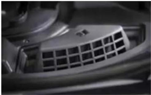
natural_image
Close-up of a car air vent grille (no visible text or symbols)- An impeller pulls wash and rinse water into the spinning ultra-fine filter.
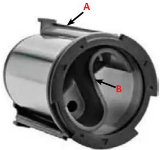
text_image
A BA. Outer Blades
B. Inner Blades
-
The ultra-fine filter is cleaned by an area of back-pressure created by two sets of wing-shaped blades located inside and outside the filter.
-
Food particles remain suspended inside the filter housing; filtered water is pumped back to the wash arms.
-
During draining, a secondary pump flushes out food particles and soils.
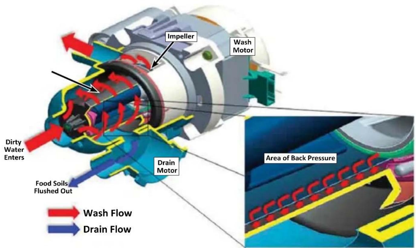
text_image
Impeller Wash Motor Dirty Water Enters Food Soils Flushed Out Drain Motor Area of Back Pressure Wash Flow Drain FlowWhirlpool® and KitchenAid® Global Wash Filtration System
This dishwasher has an updated technology in dishwasher filtration. The triple filtration system minimizes sound and optimizes water and energy conservation while providing superb performance. Throughout the life of the dishwasher, the filter will require maintenance to sustain peak cleaning performance.
The triple filter system consist of a fine-filter plate and a dual filter cup assembly.
■ The fine-filter plate protects the wash pump and water delivery system. It also removes moderate size particles from recirculation onto the dish-load.
■ The dual filter assembly protects the drain system from large objects while collecting the smallest particles for the improved cleaning performance.
The filters may need to be cleaned when:
■ Visible objects or soils are on the filters.
■ There is a degradation in cleaning performance (that is, soils still present on dishes).
■ Dishes feel gritty to the touch.
It is very easy to remove and maintain the filters. The chart below shows the recommended cleaning frequencies.
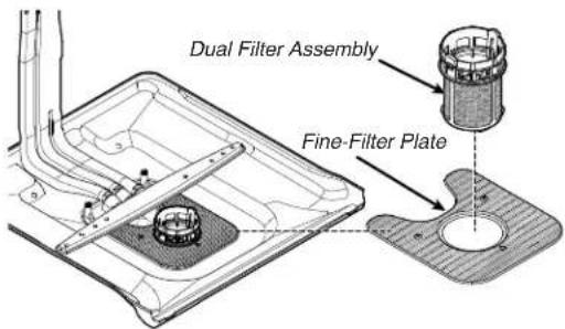
text_image
Dual Filter Assembly Fine-Filter Plate| Recommended Time Interval to Clean Your Filter | |||
| Number of Loads Per Week | If You Only Scrape Before Loading* | If You Scrape and Rinse Before Loading | If You Wash Before Loading |
| 8-12 Every two months | Every four months Once per year | ||
| 4-7 Every four months | Once per year Once per year | ||
| 1-3 Twice per year | Once per year Once per year | ||
*Manufacturer's recommendation: This practice will conserve the water and energy that you would have used to prepare your dishes. This will also save your time and efforts.
Very Hard Water
If you have hard water (above 15 grains), clean your filter at least once per month. Building up white residue on dishwasher indicates hard water.
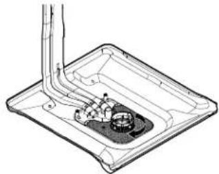
Filter Removal Instructions
- Turn the Dual-Filter Assembly 1/4 turn counterclockwise and lift out.
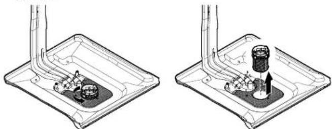
natural_image
Two technical diagrams showing mechanical components inside a tray, with no visible text or symbols.- Lift fine-filter plate out.
natural_image
Technical diagram of a mechanical assembly with no visible text or symbols- Clean the filters as given in "Cleaning Instructions."
Cleaning Instructions
IMPORTANT: Do not use wire brush, scouring pad, etc., as they may damage the filters.
Rinse the filter under running water until most soils are removed. If you have hard-to-remove soils or calcium deposits from hard water, a soft brush may be required.
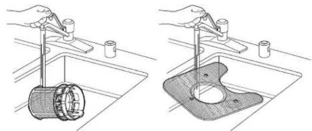
natural_image
Two technical illustrations showing hands using a tool to clean a cylindrical component in a sink (left) and a plastic housing with a circular opening (right), both without any text or symbols.Filter Reinstallation Instructions
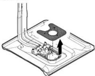
- Place the fine-filter plate under the locating tabs in the bottom of the dishwasher so the round opening for the Dual-Filter Assembly lines up with the round opening in the bottom of the tub.
natural_image
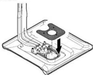
Technical line drawing of a mechanical assembly with no visible text or symbols- Insert the Dual-Filter Assembly into the circular opening in the fine-filter plate.
natural_image
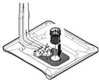
Technical line drawing of a mechanical assembly with no visible text or symbols- Slowly rotate the filter clockwise until it drops into place. Continue to rotate until the filter is locked into place. If the filter is not fully seated (still turns freely), continue to run the filter clockwise until it drops and locks into place.
natural_image
Technical line drawing of a mechanical component with internal parts and a piping (no text or symbols)NOTE: The Dual-Filter Assembly arrow does not have to align with the arrow in the fine-filter plate as long as the filter is locked.
IMPORTANT: To avoid damage to dishwasher, do not operate your dishwasher without the filters properly installed. Be sure the fine-filter plate is securely in place, the Dual-Filter Assembly does not turn freely, and is locked into place.
New Components/Features
- Tub - Taller tub for the largest place setting on the market. Less room underneath the unit to access components for service.
■ TLR - Third level rack option with it's own wash system.
■ Rear feed tube with four wash zones.
■ Spray Arms - It has new attachment method and comes with compressed size.
■ Four Legs - Made of plastic similar to dryer legs.
■ Improved anchoring - Four anchor locations in top tub collar to top mount the dishwasher under the counter-top.
■ New small screw head on anchor screws to fit into smaller side anchor holes in side of tub collar.
■ Diverter motor - The function of leak detection alerts the customer to call service.
■ New installation/service cycle can be activated after the installation to test the leaks for approximately 5 minutes.
■ 20 Horror code alarm activates if the installer forgets to turn on the water valve.
■ Improved diagnostics - Diagnose with more faults/error codes, some will be displayed to customers.
■ Flood/Water leak detection - Drip tray and float are present to catch leaks from under the tub lip or corners. Leak detection shuts unit off and turns on drain pump and alerts the customer to call service.
■ Flow meter - It measures water volume against flow rate.
- Tub LED's - Bar LED's incorporated into Third Level Rack support.
■ Terminal box - New terminal box comes with screws. No wire nuts are present in terminal box.
Model Number and Serial Number Label Location
Model Number and Serial Number Label Location
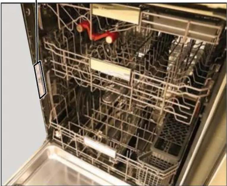
natural_image
Interior view of a stainless steel kitchen appliance with visible nutritional racks and a red safety clip (no text or symbols)Tech Sheet Location
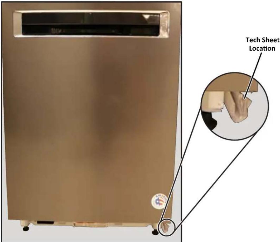
text_image
Tech Sheet LocationModel and Serial Number Nomenclature
Whirlpool® Model Number Nomenclature
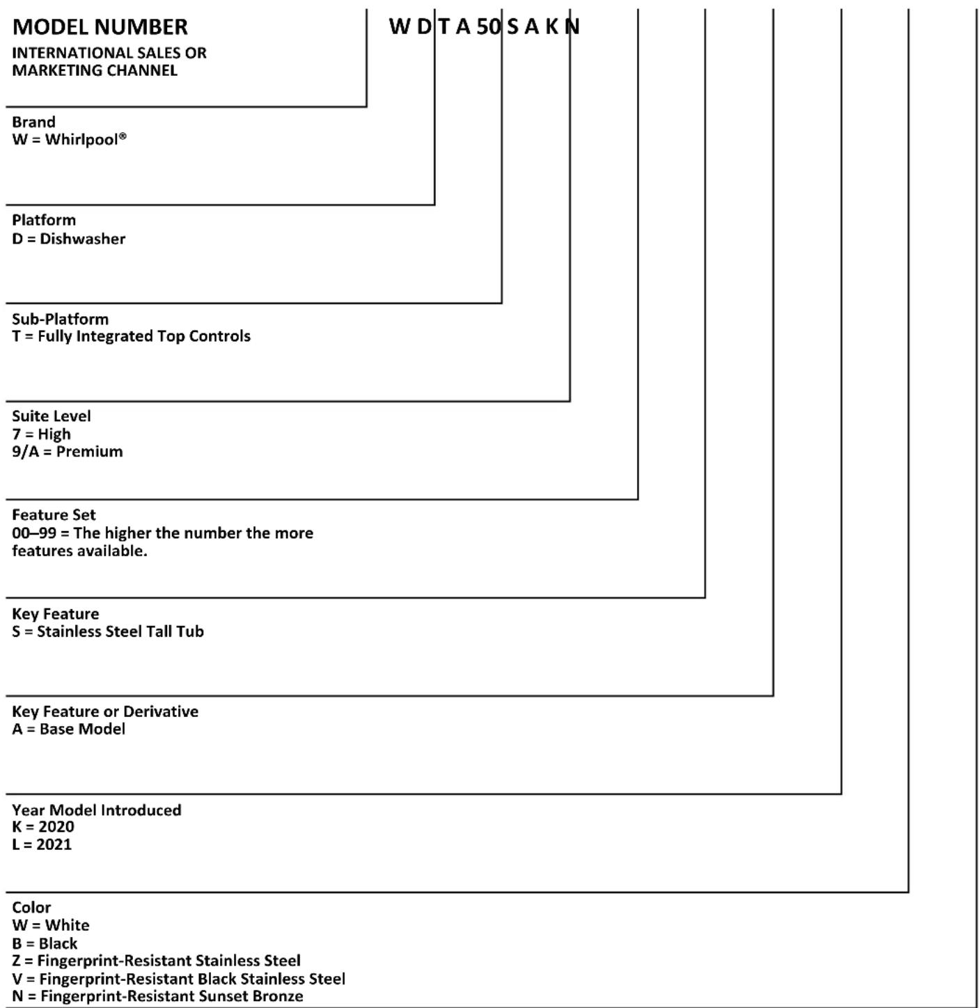
other
| Level | Item | Value | |---|---|---| | Color | Year Model Introduced | 2020 | | Color | K = 2021 | 2021 | | Color | L = 2021 | 2021 | | Key Feature or Derivative | Key Feature or Derivative | Base Model | | Key Feature | S = Stainless Steel Tall Tub | - | | Key Feature Set | 00-99 = The higher the number the more features available. | - | | Suite Level | 7 = High | Premium | | Platform | D = Dishwasher | - | | Brand | W = Whirlpool® | - | | W D T A 50 S A K N | - | - | | Color | W = White | - | | Color | B = Black | - | | Color | Z = Fingerprint-Resistant Stainless Steel | - | | Color | V = Fingerprint-Resistant Black Stainless Steel | - | | Color | N = Fingerprint-Resistant Sunset Bronze | - |Model and Serial Number Nomenclature (Continued)
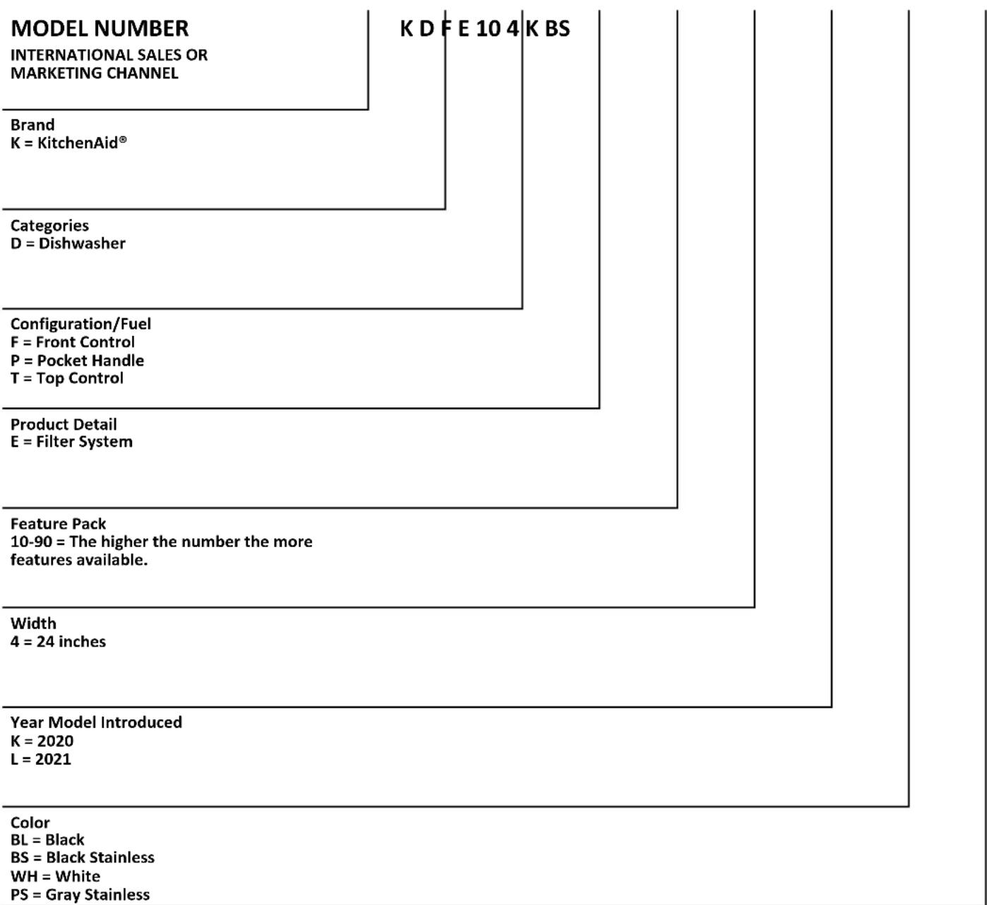
KitchenAid® Model Number Nomenclature
tree
| Category | Value | | :--- | :--- | | Brand | K = KitchenAid® | | Categories | D = Dishwasher | | Configuration/Fuel | F = Front Control | | P = Pocket Handle | T = Top Control | | Product Detail | E = Filter System | | Feature Pack | 10-90 = The higher the number the more features available. | | Width | 4 = 24 inches | | Year Model Introduced | K = 2020, L = 2021 | | Color | BL = Black, BS = Black Stainless, WH = White, PS = Gray Stainless |Model and Serial Number Nomenclature (Continued)
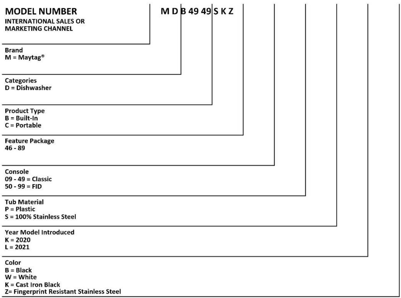
Maytag® Model Number Nomenclature
tree
| Category | Value | | :--- | :--- | | Brand | M = Maytag® | | Categories | D = Dishwasher | | Product Type | B = Built-In, C = Portable | | Feature Package | 46 - 89 | | Console | 09 - 49 = Classic, 50 - 99 = FID | | Tub Material | P = Plastic, S = 100% Stainless Steel | | Year Model Introduced | K = 2020, L = 2021 | | Color | B = Black, W = White, K = Cast Iron Black, Z = Fingerprint Resistant Stainless Steel |Serial Number Nomenclature
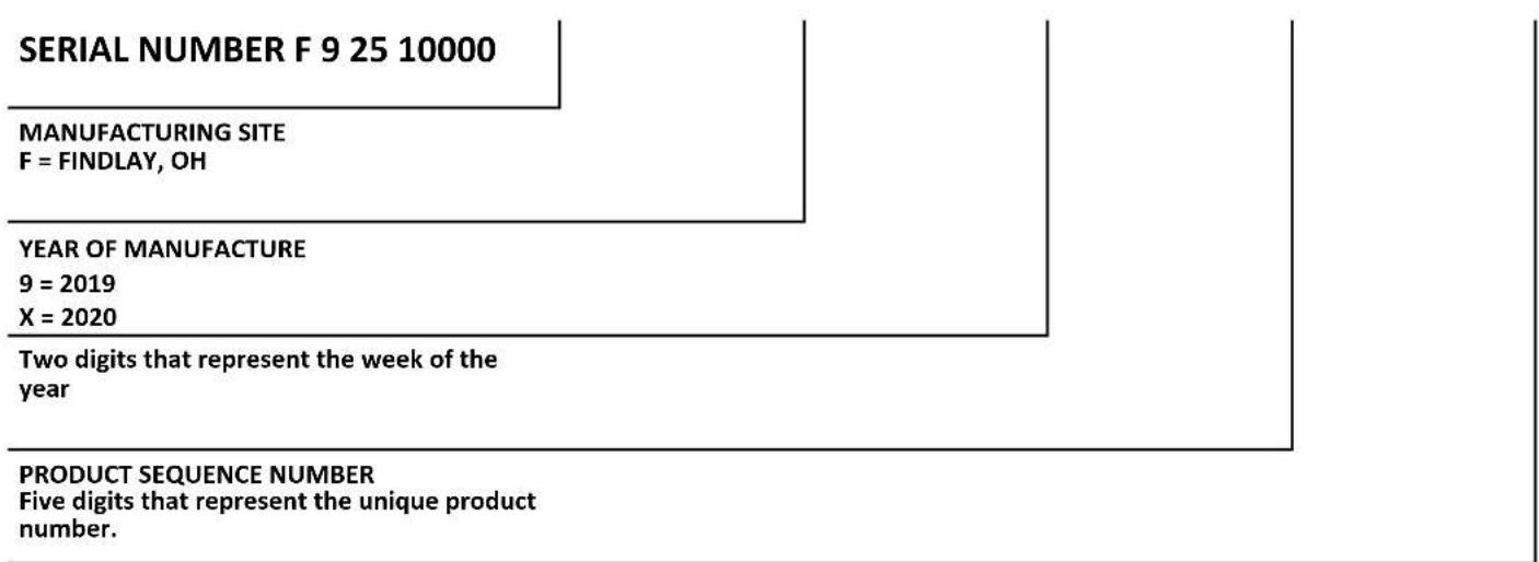
flowchart
graph TD
    A["SERIAL NUMBER F 9 25 10000"] --> B["MANUFACTURING SITE\nF = FINDLAY, OH"]
    B --> C["YEAR OF MANUFACTURE\n9 = 2019\nX = 2020"]
    C --> D["Two digits that represent the week of the year"]
    D --> E["PRODUCT SEQUENCE NUMBER\nFive digits that represent the unique product number."]
Product Specifications
Whirlpool ^® Large Capacity Dishwasher with Third Level Rack
KitchenAid ^® 39 dBA Dishwasher with Third Level Utensil Rack
Maytag ^® Stainless Steel Tub Dishwasher with Dual Power Filtration
| Dimensions | |
| Depth Closed Excluding Handles (IN, inches) 24 | ^1/_2 or 26^3/_4 |
| Depth Closed Including Handles (IN, inches) 24 | ^1/_2 or 26^1/_2 |
| Depth With Door Open 90 Degree (IN, inches) 50 | ^3/_16 or 51 |
| Depth (IN, inches) 24 | ^1/_2 or 26^3/_4 |
| Height (IN, inches) 33 | ^1/_2 |
| Maximum Height (IN, inches) 34 | ^1/_2 or 34^7/_16 |
| Minimum Height (IN, inches) 33 | ^1/_2 or 33^7/_16 |
| Width (IN, inches) 23 | ^7/_8 |
| Number of Place Settings 13 or 14 | |
| Description | |
| Dishwasher Type Built-In | |
| Controls | |
| Automatic Temperature Controls Yes | |
| Control Location Front or Hidden Top | |
| Control Type | Tap Touch with Display or Electronic Touch with Display |
| End of Cycle Signal | Yes |
| Sensor | Yes |
| Status Light | White |
| Exterior | |
| Control Panel Color | Gray or Black |
| Door Style | Flat |
| Handle Color | Gray or Stainless Steel or Black or White |
| Handle Material | Plastic or Metal |
| Handle Type | Long Pocket or Towel Bar |
| Magnetic Door | Yes |
| Toe Panel Color | Black or White |
| True Hold Door | Yes |
| Features | |
| Decibel Level (dBA) (Whirlpool® Models Only) | 41 or 47 |
| Decibel Level (dBA) (KitchenAid® Models Only) | 39 |
| Decibel Level (dBA) (Maytag® Models Only) | 50 |
| Dispensers | Detergent and Rinse Aid |
| Number of Wash Levels | 5 |
| Rinse Aid Dispenser Level Indicator | Yes |
| Sound Package | Yes |
| Cycles and Options (Whirlpool® Models Only) | |
| Dishwasher Cycle Selections | Heavy, Normal, Quick Wash, Sensor Wash, Soak & Clean |
Product Specifications (Continued)
| Cycles and Options (KitchenAid® Models Only) | |||
| Dishwasher Cycle Selections Express Wash, Normal | ProWashTM, Rinse, Tough | ||
| Cycles and Options (Maytag® Models Only) | |||
| Dishwasher Cycle Selections Auto, Normal, Quick | PowerBlast, Rinse | ||
| Cycles | |||
| Number of Wash Cycles 5 | |||
| Options Whirlpool® Models Only KitchenAid® M | Models Only Maytag® Models | Only | |
| Dishwasher Option Selections Extended Heat Dry | 4 Hour DelayControl LockHeated DryHi Temp WashSani Rinse | Extended Heat Dry4 Hour DelayControl LockHeated DryHi Temp WashSani Rinse | 4 Hour DelayControl LockHigh TempLong Heated DrySani RinseShort Heated Dry |
| Details Whirlpool® Models Only KitchenAid® M | Models Only Maytag® Models | Only | |
| Drying System Type Vent Dry with Heating | Element or Recessed Heating Element | Vent Dry with Heating Element | Vent Dry with Heating Element |
| Number of Racks 3 3 2 | |||
| Number of Wash arms 3 3 3 | |||
| Rack Material Nylon Nylon Nylon | |||
| Tub Material | Stainless Steel | Stainless Steel | Stainless Steel |
| Tub Style | Built-in Tall Tub 24" | Built-in Tall Tub 24" | Built-in Tall Tub 24" |
| Wash System | Filter | Filter | Dual Power Filtration |
| Wash System Type | MicroFilter | MicroFilter | MicroFilter with chopper |
| Water Filtration | Yes | Yes | Yes |
| Hoses Included | Drain Hose | Drain Hose | Drain Hose |
| Leak Detect | Yes | Yes | Yes |
| 2nd Level Rack | |||
| Adjustable | 2 Position Removable | ||
| Cushion-Tip Tines | Yes | ||
| Extras (Whirlpool® Models Only) | Plastic Wash Arm | ||
| Extras (KitchenAid® Models Only) | Stainless Steel Wash Arm | ||
| Extras (Maytag® Models Only) | Stainless Steel Wash ArmPlastic Cup Shelf | ||
| Fold-Down Tines | 1 Row 6 Position | ||
| Glides | Wheels or Ball Bearings | ||
| Style | Extended | ||
Product Specifications (Continued)
| Lower Rack | |
| Cushion-Tip Tines Yes | |
| Extras (Whirlpool® and KitchenAid® Models) Stainless Steel Wash Arm | |
| Extras (Maytag® Models Only) 1 Cup Shelf | Stainless Steel Wash Arm |
| Fold-Down Tines (Whirlpool® Models Only) 1 Fold Down | |
| Glides Wheels or Ball Bearings | |
| Style Extended | |
| Silverware Basket | |
| Type Large In the Rack Basket or 3 Piece Splittable | |
| Location Bottom Rack | |
| Covers Yes | |
| Culinary Basket Yes | |
| Third Level Rack (Whirlpool® Models Only) | |
| Glides Ball Bearings | |
| Removable Yes | |
| Type Third Rack with Wash Tube or Culinary Rack | |
| Third Level Rack (KitchenAid® Models Only) | |
| Glides SatinGlide Rails | |
| Removable Yes | |
| Type Culinary Rack | |
| Electrical | |
| Amps 15 | |
| Hz | 60 |
| Volts | 120 |
Product Features
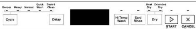
Whirlpool® Cycle Guide
Whirlpool
flowchart
graph LR
    A["Sensor"] --> B["Cycle"]
    C["Heavy"] --> D["Delay"]
    E["Normal"] --> F["Quick Wash"]
    G["Safe & Clean"] --> H["Delay"]
    I["Hi Temp Wash"] --> J["Sani Rinse"]
    K["Extended Dry"] --> L["Dry"]
    M["START"] --> N["Cancel"]
    O["×"] --> P["End"]
CYCLE
| Control Purpose | |
| Sensor | Senses soil to automatically optimize cycle. Auto cycle is selected if START is pressed first. |
| Heavy Use for hard to clean items. | |
| Normal This cycle is recommended for daily, regular or typical use to completely wash and dry a full load of normally soiled dishes. | |
| Quick Wash Use when you need faster results. | |
| Soak & Clean | Use for loads with heavy amounts of dried on or hard to clean baked-on food. For best results add prewash detergent. |
OPTIONS
| Control Purpose | |
| Hi Temp Wash Helps remove tough, baked on food. | |
| Sani Rinse | Sanitizes dishes and glassware in accordance with NSF International NSF/ANSI Standard 184 for Residential Dishwashers. See this section in the Owner's Manual. |
| Heat Dry Dries dishes with heat. Load plastic item in upper racks. | |
| Extended Dry Increases the Energy used for drying the dishes. This may lengthen the cycle time. | |
| Delay Runs the dishwasher at a later time. | |
| Start / Resume | Push to start or resume a cycle. |
| Cancel / Drain | Push to reset any cycle or options during selection. Push to end a cycle once started. |
Product Features (Continued)
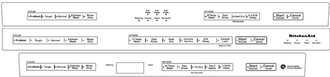
KitchenAid® Cycle Guide
flowchart
graph TD
    A["CYCLEs"] --> B["ProWash"]
    B --> C["Tough"]
    C --> D["Normal"]
    D --> E["Express Wash"]
    E --> F["Rinse Only"]
    F --> G["Washing"]
    G --> H["2 Hr Delay"]
    H --> I["4 Hr Delay"]
    I --> J["8 Hr Delay"]
    J --> K["Washing"]
    K --> L["Drying"]
    L --> M["Clean"]
    M --> N["Sanitary"]
    N --> O["Extended"]
    O --> P["Options"]
    P --> Q["Hi Temp Wash"]
    Q --> R["Sani Rinse"]
    R --> S["Heat Dry"]
    S --> T["Extended Heat Dry"]
    T --> U["4 Hr Delay"]
    U --> V["Control Lock"]
    V --> W["Start RESUME"]
    W --> X["Cancel DRAIN"]
    X --> Y["KitchenAid"]
    Y --> Z["Washing"]
    Z --> AA["Drying"]
    AA --> AB["Clean"]
    AB --> AC["Sanitary"]
    AC --> AD["Extended"]
    AD --> AE["CYCLEs"]
    AE --> AF["ProWash"]
    AF --> AG["Tough"]
    AG --> AH["Normal"]
    AH --> AI["Express Wash"]
    AI --> AJ["Rinse Only"]
    AJ --> AK["Washing"]
    AK --> AL["Cash"]
    AL --> AM["OPTIONS"]
    AM --> AN["Hi Temp Wash"]
    AN --> AO["Sani Rinse"]
    AO --> AP["ProDry"]
    AP --> AQ["Top 2 Racks"]
    AQ --> AR["1-24 Hr Delay"]
    AR --> AS["Start RESUME"]
    AS --> AT["Cancel DRAIN"]
    AT --> AU["Fan-Enabled ProDry System"]
CYCLE
| Control Purpose | |
| ProWash | Senses soil to automatically optimize cycle. ProWashTMcycle is selected if START is pressed first. |
| Tough Use for hard to clean items. | |
| Normal This cycle is recommended for daily, regular or typical use to completely wash and dry a full load of normally soiled dishes. | |
| Light Use for lightly soiled items like china and crystal. | |
| Express Wash Use when you need faster results. | |
| Rinse Only Use for rinsing dishes, glasses, and silverware that will not be washed right away. Do not use detergent. | |
OPTIONS
| Control Purpose | |
| Hi Temp Wash Helps remove tough, baked on food. | |
| Sani Rinse | Sanitizes dishes and glassware in accordance with NSF International NSF/ANSI Standard 184 for Residential Dishwashers. See this section in the Owner's Manual. |
| Heat Dry Dries dishes with heat. Load plastic item in upper racks. | |
| Extended Heat Dry Increases the Energy used for drying the dishes. This may lengthen the cycle time. | |
| Delay | Runs the dishwasher at a later time. |
| ProDry | Dries dishes with heat and a fan. Use for best performance. |
| Top 2 Racks | Wash items in the Top two racks only. Only a limited amount of water will be sent to the lower spray arm. |
| Start / Resume | Push to start or resume a cycle. |
| Cancel / Drain | Push to reset any cycle or options during selection. Push to end a cycle once started. |
Product Features (Continued)
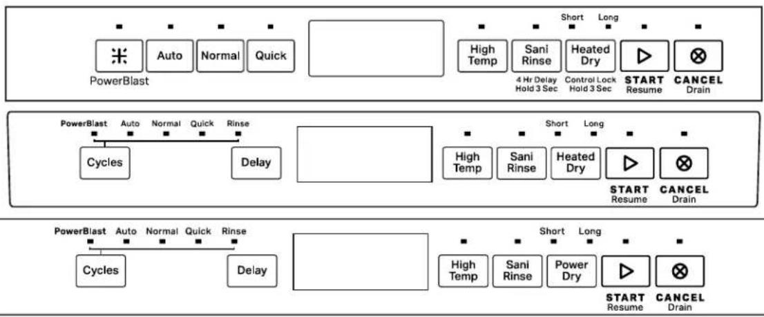
Maytag® Cycle Guide
flowchart
graph TD
    A["PowerBlast"] --> B["Auto"]
    B --> C["Normal"]
    C --> D["Quick"]
    D --> E["Short"]
    E --> F["Long"]
    F --> G["High Temp"]
    G --> H["Sani Rinse"]
    H --> I["Heated Dry"]
    I --> J["4 Hr Delay Hold 3 Sec"]
    J --> K["Control Lock Hold 3 Sec"]
    K --> L["START Resume"]
    L --> M["CANCEL Drain"]

    N["PowerBlast"] --> O["Auto"]
    O --> P["Normal"]
    P --> Q["Quick"]
    Q --> R["Rinse"]
    R --> S["Cycles"]
    S --> T["Delay"]

    U["PowerBlast"] --> V["Auto"]
    V --> W["Normal"]
    W --> X["Quick"]
    X --> Y["Rinse"]
    Y --> Z["Cycles"]
    Z --> AA["Delay"]

    AB["PowerBlast"] --> AC["Auto"]
    AC --> AD["Normal"]
    AD --> AE["Quick"]
    AE --> AF["Rinse"]
    AF --> AG["Cycles"]
    AG --> AH["Delay"]

    AI["PowerBlast"] --> AJ["Auto"]
    AJ --> AK["Normal"]
    AK --> AL["Quick"]
    AL --> AM["Rinse"]
    AM --> AN["Cycles"]
    AN --> AO["Delay"]

    AP["PowerBlast"] --> AQ["Auto"]
    AQ --> AR["Normal"]
    AR --> AS["Quick"]
    AS --> AT["Rinse"]
    AT --> AU["Cycles"]
    AU --> AV["Delay"]

    AW["PowerBlast"] --> AX["Auto"]
    AX --> AY["Normal"]
    AY --> AZ["Quick"]
    AZ --> BA["Rinse"]
    BA --> BB["Cycles"]
    BB --> BC["Delay"]

    BD["PowerBlast"] --> BE["Auto"]
    BE --> BF["Normal"]
    BF --> BG["Quick"]
    BG --> BH["Rinse"]
    BH --> BI["Cycles"]
    BI --> BJ["Delay"]

    BK["PowerBlast"] --> BL["Auto"]
    BL --> BM["Normal"]
    BM --> BN["Rinse"]
    BN --> BO["Cycles"]
    BO --> BP["Delay"]

    BQ["PowerBlast"] --> BR["Auto"]
    BR --> BS["Normal"]
    BS --> BT["Rinse"]
    BT --> BU["Cycles"]
    BU --> BV["Delay"]
CYCLE
| Control Purpose | |
| Auto | Senses soil to automatically optimize cycle. Auto cycle is selected if START is pressed first. |
| PowerBlast Use for hard to clean items. | |
| Normal This cycle is recommended for daily, regular or typical use to completely wash and dry a full load of normally soiled dishes. | |
| Quick Use when you need faster results. | |
| Rinse | Use for rinsing dishes, glasses, and silverware that will not be washed right away. Do not use detergent. |
OPTIONS
| Control Purpose | |
| High Temp Helps remove tough, baked on food. | |
| Sani Rinse | Sanitizes dishes and glassware in accordance with NSF International NSF/ANSI Standard 184 for Residential Dishwashers. See this section in the Owner's Manual. |
| Heated Dry Short (Some Models) Power Dry Short | Dries dishes with heat. Load plastic item in upper racks. Dries dishes with heat and a fan. Load plastic item in upper racks. |
| Heated Dry Long (Some Models) Power Dry Long | Increases the Energy used for drying the dishes. This may lengthen the cycle time. |
| Delay Runs the dishwasher at a later time. | |
| Start / Resume Push to start or resume a cycle. | |
| Cancel / Drain Push to reset any cycle or options during selection. Push to end a cycle once started. | |
| Control Lock (on some models) | Use the Control Lock option to avoid unintended use of dishwasher between cycles, or cycle and option changes during a cycle. To turn ON/OFF, hold button for 3 seconds. |
Notes
Section 2: Diagnostics and Troubleshooting
This section provides diagnostics, fault codes, and troubleshooting information for the "Whirlpool® and KitchenAid® Filtration and Maytag® 24" Microfiltration Dishwashers."
■Safety
■Service Diagnostics Cycle Timing
■Service Diagnostics Cycle Notes
■Service Error Codes
■Troubleshooting Guide
For Service Technician Use Only
Safety
! DANGER

Electrical Shock Hazard
Only authorized technicians should perform diagnostic voltage measurements.
After performing voltage measurements, disconnect power before servicing.
Failure to follow these instructions can result in death or electrical shock.
WARNING
Electrical Shock Hazard
Disconnect power before servicing.
Replace all parts and panels before operating.
Failure to do so can result in death or electrical shock.
Voltage Measurement Safety Information
When performing live voltage measurements, you must do the following:
■ Verify the controls are in the off position so that the appliance does not start when energized.
- Allow enough space to perform the voltage measurements without obstructions.
- Keep other people a safe distance away from the appliance to prevent potential injury.
■ Always use the proper testing equipment.
■ After voltage measurements, always disconnect power before servicing.
IMPORTANT: Electrostatic Discharge (ESD) Sensitive Electronics
ESD problems are present everywhere. ESD may damage or weaken the electronic control assembly. The new control assembly may appear to work well after repair is finished, but failure may occur at a later date due to ESD stress.
■ Use an antistatic wrist strap. Connect wrist strap to green ground connection point or unpainted metal in the appliance
-OR-
Touch your finger repeatedly to a green ground connection point or unpainted metal in the appliance.
■ Before removing the part from its package, touch the antistatic bag to a green ground connection point or unpainted metal in the appliance.
■ Avoid touching electronic parts or terminal contacts; handle electronic control assembly by edges only.
■ When repackaging failed electronic control assembly in antistatic bag, observe above instructions.
IMPORTANT SAFETY NOTICE — “For Technicians only”
This service data sheet is intended for use by persons having electrical, electronic, and mechanical experience and knowledge at a level generally considered acceptable in the appliance repair trade. Any attempt to repair a major appliance may result in personal injury and property damage. The manufacturer or seller cannot be responsible, nor assume any liability for injury or damage of any kind arising from the use of this data sheet.
For Service Technician Use Only Service Diagnostics Cycle Timing
| Numeric Display All LEDs on 1 2 3 4 5 (Scheme | models)1 | 0 | 7 | ||||||||||||||
| Interval Time 0:01 0:02 | Typical: 0:30 | Max: 5:00 | 0:01 Typical | 1:00 Max: 2:09 | 0:18 Typical | 0:15 Max: 0:24 | Typical: 0:20 Max: 0:44 | 0:01 0:20 | 0:20 0:20 0:30 | 0:15 Typical: | 30 Max: 4:45 | 0:15 0:01 | |||||
| Service Test Steps Pause | Turn on vent | (Stay on throughout) | Timed or Sensed Drain1 | Pause | Fill 2.5 L2 | Wash motor pulses | Fill 0.5 L2 | Fill 0.8 L + Wash2 | Pause | Wash = Dispenser (Middle spray arm) | Wash = Fan (Ceiling spray arm) | Wash (Third Level Rack1) | Wash + Heater [Lower spray arm] | Wash + Drain | Sensed Drain1 | Drain | Pause |
Typical Total Time 4:59
NOTES:
- Time varies depending on drain sensing.
- Time varies depending on fill rate sensed by flow meter.
- This interval is only included on models with a wash arm in the third level rack.
- Cycle times out after 5 minutes.
Activating Service Diagnostics Mode
To invoke the Service Diagnostics Mode, perform the following while in standby:
■ Press any 3 keys (except Delay, Start or Cancel) in the sequence 1-2-3, 1-2-3, 1-2-3 with no more than 1 second between key presses. All LED's will illuminate if successful. Then press button #2 and shut door to start the service cycle.
■ The Service Diagnostics Cycle will start when the door is closed.
■ Invoking Service Diagnostics clears all status and last run information from memory and restores defaults. It also forces the next cycle to be a sensor calibration cycle.
■ Sensor calibration cycle may add an extra rinse (to assure clear water) before the final rinse. This cycle may be longer than a typical run.
All LEDs turn on immediately upon receiving entry sequence (even if door is open) as a display test. A tone may play depending on the model.
Press Key #1: User Interface Test
■ All LEDs remain on. Tone is played for each key pressed.
Press Key #2: Run Service Test Cycle
■ To rapid advance 1 step at a time, press the Start/Resume key. Rapid advance may skip some sensor checks and prevent fault detection from working properly. Rapid advance can also cause false error codes to be detected in some cases. NOTE: The diagnostics cycle will pause when the door is opened and resume when closed. No Start/Resume key press required to resume.
Press Key #3: Error Code History Display
■ Up to 5 unique codes are saved in the history.
■ Most recently detected error code is displayed first.
■ If no faults are present, numeric display will show "-:-" or Clean LED will be off (Depending on display type).
■ Press third key to advance to next error code stored. Three tones are played when the end of the error code history has been reached.
Press and Hold Key #3: Clear Fault History
■ Tone will play when faults are cleared Exit procedure.
■ The service diagnostics mode will timeout after 5 minutes of user inactivity.
■ Press Cancel key to exit service diagnostics mode.
■ Service diagnostics mode will be canceled if AC power is removed from the appliance.
Service Diagnostics Mode Menu Table
| Types of Button Press | 1st Button | 2nd Button | 3rd Button |
| Momentary Press | Activates User Interface Test | Activates Service Test Cycle | Displays Next Error Code |
| Hold for 5 seconds | Clears Error Code History |
Service Diagnostics Cycle Notes
- Drain may be sensed or timed. Sensed drain maximum time is approximately 5 minutes, which includes retries. Sensed drain will have both wash motor and drain motor powered simultaneously. Timed drain is drain motor only.
- Fills are measured by flow meter and time may vary according to water flow rate. If flow meter has failed, control will revert to timed fills and record fault code to history. Wash motor may turn on during fill process to verify the presence of water in the machine.
- This step is only included on models that have a wash zone in the third level rack. On models without a third level wash zone or two racks, this step is skipped.
Reading Fault Code Display
Point LED Models
■ Each fault code is displayed by blinking the Clean or Complete LED in a pattern to indicate the Function code and the Error code.
■ Fault display is a 4 step process. Count LED blinks for each portion of the code.
- Blink Clean or Complete LED Function code number of times
- Pause 2 seconds
- Blink Clean or Complete LED Error code number of times
- Pause 5 seconds
■ Each fault code is repeated until key #3 is pressed to advance to the next code or until the service mode is exited.
Numeric Display Models
■ Each fault code is shown in the numeric display by first showing the Function code "F#" then the Error code "E#".
■ Fault display is a 4 step process:
- Display F!!
- Pause 0.5 seconds
- Display E#
- Pause 1 second
■ Each fault code is repeated until key #3 is pressed to advance to the next code or until the service mode is exited.
For Service Technician Use Only
Service Error Codes
| △DANGER |
 |
| Electrical Shock HazardOnly authorized technicians should perform diagnostic voltage measurements.After performing voltage measurements, disconnect power before servicing.Failure to follow these instructions can result in death or electrical shock. |
Fault codes are intended to give direction as to which component or subsystem has a failure. Service technician should troubleshoot the issue and confirm the validity of all fault codes before replacing parts.
| FUNCTION CODE | ERROR CODE CAUSES | ES WHAT TO CHECK | |
| 1 - Control | 1 - ACU | Relay or TRIAC failure on main control board. | Unplug dishwasher or disconnect power and replace control. |
| 2 - MCU | Motor control circuit failure on main control board. | Unplug dishwasher or disconnect power and replace control. | |
| 2 - User Interface | 1 - Stuck Key | Control detected stuck keys in user interface.NOTES:- If any keys are stuck, the stuck key(s) will be ignored and an error recorded to service history, but no alert to customer.- This fault is monitored on models with key switches only, not on capacitive touch key models. | Check responsiveness of each key. If some keys do not respond, replace user interface. If all keys are responsive, fault may be intermittent or caused by customer use. Check for vent and/or fan fault, which may lead to excessive moisture build up in door cavity and cause keys to appear stuck closed. |
| 3 - Thermistor/OWI | 1 - Open or Shorted | - Open or shorted connection or component in temperature sensing circuit- Open, shorted or faulty temperature sensor- Temperature sensor input on control failed- Incoming water temperature above 167°F (75°C) | 1. Unplug dishwasher or disconnect power.2. Check all components and connections in the temperature sensing circuit with meter.Fix/replace open/shorted connection or part.3. Verify incoming water temperature. |
| 2 - Failed Calibration | - OWI failure- OWI lens obstructed by hard water build up or food soil | 1. Check OWI lens surface. Clean if needed.2. Unplug dishwasher or disconnect power.3. Check all connections in soil sensing circuit with meter. Fix/replace bad connection/part.NOTE: Run diagnostics cycle after installing new OWI to force calibration on next regular wash cycle. | |
| FUNCTION CODE | ERROR CODE CAUSES | WHAT TO CHECK | |
| 4 - Heating | 2 - Heater relay stuck open or heater open | - Open connection in heater circuit- Heater component open- Heater drive circuit on controlNOTE: Control will continue running cycles with no heat without alerting customer if this fault is detected. | 1. Unplug dishwasher or disconnect power.2. Measure resistance of heater and all components and connections in water heating circuit/heat dry circuit. Fix/replace open connection/part. |
| 3 - Heater relay stuck closed or heater failed | - Heater relay on control shorted- Heater component shorted to groundNOTE: Control will continue running cycles with no heat without alerting customer if this fault is detected. | 1. Unplug dishwasher or disconnect power.2. Inspect heater and connections for overheating/shorting. If evidence of overheating or shorts exists, replace.3. Measure resistance of heater and all components and connections in water heating circuit/heat dry circuit. Fix/replace open connection/part. | |
| 5 - Door Switch | 1 - Door stuck open | Door was not latched within 4 seconds of pressing the Start/Resume key. | Instruct customer. Refer toOwner's Manual. |
| Loose connection in door switch circuit and/or door switch contacts stuck open and/or door switch not making contact.- Sloppy door latch assembly (Can be aggravated by high door closure force keeping strike plate from fully seating)- Door switch high resistance | 1. Check strike plate and door closure force. Verify door seal is seated properly. Check for interference between dish racks and door. Try bending strike plate down for better engagement.2. Unplug dishwasher or disconnect power.3. Check resistances of door switch contacts and all connections in the door switch circuit with meter, while opening and closing the door latch.- If high resistance with door closed, check/fix loose connections.4. Measure resistance of door switch contacts while checking mechanical operation of latch assembly. Check for broken plastic pieces on latch assembly. Replace latch if faulty. | ||
| If none of the above 1. With door open, | verify 13 VDC present across P12-9 and P12-11.2. If no voltage present, unplug dishwasher or disconnect power and replace control. | ||
| 2 - Door stuck closed | Control programmed to not start if it suspects the door switch is stuck closed. Control looks for the door switch to open between cycles.- Customer didn't open the door between cycles or door switch contacts stuck closed. | 1. Open and close the door, select cycle, the press Start/Resume key. If cycle starts, instruct customer to open the door between cycles.2. Unplug dishwasher or disconnect power.3. Measure resistances of door switch contacts while checking mechanical operation of latch assembly. Fix/replace faulty components. | |
| 6 - Communication | 1 - UI does not get communication from main control | User interface has power but cannot communicate with main control board.- Loose connection between UI and main control- Terminal or wire broken in harness between UI and main control- Main control communication circuit failed | 1. Unplug dishwasher or disconnect power.2. Check connections between P1 on main control and user interface. Reconnect, repair, or replace harness.3. If harness connections are all good, replace main control board. |
| 7 - Wash Motor | 1 - Motor not running | Loose connection in motor circuit and/or faulty wash motor. | 1. Check operation of wash motor during diagnostics.2. Unplug dishwasher or disconnect power.3. Check resistances of connections in wash motor circuit.4. Check for loose connections or replace wash motor. |
| Control motor drive circuit or sense circuit | 1. Unplug dishwasher or disconnect power.2. If meter check of wash motor circuit shows normal resistance and still not getting power to the wash motor, replace control. | ||
| 2 - Variable speed motor failure | Loose connection in motor circuit and/or faulty wash motor. | 1. Check operation of wash motor during diagnostics.2. Unplug dishwasher or disconnect power.3. Check resistances of connections in wash motor circuit.4. Check for loose connections or replace wash motor. | |
| Control motor drive circuit or sense circuit | 1. Unplug dishwasher or disconnect power2. If meter check of wash motor circuit shows normal resistance and still not getting power to the wash motor, replace control. | ||
| 8 - Inlet Water | 1 - No water | No water to dishwasher Verify water supply is turned on and supply line adequate. Check for kinked fill hose. | |
| Bowls or pots loaded or flipped upside down and captured wash water | Instruct customer on loading. Refer to Owner's Manual. | ||
| Water leaking from dishwasher Check for leaks under dishwasher. | |||
| Fill valve or water line plugged with debris | Turn off water supply to dishwasher, disconnect water line to inlet valve and inspect/clean the inlet screen of fill valve and reconnect water line. | ||
| Fill valve electrical problem Check other | fault codes to see if F8E2 is also recorded. See F8E2 description below. | ||
| Flow meter intermittent or failed Check | other fault codes to see if F8E6 is also recorded. See F8E6 description below. | ||
| 2 - Fill valve electrical problem | Loose connection in fill valve circuit and/or open fill valve solenoid | 1. Unplug dishwasher or disconnect power.2. Check resistances of fill valve solenoid and all connections in the fill circuit with meter.3. Fix/replace open connection/part. | |
| Open fuse on control to fill valve Refer to “Fuse Service and Resistance Check” in section 3. | |||
| Faulty fill valve drive circuit on control 1. | Unplug dishwasher or disconnect power.2. Check resistances of fill valve solenoid and all connections in the fill circuit. If all connections and solenoid measure good, replace control. | ||
For Service Technician Use Only
| FUNCTION CODE | ERROR CODE CAUSES | WHAT TO CHECK | |
| 8 - Inlet Water | 3 - Suds / air in pump | Too many suds 1. Start a cycle, allow unit to fill and wash for 1-2 minutes. Open door and check for excessive sudsing. Confirm using proper dishwasher detergent, not hand detergent. Check for excessive rinse aid leakage. Disconnect power and replace dispenser if rinse aid is leaking. | |
| Bowls or pots loaded or flipped upside down and captured wash water | Instruct customer on loading. Refer to Owner's Manual. | ||
| Water leaking from dishwasher Check for leaks under dishwasher. | |||
| Diverter disk in sump missing Remove lower spray arm, rear feedtube, and outlet cover and verify whether the diverter disk is installed. | |||
| 4 - Overfill switch open | Overfill switch unplugged Remove access panel and inspect overfill switch assembly. Ensure connector is fully seated. | ||
| Water in leak pan under unit Remove access panel and check for water in leak pan. If water present, unplug float switch, remove pan and empty it. Replace pan and reconnect the switch. Press Cancel key twice to remove unit from error mode. Verify that fault code is not re-detected by control. NOTE: Root cause of overfill must be corrected or customer will experience another overfill and service call in the future. | |||
| Overfill switch stuck in open/up position | 1. Remove access panel and inspect overfill switch assembly and pan for water or obstruction. Verify that Styrofoam float is able to move freely and you hear the "click" of switch contacts when it is down. 2. Unplug dishwasher or disconnect power and check resistance of overfill switch. Switch should be shorted when float is down. | ||
| Drain issue Check other fault codes to see if F9E1 and/or F9E2 have been recorded. See info for these fault codes below. | |||
| Fill valve mechanically stuck open Check other fault codes to see if F8E5 is also recorded. See info for F8E5 below. | |||
| Fill valve TRIAC on control shorted Check other fault codes to see if F1E1 is also recorded. See info for F1E1 above. | |||
| Unit not level and water surges down overfill funnels into leak pan during cycle | Check levelness of dishwasher. If unit is tilted forward, water is more likely to enter funnels and fill leak pan. Adjust unit until level. Empty leak pan. | ||
| Air pressure surges when door is opened and immediately closed while dishwasher is hot can force water droplets down funnels into leak pan. | Instruct customer to leave dishwasher open a few minutes if door is opened when unit is hot. Empty leak pan. | ||
| Too many suds 1. Start a cycle, allow unit to fill and wash for 1-2 minutes. Open door and check for excessive sudsing. Confirm using proper dishwasher detergent, not hand detergent. Check for excessive rinse aid leakage. Disconnect power and replace dispenser if rinse aid is leaking. | |||
| 8 - Inlet Water | 5 - Fill valve stuck open | Control detects water flowing through flow meter when fill valve is turned off | Confirm dishwasher fills while door is open.- If yes, unplug dishwasher or disconnect power, turn off water to dishwasher, replace fill valve and turn water back on.- If filling stops with door open, but fault is detected while running a cycle, unplug dishwasher or disconnect power and replace control. |
| Fill valve TRIAC on control shorted If dis | washer does not fill with door open, but F8E5 or F1E1 is detected while cycle is running, the fill valve TRIAC is shorted. Disconnect power and replace control. | ||
| 6 - Flow meter | Disconnected or damaged flow meterNOTE: Control is programmed to default to timed fill sequence if flow meter malfunctions. Intermittent flow meter connection may cause incorrect fill levels or false fault codes to be recorded. | 1. Unplug dishwasher or disconnect power.2. Check connections to flow meter with meter. Verify that connector is securely connected at the flow meter end and wires are not pinched/ damaged. Reconnect wires and/or replace damaged components.3. Inspect water inlet and flow meter for signs of obstruction that prevent flow meter wheel from turning. If wheel does not turn, or turns intermittently, when water is flowing, replace water inlet assembly. | |
| 9 - Draining | 1 - Not draining | Obstructed drain hose or path 1. Unplug dishwasher or disconnect power.2. Check for blockages from drain motor to customer's plumbing. Check for plugged garbage disposal or plug not knocked out, plugged hoses or drain check valve stuck. | |
| Drain pump impeller damaged 1. Unplug dishwasher or disconnect power.2. Remove drain pump and check impeller (normally there is some uneven resistance when pushing it). If it is stripped or visibly damaged, replace drain pump. | |||
| Drain motor electrical problem Check other fault codes to see if F9E2 is also recorded. See F9E2 description below. | |||
| Wash motor problem 1. Check other fault codes to see if F7E1 is also recorded. Control uses wash motor signal to verify drain so a failed wash motor can cause a drain fault to be detected.2. Check wash motor and filter assembly for proper function. | |||
| 2 - Drain motor electrical problem | Loose connection in drain motor circuit and/or open drain motor winding. | 1. Unplug dishwasher or disconnect power.2. Check resistances of drain motor winding and all connections in the drain circuit. Fix/replace open connection/part. | |
| Debris stuck in drain motor impeller causing locked rotor | 1. Unplug dishwasher or disconnect power2. Remove drain motor and dislodge debris from impeller. Inspect for damage before reassembling. | ||
| Open fuse on control to drain motor Refer to “Fuse Service and Resistance Check” in section 3. | |||
| Drain motor drive circuit on control | 1. Unplug dishwasher or disconnect power.2. Check resistances of drain motor winding and all connections in the drain circuit. If all connections and drain motor winding measure good, replace control. | ||
| 9 - Draining | 4 - Light in the tub | Loose connection or open in tub light circuit | 1. Unplug dishwasher or disconnect power.2. Check resistances of tub lights and all connections in tub light circuit. Fix/replace open connection/part. |
| 10 (A) - Other | 1 - Dispenser electrical problem | Loose connection in dispenser circuit and/or open dispenser solenoid | 1. Unplug dishwasher or disconnect power.2. Check resistances of dispenser solenoid and all connections in the dispenser circuit. Fix/replace open connection/part. |
| Open fuse on control to dispenser Refer | to “Fuse Service and Resistance Check” in section 3. | ||
| Dispenser drive circuit on control 1. Unplug dishwasher or disconnect power.2. Check resistances of dispenser solenoid and all connections in the dispenser circuit. If all connections and solenoid measure good, replace control. | |||
| 2 - Vent electrical problem | Loose connection in vent circuit and/or open vent wax motor. | 1. Unplug dishwasher or disconnect power.2. Check resistances of vent wax motor and all connections in the vent circuit. Fix/replace open connection/part. | |
| Open fuse on control to vent. Refer to “Fuse Service and Resistance Check” in section 3. | |||
| Vent drive circuit on control. 1. Unplug dishwasher or disconnect power.2. Check resistances of vent wax motor and all connections in the vent circuit. If all connections and wax motor measure good, replace control. | |||
| 3 - Drying fan electrical problem | Loose connection in fan circuit and/or open fan motor winding. | 1. Unplug dishwasher or disconnect power.2. Check resistances of fan motor and all connections in the fan circuit. Fix/replace open connection/part. | |
| Fan drive circuit on control. 1. Unplug dishwasher or disconnect power.2. Check resistances of fan motor and all connections in the fan circuit. If all connections and fan motor measure good, replace control. | |||
| 4 - Diverter can't find positions | Corroded or loose connection in diverter sensor or motor circuit. Open/shorted diverter sensor or motor. | 1. Unplug dishwasher and disconnect power.2. Check connections in diverter sensor and motor circuit with meter. Fix/replace connections/parts.3. Inspect diverter for evidence of water or contaminants; if yes, replace. | |
| 5 - Diverter leak | Corroded or loose connection in diverter sensor circuit. | 1. Unplug dishwasher and disconnect power.2. Check connections in diverter sensor circuit with meter. Fix/replace connections/parts. | |
| Leak at diverter seal Inspect diverter for evidence of water or contaminants; if yes, replace. | |||
For Service Technician Use Only Troubleshooting Guide
! DANGER

Electrical Shock Hazard
Only authorized technicians should perform diagnostic voltage measurements.
After performing voltage measurements, disconnect power before servicing.
Failure to follow these instructions can result in death or electrical shock.
NOTES:
For resistance checks, refer to the "Component Testing" in Section 3.
For checking operation with diagnostics, refer to "Service Diagnostics Cycle Timing" section.
| CUSTOMER DESCRIPTION POTENTIAL CAUSES CHECK | RELATEDERROR CODES | ||
| CLEAN LED Flashes | Control Programmed with Self Diagnostics. | Read error code from the dishwasher and refer to "Service Error Codes" table. Run service diagnostics test cycle to read full history of error codes. | F1E1F7E1F7E2F8E1F8E4F8E5F9E1F10E5 (FAE5) |
| Won't run or power up ("Dead" keypad/console)■ No operation■ No keypad response■ No LEDs or display | No power to unit or bad connection. Check fuses, circuit breakers, and junction box connections. | ||
| Loose connections in dishwasher power up circuit or between keypad(s) and control. | 1. Unplug dishwasher or disconnect power.2. Check continuity power connections keypad(s) and control. | ||
| User interface on this model is not compatible with control which has been exchanged with a control from another model. | Unplug dishwasher or disconnect power. Verify correct control is installed for this model. Control is specific to each user interface and model type. Call techline to verify part numbers if necessary. If incorrect control, replace. | ||
| Control detected door switch problem. | Refer to "Service Error Codes" table. F5E1 | ||
| User interface or control failure. 1. Unplug dishwasher or disconnect power.2. Replace user interface/console and/or control. | |||
| Won't run and Start/Resume LED is blinking slowly | By design, if door is opened for more than 5 seconds or power is interrupted during a cycle, the user must press Start/Resume to resume operation. | Instruct customer. Refer to Owner's Manual. | |
| Start/Resume key not responding See "One or more keys won't respond." | |||
| Control detected door switch problem. | Refer to "Service Error Codes" table. F5E1 | ||
| Won't start and Start/Resume LED flashes 3 times when Start/Resume key is pressed | Control looking for door to open between cycles:- Customer has not opened door since last cycle- Door switch contacts stuck closed | Refer to "Service Error Codes" table. F5E2 | |
| Won't accept key presses and Control Lock LED on | Control lockout feature accidentally enabled by customer. | Instruct customer. Refer to Owner's Manual. Press and hold Control Lock key for 5 seconds to disable lockout feature. | |
| One or more keys won't respond or unusual key/LED/display behavior | Stuck key or short circuits in keypad or in user interface's input lines that read the keys. | Refer to "Service Error Codes" table. F2E1 | |
| Capacitive touch keypad adhesive coming loose from console. | 1. Unplug dishwasher or disconnect power.2. Inspect keypad board for separation from console. Replace keypad/console if separation is seen. | ||
| Loose connections between keypad and control and/or bent connector pins. | 1. Unplug dishwasher or disconnect power.2. Inspect connections in user interface circuits. Reconnect loose connections. Replace parts if pins are damaged or contaminated. | F6E1 | |
| Excessive condensation on user interface parts due to vent and/or fan problem. | Check fault code history for vent and/or fan faults. Refer to "Service Error Codes" table. Verify that vent closes and fan turns on. Refer to "Leaks or drips on cabinet or floor." | F10E2 (FAE2)F10E3 (FAE3) | |
| User interface failure. 1. Unplug dishwasher or disconnect power.2. Replace user interface. | |||
| Dishwasher beeps constantly | User opened door during cycle and closed door without pressing Start/Resume key to resume cycle. | Instruct customer. Control is designed to beep if dishwasher is in "cycle interrupt" mode with door latched. Control will stop beeping when door is open and/or when Start/Resume key is pressed to resume cycle. | |
| Normal beeper operation is excessive to customer. | Instruct customer how to turn beeper off and on. Refer to Owner's Manual. | ||
| Control is programmed to stop cycle and alert customer when certain fault codes have been detected. | Press Cancel key once to silence alarm during fault mode. Read error code from the dishwasher and refer to "Service Error Codes" table. Use service diagnostics mode to get fault history from appliance. | F1E1F7E1F7E2F8E1F8E4F8E5F9E1F10E5 (FAE5) | |
| LEDs or displays run for a short time without loads running or wash motor runs without attempt to fill or fan is the only load that runs | Unit is in sales demo mode Check operation of Cancel key. If pressing cancel multiple times does not activate Cancel/Drain sequence, unit is likely in sales demo mode. To clear demo mode, cycle power for at least 1 minute or run service diagnostics cycle. | ||
| Open fuse on control removed power from loads | Refer to "Fuse Service and Resistance Check" in section 3. | ||
| Long cycles and/or stuck incertain parts of the cycle | As part of normal operation, the dishwasher pauses 2 or 3 times during the cycle for thermal holds and advances once temperature is met. | Instruct customer. Explain thermal holds and how the cycle timing pauses when they occur. | |
| OWI soil sensor picking high soil cycle too often. | 1. Check lens surface. Clean if needed.2. If lens surface cannot be cleaned or has visible damage, unplug dishwasher or disconnect power.3. Replace OWI and run diagnostics cycle after installing new OWI to force calibration on next customer wash cycle. | ||
| Diverter problem prevents water from heating efficiently. | Refer to "Service Error Codes" table. F10E4 | (FAE4) | |
| A water heating problem can cause long cycles, but will typically also cause a water heating fault code. | Refer to "Service Error Codes" table. F4E2 | F4E3 | |
| Heater takes a long time to heat water with low voltage. | Check for at least 100 VAC at power source. | ||
| Incoming water under 84°F (29°C) 1. Ensure dishwasher is connected to the hot water supply.2. Confirm temperature at sink. Recommended is 120°F (49°C).3. Unplug dishwasher or disconnect power and check all connections and measure resistance in temperature sensing circuit. Reconnect and/or replace parts. | |||
| Suds or air in pump requires repeated wash periods. | Refer to "Service Error Codes" table. | ||
| OWI or NTC temperature sensor problem. | Refer to "Service Error Codes" table. F3E1 | ||
| Motor problems force cycle to start and stop repeatedly. | Refer to "Service Error Codes" table. F7E1 | F7E2 | |
| Can start a cycle but only runs for a short time. Cycle does not complete (Clean or Complete LED may blink). | Control is programmed to stop cycle and alert customer when certain fault codes have been detected. | Press Cancel key once to silence alarm during fault mode. Read error code from the dishwasher and refer to "Service Error Codes" table. Use service diagnostics mode to get fault history from appliance. | F1E1F8E1F8E4F8E5F9E1F10E5 (FAE5) |
| Unit is in sales demo mode Check operation of Cancel key. If pressing cancel multiple times does not activate Cancel/Drain sequence, unit is likely in sales demo mode. To clear demo mode, cycle power for at least 1 minute or run service diagnostics cycle. | |||
| Will not drain or water left in dishwasher | Draining problem Refer to "Service Error Codes" table. F9E1 | F9E2 | |
| Customer misunderstands water level after drain | Instruct customer. Sump will normally have up to an inch of water remaining in filter area after cycle. | ||
| Detergent not dispensing or detergent left in dispenser.NOTE: Check error history.If no fault for electrical problems, problem is mechanical. Do not replace control. | Item in lower rack blocked dispenser from opening or blocked spray of water to dispenser. | Instruct customer on proper dish loading. | |
| Mechanical binding of dispenser lid. 1. Unplug dishwasher or disconnect power.2. Replace dispenser. | |||
| Lid latch binding due to excess detergent in mechanism. | Instruct customer on proper dispenser filling. | ||
| Dispenser electrical problem. | Refer to "Service Error Codes" table. F10E1 | (FAE1) | |
| Control canceled cycle prior to dispensing due to fault detected. | Read error code from the dishwasher and refer to "Service Error Codes" table. Use service diagnostics mode to get fault history from appliance. | F1E1F7E2F8E1F8E4F8E5F9E1F10E5 (FAE5) | |
| Film or spots on glasses and/or dishes | Customer not using rinse aid and/or Heated Dry | Check rinse aid level in dispenser. Instruct customer how to fill and monitor level of rinse aid. | |
| Rinse Aid dispenser problem | Refer to "Service Error Codes" table. F10E1 | (FAE1) | |
| Hard water leaving film on dishes Check w | water hardness. If hard water present, instruct customer to use dishwasher cleaner per packaging instructions. Also recommend Quick Wash cycle. | ||
| Rinse aid dosage insufficient for hardness of water. Instruct customer on how to access customer setting menu to increase rinse aid dosage. Refer to Owner's Manual. | |||
| Detergent carry-over causing oversuding | Check water hardness. If below 10 grains, instruct customer to use less detergent. Recommend using Quick Wash cycle. | ||
| Etching of glass from too much detergent at too high temperature | Check water hardness. If below 10 grains, instruct customer to use less detergent. Recommend using Quick Wash cycle. | ||
| Diverter problem | Refer to "Service Error Codes" table F10E4 | (FAE4) | |
| Poor wash | Cycle selection of customer not appropriate for dish load | Instruct customer on cycle selection. Recommend "High Temp" option for a wash performance boost. | |
| Dishes not loaded facing nozzles Instruct d | customer on proper dish loading and spray arm coverage. Refer to Owner's Manual. | ||
| Poor wash | Filters not cleaned or have been reinstalled improperly. | 1. Inspect filters and instruct customer on how to remove, clean, and reinstall them.2. Ensure that filters are fully seated and micro filter cup is tight in sump. | |
| Little or no wash pump flow | Diverter problem. Refer to "Service Error Codes" table. | F10E4 (FAE4) | |
| 1. Filter may be plugged with food soil or hard water. Place mugs or glasses upright in the middle and lower dish racks.2. Run a Normal cycle for 10-15 minutes. Open the door and inspect mugs.- If water is accumulating in them, pump is working.- If no water is present, water is not being pumped through the spray arms.3. Inspect pump, filters, and spray arms. If filter is plugged or damaged, unplug dishwasher or disconnect power and replace pump/ filter assembly. Clean or replace clogged components. Ensure that filters are fully seated in sump.4. If hard water is present, instruct customer on proper maintenance. | |||
| Spray arms not rotating or plugged 1. Check arm rotation. If arms are blocked by dish item, instruct customer. Also check for correct upper spray arm alignment with docking station located on feed tube at back tub wall.2. Check nozzles. If they are plugged, clean nozzles. Plugging may be caused by hard water build up in water delivery system, damage to pump filter, or improper assembly of filters in sump. Inspect water delivery system and clean as needed. Inspect filters, clean, reinstall, or replace. | |||
| Poor wash due to draining, dispensing and/or temperature problems. | Refer to "Will not drain", "Detergent not dispensing" or "Long cycles" sections above. Refer to "Service Error Codes" table. | F3E1F9E1F10E1 (FAE1) | |
| Soil sensor is choosing low soil cycle when high soil is present. | 1. Check lens surface. Clean if needed.2. If sensor cannot be cleaned or has visible damage, unplug dishwasher or disconnect power.3. Replace OWI and run diagnostics cycle after installing new OWI to force calibration on next customer wash cycle. | ||
| Diverter problem | Refer to "Service Error Codes" table. | ||
| Poor wash | Diverter disk in sump is missing or wrong diverter disc installed. | 1. Remove lower spray arm, rear feedtube, and outlet cover and verify whether the diverter disk is installed.2. This model should have a 2 hole diverter disc. If 1 hole disc is installed, replace. | |
| Heating problem | Refer to "Service Error Codes" table. F4E2 | F4E3 | |
| Control is programmed to stop cycle and alert customer when certain fault codes have been detected. | 1. Press Cancel key once to silence alarm during fault mode.2. Read error code from the dishwasher and refer to "Service Error Codes" table.3. Use service diagnostics mode to get fault history from appliance. | F1E1F7E1F7E2F8E1F8E4F8E5F9E1F10E5 (FAE5) | |
| Poor dry | Customer not using rinse aid and/or dispenser empty | Check rinse aid level in dispenser. Instruct customer how to fill and monitor level of rinse aid. | |
| Customer not using Heated Dry option Recommendation | Recommend use of Heated Dry or Extended Dry to customer. | ||
| Rinse aid dispenser problem | Refer to "Service Error Codes" table. | F10E1 (FAE1) | |
| Fan problem Refer to "Service Error Codes" table. F10E3 (FAE3) | |||
| Heating problem Refer to "Service Error Codes" table. F4E2 | F4E3 | ||
| Control is programmed to stop cycle and alert customer when certain fault codes have been detected. | Press Cancel key once to silence alarm during fault mode. Read error code from the dishwasher and refer to "Service Error Codes" table. Use service diagnostics mode to get fault history from appliance. | F1E1F7E1F7E2F8E1F8E4F8E5F9E1F10E5 (FAE5) | |
| Sanitized LED blinks or incomplete sanitization message at end of cycle (Control could not confirm sanitization achieved) | Door opened during final rinse or dry instruct customer | ||
| Incoming water under 84°F (29°C) 1. Ensure dishwasher is connected to the hot water supply.2. Confirm temperature at sink. Recommended is 120°F (49°C).3. Unplug dishwasher or disconnect power and check all connections and measure resistance in temperature sensing circuit. Reconnect and/or replace parts. | |||
| Heating problem | Refer to "Service Error Codes" table. F4E2 | F4E3 | |
| Thermistor/OWI sensor problem | Refer to "Service Error Codes" table. | F3E1F3E2 | |
| Sanitized LED blinks or incomplete sanitization message at end of cycle (Control could not confirm sanitization achieved) | Loose or intermittent connection in door switch circuit:- Sloppy door latch assembly (Can be aggravated by high door closure force keeping strike plate from fully seating). | 1. Check strike plate and door closure force. Verify door seal is seated properly. Check for interference between dish racks and door. Try bending strike plate down for better engagement.2. Unplug dishwasher or disconnect power.3. Check resistances of door switch contacts and all connections in the door switch circuit with meter, while opening and closing the door latch.- If high resistance with door closed, check/fix loose connections.4. Measure resistance of door switch contacts while checking mechanical operation of latch assembly. Check for broken plastic pieces on latch assembly. Replace latch if faulty. | |
| Line voltage too low to heat fast enough for sanitization. | Confirm at least 100 VAC at power source. | ||
| Air pressure surges due to washing with high suds causes brief opening of door switch contacts during final rinse. | Refer to "Service Error Codes" table. F8E3 | ||
| Melted dishware and/or spray arm and/or dishwasher always hot | Customer uses non-dishwasher safe dishes or loads plastic dishes directly over heater | Instruct customer. | |
| Temperature sensing problem Refer to "Service Error Codes" table. F3E1 | |||
| Heating problem Refer to "Service Error Codes" table. F4E2 | F4E3 | ||
| Heater displaced from mounting clip and/or pulled off center | Inspect heater. Adjust back into position if needed. | ||
| Noisy operation | Spray arm stalled or blocked and spraying on door | - Instruct customer if blocked- Check spray arm rotation and check for plugged nozzles. If plugged, clean nozzles and inspect filters. | |
| Diverter problem Refer to "Service Error Codes" table. F10E4 (FAE4) | |||
| No or low water Refer to "Service Error Codes" table. F8E1 | F8E2F8E3 | ||
| Drain periods are too long Control is programmed to run drain until complete. Long or partially obstructed drain hose may cause long drain periods. Run Service cycle and verify that drain is completed in approximately 1 minute. If drain is long, inspect drain path from dishwasher to customer's plumbing for issues. | |||
| Loose connection in vent circuit and/or open vent wax motor | Unplug dishwasher or disconnect power and check resistances of vent wax motor and all connections in vent circuit. Fix/replace open connections/part. | F10E2 (FAE2) | |
| Noisy operation | Open fuse on control to vent wax motor Re | Refer to “Fuse Service and Resistance Check” in section 3. | |
| Vent drive circuit on control failed Unplug | dishwasher or disconnect power and check resistances of vent wax motor and all connections in vent circuit. Fix/replace open connections/part. | ||
| Fan runs (makes noise) after cycle complete (On models with fan) | Dishwasher is designed to keep fan running after cycle to prevent moisture build up in dishwasher. Fan will turn off if door opened longer than 5 seconds.Instruct customer. | ||
| Excessive fan noise due to faulty fan motor (On models with fan) | 1. Check fan operation during Service cycle.2. Unplug dishwasher or disconnect power.3. Check resistances of fan motor and all connections in fan circuit. Fix/replace open connections/part. | ||
| Leaks or drips on cabinet or floor | Loose connection in vent circuit and/or open vent wax motor | Unplug dishwasher or disconnect power and check resistances of vent wax motor and all connections in vent circuit. Fix/replace open connections/part. | F10E2 (FAE2) |
| Open fuse on control to vent wax motor Re | Refer to “Fuse Service and Resistance Check” in section 3. | ||
| Vent drive circuit on control failed Unplug | dishwasher or disconnect power and check resistances of vent wax motor and all connections in vent circuit. Fix/replace open connections/part. | ||
| Fan problem | Refer to “Service Error Codes” table. F10E3 | (FAE3) | |
| Too many suds Refer to “Service Error Codes” table. F8E3 | |||
| Leaking dishwasher Check door/tub gasket and all water connections below dishwasher. Refer to “Service Error Codes” table. | F8E4 | ||
| Unit not level and water surges over front tub lip or down overfill funnels during cycle | Check levelness of dishwasher. If unit is tilted forward, water is more likely to enter funnels and fill leak pan. Adjust unit until level. Inspect leak pan and empty if needed. | F8E4 | |
| Air pressure surges when door is opened and immediately closed while dishwasher is hot can force water droplets out vent duct or down funnels into leak pan. | Instruct customer to leave dishwasher open a few minutes if door is opened when unit is hot. Inspect leak pan and empty if needed. | F8E4 | |
For Service Technician Use Only
Notes
Section 3: Component Testing
This section provides the wiring diagram and component location for the "Whirlpool® and KitchenAid® Filtration and Maytag® 24" Microfiltration Dishwashers."
■Safety
■Wiring Diagram
■Component Testing
■Component Location
■Component Location - GWS Model
For Service Technician Use Only Safety
! DANGER
Electrical Shock Hazard
Only authorized technicians should perform diagnostic voltage measurements.
After performing voltage measurements, disconnect power before servicing.
Failure to follow these instructions can result in death or electrical shock.
WARNING

Electrical Shock Hazard
Disconnect power before servicing.
Replace all parts and panels before operating.
Failure to do so can result in death or electrical shock.
Voltage Measurement Safety Information
When performing live voltage measurements, you must do the following:
■ Verify the controls are in the off position so that the appliance does not start when energized.
- Allow enough space to perform the voltage measurements without obstructions.
- Keep other people a safe distance away from the appliance to prevent potential injury.
■ Always use the proper testing equipment.
■ After voltage measurements, always disconnect power before servicing.
IMPORTANT: Electrostatic Discharge (ESD) Sensitive Electronics
ESD problems are present everywhere. ESD may damage or weaken the electronic control assembly. The new control assembly may appear to work well after repair is finished, but failure may occur at a later date due to ESD stress.
■ Use an antistatic wrist strap. Connect wrist strap to green ground connection point or unpainted metal in the appliance
-OR-
Touch your finger repeatedly to a green ground connection point or unpainted metal in the appliance.
■ Before removing the part from its package, touch the antistatic bag to a green ground connection point or unpainted metal in the appliance.
■ Avoid touching electronic parts or terminal contacts; handle electronic control assembly by edges only.
■ When repackaging failed electronic control assembly in antistatic bag, observe above instructions.
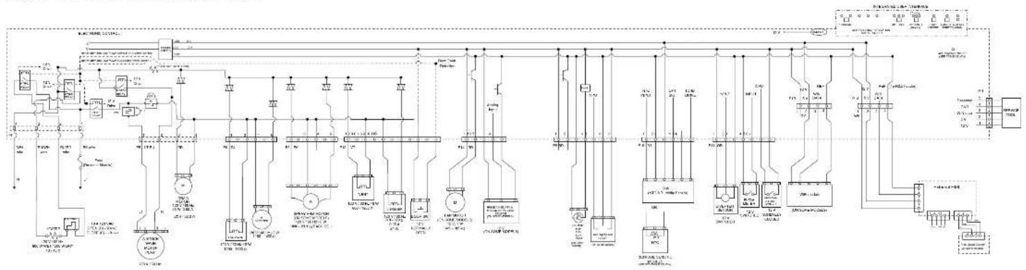
For Service Technician Use Only Wiring Diagram
IMPORTANT: Electrostatic discharge may cause damage to machine control electronics.
Check for proper voltage by completing the following steps:
- Unplug (product) or disconnect power.
- Connect voltage measurement equipment to proper connectors.
- Plug in (product) or reconnect power and confirm voltage reading.
- Unplug (product) or disconnect power.
Maytag ^® DW03G-P3 SS Rotating Inlet Filter
flowchart
graph TD
    A["AC/DC Power Supply"] --> B["AC/DC Generator"]
    B --> C["AC/DC Control Unit"]
    C --> D["Tanature"]
    D --> E["AC/DC Power Supply"]
    E --> F["AC/DC Generator"]
    F --> G["AC/DC Control Unit"]
    G --> H["Tanature"]
    H --> I["AC/DC Power Supply"]
    I --> J["AC/DC Generator"]
    J --> K["AC/DC Control Unit"]
    K --> L["Tanature"]
    L --> M["AC/DC Power Supply"]
    M --> N["AC/DC Generator"]
    N --> O["AC/DC Control Unit"]
    O --> P["Tanature"]
    P --> Q["AC/DC Power Supply"]
    Q --> R["AC/DC Generator"]
    R --> S["AC/DC Control Unit"]
    S --> T["Tanature"]
    T --> U["AC/DC Power Supply"]
    U --> V["AC/DC Generator"]
    V --> W["AC/DC Control Unit"]
    W --> X["Tanature"]
    X --> Y["AC/DC Power Supply"]
    Y --> Z["AC/DC Generator"]
COMPONENT TESTING (Cont.)
For Service Technician Use Only Wiring Diagram (Continued)
Whirlpool ^ and KitchenAid ^ Global Wash SS
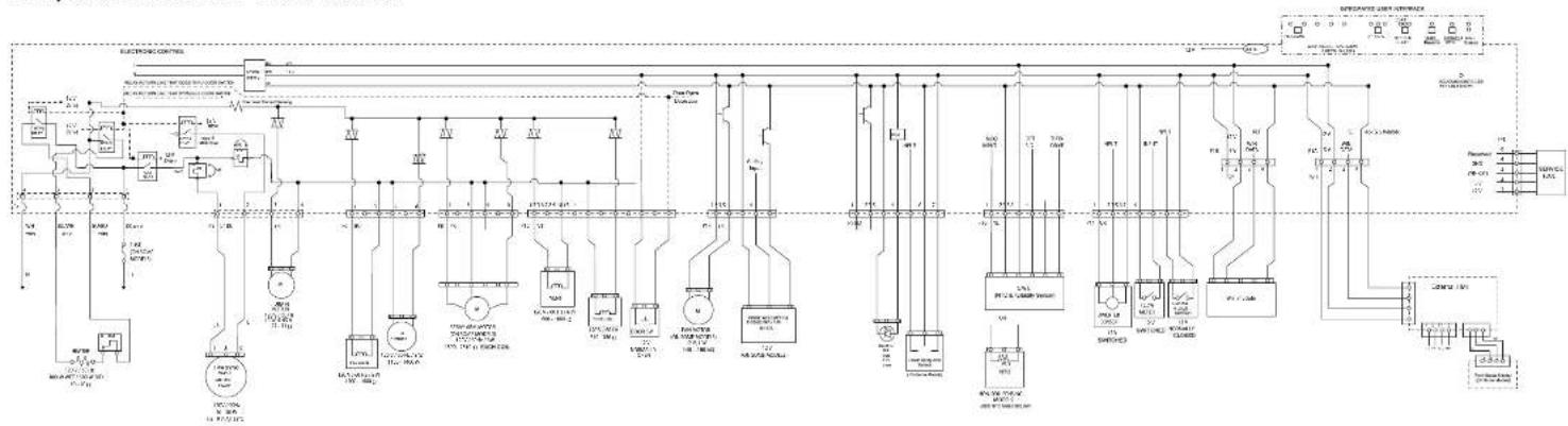
flowchart
graph TD
    A["Power Supply"] --> B["Branch 1"]
    B --> C["Transformer 1"]
    C --> D["Control Unit 1"]
    D --> E["Output"]
    style A fill:#f9f,stroke:#333
    style E fill:#ccf,stroke:#333
Whirlpool ^a and KitchenAid ^b VS Wash Motor
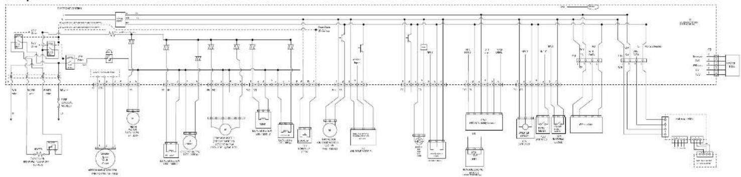
flowchart
graph TD
    A["Power Source"] --> B["Node 1"]
    A --> C["Node 2"]
    B --> D["Component 1"]
    C --> E["Component 2"]
    D --> F["Load 1"]
    D --> G["Load 2"]
    E --> H["Load 3"]
    F --> I["Control Unit"]
    G --> J["Control Unit"]
    H --> K["Output 1"]
    I --> L["Output 2"]
    J --> M["Output 3"]
    K --> N["External Control Unit"]
    L --> O["External Control Unit"]
    M --> P["External Control Unit"]
    N --> Q["External Control Unit"]
    O --> R["External Control Unit"]
    P --> S["External Control Unit"]
    Q --> T["External Control Unit"]
    R --> U["Output 4"]
    S --> V["Output 5"]
    T --> W["Output 6"]
    U --> X["Output 7"]
    V --> Y["Output 8"]
    W --> Z["Output 9"]
    X --> AA["Output 10"]
    Y --> AB["Output 11"]
    Z --> AC["External Control Unit"]
    AA --> AD["External Control Unit"]
    AB --> AE["External Control Unit"]
3-4 ■ Whirlpool® and KitchenAid® Filtration and Maytag® 24" Microfiltration Dishwashers
For Service Technician Use Only
! DANGER

Electrical Shock Hazard
Only authorized technicians should perform diagnostic voltage measurements.
After performing voltage measurements, disconnect power before servicing.
Failure to follow these instructions can result in death or electrical shock.
Control Board Information
Specifications
Electrical Supply: (Under Load): 60 Hz 120 VAC
Supply Water Flow Rate: To fill 2 qt (1.9 L) in 46 seconds, 120 psi maximum, 20 psi minimum.
Supply Water Temperature: 120°F (49°C) (Before starting a cycle, run water from sink faucet until hot.)
Water Charge: 1.0 gal. (3.9 L) Approximate
Lower Spray Arm Rotation: 12 to 40 RPM
Upper Spray Arm Rotation: 12 to 30 RPM
Fuse Service and Resistance Check
F500 = Small - TRIAC Load Fuse
Check operation of loads during the Service Diagnostics cycle.
■ If any of the TRIAC loads work, F500 Fuse is OK.
If all TRIAC loads fail to work, F500 Fuse could be open. See Fuse Resistance Check.
Fuse Resistance Check:
- Unplug the dishwasher or disconnect power.
- Measure resistance of F500 Fuse.
NOTE: Fuses are on the bottom of the Control Board but can be checked from the top side. See "Control Pin-out" diagram.
If resistance is < 3 Ω, then fuse is OK.
If resistance is > 3 Ω, then fuse is OPEN.
If the fuse is open:
Inspect and check resistance of all loads on fuse. If any loads are open, shorted, or have evidence of overheating or pinched wires, replace them.
Component Testing
Testing Dishwasher Components from the Control
Before testing any of the components, perform the following checks:
The most common cause for mis-diagnosed control failure is poor connections. Therefore, disconnecting, inspecting, and reconnecting wires will be necessary throughout test procedures.
All tests/checks should be made with a VOM or DVM having a sensitivity of 20,000 ohms-per-volt DC, or greater.
- Check all connections before replacing components, look for broken or loose wires, failed terminals, or wires not pressed into connectors far enough.
■ Voltage checks must be made with all connectors attached to the boards.
■ Resistance checks must be made with power cord unplugged or power disconnected, and with wiring harness or connectors disconnected from the control.
The testing procedures in this section may require the use of needle probes to measure voltage. Failure to use needle probes will damage the connectors.
For Service Technician Use Only
Electronic Control Board
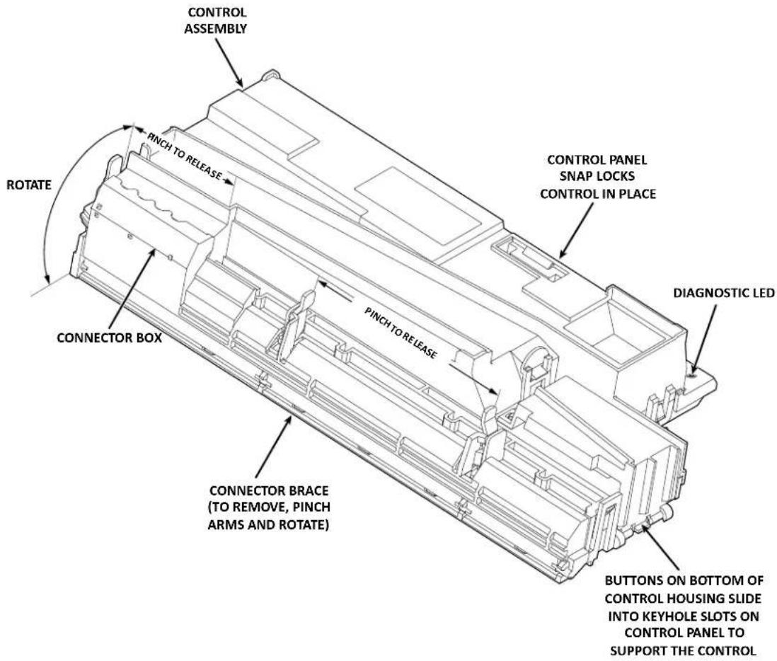
text_image
CONTROL ASSEMBLY PINCH TO RELEASE ROTATE CONNECTOR BOX CONNECTOR BRACE (TO REMOVE, PINCH ARMS AND ROTATE) PINCH TO RELEASE CONTROL PANEL SNAP LOCKS CONTROL IN PLACE DIAGNOSTIC LED BUTTONS ON BOTTOM OF CONTROL HOUSING SLIDE INTO KEYHOLE SLOTS ON CONTROL PANEL TO SUPPORT THE CONTROLMeter Check of Loads and Supplies
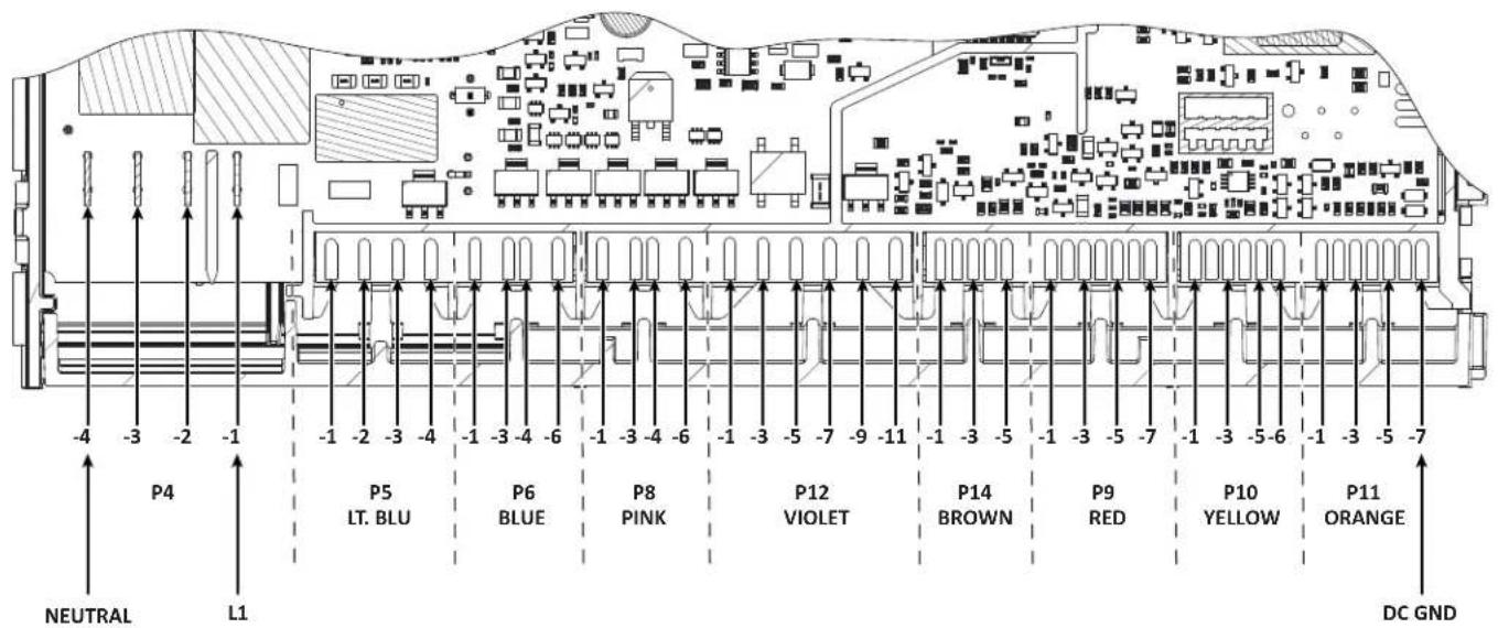
text_image
P4 -4 -3 -2 -1 P5 LT. BLU P6 BLUE P8 PINK P12 VIOLET P14 BROWN P9 RED P10 YELLOW P11 ORANGE NEUTRAL L1 DC GNDFor Service Technician Use Only
Electronic Control Board for Variable Speed Wash Motor Model
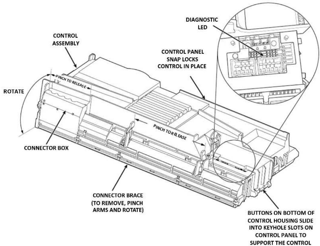
text_image
CONTROL ASSEMBLY PINCH TO RELEASE ROTATE CONNECTOR BOX CONNECTOR BRACE (TO REMOVE, PINCH ARMS AND ROTATE) PINCH TO RELEASE DIAGNOSTIC LED CONTROL PANEL SNAP LOCKS CONTROL IN PLACE BUTTONS ON BOTTOM OF CONTROL HOUSING SLIDE INTO KEYHOLE SLOTS ON CONTROL PANEL TO SUPPORT THE CONTROLMeter Check of Loads and Supplies
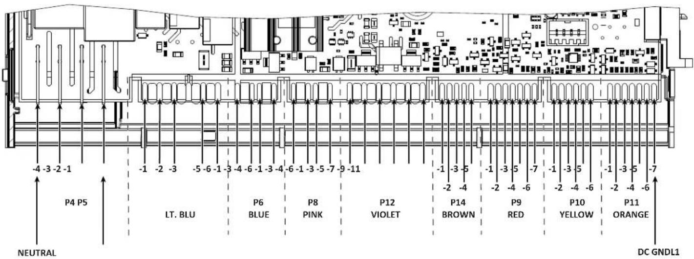
text_image
-4 -3 -2 -1 P4 P5 LT. BLU NEUTRAL -1 -2 -3 -5 -6 -1 -3 -4 -6 -1 -3 -4 -6 -1 -3 -5 -7 -9 -11 P6 BLUE P8 PINK P12 VIOLET -1 -3 -5 -2 -4 -1 -3 -5 -7 -1 -3 -5 -2 -4 -6 -2 -4 -6 P14 BROWN P9 RED P10 YELLOW P11 ORANGE DC GNDL1For Service Technician Use Only
General Theory of Operation
DANGER

Electrical Shock Hazard
Only authorized technicians should perform diagnostic voltage measurements.
After performing voltage measurements, disconnect power before servicing.
Failure to follow these instructions can result in death or electrical shock.
Refer to Wiring Diagram on page 3-3.
Neutral and L1 (AC voltage) enters the Control Board at P4, pins 4 and 1 respectively. AC is converted to DC voltage at the Low Volts Power Supply (LVPS). Supplies include 13 VDC and 5 VDC, and DC GND (REF). These low voltage supplies are used to provide power to the microprocessors and board components, control the TRIAC, power the sensors, user interface, buzzer, fan motor, and energize the AC relays.
The 13 VDC is vital to the operation of the dishwasher. This supply is necessary to operate all 120 VAC loads in the dishwasher, whether they are connected to a relay or controlled by TRIAC. 13 VDC is generated by the power supply and flows through the door switch-when closed-to be available to the heater relays (L1 and N), wash motor relay, and the pilot relay. A relay coil becomes energized when the control closes the LV drive circuit for a specific relay completing 13 V pathway, which in turn closes the relay switch providing AC to the load. The Pilot relay provides "L1" to the remainder of the components that are controlled by the Neutral-sensed TRIAC.
In the micro-filtration dishwasher, there are 2 or 3 fuses on the Control Board: F500 Small TRIAC Load Fuse, F101 Main Power Supply Fuse, and F501 Wash Motor Fuse. If the TRIAC Fuse is open, all loads controlled by TRIAC will not operate. If the Main Power Supply Fuse is open, no 5 V or 13 V supply will be available and the unit will appear to not power up. If the Wash Motor Fuse (optional) is open, all loads will work except the wash motor.
NOTE: Refer to "Fuse Service and Diagnostic Checks" on page 3-4.
Power Check
This test checks for incoming and outgoing power to and from the control board. This test assumes that proper voltages is present at the outlet or direct connect cable.
Test Procedure
- Unplug dishwasher or disconnect power.
- Remove access panel.
- Remove terminal box cover.
- With a voltmeter set to AC, place black probe on white terminal block screw head (N) and red probe on black terminal block screw head (L1).
- Plug in dishwasher or reconnect power.
If 120 VAC is present, unplug dishwasher or disconnect power and proceed to step 6.
If 120 VAC is not present, have customer correct power.
- Remove the outer door panel to access the control board.
- Remove cover from control board and locate connector P4.
- With a voltmeter set to AC, connect black probe to P4, pin 4 (N) and red probe to P4, pin 1 (L1).
- Plug in dishwasher or reconnect power.
If 120 VAC is present, go to step 10.
If 120 VAC is not present, check for open connection between terminal block and control. Repair as needed.
- Verify DC Supplies.
- 5 VDC is used to power IC's and micro-processors on the circuit board as well as provide power to the sensors.
If 5 VDC were missing, the OWI (Optical Water Indicator) and user interface would not function. To verify 5 V ± 5%, with a voltmeter set to DC, connect the black lead to P10-2 (DC GND) and the red lead to P11A-2 or P11B-2 (5 V).
- 13 VDC is used to actuate the 120 VAC relays and TRIAC on the control, the overfill switch input, and the LEDs on models with interior lighting.
If 13 VDC was missing, the heater, motors, and all the other loads would not turn on as well as the LEDs on models with interior lighting. The control would falsely detect an overfill fault. To verify 13 V ± 5% , with a voltmeter set to DC, connect the black lead to P10-2 (DC GND) and the red lead to P11-7 (13 V).
Troubleshooting Missing DC Supplies: Refer to the Wiring Diagram on page 3-3 when troubleshooting the DC supplies. If 5 VDC or 13 VDC is missing on the control, unplug dishwasher or disconnect power, and then disconnect all components/ loads from the control relying on the missing or loaded supply. Plug in dishwasher or reconnect power and check if the DC supply has returned.
If not, replace the control.
If it has, turn off dishwasher and reconnect one connector at a time until the component loading down that supply has been identified.
- Unplug dishwasher or disconnect power.
- Reassemble all parts and panels.
For Service Technician Use Only
! DANGER

Electrical Shock Hazard
Only authorized technicians should perform diagnostic voltage measurements.
After performing voltage measurements, disconnect power before servicing.
Failure to follow these instructions can result in death or electrical shock.
Door Switch Circuit
Perform the following checks if the dishwasher does not detect the door open or closed. This test will check the wiring to the door switch and the door switch itself. The following items are part of the door switch circuit:
■ Harness/Connection
■ Door Switch/Latch Assembly
Control Board
Test Procedure
- Check for improper installation of the dishwasher or leveling.
- Check door latch mechanism for obstructions or binding. Verify door seal is seated properly.
- Check for interference between dish racks and door. Repair as necessary.
- Unplug dishwasher or disconnect power.
-
Remove outer door panel to access door latch and remove toe and access panels to access control board.
-
Check door switch contacts and all connections in the door switch circuit. Visually check that the P12 connector on the control and the door latch connector are securely installed.
If visual check passes, go to step 5.
If any of the connectors are not inserted properly, reconnect and retest door latch/switch.
-
Disconnect connector P12 from the control board.
-
Using an ohmmeter, measure across P12, pins 9 and 11 with the door closed, strike completely in latch mechanism (switch closed).
If 3 ohms or less is measured, proceed to step 7.
If high resistance is measured when door is closed, check for loose connections and repair as needed.
- Using an ohmmeter, measure across P12, pins 9 and 11 with the door open, strike removed from latch mechanism (switch open).
If reading is infinite, go to step 8.
If reading shows continuity, or door switch is damaged, replace door switch and retest.
-
Set voltmeter to DC and connect red lead to test-pad P11-7 (13 V) and black lead to P10-2 (DC GND) on the control board.
-
Plug in dishwasher or reconnect power and with door open, verify that 13 VDC is present across P11-7 and P10-2.
If 13 VDC is not present, replace the control and retest.
If 13 VDC is present, proceed to step 10.
- Reconnect P12 to control board and perform Diagnostics Cycle to verify operation.
- Unplug dishwasher or disconnect power.
- Reassemble all parts and panels.
- Plug in dishwasher or reconnect power.
Strip Circuit - Door Switch
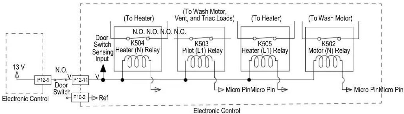
flowchart
graph LR
    A["Electronic Control"] --> B["P12-9"]
    B --> C["Door Switch"]
    C --> D["P12-11"]
    D --> E["P10-2"]
    E --> F["Ref"]
    F --> G["Door Switch Sensing Input"]
    G --> H["(To Heater)"]
    H --> I["K504 Heater (N) Relay"]
    I --> J["Micro Pin Micro Pin"]
    J --> K["(To Wash Motor, Vent, and Triac Loads)"]
    K --> L["K503 Pilot (L1) Relay"]
    L --> M["(To Heater)"]
    M --> N["K505 Heater (L1) Relay"]
    N --> O["Micro Pin Micro Pin"]
    O --> P["(To Wash Motor)"]
    P --> Q["K502 Motor (N) Relay"]
    Q --> R["Micro Pin Micro Pin"]
    R --> S["Electronic Control"]
For Service Technician Use Only
DANGER

Electrical Shock Hazard
Only authorized technicians should perform diagnostic voltage measurements.
After performing voltage measurements, disconnect power before servicing.
Failure to follow these instructions can result in death or electrical shock.
Fill Circuit
This test will check the wiring and components in the fill circuit. The following items are part of the fill circuit:
■ Harness/Connection
Fill Valve
■ Control Board
Test Procedure
- Verify water supply is turned on and supply line is adequate. Check for water siphoning out of the dishwasher (drain loop or improper drain connection). Check for debris in water line or fill valve inlet screen. Check for proper float switch operation. Repair as necessary.
- Are all the loads controlled by TRIAC not working?
➢ YES - check for open door switch, TRIAC fuse, or pilot relay.
NO - just the Fill Valve. Go to step 3.
- Unplug dishwasher or disconnect power.
- Remove toe and outer door panels to access control board.
- Unplug connector P6 from control board.
Strip Circuit - Fill Valve
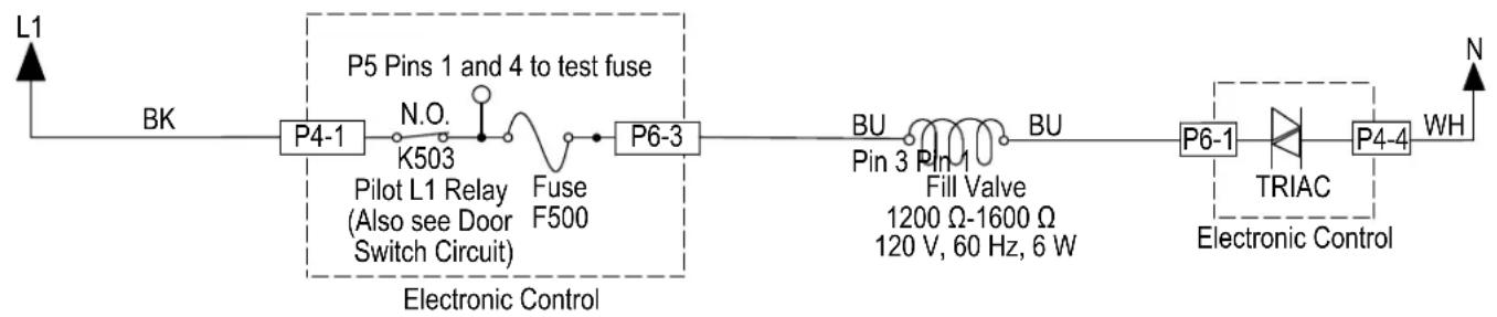
flowchart
graph LR
    L1 --> BK
    BK --> P4-1
    P4-1 --> N.O.
    N.O. --> K503
    K503 --> Pilot_L1_Relay[" Pilot L1 Relay (Also see Door Switch Circuit) "]
    Pilot_L1_Relay --> Fuse_F500
    Fuse_F500 --> P6-3
    P6-3 --> BU
    BU --> Pin_3
    Pin_3 --> Fill_1
    Fill_1 --> 1200Ω-1600Ω
    1200Ω-1600Ω
    120V, 60Hz, 6W
    P6-1 --> TRIAC
    TRIAC --> P4-4
    P4-4 --> WH
    WH --> N
    style P5 Pins_1 and_P6-3 fill:#f9f,stroke:#333,stroke-width:2px
    style P6-3 fill:#ccf,stroke:#333,stroke-width:2px
    style P4-1 fill:#cfc,stroke:#333,stroke-width:2px
    style P6-3 fill:#fcc,stroke:#333,stroke-width:2px
    style P6-1 fill:#ffc,stroke:#333,stroke-width:2px
    style TRIAC fill:#cfc,stroke:#333,stroke-width:2px
    style P4-4 fill:#fcc,stroke:#333,stroke-width:2px
- Check the fill valve and harness-using an ohmmeter, measure the resistance between P6-1 and P6-3.
If the resistance is between 1200-1600 ohms, the fill valve and harness are good. Go to step 7.
If outside the range, replace the fill valve.
If an open circuit is detected, check connections and harness continuity between control and fill valve. If good, replace the fill valve.
- Reconnect P6 to control board.
- Set voltmeter to AC and connect leads to test-pads P6-1 and P6-3 on the control board. Plug in dishwasher or reconnect power.
- Start the Diagnostics Cycle and at the proper interval measure for AC out of the control board between test-pads P6-1 and P6-3 (Refer to the Fill Valve Strip Circuit below).
IMPORTANT: The Fill Valve must be connected to the control board to measure voltage accurately.
If no AC voltage is measured, replace the control board and retest.
If 120 VAC is measured and fill valve is energized, go to step 12.
- Unplug dishwasher or disconnect power.
- Reassemble all parts and panels.
- Plug in dishwasher or reconnect power and run Diagnostics Cycle to verify repair.
For Service Technician Use Only
DANGER

Electrical Shock Hazard
Only authorized technicians should perform diagnostic voltage measurements.
After performing voltage measurements, disconnect power before servicing.
Failure to follow these instructions can result in death or electrical shock.
Dispenser Circuit
This test will check the wiring to the dispenser and the dispenser solenoid itself. The following items are part of the dispenser circuit:
■ Harness/Connection
■ Dispenser Solenoid
Control Board
Test Procedure
- Check for obstructions or mechanical binding preventing the dispenser lid from opening. Repair or replace as necessary.
- Are all the loads controlled by TRIAC not working?
➢ YES - check for open door switch, TRIAC fuse, or pilot relay.
NO - just the Dispenser. Go to step 3.
- Unplug dishwasher or disconnect power.
- Remove outer door panel to access dispenser and remove toe and outer door panels to access control board.
- Unplug connector P12 from control board.
- Remove outer door panel to access dispenser and remove toe and outer door panels to access control board.
-
Unplug connector P12 from control board.
-
Check the dispenser solenoid and harness-using an ohmmeter, measure the resistance between P12-5 and P12-7.
Solenoid:
If the resistance is between 310-380 ohms, the solenoid valve and harness are good. Go to step 7.
If outside the range, replace the dispenser solenoid.
If an open circuit is detected, check connections and harness continuity between control and dispenser. If good, replace the dispenser solenoid.
- Reconnect P12 to control board.
- Set voltmeter to AC and connect leads to test-pads P12-5 and P12-7 on the control board. Plug in dishwasher or reconnect power.
- Start the Diagnostics Cycle and at the proper interval measure for AC out of the control board between P12-5 to P12-7 (Refer to the Dispenser Strip Circuit below).
IMPORTANT: The Dispenser Solenoid must be connected to the control board to measure voltage accurately.
If no AC voltage is measured, replace the control board and retest.
If 120 VAC is measured and dispenser motor/solenoid is energized, go to step 10.
- Unplug dishwasher or disconnect power.
- Reassemble all parts and panels.
- Plug in dishwasher or reconnect power and run Diagnostics Cycle to verify repair.
Strip Circuit -Dispenser
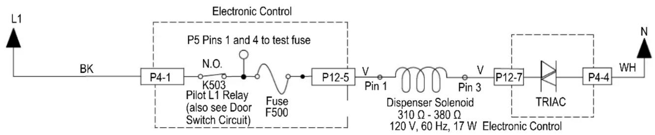
flowchart
graph LR
    L1 --> BK
    BK --> P4-1
    P4-1 --> K503
    K503 --> Pilot_L1_Relay[" Pilot L1 Relay (also see Door Switch Circuit) "]
    Pilot_L1_Relay --> Fuse_F500
    Fuse_F500 --> P12-5
    P12-5 --> Pin_1
    Pin_1 --> Dispenser_Solenoid[" Dispenser Solenoid 310 Ω - 380 Ω, 120 V, 60 Hz, 17 W Electronic Control "]
    Pin_1 --> Pin_3
    Pin_3 --> P12-7
    P12-7 --> TRIAC
    TRIAC --> P4-4
    P4-4 --> WH
    P5["Pins 1 and 4 to test fuse"] --> P5
    style P5 fill:#f9f,stroke:#333
    style P12-5 fill:#ccf,stroke:#333
    style P12-7 fill:#cfc,stroke:#333
    style TRIAC fill:#fcc,stroke:#333
For Service Technician Use Only
DANGER

Electrical Shock Hazard
Only authorized technicians should perform diagnostic voltage measurements.
After performing voltage measurements, disconnect power before servicing.
Failure to follow these instructions can result in death or electrical shock.
Water Heating/Heat Dry
This test will check the wiring to the heater element, hi-limit thermostat and the heating circuit itself. The following items are part of the heater circuit:
■ Harness/Connection
Heater Coil
■ Hi Limit Thermostat
Control Board
Test Procedure
Control is programmed to disable the heater if it detects a problem with the heating system. This check is performed at the start of a heating period in each cycle. If heating problem is not corrected, the control will disable the heater again.
- Unplug dishwasher or disconnect power.
- Remove toe and access panels to outer door control board.
- Disconnect P4 from the control board.
Strip Circuit - Heater Circuit
- Using an ohmmeter, measure resistance between P4, pins 2 and 3.
If the resistance is between 10-40 ohms, go to step 6.
If an open circuit is detected, go to step 5.
- Visually check the wire connections between the control board, the heater element and the hi-limit thermostat. If the connections look good, check for continuity across the heater element and the hi-limit.
➢ Replace heater element or hi-limit thermostat if it is electrically open.
Repair or replace wire harness if test fails continuity.
- Reconnect P4 to control board.
- Set voltmeter to AC and connect leads to test-pads P4-2 and P4-3 on the control board. Plug in dishwasher or reconnect power.
- Start the Diagnostics Cycle and at the proper interval measure for AC out of the control board between P4-2 and P4-3 using a voltmeter set to AC.
If 120 VAC is measured and heater element is on, go to step 9.
If no AC voltage is measured, replace control board.
- Perform Diagnostics Cycle to verify repair.
If heater related error still exists, perform Water Sensing test procedure on following page.
-
Unplug dishwasher or disconnect power.
-
Reassemble all parts and panels.
- Plug in dishwasher or reconnect power.
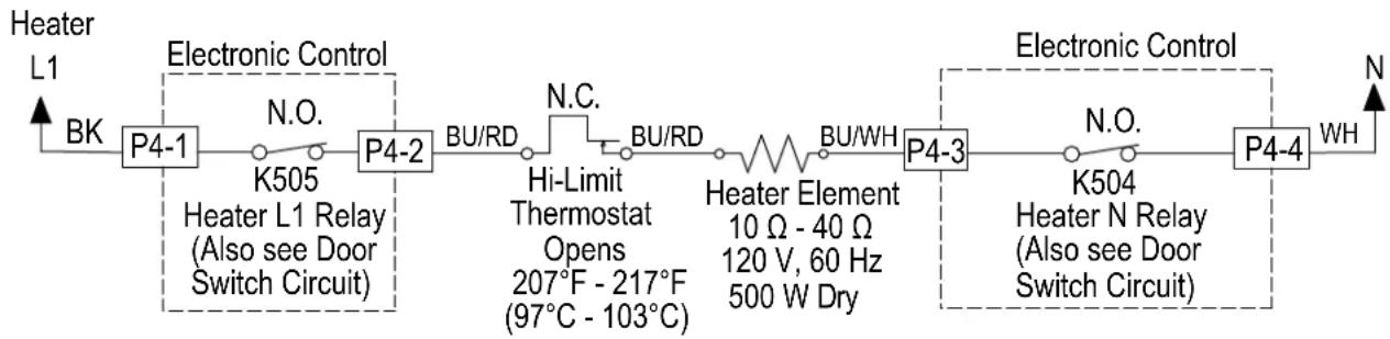
flowchart
graph LR
    A["Heater L1"] -->|BK| B["P4-1"]
    B --> C["K505"]
    C --> D["Heater L1 Relay (Also see Door Switch Circuit)"]
    D --> E["P4-2"]
    E --> F["BU/RD"]
    F --> G["N.C."]
    G --> H["Hi-Limit Thermostat Opens 207°F - 217°F (97°C - 103°C)"]
    H --> I["BU/RD"]
    I --> J["Heater Element 10 Ω - 40 Ω 120 V, 60 Hz 500 W Dry"]
    J --> K["BU/WH"]
    K --> L["P4-3"]
    L --> M["K504"]
    M --> N["Heater N Relay (Also see Door Switch Circuit)"]
    N --> O["P4-4"]
    O --> P["WH"]
    style A fill:#f9f,stroke:#333
    style P fill:#f9f,stroke:#333
For Service Technician Use Only
DANGER

Electrical Shock Hazard
Only authorized technicians should perform diagnostic voltage measurements.
After performing voltage measurements, disconnect power before servicing.
Failure to follow these instructions can result in death or electrical shock.
Water Sensing with the OWI Sensor
This test will check the wiring to the OWI (Optical Water Indicator), which incorporates the temperature thermistor and the foam and turbidity sensor. The following items are part of the water sensing circuit:
■ Harness/Connection
OWI Sensor
Control Board
Test Procedure
- Check the operation of the OWI Sensor in the Service Diagnostics Cycle.
- Unplug dishwasher or disconnect power.
- Remove toe and access panels to access control board.
- Disconnect P10 from the Control Board.
- Using an ohmmeter, measure resistance between P10, pins 1 and 3. The following table provides approximate room and hot water temperatures and their associated resistance values.
| Temp °C (°F) RES Range kΩ (ohms) | |
| 20 (68) 57.3 - 60.3 | |
| 25 (77) 45.9 - 48.1 | |
| 30 (86) 37.0 - 38.7 | |
| 35 (95) 30.1 - 31.3 | |
| Temp °C (°F) RES Range kΩ (ohms) | |
| 40 (104) 24.6 - 25.4 | |
| 45 (113) 20.2 - 20.8 | |
| 50 (122) 16.7 - 17.1 | |
| 55 (131) 13.9 - 14.2 | |
| 60 (140) 11.6 - 11.8 | |
| 65 (149) 9.7 - 9.9 | |
| 70 (158) 8.2 - 8.4 | |
NOTE: All thermistor resistance measurements must be made while dishwasher is unplugged or disconnected from power and connector P10 removed from control.
If the thermistor resistance is OK, the thermistor is good. Go to step 6.
If the thermistor resistance does not agree with the table, replace the OWI Sensor.
If an open circuit is detected, check connections and harness continuity between control and OWI. If good, replace the OWI Sensor.
- Using an ohmmeter, check P10-1 to cabinet ground and P10-3 to cabinet ground.
If no short is indicated, go to step 7.
If either pin indicates continuity to ground (short), repair or replace wiring harness and retest.
- Reconnect P10 to control board.
- Test for 5 VDC with a voltmeter set to DC, connect the black lead to P10-2 and the red lead to P10-3.
- Plug in dishwasher or reconnect power.
- Start the Diagnostics Cycle and at the proper interval measure for 5 VDC out of the control board between P10-2 and P10-3.
If 5 VDC is measured the control is functioning, go to step 11.
If no DC voltage is measured, replace the control board and retest.
- Unplug dishwasher or disconnect power.
- Reassemble all parts and panels.
- Plug in dishwasher or reconnect power and run Diagnostics Cycle to verify repair.
Strip Circuit - Water Sensing
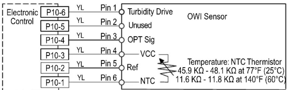
flowchart
graph TD
    A["Electronic Control"] --> B["P10-6"]
    B --> C["YL Pin 1"]
    C --> D["Turbidity Drive"]
    D --> E["Unused"]
    E --> F["P10-5"]
    F --> G["YL Pin 2"]
    G --> H["Pin 2"]
    H --> I["OPT Sig"]
    I --> J["P10-4"]
    J --> K["YL Pin 3"]
    K --> L["Pin 3"]
    L --> M["VCC"]
    M --> N["P10-3"]
    N --> O["YL Pin 4"]
    O --> P["Ref"]
    P --> Q["VCC"]
    Q --> R["P10-2"]
    R --> S["YL Pin 5"]
    S --> T["NTC"]
    T --> U["P10-1"]
    U --> V["YL Pin 6"]
    V --> W["NTC"]
    W --> X["Temperature: NTC Thermistor\n45.9 KΩ - 48.1 KΩ at 77°F (25°C)\n11.6 KΩ - 11.8 KΩ at 140°F (60°C)"]
Measure NTC resistance at P10-1 and
P10-3 connector disconnected from control.
For Service Technician Use Only
DANGER

Electrical Shock Hazard
Only authorized technicians should perform diagnostic voltage measurements.
After performing voltage measurements, disconnect power before servicing.
Failure to follow these instructions can result in death or electrical shock.
Overfill Switch Circuit
Perform the following checks if the dishwasher detects F8E4 when there is no water in the leak pan, or if F8E4 is not detected when water is present in the leak pan. The following items are part of the overfill switch circuit:
■ Harness/Connection
■ Overfill Switch/Float Assembly
Control Board
Test Procedure
- Unplug dishwasher or disconnect power.
- Remove toe and outer door panels to access leak pan and control board.
- Check leak pan for water. If no water is present, go to step 5. If leak pan is full of water, unplug float switch, remove pan and empty. Replace pan and reconnect float switch.
- Reconnect power. If F8E4 fault does not return, find source of leak and repair.
NOTE: If root cause of overfill is not corrected, customer will experience another overfill and service call in the future.
- Inspect float assembly. Verify that connector is fully seated. Ensure that Styrofoam floater moves freely up and down and no debris is preventing it from sitting in the down (closed) position.
■ If no issue found, go to step 6.
■ Repair/reconnect if any issues found.
-
Disconnect connector P11 from control board.
-
Using an Ohmmeter, measure across P11 pins 6 and 7 with the float assembly connected and installed in the leak pan.
■ If 3 ohms or less is measured, go to step 8.
■ If high resistance is measured, check for loose connections and repair/replace as needed.
- Using an Ohmmeter, measure across P11 pins 6 and 7 with the Styrofoam floater lifted up (switch should be open).
■ If reading is infinite, go to step 9.
■ If reading shows continuity, replace float assembly and retest.
-
Set meter to DC and connect leads to P11 pins 6 and 7.
-
Plug in dishwasher or reconnect power and verify that 13 VDC is present across P11 pins 6 and 7 with P11 disconnected from the board.
■ If 13 VDC is not present, replace the control and retest.
■ If 13 VDC is present, proceed to step 10.
-
Reconnect P11 to control board and run Diagnostics cycle to confirm operation.
-
Reassemble all parts and panels. Ensure that float assembly is connected, seated in leak tray, and tray is reinstalled.
-
Plug in dishwasher or reconnect power.
Strip Circuit - Overfill Switch
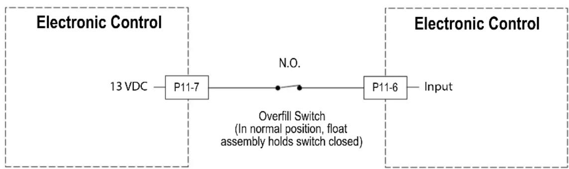
flowchart
graph LR
    A["13 VDC"] --> B["P11-7"]
    B --> C["Overfill Switch\n(In normal position, float assembly holds switch closed)"]
    C --> D["P11-6"]
    D --> E["Input"]
    style A fill:#f9f,stroke:#333
    style B fill:#ccf,stroke:#333
    style C fill:#cfc,stroke:#333
    style D fill:#fcc,stroke:#333
    style E fill:#ffc,stroke:#333
For Service Technician Use Only
! DANGER

Electrical Shock Hazard
Only authorized technicians should perform diagnostic voltage measurements.
After performing voltage measurements, disconnect power before servicing.
Failure to follow these instructions can result in death or electrical shock.
Diverter Motor
This test will check the wiring to the diverter motor and the diverter motor itself. The following items are part of the diverter motor circuit:
■ Harness/Connection
■ Divverter Motor
■ Diverter Position Switch (see test on following page)
■ Control Board
Test Procedure
- Check for operation in Diagnostics Cycle. Listen for water spray changing zones or inspect shaft with mirror to see it rotating during diverter interval. If diverter is rotating, the likely problem is with the diverter sensor (see test procedure on following page). Verify that diverter disk is properly installed on shaft.
- Are all the loads controlled by TRIAC not working?
➢ YES - check for open door switch, TRIAC fuse, or pilot relay.
NO - just the diverter valve. Go to step 3.
- Unplug dishwasher or disconnect power.
- Remove toe and access panels to access control board.
- Unplug connector P6 from control board.
- Check the diverter motor using an ohmmeter, measure the resistance between P6-4 and P6-6.
If the resistance is between 1100-1400 ohms, the diverter motor and harness are good. Go to step 7.
If outside the range, replace the diverter assembly.
If an open circuit is detected, check connections and harness continuity between control and diverter assembly. If good, replace the diverter assembly.
- Reconnect P6 to control board.
- Set voltmeter to AC and connect leads to test-pads P6-4 and P6-6 on the control board. Plug in dishwasher or reconnect power.
- Start the Diagnostics Cycle and at the proper interval measure for AC out of the control board between P6-4 and P6-6 (Refer to Diverter Motor Strip Circuit below).
IMPORTANT: The Diverter Motor must be connected to the control board to measure voltage accurately.
If no AC voltage is measured, replace the control board and retest.
If 120 VAC is measured and diverter is rotating, go to step 10.
- Perform Diagnostics Cycle to verify repair.
If diverter error still exists, perform diverter sensor test procedure on following page.
- Unplug dishwasher or disconnect power.
- Reassemble all parts and panels.
- Plug in dishwasher or reconnect power.
Strip Circuit - Divverter Motor
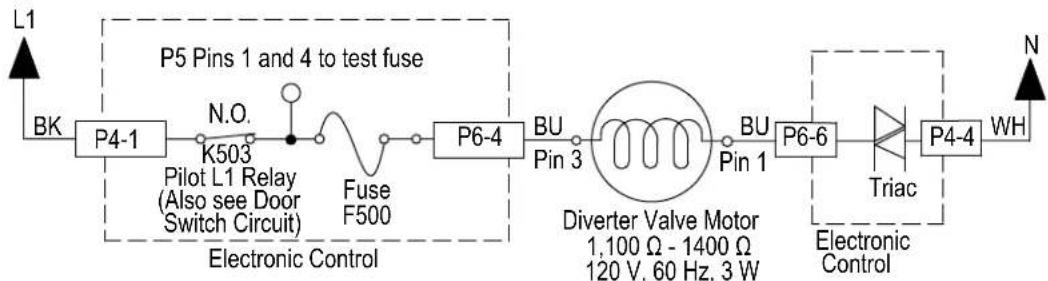
flowchart
graph LR
    L1 --> BK
    BK --> P4-1
    P4-1 --> N.O.
    N.O. --> K503
    K503 --> Pilot_L1_Relay[" Pilot L1 Relay (Also see Door Switch Circuit) "]
    Pilot_L1_Relay --> Fuse_F500
    Fuse_F500 --> P6-4
    P6-4 --> BU_Pin_3
    BU_Pin_3 --> Diverter_Diverter_Valve_Motor[" Diverter Valve Motor 1,100 Ω - 1400 Ω 120 V, 60 Hz, 3 W "]
    Diverter_Diverter_Valve_Motor --> BU_Pin_1
    BU_Pin_1 --> P6-6
    P6-6 --> Triac["Triac"]
    Triac --> P4-4
    P4-4 --> WH
    WH --> N
    style P5 Pins_1 and_4 to test fuse fill:#f9f,stroke:#333
    style P6-4 fill:#ccf,stroke:#333
    style Diverter_Diverter_Valve_Motor fill:#cfc,stroke:#333
    style Triac fill:#fcc,stroke:#333
For Service Technician Use Only
DANGER

Electrical Shock Hazard
Only authorized technicians should perform diagnostic voltage measurements.
After performing voltage measurements, disconnect power before servicing.
Failure to follow these instructions can result in death or electrical shock.
Diverter Position Optical Sensor
This test will check the wiring to the diverter sensor/position sensor and the diverter assembly itself. The following items are part of the diverter sensor/switch circuit:
■ Harness/Connection
■ Diverter Motor (see test on previous page)
■ Diverter Position Optical Sensor
Control Board
Test Procedure
-
Check the operation of the diverter motor in the Service Diagnostics Cycle. You should be able to "hear" the water spraying from different spray arms as the diverter rotates through the various wash zones.
-
If the diverter is diverting the flow of water to the wash zones, the diverter motor is working-continue to step 3. If not, perform the diverter motor test procedure on the preceding page.
-
Unplug dishwasher or disconnect power.
-
Remove toe and outer door panels to access control board.
-
Visually check that the diverter position switch connector and P11 connector on the control are securely installed.
If visual check passes, go to step 6.
If any of the connectors are not inserted properly, reconnect and retest diverter position switch.
- Check continuity of harness between diverter position switch and P11 on control.
If continuity test is good, continue to step 7.
If continuity test fails, repair or replace harness as needed.
-
To test diverter switch, set up voltmeter for DC voltage and connect red lead to P11-2 and black lead to P10-2.
-
Plug in dishwasher or reconnect power.
-
Run the Service Diagnostics Cycle as stated in Step 1, and you should observe the diverter position switch closing momentarily and then reopening as it reaches each potential position. DC voltage should vary from approximately 0 V to 8-10 V as the diverter rotates and the sensor detects positions. Monitor for several intervals of the Service Diagnostics Cycle to observe behavior.
If the sensor is functioning normally (Voltage is varying as diverter rotates), proceed to step 10.
If sensor does not detect positions properly, or voltage is consistently at 0 V or 8-10 V and does not change, then replace diverter assembly and retest.
-
If the preceding steps did not correct the diverter/position switch problem, replace the control board and retest.
-
Reassemble all parts and panels.
-
Plug in dishwasher or reconnect power and run Diagnostics Cycle to verify repair.
Strip Circuit - Divverter Switch
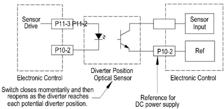
flowchart
graph TD
    A["Sensor Drive"] --> B["P11-3"]
    B --> C["P11-2"]
    C --> D["Diverter Position Optical Sensor"]
    D --> E["P10-2"]
    E --> F["P10-2"]
    F --> G["Sensor Input"]
    F --> H["Ref"]
    I["Reference for DC power supply"] --> J["Diverter Position Optical Sensor"]
    J --> K["Switch closes momentarily and then reopens as the diverter reaches each potential diverter position."]
    style A fill:#f9f,stroke:#333
    style B fill:#ccf,stroke:#333
    style C fill:#cfc,stroke:#333
    style D fill:#fcc,stroke:#333
    style E fill:#cff,stroke:#333
    style F fill:#ffc,stroke:#333
    style G fill:#fcc,stroke:#333
    style H fill:#fcc,stroke:#333
    style I fill:#fff,stroke:#333
    style J fill:#fff,stroke:#333
    style K fill:#fff,stroke:#333
For Service Technician Use Only
! DANGER

Electrical Shock Hazard
Only authorized technicians should perform diagnostic voltage measurements.
After performing voltage measurements, disconnect power before servicing.
Failure to follow these instructions can result in death or electrical shock.
Wash Motor RIF
This test will check the wiring to the wash motor and the wash motor itself. The following items are part of the wash motor circuit:
■ Harness/Connection
■ Wash Motor and Capacitor
Control Board
■ Wash motor fuse (Some models)
Test Procedure
- Check the tube and sump for anything that may be impeding water flow. Inspect and if necessary clean the coarse-filter system. Also, inspect spray arm water nozzles and clean if needed.
- Check the wash motor and electrical connections by performing the Service Diagnostics Cycle. The following steps assume that this step was unsuccessful.
- Unplug dishwasher or disconnect power.
- Remove toe and outer door panels to access control board.
- Unplug connector P5 from control board.
-
Check the wash motor using an ohmmeter, measure the resistance between P5-1 and P5-2.
If the resistance is between 10-15 ohms, the wash motor and harness are good. Go to step 7.
If outside the range, replace the wash motor.
If an open circuit is detected, check connections and harness continuity between control and wash motor. If good, replace the wash motor. -
Check the motor fuse (Some models). Using an ohmmeter, measure the resistance between P5-1 and P5-4 on the control.
If the resistance is less than 3 ohms, fuse is good. Go to step 8.
If the resistance is greater than 3 ohms, replace the control.
-
Reconnect P5 to control board.
-
Set voltmeter to AC and connect leads to test-pads.
-
P5-1 and P5-2 on the control board. Plug in dishwasher or reconnect power.
-
Start the Diagnostics Cycle and at the proper interval measure for AC out of the control board between P5-1 and P5-2 (Refer to Wash Motor Strip Circuit below).
If no AC voltage is measured, replace the control board and retest.
If 120 VAC is measured and wash motor is running, go to step 12.
If 120 VAC is measured and wash motor is not running, go to step 10.
- Test the wash motor capacitor.
NOTE: A faulty capacitor may cause the motor to "hum", not start, or start slowly.
A. Discharge the capacitor by touching the leads of a 20,000 ohms resistor to the two terminals.
B. Disconnect the wires from the capacitor terminals.
C. With an ohmmeter, measure across the terminals and note reading.
If a steady increase in resistance is noted, capacitor is good. Replace wash motor assembly and retest.
If the capacitor is either shorted or open, replace capacitor and retest.
If the preceding steps did not correct the wash motor problem, replace the control board.
-
Unplug dishwasher or disconnect power.
-
Reassemble all parts and panels.
-
Plug in dishwasher or reconnect power and run Diagnostics Cycle to verify repair.
Strip Circuit - Wash Motor RIF
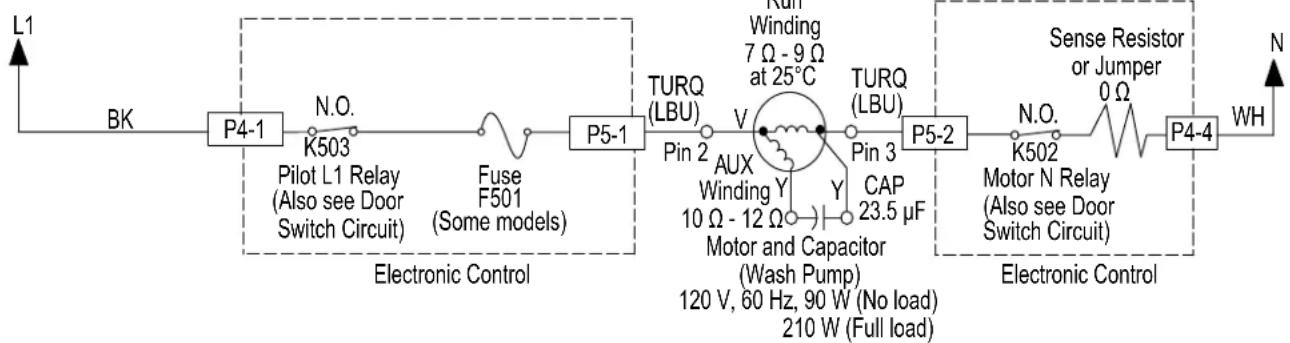
flowchart
graph LR
    L1 --> BK
    BK --> P4-1
    P4-1 --> K503
    K503 --> Pilot_L1_Relay[" Pilot L1 Relay (Also see Door Switch Circuit) "]
    Pilot_L1_Relay --> Fuse_F501
    Fuse_F501 --> F5-1
    F5-1 --> P5-1
    P5-1 --> TURQ_LBU
    TURQ_LBU --> Pin2
    Pin2 --> V
    V --> AUX_Winding
    AUX_Winding --> MotorCapacitor
    MotorCapacitor --> Y
    Y --> 23.5µF
    Y --> 10Ω-12Ω
    Y --> 120V,60Hz,90W
    Y --> 210W
    V --> Winding
    Winding --> 7Ω-9Ω at 25°C
    7Ω-9Ω at 25°C --> TURQ_LBU
    TURQ_LBU --> Pin3
    Pin3 --> CAP
    CAP --> 23.5µF
    23.5µF --> MotorCapacitor
    MotorCapacitor --> Y
    Y --> 10Ω-12Ω
    Y --> 120V,60Hz,90W
    120V,60Hz,90W --> 210W
    210W --> FullLoad[" Full load "]
    FullLoad --> SenseResistor
    SenseResistor --> Motor_N_Relay[" Motor N Relay (Also see Door Switch Circuit) "]
    Motor_N_Relay --> 0Ω
    Motor_N_Relay --> 0Ω
    SenseResistor --> SenseResistor
    SenseResistor --> WH
    WH --> N
For Service Technician Use Only
DANGER

Electrical Shock Hazard
Only authorized technicians should perform diagnostic voltage measurements.
After performing voltage measurements, disconnect power before servicing.
Failure to follow these instructions can result in death or electrical shock.
Global Wash Motor SSM
This test will check the wiring to the wash motor and the wash motor itself. The following items are part of the wash motor circuit:
■ Harness/Connection
■ Wash Motor
Control Board
■ Wash Motor Fuse (Some Models)
Test Procedure
- Check the tube and sump for anything that may be impeding water flow. Inspect and if necessary clean the coarse-filter system. Also inspect spray arm and nozzle and clean if needed.
- Check the wash motor and electrical connections by performing the Service Diagnostics Cycle. The following steps assume that this step was unsuccessful.
-
Unplug power or disconnect dishwasher.
-
Remove toe and outer door panels to access control board.
- Unplug connector P5 from control board.
- Check the wash motor using an ohmmeter, measure the resistance between P5-1 and P5-2.
If the resistance is between 7-12 ohms, the wash motor and harness are good. Go to step 7.
If outside the range, replace the wash motor.
If an open circuit is detected, check connections and harness continuity between control and wash motor. If good, replace the wash motor.
- Check the wash motor fuse (some models). Using an ohmmeter, measure the resistance between P5-1 and P5-4.
If the resistance is less than 3 ohms, fuse is good. Go to step 8.
➢ If the resistance is greater than 3 ohms, replace the control.
- Reconnect P5 to control board.
- Set voltmeter to AC and connect leads to test-pads P5-1 and P5-2 on the control board. Plug in dishwasher or reconnect power.
- Start the Diagnostics Cycle and at the proper interval measure for AC out of the control board between P5-1 and P5-2 (Refer to Wash Motor Strip Circuit below).
If no AC voltage is measured, replace the control board and retest.
If 120 VAC is measured and wash motor is running, go to step 11.
If 120 VAC is measured and wash motor is not running, go to step 9.
- Unplug dishwasher or disconnect power.
- Reassemble all parts and panels.
- Plug in dishwasher or reconnect power and run Diagnostics Cycle to verify repair.
Strip Circuit - Single Speed Wash Motor
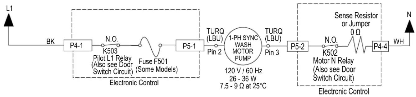
flowchart
graph LR
    L1 --> BK
    BK --> P4-1
    P4-1 --> N.O.
    N.O. --> K503
    K503 --> Pilot_L1_Relay[" Pilot L1 Relay (Also see Door Switch Circuit) "]
    Pilot_L1_Relay --> FuseF501
    FuseF501 --> P5-1
    P5-1 --> TURQ_LBU
    TURQ_LBU --> Pin2
    Pin2 --> 1PH_SYNC["WASH MOTOR PUMP"]
    1PH_SYNC --> TURQ_LBU
    TURQ_LBU --> Pin3
    Pin3 --> P5-2
    P5-2 --> N.O.
    N.O. --> Motor_N_Relay[" Motor N Relay (Also see Door Switch Circuit) "]
    Motor_N_Relay --> 0Ω
    0Ω --> 0
    0Ω --> 0
    0Ω --> 0
    0Ω --> WH
    WH --> N
    Electronic_Control[" Electronic Control "]
    120V/60Hz[" 120 V / 60 Hz "]
    26-36W[" 26 - 36 W "]
    7.5-9Ω[ 7.5 - 9 Ω at 25°C ]
For Service Technician Use Only
DANGER

Electrical Shock Hazard
Only authorized technicians should perform diagnostic voltage measurements.
After performing voltage measurements, disconnect power before servicing.
Failure to follow these instructions can result in death or electrical shock.
- Unplug power or disconnect dishwasher.
- Remove toe and outer door panels to access control board.
- Unplug connector P5 from control board.
- Check the wash motor using an ohmmeter, measure the resistance between P5-1 and P5-2.
If the resistance is between 16-18 ohms, the wash motor and harness are good. Go to step 7.
If outside the range, replace the wash motor.
If an open circuit is detected, check connections and harness continuity between control and wash motor. If good, replace the wash motor.
-
Reassemble all parts and panels.
-
Plug in dishwasher or reconnect power and run Diagnostics Cycle to verify repair.
Global Wash Motor VSM
This test will check the wiring to the wash motor and the wash motor itself. The following items are part of the wash motor circuit:
■ Harness/Connection
Wash Motor
Control Board
Test Procedure
- Check the tube and sump for anything that may be impeding water flow. Inspect and if necessary clean the coarse-filter system. Also inspect spray arm and nozzle and clean if needed.
- Check the wash motor and electrical connections by performing the Service Diagnostics Cycle. The following steps assume that this step was unsuccessful.
Strip Circuit - Variable Speed Wash Motor
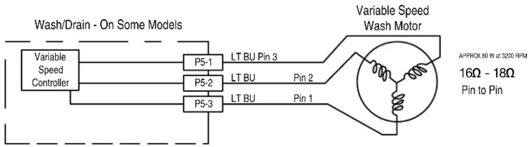
flowchart
graph LR
    A["Variable Speed Controller"] --> B["P5-1"]
    A --> C["P5-2"]
    A --> D["P5-3"]
    B --> E["LT BU Pin 3"]
    C --> F["LT BU Pin 2"]
    D --> G["LT BU Pin 1"]
    H["Variable Speed Wash Motor"] --> I["APPROX 60 W at 3200 RPM\n16Ω - 18Ω\nPin to Pin"]
For Service Technician Use Only
DANGER

Electrical Shock Hazard
Only authorized technicians should perform diagnostic voltage measurements.
After performing voltage measurements, disconnect power before servicing.
Failure to follow these instructions can result in death or electrical shock.
Drain Motor with RIF or SSM
This test will check the wiring to the drain motor and the drain motor itself. The following items are part of the drain motor circuit:
■ Harness/Connection
Drain Motor
Control Board
Test Procedure
- Verify that drain hose or drain path is not obstructed. Check for blockage from sump check valve to customer's plumbing. Check for plugged garbage disposal or disposal plug not knocked out. Check drain loop, stuck check valve, or for plugged hoses. Repair as needed.
- Check the drain motor and electrical connections by performing the Service Diagnostics Cycle. The following steps assume that this step was unsuccessful.
- Are all the loads controlled by TRIAC not working?
➢ YES - check for open door switch, TRIAC fuse, or pilot relay.
NO - just the drain motor. Go to step 4.
- Unplug dishwasher or disconnect power.
- Remove toe and outer door panels to access control board.
Strip Circuit -Drain Motor with RIF or SSM

flowchart
graph LR
    L1 --> BK
    BK --> P4-1
    P4-1 --> N.O.
    N.O. --> K503
    K503 --> Pilot_L1_Relay[" Pilot L1 Relay (Also see Door Switch Circuit) "]
    Pilot_L1_Relay --> Fuse_F500
    Fuse_F500 --> P5-4
    P5-4 --> BR_BR_MWH
    BR_BR_MWH --> Pin_1
    Pin_1 --> Drain_Motor[" Drain Motor 27 Ω - 33 Ω, 120 V, 60 Hz, 45 W "]
    Pin_3 --> P5-3
    P5-3 --> TRIAC
    TRIAC --> P4-4
    P4-4 --> N
    style P5 Pins_1 and_4_to_test_fuse fill:#f9f,stroke:#333
    style P5 Pin_1 fill:#ccf,stroke:#333
    style P5 Pin_3 fill:#cfc,stroke:#333
    style P5 Pin_4 fill:#fcc,stroke:#333
    style P5 Pin_5 fill:#ffc,stroke:#333
    style P5 Pin_6 fill:#cfc,stroke:#333
    style P5 Pin_7 fill:#fcc,stroke:#333
    style P5 Pin_8 fill:#cfc,stroke:#333
    style P5 Pin_9 fill:#fcc,stroke:#333
    style P5 Pin_10 fill:#cfc,stroke:#333
    style P5 Pin_11 fill:#fcc,stroke:#333
    style P5 Pin_12 fill:#cfc,stroke:#333
    style P5 Pin_13 fill:#fcc,stroke:#333
    style P5 Pin_14 fill:#cfc,stroke:#333
    style P5 Pin_15 fill:#fcc,stroke:#333
    style P5 Pin_16 fill:#cfc,stroke:#333
    style P5 Pin_17 fill:#fcc,stroke:#333
    style P5 Pin_18 fill:#cfc,stroke:#333
    style P5 Pin_19 fill:#fcc,stroke:#333
    style P5 Pin_20 fill:#cfc,stroke:#333
    style P5 Pin_21 fill:#fcc,stroke:#333
    style P5 Pin_22 fill:#cfc,stroke:#333
    style P5 Pin_23 fill:#fcc,stroke:#333
    style P5 Pin_24 fill:#cfc,stroke:#333
    style P5 Pin_25 fill:#fcc,stroke:#333
    style P5 Pin_26 fill:#cfc,stroke:#333
    style P5 Pin_27 fill:#fcc,stroke:#333
    style P5 Pin_28 fill:#cfc,stroke:#333
    style P5 Pin_29 fill:#fcc,stroke:#333
    style P5 Pin_30 fill:#cfc,stroke:#333
    style P5 Pin_31 fill:#fcc,stroke:#333
    style P5 Pin_32 fill:#cfc,stroke:#333
    style P5 Pin_33 fill:#fcc,stroke:#333
    style P5 Pin_34 fill:#cfc,stroke:#333
    style P5 Pin_35 fill:#fcc,stroke:#333
    style P5 Pin_36 fill:#cfc,stroke:#333
    style P5 Pin_37 fill:#fcc,stroke:#333
    style P5 Pin_38 fill:#cfc,stroke:#333
    style P5 Pin_39 fill:#fcc,stroke:#333
    style P5 Pin_40 fill:#cfc,stroke:#333
    style P5 Pin_41 fill:#fcc,stroke:#333
    style P5 Pin_42 fill:#cfc,stroke:#333
    style P5 Pin_43 fill:#fcc,stroke:#333
    style P5 Pin_44 fill:#cfc,stroke:#333
    style P5 Pin_45 fill:#fcc,stroke:#333
    style P5 Pin_46 fill:#cfc,stroke:#333
    style P5 Pin_47 fill:#fcc,stroke:#333
    style P5 Pin_48 fill:#cfc,stroke:#333
    style P5 Pin_49 fill:#fcc,stroke:#333
    style P5 Pin_50 fill:#cfc,stroke:#333
- Unplug connector P5 from control board.
- Check the drain motor using an ohmmeter, measure the resistance between P5-3 and P5-4.
If the resistance is between 27-33 ohms, the drain motor and harness are good. Go to step 8.
If outside the range, replace the drain motor.
If an open circuit is detected, check connections and harness continuity between control and drain motor. If good, replace the drain motor.
- Reconnect P5 to control board.
- Set voltmeter to AC and connect leads to test-pads P5-3 and P5-4 on the control board. Plug in dishwasher or reconnect power.
- Start the Diagnostics Cycle and at the proper interval measure for AC out of the control board between P5-3 and P5-4 (Refer to Drain Motor Strip Circuit below).
IMPORTANT: The Drain Motor must be connected to the control board to measure voltage accurately.
If no AC voltage is measured, replace the control board and retest.
If 120 VAC is measured and drain motor is running, go to step 11.
- Unplug dishwasher or disconnect power.
- Reassemble all parts and panels.
- Plug in dishwasher or reconnect power and run Diagnostics Cycle to verify repair.
For Service Technician Use Only
! DANGER

Electrical Shock Hazard
Only authorized technicians should perform diagnostic voltage measurements.
After performing voltage measurements, disconnect power before servicing.
Failure to follow these instructions can result in death or electrical shock.
Drain Motor with VSM
This test will check the wiring to the drain motor and the drain motor itself. The following items are part of the drain motor circuit:
■ Harness/Connection
Drain Motor
Control Board
Test Procedure
- Verify that drain hose or drain path is not obstructed. Check for blockage from sump check valve to customer's plumbing. Check for plugged garbage disposal or disposal plug not knocked out. Check drain loop, stuck check valve, or for plugged hoses. Repair as needed.
- Check the drain motor and electrical connections by performing the Service Diagnostics Cycle. The following steps assume that this step was unsuccessful.
- Are all the loads controlled by TRIAC not working?
➢ YES - check for open door switch, TRIAC fuse, or pilot relay.
NO - just the drain motor. Go to step 4.
- Unplug dishwasher or disconnect power.
- Remove toe and outer door panels to access control board.
Strip Circuit -Drain Motor with Variable Speed Motor
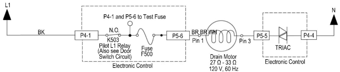
flowchart
graph LR
    L1 --> BK
    BK --> P4-1
    P4-1 --> N.O.
    N.O. --> K503
    K503 --> Pilot_L1_Relay[" Pilot L1 Relay (Also see Door Switch Circuit) "]
    Pilot_L1_Relay --> Fuse_F500
    Fuse_F500 --> P5-6
    P5-6 --> BR_BR_MWH
    BR_BR_MWH --> Pin_1
    Pin_1 --> Drain_Motor[" Drain Motor 27 Ω - 33 Ω 120 V, 60 Hz "]
    Pin_1 --> Pin_3
    Pin_3 --> P5-5
    P5-5 --> TRIAC
    TRIAC --> P4-4
    P4-4 --> N
    P4-4 --> Electronic_Control
    style P4-1 fill:#f9f,stroke:#333
    style P4-6 fill:#ccf,stroke:#333
    style P5-5 fill:#cfc,stroke:#333
    style P4-4 fill:#fcc,stroke:#333
- Unplug connector P5 from control board.
- Check the drain motor using an ohmmeter, measure the resistance between P5-5 and P5-6.
If the resistance is between 27-33 ohms, the drain motor and harness are good. Go to step 8.
If outside the range, replace the drain motor.
If an open circuit is detected, check connections and harness continuity between control and drain motor. If good, replace the drain motor.
- Reconnect P5 to control board.
- Set voltmeter to AC and connect leads to test-pads P5-5 and P5-6 on the control board. Plug in dishwasher or reconnect power.
- Start the Diagnostics Cycle and at the proper interval measure for AC out of the control board between P5-5 and P5-6 (Refer to Drain Motor Strip Circuit below).
IMPORTANT: The Drain Motor must be connected to the control board to measure voltage accurately.
If no AC voltage is measured, replace the control board and retest.
If 120 VAC is measured and drain motor is running, go to step 11.
- Unplug dishwasher or disconnect power.
- Reassemble all parts and panels.
- Plug in dishwasher or reconnect power and run Diagnostics Cycle to verify repair.
For Service Technician Use Only
! DANGER

Electrical Shock Hazard
Only authorized technicians should perform diagnostic voltage measurements.
After performing voltage measurements, disconnect power before servicing.
Failure to follow these instructions can result in death or electrical shock.
DC Fan Motor
This test will check the wiring to the DC fan motor and the fan motor itself. The following items are part of the DC Fan Motor circuit:
■ Harness/Connection
DC Fan Motor
Control Board
Test Procedure
- Check for fan operation in the Diagnostics Cycle. The DC fan should be running during step 4.
- Unplug dishwasher or disconnect power.
-
Remove toe and outer door panels to access control board.
-
Unplug connector P14 from control board.
- Check the fan motor using an ohmmeter, measure the resistance between P14-1 and P14-2.
If the resistance is between 145k-185k ohms, the fan motor and harness are good. Go to step 7.
If outside the range, replace the fan motor assembly.
If an open circuit is detected, check connections and harness continuity between control and fan motor. If good, replace the fan motor assembly.
-
Reconnect P14 to control board.
-
Set voltmeter to DC and connect leads to test-pads P14-1 and P14-2 on the control board. Plug in dishwasher or reconnect power.
- Start the Diagnostics Cycle and at the proper interval measure for DC out of the control board between P14-1 and P14-2 (Refer to DC Fan Motor Strip Circuit below).
IMPORTANT: The Fan Motor must be connected to the control board to measure voltage accurately.
If no DC voltage is measured, replace the control board and retest.
If 13 VDC ± 5% is measured and the fan is spinning, go to step 9.
- Unplug dishwasher or disconnect power.
- Reassemble all parts and panels.
- Plug in dishwasher or reconnect power and run Diagnostics Cycle to verify repair.
Strip Circuit -DC Fan Motor
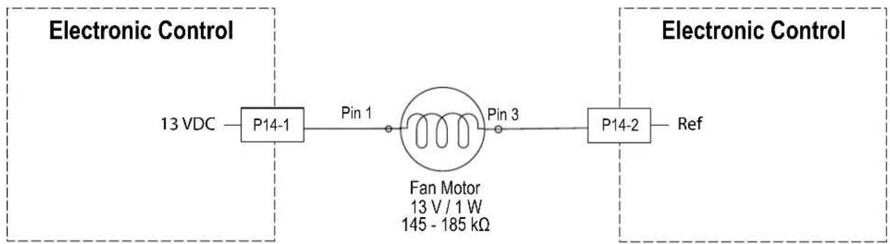
flowchart
graph LR
    A["13 VDC"] --> B["P14-1"]
    B --> C["Pin 1"]
    C --> D["Fan Motor\n13 V / 1 W\n145 - 185 kΩ"]
    D --> E["Pin 3"]
    E --> F["P14-2"]
    F --> G["Ref"]
For Service Technician Use Only
DANGER

Electrical Shock Hazard
Only authorized technicians should perform diagnostic voltage measurements.
After performing voltage measurements, disconnect power before servicing.
Failure to follow these instructions can result in death or electrical shock.
Interior LED Lighting (some models)
This test will check the wiring to the LED tube lights and the lights themselves. The following items are part of the LED Tube Lights circuit:
■ Harness/Connection
■ LED Tube-lights (2)
Control Board
Under normal operation
- The Interior LED Lighting is not on during the wash cycle.
- The Interior LED Lighting turns on when the door is opened and remains on for 10 minutes.
Test Procedure
NOTE: The two (2) LED Tube-lights are wired in parallel. It is possible for one light to malfunction and the other to remain operational.
- Open dishwasher door. The Interior LED Lights should turn on. The following steps assume that this step was unsuccessful.
- Unplug dishwasher or disconnect power.
- Remove toe and outer door panels to access control board.
- Visually check that the P9 connector on the control is securely installed.
If visual passes, go to step 5.
If the connector is not inserted properly, reconnect and retest Interior LED Lighting.
- Disconnect P9 from the Control Board.
- Measure each LED light individually using the diode check setting on the multimeter. Meter should display a numeric reading from anode to cathode and "OL" reading from cathode to anode (refer to strip circuit below).
If LED check passes, go to step 7.
If any of the LEDs do not pass the check, replace the defective LED individually and retest Interior LED lighting.
- Set voltmeter to DC and connect red lead to P9-3 and black lead to P9-4 on the control board. Plug in dishwasher or reconnect power.
- Measure for 13 VDC between P9-2 and P9-4 with lights disconnected and door opened. Light output must be measured within 10 minutes of opening the door.
If 13 VDC is not present, replace the control and retest.
If 13 VDC is present, proceed to step 9.
-
Unplug dishwasher and disconnect power.
-
Reassemble all parts and panels.
- Plug in dishwasher or reconnect power.
Strip Circuit -Interior LED Lighting
Electronic Control
13 VDC
P9-4
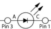
Light
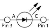
Light
Electronic Control
P9-3
Ref
For Service Technician Use Only
DANGER

Electrical Shock Hazard
Only authorized technicians should perform diagnostic voltage measurements.
After performing voltage measurements, disconnect power before servicing.
Failure to follow these instructions can result in death or electrical shock.
ACU Diagnostic LED
The control is equipped with a single LED which is intended to help diagnose if the ACU needs to be replaced. The LED has different display patterns which indicate different states.
LED Slow Blinking: Normal ACU operation. Unrecoverable ACU fault has been recorded. Power supply and microcontroller are functional.
LED Solid ON: Power is applied to ACU, but no Setting File has been programmed. Control is not functional in this state. Flash Setting File (if service tool is available) or replace ACU.
LED Double Blink: Communication failure between ACU and HMI.
LED Fast Blink: ACU is performing initialization or ACU setting file is in progress of being programmed. This should be a temporary state that occurs briefly at power up.
LED OFF: An unrecoverable ACU fault has been recorded or no power is applied to ACU. Check for 120 VAC across P4-1 and P4-4. See "Service Fault Codes" table above.
LED Triple Blink: Incompatibility between ACU Setting File and firmware.
User Interface (UI)
This test will check the wiring to the user interface and the user interface itself. The following items are part of the user interface circuit:
■ Harness/Connection
■ User Interface (UI)
■ Status LED (On some models)
■ Control Board
Test Procedure
- Verify that the control lock-out feature has not been turned on by the customer. If unit will not run or power up, perform Power Check procedure on page 3-8. Also, check for excessive condensation on UI parts due to vent and/or fan problem.
- Unplug dishwasher or disconnect power.
- Remove toe and outer door panels to access control board.
- Disconnect user interface connection from control board. Verify all other connections to the control are good.
- Plug in dishwasher or reconnect power.
- Perform DC power supply voltage checks as described above in "General Theory of Operation" section.
- Repair/replace faulty parts.
- Unplug dishwasher or disconnect power.
- Reassemble all parts and panels.
- Plug in dishwasher or reconnect power.
For Service Technician Use Only Component Location
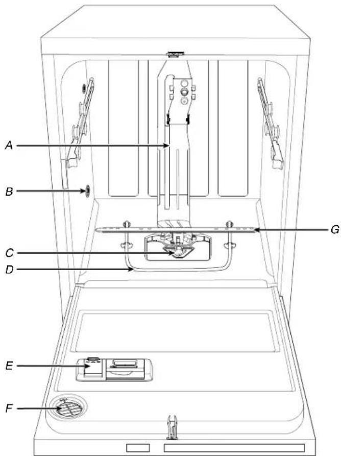
text_image
A B C D G E FA. Water Feed Tube
B. Water Inlet Opening
C. Coarse Filter
D. Heating Element
E. Detergent Dispenser
F. Active Vents (On Some Models)
G. Lower Spray Arm
For Service Technician Use Only Component Location - GWS Model
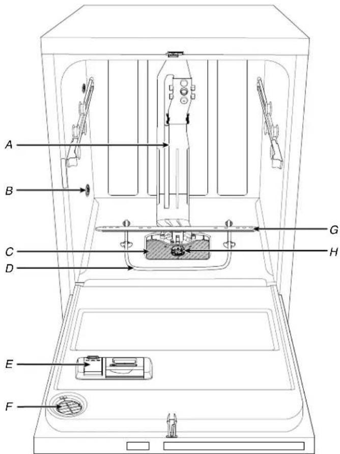
text_image
A B C D E F G HA. Water Feed Tube
B. Water Inlet Opening
C. Fine-Filter Plate
D. Heating Element
E. Detergent Dispenser
F. Active Vents (On Some Models)
G. Lower Spray Arm
H. Dual Filter Assembly
Multimedia Enhanced
Section 4: Component Access
This section provides service parts access, removal, and installation instructions for the "Whirlpool® and KitchenAid® Filtration and Maytag® 24" Microfiltration Dishwashers."
■ Insulation Blanket and Door Latch Strike
■ Siphon Break
■ Accessing Door Components
■ Removing the Inner Door and Hinges
■ ProDry™ Assembly
■ Removing User Interface and Door Latch
■ Removing Dispenser Assembly
■ Removing the Upper Rack (for SatinGlide rails)
■ Removing the Third Level Rack (available on some models)
■ Removing Lower Spray Arm and Manifold Assembly
■ Removing Heater Assembly
■ Removing Drain Pump
■ Under the Tub Components
■ Drip Pan and Float Assembly
■ Removing Sump and Motor Assembly
■ Under the Tub Components - GWS Model
■ Removing Sump and Motor Assembly - GWS Model
Insulation Blanket and Door Latch Strike
WARNING

Electrical Shock Hazard
Disconnect power before servicing.
Replace all parts and panels before operating.
Failure to do so can result in death or electrical shock.
Installing Insulation (Stainless models only)
- Fasten the blanket on the hooks located on each side of the tube.
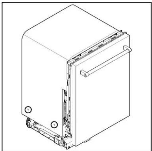
natural_image
Technical line drawing of a mechanical device with internal components and mounting holes (no text or symbols)Removing Door Latch Strike
-
Open the dishwasher door.
-
Press down on the round tab in front of the door latch strike.
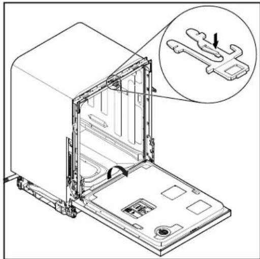
natural_image
Technical line drawing of an open kitchen appliance with a magnified inset showing internal components (no text or symbols)- While pressing down on the round tab, depress the two outside bars and pull out the latch.
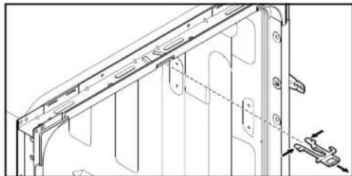
natural_image
Technical line drawing of a mechanical bracket assembly (no text or symbols)Siphon Break
WARNING
Electrical Shock Hazard
Disconnect power before servicing.
Replace all parts and panels before operating.
Failure to do so can result in death or electrical shock.
Tools Needed:

Oil filter wrench or 90 degree bent nose pliers
- Locate siphon break nut inside tub back lower left corner.
- Use oil filter wrench or bent nose pliers to loosen siphon break nut inside tube by turning it counterclockwise.
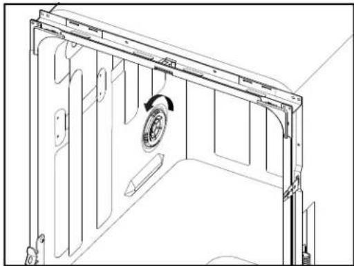
natural_image
Technical line drawing of a mechanical assembly with internal components and a circular component (no text or symbols)- Disconnect water inlet hose. Using pliers, squeeze water inlet clamp and pull hose away from siphon break.
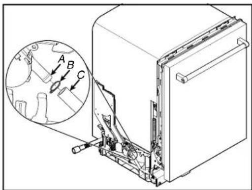
text_image
Technical diagram of a refrigerator with labeled parts and an inset showing mechanical components with arrows A, B, and C.A. Siphon Break Assembly
B. Clamp
C. Water Inlet Hose
- Disconnect drain pump hose. Remove black plastic C-clamp securing drain pump hose to siphon break and pull hose down and away from siphon break assembly.
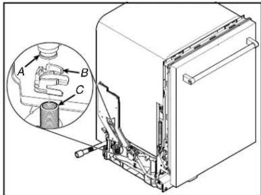
text_image
Technical diagram of a refrigerator with labeled parts A, B, and C, showing internal components and a magnified inset view.A. Siphon Break Assembly
B. C-Clamp
C. Drain Pump Hose
- Disconnect drain pump output hose. Using pliers, squeeze drain hose output clamp and pull down on hose away from siphon break assembly.
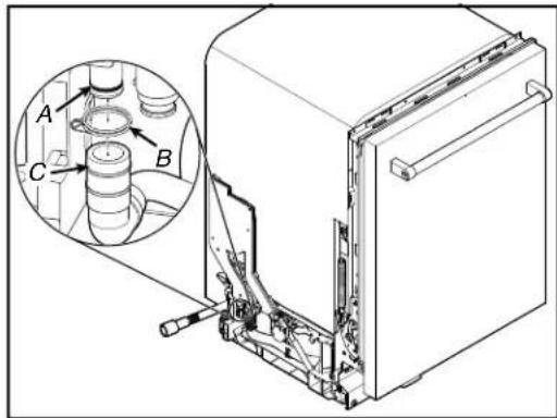
text_image
Technical diagram of a refrigerator with labeled parts and an inset showing mechanical components, likely for assembly or maintenance.A. Siphon Break Assembly
B. Clamp
C. Drain Pump Output Hose
- Using pliers squeeze plastic retainer together and pull siphon break assembly out and up to remove.
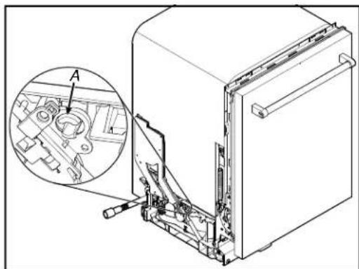
natural_image
Technical illustration of an appliance front view showing internal components and a magnified inset (no text or symbols)A. Plastic Retainer
Accessing Door Components
WARNING

Electrical Shock Hazard Disconnect power before servicing. Replace all parts and panels before operating. Failure to do so can result in death or electrical shock.
- Lift the outer door assembly up and away with enough room to disconnect the ACU harness and clip. Unclip the harness from the harness retaining clip.
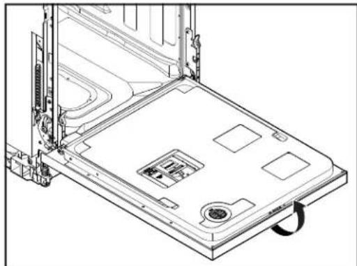
natural_image
Technical line drawing of a laptop chassis with visible internal components and mounting bracket (no text or symbols)Remove Outer Door Panel
- Unplug dishwasher or disconnect power.
- Using a TORX ^+ T15 ^-/- screwdriver, remove the six short screws (three on each side) and three long as shown in below image:
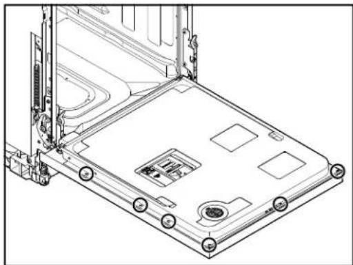
natural_image
Technical line drawing of a laptop chassis with mounting holes and internal components (no text or symbols)NOTE: Leave the (short) screw to the left of the door latch in place as this screw secures the door latch to the door.
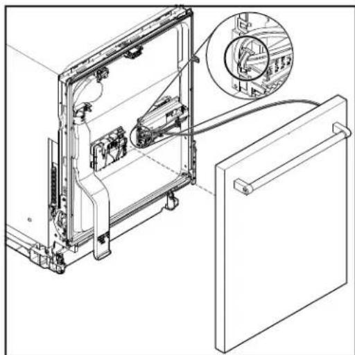
natural_image
Technical line drawing of a refrigerator interior with an inset close-up showing internal components (no text or symbols)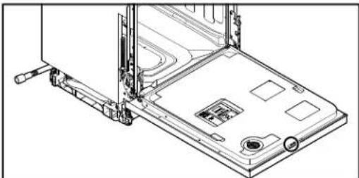
natural_image
Technical line drawing of a laptop chassis with mounting bracket and drive mechanism (no text or symbols)Accessing Door Components (Continued)
- Flip the ACU cover on door. Push up on the connector tab and pull the harness connector off the board.
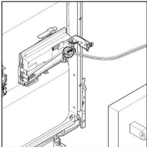
natural_image
Technical line drawing of a mechanical assembly with no visible text or symbolsRemove ACU
- To remove ACU, use a flat blade screwdriver to push in on tab. Then lift up on ACU and slide to the left.
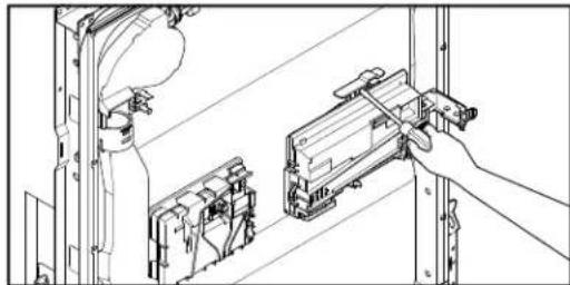
natural_image
Technical line drawing of a mechanical assembly with a hand operating a tool (no text or symbols present)- Turn the ACU assembly over and depress the three tabs to release the wire harness connector cover. Disconnect wire harness connectors and replace ACU.

natural_image
Technical line drawing of a mechanical component with internal cavities and mounting holes (no text or symbols)Removing the Inner Door and Hinges
WARNING
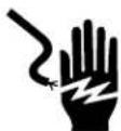
Electrical Shock Hazard Disconnect power before servicing. Replace all parts and panels before operating. Failure to do so can result in death or electrical shock.
Removing the Inner Door
- Unplug dishwasher or disconnect power.
- Complete the step 1-4 from "Remove Outer Door Panel" section.
- Open the inner door slightly and insert 7/64" drill bits (or Allen wrench's) into hinge hole as shown in below image:
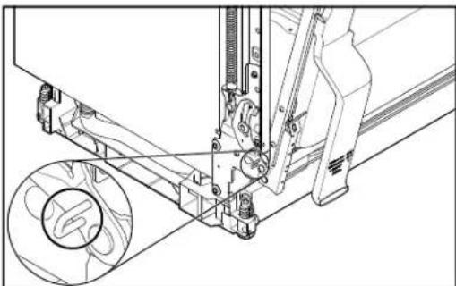
natural_image
Technical line drawing of a mechanical assembly with no visible text or symbolsThis will keep the hinge slightly open and make replacing the inner door easier.
- Remove the two TORX T20 screws attaching the inner door panel to the hinge and repeat for other hinge. Then lift up on inner door to remove.
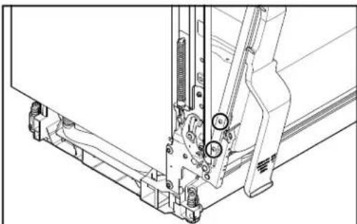
natural_image
Technical line drawing of a mechanical assembly with no visible text or symbolsRemoving the Hinge
- Using a 5/16" nut driver remove two rear screws and use a 1/4" nut driver to remove the front two screws. Repeat the step for other hinge.
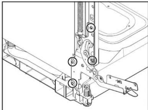
natural_image
Technical line drawing of a mechanical assembly with no visible text or symbolsProDry™ Assembly
WARNING
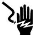
Electrical Shock Hazard
Disconnect power before servicing.
Replace all parts and panels before operating.
Failure to do so can result in death or electrical shock.
Tools Needed:

90 degree bent nose pliers
- Complete the step 1-4 from "Remove the Inner Door" section.
- Using 90 degree bent nose pliers turn the ProDry™ vent counterclockwise to loosen and remove.
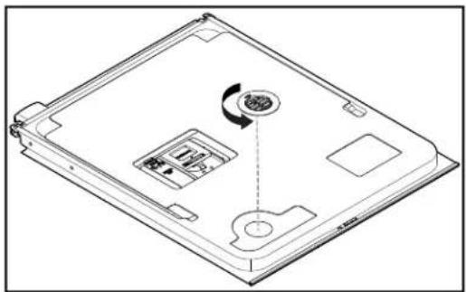
natural_image
Line drawing of a laptop case with an internal component and a circular arrow indicating rotation (no text or symbols)- The ProDry ^™ assembly can now be removed.
natural_image
Line drawing of a person using a handheld device to interact with a wall-mounted device (no text or symbols present)- Disconnect wax motor connector by pressing down on tab and lifting up on harness connector.
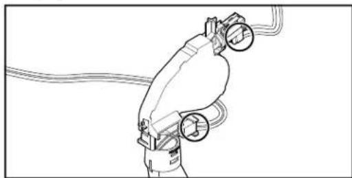
natural_image
Line drawing of a robotic arm with hoses and valves (no text or symbols)- Remove fan harness by pushing down on tab and lifting up on harness. Refer the below image.
- To remove vent assembly, use a screwdriver to push in on tab shown and pull vent away from wax motor.
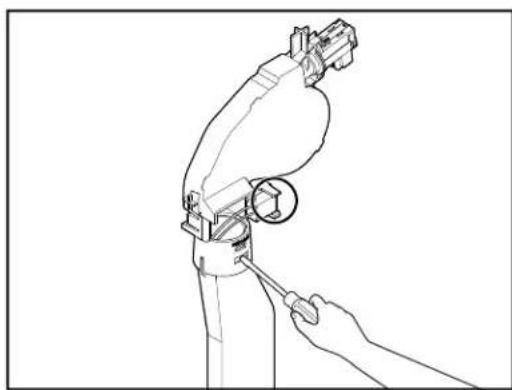
natural_image
Line drawing of a robotic arm with a wrench, showing mechanical components and a circular detail (no text or symbols)Removing User Interface and Door Latch
WARNING

Electrical Shock Hazard Disconnect power before servicing. Replace all parts and panels before operating. Failure to do so can result in death or electrical shock.
Removing the User Interface
- Unplug dishwasher or disconnect power.
- Complete the step 1-6 from "ProDry™ Assembly" section.
- Use a TORX T15 screwdriver to remove the three (3) screws securing the UI to the outer door panel.
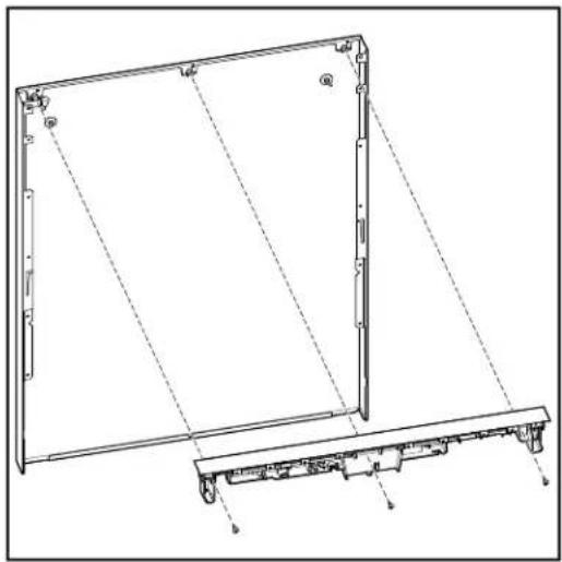
natural_image
Technical line drawing of a mechanical frame assembly with mounting base (no text or symbols)NOTE: The light pipe is not removed during UI replacement. It remains attached to the outer door panel.
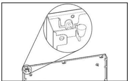
natural_image
Technical line drawing of a mechanical assembly with an inset showing a close-up of a component (no text or symbols present)Remove Latch Assembly
- Use a TORX T15 screwdriver to remove the one screw attaching the Latch Assembly to the door panel.
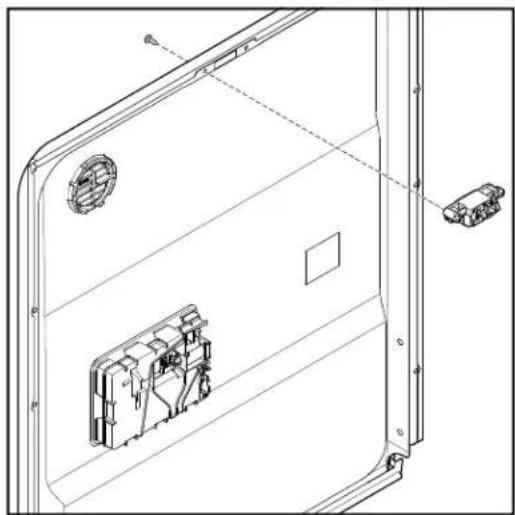
natural_image
Technical line drawing of a door frame with internal components and mounting holes (no text or symbols)Removing Dispenser Assembly
WARNING

Electrical Shock Hazard
Disconnect power before servicing.
Replace all parts and panels before operating.
Failure to do so can result in death or electrical shock.
- Unplug dishwasher or disconnect power.
- Remove the outer panel from the door.
- Disconnect dispenser harness by pushing down on harness retainer while pulling the harness from the dispenser.
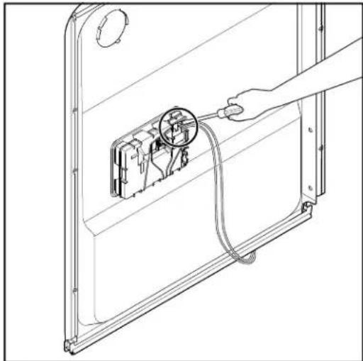
natural_image
Line drawing of a hand connecting a cable to an electrical outlet with a magnified inset showing internal components (no text or symbols)- Remove dispenser by prying each clip away from the dispenser and lifting it away from the door panel.
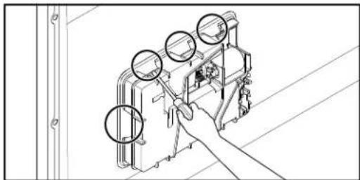
natural_image
Line drawing of a hand operating a mechanical device with three circular components, no text or symbols presentLocking Clips for Dispenser Assembly
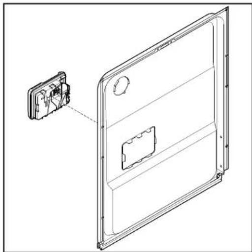
natural_image
Technical line drawing of a door frame with an inset showing internal components (no text or symbols)
Removing the Upper Rack (for SatinGlide rails)
-
Open the dishwasher door.
-
To gain access to the removable tabs on the tracks/rails, pull the upper rack forward about halfway out of the tube.
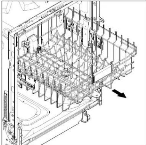
natural_image
Technical line drawing of a mechanical assembly with internal components and a directional arrow (no text or symbols)- On one side, press the tab on the track in and pull up the front end of the rack out of the track.

natural_image
Technical line drawing of a mechanical assembly with internal components and mounting brackets (no text or symbols)-
Then repeat this step on the other side to completely remove the front end of the rack.
-
Then remove the back end of the rack, by pulling the back end out with a slightly forward, and then upward motion.
Remove Roller and Rack Adjuster Assembly
- Remove rack adjust retainer. Using a flat blade screwdriver push in on the tab.
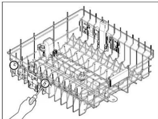
natural_image
Isometric technical drawing of a mechanical assembly with no visible text or symbols- While pushing in on tab lift up on the rack adjust retainer to remove.
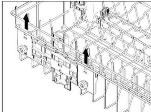
natural_image
Technical line drawing of a mechanical assembly with no visible text or symbols-
Repeat for other rack adjust tab.
-
Using a flat blade screwdriver push in on two tabs as shown in below image:
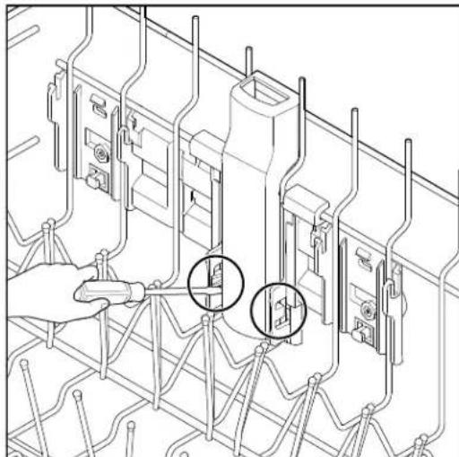
natural_image
Technical line drawing of a mechanical assembly with two circular annotations highlighting specific components (no text or symbols present)Removing the Upper Rack (Continued)
- From outside of the rack lift up from the bottom of the roller/rack adjust and remove.
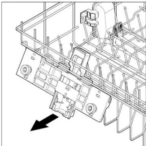
natural_image
Technical line drawing of a mechanical assembly with no visible text or symbolsRemove Spray Arm Assembly
-
Complete the steps 1-5 from "Removing the Upper Rack (for SatinGlide rails)" section.
-
Using a flat blade screwdriver push in on the tab.
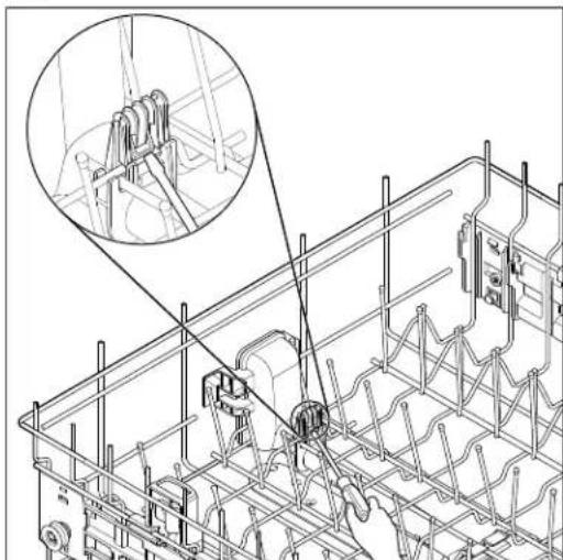
natural_image
Technical line drawing of a mechanical assembly with a magnified inset showing a close-up of a component (no text or symbols present)- Pull spray arm assembly away to remove.
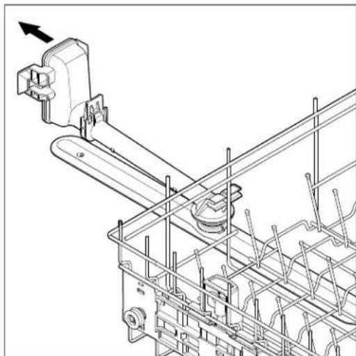
natural_image
Technical line drawing of a mechanical assembly with no visible text or symbolsReinstall Spray Arm Assembly
- Align spray arm assembly as shown in below image and push into place.
NOTE: Spray arm assembly is offset.
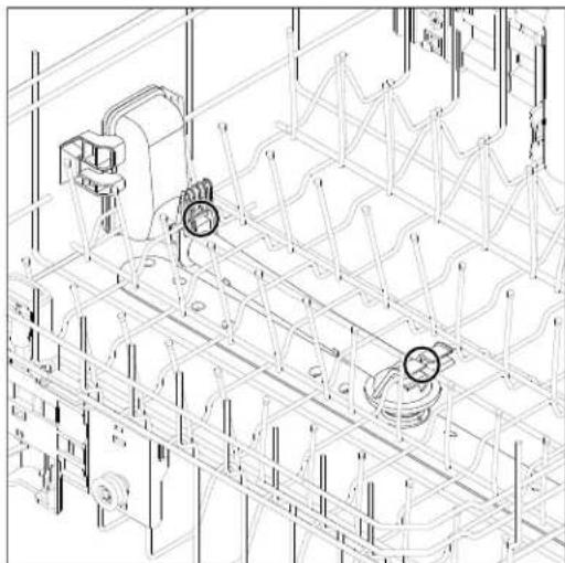
natural_image
Technical line drawing of a mechanical assembly with no visible text or symbols- Push up on spray arm assembly to lock in place.

Removing the Third Level Rack (available on some models)
WARNING

Electrical Shock Hazard
Disconnect power before servicing.
Replace all parts and panels before operating.
Failure to do so can result in death or electrical shock.
- Open the dishwasher door.
- To access track stops, pull the rack forward until it stops and clicks into place.
- To open track stops, flip the track stop to the outside of the track.
- After opening both track stops, slide front wheels up and out of the slot in track. Continue to pull rack forward in track and slide the back wheels up and out of the track.
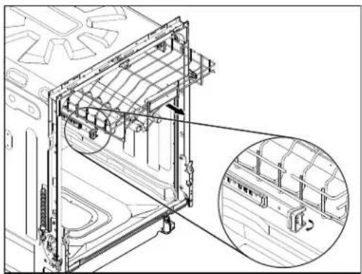
natural_image
Technical line drawing of a mechanical assembly with an inset magnified view showing internal components (no text or symbols)- Close track stops.
- Slide rack tracks back into dishwasher.
Removing the Rack Rails
- Turn white plastic rail retainers counterclockwise to remove third level rack rails.
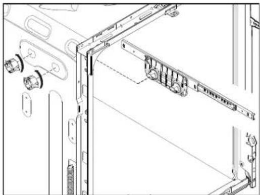
natural_image
Technical line drawing of a mechanical assembly with mounting brackets and connectors (no text or symbols)- Use a 5/16" nut driver to remove the four bolts holding the upper rack rail.
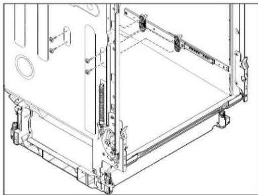
natural_image
Technical line drawing of a mechanical assembly frame with mounting brackets and internal components (no text or symbols)Remove Wash Tube Cover
- Complete the steps 1-6 from "Removing the Third Level Rack" section.
- Pry two tabs outward and push to disengage Wash Tube Cover from Manifold Drive Box.
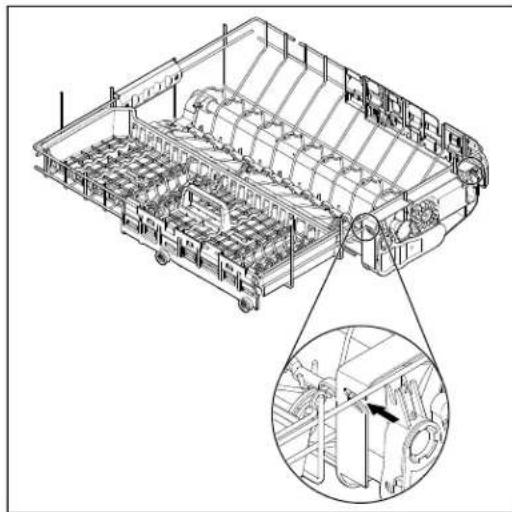
natural_image
Technical line drawing of a mechanical assembly with internal components and a magnified inset showing a detail (no text or symbols)- Spread the two tabs to remove Manifold Drive Box from rails.
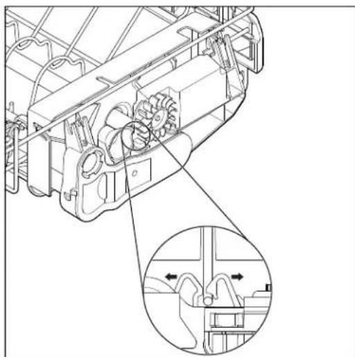
natural_image
Technical line drawing of a mechanical assembly with internal gears and a magnified inset showing internal components (no text or symbols)Removing the Third Level Rack (Continued)
Remove Spray Arms
- Pull spray arms away from Manifold Drive Box.
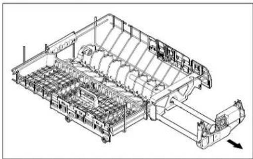
natural_image
Technical line drawing of a mechanical assembly with gears and shafts (no text or symbols)- To remove Tube Hanger from the Tube Hanger Bracket push Hanger in direction shown in below image:
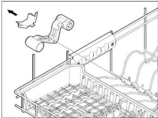
natural_image
Technical line drawing of a mechanical assembly with pipes and components, no visible text or symbolsRemove Roller Assembly
- Using a flat blade screwdriver push in on the three tabs. Then lift roller assembly up and away from rack.
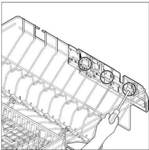
natural_image
Technical line drawing of a mechanical component with grid lines and circular annotations (no readable text or symbols)Remove Spray Bar Cover
- Use a flat blade screwdriver to pry four locking tabs to remove spray bar cover.
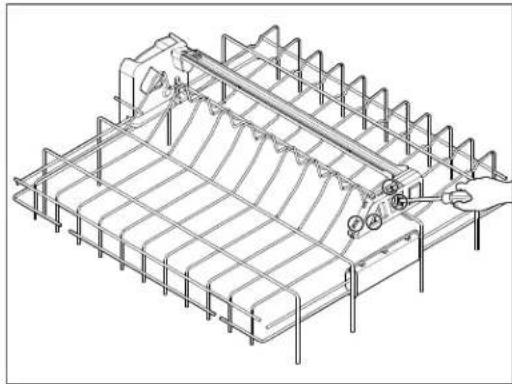
natural_image
Isometric technical line drawing of a structural grid framework with no visible text or symbolsRemove Spray Bar
- Use a flat blade screwdriver to pry locking tab to remove spray bar.
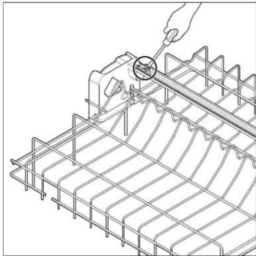
natural_image
Technical line drawing of a wire mesh grid with a hand using a tool to measure a circular component (no text or symbols present)Removing Lower Spray Arm and Manifold Assembly
Remove Lower Spray Arm
- Open the dishwasher door.
- Complete the steps 1-5 from "Removing the Upper Rack" section.
- Complete the steps 1-6 from "Removing the Third Level Rack" section.
- To remove lower spray arm lift up and turn counterclockwise.
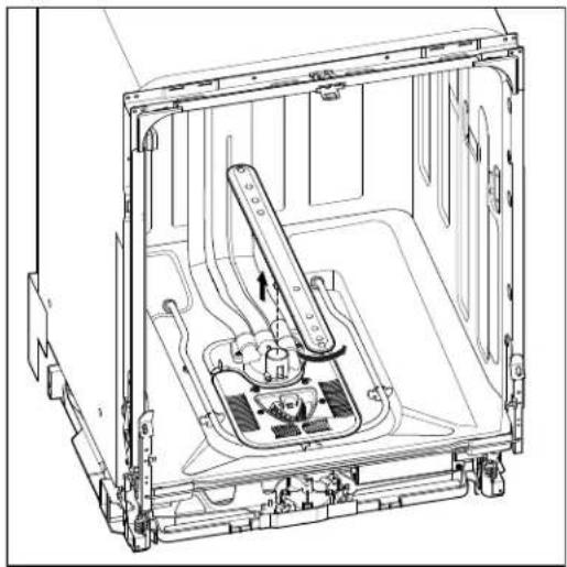
natural_image
Technical line drawing of an open refrigerator interior showing internal components and mounting brackets (no text or symbols)Remove Filter Cover
- To remove filter cover remove four TORX T15 screws.
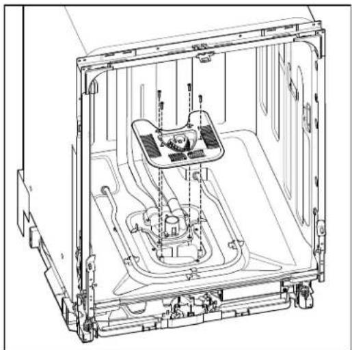
natural_image
Technical line drawing of an internal appliance assembly (no text or symbols)Remove Manifold Assembly
- To remove manifold assembly remove two TORX T15 screws at diverter cover.
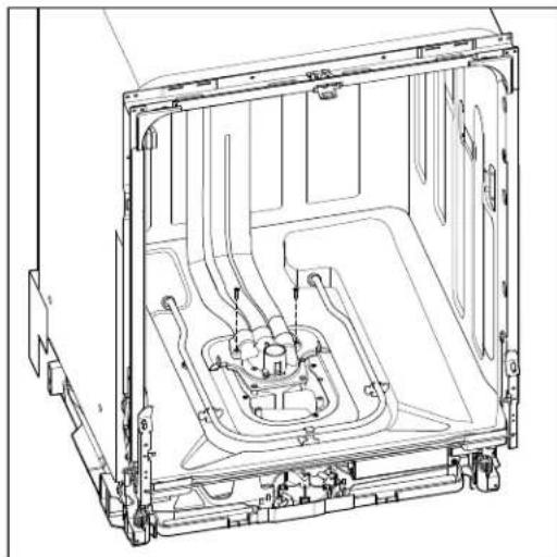
natural_image
Technical line drawing of an internal mechanical assembly (no text or symbols)- Starting at the top, use a flat blade screwdriver to press in on the four tabs. The manifold assembly can then be removed from the tub.
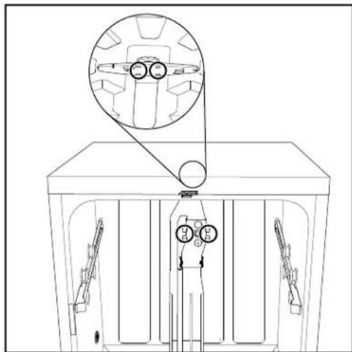
natural_image
Technical line drawing of a mechanical assembly with no visible text or symbolsRemoving Heater Assembly
WARNING

Electrical Shock Hazard
Disconnect power before servicing.
Replace all parts and panels before operating.
Failure to do so can result in death or electrical shock.
- Unplug dishwasher or disconnect power.
- Locate the heater terminals at the bottom of the dishwasher. Disconnect wires from both heater terminals.
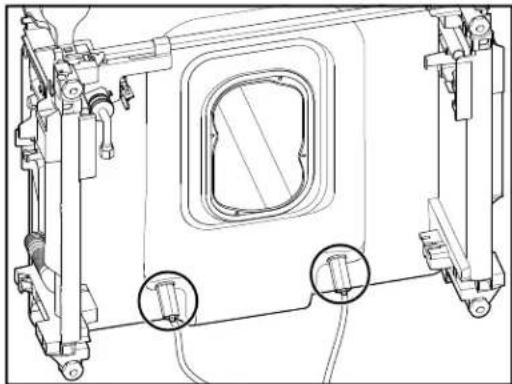
natural_image
Technical line drawing of a mechanical assembly with no visible text or symbols- Remove both heater element nuts.
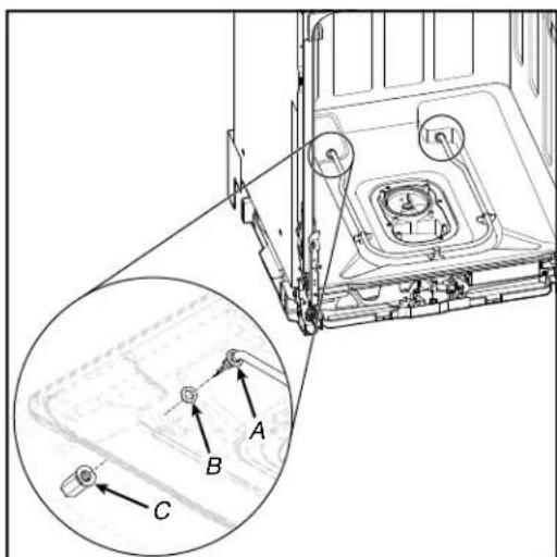
text_image
Technical diagram of a mechanical assembly with labeled components A, B, and C, including an inset magnified view.A. Heater Element Assembly
B. Heater Washer
C. Heater Element Nut
- Remove heater element assembly from tub.
Removing Drain Pump
WARNING

Electrical Shock Hazard
Disconnect power before servicing.
Replace all parts and panels before operating.
Failure to do so can result in death or electrical shock.
- Unplug dishwasher or disconnect power.
- Uninstall dishwasher so that it can be pulled half way out of cabinet.
- Turn off water supply to dishwasher. Disconnect drain hose if necessary. Unscrew anchors to cabinet.
- Locate the drain pump in the lower front right of dishwasher.
- Push in on tab and turn drain pump 1/4 turn counterclockwise to remove.
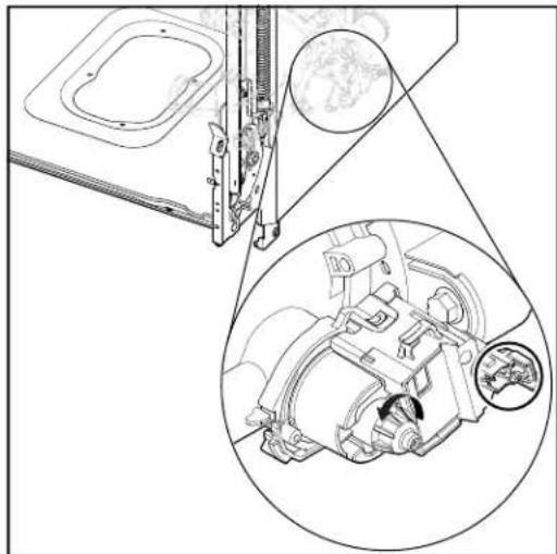
natural_image
Technical line drawing of a mechanical assembly with an inset close-up showing internal components (no text or symbols)- Remove plastic wire harness connector retainer by pulling it straight out. Push in on connector retainer and remove harness.
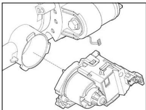
natural_image
Technical line drawing of a mechanical assembly with exploded view and assembled view (no text or symbols)Under Tub Components
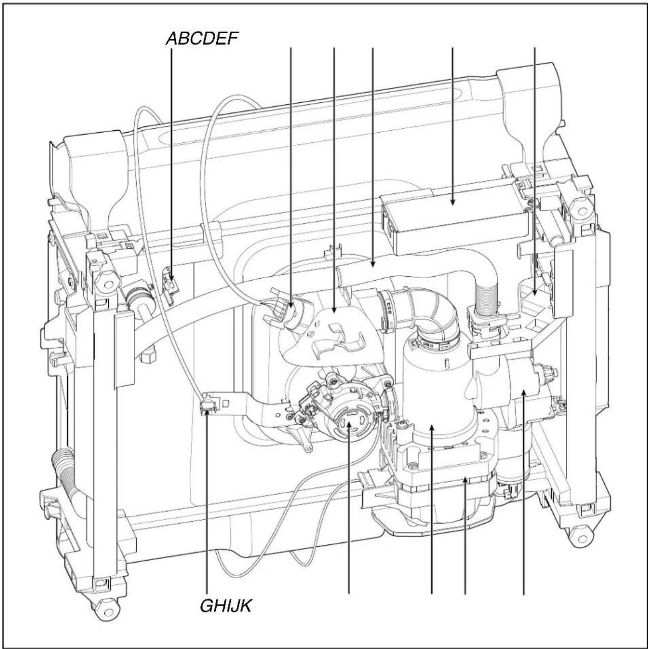
text_image
ABCDEF GHIJKA. Fill Valve
B. OWI Sensor
C. Sump
D. Drain Hose
E. Junction Box
F. Drain Pump Bracket
G. Thermostat
H. Diverter
- Rotating Inlet Filter
J. Wash Motor
K. Drain Pump
Drip Pan and Float Assembly
WARNING

Electrical Shock Hazard
Disconnect power before servicing.
Replace all parts and panels before operating.
Failure to do so can result in death or electrical shock.
Remove Drip Pan and Float Assembly
- Remove toe/access panel using a 5/16" nut driver.
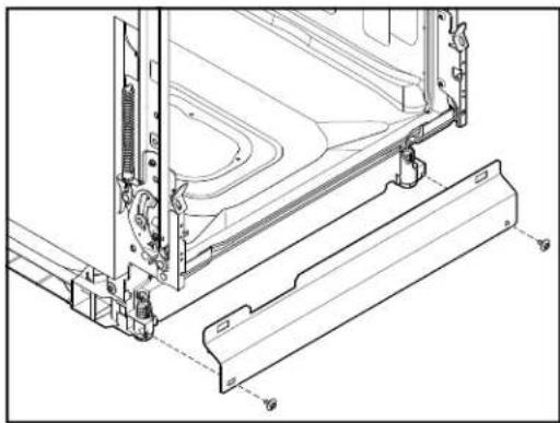
natural_image
Technical line drawing of a mechanical assembly with mounting brackets and internal components (no text or symbols)- To remove the drip pan assembly, press the snap at each side of the plastic tray in toward the center of the product and pull toward yourself.
NOTE: Take caution not to pull too far or too hard as the float switch wire is still connected at this time.
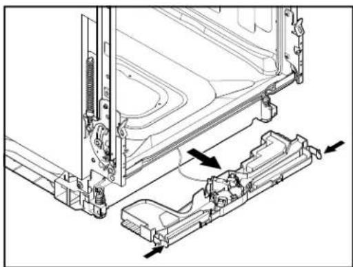
natural_image
Technical line drawing of a mechanical assembly with mounting brackets and internal components (no text or symbols)Remove Float Switch Wire
- To remove the float switch wire, gently depress the connector latch tab and then pull the connector out of the housing. To remove the float push in on the two tabs and lift up on the float.
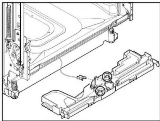
natural_image
Technical line drawing of a vehicle chassis assembly with mounting bracket and internal components (no text or symbols)
Removing Sump and Motor Assembly
WARNING

Electrical Shock Hazard
Disconnect power before servicing.
Replace all parts and panels before operating.
Failure to do so can result in death or electrical shock.
- Unplug dishwasher or disconnect power.
- Complete the steps 1-4 from "Drip Pan and Float Assembly" section.
- Complete the steps 1-7 from "Removing Lower Spray Arm and Manifold Assembly" section.
- Remove four (4) TORX T15 screws to sump.
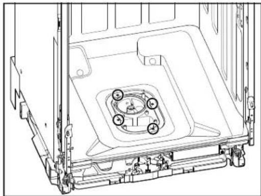
natural_image
Technical line drawing of a mechanical assembly with mounting brackets and central circular components (no text or symbols)Removing Sump and Motor Assembly (Continued)
- Disconnect water supply under sink if necessary.
- Disconnect drain hose under sink if necessary.
- Disconnect electrical under sink or at junction box if needed.
- Pull dishwasher out from under the counter and lay it on it's back.
- Move junction box out of the way by twisting up on left side and pulling it up and away from the retaining bar.

natural_image
Technical line drawing of a mechanical assembly with no visible text or symbols- To remove plastic drain pump bracket, use a standard screwdriver to push down on tab and push bracket away from you.
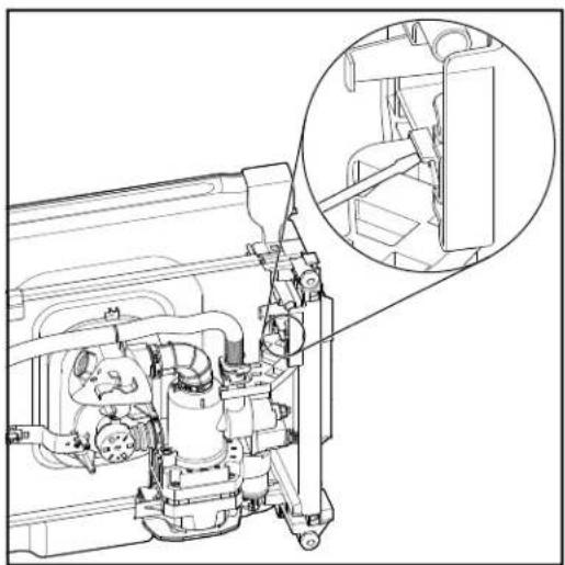
natural_image
Technical line drawing of a mechanical assembly with an inset close-up showing internal components (no text or symbols)- Remove black plastic hose retainer and disconnect drain hose from drain pump port.
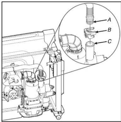
text_image
Technical diagram of a mechanical assembly with labeled parts A, B, and C, showing internal components and a magnified inset view.A. Drain Pump Port
B. Plastic Hose Retainer
D. Drain Pump Hose
- Complete the steps 1-6 from "Removing Drain Pump" section.
- Remove plastic screw/plug on the right side of the motor bracket using a Phillips screwdriver.
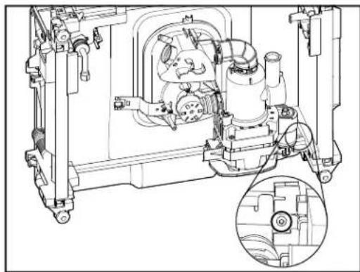
natural_image
Technical line drawing of a mechanical assembly with internal components and a magnified inset (no text or symbols)Removing Sump and Motor Assembly (Continued)
- Unclip harness from the sump. Disconnect wire harness connectors to diverter motor and wash motor.
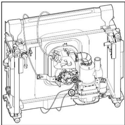
natural_image
Technical line drawing of a mechanical assembly with no visible text or symbols- Remove OWI by turning in counterclockwise a quarter turn.
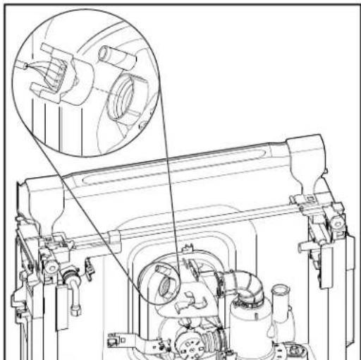
natural_image
Technical line drawing of a mechanical assembly with an inset showing a close-up of a component (no text or symbols present)- Slide sump and motor assembly to the left along the rear bracket. Lift up on the left side of the assembly and pull it up and away from the rear bracket.
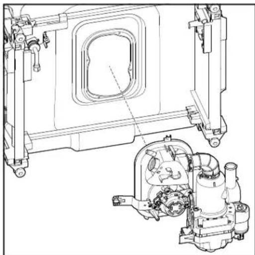
natural_image
Technical line drawing of a mechanical assembly with internal components and mounting brackets (no text or symbols)- Remove thermostat and bracket using a TORX T15 screwdriver.
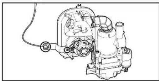
natural_image
Technical line drawing of a mechanical assembly with gears and housing (no text or symbols)Under Tub Components - GWS Model
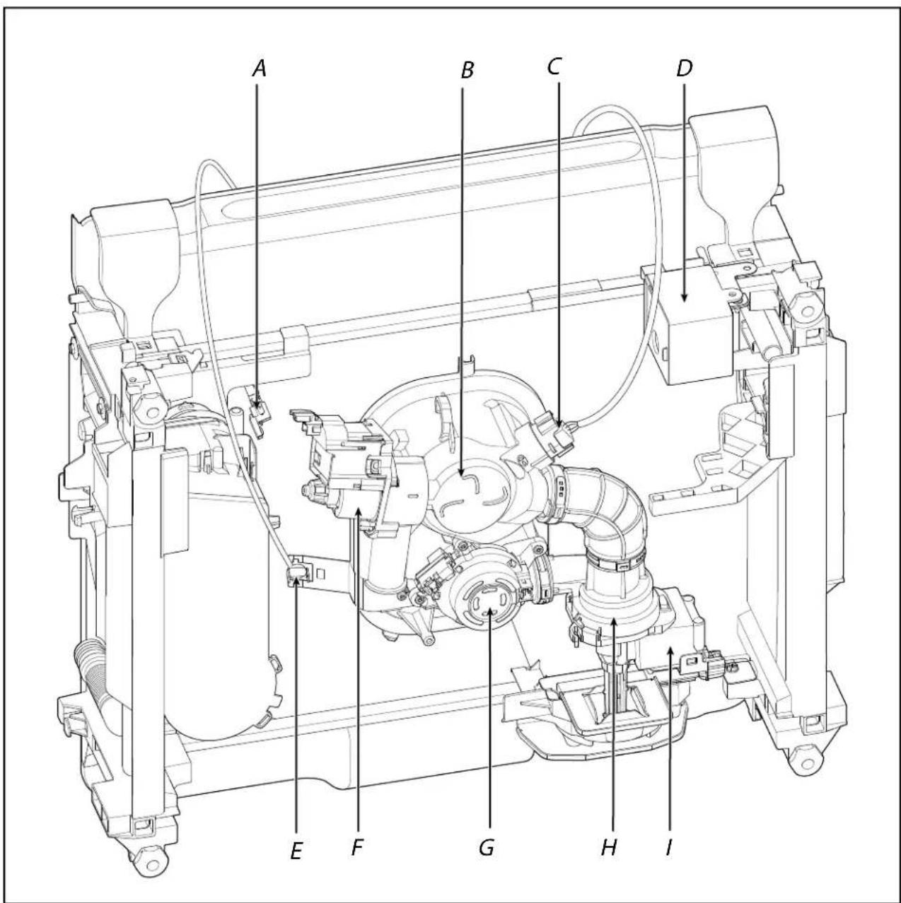
text_image
A B C D E F G H IA. Fill Valve
B. Sump
C. OWI Sensor
D. Junction Box
E. Thermostat
F. Drain Pump
G. Diverter
H. Inlet Filter
- Wash Motor
Removing Sump and Motor Assembly - GWS Model
WARNING

Electrical Shock Hazard Disconnect power before servicing. Replace all parts and panels before operating. Failure to do so can result in death or electrical shock.
- Unplug dishwasher or disconnect power.
- Complete the steps 1-4 from "Drip Pan and Float Assembly" section.
- Complete the steps 1-7 from "Removing Lower Spray Arm and Manifold Assembly" section.
- Remove four TORX T15 screws to sump.
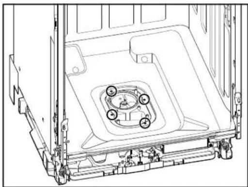
natural_image
Technical line drawing of a mechanical assembly with mounting brackets and central circular components (no text or symbols)- Disconnect water supply under sink if necessary.
- Disconnect drain hose under sink if necessary.
- Disconnect electrical under sink or at junction box if needed.
-
Pull dishwasher out from under the counter and lay it on it's back.
-
Cut the hose clamp crimp to remove the hose to the sump.
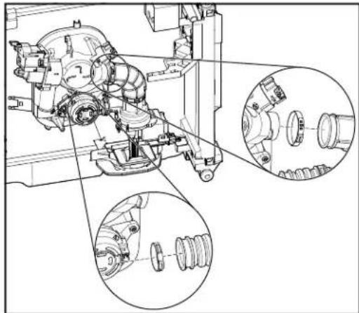
natural_image
Technical line drawing of a mechanical assembly with multiple circular insets showing internal components (no text or labels)NOTE: For reconnecting the hoses, re-crimp a new replacement clamp in the positions shown in the figure.
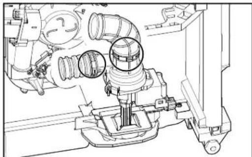
natural_image
Technical line drawing of a mechanical assembly with pipes and housing (no text or symbols)- Press in both sides of the TPA to remove the connector from the housing. Pull the TPA out of secured position and remove.
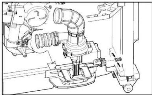
natural_image
Technical line drawing of a mechanical assembly with pipes and housing (no text or symbols)Motor Assembly GWS Model
- Push to release the tab and pull up the connector to remove from the housing.
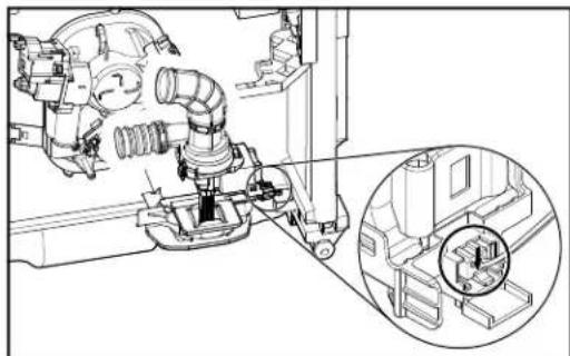
natural_image
Technical line drawing of a mechanical assembly with an inset close-up showing a circular detail (no text or symbols)Removing Sump and Motor Assembly - GWS Model (Continued)
- Using a small Phillips screwdriver, turn counterclockwise to remove plastic screw which is securing the locator/motor bracket.
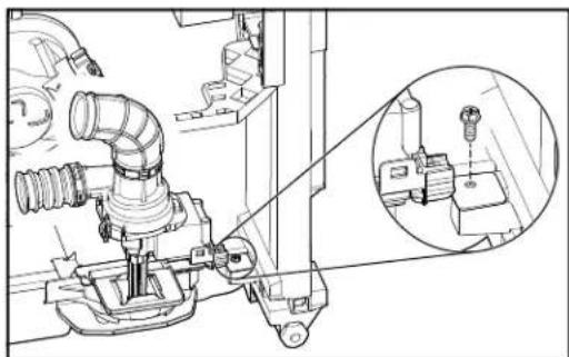
natural_image
Technical line drawing of a mechanical assembly with an inset close-up showing a component detail (no text or symbols)- Push locator away from grommet center to remove.
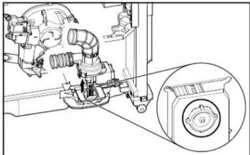
natural_image
Technical line drawing of a mechanical assembly with no visible text or symbols- Remove the motor assembly.
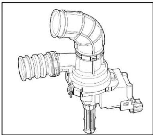
natural_image
Technical line drawing of a mechanical pipe fitting with no visible text or symbolsSump Assembly GWS Model
- Unclip harness from the sump. Remove thermostat and disconnect wire harness connectors to diverter motor and wash motor.
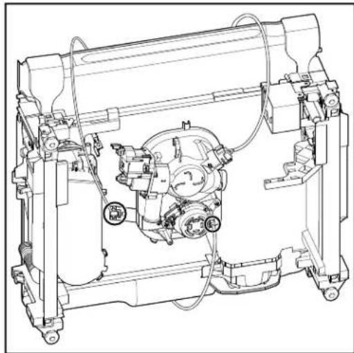
natural_image
Technical line drawing of a mechanical assembly with no visible text or symbols- Remove OWI by turning in counterclockwise a quarter turn.
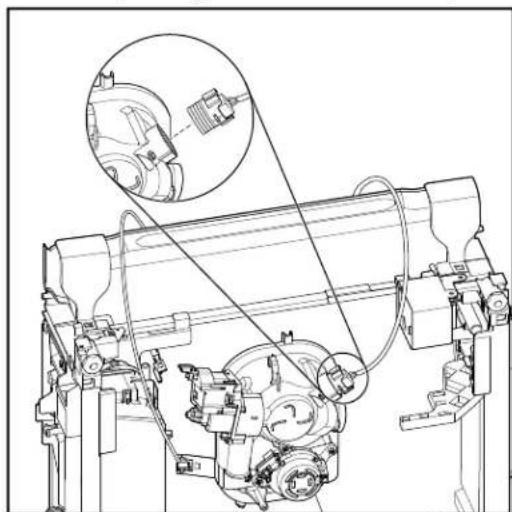
natural_image
Technical line drawing of a mechanical assembly with no visible text or symbols- Slide sump assembly to the left along the rear bracket. Lift up on the left side of the assembly and pull it up and away from the rear bracket.
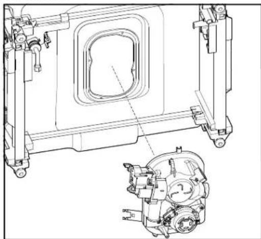
natural_image
Technical line drawing of a mechanical assembly with internal components and mounting brackets (no text or symbols)PRODUCT SPECIFICATIONS & WARRANTY INFORMATION SOURCES
IN THE UNITED STATES:
FOR PRODUCT SPECIFICATIONS AND WARRANTY INFORMATION CALL:
FOR WHIRLPOOL PRODUCTS: 1-800-253-1301
FOR TECHNICAL ASSISTANCE WHILE AT THE CUSTOMER'S HOME CALL:
THE TECHNICAL ASSISTANCE LINE: 1-800-832-7174
HAVE YOUR STORE NUMBER READY TO IDENTIFY YOU AS AN AUTHORIZED IN-HOME SERVICE PROFESSIONAL
FOR LITERATURE ORDERS (CUSTOMER EXPERIENCE CENTER):
PHONE: 1-800-851-4605
FOR TECHNICAL INFORMATION AND SERVICE POINTERS:
www.servicematters.com
IN CANADA:
FOR PRODUCT SPECIFICATIONS AND WARRANTY INFORMATION CALL:
1-800-461-5681
FOR TECHNICAL ASSISTANCE WHILE AT THE CUSTOMER'S HOME CALL:
THE TECHNICAL ASSISTANCE LINE: 1-800-488-4791
HAVE YOUR STORE NUMBER READY TO IDENTIFY YOU AS AN AUTHORIZED IN-HOME SERVICE PROFESSIONAL
Whirlpool® and
KitchenAid® Filtration and
Maytag® 24" Microfiltration
Dishwashers
W11447459