
KS1500L - Service après-vente BLACK & DECKER - Free user manual and instructions
Find the device manual for free KS1500L BLACK & DECKER in PDF.


| Product type | Jigsaw |
| Brand | Black & Decker |
| Model | KS1500L |
| Power | 550 W |
| No-load speed | 500 – 3000 rpm (variable) |
| Stroke | 20 mm |
| Wood cutting capacity | 80 mm |
| Metal cutting capacity | 10 mm |
| Power supply | Mains, 230 V ~ 50 Hz |
| Weight | 2.2 kg |
| Dimensions (L × W × H) | 250 × 80 × 200 mm |
| Main features | Precise cutting, integrated chip blower, variable speed, LED light, laser guide |
| Maintenance and cleaning | Regularly clean ventilation slots, replace worn blades, lubricate guides |
| Safety | Safety shut-off in case of overload, spindle lock for blade change, double insulation |
| Spare parts | Blades (multiple types), sliding shoe, anti-splinter guard, parallel guide |
| Repairability | Repairability index: 7.5/10, parts available for 5 years after purchase |
| Warranty | 2 years (in accordance with applicable legislation) |
Frequently Asked Questions - KS1500L BLACK & DECKER
User questions about KS1500L BLACK & DECKER
0 question about this device. Answer the ones you know or ask your own.
Ask a new question about this device
Download the instructions for your Service après-vente in PDF format for free! Find your manual KS1500L - BLACK & DECKER and take your electronic device back in hand. On this page are published all the documents necessary for the use of your device. KS1500L by BLACK & DECKER.
USER MANUAL KS1500L BLACK & DECKER
KS1400L
KS1401L
KS1500L
KS1501L
KS1600L
English (Original instructions) 5
natural_image
Technical line drawing of a mechanical cutting tool with labeled part '192018' (no other text or symbols)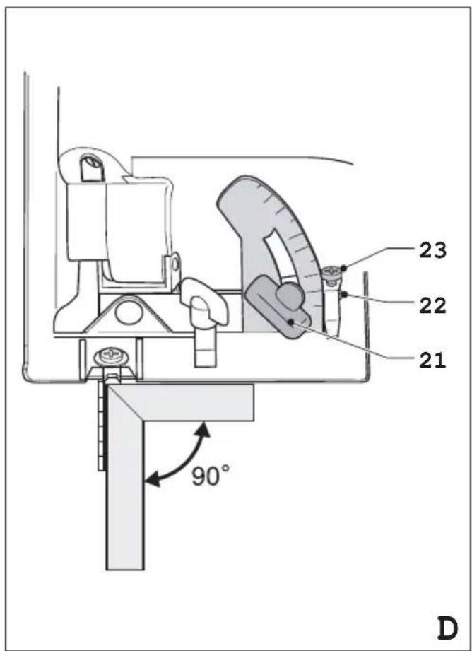
natural_image
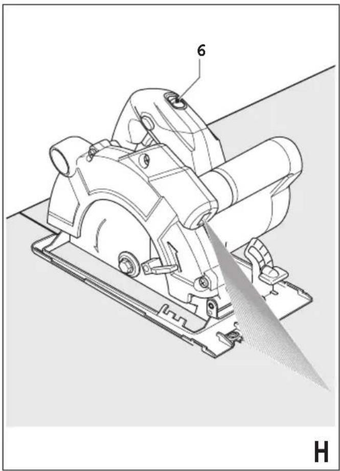
Technical line drawing of a cutting tool with labeled component 6, showing blade and base assembly (no text or symbols beyond labels)Intended use
Your Black & Decker saw has been designed for sawing wood and wood products. This tool is intended for consumer use only.
Safety instructions
General power tool safety warnings

Warning! Read all safety warnings and all instructions. Failure to follow the warnings and instructions listed below may result in electric shock, fire and/or serious injury.
Save all warnings and instructions for future reference.
The term "power tool" in all of the warnings listed below refers to your mains operated (corded) power tool or battery operated (cordless) power tool.
- Work area safety
a. Keep work area clean and well lit. Cluttered or dark areas invite accidents.
b. Do not operate power tools in explosive atmospheres, such as in the presence of flammable liquids, gases or dust. Power tools create sparks which may ignite the dust or fumes.
c. Keep children and bystanders away while operating a power tool. Distractions can cause you to lose control.
- Electrical safety
a. Power tool plugs must match the outlet. Never modify the plug in any way. Do not use any adapter plugs with earthed (grounded) power tools. Unmodified plugs and matching outlets will reduce risk of electric shock.
b. Avoid body contact with earthed or grounded surfaces such as pipes, radiators, ranges and refrigerators. There is an increased risk of electric shock if your body is earthed or grounded.
c. Do not expose power tools to rain or wet conditions. Water entering a power tool will increase the risk of electric shock.
d. Do not abuse the cord. Never use the cord for carrying, pulling or unplugging the power tool. Keep cord away from heat, oil, sharp edges or moving parts. Damaged or entangled cords increase the risk of electric shock.
e. When operating a power tool outdoors, use an extension cord suitable for outdoor use. Use of a cord suitable for outdoor use reduces the risk of electric shock.
f. If operating a power tool in a damp location is unavoidable, use a residual current device (RCD) protected supply. Use of an RCD reduces the risk of electric shock.
- Personal safety
a. Stay alert, watch what you are doing and use common sense when operating a power tool. Do not use a power tool while you are tired or under the influence of drugs, alcohol or medication. A moment of inattention while operating power tools may result in serious personal injury.
b. Use personal protective equipment. Always wear eye protection. Protective equipment such as dust mask, non-skid safety shoes, hard hat, or hearing protection used for appropriate conditions will reduce personal injuries.
c. Prevent unintentional starting. Ensure the switch is in the off-position before connecting to power source and/or battery pack, picking up or carrying the tool. Carrying power tools with your finger on the switch or energising power tools that have the switch on invites accidents.
d. Remove any adjusting key or wrench before turning the power tool on. A wrench or a key left attached to a rotating part of the power tool may result in personal injury.
e. Do not overreach. Keep proper footing and balance at all times. This enables better control of the power tool in unexpected situations.
f. Dress properly. Do not wear loose clothing or jewellery. Keep your hair, clothing and gloves away from moving parts. Loose clothes, jewellery or long hair can be caught in moving parts.
g. If devices are provided for the connection of dust extraction and collection facilities, ensure these are connected and properly used. Use of dust collection can reduce dust-related hazards.
- Power tool use and care
a. Do not force the power tool. Use the correct power tool for your application. The correct power tool will do the job better and safer at the rate for which it was designed.
b. Do not use the power tool if the switch does not turn it on and off. Any power tool that cannot be controlled with the switch is dangerous and must be repaired.
c. Disconnect the plug from the power source and/or the battery pack from the power tool before making any adjustments, changing accessories, or storing power tools. Such preventive safety measures reduce the risk of starting the power tool accidentally.
d. Store idle power tools out of the reach of children and do not allow persons unfamiliar with the power tool or these instructions to operate the power tool. Power tools are dangerous in the hands of untrained users.
e. Maintain power tools. Check for misalignment or binding of moving parts, breakage of parts and any other condition that may affect the power tools operation. If damaged, have the power tool repaired before use. Many accidents are caused by poorly maintained power tools.
ENGLISH
f. Keep cutting tools sharp and clean. Properly maintained cutting tools with sharp cutting edges are less likely to bind and are easier to control.
g. Use the power tool, accessories and tool bits etc. in accordance with these instructions, taking into account the working conditions and the work to be performed. Use of the power tool for operations different from those intended could result in a hazardous situation.
- Service
a. Have your power tool serviced by a qualified repair person using only identical replacement parts. This will ensure that the safety of the power tool is maintained.
Additional power tool safety warnings

Warning! Additional safety warnings for saws
a. Keep hands away from cutting area and the blade. Keep your second hand on auxiliary handle, or motor housing. If both hands are holding the saw, they cannot be cut by the blade.
b. Do not reach underneath the workpiece. The guard cannot protect you from the blade below the workpiece.
c. Adjust the cutting depth to the thickness of the workpiece. Less than a full tooth of the blade teeth should be visible below the workpiece.
d. Never hold piece being cut in your hands or across your leg. Secure the workpiece to a stable platform. It is important to support the work properly to minimize body exposure, blade binding, or loss of control.
e. Hold power tool by insulated gripping surfaces when performing an operation where the cutting tool may contact hidden wiring or its own cord. Contact with a "live" wire will also make exposed metal parts of the power tool "live" and shock the operator.
f. When ripping always use a rip fence or straight edge guide. This improves the accuracy of cut and reduces the chance of blade binding.
g. Always use blades with correct size and shape (diamond versus round) of arbour holes. Blades that do not match the mounting hardware of the saw will run eccentrically, causing loss of control.
h. Never use damaged or incorrect blade washers or bolt. The blade washers and bolt were specially designed for your saw, for optimum performance and safety of operation.
Further safety instructions for all saws
Causes and operator prevention of kickback:
- kickback is a sudden reaction to a pinched, bound or misaligned saw blade, causing an uncontrolled saw to lift up and out of the workpiece toward the operator;
- when the blade is pinched or bound tightly by the kerf closing down, the blade stalls and the motor reaction drives the unit rapidly back toward the operator;
- if the blade becomes twisted or misaligned in the cut, the teeth at the back edge of the blade can dig into the top surface of the wood causing the blade to climb out of the kerf and jump back toward the operator.
Kickback is the result of saw misuse and/or incorrect operating procedures or conditions and can be avoided by taking proper precautions as given below.
a. Maintain a firm grip with both hands on the saw and position your arms to resist kickback forces. Position your body to either side of the blade, but not in line with the blade. Kickback could cause the saw to jump backwards, but kickback forces can be controlled by the operator, if proper precautions are taken.
b. When the blade is binding, or when interrupting a cut for any reason, release the trigger and hold the saw motionless in the material until the blade comes to a complete stop. Never attempt to remove the saw from the work or pull the saw backward while the blade is in motion or kickback may occur. Investigate and take corrective actions to eliminate the cause of blade binding.
c. When restarting a saw in the workpiece, centre the saw blade in the kerf and check that saw teeth are not engaged into the material. If saw blade is binding, it may walk up or kickback from the workpiece as the saw is restarted.
d. Support large panels to minimise the risk of blade pinching and kickback. Large panels tend to sag under their own weight. Supports must be placed under the panel on both sides, near the line of cut and near the edge of the panel.
e. Do not use dull or damaged blades. Unsharpened or improperly set blades produce narrow kerf causing excessive friction, blade binding and kickback.
f. Blade depth and bevel adjusting locking levers must be tight and secure before making cut. If blade adjustment shifts while cutting, it may cause binding and kickback.
g. Use extra caution when making a "plunge cut" into existing walls or other blind areas. The protruding blade may cut objects that can cause kickback.
Safety instructions for circular saws with outer or inner pendulum guards and with tow guard
a. Check lower guard for proper closing before each use. Do not operate the saw if lower guard does not move freely and close instantly. Never clamp or tie the lower guard into the open position. If saw is accidentally dropped, lower guard may be bent. Raise the lower guard with the retracting handle and make sure it moves freely and does not touch the blade or any other part, in all angles and depths of cut.
b. Check the operation of the lower guard spring. If the guard and the spring are not operating properly, they must be serviced before use. Lower guard may operate sluggishly due to damaged parts, gummy deposits, or a build-up of debris.
c. Lower guard should be retracted manually only for special cuts such as "plunge cuts" and "compound cuts". Raise lower guard by retracting handle and as soon as blade enters the material, the lower guard must be released. For all other sawing, the lower guard should operate automatically.
d. Always observe that the lower guard is covering the blade before placing saw down on bench or floor. An unprotected, coasting blade will cause the saw to walk backwards, cutting whatever is in its path. Be aware of the time it takes for the blade to stop after switch is released.
Additional safety instructions for all saws with riving knife
a. Use the appropriate riving knife for the blade being used. For the riving knife to work, it must be thicker than the body of the blade but thinner than the tooth set of the blade.
b. Adjust the riving knife as described in this instruction manual. Incorrect spacing, positioning and alignment can make the riving knife ineffective in preventing kickback.
c. Always use the riving knife except when plunge cutting. Riving knife must be replaced after plunge cutting. Riving knife causes interference during plunge cutting and can create kickback.
d. For the riving knife to work, it must be engaged in the workpiece. The riving knife is ineffective in preventing kickback during short cuts.
e. Do not operate the saw if riving knife is bent. Even a light interference can slow the closing rate of a guard.
Residual risks
The following risks are inherent to the use of saws:
- Injuries caused by touching the rotating parts.
Even with the application of the relevant safety regulations and the implementation of safety devices, certain residual risks cannot be avoided. These are:
- Impairment of hearing.
- Risk of accidents caused by the uncovered parts of the rotating saw blade.
- Risk of injury when changing the blade.
- Risk of squeezing fingers when opening the guards.
- Health hazards caused by breathing dust developed when sawing wood, especially oak, beech and MDF.
Saw blades
Do not use blades of larger or smaller diameter than recommended. For the proper blade rating refer to the technical data. Use only the blades specified in this manual, complying with EN 847-1.
◆ Warning! Never use abrasive wheels.
Safety of others
This appliance is not intended for use by persons (including children) with reduced physical, sensory or mental capabilities, or lack of experience and knowledge, unless they have been given supervision or instruction concerning use of the appliance by a person responsible for their safety.
◆ Children should be supervised to ensure that they do not play with the appliance.
Vibration
The declared vibration emission values stated in the technical data and the declaration of conformity have been measured in accordance with a standard test method provided by EN 60745 and may be used for comparing one tool with another. The declared vibration emission value may also be used in a preliminary assessment of exposure.
Warning! The vibration emission value during actual use of the power tool can differ from the declared value depending on the ways in which the tool is used. The vibration level may increase above the level stated.
When assessing vibration exposure to determine safety measures required by 2002/44/EC to protect persons regularly using power tools in employment, an estimation of vibration exposure should consider, the actual conditions of use and the way the tool is used, including taking account of all parts of the operating cycle such as the times when the tool is switched off and when it is running idle in addition to the trigger time.
Labels on tool
The following pictograms are shown on the tool:

Warning! To reduce the risk of injury, the user must read the instruction manual.
ENGLISH
Electrical safety

This tool is double insulated; therefore no earth wire is required. Always check that the power supply corresponds to the voltage on the rating plate.
If the supply cord is damaged, it must be replaced by the manufacturer or an authorised Black & Decker Service Centre in order to avoid a hazard.
Additional safety instructions for lasers

Read all of this manual carefully.

This product is not to be used by children under 16.

Warning! Laser radiation.

Do not look into the laser beam.

Do not view the laser beam directly with optical instruments.

Refer to the laser product characteristics.
This laser complies with class 2 according to IEC60825-1:2007. Do not replace a laser diode with a different type. If damaged, have the laser repaired by an authorised repair agent.
- Do not use the laser for any purpose other than projecting laser lines.
- An exposure of the eye to the beam of a class 2 laser is considered safe for a maximum of 0.25 seconds. Eyelid reflexes will normally provide adequate protection. At distances over 1 m, the laser complies with class 1 and thus is considered completely safe.
◆ Never look into the laser beam directly and intentionally.
◆ Do not use optical tools to view the laser beam.
- Do not set up the tool at a position where the laser beam can cross any person at head height.
◆ Do not let children come near the laser.
Warning! The use of controls or adjustment or performance of procedures other than those specified in these instructions may result in exposure to hazardous laser radiation.
Warning! This tool is intended for indoor use only. Do not use the tool for outdoor applications.
Features
- On/off switch
- Lock-off button
- Main handle
- Secondary handle
- Spindle lock button
- Laser on/off switch
- Laser aperture
- Shoe
- Saw blade
- Saw blade guard
- Riving knife
- Saw dust outlet
Assembly
Warning! Before attempting any of the following operations, make sure that the tool is switched off and unplugged and that the saw blade has stopped.
Removing and fitting a saw blade (fig. A)
Removing
- Keep the spindle lock button (5) depressed and rotate the blade until the spindle lock engages.
- Loosen and remove the blade retaining screw (13) by turning it counterclockwise using the spanner (14) supplied.
◆ Remove the outer washer (15).
◆ Remove the saw blade (9).
Fitting
◆ Place the saw blade onto the inner flange (16), making sure that the arrow on the blade points in the same direction as the arrow on the tool.
◆ Fit the outer washer (15) on the spindle, with the raised part pointing away from the saw blade.
◆ Insert the blade retaining screw (13) into the hole.
◆ Keep the spindle lock button (5) depressed.
- Securely tighten the blade retaining screw by turning it clockwise using the spanner (14) supplied.
◆ Adjust the riving knife as described below.
Adjusting the riving knife (fig. B)
The riving knife prevents the saw blade from jamming during rip sawing operations. The riving knife must be adjusted after replacing the saw blade.
◆ Loosen the screws (17), using the spanner (14), while holding the riving knife in position.
◆ Position the riving knife (11) as shown.
◆ The distance between the toothed rim and the riving knife should be 2 - 3 mm.
◆ The height difference between the toothed rim and the lower end of the riving knife should be 2 - 3 mm.
◆ Tighten the screws.
Fitting and removing the parallel fence (fig. C)
- The parallel fence is used to saw in a straight line parallel to the edge of the workpiece.
Fitting
◆ Loosen the locking knob (18).
◆ Insert the parallel fence (19) through the openings (20).
◆ Slide the parallel fence into the desired position.
◆ Tighten the locking knob.
Removing
◆ Loosen the locking knob.
◆ Pull the parallel fence off the tool.
Use
Warning! Let the tool work at its own pace. Do not overload.
This tool can be used in the right hand or the left hand.
Adjusting the sawing angle (fig. D)
The default angle between the saw blade and the shoe is 90°.
Use a square to check that the angle between the saw blade and the shoe is 90^ . If the angle does not measure 90^ adjust as follows:
◆ Loosen the locking knob (21) to unlock the saw shoe.
◆ Loosen the locknut (22) on the adjusting screw (23).
◆ Screw the adjusting screw in or out to achieve a 90° angle.
◆ Retighten the locknut.
◆ Tighten the locking knob to lock the saw shoe in place.
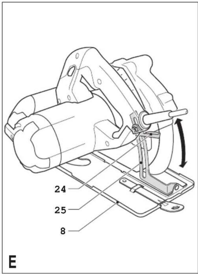
Adjusting the depth of cut (fig. E)
The depth of cut should be set according to the thickness of the workpiece. It should exceed the thickness by approx. 2 mm.
◆ Loosen the knob (24) to unlock the saw shoe.
- Move the saw shoe (8) into the desired position. The corresponding depth of cut can be read from the scale (25).
◆ Tighten the knob to lock the saw shoe in place.
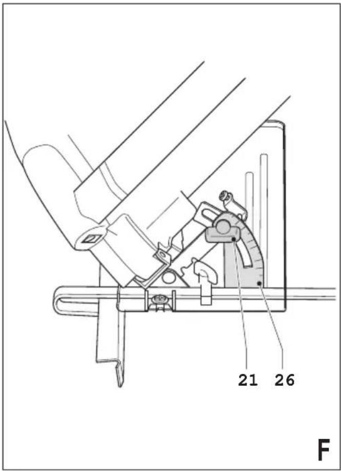
Adjusting the bevel angle (fig. F)
This tool can be set to bevel angles between 0° and 45°.
◆ Loosen the locking knob (21) to unlock the saw shoe.
- Move the saw shoe (10) into the desired position. The corresponding bevel angle can be read from the scale (26).
◆ Tighten the locking knob to lock the saw shoe in place.
Switching on and off
◆ To switch the tool on, move the lock-off button (2) into the unlock position and squeeze the on/off switch (1).
◆ To switch the tool off, release the on/off switch.
Sawing
Always hold the tool with both hands.
- Let the blade run freely for a few seconds before starting the cut.
- Apply only a gentle pressure to the tool while performing the cut.
◆ Work with the shoe pressed against the workpiece.
Hints for optimum use
- As some splintering along the line of cut on the top side of the workpiece cannot be avoided, cut on the side where splintering is acceptable.
- Where splintering is to be minimised, e.g. when cutting laminates, clamp a piece of plywood onto the top of the workpiece.
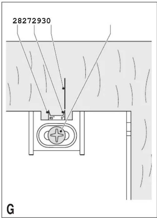
Using the sight guide (fig. G)
The tool is equipped with a sight guide for straight cutting (27) and for 45° bevel cutting (28).
- Adjust the sight guide as described below.
◆ Align the left edge of the guides (27) or (28) with the cutting line (29). - Keep the sight guide aligned with the cutting line while sawing.
◆ Work with the shoe pressed against the workpiece.
Adjusting the sight guide
◆ Make a test cut halfway through a piece of scrap wood.
◆ Withdraw the saw so the cutting line (29) becomes visible.
- While keeping the saw in this position, loosen the sight guide on the saw shoe as shown.
♦ Align the 0° mark (27) on the sight guide with the cutting line (29). When adjusting for 45° bevel cuts, align the 45° mark (28) on the sight guide with the cutting line.
◆ Secure the sight guide using the screw (30).
How to use the laser (fig. H)
The laser projects the line of cut on the workpiece surface.
◆ To switch the laser on, slide the switch (6) forward.
To switch the laser off, slide the switch (6) backward. Viewing from directly above the saw, the line of cut can be easily followed. Should this view be restricted for any reason, the laser can be used as an alternate cutting guide.
◆ Use a pencil to mark the cutting line.
◆ Position the saw over the line.
◆ Switch on the laser.
ENGLISH
Dust extraction
An adaptor is required to connect a vacuum cleaner or dust extractor to the tool.
◆ Insert the dust extraction adaptor into the saw dust outlet (12).
◆ Connect the vacuum cleaner hose to the adaptor.
Maintenance
Your Black & Decker corded/cordless appliance/tool has been designed to operate over a long period of time with a minimum of maintenance. Continuous satisfactory operation depends upon proper tool care and regular cleaning.
Warning! Before performing any maintenance on corded/ cordless power tools:
◆ Switch off and unplug the appliance/tool.
- Or switch off and remove the battery from the appliance/tool if the appliance/tool has a separate battery pack.
- Or run the battery down completely if it is integral and then switch off.
◆ Unplug the charger before cleaning it. Your charger does not require any maintenance apart from regular cleaning.
- Regularly clean the ventilation slots in your appliance/tool/charger using a soft brush or dry cloth.
◆ Regularly clean the motor housing using a damp cloth. Do not use any abrasive or solvent-based cleaner.
- Regularly open the chuck and tap it to remove any dust from the interior (when fitted).
Mains plug replacement (U.K. & Ireland only)
If a new mains plug needs to be fitted:
◆ Safely dispose of the old plug.
◆ Connect the brown lead to the live terminal in the new plug.
◆ Connect the blue lead to the neutral terminal.
◆ Connect the green/yellow lead to the earth terminal.
Warning! Follow the fitting instructions supplied with good quality plugs. Recommended fuse: 13 A.
Protecting the environment

Separate collection. This product must not be disposed of with normal household waste.
Should you find one day that your Black & Decker product needs replacement, or if it is of no further use to you, do not dispose of it with household waste. Make this product available for separate collection.

parate collection of used products and packaging allows materials to be recycled and used again. Re-use of recycled materials helps prevent environmental pollution and reduces the demand for raw materials.
Local regulations may provide for separate collection of electrical products from the household, at municipal waste sites or by the retailer when you purchase a new product.
Black & Decker provides a facility for the collection and recycling of Black & Decker products once they have reached the end of their working life. To take advantage of this service please return your product to any authorised repair agent who will collect them on our behalf.
You can check the location of your nearest authorised repair agent by contacting your local Black & Decker office at the address indicated in this manual. Alternatively, a list of authorised Black & Decker repair agents and full details of our after-sales service and contacts are available on the Internet at: www.2helpU.com
Technical data
| KS1400L TYPE 2 | KS1401L TYPE 2 | |
| Input voltage V | AC 230 230 | |
| Power input W 1,400 1,400 | ||
| No-load speed min | -1 5,200 | 5,200 |
| Max. depth of cut mm 65 65 | ||
| Depth of cut at 45° bevel mm 50 50 | ||
| Blade diameter | mm 190 190 | |
| Blade bore | mm 16 16 | |
| Blade tip width | mm 2.3 | 2.3 |
| Laser properties: | ||
| Laser class | 2 | 2 |
| Wave length | nm 650 650 | |
| Laser power | mW < 5 < 5 | |
| Weight | kg 5.4 | 5.4 |
| KS1500L TYPE 2 | KS1501L TYPE 2 | |
| Input voltage V | AC 230 230 | |
| Power input W 1,500 1,500 | ||
| No-load speed min | -1 5,200 | 5,200 |
| Max. depth of cut mm 65 65 | ||
| Depth of cut at 45° bevel mm 50 50 | ||
| Blade diameter | mm 190 190 | |
| Blade bore | mm 16 16 | |
| Blade tip width | mm 2.3 | 2.3 |
| Laser properties: | ||
| Laser class | 2 | 2 |
| Wave length | nm 650 650 | |
| Laser power | mW < 5 < 5 | |
| Weight | kg 5.4 | 5.4 |
KS1600L TYPE 2
| Input voltage V | AC 230 |
| Power input W 1,600 | |
| No-load speed min | -1 5,200 |
| Max. depth of cut mm 65 | |
| Depth of cut at 45° bevel mm 50 | |
| Blade diameter mm 190 | |
| Blade bore mm 16 | |
| Blade tip width mm 2.3 | |
| Laser properties: | |
| Laser class 2 | |
| Wave length nm 650 | |
| Laser power mW < 5 | |
| Weight kg 5.4 |
Level of sound pressure according to EN 60745:
| Sound pressure (LpA) 95 dB(A), uncertainty (K) 3 dB(A) |
| Acoustic power (LwA) 106 dB(A), uncertainty (K) 3 dB(A) |
Vibration total values (triax vector sum) according to EN 60745:
| Vibration emission value (ah) 2.2 m/s2, uncertainty (K) 1.5 m/s2 |
EC declaration of conformity
MACHINERY DIRECTIVE

KS1400L/KS1401L/KS1500L/KS1501L/KS1600L
Black & Decker declares that these products described under "technical data" are in compliance with: 2006/42/EC, EN 60745-1, EN 60745-2-5
For more information, please contact Black & Decker at the following address or refer to the back of the manual.
The undersigned is responsible for compilation of the technical file and makes this declaration on behalf of Black & Decker.
Kevin Hewitt
Vice-President Global Engineering
Black & Decker Europe, 210 Bath Road, Slough,
Berkshire, SL1 3YD
United Kingdom
04/10/2011
Guarantee
Black & Decker is confident of the quality of its products and offers an outstanding guarantee. This guarantee statement is in addition to and in no way prejudices your statutory rights. The guarantee is valid within the territories of the Member States of the European Union and the European Free Trade Area.
If a Black & Decker product becomes defective due to faulty materials, workmanship or lack of conformity, within 24 months from the date of purchase, Black & Decker guarantees to replace defective parts, repair products subjected to fair wear and tear or replace such products to ensure minimum inconvenience to the customer unless:
◆ The product has been used for trade, professional or hire purposes;
◆ The product has been subjected to misuse or neglect;
◆ The product has sustained damage through foreign objects, substances or accidents;
◆ Repairs have been attempted by persons other than authorised repair agents or Black & Decker service staff.
To claim on the guarantee, you will need to submit proof of purchase to the seller or an authorised repair agent. You can check the location of your nearest authorised repair agent by contacting your local Black & Decker office at the address indicated in this manual. Alternatively, a list of authorised Black & Decker repair agents and full details of our after-sales service and contacts are available on the Internet at:
www.2helpU.com
Please visit our website www.blackanddecker.co.uk to register your new Black & Decker product and to be kept up to date on new products and special offers. Further information on the Black & Decker brand and our range of products is available at www.blackanddecker.co.uk
DEUTSCH
Vice-President Global Engineering
Black & Decker Europe, 210 Bath Road, Slough,
Berkshire, SL1 3YD
Black & Decker Europe, 210 Bath Road, Slough,
Berkshire, SL1 3YD
Royaume Uni
04/10/2011
Garantie
Black & Decker Europe, 210 Bath Road, Slough,
Berkshire, SL1 3YD
Regno Unito
04/10/2011
Garanzia
Vice-President Global Engineering
Black & Decker Europe, 210 Bath Road, Slough,
Berkshire, SL1 3YD
Verenigd Koninkrijk
04/10/2011
Garantie
Vice-President Global Engineering
Black & Decker Europe, 210 Bath Road, Slough,
Berkshire, SL1 3YD
Reino Unido
04/10/2011
Garantía
Black & Decker Europe, 210 Bath Road, Slough,
Berkshire, SL1 3YD
Reino Unido
04/10/2011
Garantia
Vice-President Global Engineering
Black & Decker Europe, 210 Bath Road, Slough,
Berkshire, SL1 3YD
Storbrittannien
04/10/2011
Reservdelar/Reparationer
Visepresident, Global Engineering
Black & Decker Europe, 210 Bath Road, Slough,
Berkshire, SL1 3YD
Storbritannia
04/10/2011
Vice-President Global Engineering
Black & Decker Europe, 210 Bath Road, Slough,
Berkshire, SL1 3YD
Storbritannien
04/10/2011
Reservedele/Reparationer
Vice-President Global Engineering
Black & Decker Europe, 210 Bath Road, Slough,
Berkshire, SL1 3YD
Iso-Britannia
04/10/2011
Korjaukset/Varaosat
Vice-President Global Engineering
Black & Decker Europe, 210 Bath Road, Slough,
Berkshire, SL1 3YD
Ηνωμένο Βασίλειο
04/10/2011
Εγγύηση

ENGLISH
Do not forget to register your product!
www.blackanddecker.co.uk/productregistration
Register your product online at www.blackanddecker.co.uk/productregistration or send your name, surname and product code to Black & Decker in your country.
DEUTSCH
www.blackanddecker.it/productregistration
www.blackanddecker.nl/productregistration
www.blackanddecker.es/productregistration
www.blackanddecker.pt/productregistration
- Intended use
- Safety instructions
- General power tool safety warnings
- Save all warnings and instructions for future reference.
- ENGLISH
- Additional power tool safety warnings
- Further safety instructions for all saws
- Residual risks
- Saw blades
- Safety of others
- Vibration
- Labels on tool
- Electrical safety
- Additional safety instructions for lasers
- Features
- Assembly
- Removing and fitting a saw blade (fig. A)
- Removing
- Fitting
- Adjusting the riving knife (fig. B)
- Fitting and removing the parallel fence (fig. C)
- Use
- Adjusting the sawing angle (fig. D)
- Adjusting the depth of cut (fig. E)
- Adjusting the bevel angle (fig. F)
- Switching on and off
- Sawing
- Hints for optimum use
- Using the sight guide (fig. G)
- Adjusting the sight guide
- How to use the laser (fig. H)
- Dust extraction
- Maintenance
- Mains plug replacement (U.K. & Ireland only)
- Protecting the environment
- EC declaration of conformity
- Guarantee
- www.2helpU.com
- DEUTSCH
- Garantie
- Garanzia
- Garantía
- Garantia
- Reservdelar/Reparationer
- Reservedele/Reparationer
- Korjaukset/Varaosat
- Εγγύηση
- Do not forget to register your product!
Brand : BLACK & DECKER
Model : KS1500L
Category : Service après-vente