
HH64DB3T - Cooker HOOVER - Free user manual and instructions
Find the device manual for free HH64DB3T HOOVER in PDF.


| Product type | Gas freestanding cooker |
| Brand | Hoover |
| Model | HH64DB3T |
| Number of burners | 4 |
| Energy type | Natural gas or propane |
| Oven volume | 58 liters |
| Oven type | Convection oven |
| Maximum power | 10,5 kW |
| Dimensions (H x W x D) | 90 x 60 x 60 cm |
| Net weight | 50 kg |
| Power supply | 220-240 V, 50-60 Hz |
| Energy class | A |
| Oven functions | Conventional cooking, convection, grill, defrost |
| Child safety | Control lock |
| Ignition | Integrated electronic ignition |
| Oven cleaning | Pyrolytic (self-cleaning) |
| Glass type | Refractory double glazing |
| Included accessories | Grill, baking tray, drip pan |
| Repairability | Repairability index: 8.0/10 |
| Warranty | 2 years |
Frequently Asked Questions - HH64DB3T HOOVER
User questions about HH64DB3T HOOVER
0 question about this device. Answer the ones you know or ask your own.
Ask a new question about this device
Download the instructions for your Cooker in PDF format for free! Find your manual HH64DB3T - HOOVER and take your electronic device back in hand. On this page are published all the documents necessary for the use of your device. HH64DB3T by HOOVER.
USER MANUAL HH64DB3T HOOVER
SAFETY INSTRUCTIONS ....03
- General warnings....04
- Protection of the environment ....04
- Installation . 04
- Electrical connection .... 5
- Hob cookware advice ....07
- Use 07
- Cleaning and maintenance 09
- Problem solving .....09
- Aftercare 09
INDICE
IT
ISTRUZIONI DI SICUREZZA....11
We recommend you keep the instructions for installation and use for later reference, and before installing the hob, note its serial number in case you need to get help from the after sales service. WARNING: the appliance and its accessible parts become hot during use. Care should be taken to avoid touching heating elements. Children under 8 years of age must be kept away from the appliance unless they are continuously supervised.
WARNING: use only hob guards designed by the Manufacturer of the cooking appliance or indicated by the Manufacturer of the appliance the instructions for use as suitable or hob guar incorporated in the appliance. The use of inappropriate guards can cause accidents.
WARNING: unattended cooking on a hob with f or oil can be dangerous and may result in fire. NEVER try to extinguish a fire with water, but switch off the appliance and then cover flame e with a lid or a fire blanket.
WARNING: danger of fire: do not store items of the cooking surfaces.
WARNING: if the surface is cracked, do not touch the glass and switch off the appliance to avoid possibility of electric shock.
This appliance can be used by children aged 8 years and above and people with reduced physical, sensory or mental capabilities or lack of experience and knowledge if they have been given supervision or instruction concerning use of the appliance in a safe way and understand the hazards involved. Children should be supervised to ensure that they do not play with the appliance. Cleaning and user maintenance shall not be made by children without supervision.
CAUTION: the cooking process must be supervised. A short term cooking process has to be supervised continuously.
It is strongly recommended to keep children away from the cooking zones while they are in operat or when they are switched off, so long as the residual heat indicator is on, in order to prevent the risks of serious burns.
This appliance is not intended to be operated means of an external timer or separate remote control system.
If present do not to stare into halogen lamp hob elements.
Connect a plug to the supply cable that is able to bear the voltage, current and load indicated on the tag and having the earth contact. The socket must be suitable for the load indicated on the tag and must be having the earth contact connected and in operation. The earth conductor is yellow-green in color. This operation should be carried out by suitably qualified professional. In case of
incompatibility between the socket and the appliance plug, ask a qualified electrician to substitute the socket with another suitable type. The plug and the socket must be conformed to the current norms of the installation country. Connection to the power source can also be made by placing an omnipolar breaker between the appliance and the power source that can be the maximum connected load and that is in line with current legislation.
The yellow-green earth cable should not be interrupted by the breaker. The socket or homnipolar breaker used for the connection should be easily accessible when the appliance is installed.
The disconnection may be achieved by having the plug accessible or by incorporating a switch in the fixed wiring in accordance with the wiring rules.
gf the supply cord is damaged, it must be replaced by Manufacturer, its service agent or similarly qualified people in order to avoid a hazard. The earth conductor (yellow-green) must be longer
than 10 mm on the terminal block side. The thermal conductors section should be appropriate to the power absorbed by the hob (indicated on the tag). The type of power cable must be HO5V2V2-F.
fDo not put metallic objects such as knives, forks spoons or lids on the hob. They could heat up. fAluminum foil and plastic pans must not be placed on heating zones.
After every use, some cleaning of the hob is necessary to prevent the build-up of dirt and grease. If left, this is recooked when the hob is used and burns giving off smoke and unpleasant smells, not to mention the risks of fire propagation.
Never use a steam or high pressure spray to clean the appliance.
Do not touch the heat zones during operation or for a while after use.
Never cook food directly on the glass ceramic hob.
/Always use the appropriate cookware. Always place the pan in the center of the unit that you cooking on.
Do not place anything on control panel.
Do not use the hob as a working surface.
Do not use the surface as a cutting board.
Do not store heavy items above the hob. If they stop onto the hob, they may cause damage.
Do not use the hob for storage of any items.
Do not slide cookware across the hob. No additional operation/setting is required in order to operate the appliance at the rated frequencies.
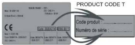
Identification Plate (located under the hob's bottom casing)
By placing the mark on this appliance we are assuring compliance to all European Safety, Health and Environment requirements which are applicable for this product category.
2. PROTECTION OF THE ENVIRONMENT
This appliance is marked according to European Directive 2012/19/EU on Waste Electrical and Electronic Equipment (WEEE). WEEE contains both polluting substances (which can cause negative consequences for the environment) and basic components which can be reused. It is important to have WEEE subjected to specific treatments, in order to remove and dispose properly all pollutants and recover and recycle all materials.
IndividualscanplayanimportantroleinensuringthattheWEEE doesnotbecomeanenvironmentalissue;itisessentialtofollow somebasicrules:
•WEEE shall not be threatened as household waste.
- WEEE shall be handled over to the relevant collection points managed by the municipality or by registered companies. In many Countries, for large WEEE, home collection could be present. - In many Countries, when you buy an new appliance, the old one may be returned to other retailer who have to collect it free of charge on a one-to-one basis, as long as the appliance is of equivalent typology and has the same functions as the supplied one.
3. INSTALLATION
Installing a domestic appliance it is a complicated operation which, if not carried out correctly, can seriously have impact on safety of goods, properties or people. For this reason, it should be carried out by a professionally qualified person in accordance with technical regulations.
In the event that this advice it is ignored and installation is carried out by an unqualified person, the Manufacturer declines all responsibility for any technical failure of the appliance whether or not it results in damage of goods or properties or in injury of people or animals.
After having removed the packaging please be sure that the appliance it is not damaged, otherwise contact the Retailer or Manufacturer After Sales Service.
Make sure that the furniture in which the appliance will be fitted and all other furniture in the nearby are made with materials which can withstand high temperatures (min 100 °C).
In addition, all decorative laminates should be fixed with high-resistance glue.
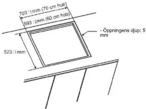
Appliance can be installed in a Built-in furniture in "Standard" or "Flush" mode.
Worktop thickness should be between 25 and 45 mm.
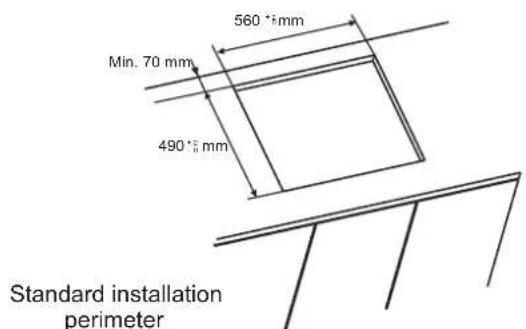
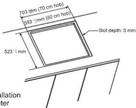
Note: Inner perimeter dimensions are same with standard installation
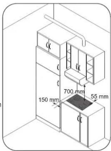
Leave a distance of at least 55 mm between the hob and the back wall and of at least 150 mm between the hob and the vertical furniture or walls in the lateral side. If a furniture is installed above the hob, the minimum distance required is 700 mm.
When installing a hood above the hob, please consult the installation requirements specified for the hood but, in any case, the distance between the hob and the hood must not be lower than 700 mm.
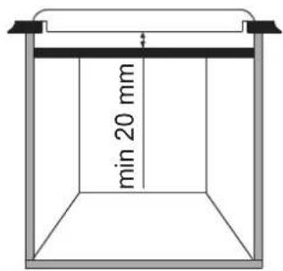
If the bottom part of the hob is adjacent to an area normally accessible for handling or cleaning operations, a separator it must be put 20 mm below the bottom part of the hob.
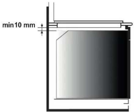
When installing an oven under the hob, separator must not be put and the minimum distance between the bottom part of the hob and the oven must not be lower than 10 mm. Do not install not cooled oven under this hob and install the oven following its own installation requirements.
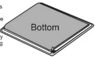
A watertight seal gasket is supplied with the hob. Fit the seal gasket around the bottom hob as described and make sure that it is properly fitted to avoid any leakage into the supporting furniture.
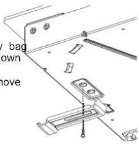
Normal Fixing:
- Get the fixing clips from accessory bag and screw them into the position shown on bottom box. (Do not tighten the screws to block clips, they should move freely)
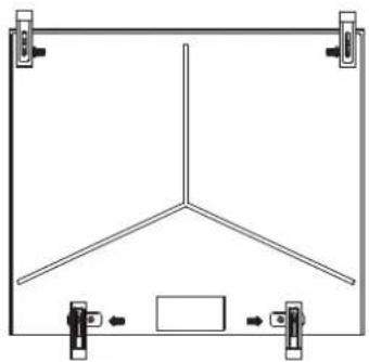
- Insert the hob in center position of cut out. - Turn the clips and tighten them fully.
natural_image
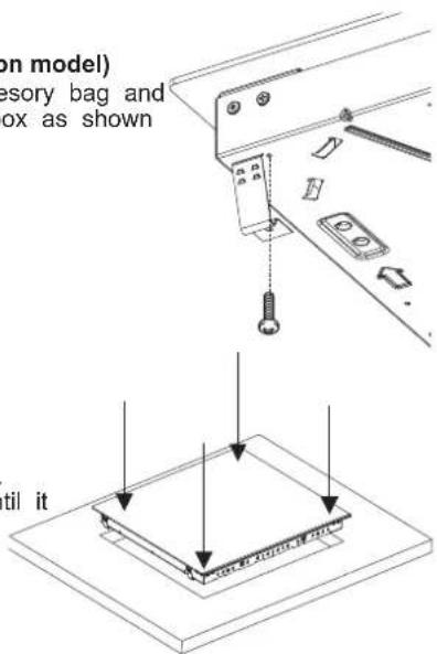
Pure technical line drawing of a Y-shaped structural frame with mounting clips (no text or symbols)Quick Fixing: (Depending on model)
Get four springs form accesory bag and screw them onto bottom box as shown in figure.
Center and insert the hob. Press the sides of hob until it is supported around its entire perimeter.
FLUSH INSTALLATION
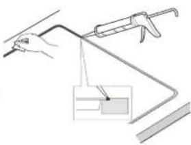
After checking that the position of the hob is correct fill the gap between the worktop and the hob with silicone adhesive. Flatten the silicone layer with a scraper or with wet finger damped with water and soap before it forms. Do not use the hob until the silicone layer it is completely dry.
natural_image
Illustration of a hand using a tool to lift a curved object, with no visible text or symbols4. ELECTRICAL CONNECTION
According to model
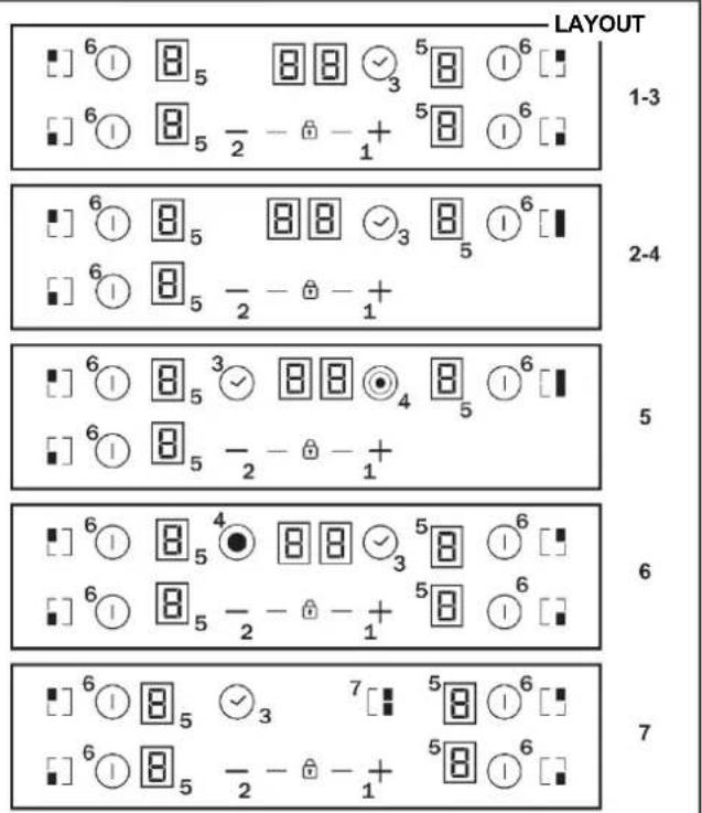
1."+"
"2"
3. TIMER
4. Additional cooking zone led
5. Cooking zone programming indicator
6. Selection of the zone
7. Bridge
"Installation must conform to the standards & directives." Manufacturer declines all responsibility for any damage that might be caused by unsuitable or unreasonable use.
WARNING: Manufacturer cannot be held responsible for any incident or its consequences that may arise during the use of an appliance not linked to the earth, or linked to an earth whose continuity is defective. Before any electrical operation, please check the supply tension shown on the electricity meter, the adjustment of the circuit-breaker, the continuity of the connection to earth to the installation and that the fuse is suitable.
The electrical connection to the installation should be made according to the rated power of the Appliance; this should be made via an Omni pole cut-out switch.
If the appliance has a socket outlet, it must be installed so that the socket outlet is accessible.
The yellow/green wire of the power supply cable must be connected to the earth of both power supply and appliance terminals. For any questions regarding power supply cord refer to After Sales Service or a qualified technician.
If the hob is fitted with power supply cord, this shall be connected only to a power supply of 220-240 V between phase and neutral.
It is however possible to connect the hob to:
Three Phase 220-240 V3
Three Phase 380-415 V2N
To proceed to the new connection, please follow below instructions: Before making the connection, make sure that the installation is protected by a suitable fuse, and that it is fitted with wires of a large enough section to supply the appliance normally. Turn over the hob, glass side against the working top, taking care to protect the glass.
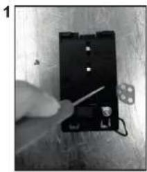
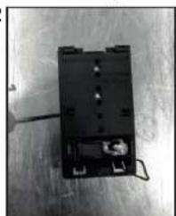
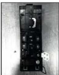
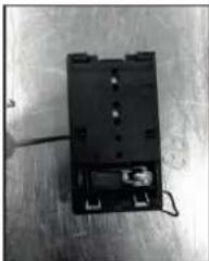
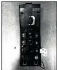
Open the cover in the following sequence:
natural_image
Close-up of a hand holding a small electronic component with wires, placed on a wooden surface (no visible text or symbols)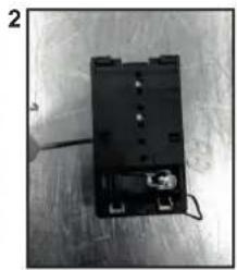
natural_image
Black electronic component with wires and connectors on a wooden surface (no visible text or symbols)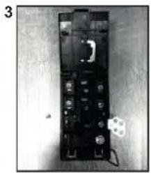
natural_image
Black-and-white photo of a handheld electronic device with buttons and a small white component, placed on a light surface (no visible text or symbols)- unscrew the cable clamp "1";
- find the two tabs located on the sides;
- put the blade of a flat screw-driver in front of each tab "2" e
"3", push in and press; - remove the cover.
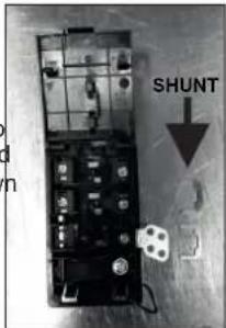
To release the power supply cord:
- Remove the screws retaining the terminal block which contains the shunt bars and the conductors of the supply cord;
- Pull out the supply cord.
Operations to be carried out to make a new connection:
- Choose the power supply cable in accordance with the recommendations in the table;
- Pass the power supply cable into the clamp;
- Strip the end of each conductor of the supply cord on a 10 mm length, by taking in account the requested length of the cord for the connection to the terminal block;
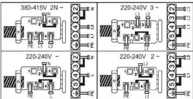
-According to the installation and with the help of shunt bars which you should have recovered in the first operation, fix the conductor as shown on the chart; - Fix the cover;
- Screw the cable clamp.
Note: make sure the terminal board screws are tight.
Operations to be carried out to make a new connection:
- Choose the power supply cable in accordance with the recommendations in the table;
- Pass the power supply cable into the clamp;
- Strip the end of each conductor of the supply cord on a 10 mm length, by taking in account the requested length of the cord for the connection to the terminal block;
- According to the installation and with the help of shunt bars which you should have recovered in the first operation, fix the conductor as shown on the chart;
- Fix the cover;
- Screw the cable clamp.
ATTENTION:
If it should be necessary to replace the power supply cord, connect the wire in accordance with following colors/codes:
| BLUE | Neutral | (N) |
| BROWN | Live | (L) |
| YELLOW-GREEN | Earth | (⊕) |
Connection to the terminals on the terminal block
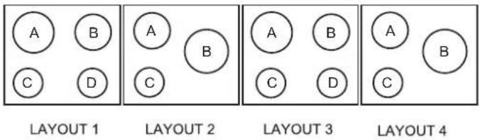
| LAY OUT"1-6" | LAY OUT"7" | |
| MONOPHASE or TWO PHASES 220-240 V~ | ||
| CableHO5V2V2F | 3x2,5 mm ^2 | 3x4 mm ^2 |
| THREE PHASES 220-240 V3~ | ||
| CableHO5V2V2F | 4x1,5 mm ^2 | 4x1,5 mm ^2 |
| THREE PHASES 380-415 V2N~ | ||
| CableHO5V2V2F | 4x1,5 mm ^2 | 4x1,5 mm ^2 |
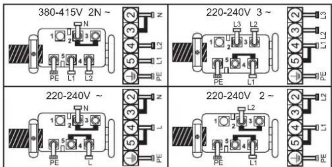
L1 / L2 / L3 = Phase N = Neutral PE = Earth
5. HOB COOKWARE ADVICE
Using good quality cookware is critical for setting the best performance from your hob.

natural_image
Three identical illustrations of cooking utensils with crossed-out X marks, no text or symbols present.• Always use good quality cookware with perfectly flat and thick bases : using this type of cookware will prevent hot spots that cause foodtostick.Thickmetalpotsandpanswillprovideaneven distributionofheat.
- Ensure that the base of the pot or pan is dry: when filling pans with liquid or using one that has been stored in the refrigerator, ensure that the base of the pan is completely dry before placing it on the hob. This will help to avoid staining the hob.
- Use pans whose diameter is wide enough to completely cover the surface unit: the size of the pan should be no smaller than the heating area. If it is slightly wider the energy will be used at its maximum efficiency.
THE CHOICE OF COOKWARE - The following information will help you to choose cookware which will give good performance.
Stainless Steel : highly recommended. Especially good with a sandwich clad base. The sandwich base combines the benefits of stainless steel (appearance, durability and stability) with the advantages of aluminium or copper (heat conduction, even heat distribution).
Aluminium : heavy weight recommended. Good conductivity. Aluminium residues sometimes appear as scratches on the hob, but can be removed if cleaned immediately. Because of its low melting point, thin aluminium should not be used.
Cast Iron : usable, but not recommended. Poor performance. May scratch the surface.
Copper Bottom / stoneware: heavy weight recommended. Good performance, but copper may leave residues which can appear as scratches. The residues can be removed, as long as the hob is cleaned immediately. However, do not let these pots boil dry. Overheated metal can bond to glass hobs. An overheated copper pot will leave a residue that will permanently stain the hob.
Porcelain/enamel : Good performance only with a thiny smooth, flat base.
Glass-ceramic : not recommended. Poor performance. May scratch the surface.
6. USE
How to choose power management level
Through the "Power management" function, the user can set the maximum power that can be reached by the hob. Power management function is only available during first 30 seconds after switch on the hob. There is even the possibility to repeat this setting switching off and on the power plug. By setting the desired maximum power, the hob automatically adjusts the distribution in the various cooking zones so that this limit is never exceeded; with the added advantage of being able to simultaneously manage all the zones without overload problems. The customer can set the maximum power of hob between 2.5kW and the maximum related power of the hob (this can change according to the model) (for example if the maximum power of the hob is 7.2kW . The maximum power level for setting is between 2.5kW and 7.2kW ) At the time of purchase, the hob is set to maximum power. After connecting the appliance to the electrical power, within 30 seconds you can set the power level based on the points shown below:
1.- Switch on hob.
2.- Let touch control finish its initialization process.
3.- Before pass 30 seconds touch during 5 seconds (一) key.
4.-After this moment, this message will appear on display.
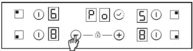
5.- Using 'Plus' and 'Minus' keys Power management value can be adjusted. In this example case between 6500 and 2500w. When required value is selected, touch at the same time 'Plus' & 'Minus' keys during 5 seconds.
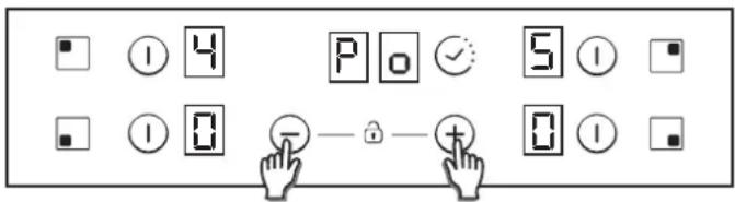
6.- When this process is finished, a long beep is heard and a reset is produced. Start-up process will be generated again.
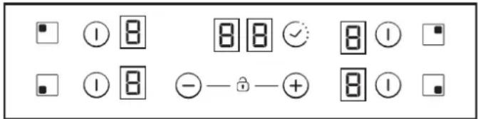
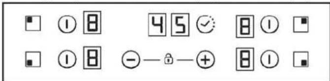
7.- After start-up process, in timer display ECO power management will be showed.
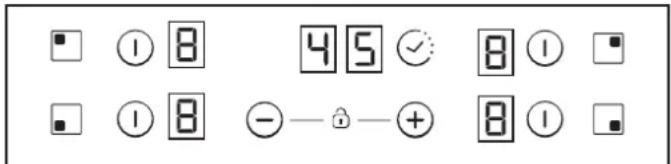
After that, touch control won't allow any combination which can exceed this Eco limit.
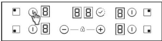
Switch ON/OFF a heater zone
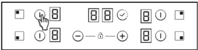
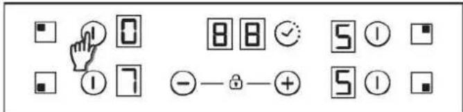
To switch ON a heater Touch any heater's zone during 400 msec. Long beep will be heard and "0" value will appear in target zone digit, indicating power level.
1) If any cooking stage is in position 0, this display will switch OFF automatically after 10 seconds and the zone OFF sequence will sound.
2) If there is residual heat indication in the display which is ON but in 0 power, "0" will appear changing over.
3) If lock function is active you cannot switch ON a zone.
To switch OFF a heater Touch any heater's zone during 1,2 sec. 3 Short beeps will be heard and nothing or "H" value will appear in target zone digit if residual heat exists. Zone will be OFF.
1) If any cooking stage is in position 0, this display will switch OFF automatically after 10 seconds and the zone OFF sequence will sound.
2) If there is residual heat indication in the display which is OFF, "H" will be displayed.
3) Even lock function is active you can switch OFF a zone.
4) If only one heater is active and this one is switched off, 4 Short beep will be heard indicating all cook top is Off.
Selecting a zone
When zone is already ON a lower lighting intensity for the not zones that are ON is produced.
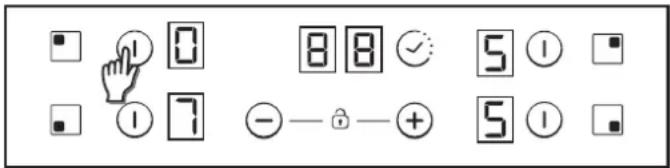
If only one zone is ON, this zone is already selected by default, needing to short press (150 msec) over selection key.
Increase / Decrease power level
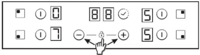
With a short press on '+' or '-' keys, Increase or decrease power selected zones digit: 0-1-2-3...9-P
2 LEDs over extension key turn ON if 1st and 2nd extension rings ON 3rd Short Press on extension key. Switches OFF 1st and 2nd extension rings.
Short beep each press on extension key.
Bridge function
The bridge can be enabled only when both heaters are off. One heat of the bridge has been selected, to activate bridge function touch bridge key.
Abeep sounds and the zone LED is switched on if the zone is enable. It Both bridge heaters will be selected at the same time.
Once the heaters selected, if the power level is not the desired pow level, by the + - keys.
Both bridge heater displays will show same power level.
The function will finish:
- If the bridge key is touched in setting mode
- If user selects power level "0"
Overflow security
Something (an object or a liquid) is pressing any key during more th 5s. 2 Short Beep + 1 Long beep every 30s while the key is presse Cook-top will turn Off. This symbol will maintain blinking while the matter persist.
- For Long Presses in + or - keys, power level increases /decreasesTimer
continuously. With a fast increase, power stops at level 9, and for a higher power another short press is needed on the + key. No beep sound is heard with fast increase / decrease. Timer function can be activated with its own key. Select the zone to be timed. Power level of the - Once arrived to P power level, pressing + key again does not change power level to 0.Once arrived to 0 power level, pressing - key again does not change power level to P. Select the zone to be timed. Power level of the zone greater than 0 Static [E.] is displayed in the zone being timed . "0 0" in the digits reserved for the timer.
- With a zone ON at 0 power level, if the zone is hot, 0 will blink ^1 . With "+" or "-" keys, timer time can be chosen. No Beeps at tim alternatively. After 10 seconds, 0 will disappear an 'H' letter will appear fixed on display. 2) Pressing continuously timer key, the timer is cancelled (goes to 0
- When a heater is selected and '+' & '-' keys are touched at the same time, power level will go to '0' but heater will maintain selected during key, and from "99" to "00" with "+" key.
10 seconds. If heater was temporized, timer will go to Off. This action 5) Maximum time 99 minutes.
can only be developed in several cases depending touch control configuration. The following examples are for information only. Personal experience should then let you adapt these settings to your taste and habits. 6) When the time is elapsed and the hob is beeping, press any key the alarm and digit sequence will end. 7) It is possible to adjust the timer time while the timer is previously running.
Select the zone to be timed. Power level of the zone greater than 0 Static is displayed in the zone being timed . "0 0" in the digits reserved for the timer.
(1) With "+" or "-" keys, timer time can be chosen. No Beeps at time change.
2) Pressing continuously timer key, the timer is cancelled (goes to 0 3) If timer "+" or "-" keys is maintained pressed there is quick settir 4) When setting timer time, it is possible to go from "00" to "99" wi 5) if key, and from "99" to "00" with "+" key.
5) Maximum time 99 minutes.
6) When the time is elapsed and the hob is beeping, press any key the alarm and digit sequence will end.
7) It is possible to adjust the timer time while the timer is previously running.
Child Lock option
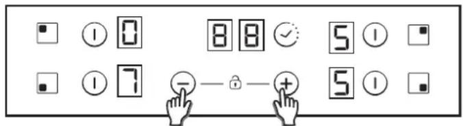
This action will be done when ‘+’ & ‘-’keys were touched at the s time.
Then, any time when a key will be touched, displays will show "L" during 2sec. heating remains at the same state.
To deactivate Child Lock, follow the same process explained before. Then Short beep will be heard and displays will show "n" letter. Ho remain unlocked.
Note: An automatic child lock will produce in 15 minutes after total Switch OFF of the hob.
Double / Triple zones
To switch ON double extension ring, associated main zone must be already ON and Indicating power level must be higher than 0. 8.1- Double zone ON
1st Short Press on extension key Switches ON extension ring. LED over extension key turns ON if Extension ring is ON. 2nd Short Press on extension key Switches OFF extension ring. Short beep each press on extension key.
8) Power of timed zone can be modified without consequences on the timer programming.
9) Last minute will be displayed by seconds (For Variants only visible we enter the timer programming while the last minute of the countdown)
10) Pressing the Timer key without any selected zone and when no zone is being timed, does nothing.
11) Pressing the Timer key without any selected zone and when ma zones are being timed, the time shown in time digits changes in a rotatory way, and shows the time whose power display has the decimal point ON.
12) Alternatively Power (5s) and (0,5s) is displayed in the zone being timed.
Remaining time is displayed in the digits reserved for the timer. If multiple zones are timed, the smallest remaining time is displayed,
band the decimal point is displayed in the corresponding zone.
Residual Heat Indicator (In radiant heaters-> calculated)
The same indicators can be used for "residual heat" indication as we A time table must be defined on this purpose: Rest Heat time=f (po level, working time).
While a temperature on the cook top glass surface is above 65^ Cb(theory value), this condition will be shown in the associated display, by means of an “H”.
To generate a temperature above ^65 C a heating element has to be operation for certain time, this time depends on the power level. Once this time has expired, the residual heat warning will be shown when the heating element is switched off.
8.2- Triple zone ON
1st Short Press on extension key Switches ON 1st extension ring. 1 LED over extension key turns ON if 1st extension ring is ON (left LED in case of triple zone, middle and only LED in case of double zone) 2nd Short Press on extension key Switches ON 2nd extension ring.
Automatic Safety Off
If the power level is not changed during a preset time, the corresponding heater turns off automatically.
The maximum time a heater can stay on, depends on the selected cooking level.
| Power level | Max. time on (hours) |
| 1 | 10 |
| 2 | 5 |
| 3 | 5 |
| 4 | 4 |
| 5 | 3 |
| 6 | 2 |
| 7 | 2 |
| 8 | 2 |
| 9 | 2 |
| P | 2 |
NOTE: while an overheating situation should occur during the operation of the highest power levels, the Hob control will automatically adjust the power level in order to protect the hob from overheating.
7. CLEANING AND MAINTENANCE
. Before carrying out any maintenance work on the hob, allow it to cool down.
.Only products, (creams and scrapers) specifically designed for aglass ceramic surfaces should be used. They are obtainable from hardware stores.
. Avoid spillages, as anything which falls on to the hob surface will quickly burn and will make cleaning more difficult.
.It is advisable to keep away from the hob all substances which are liable to melt, such as plastic items, sugar, or sugar-based products. MAINTENANCE:
- Place a few drops of the specialised cleaning product on the hob surface.
- Rub any stubborn stains with a soft cloth or with slightly damp kitchen paper.
- Wipe with a soft cloth or dry kitchen paper until the surface is clean.
If there are still some stubborn stains:
- Place a few more drops of specialised cleaning fluid on the surface.
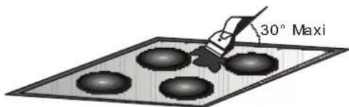
- Scrape with a scraper, holding it at an angle of 30^ to the hob, until the stains disappear.
- Wipe with a soft cloth or dry kitchen paper until the surface is clean.
- Repeat the operation if necessary.
AFEW HINTS:
Frequent cleaning leaves a protective layer which is essential to prevent scratches and wear. Make sure that the surface is clean before using the hob again. To remove marks left by water, use a few drops of white vinegar or lemon juice. Then wipe with absorbent paper and a few drops of specialised cleaning fluid.
The glass ceramic surface will withstand scraping from flat-bottomed cooking vessels, however, it is always better to lift them when moving them from one zone to another.
NB:
Do not use a sponge which is too wet.
Never use a knife or a screwdriver.
A scraper with a razor blade will not damage the surface, as long as it is kept at an angle of 30^ .
Never leave a scraper with a razor blade within the reach of children.
Never use abrasive products or scouring powders.
. The metal surround: to safely clean the metal surround wash with soap and water, rinse, then dry with a soft cloth.
Any change in the colour of the glass-ceramic surface does not affect its operation or the stability of the surface. Such discolorations are mostly a result of burnt food residues or use of cookware made of materials such as aluminium or copper; these stains are difficult to remove.
8. PROBLEM SOLVING
The cooking zones do not simmer or only fry gently
Only use flat-bottomed pans. If light is visible between the pan and the hob, the zone is not transmitting heat correctly.
The pan bottom should fully cover the diameter of the selected zone.
The cooking is too slow
Unsuitable pans are being used. Only use flatbottomed utensils, that are heavy and have a diameter at least the same as the cooking zone.
Small scratches or abrasions on the hob's glass surface
Incorrect cleaning or rough-bottomed pans are used; particles like grains of sand or salt get between the hob and the bottom of the pan. Refer to the "CLEANING" section; make sure that pan bottoms are clean before use and only use smooth bottomed pans. Scratches can be lessened only the cleaning is done correctly.
Metal marks
Do not slide aluminium pans on the hob. Refer to the cleaning recommendations.
You use the correct materials, but the stains persist.
Use a razor blade and follow the "CLEANING" section.
Dark stains
Use a razor blade and follow the "CLEANING" section.
Light surfaces on the hob
Marks from an aluminium or copper pan, but also mineral, water or food deposits; they can be removed using the cream cleaner.
Caramelisation or melted plastic on the hob.
Refer to the "CLEANING" section.
The hob does not operate or certain zones don't work
The shunts are not positioned correctly on the terminal board. Have a check made that the connection is done he control panel is locked. Unlock the hob.
The hob does not cut off.
The control panel is locked. Unlock the hob.
Frequency of on/off operations for cooking zones
The on-off cycles vary according to the required heat level:
- low level: short operating time,
- high level: long operating time.
The cooktop is not working.
Check the condition of the fuses / circuit breakers at your location. Check to see if you are experiencing a power failure.
The cooktop has turned itself off.
The main switch (ON/OFF key) was accidentally touched or there is any object above any key. Turn the unit on again without any object about the keyboard. Enter your settings again.
Display F and numbers
If F and numbers appears in the display, your unit has detected a fault. The following table list actions you can take to correct the problem.
9. AFTERCARE
Before calling out a Service Engineer please check the
following:
— that the plug is correctly inserted and fused;
If the fault cannot be identified switch off the appliance — do not tamper with it — call the Aftercare Service Centre. The appliance is supplied with a guarantee certificate that ensures that it will be repaired free of charge at the Service Centre.
Heater display Fault Action
| F0 | Touch control softwareerror. | If error has occurred disconnected and connect again the cooktop to the power supply. If error persist, call after-sales service. If error appears suddenly in a normal operation, call after-sales service. |
| Fc | Touch control zone is too hot and has turned off all the heaters. | Wait until temperature goes down. Cook-top will automatically recovered when temperature reaches a normal value. |
| Ft | Touch control temperature sensor can be damaged. | Wait until temperature goes down. If message persist when temperature reaches an environment value, call after-sales service. |
| FE | Touch control temperature sensor can be damaged. | Wait until temperature goes down. If message persist when temperature reaches an environment value, call after-sales service. |
| Fb | Excessive sensitivity on any key. | See if cook-top is mounted correctly. Be sure that keys touch correctly the glass surface. |
| FU / FJ | Security keyboard error | This error is a keyboard auto-check. It disappears when autocheck return to secure value. If error persist, call after-sale service. |
| FA | Security software error | This error is a software auto-check. It disappears when auto-check return to secure value. If error persist, call after-sale service. |
| FC / Fd | Security software error | This error is a software auto-check. It disappears when auto-check return to secure value. If error persist, call after-sale service. |
| Fr | Relays security error | Any relay driver can have any problemn. Remove cook-top from the power supply, wait a minute and switch on again. If error persist, call after-sale service. |
natural_image
Technical line drawing of a mechanical assembly with no visible text or symbolsnatural_image
Simple line drawing of a Y-shaped frame with connectors and a central rectangle (no text or symbols)natural_image
Technical line drawing of a mechanical assembly with no visible text or symbolsnatural_image
Isometric diagram of a layered structure with arrows indicating direction (no text or symbols)INSTALLAZIONEAFILO
natural_image
Simple line drawing of a hand holding a tool with a bracket and a small inset showing a grid (no text or symbols)| BLU | Neutro | (N) |
| MARRONE | Fase | (L) |
| GIALLO VERDE | Terra | (⊕) |
L1 / L2 / L3 = Fase N = Neutro PE = Terre
natural_image
Three identical illustrations of a cooking pot with crossed-out handles, no text or symbols presentnatural_image
Technical line drawing of a mechanical assembly with no visible text or symbolsnatural_image
Pure technical line drawing of a Y-shaped structural frame with mounting brackets (no text or symbols)natural_image
Technical line drawing of a mechanical assembly with no visible text or symbolsZarovnejte a vložte varnou desku.
natural_image
Isometric diagram of a layered structure with arrows indicating direction (no text or symbols)INSTALACE FLUSH
natural_image
Simple line drawing of a hand holding a tool with a bracket and a magnified inset showing a small object (no text or symbols)4. ELEKTRICKÉ PŘIPOJENÍ
natural_image
Close-up of a hand holding a small electronic component with wires, placed on a wooden surface (no visible text or symbols)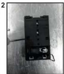
natural_image
Black electronic component with wires and connectors on a metal surface (no visible text or symbols)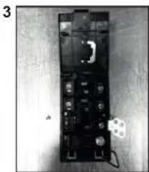
natural_image
Black electronic device with multiple ports and a small circular component on the right side (no visible text or symbols)natural_image
Three identical illustrations of cooking utensils with crossed-out X marks, no text or symbols presentnatural_image
Technical line drawing of a mechanical assembly with no visible text or symbolsnatural_image
Simple line drawing of a Y-shaped structure with two vertical supports and a central rectangle, no text or symbols present.natural_image
Simple line drawing of a hand holding a tool with a spring scale, no text or symbols presentnatural_image
Hand holding a pen next to a small electronic component with wires and a small inset (no visible text or symbols)2
natural_image
Black rectangular electronic device with attached wires and connectors, placed on a wooden surface (no visible text or symbols)3
natural_image
Black electronic device with multiple ports and a small white connector on the side (no visible text or symbols)N = Neutre PE = TerreL1 / L2 / L3 = Phase
5. CONSEILS CONCERNANT LES USTENSILES DE CUISINE POUR LA TABLE DE CUISSON
natural_image
Three identical illustrations of cooking pots with crossed-out X marks, no text or symbols present.1. ALGEMENE WAARSCHUWINGEN
natural_image
Technical line drawing of a mechanical assembly with no visible text or symbolsnatural_image
Simple line drawing of a Y-shaped structure with two vertical supports and a central vertical line, no text or symbols present.natural_image
Diagram of a hand holding a tool with a spring scale, showing a magnified view of a small object inside a frame (no text or symbols)natural_image
Hand holding a screwdriver next to a black electronic component with a small inset (no visible text or symbols)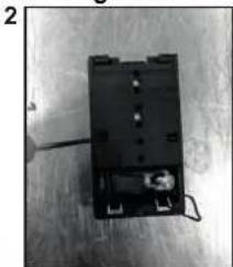
natural_image
Black electronic component with wires and connectors on a wooden surface (no visible text or symbols)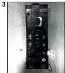
natural_image
Black-and-white photo of a rectangular electronic device with multiple ports and connectors, no visible text or symbols.natural_image
Three identical illustrations of cooking utensils with crossed-out triangular marks, no text or symbols present.natural_image
Technical line drawing of a mechanical assembly with no visible text or symbolsnatural_image
Pure technical line drawing of a Y-shaped structural frame with mounting clips (no text or symbols)natural_image
Simple line drawing of a hand holding a tool with a bracket and connecting lines, no text or symbols present.natural_image
Hand holding a small tool next to a black electronic device with a screw and a small inset showing a component (no visible text or symbols)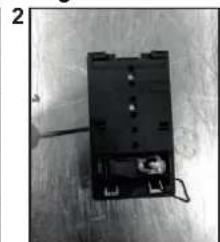
natural_image
Black electronic component with wires and connectors on a wooden surface (no visible text or symbols)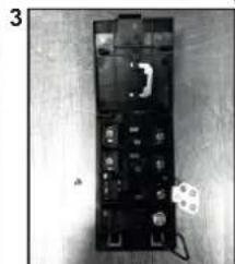
natural_image
Black electronic component with multiple ports and a small white symbol on the side (no readable text or labels)L1 / L2 / L3 = Phase N = Nullleiter PE = Masse
natural_image
Three identical illustrations of a cooking pot with crossed-out handles, no text or symbols presentnatural_image
Technical line drawing of a mechanical assembly with no visible text or symbolsnatural_image
Pure technical line drawing of a Y-shaped frame with mounting clips (no text or symbols)natural_image
Simple line drawing of a hand holding a tool with a clamp, no text or symbols present4. LIGAÇÃO ELÉTRICA
natural_image
Close-up of a hand holding a screwdriver next to a black electronic device with wires and components (no visible text or symbols)2
natural_image
Black electronic device with attached wires and a small component, placed on a wooden surface (no visible text or symbols)3
natural_image
Black electronic device with multiple ports and a small white component on the surface (no visible text or symbols)natural_image
Three identical illustrations of cooking utensils with crossed-out X marks, no text or symbols present.Switch ON/OFF a heater zone
natural_image
Symbol of a trash bin crossed with no visible text or labelsnatural_image
Pure technical diagram of a mechanical component with no text, numbers, or symbolsnatural_image
Technical line drawing of a mechanical assembly with no visible text or symbols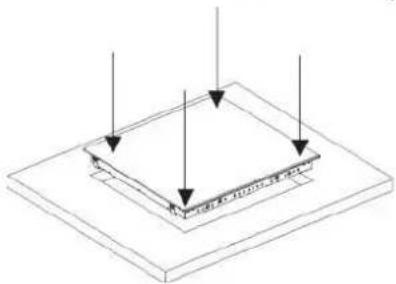
natural_image
Isometric diagram of a layered structure with arrows indicating direction (no text or symbols)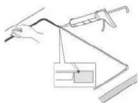
natural_image
Illustration of a hand holding a tool with a magnified inset showing a small rectangular object (no text or symbols)4. SÄHKÖLIITÄNTÄ
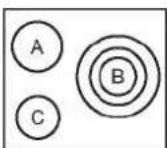
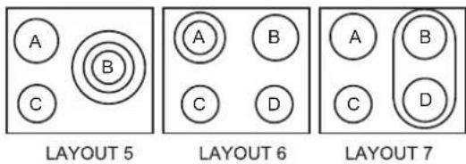
LAYOUT 5
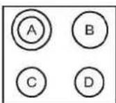
LAYOUT 6
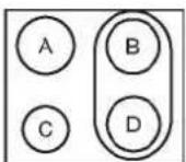
LAYOUT 7
natural_image
Three identical illustrations of cooking pots with crossed-out marks, no text or symbols presentnatural_image
Pure technical diagram of a mechanical component with no text, numbers, or symbolsnatural_image
Technical line drawing of a mechanical assembly with no visible text or symbols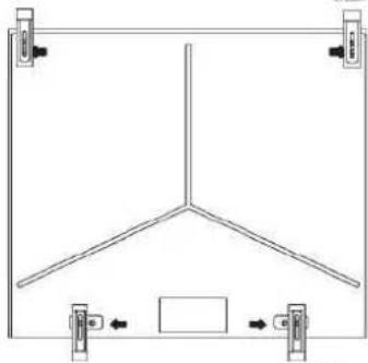
natural_image
Pure technical line drawing of a Y-shaped structural frame with mounting brackets and directional arrows (no text or symbols)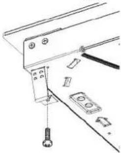
natural_image
Technical line drawing of a mechanical assembly with no visible text or symbols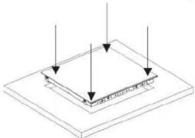
natural_image
Isometric diagram of a layered structure with arrows indicating direction (no text or symbols)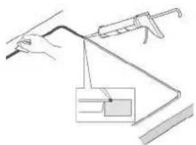
natural_image
Line drawing of a hand holding a tool with a spring scale, connected to a bracket (no text or symbols)4. ELEKTRISK TILKOBLING
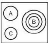
LAYOUT 5
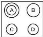
LAYOUT 6
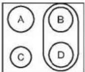
LAYOUT 7
natural_image
Three identical illustrations of cooking utensils with crossed marks, no text or symbols present-
- Ved bruk av tastene 'Pluss' og 'Minus' kan du regulere effektstyringsverdien. I dette eksempelet mellom 6500 og 2500 w. Når den ønskede verdien er valgt tar du samtidig på tastene "pluss" og "minus" i 5 sekunder.
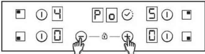
6.- Når prosessen er avsluttet høres det en lang pipelyd og det foretas en nullstilling. Oppstartprosessen vil genereres på nytt.
7.- Etter oppstartprosessen vil ECO effektstyring vises i tidsurdisplayet.
For å slå PÅ en varmesone tar du på varmesonens felt i 400 msec. Det høres en lang pipelyd og verdien "0" vil dukke opp i målsonens felt, for å indikere effektnivået.
1) Hvis en kokesone er i posisjonen 0 vil displayet slå seg automatisk AV etter 10 sekunder og AV-signalet for den sonen vil høres.
2) Hvis det er en restvarmeindikasjon på displayet som er PÅ men med 0 i effekt, vil "0" dukke opp ved endring.
3) Hvis läsefunksjonen er på kan du ikke slå PÅ en sone.
For å slå AV en varmesone trykker du på sonens felt i 1,2 sek. 3 korte pipelyder høres, og ingenting eller "H" vil dukke opp i målsonen hvis det finnes restvarme. Sonen vil være AV (OFF).
1) Hvis en kokesone er i posisjonen 0 vil displayet slå seg automatisk AV etter 10 sekunder og AV-signalet for den sonen vil høres.
2) Hvis det er en restvarmeindikasjon på displayet som er AV, vil "H" vises.
3) Selv om läsefunksjonen er på kan du slå AV en sone.
4) Hvis bare en varmesone er aktivert og dette slås av vil du høre 4 korte pipelyder som indikerer at platetoppen er slått av.
Velge en sone
Denne funksjonen slås på när du trykker på tastene '+' og '-' samtidig.
natural_image
Symbol of a trash bin crossed with no visible text or labelsFlush-installationsomrets
Standard-installationsomrets
natural_image
Pure technical diagram of a mechanical component with no text, numbers, or symbolsnatural_image
Isometric diagram of a layered structure with arrows indicating direction (no text or symbols)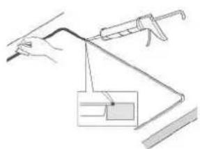
natural_image
Simple line drawing of a hand holding a tool with a magnified inset showing a small rectangular object (no text or symbols)4. ELANSLUTNING
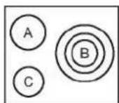
LAYOUT 5
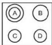
LAYOUT 6
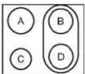
LAYOUT 7
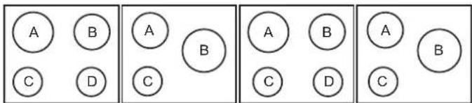
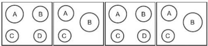
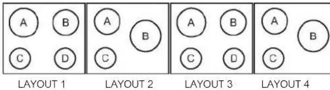
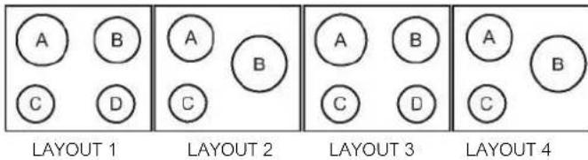
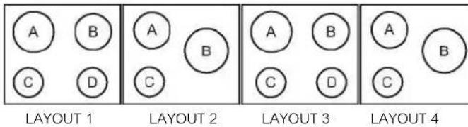
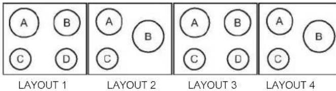
| A | B | C | D | |
| LAYOUT 1 | 2300W | 1800W | 1200W | 1200W |
| LAYOUT 2 | 1800W | 2500W | 1200W | - |
| LAYOUT 3 | 2300W | 1800W | 1200W | 1200W |
| LAYOUT 4 | 1800W | 2500W | 1200W | - |
| LAYOUT 5 | 1800W | 750 + 900 + 1050 W | 1200W | - |
| LAYOUT 6 | 1000+1200 w | 1800W | 1200W | 1200W |
| LAYOUT 7 | 1800W | 1800W | 1200W | 1800W |
Enligt modell
L1 / L2 / L3 = Fas N = Neutral PE = Jord
5. RÅD OM KÖKSUTRUSTNING
natural_image
Three identical illustrations of cooking pots with crossed-out X marks, no text or symbols presentnatural_image
Symbol of a trash bin crossed with no visible text or labelsnatural_image
Pure technical diagram of a mechanical component with no text, numbers, or symbolsnatural_image
Isometric diagram of a layered structure with arrows indicating direction (no text or symbols)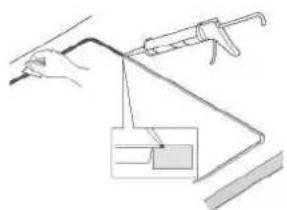
natural_image
Simple line drawing of a hand holding a tool with a spring scale, no text or symbols present4. ELEKTRISKE FORBINDELSER
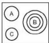
LAYOUT 5
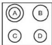
LAYOUT 6
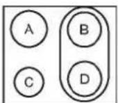
LAYOUT 7
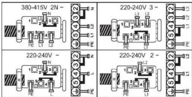
L1 / L2 / L3 = Fase N = Neutral PE = Jord
5. RÅD OM KOGEGREJ
natural_image
Three identical illustrations of cooking pots with crossed-out marks, no text or symbols presentThe manufacturer will not be responsible for any inaccuracy resulting from printing or transcript errors contained in this brochure. We reserve the right to carry out modifications to products as required, including the interests of con sumption, without prejudice to the characteri stics relating to safetyor function.
IT
- INDICE
- IT
- PROTECTION OF THE ENVIRONMENT
- INSTALLATION
- Normal Fixing:
- Quick Fixing: (Depending on model)
- FLUSH INSTALLATION
- ELECTRICAL CONNECTION
- Open the cover in the following sequence:
- To release the power supply cord:
- Operations to be carried out to make a new connection:
- ATTENTION:
- Connection to the terminals on the terminal block
- HOB COOKWARE ADVICE
- USE
- How to choose power management level
- Switch ON/OFF a heater zone
- Selecting a zone
- Bridge function
- Overflow security
- Double / Triple zones
- Residual Heat Indicator (In radiant heaters-> calculated)
- Automatic Safety Off
- CLEANING AND MAINTENANCE
- If there are still some stubborn stains:
- AFEW HINTS:
- PROBLEM SOLVING
- The cooking is too slow
- Small scratches or abrasions on the hob's glass surface
- Metal marks
- Dark stains
- Light surfaces on the hob
- Caramelisation or melted plastic on the hob.
- The hob does not operate or certain zones don't work
- The hob does not cut off.
- Frequency of on/off operations for cooking zones
- The cooktop is not working.
- The cooktop has turned itself off.
- Display F and numbers
- AFTERCARE
- Before calling out a Service Engineer please check the
- following:
- INSTALLAZIONEAFILO
- INSTALACE FLUSH
- ELEKTRICKÉ PŘIPOJENÍ
- CONSEILS CONCERNANT LES USTENSILES DE CUISINE POUR LA TABLE DE CUISSON
- ALGEMENE WAARSCHUWINGEN
- LIGAÇÃO ELÉTRICA
- SÄHKÖLIITÄNTÄ
- ELEKTRISK TILKOBLING
- Velge en sone
- ELANSLUTNING
- Enligt modell
- RÅD OM KÖKSUTRUSTNING
- ELEKTRISKE FORBINDELSER
- RÅD OM KOGEGREJ
Brand : HOOVER
Model : HH64DB3T
Category : Cooker