
KMDA 7774 FL - Cooker MIELE - Free user manual and instructions
Find the device manual for free KMDA 7774 FL MIELE in PDF.

User questions about KMDA 7774 FL MIELE
0 question about this device. Answer the ones you know or ask your own.
Ask a new question about this device
Download the instructions for your Cooker in PDF format for free! Find your manual KMDA 7774 FL - MIELE and take your electronic device back in hand. On this page are published all the documents necessary for the use of your device. KMDA 7774 FL by MIELE.
USER MANUAL KMDA 7774 FL MIELE
Operating and installation instructions Ceramic cooktops with induction
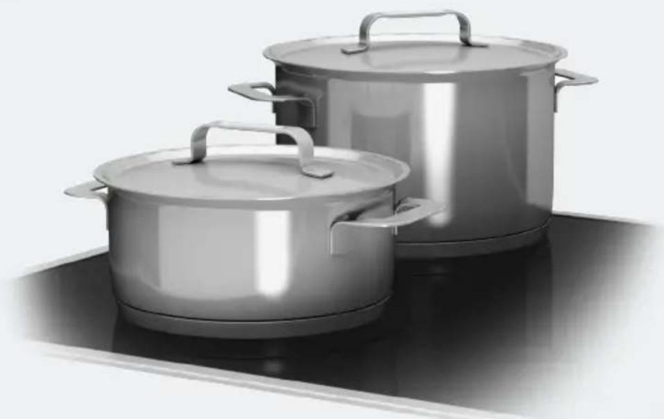
natural_image
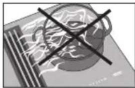
Two stainless steel cooking pots on a stovetop (no text or symbols visible)To prevent the risk of accidents or damage to the appliance, it is essential to read these instructions before it is installed and used for the first time.
Warning and Safety instructions.... 5
Caring for the environment 18
Overview.... 19
Cooktop with extractor.... 19
Controls / Indicators.... 20
Cooktop.... 20
Extractor 21
Cooking zone data 22
Before using for the first time 23
Cleaning the cooktop for the first time.... 23
Switching on the cooktop for the first time 23
Induction 24
How it works.... 24
Noises.... 25
Cookware 26
How the extractor works 27
Tips on saving energy 28
Cooking zone power levels 29
Operation.... 30
Operating principles 30
Switching on the cooktop 31
Setting the power level.... 31
Switching off a cooking zone/the cooktop.... 31
Residual heat indicator.... 31
Setting the power level - extended power level range 32
PowerFlex area.... 32
Auto heat-up 33
Booster 34
Keeping warm 35
Extractor 36
Timer 38
Minute minder 38
Switching off a cooking zone automatically.... 39
Additional functions 40
Stop & Go 40
Recall.... 40
Wipe protection 41
Demonstration mode.... 41
Displaying cooktop data 41
Safety features.... 42
System lock / Safety lock.... 42
Safety switch-off 44
Overheating protection.... 45
Programming 46
Cleaning and care 49
Extractor drip tray.... 51
Grease filter / Extraction grille 51
Resetting the grease filter operating hours counter 52
Reactivating the charcoal filter.... 52
Resetting the charcoal filter operating hours counter 52
Problem solving guide 53
Optional accessories 58
Con@ctivity 59
Signing on the cooktop 59
Signing off the cooktop 59
Safety instructions for installation.... 60
Safety distances 62
Installation notes 64
Installation of surface-mounted appliances 64
Flush-mounted installation.... 65
Minimum plinth height.... 65
Grease trap.... 65
Installation examples.... 66
Installation dimensions – Surface-mounted 67
Worktop depth 600 mm 68
Worktop depth greater than 600 mm 70
Installation dimensions – Flush 72
KMDA 7774 FL 72
Worktop depth 600 mm 73
Worktop depth greater than 600 mm 75
Contents
Change extraction direction.... 77
Installation....79
Connection to window contact, if required 79
Installation of surface-mounted cooktops 81
Flush-mounted installation.... 82
Connection for air extraction 83
Electrical connection 85
Service 87
Contact in case of fault 87
Data plate 87
Warranty 87
This appliance conforms to current safety requirements. Inappropriate use can, however, lead to personal injury and damage to property.
To avoid the risk of accidents and damage to the appliance, please read these instructions carefully before using it for the first time. They contain important notes on installation, safety, use and maintenance.
Miele cannot be held liable for non-compliance with these instructions.
Keep these instructions in a safe place and ensure that new users are familiar with the contents. Pass them on to any future owner.
Correct application
This cooktop is designed for domestic use and for use in similar environments by guests in hotel or motel rooms, bed & breakfasts and other typical living quarters. This does not include common/shared facilities or commercial facilities within hotels, motels or bed & breakfasts.
This cooktop is not suitable for outdoor use.
It is intended only to cook food and keep it warm. Any other use is not supported by Miele and could be dangerous.
This cooktop is not intended for use by people (including children) with reduced physical, sensory or mental capabilities or lack of experience and knowledge, unless they have been given supervision and instruction concerning its use by a person responsible for their safety. They may only use the cooktop unsupervised if they have been shown how to use it in a safe way. They must be able to recognise and understand the potential dangers of improper use.
Safety with children
▶ Young children must not be allowed to use this appliance.
▶ Older children may use the appliance without supervision if its operation has been clearly explained to them and they are able to use it safely. Children must be able to recognise and understand the potential dangers of improper use.
▶ Cleaning may only be carried out by older children under the supervision of an adult.
▶ Please supervise children in the vicinity of the cooktop and do not let them play with it.
The cooktop gets hot when in use and remains hot for a while after being switched off. Keep children well away from the cooktop until it has cooled down and there is no danger of burning.
Danger of burning!
Do not store anything which might arouse a child's interest in storage areas above or behind the cooktop. Otherwise children could be tempted to climb onto the cooktop.
▶ Danger of burning and scalding!
Turn the handles of pots and pans on the cooking zone to the side or the rear so that children cannot pull them down and burn themselves.
Danger of suffocation!
Whilst playing, children may become entangled in packaging material (such as plastic wrapping) or pull it over their head with the risk of suffocation. Keep packaging material away from children.
▶ Activate the system lock to ensure that children cannot switch on the cooktop inadvertently. Use the safety lock when the cooktop is in use to prevent children from altering the settings selected.
Technical safety
▶ Unauthorised installation, maintenance and repairs can cause considerable danger for the user. Installation, maintenance and repairs must only be carried out by a Miele authorised technician.
▶ Damage to the cooktop can compromise your safety. Check the appliance for visible signs of damage. Do not use the cooktop if it is damaged.
▶ Reliable and safe operation of this cooktop can only be assured if it has been connected to the mains electricity supply.
The cooktop must not be connected to the inverter of an autonomous power supply, e.g. a solar power system. When the cooktop is switched on, power surges could result in a safety switch-off. This may damage the electronic unit.
The electrical safety of this appliance can only be guaranteed when continuity is complete between it and an effective earthing system which complies with local and national safety regulations. It is most important that this basic safety requirement is present and tested regularly and, where there is any doubt, the household wiring system should be inspected by a qualified electrician.
Before connecting the appliance to the mains supply, ensure that the connection data on the data plate (voltage and frequency) matches the mains electricity supply. This data must correspond in order to avoid the risk of damage to the appliance.
Do not connect the cooktop to the mains electricity supply by a multi-socket adapter or extension lead. These are a fire hazard and do not guarantee the required safety of the appliance.
For safety reasons, this cooktop may only be used after it has been built in.
This appliance must not be installed and operated in mobile installations (e.g. on a ship).
▶ Never open the casing of the cooktop.
Touching or tampering with electrical connections or components and mechanical parts is highly dangerous to the user and can cause operational faults.
The manufacturer's warranty will be invalidated if the appliance is not repaired by a Miele approved service technician.
▶ Faulty components must only be replaced by genuine Miele spare parts. The manufacturer can only guarantee the safety of the appliance when Miele replacement parts are used.
The cooktop is not intended for use with an external timer switch or a remote control system.
The cooktop must be connected to the electricity supply by a qualified electrician (see “Electrical connection”).
If the mains connection cable is damaged, it must be replaced with a special connection cable by an electrician in order to avoid a hazard (see “Electrical connection”).
During installation, maintenance and repair work, the appliance must be disconnected from the mains electricity supply. It is only completely isolated from the electricity supply when:
– the mains circuit breaker is switched off, or
- it is switched off at the wall socket and the plug is withdrawn from the socket. Do not pull the mains connection cable but the mains plug to disconnect your appliance from the mains electricity supply.
▶ Danger of electric shock!
If the ceramic surface is faulty, cracked, chipped or damaged in any way, switch off the cooktop immediately. Disconnect the cooktop from the mains electricity supply. Contact Miele.
If the cooktop is installed behind a furniture door, do not close the door while the cooktop is in operation. Heat and moisture can build up behind the closed door. This can result in damage to the cooktop, the housing unit and the floor. Do not close the door until the residual heat indicators have gone out.
In areas which may be subject to infestation by cockroaches or other vermin, pay particular attention to keeping the appliance and its surroundings clean at all times. Any damage caused by cockroaches or other vermin will not be covered by the warranty.
DO NOT MODIFY THIS APPLIANCE.
Using at the same time as other heating appliances that depend on the air from the room
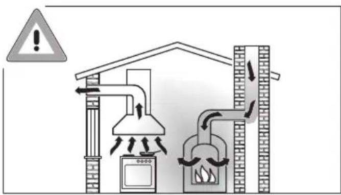
Danger of toxic fumes!
Great care should be taken when using the extractor in the same room or the same area of the house as another heating appliance that depends on the air from the room.
Such heating appliances draw in air from the room and duct exhaust gases out through a chimney or extraction ducting. They include gas, oil, wood and coal-fired boilers and heaters, continuous flow or other water heaters, gas cooktops and ovens.
The extractor draws in air from the kitchen and from neighbouring rooms. This applies to the following modes of operation:
- extraction mode,
- recirculation mode with a recirculation box installed outside the room.
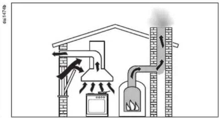
If there is insufficient air, an underpressure will occur. The heating appliance may be starved of oxygen. This impairs combustion.
Harmful gases could be drawn from the chimney or extraction ducting back into the room.
This could have potentially fatal consequences!
In order to ensure safe operation and to prevent gases given off by the heating appliance from being drawn back into the room when the extractor and the heater are both operated simultaneously, an underpressure in the room of 4 Pa (0.04 mbar) is the maximum permissible.
Sufficient ventilation can be maintained by air inlets which cannot be blocked, e.g. in windows, doors and outside wall vents. The diameter of the inlet openings must enable sufficient ventilation. A ventilation brick alone is not generally sufficient to ensure safe ventilation.
The overall ventilation condition of the dwelling must be taken into account. If in any doubt, the advice of a competent builder or, for gas, a qualified gas fitter (registered with an official gas safety body in accordance with national safety regulations) must be sought.
If the extractor is being operated in recirculation mode, where the air is directed back into the room in which it is located, operating a heating appliance which depends on the room air at the same time is not hazardous.
Correct use
The cooktop gets hot when in use and remains hot for a while after being switched off. There is a danger of burning until the residual heat indicators go out.
▶ Oil and fat can overheat and catch fire. Do not leave the cooktop unattended when cooking with oil and fat. If it does ignite, do not attempt to put the flames out with water.
Switch off the cooktop and use a suitable fire blanket, saucepan lid, damp towel or similar to smother the flames.
The cooking process has to be supervised. A short term cooking process has to be supervised continuously.
▶ Open flames are a fire hazard!
Do not flambé food. When switched on, the extractor could draw flames into the filter. Kitchen grease deposits could ignite.
Spray canisters, aerosols and other inflammable substances can ignite when heated. Therefore do not store such items or substances in a drawer under the cooktop. Cutlery inserts must be heat-resistant.
▶ Do not heat an empty pan.
Do not heat up food in closed containers e.g. tins or sealed jars on the cooktop, as pressure can build up in the containers, causing them to explode.
Do not cover the cooktop, e.g. with a cooktop cover, a cloth or protective foil. The material could catch fire, shatter or melt if the cooktop is switched on by mistake or if residual heat is still present.
When the appliance is switched on either deliberately or by mistake, or when there is residual heat present, there is the risk of any metal items left on the cooktop heating up, with the danger of burning. Depending on the material, other items left on the cooktop could also melt or catch fire. Damp pan lids might adhere to the ceramic surface and be difficult to dislodge. Do not use the appliance as a resting place. Switch the cooking zones off after use and do not rely on the pan detector.
▶ You could burn yourself on the hot cooktop. Protect your hands with heat-resistant pot holders or gloves when handling hot pots and pans. Do not let them get wet or damp, as this causes heat to transfer through the material more quickly with the risk of scalding or burning yourself.
Hot cooking vapours during cooking can cause the extractor to get hot.
Do not touch the casing or the grease filters until the extractor has cooled down.
When using an electrical appliance, e.g. a hand-held food mixer, near the cooktop, ensure that the cable of the electrical appliance cannot come into contact with the hot cooktop. The insulation on the cable could become damaged.
Grains of salt, sugar and sand (e.g. from cleaning vegetables) can cause scratches if they get under pan bases. Make sure that the ceramic surface is clean before placing pans on it.
Even a light object can cause damage in certain circumstances. Do not drop anything on the ceramic surface.
Placing hot pans on the sensors and indicators could damage the electronics underneath. Do not place hot pans on the sensors or indicators.
Do not allow solid or liquid sugar, or pieces of plastic or aluminium foil to get onto the cooktop when it is hot, as they can damage the ceramic surface when it cools down. If this should occur, switch off the appliance and scrape off all the sugar, plastic or aluminium residues whilst still hot, using a shielded scraper blade suitable for use on glass. Wear oven gloves when doing this. Allow the ceramic surface to cool down and then clean it with a suitable ceramic cooktop cleaning agent.
Pans which boil dry can cause damage to the ceramic glass. Do not leave the cooktop unattended whilst it is being used.
▶ Only use pots and pans with smooth bases. Rough bases will scratch the ceramic glass.
▶ Lift pans into position on the cooktop. Sliding them into place can cause scuffs and scratches.
Because induction heating works so quickly, the base of the pan could heat up to the temperature at which oil or fat self-ignites within a very short time. Do not leave the cooktop unattended during cooking!
▶ Heat oil or fat for a maximum of one minute. Never use the Booster function to heat oil or fat.
For people fitted with a heart pacemaker: please note that the area immediately surrounding the cooktop is electromagnetically charged when it is switched on. It is very unlikely to affect a pacemaker. However, if in any doubt, consult the manufacturer of the pacemaker or your doctor.
To prevent damage to items which are susceptible to electromagnetic fields, e.g. credit cards, digital storage devices, pocket calculators, etc., do not leave them in the immediate vicinity of the cooktop.
Metal utensils stored in a drawer under the cooktop can become hot if the appliance is used intensively for a long time. Do not store any metal items or utensils in a drawer under the cooktop.
The cooktop is fitted with a cooling fan. If a drawer is fitted directly underneath the cooktop, ensure that there is sufficient space between the drawer and its contents and the underside of the cooktop in order to ensure sufficient ventilation of the cooktop. Do not store pointed or small items or paper in the drawer. They could get in through the ventilation slots or be sucked into the casing by the fan and damage the fan or impair cooling.
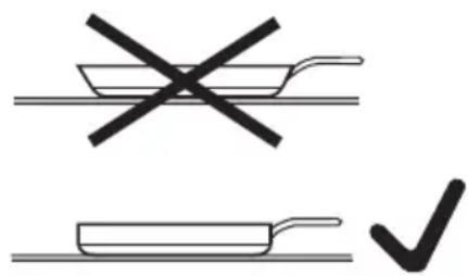
▶ Never use two pans on a cooking zone, extended zone or PowerFlex zone at the same time.
If the cookware only partially covers a cooking zone or extended zone, the handle could become very hot.
Always place cookware in the middle of a cooking zone or extended zone!
Deposits of grease and dirt will prevent the extractor from working properly.
Do not use the extractor without the grease filters in place. Otherwise cooking vapours will not be cleaned.
There is a risk of fire if cleaning is not carried out as described in these operating instructions.
Do not cover the intake grille on the extractor when in use.
▶ Liquids can damage the extractor if they get into it. Keep liquids away from the extractor.
Light objects can be drawn into the extractor and impair its operation. Do not place any light objects (e.g. paper towels) within close proximity of the extractor.
Cleaning and care
Do not use a steam cleaning appliance to clean this appliance. The steam could reach the electrical components and cause a short circuit.
Accessories
▶ Use only genuine original Miele spare parts. If spare parts or accessories from other manufacturers are used, the warranty will be invalidated, and Miele cannot accept liability.
Disposal of the packing material
The transport and protective packaging has been selected from materials which are environmentally friendly for disposal, and can normally be recycled.
Recycling the packaging reduces the use of raw materials in the manufacturing process and also reduces the amount of waste in landfill sites. Ensure that any plastic wrappings, bags etc. are disposed of safely and kept out of the reach of babies and young children. Danger of suffocation.
Disposing of your old appliance
Electrical and electronic appliances often contain valuable materials. They also contain specific materials, compounds and components, which were essential for their correct function and safety. These could be hazardous to human health and to the environment if disposed of with your domestic waste or if handled incorrectly. Please do not, therefore, dispose of your old appliance with your household waste.
Please dispose of it at your local community waste collection / recycling centre for electrical and electronic appliances. You are also responsible for deleting any personal data that may be stored on the appliance prior to disposal. Please ensure that your old appliance poses no risk to children while being stored prior to disposal.
Cooktop with extractor
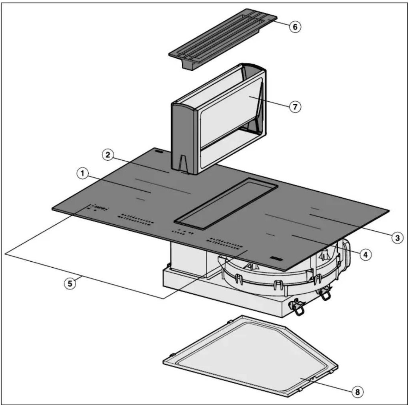
① PowerFlex cooking zone
② PowerFlex cooking zone
①② can be combined to form a PowerFlex cooking area
③ PowerFlex cooking zone
④ PowerFlex cooking zone
③④ can be combined to form a PowerFlex cooking area
⑤ Controls / Indicators
⑥ Grille
⑦ Grease filter
⑧ Removable drip tray
Controls / Indicators
Cooktop
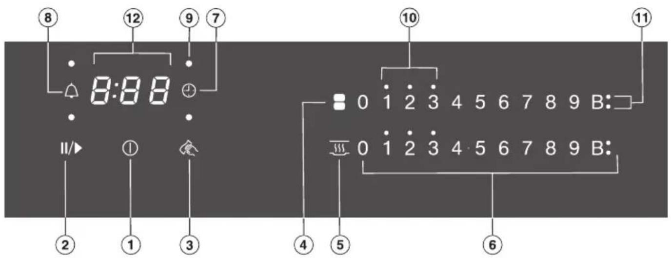
Sensor controls
① For switching the cooktop on/off
② Stop & Go
③ Wipe protection
④ Switching PowerFlex cooking zones on together/separately
⑤ Activating/Deactivating the keeping warm function
⑥ Numerical keybank
For setting power levels/minute minder and switch-off times
⑦ Automatic switch-off selector for cooking zones
⑧ Minute minder
Indicator lights
⑨ Automatic switch-off allocation of cooking zones
⑩ Residual heat
⑪ Booster
⑫ Timer display
0:00 to Duration
9:59
LOC System lock/Safety lock activated
dE Demonstration mode activated
Extractor
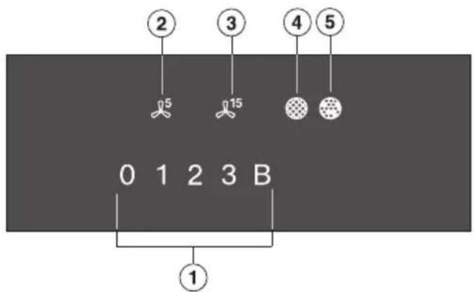
① Numerical keybank for setting the power level
② Sensor control for the 5 minute run-on option
③ Sensor control for the 15 minute run-on option
④ Clean grease filter indicator
⑤ Reactivate charcoal filter indicator
Cooking zone data
| Cooking zone | ∅ in cm* Rating in watts for 230 V** | |
| 1 15-23 Normal | 2100 | |
| TwinBooster, level 1 | 3000 | |
| TwinBooster, level 2 | 3650 | |
| 2 15-23 Normal | 2100 | |
| TwinBooster, level 1 | 3000 | |
| TwinBooster, level 2 | 3650 | |
| 1 + 2 22-23 / 15 x 23-23 x 39 | Normal | 3400 |
| TwinBooster, level 1 | 4800 | |
| TwinBooster, level 2 | 7300 | |
| 3 15-23 Normal | 2100 | |
| TwinBooster, level 1 | 3000 | |
| TwinBooster, level 2 | 3650 | |
| 4 15-23 Normal | 2100 | |
| TwinBooster, level 1 | 3000 | |
| TwinBooster, level 2 | 3650 | |
| 3 + 4 22-23 / 15 x 23-23 x 39 | Normal | 3400 |
| TwinBooster, level 1 | 4800 | |
| TwinBooster, level 2 | 7300 | |
| Total 7300 | ||
* Pans with a base diameter within the given range may be used.
** The wattage quoted may vary depending on the size and material of pans used.
- Please stick the extra data plate for the appliance supplied with this documentation in the space provided in the “Service” section of this booklet. Alternatively, the additional label can be stuck near the appliance if the appliance markings are not visible after installation.
■ Remove any protective wrapping and stickers.
Cleaning the cooktop for the first time
■ Before using for the first time, clean the cooktop with a damp cloth only and then wipe dry.
Switching on the cooktop for the first time
The metal components have a protective coating which may give off a slight smell when heated up for the first time. The induction coils may also give off a slight smell for the first few hours of operation. This smell will be less noticeable with each subsequent use before dissipating completely.
The smell and any vapours given off do not indicate a faulty connection or appliance and they are not hazardous to health.
Please note that the heating up time on induction cooktops is significantly shorter than on conventional cooktops.
How it works
An induction coil is located under each cooking zone. When a cooking zone is switched on, this coil creates a magnetic field which impacts directly on the base of the pan and heats it up. The cooking zone itself is heated up indirectly by the heat given off by the pan.
An induction cooking zone only works when a pan with a magnetic base is placed on it (see “Pans”). Induction automatically recognises the size of the pan.
The set power level flashes in the numerical keybank for the cooking zone
- if the zone is switched on without a pan in place, or if the pan is unsuitable (non-magnetic base),
- if the diameter of the base of the pan is too small,
- if the pan is taken off the cooking zone while it is switched on.
If a suitable pan is placed on the cooking zone within 3 minutes, the flashing power level will go out and you can continue as normal.
If no pan or an unsuitable pan is placed on the cooking zone, the cooking zone will switch off automatically after 3 minutes.
When the appliance is switched on either deliberately or by mistake, or when there is residual heat present, there is the risk of any metal items placed on the cooktop (e.g. cutlery) heating up.
Danger of burning!
Do not use the appliance as a resting place for anything else. Switch the cooking zones off after use with the appropriate sensor controls.
Noises
When using an induction cooking zone, the following noises can occur in the pan, depending on what it is made of and how it has been constructed.
Buzzing on the higher power levels. This will decrease or cease altogether when the power level is reduced.
If the pan base is made of layers of different materials (e.g. in a sandwiched base), it might emit a cracking sound.
Whistling might occur if linked zones (see “Operation - Booster”) are being used at the same time, and the pans also have bases made of layers of different materials.
You might hear a clicking sound from the electronic switches, especially on lower power levels.
A whirring sound when the cooling fan comes on. It switches on to protect the electronics when the cooktop is being used intensively. The fan may continue to run after the cooktop has been switched off.
Cookware
Suitable pans include:
- stainless steel pans with a base that can be magnetised,
- enamelled steel pans,
- cast iron pans.
Unsuitable pans include:
- stainless steel pans with a base which cannot be magnetised,
– aluminium or copper pans, - glass, ceramic or earthenware pots and pans.
To test whether a pot or pan is suitable for use on an induction cooktop, hold a magnet to the base of the pan. If the magnet sticks, the pan is generally suitable.
If the pan is unsuitable the set power level will flash in the numerical keybank for the cooking zone.
Please be aware that the properties of the pan base can affect the evenness with which the food heats up (e.g. when making pancakes).
- To make optimum use of the cooking zones, choose pans with a suitable base diameter (see “Cooking zones”). If the pan is too small, it will not be recognised and the set power level will flash in the numerical keybank for the cooking zone.
- Use only pots and pans with smooth bases. Rough bases can scratch the ceramic glass.
- Always lift the pans to move them. This will help prevent scratching.
- Please note that the maximum diameter quoted by manufacturers often refers to the diameter of the top rim of the pot or pan. The diameter of the base (generally smaller) is more important.
- Where possible, use pans with vertically straight sides. If a pan has angular sides, induction also acts on the sides of the pan. The sides of the pan may discolour or the coating may peel off.
The extractor can be operated in one of the following ways:
Air extraction mode
The air is drawn in and cleaned by the grease filter and directed outside.
Recirculation mode
(DUU 1000(-1) conversion kit required)
The air is drawn in and cleaned by the grease filter. The air is then directed into the recirculation box where it is also cleaned by the charcoal filter. The cleaned air is then recirculated back into the kitchen.
Operating hours counter
The number of hours that the extractor has been used for is stored in memory.
When the grease filter symbol 📍 or the charcoal filter symbol 🔒 lights up, the operating hours counters are signalling that the filters need to be cleaned or replaced. Further information about cleaning and replacing the filters and resetting the operating hours counters can be found under “Cleaning and care”.
The operating and installation instructions supplied with the recirculation box state that the operating hours counter for the charcoal filter needs to be activated. This is not necessary here.
The charcoal filter symbol ⚙ also appears when the appliance is operated using extraction mode.
Tips on saving energy
- Use a lid whenever possible to minimise heat loss.
- Select a smaller pan when cooking small quantities. A smaller pan uses less energy than a larger pan with very little in it.
– Cook with as little water as possible. - Once food has come to the boil or the oil in the pan is hot enough for frying, reduce the heat to a lower setting.
- Use a pressure cooker to reduce cooking times.
- It is important to ensure that the kitchen is well ventilated during operation. In extraction mode if there is insufficient airflow, the extractor cannot operate efficiently and this causes increased operating noise levels.
- Always cook with the lowest possible cooking setting. This produces fewer cooking vapours, so you can use a lower extractor power level and therefore benefit from reduced energy consumption.
- Check the power level on the extractor. A low power level is usually sufficient. Only use the Booster setting when necessary.
- When a large volume of cooking vapours are being produced, switch to a high power level in good time. This is more efficient than operating the extractor for longer to try to capture cooking vapours which have already been distributed throughout the kitchen.
- Switch the extractor off after cooking.
- Clean or replace the filters at regular intervals. Heavily soiled filters reduce performance, increase the risk of fire and are unhygienic.
The cooking zones are set as standard with 9 power levels. If you wish to fine-tune a setting, you can extend the power level range to 17 power levels (see "Programming").
| Power level range | ||
| Default setting (9 power levels) | Extended settings (17 power levels) | |
| Melting butter Dissolving gelatine Melting chocolate | 1-2 1-2. | |
| Making milk puddings 2 2-2. | ||
| Heating small quantities of liquid Cooking rice | 3 3-3. | |
| Defrosting frozen vegetables 3 2.-3 | ||
| Making porridge 3 2.-3. | ||
| Heating liquid and semi-solid food Making omelettes and lightly frying eggs Steaming fruit | 4 4-4. | |
| Cooking pasta/dumplings 4 4-5. | ||
| Steaming vegetables, fish 5 5 | ||
| Defrosting and reheating frozen food 5 5-5. | ||
| Gently frying eggs (without overheating the fat) 6 5.-6. | ||
| Bringing large quantities of food to the boil, e.g. casseroles Thickening custard and sauces, e.g. Hollandaise | 6-7 6.-7 | |
| Gently frying meat, fish and sausages (without overheating the fat) | 6-7 6.-7. | |
| Frying pancakes, potato fritters etc. 7 6.-7 | ||
| Braising for stews 8 8-8. | ||
| Boiling large quantities of water Bringing to the boil | 9 | 9 |
These settings should only be taken as a guide. The power of the induction coils will vary depending on the size and material of the pan. For this reason, it is possible that the settings will need to be adjusted slightly to suit your pans. As you use the cooktop, you will get to know which settings suit your pans best. When using new pans that you are not familiar with, set the power level below the one specified.
Operating principles
This ceramic cooktop is equipped with electronic sensor controls which react to finger contact. For safety reasons, when switching the appliance on, the On/Off ① sensor needs to be touched for a little longer than the other sensors. Each time you touch a sensor, an acoustic signal sounds.
Only the printed On/Off ① symbol is visible when the cooktop is switched off. More sensor controls light up when the cooktop is switched on.
Malfunction due to dirty and/or covered sensor controls. If the sensor controls are dirty or covered this could cause them to fail to react, to activate a function inadvertently or even to switch the appliance off automatically (see "Safety switch-off"). Placing hot pans on the sensor controls/indicators can damage the electronic unit underneath.
Keep the sensor controls and indicators clean.
Do not place anything over the sensor control or indicators.
Do not place hot pans over the sensor controls or indicators.
Risk of fire with overheated food.
Unattended food can overheat and ignite.
Do not leave the cooktop unattended whilst it is being used.
Please note that the heating up time on induction cooktops is very much shorter than on conventional cooktops.
Switching on the cooktop
■ Touch the Ⓘ sensor.
Further sensor controls will light up.
If no further entry is made, the cooktop will switch itself off after a few seconds for safety reasons.
Setting the power level
Permanent pan recognition is activated as standard (see "Programming"). When the cooktop is switched on and you place a pan on one of the cooking zones, all the sensors for that cooking zone's numerical keybank will light up.
■ Place a pan on the cooking zone you want to use.
■ Touch the appropriate sensor control on the respective numerical keybank for the power level you want.
Switching off a cooking zone/the cooktop
■ To switch off a cooking zone, touch the 0 sensor for that cooking zone.
■ To switch off the cooktop and all the cooking zones, touch the ① sensor.
Residual heat indicator
If a cooking zone is still hot, the residual heat indicator will light up after the zone has been switched off. Depending on the temperature, a dot will appear above power levels 1, 2 and 3.
The dots of the residual heat indicator will go out one after another as the cooking zone cools down. The last dot only goes out when the cooking zone is safe to touch.
⚠️ Risk of burning on hot cooking zones!
The cooking zones will be hot after use.
Do not touch the cooking zones while the residual heat indicators are on.
Setting the power level - extended power level range
■ Touch the numerical keybank in between two number sensors.
The sensors in front of and after the interim level will light up brighter than the other sensors.
Example:
If you have set power level 7., the numbers 7 and 8 will be brighter than the other numbers.
PowerFlex area
The PowerFlex cooking zones combine automatically to form a PowerFlex cooking area when you place a sufficiently large pot or pan on them (see “Guide to the appliance - Cooktop”). Settings for the linked cooking area are controlled by the numerical keybank of the front or left PowerFlex zone (depending on model). The PowerFlex cooking area can also be switched on and off manually.
Position the pan centrally on the PowerFlex cooking area.
Manually switching PowerFlex cooking zones on together/separately
■ Touch the ■ or ■ sensor.
Auto heat-up
When Auto heat-up has been activated, the cooking zone switches on automatically at the highest setting and then switches to the continued cooking setting which you have previously selected. The heat-up time depends on which continued cooking setting has been chosen (see chart).
Activating Auto heat-up
■ Touch the sensor for the continued cooking setting you want until a tone sounds and the sensor starts to pulsate.
During the heat-up time (see chart), the continued cooking setting selected will pulsate.
With extended power levels (see “Programming”) and a selected interim power level, the sensors for the power levels in front of and after the interim power level will pulsate.
Changing the continued cooking setting while the cooking zone is heating up deactivates Auto heat-up.
Deactivating Auto heat-up
■ Touch the sensor for the continued cooking setting.
Or
■ Set a different power level.
| Continued cooking setting* | Heat-up time [min:sec] |
| 1 Approx. | 0:15 |
| 1. Approx. | 0:15 |
| 2 Approx. | 0:15 |
| 2. Approx. | 0:15 |
| 3 Approx. | 0:25 |
| 3. Approx. | 0:25 |
| 4 Approx. | 0:50 |
| 4. Approx. | 0:50 |
| 5 Approx. | 2:00 |
| 5. Approx. | 5:50 |
| 6 Approx. | 5:50 |
| 6. Approx. | 2:50 |
| 7 Approx. | 2:50 |
| 7. Approx. | 2:50 |
| 8 Approx. | 2:50 |
| 8. Approx. | 2:50 |
| 9 | - |
* The continued cooking settings with a dot after the number are only available if the power level range has been extended (see "Programming").
Booster
The cooking zones are equipped with a TwinBooster.
When activated, the power is boosted so that large quantities can be heated up quickly, e.g. when boiling water for cooking pasta. The boost in power is active for a maximum of 15 minutes.
The Booster function can be used on a maximum of two cooking zones at the same time.
If the Booster function is switched on when
- no power level has been selected, the cooking zone will revert automatically to level 9 at the end of the Booster time or if the Booster function is switched off before this.
- a power level has been selected, the cooking zone will revert automatically to the power level selected at the end of the Booster time or if the Booster function is switched off before this.
In each case two cooking zones are linked together in order to provide sufficient power for the Booster. While the Booster is in operation some of the power is taken away from the linked cooking zone. This has one of the following effects:
- Auto heat-up is deactivated.
- The power level will be reduced.
- The linked cooking zone is switched off.
Activating TwinBooster, level 1
■ Place a pan on the cooking zone you want to use.
■ Select a power level if necessary.
■ Touch the B sensor control.
The • indicator for TwinBooster level 1 lights up.
Activating TwinBooster, level 2
■ Place a pan on the cooking zone you want to use.
■ Select a power level if necessary.
■ Touch the B sensor control twice.
The indicator for TwinBooster level 2 lights up.
Deactivating TwinBooster
■ Touch the B sensor control repeatedly until the indicators go out, or
■ Set a different power level.
Keeping warm
This function is for keeping food warm which has just been cooked and is still hot. It is not for reheating food that has gone cold.
The maximum duration for keeping food warm is 2 hours.
- Only use cookware (pots/pans) for keeping food warm. Cover the pot or pan with a lid.
- Stir firm or viscous food (mashed potatoes, stew) occasionally.
- Nutrients are lost when food is cooked, and continue to diminish when food is kept warm. The longer food is kept warm for, the greater the loss of nutrients. Try to keep food warm for as short a time as possible.
Activating/Deactivating the keeping warm function
■ Touch the sensor for the cooking zone you wish to use.
Extractor
The extractor will switch itself on automatically if a there is a pan on a cooking zone and a power level has been set for that zone (Con@ctivity). The power level on the extractor is set to suit to the power level on the cooktop.
You can deactivate Con@ctivity temporarily.
The power level of the extractor can be manually altered at any time. For light to heavy cooking vapours, select from power levels 1 to 3. For short periods of strong vapours and cooking odours, e.g. whilst searing meat, select the B Booster setting.
Setting the power level / Switching off
■ To switch the fan on and set a power level, touch the appropriate sensor for the power level you want.
■ To switch the fan off, touch the 0 sensor.
If the extractor is not switched off, it will switch itself off automatically 12 hours after the last sensor is touched.
Deactivating Con@ctivity
The extractor has switched on automatically.
■ Touch the 0 control to deactivate Con@ctivity.
■ Set the power level you want.
Con@ctivity is activated again when you switch the cooktop off and back on again.
Booster
The maximum duration for the Booster is 10 minutes.
■ To switch the Booster off early, set a different power level.
Run-on time
It is advisable to run the fan for a few minutes after cooking has finished. This helps to neutralise any lingering vapours and odours in the air. The following two options are available:
^5 (5 minutes) and ^15 (15 minutes). The run-on duration will be carried out using the power level set during activation.
You can change the power level during the run-on period.
■ Touch the 5 or 15 sensor to activate the run-on period.
■ Touch the 5 , 15 or 0 sensor to deactivate the run-on period.
If you switch the cooktop off with the ① sensor, the run-on period will continue through to the end.
natural_image
Abstract graphic with intersecting black lines and a globe-like shape on a gray background (no text or symbols)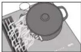
natural_image
Illustration of a pot on a stove with steam rising (no text or symbols)Useful tip: To help release vapours effectively with pans over 15 cm high, place a wooden spoon between the lid and the pan.
The cooktop has to be switched on if you wish to use the timer.
A duration of between 1 minute (0:01) and 9 hours 59 minutes (9:59) can be set.
Durations of up to 59 minutes are shown in minutes (00:59) and durations of more than 60 minutes are shown in hours and minutes. Times are entered in the order of hours, followed by minutes in tens and then units.
Example:
59 min = 00:59, entry: 5-9
80 min = 1:20, entry: 1-2-0
After the first number has been entered, the timer display will light up constantly. After the second number has been entered, the first number will move to the left. After the third number has been entered, the first and second numbers will move to the left.
The timer can be used for two different functions:
- For setting the minute minder.
- For automatically switching a cooking zone off.
The functions can be used at the same time. The shortest time is always displayed and the 🔔 sensor control (minute minder) or the indicator light of the cooking zone for automatic switch-off pulsates.
Touch the 🔒 or ⏻ sensor control if you want to show the times remaining counting down in the background. If a switch-off time has been programmed for several cooking zones, touch the ⏻ sensor control repeatedly until the indicator for the required cooking zone pulsates.
Minute minder
The minute minder is set using the numerical keybank for the left or front left cooking zone (depending on model).
Setting the minute minder
■ Touch the 🔒 sensor.
The timer display will start to flash.
■ Select the time you require.
Changing the time set for the minute minder
■ Touch the 🔒 sensor.
■ Select the time you require.
Cancelling the minute minder duration
■ Touch the 🔒 sensor until 0:00 appears in the timer display.
Switching off a cooking zone automatically
You can set a time after which the cooking zone will switch off automatically. This function can be used on all zones at the same time.
The switch-off time is set with the numerical keybank for each cooking zone you want to switch off automatically.
If the time programmed is longer than the maximum operational time allowed, the safety switch-off will switch off the cooking zone after the maximum permitted safety time has elapsed (see “Safety features - Safety switch-off”).
■ Select a power level for the cooking zone you wish to use.
■ Touch the ⏻ sensor.
The indicator light will start to flash.
■ Set the required time.
■ If you want to set another cooking zone to switch off automatically, follow the same steps as described above.
If more than one switch-off time is programmed, the shortest time remaining will be displayed, and the corresponding indicator light will flash. The other indicator lights will light up constantly.
■ If you want to show the time remaining for another zone which is counting down in the background,
touch the ⏻ sensor repeatedly until the indicator light for the zone you require flashes.
Changing the switch-off time
■ Touch the ⏻ sensor repeatedly until the indicator light for the zone you require flashes.
■ Set the required time.
Deleting the switch-off time
■ Touch the ⏻ sensor repeatedly until the indicator light for the zone you require flashes.
■ Touch the 0 sensor control on the numerical keybank.
Stop & Go
When Stop & Go is activated, the power of all cooking zones in use is reduced to power level 1. The power level of the extractor is not reduced. Depending on the power level set for the cooktop, it may even increase.
The power levels set for the cooking zones and the timer settings cannot be changed, the cooktop can only be switched off. The minute minder, switch-off, Booster and Auto heat-up times continue to run.
When Stop & Go is deactivated, the cooking zones will operate at the power level previously selected.
If the function is not deactivated within 1 hour, the cooktop will switch off.
Activating/Deactivating
■ Touch the II/▶ sensor.
Use this function if there is a danger of food boiling over.
Recall
If the cooktop is switched off inadvertently during operation, this function can be used to reset all settings. For this to work, the cooktop must be switched on again within 10 seconds of being switched off.
■ Switch the cooktop on again.
The previously set power levels will flash.
■ Press one of the flashing power level indicators immediately.
All the cooking zones and the timer will continue to operate using the settings selected previously.
Wipe protection
The cooktop sensors can be locked for 20 seconds in order, for example, to remove soiling. The ① sensor control is not locked.
Activating
■ Touch the 📄 sensor.
The time counts down in the timer display.
Deactivating
■ Touch the sensor control until the timer display goes out.
Demonstration mode
This function enables the cooktop to be demonstrated in showrooms without heating up.
Activating / Deactivating
■ Switch the cooktop on.
■ Touch the 0 sensor control on any of the numerical keybanks.
■ Then touch the 0 and 2 sensors at the same time for 6 seconds.
In the timer display, dE flashes alternately with _n (demonstration mode activated) or OFF (demonstration mode deactivated) for a few seconds.
Displaying cooktop data
The model designation and software version can be displayed. There must not be any pots or pans on the cooktop.
Model designation
■ Switch the cooktop on.
■ Touch the 0 sensor control on any of the numerical keybanks.
■ Then touch the 0 and 4 sensor controls at the same time.
The timer display shows 2 numbers flashing alternately:
Example: 12 flashing alternately with 34 = KM 1234
Software version
■ Switch the cooktop on.
■ Touch the 0 sensor control on any of the numerical keybanks.
■ Then touch the 0 and 3 sensor controls at the same time.
Numbers appear in the timer display:
Example: 2:00 = Software version 2.00
System lock / Safety lock
The safety lock is deactivated if there is a break in the mains electricity supply.
Your cooktop is equipped with a system lock and a safety lock to prevent the cooktop and the cooking zones being switched on inadvertently or any settings being altered.
The system lock is activated when the cooktop is switched off. If the system lock is activated, the cooktop cannot be switched on and the timer cannot be used. A set minute minder time continues to count down. The cooktop is programmed so that the system lock must be activated manually. It can be programmed to be activated automatically 5 minutes after the cooktop has been switched off if it is not manually locked first (see "Programming").
The safety lock is activated when the cooktop is switched on. When the safety lock is activated, the cooktop can be operated only under certain conditions:
- The cooking zones, the extractor and the cooktop can only be switched off.
- A set minute minder time can be modified.
If an unavailable sensor control is touched whilst the system lock or safety lock is activated, LOC will appear in the timer display for a few seconds and a tone will sound.
Activating the system lock
■ Touch the ① sensor for 6 seconds.
The seconds can be seen counting down in the timer display. When this time has elapsed LOC will appear in the timer display. The system lock has been activated.
Deactivating the system lock
■ Touch the ① sensor for 6 seconds.
LOC will appear briefly in the timer display and then the seconds will count down. The system lock is deactivated once the time has elapsed.
Activating the safety lock
■ Touch and hold the ⏻ and II/▶ sensors at the same time for 6 seconds.
The seconds can be seen counting down in the timer display. When this time has elapsed LOC will appear in the timer display. The safety lock is activated.
Deactivating the safety lock
■ Touch and hold the ⏻ and II/▶ sensors at the same time for 6 seconds.
LOC will appear briefly in the timer display and then the seconds will count down. The safety lock is deactivated once the time has elapsed.
Safety switch-off
Safety switch-off if the sensors are covered
Your cooktop will switch off automatically if one or several of the sensors remain covered for longer than 10 seconds, for example, by finger contact, food boiling over or by an object such as an oven glove or tea towel. ① flashes briefly above the F sensor control and a tone will sound. F will go out once you have removed the object and/or cleaned the cooktop and the cooktop will be ready to use again.
Excessive operating time
The safety switch-off mechanism is triggered automatically if a cooking zone is heated for an unusually long period of time. This time depends on the power level selected. If it has been exceeded, the cooking zone switches off and the residual heat indicator appears. If you switch the cooking zone on and off again, it is ready for operation again.
The cooktop is programmed to safety setting 0 at the factory. If required you can set a higher safety setting with a shorter maximum operating time (see chart).
| Power level* Maxi | mum operating time[h:min] | ||
| Safety setting | |||
| 0** 1 2 | |||
| 1 10:00 | 8:00 5:00 | ||
| 1. 10:00 | 7:00 4:00 | ||
| 2/2. 5:00 | 4:00 3:00 | ||
| 3/3. 5:00 | 3:30 2:00 | ||
| 4/4. 4:00 | 2:00 1:30 | ||
| 5/5. 4:00 | 1:30 1:00 | ||
| 6/6. 4:00 | 1:00 00:30 | ||
| 7/7. 4:00 | 00:42 00:24 | ||
| 8 4:00 00 | 0:30 00:20 | ||
| 8. 4:00 00 | 0:30 00:18 | ||
| 9 1:00 00 | 0:24 00:10 | ||
* The power levels with a dot after the number are only available if the power level range has been extended (see “Power level range”).
** Factory default setting
Overheating protection
All the induction coils and cooling elements for the electronics are fitted with an overheating protection mechanism. Before the induction coils and/or cooling elements get too hot, the overheating protection mechanism cuts in in one of the following ways:
Induction coils
– Any Booster function in operation will be switched off.
- The set power level will be reduced.
- The cooking zone switches off automatically. Err will flash alternately with 44 in the timer display.
You can use the cooking zone again as usual when the fault message has gone out.
Cooling elements
– Any Booster function in operation will be switched off.
- The set power level will be reduced.
- The cooking zones switch off automatically.
The affected cooking zones can only be used again as usual once the cooling element has cooled down to a safe level.
The overheating protection may be triggered under the following circumstances:
- The pot or pan being used is empty.
- Fat or oil being heated on a high power level.
- Insufficient ventilation to the underside of the cooktop.
- A hot cooking zone being switched on after an interruption to the power supply.
If, despite removing the cause, the overheating protection mechanism triggers again, contact Miele.
You can adapt the programming of the cooktop to your personal needs.
Several settings can be altered in succession.
After accessing programming mode, the ⏻ symbol appears and PC will appear in the timer display. After a few seconds P:01 (Programme 01) will flash alternately with C:01 (Code) in the timer display.
Changing the programming
Calling up programming
The II/▶ sensor is located approx. 1 cm (index finger width) to the left of the ⏻ sensor.
■ With the cooktop switched off, press and hold the ① and II/▶ sensor controls together until the ⏻ symbol lights up and PC appears in the timer display.
Setting a programme
For a two-digit programme number you need to first set the tens position.
■ Whilst the programme is visible in the display (e.g. P:01), touch the ⏻ sensor repeatedly until the number for the programme you want appears in the display or touch the appropriate number on the numerical keybank.
Setting the code
■ While the code is visible in the display (e.g. C:01), touch the ⏻ sensor repeatedly until the number for the
code you want appears in the display or touch the appropriate number on the numerical keybank.
How to save the settings
■ While the programme is visible in the display (e.g. P:01), touch the ① sensor control until the indicators go out.
How to avoid saving the settings
■ While the code is visible in the display (e.g. C:01) touch the ① sensor until the indicators go out.
| Programme^1) | Code^2) | Settings | |
| P:01 | Demonstration mode C:00 Demonstration mode | C:01 | off |
| Demonstration mode on ^3) | |||
| P:03 | Factory settings C:00 Factory default settings not restored | ||
| C:01 Factory default settings restored | |||
| P:04 | Number of power levels C:00 9 power levels | ||
| C:01 | 17 power levels ^4) | ||
| P:06 | Keypad tone when a sensor is touched | C:00 | Off^5) |
| C:01 Quiet | |||
| C:02 Medium | |||
| C:03 Loud | |||
| P:07 | Audible tone for the timer C:00 | Off^5) | |
| C:01 Quiet | |||
| C:02 Medium | |||
| C:03 Loud | |||
| P:08 | System lock C:00 System lock can only be activated manually | ||
| C:01 System lock activated automatically | |||
| P:09 | Maximum operating time C:00 Safety setting 0 | ||
| C:01 Safety setting 1 | |||
| C:02 Safety setting 2 | |||
| P:10 | Miele@home/Con@ctivity (external rangehood) | C:00 Not available | |
| C:01 Signed off | |||
| C:02 Signed on | |||
| P:12 | Sensor controls reaction speed | C:00 Slow | |
| C:01 Normal | |||
| C:02 Fast | |||
Programming
| Programme^1) | Code^2) | Settings | |
| P:15 Permanent pan recognition C:00 Not active | |||
| C:01 Active | |||
^1) Programmes not shown here have no allocation.
2) The factory setting is shown in bold.
3) After switching the cooktop on, dE appears in the timer display for several seconds.
^4) In the text and charts, the extended power levels are shown with a dot after the number for better understanding.
5) The tone which sounds when the On/Off sensor is touched cannot be switched off.
⚠️ Risk of burning on hot cooking zones!
The cooking zones will be hot after use.
Switch the cooktop off.
Allow the cooking zones to cool down before cleaning the cooktop.
⚠️ Risk of damage due to moisture ingress.
The steam from a steam cleaner could reach electrical components and cause a short circuit.
Do not use a steam cleaner to clean the cooktop.
The use of unsuitable cleaning agents can cause the surfaces to discolour or alter. All surfaces are susceptible to scratching.
Remove any residual cleaning agent immediately.
Never use abrasive sponges or cleaning agents.
■ Clean the cooktop after every use.
■ Dry the cooktop thoroughly after every cleaning to avoid limescale residue.
Unsuitable cleaning agents
To avoid damaging the surfaces of the appliance, do not use:
- washing-up liquid,
- cleaning agents containing soda, alkalines, ammonia, acids or chlorides,
- cleaning agents containing descaling agents,
- stain and rust removers,
- abrasive cleaning agents, e.g. powder cleaners and cream cleaners,
– solvent-based cleaning agents, - dishwasher cleaner,
- oven sprays,
- glass cleaning agents,
– hard, abrasive brushes or sponges (e.g. pot scourers), or sponges which have been previously used and still contain abrasive cleaning agents, - dirt erasers.
Cleaning the ceramic surface
⚠️ Risk of damage by pointed objects.
The seal between the cooktop and the worktop could be damaged.
The seal between the ceramic surface and the frame could be damaged.
Do not use pointed objects for cleaning.
Do not use washing-up liquid to clean the appliance. Using washing-up liquid will not remove all soiling and residues. An invisible film can develop that can lead to discolouration of the ceramic glass surface. This discolouration cannot be removed.
Clean the ceramic surface regularly with a proprietary ceramic glass cleaning agent.
■ Remove any coarse soiling with a damp cloth and more stubborn soiling with a glass scraper.
■ Then clean the ceramic glass surface with the Miele ceramic and stainless steel cooktop cleaner (see “Optional accessories”) or with a proprietary ceramic glass cleaner applied with paper towel or a clean cloth. Do not apply the cleaner while the cooktop is still hot, as this can result in marking. Please follow the cleaning agent manufacturer's instructions.
■ Finally wipe the cooktop with a damp cloth and dry it with a soft, dry cloth.
Residues can burn onto the cooktop the next time it is used and cause damage to the glass ceramic surface. Ensure that all cleaner residues are removed.
■ Spots caused by limescale, water and aluminium residues (spots with a metallic appearance) can be removed using the Miele ceramic and stainless steel cooktop cleaner.
⚠️ Risk of burning on hot cooking zones!
The cooking zones are hot during use.
Wear oven gloves when removing residues of sugar, plastic or aluminium foil from a hot cooktop with a glass scraper.
■ Should any sugar, plastic or aluminium foil spill or fall onto a hot cooking zone while it is in use, first switch off the appliance.
■ Then carefully scrape off these residues immediately whilst they are still hot, using a shielded scraper blade suitable for use on glass.
■ Afterwards, clean the ceramic surface in its cooled state, as described above.
Extractor drip tray
Clean the drip tray if liquid from food being spilled or boiling over has got into the extractor.
■ Remove and clean the grease filter as described in the “Grease filter” section.
natural_image
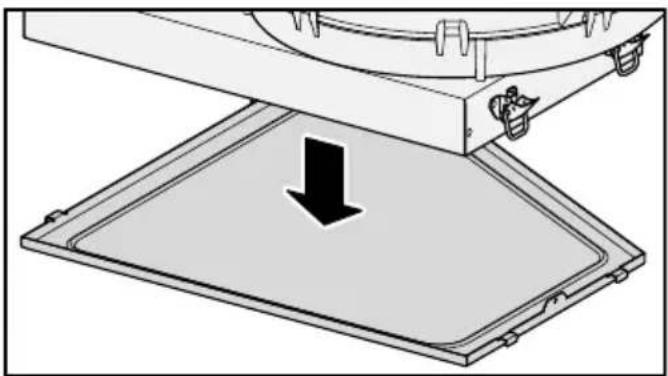
Diagram of a mechanical device with a downward arrow indicating compression or disassembly (no text or symbols present)■ Hold the drip tray securely and open the 4 catches (2 on the right and 2 on the left). Carefully remove the tray from the casing, making sure it is kept horizontal.
■ Pour out the liquid.
■ Clean and dry the drip tray.
■ Also clean and dry accessible areas inside the extractor.
■ Fasten the drip tray back onto the casing.
■ Refit the grease filter and the extraction grille.
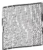
Grease filter / Extraction grille
The extraction grille and the reusable metal grease filter collect solid matter from kitchen vapours (grease, dust etc.) and therefore prevent soiling of the extractor. The grease filter must be cleaned after 30 hours of use. The sensor will light up.
An oversaturated filter is a fire hazard. Clean the grease filter regularly.
Removing the grease filter
■ Lift up the extraction grille.
■ Carefully remove the grease filter. Ensure that you do not tilt the grease filter.
■ Pour out any liquid which has collected at the bottom of the grease filter.
Cleaning the grease filter and the extraction grille by hand
■ Clean the extraction grille and the grease filter with a soft nylon brush in a mild solution of hot water and a little washing-up liquid. Do not use concentrated washing-up liquid.
Cleaning the grease filter and the extraction grille in the dishwasher
■ Place the extraction grille upright in the lower basket.
■ Place the grease filter with its base facing upwards in the lower basket. Ensure the spray arm is not obstructed.
■ Use a standard household dishwasher detergent.
■ Select a dishwasher programme with a wash temperature between 50 °C and 65 °C.
Depending on the detergent used, cleaning the grease filter in a dishwasher can cause permanent discolouration to the internal surfaces of the filter. This will not affect the functioning of the grease filter in any way.
Internal surfaces of the extractor
■ When removing the grease filter for cleaning, also clean off any accessible oil or fat build-up from the casing. Doing so will prevent a fire hazard.
Resetting the grease filter operating hours counter
After cleaning the grease filter, the operating hours counter needs to be reset.
■ Touch the Ⓧ sensor for 3 seconds.
The sensor will go out.
Reactivating the charcoal filter
The charcoal filter needs to be reactivated after 120 operating hours. The ● sensor will light up.
■ Reactivate the charcoal filter as described in the operating and installation instructions supplied with the recirculation box.
Resetting the charcoal filter operating hours counter
■ Touch the ⚙ sensor for 3 seconds.
The sensor will go out.
With the help of the following guide, minor faults in the performance of the appliance, some of which may result from incorrect operation, can be remedied without contacting Miele. This will save you time and money because you will not need a service call.
Please note that a call-out charge will be applied to unnecessary service visits where the problem could have been rectified as described in these operating instructions.
| Problem Possible cause | and remedy |
| The cooktop or cooking zones do not switch on. | There is no power to the cooktop.■ Check if the circuit breaker has tripped. Contact an electrician or Miele (for the minimum fuse rating, see data plate). |
| There may be a technical fault.■ Disconnect the appliance from the mains electricity supply for approx. 1 minute. To do this: - switch off at the wall socket and withdraw the plug, or - switch off at the residual current device.■ If, after switching the circuit breaker or residual current device back on, the appliance will still not switch on, contact a qualified electrician or Miele. | |
| A smell and vapours are given off when the new appliance is being used. | The metal components have a protective coating. When the appliance is used for the first time, this causes a smell and possibly also vapour. The material from which the induction coils are made also gives off a smell in the first few hours of operation. This smell will be less noticeable with each subsequent use before dissipating completely. The smell and any vapours given off do not indicate a faulty connection or appliance and they are not hazardous to health. |
| The power level selected is flashing. | There is no pan on the cooking zone, or the pan is unsuitable.■ Use suitable pans (see “Induction - Pans”). |
| After the cooktop has been switched on LOC appears in the timer display for a few seconds. | The system lock or safety lock is activated.■ Deactivate the system lock or safety lock (see “Safety features - System lock / Safety lock”). |
| The cooktop has switched off automatically. When the element is switched back on, £ appears above the On/Off 1 sensor control. | One or more of the sensor controls are covered, e.g. by finger contact, food boiling over or an object.■ Clean off any dirt and/or remove the object (see “Safety features - Safety switch-off”). |
| The cooktop has switched off automatically. When the cooktop is switched back on, an F appears above the On/Off sensor control 1. | One or more of the sensor controls are covered, e.g. by finger contact, food boiling over or an object.■ Clean off any dirt and/or remove the object (see “Safety switch-off”). |
| After the cooktop has been switched on, dE appears in the timer display for a few seconds. The cooking zones do not heat up. | The cooktop is in Demonstration mode.■ Touch the 0 and 2 sensors at the same time until dE flashes alternately with OFF in the timer display. |
| A cooking zone switches itself off automatically. | It has been operated for too long.■ You can use the cooking zone again by switching it back on (see “Safety features - Safety switch-off”). |
| A cooking zone or the whole cooktop switches off automatically. | The overheating protection mechanism has been activated.■ See “Safety features - Overheating protection”. |
| The Booster has automatically switched off early. | The overheating protection mechanism has been activated.■ See “Safety features - Overheating protection”. |
| The cooking zone is not working in the usual way on the power level selected. | The overheating protection mechanism has been activated.■ See “Safety features - Overheating protection”. |
| Power level 9 is automatically reduced if you select power level 9 on two linked cooking zones or extended zones at the same time. | Operating both zones at power level 9 would exceed the permitted maximum power for the cooktop.■ Use another cooking zone which is not linked. |
| The food in the pan hardly heats up or does not heat up at all when the Auto heat-up function is switched on. | There is too much food in the pan.■ Start cooking at the highest power level and then turn down to a lower one manually later on. |
| The pan is not conducting heat properly.■ Use a different pan which is better able to conduct heat. | |
| A noise can be heard after the appliance is switched off. | The fan will continue running until the cooktop has cooled down. It will then switch itself off automatically. |
| The sensor switches show increased sensitivity or fail to react. | The sensitivity level of the sensor switches has changed.■ Make sure that there is no direct light (from the sun or from an artificial source) falling onto the cooktop. The area surrounding the cooktop must not be too dark.■ Make sure that there is nothing covering the sensors or the cooktop.Take any pans off the cooktop and wipe away any food deposits.■ Interrupt the power supply to the cooktop for approx. 1 minute.■ If the problem persists after power is restored, please contact Miele. |
| Err flashes alternately with 30 in the timer display and a tone is sounding. | The cooktop is incorrectly connected.■ Disconnect the cooktop from the mains electricity supply.■ Contact Miele. The cooktop must be connected to the mains according to the wiring diagram. |
| 1 and a number, e.g. 1-0 flash alternately with a 3 digit number in the timer display. | Cooking zone faultInterrupt the power supply to the cooktop for approx. 1 minute.If the problem persists after power is restored, please contact Miele. |
| Err will flash alternately with numbers in the timer display. | Err44The overheating protection mechanism has been activated.See “Safety features - Overheating protection”. |
| Err47, Err48 or Err49The fan is blocked or defective.Make sure it has not been blocked by something like a fork. Remove the cause of the blockage.If this fault code continues to appear in the display, contact Miele. | |
| Err and other numbersThere is a fault in the electronic module.Interrupt the power supply to the cooktop for approx. 1 minute.If the problem persists after power is restored, please contact Miele. | |
| Liquid has entered the extractor. | Due to boiling over or spillage, liquid has made its way through the extraction grille into the extractor. The base of the grease filter can hold approx. 250 ml of liquid. The drip tray underneath the housing can hold a further 250 ml of liquid.Switch the extractor off.Clean the grease filter, the drip tray and the inside of the housing (see “Cleaning and care”). |
| Extraction performance has decreased.Extraction noise has increased. | Objects (e.g. a cloth) have been drawn into the extractor.Switch the extractor off.Remove the grease filter (see “Cleaning and care”).Remove any objects from the grease filter. |
| Problem Possible cause and remedy |
| The sensor is lit up. The charcoal filter needs to be reactivated.■ If the extractor is being operated in Recirculation mode, proceed as described in the operating and installation instructions supplied with the recirculation box. Reset the operating hours counter (see “Cleaning and Care” in this manual).■ If the extractor is being operated in Extraction mode, reset the operating hours counter (see “Cleaning and Care” in this manual). |
| The sensor is lit up. The grease filter must be cleaned.■ Clean the grease filter as described in “Cleaning and Care – Grease filter / Extraction grille”. |
Miele offers a range of useful accessories, as well as cleaning and conditioning products for your appliance.
These products can be ordered from the Miele online shop.
They can also be ordered directly from Miele (see end of this booklet for contact details).
Saucepans and frying pans
Miele offers a wide range of pans which are perfect for Miele cooktops. Please refer to the Miele website for more details on individual products.
- Pans in various sizes
- Frying pan with lid
- Non-stick pan
- Wok
- Gourmet oven dishes
Cleaning and care products
Original Miele ceramic and stainless steel cooktop cleaner 250 ml
Removes heavy soiling, limescale deposits and aluminium residues.
Original Miele all purpose microfibre cloth
Removes finger marks and light soiling.
Signing on the cooktop
To sign the cooktop onto Miele@home, prepare the logging-on process on the master appliance.
■ With the cooktop switched off, press and hold the ① and II/▶ sensor controls together until the ⏻ symbol lights up and PC appears in the timer display.
After a few seconds P:01 (Programme 01) will flash alternately with C:01 (Code) in the timer display.
■ While P:01 is visible in the display, touch the ⏻ sensor control as often as necessary until P:10 (Programme P:10) is displayed.
■ While C:00 is visible in the display, touch the ⏻ sensor control as often as necessary until C:02 is displayed.
The signing-on process will begin and a scrolling bar will appear in the display. The signing-on process will take a few minutes. Once the process has been completed successfully, C:02 will light up in the display.
■ If the signing-on process is not completed successfully, repeat the process.
■ While P:10 is visible in the display, touch the ① sensor control until the indicators go out to save the setting.
■ Finish the signing-on process on the master appliances (see the appropriate instructions).
Signing off the cooktop
■ With the cooktop switched off, press and hold the ① and II/▶ sensor controls together until the ⏻ symbol lights up and PC appears in the timer display.
After a few seconds P:01 (Programme 01) will flash alternately with C:01 (Code) in the timer display.
■ While P:01 is visible in the display, touch the ⏻ sensor control as often as necessary until P:10 (Programme P:10) is displayed.
■ While C:02 is visible in the display, touch the ⏻ sensor control as often as necessary until C:01 is displayed.
The signing-off process will begin and a scrolling bar will appear in the display. The signing-off process will take a few minutes. Once the process has been completed successfully, C:01 will light up in the display.
■ If the signing-off process is not completed successfully, repeat the process.
■ While P:10 is visible in the display, touch the ① sensor control until the indicators go out to save the setting.

Risk of damage from incorrect installation.
Incorrect installation can cause damage to the cooktop.
The cooktop must only be installed by a qualified person.

Danger of electric shock!
Incorrect connection to the power supply may result in an electric shock.
The cooktop must be connected to the power supply by a qualified electrician.

Damage from falling objects.
Take care not to damage the cooktop when fitting wall units or a rangehood above it.
Fit the wall units and the rangehood before the cooktop.
The veneer or laminate coatings of worktops (or adjacent kitchen units) must be treated with 100 °C heat-resistant adhesive which will not dissolve or distort. Any splashbacks must be of heat-resistant material as well.
The cooktop must not be installed over a fridge, fridge-freezer, freezer, dishwasher, washing machine, washer-dryer or tumble dryer.
The cooktop must not be installed over an oven.
A gas cooktop must not be installed adjacent to this cooktop.
▶ After installation, ensure that nothing can come into contact with the connection cable and that it is without hindrance.
The connection cable may not come into contact with any moving kitchen component (e.g. a drawer) or be subject to mechanical obstruction which could damage it.
Carefully observe the safety clearances listed on the following pages.
All pipework, ducting and fittings must be of non-flammable material and comply with all relevant national and local building regulations.
The appliance must not be connected to a chimney or vent flue which is in current use for exhausting fumes from appliances burning gas or other fuels. Neither should it be connected to ducting which ventilates rooms with fireplaces.
If exhaust air is to be extracted into a chimney or ventilation duct no longer used for other purposes, seek professional advice.
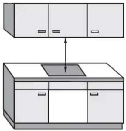
Safety distance above the cooktop
natural_image
Diagram showing two kitchen cabinets with one cabinet and one cabinet, one with a downward arrow pointing to a central display (no text or symbols)The safety distance specified by the manufacturer of the rangehood must be maintained between the cooktop and the rangehood above it.
For any flammable objects, e.g. utensil rails, wall units etc., a minimum safety distance of 600 mm must be maintained between these objects and the highest part of the cooktop below.
When two or more appliances which have different safety distances are installed together below a rangehood, observe the greatest specified safety distance.
Safety distances to the sides and back of the appliance
The minimum distance shown below must be maintained between the back edge of the cooktop and a tall unit or wall.
Ideally the cooktop should be installed with plenty of space on either side. There may be a wall at the rear or a tall unit or wall on one side (right or left), taking into account the distances below. On the other side, however, no tall unit or wall should stand closer than 300 mm to the edge of the cooktop. Before installing the cooktop, check that the below clearance requirements are met.
Minimum horizontal distance from the back edge of the cooktop to a combustible surface: 50 mm.
Minimum horizontal distance from the right edge of the cooktop to a combustible surface: 50 mm.
Minimum horizontal distance from the left edge of the cooktop to a combustible surface: 50 mm.
All dimensions in this instruction booklet are given in mm.
Installation of surface-mounted appliances
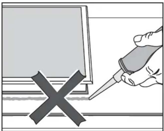
Seal between the cooktop and the worktop
natural_image
Illustration of a hand using a tool to mark a cross symbol on a document (no text or symbols present)⚠️ Damage caused by incorrect installation.
Using sealant under the cooktop could result in damage to the cooktop and the worktop if the cooktop ever needs to be removed for servicing.
Do not use sealant between the cooktop and the worktop.
The sealing strip under the edge of the cooktop provides a sufficient seal for the worktop.
Tiled worktop

Grout lines ① and the hatched area underneath the cooktop frame must be smooth and even. If they are not, the cooktop will not sit flush with the worktop and the sealing strip underneath the cooktop will not provide a good seal between the cooktop and the worktop.
Flush-mounted installation
Flush-mounted installation is only possible in natural stone (granite, marble), solid wood and tiled worktops. Certain models are suitable for building into glass worktops - please see the relevant label on the cooktop. When using a worktop made from any other material, please check first with the worktop manufacturer that it is suitable for installing a flush-mounted cooktop.
The internal width of the base unit underneath the appliance must be at least as wide as the inner worktop cut-out (see “Building-in dimensions - Flush-mounted cooktops”), so that the cooktop is easily accessible from underneath after installation and the bottom half of the casing can be removed for maintenance. If the underside of the cooktop is not freely accessible after installation, any sealant used to plug the gaps around the appliance must be removed to enable the cooktop to be lifted out of the cut-out should this be necessary.
Natural stone worktops
The cooktop is placed directly in the cut-out.
Solid wood worktops, tiled worktops, glass worktops
The cooktop is placed on a wooden frame inside the cut-out. The frame must be provided on site and is not supplied with the appliance.
Minimum plinth height
The minimum plinth height is 100 mm (recirculation mode only).
Housing unit back panel
The extraction ducting is laid behind the housing unit back panel. The back panel must be removable for maintenance purposes.
Grease trap
The cooktop must be installed such that the grease trap is easily accessible as it needs to be removed for cleaning.
Installation examples
Recirculation mode
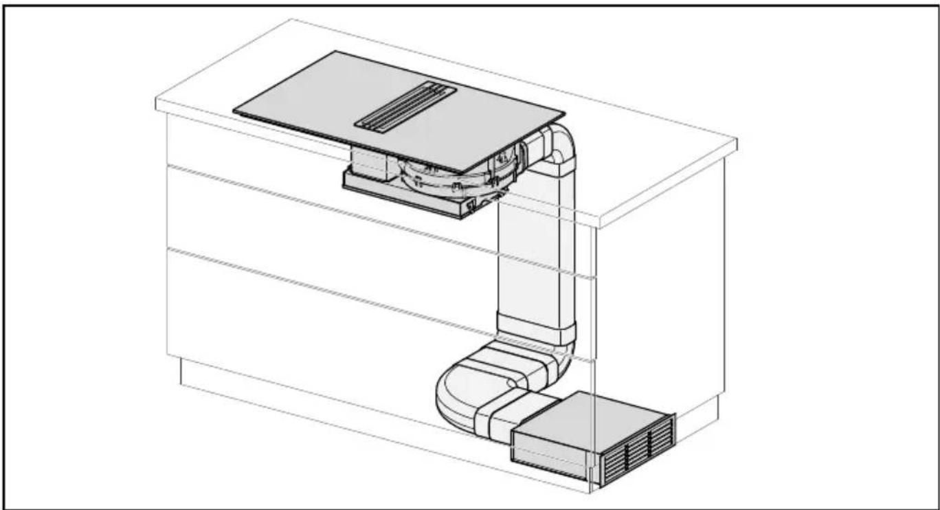
natural_image
Technical line drawing of a mechanical or electrical enclosure with internal components and no visible text or symbolsExtraction mode
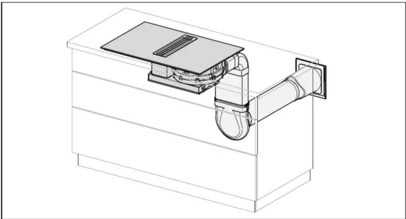
natural_image
Technical line drawing of a mechanical device with a central component and attached pipe (no text or symbols)KMDA 7774 FL
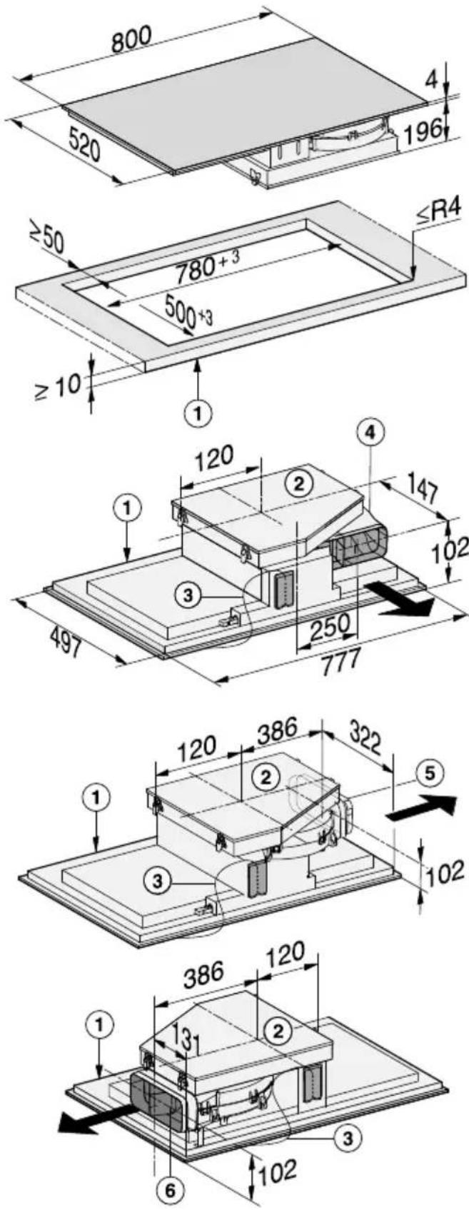
① Front
② Removable drip tray
③ Mains connection box with mains connection cable, L = 1440 mm
④ Air duct connection – at the back (ex-works)
⑤ Air duct connection - on the right (conversion required)
⑥ Air duct connection - on the left (conversion required)
Worktop depth 600 mm
KMDA 7774 FL
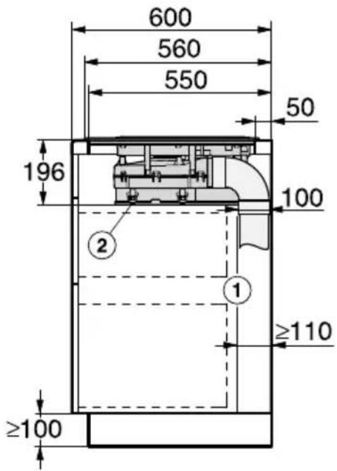
① Housing unit back panel The housing unit back panel must be removable for service work. The housing unit wall and an adjoining room wall or furniture housing must be at least 110 mm apart to ensure sufficient room for the ducting.
② Drip tray After installation the removable drip tray must be accessible from below.
Extraction to the rear (standard)
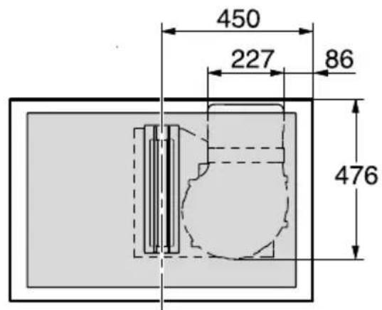
Extraction to the right
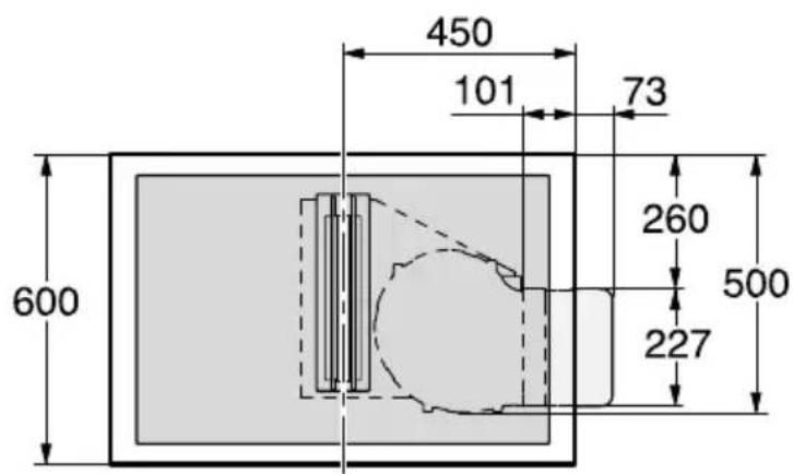
Extraction to the left
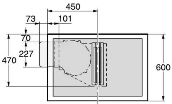
Worktop depth greater than 600 mm
KMDA 7774 FL
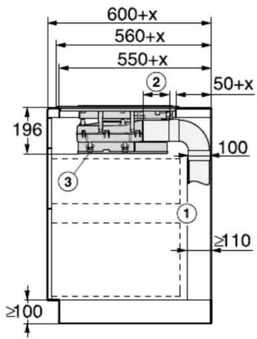
① Housing unit back panel
The housing unit back panel must be removable for service work. The housing unit wall and an adjoining room wall or furniture housing must be at least 110 mm apart to ensure sufficient room for the ducting.
② Variable length of interim piece
③ Drip tray
After installation the removable drip tray must be accessible from below.
x = Dimension by which the worktop is deeper than 600 mm.
Extraction to the rear (standard)

Extraction to the right
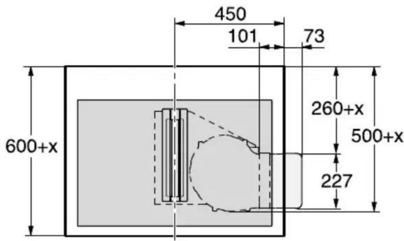
Extraction to the left

KMDA 7774 FL
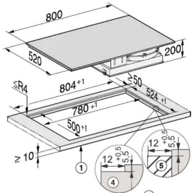
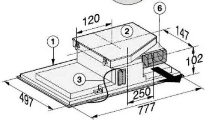
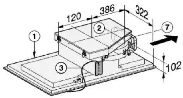
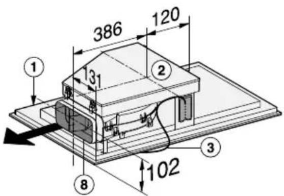
① Front
② Removable drip tray
③ Mains connection box with mains connection cable, L = 1440 mm
④ Stepped cut-out
⑤ Wooden frame (to be provided on site)
⑥ Air duct connection – at the back (ex-works)
⑦ Air duct connection - on the right (conversion required)
⑧ Air duct connection - on the left (conversion required)
Worktop depth 600 mm
KMDA 7774 FL
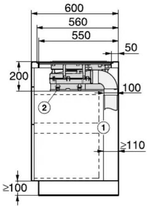
① Housing unit back panel The housing unit back panel must be removable for service work. The housing unit wall and an adjoining room wall or furniture housing must be at least 110 mm apart to ensure sufficient room for the ducting.
② Drip tray After installation the removable drip tray must be accessible from below.
Extraction to the rear (standard)
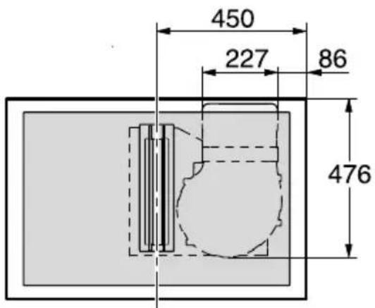
Extraction to the right
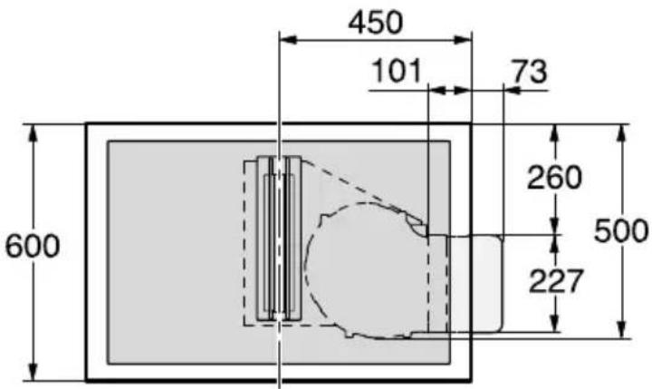
Extraction to the left
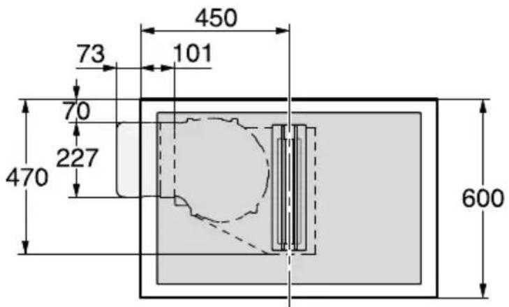
Worktop depth greater than 600 mm
KMDA 7774 FL

① Housing unit back panel
The housing unit back panel must be removable for service work. The housing unit wall and an adjoining room wall or furniture housing must be at least 110 mm apart to ensure sufficient room for the ducting.
② Variable length of interim piece
③ Drip tray
After installation the removable drip tray must be accessible from below.
x = Dimension by which the worktop is deeper than 600 mm.
Extraction to the rear (standard)
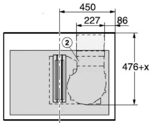
Extraction to the right

Extraction to the left
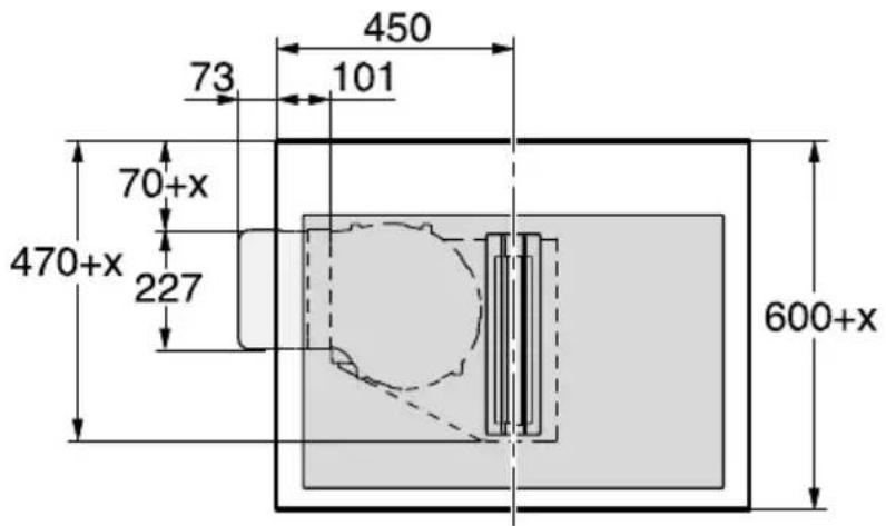
Rotating the fan
■ Place the cooktop on its ceramic surface on a soft underlay.
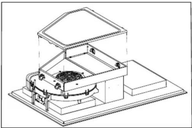
natural_image
Technical line drawing of a mechanical device with no visible text or symbols■ Release the 4 catches and remove the drip tray.
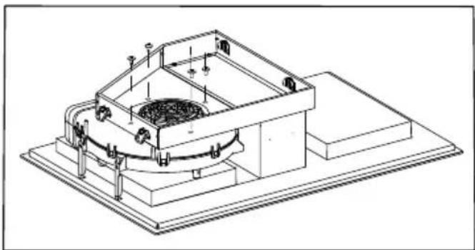
natural_image
Technical line drawing of a mechanical device with internal components and mounting base (no text or symbols)■ Undo the 5 screws on the fan.
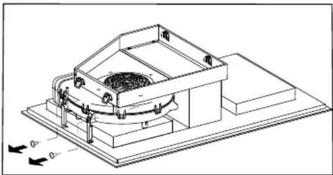
natural_image
Technical line drawing of a mechanical device with mounting base and internal components (no text or symbols)■ Undo the fixing bracket.
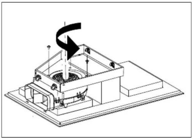
natural_image
Technical line drawing of a mechanical device with a black arrow indicating direction (no text or symbols)■ Rotate the fan by 90°.
- Secure the fan by the 5 screws. Make sure that the plastic edge is on the left.
Extraction to the right
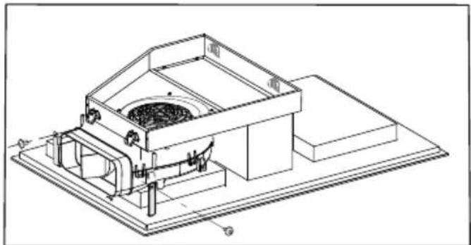
natural_image
Technical line drawing of a mechanical device with internal components and mounting base (no text or symbols)■ Secure the fan to the fixing brackets.
■ Place the drip tray onto the extractor again and secure the tray using the 4 catches.
Change extraction direction
Extraction to the left
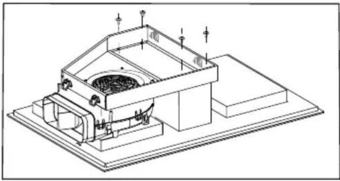
natural_image
Technical line drawing of a mechanical device with mounting base and internal components (no text or symbols)■ Undo the 4 screws on the frame.
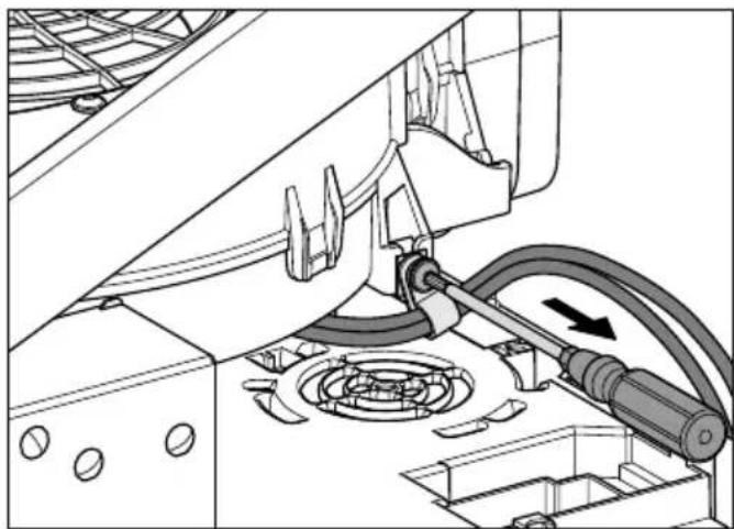
natural_image
Mechanical assembly diagram showing a valve mechanism with rotating components and a directional arrow (no text or symbols)■ Loosen the cable tie.
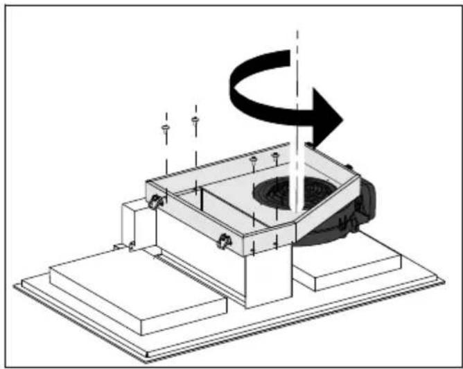
natural_image
Technical diagram of a mechanical assembly with a rotating component and mounting base (no text or symbols)■ Lift the frame and the fan and turn them 180°.
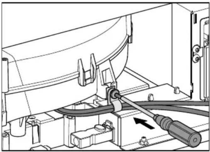
natural_image
Mechanical assembly diagram showing a valve and screwdriver inserted into a housing (no text or symbols visible)■ Guide the cable under the fan.
■ Reattach the cable tie.
■ Refit the 4 screws in the frame.
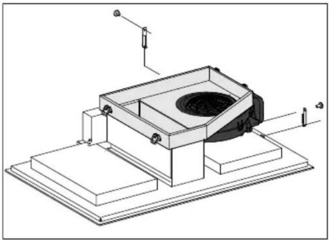
natural_image
Technical line drawing of a mechanical device with mounting base and internal components (no text or symbols)■ Secure the fan to the fixing brackets.
■ Place the drip tray onto the extractor again and secure the tray using the 4 catches.
Connection to window contact, if required
⚠️ The window contact is connected to the mains voltage! Danger of electric shock! Disconnect the cooktop from the mains electricity supply before connecting the switching mechanism. The connection cable of the switching system must only be connected by a suitably qualified and competent electrician.
The connection cable of the switching system must be of the correct type and cross-sectional area in strict accordance with current national and local safety regulations and must not exceed 2.0 m in length. The switching system must be equipped with a potential-free contact suitable for 230 V, 1 A. The extractor is switched off when the switch is open. Only use suitable switching systems (e.g. window contact switches, pressure switches). The switching system must be suitable for use with inductive loads (BLDC motor). Use switching systems in strict accordance with current national and local safety regulations.
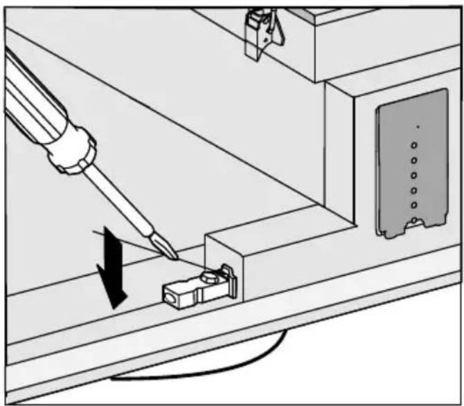
natural_image
Technical diagram showing a screwdriver inserted into a component with an arrow indicating the process (no text or symbols present)■ Loosen the lug and pull the plug out.
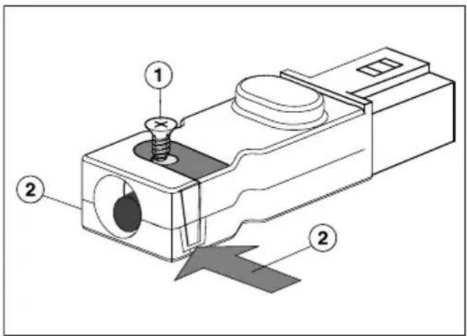
■ Loosen the strain relief screw ① and unlock the casing on both sides ②.
■ Open the casing.
■ Remove the stopper.
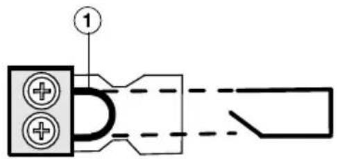
■ Exchange the jumper ① with the connection cable of the switching system.
■ Close the casing.
■ Tighten the strain relief screw.
■ Reinsert the plug.
Installation of surface-mounted cooktops
■ Create the worktop cut-out. Remember to maintain the minimum safety distances (see “Safety distances”).
■ Seal the cut surfaces of wooden worktops with a suitable heat-resistant sealant to avoid swelling caused by moisture. The sealant must be temperature-resistant.
Make sure the sealant does not come into contact with the top surface of the worktop.
■ Attach the sealing strip provided underneath the edge of the cooktop.
■ Feed the mains connection cable down through the cut-out.
■ Place the cooktop centrally in the cut-out. When doing this make sure that the seal of the appliance sits flush with the worktop on all sides. This is important to ensure an effective seal all round.
Do not use any additional sealant (e.g. silicone).
If the seal does not meet the worktop correctly on the corners, the corner radius ( ≤ R4) can be carefully scribed to suit.
■ Connect the cooktop to the mains electricity supply.
■ Check that the cooktop works.
Flush-mounted installation
■ Create the worktop cut-out. Remember to maintain the minimum safety distances (see “Safety distances”).
■ Solid wood, tiled and glass worktops: Fix a wooden frame 5.5 mm below the top edge of the worktop (see "Building-in diagram - Flush-mounted installation").
■ Attach the sealing strip provided underneath the edge of the cooktop.
■ Feed the mains connection cable down through the cut-out.
■ Centre the cooktop in the cut-out.
The gap between the ceramic surface and the worktop must be at least 2 mm wide. This is required so that the cooktop can be sealed.
■ Connect the cooktop to the mains electricity supply.
■ Check that the cooktop works.
■ Seal the gap between the cooktop and worktop with a silicone sealant that is heat-resistant to at least 160 °C.
⚠️ Damage caused by unsuitable sealant.
Unsuitable sealant can damage natural stone.
For natural stone worktops and natural stone tiles, only use silicone sealant that is specially formulated for natural stone. Please follow the manufacturer's instructions.
⚠️ Before installation, it is important to read the following information. This is particularly crucial when using the extractor at the same time as a heating appliance that relies on oxygen from the same room, which could result in the build-up of toxic fumes.
It is particularly important that the "Warning and Safety instructions" are observed.
The extractor should be installed according to local and national building regulations. Seek approval from the building inspector where necessary.
- For the rectangular ducting, Miele recommends not to exceed a maximum total ducting length of 5m , with a maximum number of three bends.
- Only use wide radius bends.
- The exhaust ducting must not be kinked or compressed.
- Ensure that all connections are strong and airtight.
Remember that any constriction of the airflow will reduce extraction performance and increase operating noise.
The extractor has an exhaust connection of 222 x 89 mm.
In order to achieve optimum extraction or recirculation performance and low noise levels, Miele recommends the installation of a modular rectangular ducting system made from approved non-flammable materials.
■ To achieve the most efficient air extraction with the lowest noise levels, please note the following:
- The cross-section of the exhaust ducting must not be smaller than the cross-section of the exhaust connection (see “Appliance dimensions”).
- The exhaust ducting should be as short and straight as possible.
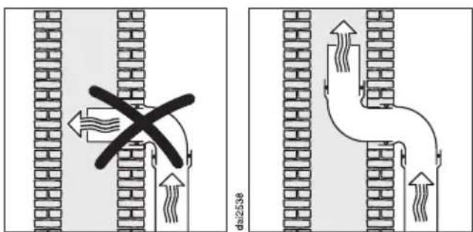
■ If the exhaust air is to be ducted into a flue, the ducting must be directed in the flow direction of the flue.
If ducting is to be laid horizontally, it must be laid with a downwards sloping gradient. This is to ensure that condensate cannot drain back into the extractor.
If the exhaust ducting is to run through rooms, ceiling space, etc. there may be great variations in temperature between the different areas. The problem of condensation will need to be addressed. The exhaust ducting will need to be suitably insulated.
■ Ensure that the ducting can easily be disconnected from the exhaust connection in the event the cooktop needs to taken out of the worktop for service purposes.
natural_image
Technical line drawing of a mechanical component with a spring and housing (no text or symbols)■ Stick the supplied sealing strip on the exhaust connection if the ducting does not sit securely up against the exhaust connection.
⚠️ Risk of damage from incorrect connection.
Incorrect installation, maintenance and repairs can be dangerous to users.
Miele cannot be held liable for damage or injury caused by unauthorised installation, maintenance or repair work, or by an inadequate or faulty on-site earthing system (e.g. electric shock).
The cooktop must be connected to the power supply by a qualified electrician.
The electrician must be familiar with and comply with the national regulations and any additional regulations of the local electricity provider.
After installation, ensure that all electrical components are shielded and cannot be accessed by users.
Total power output
See data plate.
Connection data
The connection data is quoted on the data plate. Please ensure this information matches the household mains supply.
Please see the wiring diagrams for connection.
Residual current device
For extra safety, it is advisable to protect the appliance with a suitable residual current device (RCD) with a trip range of 30 mA.
Mains connection cable
The cooktop must be connected to the electrical supply with a special connection cable, type H 05 VV-F (PVC insulated) with a suitable diameter.
Please see the wiring diagram for connection.
See the data plate on the cooktop for the correct voltage and frequency.
Replacing the mains connection cable
Danger of electric shock! Incorrect connection to the electricity supply may result in an electric shock.
The mains connection cable must only be replaced by a suitably qualified and competent person in accordance with current local and national safety regulations in order to avoid a hazard.
When replacing the mains connection cable, it must be replaced with cable type H 05 VV-F with a suitable cross-section. These cables are available from Miele.
Wiring diagram
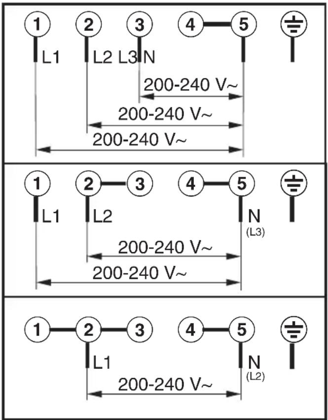
Contact in case of fault
In the event of any faults which you cannot remedy yourself, please contact Miele.
Contact information for Miele can be found at the end of this booklet.
Please quote the model and serial number of your appliance when contacting Miele. This information can be found on the data plate.
Data plate
Adhere the extra data plate supplied with the appliance in the space below. Make sure that the model number matches the one specified on the back cover of this document.
Warranty
The manufacturer's warranty for this appliance is 2 years.
For further information, please refer to your warranty booklet.
Miele Australia Pty. Ltd.
ACN 005 635 398
ABN 96 005 635 398
Miele Experience Centre and
Head Office Melbourne:
1 Gilbert Park Drive
Knoxfield, VIC 3180
Miele Experience Centre South Melbourne:
206-210 Coventry Street
South Melbourne, VIC 3205
Miele Experience Centre and Office Sydney:
3 Skyline Place
Frenchs Forest, NSW 2086
Miele Experience Centre and Office Brisbane:
Tenancy 4C, 63 Skyring Terrace
Newstead, QLD 4006
Miele Experience Centre Gold Coast:
131 Ferry Road
Southport, QLD 4215
Miele Experience Centre and Office Adelaide:
83-85 Sir Donald Bradman Drive
Hilton, SA 5033
Miele Experience Centre and Office Perth:
205-207 Stirling Highway
Claremont, WA 6010

1300 4 MIELE (1300 464 353)
www.miele.com.au

Miele New Zealand Limited
IRD 98 463 631
Head Office:
Level 2, 10 College Hill
Freemans Bay, Auckland 1011
Miele Experience Centre
Auckland:
8 College Hill
Freemans Bay, Auckland 1011
Telephone:
0800 464 353 (0800 4 MIELE)
www.miele.co.nz
Miele Global Headquarters Germany
Miele & Cie. KG
Federal Republic of Germany
Miele
KMDA 7774