
PJ X6181N - Projector RICOH - Free user manual and instructions
Find the device manual for free PJ X6181N RICOH in PDF.


| Product Type | Video Projector |
| Brand | Ricoh |
| Model | PJ X6181N |
| Display Technology | Liquid Crystal (LCD) |
| Native Resolution | XGA (1024 x 768) |
| Brightness (ECO OFF) | 7200 lm |
| Brightness (ECO ON) | Approx. 5760 lm (80% of ECO OFF) |
| Contrast Ratio | 6000:1 (all white/all black) |
| Light Source | 350 W AC Lamp (264 W in Eco mode) |
| Lamp Life (ECO ON) | Up to 4000 hours |
| Screen Size | 30" to 500" (diagonal) |
| Lens Shift | Manual (vertical and horizontal) |
| Keystone Correction | Horizontal and vertical (CORNERSTONE) |
| Built-in Speaker | 10 W monaural |
| Input Connectors | HDMI (2), DisplayPort, BNC (5), Component, Computer (D-Sub 15), Ethernet, USB-A |
| Output Connectors | HDMI OUT, Audio Out, 3D SYNC |
| Power Consumption (ECO OFF) | 483 W (100-130 V) / 460 W (200-240 V) |
| Standby Power (NORMAL) | 0.11 W (100-130 V) / 0.16 W (200-240 V) |
| Dimensions (W x H x D) | 499 x 142 x 359 mm (without protrusions) |
| Weight | 8.4 kg (18.5 lbs) without lens |
| Operating Temperature | 5°C to 40°C (41°F to 104°F) |
| Network | Wired LAN (RJ-45), optional wireless LAN (USB) |
| Security | Keyword lock to prevent unauthorized use |
| Supported 3D Formats | HDMI 3D (active shutter, VESA compliant) |
Frequently Asked Questions - PJ X6181N RICOH
User questions about PJ X6181N RICOH
0 question about this device. Answer the ones you know or ask your own.
Ask a new question about this device
Download the instructions for your Projector in PDF format for free! Find your manual PJ X6181N - RICOH and take your electronic device back in hand. On this page are published all the documents necessary for the use of your device. PJ X6181N by RICOH.
USER MANUAL PJ X6181N RICOH
RICOH PJ WU6181N/WX6181N/X6181N
User's Manual
natural_image
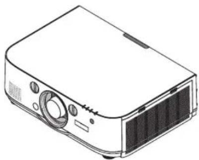
Line drawing of a projector with front panel and side ports (no text or symbols)
natural_image
Abstract composition of five colored circles (orange, blue, pink, green, cyan) arranged in a scattered pattern on white background (no text or symbols)• Macintosh, Mac OS X and PowerBook are trademarks of Apple Inc. registered in the U.S. and other countries.
- Microsoft, Windows, Windows Vista, Internet Explorer, .NET Framework and PowerPoint are either a registered trademark or trademark of Microsoft Corporation in the United States and/or other countries.
- MicroSaver is a registered trademark of Kensington Computer Products Group, a division of ACCO Brands.
- Adobe, Adobe PDF, Adobe Reader, and Acrobat are either registered trademarks or trademarks of Adobe Systems Incorporated in the United States and/or other countries.
- HDMI, the HDMI Logo and High-Definition Multimedia Interface are trademarks or registered trademarks of HDMI Licensing LLC.
- DisplayPort, DisplayPort Certified Logo, VESA, and VESA logo are trademarks of the Video Electronics Standards Association, registered in the U.S. and other countries.

• Trademark PJLink is a trademark applied for trademark rights in Japan, the United States of America and other countries and areas.
• Wi-Fi ^ , Wi-Fi Alliance ^ , and Wi-Fi Protected Access (WPA, WPA2) ^ are registered trademarks of the Wi-Fi Alliance.
- Blu-ray is a trademark of Blu-ray Disc Association
- Crestron, Crestron Control, and Crestron RoomView are trademarks or registered trademarks of Crestron Electronics Inc.
- Other product and company names mentioned in this user's manual may be the trademarks or registered trademarks of their respective holders.
NOTES
(1) The contents of this user's manual may not be reprinted in part or whole without permission.
(2) The contents of this user's manual are subject to change without notice.
(3) Great care has been taken in the preparation of this user's manual; however, should you notice any questionable points, errors or omissions, please contact us.
(4) Notwithstanding article (3), Ricoh will not be responsible for any claims on loss of profit or other matters deemed to result from using the Projector.
Important Information
Safety Cautions
Precautions
Please read this manual carefully before using your Ricoh projector and keep the manual handy for future reference.
CAUTION

To turn off main power, be sure to remove the plug from power outlet.
The power outlet socket should be installed as near to the equipment as possible, and should be easily accessible.
CAUTION

TO PREVENT SHOCK, DO NOT OPEN THE CABINET.
THERE ARE HIGH-VOLTAGE COMPONENTS INSIDE.
REFER SERVICING TO QUALIFIED SERVICE PERSONNEL.

This symbol warns the user that uninsulated voltage within the unit may be sufficient to cause electrical shock.
Therefore, it is dangerous to make any kind of contact with any part inside of the unit.

This symbol alerts the user that important information concerning the operation and maintenance of this unit has been provided.
The information should be read carefully to avoid problems.
WARNING: TO PREVENT FIRE OR SHOCK, DO NOT EXPOSE THIS UNIT TO RAIN OR MOISTURE. DO NOT USE THIS UNIT'S PLUG WITH AN EXTENSION CORD OR IN AN OUTLET UNLESS ALL THE PRONGS CAN BE FULLY INSERTED.
DOC Compliance Notice (for Canada only)
This Class B digital apparatus meets all requirements of the Canadian Interference-Causing Equipment Regulations.
Machine Noise Information Regulation - 3. GPSGV,
The highest sound pressure level is less than 70 dB (A) in accordance with EN ISO 7779.
CAUTION

Avoid displaying stationary images for a prolonged period of time.
Doing so can result in these images being temporarily sustained on the surface of the LCD panel.
If this should happen, continue to use your projector. The static background from previous images will disappear.
User Information on Electrical and Electronic Equipment
Users in the countries where this symbol shown in this section has been specified in national law on collection and treatment of E-waste
Our Products contain high quality components and are designed to facilitate recycling.
Our products or product packaging are marked with the symbol below.
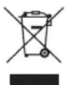
This product contains substances which are harmful to humans and the environment.
• The lamp contains mercury.
Please dispose of this product or used lamps in accordance with local regulations.
Important Information
The symbol indicates that the product must not be treated as municipal waste. It must be disposed of separately via the appropriate return and collection systems available. By following these instructions you ensure that this product is treated correctly and help to reduce potential impacts on the environment and human health, which could otherwise result from inappropriate handling. Recycling of products helps to conserve natural resources and protect the environment.
For more detailed information on collection and recycling systems for this product, please contact the shop where you purchased it, your local dealer or sales/service representatives.
Note for the Battery and/or Accumulator Symbol (For EU countries only)

In accordance with the Battery Directive 2006/66/EC Article 20 Information for end-users Annex II, the above symbol is printed on batteries and accumulators.
This symbol means that in the European Union, used batteries and accumulators should be disposed of separately from your household waste.
In the EU, there are separate collection systems for not only used electrical and electronic products but also batteries and accumulators.
Please dispose of them correctly at your local community waste collection/recycling centre.
CE Marking Traceability Information
Manufacturer: Ricoh Co., Ltd.
3-6 Nakamagome 1-chome, Ohta-ku, Tokyo. 143-8555, Japan
Importer: Ricoh Europe PLC
20 Triton Street, London. NW1 3BF, United Kingdom
Declaration of Conformity for EU countries
• EMC Directive 2004/108/EC (including amendments)
• Low Voltage Directive 2006/95/EC
WARNING TO CALIFORNIA RESIDENTS:
Handling the cables supplied with this product will expose you to lead, a chemical known to the State of California to cause birth defects or other reproductive harm. WASH HANDS AFTER HANDLING.
RF Interference (for USA only)
WARNING
The Federal Communications Commission does not allow any modifications or changes to the unit EXCEPT those specified by Ricoh Americas Corporation in this manual. Failure to comply with this government regulation could void your right to operate this equipment. This equipment has been tested and found to comply with the limits for a Class B digital device, pursuant to Part 15 of the FCC Rules. These limits are designed to provide reasonable protection against harmful interference in a residential installation. This equipment generates, uses, and can radiate radio frequency energy and, if not installed and used in accordance with the instructions, may cause harmful interference to radio communications. However, there is no guarantee that interference will not occur in a particular installation. If this equipment does cause harmful interference to radio or television reception, which can be determined by turning the equipment off and on, the user is encouraged to try to correct the interference by one or more of the following measures:
- Reorient or relocate the receiving antenna.
- Increase the separation between the equipment and receiver.
- Connect the equipment into an outlet on a circuit different from that to which the receiver is connected.
- Consult the dealer or an experienced radio / TV technician for help.
For UK only: In UK, a BS approved power cord with moulded plug has a Black (five Amps) fuse installed for use with this equipment. If a power cord is not supplied with this equipment please contact your supplier.
Important Safeguards
These safety instructions are to ensure the long life of your projector and to prevent fire and shock. Please read them carefully and heed all warnings.

Installation
- Do not place the projector in the following conditions:
- on an unstable cart, stand, or table.
- near water, baths, or damp rooms.
- in direct sunlight, near heaters, or heat radiating appliances.
- in a dusty, smoky or steamy environment.
- on a sheet of paper or cloth, rugs or carpets.
- If you wish to have the projector installed on the ceiling:
- Do not attempt to install the projector yourself.
- The projector must be installed by qualified technicians in order to ensure proper operation and reduce the risk of bodily injury.
- In addition, the ceiling must be strong enough to support the projector and the installation must be in accordance with any local building codes.
- Please consult your dealer for more information.
- For sales or service representatives:
- Use brackets that are strong enough to support the projector. (PJ WU6181N Series weighs about 8.4kg.(18.5lbs)) (Not including lens)
- The projector must be installed in a location that is sturdy enough to support the full weight of the projector and brackets.
- Use only the screws (four M4\~16 screws) provided with the projector to attach the brackets to the projector.
- Use all four of the projector's screw holes to attach the brackets. The locations of the screw holes are shown in the illustration below.(→ page 242) Make sure that the screws are tightened firmly.
WARNING
- Do not cover the lens with the lens cap or equivalent while the projector is on. Doing so can lead to melting of the cap due to the heat emitted from the light output.
- Do not place any objects, which are easily affected by heat, in front of the projector lens. Doing so could lead to the object melting from the heat that is emitted from the light output.
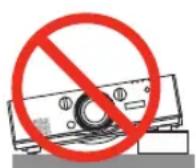
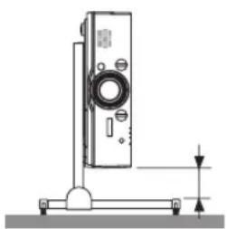
Do not use the projector with it leaning to the left and right. This may result in a malfunction. However, portrait installation is possible* (when a custom-designed stand is made). For portrait installation, install the projector with the intake vent at the bottom and leave a space of at least 130 mm below the intake vent.
natural_image
Technical line drawing of a mechanical device with mounting base and vertical support (no text or symbols)
Fire and Shock Precautions

- Ensure that there is sufficient ventilation and that vents are unobstructed to prevent the build-up of heat inside your projector. Allow at least 4 inches (10cm) of space between your projector and a wall.
- Do not try to touch the ventilation outlet on the left front (when seen from the front) as it can become heated while the projector is turned on and immediately after the projector is turned off. Parts of the projector may become temporarily heated if the projector is turned off with the Power button or if the AC power supply is disconnected during normal projector operation.
Use caution when picking up the projector.
- Prevent foreign objects such as paper clips and bits of paper from falling into your projector. Do not attempt to retrieve any objects that might fall into your projector. Do not insert any metal objects such as a wire or screwdriver into your projector. If something should fall into your projector, disconnect it immediately and have the object removed by a qualified service personnel.
- Do not place any objects on top of the projector.
- Do not touch the power plug during a thunderstorm. Doing so can cause electrical shock or fire.
- The projector is designed to operate on a power supply of 100-240V AC 50/60 Hz. Ensure that your power supply fits this requirement before attempting to use your projector.
- Do not look into the lens while the projector is on. Serious damage to your eyes could result.
- Keep any items (magnifying glass etc.) out of the light path of the projector. The light path being projected from the lens is extensive, therefore any kind of abnormal objects that can redirect light coming out of the lens, can cause an unpredictable outcome such as a fire or injury to the eyes.
- Do not place any objects, which are easily affected by heat, in front of a projector exhaust vent.
Doing so could lead to the object melting or getting your hands burned from the heat that is emitted from the exhaust.
- Handle the power cord carefully. A damaged or frayed power cord can cause electric shock or fire.
- Do not use any power cord other than the one supplied with the projector.
- Do not bend or tug the power cord excessively.
- Do not place the power cord under the projector, or any heavy object.
- Do not cover the power cord with other soft materials such as rugs.
- Do not heat the power cord.
- Do not handle the power plug with wet hands.
- Turn off the projector, unplug the power cord and have the projector serviced by a qualified service personnel under the following conditions:
- When the power cord or plug is damaged or frayed.
- If liquid has been spilled into the projector, or if it has been exposed to rain or water.
- If the projector does not operate normally when you follow the instructions described in this user's manual.
- If the projector has been dropped or the cabinet has been damaged.
- If the projector exhibits a distinct change in performance, indicating a need for service.
- Disconnect the power cord and any other cables before carrying the projector.
- Turn off the projector and unplug the power cord before cleaning the cabinet or replacing the lamp.
- Turn off the projector and unplug the power cord if the projector is not to be used for an extended period of time.
- When using a LAN cable:
For safety, do not connect to the connector for peripheral device wiring that might have excessive voltage.

CAUTION
- Do not use the tilt-foot for purposes other than originally intended. Misuses such as gripping the tilt-foot or hanging on the wall can cause damage to the projector.
- Do not send the projector in the soft case by parcel delivery service or cargo shipment. The projector inside the soft case could be damaged.
- Select [HIGH] in Fan mode if you continue to use the projector for consecutive days. (From the menu, select [SETUP] → [OPTIONS(1)] → [FAN MODE] → [MODE] → [HIGH].)
- Before using Direct Power Off, be sure to allow at least 20 minutes immediately after turning on the projector and starting to display an image.
- Do not unplug the power cable from the wall outlet or projector when the projector is powered on. Doing so can cause damage to the AC IN connector of the projector and (or) the prong plug of the power cable.
To turn off the AC power supply when the projector is powered on, use a power strip equipped with a switch and a breaker. - Do not turn off the AC power for 60 seconds after the lamp is turned on and while the Power indicator is blinking blue. Doing so could cause premature lamp failure.
Caution on Handling the Optional Lens
When shipping the projector with the lens, remove the lens before shipping the projector. Always attach the dust cap to the lens whenever it is not mounted on the projector. The lens and the lens shift mechanism may encounter damage caused by improper handling during transportation.
Do not hold the lens part when carrying the projector.
Doing so could cause the Focus ring to rotate, resulting in accidental dropping of the projector.
Remote Control Precautions
- Handle the remote control carefully.
- If the remote control gets wet, wipe it dry immediately.
- Avoid excessive heat and humidity.
- Do not short, heat, or take apart batteries.
- Do not throw batteries into fire.
- If you will not be using the remote control for a long time, remove the batteries.
- Ensure that you have the batteries' polarity (+/−) aligned correctly.
- Do not use new and old batteries together, or use different types of batteries together.
- Dispose of used batteries according to your local regulations.
Note for US Residents
LAMP(S) INSIDE THIS PRODUCT CONTAIN MERCURY AND MUST BE RECYCLED OR DISPOSED OF ACCORDING TO LOCAL, STATE OR FEDERAL LAWS.
Notes to Users in the State of California
Perchlorate Material - special handling may apply, See www.dtsc.ca.gov/hazardouswaste/perchlorate.
WARNING: Handling the cord on this product will expose you to lead, a chemical known to the State of California to cause cancer, and birth defects or other reproductive harm. Wash hands after handling.
Lamp Replacement
- Use the specified lamp for safety and performance.
• To replace the lamp, follow all instructions provided on page 176. - Be sure to replace the lamp and filter when the message [THE LAMP HAS REACHED THE END OF ITS USABLE LIFE. PLEASE REPLACE THE LAMP AND FILTER. USE THE SPECIFIED LAMP FOR SAFETY AND PERFORMANCE.] appears. If you continue to use the lamp after the lamp has reached the end of its usable life, the lamp bulb may shatter, and pieces of glass may be scattered in the lamp case. Do not touch them as the pieces of glass may cause injury.
If this happens, contact your dealer for lamp replacement.
A Lamp Characteristic
The projector has a high-pressure mercury lamp as a light source.
A lamp has a characteristic that its brightness gradually decreases with age. Also repeatedly turning the lamp on and off will increase the possibility of its lower brightness.

CAUTION:
- DO NOT TOUCH THE LAMP immediately after it has been used. It will be extremely hot. Turn the projector off and then disconnect the power cord. Allow at least one hour for the lamp to cool before handling.
- When removing the lamp from a ceiling-mounted projector, make sure that no one is under the projector. Glass fragments could fall if the lamp has been burned out.
About High Altitude mode
- Set [FAN MODE] to [HIGH ALTITUDE] when using the projector at altitudes approximately 5500 feet/1700 meters or higher. Using the projector at altitudes approximately 5500 feet/1700 meters or higher without setting to [HIGH ALTITUDE] can cause the projector to overheat and the protector could shut down. If this happens, wait a couple minutes and turn on the projector.
- Using the projector at altitudes less than approximately 5500 feet/1700 meters and setting to [HIGH ALTITUDE] can cause the lamp to overcool, causing the image to flicker. Switch [FAN MODE] to [AUTO].
- Using the projector at altitudes approximately 5500 feet/1700 meters or higher can shorten the life of optical components such as the lamp.
About Copyright of original projected pictures:
Please note that using this projector for the purpose of commercial gain or the attraction of public attention in a venue such as a coffee shop or hotel and employing compression or expansion of the screen image with the following functions may raise concern about the infringement of copyrights which are protected by copyright law. [ASPECT], [KEYSTONE], Magnifying feature and other similar features.
Notice: Users in Turkey
Notice: Users in Taiwan

廢電池請回收
If you wish to discard this product, please contact your local authorities, the shop where you bought this product, your local dealer or sales/service representatives.
This device is not intended for use in the direct field of view at visual display workplaces. To avoid incommodding reflections at visual display workplaces this device must not be placed in the direct field of view.
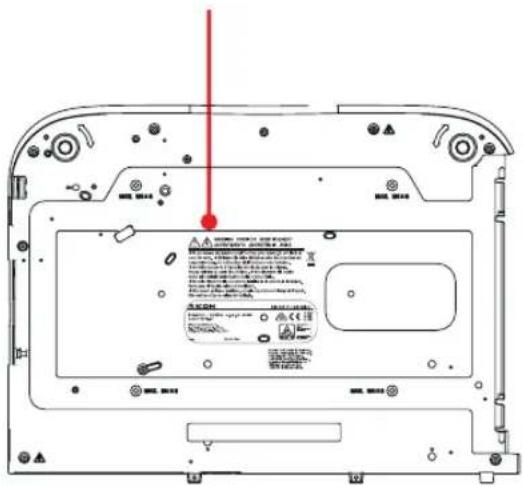
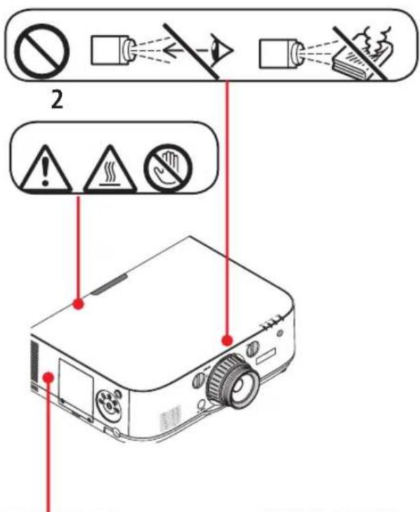
Safety Labels of This Machine
1 Do not look into the lens while the projector is on. Serious damage to your eyes could result. Do not cover the lens with the lens cap or equivalent while the projector is on. Doing so can lead to melting of the cap due to the heat emitted from the light output. Do not place any objects, which are easily affected by heat, in front of the projector lens. Doing so could lead to the object melting from the heat that is emitted from the light output.
2 Do not try to touch the ventilation outlet on the left front (when seen from the front) as it can become heated while the projector is turned on and immediately after the projector is turned off. Parts of the projector may become temporarily heated if the projector is turned off with the Power button or if the AC power supply is disconnected during normal projector operation.
Use caution when picking up the projector.
3 Do not remove any screws except the lamp cover screws. Do not block or cover the vents.
4 To replace the lamp, first unplug the power cord then wait for more than 1 hour.
The lamp might be broken. Be careful of pieces of broken glass.
*The label changes depending on the destination.
3

WARNING AVERTISSEMENT ADVERTENCIA AVISO
- Do not remove any screws except the lamp cover screws. Do not block or cover the vents.
- Ne retirer aucune vis à l'exception des vis du cache de la lampe. Ne pas obstruer ou couvrir les aérations.
- No retire ningún tornillo excepto los tornillos de la cubierta de la lámpara. No bloquee ni tape las salidas de ventilación.
- Não remova quaisquer parafusos, excepto os parafusos da tampa da lâmpada. Não obstrua ou tape as saídas de ventilação.

WARNING VORSICHT AVERTISSEMENT AVVERTIMENTO ADVERTENCIA AVISO
- Do not remove any screws except the lamp cover screws. Do not block or cover the vents.
- Entfernen Sie keine Schrauben außer den Schrauben der Lampenabdeckung. Die Luftauslässe nicht blockieren oder abdecken.
- Ne retirer aucune vis à l'exception des vis du cache de la lampe. Ne pas obstruer ou couvrir les aérations. - Non rimuovere viti eccetto quelle sul coperchio lampada. Non coprire le prese d'aria.
- No retire ningún tornillo excepto los tornillos de la cubierta de la lámpara. No bloquee ni tape las salidas de ventilación.
- Não remova quaisquer parafusos, excepto os parafusos da tampa da lâmpada. Não obstrua ou tape as saídas de ventilação.

4

CAUTION ATTENTION PRECAUCIÓN CUIDADO 注意
- To replace the lamp, first unplug the power cord then wait for more than 1 hour. • The lamp might be broken. Be careful of pieces of broken glass. • Pour rempl. lampe, débrancher cordon d'alimentation, puis attendre + d'î h. • Lampe peut-être cassée. Attent ^® aux morceaux de verre brisé.
- Para cambiar la lámpara, desenchufe el cable y espere más de 1 hora. • La lámpara puede romperse. Cuidado con los cristales rotos.
- P/ subst. a lâmpada, desligue o cabo de alimentação e aguarde + de 1 hora.
- A lâmpada pode estar partida. Tome cuidado com vidros partidos.
- 要更换灯泡,首先拔下电源线然后等待1小时以上。
· 灯泡可能会被碰碎。小心玻璃碎片。
Lamp Type : Type21
1

CAUTION ACHTUNG ATTENTION ATTENZIONE PRECAUCIÓN
- To replace the lamp, first unplug the power cord then wait for more than 1 hour.
- The lamp might be broken. Be careful of pieces of broken glass.
- Z. Ersetzen d. Lampe erst Netzkabel herausziehen u. über 1 Stunde warten.
• Die Lampe könnte zerbrochen sein. Auf Glasscherben achten. • Pour rempl. lampe, débrancher cordon d'alimentation, puis attendre + d'1 h. • Lampe peut-être cassée. Attent* aux morceaux de verre brisé. - Per sostituire la lampada, scollegare l'alimentazione e attendere min.1 ora.
- La lampada potrebbe essere rotta. Attenzione schegge vetro. - Para cambiar la lámpara, desenchufe el cable y espere más de 1 hora.
- La lámpara puede romperse. Cuidado con los cristales rotos.
Lamp Type : Type 21

Health precautions to users viewing 3D images
Before viewing, be sure to read health care precautions that may be found in the user's manual included with your 3D eyeglasses or your 3D compatible content such as Blu-ray Discs, video games, computer's video files and the like.
To avoid any adverse symptoms, heed the following:
- Do not use 3D eyeglasses for viewing any material other than 3D images.
- Allow a distance of 2 m/7 feet or greater between the screen and a user. Viewing 3D images from too close a distance can strain your eyes.
- Avoid viewing 3D images for a prolonged period of time. Take a break of 15 minutes or longer after every hour of viewing.
- If you or any member of your family has a history of light-sensitive seizures, consult a doctor before viewing 3D images.
- While viewing 3D images, if you get sick such as nausea, dizziness, queasiness, headache, eyestrain, blurry vision, convulsions, and numbness, stop viewing them. If symptoms still persist, consult a doctor.
• View 3D images from the front of the screen. Viewing from an angle may cause fatigue or eyestrain.
Power management function
In order to keep power consumption low, the following power management functions (1) and (2) have been set when shipped from the factory. Please display the on-screen menu and change the settings (1) and (2) according to the aim of using the projector.
1. STANDBY MODE (Factory preset: NORMAL)
- When [NORMAL] is selected for [STANDBY MODE], the following connectors and functions will not work: HDMI OUT connector, AUDIO OUT connector, Ethernet Port* USB-A Port, LAN functions, Mail Alert function (→ page 127)
2. AUTO POWER OFF (Factory preset: 60 minutes)
- When [1:00] is selected for [AUTO POWER OFF], you can enable the projector to automatically turn off in 1 hour if there is no signal received by any input or if no operation is performed. (→ page 128)
Clearance for Installing the Projector
Allow ample clearance between the projector and its surroundings as shown below.
The high temperature exhaust coming out of the device may be sucked into the device again.
Avoid installing the projector in a place where air movement from the HVAC is directed at the projector.
Heated air from the HVAC can be taken in by the projector's intake vent. If this happens, the temperature inside the projector will rise too high causing the over-temperature protector to automatically turn off the projectors power.
Example 1 – If there are walls on both sides of the projector.
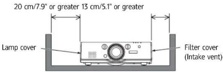
NOTE:
The drawing shows the proper clearance required for the front, back and top of the projector.
Example 2 – If there is a wall behind the projector.
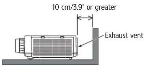
NOTE:
The drawing shows the proper clearance required for the back, sides and top of the projector.
Example 3 – In the case of portrait projection.
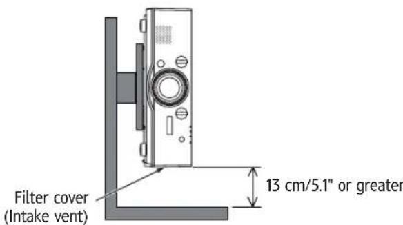
NOTE:
- The drawing shows the proper clearance required for the front, back and top of the projector.
• See page 163 for an installation example on portrait projection.
Important Information......i
1. Introduction ...... 1
① What's in the Box? .... 1
② Introduction to the Projector ....2
Congratulations on Your Purchase of the Projector....2
Installation 2
Videos 2
Network 3
Energy-saving 3
Maintenance....4
About this user's manual 5
About the Projector's [NETWORK SETTINGS] 6
③ Part Names of the Projector....7
Front/Top 7
Rear 8
Controls/Indicator Panel....9
Terminals 10
④ Part Names of the Remote Control....11
Battery Installation....12
Remote Control Precautions....12
Operating Range for Wireless Remote Control 13
2. Projecting an Image (Basic Operation) 14
① Flow of Projecting an Image .... 14
② Connecting Your Computer/Connecting the Power Cord....15
③ Turning on the Projector....16
Note on Startup screen (Menu Language Select screen) 17
4 Selecting a Source....18
Selecting the computer or video source....18
⑤ Adjusting the Picture Size and Position 20
Adjusting the vertical position of a projected image (Lens shift)....21
Focus 22
Applicable lens: Replacement Lens Type8....23
Applicable lens: Replacement Lens Type1 24
Zoom 25
Adjusting the Tilt Feet....25
6 Optimizing Computer Signal Automatically 26
Adjusting the Image Using Auto Adjust....26
⑦ Turning Up or Down Volume 26
⑧ Turning off the Projector....27
⑨ After Use 28
3. Convenient Features....29
① Turning off the Image and Sound 29
② Freezing a Picture 30
③ Enlarging a Picture....30
④ Changing Eco Mode/Checking Energy-Saving Effect Using Eco Mode [ECO MODE] ...31 Checking Energy-Saving Effect [CARBON METER] .... 32
⑤ Correcting Horizontal and Vertical Keystone Distortion [CORNERSTONE] 33
6 Preventing the Unauthorized Use of the Projector [SECURITY]....36
7 Projecting 3D videos....39
Procedure to watch 3D videos using this projector....39
When videos cannot be viewed in 3D....41
8 Controlling the Projector by Using an HTTP Browser....42
9 Projecting Your Computer's Screen Image from the Projector via a Network [NETWORK PROJECTOR] 52
10 Using the Projector to Operate Your Computer via a Network [REMOTE DESKTOP] ....56
Prepare a commercially available wireless keyboard ....56
Setting the password to the user account of Windows 7 ....57
Setting the Remote Access....57
Checking the IP address on Windows 7....57
Starting the Remote Desktop....58
4. Multi-Screen Projection....61
① Things that can be done using multi-screen projection....61 Case 1. Using a single projector to project two types of videos [PIP/PICTURE BY PICTURE]....61 Case 2. Using four projectors (liquid crystal panel: XGA) to project videos with a resolution of 1920 × 1080 pixels [TILING]....62 Things to note when installing projectors....64
② Displaying Two Pictures at the Same Time....65 Projecting two screens....66 Switching the main display with the sub-display and vice versa....67 Restrictions....68
③ Displaying a Picture Using [EDGE BLENDING]....69 Setting the overlap of projection screens....70 Black Level Adjustment....73
5. Using On-Screen Menu....75
① Using the Menus....75
② Menu Elements 76
③ List of Menu Items....77
④ Menu Descriptions & Functions [INPUT] 83
⑤ Menu Descriptions & Functions [ADJUST]....87
[PICTURE]....87
[IMAGE OPTIONS]....91
[VIDEO]....95
[3D SETTINGS]....97
6 Menu Descriptions & Functions [DISPLAY] ..... 98 [PIP/PICTURE BY PICTURE] ..... 98 [GEOMETRIC CORRECTION] ..... 100 [EDGE BLENDING] ..... 104 [MULTI SCREEN] ..... 105
⑦ Menu Descriptions & Functions [SETUP]....107 [MENU]....107
[INSTALLATION]....109
[CONTROL]....112
[NETWORK SETTINGS]....120
[SOURCE OPTIONS] 125
[POWER OPTIONS]....127
Returning to Factory Default [RESET] 129
⑧ Menu Descriptions & Functions [INFO.] 131
[USAGE TIME]....131
[SOURCE(1)] 132
[SOURCE(2)] 132
[SOURCE(3)] 132
[SOURCE(4)] 133
[WIRED LAN]....133
[VERSION(1)] 133
[VERSION(2)] 133
[OTHERS]....134
[CONDITIONS] 134
⑨ Application Menu 136
ADVANCED NETWORK UTILITY 136
NETWORK PROJECTOR 137
REMOTE DESKTOP CONNECTION....137
NETWORK SETTINGS(MM) 138
6. Connecting to Other Equipment....153
① Mounting a lens (sold separately) 153
Mounting the lens....153
Removing the lens 154
② Making Connections....155
Analog RGB signal connection....155
Digital RGB signal connection 156
Connecting an External Monitor....159
Connecting Your Blu-ray Player or Other AV Equipment 160
Connecting Component Input 161
Connecting HDMI Input 162
Portrait projection (vertical orientation) 163
Connecting to a Wired LAN 166
Connecting to a Wireless LAN (sold separately) 167
Mounting a wireless LAN unit 167
To remove the wireless LAN unit 168
Example of wireless LAN connection 170
7. Maintenance....171
① Cleaning the Filters 171
② Cleaning the Lens 174
③ Cleaning the Cabinet 174
④ Replacing the Lamp and the Filters....175
8. User Supportware 180
① Operating Environment for Software Included on CD-ROM 180
Names and Features of Bundled Software Programs....180
Download service....181
Operating Environment 181
② Installing Software Program....183
Installation for Windows software 183
Using on Mac OS....185
3 Projecting Your Computer's Screen Image or Video from the Projector over a LAN
(Projection Utility) 186
Starting Projection Utility from a USB Memory or SD Card 191
4 Projecting an Image from an Angle (Geometric Correction Tool in Projection Utility) ....193
What you can do with GCT 193
Projecting an Image from an Angle (GCT) 193
5 Projecting Images from the Projector over a LAN (Advanced Network Utility) 195
What you can do with Advanced Network Utility 195
Connecting the projector to a LAN 196
Basic Operation of Advanced Network Utility....197
6 JPEG Conversion Tool 206
⑦ Managing the Projector Using Projector Management Utility 207
9. Using the Viewer....208
① What you can do with the Viewer....208
② Projecting images stored in a USB memory device....211
Starting the Viewer 211
Names and functions of Viewer screen 214
Viewer option settings....219
3 Projecting data from shared folder 222
Connecting the projector to the shared folder 222
Disconnecting the shared folder from the projector....225
4 Projecting data from media server 226
Setting up "Media Sharing" in Windows Media Player 11....226
Setting up "Media Sharing" in Windows Media Player 12....228
Connecting the projector to the media server 229
Disconnecting the projector from the media server 230
10. Appendix......231
1 Throw distance and screen size 231
Lens types and throw distance....231
Tables of screen sizes and dimensions....234
Lens shifting range....235
② Compatible Input Signal List....237
③ Specifications....240
4 Cabinet Dimensions....242
⑤ Pin assignments and signal names of main connectors....243
6 Troubleshooting 245
Indicator Messages....245
Common Problems & Solutions 247
If there is no picture, or the picture is not displayed correctly. 249
7 PC Control Codes and Cable Connection....250
1. Introduction
① What's in the Box?
Make sure your box contains everything listed. If any pieces are missing, contact your dealer. Please save the original box and packing materials if you ever need to ship your projector.
Projector
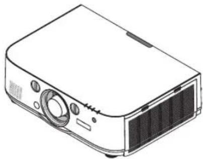
natural_image
Line drawing of a projector with front panel and control panel (no text or symbols)Dust cap for lens
* The projector is shipped without a lens. For the types of lens and throw distances, see page 231.
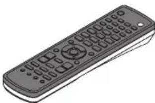
natural_image
Illustration of a black remote control with standard buttons and a circular keypad (no text or symbols)Remote control AA alkaline batteries
(x2)
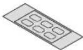
Input selection character sticker
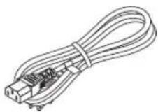
Power cord Lens theft prevention screw

This screw makes it difficult to remove the lens mounted on the projector. (→ page 154)
natural_image
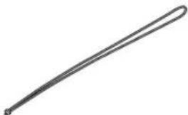
Simple line drawing of a curved object resembling a tool or tool (no text or symbols)Straps (for preventing lamp cover from falling) Attaching the straps to the lamp cover prevents them from falling when the projector is suspended from the ceiling.
natural_image
Two overlapping gray rectangular sheets with no text or symbols- Important Infomation · Quick Setup Guide

CD-ROM
User's manual (PDF) and the utility software
For North America only Limited warranty
② Introduction to the Projector
This section introduces you to your new projector and describes the features and controls.
Congratulations on Your Purchase of the Projector
This projector is one of the very best projectors available today. The projector enables you to project precise images up to 500 inches across (measured diagonally) from your PC or Mac computer (desktop or notebook), VCR, Blu-ray player, or document camera. You can use the projector on a tabletop or cart, you can use the projector to project images from behind the screen, and the projector can be permanently mounted on a ceiling ^*1 . The remote control can be used wirelessly.
^*1 Do not attempt to mount the projector on a ceiling yourself.
The projector must be installed by qualified technicians in order to ensure proper operation and reduce the risk of bodily injury.
In addition, the ceiling must be strong enough to support the projector and the installation must be in accordance with any local building codes. Please consult your dealer for more information.
Installation
- Liquid crystal type high brightness/high resolution projector
| Model Brightness | Resolution Aspect Ratio | ||
| PJ WU6181N 6200 lm | WUXGA (1920 1200) 16:10 | ||
| PJ WX6181N 6700 lm | WXGA (1280 800) 16:10 | ||
| PJ X6181N 7200 lm | XGA (1024 768) 4:3 |
- Wide range of optional lenses selectable according to the place of installation
This projector supports 6 types of optional lenses, providing a selection of lenses adapted to a variety of places of installation and projection methods.
In addition, the lenses can be mounted and removed in one touch.
Note that no lens is mounted upon shipment from the factory. Please purchase optional lenses separately.
- Lens shift function for easily adjusting the position of the projected image
The position of the projected image is moved by turning the two dials on the projector's front, one for the vertical direction, one for the horizontal direction.
• 360° installation angle (tilt-free)
The projector can be installed at any angle (360°).
Note, however, that the "fan mode" setting must be changed according to the angle of installation.
Also, the projector cannot be installed tilted to the left or right.
• Portrait projection is possible
This projector can perform portrait projection with the projection screen turned 90°.
However, the lamp replacement time* is 2000 hours for portrait projection.
* Replacement time not guaranteed.
Videos
- Wide range of input/output connectors (HDMI, DisplayPort, BNC, etc.) and built-in monaural speaker
The projector is equipped with a variety of input/output connectors: HDMI (input 2, output 1), DisplayPort, BNC (5-core), computer (analog), etc.
The projector's HDMI input/output connectors and DisplayPort input connector.
The projector is also equipped with a built-in 10W monaural speaker.
- Simultaneous display of 2 images (PIP/PICTURE BY PICTURE)
Two images can be projected simultaneously with a single projector.
There are two types of layouts for the two images: "picture-in-picture" in which a sub-picture is displayed on the main picture, and "picture-by-picture" in which the main and sub pictures are displayed next to each other.
- Multi-screen projection using multiple projectors
This projector is equipped with multiple HDMI input & output terminals that can connect multiple projectors in a daisy chain. A high quality picture is achieved by dividing and projecting high resolution videos among the various projectors.
Furthermore, the boundaries of the screens are smoothed using an edge blending function.
* Both the composite video signal from each input connector as the computer, BNC, and BNC (CV), and the S-video signal from the BNC (Y/C) Input connector are not output from HDMI OUT Connector of this projector.
- Seamless switch function for smoother screen changes when switching the signal
When the input connector is switched, the image displayed before switching is held so that the new image can be switched to without a break due to absence of a signal.
• Supports HDMI 3D format
This projector can be used to watch videos in 3D using commercially-available active shutter-type 3D eyewear and 3D emitters that support Xpand 3D.
Network
• Supported by wired LAN/wireless LAN (wireless LAN unit sold separately)
Ethernet Port *Video can be transmitted from a computer equipped with a RF-45 port that is connected to a wired LAN to the projector, and the projector can also be controlled from the computer.
In addition, the all models can also be used over a wireless LAN by using a wireless LAN unit sold separately.
• LAN-compatible Viewer
The projector's built-in Viewer allows you to view images or movie files in the shared folder of your PC connected to a wired or wireless LAN.
* The Viewer supports the Media Sharing function of Windows Media Player 11.
- CRESTRON ROOMVIEW compatibility
The projector supports CRESTRON ROOMVIEW, allowing multiple devices connected in the network to be managed and controlled from a computer or controller.
- Convenient utility software (User Supportware) provided as standard
The 2 utility software stored in the attached CD-ROM (Projection Utility (for Windows/Mac OS), Advanced Network Utility (for Windows), ) may be used. Projection Utility (for Windows) may be started up and used from a USB memory or SD card available commercially even without installing on a computer.
Projection Utility (for Windows/Mac OS), Advanced Network Utility (for Windows)
Energy-saving
• Energy-saving design with a standby power consumption of 0.11 watts (100-130 V)/0.16 watts (200-240 V)
When the on-screen menu's standby mode is set to "NORMAL", the power consumption in the standby mode is 0.11 watts (100-130 V)/0.16 watts (200-240 V).
- "Eco mode" for low power consumption and "Carbon Meter" display
The projector is equipped with an "eco mode" for reducing power consumption during use. Furthermore, the power-saving effect when the eco mode is set is converted into the amount of reductions of CO_2 emissions and this is indicated on the confirmation message displayed when the power is turned off and at "Information" on the on-screen menu (CARBON METER).
Maintenance
• Maximum lamp replacement time of 4000 hours and no need to clean the filters
When used in the eco mode, the lamp replacement time* is extended to a maximum of 4000 hours.
* This time is not guaranteed.
Furthermore, this projector uses large 2-layer filters. When these filters are replaced with new ones when changing the lamp, there is no need for regular filter cleaning.
* Actual menus may be different from the menu images in this user's manual.
About this user's manual
The fastest way to get started is to take your time and do everything right the first time. Take a few minutes now to review the user's manual. This may save you time later on. At the beginning of each section of the manual you'll find an overview. If the section doesn't apply, you can skip it.
Notation by Resolution
These indicate the descriptions of the model groups according to the resolution of the liquid crystal panels.
WUXGA Type
Applicable to models PJ WU6181N.
WXGA Type
Applicable to models PJ WX6181N.
XGA Type
Applicable to models PJ X6181N.
*The description applies to all models if the type name is not indicated.
About the Projector's [NETWORK SETTINGS]
"NETWORK SETTINGS" need to be carried out when connecting this projector to a wired or wireless LAN.
The following two types of [NETWORK SETTINGS] 1 and 2 can be used. Use the [NETWORK SETTINGS] 1 and 2 for different purposes depending on the software and function described in the table below.
1. "NETWORK SETTINGS" under [SETUP] in the on-screen menu (→ Page 120)
Or "NETWORK SETTINGS" in the HTTP server ( Page 46)
2. "NETWORK SETTINGS" in the application menu (→ Page 138)
Or "NETWORK SETTINGS" in the HTTP server ( Page 49)
| 1. NETWORK SETTINGS 2. NETWORK | SETTINGS (MM) | |
| Wired LAN OK OK | ||
| Wireless LAN Not OK OK* | ||
| Main uses Projector control Transmission of images | ||
| Function · PC control | PJLinkAMX BEACONCRESTRONALERT MAILHTTP server (PROJECTOR ADJUSTMENT)Synchronize with an Internet time server | Shared folder (viewer)Media Server (viewer)Network Projector |
| User Supportware · Projector Management Utility · Projection UtilityAdvanced Network Utility | ||
* A wireless LAN unit sold separately is required to connect the projector to a wireless LAN.
③ Part Names of the Projector
Front/Top
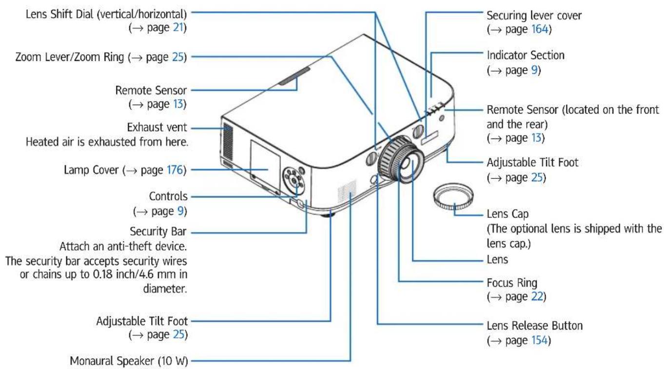
The lens is sold separately. The description below is for when the Standard Lens Type1 lens is mounted.
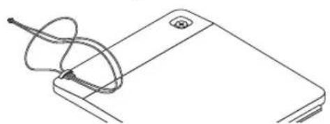
Mounting the strap
- Mount the strap to the filter cover and lamp cover as shown on the diagram below.
- Insert the knot in the strap into the hole on the bottom of the projector and pull in the direction of the arrow to fasten.
natural_image
Line drawing of a smartphone with a cable inserted into the screen (no text or symbols)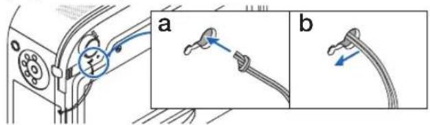
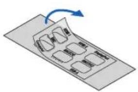
How to paste the input selection character sticker of the remote control
- Peel off the cover of the sticker and align the sticker holes with Buttons 1 to 6 before pasting.
- Please take care not to let the sticker contact the buttons when pasting.
- The explanations and illustrations in this manual are provided with the sticker pasted.
natural_image
Diagram of a mechanical or electronic component with internal compartments and a blue arrow indicating rotation (no text or symbols)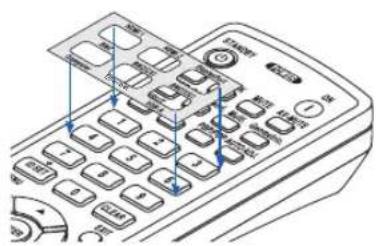
natural_image
Line drawing of a remote control device with buttons and dials (no text or symbols)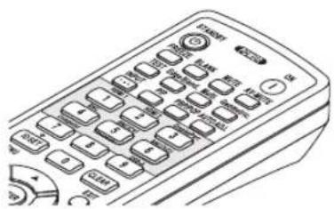
natural_image
Line drawing of a remote control device with keypad and function buttons (no text or symbols)Rear
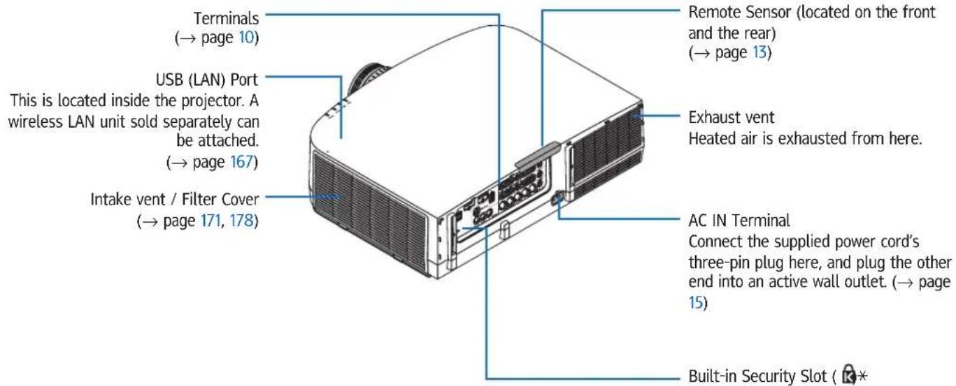
* This security slot supports the MicroSaver ® Security System.
Controls/Indicator Panel
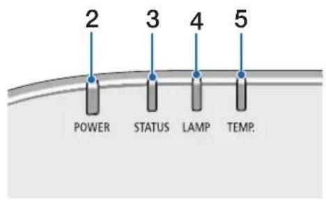
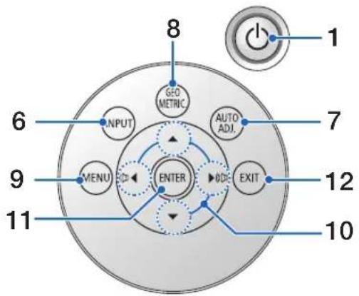
- (POWER) Button
(→ page 16, 27)
- POWER Indicator
(→ page 15, 16, 27, 245)
- STATUS Indicator
(→ page 245)
- LAMP Indicator
(→ page 176, 246)
- TEMP. Indicator
(→ page 246)
- INPUT Button
(→ page 18)
- AUTO ADJ. Button
(→ page 26)
- Geometric. Button
(→ page 33)
- MENU Button
(→ page 75)
- ▲▼◀▶ / Volume Buttons ◀▶
(→ page 26, 75)
- ENTER Button
(→ page 75)
- EXIT Button
(→ page 75)
Terminals
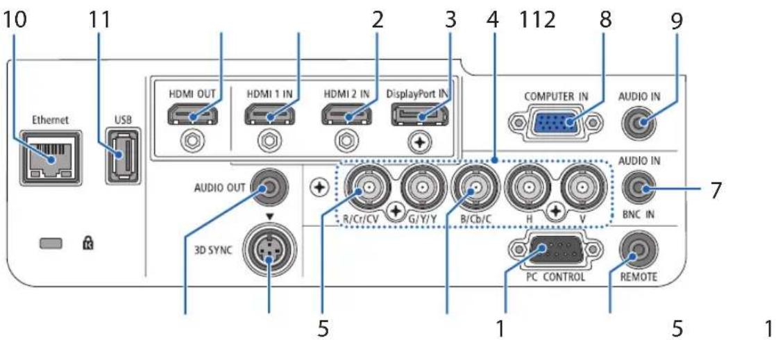
- HDMI 1 IN Connector (Type A)
(→ page 156, 158, 162)
- HDMI 2 IN Connector (Type A)
(→ page 156, 158, 162)
- DisplayPort IN Connector
(→ page 156)
- BNC IN [R/Cr/CV, G/Y/Y, B/Cb/C, H, V] Connectors (BNC × 5)
(→ page 155, 160)
- BNC (CV) Input Connector (BNC × 1)
(→ page 160)
- BNC (Y/C) Input Connector (BNC × 2)
(→ page 160)
- BNC AUDIO IN Mini Jack (Stereo Mini)
(→ page 158, 160)
- COMPUTER IN/ Component Input Connector (Mini D-Sub 15 Pin)
(→ page 155, 161)
- COMPUTER AUDIO IN Mini Jack (Stereo Mini)
(→ page 155, 161)
- Ethernet Port (RJ-45)
(→ page 166)
- USB-A Port (Type A)
(→ page 211)
- HDMI OUT Connector (Type A)
(→ page 159)
- AUDIO OUT Mini Jack (Stereo Mini)
(→ page 159)
- 3D SYNC Connector (Mini DIN 4 Pin)
(→ page 39)
- PC CONTROL Port (D-Sub 9 Pin)
(→ page 244)
Use this port to connect a PC or control system. This enables you to control the projector using serial communication protocol. If you are writing your own program, typical PC control codes are on page 250.
- REMOTE Connector (Stereo Mini)
This port is for the dealer or service personnel. For details, contact your dealer.
NOTE:
- When a remote control cable is connected to the REMOTE connector, infrared remote control operations cannot be performed.
④ Part Names of the Remote Control
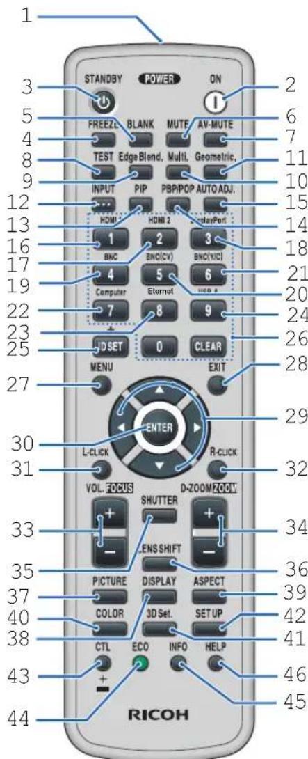
- Infrared Transmitter (→ page 13)
- POWER ON Button (→ page 16)
- STANDBY Button (→ page 27)
- FREEZE Button (→ page 30)
- BLANK Button (→ page 29)
- MUTE Button (→ page 29)
-
AV-MUTE Button (→ page 29)
-
TEST Button (→ page 83)
- Edge Blend. Button (→ page 69, 104)
- Multi. Button (→ page 105)
- Geometric. Button (→ page 33, 100)
- INPUT Button (→ page 18)
- PIP Button (→ page 66)
- PBP/POP Button (→ page 66)
- AUTO ADJ. Button (→ page 26)
- 1 (HDMI 1) Button (→ page 18)
- 2 (HDMI 2) Button (→ page 18)
- 3 (DisplayPort) Button (→ page 18)
- 4 (BNC) Button (→ page 18)
- 5 (BNC(CV)) Button (→ page 18)
- 6 (BNC(Y/C)) Button (→ page 18)
- 7 (Computer) Button (→ page 18)
- 8 (Ethernet) Button (→ page 18)
- 9 (USB-A) Button (→ page 18)
- ID SET Button (→ page 118)
- Numeric Keypad Button/CLEAR Button (→ page 118)
- MENU Button (→ page 75)
-
EXIT Button (→ page 75)
-
▲▼◀▶ Button (→ page 75)
- ENTER Button (→ page 75)
- L-CLICK Button* (not available on this series of projectors)
- R-CLICK Button* (not available on this series of projectors)
- VOL./FOCUS (+)(−) Button (→ page 26)
- D-ZOOM/ZOOM (+)(−) Button (→ page 30) ("ZOOM" Button does not work on this series of projectors)
- SHUTTER Button (not available on this series of projectors)
- LENS SHIFT Button (not available on this series of projectors)
- PICTURE Button (→ page 87)
- DISPLAY Button (→ page 98)
- ASPECT Button (→ page 93)
- COLOR Button (→ page 89)
- 3D Set. Button (→ page 97)
- SETUP Button (→ page 107)
- CTL Button (not available on this series of projectors)
- ECO Button (→ page 31)
- INFO Button (→ page 131)
- HELP Button (→ page 131)
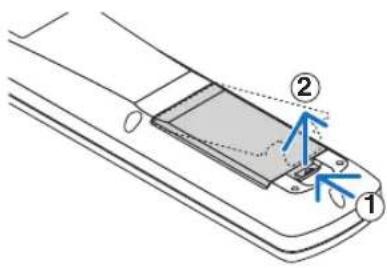
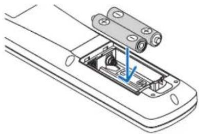
Battery Installation
-
Press the catch and remove the battery cover.
-
Install new ones (AA). Ensure that you have the batteries' polarity (+/ ) aligned correctly.
-
Slip the cover back over the batteries until it snaps into place.
NOTE: Do not mix different types of batteries or new and old batteries.
Remove the old battery and put the new battery.
natural_image
Line drawing of a remote control panel with battery pack and cable connector (no text or symbols)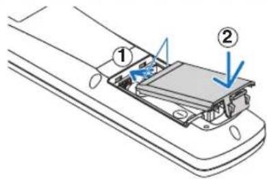
Remote Control Precautions
- Handle the remote control carefully.
- If the remote control gets wet, wipe it dry immediately.
- Avoid excessive heat and humidity.
- Do not short, heat, or take apart batteries.
- Do not throw batteries into fire.
- If you will not be using the remote control for a long time, remove the batteries.
- Ensure that you have the batteries' polarity (+/ ) aligned correctly.
- Do not use new and old batteries together, or use different types of batteries together.
- Dispose of used batteries according to your local regulations.
Operating Range for Wireless Remote Control
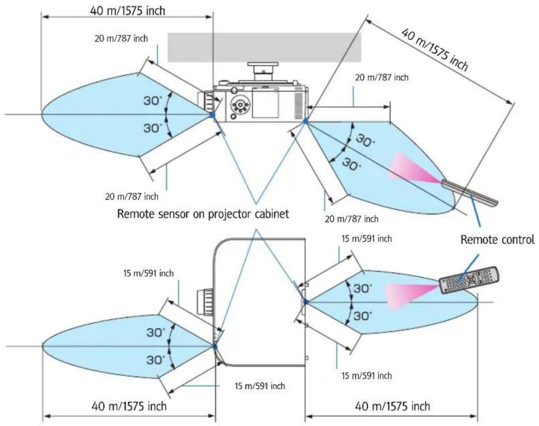
- The infrared signal operates by line-of-sight up to a distance of above meters and within a 60-degree angle of the remote sensor on the projector cabinet.
- The projector will not respond if there are objects between the remote control and the sensor, or if strong light falls on the sensor. Weak batteries will also prevent the remote control from properly operating the projector.
2. Projecting an Image (Basic Operation)
This section describes how to turn on the projector and to project a picture onto the screen.
① Flow of Projecting an Image
Step 1
- Connecting your computer / Connecting the power cord (→ page 15)

Step 2
- Turning on the projector ( page 16)

Step 3
- Selecting a source (→ page 18)

Step 4
- Adjusting the picture size and position ( page 20)
- Correcting keystone distortion [CORNERSTONE] (→ page 33, 100)

Step 5
- Adjusting a picture and sound
- Optimizing a computer signal automatically (→ page 26)
- Turning up or down volume ( page 26)

Step 6
- Making a presentation

Step 7
- Turning off the projector (→ page 27)

Step 8
· After use ( page 28)
② Connecting Your Computer/Connecting the Power Cord
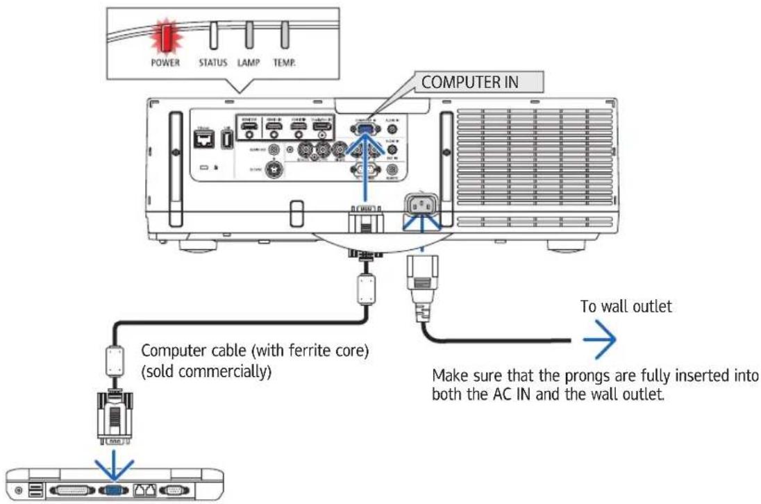
1. Connect your computer to the projector.
This section will show you a basic connection to a computer. For information about other connections, see “(2) Making Connections” on page 155.
Connect the display output terminal (mini D-sub 15 pin) on the computer to the computer video input terminal on the projector with a commercially-available computer cable (with ferrite core) and then turn the knobs of the connectors to secure them.
2. Connect the supplied power cord to the projector.
First connect the supplied power cord's three-pin plug to the AC IN terminal of the projector, and then connect the other plug of the supplied power cord in the wall outlet.
Upon connecting the power cable, the POWER indicator of the projector will light up in orange. If there are no input signals, the device will go into the standby mode after about 10 seconds and light up in red*.
The STATUS indicator will light off*.
* This will apply for both indicators when [NORMAL] is selected for [STANDBY MODE]. See the Power Indicator section. (→ page 245)

CAUTION:
Parts of the projector may become temporarily heated if the projector is turned off with the POWER button or if the AC power supply is disconnected during normal projector operation.
Use caution when picking up the projector.
③ Turning on the Projector
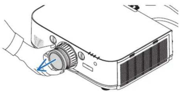
1. Remove the lens cap.
2. Press the ⏻ (POWER) button on the projector cabinet or the POWER ON button on the remote control.
The POWER indicator will light up in blue from red and then start blinking. After that, the image will be projected onto the screen.
TIP:
- When the message "PROJECTOR IS LOCKED! ENTER YOUR PASSWORD." is displayed, it means that the [SECURITY] feature is turned on. (→ page 36)
- When the ECO message is displayed, it means that [ON] is selected for [ECO MES-SAGE]. (→ page 108)
- Pressing buttons such as power button and MENU button will make sound. To turn off the beep sound, select [OFF] for [BEEP] from the menu. (→ page 119)
After you turn on your projector, ensure that the computer or video source is turned on.
NOTE: A blue screen (blue background) is displayed when no signal is being input (by factory default menu settings).
natural_image
Illustration of a projector with a hand operating the lens (no text or symbols visible)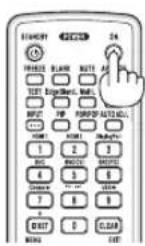
Standby Blinking Power On
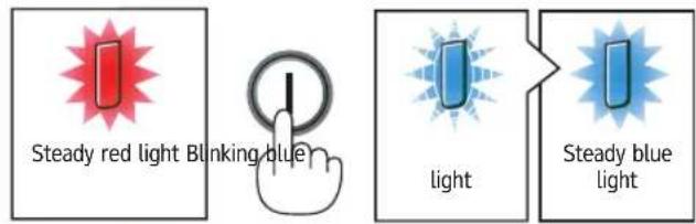
(→ page 245)
Note on Startup screen (Menu Language Select screen)
When you first turn on the projector, you will get the Startup menu. This menu gives you the opportunity to select one of the 29 menu languages.
To select a menu language, follow these steps:
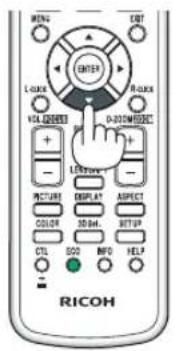
- Use the ▲, ▼, ◀ or ▶ button to select one of the 29 languages from the menu.
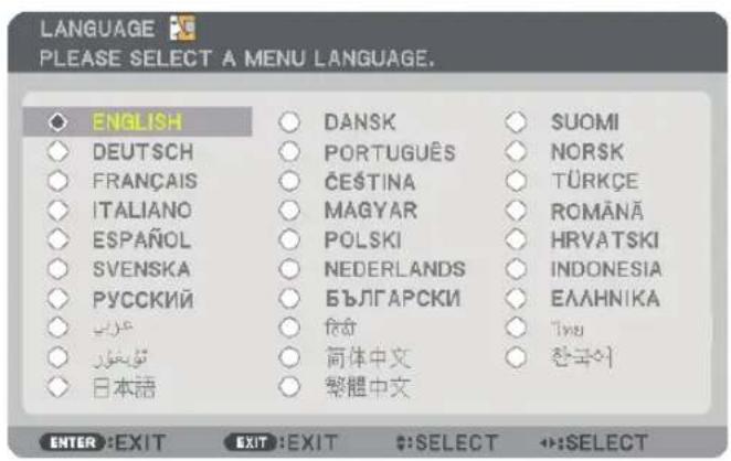
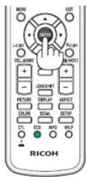
2. Press the ENTER button to execute the selection.
After this has been done, you can proceed to the menu operation. If you want, you can select the menu language later.
(→ [LANGUAGE] on page 79 and 107)
NOTE:
- During projection, after shutting down the power supply (direct power off), wait for about 1 minute or longer before turning on the power again.
- Keep the lens cap off the lens while the projector's power is on.
If the lens cap is on, it could be warped due to high temperature. - If one of the following things happens, the projector will not turn on.
- If the internal temperature of the projector is too high, the projector detects abnormal high temperature. In this condition the projector will not turn on to protect the internal system. If this happens, wait for the projector's internal components to cool down.
- When the lamp reaches its end of usable life, the projector will not turn on. If this happens, replace the lamp.
- If the STATUS indicator lights orange with the power button pressed, it means that the [CONTROL PANEL LOCK] is turned on. Cancel the lock by turning it off. (→ page 117)
-
If the lamp fails to light, and if the LAMP indicator flashes on and off in a cycle of six times, wait a full minute and then turn on the power.
-
While the POWER indicator is blinking blue in short cycles, the power cannot be turned off by using the power button.
- Immediately after turning on the projector, screen flicker may occur. This is normal. Wait 3 to 5 minutes until the lamp lighting is stabilized.
- When the projector is turned on, it may take some time before the lamp light becomes bright.
- If you turn on the projector immediately after the lamp is turned off or when the temperature is high, the fans run without displaying an image for some time and then the projector will display the image.
④ Selecting a Source
Selecting the computer or video source
NOTE: Turn on the computer or video source equipment connected to the projector.
Detecting the Signal Automatically
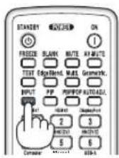
Press the INPUT button for 1 second or longer. The projector will search for the available input source and display it. The input source will change as follows:
Automatically checks for any input signal in the order HDMI 1 → HDMI 2 → Display Port → BNC → BNC(CV) → BNC(Y/C) → COMPUTER → USB-A. The input signal will be projected when it is detected.
- Press it briefly to display the [INPUT] screen.
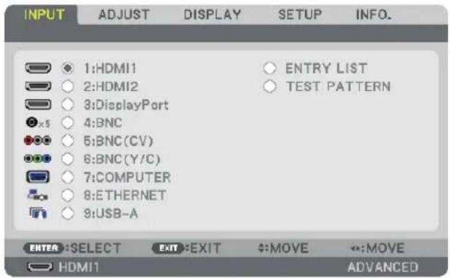
Press the ▼/▲ buttons to match the target input terminal and then press the ENTER button to switch the input. To delete the menu display in the [INPUT] screen, press the MENU or EXIT button.
TIP: If no input signal is present, the input will be skipped.
Using the Remote Control
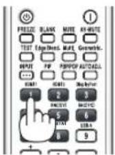
Press any one of the 1/HDMI 1, 2/HDMI 2, 3/DisplayPort, 4/BNC, 5/BNC(CV), 6/BNC(Y/C), 7/Computer, 8/Ethernet, or 9/USB-A buttons.
Selecting Default Source
You can set a source as the default source so that it will be displayed each time the projector is turned on.
- Press the MENU button.
The menu will be displayed.
- Press the ▶ button to select [SETUP] and press the ▼ button or the ENTER button to select [BASIC].
- Press the ▶ button to select [SOURCE OPTIONS].
- Press the ▼ button four times to select [DEFAULT INPUT SELECT] and press the ENTER button.
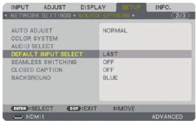
The [DEFAULT INPUT SELECT] screen will be displayed.
(→ page 126)
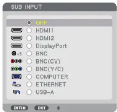
NOTE:
- Ethernet cannot be detected automatically even if [DEFAULT INPUT SELECT] has been set to [AUTO]. Select [ETHERNET] in [DEFAULT INPUT SELECT] to enable Ethernet to be selected automatically when power to the projector is turned on.
- Select a source as the default source, and press the ENTER button.
- Press the EXIT button a few times to close the menu.
- Restart the projector.
The source you selected in step 5 will be projected.
TIP:
- When the projector is in Standby mode, applying a computer signal from a computer connected to the COMPUTER IN input will power on the projector and simultaneously project the computer's image.
([AUTO POWER ON SELECT] → page 128)
- On the Windows 7 keyboard, a combination of the Windows and P keys allows you to set up external display easily and quickly.
⑤ Adjusting the Picture Size and Position
Use the lens shift dial, the adjustable tilt foot lever, the zoom lever/zoom ring and the focus ring to adjust the picture size and position.
In this chapter drawings and cables are omitted for clarity.
Adjusting the projected image's vertical and horizontal position[Lens shift](→ page 21)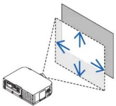 | Adjusting the focus[Focus ring](→ page 22)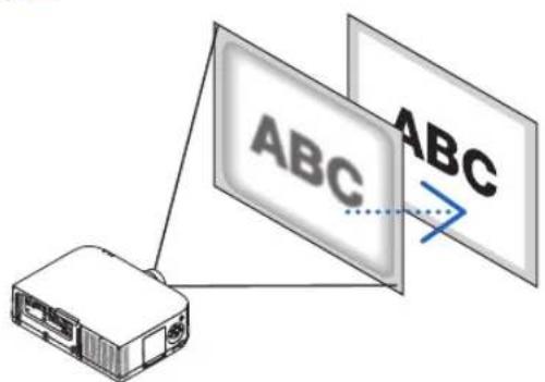 |
Finely adjusting the size of an image[Zoom lever/Zoom ring](→ page 25)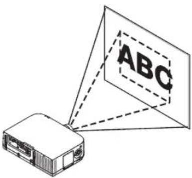 | Adjusting the projected image's height and horizontal tilt[Tilt foot] *(→ page 25)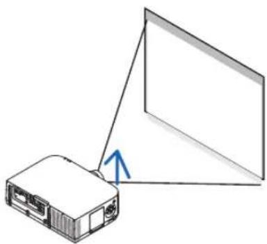 |
NOTE ^*1 : Adjust the projected image's height using the tilt feet when you want to project the image at a position higher than the lens shift adjustment range.
Adjusting the vertical position of a projected image (Lens shift)

CAUTION
Perform the adjustment from behind or from the side of the projector. Adjusting from the front could expose your eyes to strong light which could injure them.
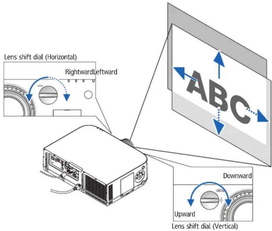
- Turn the lens shift dials clockwise or counterclockwise.
Vertical dial
Turn this clockwise or counterclockwise to adjust the projection position in the vertical direction.
Approximate turning range: About 6 turns counterclockwise, about 2 turns clockwise when the lens is at the center position.
Horizontal dial
Turn this clockwise or counterclockwise to adjust the projection position in the horizontal direction.
Approximate turning range: About 1 turn counterclockwise, about 1 turn clockwise when the lens is at the center position.
NOTE:
- The dials can be turned more than one full turn, but the projection position cannot be moved more than the range indicated on the following page.
- If the lens is shifted to the maximum in the diagonal direction, the edges of the screen will be dark or shaded.
- The vertical shift adjustment must be finished with an image shifted upward. If you finish the vertical shift adjustment with an image shifted down, the zoom/focus adjustments or strong shaking may cause a projected image to slightly shift down.
- The lens shift function cannot be used when using the separately sold Replacement Lens Type1 lens.
TIP:
- The diagram below shows the lens shift adjustment range (projection format: desk/front) of the WUXGA type (excluding the lens unit Replacement Lens Type8). Use the tilt foot if you wish to raise the projection position beyond this. (→ page 25)
• Refer to Page 235 for the lens shift adjustment range of the WXGA type/XGA type and for ceiling hanging/front projection.
Ricoh PJ WU6181N
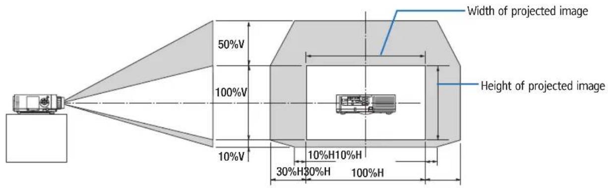
Description of symbols: V indicates vertical (height of the projected image), H indicates horizontal (width of the projected image).
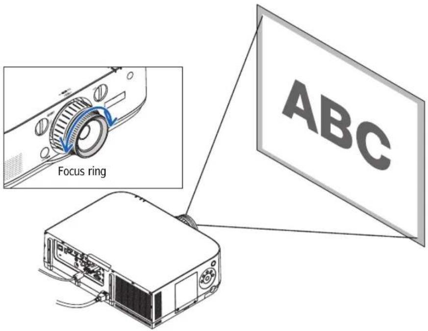
Focus
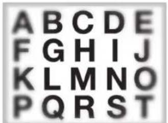
Applicable lens: Standard Lens Type1/Replacement Lens Type2/3/4 Use the FOCUS ring to obtain the best focus.
Applicable lens: Replacement Lens Type8
The Replacement Lens Type8 lens unit aligns the peripheral focus around the optical axis.
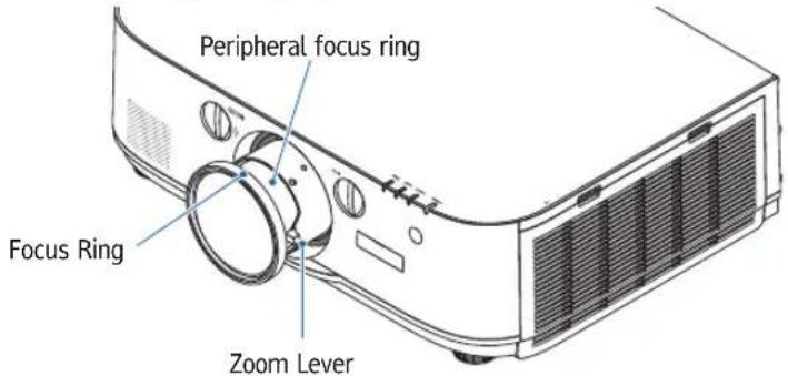
- Turn the focus ring left and right to align the focus around the optical axis.
* The diagram shows an example when the lens shift is moved to the top. The top of the screen is adjusted.
When the lens is in the center, the center of the screen is adjusted.
- Turn the peripheral focus ring to the left and right to align the focus of the overall screen.
At this point, the focus around the optical axis adjusted in (1) remains unchanged.
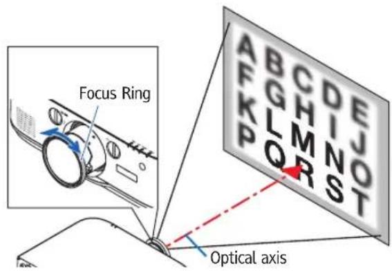
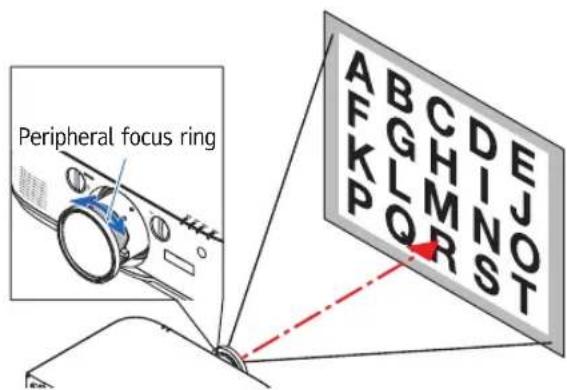
Applicable lens: Replacement Lens Type1
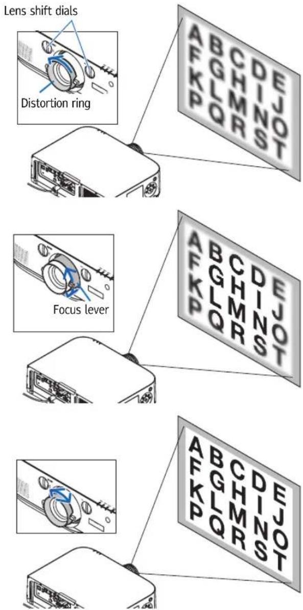
With the Replacement Lens Type1 lens, adjust the focus and picture distortion.
Preparations:
Turn the lens shift dials (vertical and horizontal) on the projector to return the lens shift to the center.
Approximate lens center position (explained here for the desktop front projection mode)
Horizontal dial......First turn the dial to the left edge, then turn it further so that the knob is horizontal. From this position, turn the dial 1 full turn clockwise.
Vertical dial....First turn the dial to the bottom edge, then turn it further so that the knob is horizontal. From this position, turn the dial 2 full turns counterclockwise.
-
Turn the distortion ring to the left edge.
-
Turn the focus lever clockwise and counterclockwise to adjust the focus at the center of the screen.
-
Use the distortion ring to correct the screen's distortion.
(This also brings the edges of the screen into focus.)
- Use the focus lever to adjust the screen's overall focus.
* If the focus at the center of the screen is off, turn the distortion ring a little counterclockwise. The focus at the center of the screen can now be adjusted with the focus lever.
Zoom
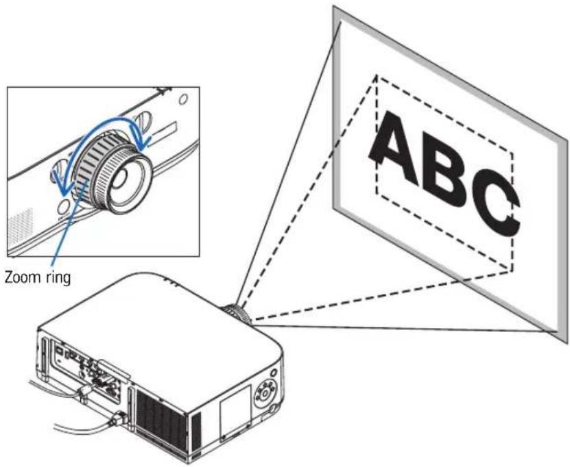
Turn the zoom lever or zoom ring clockwise and counterclockwise.
- The separately sold Replacement Lens Type1 lens does not have a zoom ring.
Adjusting the Tilt Feet
- Turn the left and right tilt feet to adjust.
The tilt feet lengthen and shorten when turned.
The height of the projected image is adjusted by turning the left and right tilt feet.
If the projected image is tilted, turn one of the tilt feet to adjust the image so that it is level.
- If the projected image is distorted, see "3-6 Correcting Horizontal and Vertical Keystone Distortion [CORNERSTONE]" (→ page 33) and "[GEOMETRIC CORRECTION]" (→ page 100).
- The tilt feet can be lengthened by a maximum of 20 mm.
- The tilt feet can be used to tilt the projector by a maximum of 4^ .
NOTE:
- Do not lengthen the tilt feet any more than 20 mm/0.8". Doing so will make the tilt feet's mount section unstable and could cause the tilt feet to come off the projector.
- Do not use the tilt feet for any purpose other than adjusting the projector's projection angle.
Handling the tilt feet improperly, such as carrying the projector by grasping the tilt feet or hooking it onto a wall using the tilt feet, could damage the projector.
natural_image
Simple line drawing of a monitor mounted on a stand, no text or symbols present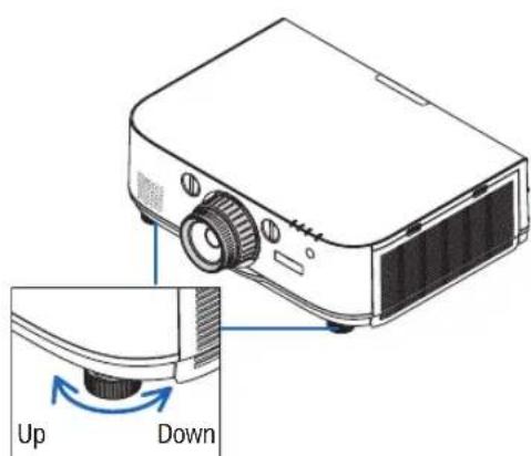
Tilt foot
⑥ Optimizing Computer Signal Automatically
Adjusting the Image Using Auto Adjust
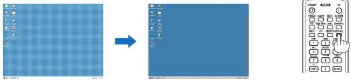
When projecting a signal from the computer video input terminal, BNC video input terminal (anlaog RGB), HDMI 1 input terminal, HDMI 2 input terminal, DisplayPort input terminal, adjust the picture quality with a single touch of the button if the edges of the screen are cut off or if the projection quality is bad.
Press the AUTO ADJ. button to optimize a computer image automatically.
This adjustment may be necessary when you connect your computer for the first time.
[Poor picture] [Normal picture]
NOTE:
Some signals may take time to display or may not be displayed correctly.
- If the Auto Adjust operation cannot optimize the computer signal, try to adjust [HORIZONTAL], [VERTICAL], [CLOCK], and [PHASE] manually. (→ page 91, 92)
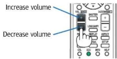
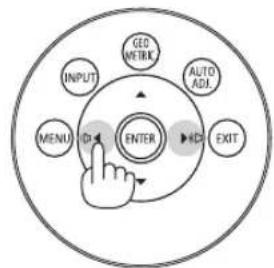
⑦ Turning Up or Down Volume
Sound level from the speaker can be adjusted.
Important:
- Do not turn up the volume to the maximum level on the external speaker system connected to the AUDIO OUT of the projector. Doing so may produce an unexpected, loud sound at the time of turning on or off the projector, causing damage to your hearing. When adjusting the volume on the external speaker system, set volume level of the speaker system to less than half its rating and adjust the volume on the projector to get appropriate sound level.
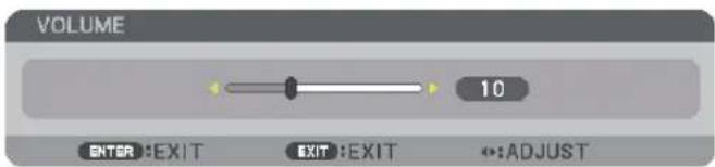
TIP: When no menus appear, the ◀ and ▶ buttons on the projector cabinet work as a volume control.
NOTE:
When the on-screen menu is displayed and the screen has been enlarged using the button, the volume cannot be adjusted using the button if the viewer or Ethernet (audio selection is Ethernet) is being displayed.
flowchart
graph TD
    A["INPUT"] --> B["ENTER"]
    C["GPIO METRK"] --> B
    D["AUTO ADJ"] --> B
    E["EXIT"] --> B
    F["MENU"] --> B
    B --> G["↓"]
    style B fill:#f9f,stroke:#333
⑧ Turning off the Projector
To turn off the projector:
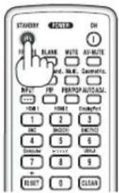
- First, press the (POWER) button on the projector cabinet or the STANDBY button on the remote control.
The [POWER OFF / ARE YOU SURE ? / CARBON SAVINGS- SESSION 0.000[g-CO2]] message will appear.
![POWER OFF ARE YOU SURE ? CARBON SAVINGS-SESSION 0.000[g-CO2] YES NO](/content/2026/05/872418/images/d8d782ce7b07f68ed3c44618d5959e8d361435292f50903d104a96458e676f61.jpg)
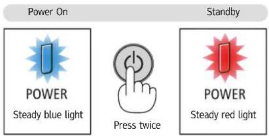
- Secondly, press the ENTER button or press the ⏻POWER) or the STANDBY button again.
The lamp will go off and the power supply will be cut. At this point, if there are no input signals, the projector will go into the standby mode after about 10 seconds. When in standby mode, the POWER indicator will light red and the STATUS indicator will light off when [NORMAL] is selected for [STANDBY MODE].

CAUTION:
Parts of the projector may become temporarily heated if the projector is turned off with the POWER button or if the AC power supply is disconnected during normal projector operation. Use caution when picking up the projector.
NOTE:
- While the POWER indicator is blinking blue in short cycles, the power cannot be turned off.
- You cannot turn off the power for 60 seconds immediately after turning it on and displaying an image.
- Do not unplug the power cord from the projector or from the power outlet while an image is being projected. Doing so could deteriorate the projector's AC IN terminal or the power plug's contact. To turn off the AC power while an image is being projected, use the power strip's switch, the breaker, etc.
- Do not disconnect the AC power supply to the projector within 10 seconds of making adjustment or setting changes and closing the menu. Doing so can cause loss of adjustments and settings.
9 After Use
Preparation: Make sure that the projector is turned off.
- Unplug the power cord.
- Disconnect any other cables.
- Mount the lens cap on the lens.
- Before moving the projector, screw in the tilt feet if they have been lengthened.
3. Convenient Features
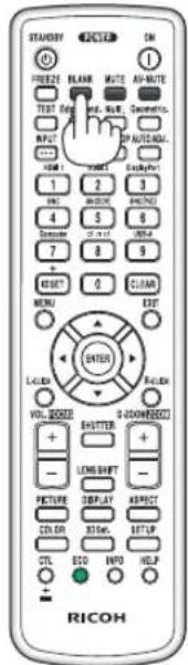
① Turning off the Image and Sound
The projected video and the output sound from the internal speaker and sound output terminal will disappear momentarily.
Press the BLANK button.
The projected video will be cut off.
Press the MUTE button.
The projected audio will be cut off.
Press the AV-MUTE button.
The projected video and audio will be cut off.
- Press the buttons one more time for the cancelled video and audio to appear again. When AV-MUTE and BLANK are continued for some time, the energy-saving function will activate to lower the lamp power.
NOTE:
- When the AV-MUTE and BLANK buttons are pressed immediately after the energy-saving function is activated, sometimes the brightness may not return to normal immediately.
TIP:
• The video will disappear but not the menu display.
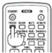
② Freezing a Picture
Press the FREEZE button to freeze a picture. Press again to resume motion.
NOTE: The image is frozen but the original video is still playing back.
③ Enlarging a Picture
You can enlarge the picture up to four times.
NOTE:
- Depending on an input signal, the maximum magnification may be less than four times, or the function may be restricted.
To do so:
- Press the D-ZOOM (+) button to magnify the picture.
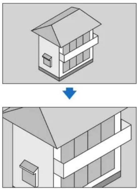
natural_image
Isometric diagram of a two-story house with a window and door, showing a change from top to bottom view (no text or symbols)- Press the ▲▼◀▶ button.
The area of the magnified image will be moved
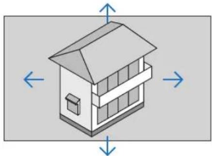
natural_image
Isometric diagram of a two-story house with directional arrows indicating orientation (no text or symbols)- Press the D-ZOOM ( ) button.
Each time the D-ZOOM ( ) button is pressed, the image is reduced.
NOTE:
- The image will be enlarged or reduced at the center of the screen.
- Displaying the menu will cancel the current magnification.
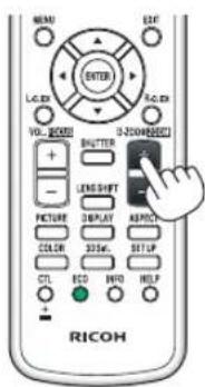
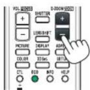
④ Changing Eco Mode/Checking Energy-Saving Effect Using Eco Mode [ECO MODE]
This feature enables you to select two brightness modes of the lamp:
OFF and ON modes. The lamp life can be extended by turning on the [ECO MODE].
| [ECO MODE] Description | |
| [OFF] This is the default setting | (100% Brightness). |
[ON]![RICOH PJ X6181N - ④ Changing Eco Mode/Checking Energy-Saving Effect Using Eco Mode [ECO MODE] - 1](/content/2026/05/872418/images/fc72b6fdcb1c555308c8a8190ff53e7c64f166702fd1c16bbe95ea05f2c19ad8.jpg) | Low lamp power consumption (approx. 80% Brightness). |
To turn on the [ECO MODE], do the following:
- Press the ECO button on the remote control to display [ECO MODE] screen.
- Use the ▲ or ▼ button to select [ON].
- Press the ENTER button.
To change from [ON] to [OFF], Go back to Step 2 and select [OFF]. Repeat Step 3.
NOTE:
- The [ECO MODE] can be changed by using the menu.
Select [SETUP] → [INSTALLATION] → [LAMP MODE] → [ECO MODE]. - The lamp life remaining and lamp hours used can be checked in [USAGE TIME]. Select [INFO.] →[USAGE TIME].
- [ECO MODE] is always set to [OFF] for 1 minute immediately after the lamp is turned on. The lamp condition will not be affected even when [ECO MODE] is changed.
• After a lapse of 1 minute from when the projector displays a blue, black or logo screen, [ECO MODE] will automatically switch to [ON]. - If the projector is overheated in [OFF] mode, there may be a case where the [ECO MODE] automatically changes to [ON] mode to protect the projector. This is called "Forced ECO Mode". When the projector is in the Forced Eco Mode, the picture brightness decreases slightly and the TEMP. indicator lights orange. At the same time the Thermometer symbol [ ] is displayed at the bottom right of the screen.
When the projector comes back to normal temperature, the Forced Eco Mode is cancelled and the [ECO MODE] returns to [OFF] mode.
Checking Energy-Saving Effect [CARBON METER]
This feature will show energy-saving effect in terms of CO_2 emission reduction (kg) when the projector's [ECO MODE] is set to [OFF], or [ON]. This feature is called as [CARBON METER].
There are two messages: [TOTAL CARBON SAVINGS] and [CARBON SAVINGS-SESSION]. The [TOTAL CARBON SAVINGS] message shows the total amount of CO_2 emission reduction from the time of shipment up to now. You can check the information on [USAGE TIME] from [INFO.] of the menu. ( page 131)
![INPUT ADJUST DISPLAY SETUP INFO. USAGE TIME SOURCE(1) SOURCE(2) 1/3 LAMP LIFE REMAINING 100 % LAMP HOURS USED 00000 [H] FILTER HOURS USED 00000 [H] TOTAL CARBON SAVINGS 0.000[kg-CO2] EXIT:EXIT ↔:MOVE ↔:MOVE HDMI1 ADVANCED](/content/2026/05/872418/images/ad1df58b4aa5952389f40ffdad1e0b97ccfa03973921f6c74f9a228a02b3b034.jpg)
The [CARBON SAVINGS-SESSION] message shows the amount of CO_2 emission reduction between the time of changing to ECO MODE immediately after the time of power-on and the time of power-off. The [CARBON SAVINGS-SESSION] message will be displayed in the [POWER OFF/ ARE YOU SURE ?] message at the time of power-off.
![POWER OFF ARE YOU SURE ? CARBON SAVINGS-SESSION 0.000[g-CO2] YES NO](/content/2026/05/872418/images/2e5efa567e6845849c496584b5a05e19c4e3c4fc18157a97ee59900f17e4daa5.jpg)
TIP:
- The formula as shown below is used to calculate the amount of CO2 emission reduction.
Amount of CO 2 emission reduction = (Power consumption in OFF for ECO MODE — Power consumption in ON for ECO MODE) × CQ conversion factor.* When the image is turned off with the AV-MUTE button the amount of CO 2 emission reduction will also increase.
* Calculation for amount of CO 2 emission reduction is based on an OECD publication “CO _2 Emissions from Fuel Combustion, 2008 Edition”. - The [TOTAL CARBON SAVINGS] is calculated based on savings recorded in 15 minutes intervals.
- This formula will not apply to the power consumption which is not affected by whether [ECO MODE] is turned on or off.
⑤ Correcting Horizontal and Vertical Keystone Distortion [CORNERSTONE]
Use the [CORNERSTONE] feature to correct keystone (trapezoidal) distortion to make the top or bottom and the left or right side of the screen longer or shorter so that the projected image is rectangular.
- Press and hold the Geometric button for a minimum of 2 seconds to reset current adjustments. Current adjustments for [GEOMETRIC CORRECTION] will be cleared.
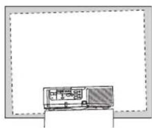
- Project an image so that the screen is smaller than the area of the raster.
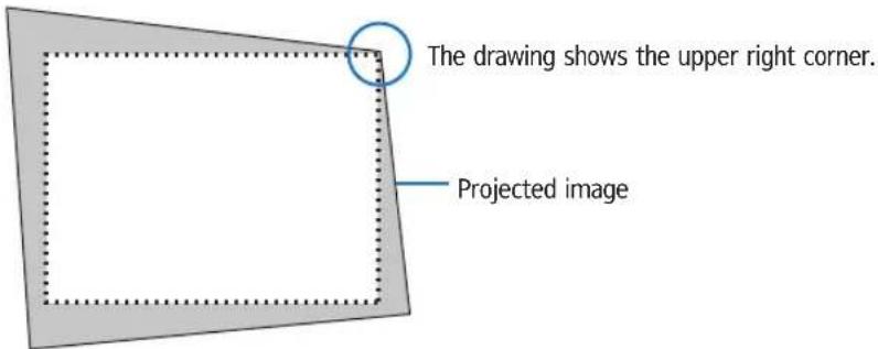
- Pick up any one of the corners and align the corner of the image with a corner of the screen.
![RICOH PJ X6181N - ⑤ Correcting Horizontal and Vertical Keystone Distortion [CORNERSTONE] - 2](/content/2026/05/872418/images/90a0e30e0ee908c702c362091cc516d33865bba8cd215a8b7827e4a8fb1c5111.jpg)
natural_image
Simple geometric diagram with a rectangle and dotted inner lines, no text or symbols present.- Press the Geometric. button.
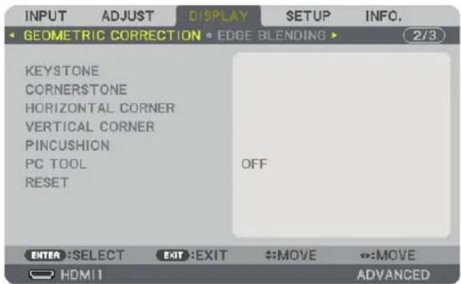
Display the [GEOMETRIC CORRECTION] screen of the on-screen menu.
- Press the ▼ button to align with the [CORNERSTONE] and then press the ENTER button.
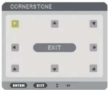
The drawing shows the upper left icon (▼) is selected.
The screen will switch to the [CORNERSTONE] screen.
NOTE:
- When a [GEOMETRIC CORRECTION] function other than [CORNERSTONE] has been set up, the [CORNERSTONE] screen will not be displayed. When the screen is not displayed, either press the Geometric. button for 2 or more seconds, or run [RESET] in[GEOMETRIC CORRECTION] to clear the adjustment value of [GEOMETRIC CORRECTION].
- Use the ▲▼◀▶ button to select one icon (▲) which points in the direction you wish to move the projected image frame.
- Press the ENTER button.
- Use the ▲▼◀▶ button to move the projected image frame as shown on the example.
![RICOH PJ X6181N - ⑤ Correcting Horizontal and Vertical Keystone Distortion [CORNERSTONE] - 5](/content/2026/05/872418/images/a83c0091664fb22462fed8f06ee763f2b5cf20d46822408d683704ed1cfb5ca5.jpg)
natural_image
Blank rectangular frame with dotted border and small blue arrow icon at top-left corner (no text or symbols)- Press the ENTER button.
- Use the ▲▼◀▶ button to select another icon which points in the direction.
![RICOH PJ X6181N - ⑤ Correcting Horizontal and Vertical Keystone Distortion [CORNERSTONE] - 6](/content/2026/05/872418/images/dc8b3c31084342db954679ca5f3e05b1b47392d05ffa17a24695b75f08817aa7.jpg)
natural_image
Empty rectangular frame with dotted border and corner arrows (no text or symbols)![RICOH PJ X6181N - ⑤ Correcting Horizontal and Vertical Keystone Distortion [CORNERSTONE] - 7](/content/2026/05/872418/images/66901fc7bc9d21fa49d9e1c959e73cb65e4933bb6acf61333326beb1008e8edc.jpg)
natural_image
Empty white rectangle with a thin gray border (no text or symbols)On the [CORNERSTONE] screen, select [EXIT] or press the EXIT button on the remote control.
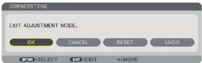
The confirmation screen is displayed.
11. Press the ◀ or ▶ button to highlight the [OK] and press the ENTER button.
This completes the [CORNERSTONE] correction.
- Select [CANCEL] and press the ENTER button to return to the [CORNERSTONE] screen.
Selecting [CANCEL] will return to the adjustment screen without saving changes (Step 3).
Selecting [RESET] will return to the factory default.
Selecting [UNDO] will exit without saving changes.
NOTE:
- Even when the projector is turned on, the last used correction values are applied.
- Carry out either one of the following actions to clear the adjustment value of [CORNERSTONE].
- In Step 11, select [RESET] and then press the ENTER button.
- Press the Geometric. button for 2 or more seconds.
- Run [DISPLAY] [GEOMETRIC CORRECTION] [RESET] in the on-screen menu.
• Using CORNERSTONE correction can cause the image to be slightly blurred because the correction is made electronically.
6 Preventing the Unauthorized Use of the Projector [SECURITY]
A keyword can be set for your projector using the Menu to avoid operation by an unauthorized user. When a keyword is set, turning on the projector will display the Keyword input screen. Unless the correct keyword is entered, the projector cannot project an image.
- The [SECURITY] setting cannot be cancelled by using the [RESET] of the menu.
To enable the Security function:
-
Press the MENU button.
The menu will be displayed. -
Press the ▶ button twice to select [SETUP] and press the ▼ button or the ENTER button to select [MENU].
-
Press the ▶ button to select [CONTROL].
-
Press the ▼ button three times to select [SECURITY] and press the ENTER button.
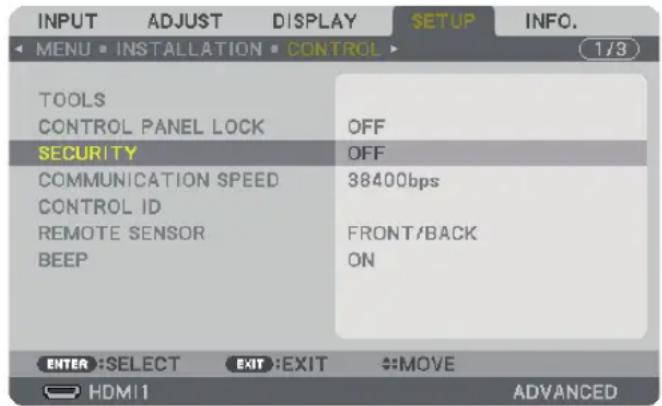
The OFF/ON menu will be displayed.
- Press the ▼ button to select [ON] and press the ENTER button.
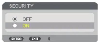
The [SECURITY KEYWORD] screen will be displayed.
- Type in a combination of the four ▲▼◀▶ buttons and press the ENTER button.
NOTE: A keyword must be 4 to 10 digits in length.
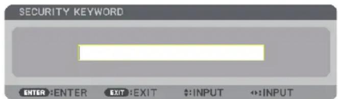
The [CONFIRM KEYWORD] screen will be displayed.
NOTE: Make a note of your password and store it in a safe place.
- Type in the same combination of ▲▼◀▶ buttons and press the ENTER button.
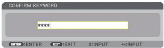
The confirmation screen will be displayed.
- Select [YES] and press the ENTER button.
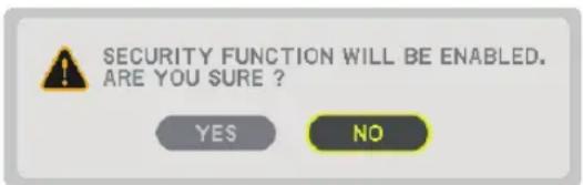
The SECURITY function has been enabled.
To turn on the projector when [SECURITY] is enabled:
- Press the POWER button.
The projector will be turned on and display a message to the effect that the projector is locked.
- Press the MENU button.
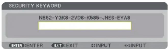
- Type in the correct keyword and press the ENTER button. The projector will display an image.
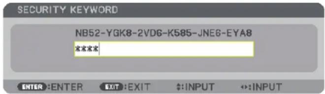
NOTE: The security disable mode is maintained until the main power is turned off or unplugging the power cord.
To disable the SECURITY function:
-
Press the MENU button.
The menu will be displayed. -
Select [SETUP] → [CONTROL] → [SECURITY] and press the ENTER button.
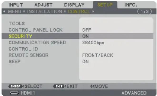
The OFF/ON menu will be displayed.
- Select [OFF] and press the ENTER button.
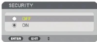
The SECURITY KEYWORD screen will be displayed.
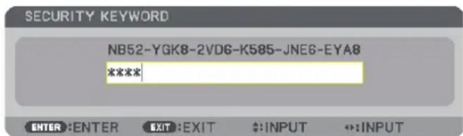
- Type in your keyword and press the ENTER button.
When the correct keyword is entered, the SECURITY function will be disabled.
NOTE: If you forget your keyword, contact your dealer. Your dealer will provide you with your keyword in exchange for your request code. Your request code is displayed in the Keyword Confirmation screen. In this example [NB52-YGK8-2VD6-K585-JNE6-EYA8] is a request code.
⑦ Projecting 3D videos
This projector can be used to watch videos in 3D using commercially-available active shutter-type 3D eyewear. In order to synchronize the 3D video and eyewear, a commercially-available 3D emitter needs to be connected to the projector (on the projector side). The 3D eyewear receives information from the 3D emitter and performs opening and closing on the left and right.

CAUTION
Health precautions
Before use, please make sure to read any health precautions that may be stated in the operating manuals enclosed with the 3D eyewear and 3D video software (Blu-ray player, games, computer animation files, etc.).
Please take note of the following in order to avoid adverse health effects.
- Please do not use the 3D eyewear for purposes other than to watch 3D videos.
- Please keep a distance of at least 2 m away from the screen when watching videos. Watching a video too close to the screen will increase eye fatigue.
- Please do not watch videos continuously for a long period of time. Please take a 15 minutes' break after every hour of watching.
- Please consult a doctor before watching if you or any of your family members have a history of suffering from seizures caused by light sensitivity.
- Please stop watching immediately and take a rest when you feel physically unwell while watching (vomiting, giddiness, nausea, headaches, sore eyes, blurred vision, cramps and dumbness in the limbs, etc.). Please consult a doctor if the symptoms persist.
- Please watch a 3D video directly in front of the screen. If you watch a 3D video obliquely from the sides, this may result in physical and eye fatigue.
3D eyewear and 3D emitter preparations
Please use an active shutter-type 3D eyewear that conforms with the VESA standard.
A commercially-available RF type made by Xpand is recommended.
3D eyewear.....Xpand X105-RF
3D emitter.....Xpand AD025-RF-X1
Procedure to watch 3D videos using this projector
- Connect the video device to the projector.
- Switch on the power supply to the projector.
- Run the 3D video software and project the video using the projector.
This has been automatically set up when shipped from the factory. When a 3D video cannot be projected, it may be because the 3D detection signals are not included or because they are not detectable by the projector.
Please manually select the format.
4. Select the 3D video format.
(1) Press the "3D Set." button on the remote control.
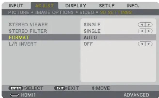
The [3D SETTINGS] screen will be displayed.
(2) Press the ▼ button to align the cursor with the [FORMAT] and press the ENTER button.
The format screen will be displayed.
(3) Select the input signal format using the ▼ button and then press the ENTER button.
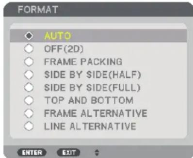
The 3D settings screen will disappear and the 3D video will be projected.
Press the MENU button and the on-screen menu will disappear.
The 3D caution message screen will be displayed when switching to a 3D video (default factory setting when shipped). Please read the "Health Precautions" on the previous page to watch videos in the correct manner. The screen will disappear after 60 seconds or when the ENTER button is pressed. (→ page 108)
5. Turn on the power supply of the 3D eyewear and wear the eyewear to watch the video.
A normal video will be shown when a 2D video is input.
To watch a 3D video in 2D, select [OFF(2D)] in the [FORMAT] screen mentioned above in (3).
NOTE:
- Upon switching to 3D image, the following functions will be cancelled and disabled. [BLANKING], [PIP/PICTURE BY PICTURE], [GEOMETRIC CORRECTION], [EDGE BLENDING] ([GEOMETRIC CORRECTION] and [EDGE BLENDING] adjustment values will be maintained.)
- The output may not automatically switch to a 3D video depending on the 3D input signal.
- Check the operating conditions described in the user manual of the Blu-ray player.
- Please connect the DIN terminal of the 3D emitter to the 3D SYNC of the main projector.
- The 3D eyewear allows videos to be viewed in 3D by receiving synchronized optical signals output from the 3D emitter.
As a result, the 3D image quality may be affected by conditions such as the brightness of the surroundings, screen size, viewing distance, etc. - When playing a 3D video software on a computer, the 3D image quality may be affected if the computer CPU and graphics chip performance are low. Please check the required operating environment of the computer that is stated in the operating manual attached to the 3D video software.
- Depending on the signal, [FORMAT] and [L/R INVERT] may not be able to be selected. Please change the signal in that case.
When videos cannot be viewed in 3D
Please check the following points when videos cannot be viewed in 3D.
Please also read the operating manual attached to the 3D eyewear.
| Possible reasons Solutions | ||
| The selected signal does not support 3D output. Please change the video input to one that supports 3D. | ||
| The format for the selected signal is turned to [OFF(2D)]. | Please change the format in the on-screen menu to [AUTO] or a format that supports 3D. | |
| A eyewear that is not supported by the projector is being used. | Please purchase a commercially-available 3D eyewear or 3D emitter (recommended). (→ page 39) | |
| Please check the following points when a video cannot be viewed in 3D using a 3D eyewear that is supported by the projector. | ||
| The power supply of the 3D eyewear is turned off. Please turn on the power supply of the 3D eyewear. | ||
| The internal battery of the 3D eyewear is flat. Please charge or replace the battery. | ||
| The viewer is located too far away from the screen. Please get closer to the screen until the video can be seen in 3D. | ||
| Due to multiple 3D projectors working at the same time in the vicinity, the projectors may interfere with one another. Alternatively, there may be a bright light source near the screen. | Please maintain sufficient distance between the projectors. | |
| Please keep the light source away from the screen. | ||
| Please turn the L/R INVERT in the on-screen menu to [OFF]. | ||
| There is an obstacle between the optical receiver of the 3D eyewear and the 3D emitter. | Please remove the obstacle. | |
| The 3D format of the 3D video contents is not supported. Please check with the company selling the 3D video contents. | ||
⑧ Controlling the Projector by Using an HTTP Browser
Overview
Using the web browser on the computer, the HTTP server screen of the projector can be displayed to operate the projector. For the HTTP server screen of the projector, there is the basic HTTP server screen and the dedicated HTTP server screen.
Possible operations on the HTTP server screen
(1) Possible operations on the basic HTTP server screen
- Configure the email notification. (ALERT MAIL)
When the projector is connected to a network (wired LAN), notifications on the lamp replacement period and various errors are sent to the email address that has been set up.
- Operate the projector.
Operations such power on/off of the projector, input terminal switchover, volume control, picture control etc. can be carried out.
- Configure the [PJLink PASSWORD] and [AMX BEACON] etc.
(2) Possible operations on the dedicated HTTP server screen
- When using the following functions, configure the settings required to connect the projector to the network (wired LAN/wireless LAN).
- Projection Utility
- Advanced Network Utility
• Network Management Utiliy
To view the HTTP server screen
(1) Basic HTTP server screen
- Connect the projector to the computer with a LAN cable sold commercially. (→ page 166)
- Select [SETUP] → [NETWORK SETTINGS] → [WIRED LAN] in the on-screen menu to configure the network settings. (→ page 120)
- Start up the web browser on your computer and enter the address or URL in the input field.
Specify the address or URL as "http://
The basic HTTP server screen will be displayed.
(2) HTTP server screen
- Connect the projector to the computer with a LAN cable sold commercially. ( page 166) Alternatively, install a wireless LAN unit sold separately. ( page 167)
- Select [INPUT TERMINAL] → [ETHERNET] in the on-screen menu.
The application menu will be displayed.
- Select "NETWORK SETTINGS (MM)" and configure the network settings. (→ page 136)
TIP:
- If you want to set the IP address here, set a different IP address in the same segment as the IP address that has been set up in the basic HTTP server screen.
- Start up the web browser on your computer and enter the address or URL in the input field.
Specify the address or URL as "http://
TIP: The factory setting IP address is [DHCP ON].
NOTE:
- To use the projector in a network, consult with your network administrator about network settings.
- The display's or button's response can be slowed down or operation may not be accepted depending the settings of your network.
Should this happen, consult your network administrator. The projector may not respond if its buttons are repeatedly pressed in rapid intervals. Should this happen, wait a moment and repeat. If you still can't get any response, turn off and back on the projector.
- If the PROJECTOR NETWORK SETTINGS screen does not appear in the web browser, press the Ctrl+F5 keys to refresh your web browser (or clear the cache).
- This projector uses "JavaScript" and "Cookies" and the browser should be set to accept these functions. The setting method will vary depending on the version of browser. Please refer to the help files and the other information provided in your software.
Preparation before Use
Connect the projector to a commercially available LAN cable before engaging in browser operations. ( page 166)
Operation with a browser that uses a proxy server may not be possible depending on the type of proxy server and the setting method. Although the type of proxy server will be a factor, it is possible that items that have actually been set will not be displayed depending on the effectiveness of the cache, and the contents set from the browser may not be reflected in operation. It is recommended that a proxy server not be used unless it is unavoidable.
Handling of the Address for Operation via a Browser
Regarding the actual address that is entered for the address or entered to the URL column when operation of the projector is via a browser, the host name can be used as it is when the host name corresponding to the IP address of the projector has been registered to the domain name server by a network administrator, or the host name corresponding to the IP address of the projector has been set in the "HOSTS" file of the computer being used.
Example 1: When the host name of the projector has been set to "pj.ricoh.com", access is gained to the network setting by specifying
http://pj.ricoh.com/index.html
for the address or the entry column of the URL.
Example 2: When the IP address of the projector is "192.168.73.1", access is gained to the network setting by specifying
http://192.168.73.1/index.html
for the address or the entry column of the URL.
PROJECTOR ADJUSTMENT
Projector adjustment screen
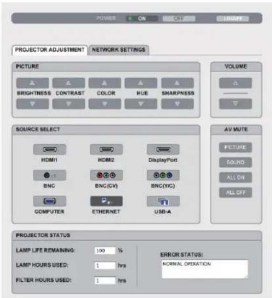
POWER: This controls the power of the projector.
ON....Power is switched on.
OFF....Power is switched off.
VOLUME: This controls the volume of the projector.
▲......Increases the volume adjustment value.
▼ Decreases the volume adjustment value.
AV-MUTE: This controls the mute function of the projector.
PICTURE ON......Mutes the video.
PICTURE OFF......Cancels the video muting.
SOUND ON......Mutes the audio.
SOUND OFF......Cancels the audio muting.
ALL ON......Mutes each of the video, and audio functions.
ALL OFF....Cancels the muting of each of the video, and audio functions.
PICTURE: Controls the video adjustment of the projector.
BRIGHTNESS ▲ Increases the brightness adjustment value.
BRIGHTNESS ▼ Decreases the brightness adjustment value.
CONTRAST ▲ Increases the contrast adjustment value.
CONTRAST ▼ Decreases the contrast adjustment value.
COLOR ▲ Increases the color adjustment value.
COLOR ▼ Decreases the color adjustment value.
HUE ▲ Increases the hue adjustment value.
HUE ▼ Decreases the hue adjustment value.
SHARPNESS ▲ Increases the sharpness adjustment value.
SHARPNESS ▼ Decreases the sharpness adjustment value.
- The functions that can be controlled will vary depending on the signal being input to the projector. (→ page 89, 90)
SOURCE SELECT: This switches the input connector of the projector.
HDMI1 Switches to the HDMI 1 IN connector.
HDMI2 Switches to the HDMI 2 IN connector.
DisplayPort Switches to the DisplayPort.
BNC Switch to BNC (analog RGB) video input.
BNC(CV) Switch to BNC (CV) video input.
BNC(Y/C) Switch to BNC (Y/C) video input.
COMPUTER Switches to the COMPUTER IN connector.
ETHERNET Switch to the data display that is sent from the network.
USB-A Switch to the data display of the USB memory that has been set up in the projector.
PROJECTOR STATUS: This displays the condition of the projector.
LAMP LIFE REMAINING Displays the remaining life of the lamp as a percentage.
LAMP HOURS USED Displays how many hours the lamp has been used.
FILTER HOURS USED Displays how many hours the filter has been used.
ERROR STATUS Displays the status of errors occurring within the projector.
LOG OFF: Logging off your projector and returning to the authentication screen (LOGON screen).
NETWORK SETTINGS
http://
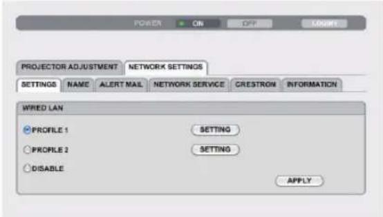
- SETTINGS
WIRED
| SETTING Set for wired LAN. | |
| APPLY Apply your settings to wired LAN. | |
| PROFILE 1/PROFILE 2 Two settings can be set for wired LAN connection. Select PROFILE 1 or PROFILE 2. | |
| DISABLE Turn off wired LAN connection | |
| DHCP ON | Automatically assign IP address, subnet mask, and gateway to the projector from your DHCP server. |
| DHCP OFF | Set IP address, subnet mask, and gateway to the projector assigned by your network administrator. |
| IP ADDRESS Set your IP address of the network connected to the projector. | |
| SUBNET MASK Set your subnet mask number of the network connected to the projector. | |
| GATEWAY Set the default gateway of the network connected to the projector. | |
| AUTO DNS ON DHCP server will automatically assign IP address of DNS server connected to the projector. | |
| AUTO DNS OFF Set your IP address of DNS server connected to the projector. | |
- NAME
| PROJECTOR NAME | Enter a name for your projector so that your computer can identify the projector. A projector name must be 16 characters or less.TIP: Projector name will not be affected even when [RESET] is done from the menu. |
| HOST NAME | Enter the hostname of the network connected to the projector. A host name must be 15 or less. |
| DOMAIN NAME | Enter the domain name of the network connected to the projector. A domain name must be 60 characters or less. |
- ALERT MAIL
| ALERT MAIL | This option will notify your computer of lamp replace time or error messages via e-mail when using wired LAN.Placing a checkmark will turn on the Alert Mail feature.Clearing a checkmark will turn off the Alert Mail feature.Sample of a message to be sent from the projector:The lamp and filters are at the end of its usable life. Please replace the lamp and filters.Projector Name: rdpjLamp Hours Used: 100 [H] |
| SENDER'S ADDRESS Enter sender's address. | |
| SMTP SERVER NAME Enter the SMTP server name to be connected to the projector. | |
| RECIPIENT'S ADDRESS 1, 2, 3 Enter your recipient's address. Up to three addresses can be entered. | |
| TEST MAIL | Send a test mail to check whether your settings are correct or notNOTE:If you execute a test, you may not receive an Alert mail. Should this happen, check if network settings are correct.If you entered an incorrect address in a test, you may not receive an Alert mail. Should this happen, check if the Recipient's Address is correct. |
| SAVE Click this button to save your settings to the projector's memory. | |
• NETWORK SERVICE
| PJLink PASSWORD | Set a password for PJLink*. A password must be 32 characters or less. Do not forget your password. However, if you forget your password, consult with your dealer. |
| HTTP PASSWORD Set a password for HTTP server. A password must be 10 characters or less.When a password is set up, you will be prompted for your user name (arbitrary) and password during LOGON. | |
| AMX BEACON | Turn on or off for detection from AMX Device Discovery when connecting to the network supported by AMX's NetLinx control system.TIP:When using a device that supports AMX Device Discovery, all AMX NetLinx control system will recognize the device and download the appropriate Device Discovery Module from an AMX server.Placing a checkmark will enable detecting the projector from AMX Device Discovery.Clearing a checkmark will disable detecting the projector from AMX Device Discovery. |
NOTE: If you forget your password, contact your dealer.
*What is PJLink?
PJLink is a standardization of protocol used for controlling projectors of different manufacturers. This standard protocol is established by Japan Business Machine and Information System Industries Association (JBMIA) in 2005.
The projector supports all the commands of PJLink Class 1.
Setting of PJLink will not be affected even when [RESET] is done from the menu.
- CRESTRON
ROOMVIEW for managing from the computer.
| DISABLE Disables ROOMVIEW. | |
| ENABLE Enables ROOMVIEW. |
CRESTRON CONTROL for managing from the controller.
| DISABLE Disables CRESTRON CONTROL. |
| ENABLE Enables CRESTRON CONTROL. |
| IP ADDRESS Set your IP address of CRESTRON SERVER. |
| IP ID Set your IP ID of CRESTRON SERVER. |
TIP: The CRESTRON settings are required only for use with CRESTRON ROOMVIEW.
For more information, visit http://www.crestron.com
• INFORMATION
| WIRED LAN Display a list of settings of wired LAN connection. | |
| UPDATE Reflect settings when they are changed. |
NETWORK SETTINGS
http://
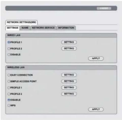
- SETTINGS
WIRED or WIRELESS
| SETTING Set for wired LAN or | for wireless LAN. |
| APPLY Apply your settings to | wired LAN or wireless LAN. |
| DISABLE Turn off wired LAN connection | |
| PROFILE 1/PROFILE 2 Two settings can be set for wired LAN connection. Select PROFILE 1 or PROFILE 2. | |
| DHCP ON | Automatically assign IP address, subnet mask, and gateway to the projector from your DHCP server. |
| DHCP OFF | Set IP address, subnet mask, and gateway to the projector assigned by your network administrator. |
| IP ADDRESS Set your IP address of the network connected to the projector. | |
| SUBNET MASK Set your subnet mask number of the network connected to the projector. | |
| GATEWAY Set the default gateway of the network connected to the projector. | |
| WINS | Set the IP address of your WINS server of the network connected to the projector when [DHCP] is turned on, this option is not available. |
| AUTO DNS ON DHCP server will automatically assign IP address of DNS server connected to the projector. | |
| AUTO DNS OFF Set your IP address of DNS server connected to the projector. | |
Setting for WIRELESS LAN (the optional Wireless LAN Unit required)
| EASY CONNECTION | Execute a wireless LAN using EASY CONNECTION. | ||
| SIMPLE ACCES POINT | Set the projector for simple access point. | ||
| WPS | Use WPS (Wi-Fi Protected SetupTM) to set up the wireless LAN for the projector.NOTE:· Use the projector's menus to make WPS connections and change the WPS profile settings. | ||
| CHANNEL | Select a channel. Available channels vary depending on the country and region. When you select [INFRASTRUCTURE], make sure that the projector and your access point are on the same channel; when you select [AD HOC], make sure that the projector and your computer are on the same channel. | ||
| SSID | Enter an identifier (SSID) for wireless LAN. Communication can be done only with equipment whose SSID matches SSID for your wireless LAN. | ||
| SITE SURVEY | Displays a list of available SSIDs for wireless LAN on site. Select an SSID which you can access. | ||
| NETWORK TYPE Select communication method when using wireless LAN.INFRASTRUCTURE: Select this option when communicating with one or more equipment connected to the wireless LAN network via a wireless access point.AD HOC: Select this option when using the wireless LAN to directly communicate with a computer in peer-to-peer mode. | |||
| SECURITY TYPE | Turn on or off the encryption mode for secure transmission. When turn on the encryption mode, set WEP key or encrypted key. | ||
| DISABLE Will not | turn on the encryption feature. Your communications may be monitored by someone. | ||
| WEP 64 bit Uses 6 | 4-bit datalength for secure transmission. | ||
| WEP 128 bit Uses | 128-bit datalength for secure transmission. This option will increase privacy and security when compared to use of 64-bit datalength encryption. | ||
| WPA-PSK TKIP / WPA-PSK AES/WPA2-PSK TKIP / WPA2-PSK AES/WPA-EAP TKIP EAP-TLS/WPA-EAP AES EAP-TLS/WPA-EAP TKIP PEAP-MSCHAP v2/WPA-EAP AES PEAP-MSCHAP v2/WPA2-EAP TKIP EAP-TLS/WPA2-EAP AES EAP-TLS/WPA2-EAP TKIP PEAP-MSCHAP v2/WPA2-EAP AES PEAP-MSCHAP v2 | These options parovide stronger security than WEP. | ||
| NOTE:The WEP settings must be the same as communication devices such as PC or access point in your wireless network.When you use WEP, your image transmission speed will slow down.Other encryption keys than WEP 64bit and WEP 128bit are not available when [AD HOC] is selected from [NETWORK TYPE].To install a digital certificate, use the projector's menu. (→ page 143) | |||
| INDEX Select encryption key when selecting [WEP 64 bit] or [WEP 128 bit] in [SECURITY TYPE]. | |||
| KEY When selecting [WEP 64 bit] or [WEP 128 bit] in [SECURITY TYPE]:Enter WEP key. | |||
| When selecting [WPA PSK-TKIP], [WPA PSK-AES], [WPA2 PSK-TKIP] or [WPA2 PSK-AES]: Enter encryption key. Key length must be 8 or greater and 63 or less. | |||
| USERNAME | Set a user name for WPA-EAP/WPA2-EAP. | ||
| PASSWORD | Set a password for WPA-EAP TKIP PEAP-MSCHAP v2/WPA-EAP AES PEAP-MSCHAP v2/WPA2-EAP TKIP PEAP-MSCHAP v2/WPA2-EAP AES PEAP-MSCHAP v2. | ||
| USE DIGITAL CERTIFICATE | Select this if you use a digital certificate for WPA-EAP TKIP PEAP-MSCHAP v2/WPA-EAP AES PEAP-MSCHAP v2/WPA2-EAP TKIP PEAP-MSCHAP v2/WPA2-EAP AES PEAP-MSCHAP v2. | ||
- NAME
| HOST NAME | Enter the hostname of the network connected to the projector. A host name must be 15 or less. |
• NETWORK SERVICE
| HTTP PASSWORD Set a password for HTTP server. A password must be 10 characters or less. |
- CRESTRON
ROOMVIEW for managing from the computer.
| DISABLE Disables ROOMVIEW. | |
| ENABLE Enables ROOMVIEW. |
CRESTRON CONTROL for managing from the controller.
| DISABLE Disables CRESTRON CONTROL. |
| ENABLE Enables CRESTRON CONTROL. |
| IP ADDRESS Set your IP address of CRESTRON SERVER. |
| IP ID Set your IP ID of CRESTRON SERVER. |
TIP: The CRESTRON settings are required only for use with CRESTRON ROOMVIEW.
For more information, visit http://www.crestron.com
About the Projector's [NETWORK SETTING].(→ page 6)
• INFORMATION
| WIRED LAN Display a list of settings of wired LAN connection. | |
| WIRELESS LAN Display a list of settings of wireless LAN connection. | |
| UPDATE Reflect settings when they are changed. |
⑨ Projecting Your Computer's Screen Image from the Projector via a Network [NETWORK PROJECTOR]
By selecting the projector connected to the same network as that of your PC, the PC screen image can be projected to the screen via network. There is no need of connection using the computer cable (VGA).
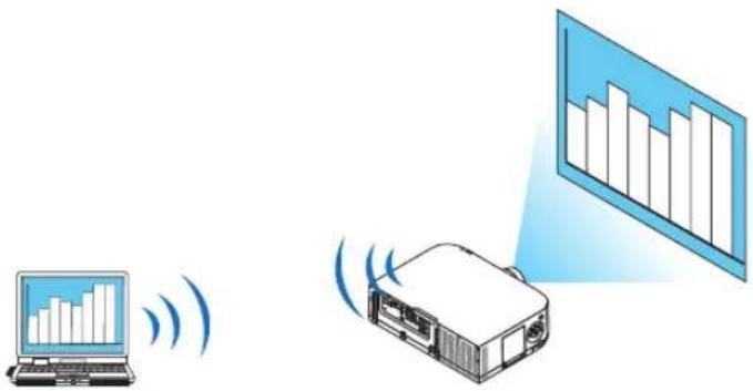
Operation Environment
| Applicable OS Windows 8/8.1 Pro | Windows 8/8.1 EnterpriseWindows 7 ProfessionalWindows 7 UltimateWindows 7 EnterpriseWindows Vista Home PremiumWindows Vista BusinessWindows Vista UltimateWindows Vista Enterprise |
| Hardware specifications | The specifications recommended by Microsoft as the operation environment for Windows 8/8.1/Windows 7/Windows Vista should be satisfied. |
| Network Environment Wired LAN or | wireless LAN environment that supports TCP/IP is required. |
| Screen color High Color (16 bits) | True Color (24 bits and 32 bits)* Setting with 256 colors or less is not available. |
Setting the Projector to Network Projector Input Mode
- Press the "8/Ethernet" button on the remote control with the power supply to the projector turned on.
The application menu screen will be displayed.
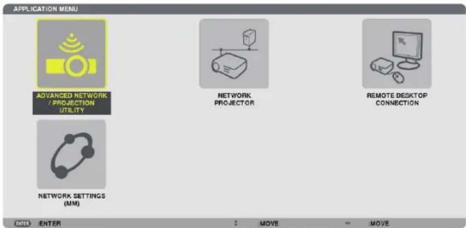
- When operating with the main body, press briefly the "INPUT" button to display the [INPUT TERMINAL] screen of the on-screen menu.
Press the ▼ button to select [8:ETHERNET] and then press the "ENTER" button to display the application menu screen.
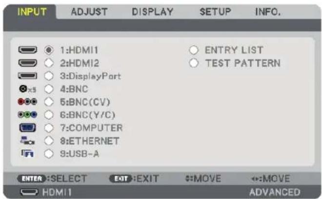
- Press the SELECT ▼ or ▲ button to select [NETWORK] and press the ENTER button. In the screen, the [APPLICATION MENU] menu is displayed.
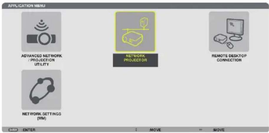
- From the [APPLICATION MENU] menu, select [NETWORK PROJECTOR]. The [PROJECTOR NAME/DISPLAY RESOLUTION/PASSWORD/URL] will be displayed.
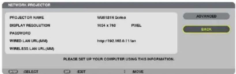
Projecting the Image with Network Projector
- Click [Start] from the desktop of Windows 7.
- Click [All Programs].
- Click [Accessories].
- Click [Connect to a Network Projector].
When the [Permission Connect to a Network Projector] window appears, click [Yes].
The "Connect to a Network Projector" window appears.
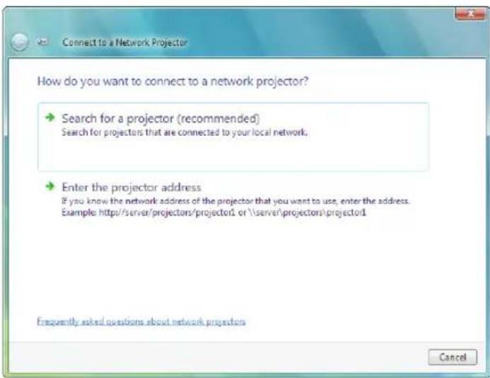
- Click [→ Search for a projector (recommended)].
In the "Available projectors" box, "WU6181N Series" is displayed.
- Click [WU6181N Series].
The message "Enter the password for the projector that you selected." is displayed at the bottom of the window.
- Input the password to the password input box displayed by the operation at step 3 on page 53.
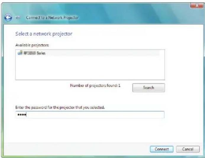
8. Click [Connect].
The network projector function works and the screen of Windows 7 is projected from the projector.
- If the resolution of your computer's screen is different from the projector's screen resolution, the NETWORK PROJECTOR function may not work. If this happens, change the resolution of the computer's screen to lower resolution than the one displayed at Step 3 on page 53.
NOTE: When the network projector function works, the background color of the desktop changes to solid color. When the network projector function is stopped, the original background color is restored.
Reference: If the projector cannot be found at Step 5, click [→ Enter the projector address]. Then, input the "Network address" (Input example: http://10.32.97.61/lan) and "Projectorpassword" (Input example: 82291627) displayed in the screen projected from the projector.
⑩ Using the Projector to Operate Your Computer via a Network [REMOTE DESKTOP]
- By selecting the PC connected to the same network as that of the projector, the PC screen image can be projected to the screen via network.
Then, by operating the keyboard, you can operate Windows 8/8.1, Windows 7, Windows Vista on the PC connected with the network. - With the Remote Desktop function, you can remotely operate the PC placed at a distance from the projector.
![RICOH PJ X6181N - ⑩ Using the Projector to Operate Your Computer via a Network [REMOTE DESKTOP] - 1](/content/2026/05/872418/images/6b1eab78a3efb68d72c386698ae76b4505b8a3da4d3051fcf69046b7e51978e5.jpg)
flowchart
graph TD
    A["Meeting room"] --> B["Computer"]
    B --> C["Desktop"]
    C --> D["Monitor"]
    D --> E["Office"]
    style A fill:#f9f,stroke:#333
    style B fill:#ccf,stroke:#333
    style C fill:#cfc,stroke:#333
    style D fill:#fcc,stroke:#333
    style E fill:#cff,stroke:#333
NOTE:
- The [REMOTE DESKTOP] function will work on the following Windows editions.
Windows 8/8.1 Pro, Windows 8/8.1 Enterprise,
Windows 7 Professional, Windows 7 Ultimate, Windows 7 Enterprise,
Windows Vista Home Premium, Windows Vista Business, Windows Vista Ultimate, Windows Vista Enterprise. - In this user's manual this feature is described using Windows 7 as an example.
- A keyboard is required to use the Remote Desktop function.
- The Remote Desktop function can be operated with a keyboard. Using a wireless mouse with a wireless keyboard is more useful for operating.
Use a commercially available wireless keyboard, a wireless mouse, and a USB wireless receiver.
Use a commercially available USB keyboard and USB mouse. - A USB keyboard with a built-in USB hub cannot be used with the projector.
- A wireless keyboard or mouse that supports Bluetooth cannot be used with the projector.
• We do not warrant that the USB port of the projector will support all USB devices in the market.
Prepare a commercially available wireless keyboard (US layout version).
Connect the USB wireless receiver to the USB port (Type A) of the projector. Make all necessary settings for your wireless keyboard and mouse.
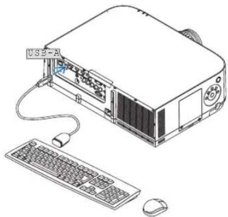
natural_image
Line drawing of a computer setup with monitor, keyboard, mouse, and USB-A label (no text or symbols on main components)Setting the password to the user account of Windows 7
TIP: If a password has been set for an account, the steps 1 to 9 can be skipped.
- Click [Start] from the desktop of Windows 7.
- Click [Control Panel].
- Click [Add or remove user accounts] displayed under [User Accounts].
- When the [User Account Control] confirmation window appears, click [Continue].
- Click [Administrator].
- Click [Create a password].
- Input the password to the [New password] box.
- Input the same password as that at Step 7 to the [Confirm new password] box.
- Click [Create a password].
The Administrator is changed to [Password Protection].
Setting the Remote Access
- Click [Start] from the desktop of Windows 7.
- Click [Control Panel].
- Click [System and Security].
- Click [Allow remote access] displayed under [System].
-
When the [User Account Control] confirmation window appears, click [Continue].
The [System Properties] window appears. -
Click [Allow connections from computers running any version of Remote Desktop (less secure)] in the Remote Desktop box and click [OK].
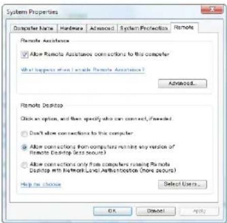
Checking the IP address on Windows 7
- Click [Start] from the desktop of Windows 7.
- Click [Control Panel].
-
Click [View network status and tasks] displayed under [Network and Internet].
-
Click [View status] displayed in blue on the right of [Local Area Connection] in the window.
The [Local Area Connection Status] window appears.
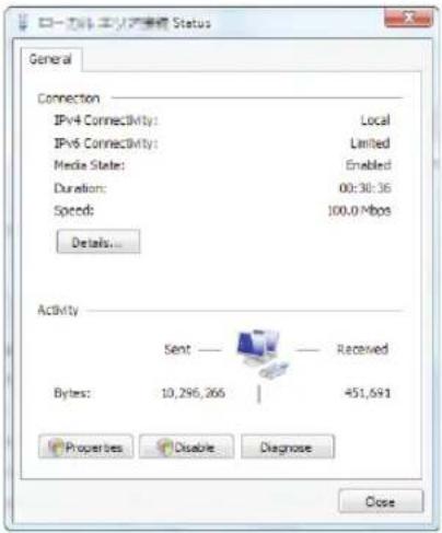
5. Click [Details...].
Write down the value for "IPv4 IP Address" (xxx.xxx.xxx.xxx) displayed.
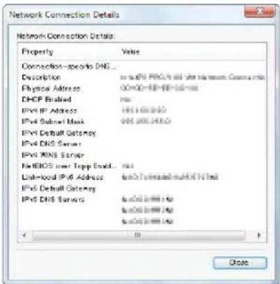
- Click [Close].
- Click [X] at the upper right of the window.
The system goes back to the desktop.
Starting the Remote Desktop
- Press the "8/Ethernet" button on the remote control with the power supply to the projector turned on.
The application menu screen will be displayed.
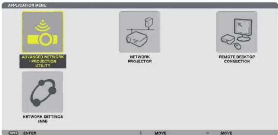
- When operating with the main body, press briefly the "INPUT" button to display the [INPUT TERMINAL] screen of the on-screen menu.
Press the ▼ button to select [8:ETHERNET] and then press the "ENTER" button to display the application menu screen.
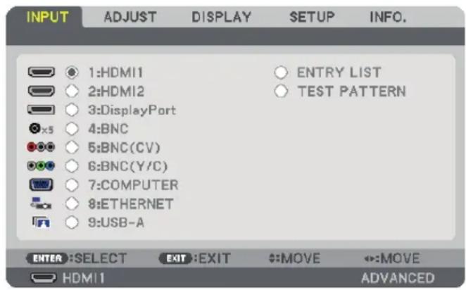
The [REMOTE DESKTOP CONNECTION] window appears.
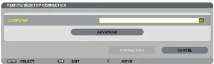
- Operate the wireless keyboard to input the IP address of Windows 7 and click [CONNECTION].
The log-on screen of Windows 7 is displayed in the screen projected by the projector.
- Operate the wireless keyboard to input the user's password and press "Enter".
The remote desktop function is started.
Windows 7 desktop is displayed in the screen projected by the projector.
Log out the computer.
Use the wireless keyboard connected to the projector to operate Windows 7.
NOTE: When the projection is made with the remote desktop function, the background color of the desktop is changed to solid color.
Exiting the Remote Desktop
- Operate the wireless keyboard to click [Start] from the desktop screen projected by the projector.
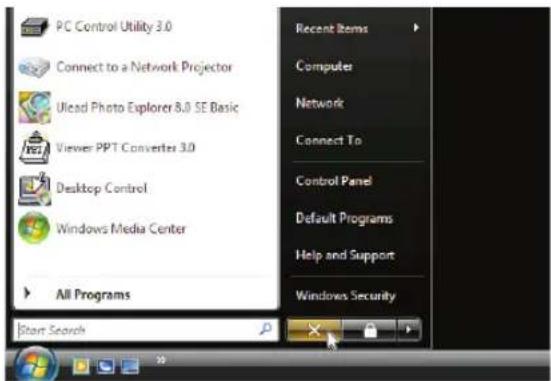
- Click [X] on the right of the start menu.
The remote desktop function is stopped.
- Press the button for an input terminal other than "8/Ethernet" on the remote control.
Switch the input terminal using the "INPUT" button for operations on the main body.
TIP:
Setting [OPTIONS] in REMOTE DESKTOP
Clicking [OPTIONS] displays the [PERFORMANCE] screen.
Making settings to [OPTIONS] will allow you to display the desktop background, or to enable the window animation function during the Remote Desktop operation.
However, doing this will cause the display's or mouse's response to slow down.
If the display's or mouse's response is slowed down, try one or more of the following:
DESKTOP BACKGROUND: Clear the check mark to display the desktop background in solid color.
MENU AND WINDOW ANIMATION: Clear the check mark to disable menu and window animation.
THEMES: Clear the check mark not to use Themes.
SHOW CONTENTS OF WINDOW WHILE DRAGGING: Clear the check mark to show only the window pane while dragging.
4. Multi-Screen Projection
① Things that can be done using multi-screen projection
This projector can be used singly or arranged in multiple units for multi-screen projection. We will introduce an example using two projection screens here.
Case 1
Using a single projector to project two types of videos at the same time [PIP/PICTURE BY PICTURE]
Case 2
Using four projectors (liquid crystal panel: XGA) to project video with a resolution of 1920 1080 pixels [TILING]
Case 1. Using a single projector to project two types of videos [PIP/PICTURE BY PICTURE] Connection example and projection image
In the case of [PICTURE BY PICTURE] In the case of [PIP]
![RICOH PJ X6181N - Case 1. Using a single projector to project two types of videos [PIP/PICTURE BY PICTURE] Connection example and projection image - 1](/content/2026/05/872418/images/3a880b1d8650ac71b272fcf29577ac5fa36b76dec58aa50f3384a56135397260.jpg)
On-screen menu operations
Display [DISPLAY] → [PIP/PICTURE BY PICTURE] → [MODE] screen in the on-screen menu and select [PIP] or [PICTURE BY PICTURE]. For details, please refer to "4-2 Displaying Two Pictures at the Same Time". (→ page 65)
Case 2. Using four projectors (liquid crystal panel: XGA) to project videos with a resolution of 1920 × 1080 pixels [TILING]
Connection example and projection image
![RICOH PJ X6181N - Case 2. Using four projectors (liquid crystal panel: XGA) to project videos with a resolution of 1920 × 1080 pixels [TILING] - 1](/content/2026/05/872418/images/398b5cc8b9bc467c7c70ab55b7b75ef542c9d2f13e3412a0e14bd03dbb412b80.jpg)
flowchart
graph TD
    A["Server"] --> B["Cityscape"]
    B --> C["Switch"]
    C --> D["Server"]
    D --> E["Switch"]
    E --> F["Server"]
    style A fill:#f9f,stroke:#333
    style B fill:#ccf,stroke:#333
    style C fill:#cfc,stroke:#333
    style D fill:#fcc,stroke:#333
    style E fill:#cff,stroke:#333
    style F fill:#ffc,stroke:#333
On-screen menu operations
1 Four similar videos are displayed when four projectors are projected.
Please request the retail store to adjust the projection position of each projector.
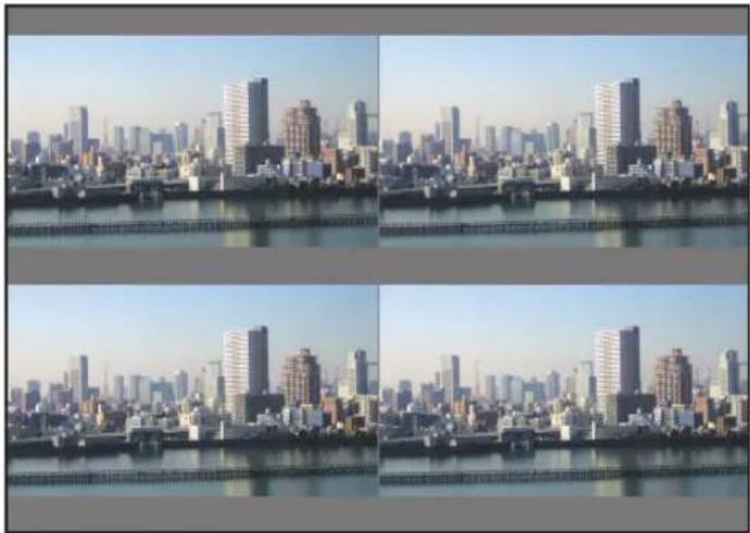
natural_image
Four-panel cityscape photo showing a dense skyline of high-rise buildings along a waterfront promenade, with no visible text or signage.NOTE:
- When setting up the projector, assign a unique control ID to each projector.
- Set the "Color setting" and "DeepColor setting" on your Blu-ray player or computer to "Auto". Refer to the owner's manual accompanied with your Blu-ray player or computer for more information.
- Connect an HDMI output of your Blu-ray player or computer to the first projector and then connect to the HDMI1 or HDMI2 input connector of the second and subsequent projectors.
- Selecting another input source on the second and subsequent projectors will disable the HDMI repeater function.
2 Operate the on-screen menu using the four respective projectors to divide the image into four portions.
Display [DISPLAY] → [MULTI SCREEN] → [PICTURE SETTING] Screen in the on-screen menu and select [TILING].
(1) In the screen for setting the number of horizontal units, select [2 UNITS]. (number of units in the horizontal direction)
(2) In the screen for setting the number of vertical units, select [2 UNITS]. (number of units in the vertical direction)
(3) In the screen for setting the horizontal order, select [1st UNIT] or [2nd UNIT].
(look at the screens, the one on the left is the [1st UNIT] while the one on the right is the [2nd UNIT])
(4) In the screen for setting the vertical order, select the [1st UNIT] or the [2nd UNIT].
(look at the screens, the one at the top is the [1st UNIT] while the one at the bottom is the [2nd UNIT])
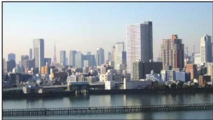
natural_image
City skyline with modern skyscrapers and a waterfront promenade (no visible text or signage)3 Adjust the lens shift of each projector to fine-tune the boundaries of the screen.
For further fine-tuning, adjust using [DISPLAY] → [EDGE BLENDING] in the on-screen menu for each projector. For details, please refer to "4-3 Displaying a Picture Using [EDGE BLENDING]".
(→ page 69)
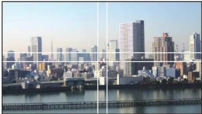
natural_image
Panoramic cityscape with modern skyscrapers and a river in the foreground (no visible text or signage)Things to note when installing projectors
- Leave sufficient space on the left and right of the projector so that the intake and exhaust vents of the projector are not obstructed. When the intake and exhaust vents are obstructed, the temperature inside the projector will rise and this may result in a malfunction.

natural_image
Diagram showing two identical electronic devices connected by an arrow, no text or symbols present- Please do not pile up the projectors directly on top of one another when installing them. When the projectors are piled up on top of one another, they may fall down, resulting in damage and failure.
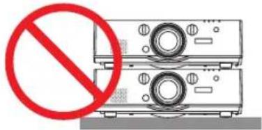
- Installation example when using two projectors
The following installation is recommended when combining the installation of two projectors for multi-screen projection. Please leave a space of at least 10 cm between the the intake/exhaust vent and the wall. [Installation example]
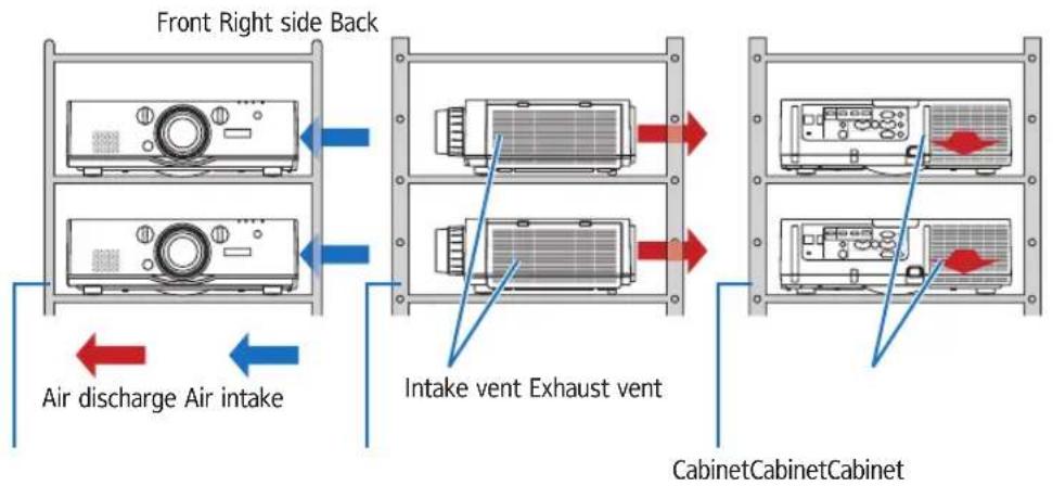
flowchart
graph TD
    A["Front Right side Back"] --> B["Air discharge Air intake"]
    B --> C["Intake vent Exhaust vent"]
    C --> D["Cabinet Cabinet Cabinet"]

WARNING
Please request the retail store for special installation services such as when mounting the projector to the ceiling. Never carry out the installation by yourself. The projector may fall down and result in injury. Please use a sturdy cabinet that can withstand the weight of the projector for the installation. Please do not pile up the projectors directly on top of one another.
NOTE:
- For the range of the projection distance, please refer to the Appendix "Throw distance and screen size". (→ page 231)
② Displaying Two Pictures at the Same Time
The projector has a feature that allows you to view two different signals simultaneously. You have two modes: PIP mode and PICTURE BY PICTURE mode.
The projection video in the first screen display is known as the main display while the projection video that is called out subsequently is known as the sub-display.
Select the projection function under [DISPLAY] → [PIP/PICTURE BY PICTURE] → [MODE] in the on-screen menu (the default factory setting when shipped is PIP). (→ page 98)
- A single screen is projected when power is turned on.
Picture in Picture function
A small sub-display is displayed inside the main display.
The sub-display can be set up and adjusted as follows. ( page 98)
- Select whether to display the sub-display at the top right, top left, bottom right or bottom left of the screen (the size of the sub-display can be selected and the position can be fine-tuned)
- Switch the main display with the sub-display
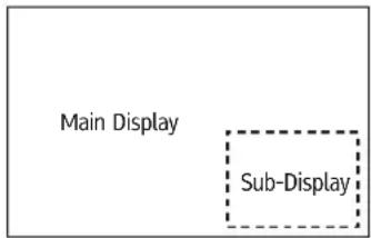
Picture by picture function
Display the main display and sub-display side by side.
The main display and sub-display can be set up and adjusted as follows. (→ page 99)
- Selecting the display boundary (ratio) of the main display and sub-display
- Switch the main display and sub-display
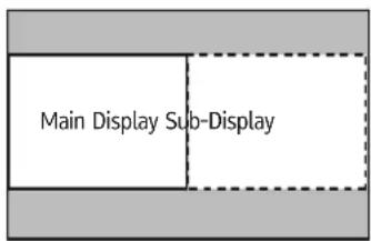
Input terminals that can be used for the main screen and sub-screen.
The main screen and sub-screen can provide the following input terminals.
- The main display and sub-display support computer signals up to WUXGA@60HzRB.
| Sub-Display or additional display | ||||||||
| HDMI1 HDMI2 DisplayPort BNC BNC(CV) BNC(Y/C) COMPUTER | ||||||||
| Main Display | HDMI1 | Yes Yes No | Yes Yes Yes Yes | |||||
| HDMI2 Yes Yes Yes Yes Yes Yes Yes | ||||||||
| DisplayPort Yes Yes Yes Yes | ||||||||
| BNC | Yes Yes Yes | No Yes | No | |||||
| BNC(CV) | Yes Yes Yes | |||||||
| BNC(Y/C) | Yes Yes Yes | |||||||
| COMPUTER | Yes | Yes | Yes | No | Yes | Yes | No | |
NOTE:
• Some signals may not appear depending on the resolution.
Projecting two screens
- Press the MENU button to display the on-screen menu and select [DISPLAY] → [PIP/PICTURE BY PICTURE].
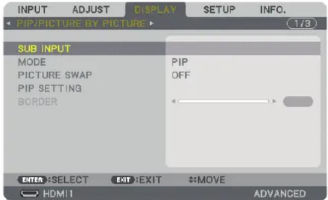
This displays the [PIP/PICTURE BY PICTURE] screen in the on-screen menu.
- Select [SUB INPUT] using the ▼/▲ buttons, and press the ENTER button.
This displays the [SUB INPUT] screen.
- Select the input signal using the ▼/▲ buttons, and press the ENTER button.
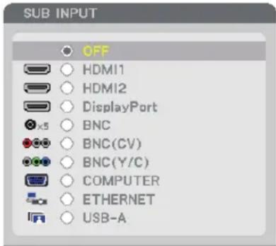
The [PIP] (PICTURE IN PICTURE) or [PICTURE BY PICTURE] screen set up under [MODE] is projected. (→ page 98)
- When the signal name is displayed in grey, this means that it cannot be selected.
-
The signal can also be selected by pressing the PIP button or PBP/POP button on the remote control.
-
Press the MENU button.
The on-screen menu will disappear.
- When returning to single screen, display the [PIP/PICTURE BY PICTURE] screen one more time and select [OFF] in the [SUB INPUT] screen of the Step 3.
TIP:
- During dual-screen projection, if the selected input is not supported by the sub-screen, the sub-screen will appear as a black screen.
Switching the main display with the sub-display and vice versa
- Press the MENU button to display the on-screen menu and select [DISPLAY] → [PIP/PICTURE BY PICTURE].
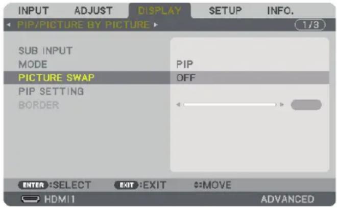
This displays the [PIP/PICTURE BY PICTURE] screen in the on-screen menu.
- Select [PICTURE SWAP] using the ▼/▲ buttons and then press the ENTER button.
Display the screen for switching the display positions.
- Select [ON] using the ▼ button and then press the ENTER button.
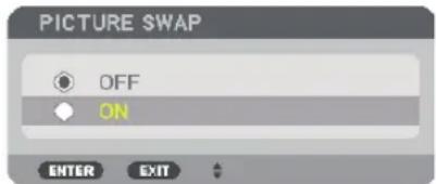
The video of the main display will switch with that of the sub-display.
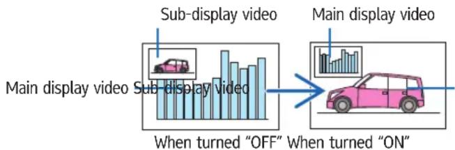
flowchart
graph LR
    A["Main display video"] --> B["Sub-display video"]
    B --> C["When turned "OFF""]
    C --> D["Main display video"]
    D --> E["When turned "ON""]
The signal output from the HDMI output terminal does not change even if the display positions are switched.
- Press the menu button.
The on-screen menu will disappear.
Restrictions
- The following operations are enabled only for the main display.
• Audio-visual adjustments
- Video magnification / compression using the partial D-ZOOM/ZOOM +/ buttons.
However, magnification / compression is up to the positions set in [PICTURE BY PICTURE BORDER] only.
- TEST PATTERN
- The following operations are enabled for both the main display and sub-display. These operations cannot be applied individually.
- Momentary deletion of video / audio
- Video pause
- [PIP/PICTURE BY PICTURE] cannot be used when a 3D video is being displayed.
- When using the [PIP/PICTURE BY PICTURE] function, [CLOSED CAPTION] and [DYNAMIC CONTRAST] can be used.
- [PIP/PICTURE BY PICTURE] cannot be used when the signal input has a resolution of 1920 1200 or more.
- The HDMI output terminal has a repeater function. The output resolution is limited by the maximum resolution of the connected monitor and projector.
③ Displaying a Picture Using [EDGE BLENDING]
A high resolution video can be projected on an even bigger screen by combining multiple projectors on the left, right, top and bottom. This projector is equipped with an "EDGE BLENDING Function" that makes the edges (boundaries) of the projection screen indistinguishable.
NOTE:
- For projector throw distances, refer to "Throw distance and screen size" on page 231.
- Before performing the Edge Blending function, place the projector in the correct position so that the image becomes square in the appropriate size, and then make optical adjustments (lens shift, focus, and zoom).
- Adjust the brightness of each projector using [LAMP ADJUST] under [LAMP MODE]. In addition, use [REF. WHITE BALANCE] to adjust the [CONTRAST], [BRIGHTNESS] and [UNIFORMITY].
Before explaining use of the Edge Blending function
This section explains the case for "Example: Placing two projectors side by side". As shown, the projected image on the left is referred to as "Projector A" and the projected image on the right is referred to "Projector B". Unless otherwise specified hereinafter, the "projector" is used to mean both A and B.
Example: Placing two projectors side by side
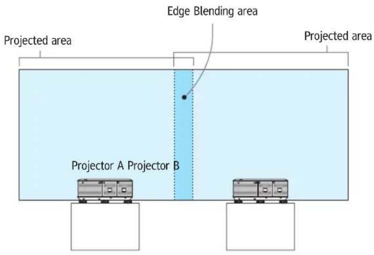
Preparation:
- Turn on the projector and display a signal.
- When performing settings or adjustments using the remote control, enable the [CONTROL ID] so as not to activate the other projectors. (→ page 118)
Setting the overlap of projection screens
① Enable [EDGE BLENDING].
1 Press the "Edge Blend." button.
The [EDGE BLENDING] screen will be displayed. Align the cursor with [MODE] and then press the ENTER button. The mode screen will be displayed.

2 Select [MODE] → [ON] and press the ENTER button.
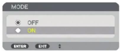
This enables the Edge Blending function. The following menu items are available:
[TOP], [BOTTOM], [LEFT], [RIGHT], and [BLACK LEVEL]
3 Select [RIGHT] for Projector A and [LEFT] for Projector B.
Press the ENTER button.
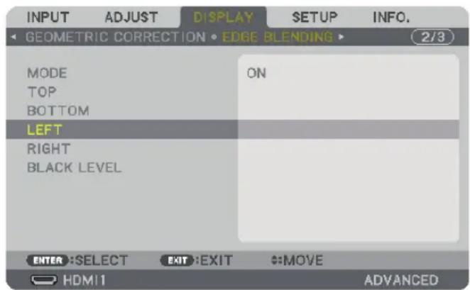
The following items are available:
[CONTROL], [MARKER], [RANGE], and [POSITION]
4 Select [CONTROL] → [ON] and press the ENTER button.
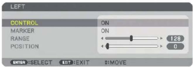
Each [TOP], [BOTTOM], [LEFT], [RIGHT], and [BLACK LEVEL] has its own [CONTROL], [MARKER], [RANGE], and [POSITION].
- For Projector A, set the [CONTROL] for the [TOP], [LEFT] and [BOTTOM] to [OFF]. Similarly for Projector B, set the [CONTROL] for the [TOP], [RIGHT] and [BOTTOM] to [OFF].
② Adjust [RANGE] and [POSITION] to determine an area of overlapped edges of images projected from each projector.
Turning on [MARKER] will display markers in magenta and green. The magenta marker is used for [RANGE] and green one for [POSITION].
![[RANGE] (Determine an area of overlapped edges of images.) Turn on [RIGHT] Turn on [LEFT] Magenta marker Magenta marker [POSITION] (Determine the position of overlapped edges of images.) Green marker](/content/2026/05/872418/images/d67fe3dc2734d208cb3327096085e1c15bc18f0684beaa16a37397b3a514d008.jpg)
* The 2 screens are separated in the diagram for explanatory purposes.
1 Adjust [RANGE].
Use the ◀ or ▶ button to adjust the overlapped area.
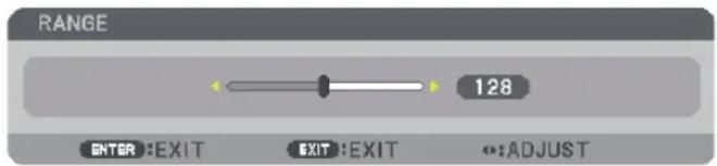
TIP:
- Adjust to overlap one projector' marker with the other projector's marker.
2 Adjust [POSITION].
Use the ◀ or ▶ button to align one edge with the other edge of overlapped images.
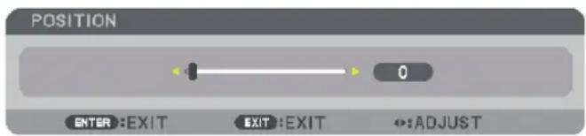
TIP:
- When displaying a signal with a different resolution, perform the Edge Blending function from the start.
- Setting of [MARKER] will not be saved and return to [OFF] when the projector is turned off.
- To display or hide the marker while the projector is running, turn on or off [MARKER] from the menu.
Black Level Adjustment
This adjusts the black level of the overlapping area and the non-overlapping area of the multi-screen (EDGE BLENDING). Adjust the brightness level if you feel the difference is too large.
NOTE:
This function is enabled only when [MODE] is turned on.
Adjustable area varies depending on what combination of [TOP], [BOTTOM], [LEFT] and [RIGHT] are turned on.
Example: Adjusting the Black Level when placing two projectors side by side
![Adjust [CENTER] Adjust [CENTER] Width of overlap Projector A's image Projector B's image Adjust [CENTER-RIGHT] Adjust [CENTER-LEFT]](/content/2026/05/872418/images/173232d5f819640c7b0b6aebd78c2532c24af981c434db52a7d84864eb1a8f5e.jpg)
- Turn on [MODE]
- Select [BLACK LEVEL] and press the ENTER button.
The screen will switch to the black level adjustment screen.
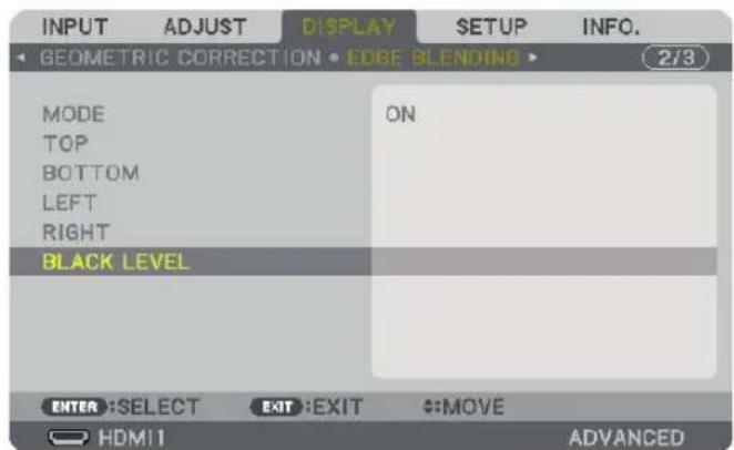
- Use the ▼ or ▲ button to select an item and use the ◀ or ▶ to adjust the black level.
Do this for the other projector if necessary.
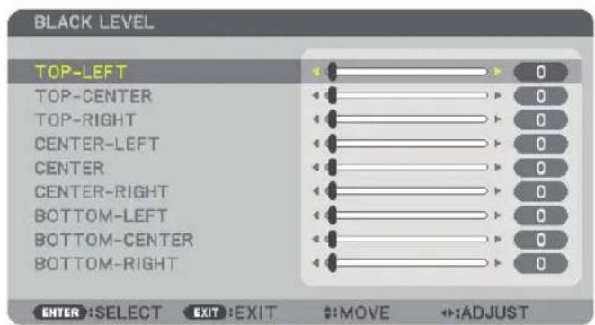
9-segmented portions for Black Level adjustment
The center projector
This function adjusts the brightness level of 9-segmented portions for the center projector and 4-segmented portions for the left bottom projector as shown below.
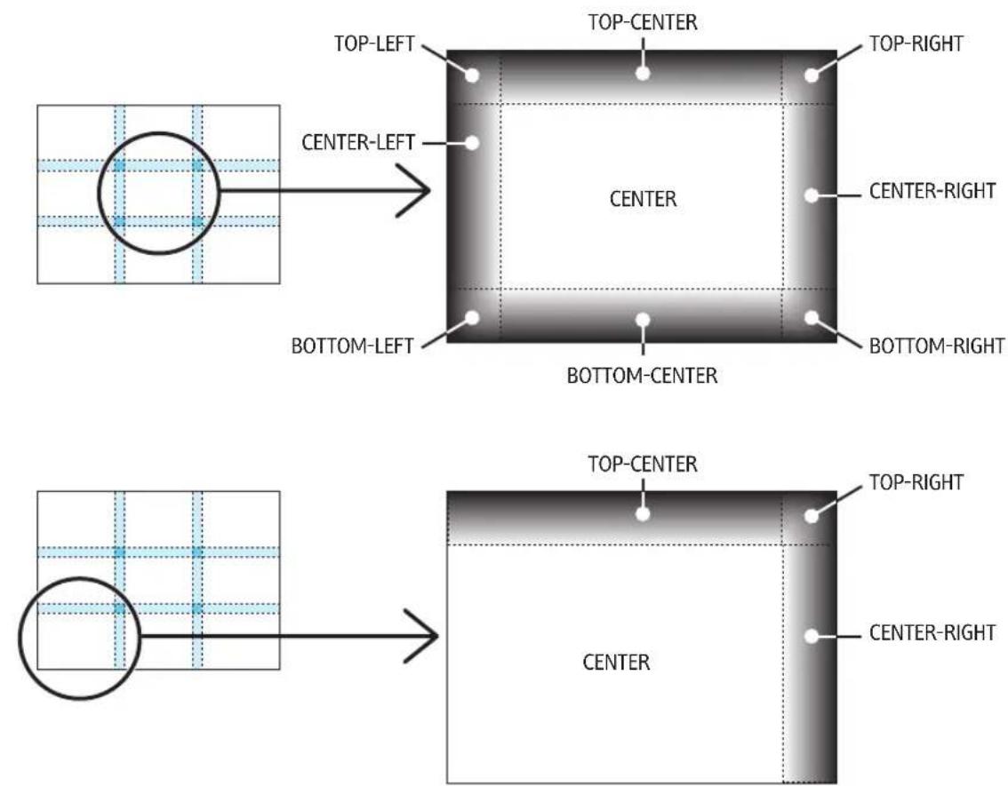
TIP:
- The number of black level division screens (maximum of nine divisions) changes depending on the number of edge blending positions selected (top, bottom, right, left). In addition, when the top / bottom and left / right ends are selected, the corner division screen appears.
- The edge blending width is the width set in the range and the corner is formed by the intersecting area of the top / bottom ends or left / right ends.
• The [BLACK LEVEL] can be adjusted to make it brighter only.
5. Using On-Screen Menu
① Using the Menus
NOTE: The on-screen menu may not be displayed correctly while interlaced motion video image is projected.
- Press the MENU button on the remote control or the projector cabinet to display the menu.
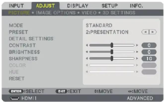
NOTE: The commands such as ENTER, EXIT, ▲▼, ◀▶ in the bottom show available buttons for your operation.
- Press the ◀▶ buttons on the remote control or the projector cabinet to display the submenu.
- Press the ENTER button on the remote control or the projector cabinet to highlight the top item or the first tab.
- Use the ▲▼ buttons on the remote control or the projector cabinet to select the item you want to adjust or set. You can use the ◀▶ buttons on the remote control or the projector cabinet to select the tab you want.
- Press the ENTER button on the remote control or the projector cabinet to display the submenu window.
- Adjust the level or turn the selected item on or off by using the ▲▼◀▶ buttons on the remote control or the projector cabinet.
Changes are stored until adjusted again.
- Repeat steps 2-6 to adjust an additional item, or press the EXIT button on the remote control or the projector cabinet to quit the menu display.
NOTE: When a menu or message is displayed, several lines of information may be lost, depending on the signal or settings.
- Press the MENU button to close the menu.
To return to the previous menu, press the EXIT button.
② Menu Elements
Slide bar
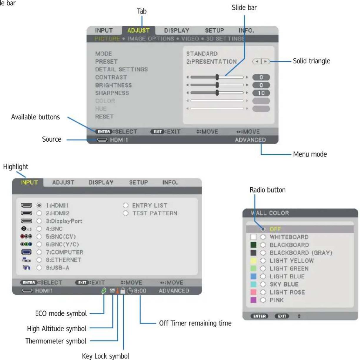
Menu windows or dialog boxes typically have the following elements:
Highlight Indicates the selected menu or item.
Solid triangle Indicates further choices are available. A highlighted triangle indicates the item is active.
Tab Indicates a group of features in a dialog box. Selecting on any tab brings its page to the front.
Radio button Use this round button to select an option in a dialog box.
Source Indicates the currently selected source.
Menu mode Indicates the current menu mode: BASIC or ADVANCED.
Off Timer remaining time Indicates the remaining countdown time when the [OFF TIMER] is preset.
Slide bar Indicates settings or the direction of adjustment.
ECO mode symbol Indicates [ECO MODE] is set.
Key Lock symbol Indicates the [CONTROL PANEL LOCK] is enabled.
Thermometer symbol Indicates the [ECO MODE] is forcibly set to [ON] mode because the internal temperature is too high.
High Altitude symbol Indicates the [FAN MODE] is set to [HIGH ALTITUDE] mode.
③ List of Menu Items
- Basic menu items are indicated by shaded area.
Some menu items are not available depending on the input source.
| Menu Item Default Options | |||||
| INPUT | 1:HDMI1 * | ||||
| 2:HDMI2 * | |||||
| 3:DisplayPort * | |||||
| 4:BNC * | |||||
| 5:BNC(CV) * | |||||
| 6:BNC(Y/C) * | |||||
| 7:COMPUTER * | |||||
| 8:ETHERNET | |||||
| 9:USB-A | |||||
| ENTRY LIST | |||||
| TEST PATTERN | |||||
| ADJUST | PICTURE | MODE STANDARD STANDARD, PROFESSIONAL | |||
| PRESET | * | HIGH-BRIGHT, PRESENTATION, VIDEO, MOVIE, GRAPHIC, sRGB, DICOM SIM. | |||
| DETAIL SETTINGS | GENERAL | ||||
| REFERENCE | * | HIGH-BRIGHT, PRESENTATION, VIDEO, MOVIE, GRAPHIC, sRGB, DICOM SIM. | |||
| GAMMA CORRECTION*1 | DYNAMIC, NATURAL, BLACK DETAIL | ||||
| SCREEN SIZE*2 | * | LARGE, MEDIUM, SMALL | |||
| COLOR TEMPERATURE*3 | * | ||||
| DYNAMIC CONTRAST | * | OFF, MOTION IMAGE, STILL IMAGE | |||
| WHITE BALANCE | |||||
| CONTRAST R | 0 | ||||
| CONTRAST G | 0 | ||||
| CONTRAST B | 0 | ||||
| BRIGHTNESS R | 0 | ||||
| BRIGHTNESS G | 0 | ||||
| BRIGHTNESS B | 0 | ||||
| COLOR CORRECTION | |||||
| RED | 0 | ||||
| GREEN | 0 | ||||
| BLUE | 0 | ||||
| YELLOW | 0 | ||||
| MAGENTA | 0 | ||||
| CYAN | 0 | ||||
| CONTRAST | 50 | ||||
| BRIGHTNESS | 50 | ||||
| SHARPNESS | 10 | ||||
| COLOR | 50 | ||||
| HUE | 0 | ||||
| RESET | |||||
| IMAGE OPTIONS | CLOCK | * | |||
| PHASE | * | ||||
| HORIZONTAL | * | ||||
| VERTICAL | * | ||||
| BLANKING | * | TOP, BOTTOM, LEFT, RIGHT | |||
| OVERSCAN | * | AUTO, 0[%], 5[%], 10[%] | |||
| ASPECT RATIO | * | (COMPUTER) AUTO, 4:3, 5:4, 16:9, 15:9, 16:10, NATIVE | |||
| * | COMPONENT/VIDEO/S-VIDEO) AUTO, 4:3, LETTERBOX, WIDE SCREEN, ZOOM | ||||
| * | COMPONENT/VIDEO/S-VIDEO) AUTO, 4:3 WINDOW, LETTERBOX, WIDE SCREEN, FULL | ||||
| INPUT RESOLUTION*4 | * | - | |||
| VIDEO | NOISE REDUCTION | RANDOM NR | * | OFF, LOW, MEDIUM, HIGH | |
| MOSQUITO NR | OFF | OFF, LOW, MEDIUM, HIGH | |||
| BLOCK NR | OFF | OFF, LOW | |||
| DEINTERLACE | NORMAL | NORMAL, MOVIE, STILL | |||
| CONTRAST ENHANCEMENT | MODE | AUTO | OFF, AUTO, NORMAL | ||
| GAIN | |||||
| SIGNAL TYPE | AUTO | AUTO, RGB, COMPONENT | |||
| VIDEO LEVEL | AUTO | AUTO, NORMAL, ENHANCED | |||
* The asterisk (*) indicates that the default setting varies depending on the signal.
*1 The [GAMMA CORRECTION] item is available when an item other than [DICOM SIM.] is selected for [REFERENCE].
*2 The [SCREEN SIZE] item is available when [DICOM SIM.] is selected for [REFERENCE].
*3 When [PRESENTATION] or [HIGH-BRIGHT] is selected in [REFERENCE], the [COLOR TEMPERATURE] is not available.
*4 The [INPUT RESOLUTION] item can be selected for COMPUTER input and BNC (analog RGB) input.
| Menu Item Default Options | |||||
| ADJUST 3D SETTINGS | STEREO VIEWER SINGLE SINGLE, DUAL LEFT, DUAL RIGHT | ||||
| STEREO FILTER SINGLE SINGLE, DUAL LEFT, DUAL RIGHT | |||||
| FORMAT AUTO | AUTO, OFF(2D), FRAME PACKING, SIDE BY SIDE(HALF), SIDE BY SIDE(FULL), TOP AND BOTTOM, FRAME ALTERNATIVE, LINE ALTERNATIVE | ||||
| L/R INVERT OFF OFF, ON | |||||
| DISPLAY | PIP/PICTURE BY PICTURE | SUB INPUT | OFF, HDMI1, HDMI2, DisplayPort, BNC, BNC(CV), BNC(Y/C), COMPUTER, ETHERNET | ||
| MODE PIP, PICTURE BY PICTURE | |||||
| PICTURE SWAP OFF OFF, ON | |||||
| PIP SETTING | START POSITION TOP-LEFT, TOP-RIGHT, BOTTOM-LEFT, BOTTOM-RIGHT | ||||
| HORIZONTAL POSITION | |||||
| VERTICAL POSITION | |||||
| SIZE LARGE, MEDIUM, SMALL | |||||
| BORDER | |||||
| GEOMETRIC CORRECTION | KEYSTONE | HORIZONTAL | |||
| VERTICAL | |||||
| TILT | |||||
| THROW RATIO | |||||
| CORNERSTONE | TOP-LEFT, TOP, TOP-RIGHT, LEFT, RIGHT, BOTTOM-LEFT, BOTTOM, BOTTOM-RIGHT | ||||
| HORIZONTAL CORNER | TOP-LEFT, TOP, TOP-RIGHT, LEFT, RIGHT, BOTTOM-LEFT, BOTTOM, BOTTOM-RIGHT | ||||
| VERTICAL CORNER | TOP-LEFT, TOP, TOP-RIGHT, LEFT, RIGHT, BOTTOM-LEFT, BOTTOM, BOTTOM-RIGHT | ||||
| PINCUSHION TOP, BOTTOM, LEFT, RIGHT | |||||
| PC TOOL OFF OFF, 1, 2, 3 | |||||
| RESET | |||||
| EDGE BLENDING | MODE | OFF OFF | ON | ||
| TOP | CONTROL | ON | OFF, ON | ||
| MARKER | ON | OFF, ON | |||
| RANGE | |||||
| POSITION | |||||
| BOTTOM | CONTROL | ON | OFF, ON | ||
| MARKER | ON | OFF, ON | |||
| RANGE | |||||
| POSITION | |||||
| LEFT | CONTROL | ON | OFF, ON | ||
| MARKER | ON | OFF, ON | |||
| RANGE | |||||
| POSITION | |||||
| RIGHT | CONTROL | ON | OFF, ON | ||
| MARKER | ON | OFF, ON | |||
| RANGE | |||||
| POSITION | |||||
| BLACK LEVEL | TOP-LEFT | ||||
| TOP-CENTER | |||||
| TOP-RIGHT | |||||
| CENTER-LEFT | |||||
| CENTER | |||||
| CENTER-RIGHT | |||||
| BOTTOM-LEFT | |||||
| BOTTOM-CENTER | |||||
| BOTTOM-RIGHT | |||||
| MULTI SCREEN | WHITE BALANCE | MODE | OFF OFF | ON | |
| CONTRAST W | |||||
| CONTRAST R | |||||
| CONTRAST G | |||||
| CONTRAST B | |||||
| BRIGHTNESS W | |||||
| BRIGHTNESS R | |||||
| BRIGHTNESS G | |||||
| BRIGHTNESS B | |||||
| PICTURE SETTING | MODE | OFF OFF | ZOOM, TILING | ||
| ZOOM | HORIZONTAL ZOOM | ||||
| VERTICAL ZOOM | |||||
| HORIZONTAL POSITION | |||||
| VERTICAL POSITION | |||||
| TILING | WIDTH | ||||
| HEIGHT | |||||
| HORIZONTAL POSITION | |||||
| VERTICAL POSITION | |||||
| SETUP | MENU | LANGUAGE ENGLISH | ENGLISH, DEUTSCH, FRANÇAIS, ITALIANO, ESPAÑOL, SVENSKA,日本語 | ||
| DANSK, PORTUGUÊS, ČEŠTINA, MAGYAR, POLSKI, NEDERLANDS,SUOMI | |||||
| NORSK, TÜRKÇE, PYCCKIIЙ, عربی , Eλληνικά, 中文, 한국어 | |||||
| ROMÄNÄ, HRVATSKA, БЪЛГАРСКИ, INDONESIA, ṅनिसी, ไทย,نُويغۇر, 繁體中文 | |||||
| COLOR SELECT COLOR COLOR, MONOCHROME | |||||
| INPUT DISPLAY ON OFF, ON | |||||
| MESSAGE DISPLAY ON OFF, ON | |||||
| ID DISPLAY ON OFF, ON | |||||
| ECO MESSAGE OFF OFF, ON | |||||
| 3D CAUTION MESSAGE ON OFF, ON | |||||
| DISPLAY TIME | AUTO 45SEC | MANUAL, AUTO 5 SEC, AUTO 15 SEC, AUTO 45 SEC | |||
| FILTER MESSAGE OFF OFF, 100[H], 500[H], 1000[H], 2000[H] | |||||
| INSTALLATION | ORIENTATION AUTO | AUTO, DESKTOP FRONT, CEILING REAR, DESKTOP REAR, CEILINGFRONT | |||
| SCREEN TYPE FREE FREE, 4:3 SCREEN, 16:9 SCREEN, 16:10 SCREEN | |||||
| WALL COLOR | OFF | OFF, WHITEBOARD, BLACKBOARD, BLACKBOARD (GRAY), LIGHTYELLOW, LIGHT GREEN, LIGHT BLUE, SKY BLUE, LIGHT ROSE, PINK | |||
| FAN MODE | AUTO | AUTO, HIGH, HIGH ALTITUDE | |||
| LAMP MODE | ECO MODE | OFF OFF, | ON | ||
| LAMP ADJUST | |||||
| REF. WHITE BALANCE | CONTRAST R | ||||
| CONTRAST G | |||||
| CONTRAST B | |||||
| BRIGHTNESS R | |||||
| BRIGHTNESS G | |||||
| BRIGHTNESS B | |||||
| UNIFORMITY R | |||||
| UNIFORMITY B | |||||
| STATIC CONVERGENCE | HORIZONTAL R | ||||
| HORIZONTAL G | |||||
| HORIZONTAL B | |||||
| VERTICAL R | |||||
| VERTICAL G | |||||
| VERTICAL B | |||||
| Menu Item Default Options | |||||||
| SETUP CONTROL | TOOLS | ADMINISTRA-TOR MODE | MENU MODE ADVANCED ADVANCED, BASIC | ||||
| NOT SAVE SETTING VALUES OFF OFF, ON | |||||||
| NEW PASSWORD | |||||||
| CONFIRM PASSWORD | |||||||
| PROGRAM TIMER | ENABLE OFF OFF, ON | ||||||
| SETTINGS | EDIT | ACTIVE OFF, ON | |||||
| DAY | |||||||
| TIME | |||||||
| FUNCTION POWER, INPUT, ECO MODE | |||||||
| ADVANCED SETTINGS | |||||||
| POWER OFF, ON | |||||||
| INPUT HDMI1, HDMI2, Display Port, BNC, BNC(CV), BNC(Y/C), COMPUTER | |||||||
| ECO MODE OFF, ON | |||||||
| REPEAT OFF, ON | |||||||
| DELETE | |||||||
| UP | |||||||
| DOWN | |||||||
| BACK | |||||||
| DATE AND TIME SETTINGS | TIME ZONE SETTIMGS | GMT | -12:00, -11:30, -11:00, -10:30, -10:00, -09:30, -09:00, -08:30, -08:00, -07:30, -07:00, -06:30, -06:00, -05:30, -05:00, -04:30, -04:00, -03:30, -03:00, -02:30, -02:00, -01:30, -01:00, -00:30, 00:00, +00:30, +01:00, +01:30, +02:00, +02:30, +03:00, +03:30, +04:00, +04:30, +05:00, +05:30, +06:00, +06:30, +07:00, +07:30, +08:00, +08:30, +09:00, +09:30, +10:00, +10:30, +11:00, +11:30, +12:00, +12:30, +13:00 | ||||
| DATE MM/DD/YYYY | |||||||
| TIME HH:MM | |||||||
| INTERNET TIME SERVER | OFF, ON | ||||||
| IP ADDRESS | |||||||
| UPDATE | |||||||
| SUMMER TIME SETTINGS | ENABLE | OFF, ON | |||||
| MON(START) | 1, 2, 3, 4, 5, 6, 7, 8, 9, 10, 11, 12 | ||||||
| DAY(START) | FIRST WEEK, SECOND WEEK, THIRD WEEK, FOURTH WEEK, LAST WEEK | ||||||
| SUN, MON, TUE, WED, THU, FRI, SAT | |||||||
| TIME(START) | |||||||
| MON(EXIT) | 1, 2, 3, 4, 5, 6, 7, 8, 9, 10, 11, 12 | ||||||
| DAY(EXIT) | FIRST WEEK, SECOND WEEK, THIRD WEEK, FOURTH WEEK, LAST WEEK | ||||||
| SUN, MON, TUE, WED, THU, FRI, SAT | |||||||
| TIME(EXIT) | |||||||
| TIME DIFFERENCE | +01:00, +00:30, -00:30, -01:00 | ||||||
| MOUSE | (Note) Cannot be used for this device. | ||||||
| CONTROL PANEL LOCK | OFF OFF | ON | |||||
| SECURITY | OFF OFF | ON | |||||
| COMMUNICATION SPEED | 38400bps | 4800bps, 9600bps, 19200bps, 38400bps, 115200bps | |||||
| CONTROL ID | CONTROL ID NUMBER | 1 | 1-254 | ||||
| CONTROL ID | OFF OFF, ON | ||||||
| REMOTE SENSOR | FRONT/ BACK | FRONT/BACK, FRONT, BACK | |||||
| BEEP | ON | OFF, ON | |||||
| Menu Item Default Options | ||||||
| SETUP | NETWORK SETTINGS | WIRED LAN | PROFILES DISABLE, PROFILE 1, PROFILE 2 | |||
| DHCP OFF, ON | ||||||
| IP ADDRESS 192.168.0.10 | ||||||
| SUBNET MASK 255.255.255.0 | ||||||
| GATEWAY 192.168.0.1 | ||||||
| AUTO DNS OFF, ON | ||||||
| DNS CONFIGURATION | ||||||
| RECONNECT | ||||||
| PROJECTOR NAME PROJECTOR NAME WU6181N Series | ||||||
| DOMAIN | HOST NAME rdpj | |||||
| DOMAIN NAME | ||||||
| ALERT MAIL | ALERT MAIL OFF, ON | |||||
| HOST NAME | ||||||
| DOMAIN NAME | ||||||
| SENDER'S ADDRESS | ||||||
| SMTP SERVER NAME | ||||||
| RECIPIENT'S ADDRESS 1 | ||||||
| RECIPIENT'S ADDRESS 2 | ||||||
| RECIPIENT'S ADDRESS 3 | ||||||
| TEST MAIL | ||||||
| NETWORK SERVICE | HTTP | NEW PASSWORD | ||||
| SERVER | CONFIRM PASSWORD | |||||
| PJLink | NEW PASSWORD | |||||
| CONFIRM PASSWORD | ||||||
| AMXBEACON | OFF, ON | |||||
| CRESTRON | ROOMVIEWCRESTRON CONTROL | |||||
| SOURCE OPTIONS | AUTO ADJUST NORMAL OFF, NORMAL, FINE | |||||
| COLOR SYSTEM | BNC(VIDEO) AUTO AUTO, NTSC3.58, BNC(Y/C) | NTSC4.43, PAL, PAL-M, PAL-N, PAL60, SECAM | ||||
| AUTO AUTO, NTSC3.58, NTSC4.43, PAL, PAL-M, PAL-N, PAL60, SECAM | ||||||
| AUDIO SELECT | HDMI1 | HDMI1 | HDMI1, BNC | |||
| HDMI2 HDMI2 HDMI2, BNC | ||||||
| DisplayPort | DisplayPort | DisplayPort, BNC | ||||
| ETHERNET | ETHERNET | ETHERNET, BNC | ||||
| USB-A*11 | USB-A | USB-A, BNC | ||||
| DEFAULT INPUT SELECT | LAST | LAST, AUTO, HDMI1, HDMI2, DisplayPort, BNC, BNC(CV), BNC(Y/C), COMPUTER, ETHERNET | ||||
| SEAMLESS SWITCHING | OFF | OFF, ON | ||||
| CLOSED CAPTION | OFF | OFF, CAPTION1, CAPTION2, CAPTION3, CAPTION4, TEXT1, TEXT2, TEXT3, TEXT4 | ||||
| BACKGROUND | BLUE | BLUE, BLACK, LOGO | ||||
| POWER OPTIONS | STANDBY MODE | NORMAL | NORMAL, NETWORK STANDBY | |||
| DIRECT POWER ON | OFF | OFF, ON | ||||
| AUTO POWER ON SELECT | OFF | OFF, HDMI1, HDMI2, DisplayPort, COMPUTER, | ||||
| AUTO POWER OFF | 1:00 | OFF, 0:05, 0:10, 0:15, 0:20, 0:30, 1:00 | ||||
| OFF TIMER | OFF | OFF, 0:30, 1:00, 2:00, 4:00, 8:00, 12:00, 16:00 | ||||
| RESET | CURRENT SIGNAL | |||||
| ALL DATA | ||||||
| ALL DATA (INCLUDING ENTRY LIST) | ||||||
| CLEAR LAMP HOURS | ||||||
| CLEAR FILTER HOURS | ||||||
| INFO. | USAGE TIME | LAMP LIFE REMAINING | ||||
| LAMP HOURS USED | ||||||
| FILTER HOURS USED | ||||||
| TOTAL CARBON SAVINGS | ||||||
| SOURCE(1) | INPUT TERMINAL | |||||
| RESOLUTION | ||||||
| HORIZONTAL FREQUENCY | ||||||
| VERTICAL FREQUENCY | ||||||
| SYNC TYPE | ||||||
| SYNC POLARITY | ||||||
| SCAN TYPE | ||||||
| SOURCE NAME | ||||||
| ENTRY NO. | ||||||
| SOURCE(2) | SIGNAL TYPE | |||||
| VIDEO TYPE | ||||||
| BIT DEPTH | ||||||
| VIDEO LEVEL | ||||||
| LINK RATE | ||||||
| LINK LANE | ||||||
| 3D FORMAT | ||||||
| SOURCE(3) | INPUT TERMINAL | |||||
| RESOLUTION | ||||||
| HORIZONTAL FREQUENCY | ||||||
| SYNC TYPE | ||||||
| SOURCE NAME | ||||||
| ENTRY NO. | ||||||
| SOURCE(4) | SIGNAL TYPE | |||||
| VIDEO TYPE | ||||||
| BIT DEPTH | ||||||
| VIDEO LEVEL | ||||||
| LINK RATE | ||||||
| LINK LANE | ||||||
| 3D FORMAT | ||||||
| WIRED LAN | IP ADDRESS | |||||
| SUBNET MASK | ||||||
| GATEWAY | ||||||
| MAC ADDRESS | ||||||
| VERSION(1) | FIRMWARE | |||||
| DATA | ||||||
| SUB-CPU | ||||||
| VERSION(2) FIRMWARE(MM) | ||||||
| OTHERS | DATE TIME | |||||
| PROJECTOR NAME | ||||||
| MODEL NO. | ||||||
| SERIAL NUMBER | ||||||
| CONTROL ID*5 | ||||||
| CONDITIONS | INTAKE TEMPERATURE | |||||
| EXHAUST TEMPERATURE | ||||||
| INSTALLATION POSITION | ||||||
| X-AXIS | ||||||
| Y-AXIS | ||||||
| Z-AXIS | ||||||
*5 [CONTROL ID] will be displayed when [CONTROL ID] has been set up.
④ Menu Descriptions & Functions [INPUT]
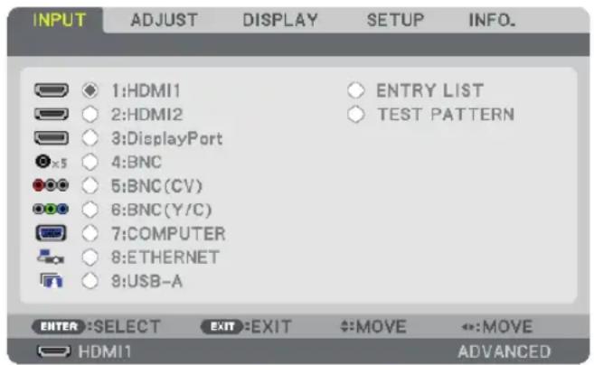
1:HDMI1
This projects the video of the device connected to the HDMI 1 IN terminal.
2:HDMI2
This projects the video of the device connected to the HDMI 2 IN terminal.
3:DisplayPort
This projects the video of the device connected to the Display Port input terminal.
4:BNC
This projects the video of the device connected to the video input terminal.
(This projects the analog RGB signal or component signal.)
5:BNC(CV)
This projects the video of the device connected to the BNC (CV) video input terminal.
(This projects the composite video signal.)
6:BNC(Y/C)
This projects the video of the device connected to the BNC (Y/C) video input terminal.
(This projects the S-video signal.)
7:COMPUTER
This projects the video of the device connected to the computer video input terminal.
(This projects the analog RGB signal or component signal.)
8:ETHERNET
Switch to the data display that is sent from the network.
9:USB-A
Switch to the data display (viewer display) of the USB memory that has been set up in the projector. ( page 211)
ENTRY LIST
Displays a list of signals. See the following pages.
TEST PATTERN
Closes the menu and switches to the test pattern screen.
Using the Entry List
When any source adjustments are made, the adjustments are automatically registered in the Entry List. The (adjustment values of) registered signals can be loaded from the Entry List whenever necessary.
However, only up to 100 patterns can be registered in the Entry List. When 100 patterns have been registered in the Entry List, an error message is then displayed and no additional patterns can be registered. You should thus delete (adjustment values of) signals that are no longer needed.
Displaying the Entry list
1. Press the MENU button.
The menu will be displayed.
2. Press the ◀ or ▶ button to select [INPUT].
The INPUT list will be displayed.
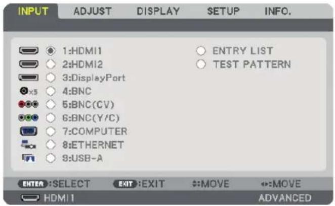
3. Use the ◀, ▶, ▲, or ▼ to select [ENTRY LIST] and press the ENTER button.
The ENTRY LIST windows will be displayed.
If the ENTRY LIST window is not displayed, switch the menu to [ADVANCED].
To switch the menu between [ADVANCED] and [BASIC], select [SETUP] → [CONTROL] → [TOOLS] → [ADMINISTRATOR MODE] → [MENU MODE]. (→ page 112)
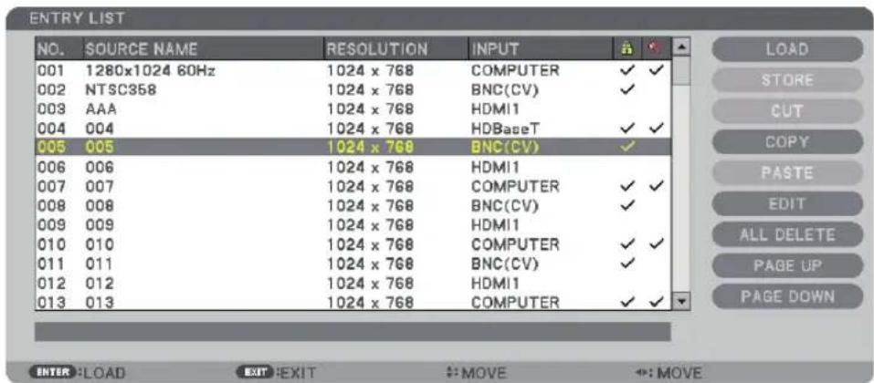
Entering the currently projected signal into the Entry List [STORE]
- Press the ▲ or ▼ button to select any number.
- Press the ◀ or ▶ button to select [STORE] and press the ENTER button.
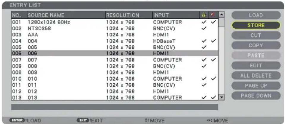
Calling up a signal from the Entry List [LOAD]
Press the ▲ or ▼ button to select a signal and press the ENTER button.
Editing a signal from the Entry List [EDIT]
- Press the ▲ or ▼ button to select a signal you wish to edit.
- Press the ◀, ▶, ▲, or ▼ button to select [EDIT] and press the ENTER button.
The Edit window will be displayed.
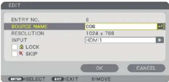
| SOURCE NAME Enter a | signal name. Up to 18 alphanumeric characters can be used. |
| INPUT | The input terminal can be changed. The input terminal may be switched to HDMI1/HDMI2/Display Port/BNC/BNC(CV)/BNC(Y/C)/COMPUTER/ETHERNET. |
| LOCK | Set so that the selected signal cannot be deleted when [ALL DELETE] is executed. The changes made after LOCK execution cannot be saved. |
| SKIP Set so that the selected signal will be skipped during auto search. | |
3. Set the above items and select [OK] and press the ENTER button.
NOTE: The input terminal cannot be changed to the currently projected signal.
Cutting a signal from the Entry List [CUT]
- Press the ▲ or ▼ button to select a signal you wish to delete.
- Press the ◀, ▶, ▲, or ▼ button to select [CUT] and press the ENTER button.
The signal will be deleted from the Entry List and the deleted signal will be displayed on the clipboard at the bottom of the Entry List.
NOTE:
- The currently projected signal cannot be deleted.
- When the locked signal is selected, it will be displayed in gray which indicates it is not available.
TIP:
- Data on the clipboard can be passed onto the Entry List.
- Data on the clipboard will not be lost after the Entry List is closed.
Copying and pasting a signal from the Entry List [COPY] / [PASTE]
- Press the ▲ or ▼ button to select a signal you wish to copy.
- Press the ◀, ▶, ▲, or ▼ button to select [COPY] and press the ENTER button.
The copied signal will be displayed on the clipboard at the bottom of the Entry List.
- Press the ◀ or ▶ button to move to the list.
- Press the ▲ or ▼ button to select a signal.
- Press the ◀, ▶, ▲, or ▼ button to select [PASTE] and press the ENTER button.
Data on the clipboard will be pasted to the signal.
Deleting all the signals from the Entry List [ALL DELTE]
- Press the ◀, ▶, ▲, or ▼ button to select [ALL DELETE] and press the ENTER button.
The confirmation message will be displayed.
- Press the ◀ or ▶ button to select [YES] and press the ENTER button.
NOTE: The locked signal cannot be deleted.
⑤ Menu Descriptions & Functions [ADJUST]
[PICTURE]
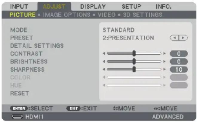
[MODE]
This function allows you to determine how to save settings for [DETAIL SETTINGS] of [PRESET] for each input.
STANDARD.....Saves settings for each item of [PRESET] (Preset 1 through 7)
PROFESSIONAL......Saves all the settings of [PICTURE] for each input.
NOTE:
- When [TEST PATTERN] is displayed, [MODE] cannot be selected.
[PRESET]
This function allows you to select optimized settings for your projected image.
You can adjust neutral tint for yellow, cyan or magenta.
There are seven factory presets optimized for various types of images. You can also use [DETAIL SETTINGS] to set user adjustable settings to customize each gamma or color.
Your settings can be stored in [PRESET 1] to [PRESET 7].
HIGH-BRIGHT......Recommended for use in a brightly lit room.
PRESENTATION......Recommended for making a presentation using a PowerPoint file.
VIDEO......Recommended for typical TV program viewing.
MOVIE......Recommended for movies.
GRAPHIC......Recommended for graphics.
sRGB......Standard color values
DICOM SIM......Recommended for DICOM simulation format.
NOTE:
- The [DICOM SIM.] option is for training/reference only and should not be used for actual diagnosis.
• DICOM stands for Digital Imaging and Communications in Medicine. It is a standard developed by the American College of Radiology (ACR) and the National Electrical Manufacturers Association (NEMA).
The standard specifies how digital image data can be moved from system to system.
[DETAIL SETTINGS]
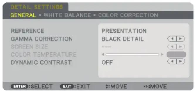
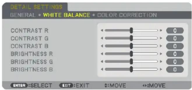
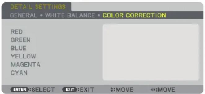
[GENERAL]
Storing Your Customized Settings [REFERENCE]
This function allows you to store your customized settings in [PRESET 1] to [PRESET 7].
First, select a base preset mode from [REFERENCE], then set [GAMMA CORRECTION] and [COLOR TEMPERATURE].
HIGH-BRIGHT......Recommended for use in a brightly lit room.
PRESENTATION......Recommended for making a presentation using a PowerPoint file.
VIDEO......Recommended for typical TV program viewing.
MOVIE......Recommended for movies.
GRAPHIC......Recommended for graphics.
sRGB......Standard color values.
DICOM SIM......Recommended for DICOM simulation format.
Selecting Gamma Correction Mode [GAMMA CORRECTION]
Each mode is recommended for:
DYNAMIC......Creates a high-contrast picture.
NATURAL....Natural reproduction of the picture.
BLACK DETAIL.....Emphasizes detail in dark areas of the picture.
NOTE: This function is not available when [DICOM SIM.] is selected for [DETAIL SETTINGS].
Selecting Screen Size for DICOM SIM [SCREEN SIZE]
This function will perform gamma correction appropriate for the screen size.
LARGE......For screen size of 150"
MEDIUM......For screen size of 100"
SMALL......For screen size of 50"
NOTE: This function is available only when [DICOM SIM.] is selected for [DETAIL SETTINGS].
Adjusting Color Temperature [COLOR TEMPERATURE]
This option allows you to select the color temperature of your choice.
A value between 5000 K and 10500 K can be set in 100 K units.
NOTE: When [PRESENTATION] or [HIGH-BRIGHT] is selected in [REFERENCE], this function is not available.
Adjusting Brightness and Contrast [DYNAMIC CONTRAST]
When set, the most optimal contrast ratio is adjusted according to the video.
OFF......Dynamic contrast is disabled.
MOTION IMAGE......Most optimal settings for moving images.
STILL IMAGE......Most optimal settings for static images. Rapidly follows any changes in the video.
NOTE:
- Depending on the conditions, projector settings such as [DYNAMIC CONTRAST] may not be able to be selected.
Adjusting White Balance [WHITE BALANCE]
This allows you to adjust the white balance. Contrast for each color (RGB) to adjust the white level of the screen; Brightness for each color (RGB) is used to adjust the black level of the screen.
[COLOR CORRECTION]
Corrects the color for all signals.
Adjusts the tone for the colors red, green, blue, yellow, magenta and cyan.
| RED HUE + Direction Magenta direction | Direction | ||
| Direction Yellow direction | |||
| SATURATION + Direction Vivid | |||
| Direction Weak | |||
| GREEN HUE + Direction Yellow direction | Direction | ||
| Direction Cyan direction | |||
| SATURATION + Direction Vivid | |||
| Direction Weak | |||
| BLUE HUE + Direction Cyan direction | |||
| Direction Magenta direction | |||
| SATURATION + Direction Vivid | |||
| Direction Weak | |||
| YELLOW HUE + Direction Red direction | |||
| Direction Green direction | |||
| SATURATION + Direction Vivid | |||
| Direction Weak | |||
| MAGENTA HUE + Direction Blue direction | |||
| Direction Red direction | |||
| SATURATION + Direction Vivid | |||
| Direction Weak | |||
| CYAN HUE + Direction Green direction | |||
| Direction Blue direction | |||
| SATURATION + Direction Vivid | |||
| Direction Weak | |||
[CONTRAST]
Adjusts the intensity of the image according to the incoming signal.
[BRIGHTNESS]
Adjusts the brightness level or the back raster intensity.
[SHARPNESS]
Controls the detail of the image.
[COLOR]
Increases or decreases the color saturation level.
[HUE]
Varies the color level from +/- green to +/- blue. The red level is used as reference.
| Input signal CONTRAST BRIGHTNESS SHARPNESS COLOR HUE | ||||
| RGB system of “COMPUTER/DisplayPort/HDMI | Yes Yes Yes No No | |||
| COMPONENT system of “COMPUTER/DisplayPort/HDMI | Yes Yes Yes Yes Yes | |||
| Composite Video/S-Video Yes Yes Yes Yes | ||||
| USB-A, ETHERNET Yes Yes Yes No No |
Yes = Adjustable, No = Not adjustable
NOTE:
- When [TEST PATTERN] is displayed, [CONTRAST], [BRIGHTNESS], [SHARPNESS], [COLOR] and [HUE] cannot be adjusted.
[RESET]
The settings and adjustments for [PICTURE] will be returned to the factory settings with the exception of the following; Preset numbers and [REFERENCE] within the [PRESET] screen.
The settings and adjustments under [DETAIL SETTINGS] within the [PRESET] screen that are not currently selected will not be reset.
[IMAGE OPTIONS]
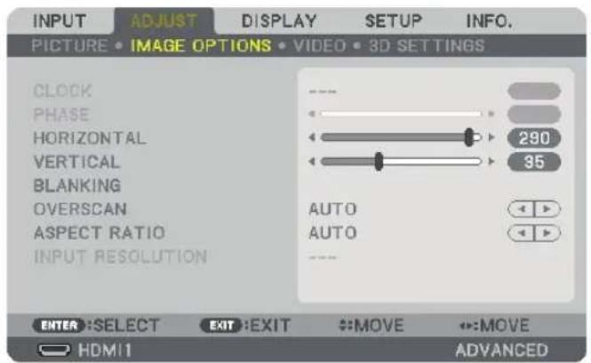
Adjusting Clock and Phase [CLOCK/PHASE]
This allows you to manually adjust CLOCK and PHASE.
![RICOH PJ X6181N - Adjusting Clock and Phase [CLOCK/PHASE] - 1](/content/2026/05/872418/images/71af6b2db0d2c8dc58e145aca04c499266054eadfd004276e69cf3bf74ca3a07.jpg)
natural_image
Two-step diagram showing a circle and triangle shapes before and after transformation, with no text or symbols present.CLOCK.....Use this item to fine tune the computer image or to remove any vertical banding that might appear. This function adjusts the clock frequencies that eliminate the horizontal banding in the image.
This adjustment may be necessary when you connect your computer for the first time.
![RICOH PJ X6181N - Adjusting Clock and Phase [CLOCK/PHASE] - 2](/content/2026/05/872418/images/9dfe219a81fea3021e5d7532dcab514778d7008023b93d452f79f28fff285663.jpg)
natural_image
Two-step diagram showing transformation from a blank canvas to a gray geometric shapes (circle, square, triangle) on a canvas, with no text or symbols present.PHASE.....Use this item to adjust the clock phase or to reduce video noise, dot interference or cross talk. (This is evident when part of your image appears to be shimmering.)
Use [PHASE] only after the [CLOCK] is complete.
NOTE: The [CLOCK] and [PHASE] items are available for RGB signals only.
Adjusting Horizontal/Vertical Position [HORIZONTAL/VERTICAL]
Adjusts the image location horizontally and vertically.
![RICOH PJ X6181N - Adjusting Horizontal/Vertical Position [HORIZONTAL/VERTICAL] - 1](/content/2026/05/872418/images/edb3f079c87fbd98df9e581e1ef8719b3dae3d23538f06d9eae5a17a9fbf73bb.jpg)
flowchart
graph TD
    A["Rectangle with circles and triangles"] --> B["Rectangle with circles and triangles"]
    C["Rectangle with circles and triangles"] --> D["Rectangle with circles and triangles"]
- An image can be distorted during the adjustment of [CLOCK] and [PHASE]. This is not malfunction.
- The adjustments for [CLOCK], [PHASE], [HORIZONTAL], and [VERTICAL] will be stored in memory for the current signal. The next time you project the signal with the same resolution, horizontal and vertical frequency, its adjustments will be called up and applied.
To delete adjustments stored in memory, from the menu, you select [RESET] → [CURRENT SIGNAL] and reset the adjustments.
[BLANKING]
Adjusts the display range (blanking) at the top, bottom, left and right edges of the input signal.
![RICOH PJ X6181N - [BLANKING] - 1](/content/2026/05/872418/images/29f8d52cb51a2f1346ed3702a7ae6700bd9b1f95540c6ed86acb3aa847912198.jpg)
natural_image
Pure geometric diagram with a circle inside a square frame and directional arrows, no text or symbols present.Selecting Overscan Percentage [OVERSCAN]
Select overscan percentage (Auto, 0%, 5% and 10%) for signal.
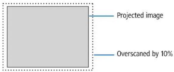
NOTE:
• The [OVERSCAN] item is not available:
- when [NATIVE] is selected for [ASPECT RATIO].
Selecting the Aspect Ratio [ASPECT RATIO]
Use this function to select the screen's vertical:horizontal aspect ratio.
Select the screen type (4:3 screen, 16:9 screen or 16:10 screen) at the screen setting before setting the aspect ratio. (→ page 112)
The projector automatically identifies the signal being input and sets the optimum aspect ratio.
For Computer signal
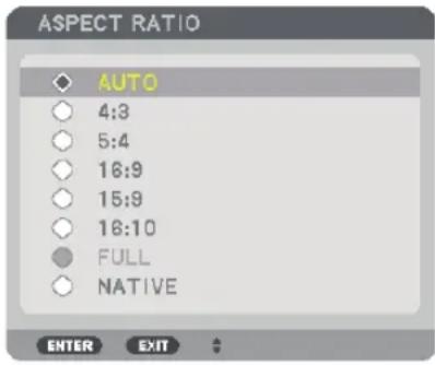
For Component/Video/S-Video signals
When the screen type is set to 4:3 When the screen type is set to 16:9 or 16:10
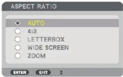
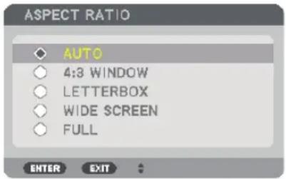
| Resolution Aspect Ratio | |||
| VGA 640 480 4:3 | |||
| SVGA 800 600 4:3 | |||
| XGA 1024 768 4:3 | |||
| WXGA 1280 768 15:9 | |||
| WXGA 1280 800 16:10 | |||
| HD(FWXGA) 1366 | 768 approx. 16:9 | ||
| WXGA+ 1440 900 16:10 | |||
| SXGA | 1280 | 1024 | 5:4 |
| SXGA+ | 1400 | 1050 | 4:3 |
| WXGA++ | 1600 | 900 16:9 | |
| UXGA | 1600 | 1200 4:3 | |
| WSXGA+ | 1680 | 1050 | 16:10 |
| FHD(1080P) | 1920 | 1080 | 16:9 |
| WUXGA | 1920 | 1200 | 16:10 |
| WQXGA | 2560 | 1600 | 16:10 |
| Options | Function |
| AUTO | The projector will automatically determine the incoming signal and display it in its aspect ratio.The projector may erroneously determine the aspect ratio depending on its signal. If this occurs, select the appropriate aspect ratio from the following. |
| 4:3 The image is displayed in 4:3 aspect ratio. | |
| 5:4 The image is displayed in 5:4 aspect ratio | |
| 16:9 | The image is displayed in 16:9 aspect ratio |
| 15:9 | The image is displayed in 15:9 aspect ratio |
| Options Function | |
| 16:10 The image is displayed in 16:10 aspect ratio | |
NATIVE The projector displays the current image in its true resolution when the incoming computer signal has a lower or higher resolution than the projector's native resolution. (→ page 2)When the incoming computer signal has a higher resolution than the projector's native resolution, the center of an image will be displayed.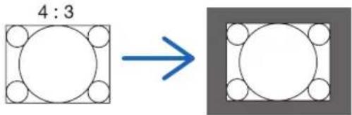 | |
| LETTER BOX | The image of a letterbox signal (16:9) is stretched equally in the horizontal and vertical directions to fit the screen.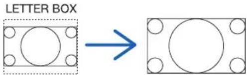 |
WIDE SCREEN The image of a squeeze signal(16:9) is stretched left and right in 16:9.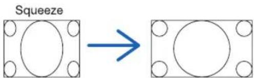 | |
ZOOM The image of a squeeze signal (16:9) is stretched left and right in 4:3.Parts of the displayed image are cropped at the left and right edges and therefore not visible.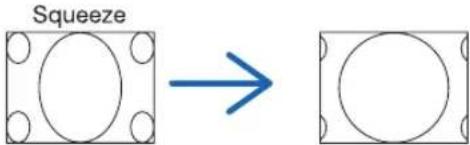 | |
| FULL Project to full screen size. | |
TIP:
- Image position can be adjusted vertically using [POSITION] when the [16:9], [15:9], or [16:10] aspect ratios are selected.
- The term "letterbox" refers to a more landscape-oriented image when compared to a 4:3 image, which is the standard aspect ratio for a vide source.
The letterbox signal has aspect ratios with the vista size "1.85:1" or cinema scope size "2.35:1" for movie film.
- The term "squeeze" refers to the compressed image of which aspect ratio is converted from 16:9 to 4:3.
[INPUT RESOLUTION]
The resolution is assigned automatically when the resolution of the input signal from the computer video input terminal or BNC video input terminal (analog RGB) cannot be distinguished.
[VIDEO]
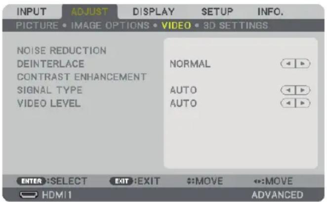
Using Noise Reduction [NOISE REDUCTION]
When projecting a video image, you can use the [NOISE REDUCTION] function to reduce the screen noise (roughness and distortion). This device is equipped with three types of noise reduction functions. Select the function according to the type of noise. Depending on the noise level, the noise reduction effect can be set to [OFF], [LOW], [MEDIUM] or [HIGH]. [NOISE REDUCTION] can be selected for SDTV, HDTV signal and component signal input.
RANDOM NR......Reduces flickering random noise in an image.
MOSQUITO NR......Reduces mosquito noise that appears around the edges of an image during Blu-ray playback.
BLOCK NR......Reduces block noise or mosaic-like patterns by selecting ON.
Selecting Interlaced Progressive Conversion Process Mode [DEINTERLACE]
This function allows you to select an interlaced-to-progressive conversion process for video signals.
NORMAL......Automatically distinguishes a moving image from a static image to create a distinct image. Please select [MOVIE] if there are any obvious jitter and noises.
MOVIE......Select when projecting moving images. This is suitable for signals with a lot of jitter and noise.
STILL......Select when projecting static images. The video will flicker when a moving image is projected.
NOTE: This function is not available with RGB signals.
[CONTRAST ENHANCEMENT]
Using the characteristics of the human eye, a picture quality with a sense of contrast and resolution is achieved.
OFF.....Suite vision is switched off.
AUTO......Contrast and picture quality are automatically improved using the suite vision function.
NORMAL.....Adjust the gain manually.
[SIGNAL TYPE]
Selection of RGB and component signals. Normally, this is set to [AUTO]. Please change the setting if the color of the image remains unnatural.
AUTO.....Automatically distinguishes RGB and component signals.
RGB....Switches to the RGB input.
COMPONENT ......Switches to the component signal input.
[VIDEO LEVEL]
Selection of the video signal level when connecting an external device to the HDMI 1 IN terminal, HDMI 2 IN terminal, DisplayPort input terminal of the projector.
AUTO......The video level is switched automatically based on the information from the device outputting the signal.
Depending on the connected device, this setting may not be made properly. In this case, switch to [NORMAL" or "ENHANCED" from the menu and view with the optimum setting.
NORMAL......This disables the enhanced mode.
ENHANCED......This improves the image's contrast, expressing the dark and light sections more dynamically.
SUPER WHITE......The video contrast is improved and the dark areas appear more dynamic.
[3D SETTINGS]
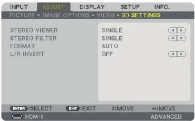
Please refer to "3-8 Projecting 3D videos" (→ page 39) for the operation.
STEREO VIEWER
Stack up a single or multiple projectors and carry out the settings for projecting 3D videos. Select the left / right settings of the 3D eyewear using the stereo viewer.
SINGLE Use a single projector to project 3D videos.
DUAL LEFT Use a dedicated projector for displaying videos on the left.
DUAL RIGHT Use a dedicated projector for displaying videos on the right.
STEREO FILTER
Stack up a single or multiple projectors and carry out the settings for projecting 3D videos. Image setting for 3D glasses made by Infitec.
SINGLE Use a single projector to project 3D videos.
DUAL LEFT Use a dedicated projector for displaying videos on the left.
DUAL RIGHT Use a dedicated projector for displaying videos on the right.
FORMAT
Select the 3D video format (recording / transmission format). Select to match the 3D broadcast and 3D media. Normally, [AUTO] is selected. Please select the 3D input signal format when the 3D detection signal of the format cannot be distinguished.
L/R INVERT
Invert the display order of the left and right videos.
Select [ON] if you feel uncomfortable with the 3D display when [OFF] is selected.
6 Menu Descriptions & Functions [DISPLAY]
[PIP/PICTURE BY PICTURE]
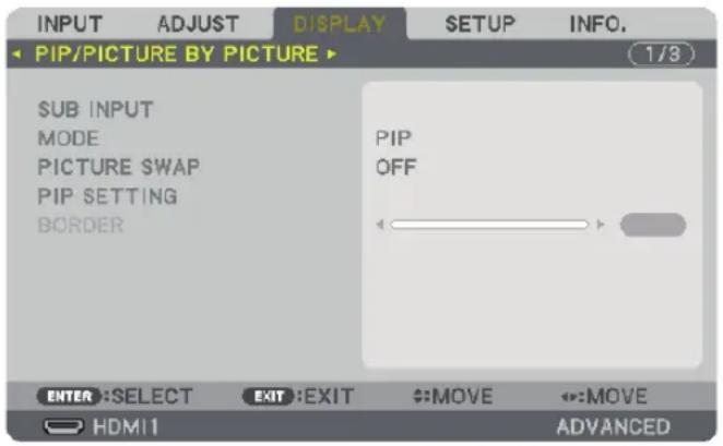
SUB INPUT
Select the input signal to be displayed in the sub-display.
Please refer to "4-2 Displaying Two Pictures at the Same Time" ( page 65) for details on the operation.
MODE
Select either PIP or PICTURE BY PICTURE when switching to 2-screen display.
PICTURE SWAP
The videos in the main display and sub-display will be switched.
Please refer to "4-2 Displaying Two Pictures at the Same Time" ( page 67) for details.
PIP SETTING
Select the display position, position adjustment and size of the sub-display in the PIP screen.
START POSITION.....Selection of the display position of the sub-display when switching to the PIP screen.
HORIZONTAL POSITION
....Adjust the display position of the sub-display in the horizontal direction. The respective corners will serve as reference points.
VERTICAL POSITION
....Adjust the display position of the sub-display in the vertical direction. The respective corners will serve as reference points.
SIZE......Select the display size of the sub-display.
TIP:
The horizontal position and vertical position are the amount of movement from the reference points. For example, when TOP-LEFT is adjusted, the position is displayed with the same amount of movement even if displayed with other starting positions.
The maximum amount of movement is half the resolution of the projector.
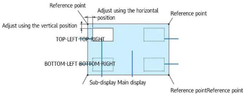
BORDER
Select the display boundary of the main display and sub-display of the [PICTURE BY PICTURE] screen.
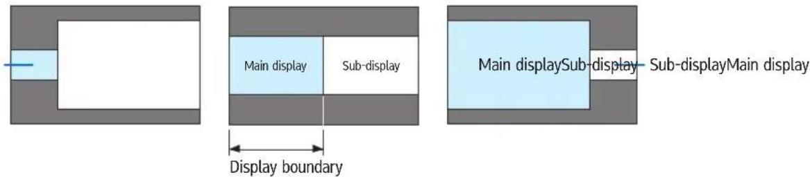
TIP:
- For WUXGA type, six steps can be selected.
- For WXGA type/XGA type, three steps can be selected.
[GEOMETRIC CORRECTION]
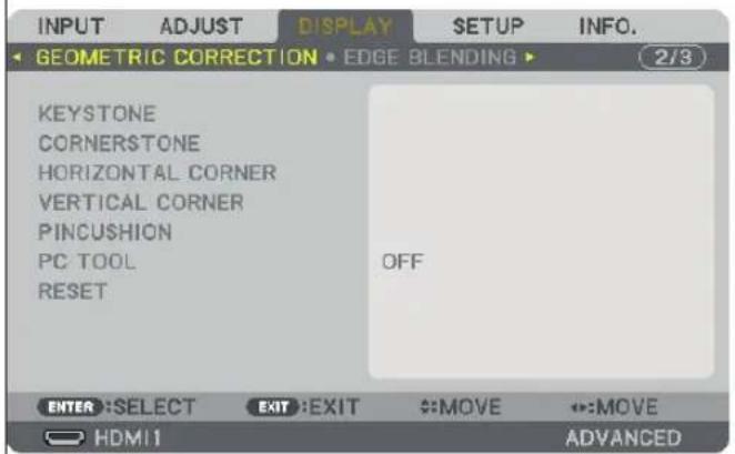
KEYSTONE
Display the trapezoid correction screen and adjust the trapezoidal distortion of the projection screen.
To display the [KEYSTONE] screen, select → [DISPLAY] → [GEOMETRIC CORRECTION] → [KEYSTONE] in the on-screen menu. The [GEOMETRIC CORRECTION] screen can also be displayed by pressing the Geometric. button on the remote control.
HORIZONTAL....Adjustments when projecting from a diagonal direction to the screen.
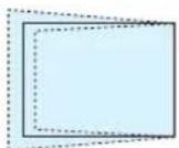
VERTICAL....Adjustments when projecting from the top or bottom direction to the screen.
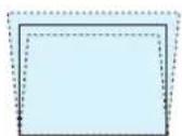
TILT....Adjusts the distortion when performing trapezoidal correction with the screen moved in the vertical direction using the lens shift.
THROW RATIO.....Adjusts according to the projection ratio of the optional lens used.
| Model name of lens unit Adjustment range | |
| Replacement Lens Type1 8 | |
| Replacement Lens Type8 8-10 | |
| Replacement Lens Type2 12-15 | |
| Standard Lens Type1 15-30 | |
| Replacement Lens Type3 29-47 | |
| Replacement Lens Type4 46-71 | |
NOTE:
- When power is supplied to the device, the adjustment value of the [KEYSTONE] used previously is retained even if the gradient of the device is changed.
- When clearing the adjustment value of [KEYSTONE], press the Geometric. button for 2 or more seconds.
- When setting other [GEOMETRIC CORRECTION] functions, the [KEYSTONE] menu cannot be selected. When performing trapezoidal correction, press the Geometric button for 2 or more seconds to clear the adjustment value of [GEOMETRIC CORRECTION].
As electrical correction is carried out by [KEYSTONE], the brightness may be reduced or the screen quality may deteriorate sometimes.
CORNERSTONE
Display the 4-point correction screen and adjust the trapezoidal distortion of the projection screen.
Please refer to "Correcting Horizontal and Vertical Keystone Distortion [CORNERSTONE]" (→ page 33) for details on the operation.
HORIZONTAL CORNER/VERTICAL CORNER
Distortion correction for corner projection such as wall surfaces.
HORIZONTAL CORNER
......Performs correction for projection onto a wall lying at an angle to the horizontal direction.
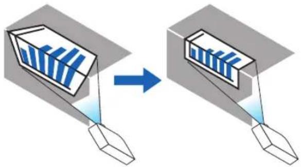
natural_image
Diagram showing two 3D geometric shapes with blue vertical bars inside, connected by a blue arrow (no text or symbols)* Reverse angle correction is also possible.
VERTICAL CORNER
......Performs correction for projection onto a wall lying at an angle to the vertical direction.
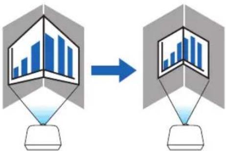
flowchart
graph TD
    A["3D Model with Bar Chart"] --> B["2D Model with Bar Chart"]
    style A fill:#f9f,stroke:#333
    style B fill:#bbf,stroke:#333
* Reverse angle correction is also possible.
NOTE:
- When the maximum adjustment range is exceeded, distortion adjustment is disabled. Set up the projector at an optimal angle as the deterioration in the image quality increases as the distortion adjustment volume gets larger.
- Please note that the image will go out of focus due to the difference in the distance between the upper and lower or left and right sides and the center of the screen for projections cutting across corners. Lenses with short focal points are also not recommended for projections cutting across corners as the image will go out of focus.
Adjustment method
- Align the cursor with the [HORIZONTAL CORNER] or [VERTICAL CORNER] of the [GEOMETRIC CORRECTION] menu and then press the ENTER button.
- The adjustment screen will be displayed.
- Press the ▼▲◀▶ buttons to align the cursor (yellow box) with the target adjustment point and then press the ENTER button.
- The cursor will change into an adjustment point (yellow in color).
- Press the ▼▲◀▶ buttons to adjust the corners or sides of the screen and then press the ENTER button.
- The adjustment point will go back to being a cursor (yellow box).
Explanation of screen transition
- The adjustment points of the four corners (a, c, f and h in the drawing) will move independently.
- The following adjustment points differ at the [HORIZONTAL CORNER] and [VERTICAL CORNER].
HORIZONTAL CORNER: When Point b in the drawing is moved, and the upper side and Point g are moved, the lower side will move in a parallel manner.
VERTICAL CORNER: When Point d in the drawing is moved, and the left side and Point e are moved, the right side will move in a parallel manner.
[Adjustment points of the [HORIZONTAL CORNER] screen and movement points of the projection screen]
Point b will be displaced in a parallel manner at the same time as Points a, b, c
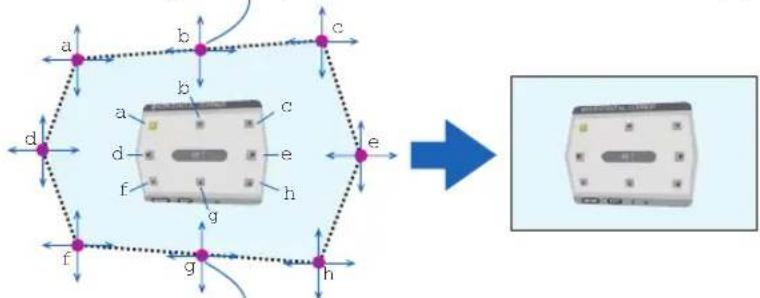
flowchart
graph TD
    A["a"] --> B["b"]
    B --> C["c"]
    D["d"] --> E["e"]
    E --> F["h"]
    G["f"] --> H["g"]
    H --> I["h"]
    J["b"] --> K["c"]
    K --> L["d"]
    M["e"] --> N["h"]
    N --> O["g"]
    P["f"] --> Q["h"]
    Q --> R["g"]
    S["d"] --> T["h"]
    T --> U["g"]
    V["b"] --> W["c"]
    W --> X["d"]
    Y["c"] --> Z["e"]
    AA["a"] --> AB["b"]
    AC["d"] --> AD["e"]
    AE["f"] --> AF["h"]
    AG["g"] --> AH["h"]
    AI["h"] --> AJ["Output"]
Point g will be displaced in a parallel manner at the same time as Points f, g, h
[Adjustment points of the [VERTICAL CORNER] screen and movement points of the projection screen]
Point d will be displaced in a parallel manner at the same time as Points a, d, f
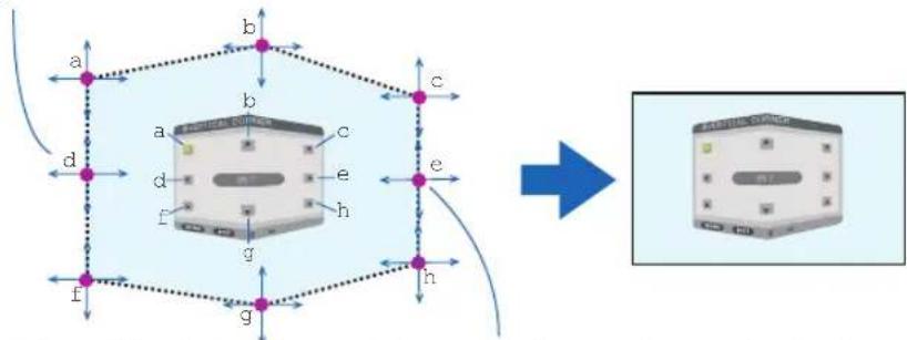
flowchart
graph TD
    A["3D Cube with dimensions a, b, c, d, e, f, g"] --> B["Transformation Process"]
    B --> C["Electronic Device"]
Point e will be displaced in a parallel manner at the same time as Points f, g, h
-
Start from Step 2 onwards to adjust the other points.
-
When the adjustment is completed, press the ▼▲◀▶ buttons to align the cursor with the [EXIT] in the adjustment screen and then press the ENTER button.
- Switch to the [GEOMETRIC CORRECTION] menu screen.
PINCUSHION
Adjust the curve distortion of the projection screen.
TOP....Adjust the curve distortion of the upper edge of the projection screen.
BOTTOM....Adjust the curve distortion of the lower edge of the projection screen.
LEFT....Adjust the curve distortion of the left edge of the projection screen.
RIGHT....Adjust the curve distortion of the right edge of the projection screen.
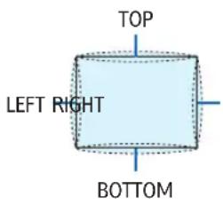
PC TOOL (For future support)
Recall the geometric correction data that is registered in the projector beforehand.
There are three types of registered data.
NOTE:
- KEYSTONE, CORNERSTONE, and PINCUSHION cannot be selected when setting the geometric correction using a PC tool.
- To clear the [GEOMETRIC CORRECTION] data that has been set up, press the Geometric. button for 2 or more seconds.
- As electrical correction is carried out in geometric correction, the brightness may be affected and the picture quality may be degraded.
RESET
Reset the adjustment value that has been set up in GEOMETRIC CORRECTION (return to the initial value).
[EDGE BLENDING]
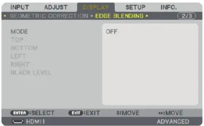
This adjusts the edges (boundaries) of the projection screen when projecting high resolution videos using a combination of several projectors in the up, down, left and right positions.
MODE
This enables or disables the EDGE BLENDING function.
When MODE is set to ON, the TOP, BOTTOM, LEFT, RIGHT and BLACK LEVEL settings can be adjusted.
TOP/BOTTOM/LEFT/RIGHT
This selects the EDGE BLENDING locations on the left, right, top and bottom on the screen.
The following settings can be adjusted when an item is selected. ( page 69)
CONTROL......Enable TOP, BOTTOM, LEFT and RIGHT functions.
MARKER.....Set whether to display marker or not when adjusting the range and display position. When turned on, a magenta marker for adjusting the range adjustment and a green marker for adjusting the display position will be displayed.
RANGE.....Adjust the range (width) of the edge blending.
POSITION.....Adjust the display position of the edge blending.
BLACK LEVEL
Divide the screen into nine parts and keep the black level uniform for each projector.
The nine divisions screens are TOP-LEFT, TOP-CENTER, TOP-RIGHT, CENTER-LEFT, CENTER, CENTER-RIGHT, BOTTOM-LEFT, BOTTOM-CENTER and BOTTOM-RIGHT. ( page 73)
[MULTI SCREEN]
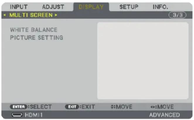
WHITE BALANCE
This adjusts the white balance for each projector when projecting using a combination of several projectors.
This can be adjusted when [MODE] is set to [ON].
....Adjusting the black color of the video.
CONTRAST W, CONTRAST R, CONTRAST G, CONTRAST B
....Adjusting the white color of the video.
PICTURE SETTING
This sets the division condition when projecting using a combination of several projectors.
Please refer to "4. Multi-Screen Projection" ( page 61) for details.
| MODE OFF Use the projector in a standalone state. | |
| ZOOM This adjusts the position and width of the video area that you wish to divide. The edge blending width will also be automatically set to that width. | |
| TILING This assigns the divided screens to the projectors. The edge blending function will also be set automatically. | |
| ZOOM HORIZONTAL | This enlarges the video area in the horizontal direction. |
| VERTICAL ZOOM This enlarges the video area in the vertical direction. | |
| HORIZONTAL POSITION This shifts the video area in the horizontal direction. | |
| VERTICAL POSITION This shifts the video area in the vertical direction. | |
| TILING WIDTH This selects the number of projectors to be arranged horizontally. | |
| HEIGHT This selects the number of projectors to be arranged vertically. | |
| HORIZONTAL POSITION This selects the position of the projector starting from the left among those arranged horizontally. | |
| VERTICAL POSITION This selects the position of the projector starting from the top among those arranged vertically. | |
Conditions for using tiling
- All the projectors need to fulfil the following conditions.
- The panel size must be the same
- The projection screen size must be the same
- The left and right ends or top and bottom ends of the projection screen must be consistent.
- The settings for the left and right edges of the edge blending are the same
- The settings for the top and bottom edges of the edge blending are the same
If the tiling conditions are satisfied, the video screen of the projector at each installation position will be automatically extracted and projected.
If the tiling conditions are not satisfied, adjust the video screen of the projector at each installation position using the zoom function.
- Assign a unique control ID to each projector.
- Set the "Color setting" and "DeepColor setting" on your Blu-ray player or computer to "Auto". Refer to the owner's manual accompanied with your Blu-ray player or computer for more information. Connect an HDMI output of your Blu-ray player or computer to the first projector and then connect to the HDMI1 or HDMI2 input connector of the second and subsequent projectors.
Tiling setting example) Number of horizontal units = 2, Number of vertical units = 2
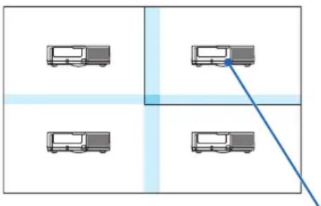
flowchart
graph TD
    A["Bus Station 1"] --> B["Bus Station 2"]
    C["Bus Station 3"] --> D["Bus Station 4"]
    E["Bus Station 5"] --> F["Bus Station 6"]
    G["Bus Station 7"] --> H["Bus Station 8"]
    I["Bus Station 9"] --> J["Bus Station 10"]
Horizontal order = Second unit
Vertical order = First unit
⑦ Menu Descriptions & Functions [SETUP]
[MENU]
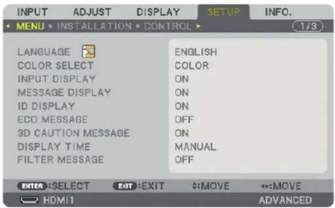
Selecting Menu Language [LANGUAGE]
![RICOH PJ X6181N - Selecting Menu Language [LANGUAGE] - 1](/content/2026/05/872418/images/fba28c48e0f081ea4dbf2e65f59e8a1cf6704a4fa173108c6d3b442690d63e55.jpg)
You can choose one of 29 languages for on-screen instructions.
NOTE: Your setting will not be affected even when [RESET] is done from the menu.
Selecting Menu Color [COLOR SELECT]
You can choose between two options for menu color: COLOR and MONOCHROME.
Turning On / Off Source Display [INPUT DISPLAY]
This option turns on or off input name display such as HDMI1, HDMI2, DisplayPort, BNC, BNC(CV), BNC(Y/C), COMPUTER to be displayed on the top right of the screen.
Turning messages on and off [MESSAGE DISPLAY]
This option selects whether or not to display projector messages at the bottom of the projected image.
Even when "OFF" is selected, the security lock warning is displayed. The security lock warning turns off when the security lock is canceled.
Turning ON/OFF Control ID [ID DISPLAY]
ID DISPLAY......This option turns on or off the ID number which is displayed when the ID SET button on the remote control is pressed. (→ page 118)
Turning On / Off Eco Message [ECO MESSAGE]
This option turns on or off the following messages when the projector is turned on.
The Eco Message prompts the user to save energy. When [OFF] is selected for [ECO MODE], you will get a message to prompt you to select [ON] for [ECO MODE].
When [ON] is selected for [ECO MODE]
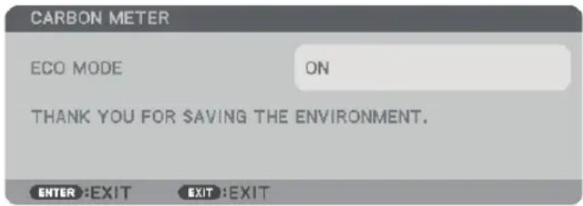
To close the message, press any one of the buttons. The message will disappear if no button operation is done for 30 seconds.
When [OFF] is selected for [ECO MODE]
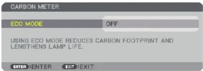
Pressing the ENTER button will display the [ECO MODE] screen. (→ page 31)
To close the message, press the EXIT button.
[3D CAUTION MESSAGE]
This selects whether to display a caution message or not when switching to a 3D video. The default condition when shipped from the factory is ON.
OFF......The 3D caution message screen will not be displayed.
ON......The 3D caution message screen will be displayed when switching to a 3D video. Press the ENTER button to cancel the message.
- The message will disappear automatically after 60 seconds or when other buttons are pressed. If it disappears automatically, the 3D caution message will be displayed again when switching to a 3D video.
Selecting Menu Display Time [DISPLAY TIME]
This option allows you to select how long the projector waits after the last touch of a button to turn off the menu. The preset choices are [MANUAL], [AUTO 5 SEC], [AUTO 15 SEC], and [AUTO 45 SEC]. The [AUTO 45 SEC] is the factory preset.
Selecting Interval Time for Filter Message [FILTER MESSAGE]
This option allows you to select the time preference between displaying the message for cleaning the filters. Clean the filter when you get the message "PLEASE CLEAN FILTER." (→ page 171)
Five options are available: OFF, 100[H], 500[H], 1000[H], 2000[H]
The default setting is [OFF].
NOTE: Your setting will not be affected even when [RESET] is done from the menu.
[INSTALLATION]
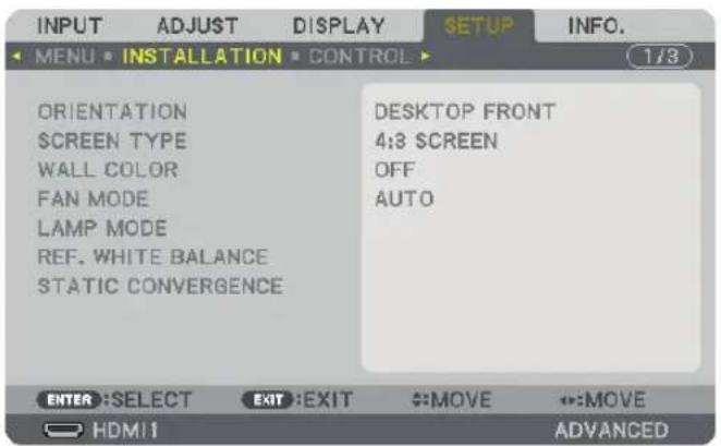
Selecting Projector Orientation [ORIENTATION]
This reorients your image for your type of projection. The options are: desktop front projection, ceiling rear projection, desktop rear projection, and ceiling front projection.
NOTE:
- Please consult the retail store if you require special installation services e.g. when mounting the projector to a ceiling. Never install the projector on your own. This may result in the projector falling down and causing injury to people.
- When using the projector suspended from a ceiling, ensure that people do not stay below the projector. In the event the lamp were to break, there is a risk that glass fragments may fall from the projector.
AUTO....This automatically detects and projects the DESKTOP FRONT and CEILING FRONT.
NOTE:
- The DESKTOP REAR and CEILING REAR will not be detected. Please select manually.
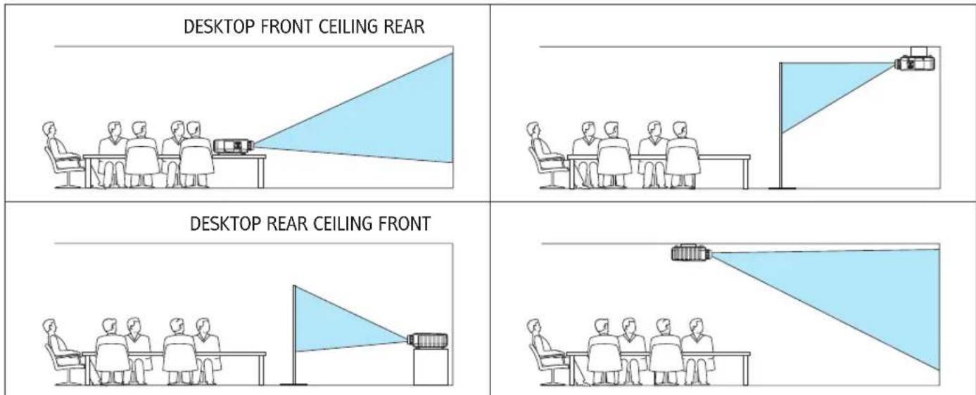
TIP:
- Check whether the automatic DESKTOP FRONT is installed within ± 10 degrees for floor installation and whether the CEILING FRONT is within ± 10 degrees for ceiling installation. Select manually when the projection screen is inverted.
Selecting Aspect Ratio and Position for Screen [SCREEN TYPE]
| Screen type Sets the aspect ratio of the projection screen. | |
| FREE The ratio of the | liquid crystal panel is selected. Select this when projecting multi-screen and 17:9 screen (2K). |
| 4:3 screen For a screen with a 4:3 aspect ratio | |
| 16:9 screen For a screen with a 16:9 aspect ratio | |
| 16:10 screen For a screen with a 16:10 aspect ratio | |
NOTE:
• After changing the screen type, check the setting of [ASPECT RATIO] in the menu. (→ page 93)
Using the Wall Color Correction [WALL COLOR]
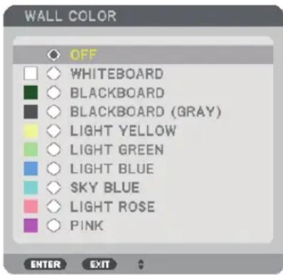
This function allows for quick adaptive color correction in applications where the screen material is not white.
NOTE: Selecting [WHITEBOARD] reduces lamp brightness.
Selecting Fan Mode [FAN MODE]
Fan Mode is used to set the speed of the internal cooling fan.
MODE......Select three modes for fan speed: AUTO, HIGH, and HIGH ALTITUDE.
AUTO: The built-in fans automatically run at a variable speed according to the internal temperature.
HIGH: The built-in fans run at high speed
HIGH ALTITUDE: The built-in fans run at a high speed. Select this option when using the projector at altitudes approximately 5500 feet/1700 meters or higher.
NOTE:
- Make sure the speed is set to [HIGH] when you are using this device continuously for several days.
- Set [FAN MODE] to [HIGH ALTITUDE] when using the projector at altitudes approximately 5500 feet/1700 meters or higher.
- Using the projector at altitudes approximately 5500 feet/1700 meters or higher without setting to [HIGH ALTITUDE] can cause the projector to overheat and the protector could shut down. If this happens, wait a couple minutes and turn on the projector.
- Using the projector at altitudes less than approximately 5500 feet/1700 meters and setting to [HIGH ALTITUDE] can cause the lamp to overcool, causing the image to flicker. Switch [FAN MODE] to [AUTO].
• Using the projector at altitudes approximately 5500 feet/1700 meters or higher can shorten the life of optical components such as the lamp. - Your setting will not be affected even when [RESET] is done from the menu.
TIP:
- When [HIGH ALTITUDE] is selected for [FAN MODE], a symbol icon will be displayed at the bottom of the menu.
[LAMP MODE]
When eco-mode is set to [ON], the CO_2 emissions (calculated from the reduction in power consumption) of the projector can be reduced. The eco-mode reduces power consumption by mainly lowering the brightness of the lamp. As a result, the lamp replacement time (as a guide)* is extended. ( page 31, 131)
* Replacement time not guaranteed.
LAMP ADJUST......This can be set when the eco-mode is set to [OFF]. Adjust the lamp to match the brightness of each projector when projecting a multi-screen display using multiple projectors.
| ECO MODE OFF The | lamp luminance (brightness) will become 100% and the screen will turn bright.The luminance of the lamp can be set using the lamp adjustment. | |
| ON The | lamp luminance (brightness) will become approximately 80% and the lamp replacement time (estimated)* will be extended.* The replacement time is not guaranteed. | |
| LAMP ADJUST When the [ECO | MODE] is set to [OFF], [LAMP ADJUST] is enabled.Adjust the lamp to match the brightness of each projector when projecting a multi-screen display using multiple projectors. | |
[REF. WHITE BALANCE]
This feature allows you to adjust the white balance for all signals.
The white and black levels of the signal are adjusted for optimum color reproduction.
Uniformity is also adjusted when the redness (R) and blueness (B) of the white color in the screen's horizontal (left/right) direction are uneven.
CONTRAST R/CONTRAST G/CONTRAST B
......These adjust the picture's white color.
......These adjust the picture's black color.
UNIFORMITY R......The further this is set to the + side, the stronger the redness on the left side of the picture (increasing towards the left edge) and the weaker the redness on the right side of the picture (decreasing towards the right edge).
This is reversed when set to the - side.
UNIFORMITY B......The further this is set to the + side, the stronger the blueness on the left side of the picture (increasing towards the left edge) and the weaker the blueness on the right side of the picture (decreasing towards the right edge).
This is reversed when set to the - side.
[STATIC CONVERGENCE]
This features allows you to adjust for color deviation in the picture.
This can be adjusted in units of ± 1 pixel in the horizontal direction for HORIZONTAL R, G and B, in the vertical direction for VERTICAL R, G and B.
[CONTROL]
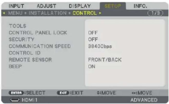
TOOLS
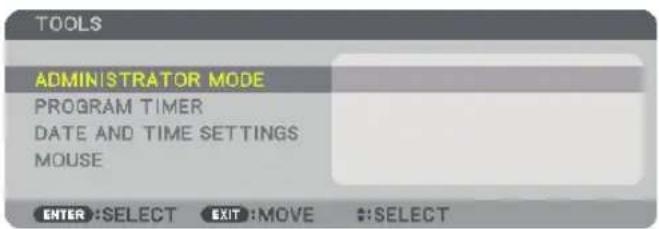
ADMINISTRATOR MODE
This allows you to select MENU MODE, save settings, and set a password for the administrator mode.
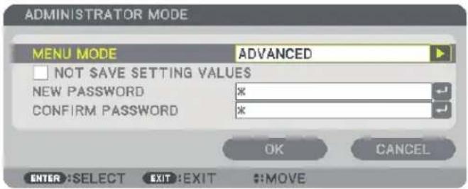
| MENU MODE Select either | [BASIC] or [ADVANCED] menu. (→ page 84) | — |
| NOT SAVE SETTING VALUES | Placing a check mark will not save your projector settings. Clear this check box to save your projector settings. | — |
| NEW PASSWORD/CONFIRM PASSWORD | Assign a password for the administrator mode. Up to 10 alphanumeric | characters |
PROGRAM TIMER
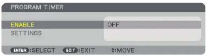
This option turns on/standby the projector and changes video signals, and selects ECO mode automatically at a specified time.
NOTE:
• Before using [PROGRAM TIMER], make sure that the [DATE AND TIME] feature is set. (→ page 115)
Make sure that the projector is in the standby condition with the POWER cord connected.
The projector has a built-in clock. The clock will keep working for about two weeks after the main power is turned off. If the main power is not supplied to the projector for two weeks or more, the built-in clock stops working.
Setting a new program timer
- On the PROGRAM TIMER screen, use the ▲ or ▼ button to select [SETTINGS] and press the ENTER button.
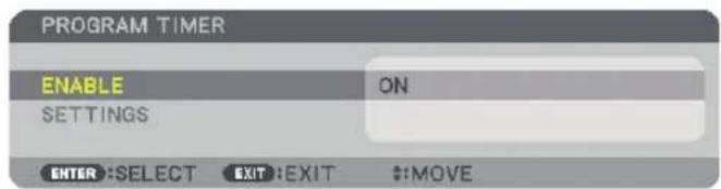
The [PROGRAM LIST] screen will be displayed.
- Select a blank program number and press the ENTER button.
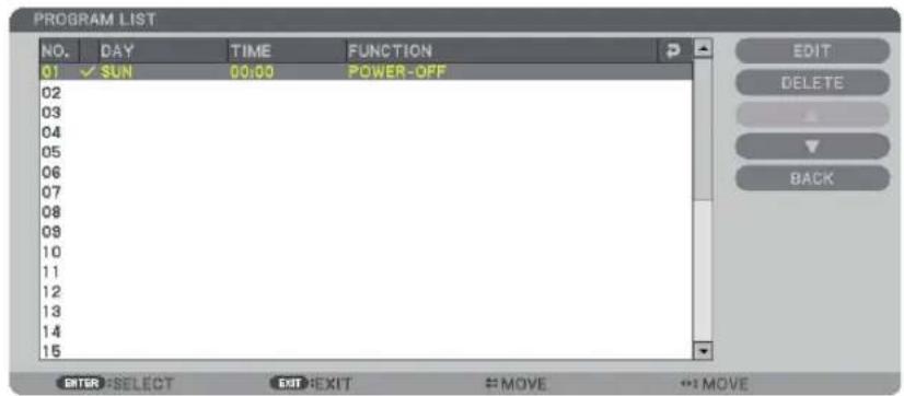
The [EDIT] screen will be displayed.
- Make settings for each item as required.
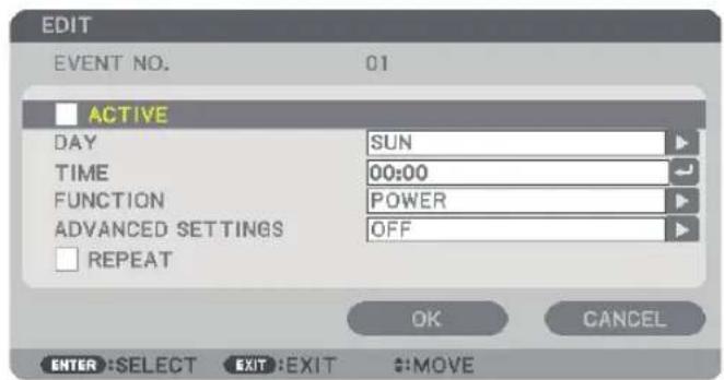
ACTIVE....Place a check mark to enable the program.
DAY....Select days of the week for the program timer. To execute the program from Monday to Friday, select [MON-FRI]. To execute the program in everyday basis, select [EVERYDAY].
TIME....Set the time to execute the program. Enter time in 24-hour format.
FUNCTION......Select a function to be executed. Selecting [POWER] will allow you to turn on or off the projector by setting [ADVANCED SETTINGS]. Selecting [INPUT] will allow you to select a video source by setting [ADVANCED SETTINGS]. Selecting [ECO MODE] will allow you to select [ECO MODE] by setting [ADVANCED SETTINGS].
ADVANCED SETTINGS
......Select power on/off, a type of video source, or ECO MODE for the selected item in [FUNCTION].
REPEAT....Place a check mark to repeat the program continuing basis. To use the program this week only, clear the check mark.
4. Select [OK] and press the ENTER button.
This will complete the settings.
You will be returned to the [PROGRAM LIST] screen.
5. Select [BACK] and press the ENTER button.
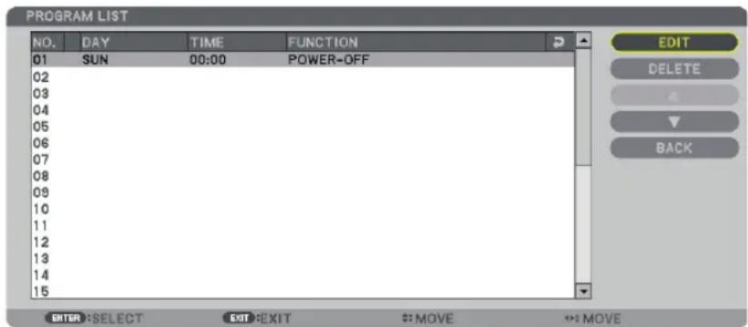
You will be returned to the [PROGRAM TIMER] screen.
6. Press the EXIT button.
You will be returned to the [TOOLS] screen.
NOTE:
- Up to 30 different timer settings can be programmed.
- When [PROGRAM TIMER] is turned on, the [STANDBY MODE] setting is ignored.
- The Program Timer is executed on a set time basis, not in a program basis.
- Once the program not marked with a check in [REPEAT] has been executed, the check mark in the [ACTIVE] check box will be cleared automatically and the program will be disabled.
- When the on-time and the off-time set for the same time, the off-time setting will take preference.
- Two different sources are set for the same time, the larger program number will take preference.
- The on-time setting will not be executed while the cooling fans are running or an error is occurring.
- If the off-time setting is expired under the condition in which the power off is not possible, the off-timer setting will not be executed until the power off becomes possible.
- Programs not marked with a check mark in [ACTIVE] of the [EDIT] screen will not be executed even if the Program Timer is enabled.
- When the projector is turned on by using the program timer and if you want to turn off the projector, set the off-time or do it manually so as not to leave the projector on for a long period of time.
Activating the program timer
- Select [ENABLE] on the [PROGRAM TIMER] screen and press the ENTER button.
The selection screen will be displayed.
- Press the ▼ button to align the cursor with [ON] and then press the ENTER button.
Return to the [PROGRAM TIMER] screen.
NOTE:
- When the effective settings of the [PROGRAM TIMER] have not been set to [ON], the program will not be executed even if the [ACTIVE] items in the program list have been ticked.
• Even when the effective settings of the [PROGRAM TIMER] are set to [ON], the [PROGRAM TIMER] will not work until the [PROGRAM TIMER] screen is closed.
Changing the programmed settings
- On the [PROGRAM LIST] screen, select a program you want to edit and press the ENTER button.
- Change the settings on the [EDIT] screen.
- Select [OK] and press the ENTER button.
The programmed settings will be changed.
You will be returned to the [PROGRAM LIST] screen.
Changing the order of programs
- On the [PROGRAM LIST] screen, select a program whose order you want to change and press the ▶ button.
- Press the ▼ button to select ▲ or ▼.
- Press the ENTER button a few times to select a row to which you wish to move the program.
The order of the programs will be changed.
Deleting the programs
- On the [PROGRAM LIST] screen, select a program number you want to delete and press the ▶ button.
- Press the ▼ button to select [DELETE].
- Press the ENTER button.
The confirmation screen will be displayed.
- Select [YES] and press the ENTER button.
The program will be deleted.
This will complete deleting the program.
DATE AND TIME SETTINGS
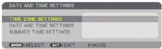
You can set the current time, month, date, and year.
NOTE: The projector has a built-in clock. The clock will keep working for about 2 weeks after the main power is turned off. If the main power is off for 2 weeks or more, the built-in clock will cease. If the built-in clock ceases, set the date and time again. The built-in clock will not cease while in the standby mode.
TIME ZONE SETTINGS......Select your time zone.
DATE AND TIME SETTINGS...... Set your current date (MM/DD/YYYY) and time (HH:MM).
INTERNET TIME SERVER......If you place a check mark, the projector's built-in clock will be synchronized with an Internet time server in every 24 hours and at the time of projector's startup.
UPDATE.... Synchronizes the projector's built-in clock immediately. The UPDATE button is not available unless the INTERNET TIME SERVER check box is turned on.
SUMMER TIME SETTINGS...... If you place a check mark, the clock for daylight saving will be enabled.
[MOUSE]
This function cannot be used in this device. It is used for future expansion purposes only.
Disabling the Cabinet Buttons [CONTROL PANEL LOCK]
This option turns on or off the CONTROL PANEL LOCK function.
NOTE:
• How to cancel the [CONTROL PANEL LOCK]
When the [CONTROL PANEL LOCK] is set to [ON], press the EXIT button or the INPUT button on the main body for about 10 seconds to cancel the [CONTROL PANEL LOCK] setting.
TIP:
- When the [CONTROL PANEL LOCK] is turned on, a key lock icon [ ] will be displayed at the bottom right of the menu.
- This CONTROL PANEL LOCK does not affect the remote control functions.
Enabling Security [SECURITY]
This feature turns on or off the SECURITY function.
Unless the correct keyword is entered, the projector cannot project an image. (→ page 36)
NOTE: Your setting will not be affected even when [RESET] is done from the menu.
Selecting Communication Speed [COMMUNICATION SPEED]
This feature sets the baud rate of the PC Control port (D-Sub 9P). It supports data rates from 4800 to 115200 bps. The default is 38400 bps. Select the appropriate baud rate for your equipment to be connected (depending on the equipment, a lower baud rate may be recommended for long cable runs).
NOTE:
- Select [38400bps] or less when using the supplied software programs.
- Your selected communication speed will not be affected even when [RESET] is done from the menu.
Setting ID to the Projector [CONTROL ID]
You can operate multiple projectors separately and independently with the single remote control that has the CONTROL ID function. If you assign the same ID to all the projectors, you can conveniently operate all the projectors together using the single remote control. To do so, you have to assign an ID number to each projector.
CONTROL ID NUMBER...... Select a number from 1 to 254 you wish to assign to your projector.
CONTROL ID......Select [OFF] to turn off the CONTROL ID setting and select [ON] to turn on the CONTROL ID setting.
NOTE:
- When [ON] is selected for [CONTROL ID], the projector cannot be operated by using the remote control that does not support the CONTROL ID function. (In this case the buttons on the projector cabinet can be used.)
- Your setting will not be affected even when [RESET] is done from the menu.
- Pressing and holding the ENTER button on the projector cabinet for 10 seconds will display the menu for canceling the Control ID.
Assigning or Changing the Control ID
1. Turn on the projector.
2. Press the ID SET button on the remote control.
The CONTROL ID screen will be displayed.
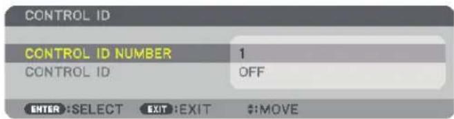
If the projector can be operated with the current remote control ID, the [ACTIVE] will be displayed. If the projector cannot be operated with the current remote control ID, the [INACTIVE] will be displayed. To operate the inactive projector, assign the control ID used for the projector by using the following procedure (Step 3).
3. Press one of numeric keypad buttons while pressing and holding the ID SET button on the remote control.
Example:
To assign "3", press the "3" button on the remote control.
No ID means that all the projectors can be operated together with a single remote control. To set "No ID", enter "000" or press the CLEAR button.
TIP: The range of IDs is from 1 to 254.
4. Release the ID SET button.
The updated CONTROL ID screen will be displayed.
NOTE:
- The IDs can be cleared in a few days after the batteries are run down or removed.
- Accidentally pressing any one of the buttons of the remote control will clear currently specified ID with batteries removed.
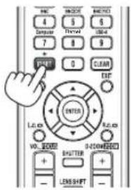
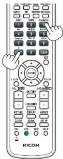
Turning On or Off Remote Sensor [REMOTE SENSOR]
This option determines which remote sensor on the projector is enabled in wireless mode.
The options are: FRONT/BACK, FRONT, BACK.
TIP:
- If the remote control system does not function when direct sunlight or strong illumination strikes the remote control sensor of the projector, change another option.
Enabling Key Sound and Error Sound [BEEP]
This feature turns on or off the button sound or alarm when an error occurs or the following operations are performed.
- Displaying the main menu
- Switching sources
- Resetting data by using [RESET]
- Pressing POWER ON or STANDBY button
[NETWORK SETTINGS]
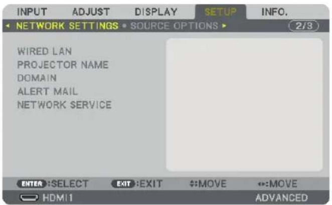
Important:
- Consult with your network administrator about these settings.
- When using a wired LAN, connect the Ethernet cable (LAN cable) to the Ethernet port on the projector. (→ page 166)
TIP: The network settings you make will not be affected even when [RESET] is done from the menu.
About the Projector's [NETWORK SETTING].(→ page 6)
Hints on How to Set Up LAN Connection
To set up the projector for a LAN connection:
Select [WIRED LAN] → [PROFILES] → [PROFILE 1] or [PROFILE 2].
Two settings can be set for wired LAN.
Next turn on or off for [DHCP], [IP ADDRESS], [SUBNET MASK], and [GATEWAY] and select [OK] and press the ENTER button. (→ page 121)
To recall LAN settings stored in the profile number:
Select [PROFILE 1] or [PROFILE 2] for wired LAN, and then select [OK] and press the ENTER button. (→ page 121)
To connect a DHCP server:
Turn on [DHCP] for wired LAN. Select [ON] and press the ENTER button. To specify IP address without using the DHCP server, turn off [DHCP]. (→ page 121)
To receive lamp replacement time or error messages via e-mail:
Select [ALERT MAIL], and set [SENDER'S ADDRESS], [SMTP SERVER NAME], and [RECIPIENT'S ADDRESS]. Last, select [OK] and press the ENTER button. (→ page 123)
WIRED LAN
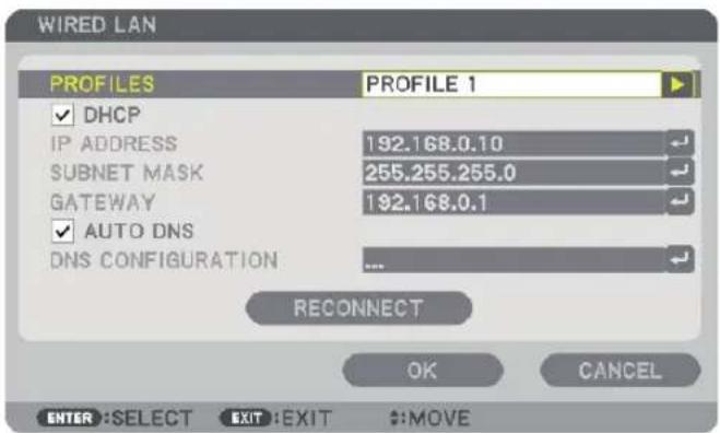
| PROFILES · The settings for using the built-in Ethernet port in the projector can be recorded in the projector memory in two ways.· Select [PROFILE 1] or [PROFILE 2] and then do settings for [DHCP] and the other options.After doing this, select [OK] and press the ENTER button. This will store your settings in memory.· To recall the settings from memory:After selecting [PROFILE 1] or [PROFILE 2] from the [PROFILES] list.Select [OK] and press the ENTER button.· Select [DISABLE] when not connecting to a wired LAN | — |
| DHCP Place a check mark to automatically assign an IP address to the projector from your DHCP server.Clear this check box to register the IP address or subnet mask number obtained from your network administrator. | — |
| IP ADDRESS Set your IP address of the network connected to the projector when [DHCP] is turned off. | Up to 12 numeric characters |
| SUBNET MASK Set your subnet mask number of the network connected to the projector when [DHCP] is turned off. | Up to 12 numeric characters |
| GATEWAY Set the default gateway of the network connected to the projector when [DHCP] is turned off. | Up to 12 numeric characters |
| AUTO DNS Place a check mark to automatically assign the IP address of your DNS server connected to the projector from your DHCP server.Clear this check box to set the IP address of your DNS server connected to the projector. | Up to 12 numeric characters |
| DNS CONFIGURATION Set the IP address of your DNS server on the network connected to the projector when [AUTO DNS] is cleared. | Up to 12 numeric characters |
| RECONNECT Retry to connect the projector to a network. Try this if you have changed [PROFILES]. | — |
PROJECTOR NAME
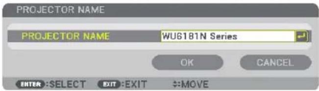
| PROJECTOR NAME Set a unique projector name. Up to 16 alphanumeric | characters and symbols |
DOMAIN
Set a host name and domain name of the projector.
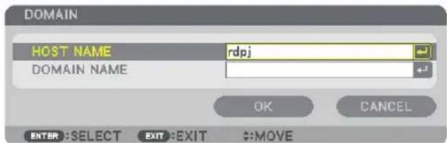
| HOST NAME Set a host name of the projector. Up to 15 alphanumeric | characters |
| DOMAIN NAME Set a domain name of the projector. Up to 60 alphanumeric | characters |
ALERT MAIL
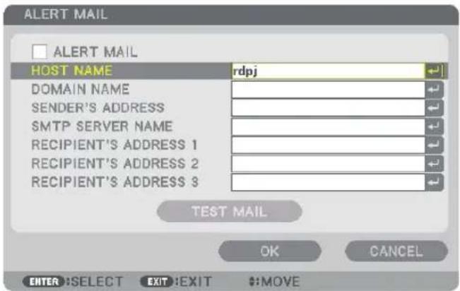
| ALERT MAIL This option will notify your computer of lamp replace time or error messages via e-mail when using wireless or wired LAN.Placing a checkmark will turn on the Alert Mail feature.Clearing a checkmark will turn off the Alert Mail feature.Sample of a message to be sent from the projector:The lamp and filters are at the end of its usable life. Please replace the lamp and filters.Projector Name: rdpjLamp Hours Used: 100 [H] | — |
| HOST NAME Type in a host name. Up to 15 alphanumeric | characters |
| DOMAIN NAME Type in a domain name of the network connected to the projector. Up to 60 alphanumeric characters | character |
| SENDER'S ADDRESS Specify the sender's address. Up to 60 alphanumeric characters and symbols | characters and symbols |
| SMTP SERVER NAME Type in the SMTP server name to be connected to the projector. Up to 60 alphanumeric characters | humanmeric |
| RECIPIENT'S ADDRESS 1, 2, 3 | Type in your recipient's address. Up to 60 alphanumeric characters and symbols |
| TEST MAIL | Send a test mail to check if your settings are correct.NOTE:If you entered an incorrect address in a test, you may not receive an Alert mail. Should this happen, check if the Recipient's Address is correctly set.Unless any one of the [SENDER'S ADDRESS], [SMTP SERVER'S NAME] or [RECIPIENT'S ADDRESS 1-3] is selected, [TEST MAIL] is not available.Be sure to highlight [OK] and press the ENTER button before executing [TEST MAIL]. |
NETWORK SERVICE
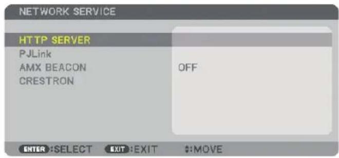
| HTTP SERVER Set a password for your HTTP server. Up to 10 alphanumeric | characters | |
| PJLink | This option allows you to set a password when you use the PJLink feature.NOTE:Do not forget your password. However, if you forget your password, consult with your dealer.What is PJLink?PJLink is a standardization of protocol used for controlling projectors of different manufacturers. This standard protocol is established by Japan Business Machine and Information System Industries Association (JBMIA) in 2005.The projector supports all the commands of PJLink Class 1.Setting of PJLink will not be affected even when [RESET] is done from the menu. | Up to 32 alphanumeric characters |
| AMX BEACON Turn on or off for detection from AMX Device Discovery when connecting to the network supported by AMX's NetLinx control system.TIP:When using a device that supports AMX Device Discovery, all AMX NetLinx control system will recognize the device and download the appropriate Device Discovery Module from an AMX server.Placing a checkmark will enable detecting the projector from AMX Device Discovery.Clearing a checkmark will disable detecting the projector from AMX Device Discovery. | — | |
| CRESTRON ROOMVIEW: Turn on or off when controlling the projector from your PC.CRESTRON CONTROL: Turn on or off when controlling the projector from your controller.CONTROLLER IP ADDRESS: Enter your IP address of CRESTRON SERVER.IP ID: Enter your IP ID of CRESTRON SERVER. | Up to 12 numeric characters | |
[SOURCE OPTIONS]
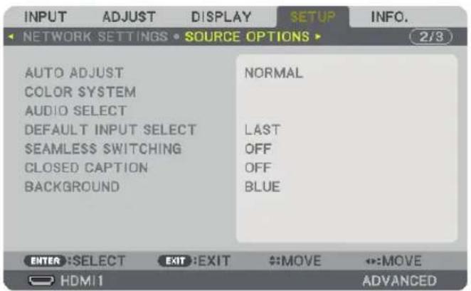
Setting Auto Adjust [AUTO ADJUST]
This feature sets the Auto Adjust mode so that the computer signal can be automatically or manually adjusted for noise and stability. You can automatically make adjustment in two ways: [NORMAL] and [FINE].
OFF......The computer signal will not be automatically adjusted. You can manually optimize the computer signal.
NORMAL......Default setting. The computer signal will be automatically adjusted. Normally select this option.
FINE......Select this option if fine adjustment is needed. It takes more time to switch to the source than when [NORMAL]is selected.
TIP:
- The default setting when shipped from the factory is [NORMAL].
- When the AUTO ADJ. button is pressed, the same [FINE] adjustment is carried out.
[COLOR SYSTEM]
This feature allows you to select the TV video signal, which differs from country to country (NTSC, PAL, etc.).
This is set to [AUTO] by factory default. Set this if the projector cannot identify the signal automatically.
[AUDIO SELECT]
This selects the audio input of the HDMI 1 IN terminal, HDMI 2 IN terminal, DisplayPort input terminal and Ethernet port, USB A port. When inputting analog audio, connect the audio output terminal of the connecting device with the BNC audio input terminal and set the Audio Select to "BNC".
Selecting Default Source [DEFAULT INPUT SELECT]
You can set the projector to default to any one of its inputs each time the projector is turned on.
LAST....Sets the projector to default to the previous or last active input each time the projector is turned on.
AUTO....Searches for an active source in order of HDMI1 → HDMI2 → DisplayPort → BNC → BNC(CV) → BNC(Y/C) → COMPUTER and displays the first found source.
HDMI1......Displays the digital source from the HDMI 1 IN connector every time the projector is turned on.
HDMI2....Displays the digital source from the HDMI 2 IN connector every time the projector is turned on.
DisplayPort......Displays the digital source from the DisplayPort every time the projector is turned on.
BNC....Project the input signal from the BNC video input terminal
BNC(CV)....Project the input signal from the BNC(CV) video input terminal.
BNC(Y/C)....Project the input signal from the BNC(Y/C) video input terminal.
COMPUTER......Displays the computer signal from the COMPUTER IN connector every time the projector is turned on.
ETHERNET......Project the data sent from the computer via the wireless LAN unit (sold separately) that is fitted to the main body or the Ethernet port (RJ-45).
USB-A....Project the data (viewer display) of the USB memory set up in the projector.
[SEAMLESS SWITCHING]
When the input connector is switched, the image displayed before switching is held to switch to the new image without a break due to absence of a signal.
Setting Closed Caption [CLOSED CAPTION]
This option sets several closed caption modes that allow text to be superimposed on the projected image of Video or S-Video. The subtitles and text will be displayed a short while after the on-screen menu disappears.
OFF....This exits the closed caption mode.
CAPTION 1-4......Text is superimposed.
TEXT 1-4......Text is displayed.
Selecting a Color or Logo for Background [BACKGROUND]
Use this feature to display a blue/black screen or logo when no signal is available. The default background is [BLUE].
NOTE:
- Even when the background logo is selected, if two pictures are displayed in [PIP/PICTURE BY PICTURE] mode, the blue background is displayed without the logo when there is no signal.
[POWER OPTIONS]
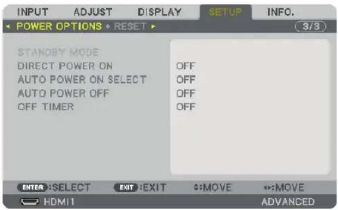
Selecting Power-saving in [STANDBY MODE]
Setting the power consumption in the standby mode.
NORMAL....In the standby mode, the power consumption of the projector is 0.11 W (100-130 V)/0.16 W (200-240 V). In the standby mode, the POWER indicator lights up in red while the STATUS indicator will go off.
- When set to [NORMAL], the following terminals and functions will be disabled. HDMI output terminal, Audio output terminal, Ethernet port, USB-A port, LAN function, [ALERT MAIL] function
NETWORK STANDBY
......Compared to [NORMAL], the power consumption in the standby mode is higher but power can be supplied to the projector using a wired LAN.
In the standby mode, the power indicator will light up in orange while the status indicator will be turned off.
Important:
- When [NETWORK STANDBY] is selected, [AUTO POWER OFF] turns grey in colour and becomes disabled while [0:15] is selected compulsorily.
- When it is set to [NETWORK STANDBY], under the following conditions, the [STANDBY MODE] setting is disabled and the unit will go into the sleep mode*.
* Sleep mode refers to the mode whereby the functional restrictions due to the [STANDBY MODE] setting are removed.
- When [ENABLE] is selected under [NETWORK SERVICE] [AMX BEACON]
- When [NETWORK SERVICE] [CRESTRON] [CRESTRON CONTROL] [ENABLE] is selected
- When [NORMAL] is selected, the [AUTO POWER ON SELECT] display turns grey in color and is disabled, and [OFF] is automatically selected.
TIP:
- Your setting will not be affected even when [RESET] is done from the menu.
- The power consumption in the standby mode will not be included in calculating CO_2 emission reduction.
Enabling Direct Power On [DIRECT POWER ON]
Turns the projector on automatically when the power cord is inserted into an active power outlet. This eliminates the need to always use the POWER button on the remote control or projector cabinet.
Turning On the Projector by Detecting Input Signal [AUTO POWER ON SELECT]
Under the condition of [NETWORK STANDBY], the projector automatically detects and projects synchronizing signal input from the selected terminals among Computer, HDMI1/2, DisplayPort by this function.
OFF......AUTO POWER ON SELECT function becomes inactive.
HDMI1, HDMI2, DisplayPort, COMPUTER
......When the projector detects the computer signal input from the selected terminal, automatically it will be turned ON and will project the computer screen.
NOTE:
- If you want to activate this AUTO POWER ON SELECT function after powering OFF the projector, interrupt signal from input terminals or pull out the computer cable from the projector and wait for over 3 seconds and then input signal from the selected terminal. In case computer signal is continuously input to the projector, however the projector is turned OFF and is in the transition to NETWORK STANDBY mode, it will keep NETWORK STANDBY mode and will not be turned ON automatically. In addition, if signal from HDMI1/2, DisplayPort is continuously input to the projector, the projector may be turned ON again automatically based on the setting of external devices even if the projector is turned OFF and in the condition of NETWORK STANDBY mode.
- This function is not activated either by component signal input from the computer screen input terminal or computer signal as Sync on Green and Composite Sync.
Enabling Power Management [AUTO POWER OFF]
When this option is selected you can enable the projector to automatically turn off (at the selected time: 0:05, 0:10, 0:15, 0:20, 0:30, 1:00) if there is no signal received by any input or if no operation is performed.
NOTE:
- [AUTO POWER OFF] works even when the viewer or network is being projected.
- When the [STANDBY MODE] is set to [NETWORK STANDBY], [AUTO POWER OFF] will turn grey in color and [0:15] will be selected compulsorily.
Using Off Timer [OFF TIMER]
- Select your desired time between 30 minutes and 16 hours: OFF, 0:30, 1:00, 2:00, 4:00, 8:00, 12:00, 16:00.
- Press the ENTER button on the remote control.
- The remaining time starts counting down.
- The projector will turn off after the countdown is complete.
NOTE:
- To cancel the preset time, set [OFF] for the preset time or turn off the power.
- When the remaining time reaches 3 minutes before the projector is turned off, the [THE PROJECTOR WILL TURN OFF WITHIN 3 MINUTES] message will be displayed on the bottom of the screen.
Returning to Factory Default [RESET]
The RESET feature allows you to change adjustments and settings to the factory preset for a (all) source (s) except the following:
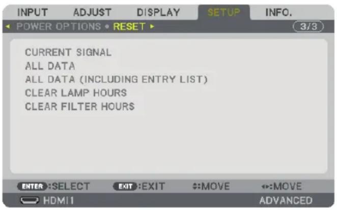
[CURRENT SIGNAL]
Resets the adjustments for the current signal to the factory preset levels.
The items that can be reset are: [PRESET], [CONTRAST], [BRIGHTNESS], [COLOR], [HUE], [SHARPNESS], [ASPECT RATIO], [HORIZONTAL], [VERTICAL], [CLOCK], [PHASE], and [OVERSCAN].
[ALL DATA]
Reset all the adjustments and settings for all the signals to the factory preset.
All items can be reset EXCEPT [ENTRY LIST], [LANGUAGE], [BACKGROUND], [FILTER MESSAGE], [EDGE BLENDING], [MULTI SCREEN], [SCREEN TYPE], [GEOMETRIC CORRECTION], [REF. WHITE BALANCE], [STATIC CONVERGENCE], [ADMINISTRATOR MODE], [CONTROL PANEL LOCK], [SECURITY], [COMMUNICATION SPEED], [DATE AND TIME SETTINGS], [CONTROL ID], [STANDBY MODE], [FAN MODE], [LAMP LIFE REMAINING], [LAMP HOURS USED], [FILTER HOURS USED], [TOTAL CARBON SAVINGS], [WIRED LAN], and [WIRELESS LAN]. To reset the lamp usage time, see "Clearing Lamp Hour Meter [CLEAR LAMP HOURS]" below.
[ALL DATA (INCLUDING ENTRY LIST)]
Reset all the adjustments and settings for all the signals to the factory preset except [LANGUAGE], [BACKGROUND], [FILTER MESSAGE], [EDGE BLENDING], [MULTI SCREEN], [SCREEN TYPE], [GEOMETRIC CORRECTION], [REF. WHITE BALANCE], [STATIC CONVERGENCE], [ADMINISTRATOR MODE], [CONTROL PANEL LOCK], [SECURITY], [COMMUNICATION SPEED], [DATE AND TIME SETTINGS], [CONTROL ID], [STANDBY MODE], [FAN MODE], [LAMP LIFE REMAINING], [LAMP HOURS USED], [FILTER HOURS USED], [TOTAL CARBON SAVINGS], [WIRED LAN], and [WIRELESS LAN].
Also deletes all the signals in the [ENTRY LIST] and returns to the factory preset.
NOTE: Locked signals in Entry List cannot be reset.
Clearing Lamp Hour Meter [CLEAR LAMP HOURS]
Resets the lamp clock back to zero. Selecting this option displays submenu for a confirmation. Select [YES] and press the ENTER button.
NOTE:
- Elapsed time of the lamp use will not be affected even when [RESET] is done from the menu.
- Performing [CLEAR LAMP HOURS] will return the [LAMP ADJUST] in [LAMP MODE] to its default adjustments. When the projector is used for multi-screen projection, use [LAMP ADJUST] to adjust the brightness again.
Clearing the Filter Usage Hours [CLEAR FILTER HOURS]
Resets the filter usage back to zero. Selecting this option displays submenu for a confirmation. Select [YES] and press the ENTER button.
The [OFF] item is selected for [FILTER MESSAGE] at the time of shipment. When [OFF] is selected, you do not need to clear the filter usage hour.
NOTE: Elapsed time of the filter use will not be affected even when [RESET] is done from the menu.
⑧ Menu Descriptions & Functions [INFO.]
Displays the status of the current signal and lamp usage. This item has nine pages. The information included is as follows:
TIP: Pressing the HELP button on the remote control will show the [INFO.] menu items.
[USAGE TIME]
![INPUT ADJUST DISPLAY SETUP INFO. 1/3 USAGE TIME • SOURCE(1) • SOURCE(2) ▶ LAMP LIFE REMAINING LAMP HOURS USED 00000 [H] FILTER HOURS USED 00000 [H] TOTAL CARBON SAVINGS 0.000[kg-CO2] EXIT:EXIT MOVE MOVE HDMI1 ADVANCED](/content/2026/05/872418/images/9e489b1da0ecca6aa82308cfa5843f48cfb3ee5aeb2b8cbab6aae6edaed6e4c7.jpg)
The sub-menu tab in the [INFO.] display will become [USAGE TIME]/[SOURCE(1)]/[SOURCE(2)]/[WIRED LAN]/[VERSION(1)]/[VERSION(2)]/[OTHERS]/[CONDITIONS].
[LAMP LIFE REMAINING] (%)*
[LAMP HOURS USED] (H)
[FILTER HOURS USED] (H)
[TOTAL CARBON SAVINGS] (kg-CO2)
* The progress indicator shows the percentage of remaining bulb life.
The value informs you of the amount of lamp usage. When the remaining lamp time reaches 0, the LAMP LIFE REMAINING bar indicator changes from 0% to 100 Hours and starts counting down.
If the remaining lamp time reaches 0 hours, the projector will not turn on.
- The message to the effect that the lamp or the filters should be replaced will be displayed for one minute when the projector is turned on and when the POWER button on the projector or the remote control is pressed.
To dismiss this message, press any button on the projector or the remote control.
| Lamp life(H) | Replacement lamp | ||
| ECO MODE | During portrait installation | ||
| NORMAL(OFF) | ECO(ON) | ||
| 3000 4000 2000 Type21 | |||
• [TOTAL CARBON SAVINGS]
This displays the estimated carbon saving information in kg. The carbon footprint factor in the carbon saving calculation is based on the OECD (2008 Edition). ( page 32)
[SOURCE(1)]
![INPUT ADJUST DISPLAY SETUP INFO. USAGE TIME SOURCE(1) SOURCE(2) 1/3 INPUT TERMINAL HDMI1 RESOLUTION 1024x768 HORIZONTAL FREQUENCY 48.58[kHz] VERTICAL FREQUENCY 82.13[Hz] SYNC TYPE SEPARATE SYNC SYNC POLARITY H:( - ) V:( - ) SCAN TYPE NON-INTERLACE SOURCE NAME 1024x768 ENTRY NO. 1 EXIT :EXIT :MOVE ::MOVE HDMI1 ADVANCED](/content/2026/05/872418/images/6a90584aa96cc79a18e464b7aa70a87b372b27f5f843f24c835de23010c7e60f.jpg)
INPUT TERMINAL RESOLUTION
HORIZONTAL FREQUENCY VERTICAL FREQUENCY
SYNC TYPE SYNC POLARITY
SCAN TYPE SOURCE NAME
ENTRY NO.
[SOURCE(2)]
![INPUT ADJUST DISPLAY SETUP INFO. USAGE TIME SOURCE(1) SOURCE(2) SIGNAL TYPE RGB VIDEO TYPE NTSC BIT DEPTH 6[bits] VIDEO LEVEL FULL LINK RATE 2.7[Gbps] LINK LANE 1[lane] 3D FORMAT FRAME PACKING EXIT:EXIT #:MOVE #:MOVE HDMI ADVANCED](/content/2026/05/872418/images/6060ba81565033d6e309453f58d20460e05ac62367e22cb794789a3d125abe28.jpg)
SIGNAL TYPE VIDEO TYPE
SOURCE NAME ENTRY NO.
[SOURCE(4)]
![INPUT ADJUST DISPLAY SETUP INFO. SOURCE(3) SOURCE(4) WIRED LAN VERSION(1) 2/3 SIGNAL TYPE RGB VIDEO TYPE NTSC BIT DEPTH 6[bits] VIDEO LEVEL FULL LINK RATE 2.7[Gbps] LINK LANE 1[lane] 3D FORMAT FRAME PACKING EXIT:EXIT #:MOVE #:MOVE HDMI ADVANCED](/content/2026/05/872418/images/b54a731b341fee06ee32c74d1b5bb9850f80c880ec31f16100561abed7214b1b.jpg)
SIGNAL TYPE VIDEO TYPE
IP ADDRESS SUBNET MASK
GATEWAY MAC ADDRESS
[VERSION(1)]
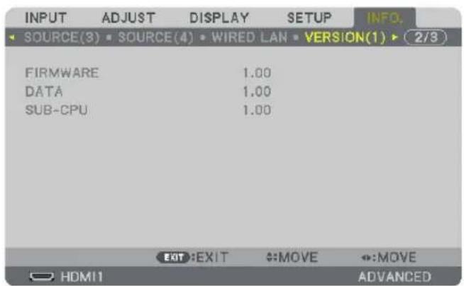
FIRMWARE
SUB-CPU
[VERSION(2)]
FIRMWARE
DATA
[OTHERS]
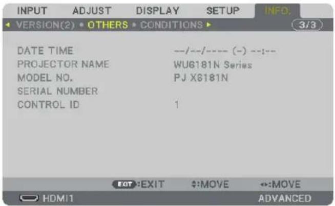
DATE TIME PROJECTOR NAME
MODEL NO. SERIAL NUMBER
CONTROL ID (when [CONTROL ID] is set)
[CONDITIONS]
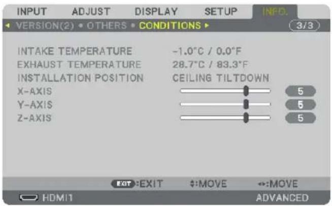
INTAKE TEMPERATURE EXHAUST TEMPERATURE INSTALLATION POSITION X-AXIS
Y-AXIS
Z-AXIS
About the X-AXIS, Y-AXIS and Z-AXIS CONDITIONS
* Arrow direction of the Z-AXIS in the figure represents the top of the projector.
X-AXIS.....Display the projector image at an angle of 100 - +100 degrees to the horizontal in the X-axis direction.
Y-AXIS....Display the projector image at an angle of 100 - +100 degrees to the horizontal in the Y-axis direction.

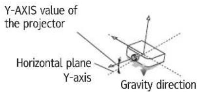
Z-AXIS.....Display the projector image at an angle of 100 - +100 degrees to the vertical in the Z-axis direction.
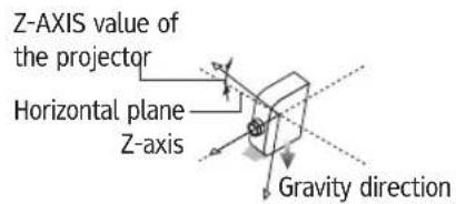
⑨ Application Menu
When [ETHERNET] is selected from the [INPUT] menu, the application menu [APPLICATION MENU] will be displayed.
The application menu allows you to set up the User Supportware and Network Settings (NETWORK SETTINGS).
The User Supportware is contained on the supplied CD-ROM.
[ADVANCED] and [BASIC] can be selected in the [MENU MODE] under [SETUP] → [CONTROL] → [TOOLS] → [ADMINISTRATOR MODE]. (→ page 112)
The [BASIC] menu contains minimum essentials of menus and commands.
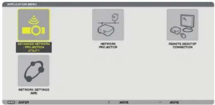
ADVANCED NETWORK UTILITY
This shows information for projector name, resolution, and network (wired/wireless) which are required to use Advanced Network Utility.
Use this information to set up for your computer.
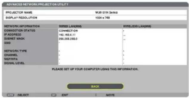
NETWORK PROJECTOR
This shows information for projector name, resolution, and network (wired/wireless) which are required to use Network Projector. Use this information to set up for your computer.
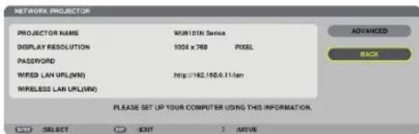
REMOTE DESKTOP CONNECTION
This allows you to set up for computer name entry and effects for Remote Desktop.
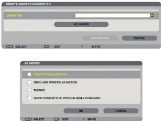
NOTE:
- A USB keyboard is required to set up the Remote Desktop Connection.
NETWORK SETTINGS(MM)
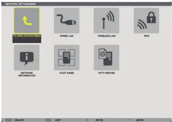
Important:
- Consult with your network administrator about these settings.
- When using a wired LAN, connect the LAN cable (Ethernet cable) to the Ethernet port (LAN) of the projector. (→ page 166)
- When using a wireless LAN, attach the wireless LAN unit sold separately to the projector. (→ page 167)
TIP: The [NETWORK SETTINGS(MM)] you make will not be affected even when [RESET] is done from the menu.
About the Projector's [NETWORK SETTING].(→ page 6)
Hints on How to Set Up LAN Connection
To set up the projector for a LAN connection:
Select [WIRED LAN] or [WIRELESS LAN] → [PROFILES] → [PROFILE 1] or [PROFILE 2].
Two settings can be set for wired or wireless LAN.
Next turn on or off for [DHCP], [IP ADDRESS], [SUBNET MASK], and [GATEWAY] and select [OK] and press the ENTER button. (→ page 140)
To recall LAN settings stored in the profile number:
Select [PROFILE 1] or [PROFILE 2] for wired or wireless LAN, and then select [OK] and press the ENTER button. (→ page 139)
To connect a DHCP server:
Turn on [DHCP] for wired or wireless LAN. Select [ON] and press the ENTER button. To specify IP address without using the DHCP server, turn off [DHCP]. (→ page 140)
To set only for wireless LAN (NETWORK TYPE and WEP/WPA):
Select [PROFILE 1] or [PROFILE 2] for wireless LAN, and then select [ADVANCED] and [OK] and press the ENTER button. The Advanced menu will be displayed. (→ page 141)
To select an SSID:
Select [ADVANCED] → [SITE SURVEY] and press the ENTER button.
Select an SSID and press the > button to select [OK] and press the ENTER button.
If you do not use [SITE SURVEY], type the SSID and select [INFRASTRUCTURE] or [AD HOC]. (→ page 141)
To execute [EASY CONNECTION] using Advanced Network Utility:
The [EASY CONNECTION] is a mode that can abbreviate the troublesome LAN settings when using the Advanced Network Utility and connecting the PC and projector via a wireless LAN.
The Projection Utility and Advanced Network Utility are contained on the supplied CD-ROM.
To use [EASY CONNECTION], select [WIRELESS LAN] → [PROFILES] → [EASY CONNECTION].
NOTE: The [EASY CONNECTION] function is available on Windows 7, Windows Vista.
WIRED LAN or WIRELESS LAN (ADVANCED menu only)
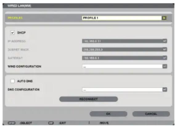
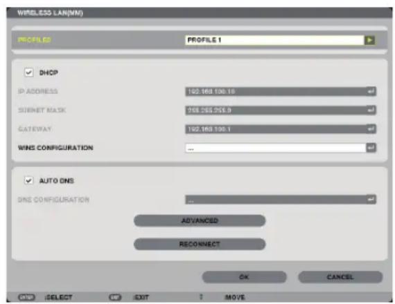
| PROFILES · Up to two settings for the Ethernet port or USB wireless LAN unit can be stored in memory of the projector. Total of four settings can be stored.Five settings can be stored: two for the built-in Ethernet port, two for wireless LAN and one for WPS.Select [PROFILE 1] or [PROFILE 2] and then do settings for [DHCP] and the other options.After doing this, select [OK] and press the ENTER button. This will store your settings in memory.To recall the settings from memory:After selecting [PROFILE 1] or [PROFILE 2] from the [PROFILES] list. Select [OK] and press the ENTER button.To execute [EASY CONNECTION] using Projection Utility or Advanced Network Utility, select [WIRELESS LAN] → [PROFILES] → [EASY CONNECTION].To stop emitting radio waves from the USB Wireless LAN Unit, select [DISABLE] from the [PROFILES] list.Selecting [SIMPLE ACCESS POINT] will allow the projector to create an infrastructure network.The IP address of the projector will be set automatically.Select “Obtain an IP Address Automatically” to set the IP address of a connected computer.It takes a few seconds for a change of your computer’s IP address to come into effect in Windows 7/Windows Vista.When you connect with your computer to save your profile and select “Automatically connect when within range” from the Properties tab of Wireless Network in Windows for your selected profile, your wireless LAN will be accessed under the following conditions:at the time of turning on the computer or the projectorwhen the notebook type is within the range of the projector’s wireless LAN can be achieved.Data transmission between wireless LAN and wired LAN is not possible.When the [SIMPLE ACCESS POINT] mode is used to send images, it is recommended to connect to only one computer.When selecting [WPS], the network will be connected by using settings stored automatically with the WPS function.Selecting [WPS] will allow the projector to access the network by using the settings the WPS function automatically stored. |
| DHCP Place a check mark to automatically assign an IP address to the projector from your DHCP server.Clear this check box to register the IP address or subnet mask number obtained from your network administrator. | — | |
| IP ADDRESS Set your IP address of the network connected to the projector when [DHCP] is turned off. | Up to 12 numeric characters | |
| SUBNET MASK Set your subnet mask number of the network connected to the projector when [DHCP] is turned off. | Up to 12 numeric characters | |
| GATEWAY Set the default gateway of the network connected to the projector when [DHCP] is turned off. | Up to 12 numeric characters | |
| WNS CONFIGURATION Set the IP address of your WINS server of the network connected to the projector when [DHCP] is turned off. | Up to 12 numeric characters | |
| AUTO DNS Place a check mark to automatically assign the IP address of your DNS server connected to the projector from your DHCP server.Clear this check box to set the IP address of your DNS server connected to the projector. | — | |
| DNS CONFIGURATION Set the IP address of your DNS server on the network connected to the projector when [AUTO DNS] is cleared. | Up to 12 numeric characters | |
| ADVANCED* This menu allows you to set various items for your wireless LAN connection (network type, security). | — | |
| RECONNECT Retry to connect the projector to a network. Try this if you have changed [PROFILES]. | — |
* The [ADVANCED] setting screen is available for [WIRELESS LAN] only.
NOTE:
- If you select [EASY CONNECTION] from [PROFILES], you cannot make settings to DHCP and its following items except [CHANNEL] in [ADVANCED].
ADVANCED Setting (required for wireless LAN only) (ADVANCED menu only)
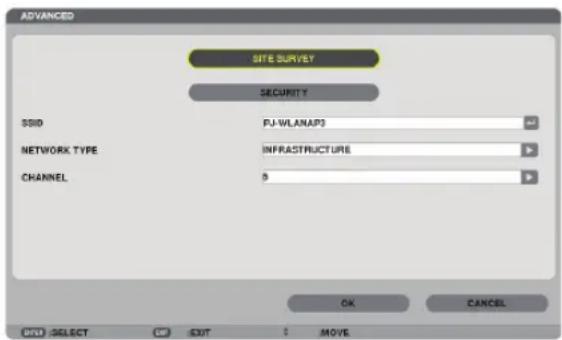
| SITE SURVEY Displays a list of available SSIDs for wireless LAN on site. Select an SSID which you can access.To select an SSID, highlight [SSID] and use the SELECT → to select [OK] and press the ENTER button.......Wireless access point......Ad Hoc PC......WEP or WPA enabled | — |
| SECURITY This will turn on | or off the encryption mode for secure transmission.To use encryption, specify a WEP key or encryption key. Select your security type appropriate for your computer and the wireless LAN unit.DISABLE......Will not turn on the encryption feature. Your communications may be monitored by someone.WEP(64bit) ......Uses 64-bit datalength for secure transmission.WEP(128bit) ......Uses 128-bit datalength for secure transmission.This option will increase privacy and security when compared to use of 64-bit datalength encryption.WPA-PSK/WPA2-PSK/WPA-EAP/WPA2-EAP......These options provide stronger security than WEP. | — |
| NOTE:The security type, WEP key, and encryption key settings must be the same as communication devices such as PC or access point in your wireless network.When you use [SECURITY], your image transmission speed will slow down.[WPA-PSK], [WPA-EAP], [WPA2-PSK] and [WPA2-EAP] are not available when [AD HOC] is selected from [NETWORK TYPE]. | ||
| SSID Enter an identifier (SSID) for wireless LAN. Communication can be doneonly with equipment whose SSID matches SSID for your wireless LAN. | Up to 32 alphanumeric characters (case sensitive). | |
| NETWORK TYPE Select com | communication method when using wireless LAN.INFRASTRUCTURE......Select this option when communicating with one or more equipment connected to the wireless or wired LAN network via a wireless access point.AD HOC......Select this option when using the wireless LAN to directly communicate with a computer in peer-to-peer mode. | — |
| CHANNEL Select a channel. | Available channels vary depending on the country and region. When you select [INFRASTRUCTURE], make sure that the projector and your access point are on the same channel; when you select [AD HOC], make sure that the projector and your computer are on the same channel. | — |
When [WEP(64bit)] or [WEP(128bit)] is selected for [SECURITY TYPE]
| KEY SELECT Selects one WEP key from the four keys below. | |||
| KEY1, KEY2, KEY3, KEY4 Enter a WEP key.• Maximum number of characters | |||
| Option Alphanumeric (ASCII) Hexadecimal (HEX) | |||
| WEP 64bit 5 10 | |||
| WEP 128bit 13 | 26 | ||
When [WPA-PSK], [WPA-EAP], [WPA2-PSK], or [WPA2-EAP] is selected for [SECURITY TYPE]
| ENCRYPTION TYPE Select | [TKIP] or [AES]. |
| KEY Enter encryption key. | Key length must be 8 or greater and 63 or less. |
[AUTHENTICATION] (required for wireless only)
Setting is required for using WPA-EAP or WPA2-EAP.
Preparation before setting
Select a wireless LAN compliant WPA-EAP or WPA2-EAP authentication and install a digital certificate on the projector.
-
Set [DATE AND TIME] on the projector. (→ page 116)
-
Use a computer to save digital certificates (files) for WPA-EAP or WPA2-EAP setting to your USB memory device. After completing saving the file, remove the USB memory device from the computer.
NOTE:
- Save a digital certificate (file) to the root folder of the USB memory.
- The file formats of digital certificate that are supported by the projector are DER and PKCS#12 only.
- The projector cannot handle any digital certificate whose file size exceeds 8 KB.
• CRL (Certificate Relocation List) is not supported. -
Client certificate chain is not supported.
-
Plug the USB memory device into the USB port of the projector.
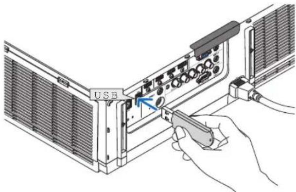
Setting Procedures
- Select [MM)] → [WIRELESSS LAN].
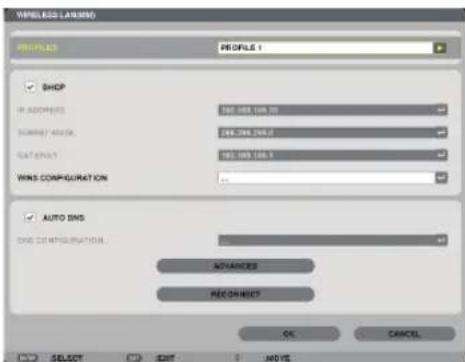
- Set items such as PROFILES, DHCP, IP ADDRESS, SUBNET MASK and others as required.
- Select [PROFILE 1] or [PROFILE 2] for [PROFILES]. If [EASY CONNECTION] is selected, WPA-PSK, WPA2-PSK, WPA-EAP, or WPA2-EAP is not available.
- Select [ADVANCED] and press the ENTER button.
The [ADVANCED] setting screen will be displayed.
- Select [SITE SURVEY] and press the ENTER button.
The "SSID" list will be displayed.
- Select a connecting SSID, and then select [OK].
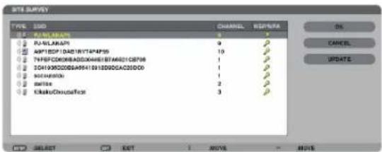
Finally press the ENTER button.
- Select the SSID for which WPA-PSK or WPA2-PSK is set.
-
Select [INFRASTRUCTURE ( )] for [NETWORK TYPE]. WPA-PSK, WPA2-PSK, WPA-EAP, or WPA2-EAP is not available when [AD HOC ( )] is selected.
-
Select the [SECURITY] tab.
The [SECURITY] page will be displayed.
- Select the [SECURITY TYPE] field and press the ENTER button.
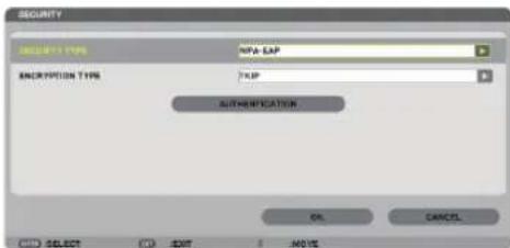
The pull-down list will be displayed.
- Select [WPA-EAP] or [WPA2-EAP] and press the ENTER button.
- Select the [TKIP/AES] field and press the ENTER button.
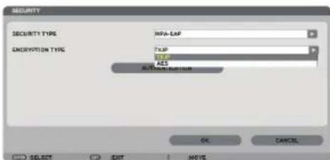
The pull-down list will be displayed.
- Select [TKIP] or [AES] and press the ENTER button.
Select [TKIP] or [AES] according to the setting for your access point.
11. Select the [AUTHENTICATION] tab.
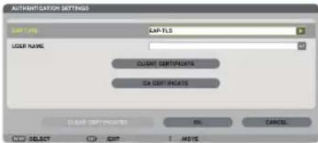
The [AUTHENTICATION] page will be displayed.
Select either [EAP-TLS] or [PEAP-MSCHAPv2] for [EAP TYPE]. The setting items vary depending on the EAP type. See the table below.
| EAP Type Setting Item Note | ||
| EAP-TLS User Name 1 character or more and 32 characters or less | ||
| Client Certificate PKCS#12 format file | ||
| CA Certificate(Certificate authority's certificate) | DER format file | |
| PEAP-MSCHAPv2 User Name 1 character or more and 32 characters or less | ||
| Password 1 character or more and 32 characters or less | ||
| CA Certificate(Certificate authority's certificate) | DER format file |
① Selecting [EAP-TLS] for [EAP TYPE]:
The following section explains the operation for selecting [EAP-TLS]. For selecting [PEAP-MSCHAPv2], go on to Step 12 on page 147.
12. Select the [USER NAME] field and press the ENTER button.
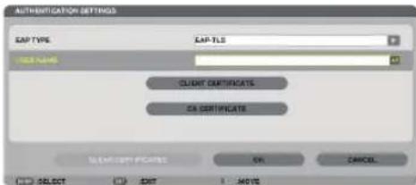
![RICOH PJ X6181N - Select the [USER NAME] field and press the ENTER button. - 2](/content/2026/05/872418/images/c18a32a33fcb1a11d01e4fb2761431daf14c765b135087ffb63b988c75924c97.jpg)
The character entry screen (software keyboard) will be displayed. Set a user name.
- A user name must be 1 character or more and 32 characters or less.
-
See page 149 for using the software keyboard to enter characters.
-
Select [CLIENT CERTIFICATE] and press the ENTER button.
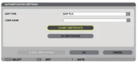
A list of files ([FILES] screen) will be displayed.
- For operating the [FILES] screen.
- To return to the [AUTHENTICATION] page, press the EXIT button.
NOTE:
Installing a digital certificate
You can install each digital certificate (client certificate and CA certificate) for [PROFILE 1 (or 2)] on a file-by-file basis.
• Install a root CA certificate for a CA certificate.
- If you install a digital certificate over your existing digital certificate, the existing digital certificate will be overwritten with the new digital certificate.
- Once a digital certificate has been installed, its information cannot be deleted even if you stop setting WPA-EAP or WPA2-EAP.
- On the [FILES] screen, select a digital certificate (PKCS#12 format file) saved in your USB memory device and press the ENTER button.
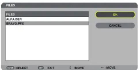
The password screen will be displayed.
- Select [PASSWORD] field and press the ENTER button.
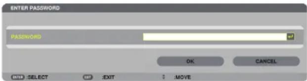
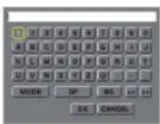
The character entry screen (software keyboard) will be displayed. Set the password of the private key. A password must be 1 character or more and 32 characters or less.
The selected digital certificate file will be installed on the projector.
- When the root CA certificate is not included in the file that was selected in Step 14, proceed to Step 16. When the root certification authority certificate is included, proceed to Step 18.
- Select [CA CERTIFICATE] and press the ENTER button.
The drive list screen will be displayed.
- On the [FILES] screen, select a digital certificate (DER format file) saved in your USB memory device and press the ENTER button.
- Select your root CA certificate here. The selected digital certificate will be installed on the projector.
- After completing required settings, select [OK] and press the ENTER button.
The [WIRELESS] page will be returned.
-
Select [RECONNECT] and press the ENTER button.
-
Select [OK] and press the ENTER button.
This will complete setting [EAP-TLS] for [EAP TYPE] in [WPA-EAP] or [WPA2-EAP].
TIP:
Clearing the digital certificate that is installed on the projector
To clear the digital certificate installed on the projector, follow the steps below.
By doing the following procedure, all the digital certificates for the currently displayed profile will be cleared.
- Select [CLEAR CERTIFICATES] in the bottom left of the [ADVANCED] setting screen and press the ENTER button.
A message for confirmation will be displayed.
- Select [YES] and press the ENTER button.
The digital certificates will be cleared.
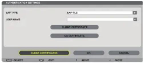
TIP:
- The PKCS#12 format digital certificate including a CA certificate will be installed as a root CA certificate.
② Selecting [PEAP-MSCHAPv2] for [EAP TYPE]:
- From the [AUTHENTICATION] page, select [EAP TYPE] field and press the ENTER button.
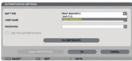
The pull-down list will be displayed.
-
Select [PEAP-MSCHAPv2] and press the ENTER button.
-
Select [USER NAME] field and press the ENTER button.
The character entry screen (software keyboard) will be displayed. Set a user name.
- A user name must be 32 characters or less.
(→ page 145)
- After completing setting a user name, select the [PASSWORD] field and press the ENTER button.
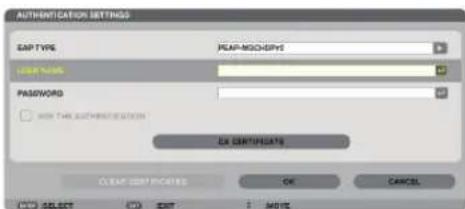
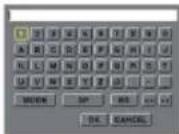
The character entry screen (software keyboard) will be displayed. Set a password.
- A password must be 32 characters or less.
- After completing setting the password, select [CA CERTIFICATE] field and press the ENTER button.
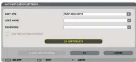
The drive list screen will be displayed.
- For operating the thumbnail screen.
- To return to the [AUTHENTICATION] page, press the EXIT button.
NOTE:
Installing a digital certificate
You can install each digital certificate (client certificate and CA certificate) for [PROFILE 1 (or 2)] on a file-by-file basis.
• Install a root CA certificate for a CA certificate.
- If you install a digital certificate over your existing digital certificate, the existing digital certificate will be overwritten with the new digital certificate.
- Once a digital certificate has been installed, its information cannot be deleted even if you stop setting WPA-EAP or WPA2-EAP.
- On the thumbnail screen, select a digital certificate (DER format file) saved in your USB memory device and press the ENTER button.
- Select your root CA certificate here. The selected digital certificate will be installed on the projector.
- After completing required settings, select [OK] and press the ENTER button.
The [WIRELESS] page will be returned.
-
Select [RECONNECT] and press the ENTER button.
-
Select [OK] and press the ENTER button.
This will complete setting [PEAP-MSCHAPv2] for [EAP TYPE] in [WPA-EAP] or [WPA2-EAP].
TIP:
Clearing the digital certificate that is installed on the projector
To clear the digital certificate installed on the projector, follow the steps below.
By doing the following procedure, all the digital certificates for the currently displayed profile will be cleared.
- Select [CLEAR CERTIFICATES] in the bottom left of the [ADVANCED] setting screen and press the ENTER button.
A message for confirmation will be displayed.
- Select [YES] and press the ENTER button.
The digital certificates will be cleared.
TIP:
Entering WEP keys (Switching between Alphanumeric characters and hexadecimal)
To enter from [KEY1] to [KEY4], do the following:
- Select one of [KEY 1], [KEY 2], [KEY 3] and [KEY 4] and press the ENTER button.
The character entry screen (software keyboard) will be displayed.
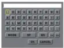
-
Use the ▼, ▲, ◀, or ▶ button to select a character and press the ENTER button.
-
To enter a WEP key or passphrase, use alphanumeric characters (ASCII) or hexadecimal (HEX). To enter a PSK key, use alphanumeric characters (ASCII).
- Press the [HEX] button to change to [ASCII] to set the key in ASCII digit. You can toggle this button between [ASCII] and [HEX].
- Enter Ox(numeral and alphabet respectively) right in front of your key code.
-
Hexadecimal uses 0 to 9 and A to F.
-
After entering your WEP key or passphrase, use the ▼, ▲, ◀, or ▶ button to select [OK] and press the ENTER button.
The character entry screen (software keyboard) will be closed.
WPS(MM)
When the wireless LAN access point connected to the projector supports WPS (Wi-Fi Protected Setup™), you can use PIN method or push button method to set up the wireless LAN for the projector.
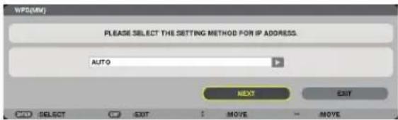
| PIN TYPE | Set a 4-digit or 8 digit-PIN code of WPS for your access point to complete setting for the SSID security. |
| PUSH BUTTON TYPE | Press the dedicated button of the access point and the projector's wireless LAN unit to complete setting for the SSID security. |
NETWORK INFORMATION
The following information will be displayed when the projector is connected to a network (wired LAN or wireless LAN).
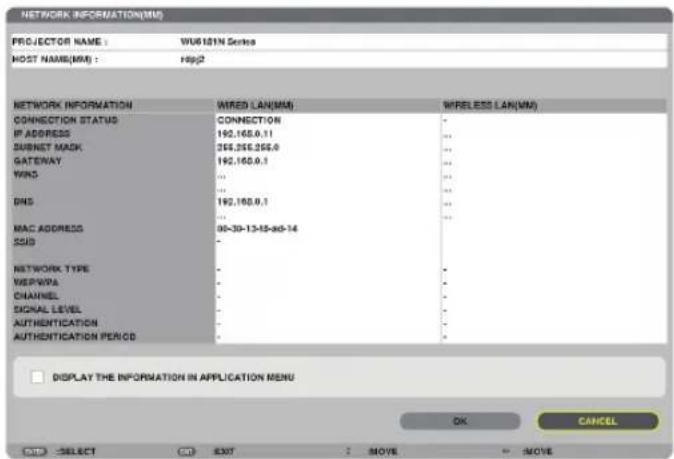
| PROJECTOR NAME | |
| HOST NAME | |
| NETWORK INFORMATION (WIRED LAN/WIRELESS LAN) | CONNECTION STATUS, IP ADDRESS, SUBNET MASK, GATEWAY, WINS, DNS, MAC ADDRESS, SSID, NETWORK TYPE, WEP/WPA, CHANNEL, SIGNAL LEVEL, AUTHENTICATION, AUTHENTICATION PERIOD |
| DISPLAY THE INFORMATION IN APPLICATION MENU | Turn on or off the display of the network information. |
The meanings of these status statements are described below.
| Statement Authentication status | |
| Authenticated Authentication is done correctly. | |
| Failure Authentication failed. | |
| Authenticating... Authentication is in process. | |
| Expired The digital certificate is expired. Or [DATE, TIME PRESET] is not set correctly. | |
| Time Error The [DATE, TIME PRESET] has been cleared. Set the correct date and time. |
HOST NAME (ADVANCED menu only)
Setting up the host name of the projector.
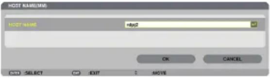
| HOST NAME Set a host name of the projector. Up to 15 alphanumeric | characters |
HTTP SERVER (ADVANCED menu only)
Password setting when using a HTTP server.
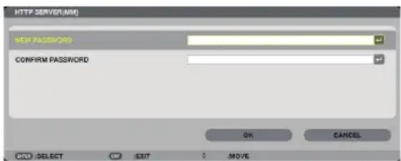
| HTTP SERVER Set a password for your HTTP server. Up to 10 alphanumeric | characters |
6. Connecting to Other Equipment
① Mounting a lens (sold separately)
Six separate bayonet style lenses can be used with this projector. The descriptions here are for the Standard lens Type1 (2x zoom) lens. Mount other lenses in the same manner.
NOTE:
- The projector and lenses are made of precision parts. Do not subject them to shock or excessive forces.
- Remove the separately sold lens when moving the projector. If not, the lens could be subject to shock while the projector is being moved, damaging the lens and the lens shift mechanism.
- Turn off the power and wait for the cooling fan to stop before mounting or removing the lens.
- Never touch the lens surface while the projector is operating.
- Be very careful not to let dirt, grease, etc., on the lens surface and not to scratch the lens surface.
- Perform these operations on a flat surface over a piece of cloth, etc., to prevent the lens from getting scratched.
- When leaving the lens off the projector for long periods of time, mount the dust cap on the projector to prevent dust or dirt from getting inside.
- If you have multiple projectors, be careful of the following:
- When mounting a lens designed exclusively for this projector onto another projector in the WU6181N series, be sure to remove the lens attachment before mounting the lens on the projector. The lens cannot be mounted if its attachment is on. For the types of lenses that can be mounted and instructions on removing them, see the lens's operating instructions.
- Other types of lenses cannot be mounted on this projector.
Mounting the lens
-
Remove the dust cap from the projector.
-
Remove the lens cap on the back of the lens.
-
Insert the lens onto the projector with the yellow-marked protrusion on the lens facing upwards.
There is a positioning slit on the projector's lens insertion slot. Insert the lens slowly all the way in, keeping the positioning slit at the same angle.
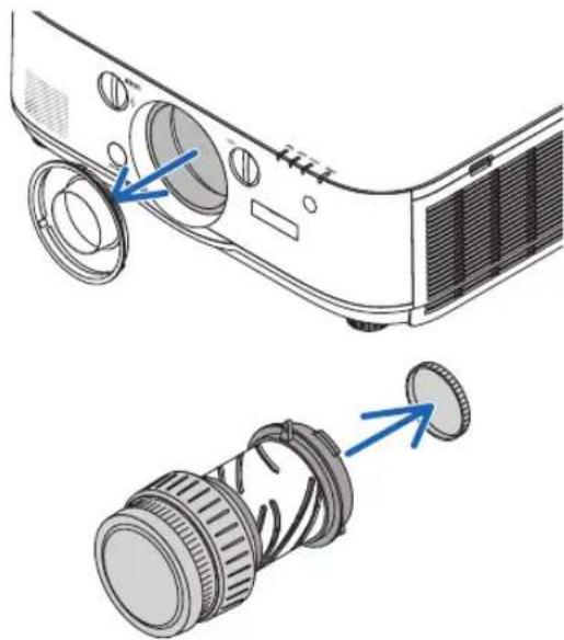
natural_image
Diagram showing two views of a projector with lens and aperture components, no text or symbols present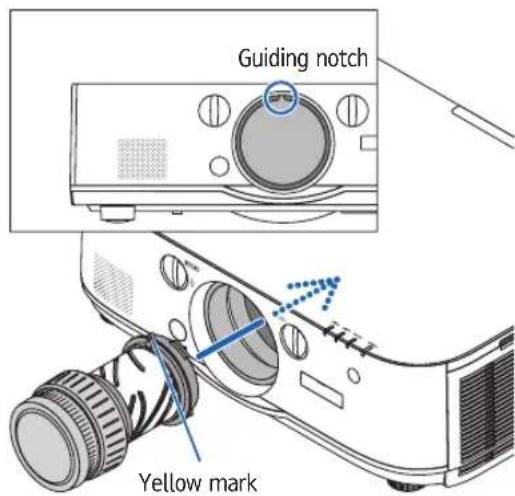
4. Turn the lens clockwise.
Turn until a click is heard.
The lens is now fastened onto the projector.
TIP: Mounting the lens theft prevention screw
Fasten the lens theft prevention screw included with the projector to the bottom of the projector so that the lens cannot be removed easily.
Removing the lens
1. While pressing the lens release button on the projector's front panel fully in, turn the lens counterclockwise.
The lens comes off.
NOTE:
- Check the following areas if the lens unit cannot be removed even when the lens release button is pressed.
-
Check whether the theft prevention screws of the lens unit have been installed.
-
The lens release button may be locked sometimes. In that case, turn the lens fully to the right. The lens release button lock will be released.
2. Slowly pull the lens off the projector.
- After removing the lens, mount the lens caps (front and back) included with the lens before storing the lens.
- If no lens is going to be mounted on the projector, mount the dust cap included with the projector.
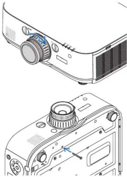
natural_image
Technical line drawing of a projector module with adjustment knobs and a close-up view (no text or symbols)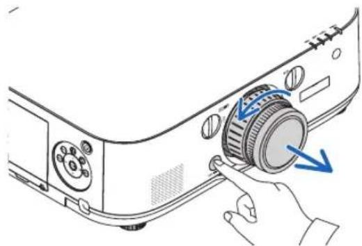
natural_image
Diagram of a projector with a circular dial and blue directional arrows indicating action (no text or symbols)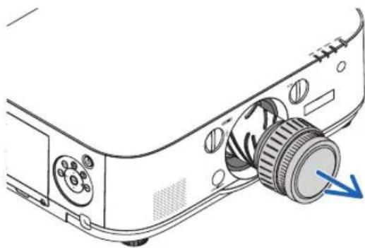
natural_image
Line drawing of a projector with a circular button and directional arrow indicating motion (no text or symbols)② Making Connections
A computer cable, BNC cable (5-core type), HDMI cable, or a DisplayPort cable can be used to connect to a computer. The connection cable is not enclosed with the projector. Please get ready a suitable cable for the connection.
Analog RGB signal connection
- Connect the computer cable to the display output terminal (mini D-sub 15 pin) on the computer and the computer video input terminal on the projector. Please use a computer cable attached with a ferrite core.
- When connecting the display output terminal (mini D-sub 15 pin) on the computer to the BNC video input terminal, use a conversion cable to convert the BNC cable (5 core) to a mini D-sub 15 pin cable.
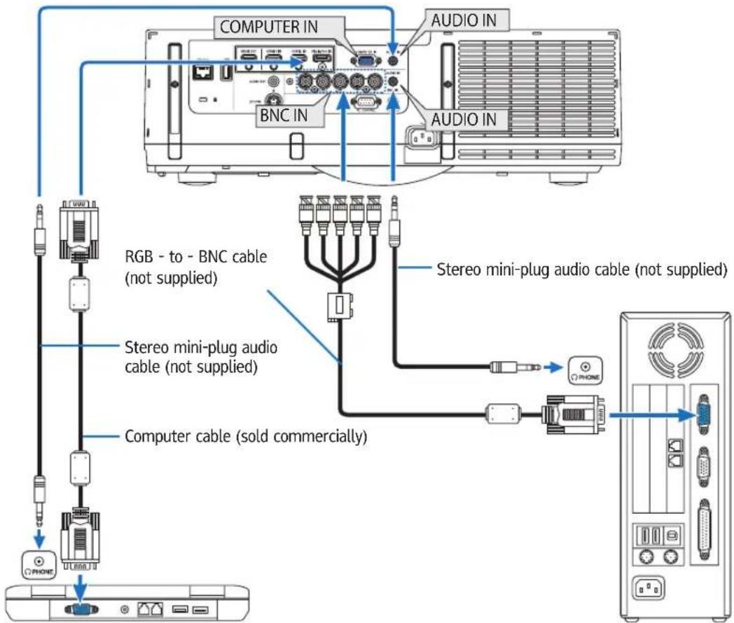
NOTE: Please check the operating manual of the computer as the name, position and direction of the terminal may differ depending on the computer.
- Select the source name for its appropriate input connector after turning on the projector.
| Input connector | INPUT button on the projector cabinet | Button on the remote control |
| COMPUTER IN | 7:COMPUTER 7/COMPUTER | |
| BNC IN | - × 5 4:BNC 4/BNC |
Digital RGB signal connection
- Connect a commercially available HDMI cable between the computer's HDMI output connector and the projector's HDMI1 or HDMI2 input connector.
- Connect a commercially available DisplayPort cable between the computer's DisplayPort output connector and the projector's DisplayPort input connector.
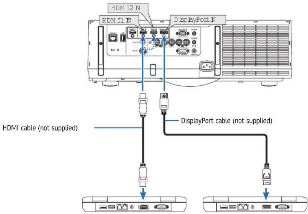
- Select the source name for its appropriate input connector after turning on the projector.
| Input connector | INPUT button on the projector cabinet | Button on the remote control |
| HDMI 1 IN | ||
| HDMI 2 IN | ||
| DisplayPort IN |
Cautions when connecting an HDMI cable
- Use a certified High Speed HDMI ® Cable or High Speed HDMI® Cable with Ethernet.
Cautions when connecting a DisplayPort cable
- Use a certified DisplayPort cable.

- Depending on the computer, some time may be required until the image is displayed.
- Some DisplayPort cables (commercially available) have locks.
- To disconnect the cable, press the button on the top of the cable's connector, then pull the cable out.
- Power can be supplied to the connecting device from the Display Port input terminal (maximum of 1.65 W). However, power will not be supplied to the computer.
- When signals from a device that uses a signal converter adapter are connected to the DisplayPort input connector, in some cases the image may not be displayed.
- When the HDMI output of a computer is connected to the DisplayPort input connector, use a converter (commercially available).
Cautions when using a DVI signal
- When the computer has a DVI output connector, use a commercially available converter cable to connect the computer to the projector's HDMI 1 or HDMI 2 input connector (only digital video signals can be input). Also, connect the computer's audio output to the projector's BNC audio input connector. In this case, switch the HDMI1 or HDMI2 setting at on-screen menu's audio selection on the projector to [BNC]. ( page 125)
To connect the computer's DVI output connector to the projector's DisplayPort input connector, use a commercially available converter.
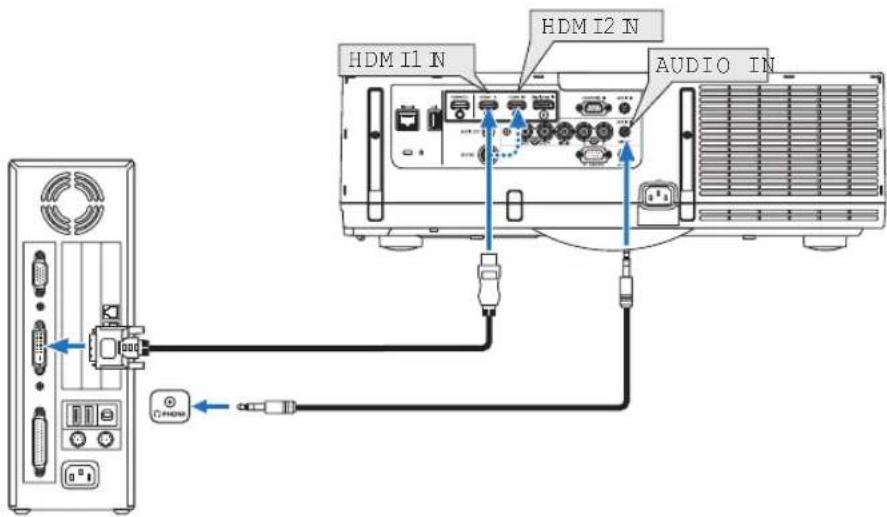
NOTE: When Viewing a DVI Digital Signal
- Turn off the power of the computer and projector before connecting.
- Lower the computer's volume setting before connecting an audio cable to the headphones connector. When using with a computer connected to the projector, adjust the volume of both the projector and computer to set the appropriate volume level.
• If the computer has a mini-jack type audio output connector, we recommend connecting the audio cable to that connector. - When a video deck is connected via a scan converter, etc., the display may not be correct during fast-forwarding and rewinding.
- Use a DVI-to-HDMI cable compliant with DDWG (Digital Display Working Group) DVI (Digital Visual Interface) revision 1.0 standard. The cable should be within 197"/5 m long.
- Turn off the projector and the PC before connecting the DVI-to-HDMI cable.
• To project a DVI digital signal: Connect the cables, turn the projector on, then select the HDMI input. Finally, turn on your PC.
Failure to do so may not activate the digital output of the graphics card resulting in no picture being displayed. Should this happen, restart your PC. - Some graphics cards have both analog RGB (15-pin D-Sub) and DVI (or DFP) outputs. Use of the 15-pin D-Sub connector may result in no picture being displayed from the digital output of the graphics card.
- Do not disconnect the DVI-to-HDMI cable while the projector is running. If the signal cable has been disconnected and then reconnected, an image may not be correctly displayed. Should this happen, restart your PC.
• The COMPUTER video input connectors support Windows Plug and Play. The BNC video input connector does not support Windows Plug and Play. - A Mac signal adapter (commercially available) may be required to connect a Mac computer.
To connect a Mac computer equipped with a Mini DisplayPort to the projector, use a commercially available Mini DisplayPort → DisplayPort converter cable.
Connecting an External Monitor
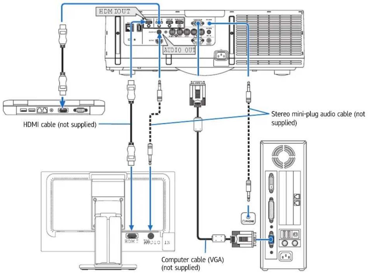
You can connect a separate, external monitor to your projector to simultaneously view on a monitor the computer analog image you're projecting.
- Please refer to Page 65 when displaying the [PIP/PICTURE BY PICTURE] screen.
NOTE:
- When outputting HDMI signals, turn on the power of the video device on the output side and keep it connected before inputting video signals into this device. The HDMI output terminals of the projector are equipped with repeater functions. When a device is connected to the HDMI output terminal, the resolution of the output signal is limited by the resolution supported by the connected device.
- Connecting and disconnecting an HDMI cable or selecting another input source on the second and subsequent projectors will disable the HDMI repeater function.
- In the case of the HDMI output terminal of the projector, the theoretical number of units that can be connected in a series is seven. The maximum number of units that can be connected may be reduced by the external environment and quality of the signal and cable, etc. The number of units that can be connected may differ depending on the HDCP version, restriction on the number of HDCP repeaters in the source device and the quality of the cable. The overall system needs to be checked in advance when building a system.
- When audio equipment is connected, the projector speaker is disabled.
- To output audio from the audio output terminal when the input terminal is neither "COMPUTER IN" nor "BNC IN", select [BNC] under [AUDIO SELECT] of the on-screen menu.
- When the [STANDBY MODE] is set to [NORMAL], video and audio will not be output when the projector is set to the standby mode. Set the standby mode to [NETWORK STANDBY].
- Both the composite video signal from each input connector as the computer, BNC, and BNC (CV), and the S-video signal from the BNC (Y/C) Input connector are not output from HDMI OUT Connector of this projector.
Connecting Your Blu-ray Player or Other AV Equipment
Component video signal/S-video signal connection
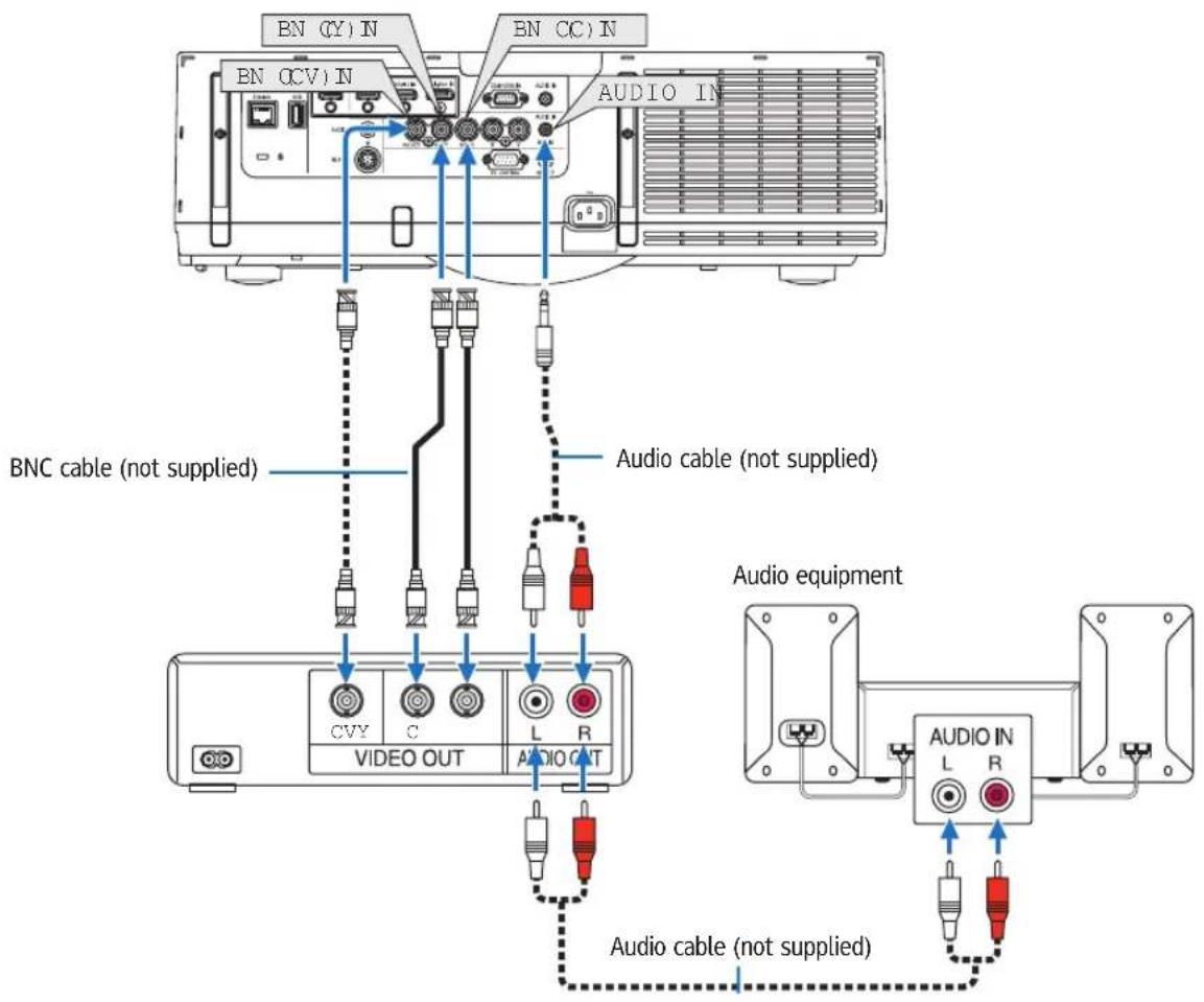
- Select the source name for its appropriate input connector after turning on the projector.
| Input connector | INPUT button on the projector cabinet | Button on the remote control |
| BNC(CV) IN | ||
| BNC(Y/C) IN |
NOTE:
• The BNC (analog RGB/component), BNC (CV) and BNC (Y/C) audio input terminals are shared.
Connecting Component Input
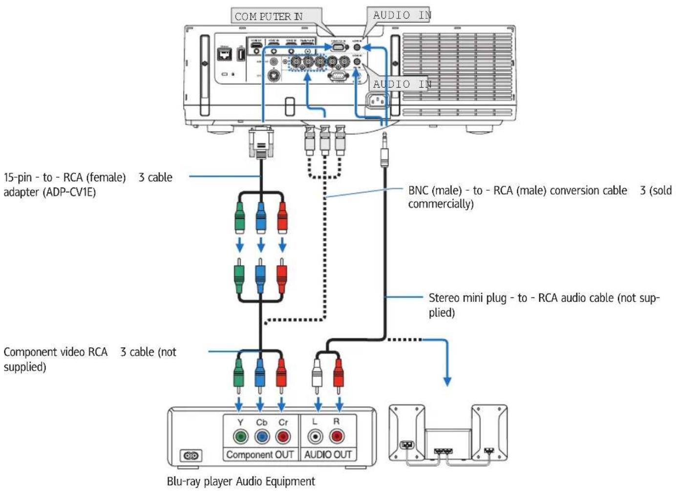
- Select the source name for its appropriate input connector after turning on the projector.
| Input connector | INPUT button on the projector cabinet | Button on the remote control |
| COMPUTER IN | 7:COMPUTER 7/COMPUTER | |
| BNC IN | ●×5 4:BNC 4/BNC |
NOTE:
- When the signal format is set to [AUTO] (default factory setting when shipped), the computer signal and component signal are automatically distinguished and switched. If the signals cannot be distinguished, select [COMPONENT] under [ADJUST] → [VIDEO] → [SIGNAL TYPE] in the on-screen menu of the projector.
• To connect to a video device with a D connector, use the sold separately D connector converter adapter (model ADP-DT1E).
Connecting HDMI Input
You can connect the HDMI output of your Blu-ray player, hard disk player, or notebook type PC to the HDMI 1 IN or HDMI 2 IN connector of your projector.
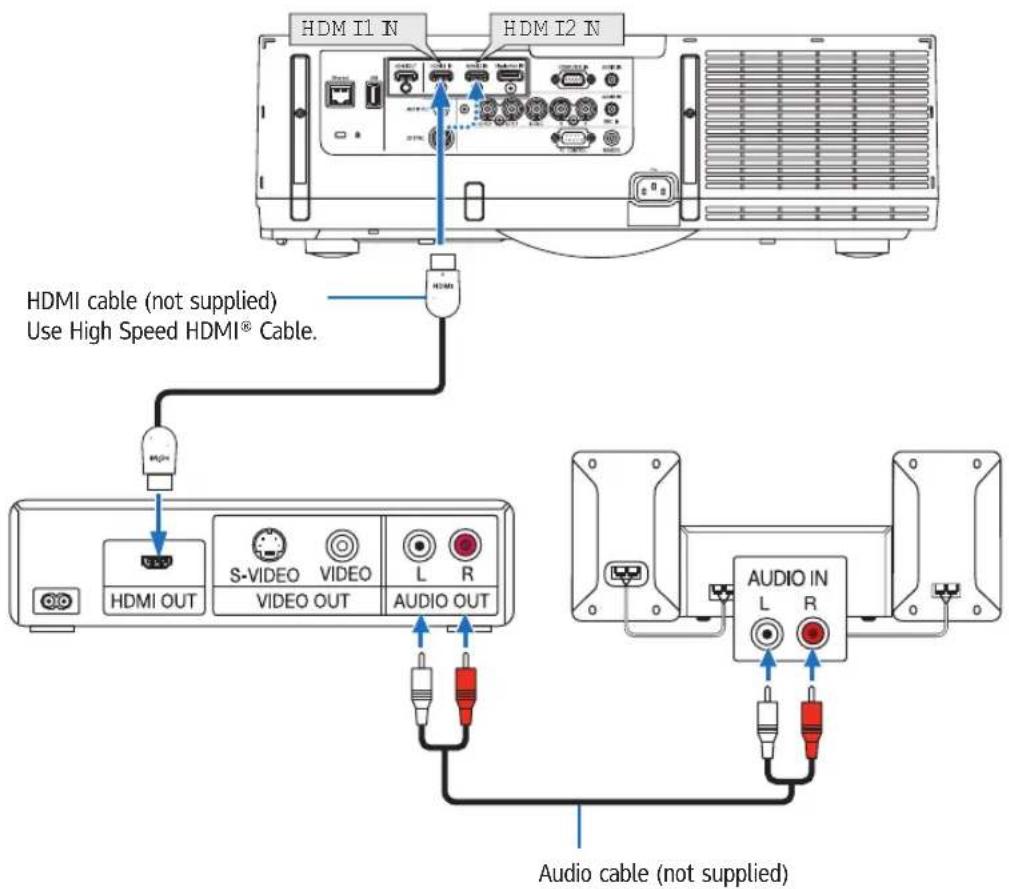
| Input connector | INPUT button on the projector cabinet | Button on the remote control |
| HDMI 1 IN | ||
| HDMI 2 IN |
TIP: For users of audio video equipment with an HDMI connector:
Select "Enhanced" rather than "Normal" if HDMI output is switchable between "Enhanced" and "Normal".
This will provide improved image contrast and more detailed dark areas.
For more information on settings, refer to the instruction manual of the audio video equipment to be connected.
- When connecting the HDMI 1 IN or HDMI 2 IN connector of the projector to the Blu-ray player, the projector's video level can be made settings in accordance with the Blu-ray player's video level. In the menu select [ADJUST] → [VIDEO] → [VIDEO LEVEL] and make necessary settings.
• If the HDMI input sound cannot be heard, in the menu select [AUDIO SELECT] → [HDMI1] or [HDMI2].
- If the HDMI input's sound is not output, check that [SOURCE OPTIONS] → [AUDIO SELECT] → [HDMI1] or [HDMI2] on the projector's on-screen menu is set to "HDMI". (→ page 125)
Portrait projection (vertical orientation)
Portrait screens from a computer can be projected by installing the projector in a vertical orientation. All the screens such as the on-screen menu will be rotated in an counter-clockwise direction.
The projector is equipped with a sensor to automatically detect the installation state.
When the projector is installed in a portrait configuration for the first time with the lamp lit up, a caution message to indicate that the operating time of the lamp may be shortened will be displayed.
This message will automatically disappear when the installation state of the projector is returned to the original state.
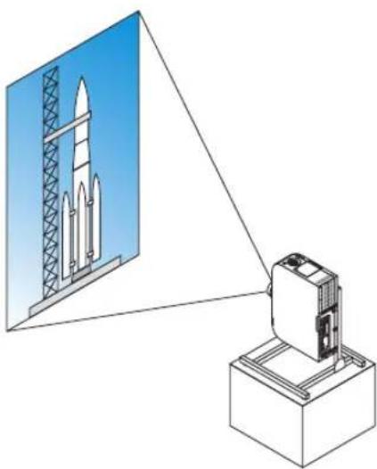
natural_image
Illustration of a rocket being pointed at a base station (no text or symbols present)
Precautions during installation
- Please do not install the projector in a vertical orientation on top of the floor or table on its own. The intake vent may be obstructed, resulting in the projector getting warm and the possibility of fire and malfunction occurring.
- For vertical installation, install the projector with the intake vent (filter) facing downwards. A stand for supporting the projector needs to be made for this purpose. In this case, the stand must be designed such that the center of gravity of the projector is located well within the legs of the stand. If not, the projector may fall over and result in injury, damage and malfunction.
- Do not use the lens shift function when performing portrait projection. Use the position of the lens shift mechanism in the center (lens center).
NOTE:
- The lamp replacement time (as a guide)* is about 2000 hours for portrait projection.
* Replacement time is not guaranteed. - When installing in a portrait configuration for the first time, portrait projection cannot be used when the number of lamp hours used shown under [INFO.] → [USAGE TIME] → [LAMP HOURS USED] in the on-screen menu exceeds 1900 hours.
- When the [FAN MODE] is set to a mode other than [AUTO], portrait projection cannot be used.
Design and manufacturing conditions for the stand
Please engage an installation service provider for the design and manufacture of the customized stand to be used for portrait projection. Please ensure that the following are complied with when designing the stand.
- Maintain an opening of at least 310 170 mm so as not to obstruct the intake vent / filter of the projector.
- Maintain a distance of at least 130 mm between the projector intake vent and the floor (for the opening of the filter cover).
- Use the four screw holes at the back of the projector to secure it to the stand.
Screw hole center dimension: 200 250 mm
Screw hole dimension on the projector: M4 with a maximum depth of 8 mm.
* Please design the stand such that the rear legs at the back of the projector do not contact the stand. The front legs can be turned and removed.
-
Horizontal adjustment mechanism (for example, bolts and nuts in four locations)
-
Please design the stand such that it does not topple over easily.
-
Horizontal adjustment mechanism (for example, bolts and nuts in four locations)
- Please design the stand such that it does not topple over easily.
Reference drawings
* The drawing showing the dimensional requirements is not an actual stand design drawing.
![[Side View] [Front View] 200 Screw holes for 4 - M4 use Tilt foot (remove) Rear foot 130 or greater Filter cover (when opened) Horizontal adjuster [Bottom View] 310 or greater Filter cover](/content/2026/05/872418/images/64a0508af86911ae3305e97cdd0110b67f34498b127df613ff9535b15bded431.jpg)
Lens shift securing method
- Pull the securing lever cover towards you to remove it.
- The cover cannot be detached from the projector.
- Turn the screws to the left to loosen them.
- Screws cannot be removed.
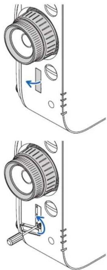
natural_image
Technical illustration of a mechanical device with two views showing a gear assembly and a close-up of the mechanism (no text or symbols present)-
Slide the securing lever towards the top until it comes to a stop and then turn the screws to the right to tighten them.
-
Tighten the screws while pressing the securing lever towards the top.
* Loosen the screws first before re-adjusting the lens shift.
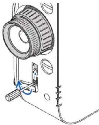
natural_image
Technical diagram of a mechanical device with a pulley and spring mechanism (no text or symbols)- Fix the four securing lever covers.
NOTE:
- Determine the screen position first before using the securing levers.
- Do not turn the zoom ring when using the securing lever. Please do not remove the lens either.
- The securing lever is used to support the lens and not to secure the lens. As a result, the screen may shift when the lens is touched.
Connecting to a Wired LAN
The projector comes standard with a Ethernet port (RJ-45) which provides a LAN connection using a LAN cable.
To use a LAN connection, you are required to set the LAN on the projector menu. Select [SETUP] → [NETWORK SETTINGS] → [WIRED LAN]. (→ page 121).
Example of LAN connection
Example of wired LAN connection
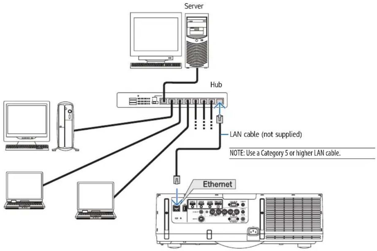
flowchart
graph TD
    Server["Server"] --> Hub["Hub"]
    Hub -->|LAN cable (not supplied)| Server1["Server"]
    Hub -->|LAN cable (not supplied)| Server2["Server"]
    Hub -->|LAN cable (not supplied)| Server3["Server"]
    Hub -->|LAN cable (not supplied)| Ethernet["Ethernet"]
    Server1 -->|Note: Use a Category 5 or higher LAN cable.| Ethernet
    Server2 -->|Note: Use a Category 5 or higher LAN cable.| Ethernet
Connecting to a Wireless LAN (sold separately)
The separately sold wireless LAN unit allows you to use a wireless LAN environment. When using the projector in a wireless LAN environment, the IP address and other settings must be made on the projector.
Important:
- If you use the projector with the USB Wireless LAN Unit in the area where the use of wireless LAN equipment is prohibited, remove the USB Wireless LAN Unit from the projector.
- Buy the appropriate USB Wireless LAN Unit for your country or area.
NOTE:
- The green LED on the USB Wireless LAN Unit flashes to show that the USB Wireless LAN Unit is working.
- Your computer's wireless LAN adapter (or unit) must be complied with Wi-Fi (IEEE802.11b/g/n) standard.
Flow of Setting Wireless LAN
Step 1: Attach the USB Wireless LAN Unit to the projector if required.
Step 2: Display [NETWORK SETTINGS(MM)] from [APPLICATION MENU]. (→ page 138)
Step 3: Select [NETWORK SETTINGS(MM)] → [WIRELESS LAN] → [PROFILES] and set [EASY CONNECTION], [PROFILE 1], or [PROFILE 2]. (→ page 139)
TIP:
Access the HTTP server function to set [NETWORK SETTINGS] → [SETTINGS] → [WIRELESS] → [EASY CONNECTION], [PROFILE1], [PROFILE2].
Mounting a wireless LAN unit

CAUTION:
- The wireless LAN unit is mounted inside the projector. Before mounting it, turn off the power, unplug the power cord and let the projector cool down completely. Removing the filter unit while the projector is running could result in burns or electric shocks from touching internal parts.
NOTE:
- The wireless LAN unit has a front and a back and must be mounted in the wireless LAN port in a specific direction. The port is designed so that the unit cannot be mounted in the opposite direction, but trying to push it in by force could damage the wireless LAN unit port.
- To prevent damage due to static electricity, touch a nearby metal object (a door knob, aluminum sash, etc.) before touching the wireless LAN unit to eliminate the static electricity from your body.
- Disconnect the power cord when mounting and removing the wireless LAN unit.
Mounting and removing the wireless LAN unit while the projector's power is on could damage the wireless LAN unit or result in malfunction on the projector. If the projector should malfunction, turn off the projector's power, unplug the power cord, then plug the power cord back in. -
Do not attach USB devices other the wireless LAN unit to the USB (LAN) port inside the main body. Do not attach the wireless LAN unit to the USB-A port at the terminal unit as well.
-
Press the ⏻ button to set the projector to the standby mode, then disconnect the power cord.
Wait for the projector to fully cool off.
- Press down on the buttons on the left and right and then pull the filter cover towards you to open it.
The cover will open about 90 degrees before it stops.
-
Remove the filter unit by pulling out the tab.
-
Slowly insert the wireless LAN unit into the USB (LAN) port.
- Remove the wireless LAN unit's cap, set the unit with the front (the side with the indicator) facing upwards, hold the back edge and insert the unit gently.
Next, press the wireless LAN unit in with a finger.
- The cap you have removed will be used when the wireless LAN unit is removed, so store it in a safe place.
NOTE: If the wireless LAN unit is hard to insert, do not push it in by force.
- Mount the filter unit back onto the projector cabinet.
Insert the filter unit onto the projector with the sides on which the left and right hooks are located on the outside.
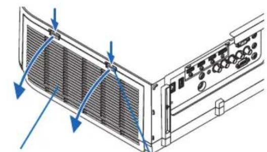
natural_image
Diagram of a computer rack with ventilation grilles and control panel (no text or symbols)Filter cover Button
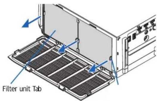
Wireless LAN unit
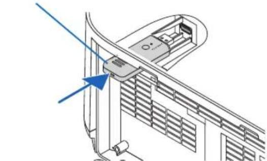
natural_image
Technical diagram of a mechanical assembly with a blue arrow pointing to a component (no text or symbols present)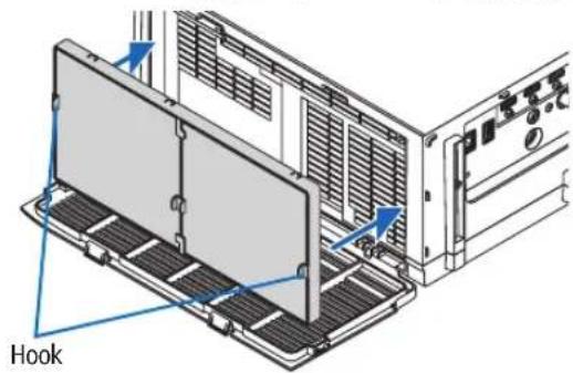
- Close the filter cover.
After closing, push the filter cover near the buttons until a "click" sound is heard. The filter cover will be secured in position.
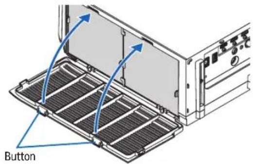
To remove the wireless LAN unit
- Remove the filter unit following steps 1 to 3 above.
- Remove the wireless LAN unit.
If the wireless LAN unit is hard to remove, place a cloth, etc., over needle-nose pliers to grasp the wireless LAN unit and pull it out.
NOTE: Do not grasp the wireless LAN unit with excessive force. Doing so will damage it.
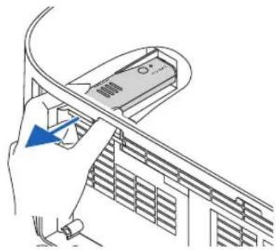
natural_image
Illustration of a hand inserting a cable into a car air conditioner unit (no text or symbols visible)- Mount the filter unit and filter cover as described in steps 5 and 6 above.
Example of wireless LAN connection
(Network Type → Infrastructure)
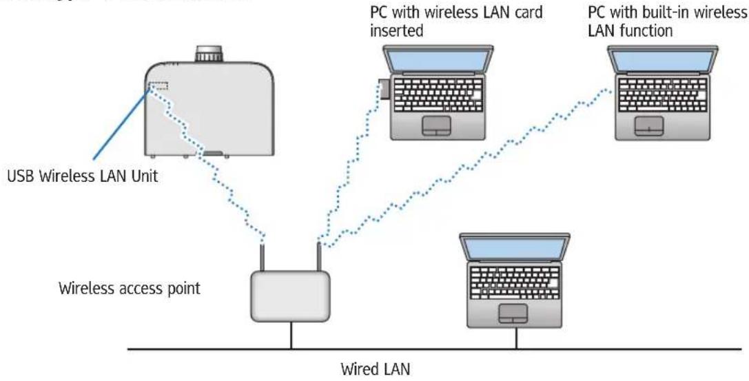
flowchart
graph TD
    A["USB Wireless LAN Unit"] --> B["Wireless access point"]
    B --> C["PC with wireless LAN card inserted"]
    C --> D["PC with built-in wireless LAN function"]
    D --> E["PC with wireless LAN card inserted"]
    E --> F["PC with built-in wireless LAN function"]
    style A fill:#f9f,stroke:#333
    style B fill:#ccf,stroke:#333
    style C fill:#cfc,stroke:#333
    style D fill:#fcc,stroke:#333
    style E fill:#cff,stroke:#333
    style F fill:#ffc,stroke:#333
(Network Type → Ad Hoc)
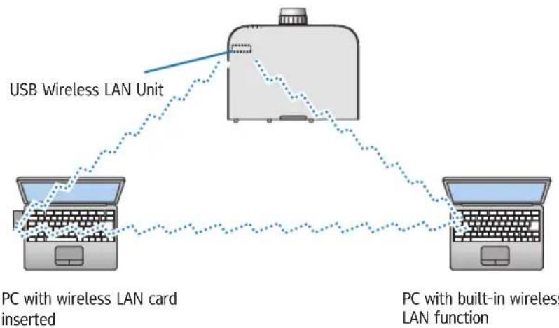
flowchart
graph TD
    A["USB Wireless LAN Unit"] --> B["PC with wireless LAN card inserted"]
    B --> C["PC with built-in wireless LAN function"]
    C --> A
To enable direct communication (i.e., peer-to-peer) between personal computers and projectors, you need to select the Ad Hoc mode.
7. Maintenance
This section describes the simple maintenance procedures you should follow to clean the filters, the lens, the cabinet, and to replace the lamp and the filters.
① Cleaning the Filters
The air-filter sponge keeps dust and dirt from getting inside the projector and should be frequently cleaned. If the filter is dirty or clogged, your projector may overheat.

WARNING
- Please do not use a spray containing flammable gas to remove dust attached to the filters, etc. Doing so may result in fires.
NOTE: The message for filter cleaning will be displayed for one minute after the projector is turned on or off. When the message is displayed, clean the filters. The time to clean the filters is set to [OFF] at time of shipment. (→ page 108)
To cancel the message, press any button on the projector cabinet or the remote control.
The two-layer filter on the projector improves cooling and dust-proof capabilities compared with the conventional models.
The outsides (the intake vent side) of the first and second layer filters remove dust.
To clean the filter, detach the filter unit and the filter cover.

CAUTION
- Before cleaning the filters, turn off the projector, disconnect the power cord and then allow the cabinet to cool. Failure to do so can result in electric shock or burn injuries.
- Press down on the buttons on the left and right and then pull the filter cover towards you to open it.
The cover will open about 90 degrees before it stops.
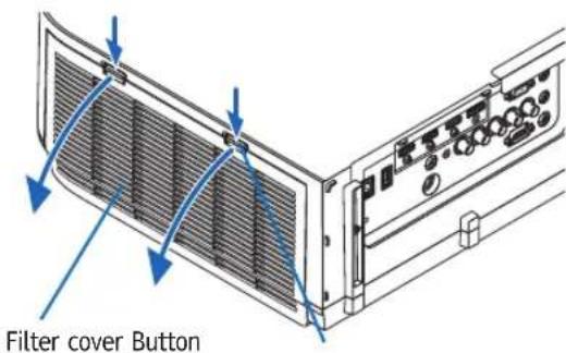
When mounting the projector to a ceiling
The filter cover will open about 90 degrees before it comes to a stop at the stopper position. Remove your hands as the stopper will be detached if it is opened further. The filter cover will stop at a position of about 90 degrees.
However, the filter cover may close if the projector vibrates.
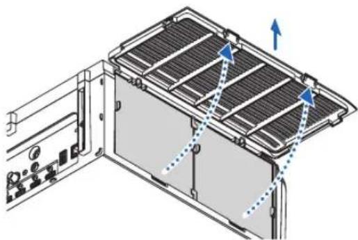
natural_image
Diagram of a server rack with ventilation grilles and directional arrows indicating airflow or movement (no text or symbols)-
Remove the filter unit by pulling out the tab.
-
Remove the four filters.
Hold and remove the filters fitted to the two sides of the filter unit.
- Use a vacuum cleaner to vacuum all the dust inside.
Get rid of dust in the filter.
NOTE:
- Whenever you vacuum the filter, use the soft brush attachment to vacuum. This is to avoid damage to the filter.
-
Do not wash the filter with water. Doing so can result in filter clogging.
-
Remove the dust on the front and back of the filter unit.
- Please also remove all dust from the filter cover of the projector.
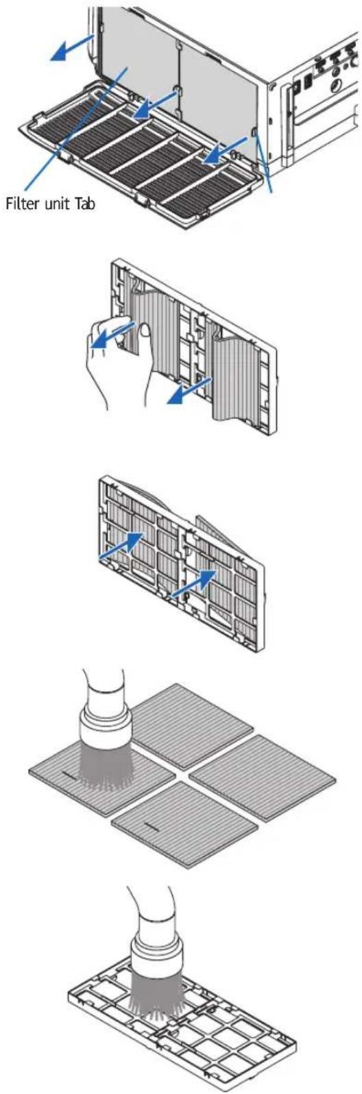
6. Attach 4 new filters to both sides of the filter unit.
The installation locations of the filters are differentiated by whether there are any slits (notches). Install the filter under the flange around the filter unit as follows.
(1) Attach the 2 filters with transparent frames fitted to the grips to the side of the filter unit where the knob is located.
- Turn over the side of the filter with the transparent box and then install it.
(2) Attach the 2 filters with the black lines to the side of the filter unit where there is no knob.
- Turn over the side of the filter with the black line, and then insert the slits into the protrusions on the filter unit to install it.
7. Mount the filter unit back onto the projector cabinet.
Insert the filter unit onto the projector with the sides on which the left and right hooks are located on the outside.
8. Close the filter cover.
After closing, push the filter cover near the buttons until a "click" sound is heard. The filter cover will be secured in position.
9. Clear the filter usage hours.
Plug the power cord into the wall outlet, and then turn on the projector.
From the menu, select [RESET] → [CLEAR FILTER HOURS]. (→ page 130)
The interval time to clean the filters is set to [OFF] at time of shipment. When using the projector as it is, you do not clear the filter usage
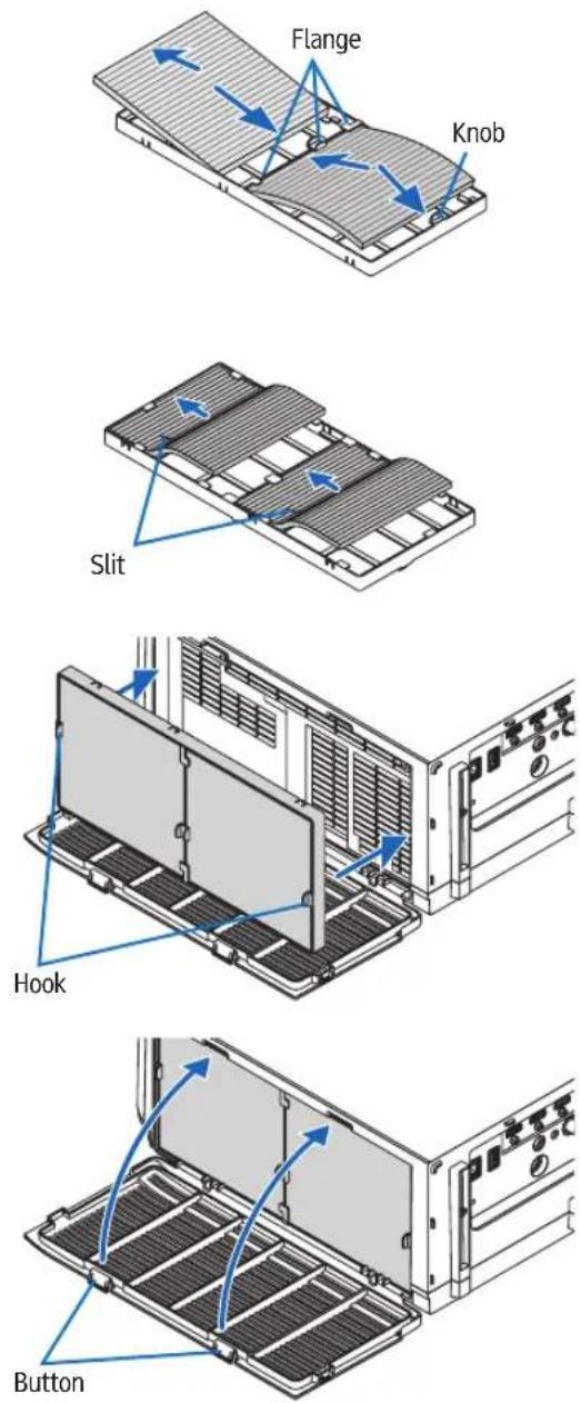
② Cleaning the Lens
- Turn off the projector before cleaning.
- The projector has a plastic lens. Use a commercially available plastic lens cleaner.
- Do not scratch or mar the lens surface as a plastic lens is easily scratched.
- Never use alcohol or glass lens cleaner as doing so will cause damage to the plastic lens surface.

WARNING
- Please do not use a spray containing flammable gas to remove dust attached to the lens, etc. Doing so may result in fires.
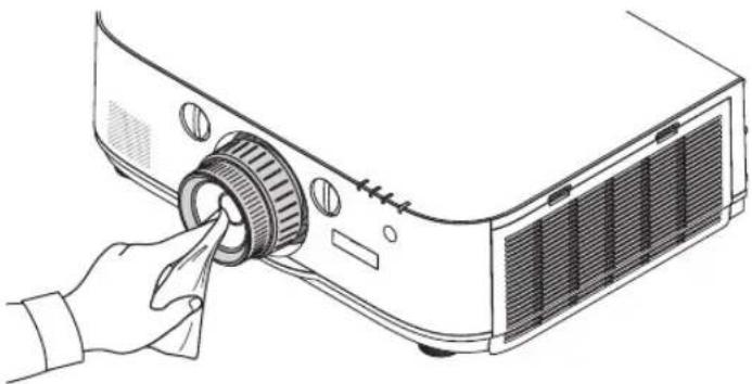
natural_image
Line drawing of a projector with a hand inserting a button to the left (no text or symbols)③ Cleaning the Cabinet
Turn off the projector, and unplug the projector before cleaning.
- Use a dry soft cloth to wipe dust off the cabinet.
If heavily soiled, use a mild detergent. - Never use strong detergents or solvents such as alcohol or thinner.
- When cleaning the ventilation slits or the speaker using a vacuum cleaner, do not force the brush of the vacuum cleaner into the slits of the cabinet.
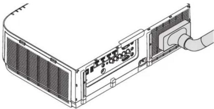
natural_image
Technical line drawing of a server rack with ventilation grilles and a cable inserted (no text or symbols)Vacuum the dust off the ventilation slits.
- Clogged ventilation slits may cause a rise in the internal temperature of the projector, resulting in malfunction.
- Do not scratch or hit the cabinet with your fingers or any hard objects
- Contact your dealer for cleaning the inside of the projector.
NOTE: Do not apply volatile agent such as insecticide on the cabinet, the lens, or the screen. Do not leave a rubber or vinyl product in prolonged contact with it. Otherwise the surface finish will be deteriorated or the coating may be stripped off.
④ Replacing the Lamp and the Filters
When the lamp reaches the end of its life, the LAMP indicator in the cabinet will blink red and the message "THE LAMP HAS REACHED THE END OF ITS USABLE LIFE. PLEASE REPLACE THE LAMP AND FILTER. USE THE SPECIFIED LAMP FOR SAFETY AND PERFORMANCE." will appear (*). Even though the lamp may still be working, replace the lamp to maintain the optimal projector performance. After replacing the lamp, be sure to clear the lamp hour meter. (→ page 129)

CAUTION
- DO NOT TOUCH THE LAMP immediately after it has been used. It will be extremely hot. Turn the projector off and then disconnect the power cord. Allow at least one hour for the lamp to cool before handling.
- Use the specified lamp for safety and performance.
- DO NOT REMOVE ANY SCREWS except one lamp cover screw and two lamp housing screws. You could receive an electric shock.
- Do not break the glass on the lamp housing.
Keep finger prints off the glass surface on the lamp housing. Leaving finger prints on the glass surface might cause an unwanted shadow and poor picture quality.
- The projector will turn off and go into standby mode when you continue to use the projector for another 100 hours after the lamp has reached the end of its life. If this happens, be sure to replace the lamp. If you continue to use the lamp after the lamp reaches the end of its life, the lamp bulb may shatter, and pieces of glass may be scattered in the lamp case. Do not touch them as the pieces of glass may cause injury. If this happens, contact your Ricoh dealer for lamp replacement.
*NOTE: This message will be displayed under the following conditions:
• for one minute after the projector has been powered on
- when the ⏻ (POWER) button on the projector cabinet or the STANDBY button on the remote control is pressed
To turn off the message, press any button on the projector cabinet or the remote control.
Optional lamp and tools needed for replacement:
- Phillips screwdriver (plus-head)
- Replacement lamp: Type21
Flow of Replacing the Lamp and the Filters
Step 1. Replace the lamp
Step 2. Replace the filters ( page 178)
Step 3. Clear the lamp usage hours and the filter usage hours ( page 129, 130)
To replace the lamp:
1. Remove the lamp cover.
(1) Loosen the lamp cover screw
- The lamp cover screw is not removable.
(2) Pull the bottom of the lamp cover towards you and remove it.
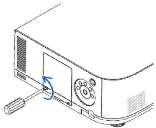
natural_image
Line drawing of a projector with a blue circular arrow indicating rotation (no text or symbols)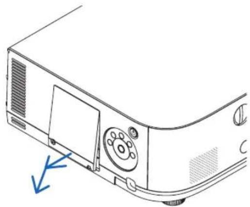
natural_image
Line drawing of a projector casing with control panel and ventilation slots (no text or symbols)2. Remove the lamp housing.
(1) Loosen the two screws securing the lamp housing until the phillips screwdriver goes into a freewheeling condition.
- The two screws are not removable.
- There is an interlock on this case to prevent the risk of electrical shock. Do not attempt to circumvent this interlock.
(2) Remove the lamp housing by holding it.

CAUTION:
Make sure that the lamp housing is cool enough to before removing it.
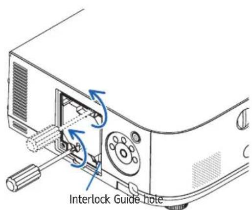
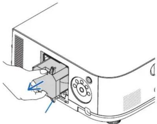
natural_image
Line drawing of a hand inserting a device into a projector (no text or symbols)3. Install a new lamp housing.
(1) Insert a new lamp housing until the lamp housing is plugged into the socket.
(2) Position so that the guide hole in the bottom right of the lamp house is over the protrusion on the projector then press all the way in.
(3) Secure it in place with the two screws.
- Be sure to tighten the screws.
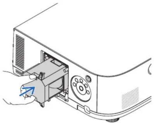
natural_image
Diagram of a computer monitor with an open case and a blue arrow pointing to the handle (no text or symbols present)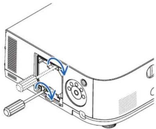
natural_image
Diagram of a computer monitor with an open control panel and blue arrows indicating rotation or adjustment (no text or symbols present)4. Reattach the lamp cover.
(1) Insert the top edge of the lamp cover into the groove in the projector and close the lamp cover.
(2) Tighten the screw to secure the lamp cover.
- Be sure to tighten the screw.
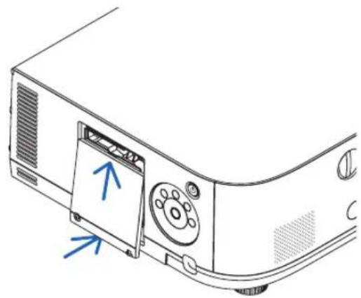
natural_image
Line drawing of a projector module with an open lid and blue arrows indicating direction (no text or symbols)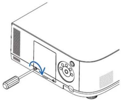
natural_image
Diagram of a computer monitor with a scroll wheel and cable, showing a blue circular arrow indicating rotation (no text or symbols present)This completes the lamp replacement. Go on to the filter replacement.
NOTE:
- When you continue to use the projector for another 100 hours after the lamp has reached the end of its life, the projector cannot turn on and the menu is not displayed. If this happens, press the HELP button on the remote control for 10 seconds to reset the lamp clock back to zero. When the lamp time clock is reset to zero, the LAMP indicator goes out.
- For portrait projection, the power supply will be switched off when the lamp replacement time (estimated)* is reached. A lamp replacement message will be displayed 100 hours before the lamp replacement time is reached.
* The replacement time is not guaranteed.
To replace the filters:
Four filters are packaged with the replacement lamp.
Honeycomb filter (coarse mesh): Large and small sizes (attached to the outside of the filter unit)
Accordion filter (fine mesh): Large and small sizes (attached to the inside of the filter unit)
NOTE:
- Replace all four filters at the same time.
- Before replacing the filters, wipe off dust and dirt from the projector cabinet.
- The projector is precision equipment. Keep out dust and dirt during filter replacement.
- Do not wash the filters with soap and water. Soap and water will damage the filter membrane.
- Put filters into place. Incorrect attachment of a filter may cause dust and dirt to get into the inside of the projector.
Before replacing the filters, replace the lamp. (→ page 176)
1. Press down on the buttons on the left and right and then pull the filter cover towards you to open it.
The cover will open about 90 degrees before it stops.
When mounting the projector to a ceiling
The filter cover will open about 90 degrees before it comes to a stop at the stopper position. Remove your hands as the stopper will be detached if it is opened further. The filter cover will stop at a position of about 90 degrees.
However, the filter cover may close if the projector vibrates.
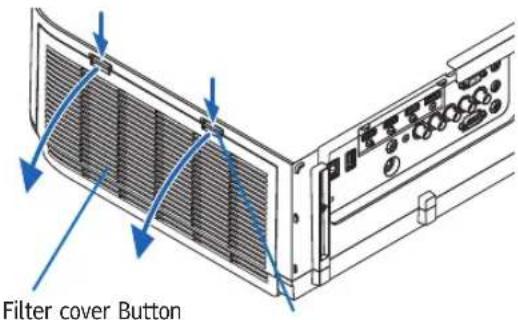
2. Remove the filter unit by pulling out the tab.
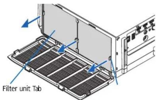
3. Remove the four filters.
Hold onto the filters fitted to both sides of the filter unit to remove the filter unit.
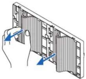
natural_image
Illustration of a hand inserting a component into a grid-like structure (no text or symbols)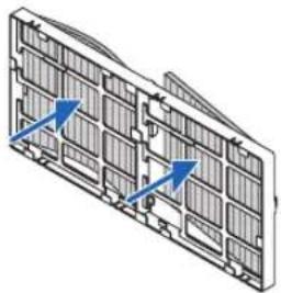
natural_image
Technical diagram of a multi-panel air vent or rack structure with blue directional arrows indicating flow or movement (no text or symbols present)- Remove dust from the filter unit and the filter cover.
Clean both outside and inside.
- Attach 4 new filters to both sides of the filter unit.
The installation locations of the filters are differentiated by whether there are any slits (notches). Install the filter under the flange around the filter unit as follows.
(1) Attach the 2 filters with transparent frames fitted to the grips to the side of the filter unit where the knob is located.
- Turn over the side of the filter with the transparent box and then install it.
(2) Attach the 2 filters with the black lines to the side of the filter unit where there is no knob.
- Turn over the side of the filter with the black line, and then insert the slits into the protrusions on the filter unit to install it.
- Mount the filter unit back onto the projector cabinet.
Insert the filter unit onto the projector with the sides on which the left and right hooks are located on the outside.
- Close the filter cover.
After closing, push the filter cover near the buttons until a "click" sound is heard. The filter cover will be secured in position.
This completes the filter replacement.
Go on to the clearing lamp and filter hour meters.
To clear the lamp usage hours and the filter usage hours:
-
Place the projector where you use it.
-
Plug the power cord into the wall outlet, and then turn on the projector.
-
Clear the lamp usage hours and the filter usage hours.
-
From the menu, select [RESET] → [CLEAR LAMP HOURS] and reset the lamp usage hours.
-
Select [CLEAR FILTER HOURS] and reset the filter usage hours. (→ page 130)
8. User Supportware
① Operating Environment for Software Included on CD-ROM
Names and Features of Bundled Software Programs
| Name of software program Features | |
| Projection Utility | This is a software program used to project your computer's screen, streaming movie, or sound from the computer over the wired/wireless network. The computer cable (VGA) is not required. (→ page 186)This software program can be used to control the power ON/OFF and source selection of the projector from your computer.The Geometric Correction Tool (GCT) and audio function allows you to correct distortion of images projected on a curved wall. (→ page 193) The GCT function is not available for streaming video. |
| Projection Utility for Mac OS | This is a software program used to project your computer's screen over the wired/ wireless network. The computer cable (VGA) is not required. (→ page 192)This software program can be used to control the power ON/OFF and source selection of the projector from your computer. |
| Advanced Network Utility (Windows only) | This is a software program used to send the screens of your personal computers to the projector via wired/wireless LAN (Meeting mode).Projected images can be transferred and saved to personal computers.When "Meeting Mode" is used, projected images can be sent and saved to the personal computers. Images can be sent from a personal computer to not only one projector but also to two or more projectors at the same time. (→ page 195) |
| Jpeg Conversion Tool | The JPEG Conversion Tool converts JPEG files not supported by the projector, image files in other formats, PowerPoint files, and other similar files into JPEG files. (→ page 206) |
| Projector Management Utility | Projector Management Utility conforms to the PJLink class 1 standards, and is compatible with all class 1 commands.A maximum of 100 projectors connected to the network can be managed using one computer. (→ page 207)Projector Management Utility's operating environment, see page 207. |
NOTE:
- Projection Utility does not support "Meeting Mode" in Advanced Network Utility included with our other models.
- Take note of the following point when using the three software (Projection Utility (for Windows and Mac OS), Advanced Network Utility in the [NETWORK STANDBY] mode.
When the projector is in the [NETWORK STANDBY] mode, communications will not be possible for about 20 seconds after the power supply of the projector is turned on.
Download service
For the update information about these software programs, visit our website:
URL: http://www.ricoh.com/downloads/
Operating Environment
The following is the operating environment for Projection Utility. For the operating environment of other software program, refer to the help function of each software program.
[Windows]
| Supported OS Windows 8/8.1 (Core Edition) | Windows 8/8.1 ProWindows 8/8.1 EnterpriseWindows 7 Home BasicWindows 7 Home PremiumWindows 7 ProfessionalWindows 7 UltimateWindows 7 EnterpriseWindows Vista Home BasicWindows Vista Home PremiumWindows Vista BusinessWindows Vista UltimateWindows Vista EnterpriseWindows power-saving function is not supported.To use the audio transfer capability, Windows 8/8.1/Windows 7/Windows Vista Service Pack 1 or later is required. |
| Processor · Windows 8/8.1/Windows 7/ | Windows VistaPentium M 1.2 GHz equivalent or higher requiredDual core 1.5 GHz or higher recommended |
| Memory · Windows 8/8.1/Windows 7/ | Windows Vista512 MB or more required1 GB or more recommended* More memory may be required to run additional applications simultaneously. |
| Graphic processor · Windows 8/8.1/ | Windows 7/Windows VistaThe "Graphics" score 3.0 or more of "Windows Experience Index" recommended. |
| Network environment TCP/IP-compatible | wired LAN or wireless LAN* Use a wireless LAN unit complying with the Wi-Fi standard.* Audio transfer capability requires 3 Mbps or more throughput. |
| Resolution · Windows 8/8.1/Windows | 7/Windows VistaSVGA (800 600) or higher requiredXGA (1024 768) recommended(1024 768 - 1280 800 recommended for WXGA type) |
| Screen Colors High Color (15 bits, 16 bits) | True Color (24 bits, 32 bits) (recommended)· 256 or fewer colors are not supported. |
[Mac]
| Supported OS Mac OS X v10.7, v10.8, | v10.9, v10.10 |
| Processor (CPU) Intel | ® CoreTM Duo processor 1.5 GHz or higher requiredIntel® CoreTM 2 Duo processor 1.6 GHz or higher recommended* PowerPC® is not supported |
| Memory 512 MB or higher required | |
| Network environment Wired or wireless | LAN required that supports TCP/IP* The following LAN adapters are verified to work with Projection Utility:Wired LAN adapter built into MacWireless LAN adapter built into MacApple USB Ethernet adapterApple Thunderbolt Ethernet adapter“Easy Connection” supports only wireless LAN. |
| Supported Resolution SVGA (800 600) | or higher requiredXGA (1024 768) recommended(1024 768 - 1280 800 recommended for WXGA type) |
| Supported Screen Colors 16.70 million | colors required |
② Installing Software Program
Installation for Windows software
NOTE:
- To install or uninstall each software program, the Windows user account must have "Administrator" privilege (Windows 8/8.1, Windows 7, Windows Vista).
- Exit all running programs before installation. If another program is running, the installation may not be completed.
1 Insert the accompanying CD-ROM into your CD-ROM drive.
The menu window will be displayed.
TIP:
If the menu window will not be displayed, try the following procedure.
For Windows 7
- Click "start" on Windows.
- Click "All Programs" → "Accessories" → "Run".
- Type your CD-ROM drive name (example: "Q:\") and "LAUNCHER.EXE" in "Name". (example: Q:\LAUNCHER.EXE)
- Click "OK".
The menu window will be displayed.
2 Click a software program you wish to install on the menu window.
The installation will start.
- Follow the instructions on the installer screens to complete the installation.
TIP:
Uninstalling a Software Program
Preparation:
Exit the software program before uninstalling. To uninstall the software program, the Windows user account must have "Administrator" privilege (Windows 8/8.1, Windows 7, and Windows Vista).
• For Windows 8/8.1/Windows 7/Windows Vista
1 Click "Start" and then "Control Panel".
The Control Panel window will be displayed.
2 Click "Uninstall a program" under "Programs"
The "Programs and Features" window will be displayed.
3 Select the software program and click it.
4 Click "Uninstall/Change" or "Uninstall".
- When the "User Account Control" windows is displayed, click "Continue".
Follow the instructions on the screens to complete the uninstallation.
Using on Mac OS
[Example] Install Projection Utility on the computer.
- Insert the accompanying CD-ROM in your Mac CD-ROM drive.
The CD-ROM icon will be displayed on the desktop.
- Double-click the CD-ROM icon.
The CD-ROM window will be displayed.
-
Double-click the "Mac OS X" folder.
-
Double-click "Projection Utility.pkg".
The installer will start.
- Click "Next".
"END USER LICENSE AGREEMENT" screen will be displayed.
- Read "END USER LICENSE AGREEMENT" and click "Next".
The confirmation window will be displayed
- Click "I accept the terms in the license agreement".
Follow the instructions on the installer screens to complete the installation.
TIP:
- Uninstalling a software program
-
Put the "Projection Utility" folder to the Trash icon.
-
Put the configuration file of Projection Utility to the Trash icon.
- The configuration file of Projection Utility is located in "/Users/
③ Projecting Your Computer's Screen Image or Video from the Projector over a LAN (Projection Utility)
Using Projection Utility contained on the supplied CD-ROM allows you to send the computer's screen image to the projector over a wired or wireless LAN.
Projection Utility is a program compatible with Windows.
Projection Utility for Mac OS is a program compatible with Mac OS. (→ page 192)
This section will show you an outline about how to connect the projector to a LAN and to use Projection Utility. For the operation of Projection Utility, see the help of Projection Utility.
Step 1: install Projection Utility on the computer.
Step 2: Connect the projector to a LAN.
Step 3: Start Projection Utility.
TIP:
- Projection Utility (for Windows) can be started from most commercially available removable media such as USB memory devices or SD cards without the need to install on your computer. (→ page 191)
What You can Do with Projection Utility
• Image transmission (for Windows and Mac OS)
• The screen of your computer can be sent to the projector via a wired or wireless network without a computer cable (VGA).
- By using "EASY CONNECTION" function, the complicated network settings can be simplified and the computer will automatically connect to the projector.
- The screen of your computer can be sent to up to four projectors at the same time.
• Audio transfer capability (for Windows only)
- Projection Utility allows you to send the computer's screen image and audio to the projector over wired/wireless LAN or USB connection.
- Audio transfer capability is available only when the computer connects with the projector in peer-to-peer network.
- Playing streaming video (for Windows only)
- Projection Utility allows you to send streaming video from the computer to a single projector over wired or wireless LAN without the need of connecting a computer cable. For list of supported movie files and playback requirements, see page 208 of "9. Using the Viewer".
- Geometric Correction Tool [GCT] (for Windows only)
See “⑥ Projecting an Image from an Angle (Geometric Correction Tool in Projection Utility)”. (→ page 193)
NOTE:
- When Projection Utility is used, the audio from the COMPUTER AUDIO IN Mini Jack (Stereo Mini) may not be synchronized with the video.
Using on Windows
Step 1: install Projection Utility on the computer.
NOTE:
- To install or uninstall the program, the Windows user account must have "Administrator" privilege (Windows 7, Windows Vista).
- Exit all running programs before installation. If another program is running, the installation may not be completed.
- Projection Utility will be installed to the system drive of your computer.
If the message "There is not enough free space on destination" is displayed, free up enough space (about 100 MB) to install the program.
1. Insert the accompanying CD-ROM into your CD-ROM drive.
The menu window will be displayed.
TIP:
If the menu window will not be displayed, try the following procedure.
For Windows 7:
- Click "start" on Windows.
- Click "All Programs" → "Accessories" → "Run".
-
Type your CD-ROM drive name (example: "Q:\") and "LAUNCHER.EXE" in "Name". (example: Q:\LAUNCHER.EXE)
-
Click "OK".
The menu window will be displayed.
2. Click "Installing Projection Utility" on the menu window.
The installation will start.
"END USER LICENSE AGREEMENT" screen will be displayed.
Read "END USER LICENSE AGREEMENT" carefully
3. If you agree, click "I agree." and then click "Next".
- Follow the instructions on the installer screens to complete the installation.
- When the installation is complete, you will return to the menu window.
When the installation is complete, a completion message will be displayed.
4. Click "OK".
This completes the installation.
TIP:
- Uninstalling Projection Utility
To uninstall Projection Utility, do the same procedures stated as in "Uninstalling a software program". (→ page 185)
Step 2: Connect the projector to a LAN.
Connect the projector to the LAN by following the instructions in "Connecting to a Wired LAN" ( page 166) and "9. Controlling the Projector by Using an HTTP Browser" ( page 42)
Step 3: Start Projection Utility.
- On Windows, click "Start" → "All programs" → "Ricoh Projector UserSupportware" → "Projection Utility" → "Projection Utility".
Projection Utility will start.
The select window for network connection will be displayed
- Select Network and click "OK".
The select window for destination will show a list of connectable projectors.
- When connecting the computer directly to the projector by one-to-one, "Easy Connection" is recommended.
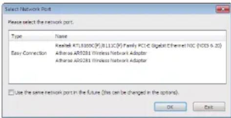
- When one or more networks for "EASY CONNECTION" are found, the "Easy Connection Selection Screen" window will be displayed.
-
To verify the network used by the projector to be connected, display the [INPUT TERMINAL] → [ETHERNET] → [NETWORK SETTINGS (MM)] → [NETWORK INFORMATION] screen on the on-screen menu of the projector and check the "SSID" character string.
-
Select the network you wish to connect, and click "Select".
The target selection window will be displayed.
- Place a check mark for projectors to be connected, and then click "Connect".
- When multiple projectors are displayed, display the [INPUT TERMINAL] → [ETHERNET] → [NETWORK SETTINGS (MM)] → [NETWORK INFORMATION] screen on the on-screen menu of the projectors to be connected and check the [IP ADDRESS]. When connecting with the projector is established, you can operate the control window to control the projector. (→ page 189)
NOTE:
- Projectors in which the [STANDBY MODE] in the on-screen menu has been set to [NORMAL] (power indicator is lighted up in red) and those in which the [PROGRAM TIMER] has been set up (power indicator blinks slowly) will not be displayed in the connection destination options when the unit is in the standby mode.
5. Operate the control window.
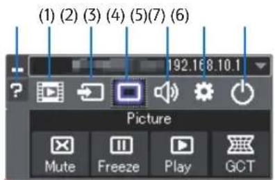
(1) (Streaming). Displays the streaming window. Movie files on the PC can be transferred to the projector via the network and played on the projector. Refer to "Movie streaming function" in the help file of Projection Utility.
(2) (Source).....Selects an input source of the projector.
(3) (Picture).....Turns on or off AV-MUTE (Picture mute), and turns on or off FREEZE (Freeze a picture).
(4) (Sound).....Turns on or off AV-MUTE (Sound mute), play the sound and turns up or down the volume.
(5) 🙏 (Others)......Uses "Update", "HTTP Server", "Settings" and "Information".
(6) ⏻ (Exit)......Exit Projection Utility. You can also turn off the projector at the same time.
(7) ? (Help)....Displays the help of Projection Utility.
TIP:
Viewing the "Help" file of Projection Utility
- Displaying the Help file of Projection Utility while it is running.
Click the [?] (help) icon on the control window.
The Help screen will be displayed.
- Displaying the Help file of GCT while it is running.
Click "Help" → "Help" on the edit window.
The Help screen will be displayed.
- Displaying the help file using the Start Menu.
Click "Start" → "All programs" or "Programs" → "Ricoh Projector User Supportware" → "Projection Utility" → "Projection Utility Help".
The Help screen will be displayed.
Starting Projection Utility from a USB Memory or SD Card
Projection Utility can be started from commercially available removable media such USB memory or SD cards if it is copied beforehand. This will eliminate the trouble of installing Projection Utility to your computer.
- Copy Projection Utility to removable media.
Copy all the folders and files (total size approx. 6MB) from the "Projection Utility (removable-media)" folder in the supplied CD-ROM to the root directory of your removable media.
- Insert your removable media into your computer.
The "AutoPlay" screen will be displayed on your computer.
- Click "Open folder to view files"
The Projection Utility.exe, other folder, and files will be displayed.
- Double-click the "Projection Utility.exe" (icon.
Projection Utility will start.
NOTE:
- The "EASY CONNECTION" function is not supported when Projection Utility is started from removable media.
Using on Mac OS
Step 1: Install Projection Utility for Mac OS on the computer
- Insert the accompanying CD-ROM in your Mac CD-ROM drive.
The CD-ROM icon will be displayed on the desktop.
- Double-click the CD-ROM icon.
The CD-ROM window will be displayed.
-
Double-click the "Mac OS X" folder.
-
Double-click "Projection Utility.dmg" in the "Projection Utility" folder.
The "Projection Utility" window will be displayed.
- Drag and drop the "Projection Utility" folder to your Applications folder in Mac OS.
Step 2: Connect the projector to a LAN
Connect the projector to the LAN by following the instructions in "Connecting to a Wired LAN" ( page 166) and "⑨ Controlling the Projector by Using an HTTP Browser" ( page 42)
Step 3: Start Projection Utility for Mac OS
- Open your Applications folder in Mac OS.
- Double-click the "Projection Utility" folder.
- Double-click the "Projection Utility" icon.
When Projection Utility for Mac OS starts, the select window for destination will be displayed.

- At the first time of startup, "END USER LICENSE AGREEMENT" screen will be displayed before the select window for destination is displayed.
Read "END USER LICENSE AGREEMENT" and select "I accept the terms in the license agreement", and click "OK".
- Select a projector to be connected, and then click "Connect".
Your desktop screen will be displayed on the projector.
TIP:
Viewing the Help of Projection Utility for Mac OS
- From the menu bar, click "Help" → "Projection Utility Help" while Advanced Network Utility is running.
The Help screen will be displayed
4 Projecting an Image from an Angle (Geometric Correction Tool in Projection Utility)
The Geometric Correction Tool (GCT) function allows you to correct distortion of images projected even from an angle.
What you can do with GCT
- The GCT feature includes the following three functions
4-point Correction: You can fit a projected image within the border of the screen easily by align the four corners of an image to the ones of the screen.
- Multi-point Correction: You can correct a distorted image on the corner of a wall or irregular shaped screen by using many separated screens to correct the image as well as 4-point Correction.
- Parameters Correction: You can correct a distorted image by using a combination of transformational rules prepared in advance.
This section will show an example for use with 4-point Correction.
For information about "Multi-point Correction" and "Parameters Correction", see the help file of Projection Utility. (→ page 190)
- Your correction data can be stored in the projector or your computer which can be restored when necessary.
- The GCT function is available with a wired or wireless LAN connection, and video cable.
Projecting an Image from an Angle (GCT)
- For a video cable or LAN connection, install and start Projection Utility in your computer beforehand. (→ page 188)
Preparation: Adjust the projector position or the zoom so that the projected image can cover the whole screen area.
- Click the "☐" (Picture) icon and then the "☑" button.
The "4-point Correction" window will be displayed.
- Click the "Start Correction" button and then "Start 4-point Correction" button.
A green frame and a mouse pointer ( + ) will be displayed.
- Four [●] marks will be appeared at four corners of the green frame
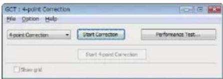
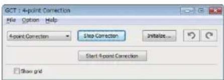
- Use the mouse to click the [●] mark of which corner you wish to move.
The currently selected [ ● ] mark will turn red.
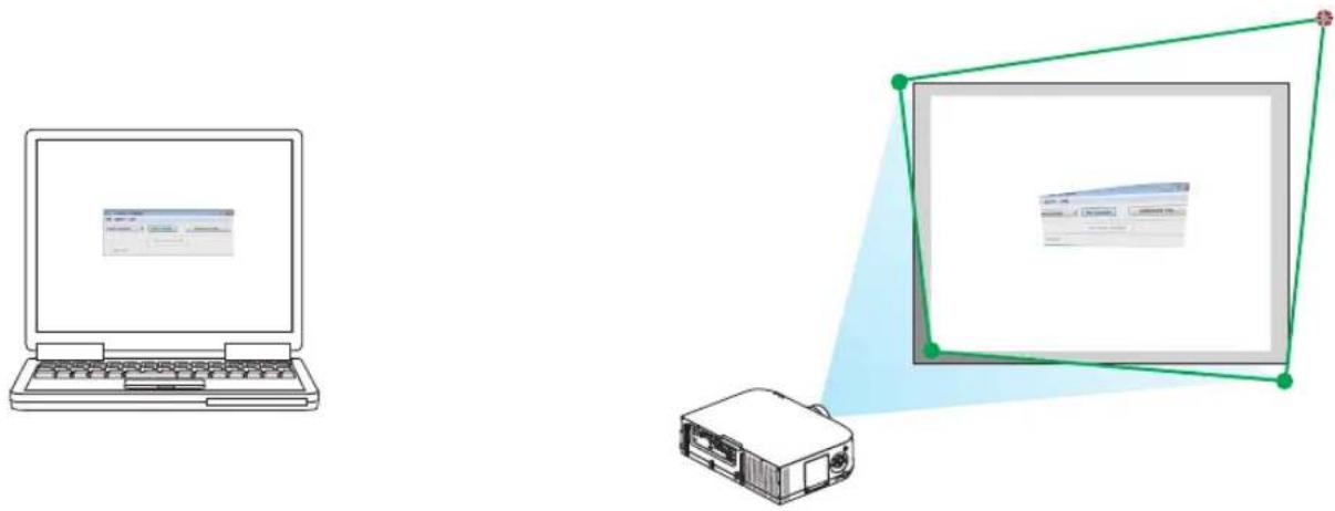
natural_image
Illustration of a laptop and a projector connected via a green wireframe diagram (no text or symbols)(In the above example, Windows screens are omitted for clarification.)
- Drag the selected [●] mark to the point you wish to correct and drop it.
- When you click somewhere within the project image area, the nearest [ ● ] mark will go to the position where the mouse cursor is.
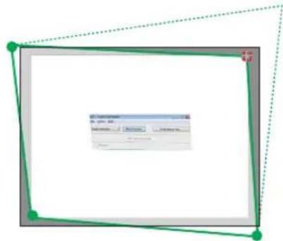
- Repeat Step 3 and 4 to correct the distortion of the projected image.
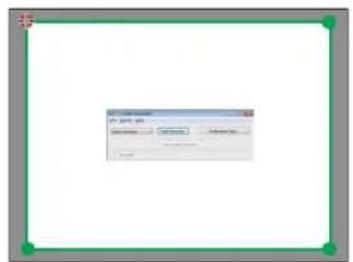
- After completing, right-click the mouse.
The green frame and the mouse pointer will disappear from the projected image area. This will complete the correction.
- Click the "X" (close) button on the "4-point Correction" window.
The "4-point Correction" window will disappear and the 4-point correction will take effect.
- Click the " 🔊 " button on the control window to exit the GCT.
TIP:
- After performing the 4-point correction, you can save the 4-point correction data to the projector by clicking "File" → "Export to the projector..." on the "4-point Correction" window.
• See the Help of Projection Utility for operating "4-point Correction" window and other functions than GCT. (→ page 193)
⑤ Projecting Images from the Projector over a LAN (Advanced Network Utility)
What you can do with Advanced Network Utility
- Using Advanced Network Utility allows you to send the screens of your computers to the projector via wired/wireless LAN. The difference from Projection Utility is that projected images can be sent from a computer to not only one projector but also to two or more projectors at the same time.
When "Meeting Mode" is used, projected images can be sent and received between two or more computers.
- High-speed, high-quality image transmissions based on Ricoh's original compression algorithm
Ricoh's original compression algorithm allows high-quality images to be sent over the network at high speed, from your computer to the projector.
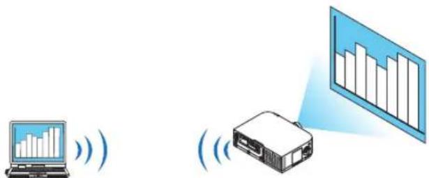
- Simultaneous projection by multiple projectors
Images can be sent from a computer to not only one projector but also to two or more projectors at the same time.
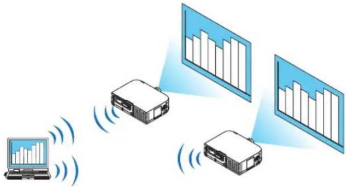
flowchart
graph TD
    A["Laptop"] -->|Wireless Signal| B["Projector 1"]
    A -->|Wireless Signal| C["Projector 2"]
    B --> D["Bar Chart 1"]
    C --> E["Bar Chart 2"]
- "Easy Connection" function for connecting wireless LAN
By using "Easy Connection" function* 1, the complicated setting of wireless LAN can be simplified.
^*1 If the OS is Windows 7/Windows Vista, input of logon password as “Administrator” may be prompted.
- Projected images can be transferred and saved to computers.
When "Meeting Mode" is used, projected images can be sent to the computers of all the participants (attendants) of a "Meeting". The received images can be saved to your computer with a memo (text data) attached.
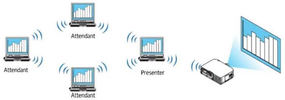
flowchart
graph TD
    A["Attendant"] --> B["Attendant"]
    B --> C["Presenter"]
    C --> D["Podcast"]
    style A fill:#f9f,stroke:#333
    style B fill:#f9f,stroke:#333
    style C fill:#f9f,stroke:#333
    style D fill:#ccf,stroke:#333
• 1-click switching of presenter
When switching to another presenter during the conference, the participants (attendants) can simply click a button to switch over to the new presenter.
• Central management of the projecting computer
Using the Training Mode allows you to use a single computer (Manager) to manage which computer (Attendant) projects. Possible operation includes switching projecting computers to project from, as well as temporarily terminating communication with the projector.
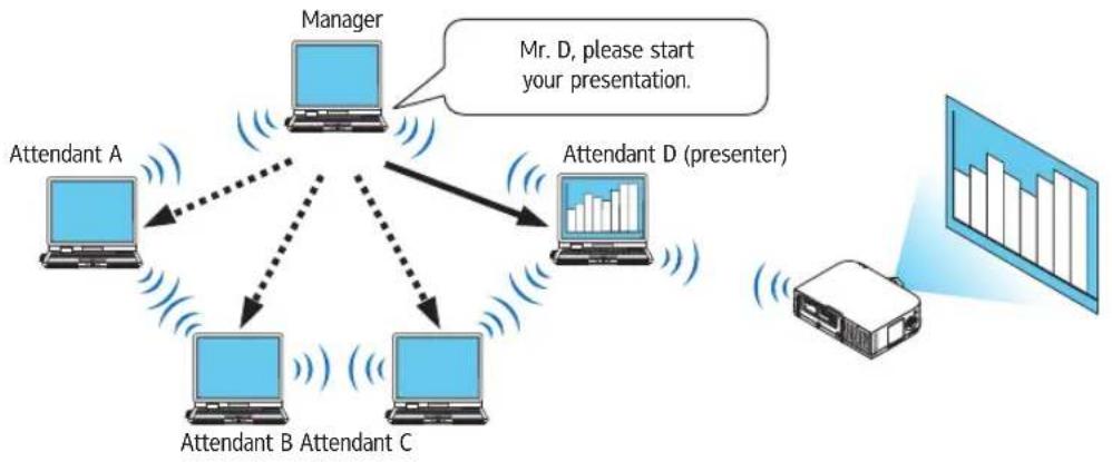
flowchart
graph TD
    A["Attendant A"] -->|dotted arrow| B["Attendant B"]
    B -->|dotted arrow| C["Attendant C"]
    C -->|dotted arrow| D["Attendant D (presenter)"]
    D --> E["Manager"]
    E -->|Mr. D, please start your presentation.| F["Monitor with bar chart data"]
NOTE:
The Training Mode is not installed via the "Typical" installation option when Advanced Network Utility is installed.
To use Training Mode, select "Extension" installation option on the install selection screen that is displayed while Advanced Network Utility installation is in progress, and select "Training Mode (Attendant)" or "Training Mode (Manager)".
Connecting the projector to a LAN
Connect the projector to the LAN by following the instructions in "Connecting to a Wired LAN" (→ page 166), "Connecting to a Wireless LAN" (→ page 167) and "9 Application Menus" (→ page 136)
Basic Operation of Advanced Network Utility
This section explains the following three cases as examples of operating Advanced Network Utility.
(1) Transferring images to the projector
(2) Holding a conference
(3) Participating in a conference
Sending Images to Projector
- Connecting projector
1 Turn on the power to the projector for which LAN has been set.
2 Click Windows [Start] → [All Programs] → [Ricoh Projector User Supportware] → [Advanced Network Utility] → [Advanced Network Utility], in that order.
The "Selection Of Network Connections" window will be displayed.
A list of the network equipment connected to your computer will be displayed.
3 Select the network equipment that is to be used and click [OK].
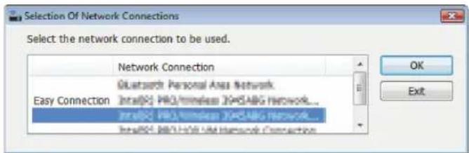
Select the network device displaying "Easy Connection" if the product LAN setting is for "Easy Connection." This will call up the "Projector List" window.
4 Check(☐) the projector to connect and click [Connect].
If the name of the projector to connect is not on the list or if it is hidden, click [Update].
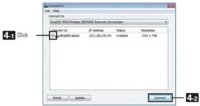
The screen of your computer will be projected from the projector.
At this time, the input signal of the projector will automatically change to "ETHERNET".
• Transferring images
When your computer is connected to the projector, the screen of the computer is projected from the projector as is. To make your presentation by using a PowerPoint file, open the PowerPoint file and start your presentation.
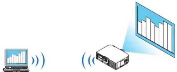
- Stopping or resuming the transmission of images
The transmission of the screen of the computer to the projector can be temporarily stopped and then resumed.
1 Click the projector icon ( 📋 ) on the Windows taskbar.
A pop-up menu will be displayed.
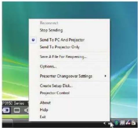
2 Click [Stop Sending].
The projector icon on the taskbar will change ( →)
NOTE:
Even if the screen of the computer is changed in this status, the image projected from the projector does not change.
To manipulate the screen that should not be disclosed (projected from the projector), stop transmission.
3 Click the projector icon (☐) on the Windows taskbar.
A pop-up menu will be displayed.
4 Click [Start Sending].
The projector icon on the taskbar will change ( → )
The transmission of the screen for the computer will be resumed, and the current screen of the computer will be projected from the projector.
• End the transmission of images
Exit Advanced Network Utility.
1 Click the projector icon ( 📋 ) on the Windows taskbar.
A pop-up menu will be displayed.
2 Click [Exit].
Holding Conferences
- Holding conferences
1 Follow steps 1 through 4 in "Connecting projector" of "Sending Images to Projector" (→ page 197).
The screen of your computer will be projected from the projector.
- Disclose a file to the participants of the conference.
NOTE:
To disclose a file to the participants, selection can be made only in folder units.
Therefore, a folder only having files that can be disclosed to the participants must be created in advance.
1 Click the projector icon (图标) on the Windows taskbar.
A pop-up menu will be displayed.
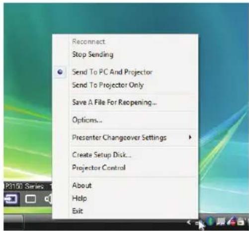
2 Before clicking [Send to PC and Projector], check that there is a “·” mark applied.
3 Click the [Advanced Network Utility] button on the taskbar.
The presenter window will be opened.
4 Click [Select Folder].
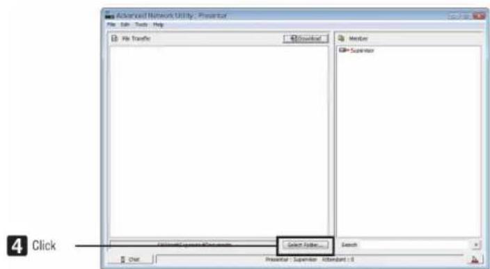
5 Select a folder saving the file to be disclosed to the participants, and click [OK].
The file in the selected folder will be displayed in the list of files to transfer.
6 Click [Download].
The file will be shown to the participants.
NOTE:
When the computer is connected to the projector, the computer screen that is in of being progress is also projected from the projector. To manipulate a screen that should not be shown (not projected), temporarily stop the transmission ( page 199).
• Ending conference
1 Click [File] in the presenter window, and click [Exit].
You can also end the conference by clicking [ ] at the upper right of the presenter window.
Participating in Conference
• Participating in conferences
1 Click Windows [Start] → [All Programs] → [Ricoh Projector User Supportware] → [Advanced Network Utility] → [Advanced Network Utility], in that order.
The "Selection Of Network Connections" window will be displayed.
A list of the network equipment connected to your computer will be displayed.
2 Select the network equipment that is to be used and click [OK].
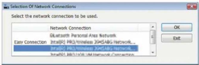
Select the network device displaying "Easy Connection" if the product LAN setting is for "Easy Connection." This will call up the "Meeting List" window.
3 Click the Meeting Name to participate, and click [Connect].
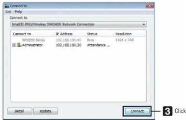
The computer will be connected to the selected conference and the attendant window will be displayed.
If the presenter selects "Send to PC And Projector", the image projected from the projector is displayed in the attendant window.
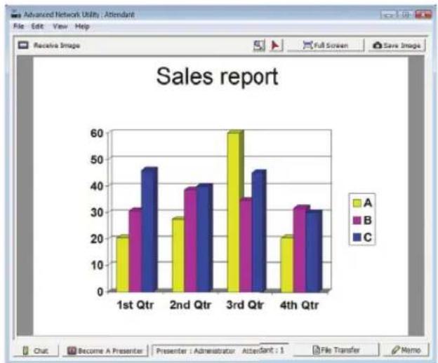
bar
Sales report | Quarter | A | B | C | | :--- | :--- | :--- | :--- | | 1st Qtr | 21 | 31 | 47 | | 2nd Qtr | 28 | 39 | 41 | | 3rd Qtr | 60 | 35 | 46 | | 4th Qtr | 21 | 32 | 31 |- Saving received images
1 Click [Memo] in the attendant window.
A memo pane will be displayed.
![RICOH PJ X6181N - Click [Memo] in the attendant window. - 1](/content/2026/05/872418/images/2a04a0cbb643c6db674b3c2b1c321de66ccb5735b198a335f9c31748acc3cd16.jpg)
bar
| Quarter | A (%) | B (%) | C (%) | | :--- | :--- | :--- | :--- | | 1st Qtr | 20 | 30 | 47 | | 2nd Qtr | 27 | 39 | 41 | | 3rd Qtr | 60 | 35 | 46 | | 4th Qtr | 20 | 32 | 30 | The chart displays the Sales report data for each quarter. The legend indicates that yellow bars represent category A, purple bars represent category B, and blue bars represent category C. Annotations 'Memo pane' and 'Click' are annotated on the interface.2 Click [Save Image] in the attendant window.
The image displayed in the attendant window will be saved.
- The saved image is added to the memo list and a thumbnail is displayed.
• A memo can be attached to the saved image.
REFERENCE:
- In case of Windows 7/Windows Vista, "Document\Advanced Network Utility\" is the default folder to save a created file.
- A folder is created below the default folder based on the time and date of the conference, and the image is saved to a file in the created folder.
For example, if a conference is held at 11:20 on May 14, 2015, the default folder name on Windows 7/Windows Vista, will be "Documents\Advanced Network Utility\2015-05-14_11-20_Meeting Records".
In this folder, an HTML file named "Meeting Records" is created.
The saved image is saved in "Images" folder.
- Downloading disclosed file
1 Click [File Transfer] in the attendant window.
The "File Transfer" window will be opened.
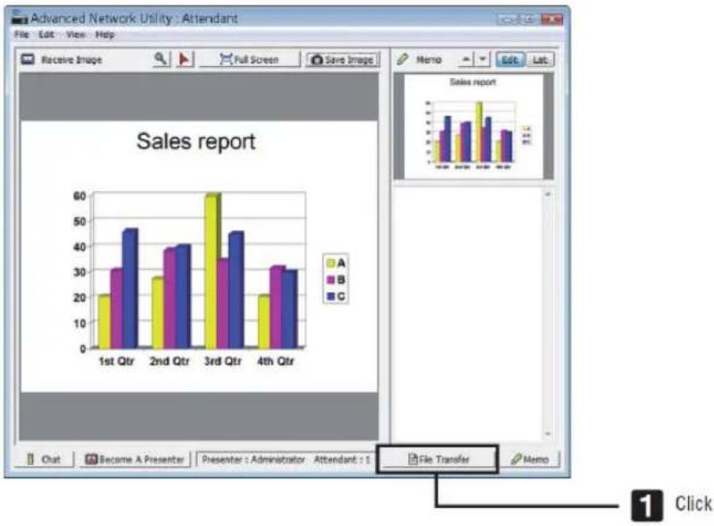
bar
| Quarter | A (%) | B (%) | C (%) | | :--- | :--- | :--- | :--- | | 1st Qtr | 21 | 31 | 47 | | 2nd Qtr | 28 | 39 | 41 | | 3rd Qtr | 60 | 35 | 46 | | 4th Qtr | 21 | 32 | 30 |2 Select a file to download, and click [Download].
Downloading will begin.
The progress of the downloading is displayed at the lower left of the window.
3 When downloading is complete, click [File] in the "File Transfer" window, and click [Exit].
The "File Transfer" window will be closed.
REFERENCE:
- If "Open After Downloading" is checked, the file is opened by specified Windows application software after downloading is complete.
- In case of Windows 7/Windows Vista, "Document\Advanced Network Utility\" is the default folder to save a created file.
- A folder is created below the default folder based on the time and date of the conference, and the image is saved to a file in the created folder.
For example, if a conference is held at 11:20 on May 14, 2014, the default folder name on Windows 7 will be "Document\Advanced Network Utility\2014-05-14_11-20_Meeting Records".
- Changing presenter
Three types of settings may be made to change the presenter: "Not Approved", "Approved", and "Changing Prohibited" (these can be selected only by the presenter).
In the following example, "Not Approved" is selected.
- Click [Become A Presenter] in the attendant window.
You will change from a participant to a presenter.
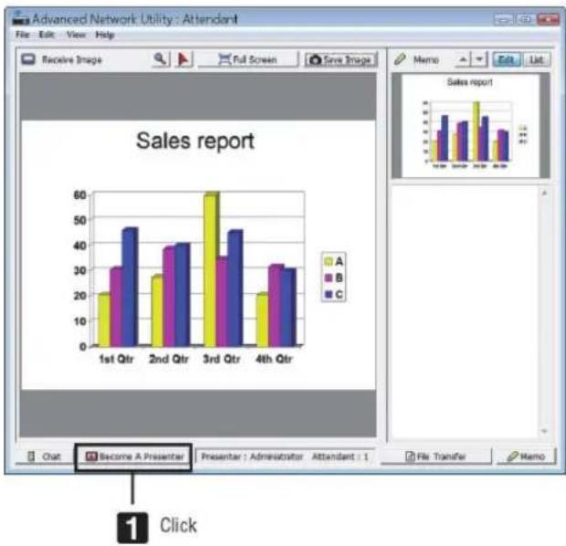
bar
Sales report | Quarter | A (%) | B (%) | C (%) | | :--- | :--- | :--- | :--- | | 1st Qtr | 20 | 30 | 45 | | 2nd Qtr | 28 | 39 | 41 | | 3rd Qtr | 60 | 35 | 45 | | 4th Qtr | 20 | 31 | 30 | The chart displays a single bar chart with three categories (A, B, C) representing different sales metrics. The 'Sales report' table below visually compares the values for each quarter and category. The 'Click' button is labeled at the bottom left.• Leaving conference
Leave the conference and exit Advanced Network Utility.
- Click [File] in the attendant window, and click [Exit].
You can also leave the conference by clicking [ ] at the upper right of the attendant window.
6 JPEG Conversion Tool
The JPEG Conversion Tool converts JPEG files not supported by the projector, image files in other formats, PowerPoint files, and other similar files into JPEG files.
Installing JPEG Conversion Tool
NOTE:
- To install or uninstall each software program, the Windows user account must have "Administrator" privilege (Windows 7, Windows Vista).
- Exit all running programs before installation. If another program is running, the installation may not be completed.
- JPEG Conversion Tool will be installed to the system drive of your computer. If the message "There is not enough free space on destination" is displayed, free up enough space (about 100 MB) to install the program.
1 Insert the accompanying CD-ROM into your CD-ROM drive.
The menu window will be displayed.
TIP:
If the menu window will not be displayed, try the following procedure. For Windows 7
- Click "Start" on Windows.
- Click "All Programs" → "Accessories" → "Run".
- Type your CD-ROM drive name (example: "Q:\") and "LAUNCHER.EXE" in "Name". (example: Q:\LAUNCHER.EXE)
- Click "OK".
The menu window will be displayed.
2 Click "JPEG Conversion Tool" on the menu window.
The installation will start.
- Follow the instructions on the installer screens to complete the installation.
⑦ Managing the Projector Using Projector Management Utility
Projector Management Utility conforms to the PJLink class 1 standards, and is compatible with all class 1 commands. A maximum of 100 projectors connected to the network can be managed using one computer.
Operating environment
Supported OS
Windows 8/8.1 (Core Edition)
Windows 8/8.1 Pro
Windows 8/8.1 Enterprise
Windows 7 Home Premium
Windows 7 Professional
Windows 7 Ultimate
Windows 7 Enterprise
Windows Vista Home Basic
Windows Vista Home Premium
Windows Vista Business
Windows Vista Ultimate
Windows Vista Enterprise
* Only 32-bit version
Memory
Recommended memory size for the operating system of the computer you are using
Resolution
800 600 pixels or more
Installing Projector Management Utility
Projector Management Utility is included on the supplied CD-ROM.
NOTE:
• This software is to control and monitor projectors manufactured by our company. The software may not work properly when used to control other projectors.
- To install or uninstall each software program, the Windows user account must have "Administrator" privilege (Windows 7, Windows Vista).
- Exit all running programs before installation. If another program is running, the installation may not be completed.
- This software will be installed to the system drive of your computer.
If the message "There is not enough free space on destination" is displayed, free up enough space (about 100 MB) to install the program.
- Close all applications.
- Insert the CD-ROM in the CD-ROM drive of your computer, and then click [Exit] on the launcher screen.
- Open the "Projector Management Utility" folder in the "Windows" folder stored on the CD-ROM.
- Double-click "setup.exe" stored in the "Projector Management Utility" folder.
- Install the application by following the on-screen instruction.
- When the installation is complete, exit the installer.
A shortcut icon is created on the desktop.
TIP:
To uninstall Projector Management Utility, use the program delete function in "Control Panel" to delete "Projector Management Utility".
9. Using the Viewer
① What you can do with the Viewer
The Viewer feature allows you to view slides or movie files stored on a USB memory on the projector, or a shared folder in a computer connected to the network.
The Viewer has the following features.
- When a commercially available USB memory that stores image files is inserted into the USB port (Type A) of the projector, the Viewer allows you to view the image files on the USB memory.
Even if no computer is available, presentations can be conducted simply with the projector.
- Movie file with audio can be played back.
- Image and movie files stored in a shared folder in a computer connected to a network can be projected.
The computer with "Media Sharing" of Windows Media Player 11 turned on can be used as a media server.
Supported graphic formats
| Format File name extension | |
| JPEG .jpg, .jpe, .jpeg (CMYK is not supported.) | |
| BMP .bmp (bit field not supported) | |
| PNG .png (Interlaced PNG and α channel PNG are not supported.) | |
| GIF .gif (Interlaced GIF, transparation GIF, and animation GIF are not supported.) | |
* If an unsupported image is selected, the icon 📄 will be displayed.
NOTE:
Maximum number of pixels of image which can be displayed are:
• Baseline JPEG: 10000 × 10000
• Progressive JPEG: 1280 × 1280
• GIF: 1280 × 1280
- Others: 4000 × 4000
- Some files supported by the above requirements may not be displayed.
Supported movie files
| File name extension Video compression/expansion method Audio compression/expansion method | ||
| .mpg, .mpeg. MPEG2 MPEG Audio Layer2 | ||
| MPEG Audio Layer3 | ||
| .wmv WMV9 WMA9 Standard | ||
| .mp4 H.264/AVC | AAC-LC | |
Playback requirements:
Resolution: 320 240 to 1280 720
Video frame rate: up to 30fps
Bitrate: up to 15Mbps
Audio sampling rate: up to 48kHz
Channel: up to 2ch stereo
Audio bit rate: up to 256 Kbps
Max. file size: up to 2GB
NOTE:
- Movie files converted by using the video/audio format which is not supported by this projector cannot be played back. In this case, there will be no icon to show that playback is not possible.
- Files with Digital Rights Management(DRM) protection cannot be played back.
- Some of the movie files that meet the above requirements may not be played back. Movie files may not be played back correctly depending on your network environment or the bit rate of your file.
- WMV format video file will be displayed in an aspect ratio of 1 to 1 independently of its original aspect ratio.
- Files that can be played back on the media server are graphics and movie files. In Windows Media Player 11 (Windows Vista) mp4 files cannot be played back.
Supported USB memory devices
- Be sure to use a USB memory device formatted with the FAT, exFAT, FAT32 or FAT16 file system.
The projector does not support NTFS formatted USB memory.
If the projector does not recognize your USB memory, check if the format is supported.
To format your USB memory in your computer, refer to the document or help file that comes with your Windows.
- We do not warrant that the USB port of the projector will support all USB memories in the market.
Notices on shared folder and media server
- Files from a shared folder or media server may not be projected if security or antivirus software is installed on your computer.
- Open the following firewall ports:
- Media server
| Port number Protocol | |
| 1900 UDP | |
| 2869 TCP | |
| 10243 TCP | |
| 10280-10284 UDP |
- Shared folder
| Port number Protocol | |
| 137 UDP/TCP | |
| 138 UDP/TCP | |
| 139 UDP/TCP | |
| 445 UDP/TCP |
- Set your computer for sharing and security to grant access to files in the shared folder and set your security or antivirus software to grant access to files in the shared folder. Consult your network administrator for more information.
- Movie files in the shared folder or the media server may not be played back correctly depending on your network environment or the bit rate of your file.
NOTE
- The following operations by using the buttons on the projector are not possible when the VIEWER screen such as the slide screen and the thumbnail screen is displayed.
- Keystone correction by using the ▲ or ▼ button
- Auto Adjustment by using the AUTO ADJ. button
- Volume control with the ◀ or ▶ button
- Freezing picture by using the FREEZE, ASPECT, or AUTO ADJ. button on the remote control is not possible when the VIEWER screen such as the slide screen and the thumbnail screen is displayed.
- Executing [RESET] → [ALL DATA] from the menu will return the settings for the Viewer toolbar to the factory default.
② Projecting images stored in a USB memory device
This section explains the basic operation of the Viewer.
The explanation provides the operational procedure when the Viewer toolbar is set to the factory default.
Preparation: Before starting the Viewer, store images to the USB memory using your computer.
Starting the Viewer
- Turn on the projector. (→ page 16)
- Insert the USB memory into the USB port of the projector.
NOTE:
- Do not remove the USB memory from the projector while it's LED flashes. Doing so may corrupt the data.
TIP:
You can a USB memory insert the projector when the drive list screen is displayed.
3. Press the "9/USB-A" button.
The screen will change to the viewer display and a screen showing a list of the drives will be displayed after 2 to 3 seconds.
TIP:
- Press the button to display the viewer with the main body operation. Refer to page 18 for the selection method.
- For more information about the drive list screen, see page 214.
- To display graphics in a shared folder, see page 222; to display still images or movie files in a media server, see page 226.
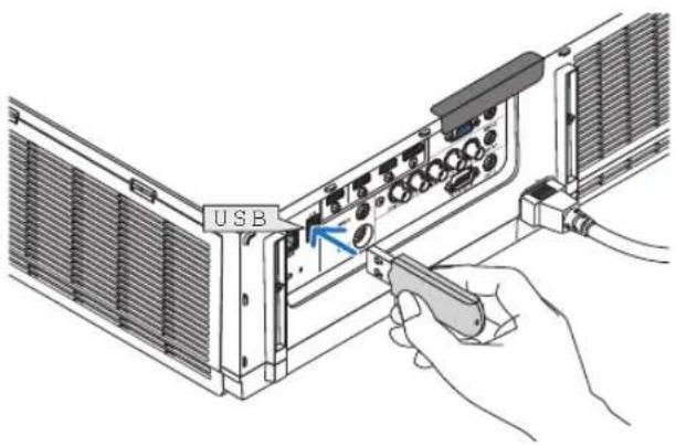
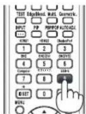
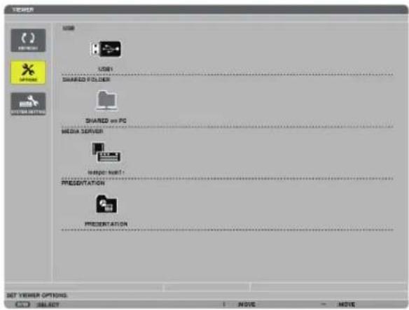
- Press the ▶ button to select "USB1" and press the ENTER button.
The "USB1" thumbnail screen will be displayed.
TIP:
- For more information about thumbnail screen, see page 216.
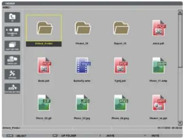
- Use the ▲▼◀ or ▶ button to select an icon.
- The → (arrow) symbol on the right indicates there are more pages. pressing the CTL + ▼ (page down) button will show the next page: pressing the CTL + ▲ (page up) will show the previous page.
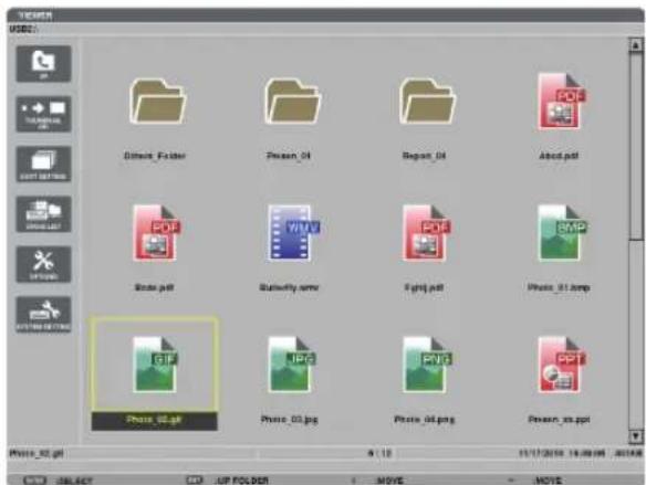
- Press the ENTER button.
Operation varies depending on the selected file.
- Still image
The selected slide will be displayed.
The ◀ or ▶ button can be used to select the next (right) slide or the previous (left) slide in the thumbnail screen.
- Pressing the ENTER button will display the control bar with which is used to select or rotate an slide.(→ page 217)
natural_image
Snow-capped mountain peak under a partly cloudy sky, with dry grassland in the foreground (no text or symbols visible)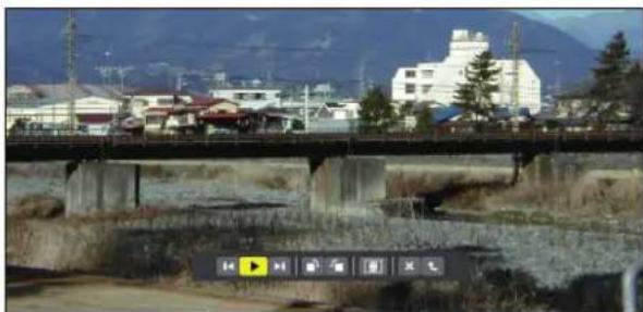
natural_image
Exterior view of a concrete bridge over a river with buildings and mountains in the background (no signage or text visible)- Movie file
The movie file will start playing.
After finishing the playback, the screen will turn to black. Press the EXIT button to return to the thumbnail screen.
- Pressing the ENTER button will display the movie's control bar with which you can pause or fastforward and some other operations.
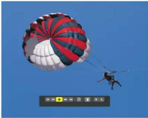
natural_image
Parachute in mid-air against a clear blue sky, with red and white stripes (no text or symbols visible)7. Remove the USB memory from the projector.
Return to the drive list screen. Make sure that the LED on the USB memory is not flashing before removing the USB memory.
NOTE: If you remove the USB memory from the projector with a slide displayed, the projector may not operate correctly. If this happens, turn off the projector and unplug the power cord. Wait 3 minutes, then connect the power cord, and turn on the projector.
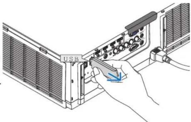
Exiting the Viewer
- Press the "INPUT" button on the remote control and select an input terminal other than "USB-A".
- When operating with the main body, use the "INPUT" button to select an input terminal other than [9:USB-A].
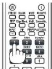
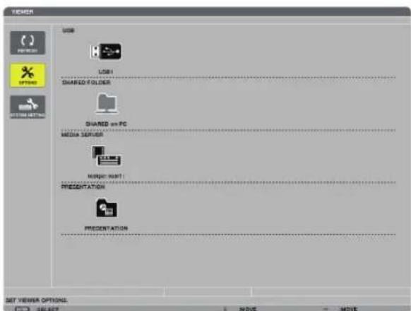
Names and functions of Viewer screen
The Viewer has three screens: Drive list screen, Thumbnail screen, and Slide screen.
Cursor (yellow) Cursor (yellow)
Menu Menu
[Drive list screen] [Thumbnail screen]
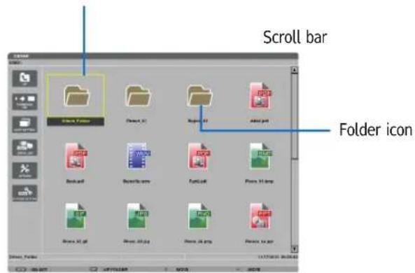
Path information

Drive information/File information

Operation button guide
Menu guide
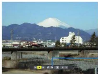
natural_image
Scenic view of Mount Fuji with white snow-capped mountains in the background and a bridge over a river below (no visible text or symbols)[Slide screen]
Control bar
* The operation for still image differs from that for movie.
- Drive list screen
Displays a list of drives connected to the projector.
Menu operation
- Use the ▼ or ▲ button to move the cursor up or down. Select the menu item and press the ENTER button to display the submenu.
Operation for Drive list screen
- Press the ▶ button to move the cursor to the drive list.
(Use the ◀ or ▶ button to switch between the menu and the drive list.)
Press the ▼ or ▲ button to select a type of drive; press the ◀ or ▶ button to select the drive connected to the projector.
- Select the drive and press the ENTER button to switch to the thumbnail screen of the selected drive.
Functions
| Name Description | ||
 REFRESH Displays additional media servers in the drive list screen. REFRESH Displays additional media servers in the drive list screen. | ||
| OPTIONS Opens the OPTIONS menu. | ||
 SLIDE SETTING Sets up slides. (→ page 219) SLIDE SETTING Sets up slides. (→ page 219) | ||
 MOVIE SETTING Sets up movie files. (→ page 220) MOVIE SETTING Sets up movie files. (→ page 220) | ||
 AUTO PLAY SETTING Sets up auto play. (→ page 220) AUTO PLAY SETTING Sets up auto play. (→ page 220) | ||
 SHAREED FOLDER Sets up a shared folder. (→ page 222) SHAREED FOLDER Sets up a shared folder. (→ page 222) | ||
| [AZTS] MEDIA SERVER Sets up a media server. (→ page 226) | ||
 RETURN Closes the OPTIONS menu. RETURN Closes the OPTIONS menu. | ||
 SYSTEM SETTING Switches to the system setting menu. See wired LAN, wireless LAN, WPS, network information, and keyboard in “9. Application Menu”. (→ page 136) SYSTEM SETTING Switches to the system setting menu. See wired LAN, wireless LAN, WPS, network information, and keyboard in “9. Application Menu”. (→ page 136) | ||
 USB Displays the icon for a USB memory inserted into the USB port of the projector. USB Displays the icon for a USB memory inserted into the USB port of the projector. | ||
| [D43S] SHARED FOLDER Displays up to four drives of a computer connected to a LAN (set for connecting a shared folder).* See page 222 for setting up for connecting a shared foler of the projector. | ||
 MEDIA SERVER Displays up to four drives of a computer connected to a LAN (set for connecting a media server).* See page 226 for setting up for connecting a media server of the projector MEDIA SERVER Displays up to four drives of a computer connected to a LAN (set for connecting a media server).* See page 226 for setting up for connecting a media server of the projector | ||
| [B66G] PRESENTATION Displays the icon when a USB memory or shared foler stores index files. | ||
| Path information | Displays the location of a folder or file. | |
| Drive information | [Example]USB1 314MB FREE/492MBDisplays the drive.Displays free space and capacity of a drive.* (USB only) | |
| Menu guide | Displays the description of a selected menu. | |
| Operation button guide | Displays information about operation buttons. | |
* It is displayed in three-digit number (rounding up)
NOTE:
When the OPTIONS menu is displayed, the drive list screen or thumbnail screen is not displayed. To display it, select the [RETURN] icon and press the ENTER button.
- Thumbnail screen
Displays a list of folders, thumbnails, and icons in the drive selected on the drive list screen.
Menu operation
- Use the ▼ or ▲ button to move the cursor up or down. Select the menu item and press the ENTER button to display the menu or setting screen.
Operation for Thumbnail screen
- Press the ▶ button to move the cursor to the thumbnail screen when the OPTIONS menu is not displayed.
- Press the ▼, ▲, ◀, or ▶ button to select a file or folder.
- Press the ENTER button to start slideshow or playback of the selected file. Selecting a folder will display its thumbnail screen.
Functions
| Name Description | |
 UP Goes to one upper level menu. UP Goes to one upper level menu. | |
 THUMBNAIL Switches two displays between thumbnail and icon. THUMBNAIL Switches two displays between thumbnail and icon. | |
 SORT SETTING Rearranges folders or files. SORT SETTING Rearranges folders or files. | |
 DRIVE LIST Returns to the drive list screen. DRIVE LIST Returns to the drive list screen. | |
 OPTIONS Changes to the OPTIONS menu. OPTIONS Changes to the OPTIONS menu. | |
 SYSTEM SETTING Opens the system setting menu. SYSTEM SETTING Opens the system setting menu. | |
| Scroll bar | Thumbnail screen will display 12 files with 4 by 3. If the thumbnail screen has twelve or more files or folders, the scroll bar will be displayed at the right side. Using the CTL +▼ or CTL +▲ button will scroll the whole screen down or up. |
| Path information Displays the location of a folder or file. | |
| Thumbnail information [Example]005.jpg 5/20011/03/2010 13:25:12 502KBSelected folder Numbers and order of M/D/Y/H/M/B Create/Change date: Displays file name or file name files in a folder (only when folder selected) folder selected) | |
| Menu guide | Displays the description of a selected menu. |
| Operation button guide | Displays information about operation buttons. |
TIP:
- If an unsupported image is selected, the icon [?] will be displayed,
- The maximum displayable number of images is 300 in the thumbnail screen including the number of folders.
- If a file name or path of a folder is longer than specified, it will be displayed with center characters or path skipped.
Example: "123456789.jpg" will be displayed in "123..789.jpg".
- Slide screen (still image/movie)
Plays a file selected from a list of thumbnails or icons.
Control bar operation
- The control bar will be displayed only when a still image (or index file) and a movie file is selected.
-
The control bar for still images differs from that for movie files.
-
Pressing the ENTER button in Slide screen will display the control bar at the bottom of the screen.
-
Use the ◀ or ▶ button to select a file and press the ENTER button.
- The selected function will be executed.
Functions of still image control bar

| Name Description | ||
 PREV Goes back to the previous image PREV Goes back to the previous image | ||
 PLAY Plays the image. This button also is used to stop or start playing an image. PLAY Plays the image. This button also is used to stop or start playing an image. | ||
 NEXT Goes to the next image. NEXT Goes to the next image. | ||
 RIGHT Rotates the image 90° clockwise. · To cancel, select another folder. RIGHT Rotates the image 90° clockwise. · To cancel, select another folder. | ||
 LEFT Rotates the image 90° counter clockwise. · To cancel, select another folder. LEFT Rotates the image 90° counter clockwise. · To cancel, select another folder. | ||
| SIZE | [B5HX] BEST FIT Displays the image with its aspect ratio in the projector's displayable maximum resolution. | |
 ACTUAL SIZE Displays the image in its actual size. ACTUAL SIZE Displays the image in its actual size. | ||
| CLOSE Closes the control bar. · You can also press the EXIT button to close the control bar. | ||
| END | Stops playing slides or slideshow, and closes the control bar to return to the thumbnail screen. | |
Functions of movie control bar

| Name Description | ||
 PREV Goes back to the beginning of a movie file.· Goes back to the beginning of the previous movie file if executed immediately after being started playing. PREV Goes back to the beginning of a movie file.· Goes back to the beginning of the previous movie file if executed immediately after being started playing. | ||
| FR Fast-rewinds a movie file for about 7 seconds. | ||
| PLAY/PAUSE |  PLAY Plays a movie file. PLAY Plays a movie file. | |
 PAUSE Stops playing a movie file. PAUSE Stops playing a movie file. | ||
 FF Fast-forwards a movie file for about 7 seconds. FF Fast-forwards a movie file for about 7 seconds. | ||
 NEXT Goes to the beginning of a next movie file. NEXT Goes to the beginning of a next movie file. | ||
 TIME Displays an elapsed time for playback or pause. TIME Displays an elapsed time for playback or pause. | ||
| SIZE |  BEST FIT Displays the image with its aspect ratio in the projector's displayable maximum resolution. BEST FIT Displays the image with its aspect ratio in the projector's displayable maximum resolution. | |
 ACTUAL SIZE Displays the image in its actual size. ACTUAL SIZE Displays the image in its actual size. | ||
 CLOSE Closes the control bar.· You can also press the EXIT button to close the control bar. CLOSE Closes the control bar.· You can also press the EXIT button to close the control bar. | ||
 END Stops playing a movie, and closes the control bar to return to the thumbnail screen. END Stops playing a movie, and closes the control bar to return to the thumbnail screen. | ||
Viewer option settings
- SLIDE SETTING
Sets still images or slides.
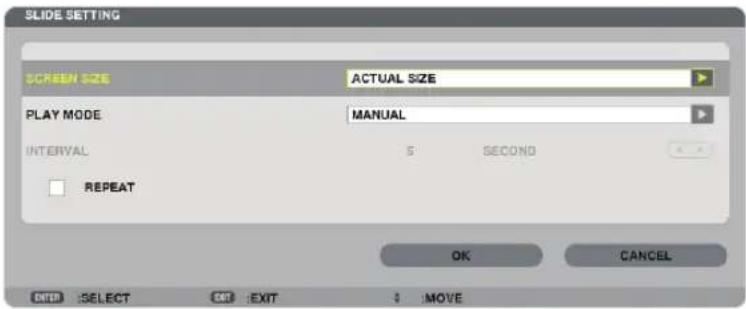
| Name Options Description | ||
| SCREEN SIZE BEST FIT Dis | plays the image with its aspect ratio in the projector's displayable maximum resolution. | |
| ACTUAL SIZE Displays the image in its actual size. | ||
| PLAY MODE MANUAL Selects manual play. | ||
| INTERVAL 5 - 300 seconds Specifies interval time when [AUTO] is selected for PLAY MODE. | ||
| REPEAT Check mark Turns on or off the repeat function. | ||
TIP
- To play one or more slides, place those files into a folder.
• MOVIE SETTING
Sets the functions for a movie file.
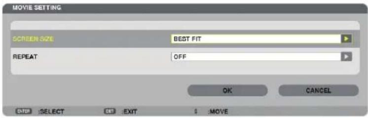
| Name Options Description | ||
| SCREEN SIZE BEST FIT Displays the image with its aspect ratio in the projector's displayable maximum resolution. | ||
| REPEAT OFF Turns on or off the repeat function. | ||
TIP
- Turning on [REPEAT] will display black screen during intermission between movies.
• AUTO PLAY SETTING
Sets auto play for slideshow when a USB memory device is inserted into the USB port of the projector, or when [VIEWER] is selected for [SOURCE].
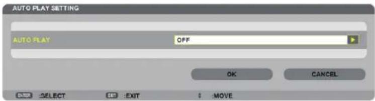
| Name Options Description | ||
| AUTO PLAY OFF — | ||
| PICTURE Plays a first found | still image in a drive. | |
| MOVIE Plays a first found | movie file in a drive. |
TIP
• Auto play behavior is different between when a USB memory device is inserted into the USB port of the projector and when [VIEWER] is selected for [SOURCE].
- Auto play starts for the first found file supporting the file type set up for Auto Play. The file will be searched in the drive root or lower level.
- When [VIEWER] is selected for [SOURCE], the last selected file will be automatically played if it is found, or the last selected folder will be searched and the first found file will be automatically played.
To automatically play a movie file in a USB memory, store one movie file or change its file name so that it can be searched first.
- SORT SETTING
Sets the order of displaying thumbnails or slides.
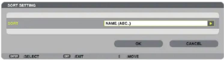
| Name Options Description | ||
| SORT NAME (ABC..) Displays the files alphabetically by name in ascending order. | ||
③ Projecting data from shared folder
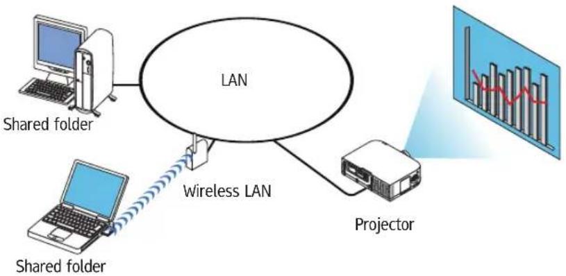
flowchart
graph TD
    A["Shared folder"] --> B["LAN"]
    C["Shared folder"] --> D["Wireless LAN"]
    B --> E["Projector"]
    D --> E
    E --> F["Bar chart inset"]
Preparation
For projector: Connect the projector to the network.
For computer: Place files to be projected in a shared folder and note the folder's path. Memorize or write down the path for later use.
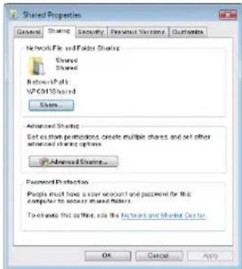
- For sharing a folder, refer to your user guide or help file accompanied with your Windows computer.
- Use a keyboard to give a name to the shared folder in alphanumeric characters.
- To connect the shared folder beyond the subnet, set [WINS CONFIGURATION] in [NETWORK SETTINGS] from the menu.
• Digital signature (SMB signature) is not supported.
Connecting the projector to the shared folder
1. Press the 9/USB-A button on the remote control.
The drive list window will be displayed.
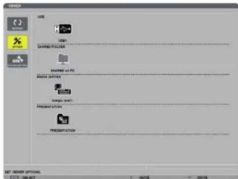
- When operating with the main body, use the "INPUT" button to select [9:USB-A].
2. Displays the [OPTIONS] menu.
Press the ▼ button to select the (OPTIONS) icon and press the ENTER button.
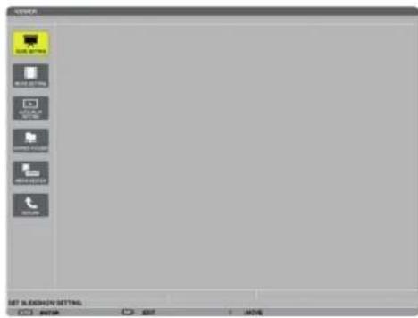
- When the OPTIONS menu is displayed, the drive list will not be displayed.
3. Display the [SHARED FOLDER] screen.
Press the ▼ button to select the (SHARED FOLDER) icon and press the ENETR button.
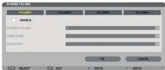
4. Select a folder number and place to enable it.
Press the ◀ or ▶ button to a shared folder number and press the ▼ button to select [ENABLE], and then press the ENTER button.
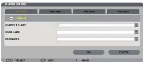
5. Enter the path, user name, and password for the shared folder.
Press the ▼ button to select the [SHARED FOLDER] field. The software keyboard will be displayed.
For using the software keyboard, see page 149.
- If your computer is not password protected, entering a password is not required.
- Up to four shared folders can be added.
- The maximum length of a path of the shared folder must be 15 alphanumeric characters for computer name and 23 alphanumeric characters for folder name.
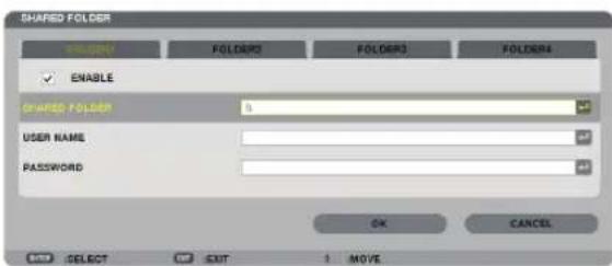
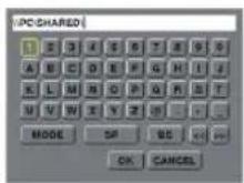
6. Exit the setting.
Press the ▼ button to select [OK] and press the ENTER button.
This will close the [SHARED FOLDER] screen.
- If an error message appear, your settings are not correct. Try again.

Disconnecting the shared folder from the projector
- Disable the number of a shared folder you wish to disconnect
Press the ▼ button to select [ENABLE] and press the ENTER button to clear it.
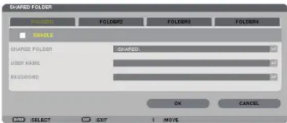
TIP:
- Connecting settings for Shared folder
Settings of up to four folders can be saved.
Restarting the projector will display setting-saved shared folders in grey folder icon on the drive list screen.
Selecting the grey icon folder will skip entry for a folder path.
- Failing to connect with a shared folder will display the folder icon with "x" mark. If this happen, check your folder setting.
4 Projecting data from media server
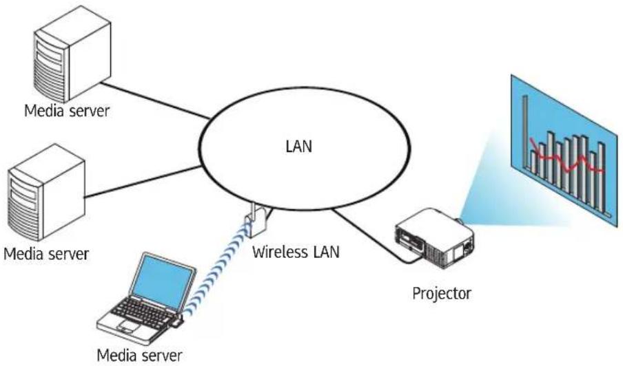
flowchart
graph TD
    A["Media server"] --> B["LAN"]
    C["Media server"] --> B
    D["Media server"] --> B
    E["Media server"] --> F["Wireless LAN"]
    G["Projector"] --> F
    F --> H["Bar Chart inset"]
Preparation
For projector: Connect the projector to the network.
For computer: Prepare image files or movie files to be projected, and set up "Media Sharing" in Windows Media Player 11 or Windows Media Player 12.
NOTE:
- Both the projector and the media server must be on the same subnet. Connecting to the media server beyond the subnet is not possible.
- Types of images and movies which can be shared may vary depending on Windows version.
Setting up "Media Sharing" in Windows Media Player 11
- Start Windows Media Player 11.
- Select "Media Sharing" from "Library".
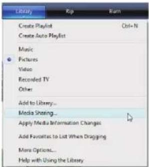
The "Media Sharing" dialog box will be displayed.
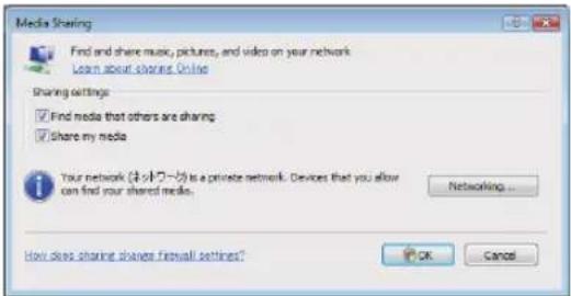
- Select "Share my media" check box, and then select OK.
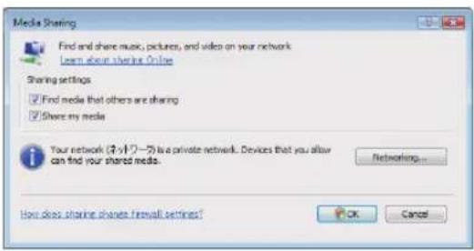
A list of accessible devices will be displayed.
- Select "WU6181N Series" and then "Allow".
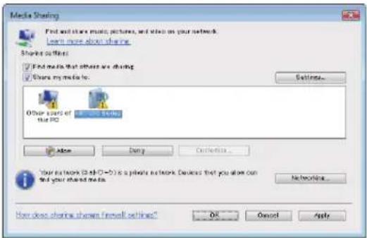
A check mark will be added to the "WU6181N Series" icon.
- The "WU6181N Series" is a projector name specified in [NETWORK SETTINGS].
- Select "OK".
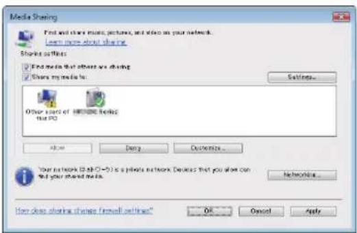
This will make pictures and video in "Library" available from the projector.
Setting up "Media Sharing" in Windows Media Player 12
1. Start Windows Media Player 12.
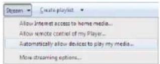
2. Select "Stream", and then select "Automatically allow devices to play my media".
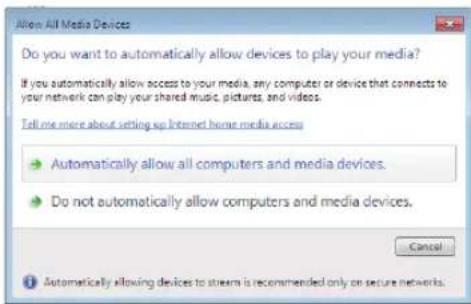
The "Allow All Media Devices" windows will be displayed.
3. Select "Automatically allow all computers and media devices".
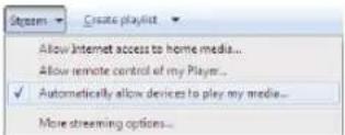
Graphics and movie files in "Library" can be used from the projector.
Connecting the projector to the media server
Press the 9/USB-A button on the remote control.
The VIEWER will start.
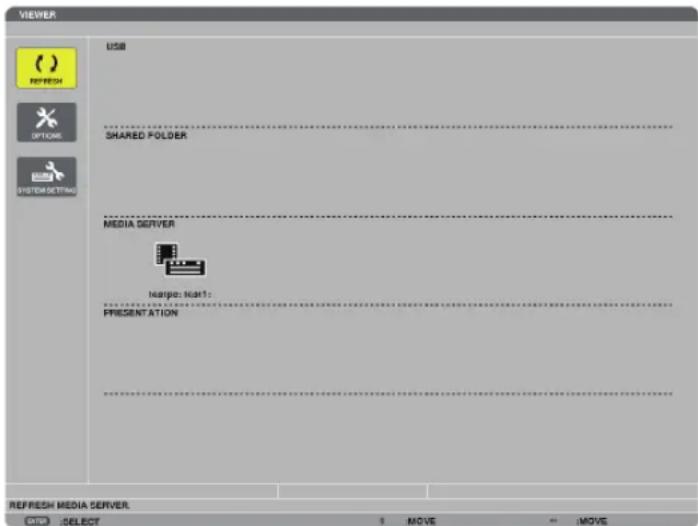
- When operating with the main body, use the "INPUT" button to select [9:USB-A].
- This will start searching for a computer with "media sharing" enabled in the network and add it to the "Media server" of the thumbnail screen.
Another way to do this is to point the cursor to "Media server" and select [REFRESH] from the thumbnail menu and press the ENTER button.
NOTE:
- Up to four accessible media servers can be automatically searched and displayed. The fifth device or later cannot be displayed.
Disconnecting the projector from the media server
1. Display the OPTIONS menu.
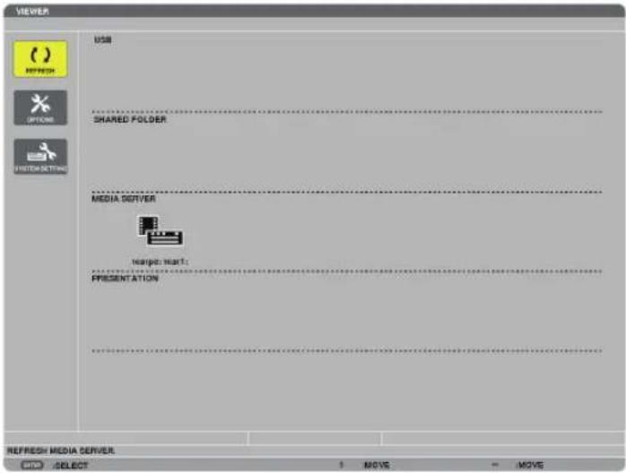
Press the ▼ button to select the [OPTIONS] icon and select the ENTER button.
2. Display the MEDIA SERVER setting screen.
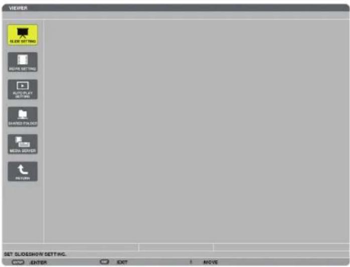
Press the ▼ button to select the MEDIA SERVER icon and press the ENTER button.
3. Disable the connection.
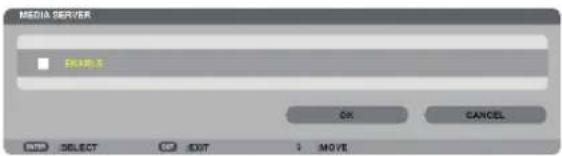
Press the ENTER button to clear the checkmark to disable the connection.
Press the ▼ button to select [OK] and press the ENTER button to close the MEDIA SERVER setting screen.
① Throw distance and screen size
Six separate bayonet style lenses can be used on this projector. Refer to the information on this page and use a lens suited for the installation environment (screen size and throw distance). For instructions on mounting the lens, see page 153.
Lens types and throw distance
WUXGA Type
| Screen size Lens model name | ||||||
| Replacement Lens Type1 | Replacement Lens Type8 | Replacement Lens Type2 | Standard Lens Type1 | Replacement Lens Type3 | Replacement Lens Type4 | |
| 30" 0.7 - 0.9 | ||||||
| 40" 0.7 1.0 - 1.3 1.2 - 2.5 | ||||||
| 60" 1.0 1.0 - 1.3 1.5 - 1.9 1.9 - 3.8 3.7 - 6.0 5.9 - 9.0 | ||||||
| 80" 1.4 1.4 - 1.8 2.0 - 2.6 2.5 - 5.1 5.0 - 8.0 | 7.9 - 12.1 | |||||
| 100" | 1.7 | 1.7 - 2.2 | 2.5 - 3.3 | 3.2 - 6.3 | 6.3 - 10.1 | 9.9 - 15.1 |
| 120" | 2.1 2.0 - 2.7 | 3.0 - 3.9 3.8 - 7.6 7.5 - 12.1 | 11.9 - 18.2 | |||
| 150" | 2.6 | 2.6 - 3.4 | 3.8 - 4.9 | 4.8 - 9.5 | 9.4 - 15.2 | 14.9 - 22.8 |
| 200" | 3.4 - 4.5 | 5.1 - 6.6 | 6.4 - 12.7 | 12.6 - 20.3 | 20.0 - 30.5 | |
| 240" | 4.1 - 5.4 | 6.1 - 7.9 | 7.6 - 15.3 | 15.2 - 24.4 | 24.0 - 36.6 | |
| 300" | 5.2 - 6.8 | 7.6 - 9.9 | 9.6 - 19.1 | 19.0 - 30.5 | 30.1 - 45.8 | |
| 400" | 6.9 - 9.0 | 10.2 - 13.2 | 12.8 - 25.5 | 25.4 - 40.7 | 40.1 - 61.1 | |
| 500" | 8.7 - 11.3 | 12.7 - 16.5 | 16.0 - 31.9 | 31.8 - 50.9 | 50.2 - 76.4 | |
TIP
Calculation of the throw distance from the screen size
Replacement Lens Type1 lens throw distance (m) = H × 0.8 : 0.7 m (min.) to 2.6 m (max.)
Replacement Lens Type8 lens throw distance (m) = H × 0.8 to H × 1.0 : 1.0 m (min.) to 11.3 m (max.)
Replacement Lens Type2 lens throw distance (m) = H × 1.2 to H × 1.5 : 0.7 m (min.) to 16.5 m (max.)
Standard Lens Type1 lens throw distance (m) = H × 1.5 to H × 3.0 : 1.2 m (min.) to 31.9 m (max.)
Replacement Lens Type3 lens throw distance (m) = H × 2.9 to H × 4.7 : 3.7 m (min.) to 50.9 m (max.)
Replacement Lens Type4 tlens hrow distance (m) = H × 4.6 to H × 7.1 : 5.9 m (min.) to 76.4 m (max.)
"H" (Horizontal) refers to the screen width.
* Figures differ by several % with the table above because the calculation is approximate.
Ex.: Throw distance when projecting on a 150" screen with the WUXGA Type using the Standard Lens Type1:
According to the "Screen Size (for reference)" table (→ page 234), H (screen width) = 323.1 cm.
The throw distance is 323.1cm× 1.5 to 323.1cm× 3.0 = 484.7cm to 969.3cm (because of the zoom lens).
WXGA Type
| Screen size Lens model name | ||||||
| Replacement Lens Type1 | Replacement Lens Type8 | Replacement Lens Type2 | Standard Lens Type1 | Replacement Lens Type3 | Replacement Lens Type4 | |
| 30" 0.7 - 1.0 | ||||||
| 40" 0.7 1.0 - 1.3 1.2 - 2.5 | ||||||
| 60" 1.0 1.0 - 1.3 1.5 - 2.0 1.9 - 3.8 3.7 - 6.0 5.9 - 9.1 | ||||||
| 80" 1.4 1.4 - 1.8 2.0 - 2.6 2.5 - 5.1 5.0 - 8.1 7.9 - 12.1 | ||||||
| 100" 1.7 1.7 - 2.2 2.5 - 3.3 3.2 - 6.4 6.3 - 10.1 9.9 - 15.2 | ||||||
| 120" | 2.1 | 2.0 - 2.7 | 3.0 - 4.0 | 3.9 - 7.7 | 7.6 - 12.2 | 12.0 - 18.3 |
| 150" | 2.6 | 2.6 - 3.4 | 3.8 - 5.0 | 4.8 - 9.6 | 9.5 - 15.3 | 15.0 - 22.9 |
| 200" | 3.4 - 4.5 | 5.1 - 6.6 | 6.4 - 12.8 | 12.7 - 20.4 | 20.1 - 30.6 | |
| 240" | 4.1 - 5.4 | 6.1 - 8.0 | 7.7 - 15.4 | 15.3 - 24.5 | 24.1 - 36.8 | |
| 300" | 5.2 - 6.8 | 7.7 - 10.0 | 9.6 - 19.2 | 19.1 - 30.7 | 30.2 - 46.0 | |
| 400" | 6.9 - 9.0 | 10.2 - 13.3 | 12.8 - 25.7 | 25.5 - 40.9 | 40.4 - 61.4 | |
| 500" | 8.7 - 11.3 | 12.8 - 16.7 | 16.0 - 32.1 | 31.9 - 51.2 | 50.5 - 76.9 | |
TIP
Calculation of the throw distance from the screen size
Replacement Lens Type1 lens throw distance (m) = H × 0.8 : 0.7 m (min.) to 2.6 m (max.)
Replacement Lens Type8 lens throw distance (m) = H × 0.8 to H × 1.0 : 1.0 m (min.) to 11.3 m (max.)
Replacement Lens Type2 lenstthrow distance (m) = H × 1.2 to H × 1.5 : 0.7 m (min.) to 16.7 m (max.)
Standard Lens Type1 lens throw distance (m) = H × 1.5 to H × 3.0 : 1.2 m (min.) to 32.1 m (max.)
Replacement Lens Type3 lens throw distance (m) = H × 2.9 to H × 4.7 : 3.7 m (min.) to 51.2 m (max.)
Replacement Lens Type4 lens throw distance (m) = H × 4.6 to H × 7.1 : 5.9 m (min.) to 76.9 m (max.)
"H" (Horizontal) refers to the screen width.
* Figures differ by several % with the table above because the calculation is approximate.
Ex.: Throw distance when projecting on a 150" screen with the WXGA Type using the Standard Lens Type1:
According to the "Screen Size (for reference)" table ( page 234), H (screen width) = 323.1 cm.
The throw distance is 323.1 cm × 1.5 to 323.1 cm × 3.0 = 484.7 cm to 969.3 cm (because of the zoom lens).
XGA Type
| Screen size Lens model name | ||||||
| Replacement Lens Type1 | Replacement Lens Type8 | Replacement Lens Type2 | Standard Lens Type1 | Replacement Lens Type3 | Replacement Lens Type4 | |
| 30" lens | 0.7 - 0.9 | |||||
| 40" 0.6 | 0.9 - 1.2 | 1.2 - 2.4 | ||||
| 60" 1.0 1.0 - 1.3 1.4 - 1.9 1.8 - 3.7 3.6 - 5.8 | 5.7 - 8.7 | |||||
| 80" 1.3 | 1.3 - 1.7 | 1.9 - 2.5 2.4 - 4.9 4.8 - 7.8 | 7.6 - 11.6 | |||
| 100" | 1.6 | 1.6 - 2.1 | 2.4 - 3.2 | 3.0 - 6.1 | 6.0 - 9.7 | 9.6 - 14.6 |
| 120" | 2.0 2.0 - 2.6 | 2.9 - 3.8 3.7 - 7.4 7.3 - 11.7 | 11.5 - 17.6 | |||
| 150" | 2.5 | 2.5 - 3.2 | 3.7 - 4.8 | 4.6 - 9.2 | 9.1 - 14.7 | 14.4 - 22.0 |
| 200" | 3.3 - 4.3 | 4.9 - 6.4 | 6.1 - 12.3 | 12.2 - 19.6 | 19.3 - 29.4 | |
| 240" | 4.0 - 5.2 | 5.9 - 7.7 | 7.4 - 14.8 | 14.7 - 23.6 | 23.2 - 35.3 | |
| 300" | 5.0 - 6.5 | 7.4 - 9.6 | 9.2 - 18.5 | 18.4 - 29.5 | 29.1 - 44.2 | |
| 400" | 6.7 - 8.7 | 9.8 - 12.8 | 12.3 - 24.7 | 24.6 - 39.4 | 38.8 - 59.0 | |
| 500" | 8.4 - 10.9 | 12.3 - 16.0 | 15.4 - 30.8 | 30.7 - 49.2 | 48.6 - 73.8 | |
TIP
Calculation of the throw distance from the screen size
Replacement Lens Type1 lens throw distance (m) = H × 0.8 : 0.6 m (min.) to 2.5 m (max.)
Replacement Lens Type8 lens throw distance (m) = H × 0.8 to H × 1.1 : 1.0 m (min.) to 10.9 m (max.)
Replacement Lens Type2 lens throw distance (m) = H × 1.2 to H × 1.6 : 0.7 m (min.) to 16.0 m (max.)
Standard Lens Type1 lens throw distance (m) = H × 1.5 to H × 3.0 : 1.2 m (min.) to 30.8 m (max.)
Replacement Lens Type3 lens throw distance (m) = H × 3.0 to H × 4.8 : 3.6 m (min.) to 49.2 m (max.)
Replacement Lens Type4 lens throw distance (m) = H × 4.7 to H × 7.3 : 5.7 m (min.) to 73.8 m (max.)
"H" (Horizontal) refers to the screen width.
* Figures differ by several % with the table above because the calculation is approximate.
Ex.: Throw distance when projecting on a 150" screen with the XGA Type using the Standard Lens Type1: According to the "Screen Size (for reference)" table (☐ page 234), H (screen width) = 304.8 cm. The throw distance is 304.8 cm 1.5 to 304.8 cm 3.0 = 457.2 cm to 914.4 cm (because of the zoom lens).
Projection range for the different lenses
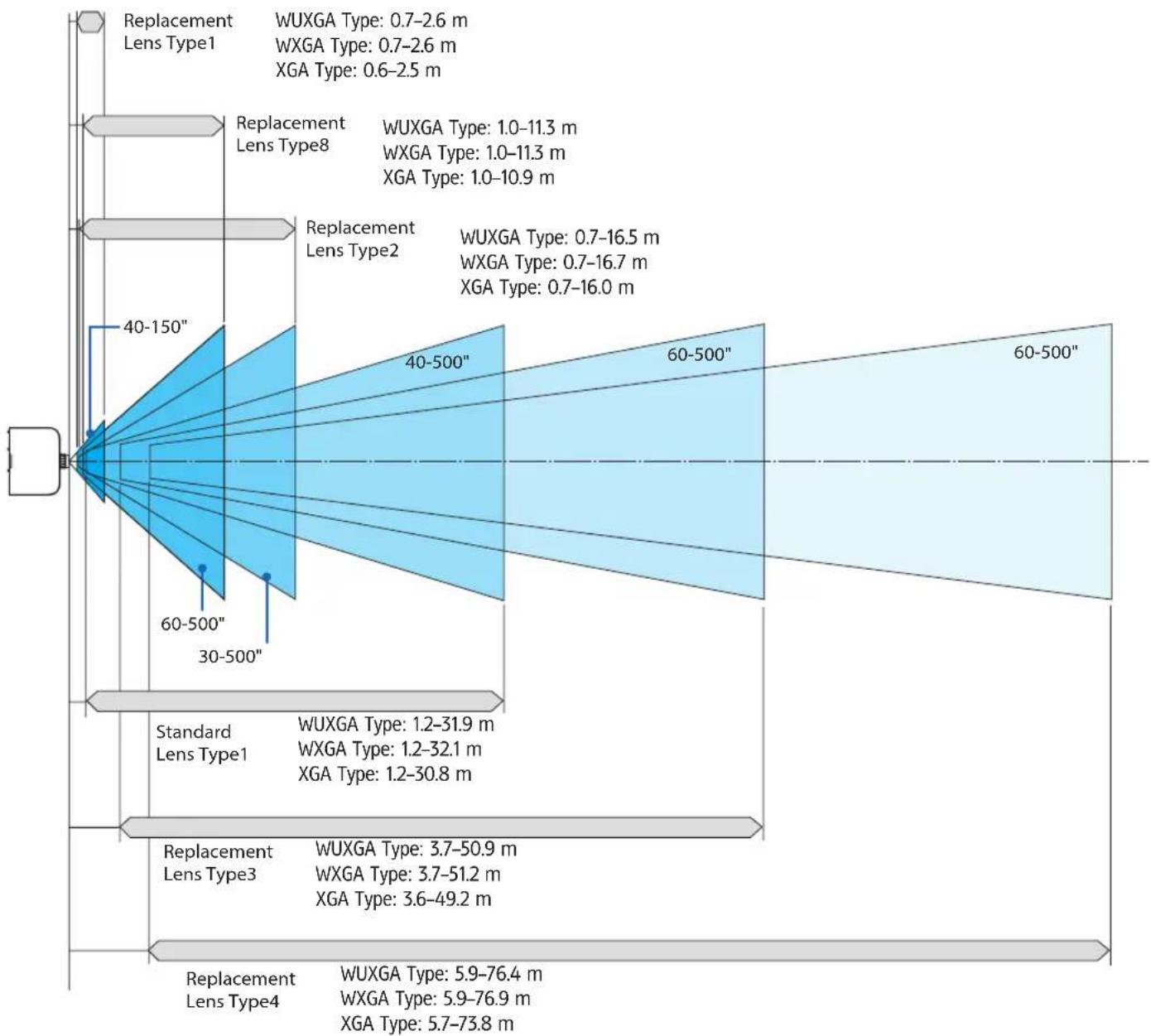
other
| Lens Type | Width Range (m) | |-----------|-----------------| | Lens Type1 | 0.7–2.6 | | Lens Type8 | 1.0–11.3 | | Lens Type2 | 0.7–16.5 | | Standard Lens Type1 | 1.2–31.9 | | Standard Lens Type3 | 1.2–32.1 | | Standard Lens Type4 | 3.7–50.9 | | WUXGA Type | 3.7–50.9 | | WXGA Type | 3.7–51.2 | | XGA Type | 3.6–49.2 | | WUXGA Type | 5.9–76.4 | | WXGA Type | 5.9–76.9 | | XGA Type | 5.7–73.8 |Tables of screen sizes and dimensions
WUXGA Type/WXGA Type
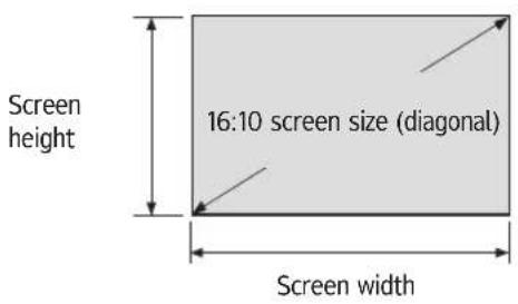
| Size (inches) Screen | en width Screen height | |||
| (inches) (cm) (inches) (cm) | ||||
| 30 25.4 64.6 | 15.9 40.4 | |||
| 40 33.9 86.2 | 21.2 53.8 | |||
| 60 50.9 129.2 | 31.8 80.8 | |||
| 80 67.8 172.3 | 42.4 107.7 | |||
| 100 84.8 215.4 | 53.0 134.6 | |||
| 120 101.8 258.5 | 63.6 161.5 | |||
| 150 127.2 323.1 | 79.5 201.9 | |||
| 200 | 169.6 | 430.8 | 106.0 | 269.2 |
| 240 | 203.5 516.9 | 127.2 | 323.1 | |
| 300 | 254.4 | 646.2 | 159.0 | 403.9 |
| 400 | 339.2 | 861.6 212.0 | 538.5 | |
| 500 | 424.0 1077.0 | 265.0 | 673.1 | |
XGA Type
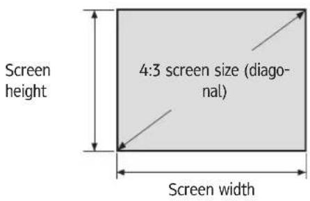
| Size (inches) Screen width Screen height | ||||
| (inches) (cm) (inches) (cm) | ||||
| 30 | 24 | 61.0 | 18 | 45.7 |
| 40 | 32 | 81.3 | 24 | 61.0 |
| 60 | 48 | 121.9 | 36 | 91.4 |
| 80 | 64 162.6 | 48 | 121.9 | |
| 100 | 80 203.2 | 60 | 152.4 | |
| 120 96 243.8 | 72 182.9 | |||
| 150 120 304 | 8 90 228.6 | |||
| 200 | 160 406 | 4 120 304.8 | ||
| 240 | 192 487 | 7 144 365.8 | ||
| 300 | 240 609 | 6 180 457.2 | ||
| 400 | 320 812 | 8 240 609.6 | ||
| 500 | 400 1016 | 0 300 762.0 | ||
Lens shifting range
This projector is equipped with a lens shift function for adjusting the position of the projected image by turning the lens shift dials. The lens can be shifted within the range shown below.
NOTE:
- The lens shift function cannot be used when using the Replacement Lens Type1 lens.
- Please do not use the lens shift function when projecting portrait images. Please use it with the lens in the center.
* Refer to the lens shift table on the next page for the drawing number of the lens shift range.
Desk/front projection
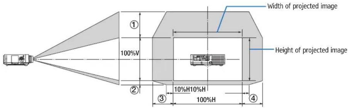
Description of symbols: V indicates vertical (height of the projected image), H indicates horizontal (width of the projected image).
Ceiling/front projector
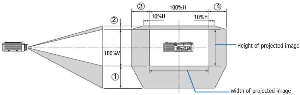
Lens shift table
| Applicable type Drawing number Lens unit | ||||||
| Replacement Lens Type8 | Replacement Lens Type2 | Standard Lens Type1 | Replacement Lens Type3 | Replacement Lens Type4 | ||
| WUXGA Type | 1 | 50% V 50% | V 50% V 50% V 50% V | % V | ||
| 2 | 10% V 10% V | V 10% V 10% V 10% V | ||||
| 3 | 20% H* 30% | H 30% H 30% H 30% H | ||||
| 4 | 20% H* 30% | H 30% H 30% H 30% H | ||||
| WXGA Type | 1 | 50% V 60% | V 60% V 60% V 60% V | % V | ||
| 2 | 10% V 10% V | V 10% V 10% V 10% V | ||||
| 3 | 20% H 30% | H 30% H 30% H 30% H | ||||
| 4 | 20% H 30% | H 30% H 30% H 30% H | ||||
| XGA Type | 1 | 35% V 50% V | 50% V 50% V 50% V | |||
| 2 | 10% V 10% V | 10% V 10% V 10% V | ||||
| 3 | 20% H 30% | H 30% H 30% H 30% H | ||||
| 4 | 20% H 30% | H 30% H 30% H 30% H | ||||
* For WUXGA Type, the shift range in the horizontal direction is up to 15% H when using the lens unit "Replacement Lens Type8" to project a screen exceeding Model 150.
Ex.: When projecting on a 150" screen
The explanation is for a XGA Type projector (4:3 panel) with a Replacement Lens Type2 lens fitted.
- Please replace the screen dimensions and maximum shift value in the calculations for the WXGA Type and WUXGA Type projectors (16:10 panel) as well.
According to the tables of screen sizes and dimensions ( page 234), H = 304.8 cm, V = 228.6 cm.
Adjustment range in the vertical direction: The projected image can be moved upwards 0.5–228.6 cm = 114 cm, downwards 0.1–228.6 cm = 22 cm (when the lens is at the center position). For a ceiling/front installation, the above figures are inverted.
Adjustment range in the horizontal direction: The projected image can be moved to the left 0.3 304.8 cm = 91 cm, to the right 0.3 304.8 cm = 91 cm.
* Figures differ by several % because the calculation is approximate.
② Compatible Input Signal List
Analog Computer Signal
| Signal Resolution ( dots ) Aspect Ratio Refresh Rate ( Hz ) | |||||
| VGA 640 480 4 : 3 60/72/75/85/iMac | |||||
| SVGA 800 600 4 : 3 56/60/72/75/85/iMac | |||||
| XGA 1024 768 * | 1 | 4 : 3 60/70/75/85/iMac | |||
| XGA+ 1152 864 4 : 3 60/70/75/85 | |||||
| WXGA | 1280 | 768 * | ^2 | 15 : 9 60 | |
| 1280 | 800 * | ^2 | 16 : 10 60 | ||
| 1360 | 768 * | ^5 | 16 : 9 * ^4 | 60 | |
| 1366 | 768 * | ^5 | 16 : 9 * ^4 | 60 | |
| Quad-VGA | 1280 | 960 4 : 3 60/75/85 | |||
| SXGA | 1280 | 1024 | 5 : 4 60/75/85 | ||
| SXGA+ | 1400 | 1050 | 4 : 3 60/75 | ||
| WXGA+ | 1440 | 900 | 16 : 10 60 | ||
| WXGA++ | 1600 | 900 | 16 : 9 60 | ||
| UXGA | 1600 | 1200 | * ^3 | 4 : 3 60/65/70/75 | |
| WSXGA+ | 1680 | 1050 | 16 : 10 60 | ||
| WUXGA | 1920 | 1200 | * ^3 | 16 : 10 60 (Reduced Blanking) | |
| 2K | 2048 | 1080 | 17 : 9 60 | ||
| Full HD | 1920 | 1080 | * ^3 | 16 : 9 60 | |
| MAC 13" | 640 | 480 4 : 3 67 | |||
| MAC 16" | 832 | 624 | 4 : 3 75 | ||
| MAC 19" | 1024 | 768 | 4 : 3 | 75 | |
| MAC 21" | 1152 | 870 * | ^6 | 4 : 3 * ^4 | 75 |
| MAC 23" | 1280 | 1024 | 5 : 4 65 | ||
Component
| Signal Resolution ( dots ) Aspect Ratio Refresh Rate ( Hz ) | ||||
| HDTV (1080p) | 1920 | 1080 | 16 : 9 50/60 | |
| HDTV (1080i) | 1920 | 1080 | 16 : 9 | 48/50/60 |
| HDTV (720p) | 1280 | 720 | 16 : 9 50/60 | |
| SDTV (480p) | 720 | 480 | 4:3 / 16:9 | 60 |
| SDTV (576p) | 720 | 576 | 4:3 / 16:9 | 50 |
| SDTV (480i) | 720 | 480 | 4:3 / 16:9 | 60 |
| SDTV (576i) | 720 | 576 | 4:3 / 16:9 | 50 |
Composite Video/S-Video
| Signal | Aspect Ratio Refresh Rate ( Hz ) | |
| NTSC | 4 : 3 60 | |
| PAL | 4 : 3 50 | |
| PAL60 | 4 : 3 60 | |
| SECAM | 4 : 3 50 | |
HDMI
| Signal Resolution ( dots ) Aspect Ratio Refresh Rate ( Hz ) | ||||
| VGA 640 480 4 : 3 60 | ||||
| SVGA 800 600 4 : 3 60 | ||||
| XGA 1024 768 * | 1 | 4 : 3 60 | ||
| HD 1280 720 * | 2 | 16 : 9 60 | ||
| WXGA | 1280 768 * | 2 | 15 : 9 60 | |
| 1280 800 * | 2 | 16 : 10 60 | ||
| 1366 768 * | 5 | 16 : 9 * 4 | 60 | |
| Quad-VGA | 1280 960 4 : 3 60 | |||
| SXGA | 1280 1024 | 5 : 4 60 | ||
| SXGA+ | 1400 1050 | 4 : 3 60 | ||
| WXGA+ | 1440 900 | 16 : 10 60 | ||
| WXGA++ | 1600 900 | 16 : 9 60 | ||
| WSXGA+ | 1680 1050 | 16 : 10 60 | ||
| UXGA | 1600 1200 * | 3 | 4 : 3 60 | |
| Full HD | 1920 1080 * | 3 | 16 : 9 60 | |
| WUXGA | 1920 1200 * | 3 | 16 : 10 60 | |
| 2K | 2048 1080 | 17 : 9 60 | ||
| WQHDiMac 27" | 2560 1440 | 16 : 9 60 | ||
| WQXGA | 2560 1600 | 16 : 10 | 60 (Reduced Blanking) | |
| 4K | 3840 2160 | 16 : 9 23.98/24/25/29.97/30 | ||
| 4096 2160 | 17 : 9 24 | |||
| HDTV(1080p) | 1920 1080 | 16 : 9 | 24/25/30/50/60 | |
| HDTV(1080i) | 1920 1080 | 16 : 9 48/50/60 | ||
| HDTV (720p) | 1280 720 | 16 : 9 50/60 | ||
| SDTV (480i/p) | 720/1440 480 | 4:3 / 16:9 | 60 | |
| SDTV (576i/p) | 720/1440 576 | 4:3 / 16:9 | 50 | |
HDMI 3D
| Signal Resolution ( dots ) | Refresh Rate ( Hz ) | Aspect Ratio | 3D Format |
| 1920 1080p | 23.98/24 | 16 : 9 | Frame Packing |
| Side By Side | |||
| Top and Bottom | |||
| 25 | Side By Side | ||
| Top and Bottom | |||
| 50 | Side By Side | ||
| Top and Bottom | |||
| 59.94/60 | Side By Side | ||
| Top and Bottom | |||
| 1920 1080i | 50 | Top and Bottom | |
| Side By Side | |||
| 59.94/60 | Top and Bottom | ||
| Side By Side | |||
| 1280 720p | 50 | Frame Packing | |
| Side By Side | |||
| Top and Bottom | |||
| 59.94/60 | Frame Packing | ||
| Side By Side | |||
| Top and Bottom |
DisplayPort
| Signal Resolution ( dots ) Aspect Ratio Refresh Rate ( Hz ) | |||||
| VGA 640 480 4 : 3 60 | |||||
| SVGA 800 600 4 : 3 60 | |||||
| XGA 1024 768 * | 1 | 4 : 3 60 | |||
| HD 1280 720 * | 2 | 16 : 9 60 | |||
| WXGA | 1280 | 768 * | 2 | 15 : 9 60 | |
| 1280 | 800 * | 2 | 16 : 10 | 60 | |
| 1366 | 768 * | 5 | 16 : 9 * | 4 60 | |
| Quad-VGA | 1280 | 960 4 : 3 60 | |||
| SXGA | 1280 | 1024 | 5 : 4 60 | ||
| SXGA+ | 1400 | 1050 | 4 : 3 60 | ||
| WXGA+ | 1440 | 900 | 16 : 10 | 60 | |
| WXGA++ | 1600 | 900 | 16 : 9 60 | ||
| WSXGA+ | 1680 | 1050 | 16 : 10 | 60 | |
| UXGA | 1600 | 1200 * | 3 | 4 : 3 60 | |
| Full HD | 1920 | 1080 * | 3 | 16 : 9 60 | |
| WUXGA | 1920 | 1200 * | 3 | 16 : 10 | 60 (Reduced Blanking) |
| 2K | 2048 | 1080 | 17 : 9 60 | ||
| WQHD iMac 27" | 2560 | 1440 | 16 : 9 60 | ||
| WQXGA | 2560 | 1600 | 16 : 10 | 60 (Reduced Blanking) | |
| 4K | 3840 | 2160 | 16 : 9 23.98/24/25 | /29.97/30 | |
| 4096 | 2160 | 17 : 9 24 | |||
| HDTV(1080p) | 1920 | 1080 | 16 : 9 | 24/25/30/50/60 | |
| HDTV (720p) | 1280 | 720 | 16 : 9 50/60 | ||
| SDTV (480i/p) | 720/1440 | 480 | 4:3 / 16:9 | 60 | |
| SDTV (576i/p) | 720/1440 | 576 | 4:3 / 16:9 | 50 | |
DisplayPort 3D
| Signal Resolution ( dots ) | Refresh Rate ( Hz ) | Aspect Ratio | 3D Format |
| 1920 1080p | 23.98/24 | 16 : 9 | Frame Packing |
| Side By Side | |||
| Top and Bottom | |||
| 25 | Side By Side | ||
| Top and Bottom | |||
| 50 | Side By Side | ||
| Top and Bottom | |||
| 59.94/60 | Side By Side | ||
| Top and Bottom | |||
| 1920 1080i | 50 | Top and Bottom | |
| Side By Side | |||
| 59.94/60 | Top and Bottom | ||
| Side By Side | |||
| 1280 720p | 50 | Frame Packing | |
| Side By Side | |||
| Top and Bottom | |||
| 59.94/60 | Frame Packing | ||
| Side By Side | |||
| Top and Bottom |
*1 Native resolution on XGA Type
*2 Native resolution on WXGA Type
*3 Native resolution on WUXGA Type
*4 Approximate Value
*5 The projector may fail to display these signals correctly when [AUTO] is selected for [ASPECT RATIO] in the on-screen menu. The factory default is [AUTO] for [ASPECT RATIO]. To display these signals, select [16:9] for [ASPECT RATIO].
*6 The projector may fail to display these signals correctly when [AUTO] is selected for [ASPECT RATIO] in the on-screen menu. The factory default is [AUTO] for [ASPECT RATIO]. To display these signals, select [4:3] for [ASPECT RATIO].
- Signals exceeding the projector's resolution are handled with Advanced AccuBlend.
- With Advanced AccuBlend, the size of characters and ruled lines may be uneven and colors may be blurred.
- Upon shipment, the projector is set for signals with standard display resolutions and frequencies, but adjustments may be required depending on the type of computer.
③ Specifications
| Model name RICOH PJ WU6181N/WX6181N/X6181N | |||
| Method Three primary color liquid crystal shutter projection method | |||
| Specifications of main parts | |||
| Liquid crystal panel Size X6181N: 0.79" (with MLA) 3 (aspect ratio: 4:3)WX6181N: 0.76" (with MLA) 3 (aspect ratio: 16:10)WU6181N: 0.76" (with MLA) 3 (aspect ratio: 16:10) | |||
| Projection lenses Zoom Manual (zoom range depends on lens) | |||
| Light source 350 W AC lamp (264 W when Eco mode is on) | |||
| Optical device Optical isolation by dichroic mirror, combining by dichroic prism | |||
| Light output (*2) (*3) | ECO OFF X6181N: 7200 lm, WX6181N: 6700 lm, WU6181N: 6200 lm | ||
| Contrast ratio (*2) (all white/all black) 6000:1 | |||
| Screen size (throw distance) 30" to 500" (throw distance depends on lens) | |||
| Color reproducibility 10-bit color processing (approx. 1.07 billion colors) (*4) | |||
| Audio output Built-in 10W monaural speaker | |||
| Scanning frequency | Horizontal | Analog: 15 kHz, 24 to 100 kHz (24 kHz or greater for RGB inputs), conforming to VESA standardsDigital: 15 kHz, 24 to 153 kHz, conforming to VESA standards | |
| Vertical | Analog: 48 Hz, 50 to 85 Hz, 100, 120 Hz conforming to VESA standardsDigital: 24, 25, 30, 48 Hz, 50 to 85 Hz, 100, 120 Hz conforming to VESA standards | ||
| Main adjustment functions | Manual zoom, manual focus, manual lens shift, input signal switching (HDMI1/HDMI2/Display-Port/BNC/BNC(CV)/BNC(Y/C)/COMPUTER/ETHERNET), auto image adjustment, picture enlarg-ing, picture position adjustment, muting (both video and audio), power on/standby, on-screen display/selection, etc. | ||
| Max. display resolution (horizontal vertical) | Analog: 1920 1200 (handled with Advanced AccuBlend)Digital: 4096 2160 (handled with Advanced AccuBlend) | ||
| Input signals | |||
| R,G,B,H,V | RGB: 0.7Vp-p/75Ω | ||
| Y: 1.0Vp-p/75Ω (with Negative Polarity Sync) | |||
| Cb, Cr (Pb, Pr): 0.7Vp-p/75Ω | |||
| H/V Sync: 4.0Vp-p/TTL | |||
| Composite Sync: 4.0Vp-p/TTL | |||
| Sync on G: 1.0Vp-p/75Ω (with Sync) | |||
| Composite video | 1.0Vp-p/75Ω | ||
| S-Video Y: 1.0Vp-p/75Ω | |||
| C: 0.286Vp-p/75Ω | |||
| Component | Y: 1.0Vp-p/75Ω (with Sync) | ||
| Cb, Cr (Pb, Pr): 0.7Vp-p/75Ω | |||
| DTV: 480i, 480p, 720p, 1080i, 1080p (60Hz)576i, 576p, 720p, 1080i (50Hz) | |||
| DVD: Progressive signal (50/60Hz) | |||
| Audio | 0.5Vrms/22kΩ or greater | ||
| Input/output connectors | |||
| Computer/Component | Video input | Mini D-Sub 15-pin 1, BNC connector 5 | |
| Audio input | Stereo mini jack 2 | ||
| Audio output | Stereo mini jack 1 (common for all signals) | ||
| HDMI | Video input | HDMI® Connector type A 2Deep Color (color depth): 8-/10-/12-bit compatibleColorimetry: RGB, YcbCr444 and YcbCr422 compatibleLipSync compatible, HDCP compatible (*5), Supports 4K and 3D | |
| Video output | Repeater | ||
| Audio input | HDMI: Sampling frequency - 32/44.1/48 kHz, Sampling bits - 16/20/24 bits | ||
| Model name RICOH PJ WU6181N/WX6181N/X6 | 181N | ||
| DisplayPort Video input | DisplayPort 1 | Data rate: 2.7Gbps/1.62GbpsNo. lanes: 1 lane/2 lanes/4 lanesColor depth: 6-bit, 8-bit, 10-bitColorimetry: RGB, YcbCr444 and YcbCr422 compatibleHDCP compatible (*5) | |
| Audio input DisplayPort: Sampling frequency - 32/44.1/48 kHz, Sampling bits - 16/20/24 bits | |||
| BNC (CV) Video input | BNC 1 | ||
| Audio input (shared with the BNC, BNC (CV), BNC (Y/C) audio input terminals) | |||
| BNC (Y/C) Video input | BNC 2 | ||
| Audio input (shared with the BNC, BNC (CV), BNC (Y/C) audio input terminals) | |||
| PC control connector D-Sub 9-pin 1 | |||
| USB port USB type A 1 | |||
| USB port for wireless LAN USB type A | 1 | ||
| Ethernet port RJ-45 1, 10/100 BASE | |||
| Remote connector Stereo mini jack 1 | |||
| 3D SYNC output terminal 5 V / 10 mA, s | synchronized signal output for 3D use | ||
| Usage environment Operating temperature: 41 | to 104°F (5 to 40°C) (*6)Operating humidity: 20 to 80% (with no condensation) | ||
| Storage temperature: 14 to 122°F (-10 to 50°C)Storage humidity: 20 to 80% (with no condensation) | |||
| Operating altitude: 0 to 3650 m/12000 feet(1700 to 3650 m/5500 to 12000 feet: Set [FAN MODE] to [HIGH ALUTITUDE]) | |||
| Power supply 100-240 V AC, 50/60Hz | |||
| Power con-sumption | Eco mode off 483 W (100-130 V)/460W (200-240 V) | ||
| Eco mode on 377 W (100-130 V)/362 W (200-240 V) | |||
| STANDBY (NORAML) | 0.11 W (100-130 V)/0.16 W (200-240 V) | ||
| STANDBY (NETWORK STANDBY) | 4.7 W (100-130 V)/4.9 W (200-240 V) | ||
| Rated input current | 5.5 A-2.2 A | ||
| External dimensions | 19.7" (width) 5.68" (height) 14.1" (depth)/499 (width) 142 (height) 359 (depth) mm (not including protruding parts)19.7" (width) 6.38" (height) 14.5" (depth)/499 (width) 162 (height) 368 (depth) mm(including protruding parts) | ||
| Weight | 18.5 lbs/8.4 kg (not including lens) | ||
*1 Effective pixels are more than 99.99%.
*2 This is the light output value (lumens) when the [PRESET] mode is set to [HIGH-BRIGHT]. The light output values will drop to 80% when [ON] is selected for [ECO MODE]. If any other mode is selected as the [PRESET] mode, the light output value may drop slightly.
*3 Compliance with ISO21118-2005
*4 Full color (approx. 16.77 million colors or greater) when the Ethernet input connector is selected.
*5 HDMI® (Deep Color, Lip Sync) with HDCP
What is HDCP/HDCP technology?
HDCP is an acronym for High-bandwidth Digital Content Protection. High bandwidth Digital Content Protection (HDCP) is a system for preventing illegal copying of video data sent over a High-Definition Multimedia Interface (HDMI).
If you are unable to view material via the HDMI input, this does not necessarily mean the projector is not functioning properly. With the implementation of HDCP, there may be cases in which certain content is protected with HDCP and might not be displayed due to the decision/intention of the HDCP community (Digital Content Protection, LLC).
Video: Deep Color; 8/10/12-bit, LipSync
Audio: LPCM; up to 2 ch, sample rate 32/44.1/48 KHz, sample bit; 16/20/24-bit
*6 95 to 104°F (35 to 40°C) - "Forced eco mode"
(Ricoh PJ WU6181N will shift to the eco-mode in stages starting from 33 °C.)
These specifications and the product's design are subject to change without notice.
④ Cabinet Dimensions
Unit: mm (inch)
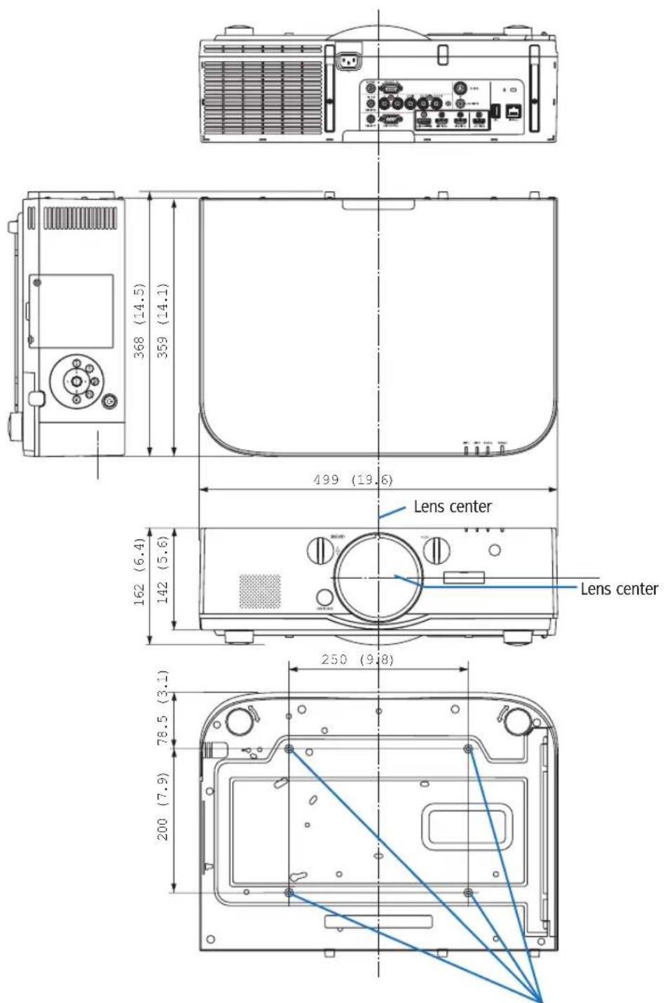
Holes for ceiling mount
⑤ Pin assignments and signal names of main connectors
COMPUTER IN/ Component Input Connector (Mini D-Sub 15 Pin)
Connection and signal level of each pin
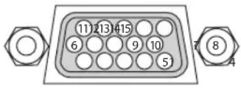
Signal Level
Video signal : 0.7Vp-p (Analog)
Sync signal : TTL level
2
| Pin No. RGB Signal (Analog) YCbCr Signal | ||
| 1 Red Cr | ||
| 3 | 2 Green or Sync on Green Y | |
| 3 Blue Cb | ||
| 4 Ground | ||
| 5 Ground | ||
| 6 Red Ground Cr Ground | ||
| 7 Green Ground Y Ground | ||
| 8 Blue Ground Cb Ground | ||
| 9 No Connection | ||
| 10 Sync Signal Ground | ||
| 11 No Connection | ||
| 12 Bi-directional DATA (SDA) | ||
| 13 Horizontal Sync or Composite Sync | ||
| 14 Vertical Sync | ||
| 15 Data Clock | ||
HDMI 1 IN/HDMI 2 IN Connector (Type A)
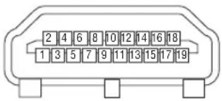
| Pin No. | Signal | Pin No. | Signal |
| 1 TMDS | Data 2+ | 11 TMDS | Clock Shield |
| 2 TMDS | Data 2 Shield | 12 TMDS | Clock |
| 3 TMDS | Data 2 | 13 CEC | |
| 4 TMDS | Data 1+ | 14 Disconnection | |
| 5 TMDS | Data 1 Shield | 15 SCL | |
| 6 TMDS | Data 1 | 16 SDA | |
| 7 TMDS | Data 0+ | 17 DDC/CEC grounding | |
| 8 TMDS | Data 0 Shield | 18 +5 V power supply | |
| 9 TMDS | Data 0 | 19 Hot plug detection | |
| 10 | TMDS Clock + |
DisplayPort IN Connector
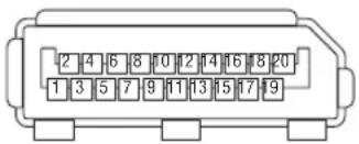
| Pin No. | Signal | Pin No. | Signal |
| 1 Main | link lane 3 | 11 Grounding 0 | |
| 2 Grounding 3 | 12 Main link lane 0+ | ||
| 3 Main | link lane 3+ | 13 Configuration 1 | |
| 4 Main | link lane 2 | 14 Configuration 2 | |
| 5 | Grounding 2 | 15 | Supplementary channel + |
| 6 Main | link lane 2+ | 16 Grounding 4 | |
| 7 | Main link lane 1 | 17 | Supplementary channel |
| 8 Grounding 1 | 18 Hot plug detection | ||
| 9 Main | link lane 1+ | 19 Return | |
| 10 | Main link lane 0 | 20 | +3.3 V power supply |
Ethernet Port (RJ-45)
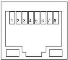
| Pin No. Signal | |
| 1 TxD+ | |
| 2 TxD | |
| 3 RxD+ | |
| 4 Disconnection | |
| 5 Disconnection | |
| 6 RxD | |
| 7 Disconnection | |
| 8 Disconnection | |
USB-A Port (Type A)
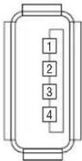
| Pin No. Signal | |
| 1 | V_BUS |
| 2 D | |
| 3 | D+ |
| 4 Grounding | |
PC CONTROL Port (D-Sub 9 Pin)
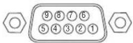
Communications protocol
| Pin No. Signal |
| 1 Unused |
| 2 RxD reception data |
| 3 TxD transmission data |
| 4 Unused |
| 5 Grounding |
| 6 Unused |
| 7 RTS transmission request |
| 8 CTS transmission allowed |
| 9 Unused |
6 Troubleshooting
This section helps you resolve problems you may encounter while setting up or using the projector.
Indicator Messages
Power Indicator
| Indicator display Projector | status Procedure | ||
| Off Power is off. - | |||
| Flashing Blue (short flashes) Preparing to turn power on Wait a while. | |||
| Blue (long flashes) Off timer (enabled)Program timer (off time enabled) | - | ||
| Orange (short flashes) Projector cooling Wait a while. | |||
| Orange (long flashes) Program timer (on time enabled) | |||
| Lit Blue Power on - | |||
| Red Standby mode (NORMAL) | - | ||
| Orange | Standby mode [NETWORK STANDBY] | ||
Status Indicator
| Indicator display | Projector status | Procedure | |
| Off | No problem, or standby mode | - | |
| Flashing | Red (cycles of 1) | Cover problem | The lamp cover is not properly mounted. Mount it properly. (→ Page 177) |
| Red (cycles of 4) | Fan problem | The cooling fan has stopped turning. Contact an Ricoh projector customer support center for repairs. | |
| Flashing | Orange | Network conflict | It is not possible to connect the projector's built-in LAN and wireless LAN simultaneously to the same network. To connect the projector's built-in LAN and wireless LAN simultaneously, connect them to different networks. |
| Lit | Green | STANDBY MODE in sleep mode ×^2 | - |
| Orange | Button has been pressed while projector is in key lock mode | The projector's keys are locked. The setting must be canceled to operate the projector. (→ Page 117) | |
| Projector's ID number and remote control's ID number do not match | Check the control IDs. (→ Pages 118) | ||
*2 Sleep mode refers to the state whereby the functional restrictions due to the standby mode setting are removed.
Lamp Indicator
| Indicator display Projector status Procedure | |||
| Off The lamp is turned off. – | |||
| Flashing Gr | Green Preparing to relight lamp after lighting has failed | Wait a while. | |
| Red | Lamp replacement grace period | The lamp has reached the end of its service life and is now in the replacement grace period (100 hours). Replace the lamp as soon as possible. ( page 176) | |
| Red (cycles of 6) | Lamp does not light | The lamp has not turned on. Wait at least 1 minute, then turn the power back on. If the lamp still does not light, contact an Ricoh projector customer support center. | |
| Lit Red Lamp usage time exceeded The lamp has exceeded its usage time. The projector’s power cannot be turned on until the lamp is replaced. ( page 176) | |||
Temp. Indicator
| Indicator display | Projector status | Procedure | |
| Off | No problem | ||
| Flashing | Red (cycles of 2) | Temperature problem | The temperature protector has been activated. If the room temperature is high, move the projector to a cool place. If the problem still persists, contact an Ricoh projector customer support center. |
| Lit | Orange | High surrounding temperature | The surrounding temperature is high. Lower the room temperature. |
If the temperature protector is activated
If the projector's internal temperature rises abnormally, the lamp turns off and the temperature indicator flashes (repeatedly in cycles of 2).
It may happen that the projector's temperature protector is simultaneously activated and the projector's power turns off. If this happens, do the following:
- Unplug the power cord from the power outlet.
- If using in a place where the surrounding temperature is high, move the projector to a different, cool place.
- If there is dust in the ventilation holes, clean. (→ pages 171 and 174)
- Wait as such about 1 hour for the projector's internal temperature to lower.
Common Problems & Solutions
(→ "Power/Status/Lamp Indicator" on page 245.)
| Problem Check These Items | |
| Does not turn on or shut down | ·Check that the power cord is plugged in and that the power button on the projector cabinet or the remote control is on. (→ pages 15, 16)·Ensure that the lamp cover is installed correctly. (→ page 177)·Check to see if the projector has overheated. If there is insufficient ventilation around the projector or if the room where you are presenting is particularly warm, move the projector to a cooler location.·Check to see if you continue to use the projector for another 100 hours after the lamp has reached the end of its life. If so, replace the lamp. After replacing the lamp, reset the lamp hours used. (→ page 129)·The lamp may fail to light. Wait a full minute and then turn on the power again.·Set [FAN MODE] to [HIGH ALTITUDE] when using the projector at altitudes approximately 5500 feet/1700 meters or higher. Using the projector at altitudes approximately 5500 feet/1700 meters or higher without setting to [HIGH ALTITUDE] can cause the projector to overheat and the projector could shut down. If this happens, wait a couple minutes and turn on the projector. (→ page 110)If you turn on the projector immediately after the lamp is turned off, the fans run without displaying an image for some time and then the projector will display the image. Wait for a moment. |
| Will turn off | ·Ensure that the [OFF TIMER], [AUTO POWER OFF] or [PROGRAM TIMER] is off. (→ page 113, 128) |
| No picture | ·Check if the appropriate input is selected. (→ page 18) If there is still no picture, press the INPUT button or one of the input buttons again.·Ensure your cables are connected properly.·Use menus to adjust the brightness and contrast. (→ page 89)·Ensure that the lens cover is open. (→ page 16)·Reset the settings or adjustments to factory preset levels using the [RESET] in the Menu. (→ page 129)·Enter your registered keyword if the Security function is enabled. (→ page 36)·If the HDMI input or the DisplayPort signal cannot be displayed, try the following.-Reinstall your driver for the graphics card built in your computer, or use the updated driver.For reinstalling or updating your driver, refer to the user guide accompanied with your computer or graphics card, or contact the support center for your computer manufacturer.Install the updated driver or OS on your own responsibility.We are not liable for any trouble and failure caused by this installation.·Both the composite video signal from each input connector as the computer, BNC, and BNC (CV), and the S-video signal from the BNC (Y/C) input connector are not output from HDMI OUT Connector of this projector.·Be sure to connect the projector and notebook PC while the projector is in standby mode and before turning on the power to the notebook PC.In most cases the output signal from the notebook PC is not turned on unless connected to the projector before being powered up.* If the screen goes blank while using your remote control, it may be the result of the computer's screen-saver or power management software.·See also the page 249. |
| Picture suddenly becomes dark | ·Check if the projector is in the Forced ECO mode because of too high ambient temperature. If this is the case, lower the internal temperature of the projector by selecting [HIGH] for [FAN MODE]. (→ page 110) |
| Color tone or hue is unusual | ·Check if an appropriate color is selected in [WALL COLOR]. If so, select an appropriate option. (→ page 110)·Adjust [HUE] in [PICTURE]. (→ page 90) |
| Image isn't square to the screen | ·Reposition the projector to improve its angle to the screen. (→ page 20)·Perform [GEOMETRIC CORRECTION] when the trapezoid is distorted. (→ page 100) |
| Picture is blurred · Adjust the focus. (→ page 22)·Reposition the projector to improve its angle to the screen. (→ page 20)·Ensure that the distance between the projector and screen is within the adjustment range of the lens. (→ page 233)·Has the lens been shifted by an amount exceeding the guaranteed range? (→ page 236)·Condensation may form on the lens if the projector is cold, brought into a warm place and is then turned on. Should this happen, let the projector stand until there is no condensation on the lens. | |
| Flicker appears on screen | ·Set [FAN MODE] to other than [HIGH ALTITUDE] mode when using the projector at altitudes approximately 5500 feet/1700 meters or lower. Using the projector at altitudes less than approximately 5500 feet/1700 meters and setting to [HIGH ALTITUDE] can cause the lamp to overcool, causing the image to flicker. Switch [FAN MODE] to [AUTO]. (→ page 110) |
| Image is scrolling vertically, horizontally or both | ·Check the computer's resolution and frequency. Make sure that the resolution you are trying to display is supported by the projector. (→ page 237)·Adjust the computer image manually with the Horizontal/Vertical in the [IMAGE OPTIONS]. (→ page 91) |
| Remote control does not work | • Install new batteries. (→ page 12)• Make sure there are no obstacles between you and the projector.• Stand within 40 m/1575 inch of the projector. (→ page 13) |
| Indicator is lit or blinking | • See the POWER/STATUS/LAMP Indicator. (→ page 245) |
| Cross color in RGB mode | • Press the AUTO ADJ. button on the projector cabinet or the remote control. (→ page 26)• Adjust the computer image manually with [CLOCK]/[PHASE] in [IMAGE OPTIONS] in the menu. (→ page 91) |
If there is no picture, or the picture is not displayed correctly.
- Power on process for the projector and the PC.
Be sure to connect the projector and notebook PC while the projector is in standby mode and before turning on the power to the notebook PC.
In most cases the output signal from the notebook PC is not turned on unless connected to the projector before being powered up.
NOTE: You can check the horizontal frequency of the current signal in the projector's menu under Information. If it reads "0kHz", this means there is no signal being output from the computer. (→ page 132 or go to next step)
- Enabling the computer's external display.
Displaying an image on the notebook PC's screen does not necessarily mean it outputs a signal to the projector. When using a PC compatible laptop, a combination of function keys will enable/disable the external display. Usually, the combination of the "Fn" key along with one of the 12 function keys gets the external display to come on or off. For example, NEC laptops use Fn + F3, while Dell laptops use Fn + F8 key combinations to toggle through external display selections.
• Non-standard signal output from the computer
If the output signal from a notebook PC is not an industry standard, the projected image may not be displayed correctly. Should this happen, deactivate the notebook PC's LCD screen when the projector display is in use. Each notebook PC has a different way of deactivate/reactivate the local LCD screens as described in the previous step. Refer to your computer's documentation for detailed information.
- Image displayed is incorrect when using a Mac
When using a Mac with the projector, set the DIPswitch of the Mac adapter (not supplied with the projector) according to your resolution. After setting, restart your Mac for the changes to take affect.
For setting display modes other than those supported by your Mac and the projector, changing the DIP switch on a Mac adapter may bounce an image slightly or may display nothing. Should this happen, set the DIP switch to the 13" fixed mode and then restart your Mac. After that, restore the DIP switches to a displayable mode and then restart the Mac again.
NOTE: A Video Adapter cable manufactured by Apple Computer is needed for a MacBook which does not have a mini D-Sub 15-pin connector.
- Mirroring on a MacBook
* When using the projector with a MacBook, output may not be set to 1024 768 unless "mirroring" is off on your MacBook. Refer to owner's manual supplied with your Mac computer for mirroring.
- Folders or icons are hidden on the Mac screen
Folders or icons may not be seen on the screen. Should this happen, select [View] → [Arrange] from the Apple menu and arrange icons.
⑦ PC Control Codes and Cable Connection
PC Control Codes
| Function Code Data | |||||||||||
| POWER | ON | 02H | 00H | 00H | 00H | 00H | 00H | 02H | |||
| POWER | OFF | 02H | 01H | 00H | 00H | 00H | 03H | ||||
| INPUT SELECT HDMI1 | 02H | 03H | 00H | 00H | 02H | 01H | A1H | A9H | |||
| INPUT SELECT HDMI2 | 02H | 03H | 00H | 00H | 02H | 01H | A2H | AAH | |||
| INPUT SELECT DisplayPort | 02H | 03H | 00H | 00H | 02H | 01H | A6H | AEH | |||
| INPUT SELECT BNC(CV) | 02H | 03H | 00H | 00H | 02H | 01H | 02H | 0AH | |||
| INPUT SELECT BNC(Y/C) | 02H | 03H | 00H | 00H | 02H | 01H | 06H | 0EH | |||
| INPUT SELECT COMPUTER | 02H | 03H | 00H | 00H | 02H | 01H | 0BH | 13H | |||
| PICTURE | MUTE | ON | 02H | 10H | 00H | 00H | 00H | 12H | |||
| PICTURE | MUTE | OFF | 02H | 11H | 00H | 00H | 00H | 00H | 13H | ||
| SOUND | MUTE | ON | 02H | 12H | 00H | 00H | 00H | 14H | |||
| SOUND | MUTE | OFF | 02H | 13H | 00H | 00H | 00H | 00H | 15H | ||
NOTE: Contact your local dealer for a full list of the PC Control Codes if needed.
Cable Connection
Communication Protocol
| Baud rate | 38400 bps |
| Data length | 8 bits |
| Parity | No parity |
| Stop bit | One bit |
| X on/off | None |
| Communications procedure......Full duplex | |
NOTE: Depending on the equipment, a lower baud rate may be recommended for long cable runs.
PC Control Connector (D-SUB 9P)
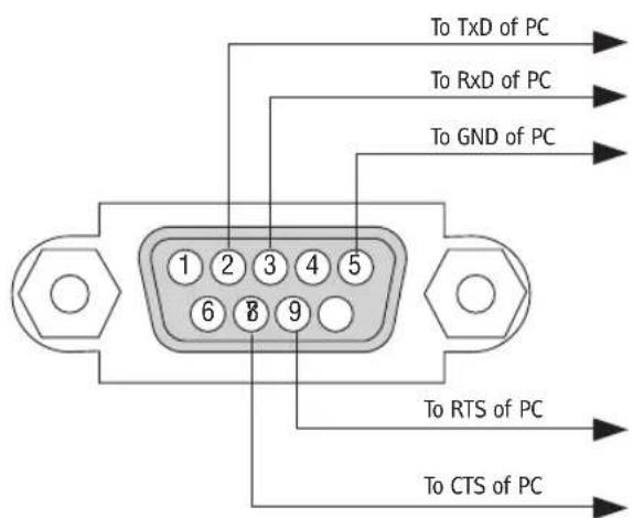
NOTE 1: Pins 1, 4, 6 and 9 are no used.
NOTE 2: Jumper "Request to Send" and "Clear to Send" together on both ends of the cable to simplify cable connection.
NOTE 3: For long cable runs it is recommended to set communication speed within projector menus to 9600 bps.

- RICOH PJ WU6181N/WX6181N/X6181N
- NOTES
- Important Information
- Safety Cautions
- Precautions
- CAUTION
- DOC Compliance Notice (for Canada only)
- Machine Noise Information Regulation - 3. GPSGV,
- User Information on Electrical and Electronic Equipment
- Users in the countries where this symbol shown in this section has been specified in national law on collection and treatment of E-waste
- Note for the Battery and/or Accumulator Symbol (For EU countries only)
- Declaration of Conformity for EU countries
- WARNING TO CALIFORNIA RESIDENTS:
- RF Interference (for USA only)
- WARNING
- Important Safeguards
- Installation
- Fire and Shock Precautions
- Caution on Handling the Optional Lens
- Remote Control Precautions
- Note for US Residents
- Notes to Users in the State of California
- Lamp Replacement
- A Lamp Characteristic
- CAUTION:
- About High Altitude mode
- About Copyright of original projected pictures:
- Notice: Users in Turkey
- Notice: Users in Taiwan
- Safety Labels of This Machine
- WARNING AVERTISSEMENT ADVERTENCIA AVISO
- WARNING VORSICHT AVERTISSEMENT AVVERTIMENTO ADVERTENCIA AVISO
- CAUTION ATTENTION PRECAUCIÓN CUIDADO 注意
- CAUTION ACHTUNG ATTENTION ATTENZIONE PRECAUCIÓN
- Health precautions to users viewing 3D images
- Power management function
- STANDBY MODE (Factory preset: NORMAL)
- AUTO POWER OFF (Factory preset: 60 minutes)
- Clearance for Installing the Projector
- Example 1 – If there are walls on both sides of the projector.
- NOTE:
- Example 2 – If there is a wall behind the projector.
- Example 3 – In the case of portrait projection.
- Important Information......i
- Introduction ...... 1
- Projecting an Image (Basic Operation) 14
- Convenient Features....29
- Multi-Screen Projection....61
- Using On-Screen Menu....75
- Connecting to Other Equipment....153
- Maintenance....171
- User Supportware 180
- Using the Viewer....208
- Appendix......231
- Introduction
- ① What's in the Box?
- ② Introduction to the Projector
- Congratulations on Your Purchase of the Projector
- Videos
- - Simultaneous display of 2 images (PIP/PICTURE BY PICTURE)
- - Multi-screen projection using multiple projectors
- - Seamless switch function for smoother screen changes when switching the signal
- • Supports HDMI 3D format
- Network
- • Supported by wired LAN/wireless LAN (wireless LAN unit sold separately)
- • LAN-compatible Viewer
- - CRESTRON ROOMVIEW compatibility
- - Convenient utility software (User Supportware) provided as standard
- Energy-saving
- • Energy-saving design with a standby power consumption of 0.11 watts (100-130 V)/0.16 watts (200-240 V)
- - "Eco mode" for low power consumption and "Carbon Meter" display
- Maintenance
- About this user's manual
- Notation by Resolution
- WUXGA Type
- WXGA Type
- XGA Type
- About the Projector's [NETWORK SETTINGS]
- "NETWORK SETTINGS" under [SETUP] in the on-screen menu (→ Page 120)
- "NETWORK SETTINGS" in the application menu (→ Page 138)
- ③ Part Names of the Projector
- Front/Top
- Mounting the strap
- How to paste the input selection character sticker of the remote control
- Controls/Indicator Panel
- Terminals
- ④ Part Names of the Remote Control
- Battery Installation
- Operating Range for Wireless Remote Control
- Projecting an Image (Basic Operation)
- ① Flow of Projecting an Image
- Step 1
- Step 2
- Step 3
- Step 4
- Step 5
- Step 6
- Step 7
- Step 8
- ② Connecting Your Computer/Connecting the Power Cord
- Connect your computer to the projector.
- Connect the supplied power cord to the projector.
- ③ Turning on the Projector
- Remove the lens cap.
- Press the ⏻ (POWER) button on the projector cabinet or the POWER ON button on the remote control.
- TIP:
- Note on Startup screen (Menu Language Select screen)
- To select a menu language, follow these steps:
- Press the ENTER button to execute the selection.
- ④ Selecting a Source
- Selecting the computer or video source
- Detecting the Signal Automatically
- Using the Remote Control
- Selecting Default Source
- ⑤ Adjusting the Picture Size and Position
- Adjusting the vertical position of a projected image (Lens shift)
- Vertical dial
- Horizontal dial
- Focus
- Applicable lens: Replacement Lens Type8
- Applicable lens: Replacement Lens Type1
- Preparations:
- Zoom
- Adjusting the Tilt Feet
- ⑥ Optimizing Computer Signal Automatically
- Adjusting the Image Using Auto Adjust
- ⑦ Turning Up or Down Volume
- Important:
- ⑧ Turning off the Projector
- To turn off the projector:
- After Use
- Convenient Features
- ① Turning off the Image and Sound
- Press the BLANK button.
- Press the MUTE button.
- Press the AV-MUTE button.
- ② Freezing a Picture
- ③ Enlarging a Picture
- ④ Changing Eco Mode/Checking Energy-Saving Effect Using Eco Mode [ECO MODE]
- Checking Energy-Saving Effect [CARBON METER]
- ⑤ Correcting Horizontal and Vertical Keystone Distortion [CORNERSTONE]
- Press the ◀ or ▶ button to highlight the [OK] and press the ENTER button.
- Preventing the Unauthorized Use of the Projector [SECURITY]
- To enable the Security function:
- To disable the SECURITY function:
- ⑦ Projecting 3D videos
- Health precautions
- 3D eyewear and 3D emitter preparations
- Procedure to watch 3D videos using this projector
- Select the 3D video format.
- Turn on the power supply of the 3D eyewear and wear the eyewear to watch the video.
- When videos cannot be viewed in 3D
- ⑧ Controlling the Projector by Using an HTTP Browser
- Overview
- Possible operations on the HTTP server screen
- Possible operations on the basic HTTP server screen
- Possible operations on the dedicated HTTP server screen
- To view the HTTP server screen
- Basic HTTP server screen
- HTTP server screen
- Preparation before Use
- Handling of the Address for Operation via a Browser
- PROJECTOR ADJUSTMENT
- NETWORK SETTINGS
- - SETTINGS
- - CRESTRON
- • NETWORK SERVICE
- ⑨ Projecting Your Computer's Screen Image from the Projector via a Network [NETWORK PROJECTOR]
- Setting the Projector to Network Projector Input Mode
- Projecting the Image with Network Projector
- Click [Connect].
- ⑩ Using the Projector to Operate Your Computer via a Network [REMOTE DESKTOP]
- Prepare a commercially available wireless keyboard (US layout version).
- Setting the password to the user account of Windows 7
- Setting the Remote Access
- Checking the IP address on Windows 7
- Click [Details...].
- Starting the Remote Desktop
- Exiting the Remote Desktop
- Multi-Screen Projection
- ① Things that can be done using multi-screen projection
- Case 1
- Case 2
- Case 1. Using a single projector to project two types of videos [PIP/PICTURE BY PICTURE] Connection example and projection image
- On-screen menu operations
- Case 2. Using four projectors (liquid crystal panel: XGA) to project videos with a resolution of 1920 × 1080 pixels [TILING]
- Things to note when installing projectors
- ② Displaying Two Pictures at the Same Time
- Picture in Picture function
- Picture by picture function
- Input terminals that can be used for the main screen and sub-screen.
- Projecting two screens
- Switching the main display with the sub-display and vice versa
- Restrictions
- ③ Displaying a Picture Using [EDGE BLENDING]
- Before explaining use of the Edge Blending function
- Preparation:
- Setting the overlap of projection screens
- ① Enable [EDGE BLENDING].
- Press the "Edge Blend." button.
- Select [MODE] → [ON] and press the ENTER button.
- Select [RIGHT] for Projector A and [LEFT] for Projector B.
- Select [CONTROL] → [ON] and press the ENTER button.
- ② Adjust [RANGE] and [POSITION] to determine an area of overlapped edges of images projected from each projector.
- Adjust [RANGE].
- Adjust [POSITION].
- Black Level Adjustment
- Example: Adjusting the Black Level when placing two projectors side by side
- 9-segmented portions for Black Level adjustment
- Using On-Screen Menu
- ① Using the Menus
- ② Menu Elements
- Menu windows or dialog boxes typically have the following elements:
- ③ List of Menu Items
- ④ Menu Descriptions & Functions [INPUT]
- 1:HDMI1
- 2:HDMI2
- 3:DisplayPort
- 4:BNC
- 5:BNC(CV)
- 6:BNC(Y/C)
- 7:COMPUTER
- 8:ETHERNET
- 9:USB-A
- ENTRY LIST
- TEST PATTERN
- Using the Entry List
- Displaying the Entry list
- Press the MENU button.
- Press the ◀ or ▶ button to select [INPUT].
- Use the ◀, ▶, ▲, or ▼ to select [ENTRY LIST] and press the ENTER button.
- Entering the currently projected signal into the Entry List [STORE]
- Calling up a signal from the Entry List [LOAD]
- Editing a signal from the Entry List [EDIT]
- Set the above items and select [OK] and press the ENTER button.
- Cutting a signal from the Entry List [CUT]
- Copying and pasting a signal from the Entry List [COPY] / [PASTE]
- Deleting all the signals from the Entry List [ALL DELTE]
- ⑤ Menu Descriptions & Functions [ADJUST]
- [PICTURE]
- [MODE]
- [PRESET]
- [GENERAL]
- Storing Your Customized Settings [REFERENCE]
- Selecting Gamma Correction Mode [GAMMA CORRECTION]
- Selecting Screen Size for DICOM SIM [SCREEN SIZE]
- Adjusting Color Temperature [COLOR TEMPERATURE]
- Adjusting Brightness and Contrast [DYNAMIC CONTRAST]
- Adjusting White Balance [WHITE BALANCE]
- [COLOR CORRECTION]
- [CONTRAST]
- [BRIGHTNESS]
- [SHARPNESS]
- [COLOR]
- [HUE]
- [RESET]
- [IMAGE OPTIONS]
- Adjusting Clock and Phase [CLOCK/PHASE]
- Adjusting Horizontal/Vertical Position [HORIZONTAL/VERTICAL]
- [BLANKING]
- Selecting Overscan Percentage [OVERSCAN]
- Selecting the Aspect Ratio [ASPECT RATIO]
- For Component/Video/S-Video signals
- [INPUT RESOLUTION]
- [VIDEO]
- Using Noise Reduction [NOISE REDUCTION]
- Selecting Interlaced Progressive Conversion Process Mode [DEINTERLACE]
- [CONTRAST ENHANCEMENT]
- [SIGNAL TYPE]
- [VIDEO LEVEL]
- [3D SETTINGS]
- STEREO VIEWER
- STEREO FILTER
- FORMAT
- L/R INVERT
- Menu Descriptions & Functions [DISPLAY]
- [PIP/PICTURE BY PICTURE]
- SUB INPUT
- MODE
- PICTURE SWAP
- PIP SETTING
- BORDER
- [GEOMETRIC CORRECTION]
- KEYSTONE
- CORNERSTONE
- HORIZONTAL CORNER/VERTICAL CORNER
- Adjustment method
- PINCUSHION
- PC TOOL (For future support)
- RESET
- [EDGE BLENDING]
- TOP/BOTTOM/LEFT/RIGHT
- BLACK LEVEL
- WHITE BALANCE
- PICTURE SETTING
- Conditions for using tiling
- ⑦ Menu Descriptions & Functions [SETUP]
- Selecting Menu Language [LANGUAGE]
- Selecting Menu Color [COLOR SELECT]
- Turning On / Off Source Display [INPUT DISPLAY]
- Turning messages on and off [MESSAGE DISPLAY]
- Turning ON/OFF Control ID [ID DISPLAY]
- Turning On / Off Eco Message [ECO MESSAGE]
- [3D CAUTION MESSAGE]
- Selecting Menu Display Time [DISPLAY TIME]
- Selecting Interval Time for Filter Message [FILTER MESSAGE]
- [INSTALLATION]
- Selecting Projector Orientation [ORIENTATION]
- Using the Wall Color Correction [WALL COLOR]
- Selecting Fan Mode [FAN MODE]
- [LAMP MODE]
- [REF. WHITE BALANCE]
- [STATIC CONVERGENCE]
- [CONTROL]
- TOOLS
- ADMINISTRATOR MODE
- PROGRAM TIMER
- Setting a new program timer
- Select [OK] and press the ENTER button.
- Select [BACK] and press the ENTER button.
- Press the EXIT button.
- Activating the program timer
- Changing the programmed settings
- Changing the order of programs
- Deleting the programs
- DATE AND TIME SETTINGS
- [MOUSE]
- Disabling the Cabinet Buttons [CONTROL PANEL LOCK]
- Enabling Security [SECURITY]
- Selecting Communication Speed [COMMUNICATION SPEED]
- Setting ID to the Projector [CONTROL ID]
- Assigning or Changing the Control ID
- Turn on the projector.
- Press the ID SET button on the remote control.
- Press one of numeric keypad buttons while pressing and holding the ID SET button on the remote control.
- Example:
- Release the ID SET button.
- Turning On or Off Remote Sensor [REMOTE SENSOR]
- Enabling Key Sound and Error Sound [BEEP]
- [NETWORK SETTINGS]
- Hints on How to Set Up LAN Connection
- WIRED LAN
- PROJECTOR NAME
- DOMAIN
- ALERT MAIL
- NETWORK SERVICE
- [SOURCE OPTIONS]
- Setting Auto Adjust [AUTO ADJUST]
- [COLOR SYSTEM]
- [AUDIO SELECT]
- Selecting Default Source [DEFAULT INPUT SELECT]
- [SEAMLESS SWITCHING]
- Setting Closed Caption [CLOSED CAPTION]
- Selecting a Color or Logo for Background [BACKGROUND]
- [POWER OPTIONS]
- Selecting Power-saving in [STANDBY MODE]
- Enabling Direct Power On [DIRECT POWER ON]
- Turning On the Projector by Detecting Input Signal [AUTO POWER ON SELECT]
- Enabling Power Management [AUTO POWER OFF]
- Using Off Timer [OFF TIMER]
- Returning to Factory Default [RESET]
- [CURRENT SIGNAL]
- [ALL DATA]
- [ALL DATA (INCLUDING ENTRY LIST)]
- Clearing Lamp Hour Meter [CLEAR LAMP HOURS]
- Clearing the Filter Usage Hours [CLEAR FILTER HOURS]
- ⑧ Menu Descriptions & Functions [INFO.]
- [SOURCE(1)]
- [SOURCE(2)]
- [SOURCE(4)]
- [VERSION(1)]
- [VERSION(2)]
- [OTHERS]
- [CONDITIONS]
- About the X-AXIS, Y-AXIS and Z-AXIS CONDITIONS
- ⑨ Application Menu
- ADVANCED NETWORK UTILITY
- NETWORK PROJECTOR
- REMOTE DESKTOP CONNECTION
- NETWORK SETTINGS(MM)
- To set up the projector for a LAN connection:
- To recall LAN settings stored in the profile number:
- To connect a DHCP server:
- To set only for wireless LAN (NETWORK TYPE and WEP/WPA):
- To select an SSID:
- To execute [EASY CONNECTION] using Advanced Network Utility:
- WIRED LAN or WIRELESS LAN (ADVANCED menu only)
- ADVANCED Setting (required for wireless LAN only) (ADVANCED menu only)
- [AUTHENTICATION] (required for wireless only)
- Preparation before setting
- Setting Procedures
- Select the [AUTHENTICATION] tab.
- ① Selecting [EAP-TLS] for [EAP TYPE]:
- Select the [USER NAME] field and press the ENTER button.
- Installing a digital certificate
- Clearing the digital certificate that is installed on the projector
- Entering WEP keys (Switching between Alphanumeric characters and hexadecimal)
- WPS(MM)
- NETWORK INFORMATION
- HOST NAME (ADVANCED menu only)
- HTTP SERVER (ADVANCED menu only)
- Connecting to Other Equipment
- ① Mounting a lens (sold separately)
- Mounting the lens
- Turn the lens clockwise.
- Removing the lens
- While pressing the lens release button on the projector's front panel fully in, turn the lens counterclockwise.
- Slowly pull the lens off the projector.
- ② Making Connections
- Analog RGB signal connection
- Digital RGB signal connection
- Cautions when connecting an HDMI cable
- Cautions when connecting a DisplayPort cable
- Cautions when using a DVI signal
- NOTE: When Viewing a DVI Digital Signal
- Connecting an External Monitor
- Connecting Your Blu-ray Player or Other AV Equipment
- Connecting Component Input
- Connecting HDMI Input
- Portrait projection (vertical orientation)
- Precautions during installation
- Design and manufacturing conditions for the stand
- Reference drawings
- Lens shift securing method
- Connecting to a Wired LAN
- Example of LAN connection
- Connecting to a Wireless LAN (sold separately)
- Flow of Setting Wireless LAN
- Mounting a wireless LAN unit
- To remove the wireless LAN unit
- Example of wireless LAN connection
- Maintenance
- ① Cleaning the Filters
- Attach 4 new filters to both sides of the filter unit.
- Mount the filter unit back onto the projector cabinet.
- Close the filter cover.
- Clear the filter usage hours.
- ② Cleaning the Lens
- ③ Cleaning the Cabinet
- ④ Replacing the Lamp and the Filters
- Flow of Replacing the Lamp and the Filters
- To replace the lamp:
- Remove the lamp cover.
- Remove the lamp housing.
- Install a new lamp housing.
- Reattach the lamp cover.
- This completes the lamp replacement. Go on to the filter replacement.
- To replace the filters:
- Press down on the buttons on the left and right and then pull the filter cover towards you to open it.
- Remove the filter unit by pulling out the tab.
- Remove the four filters.
- To clear the lamp usage hours and the filter usage hours:
- User Supportware
- ① Operating Environment for Software Included on CD-ROM
- Names and Features of Bundled Software Programs
- Download service
- Operating Environment
- ② Installing Software Program
- Installation for Windows software
- Insert the accompanying CD-ROM into your CD-ROM drive.
- Uninstalling a Software Program
- Using on Mac OS
- [Example] Install Projection Utility on the computer.
- ③ Projecting Your Computer's Screen Image or Video from the Projector over a LAN (Projection Utility)
- What You can Do with Projection Utility
- • Image transmission (for Windows and Mac OS)
- • Audio transfer capability (for Windows only)
- - Playing streaming video (for Windows only)
- - Geometric Correction Tool [GCT] (for Windows only)
- Using on Windows
- Step 1: install Projection Utility on the computer.
- Insert the accompanying CD-ROM into your CD-ROM drive.
- Click "Installing Projection Utility" on the menu window.
- If you agree, click "I agree." and then click "Next".
- Click "OK".
- Step 2: Connect the projector to a LAN.
- Step 3: Start Projection Utility.
- Operate the control window.
- Viewing the "Help" file of Projection Utility
- Starting Projection Utility from a USB Memory or SD Card
- Step 1: Install Projection Utility for Mac OS on the computer
- Step 2: Connect the projector to a LAN
- Step 3: Start Projection Utility for Mac OS
- Projecting an Image from an Angle (Geometric Correction Tool in Projection Utility)
- What you can do with GCT
- Projecting an Image from an Angle (GCT)
- ⑤ Projecting Images from the Projector over a LAN (Advanced Network Utility)
- What you can do with Advanced Network Utility
- - Projected images can be transferred and saved to computers.
- • 1-click switching of presenter
- • Central management of the projecting computer
- Connecting the projector to a LAN
- Basic Operation of Advanced Network Utility
- Sending Images to Projector
- - Connecting projector
- Check(☐) the projector to connect and click [Connect].
- • Transferring images
- - Stopping or resuming the transmission of images
- Click the projector icon ( 📋 ) on the Windows taskbar.
- Click [Stop Sending].
- Click the projector icon (☐) on the Windows taskbar.
- Click [Start Sending].
- • End the transmission of images
- Holding Conferences
- - Holding conferences
- Participating in Conference
- - Saving received images
- Click [Memo] in the attendant window.
- Click [Save Image] in the attendant window.
- REFERENCE:
- - Downloading disclosed file
- - Changing presenter
- • Leaving conference
- JPEG Conversion Tool
- Installing JPEG Conversion Tool
- Click "JPEG Conversion Tool" on the menu window.
- ⑦ Managing the Projector Using Projector Management Utility
- Supported OS
- Memory
- Resolution
- Installing Projector Management Utility
- Using the Viewer
- ① What you can do with the Viewer
- Playback requirements:
- Supported USB memory devices
- Notices on shared folder and media server
- NOTE
- ② Projecting images stored in a USB memory device
- Starting the Viewer
- Press the "9/USB-A" button.
- - Movie file
- Remove the USB memory from the projector.
- Exiting the Viewer
- Names and functions of Viewer screen
- Control bar
- - Drive list screen
- Menu operation
- Operation for Drive list screen
- - Thumbnail screen
- Operation for Thumbnail screen
- - Slide screen (still image/movie)
- Control bar operation
- Functions of still image control bar
- Functions of movie control bar
- Viewer option settings
- - SLIDE SETTING
- • MOVIE SETTING
- • AUTO PLAY SETTING
- - SORT SETTING
- ③ Projecting data from shared folder
- Preparation
- Connecting the projector to the shared folder
- Press the 9/USB-A button on the remote control.
- Displays the [OPTIONS] menu.
- Display the [SHARED FOLDER] screen.
- Select a folder number and place to enable it.
- Enter the path, user name, and password for the shared folder.
- Exit the setting.
- Disconnecting the shared folder from the projector
- Projecting data from media server
- Setting up "Media Sharing" in Windows Media Player 11
- Setting up "Media Sharing" in Windows Media Player 12
- Start Windows Media Player 12.
- Select "Stream", and then select "Automatically allow devices to play my media".
- Select "Automatically allow all computers and media devices".
- Connecting the projector to the media server
- Disconnecting the projector from the media server
- Display the OPTIONS menu.
- Display the MEDIA SERVER setting screen.
- Disable the connection.
- ① Throw distance and screen size
- Lens types and throw distance
- Tables of screen sizes and dimensions
- Lens shifting range
- ② Compatible Input Signal List
- ④ Cabinet Dimensions
- ⑤ Pin assignments and signal names of main connectors
- COMPUTER IN/ Component Input Connector (Mini D-Sub 15 Pin)
- Connection and signal level of each pin
- Signal Level
- HDMI 1 IN/HDMI 2 IN Connector (Type A)
- DisplayPort IN Connector
- Troubleshooting
- Indicator Messages
- If the temperature protector is activated
- Common Problems & Solutions
- If there is no picture, or the picture is not displayed correctly.
- ⑦ PC Control Codes and Cable Connection
- PC Control Codes
- Cable Connection
- PC Control Connector (D-SUB 9P)
Brand : RICOH
Model : PJ X6181N
Category : Projector