
RPK4-CH4103 - Car Mounting Kit PAC - Free user manual and instructions
Find the device manual for free RPK4-CH4103 PAC in PDF.


| Product Type | Radio Replacement Kit with Climate Control Retention |
| Compatible Vehicles | 2014-2020 Jeep Grand Cherokee |
| Integrated Display | Secondary 5.2 inch LCD screen for vehicle controls and gauges |
| Retained Features | Steering wheel controls, factory reverse camera, AM/FM reception, climate controls, vehicle settings |
| Hard Buttons | 4 programmable hard buttons below LCD screen |
| Accessory Button Inserts | Up to 7 button openings with included inserts for vehicle functions |
| Camera Support | Up to 5 cameras with optional RPA-16P5V harness (sold separately) |
| Reverse Camera Retention | Included RPA-16P1V harness for factory reverse camera |
| Steering Wheel Control (SWC) | Pre-programmed with factory SWC; custom programming available |
| Factory Amplifier Control | Retains and allows adjustment of factory amplifier settings via LCD |
| Parking Sensor Chimes | External chime speaker included; adjustable chime output |
| Radio Compatibility | Alpine, JVC, Kenwood, Clarion, Pioneer, Sony, Fusion, and others (DIP switch selectable) |
| USB Hub | Replacement OEM USB hub included; retains factory USB ports |
| Antenna Adapter | Included AM/FM antenna adapter (BAADIN22) |
| Installation Difficulty | Moderate; requires dash disassembly and some cutting (2014-2018 models) |
| Power Supply | 12V vehicle electrical system; 10A accessory output |
| Firmware Updates | Via RadioPRO PC app; USB port on interface module and LCD bezel |
| Warranty / Support | Technical support via phone or email; product updates available online |
| Dimensions (Kit) | Custom-molded dash bezel; approximately 10 x 6 x 3 inches (estimate) |
| Weight | Approximately 2.5 lbs (with all components) |
Frequently Asked Questions - RPK4-CH4103 PAC
User questions about RPK4-CH4103 PAC
0 question about this device. Answer the ones you know or ask your own.
Ask a new question about this device
Download the instructions for your Car Mounting Kit in PDF format for free! Find your manual RPK4-CH4103 - PAC and take your electronic device back in hand. On this page are published all the documents necessary for the use of your device. RPK4-CH4103 by PAC.
USER MANUAL RPK4-CH4103 PAC
Introduction and Features
The RPK4-CH4103 is a complete radio replacement kit with integrated climate control retention for the 2014-2020 Jeep Grand Cherokee. All modules and cables are included to retain important features of the factory system including: steering wheel-mounted radio controls, factory reverse camera, and AM/FM reception.
A secondary 5.2" LCD screen is added for additional vehicle features and controls including: vehicle performance gauges and information, climate controls, vehicle settings, factory amplifier control, and forced camera activation. Simplified installation and setup menus allow direct programming of camera triggers, steering wheel controls, and other settings of the kit and RP4.2-CH4103 interface. Features provided by the LCD screen will vary based on the vehicle features. See Important Notes (next section) for additional information.
Four hard buttons added to the radio dash bezel (below the 5.2" LCD screen) allow the user to set presets to control functions including: specific climate controls, forced camera activation, and LCD screen controls. Options for hard buttons will vary based on vehicle features and which cameras are installed.
Button inserts and seven button openings on the radio dash bezel allow for retention of functions that would typically be lost when replacing the factory radio.
Some advanced features require additional accessories (sold separately).
Important Notes
We recommend reading this manual thoroughly to familiarize yourself with the entire process prior to beginning the installation.
1. Does Not Retain:
Cluster Display Features
- Compass
- Clock
- Phone pop-ups
- Navigation pop-ups
Factory Amplifier Features
• Speed Controlled Volume
Uconnect Features
- Uconnect Access Remote Start / Lock / Unlock
- SOS / Assist
• Vehicle Location Service - WiFi-Hotspot
SiriusXM Guardian Services
- In vehicles equipped with parking sensors, you must use the included external speaker in order to continue hearing parking sensor chimes. If the vehicle has a factory amplified system and parking sensors, the speaker is not necessary unless the factory amplifier is no longer being used. In cases where the factory amplifier and aftermarket amplifier are being used (for example, using an aftermarket amplifier for the front speakers and using the factory amplifier for the rear speakers), the RPK4-CH4103 allows the chime output to the external speaker to be set to the channels that are being driven off of the aftermarket amplifier.
- If you are adding additional cameras, PAC part number RPA-16P5V (sold separately) must be used to connect up to 5 total cameras.
- It is very important that the vehicle's accessory buttons be programmed and tested right away. If they do not operate, it is likely because the incorrect CAN wire connections are being used.
Vehicle Accessories Buttons:

In 2018+ vehicles, the CAN connections must be made at the vehicle's star connector (see page 10 for details). Failure to do so will cause the vehicle's accessory buttons to not operate and may cause the vehicle's battery to drain.
- In newer (2018+) vehicles, the factory amplifier may not work or the audio level will be low until the ignition is cycled. Make sure the aftermarket radio's volume level is turned down prior to cycling the ignition to prevent excess volume after the ignition cycle!
- Only in 2014 Grand Cherokee: All vehicle settings options will be listed in the vehicle settings menu, including vehicle settings that are not available for your vehicle. The only settings options that can be changed and saved, are options that were available through the factory radio.
Components
Tools needed for installation: Phillips head screwdriver, pick tool or small flathead screwdriver, 7mm socket, ratchet, T20 torx screwdriver, plastic panel removal tool (example - PAC part number TL-PRY2), and an airsaw or hacksaw for sub-dash modification (only required for 2014–2018 applications).
- Vehicle Accessories Button Inserts
- Radio Dash Bezel with 5.2" LCD Display
- External Chime Speaker
- RP4.2-CH4103 Interface Harness
-
RP4.2-CH4103 Aftermarket Radio Connection Harness (A109-RAD-HAR TYPE 1-V1)
-
Radio Mounting Shroud
-
AM / FM Antenna Adapter (BAADIN22)
-
Radio Mounting Brackets
-
Speaker Mounting Accessories
-
Reverse Camera Retention Harness (RPA-16P1V)
-
Single DIN Mounting Pocket
-
Radio Mounting Screws
-
RP4.2-CH4103 Radio Replacement Interface
-
LCD Display Harness (10P-2-10P-18-HAR V2
-
Female 3.5mm to Male RCA adapter (X-3.5JACK3F-2RCAM)
-
Male 3.5mm to Female RCA adapter (X-3.5JACK4M-3RCAF)
-
CAN-Bus Connection Harness (MQS4PT-36)
-
OEM USB Replacement Hub

Installation
Part One: Disassembly of Factory Dash / Dash Prep.

Step 1
Start removing the dash panel by gripping firmly and pulling straight out from the bottom corner of the panel. Once the bottom is released, work your way around the outside of the dash panel, pulling away from the dash until the dash panel comes free.
After step 1, the disassembly and radio removal process varies slightly depending on whether the vehicle is between the years of 2014–2017 or if the vehicle is from 2018 and up. If the vehicle is 2014–2017, proceed to Page 3; otherwise, skip ahead to Page 5 Section B.
Part One: Disassembly of Factory Dash / Dash Prep. (Cont.)
Section A: 2014 - 2017 Grand Cherokee (Screen is Part of Radio)

natural_image
Close-up of hands installing or adjusting a device component in an aircraft cockpit (no visible text or symbols)Step 2
Disconnect the harness that is plugged into the back of the dash panel and set the dash panel aside.

Step 3 Step 4
Remove the four 7mm screws securing the radio in place.

natural_image
Close-up of a car's internal battery pack with highlighted components (no visible text or symbols)Disconnect the 52-pin dock and lock connector and all of the antennas from the radio (the number of antenna connections will vary based on the vehicle's available features).

natural_image
Close-up of a vehicle chassis frame with visible wiring and components (no text or symbols)Step 5
Remove the radio from the dash (dash appearance may vary according to model year).
Relocating the AC / Heater Control Module (Steps 6–10)
Only necessary for installation in 2014–2017 Grand Cherokee and only if there are problems with the depth of the aftermarket radio. (Not necessary if installing a shallow-mount radio)

Step 7

Step 6
Remove the three 7mm screws securing the AC / Heater Control Module in place.
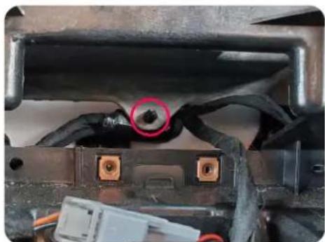
To relocate the AC / Heater Control Module, it is necessary to release the clip that holds the harness of the module in place. To access the clip, remove the two 7mm screws that hold the Keyless Entry Antenna in place (if available).
Part Two: Radio removal / Dash preparation (cont.)
natural_image
Close-up of a mechanical component with black wires and connectors, no visible text or symbolsStep 8
The clip that secures the harness in place is pushed in place from the back side of the opening. To release the harness, the exposed plastic nub must be pushed forward through the opening.

Step 9
With the harness clip released, it is possible to carefully pull just enough length from the AC / Heater Control Module to allow the module to be relocated to the right side of the dash opening.

Step 10
Return the Keyless Entry Antenna into place, and secure it with the two 7mm screws that were removed on the previous page.
Cutting the Sub-Dash
The sub-dash on 2018 and up vehicles is designed differently and does not require modification.


Step 11
To allow the Radio Mounting Shroud to sit properly in the radio opening, the top of the radio opening must be trimmed.
The cut must be made from the inner corner of the two gussets / ribs, 9/16" in height from the bottom lip.
Part Two: Radio removal / Dash preparation (cont.)
Section B: 2018 and Up Grand Cherokee (Screen is Part of Dash Panel)
natural_image
Close-up of a car's electrical connector with wiring and a small white component, no visible text or symbolsStep 2 Step 3 Step 4
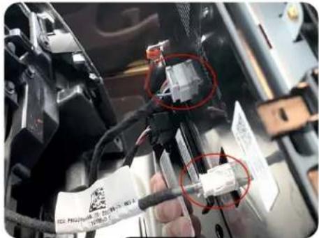
Disconnect the harnesses that are plugged into the back of the dash panel, and set the dash panel aside.

natural_image
Interior view of a car showing internal components and wiring (no visible text or symbols)
Remove the four 7mm screws securing the radio module in place.

natural_image
Interior view of a car chassis frame with visible wiring and components (no text or symbols)
Disconnect the 52-pin dock and lock connector and all of the antennas from the radio (the number of antenna connections will vary based on the vehicle's available features).
Part Three: Installing the New Dash Panel
Removing the Vents from the Factory Dash Panel

natural_image
Laptop chassis with two front seats and a back panel, highlighted by red outlines (no text or symbols visible)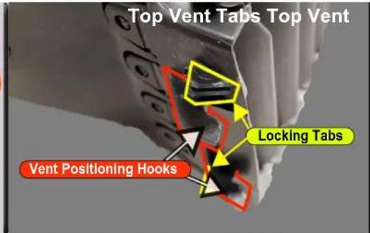
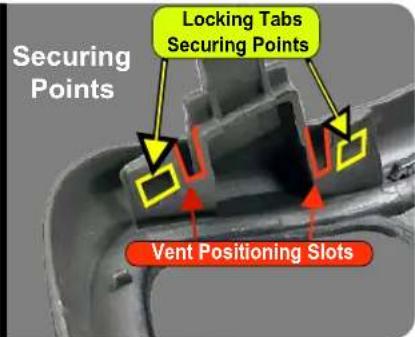

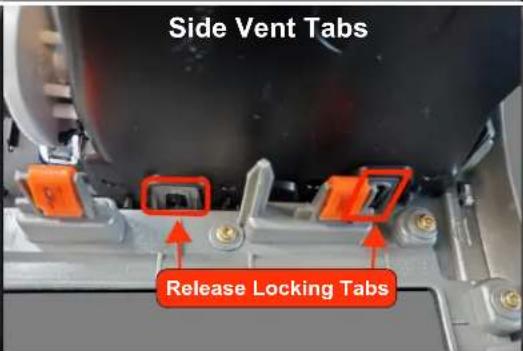

The vents must be removed from the factory dash panel for reuse with the RPK4-CH4103. To remove the vents, use a pick tool or small flathead screwdriver to release the bottom vent tabs, and slightly pull the bottom of the vent away from the dash panel. Do the same with the side vent tabs. With the bottom and side tabs released, release the locking tabs on the top vent as you pull the vent straight out and away from the dash panel. The factory dash panel can now be stored away for use when it is time to reinstall the factory radio.
Part Three: Installing the New Dash Panel
Installing Vehicle Accessories Buttons and Auto Climate Button

Step 1
The RPK4-CH4103 comes with a "Blank" and an "Auto" button insert for the fan speed knob. The Grand Cherokee always comes with the auto HVAC function, so install the insert that says "Auto". Be sure to line up the light pipe with the hole in the kit, and then push the button into place.

natural_image
Interior view of a car dashboard with digital display and red control buttons (no visible text or symbols)Step 2
Depending on the accessories installed on the vehicle, there may be up to 7 functioning buttons below the climate controls. Only the options available on the factory dash panel will operate with the RPK4-CH4103. Inserting buttons with icons that do not match the factory buttons will not add features to the vehicle.

Step 3
Sort through the included RPK4-CH4103 loose buttons and set aside the ones that match the buttons on the factory dash panel and a blank button / buttons (when necessary) for a total of 7 buttons that will be installed into the new dash panel. The leftover buttons will not be used.

Step 4
The buttons will be programmed later (see page 16), so their arrangement in the new dash panel is a matter of customer preference. The top of the blank is easily noted by the line on the side. Loosely slide the buttons into the desired opening, but make sure you are satisfied with the positions prior to seating them fully into the kit. The buttons are difficult to remove once they are fully seated.
Installing the Vents from the Factory Dash Panel

Part Three: Installing the New Dash Panel (cont.)
Installing the Vents from the Factory Dash Panel (cont.)
Step 1
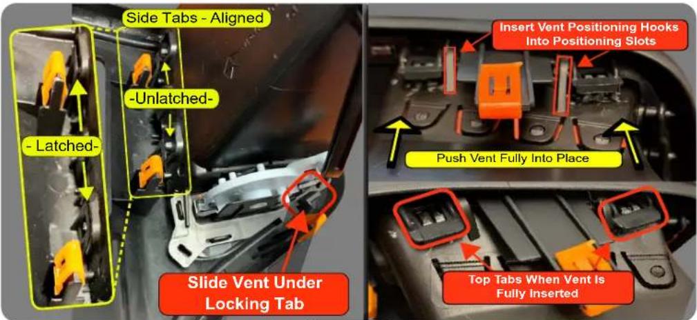
To install the vents in the new dash panel, slide the bottom of the vent under the outermost bottom locking tab of the appropriate vent opening. Verify that the side tabs are aligned, and then insert the vent positioning hooks into the vent positioning slots at the top of the dash panel. Once the positioning hooks are in place, push the vent towards the dash panel until the vent is fully seated and locked in place.

natural_image
Interior view of a car dashboard with air filters, control panel, and display (no visible text or symbols)Step 2
From the front of the dash panel, inspect the vents to make sure there are no gaps between the vents and the dash panel. Also, verify that the vent's directional adjustment for up and down, left and right is not binding against the dash panel.
Part Four: USB Hub Removal
Removing the Shifter Assembly

Step 1 Step 2
Gently pry around the edge of the shifter pad and and lift up to remove.
natural_image
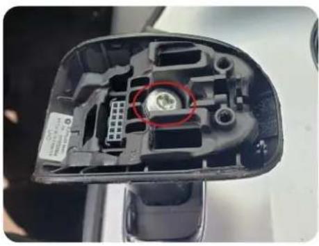
Close-up of a car's internal component showing internal parts and a red circle highlighting a specific area (no text or symbols visible)Remove the single T30 bolt securing the shifter assembly to the shifter post.
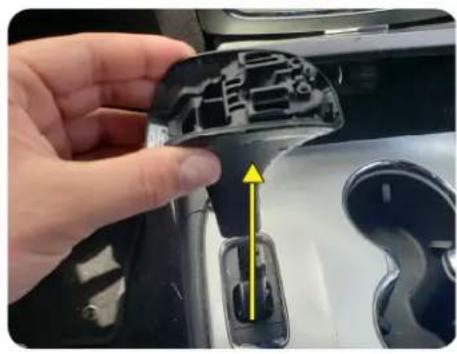
natural_image
Close-up of a hand holding a plastic component with a yellow arrow pointing to a mechanical part (no text or symbols visible)Step 3
Lift vertically on the shifter post cover to remove.
Removing the Center Console Panel

natural_image
Interior view of a car showing the rearrest seat and dashboard compartment with a hand inserting a device (no visible text or symbols)Step 1
Open the armrest/lid of the center console storage compartment.

natural_image
Close-up of a car headrest with a hand adjusting the intake compartment (no visible text or symbols)Step 2 Step 3
Remove the panel by lifting up on it. Start lifting at the side closest to the rear of the vehicle and work your way around the edge until the panel comes free.

natural_image
Close-up of a hand holding a white plastic connector attached to a black automotive engine compartment (no visible text or symbols)Disconnect the harness that is plugged into the back of the center console panel, and set the center console panel aside. There may be more than one connector depending on the vehicle's features.
Part Four: USB Hub Removal (cont.)
Removing the Storage Bin Below the Radio

natural_image
Close-up of a hand inserting a white plastic component into a black electronic device (no visible text or symbols)Step 1 Step 2 Step 3
Disconnect the harness that is plugged in at the top of the storage bin.

natural_image
Interior view of a car air intake console with control panel and red circular markers (no visible text or symbols)Remove the four 7mm screws securing the storage bin in place. Close the storage bin door and slide the bin out of the dash cavity towards the rear of the vehicle

natural_image
Close-up of a car engine compartment showing three connected electrical connectors (no visible text or symbols)Disconnect the three harnesses from the factory USB hub and 12v outlet on the back of the storage bin, and remove the storage bin from the vehicle.
Removing the Factory USB Hub
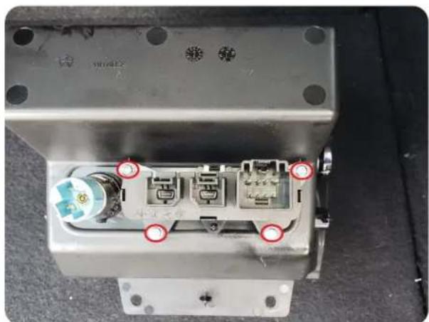
natural_image
Close-up of a mechanical component with red annotations highlighting ports and features (no readable text or symbols)Step 1
Remove the four T20 screws holding the factory USB hub in place, and separate the factory usb hub from the storage bin.
Part Five: Installing the New USB Hub
Mounting the New USB Hub

natural_image
Close-up of a mechanical or electronic component with wires and connectors (no visible text or symbols)Step 1
Mount the new USB hub by securing it to the back of the storage bin. Use the four factory T20 screws to mount it the same way that the factory USB hub was mounted.
Routing the USB Hub Cables / Preparing the USB Hub Ports

natural_image
Interior view of a car's head and lower body showing wiring and components (no visible text or symbols)Step 1
First route the new USB hub cables through the opening underneath the storage bin area. Then, route the cables through the sub-dash up to the area behind the radio opening so they can be connected to the aftermarket radio. Connect the 12v outlet and reinsert the storage bin back into the dash cavity.

Step 2
Remove the silicon dust caps from the ports on the new USB hub that will be used by the aftermarket radio. If the aftermarket radio does not support some of the ports on the new USB hub, leave those dust caps in place. Reassembly is done in the reverse order of disassembly.
Mounting the Aftermarket Radio


Part Six: Configuring and Wiring the RadioPRO Interface
RP4.2-CH4103 Module Layout
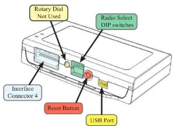

Part Six: Configuring and Wiring the RadioPRO Interface (cont.)
Connectors

Interface Connector 1
| Red | Accessory Output (10A) |
| Yellow | 12v+ |
| Black | Ground |

Interface Connector 2
| White / Red HS-CAN + Input |
| White / Black HS-CAN - Input |
| Pink MS-CAN + Input |
| Pink / Black MS-CAN - Input |
| Brown Loop TerminationResistor - LeaveIntact |
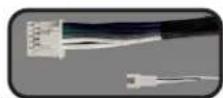
Interface Connector 3
| White | Front L + Output |
| White / Black | Front L - Output |
| Gray | Front R + Output |
| Gray / Black | Front R - Output |
| Green | Rear L + Output |
| Green / Black | Rear L - Output |
| Purple | Rear R + Output |
| Purple / Black | Rear R - Output |
| Ext Speaker Out | Connect to supplied external speaker when installing this kit into a vehicle that has factory parking sensors |

Interface Connector 4
| Purple Rear R + Input | |
| Purple / Black Rear R - input | |
| Green Rear L + Input | |
| Green / Black Rear L - input | |
| Gray Front R + input | |
| Gray / Black Front R - input | |
| White Front L + input | |
| White / Black Front L - input | |
| Blue / Yellow SWC Output / Key 1 | |
| Brown | SWC Output / Key 2 |
| 3.5 mm Jack | SWC Output |
| Pink | Vehicle SpeedSense Output |
| Light Green | Parking BrakeOutput |
| Violet / White Reverse SignalOutput | |
| Orange / White | Illumination Output |
| Blue / White Amp Turn-On Input | |
| Blue | Not Used |

Reverse Camera
Retention Harness
| Red | Aftermarket Camera Acc 12v+ Output (800 mA) |
| Black | Aftermarket Camera Ground Output |
| Yellow Composite Male | Camera Out To Aftermarket Radio |
| Yellow Composite Female | Camera In From Vehicle Connector |

natural_image
Coiled black electrical cable with white and green connectors (no text or symbols visible)CAN-Bus Connection Harness*
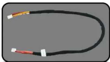
natural_image
Coiled black cable with red and yellow connectors, no visible text or symbolsLCD Display Harness
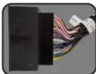
Vehicle Connector 1
| Yellow | Battery +12v |
| Black | Ground |
| Pink | MS-CAN + |
| Pink / Black | MS-CAN - |
| White / Red | HS-CAN+ |
| White / Black | HS-CAN- |
| White | Front L + input |
| White / Black Front L - input | |
| Gray | Front R + input |
| Gray / Black Front R - input | |
| Green | Rear L + input |
| Green / Black Rear L - input | |
| Purple | Rear R + input |
| Purple / Black | Rear R - input |
| Reverse Camera | Video from factory Reverse Camera |
| Cargo Camera / RSE Video | Not Used |
| RSE Audio | Not Used |
| OEM AUX Audio | Audio from factory Auxiliary Input Jack |
*The CAN-Bus Connector Harness (MQS4PT-36) is only required for the 2018 and up Grand Cherokee
DIP Switches
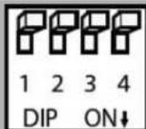
Set DIP switches that correspond with your radio to the ON position. Set all other DIP switches to the OFF position.
| Alpine | JVC | Kenwood / Lightning Audio | Clarion / Nakamichi / Stinger | 2-Wire Resistive | Pioneer / Other* | Sony | Fusion |
| 1 | 2 | 1 & 2 | 3 | 2 & 3 | 1, 2, & 3 | 4 | 1 & 4 |
*Other - Dual / Axxera (these brands could also have 2-wire resistive), Jensen, Rockford Fosgate
The radio select DIP switches on the side of the interface must be adjusted to the proper radio setting before plugging the interface into the vehicle.
Wiring Connections
Installing the CAN-Bus Connection Harness - MQS4PT-36
(Only needed for 2018 and up Grand Cherokee)
If the installation is being performed in a 2014 - 2017 Grand Cherokee, the use of the MQS4PT-36 is not necessary.
Continue to Section B on page 14. For the 2018 and up Grand Cherokee, proceed to Section A on the next page.

Wiring Connections (Section A)
Installing the MQS4PT-36 (Only needed for 2018 and up Grand Cherokee):
The 2018 and up Grand Cherokee requires additional connections to the vehicle's star connectors that are located on the driver's side of the dash, using the included MQS4PT-36 harness. The installation process for the MQS4PT-3 is covered below.

natural_image
Close-up of a car's side profile showing the seat and dashboard, with a red arrow pointing to the lower side (no text or symbols visible)Step 1 Step 2 Step 3
Using the plastic pry tool, remove the driver's side dash trim.

natural_image
Close-up of an automotive electrical connector with wiring and a highlighted green component (no visible text or symbols)With the trim panel removed, locate the star connectors.

natural_image
Interior view of a car's dashboard frame with visible wiring and components (no text or symbols)Feed the White and Green connectors side of the MQS4PT-36 harness down the driver's side of the dash. Leave 6 to 8 inches of length for the 4-Pin connector to allow for connection to the RP4.2-CH4103 harness.

natural_image
Close-up of a car's head and neck assembly, showing a red arrow pointing to a component (no text or symbols visible)Step 4
Release the dash trim that surrounds the base of the steering column by pulling the trim away from the dash. With the trim pulled back, there is space to slide your hand into the dash to route the MQS4PT-36 harness and to plug it into the star connectors. Route the MQS4PT-36 harness to the star connectors on the left-most side of the dash. Make sure to route the cable to where it does not interfere with any moving parts (brakes, accelerator, steering column).
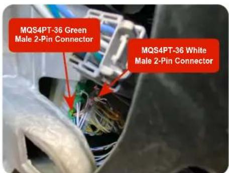
Step 5
Plug the MQS4PT-36 male Green and White connectors into the appropriate ports on the star blocks. The Green connector from the MQS4PT-36 plugs into a port in the White star block, and the White connector from the MQS4PT-36 plugs into a port in the Green star block. If the star block does not have an open port, remove one of the existing connectors, plug it into the female connector from the MQS4PT-36 and plug the male from the MQS4PT-36 into the now open port on the star block.

Step 6
Locate the Black 4-Pin mated connectors in the RP4.2-CH4103 harness. Unplug the connectors, and attach the Black 4-Pin male connector from the MQS4PT-36 into the Black 4-Pin female connector that goes to the White JST connector. The remaining Black male 4-Pin connector in the RP4.2-CH4103 harness will no longer be used.
Wiring Connections (Section B)
-
Connect Interface Connector 3 to either the amplified output connector if retaining the factory amp or to the non-amplified audio output connector if there is no factory amplifier.
-
Connect one end of the supplied LCD Display harness into the LCD Display Port on the RP4.2-CH4103 interface module, and ensure that it will be accessible when installing the radio dash bezel.
-
Set the DIP Switches on the side of the interface according to the chart on page 9.
- Wire the aftermarket radio harness to Interface Connectors 1 and 4 according to the wiring connection charts provided on page 12.
- Connect Interface Connectors 1, 2 and 4 to the RP4.2-CH4103 interface module.
- If you are installing this kit into a vehicle with factory parking sensors and it IS NOT equipped with a factory amplifier, or if the factory amplifier is being bypassed, connect the supplied external chime speaker to the external speaker output on interface connector 3. Mount in a place free of obstructions so that the parking sensor chimes can be heard.
- Ensure the SWC output is connected to the aftermarket radio (aftermarket radio must support a wired remote input).
- Once all connections have been made, plug the vehicle connectors into the vehicle harness.
- Reverse camera connection (see Fig. 2):
a. Connect the included RPA-16P1V harness to the camera input / output port (Connector 3) on the back of the radio dash bezel (see Fig. 1).
b. Connect the Male Yellow RCA (Video Output) from the RPA-16P1V harness to the aftermarket radio's reverse camera input.
Fig.1: Rear of RPK4-CH4103 Radio Dash Bezel

| Connector | Connector Function |
| 1 | LCD Display Port |
| 2 | Expansion Port (Not Currently Used) |
| 3 | Camera Input / Output Port |
| 4 | 5.2" Display USB Update Port |
Fig.2: RPA-16P1V Harness

c. Connect the Female Yellow RCA (Video Input) from the RPA-16P1V harness to the Male Yellow RCA from vehicle connector 1 (factory reverse camera) or to the aftermarket reverse camera's RCA video output.
d. Connect the Red and Black power wires from the RPA-16P1V to the aftermarket reverse camera's power wires. If you are utilizing a factory camera, simply insulate these wires.
e. To Add Additional Cameras (Front, Blind Spot, Cargo, etc.), use the RPA-16P5V (sold separately) in place of the included RPA-16P1V harness. See the next page for additional information.
- Now it's time to install the radio dash bezel into the vehicle. Connect the factory plugs from the vehicle into the appropriate connectors on the back of the radio dash bezel.
- Connect the free end of the LCD Display harness into the LDC Display port (Connector 1) on the back of the radio dash bezel (see Fig. 1).
- If you are retaining or installing cameras, connect the RPA-16Pxx harness into the Camera Input / Output (Connector 3) on the back of the radio dash bezel (see Fig. 1).
- OPTIONAL: To update firmware with minimal effort and without accessing the back of the radio dash bezel, a USB extension cable, PAC part USBDMA3 (sold separately), can be connected into the 5.2" Display USB port (Connector 4) on the back of the radio dash bezel (see Fig. 1) and run to a location that allows for easy access (glove box, tucked under an interior panel, etc.).
- Once the radio dash bezel has been connected, the LEDs for the illumination of the four hard buttons on the kit (below the radio dash bezel's LCD display) will illuminate momentarily and then start flashing. This indicates the system is initializing. Next, the LEDs will turn off and then the RadioPRO splash screen will appear on the LCD. The initialization sequence can take up to 2 minutes on initial powerup. Once the LCD screen comes on, you can proceed to the setup and testing section on the next page.
Using Multiple Cameras
With the addition of the optional RPA-16P5V harness, the RPK4-CH4103 supports the display and control of up to 5 cameras. The RPA-16P5V replaces the RPA-16P1V camera harness that is included with the RPK4-CH4103.
Additional cameras can be connected to any of the 4 separate video inputs (video input 1 is reserved for the reverse camera). Camera input and control are adjustable through the settings menu on the LCD display on the dash bezel. The provided power and ground connections are active when the vehicle is on. Use these leads to power your aftermarket camera(s) (up to 800mA total). If the cameras require more than 800mA, please use an external relay. See page 17 for setup and operation.

flowchart
graph TD
    A["Red - Camera 12v Out (800mA)"] --> B["Video Output"]
    C["Black - Camera Ground Out"] --> B
    B --> D["Video Inputs"]
    D --> E["Video Input1"]
    E --> F["Video Input2"]
    F --> G["Video Input3"]
    G --> H["Signal from aftermarket cameras"]
    I["RPA-16P5V (Optional Multi Camera Harness)"] --> J["Video Inputs"]
    J --> K["Video Input2"]
    K --> L["Video Input3"]
    L --> M["Video Input4"]
    M --> N["Signal from aftermarket camera input"]
Setup and Testing
Verify that all screens and functions are present through the 5.2" display

flowchart
graph TD
    A["Options Screen"] --> B["Vehicle Settings"]
    B --> C["Button Settings"]
    C --> D["Display"]
    D --> E["About"]
    F["Climate Control*"] --> G["Lo Max A/C Sync"]
    H["Camera Control"] --> I["Rear Left Right"]
    J["Information Screen"] --> K["P 13.9V"]
    K --> L["32 psi"]
    K --> M["32 psi"]
    N["Vehicle Gauges 1"] --> O["1039 0 57"]
    P["Vehicle Gauges 2"] --> Q["Best 0-60 (sec) N/A Last 0-60 (sec)"]
    P --> R["Best 60-0 (ft) N/A Last 60-0 (ft)"]
    P --> S["Best Qtr Mile (sec) N/A"]
    P --> T["Clear Accel. Time Clear Braking Di... Clear Drive Time"]
    U["*Dual Zone Climate shown, exact appearance may vary based on vehicle."] --> V["Climate Control"]
Enter the Installation Settings menu by pressing and holding the Vehicle Settings icon on the Options screen.

flowchart
graph LR
    A["Press and Hold Vehicle Settings"] --> B["Available Installation Settings Menu Options"]
    A --> C["Carryers"]
    A --> D["Factory Amplifier"]
    A --> E["SWI"]
    A --> F["Advanced"]
    A --> G["Bezel Buttons"]
Setup and Testing (cont.)
Vehicle Accessories Buttons Setup
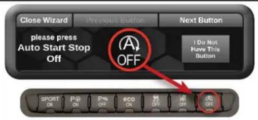
Because the vehicle accessories buttons that are used vary from vehicle to vehicle, the accessories buttons must be configured to the position in which they are installed. Some vehicles will have fewer installed accessories, so instead of a button there will be a blank installed. Configuring a button that was not present on the factory dash panel will not add features to the vehicle.

Step 1
Open Installer Settings

Step 3
If the vehicle is equipped with the button shown, press that button on new dash panel. If not equipped, press "I Do Not Have This Button". Once the button is programmed, a different button will be displayed. Continue this process until the verify configuration screen is displayed.
Step 2
Open the Buttons Setup Wizard

Step 4
Verify that the buttons are correct on the display, and match the buttons and button positions on the new dash panel. If the layout matches, press "Looks good" to complete the vehicle accessories buttons setup. If it does not match, press "Go back" to perform the setup again.

Camera Setup
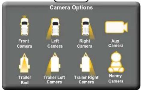
The camera settings menu is used to set up which cameras are installed on the vehicle. When used with the PAC harness RPA-16P5V (sold separately), the RPK4-CH4103 gives you the ability for switching via the 5.2" LCD and automatic triggers for up to 5 different camera images to display on the aftermarket radio. Note: Camera 1 is permanently set as the Rear Camera and cannot be changed in the settings menu. Camera inputs 2, 3, 4 and 5 can be toggled between "None" (no camera) or the options shown in Fig. 1 below.
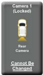
Fig. 1
Setup and Testing (cont.)
To edit the camera settings, from the Installer Settings menu, do the following:
Step 1
Open Camera Settings

Step 3
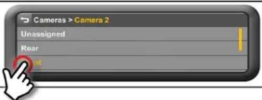
From the set of options, touch the label that matches the image displayed on the radio. Repeat steps 2 and 3 for each camera that is being added.
Step 2
Touch the camera input (Camera 2, 3, 4, 5) you wish to activate. The radio will display the image of the camera connected to the selected camera input.

Step 4
Verify the camera input(s) have been setup properly. Exit the settings by pressing the back button until you are on the options screen.

Step 5
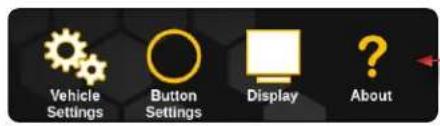
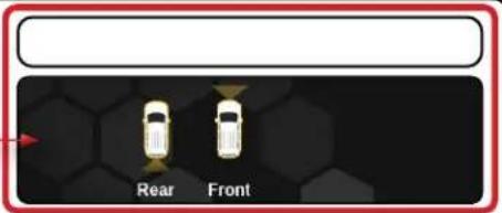
Swipe left to the camera control screen
Options Screen Climate Control
Camera Control

Step 6
Verify the new camera icon(s) are displayed on the screen and activates the camera when touched.
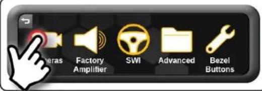
Setting Automatic Camera Triggers (Front, Left and Right Cameras Only)
Step 1
Open Camera Settings

Step 2
Select Desired Camera
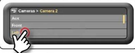
Step 3
Select the camera trigger.
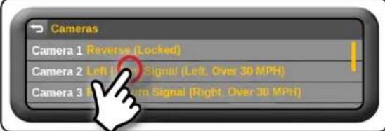
Setup and Testing (cont.)
The selectable triggers for the Front camera are:
- Auto Turn On Into Drive - The Front camera will come on when the vehicle is placed into drive and will stay on for 30 seconds or until the configured speed threshold is reached.
- Steering Wheel Angle Mode - The Front camera will turn on when the steering wheel is greater than the selected angle and the vehicle's speed is less than the selected speed threshold.
- Speed Threshold - The Front camera will come on when the vehicle's speed is less than the speed selected here and greater than the SW Angle threshold.
- Steering Wheel Angle Threshold - The Front camera will come on when the steering wheel angle is greater than what is selected here and less than the selected speed threshold.
The selectable triggers for the Left and Right cameras are independently selectable and are:
Blindspot Trigger:
- Turn Signal
• Turn Signal and Over 0 MPH
• Turn Signal and Over 10 MPH
• Turn Signal and Over 20 MPH
• Turn Signal and Over 30 MPH
• Turn Signal and Over 40 MPH
• Double Tap Turn Signal - Manual Only
Steering Wheel Controls
IMPORTANT! The interface comes pre-programmed with all factory SWC functions and does not require programming unless you wish to re-assign the SWC functions, or utilize short press/long press dual command functionality. See below for information on custom programming the steering wheel controls, including adding short press/long press operation.
| Alpine | JVC | Kenwood | Clarion | Pioneer | Sony | Fusion | |
| Volume + Volume + Volume + Volume + Volume + Volume + Volume + | |||||||
| Volume - | Volume - | Volume - | Volume - | Volume - | Volume - | Volume - | Volume - |
| Source | Source | Source | Source | Source | Source | Source | Source |
| Track + | Track + | Track + | Track + | Search + | Track + | Track + | Track + |
| Track - | Track - | Track - | Track - | Search - | Track - | Track - | Track - |
| Preset + | Preset + | Band/Disc Up | Disc/Radio + | Band | Preset + | Preset + | Audio |
| Voice | Mute | Mute | Mute | Mute | Mute | Mute | Mute |
| Phone/Answer | Receive | Receive | Off Hook | Send | Answer | Answer | Power |
Note: 2 Wire Resistive radios do not have a specific default programming order and cannot be custom programmed through the RPK4-CH4103. Please refer to the owner's manual of your particular radio for programming instructions.
Custom SWC Programming
Example: To program the Track Up button to perform the Track Up function with a quick press and perform the Preset Up function when the button is pressed and held for more than 1 second, from the SWI settings menu, do the following:
Step 1
Open SWI Settings

Step 2
Touch the display on the Track Up Long Press function that is currently labeled as Not Assigned.

Setup and Testing (cont.)
Step 3
Scroll to find and press the Preset Up option.

Audio Adjustments
Custom SWC Programming Tips:
Each SWC radio function can be used only once. If you try to use a radio function that is already assigned to a button, the pre-existing button's radio function will change to "Not Assigned", and the radio function will be set to the new button. For example, if you were to try to program Volume Up to the Mode button, the Volume Up button would now be set to "Not Assigned", and the Mode button would be set to Volume Up.
If the vehicle has a factory amplifier, the 5.2" display has the ability to adjust the factory amplifier's audio settings.
Amplifier Audio Settings
Step 1
Open Factory Amplifier Settings
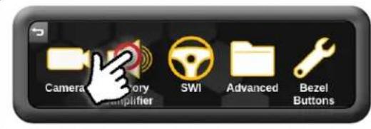
Step 2
Make Adjustments

Real Time Fade On = Fading from aftermarket radio Real Time Fade Off = Fading from this menu only Note: Typical Gain Setting will have the gain at or near the top.
Chime Speaker Adjustment
The chime speaker adjustment allows you to control what chimes will be sent to the RPK4-CH4103-supplied chime speaker and the volume of the chimes from the speaker. If there is no factory amplifier, or if an aftermarket amplifier is being used for the front / rear / all speakers, the chime speaker can be adjusted for that particular application. This setting will not affect the output of chimes through the factory amplifier, only what chimes (front\rear) will output through the external speaker and the volume of the chimes through the external speaker.
Step 1
Open Advanced Settings

Step 2
Adjust Chime Speaker

Front Chimes - On (Highlighted) / Off (Not Highlighted) Rear Chimes - On (Highlighted) / Off (Not Highlighted)
Chime Speaker Volume - Slide Up to Increase Slide Down to Decrease
Setup and Testing (cont.)
Hard Buttons
The four hard buttons located below the RPK4-CH4103 display give you the ability to assign a single preset to each button to control a speci c Climate Control function, force activate a speci c camera to display on the radio or control select screen settings. Once the buttons have been assigned a function, a descriptive pop-up tab above each button showing what function that button performs will be presented when the proximity sensor is alerted to your nger touching the button (this function can be toggled on / o ).

If popups are turned on in the menu: The proximity sensor within the dash bezel will display the descriptive tabs when your nger touches the buttons. When your nger is removed, the tabs will disappear.
The options that are able to be preset to the hard buttons are:
Climate Control Functions\*
- Max A/C
- Sync
- Heated Wheel
- Fan Mode
CameraFunctions\*\*
- Camera 1
- Camera 2
-
Camera 3
-
Camera 4
- Camera 5
Screen Shortcut Functions\*
- Climate
- Cameras
- Gauges
- Display On / O
* Climate Control Functions will vary for Single Zone and Dual Zone applications.
** The number of available cameras will vary based on how many cameras are installed and activated.
Assigning functions to the Hard Buttons
Step 1 \$tep 2
Press the Button Settings icon in the main menu

Step 3
Click on the device (Unassigned, Climate Control, Camera) operation you wish to program. In the example, we want to use the first hard button to force activate the Nanny camera, so we select the Camera option.
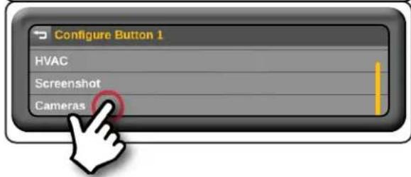
Touch the tab that corresponds to the hard button that you wish to assign a function to.

Step 4
In the example, because Camera 5 is the Nanny camera, we select the Camera 5 option. Repeat steps 3 and 4 for each hard button you wish to program.

Setup and Testing (cont.)
To test the functionality of the radio and RPK4-CH4103, start with the ignition off and driver's door open and then do the following:
- Turn the ignition on. The LED on the interface will turn on, and the +12v accessory wire will turn on.
- Verify that all RPK4-CH4103 radio dash bezel buttons operate their intended function:
a. Hazard Button
b. Climate / Defrost Buttons
c. Vehicle Accessories Buttons

-
Turn on the radio, and check volume, balance and fade.
-
If the overall volume is excessively low or high: Verify that Interface Connector 3 is connected to the appropriate output connector on the RP4.2-CH4103 module (one is for amplified audio systems, while the other is for non-amplified audio systems).
- If the overall volume is slightly lower or higher (vehicles with a factory amplifier only): Use the factory amp gain adjustment through the RPK4-CH4103 settings menu to set it to the desired level. See page 19 for information on how to access the factory amplifier settings menu.
-
Verify that all SWC are functioning properly. See the Steering Wheel Control section (page 18-19) for radio-specific details.
-
Verify that all vehicle functions are present through the RPK4-CH4103 5.2" LCD display:
• Climate Controls
• Factory Amplifier Settings (Only applicable in vehicles with a Factory Amplifier)
• SWI Settings (If DIP Switches are set for any radio other than 2-Wire Resistive)
• Vehicle Settings
• Information Screen
- Vehicle Gauges
- Camera Control
Troubleshooting
- On initial install, Climate Control fan speed is low and unresponsive - The vehicle needs to be sleep cycled. Turn the vehicle off, close all doors, lock the vehicle with the keyfob and let it sit for 10 minutes. After 10 minutes, start the truck and check the Climate Control functionality again.
- If a vehicle function is not present: Reset the RP4.2-CH4103 Interface Module (see page 22). If a vehicle function is not present after a reset: With the vehicle running, disconnect and reconnect the LCD Display Harness from the back of the radio dash bezel.
- Steering wheel controls inoperable - Verify that the DIP switches are set properly according to page 12 of this manual.
- Reverse Camera inoperable - Verify that all reverse camera connection points are proper by reviewing the reverse camera wiring connection steps on pages 14 and 15.
RP4.2-CH4103 Interface Module LED Diagnostics
| LED Pattern State Action | ||
| LED 2 solid red Vehicle RAP / ACC Output is On N / A | ||
| LED 2 flashing green SWC Activity N / A | ||
| LED 2 flashing red Module Resetting / Initializing N / A | ||
| LED 1 solid green Module Powered and Operating N / A | ||
| LED 1 flashing amber USB Connected | N / A | |
| Off | No Activity | Verify Key is in ignition position.Verify that there is 12v on the Yellow wire and Ground on the Black wire. |
Product Updates (Firmware)
Firmware Updates
The RadioPRO app will allow you to update the RP4.2-CH4103 interface module with new firmware as it becomes available. Please visit www.PAC-audio.com/firmware to download available updates.
The radio dash bezel can also be updated. Refer to the RPK4-CH4103 User Manual for additional information.
To update the RadioPRO interface module, open the Radio PRO PC app, connect the interface to your PC and select "Firmware" and then "Update Firmware".


Now, select "Select File". Finally, browse to the place where you saved the file, and select it. This will begin the updating process. Once finished, disconnect the interface from the PC and test operation.
Reset / Restoring Interface Factory Settings
You can restore the interface to factory default settings by pressing and holding the programming button on the side of the module until the status LED starts blinking red. Once the LED starts blinking red, release the button. You must release the button while the LED is blinking red in order to perform the reset. This reset will restore all settings to factory defaults.
Technical Support
Email: support@PAC-audio.com
Phone: 866-931-8021
International: 727-592-5991
- Introduction and Features
- Important Notes
- We recommend reading this manual thoroughly to familiarize yourself with the entire process prior to beginning the installation.
- Does Not Retain:
- Cluster Display Features
- Factory Amplifier Features
- Uconnect Features
- SiriusXM Guardian Services
- Vehicle Accessories Buttons:
- Components
- Installation
- Part One: Disassembly of Factory Dash / Dash Prep. (Cont.)
- Relocating the AC / Heater Control Module (Steps 6–10)
- Part Two: Radio removal / Dash preparation (cont.)
- Cutting the Sub-Dash
- Section B: 2018 and Up Grand Cherokee (Screen is Part of Dash Panel)
- Part Three: Installing the New Dash Panel
- Removing the Vents from the Factory Dash Panel
- Part Three: Installing the New Dash Panel (cont.)
- Part Four: USB Hub Removal
- Removing the Shifter Assembly
- Step 1 Step 2
- Step 3
- Removing the Center Console Panel
- Step 1
- Step 2 Step 3
- Part Four: USB Hub Removal (cont.)
- Removing the Storage Bin Below the Radio
- Removing the Factory USB Hub
- Mounting the New USB Hub
- Routing the USB Hub Cables / Preparing the USB Hub Ports
- Part Six: Configuring and Wiring the RadioPRO Interface (cont.)
- Connectors
- DIP Switches
- Wiring Connections
- Installing the CAN-Bus Connection Harness - MQS4PT-36
- (Only needed for 2018 and up Grand Cherokee)
- Wiring Connections (Section A)
- Installing the MQS4PT-36 (Only needed for 2018 and up Grand Cherokee):
- Wiring Connections (Section B)
- Using Multiple Cameras
- Setup and Testing
- Setup and Testing (cont.)
- Vehicle Accessories Buttons Setup
- Camera Setup
- To edit the camera settings, from the Installer Settings menu, do the following:
- Setting Automatic Camera Triggers (Front, Left and Right Cameras Only)
- The selectable triggers for the Front camera are:
- Blindspot Trigger:
- Steering Wheel Controls
- Custom SWC Programming
- Audio Adjustments
- Custom SWC Programming Tips:
- Amplifier Audio Settings
- Chime Speaker Adjustment
- Hard Buttons
- The options that are able to be preset to the hard buttons are:
- Climate Control Functions\*
- CameraFunctions\*\*
- Screen Shortcut Functions\*
- Assigning functions to the Hard Buttons
- Step 1 \$tep 2
- Step 4
- Troubleshooting
- Product Updates (Firmware)
- Firmware Updates
- Reset / Restoring Interface Factory Settings
- Technical Support
Brand : PAC
Model : RPK4-CH4103
Category : Car Mounting Kit