
Picturall Quad - Server Analog Way - Free user manual and instructions
Find the device manual for free Picturall Quad Analog Way in PDF.


| Type | Media Server |
| Brand | Analog Way |
| Model | Picturall Quad |
| Form Factor | 19" rackmount, 4U |
| Outputs | 4 x DisplayPort 1.2 (4K@60Hz 10-bit 4:4:4) |
| Input Slots | 2 slots for optional input cards (HDMI, SDI, DVI) |
| Max Layers | Up to 200 (configurable) |
| Supported Codecs | MPEG1/2/4, H.264, H.265, ProRes, PRKL, JPEG, PNG, DPX, TGA |
| Audio Support | Optional balanced XLR outputs, PCM, WAV, AAC |
| Control Software | Picturall Commander (Java), Web Configurator |
| External Control | Art-Net/DMX, TCP/IP, RS232 (future) |
| Network | 1 x Ethernet (Gigabit), DHCP/Static/Art-Net |
| Storage | RAID 0 or RAID 1 (2 x 1TB default) |
| Power Supply | Optional redundant, hot-swappable |
| Front Panel | OLED display, Power button, Next/Status button, 2 x USB |
| Ventilation | Front-to-rear airflow, EMC air filter (user-replaceable) |
| Mounting Precautions | Allow 50 cm clearance front/rear, avoid blocking vents |
| Software Update | Via USB stick (FAT32) or network |
| Warranty | 1 year hardware (return to base) |
| Manual Language | English (86 pages PDF) |
Frequently Asked Questions - Picturall Quad Analog Way
User questions about Picturall Quad Analog Way
0 question about this device. Answer the ones you know or ask your own.
Ask a new question about this device
Download the instructions for your Server in PDF format for free! Find your manual Picturall Quad - Analog Way and take your electronic device back in hand. On this page are published all the documents necessary for the use of your device. Picturall Quad by Analog Way.
USER MANUAL Picturall Quad Analog Way
Picturall Series Media Servers
(V2.6.0)
References: MST02-R1, MSQ04-R1, MSP16-R1

ANALOG WAY®
Pioneer in Analog, Leader in Digital
Information contained in this document, in particular data, pictures, information, trademarks and logos are exclusive property of Analog Way and are protected by copyrights and other intellectual property rights.
2018, Analog Way, all rights reserved – 10/2018
Consequently, any representation and/or reproduction, in part or in full, is prohibited and would be considered a violation of Analog Way's copyright and other intellectual property rights.
Visual representations (diagrams, photos, icons, pictograms, screenshots, spare parts, etc.) are not contractual.
Contents
1 Disclaimer....7
1.1 Copyrights ....7
1.2 Media 7
1.3 Warranty....7
1.4 Liability....7
1.5 Force Majeure....7
2 Introducing Picturall Series Media Servers 8
2.1 Picturall Series Media Servers....8
2.2 Package Contents....8
2.3 Front panel....9
2.3.1 Display screen....9
2.3.2 Power off 9
2.3.3 Forced shutdown....9
2.4 Rear panels and Connections....9
2.4.1 Picturall Twin rear panel....10
2.4.2 Picturall Quad rear panel....10
2.4.3 Picturall Pro rear panel 11
2.4.4 Optional Hardware 11
2.4.5 External Audio support....12
3 Getting Started....13
3.1 Precautions when Mounting Picturall Series Media Server ....13
3.2 Start the Picturall Series Media Server....13
4 Configuration 14
4.1 Web configurator....14
4.1.1 Dashboard 14
4.1.2 Server configuration 15
4.1.3 Display configuration.... 15
4.1.4 DMX Configuration 16
4.1.5 Network configuration 17
4.1.6 Import and Export configuration 18
4.1.7 Format Media Drives - Storage configuration 18
4.1.8 Conflicting Settings.... 19
4.2 Configuration mode....19
4.3 Update Server Software....20
4.3.1 Creating an installation USB stick 20
4.3.2 Installing the server software from a USB stick....20
5 Configure Picturall Commander 21
5.1 Java compatibility ....21
5.2 Installing / Updating Picturall Commander....21
5.3 Connecting to Picturall Series Media Server....22
5.4 User Interface 22
5.5 Control Tabs 22
5.5.1 Arrange windows....23
5.5.2 Reset windows....23
5.6 Preferences....23
5.7 Hotkeys 23
6 Media....24
6.1 Media types 24
6.2 Manage Media Collections 25
6.3 Importing media files....25
6.3.1 Import a local media file 25
6.3.2 Import and encode a file 26
6.3.3 Import an image sequence 26
6.3.4 Import a media using FTP 26
6.3.5 Reuse imported media files - Add server files to a media collection 27
6.4 Add inputs to a media collection 27
6.5 Add web pages and video streams 27
6.5.1 Add a web page to a media collection 27
6.5.2 Import a web page using FTP 28
6.5.3 Add FTP imported web page to a media collection....28
6.5.4 Add a video stream to the server 29
6.6 Add a custom text....29
7 Displays 30
7.1 Display menu icons 31
7.2 Display adjustment tabs....31
7.3 Test images 31
7.4 Positioning and Grouping Displays 32
7.4.1 Multi-display screen - Display wizard 33
7.4.2 Reset Display 34
7.5 Optimize pixel space - GPUs tab 34
7.6 Edge Blending....34
7.6.1 Keystone and Angle Correction 34
7.7 Adjust curved surface projection - Warp correction 36
7.8 Color correction (Display) 36
7.9 Crop display size....36
8 Layers 37
8.1 Layers tab....37
8.1.1 Layer List....37
8.1.2 Layer Priority 37
8.1.3 Layers adjustments....37
8.2 Select and play a media - Media selection....38
8.2.1 Playback control 38
8.2.2 End action....38
8.3 Composition....38
8.3.1 Draw modes....39
8.3.2 Graph 40
8.3.3 Composition Advanced settings 41
8.4 Color correction (layer) 41
8.5 Advanced....41
8.5.1 Synchronize to another layer 41
8.5.2 Set layer Frame rate 41
8.6 Audio (optional) 42
8.7 Using Effects....42
8.7.1 Alpha Fill and Alpha Key – Cut & Fill 50
8.8 Layer macro....50
8.8.1 Create a layer macro 50
8.8.2 Load a layer macro 50
8.9 Geometry....51
8.10 Set default show on server boot – Export show....51
9 Program a Show - Cue....52
9.1 Presentation....52
9.1.1 How cues work 52
9.1.2 Timings (Wait, Fade and Hold) 52
9.1.3 Trigger....54
9.2 Creating Cues....54
9.2.1 Create the first Cue....54
9.2.2 Cue List 54
9.2.3 Stop cue 54
9.3 Cue Stacks ....55
9.3.1 Create a cue stack....55
9.3.2 Remove a cue from a cue stack 55
9.3.3 Change trigger type 55
9.3.4 Order cues in the stack – Index number....55
9.4 Timing and Running Cues in Playback....55
9.5 Example Show....56
9.6 Live show recommendations....56
9.7 Cue macro....57
9.7.1 Cue macro and Cue stack macro 57
9.7.2 Cue macro actions 57
9.7.3 Edit or remove a cue macro 59
10 Miscellaneous....60
10.1 Save a show....60
10.2 Performance 60
10.2.1 Toggle view....61
10.2.2 Refresh....61
10.2.3 Color 61
10.3 Timecode....62
10.4 Control Model....62
10.5 Commander Log....62
11 User maintenance and Troubleshooting....63
11.1 User Maintenance – EMC air filter....63
11.2 System Diagnostics 63
11.3 Troubleshooting....64
APPENDICES 65
Appendix A. DMX chart 65
Appendix B. BIOS setup....73
Appendix C. Optimize GPU resolution and drawing performance....74
Appendix D. Picturall Pro communication protocol specifications....77
CONTACT INFORMATION 85
1 Disclaimer
The information in this document is subject to change without notice, while every effort is made to be accurate. Analog Way cannot be held liable for any kind of loss whatsoever that may be caused by the use of or reliance in this manual.
1.1 Copyrights
The Software installed in the Picturall Series Media Server remains the sole property of Analog Way unless stated otherwise in a separate licensing agreement. Any attempt to copy or alter the software is prohibited and will render any warranties void.
1.2 Media
Analog Way may have supplied video libraries pre-installed on the media server. If you have any questions regarding them, please contact us. These videos have been licensed exclusively for use within the Picturall Series Media Servers. Any copying or other usage without proper rights clearance is forbidden. Analog Way will not accept any liability or claims from third parties.
1.3 Warranty
The Picturall Series Media Servers have been tested in various applications and is deemed to be suitable for uses described in this manual. This product is provided “as is”, including all or any ‘perceived’ or possible faults. The Licensor grants no warranty regarding the utility or contents of the software. Analog Way will warrant the hardware for one year from the date of purchase. The method of warranty is Return to Base (transport costs from and to us are the owner’s responsibility). In case of hardware fault please contact your local distributor or us (www.analogway.com).
While not an exhaustive list, the following are provided for guidance. Warranty claims will be invalidated in these circumstances:
- A hardware failure is caused by inappropriate handling of hardware such as dropping the media server, using the media server without proper ventilation, exposing the media server to water, other liquids or dust.
- The software has been loaded or there has been an attempt to load software onto the media server in any way other than described in the manual or recommended by Analog Way.
• The hardware has been modified by someone other than a certified Analog Way dealer.
1.4 Liability
Analog Way shall not be liable for any loss or damage, be it direct or indirect in regards to the utility or contents of the software or hardware, except to the extent provided by law. Notwithstanding the above, liability for indirect, special, incidental or consequential loss or damage that may arise in respect of the software or hardware, is expressly excluded.
1.5 Force Majeure
Liability of Analog Way is excluded in all cases that constitute Force Majeure circumstances, namely, circumstances beyond the control of Analog Way.
2 Introducing Picturall Series Media Servers
Thank you for choosing Picturall Series Media Servers! The one that combines cutting-edge technology with ease-of-use and unrivalled efficiency.
Picturall Series Media Servers are powerful real time multi-output media servers. They can manage multiple inputs (media files, live feeds or network streams) with various features and effects. Then output them to multiple displays.
Control the server with Picturall Commander, a dedicated software designed exclusively for Picturall Series Media Servers. Alternatively, Picturall Series Media Servers can also be controlled with External controllers such as Lighting consoles.
Picturall Series Media Servers are 19" wide and 4 rack units (4U) high, following the industrial rack mounting standard.
2.1 Picturall Series Media Servers
The Picturall Series Media Servers product range includes 3 models: Twin, Quad, and Pro.
The following table illustrates the differences between the units.
| Picturall Series Media Servers | Outputs | Description |
| Twin | 2 | Heavy-duty dual-output 4K Series Media Server. Designed for medium-sized events and installations requiring high levels of performance and reliability. |
| Quad | 4 | Heavy-duty quad-output 4K Series Media Server. Designed for large scale events and installations requiring high levels of performance and stability. |
| Pro | Up to 16 | Mission critical 8K modular Series Media Server. Engineered to support massive events and installations from one single server unit. |
Table 1 - Picturall Series Media Servers family
2.2 Package Contents
The Picturall Series Media Server sales package includes:
- One Picturall Series Media Server
- One Power cord
- One Rackmount kit
- One Ethernet cross cable
- One USB memory stick containing the Picturall Commander and server software
A USB keyboard is needed for configuring the server and a remote computer for running Picturall Commander.
2.3 Front panel
All the Media Servers have the same front panel. It is composed of one OLED display, two USB ports, a Power button and a Next/Status button.
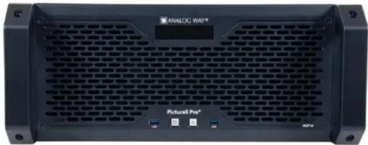
Fig. 1 - Front panel
2.3.1 Display screen
The front panel displays information such as device IP address, firmware version, or CPU.
- Press the Next/Status button to wake the display and show server information.
- Press again to cycle through the next pages.
The display automatically goes off after 3 minutes of inactivity.
2.3.2 Power off
Tip: The following procedure is the recommended method to safely turn off the Media Server.
To turn off the media server, press the Power button then press the Next/Status button to confirm.
2.3.3 Forced shutdown
If the Media Server crashed, turn off the power by Forced shutdown.
- Press and hold the Power button until shutdown.
Caution: Using Forced shutdown regularly is not recommended. Use Forced shutdown only if the Media Server has crashed.
2.4 Rear panels and Connections
The Media Server chassis and the hardware are designed to produce the best possible performance in a sleek, rack-mountable unit.
2.4.1 Picturall Twin rear panel

Fig. 2 - Picturall Twin rear panel
- Power supply (optional redundant and hot-swappable power supplies)
- Two-channel audio interface with balanced XLR outputs (optional)
- RS232 plug* (optional)
- Ethernet plug
- USB plug
- Two DisplayPort 1.2 outputs (4K@60Hz 10-bit 4:4:4)
- Two slots for additional input cards (2 x HDMI 1.4, 4 x HDMI 1.4, 1 x HDMI 2.0, 2 x 3G-SDI, 4 x 3G-SDI, 1 x DVI, 2 x DVI)
*to be supported in future software version
2.4.2 Picturall Quad rear panel

Fig. 3 - Picturall Quad rear panel
- Power supply (optional redundant and hot-swappable power supplies)
- Two-channel audio interface with balanced XLR outputs (optional)
- RS232 plug* (optional)
- Ethernet plug
- USB plug
- Four DisplayPort 1.2 outputs (4K@60Hz 10-bit 4:4:4)
- Two slots for additional input cards (2 x HDMI 1.4, 4 x HDMI 1.4, 1 x HDMI 2.0, 2 x 3G-SDI, 4 x 3G-SDI, 1 x DVI, 2 x DVI)
*to be supported in future software version
2.4.3 Picturall Pro rear panel

Fig. 4 - Picturall Pro rear panel
- Power supply (optional redundant and hot-swappable power supplies)
- Two-channel audio interface with balanced XLR outputs (optional)
- RS232 plug* (optional)
- Primary Ethernet plug (left), secondary Ethernet plug* (right)
- Two USB plugs
- Four DisplayPort 1.2 outputs (4K@60Hz 10-bit 4:4:4)
- Three slots for additional output cards (4 x DisplayPort 1.2) or input cards (2 x HDMI 1.4, 4 x HDMI 1.4, 1 x HDMI 2.0, 2 x 3G-SDI, 4 x 3G-SDI, 1 x DVI, 2 x DVI)
- One slot for additional input card only (2 x HDMI 1.4, 4 x HDMI 1.4, 1 x HDMI 2.0, 2 x 3G-SDI, 4 x 3G-SDI, 1 x DVI, 2 x DVI)
- One slot for optional Genlock card
*to be supported in future software version
2.4.4 Optional Hardware
The Picturall Series Media Servers can be equipped with various options.
| Option | Description |
| Dual Power supply unit | Redundant, hot-swappable power supplies |
| Audio XLR output | Two-channel audio interface with balanced XLR outputs |
| SSD storage device | Replaces the default SSD |
| Output card | 4 x DisplayPort 1.2 |
| Input cards | 2 x HDMI 1.4 |
| 4 x HDMI 1.4 | |
| 1 x HDMI 2.0 | |
| 2 x 3G-SDI | |
| 4 x 3G-SDI | |
| 1 x DVI | |
| 2 x DVI |
Table 2 - Picturall Series Media Servers optional hardware
For more information on optional hardware, visit www.analogway.com or contact Analog Way support.
2.4.5 External Audio support
Caution: Disconnecting the sound card may freeze all layers with audio playback.
The Picturall Series Media Servers support various sound cards.
Audio support lets the media server adjust audio settings for medias files with embedded audio.
For more information on supported audio cards, contact your reseller or Analog Way support.
3 Getting Started
3.1 Precautions when Mounting Picturall Series Media Server
Caution: Follow these precautions to avoid risks for products and users.
When mounting the server, ensure proper air flow and consider the following points on safe use.
- Always use the handles built on the sides of the chassis for easy mounting into any standard rack or flight case.
- Remove the front and back panels of the flight case during operation to provide sufficient air flow through the unit and prevent overheating.
- Place the server preferably in a cool and dry environment.
- The fans inside the server expel the heat through the front and rear panels. Therefore, it is crucial that both the front and the rear are unobstructed at all times. A minimum of 50 cm (20 in.) of clear space at the front and rear of the unit is recommended.
- Do not block the ventilation.
- Do not place any fluid above or near the server.
- Do not apply any pressure against the chassis or the connectors.
3.2 Start the Picturall Series Media Server
When starting the media server for the first time, a test image with server IP address and display number is sent to every connected display. This helps identifying displays and checking the setup is correct.
Tip: Connect all displays before starting the media server for the first time.
To start the Picturall Series Media Server safely and correctly:
- Connect the power cable to the server and then plug it into a mains socket.
- Connect displays to the media server (at least one display to the first connector).
- If configuration is needed, connect a USB keyboard to the USB port on the server front panel.
- Press the power button.
Tip: - If the media server is restarted, close and restart Picturall Commander as well.
- If a new display is connected, restart the server and Picturall Commander.
4 Configuration
The server can be configured from the Web configurator or by booting the server in Configuration mode. Configuration is needed for DMX / Art-Net, display, network and media storage settings.
4.1 Web configurator
The web configurator allows the user to configure the server from a computer connected to same network without installing a separate control software.
To access the web configurator, launch a web browser and enter the server IP address in the address bar.

Fig. 5 - Web configurator connection
All devices default IP addresses are 192.168.2.140.
Note: The Picturall Series Media Server and the computer must be connected to the same network to run the Web configurator.
4.1.1 Dashboard

Fig. 6 - Web configurator Dashboard
The Dashboard is the home page of the Web configurator. It shows general information about the media server.
- Click Configure server or Configurator to access server configuration.
- Click on a link in the left tab to open the corresponding menu.
4.1.2 Server configuration

Fig. 7 - Server configuration
Set server settings from the Server configuration:
- Number of layers: Set the number of layers to use and patch to Art-Net (max 200). This affects the number of available layers in Picturall Commander.
- Max layer width and height: Set the maximum resolution to be processed by the media server.
Caution: Media with a larger resolution than the max layer size might not be displayed correctly. This does not apply PRKL files.
4.1.3 Display configuration

Fig. 8 - Display configuration
In the Display configuration menu, choose the display mode:
- Auto: follow EDID settings
- Manual: set the output resolution, refresh rate and connectors manually
- Custom: select a custom display configuration
- Special: select a preset mode for display signal splitters (Matrox TH2GO and DH2GO, Datapath X4 and FX4)
Note: Displays in the same GPU (for example outputs 1 and 2) are set with the same parameters.
For Auto mode, connect and power all the relevant displays before booting the server. In Manual mode, select the output connectors, resolution and refresh rate for the selected GPU.
Note: Do not use multiple display devices with different refresh rates as this may cause bad playback (stuttering).
Tip: If using identical displays, use the buttons Copy, Paste and Copy to all.
4.1.3.1 Display division
Displays can be divided into grids of virtual displays with Display division. This separates all Displays into independent displays. These displays are affected independently (Keystone, Angle, Crop). This is very useful for complex screens and Led walls.
4.1.4 DMX Configuration
Picturall Series Media Servers have three fixture profiles for Art-Net / DMX control.
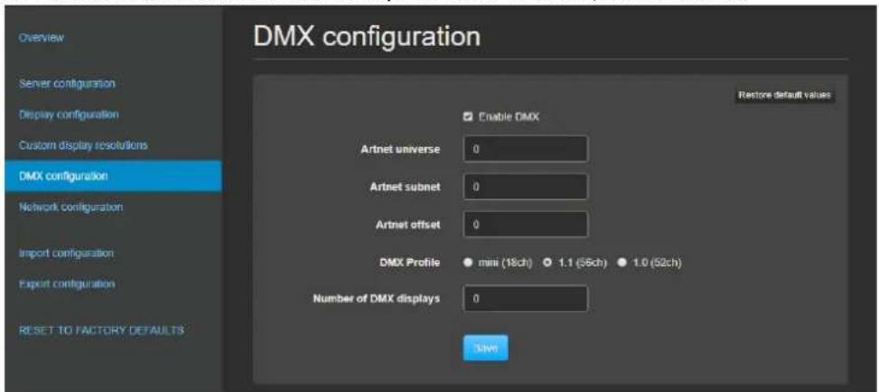
Fig. 9 - DMX configuration
- Art-Net universe: Set the first universe and the rest of the layers will be patched to next universes. If patching more than 9 layers, the server will use several Art-Net universes.
- Art-Net subnet: Set the Art-Net subnet value (between 0 and 15).
- Art-Net offset: Set the first channel of the first universe for layer 1.
- DMX profile: Set the preferred DMX fixture profile (1.1, 1.0 or mini).
- Number of DMX displays: Enter the number of the displays controlled with DMX
DMX control for the Picturall Series Media Server consists of two elements: layers and master block. The master block controls general functions that are not specific to any layer such as choosing display preset (for more information, see Appendix A DMX chart page 65).
Layers are patched first starting from a given offset on a given universe. Layers are patched so that they do not split at the universe border. The following table shows the patching for 32 layers (default).
Master block is patched immediately after the layers.
| Universe | DMX | Layer |
| 1 | 1 | Layer 1 |
| 57 | Layer 2 | |
| 113 | Layer 3 | |
| 168 | Layer 4 | |
| 225 | Layer 5 | |
| 281 | Layer 6 | |
| 337 | Layer 7 | |
| 393 | Layer 8 | |
| 449 | Layer 9 | |
| 2 | 1 | Layer 10 |
| 57 | Layer 11 | |
| 113 | Layer 12 | |
| 168 | Layer 13 | |
| 225 | Layer 14 | |
| 281 | Layer 15 | |
| 337 | Layer 16 | |
| 393 | Layer 17 | |
| 449 | Layer 18 |
| Universe | DMX | Layer |
| 3 | 1 | Layer 19 |
| 57 | Layer 20 | |
| 113 | Layer 21 | |
| 168 | Layer 22 | |
| 225 | Layer 23 | |
| 281 | Layer 24 | |
| 337 | Layer 25 | |
| 393 | Layer 26 | |
| 449 | Layer 27 | |
| 4 | 1 | Layer 28 |
| 57 | Layer 29 | |
| 113 | Layer 30 | |
| 168 | Layer 31 | |
| 225 | Layer 32 | |
| 281 | Master Block |
Table 3 - Example patch of 32 layers using 56ch DMX profile
4.1.5 Network configuration

Fig. 10 - Network configuration
There are three ways to set the IP addresses for the server.
- Automatic (DHCP): The server gets IP address from DHCP server in the same network
- Automatic (ARTNET): The IP address is generated based on the Art-Net protocol
- Manual: Set the IP address and netmask manually
Caution: Never have two DHCP servers in the same network.
Caution: Set the IP address manually if Automatic (DHCP) is activated in the server.
4.1.6 Import and Export configuration
4.1.6.1 Export configuration (save)
Tip: Export server configuration before updating the Server Software as this deletes Configuration options.
To save the current configuration:
- On a web browser, enter the media server IP address in the address bar.
- Go to Configurator or Configure Server.
- Go to Export configuration.
- Choose the configuration parameters to be saved.
- Click Export configuration.
The Configuration is saved in a PSC file.
4.1.6.2 Import configuration (load)
- On a web browser, enter the media server IP address in the address bar.
- Go to Configurator or Configure Server.
- Go to Import configuration.
- Choose the PSC file to import.
- Choose the configuration parameters to load.
- Click Import configuration.
4.1.6.3 Back up the contents on another Picturall Series Media Server
It is possible to back the contents of one server onto another one connected on the same network.
The following example shows how to back from a Server A to a Server B.
- Make sure the two servers have the same software version (latest if possible).
- Make sure the two servers have Picturall Commander installed in same version (latest if possible).
- Create a show and transfer some media files on Server A.
- Make sure that Server B is up and running.
- On a web browser, enter the IP address of Server A in the address bar.
- Go to Tools / Backup.
- Select Server B in the dropdown list or enter the IP address of server B then click Save.
Server A sends all medias and shows to Server B (configuration settings are not duplicated and existing medias on server B are not deleted).
- After the transfer is complete, restart Server B and make sure that it has the same shows and media data as Server A.
4.1.7 Format Media Drives - Storage configuration
In Tools / Format media drives, set the hard drives formatting method.
In the following example, a Picturall Series Media Server has two hard drives of 1TB capacity.
- RAID 0 (striped): 2TB of storage with fastest writing speed. Media drive failure loses all media files.
- RAID 1 (mirrored): 1TB of total storage, medias are stored identically on both media drives. If one media drive fails, the show continues using the other media drive. Best reliability but performance is halved.
Recommendation: Use RAID 0 for optimal performance.
Note: - If the formatting method is modified, all media on hard drives will be deleted.
- RAID 1 is only available for Quad and Pro.
4.1.8 Conflicting Settings
Sometimes settings may conflict with each other. For example: the same Display resolution cannot be set to 1920x1080 and to automatic. In case of conflict, the most recent value is kept and the previous value is discarded.
Settings that easily conflict in the display settings:
| Settings | Conflicts with |
| Auto | A connector, a resolution, a refresh rate and a special mode |
| A special mode | Auto, or a connector, setting a resolution, a refresh rate |
| A connector, a resolution or a refresh rate | Auto and a special mode |
Settings that easily conflict in the network settings:
| Settings | Conflicts with |
| An IP address and a netmask | DHCP client |
| DHCP client | DHCP server, an IP address and a netmask |
| DHCP server | DHCP client |
4.2 Configuration mode
The Configuration mode allows the user to configure the directly on the media server using a connected keyboard. This mode includes all the functionality of Web configurator.
To enter the Configuration mode:
- Make sure a USB Keyboard is connected to the media server.
- Start the server and press any key when the startup screen displays.
- Use the arrow keys in the start menu to select Configuration mode. The Configurator menu is displayed.
Configurator has three main sections: Server configuration, Display configuration, and Network configuration. Use arrow keys to navigate menus and use enter to select. Use the Tab button to move between different sections.

Fig. 11 - Configuration mode
4.3 Update Server Software
Caution: Picturall Commander must always be in the same version as the Server software. Update Picturall Commander together with Server software for best compatibility and performance. A message is displayed in Picturall Commander if the versions do not match.
Tip: Updating the Server Software resets Configuration options but medias are not deleted. Export server configuration to recover it after the update (see Import and Export configuration page 18).
The server comes fully installed with the server software. If a software update is needed, create an installation USB stick and use it to update the software.
Find all installation files for the Media servers on www.analogway.com
4.3.1 Creating an installation USB stick
Tip: Use a high-quality USB memory stick, a low-quality USB memory might cause problems when installing the software.
Note: At the moment, the Picturall Series Media Server installer only runs on Windows.
On a computer:
- Connect an empty, FAT32 formatted USB stick with at least 2GB of space.
- Go to www.analogway.com and download the Picturall installer.
- Run the installer.
- In the Distribution menu, select the latest version (non-beta).
- Make sure the selected Drive is the USB stick.
- Click OK to write the installer onto the USB stick.
The USB stick is now ready for installation.
4.3.2 Installing the server software from a USB stick
- Connect a USB keyboard and the installation USB stick to the server.
- (Re)boot the server.
- When booting, enter Boot menu by pressing F8 (Twin and Quad) or F12 (Pro).
- Select the USB stick. The installer starts.
- Follow the instructions displayed on the screen.
After the installation, the server reboots and sends a test image with server IP address and display number is sent to every connected display.
-
If needed, go to the Network configuration > Manual and set new IP address.
-
If needed, import saved Configuration.
5 Configure Picturall Commander

Fig. 12 - Picturall Commander
Picturall Commander is the software (Java application) used to control the Picturall Series Media Server. This chapter describes the installation and the top-level parts of the Picturall Commander user interface.
5.1 Java compatibility
The operating systems must support Java version 8 for Picturall Commander to be installed. Make sure Java version 8 is installed on the computer before installing Picturall Commander.
Caution: Java version 9 is not compatible with the current version of Picturall Commander. If Java version 9 is installed, Picturall Commander installation will fail. Use Java version 8 only.
5.2 Installing / Updating Picturall Commander
Caution: Picturall Commander must always be in the same version as the Server software. Update Picturall Commander together with Server software for best compatibility and performance. A message is displayed in Picturall Commander if the versions do not match.
Tip: Use a dedicated computer for running Picturall Commander. This ensures that the show files are safe at all times.
The software is on the USB stick delivered with the server. The latest version of Commander is automatically downloaded during the installation process.
If needed, the latest version of Picturall Commander can also be downloaded from www.analogway.com.
To install Picturall Commander, follow these steps:
- On the computer, insert the USB stick delivered with the media server.
- Copy the installer file matching the operating system from the USB stick to the computer.
- Run the installer file and follow the instructions to complete the installation process.
- If needed, open Picturall Commander and go to File / Load show to load previous configuration.
5.3 Connecting to Picturall Series Media Server
Caution: If the computer goes into a standby mode, the connection to the server is lost after the computer resumes.
Tip: If the media server is restarted, close and restart Picturall Commander as well.

Fig. 13 - Add new connection dialog
- Connect the computer and the Picturall Series Media Server to the same network.
- Use same netmask in the server and the computer if not using DHCP server. If DHCP server is enabled in the server, use automatic network settings in the computer.
- Run Picturall Commander and click Add new connection on the Connections tab.
- Type the IP address of the server in the Address field or click Locate to automatically find the servers in the same network and view the server versions before connecting.
- In the Name field, enter a name for the connection.
- Under Advanced, change the values for Text protocol port and Data protocol port if needed.
- If needed, uncheck Connect immediately.
- Click Finish to Create the Connection. A message confirms the connection to the Picturall Series Media Server.
5.4 User Interface
The Picturall Commander user interface consists of a few basic elements:
- The main Commander toolbar.
- The control tabs.
- The control panels within the tabs.
The control tabs are positioned in the right, middle, left or bottom depending on their function.
5.5 Control Tabs
Click Window then click any menu to open the corresponding control panel.
- Connections: Connect and reconnect to a server pressing Reconnect button. The main control tabs are available in the Connections tab.
- Media: Transfer media files to the Picturall Series Media Server and arrange the media library. For more information, see Media page 24.
-
Displays: Configure the display setup. For more information, see Displays page 30.
-
Layers: Control all layer parameters. This is the main menu for controlling the Picturall Series Media Server with Picturall Commander. For more information, see Layers page 37.
- GPUs: Optimize the use of the GPUs.
- Timecode: Set the timecode format and offset.
- Cues: Program and time cues for the show.
- Test images: Configure test images to help when setting up the show.
- Performance: Check the performance and temperature of the server. For more information, see Performance page 60.
- Control model: Shows a tree structure of all the parameter information on the server.
- Server info: Opens a window with all server information.
- Properties: Shows additional information on a given selected item. Located in Window > Properties.
Tip: Open these menus in one click from the menu icons toolbar:

5.5.1 Arrange windows
Once a panel is opened, drag and drop a tab to customize the layout. All tabs can be placed anywhere in the layout (top, bottom, left or right).


Fig. 14 - Windows arrangement
5.5.2 Reset windows
If needed, reset the default layout by clicking Window/ Reset windows.
5.6 Preferences
Go to Edit > Options to set user preferences (General, Media, Layer, Cue, Keymap and Logging).
5.7 Hotkeys
Hotkeys can be set to several actions in Picturall Commander. Go to Edit > Options > Keymap to set custom hotkeys. Here is a list of common features using default hotkeys:
- Hold Shift while adjusting values to make fine adjustments to numerical sliders and control.
- Hold Alt and click parameter values or other settings to record or unrecord it in the Programmer. The value turns green if it is recorded. For more information, see Program a Show - Cue page 52.
- Hold Ctrl and click a parameter to reset it to default value. (Use cmd on Mac OS).
- Use Alt + arrow keys on the keyboard to change the selected control point on the Warp and Keystone tabs.
- Use Ctrl and click to reset a single control point on the Warp and Keystone tabs.
6 Media
In the Media menu, manage all contents that will be played during the show:
- import files to the server,
- encode medias,
- add web pages and video streams,
- organize server files and inputs in collections to be used in layers.

Fig. 15 - Picturall Commander Media menu
6.1 Media types
Picturall Series Media Servers support the following codecs:
- MPEG1
- MPEG2
- MPEG4
- MJPEG
H.264
H.265 - ProRes
• PRKL (also with alpha channel) - JPEG
• PNG (also with alpha channel)
• DPX (also as sequences)
• TGA (also as sequences)
All codecs can be played with nearly any frame rate and bit rate within the server performance limits. Audio is supported in PCM, WAV and AAC formats.
Note: Playing back too many large resolution files may cause playback issues or even a crash.
6.2 Manage Media Collections
- Select a media collection in the Media collection dropdown on the top part of the Media tab.
- Rename the media collection using the Rename... button.
- To delete a media from a collection, right-click on it and select Delete.
- To delete all medias from all collections, click the Reset... button.
- To define a specific action at end of the playback of one media, click on the dropdown in the Play mode column and select an end action (see End action page 38).
6.3 Importing media files
Tip: If running Picturall Commander on Windows, it may be needed to disable the firewall to transfer files smoothly.
Note: The amount of free space on the server is displayed in the Free server space bar.
6.3.1 Import a local media file
To import a local media file to the server:
- Select a media file in the Local path list or computer file browser. Hold Ctrl or Shift to select multiple files.
- Drag and drop it on the media collection slot to use.

Fig. 16 - Importing a media file
- The Local files to be transferred window opens with a list of the importing files. If needed, set target directory and filename.
- Click OK. The current transfer and encoding process bars are displayed on the Transfers subtab.
Note: After a file is imported on the server, it is impossible to change its filename and location.
If importing multiple folders, Picturall Commander puts all folders into their own media collections.
- If needed, use Cancel buttons for canceling file transfer.
Medias added to the server are displayed in the Media collection and are available in Server path files.
6.3.2 Import and encode a file
- Select a media file in the Local path list or computer file browser. Hold Ctrl or Shift to select multiple files.
- Drag and drop it on the media collection slot to use.
-
The Local files to be transferred window opens with a list of the importing files. If needed, set target directory and filename. Then click OK.
Note: After a file is imported on the server, it is impossible to change its filename and location. -
In the Default encoding dropdown, select the media encoding format.
Tip: PRKL encoding is recommended for files with format bigger than 8K (and PRKL Alpha if alpha channel).
Note: Encoding files that are non-encodable will make them appear in red and a warning will display.
-
Click OK. The current transfer and encoding process bars are displayed on the Transfers subtab.
-
If needed, use Cancel buttons for canceling file transfer.
Medias added to the server are displayed in the Media collection and are available in Server path files.
6.3.3 Import an image sequence
Picturall Commander is able to convert images and create an image sequence as one media object with uncompressed image quality.
Tip: - An image sequence must have at least 49 frames. - Images must have the same filename ending in 000, 001, 002, etc. to be detected as a sequence.
To import an image sequence, follow these steps:
- Select the images files in the Local path list or computer file browser. Hold Ctrl or Shift to select multiple files.
- Drag and drop it on the media collection slot to use.
Tip: Group the images in one folder then drag and drop the whole folder.
The Local files to be transferred window opens with a list of the importing files.
- Enter the number of Frames per second (FPS).
- If needed, select the encoding format and choose to keep the original images on the server as individual files.
- If needed, set target directory and filename.
Note: After a file is imported on the server, it is impossible to change its filename and location. - Click OK. The current transfer and encoding process bars are displayed on the Transfers subtab.
6.3.4 Import a media using FTP
Caution (Risk of server crashing): Do not overwrite files that are playing on the server through an FTP connection.
Tip: Importing media using FTP can slow down the media server. Avoid transferring large files during a show or while making changes to the configuration.
To import media through FTP connection, follow these steps:
- Open an FTP connection to the Picturall Series Media Server.
- Log in:
-Username: picmedia - Password: aidemcip
- Import the media files to the server. The media are located in /picturall/media.
6.3.5 Reuse imported media files - Add server files to a media collection
To add media files already present on the server to a media collection, follow these steps:
- Select a media file in the Server path list. Hold Ctrl or Shift to select multiple files.
- Drag and drop it on the media collection slot to use.
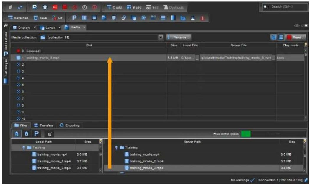
Fig. 17 - Add a server file to a media collection
- If adding multiple folders, Picturall Commander will automatically put all folders into their own media collections.
6.4 Add inputs to a media collection
Note: Inputs are only available for Media Servers equipped with optional input cards.
An input is available as a Server File if it is connected to the media server.
To add an input to a media collection, follow these steps:
- Select an input in the Server path list. Hold Ctrl or Shift to select multiple inputs.
- Drag and drop it on the media collection slot to use.
6.5 Add web pages and video streams
6.5.1 Add a web page to a media collection
Picturall Series Media Servers connected to the internet support web page playback. Multiple web pages can be played at the same time and background transparency is supported.
Note: Web page sound and interaction are not supported.
To add a web page to a media collection, follow these steps:
- In the Server path list, under Network, select Web page.
- Drag and drop it on the media collection slot to use.
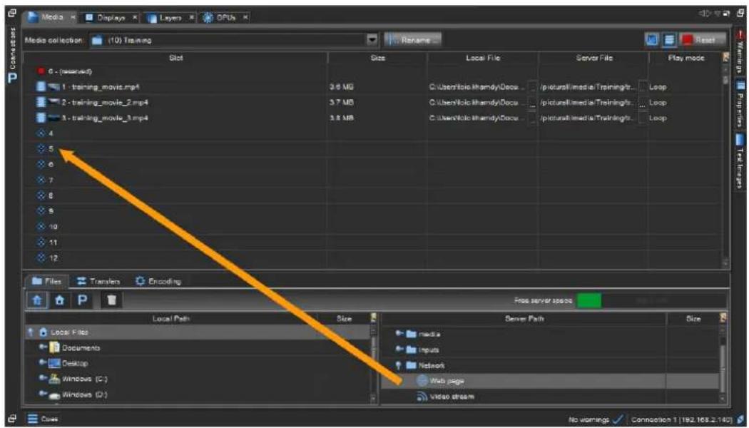
Fig. 18 - Add a web page to a media collection
- A window opens, enter the Web page address (URL), the reload timing and the browser window width and height in pixels.
- Click OK.
Note: After a web page is added to a collection, it is impossible to change its URL.
6.5.2 Import a web page using FTP
Caution (Risk of server crashing): Do not overwrite files that are playing on the server through an FTP connection.
To import a web page through FTP connection, follow these steps:
- Open an FTP connection to the Picturall Series Media Server.
- Log in:
-Username: picmedia
- Password: aidemcip
- Import the files to the server. The files are located in /picturall/media/.webpages/.
6.5.3 Add FTP imported web page to a media collection
To add an FTP imported web page:
- In the Server path list, under Network, select Web page.
- Drag and drop it on the media collection slot to use.
- A window opens, enter the URL to the html file starting with http://localhost/webpages/
- Enter the browser window width and height in pixels.
- Click OK.
Note: After a web page is added to a collection, it is impossible to change its URL.
6.5.4 Add a video stream to the server
Picturall Series Media Servers connected to the internet support video stream playback. URL beginning with rtsp:// and rtmp:// are supported.
To add a video stream to a media collection, follow these steps:
- In the Server path list, under Network, select Video stream.
- Drag and drop it on the media collection slot to use.
- A window opens, enter the Video stream URL.
- If using RTSP, set transport parameters.
- Click OK.
Note: After a video stream is added to a collection, it is impossible to change its URL.
6.6 Add a custom text
Create a text with custom settings (font, style, size, color and resolution).
To add a custom text to a media collection, follow these steps:
- In the Server path list, under Generators, select Text generator.
- Drag and drop it on the media collection slot to use.
- A window opens, enter a text and set the parameters.
- Click OK.
To edit a custom text, right-click it in the Media tab or in the Layers tab in Media selection then choose Edit.
7 Displays
In the Displays menu, configure the displays of the show.
![Code S-03 Edit Duplicates Search (Ctrl+) Display Media Layers Position Reset Enabled Yes X 0.0000 Y 0.4000 Width 0.5000 Height 0.26125 Rotation 8.50 Graph 1 2 Mode: Individual, leacher is display 1 Cues No warnings ✓ Connection 1 [192.160.2.100]](/content/2026/05/869927/images/1d9f339a98ce3dde57df28f5748a0237bba78697a09605df58552fb0d796e1f3.jpg)
Fig. 19 - Picturall Commander Display Menu
- Select a display from the Display list.
- At the right of the Display list, there are control panels to adjust the display. Click the tabs (Pos, Proj, etc.) to show or hide the corresponding panels.
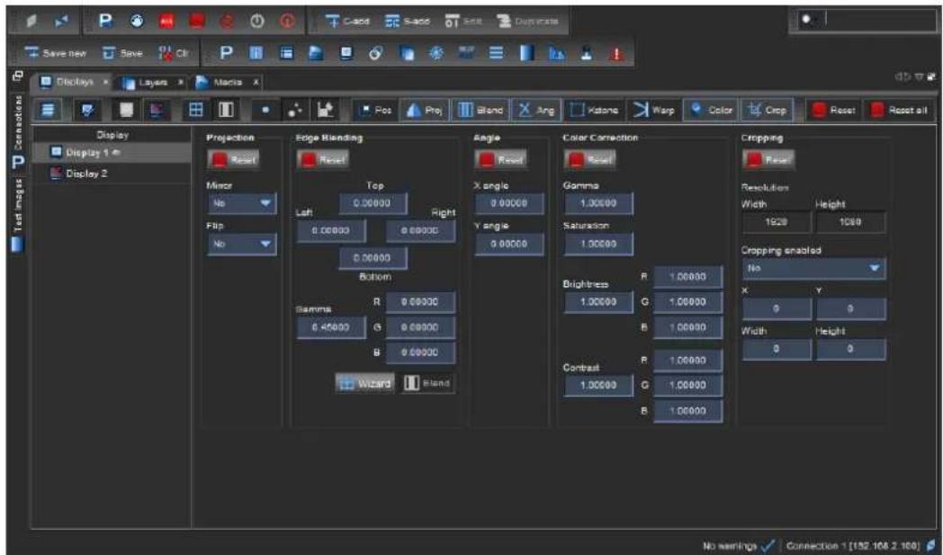
7.1 Display menu icons
| Icon | Description |
 | Show / hide the display list. |
 | Select all enabled displays. |
 | Enable selected displays. |
 | Disable selected displays. |
 | Opens the Display wizard to create a group of displays (see Multi-display screen - Display wizard page 33). |
 | Blend the selected group of displays (see Multi-display screen - Display wizard page 33). |
 | Enable/disable adjusting selected displays as a group. |
 | Enable/disable adjusting single display as a group. |
 | Set current state as a default, adjustments become relative to this state. |
7.2 Display adjustment tabs
| Adjustment tab | Description |
| Positioning | Place, transform, and enable/disable displays |
| Projection | Flip and mirror |
| Edge blending | Edge blending functions |
| Angle | Distortion (for example to correct a projection onto a screen from an angle) |
| Keystone | Keystone |
| Warp | Curved surface projection |
| Color correction | Display color correction |
| Cropping | Crop the display |
7.3 Test images
Picturall Commander provides test images to help setup.
- Double-click the Test images button on the Connections tab (or click the icon in the menu toolbar) to open the Test images tab on the right side.
- Select the test images to be displayed.
| Test image | Description |
| Line width | Adjust the line width in a test image using the slide bar. |
| Blue background | Show display areas that are not drawn in blue. Use when adjusting Keystone or curved surface correction. |
| Canvas grid | Show white continuous grid across the composition. Also shows yellow X in the middle of composition. Use for final adjustments. |
| Canvas lines | Show multicolored lines in selected angle. Use the checkboxes for defining the line orientation. Use when adjusting display positions and bezel corrections. |
| Blend areas | Show display borders, edge blend area and edge blend center.Use when adjusting edge blends. |
| Display borders | Show display borders with white lines. Use when adjusting keystone. |
| Display numbers | Show the display number of each display. Use to identify displays and make sure they are properly connected. |
| (Selected) Display grid | Show grid and middle point of selected display. Use when adjusting angle and curved surface corrections. |
| Control points | Show selected control points on the output. The selected control point turn from green to red on the output. If selecting multiple points, only one point turns red. |
| Layer borders / Layer numbers | Show layer borders and/or numbers. Use to identify layers and help position them in the show. |
| System info | Show server IP address, display number, output resolution and system runtime.This test image is enabled on first boot, and after Media Server update. |
Table 4 - Test images
7.4 Positioning and Grouping Displays
- Select the display to control in the Display list.
- Open the Positioning panel and adjust the position, size, aspect ratio and rotation for the display. Drag or scroll to adjust the values (hold Shift for precise adjustments).

Fig. 20 - Positioning panel
- If needed, open the Projection panel to mirror and flip the image.
Tips: - Right-click a parameter and select Edit to enter numerical values.
- Position the displays from the same graphics card close to each other to avoid performance loss.
- For best performance, disable displays when they are not used.
- Copy and paste settings from one display to the other by selecting displays and clicking Copy and Paste buttons.
It is possible to copy and paste one object over several objects and vice versa. - Go to Windows / Displays Graph to open the display graph in a separate tab.
7.4.1 Multi-display screen - Display wizard
Displays can be arranged in groups to allow control of multiple displays at once. The Display wizard helps creating screens made with multiple displays.
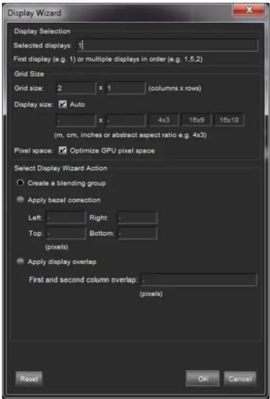
Fig. 21 - Display wizard
- Click the Display Wizard button in the Edge blending panel, or in the Displays tab toolbar. If displays are selected, they are automatically added to the Selected displays field.
Preselected displays appear in order of selection.
- In the Selected displays field, enter the displays in order (1,2,4,8) or just the first one if they are ordered logically.
- Enter the Grid size and display aspect ratio.
- If needed, create a Blending and set the blending size (see Optimize GPU resolution and drawing performance page 74.
- Edge Blending page 34).
- If needed, use Bezel correction to correct video wall bezels. Enter the display total dimensions and bezel width and height.
- Click OK to create the display group.
7.4.2 Reset Display
- Hold Ctrl and click a field to reset the value.
- Use the Adjustment tab Reset button to reset the corresponding parameter for the selected display.
- Use the Upper right Reset button to reset all parameters from the selected display.
- Use the Reset all button to reset all displays.
7.5 Optimize pixel space - GPUs tab
For best results, use canvas optimization when working with a display setup where the displays are not side-by-side horizontally. Using optimize also displays a sharper image.
- Open the GPUs menu and click Optimize to start an automatic calculation that optimizes graphic card performance with the current display setup.
For more information about GPU optimization, see Optimize GPU resolution and drawing performance page 74.
7.6 Edge Blending
Edge blending is a feature that gradually fades out the overlapping area from both projectors to create a seamless projection.
7.6.1 Keystone and Angle Correction
The Keystone correction tool moved the picture corners on the display. Use Keystone when the projection angle is not optimal.
![Display Media Layers OPUs Play Proi Blend Ang Kalore Warp Color Crop Reset Reset all Display Group 1 [2x1] [0,0] Display 1 [1,0] Display 2 Position Reset Enabled: Yes X (☐) 0.49488 Y (☐) 0.50000 Width (☐) 1.00000 Height (☐) 0.20500 Rotation (☐) 9.00 Grain Keystone (leader display) Reset Scale 1 2 Li…](/content/2026/05/869927/images/ed14cadfe44f5c69cf0140170481799b5af64c7efd22b0aadca0dbb27618a98f.jpg)
Fig. 22 - Keystone and Angle correction
- Open the Test images tab and enable the Display borders test image.
- Go to Displays and select the display to control in the Display list.
- Open the Keystone panel.
- Click and drag the corners to correct the position or click the corner and use arrow keys to move it. It is possible to select multiple points. Hold the Shift key for more precise adjustments.
- If needed, open the Angle panel to correct the image with Angle controls.
- Enable the Display grid test image.
- Adjust X angle and Y angle controls until the red cross is in the middle of the projection.
- Open the Test images side panel and enable the Blend areas test image.
- Open the Edge Blending panel, then click the Display Wizard button to create a display grid.
- Check the Create blending group box to group the displays and click OK to create the group.
- In the Displays list, select the first display of the group.
- In the Edge blending control panel, use the Left, Right, Top and Bottom controls to set edge blending size. Hold Shift for precise adjustment or right-click to enter a value.
- Adjust the value until the red line overlaps with the border of the adjacent display.
- Select the other displays of the group and repeat the adjustment step (red line overlap).
- When all overlaps are done, click the Blend button to enable edge blend.
- Open the GPUs menu, click Optimize for best performance.

Fig. 23 - Edge blending panel
Tip: If blend area is brighter or dimmer than rest of the picture, use the Gamma setting to correct the image. The color correction is also possible with the RGB controls.
Note: When clicking Blend, the displays overlap and sizes are automatically calculated from blend values. The result is displayed on the Positioning area.
7.6.3 Edge blending example
The following is an example for making a three-projector blend of displays 1, 2 and 3:
- Open the Test images side panel and enable the Blend areas test image.
- Open the Edge Blending panel, click the Display Wizard button to create a display grid.
- Enter Display number (1), Grid size (3x1) and Aspect ratio (16:9).
- Check the Create blending group box to group the displays and click OK to create the group.
- In the Displays list, select Display 1 and open the Edge blending control panel.
- Adjust the Right value until the red line overlaps with the left border of Display 2.
- Select Display 2 and adjust Left and Right until overlap.
- Select Display 3 and adjust Left until overlap.
- Click Blend to enable the edge blend.
- If needed, correct the Gamma and RGB.
- Open the GPUs menu, click Optimize for best performance.
7.7 Adjust curved surface projection - Warp correction
Warp correction transforms the display for curved surface projection or projector lens distortion. There are 16 control points.
Tip: Use the Display borders, Display grid and Canvas grid test images.
- Go to Displays and select the display to control in the Display list.
- Open the Warp panel.
- Click and drag a point to correct the position or use arrow keys to move it. It is possible to select multiple points. Hold the Shift key for more precise adjustments.
Use Alt + arrow keys to change the selected control point, and Ctrl + click to reset a point.
7.8 Color correction (Display)
Adjust color correction independently for each display.
- Go to Displays and select one or more displays to control in the Display list.
- Open the Color Correction panel to set the Gamma, Saturation, Contrast and Brightness levels for each display.
- Red (R), Green (G), and Blue (B) values can be adjusted for contrast and brightness separately.
7.9 Crop display size
Use Cropping to limit the size of the display.
Tip: Use Cropping with LED walls with non-scaling processors and custom resolution.
- Go to Displays and select the display to control in the Display list.
- Open the Cropping panel. The values in Resolution gives the original width and height of the display.
- Set Cropping enabled to Yes. Adjust the cropping values even if cropping is disabled.
- Set the X and Y position values for the display and limit its size in Height and Width to make the display smaller than its normal size.
8 Layers
In the Layers menu, control and program layers. Layers are the elements containing the medias, one layer contains one media.
Note: The Layer menu is not needed if using external controller (lighting consoles or show control systems).

Fig. 24 - Picturall Commander Layers menu
8.1 Layers tab
8.1.1 Layer List
The layers are listed on the left panel. Right click a layer to show quick interactions (Rename, Play, etc.)
Tip: Rename the layers for easier use.
8.1.2 Layer Priority
The layers a listed from 1 to 32. By default, the layer number defines its priority. If layers overlap on the composition, the layer with the highest number is displayed on the overlap area. It is possible to override the layer priority with Advanced settings, see Advanced page 41.
Tip: Use the layers wisely and create the layers from background to foreground.
8.1.3 Layers adjustments
| Adjustment panel | Description |
| Composition | Preview the media and set position, rotation, intensity for each layer |
| Color correction | Layer color correction |
| Media Selection | Browse media collection, assign media to layer, play back and end action |
| Effect 1 and 2 | Select layer effects |
| Advanced | FPS and layer synchronization settings |
| Macros | Save layer settings |
| Geometry | Warp, Keystone and Edge Blending for each layer |
8.2 Select and play a media - Media selection
In Media Selection, assign a media to a layer and choose playback mode.
- Go to Layers and select the layer to control in the Layer list.
- Open the Media panel.
- Select a collection in the dropdown.
- Double-click a media to select it.
- Click the Play button. The Media is displayed.
- In Media end action, select the action at the end of playback.
Tip: - Click the Pin button to go to current Media location. - Click the Toggle view button to toggle between List and Thumbnail.
8.2.1 Playback control
| Playback button | Description |
| Play | Play/Resume video from the current frame. |
| Pause | Pause the video and leaves a still image of current visible frame. |
| Stop | Stop media playback and returns to the media start point. |
| Set in and Set out points | Use current position as start and end points for the media. It is possible to set the In and Out points on the playback bar by dragging the points or right-clicking on the bar. |
| Go 10 (20 or 30) | Set the current playback position to X seconds before the end. |
8.2.2 End action
This defines what the player does when the playback reaches the end of a media.
| End action | Description (at the end of the media) |
| Default | Follow the media file Play mode set in the media collection. |
| Loop | Loop the media file. |
| Loop collection | Play the next media in collection and loop. At the end of the last media, replay the collection from the first media. |
| Random | Loop the collection in random order. |
| Next | Play the next media in collection. At the end of the last media, stop the playback. |
| Pause | Pause the playback (still frame). |
| Stop | Stop the playback (no frame). |
8.3 Composition
In Composition, adjust the layer position, scale, and rotation on the display.
Click then drag or scroll to adjust the values (hold Shift for precise adjustments).
- Go to Layers and select the layer to control in the Layer list.
- Open the Composition panel. If a media is playing, its thumbnail is shown in the Graph.
- Use the adjustments to control the layer.
Tips: - Right-click a parameter and select Edit to enter numerical values.
- Copy and paste settings from one layer to the other by selecting layers and clicking Copy and Paste buttons. It is possible to copy and paste one object over several objects and vice versa.
- Go to Windows / Layers Graph to open the layers graph in a separate tab.
| Adjustment | Description |
| Intensity | Transparency (opacity) of the layer |
| Pos X and Y | Horizontal and Vertical position of the layer. 0 is the center of the composition. |
| Scale | Size of the layer scaled on the full composition. 1 fills the composition horizontally. |
| Scale height | Height of the layer scaled on the Scale value. 1 keeps the original aspect ratio. |
| Rotation | Rotate the layer (360 degrees). |
| Rot. speed | Enable a continuous rotation of the layer. Set the speed of the rotation (set negative value to rotate clockwise). |
| Draw mode | Set how this layer is drawn compared to other layers. |
Note: For more information on position coordinates, see Canvas and coordinates page 74.
8.3.1 Draw modes
Draw mode determines how a layer is drawn and how it affects the layers beneath it.
The following table describes the different draw modes:

Fig. 25 - Draw mode example images
- Layer 2 (L2) is always on top of Layer 1 (L1).
- The Draw mode of L1 does not affect L2 (L1 is set to Replace in the following examples).
- Changing the Draw mode of Layer 2 gives different results.
| Effect | Image | Description |
| Replace |  | Equation: L2Default mode. Draw the layer on top of layers below. The layers below the drawn layer are not visible (except alpha channel). |
| Additive |  | Equation: L1+L2Add the pixel values of the drawn layer to layers below it (brighter image). White areas in either layer stay white. |
| Subtract |  | Equation: L1-L2Subtract the pixel values of the drawn layer from layers below it (darker image). Black areas on L2 leaves L1 unmodified. White areas on L2 become black areas. |
| Darken |  | Equation: min(L1,L2)Compare the drawn layer to layers below it.The darker pixels of the result are drawn. |
| Lighten |  | Equation: max(L1,L2)Compare the drawn layer to layers below it.The brighter pixels of the result are drawn. |
| Multiply | 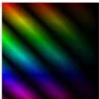 | Equation: L1xL2Multiply drawn layer pixel values with layer below it (darker image). Black areas on either layer will result black areas. This mode is useful when creating masks. |
| Linear burn |  | Equation: L1+L2-1Variant of the Subtract mode. The result is a darker image. |
| Screen |  | Equation: 1-(1-L1)x(1-L2)Opposite of the multiply mode. The result is a brighter image. |
Table 5 - Draw modes
8.3.2 Graph
| Icon | Description |
 | Show / hide the layers graph. |
 | Show / hide all layer numbers on the graph. |
 | Show / hide all enabled display numbers on the graph. |
 | Show / hide all enabled displays on the graph. |
Adjust the layer from the graph:
- Drag the layer to set Position.
- Use the handles in the right corners to scale and rotate the layers.
8.3.3 Composition Advanced settings
Under Advanced (in Composition), set the layer Draw priority, Deinterlacing and Scaling algorithm.
- Draw priority: Set a number to override the layer number priority system (see Layer Priority page 37). By default, all layers have a Draw priority at 0. Draw priority values goes from -5 to 5. For example: a layer with draw priority set at 1 is displayed on top of all layers with draw priority under 1, no matter the Layer number. If layers have same Draw priority, the Layer number defines the priority.
Tip: Use draw priority wisely to have a clear configuration. Prioritize using layer numbers and use draw priority for rare exceptions (force layer on foreground or background).
- Deinterlacing: Select the Deinterlacing mode (No deinterlacing, Line doubling or Blending).
- Scaling algorithm: Select the Scaling technology (Bilinear, Cubic weighted, Quintic weighted, Sinus weighted or Bicubic).
8.4 Color correction (layer)
Adjust color correction independently for each layer.
- Go to Layers and select one or more layers to control in the Layer list.
- Open the Color Correction panel to set the Gamma, Saturation, Contrast and Brightness levels for each display.
- Red (R), Green (G), and Blue (B) values can be adjusted for contrast and brightness separately.
8.5 Advanced
In Advanced, set the frame rate values and synchronize the layers.
Note: Frame rate can be modified only if no audio track is embedded to the media.
8.5.1 Synchronize to another layer
This feature makes one layer follow the framerate of another layer or a MIDI timecode (MTC).
- Go to Layers and select one or more layers to control in the Layer list.
- Click Sync selected
- Select the layer or MTC to be the source for the current layer.
Note: By default, the layers do not synchronize to any source.
8.5.2 Set layer Frame rate
Note: Frame rate can only be set if:
- the layer is not part of synchronization.
- the media file doesn't have audio track (even if audio is disabled).
- and media is not a stream video or input.
Modified frame rate (or FPS) can be defined or relative to original frame rate.
| Adjustment | Description |
| Effective FPS | Current effective FPS of the playback with the following settings applied. |
| FPS controllable | Yes or No. Displays if the frame rate can be modified. |
| FPS mode | Select Media to use media original frame rate or Defined to use manual value. |
| Defined FPS | Set absolute frame rate (number of frames per second). |
| Relative FPS | Set a frame rate relative to the original frame rate (from 0.10 to 2.00). |
| Frame blending | Set to Enabled or Disabled. This uses a crossfade between frames and displays a smoother playback when frame rate is lower than original. |
8.6 Audio (optional)
Note: Audio is grayed-out if Audio support is not enabled in Configuration mode.
In Audio, control the volume for the selected layer and assign audio channel to output.
Use the Channel mixer to assign an output and volume for each audio channel. Use values from 0.0 to 1.0 for the channel volume.
For example: To play a mono audio media file (1 channel) from two speakers, assign that channel to output from both output 1 and 2 (O1 and O2) with full volume (1.0).
Note: By default, channel number 1 gets assigned to output 1, channel 2 to output 2 and so on.
8.7 Using Effects
In Effect1(Fx1) and Effect2(Fx2), use effects on the media in the layers (keying, blur, waves, glow, etc.). Two effects per layer can be used at the same time and both panels are identical.
Note: Effect1 is applied on the layer before Effect2. If Fx1 = Pixelize and Fx2 = 3D Cube, the media is pixelized then rotated with cube effect and vice versa if Fx1 = 3D Cube and Fx2 = Pixelize.

Fig. 26 - Effects
- To apply an effect, select one effect in the dropdown list, and adjust the effect-specific parameters to see the result.
- Click the Reset button to reset the current effect panel and cancel the effect.
- Click the R. params button to reset the parameters and keep the effect selected.
The following table describes the various effects:
| Effect | Image | Description |
| 3D Cube | 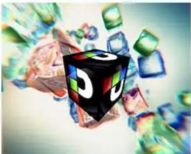 | Reshape the layer into a cube shaped object. Adjust rotation speed and axes. |
| 3D Plane |  | Reshape the layer into a 3D plane. Adjust rotation speed and axes. |
| 3D Sphere |  | Reshape the layer into a 3D sphere. Adjust rotation speed and axes. |
| Alpha Fill | Uses this layer as the Fill Layer for alpha keying when using the Alpha Key effect (see Alpha Fill and Alpha Key – Cut & Fill page 50). | |
| Alpha Key | Uses this layer as the Alpha Key layer for the previous layer (see Alpha Fill and Alpha Key – Cut & Fill page 50). | |
| Blur |  | Add blur to the layer by comparing surrounding pixels, making outlines less distinct. |
| Cartoon |  | Simplify the colors and smooths the shading in the layer, increasing the difference between low and high contrast areas. |
| Chromakey |  | Create a color key compositing function. Adjust Red, Green and Blue value parameters to set transparency. |
| Chromakey inverse |  | Create a color key compositing function with inverse values to the Chromakey effect. |
| Comic |  | Reduce the number of colors and hues used in the layer, creating a comic book-like effect. |
| Directional blur | 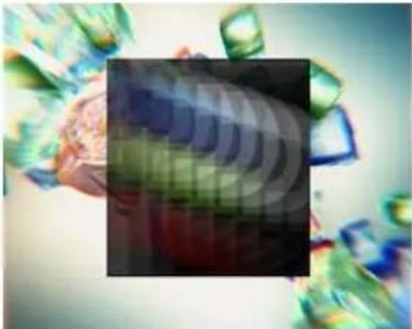 | Smear the pixels of the layer into a given direction. |
| Drop shadow | 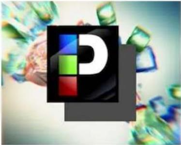 | Create a background shadow to the layer, giving the impression that the layer is situated above the layer behind it. |
| Edge blur |  | Blur the outer borders of the layer. |
| Edge Laplace |  | Detect edges in the layer by adding blur and subtract the result from the original layer image gradually using the mixing parameter. |
| Edge Laplace add | 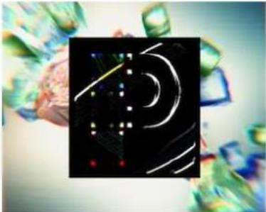 | Detect edges in the layer by adding blur and subtracts the result from the original layer image. |
| Gaussian blur |  | Add blur to the layer using the Gaussian function. The result is a very smooth blur, as if looking through a translucent glass. |
| Glow |  | Make bright areas in the layer appear brighter, adding the impression of glow. |
| Halftone |  | Modify the layer from continuous colors to single-colored dots. Adjust dots size. |
| Halftone advanced |  | Modify the layer from continuous colors to single-colored dots. Adjust dots size, background color and alpha channel. |
| Heavy blur |  | Add a large amount of blur by comparing surrounding pixels with a large radius. |
| Inverse |  | Invert the color values of the layer. |
| Kaleidoscope |  | Create uniform hyperbolic tiling on the layer, resembling the view through a kaleidoscope. |
| Keystone |  | Modify the layer using the keystone corner points. |
| Lumakey |  | Create a luminance key compositing function for the layer, making the bright areas transparent. |
| Lumakey inverse |  | Create a luminance key compositing function with inverse values to the Lumakey effect. |
| Mask |  | Mask out or crop the layer so only part of it is displayed. |
| Pencil sketch |  | Color the outlines black and the background white, creating the impression of a pencil sketch. |
| Pixelize |  | Blur the layer by substantially reducing its apparent resolution. |
| Quick border |  | Blur and color the outer border of the layer. Similar to the Edge blur effect with more parameters. |
| Radial blur |  | Blur the layer by smearing pixels around the center point. |
| Radial blur advanced |  | Blur the layer by smearing pixels around the center point and adjust the position of the center point. |
| Sepia |  | Recolor the layer with a reddish-brown sepia color. |
| Sharpen |  | Increase the contrast where color changes occur, resulting in a sharper layer image. |
| Tiles |  | Create scaled-down, tiled copies of the layer. |
| Water ripple |  | Add a distortion on the layer resembling a ripple on water. |
| Wave |  | Add distortion to the layer to create the impression of waves. |
Table 6 - Effects descriptions
8.7.1 Alpha Fill and Alpha Key – Cut & Fill
Create a Cut & Fill effect using Alpha keying to limit the way the fill layer is displayed.
Note: The lower layer is always the Alpha Fill layer and the upper layer is always the Alpha Key layer.
Tip: To use Cut & Fill, prepare medias to be the "Cut media". Cut medias are preferably black and white with the black area being the "displayed" part.
- Select a Layer in the Layer list.
- In the Media panel, select a media and play it.
- In the Effect 1(Fx1) panel, select the Alpha Fill effect in the dropdown list.
This layer is now the Alpha Fill layer. - Select the next layer in the Layer list.
- In the Media panel, select the "Cut media" and play it.
- In the Effect 1(Fx1) panel, select the Alpha Key effect in the dropdown list.
This layer is now the Alpha Key layer.
The content of the Alpha Fill layer is now displayed in the black areas of the Alpha Key layer.
Note: - Alpha Fill is only effective if the next layer has the Alpha Key effect. - Alpha Key is only effective if the previous layer has the Alpha Fill effect. - The Alpha Key layer only contain the contents from actual media or input. Other effects, composition or color correction are not applied.
Tip: Use the Alpha Fill Inverse effect on the Alpha Fill layer to display the its content in the white areas instead of the black ones.
8.8 Layer macro
Tip: Go to Edit > Options > Layer > Layer Macros to define the number of available macros (save slots).
Use Macro to save and load the state of one layer.
8.8.1 Create a layer macro
- Select a layer in the Layer list to save as a macro.
- Right-click a macro slot and select the layer parameters to save.
- Click Save.
The layer macro is saved with the selected parameters.
Tip: Name the macro for a clear configuration. Right-click the macro and click Rename to label the macro. Use only alphanumeric characters.
8.8.2 Load a layer macro
- Select one or more layers in the Layer list.
- Click a macro slot.
The macro is loaded on the selected layers.
Tip: Right-click a saved macro and click Reset to empty the macro.
8.9 Geometry
Use Geometry to use Warp, Keystone and Edge Blending features at layer level.
For more information, see Edge Blending page 34.
8.10 Set default show on server boot – Export show
Use Export to set the current show as a default show. This show will be loaded every time the Picturall Series Media Server is turned on. When starting with exported show, Playback 1 automatically starts playing assigned cue stack if any is assigned.
- Click Server then Export to save the current show as a default show.
Exporting erases the previous export. The last exported show is loaded automatically at startup.
Note: The active values on the Layers tab are also exported at the time of the export, they will be the media state where the first cue starts playing.
9 Program a Show - Cue
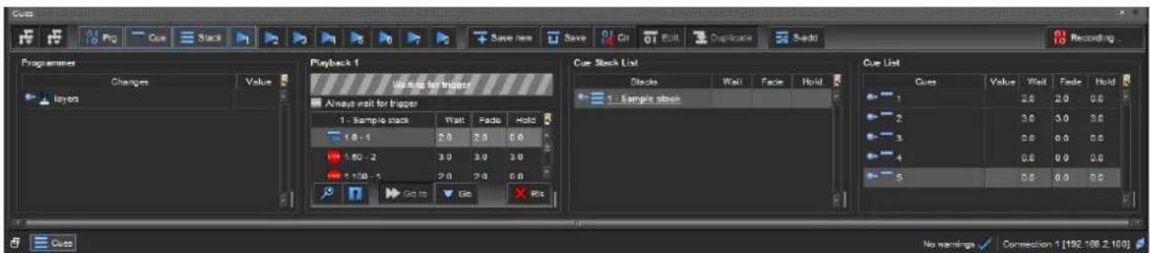
Fig. 27 - Cues panel
In the Cue menu, create presets of Layers (with their parameters) and order them with timing settings. A cue holds visual and non-visual information about a particular media state. A cue is a preset with layers settings to create a specific view on the displays. For example, cues can time media states or run a sequence of different media states. Cues are organized in Cue Stacks.
9.1 Presentation
9.1.1 How cues work
By default, any modification in the Displays or Layers tab is marked in Green, which indicates that it is recorded in a cue. The cue records the last assigned value for an unchanged parameter (not always the default parameter value). It is possible to record unchanged or default values into a cue manually.
A change in a cue depends on difference between the output from the previous cue and the current cue. A parameter only changes if it is defined in the cue.
| Cue | Parameter 1 | Parameter 2 | Parameter 3 |
| Call Cue 1 | 10 | 20 | 30 |
| Call Cue 2 | 20 | no change (keep 20) | 35 |
| Call Cue 3 | no change (keep 20) | 25 | 40 |
| Call Cue 2 | 20 | no change (keep 25) | 35 |
Table 7 - Cue logic example
In the example above, parameter 2 remains at value 20 when cue 3 is played after cue 2, because no change is recorded for it. And parameter 2 remains at value 25 when cue 2 is played after cue 3.
9.1.2 Timings (Wait, Fade and Hold)
A cue is associated with timing settings: Wait, Fade and Hold.
- Wait – Time before executing the content
- Fade – Time of the execution of the content
- Hold – Time before the next Cue (for Automatic trigger)

Fig. 28 - Cue timing example
The previous example shows two cues: Cue 1 and Cue 2.
- Cue 1 has an intensity value of 100.
- Cue 2 has an intensity value of 0.
- The intensity starts at 0 and progressively increases to 100 at the fade of Cue 1.
- After the end of Cue 1, Cue 2 starts.
- The intensity progressively decreases to 0 at the fade of Cue 2.
It is possible to set Default Cue timings for all cues and custom wait and fade times for specific cues. In case of conflict, the custom timings prevail. Otherwise a cue is complete when the cue hold time is finished.
Note: Cues can run for a longer time than the timing values indicated in the Cues panels.
![graph TD A["wait 1s"] --> B["Layer 1 intensity default timing"] B --> C["Layer 2 intensity wait 0.5, fade default"] C --> D["Layer 3 intensity wait 0, fade default"] D --> E["Layer 4 intensity wait 3.5, fade 0"] E --> F["Hold 1s"]](/content/2026/05/869927/images/d66ac557b508cf778ed7839cdccae159353600ca326f9f568b6b0e7db74a2dbf.jpg)
Fig. 29 - Timing parameters for layers 2, 3 and 4 override default cue timings
Fade exceptions
The following parameters do not fade but will take the new value at start of fade:
- Media selection / FX selection
- Deinterlacing type
- Draw mode / Play mode
- Scaling algorithm
- Timecode settings
- Layer synchronization
- Media end action
- Frame blending
- FPS mode
9.1.3 Trigger
A trigger is the transition from one cue to next inside a cue stack. It can be manual or automatic:
- Manual: The user must click the Go button to trigger the next cue.
- Automatic: The next cue is triggered after the previous cue has been completed (wait + fade + hold).
9.2 Creating Cues
9.2.1 Create the first Cue
- Make sure the Layers menu, Cue menu and cue panels are opened.
- On the Layers menu, click Reset all to have default settings in all the layer controls.
- On the Cues panel, click the S-add button to create a new Cue stack. The new stack is activated, new Cues are automatically added to this Cue stack.
- Click the Clr button to clear the Programmer.
- Make adjustments on the layer controls to create a media state. Values turn green to indicate the change has been recorded to the Programmer.
- Hold Alt and click a parameter to manually select or deselect it from the Recorded selection.
- Click Save new to save the Cue. The new cue item appears in the Cue list and the Programmer gets cleared.
Saving a cue empties the Programmer and makes it ready for the next one.
Tips:
- Name the cues to have a clear list using right-click then Rename.
- Check the parameters recorded in the Programmer before saving a Cue.
- Clear the Programmer before creating a Cue.
9.2.2 Cue List
All the created cues are available in the Cue List.
- Click the C-add button to add a new Cue to the Cue list.
This new cue is active. Hold Shift and click C-add to add a new cue without activating it. The current cue stays active. - Set the timings settings (Wait, Fade and Hold) for each cue.
- Right-click a cue and select Run to test it. Select Edit to open the cue in the Programmer to see the saved control states. If needed, make adjustments then click Save.
Tip: Click the Recording... button to stop recording layer controls.
9.2.3 Stop cue
A stop cue is a cue with the default values of all the layer controls. It ensures the next cue starts from the default settings.
- Select all layers in the Layer list (using Ctrl + A or Holding Shift + click).
- Right click the list and select Toggle in programmer. All layers are set to Default value.
- Create a cue with default values on all layers and name it "Stop Cue".
Tip: Create a "stop cue" and put it at the end of each stack.
Note: It is also possible to reset to default values manually by clicking Reset all between cue stacks.
9.3 Cue Stacks
A cue stack is a sequence that runs the cues in ascending order. Create as many stacks as needed. For example, a media show in a music concert might have a cue stack for each song.
9.3.1 Create a cue stack
-
Click S-add to create a cue stack.
-
Create cues or select cues in the Cue List and drag and drop them in the stack.
-
Order the cues inside the stack.
-
Create cue stacks as needed for the show.
-
Each cue in a cue stack is a reference to the original cue in the Cue list. This reference is called Cue Stack Entry or CSE).
Caution: Use a cue once per Cue Stack. Reusing the same cue too many times might produce unpredictable results.
9.3.2 Remove a cue from a cue stack
Right-click a cue in a stack and select Remove to remove it from the stack. This only removes it from the cue stack and does not delete the cue. The CSE is removed but the cue is still present in the Cue List.
9.3.3 Change trigger type
Right-click a cue in the stack to change trigger type. Choose between Manual and Automatic depending on whether to trigger the cue manually or want it to run automatically after the previous cue. This can be done either in the Cue Stack List or in the Playback list.
9.3.4 Order cues in the stack – Index number
Order cues in the stack by using drag and drop or custom index number.
- Drag and drop a cue in a stack to change its position in the sequence.
Index number
Each Cue Stack Entry (CSE) has a Major index number and a Minor index number. CSEs are ordered by Major index number in ascending order. The Minor index number is used in case of equal Major index number.
- Right-click a cue in a stack and select Move, then enter the index numbers.
For example, to move a cue between cues numbered 5.0 and 6.0, enter a major index number 5 and a minor index number 1.
9.4 Timing and Running Cues in Playback
Picturall Series Media Servers can run up to three cue stacks simultaneously using the three different playback areas in the cue system. Separate playbacks are useful to play different sequences of media on different displays.
To run a cue stack in playback:
- Click

open Playback 1.
-
Drag a cue stack to Playback 1. One playback can only play one stack at a time.
-
If needed, right-click the cue stack in the playback list to change its trigger type (Manual or Automatic).
-
Tick the Always wait for trigger box to manual trigger for every cue in the Playback.
-
Click Go at the bottom of the Playback area to run the playback. Select a cue and click Go to skip to a specific cue.
-
Enter timings for the cues in the Wait, Fade and Hold columns.
-
Click RIs to release the cue stack from the playback. This only removes the cues from playback, not from the cue stack list or the cue list.
Note: If a show is exported with cue stacks in one of the Playback areas, rebooting the server will automatically start playing the cues in the stack.
9.5 Example Show
Let us create a simple show in which one media layer is playing in the background and another layer is on top of it with a logo (still image) on it. Using cues, the logo will move from the left side of the projection area to the right side.
To achieve this, do the following:
- Open the Cues panel and make sur Recording... is enabled.
- Go to Layers, select a background media and play it on Layer 1 (a green border appears around these controls).
- In Cues, click Save new to create a cue with the recorded media state. A new cue appears in the Cue list.
-
In Layers, select the logo image in the Media selection panel of Layer 2, play it and use the position controls to place it on the left side of the composition.
-
Make sure that media selection, play mode and position control adjustments are recorded on the Programmer.
-
In Cues, click Save new to create a new cue.
-
In Layer 2, use the position controls to move the logo to the right side of the composition.
-
In Cues, click Save new to save the position change to a new cue.
Three cues are created in the Cue List: a background media without logo, the background media with the logo on the left and the background media with the logo on the right.
-
Click S-add to create a new cue stack in the Cue stack list. Select the cues and drag them into this stack.
-
Drag the stack into Playback 1.
-
Select the first cue in the Playback list and click Go.
-
Enter timings for each cue (Wait, Fade and Hold).
- Right-click a cue to change its trigger type (Manual or Automatic).
o In Manual mode, keep clicking Go to go through the three cues of the Playback.
9.6 Live show recommendations
Here a few tips and recommendations for live show setup:
- Create a "Stop cue" and put it at the end of each cue stack.
- Use separate playbacks to play different sequences of media on different displays.
- Set the User Interface so that the Cues, Layers, and Performance panels are visible.
- When live, use the Layers panel only for adjusting minor things such as audio volume.
- Hide the Displays. GPU and other tabs that do not directly affect the show.
- Set hotkeys on the keyboard to play specific Playbacks (Edit > Options > Keymap), by default F9, F10 and F11 play Playback 1, 2 and 3 respectively.
9.7 Cue macro
A cue macro is an action associated to a Cue or a Cue stack.
Note: - Cue macro and Layer macro are different concepts.
- A saved show (.pcf file) containing Cue macros can only be loaded on Picturall Commander from version 2.6 and onwards.
9.7.1 Cue macro and Cue stack macro
9.7.1.1 Cue macro
A cue macro is associated to a cue and affects all CSEs of this cue.
- The cue macro is executed when the cue is executed.
To create a cue macro:
- Right-click a cue in the Cue List (or a CSE in a Cue stack) then click Edit macro...
9.7.1.2 Empty cue
It is possible to create a cue macro on an empty cue (a cue with no layer change).
To create an empty cue:
- Right-click a cue in the Cue List then click Add cue.
Note: It is also possible to delete the parameters of an existing cue to make it empty.
9.7.1.3 Cue stack macro
A Cue stack can have two types of macro associated to it: entry macro and exit macro.
- The entry macro is executed when the Cue stack is loaded in a playback.
- The exit macro is executed when the Cue stack is released from a playback.
To create a Cue stack macro:
- Right-click a Cue stack in the Cue Stack List then click Edit entry macro... or Edit exit macro...
9.7.2 Cue macro actions
Tip: A little "M" appears next to the Cue number (or Cue stack number) to indicate that a Cue macro is enabled.
When creating a Cue macro, the following window opens and four macro actions are available:
- Trigger a specific cue
- Trigger a specific playback
- Send a network command
- Custom macro

Fig. 30 - Cue macro
9.7.2.1 Trigger cue macro
This executes a cue when a macro is executed.
- Click Trigger cue.
- Click the dropdown list and select a cue.
- Click OK.
9.7.2.2 Trigger playback
This executes a playback when a macro is executed.
- Click Trigger playback.
- Click the dropdown list and select a playback number.
- Click OK.
9.7.2.3 Trigger network command
This sends a custom command to a device connected on the same network when a macro is executed.
- Click Trigger network command.
- Enter the target address and port number.
- Enter the command to be sent.
- Choose the Line separator.
- Click OK.
9.7.2.4 Macro content and Custom macro command
When creating a cue macro, the content of the macro is displayed in the Macro content section.

Fig. 31 - Macro content
Cue macros are written in Lua language. Using a custom macro, it is possible to write anything in Lua in the content section. For example, a custom macro can be used to trigger multiple cues and playbacks and send a network command at the same time.
Tip: - Click an action to load a command then click custom macro to edit the content. - The command list is available in a document enclosed to this User Manual.
To create a custom cue macro:
- If needed, click any action to load the content.
- Click Custom macro.
- Edit the content to create a custom command.
- Click OK.
Note: Custom macro does not have syntax validation. Enter custom commands carefully.
9.7.3 Edit or remove a cue macro
To edit a cue macro:
- Right-click a Cue or a Cue stack then click Edit macro...
- Edit the cue macro then click OK.
To remove a cue macro:
- Right-click a Cue or a Cue stack then click Edit macro...
- Click Remove macro.
10 Miscellaneous
10.1 Save a show
Save a show to recover it or to reuse it on another computer using Picturall Commander.
- Run Picturall Commander.
- Go to File > Save show.
- Select a folder and enter a filename.
- Click Save.
The show is saved in a PSF file.
- Go to File > Load show to load a show.
10.2 Performance

Fig. 32 - Performance menu
In the Performance menu, monitor the performance of the system as graphs. Use the Enabled checkboxes to show/hide the corresponding graphs.
Tip: These metrics are useful to show potential problems.
| Graph | Description |
| CPU | Average workload."1" means the load is equivalent to a single CPU core being fully loaded."8" means that 8 cores are fully loaded.If the value is higher than number of CPU cores installed, the CPUs is doing more than it can handle. However, this value does not reflect the smoothness of the playback. The average workload can get high without affecting playback quality. |
| CPU_TEMP | CPU temperature in Celsius degrees. |
| GPU | GPU refresh rate. The server unit's performance is fine if the indicator values match the display's refresh rate. In this example the display refresh rate is 60. |
| GPU_DRAW | Time it takes GPU to draw one single frame. If GPU_DRAW reaches 80% of GPU_SWAP, lower GPU load (effects, resolutions, active layers). |
| GPU_MEM | The amount of memory used by the GPU. |
| GPU_SWAP | Time it takes GPU to show one frame (except when Triple buffering is enabled). This should always be 16.67 ms for 60Hz displays. |
| GPU_TEMP | GPU temperature in Celsius degrees. |
| GPU_TEX | The amount of data transferred to the GPU (in megabytes per second). |
Table 8 - Performance
10.2.1 Toggle view
On the top left of the Performance tab toolbar are the view buttons:

Toggle between graph and table view, or both of them side by side horizontally or vertically.
10.2.2 Refresh
On the top right corner, set refresh rate, turn refreshing on/off and manually refresh the graphs.
10.2.3 Color
In the Color column in the table, click the [...] buttons on every row to set the color scheme of the graph view.
10.3 Timecode
In the Timecode menu, set the timecode format and offset it by time or frames.

The Timecode format and Timecode offset fields show the current values.
- In Timecode source, click the dropdown and select the layer to output the timecode from. Or select OFF to disable sending the outgoing timecode.
- Click Edit and enter new values in the MTC Settings dialog.
10.4 Control Model
The Control Model is a tree structure of all the control groups and the controls in them. It is mostly used when programming custom control systems.
![Control Model Control Model [Connection 1] displays gpus layers alsamixer artnet1 canvas1 citp cue_system encoder file_watch fx_info gl_help monitor mtc performance_watch](/content/2026/05/869927/images/603603ba7e6d48b662e870ac6789df97c3af233f2f0e0670bb5f078a3442b78c.jpg)
- Open both the Control Model and Properties tab.
- Click in the tree structure to view control-specific information and view the information on the Properties tab.
10.5 Commander Log
Every action taken in Picturall Commander is logged.
- Go to View > Commander Log... to open the panel.
Seeing the command format is useful for advanced Linux users as Picturall Commander can be controlled via sent commands.
11 User maintenance and Troubleshooting
11.1 User Maintenance – EMC air filter
Tip: For optimal performance, this air filter must be cleaned by the user regularly (once a year).
The Picturall Series Media Server is equipped with a removable EMC air filter at the front of the Series Media Server.
Tools: Phillips screwdriver size 2, duster or vacuum.
- Turn the media server off and unplug mains.
- Remove the four screws on the front panel.
- Using both hands, gently pull the front panel on a straight axis.
- Gently tilt it down until mechanical stop.
The front panel is in safe still position.
- Pull the air filter and take it out from the media server.
- Carefully clean the air filter with a duster or vacuum.
- When the air filter is clean, gently put it back in place.
- Gently tilt up the front panel until it is aligned.
- Gently push the front panel back in place on a straight axis.
- Set the screws back in place.
The air filter is cleaned and the media server is ready for use.
11.2 System Diagnostics
System diagnostics are used for technical support. It is a file exported from Picturall Commander to be sent to technical support.
To export the system diagnostics file:
- Go to File > Get system diagnostics.
- Save the file on the computer.
11.3 Troubleshooting
Picturall Commander installation failure
- Make sure Java version 8 is installed on the computer.
- Make sure Java version 9 is not installed on the computer as this version is not compatible with Picturall Commander.
Layer control > Advanced: Dropdown menus are not visible
- Make sure Java version 8 is installed on the computer.
Unable to Connect to the Server
- Verify that the server and the computer running Picturall Commander are using the same netmask.
- Verify that the server IP-address is correct.
- Verify that the network is running correctly with a ping command.
- Verify that there is no more than one DHCP server in the network.
- Verify that the firewall is not blocking the connection.
Video Playback is not smooth
- Disable unused displays.
- Verify there are no playing back of layers that are not visible: select all layers in the Layer list, right-click on them and select Stop. Then click Play on the desired layers only.
- Too many layers or too high resolutions are in use. Playback performance is 4-16 layers of FullHD depending on the display setup, codecs and bitrates.
- Simultaneous use of displays with different refresh rates. Force resolution and refresh rate in the Configurator.
Video output has poor resolution
- Disable unused outputs.
- Position displays using the same graphic card closer to each other and optimize the pixel space in the GPUs tab.
"Cable disconnected" error message keeps displaying
- Stop all playbacks.
APPENDICES
Appendix A. DMX chart
PICTURALL V2.5
DMX Chart - Layer full
LAYER SIZE AND POSITION:
- Composition canvas has coordinates from 0,0 to 1,1 with 0,0 being the bottom left corner
- Layer default position is 0.5, 0.5 (32768, 32768 in DMX values).
- Position coordinate is the layer center point coordinate.
- Default scale for layer is 1.0 (32768 in DMX values). Default layer width is 1.0 in canvas coordinates.
- Layer height is affected by media Aspect ratio and Aspect-control. Media default Aspect is used when Aspect is 1.0.
- Aspect ratio height multiplier derived from media aspect ratio and scale.
- For Scale and Aspect value, descriptions contain physical value multiplier. For example, "7 x" in Scale means the layer is seven times larger is scaled and "7 x" in Aspect means the media aspect ratio is multiplied by seven.
LAYER:
| DMX COARSE | DMX FINE | Name | Description | Values | Values description | Default Value | Home/ locate value |
| 1 | Intensity | 0 | 255 | ||||
| 2 | 3 | X | Layer X position | 0-65535 | Coordinate ranges from -5 to 5 | 32768 | 32768 |
| 4 | 5 | Y | Layer Y position | 0-65535 | Coordinate ranges from -5 to 5 | 32768 | 32768 |
| 6 | 7 | Rotation | 0-65535 | 32768 | 32768 | ||
| 0-16383 | Continuous rotation counterclockwise, 240 RPM - 0 RPM | ||||||
| 16384 | Indexing rotation counterclockwise 360' | ||||||
| 16385-32767 | Indexing rotation counterclockwise | ||||||
| 32768 | Center position | ||||||
| 32769-49151 | Indexing rotation clockwise | ||||||
| 49152 | Indexing rotation clockwise 360' | ||||||
| 49153-65535 | Continuous rotation clockwise, 0 RPM - 240 RPM | ||||||
| 8 | 9 | Scale | 0-65535 | 32768 | 32768 | ||
| 0 | Mirrored and flipped layer max size, -5 x | ||||||
| 1-21844 | Mirrored and flipped layer upscaling, -5 x | ||||||
| 21845 | Mirrored and flipped layer fullscreen, -1 x | ||||||
| 21846-27306 | Mirrored and flipped layer downscaling -1 x - 0 x | ||||||
| 27307-32767 | Layer downscaling, 0 x - 1 x | ||||||
| 32768 | Layer fullscreen, 1 x | ||||||
| 32769-65534 | Layer upscaling, 1 x - 7 x | ||||||
| 65535 | Layer upscaling max size, 7 x | ||||||
| 10 | 11 | Aspect | Vertical Scaling | 0-65535 | 32768 | 32768 | |
| 0 | Flipped layer upscaling max size, -5 x | ||||||
| 1-21844 | Flipped layer upscaling, -5 x - -1 x | ||||||
| 21845 | Flipped layer original aspect ratio, -1 x | ||||||
| 21846-27306 | Flipped layer downscaling, -1 x - 0 x | ||||||
| 27307-31402 | Layer downscaling, 0 x - 0.75 x | ||||||
| 31403 | 4:3 -> 16:9 conversion, 0.75 x | ||||||
| 31404 - 32767 | Layer downscaling, 0.75 x - 1 x | ||||||
| 32768 | Layer original aspect ratio, 1 x | ||||||
| 32769 - 34587 | Layer upscaling, 1 x - 1.33333 x | ||||||
| 34588 | 16:9 -> 4:3 conversion, 1.33333 x | ||||||
| 34589 - 65534 | Layer upscaling, 1.33333 x - 7 x | ||||||
| 65335 | Layer upscaling max size, 7 x | ||||||
| 12 | Draw mode | 0 - 255 | Check ranges table | 0 | 0 | ||
| 13 | Media index | 0 - 255 | 0 | No value | |||
| 14 | Media library | 0 - 255 | 0 | No value | |||
| 15 | Media mode | 0 - 255 | Check ranges table | 0 | 0 | ||
| 16 | FPS | 0 - 255 | 112 | 112 | |||
| 0 | Media default fps | ||||||
| 1 - 63 | 1 - 63 fps fixed playback | ||||||
| 64 - 160 | 0% - 200% relative playback speed | ||||||
| 112 | Media default fps | ||||||
| 161 - 255 | Reserved (frame blending) | ||||||
| 17 | 18 | Seek | Seek to position | 0 - 65535 | No value | No value | |
| 0 | Beginning of the media | ||||||
| 65535 | End of the media | ||||||
| 19 | Audio volume | 0 - 255 | 0 | 255 | |||
| 20 | Reserved | Reserved | No value | No value | |||
| 21 | Reserved | Reserved | No value | No value | |||
| 22 | Sync source | Layer sync source (V1.2 and later) | 0 | Internal (no sync) | 0 | 0 | |
| 1 - 128 | Sync to layer 1 - 128 | ||||||
| 255 | Sync to MTC | ||||||
| 23 | Saturation | 0 - 255 | 128 | 128 | |||
| 0 - 127 | Less saturation | ||||||
| 128 | Default | ||||||
| 129 - 255 | More saturation | ||||||
| 24 | Brightness | 0 - 255 | 128 | 128 | |||
| 0 - 127 | Less brightness | ||||||
| 128 | Default | ||||||
| 129 - 255 | More brightness | ||||||
| 25 | Contrast | 0 - 255 | 128 | 128 | |||
| 0 - 127 | Less contrast | ||||||
| 128 | Default | ||||||
| 129 - 255 | More contrast | ||||||
| 26 | Gamma | 0 - 255 | 128 | 128 | |||
| 0 - 127 | Low gamma | ||||||
| 128 | Default | ||||||
| 129 - 255 | High gamma | ||||||
| 27 | Brightness Red | 0 - 2550-127 | Reduce Red | 128 | 128 | ||
| 128 | Default | ||||||
| 129-255 | Increase Red | ||||||
| 28 | Brightness Green | 0-255 | 128 | 128 | |||
| 0-127 | Reduce Green | ||||||
| 128 | Default | ||||||
| 129-255 | Increase Green | ||||||
| 29 | Brightness Blue | 0-255 | 128 | 128 | |||
| 0-127 | Reduce Blue | ||||||
| 128 | Default | ||||||
| 129-255 | Increase Blue | ||||||
| 30 | Contrast Red | 0-255 | 128 | 128 | |||
| 0-127 | Reduce contrast for Red color | ||||||
| 128 | Default | ||||||
| 129-255 | Increase contrast for Red color | ||||||
| 31 | Contrast Green | 0-255 | 128 | 128 | |||
| 0-127 | Reduce contrast for Green color | ||||||
| 128 | Default | ||||||
| 129-255 | Increase contrast for Green color | ||||||
| 32 | Contrast Blue | 0-255 | 128 | 128 | |||
| 0-127 | Reduce contrast for Blue color | ||||||
| 128 | Default | ||||||
| 129-255 | Increase contrast for Blue color | ||||||
| 33 | FX1 Library | FX1 Library | 0-255 | Select FX (look at FX Assignment sheet) | 0 | 0 | |
| 34 | FX1 Index | FX1 Index | 0-255 | Select FX | No value | No value | |
| 35 | FX1 Param1 | FX1 Param1 | 0-255 | No value | No value | ||
| 36 | FX1 Param2 | FX1 Param2 | 0-255 | No value | No value | ||
| 37 | FX1 Param3 | FX1 Param3 | 0-255 | No value | No value | ||
| 38 | FX1 Param4 | FX1 Param4 | 0-255 | No value | No value | ||
| 39 | FX1 Param5 | FX1 Param5 | 0-255 | No value | No value | ||
| 40 | FX1 Param6 | FX1 Param6 | 0-255 | No value | No value | ||
| 41 | FX1 Library | FX1 Library | 0-255 | Select FX | 0 | 0 | |
| 42 | FX1 Index | FX1 Index | 0-255 | Select FX | No value | No value | |
| 43 | FX1 Param1 | FX1 Param1 | 0-255 | No value | No value | ||
| 44 | FX1 Param2 | FX1 Param2 | 0-255 | No value | No value | ||
| 45 | FX1 Param3 | FX1 Param3 | 0-255 | No value | No value | ||
| 46 | FX1 Param4 | FX1 Param4 | 0-255 | No value | No value | ||
| 47 | FX1 Param5 | FX1 Param5 | 0-255 | No value | No value | ||
| 48 | FX1 Param6 | FX1 Param6 | 0-255 | No value | No value | ||
| 49 | Reserved | Reserved | No value | No value | |||
| 50 | Reserved | Reserved | No value | No value | |||
| 51 | Reserved | Reserved | No value | No value | |||
| 52 | Reserved | Reserved | No value | No value | |||
| 53 | Reserved | Reserved | No value | No value | |||
| 54 | Reserved | Reserved | No value | No value | |||
| 55 | Reserved | Reserved | No value | No value | |||
| 56 | Reserved | Reserved | No value | No value |
RANGES:
| Parameter | Value | Name | Description |
| Draw mode | 0 | Additive | Add layer intensities |
| 1 | Replace | Replace lower layer | |
| 2 | Subtract | Subtract upper layer from lower layers | |
| 3 | Darken | Select darker parts of upper and lower layers | |
| 4 | Lighten | Select lighter parts of upper and lower layers | |
| 5 | Multiply | Multiply layer intensities | |
| 6 | Linear burn | Linear burn (Subtract variant) | |
| 7 | Screen | Screen layers (opposite of Multiply) | |
| Media mode | 0 | Media default | |
| 1 | Play Next | Play next media after current | |
| 2 | Play Stop | Stop after playing current media | |
| 3 | Play Pause | Pause on the last frame of current media | |
| 4 | Play Loop | Loop current media | |
| 5 | Pause | ||
| 6 | Stop | ||
| 10 | Play Loop collection | Play next media and after last media in collection, replay from the first one. |
EFFECTS:
| FX NAME | Library | Index | Parameter 1 | Parameter 2 | Parameter 3 | Parameter 4 | Parameter 5 | Parameter 6 |
| Wave | 1 | 1 | Amplitude | Amplitude aspect | Frequency | Frequency aspect | Speed | |
| Water Ripple | 1 | 2 | Size | X | Y | |||
| Blur | 2 | 1 | Size | |||||
| Heavy blur | 2 | 2 | Blur size | |||||
| Gaussian blur | 2 | 3 | Blur size | |||||
| Radial Blur | 2 | 4 | Size | Amount | ||||
| Radial Blur Advanced | 2 | 5 | Size | Amount | Blur center X | Blur center Y | ||
| Directional Blur | 2 | 6 | Blur size | Angle | ||||
| Glow | 2 | 7 | Threshold | Glow size | ||||
| Chromakey | 3 | 1 | Threshold | Red key | Green key | Blue key | Smoothing | |
| Chromakey Inverse | 3 | 2 | Threshold | Red key | Green key | Blue key | Smoothing | |
| Lumakey | 3 | 3 | Accuracy | Key | Smoothing | |||
| Lumakey Inverse | 3 | 4 | Accuracy | Key | Smoothing | |||
| Alpha Fill | 3 | 5 | ||||||
| Alpha Fill inverse | 3 | 6 | ||||||
| Alpha Key | 3 | 7 | ||||||
| Quick Border | 4 | 1 | Amount of border | Outside blur | Inside blur | Border color red | Border color green | Border color blue |
| Edge Blur | 4 | 2 | Blur amount | |||||
| Mask | 4 | 3 | Mask left | Mask right | Mask top | Mask bottom | ||
| Keystone | 4 | 4 | On/Off | Left side | Right side | Top side | Bottom side | |
| 3D Plane | 5 | 1 | X Rotation | Y Rotation | Z Rotation | Continuous rotation speed | FOV | Material mode |
| 3D Cube | 5 | 2 | X Rotation | Y Rotation | Z Rotation | Continuous rotation speed | FOV | Material mode |
| 3D Sphere | 5 | 3 | X Rotation | Y Rotation | Z Rotation | Continuous rotation speed | FOV | Material mode |
| Sepia | 6 | 1 | Amount | |||||
| Inverse | 6 | 2 | ||||||
| Halftone | 6 | 3 | Amount | |||||
| Halftone Advanced | 6 | 4 | Amount | Background Red | Background Green | Background Blue | Background Transparency | |
| Comic | 6 | 5 | Amount | |||||
| Pixelize | 6 | 6 | Amount | |||||
| Edge Laplace | 7 | 1 | Mixing | Laplace amount | ||||
| Edge Laplace Add | 7 | 2 | Amount | |||||
| Sharpening | 7 | 3 | Radius | |||||
| Pencil Sketch | 7 | 4 | Amount | Intensity | ||||
| Cartoon | 7 | 5 | Border | Intensity | ||||
| Tiles | 8 | 1 | Scale | |||||
| Kaleidoscope | 8 | 2 | Amount | Shape | Scale | Zoom | Speed | Amplitude |
| Drop Shadow | 9 | 1 | Opacity | X Offset | Y Offset | Color Red | Color Green | Color Blue |
PICTURALL V2.5
Ranges are same as in full layer
| DMX COARSE | DMX FINE | NAME |
| 1 | Intensity | |
| 2 | 3 | X |
| 4 | 5 | Y |
| 6 | 7 | Rotation |
| 8 | 9 | Scale |
| 10 | 11 | Aspect |
| 12 | Draw mode | |
| 13 | Media index | |
| 14 | Media library | |
| 15 | Media mode | |
| 16 | FPS | |
| 17 | Audio Volume | |
| 18 | Reserved |
PICTURALL V2.5
DMX Chart - Master
| DMX COARSE | Name | Description | Values | Values description | Default Value | Home/ locate value |
| 1 | Grid width | Number of displays in a display grid horizontally | 0 – 255 | Number of columns in a display grid | 1 | 1 |
| 2 | Grid height | Number of displays in a display grid vertically | 0 – 255 | Number of rows in a display grid | 1 | 1 |
| 3 | Blend size | Amount of blend overlap in percentage | 0 – 255 | Blend the edges of adjacent displays | 0 | 0 |
| 4 | Blend gamma | Blend gamma value | 0 – 255 | Gamma correction on blend area | 128 | 128 |
| 0 – 128 | Less intense blend gamma (0.00 to 0.45) | |||||
| 128 | Default value: 0.45 | |||||
| 128 – 255 | More intense blend gamma (0.45 to 0.90) | |||||
| 5 | Aspect ratio | Select display aspect ratio | 0 – 255 | 3 predefined values | ||
| 0 | 16:9 (default) | |||||
| 1 | 4:3 | |||||
| 2 | 16:10 | |||||
| 3 – 255 | 16:9 (ignored) | |||||
| 6 | Test images | Test images | 0 – 255 | Show test images on display | 0 | 0 |
| 0 | None (default) | |||||
| 1 | Display numbers (DN) | |||||
| 2 | DN + Blend areas | |||||
| 3 | DN + Display borders | |||||
| 4 | DN + Display grid | |||||
| 5 | DN + Control points | |||||
| 6 | DN + Selected display grid | |||||
| 7 | DN + Layer borders | |||||
| 8 | Layer numbers (disables Display numbers) | |||||
| 9 | DN + Blue background | |||||
| 10 | DN + Canvas grid | |||||
| 11 | DN + Canvas lines all (horizontal, vertical, diagonal) | |||||
| 12 | DN + Canvas lines only horizontal | |||||
| 13 | DN + Canvas lines only vertical | |||||
| 14 | DN + Canvas lines only 45 degrees diagonal | |||||
| 15 | DN + Canvas lines only 135 degrees diagonal | |||||
| 16 | DN + Canvas lines horizontal and vertical | |||||
| 17 | DN + Canvas lines horizontal and 45 degrees diagonal | |||||
| 18 | DN + Canvas lines horizontal and 135 degrees diagonal | |||||
| 19 | DN + Canvas lines vertical and 45 degrees diagonal | |||||
| 20 | DN + Canvas lines vertical and 135 degrees diagonal | |||||
| 21 | DN + Canvas lines diagonal of 45 and 135 degrees | |||||
| 22 – 255 | None (ignored) |
PICTURALL V2.5
DMX Chart - Display
| DMX COARSE | DMX FINE | Name | Description | Values | Values description | Default Value | Home/ locate value |
| 1 | Display position | 0 – 255 | 0 | 0 | |||
| 0 | Display not affected by setup, keeps previously set values | ||||||
| 1 – 254 | Display position. Display within grid size is enabled. Display out of grid is disabled. | ||||||
| 255 | Reset display position and grouping | ||||||
| 2 | 3 | Keystone TL X | Keystone top left X | 0 – 65535 | Moves coordinate 0 – 0.5 units towards the center | 0 | 0 |
| 4 | 5 | Keystone TL Y | Keystone top left Y | 0 – 65535 | Moves coordinate 0 – 0.5 units towards the center | 0 | 0 |
| 6 | 7 | Keystone TR X | Keystone top right X | 0 – 65535 | Moves coordinate 0 – 0.5 units towards the center | 0 | 0 |
| 8 | 9 | Keystone TR Y | Keystone top right Y | 0 – 65535 | Moves coordinate 0 – 0.5 units towards the center | 0 | 0 |
| 10 | 11 | Keystone BR X | Keystone bottom right X | 0 – 65535 | Moves coordinate 0 – 0.5 units towards the center | 0 | 0 |
| 12 | 13 | Keystone BR Y | Keystone bottom right Y | 0 – 65535 | Moves coordinate 0 – 0.5 units towards the center | 0 | 0 |
| 14 | 15 | Keystone BL X | Keystone bottom left X | 0 – 65535 | Moves coordinate 0 – 0.5 units towards the center | 0 | 0 |
| 16 | 17 | Keystone BL Y | Keystone bottom left X | 0 – 65535 | Moves coordinate 0 – 0.5 units towards the center | 0 | 0 |
| 18 | 19 | Angle X | Angle correction by X | 0 – 65535 | Horizontal distortion to compensate tilted viewing angle. Range - 0.0 – 1.0 | 32768 | 32768 |
| 0 | 0.0 No distortion (default) | ||||||
| 20 | 21 | Angle Y | Angle correction by Y | 0 – 65535 | Vertical distortion to compensate tilted viewing angle. Range - 0.0 – 1.0 | 32768 | 32768 |
| 0 | 0.0 No distortion (default) |
Appendix B. BIOS setup
Press the Del button on startup to access BIOS settings.
Tip: Load default settings and reboot the server before modification (Exit > Load Setup Defaults).
Here are the default Pro BIOS settings:
- Advanced > SATA Configuration > SATA Mode > AHCI Mode
- Advanced > SATA Configuration > S.M.A.R.T Status Check > Disabled
- Advanced > Onboard devices configuration > Azalia HD Audio > Disabled
- Advanced > Onboard devices configuration > Intel LAN1 Controller > Disabled
- Advanced > Onboard devices configuration > Intel LAN2 PXE OPROM > Enabled
- Advanced > Onboard devices configuration > Asmedia USB 3.0 Controller > Disabled
- Advanced > Onboard devices configuration > Marvell Storage OPROM > Disabled
- Boot > Boot > Full Screen Logo > Disabled
- Boot > Boot > Wait for 'F1' if error > Disabled
- Boot > Boot > Setup mode > Advanced mode
- Boot > Hard Drive BBS Priorities > SSD first
- Tool > ASUS O.C. Profile > Label "pro_defaults" > Save to Profile "1"
Appendix C. Optimize GPU resolution and drawing performance
This chapter describes how to optimize the GPUs performance when positioning displays.
C.a. Definitions
- GPU Output board consisting of two outputs.
- Output Physical DVI output.
- Display Destination where the picture will be displayed. For example, it could be a single display or a projection surface composed of one or several outputs. Usually there is one display for each output.
- Canvas Total drawing area. Displays are placed inside a canvas.
Note: Using display splitters enables having more than one display for one output.
C.b. Automatic optimization
In the GPUs menu, select a GPU and click Optimize.
The automatic calculation optimizes the graphic card performance with the current display setup.
If the displays are not side-by-side horizontally in the show composition, using the automatic canvas optimization gives the best results.
C.c. Canvas and coordinates
Canvas is the drawing area defined in coordinate system, it is not a pixel space.
Canvas coordinates are in 0.0 - 1.0 range in both X and Y axis and origin is in left bottom corner. A display is positioned in the canvas by setting display X and Y position, display width and height and rotation.
Use the display wizard to set display grids easily.
![Display Group 1 (Shr) [0.0] Display 1 [1.0] Display 2 Position Reset Enabled X (←) 0.0000 Y (←) 0.0000 Width (←) 1.0000 Height (←) 1.0000 Rotation (←) 0.00 Graph Mode: group, relative, no leader display 1 2](/content/2026/05/869927/images/c02c497c6240b6321482596256fbf99184c58ca60835db20e6c6d4ec75436f4b.jpg)
Fig. 33 - 2x1 grip made with Display wizard
Display coordinates are independent of the display resolution and physical aspect ratio. X and Y in display positioning point to the left bottom corner of the display.
- X and Y in layers point to center of the layer.
- When scale and scale height are 1, the layer fills the entire display.
- Layer aspect ratio control adjusts the aspect ratio of content.
- Layer scale controls layer width and height while keeping aspect ratio constant.
C.d. Calculating pixels
Drawing is done independently on all GPUs and each GPU draws only the part of the canvas that is needed by all the displays connected to that GPU. Then GPU draws one rectangular area that covers all the displays.
GPU allocates drawing area that has same resolution as all outputs combined. Output resolutions are composed in horizontal grid except for Matrox TH2GO modes 3x1080p @ 50Hz and 3x1366x768 which have vertical composition.
For example, if GPU is configured for 2 x 1280x1024 resolution, then drawing area will have resolution of 2560 x 1024. For TH2Go 3 x 1280x1024 resolution will be 7680x1024 (2 x 3 x 1280 = 7680). For vertical exceptions 3 x 1366x768 will be 4098x1536 and 3 x 1080p resolution is 5760x2160.
If the displays for GPU are positioned in canvas so that they form similar horizontal (or vertical for the exceptions mentioned before) grid, then displays will have true native resolution 1 .
If displays have gap between them or they have different sizes then scaling will be performed and native resolution might not be archived.
To know actual pixels representing single display, first calculate the total area covered by GPU. Then for each display, multiply the display X and Y resolution by portion of the display width/height of the GPU draw area. With total width (Total_w), total height (Total_h), display size (w and h) and GPU resolution (GPU_w and GPU_h). Equation for display "real" resolution is:
width: GPU _ w × w/Total _ w
height : GPU _ - h × hTotal _ - h
For example, a setup has two displays with resolutions of 1280x1024.
- Display 1 has position 0.0, 0.36 and size 0.5 × 0.28 .
- Display 2 has position 0.82, 0.36 and size 0.18 x 0.10.
- Total width for GPU drawing those displays will be 1: Display 2 has rightmost point in the canvas which is position 0.82 + width 0.18 = 1.0.
- From this we subtract leftmost point, which is inside display 1 and X position is 0. So total width is 1.
Total height is computed similarly, in this case display 1 has both upper and lower limits so area height is same as display 1 height: 0.28.

Fig. 34 - Drawing area example
- GPU_w = 2_1280 = 2560
Then: - GPU_h = 1024
- Total_w = 1
- Total_h = 0:28
- Display 2 w = 0:18 and h = 0:10.
width : 2 5 6 0 × 0 . 1 8/1 . 0 0 = 4 6 0
height: 1 0 2 4 × 0 . 1 0/0 . 2 8 = 3 6 5
The GPU draws Display 1 and 2 in the same pixel space (green area).
Display 2 will have only 460 x 365 pixels representing full display area.
Situation will be even worse in the following situation:

Fig. 35 - Another example of bad performance optimization
Total area is huge compared to either display.
Common situation is for the setup display to be "control monitor" showing everything.
Note: If the control monitor is connected to a GPU that has other displays connected, resolution in those display is going to be bad. This also affects performance.
C.e. Performance
All layer that are even partially inside GPU draw area are drawn in that GPU. Videos playing on those layers have to be transferred to the GPU by PCIe bus and the layers have to be drawn. This requires lot of resources from PCIe bandwidth and GPU processing power. This is particularly troublesome in control monitor situation.
C.f. Conclusion
To get optimal performance and resolution for displays:
- Position displays that are connected to same GPU as close to each other as possible
- Avoid setups where many displays show same area of canvas
Appendix D. Picturall Pro communication protocol specifications
D.a. Locating Pro on network
Pro listens to multicast group 224.0.0.180 port 11009. When it receives message "HELLO", it responds with a UDP packet containing following data:
/**
 * Structure for Pro identification over network.
 *
 * All strings use UTF-8 character encoding and are always null terminated if
 * not otherwise specified.
 *
 * If string doesn't fit into the allocated buffer it will be silently
 * truncated, but will remain null terminated.
 *
 * bc_version is currently 1. If you get larger values, then protocol has been
 * changed and you should discard the packet and get updated specifications
 * from Picturall.
 * */
struct bcast_identity_s {
char magic[16]; // "PICTURALL SERVER" (no null termination)
uint32_t bc_version; // bcast protocol version network byte order
char ip[32]; // null terminated TP-address
char name[32]; // null terminated host name
char version[32]; // null terminated server version string
} __attribute__ ((packed));
Clients can then connect to a given IP address and use the version field for detecting compatible versions.
D.b. Connecting to Pro
Communication with Picturall Pro works through TCP/IP based telnet-like connection to Pro command line. Client starts communication by connecting to Pros IP address and port 11000. You can then send commands to Pro.
For example, you can telnet 10.0.0.1 11000 on the command line on a Windows or a Mac computer. This grants you access to the Pro command line. You can then enter config on the command line. Pro should print current version number and some internal configuration data.
When you connect to Pro you should immediately send following command:
wait\startup
This command waits until Pro startup procedure and show loading is completed. If you connect while Pro startup is still in progress you might get unexpected results or even hanging due to other commands being sent. If Pro startup is already completed when this command is given, the command will not do anything.
D.b.a. Compatibility with older versions
If you need compatibility with 1.2 series and older Pros you need to send following special hexadecimal characters: 0xFF 0xFE 0x01 0x0A. They have to be sent immediately after connection has been established (even before wait_startup command)
D.c. Control model
Pro has three layers of control abstractions: objects, controls and parameters. Objects are independent units that implement some parts of Pro's functionality. Objects usually have some user controllable parameters to control functionality. They are grouped into different controls. Controls contain any number of parameters. Parameters are basic controllable entities and they can be of different types:
- Int 64bit signed integer
- Double floating point value
- String UTF-8 string
- DoubleArray Array of floats
- Bool True / false value which is actually integer value where 0 is false and any other value is true.
One video layer in Pro consists of several objects: Source, Composer and Audio which are named sourcen, layern and audion where n is the number of the layer. Layer 1 is controlled by objects source1, layer1 and audio1.
To get description of controls on a given object you can send command ctrl_info object where object is name of the object. By sending command ctrl_info source1 a similar output is displayed:
cmd_ctrlInfo() at cmdiface.cc:2409: Control info for source1:
Control:object:0:"Object controls"
Parameter:name:String:"Object name":0:source1
Parameter:description:String:"Description of the object":0:
Control:info:0:"Media information"
r
Parameter:play_state:Int:"Play state. Like Media Mode, but this is read-only and tells the actual playback state.":1:6:0:255
Parameter:timecode:Int:"Timecode of currently playing media in nanoseconds":1:0:0:9223372036854775807
Parameter:media_length:Int:"Length of current media in nanoseconds":1:0:0:9223372036854775807
Control:selection:0:"Media selection"
Parameter:slot:Int:"Currently playing media":0:0:0:255
Parameter:collection:Int:"Currently playing media library":0:0:0:255
Control:control:0:"Media control"
Parameter:media_end_action:Int:"Media: Action to take at end of file":0:0:0:10
Parameter:play_state_req:Int:"Media: Requested play mode":0:6:0:6
Parameter:seek:Double:"Seek":2:0:0:1
Control:sync:0:"Layer synchronization"
Parameter:source:Int:"Sync source":0:0:0:255
Control:time:0:"Media timing"
Parameter:fps:Double:"Frame rate control":0:30:1:140
Parameter:relative_fps:Double:"Relative fps":0:1:0.1:2
Parameter:fps_mode:Int:"FPS mode":0:0:0:1
Parameter:effective_fps:Double:"Current effective fps":1:0:0:10000
Parameter:fps_control_allowed:Boolean:"":1:1:0:1
Control:frame_blending:0:"Frameblending"
Parameter:mode:Int:"Frameblending mode":0:0:0:1
| 1st | "Parameter" text (always the same) |
| 2nd | Name of the parameter |
| 3rd | Parameter type |
| 4th | Parameter description |
| 5th | undefined |
| 6th | Default value |
| 7th | Minimum value (only for numbers) |
| 8th | Maximum value (only for numbers) |
Table 9 - Fields in parameter descriptions
Looking at the above, you can see that there are 7 controls, although many of them are not really useful for anything but Pro internal functionality. The most interesting ones in the layer source are the info, selection and control controls. They all have parameters that define what you are currently playing back.
Parameter description contains at least 6 fields separated by ‘:’ that are defined in table 7
You can also use command ctrl_status object to see an object's current parameter values. Both ctrl_status and ctrl_info commands send their output normally as human readable text, but also as a message that is easier to parse by computers.
D.d. Parameter descriptions
Because most of the parameters are trivially understood and you can query them using the ctrl_info command, only the nontrivial parameters are described here.
D.d.a. Media Mode
Media mode parameter in Source / control describes whether the media is paused, stopped or playing. There are multiple play modes because we need to know what to do when the media is played to the end: should we loop, stop or continue to next clip.
| -1 | Error condition |
| 0 | Default (play loop) |
| 1 | Play next |
| 2 | Play stop |
| 3 | Play pause |
| 4 | Play loop |
| 5 | Pause |
| 6 | Stop |
Table 10 - Media modes
Media modes. We have multiple play modes where the last word tells us what happens when the media is played to the end: should it loop, stop or continue to next clip
| 0 | Additive |
| 1 | Replace |
| 2 | Subtract |
| 3 | Darken |
| 4 | Lighten |
| 5 | Multiply |
| 6 | Linear burn |
| 7 | Screen |
Table 11 - Draw modes
D.d.b. Playback information
When video is playing on any layer, the source for layer actively updates Source / info control.
D.d.c. Draw modes
Layer draw mode is defined in Composer / draw_mode. Draw modes are described in table 9
D.e. Messages from Pro
Pro has specifically formatted messages that can be used to receive information about different aspects of the system.
Messages are sent together with any other output in normal Pro connection. Messages are formed as single lines in following format:
MSG(target, source, type, content)
- target: ID of message target
- source: Object ID of the sender
- type: Message type specified as number
- content: Content of message depends on message type
| 13 | CTRL_STATUS | Control status (result of ctrl_status) |
| 14 | CTRL_INFO | Control info (result of ctrl_info) |
| 15 | ENUM_OBJECTS | Object list (result of enum_objects) |
| 20 | OVERFLOW | Message queue overflow (value 20) |
| 24 | MODEL_CHANGE_ADD | Model changed: object added (value 24) |
| 33 | CMD_SYSTEM_RESULTS | system and system_bg command results |
| 38 | CMD_SYSTEM_LINE_RESULTS | system_bg command line output |
Table 12 - Message types
D.e.a. Model changed: object added
When new object is added, server sends MODEL_CHANGE_ADD message. Message has 24 as a type. Message content is the name of the added object.
D.e.b. Message queue overflow
If the client cannot keep up with the network traffic the server generates, the server will send the client a message with type 20 (message queue overflow). This message has no content. Immediately after sending this message, the server will disconnect the client to prevent server crash resulting from out-of-memory condition.
D.e.c. Control status
Control status message is generated either by directly requesting it by running command ctrl_status or by changing a parameter in control. For example, if you change layer intensity from lighting console, you should get control status message to all clients connected to Pro.
Find the object that the controls belong to by translating messages source field from number to object name as specified in section D.E
Message contents are strings that lists controls and their current values in a format that is compatible with set command. Many controls can be specified by separating them with string "\n".
Example message (linefeeds added for better readability):
MSG(100002, 176, 13, object name="source1", description="\\ninfo media_file="/picturall/media/33_CederbergWildernessArea.jpg", play_state=5, timecode=0, media_length=40000000\nselection slot=2, collection=0\ncontrol media_end_action=0, play_state_req=0, seek=0\nsync source=0\ntime fps=30, relative_fps=1, fps_mode=0, effective_fps=25, fps_control_allowed=1\nframe_blending mode=0\n)
D.e.d. Control info
Control info message is like control status except that instead of status this message sends information about objects parameters.
Message content is the parameter descriptions for object.
Example message (linefeeds added for better readability):
MSG(100002, 176, 14, Control:object:0:"Object controls"\nParameter:name:
String:"Object name":0:source1\n
Parameter:description:String:"Description of the object":0:\nControl:info:0:"
Media information"\nParameter:media_file:String:"Filename of current media":
1:\nParameter:play_state:Int:"Play state.
Like Media Mode, but this is read-only and tells the actual playback state.": 1:6:0:255\n
Parameter:timecode:Int:"Timecode of currently playing media in nanoseconds":
1:0:0:9223372036854775807\nParameter:media_length:Int:"Length of current media in nanoseconds":1:0:0:9223372036854775807\nControl:selection:0:"Media selection"\n
Parameter:slot:Int:"Currently playing media":0:0:0:255\nParameter:collection:Int:"
Currently playing media library":0:0:0:255\nControl:control:0:"Media control"\nParameter:media_end_action:Int:"Media: Action to take at end of file":0:0:0:10\nParameter:play_state_req:
Int:"Media: Requested play mode":0:6:0:6\n
Parameter:seek:Double:"Seek":2:0:0:1\nControl:sync:0:"Layer synchronization"
\nParameter:source:Int:"Sync source":0:0:0:255\nControl:time:0:"Media timing"\nParameter:fps:Double:"Frame rate control":0:30:1:140\n
Parameter:relative_fps:Double:"Relative fps":0:1:0.1:2\nParameter:fps_mode:Int:"FPS mode":
0:0:0:1\nParameter:effective_fps:Double:"Current effective fps":1:0:0:10000\nParameter:fps_control_allowed:Bool:"":1:1:0:1\nControl:frame_blending:0:"
Frameblending"\nParameter:mode:Int:"Frameblending mode":0:0:0:1\n)
D.e.e. Object list
Object list is result of enum_objects. It lists objects and their object ID:s. It is used to translate object IDs to object names.
Message content is list of all the objects in object_number:object_name format separated by \n.
Example message (linefeeds added for better readability and message is clipped):
MSG(100002, 1, 15, 101:gl_help:\n102:canvas1:\n103:artnet1:\n104:encoder:\n105:mtc:\n140:fx_info:\n175:layer1:\n176:source1:\n180:audio1:\n181:fx_11_fx1:\n182:fx_11_fx2:\n183:layer2:\n184:source2:\n188:audio2:\n189:fx_12_fx1:\n190:fx_12_fx2:\n191:layer3:\n192:source3:\n196:audio3:\n197:fx_13_fx1:\n198:fx_13_fx2:\n199:layer4:\n200:source4:\n204:audio4:\n205:fx_14_fx1:\n206:fx_14_fx2:\n207:layer5:\n208:source5:\n212:audio5:\n213:fx_15_fx1:\n214:fx_15_fx2:\n215:layer6:\n216:source6:\n220:audio6:\n221:fx_16_fx1:\n222:fx_16_fx2:\n223:layer7:\n224:source7:\n228:audio7:\n229:fx_17_fx1:\n230:fx_17_fx2:\n231:layer8:\n232:source8:\n236:audio8:\n237:fx_18_fx1:\n238:fx_18_fx2:\n239:layer9:\n240:source9:\n244:audio9:\n245:fx_19_fx1:\n246:fx_19_fx2:\n247:layer10:\n248:source10:\n252:audio10:\n253:fx_110_fx1:\n254:fx_110_fx2:\n255:layer11:\n256:source11:\n260:audio11:\n261:fx_111_fx1:\n262:fx_111_fx2:\n263:layer12:\n264:source12:\n268:audio12:\n269:fx_112_fx1:\n270:fx_112_fx2:\n271:layer13:\n272:source13:\n276:audio13:\n277:fx_113_fx1:\n278:fx_113_fx2:\n279:layer14:\n280:source14:\n284:audio14:\n285:fx_114_fx1:\n286:fx_114_fx2:\n287:layer15:\n288:source15:\n292:audio15:\n293:fx_115_fx1:\n294:fx_115_fx2:\n295:layer16:\n296:source16:\n300:audio16:\n301:fx_116_fx1:\n302:fx_116_fx2:\n303:layer17:\n304:source17:\n308:audio17:\n309:fx_117_fx1:\n310:fx_117_fx2:\n311:layer18:\n312:source18:\n316:audio18:\n317:fx_118_fx1:\n318:fx_118_fx2:\n319:citp:\n320:monitor:\n321:file_watch:\n322:stack1:\n323:stack2:\n324:stack3:\n325:cue1:\n326:gpu1:\n327:gpu2:\n328:gpu3:\n329:gpu4:\n)
In example above object source1 would have object id of 176.
D.f. Commands
D.f.a. ctrl_status
This command displays current parameter status for given object. If the object is not specified, all parameters for all objects are displayed. Parameters are sent both as human readable format and as a message.
Examples:
ctrl_status layer30
ctrl_status source1
D.f.b. ctrl_info
This command displays parameter information for a given object. If an object is not specified, all parameters for all objects are displayed. Parameters are sent both as human readable format and as a message.
Examples:
ctrl_info layer30
ctrl_info source1
D.f.c. enum_objects
This command sends a list of objects defined in the Pro show. The list is sent both as human readable format and as a message.
D.f.d. loglevel
This command allows the client to specify whether debugging log messages and human readable messages from commands should be sent to this client. This command takes either "all" or "none" as argument.
D.f.e. receiving
This command controls receiving of the system messages. It takes one parameter that is either "all" or "none". receiving all orders Pro to start sending messages to the client giving the command. receiving none on the other hand stops messages from being transmitted to that client.
D.f.f. set
The 'set' command sets parameter values in given control / object combination. This command takes three arguments: First is name of the object to control, the second is control name and the third one specifies parameters and their values.
Third argument takes the form parameter=value[...] where parameter is name of the parameter belonging to selected object and value is a valid value for that parameter. Multiple parameter / value pairs can be given by separating them with comma.
Examples:
set layer14 composition x="0.3", y="0.2", intensity="0.8"
set source1 selection slot=3, collection=2
Set command also allows specifying timing for single set command. When time is specified, the set command effects are crossfaded to new values in time seconds.
Complete set command format:
set object_name ctrlname [time=<time>] paramname=pvalue[,param2name=p2val[,...]]
For example:
set layer1 composition time=1.5 intensity=0.0
set layer1 composition time=1.5 intensity=1.0, x=1.0
D.f.g. wait_startup
This command blocks all other commands until server startup has been completed. This should be called immediately after you have connected to Pro to verify that server startup is complete before sending any commands.
D.f.h. fullscreen
This command allows you to set layer position to match given screen. It is also possible to set layer to cover list of displays.
Example:
Fullscreen layer1 4 Set layer 1 to fill display 4.
fullscreen layer2 2 5 3 Set layer 2 to fill bounding box formed by displays 2, 3 and 5.
D.g. system and system_bg
These commands execute arbitrary command as Linux shell command. Difference between system and system_bg is that system blocks while the command is running and then gives all of the command output in one message. system_bg on the other hand runs the command on background sending one MSG for each line the command outputs as it is available.
These commands send CMD_SYSTEM_RESULTS message once the command is complete and CMD SYSTEM_LINE RESULTS for each output line.
CMD SYSTEM RESULTS has following fields that can be in any order:
- stdout Complete output from standard output
- stderr Complete output from standard error output
- exit_code Command exit code. 0 usually means success and any other value some kind of error. This depends on the command being run.
- id Unique id for this system call. Used to identify possibly overlapping output from multiple system_bg calls.
- error Error description in case of bad system call.
- success yes/no depending on whether the call succeeded.
None of the fields are mandatory except for success and that either error or exit_code must be given.
All strings have ''' and '' escaped and linefeed replaced with 'n'.
CMD_SYSTEM_LINE_RESULTS has only fields id, stdout and stderr. They behave like in CMD SYSTEM RESULTS. Id field is mandatory.
Both system calls have following structure in sending messages:
- Send CMD_SYSTEM_LINE_RESULTS to define id
- Run the command and send CMD_SYSTEM_LINE_RESULTS for each line the command outputs
- Send CMD_SYSTEM_RESULTS when the command completes
Example:
10.0.0.1 # loglevel none
10.0.0.1 # receiving all
10.0.0.1 # system ls /picturall/media/bbb
MSG(100001, 0, 38, id=3)
MSG(100001, 0, 38, id=3, stdout="bbb_sunflower_2160p_60fps_normal.mp4\n")
MSG(100001, 0, 38, id=3, stdout="bbb_sunflower_2160p_60fps_normal.mp4.thumb\n")
MSG(100001, 0, 33, success="yes", id=3, stdout="bbb_sunflower_2160p_60fps_normal.mp4\n
bbb_sunflower_2160p_60fps_normal.mp4.thumb\n", stderr="", exit_code=0)
Line wrapping has been changed in the example to increase readability.
CONTACT INFORMATION


The Americas

be, Middle East & Africa
Asia Pacific
Analog Way SAS - Headquarters
Toll free: +1 855 353 4988
Analog Way Ltd
Tel.: +852 2967 0428
Sales/General information:
saleseuro@analogway.com
Technical support:
techsupport@analogway.com
Sales/General information:
salesusa@analogway.com
Technical support:
techsupportusa@analogway.com
Unit 2705-06, 27/F, Tung Seng
Commercial Building,
69 Jervois Street
Sheung Wan, Hong Kong
Sales/General information:
sales-apac@analogway.com
Technical support:
techsupport-apac@analogway.com


- PICTURALL SERIES MEDIA SERVERS
- CONTENTS
- 1 DISCLAIMER....7
- 2 INTRODUCING PICTURALL SERIES MEDIA SERVERS 8
- 3 GETTING STARTED....13
- 4 CONFIGURATION 14
- 5 CONFIGURE PICTURALL COMMANDER 21
- 6 MEDIA....24
- 7 DISPLAYS 30
- 8 LAYERS 37
- 9 PROGRAM A SHOW - CUE....52
- 10 MISCELLANEOUS....60
- 11 USER MAINTENANCE AND TROUBLESHOOTING....63
- APPENDICES 65
- CONTACT INFORMATION 85
- 1 DISCLAIMER
- 1.1 COPYRIGHTS
- 1.2 MEDIA
- 1.3 WARRANTY
- 1.4 LIABILITY
- 1.5 FORCE MAJEURE
- 2 INTRODUCING PICTURALL SERIES MEDIA SERVERS
- 2.1 PICTURALL SERIES MEDIA SERVERS
- 2.2 PACKAGE CONTENTS
- 2.3 FRONT PANEL
- 2.3.1 DISPLAY SCREEN
- 2.3.2 POWER OFF
- 2.3.3 FORCED SHUTDOWN
- 2.4 REAR PANELS AND CONNECTIONS
- 2.4.1 PICTURALL TWIN REAR PANEL
- 2.4.2 PICTURALL QUAD REAR PANEL
- 2.4.3 PICTURALL PRO REAR PANEL
- 2.4.4 OPTIONAL HARDWARE
- 2.4.5 EXTERNAL AUDIO SUPPORT
- 3 GETTING STARTED
- 3.1 PRECAUTIONS WHEN MOUNTING PICTURALL SERIES MEDIA SERVER
- 3.2 START THE PICTURALL SERIES MEDIA SERVER
- 4 CONFIGURATION
- 4.1 WEB CONFIGURATOR
- 4.1.1 DASHBOARD
- 4.1.2 SERVER CONFIGURATION
- 4.1.3 DISPLAY CONFIGURATION
- 4.1.3.1 DISPLAY DIVISION
- 4.1.4 DMX CONFIGURATION
- 4.1.5 NETWORK CONFIGURATION
- 4.1.6 IMPORT AND EXPORT CONFIGURATION
- 4.1.6.1 EXPORT CONFIGURATION (SAVE)
- 4.1.6.2 IMPORT CONFIGURATION (LOAD)
- 4.1.6.3 BACK UP THE CONTENTS ON ANOTHER PICTURALL SERIES MEDIA SERVER
- 4.1.7 FORMAT MEDIA DRIVES - STORAGE CONFIGURATION
- 4.1.8 CONFLICTING SETTINGS
- 4.2 CONFIGURATION MODE
- 4.3 UPDATE SERVER SOFTWARE
- 4.3.1 CREATING AN INSTALLATION USB STICK
- ON A COMPUTER
- 4.3.2 INSTALLING THE SERVER SOFTWARE FROM A USB STICK
- 5 CONFIGURE PICTURALL COMMANDER
- 5.1 JAVA COMPATIBILITY
- 5.2 INSTALLING / UPDATING PICTURALL COMMANDER
- 5.3 CONNECTING TO PICTURALL SERIES MEDIA SERVER
- 5.4 USER INTERFACE
- 5.5 CONTROL TABS
- 5.5.1 ARRANGE WINDOWS
- 5.5.2 RESET WINDOWS
- 5.6 PREFERENCES
- 5.7 HOTKEYS
- 6 MEDIA
- 6.1 MEDIA TYPES
- 6.2 MANAGE MEDIA COLLECTIONS
- 6.3 IMPORTING MEDIA FILES
- 6.3.1 IMPORT A LOCAL MEDIA FILE
- 6.3.2 IMPORT AND ENCODE A FILE
- 6.3.3 IMPORT AN IMAGE SEQUENCE
- 6.3.4 IMPORT A MEDIA USING FTP
- 6.3.5 REUSE IMPORTED MEDIA FILES - ADD SERVER FILES TO A MEDIA COLLECTION
- 6.4 ADD INPUTS TO A MEDIA COLLECTION
- 6.5 ADD WEB PAGES AND VIDEO STREAMS
- 6.5.1 ADD A WEB PAGE TO A MEDIA COLLECTION
- 6.5.2 IMPORT A WEB PAGE USING FTP
- 6.5.3 ADD FTP IMPORTED WEB PAGE TO A MEDIA COLLECTION
- 6.5.4 ADD A VIDEO STREAM TO THE SERVER
- 6.6 ADD A CUSTOM TEXT
- 7 DISPLAYS
- 7.1 DISPLAY MENU ICONS
- 7.2 DISPLAY ADJUSTMENT TABS
- 7.3 TEST IMAGES
- 7.4 POSITIONING AND GROUPING DISPLAYS
- 7.4.1 MULTI-DISPLAY SCREEN - DISPLAY WIZARD
- 7.4.2 RESET DISPLAY
- 7.5 OPTIMIZE PIXEL SPACE - GPUS TAB
- 7.6 EDGE BLENDING
- 7.6.1 KEYSTONE AND ANGLE CORRECTION
- 7.6.3 EDGE BLENDING EXAMPLE
- 7.7 ADJUST CURVED SURFACE PROJECTION - WARP CORRECTION
- 7.8 COLOR CORRECTION (DISPLAY)
- 7.9 CROP DISPLAY SIZE
- 8 LAYERS
- 8.1 LAYERS TAB
- 8.1.1 LAYER LIST
- 8.1.2 LAYER PRIORITY
- 8.1.3 LAYERS ADJUSTMENTS
- 8.2 SELECT AND PLAY A MEDIA - MEDIA SELECTION
- 8.2.1 PLAYBACK CONTROL
- 8.2.2 END ACTION
- 8.3 COMPOSITION
- 8.3.1 DRAW MODES
- 8.3.2 GRAPH
- 8.3.3 COMPOSITION ADVANCED SETTINGS
- 8.4 COLOR CORRECTION (LAYER)
- 8.5 ADVANCED
- 8.5.1 SYNCHRONIZE TO ANOTHER LAYER
- 8.5.2 SET LAYER FRAME RATE
- 8.6 AUDIO (OPTIONAL)
- 8.7 USING EFFECTS
- 8.7.1 ALPHA FILL AND ALPHA KEY – CUT & FILL
- 8.8 LAYER MACRO
- 8.8.1 CREATE A LAYER MACRO
- 8.8.2 LOAD A LAYER MACRO
- 8.9 GEOMETRY
- 8.10 SET DEFAULT SHOW ON SERVER BOOT – EXPORT SHOW
- 9 PROGRAM A SHOW - CUE
- 9.1 PRESENTATION
- 9.1.1 HOW CUES WORK
- 9.1.2 TIMINGS (WAIT, FADE AND HOLD)
- FADE EXCEPTIONS
- 9.1.3 TRIGGER
- 9.2 CREATING CUES
- 9.2.1 CREATE THE FIRST CUE
- 9.2.2 CUE LIST
- 9.2.3 STOP CUE
- 9.3 CUE STACKS
- 9.3.1 CREATE A CUE STACK
- 9.3.2 REMOVE A CUE FROM A CUE STACK
- 9.3.3 CHANGE TRIGGER TYPE
- 9.3.4 ORDER CUES IN THE STACK – INDEX NUMBER
- INDEX NUMBER
- 9.4 TIMING AND RUNNING CUES IN PLAYBACK
- 9.5 EXAMPLE SHOW
- 9.6 LIVE SHOW RECOMMENDATIONS
- 9.7 CUE MACRO
- 9.7.1 CUE MACRO AND CUE STACK MACRO
- 9.7.1.1 CUE MACRO
- 9.7.1.2 EMPTY CUE
- 9.7.1.3 CUE STACK MACRO
- 9.7.2 CUE MACRO ACTIONS
- 9.7.2.1 TRIGGER CUE MACRO
- 9.7.2.2 TRIGGER PLAYBACK
- 9.7.2.3 TRIGGER NETWORK COMMAND
- 9.7.2.4 MACRO CONTENT AND CUSTOM MACRO COMMAND
- 9.7.3 EDIT OR REMOVE A CUE MACRO
- TO EDIT A CUE MACRO
- TO REMOVE A CUE MACRO
- 10 MISCELLANEOUS
- 10.1 SAVE A SHOW
- 10.2 PERFORMANCE
- 10.2.1 TOGGLE VIEW
- 10.2.2 REFRESH
- 10.2.3 COLOR
- 10.3 TIMECODE
- 10.4 CONTROL MODEL
- 10.5 COMMANDER LOG
- 11 USER MAINTENANCE AND TROUBLESHOOTING
- 11.1 USER MAINTENANCE – EMC AIR FILTER
- 11.2 SYSTEM DIAGNOSTICS
- 11.3 TROUBLESHOOTING
- PICTURALL COMMANDER INSTALLATION FAILURE
- LAYER CONTROL > ADVANCED: DROPDOWN MENUS ARE NOT VISIBLE
- UNABLE TO CONNECT TO THE SERVER
- VIDEO PLAYBACK IS NOT SMOOTH
- VIDEO OUTPUT HAS POOR RESOLUTION
- CABLE DISCONNECTED" ERROR MESSAGE KEEPS DISPLAYING
- APPENDICES
- APPENDIX A. DMX CHART
- LAYER SIZE AND POSITION
- PICTURALL V2.5
- APPENDIX B. BIOS SETUP
- APPENDIX C. OPTIMIZE GPU RESOLUTION AND DRAWING PERFORMANCE
- C.A. DEFINITIONS
- C.B. AUTOMATIC OPTIMIZATION
- C.C. CANVAS AND COORDINATES
- C.D. CALCULATING PIXELS
- C.E. PERFORMANCE
- C.F. CONCLUSION
- APPENDIX D. PICTURALL PRO COMMUNICATION PROTOCOL SPECIFICATIONS
- D.A. LOCATING PRO ON NETWORK
- D.B. CONNECTING TO PRO
- D.B.A. COMPATIBILITY WITH OLDER VERSIONS
- D.C. CONTROL MODEL
- D.D. PARAMETER DESCRIPTIONS
- D.D.A. MEDIA MODE
- D.D.B. PLAYBACK INFORMATION
- D.D.C. DRAW MODES
- D.E. MESSAGES FROM PRO
- D.E.A. MODEL CHANGED: OBJECT ADDED
- D.E.B. MESSAGE QUEUE OVERFLOW
- D.E.C. CONTROL STATUS
- D.E.D. CONTROL INFO
- D.E.E. OBJECT LIST
- D.F. COMMANDS
- D.F.A. CTRL_STATUS
- D.F.B. CTRL_INFO
- D.F.C. ENUM_OBJECTS
- D.F.D. LOGLEVEL
- D.F.E. RECEIVING
- D.F.F. SET
- D.F.G. WAIT_STARTUP
- D.F.H. FULLSCREEN
- D.G. SYSTEM AND SYSTEM_BG
- EXAMPLE
Brand : Analog Way
Model : Picturall Quad
Category : Server