
SNMP - Inverter AEG - Free user manual and instructions
Find the device manual for free SNMP AEG in PDF.


| Product Type | Dishwasher |
| Brand | AEG |
| Model | SNMP |
| Dimensions (H x W x D) | 85 x 60 x 60 cm |
| Weight | 45 kg |
| Energy Efficiency Class | A++ |
| Annual Energy Consumption | 262 kWh |
| Water Consumption per Cycle | 10 L |
| Number of Place Settings | 12 |
| Noise Level | 44 dB(A) |
| Power Supply | 220-240 V, 50 Hz |
| Rated Power | 2100 W |
| Number of Programs | 6 |
| Child Lock | Yes |
| Overflow Protection | Yes |
| Adjustable Racks | Yes |
| Delay Start | Up to 24 hours |
| Interior Light | Yes |
| Filter Type | Self-cleaning microfilter |
| Warranty | 2 years |
| Spare Parts Availability | 7 years after production |
Frequently Asked Questions - SNMP AEG
User questions about SNMP AEG
0 question about this device. Answer the ones you know or ask your own.
Ask a new question about this device
Download the instructions for your Inverter in PDF format for free! Find your manual SNMP - AEG and take your electronic device back in hand. On this page are published all the documents necessary for the use of your device. SNMP by AEG.
USER MANUAL SNMP AEG
CS141 User Manual English
UPS WEB/SNMP MANAGER
Copyright Statement for Intellectual Property and Confidential Information
The information contained in this manual is non-conditional and may be changed without due notice. Although Generex has attempted to provide accurate information within this document, Generex assumes no responsibility for the accuracy of this information.
Generex shall not be liable for any indirect, special, consequential, or accidental damage including, without limitations, lost profits or revenues, costs of replacement goods, loss or damage to data arising out of the use of this document.
Generex, the manufacturer of the BACS products, undertakes no obligations with this information. The products described in this brochure are provided solely as information to its channel partners for them to have a better understanding of the Generex products.
Generex allows its channel partners to transfer information contained in this document to third persons, either staff within their own company or their own customers, either electronically or mechanically, or by photocopies or similar means. Generex states that the content must not be altered or adapted in any way without written permission from Generex.
It is agreed that all rights, title, and interest in Generex's trademarks or trade names (whether or not registered) or goodwill from time to time of Generex, or in any intellectual property right including without limitation any copyright, patents relating to the Products, shall remain the exclusive property of Generex.
Generex will undertake to deal promptly with any complaints about the content of this document. Comments or complaints about the document should be addressed to Generex Systems GmbH.
Copyright of the European Union is effective (Copyright EU). Copyright (c) 1995-2016 GENEREX GmbH, Hamburg, Germany. All rights reserved.
Summary
General Information
1 Introduction 2 Changes in comparison to predecessor CS121 3 Model overview 4 Delivery content
Operation
5 Function overview 6 Scope of functions of CS141 7 Port occupancy 8 Port description 9 LED Status
Commissioning
10 Network integration 11 Hardware- and Firmware informations 12 Timeserver 13 UPS selection 14 UPS function 15 Email configuration 16 Email Traps 17 Events and alerts 18 RCCMD-Signals 19 SNMP 20 MODBUS 21 Log files
Miscellaneous
22 Firmware Update 23 Backup & Restore 24 Tools 25 External devices 26 Rescue System 27 Sensors 28 Diagnostics 29 FAQ 30 Manual version
1. Introduction
The CS141 line is a series for special administration of systems in critical resource management for technical institutions. All devices maintain the same core functions as devices with SNMP properties.
CS141 devices get UPS status messages via SNMP and execute information messages and warnings. These are delivered to specific clients and are also displayed in the web browser for verification. It is also possible to shut down and reboot configured clients. This is performed by RCCMD – A software which has to be installed separately on a client.
Additional information about RCCMD is stored on our website www.generex.de if you navigate to products -> Software -> RCCMD or in the download area to documentation -> Software -> RCCMD.
This manual describes the core functions and the functions of additional hardware as well.
The structure and configuration of CS141 are universal. The adaptation and configuration has to be done similar to the UPS models of worldwide leading manufacturers, which all use different professional terminology. Therefore, this manual can't describe all different variants. Different expressions, screens and described details may have to be interpreted correspondingly.
The CS141 is the successor of the triumphant CS121. Beside an upgraded technology more functions and possibilities are added to the devices.
2. Changes in comparison to predecessor CS121
The menu architecture was remodeled completely. The easier-to-handle interface allows a massive performance boost in comparison. While the CS121 needed a reboot after changing the configuration, it is no longer necessary with the CS141. Changes in configuration will be written in the system within seconds.
The CS141 has two additional user accounts, engineer and guest. These accounts have restricted rights. The engineer may change the UPS model, create jobs but cannot change system settings like email settings, time server or network configuration. He can look at the log files. The guest can only view the UPS status, firmware and uptime. Both DIP-Switches have been removed. Instead there is only one switch on the device on the front. If the position of the switch is changed, a reboot has to be initialized. For slot cards it is not necessary to remove the card for changing the switch position.

Switch position

A firmware update can now be done via Drag & Drop in the browser. It is no longer necessary to use a Windows environment with activated FTP services. A user-initiated reboot is also not necessary. If there are problems with the firmware, an update can be performed without a login. Enter the IP address of the device followed by /update. After successful admin authentication you may update the firmware and also perform a factory reset. This will not reset the configured IP address.
The default password for admin is cs141-snmp. Use this account for first setup.
The default password for engineer is engineer.
The default password for guest is guest.
Default Auto-Logout is enabled (15 min). After this time of inactivity the user will be logged out. If you want to change these settings go to Setup -> System -> Settings. The power consumption is less compared to the predecessor despite being 10 times faster.
Model overview:
| Device | Function | Remarks |
| CS141L | SNMP adapter | external adapter |
| CS141SC | SNMP adapter | Slot Adapter for UPS with slot |
| CS141LM | SNMP adapter | External adapter with MODBUS output (RS485) |
| CS141SCM | SNMP adapter | Slot adapter with MODBUS output (RS485) |
| CS141BL | SNMP adapter | External adapter BUDGET-Modell (No COM2- and AUX-port) |
| CS141BSC | SNMP adapter | Slot adapter BUDGET-Modell (No COM2- und AUX-port) |
| CS141R_2 | SNMP adapter | Slot adapter for PILLER/CTA/RIELLO/AROS UPS Italy |
| CS141MINI | SNMP adapter | Slot adapter for UPS models with MINI Slot |
Additional devices based on CS141:
| Device | Function | Remarks |
| BACSKIT_B4 | Battery management | External adapter |
| BACSKIT_BSC4 | Battery management | Slot adapter |
| Device | Features | Supported UPS devices |
| CS141L | Additional Mini DIN 8 COM Port for RS232. AUX Port for Digital Input/Output. Remote RAS Management optional. | Over 1400 UPS modells from over 80 different manufacturers are supported |
| CS141SC | Additional Mini DIN 8 COM Port for RS232. AUX Port for Digital Input/ Output. Remote RAS Management optional. | All devices with basic slot SC |
| CS141LM | Additional Mini device. AUX Port for Digital Input/ Output.. Remote RAS Management optional. | Over 1400 UPS modells from over 80 different manufacturers are supported |
| CS141SCM | Additional RS485. AUX Port for Digital Input/ Output. Remote RAS Management optional. | All devices with basic Slot SC |
| CS141BL | Slot Budget variant of the CS141. UPS Manage-ment via LAN. No AUX Port for floating contacts. No COM2 Port for Pipe-through, sensors, etc. | Over 1400 UPS modells from over 80 different manufacturers are supported |
| CS141BSC | Slot Budget variant of the CS141. UPS Manage-ment via LAN. No AUX Port for floating contacts. No COM2 Port for Pipe-through, sensors, etc. | All devices with basic Slot SC |
| CS141R 2 | Additional Mini DIN 8 COM Port for RS232.. | Riello and Aros UPS with Netman Slot |
| CS141MINI | Additional Mini DIN 8 COM Port for RS232. | UPS devices with MINI Slot (Soltec, Voltronic, etc) |
All CS141 are able to manage UPS devices which are deposited in the native serial protocol and are easy to implement in already existing SNMP systems. All models maintain their own web server with customizable event management for automatic job execution based on the UPS status. This includes emailing, RCCMD messages and shutdown commands, log file entries, shutdown the UPS, graphical log files and wake up commands for already shut down clients (Wake On Lan).
Additionally, all devices can be customized individually for scheduling events and job executions (e.g. Battery Tests, calibration, shutdown/restore). A wide selection of network management features for informing and alerting users and also configuration of other SNMP devices and power resource management with RCCMD are possible.
Every adapter has two years of guarantee and free updates for three years.
4. Delivery content
The CS141 adapter comes by default with a network adapter unit with additional hardware and software (Please note that not all features are included in the BUDGET version).
| Product | Included components | ||||
| External power supply | User manual on CD | Mini-DIN-8 Connector (MODBUS) | RS-485 Via COM2 | Rescue Jumper | |
| CS141L | X | X | X | X | |
| CS141SC | X | X | X | ||
| CS141LM | X | X | X | X | |
| CS141SCM | X | X | X | ||
| CS141BL | X | X | X | ||
| CS141BSC | X | X | |||
| CS141R_2 | X | X | |||
| CS141MINI | X | X | |||
5. Function overview
In SNMP mode the CS141 uses an inbuilt Simple Network Management Protocol (SNMP) Software Agent. This agent exchanges get/set-commands and forwards trap messages to preconfigured recipients. These trap messages can inform the user about critical situations of the UPS (e.g. switching to battery mode). Additionally, the adapter is able to send RCCMD signals (Remote Control Commands). Clients, which have installed RCCMD can execute certain jobs. Especially the Shutdown and Restore are essential.
Also, controlling the UPS via web interface is possible (e.g. switching to Bypass mode). RCCMD is a separate licensed software.
![graph TD A["Manage all stations in the network via RCCMD"] --> B["Useable with other1400 different UPS and Power Generators"] B --> C["COM1"] C --> D["SNMP: WFR/MOBUS MANAGER"] C --> E["Easy AUX port setup of various dry contact add-ons or as BACS (COM3) interface"] F["Seemless integration with othe…](/content/2026/05/867592/images/2f930da25df6ec005bdbe67a4badb6c9cdb46521d6d2dfef8d61e22d38caa482.jpg)
SNMP Adapter: The SNMP adapter is a compact unit requiring minimal workspace (28x69x126 mm for the external adapter). The slot card versions of the adapter get inserted into the extension slots of UPS models supporting such a card type.
SNMP-Traps for remote monitoring and pre-alarming: The main function of the SNMP-adapter is the transmission of alarm conditions of the UPS to the monitoring station (SNMP traps and RCCMD traps/commands). It also makes UPS data for users in the network upon request available. With this function, it is possible to retrieve and monitor e.g. battery capacity of an UPS from a SNMP management station. The event settings configuration menu also allows for SNMP trap testing.
Remote Control: With this function it is possible to switch the UPS to Bypass (depending on the model) or start battery tests. This remote command is executed either via the Network Management Station or the UPS Management Software or any web-browser.
Works with all major NMS: The CS141 works with most, widely used Network Management Systems. All SNMP systems, which either allow the compilation of the MIB or already incorporate MIB RFC 1628 for UPS Systems, can be used with the adapter.
Multiserver shutdown via RCCMD: The CS141 is able to initiate a network shutdown with any RCCMD modules from the UPS-Management Software. A TCP/IP based RCCMD signal will be send to all RCCMD clients in the network. This enables the remote shutdown of practically an unlimited number of client computers, independent of the operating systems of the clients. RCCMD is an optional part of the UPS-Management Software. Your UPS dealer is able to provide you with license keys for the RCCMD Software.
RS232 UPS Protocol Router – Pipe- through: The CS141 is able to transfer the UPS RS232 protocol on COM1 directly to COM2. This allows the use of additional monitoring software on COM2, while making extra hardware (RS232 Multiplexer) to multiply the UPS comport unnecessary.
UPS cable: Please use the serial cable delivered by the UPS manufacturer to connect the CS141 with the UPS. If you use a contact-UPS use the specified cable. On any questions about the cables contact your UPS dealer.
Precisely log file: The CS141 maintains several own log files which (if you use a time server) records all events and alerts. This log file may be accessed through UNMS, UPSMAN, WebGUI and FTP. Also sorting the log and export as CSV-file is possible.
Email Client: The CS141 models include a Simple Mail Transfer Protocol (SMTP) compatible Email Client which is able to send emails automatically when an event occurs.
Web-server: The CS141 models maintain an own web server which shows all informations of the device. With UPSView also a graphic display of the data is possible. Accessing the web interface is possible with all common browsers (Internet Explorer / Edge, Firefox, Chrome, Safari etc.).
Network connection: A possible usage of the SNMP adapter is shown in the following picture, where the SNMP adapter monitors a UPS in an Ethernet network. The adapter communicates with the UPS (e.g., to get information about voltage).
![graph TD A["NMS (Network Management Station)"] --> B["IP Network (LAN/WAN)"] C["CS141SCM"] --> D["UPS"] B --> E["Laptop"] B --> F["Laptop"] B --> G["Laptop"] B --> H["Power cable"] style A fill:#f9f,stroke:#333 style C fill:#f9f,stroke:#333 style B fill:#bbf,stroke:#333 style D fill:#dfd,stroke:#333…](/content/2026/05/867592/images/a78f498cb0330d5716e38d437372f5b864a6a76edc479e0bafdb3790ebbe2cc1.jpg)
MODBUS: Modbus is the de facto standard protocol in industry, which is used in facility management. All CS141 include a MODBUS over IP interface and MODBUS over RS232 (CS141L, SC) and RS485 (141L, SCM). The CS141 MODBUS device types possess a RS485 interface at COM2.
SNMP: The SNMP (Simple Network Management Protocol) is an Internet standard protocol to monitor devices over IP networks and is defined and standardized in RFC specifications. UPS devices generally use as MIB the RFC 1628 specification, which defines UPS specific devices.
The adapter communicates via SNMP per UPS standard MIB RFC 1628. This MIB is supported by almost every SNMP software product. Therefore, it is not necessary to insert an own MIB into the SNMP software. Systems that do not include this basic MIB can compile the MIB RFC1628, which you can download from our website.
For this, you copy the MIB file into the MIB folder of your SNMP station and compile this file. Before that, search for a UPSMIB in the MIB2 tree. This should be a RFC1628 standard MIB.
UPSTCP: The easiest way to communicate with the adapter is TCP. The CS141 includes UPSTCP, which provides a complete API interface for integrating the adapter into your network. This interface is delivered on request to software manufacturers to
enable own integration. All other users utilize TCP for accessing the web interface (UPSVIEW, UPSMON, UNMS) or SNMP or MODBUS over IP.
7. Port occupancy
- Slide-Switch for network configuration
- Network Interface
- COM2 MINIDIN Connector for RS232
- COM2 Phoenix Connector for RS485
- Green and Red Status LED
- AUX Interface
- PoE Header
- Debug Adapter
- Rescue Jumper: Open = Normal Boot, Close = Rescue Boot
- NAND Flash
- CPU
- RAM
- USB Interface
- COM1
- Slot Interface
- Power Supply
- DIP Switch
- Fuse
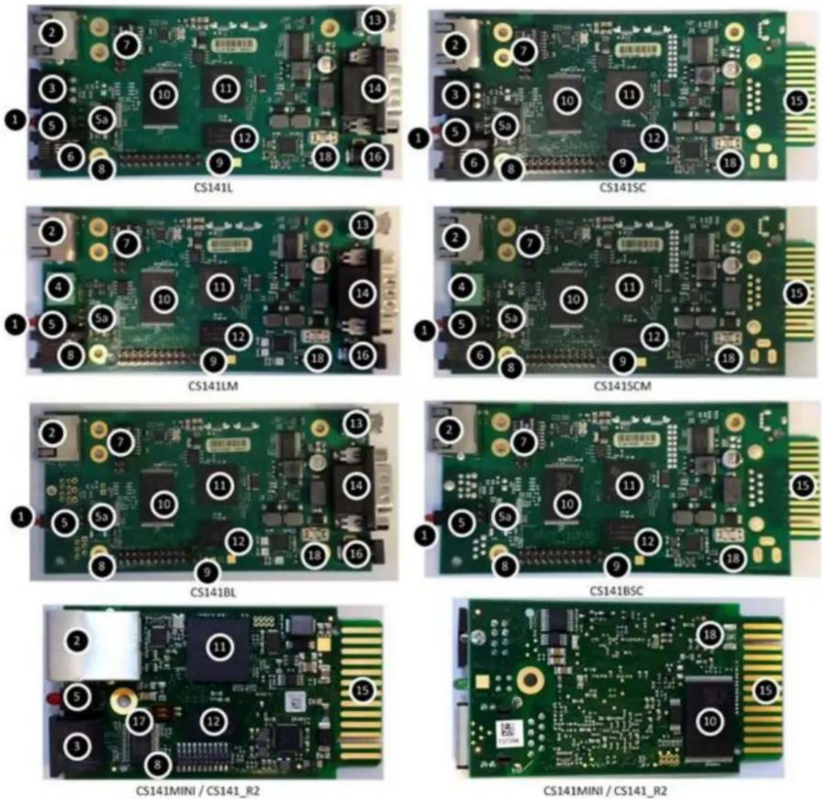
Important here is (9) – the Rescue jumper. If the system does not start correctly or does not show the web UI, several models offer the option to set a jumper here. If you do so, the adapter will boot another UI where you can reset the device to factory settings or perform a firmware upgrade.
More information can be found under 26) Rescue System.
8. Port Description
Pin Layout CS121 COM1:
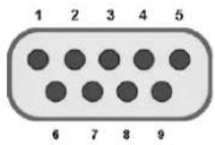
External D-SUB 9-pin male
| Pin1: | DCD | Pin6: | DSR |
| Pin2: | RxD | Pin7: | RTS |
| Pin3 | TxD | Pin8: | CTS |
| Pin4 | DTR | Pin9: | RI |
Pin5 GND
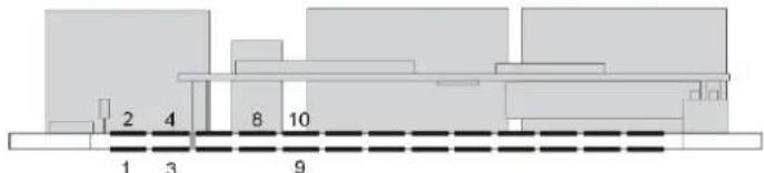
Slot version: Circuit board connection
| Pin | Signal name | Pegel | Function |
| 1 | GND | Power Ground | |
| 2 | 8 – 34V DC | Power Input | |
| 3 | COM1 TXD | V24 | COM1 Transmit Data |
| 4 | COM1 RXD | V24 | COM1 Receive Data |
| 5 | SW_GPIO_1 1) 2) | 3,3V TTL | CS141DMINI: Funktionalität von DIP-Switch 1 |
| 6 | SW_GPIO_2 1) 2) | 3,3V TTL | CS141DMINI: Funktionalität von DIP-Switch 2 |
| 7 | POW# Input 1) | 3,3V TTL | Enable des Netzteils (active low) |
| 8 | Bridged with Pin 10 | ||
| 9 | GND | Signal Ground | |
| 10 | Bridged with Pin 8 | ||
| 11 | COM1 DTR 1) | V24 | COM1 Data Transmit Ready |
| 12 | COM1 RI 1) | V24 | COM1 Ring Indicator |
| 13 | COM3 RXD 1) 2) | 5V TTL | COM3 Receive Data |
| 14 | COM3 TXD 1) 2) | 5V TTL | COM3 Transmit Data |
| 15 | COM2 TXD 1) 2) | 3,3V TTL | COM2 Transmit Data |
| 16 | COM2 RXD 1) 2) | 3,3V TTL | COM2 Receive Data |
| 17-26 | - | n.c. |
1) Connectable with solder bridge (MINI: resistor bridge) 2) Input with Pull-Up

2 Mini-DIN 8-pin
Mini DIN 8 socket RS-232:
Pin1: -> DCD Pin2: -> RxD Pin3: -> TxD Pin4: -> DTR Pin5: -> DSR Pin6: -> RTS Pin7: -> CTS Pin8: -> RI ISO -> GND
RS-485 (optional):
Pin1 → GND
Pin2: -> RS485/A
Pin3: -> RS485/B(-)
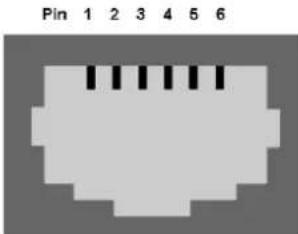
AUX-Port (Hardware Revision 1.1 = from Serial numbers 0121-1203, 0122-00198, 0123-00564 onwards) RJ11 6-pin
Pin1: -> +3,3V
Pin2: ->
Pin3: ->
Pin4: -> RxD (COM3 Input)
Pin5: -> TxD (COM3 Output)
Pin6: -> GND
- LED status
| Green LED | Red LED | Adapter |
| Off | Off | No power |
| Off | On | Booting |
| Off | Slow flashing | Updating |
| Off | Fast flashing | Update fault |
| On | On | Connection to UPS (external device) lost |
| Slow flashing | Off | Normal operation |
On top of the physical LED status, you can have a look at the status bar. Here are several status informations shown – including the exact warning:
UPS: ● Ready
Green means everything is fine, communication is established and no problems occur. If you do not set a UPS model, the LED will also flash green.
UPS: ● Initializing
While establishing the connection, the LED will change to yellow. Also, several warnings will switch the color to yellow.
UPS: ● Not Available
If the LED is grey, there is no communication established. Check the cable and if you have set the correct UPS model.
UPS: ● Temperature Bad
A red LED means there is an alert or critical condition. All kinds of alerts are shown here. Also, if the connection to the UPS is lost.
10. Integration of the CS141 in the network
Configuring the CS141 is only possible via web GUI of the adapter and via browser (Internet Explorer/ Edge, Chrome, Mozilla, Safari). Deactivate Proxies and Plugins which could interfere with the web GUI.
The typical integration of the CS141 into your network is shown in the picture below:
![graph TD A["NMS (Network Management Station)"] --> B["IP Network (LAN/WAN)"] C["CS141SCM"] --> D["UPS"] D --> E["Power cable"] B --> F["Computer"] B --> G["Laptop"] B --> H["Computer"] B --> I["Server"]](/content/2026/05/867592/images/46ceeb67700918701bba2110f74e305191dc3ac954760c921fc689e98df87580.jpg)
For configuration, you may use a LAN cable or a crossover cable, depending on the PC/Notebook network adapter. For initial installation, we recommend not using any hub or switch.
Recommended client settings for configuring the CS141:
When the adapter responds to a PING command, you can open the preconfigured IP address in your browser.
Different response intervals do not indicate a problem. Due to differently designed UPS protocols, the adapter may not respond to every PING with the same priority. Only a permanent timeout indicates an issue.
Setting a static IP is explicitly recommended, because the adapter may be configured for multiple server shutdowns with RCCMD and it may happen that the DHCP server stops working. Also, it is possible to restrict sending RCCMD messages to specified IP addresses.
To access the system, log in with the admin user and password (default: cs141-snmp). Go to Setup, then System, and then Network. Here you must enter a hostname. You can now enter the IP address, subnet mask, and gateway as well. Optionally, you may enter a DNS server.
After changing the values, click on Apply. If the DIP switch on the device has been changed, the CS141 will try to forward you to the new address. You may need to change the client IP.
If you want to change the switch later, you will have to use the reboot button in the web interface or disconnect the power supply of the CS141 for 5 seconds.
Important: All settings will be directly applied when you click on Apply. If you change the website or click on another menu entry, all changes you have made will be lost.

In Setup > System -> Settings, you may enter information for every user. This information may also be received by UNMS.
a) Location means the exact location of your UPS device. b) System Contact is the administrator of the device. c) In Attached Devices, you enter the additional devices connected to the CS141 (e.g., BACS).
The marks at the services can be enabled or disabled. It is recommended to disable all services you do not want to use. All these services can be used to connect to the CS141.
The following languages are supported:
German, English (Simplified), French, Spanish, Polish, Portuguese
Terms that are not translated in the respective language appear in English. The display of the languages is according to your web browser.

- Hardware and Firmware Information
In case of (support) requests, the information from the About page is essential. Besides model and firmware version, you may also see how long the device has been running without interruption. On the Generex homepage, you can find the current version in the download area. The V-reference number shows the stable version, the six-digit number the version date (yymmdd).
Note: If you boot the rescue system, you may see RESCUE behind the version.

- Timeserver configuration
In Setup -> System -> Services, you can configure the time server. The current system time is displayed above. In the three fields, you may enter up to three different time servers. They can be entered as addresses or IP addresses. You can also change the time zone. After that, click on Apply and then on Synchronize to apply all changes you have made. Alternatively, you can set the system time manually.

If the CS141 is not connected to the internet or a time server in the network, you can also use a Windows client as a time server:
a) Open Run via shortcut or Windows-Key + R. b) Type in regedit and click OK. c) Go to the following entry: KEY_LOCAL_MACHINE\SYSTEM\CurrentControlSet\Services\W32TimeConfig d) Set the value AnnounceFlags from 10 (alternative a in hex) to 5. e) Go to the following entry: HKEY_LOCAL_MACHINE\SYSTEM\CurrentControlSet\Services\W32Time\TimeProviders\NtpServer f) Set the value enabled to 1. g) Close regedit and open Run again. Type in cmd and click OK. h) Enter the following command: net stop w32time && net start w32time i) If you see any data, the client is ready to act as an NTP server. Maybe you have to open UDP port 123 in the client firewall. Afterwards, the client IP can be used as a time server.
Note: If you use a Windows client (Vista, 7, 8, 10) as a time server, you have to download and install the NTP fix from Microsoft. If you use the server version, this is not necessary.
13. UPS selection
Go to Setup -> Devices -> UPS -> Setup. Choose your UPS model according to the list. If your UPS is not listed, please contact your manufacturer who can give you an alternate model that you can choose from the list. If you haven't got any different information about the baud rate, do not change the values.
The value on system shutdown time shows the amount of time a system shutdown will be performed in case of power failure.
Important: If the wrong cable type is used, no communication to the UPS will be established.
Warning: If you have a UPS with multiple modules, the boot process may take a while (up to 5 minutes). The startup process Initializing must not be interrupted.
Please note the entry System Shutdown time. This value determines how many minutes before a complete battery discharge the event System Shutdown will be executed. This event is the last job which can be executed before the UPS will shut down. Do not use this event for sending RCCMD commands because the remaining time is not secure enough. Please use the event "powerfail" for this case.
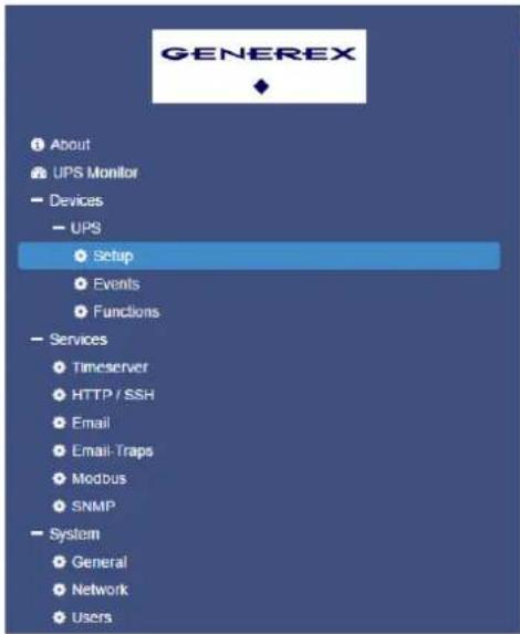

Note: If you change the model and you have configured events, all changes you made are lost.

14. UPS functions
The CS141 can be used as a remote control to initiate supported commands and tests. Please note that all shown functions and screens may differ from one model to another and can only be executed if the manufacturer has activated these for the device.
![UPS Remote Control UPS Test Start Custom Test Custom Test Duration[Min] 3 Start Battery Test Battery Test Start Full Test Full Test Start Cancel Test Cancel Test Last UPS Test Result Name Status(Result Holdtime[Min] Start Time CustomTest BatteryTest FullTest UPS Control Shutdown Restore Shutdown[Sec…](/content/2026/05/867592/images/df209c527c7e27a4a5a517b4f283bf584884821e054889849adad7e7a8b4ddd9.jpg)
- Email configuration
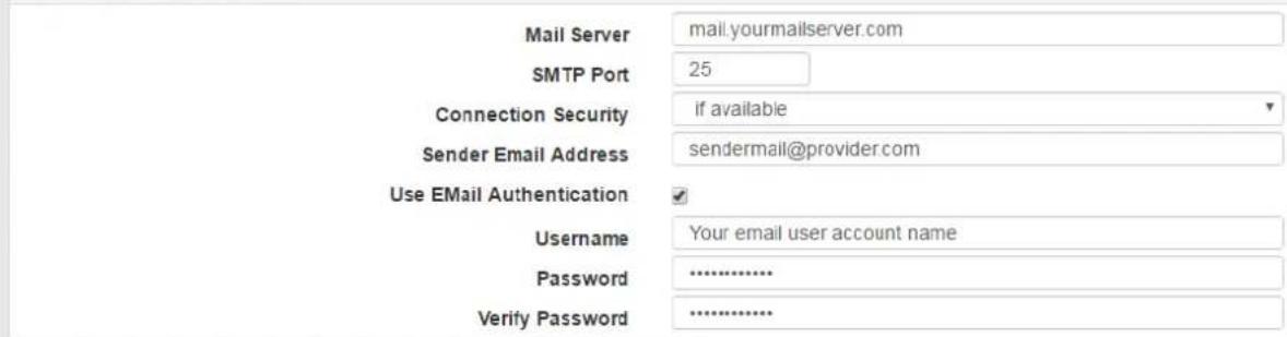
If you wish sending emails when specific events occur, you may go to System -> Services -> Email and configure the CS141 for these scenarios.
Enter the mail server as host name or IP. Choose the port and type of encryption. You may choose between none, if available and forced.
Enter a meaningful subject. This subject will be used for each email.
The CS141 admin account is optional. If you enter an address here, all emails will be additionally sent to this address.
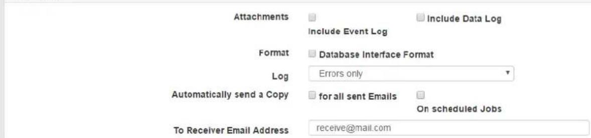
With the mark Attach AlarmLog the AlarmLog and UPSDataLog will be attached to every mail (as .csv-file). Additionally the mail includes the MAC-Address, UPS Model, UPS Location, IP address of CS141, system time and the executed event.
If you set the mark for Attach DataLog to Email all DataLogs will be attached to the mail. Optional, you can send the mails in the email database format.
You can choose to log all sent emails. You have the options to log always, never and on errors.
If you set the mark for Email Authentication, you have to enter validated user and password. The CS141 will check if you entered the password correct.
Now click on apply. You can now send a test email. Enter a recipient and a subject. Optional is sending a body text and attaching the log files.
Services Email
Outgoing Mail Server
Advanced
Test Email Settings

16. Email traps
Email traps allow devices to transfer data over POP protocol to UNMS.
UNMS II is a web server based customizable software for monitoring and schematic viewing of different UPS devices and network based systems. The software shows the current status of integrated devices and systems (e.g., CS141 or BACS).
In the UNMS II Admin Console, the connection type can be set per device (UPSTCP, SNMP, RAS) and remote monitoring of a CS141 is possible. The difference to other remote software is the email trap restriction to send emails; a reply or intervention is not possible.
- Transfer Protocol: POP
- Payloads: IDP, VDP, proprietary Data • Data format: JSON (as Attachment)
- Configuration Mail Server: Global for all connections, in UNMS II Admin Console
- Configuration Mail Client: By device as connection type in UNMS II Admin Console
- An email inbox/user for all devices. Distinguished via IP and MAC address.
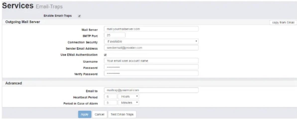
If you want to adopt the email settings, click on copy from Email. We suggest using a separate account for email traps which is only used by TeleService from UNMS. So, you have to adjust the parameters.
If email traps are configured and UNMS has a TeleService license, every device can be monitored over emails. In UNMS, every device will be shown on a schematic screen where all values are displayed with a time stamp since the last update. As soon as a status change occurs, the values are immediately updated. If no change occurs, the values will be updated in the heartbeat interval.
The Heartbeat Period defines the time span how long the CS141 waits until an alert will be executed if the heartbeat does not work anymore. The Period in case of alarm defines the time span for transmission in case of alert.
17. Events and alerts
The CS141 allows to execute event based jobs. These events are triggered by UPS or additional devices connected to CS141. It is possible to create several jobs for each event. These jobs may be RCCMD shutdowns, emails, log entries. Also you can set when and how often a job shall be executed.
You find the events in Devices -> UPS -> Events.
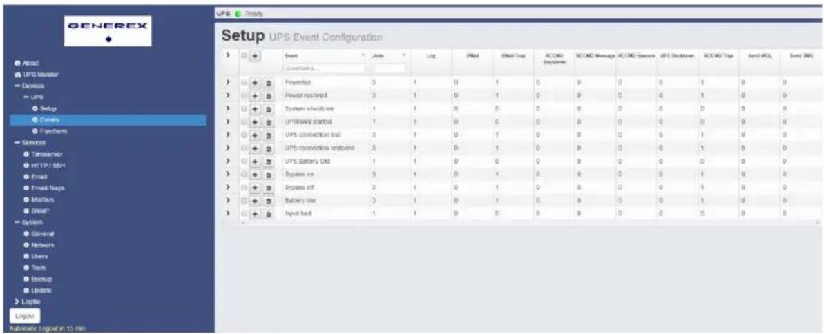
Please note that the events may differ from one UPS to another.
Click on the arrow > to display the configured jobs for the specified event.
With a click on Plus + you can add new jobs.
With a click on the garbage can you delete all jobs for one event.
| - | Powerfail | 3 | 1 | |||
| Job Typ | Wann | ✓ | Parameter | |||
| Log | Log | Once,defer 0s | {"text":"POWEI" | |||
| Once,defer 0s | {"text":"POW F" | |||||
| RCCMD Shutd... | RCCMD Shutd... | Once,defer 0s | {"ip":"192.168.." | |||
When you expand the job list you can edit jobs with a click on the pen. If you click on the garbage can here you can delete a single job. If you click on Play, you execute the job instantly. Warning: RCCMD shutdowns will be also executed directly!
With a click on the down arrow next to the column you can fade out columns or sort the view by that column. If you change the site and go back to events all columns are set back to normal.
Edit Job to Event Powerfail
Job:
Log
Job Data
Text
UPS on battery
Timing
Immediately, once Scheduled in seconds
Actions will only be executed if event condition is still true after the specified seconds!

Cancel
Save Configuration
Additional information about RCCMD is available on our website:
http://www.generex.de/generex/download/manuals/manual RCCMD Win Unix Mac en.pdf
For each event, you can create the following jobs:
- Log: Writes a log entry in the alert log of the CS141. This setting is default for each job.
- Email: Enter recipient and a meaningful text. Optionally, you can attach AlarmLog and DataLog.
- EmailTrap: Send an email trap. Here, you do not have to enter any additional parameters.
- RCCMD Shutdown: Executes a shutdown via RCCMD. Enter IP address of the client and port (Default 6003).
- RCCMD Message: Sends a message to a RCCMD client. Additionally to IP and ports, you have to enter the text. You can view the text in the client log file.
- RCCMD Execute: Send a specific command to a RCCMD client. Enter IP, port, and the command.
- UPS Shutdown: Enter shutdown and restore time. Type should only be changed if the manufacturer requires this. (Default setting: 1).
- RCCMD Trap: Send a RCCMD trap. Here you can enter the text which the trap includes.
- Send WOL: Send a Wake on LAN command. Enter MAC address of the target and optionally a password.
- Send SMS: If you have connected a modem you can enter a recipient of a SMS and the displayed text.
Timing:
Timing sets when the job will be executed:
- Immediately, once: Direct execution. Recommended for log entries.
- Scheduled in X seconds: Execution after the specified time. Note that the job will still be executed after this amount of time even when the event does not longer occur.
- After X seconds, repeat all Y seconds: Executes the job after X seconds if the event still occurs and will be repeated every Y seconds.
- After X seconds on Battery: Will be executed if UPS is X seconds on battery operation.
- At X seconds remaining time: Will be executed if hold time reaches X seconds.
Timing

Immediately, once

Scheduled in

seconds
Actions will only be executed if event condition is still true after the specified seconds!

After
seconds, repeat all
seconds

After
seconds on Battery

At
seconds remaining time
18. RCCMD signals
Each physical host needs a valid license for RCCMD. Otherwise the functionality of the software will be removed after 30 days. The license key can only be used once per installation.
RCCMD communicates default on port 6003. As a test it is recommended to edit the shutdown script on client side and remove the shutdown command. If you send now a test shutdown, the client will not shutdown but show a log entry for shutting down the machine will be generated. Please make sure to enable the shutdown in the script afterwards. If the test fails, look into the alert log for accurate details.
In this example the CS141 would wait for 5 minutes after a powerfail and execute a RCCMD shutdown. If power is restored before 5 minutes are reached, the shutdown will not be sent.
Add Job to Event Powerfail
If you use redundancy (two or more UPS devices) and the devices secure a single client, it is possible to negate sent RCCMD shutdown commands. Create a new job „Execute RCCMD command“ and enter as a command WAKEUP.
Add Job to Event Powerfail

Therefore, the RCCMD shutdown will be removed and redundancy level increases by one.
Additional information about RCCMD is available on our website: http://www.generex.de/generex/download/manuals/manual_RCCMD_Win_Unix_Mac_en.pdf
19. SNMP
In this menu you can set the access rights for SNMP communities. The CS141 supports SNMPv2 and v3 as well, but only one at a time (not both simultaneously).
In v2 you have to set only 3 values. These are IP address, SNMP community (Default: public) and the permission (Read only or Read/Write).
In v3 you have the three known methods:
- No security: No authentication and no privacy, only user is needed.
- Authentication: Authentication (SNMP v3 user and password), but no privacy. Authentication and privacy: Authentication (SNMP v3 user and password) and v3 privacy password.
The possible authentication algorithms are MD5 and SHA. Privacy algorithm must be DES or AES.
Afterwards you can check your settings:

- MODBUS
MODBUS is a serial communication protocol which is used with programmable logic controllers (PLCs). It allows communication between several devices connected in the same network, e.g., a system which measures temperature and humidity and reports the results to a computer. MODBUS is often used to connect a monitoring computer with a Remote Terminal Unit (RTU) with a Supervisory Control and Data Acquisition system (SCADA).
You can set the parameters in Setup -> Services -> Modbus. Enable the service and set the maximum amount of allowed connections to the device. The field for Modbus Slave address sets the Slave address on which the CS141 transmits the data. The CS141 series supports general MODBUS over IP and MODBUS over RS232, as well as the model CS141LM/SCM. Instead of RS232, MODBUS will be provided via RS485. Requests, which are not supported by UPS or other devices are displayed with the values -9999 or -1. So unsupported values can be easily identified. The Modbus addresses are found in the manual of CS121 (Predecessor version) or in the Modbus manual for CS141.
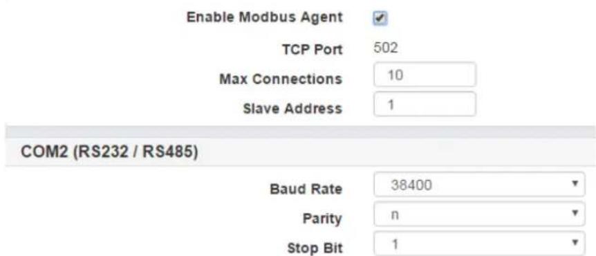
You find the MODBUS settings in Services -> Modbus. You may change here the values maximum allowed connections, the slave address, parity and the stop bit. Also, you can change the baud rate (Default 38400).
21. Log files
The CS141 maintains two different log files: the alert log and the data log. In the alert log, all actions done or recognized by the CS141 are displayed. This includes, for example, sending emails and RCCMD signals, UPS status changes, starting and stopping services on the CS141, etc. This information can be downloaded as a CSV file. If an event occurs (e.g., power failure), it is displayed, and all executed jobs and events are shown. With the power failure example, if you have configured sending an email, a RCCMD signal, and generating a log entry, you will find four new entries in the alert log. You can refresh each log file page with a click on this button: Event Log.
The data log shows (beginning with the date) the different measurements. These values are detailed and can also be downloaded as a CSV file. For an easier view, you can also use the data log chart. Here you can deselect non-required values and get an actual overview.
If you click on a coordinate in the Datalog Chart, you activate the zoom function. You may also drag the mouse over a certain area to zoom in. To go back to the basic overview, click on reset zoom.

The log file may store over 4000 entries. If the log file is full, you will find an entry "Logfiles rotated". When you go to archived Logfiles, you can download the old entries as a CSV file.
22. Firmware update
In Setup -> System -> Update you can update the firmware of the CS141. Drag the update file with Drag & Drop into the dotted square or click on the square and search your local computer or available memory for the downloaded update. Extracting the file is NOT necessary.
You can also perform a factory reset. If you want, set the mark before you start the update procedure. The preconfigured IP address will be retained.
To update the firmware, it is not necessary to log in to the web interface. Enter the IP address of your adapter, followed by /update. Enter as user admin followed by the affiliated password and start the progress.
After updating, it is recommended to delete the browser cache once (CTRL+F5).
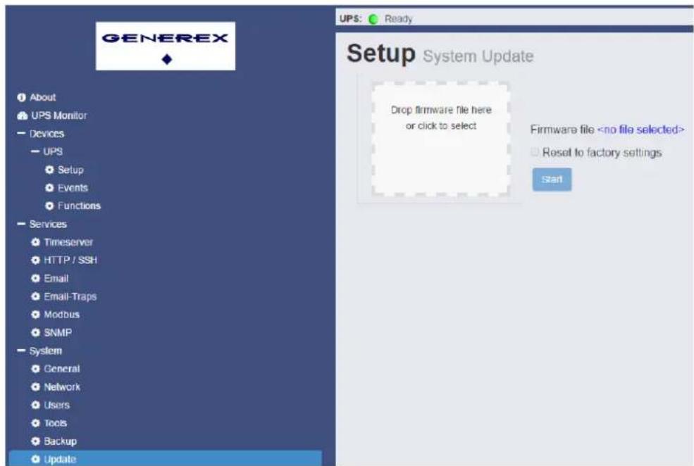
If you change the OEM, it is recommended to perform a factory reset. The configured IP address will be taken over. If you do not perform a factory reset while changing the OEM, it may result in an error (depending on the previous configuration).
You can download the latest firmware here.
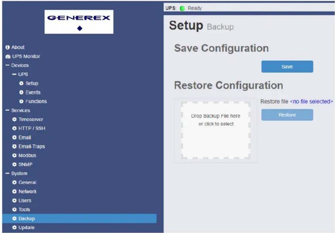
The CS141 offers to save and restore your configuration. You find the Backup option in Setup -> System -> Backup. Click on Save and download the configuration from your device. If you want to restore your configuration, you may proceed here the same way you do like performing a firmware update.
It is possible to prepare a configuration for using it as a template for other adapters (Configuration of identical CS141/BACS for mass distribution). Simply save your configuration and restore it on another adapter.
Caution: Both adapters have to be on the same firmware version; otherwise, errors may occur!
Note: The IP settings do not change by the restore process, after the restore has finished, you have to configure the new IP setting manually!
- Tools
With the Tools (System -> Tools) you may reboot the adapter and you can also use own RCCMD certificates. Some configuration changes need a soft reboot, eg. If you change the IP address but did not set the DIP switch to another position and change additional parameters. To access this page it is necessary to enter the admin password again.

Alternatively you may reboot the device without logging in if you enter the IP address of the device, followed by /reboot. Again, you have to enter the password here.
To use own certificates for RCCMD you need to upload them here. After this, reboot the device (on the same page) to enable using own certificates.
Note: The certificate must be named RCCMD.pem, otherwise the device will deny the upload.
25. External devices
If you use a CS141 professional series adapter, you may connect additional devices such as SM_T_COM, Sensormanager and CON_R_AUX. You will notice that you have an enlarged status bar on top of the screen.
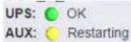
Sensor: ● Disabled
If you change the settings of the ports, the service will restart – same like an UPS modell change.
The AUX setup is available on Devices -> Aux -> Setup. At first, you have to enable the device with setting the mark. After that, you can set the ports as Input (no change), Output (first row mark), Inverted (second row mark) and switch ON when adapter boots (third row). Also, you can set a delay for switching on the port after boot.

You can also configure certain jobs for each port, which is like configuring jobs for the UPS. Go to Devices -> AUX -> Events to configure the jobs. You have the same options in all event configuration menus.
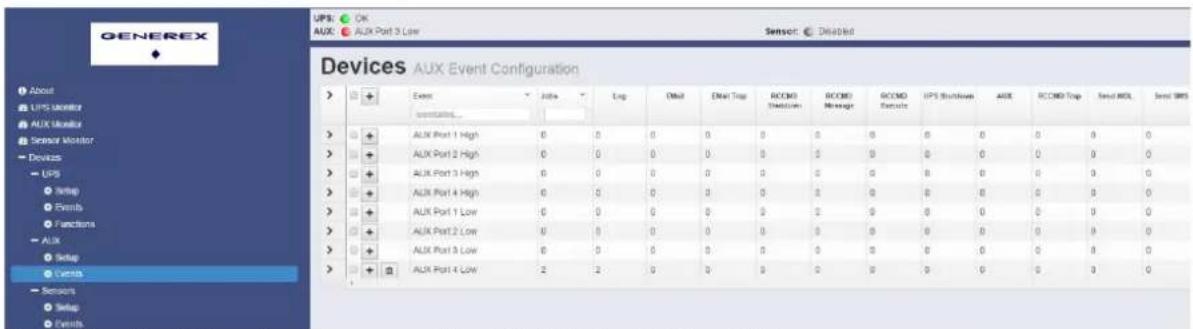
If you click on the AUX monitor, you may manually set the Output ports ON and OFF.

For the COM2 port the sensor menu and monitor are used. Go to devices -> Sensors -> Setup to choose the connected device.

When choosing a device, the available options will change and you can set the different values, eg. Sensortype and NC contacts. If you do not set a device or the communication is not established, you will get an error when opening the monitoring page.
The data necessary to complete this operation is not yet available.
Of course you can configure jobs for the sensor behaviour. Open Devices -> Sensors -> Events to configure.
Additional information is available on our website in the Accessories section and on the external devices page.
26. Rescue System
The CS141 comes with two options to initiate the firmware again respectively reset the device to factory settings.
If the CS141 denies a login or the GUI shows corrupt screens, you can enter the IP address followed by /update to install another firmware version or set the option reset to factory settings. Example:
Now you can drag & drop the favored firmware or browse by clicking in the panel. Before you click on start, you may optionally set the mark on reset to factory settings. Enter now the password for the administrator account (Default: cs141-snmp). The progress will start and after successful installation the login page will appear.
The second option is to boot a different firmware version. This is recommended if you can't access via GUI but ping the device or if an update fails. For this you will need a jumper which has to be set according to the picture followed. If you go to 7) Port occupancy you can check which version of the adapter you have and where to set the jumper.
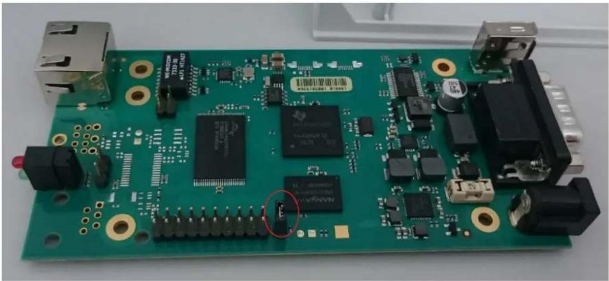
When the jumper is set and the adapter has booted, you can recognize the rescue system when you click on about. The firmware version is followed by (RESCUE). You can now update the adapter or reset the device to factory settings. Remove the jumper afterwards and reboot the device.
For the case you forgot the password you may reset the device. Please note that all settings and configurations are lost. Set the DIP switch to the middle (10.10.10.10). Enter the IP followed by /update in your browser. Upload the desired firmware, and set the mark Reset to factory settings before you start – all settings including the password will be reset. In contrast to the normal update the adapter will not ask for a password in this position. After finishing the progress you may login with the default password (cs141-snmp) and configure the device again.
27. Sensors
The CS141L/SC/R/MINI offers to connect external sensors. It is possible to connect them directly (SM_T_COM or SM_T_H_COM) or with the SENSORMANAGER2 on COM2 port.
Choose Sensor in the menu System -> General -> COM2.
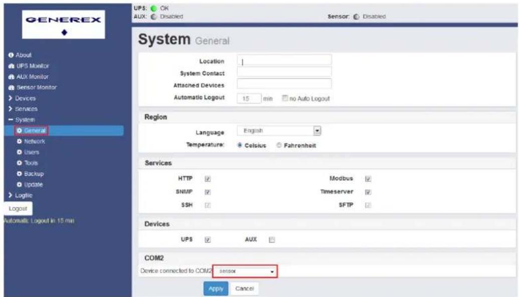
Choose the connected type in Sensors -> Setup -> Sensor connected to COM.
If you have connected the Sensorman2:

The configuration of Inputs and Outputs and further information can be found in the SENSORMANAGER manual: http://www.generex.de/generex/download/manuals/manual_SENSORMANAGER_en.pdf
If SM_T_COM is connected:
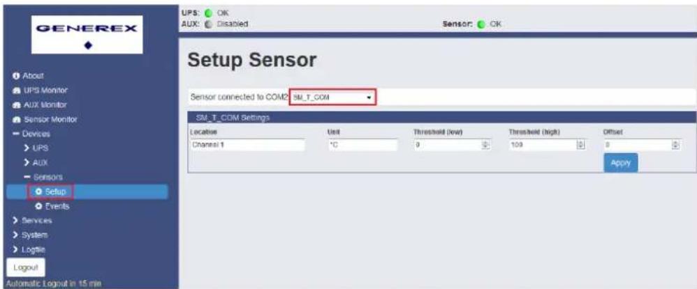
The configuration and further information can be found in the SM_T_COM manual: http://www.generex.de/generex/download/datasheets/datasheet_SM_T_COM_en.pdf
If SM_T_H_COM is connected:

The configuration and further information can be found in the SM_T_H_COM manual: http://www.generex.de/generex/download/datasheets/datasheet_SM_T_H_COM_de.pdf
CS141 MODBUS RS232 configuration: The CS141L/SC/R/MINI offers the possibility to output MODBUS RS232 at COM2 Port. Therefore, choose Modbus in System -> General -> COM2.
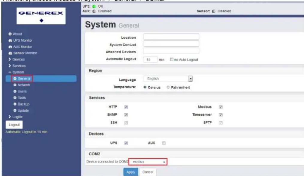
Further information about MODBUS can be found here: http://www.generex.de/generex/download/manuals/manual_MODBUS_CS141_en.pdf
The CS141 has an inbuilt Diagnostics tool (Since firmware 1.40) which can analyze the data traffic directly on the serial port.
Open a new tab and enter the IP address of the adapter, followed by /trace/ups. On this page you see the raw data of the connection on the serial port. Blue values are sent from the CS141, red values show data from the UPS device. If the connection is interrupted (for example, reboot or changing the UPS model) you will see "Connection closed". If you refresh the page the trace will be restarted then.
This diagnostics tool uses few resources of CS141. It is recommended to use the tool only if any errors are present and to close the tab after analyzing.
| 02 04 43 4b 6f 01 | ..CKo. |
| 02 05 43 00 05 00 4d | ..C...M |
| 02 04 43 4b 6f 01 | ..CKo. |
| 02 05 43 00 0a 00 52 | ..C...R |
| 02 04 43 4b 6f 01 | ..CKo. |
| 02 05 43 00 0c 00 54 | ..C...T |
| 02 04 43 4b 6f 01 | ..CKo. |
| 02 05 43 00 0d 00 55 | ..C...U |
| 02 04 43 4b 6f 01 | ..CKo. |
| 02 05 43 00 0e 00 56 | ..C...V |
| 02 04 43 4b 6f 01 | ..CKo. |
| 02 05 43 00 16 00 5e | ..C...^ |
| 02 04 43 4b 6f 01 | ..CKo. |
29. FAQ – Frequently asked questions
- What is Error 503?
This error occurs when the web server on the CS141 encountered a problem. If the issue is still present after rebooting the device, the firmware needs to be updated or transferred again. Recommended is here the factory reset option.
- What is Error 422?
This error occurs when you try to change some parameters of the configuration in an older firmware. Please update to the latest version.
- What is Error 400 / 420?
This problem may occur after a firmware update, but the browser uses cached data. Press CTRL + F5 or delete your browser cache. Reboot the device afterwards.
- The UPS Status is (temporary) on "Paused".
If you open the UPS alert history it is necessary to pause the connection between adapter and UPS for a couple of seconds. Go to another page and press F5 to restore the correct status (if not done automatically).
- What is Error -1?
This error occurs when there is no connection to the adapter (for example after a reboot) but the configuration page is still open. Wait for the adapter to switch back to normal operation mode and open the IP address of the adapter again.
- I have lost my password.
Have a look at the rescue system section, there is a description how to retrieve a lost password.
- Why do I get logged out after deactivating the http tooltips on services?
The tooltips are connected with the http service. Changing anything requires the adapter to forward you on the new address / port.
If you have additional questions contact us per mail on support@generex.de!
- Manual Version
| 04.10.16 | - 1.6.1 | Minor change at Trace |
| 28.09.16 | - 1.6 | Diagnostic & FAQ added, features extended, logfile size added |
| 01.09.16 | - 1.52 | Links updated, pictures exchanged, Modbus extended |
| 22.08.16 | - 1.51 | Minor changes |
| 02.08.16 | - 1.5 | Sensors added |
| 27.06.16 | - 1.4 | |
| 04.05.16 | - 1.3 | |
| 19.04.16 | - 1.2 | |
| 07.04.16 | - 1.1.3 | |
| 05.04.16 | - 1.1.2 | |
| 01.04.16 | - 1.1.1 | |
| 18.03.16 | - 1.1 | |
| 09.03.16 | - 1.0 |


- CS141 USER MANUAL ENGLISH
- UPS WEB/SNMP MANAGER
- COPYRIGHT STATEMENT FOR INTELLECTUAL PROPERTY AND CONFIDENTIAL INFORMATION
- SUMMARY
- GENERAL INFORMATION
- OPERATION
- COMMISSIONING
- MISCELLANEOUS
- INTRODUCTION
- CHANGES IN COMPARISON TO PREDECESSOR CS
- SWITCH POSITION
- DELIVERY CONTENT
- FUNCTION OVERVIEW
- PORT OCCUPANCY
- PORT DESCRIPTION
- UPS: ● READY
- UPS: ● INITIALIZING
- UPS: ● NOT AVAILABLE
- UPS: ● TEMPERATURE BAD
- INTEGRATION OF THE CS141 IN THE NETWORK
- UPS SELECTION
- UPS FUNCTIONS
- SERVICES EMAIL
- OUTGOING MAIL SERVER
- ADVANCED
- TEST EMAIL SETTINGS
- EMAIL TRAPS
- EVENTS AND ALERTS
- EDIT JOB TO EVENT POWERFAIL
- JOB DATA
- TIMING
- ACTIONS WILL ONLY BE EXECUTED IF EVENT CONDITION IS STILL TRUE AFTER THE SPECIFIED SECONDS
- RCCMD SIGNALS
- ADD JOB TO EVENT POWERFAIL
- SNMP
- LOG FILES
- FIRMWARE UPDATE
- EXTERNAL DEVICES
- ADDITIONAL INFORMATION IS AVAILABLE ON OUR WEBSITE IN THE ACCESSORIES SECTION AND ON THE EXTERNAL DEVICES PAGE
- RESCUE SYSTEM
- SENSORS
- FAQ – FREQUENTLY ASKED QUESTIONS
Brand : AEG
Model : SNMP
Category : Inverter