
MPC1500 - Audio Amplifier MCINTOSH - Free user manual and instructions
Find the device manual for free MPC1500 MCINTOSH in PDF.


| Product Type | Power Controller |
| Brand | McIntosh |
| Model | MPC1500 |
| Versions | MPC1500-NA (120VAC), MPC1500-EU (230VAC), MPC1500-JA (100VAC) |
| Dimensions (W x H x D) | 17-1/2 inches (44.45 cm) x 7-5/8 inches (19.37 cm) including feet x 22 inches (55.88 cm) including front panel, knobs and cables |
| Weight (net) | 87 pounds (39.46 kg) |
| Weight (shipping) | 105 pounds (47.63 kg) |
| Power Requirements (NA) | 120V ~ 60Hz, 12 Amps maximum, 1440 Watts maximum |
| Power Requirements (EU) | 230V ~ 50/60Hz, 6 Amps maximum, 1380 Watts maximum |
| Power Requirements (JA) | 100V ~ 50/60Hz, 12 Amps maximum, 1200 Watts maximum |
| Output Voltage (NA) | 120 Volts AC Nominal |
| Load Regulation | ± 2.5% |
| AC Outlets | 2 Unswitched (always on), 4 Switched (individually configurable as Global, Local, or always On) |
| Transformer | Toroidal Isolation Power Transformer |
| Low Noise Technology | LONO™ (Low Noise) Transformer Technology from Plitron eliminates audible transformer noise |
| Surge Protection | Torus™ Surge Suppression Circuitry (activates ~2V above peak nominal voltage; not based on MOVs) |
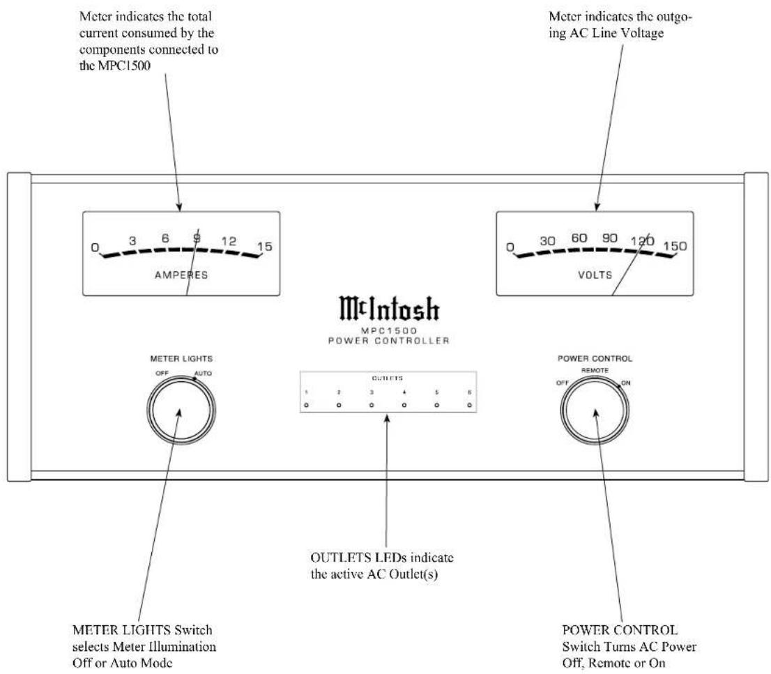
| Meters | Illuminated Voltage (VOLTS) and Current (AMPERES) meters |
| Meter Illumination | Switchable Off or Auto (remote controlled with compatible McIntosh preamp/AV controller) |
| Front Panel Illumination | Fiber Optic Solid State (LEDs with fiber optic light diffusers) |
| Power Control | Global and Local Power Control inputs/outputs (5-12V trigger signals) |
| Circuit Breaker | Rear panel push-to-reset circuit breaker |
| Cleaning | Only with a dry cloth |
| Servicing | Refer all servicing to qualified personnel. No user-serviceable parts inside. |
| Safety Compliance | Includes important safety instructions; do not expose to rain or moisture; polarized/grounding type plug |
| Included Accessories | AC power cord, owner's manual |
| Optional Accessory | Data and Power Control Cable (Part No. 170-202) |
| Country of Manufacture | USA |
Frequently Asked Questions - MPC1500 MCINTOSH
User questions about MPC1500 MCINTOSH
0 question about this device. Answer the ones you know or ask your own.
Ask a new question about this device
Download the instructions for your Audio Amplifier in PDF format for free! Find your manual MPC1500 - MCINTOSH and take your electronic device back in hand. On this page are published all the documents necessary for the use of your device. MPC1500 by MCINTOSH.
USER MANUAL MPC1500 MCINTOSH
McIntosh Laboratory, Inc. 2 Chambers Street Binghamton, New York 13903-2699 Phone: 607-723-3512 www.mcintoshlabs.com
Torus Power Technology under license from Plitron Manufacturing Inc.
MPC1500
Power Controller
Owner's Manual


The lightning flash with arrowhead, within an equilateral triangle, is intended to alert the user to the presence of uninsulated "dangerous voltage" within the product's enclosure that may be of sufficient magnitude to constitute a risk of electric shock to persons.
WARNING - TO REDUCE RISK OF FIRE OR ELECTRICAL SHOCK, DO NOT EXPOSE THIS EQUIPMENT TO RAIN OR MOISTURE.
IMPORTANT SAFETY INSTRUCTIONS!
PLEASE READ THEM BEFORE OPERATING THIS EQUIPMENT.
- Read these instructions.
- Keep these instructions.
- Heed all warnings.
- Follow all instructions.
- Do not use this apparatus near water.
- Clean only with a dry cloth.
- Do not block any ventilation openings. Install in accordance with the manufacturer's instructions.
- Do not install near any heat sources such as radiators, heat registers, stoves, or other apparatus (including amplifiers) that produce heat.
- Do not defeat the safety purpose of the polarized or grounding-type plug. A polarized plug has two blades with one wider than the other. A grounding type plug has two blades and a

AVIS RISQUE DE CHOC ELECTRIQUE - NE PAS OUVRIR.
NO USER-SERVICEABLE PARTS INSIDE. REFER SERVICING TO QUALIFIED PERSONNEL.
third grounding prong. The wide blade or the third prong are provided for your safety. If the provided plug does not fit into your outlet, consult an electrician for replacement of the obsolete outlet.
- Protect the power cord from being walked on or pinched particularly at plugs, convenience receptacles, and the point where they exit from the apparatus.
- Only use attachments/accessories specified by the manufacturer.
- Use only with the cart, stand, tripod, bracket, or table specified by the manufacturer, or sold with the apparatus. When a cart is used, use caution when moving the cart/ apparatus combination to avoid injury from tip-over.
- Unplug this apparatus during lightning storms or when unused for long periods of time.
- Refer all servicing to qualified service personnel. Servicing is required when the apparatus has been damaged in any way, such as power-
The exclamation point within an equilateral triangle is intended to alert the user to the presence of important operating and maintenance (servicing) instructions in the literature accompanying the appliance.
To prevent the risk of electric shock, do not remove cover or back. No user-serviceable parts inside.
supply cord or plug is damaged, liquid has been spilled or objects have fallen into the apparatus, the apparatus has been exposed to rain or moisture, does not operate normally, or has been dropped.
15. Do not expose this equipment to dripping or splashing and ensure that no objects filled with liquids, such as vases, are placed on the equipment.
16. To completely disconnect this equipment from the a.c. mains, disconnect the power supply cord plug from the a.c. receptacle.
17. The mains plug of the power supply cord shall remain readily operable.
18. Do not expose batteries to excessive heat such as sunshine, fire or the like.
19. Connect mains power supply cord only to a mains socket outlet with a protective earthing connection.
McIntosh Products are marketed world wide. There are several versions of the MPC1500 to meet the different AC Power and Safety Requirements in each country.
This Owner's Manual covers the three versions of the MPC1500. In the Owner's Manual there is a section containing common information for all three versions of the MPC1500 and separate sections pertaining to the specific version of the MPC1500.
The designation of MPC1500-NA refers to the 120VAC version for use in North America. Refer to figure MPC1500-NA.
The designation of MPC1500-EU refers to the 230VAC version for use in Continental Europe. Refer to figure MPC1500-EU.
The designation of MPC1500-JA refers to the 100VAC version for use in Japan. Refer to figure MPC1500-JA.

Figure MPC1500-NA

Figure MPC1500-EU
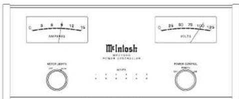
Figure MPC1500-JA
Copyright 2009 © by McIntosh Laboratory, Inc.
Table of ContentsModel Versions
Safety Instructions....2
Preamble and Table of Contents .... 3
Thank You and Please Take a Moment....4
Technical Assistance and Customer Service......4
General Information 4
Connector and Cable Information .... 5
Introduction....5
Performance Features 5
Dimensions 6
Installation 7
MPC1500-NA
Rear Panel Connections....8
How to Connect in a Two Channel System ...... 9
How to Connect in a Multi Channel System .....10
Front Panel Displays and Controls....11
How to Operate the MPC1500....12-13
Specifications....14
MPC1500-EU
Rear Panel Connections....16
How to Connect in a Two Channel System....17
How to Connect in a Multi Channel System......18
Front Panel Displays and Controls....19
How to Operate the MPC1500....20-21
Specifications....22
MPC1500-JA
Rear Panel Connections 24
How to Connect in a Two Channel System .... 25
How to Connect in a Multi Channel System ..... 26
Front Panel Displays and Controls....27
How to Operate the MPC1500....28-29
Specifications....30
Packing Instruction....31

Thank You
Your decision to own this McIntosh MPC1500 Power Controller ranks you at the very top among discriminating music listeners. You now have “The Best.” The McIntosh dedication to “Quality,” is assurance that you will receive many years of enjoyment from this component.
Please take a short time to read the information in this manual. We want you to be as familiar as possible with all the features and functions of your new McIntosh.
Please Take A Moment
The serial number, purchase date and McIntosh Dealer name are important to you for possible insurance claim or future service. The spaces below have been provided for you to record that information:
Serial Number:
Purchase Date:
Dealer Name:
Technical Assistance
If at any time you have questions about your McIntosh product, contact your McIntosh Dealer who is familiar with your McIntosh equipment and any other brands that may be part of your system. If you or your Dealer wish additional help concerning a suspected problem, you can receive technical assistance for all McIntosh products at:
McIntosh Laboratory, Inc.
2 Chambers Street
Binghamton, New York 13903
Phone: 607-723-1545
Fax: 607-724-0549
Customer Service
If it is determined that your McIntosh product is in need of repair, you can return it to your Dealer. You can also return it to the McIntosh Laboratory Service Department. For assistance on factory repair return procedure, contact the McIntosh Service Department at:
McIntosh Laboratory, Inc.
2 Chambers Street
Binghamton, New York 13903
Phone: 607-723-3515
Fax: 607-723-1917
General Information
- For additional connection information, refer to the owner's manual(s) for any component(s) connected to the MPC1500 Power Controller.
- The Main AC Power going to the MPC1500 and any other McIntosh Component(s) should not be applied until all the system components are connected together. Failure to do so could result in malfunctioning of some or all of the system's normal operations.
- In the event the MPC1500 Power Controller overheats due to improper ventilation and/or high ambient temperature, the Power Controller will switch off. When the MPC1500 has returned to a safe operating temperature, normal operation will resume.
- The MPC1500 is designed for connection of Audio/Video Components with low energy consumption. This would include components such as Preamplifiers, A/V Control Centers, Source Components, Integrated Amplifiers and Power Amplifiers with low to modest power output.
General Information, con't
The total amount of current drawn by all the components connected to the MPC1500 should not exceed Amps rating indicated on the rear panel of your MPC1500. Typically, components consuming low amounts of energy are rated in watts. Refer to the chart below for converting a wattage rating into an approximate current rating.
| MPC1500 Versions | |||
| NA - (120VAC) | EU - (230VAC) | JA - (100VAC) | |
| Watts Rating on component | Approximate current | Approximate current | Approximate current |
| 0- 50 Watts | 0.5A 0.25A | 0.6A | |
| 51-100 Watts | 1A 0.5A | 1.2A | |
| 101-150 Watts | 1.5A 0.75A | 1.8A | |
| 151-200 Watts | 2A 1A 2.4A | ||
| 201-250 Watts | 2.5A 1.25A | 3A | |
-
When discarding the unit, comply with local rules or regulations. Batteries should never be thrown away or incinerated but disposed of in accordance with the local regulations concerning battery disposal.
-
For additional information on the
MPC1500 and other McIntosh Products please visit the McIntosh Web Site at www.mcintoshlabs.com.

Connector and Cable Information
Power Control Connectors
The MPC1500 Global Power Control Input and Local Power Control Inputs receive On/Off signals from +5 to +12 volts. The Global Power Control Output will provide a +12 volt Output Signal with a current up to 20mA. The Local Power Control Outputs will in turn provide from +5 to +12 volt Output Signal (Input Signal Dependent). The Global Power Control Input Control Ground has an additional connection for controlling the illumination of the MPC1500 Voltage and Current Output Meters. The 1/8 inch stereo mini phone plug connects to a McIntosh Component Power Control Output.
Note: The Power Control Connecting Cable is available from the McIntosh Parts Department:
Data and Power Control Cable Part No. 170-202
Six foot, shielded 2 conductor, with 1/8 inch stereo mini phone plugs on each end.

Introduction
Now you can add to your system the advantage of traditional McIntosh standards of excellence in the MPC1500 Power Controller. It offers full transformer isolation from the incoming AC Line for the components connected to it. The MPC1500 helps to assure the sound and video reproduction from your McIntosh System is the best it can be, totally transparent and absolutely accurate.
Performance Features
• Toroidal Isolation Power Transformer
The very large Toroidal Isolation Power Transformer used in the MPC1500 occupies over three quarters of the internal space in the chassis. It ensures stable noise free operation for the audio/video components connected to the MPC1500. It also isolates them from potential interference produced from common household appliances that utilize motors, compressors and electronic control devices.
- Stable Voltage
The MPC1500's Large Isolation Power Transformer minimizes variations in the voltage available to the connected components as they draw more current, up to the Amp rating on the Rear Panel.
• Lono Technology
The LONO ^TM (Low Noise) Transformer Technology from Plitron used in the MPC1500, eliminates audible noise emanating from the Transformer and thus will not distract from musical enjoyment, even with varying AC Line conditions.
• Superior Line Surge Protection
The McIntosh MPC1500 utilizes the finest, most sophisticated surge suppression technology available. LONO™ - is a registered trademark of Plitron Manufacturing Inc.
Unlike most of the AC Line Surge protection devices available, the MPC1500 doesn't rely on commonly used inexpensive MOV devices. The MOV's can fail after just one surge thus no longer providing protection and they can allow as much as 3 times the line voltage through to the connected components allowing substantial damage to occur. The MPC1500 incorporates Torus™ Surge Suppression Circuitry, which activates around 2V above peak nominal voltage providing constant long term protection.
- Illuminated Voltage and Current Meters
The Illuminated Voltage and Current Meters indicate at all times the voltage available to your McIntosh Components and the actual current consumed by them.
- Power Control
The Power Control Input connection provides convenient Turn-On/Off of the McIntosh MPC1500 with your McIntosh System.
• Fiber Optic Solid State Front Panel Illumination
The even Illumination of the Front Panel is accomplished by the combination of custom designed Fiber Optic Light Diffusers and extra long life Light Emitting Diodes (LEDs). The glass Front Panel ensures the pristine beauty of the MPC1500 will be retained for many years.
Tor us™ - Torus Power Technology under license from Plitron Manufacturing Inc.
Dimensions
The following dimensions can assist in determining the best location for your MPC1500.
Front View of the MPC1500
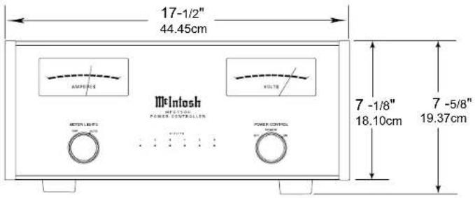
Rear View of the MPC1500

Side View of the MPC1500

Installation
The MPC1500 can be placed upright on a table or shelf, standing on its four feet. It also can be custom installed in a piece of furniture or cabinet of your choice. The four feet may be removed from the bottom of the MPC1500 when it is custom installed as outlined below. The four feet together with the mounting screws should be retained for possible future use if the MPC1500 is removed from the custom installation and used free standing. The required panel cutout, ventilation cutout and unit dimensions are shown.
Always provide adequate ventilation for your MPC1500. Cool operation ensures the longest possible operating life for any electronic instrument. Do not install the MPC1500 directly above a heat generating component such as a high powered amplifier. If all the components are installed in a single cabinet, a quiet running ventilation fan can be a definite asset in maintaining all the system components at the coolest possible operating temperature.
A custom cabinet installation should provide the following minimum spacing dimensions for cool operation.
Allow at least 4 inches (10.16cm) above the top, 2 inches (5.08cm) below the bottom and 1 inch (2.54cm) on each side of the Power Controller, so that airflow is not obstructed. Allow 20 inches (50.8cm) depth behind the front panel. Allow 2 inches (5.08cm) in front of the mounting panel for knobs. Be sure to cut out a ventilation hole in the mounting shelf according to the dimensions in the drawing.

LOCAL POWER CONTROL for AC Outlet number 6 receives a turn-on signal (5 to 12 volts) from a McIntosh component and the LOCAL POWER CONTROL OUT sends a turn-on signal (same voltage as the Power Control Input) on to another McIntosh component. The LED indicates when the AC Outlet is active. The LOCAL POWER CONTROL switch selects LOCAL, GLOBAL or always ON activation
LOCAL POWER CONTROL for AC Outlet number 5 receives a turn-on signal (5 to 12 volts) from a McIntosh component and the LOCAL POWER CONTROL OUT sends a turn-on signal (same voltage as the Power Control Input) onto another McIntosh component. The LED indicates when the AC Outlet is active. The LOCAL POWER CONTROL switch selects LOCAL, GLOBAL or always ON activation
LOCAL POWER CONTROL for AC Outlet number 4 receives a turn-on signal (5 to 12 volts) from a McIntosh component and the LOCAL POWER CONTROL OUT sends a turn-on signal (same voltage as the Power Control Input) onto another McIntosh component. The LED indicates when the AC Outlet is active. The LOCAL POWER CONTROL switch selects LOCAL, GLOBAL or always ON activation
LOCAL POWER CONTROL for AC Outlet number 3 receives a turn-on signal (5 to 12 volts) from a McIntosh component and the LOCAL POWER CONTROL OUT sends a turn-on signal (same voltage as the Power Control Input) onto another McIntosh component. The LED indicates when the AC Outlet is active. The LOCAL POWER CONTROL switch selects LOCAL, GLOBAL or always ON activation
GLOBAL POWER CONTROL
IN receives a turn-on-signal (5 to 12 volts) for the Local Power Control selection of Global and the GLOBAL POWER CONTROL OUT sends a delayed turn-on signal (12 volts) to other McIntosh Component(s)
The LEDs indicate the MPC1500 Power Controller is connected to a live AC Outlet and the UN-SWITCHED AC OUTLETs number 1 and 2 are active.
SWITCHED AC Outlet controlled by LOCAL POWER CONTROL number 6 Switch Setting and/or the received Power Control Signal
SWITCHED AC Outlet controlled by LOCAL POWER CONTROL number 5 Switch Setting and/or the received Power Control Signal

SWITCHED AC Outlet controlled by LOCAL POWER CONTROL number 4 Switch Setting and/or the received Power Control Signal
SWITCHED AC Outlet controlled by LOCAL POWER CONTROL number 3 Switch Setting and/or the received Power Control Signal
Unswitched AC outlets number 1 and 2 are active when the MPC1500 is connected to a live AC Outlet
How to Connect in a Two Channel System
The MPC1500 has the ability to automatically switch AC Power On/Off to Components connected to the SWITCHED AC OUTLETS via the Power Control connection coming from the Preamplifier. Source Components switch On/Off via the Power Control connection from the Preamplifier. For additional information refer to "General Information" on page 4 and "Connector and Cable Information" on page 5.
- Connect a Control Cable from the MPC1500 GLOBAL POWER CONTROL IN Jack to the Power Control Main Out Jack on the Preamplifier.
- Connect the AC Power Cord from the Power Amplifier to MPC1500 SWITCHED AC OUTLET 3.
- Connect a Control Cable from the Preamplifier Acc Power Control Out Jack to the Power Control In jack on the Disc Player.
- Connect the AC Power Cords from the Preamplifier and Disc Player to the UNSWITCHIED AC OUTLETS 1 and 2.
- Connect any remaining Components in a similar manner.
- Using the supplied AC Cord, connect the MPC1500 directly to an AC Wall Outlet.


How to Connect in a Multi Channel System
In the following example two of the four SWITCHED AC OUTLETS on the MPC1500 will operate differently from the default settings. Outlet number 4 will be used for the Zone B Power Amplifier. Outlets 3 and 5 for source components to power up for Zone A and/or Zone B. For additional information refer to "How to Operate" on page 12.
- Connect a Control Cable from the MPC1500 LOCAL POWER CONTROL IN Jack number 4 to the Power Control Zone B Out Jack on the A/V Control Center. Place the number 4 switch in the LCL position.
- Connect the AC Power Cord from the Power Amplifier to MPC1500 SWITCHED AC OUTLET 4.
- Connect a Control Cable from the MPC1500 GLOBAL POWER CONTROL IN Jack to A/V Control Center ACC Power Control Out Jack.
- Connect a Control Cable from the MPC1500 GLOBAL POWER CONTROL OUT Jack to the Power Control In jack on the Disc Player.
- Connect the AC Power Cords from the Disc Player to the SWITCHED AC OUTLET 5. Place the number 6 switch in the ON position.
- Connect any remaining Components in a similar manner.
- Using the supplied AC Cord, connect the MPC1500 directly to an AC Wall Outlet.
Zone B Power Amplifier

natural_image
Pure electrical circuit lines without any symbols

How to Operate
The MPC1500 Power Controller is very versatile in its connection and operation in an Audio, Video or Audio/Video System. There are two examples of connecting and using the MPC1500 on pages 9 and 10 of this Owner's Manual. By becoming familiar with the "How to Operate" section of this Owner's Manual many additional connection and operation possibilities will become apparent.
Power Control
To have the MPC1500 automatically turn On or Off when a Preamplifier or A/V Control Center turns on or off, rotate the POWER CONTROL Switch to the REMOTE position. For manual operation, rotate the POWER CONTROL Switch to the ON or OFF position as desired. Refer to figure 1.
Notes: 1. There must be a power control connection
between the MPC1500
Global Power Control
Input and the Preamplifier or A/V Control Center, in order for the remote power turn-on to function.
- When the POWER CONTROL Switch is placed in the ON the position, the Global Power Control Input activation is overridden.
- AC Outlets 3 thru 6 switch On in sequence with a slight delay in time between each outlet activation.
Meter Illumination
Rotate the METER LIGHTS Switch to select the meter operation mode you desire. Refer to figure 2.
OFF - Meter lights are switched Off.
Note: The meters will continue to indicate
the Input AC
Line Voltage
and the con-
sumed Current.
AUTO - Meter lights are switched
On. When Global Power Control Input of the MPC1500 is connected
to a McIntosh Preamplifier or A/V Control Center with Remote Meter Illumination Control, the Meter Illumination will be remotely controlled (On/Off).
METER LIGHTS
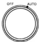
Figure 2
Volt Meter
The VOLTS Meter indicates the AC Voltage available at the AC Outlets on the MPC1500 Rear Panel. Refer to figure 3. The MPC1500 utilizes a very large
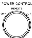
Figure 1
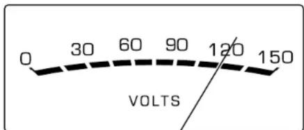
Figure 3
isolation power transformer, so essentially the VOLTS Meter reading is a reflection of the incoming AC Line Voltage. If the VOLTS Meter reading starts to drop more than several volts (from the nominal voltage reading at lower current consumption) when the MPC1500 AMPERES Meter indicates 6 Amps of current or greater, it may be an indication of a condition known as "AC Line Sag". AC Line Sag is usually a result of limitations in the AC Wiring in the walls
due to small wire size and/or long lengths of wire. For additional assistance in this matter contact your McIntosh Dealer and/or Electrical Contractor.
Current Meter
The AMPERES Meter indicates the total amount of current being consumed by the components connected to the MPC1500 AC Outlets. Refer to figure 4. It is

Figure 4
normal for the AMPERES Meter indication to fluctuate especially when a Power Amplifier or Integrated Amplifier is connected to the MPC1500 AC Outlets and music is being played loudly.
Rear Panel Options
AC Outlets number 3 thru 6 can be individually configured to become active via three different methods using the Rear Panel Switches. The first way is using the default configuration (the switch in the GLB position) where the outlet is controlled to switch On or Off via the MPC1500 Global Power Control Input or the Front Panel Power Control Switch. Refer to figure 5 on the next page. The second option is to have any one of the AC Outlets (number 3 thru 6) controlled independently On/Off via the MPC1500 Local Power Control Input for each outlet by placing the Rear Panel

Figure 5
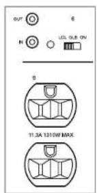
Figure 6

Figure 7
Switch in the LCL Position. Refer to figure 6. The last option is to have the AC Outlets number 3 thru 6 On all the time by placing the Rear Panel Switch in the ON Position. Refer to figure 7.
MPC1500 - NA Specifications
Output Voltage
120 Volts AC Nominal
Load Regulation
± 2.5 %
Power Requirement
120V \~ 60Hz
12 Amps, maximum current
1440 Watts, maximum power
Overall Dimensions
Width is 17-1/2 inches (44.45cm)
Height is 7-5/8 inches (19.37cm) including feet
Depth is 22 inches (55.88cm) including the Front
Panel, Knobs and Cables
Weight
87 pounds (39.46 kg) net, 105 pounds (47.63 kg) in
shipping carton
Shipping Carton Dimensions
Width is 29-1/2 inches (74.93cm)
Depth is 29 inches (73.66cm)
Height is 17 inches (43.18cm)
MPC1500 - EU
(Continental Europe Version)

McIntosh
MPC1500
POWER CONTROLLER


Rear Panel Connections
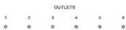
LOCAL POWER CONTROL for AC Outlet number 6 receives a turn-on signal (5 to 12 volts) from a McIntosh component and the LOCAL POWER CONTROL OUT sends a turn-on signal (same voltage as the Power Control Input) on to another McIntosh component. The LED indicates when the AC Outlet is active. The LOCAL POWER CONTROL switch selects LOCAL, GLOBAL or always ON activation LOCAL POWER CONTROL for AC Outlet number 5 receives a turn-on signal (5 to 12 volts) from a McIntosh component and the LOCAL POWER CONTROL OUT sends a turn-on signal (same voltage as the Power Control Input) onto another McIntosh component. The LED indicates when the AC Outlet is active. The LOCAL POWER CONTROL switch selects LOCAL, GLOBAL or always ON activation
LOCAL POWER CONTROL for AC Outlet number 4 receives a turn-on signal (5 to 12 volts) from a McIntosh component and the LOCAL POWER CONTROL OUT sends a turn-on signal (same voltage as the Power Control Input) onto another McIntosh component. The LED indicates when the AC Outlet is active. The LOCAL POWER CONTROL switch selects LOCAL, GLOBAL or always ON activation
LOCAL POWER CONTROL for AC Outlet number 3 receives a turn-on signal (5 to 12 volts) from a McIntosh component and the LOCAL POWER CONTROL OUT sends a turn-on signal (same voltage as the Power Control Input) onto another McIntosh component. The LED indicates when the AC Outlet is active. The LOCAL POWER CONTROL switch selects LOCAL, GLOBAL or always ON activation
GLOBAL POWER CONTROL IN receives a turn-on-signal (5 to 12 volts) for the Local Power Control selection of Global and the GLOBAL POWER CONTROL OUT sends a delayed turn-on signal (12 volts) to other McIntosh Component(s)
The LEDs indicate the MPC1500 Power Controller is connected to a live AC Outlet and the UN-SWITCHED AC OUTLETs number 1 and 2 are active.
SWITCHED AC Outlet controlled by LOCAL POWER CONTROL number 6 Switch Setting and/or the received Power Control Signal
SWITCHED AC Outlet controlled by LOCAL POWER CONTROL number 5 Switch Setting and/or the received Power Control Signal
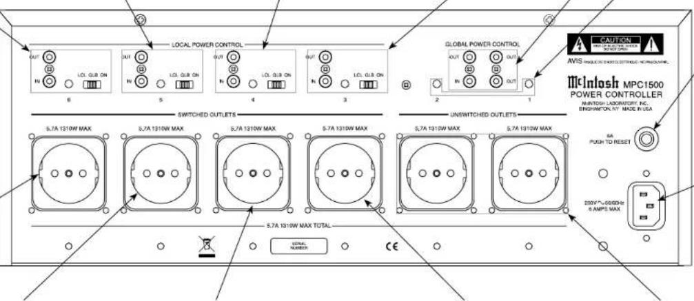
SWITCHED AC Outlet controlled by LOCAL POWER CONTROL number 4 Switch Setting and/or the received Power Control Signal
SWITCHED AC Outlet controlled by LOCAL POWER CONTROL number 3 Switch Setting and/or the received Power Control Signal
Unswitched AC outlets number 1 and 2 are active when the MPC1500 is connected to a live AC Outlet
CIRCUIT BREAKER press to reset if the MPC1500 Power Controller will not power up
Connect the MPC1500 power cord to a live AC outlet. Refer to information on the back panel of your MPC1500 to determine the correct voltage for your unit
How to Connect in a Two Channel System
The MPC1500 has the ability to automatically switch AC Power On/Off to Components connected to the SWITCHED AC OUTLETS via the Power Control connection coming from the Preamplifier. Source Components switch On/Off via the Power Control connection from the Preamplifier. For additional information refer to "General Information" on page 4 and "Connector and Cable Information" on page 5.
- Connect a Control Cable from the MPC1500 GLOBAL POWER CONTROL IN Jack to the Power Control Main Out Jack on the Preamplifier.
- Connect the AC Power Cord from the Power Amplifier to MPC1500 SWITCHED AC OUTLET 3.
- Connect a Control Cable from the Preamplifier Acc Power Control Out Jack to the Power Control In jack on the Disc Player.
- Connect the AC Power Cords from the Preamplifier and Disc Player to the UNSWITCHED AC OUTLETS 1 and 2.
- Connect any remaining Components in a similar manner.
- Using the supplied AC Cord, connect the MPC1500 directly to an AC Wall Outlet.


How to Connect in a Multi Channel System
In the following example two of the four SWITCHED AC OUTLETS on the MPC1500 will operate differently from the default settings. Outlet number 4 will be used for the Zone B Power Amplifier. Outlets 3 and 5 for source components to power up for Zone A and/or Zone B. For additional information refer to "How to Operate" on page 20.
- Connect a Control Cable from the MPC1500 LOCAL POWER CONTROL IN Jack number 4 to the Power Control Zone B Out Jack on the A/V Control Center. Place the number 4 switch in the LCL position.
- Connect the AC Power Cord from the Power Amplifier to MPC1500 SWITCHED AC OUTLET 4.
- Connect a Control Cable from the MPC1500 GLOBAL POWER CONTROL IN Jack to A/V Control Center ACC Power Control Out Jack.
- Connect a Control Cable from the MPC1500 GLOBAL POWER CONTROL OUT Jack to the Power Control In jack on the Disc Player.
- Connect the AC Power Cords from the Disc Player to the SWITCHED AC OUTLET 5. Place the number 6 switch in the ON position.
- Connect any remaining Components in a similar manner.
- Using the supplied AC Cord, connect the MPC1500 directly to an AC Wall Outlet.
Zone B Power Amplifier

natural_image
Pure electrical circuit lines without any symbols


How to Operate
The MPC1500 Power Controller is very versatile in its connection and operation in an Audio, Video or Audio/Video System. There are two examples of connecting and using the MPC1500 on pages 17 and 18 of this Owner's Manual. By becoming familiar with the "How to Operate" section of this Owner's Manual many additional connection and operation possibilities will become apparent.
Power Control
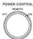
To have the MPC1500 automatically turn On or Off when a Preamplifier or A/V Control Center turns on or off, rotate the POWER CONTROL Switch to the REMOTE position. For manual operation, rotate the POWER CONTROL Switch to the ON or OFF position as desired. Refer to figure 10.
Notes: 1. There must be a power control connection between the MPC1500
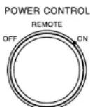
Figure 10
Global Power Control Input and the Preamplifier or A/V Control Center, in order for the remote power turn-on to function.
- When the POWER CONTROL Switch is placed in the ON the position, the Global Power Control Input activation is overridden.
- AC Outlets 3 thru 6 switch On in sequence with a slight delay in time between each outlet activation.
Meter Illumination
Rotate the METER LIGHTS Switch to select the meter operation mode you desire. Refer to figure 12.
OFF - Meter lights are switched Off.
Note: The meters will continue to indicate
the Input AC
Line Voltage
and the con-
sumed Current.
AUTO - Meter lights are switched
On. When Global Power Control Input of the MPC1500 is connected
to a McIntosh Preamplifier or A/V Control Center with Remote Meter Illumination Control, the Meter Illumination will be remotely controlled (On/Off).
METER LIGHTS

Figure 12
Volt Meter
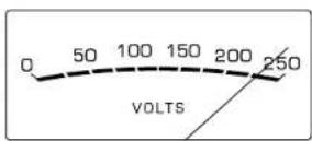
The VOLTS Meter indicates the AC Voltage available at the AC Outlets on the MPC1500 Rear Panel.
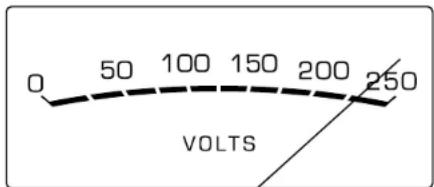
Figure 13
Refer to figure 13. The MPC1500 utilizes a very large isolation power transformer, so essentially the VOLTS Meter reading is a reflection of the incoming AC Line Voltage. If the VOLTS Meter reading starts to drop more than several volts (from the nominal voltage reading at lower current consumption) when the MPC1500 AMPERES Meter indicates 3 Amps of current or greater, it may be an indication of a condition known as “AC Line Sag”. AC Line Sag is usually a result of limitations in the AC Wiring in the walls due to small wire size and/or long lengths of wire. For additional assistance in this matter contact your McIntosh Dealer and/or Electrical Contractor.
Current Meter
The AMPERES Meter indicates the total amount of current being consumed by the components connected to the MPC1500 AC Outlets. Refer to figure 14. It is
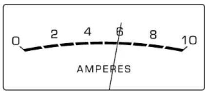
Figure 14
normal for the AMPERES Meter indication to fluctuate especially when a Power Amplifier or Integrated Amplifier is connected to the MPC1500 AC Outlets and music is being played loudly.
Rear Panel Options
AC Outlets number 3 thru 6 can be individually configured to become active via three different methods using the Rear Panel Switches. The first way is using the default configuration (the switch in the GLB position) where the outlet is controlled to switch On or Off via the MPC1500 Global Power Control Input or the Front Panel Power Control Switch. Refer to figure 15 on the next page. The second option is to have any one of the AC Outlets (number 3 thru 6) controlled independently On/Off via the MPC1500 Local Power

Figure 15
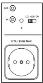
Figure 16 Figure 17
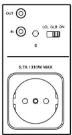
Control Input for each outlet by placing the Rear Panel Switch in the LCL Position. Refer to figure 16. The last option is to have the AC Outlets number 3 thru 6 On all the time by placing the Rear Panel Switch in the ON Position. Refer to figure 17.
MPC1500 - EU Specifications
Output Voltage
230 Volts AC Nominal
Load Regulation
±2.5%
Power Requirement
230V \~ 50/60Hz
6 Amps, maximum current
1380 Watts, maximum power
Overall Dimensions
Width is 17-1/2 inches (44.45cm)
Height is 7-5/8 inches (19.37cm) including feet
Depth is 22 inches (55.88cm) including the Front
Panel, Knobs and Cables
Weight
87 pounds (39.46 kg) net, 105 pounds (47.63 kg) in
shipping carton
Shipping Carton Dimensions
Width is 29-1/2 inches (74.93cm)
Depth is 29 inches (73.66cm)
Height is 17 inches (43.18cm)
MPC1500 - JA
(Japan Version)

McIntosh
Rear Panel Connections

How to Connect in a Two Channel System
The MPC1500 has the ability to automatically switch AC Power On/Off to Components connected to the SWITCHED AC OUTLETS via the Power Control connection coming from the Preamplifier. Source Components switch On/Off via the Power Control connection from the Preamplifier. For additional information refer to "General Information" on page 4 and "Connector and Cable Information" on page 5.
- Connect a Control Cable from the MPC1500 GLOBAL POWER CONTROL IN Jack to the Power Control Main Out Jack on the Preamplifier.
- Connect the AC Power Cord from the Power Amplifier to MPC1500 SWITCHED AC OUTLET 3.
- Connect a Control Cable from the Preamplifier Acc Power Control Out Jack to the Power Control In jack on the Disc Player.
- Connect the AC Power Cords from the Preamplifier and Disc Player to the UNSWITCHED AC OUTLETS 1 and 2.
- Connect any remaining Components in a similar manner.
- Using the supplied AC Cord, connect the MPC1500 directly to an AC Wall Outlet.
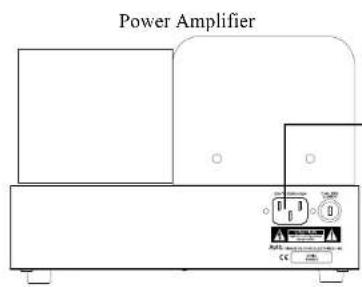

How to Connect in a Multi Channel System
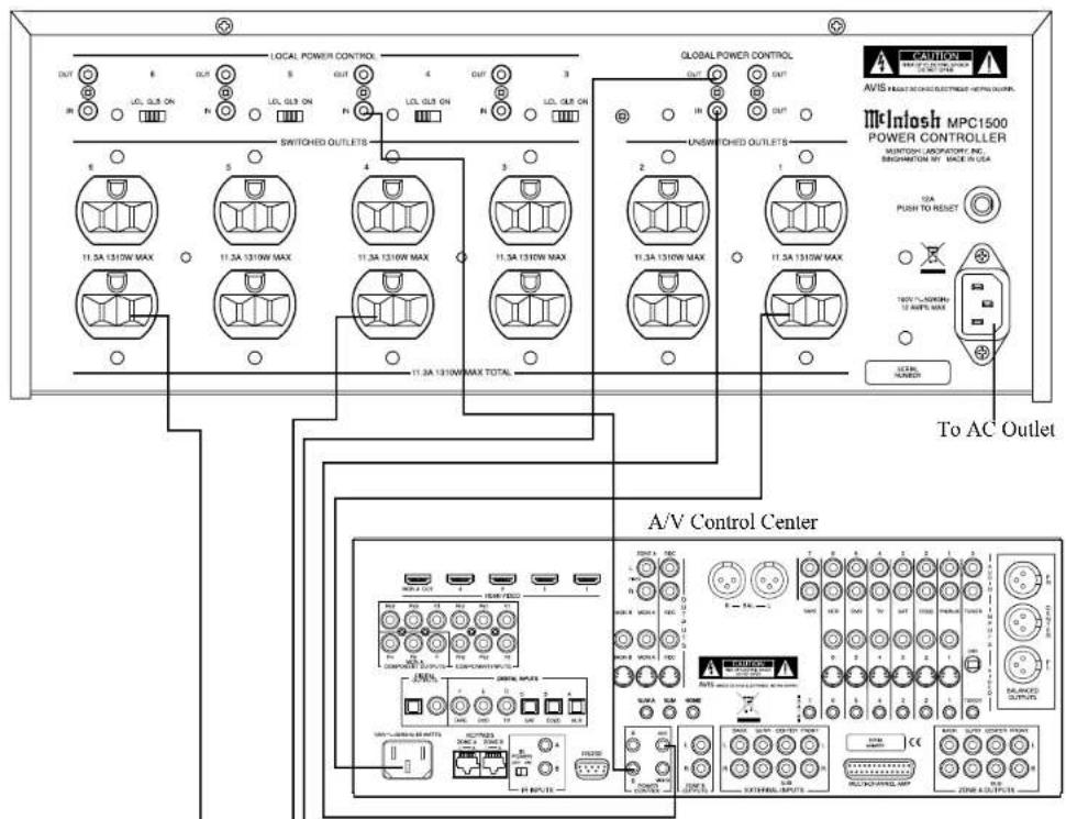
In the following example two of the four SWITCHED AC OUTLETS on the MPC1500 will operate differently from the default settings. Outlet number 4 will be used for the Zone B Power Amplifier. Outlets 3 and 5 for source components to power up for Zone A and/or Zone B. For additional information refer to "How to Operate" on page 28.
- Connect a Control Cable from the MPC1500 LOCAL POWER CONTROL IN Jack number 4 to the Power Control Zone B Out Jack on the A/V Control Center. Place the number 4 switch in the LCL position.
- Connect the AC Power Cord from the Power Amplifier to MPC1500 SWITCHED AC OUTLET 4.
- Connect a Control Cable from the MPC1500 GLOBAL POWER CONTROL IN Jack to A/V Control Center ACC Power Control Out Jack.
- Connect a Control Cable from the MPC1500 GLOBAL POWER CONTROL OUT Jack to the Power Control In jack on the Disc Player.
- Connect the AC Power Cords from the Disc Player to the SWITCHED AC OUTLET 5. Place the number 6 switch in the ON position.
- Connect any remaining Components in a similar manner.
- Using the supplied AC Cord, connect the MPC1500 directly to an AC Wall Outlet.



How to Operate
The MPC1500 Power Controller is very versatile in its connection and operation in an Audio, Video or Audio/Video System. There are two examples of connecting and using the MPC1500 on pages 8 and 9 of this Owner's Manual. By becoming familiar with the "How to Operate" section of this Owner's Manual many additional connection and operation possibilities will become apparent.
Power Control
To have the MPC1500 automatically turn On or Off when a Preamplifier or A/V Control Center turns on or off, rotate the POWER CONTROL Switch to the REMOTE position. For manual operation, rotate the POWER CONTROL Switch to the ON or OFF position as desired. Refer to figure 20.
Notes: 1. There must be a power control connection between the MPC1500 Global Power Control Input and the Preamplifier or A/V Control Center, in order for the remote power turn-on to function.
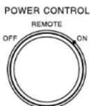
Figure 20
-
When the POWER CONTROL Switch is placed in the ON the position, the Global Power Control Input activation is overridden.
-
AC Outlets 3 thru 6 switch On in sequence with a slight delay in time between each outlet activation.
Meter Illumination
Rotate the METER LIGHTS Switch to select the meter operation mode you desire. Refer to figure 21.
OFF - Meter lights are switched Off.
Note: The meters will continue to indicate
the Input AC
Line Voltage and the con-
sumed Current.
AUTO - Meter lights are switched On. When Global Power Control Input of the MPC1500 is connected to a McIntosh Preampli-
fier or A/V Control Center with Remote Meter Illumination Control, the Meter Illumination will be remotely controlled (On/Off).
Volt Meter
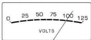
The VOLTS Meter indicates the AC Voltage available at the AC Outlets on the MPC1500 Rear Panel. Refer to figure 22. The MPC1500 utilizes a very

Figure 22
large isolation power transformer, so essentially the VOLTS Meter reading is a reflection of the incoming AC Line Voltage. If the VOLTS Meter reading starts to drop more than several volts (from the nominal voltage reading at lower current consumption) when the MPC1500 AMPERES Meter indicates 6 Amps of current or greater, it may be an indication of a condition known as "AC Line Sag". AC Line Sag is usually a result of limitations in the AC Wiring in the walls due to small wire size and/or long lengths of wire. For additional assistance in this matter contact your McIntosh Dealer and/or Electrical Contractor.
METER LIGHTS

Figure 21
Current Meter
The AMPERES Meter indicates the total amount of current being consumed by the components connected to the MPC1500 AC Outlets. Refer to figure 23. It is

Figure 23
normal for the AMPERES Meter indication to fluctuate especially when a Power Amplifier or Integrated Amplifier is connected to the MPC1500 AC Outlets and music is being played loudly.
Rear Panel Options
AC Outlets number 3 thru 6 can be individually configured to become active via three different methods using the Rear Panel Switches. The first way is using the default configuration (the switch in the GLB position) where the outlet is controlled to switch On or Off via the MPC1500 Global Power Control Input or the Front Panel Power Control Switch. Refer to figure 24 on the next page. The second option is to have any one of the AC Outlets (number 3 thru 6) controlled independently On/Off via the MPC1500 Local Power

Figure 24

Figure 25
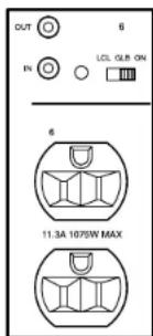
Figure 26
Control Input for each outlet by placing the Rear Panel Switch in the LCL Position. Refer to figure 25. The last option is to have the AC Outlets number 3 thru 6 On all the time by placing the Rear Panel Switch in the ON Position. Refer to figure 26.
MPC1500 - JA Specifications
Output Voltage
100 Volts AC Nominal
Load Regulation
± 2.5 %
Power Requirement
100V \~ 50/60Hz
12 Amps, maximum current
1200 Watts, maximum power
Overall Dimensions
Width is 17-1/2 inches (44.45cm)
Height is 7-5/8 inches (19.37cm) including feet
Depth is 22 inches (55.88cm) including the Front
Panel, Knobs and Cables
Weight
87 pounds (39.46 kg) net, 105 pounds (47.63 kg) in
shipping carton
Shipping Carton Dimensions
Width is 29-1/2 inches (74.93cm)
Depth is 29 inches (73.66cm)
Height is 17 inches (43.18cm)
Packing Instructions
In the event it is necessary to repack the equipment for shipment, the equipment must be packed exactly as shown below. It is very important that the four plastic feet are attached to the bottom of the equipment. Two #10 x 2-1/2 inch screws and washers must be used to fasten the unit securely to the bottom pad and wood skid. This will ensure the proper equipment location on the bottom pad. Failure to do this will result in shipping damage.
Use the original shipping carton and interior parts only if they are all in good serviceable condition. If a shipping carton or any of the interior part(s) are needed, please call or write Customer Service Department of McIntosh Laboratory. Refer to page 4. Please see the Part List for the correct part numbers.
Quantity Part Number Description
1 033888 Shipping carton
4 033887 End Cap
1 033697 Inner carton
1 033725 Top pad
1 034301 Bottom pad
1 033699 Wood skid
2 017218 Plastic foot (spacer)
2 401204 #10 x 2-1/2 inch wood screw
2 404033 #10 flat washer 1-3/4 inch
4 017937 Plastic foot
4 400159 #10-32 x 3/4 machine screw
4 404080 #10 flat washer


McIntosh Laboratory, Inc.
2 Chambers Street
Binghamton, NY 13903
www.mcintoshlabs.com
The continuous improvement of its products is the policy of McIntosh Laboratory Incorporated who reserve the right to improve design without notice. Printed in the U.S.A.
- WARNING - TO REDUCE RISK OF FIRE OR ELECTRICAL SHOCK, DO NOT EXPOSE THIS EQUIPMENT TO RAIN OR MOISTURE.
- IMPORTANT SAFETY INSTRUCTIONS!
- PLEASE READ THEM BEFORE OPERATING THIS EQUIPMENT.
- NO USER-SERVICEABLE PARTS INSIDE. REFER SERVICING TO QUALIFIED PERSONNEL.
- To prevent the risk of electric shock, do not remove cover or back. No user-serviceable parts inside.
- Table of ContentsModel Versions
- MPC1500-NA
- MPC1500-EU
- MPC1500-JA
- Thank You
- Please Take A Moment
- Technical Assistance
- Customer Service
- General Information
- General Information, con't
- Connector and Cable Information
- Power Control Connectors
- Introduction
- Performance Features
- • Toroidal Isolation Power Transformer
- - Stable Voltage
- • Lono Technology
- • Superior Line Surge Protection
- - Illuminated Voltage and Current Meters
- - Power Control
- • Fiber Optic Solid State Front Panel Illumination
- Dimensions
- Installation
- How to Connect in a Two Channel System
- How to Connect in a Multi Channel System
- How to Operate
- Power Control
- Meter Illumination
- Volt Meter
- Current Meter
- Rear Panel Options
- MPC1500 - NA Specifications
- Rear Panel Connections
- MPC1500 - EU Specifications
- Output Voltage
- Load Regulation
- Power Requirement
- Overall Dimensions
- Weight
- Shipping Carton Dimensions
- MPC1500 - JA
- McIntosh
- MPC1500 - JA Specifications
- Packing Instructions
Brand : MCINTOSH
Model : MPC1500
Category : Audio Amplifier