
ESP3 - Coffee maker AFK - Free user manual and instructions
Find the device manual for free ESP3 AFK in PDF.


| Product Type | Espresso Machine (Coffee Maker) |
| Model | ESP3 |
| Brand | AFK |
| Boiler Capacity | 19 quarts |
| Cups Per Hour | 720 |
| Dimensions (W x D x H) | 24 7/8” x 21 9/16” x 21 1/2” |
| Weight | 185 lbs (84 kg) |
| Electrical Requirements | 240V, 6.5KW, 27A |
| Water Line Size | 1/2” required |
| Fully Automatic | Yes, with single/double espresso, 1-2 cups or continuous flow |
| Dual Pressure Gauge | Reads dispensing water pressure and boiler steam pressure |
| Microprocessor Control | Touch pad controls with LED display |
| Pump | Internal pump for low water pressure areas |
| Boiler Type | Stainless steel dual boiler |
| Sight Glass | For monitoring water level |
| Auto Cleaning | Automatic reverse flushing function |
| Hot Water Valve | Yes, dispensing hot water for tea |
| Included Accessories | One and two cup filter holder assemblies, hoses |
| Safety Features | Safety valve, pressure relief valve, automatic shut-off |
| Cleaning | Daily rinse of filter basket, steam tube; weekly reverse flush with detergent |
| Repair Parts | Widely available; see manual for part numbers |
Frequently Asked Questions - ESP3 AFK
User questions about ESP3 AFK
0 question about this device. Answer the ones you know or ask your own.
Ask a new question about this device
Download the instructions for your Coffee maker in PDF format for free! Find your manual ESP3 - AFK and take your electronic device back in hand. On this page are published all the documents necessary for the use of your device. ESP3 by AFK.
USER MANUAL ESP3 AFK
ESP Espresso Machines
Instruction Manual

Models: ESP1, ESP2 and ESP3
Cecilware Corporation 43-05 20th. Avenue, LIC NY 11105
Tel: 800.935.2211 / 718.932.1414 • Fax: 718.932.7860
Operation Manual
Table of Contents
- General ...... pg. 3
- Precautions ...... pg. 4
- Machine Overview ...... pg. 5
- Operations ...... pg 6
- Cleaning and Maintenance....pg. 9
- Troubleshooting Common Problems ...... pg. 11
- Replacement Parts ...... pg. 12
Standard Features
- Fully Automatic – Dispense single or double espresso, 1 or 2 cups at a time, or choose manual continuous flow.
- Dual Pressure Gauge – Readouts for the dispensing water pressure & boiler steam pressure.
- User Friendly Microprocessor Technology - features touch pad controls & LED display.
- Heavy Duty Design – Built-in 260W motor & 200-300 qt/hr pump.
- Sight Glass – For instant & easy monitoring of the water tank level.
- Auto Cleaning Function – Flushes the line to the brew head.
- Stainless Steel Dual Boiler.
• Hot Water Dispensing Valve. - In low water pressure locations, an internal pump will draw water into the boiler.
| Model # of | Heads Boiler Size | Cups / Hr.* | DimensionsW x D x H | Electrical | Ship Weight | |
| ESP1-110V | 1 Group 6 qts. | 240 20 | 5/16" × 219/16" × 211/2" | 120V, 1.5KW, 18A | 106 lbs. | |
| ESP1-220V | 1 Group 6 qts. | 240 20 | 5/16" × 219/16" × 211/2" | 40V, 2.5KW, 10A | 106 lbs. | |
| ESP2-220V | 2 Group | 13 qts. | 480 | 3/8" × 219/16" × 211/2" | 240V, 4.7KW, 20A | 147 lbs. |
| ESP3-220V | 3 Group | 19 qts. | 720 | 7/8" × 219/16" × 211/2" | 240V, 6.5KW, 27A | 185 lbs. |
Plumbing: 1/2 " water line required
Accessories: Two & one cup filter holder assemblies and hoses are included with all espresso machines.
Note: in-line water filter must be installed for warranty to be in effect
Specifications subject to change without notice.
1 General
1-1 This operations manual includes instructions for using and maintaining your espresso machine, please keep this manual readily available.
1-2 After unpacking, please check to ensure your machine has not been damaged during shipping and includes all parts/components. Please notify your service representative regarding any questions or concerns before installing. Please note that machine packaging material can be dangerous and should be kept out of reach of children.
1-3 Please confirm that your electricity supply conforms to the espresso machine power requirements. A qualified technician should install the machine in accordance with manufacturer instructions. The manufacturer assumes no responsibility for injury or damage resulting from improper installation.
1-4 Please use an independent and suitable power source for your machine.
1-5 Please use an independent, fuseless breaker appropriate to machine safety requirements. Do not plug your machine into an extension cord.
1-6 Be sure to use a grounded power source to prevent electric shock and ensure operating safety.
1-7 Use the automatic espresso machine for its intended purpose only. Any other usage is inappropriate and may be dangerous. The manufacturer assumes no responsibility for injury, loss or damage resulting from improper machine use.
1-8 Do Not:
a. touch machine with wet hands or feet.
b. touch machine with bare feet.
c. pull on the cord to disconnect machine from power outlet.
d. expose the espresso machine to rain or direct sunlight.
e. permit children or persons not normally qualified to operate basic machinery to use this machine.
1-9 Turn off the power source first before maintaining or servicing your espresso machine.
1-10 Take care when touching machine parts; subject to high temperature heating to avoid injury.
1-11 Clean machine according to instructions provided in this manual to ensure proper operations.
1-12 Turn power off if machine functions abnormally and notify qualified service personnel for repairs. Do not permit non-qualified service personnel to attempt repairs. Continuing to use a damaged or otherwise irregularly functioning machine will nullify the manufacturer warranty.
1-13 Use softened water to make coffee or tea. Well / municipal water should be softened to prevent scaling in the boiler, which will shorten the serviceable life of your machine. If a hard water source is used, the filter should be replaced every two weeks -- although long-life filters may remain serviceable up to eight weeks. Actual filter replacement scheduling will vary based on volume and quality of water used.
1-14 The machine refills water automatically (see Section 4-2 for initializing). An error code will appear if water flow into the machine exceeds two minutes (see Troubleshooting Section in this manual), and power will be cut off automatically to protect the system. To resume normal functions, restart the system after three or more seconds.
1-15 The heating element will not operate when water in the machine is less than the minimum required level. When starting the machine without any water in the tank, heating will be delayed for about 60 seconds.
1-16 Please ensure the water inside the piping will not be frozen while using the machine. The water temperature must maintain over the freezing point even during the power off period. The warranty does not cover any damages on piping and boiler cost by frozen water.
1-17 When turning off the machine for long-term, please be sure to evacuate the water inside the piping completely. For this may freeze the water and lead to damaging the machine. To ensure the safety of your machine, please notify your service representative regarding any needs on operations in frigid zone or prepare to shut down the machine for long-term for complete water evacuation.
2. Operating Precautions
Do not use the machine and turn off the power when water intake has ceased.
When operating the machine for the first time or replacing the filter, remove the water inlet tube and allow it to drain for about one minute in order to discharge impurities from the water.
Please check and confirm normal water supply before turning on power.
Please check and confirm water level registers within the green zone. Operating the machine outside the green zone may cause the electric heating element to overheat and burn out.
After installing the machine, please check to make sure that, during water intake, the steam pressure gauge indicator is within the green zone (1\~1.4bar) and the water pressure gauge indicator is also within the green zone (8\~10bar). Please adjust the system to the water supply pressure conditions in your area.
The water and steam taps are used to make coffee or tea. The nozzle at the hot water outlet and the steam outlet are very hot -- please do not touch.
To avoid overheating, electric wires should be kept untangled and free of obstructions. Do not block air intake or outlet vents on the machine. Never cover or otherwise prevent the free flow of air across the cup warmer.
Please clean machine components with a soft cloth only. Do not use plastic or wire brushes.
Turn the power off and release all boiler pressure if the machine is to remain idle for an extended period of time.
Place an appropriate quantity of ground coffee in the filter cup and tamper carefully. Clean all residual coffee from the rim and sides of the filter to ensure a good seal and full pressure for steaming and to maximize service life.
The filter basket must be connected firmly to the filter support during steaming to avoid disengagement of the handle or overflow.
Remove the cup from the steam tube after foaming milk. Failure to do so may draw liquid from the cup into the steam tube, risking machine component contamination.
After machine power has been switched off, always let the machine set for at least 3 seconds before restarting.

3. Machine Overview
A. Foot I. Manual water outlet controller
B. Water tray J. Power indicator
C. Pressure gauge (water/steam pressure) K. Power switch
D. Steam tube L. Water level viewing window
E. Hot water outlet nozzle
F. Hot water control knob
G. Steam control knob
H. Control Panel
M. Manufacturer plate
N. Filter basket handle
O. Cup warming tray holder
4. Operations
4-1 Activating / Deactivating the Water Inlet Motor
a. If filtered water source pressure exceeds 2 bar and the amount of hot water needed is small, turn the water inlet motor (2) to the OFF (up) position to permit water inflow without internal pump assistance.


b. In areas of low source water pressure, turn the water inlet motor (2) to the ON (down) position to activate the internal pump and draw water into the boiler mechanically.
Caution: When source water pressure is low & turn the water inlet motor (2) to the OFF (up) position may risks drawing hot water away from the boiler and damaging the pump and water intake solenoid.
4-2 Starting the Automatic Machine
a. Check and confirm that water source is in normal working order.
b. Turn the power switch to position 1 to initiate automatic system check. If boiler water level is not in the green zone, wait until the automatic water replenishment process is complete before proceeding to the next step.
c. Heating will stop when boiler pressure reaches approximately 1.2 bars (factory default setting). Do not operate machine until steam pressure gauge reading is in the green zone.
4-3 Using the Various Machine Functions
a. Steam Output
Turn steam knob counterclockwise to draw steam through the steam tube. Steam output will increase the further the steam knob is turned. Turn the knob clockwise to reduce/stop steam output. Pull out the steam knob when needing a good deal of steam for a short period of time.
b. Hot Water Output
Turn the hot water knob counterclockwise to obtain hot water through the hot water tube. Hot water output will increase the further the hot water knob is turned. Turn the knob clockwise to reduce/stop steam output. Pull out the hot water knob for hot water supply for a short period of time.
c. Coffee / Tea Output Presets
Place an appropriate quantity of ground coffee or tea in the filter basket and fix it into the handle seat. Choose desired water output by selecting coffee or tea output values 1 through 4. Coffee or tea flow will stop automatically.
d. Continuous Output & Stop
Place an appropriate quantity of ground coffee or tea into the filter basket, and fix it into the handle seat. Press the manual output button to start coffee or tea flow. Press once again to stop.
4-4 Output Volume, Estimated steep time, and Frequency Setup
There are two identical button suites on two-cup models and three identical button suites on 3-cup models. No default coffee / tea output setting is provided. Settings must be made manually during set-up. If you are using a multi-cup machine, settings made on the farthest right hand side button suite will serve as the default for the others. Therefore, to set different values for different cup compartments, begin set up from the right and work your way to the left, to prevent the previous setting been covered.


Output Volume Setup
a. Turn the output volume setup switch ON (1) and press the PROG (setup) button.

b. The output LEDs should be lit, indicating the machine is in setup mode.
c. To configure key 1, press the key 1 button, which should light LED 1 and switch off all other LEDs. Once desired setup parameters have been set, press key 1 again to confirm and exit key 1 setup.
d. At this point, LED 1 should be off and LED's 2, 3 and 4 should be lit.
e. Repeat steps (b) through (d) to set up keys 2, 3 and 4, respectively.
f. The left set(s) of keys will mirror the value settings in the set of keys to its immediate right. Repeat steps (b) through (e) if different output volumes are desired for different cup compartments.
g. After completing setup, turn the output volume setup switch OFF (1) to return the machine to normal operational mode.
4-5 Automatic Reverse Flushing
a. Press any key simultaneously to start automatic reverse flushing. Keys 2-4 in the control panel will start flashing and start automatic reverse flushing from the right output system to the left.
b. The default is 10 cleaning cycles.
c. Flush the second output system after flushing the first output system. Or press the 3rd key to skip to the next output system, System will stop automatically after finish all the reverse flushing.
4-6 Stopping the Machine
a. After cleaning the machine, remove all liquids and solid matter from the water tray.
b. Turn off the power (turn power switch to position 0).
c. Open steam knob to release steam flow. Do not place any liquid under the steam tube during this process in to avoid system contamination.
5. Cleaning and Maintenance
5-1 Cleaning the Machine Body
Wipe machine exterior with soft, slightly dampened cloth daily before starting operations.
If necessary, a mild, non-corrosive cleaning agent may be applied to the cloth. Do not spray cleaning agents directly on the machine body to avoid corrosion and possible damage to circuits.
5-2 Brewing System
After each brewing cycle, remove the handle and press the manual water output button to remove all residual ground coffee from the filter element. Then, fix the handle to the seat again (Important: Do not force handle or fix it into the seat too tightly). Press the manual water output button, shake the handle to clean the handle seat gasket and remove residual coffee grounds from the along the inside.
A Flush the steam outlet in REVERSE daily before shutting off the machine.
Remove the copper plate and filter element from the water outlet (be careful, metal components may be hot).
B Place a reverse flushing silica plate in the filter cup, and apply about 2-3 grams of detergent. Fix the handle into the seat and check for tightness.
C To dissolve residual detergent in the machine, press the manual water output button for approximately 4 seconds and release. Repeat this process several times. Press the manual water output button and shake the handle to clean the gasket and the inside of the brewer. Continue the process until water in the filter cup is clear and clean.
D After cleaning, remove the handle. Press the manual water output button to allow residual cleaning solution in the brewing system to flow out. Turn water off after flushing for about one minute.
a. During reverse flushing, remove and wash the copper plate and filter element with clean tap water. Wipe with soft cloth.
b. If process is unable to sufficiently clean the plate and filter element, immerse the components overnight in a mild cleaning solution of 3 tsp detergent in 1 pint hot water. Rinse and reassemble components before restarting the espresso machine.
5-3 Filter Basket and Basket Handle
a. Rinse the handle with hot water after each brewing cycle to dissolve residual oils in the filter basket and outlet nozzle and prevent oils from affecting the quality of coffee.
b. Disassemble filter basket handle and filter basket. Immerse both in cleaning solution (3tsp of detergent in 1 pint hot water) for 24 hours to dissolve residual coffee oils. Important: Do not immerse the plastic portion of the handle in the cleaning solution to avoid deterioration.
C. Rinse all components with clean water. Wipe with a soft, clean cloth only.


Dia. Part List
# # Description Price
| 1 | 01346 SILICA GEL WASHER | $ 2.10 |
| 2 | 01347 1 CUP FILTER HOLDER ASSY | 156.40 |
| 3 | 01348 1 CUP STAINLESS STEEL FILTER | 24.60 |
| 4 | 01349 1 CUP FILTER HOLDER WITHOUT FILTER | 121.20 |
| 5 | 01350 FILTER SUPPORT | 83.70 |
| 6 | 01351 BRASS SPOUT 1 LONG CUP | 23.40 |
| 7 | 01352 FILTER CLAMP SPRING D1.4 | 1.00 |
| 8 | 01353 FILTER HOLDER KNOB CAP | 14.00 |
| 9 | 01354 FILTER HOLDER BACK LID | 1.50 |
| 10 | 01355 2 CUPS FILTER HOLDER ASSY | 163.00 |
| 11 | 01356 2 CUPS STAINLESS STEEL FILTER | 24.60 |
| 12 | 01357 2 CUPS FILTER HOLDER WITHOUT FILTER | 127.90 |
| 13 | 01358 2 CUPS BRASS SPOUT | 30.00 |
5-4 Steam Tube
a. After making steamed milk, use a slightly moistened soft cloth to wipe steam tube. After wiping, release a steam burst through the tube to remove any residual milk remaining in the nozzle.
b. If hardened milk residuals remain in the steam tube, disassemble and immerse tube in hot water for about 20 minutes to soften. Reassemble and repeat step (a).
5-5 Boiler
To extend your boiler's serviceable life, when the machine is expected to sit idle for a period of one or more days, turn power to the machine OFF and open the steam output to discharge pressure in the boiler. Continue until the pressure gauge reading falls to zero and steam discharge ends. Once complete, empty and clean the water tray and discharge trough. (Important: Leave the steam output setting open following steam discharge. Steam output should remain open until after the machine is turned back on and hot water begins dripping from the steam tube.
5-6 Water Tray
Remove and wash the water tray after stopping your automatic machine. Reassemble after the water tray has dried.
5-7 Discharge Trough
a. After removing the water tray, wipe and remove sediments in the discharge trough with a wet cloth or napkin and wash with hot water to clear the discharge tube.
b. If water does not discharge properly, place a teaspoon of detergent into the discharge trough and flush with hot water to dissolve residual oils in the tube.
5-8 Filter
a. The manufacturer recommends replacing the filter element on the resin exchange filter after processing 53 gallons of water (about 3,000 – 4,000 cups of coffee). This schedule can be expected to vary based on the quality of water used in your machine.
6 Trouble Shooting
| Indication Status Possible Cause | CorrectiveActions | ||
| L | After two minutes of water input, indicator still does not show a rise in machine water level. It will take more than two minutes to replenish water when the machine is used for the first time. | 1. Water level indicator not functioning properly.2. Water intake solenoid is out of order. Input water flow has been interrupted. | 1. Make sure that the water input switch is ON and that water is flowing into the machine.2. Turn off the machine.Restart after 3 seconds.3. Notify local dealer. |
| E | 1. No water output from the brewer.2. Machine does not reach preset parameters. | 1. Coffee grounds are too fine.2. No water input3. Water intake solenoid is out of order. | 1. Adjust coffee ground fineness.2. Ensure water input is normal.3. Notify local dealer. |
| - | Boiler is in automatic water input mode. | Boiler water level is too low, automatic water input system is working. | Indication of an action for reference. |
| A or B | IC board does not function properly. | Software or hardware error. | 1. Turn machine off.Restart after 3 seconds.2. Notify local dealer. |
Wait at least 3 seconds to restart the automatic espresso machine after turning it off to ensure previous data stored in machine memory is erased. Turning the machine on too quickly may cause the machine to function improperly.
7. Replacement Parts (For Reference Only)
Item Particular Serviceable Life
| 1 Brewer gasket 3 - 6 months, depending of volume of coffee brewed |
| 2 Upper gasket for steam tube 1 year |
| 3 Lower gasket for steam tube 1 year |
| 4 Leak-stop gasket for steam/hot water valve 1 year |
| 5 Upper gasket for steam/hot water valve 1 year |
| 6 Pressure relief valve 2 years |
| 7 Safety valve 2 years |
| 8 Filter pad 1 – 3 months, depending on water quality |
| 9 Filter element (active carbon) 1 – 3 months, depending on water quality |
| 10 Filter element (soft water resin) 1 – 3 months, depending on water quality |
Overall Composition Chart ESP1, ESP2, ESP3

| Dia. Part | List Price | Dia. Part | List Price | ||||
| # | # | Description | # | # | Description | ||
| 1 | xxx | SCREW M4*8 | 9 | xxx | FLOWMETER DOSER ASSY | ||
| 2 | xxx | NUT M10 | 10 | xxx | NUT M6 | ||
| 3 | xxx | SPRING WASHER M10 | 11 | xxx | SPRING WASHER M6 | ||
| 4 | xxx | DRAIN BASIN | 12 | xxx | ANTI FOOT VIBRATION | ||
| 5 | 01325 | FLOWMETER DOSER | 161.50 | 13 | 01331 | PRESSURE GAUGE FOR ESP 220V .188.20 | |
| 6 | xxx | BRASS FITTING PS/1/4*PS1/4*L33.5 | 14 | xxx | PRESSURE GAUGE | ||
| 7 | xxx | BRASS FITTING PS/1/4*PS1/4*L42 | 15. | xxx | SCREW M8*20 | ||
| 8 | xxx | SCREW M4*6 | 16. | xxx | SPRING WASHER M8 | ||
xxx special order contact Cecilware for more information
Electrical Assembly
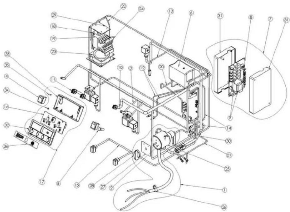
Dia. Part List
# # Description Price
1 xxx MAIN SWITCH ASSY ESP1 .....
xxx MAIN SWITCH ASSY ESP2 ....
xxx MAIN SWITCH ASSY ESP3 .....
2 xxx MAIN SWITCH ESP1, 2 ....
xxx MAIN SWITCH ESP3 ....
3 xxx CABLE UNIT ESP1 ....
xxx CABLE UNIT ESP2
xxx CABLE UNIT ESP3 ....
4 xxx LUMINOUS BLACK BIPOLAR .....
5 xxx GREEN INDICATOR LAMP .....
6 01326 SI 501 CE PRESSURE SWITCH
110V / 240V AC 20A \$ 319.50
7 xxx CONTROL BOX WITH IC BOARD ....
8 01328 CONTROL PC-MAIN BOARD ..... \$ 400.40
9 xxx FUSE 1.5A
xxx FUSE 4A (MOTOR) ....
10 xxx SERIES CABLE PCB PANEL .....
11 xxx SERIES CABLE PANEL ....
12 xxx SELECT SWITCH ....
13 xxx LEVEL PROBE CABLE .....
14 xxx HEATING ELEMENT POWER CABLE .
15 xxx FLOWMETER GAUGE CABLE ESP1. xxx FLOW METER GAUGE CABLE ESP2. xxx FLOW METER GAUGE CABLE ESP3.
16 xxx CONTROL PC-MAIN BOARD .....
17 01327 AS OPERATE FACEPLATE ....\$129.30
19 xxx SOLID STATE RELAY 25A
GN84131011 ESP1
18 xxx SINGLE CABLE SSR-2-4 ....
Dia. Part List
# # Description Price
xxx SOLID STATE RELAY 50A
GN84137021 ESP2, ESP3 ....
20 xxx SINGLE CABLE
PRESSURE SWITCH<->PCB .....
21 xxx MOTOR POWER ESP1,120V
xxx MOTOR POWER ESP1, 220V .....
xxx MOTOR POWER ESP2 ....
xxx MOTOR POWER ESP3 ....
22 xxx SSR-PRESSURE SWITCH CABLE
23 xxx FAN FOR SSR
24 xxx RADIATOR ....
25 xxx MAIN SWITCH COVER ....
26 xxx BAND
27 xxx MAIN SWITCH HAND GRIP LABEL PLATE
28 xxx MAIN SWITCH HAND GRIP .....
29 xxx SSR HOLDER ....
30 01338 TEMP. PROTECTION FUSE \$ 8.60
31 xxx CONTROL BOX WITHOUT IC
xxx BOARD (UP & DOWN COVER) .....
32 xxx AS MANIPULATION FACEPLATE UP COVER
33 xxx MANIPULATION BOX....
34 xxx SCREW M3*6 ESP 220V .....
35 xxx SCREW M3*15 ESP 220V .....
36 xxx OPERATION LABEL ....
37 xxx FLOWMETER GAUGE JOINT)
(NOT SHOWN) ESP1 120V .....
38 xxx ELECTROMAGNETIC JOINT
(NOT SHOWN) ESP120V .....
Water & Steam Assembly ESP1

Dia. Part List
# Number Description Price
1 xxx WATER/STEAM TAP UNIT .....
2 xxx TAP BODY ....
3 01334 SEAL \$ .20
4 01335 CHROMED TAP SHAFT \$ 6.90
5 xxx TAP CONNECTOR .....
6 01309 O-RING \$ 1.50
7 xxx TIGHTENING GASKET .....
8 xxx STEAM HOT WATER
A VALVE SHAFT ....
9 xxx STEAM TAP SPRING .....
# Number Description Price
15 01332 HOT WATER KNOB CAP ..... \$ 4.70
16 xxx KIT STEAM TUBE ....
17 xxx NUT PIPE STEAM FOR SPRING.
18 xxx KIT STEAM TUBE ....
19 01313 O-RING FOR ESP 220V ..... \$ 2.30
20 xxx STEAM TAP WASHER .....
21 xxx STEAM TAP SPRING .....
xxx special order contact Cecilware for more information
Boiler ESP 1 Hydraulic Circuit

Dia. Part List
# # Description Price
1 xxx BOILER ....
2 HEATING ELEMENT xxx 1500W 110V FOR ESP1 ...... 01316 2000W 220V FOR ESP ....\$97.40
3 xxx SI-GASKET ELEMENT .....
4 xxx HEX SCREW (M10*16) ....
5 xxx SAFETY VALVE ....
6 xxx LEVEL PROBE ASSY ....
7 xxx VALVE GASKET BRASS ....
8 xxx ANTI-EDDY VALVE V.A.R. . . . . . . . . . .
9 xxx VALVE GASKET BRASS ....
10 xxx ELBOW BRASS PT1/4*3/8 .....
11 xxx ELBOW BRASS CONNECTOR 3/8*PT3/8 ....
12 xxx BRASS CONNECTOR PT 1/4*1/2-20UNF*1/2-20UNF ....
13 xxx BRASS CONNECTOR ....
14 SOL. VALVE WATER REFILL ASS. xxx 110V 60 HZ FOR ESP 110V ...... 01324 208-240V 60Hz FOR ESP 220V ..... \$216.90
15 xxx SPHERICAL BRONZE CONICAL FILTER 16 01323 NBR O RING FOR ESP 220V .... \$ .30
Dia. Part List
# # Description Price
17 xxx WATER LEVEL UPPER TUBE 220V MODELS xxx WATER LEVEL UPPER TUBE 110V MODELS
18 xxx WATER LEVEL LOWER TUBE .....
19 xxx AUT. WATER REFILL TUBE .....
20 xxx AUT. WATER REFILL TUBE REAR .....
21 xxx PRESSURE GAUGE COPPER TUBE ...
22 xxx HEAT EXCHANGER OUTLET TUBE ....
23 xxx HEAT EXCHANGER RETURN TUBE ...
24 xxx FLOWMETER INLET TUBE .....
25 xxx S.C.N.R.DOSER VALVE 1/2*1/2*1/2 ....
26 xxx HEAT EXCHANGER INLET TUBE .....
27 xxx STEAM PRESSURE GAUGE TUBE ....
28 xxx EXPANSION DRAIN TUBE .....
29 xxx BOILER DRAIN TUBE REAR .....
30 xxx PRESSURE RELEASE TAP BULK UNIT PS1/4xPS1/4
31 xxx BOILER DRAIN TUBE FRONT .....
32 xxx HOT WATER OUTLET TUBE REAR ....
33 STEAM OUTLET TUBE FRONT xxx 220V MODELS ...... xxx 120V MODELS ...... .....
34 xxx ELBOW BRASS CONNECTOR PT1/8 * PT1/4 ....
xxx special order contact Cecilware for more information; unless indicated, parts are universal to all models
Boiler ESP 2 Hydraulic Circuit

Dia. Part List
# # Description Price
1 xxx BOILER....
2 01315 HEATING ELEMENT 220V, 4000W .....\$ 118.80
3 xxx SI-GASKET ELEMENT .....
4 xxx HEX SCREW (M10*16) ....
5 xxx SAFETY VALVE....
6 xxx LEVEL PROBE ASSY ....
7 xxx VALVE GASKET BRASS ....
8 xxx ANTI-EDDY VALVE V.A.R.
9 xxx VALVE GASKET BRASS ....
10 xxx HOT WATER CONDUCT
TUBE IN BOILER ....
11 xxx ELBOW BRASS PT1/4*3/8 .....
12 xxx ELBOW BRASS CONNECTOR
3/8 * PT 3/8 ....
13 xxx ELBOW BRASS CONNECTOR PT
1/8 * PT1/4 ....
14 xxx BRASS CONNECTOR PT
1/4*1/2-20UNF*1/2-20UNF ....
15 xxx BRASS CONNECTOR ....
16 xxx SOL. VALVE WATER REFILL ASSY
208-240V 60Hz
17 xxx SPHERICAL BRONZE CONICAL FILTER
Dia. Part List
# # Description Price
18 xxx NBR O RING
19 xxx WATER LEVEL LOWER TUBE .....
20 xxx AUT. WATER REFILL TUBE .....
21 xxx AUT. WATER REFILL TUBE REAR .....
22 xxx PRESSURE GAUGE COPPER TUBE...
23 xxx HEAT EXCHANGER OUTLET TUBE LEFT
24 xxx HEAT EXCHANGER OUTLET TUBE RIGHT
25 xxx HEAT EXCHANGER RETURN TUBE LEFT
26 xxx HEAT EXCHANGER RETURN TUBE RIGHT
27 xxx FLOWMETER INLET TUBE .....
28 xxx S.C.N.R.DOSER VALVE 1/2*1/2*1/2 . . .
29 xxx HEAT EXCHANGER INLET TUBE .....
30 xxx STEAM PRESSURE GAUGE TUBE ....
31 xxx EXPANSION DRAIN TUBE .....
32 xxx BOILER DRAIN TUBE REAR .....
33 xxx PRESSURE RELEASE TAP BULK UNIT PS1/4xPS1/4
34 xxx BOILER DRAIN TUBE FRONT .....
35 xxx HOT WATER OUTLET TUBE REAR ....
36 xxx STEAM OUTLET TUBE FRONT LEFT ..
37 xxx STEAM OUTLET TUBE FRONT RIGHT .
38 xxx WATER LEVEL UPPER TUBE .....
xxx special order contact Cecilware for more information
Boiler ESP 3 Hydraulic Circuit

Dia. Part List
# # Description Price
1 xxx BOILER
2 01317 HEATING ELEMENT 6000W 220V ....\$ 249.40
3 01318 SI-GASKET ELEMENT FOR 220V ..... \$ 16.00
4 xxx HEX SCREW (M10*16) ....
5 xxx SAFETY VALVE ....
6 01320 LEVEL PROBE ASSY FOR ESP 220V \$ 15.20
7 01321 VALVE GASKET BRASS FOR ESP 220V \$ 4.30
8 01319 ANTI-EDDY VALVE V.A.R. FOR ESP 220V \$ 19.50
9 01322 VALVE GASKET BRASS FOR ESP 220V \$ 3.40
10 xxx HOT WATER CONDUCT TUBE IN BOILER .
11 xxx ELBOW BRASS PT1/4*3/8
12 xxx ELBOW BRASS CONNECTOR 3/8*PT3/8 ..
13 xxx AUT. WATER REFILL TUBE UPPER .....
14 xxx BRASS CONNECTOR PT1/4*1/2-20UNF*1/2-20UNF ....
15 xxx BRASS CONNECTOR....
16 xxx SOL. VALVE WATER REFILL ASSY 208-240V 60Hz
17 xxx GROUP FILTER ST.STEEL D13.8*d10.5*11.5
18 xxx NBR O RING
19 xxx AUT. WATER REFILL REDUCTION .....
20 xxx AUT. WATER REFILL TUBE MIDDLE .....
Dia. Part List
# # Description Price
21 xxx AUT.WATER REFILL TUBE REAR .....
22 xxx PRESSURE GAUGE COPPER TUBE .....
23 xxx HEAT EXCHANGER OUTLET TUBE LEFT ..
24 xxx HEAT EXCHANGER OUTLET TUBE RIGHT
25 xxx HEAT EXCHANGER OUTLET TUBE MIDDLE
26 xxx HEAT EXCHANGER RETURN TUBE LEFT ..
27 xxx HEAT EXCHANGER RETURN TUBE RIGHT .
28 xxx HEAT EXCHANGER RETURN TUBE MIDDLE
29 xxx FLOW METER INLET TUBE ....
30 xxx S.C.N.R.DOSER VALVE 1/2*1/2*1/2 .....
31 xxx HEAT EXCHANGER INLET TUBE LEFT ....
32 xxx HEAT EXCHANGER INLET TUBE MIDDLE ..
33 xxx HEAT EXCHANGER INLET TUBE RIGHT ...
34 xxx STEAM PRESSURE GAUGE TUBE .....
35 xxx EXPANSION DRAIN TUBE ....
36 xxx BOILER DRAIN TUBE REAR .....
37 xxx PRESSURE RELEASE TAP BULK UNIT PS1/4xPS1/4 ....
38 xxx BOILER DRAIN TUBE FRONT ....
39 xxx HOT WATER OUTLET TUBE REAR .....
40 xxx STEAM OUTLET TUBE FRONT LEFT .....
41 xxx STEAM OUTLET TUBE FRONT RIGHT ....
42 xxx WATER LEVEL UPPER TUBE .....
43 xxx WATER LEVEL LOWER TUBE .....
44 xxx ELBOW BRASS CONNECTOR PT1/8 * PT1/4
45 xxx ELBOW BRASS CONNECTOR PF3/8 * PT1/8
Water Level Assembly ESP1

Dia. Part List
# # Description Price
1 xxx LEVEL CONNECTOR (UPPER) .....
2 xxx RUBBER GASKET (16*10*8) 110V MODEL . xxx SI-O-RING (7.5*2.5) 220V MODELS ..
3 01306 COPPER SEAL \$ 1.50
4 xxx BRASS NUT ....
5 xxx LEVEL-INDICATING BALL .....
6 01307 SIGHT GLASS FOR \$ 9.20
7 xxx SIGHT GLASS REAR COVER .....
8 xxx WASHER (M8*3t)
9 xxx HEX SCREW (M8*10) ....
10 xxx PC PANEL ....
11 xxx LEVEL LABEL ....
12 xxx LEVEL CONNECTOR (LOWER) .....
xxx special order contact Cecilware for more information;
Motor Pump Assembly ESP1, 2, 3

Dia. Part List
# # Description Price
1 01329 MOTOR FOR ESP 220V.....\$ 508.90 xxx MOTOR FOR ESP 120V.....
2 01330 PUMP \$ 444.00
3 xxx PS 3/8"*PS1/2" GAS FITTING
5 xxx S.T. STEEL WIRE PIPE (60mm) ...
6 xxx S.T. STEEL WIRE PIPE (2400mm).
7 xxx CAPACITOR ....
xxx special order contact Cecilware for more information
Distribution Group Assembly ESP 1, 2, 3

Dia. Part List
# # Description Price
1 xxx DISTRIBUTION GROUP BODY ....
2 xxx CHROMED CLAMPING RING ....
3 01304 O-RING d47*3.5t \$ 4.00
4 xxx STAINLESS STEEL SCREW M5*10
5 01300 FILTER SUPPORT RUBBER \$ 6.90
6 xxx WATER SPOUT UNIT SUPPORT ....
7 xxx GROUP SHOWER PLATE FOR ESP 120V ......
01301 GROUP SHOWER PLATE FOR ESP 220V ......
\$ 21.60
8 01302 STAINLESS STEEL FLATHEAD SCREW M5*15 . . . . . . . . . \$ .40
9 xxx BRASS PLUG
10 xxx GROUP ASBESTOS WASHER ....
11 xxx WATER MLET CONNECTOR ....
12 xxx WATER RECYCLE CONNECTOR ....
13 xxx PT1/4x5/8-18UNFL FITTING
14 PAEKER GROUP SOLENOID VALVE COIL
xxx 120V FOR ESP 120V ......
01303 208\~240V 60Hz FOR ESP 220V .... \$ 183.60
15 xxx HEX SCREW M4*12
16 xxx PRESSURE RELEASE DRAIN TUBE FOR ESP 120V ....
xxx PRESSURE RELEASE DRAIN TUBE FOR ESP 220V ....
17 xxx GROUP JET D0.8
18 xxx GROUP FILTER ST.STEEL D13.8*d10.5*11.5 .....
19 xxx TEFLON GASKET D22*d18*2.0
20 xxx DISTRIBUTION GROUP CAP ....
21 xxx DISTRIBUTION GROUP ASSY ....
xxx special order contact Cecilware for more information
NOTES
- ESP ESPRESSO MACHINES
- INSTRUCTION MANUAL
- OPERATION MANUAL
- TABLE OF CONTENTS
- STANDARD FEATURES
- 1 GENERAL
- OPERATING PRECAUTIONS
- MACHINE OVERVIEW
- OPERATIONS
- ACTIVATING / DEACTIVATING THE WATER INLET MOTOR
- STARTING THE AUTOMATIC MACHINE
- USING THE VARIOUS MACHINE FUNCTIONS
- STEAM OUTPUT
- HOT WATER OUTPUT
- COFFEE / TEA OUTPUT PRESETS
- CONTINUOUS OUTPUT & STOP
- OUTPUT VOLUME, ESTIMATED STEEP TIME, AND FREQUENCY SETUP
- OUTPUT VOLUME SETUP
- AUTOMATIC REVERSE FLUSHING
- STOPPING THE MACHINE
- CLEANING AND MAINTENANCE
- CLEANING THE MACHINE BODY
- BREWING SYSTEM
- FILTER BASKET AND BASKET HANDLE
- DIA. PART LIST
- DESCRIPTION PRICE
- STEAM TUBE
- BOILER
- WATER TRAY
- DISCHARGE TROUGH
- FILTER
- REPLACEMENT PARTS (FOR REFERENCE ONLY)
- WATER & STEAM ASSEMBLY ESP1
- NUMBER DESCRIPTION PRICE
- BOILER ESP 1 HYDRAULIC CIRCUIT
- BOILER ESP 2 HYDRAULIC CIRCUIT
- WATER LEVEL ASSEMBLY ESP1
- MOTOR PUMP ASSEMBLY ESP1, 2, 3
- DISTRIBUTION GROUP ASSEMBLY ESP 1, 2, 3
- NOTES
Brand : AFK
Model : ESP3
Category : Coffee maker