
RACK 12 - Server G-TECHNOLOGY - Free user manual and instructions
Find the device manual for free RACK 12 G-TECHNOLOGY in PDF.


| Product Type | Rackmount Server |
| Form Factor | 4U Rackmount |
| Dimensions (W x H x D) | 19 x 7 x 24 inches |
| Weight | 45 lbs (20.4 kg) |
| Drive Bays | 12 x 3.5" hot-swappable |
| Maximum Storage Capacity | Up to 12 x 20TB (240TB total) |
| RAID Support | RAID 0, 1, 5, 6, 10, 50, 60 |
| Interface | Thunderbolt 3, USB-C, 10GbE |
| Power Supply | Dual redundant 1200W PSU |
| Cooling | 3 x hot-swappable fans |
| Operating System Support | macOS, Windows, Linux |
| Software Included | G-Technology RAID Manager |
| Key Functions | High-speed data storage, video editing, backup |
| Maintenance | Replace faulty drives and fans; clean dust filters monthly |
| Safety Instructions | Mount securely in rack; use grounding strap; avoid overloading circuits |
| Spare Parts & Repairability | Hot-swap drives and PSUs user-replaceable; warranty covers internal components |
| General Information | Professional-grade storage server; 3-year limited warranty |
Frequently Asked Questions - RACK 12 G-TECHNOLOGY
User questions about RACK 12 G-TECHNOLOGY
0 question about this device. Answer the ones you know or ask your own.
Ask a new question about this device
Download the instructions for your Server in PDF format for free! Find your manual RACK 12 - G-TECHNOLOGY and take your electronic device back in hand. On this page are published all the documents necessary for the use of your device. RACK 12 by G-TECHNOLOGY.
USER MANUAL RACK 12 G-TECHNOLOGY
High-Performance NAS

natural_image
Exterior view of a silver GRACK 12 audio drive chassis (no visible text or symbols on body)This page is intentionally left blank.
Remove this text from the manual
template if you want it completely blank.
Copyrights 11
Introduction 13
About G-RACK 12 .... 15
Safety Notice 16
System Requirements 17
Getting Started 18
What's in the Box 20
G-RACK 12 View 22
G-RACK 12 Installation 23
Preparing for Setup 23
Choosing a Setup Location 23
Warnings and Precautions 23
Rack Precautions 23
Server Precautions 23
Rack Mounting Considerations 24
Installing the System into a Rack 25
Separating the Sections of the Rack Rails 25
Installing the Inner Rail Extension 25
Outer Rack Rails 27
Physically Connecting G-RACK 12 28
Connecting G-RACK 12 to Your Network 29
G-RACK 12 Web-Based Setup Wizard .... 34
G-RACK 12 Administrative Tool 40
Dashboard 42
Workspaces 45
Add/Edit Workspace 45
Modify Shared Folder Permissions 46
Create snapshot 47
Quotas 48
General settings 48
Quota information 48
Mount 49
Unmount 49
Delete Workspace 49
Storage 50
Physical Disks 50
Physical disk properties 51
Wipe physical drive 51
Scan for new drives 52
S.M.A.R.T. 52
Devices 52
Device properties 52
S.M.A.R.T. Information 53
Scheduled Tests 56
Add/ Edit scheduled test 56
Execute scheduled test 58
Delete 58
Settings 58
RAID 60
Create RAID device 61
Grow RAID device 62
Remove devices from RAID 62
Select hot spare devices for RAID 63
Balance 64
Array details 64
Mount 64
Unmount 64
Delete 64
Refresh 65
USB Backup 65
Connect 66
Advanced Menu & Simple Menu 66
Network 66
General 66
Interfaces 67
Add/Edit Ethernet 68
Add/Edit Bond 69
Identify 71
Delete 72
Service Discovery 72
Firewall 72
Add/Edit 73
Delete 74
Up/Down 74
Save 74
Refresh 74
Services 74
Overview 75
SSH 75
SMB/CIFS 75
FTP 76
NFS 76
Shares 76
Settings 78
SMB/CIFS 79
Workspaces 79
Settings 81
AFP (Apple Filling) 82
Workspaces 82
Setti ngs 83
FTP 83
SSL/TLS 84
Ban List 85
Shares 86
Settings 87
Rsync 89
Jobs 90
Rsync and iSCSI 91
Server 92
Settings 92
Modules 93
iSCSI SCST 94
Settings 95
Targets 95
Edit LUNs list 98
Access Control 99
Users 99
Add/Edit user 99
Import users 100
Delete 100
Refresh 101
Group 101
Add/Edit group 101
Import groups 102
Delete 102
Refresh 102
Active Directory 102
Directory Service 104
System 105
General Settings 105
Web Administration 105
Web Administrator Password 107
Date & Time 107
OS RAID 109
Monitoring 109
Performance statistics 109
Hardware sensors 110
Notifications 111
Settings 111
Certificates 112
SSH 112
SSL 113
Scheduled Jobs 114
Add/ Edit scheduled job 115
Execute cron job 116
Delete scheduled Job 116
System Information 116
Overview 116
Process 116
Performance statistics 117
Report 120
Logs 120
Support 121
Update Manager 121
Updates 121
Snapshots 122
Take snapshot 122
Reboot with selected snapshot 122
Reset to Factory Settings 123
Shutdown 124
Reboot 125
Hardware Description 126
Server Unit 128
Introduction - Hardware 128
Overview 128
Serverboard Features 128
Processors 129
Memory 130
Main Storage Controller 130
Serial ATA 130
PCI Expansion Slots 130
Rear I/O Ports 130
Onboard Graphics 131
Server Chassis Features 131
System Power 131
Hard Drive Subsystem 131
Front Control Panel 131
Cooling System 7 132
System Interface 132
Overview 132
Control Panel Buttons 133
Control Panel LEDs 133
Drive Carrier LEDs 135
Chassis Installation and Precautions 136
Introduction 136
Overview 136
Features 136
Static-Sensitive Devices 137
Attaching an Expansion Chassis 137
Checking the Airflow 138
Rack Installation 139
Installing the System into a Rack 139
Identifying the Sections of the Rack Rails 139
Releasing the Inner Rail 139
Installing the Inner Rails on the Chassis 139
Installing the Outer Rails onto the Rack 140
Sliding the Chassis onto the Rack Rails 140
Drive Bay Installation/Removal 140
Accessing the Drive Bays 140
SAS/SATA Drive Installation 141
Chassis Setup and Maintenance 144
Removing Power from the System 144
Removing the Chassis Cover 145
Accessing the Inside of the Chassis 145
Installing Hard Drives 146
Removing a 3.5" Hard Drive Carrier .... 147
Installing 3.5" Hard Drives .... 147
Hard Drive Backplane 149
System Fans 150
System Fan Failure 150
Replacing System Fans 150
Power Supply 151
Power Supply Failure 151
Removing/Replacing the Power Supply 152
Power Distributor 153
System Interface 154
Overview 154
Control Panel Buttons 155
Control Panel LEDs 155
Overheating 156
Overheat Temperature Setting 156
Responses 156
Drive Carrier LEDs 156
Power Supply LEDs 157
Use Cases/Tutorials 158
G-RACK 12 RAID Guide .... 195
What is RAID? 196
RAID Levels: Advantages and Disadvantages 197
Creating and Managing a RAID Array 198
How To Grow a RAID Array 200
How To Shrink a RAID Array 203
Setting a Hot Spare 204
Troubleshooting 206
iSCSI Essentials 208
Mac OS Initiators 215
Troubleshooting 220
Bare Metal Recovery 226
iSCSI - Improper dismounts cause permissions issues 234
Recycle SMB vs OSX 236
ACLS & Permissions on the G-RACK 12 238
Missing Storage Space on NAS shares 240
F.A.Q. 242
G-RACK 12 BTRfs Backgrounder 249
Active Directory Disabled 255
iSCSI Connection Issues 256
High CPU Usage During Filesystem Check 257
BTRfs Links and references 258
G-RACK 12 FCPX Essentials Guide_3....259
Does G-RACK 12 support Final Cut Pro X? 259
What do I need to know to get the server ready to work optimally with FCP? ..... 259
Configuring your Mac to access the G-RACK 12 and use FCP. 261
FCPX/NFS G-RACK 12 Workflow Overview_2 262
Links and references_3 265
Technical Support 266
Warranty 268
End User License Agreement 271
Glossary 278
Appendix. Technical Specification - Server 283
Appendix. Technical Specification - Chassis 287
Appendix. BIOS POST Error Codes 290
Appendix. Chassis Power Supply Specifications 292
Appendix. Standardized Warning Statements for AC/DC Systems 294
Index 297
G|RACK™ 12
Copyrights
G-Technology and G-RACK 12 are registered trademarks of Western Digital Corporation or its affiliates in the United States and/or other countries. Adobe, Adobe Premiere, and the Adobe logo are trademarks of Adobe Systems Inc. in the U.S. and other countries. Apple, Mac, macOS, OS X, Time Machine and the Mac logo are trademarks of Apple, Inc., registered in the U.S. and other countries. Avid Media Composer is a trademark of Avid Technology, Inc. in the U.S. and other countries. Microsoft, Active Directory, Internet Explorer, and Windows are trademarks or registered trademarks of Microsoft Corporation in the US and/or other countries. Linux® is the registered trademark of Linus Torvalds in the U.S. and other countries. Intel is a trademark of Intel Corporation or its subsidiaries in the U.S. and/or other countries. As used for storage capacity, one gigabyte (GB) = one billion bytes and one terabyte (TB) = one trillion bytes. Total accessible capacity varies depending on operating environment.
Other trademarks are the property of their respective owners.
© 2019 Western Digital Corporation. (0G10368-A03) 1.1.1R3 1/19
G|RACK™ 12
Introduction
The G-RACK 12 is a complete Network Attached Storage (NAS) system. The G-RACK 12 uses state of the art hardware and software to provide a turnkey storage solution for today's storage user. Configuration and management is done through an easy to use web interface.
The G-RACK 12 hardware combines Intel ^® Xeon ^® processors, latest generation hard disks, high speed networking, with the G-RACK 12 software to provide a solution that is both powerful and easy to maintain.
The G-Technology NAS OS has been customized and optimized for speed, reliability and ease of use. The operating system implements the latest stable Linux ^® kernel combined with the powerful BTRFs file system. Features and compatibility are balanced so you get to provide a high speed solution that will work in most modern network environments.
When you install the G-RACK 12 you will get a fully operational storage system ready to use on your network.
About G-RACK 12
Introduction > About G-RACK 12
The G-RACK 12 Network-Attached Storage (NAS) delivers the ultimate in high-performance, centralized storage for small-to-medium size post-production houses, ad agencies, TV/broadcast studios and in-house creative departments that use Avid Media Composer ^® , Final Cut Pro X, or Adobe Premiere ^® software.
The G-RACK 12 brings G-Technology's industry-leading reliability, scalability and studio-friendly technology to shared storage. Streamline demanding media and entertainment workflows of 4K and above with:
- A flexible 12-Bay server in 48TB to 120TB capacities.
- An optional 48TB to 120TB Expansion Module.
- Seamless integration with your data network and non-linear editing (NLE) suites.
- The latest Btrfs file system for better data protection and faster content recovery.
Key Features:
- Enterprise-grade Network-Attached Storage (NAS).
- Seamless integration with top non-linear editing suites.
- Internet Small Computer System Interface (iSCSI) support for simple shared storage management over data networks.
- G-Technology NAS operating system with easy-to-use workstation interface and setup Wizard.
- Advanced B-tree file system (Btrfs) for superior data protection.
- Scalable 12-bay server with 48, 72, 96, and 120TB capacities.
- Expandable to 240TB capacity with optional 120TB Expansion Module.
- Up to 2000 MB/s transfer rates.
- Ultra-reliable premium quality G-Technology hard disk drives.
- Outstanding 5-Year limited warranty.
Safety Notice
Introduction > Safety Notice
Please read and observe the following precautions to assure personal safety. Improper use can result in hazardous situations.
- The G-RACK 12 operates normally in the temperature range of 0^ C– 50^ C and relative humidity of 8%–90%. Please make sure the environment is well ventilated.
- The power cord and devices connected to the G-RACK 12 must provide correct supply voltage (100W, 90–264V). If unsure, please contact the distributor or the local power supply company.
- Do NOT place the G-RACK 12 in direct sunlight or near chemicals.
- Unplug the power cord and all the connected cables before cleaning. Wipe the G-RACK 12 with a dry towel. Do NOT use chemical or aerosol to clean the G-RACK 12.
- Do NOT place any objects on the G-RACK 12 during normal system operations to avoid overheat.
- Use the flat head screws in the product package to lock the hard disk drives in the G-RACK 12 when installing the hard drives for proper operation.
- Do NOT place the G-RACK 12 on any uneven surface to avoid falling off and damage.
- Do NOT expose the G-RACK 12 to dampness, dust, corrosive or any liquids.
- Do NOT attempt to repair the G-RACK 12 in any occasions. Improper dissemblance of the product may expose you to electric shock or other risks. For any inquiries, please contact the distributor.
- Do NOT use the G-RACK 12 near water, for example, in a wet basement or near a swimming pool.
- Do NOT place any object on the power cord. Do NOT locate the G-RACK 12 where it can be stepped on or tripped over.
- Do NOT install, use, or service the G-RACK 12 during a thunder storm. There is a remote risk of electric shock from lightning.
- If an extension cord is used with the G-RACK12, make sure that the total ampere rating of the equipment plugged into the extension cord does not exceed the extension cord ampere rating. Also, make sure that the total rating of all products plugged into the wall outlet does not exceed the fuse rating.
- Do NOT drop the G-RACK 12.
- Do NOT use the G-RACK 12 outside, and make sure all the connections are indoors.
- Never push objects of any kind into the G-RACK 12 through the chassis slots as they may touch dangerous voltage points or short out parts that could result in a fire or electric shock.
- ONLY qualified service personnel should service or disassemble the G-RACK 12.
- If the power adapter or cord is damaged, remove it from the power outlet. Do NOT attempt to repair the power adapter or cord. Contact your local vendor to order a new one.
System Requirements
Introduction > System Requirements
Any computer that will be used to access your the G-RACK 12 must meet these requirements to ensure the best use experience:
Operating Systems:
A computer system running one of these operating systems:
- Windows® 7, 8.1, or 10, with the latest Service Pack installed
• Mac OS X ^® 10.9, 10.10, 10.11 - macOS® 10.12, 10.13
Supported Web browsers:
- Microsoft Internet Explorer® 11 or newer (Windows only)
- Microsoft Edge
• Apple Safari v9 newer (for Mac) - Mozilla Firefox® v42 or newer (Windows or Mac)
- Google Chrome™ v46 or newer
Hardware:
- Local area network (LAN) or wireless LAN (WLAN)
• Network switch or router, with at least one available Ethernet port - Internet connection (for remote access to server and software and firmware updates)
- Ethernet port on your computer
NOTE: Compatibility may vary depending on your computer's hardware configuration and operating system.
For highest performance and reliability install the latest updates and service packs.
G|RACK™ 12
Getting Started
What's in the Box
Getting Started > What's in the Box
You should inspect the box in which the G-RACK 12 was shipped and note if it was damaged in any way. If the unit itself shows damage you should file a damage claim with the carrier who delivered it.
Decide on a suitable location for the rack unit that will hold the G-RACK 12 – it should be situated in a clean, dust-free area that is well ventilated. Avoid areas where heat, electrical noise and electromagnetic fields are generated. You will also need it placed near a grounded power outlet.
The G-RACK 12 must be handled with care during unpacking and installation. Drives may be damaged by rough handling, shock or vibration. Be aware of the following precautions when unpacking and installing your external storage product:
• Make sure that the package is not damaged.
- Do not drop or jolt the drive.
- Do not move the drive while it is powered on.
- Do not use this product as a portable drive.
- Determine the area you plan on placing this device - designed for 19" data rack. Open the outer box, then open the inner box. Two people should work together to remove the device from the box. Remove the rail kit and install into the rack. Install the G-RACK 12 into the rack (or place the unit in your desired location).

natural_image
Technical line drawings of server racks and connected devices (no text or symbols)The box includes:
• The G-RACK 12 server, including 12 bays with internal hard drives
• (2) Power cords
• (2) Bezel locking Keys
- Front bezel
- Rack rail kit
- Rail kit adapter
- Hardware QSG
GRACK™ 12
- Software QSG
- 5-Year limited warranty
G-RACK 12 View
Getting Started > G-RACK 12 View
Front View
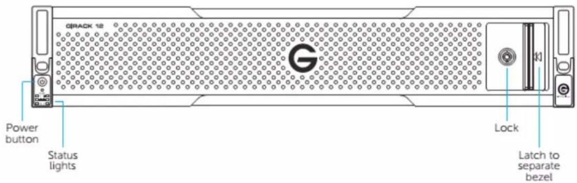
Rear View

G-RACK 12 Installation
Getting Started > G-RACK 12 Installation
Preparing for Setup
Getting Started > G-RACK 12 Installation > Preparing for Setup
The box the G-RACK 12 was shipped in should include two sets of rail assemblies, two rail mounting brackets and the mounting screws you will need to install the system into the rack. Follow the steps in the order given to complete the installation process in a minimum amount of time. Please read this section in its entirety before you begin the installation procedure outlined in the sections that follow.
Choosing a Setup Location
Getting Started > G-RACK 12 Installation > Choosing a Setup Location
- Leave enough clearance in front of the rack to enable you to open the front door completely (\~25 inches) and approximately 30 inches of clearance in the back of the rack to allow for sufficient air flow and ease in servicing.
- This product is for installation only in a Restricted Access Location (dedicated equipment rooms, service closets and the like).
- Determine the area you plan on placing this device - designed for 19" data rack.
Warnings and Precautions
Getting Started > G-RACK 12 Installation > Warnings and Precautions
Rack Precautions
Getting Started > G-RACK 12 Installation > Warnings and Precautions > Rack Precautions
- Ensure that the leveling jacks on the bottom of the rack are fully extended to the floor with the full weight of the rack resting on them.
- In single rack installation, stabilizers should be attached to the rack. In multiple rack installations, the racks should be coupled together.
- Always make sure the rack is stable before extending a component from the rack.
- Only one chassis should be extended from the rack at a time - extending two or more simultaneously may cause the rack to become unstable.
Server Precautions
Getting Started > G-RACK 12 Installation > Warnings and Precautions > Server Precautions
- Review the electrical and general safety precautions.
- Determine the placement of each component in the rack before you install the rails.
• Install the heaviest server components on the bottom of the rack first, and then work up. - Use a regulating uninterruptible power supply (UPS) to protect the server from power surges,
voltage spikes and to keep your system operating in case of a power failure.
- Allow any hot plug drives and power supply modules to cool before touching them.
- Always keep the rack front door and all panels and components on the servers closed when not servicing to maintain proper airflow and cooling.
Rack Mounting Considerations
Getting Started > G-RACK 12 Installation > Warnings and Precautions > Rack Mounting Considerations
Ambient Operating Temperature
If installed in a closed or multi-unit rack assembly, the ambient operating temperature of the rack environment may be greater than the ambient temperature of the room. The consideration should be given to installing the equipment in an environment compatible with the manufacturer's maximum rated ambient temperature (TMRA).
Sufficient Air flow
Equipment should be mounted into a rack so that a hazardous conditions does not arise due to uneven mechanical loading. These include: even floor surfaces, rack stabilizers, and making sure the server rails are level.
Mechanical Loading
Equipment should be mounted into a rack so that a hazardous condition does not arise due to uneven mechanical loading.
Circuit Overloading
Consideration should be given to the connection of the equipment to the power supply circuitry and the effect that any possible overloading of circuits might have on overcurrent protection and power supply wiring. Appropriate consideration of equipment nameplate ratings should be used when addressing this concern.
Reliable Ground
A reliable ground must be maintained at all times. To ensure this, the rack itself should be grounded. Particular attention should be given to power supply connections other than the direct connections to the branch circuit (i.e. the use of power strips, etc.).

Warning! To prevent bodily injury when mounting or servicing this unit in a rack, you must take special precautions to ensure that the system remains stable. The following guidelines are provided to ensure your safety:
- This unit should be mounted at the bottom of the rack if it is the only unit in the rack.
- When mounting this unit in a partially filled rack, load the rack from the bottom to the top with the heaviest component at the bottom of the rack.
- If the rack is provided with stabilizing devices, install the stabilizers before mounting or servicing the unit in the rack.
- Slide rail mounted equipment is not to be used as a shelf or a work space.
Installing the System into a Rack
Getting Started > G-RACK 12 Installation > Installing the System into a Rack
This section provides information on installing the G-RACK 12 chassis into a rack unit with the quick-release rails provided. There are a variety of rack units on the market, which may mean the assembly procedure will differ slightly. You should also refer to the installation instructions that came with the rack unit you are using.
Separating the Sections of the Rack Rails
Getting Started > G-RACK 12 Installation > Installing the System into a Rack > Separating the Sections of the Rack Rails
The chassis package includes two rail assemblies in the rack mounting kit. Each assembly consists of two sections: an inner fixed chassis rail that secures directly to the server chassis and an outer fixed rack rail that secures directly to the rack itself.
Installing the Inner Rail Extension
Getting Started > G-RACK 12 Installation > Installing the System into a Rack > Installing the Inner Rail Extension
The G-RACK 12 chassis includes a set of inner rails in two sections: inner rails and inner rail extensions. The inner rails are pre-attached to the chassis, and do not interfere with normal use of the chassis if you decide not to use a server rack. The inner rail extension is attached to the inner rail to mount the chassis in the rack.
Installing the Inner Rails
- Place the inner rail extensions on the side of the chassis aligning the hooks of the chassis with the rail extension holes. Make sure the extension faces "outward" just like the pre-attached inner rail.
- Slide the extension toward the front of the chassis.
- Secure the chassis with 2 screws as illustrated. Repeat steps for the other inner rail extension.

Warning: do not pick up the server with the front handles. They are designed to pull the system from a rack only.
Figure 2-1. Separating the Rack Rails

Separating the Inner and Outer Rails
- Locate the rail assembly in the chassis packaging.
- Extend the rail assembly by pulling it outward.
- Press the quick-release tab.
- Separate the inner rail extension from the outer rail assembly.

flowchart
graph TD
    A["Extending the Rails"] --> B["Quick-Release Tab"]
    B --> C["Separating the Inner Rail Extension"]

Slide rail mounted equipment is not to be used as a shelf or a work space.

Stability hazard. The rack stabilizing mechanism must be in place, or the rack must be to the floor before you slide the unit out for servicing. Failure to stabilize the rack can he rack to tip over.

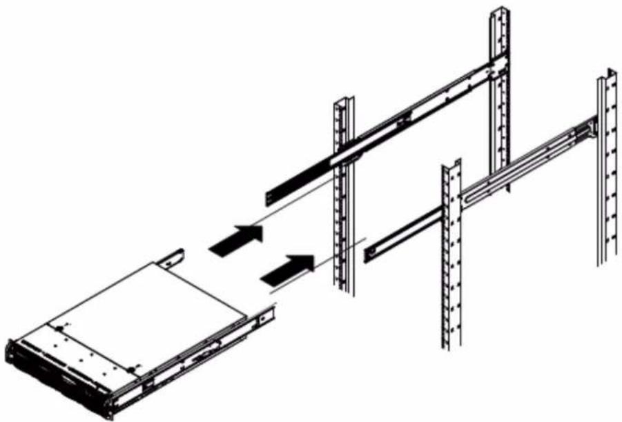
Figure 2-2. Assembling the Outer Rails
Outer Rack Rails
Getting Started > G-RACK 12 Installation > Installing the System into a Rack > Outer Rack Rails
Outer rails attach to the rack and hold the chassis in place. The outer rails for the G-RACK 12 chassis extend between 30 inches and 33 inches.
Installing the Outer Rails to the Rack
- Secure the back end of the outer rail to the rack, using the screws provided.
- Press the button where the two outer rails are joined to retract the smaller outer rail.
- Hang the hooks of the rails onto the rack holes and if desired, use screws to secure the front of the outer rail onto the rack.
- Repeat steps 1-3 for the remaining outer rail.
natural_image
Technical line drawing of a server rack with vertical supports and a central panel, showing structural components without any text or symbols.Figure 2-3. Installing the Rack Rails
Installing the Chassis into a Rack
- Extend the outer rails as illustrated above.
- Align the inner rails of the chassis with the outer rails on the rack.
- Slide the inner rails into the outer rails, keeping the pressure even on both sides. When the chassis has been pushed completely into the rack, it should click into the locked position.
- Optional screws may be used to secure the to hold the front of the chassis to the rack.
NOTE: The figure above is for illustration purposes only. Always install servers to the bottom of the rack first.
Physically Connecting G-RACK 12
Getting Started > Physically Connecting G-RACK 12
- Plug in 2 power cords to back of the G-RACK 12

natural_image
Back view of a server rack with front panel, ports, and ventilation grilles (no visible text or labels)- Plug in the Ethernet cable

natural_image
Back view of a server rack with ports, connectors, and ventilation grilles (no visible text or labels)-
LEDs will flash green
-
Press power button


Connecting G-RACK 12 to Your Network
Getting Started > Connecting G-RACK 12 to Your Network
When first powered on, during the initial boot sequence, the G-RACK 12 will wait to be assigned an IP address via DHCP. If it does not receive a DHCP assigned IP address, by default, it will have a self-assigned IP address of 172.16.12.12. It is recommended to use IP Search Utility when accessing and configuring the G-RACK 12 for the first time. To make any needed changes in the network settings you can use web-based the G-RACK 12 Administrative Tool.
This can be found using Bonjour browser - Download Link (http://www.tildesoft.com/) or using dhclient
Bonjour Browser
▼ local - 37
_acp-sync._tcp. - 1
_adisk._tcp. - 2
_airplay._tcp. - 2
_appletv-v2._tcp. - 2
_atc._tcp. - 1
_attocfgd._tcp. - 1
_device-info._tcp. - 2
_home-sharing._tcp. - 1
_http-alt._tcp. - 1
_ldap._tcp. - 1
_od-master._tcp. - 1
_odproxy._tcp. - 1
_ctservice._tcp. - 1
_scanner._tcp. - 1
_sleep-proxy_.udp. - 2
_teamviewer._tcp. - 2
_touch-able._tcp. - 2
_uscan._tcp. - 1
_xsan4server._tcp. - 1
_Airport Base Station (_AirTunes(_raop._tcp.) - Apple File Sharing(_afApple Password ServerApple Remote DesktopFTP(_ftp._tcp.) - 7
_HTTP(_http._tcp.) - 11
_EPSON859289-8592
_grack12-2 - Web ad
10.82.17.104:80
_path=/index.php
_grack12-3 - Web ad
_grack12-4 - Web ad
_grack12-6 - Web ad
_HP Color LaserJet C
_HP Color LaserJet C
_HP Officejet Pro 861
_ISGCreativeTeam
_YB-1523-HP6040
_YB-2523-HP6040
_iChat AV(_presence._tc)
_Internet Printing Prot
_Network File System (_
Reload Services
If not using DHCP, you can plug your primary network cable into [ETH1]. The default IP Address is 172.16.12.12. You can connect to the G-RACK 12 with this static IP address and with the G-RACK 12 Administration Tool you can change the IP address to what works best for you.

When using a static IP address, you will need to change your client computer's IP address to match the static.
For Mac operating systems:
- Open Network Preferences
- Choose WiFi and click "Advanced"
- Click on TCP/IP tab
- Click the drop down menu and choose "manually"
- Enter IP 172.16.12.12
- Enter Netmask 255.255.255.0
- Save your settings

For Windows operating systems:
- Open Network
- Go to Sharing > Change adapter settings and choose your connected network
- View Properties.
- Click Internet Protocol Version 4 and
- Click Properties

Wi-Fi Properties


- Change the IP to 172.16.12.12
- Netmask 255.255.255.0
- Save your settings

THE FURTHER PROCEDURES SHOULD BE COMPLETED ON ANOTHER NETWORKED CLIENT COMPUTER WITH A WEB BROWSER
Access the G-RACK 12 by using a supported web browser and use the IP address of the device (Listed in Bonjour or using Static IP from above)
G-RACK 12 Web-Based Setup Wizard
Getting Started > G-RACK 12 Web-Based Setup Wizard
The G-RACK 12 Web-based Administration Tool will initially provide a wizard or vertical market selection that is associated with a particular JSON configuration file that will configure the system in a single click of a mouse.
The composite configuration will include a format for configuring the following:
- Admin password setup;
- Email notification;
- User authentication;
• Data disk configuration;
• Networking performance.
THE FURTHER PROCEDURES SHOULD BE COMPLETED ON ANOTHER NETWORKED CLIENT COMPUTER WITH A WEB BROWSER
Access the G-RACK 12 by using a supported web browser and use the IP address of the device (Listed in Bonjour browser or using Static IP from previous chapter)
The G-RACK 12 has a setup Wizard that allows you to quickly step through the basic procedures of the device settings for the first use and to configure it for your environment.
STEP 1. Access the G-RACK 12 by using a supported web browser. Use the IP address of the device(Refer to Bonjour browser or apply Static IP of the device).
Log into the G-RACK 12 Administrator Tool:
user: admin
password: gtech

STEP 2. End User License Agreement.
An information window with the End User License Agreement prompting you to confirm will appear Please confirm that you have read and agree with the Agreement.

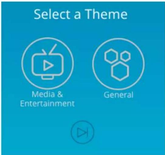
STEP 3. Choose a theme for your environment
Theme is a set of pre-configured parameters, that are most likely to suit to desired working environment.
You can skip Wizard by pressing Skip To Storage Setup button

Using the G-RACK 12 Administrative Tool you are free to reconfigure the G-RACK 12 later.
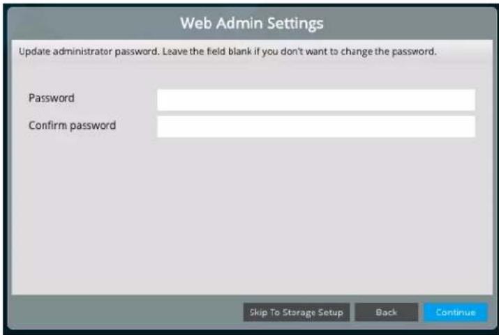
STEP 4. Web Admin Password.
Set your G-RACK 12 Admin password here. Login user name will remain "admin".
Please note that password is case sensitive. Min length is 5 characters.
If you don't change the password at this step, it will remain as default. You can reset it later using Web Administrator Password ^107
STEP 5. Email Notification
Enable this option to receive notifications from the G-RACK 12 on drives and system health. It is possible to set email notifications later using Monitoring Settings menu ^111 .
An email account for the G-RACK 12 is to be created prior to enabling this option.
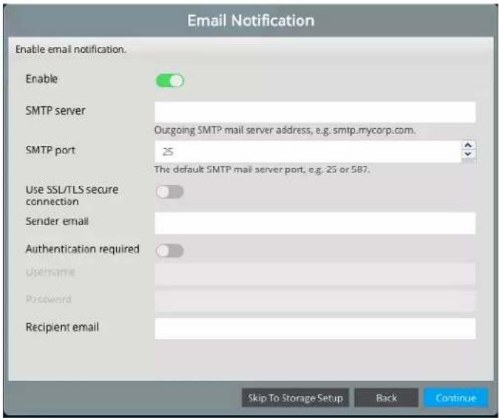
| Enable | Toggle the button to enable the option |
| SMTP server | Specify the SMTP server of the G-RACK 12 email account |
| SMTP port | Specify the SMTP port of the G-RACK 12 email account |
| Use SSL/TLS secure connection | Toggle to enable secure connection for of the G-RACK 12 email account |
| Sender email | Specify the G-RACK 12 email account |
| Authentication required | Toggle to enable authentication |
| Username | Specify Username of the G-RACK 12 email account |
| Password | Specify Password of the G-RACK 12 email account |
| Recipient email | Specify who will receive email for the G-RACK 12 to send to emails |
To choose additional notification alerts, go to Notifications in the G-RACK 12 Administration Tool.
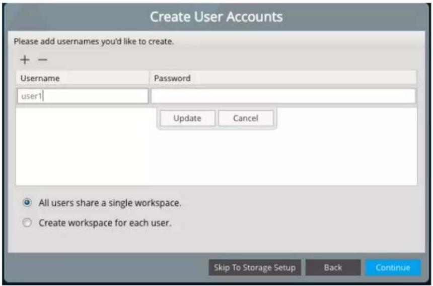
STEP 6. Create User Accounts
Set up at least one user to continue. User names are lower case only without length limits.
Passwords allow both lower and upper cases ( case-sensitive) with the minimal length of 5 characters.
Choose whether all users will share a single workspace or each user will be assigned a separate one.
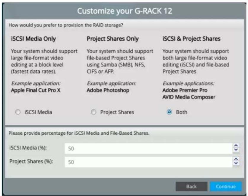
STEP 7. Customize your G-RACK 12
You will not see this dialog if you have chosen General theme.
Divide space between Project shares and iSCSI Media. Setting a percentage of the space to be used for iSCSI Media will allocate the space on the default RAID created and this space will be displayed as occupied in the RAID under the Storage menu once the Wizard is completed.
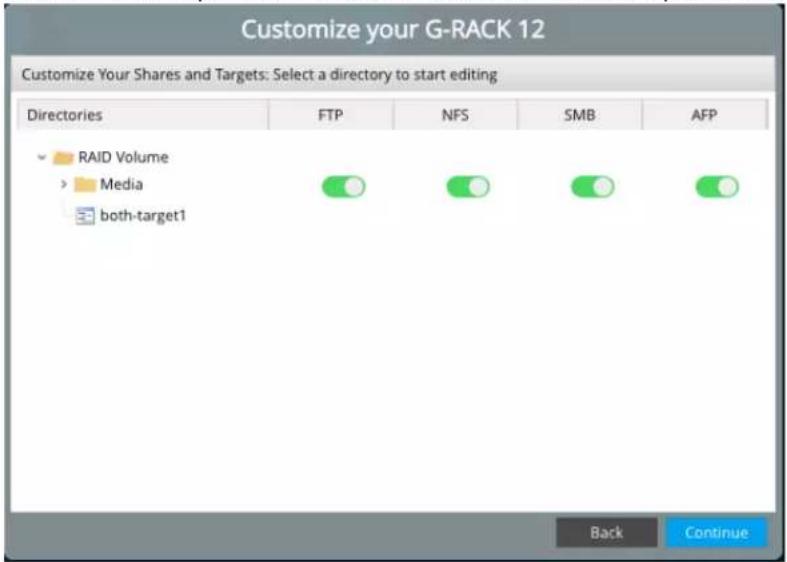
STEP 8. Customize the G-RACK 12 Shares and Targets settings.
Enable network protocols to used for each Share (workspace) and Targets.
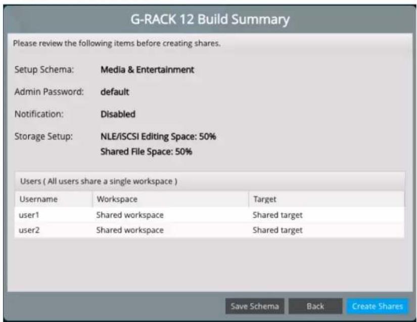
STEP 9. The G-RACK 12 Build Summary.
This step is informational. Review the configuration settings to be applied to your G-RACK12.
STEP 10. Welcome to the G-RACK 12 Administrative tool
Once you are done with primary settings, you will see the Dashboard ^42

All settings can be changed manually in the G-RACK 12 Administrative Tool at any time.
G|RACK™ 12
G-RACK 12 Administrative Tool
To access the Web user interface, open a web browser, type in the IP address of your G-RACK 12 and log in.
Dashboard
G-RACK 12 Administrative Tool > Dashboard
You are here

The G-RACK 12 Dashboard provides a quick overview of performance metrics and health statuses in the form of widgets. The title of a widget is a quick access link to the corresponding menu of the G-RACK 12 Administrative Tool. The information is periodically refreshed automatically.
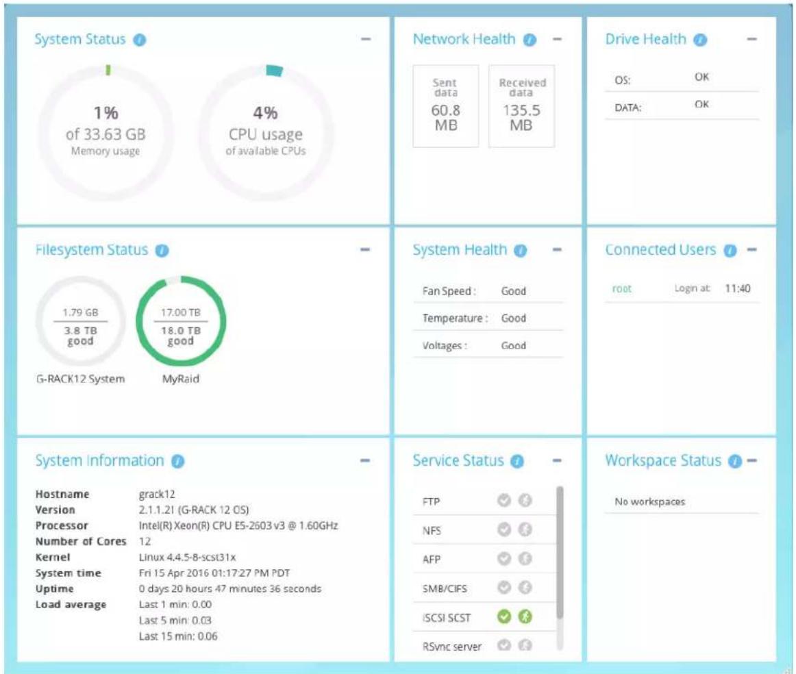
System Status
The widget displays the summary of total memory, used memory and CPU usages by all running processes.
Click the widget title to see more details in the System Overview 116 section.
Network Health
The widget indicates the state of the network connection and input/output traffic.
Click the widget title to see more information in the Performance statistics 109 section.
Drive Health
The widget displays the general health status for OS and Data physical drives.
The status can be one of the following: "OK", "Checking", "Warning", "Error".
Click the widget title to see more information in the S.M.A.R.T. [52] menu section.
Filesystem Status
The widget shows all filesystems that have been created, and specifies total space allocated for each of them, space available and the status.
The status can be one of the following: "Good", "Replacing", "Balancing", "Degraded", "Replacing_stuck".
Click the widget title to see more information in the RAID 60 section.
More details on OS filesystem is in OS RAID ^109 menu.
System Health
The widget displays the status of CPU temperature, Fan speed and Voltage.
The status can be one of the following: "OK", "Abnormal".
For more details click the widget title to be see more information in the Monitoring section.
Connected Users
The widget displays all connected users except guests users along with the time of connection to the G-RACK 12.
Dashboard will not show that a user is 'logged into' the G-RACK 12 server if the user logged in as user 'anonymous' to the FTP service. This also applies to users who use the SMB/CIFS service if 'guests allowed' options is turned on.
Click the widget title to go to Users menu for further information and settings.
System Information
The widget displays general system information, including hostname, system time and load average values.
Click the widget title to go to System Overview 116 menu for further information.
Service Status
The widget displays the services available and their status. The status can be the following:

means the service is enabled.

means disabled.

the services disabled. Normally this goes together with service disable sign.

means the service is running.
[red running man] means the service is stopped.
Click the widget title to see more information under Services 74 section.
Workspace Status
The widget displays the workspaces created on the G-RACK 12.

means at least one service is enabled for this particular workspace.

means no service is enabled for this particular workspace.
Workspaces
G-RACK 12 Administrative Tool > Workspaces
You are here
Add/Edit Workspace
G-RACK 12 Administrative Tool > Workspaces > Add/Edit Workspace
To create a Workspace, there should be a RAID ^61 already created.
Click the Add button to create a new Workspace

The following table describes the labels on the screen:
| Name | Input the name of the Workspace |
| Device | Select RAID array, which will contain the volume. Multiple volumes can share the same space in RAID. |
| Compress files | Compress files on-the-fly using Zlib algorithm. NOTE: It is not recommended to enable Zlib option, if the volume will be used to work with video files. |
| Permissions | The file level access of the shared folder path |
| Comment | Add notes on the Workspace here |
Click the Permissions button to set users and groups access permission ^46 for the Workspace.
To change properties click the Edit button.
Modify Shared Folder Permissions
G-RACK 12 Administrative Tool > Workspaces > Modify Shared Folder Permissions
Click the Permissions button to set permission for the Workspace

The following table describes the labels on the screen:
| Directory | Choose a workspace to set permission to |
| User/group permissions | Decide on permission to be granted to a particular user or group for the workspace and toggle the button on. |
Advanced options
Advanced options can be found by clicking the Advanced options arrow at the bottom of the dialog window. The options allow specific access rights to individual users and groups to be assigned.
| Owner | The name of the owner and associated permissions |
| Group | The name of the group and associated |
| permissions | |
| Others | Permissions for others, guests and anonymous user types. |
| Recursive | This option will apply permissions to files and sub-folders.Note: This option is always ON and will need to be toggled OFF every time permissions are modified. |
To enable domain users go to the Active Directory menu.
NOTE: In some situations the permissions of a user may differ from the permissions of a group he is assigned to.
NOTE: It is important to note that additionally you can also enable a guest account. This enables users without local or domain account to access the shares. Before they can access any share user „guest" must be allowed under access settings for this share.
Create snapshot
G-RACK 12 Administrative Tool > Workspaces > Create snapshot
A snapshot is a volume that shares its data and metadata with another volume. Once a writable snapshot is made, there is no difference between the original volume and the new snapshot volume.
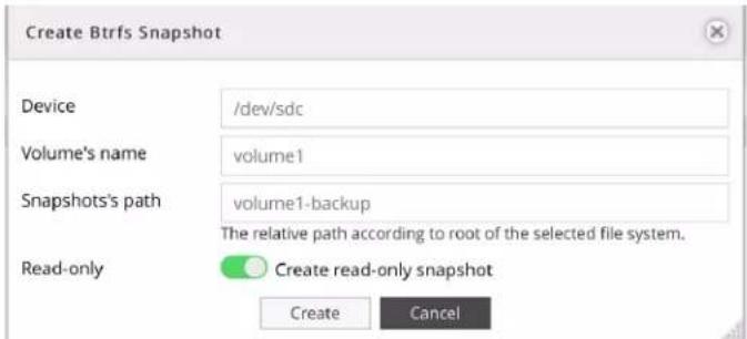
The following table describes the labels on the screen:
| Device | Name of the related physical disk |
| Volume's name | Name of the volume |
| Snapshots's path | The relative path according to root of the selected file system |
| Read only | Toggle to make the snapshot read-only |
Quotas
G-RACK 12 Administrative Tool > Workspaces > Quotas
This option is used to limit the amount of disk storage space that is allowed for a workspace. When the quota limits are approached or exceeded, the system will generate notifications. To set quota limits, select the Workspace and click the Quota button to open the setting dialog.
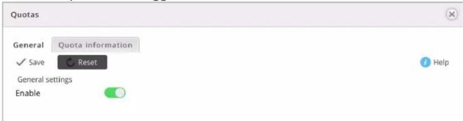
General settings
G-RACK 12 Administrative Tool > Workspaces > Quotas > General settings
To enable quota limits toggle the button on and click Save.
Quota information
G-RACK 12 Administrative Tool > Workspaces > Quotas > Quota information
The table lists all created workspaces, space already used and their quota
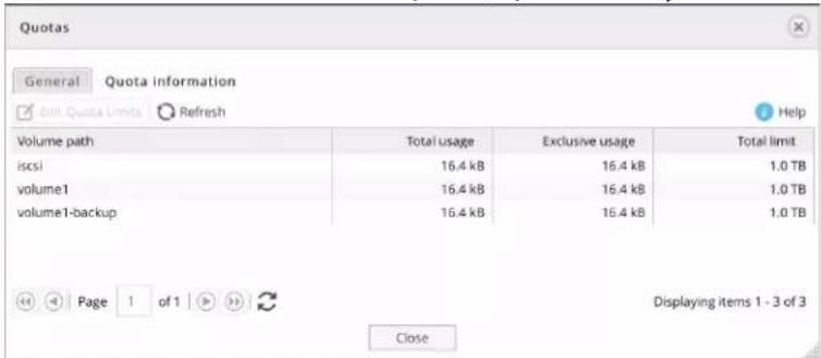
Select the workspace to set a quota limit and click the Edit Quota Limits button.

NOTE: It is not possible to set the quota limit less than the already used space.
Mount
G-RACK 12 Administrative Tool > Workspaces > Mount
Click the Mount button to mount a workspace. Until you mount the workspace, all the options will remain unavailable.
Unmount
G-RACK 12 Administrative Tool > Workspaces > Unmount
To unmount the selected workspace, highlight it and click the Unmount button.
Delete Workspace
G-RACK 12 Administrative Tool > Workspaces > Delete Workspace
To delete a workspace highlight the workspace and click Delete button.
Storage
G-RACK 12 Administrative Tool > Storage
You are here

Physical Disks
G-RACK 12 Administrative Tool > Storage > Physical Disks
This information page displays all the hard drives of the G-RACK 12. It shows the drive slot number, system name of the drive, vendor, model, serial number and disk capacity.
For best practice we recommend using all disks of the same capacity and the same vendor.
| Drive Slot | Device | Model | Serial Number | Vendor | Capacity | |
| r/a | /dev/sdd | HGST HUS726060AL | NAG33HSX | ATA | 6.0 TB | |
| r/a | /dev/sdc | HGST HUH728080AL | 2EGV2U8X | ATA | 8.0 TB | |
| 0 | /dev/sde | HGST HUS726060AL | 5000cca242c144bd | ATA | 6.0 TB | |
| 1 | /dev/sdf | HGST HUS726060AL | 5000cca242c144f1 | ATA | 6.0 TB | |
| 2 | /dev/sdg | HGST HUS726060AL | 5000cca242c13120 | ATA | 6.0 TB | |
| 3 | /dew/sdh | HGST HUS726060AL | 5000cca242c10f55 | ATA | 6.0 TB | |
| 4 | /dev/sdi | HGST HUS726060AL | 5000cca242c1311f | ATA | 6.0 TB | |
| 5 | /dev/sdj | HGST HUS726060AL | 5000cca24dc0Cdce | ATA | 6.0 TB | |
| 6 | /dev/sdk | HGST HUS726060AL | 5000cca24dc0C6c | ATA | 6.0 TB | |
| 7 | /dev/sdl | HGST HUS726060AL | 5000cca24dc026c5 | ATA | 6.0 TB | |
| 8 | /dev/sdm | HGST HUS726060AL | 5000cca242c13078 | ATA | 6.0 TB | |
| 9 | /dev/sdn | HGST HUS726060AL | 5000cca242c13103 | ATA | 6.0 TB | |
| 10 | /dev/sdo | HGST HUS726060AL | 5000cca24dc0Cbf6 | ATA | 6.0 TB | |
| 11 | /dev/sdp | HGST HUS726060AL | 5000cca242c13102 | ATA | 6.0 TB | |
| OSO | /dev/sda | HGST HUS724040AL | PK2334PCHMGS9B | ATA | 4.0 TB | |
| OS1 | /dev/sdb | HGST HUH728080AL | 2EG32GZJ | ATA | 8.0 TB |
Physical disk properties
G-RACK 12 Administrative Tool > Storage > Physical Disks > Physical disk properties
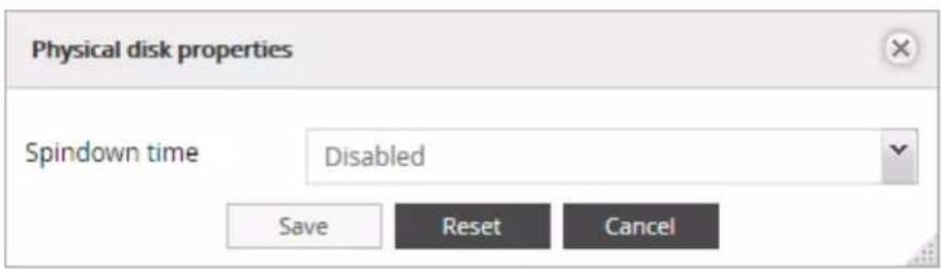
To access the Physical disk properties dialog box, select the desired drive from the Physical Disks list and click the Edit button.
The Physical disk properties dialog box will appear and provide one feature listed in the table below. This feature can be disabled or enabled.
The following table describes the labels on the screen:
| Spindown time | Directly connected with Advanced Power Management level chosen. Sets the idle time for the drive after which the spindle will stop spinning. |
Wipe physical drive
G-RACK 12 Administrative Tool > Storage > Physical Disks > Wipe physical drive
This option erases all the data from a physical disk. When you click the button, a warning message will appear to inform you that all the data will be erased.

There are two options for wiping - Secure and Quick
Quick - erases only boot sector and file system meta data so that the drive will be treated by OS as a brand new one.
Secure - in addition to the Quick erase functionality, Secure erase also erases all user's data, which makes the data unrecoverable.
Scan for new drives
G-RACK 12 Administrative Tool > Storage > Physical Disks > Scan for new drives
Use this option to force the system to scan for new drives. The system automatically scans for new drives every minute.
S.M.A.R.T.
G-RACK 12 Administrative Tool > Storage > S.M.A.R.T.
S.M.A.R.T. stands for "Self-Monitoring, Analysis and Reporting Technology". This is the system on a hard drive used to monitor and report on the health of the drive. It helps to diagnose the system and provide early warnings about the drives' health.
Devices
G-RACK 12 Administrative Tool > Storage > S.M.A.R.T. > Devices
Provides the list of all installed physical drives. It is possible to switch on S.M.A.R.T. monitoring here and call Device properties 52 dialog. In the list you can toggle the switch for each drive individually.
The following table describes the labels on the screen
| Monitor | Toggle on to enable monitoring |
| Device | System name of the physical disk |
| Model | Manufacturer's model of the physical disk |
| Vendor | Name of the vendor |
| Serial number | Serial number of the physical disks |
| Capacity | Capacity of the physical disk |
| Temperature | Current temperature of the physical disk |
The status of the physical disks is displayed in the Drive Health widget of the Dashboard:
OK - drives operating properly.
Checking - system is checking the health status of the drives.
Warning - at least one drive that has exceeded a S.M.A.R.T. parameters
Error - S.M.A.R.T. has detected at least one drive with a failure. The drive may need to be replaced.
Device properties
G-RACK 12 Administrative Tool > Storage > S.M.A.R.T. > Devices > Device properties
To enter the dialog select desired drive and click the Edit button.

To allow S.M.A.R.T. monitoring system wide, select all the drives, then click the Edit button. Toggle the button and save.
S.M.A.R.T. Information
G-RACK 12 Administrative Tool > Storage > S.M.A.R.T. > Devices > S.M.A.R.T. Information
S.M.A.R.T. information dialog provides a set of reports.
The screens below display the information about the physical drive health.
NOTE: The available S.M.A.R.T. information varies from one physical disk's manufacturer to another. Also, not all physical disks have S.M.A.R.T. support.
Device information
Select the device and click the information button to pull up the information dialog.
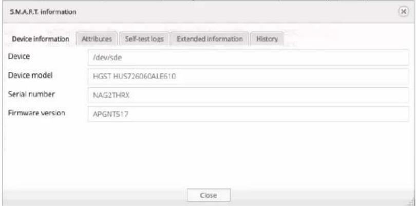
The following table describes the labels on the screen:
| Device | Device reference name in the system |
| Device model | Shows the hard drive's model that uniquely identifies a physical disk |
| Serial number | Shows the individual serial number of an individual physical disk from the manufacturer |
| Firmware version | Shows the version of physical drive's internal operating system software. |
Attributes describe the physical drive state, performance and other data S.M.A.R.T. can access.
| S.M.A.R.T. information | |||||||
| Device information | Attributes | Self-test logs | Extended information | History | |||
| ID | Attribute name | Flags | Value | Worst | Tresho... | When failed | Raw value |
| 1 | Raw_Read_Error_Rate | PO-R- | 100 | 100 | 16 | - | 0 |
| 2 | Throughput_Performance | P-S- | 138 | 138 | 54 | - | 100 |
| 3 | Spin_Up_Time | POS- | 129 | 129 | 24 | - | 512 (Average 5... |
| 4 | Start_Stop_Count | -O-C- | 100 | 100 | 0 | - | 30 |
| 5 | Reallocated_Sector_Ct | PO-CK | 100 | 100 | 5 | - | 0 |
| 7 | Seek_Error_Rate | PO-R- | 100 | 100 | 67 | - | 0 |
| 8 | Seek_Time_Performance | P-S- | 128 | 128 | 20 | - | 18 |
| 9 | Power_On_Hours | -O-C- | 99 | 99 | 0 | - | 7126 |
| 10 | Spin_Retry_Count | PO-C- | 100 | 100 | 60 | - | 0 |
| 12 | Power_Cycle_Count | -O-CK | 100 | 100 | 0 | - | 30 |
| 192 | Power-Off_Retract_Count | -O-CK | 100 | 100 | 0 | - | 742 |
| 193 | Load_Cycle_Count | -O-C- | 100 | 100 | 0 | - | 742 |
| 194 | Temperature_Celsius | -O--- | 200 | 200 | 0 | - | 30 (Min/Max 22... |
| 196 | Reallocated_Event_Count | -O-CK | 100 | 100 | 0 | - | 0 |
| 197 | Current_Pending_Sector | -O-K- | 100 | 100 | 0 | - | 0 |
| 198 | Offline_Uncorrectable | ||||||
The following table describes the labels on the screen:
| ID | Identification number to mark a hard drive attribute. This is a standard across all S.M.A.R.T. enabled storage devices. However it depends on the storage vendor which attributes it will allow S.M.A.R.T. to diagnose. |
| Attribute name | This refers to an attribute of the hard drive that S.M.A.R.T. can access. Attributes describe the drive's physical state. performance, etc. |
| Flags | Indicates the main purpose of the attribute. An attribute can be critical (able to predict failure) or statistical one (does not directly affect condition)P - pre-failureO - onlineS - performanceR - errorC - event countK - self-preserving+ - any other flag |
| Value | Value that correspond to the Raw value. Compare this with the Threshold. S.M.A.R.T. compresses the raw value(s) into a digit from 1 to 253, where 1 indicates the worst scenario while 253 indicates the best scenario. The value 100 or 200 usually represent the normal value. |
| Worst | This is the lowest value attained by the hard drive since S.M.A.R.T. started its assessment of the physical drive. |
| Treshold | This is the attribute's threshold value. if the attribute's current normalized value is less than or equal to the threshold, the attribute has failed. An attribute value close to or below the threshold indicates the hard drive is no longer reliable |
| When failed | The field indicates when (if ever) the attribute failed. An attribute has failed if the normalized value is less than or equal to the threshold |
| Raw value | This is the attribute's unprocessed raw data. These values show exact amount of time or numbers of attempts or errors. The meaning to the raw values is specific to the physical drive manufacture. |
Self-test logs
This tab will show the results of any self-test that have been run
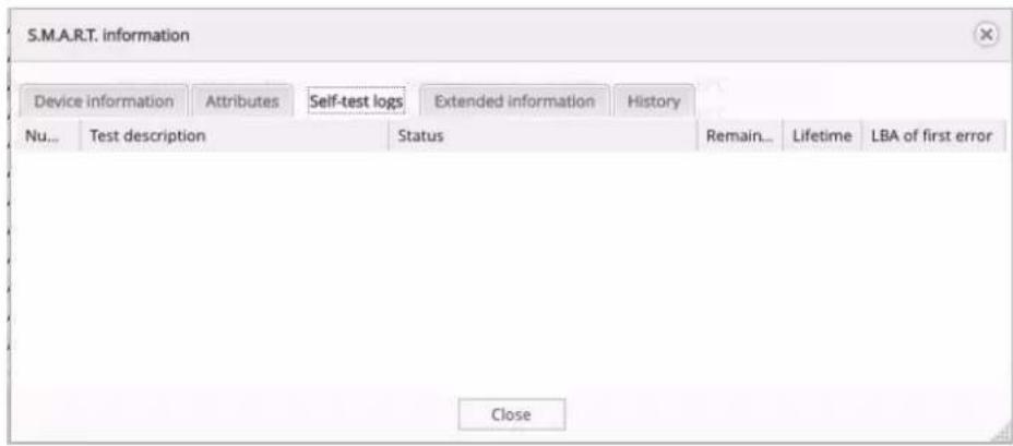
Extended information from smartctl utility
![S.M.A.R.T. information Device information Attributes Self-test logs Extended information History smartctl 5.41 2011-06-09 r3365 [x86_64-linux-4.4.5-scstJlx] (local build) Copyright (C) 2002-11 by Bruce Allen, http://smartmontools.sourceforge.net --- START OF INFORMATION SECTION --- Device Model: HGST HUS726060ALE610 Serial Number: NAG2THRX LU WWN Device Id: 5 000cca 242c144bd Firmware Version: APGNT517 User Capacity: 6,001,175,126,016 bytes [6.00 TB] Sector Sizes: 512 bytes logical, 4096 bytes physical Device is: Not in smartctl database [for details use: -P showall] ATA Version is: 8 ATA Standard is: ATA-8-ACS revision 4 Close](/content/2026/05/860865/images/f5031bbda80ebec437167088cecfe655067d376f4a15d737b0284edaccc23286.jpg)
History
Scheduled Tests
G-RACK 12 Administrative Tool > Storage > S.M.A.R.T. > Scheduled Tests
Add/ Edit scheduled test
G-RACK 12 Administrative Tool > Storage > S.M.A.R.T. > Scheduled Tests > Add/ Edit scheduled test
For each of the devices you can schedule a particular test from the list. The test will run at a predetermined time and date. Click the plus button to add a scheduled test.

The following table describes the labels on the screen:
| Enable | Enables the scheduled test to run |
| Device | Select a physical drive for a test. S.M.A.R.T. monitoring must be activated for the selected device. |
| Type | Choose type of test.Short self-testThe goal of the short test is the rapid identification of a defective hard drive. Therefore, a maximum run time for the short test is 2 min. The test checks the disk by dividing it into three different segments. The following areas are tested:Electrical Properties: The controller tests its own electronics, and since this is specific to each manufacturer, it cannot be explained exactly what is being tested. It is conceivable,for example, to test the internal RAM, the read/write circuits or the head electronics.Mechanical Properties: The exact sequence of the servos and the positioning mechanism to be tested is also specific to each manufacturer.Read/Verify: It will read a certain area of the disk and verify certain data, the size and position of the region that is read is also specific to each manufacturer.Long self-testThe long test was designed as the final test in production and is the same asthe short test with twodifferences. There is no time restriction and in the Read/Verify segment the entire disk is checkedand not just a section. The Long test can, for example, be used to confirm the results of the short tests.Conveyance self-testThis test can be performed to determine damage during transport of the hard disk within just a few minutes.Offline immediate self-test |
| Hour | Set the time when the test will be performed.Asterisk means "every hour" |
| Day of month | Set the day when the test will be performed.Asterisk means "every day" |
| Month | Set the month when the test will be performed.Asterisk means "every month" |
| Day of week | Set the day of the week when the test will be performed. Asterisk means "every week" |
| Comment | Add optional text here |
The test created will appear under the Scheduled tests tab.
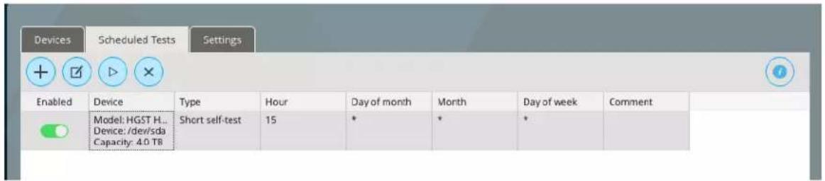
To disable the test, toggle off the enable button. The test will not run, but will remain in the list.
Execute scheduled test
G-RACK 12 Administrative Tool > Storage > S.M.A.R.T. > Scheduled Tests > Execute scheduled test
The Run button starts the test immediately. When finished, output is displayed in the dialog window. Most of the tests update smart attributes/counters that are shown in Attributes tab under S.M.A.R.T. information 53
Delete
G-RACK 12 Administrative Tool > Storage > S.M.A.R.T. > Scheduled Tests > Delete
Click the Delete button to delete the test.
Settings
G-RACK 12 Administrative Tool > Storage > S.M.A.R.T. > Settings
Use this screen for setting hardware sensors to monitor physical disks' health. They detect and report the changes the behavior of the fan, temperature and voltage.

The following table describes the labels on the screen:
| Enable | Toggle on to enable S.M.A.R.T. monitoring for the physical disks |
| Check interval | Sets the interval between disk checks to N seconds. |
| Power mode | Prevent a disk from being spun-up when it is periodically polled.Never - Poll (check) the device regardless of its power mode. This may cause a disk which is spun-down to be spun-up when it is checked.Sleep - Check the device unless it is in SLEEP mode.Standby - Check the device unless it is in SLEEP or STANDBY mode. In these modes most disks are not spinning, so if you want to prevent a disk from spinning up each poll, this is probably what you want.Idle - Check the device unless it is in SLEEP, STANDBY or IDLE mode. In the IDLE state, most disks are still spinning, so this is probably not what you want. |
| Difference | Report if the temperature had changed by at least N degrees Celsius since last report. Set to 0 to disable this report. |
| Informal | Report if the temperature is greater or equal than N degrees Celsius. Set to 0 to disable this report. |
| Critical | Report if the temperature is greater or equal than N degrees Celsius. Set to 0 to disable this report. |
The changes of status will be reflected in Dashboard. If the values are between LNC (Low Non Critical) and UNC (Upper Non Critical), it is "OK". Otherwise the status is "Abnormal"
"Abnormal" status for the fan means that it is failing, and the related hardware temperature will go up.
If the temperature is too high and shows the "Abnormal" status in Dashboard, the system will shut down by itself to protect the hardware, will malfunction or will break down.
If voltages are not stable and the Dashboard displays "Abnormal" status, the system will show unstable behavior. It may randomly freeze or will not respond.
If you experience any of these issues, call support team.
RAID
G-RACK 12 Administrative Tool > Storage > RAID
This menu is used to set RAID configuration and format the data drives.
| Name | Device | State | Level | Capacity | Used | Devices | Mounted | Referenced | Recovery mode |
| MyRAID | /dev/sda | good | RAID 6 Btrfs | 60.0 TB | 29.98 TB | /dev/sde /dev/sdf dev/sdg dev/sdh dev/sdi dev/sdj dev/sdk dev/sdl dev/sdm dev/sdn dev/sdc dev/sdp | Yes (normal) | Yes | manual |
The status is displayed in the Dashboard and can be one of the following:
Good - normal state, everything is ok
Unmounted - filesystem unmounted, not in use
Degraded - there is a drive missing. The filesystem is still operational. Replace the missing drive. Replacing (%) - the user has added a replacement drive into the system and the system in the process of bringing it into the RAID. Percentage will show how much is completed.
Balancing - when the filesystem is re-allocating/ distributing the information across all the drives Delete missing - system is removing the drive that has failed(drive is gone), recovery operation Replacing_stuck - mounting has been resumed after rebooting, but the physical disk is missing
Create RAID device
G-RACK 12 Administrative Tool > Storage > RAID > Create RAID device
Use this menu to create a new data RAID device
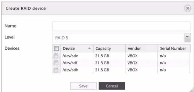
The following table describes the labels on the screen:
| Name | Input a name for new RAID |
| Level | Choose RAID level from the list - 5 or 6. Please refer to Appendix for additional information.Default displayed is RAID 5. |
| Devices | Select physical drives, that will be part of this RAID array. |
NOTE: The minimal number of drives for different RAID levels is:
RAID 5 - minimum 3 physical disks
RAID 6 - minimum 4 physical disks
For best practice we recommend using all disks of the same capacity, vendor, and format type. If your system happens to have disks of different capacity or format type, please ensure the disks are the same size and format type within each RAID. (When using disks of different sizes, the system may report the capacity incorrectly). This approach will help to ensure data integrity and security, it's also associated with correctly storing and fetching the data.
Grow RAID device
G-RACK 12 Administrative Tool > Storage > RAID > Grow RAID device
Select devices to be added to the RAID device. The list will display unassigned physical drives. Remember to perform balance on any modification of RAID structure.
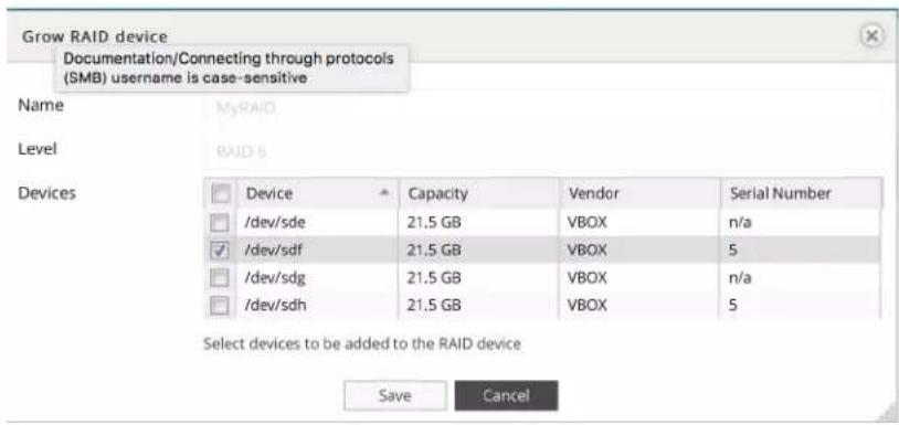
The following table describes the labels on the screen:
| Name | The name of the RAID |
| Level | The level of the RAID |
| Devices | Choose physical drive to join the RAID array |
NOTE: Remember to perform balance on any modification of RAID structure.
For best practice we recommend using all drives of the same capacity and format type. If your system happens to have disks of different capacity or format type, please ensure the disks are the same size and format type within each RAID.
Remove devices from RAID
G-RACK 12 Administrative Tool > Storage > RAID > Remove devices from RAID
Select devices to be removed from the RAID device. Repeat the steps if you need to remove more than one physical drive.

The following table describes the labels on the screen:
| Name | The name of the RAID |
| Level | The level of the RAID |
| Devices | Choose the physical disk to be removed from the RAID |
NOTE: The minimal number of drives for different RAID levels is:
RAID 5 - minimum 3 physical disks
RAID 6 - minimum 4 physical disks
Select hot spare devices for RAID
G-RACK 12 Administrative Tool > Storage > RAID > Select hot spare devices for RAID
Hot spare is a standby physical disk that can repair a degraded RAID device by automatically replacing a failed disk. Setting a hot spare will minimize degraded array state.
Click the Hot spare button to call the dialog to set a hot spare for a RAID. Select devices to be added as a hot spare to the selected RAID device

The following table describes the labels on the screen:
| Name | The name of the RAID will be displayed here |
| Level | The level of the RAID will be displayed here |
| Devices | Choose the physical disk to be set as a hot spare |
It is possible to assign one standby physical disk as a hot spare to be shared by several RAID devices.
Once the data rebuilding finishes, the administrator can take out the faulty physical disk, insert a new one and assign it to be a new hot spare.
Drives of the same capacity and format type should be used as the hot spare drive(s).
Balance
G-RACK 12 Administrative Tool > Storage > RAID > Balance
While the RAID is being balanced, its status in the field State will be "balancing". Balance operation may take a significant amount of time. Balancing may have impact on the RAID performance but does not block any regular operations.
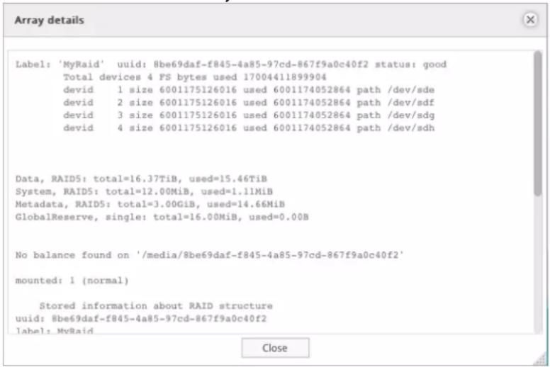
Array details
G-RACK 12 Administrative Tool > Storage > RAID > Array details
The menu will call the array information window
Mount
G-RACK 12 Administrative Tool > Storage > RAID > Mount
Click the Mount button to mount the RAID device.
A newly created RAID will be mounted automatically
Unmount
G-RACK 12 Administrative Tool > Storage > RAID > Unmount
To unmount the selected RAID click the Unmount button.
To make this option active, all volumes of the RAID are to be deleted. Otherwise the status of the RAID will be displayed as "referenced" and Unmount option will stay inactive.
Delete
G-RACK 12 Administrative Tool > Storage > RAID > Delete
Click the Delete button to delete a RAID
The button will become active only when unmounted RAID is selected.
Refresh
G-RACK 12 Administrative Tool > Storage > RAID > Refresh
Click the Refresh button to force the system to search for new RAIDs or display the latest changes.
USB Backup
G-RACK 12 Administrative Tool > Storage > USB Backup
The USB Backup feature for the G-Rack 12 provides access to an external USB storage device. The only way to transfer data to and from an external USB storage device is to create a backup job. This is essentially a synchronization of data and uses rsync for the process. A backup job cannot be scheduled and must be run manually.
Follow these steps to access a newly attached USB storage device:
- Click Storage from the main menu.
- Click the USB Backup option.
- Click the Backup Devices icon.
- Select the USB storage device and click the Mount option
- Click Close
Follow these steps to create a backup job:
- Click the Add icon
- Select the Mode, Shared Workspace and Device for this backup job.
- Click Save
Follow these steps to run, edit, delete a backup job or see the details of a backup job:
- Click the backup job that is to be edited or deleted.
-
Click the Edit, Run, Details or Delete button.
-
EDIT: The edit screen is the same screen used for creating a backup job.
- RUN: After selecting the Run option, click the Start button. When the backup job completes, click the Close button.
- DETAILS: After selecting the Details option, the log file for the most recent backup will display. Click Close to go back to the USB Backup screen.
- DELETE: After selecting the Delete option, click Yes to delete this backup job.

NOTE: G-RACK 12 will only recognize and sync with an external USB storage device that uses the following file systems: NTFS, HFS, HFS+, exFAT and FAT32.
Connect
G-RACK 12 Administrative Tool > Connect
You are here

Advanced Menu & Simple Menu
G-RACK 12 Administrative Tool > Connect > Advanced Menu & Simple Menu
Simple menu button is set to shrink the displayed menu buttons to the most used items. The icons that are not displayed will remain hidden until you press the Advanced menu button. Simple menu displays only Network, Services, NFS, SMB/CIFS, and iSCSI SCST. Advanced menu also includes FTP, Rsync and SSH.
Network
G-RACK 12 Administrative Tool > Connect > Network
General
G-RACK 12 Administrative Tool > Connect > Network > General
Here you can set the G-RACK 12 host and domain information.

The following table describes the labels on the screen:
| Hostname | Label that identifies the system to the network |
| Domain Name | DNS domain where the G-RACK 12 hostname should be registered |
Interfaces
G-RACK 12 Administrative Tool > Connect > Network > Interfaces
| Name | Method | Address | Netmask | Gateway | MTU |
| eth0 | IPv4: DHCP IPv6: Disabled | IPv4: 10.82.17.141 IPv6: - | IPv4: 255.255.255.0 IPv6: - | IPv4: 10.82.17.1 IPv6: - | 1500 |
| eth1 | IPv4: Static IPv6: Disabled | IPv4: 172.16.12.12 IPv6: - | IPv4: 255.255.255.0 IPv6: 64 | IPv4: - IPv6: - | n/a |
Add/Edit Ethernet
G-RACK 12 Administrative Tool > Connect > Network > Interfaces > Add/Edit Ethernet
The menu is used to configure and add network interfaces. Both ipv4 and ipv6 are configurable using this menu.
To configure a particular interface highlight, that interface and select the edit button.

Set configuration for each network interface.
The following table describes the labels on the screen:
| Name | type in the name if( active) |
| Comment | add you text to remind you what the interface is connected to |
| IPv4 | for ip version 4 protocol setup |
| Method | static - you manually enter an ip address of your choosing, netmask and gatewaydynamic - allow dhcp server to assign you an ip address, a netmask and the gateway. |
| Address | supplied if you choose static or automatically supplied if you dynamic method has been chosen |
| Netmask | Add Netmask |
| Gateway | Add Gateway |
| IPv6 | for ip version 4 protocol setup |
| Method | DHCP - allow DHCP server to assign you an IP address, Netmask and the gateway.Auto - requests information specifically from an IPv6-enabled router and automatically configure your settingsStatic - Enter manually an IP address of your choosing, netmask and gateway( provided by your system administrator).Disabled - do not use IPv6 |
| Address | Add address |
| Prefix length | Default value is alsways 64 |
| Gateway | Add gateway |
| Advanced settings | |
| DNS servers | Ip addresses of domain name servers used to resolve host names |
| Search domains | Domains used when resolving host names |
| MTU | Media Transfer Unit - the size of the packet payload for the this interface |
| Wake-on-LAN | Toggle to enable Wake-on-Lan if packets arrive at this interface |
| Options | Additional device settings, e.g. 'autoneg off speed 100 duplex full'. See manual page for more details. |
Add/Edit Bond
G-RACK 12 Administrative Tool > Connect > Network > Interfaces > Add/Edit Bond
Bonding is a technology that allows aggregations of multiple Ethernet interfaces into a single virtual link, thus getting higher data rates and providing failover.
How to Bond Two or More Ports:
- Login to admin tool after G-RACK 12 has been setup and configured with one of the primary Ethernet ports (eth0 or eth1) I am using DHCP eth0 port to login as.
- Navigate to Connect > Network > Interfaces tab
• G-RACK 12 will configure eth0 and eth1(static). Delete eth1 interface. - After eth1 has been deleted, eth0 should be only one remaining. Do not delete eth0. You will not be able to log on to the admin tool if no other configured port is available. Eth0 is the admin port and not available for bonding.
- Click on "+" to add a new network interface.
- Select "Bond" interface
- In the Add bond connection view that displays, under the available slaves list select the desired interfaces for the bond.

The following table describes the labels on the screen:
| Name | Enter the name of the connection |
| Comment | Add an optional text here |
| Bond Slaves | Choose slaves from the drop down list |
| Mode | Specifies one of the bonding policies |
| Primary | Specifies which slave is the primary device. |
| MII monitoring frequency | Specifies the MII link monitoring frequency in milliseconds |
| Down delay | Specifies the time, in milliseconds, to wait before enabling a slave after a link recovery has been detected |
| Up delay | Specifies the time, i n milliseconds, to wait before enabling a slave after a link recovery has been detected |
| IPv4 | |
| Method | static - you manually enter an ip address of your choosing, netmask and gateway dynamic - allow dhcp server to assign you an ip address, a netmask and the gateway. |
| Address | Enter an IP address |
| Netmask | Enter the subnet mask of your network |
| Gateway | Enter the IP address of your gateway |
| IPv6 | |
| Method | DHCP - allow DHCP server to assign you an IP address, Netmask and the gateway. Auto - requests information specifically from anIPv6-enabled router and automatically configure your settingsStatic - Enter manually an IP address of your choosing, netmask and gateway( provided by your system administrator).Disabled - do not use IPv6 |
| Address | Enter an IP address |
| Prefix length | Default value is always 64 |
| Gateway | Enter the IP address of your gateway |
| Advanced settings | |
| DNS servers | IP addresses of domain name servers used to resolve host names |
| Search domains | Domains used when resolving host names |
| MTU | Media Transfer Unit - the size of the packet payload for the this interface |
| Wake-on-LAN | Toggle to enable Wake-on-LAN if packets arrive at this interface |
| Options | Additional device settings, e.g. 'autoneg off speed 100 duplex full'. See manual page for more details |
• Under IPv4 choose either static or DHCP as the method.
- Not changing any other settings, save the new bond configuration. Bond0 should display in the list with a DHCP IP generated.
- Remember to add all ports on switch side to be trunk members in LACP Lag type configuration as well.
Once a new bond connection has been created, use "Edit Ethernet connection" ^68 dialog for its configuration.
Identify
G-RACK 12 Administrative Tool > Connect > Network > Interfaces > Identify
This menu is used to find Ethernet port corresponding to the particular Interface.

Delete
G-RACK 12 Administrative Tool > Connect > Network > Interfaces > Delete
To delete an interface, highlight it and click the Delete button.
Service Discovery
G-RACK 12 Administrative Tool > Connect > Network > Service Discovery
The service allows the tool that probes each TCP/UDP port to see if there is a service listening. Then the tool will know that the service is available to connect to the G-RACK 12. If the advertising of service of each port is turned on, the port can be scanned.
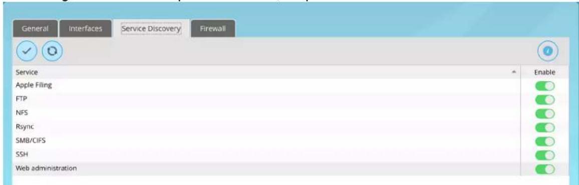
NOTE: Enabling a service discovery for a particular service does not enable the service itself. To enable the service, refer to the corresponding setting menu under Connect 66 menu.
Firewall
G-RACK 12 Administrative Tool > Connect > Network > Firewall
Firewall Filters the network traffic based on specific ruled, added by the administrator.

Add/Edit
G-RACK 12 Administrative Tool > Connect > Network > Firewall > Add/Edit
By adding custom rules, it is possible to allow or block access based on the service or application, source or destination IP addresses, time of the day. its also possible to choose to log traffic that matches or does not match the defined rule.

The following table describes the labels on the screen:
| Family | For ipv4 |
| Direction | Choose the direction of the traffic to filter |
| Action | This specifies what to do if the packet matches |
| Source | Source address can be either a network IP address (with/mask), an IP range or a plain IP address. A"!" argument before the address specification inverts the sense of the address |
| Source port | Match if the source port is one of the given ports. E.g. 21 or !443 or 1024-65535 |
| Destination | Destination address can be either a network IPaddress (with/mask), an IP range or a plain IP address. A"!" argument before the address specification inverts the sense of the address |
| Destination port | Match if the destination port is one of the given ports, E.g. 21 or !443 or 1024-65535 |
| Protocol | Choose the protocol from drop down menu |
| Advanced options | Text field for adding additional commands |
| Comment | Add an optional text |
Delete
G-RACK 12 Administrative Tool > Connect > Network > Firewall > Delete
Use this button to delete the rule.
Up/Down
G-RACK 12 Administrative Tool > Connect > Network > Firewall > Up/Down
The Up button and the down button will move the rule.
Save
G-RACK 12 Administrative Tool > Connect > Network > Firewall > Save
The save button saves the changes made.
Refresh
G-RACK 12 Administrative Tool > Connect > Network > Firewall > Refresh
The Refresh button will reload the screen and display the changes.
Services
G-RACK 12 Administrative Tool > Connect > Services
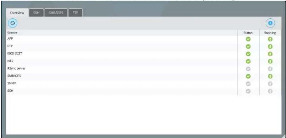
Overview
G-RACK 12 Administrative Tool > Connect > Services > Overview
The menu shows network services enabled and successfully running.
SSH
G-RACK 12 Administrative Tool > Connect > Services > SSH
The menu shows additional information on SSH status, currently logged in users and established connections.
SMB/CIFS
G-RACK 12 Administrative Tool > Connect > Services > SMB/CIFS
The menu shows additional information on SMB/CIFS status, currently logged in users and established connections.

FTP
G-RACK 12 Administrative Tool > Connect > Services > FTP
The menu shows additional information on its status, currently logged in users and established connections.

NFS
G-RACK 12 Administrative Tool > Connect > NFS
The G-RACK 12 supports Network File System ( NFS) service. Enable this multi-platform file system here. Otherwise disable the option to prevent unnecessary CPU overhead.
Shares
G-RACK 12 Administrative Tool > Connect > NFS > Shares
Share is a way a user will connect to the G-RACK 12 to transfer files. We are sharing a workspace. Need set NFS protocol to reach the workspace. i.e. to share a workspace.

The following table describes the labels on the screen:
| Shared Workspace | The name of the workspace you wish to share. You can choose an existing workspace or create a new one. Find your Workspace by using the drop down option or you can use the search feature to locate the Workspace desired. The NFS share will be accessible at /export/ when your NFS client is pointed to the share. |
| Client | This defines the scope of network access to the NFS share. You can limit or expand access to the NFS share by setting these parameters.The most limiting parameter would be to type in an exact IP address. An example of this is setting of 192.168.0.12 and by doing so you would limit the NFS share to exactly the one computer that had that IP address.The next level of access is to provide access to all computers on a specific subnet. An example of this is a setting of 192.168.0.0/24 and by doing so you would limit the NFS share to all computers that have a matching subnet. This means all computers with IP addresses in the 192.168.0.0 to 192.168.0.254 range would be able to mount this NFS share.Finally, the least restrictive setting available for this Client parameter is leaving it blank. If you leave it blank then any computer that can negotiate traffic to the IP address of the G-RACK 12 will have access to the NFS share. You will only want to use this in networks where outside traffic is limited by other means such as a secure firewall. |
| Privilege | This is a dropdown box that has two options that are fairly clear. 1) Read-only which means you will be able read and copy the files on this NFS share but you will not be able to edit them and 2) Read-Write that gives you privileges to read, edit, copy, and delete the files available on this NFS share. |
| Advanced options | Advanced Options - Additional information on these settings can be found online at http://linux.die.net/man/5/exports |
| Comment | This is fairly self explanatory. Place text in this box that you want associated with this NFS share. It can be notes on why it was created or any other information you choose |
Settings
G-RACK 12 Administrative Tool > Connect > NFS > Settings
Use this menu to enable the service

The following table describes the labels on the screen:
| Enable | Turns on the service protocol |
| Number of servers | Specifies how many server threads to create.The number of users that can connect to the server at one time. |
NOTE: The Dashboard will show the service as "running" only if at least one workspace is set to use NFS protocol. NFS service doesn't run unless something is exported.
Mac Client Information
On a Mac clients and mounting through NFS with the 'Connect to Server' option the Mac client admin must go to NFS share and change it from 'secure' to 'insecure' in the extra options. The whole share directory will be set as insecure since it does not display child folders.
When mounting through NFS Mac OS does not ask for user authentication like SMB, it automatically mounts it. In order to write to the share admins need to go into admin tool and go to workspace and enable read/write/execute for Others in the ACL options. (This can be set for child folders only)
Use these steps to mount and allow users to write to the share.
- Go through Wizard > Media > Both setup and enable NFS protocol
- After creating shares and logging in, navigate to Connect > NFS
- Edit share and change client IP
- In extra options change secure to insecure and save
- Navigate to Access Control > Workspaces and open up ACL options
- Change Others to Read/Write/Execute and save
- On mac client open up 'Connect to Server' (can hit command+k)
- Enter url for server: nfs://grack_ip/export/share_name
NFS share will mount and folder that had Others enabled to Read/Write/Execute will allow write
ability.
SMB/CIFS
G-RACK 12 Administrative Tool > Connect > SMB/CIFS
Workspaces
G-RACK 12 Administrative Tool > Connect > SMB/CIFS > Workspaces
Add a workspace that will connect via SMB/CIFS service

The following table describes the labels on the screen:
| Enable | Toggle on to enable the service |
| Workspace folder | The location of the files to share. |
| Name | The name of the share. |
| Comment | This is a text field that is seen next to a sharewhen a client queries the server. |
| Public | If 'Guests allowed' is selected and no login credential is provided, then access as guest. Always access as guest when 'Only guests' is selecting; in this case no password is required to connect to the share. |
| Read only | Set read onlyIf this parameter is set, then users may not create or modify files in the share |
| Browseable | Set browseableThis controls whether this share is seen in the list of available shares in a net view and in the browse list. |
| Inherit ACLs | Honor existing ACLsThis parameter can be used to ensure that if default ACLs exist on parent directories, they are always honored when creating a new file or subdirectory in these parent directories. |
| Inherit permissions | Enable permission inheritanceThe permissions on new files and directories are normally governed by create mask and directory mask but the inherit permissions parameter overrides this. This can be particularly useful on systems with many users to allow a single share to be used flexibly by each user. |
| Recycle bin | Enable recycle bin.This will create a recycle bin on the share.Files that are larger than the specified number of bytes will not be put into the recycle bin. Set to 0 for unrestricted file size.Files in the recycle bin will be deleted automatically after the specified number of days. Set to 0 for manual deletion. |
| Hide dot files | This parameter controls whether files starting with a dot appear as hidden files |
| Extended attributes | Enable extended attribute supportAllow clients to attempt to store OS/2 style extended attributes on a share. |
| Store DOS attributes | Enable store DOS attributes supportIf this parameter is set, Samba attempts to first read DOS attributes (SYSTEM, HIDDEN, ARCHIVE or READ-ONLY) from a file system extended attribute, before mapping DOS attributes to UNIX permission bits. When set, DOS attributes will be stored onto an extended attribute in the UNIX file system, associated with the file ordirectory. |
| Hosts allow | This option is a comma, space, or tab delimited set of hosts which are permitted to access this share. You can specify the hosts by name or IP number. Leave this field empty to use default settings. |
| Hosts deny | This option is a comma, space, or tab delimited set of host which are NOT permitted to access this share. Where the lists conflict, the allow list takes precedence. In the event that it is necessary to deny all by default, use the keyword ALL (or the netmask 0.0.0.0/0) and then explicitly specify to the hosts allow parameter those hosts that should be permitted access. Leave this field empty to use default settings. |
| Audit | Audit file operations. |
NOTE: Connecting a shared workspace through SMB protocol, the username is case sensitive.
Settings
G-RACK 12 Administrative Tool > Connect > SMB/CIFS > Settings
Use this menu to enable the service

The following table describes the labels on the screen:
| Enable | Toggle on to enable the service |
| Workgroup | The workgroup the server will appear to be in when queried by clients. |
| Description | The NT description field. |
| Local Master Browser | Allow this server to try and become a local master browser. Eae i use a computer it will show all available shares |
| Time server | Allow this server to advertise itself as a time server to Windows clients |
| WINS support | Enable WINS serverAct as a WINS server. |
| WINS server | Use the specified WINS server. |
| Log level | Choose log level from None, Minimum, Normal, Full, Debug. |
AFP (Apple Filling)
G-RACK 12 Administrative Tool > Connect > AFP (Apple Filling)
The G-RACK 12 supports Apple Filling Service for connectivity with Mac OS computers. If you need to use AFP service enable it here otherwise leave it disabled to reduce CPU resource overhead.
Workspaces
G-RACK 12 Administrative Tool > Connect > AFP (Apple Filling) > Workspaces
Add a workspace that will connect via AFPservice
![Edit share Shared Workspace Media [on MyRAID, Media/] The location of the files to share. Workspace Media The name of the share. Read only Set read only. If this option is set, then users may not create or modify files in the share. Guest login Allow guest login. Guests only have read access by default. Guest permissions Allow guests to create or modify files. Time Machine support Enable Time Machine support for this share. Unix privileges Use AFP3 unix privileges. Use dots Don't do :hex translation for dot files. When this option gets set, certain file names become illegal. These are .Parent and anything that starts with Apple. Hide dot files Make dot files invisible. Forces filename restrictions This forces filenames to be restricted to the character set used by Windows. Case folding None This option handles, if the case of filenames should be changed. Comment Save Reset Cancel](/content/2026/05/860865/images/ee9e3637d707f5eb5a59b1ec53c8329a357fd8a61ac517f9f8f76736fd673590.jpg)
The following table describes the labels on the screen:
| Shared workspace | The location of the files to share. |
| Workspace | The name of the share. |
| Read only | Set read only.If this option is set, then users may not create or modify files in the share. |
| Guest login | Allow guest login.Guests only have read access by default. |
| Guest permissions | Allow guests to create or modify files. |
| Time Machine support | Enable Time Machine support for this share. |
| Unix privileges | Use AFP3 unix privileges. |
| Use dots | Don't do :hex translation for dot files.When this option gets set, certain file names become illegal. These are .Parent and anything that starts with .Apple. |
| Hide dot files | Make dot files invisible. |
| Forces filename restrictions | This forces filenames to be restricted to the character set used by Windows. |
| Case folding | This option handles, if the case of filenames should be changed. |
| Comment | Add an optional text here |
Settings
G-RACK 12 Administrative Tool > Connect > AFP (Apple Filling) > Settings
Use this menu to enable the service

The following table describes the labels on the screen:
| Enable | Toggle on to enable the protocol |
| Allow plain passwords | Allow logins with passwords transmitted in the clear. |
FTP
G-RACK 12 Administrative Tool > Connect > FTP
SSL/TLS
G-RACK 12 Administrative Tool > Connect > FTP > SSL/TLS
Use this tab to enable SSL/TLS encryption for FTP connections. You may also want to restrict FTP ovel SSL/TLS connections to establish only certain SSL certificates.

The following table describes the labels on the screen:
| Enable | Enable SSL/TLS connections |
| Certificate | The SSL certificate. |
| Required | This option requires clients to use FTP over TLS when talking to this server. |
| No certificate request | This option causes the server to not send a certificate request during a SSL handshake. |
| No session reuse required | The requirement that the SSL session from the control connection is reused for data connections is not required. |
| Implicit SSL | This option will handle all connections as if they are SSL connections implicitly. |
Ban List
G-RACK 12 Administrative Tool > Connect > FTP > Ban List
The tab allows further hardening of FTP server security. Here you can limit users for various criteria, like maximum amount of simultaneous connections or maximum duration of the client-server session.
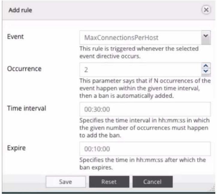
The following table describes the labels on the screen:
| Event | This rule is triggered whenever the selected event directive occurs. |
| Occurrence | This parameter says that if N occurrences of the event happen within the given time interval, then a ban is automatically added. |
| Time interval | Specifies the time interval in hh:mm:ss in which the given number of occurrences must happen to add the ban. |
| Expire | Specifies the time in hh:mm:ss after which the ban expires. |
The Ban List blocked will display the IP addresses you blocked.
Shares
G-RACK 12 Administrative Tool > Connect > FTP > Shares
Add a workspace that will connect via FTP service

The following table describes the labels on the screen:
| Shared workspace | The location of the files to share. |
| Comment | Optional comment text box |
Settings
G-RACK 12 Administrative Tool > Connect > FTP > Settings
Use this menu to enable the FTP service

The following table describes the labels on the screen:
| Enable | Toggle on to enable the service |
| Port | Specify the port to be used |
| Max. clients | Set the maximum number of simultaneous clients that can connect to the FTP server |
| Max.connections per host | Maximum number of connections per IP (0 = unlimited). |
| Max. login attempts | Maximum number of allowed password attempts before disconnection. |
| Timeout | Maximum idle time in seconds. Setting idle timeout to 0 disables the idle timer completely (clients can stay connected for ever, without sending data). |
| Anonymous FTP | Enable anonymous FTP |
| Welcome message | The welcome message which will be displayed to the user when they initially login. |
| Permit root login | Specifies whether it is allowed to login assuperuser directly |
| Require valid shell | Deny logins which do not have a valid shell |
| Bandwidth restriction | Use the following bandwidth restriction:0 KiB/s means unlimited. |
| Passive FTP | Use the following port range:In some cases you have to specify passive ports range to by-pass firewall limitations. Passive ports restricts the range of ports from which the server will select when sent the PASV command from a client. The server will randomly choose a number from within the specified range until an open port is found. The port range selected must be in the non-privileged range (eg. greater than or equal to 1024). It is strongly recommended that the chosen range be large enough to handle many simultaneous passive connections (for example, 49152-65534, the IANA-registered ephemeral port range). |
| Masquerade address | If your host is acting as a NAT gateway or port forwarder for the server, this option is useful in order to allow passive transfers to work. You have to use your public address and opening the passive ports used on your firewall as well.Specifies the amount of time, in seconds, between checking and updating the masquerade address by resolving the IP address. Set this value to 0 to disable this option. |
| FXP | Enable FXP protocolFXP allows transfers between two remote FTP servers without any file data going to the client asking for the transfer.Note: In order to use FXP (File Exchange Protocol) for server-to-server data transfer, make sure to change the port from 21 to some other port. Also, make sure to open the corresponding port on your router and forward that port from your router to the device. |
| Resume | Allow clients to resume interrupted uploads and downloads |
| Ident protocol | Enable the ident protocol (RFC1413)When a client initially connects to the server the ident protocol is used to attempt to identify the remote username. |
| Reverse DNS lookup | Enable reverse DNS lookupEnable reverse DNS lookup performed on the remote host's IP address for incoming activemode data connections and outgoing passive mode data connections. |
| Transfer log | Enable transfer log |
Rsync
G-RACK 12 Administrative Tool > Connect > Rsync
Rsync is a tool for copying and backing up data from one location( the source) to another( the destination). It is efficient because it only transfers files which are different between the source and destination directories.
Jobs
G-RACK 12 Administrative Tool > Connect > Rsync > Jobs
To add a new rsync task press the Add button. These parameters define the overall behavior of RSync.

The following table describes the labels on the screen:
| Enable | Toggle the button to enable RSync |
| Type | Choose the type:Local - synchronizes two local directoriesRemote - synchronizes a local directory to aremote one. Obtain SSH access to perform this. The remote system is to have synchronizing enabled |
| Mode | This option will be available if "remote" type has been chosen. Is specifies the synchronizing direction.Push - pushes the directory from the local system to a remote systemPull - is used to sync a remote directory to the local system. |
| Source shared folder | The source shared folder to be synchronized |
| Destination shared folder | The destination shared folder. |
| Trial run | Perform a trial run with no changes made |
| Recursive | Recurse into directories |
| Times | Preserve modification times |
| Compress | Compress file data during the transfer |
| Archive | Enable archive mode |
| Delete | Delete files on the receiving side that don't exist on sender |
| Quiet | Suppress non-error messages |
| Preserve permissions | Set the destination permissions to be the same as the source permissions |
| Preserve ACLs | Update the destination ACLs to be the same as the source ACLs |
| Preserve extended attributes | Update the destination extended attributes to be the same as the local ones |
| Keep partially transferred files | Enable this option to keep partially transferred files, otherwise they will be deleted if the transfer is interrupted. |
| Send email | Send command output via emailAn email message with the command output (if any produced) is send to the administrator. |
| Comment | Optional comment text box |
Rsync and iSCSI
G-RACK 12 Administrative Tool > Connect > Rsync > Rsync and iSCSI
It is possible to rsync one iSCSI target to another G-RACK 12. Unfortunately, there is no native way to access it from the G-RACK 12 Administration GUI and initiators will not recognize it.
In order to access the duplicate iSCSI target on the second G-RACK 12 you will need to do the following hack:
- Create an iSCSI target (original).
-
Rsync this iSCSI target to another G-RACK 12 (duplicate).
-
If at this point you try to discover the (duplicate) target from initiator the result will be it is not recognized
- On the G-RACK 12 that has the duplicate you will want to create new target LUN (fake target).
- Replace new (fake) target with rsync'd (duplicate) target keeping (fake) targets file name.
• Re-discover targets from initiator computer.
• Result: You will be able to access rsync'd (duplicate) target using the (fake) target's name.
Server
G-RACK 12 Administrative Tool > Connect > Rsync > Server
Settings
G-RACK 12 Administrative Tool > Connect > Rsync > Server > Settings
Use this menu to enable rsync utility and set the port

The following table describes the labels on the screen:
| Enable | Toggle on to enable |
| Port | Choose the port. Default :873 |
Modules
G-RACK 12 Administrative Tool > Connect > Rsync > Server > Modules
Use this menu to set a folder to be shared.

The following table describes the labels on the screen:
| Enable | Toggle the button to enable |
| Shared folder | The location of the files to share. |
| Name | The name of the share |
| User | This option specifies the user name that file transfers to and from that module should take place. |
| Group | This option specifies the group name that file transfers to and from that module should take place. |
| Use chroot | Enable chroot.If this option is set, the daemon will chroot to the shared folder path before starting the file transfer with the client. Then it is not possible to map users and groups by name and the daemon is not being able to follow symbolic links that are either absolute or outside of the new root path. |
| Authenticate users | Enable user authenticationIf set then the client will be challenged to supply a username and password to connect to the module. |
| Read only | Set read onlyIf this option is set, then any attempted uploadswill fail. |
| Write only | Set write onlyIf this option is set, then any attempted downloads will fail. |
| List | Enable module listingThis option determines if this module should be listed when the client asks for a listing of available modules. |
| Max.connections | This option specifies the maximum number of simultaneous connections. 0 means no limit. |
| Hosts allow | This option is a comma, space, or tab delimited set of hosts which are permitted to access this module. You can specify the hosts by name or IP number. Leave this field empty to use default settings. |
| Hosts deny | This option is a comma, space, or tab delimited set of host which are NOT permitted to access this module. Where the lists conflict, the allow list takes precedence. In the event that it is necessary to deny all by default, use the keyword ALL (or the netmask 0.0.0.0/0) and then explicitly specify to the hosts allow parameter those hosts that should be permitted access. Leave this field empty to use default settings. |
| Comment | Add an optional text here |
iSCSI SCST
G-RACK 12 Administrative Tool > Connect > iSCSI SCST
iSCSI stands for "Internet SCSI". iSCSI allows a SCSI-protocol to be transported in Ethernet packages via an IP network. This allows enterprises to set up inexpensive SANSs using their already existing standardized Ethernet network infrastructure. iSCSI runs on widely used and trusted IP networks which makes it possible to use the advantages of a SAN without creating a new network infrastructure, and in addition you do not need to train your employees. On the client side it requires an iSCSI "initiator".
The connection between the G-RACK 12 server and the iSCSI initiator is set via the normal Ethernet infrastructure (Network switch). The client then detects the storage of the G-RACK 12 server as an own local hard disk drive.
Settings
G-RACK 12 Administrative Tool > Connect > iSCSI SCST > Settings
Toggle the button to enable the protocol and click the Save button.

Targets
G-RACK 12 Administrative Tool > Connect > iSCSI SCST > Targets
Under configured iSCSI targets you can see all existing targets on the server and their corresponding status.
Click the Add button to create a new iSCSI target. Also you can configure CHAP Authentication for this iSCSI Target

The following table describes the labels on the screen:
| Name | The name of target. |
| User name | optional attribute containing user name for incoming user name. goes to the iSCSI target and the LUN that is automatically created. CHAP secret |
| Password | optional attribute containing user password for incoming user name. Password must be at least 12 characters |
| QueuedCommands | defines maximum number of commands queued to any session of this target. Default is 32 commands. |
| InitialR2T | Turns on the default use of R2T; if disabled, allows an initiator to start sending data to atarget as if it had received an initial R2T. The result function is OR |
| ImmediateData | Configure using of unsolicited data. The result function is AND. |
| HeaderDigest | |
| DataDigest | |
| MaxConnections | the maximum number of connections that can be requested or are acceptable. The result function is Min. |
| MaxRecvDataSegmentLenght | The maximum amount of data that the target can receive in any iSCSI PDU. This is a connection- and direction- specific parameter. The actual value used for targets will be Min (This value, MaxBurstLength) for data-in and solicited data-out data. Min (This value, FirstBurstLength) for unsolicited data. |
| MaxXmitDataSegmentLenght | The maximum amount of data that the target can transmit in any iSCSI PDU. This is a connection- and direction- specific parameter. The actual value used for targets will be Min (This value, MaxBurstLength) for data-in and solicited data-out data. Min (This value, FirstBurstLength) for unsolicited data. |
| MaxBurstLength | Maximum SCSI data payload in bytes for data-in or for a solicited data-out sequence. The responder's number is used. The result function is Min. |
| FirstBurstLength | Maximum SCSI payload, in bytes, of unsolicited data an initiator may send to the target. Includes immediate data and a sequence of unsolicited Data-Out PDUs. Must be <= MaxBurstLength. The result function is Min. |
| DefaultTime2Wait | Min seconds to wait before attempting connection and task allegiance reinstatement after a connection termination or a connection reset. The results function is Max. A value of zero means that task reassignment can be done immediately. Also known as Time2Wait. |
| DefaultTime 2Retain | Max seconds that connection and task allegiance reinstatement is still possible following a connection termination or reset. The results function is Min. Zero means no reinstatement is possible. Also known as Time2Retain. |
| MaxOutstandingR2T | The maximum number of outstanding R2Ts. The responder's value is used. The result function is Min. |
| DataPDUInOrder | No indicates that the data PDUs within a sequence can be in any order. Yes indicates that the data PDUs within a sequence have to be at continuously increasing addresses and that overlays are forbidden. The result function is OR. |
| DataSequenceInOrder | If set to No, the data PDU sequence may be transferred in any order. If set to Yes, the sequence must be transferred using continuously increasing offsets except for error recovery. The result function is OR. |
| ErrorRecoveryLevel | Recovery levels represent a combination of recovery capabilities. Each level includes all the capabilities of the lower recovery level. The result function is Min. |
| OfMaker | Turns on or off the initiator-to-target markers. The result function is AND |
| IfMaker | Turns on or off the initiator-to-target markers. The result function is AND |
| OfMarkInt | The interval value (in 4-byte words) for initiator-to-target markers, measured from the end of one marker to the beginning of the next. The offer can have only a range; the response can have only a single value (picked from the offered range) or Reject. |
| IfMarkInt | Interval value (in 4-byte words) for target-to-initiator markers. The interval is measured from the end of one marker to the beginning of the next one. The offer can have only a range; the response can have only a single value (picked from the offered range) or Reject. |
| RspTimeout | defines the maximum time in seconds a command can wait for response from initiator, otherwise the corresponding connection will be closed. Default is 90 seconds. |
| NoplInterval | defines interval between NOP-In requests, which the target will send on idle connections to check if the initiator is still alive. If there is no NOP-Out reply from the initiator in NoplTimeout seconds, the corresponding connection will be closed. Default is 30 seconds. If it's set to 0, then NOP-In requests are disabled. |
| NoplTimeout | defines the maximum time in seconds a NOP-In request can wait for response from initiator, otherwise the corresponding connection will be closed. Default is 30 seconds. |
This dialog automatically creates a default LUN. Its size is 1TB size. To manage the default LUN
size press [paper-and-pen] to go to "Edit LUNs list" menu.
Edit LUNs list
G-RACK 12 Administrative Tool > Connect > iSCSI SCST > Targets > Edit LUNs list
You can select on which drive iSCSI Target should be created, name and size.
Access Control
G-RACK 12 Administrative Tool > Access Control
You are here
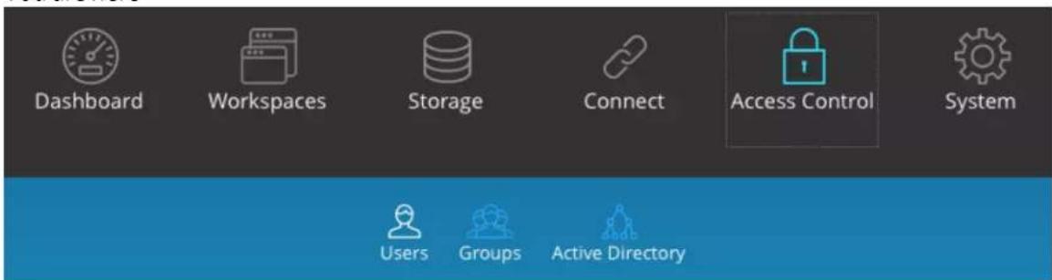
Access Control menu is used to create and manage user and groups accounts. Access rules can be created and edited in the Permissions menu under Workspaces.
Users
G-RACK 12 Administrative Tool > Access Control > Users
Add/Edit user
G-RACK 12 Administrative Tool > Access Control > Users > Add/Edit user
Use this menu to create new users' account and to assign them to groups.
To create new or to editing the existing one user account click the Add button, then fill out the required fields.

The following table describes the labels on the screen:
NOTE: The password is case-sensitive.
In text fields, you may enter from 4 to 20 characters using letters, numbers, symbols, hyphen, and underscore. Do not begin or end with a hyphen or underscore.
Import users
G-RACK 12 Administrative Tool > Access Control > Users > Import users
To create multiple users, use "Import" option.

Mandatory fields are Name, Password and Disallowusermod.
Disallowusermod can be a boolean value of true or false and stands for "do not allow user to modify account".
When entering users to import do not use <>. To skip a field so not enter any text put semi-colon separator, e.g. "john;;john smith;;grack12;PLM;false".
A uid was not set and is not mandatory here because the G-RACK 12 will set the next user id in the line for them.
NOTE: It is not possible to set a group name that does not exist yet. In this case the standard work flow is to import groups first in the Group tab and then to import users.
NOTE: The manually assigned uid's must start off at 1000 or higher, otherwise they will not appear in the list.
Delete
G-RACK 12 Administrative Tool > Access Control > Users > Delete
Highlight the desired user and press the Delete button. Confirm in the dialogue window.
Refresh
G-RACK 12 Administrative Tool > Access Control > Users > Refresh
The Refresh button will refresh the users list or updated information.
NOTE: Newly created users will appear automatically. Refresh button will display any new or updated information about the already existing users. It may take a few minutes to update the information.
Group
G-RACK 12 Administrative Tool > Access Control > Group
A user group is a collection of users with the same access right to the files or folders. Assigning users to groups gives you powerful tools to manage large numbers of users and their permissions. They allow administrators to change access rights to entire groups rather than individually. From this page, administrators can: create, modify, delete, and add users to groups.
Add/Edit group
G-RACK 12 Administrative Tool > Access Control > Group > Add/Edit group
Use this menu to create a new group and assign users to it, then fill out the required fields.

Import groups
G-RACK 12 Administrative Tool > Access Control > Group > Import groups
To create multiple groups, use "Import" option.

NOTE: The manually assigned uid's must start off at 1000 or higher, otherwise they will not appear in the list.
Delete
G-RACK 12 Administrative Tool > Access Control > Group > Delete
Highlight the desired group and press the Delete button. Confirm in the dialogue window. NOTE: Deleting a group will not affect user data.
Refresh
G-RACK 12 Administrative Tool > Access Control > Group > Refresh
The Refresh button will reload the screen and display any new or updated information about groups.
NOTE: Newly created groups will appear automatically. Refresh button will display any new or updated information about the already existing groups. It may take a few minutes to update the information.
Active Directory
G-RACK 12 Administrative Tool > Access Control > Active Directory
Active Directory ^® is a Microsoft directory used in Windows environments to centrally store, share, and manage the information and resources on your network. It is a hierarchical data center which centrally holds the information of the users, user groups, and the computers for secure access management.
By joining the G-RACK 12 to the Active Directory, all the user accounts of the Active Directory server will be imported to the G-RACK 12 automatically.
This will allow the administrator to configure the access rights (read only, read/write, or deny
access) to the network shared workspaces.
NOTE: In order to join the domain you must have an administrator account for this domain.

The following table describes the labels on the screen:
| Enable | Toggle on to enable the service |
| ADS server's full domain name | The FQDN of the server. e.g. server1.example.com |
| Domain name | e.g. example.com |
| Kerberos Realm | Usually it's the same as domain name but in upper case, e.g. EXAMPLE.COM |
| Domain NetBIOS name | Usually it's first part of realm, e.g. EXAMPLE |
| Admin username | Active Directory Server's admin user name |
| Admin password | Active Directory Server's admin password |
| ADS Join Status | The status will be displayed |
Users local to the G-RACK 12 system that have the same name as imported ADS domain users will cause some conflicts. Users will merge as one and display as being part of both local and domain groups. This may cause issues when mounting shared workspaces or setting permissions. For best practice to avoid such conflicts:
- Enable Active Directory and import ADS domain users
- Create local G-RACK 12 users with unique names.
NOTE: It is important to note that additionally you can also enable a guest access for shared workspaces in the Connect menu ^66 for the protocol. This enables users to access the shared workspace through protocol services as long as correct permissions set.
Directory Service
G-RACK 12 Administrative Tool > Access Control > Directory Service
The Directory Service feature allows the G-Rack 12 to enable the Lightweight Directory Access Protocol (LDAP) and communicate with an LDAP server. When this application protocol is enabled, local users and groups will be disabled. Users and groups from the LDAP server will be made available on the G-Rack 12.
Follow these steps to enable LDAP:
- On the main menu, click Access Control.
- Click Directory Service
- Click Enable to toggle-on this feature.
- Fill in the necessary fields with information from the LDAP server.
- If SSL/TLS is being used by the LDAP server, enable on the G-Rack 12 by clicking Enable SSL/TLS, and fill in the necessary fields.

NOTE: If the Server Message Block (SMB) network protocol is incorrectly configured on the LDAP server, the G-Rack 12 server will disable SMB.
System
G-RACK 12 Administrative Tool > System
You are here

General Settings
G-RACK 12 Administrative Tool > System > General Settings
Web Administration
G-RACK 12 Administrative Tool > System > General Settings > Web Administration
Use this menu to set general system settings
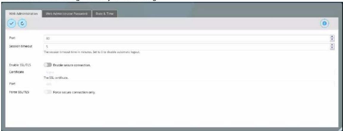
The following table describes the labels on the screen:
| Port | Specify the port |
| Session timeout | The session timeout time in minutes. Set to 0 to disable automatic logout.NOTE: Choose a shorter timeout period if your organization has sensitive information and you want to enforce stricter security. |
| Enable SSL/TLS | Enable secure connection. See note below. |
| Certificate | The SSL certificate |
| Port | Specify the port for secure connection |
| Force SSL/TLS | Force secure connection only |
Note: When you turn on "Enable SSL/TLS" you will need to add https:// to the URL for the Admin Tool. When you do this all browsers will report that you are using an "untrusted certificate error" when connecting to the Admin Tool using https.
This error message should not have you worry. The lack of trust comes from the fact you created the certificate and did not buy it from a known certificate authority. It is easy to either ignore or tell your browser to trust this certificate.
- Safari - Users can just continue to site anyways and select to trust the certificate.
- Chrome - Users can go to advance settings and continue anyway.
- Firefox - Users can go to advance settings and create exception for the Admin Tool IP address.
Example error message:

Your connection is not private
Attackers might be trying to steal your information from 10.2.10.237 (for example, passwords, messages, or credit cards). NET::ERR_CERT_AUTHORITY_INVALID
□ Automatically report details of possible security incidents to Google. Privacy policy
Advanced
Back to safety
chrome
Web Administrator Password
G-RACK 12 Administrative Tool > System > General Settings > Web Administrator Password
Set the administrator's password.

NOTE: Make sure to remember the password. If the admin password is lost, contact G-Technology support center for the assistance.
NOTE: For security purposes the system will block the login form after 3 incorrect password attempts for 3 minutes.
Date & Time
G-RACK 12 Administrative Tool > System > General Settings > Date & Time
The Time & Date option allows you to configure, update and maintain the correct time and date on the internal system clock.
Adjust the date, time, and time zone according to the location of the NAS. If the settings are incorrect, the following problems may occur:
- When using a web browser to connect to the G-RACK 12 or save a file, the display time of the action will be incorrect.
- The time of the event log displayed will be inconsistent with the actual time when an action occurs.

| Current time | The current time of the G-RACK 12 will be displayed |
| Time zone | Set the time zone from the drop-down menu to the appropriate geographical zone closest to your zone. |
| Use NTP server | Turn on this option to synchronize the date and time of the NAS automatically with an NTP (Network Time Protocol) server. |
| Time servers | Enter the IP address or domain name of the NTP server, for example, pool.ntp.org. This option can be used only when the NAS is connected to the Internet. |
| Manual | To synchronize the time of the G-RACK 12 with the computer time, click "Update now" next to this option. Enter manual time values for date and time. Unavailable if "Use NTP server" option is active. |
The first time synchronization may take several minutes to complete.
NOTE: In an Active Directory environment this functionality should not be used because the server should sync the time with the domain server.
NOTE: When connected to Active Directory domain and there is an alteration of the date and time between the G-RACK 12 server and Domain servers you can cause errors. Time must be in sync. If you encounter an issue where the LDAP server is not found and domain users cannot mount AFP shares, this may be the issue
OS RAID
G-RACK 12 Administrative Tool > System > OS RAID
The RAID OS menu option provides the G-RACK 12 operating system information.
The status of the operating system RAID is also displayed in the Dashboard 42
| Name | Device | State | Level | Capacity | Used | Devices | Mounted | Referenced | Recovery mode |
| G-RACK12 System... | /dev/sdb2 | good | 3.8 TB | 1.44 GB | /dev/sdb2 /dev/sdb2 | Yes (normal) | Yes | manual |
Should one of the operating system physical disks fail, the status will be changed to "degraded". The G-RACK 12 will send the notification to the administrator's email (Use Settings ^111 menu under Monitoring ^109 tab).
In this situation:
-
Find out which disk has failed, for this click "Details" button. It will say "device1" or "device 2" ID1 - on the left. ID 2 on the right - when you are facing the G-RACK 12. Also the LED of the tray with the failed disk will go red
-
Pull out the failed disk
-
Put in the new disk.
If the disk has any existing data on it, it will be wiped automatically. If the replacing disk contains a boot partition, you will need to use another drive or wipe this one manually.
- Once you have pulled in the new disk, the recovery process will be finished automatically.
Monitoring
G-RACK 12 Administrative Tool > System > Monitoring
Performance statistics
G-RACK 12 Administrative Tool > System > Monitoring > Performance statistics
Performance statistics refer to values of various data of the G-RACK 12 system at different points of time. The performance statistics are presented in form of charts and can be viewed under System information menu. The performance statistics directly shows users the performance of the G-RACK 12 from multiple angles. In the event of a performance exception, you can find the cause by viewing the performance statistics.
It is advised to always keep the real time performance monitoring function on.
Toggle on to enable gathering performance statistics.

Hardware sensors
G-RACK 12 Administrative Tool > System > Monitoring > Hardware sensors
Hardware sensors monitor utilizes sensor chips on smart motherboards to track system and CPU core temperatures, voltages and cooling fans. By quickly catching a raising value of the parameter, you can prevent disasters such as system instability or damage.
| Performance statistics | Hardware sensors | Notifications | Settings | |
| Sensor | Value | Status | High Limit | |
| Fan Speed | ||||
| FAN1 | 5600 RPM | OK | 25300 RPM | |
| FAN2 | 5600 RPM | OK | 25300 RPM | |
| FAN3 | 5700 RPM | OK | 25300 RPM | |
| FAN4 | 5900 RPM | OK | 25300 RPM | |
| FANA | 6400 RPM | OK | 25300 RPM | |
| Temperature | ||||
| CPU1 Temp | 36°C (96.8°F) | OK | 79°C (183.2°F) | |
| CPU2 Temp | 38°C (100.4°F) | OK | 79°C (183.2°F) | |
| LAN Temp | 55°C (131°F) | OK | 95°C (212°F) | |
| Peripheral Temp | 34°C (92.2°F) | OK | 80°C (185°F) | |
| System Temp | 26°C (78.8°F) | OK | 80°C (185°F) | |
| Voltrages | ||||
| 12V | 12.126 Volts | OK | 12.945 Volts | |
| 3.3VCC | 3.316 Volts | OK | 3.554 Volts | |
| 5VCC | 5.078 Volts | OK | 5.390 Volts | |
| Vcpu1 | 1.836 Volts | OK | 1.899 Volts | |
| Vcpu2 | 1.836 Volts | OK | 1.899 Volts | |
Notifications
G-RACK 12 Administrative Tool > System > Monitoring > Notifications
You can limit which events are sent as notification alerts to the email. Select the information you want emailed to the your address. The items checked will be sent when necessary.

Settings
G-RACK 12 Administrative Tool > System > Monitoring > Settings
Use this dialog to set SMTP server which is used to send emails from the notification service. Yu can use either external public SMTP like smtp.gmail.com, or private SMTP in your local corporate network. Consult your network administrator for further details.
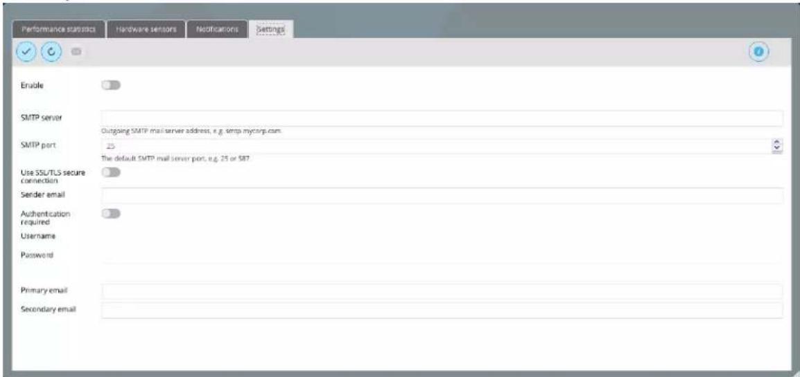
The following table describes the labels on the screen:
| Enable | Toggle on to enable sending notification emails |
| SMTP server | Enter the SMTP server name or IP address |
| SMTP port | Enter the SMTP port number |
| Use SSL/TLS secure connection | If your SMTP server requires SSL/TLS connection, toggle on to enable it |
| Sender email | Enter the "from" email address (notification@g-technology.com). If your client is filtering spam, make sure you allow this address to be received. |
| Authentication required | If your SMTP server requires authentication, toggle on to enable it |
| Username | Enter the Username for the email server |
| Password | Enter the Password for the email serve |
| Primary email | Enter the primary email to send to notifications |
| secondary email | Enter the secondary email to send to notifications |
Now no matter if you are out at work or away from home you will still be notified of the status and the condition of your G-RACK 12 right away.
Certificates
G-RACK 12 Administrative Tool > System > Certificates
Certificates are needed for secure, encrypted communication over networks. On the G-RACK 12 you need them for SSH and a secure connection to the web administration interface (see General Settings).
SSH
G-RACK 12 Administrative Tool > System > Certificates > SSH
SSH (Secure Socket Shell) is a network protocol that provides administrators with a secure way to access a remote computer. Secure Shell provides strong authentication and secure encrypted data communications between two computers connecting over an insecure network in client-server architecture. SSH is widely used by network administrators for managing systems remotely, allowing them to log in to another computer over a network, execute commands and move file.
To create a new SSH certificate click Add button and choose Create from the drop down menu

To import an existing SSH certificate click Add button and choose Import from the drop down menu

| Private key | The private RSA key in X.509 PEM format |
| Public key | The RSA public key in OpenSSH format. |
| Comment | Optional text here |
SSL
G-RACK 12 Administrative Tool > System > Certificates > SSL
SSL is a cryptographic protocol for communication security and data confidentiality over the Internet. To use SSL, you will need a certificate and a key. These are available from web hosting services and many private privacy providers.
To create a new SSL certificate click Add button and choose Create in the drop down menu. This dialog will create a self-signed certificate.

To import an existing SSL certificate click Add button and choose Import in the drop down menu

Scheduled Jobs
G-RACK 12 Administrative Tool > System > Scheduled Jobs
Add/ Edit scheduled job
G-RACK 12 Administrative Tool > System > Scheduled Jobs > Add/ Edit scheduled job
Use this dialog to add a cron job which is a rule for the cron daemon. Cron is intended to run arbitrary commands on a periodical basis.

The following table describes the labels on the screen:
| Enable | Toggle on to enable |
| Time of execution | Choose from the drop down menu the time to execute the scheduled job. |
| Minute | Set the time when the test will be performed. |
| Hour | Set the time when the test will be performed.Asterisk means "every hour" |
| Day of month | Set the day when the test will be performed.Asterisk means "every day" |
| Month | Set the month when the test will be performed.Asterisk means "every month" |
| Day of week | Set the day of the week when the test will be performed. Asterisk means "every week" |
| User | Select a user from the drop down menu |
| Command | Input the command to execute |
| Send email | Send command output via email. An email message with the command output (if any produced) is send to the user who performs the job. |
Comment
Add an optional text here
Execute cron job
G-RACK 12 Administrative Tool > System > Scheduled Jobs > Execute cron job
The Run button starts the job immediately.
Delete sheduled Job
G-RACK 12 Administrative Tool > System > Scheduled Jobs > Delete scheduled Job
Click the Delete button to delete the test.
System Information
G-RACK 12 Administrative Tool > System > System Information
Under this tab you find the most important information about the G-RACK 12 server.
- Server name
- Version
• Time
• Hardware information Raid status - CPU usage
- System memory
• Network info with current transfer rate
Overview
G-RACK 12 Administrative Tool > System > System Information > Overview
General information summary about the system. For more details refer to other sections under this menu

Process
G-RACK 12 Administrative Tool > System > System Information > Process
This is an informational menu. The Process tab all running processes sorted by CPU consumption. This info may be helpful if you are trying to figure out why the performance is suboptimal or if the process for the corresponding service is actually running. Here you can also find out which processes consume large amount of memory.
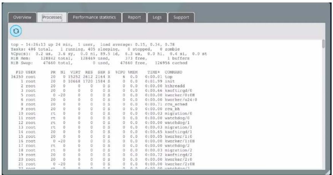
Performance statistics
G-RACK 12 Administrative Tool > System > System Information > Performance statistics
It focuses on global system monitoring, viewing real-time performance, historical performance of related devices and storing performance log files.
If a problem occurs, handle it by the following steps:
- View the real-time performance and historical performance of the device
- Download log files
- Analyze performance statistics files
- Adjust the G-RACK 12 system based on the analysis result to resolve the performance problem.
Performance statistics
CPU usage

bar
| CPU usage - by hour | Percent (%) | |---|---| | 13:20 | 45 | | 13:30 | 38 | | 13:40 | 52 | | 13:50 | 12 | | 14:00 | 35 | | 14:10 | 48 |Load average

line
| Time | Load Average - by hour | | -------- | ---------------------- | | 13:20 | 0.00 | | 13:30 | 2.41 | | 13:40 | 6.43 | | 13:50 | 0.45 | | 14:00 | 2.41 | | 14:10 | 6.43 |Memory usage
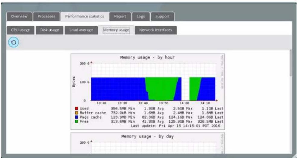
bar_stacked
Memory usage - by hour | Time | Used (Bytes) | Buffer cache (Bytes) | Page cache (Bytes) | Free (Bytes) | | :--- | :--- | :--- | :--- | :--- | | 13:20 | 956.5MB Min | 732.0kB Min | 123.9MB Min | 313.6MB Min | | 13:30 | 1.3GB Avg | 1.6MB Avg | 82.3GB Avg | 41.3GB Avg | | 13:40 | 2.5GB Max | 2.4MB Max | 124.1GB Max | 125.3GB Max | | 13:50 | 1.8MB Last | | | | | 14:00 | 124.0GB Last | | | | | 14:10 | 326.5MB Last | | | | Last update: Fri Apr 15 14:15:01 PDT 2016 Memory usage - by dayNetwork interfaces
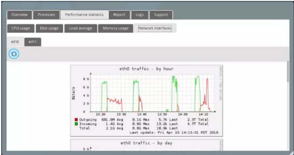
line
| Metric | Value | | -------------- | --------- | | Outgoing | 681.8M Avg | | Incoming | 1.4G Avg | | Total | 2.1G Avg | | Max | 8.1G Max | | Max | 8.8G Max | | Max | 8.8G Max | | Max | 13.2K Last | | Max | 18.9K Last | | Last Update | 2.3T Total | | Last Update | 4.7T Total |Report
G-RACK 12 Administrative Tool > System > System Information > Report
The Report tab contains essential information about the G-RACK 12 which may be helpful for investigation of possible issues. Please attach this information to any request to the G-Technology support.

Logs
G-RACK 12 Administrative Tool > System > System Information > Logs
Log files help troubleshooting in case of problems. Especially when contacting technical support it is very important to create and send support log files as well. These files help technical support team to determine the problem and find the solution much quicker.
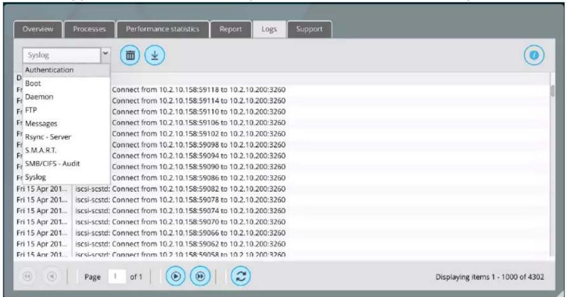
Support
G-RACK 12 Administrative Tool > System > System Information > Support
If you encounter a fault that you cannot rectify, download the log files for further investigation or report it to the technical support engineers.
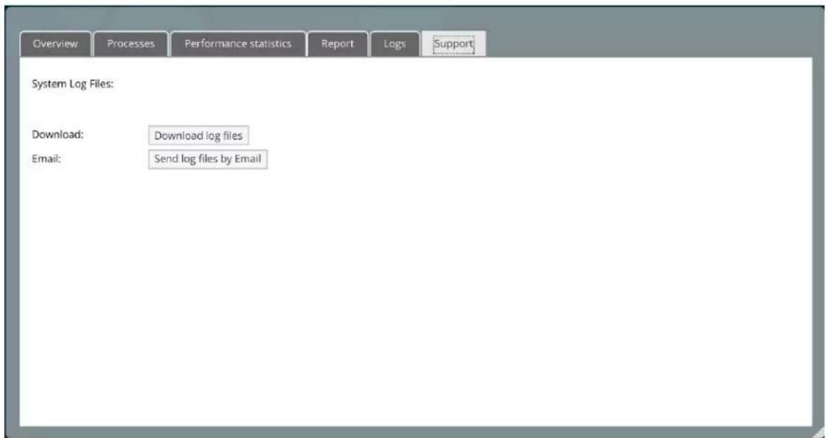
If a tough or critical problem persist in routine maintenance or troubleshooting, contact G-Technology for technical support. After analyzing log information, technical support engineers will provide guidance for you to handle the fault.
Update Manager
G-RACK 12 Administrative Tool > System > Update Manager
Updates
G-RACK 12 Administrative Tool > System > Update Manager > Updates
Update manager is a utility that oversees the installation of updates for the G-RACK 12 existing software.

Once an update is available, you will see a notice in the menu and [plus button] will be active.
To eliminate vulnerabilities within the G-RACK 12 software settings, take a snapshot ^[122] of the operating system before applying an update.
Snapshots
G-RACK 12 Administrative Tool > System > Update Manager > Snapshots
Take snapshot
G-RACK 12 Administrative Tool > System > Update Manager > Snapshots > Take snapshot
Should you experience any troubles after an update or due to other circumstances, snapshots will help you to roll the operating system back.
NOTE: Snapshots of OS RAID are read-only.
To take snapshot click the Take snapshot button.

The snapshots will be displayed in the list.

Reboot with selected snapshot
G-RACK 12 Administrative Tool > System > Update Manager > Snapshots > Reboot with selected snapshot
Use a snapshot from the list to roll back the previous stable version of the operating system to reboot with.
Reset to Factory Settings
G-RACK 12 Administrative Tool > Reset to Factory Settings
To perform Reset to Factory Settings, first backup your data to a different device, then click the system menu and choose Reset to Factory Settings


NOTE: WHILE PERFORMING RESET TO FACTORY SETTINGS ALL THE DATA WILL BE WIPED OUT AND BECOME UNRECOVERABLE. THE G-RACK 12 WILL BE RESTORED TO ITS OUT-OF-BOX STATE.
Use this option only if you need a fresh system to start a new project.
To be able to use the data with new settings, backup the data to a different location, perform Reset to Factory Settings and move the data back.
Also you can manually go through the menus and adjust them to meet the current requirements.
Shutdown
G-RACK 12 Administrative Tool > Shutdown
To perform factory reset, click the system menu and choose Shutdown

This option will shutdown the G-RACK 12 server unit only. To perform a full shutdown it is required to press the power button on the front panel of the expansion chassis(es).
Reboot
G-RACK 12 Administrative Tool > Reboot
To perform reboot, click the system menu and choose Reboot.

G|RACK™ 12
Hardware Description
This section will cover the hardware and configuration for the G-RACK 12.
Server Unit
Hardware Description > Server Unit
Introduction - Hardware
Hardware Description > Server Unit > Introduction - Hardware
Overview?
Hardware Description > Server Unit > Introduction - Hardware > Overview
The G-RACK 12 is 19" rack mount NAS server chassis with integrated dual processor server board. The server comes pre-installed with NAS OS and all required hardware for operation.
In addition to the server board and chassis, various hardware components have been included with the G-RACK 12, as listed below:
- Two passive CPU heat sinks
• Three 8-cm system fans - One air shroud
- SATA Accessories One SATA backplane Twelve drive carriers
- Expansion Port
• One rack mount rail kit
NOTE: For your system to work and operate properly, please review the sections below in the user's manual for your server.
• Product safety section.
• F.A.Q.
- If you have any questions contact support https://support-en.g-technology.com/app/Contact_Us/
Serverboard Features
Hardware Description > Server Unit > Introduction - Hardware > Serverboard Features
The G-RACK 12 is built around a dual processor server board based on the Intel C612 chipset. Below are the main features of the unit. (See Figure 1-1 for a block diagram of the chipset.)
Figure 1-1. Intel C612 Chipset:
System Block Diagram

flowchart
graph TD
    subgraph PCH_612
        A["CPU1"] -->|P0| B["CPU2"]
        B -->|P1| A
        A --> C["DDR4 133V2133"]
        B --> D["DDR4 133V2133"]
        C --> E["DDR4 133V2133"]
        D --> F["DDR4 133V2133"]
        E --> G["DDR4 133V2133"]
        F --> H["DDR4 133V2133"]
        I["LAN1.2 X540I050"] --> J["BMC AST2400"]
        K["PCIe X8 G3"] --> L["PCIe X8 G3 (LAN REVERSE)"]
        M["PCIe X8"] --> N["PCIe X8 G3 (LAN REVERSE)"]
        O["PCIe X8G2"] --> P["PCIe X8G2 (LAN REVERSE)"]
        Q["PCIe X8G3"] --> R["PCIe X8G3 (LAN REVERSE)"]
        S["PCIe X8G3"] --> T["PCIe X8G3 (LAN REVERSE)"]
    end

    subgraph PCH_612
        U["PVCCIO (1.05/0.95) from 3.3v"] --> V["PCIe X8 G3"]
        W["PVCCIO (1.05/0.95) from 3.3v"] --> X["PCIe X8 G3"]
        Y["PVCCIO (1.05/0.95) from 3.3v"] --> Z["PCIe X8 G3"]
        AA["PVCCIO (1.05/0.95) from 3.3v"] --> AB["PCIe X8 G3"]
    end

    subgraph PCH_612
        AC["SATA"] --> AD["I-SATA 0,1,2,3 SATADOM 5,6 S-SATA 7,8,9,10"]
        AE["USB2"] --> AF["USB 0/1, 2/3"]
        AG["USB3"] --> AH["USB 4/5, 6, 7/8"]
    end

    subgraph PCH_612
        AI["TPM HEADER Debug Card"] --> AJ["BIOS HEADER"]
        AK["FANT PANEL"] --> AL["FAN SPEED CTRL"]
    end

    subgraph PCH_612
        AM["VGA CONN"] --> AN["Temp Sensor EMC148E-1 '2 at off SMBUS"]
        AO["COM1 Connector"] --> AP["COM2 Header"]
    end

    subgraph PCH_612
        AQ["BIOS"] --> AR["BIOS HEADER"]
        AS["BIOS"] --> AT["BIOS HEADER"]
    end

    subgraph PCH_612
        AU["RJ45"] --> AV["LAN3 RTL82115-VB-CG"]
        AW["DOR3"] --> AX["BMC Boot Flash"]
        AY["BIO"] --> AZ["BMC"]
    end

    subgraph PCH_612
        BA["SATA"] --> BB["I-SATA 0,1,2,3 SATADOM 5,6 S-SATA 7,8,9,10"]
        BC["SATA"] --> BD["I-SATA 0,1,2,3 SATADOM 5,6 S-SATA 7,8,9,10"]
    end
Processors
Hardware Description > Server Unit > Introduction - Hardware > Serverboard Features > Processors
The G-RACK 12 supports single or dual Intel® Xeon Haswell Series processors. These processors are pre-installed and not considered a user serviceable component.
Memory
Hardware Description > Server Unit > Introduction - Hardware > Serverboard Features > Memory
The G-RACK 12 is shipped with 128 GB of internal RAM memory.
Main Storage Controller
Hardware Description > Server Unit > Introduction - Hardware > Serverboard Features > Main Storage Controller
An LSI 3008 controller card is included in the system to support up to 240 SATA 3.0/SAS 3.0 hard drives. The SATA/SAS drives are hot-swappable units.
Serial ATA
Hardware Description > Server Unit > Introduction - Hardware > Serverboard Features > Serial ATA
A SATA controller is integrated into the chipset to provide 10 SATA 3.0 (6/Gbps) ports (I-SATA0-5 supported by the Intel PCH and a vertical 4-port S-SATA connection supported by the Intel SCU). The SATA drives are hot-swappable units.
PCI Expansion Slots
Hardware Description > Server Unit > Introduction - Hardware > Serverboard Features > PCI Expansion Slots
The G-RACK 12 has six PCI-Express 3.0 x8 slots (CPU1 Slots 1-3 and CPU2 Slots 5-7) and one PCI-Express 3.0 x16 slot (CPU2 Slot4). While these slots are in the system they are not available to the customer for adding devices.
Rear I/O Ports
Hardware Description > Server Unit > Introduction - Hardware > Serverboard Features > Rear I/O Ports
The I/O ports include one COM port, a VGA port, four USB (two USB 3.0 and two USB 2.0), two 10G Ethernet ports, a dedicated IPMI LAN port and dual JBOD expansion ports. A UID (Unit Identifier) button and LED are also located beside the VGA port.
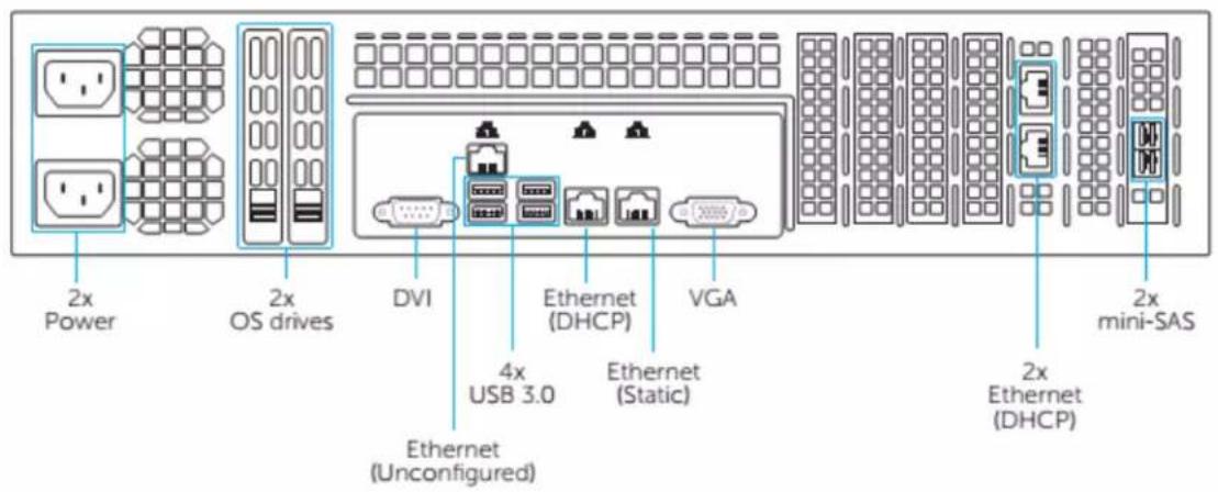
Onboard Graphics
Hardware Description > Server Unit > Introduction - Hardware > Serverboard Features > Onboard Graphics
Graphics are provided by an on board ASpeed AST 2400 BMC, which supports IPMI.
Server Chassis Features
Hardware Description > Server Unit > Introduction - Hardware > Server Chassis Features
The G-RACK 12 is a 2U form factor chassis designed to be used in a storage configuration. The following is a general outline of the main features of the G-RACK 12 chassis.
System Power
Hardware Description > Server Unit > Introduction - Hardware > Server Chassis Features > System Power
The G-RACK 12 features a redundant, hot-plug 920W power supply composed of two separate power modules. This power redundancy feature allows you to replace a failed power supply without shutting down the system.
Hard Drive Subsystem
Hardware Description > Server Unit > Introduction - Hardware > Server Chassis Features > Hard Drive Subsystem
The G-RACK 12 chassis was designed to support 12 hot-swap SATA hard drives. An optional, internal drive mounting bracket may be added to support two 2.5" SATA drives.
Front Control Panel
Hardware Description > Server Unit > Introduction - Hardware > Server Chassis Features > Front Control Panel
The control panel on the G-RACK 12 provides you with system monitoring and control. LEDs indicate system power, HDD activity, network activity, system overheat and power supply failure. A main power button and a system reset button are also included.

Cooling System?
Hardware Description > Server Unit > Introduction - Hardware > Server Chassis Features > Cooling System

The G-RACK 12 chassis includes three 8-cm hot-plug system cooling fans located in the middle section of the chassis. An air shroud channels the air flow from the system fans to efficiently cool the processor area of the system. Each power supply module also includes a cooling fan.
System Interface
Hardware Description > Server Unit > System Interface
Overview
Hardware Description > Server Unit > System Interface > Overview
There are several LEDs on the control panel as well as others on the drive carriers to keep you constantly informed of the overall status of the system as well as the activity and health of specific components. There are also two buttons on the chassis control panel.
Control Panel Buttons
Hardware Description > Server Unit > System Interface > Control Panel Buttons
There are two buttons located on the front of the chassis: a reset button and a power on/off button.
RESET

Reset
Use the reset button to reboot the system.

Power
This is the main power button, which is used to apply or turn off the main system power. Turning off system power with this button removes the main power but keeps standby power supplied to the system.
Control Panel LEDs
Hardware Description > Server Unit > System Interface > Control Panel LEDs
The control panel located on the front of the chassis has several LEDs. These LEDs provide you with critical information related to different parts of the system. This section explains what each LED indicates when illuminated and any corrective action you may need to take.

Power Fail
Indicates a power supply module has failed. The second power supply module will take the load and keep the system running but the failed module will need to be replaced. Refer to the section titled "Removing/Replacing the Power Supply" for details on replacing the power supply. This LED should be off when the system is operating normally.

Information LED
This LED will be blue when the UID function has been activated. When this LED ashes red, it indicates a fan failure. When red continuously it indicates an overheat condition, which may be caused by cables obstructing the air ow in the system or the ambient room temperature being too warm. Check the routing of the cables and make sure all fans are present and operating normally. You should also check to make sure that the chassis covers are installed. Finally, verify that the heatsinks are installed properly. This LED will remain flashing or on as long as the indicated condition exists.

NIC1
Indicates network activity on the LAN1 port when active.
NIC2
Indicates network activity on the LAN2 port when active.

HDD
On the G-RACK 12, this LED indicates hard drive activity for any drive in the system. Each drive carrier also has an LED for individual activity.

Power
Indicates power is being supplied to the system's power supply units. This LED should normally be illuminated when the system is operating and powered on.
Drive Carrier LEDs
Hardware Description > Server Unit > System Interface > Drive Carrier LEDs
The chassis includes externally accessible SATA drives. Each drive carrier displays two status LEDs on the front of the carrier. The LED status can be understood using the table below. For details regarding drive status, use the Admin Tool.
| LED Color | State | Status | |
| Activity LED | Blue | Blinking | I/O Activity |
| Status LED | Red | Solid On | Potential Drive Issue/Error - check Admin Tool |
| Red | Blinking | Drive Locate |
Chassis Installation and Precautions
Hardware Description > Chassis Installation and Precautions
This chapter covers the steps required to install components and perform maintenance on the G-RACK 12 chassis. For component installation, follow the steps in the order given to eliminate the most common problems encountered. If some steps are unnecessary, skip ahead to the step that follows. Please do not perform modifications beyond the directions as they may render the unit inoperable.
Tools Required: The only tool you will need to install components and perform maintenance is a Phillips-head screwdriver.
Introduction
Hardware Description > Chassis Installation and Precautions > Introduction
Overview
Hardware Description > Chassis Installation and Precautions > Introduction > Overview
G-RACK 12 chassis maximizes the storage capacity of a 2U form factor by offering twelve hot-swappable hard drive bays. It is ideal for data storage applications. The chassis design optimizes every aspect of interior space, without compromising superior cooling and is equipped with a redundant power supply.
Features
Hardware Description > Chassis Installation and Precautions > Introduction > Features
Drives
The chassis allows twelve 3.5" hot-swap SAS3/SATA hard disk drives. Some models support two optional 2.5" hot-swap drives for OS mirroring.
System Power
Different models offer redundant power supply modules of several different wattages.
Front Control Panel
The control panel provides a monitoring and control interface. LEDs indicate system status and buttons control system power.
Cooling System
The system includes three 80mm hot-swap fans.
Static-Sensitive Devices
Hardware Description > Chassis Installation and Precautions > Introduction > Static-Sensitive Devices
Electrostatic discharge (ESD) can damage electronic components. To prevent damage to any printed circuit boards (PCBs), it is important to handle them very carefully. The following measures are generally sufficient to protect your equipment from ESD damage.
Attaching an Expansion Chassis
Hardware Description > Chassis Installation and Precautions > Introduction > Attaching an Expansion Chassis
Handling Precautions
- Use a grounded wrist strap designed to prevent static discharge. Touch a grounded metal object before removing any board from its antistatic bag.
- Handle a board by its edges only; do not touch its components, peripheral chips, memory modules or gold contacts.
- When handling chips or modules, avoid touching their pins.
- Put the motherboard, add-on cards and peripherals back into their antistatic bags when not in use.
- For grounding purposes, make sure your computer chassis provides excellent conductivity between the power supply, the case, the mounting fasteners and the motherboard.
Power Sequence Requirement
- When using a G-Rack 12 Expansion unit, it must be powered on before the main G-Rack 12 unit is powered on. Failure to follow this sequence can result in a degraded RAID setup.
Physical Layout
- Note the physical layout of the unit and the logical numbering used for the drive bays listed below in Figures 6-1 and 6-2.
Figure 6-1. Front and Rear Chassis Views
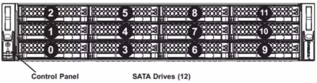
Note: the numbers above indicate the logical drive locations (drive map).
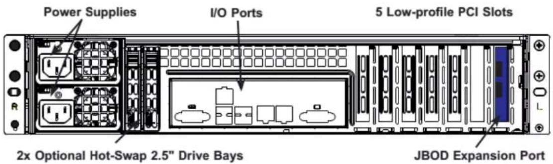
Figure 6-2. JBOD Expansion Ports
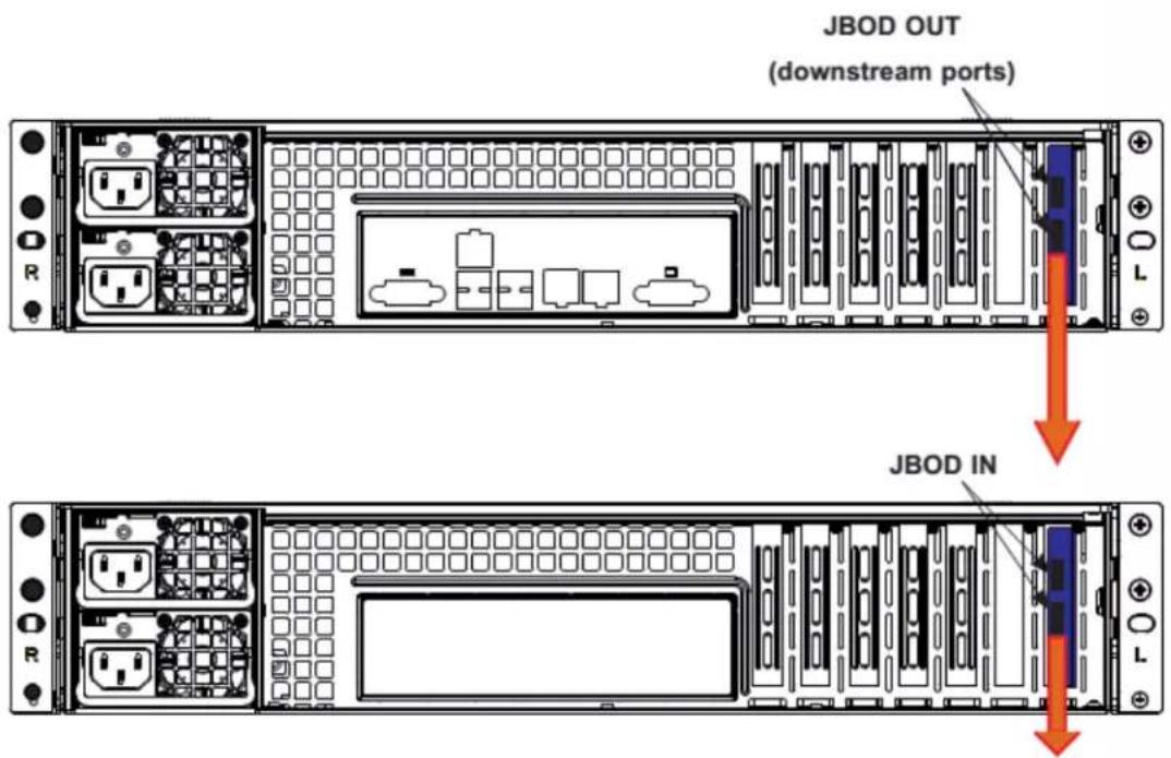
Checking the Airflow
Hardware Description > Chassis Installation and Precautions > Introduction > Checking the Airflow
- Make sure there are no objects to obstruct airflow in and out of the server. In addition, make sure the front bezel's filter is replaced periodically.
- Do not operate the server without drives or drive carriers in the drive bays. Use only recommended server parts.
- Make sure no wires or foreign objects obstruct airflow through the chassis. Pull all excess cabling out of the airflow path or use shorter cables.
The control panel LEDs inform you of system status. See "System Interface Chapter" for details on the LEDs and the control panel buttons.
Rack Installation
Hardware Description > Chassis Installation and Precautions > Rack Installation
This chapter provides instructions for preparing and mounting your chassis in a rack.
Installing the System into a Rack
Hardware Description > Chassis Installation and Precautions > Rack Installation > Installing the System into a Rack
This section provides information on installing the chassis into a rack unit with the rails provided. There are a variety of rack units on the market, which may mean that the assembly procedure will differ slightly from the instructions provided. You should also refer to the installation instructions that came with the rack unit you are using.
Note: This rail will fit a rack between 26.5" and 36.4" deep.
Identifying the Sections of the Rack Rails
Hardware Description > Chassis Installation and Precautions > Rack Installation > Identifying the Sections of the Rack Rail
The chassis package includes two rail assemblies. Each assembly consists of three sections: An inner rail that secures directly to the chassis, an outer rail that secures to the rack, and a middle rail which extends from the outer rail. These assemblies are specifically designed for the left and right side of the chassis.
Releasing the Inner Rail
Hardware Description > Chassis Installation and Precautions > Rack Installation > Releasing the Inner Rail
Each inner rail has a locking latch. This latch prevents the server from coming completely out of the rack when the chassis is pulled out for servicing.
To mount the rail onto the chassis, first release the inner rail from the outer rails.
Releasing Inner Rail from the Outer Rails
- Pull the inner rail out of the outer rail until it is fully extended as illustrated below.
- Press the locking tab down to release the inner rail.
- Pull the inner rail all the way out.
- Repeat for the other outer rail.
Installing the Inner Rails on the Chassis
Hardware Description > Chassis Installation and Precautions > Rack Installation > Installing the Inner Rails on the Chassis
- Identify the left and right inner rails. They are labeled.
- Place the inner rail firmly against the side of the chassis, aligning the hooks on the side of the chassis with the holes in the inner rail.
- Slide the inner rail forward toward the front of the chassis until the quick release bracket snaps into place, securing the rail to the chassis.
- Optionally, you can further secure the inner rail to the chassis with a screw.
- Repeat for the other inner rail.
Installing the Outer Rails onto the Rack
Hardware Description > Chassis Installation and Precautions > Rack Installation > Installing the Outer Rails onto the Rack
- Press upward on the locking tab at the rear end of the middle rail.
- Push the middle rail back into the outer rail.
- Hang the hooks on the front of the outer rail onto the square holes on the front of the rack. If desired, use screws to secure the outer rails to the rack.
- Pull out the rear of the outer rail, adjusting the length until it just fits within the posts of the rack.
- Hang the hooks of the rear section of the outer rail onto the square holes on the rear of the rack. Take care that the proper holes are used so the rails are level.
If desired, use screws to secure the rear of the outer rail to the rear of the rack.
Stability hazard. The rack stabilizing mechanism must be in place, or the rack must be bolted to the floor before you slide the unit out for servicing. Failure to stabilize the rack can cause the rack to tip over.
NOTE: Do not use a two post "telco" type racks as they will not support the G-RACK 12's weight.
Sliding the Chassis onto the Rack Rails
Hardware Description > Chassis Installation and Precautions > Rack Installation > Sliding the Chassis onto the Rack Rails
Warning: Mounting the system into the rack requires at least two people to support the chassis during installation. Please follow safety recommendations printed on the rails.
Installing the Chassis into a Rack
- Extend the outer rails as illustrated above.
- Align the inner rails of the chassis with the outer rails on the rack.
- Slide the inner rails into the outer rails, keeping the pressure even on both sides. When the chassis has been pushed completely into the rack, it should click into the locked position.
- Optional screws may be used to hold the front of the chassis to the rack.
Drive Bay Installation/Removal
Hardware Description > Chassis Installation and Precautions > Drive Bay Installation/Removal
Accessing the Drive Bays
Hardware Description > Chassis Installation and Precautions > Drive Bay Installation/Removal > Accessing the Drive Bays
You do not need to access the inside of the chassis or remove power to replace or swap hard drives. Proceed to the next step for instructions.
SAS/SATA Drive Installation
Hardware Description > Chassis Installation and Precautions > Drive Bay Installation/Removal > SAS/SATA Drive Installati
These drives are mounted in carriers to simplify their installation and removal from the chassis. The carriers also help promote proper air ow for the drives. For this reason, even empty carriers without hard drives installed must remain in the chassis.
Removing a Drive Carrier
- Push the release button located beside the drive's LEDs.
- Swing the handle fully out and use it to pull the drive carrier straight out (see Figure 6-5).
Mounting a Drive in a Drive Carrier
- To add a new hard drive, install the drive into the carrier with the printed circuit board side facing down so that the mounting holes align with those in the carrier.
- Secure the drive to the carrier with screws, as shown in Figure 6-6.
Caution: Enterprise level hard disk drives are recommended for use in the G-RACK 12.
Figure 6-5. Removing a Hard Drive Carrier

Caution: Regardless of how many hard drives are installed, all drive carriers must remain in the drive bays to maintain proper airflow.
Figure 6-6. Mounting a Drive in a Carrier
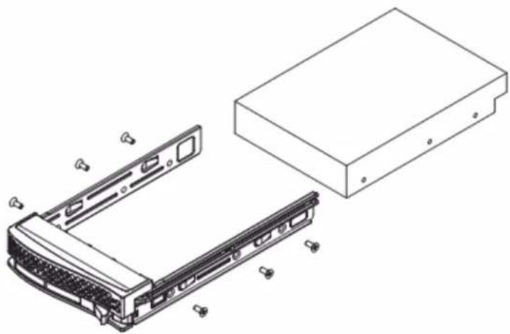
natural_image
Technical line drawing of an electronic device showing internal components and housing (no text or symbols)Chassis Setup and Maintenance
Hardware Description > Chassis Setup and Maintenance
This chapter covers the steps required to install components and perform maintenance on the chassis. The only tool required is a Phillips screwdriver.
Note and heed the warnings and precautions listed in the setup instructions.
ESD Safety Guidelines
Electrostatic Discharge (ESD) can damage electronic components. To prevent damage to your system, it is important to handle it very carefully. he following measures are generally sufficient to protect your equipment from ESD.
- Use a grounded wrist strap designed to prevent static discharge.
- Touch a grounded metal object before removing a component from the antistatic bag.
- Handle the backplane by its edges only; do not touch its components, peripheral chips, memory modules or gold contacts.
- When handling chips or modules, avoid touching their pins.
- Put the card and peripherals back into their antistatic bags when not in use.
General Safety Guidelines
- Always disconnect power cables before installing or removing any components from the computer, including the backplane.
- Disconnect the power cable before installing or removing any cables from the backplane.
- Make sure that the backplane is securely and properly installed on the motherboard to prevent damage to the system due to power shortage.
An Important Note to Users
- All images and layouts shown in this user's guide are based upon the latest PCB Revision available at the time of publishing. The card you have received may or may not look exactly the same as the graphics shown in this manual.
Removing Power from the System
Hardware Description > Chassis Setup and Maintenance > Removing Power from the System
Before performing most setup or maintenance tasks, use the following procedure to ensure that power has been removed from the system.
- Use the operating system to power down the system
, following the on-screen prompts. - After the system has completely shut-down, carefully grasp the head of the power cord and gently pull it out of the back of the power supply. Remove the cords from both power supply modules.
- Disconnect the cord from the power strip or wall outlet.

Figure 4-1. Removing the Chassis Cover
Removing the Chassis Cover
Hardware Description > Chassis Setup and Maintenance > Removing the Chassis Cover
- Power down the server as described in section 4-1, lay the chassis on a flat stable surface and remove the chassis cover.
- Remove the two screws from the sides of the chassis cover.
- Press the release tabs to remove the cover from the locked position. Press both tabs at the same time.
- Once the top cover is released from the locked position, slide the cover toward the rear of the chassis.
- Lift the cover off the chassis.
Caution: Except for short periods of time, do not operate the system without the cover in place. The chassis cover must be in place to allow proper airflow and prevent overheating.
Accessing the Inside of the Chassis
Hardware Description > Chassis Setup and Maintenance > Accessing the Inside of the Chassis
Some maintenance will require accessing the inside of the server.
- Remove the two screws from the sides of the chassis cover.
- Press both release tabs at the same time to unlock the cover.
- Slide the cover toward the rear of the chassis.
- Lift the cover off the chassis.

Figure 6-2. Removing the Chassis Cover
Installing Hard Drives
Hardware Description > Chassis Setup and Maintenance > Installing Hard Drives
The G-RACK 12 chassis supports twelve hot-swappable 3.5" hard drives, which may be removed without powering-down the system. The drives are mounted in drive carriers to simplify their installation and removal from the chassis. These carriers also help promote proper airflow for the drive bays.
The drive carriers also support an optional a 2.5" hard drive cage, which holds up to two additional 2.5" hard drives. (Instructions on the following pages.)
Removing a 3.5" Hard Drive Carrier
Hardware Description > Chassis Setup and Maintenance > Removing a 3.5" Hard Drive Carrier
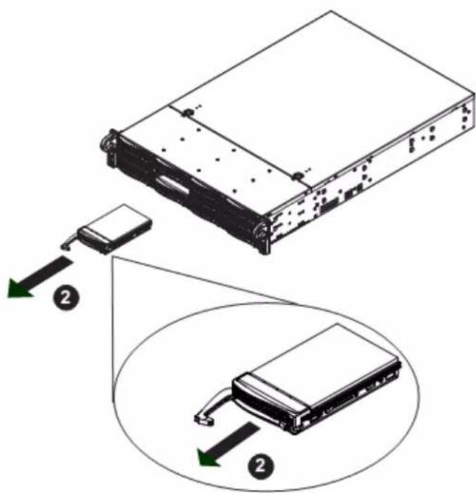
Figure 4-2. Removing a Hard Drive Carrier
Removing Hard Drive Carriers
- Press the release button on the drive tray. This extends the drive bay handle.
- Use the handle to pull the drive out of the chassis.
Installing 3.5" Hard Drives
Hardware Description > Chassis Setup and Maintenance > Installing 3.5" Hard Drives
Caution: Except for short periods of time (swapping hard drives), do not operate the server with the hard drive bays empty.
Note: Your operating system must have RAID support to enable the hot-swap capability of the drives.

Figure 4-3. Dummy Drive in a Drive Carrier

Figure 4-4. Removing the Dummy Drive from the Carrier
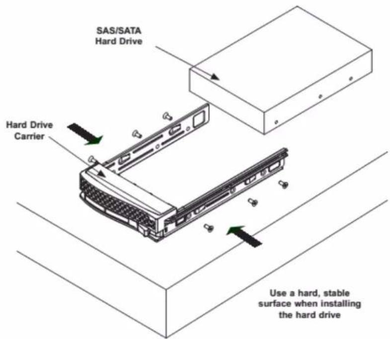
Installing a Hard Disk Drive
- Remove the two screws connecting the dummy drive to the carrier.
- Remove the dummy drive from the carrier.
- Place the hard drive carrier on a fat, stable surface such as a desk, table, or work bench.
- Slide the hard drive into the carrier with the printed circuit board side facing down.
- Carefully align the mounting holes in the hard drive and the carrier. Make sure the bottom of the hard drive and bottom of the hard drive carrier are flush.
- Secure the hard drive using all six screws.
- Replace the drive carrier into the chassis. Make sure to close the drive tray using the drive carrier handle.
Hard Drive Backplane
Hardware Description > Chassis Setup and Maintenance > Hard Drive Backplane
The hard drives plug into a backplane that provides power, drive ID and bus termination. The supplied RAID controller provides hot-swap capability with SAS/SATA drive state indication. The backplane is already pre-configured, so no jumper or switch configurations are required.
Caution: Use care when working around the backplane. Do not touch the backplane with any metal objects and make sure no ribbon cables touch the backplane or obstruct the holes, which aid in proper air flow.
System Fans
Hardware Description > Chassis Setup and Maintenance > System Fans
Three 8-cm hot-swap fans provide the cooling for the system. It is very important that the chassis top cover is properly installed and making a good seal in order for the cooling air to circulate properly through the chassis and cool the components.
System Fan Failure
Hardware Description > Chassis Setup and Maintenance > System Fans > System Fan Failure
Fan speed is controlled by system temperature via IPMI. If a fan fails, the remaining fans will ramp up to full speed and the overheat/fan fail LED on the control panel will turn on. Replace any failed fan at your earliest convenience with the same type and model (the system can continue to run with a failed fan). Remove the top chassis cover while the system is still running to determine which of the fans has failed.
Caution: Except for short periods of time, do not operate the server without the chassis cover in place. The cover must be in place to allow proper air ow and prevent overheating.
Replacing System Fans
Hardware Description > Chassis Setup and Maintenance > System Fans > Replacing System Fans
Three heavy-duty fans provide cooling for the chassis.
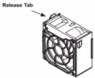
Replacing a System Fan
- If necessary, open the chassis while the power is running to determine which fan requires changing. Never run the server for an extended period of time with the chassis open.
- Power down the server as described in section 4-1, lay the chassis on a fat, stable surface and remove the chassis cover.
- Remove the failed fan's power cord from the motherboard.
- Press the fan release tab to lift the failed fan from the fan tray and pull it completely from the chassis.
- Place the new fan into the vacant space in the fan tray, while making sure the arrows on the top of the fan (indicating air direction) point in the same direction as the arrows on the other fans.
- Power up the system and check that the fan is working properly before replacing the chassis cover.
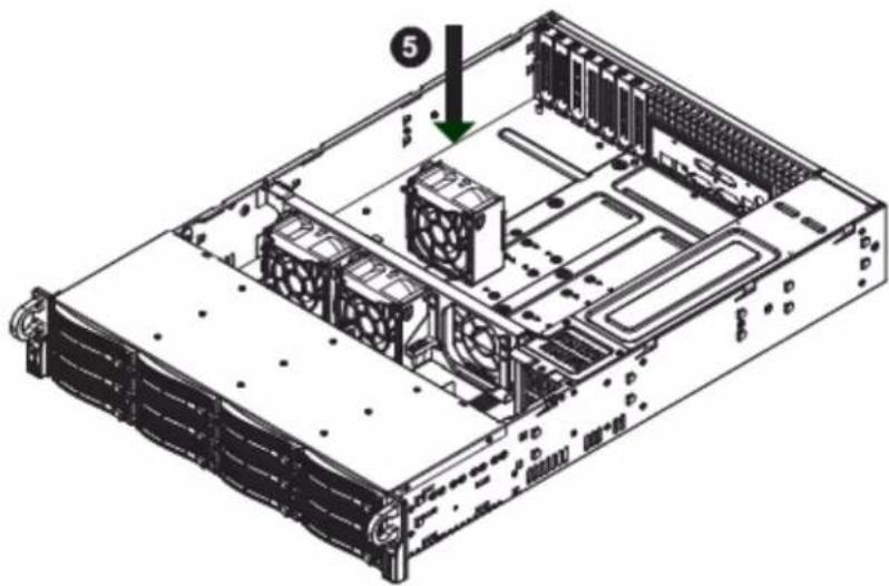
natural_image
Isometric view of a server rack with cooling fans and drive bays (no text or labels visible)Figure 4-16. Placing the System Fan in the Chassis
Power Supply
Hardware Description > Chassis Setup and Maintenance > Power Supply
The G-RACK 12chassis has a 920 watt redundant, hot-plug power supply consisting of two power modules. Each power supply module has an auto-switching capability, which enables it to automatically sense and operate at a 100V - 240V input voltage.
Power Supply Failure
Hardware Description > Chassis Setup and Maintenance > Power Supply > Power Supply Failure
An amber light will be illuminated on the power supply when the power is off. An illuminated green light indicates that the power supply is operating. If either of the two power supply modules fail, the other module will take the full load and allow the system to continue operation without interruption. The Power Fail LED on the front control panel will illuminate and remain on until the failed unit has been replaced. The power supply units have a hot-swap capability, meaning you can replace the failed unit without powering down the system.
Replacement units can be procured by contacting support. Contact information is found on our website www.g-technology.com on our support page.
Removing/Replacing the Power Supply
Hardware Description > Chassis Setup and Maintenance > Power Supply > Removing/Replacing the Power Supply
You do not need to shut down the system to replace a power supply unit. The backup power supply module will keep the system up and running while you replace the failed hot-swap unit. Replace with the same model (see part number in the Appendix), which can be ordered directly from G-Technology.
Removing the Power Supply (Figure 6-7)
- First unplug the AC power cord from the failed power supply module.
- Depress the locking tab on the power supply module.
- Use the handle to pull it straight out with the rounded handle.
Installing a New Power Supply
- Replace the failed hot-swap unit with another identical power supply unit.
- Push the new power supply unit into the power bay until you hear a click.
- Secure the locking tab on the unit.
- Finish by plugging the AC power cord back into the unit.
Figure 6-7. Removing the Power Supply

Power Distributor
Hardware Description > Chassis Setup and Maintenance > Power Distributor
Chassis that are 2U or more in height require a power distributor. The power distributor provides fail over and power supply redundancy
Changing the Power Distributor
- Power down the server, lay the chassis on a flat, stable surface and remove the chassis cover.
- Remove all cable connections to the power supply from the motherboard, backplane, and other components.
- Remove both power supplies.
- Locate the power distributor between the power supply and the fan row.
- Remove the three screws securing the power supply.
- Gently pull the power distributor from the chassis, carefully guiding all the cables through the power distributor housing.
- Slide the new power distributor module into the power distributor housing. Make that you slide the cables through the bottom of the housing.
- Reconnect all the power cables, replace the power supply, and insert the plug into the wall.
System Interface
Hardware Description > System Interface
Overview
Hardware Description > System Interface > Overview
The chassis includes:
• A control panel on the front that includes power buttons and status monitoring lights
- Status lights on externally accessible hard drives
• Status lights for the power supply
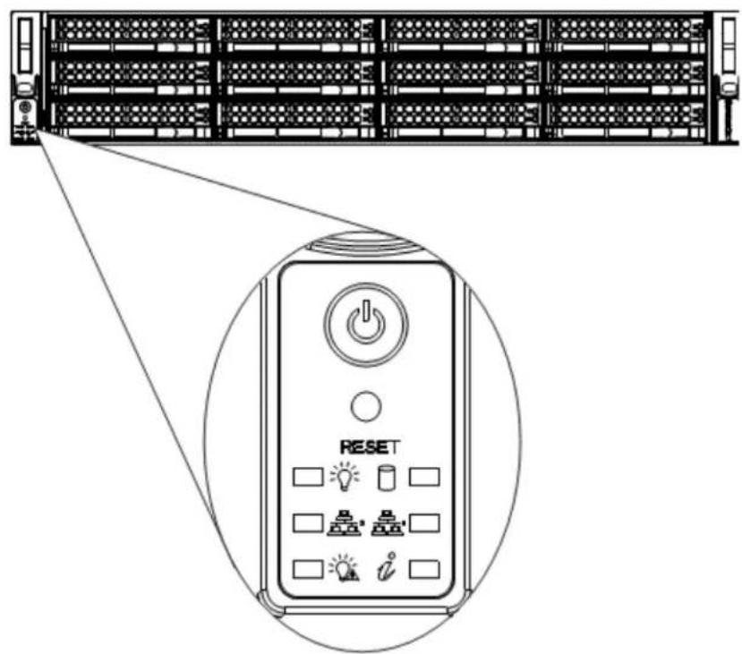
Figure 4-1. Control Panel
Control Panel Buttons
Hardware Description > System Interface > Control Panel Buttons
The chassis includes two push-buttons that control power to the system.

Power: The main power switch is used to apply or remove power from the power supply to the server. Turning off system power with this button removes the main power but maintains standby power. To perform many maintenance tasks, you must unplug system before servicing.

Reset: The reset button is used to reboot the system.
Control Panel LEDs
Hardware Description > System Interface > Control Panel LEDs
There are six LEDs that provide status information about the system.

Power: Indicates power is being supplied to the system power supp

HDD: Indicates IDE channel activity on the hard drive when flashing.

NIC2: Indicates network activity on GLAN2 when flashing.

NIC1: Indicates network activity on GLAN1 when flashing.

Power Fail: Indicates a power supply module has failed

Information LED
Overheating
Hardware Description > System Interface > Overheating
There are several possible responses if the system overheats.
Overheat Temperature Setting
Hardware Description > System Interface > Overheat Temperature Setting
The unit comes with temperature sensors set for the optimal safe operating range.
Responses
Hardware Description > System Interface > Responses
If the server overheats
- Use the LEDs to determine the nature of the overheating condition.
- Confirm that the chassis covers are installed properly.
- Check the routing of the cables and make sure all fans are present and operating normally.
- Verify that the heatsinks are installed properly.
- Make sure lid is attached to the server and that nothing is blocking the front or back of the unit.
Drive Carrier LEDs
Hardware Description > System Interface > Drive Carrier LEDs
The chassis includes externally accessible SAS/SATA drives. Each drive carrier displays two status LEDs on the front of the carrier.
- Blue: When illuminated, this LED indicates drive activity. It blinks on and off when that particular drive is being accessed. This function is controlled by the backplane.
- Red: When illuminated, this LED indicates a drive failure. You should be notified by your system management software.
Power Supply LEDs
Hardware Description > System Interface > Power Supply LEDs
On the rear of the power supply module, an LED displays the status.
- Solid Green: When illuminated, indicates that the power supply is on.
- Solid Amber: When illuminated, indicates the power supply is plugged in and turned off, or the system is off but in an abnormal state.
- Blinking Amber: When blinking, this system power supply temperature has reached 63^ C. The system will automatically power-down when the power supply temperature reaches 70^ C and restarts when the power supply temperature goes below 60^ C.
G|RACK™ 12
Use Cases/Tutorials
System Information and System Settings
How do I reset the web administrator password?
- Navigate to the System page
- Under General Settings select the Web Administrator Password panel.
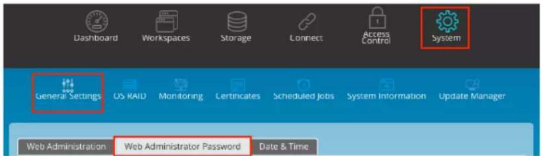
- Choose a new password and enter it again in the Confirm Password field
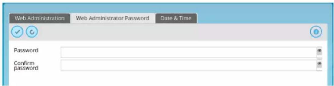
- Press Save

How do I see which services are running?
- To see which services are active on your G-RACK 12, navigate to the Dashboard. You will see a section labeled Service Status.
- For more details click the Service Status title and it will link you to the services page for more details
How can I enable a service (SMB, NFS)?
- You can enable SMB/CIFS and NFS by navigating to Connect>NFS or Connect>SMB. NOTE: A Volume must exist.
-
Click the Plus (+) to start the process.
-
Selecting an existing workspace folder or use the Plus (+) on the Workspace folder line to create a new folder.
- Name your share.
- Select Balance of the options based on your network configuration and IT policies.
- Press Save to complete the creation of the share.
How do I set up notifications?
- Prior to selecting which notifications you wish to receive you must configure the email connection that will allow you to receive them. This is called SMTP.
- Navigate to the System screen and select Monitoring>Settings
- Enable the notifications - toggle.
- Enter the information for your SMTP email server.
- Press the Save button.
- Attempt to send a test email by pressing the button by the same name. Once you have received the test email you know your system is properly configured.
- To get notifications for system events you need to navigate to the System screen and select Monitoring>Notifications
- On the Notification tab you can choose which notifications to receive and which to ignore. Check the desired notifications and when the system determines the criteria has been meet an email will be generated and sent to the specified email account.
Who will receive notifications?
When you configure notifications you can choose both a primary and secondary email address to receive notifications.
What notifications can be sent?
If you have set your emails for notifications, by default you will be notified about the following system parameters and function monitors.

To customize notification settings go to Monitoring ^109 menu where you will be able to turn on and off additional notifications.
How can I determine the admin interface URL?
To define the URL, please use DHCP client to scan for the new address (e.g. Bonjour) or, if there is no DHCP server available, utilize the default IP address to connect and set a static IP address of 172.16.12.12. It is recommended to use an IP Search Utility when accessing and configuring G-RACK 12 for the first time.
How do I log in to the admin interface?
Once you have the IP address from above you simply need to type the address in to the URL bar of your browser. (Example: http://192.168.10.200)
The default user name is "admin" and the password is "gtech". If you have changed the admin password and forgotten it, you are not able to login. You will be required to contact G-Technology Support.
How do I add a User to a Workspace?
- You need to have a workspace previously configured.
- Click Workspaces icon.
- Select a workspace.
- Click the permissions button.
- Toggle the permissions per user/group.
- Press Apply.
When does a User need to login?
To access the shares a user will need login for security purpose. The exception to this is shares that allow for guest access.
How does a user reset their password?
Resetting a password is done exclusively by the G-RACK 12 administrator.
- Click the Access Control icon.
- Choose a user for which you wish to change the password.
- Click the Edit button.
- Type the new password in both the password and confirmation boxes.
- Press Save.
How do I view log files?
Accessing the server logs can be done from the Administrator page.
- Navigate to the Systems Icon.
- Select the Systems Information function.
- Click on the Logs tab.
- You have the option of downloading the logs as a text file for viewing in an editor.
- To download all log files at once or to email them to the admin email, go to the Support tab.
Where should I send log files if I need to send them to G-Technology?
- Before sending logs, reach out to support here: http://support.g-technology.com/contact/contact_support
How much space is available on my Volume?
Go to Storage>Volumes. The available space field will display the available space for each volume. Additionally, the dashboard will show you the Filesystem Status
How is a self-signed certificate used in the G-RACK 12 system?
SSL certificates allow you to SSL encryption on the G-RACK 12. The addition of a SSL certificate allows for https access to the Administration pages for the unit.
How to shrink your data RAID to fewer physical disks.
To shrink your data RAID set use the RAID ^60 menu and press the Shrink button. Note the minimal number of drives for your selected RAID set. Important: Remember to balance the RAID device after shrinking by pressing the balance button on the RAID menu.
How to grow your RAID set.
To grow your data RAID set use the RAID ^60 menu and press the Grow button. Add available drives to the RAID set by clicking on the list of available drives. Important: Remember to balance the RAID device after growing by pressing the balance button on the RAID menu.
How to change your RAID level.
At this time there is no method available for changing a RAID level. If you must have a new RAID level then:
- Backup the data.
- Create a new RAID set with the desired RAID level.
- Restore the data to the new RAID set.
- Delete the old RAID set once you are happy that the data was successfully restored.
How to determine if your physical drive is about to fail.
The simple method of seeing a physical drive issue is on the Dashboard. The section marked Drive Health will give you the first indication of a drive issue. Beyond that you can access the S.M.A.R.T. information for each drive by:
- Navigating to the Storage menu and selecting the S.M.A.R.T tab.
- Selecting a drive from the list.
- Running a self test on the drive in question. Note some tests can degrade performance and, in some cases, cause the system to halt. It is best to do these tests when users are offline.
How to assign a new disk as a Hot Spare
A hot spare is a drive that takes over for a failing or failed drive in a RAID set. It is a live drive inserted in the server and connected to the backplane. The idea behind hot spares is that if you
have a drive fail or one you need to remove then the hot spare takes the place of the drive you are removing without any loss of time or access to the data.
INFORMATION: A hot spare needs time to sync/balance with your RAID set after it has been activated.
Steps for adding a hot spare:
- Make sure you have an available disk.
- Go to Storage>RAID
- Click hot spare. This button is always active.
- If you have an available drive- it will be shown.
- Select it and save.
How to check the consistency of the file system and fix it.
You can have email notifications setup to email you for early warnings
- Dashboard will show you a quick status.
- For a more detailed log of the file system status navigate to Storage> RAID.
- Click the RAID set you are interested in and press the details button for a detailed log.
How to make a snapshot for the RAID data.
A snapshot volume is a special type of volume that presents all the data that was in the volume at the time the snapshot was created. This means we can back up that volume without having to worry about data being changed while the backup is going on, and we don't have to take the volume offline while the backup is taking place.
- Taking a snapshot starts by navigating to the Workspaces.
- Select a workspace which you want to take a snapshot of.
- From the Workspaces menu select the Make Snapshot option.
- You have the option to name the Snapshot's path and to allow the snapshot to be read/write or read-only.
- Press Create and the system will process the request. The newly created snapshot will show up in the Workspaces list.
How to make a snapshot for the OS drive.
- Navigate to System>Update Manager
- Select the Snapshot tab.
- Press the Take snapshot button
- A copy of the OS drive will appear in the list of snapshots.
- NOTE: You can reboot from this snapshot. It is a good idea to take a snapshot before any OS updates. If you as the admin are not happy with the update, you can use the snapshot taken prior to the update to reboot the system into its previous state.
How to define a quota for a user.
- Navigate to Storage>Volumes
- Select a volume
- Click the quota button
-
Enable quota then press the save button. Pressing save is required at this step. If you click anywhere else then the feature will not be enabled.
-
Click Quota information tab
-
Select your volume and edit quota limit
NOTE: Don't set quota smaller the space already in use.
NOTE: A volume must be greater than 1TB to have a quota set.
How to wipe you data disks.
IMPORTANT: This feature can (as designed) cause data loss. Using it without understanding the implications can be catastrophic.
To wipe a physical disk:
-
Navigate to Storage>Physical disks.
-
Select a drive from the list you wish to wipe.
-
Press the Wipe button.
-
Confirm the process.
-
The drive will be wiped clean at the end of the process and this will make the disk's data unrecoverable.
Network services
How to setup a network (IPV4 and IPV6). Configuring New and Editing Existing Connections.
-
To set up a network connection navigate to the Connect menu.
-
Press the Network option.

-
You will be presented with 4 tabs. (General, Interfaces, Service Discovery, and Firewall)
-
Select select the Interfaces tab.
-
Click Add button and select Ethernet from the drop down menu

- Enter the appropriate data for your network in the editable fields.
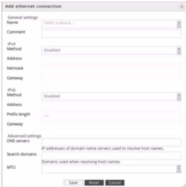
- Press save. The values will change quickly on the system. It make take a moment before equipment on your network notices the change.
How to aggregate network interfaces to get a higher throughput.
To aggregate network interfaces the G-RACK 12 uses channel bonding. Channel bonding is a computer networking arrangement in which two or more network interfaces on a host computer are combined for redundancy or increased throughput.
- Press the Network option.
- You will be presented with 4 tabs. (General, Interfaces, Service Discovery, and Firewall)
-
Select select the Interfaces tab.
-
Click the listing for eth0:
- Click the Plus (+) option.
- From the dialog box select the additional interface you wish to bond to the primary Ethernet interface.
- Complete the needed fields based on your network requirements.
- Press save. The values will change quickly on the system. It make take a moment before equipment on your network notices the change.
How to set higher MTU on Ethernet (jumbo frames).
- To change the MTU value to the Connect menu.
- Press the Network option.
- You will be presented with 4 tabs. (General, Interfaces, Service Discovery, and Firewall)
- Select select the Interfaces tab.
- Click the listing for eth0 or the interface you wish to edit:
- Press the Edit button.
- The MTU value is at the bottom of the edit dialog box. Enter the appropriate data for your network.
- Press save.
ATTO configuration to allow Jumbo Frames
You can achieve the best performance out of the ATTO FF NT12 card if the configuration is set to get Jumbo Frames on the client. In order for Jumbo Frames above 1500k packet length to/from G-RACK 12 it is imperative that all hardware components (G-RACK 12, Switch, All clients) must be made ready to receive larger packet sizes. This includes the NIC. ATTO offers a Configuration Tool. Once logged in, navigate to the NIC FF-NT12 and click the Advanced Tab. Change the ATTO card Maximum's I/O Transfer size from 'default' to the max of 32MB and press the commit button. NOTE: Make sure all shares and targets are dismounted as this might cause a slight drop in network connectivity. Additionally, All clients that wish to use Jumbo Frames will have to make this I/O change to their NIC when applicable.
If you have any difficulty setting these cards on your network please contact our technical support team for assistance.
ATTO says:
A FastFrame aggregate group derives most of its operational settings, such as Offloads and jumbo
packets, automatically, based on the settings of the network adapters in the group. Therefore, in order for a feature to be in effect for a group, that feature must be set identically on each member adapter.
In short: Set all cards to the same Jumbo Frame setting.
*Source: https://www.attotech.com/software/files/manuals/Manual_FFNICInstall.pdf
How to turn on advertising of the network protocols.
- Press the Network option.
- You will be presented with 4 tabs. (General, Interfaces, Service Discovery, and Firewall)
- Select select the Service Discovery tab.

- Toggle on to enable Service Discovery protocol for desired services

- Click Save button

NOTE: Service Discovery concerns the process of searching for service providers according to certain criteria. Therefore, further service usage is a separate issue. This option does not enable the service. You have to do that in the Settings tab of each individual protocol under the Connect menu. Make sure you press "Advanced" to see all options.
How to protect your G-RACK 12 from (unwanted) network traffic.
Use the Firewall configuration to screen unwanted traffic. The G-RACK 12 has a built-in network firewall in the OS that filters traffic between the server and incoming network traffic.
- Press the Network option.
- You will be presented with 4 tabs. (General, Interfaces, Service Discovery, and Firewall)
- Select select the Firewall tab.

- Chose if you are creating an IPv4 or IPv6 rule.
- Press the Plus (+) to open the rules dialog.
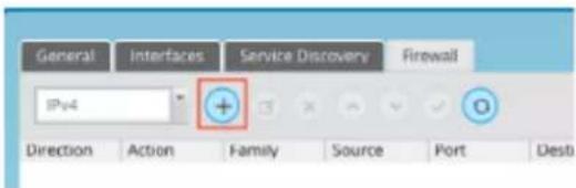
- Select direction of the rule:
a. INPUT for inbound connections
b. OUTPUT for outbound connections
- Choose action for a packet which matches the rule:
a. ACCEPT -- allow the packet to pass over
b. REJECT -- drop the packet and send ICMP reject message back to the sender which prevents hanging of the connection
c. DROP -- drop the packet
d. LOG -- just log the packet in the journal
e. Nothing -- do nothing (useful for debugging)
-
Specify source and destination port and address. Destination address can be either a network IP address (with /mask), a IP range or a plain IP address. A '!' argument before the address specification inverts the sense of the address. Ports can be specified either by number (e.g. 80 for HTTP, 443 for HTTPS), by interval (1024-65535) or by names (SMTP, HTTP, FTP). You can also use '!' to reverse the meaning of the value (e.g. !443 means all ports except 443).
-
If you wish, you can add some comments to the rule.
You can also specify additional parameters to the rule in the field 'advanced options'. Configuration of that options is beyond this manual. Please refer to the Linux nftables manual for additional info.
You can edit or delete a firewall rule by selecting the rule and clicking the appropriate button.
How to run arbitrary commands on a scheduled basis.
There are many times when you want a command to be executed on a schedule. The G-RACK 12 has a built-in CRON function that allows you to set a schedule for commands to run on the server.
- Click on System>Scheduled Jobs.
- Click the plus (+).
- Enable it.
- Select the time and parameters that fit your needs.
- Press Save.
- If you need you can manually execute the job by pressing the Run button.
- You can edit or delete a command by using the Edit or Delete buttons.
How to allow access your G-RACK 12 via SSH without password (authentication by a certificate).
Skilled Linux system administrators can access the NAS OS by using SSH terminal tools. This method of access is not recommended as this level of access can easily corrupt the OS and make
the unit inoperable. In order to enable this method of access you must follow these steps:
- Click on Connect>SSH.
- Enable SSH.
- Choose the port number. Port 22 is the standard port.
- Enable SSH tunneling if desired.
- Enable it.
How to perform automatic synchronizing of the user data to G-RACK 12. Configuring RSyncjobs.
RSync is used to backup data. RSync will allow the admin to choose a "source" folder and sync it to the chosen "destination". RSync can be used locally on the GRack server or remotely to a different system or another G-RACK 12.
How to setup a Local RSync job
To setup a local RSync job to copy an existing workspace to a new destination on the GRack:
- Navigate to Connect > Rsync
- Click the Add button to add a new job
- Choose job type as Local
- Select the Source workspace to Copy to a new destination
- Select the Destination workspace
- Choose settings you would like (achieve, set time/data)
- Create Job
This Job will now execute at the specified time or you can manually start the job.
How to setup a Remote RSync job
Remote RSync will require a module to be setup on the remote location. This Module will be the source to push or pull from.
To setup a module on GRack:
- Navigate to Connect > Rsync
- Click Server Tab
- Toggle on the Enable switch
- Click Modules Tab
- Click + button
- Choose the source workspace or create a new workspace
- Choose settings you would like (User authentication, read/write only, Host allow/deny)
- Click Save
RSync module is now setup
How to setup a Push RSync job
- To setup a remote RSync job to copy a local workspace to a remote location (2nd G-RACK 12 or a different server or client computer)
- Navigate to Connect > RSync
- Click + icon to add a new job
-
Choose job type as remote
-
Choose mode as Push
- Choose the source folder (This folders data will be "Pushed" to the destination)
- Enter the Destination
- Without user authentication
- Enter the destination IP follow by Module e.g 192.168.1.128::ModuleName
- With user authentication
- Enter the Username followed by destination and Module e.g user@192.168.1.128::ModuleName
- Add password in the password field
- Choose settings you would like (archive, choose time/date)
- Save job
This Job will now execute at the specified time or you can manually start the job.
How to setup a Pull RSync job
To setup a remote RSync job to copy a remote directory/folder on a different G-RACK 12, a module must be setup, follow steps above to create Module on the remote G-RACK 12.
- Navigate to Connect > RSync
- Click + icon to add a new job
- Choose job type as remote
- Choose mode as Pull
- Enter the Source server info
- Without user authentication
- Enter the destination IP follow by Module e.g 192.168.1.128::ModuleName
- With user authentication
- Enter the Username followed by destination and Module e.g user@192.168.1.128::ModuleName
- Enter password in the Password field
- Choose the local destination, select a workspace or create a new one
- Choose settings you would like (archive, choose time/date)
- Save job
This Job will now execute at the specified time or you can manually start the job.
User Authentication for a module on the G-RACK 12
To set User Authentication on a module on the G-RACK 12:
- Navigate to Connect > RSync
- Click on Server, click on Module tab
- Click + button or edit an existing module
- Click on the Users tab
- Add a new user and password
- Click on General Tab
- Toggle on User authentication
- Click Save
To now use this module it will require user authentication
How to join your G-RACK 12 to Windows Active Directory corporate network.
Active Directory (AD) is a Windows OS directory service that facilitates working with interconnected, complex and different network resources in a unified manner. The G-RACK 12 is able to participate in an Active Directory network.
- Click on Access Control>Active Directory.
- Click Enable
- Enter the information for your Active Directory Server
- Click the Save button
How to set an iSCSI connection.
iSCSI is a way of connecting storage devices over a network using TCP/IP. It can be used over a local area network (LAN), a wide area network (WAN), or the Internet. iSCSI devices are disks, tapes, CDs, and other storage devices on another networked computer that you can connect to.
- Navigate to Connect>iSCSI SCST.
- Press Enable and Save.
- Click on the Targets tab.
- Press the Plus (+) button.
- Enter a name for the target.
- User name and passwords are optional - this is for authentication (chap) on systems that require it.
- Enter the field data that matches you network requirements. In most cases the default values will work well.
- Press Save
How effectively apply permissions to Workspaces.
- Navigate to Workspaces
- Select a workspace
- Click permissions
- Assign permissions
- Apply and save
How to keep G-RACK 12 software up to date.
Registered users will receive emails when new updates are available. Or you can manually check:
- Navigate to System>Update Manager.
- Press the Check button.
- If an update is available press the Plus (+) button.
- You will be asked if you want to take a snapshot first. Normally, this is a good thing and should be accepted.
- Once the Update is applied the system may restart.
How can I restore the forgotten admin password?
Contact support http://support.g-technology.com/contact/contact_support they can help you unlock the G-RACK 12 and regain access to the unit.
How to transfer the data from a local computer to the G-RACK 12 storage space?
Once you have configured a share on the G-RACK 12 it is simply a matter of attaching the share to your local computer and using normal OS tools (File Manager, Finder, Copy, FTP) to copy or move the files on to the G-RACK 12. In most cases it is nothing more complex than selecting the files and dragging them to the desired share location.
How to transfer the data from the G-RACK 12 storage space to a local computer?
Once you have configured a share on the G-RACK 12 it is simply a matter of attaching the share to your local computer and using normal OS tools (File Manager, Finder, Copy, FTP) to copy or move the files from the G-RACK 12. In most cases it is nothing more complex than selecting the files and dragging them to the desired share location.
How to control who can access files/ folders on G-RACK 12?
If you are the administrator of G-RACK 12, you can set access rights for users and groups. Use Permissions ^46 menu to do this.
How to know the software version of G-RACK 12?
Refer to Dashboard 42. System information widget shows the current software running.
G-RACK 12 Administrative Tools logs out itself too soon.
G-RACK 12 Administrative Tool automatically times out if it stays idle for 5 minutes. To change session timeout go to Web Administration ^105 menu. If you set the value to zero (0) you will not log out. This can leave your system exposed to misuse if you leave your keyboard.
What is the update time for G-RACK 12 Dashboard widgets?
Dashboard information automatically updates every 10 seconds.
What NLEs does G-RACK 12 work with?
G-RACK 12 has been thoroughly tested against numerous third-party applications. Specifically, but not limited to, Apple's Final Cut Pro X, Adobe Premiere Pro AVID Media Composer, REDcineXpro and Davinci Resolve.
How to increase the size of my iSCSI LUN?
The size your LUN it is associated with your volume size. There is no grow LUN function. If you go from one volume to another with the same LUN your content will be deleted even if the target volume is bigger than the original one. Make sure you have backup if you need to move data to a new LUN.
How to get more storage space if I have run out of storage space for the volume that is
associated with all of my iSCSI target.
Create a new volume. Copy the data to the new volume and then reclaim the space from the old LUN.
The drive that I want to use as a hot spare says to have some information on it.
You can still use this physical disks as a hot spare. To do this:
- Navigate Storage>Physical Disks.
- Select the new hot spare disk.
- Click wipe and confirm.
- All data will be erased and will become unrecoverable but the drive is now available for use as a hot spare.
I have set read/write permissions for my SMB enabled workspace but still have no write access.
Make sure that read-only toggle is not on. Check this in workspace settings under SMB/CIFS menu
What are steps to set up the G-RACK 12 (Walk through)?
- Enter in the IP address of the G-RACK 12. If you are unsure of the IP address see the section "Finding the server IP address".
- If this is your first time logging in you will use the default login.

○ Username: admin
○ Password: gtech
- If you have logged in then the first time you will see the end user license agreement
(EULA). Once you have read the EULA please click "Agree" to continue.

- You will be presented with the option of selecting a theme.
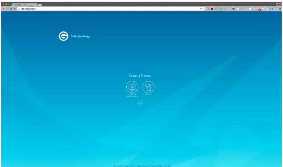
• There are three options you can take here.
○ Media & Entertainment Theme
- General Theme
- Skip Theme Selection
- New password for admin is required after your selection.

- Follow these password word rules for setting a password:
○ Minimum number of characters is 5
○ A-Z, a-z, 0-9, (!, @, #, \$, %, ^, &, *) - The password will need to be confirmed and must match both entries.
- Once you have entered a new password you are presented with the option of allowing the G-RACK 12 to email you when there are system events.

- You need to click the enable slider to activate this option.
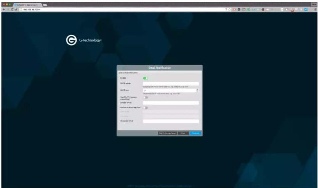
- If you choose to activate email notifications then you must complete the email fields as seeing in this example.
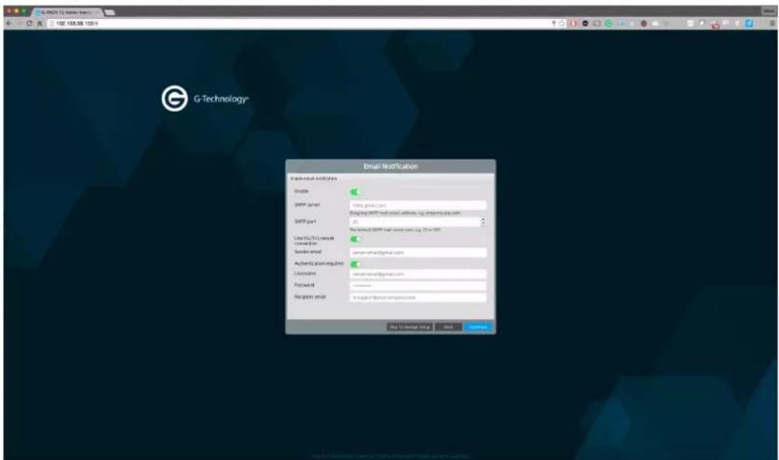
- The next configuration option is Creating User Accounts.
- When you get to this screen use the plus (+) symbol to add a new user to the server.
- You have the option of giving each user their own Workspace (storage area) or allowing all users to share a Workspace.
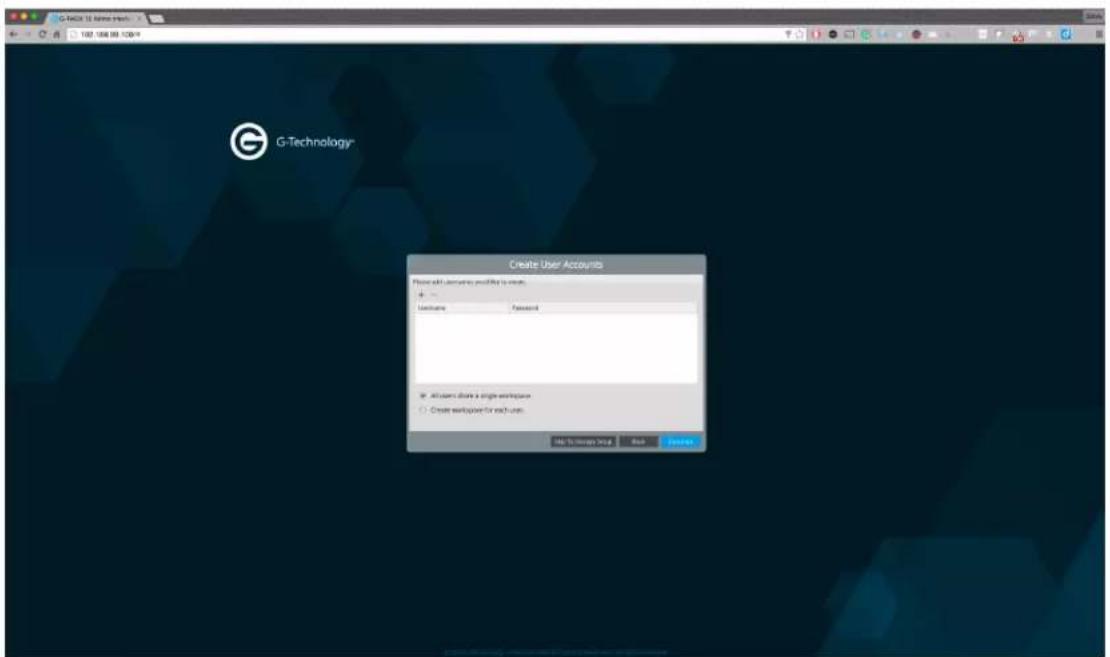
- If the server is established to share common files then you will want a single Workspace.
- If the server is established to create storage for each user to have their files on then you will want to select the "Create Workspace for each user." option.
- As you create users you will give each user a username and password. You need to press "Update" to save the user.
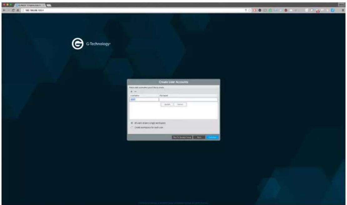
- Now that you have users saved you can continue on to selecting the type of storage to which you want your users to have access.
• There are three options.

- iSCSI Media Only - Your system should support large file-format video editing at a block level (fastest data rates). Example application: Apple Final Cut Pro® X
- Project Shares Only - Your system should support file-based Project Shares using SMB (Samba) CIFS, NFS or AFP. Example application: Adobe Photoshop®
- iSCSI & Project Shares - Your system should support both large file-format video editing (iSCSI) and file-based Project Shares. Example applications: Adobe Premiere® Pro & AVID Media Composer®
- Pick the one that best suites your storage needs.
- If you need help selecting one or understanding the differences please read the section titled "iSCSI vs File Storage: Which one to choose"
- For the purpose of this walk through we have selected both iSCSI and Project Shares.

- You will need to select what percentage of storage to reserve for each storage type.
- File share Workspaces can be accessed using various protocols. You can turn on and off each type on this next screen.

- If you are unsure which to use then leave them all on until you can determine which are best for your network and users.
○ Lastly, a review is presented before the shares are created.

- Once you confirm the process starts.

- The next screen you see is the G-RACK 12 Dashboard.
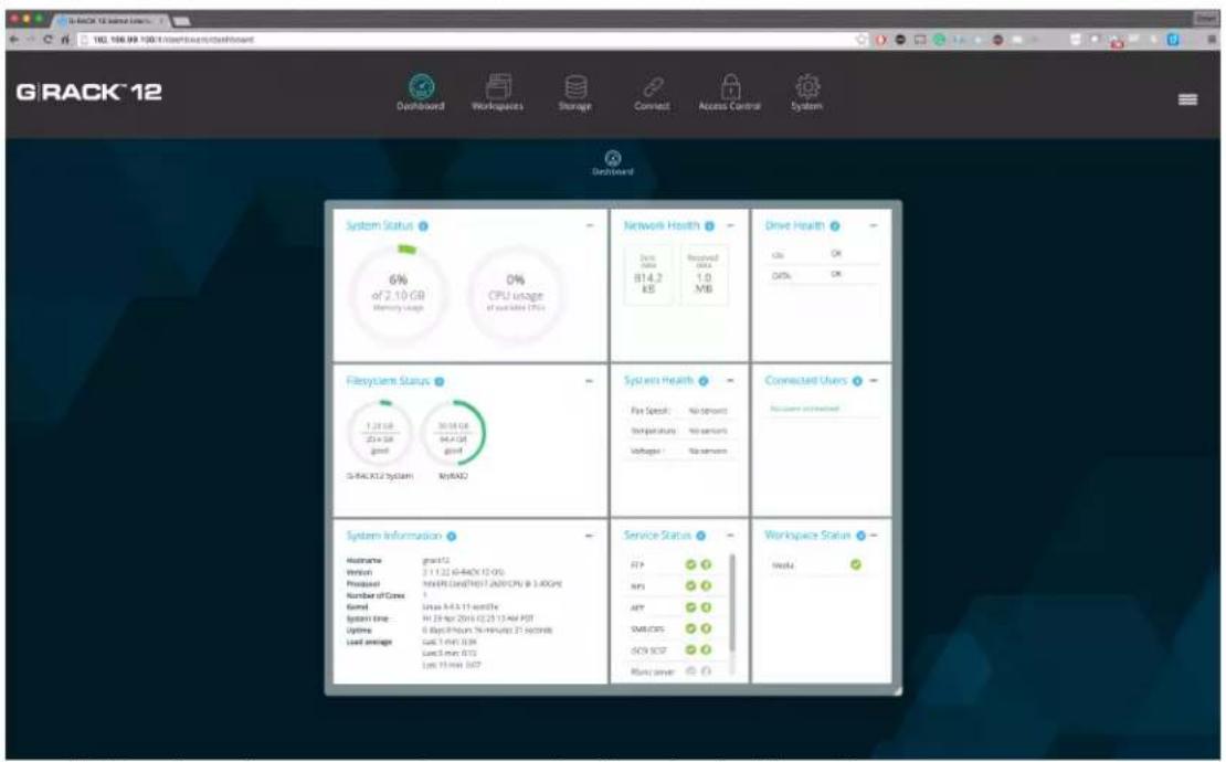
- Follow the other use cases for more detail on the dashboard.
How do I reset the G-RACK 12 to factory default?
Resetting the G-RACK 12 to factory defaults settings will erase the data and settings for the server.
- From the dashboard click the three line drop down on the upper right of the screen.
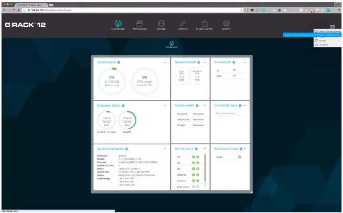
- You will be asked to confirm and type in the word "DELETE".
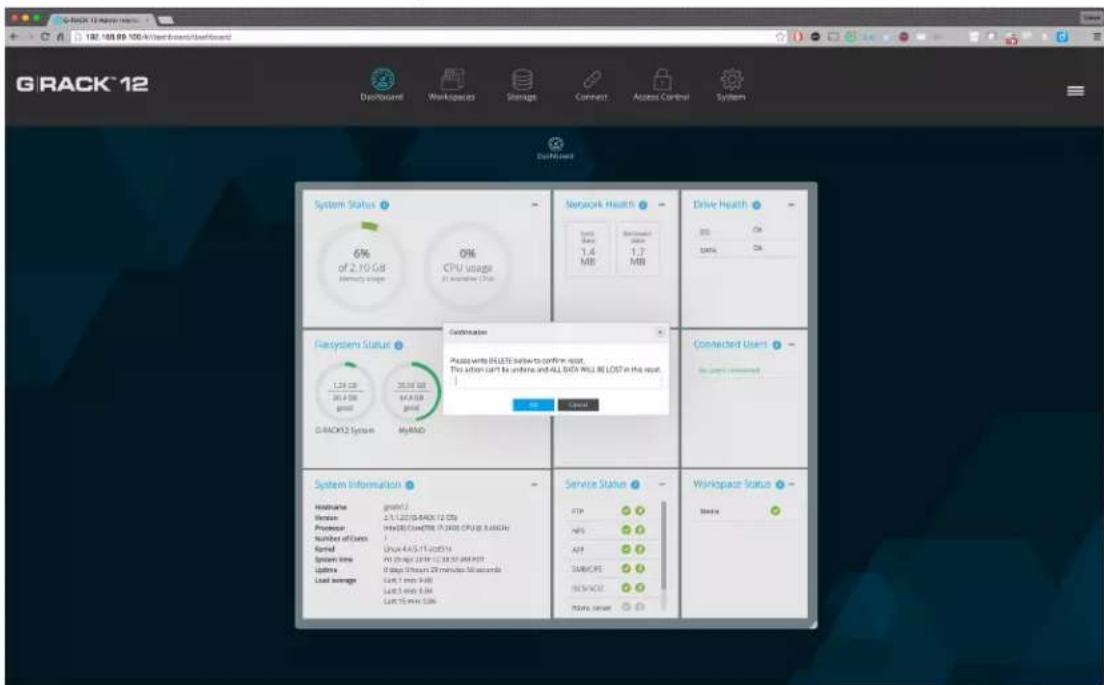
- Once you press "OK" the process will start and the unit will behave like it was never configured before.
What File and Network Protocols are supported on the G-RACK 12?
From the Connect menu you can control and configure each of the following features:
- FTP - The File Transfer Protocol (FTP) is a standard network protocol used to transfer computer files between a client and server on a computer network. FTP is built on a client-server model architecture and uses separate control and data connections between the client and the server.
- NFS - The Network File System (NFS) is a client/server application that lets a computer user view and optionally store and update file on a remote computer as though they were on the user's own computer. The user's system needs to have an NFS client and the other computer needs the NFS server.
- SMB - The Server Message Block (SMB) Protocol is a network file sharing protocol, and as implemented in Microsoft Windows is known as Microsoft SMB Protocol. The set of message packets that defines a particular version of the protocol is called a dialect. The Common Internet File System (CIFS) Protocol is a dialect of SMB.
- AFP - The Apple Filing Protocol (AFP), formerly AppleTalk Filing Protocol, is a proprietary network protocol that offers file services for Mac OS.
- iSCSI - iSCSI, which stands for Internet Small Computer System Interface, works on top of the Transport Control Protocol (TCP) and allows the SCSI command to be sent end-to-end
over local-area networks (LANs), wide-area networks (WANs) or the Internet. Unlike file sharing protocols it presents the option of having a block device that can be treated like a raw hard disk.
- SSH - Also known as Secure Socket Shell, is a network protocol that provides administrators with a secure way to access a remote computer. SSH also refers to the suite of utilities that implement the protocol.
- SSL - SSL (Secure Sockets Layer) is the standard security technology for establishing an encrypted link between a web server and a browser. This link ensures that all data passed between the web server and browsers remain private and integral.
Are the hard drives in the G-RACK 12 hot-swappable?
Yes. In case of a drive failure, users can run G-RACK 12 in the degraded state (meaning one drive failed) and replace the failed drive with a new one. It is important to replace a failed drive with an approved replacement drive to keep all the data intact and safe.
NOTE: To avoid data loss never remove more than one (1) drive at any given time. If there are two drives it is important that you allow the system to re-sync before you move forward with the second replacement drive. Once, the first drive is fully back online and re-synced you can repeat the steps and replace the next drive.
What are the key reasons to contact G-Technology support?
- Admin password loss.
- G-Technology does not publish the method for accessing a unit with a lost password but our support team can help you re-gain access in the case you are locked out.
- Serious troubles with hardware.
- Odd noises.
- Inability to power up.
Reports of drives missing that are clearly in the server.
- Troubles with the G-RACK 12 software.
○ Failure to boot.
o Unexpected data loss.
How do I know how full my server is with data?
The best way to see exactly how much room you have left on the server is to view the dashboard. If you have configured email notifications the server will send you a note when you start to reach capacity limits.
How to migrate data from another NAS to the G-RACK 12?
Moving data from one NAS device to another is a simple file copy process.
- Connect your old NAS to a client computer on the same network as the G-RACK 12. - Adjust your settings and connect G-RACK to your client computer such that the client computer sees both the previous NAS device and the G-RACK 12.
- Migrating the data can be done via line command, file tools, or click and drag on an operating system's GUI.
- If you are moving a large group of files it is advised that you use a tool that not only copies but logs each copy so you know if there are failures.
Does the G-RACK 12 support HTTPS connection?
Yes. You will need to create and save a SSL certificate to turn on HTTPS access.

If you like you can import an SSL certificate generated outside the G-RACK 12 or you use a generated certificate by filling in all the fields and pressing "Save"


How do I log in if I forgot the admin password?
The short answer is you don't. The long answer is please call our support line and they will help
you regain access to the server.
How to choose the right HDD for my G-RACK 12?
- We recommend using HGST drives with your G-RACK 12. HGST drives are properly tested and certified to be completely compatible with your server.
- If you choose a different brand of drives, we advise that you use drives of the same size, manufacturer, and model throughout the system. This will help with performance, stability, system health, monitoring and allows for the same S.M.A.R.T. attributes.
- S.M.A.R.T. is used in the monitoring of drive health.
How to enable HTTPS and create a certificate signing request on the G-RACK 12?
HTTPS is generally desired and used for encrypted and secure communication. This option is available once you have created or imported a SSL certificate. Steps on how to do this are included elsewhere in this document.
- To turn on HTTPS access you navigate to the System>General Settings>Web Administration tab.

- Click the "Enable secure connection" toggle.

- Select the certificate you imported or created.
- Click the "Force secure connection only." toggle if you want to assure that only HTTPS is used to access the admin software.
- Click the "Save" button to save the settings.
The system seems slow. How to speed up file transfers?
Visit the dashboard and check the following:
- View the "Health" panels for high usage on the G-RACK 12. If something seems high you can click each of them for more details.
- Check the system status(es) of the G-RACK 12. If the CPU or memory are very busy this is an indicator of why the system seems slow. Normally, this is a transient condition and once the user(s) or process that needs extra RAM or CPU completes the transfers will speed right back up.
- Check that drives are healthy.
- Check the speed on the side of the receiving computer. More times than not, it will be only one user on the G-RACK 12 that feels things are slow. If this happens then review the potential bottlenecks on that user's computer.
What make and model of CPU does the G-RACK 12 have?
The G-RACK 12 comes equipped with Intel Xeon E5-2600 (V3) CPUs. More detail can be found online:
http://ark.intel.com/products/family/78583/Intel-Xeon-Processor-E5-v3-Family#@All
How do I create a new RAID device?
- Navigate to the Storage>RAID tab.
- Press the Create button (+)
- Create a name
- Select a RAID level
- Select the storage devices that will contain the RAID.
- Once the RAID is created can assign a Workspace to it and give users access rights.
How to a create an iSCSI volume?
Set RAID, and then volume - set quota if necessary
Then create iSCSI target. You will get a LUN auto created size 1 TB. Manage the size of this LUN or create new ones
How to change RAID level?
RAID levels are set at the time you set up your Workspaces. In order to make a change to an existing RAID set do the following:
- Backup the data on the current RAID.
- Delete old RAID. When you do this the existing data is gone.
- Create new RAID with the desired level.
- Set volumes and Workspaces as you need.
- Restore the data back to the new RAID on the appropriate Workspace and establish access for users..
How to create a new user?
- Navigate to the Access Control>Users menu.
- Obeying the naming rules: Make sure the name is unique in the system and will not to cause a conflict with Active Directory users and groups, and their permissions.
- Press the Add button (+).
- Enter user information.
- Press Save.
How to access an FTP shared workspace?
- To access and FTP share the user will use a GUI tool called an FTP client or the CLI built into the OS.
- Popular FTP clients include: Filezilla, AndFTP, WinSCP, and sFTP. There are many more and
they vary by operating system.
- You can allow guest access via anonymous FTP - for this you need the user just needs to know the IP address of the G-RACK 12 server. NOTE: you will not see these users in the Dashboard
- For more secure connections you can have the users access using userid and password as well as SSL connections to make sure all data is encrypted over the wire.
How to access an AFP shared workspace?
On OSX all you need to do is open your finder and look for the "Shared" connections on the left hand side.

How to access an SMB shared workspace?
Open Windows explorer. Locate the name of the G-RACK 12 server and click on it.

How to access an NFS shared workspace?
Mounting a NFS share on Windows can be seeing here:
https://technet.microsoft.com/en-us/library/cc754350.aspx
Mounting a NFS share on OSX can be found here:
http://serverfault.com/questions/716350/mount-nfs-volume-on-ubuntu-linux-server-from-mac-os-x-yosemite-client
How to access an iSCSI shared workspace?
On Windows a good explanation of the process can be found here:
http://www.windowsnetworking.com/articles-tutorials/windows-7/Connecting-Windows-7-iSCSI-SAN.html
How to get more storage space if I have run out of storage space associated with my LUN.
There are several methods of getting more space for your LUN or Workspace:
- One of the first things you should look at is enlarging the quota if you have more available space but have limited the use by quota size. If you have run out of room to increase the quota then try the next step.
- Create a bigger volume, associate it with your iSCSI target, create LUN of the desired size. If necessary move the data and if necessary delete the old target so that the free space can be reallocated.
- If you are fully at capacity the best option is to purchase a G-RACK Expansion Chassis. This
unit will connect to your G-RACK 12 and add 12 more available drive slots for expanding storage. Contact your reseller for more information.
A domain user can not access the workspace.
Check there is no conflict between names as there can be a domain user and a local user with the same name.
Check that the necessary service is enabled for the particular shared workspace and all the settings are correct.
Check that on the client side correct settings are used. In some cases it's required to have a third party application to get assigned access to the shared workspace (i.e. Mac Connect to Server does not allow read-write access via FTP)
Check permissions of the user and of the group he belongs to.
Local RSync Config
To setup a local RSync job to copy an existing workspace to a new destination on the GRack:
- Navigate to Connect > Rsync
- Click + icon to add a new job
- Choose job type as Local
- Select the Source workspace to Copy to a new destination
- Select the Destination workspace
- Choose settings you would like (archive, set time/data)
- Create Job
This Job will now execute at the specified time or you can manually start the job.
Remote RSync Config
Remote RSync will require a module to be setup on the remote location. This Module will be the source to push or pull from.
To setup a module on GRack:
- Navigate to Connect > Rsync
- Click Server Tab
- Toggle on the Enable switch
- Click Modules Tab
- Click + button
- Choose the source workspace or create a new workspace
- Choose settings you would like (User authentication, read/write only, Host allow/deny)
- Click Save
RSync module is now setup
Push RSync Config
To setup a remote RSync job to copy a local workspace to a remote location (2nd GRack or a different server or client computer)
- Navigate to Connect > RSync
- Click + icon to add a new job
- Choose job type as remote
- Choose mode as Push
- Choose the source folder (This folders data will be "Pushed" to the destination)
-
Enter the Destination
-
Without user authentication
- Enter the destination IP follow by Module e.g 192.168.1.128::ModuleName
- With user authentication
- Enter the Username followed by destination and Module e.g
Steve@192.168.1.128::ModuleName - Add password in the password field
- Choose settings you would like (archive, choose time/date)
- Save job
This Job will now execute at the specified time or you can manually start the job.
Pull RSync Config
To setup a remote RSync job to copy a remote directory/folder on a different G-RACK 12, a module must be setup, follow steps above to create Module on the remote G-RACK 12.
- Navigate to Connect > RSync
- Click + icon to add a new job
- Choose job type as remote
- Choose mode as Pull
-
Enter the Source server info
-
Without user authentication
- Enter the destination IP follow by Module e.g 192.168.1.128::ModuleName
- With user authentication
- Enter the Username followed by destination and Module e.g Steve@192.168.1.128::ModuleName
-
Enter password in the Password field
-
Choose the local destination, select a workspace or create a new one
- Choose settings you would like (archive, choose time/date)
- Save job
This Job will now execute at the specified time or you can manually start the job.
User Authentication for a module on G-RACK 12.
To set User Authentication on a module on G-RACK 12:
- Navigate to Connect > RSync
- Click on Server, click on Module tab
- Click + button or edit an existing module
- Click on the Users tab
- Add a new user and password
- Click on General Tab
- Toggle on User authentication
- Click Save
To now use this module it will require user authentication
**RSync can be used on a regular client computer, but it will require to run a daemon and a manually setup for a module. Also would require use of CLI.
How to track users and their activity?
To track users connected to the G-RACK 12 refer to the Connected users widget of the Dashboard. It will display a list of all users.
G-RACK 12 RAID Guide
Use Cases/Tutorials > G-RACK 12 RAID Guide
Overview
Traditionally, mass storage devices are based on mechanical hard disk drives (HDD). Although Solid State Devices (SSD) are becoming more common in the consumer space, classical HDDs remain the preferred solution for computers with mass storage requirements. HDDs provide a huge amount of space at a reasonable cost, and with the adaptation of RAID technology as with a G-RACK 12, data loss becomes less likely to occur.
What is RAID?
Use Cases/Tutorials > What is RAID?
RAID now stands for Redundant Array of Independent Disks (it originally stood for Redundant Array of Inexpensive Disks) and this acronym was first used in a technology paper presented at a conference in June 1988 describing the benefits of data storage virtualization. Interestingly, the technologies and concepts for RAID had been used to some extent for over two decades before this technology paper was presented at the SIGMOD conference.
RAID technology as we use it today is designed to improve data protection and performance, while storing large amounts of data. Instead of relying on a single physical storage location — subsequently also a single point of failure with potentially total data loss — RAID technology makes available the grouping of multiple physical disks into a logical drive with the option of data redundancy. Depending on the RAID level selected, performance, redundancy, storage capacity and reliability of the logical drive will differ. In general, most levels offer redundancy against drive failure. For the G-RACK 12 unit, both supported RAID levels offer data redundancy.
RAID Levels: Advantages and Disadvantages
Use Cases/Tutorials > RAID Levels: Advantages and Disadvantages
The G-RACK 12 supports either RAID 5 or RAID 6. As with all drive configurations, each RAID level has its advantage and disadvantage. Note the reference table below to help determine what RAID Level is best for your data storage needs.
| RAID Level | Description | Advantage | Disadvantage | Ideal For |
| RAID 5 | Disk striping with distributed parity. | High read performance, medium write performance with data protection in case of a single drive failure. | Usable storage capacity equals total capacity of all drives in the array less the capacity of one drive | RAID volumes with less than 5 drivesContent creation applications requiring data protection performance |
| RAID 6 | Block-level striping with double distributed parity. | Double parity provides fault tolerance up to two failed drives. | Usable storage capacity equals total capacity of all drives in the array less the capacity of two drives | RAID volumes with 5+ drivesFile and Application serversDatabase servers |
Creating and Managing a RAID Array
Use Cases/Tutorials > Creating and Managing a RAID Array
How to create a new RAID volume
To create a RAID volume you need to be logged in as admin and follow these steps.
WARNING: The RAID volume should not include more than 28 Devices (physical drives). In the event of a RAID volume error, if more than 28 Devices are used, the volume may become unrecoverable.
- Navigate to the Storage menu, select the RAID option

- Click the Add button to start the process of adding a physical disk to the selected RAID

- Create a new RAID
3.1. Name your RAID volume. (Example: OfficeShare_RAID5)
3.2. Use the Level drop-down menu to choose the RAID level you desire.
3.3. Use the check-boxes to select the number of drives/Devices you want to include in the volume.

- Click Save
- Confirm you want to create the RAID volume

- Once the RAID volume is created it will automatically mount. The selected RAID is highlighted and the Mount button is now inactive.
| Name | Device | State | Level | Capacity | Used | Devices | Mounted | Referenced | Re |
| MyRAID | /dev/sdc | good | RAID 5 Btrfs | 21.5 GB | 17.43 MB | /dev/sdc /dev/sdj | Yes | No | ma |
| Video | /dev/sdd | good | RAID 5 Btrfs | 64.4 GB | 17.23 MB | /dev/sdd /dev/sde /dev/sdf /dev/sdi | Yes | No | ma |
How To Grow a RAID Array
Use Cases/Tutorials > How To Grow a RAID Array
There are times when you want the size of your RAID array to be larger. Here are the steps to grow your RAID.
- To grow your RAID array use the RAID menu

- Select the desired RAID array and press the Grow button.
| Name | Device | State | Level | Capacity | Used | Devices | Mounted | Referenced | Re |
| MyRAID | /dev/sdc | good | RAID 5 Btrfs | 21.5 GB | 17.43 MB | /dev/sdc /dev/sdj | Yes | No | ma |
| Video | /dev/sdd | good | RAID 5 Btrfs | 64.4 GB | 17.23 MB | /dev/sdd /dev/sde /dev/sdf /dev/sdi | Yes | No | ma |
- Select drives to be added to the RAID from the list of the available drives.

4. Confirm your choice and press Save

- Important: Remember to balance the RAID array after growing. Highlight the RAID array and press the Balance button.
| Name | Device | State | Level | Capacity | Used | Devices | Mounted | Referenced | Re |
| MyRAID | /dev/sdc | good | RAID 5 Btrfs | 21.5 GB | 17.43 MB | /dev/sdc /dev/sdk | Yes | No | ma |
| Video | /dev/sdd | good | RAID 5 Btrfs | 85.9 GB | 18..21 MB | /dev/sdd /dev/sde /dev/sdf /dev/sdi /dev/sdj | Yes | No | ma |
6. The RAID is ready
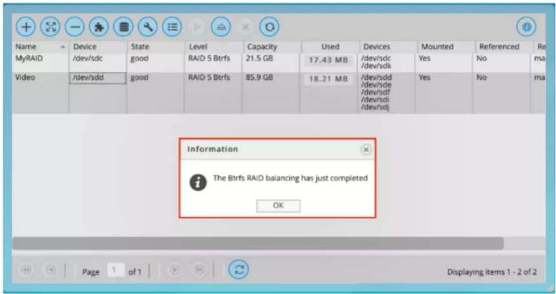
How To Shrink a RAID Array
Use Cases/Tutorials > How To Shrink a RAID Array
There may be times when you want to reduce the number of drives in a RAID array. By following these steps you can shrink your RAID size.
- To shrink your data RAID array use the RAID menu and press the Shrink button.

- Note the minimal number of drives for your selected RAID set. As a reference, a RAID 6 setup should not use less than 5 drives.
Setting a Hot Spare
Use Cases/Tutorials > Setting a Hot Spare
Setting a Hot Spare will allow your RAID array to be ready for a drive failure.
How to assign a new disk as a Hot Spare
NOTE: Hot spare icon is only active after selecting a RAID
- Go to Storage and select the RAID option

- Click Hot Spare button

- The list of available drives will be displayed.*
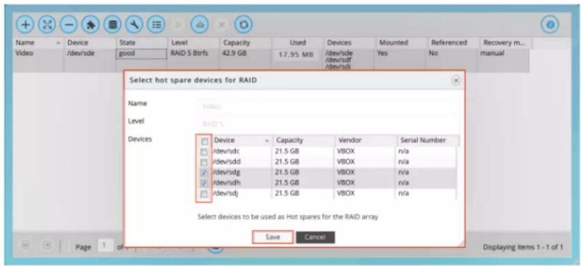
- Select and Save.
\* What if my newly inserted drive is not showing in the hot spare list?
Your drive probably has existing data on it. However, you can still use the drive for hot spare, but it will erase the data on this drive.
To make this drive available as a hot spare, follow these steps:
- Navigate to Storage then to Physical Disks.
- Select the New Hot Spare Disk.
- Click Wipe and Confirm — this action will erase all data on this drive and the data will be unrecoverable.
- The drive is now available for use as a hot spare.
Troubleshooting
Use Cases/Tutorials > Troubleshooting
Recovering from degraded state (How to replace a failed data physical disk?)
- Detecting the failed drive:
1.1. You will receive notification via email with the name of the failed drive.
1.2. The tray LED will be red.
1.3. File system health widget in Dashboard will change the status of the corresponding RAID from "good" to "degraded".
1.4. Refer to the Physical Disks under the Storage menu. Find the name of the drive to see the number of the disk slot.
- Pull out the failed drive.
- Insert a brand new drive.
- Go to the G-RACK 12 Administrative tool, click on Storage and then the RAID option.

- Select the degraded RAID array.
- Click the Hot Spare button.
- The list Device list will contain the name of the new drive. Select this drive and then Click Save.
- Wait for the RAID array to get balanced. This process will be performed automatically by the G-RACK 12.
- NOTE: There is a delay between adding a hot spare and the recovery process beginning. It can take up to a minute. The status of the RAID array will change to rebuilding.
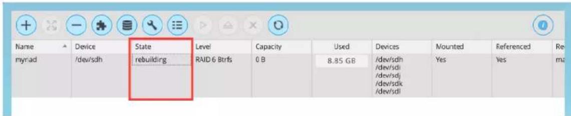
- The status of the RAID array will change to balancing.
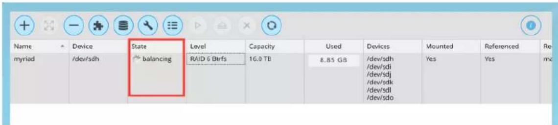
- NOTE: "Balance" passes all data in the filesystem through the allocator again. It is primarily intended to re-balance the data in the filesystem across the devices when a device is added or removed. A balance will regenerate missing copies for the redundant RAID levels, if a device has failed. The re-balancing process can take several minutes.
- When the balancing is completed, the status of the RAID array will change to a State of good.
How to change a RAID array level
At this time there is no method available for changing a RAID level. If you must have a new RAID level then:
- Backup the data of the current RAID.
- Create a new RAID set with the desired RAID level.
- Restore the data to the new RAID set.
- Delete the old RAID set once you are happy that the data was successfully restored.
How to check filesystem consistency
You can have email notifications setup to email you for early warnings
- Dashboard will show you a quick status.
- For a more detailed log of the file system status navigate to Storage>RAID
- Click the RAID set you are interested in and press the details button for a detailed log
G|RACK™ 12
iSCSI Essentials
Overview
In a world where Internet Protocol (IP) dominates local and wide area networks, and data storage requirements grow unabated, it seems inevitable that these two forces converge. The Internet Small Computer Systems Interface (iSCSI) protocol unites storage and IP networking. iSCSI enables the transport of block-level storage traffic over IP networks. The protocol is used on servers (initiators), storage devices (targets), and protocol transfer gateway devices. iSCSI uses standard Ethernet switches and routers to move the data from server to storage.
What is iSCSI
iSCSI, (Internet Small Computer System Interface), an Internet Protocol (IP)-based storage networking standard for linking data storage facilities. By carrying SCSI commands over IP networks, iSCSI is used to facilitate data transfers over intranets and to manage storage over long distances. iSCSI can be used to transmit data over local area networks (LANs), wide area networks (WANs), or the Internet and can enable location-independent data storage and retrieval.
How and when is iSCSI used?
The protocol allows clients (called initiators) to send SCSI commands (CDBs) to SCSI storage devices (targets) on remote servers. It is a storage area network (SAN) protocol, allowing organizations to consolidate storage into data center storage arrays while providing hosts (such as database and web servers) with the illusion of locally attached disks. Unlike some SAN protocols, iSCSI requires no dedicated cabling; it can be run over existing IP infrastructure. As a result, iSCSI is often seen as a low-cost alternative to Fibre Channel.
Target
The iSCSI specification refers to a storage resource located on an iSCSI server (more generally, one of potentially many instances of iSCSI storage nodes running on that server) as a target.
"iSCSI target" should not be confused with the term "iSCSI" as the latter is a protocol and not a storage server instance.
An iSCSI target is often a dedicated network-connected hard disk storage device, but may also be a general-purpose computer, since as with initiators, software to provide an iSCSI target is available for most mainstream operating systems.
Initiator
An initiator functions as an iSCSI client. An initiator typically serves the same purpose to a computer as a SCSI bus adapter would, except that, instead of physically cabling SCSI devices (like hard drives and tape changers), an iSCSI initiator sends SCSI commands over an IP network. An initiator falls into two broad types:
A software initiator uses code to implement iSCSI. Typically, this happens in a kernel-resident device driver that uses the existing network card (NIC) and network stack to emulate SCSI devices for a computer by speaking the iSCSI protocol. Software initiators are available for most popular operating systems and are the most common method of deploying iSCSI.
How to create an iSCSI target and LUNs on the G-RACK 12?
iSCSI Target Creation
Navigate to the iSCSI SCST under the Connect menu

You will be brought to the iSCSI Settings page where you must first enable the iSCSI service by switching the enable toggle to On (green) and pressing the Save button. The iSCSI service might already be toggled On if you created iSCSI targets in the Wizard setup process.
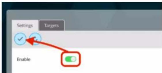
Press the Targets tab in the iSCSI SCST menu to continue to the iSCSI target/LUN creation.

In the iSCSI SCST Targets tab you may notice previously created Wizard-generated target. This page allows you to view the current iSCSI targets and, if highlighted, edit your LUNs associated with that target or delete the Target altogether.
To create a new Target, press the Add iSCSI target button.

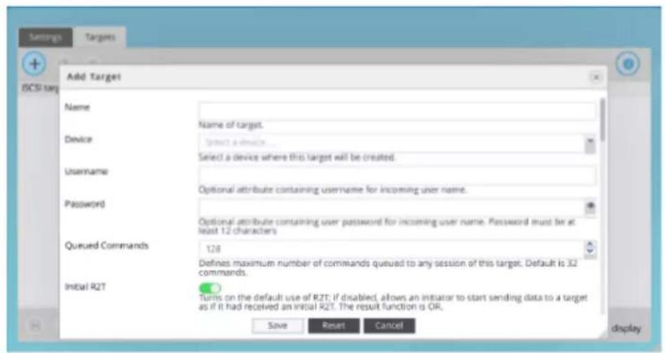
G-RACK's iSCSI Add Target page allows you to give your Target a name, associate it with a RAID-Workspace, access credentials like username / password assignments (known by iSCSI initiators as username & secret) as well as a multitude of performance and initiator parameters. G-RACK 12's default advanced parameter configuration has already been maximized for performance but if your network or administrator choose to personalize the advanced parameters for iSCSI targets you will find those attributes here. To expedite this lesson however all you need to proceed is a Target Name and a File device.
Press the Save button to create the target, press the Reset button to return to the default settings or press the Cancel button to exit the iSCSI Add Target page.

iSCSI is the protocol with which one communicates with the server. The Target is the shell with which one harbors and performs with files and a LUN is the Volume that will eventually be mounted and formatted by a client computer's iSCSI initiator. G-RACK 12 makes LUN creation simple by automatically generating a one-Terabyte allocation within the workspace.
If you choose to, you may edit that LUN or create addition LUNs within a Target resulting in multiple Volumes much like a partition for a Directly Attached Storage device (DAS). However, you should know that once a G-RACK 12 iSCSI target has been initialized by a client computer you will not be able to grow a LUN without wiping out all of your data. So plan accordingly and always make backups of your files.
Edit LUN
If you want to grow (increase the size of) your auto-generated one-Terabyte LUN, do this BEFORE it has been mounted and formatted by a client computer.
Navigate to the iSCSI SCST under the Connect menu

Highlight the target your desired iSCSI Target and press the Edit LUNs list button.

From the Manage LUNs list page you have the option to add a new LUN to your iSCSI target or edit any of the current LUNs. For this instance we will discuss the Edit LUN function. Highlight the auto-generated LUN (id=0) and press the Edit LUN button. You will be presented with the G-RACK 12's Edit LUN page. Edit the auto-generated File-size field from "1" Terabyte to your desired size. Once satisfied press the Update LUN button.
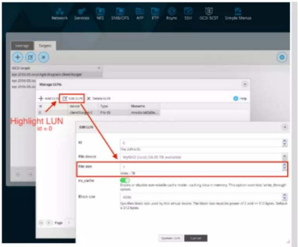
Now when you mount and format the Target on a client computer via an iSCSI initiator you will have a Volume mounted on your desktop that is of the same size as your edited LUN File-size.
NOTE: A LUN with id#0 MUST always be in place in order for iSCSI targets to be mountable on client.
Warning NOT to delete LUN id0 without creating a new LUN with id0.
Add LUNs
LUN's correspond to Volumes that are mounted on your desktop. The G-RACK 12 has made adding additional LUNs simple.
Navigate to the iSCSI SCST under the Connect menu and select the Targets tab.

Highlight the target you wish to add a LUN to and press the Edit LUNs list button to access the Manage LUNs page.
For organizational reasons the File device field is now a non-editable field. Do not change the auto-generated id number. Leaving nv_cache enabled and Block-size to 4096 will ensure optimal performance but they are editable.

Links and references
https://en.wikipedia.org/wiki/ISCSI
Mac OS Initiators
iSCSI Essentials > Mac OS Initiators
GlobalSAN iSCSI initiator & Xtarget
Setup:
To download GlobalSAN iSCSI initiator & Xtarget (this document will not cover Xtarget) start by creating an account with SNS here. If you wish to bypass the limited-but-free trial version you can go here to setup an account and request the required Permanent keys. To finish and start downloading the iSCSI initiator press the download button. The install process will require a restart so make sure all workstation data has been saved. Navigate to the newly downloaded GlobalSAN iSCSI Xtarget package and double-click to start the installation process. Follow the install procedure and reboot when prompted at the end of the process.
Once the application has been installed and the system restart has rebooted your workstation, access System Preferences from the Mac pull-down menu. Press the new GlobalSAN and Xtarget icon located at the bottom of System Preferences and follow SNS's instructions here to RETRIEVE and ACTIVATE a permanent key.

The permanent key allows that particular workstation full access to GlobalSAN iSCSI initiator & Xtarget including support for mounting multiple iSCSI targets, scanning for newly-created iSCSI targets on your G-RACK 12 as well as allowing your iSCSI target to persist after a system restart. To learn learn more about the full functionality of GlobalSAN iSCSI initiator & Xtarget and how to use the application please view the PDF guide in Applications > GlobalSAN folder after installation.
SANmp Administrator & Client tools
Two workstations attempting to mount and write to the same iSCSI target will cause data loss. SANmp is an additional layer of protection for your iSCSI targets. With the SANmp Administrator tool managing your iSCSI targets, you will not run into ownership and permissions conflicts.
SANmp Administrator application achieves iSCSI target management by scanning your GRACK-12 and other workstations on the network to make sure no other workstation already has a particular iSCSI target mounted.
To download and install SANmp you will have to sign-up for a dongle to be sent to you from SNS or a qualified reseller. You can contact SNS for the dongles as well as download the software here.
SANmp Administrator tool:

After receiving your SANmp dongles for both your administrator workstation and client(s) workstation(s) download and install SANmp. The install process will require a restart so make sure all workstation data has been saved. The Admin-caveat you will have to know is during the install process at the "Installation Type" page press the "Customize" button and add the SANmp Admin option to your installation.
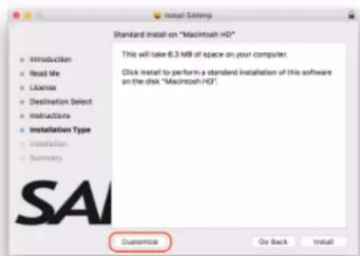
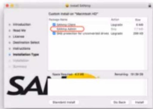
In order for SANmp Administrator tool to manage an iSCSI target you must first initialize one via GlobalSAN iSCSI initiator tool (view the PDF guide in Applications > GlobalSAN folder after installation.) Once you have initialized and then formatted your disk you can launch and login. When prompted to enter a password, use the default password: adminpw111 (which can be changed later on if you wish).
From the SANmp admin tool, highlight your initialized disk and press the "Convert Disk" button. This process will dismount the volume from your desktop. Now highlight the volume underneath the disk and press the "Add User" button. Add at least two users (User password is created here too) and give both users Read/Write privileges.

SANmp Client tool:

Now that you have at least two SANmp users you will want to be able to use the SANmp-manager iSCSI target. Add another dongle to another workstation that is on your network and install GlobalSAN iSCSI initiator & SANmp Client to the new workstation. The install process will
require a restart x2 so make sure all workstation data has been saved.
When the workstation restarts launch GlobalSAN iSCSI initiator and mount the volume that was converted by the admin SANmp workstation. Then launch SANmp Client and sign-in with the credentials that were created on the Admin workstation. Now highlight the SANmp-managed volume and press the Read/Write button. SANmp Client will reach out to the SANmp admin tool and other devices on the network to see if the requested volume is in use. When the Client has confirmed the volume is not in use it will mount it in your desktop. Notice that the volume icon has changed.
Other Notes
- When releasing an SANmp-managed disk for use on a different workstation it is important to completely disconnect your disk from Global iSCSI initiator as well before the next user attempts to mount it through SANmp Client.

- If you are experiencing any shutdown issues, specifically with El Capitan and Pro Tools, certain features that require a restart may not take hold
- In order for a SANmp client to simultaneously see iSCSI targets that will not be managed by the SANmp Admin tool you must select Preferences > Allow Unconverted SAN volumes (which allows both SANmp-managed disk and non-SANmp-managed disks to be mounted at the same time) will not take hold when the user is prompted to restart her workstation. You can temporarily allow this option by purging your workstation's caches. Log in to Terminal (Utilities>Terminal) and when prompted type "sudo purge".
- iSCSI initiators are not compatible with one another. So if you have a different brand installed on your system you will have to uninstall it before working with SNS GlobalSAN initiator on the SANmp software bundle.
- SNS does not support ExFAT file system. SANmp Admin will reformat your ExFAT Disk if you wish it to be managed by SANmp.
- It is possible to delete or reformat an iSCSI target in Disk Utility even if it is being managed by SANmp. So be conscience of which iSCSI target you are working on in Disk Utility
Other known SNS issues:
https://studionetworksolutions.zendesk.com/hc/en-us/articles/204740359-OS-X-El-Capitan-w-SNS-Products
G|RACK™ 12
Troubleshooting
Troubleshoot Hardware Issues
How to check if the G-RACK 12 is a faulty unit?
Power
- Confirm the power cords are plugged in and the unit is turned on. You would be surprised how many times a cord becomes unplugged.
- If the this is the only unit in the area confirm the wall power is working.
- Is there any sound coming from the unit at all? If not it may be a faulty power supply. Since the G-RACK 12 has dual power supplies would mean that both failed at the same time. This normally would only happen if the unit was not plugged into a surge protected power source.
Lights
- There are several lights that indicate issues.
- Whole Unit - The HDD activity light indicates for the unit means one of the installed drives has activity. In normal operation this light will blink or appear to be on solid during period of high activity.
- Each drive also has an activity light indicating that single drive has activity. In the case of swapping out a drive you will want to see no blinking before removing a disk drive. When adding a new drive you will want to look for activity to see that synchronization has started.
- Network activity - What does the network activity light mean? When data is flowing on/off the server the light on the network activity LED will blink. There are also LEDs on the network connector that indicate connection and activity.
- Power light just indicated the unit has power and is turned on.
- If there is no drive or network activity the server may be frozen. Rebooting can resolve this. If it does resolve the issue make sure you review the logs and if necessary email them to G-Technology Support for additional review.
Beeps
If the server is sounding out beeps during or right after the power is turned on there are any number of issues possible.
Motherboard BIOS Error Beep Codes
- 1 beep: Refresh Ready to boot. You want this.
-
5 short beeps + 1 long beep: Memory error No memory detected in the system. You will want to check that all memory chips are proper seated on the motherboard.
a. 5 beeps: No con-in or con-out devices
b. Con-in includes USB or PS/2 keyboard, PCI or serial console redirection, and IPMI KVM or SOL.
c. Con-out includes the video controller, PCI or serial console redirection, and IPMI SOL.
d. If you get these you will want to check cable connections. -
1 beep per device:
a. Refresh 1 beep for each USB device detected
IPMI Error Codes
-
One Continuous beep System OH System overheat.
-
In the overheat condition you will want to supply additional air conditioning, unblock fans, and/or return server cover to unit.
- If you have done this and the unit continues to overheat then power down the unit until you can determine the source of the overheating.
Connections
- If at any time all users lose access to the unit the first thing to check is to see if the unit is running. If it is running start checking connections. Ethernet cables that have been removed or relocated can cause a spontaneous loss of access.
- Check the switches and routers on the network to make sure both ends of the cable are secure.
- Additionally, the Ethernet ports on the unit will indicate if they have a good connection and if data is flowing.
User interface
- If you are having issues with data access or speed please login to the Admin Dashboard and see if there are any alerts present.
DHCP/Network
- Power failures, reboots of the G-RACK 12 or the DHCP server can cause the IP address to change. If this happens then any number of problems can appear. Mostly the iSCSI connections will not work.
- If you are setting up the unit for the first time make sure that the cables you are using are CAT5/6 using other cables can and will cause network issues and loss of connectivity.
What should I do if the system fan, LCD panel, or other hardware components are not working properly?
Do NOT repair or replace the hardware components yourself. Please contact your local reseller or distributor for repair or replacement services. If you are unsure of who your local reseller is please contact us using our support page. http://support.g-technology.com/contact/contact_support
A domain user can not access the workspace
- Confirm that the settings did not change. Navigate to Connect>SMB/CIFS>Settings
- See if the user password was reset
- If all users have lost access confirm the domain controller is active and that access to other network connections are not also as well.
How to replace a failed OS physical disk?
- Determine which drive failed by clicking details in the Administrative interface. It will say device1 or device2.
- ID1 - on the left. ID 2 on the right - when you are facing the G-RACK 12.
- Pull out the failed drive. Be careful to remove the failed drive and not the other drive.
- Insert the new drive in the same slot.
- If the drive has existing data it will be wiped automatically. Unless the drive contains a boot partition, in which case you will need to use another drive or wipe the drive by other means
before inserting.
- Once you have inserted the new drive the recovery process will start automatically.
How to import domain user or user group information.
When you activate Active Directory (AD) on the G-RACK 12 you must furnish the admin credentials so the server can access the AD listing of users and groups from the Windows Server. Once, properly connected the G-RACK 12 will request the listing and populate the local user list.
Pro Tools 11 (Mac & El Capitan) won't launch when I have SANmp-managed and unmanaged iSCSI targets
Using both SANmp-managed and un-managed targets that were created from G-RACK12's default iSCSI settings may need to be ejected before launching Pro Tools 11 if you are running El Capitan on a Macintosh.
Why can't I see an iSCSI target that was formatted by another iSCSI initiator?
There is a conflict between using two different iSCSI initiator for the same iSCSI target. If you are seeing issues with mounting an iSCSI target on a different client, make sure you are using the same iSCSI initiator that was used to originally format the volume.
Why can't multiple users access the same CIFS/SMB share when working in Pro Tools 11?
Pro Tools is a single-client to single-share application. Best practices suggest you create a new Workspace and a new CIFS/SMB share and copy the media to that new share.
Why is Adobe® Premiere Pro is presenting me with multiple iterations of the same G-RACK12 volume when I attempt a relink?
Adobe Premiere Pro has already set a path to where your media lives. It keeps this path in a cached file with your project. If you have to attempt a relink know that the application session will remember both the old and the new paths and will present to you both. This will not effect your project.
Why are there so many connection options in my iSCSI initiator after I attempt a Group discovery?
G-RACK12 has multiple Ethernet ports that can be configured in different ways. If you would. The Connections window is simply showing you that you have multiple paths (IP) to access your iSCSI target. Best practices suggest you use the connect of the same IP you used to discover your targets.
Why can't multiple computers write to the same iSCSI target?
iSCSI targets are formatted on the client-side. thus they are treated like any other Directly-Attached Storage device where Write/Read permissions are governed by the client to first mount the target. It is recommended that you use an iSCSI manager to control the permissions rights for all iSCSI targets.
How to set iSCSI target and LUNs?
Creating and eventually mounting iSCSI target (for Mac).
Prerequisites : RAID(with at least 1TB of available space)/Volume/WS and some kind of iSCSI target initiator program (windows is built in to OS).
- Create iSCSI target(and LUN) on G-RACK 12: Connect>iSCSI SCST>Target>Add: Name the target and press Save (if you wish to associate credentials or tune your target now is the time).
- On your Mac Client: launch your iSCSI target initiator (SNS herein). Unlock the locking mechanism. press the plus button in the Target/Portal window on the left and select "Portal/Group" option (you can manually enter the iqn number of any individual target here too if you prefer. Just select "Target" in the plus pull down menu).
- In the "Portal/Group" window add the IP address of you G-RACK 12 and press enter.
- Your "Portal/Group" will now populate the Target/Portal window. Toggle down the selection icon next to your G-RACK 12's IP and choose which target you would like to initialize. The Ethernet ports will populate the Connections window on the right. Select the top option and press connect.
- Once connected you will be prompted to format the target. Format the target to your specific needs in Disk Utility.
Users could not see all mounted volumes in Finder (Mac OS)
In this situation try to mount the volume manually, using Connect to Server.
Unable to delete files from a mounted Workspace after exceeding quota limit.
To be able to delete files from a mounted Workspace:
- Increase quota limit for this Workspace
- Delete the files
- if required, reset the previous quota limit for this Workspace
Unable to write to FTP shared workspace when mounting through Mac client, using "Connect to server".
This issue can be caused by some settings of Mac OS and the shared workspace mounted does not support write access, even if the user has read/write permissions. To resolve the situation the users will need to download an FTP client and this most likely will allow read/write access to the shared workspace.
Some users have problems accessing SMB and AFP mounted shared Workspaces.
The problem may appear due to merge conflict between local and ADS users. Local and Domain users that have the same name will merge as one user after import. The user will be displayed as a domain user type and will be included in both local and domain groups. In this case after mounting through SMB and AFP, there may be some content inconsistencies.
Restoring a Mac from G-RACK iSCSI target.
When initializing an iSCSI target, Mac asks to use as the LUN as Time Machine. This will work but you will need to manually restore the data. Apple recommends a fresh install of Mac OS. Once the Mac OS is installed then download iSCSI Manager, mount your target and manually restore the files. The AFP time machine will show as an available Time Machine restore point.
Mac OSX El Capitan & GlobalSAN iSCSI 5.3.0.518
The GlobalSAN iSCSI Initiator throws an easily avoidable error: "Header and Data" error every time you set up a new iSCSI target.
GlobalSAN recommends setting HeaderDigest and DataDigest default setting to CRC32C for more protection against data loss. These settings are available in iSCSI target creation page for G-RACK 12 Administration Tool. Once you have modified the settings to include both the CRC32C Header and Data Digest, the GlobalSAN iSCSI Initiator does not throw the error.
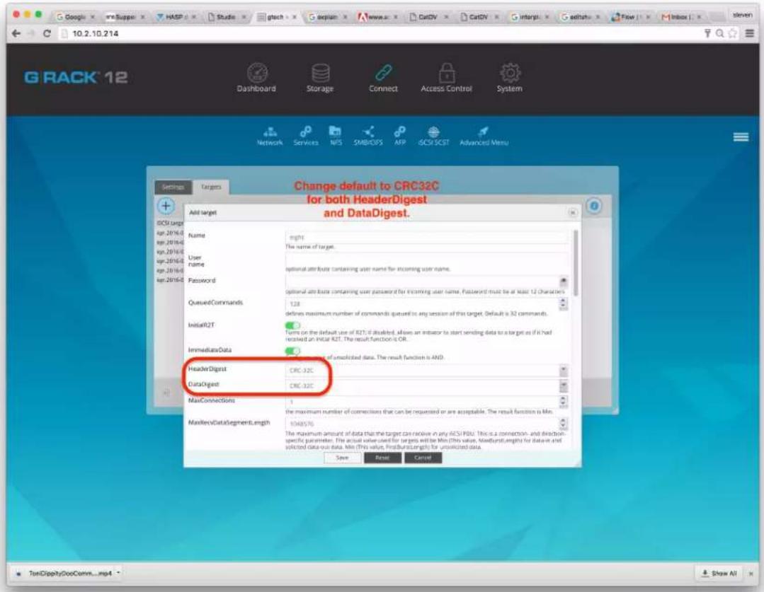
Bare Metal Recovery
Troubleshooting > Bare Metal Recovery
The term "bare metal recovery" comes from the idea that you are restoring a device to working order after a catastrophic failure. While the process will get your G-RACK 12 in working order it does not restore data that was on the drives. For that you will have to run your backup/restore software against the backups you were taking all along.
What you need to get started.
• There is a list of items you need to complete this task:
- G-RACK 12 with all the electronic components in place and properly working. This process fails if you do not have the drives in the unit.
- A G-Technology provided USB key with the restoration software pre-loaded.
- USB Keyboard
- Monitor
Connections.
- With the unit powered off attach the keyboard and USB Key to the USB ports on the rear of the unit.
- Attach the monitor to either the VGA or the DVI ports.
- Make sure you have power cords attached to the power supplies
- To aid in the recovery process you should also have the Ethernet cable attached to either the DHCP or Static ports.
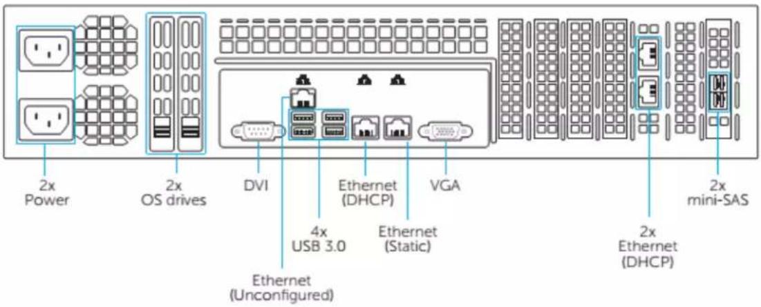
Powering Up.
When you first power up the unit look at the monitor for a sign that the USB key is booting the recovery software. If you get no change or you get an error message that you can't boot there is an excellent change the BIOS is not set to boot of the USB key. If this is the case you will need to reboot and enter the BIOS screen. Select USB boot as an option. Save the BIOS configuration and reboot once more.
Once you are configured to boot from USB you will see the OS install process start.
1) The first screen you see should look very much like this:

natural_image
Yellow hard hat icon with a rectangular opening, no text or symbols presentDebian GNU/Linux 7 (wheezy) amd64
Build: 2016-05-10 01:50:08
linux: 4.4.5-13
live-build: 4.0.3-1
live-boot: 3.0.1-1
live-config: 3.0.23-1+deb7u1
live-tools1.3.0.20-1+deb7u1
Install (Single Drive)
Install (RAID1)
Advanced options
Press ENTER to boot or TAB to edit a menu entry
2) Using your keyboard scroll down to the second option "Install (RAID1)" and press Enter.

natural_image
Yellow hard hat icon with abstract geometric design (no text or symbols)Debian GNU/Linux 7 (wheezy) amd64
Build: 2016-05-10 01:50:08
linux: 4.4.5-13
live-build: 4.0.3-1
live-boot: 3.0.1-1
live-config: 3.0.23-1+deb7u1
live-tools3.0.20-1+deb7u1
Install (Single Drive)
Install (RAID1)
Advanced options
Press ENTER to boot or TAB to edit a menu entry
3) Immediately, the install process starts.

bar
| Component | Percentage (%) | | :--- | :--- | | Loading additional components | 39 | | Retrieving grub-installer | |4) As it progresses you will see the update bar change.

bar
| Status | Percentage (%) | | :--- | :--- | | Installing the system... | 8 | | Copying data to disk... | |5) If you see this screen you have successfully installed the software. The server is ready to reboot. Remove the USB key from the back of the unit and press Enter.
![[!!] Configuring resolvconf Installation complete Installation is complete, so it is time to boot into your new system. Make sure to remove the installation media (CD-ROM, floppies), so that you boot into the new system rather than restarting the installation. moves; selects; activates buttons](/content/2026/05/860865/images/9b1e12aef7374162e34ec42382de8d569f24ca6c3903be4a90d0c8286386eaea.jpg)
6) You can expect to see messages like the ones below scrolling past the screen as the OS is fully loaded.
modprobe: module microcode not found in modules.dep
modprobe: module microcode not found in modules.dep
[ 3.941706] microcode: CPU0 update to revision 0x29 failed
[ 3.943419] microcode: CPU0 update to revision 0x29 failed
mdadm: /dev/md0 has been started with 2 drives.
Scanning for Btrfs filesystems
INIT: version 2.88 booting
Using makefile-style concurrent boot in runlevel S.
Starting the hotplug events dispatcher: udevd.
Synthesizing the initial hotplug events...done.
7) When you get to this screen your restoration is complete. It will be save to remove the USB keyboard and the monitor from the connectors.
gtech 2.1.1.29 (G-RACK 12 OS) grack12 tty1
Copyright (C) 2015 by GTechnology. All rights reserved.

To manage the system visit the gtech web management interface via a web browser:

eth0: 192.168.99.100

The default web management interface administrator account has the username 'admin' and password 'gtech'.
It is recommended that you change the password for this account via the web management interface or using the 'gtech-firstaid' CLI command.

For more information regarding this appliance, please visit the web site: http://www.g-technology.com

NOTE: changes made to the system from the console level may not be reflected in the web admin tool. These changes may also render the system unusable. By accessing the console you acknowledge and accept these risks.

grack12 login: _
8) At this point you can use the Administration software using a web browser. The screen above indicates the IP address you can enter in your URL bar.
9) Normal operation can resume. If you have an available backup of the configuration files and data you can now follow the process in the User's Guide to reload the data on to the G-RACK 12.
G|RACK™ 12
iSCSI - Improper dismounts cause permissions issues
When Client One disconnects via iSCSI initiator before ejecting the volume properly the target may get to a state where the next client has to either:
a) Authenticate each transaction or
b) Go into the client side permissions and amend the 'everyone = W/R' option in order to use an application that requires constant transactions (FCPX etc).
Steps that create this issue:
- Client1 mounts and writes to a target
- Client1 disconnects via initiator without ejecting the volume via finder or disk utility
- Client2 mounts and attempts to write to target
G|RACK™ 12
Recycle SMB vs OSX
When a user enables the recycle bin and disable option to hide dot files within SMB settings in the admin tool, it will not reflect on Mac the same way as Windows.
For Mac clients the user must disable hiding of dot files in Finder in order to see dot files and also the recycle bin which presents itself as .recycle.
OSX Hiding Option:
- Login to admin tool on Mac client that has Finder set to hide dot files
- Navigate to Connect > SMB > Shares and add a workspace share
- When creating share enable recycle bin and disable hiding of dot files
- Mount share through Connect to Server as a user
- Write a file into the share and then delete the file
End Result: The .recycle will not show up because Finder is set to hide all dot files still.
In order to see dot files through Finder must input in terminal: defaults write com.apple.finder AppleWebKitAllFiles YES
Then relaunch Finder by holding 'option+command' and right click on Finder to relaunch. Dot files will show after.
G|RACK™ 12
ACLS & Permissions on the G-RACK 12
When using ACLs on the G-RACK 12 be aware that the OS on the server allows for user permissions to override group ACLs. While this is not how you may expect them to work on Windows Servers it is the chosen method for this device.
It is worth noting that if you create a local user with the same name as an Active Directory user that the system will use the rights of the local user to override the rights provided by Active Directory.
Unexpected NFS Result
The scenario is this: There is one workspace shared by all users. Permissions appear wide open (Read write execute for everything) on this workspace. When a file is uploaded through NFS, the user is unable to edit when connecting through SMB/AFP. Conversely, uploading through SMB/AFP makes the file unable to be edited through NFS.
Expected: Since workspace permission is read/write/execute for everyone that accesses that workspace, all files added to workspace should have same permissions. There is a known conflict between the two methods that cause this to not work.
Permissions Not Inherited From Client Computer
A file on a client computer has rw-r--r-- unix permissions, when added into shared workspace through NFS the permissions follow. It does not inherit the permissions that the workspace was created with.
Causes usability issues when used with other protocols. Note: This can happen on SMB/CIFS also.
Workaround: After uploading files and folders to shared workspace through the different protocols, go to Workspaces tab and open up Permissions view for the workspace and hit Apply with recursive toggled on. Do it on top level workspace and permissions will apply throughout.
G|RACK™ 12
Missing Storage Space on NAS shares
If you have gotten to this trouble shooting section then you may be thinking you only have half the space available that you purchased. Good news is the space you can't find is not missing. Immediately after wizard setup, if you picked both NAS and iSCSI then the RAID volume for NAS shows as half the space being already used. Where you will find the other storage is in the iSCSI Workspace. The wizard assigned a 50/50 split of the storage. So, while the NAS RAID set can't get to 50% of the storage it is still available to use via iSCSI.
Example of what you may be seeing:

G|RACK™ 12
F.A.Q.
How do I reach technical support?
Web
http://support.g-technology.com/contact/contact_support
Social media is not monitored for support but please do express how much you love the product.
Facebook - https://www.facebook.com/GTechnology
Twitter - https://twitter.com/GTechStorage
Configuration
Which hard disk technologies are used in the G-RACK 12?
- SATA/SAS - Can you use SATA and SAS drives? Yes, it SAS3 and SATA3 drive specifications are supported. Visit our support website for a list of recommended drives.
- SSD - Does my server support SSD drives? Yes, our units are fully compatible with current generation SSD drives.
- RAID - What RAID levels are supported? The unit ships configured for RAID 5. Using the interface you can select RAID levels 0.1, 1E, 10, 5 and JBOD. For full explanation of RAID levels please visit our website or locate the User Manual.
How much RAM can be installed in this unit?
This unit has 16 DIMM slots that can support up to 1024 GB of Load Reduced(LRDIMM) or 512 GB of Registered (RDIMM) ECC DDR4-2133/1866/1600 memory. For best performance, install pairs of memory modules of the same type and speed. Please refer to our website for any updates to supported memory. All channels will run at the fastest common frequency.
Network speeds. What network speed are supported? The server comes with 2x10GBaseT ports. These ports support 10GBASE-T, 100BASE-TX, and 1000BASE-T, RJ45 output. Additionally, you will also see a dedicated Ethernet port for dedicated IPMI connectivity.
Installation
Qualifications - What do I need to know to install this server in a rack? If you are handy with computers in general and the idea of using a screwdriver to open one up does not have you cringing then installing the G-RACK 12 server will not be beyond your capabilities. You need to be able to lift 50lbs (you may want help) and know your way
around screws, bolts, nuts and power connectors.
Rack - What sort of rack do I need and where do I place the unit in the rack. Any standard 19 inch rack will support this unit. If the rack is empty place the server in the lowest location as to allow adding new units after.
Security - For Security purposes you will want to select a rack that allows for locking the front and rear of the cabinet. Otherwise you should place the rack in a location that provides physical security to the area.
Safety
- Air temp. What air temperature should I place the unit at? Most data centers operate in a temperature range between 68 and 72 degrees, and some are as cold as 55 degrees. Raising the baseline temperature inside the data center – known as a set point – can save money spent on air conditioning. You also need to make sure that air can flow inside the rack so the external room cooling aides in cooling the rack and its devices.
- ESD. Do I need to use ESD protection when using the server? ESD protection is needed when installing and servicing the server.
- What is ESD? Electrostatic discharge (ESD) is the sudden flow of electricity between two electrically charged objects caused by contact, an electrical short, or dielectric breakdown. A buildup of static electricity can be caused by electrostatic induction. In layman's terms it is that zap you get when not grounded.
- Grounding - What is grounding? In electrical engineering, ground or earth is the reference point in an electrical circuit from which voltages are measured, a common return path for electric current, or a direct physical connection to the Earth.
- Front handles. Can I pick the unit up by the front handles? No. The front handles are to be used to slide the unit on rails after being properly installed. Pick the unit up by the handles can damage you and the unit.
LED and Sensors
LED activity
- Whole Unit - The HDD activity light indicates for the unit means one of the installed drives has activity. In normal operation this light will blink or appear to be on solid during period of high activity.
• Each drive also has an activity light indicating that single drive has activity. In the case
of swapping out a drive you will want to see no blinking before removing a disk drive. When adding a new drive you will want to look for activity to see that synchronization has started.
- Network activity - What does the network activity light mean? When data is flowing on/off the server the light on the network activity LED will blink. There are also LEDs on the network connector that indicate connection and activity.
- Power light just indicated the unit has power and is turned on.
Connectors, cables & buttons
Power Supply.
- Standard computer power cords are supplied with the unit.
- What power supply is in the unit? features a redundant, hot-plug 920W power supply composed of two separate power modules. This power redundancy feature allows you to replace a failed power supply without shutting down the system. It is recommended the unit be attached to a UPS to support the unit in the case of a wall power failure.
Networking - CAT 6 cable is recommended and shield for environments where their might be a lot of RFI.
IPMI - What type of cable is needed for this port? Does it connect to its own switch or the same switch as the data ports?
USB - What USB standards are supported. The server has 4 x USB 3.0 ports and 2 x USB 2.0 ports. USB 3.0 ports are faster and will support USB 2.0 devices at a degraded speed.
Power issues
Grounding
All units must be grounded both at the chassis level and via the power cord. Failure to do so can result in damage to the server and possible electrocution to people touching the unit. If you are unclear about this requirement please consult a properly trained technician or electrician.
Racks for rack mounting should follow the same grounding requirements as the unit.
BIOS questions
Beep codes - My unit is beeping at me. What does it mean?
Motherboard BIOS Error Beep Codes Beep Code
1 beep: Refresh Ready to boot. You want this.
5 short beeps + 1 long beep: Memory error No memory detected in the system.
You will want to check that all memory chips are proper seated on the motherboard.
5 beeps: No con-in or con-out devices
Con-in includes USB or PS/2 keyboard, PCI or serial console redirection, and IPMI KVM or SOL.
Con-out includes the video controller, PCI or serial console redirection, and IPMI SOL.
If you get these you will want to check cable connections.
1 beep per device:
Refresh 1 beep for each USB device detected
IPMI Error Codes
One Continuous beep System OH System overheat.
In the overheat condition you will want to supply additional air conditioning, unblock fans, and/or return server cover to unit.
If you have done this and the unit continues to overheat then power down the unit until you can determine the source of the overheating.
RAID Information
What is hot swap? Hot swap is the removing and replacing a defective drive without powering down the entire server or losing access to the data on the server. The method for hot swapping a drive is outlined in the user manual. Please follow it carefully to avoid data loss.
What RAID levels are supported?
The unit ships configured for RAID 5. Using the interface you can select RAID levels 0.1, 1E, 10, 5 and JBOD. For full explanation of RAID levels please visit our website or locate the User Manual.
What is the default RAID level. The server comes pre-configured with RAID level 5.
How to I upgrade drives? If you wish to replace all the drives the most simple method is to backup the data, power down the unit, remove all the current drives, install the new drives in the carrier, power up and restore the data.
A more complex method requires you swap drives one at a time, wait between each swap for a full RAID re-sync to complete then add the next new drive. You would need to repeat this for all drives. The advantage to this is that the data is available the entire time. The disadvantage is that the process is very time consuming and one failure to wait for a RAID re-sync and you will have broken the RAID set and possibly lost data.
What happens when a drive fails? If you are using the default RAID 5 then your data is protected from a single drive failure. Just remove the failed drive and put a new drive of the same or larger capacity in the same slot. A RAID re-sync will bring the drive into the RAID set.
Can I replace a working drive with different drive? Yes, just make sure it is compatible and of the same or larger capacity. Don't remove other drives until you are sure the RAID set is complete.
Spare parts & servicing
Fans - Fans can be replaced while the unit is in operation. If you need to replace a fan it is important you are aware of the following:
Don't keep the unit running for long with the lid is off. Failing to do so will allow the unit to overheat. The lid helps move the air in the proper direction for optimal cooling.
Even broken fans can move. Be aware of moving fan blades and keep fingers and tools out of the blade area.
Watch for the moving fans you are not replacing. As above, your fingers and tools should stay out of the area of any fan in the unit.
Drives - Drives can be replaced easily. Be careful to replace drives one at time if you wish to keep the RAID set intact. When you remove a drive from a RAID set it take a period of time to "re-sync" the RAID. Replacing more than one drive at a time could cause a loss of data. The G-RACK 12 chassis supports twelve hot-swappable 3.5" hard drives, which may be removed without powering-down the system. The drives are mounted in drive carriers to simplify their installation and removal from the chassis. These carriers also help promote proper airflow for the drive bays.
Cables - All external cables can be replaced with cables sharing the same connectors and electrical characteristics.
Dust - All environments have dust. Some more than others. It is recommended that you dust out the unit with a vacuum and paint brush if you see dust gathered around vents on the server.
G-RACK 12 BTRfs Backgrounder
F.A.Q. > G-RACK 12 BTRfs Backgrounder
What is BTRfs?
B-tree file system. Pronounced as "butter F S", "better F S", "b-tree F S", or simply by spelling it out.
How long has it been around? Initially designed at Oracle Corporation for use in Linux. The development of BTRfs began in 2007. August 2014, the file system's on-disk format has been marked as stable.
Is it stable? August 2014, the file system's on-disk format has been marked as stable. Since its inception there have been over 45+ official releases. It has a very active community of developers.
BTRfs is a file system which is completely made from scratch. The BTRfs exists because its developers firstly wanted to expand the file system functionality in order to include snapshots, pooling, as well as checksums among the other things. While it is independent from the ext4, it also wants to build off the ideas present in the ext4 that are great for the consumers and the businesses alike as well as incorporate those additional features that will benefit everybody, but specifically the enterprises.
The role file systems play in storage devices.
Each file system has a different take on how and where to put data on the disks. Where files are stored and how they are organized is the essential role of any filesystem. Speed of retrieval is a key factor in both the design of filesystems and the selection of them for your computer.
Just in case if you are unfamiliar about what file systems really do, it is actually simple when it is summarized. The file systems are mainly used in order for controlling how the data is stored after any program is no longer using it, how access to the data is controlled, what other information (metadata) is attached to the data itself, etc. I know that it does not sound like an easy thing to be programmed, and it is definitely not. The file systems are continually still being revised for including more functionality while becoming more efficient in what it simply needs to do. Therefore, however, it is a basic need for all computers, it is not quite as basic as it sounds like.
Why is BTRfs a good choice for a file system?
The key features of BTRfs are highly desirable to most computer systems administrators:
- Snapshots
- Sub-volumes
- Quotas
- Copy on Write Logging
Data and metadata in BTRfs are protected with copy on write logging (COW). Once the transaction that allocated the space on disk has committed, any new writes to that logical
address in the file or btree will go to a newly allocated block, and block pointers in the btrees and super blocks will be updated to reflect the new location.
Some of the BTRfs trees do not use reference counting for their allocated space. This includes the root tree, and the extent trees. As blocks are replaced in these trees, the old block is freed in the extent tree. These blocks are not reused for other purposes until the transaction that freed them commits.
All subvolume (and snapshot) trees are reference counted. When a COW operation is performed on a btree node, the reference count of all the blocks it points to is increased by one. For leaves, the reference counts of any file extents in the leaf are increased by one. When the transaction commits, a new root pointer is inserted in the root tree for each new subvolume root. The key used has the form:
Subvolume inode number BTRfs_ROOT_ITEM_KEY Transaction ID
The updated btree blocks are all flushed to disk, and then the super block is updated to point to the new root tree. Once the super block has been properly written to disk, the transaction is considered complete. At this time the root tree has two pointers for each subvolume changed during the transaction. One item points to the new tree and one points to the tree that existed at the start of the last transaction.
Any time after the commit finishes, the older subvolume root items may be removed. The reference count on the subvolume root block is lowered by one. If the reference count reaches zero, the block is freed and the reference count on any nodes the root points to is lowered by one. If a tree node or leaf can be freed, it is traversed to free the nodes or extents below it in the tree in a depth first fashion.
The traversal and freeing of the tree may be done in pieces by inserting a progress record in the root tree. The progress record indicates the last key and level touched by the traversal so the current transaction can commit and the traversal can resume in the next transaction. If the system crashes before the traversal completes, the progress record is used to safely delete the root on the next mount.
Comparison of features between the most popular file system ext4.
BTRfs vs ext4
ext4 and BTRfs are modern file system types which can be used with a Linux operating system.
ext4 advantages
ext4 is the default for major Linux distributions such as Ubuntu. ext4 is in use by a very large number of Linux users and has proven to be useable. BTRfs is not considered ready for normal (production) use, and has not been widely tested by end users. One of the primary problems with BTRfs today is its incomplete fsck (filesystem check) implementation, which may not be able to successfully fix file system problems when they appear. (According to the BTRfs wiki as of 2012/7/3, "while this tool should be able to repair broken filesystems, it is still relatively new code, and has not seen widespread testing on a large range of real-life breakage. It is possible that it may cause additional damage in the process of repair.")
Benchmarks have shown that ext4 provides superior read-write speed to BTRfs. Since BTRfs is under development, it may (or may not) improve performance to match ext4 in the future. BTRfs has shown high disk consumption on small files.
BTRfs advantages
BTRfs will provide new features, such as the "copy-on-write" concept to improve performance and reliability. BTRfs systems will be able to "roll back", meaning all changes made to the hard disk since a certain point in time would be reversed.
BTRfs and ext4 both support online grow, but BTRfs supports online shrink, while ext4 only supports offline shrink. This means BTRfs users do not have to unmount the filesystem to shrink it.
The way to the future
Theodore Ts'o, principal developer of ext3 and a maintainer of ext4, says that BTRfs is the way forward due to new features in its design.
Public Opinion from /r/BTRfs on reddit.
Love:
- Online everything! Dedup, defrag, shrink, grow, raid level migration, adding/removing drives. Think about this: you can move the root partition to a different drive without rebooting.
- Snapshots. I use these every day, and sometimes when I use them they're a lifesaver.
- Send/receive. In combination with Snapshots an über awesome base to build a backup system.
- Checksumming. I have lost data in the past to bit rot and I don't want it to happen again.
Like:
- Performance - it's usually good, and it generally "does the right thing" with ssds.
- It doesn't eat RAM the way zfs does.
- Subvolumes make volume management and snapshot management easy.
- Can de-fragment (unlike zfs)
- Can dedupe out-of-band, so unlike zfs this can be done without huge memory requirements
Dislike:
- Not fully stable. Don't get me wrong. I do believe it's ready for day to day usage even for production systems. But you still have to be cautious. You should look up known problems or limitations before using some features. For example the conversion from ext seems to have problems since Linux 4. Some of them are not problems/bugs in BTRfs but other programs that have not been found yet.
- General growing pains (not everything supported on every configuration.)
- qgroups (every time I've hit a bug, it's been here.)
Hate:
- Performance with virtual machine images and databases is simply bad. I know about NoCow but it turns off checksumming.
- Encryption has been talked about for years, but is nowhere on the road map.
- RAID is limited to two disks of redundancy, and this might be by choice since a patch to allow nearly arbitrary levels of redundancy in RAID was submitted years ago. I keep hoping this is just attributed to growing pains and BTRfs RAID's immaturity, but I can't be sure.
Why BTRfs is awesome?
Ok, so BTRfs is stable enough to be trusted. Or at least with companies whose judgment has way more value than most like Facebook and SuSE Linux experts. At this point, if you still don't trust it, stop reading this post and keep using ext4 or xfs, no problem.
But if you are thinking "maybe I can use BTRfs on my next Linux deployment", why should you consider it? Well, because it has some great features! The page linked at the beginning has the complete list, here I'm going to list the ones I prefer the most.
BTRfs has been designed from the beginning to deal with modern data sources, and in fact is able to manage modern large hard disks and large disk groups, up to 2^64 byte. That number means 16 EiB of maximum file size and file system, and yes the E means Exabyte. This is possible thanks to the way it consumes space: other file systems use disks in a contiguous manner, layering their structure in a single space from the beginning to the end of the disk. This makes the rebuild of a disk, especially large ones, extremely slow, and also there's no internal protection mechanism as one disk is seen as a single entity by the filesystem itself.
BTRfs instead uses "chunks". Each disk, regardless its size, is divided into pieces (the chunks) that are either 1 GiB in size (for data) or 256 MiB (for metadata). Chunks are then grouped in block groups, each stored on a different device. The number of chunks used in a block group will depend on its RAID level. And here comes another awesome feature of BTRfs: the volume manager is directly integrated into the filesystem, so it doesn't need anything like hardware or software raid, or volume managers like LVM. Data protection and striping is done directly by the filesystem, so you can have different volumes that have inner redundancy:
Extent Allocation Tree
| Block Group 1 | Block Group 2 | Block Group 3 |
Chunk Tree: Logical -> Physical Map
| Chunk 1RAID0 | Chunk 2RAID 1 | Chunk 3RAID0 |
• Storage allocated in chunks to create specific raid levels
• Data and metadata can have different raid levels
Disk 1

Disk 2
Disk 3
Disk 4

BTRfs allocation tree
For example, Block group 2 is configured for RAID1 redundancy. So, a chunk is consumed on disk1, and its mirror is stored in another device, Disk 2 in the picture. In this way, if we lose Disk1, another copy of the block is still available on Disk2, and another copy can be immediately recreated for example on Disk3 using the free chunk. You can configure BTRfs for File Striping, File Mirroring, File Striping+Mirroring, Striping with Single and Dual Parity.
Another aspect of BTRfs is its performance. Because of its modern design and the b-tree structure, BTRfs is damn fast. If you didn't already, look at the video above starting from 30:30. They have run a test against the same storage, formatted at different stages with XFS, EXT4 and BTRfs, and they wrote around 24 million files of different size and layout. XFS takes 430 seconds to complete the operations and it was performance bound by its log system; EXT4 took 200 seconds to complete the test, and its limit comes from the fixed inode locations. Both limits are the results of their design, and overcoming of those limits was one of the original goal of BTRfs. Did they succeed? The same test took 62 seconds to be completed on BTRfs, and the limit was the CPU and Memory of the test system, while both XFS and EXT4 were able to use only around 25% of the available CPU because they were quickly IO bound.
The main BTRfs features available the G-RACK 12 include:
- Extent based file storage
- 2^64 byte == 16 EiB maximum file size (practical limit is 8 EiB due to Linux VFS)
• Space-efficient packing of small files
• Space-efficient indexed directories
• Dynamic inode allocation - Writable snapshots, read-only snapshots
- Subvolumes (separate internal filesystem roots)
- Checksums on data and metadata (crc32c)
- Compression (zlib and LZO)
- Integrated multiple device support
-
File Striping, File Mirroring, File Striping+Mirroring, Striping with Single and Dual Parity implementations (RAID-5 and RAID-6)
-
Background scrub process for finding and fixing errors on files with redundant copies
• Online filesystem defragmentation - Offline filesystem check.
- Subvolume-aware quota support
• Online filesystem check
Active Directory Disabled
F.A.Q. > Active Directory Disabled
When the Administrator toggles on and off Active Directory security, domain users/groups in workspace permissions the domain users/groups disappear within Access Control but their gid/uid or names still show in workspace permissions.
Steps to recreate:
- Login to admin tool
- Create workspace in Workspaces tab
- Navigate to Access Control > Active Directory and enable then save ADS info
- Once joined to domain and users imported, navigate to Workspaces again
- Open permissions view and set permissions on domain users/groups
- Go back to Active Directory and disable
- Open up workspace permissions view again
End Result: The domain users names or gid/uid's are being displayed within permissions view with permissions still toggled on but users/groups no longer display within Access Control and ADS is disabled.
Expected Result: Domain users/groups should not be displaying in permissions view when ADS is disabled. Should only show local users until joining domain again.
Note: The software development team is aware of this behavior.
iSCSI Connection Issues
F.A.Q. > iSCSI Connection Issues
SNS support:
It is possible with two or more computers attached to an iSCSI LUB you make encounter stability issues if you are disconnecting and then reconnecting an initiator, If the problem of connecting is not happening on the computer you are doing the disconnect and reconnect on then, it is possible the problem lies with the second computer.
Error detection used to be disabled by default on the initiator, but beginning with 10.8, OSX introduced an issue where the occasional SCSI command would not be sent. We are only able to produce this in our lab, and have not heard any reports of data loss in the field, but to be safe we opted to enable the policy. We filed a bug report and have tested each subsequent Mac OS release. Preliminary testing on the latest OS versions look good.
If you run into a problem like the one described above please check the following.
- Has any other SAN software been installed on the workstation at any point?
- What are the OS versions on these machines? Do the OS versions match?
- Do you have another Mac to see if the symptom is reproduced there?
- Do you have any other SAN management software installed or antivirus software?
- Typically, when the AUSV feature blocks "unconverted" (aka non-SANmp) storage, it does so silently.
High CPU Usage During Filesystem Check
F.A.Q. > High CPU Usage During Filesystem Check
You will notice when you run a filesystem check RAID that overall performance drops. This is to be expected. The process of checking a filesystem is one of the most math-intensive tasks a storage server can be asked to do. Because of this is recommended that you watch the CPU utilization on the dashboard of the Administration tool or by navigating to System>System Information>Performance statistics>CPU usage.

line
| Time | CPU Usage - by Hour (%) | CPU Usage - by Day (%) | | ---------- | ------------------------ | ----------------------- | | 09:40 | 100 | 100 | | 05:50 | 100 | 100 | | 10:00 | 100 | 100 | | 10:10 | 80 | 80 | | 10:20 | 80 | 80 | | 10:30 | 80 | 80 |It is best to wait until the CPU usage drops back down to a normal range before executing any more operations in the Administrative GUI. Failure to wait will result in additional poor performance and significant lag of operations.
BTRfs Links and references
F.A.Q. > BTRfs Links and references
Informative Links about BTRfs:
- https://www.reddit.com/r/btrfs/
- https://btrfs.wiki.kernel.org/index.php/Main_Page
- https://en.wikipedia.org/wiki/Btrfs
G-RACK 12 FCPX Essentials Guide\_3
F.A.Q. > G-RACK 12 FCPX Essentials Guide_3
Overview
Videos use a tremendous amount of storage. Demand for for video is nearly insatiable. Digital video is eroding TV video each year. This means that both videos for broadcast, while still dominate, is in a competition for eyeballs.
The tool that Apple creates and promotes for editing videos on Mac OS is called Final Cut Pro X (FCPX). Final Cut Pro X is the name given to a series of non-linear video editing software programs - first developed by Macromedia Inc. and later Apple Inc. The most recent version, Final Cut Pro X 10.2, runs on Intel-based Mac OS computers powered by OS X version 10.10 Yosemite or later. The software allows users to log and transfer video onto a hard drive (internal or external), where it can be edited, processed, and output to a wide variety of formats. The fully rewritten and re-imagined Final Cut Pro X was introduced by Apple in 2011, with the last version of the legacy Final Cut Pro being version 7.0.3. Since the early 2000s, Final Cut Pro has developed a large and expanding user base, mainly video hobbyists and independent filmmakers.
Does G-RACK 12 support Final Cut Pro X?
F.A.Q. > G-RACK 12 FCPX Essentials Guide_3 > Does G-RACK 12 support Final Cut Pro X?
GRACK-12 Absolutely supports Final Cut Pro X. The performance and storage capacity of G-RACK-12 along with proper security and multiple methods of access makes GRACK-12 the suitable companion for all your FCPX workflows.
What do I need to know to get the server ready to work optimally with FCP?
F.A.Q. > G-RACK 12 FCPX Essentials Guide_3 > What do I need to know to get the server ready to work optimally with FC
FCPX likes to have its resources close.
What that means is that by default is it does not work well with data over some network connections like AFP and SMB/CIFS. G-RACK 12 provides two methods of connection that do work well and provides the speed needed to allow Macs to connect to the server in a manner that makes FCPX happy and not slow down the video editing process.
Picking what works best for you.
There are two types of Workspaces you can create that work well with FCPX. Both NFS and iSCSI connections are geared for video editing using FCPX. Each provide different connection processes and data transfer methods. By support both connection types you can choose the one that works best for your configuration and that provides the most performance in your network environment.
If you have selected NFS you will want to become familiar with the settings and parameters available on the G-RACK 12 server.
For NFS in Settings change the Number of Servers from 8 to 16.

Alter the Advanced Options field: no_subtree_check, insecure, async

NOTE: Change Add Workspace window the admin has to change privileges from 'Read only' to "Read/Write"
Admin ALSO has to confirm in Workspaces > (highlight NFS Workspace) Permissions > Advanced options > "Others" is set to Read/Write/Execute.
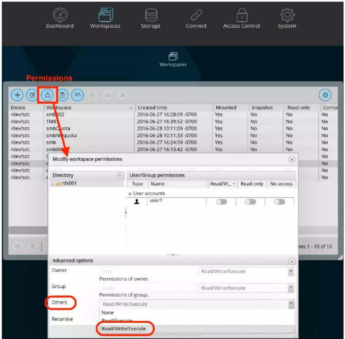
Configuring your Mac to access the G-RACK 12 and use FCP.
F.A.Q. > G-RACK 12 FCPX Essentials Guide_3 > Configuring your Mac to access the G-RACK 12 and use FCP.
If you have selected iSCSI as your method of connecting.
Please review the G-RACK 12 iSCSI Essentials to get the optimal speed for your connections.
Understand that Mac OS does not come with native support for iSCSI. There are some good iSCSI initiator products on the market that allows Mac OS to support iSCSI but they do require a purchase.
To download GlobalSAN iSCSI initiator & Xtarget (this document will not cover Xtarget) start by creating an account with SNS. If you wish to bypass the limited-but-free trial version you can setup an account and request the required Permanent keys. To finish and start downloading the iSCSI initiator press the download button. The install process will require a restart so make sure all workstation data has been saved. Navigate to the newly downloaded GlobalSAN iSCSI Xtarget package and double-click to start the installation process. Follow the install procedure and reboot when prompted at the end of the process.
Once the application has been installed and the system restart has rebooted your workstation, access System Preferences from the Mac pulldown menu. Press the new GlobalSAN and Xtarget icon located at the bottom of System Preferences and follow SNS's instructions to RETRIEVE and ACTIVATE a permanent key.
If you have selected NFS as your method of connecting.
This information applies to OS X - Version 10.11 El Capitan and Version 10.10 Yosemite.
- Open terminal and do sudo -s. Enter password of client machine.
- cd /etc on client machine, run ls after
- Use nano or vi to open up nfs.conf file
- If your system has not been used for NFS before you may find your nfs.conf file empty at first. (This is where you can insert the mount_nfs commands as well so that you won't have to keep doing it through the command line each time you mount.)
- Enter the lines below into the nfs.conf:
nfs.client.nfsiod_thread_max = 128
nfs.client.allow_async = 1
nfs.client.mount.options = vers=3,nfs,tcp,async,rwsize=65536,rdirplus,intr,locallocks
nfs.server.async = 1
nfs.server.nfsd_threads = 16
FCPX/NFS G-RACK 12 Workflow Overview\_2
F.A.Q. > G-RACK 12 FCPX Essentials Guide_3 > FCPX/NFS G-RACK 12 Workflow Overview_2
G-RACK 12 excels in the shared environment. Utilizing this dual-share / dual-protocol workflow, Final Cut Pro X can once again enjoy the benefits of network connectivity and performance in a shared workflow.
The high-level overview
- One ingest client transfers media to an SMB share.
- One (or more) editing client(s) mounts the same SMB share for accessing the media along with a separate NFS share for Library bundles.
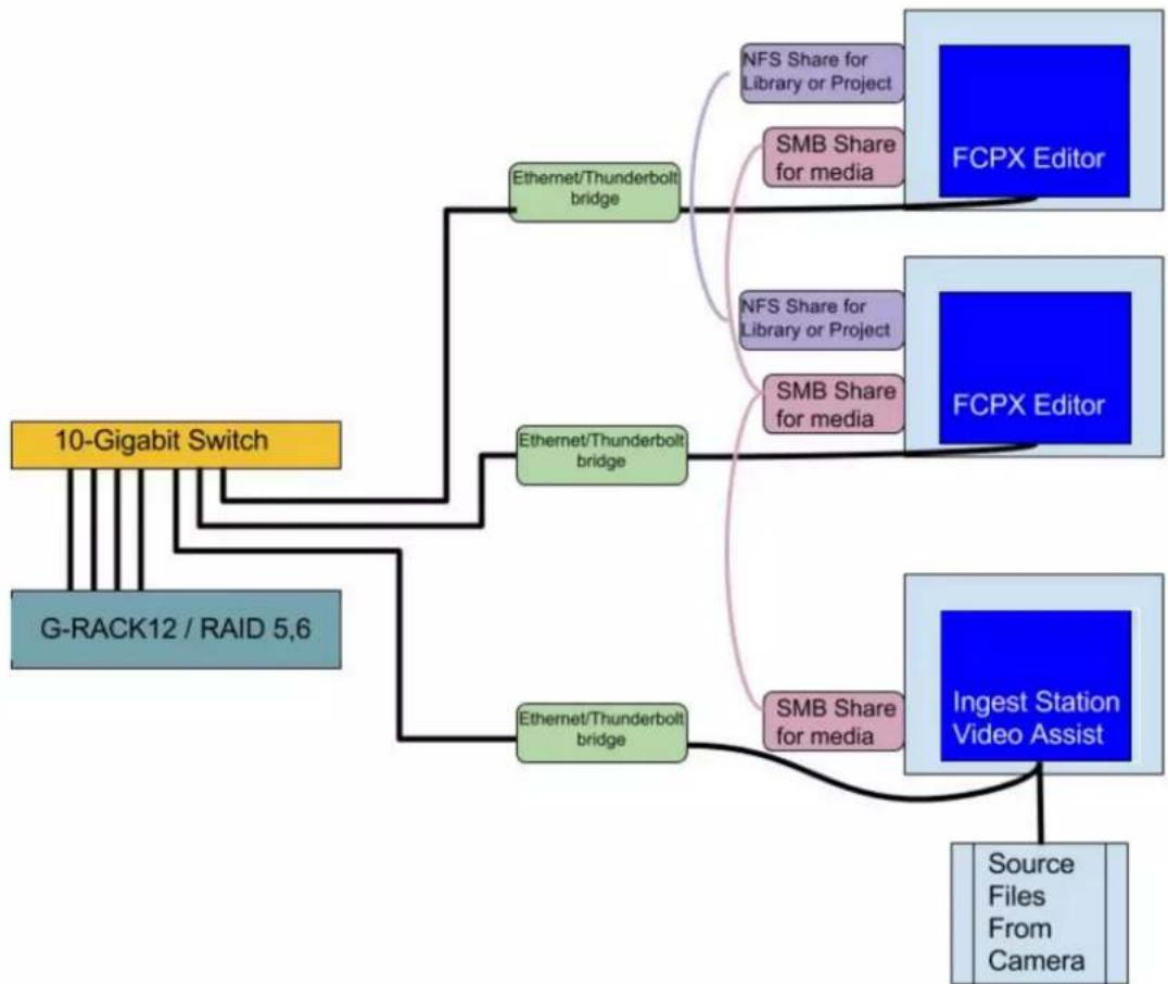
flowchart
graph TD
    A["10-Gigabit Switch"] --> B["G-RACK12 / RAID 5,6"]
    B --> C["Ethernet/Thunderbolt bridge"]
    C --> D["NFS Share for Library or Project"]
    C --> E["SMB Share for media"]
    D --> F["FCPX Editor"]
    E --> G["NFS Share for Library or Project"]
    E --> H["SMB Share for media"]
    G --> I["FCPX Editor"]
    H --> J["Ingest Station Video Assist"]
    C --> K["Ethernet/Thunderbolt bridge"]
    K --> L["SMB Share for media"]
    L --> M["Source Files From Camera"]
The editing client(s) creates and edits from a Library bundle on an NFS share. The key factor for the Library bundle is that it links to select the "Leave Files in Place" option during the FCPX > Import operation for the media on the SMB share during import. This allows for media and project files to live in different locations.

The Why
The most widely-used sharing protocols (network communication formats) are installed onto G-RACK 12's structure and each serves a different function. Protocols can be analogous to driving across country. There are many different routes one could take. Each route has their unique benefits and shortcomings.
Because OSX & network share compatibility is limited, you can not save a Library bundle to an SMB share. You can, however, read files from an SMB share to FCPX rapidly. Conversely you can save a Library bundle to an NFS share but the 'writes' for an NFS share are slower. Using the best attributes of both protocols in concert is the full solution.
Additional
After the client's nfs.conf file has been tuned (see NFS Essentials), the NFS share can be mounted and a Library bundle can be created. NFS protocol allows for multiple Macintosh clients to write to and read from the same network share.
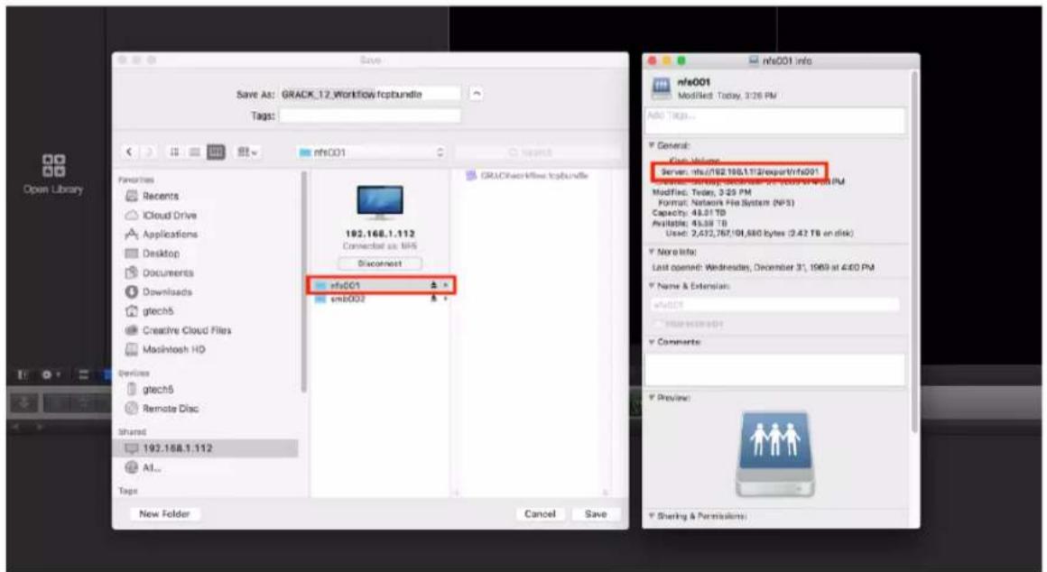
G-RACK 12 has not introduced bin-sharing yet. However, the ability to share FCPX Project assets, link on-the-fly newly added files on the SMB share to the Library and read the same files simultaneously from multiple clients on the network will lead to higher productivity.
Links and references\_3
F.A.Q. > G-RACK 12 FCPX Essentials Guide_3 > Links and references_3
- http://images.apple.com/final-cut-pro/docs/Media_Management.pdf
- http://china.emc.com/collateral/white-papers/h13204-wp-emcisilon-and-finalcutprox-workflows.pdf
- http://serverfault.com/questions/363893/how-to-tune-nfs-client-on-macos-to-get-linux-like-performance
G|RACK™ 12
Technical Support
Technical Support
Thank you for purchasing G-RACK 12. If you have any comments or questions about this manual or the product, please let us know!
G-Technology appreciates and values its customers. We strive to give you the finest service and support. If you encounter any difficulties while installing or using your G-RACK 12, please contact G-Technology Technical Support at:
https://support-en.g-technology.com/app/Contact_Us/
Helpful information for support
When contacting Technical Support, it's best to be in front of your computer and have the following information available:
- Your G-RACK 12 serial number (on bottom of unit)
- Operating System and version
- Computer model
- List of other devices attached to your computer
G|RACK™ 12
Warranty
Limited Warranty
HGST, a Western Digital Company ("HGST") including G-Technology for External Hard Disk Drives
What does this limited warranty cover?
This limited warranty applies to new HGST products purchased from an authorized HGST dealer by the original purchaser for normal use and not for resale. HGST warrants that a covered product is free from defects in materials and workmanship, with the exceptions stated below.
How long does limited warranty coverage last?
This limited warranty lasts for one year, two years, three years, or five years, or a fixed period from date of purchase, depending on when and where it was originally purchased. To determine the warranty specifically for your product, visit www.g-technology.com. A valid proof of purchase may be required to prove eligibility. If you do not have a valid proof of purchase, the limited warranty period will be measured from the date of sale from HGST to the authorized distributor.
What does this limited warranty not cover?
The limited warranty does not cover damage resulting from commercial use, misuse, accident, modification or alteration to hardware or software, tampering, unsuitable physical or operating environment beyond product specifications, improper maintenance, or failure caused by a product for which HGST is not responsible.
There is no warranty of uninterrupted or error-free operation. There is no warranty for loss of data — you must regularly back up the data stored on your product to a separate storage product. There is no warranty for product with removed or altered identification labels.
HGST DOES NOT PROVIDE ANY OTHER WARRANTIES OF ANY KIND, INCLUDING, BUT NOT LIMITED TO, THE IMPLIED WARRANTIES OR CONDITIONS OF MERCHANTABILITY AND FITNESS FOR A PARTICULAR PURPOSE. SOME JURISDICTIONS DO NOT ALLOW THE LIMITATION OF IMPLIED WARRANTIES, SO THIS LIMITATION MAY NOT APPLY TO YOU. (HGST is not responsible for returning to you a product that is not covered by this limited warranty.)
What must you do?
If you are having trouble with a product, before seeking limited warranty service, first follow the troubleshooting procedures that HGST or your reseller provides.
To obtain limited warranty service, you must first obtain a Return Materials Authorization (RMA) and ship-to address by contacting G-Technology at www.g-technology.com/support. Please follow the instructions found on this website. You must return the covered hard disk drive using approved packaging to our logistics center. You must pay any associated transportation charges, duties, and insurance in shipping the drive to our logistics center. You should remove all personal information from the product prior to its return.
What will HGST do?
HGST will replace the drive with a functionally equivalent replacement product, transportation prepaid. HGST may replace your product with a product that was previously used, repaired, and tested to meet HGST specifications. You receive tile to the replaced product at delivery to carrier at HGST's shipping point. You are responsible for importation of the replaced product, if applicable.
HGST will not return the original drive to consumers; therefore, the consumer is responsible for moving data to another media before returning. Data recovery is not covered under this warranty and is not part of the warranty returns process. HGST warrants that replaced products are covered for the remainder of the original product warranty or 90 days, whichever is greater.
How is our liability limited?
HGST AND ITS AFFILIATES, SUPPLIERS, DISTRIBUTORS AND RESELLERS ARE NOT LIABLE FOR ANY OF THE FOLLOWING: 1) THIRD-PARTY CLAIMS AGAINST YOU FOR DAMAGES (OTHER THAN BODILY INJURY INCLUDING DEATH AND TANGIBLE PERSONAL PROPERTY, 2) LOSS OF, OR DAMAGE TO, YOUR DATA; OR 3) SPECIAL, INCIDENTAL OR INDIRECT DAMAGES OR FOR ANY ECONOMIC CONSEQUENTIAL DAMAGES (INCLUDING LOST PROFITS OR SAVINGS), EVEN IF INFORMED OF THE POSSIBILITY. SOME JURISDICTIONS DO NOT ALLOW LIMITATION OF LIABILITY, INCIDENTAL DAMAGES OR CONSEQUENTIAL DAMAGES, SO THE ABOVE LIMITATIONS MAY NOT APPLY TO YOU.
How do local laws apply?
THIS LIMITED WARRANTY GIVES YOU SPECIFIC LEGAL RIGHTS, AND YOU MAY ALSO HAVE OTHER RIGHTS THAT VARY FROM JURISDICTION TO JURISDICTION.
Capacity Definition and Disclaimer
For G-Technology products 1TB or greater: 1 gigabyte (GB) is equal to 1 billion bytes and 1 terabyte (TB) equals 1,000 GB (1 trillion bytes). Accessible capacity will vary from the stated capacity due to formatting and partitioning of the hard drive, the computer's operating system, and other factors.
For G-Technology products less than 1TB: One gigabyte (GB) is equal to 1 billion bytes when referring to hard drive capacity. Accessible capacity will vary depending on the operating environment and formatting.
G|RACK™ 12
End User License Agreement
IMPORTANT - READ CAREFULLY.
This License Agreement (this "Agreement") is a legal contract between HGST, Inc., its subsidiaries and affiliates (collectively, "HGST"), and you and governs your use of this software and any associated online or electronic documentation made available to you by HGST (this software, firmware, and documentation, and any applicable updates provided by HGST, collectively, the "Software") in connection with HGST hardware devices and products, including without limitation HGST storage devices ("HGST Devices"). As used in this Agreement "you" means both any person accessing this License Agreement and the organization that has purchased an HGST Device (the "Customer"). If any HGST software or services are accompanied by a separate license agreement, the terms of that separate license agreement will apply to your use of the applicable HGST software or services.
BY INSTALLING, ACTIVATING, COPYING OR OTHERWISE USING THE SOFTWARE, YOU AGREE TO BE BOUND BY THE TERMS OF THIS AGREEMENT, AS INCORPORATED BY REFERENCE IN SECTION 5 below. IF YOU DO NOT AGREE TO THE TERMS OF THIS AGREEMENT, OR IF YOU DO NOT HAVE AUTHORITY TO AGREE TO THEM, YOU MAY NOT INSTALL, ACTIVATE, COPY, OR USE THE SOFTWARE.
1. LICENSE GRANT and Restrictions
The Software is licensed to you and not sold. Subject to the terms of this Agreement, HGST hereby grants you a limited, non-exclusive, non-transferable, non-sublicensable, and revocable license to use the Software for your use.
You will not, and you agree not to enable others to: (a) reproduce the Software, except as expressly permitted under this Section 1; (b) modify, adapt, translate the Software, or create any derivative works thereof; (c) attempt to circumvent or disable the Software or any technology features or measures in the Software including, without limitation, any access controls or copyright protection mechanisms, by any means or in any manner; (d) attempt to decompile, disassemble, reverse engineer, or otherwise attempt to derive the source code for the Software; (e) distribute, encumber, sell, rent, lease, sublicense, or otherwise transfer, publish or disclose the Software to any third party; (f) remove or alter any trademark, logo, copyright or other proprietary notices, legends, symbols or labels in or on the Software or used in connection with the Software; or (g) use the Software in any manner to aid in the violation of any third-party intellectual property rights, including without limitation copyrights, trademarks, trade secrets, and patents, or the applicable laws of any applicable jurisdictions, including without limitation libel, defamation, obscenity, and privacy-related torts. You will not use the Software with devices manufactured by entities other than HGST ("Non-HGST Devices").
2. RESERVATION OF RIGHTS
You acknowledge that the Software is protected by copyrights and other intellectual property and proprietary rights. HGST and its third-party licensors ("Licensors") reserve all of these rights with respect to the Software, except for the license expressly granted to you in Section 1. Except for the express license granted to you in Section 1, no right, title, interest or license in or to the Software, whether by implication, estoppel or otherwise, is granted, assigned or transferred to you. You will not take any action that interferes with or challenges, in any manner, HGST or its
Licensors' rights with respect to the Software.
3. UPDATES; Automatic features
HGST has no obligation to provide you with any Updates (as defined below) to the Software. HGST may, however, from time to time, issue updated versions of the Software and the Software may automatically connect to HGST to check for available updates to the Software, such as bug fixes, patches, upgrades, enhanced functions, plug-ins and new versions (collectively, "Updates") and may either (a) automatically electronically update the version of the Software that you are using on your device or (b) give you the option of manually downloading applicable Updates. By installing the Software and not disabling any automated check for Updates, if applicable, you hereby agree and consent to automatically request and receive Updates from HGST, and that the terms and conditions of this Agreement, together with any additional or updated terms provided at such time, shall apply to all of these Updates.
4. INFORMATION Automatically collected by HGST; FEEDBACK
The Software contains automatic communications features which relay certain information to HGST and/or its third-party service providers in connection with the operation of the Software. This information may include your Software settings, versions of the Software you are using, the error logs and other diagnostic information of HGST products including, without limitation, identifying potential errors and/or improvements. Such information and any other information that is provided by you to HGST in connection with the use of the Software (collectively, "Feedback") may be used by HGST to improve or enhance its products and, accordingly, HGST shall have a non-exclusive, perpetual, irrevocable, royalty-free, worldwide right and license to use, reproduce, disclose, distribute, modify, and otherwise exploit Feedback for any purpose and in any medium or product without restriction. Such right and license shall survive any termination or expiration of this Agreement for any reason. You covenant that you will not assert against HGST or any of its directors, officers, employees, subcontractors, or agents any claim or action arising from the use or exploitation of the Feedback by HGST.
5. REGISTRATION INFORMATION
As part of any Software registration process, HGST may request registration-related information, including your name and e-mail address. By providing this information, you consent to its collection and use by HGST to provide non-promotional communications, including notices of Update availability, product recalls, or safety concerns. HGST's use of any personally identifiable information you provide (if any) shall be governed by the HGST Privacy Policy (as such policy may be updated by HGST from time to time) that is located at http://www.hgst.com/privacyand is incorporated into this Agreement by this reference.
6. THIRD PARTY CONTENT and Service Providers
Your use of the Software may allow you to download and use third-party software or link to third-party content accessed through the Software (this software and content collectively, "Third-Party Content"). You acknowledge that all Third-Party Content is the property of the applicable Third-Party Content owners and may be protected by applicable copyright and other intellectual property rights. You may not use any Third-Party Content in any manner that has not been
authorized by the applicable service provider ("Service Provider") or Third-Party Content owner. You acknowledge that you may be required to enter into a separate agreement with a Service Provider or Third-Party Content owner, or comply with a Service Provider's terms or conditions of use in order to access and use certain Third-Party Content. It is your responsibility to ensure that accessing, reproducing, displaying or otherwise using Third-Party Content in connection with your use of the Software does not infringe any third-party intellectual property rights.
7. DISCLAIMER OF WARRANTY
all SOFTWARE is PROVIDED TO YOU "AS IS" WITHOUT WARRANTY OF ANY KIND. TO THE MAXIMUM EXTENT PERMITTED BY APPLICABLE LAW, HGST AND ITS LICENSORS DISCLAIM ALL WARRANTIES, EXPRESS OR IMPLIED, INCLUDING, WITHOUT LIMITATION, ANY IMPLIED WARRANTIES OF MERCHANTABILITY, FITNESS FOR A PARTICULAR PURPOSE AND NON-INFRINGEMENT OF THIRD-PARTY INTELLECTUAL PROPERTY RIGHTS OR LACK OF VIRUSES, and any warranties regarding the security, reliability or timeliness of the Software. HGST DOES NOT WARRANT THAT the SOFTWARE WILL MEET YOUR REQUIREMENTS OR BE ERROR-FREE. HGST does not warrant that use of the Software will be continuous or uninterrupted and HGST shall not be responsible or liable for ANY INTERRUPTION OR CESSATION OF TRANSMISSION TO OR FROM the Software. THE ENTIRE RISK ARISING OUT OF THE USE OR PERFORMANCE OF the SOFTWARE REMAINS WITH YOU. YOU UNDERSTAND AND AGREE THAT ANY SOFTWARE, MATERIAL OR DATA DOWNLOADED OR OTHERWISE OBTAINED THROUGH THE USE OF the SOFTWARE IS DONE AT YOUR OWN DISCRETION AND RISK AND THAT YOU SHALL BE SOLELY RESPONSIBLE FOR ANY DAMAGE TO YOUR COMPUTER, DEVICE, SYSTEM OR NETWORK, INCLUDING ANY LOSS OR CORRUPTION OF DATA. THE FOREGOING WARRANTY DISCLAIMER SHALL NOT limit OR AMEND THE APPLICABLE WARRANTY THAT RELATES TO YOUR USE OF HGST DEVICES. HGST IS NOT RESPONSIBLE OR LIABLE FOR ANY INFECTIONS OR CONTAMINATION OF YOUR SYSTEM, DAMAGE TO YOUR SYSTEM, OR DELAYS, INACCURACIES, ERRORS OR OMISSIONS ARISING OUT OF OR RELATED TO YOUR USE OF THE SOFTWARE.
HGST DOES NOT MAKE ANY REPRESENTATIONS ABOUT AND DISCLAIMS ALL WARRANTIES WITH RESPECT TO ANY THIRD-PARTY CONTENT, ANY NON-HGST DEVICE, OR THE ACTIONS OR OMISSIONS OF A SERVICE PROVIDER OR THIRD-PARTY CONTENT OWNER. HGST IS NOT RESPONSIBLE FOR EXAMINING OR EVALUATING THE CONTENT, ACCURACY, COMPLETENESS, TIMELINESS, VALIDITY, COPYRIGHT COMPLIANCE, LEGALITY, DECENCY, QUALITY OR ANY OTHER ASPECT OF THIRD PARTY CONTENT. HGST, ITS OFFICERS, AFFILIATES AND SUBSIDIARIES DO NOT WARRANT OR ENDORSE AND DO NOT ASSUME AND WILL NOT HAVE ANY LIABILITY OR RESPONSIBILITY TO YOU OR ANY OTHER PERSON FOR ANY THIRD-PARTY CONTENT OR WEB SITES, OR FOR ANY OTHER MATERIALS, PRODUCTS, OR SERVICES OF THIRD PARTIES ACCESSED THROUGH the SOFTWARE. TO THE EXTENT YOU CHOOSE TO USE OR ACCESS ANY THIRD-PARTY CONTENT THROUGH the SOFTWARE, YOU DO SO AT YOUR OWN INITIATIVE AND ARE RESPONSIBLE FOR COMPLIANCE WITH ANY APPLICABLE LAWS, INCLUDING BUT NOT LIMITED TO APPLICABLE LOCAL LAWS AND PRIVACY AND DATA COLLECTION LAWS. NO VENDOR, DISTRIBUTOR, DEALER, RETAILER, SALES PERSON, OR OTHER PERSON IS AUTHORIZED TO MODIFY THIS AGREEMENT OR TO MAKE ANY WARRANTY, REPRESENTATION, OR PROMISE ON BEHALF OF HGST.
THE SOFTWARE IS NOT INTENDED FOR USE IN THE OPERATION OF NUCLEAR FACILITIES, AIRCRAFT NAVIGATION OR COMMUNICATIONS SYSTEMS OR AIR TRAFFIC CONTROL MACHINES OR ANY OTHER MACHINES IN WHICH CASE THE FAILURE OF SOFTWARE COULD LEAD TO DEATH, PERSONAL INJURY OR SEVERE PHYSICAL OR ENVIRONMENTAL DAMAGE.
8. LIMITATION ON LIABILITY
TO THE MAXIMUM EXTENT PERMITTED BY APPLICABLE LAW, IN NO EVENT SHALL HGST OR ITS LICENSORS BE LIABLE FOR ANY CONSEQUENTIAL, INCIDENTAL, INDIRECT, SPECIAL, PUNITIVE, MULTIPLE, OR OTHER DAMAGES WHATSOEVER, INCLUDING WITHOUT LIMITATION DAMAGES FOR LOSS OF BUSINESS PROFITS, BUSINESS INTERRUPTION, LOSS OF DATA, COMPUTER SYSTEM FAILURE, MALFUNCTION OR OTHER PECUNIARY LOSS RELATING TO OR ARISING OUT OF THIS AGREEMENT, THE USE OF OR INABILITY TO USE THE SOFTWARE, any third-party content, or any Non-HGST Device, EVEN IF HGST HAS BEEN ADVISED OF THE POSSIBILITY OF SUCH DAMAGES. BECAUSE SOME JURISDICTIONS DO NOT ALLOW THE EXCLUSION OR LIMITATION OF LIABILITY FOR CONSEQUENTIAL OR INCIDENTAL DAMAGES, THE ABOVE LIMITATION MAY NOT APPLY TO YOU. IN NO EVENT SHALL HGST'S TOTAL LIABILITY TO YOU FOR ALL DAMAGES IN CONNECTION WITH this Agreement, THE SOFTWARE EXCEED \$25. THE FOREGOING LIMITATIONS, EXCLUSIONS AND DISCLAIMERS SHALL APPLY TO THE MAXIMUM EXTENT PERMITTED BY APPLICABLE LAW, EVEN IF ANY REMEDY FAILS ITS ESSENTIAL PURPOSE.
9. U.S. GOVERNMENT RESTRICTED RIGHTS
The Software is "commercial computer software" as defined in 48 CFR 2.101 and is provided with restricted rights. Use, duplication, or disclosure by the U.S. government is subject to restrictions as set forth in subparagraph (b)(3)(i) of The Rights in Technical Data and Computer Software clause of DFARS 272.7202.-3or subparagraphs (c)(1) and (2) of the Commercial Computer Software-Restricted Rights at 48 CFR 52.227-19, as applicable. The manufacturer is HGST, Inc. 3403 Yerba Buena Road, San Jose, CA 95135.
10. EXPORT AND IMPORT RESTRICTIONS
HGST makes no representation that the Software is appropriate for use in your country of use. You acknowledge that no part of the Software or underlying information or technology may be downloaded or otherwise exported or re-exported into (or to a national or resident of) any countries subject to U.S. trade embargo (currently Iran, Cuba, Syria, North Korea, and Sudan), or anyone on any of the U.S. government's Lists of Parties of Concern including, the U.S. Treasury Department's list of Specially Designated Nationals or the U.S. Commerce Department's Denied Persons List and Entity List. By using the Software, you are agreeing to the foregoing, and are representing and warranting that you are not located in or under the control of a national or resident of any such country or on any such list and you agree that you will not use the Software in any activities directly or indirectly related to the proliferation of weapons of mass destruction, except as authorized under applicable laws and regulations. You further acknowledge and understand that certain functionality of the Software, such as encryption or authentication, may be subject to export and import restrictions and you are responsible for complying with all applicable restrictions and regulatory requirements.
11. INDEMNITY
You hereby agree to indemnify, defend and hold HGST, its Licensors and its and their subsidiaries, affiliates, officers, directors, employees, consultants and agents harmless from and against any and all liabilities, damages, claims, fines, fees and expenses (including attorneys' fees and expenses) arising out of your use of the Software or any breach of this Agreement by you.
HGST reserves the right, at its own expense, to assume the exclusive defense and control of any matter otherwise subject to indemnification by you, in which event you will cooperate with HGST in asserting any available defenses.
12.TERMINATION
Without prejudice to any other HGST rights, HGST shall have the right to immediately terminate this Agreement with or without notice to you if HGST deems that you fail to comply with your obligations under this Agreement. Upon termination, you must immediately cease all use of the Software, and destroy all copies of the Software.
13.TRANSFER
You may not assign or otherwise transfer, by operation of law or otherwise, this Agreement or the Software.
14. OPEN SOURCE SOFTWARE
The Software licensed under this Agreement may include “Open Source” software (computer software that is distributed under a licensing arrangement, which provides that the computer code can be shared, viewed, and modified by the public). The restrictions of Section 1, 2, 13, and 14 of this Agreement only apply to any applicable Open Source software when and to the extent that they do not conflict with any terms of the Open Source software’s respective license(s).
15.SUPPORT
For questions regarding Software, please contact your HGST representative.
16. ENTIRE AGREEMENT
This Agreement constitutes the entire agreement between the parties concerning the subject matter hereof and supersedes all prior or contemporaneous oral or written understandings.
17. GOVERNING LAW; EXCLUSIVE VENUE FOR LITIGATION
This Agreement, and any dispute arising from or relating to this Agreement or the provision or use of the Software, shall be governed exclusively by, and construed in accordance with the laws of the United States and the State of California, without reference to any conflict of laws principles. The exclusive forum for any disputes arising out of or relating to this Agreement or the provision or use of the Service shall be an appropriate federal or state court located in Orange County, California and you hereby expressly consent to personal jurisdiction in such courts and waive all venue, jurisdiction and choice of law challenges or defenses.
18. UNITED NATIONS CONVENTION ON CONTRACTS FOR THE SALE OF INTERNATIONAL SALE OF GOODS
This Agreement shall not be governed by the United Nations Convention on Contracts for the International Sale of Goods.
19. SEVERABILITY; WAIVER
If any provision of this Agreement is held unenforceable by a court of competent jurisdiction, the applicable provision shall be modified to the extent necessary to render it enforceable without losing its intent or severed from this Agreement. If no such modification is possible, the other provisions of this Agreement shall remain in full force and effect. A waiver by either party of any term or condition of this Agreement or any breach thereof, in any one instance, shall not waive the applicable term or condition or any subsequent breach thereof.
20.SURVIVAL
Sections 1(a)-(g), 2, 7, 8, 11 and 17 of this Agreement, and any other provisions of this Agreement that require or contemplate performance after the termination of this Agreement, shall be enforceable notwithstanding termination of this Agreement.
21.EXCUSED PERFORMANCE
Neither party shall be in default or be liable for any delay, failure in performance (excepting the obligation to pay), or interruption of service resulting directly or indirectly from any cause beyond its reasonable control.
April 2016
G|RACK™ 12
Glossary
Access level — Also known as permission level, the amount of access any person has to the G-RACK 12 server. G-RACK 12 has two permission levels: administrator and user.
Administrator — A G-RACK 12 administrator is responsible for the server and all its settings. An administrator can set up or delete user accounts, group accounts, and shares; assign or remove access permissions; modify any setting on the server; and create other administrators. See also user.
CIFS — Common Internet File System, which is an early version of Server Message Block (SMB). CIFS was once the recommended file sharing protocol for the Windows platform that allows users to access shares through the network. Microsoft submitted some partial specifications as Internet-Drafts to the IETF, though these submissions have expired. CIFS is now obsolete, being replaced by newer versions of SMB.
Client computer — A computer that accesses services made available by a server computer.
DHCP — Dynamic Host Configuration Protocol. A protocol for assigning IP addresses to devices on a network. With dynamic addressing, a device can have a different IP address each time it connects to the network. In some systems, the device's IP address even changes while it is still connected. DHCP also supports a mix of static and dynamic IP addresses. See also Protocol.
DMA — Digital Media Adapter. A device that gives home entertainment devices the ability to transfer media such as music, photos, videos to and from other devices over the network.
DNS — Domain Name Service. A system that allows a network name server to translate text host names into numeric IP addresses used to uniquely identify any device connected to the Internet.
Domain — A group of computers administered as a single unit from a central location.
Ethernet — A standard method of connecting computers to a Local Area Network (LAN).
Event — A problem or change in setting on the G-RACK 12 server. A change in the server's name or the failure of a disk drive are both server events.
Firmware — Software that's built into hardware.
FTP — File Transfer Protocol. A format for exchanging files over the Internet. FTP is commonly used to upload files to or download files from a server over the Internet.
Group — A collection of user accounts grouped together to make it faster and easier to manage access to shares. All users in a group have the same level of access to any particular share. See also user account.
Host Interface — The point at which a host and a drive are connected to each other.
Host — The computer to which other computers and peripherals connect.
Hot swap — To remove and replace a disk drive without first powering off the server.
HTTP — Hypertext Transfer Protocol. Protocol used by the World Wide Web to transfer information between servers and browsers. See also Protocol.
HTTPS — Hypertext Transfer Protocol over Secure Socket Layer. A protocol that provides a more secure means of configuring your device than HTTP, but may affect the responsiveness of the user interface. All traffic between the managing computer and the G-RACK 12 server is encrypted.
Interface — A hardware or software protocol to manage the exchange of data between a device and a host. For example the communication between a computer host and a SATA or SCSI device. See also Protocol.
IP Address — The identifier of a computer, server, or other device on a TCP/IP network. IP addresses are a sequence of four numbers separated by periods. (For example, 123.456.78.1.) Every device on your local network has a unique IP address.
IP — Internet Protocol. A system that controls how data messages are separated into packets,
routed from the sender, and reassembled at the destination. See also Protocol.
iSCSI — Internet Small Computer System Interface. iSCSI is an IP-based storage networking standard for linking data storage facilities.
LAN — Local Area Network. A system in which computer users in the same company or organization are linked to each other and often to centrally-stored collections of data in LAN servers.
LED — Light-emitting Diode. An electronic device that lights up when electricity is passed through it.
Local access — Access to the server from a computer on your local network. Or, manual access to the server, which involves physical contact with the server or its cables. See also remote access.
Multi-user — A system in information technology that enables more than one user to access data at the same time.
NAS — Network Attached Storage. Hard disk storage that is set up with its own network address rather than being attached to the computer that is serving network workstation users.
Network Computer — A computer that communicates with a central data storage facility such as a server or RAID system.
NFS — Network File System. A network file system protocol that allows a user on a client computer to access files over a network as easily as if the network devices were attached to its local disks. Normally associated with UNIX systems. See also Protocol.
NTP — Network Time Protocol. A protocol for synchronizing the clocks of computers and equipment over a network. See also Protocol.
Operating System — Software that allows users and programs installed on your system to communicate with computer hardware such as a hard drive.
Parity — Data created in volumes with RAID 5 protection that's used to reconstruct files if one of the disk drives in the server fails. See also RAID 5.
Partition — A logical division on a hard drive that the operating system treats as a separate hard drive. Each partition is assigned a unique drive letter.
Port (Hardware) — A specialized outlet on a device for connecting to other devices using a cable or a plug. Ethernet ports, power ports, and USB ports are examples.
Port aggregation — A method of increasing the speed of a device's network connection by using more than one Ethernet port simultaneously to connect to the network.
Protocol — A convention of data transmission that defines timing, control format, and data representation.
RAID — Redundant Array of Independent Disks. A technology that combines disk drives together for improved performance and fault tolerance (the ability to withstand the failure of a disk drive).
RAID 10 — A level of RAID protection. A volume with RAID 10 is built from two or more equal-sized RAID 1 volumes. Data in a volume with RAID 10 is both striped and mirrored. Mirroring provides data protection, and striping improves performance. See also mirror, and stripe.
RAID 5 — A level of RAID protection. A volume with RAID 5 is built from a minimum of three disk drives, and uses data striping and parity data to provide redundancy. (Parity is extra information that's used to re-create data if a disk drive fails. In volumes with RAID 5, parity data is striped evenly across the disk drives with the stored data.) Parity data provides data protection, and striping improves performance. See also stripe.
RAM — Random Access Memory. Memory that allows any storage location to be accessed randomly, as opposed to sequential access devices such as tape drives.
Remote Access — Access to the server from a computer that is not on your local network. For instance, accessing the server from a client's computer, over the Internet, is remote access. Remote access can also refer to shutting down or resetting the server using G-RACK 12 Administrative Tool instead of physically pressing the Power button. See also local access.
ROM — Read-Only Memory. An integrated circuit memory chip containing programs and data that the computer or host can read but cannot modify. A computer can read instructions from ROM but cannot store data in ROM.
RSA Key — An encryption decoder that's part of SSL, a type of encryption used to protect data being sent over a network or the Internet. "RSA" stands for Rivest, Shamir, and Adelman, who invented the technology.
S.M.A.R.T. — Self-Monitoring Analysis and Reporting Technology. Technology built into physical disks that let them automatically monitor their own health and report on possible problems. Not all physical disks have SMART support.
Server — A computer or device on a network that manages resources. The G-RACK 12 server is a file server, a storage appliance that's dedicated to storing files.
Share — An area, similar to a folder or directory, set up to organize files and access them on your network. Shares can be Public, shared with everyone on your network, or Private, shared with only selected users on your network.
SMB — Server Message Block. File-sharing protocol for Windows platform that allows users to access shares through My Network Places. Mac OS or later also supports the CIFS protocol. See also Protocol.
SMTP — Simple Mail Transfer Protocol. A member of the TCP/IP suite of protocols that governs the exchange of electronic mail between message transfer agents. See also Protocol.
Spin down — Referring to disk drives, a term that means to stop spinning.
SSL certificate — Secure Socket Layer certificate, part of the SSL encryption method. SSL (also known as Transport Layer Security) is a type of encryption used to protect data being sent over a network or the Internet. SSL uses a system of keys, like secret passwords, to send and receive files securely.
Streaming Media — Media such as audio, video, and photos that are constantly received while being delivered by a streaming provider.
TCP/IP — Transmission Control Protocol/Internet Protocol. A set of protocols for communication over interconnected networks. The standard for data transmission over networks. See also Protocol.
UPnP — Universal Plug n Play. A set of computer network protocols that simplify the implementation of networks in the home by allowing devices to connect seamlessly. See also Protocol.
UPS — Uninterruptible Power Supply. A power supply that has a battery in it that maintains power to a computer or server in the event of a power failure. A UPS is intended to provide enough power for you to save whatever files you're working on and properly power off the computer or server; it's not meant to keep any system running for the duration of a power failure.
USB — Universal Serial Bus. The interface between your computer and the USB devices you plug into it. Your computer communicates with USB devices through the USB interface.
USB drive — A portable disk drive that connects to a computer with a USB cable, instead of being installed inside the computer itself. Also known as a thumb drive, jump drive, flash drive, or external USB hard drive.
User — In G-RACK 12 Administrative Tool, a person who can save, back up, and share files using
the G-RACK 12 server, but who can't modify user account, group account, share, or server settings.
User account — An account, with a user name and password, that a person uses to access the G-RACK 12 server. User accounts have access level permissions associated with them.
Volume — Data storage space that can be made up of one or more disk drives, or of only part of a single disk drive.
WAN — Wide Area Network. A computer network that crosses metropolitan, regional, or national boundaries.
Web access protocol — The rules for sending information over the Internet. Your G-RACK 12 server has two Web access protocol choices, HTTP and HTTPS.
Workspace — A folder on your G-RACK 12 server that stores and protects files that can be accessed by other people.
G|RACK™ 12
Appendix. Technical Specification - Server
Key Features
- Dual socket R3 (LGA 2011) supports Intel® Xeon® processor E5-2600 v3 family; QPI up to 9.6GT/s
- Up to 2TB ECC 3DS LRDIMM, up to DDR4-2400 MHz; 16x DIMM slots
- 1x PCI-E 3.0 x16, 6x PCI-E 3.0 x8 (slot 1 & 2 occupied by controller and JBOD expansion port)
- Dual 10GBase-TLAN w/ Intel ^® X540
- 12x 3.5" Hot-swap SAS3/SATA3 drive bays; 2x 2.5" optional Hot-swap drive bays (rear)
- SAS3 via LSI 3008 controller; IT mode
- Server remote management: IPMI 2.0 / KVM over LAN / Media over LAN
- 3x 8cm hot-swap redundant PWM cooling fans
- 920W Redundant Power Supplies Platinum Level (94%)
| Processor/Cache | |
| CPU | Intel® Xeon® Haswell processor E5-2600 v3 family (up to 145W TDP)Dual Socket R3 (LGA 2011) |
| Cores / Cache | Up to 18 Cores / Up to 45MB Cache |
| System Bus | QPI up to 9.6 GT/s |
| System Memory | |
| Memory Capacity | 16x 288-pin DDR4 DIMM slotsUp to 1TB ECC LRDIMM, 128GB ECC RDIMM |
| Memory Type | 2133/1866/1600MHz ECC DDR4 SDRAM 72-bit |
| DIMM Sizes | RDIMM: 64GB, 32GB, 16GB, 8GB, 4GBLRDIMM: 64GB, 32GBs |
| Memory Voltage | 1.2 V |
| Error Detection | Corrects single-bit errors |
| On-board Devices | |
| Chipset | Intel® C612 chipset |
| SAS | SAS3 (12Gbps) via LSI 3008IT mode firmware |
| SATA | SATA3 (6Gbps) with RAID 0, 1, 5, 10 |
| IPMI | Support for Intelligent Platform Management Interface v.2.0IPMI 2.0 with virtual media over LAN and KVM-over-LAN supportASPEED AST2400 BMC |
| NetworkControllers | Intel® X540 Dual Port 10GbEVirtual Machine Device Queues reduce I/O overheadSupports 10GBASE-T, 100BASE-TX, and 1000BASE-T, RJ45 output1x Realtek RTL8201N PHY (dedicated IPMI |
| Graphics | ASPEED AST2400 BMC |
| Input / Output | |
| LAN | 2x RJ45 10GBase-T LAN ports1x RJ45 Dedicated IPMI LAN port |
| USB | 2x USB 3.0 ports (rear)2x USB 2.0 ports (rear)1x Type A |
| VGA | 1x VGA port |
| Serial Port / Header | 1x Fast UART 16550 port / 1 Header |
| Chassis | |
| Form Factor | 2U Rack mount |
| Dimensions | |
| Width | 17.2" (437mm) |
| Height | 3.5" (89mm) |
| Depth | 25.6" (648mm) |
| Weight | Gross Weight: 58 lbs (26.3 kg)Net Weight: 34 lbs (15.4 kg) |
| Front Panel | |
| Buttons | Power On/Off buttonSystem Reset button |
| LEDs | Power status LEDHard drive activity LED2x Network activity LEDsSystem Overheat LEDPower fail LED |
| Expansion Slots | |
| PCI-Express | 1x PCI-E 3.0 x16 slot6x PCI-E 3.0 x8 slotsSlot 1 & 2 occupied by controller and JBOD Expansion Port |
| Drive Bays | |
| Hot-swap | 12x 3.5" Hot-swap SAS3/SATA3 drive bays |
| Optional | 2x 2.5" Hot-swap HDD bays (rear) |
| Backplane |
| SAS3/SATA3 single expander per backplane |
| System Cooling | |
| Fans | 3x 8cm hot-swap redundant PWM cooling fans |
| Power Supply with Power Distributor | |
| 920W high-efficiency (94%+) AC-DC Redundant power supplies with PMBus and I2C | |
| AC Input | 100-240 V, 50-60 Hz, 11-4.5 Amp |
| DC Output | 4 Amp @ +5V standby75 Amp @ +12V |
| Certification |  Platinum Certified[Test Report] Platinum Certified[Test Report] |
| System BIOS | |
| BIOS Type | 128Mb SPI Flash EEPROM with AMI BIOS |
| BIOS Features | Plug and Play (PnP)APM 1.2PCI 2.2ACPI 1.0 / 2.0USB Keyboard supportSMBIOS 2.3UEFI |
| Operating Environment / Compliance | |
| RoHS | RoHS Compliant |
| Environmental Specifications | Operating Temperature: 10°C to 35°C (50°F to 95°F)Non-operating Temperature: -40°C to 70°C (-40°F to 158°F)Operating Relative Humidity: 8% to 90% (non-condensing)Non-operating Relative Humidity: 5% to 95% (non-condensing) |
G|RACK™ 12
Appendix. Technical Specification - Chassis
Key Features
- 2U Storage JBOD Chassis with capacity 12 x 3.5" hot-swappable HDDs bays
- Single Expander Backplane Boards support SAS3/2 or SATA3 HDDs with 12Gb/s throughput
- 4 x Mini-SAS HD ports for Internal / External Cascading Expander Combination for high performance, high availability or high redundancy requirements
- 1x IPMI port for Remote System Power on/off and system monitoring
- Support NTP for time synchronization & RTC battery backup
- 740W (1+1) 95% efficient Platinum level power supplies
- 3 x 80mm high efficient hot-swappable fans for best system cooling
- Ideal for Cloud backup, data Replication or High density Archive Storage Applications
| Form Factor |
| 2U chassis |
| Processor Support |
| N/A |
| Dimensions | |
| Height | 3.5" (89mm) |
| Width | 17.2" (437mm) |
| Depth | 25.5" (647mm) |
| Packaging | 26.7" (W) x 11.4"(H) 34.5" (L) |
| Gross Weight | 60 lb (27.22 kg) |
| Available Colors | Black |
| Drive Bays | |
| JBOD Chassis | Up to 12 x 3.5" hot-swap HDD bays for JBOD solution ) |
| Backplane |
| (SAS3 12Gb/s single expander backplane, with LSI SAS3 expander, support 12x 3.5" SATA3/SAS2/SAS3 drives, with 4x mini-SAS3 HD connectors) |
| Front Panel | |
| Buttons | Power On/Off buttonSystem Reset ButtonUnit Identification (UID) button |
| LEDs | 1 Network Activity LEDs |
| System Cooling | |
| Fans | 3 x 80x38mm hot-swap cooling fan |
| Operating Environment (System) | |
| Operating Temperature Range | 5°C ~ 35°C (41°F ~ 95°F) |
| Non-Operating Temperature Range | -40°C ~ 60°C (-40°F ~ 140°F) |
| Operating Relative Humidity Range | 8% ~ 90% (non-condensing) |
| Non-Operating Relative Humidity Range | 5% - 95% (non-condensing |
| Power Supply with Power Distributor | |
| 740W (1+1) Redundant high-efficiency power supply with PMBus | |
| AC Input | 100-240 V, 50-60 Hz, 9-3.5 Amp |
| DC Output | 4 Amp @ +5V standby61.7 Amp @ +12V |
| Certification |  Platinum Certified[Test Report] Platinum Certified[Test Report] |
| Regulatory (Power Supply) | |
| Power Supply Safety / EMC | USA - UL listed, FCCCanada - CUL listedGermany - TUV CertifiedEurope/CE MarkEN 60950/IEC 60950-Compliant |
G|RACK™ 12
Appendix. BIOS POST Error Codes
During the POST (Power-On Self-Test) routines, which are performed upon each system boot, errors may occur.
Non-fatal errors are those which, in most cases, allow the system to continue to boot. These error messages normally appear on the screen.
Fatal errors will not allow the system to continue with boot-up. If a fatal error occurs, you should consult with your system manufacturer for possible repairs.
These fatal errors are usually communicated through a series of audible beeps. The numbers on the fatal error list correspond to the number of beeps for the corresponding error.
Motherboard BIOS Error Beep Code
| Beep Code | Error Message | Description |
| 1 Beep | Refresh | Read to Boot |
| 5 Short Beeps + 1 Long Beep | Memory Error | No memory detected in the system. |
| 5 Beeps | No Con-in or Con-out Devices | Con-in includes USB or PS/2 keyboard, PCI or serial console redirection, and IPMI, KVM or SOL. |
| 1 Beep Per Device | Refresh | 1 beep for each USB device detected. |
| IPMI Error Code | Error Message | Description |
| 1 Continuous Beep | System OH | System Overheat |
G|RACK™ 12
Appendix. Chassis Power Supply Specifications
ESD Safety Guidelines
Electrostatic Discharge (ESD) can damage electronic components. To prevent damage to your system, it is important to handle it very carefully. he following measures are generally sufficient to protect your equipment from ESD.
- Use a grounded wrist strap designed to prevent static discharge.
- Touch a grounded metal object before removing a component from the antistatic bag.
- Handle the backplane by its edges only; do not touch its components, peripheral chips, memory modules or gold contacts.
- When handling chips or modules, avoid touching their pins.
- Put the card and peripherals back into their antistatic bags when not in use.
General Safety Guidelines
- Always disconnect power cables before installing or removing any components from the computer, including the backplane.
- Disconnect the power cable before installing or removing any cables from the backplane.
- Make sure that the backplane is securely and properly installed on the motherboard to prevent damage to the system due to power shortage.
An Important Note to Users
- All images and layouts shown in this user's guide are based upon the latest PCB Revision available at the time of publishing. The card you have received may or may not look exactly the same as the graphics shown in this manual.
G|RACK™ 12
Appendix. Standardized Warning Statements for AC/DC Systems
The following statements are industry standard warnings, provided to warn the user of situations which have the potential for bodily injury. Should you have questions or experience difficulty, contact G-Technology's Technical Support department for assistance. Only certified technicians should attempt to install or configure components.
Read this appendix in its entirety before installing or configuring components in the chassis.
Warning Definition
Warning!
This warning symbol means danger. You are in a situation that could cause bodily injury. Before you work on any equipment, be aware of the hazards involved with electrical circuitry and be familiar with standard practices for preventing accidents.
Installation Instructions
Warning!
Read the installation instructions before connecting the system to the power source.
Circuit Breaker
Warning!
This product relies on the building's installation for short-circuit (over current) protection. Ensure that the protective device is rated not greater than: 60VDC, 20 A.
Power Disconnection Warning
Warning!
The system must be disconnected from all sources of power and the power cord removed from the power supply module(s) before accessing the chassis interior to install or remove system components.
Equipment Installation
Warning!
Only trained and qualified personnel should be allowed to install, replace, or service this equipment.
Restricted Area
Warning!
This unit is intended for installation in restricted access areas. A restricted access area can be accessed only through the use of a special tool, lock and key, or other means of security. (This warning does not apply to workstations).
Battery Handling
Warning!
There is the danger of explosion if the battery is replaced incorrectly. Replace the battery only with the same or equivalent type recommended by the manufacturer. Dispose of used batteries according to the manufacturer's instructions
Redundant Power Supplies
Warning!
This unit might have more than one power supply connection. All connections must be removed to de-energize the unit.
Backplane Voltage
Warning!
Hazardous voltage or energy is present on the backplane when the system is operating. Use caution when servicing.
Comply with Local and National Electrical Codes
Warning!
Installation of the equipment must comply with local and national electrical codes.
Product Disposal
Warning!
Ultimate disposal of this product should be handled according to all national laws and regulations.
Hot Swap Fan Warning
Warning!
The fans might still be turning when you remove the fan assembly from the chassis. Keep fingers, screwdrivers, and other objects away from the openings in the fan assembly's housing.
DC Power Supply
Warning!
When stranded wiring is required, use approved wiring terminations, such as closed loop or spade-type with upturned lugs. These terminations should be the appropriate size for the wires and should clamp both the insulation and conductor.
DC Power Disconnection
Warning!
Before performing any of the following procedures, ensure that power is removed from the DC circuit.
Hazardous Voltage or Energy Present on DC Power Terminals
Warning!
Hazardous voltage or energy may be present on DC power terminals. Always replace cover when terminals are not in service. Be sure uninsulated conductors are not accessible when cover is in place.
G|RACK™ 12 Index
-A-
Admin Password 107 AFP 82
-C-
Certificates 112 CPU 110
-D-
Discovery 72
-E-
Expansion Chassis Power Sequence Requirement 137
-F-
Fan speed 110 FTP anonymous FTP 76,83 configuration 76,83
-G-
Groups
create 101 delete 101 import 101 permissions 46
-1-
iSCSI target 94
-L-
Logs 120 LUNs 94
-N-
Notifications 111
-R-
RAID 60,109 Rsync 89
-S-
S.M.A.R.T. 52, 53 SMB 75, 79
-U-
Users
create 99 detele 99 group membership 101 import 99 password 99 permissions 46
- W -
Workspaces 45, 79
- Copyrights 11
- Introduction 13
- Getting Started 18
- G-RACK 12 Administrative Tool 40
- Create snapshot 47
- Quotas 48
- Mount 49
- Unmount 49
- Delete Workspace 49
- Storage 50
- Physical Disks 50
- S.M.A.R.T. 52
- RAID 60
- USB Backup 65
- Connect 66
- Advanced Menu & Simple Menu 66
- Network 66
- Group 101
- Active Directory 102
- Directory Service 104
- System 105
- General Settings 105
- OS RAID 109
- Monitoring 109
- Certificates 112
- Scheduled Jobs 114
- System Information 116
- Update Manager 121
- Hardware Description 126
- Introduction - Hardware 128
- System Interface 132
- Chassis Installation and Precautions 136
- Introduction 136
- Rack Installation 139
- Drive Bay Installation/Removal 140
- Chassis Setup and Maintenance 144
- System Interface 154
- Use Cases/Tutorials 158
- Technical Support 266
- Warranty 268
- End User License Agreement 271
- Glossary 278
- G|RACK™ 12
- About G-RACK 12
- Key Features:
- Safety Notice
- Please read and observe the following precautions to assure personal safety. Improper use can result in hazardous situations.
- System Requirements
- Operating Systems:
- Supported Web browsers:
- Hardware:
- What's in the Box
- The box includes:
- GRACK™ 12
- G-RACK 12 View
- G-RACK 12 Installation
- Preparing for Setup
- Choosing a Setup Location
- Warnings and Precautions
- Rack Precautions
- Server Precautions
- Rack Mounting Considerations
- Ambient Operating Temperature
- Sufficient Air flow
- Mechanical Loading
- Circuit Overloading
- Reliable Ground
- Installing the System into a Rack
- Separating the Sections of the Rack Rails
- Installing the Inner Rail Extension
- Installing the Inner Rails
- Separating the Inner and Outer Rails
- Outer Rack Rails
- Installing the Outer Rails to the Rack
- Installing the Chassis into a Rack
- Physically Connecting G-RACK 12
- Connecting G-RACK 12 to Your Network
- Bonjour Browser
- For Mac operating systems:
- For Windows operating systems:
- THE FURTHER PROCEDURES SHOULD BE COMPLETED ON ANOTHER NETWORKED CLIENT COMPUTER WITH A WEB BROWSER
- G-RACK 12 Web-Based Setup Wizard
- STEP 2. End User License Agreement.
- STEP 3. Choose a theme for your environment
- STEP 4. Web Admin Password.
- STEP 5. Email Notification
- STEP 6. Create User Accounts
- STEP 7. Customize your G-RACK 12
- Dashboard
- System Status
- Drive Health
- Filesystem Status
- System Health
- Connected Users
- System Information
- Service Status
- Workspace Status
- Workspaces
- Add/Edit Workspace
- Modify Shared Folder Permissions
- Advanced options
- Create snapshot
- Quotas
- General settings
- Quota information
- Mount
- Unmount
- Delete Workspace
- Storage
- Physical Disks
- Physical disk properties
- Wipe physical drive
- Scan for new drives
- S.M.A.R.T.
- Devices
- Device properties
- S.M.A.R.T. Information
- Device information
- Self-test logs
- Scheduled Tests
- Add/ Edit scheduled test
- Execute scheduled test
- Delete
- Settings
- RAID
- Create RAID device
- Grow RAID device
- Remove devices from RAID
- Select hot spare devices for RAID
- Balance
- Array details
- Refresh
- USB Backup
- Connect
- Advanced Menu & Simple Menu
- Network
- General
- Interfaces
- Add/Edit Ethernet
- Add/Edit Bond
- How to Bond Two or More Ports:
- Identify
- Service Discovery
- Firewall
- Add/Edit
- Up/Down
- Save
- Services
- Overview
- SSH
- SMB/CIFS
- FTP
- NFS
- Shares
- Mac Client Information
- AFP (Apple Filling)
- SSL/TLS
- Ban List
- Rsync
- Jobs
- Rsync and iSCSI
- Server
- Modules
- iSCSI SCST
- Targets
- Edit LUNs list
- Access Control
- Users
- Add/Edit user
- Import users
- ;;;;;;
- Group
- Add/Edit group
- Import groups
- ;;
- Active Directory
- Directory Service
- System
- Web Administration
- Your connection is not private
- Web Administrator Password
- Date & Time
- OS RAID
- In this situation:
- Monitoring
- Performance statistics
- Hardware sensors
- Notifications
- Certificates
- SSL
- Scheduled Jobs
- Add/ Edit scheduled job
- Execute cron job
- Delete sheduled Job
- Process
- Report
- Logs
- Support
- Update Manager
- Updates
- Snapshots
- Take snapshot
- Reboot with selected snapshot
- Reset to Factory Settings
- Shutdown
- Reboot
- Server Unit
- Introduction - Hardware
- Overview?
- Serverboard Features
- Figure 1-1. Intel C612 Chipset:
- Processors
- Memory
- Main Storage Controller
- Serial ATA
- PCI Expansion Slots
- Rear I/O Ports
- Onboard Graphics
- Server Chassis Features
- System Power
- Hard Drive Subsystem
- Front Control Panel
- Cooling System?
- System Interface
- Control Panel Buttons
- RESET
- Power
- Control Panel LEDs
- Power Fail
- Information LED
- NIC1
- NIC2
- HDD
- Drive Carrier LEDs
- Chassis Installation and Precautions
- Introduction
- Features
- Drives
- Cooling System
- Static-Sensitive Devices
- Attaching an Expansion Chassis
- Handling Precautions
- Power Sequence Requirement
- Physical Layout
- Checking the Airflow
- Rack Installation
- Identifying the Sections of the Rack Rails
- Releasing the Inner Rail
- Releasing Inner Rail from the Outer Rails
- Installing the Inner Rails on the Chassis
- Installing the Outer Rails onto the Rack
- Sliding the Chassis onto the Rack Rails
- Drive Bay Installation/Removal
- Accessing the Drive Bays
- SAS/SATA Drive Installation
- Removing a Drive Carrier
- Mounting a Drive in a Drive Carrier
- Chassis Setup and Maintenance
- ESD Safety Guidelines
- General Safety Guidelines
- An Important Note to Users
- Removing Power from the System
- Removing the Chassis Cover
- Accessing the Inside of the Chassis
- Installing Hard Drives
- Removing a 3.5" Hard Drive Carrier
- Removing Hard Drive Carriers
- Installing 3.5" Hard Drives
- Installing a Hard Disk Drive
- Hard Drive Backplane
- System Fans
- System Fan Failure
- Replacing System Fans
- Replacing a System Fan
- Power Supply
- Power Supply Failure
- Removing/Replacing the Power Supply
- Removing the Power Supply (Figure 6-7)
- Installing a New Power Supply
- Power Distributor
- Changing the Power Distributor
- Overheating
- Overheat Temperature Setting
- Responses
- If the server overheats
- Power Supply LEDs
- System Information and System Settings
- How do I reset the web administrator password?
- How do I see which services are running?
- How can I enable a service (SMB, NFS)?
- How do I set up notifications?
- Who will receive notifications?
- What notifications can be sent?
- How can I determine the admin interface URL?
- How do I log in to the admin interface?
- How do I add a User to a Workspace?
- When does a User need to login?
- How does a user reset their password?
- How do I view log files?
- Where should I send log files if I need to send them to G-Technology?
- How much space is available on my Volume?
- How is a self-signed certificate used in the G-RACK 12 system?
- How to shrink your data RAID to fewer physical disks.
- How to grow your RAID set.
- How to change your RAID level.
- How to determine if your physical drive is about to fail.
- How to assign a new disk as a Hot Spare
- How to check the consistency of the file system and fix it.
- How to make a snapshot for the RAID data.
- How to make a snapshot for the OS drive.
- How to define a quota for a user.
- How to wipe you data disks.
- Network services
- How to aggregate network interfaces to get a higher throughput.
- How to set higher MTU on Ethernet (jumbo frames).
- ATTO configuration to allow Jumbo Frames
- ATTO says:
- How to turn on advertising of the network protocols.
- How to protect your G-RACK 12 from (unwanted) network traffic.
- How to run arbitrary commands on a scheduled basis.
- How to allow access your G-RACK 12 via SSH without password (authentication by a certificate).
- How to perform automatic synchronizing of the user data to G-RACK 12. Configuring RSyncjobs.
- How to setup a Local RSync job
- How to setup a Remote RSync job
- How to setup a Push RSync job
- How to setup a Pull RSync job
- User Authentication for a module on the G-RACK 12
- How to set an iSCSI connection.
- How effectively apply permissions to Workspaces.
- How to keep G-RACK 12 software up to date.
- How can I restore the forgotten admin password?
- How to transfer the data from a local computer to the G-RACK 12 storage space?
- How to transfer the data from the G-RACK 12 storage space to a local computer?
- How to control who can access files/ folders on G-RACK 12?
- How to know the software version of G-RACK 12?
- G-RACK 12 Administrative Tools logs out itself too soon.
- What is the update time for G-RACK 12 Dashboard widgets?
- What NLEs does G-RACK 12 work with?
- How to increase the size of my iSCSI LUN?
- How to get more storage space if I have run out of storage space for the volume that is
- associated with all of my iSCSI target.
- The drive that I want to use as a hot spare says to have some information on it.
- I have set read/write permissions for my SMB enabled workspace but still have no write access.
- What are steps to set up the G-RACK 12 (Walk through)?
- How do I reset the G-RACK 12 to factory default?
- What File and Network Protocols are supported on the G-RACK 12?
- Are the hard drives in the G-RACK 12 hot-swappable?
- What are the key reasons to contact G-Technology support?
- How do I know how full my server is with data?
- How to migrate data from another NAS to the G-RACK 12?
- Does the G-RACK 12 support HTTPS connection?
- How do I log in if I forgot the admin password?
- How to choose the right HDD for my G-RACK 12?
- How to enable HTTPS and create a certificate signing request on the G-RACK 12?
- The system seems slow. How to speed up file transfers?
- What make and model of CPU does the G-RACK 12 have?
- How do I create a new RAID device?
- How to a create an iSCSI volume?
- How to change RAID level?
- How to create a new user?
- How to access an FTP shared workspace?
- How to access an AFP shared workspace?
- How to access an NFS shared workspace?
- Mounting a NFS share on OSX can be found here:
- How to access an iSCSI shared workspace?
- How to get more storage space if I have run out of storage space associated with my LUN.
- A domain user can not access the workspace.
- Local RSync Config
- Remote RSync Config
- Push RSync Config
- Pull RSync Config
- User Authentication for a module on G-RACK 12.
- How to track users and their activity?
- G-RACK 12 RAID Guide
- What is RAID?
- RAID Levels: Advantages and Disadvantages
- Creating and Managing a RAID Array
- How to create a new RAID volume
- How To Grow a RAID Array
- Confirm your choice and press Save
- The RAID is ready
- How To Shrink a RAID Array
- Setting a Hot Spare
- \* What if my newly inserted drive is not showing in the hot spare list?
- Troubleshooting
- Recovering from degraded state (How to replace a failed data physical disk?)
- How to change a RAID array level
- How to check filesystem consistency
- What is iSCSI
- How and when is iSCSI used?
- Target
- iSCSI Target Creation
- Edit LUN
- Add LUNs
- Links and references
- Mac OS Initiators
- GlobalSAN iSCSI initiator & Xtarget
- Setup:
- SANmp Administrator & Client tools
- SANmp Administrator tool:
- SANmp Client tool:
- Other Notes
- Other known SNS issues:
- Troubleshoot Hardware Issues
- How to check if the G-RACK 12 is a faulty unit?
- Lights
- Beeps
- Motherboard BIOS Error Beep Codes
- IPMI Error Codes
- Connections
- User interface
- DHCP/Network
- What should I do if the system fan, LCD panel, or other hardware components are not working properly?
- A domain user can not access the workspace
- How to replace a failed OS physical disk?
- How to import domain user or user group information.
- Pro Tools 11 (Mac & El Capitan) won't launch when I have SANmp-managed and unmanaged iSCSI targets
- Why can't I see an iSCSI target that was formatted by another iSCSI initiator?
- Why can't multiple users access the same CIFS/SMB share when working in Pro Tools 11?
- Why is Adobe® Premiere Pro is presenting me with multiple iterations of the same G-RACK12 volume when I attempt a relink?
- Why are there so many connection options in my iSCSI initiator after I attempt a Group discovery?
- Why can't multiple computers write to the same iSCSI target?
- How to set iSCSI target and LUNs?
- Users could not see all mounted volumes in Finder (Mac OS)
- Unable to delete files from a mounted Workspace after exceeding quota limit.
- Unable to write to FTP shared workspace when mounting through Mac client, using "Connect to server".
- Some users have problems accessing SMB and AFP mounted shared Workspaces.
- Restoring a Mac from G-RACK iSCSI target.
- Mac OSX El Capitan & GlobalSAN iSCSI 5.3.0.518
- Bare Metal Recovery
- What you need to get started.
- Connections.
- Powering Up.
- OSX Hiding Option:
- ACLS & Permissions on the G-RACK 12
- Unexpected NFS Result
- Permissions Not Inherited From Client Computer
- Missing Storage Space on NAS shares
- How do I reach technical support?
- Configuration
- Installation
- Safety
- LED and Sensors
- LED activity
- Connectors, cables & buttons
- Power issues
- BIOS questions
- RAID Information
- Spare parts & servicing
- G-RACK 12 BTRfs Backgrounder
- What is BTRfs?
- The role file systems play in storage devices.
- Why is BTRfs a good choice for a file system?
- Comparison of features between the most popular file system ext4.
- BTRfs vs ext4
- ext4 advantages
- BTRfs advantages
- The way to the future
- Public Opinion from /r/BTRfs on reddit.
- Love:
- Like:
- Dislike:
- Hate:
- Why BTRfs is awesome?
- The main BTRfs features available the G-RACK 12 include:
- Active Directory Disabled
- Steps to recreate:
- iSCSI Connection Issues
- SNS support:
- High CPU Usage During Filesystem Check
- BTRfs Links and references
- Informative Links about BTRfs:
- G-RACK 12 FCPX Essentials Guide\_3
- Does G-RACK 12 support Final Cut Pro X?
- What do I need to know to get the server ready to work optimally with FCP?
- FCPX likes to have its resources close.
- Picking what works best for you.
- Configuring your Mac to access the G-RACK 12 and use FCP.
- If you have selected iSCSI as your method of connecting.
- If you have selected NFS as your method of connecting.
- FCPX/NFS G-RACK 12 Workflow Overview\_2
- The high-level overview
- The Why
- Additional
- Links and references\_3
- Technical Support
- Helpful information for support
- Limited Warranty
- What does this limited warranty cover?
- How long does limited warranty coverage last?
- What does this limited warranty not cover?
- What must you do?
- What will HGST do?
- How is our liability limited?
- How do local laws apply?
- Capacity Definition and Disclaimer
- IMPORTANT - READ CAREFULLY.
- LICENSE GRANT and Restrictions
- RESERVATION OF RIGHTS
- UPDATES; Automatic features
- INFORMATION Automatically collected by HGST; FEEDBACK
- REGISTRATION INFORMATION
- THIRD PARTY CONTENT and Service Providers
- DISCLAIMER OF WARRANTY
- LIMITATION ON LIABILITY
- U.S. GOVERNMENT RESTRICTED RIGHTS
- EXPORT AND IMPORT RESTRICTIONS
- INDEMNITY
- 12.TERMINATION
- 13.TRANSFER
- OPEN SOURCE SOFTWARE
- 15.SUPPORT
- ENTIRE AGREEMENT
- GOVERNING LAW; EXCLUSIVE VENUE FOR LITIGATION
- UNITED NATIONS CONVENTION ON CONTRACTS FOR THE SALE OF INTERNATIONAL SALE OF GOODS
- SEVERABILITY; WAIVER
- 20.SURVIVAL
- 21.EXCUSED PERFORMANCE
- Appendix. Technical Specification - Server
- Key Features
- Appendix. Technical Specification - Chassis
- Appendix. Chassis Power Supply Specifications
- Appendix. Standardized Warning Statements for AC/DC Systems
- G|RACK™ 12 Index
- -A-
- -C-
- -D-
- -E-
- -F-
- -G-
- -1-
- -L-
- -N-
- -R-
- -S-
- -U-
- - W -
Brand : G-TECHNOLOGY
Model : RACK 12
Category : Server