
EW 100 ENG G3-G - Receiver SENNHEISER - Free user manual and instructions
Find the device manual for free EW 100 ENG G3-G SENNHEISER in PDF.

| Product Type | Diversity receiver |
| Model | EW 100 ENG G3-G |
| Brand | Sennheiser |
| Receiver Principle | Adaptive diversity |
| Frequency Ranges | 516-558, 566-608, 626-668, 734-776, 780-822, 823-865 MHz (A to E, G) |
| Number of Frequencies | 1,680, tunable in 25 kHz steps |
| Frequency Banks | 20 banks with up to 12 factory-preset channels; 1 user bank (U) with up to 12 programmable channels |
| Switching Bandwidth | 42 MHz |
| Sensitivity (with HDX, peak deviation) | < 1.6 μV for 52 dBA rms S/N |
| Adjacent Channel Rejection | ≥ 65 dB (typ.) |
| Intermodulation Attenuation | ≥ 65 dB (typ.) |
| Blocking | ≥ 70 dB |
| Squelch Threshold | Off, Low (5 dBμV), Middle (15 dBμV), High (25 dBμV) |
| Audio Output | 3.5 mm jack socket (lockable), +11 dBu (mono, unbalanced) |
| AF Output Level Adjustment | 42 dB range, adjustable in 6 dB steps |
| Power Supply | 2 AA batteries (1.5 V) or BA 2015 accupack |
| Nominal Voltage | 2.4 V |
| Current Consumption (typical) | 140 mA |
| Operating Time | Approx. 8 hours |
| Dimensions (W x H x D) | Approx. 82 x 64 x 24 mm |
| Weight (incl. batteries) | Approx. 120 g |
| Display | Backlit LCD (orange), shows frequency, name, RF/AF levels, lock status |
| Key Functions | Easy Setup, Sync, Squelch adjustment, Auto Lock, Frequency Preset, Name, AF Out |
| Cleaning | Use a dry cloth; do not use solvents or liquids |
| Safety Instructions | Do not expose to rain or moisture; use only specified accessories; refer servicing to qualified personnel |
| Spare Parts / Repairability | Contact Sennheiser service or partner for replacement parts and repairs |
| General Information | Part of ew 100 G3 series; compatible with SK 100 G3, SKM 100 G3, SKP 100 G3 transmitters |
Frequently Asked Questions - EW 100 ENG G3-G SENNHEISER
User questions about EW 100 ENG G3-G SENNHEISER
0 question about this device. Answer the ones you know or ask your own.
Ask a new question about this device
Download the instructions for your Receiver in PDF format for free! Find your manual EW 100 ENG G3-G - SENNHEISER and take your electronic device back in hand. On this page are published all the documents necessary for the use of your device. EW 100 ENG G3-G by SENNHEISER.
USER MANUAL EW 100 ENG G3-G SENNHEISER
Important safety instructions 2
The ew 100 G3 evolution wireless series 3
The frequency bank system 3
Product overviews 4
Overview of the EK 100 G3 diversity receiver 4
Overview of the SK 100 G3 bodypack transmitter 5
Overview of the SKM 100 G3 radio microphone 6
Overview of the SKP 100 G3 plug-on transmitter 7
Overview of the displays of the EK 100 G3 8
Overview of the displays of the SK 100/SKM 100/SKP 100 G3 9
Putting the devices into operation 10
EK 100 G3 diversity receiver .... 10
SK 100 G3 bodypack transmitter 12
SKM 100 G3 radio microphone 13
SKP 100 G3 plug-on transmitter 15
Using the devices 16
Switching the devices on/off 17
Synchronizing a transmitter with the diversity receiver 19
Deactivating the lock mode temporarily 20
Muting the audio signal or deactivating the RF signal 21
Selecting a standard display 22
Overview of the operating menus 23
Synchronizing transmitters with diversity receivers 26
Cleaning the devices 28
If a problem occurs ... 29
Specifications 31
Manufacturer Declarations 34

Detailed instruction manuals for the individual products can be found on the corresponding product pages at www.sennheiser.com.
Important safety instructions
- Read this instruction manual.
- Keep this instruction manual. Always include this instruction manual when passing the products on to third parties.
- Heed all warnings and follow all instructions in this instruction manual.
- Use only a cloth for cleaning the products.
- Do not place the products near any heat sources such as radiators, stoves, or other devices (including amplifiers) that produce heat.
- Only use attachments/accessories specified by Sennheiser.
- When replacement parts are required, only use replacement parts specified by Sennheiser or those having the same characteristics as the original part. Unauthorized substitutions may result in fire, electric shock, or other hazards.
- Refer all servicing to qualified service personnel.
Servicing is required if the products have been damaged in any way, liquid has been spilled, objects have fallen inside, the products have been exposed to rain or moisture, do not operate properly or have been dropped.
- WARNING: To reduce the risk of fire or electric shock, do not use the products near water and do not expose them to rain or moisture.
Intended use
Intended use of the ew 100 G3 products devices includes:
- having read these instructions especially the chapter "Important safety instructions",
- using the products within the operating conditions and limitations described in this instruction manual.
"Improper use" means using the products other than as described in these instructions, or under operating conditions which differ from those described herein.
The ew 100 G3 evolution wireless series
With the ew 100 G3 evolution wireless series, Sennheiser offers high-quality state-of-the-art RF transmission systems with a high level of operational reliability and ease of use. Transmitters and receivers permit wireless transmission with studio-quality sound.
Adaptive diversity
The EK 100 G3 diversity receiver operates on the adaptive diversity principle where the shield of the line cable is used as the second antenna to provide improved reception.
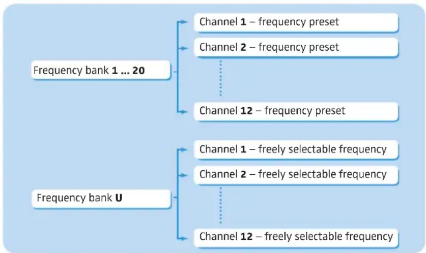
The frequency bank system
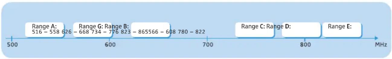
The devices are available in 6 UHF frequency ranges with 1,680 frequencies per frequency range:
line
| Range | Value | |---|---| | Range A: | 516 - 558 626 | | Range G: | 668 734 - 776 823 | | Range B: | 865566 - 608 780 - 822 | | Range C: | Range D | | Range E: | |Each frequency range (A–E, G) offers 21 frequency banks with up to 12 channels each:
flowchart
graph TD
    A["Frequency bank 1 ... 20"] --> B["Channel 1 – frequency preset"]
    A --> C["Channel 2 – frequency preset"]
    A --> D["Channel 12 – frequency preset"]
    E["Frequency bank U"] --> F["Channel 1 – freely selectable frequency"]
    E --> G["Channel 2 – freely selectable frequency"]
    E --> H["Channel 12 – freely selectable frequency"]
Each of the channels in the frequency banks "1" to "20" has been factory-preset to a fixed frequency (frequency preset).
The factory-preset frequencies within one frequency bank are intermodulation-free. These frequencies cannot be changed.
For an overview of the frequency presets, please refer to the supplied frequency information sheet. Updated versions of the frequency information sheet can be downloaded from the corresponding product page on our website at www.sennheiser.com.
The frequency bank "U" allows you to freely select and store frequencies. It might be that these frequencies are not intermodulation-free.
Product overviews
Overview of the EK 100 G3 diversity receiver
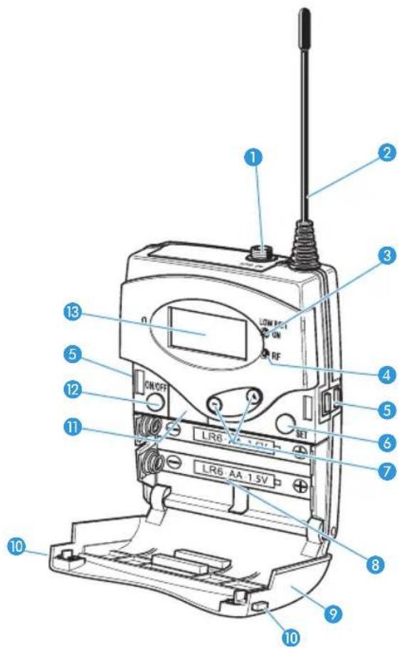
Operating elements
1 3.5 mm jack socket, lockable (AF OUT) (the shielding is used by antenna II)
2 Antenna I
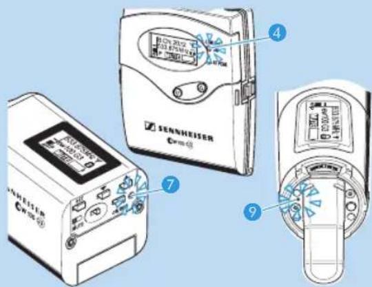
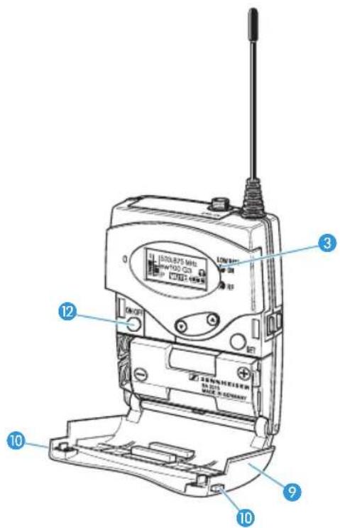
③ Operation and battery status indicator, red LED
(lit = ON/flashing = LOW BATTERY)
4 RF signal indication, green LED (lit = RF)
⑤ Charging contacts
6 SET button
7 ▲/▼ rocker button (UP/DOWN)
8 Battery compartment
9 Battery compartment cover
10 Battery compartment catches
11 Infra-red interface
12 ON/OFF button
(serves as the ESC (cancel) key in the operating menu)
13 Display panel, backlit in orange
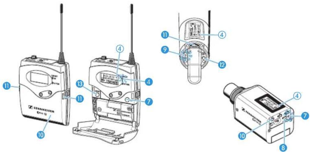
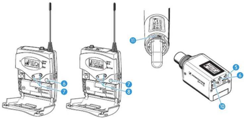
Overview of the SK 100 G3 bodypack transmitter
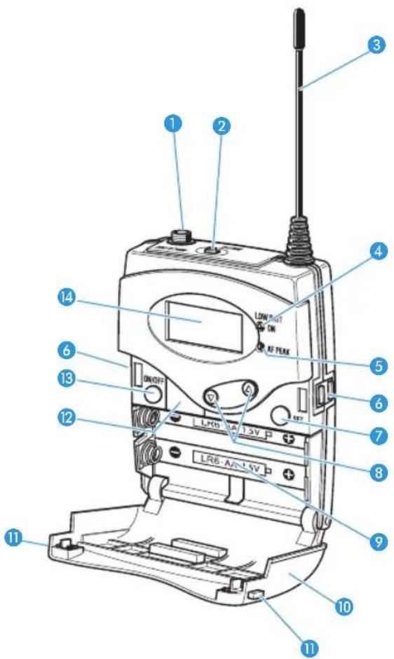
Operating elements
1 Microphone/instrument input (MIC/LINE), 3.5 mm jack socket, lockable
② MUTE switch
3 Antenna
4 Operation and battery status indicator, red LED
(lit = ON/flashing = LOW BATTERY)
5 Audio overmodulation indicator, yellow LED
(lit = AF PEAK)
6 Charging contacts
7 SET button
8 ▲/▼ rocker button (UP/DOWN)
9 Battery compartment
10 Battery compartment cover
11 Battery compartment catches
12 Infra-red interface
13 ON/OFF button,
serves as the ESC (cancel) key in
the operating menu
14 Display panel, backlit in orange
Overview of the SKM 100 G3 radio microphone
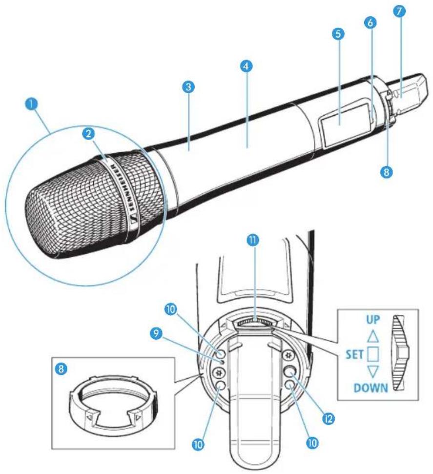
Operating elements
1 Microphone head (interchangeable)
2 Name and pick-up pattern of the microphone head (not visible here)
③ Body of radio microphone
4 Battery compartment (not visible from outside)
5 Display panel, backlit in orange
6 Infra-red interface
7 Antenna
8 Color-coded protection ring; available in different colors
9 Operation and battery status indicator, red LED
(lit = ON/flashing = LOW BATTERY)
10 Charging contacts
11 Multi-function switch:
▼ (DOWN), ▲ (UP) and ■ (SET)
12 ON/OFF button,
serves as the ESC (cancel) key in the
operating menu
Overview of the SKP 100 G3 plug-on transmitter
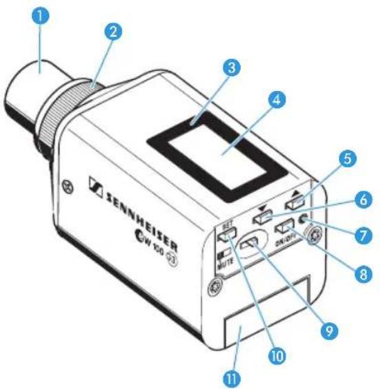
Operating elements
1 Microphone input, XLR-3 socket (female, unbalanced)
② Mechanical locking ring of XLR-3 socket
3 Infra-red interface
4 Display panel, backlit in orange
5 UP button (▲)
6 DOWN button (▼)
7 Operation and battery status indicator, red LED
(lit = ON/flashing = LOW BATTERY)
8 ON/OFF button
(serves as the ESC (cancel) key in the operating menu)
9 MUTE switch
10 SET button
11 Battery compartment cover
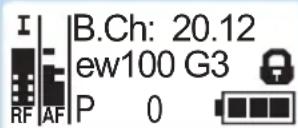
Overview of the displays of the EK 100 G3
After switch-on, the diversity receiver displays the standard display "Frequency/Name". For further illustrations and examples of the different standard displays, refer to page 22.
The display backlighting is automatically reduced after approx. 20 seconds.
| Display Meaning | |
| 1RF level "RF"(Radio Frequency) | Diversity display: Antenna input I is activeAntenna input II is activeRF signal level:Field strength of the received signalSquelch threshold level Antenna input I is activeAntenna input II is activeRF signal level:Field strength of the received signalSquelch threshold level |
| 2Audio level "AF"(Audio Frequency) | Modulation of the transmitterPeak hold functionWhen the display shows full deflection, the audio input level is excessively high. |
| 3Frequency Current receiving frequency | |
| 4Name Freely selectable name of the receiver | |
| 5Lock mode icon Lock mode is activated | |
| 6Battery status Charge status: | |
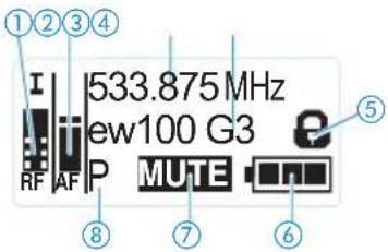
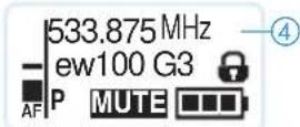
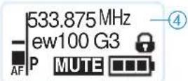
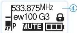
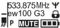
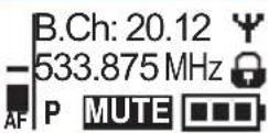
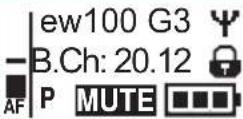
Overview of the displays of the SK 100/SKM 100/SKP 100 G3
After switch-on, the transmitter displays the standard display "Frequency/Name". For further illustrations and examples of the different standard displays, refer to page 22.
The display backlighting is automatically reduced after approx. 20 seconds.
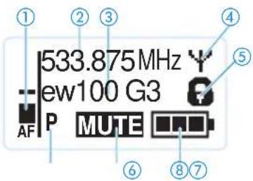
Display Meaning
① Audio level "AF" Modulation of the SK/SKM/SKP 100 G3 with peak hold function.
② Frequency Current transmission frequency
③ Name Freely selectable name of the transmitter
④ Transmission icon RF signal is being transmitted
⑤ Lock mode icon Lock mode is activated
⑥ Pilot tone "P" Pilot tone transmission is activated
⑦ "MUTE" Audio signal is muted
⑧ Battery status Charge status:

approx. 100%

approx. 70%

approx. 30%

Charge status is critical, the red
LOW BATTERY LED 7/4/9 is flashing:
Putting the devices into operation
EK 100 G3 diversity receiver
Inserting the batteries/accupack
For powering the diversity receiver, you can either use two 1.5 V AA size batteries or the rechargeable Sennheiser BA 2015 accupack.
Open the battery compartment by pushing the two catches 10 in the direction of the arrows and open the cover 9.
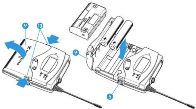
Insert the two batteries or the accupack as shown above. Please observe correct polarity when inserting the batteries/accupack.
Close the battery compartment by pressing on the center of the cover ⑨. The battery compartment cover ⑨ locks into place with an audible click.
Charging the accupack
To charge the BA 2015 accupack:
Insert the diversity receiver into the L 2015 charger (optional accessory).

The L 2015 simultaneously charges up to two devices, e.g. two diversity receivers or one diversity receiver and one SK 100 G3 bodypack transmitter.
The L 2015 charger can only charge the BA 2015 accupack. Standard batteries (primary cells) or individual rechargeable battery cells cannot be charged.
Mounting the diversity receiver to a camera
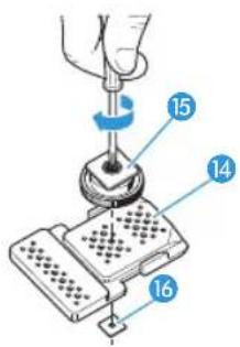
Use the supplied CA 2 camera adapter to mount the receiver to a camera's flash mount.
Determine where on the perforated plate 14 the flash mount adapter 15 will need to be fastened so that the receiver can best be attached to the camera.
At this position, place a square nut 16 under the perforated plate 14.
Fasten the flash mount adapter 15 to the perforated plate 14 using the square nut 16.
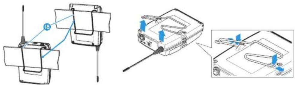
▶ Lift one side of the belt clip 17 as shown.
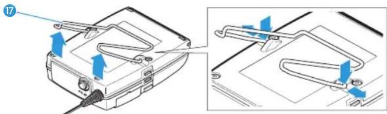
Press down the belt clip 17 at one fixing point and pull it out of the receiver housing.
▶ Repeat for the other side.
Place the perforated plate 14 onto the rear of the receiver.
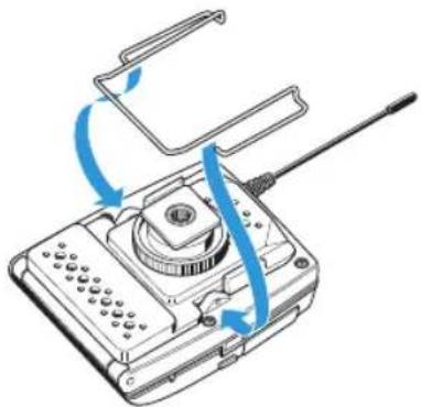
natural_image
Diagram of a handheld electronic device with a central hub and cable, showing blue arrows indicating rotation or movement (no text or symbols present)Reinsert the belt clip 17.
Use one of the supplied line cables to connect the line input of the camera to the socket ①.

The shield of the line cable serves as the antenna for the second diversity section.
SK 100 G3 bodypack transmitter
Inserting the batteries/accupack/Charging the accupack
The procedure is the same as for the EK 100 G3 diversity receiver:
To insert the batteries/accupack:
Read the chapter "Inserting the batteries/accupack" on page 10.
To charge the accupack:
Read the chapter "Charging the accupack" on page 10.
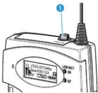
Connecting the microphone cable/line cable
The audio input is designed for the connection of condenser microphones. DC powering of the condenser microphones is via the audio input MIC/LINE 1 (3.5 mm jack socket).
Use one of the recommended Sennheiser microphones or the optional CL 2 line cable.
Connect the 3.5 mm jack plug 15 from the Sennheiser cable to the 3.5 mm jack socket MIC/LINE 1.
Lock the 3.5 mm jack plug by screwing down the coupling ring 16 of the cable.
Via the operating menu, adjust the sensitivity of the microphone/line input.
ME 2/ME 4
natural_image
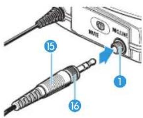
Illustration of a microphone device connected to a small electronic device (no text or symbols present)Attaching and positioning the corresponding microphones
Use the microphone clip 17 to attach the microphone to clothing (e.g. tie, lapel).
The ME 2 clip-on microphone (shown on the right in the diagram) has an omni-directional pick-up pattern. It is therefore not necessary to position it precisely.
▶ Attach the ME 2 microphone as close as possible to the sound source.
The ME 4 clip-on microphone (shown on the left in the diagram) has a cardioid pick-up pattern.
Position the ME 4 microphone so that its sound inlet is directed towards the sound source (e.g. mouth).
Attaching the bodypack transmitter to clothing
You can use the belt clip 18 to attach the bodypack transmitter to clothing (e.g. belt, waistband).
The belt clip is detachable so that you can also attach the transmitter with the antenna pointing downwards. To do so, withdraw the belt clip 18 from its fixing points and attach it the other way round. The belt clip 18 is secured so that it cannot slide out of its fixing points accidentally.
To detach the belt clip:
▶ Lift one side of the belt clip as shown in the diagram on the right-hand side.
Press down the belt clip at one fixing point and pull it out of the transmitter housing.
▶ Repeat for the other side.
SKM 100 G3 radio microphone
▶ Only hold the radio microphone by its body.

natural_image
Illustration of two hands holding microphones with a 'X' and '√' marks, no text or symbols present.
If you touch the antenna of the radio microphone during operation, the transmitter's range will be considerably reduced!
Inserting the batteries/accupack
For powering the radio microphone, you can either use two 1.5 V AA size batteries or the rechargeable Sennheiser BA 2015 accupack.
Unscrew the lower part of the radio microphone from the radio microphone's body ③ by turning it counterclockwise.
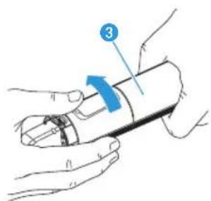

When unscrewing the radio microphone during operation, the muting function is automatically activated. "MUTE" appears on the display panel.
When screwing the lower part of the radio microphone back to the radio microphone's body, the muting is canceled.
natural_image
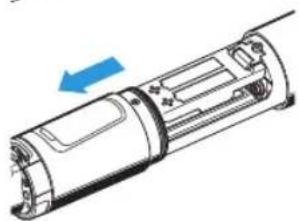
Diagram of a cylindrical device with internal components and a blue arrow indicating direction (no text or symbols)▶ Slide back the lower part of the radio microphone as far as it will go.
Open the battery compartment cover 13 (see page 14).
Insert the batteries or the BA 2015 accupack as shown on the battery compartment cover. Observe correct polarity when inserting the batteries/accupack (see page 14).
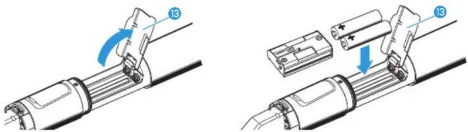
▶ Close the battery compartment cover 13.
Push the battery compartment into the radio microphone's body.
Screw the lower part of the radio microphone back to the radio microphone's body.
Charging the accupack
To charge the radio microphone with the BA 2015 accupack (optional accessory) installed:
Use the LA 2 charging adapter to insert the radio microphone into the L 2015 charger (charger and charging adapter are available as optional accessories).
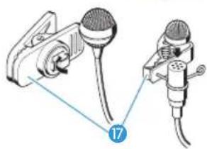
Changing the microphone head
The microphone head 1 is easy to change.
Unscrew the microphone head 1.

natural_image
Illustration of hands holding a microphone with a pen, no text or symbols present
Do not touch the contacts of the radio microphone nor the contacts of the microphone head ①. The contacts can become dirty or damaged if touched.

natural_image
Illustration of two containers with blue X marks above, one containing a glass and the other a woven basket (no text or symbols)When unscrewing the microphone head ① during operation, the muting function is automatically activated. "MUTE" appears on the display panel.
When screwing the microphone head 1 back to the radio microphone, the muting is canceled.
Screw the desired microphone head to the radio microphone.
The radio microphone is operational again.
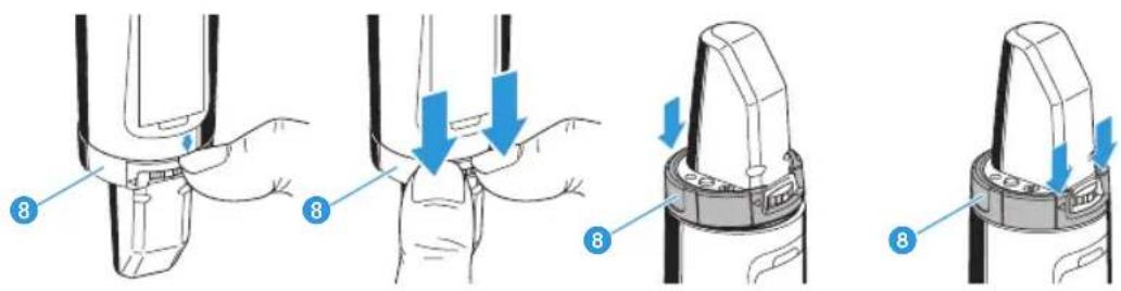
Changing the color-coded protection ring
The color-coded protection ring 8 prevents the multi-function switch 11 from accidental operation. Protection rings in different colors are available as accessories. The protection rings allow you to clearly identify each radio microphone.
Remove the color-coded protection ring as shown in the left-hand diagram.
Put on a new protection ring as shown in the right-hand diagram.
SKP 100 G3 plug-on transmitter
Inserting the batteries/accupack
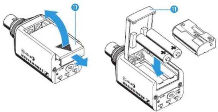
For powering the plug-on transmitter, you can either use two 1.5 V AA size batteries or the rechargeable Sennheiser BA 2015 accupack.
Slide the battery compartment cover 11 in the direction of the embossed arrow and open the cover.
Insert the two batteries or the accupack as shown below. Please observe correct polarity when inserting the batteries/accupack.
▶ Close the battery compartment.
The battery compartment cover 11 locks into place with an audible click.
Charging the accupack
Remove the BA 2015 accupack (optional accessory).
Insert the BA 2015 accupack into the L 2015 charger (accupack and charger are optional accessories):

The L 2015 charger can only charge the BA 2015 accupack. Standard batteries (primary cells) or individual rechargeable battery cells cannot be charged.
Plugging the plug-on transmitter onto a microphone
Plug the microphone's XLR-3M socket onto the transmitter's XLR-3F socket 1.
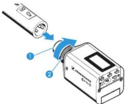
▶ Tighten the locking ring ② in the direction of the arrow.

The transmitter uses the microphone body as an antenna – therefore microphones with a metal casing should be used for best signal transmission.
Using the devices
To establish a transmission link, proceed as follows:
- Switch the diversity receiver on.
- Switch a transmitter on.
The transmission link is established and the diversity receiver's RF level display "RF" reacts.
If you cannot establish a transmission link between transmitter and diversity receiver:
Make sure that transmitter and diversity receiver are set to the same frequency bank and to the same channel.
If necessary, read the chapter "If a problem occurs ..." on page 29.

It is vital to observe the following notes:
▶ Make sure that the desired frequencies are listed in the enclosed frequency information sheet.
Make sure that the desired frequencies are approved and legal in your country and, if necessary, apply for an operating license.
Switching the devices on/off
EK 100 G3 diversity receiver
To switch the diversity receiver on:
▶ Push the two battery compartment catches 10 and open the battery compartment cover 9.
Press the ON/OFF button 12.
The red ON LED ③ lights up and the standard display "Frequency/Name" appears on the display panel.
To switch the diversity receiver off:
Press the ON/OFF button 12 until "OFF" appears on the display panel.
The red ON LED ③ goes off and the diversity receiver switches off.

When in the operating menu, pressing the ON/OFF button 12 will cancel your entry (ESC function) and return you to the current standard display.
SK 100 G3 bodypack transmitter, SKM 100 G3 radio microphone and SKP 100 G3 plug-on transmitter
To switch your transmitter on (online operation):
SK 100 G3 SKM 100 G3 SKP 100 G3
▶ Push the two catches 11 and open the battery compartment cover 10.
Briefly press the ON/OFF button ⑬. The bodypack transmitter transmits an RF signal.
The red ON LED ④ lights up and the standard display "Frequency/Name" appears on the display panel. The transmission icon ④ is displayed.
Briefly press the ON/OFF button 12.
The radio microphone transmits an RF signal.
The red ON LED 9 lights up and the standard display "Frequency/
Name" appears on the display panel. The transmission icon ④ is displayed.
Briefly press the ON/OFF button 8.
The plug-on transmitter transmits an RF signal.
The red ON LED 7 lights up and the standard display "Frequency/
Name" appears on the display panel. The transmission icon ④ is displayed.

You can switch your transmitter on and deactivate the RF signal on switch-on. For more information, refer to page 19.
To switch your transmitter off:
If necessary, deactivate the lock mode (see page 20).
Press the ON/OFF button 13 until "OFF" appears on the display panel.
The display panel turns off. The red ON LED 4 goes off.
Press the ON/OFF button 12 until "OFF" appears on the display panel.
The display panel turns off. The red ON LED goes off.
Press the ON/OFF button 8 until "OFF" appears on the display panel.
The display panel turns off. The red ON LED 7 goes off.

When in the operating menu, pressing the ON/OFF button will cancel your entry (ESC function) and return you to the current standard display.
To switch your transmitter on and to deactivate the RF signal on switch-on (offline operation): SK 100 G3 SKM 100 G3 SKP 100 G3
Keep the ON/OFF button 13 pressed until "RF Mute On?" appears on the display panel.
Press the SET button 7.
Keep the ON/OFF button 12 pressed until "RF Mute On?" appears on the display panel.
▶ Press the multi-function switch 11.
Keep the ON/OFF button ⑧ pressed until "RF Mute On?" appears on the display panel.
Press the SET button 10.
The transmission frequency is displayed but the transmitter does not transmit an RF signal.
The transmission icon ④ is not displayed.

Use this function to save battery power or to prepare a transmitter for use during live operation without causing interference to existing transmission links.
To activate the RF signal:
Briefly press the ON/OFF button 13. "RF Mute Off" appears on the display panel.
Press the SET button 7. The transmission icon ④ is displayed again.
Briefly press the ON/OFF button 12. "RF Mute Off" appears on the display panel.
Press the multi-function switch 11. The transmission icon ④ is displayed again.
Briefly press the ON/OFF button 8. "RF Mute Off" appears on the display panel.
Press the SET button 10. The transmission icon ④ is displayed again.

Synchronizing a transmitter with the diversity receiver
You can synchronize a suitable transmitter of the ew 100 G3 series with the diversity receiver. During synchronization, the following parameters are transferred to the transmitter:
| Setting Transferred parameters | |
| "Frequency Preset" | Currently set frequency |
| "Name" Freely selectable name currently set on the receiver | |
| "Pilot Tone" | Current pilot tone setting of the receiver ("Inactive"/"Active") |
To transfer the parameters:
▶ Switch the transmitter and the diversity receiver on.
On the receiver, call up the "Sync" menu item. "Sync" appears on the display panel of the diversity receiver.
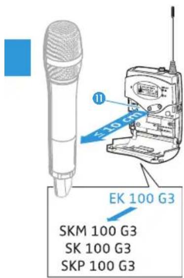
Place the infra-red interface of the transmitter (see page 5 to page 7) in front of the infra-red interface of the diversity receiver 11.
The parameters are transferred to the transmitter. When the transfer is completed, "√" appears on the display panel of the diversity receiver. The receiver then switches back to the current standard display.
To cancel the transfer:
Press the ON/OFF button 12 on the diversity receiver.
"X" appears on the display panel of the receiver. "X also appears if no suitable transmitter was found (wrong frequency range/wrong generation).
Deactivating the lock mode temporarily
You can activate or deactivate the automatic lock mode via the "Auto Lock" menu item (see page 23). If the lock mode is activated, you have to temporarily deactivate it In order to be able to operate the devices:
EK 100 G3/SK 100 G3 SKM 100 G3 SKP 100 G3
▶ Press the SET button 6 (EK) or 7 (SK).
▶ Press the multi-function switch 11.
▶ Press the SET button 10.
"Locked" appears on the display panel.
▶ Press the rocker button 7 (EK) or 8 (SK).
Move the multi-function switch 11 upwards/downwards.
▶ Press the UP button 5/ DOWN button 6.
"Unlock?" appears on the display panel.
▶ Press the SET button 6 (EK) or 7 (SK).
▶ Press the multi-function switch 11.
▶ Press the SET button 10.
The lock mode is temporarily deactivated.
How you are using the devices determines how long the lock mode remains deactivated:
When you are in the operating menu
The lock mode remains deactivated until you exit the operating menu.
When one of the standard displays is shown
The lock mode is automatically activated after 10 seconds.
The lock mode icon flashes prior to the lock mode being activated again.
Muting the audio signal or deactivating the RF signal

You can deactivate the RF signal of the transmitters (SKM 100 G3, SK 100 G3, SKP 100 G3) on switch-on. For more information, refer to the chapter "Switching the devices on/off" on page 17.
Using the ON/OFF button, you can also activate/deactivate the transmitters' RF signal during operation. To do so, briefly press the ON/OFF button and proceed as described on page 19.
SK 100 G3/SKP 100 G3
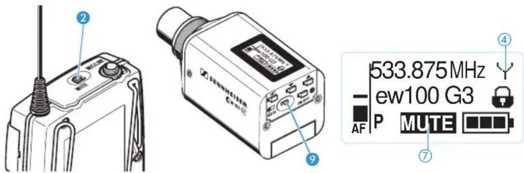
The MUTE switch ② (SK)/⑨ (SKP) allows you to mute the audio signal or to deactivate the RF signal. Via the "Mute Mode" menu item, you can set the desired function of the MUTE switch ② (SK)/⑨ (SKP):
| Setting | Slide the MUTE switch 2 / 9 ... | Function |
| "AF On/Off" | ... to the left (position MUTE) | Mutes the audio signal |
| ... to the right Unmutes the audio signal | ||
| "RF On/Off" | ... to the left (position MUTE) | Deactivates the RF signal (offline operation) |
| ... to the right Activates the RF signal (online operation) | ||
| "Disabled" No function | ||
From the "Mute Mode" menu item, select the desired setting (see page 25).
Exit the operating menu.
Slide the MUTE switch ② (SK)/ ⑨ (SKP) to the left, to the position MUTE. The transmitter reacts as indicated in the table.
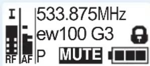
The current state of the muting function or the RF signal is displayed on the display panel of the transmitter:
| Audio signal is muted | |
| Transmitter's display panel: | "MUTE" 7 is displayed |
| Audio signal is activated (muting is canceled) | |
| Transmitter's display panel: | "MUTE" 7 is not displayed |
| RF signal is deactivated | |
| Transmitter's display panel: | Transmission icon 4 is not displayed, "MUTE" 7 is displayed |
| RF signal is activated | |
| Transmitter's display panel: | Transmission icon 4 is displayed, "MUTE" 7 is not displayed |
Selecting a standard display
EK 100 G3
ON/OFF
▶ Briefly press the ON/OFF button to select a standard display.

Contents of the display Selectable standard display
"Frequency/Name" with "MUTE" display ⑦
"Frequency bank/Channel/Name" with display of the line output level "AF OUT" ⑦
SK 100/SKM 100/SKP 100 G3
To select a standard display:
| SK 100 G3 | SKM 100 G3 | SKP 100 G3 |
| Press the rocker button. | Move the multi-function switch. | Press the UP button/DOWN button. |
| Contents of the display Selectable standard display | ||
 | "Frequency/Name" | |
 | "Channel/Frequency" | |
 | "Name/Channel" | |
Overview of the operating menus

For more detailed information on the operating menus, refer to the individual instruction manuals of the devices. These instruction manuals can be downloaded from the corresponding product pages at www.sennheiser.com.
EK 100 G3
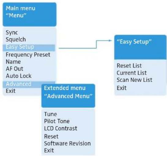
flowchart
graph TD
    A["Main menu "Menu""] --> B["Easy Setup"]
    B --> C["Reset List\nCurrent List\nScan New List\nExit"]
    A --> D["Extended menu "Advanced Menu""]
    D --> E["Tune\nPilot Tone\nLCD Contrast\nReset\nSoftware Revision\nExit"]
    A --> F["Sync\nSquelch\nEasy Setup\nFrequency Preset\nName\nAF Out\nAuto Lock\nAdvanced\nExit"]
When one of the standard displays is shown on the display panel, you can get into the main menu by pressing the SET button 6. The extended menu "Advanced Menu" and the "Easy Setup" menu can be accessed via the corresponding menu items.
| Display Function of the menu item | |
| Main menu “Menu” | |
| Sync Synchronizes a transmitter with the diversity receiver | |
| Squelch Adjusts the squelch threshold | |
| Adjustment range: “Low”, “Middle”, “High”, can be switched offSpecial function (for servicing purposes only): With the squelch threshold set to “Low”, you switch the squelch off by keeping theDOWN rocker button7pressed for 3 seconds. If you then press theUPbutton7, you switch the squelch on again. | |
| Easy Setup Scans for unused frequency presets, releases and selects frequency presets | |
| Frequency Preset Changes the frequency bank and the channel | |
| Name Enters a freely selectable name | |
| AF Out Adjusts the audio output level | |
| Adjustment range: -30 dB to +12 dB, adjustable in steps of 6 dB | |
| Auto Lock Activates/deactivates the automatic lock mode | |
| Advanced | Calls up the extended menu “Advanced Menu” |
| Exit Exits the operating menu and returns to the current standard display | |
| “Easy Setup” | |
| Reset List Releases all locked frequency presets | |
| Current List Selects an unused frequency preset | |
| Scan New List | Automatically scans for unused receiving frequencies (frequency preset scan) |
| Exit | Exits the menu “Easy Setup” menu and returns to the main menu |
| Extended menu “Advanced Menu” | |
| Tune | Sets the receiving frequencies for the frequency bank “U” |
| Sets a channel and a receiving frequency for the frequency bank “U”:Select this menu item and call it up by pressing theSETbutton6until the channel selection appears. | |
| Pilot Tone | Activates/deactivates the pilot tone evaluation |
| LCD Contrast | Adjusts the contrast of the display panel |
| Reset | Resets the diversity receiver |
| Software Revision | Displays the current software revision |
| Exit | Exits the extended menu “Advanced Menu” and returns to the main menu |
SK 100/SKM 100/SKP 100 G3
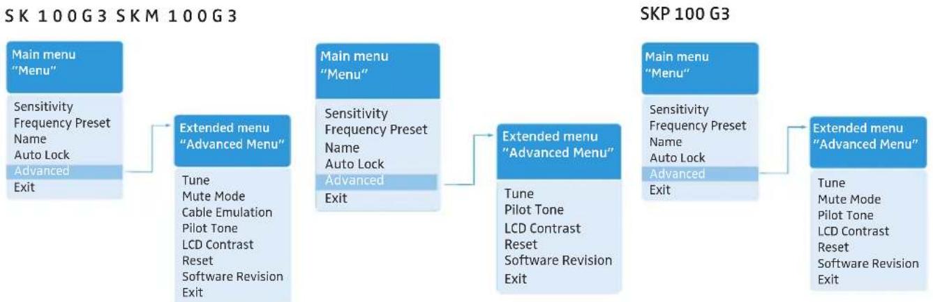
flowchart
graph LR
    A["Main menu "Menu""] --> B["Extended menu "Advanced Menu""]
    B --> C["Main menu "Menu""]
    C --> D["Extended menu "Advanced Menu""]
    D --> E["Main menu "Menu""]
    E --> F["Extended menu "Advanced Menu""]

    subgraph SK 100G3
        A -->|Sensitivity, Frequency Preset, Name, Auto Lock, Advanced Exit| B
        B -->|Tune, Mute Mode, Cable Emulation, Pilot Tone, LCD Contrast, Reset, Software Revision Exit| C
        C -->|Sensitivity, Frequency Preset, Name, Auto Lock, Advanced Exit| D
        D -->|Tune, Pilot Tone, LCD Contrast, Reset, Software Revision Exit| E
        E -->|Sensitivity, Frequency Preset, Name, Auto Lock, Advanced Exit| F
    end

    subgraph SKP 100G3
        E -->|Tune, Mute Mode, Pilot Tone, LCD Contrast, Reset, Software Revision Exit| F
    end
Display Function of the menu item
| Main menu “Menu” | |
| Sensitivity | Adjusts the sensitivity “AF” |
| Frequency Preset Changes the frequency bank and the channel | |
| Name Enters the transmitter name | |
| Auto Lock Activates/deactivates the automatic lock mode | |
| Advanced | Calls up the extended menu “Advanced Menu” |
| Exit Exits the operating menu and returns to the current standard display | |
| Extended menu “Advanced Menu” | |
| Tune | Sets the transmission frequencies for the frequency bank “U”Sets a channel and a transmission frequency for the frequency bank “U”Select this menu item and call it up by pressing the SET button (SK, SKP)/the multi-function switch (SKM) until the channel selection appears. |
| Mute Mode (SK, SKP only) | Sets the mode for the MUTE switch |
| Cable Emulation (SK only) | Emulates guitar cable capacities |
| Pilot Tone | Activates/deactivates the pilot tone transmission |
| LCD Contrast | Adjusts the contrast of the display panel |
| Reset | Resets the transmitter |
| Software Revision | Displays the current software revision |
| Exit | Exits the extended menu “Advanced Menu” and returns to the main menu |
Synchronizing transmitters with diversity receivers
When synchronizing transmitters with diversity receivers, please observe the following:
Make sure that the desired frequencies are listed in the enclosed frequency information sheet. OR:
Contact your Sennheiser partner who will be pleased to calculate intermodulation-free frequencies for you.
▶ Make sure that the desired frequencies are approved and legal in your country and, if necessary, apply for an operating license.
Upon delivery, transmitter and diversity receiver are synchronized with each other. If, however, you cannot establish a transmission link between transmitter and diversity receiver, you have to synchronize the channels of the devices:
▶ Deactivate the RF signal on all transmitters (see page 21).
This prevents that, during the frequency scan, the channels used by switched-on transmitters are displayed as "used".
With a diversity receiver, perform a frequency preset scan to scan the frequency banks for unused channels ("Scan New List", see page 24).
▶ Select a frequency bank and a channel on this diversity receiver ("Current List", see page 24).
If you want to set up a multi-channel system, select a frequency bank with a sufficient number of unused channels for all planned transmission links.
▶ Synchronize a transmitter with the diversity receiver (see page 19).
The receiver's frequency, name and pilot tone setting are transferred to the transmitter. OR:
Manually set the transmitter to the same frequency bank and channel that you set on the receiver.
▶ Activate the RF signal on the transmitter.
The transmission link is established.
If you want to set up a multi-channel system:
▶ Repeat the following 4 steps for each additional transmission link:
- Perform a frequency preset scan with the next diversity receiver.
- Select a channel from the same frequency bank as with the first diversity receiver.
– Synchronize a transmitter with the diversity receiver. - Activate the RF signal on the transmitter.
Using freely selectable frequencies
You can also freely select the receiving frequencies and store these frequencies in the frequency banks "U".

It might be that the freely selected frequencies are not intermodulation-free
If you use frequencies from the frequency bank "U", it might be that the frequencies are not intermodulation-free.
Contact your Sennheiser partner who will be pleased to calculate intermodulation-free frequencies for you (see www.sennheiser.com).
Set each diversity receiver to the frequency bank "U".
On one of the receivers, select a channel within this frequency bank and assign this channel one of the calculated receiving frequencies ("Tune", see page 24).
Synchronize a transmitter with this receiver (see page 19).
OR:
Manually set the transmitter to the same frequency bank and channel that you set on the receiver.
▶ Repeat for the remaining transmitters and receivers as described above.
Cleaning the devices
CAUTION! Liquids can damage the electronics of the devices!
Liquids entering the housing of the devices can cause a short-circuit and damage the electronics.
▶ Keep all liquids away from the devices.
Use a cloth to clean the devices from time to time. Do not use any solvents or cleansing agents.
SKM 100 G3
To clean the radio microphone's sound inlet basket:
Unscrew the upper sound inlet basket from the microphone head by turning it counterclockwise.
CAUTION! Liquids can damage the microphone head!
Liquids can damage the microphone head.
▶ Only clean the upper sound inlet basket.
Remove the foam insert.
There are two ways to clean the sound inlet basket:
- Use a cloth to clean the upper sound inlet basket from the inside and outside
- or scrub with a brush and rinse with clear water.
If necessary, clean the foam insert with a mild detergent or replace the foam insert.
Dry the upper sound inlet basket.
Dry the foam insert.
▶ Reinsert the foam insert.
Replace the sound inlet basket on the microphone head and screw it tight.
You should also clean the contact rings of the microphone head from time to time:
Wipe the contact rings of the microphone head with a cloth.
If a problem occurs ...
EK 100 G3
| Problem Possible cause Possible solution | |||
| Diversity receiver cannot be operated, “Locked” appears on the display panel | Lock mode is activated Deactivate the lock mode (see page 20). | ||
| No operation indication | Batteries are flat or accupack is flat | Replace the batteries or recharge the accupack (see page 10). | |
| No RF signal Transmitter and receiver are not on the same channel | Set the transmitter and receiver to the same channel. | ||
| Synchronize the transmitter with the receiver (see page 19). | |||
| Transmission range is exceeded Reduce the distance between receiver and transmitter. | |||
| RF signal is deactivated (“RF Mute”) | Activate the RF signal (see page 21). | ||
| RF signal available, no audio signal, “MUTE” appears on the display panel | Transmitter is muted Cancel the muting (see page 21). | ||
| Receiver’s squelch threshold is adjusted too high | Reduce the squelch threshold setting on the receiver (see page 24). | ||
| Transmitter doesn’t transmit a pilot tone | Deactivate the pilot tone evaluation (see page 24). | ||
| Audio signal has a high level of background noise | Transmitter sensitivity is adjusted too low | Adjust the transmitter sensitivity correctly (“Sensitivity”, see page 25). | |
| Audio signal is distorted Transmitter sensitivity is adjusted too high | Adjust the transmitter sensitivity correctly (“Sensitivity”, see page 25). | ||
| Receiver’s audio output level is adjusted too high | |||
| No access to a certain channel | During scanning, an RF signal has been detected on this channel and the channel has been locked | Set the transmitter operating on this channel to a different channel and redo the frequency preset scan (see page 24). | |
| During scanning, a transmitter of your system operating on this channel has not been switched off | Switch the transmitter off and redo the frequency preset scan (see page 24). | ||
SK 100/SKM 100/SKP 100 G3
| Problem Possible cause Possible solution | ||
| Transmitter cannot be operated, “Locked” appears on the display panel | Lock mode is activated Deactivate the lock mode (see page 20). | |
| No operation indication | Batteries are flat or accupack is flat | Replace the batteries or recharge the accupack (see page 13). |
| No RF signal at the receiver | Transmitter and receiver are not on the same channel | Synchronize the transmitter with the receiver (see page 19).Set the transmitter to the same channel as the receiver. |
| Transmission range is exceeded Reduce the distance between receiver and transmitter. | ||
| RF signal is deactivated (“RF Mute”) | Activate the RF signal (see page 21). | |
| RF signal available, no audio signal, “MUTE” appears on the display panel | Transmitter is muted (MUTE) | Cancel the muting (see page 21). |
| Receiver’s squelch threshold is adjusted too high | Reduce the squelch threshold setting on the receiver. | |
| Transmitter doesn’t transmit a pilot tone | Activate or deactivate the pilot tone transmission (see page 25). | |
| Audio signal has a high level of background noise or is distorted | Transmitter’s sensitivity is adjusted too low/too high | Adjust the input sensitivity (see page 25). |
If a problem occurs that is not listed in the above table or if the problem cannot be solved with the proposed solutions, please contact your local Sennheiser partner for assistance. To find a Sennheiser partner in your country, search at www.sennheiser.com under "Service & Support".
Specifications
System
Modulation wideband FM
Frequency ranges 516–558, 566–608, 626–668, 734–776,
780–822, 823–865 MHz (A to E, G, see page 3)
Frequencies 1,680 frequencies, tuneable in steps of 25 kHz
20 frequency banks, each with up to 12 factory-preset channels
1 frequency bank with up to 12 user programmable channels
Switching bandwidth 42 MHz
Frequency stability ±10 ppm ( -10^ C to +55^ C)
Compander system Sennheiser HDX
Nominal/peak deviation ±24 kHz/±48 kHz
Pilot tone (frequency/deviation) 32.7665 kHz/±2 kHz
THD ≤ 0.9%
Temperature range -10^ to +55^
EK 100 G3
Receiver principle adaptive diversity
Sensitivity
(with HDX, peak deviation)
Adjacent channel rejection
Intermodulation attenuation
Blocking
Squelch
Pilot tone squelch
S/N ratio (1 mV, peak deviation)
AF output voltage
(at peak deviation, 1 kHz AF)
Adjustment range of audio output level ("AF Out")
Power supply
Nominal voltage
Power consumption:
- at nominal voltage
• with switched-off diversity receiver
Operating time
Dimensions
Weight (incl. batteries)
< 1.6 μV for 52 dBA _rms S/N
typ. ≥ 65 dB
typ. ≥ 65 dB
≥ 70 dB
Off, Low: 5 dBμV, Middle: 15 dBμV, High: 25 dBμV
can be switched off
≥ 60 dB
3.5 mm jack socket: +11 dBu (mono, unbalanced)
42 dB, adjustable in steps of 6 dB
2 AA size batteries, 1.5 V or BA 2015 accupack
2.4 V ---
typ. 140 mA
≤ 25 μA
typ. 8 hrs
approx. 82 x 64 x 24 mm
approx. 120 g
In compliance with
Europe
USA

EMC EN 301489-1/-9
Radio EN 300422-1/-2
Security EN 60065

47 CFR 15 subpart B
Approved by
Canada Industry Canada RSS 123
IC 2099A-G3EK100
limited to 806 MHz
SK 100/SKM 100/SKP 100 G3
RF output power at 50 Ω typ. 30 mW
Pilot tone squelch can be switched off
AF frequency response
SK microphone: 80–18,000 Hz
SKM/SKP 80–18,000 Hz
Signal-to-noise ratio (1 mV RF, peak deviation)
SK/SKM/SKP ≥ 110 dBA
Max. input voltage (SK) microphone/line 3 V
Max. input voltage (SKP) 3.3 V
Input impedance SK microphone/line
Input impedance SKP 60 kΩ, unbalanced
Input capacitance SK switchable
Adjustment range of input sensitivity SK: 60 dB, adjustable
Power supply 2 AA size batteries, 1.5 V
Nominal voltage 2.4 V
Current consumption
at nominal voltage typ. 180 mA
with switched-off transmitter
Operating time
Dimensions SK: approx. 82 x 64 x 24 mm
Weight (incl. batteries)
line: 25–18,000 Hz
rms
rms
40 kΩ, unbalanced/1 MΩ
in steps of 3 dB
SKM, SKP: 48 dB, adjustable in steps of 6 dB
or BA 2015 accupack
≤ 25 μA
typ. 8 hrs
SKM: approx. ∅ 50 x 265 mm
SKP: approx. 105 x 43 x 43 mm
SK: approx. 160 g
SKM: approx. 450 g
SKP: approx. 195 g
In compliance with (SK, SKM and SKP 100 G3)
Europe

EMC EN 301489-1/-9
Radio EN 300422-1/-2
Security EN 60065, EN 62311 (SAR)
Approved by (SK, SKM and SKP 100 G3)
| SK 100 G3 SKM 100 G3 SKP 100 G3 | |||
| Canada Industry | Canada RSS 123,IC: 2099A-G3SKlimited to 806 MHz | Industry Canada RSS 123,IC: 2099A-G3SKMEMlimited to 806 MHz | Industry Canada RSS 123,IC: 2099A-G3SKPlimited to 806 MHz |
| USA FCC-Part 74, | FCC-ID: DMO G3SKlimited to 698 MHz | FCC-Part 74,FCC-ID: DMO G3SKMEMlimited to 698 MHz | FCC-Part 74,FCC-ID: DMOG3SKPlimited to 698 MHz |

For accessories and information on connector assignment, visit the ew G3 product page at www.sennheiser.com.
Microphones (SK 100 G3)
| ME 2 ME 4 | ||
| Microphone type condenser condenser | ||
| Sensitivity 20 mV/Pa 40 mV/Pa | ||
| Pick-up pattern | omni-directional | cardioid |
| Max. SPL | 130 dB SPL | 120 dB SPL |
MMD 835-1 microphone head (SKM 100 G3)
| MMD 835-1 | |
| Microphone type | dynamic |
| Sensitivity | 2.1 mV/Pa |
| Pick-up pattern | cardioid |
| Max. SPL | 154 dB SPL |
Polar diagram and frequency response curve of the MMD 835-1 microphone head (SKM 100 G3)
Polar diagram MMD 835-1
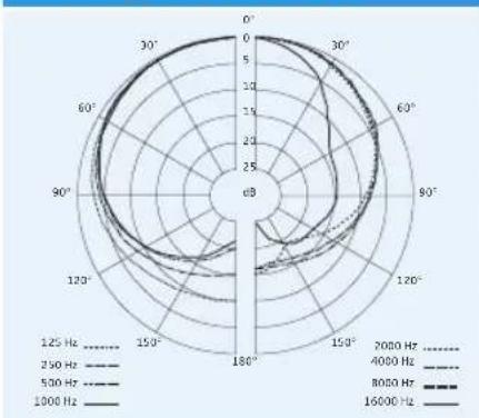
radar
| Frequency (Hz) | Value | |---|---| | 250 | 1.0 | | 500 | 1.2 | | 8000 | 1.4 | | 16000 | 1.6 |Frequency response curve MMD 835-1
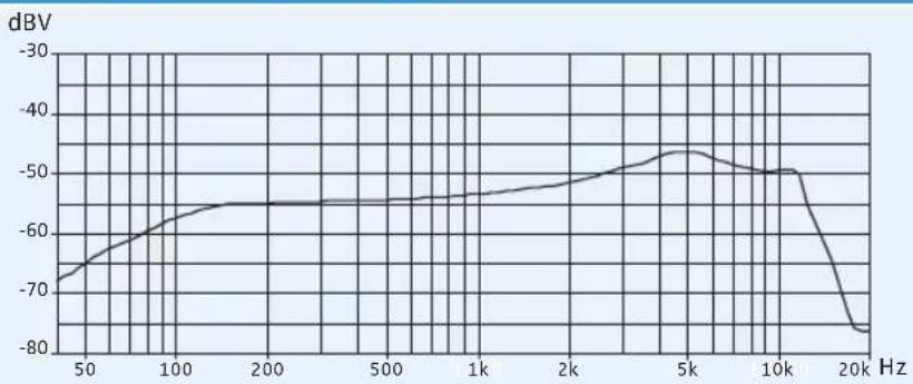
line
| Frequency (Hz) | dBV | | -------------- | ------ | | 50 | -70 | | 100 | -60 | | 200 | -55 | | 500 | -55 | | 1k | -55 | | 2k | -50 | | 5k | -45 | | 10k | -50 | | 20k | -80 |Manufacturer Declarations
Warranty
Sennheiser electronic GmbH & Co. KG gives a warranty of 24 months on this product.
For the current warranty conditions, please visit our web site at www.sennheiser.com or contact your Sennheiser partner.
In compliance with the following requirements
• RoHS Directive (2002/95/EC)
• WEEE Directive (2002/96/EC)

Please dispose of these products at the end of their operational lifetime by taking them to your local collection point or recycling center for such equipment.
• Battery Directive (2006/66/EC)

The supplied batteries or rechargeable batteries can be recycled. Please dispose of them as special waste or return them to your specialist dealer. In order to protect the environment, only dispose of exhausted batteries.
CE Declaration of Conformity
• EK 100 G3: SK/068M / SKP 100 G3: C€0682
• R&TTE Directive (1999/5/EC)
The declarations are available at www.sennheiser.com.
Before putting the devices into operation, please observe the respective country-specific regulations.
Statements regarding FCC and Industry Canada
These devices comply with Part 15 of the FCC Rules and with RSS-210 of Industry Canada. Operation is subject to the following two conditions: (1) these devices may not cause harmful interference, and (2) these devices must accept any interference received, including interference that may cause undesired operation.
This equipment has been tested and found to comply with the limits for a Class B digital device, pursuant to Part 15 of the FCC Rules. These limits are designed to provide reasonable protection against harmful interference in a residential installation. This equipment generates, uses and can radiate radio frequency energy and, if not installed and used in accordance with the instructions, may cause harmful interference to radio communications. However, there is no guarantee that interference will not occur in a particular installation. If this equipment does cause harmful interference to radio or television reception, which can be determined by turning the equipment off and on, the user is encouraged to try to correct the interference by one or more of the following measures:
- Reorient or relocate the receiving antenna.
- Increase the separation between the equipment and receiver.
- Connect the equipment into an outlet on a circuit different from that to which the receiver is connected.
- Consult the dealer or an experienced radio/TV technician for help.
These class B digital devices comply with the Canadian ICES-003.
Changes or modifications made to this equipment not expressly approved by Sennheiser electronic Corp. may void the FCC authorization to operate this equipment.
Before putting the devices into operation, please observe the respective country-specific regulations!
Sennheiser electronic GmbH & Co. KG Am Labor 1, 30900 Wedemark, Germany www.sennheiser.com
Printed in Germany Publ. 01/09 529660/A01

- Important safety instructions
- Intended use
- The ew 100 G3 evolution wireless series
- Adaptive diversity
- The frequency bank system
- Product overviews
- Operating elements
- Overview of the SK 100 G3 bodypack transmitter
- Overview of the SKP 100 G3 plug-on transmitter
- Overview of the displays of the EK 100 G3
- Overview of the displays of the SK 100/SKM 100/SKP 100 G3
- Display Meaning
- Putting the devices into operation
- EK 100 G3 diversity receiver
- Inserting the batteries/accupack
- Charging the accupack
- Mounting the diversity receiver to a camera
- SK 100 G3 bodypack transmitter
- Inserting the batteries/accupack/Charging the accupack
- Connecting the microphone cable/line cable
- Attaching and positioning the corresponding microphones
- Attaching the bodypack transmitter to clothing
- SKM 100 G3 radio microphone
- Changing the microphone head
- Changing the color-coded protection ring
- SKP 100 G3 plug-on transmitter
- Plugging the plug-on transmitter onto a microphone
- Using the devices
- Switching the devices on/off
- SK 100 G3 SKM 100 G3 SKP 100 G3
- To activate the RF signal:
- Synchronizing a transmitter with the diversity receiver
- Deactivating the lock mode temporarily
- EK 100 G3/SK 100 G3 SKM 100 G3 SKP 100 G3
- When you are in the operating menu
- When one of the standard displays is shown
- Muting the audio signal or deactivating the RF signal
- Selecting a standard display
- Contents of the display Selectable standard display
- SK 100/SKM 100/SKP 100 G3
- Overview of the operating menus
- EK 100 G3
- Synchronizing transmitters with diversity receivers
- Using freely selectable frequencies
- Cleaning the devices
- CAUTION! Liquids can damage the electronics of the devices!
- SKM 100 G3
- CAUTION! Liquids can damage the microphone head!
- If a problem occurs ...
- Specifications
- System
- In compliance with
- Approved by
- Manufacturer Declarations
- Warranty
- In compliance with the following requirements
- CE Declaration of Conformity
- Statements regarding FCC and Industry Canada
Brand : SENNHEISER
Model : EW 100 ENG G3-G
Category : Receiver