 — Dictaphone — Mode d'emploi PDF")
VR-N1600E(A) - Dictaphone JVC - Free user manual and instructions
Find the device manual for free VR-N1600E(A) JVC in PDF.

| Product Type | Network Video Recorder (NVR) |
| Brand | JVC |
| Model | VR-N1600E(A) |
| Dimensions (W x D x H) | 420 x 350 x 88 mm |
| Weight | Approx. 7.8 kg |
| Power Supply | AC 220-240 V, 50/60 Hz, 0.8 A |
| Operating Temperature | 5 °C to 40 °C |
| Storage Temperature | -20 °C to 60 °C |
| Operating Humidity | 30% to 80% (no condensation) |
| Video Compression | JPEG / MPEG-4 |
| Audio Compression | μ-law (64 kbps), A/D 8 bits, Fs = 8 kHz |
| Built-in HDD Capacity | 500 GB (1 unit) |
| HDD Expansion | Internal: up to 500 GB additional; External: up to 2 TB via USB |
| Recording Performance | Up to 16 channels at 160 ips (JPEG VGA 24 KB); up to 240 ips when NVR Viewer not started; up to 32 channels with additional licenses |
| Display/Playback Performance | Up to 160 ips (live), 80 ips (VR-N1600U/E) or 160 ips (A) |
| Network Interfaces | LAN1 (camera): 1000BASE-T/100BASE-TX/10BASE-T; LAN2 (Intranet): same |
| Video Output | VGA: up to 1600 x 1200 |
| Audio Input / Output | 2 x RCA (unbalanced, -8 dBs, 50 kΩ) / 1 x RCA (600 Ω) |
| Alarm I/O | 8 alarm inputs, 1 emergency, 5 outputs |
| RAID Support | RAID1 (mirroring) with additional HDD |
| Special Features | Motion detection, alarm email notification, power failure recovery, bidirectional audio, PTZ control, scheduler |
Frequently Asked Questions - VR-N1600E(A) JVC
User questions about VR-N1600E(A) JVC
0 question about this device. Answer the ones you know or ask your own.
Ask a new question about this device
Download the instructions for your Dictaphone in PDF format for free! Find your manual VR-N1600E(A) - JVC and take your electronic device back in hand. On this page are published all the documents necessary for the use of your device. VR-N1600E(A) by JVC.
USER MANUAL VR-N1600E(A) JVC
Please read the following before getting started:
Thank you for purchasing this JVC product.
Before operating this unit, please read the instructions carefully to ensure the best possible performance.
For Customer Use:
Enter below the Serial No. which is located on the body.
Retain this information for future reference.
Model No. VR-N1600U/VR-N900U
Serial No.
Powered by Milestone
-
Read all of these instructions.
-
Save these instructions for later use.
-
All warnings on the product and in the operating instructions should be adhered to.
-
Unplug this appliance system from the wall outlet before cleaning. Do not use liquid cleaners or aerosol cleaners. Use a damp cloth for cleaning.
-
Do not use attachments not recommended by the appliance manufacturer as they may cause hazards.
-
Do not use this appliance near water - for example, near a bathtub, washbowl, kitchen sink, or laundry tub, in a wet basement, or near a swimming pool, etc.
-
Do not place this appliance on an unstable cart, stand, or table. The appliance may fall, causing serious injury to a child or adult, and serious damage to the appliance. Use only with a cart or stand recommended by the manufacturer, or sold with the appliance.
Wall or shelf mounting should follow the manufacturer's instructions, and should use a mounting kit approved by the manufacturer.
An appliance and cart combination should be moved with care. Quick stops, excessive force, and uneven surfaces may cause the appliance and cart combination to overturn.
- Slots and openings in the cabinet and the back or bottom are provided for ventilation, and to insure reliable operation of the appliance and to protect it from overheating, these
PORTABLE CART WARNING (symbol provided by RETAC)

S3125A
openings must not be blocked or covered. The openings should never be blocked by placing the appliance on a bed, sofa, rug, or other similar surface. This appliance should never be placed near or over a radiator or heat register. This appliance should not be placed in a built-in installation such as a bookcase unless proper ventilation is provided.
-
This appliance should be operated only from the type of power source indicated on the marking label. If you are not sure of the type of power supplied to your home, consult your dealer or local power company. For appliance designed to operate from battery power, refer to the operating instructions.
-
This appliance system is equipped with a 3-wire grounding type plug (a plug having a third (grounding pin). This plug will only fit into a grounding-type power outlet. This is a safety feature. If you are unable to insert the plug into the outlet, contact your electrician to replace your obsolete outlet. Do not defeat the safety purpose of the grounding plug.
-
For added protection for this product during a lightning storm, or when it is left unattended and unused for long periods of time, unplug it from the wall outlet and disconnect the antenna or cable system. This will prevent damage to the product due to lightning and power-line surges.
-
Do not allow anything to rest on the power cord. Do not locate this appliance where the cord will be abused by persons walking on it.
-
Follow all warnings and instructions marked on the appliance.
-
Do not overload wall outlets and extension cords as this can result in fire or electric shock.
-
Never push objects of any kind into this appliance through cabinet slots as they may touch dangerous voltage points or short out parts that could result in a fire or electric shock. Never spill liquid of any kind on the appliance.
-
Do not attempt to service this appliance yourself as opening or removing covers may expose you to dangerous voltage or other hazards. Refer all servicing to qualified service personnel.
-
Unplug this appliance from the wall outlet and refer servicing to qualified service personnel under the following conditions:
a. When the power cord or plug is damaged or frayed.
b. If liquid has been spilled into the appliance.
c. If the appliance has been exposed to rain or water.
d. If the appliance does not operate normally by following the operating instructions. Adjust only those controls that are covered by the operating instructions as improper adjustment of other controls may result in damage and will often require extensive work by a qualified technician to restore the appliance to normal operation.
e. If the appliance has been dropped or the cabinet has been damaged.
f. When the appliance exhibits a distinct change in performance - this indicates a need for service.
-
When replacement parts are required, be sure the service technician has used replacement parts specified by the manufacturer that have the same characteristics as the original part. Unauthorized substitutions may result in fire, electric shock, or other hazards.
-
Upon completion of any service or repairs to this appliance, ask the service technician to perform routine safety checks to determine that the appliance is in safe operating condition.
CAUTION
RISK OF ELECTRIC SHOCK DO NOT OPEN

CAUTION: TO REDUCE THE RISK OF ELECTRIC SHOCK, DO NOT REMOVE COVER (OR BACK). NO USER-SERVICEABLE PARTS INSIDE. REFER SERVICING TO QUALIFIED SERVICE PERSONNEL
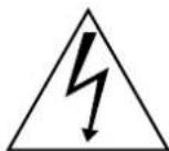
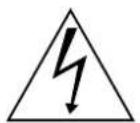
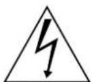
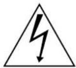
The lightning flash with arrowhead symbol, within an equilateral triangle, is intended to alert the user to the presence of uninsulated "dangerous voltage" within the product's enclosure that may be of sufficient magnitude to constitute a risk of electric shock to persons.

The exclamation point within an equilateral triangle is intended to alert the user to the presence of important operating and maintenance (servicing) instructions in the literature accompanying the appliance.
WARNING:
TO REDUCE THE RISK OF FIRE OR ELECTRIC SHOCK, DO NOT EXPOSE THIS APPLIANCE TO RAIN OR MOISTURE.
CAUTION:
Please use this unit in an appropriate power source. To prevent electric shocks and fire hazards, DO NOT use any other power source.
NOTE:
The rating plate (serial number plate) is on the rear of the unit. (VR-N900U) The rating plate (serial number plate) is on the top of the unit. (VR-N1600U/E)
INFORMATION:
This equipment has been tested and found to comply with the limits for a Class A digital device, pursuant to Part 15 of the FCC Rules.
These limits are designed to provide reasonable protection against harmful interference when the equipment is operated in a commercial environment.
This equipment generates, uses, and can radiate radio frequency energy and, if not installed and used in accordance with the instruction manual, may cause harmful interference to radio communications.
Operation of this equipment in a residential area is likely to cause harmful interference in which case the user will be required to correct the interference at his own expense.
CAUTION:
CHANGES OR MODIFICATIONS NOT APPROVED BY JVC COULD VOID USER'S AUTHORITY TO OPERATE THE EQUIPMENT.
THIS DEVICE COMPLIES WITH PART 15 OF THE FCC RULES. OPERATION IS SUBJECT TO THE FOLLOWING TWO CONDITIONS: (1) THIS DEVICE MAY NOT CAUSE HARMFUL INTERFERENCE, AND (2) THIS DEVICE MUST ACCEPT ANY INTERFERENCE RECEIVED, INCLUDING INTERFERENCE THAT MAY CAUSE UNDESIRED OPERATION.
ATTENTION
RISQUE D'ELECTROCUTION NE PAS OUVRIR

ATTENTION: POUR EVITER TOUT RISQUE D'ELECTROCUTION NE PAS OUVRIR LE BOITER.
AUCUNE PIECE INTERIEURE N'EST A REGLER PAR L'UTILISATEUR.
SE REFERER A UN AGENT QUALIFIE EN CAS DE PROBLEME
RED color indications on the operation panel are provided but they are not safety related, RED color indications :
(1) For Recording Indicator
(2) For Alarm Indicator
(3) For Warning Indicator
IMPORTANT (In the United Kingdom) Mains Supply
WARNING - THIS APPARATUS MUST BE EARTHED
The wires in this mains lead are coloured in accordance with the following code;
GREEN-and-YELLOW : EARTH
BLUE : NEUTRAL
BROWN : LIVE
As the colours of the wires in the mains lead of this apparatus may not correspond with the coloured markings identifying the terminals in your plug, proceed as follows.
The wire which is coloured GREEN-AND-YELLOW must be connected to the terminal in the plug which is marked with the letter E or by the safety earth symbol or coloured GREEN or GREEN-AND-YELLOW.
The wire which is coloured BLUE must be connected to the terminal which is marked with the letter N or which is coloured BLACK. The wire which is coloured BROWN must be connected to the terminal which is marked with the letter L or coloured RED.
POWER SYSTEM
Connection to the mains supply
Please use this unit in an appropriate power source.
WARNING:
TO REDUCE THE RISK OF FIRE OR ELECTRIC SHOCK, DO NOT EXPOSE THIS APPLIANCE TO RAIN OR MOISTURE.
CAUTION
To prevent electric shock, do not open the cabinet. No user serviceable parts inside. Refer servicing to qualified service personnel.
Note:
The rating plate and the safety caution are on the rear and top of the unit.
Caution for AC Power Cord
FOR YOUR SAFETY PLEASE READ THE FOLLOWING TEXT CAREFULLY.
Appropriate AC Power Cord must be used in each local area.
FOR CONTINENTAL EUROPE, ETC.
Not to be used in the U.K.

FOR U.K. ONLY
If the plug supplied is not suitable for your socket outlet, it should be cut off and appropriate one fitted.

PRECAUTIONS WHEN MOUNTING RACK CAUTION
- Do not install the VR-N1600U/E/VR-N900U to the rack in places where ambient temperature becomes 40°C or more.
- When rack mounting, keep the internal temperature of rack assembly 40^ or less.
- When using rack mount, keep the clearance between the rack and the rear of unit 150mm or more.
- When installing this unit or the like to the rack, refer to the consumption current value of the nameplate of each device so that the current capacity (including rated capacity of power supply wire) of the rack is not exceeded.
-
Use the rack that meets the following requirements:
-
must be equipped with overcurrent protection
- must be equipped with protective earthing conductor power plug and socket
To prevent bodily injury when mounting or servicing this unit in a rack, you must take special precautions to ensure that the system remains stable.
The following guidelines are provided to ensure your safety:
This unit should be mounted at the bottom of the rack if it is the only unit in the rack.
When mounting this unit in a partially filled rack, load the rack from the bottom to the top with the heaviest component at the bottom of the rack.
If the rack is provided with stabilizing devices, install the stabilizers before mounting or servicing the unit in the rack.
CAUTION
Before you mount this device in a rack, make sure that the rack is secure and in no danger of tipping over.
WARNING
It should be noted that it may be unlawful to re-record pre-recorded tapes, records, or discs without the consent of the owner of copyright in the sound or video recording, broadcast, or cable programme and in any literary, dramatic, musical or artistic work embodied therein.
CAUTION
RED colour indications on the operation panel are provided but they are not safety related, RED colour indications :
(1) For Recording Indicator
(2) For Alarm Indicator
(3) For Warning Indicator
WARNING
This is a Class A product. In a domestic environment this product may cause radio interference in which case the user may be required to take adequate measures.
WARNING
For PLUGGABLE EQUIPMENT, the socket outlet shall be installed near the equipment and shall be easily accessible.
WARNING
It may be unlawful to record or playback copyright material without the consent of the copyright owner.
CAUTION
(1) Please do not detach the front cover.
(2) Please put it when the front cover comes off.
Information for Users on Disposal of Old Equipment

Attention:
This symbol is only valid in the European Union.
[European Union]
This symbol indicates that the electrical and electronic equipment should not be disposed as general household waste at its end-of-life. Instead, the product should be handed over to the applicable collection point for the recycling of electrical and electronic equipment for proper treatment, recovery and recycling in accordance with your national legislation.
By disposing of this product correctly, you will help to conserve natural resources and will help prevent potential negative effects on the environment and human health which could otherwise be caused by inappropriate waste handling of this product. For more information about collection point and recycling of this product, please contact your local municipal office, your household waste disposal service or the shop where you purchased the product.
Penalties may be applicable for incorrect disposal of this waste, in accordance with national legislation.
(Business users)
If you wish to dispose of this product, please visit our web page www.jvc-europe.com to obtain information about the take-back of the product.
[Other Countries outside the European Union]
If you wish to dispose of this product, please do so in accordance with applicable national legislation or other rules in your country for the treatment of old electrical and electronic equipment.
Dear Customer,
This apparatus is in conformance with the valid European directives and standards regarding electromagnetic compatibility and electrical safety.
European representatives of Victor Company of Japan, Limited is:
JVC Technical Services Europe GmbH
Postfach 10 05 04
61145 Friedberg
Germany
INFORMATION (FOR CANADA) RENSEIGNEMENT (POUR CANADA)
This Class A digital apparatus complies with Canadian ICES-003.
WARNING (FOR EUROPE):
This is a Class A product. In a domestic environment this product may cause radio interference in which case the user may be required to take adequate measures.
SPANNUNGSVERSORGUNG
Anschluss am Netz
Automatic detection of network cameras
Significantly reduces the hassle of complex camera registration procedures.
Built-in large-capacity hard disk (500 GB) (VR-N1600U/E)
Built-in hard disk (250 GB) (VR-N900U)
Supports HDD expansion
You can add 250 GB HDD for internal of VR-N900U, and 500 GB HDD for internal of VR-N1600U/E.
For external, up to 2 TB HDD units can be added for both models of VR-N900U and VR-N1600U/E.
Simultaneous recording up to 9 channels at 120 ips (VR-N900U)
Equipped with 4-channel analog input (VR-N900U)
Display/Distribution performance at 80 ips (VR-N1600U/E) and 160 ips (VR-N1600U/E(A))
Display performance of 60 ips and distribution performance of 30 ips (VR-N900U)
Enables simultaneous recording and playback
Playback of recorded images, jog dial playback and skip playback are possible while recording is in progress.
Direct Search
Enables you to retrieve data of a specific date/time or alarm position speedily.
Power failure recovery record
If a power failure occurs during recording, the system resumes recording in the mode selected before the power failure after recovery.
Alarm recording
Enables recording to start automatically in the alarm recording mode when alarm signal input is received during recording.
Motion Detect
Enables recording to start automatically when "motion" is detected in the preset live image. You can also specify the detection area for each camera.
Alarm Mail Notification
Enables notification by e-mails to be sent out when an alarm or motion is detected.
Supports RAID1 (VR-N1600U/E)
Adding a built-in HDD enables support for RAID1. RAID1 writes the same data to two hard disks simultaneously (mirroring), so that one of them remains usable when the other breaks down.
Simultaneous recording up to 16 channels at 160 ips (VR-N1600U/E)
Simultaneous recording up to 16 channels at 240 ips is possible when NVR Viewer is not started up.
In addition, purchasing additional camera licenses enables the VR-N1600U/E(A) to handle simultaneous recording up to 32 channels.
For details, please consult your nearest JVC dealer.
Supports cameras that allow bidirectional audio transmission (VR-N1600U/E)
Microphone audio that is input into the AUDIO IN 1 terminal is transmitted to the camera that supports bidirectional audio transmission, and output from the speakers connected to the camera.
How to Read this Manual
Documents
There are two documents on this unit.
(1) Startup Guide
This comes in a booklet together with this product. It is also available in the PDF file format. You can find it in the CD-ROM provided.
(2) Instruction Manual (PDF)
This manual is available in the PDF file format. You can find it in the CD-ROM provided.
■ Symbols Used in this Manual
Caution Precautions to take during operation of this unit.
Notes Details for reference, such as functions and restrictions on uses.
A
■ Content of this Manual
- The copyright of this manual belongs to JVC. Reproduction or copy of this manual, in part or in whole, without the prior consent of JVC is strictly prohibited.
- Product names used in this manual are the trademarks or registered trademarks of the respective companies. Symbols such as ^TM , ^ , and ^ are omitted in this manual.
- Milestone and XProtect Enterprise are the registered trademarks of Milestone Systems, Inc.
- Designs, specifications and other details used in this manual may be modified for improvement without prior notice.
- Images and illustrations of VR-N1600U/E are used in the explanation of this manual except for some special cases. When images or illustrations of VR-N900U are used, the model name is indicated at the top right corner of the illustration.
■End-User License Agreement for Milestone's Software embedded in JVC's NVR products
This license agreement is a legally binding agreement among you (You, either an individual or a single entity), Milestone Systems A/S (Milestone) and Victor Company of Japan, Limited (JVC) for the software product embedded in JVC's Network Video Recorder(NVR) products (Software), which may include associated software components, media, printed materials, and online or electronic documentation, if any. By using JVC's NVR product incorporating the Software, you agree to be bound by the terms of this agreement.
The Software is protected by copyright laws and international copyright treaties, as well as other intellectual property laws and treaties. Note that the Software is licensed, not sold.
1. Grant of Use.
Milestone hereby grants you the right to use the Software on JVC's NVR products.
2. Copyright.
All title, including but not limited to copyrights, in and to the Software and any copies thereof are owned by Milestone. All rights not expressively granted are reserved by Milestone.
3. No Warranties.
Milestone and JVC expressly disclaims any warranty for the Software. The Software and any related documentation is provided "as is" without warranty of any kind, either express or implied, including, without limitation, the implied warranties of merchantability, fitness for a particular purpose or non-infringement. The entire risk and liability arising out of use or performance of the Software remains with you as the user. You are notified that the Software, when used with certain equipment or other software, may enable you to perform surveillance actions and data processing which are likely to be restricted by or contrary to applicable law, including without limitation data privacy and criminal law. The sole responsibility for verification of your use against compliance with applicable law lies with you as the user.
4. Limitation of Liability.
The provisions of this paragraph are in effect to the maximum extent permitted by applicable law. In no event shall Milestone, JVC or their suppliers be liable for any special, incidental, indirect, or consequential damages whatsoever (including, without limitation, damages for loss of business profits, business interruption, loss of business information, or any other pecuniary loss) arising out of the use of or inability to use the Software or the provision of or failure to provide proper support, even if Milestone or JVC have been advised of the possibility of such damages. Absent any wilful misconduct or gross negligence, The entire liability of Milestone and JVC under any provision of this agreement shall be limited to the amount paid by you for the Software portion of JVC's NVR product.
5. Miscellaneous.
(a) You acknowledge that the Software is embedded in JVC's NVR products, and you may not make copies of the Software. If necessary for backup and archival purposes, please contact JVC.
(b) You may not remove the Software from JVC's NVR product nor distribute copies of the Software to third parties.
(c) You may not reverse engineer, decompile, or disassemble any of the Software except to the extent permitted by applicable law which cannot be contractually waived.
(d) You may permanently transfer all of your rights for the Software, provided the recipient of JVCÕs NVR product incorporating the Software agrees to the terms of this agreement.
6. Termination.
Without prejudice to any other rights, Milestone may terminate this license agreement if you fail to comply with its terms and conditions. In such event you must cease to use the Software.
7. Governing Law.
These License Terms and the contract is governed by Japanese law and the sole and proper forum for the settlement of disputes hereunder shall be the Tokyo District Court.
VR-N1600U/VR-N1600E/VR-N900U (hereinafter referred to as "this device") is installed with Windows® XP Embedded Runtime (hereinafter referred to as "the software"), a licensed software from Microsoft Corporation. By using this device and the software, you agree to abide by the following Microsoft Software License Terms.
Microsoft Software License Terms for:
Windows®XP Embedded Runtime
These license terms are an agreement between you and JVC. Please read them. They apply to the software included on this device. The software also includes any separate media on which you received the software.
The software on this device includes software licensed from Microsoft Corporation or its affiliate.
The terms also apply to any Microsoft
- Updates,
- Supplements,
●Internet-based services, and
●Support services
for this software, unless other terms accompany those items. If so, those terms apply. If you obtain updates or supplements directly from Microsoft, then Microsoft, and not JVC, licenses those to you.
As described below, using some features also operates as your consent to the transmission of certain standard computer information for Internet-based services.
By using the software, you accept these terms. If you do not accept them, do not use or copy the software. Instead, contact JVC to determine its return policy for a refund or credit.
If you comply with these license terms, you have the rights below.
1 Use Rights.
You may use the software on the device with which you acquired the software.
2 Additional Licensing Requirements and/or Use Rights.
a.Specific Use.
JVC designed this device for a specific use. You may only use the software for that use.
b. Other Software.
You may use other programs with the software as long as the other programs
- Directly support the manufacturer's specific use for the device, or
- Provide system utilities, resource management, or anti-virus or similar protection.
Software that provides consumer or business tasks or processes may not be run on the device. This includes email, word processing, spreadsheet, database, scheduling and personal finance software. The device may use terminal services protocols to access such software running on a server.
c.Device Connections.
- You may use terminal services protocols to connect the device to another device running business task or processes software such as email, word processing, scheduling or spreadsheets.
- You may allow up to ten other devices to access the software to use
-File Services,
- Print Services,
- Internet Information Services, and
- Internet Connection Sharing and Telephony Services.
The ten connection limit applies to devices that access the software indirectly through "multiplexing" or other software or hardware that pools connections. You may use unlimited inbound connections at any time via TCP/IP.
3Scope of License.
The software is licensed, not sold. This agreement only gives you some rights to use the software. JVC and Microsoft reserve all other rights. Unless applicable law gives you more rights despite this limitation, you may use the software only as expressly permitted in this agreement. In doing so, you must comply with any technical limitations in the software that allow you to use it only in certain ways. For more information, see the software documentation or contact JVC. Except and only to the extent permitted by applicable law despite these limitations, you may not:
●Work around any technical limitations in the software;
- Reverse engineer, decompile or disassemble the software;
- Make more copies of the software than specified in this agreement;
●Publish the software for others to copy;
●Rent, lease or lend the software; or
- Use the software for commercial software hosting services.
Except as expressly provided in this agreement, rights to access the software on this device do not give you any right to implement Microsoft patents or other Microsoft intellectual property in software or devices that access this device.
You may use remote access technologies in the software such as Remote Desktop to access the software remotely from another device. You are responsible for obtaining any licenses required for use of these protocols to access other software.
- Remote Boot Feature.
If the JVC enabled the device Remote Boot feature of the software, you may
(i) your server and to deploy the software on licensed devices as part of the Remote Boot process; and
(ii) use the Remote Boot Installation Service only for deployment of the software to devices as part of the Remote Boot process; and
(iii)download the software to licensed devices and use it on them.
For more information, please refer to the device documentation or contact JVC.
- Internet-Based Services.
Microsoft provides Internet-based services with the software. Microsoft may change or cancel them at any time.
a. Consent for Internet-Based Services.
The software features described below connect to Microsoft or service provider computer systems over the Internet. In some cases, you will not receive a separate notice when they connect. You may switch off these features or not use them. For more information about these features, visit
http://www.microsoft.com/windowsxp/downloads/updates/sp2/docs/privacy.mspx.
By using these features, you consent to the transmission of this information.
Microsoft does not use the information to identify or contact you.
b. Computer Information.
The following features use Internet protocols, which send to the appropriate systems computer information, such as your Internet protocol address, the type of operating system, browser and name and version of the software you are using, and the language code of the device where you installed the software. Microsoft uses this information to make the Internet-based services available to you.
●Web Content Features.
Features in the software can retrieve related content from Microsoft and provide it to you. To provide the content, these features send to Microsoft the type of operating system, name and version of the software you are using, type of browser and language code of the device where the software was installed. Examples of these features are clip art, templates, online training, online assistance and Appshelp.
These features only operate when you activate them. You may choose to switch them off or not use them.
●Digital Certificates.
The software uses digital certificates. These digital certificates confirm the identity of Internet users sending X.509 standard encrypted information. The software retrieves certificates and updates certificate revocation lists. These security features operate only when you use the Internet.
●Auto Root Update.
The Auto Root Update feature updates the list of trusted certificate authorities. You can switch off the Auto Root Update feature.
●Windows Media Player.
When you use Windows Media Player, it checks with Microsoft for
●Compatible online music services in your region;
●New versions of the player; and
- Codecs if your device does not have the correct ones for playing content. You can switch off this feature. For more information, go to:
http://microsoft.com/windows/windowsmedia/mp10/privacy.aspx.
●Windows Media Digital Rights Management.
Content owners use Windows Media digital rights management technology (WMDRM) to protect their intellectual property, including copyrights. This software and third party software use WMDRM to play and copy WMDRM-protected content. If the software fails to protect the content, content owners may ask Microsoft to revoke the software's ability to use WMDRM to play or copy protected content. Revocation does not affect other content. When you download licenses for protected content, you agree that Microsoft may include a revocation list with the licenses. Content owners may require you to upgrade WMDRM to access their content. Microsoft software that includes WMDRM will ask for your consent prior to the upgrade. If you decline an upgrade, you will not be able to access content that requires the upgrade. You may switch off WMDRM features that access the Internet. When these features are off, you can still play content for which you have a valid license.
c. Misuse of Internet-based Services.
You may not use these services in any way that could harm them or impair anyone else's use of them. You may not use the services to try to gain unauthorized access to any service, data, account or network by any means.
Microsoft Software License Terms for: (continued)
4 Windows Update Agent (also known as Software Update Services).
The software on the device includes Windows Update Agent ("WUA") functionality that may enable your device to connect to and access updates ("Windows Updates") from a server installed with the required server component. Without limiting any other disclaimer in this Microsoft Software License Terms or any EULA accompanying a Windows Update, you acknowledge and agree that no warranty is provided by MS, Microsoft Corporation or their affiliates with respect to any Windows Update that you install or attempt to install on your device.
5Product Support.
Contact JVC for support options. Refer to the support number provided with the device.
6Backup Copy.
You may make one backup copy of the software. You may use it only to reinstall the software on the device.
7 Proof Of License.
If you acquired the software on the device, or on a disc or other media, a genuine Certificate of Authenticity label with a genuine copy of the software identifies licensed software. To be valid, this label must be affixed to the device, or included on or in JVC's software packaging. If you receive the label separately, it is not valid. You should keep the label on the device or packaging to prove that you are licensed to use the software.
To identify genuine Microsoft software, see http://www.howtotell.com.
8 Transfer to a Third Party.
You may transfer the software only with the device, the Certificate of Authenticity label, and these license terms directly to a third party. Before the transfer, that party must agree that these license terms apply to the transfer and use of the software. You may not retain any copies of the software including the backup copy.
9Not Fault Tolerant.
The software is not fault tolerant. JVC installed the software on the device and is responsible for how it operates on the device.
10 Restricted Use.
The Microsoft software was designed for systems that do not require fail-safe performance. You may not use the Microsoft software in any device or system in which a malfunction of the software would result in foreseeable risk of injury or death to any person. This includes operation of nuclear facilities, aircraft navigation or communication systems and air traffic control.
11 No Warranties for the Software.
The software is provided "as is". You bear all risks of using it. Microsoft gives no express warranties, guarantees or conditions. Any warranties you receive regarding the device or the software do not originate from, and are not binding on, Microsoft or its affiliates. When allowed by your local laws, JVC and Microsoft exclude implied warranties of merchantability, fitness for a particular purpose and non-infringement.
12 Liability Limitations.
You can recover from Microsoft and its affiliates only direct damages up to two hundred fifty U.S. Dollars (U.S. \$250.00). You cannot recover any other damages, including consequential, lost profits, special, indirect or incidental damages.
This limitation applies to:
- Anything related to the software, services, content (including code) on third party internet sites, or third party programs; and
- Claims for breach of contract, breach of warranty, guarantee or condition, strict liability, negligence, or other tort to the extent permitted by applicable law.
It also applies even if Microsoft should have been aware of the possibility of the damages.
The above limitation may not apply to you because your country may not allow the exclusion or limitation of incidental, consequential or other damages.
13 Export Restrictions.
The software is subject to United States export laws and regulations. You must comply with all domestic and international export laws and regulations that apply to the software. These laws include restrictions on destinations, end users and end use.
For additional information, see www.microsoft.com/exporting.
Contents
Getting Started
Features 2
Contents 8
Precautions for Proper Use of this Product ....10
Part Names and Functions (VR-N1600U/E) ......12
Part Names and Functions (VR-N900U) ......16
Rear Panel Terminals ......20
Camera Control Terminal (VR-N900U) ......21
Differences when operating VR-N1600U/E and VR-N900U 21
Mounting to a Rack 21
Operation Lock 22
During Initial Startup 22
Preparation
System Connection Example 26
Clock Display 27
Performance Meter 27
Character Input and Mouse Pointer 28
Entering Characters Using a Mouse ....28
Controlling Mouse Pointer from the Front Panel (Without Connecting a Mouse (Sold Separately)) ... 28
Changing Monitor Resolution ....29
Precautions when Changing Settings 29
Precautions when Changing Display Settings ....29
Basic Operation
Switching the Power On/Off ....30
Switching Operation On/Off 30
Login 31
Opening the Main Menu ....32
NVR Viewer ....33
Viewing Live Images via Front Panel Control ....34
Displaying the [Live] Screen 34
Select a View ....34
Select a Camera 34
Operating the Camera 35
Viewing Live Images via Mouse Control 36
Displaying the [Live] Screen 36
Select a View 36
Select a Camera ....36
Viewing Images Using the PTZ Features ....37
Using Preset Positions ....38
Other Useful Functions ....38
Playing Back Recorded Images via Front Panel Control 40
Select a View 40
Searching Recorded Image Using a Specific Date/Time 40
Playing, Skipping and Stopping Recorded Images .....41
Adjusting the Playback Speed (Jog/Shuttle Playback) 41
Playing Back Recorded Images via Mouse Control .....42
Select a View 43
Searching Recorded Image Using [Time Navigation] ....43
Searching Recorded Image Using the Timeline Browser 44
Searching Recorded Image Using Sequence .....44
Searching Recorded Image from the Alert List ....45
Smart Search 45
Playing, Skipping and Stopping Recorded Images .....46
Listening to Audio Sound 47
Writing Images/Audio Sound to CDs, DVDs and Other Media (Export) 47
Deleting Temporary Files (Operation on the Unit) .....50
Deleting Data from a CD-RW (Operation on the Unit) ....50
Writing Data to a USB Memory Device (Operation on the Unit) ....50
Operation from a Surveillance Computer ....51
Printing Recorded Images (Operation from a Surveillance Computer) ....51
Recording Camera Images 52
Recording Modes ....52
Recording Operation During Power Failure ....52
Selecting the Recording Control Mode ....53
Selecting the Manual Recording Mode ....53
Scheduler Setting ....53
Specifying Image Recording Settings ....55
Settings 56
Setting Picture Quality ....58
Specifying Audio Recording Settings ....59
Renaming Cameras and Assigning Camera Numbers ....60
Screen Setup 60
Screen Display (Groups and Views) 60
Creating Groups and Views 61
Adding Cameras to a View 63
Adjusting Camera Settings 63
Using Your Views on Different Computers ....64
Adding a Carousel 64
Adding Hot Spots (Enlarged Images) 66
Using the [Html Page] 67
Using Still Images (GIF/JPEG files, etc.) ......67
Adding Matrix Content 67
Applications
Main Menu List 68
List of Menu Screens 68
Unit Setting 1 ....69
Unit Setting 2 ....72
OS Setting 73
Image Server Setting 76
Auto Detect Setting 80
Camera Record Setting 83
Optional Installation 85
Adding Cameras 86
Analog Cameras (VR-N900U) 86
Adding an Analog Camera (VR-N900U) 86
Editing Device Settings 87
PTZ Camera Settings (COM1/COM2) 88
Defining a Preset PTZ Position 90
Stopping the Recording Server 90
Display the [PTZ Preset Positions for Device Name] Window 90
Defining a Preset Position 92
Moving to Preset Positions by Events .....92
Auto PTZ Patrolling 93
Camera Input/Output Port and Events 95
I/O Settings 95
Input/Output Terminal on Rear Panel 97
Specifying a VMD Event 97
Specifying Timer Events 97
Specifying an Output 98
[Advanced] Screen 98
Configuring Event Buttons 99
Specifying Generic Events ....100
Event Notification Settings ....102
Specifying an Output Port 102
Camera Output Settings ....103
Motion Settings 104
General Settings 106
E-mail Settings ....107
Archiving 108
Precautions when Changing NAS Archive Settings ... 109
Precautions when Changing Archive Settings .....109
Database Settings ....110
Flash Memory Utility 111
Auto Detect Settings 113
Specifying IP Lease 113
Language Setting 115
HDD Utility 116
Restoring Default Settings ....117
Distribution Settings (Details) 118
Master/Slave Settings ....120
Connecting to a Computer 121
Audio Transmission Application Control (VR-N1600U/E) 127
Audio Transmission 127
Event Audio Settings (VR-N1600U/E) 129
Audio Copying ....130
Setting Copy 131
Password 131
Communication Settings ....132
HDD Meter 133
Displaying the HDD Meter 133
Setting SNMP ....134
Others
Compatible Equipment 136
Compatible Network Cameras ....136
Connecting a UPS 136
External Hard Disk Drives ....136
Connecting the External Hard Disk Drive ....136
NAS 137
Special Key Operations ....138
Combining a Button with the [FUNCTION] Button .....138
Pressing a Button for Two Seconds or Longer .....138
Recording Before/After Occurrence of Event or Motion 139
PTZ Camera Control 139
Display and Saving of Maintenance Information ....141
Export Viewer 142
Customizing Joystick Settings ....144
Configuring NAS 145
Recording Time Schedule (VR-N1600U/E) ......146
Default Value List 150
Troubleshooting 156
Specifications 157
VR-N1600U/E 157
VR-N900U 158
Precautions for Proper Use of this Product
Locations of Storage and Use
- Do not place this product at the following locations.
Doing so may cause this product to malfunction or break down.
- Hot or cold places beyond the allowable operating temperature range (5°C to 40°C)
● Humid places beyond the allowable operating humidity range (30%RH to 80%RH) (no condensation) - Places that emit a strong magnetic field, such as near transformers and motors
- Places near devices that emit radio waves, such as transceivers and mobile phones
- Places with considerable dust and sand
- Places with strong vibrations
- Places where water droplets may be formed, such as window sides
- Places with considerable vapor and oil, such as kitchens
- Places that emit radiation, X-rays, and corrosive gases
● Using this unit and the cable that is connected to it near places where strong radio waves or magnetic fields (such as near radios, TVs, transformers, and monitors) are emitted may cause noises in the video images or color changes.
Handling Precautions
- Do not stack the devices on one another during use. Heat and noise from the devices may cause the unit to malfunction or break down, and lead to fire.
●Do not block the ventilation holes.
Doing so may cause heat to trap inside the unit and result in fire. Do not use this unit by laying it down sideways, upside down, or at an angle.
●Do not place objects on this unit.
Placing heavy objects, such as TV monitors, or objects that are bigger in size on this unit may cause it to lose balance and drop or fall, hence resulting in injuries.
●Do not stand or sit on this unit.
Doing so may cause this unit to fall or break down, and result in injuries. Keep it out of the reach of young children.
- Do not place objects with water (e.g., vases, flower pots, cups, cosmetic products, and chemicals) on this unit.
Water may enter this unit through the ventilation holes and result in fire or electric shock.
●Do not insert objects into this unit.
Metallic or other flammable objects that enter this unit from the ventilation holes may result in fire or electric shock.
Precautions for Handling Hard Disk Drive
●The distance between the head and the disk is only about 0.02 μm when the hard disk (henceforth HDD) is reading the data. Vibration or impact that is exerted on the HDD may therefore cause the head to hit against the disk, hence causing the disk surface to dent or the disk to chip. When this occurs, data may not be properly read, or in a worse scenario, continued use in this condition may result in head crash (damage). Careful attention must therefore be paid when handling it.
●Precautions During Installation and Change of Installation Location
Moving of this unit or installation work is strictly prohibited when the power of this unit is on or immediately after the power is turned off (approximately 1 minute). The HDD continues to move under its own inertia for some time after the power is disconnected, and exertion of vibration or impact during this interval may result in HDD failure. When moving this unit, wrap it using cushioning materials to protect it from external shock.
●Handling Precautions
- Handle this unit carefully without exerting vibration or impact on it.
- Do not remove the power plug during recording or playback, or when the HDD is being accessed.
-
The HDD is a consumable product. Although it may vary according to the environment of use, it is recommended to replace the HDD after using for 18,000 hours in a surrounding temperature of 25^ . (However, this is only a reference time and not a quarantine for HDD life span.) For inquiries on maintenance plans and expenses, consult your nearest JVC dealers.
-
When installing an external hard disk, we recommend the use of UPS (uninterruptible power supply) to ensure the stable operation of the system. [Connecting a UPS] (Page 136)
●Power failure that occurs during formatting or disconnection of the HDD may affect its subsequent use even when the UPS is connected.
●JVC shall not be held responsible for the compensation of losses incurred in the event that recording or playback fails due to defects in this unit or its hard disk drive.
●Images recorded on the HDD will be deleted when you replace it with a new disk. Note also that recorded images may be deleted when you upgrade the software for this unit.
Clock
●Use of a time server is recommended to ensure recording at an accurate time.
●There may be a daily error of 10 to 20 seconds depending on the operating environment.
●The clock time may vary significantly when the lithium battery level used for backup in this unit is running low.
●Connect the time server to the LAN2 network.
Precautions when Moving this Unit
- Remove all connected cords before moving
Turn off the power and remove the power plug before moving this unit. Failure to do so may cause damage on the cords, and result in fire or electric shock. - Moving of this unit or installation work is strictly prohibited when the power of this unit is on or immediately after the power is turned off (approximately 1 minute).
The HDD continues to move under its own inertia for some time after the power is disconnected, and exertion of vibration or impact during this interval may result in HDD failure. - When moving this unit, wrap it using cushioning materials to protect it from external shock.
●Handle this unit carefully without exerting vibration or impact on it.
Precautions for Handling Power Cords
●Do not use the supplied cords on devices other than this unit.
●Do not place heavy objects on the power cord, or place it under this unit
Doing so may cause damage on the cords, and result in fire or electric shock.
- Do not use cords other than those supplied with this unit. Use only power cords supplied together with this unit. Using cords with different withstanding voltage specifications or damaged cords may result in fire or electric shock.
●Do not remove the power plug during recording or playback, or when the HDD is being accessed.
Maintenance
●Turn off the power before performing maintenance of this unit.
●Wipe this unit using a soft cloth. Wiping using thinner or benzene may cause the surface to melt or fog. When the surface is extremely dirty, wipe using a cloth that is dipped into a neutral detergent diluted with water, followed by wiping with a dry cloth.
Energy Conservation
●Turn off the power of the system for safety reasons and to save energy if this unit is not to be used for a long time.
Copyright
●Use of video or audio sound recorded using this unit for commercial purposes or playing them for public viewing or listening may be an infringement of the copyrights of their respective authors under the copyright law.
● These video (audio) recordings shall only be restricted to personal uses, and their use without prior consent of the copyright holder is strictly prohibited under the copyright law.
Others
- When there is variation in the supply voltage such as during lightning, operation of this unit may be disabled to protect the system until the supply voltage stabilizes again.
- Eliminate static electricity before performing work that requires you to touch the input/output terminals, such as when installing devices.
●Do not touch the rear panel of this unit when it is running as static electricity may cause it to malfunction. - When there is a large number of data recorded on this unit, such as short alarm records, a longer time may be required during search or backup. This is not a malfunction.
●Data recorded from TV broadcasts or video (audio) recordings shall only be restricted to personal uses, and their use without the prior consent of the copyright holder is strictly prohibited under the copyright law. - The width of the border lines (black in color) of images on the split screen varies according to the type of input signals. This is due to the characteristics of the camera's input signals, and is not a malfunction. The condition may also be improved by adjusting this unit. For details, consult our authorized dealers or JVC service centers.
●This unit comes with a high-precision hard disk device. Be careful not to exert vibration or impact on this unit when handling it.
●Exertion of vibration or impact particularly when the power is on or when the hard disk is being accessed may cause this unit to break down. - When moving this unit, do so about 1 minute after disconnecting the power supply.
- Do not turn off the power switch at the rear of this unit or unplug the power cord during recording or playback, or when the hard disk is being accessed. Otherwise, it may break down.
Precautions During Master/Slave Connection of Milestone XProtect Enterprise (XPE) and this Unit
- Connect only one master PC to this slave unit. Connecting multiple master computers to this slave unit may cause it to malfunction.
Software Installation
- Do not install any software to this device other than the provided application software. Otherwise, operations may become unstable. Any malfunctions arised in such a case will not be covered under warranty.
Part Names and Functions (VR-N1600U/E)
Front
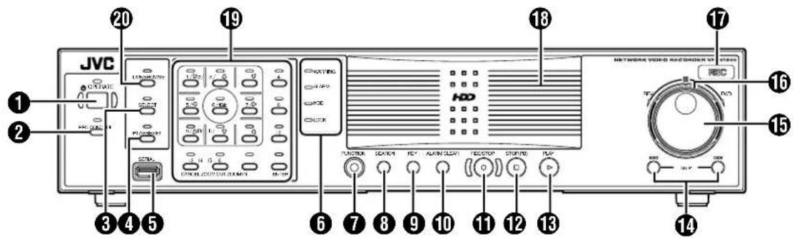
① [OPERATE] Button/Indicator
Switches operation on or off. Press the button to turn operation "ON" and hold down the button to turn operation "OFF". The indicator blinks while the recorder is starting up or shutting down.
② [REC CONTROL] Button/Indicator
Switches the recording control mode on or off. The indicator lights up when the recording control mode is set to on. Press and hold the [FUNCTION] button, and press the [REC CONTROL] button at the same time to display the menu.
Memo :
- The main menu cannot be displayed in the recording control mode or during recording.
- The recording control mode performs recording in accordance with the settings in the [Camera Record Setting] menu. (Page 53)
③ [SELECT] Button/Indicator
Use the 19 key to set to the camera selection mode. The indicator lights up when the camera selection mode is set to on. (Page 36)
4 [PTZ/PRESET] Button/Indicator
Switches between the PTZ mode and PRESET mode of the 19 key. The mode changes each time the button is pressed. The indicator lights up when PTZ mode is selected and blinks when PRESET mode is selected.
⑤ [SERIAL] Terminal
For connecting the communication control terminals on a mouse (sold separately), flash memory (sold separately) or UPS (sold separately).
Memo :
- Use the [SERIAL1 to 4] port on the rear panel for additional hard disk drive connection. (Page 14)
Note :
- Attach the serial port cover supplied with this product if this port is not in use.
- This product may malfunction due to the presence of static electricity. Remove any static before starting operation.
6 Status indicators
■ [WARNING] Indicator
Lights up when an error occurs. (Page 156)
Press and hold the [ALARM CLEAR] button to turn off the light.
[ALARM] Indicator
Lights up when an alarm is activated.
Goes off when the [ALARM CLEAR] button is pressed.
■ [HDD] Indicator
Lights up when the built-in hard disk drive is accessed.
■ [LOCK] Indicator
Lights up when operation is locked. (Page 22)
⑦ [FUNCTION] Button
Press the [FUNCTION] together with another button to use the corresponding features. [Special Key Operations] Page 138)
⑧ [SEARCH] Button
Displays the date and time search screen when in the playback mode. (Page 40)
⑨ [KEY] Button
When [KEY] button is pressed while pressing [FUNCTION] button, key operation on front panel will be disabled. (Key locked mode) To disable, perform same procedure again. Press to display or hide the "software keyboard".
Memo :
- Use the software keyboard to input characters. (Page 28)
⑩ [ALARM CLEAR] Button
Clears the [ALARM] display when an event occurs or motion is detected. Press and hold this button to turn off the [WARNING] indicator.
⑪ [REC/STOP] Button
Press to start recording in all cameras. (When the recording control mode is turned on, recording on all cameras starts after turning off the recording control mode.) Press and hold down to stop recording.
When in the recording control mode, press and hold this button to exit the recording control mode.
Memo :
- The manual recording mode executes recording from all cameras regardless of the settings in the [Camera Record Setting]. Recording is carried out in accordance with the frame rate selected in [Camera Record Setting]. (18) Page 83)
12 [STOP(PB)] Button
Stops playback when you press this button in the playback mode.
13 [PLAY] Button
Plays back at the speed and in the direction specified by the Shuttle Dial position.
14 [SKIP] Button
[S]
Press to move the item selection in the reverse direction in the menu or settings screen. Jumps to the beginning of the previous sequence on the selected camera when you press this button in the playback mode. Press and hold it to jump to the first image in the database of the selected camera.
■ [T]
Press to move the item selection in the forward direction in the menu or settings screen. Jumps to the beginning of the next sequence on the selected camera when you press this button in the playback mode. Press and hold it to jump to the last image in the database of the selected camera.
Memo :
- "Sequence" indicates a certain block of images that are recorded during motion detection.
- Recorded images are stored in the database. "Database" refers to data recorded in this unit.
15 Jog dial
Plays back a single frame when it is rotated in the playback mode.
16 Shuttle dial
The position of the dial specifies the playback speed and playback direction when in the playback mode. Playback speed is selectable from x 1/20, x 1/5, x 1, x 2, x 5, x 10 and x 20 according to the angle.
⑰ [REC] Indicator
Lights up during recording. Flashes during EMERGENCY or EXT REC IN recording.
18 Center panel
Do not remove the cover.
19 Keypad buttons/Indicator
[0] to [16]
- Login screen
- For entry of passwords (numeric characters). ([1] to [10/0], "0" is input when the [10/0] button is pressed.)
- Setting screens on the main menu
- PTZ mode Keypad For selecting a menu item. ([2/↑], [10/0/↓])
- Camera selection keypad mode For entering numeric characters. ([1] to [10/0], "0" is input when the [10/0] button is pressed.)
● Live image display and recorded image playback screens
- Camera selection keypad mode For selecting a camera number. Upon selecting, the indicator corresponding to the selected camera input lights up.
- PTZ keypad mode (live image display screen only) Moves the camera in the direction indicated by the arrow. ([1/2/ ↑] [3/5/ ←][7/↔] [9/10/0/ ↓] [11/↓] [6/HOME] moves the camera to the home position.
- Preset keypad mode (live image display screen only) For selecting the preset position. ([1] to [9]. 10 to 19 can be selected when [10/0/] is pressed at first.)
- During search for recorded images
For narrowing down the search using a date, month, week, or time. ([1/↓] to [10/0/ ↓], "0" is input when the [10/0/↓] button is pressed.)
● During display of software keyboard
- Selection keypad mode For entering numeric characters. ([1/↓ to [10/0/ ↓], “0” is input when the [10/0/↓] button is pressed.) - PTZ keypad mode (live image display screen only) Moves the mouse pointer in the direction indicated by the arrow [1/↓2/ ↑] [3/↓5/ ←][7/→] [9/↓10/0/ ↓] [11/↓[6/HOME] moves the mouse pointer to the center of the screen.)
[13/CANCEL]
- Setting screens on the main menu Cancels the selection.
[14/ZOOM OUT]
● Live image display and recorded image playback screens
- PTZ keypad mode (live image display screen only) Zooms out.
- Preset keypad mode For selecting the next view.
- Press the [14/ZOOM OUT] button while holding down the [FUNCTION] button to change the resolution of VGA output.
[15/ZOOM IN]
● Live image display and recorded image playback screens
- PTZ keypad mode (live image display screen only) Zooms in.
- Preset keypad mode For selecting the previous view.
- Press the [15/ZOOM IN] button while holding down the [FUNCTION] button to change the resolution of VGA output.
[16/ENTER]
- Setting screens on the main menu Confirms the selection.
- During display of software keyboard To perform the mouse click operation.
20 [LIVE/BROWSE] Button/Indicator
Switches between the [Live] mode and [Browse] mode.
The indicator lights up when in the [Live] mode. Pressing the [LIVE/BROWSE] button when the wallpaper screen is displayed shows the [Live] screen.
Press and hold the [FUNCTION] button, and press and hold the [LIVE/BROWSE] button at the same time to log out of the system. Press and hold the [FUNCTION] button, and press the [LIVE/BROWSE] button at the same time to reboot the NVR Viewer as well as the internal distribution server.
Memo :
- When [Auto Logon] is enabled, the login operation starts automatically immediately after logging out. ( Page 69 [Unit Setting 1])
Part Names and Functions (VR-N1600U/E) (continued)
Rear Panel
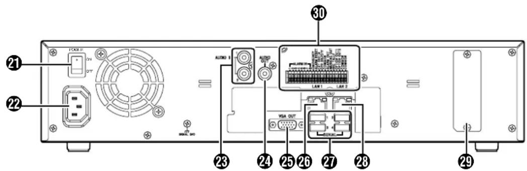
21 [POWER] switch
Switches the power on or off.
Memo :
- Be sure to press and hold down the [OPERATE] button on the front panel to shut down the system before switching off the power supply.
22 [AC IN 120V ∼ 240VH 50Hz/60Hz] power input terminal
Connect to an AC120 ∼ 240 V outlet using the power cable supplied.
23 [AUDIO IN 1/AUDIO IN 2] audio input terminals 1/2 (RCA)
Connect to the audio output terminal of the device from which audio signals are to be recorded.
24 [AUDIO OUT] audio output terminal (RCA)
Outputs live sound in the live viewing mode. Outputs recorded sound in the playback mode.
Memo :
- There is no audio output when playing back still images, when running searches other than x1, or when playing back frame-by-frame.
25 [VGA OUT] VGA output terminal
Outputs live images, recorded images and the menu screens.
26 [LAN1] LAN1 connection terminal (camera network)
For connecting to the IP camera (sold separately) network using a LAN cable.
| Color Status | |||
| Left Indicator | Off Communication at 10 Mbit/second. | ||
| Green On Communication at 100 Mbit/second. | |||
| Orange On Communication at 1 Gbit/second. | |||
| Right Indicator | Off Not connecting to the network. | ||
| Yellow Blinking Communication is in progress. | |||
27 [SERIAL1 to 4] serial terminals 1 to 4
For connecting the communication control terminals on a mouse (sold separately), flash memory (sold separately), UPS (sold separately) or additional disk drive (sold separately).
28 [LAN2] LAN2 connection terminal (Intranet)
For connecting to the remote PC network using a LAN cable.
| Color Status | |||
| Left Indicator | Off Communication at 10 Mbit/second. | ||
| Green On Communication at 100 Mbit/second. | |||
| Orange On Communication at 1 Gbit/second. | |||
| Right Indicator | Off Not connecting to the network. | ||
| Yellow Binking Communication is in progress. | |||
29 Connector cover
Memo :
- Do not remove the cover.
30 Signal input/output terminals
For operating VR-N1600U/E using external alarm signals or signals received from external devices, or for operating external devices by outputting signals.
Memo :
● Diameter of applicable cable: AWG22 to AWG28
Rear I/O Terminals
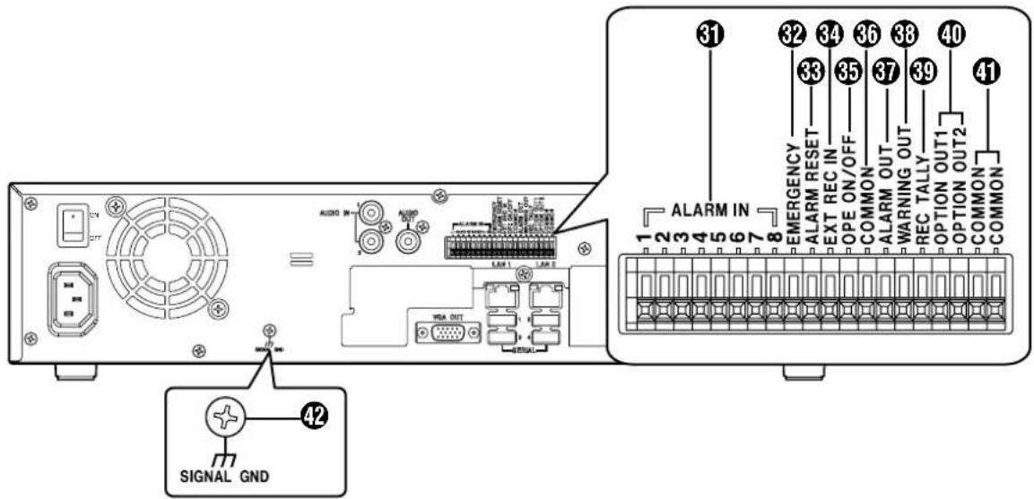
■Input ports
31 [ALARM IN 1 to 8] alarm input terminals 1 to 8
Alarm recording is activated when signals are input to these terminals.
32 [EMERGENCY] emergency input terminal
Recording is activated in all cameras when a signal is input to this terminal.
33 [ALARM RESET] alarm reset input terminal
Output from the alarm output terminal is stopped when a signal is input during output of the Alarm Out signals. Turns off the [ALARM] indicator 6 on the unit. Press and hold down to turn off the [WARNING] indicator 6.
34 [EXT REC IN] external recording input terminal
Recording in all cameras is started or stopped by an external signal. Recording will not be started in cameras to which no video signal is being input.
35 [OPE ON/OFF] Operate ON/OFF terminal
Switches between OPERATE ON or OFF when a signal is input. (Page 30)
Note :
- Input ports 31 to 45 will not operate when the main menu is displayed. Inputs such as alarms will also be ignored when the main menu is displayed.
■Output ports
36 [COMMON] signal ground terminal
This is a common ground terminal. Connect it to the signal ground terminal on the connected device. (This can be used when there are insufficient common ground terminals.)
37 [ALARM OUT] alarm output terminal
Outputs a signal when recording is started by an alarm.
38 [WARNING OUT] warning output terminal
Outputs a signal when an error such as operation abnormality occurs on the hard disk.
39 [REC TALLY] recording status output terminal
Outputs the recording status of this unit.
40 [OPTION OUT1][OPTION OUT2] OPT OUT output terminals 1/2
Outputs a signal when an event is detected.
41 [COMMON] signal ground terminal
Same as 36.
42 [SIGNAL GND] signal ground terminal
This is a common ground terminal. Connect it to the signal ground terminal on the connected device.
(This can be used when there are insufficient common ground terminals.
Memo :
- Do not use this terminal for protective earthing.
Part Names and Functions (VR-N900U)
Front Panel
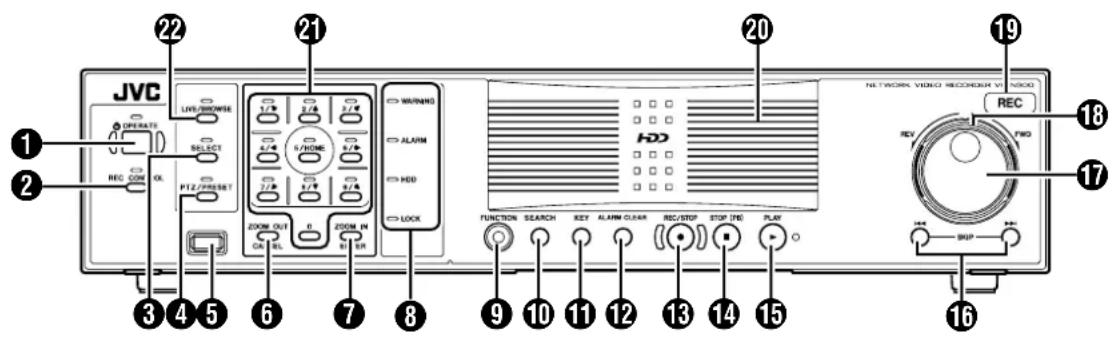
① [OPERATE] Button/Indicator
Switches operation on or off. Press the button to turn operation "ON" and hold down the button to turn operation "OFF". The indicator blinks while the recorder is starting up or shutting down.
② [REC CONTROL] Button/Indicator
Switches the recording control mode on or off. The indicator lights up when the recording control mode is set to on. Press and hold the [FUNCTION] button, and press the [REC CONTROL] button at the same time to display the menu.
Memo :
- The main menu cannot be displayed in the recording control mode or during recording.
- The recording control mode performs recording in accordance with the settings in the [Camera Record Setting] menu. (Page 53)
③ [SELECT] Button/Indicator
Use the 19 key to set to the camera selection mode. The indicator lights up when the camera selection mode is set to on. (Page 36) Press the [FUNCTION] button, [ALARM CLEAR] button and the [SELECT] button at the same time to reboot the NVR Viewer as well as the internal distribution server.
④ [PTZ/PRESET] Button/Indicator
Switches between the PTZ mode and PRESET mode of the 19 key. The mode changes each time the button is pressed. The indicator lights up when PTZ mode is selected and blinks when PRESET mode is selected.
⑤ [SERIAL] Terminal
For connecting the communication control terminals on a mouse (sold separately), flash memory (sold separately) or UPS (sold separately).
Memo
- Use the [SERIAL1 to 4] port on the rear panel for additional hard disk drive connection. (C) Page 14
Note :
- Attach the serial port cover supplied with this product if this port is not in use.
- This product may malfunction due to the presence of static electricity. Remove any static before starting operation.
6 [ZOOM OUT/CANCEL] Button
Selects ZOOM OUT (Page 35) when PTZ mode is selected and selects a view in PRESET mode.
Cancels the selected values in the Main Menu window. Also, pressing the [ZOOM OUT/CANCEL] button while holding down the [FUNCTION] button changes the resolution of VGA output.
⑦ [ZOOM IN/ENTER] Button
Selects ZOOM OUT (Page 35) when PTZ mode is selected and selects a view in PRESET mode.
Sets the selected values in the Main Menu window. Also, pressing the [ZOOM IN/ENTER] button while holding down the [FUNCTION] button changes the resolution of VGA output.
You can control the click action of the mouse when the software keyboard is displayed. (Page 28)
8 Status indicators
■ [WARNING] Indicator
Lights up when an error occurs. (Page 156)
Press and hold the [ALARM CLEAR] button to turn off the light.
[ALARM] Indicator
Lights up when an alarm is activated.
Goes off when the [ALARM CLEAR] button is pressed.
■ [HDD] Indicator
Lights up when the built-in hard disk drive is accessed.
■ [LOCK] Indicator
Lights up when operation is locked. (Page 22)
⑨ [FUNCTION] Button
Press the [FUNCTION] together with another button to use the corresponding features.
[Special Key Operations] (Page 138)
Press the [FUNCTION] button, [ALARM CLEAR] button and the [SELECT] button at the same time to reboot the NVR Viewer as well as the internal distribution server.
10 [SEARCH] Button
Displays the date and time search screen when in the playback mode. (Page 40)
11 [KEY] Button
When [KEY] button is pressed while pressing [FUNCTION] button, key operation on front panel will be disabled. (Key locked mode) To disable, perform same procedure again. Press to display or hide the "software keyboard".
Memo :
- Use the software keyboard to input characters. (Page 28)
⑫ [ALARM CLEAR] Button
Clears the [ALARM] display when an event occurs or motion is detected. Press and hold this button to turn off the [WARNING] indicator.
Press the [FUNCTION] button, [ALARM CLEAR] button and the [SELECT] button at the same time to reboot the NVR Viewer as well as the internal distribution server.
13 [REC/STOP] Button
Press to start recording in all cameras. (When the recording control mode is turned on, recording on all cameras starts after turning off the recording control mode.) Press and hold down to stop recording.
When in the recording control mode, press and hold this button to exit the recording control mode.
Memo :
- Recording will not be started in cameras to which no video signal is being input.
- The manual recording mode executes recording from all cameras regardless of the settings in the [Camera Record Setting]. Recording is carried out in accordance with the frame rate selected in [Camera Record Setting]. (e) Page 83
14 [STOP(PB)] Button
Stops playback when you press this button in the playback mode.
15 [PLAY] Button
Plays back at the speed and in the direction specified by the Shuttle Dial position.
16 [SKIP] Button
■ [S]
Press to move the item selection in the reverse direction in the menu or settings screen. Jumps to the beginning of the previous sequence on the selected camera when you press this button in the playback mode. Press and hold it to jump to the first image in the database of the selected camera.
■ [T]
Press to move the item selection in the forward direction in the menu or settings screen. Jumps to the beginning of the next sequence on the selected camera when you press this button in the playback mode. Press and hold it to jump to the last image in the database of the selected camera.
Memo :
- "Sequence" indicates a certain block of images that are recorded during motion detection.
- Recorded images are stored in the database. "Database" refers to data recorded in this unit.
17 Jog dial
Plays back a single frame when it is rotated in the playback mode.
18 Shuttle dial
The position of the dial specifies the playback speed and playback direction when in the playback mode. Playback speed is selectable from x 1/20, x 1/5, x 1, x 2, x 5, x 10 and x 20 according to the angle.
19 [REC] Indicator
Lights up during recording. Flashes during EMERGENCY or EXT REC IN recording.
20 Center panel
Do not remove the cover.
21 Keypad buttons/Indicator
[0] to [9]
Selects the camera input when viewing live images and when playing back recorded images.
The indicator that corresponds to the selected camera input lights up during camera selection mode.
Used to move the camera to the specified position during PTZ mode, to enter the preset number during PRESET mode and to narrow down the search date, month, week and time in the search mode. You can move the mouse cursor when the software keyboard is displayed. When the main menu is displayed, press the [2/↑] or [8/↓] button to move the option highlight. These buttons are also used as numeric keys.
22 [LIVE/BROWSE] Button/Indicator
Switches between the [Live] mode and [Browse] mode.
The indicator lights up when in the [Live] mode.
Pressing the [LIVE/BROWSE] button when the wallpaper screen is displayed shows the [Live] screen.
Press and hold the [FUNCTION] button, and press and hold the [LIVE/BROWSE] button at the same time to log out of the system.
Press the [FUNCTION] button, [ALARM RESET] button and the [SELECT] button at the same time to reboot the NVR Viewer as well as the internal distribution server.
Memo :
- When [Auto Logon] is enabled, the login operation starts automatically immediately after logging out. (v ^2 Page 69 [Unit Setting 1])
Part Names and Functions (VR-N900U) (continued)
Rear Panel
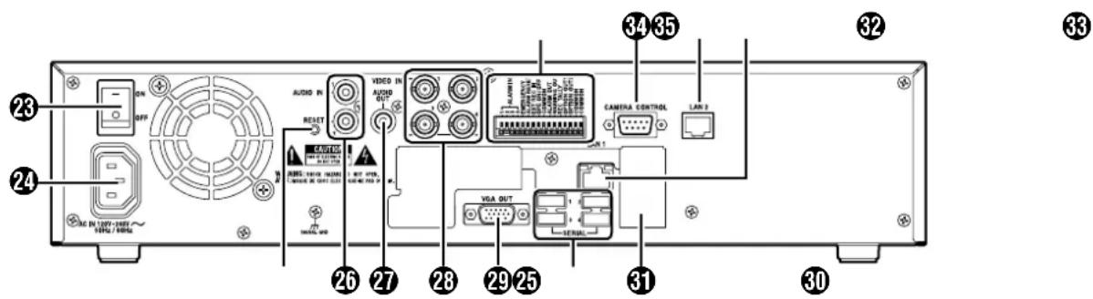
23 [POWER] switch
Switches the power on or off.
Memo :
- Be sure to press and hold down the [OPERATE] button on the front panel to shut down the system before switching off the power supply.
24 [AC IN 120V ∼ 240VH 50Hz/60Hz] power input terminal
Connect to an AC outlet using the power cable supplied.
25 [RESET]
Resets the system. Press this button when a malfunction occurs.
Note :
- Do not press this button in normal circumstances.
26 [AUDIO IN 1/AUDIO IN 2] audio input terminals 1/2 (RCA)
Connect to the audio output terminal of the device from which audio signals are to be recorded.
27 [AUDIO OUT] audio output terminal (RCA)
Outputs live sound in the live viewing mode.
Outputs recorded sound in the playback mode.
Memo :
- There is no audio output when playing back still images, when running searches other than x1, or when playing back frame-by-frame.
23 [VIDEO IN1 to 4] camera video signal input terminals 1 to 4
Connect to the video output terminal of the analog camera (sold separately).
29 [VGA OUT] VGA output terminal
Outputs live images, recorded images and the menu screens.
30 [SERIAL1 to 4] serial terminals 1 to 4
For connecting the communication control terminals on a mouse (sold separately), flash memory (sold separately), UPS (sold separately) or additional disk drive (sold separately).
31 Connector cover
Memo :
- Do not remove the cover.
32 [LAN1] LAN1 connection terminal (camera network)
For connecting to the IP camera (sold separately) network using a LAN cable.
| Color Status | |||
| Left Indicator | Off Not connected to the network or connected to a 10Mbit/Sec network. | ||
| Green On | Connected to a 100Mbit/Sec network. | ||
| Orange | On Connected to a 1Gbit/Sec network. | ||
| Right Indicator | Orange | Off Not communicating. | |
| Blinking Communicating. | |||
33 [LAN2] LAN2 connection terminal (Intranet)
For connecting to the remote PC network using a LAN cable.
| Color Status | ||
| Left Indicator | Green Off Not connected to the network. | |
| Blinking Connected to the network. | ||
| Right Indicator | Green Off Not communicating. | |
| Blinking Communicating. | ||
34 [CAMERA CONTROL] camera control terminal
Lets you control the analog cameras.
35 Signal input/output terminals
For operating VR-N1600U/E using external alarm signals or signals received from external devices, or for operating external devices by outputting signals.
Memo :
● Diameter of applicable cable: AWG22 to AWG28
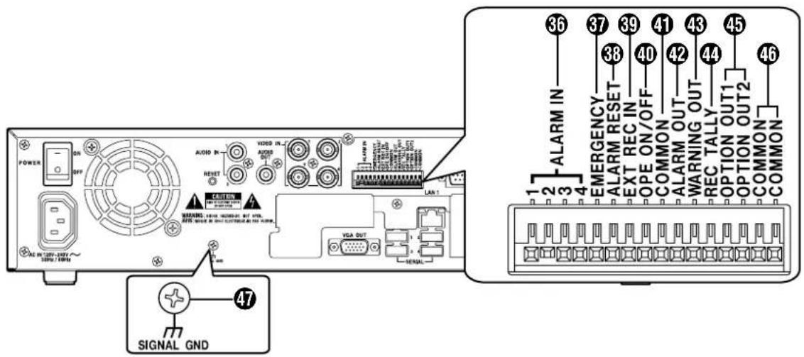
Rear I/O Terminals
■Input ports
36 [ALARM IN 1 to 4] alarm input terminals 1 to 4
Alarm recording is activated when signals are input to these terminals.
37 [EMERGENCY] emergency input terminal
Recording is activated in all cameras when a signal is input to this terminal.
38 [ALARM RESET] alarm reset input terminal
Output from the alarm output terminal is stopped when a signal is input during output of the Alarm Out signals.
Turns off the [ALARM] indicator ⑧ on the unit. Press and hold down to turn off the [WARNING] indicator ⑧.
39 [EXT REC IN] external recording input terminal
Recording in all cameras is started or stopped by an external signal. Recording will not be started in cameras to which no video signal is being input.
40 [OPE ON/OFF] Operate ON/OFF terminal
Switches between OPERATE ON or OFF when a signal is input. (Page 30)
Note :
- Input ports 36 to 40 will not operate when the main menu is displayed. Inputs such as alarms will also be ignored when the main menu is displayed.
■Output ports
41 [COMMON] signal ground terminal
This is a common ground terminal. Connect it to the signal ground terminal on the connected device. (This can be used when there are insufficient common ground terminals.)
42 [ALARM OUT] alarm output terminal
Outputs a signal when recording is started by an alarm.
43 [WARNING OUT] warning output terminal
Outputs a signal when an error such as operation abnormality occurs on the hard disk.
44 [REC TALLY] recording status output terminal
Outputs the recording status of this unit.
45 [OPTION OUT1][OPTION OUT2] OPT OUT output terminals 1/2
Outputs a signal when an event is detected.
46 [COMMON] signal ground terminal
Same as 41.
47 [SIGNAL GND] signal ground terminal
This is a common ground terminal. Connect it to the signal ground terminal on the connected device.
(This can be used when there are insufficient common ground terminals.
Memo :
- Do not use this terminal for protective earthing.
Rear Panel Terminals
Rear I/O Terminals
| Terminal Remarks | ||
| [ALARM IN] | ●Name of Input Event ●Name of Input EventAlarm IN 1 to 8 Falling (VR-N1600U/E) Alarm IN 1 to 8 Rising (VR-N1600U/E)Alarm IN 1 to 4 Falling (VR-N900U) Alarm IN 1 to 4 Rising (VR-N900U) 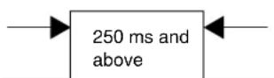 BreakMemo :● Set the impedance at the output end to 10 kΩ or lower. BreakMemo :● Set the impedance at the output end to 10 kΩ or lower. | Make Contact Input |
| [EMERGENCY][ALARM RESET] | 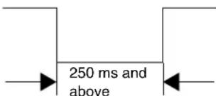 Memo :● Set the impedance at the output end to 10 kΩ or lower. Memo :● Set the impedance at the output end to 10 kΩ or lower. | Make Contact Input |
| [EXT REC IN] |  Memo :● Set the impedance at the output end to 10 kΩ or lower. Memo :● Set the impedance at the output end to 10 kΩ or lower. | Make Contact Input |
| [OPE ON/OFF] | 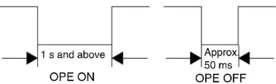 Memo :● Set the impedance at the output end to 10 kΩ or lower. Memo :● Set the impedance at the output end to 10 kΩ or lower. | Make Contact Input |
| [REC TALLY][ALARM OUT][WARNING OUT][OPTION OUT1][OPTION OUT2] | ●Name of Output Event ●Name of Output EventSet output Option Out 1,2 high Set output Option Out 1,2 low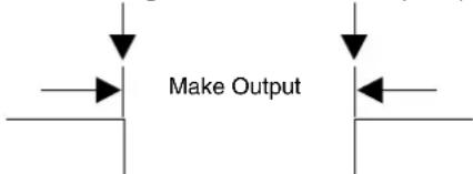 (External Pull-up Level)The make contact is formed using the individual output terminals and the COM terminal.Turning off the power of this unit switches the output of the output terminals to break. (External Pull-up Level)The make contact is formed using the individual output terminals and the COM terminal.Turning off the power of this unit switches the output of the output terminals to break. | Auto Collector Output(DC15V, 10 mA and below) |
Camera Control Terminal (VR-N900U)
Use connection cables according to the table below. Also make sure that you read through the instruction manual of the equipment to be connected.
| Signal Pin No. | |
| RX+ 1 | |
| RX- 2 | |
| TX- 3 | |
| TX+ 4 | |
| GND 5 | |
| NC | 6 |
| NC | 7 |
| NC | 8 |
| NC | 9 |
(D-sub 9 pin, male)
Differences when operating VR-N1600U/E and VR-N900U
The name of control buttons and operating methods may vary between VR-N1600U/E and VR-N900U. Such circumstances will be indicated using the rules below.
■When name of control button is different
① Indicated accordingly using [button name of VR-N1600U/E] and (button name of VR-N900U)
② mark is inserted at the end of the sentence
Pressthe16/ENTERbutton.

■When operating method is different
The operation for the respective model is stated, and the model name is indicated at the end of the sentence.
Mounting to a Rack
Use the supplied rack mount bracket to mount this unit to the EIA rack. For the installation to the rack, consult the specialist or dealer.
1 Mount the rack mount bracket using screw (1)
- Use the 4 screws (M4 x 10 mm) supplied to fasten this unit at the two sides.
2 Remove the foot screws ② (4 pcs) at the bottom of the unit
- Remove the foot.
3 Mount to the rack using screws ③
- Use the 4 screws (M5 x 11 mm) supplied to fasten this unit to the rack.
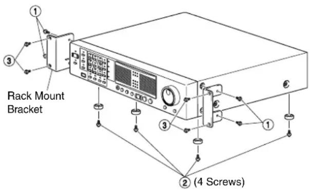
Note :
- Do not place any object on this unit when it is mounted to the rack. Doing so may cause it to lose balance and drop or fall, hence resulting in injuries or damages.
- When mounting more than one of this unit to the rack, make sure to mount each at a distance that is at least equivalent to one unit.
- When remounting the removed foot, make sure to use same screws (M3x6 mm). Using a longer screw may cause malfunction.
Operation Lock
VR-N1600U/VR-N1600E/VR-N900U is equipped with an operation lock feature to prevent the system from being turned off accidentally as well as unauthorized recording operations.
Setting Operation Lock
1 Press and hold the [FUNCTION] button, and press the [KEY] button at the same time
- Operation is locked. The [LOCK] indicator lights up when in the operation lock mode.
Canceling Operation Lock
1 (When in the operation lock mode) Press the [KEY] button while holding down the [FUNCTION] button
• Operation lock is canceled.
● The light of the [LOCK] indicator goes off.
![[LOCK] Indicator JVC [FUNCTION] button [KEY] Button VR-N1600U/E](/content/2026/05/859290/images/c4195124b710de1031911a27947f93edab3b2a9c66011f85eef7f431261f9435.jpg)
![[LOCK] Indicator JVC [FUNCTION] button [KEY] Button VR-N900U](/content/2026/05/859290/images/777830158714924d94cf8527ac68212ba08a5fdf93c5f0a4788cbdf7db098523.jpg)
During Initial Startup
Perform language setting and automatic camera registration when starting up this unit for the first time.
Before Starting Up.
- The DHCP setting is required for the IP camera beforehand. Start up this unit first, then switch the camera on after confirming that the [Auto Detect Setting] window is displayed.
- Refer to the user manual supplied with the camera for instructions on how to specify the IP camera settings.
- By default, Time zone is set to GMT. Specify a Time zone according to the region used. Refer to the INSTRUCTIONS on how to specify a Time zone settings.
![Keypad JVC [16/ENTER] Button [KEY] Button [SKIP] Button VR-N1600U/E](/content/2026/05/859290/images/f8e04d4bfc6c903b4eed2f248148ffca460264ab89d576dd83b7b03928f12389.jpg)
![Keypad JVC VR-N900U [ZOOM IN/ENTER] Button [KEY] Button [SKIP] Button](/content/2026/05/859290/images/f067f605778e920694129ea4a71e4046fb57b0800e40bb8a28780149ae6ffdb6.jpg)
Starting the Unit
1 Turn on the power switch at the rear panel.
- Doing so starts up the unit.
Selecting a Language
The [Language Setting] screen appears when you start up this unit for the first time. Select the language to use using the steps below.

1 Select a language
- Use the [2/] or 10/0/ button to select a language.

2 Use the [SKIP] button to select [OK], followed by pressing the [16/ENTER](ZOOM IN/ENTER) button
- The "The system is being set up." message may appear depending on the setting, and the system is automatically rebooted.
Memo :
- Selecting [OK] changes the color of the [OK] characters from brown to orange.
Automatic Registration of Cameras
After you have started up this unit for the first time and finished selecting a language, the [Auto Detect] screen appears.
1 Check to ensure that [Auto Detect] is selected, followed by pressing the [16/ENTER](ZOOM IN/ENTER) button
- The "Please wait..." message appears.
Memo :
- The characters of the selected item switches to orange color.
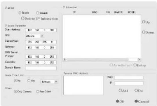
Memo :
- In the case of VR-N900U, the analog input appears on the [Auto Detect] screen from the start as the Analog-in network encoder (IP video server) of "192.168.201.12".
2 Check to ensure that the camera is detected
- After the message disappears, a list of detected cameras is displayed.
- If all the cameras are not detected, press the [Auto Detect] button again. If doing so does not solve the problem, check the connection with the cameras and the IP address of the cameras.
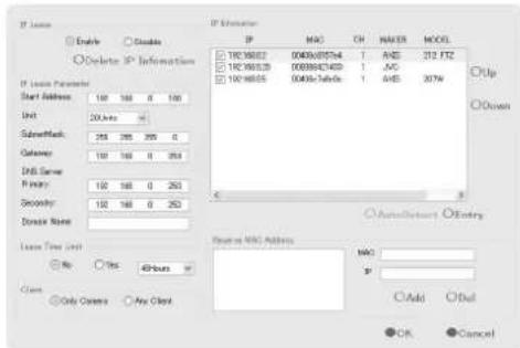
3 Replace the detected camera accordingly in sequence
Use the [SKIP] button to select the Sort button, followed by pressing the 16/ENTER button to sort the order of the detected cameras in sequence.
- The Sort button allows you to perform [IP] sort, [MAC] sort, [CH] sort, [MAKER] sort, or [MODEL] sort.
- After using the [SKIP] button to select the list, followed by using [2/] or 10/0/ to select a camera, use the [SKIP] button to select [Up] or [Down], and press the 16/ENTER button to change the sequence of the cameras.
- Deselect the check box of any camera that you are not using.
Note :
- Do not remove the check for Analog-In. (VR-N900U)
Memo :
- Priority is given to cameras at the top of the list during use, and camera numbers will be registered in sequence from the top.
● Devices other than the cameras may appear in the list. Uncheck the boxes of these devices.
4 Use the [SKIP] button to select [Entry], followed by pressing the [16/ENTER](ZOOM IN/ENTER) button
- The camera that is automatically detected is registered in the system.
5 Select the analog input channel and signal format to be used (VR-N900U)
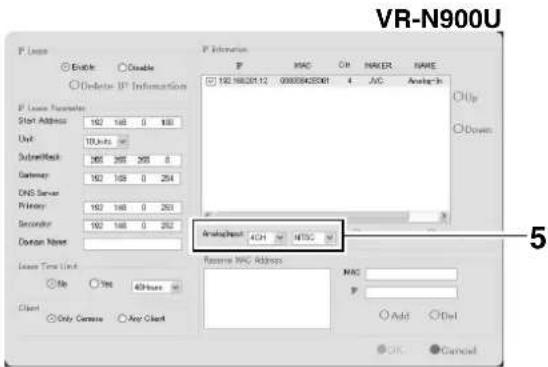
During Initial Startup (Continued)
Automatic Registration of Cameras (continued)
6 Use the [SKIP] button to select [OK], followed by pressing the [16/ENTER](ZOOM IN/ENTER) button
● The [Configure Device] screen appears.
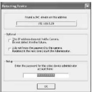
7 Enter the password for the network camera
- Press the [KEY] button to display the software keyboard. (Page 28)
- Use the keypad to move the mouse cursor over the software keyboard.
- Pressing the 16/ENTER button inputs the characters on the keyboard into the password field.
Memo :
- For cameras with the "Analog-In" message (analog cameras), proceed to Step 7. Password is not required. (VR-N900U)
8 After password entry is complete, press [KEY] again the close the software keyboard
9 Use the [SKIP] button to select [OK], followed by pressing the [16/ENTER](ZOOM IN/ENTER) button
10 Repeat the steps from 5 to 7 for every detected camera
● The [Camera Record Setting] screen appears.
11 Set the display rate of each camera such that the total display rate of all cameras does not exceed 80 ips (VR-N1600U/E), 160 ips (VR-N1600U/E(A)), or 60 ips (VR-N900U).
- The default display rate is set at 8 ips. The maximum display performance of 80 ips will be exceeded if 11 or more cameras are detected. In this case, you will need to adjust the display rate of each camera using the following steps. (VR-N1600U/E)
- The default display rate is set at 8 ips. The maximum display performance of 60 ips will be exceeded if 8 or more cameras are detected. In this case, you will need to adjust the display rate of each camera using the following steps. (VR-N900U)
Note :
- The recording rate may drop if the total display rate of all cameras exceeds 80 ips (VR-N1600U/E), 160 ips (VR-N1600U/E(A)), or 60 ips (VR-N900U).
When playing back the recorded images of VR-N1600U/E(A), set the total display rate to 80 ips or below to display the playback from the main unit and distribution for 13 channels or more simultaneously.
①Press the [SKIP] button to select Device Manager ●The device at the top is selected.
② Use the [2/] or 10/0/ button to select a device
③ Use the 7/ button to display the list of cameras
④ Use the 10/0/ button to select a camera ✉
⑤ Use the [SKIP] button to select [Settings...], followed by pressing the 16/ENTER button
●The [Camera Settings] screen appears.
⑥Set the display rate for live images
- Set the display rate for live images to "Same as recording" or "Same sa speedup" under [Live Settings].
- When "Same sa speedup" is selected, the [Frame Rate] specified under [Speedup Settings] is used as the display rate for live images.
- When "Same as recording" is selected, the [Frame Rate] specified under [Recording Settings] is used as the display rate for live images.
Memo :
- Use the [SKIP] to move between the setting items.
- Using the [2/] or 10/0/ button to select a parameter.
- To enter numeric characters, press the [SELECT] button to turn on the [SELECT] indicator. After entering the numeric characters, press the [PTZ/PRESET] button to turn on the [PTZ/PRESET] indicator.
⑦Use the [SKIP] button to select [OK], followed by pressing the 16/ENTER button
12 Repeat Step 10 for each camera
13 Use the [SKIP] button to select [Close], followed by pressing the [16/ENTER](ZOOM IN/ENTER) button
- Setting is complete and the [Live] screen appears.
- The [REC CONTROL] indicator lights up, and recording starts in the recording control mode. (Page 52)
Memo :
- For details on the recording control mode, refer to [Recording Camera Images] (Page 52).
- You can specify decimal values using the software keyboard.
[Live] Screen
System Connection Example
The following operations are possible with this system.
● Surveillance of up to 16 cameras (VR-N1600U/E)/9 cameras (VR-N900U) (live image, recording and playback)
- Checking recorded images on the VGA monitor
- Recording/Playing sound
● Transmitting audio data to a designated camera (VR-N1600U/E)
- Alarm recording
● Remote surveillance using PCs
flowchart
graph TD
    A["Analog cameras"] --> B["VIDEO IN 1 to 4"]
    B --> C["VR-N900U"]
    C --> D["Supplied power cable"]
    D --> E["AC 120 ~ 240 V, 50 Hz/60 Hz"]
    E --> F["VGA monitor"]
    F --> G["VGAM OUT"]
    G --> H["USB Mouse"]
    H --> I["SERIAL"]
    I --> J["Switching HUB"]
    J --> K["LAN1"]
    K --> L["Switching HUB"]
    L --> M["Serial"]
    M --> N["UPS control"]
    N --> O["120 V - 240 V"]
    P["Speaker (with built-in amplifier)"] --> Q["AUDIOOUT"]
    Q --> R["ALARM IN/OUT"]
    R --> S["ALARMIN/ALARMOUT"]
    T["Microphone"] --> U["Mic Amp"]
    U --> V["VR-N1600U/E"]
    W["IP cameras"] --> X["Computer for configuring cameras"]
    X --> Y["NAS"]
    Y --> Z["Switching HUB"]
    AA["Surveillance computer"] --> AB["Computer"]
    AC["You can connect up to 16 cameras. (VR-N1600U/E)"]
    AD["You can connect up to 9 cameras, out of which a maximum of 4 analog cameras are allowed. (VR-N900U)"]
    AE["You can connect up to 10 surveillance computers."]
Memo :
- Connect LAN1 to the camera network.
• LAN2 to the surveillance computer network. - For details of the protocol and port number for the network cameras on the LAN1 network, refer to the network camera's user manual.
- The protocol and port number used on the LAN2 network are shown below.
• Surveillance computer: HTTP 80
- Mail: SMTP 25, POP 110
• Time Synchronization: NTP 123
- Connect NAS to the LAN1 network.
- Connect the time server to the LAN2 network.
- Purchasing additional camera licenses enables the VR-N1600U/E(A) to handle simultaneous recording up to 32 channels. For details, please consult your nearest JVC dealer.
Note :
- Connect only after having turned "OFF" the power of all devices.
- Set the IP address of the camera to 192.168.0.xxx. When setting the IP address of the camera to an address other than 192.168.0.xxx, you must also change the IP address of LAN1. Refer to the [Instruction Manual] of each camera for procedures to change the camera's IP address,
Note :
- Do not connect LAN1 to the internet. If the internet is busy or the relay equipment fails, you may not be able to save important camera images. To maintain full recording capacity, it is recommended that a dedicated network be used. Be sure to connect the LAN1 camera network to the same segment. (Do not use the address translation of NAT and NAPT etc. or a router.)
- If you connect LAN2 to the internet from a surveillance computer, you will need to configure IP Masquerading.
- Communication between LAN1 and LAN2 is not possible. Nor is it possible to configure a camera connected to LAN1 from the surveillance computer connected to LAN2. In order to configure a camera connected to LAN1, it is necessary to connect the computer for configuring cameras to LAN1.
● LAN1 and LAN2 are incompatible with QoS. Sound may not be played normally depending on the condition of the circuit. - The default LAN1 IP address is 192.168.0.253 and the default LAN2 IP address is 192.168.1.253. To change the address, use [OS Setting] (Page 73).
- In VR-N900U, analog input circuitry is considered as a network encoder (IP video server) and the IP address is set to 192.168.201.12 by default. When altering the IP address of LAN1 and LAN2, specify an address (different segment) other than 192.168.201.0 to 192.168.201.255. Also make sure that the same segment is not specified for LAN1 and LAN2. (VR-N900U)
- When a single network camera is registered with multiple units of VR-N1600U/VR-N1600E/VR-N900U, recording may not be properly completed in some cases. Camera control (e.g. PTZ control) may also become unstable. It is recommended that a single VR-N1600U/VR-N1600E/VR-N900U be used for registering one IP camera as well as for controlling PTZ operations.
- Do not connect a broken hub, router or deteriorated network cable etc. Doing so may prevent the system from operating properly.
- Connection to a keyboard is not recommended.
Clock Display
This unit comes with a clock display feature.
You can display the current time on the screen.
1 Press and hold the [FUNCTION] button, and press the [2/] keypad button at the same time
- The clock is displayed at the top left corner of the screen beside the performance meter.
Memo :
- To turn the clock display off, press the [2/↑] keypad button while holding down the [FUNCTION] button.
- To move the clock display position, left click and drag the clock display to the desired position.
Performance Meter
This unit comes with a performance meter, which allows you to check its load on the meter.
At high operating loads, the system may not be able to record at the preset frame rate or operate normally.
1 Press and hold the [FUNCTION] button, and press the [1/3] keypad button at the same time
● The performance meter appears on the screen.
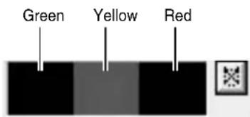
![JVC VR-N1600E(A) - Press and hold the [FUNCTION] button, and press the [1/3] keypad button at the same time - 2](/content/2026/05/859290/images/d14ae8597107bd3bbf7554dea8d5f2c8c55a92800b56b2eb1cec485e7ac9ca0a.jpg)
Load factor of 5 % or less, indicated in gray
![JVC VR-N1600E(A) - Press and hold the [FUNCTION] button, and press the [1/3] keypad button at the same time - 3](/content/2026/05/859290/images/d53094cf66e1f8e7ef09b56e100710121d774773831e2e9beaa60d2f8fbbb6e5.jpg)
Load factor of 60 % or less, lights up in green
![JVC VR-N1600E(A) - Press and hold the [FUNCTION] button, and press the [1/3] keypad button at the same time - 4](/content/2026/05/859290/images/e09672d2148b6a934598dd9b43177987a26b9d4504fe223d2bf49056e12dff15.jpg)
Load factor of 90 % or less, lights up in green and yellow
![JVC VR-N1600E(A) - Press and hold the [FUNCTION] button, and press the [1/3] keypad button at the same time - 5](/content/2026/05/859290/images/ac470183872ad48a3187d9d3b805f26cf41ffc4f28995ec3dc9463ec7ec3c3b3.jpg)
Load factor exceeds 90 %, lights up in green, yellow and red
Memo :
- The performance meter automatically appears after this unit starts up.
- To hide the performance meter, press the 1 keypad button while holding down the [FUNCTION] button.
- To move the display position of the performance meter, left click and drag it to the desired position.
Note :
- Do not use the recorder when the performance meter is indicated in red.
Character Input and Mouse Pointer
You can input characters and move the mouse pointers in two different ways.
- Operate using the buttons on the front panel.
- Operate by connecting a mouse (sold separately).
Memo :
- Connecting a mouse eases the specification of complex settings as well as input of characters.
- Connection to a keyboard is not recommended.
![Keypad JVC [16/ENTER] Button [KEY] Button VR-N1600U/E](/content/2026/05/859290/images/10d65488ee7623c2da17f0d346fdb50264966c4c24d2fb7c7dfc52a964d554b5.jpg)
![Keypad JVC [ZOOM IN/ENTER] Button [KEY] Button VR-N900U](/content/2026/05/859290/images/aea1356782d8b43a4aa8330d2990c9498ff9ea742a96a180b47ceff018fabb07.jpg)
Entering Characters Using a Mouse
You can use the software keyboard to input characters when you are using mouse.
1 Press the [KEY] button on the front panel
- The software keyboard appears.
- Press the [KEY] button again to hide the software keyboard.

Software Keyboard
2 Move the mouse pointer over the character on the software keyboard that you want to enter
3 Click on the character
Note :
- The 16/ENTER button is enabled with a click of a mouse when the software keyboard is displayed.
Controlling Mouse Pointer from the Front Panel (Without Connecting a Mouse (Sold Separately))
When a mouse is not connected, you can operate the mouse pointer from the front panel.
1 Press the [KEY] button
● The software keyboard appears.
- Press the [KEY] button again to close the software keyboard.
2 Move the mouse pointer with the keypad (arrow key)
- Pressing the 16/ENTER button has the same effect as clicking at the position of the mouse pointer.
Memo :
- You can move the software keyboard by dragging any portion of the keyboard other than the keys with the mouse.
- To drag the software keyboard from the front panel, press the arrow buttons on the keypad while holding down the 16/ENTER button.
- You can move the mouse pointer with the keypad when the software keyboard is displayed.
Changing Monitor Resolution
You can switch the resolution of the VGA output using the following procedures.
- Press and hold the [FUNCTION] button, and press the 14/ZOOM OUT button at the same time.
→Pressing the button each time increases the resolution value. - Press and hold the [FUNCTION] button, and press the 15/ZOOM IN button at the same time. →Pressing the button each time decreases the resolution value.
| Preset | : 1024 x 768 (Default value) |
| Values | 1280 x 768 |
| 1280 x 1024 | |
| 1600 x 1200 |
![JVC [14/ZOOM OUT] Button [15/ZOOM IN] Button [FUNCTION] Button VR-N1600U/E](/content/2026/05/859290/images/85cd07a94be2d8c3a9e977fe6eea9db15fdc467d2cfe4ed93bf845dddbda8dfa.jpg)
![[ZOOM OUT/ CANCEL] Button [FUNCTION] Button [ZOOM IN/ENTER] Button JVC VR-N900U REC](/content/2026/05/859290/images/96d3b4c18590240ee96805c5c187521389a08b242fccf7e93229d436911216a8.jpg)
Memo :
- Selecting a resolution not supported by the monitor may prevent normal monitor synchronization.
Precautions when Changing Settings
Note that any incorrect changes made to the settings of this unit may cause it to malfunction.
- Before making any changes, save the current settings to [Flash Memory Utility] (Page 111) to allow you to restore the previous settings should anything go wrong.
- It is recommended that you save the setting data before making any changes.
- The section at the bottom left of NVR Viewer might not be operative depending on the monitor resolution. In such a case, double-click the bar of the currently opened upper section to close it to enable the operation of the lower section.
Precautions when Changing Display Settings
The following table illustrates the relation between the number of camera channels that are displayed simultaneously and the selectable frame rate. When creating the view to display on screen, be careful not to exceed the respective values as shown in the table.
| VR-N900U/(A)/(B) | VR-N1600U/E | VR-N1600U/E(A) | |
| Basic performance Recording/ Display/ Distribution ips | 120/60/30 | 160/80/80 | 160/160/160 |
| Addition of camera license | Inapplicable | Inapplicable A | Applicable |
| Live viewing | 1 to 9 ch: 60 ips and below | 1 to 16 ch: 80 ips and below | 1 to 32 ch: 160 ips and below |
| Playback of recorded images | 1 to 9 ch: 60 ips and below | 1 to 16 ch: 80 ips and below | 1 to 12 ch: 160 ips and below13 to 16 ch: 80 ips and below17 to 32 ch: Inapplicable |
| Master-Slave connection | Applicable | Applicable | Applicable |
| Live viewing on the NVR unit during Master-Slave connection | 1 to 9 ch: 60 ips and below | 1 to 16 ch: 80 ips and below | 1 to 32 ch: 160 ips and below |
| Playback of recorded images on the NVR unit during Master-Slave connection | 1 to 9 ch: 60 ips and below | 1 to 16 ch: 80 ips and below | When the number of camera channels registered to the NVR unit among displaying cameras is1 to 12 ch: 160 ips and below13 to 16 ch: 80 ips and below17 to 32 ch: Inapplicable |
| Live viewing on the surveillance computer | Depends on the basic distribution performance of each NVR | Depends on the basic distribution performance of each NVR | Depends on the basic distribution performance of each NVR |
| Playback of recorded images on the surveillance computer | Depends on the basic distribution performance of each NVR | Depends on the basic distribution performance of each NVR | Depends on the recorded images playback performance of each NVR |
Note :
- While the basic display performance of the VR-N1600U/E(A) is 160 ips, during the playback of recorded images, the display performance is constrained by the above values depending on the number of camera channels that are displayed simultaneously on the NVR unit.
- When playing back recorded images simultaneously on the NVR unit and surveillance computer, set the number of camera channels that are displayed simultaneously on the NVR unit and surveillance computer and the total frame rate such that they do not exceed the recorded images playback performance of each NVR.
Switching the Power On/Off
Switching the Power On
1 Connect the power cable
- Connect using the power cable supplied to an AC100V (50 Hz/60 Hz) outlet.
2 Turn "ON" the power switch at the rear panel.
● A system check will run when the power is turned on.
● The [OPERATE] indicator starts blinking.
- After blinking, the [OPERATE] indicator lights up to indicate that operation has been turned on.
- When the setting is complete, recording starts automatically in the record control mode. (When the "ON at startup" checkbox of [Record Control] under [Unit Setting 1] of the main menu is selected.)
Note :
- Do not disconnect the power cord nor turn the power switch "OFF" while the system check is running or in the OPERATE ON mode. Otherwise, it may break down.
Memo :
- If the device does not start up even after the power switch on the rear panel is turned "ON", press the [OPERATE] button on the front panel.
Switching the Power Off
1 Press and hold the [OPERATE] button for about2 seconds to turn off the power
- After blinking, the [OPERATE] indicator goes off.
2 Turn off the power switch on the rear panel
Note :
- The recorded images may not be played back properly if they are not archived (Page 110) before the power failure.
- It is recommended that an uninterruptible power supply (UPS) be used to protect the hard disk from damage in the event of a power failure. (18) Page 136
- Be sure to press and hold down the [OPERATE] button on the front panel to shut down the system before switching off the power supply. Turning off the power switch on the rear panel while the device is in the OPERATE ON mode may cause malfunction.
Switching Operation On/Off
Switching On/Off Using Operate Button on Front Panel
You can switch operation to ON or OFF.
■Switching Operation On
1 (When Operation is OFF) Press the [OPERATE] button
● The [OPERATE] indicator starts blinking.
- The [OPERATE] indicator lights up, indicating that operation is enabled.
Memo :
- When the power switch on the rear panel is turned on, the system starts up automatically until the OPERATE ON mode is activated.
■Switching Operation Off
1 (When operation is ON) Press and hold the [OPERATE] button for about 2 seconds
● The [OPERATE] indicator starts blinking.
- The screen display disappears and the [OPERATE] indicator goes off, indicating that operation has been turned off.
Note :
- Do not turn off the power until operation has been turned off.
Switching On/Off Using Input/Output Terminal on Rear Panel
For details on the layout of the input and output terminals on the rear panel, refer to [Rear I/O Terminals] (Page 15).
■Switching Operation On
1 (When operation is OFF) Set the [OPE ON/OFF] terminal to make for at least 50 ms
● The [OPERATE] indicator starts blinking.
- The [OPERATE] indicator lights up, indicating that operation is enabled.
■Switching Operation Off
1 (When operation is OFF) Set the [OPE ON/OFF] terminal to make for at least 1 s
● The [OPERATE] indicator starts blinking.
- The screen display disappears and the [OPERATE] indicator goes off, indicating that operation has been turned off.
Note :
- Do not turn off the power until operation has been turned off.
Login
If [Auto Logon] is set to "off", the [Login] screen appears after operation has been turned on. (Default setting: "on")
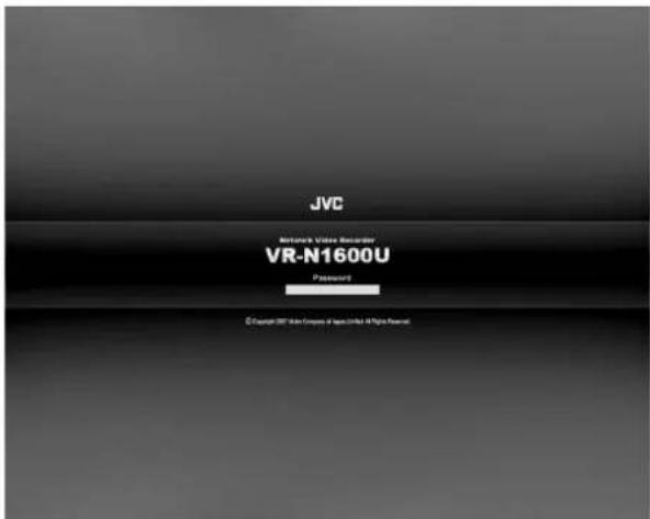
[Logon] Screen
Memo :
- You can specify the [on]/[off] setting of [Auto Logon] in [Unit Setting 1] of the main menu. (Page 69)
1 Enter the password using the keypad, and press the [16/ENTER](ZOOM IN/ENTER) button
- If login is successful, the wallpaper screen appears.
 button - 1](/content/2026/05/859290/images/4055f384d43bd3243a77ab9f48f61db3d71320522cd2d9eba448a3d6775c3129.jpg)
natural_image
Abstract grayscale image with a central sphere and six circular holes, no text or symbols present.Wallpaper Screen
- When [Live viewing Auto Start] is set to "on", the [Live] screen appears when login is successful.

[Live] Screen
Memo :
- You can specify the setting of [Live viewing Auto Start] in [Unit Setting 1] of the main menu. (Page 69)
Note :
- Operation on the main unit is disabled if you do not log in.
- Warning messages (Page 156) are not displayed when you are not logged into the system. In this case, the [WARNING] indicator lights up.
Opening the Main Menu
The following are procedures to open the main menu, which is used for specifying various settings.
Note :
- The input ports do not operate when the main menu is displayed. Inputs such as alarms will also be ignored when the main menu is displayed. [Input ports] (Page 15) (VR-N1600U/E) [Input ports] (Page 19) (VR-N900U)
![[SELECT] Button [2/↑] Button JVC [13/CANCEL] Button [REC CONTROL] Button [FUNCTION] Button [16/ENTER] Button [10/0/↓] Button [REC/STOP] Button [SKIP] Button VR-N1600U/E](/content/2026/05/859290/images/00f7f3d9dacd2e580971aac1cedec5395885be6ba9f9b0f6475206cfc0b792d0.jpg)
![[SELECT] Button [2/↑] Button JVC [FUNCTION] [REC/STOP] Button [SKIP] Button [ZOOM IN/ENTER] Button [ZOOM OUT/ CANCEL] Button [REC CONTROL] Button [8/↓] Button VR-N900U](/content/2026/05/859290/images/77a6814a4c0ebe5e7f3a66fbd936109bd43ae45dd153ff5208a023e8280de5ca.jpg)
1 Press and hold the [REC/STOP] button for at least 2 seconds
- Recording stops.
Memo :
- When in the recording control mode, press and hold the [REC CONTROL] button for at least 2 seconds to switch the recording control mode off and stop recording. - For details on the recording mode, refer to [Recording Modes] (Page 52).
2 Press and hold the [FUNCTION] button, and press the [REC CONTROL] button at the same time
- The main menu appears.
- Select a menu with the [2/↑] or 10/0/↓ button and press the 16/ENTER button to open the selected setting screen. The same operation can be done using the [SKIP] button.
![Main Menu ● Unit Setting 1 ● Unit Setting 2 ● OS Setting ● Flash Memory Utility ● HDD Utility ● Event Audio Setting ● Language Setting ● Return to default settings ● Image Server Setting ● Live Viewing ● Auto Detect Setting ● Camera Record Setting ● Optional Installation ● Exit [Operation] ↑: Up ↓: Down Enter: Enter Cancel: Exit](/content/2026/05/859290/images/566513b6ff6ae785780aa9d9f47f88c714fb2fb68d38068b74cbfff4b173afff.jpg)
![Main Menu Unit Setting 1 Unit Setting 2 OS Setting Flash Memory Utility HDD Utility Language Setting Return to default settings Image Server Setting Live Viewing Auto Detect Setting Camera Record Setting Optional Installation Exit [Operation] T : Up ↓ : Down Enter : Enter Cancel : Exit](/content/2026/05/859290/images/51c94d394eeda686956c76fd446cced5edc37b18e5df31be1bd7fbf3a75027a5.jpg)
3 Select an item
- Select the required item using the [2/↑] or 10/0/↓ button and specify the settings. - Press the 16/ENTER button to save the settings, and press the 13/CANCEL button to close the screen and return to the main menu.
Memo :
- To exit the main menu, press the 13/CANCEL button.
Note :
- In some occasions, the NVR Viewer may appear instead when you try to display the main menu while the NVR Viewer is running. In this case, press the [LIVE/BROWSE] button on the front panel and perform the operation to display the main menu again.
●For details on the main menu settings, refer to [Main Menu List] (Page 68).
NVR Viewer
- You can view live and recorded images using the NVR Viewer.
● NVR Viewer can also be used for remote surveillance of this unit from a PC. (Page 126) - Some of the NVR Viewer features may vary during remote surveillance from a PC.
![[Live] Tab [Views] Section View List [×] Button](/content/2026/05/859290/images/15693b2fe7041c4edb73eea2e6b36b0dc2ca0a3068918783c189a84d3082b94d.jpg)
NVR Viewer[Live] Screen
Memo :
- NVR Viewer operates by logging into the distribution server inside this unit.
- The built-in NVR Viewer logs into the distribution server of this unit (http://localhost or http://127.0.0.1). By default, [Auto Login] to this unit is set to [On]. For details on the login procedures, refer to [Connecting to a Computer] (Page 121).
- The NVR Viewer is unable to log in when the maximum number of clients are connected to the surveillance computer.
Note :
- When you have changed the settings in the [Camera Record Setting] of the main menu, log out of the NVR Viewer, and log in again. (Page 126)
- When in the default state, you can click the [Connect] button on the [Connect to Server] screen to log in. When settings are changed, refer to the description after Step 2 of [Login to the NVR Viewer] (Page 125).
- When the following symptoms appear, recovery may be possible by restarting the NVR Viewer.
● Live video and playback images appear in black.
• NVR Viewer action is slow.
• NVR Viewer does not respond.
Note :
- You can restart the NVR Viewer using the following procedure. In this case, the internal distribution server of this unit will also be rebooted.
- Press and hold the [FUNCTION] button, and press the [LIVE/BROWSE] button at the same time. (VR-N1600U/E)
- Press the [FUNCTION], [ALARM CLEAR], and [SELECT] buttons at the same time. (VR-N900U)
[LIVE/BROWSE] Button
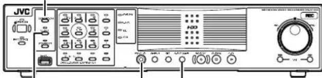
[SELECT] Button [FUNCTION] [ALARM CLEAR] Button Button
- The image and sound may not properly synchronize during playback on the NVR Viewer.
- After you have completed the e-mail setting, perform a test to verify that it can be sent successfully. (Page 107)
- When an external hard disk is connected, it may take several minutes to start up.
- Do not start the NVR Viewer during recording on VR-N1600U/E at a frame rate that exceeds 160 ips. Doing so may cause the recording frame rate to drop.
- Avoid the continuous playback of recorded images (1 hour or more) as it may cause recordings to be missed, etc.
Viewing Live Images via Front Panel Control
This section describes the procedures for viewing live images by using the front panel of this unit.
Memo :
- To operate by connecting a mouse (sold separately), refer to [Viewing Live Images via Mouse Control] (Page 36).
![[LIVE/BROWSE] Button [SELECT] Button Keypad JVC VR-N1600U/E [FUNCTION] Button [ALARM CLEAR] Button [15/ZOOM IN] Button [14/ZOOM OUT] Button [PTZ/PRESET] Button [REC CONTROL] Button [LIVE/BROWSE] Button [SELECT] Button Keypad JVC VR-N900U [FUNCTION] Button [ALARM CLEAR] Button [ZOOM IN/ENTER] Button [ZOOM OUT/CANCEL] Button [PTZ/PRESET] Button [REC CONTROL] Button](/content/2026/05/859290/images/2f867aeabada9a42fc0420b7655f888b7069177472b367f2219835d20ff3dc16.jpg)
Displaying the [Live] Screen
1 Press the [LIVE/BROWSE] button when the wallpaper *1 or main menu *2 screen is displayed.
![JVC VR-N1600E(A) - Displaying the [Live] Screen - 1](/content/2026/05/859290/images/54c2c300b2260a8fb94347fd4a043fb5ede41c6a15e4fcc32f23bb8c5793f6b4.jpg)
natural_image
Close-up of a metallic mechanical component with circular holes and a central fastener (no visible text or symbols)*1 Wallpaper Screen
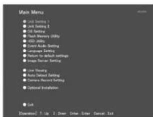
*2 Main Menu Screen
- Press the [LIVE/BROWSE] button when the [Browse] screen is displayed.
- Press the button to toggle between the [Live] and [Browse] screens.
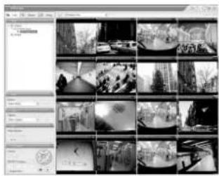
[Live] Screen
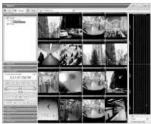
[Browse] Screen
Select a View
For details on the view settings, refer to [Screen Setup] (Page 60).
1 Press the [PTZ/PRESET] button to switch the [PTZ/PRESET] indicator to the blinking mode
- Press the [PTZ/PRESET] button to switch the [PTZ/PRESET] indicator between the lit and blinking modes.
2 Press the 15/ZOOM IN and 14/ZOOM OUT buttons to select a view
Note :
- Do not switch the view frequently within a short time interval.
- When live images do not appear on VN-C625U/VN-C655U, set the password for connecting VN-C625U/VN-C655U on the camera unit as well as this unit again. For details on the setting procedures, refer to the [INSTRUCRTIONS] of the camera in use and procedures for setting the root password on the [Edit device settings] screen in this manual (Page 87).
- The audio setting is restored to "No Audio Sources" when you return from the setting screen to [Live]. Select the parameters again.
Select a Camera
Select the camera image that you want to view as follows.
1 Press the [SELECT] button
- The [SELECT] indicator lights up.
2 Enter the camera number with the keypad
- Enter using the [1] to [16] keys in the case of VR-N1600U/E, and [0] to [9] in the case of VR-N900U.
Memo :
- You can specify a camera number between 10 to 19 by pressing [10/0] followed by a number from [10/0] to [9]. (VR-N1600U/E)
-
You can specify a camera number between 10 to 19 by pressing [0] followed by a number from [0] to [9]. Numbers from 20 cannot be selected. (VR-N900U)
-
When you have selected a camera, the blue bar at the top of each live image changes to a lighter blue tone.
● Each bar comes with a tri-color square indicator, which indicates the following features, as well as characters that indicate the operating status of the camera.
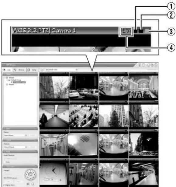
[Live] Screen
①Event indicator (Left: yellow)
Lights up when events specified in the [Camera Record Setting] occur. The indicator appears black if event indication has not been specified for the camera in question, or if no specified event has occurred.
②Motion indicator (Center: red)
Lights up when motion is detected.
③Online indicator (Right: green)
Blinks every time an image is received from the camera.
④Operating status of the camera (Characters to the left of the indicator)
| Display Status | |
| Live (Green) When | live images are displayed without being recorded |
| Recording (Red) When recording is in progress | |
| Stop (Yellow) When | images are not acquired from the camera, or when the camera is in the offline mode (Page 53) |
- You can press the [ALARM CLEAR] button to hide the event indicator and motion indicator.
- The image bar displays the name of the camera as well as the name of the device to which the camera is connected.
- Entering the number of the selected camera switches to an enlarged display. To return to normal display, enter the camera number of the enlarged display. You can identify the camera number of the [Camera Record Setting] screen of the main menu.
Operating the Camera
PTZ stands for pan, tilt and zoom. If the camera supports the PTZ functions, you can use the keypad, and the 16/ENTER and 13/CANCEL buttons to move the camera up/down (tilt), left/right (pan), or enlarge/reduce the image (zoom).
Pan/Tilt
1 Press the [PTZ/PRESET] button to switch the keypad to the PTZ mode
- The [PTZ/PRESET] indicator lights up. - Press the button to switch between the "PTZ Mode" (indicator lights up) and "Preset Mode" (indicator blinking).
2 Press the 1 to 9 key on the keypad
- Pans/Tilts in the direction indicated by the arrow on the keys. - Press the 6/HOME key to move to the home position.
■Zoom In/Zoom Out
1 Press the [PTZ/PRESET] button to switch the keypad to the PTZ mode
- The [PTZ/PRESET] indicator lights up. - Press the button to switch between the "PTZ Mode" (indicator lights up) and "Preset Mode" (indicator blinking).
2 Press the 15/ZOOM IN or 14/ZOOM OUT button
■Using Preset Positions
1 Press the [PTZ/PRESET] button to switch the keypad to the Preset mode
- The [PTZ/PRESET] indicator starts blinking. - Press the button to switch between the "PTZ Mode" (indicator lights up) and "Preset Mode" (indicator blinking).
2 Enter the preset number using the keypad
- Enter using the [1] to [16] keys in the case of VR-N1600U/E, and [0] to [9] in the case of VR-N900U. - The camera moves to the preset position.
Memo :
- You can specify a camera number between 10 to 19 by pressing [10/0] followed by a number from [10/0] to [9]. (VR-N1600U/E)
- You can specify a camera number between 10 to 19 by pressing [0] followed by a number from [0] to [9]. (VR-N900U)
- To specify a number beyond 20, use the mouse to make a selection from the [Presets:] list in the [PTZ Control] section.
Note :
- You need to specify the preset positions in advance in order to use the preset feature. (Page 92 [Defining a Preset Position])
Viewing Live Images via Mouse Control
This section describes the procedures for viewing live images by controlling the mouse.
Displaying the [Live] Screen
1 Select [Live] from the main menu
● The NVR Viewer starts up and the [Live] screen appears.
- When the [Browse] or [Screen Setup] screen of the NVR Viewer is displayed, click the [Live] tab.
- To exit the NVR Viewer, click the [×] button.
![[Live] Tab [Views] Section View List [×] Button](/content/2026/05/859290/images/f8606f06d9cec65a59f0df4a728603b2d94dbc596d8b179a019e0fb7381a4d6f.jpg)
[Live] Screen
- If you have specified the camera record settings without closing the [Live] screen, live images may not appear immediately after you have exited the camera settings. In this case, "Unable to connect to the server! Reconnecting to the server" or "Unable to connect to 127.0.0.1:80 on the device name(camera name)! Reconnecting to the server" will appear on the [Live] screen. (127.0.0.1:80 is the internal IP address of this unit that is currently in operation.)
Memo :
- Depending on the condition of the network circuit, it may take some time before images from the camera are displayed.
- Depending on the connection of the additional hard disk, several minutes may be required for the [Live] screen to appear.
Select a View
For details on the view settings, refer to [Screen Setup] (Page 60).
1 Select a view from the [Views] section, or from the view list at the upper end of the window
Note :
- Do not switch the view frequently within a short time interval.
- When live images do not appear on VN-C625U/VN-C655U, set the password for connecting VN-C625U/VN-C655U on the camera unit as well as this unit again. For details on the setting procedures, refer to the [INSTRUCRTIONS] of the camera in use and procedures for setting the root password on the [Edit device settings] screen in this manual (Page 87).
- The audio setting is restored to "No Audio Sources" when you return from the setting screen to [Live]. Set the audio parameters again.
Select a Camera
1 Select a camera by clicking on the bar at the upper end of the screen of the camera to select using the mouse
- When you have selected a camera, the blue bar at the top of each live image changes to a lighter blue tone.
![[Outputs...] Section [Event] Section MTS 240 PTZ Camera 1 Live Live Screen Live Screen Live Screen Live Screen Live Screen Live Screen Live Screen Live Screen Live Screen Live Screen Live Screen Live Screen Live Screen Live Screen Live Screen Live Screen Live Screen Live Screen Live Screen Live Screen Live Screen Live Screen Live Screen Live Screen Live Screen Live Screen Live Screen Live Screen Live Screen Live Screen Live Screen Live Screen Live Screen Live Screen](/content/2026/05/859290/images/52870d695f35b479915a0666ef5f5da8559bba93905a5e50ec152d202cf463ec.jpg)
[Audio] Section
Memo :
- When you have selected a camera, the blue bar at the top of each live image changes to a lighter blue tone. This bar comes with a tri-color square indicator, which indicates the following features, as well as characters that indicate the operating status of the camera.
①Event indicator (Left: yellow)
Lights up when events specified in the [Camera Record Setting] occur. The indicator appears black if event indication has not been specified for the camera in question, or if no specified event has occurred.
②Motion indicator (Center: red)
Lights up when motion is detect
③Online indicator (Right indicator: Green)
Blinks every time an image is received from the camera.
④Operating status of the camera (Characters to the left of the indicator)
| Display Status | |
| Live (Green) When live images are displayed without being recorded | |
| REC (Red) When recording is in progress | |
| Stop (Yellow) When images are not acquired from the camera, or when the camera is in the offline mode (Page 53) |
- The image bar displays the name of the camera as well as the name of the device to which the camera is connected.
- To enlarge the camera image, double-click the blue bar at the top. To return to the original size, double-click the blue bar again.
- You can turn off the light of the indicator by clicking the event or motion indicator that is lit.
Viewing Images Using the PTZ Features
PTZ stands for pan, tilt and zoom.
The PTZ features are only available if the camera supports the PTZ functions. If the camera is not a PTZ camera, pressing the button will have no effect.
1 Click the PTZ navigation button in the [PTZ Control] section
- The camera moves in the direction indicated by the arrow.
- Click the round button at the center to return to the home position.
- Click the [+] and [-] buttons to zoom in and out respectively.
![PTZ Navigation Button Presets IPX PTZ Positions: Local Close Digital Zoom Home Button [Live] Screen](/content/2026/05/859290/images/2709945faa29836532dcc59c1f37af9ab84e879791291404bd59617afe667903.jpg)
Note :
- The PTZ features are only available if the camera supports the PTZ functions. If the camera is not a PTZ camera, pressing the button will have no effect.
Memo :
- If you see a set of crosshairs when placing your mouse pointer over the image from a PTZ camera, then you are able to control the orientation of the camera using point-and-click control on the image screen. Control of the camera on the image screen is not possible if the mouse pointer does not change to the cross shape pointer. The mouse pointer may not change to the cross-shape pointer depending on the type of the PTZ camera. Control of the PTZ camera may not be possible for some PTZ cameras even though the mouse pointer changes to the cross-shape pointer. In this case, use the PTZ navigation button of the [PTZ Control] section to control the PTZ camera.
- The mouse pointer does not change to the cross shape pointer for analog cameras that are connected to the network encoder (IP video server) (e.g. VN-E4).
- If your mouse is equipped with a scroll wheel, you can use it to control the zoom in and out function on the PTZ camera.
- When using electronic zoom feature on VN-C625U/VN-C655U, zooming will stop at the boundary between optical zoom and electronic zoom. To continue zooming, perform zoom operation again.
Viewing Live Images via Mouse Control (continued)
Viewing Images Using the PTZ Features (continued)
Digital Zoom
By selecting the [Digital Zoom] check box in the [PTZ Control] section, you are able to use digital zoom on images from any camera displayed in the view. When digital zoom is enabled, you will see a small overview frame at the bottom right corner.
![PTZ Navigation Button [Digital Zoom]](/content/2026/05/859290/images/ebd311920a20f123f39aeb5835ccd854bbf028d2ceda1497f5ed4899772df141.jpg)
[Live] Screen
Memo :
- The recorded images will not be recorded in zoom even when digital zoom is used.
- When digital zoom is used, the recording frame rate may decrease due to an increase in the load factor of this unit.
- To exit the digital zoom function, deselect the [Digital Zoom] check box.
Note :
- When [Digital Zoom] is ticked, the actual PTZ operation will not be performed.
Using Preset Positions
You can select a position from the preset list to change the camera orientation to this preset position. (Page 92 [Defining a Preset Position])
Memo :
● The buttons are only available if the camera is a PTZ camera.
![[Presets] List Preset: IPIX PTZ Positions: Digital Zoom](/content/2026/05/859290/images/13324256015f09e3d4de805905e6a456b2fd577001feacffa18cad78a5bf5037.jpg)
1 Click the [v] button on the [Presets] list in the [PTZ Control] section
● The preset list appears on the screen.
2 Select a preset position from the preset list
● The camera moves to the preset position.
Memo :
- You can configure the preset list by going to Main Menu
→[Camera Record Setting]→[Settings...]→[PTZ Preset Positions...]. (Page 90)
Other Useful Functions
■Listening to Audio Sound
To listen to live audio sound, select the required audio source from the [Audio Source] list of the [Audio] section.
To temporarily mute the live audio sound, select the [Mute] check box.
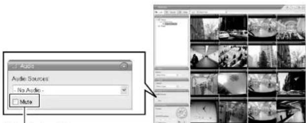
Select check box
[Live] Screen
Note :
- When the audio source is selected by multiple surveillance computers, the sound quality may deteriorate.
- The audio setting is restored to "No Audio Sources" when you return from the setting screen to [Live]. Select the parameters again.
Memo :
- If you have selected a camera for which an audio source has been set on the [Camera Settings] screen of [Camera Record Setting], the preset audio sound is being output. (15) Page 55)
- If you have selected a camera for which an audio source has not been specified, the most recently selected audio source will be continuously output.
- When the recorded and live images are simultaneously displayed, the displayed video image and audio sound may not synchronize properly. (However, this has no impact on recording to the system or additional hard disk.)
■Manually Triggering an Event
To manually trigger an event, select the event in the [Event] section, and click the [Activate] button.
![Click Events: Event01 Server Event01 Activate [Live] Screen](/content/2026/05/859290/images/744b86dc0d5c6e994a4477ede0c55bca75fa3d48adf46878dfc692d9fb130c4d.jpg)
Memo :
- For details on events, refer to [Camera Input/Output Port and Events] (Page 95).
- Events must be defined in advance. (Page 95)
■Triggering Outputs
To trigger an output, select the output in the [Outputs...] section, and click the [Activate] button.
![Output Outputs Select Output... Click [Live] Screen](/content/2026/05/859290/images/4f28bac5a92f40e150ffb3a24e41ffc43d11de0c236981c9e9e2c5a2f6616366.jpg)
Memo :
- Outputs must be defined in advance. ( page 98 [Specifying an Output]) ( page 103 [Specifying Output During Manual Control])
■Camera Shortcut Menus
You can right-click on one of the images from the camera to access the shortcut menu. Items in the shortcut menu may vary according to the configuration of the selected camera.
| Item Description | |
| 1Camera | Displays the video image of another camera in the selected position. |
| 2Sound Notifications | Temporarily mutes warning sounds. |
| 3PTZ Presets | Moves the camera to the preset position you have selected. |
| 4Matrix | Select this option to use the Milestone XProtect Matrix feature.Memo:For details, refer to the Milestone XProtect Matrix manual available on the website of Milestone Systems (http://www.milestonesys.com).The URL address may be subject to changes. |
| 5Send Camera | Sends images from the selected camera to another single-camera position in an open view. |
Playing Back Recorded Images via Front Panel Control
This section describes the procedures for viewing recorded images using the front panel of this unit.
![[LIVE/BROWSE] Button/Indicator [STOP(PB)] Button Keypad/Indicator JVC VR-N1600U/E [SEARCH] Button [16/ENTER] Button [SKIP] Button [13/CANCEL] Button [PTZ/PRESET] Button/Indicator](/content/2026/05/859290/images/8db83dc8b33eb7efb2b4ada9dc372d99f4e3fb2517d03514df3e94ee9f57e737.jpg)
![[LIVE/BROWSE] Button/Indicator Keypad/Indicator [STOP(PB)] Button VR-N900U JVC [SEARCH] Button [ZOOM IN/ENTER] Button [ZOOM OUT/CANCEL] Button [PTZ/PRESET] Button/Indicator [SKIP] Button](/content/2026/05/859290/images/42ae737f8287e1815529f4ebfe233eefcf19e1606843fd7309b7f8276d3e4b62.jpg)
Displaying the [Browse] Screen
1 Press the [LIVE/BROWSE] button when the wallpaper or main menu screen is displayed
- The NVR Viewer starts up and the [Live] screen appears.
2 When the [Live] screen appears, press the [LIVE/BROWSE] button again
- Press the button to toggle between the [Live] and [Browse] screens.
![JVC VR-N1600E(A) - Displaying the [Browse] Screen - 1](/content/2026/05/859290/images/eccbce998942e92e879c97d6748438d7147e05e32431650e67ad785e4e6457c4.jpg)
natural_image
Grid of black-and-white photos showing urban scenes with buildings and vehicles, no visible text or symbols[Live] Screen
[Browse] Screen
Select a View
For details on the view settings, refer to [Screen Setup] (Page 60).
1 Press the [PTZ/PRESET] button so that the [PTZ/PRESET] indicator starts to blink
- The [PTZ/PRESET] indicator switches between lit and blinking each time the [PTZ/PRESET] button is pressed.
2 Press the [15/Zoom In] (ZOOM IN/ENTER) and [14/Zoom Out] (ZOOM OUT/CANCEL) buttons to select a view
Note :
- Do not switch the view frequently within a short time interval.
- When live images do not appear on VN-C625U/VN-C655U, set the password for connecting VN-C625U/VN-C655U on the camera unit as well as this unit again. For details on the setting procedures, refer to the [INSTRUCRTIONS] of the camera in use and procedures for setting the root password on the [Edit device settings] screen in this manual (Page 87).
- Setting of the [Audio] section is restored to "No Audio Sources" when you return from the setting screen to [Browse]. Select the parameters again.
Searching Recorded Image Using a Specific Date/Time
You can search for and play back images by specifying a date and time using the [SEARCH] button on the front panel.
1 Press the [SEARCH] button on the [Browse] screen
- The date and time input screen appears.
![date: year month day 03 07 05 hour minutes second 08 56 07 Go To [Go To] Button](/content/2026/05/859290/images/89dbaf1fc97b48ad6036543364ebe786ea872ea3f4aa17d9336794aaf3804593.jpg)
2 Use the keypad to enter the search date and time
- Use the [SKIP] button (S or T) to select an item and input accordingly.
3 Press the 16/ENTER button
- The view in the image display screen on the right jumps to the selected date and time.
Memo :
- You can also jump to the selected date/time by clicking the [Go To] button.
- When you are using the software keyboard, click the [Go To] button.
Playing, Skipping and Stopping Recorded Images
Control using the [PLAY], [SKIP], and [STOP(PB)] buttons.
■Control using the [PLAY], [SKIP], and [STOP(PB)] buttons on the front panel
●Playing Back
1 Press the [PLAY] button
- Playback starts from the date/time indicated on the [Master Time] of [Time Navigation].
- Images are played back according to the angle of the shuttle dial (x1/20, x1/5, x1, x2, x5, x10, x20).
![[Master Time] area Tuesday, July 24, 2007 11:21:33.343 AM [Browse] Screen [Go To] Button](/content/2026/05/859290/images/e16d07395e7fd164866f5454f741806f39cc3476325a85a6b60c7b3790bc5b29.jpg)
[Time Navigation] Section
●Skipping
1 Press the [SKIP] button
● The [SKIP] buttons have the following functions.
| S Moves to the first image in the previous sequence.Moves to the first image in the database of the selected camera when the button is pressed and held down. |
| T Moves to the first image in the next sequence. Press and hold down the button to move to the latest image in the database of the selected camera. |
Memo :
- "Sequence" indicates a certain block of images that are recorded during motion detection.
- Recorded images are stored in the database.
Note :
- The [SKIP] buttons are only enabled when a camera has been selected.
- During simultaneous recording and playback, an "After Database End" message may appear as playback catches up with recording during playback near the current time.
- When recording is set to be triggered by motion/event (r ^2 Page 57), recording will not start unless a motion/event occurs. During playback near the current time, however, the image that is not recorded will also be played.
●Stopping
1 Press the [STOP(PB)] button
- Playback stops.
●Enlarging a Display
- Entering the number of the selected camera switches to an enlarged display.
- To return to normal display, enter the camera number of the enlarged display.
Adjusting the Playback Speed (Jog/Shuttle Playback)
You can adjust the playback speed by turning the jog dial/shuttle dial on the front panel.
■Shuttle Playback
- Rotate the shuttle dial during playback or when playback is paused to start fast forward, fast reverse or slow playback.
Memo :
- The playback speed that is indicated during fast forward or fast reverse playback by rotating the shuttle dial is an approximate value. The speed may differ depending on the conditions, such as the playback mode (multi-view, single view) and the recording mode (motion detection, recorded frame rate).
Jog Playback
- Rotate the jog dial to play back frame by frame.
- Rotate the dial clockwise to play back a single frame in the forward direction, and rotate the dial counterclockwise to play back a single frame in the reverse direction.
- Release the dial to pause the playback. However, when frames are played back successively in the forward or reverse direction, playback may continue momentarily after the jog dial is released.
Note :
- The jog dial is only enabled when a camera has been selected.
- When the playback speed is adjusted or when playing back at high speed during recording, the frame rate of the recording may decrease. Check the performance meter while adjusting the playback speed to ensure that the display does not turn red.
Playing Back Recorded Images via Mouse Control
This section describes the procedures for viewing recorded images by controlling the mouse.
Notes:
- The recording frame rate may decline when you are using the [Browse] screen.
- When access to the hard disk occurs frequently, such as when recording and playback of recorded images are performed simultaneously, the playback image may pause and the audio sound may be interrupted. (This has no impact on recording to the system or additional hard disk.)
- The audio setting is restored to "No Audio Sources" when you return from the setting screen to [Browse]. Set the audio parameters again.
- Set the time zone of the PC to the same time zone as this unit. If recorded images are viewed on a PC with a different time zone, the time displayed on the recorded images of this unit will be converted to the time in the PC's time zone.
- When the time zone in [OS Setting] is altered, press the [LIVE/BROWSE] while holding down the [FUNCTION] button to reboot the NVR Viewer.
Displaying the [Browse] Screen
1 Select [Live] from the main menu
● The NVR Viewer starts up and the [Live] screen appears.
2 Double-click the [Browse] tab on the NVR Viewer.
- Similarly, click the [Browse] tab when the [Screen Setup] screen of the NVR Viewer is displayed.
[Browse] Tab
[Browse] Screen
[Views] Section
[×] Button
![[Sequence] Section [Alerts] Section [Time Navigation] Section [Audio] Section [Smart Search] Section [Export] Section](/content/2026/05/859290/images/ad10c0c01036933a43375f2550153a86967a402cfd1f1a89051c9c98df101eb6.jpg)
- It may take a few minutes before the [Browse] screen is displayed.
- If you have specified the camera recording settings without closing the [Browse] screen, the playback images may not appear immediately after you have exited the camera settings.
In this case, "Unable to connect to the server!"
Reconnecting to the server" or "Unable to connect to
127.0.0.1:80 on the device name(camera name)!
Reconnecting to the server" will appear on the [Browse]
screen. (127.0.0.1:80 is the IP address of the this unit that is currently in operation.)
- If playback is executed when there are no recorded
images, the "Connection:[NVR]Camera1 on
127.0.0.1:80" message will continue to appear on the
Playback screen.
● To exit the NVR Viewer, click the Close button.
Memo :
- Each image bar comes with an online indicator at the top of the [Browse] screen. The indicator lights up in green each time a new image is displayed.
- Recorded images are saved in the database. "Database" refers to data recorded in this unit.
- When "Before Database Start" appears on the [Browse] screen, no database (recorded image) is found in the position prior to the currently viewed image.
- When "After Database End" appears on the [Browse] screen, no database (recorded image) is found in the position after the currently viewed image.
Note :
- If several sections are opened on the left side of the [Browse] screen, it may not be possible to display them all in the screen. In this case, double-click the section bars to close the sections.
- Do not switch the view frequently between [Live] and [Browse] within a short time interval.
Select a View
For details on the view settings, refer to [Screen Setup] (Page 60).
1 Select a view from the [Views] section, or from the view list at the upper end of the window
Note :
- Do not switch the view frequently within a short time interval.
- When live images do not appear on VN-C625U/VN-C655U, set the password for connecting VN-C625U/VN-C655U on the camera unit as well as this unit again. For details on the setting procedures, refer to the [INSTRUCRTIONS] of the camera in use and procedures for setting the root password on the [Edit device settings] screen in this manual (Page 87).
- The audio setting is restored to "No Audio Sources" when you return from the setting screen to [Live]. Set the audio parameters again.
Searching Recorded Image Using [Time Navigation]
You can search recorded images using [Browse] on the [Time Navigation] screen as follows.
1 Double-click the [Time Navigation] bar on the [Browse] screen
2 Select the search date/time from the box
- Specify the date in the left box and the time in the right box.
3 Click the [Go To] button
- The view in the image display screen jumps to the specified date and time.
- The specified date and time will appear in the Master Time area.
![Master Time Area 11:21:33.343 AM [Browse] Screen [Go To] Button](/content/2026/05/859290/images/3fc4a433362d3b82cc902372b2b2fec915dfd75548a408084f5f01177cee1af2.jpg)
[Time Navigation] Section
Memo :
- The Master Time area displays the recording date and time of the selected playback images. The master time is the time to which all the cameras are linked, and when you specify a time, all the recorded images you see in [Views] will be accurately displayed.
- There are cases when there is no recorded image on motion detection or on the specified date/time among the multiple cameras within the view. In this case, the last image in the camera's database prior to the specified point in time is displayed in the view. (Recorded images are saved to the database.)
- The Master Time area also displays the currently selected playback speed.
Note :
- The Master Time area may display a recording date/time beyond that of the latest recorded image. In this case, click the button to move to the latest recorded image, and click the button.
- When "Skip gaps during playback" in the [Time Navigation] section is ticked, playback may stop when it exceeds the end of the recorded portion during simultaneous recording and playback. In this case, deselect the tick in [Skip gaps during playback]. If playback stops, click the Play button again.
Playing Back Recorded Images via Mouse Control (continued)
Searching Recorded Image Using the Timeline Browser
You can search recorded images using the Timeline Browser to the right of the [Browse] screen. The vertically extended timeline shows the recording status and the number of cameras that can be displayed in the NVR Viewer. Drag the timeline up or down with the mouse while checking the time display pointer.
Note :
- The timeline is an approximate value. Therefore, the display may not coincide with the actual time.
![Timeline Display ON/ OFF Button Time Display Pointer [Timeline Browser]](/content/2026/05/859290/images/099524fb3b60447cea0cfdfb762d6796262094a977354be9a81fd08bd342eb95.jpg)
■Timeline Colors and Lines
The timeline of the camera selected in the view is highlighted in a lighter color.
| Red Indicates recordings of motion detection or events.(Pink when highlighted.) | |
| Green Shows recordings before and after motion is detected.(Light green when highlighted.) | |
| Black Indicates the period during which there is no recording.(Gray when highlighted.) | |
| Center White Line(Time Display Pointer) | Shows the time of the displayed image. |
Memo :
- The items under the timeline browser enable you to specify the time span to display on the timeline (1 hour, 2 hours, \~ 1 day), and whether to set the time flow from top to bottom or bottom to top by using the [Newest images at top] check box. These settings will not be saved. They will be lost each time the NVR Viewer is rebooted.
- If your mouse has a scroll wheel, you can also use the scroll wheel for browsing the timelines.
- Double-click on any point within the timeline to display image at the desired point in time.
- When you do not need the timeline browser, you can hide it by clicking the [Display ON/OFF] button at the center of the timeline browser's left edge.
Note :
- A portion of the timeline may not be refreshed if you drag the timeline up and down using the mouse. In this case, reboot the NVR Viewer. (Page 33)
Searching Recorded Image Using Sequence
Sequences refers to sequences of images that are recorded when an event or motion is detected. Each sequence contains a list of the recorded images.
1 Double-click the [Sequence] bar on the [Browse] screen
![[Sequence] Sequence Bar [AX9 212 P1Z] Camera 3 7/24/2007 11:16:40 AM (5 sec) 7/24/2007 11:16:26 AM (7 sec) 7/24/2007 11:14:33 AM (34 sec) 7/24/2007 11:16:11 AM (14 sec) 7/24/2007 11:11:34 AM (13 sec) Get Sequence Preview [Browse] Screen](/content/2026/05/859290/images/712d913fe0396c2d911e3b578965e7c9a645b41541cd897e80d96470a9a52e5b.jpg)
2 Click [Get Sequence]
- A list of 20 images each prior to and following the display time appears.
- If the [Preview Image] check box is selected, you are able to preview the images by placing the mouse pointer over the sequence in the list.
3 Click a sequence in the list
- Display of all the images in the view changes according to the date/time of the selected sequence.
Memo :
- Clicking the expand icon [+] next to a sequence in the list will show you the exact date and time of the first and last image in the sequence as well as the exact date and time of the motion detection or event that triggered the recording.
Note :
- Depending on [()seconds pre/post recordings on motion/event:] (r: Page 57), a consecutive number of sequences may sometimes be integrated into one sequence.
Searching Recorded Image from the Alert List
A list of recorded images is displayed for each [Alart], such as when motion is detected ( Page 105 ).
1 Double-click the [Alerts] bar on the [Browse] screen
2 Click [] on the [Alerts] list and select an event from the list
- You can select a specific event, camera or [Server].
![[Alerts] List Alerts Select Alert... Alert Time Event List [PLAY] Screen](/content/2026/05/859290/images/2245a40006c437c5538cc1f56c0509e15e1bac2a198e41f7fc158f07021236bf.jpg)
3 Click the [Get List] button
- A list of detected events appears.
- You can click on the event list to view recorded images of the selected event.
Memo :
- The Alerts list displays events occurring around the time (approx. 1 day before and after) set in [Time Navigation].
Smart Search
Smart Search enables you to search the parts with motion by specifying the search area within the recorded images of the selected camera.
1 Double-click the [Smart Search] bar on the [Browse] screen
![Smart Search Search Ratio Sensitivity: Medium Interval: All Images Search Area Show Grid Include Include Load Save Search Previous Next [Browse] Screen 7,8](/content/2026/05/859290/images/76a0ca7ff989a9818006ba14e8f49d7fbebef36dcfcdb71c93589ad85c65d63a.jpg)
2 Tick [Show Grid] in [Search Area] setting
3 Select the camera to display
- A blue grid overlay appears.
natural_image
Black-and-white photo of a large indoor space with people walking and a bridge, no visible text or symbols.4 Click and drag within the screen to specify the search area.
- The areas that you have selected become transparent. - Selecting the [Include] checkbox adds the dragged section to the search area. Selecting the [Exclude] checkbox deletes the dragged section from the search area.
5 Select the sensitivity level from the [Sensitivity] list in [Search Setup]
- The setting values are as follows. [Very High] [High] [Medium] [Low] [Very Low]
6 Set the time interval in the [Interval] list
7 Press the [Previous] or [Next] button to search through data for which motion has been detected within the area
● Smart Search begins. When motion is detected inside the selected area, it will be highlighted in the view.
Note :
- Smart Search is carried out in the [Forward] and [Backward] directions from the time of the image you are viewing.
- Smart Search that is performed during recording may lower the recording frame rate. Check the performance meter while adjusting the playback speed to ensure that the display does not turn red.
8 To continue searching, click the [Previous] and [Next] buttons
Memo :
- You can use the [Save] button to temporarily save the area that you have selected in Step 4.
To return to the saved area settings, click the [Load] button after selecting another area. - To cancel the area selection, tick [Exclude] and drag all the areas.
Playing Back Recorded Images via Mouse Control (continued)
Playing, Skipping and Stopping Recorded Images
Use the [Time Navigation] of the NVR Viewer to perform playback, stop, and skip operations.
![Browse Button at Time Navigation Tuesday, July 24, 2007 1:00x 11:21:33.343 M Back Playback Skip gaps during playback 7/04/2007 11:21:33 AM [Time] Slider [Playback] Slider Play Button [Browse] Screen](/content/2026/05/859290/images/c89dd7b4cfd65d578766d1b6b1639644d627b01e952a37067a4cbcf5c5928ad6.jpg)
The buttons and sliders have the following functions.
●Browse Button

Moves to the previous image on the selected camera (frame-by-frame reverse playback).

Moves to the next image on the selected camera (frame-by-frame forward playback).

Moves to the first image in the previous sequence of the selected camera. (This function may not work properly when there is no sequence or for some sequence lengths.)

Moves to the first image in the next sequence of the selected camera. (This function may not work properly if there is no sequence or for some sequence lengths.)

Moves to the oldest recorded image of the selected camera. (This function may not work properly at a playback speed of 10x or higher.)

Moves to the latest recorded image of the selected camera. (This function may not work properly at a playback speed of 10x or higher.)
Note :
- The browse buttons are only enabled when a camera has been selected.
- It may take several minutes for moving to complete after you have pressed the browse buttons. Note that if the buttons are clicked continuously before the images are moved, the selected sequences will be moved collectively.
●[Time] Slider
Dragging the slider to the left changes the recording date to an older date, and dragging the slider to the right changes it to a more recent date. Use the top slider bar for fine browsing (x0.4 to x240) within a limited period of time, and use the bottom bar for easy browsing (x20 to x36,000) for longer time spans.
●[Playback] Slider
The center position is for playback at normal speed (x1). Drag the slider to the left and right to reduce and increase the playback speed respectively. Dragging the slider to the leftmost position pauses playback.
The playback speed is displayed at the top right of the [Master Time] area.
●Play Button

: Plays back images in the reverse direction.

: Plays back images.

: Stops playback.
Note :
- The Play buttons do not work when the [Playback] slider is at its leftmost position (paused). Select the desired speed by moving the [Playback] Slider.
- The angle of the shuttle dial does not affect playback, which is operated in the [Time Navigation] section using a mouse.
Memo :
- When "Skip gaps during playback" of [Time Navigation] is checked, playback is performed by skipping portions for which no recorded image is found in the selected camera.
- When the recorded images are played back with some images skipped, the [SKIP] display will appear in red in the [Master Time] area for some time.
- During playback, skip playback operations may differ between a single screen and multiple screens. Even if the selected camera does not contain any recording, skipping will not take place as long as recording is found in another camera. If recorded images are not found, the last displayed image appears.
Listening to Audio Sound
To listen to recorded audio sound, select the required audio source from the [Audio Source] list of the [Audio] section.
To temporarily mute the live audio sound, select the [Mute] check box.
![Audio Audio Sources: No Audio- Mute Select [Browse] Screen](/content/2026/05/859290/images/fdce45e84b8fab765931f0d2d14ee7bdd4089f7b89d086ff82650bafa934e636.jpg)
Note :
- The sound may become distorted when audio is played back with multiple surveillance computers.
- The audio setting is restored to [No Audio Sources] when you return from screen display setting to the [Live] or [Browse] screen. To listen to an audio sound, reselect an audio source from the [Audio Source] list.
- There will be no audio output during still image playback or search/frame advance playback except at the speed of ×1.
- When a recorded image is played back during recording, the played back audio sound may be interrupted.
Memo :
- If you have selected an camera that has been set to record an audio sound, the specified audio sound will be output.
- If you have selected a camera that is not set to record an audio sound, the most recently played back audio sound will be output continuously.
- During simultaneous recording and playback of recorded images, the playback image may pause and the sound may be interrupted. (This has no impact on recording to the system or additional hard disk.)
Writing Images/Audio Sound to CDs, DVDs and Other Media (Export)
You can write (export) recorded images or audio sound to other media.
- The VR-N1600U/VR-N1600E/VR-N900U unit enables you to write images and audio sound to a CD-R, CD-RW, DVD-R, DVD-RW, or USB memory device.
- On a surveillance computer, you can write recorded images and audio to the desktop or to any folder you select.
Burning a CD/DVD (Operation on the unit)
- Steps 1 to 9 are common steps between writing to CD/DVD and USB memory devices.
1 Double-click the [Export] bar on the [Browse] screen
2 Enter the start date and time
- Click the [Set] button to input the date/time of the Master Time area.
3 Enter the end date and time
- When the [Set] button is clicked, the time input will be a second ahead of the date/time displayed in the Master Time area.
4 Select a camera from the [Source:] list, and click the [AVI/JPEG Export...] or [Database Export...] button
- You can also select [-Current View Source-] when selecting the source. When [-Current View Source-] is selected, images from all cameras within the view are exported.
- This export dialog appears. The specified start time, end time, and camera are shown in the dialog.
![Master Time Area 2 3 4 [Export] Section Start Time: 7/ 5/2007 8:40.02 AM Set End Time: 7/ 5/2007 8:40.02 AM Set Source: [JVC ] Camera 3 AVI / IPO Export Database Export... [Browse] Screen](/content/2026/05/859290/images/ae66948ff0f216eaa583fe05928b43e2a28ae380d220ad35908ea923cd75a8cb.jpg)
Memo :
- Export preparation may take some time depending on how the external hard disk drive is connected.
Writing Images/Audio Sound to CDs, DVDs and Other Media (Export) (continued)
Burning a CD/DVD (continued)
5 Select the export format if you have selected [AVI/JPEG Export...]
- Select either [AVI] (movie clip) or [JPEG] (still image).
- Select whether to add time stamps to the exported images.
6 Select the required frame rate if you have selected the [AVI] format
- Select either the [Full] option, which sends all images to the AVI file, or the [Half] option, which reduces the size of the AVI file by sending images on a per second basis (though images will still be played back in real-time).
7 If you have selected the [AVI] format, select [AVI Codec] from the [AVI Codec] list and enter the file name
- The default file name is "yyyymmdd-hhmmss.avi".
![NVR Viewer AVI / JPEG Export Export Status Ready Start Time: Thursday, July 05, 2007 8:01:23 AM End Time: Thursday, July 05, 2007 8:02:24 AM Source: [NVR] Camera 3 Export Type Export Format: AVI JFEG Add Timestamp: Yes No Framerate: Full Half Digital Zoom Export: Yes No AVI Codec: Microsoft Video 1 Export Destination CD USB AVI Filename: 20070705-080123.avi Close On Completion Export Close](/content/2026/05/859290/images/5b87ea1711ac8fe29ce254c107289f3edf622ef0c09365dc83a0c3e591102ab0.jpg)
Note :
● Make sure that the total number of characters used for the device and camera names does not exceed 61.
- If recording fails, the recorder may not be able to read the existing data correctly.
- New data cannot be added to existing data on a DVD media.
8 If you have selected [Database Export...], setting of the following items will be enabled.
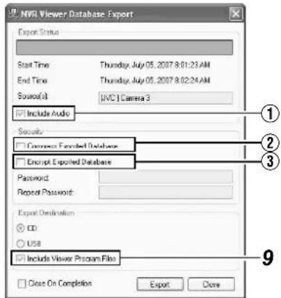
| Item Description | |
| 1Include Audio | Tick this box if you wish to include audio sound in the image to export. (You cannot select this check box if the audio source does not contain any data.) |
| 2Compress Exported Database | Select this check box to compress the exported database. |
| 3Encrypt Exported Database | Select this check box to encrypt the exported database. Specify a password for subsequent decryption. |
9 Assign a stand-alone viewer (application for playing recorded images) to the data to be exported
- If you have selected [Database Export...], you are able to include a stand-alone version of the viewer (application for playing recorded images) to the data to be exported by selecting the [Include Viewer Program Files] check box.
Memo :
- To view the exported data on a PC, double-click the [Browser.exe] file in the [Exported Images] folder of the USB memory, CD-R/RW, or DVD-R/RW used for the export. It will open the Viewer and you can view the exported data.
- For details on the Viewer, refer to [Export Viewer] (Page 142).
- DB To include audio sound by exporting in the AVI format, open the recorded image that has been exported in the DB format on the Viewer, and export it again in the AVI format on the Viewer.
Note :
- The [Database Export...] format enables you to export audio sound together, which is not possible when you export in the [AVI] or [JPEG] format.
● The recording frame rate may decline during export.
10 Specify the export destination
To write data to a CD/DVD, select [CD].
![NVR Viewer AVI / JPLG Export Export Status Ready Start Time: Thursday, July 05, 2007 8:01 23:4M End Time: Thursday, July 05, 2007 8:02 24:4M Source: [JPG] Camera 3 Export Type Export Format: AVI JPEG Add Timestamp: Yes No Frames: Full Hall Digital Zoom Export: Yes No AVI Code: Microsoft Video 1 Export Destination CD USB AVI Rename: 20070005-000123.exe Date On Completion Export Close [CD] Check Button 11](/content/2026/05/859290/images/28baa60bc25eea747bd7523a33f733958527a506b42080bd2321f4d13b8867f0.jpg)
11 Click [Export]
- Export begins to prepare for writing data to the CD/DVD.
12 When export is complete, connect the CD/DVD drive to this unit
13 Press and hold the [FUNCTION] key in front, and press [4] on the keypad
● The Burn CD/DVD screen appears.
Check Box Data List
![Camera Name Start Time End Time Size DB [JNO] Camera 2 7/5/2007 04:33 AM 7/5/2007 04:33 AM 1800 MB AVI [JNO] Camera 3 7/5/2007 05:29 AM 7/5/2007 05:29 AM 741 MB Select All Reset All Erase Sel Data Total Selected Vol 26.02 MB Free Media Space 702.62 MB Burn CD/DVD Screen Erase CD-RW End [Erase RW] Button [Erase Sel Data] Button [Burn] Button](/content/2026/05/859290/images/75687bf42a8be8b4008d21870426fbc4bb81c726f5613b520319a7d70f29cbaf.jpg)
14 Insert the media (CD-R/RW or DVD-R/RW) that you want to write data to into the CD/DVD drive
- The space available in the media is shown in [Free Media Space].
- The [Burn] button is enabled (operable).
15 Select the check boxes for the AVI/JPG/DB files that you want to write to the CD from the data list.
- The total volume of the selected data will appear in [Total Selected Vol].
- To select all the files, click the [Select All] button.
- To deselect all the files, click the [Unsel.All] button.
16 Press the [Burn] button
- A [YES] or [NO] message asking you whether to start writing appears. Select "YES".
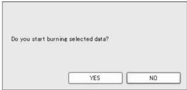
Memo :
- If no file has been selected from the data list, an error will occur.
- If the total volume of the selected data exceeds the available memory space in the media, an error will occur.
17 When writing is complete, the following message appears.
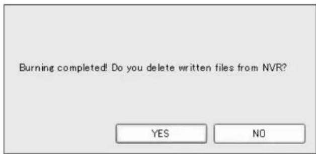
- To delete the temporary files, select "YES".
- To write the same data to another CD, select "NO".
Writing Images/Audio Sound to CDs, DVDs and Other Media (Export) (continued)
Deleting Temporary Files (Operation on the Unit)
1 Select the temporary files you want to delete from the data list.
2 Click the [Erase Sel Data] button
A [YES] or [NO] message asking you whether to delete the selected data appears. Select "YES".
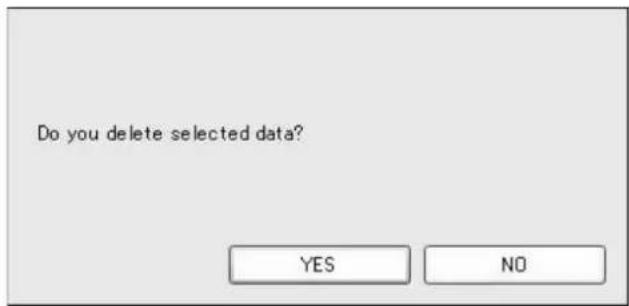
Deleting Data from a CD-RW (Operation on the Unit)
1 Insert the CD-RW
- The [Erase RW] button is "enabled".
2 Click the [Erase RW] button
- A [YES] or [NO] message asking whether you want to delete data in the RW appears. Select "YES".
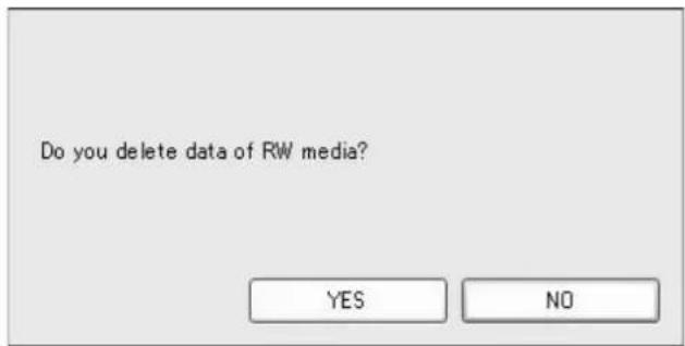
Note :
- You cannot perform other operations while data is being written to a CD/DVD.
- Recorded images may be omitted during writing to the CD/DVD (temporary recording error).
- Do not display the Burn CD/DVD screen during export.
- Do not connect the CD/DVD drive while a media is inserted.
- Do not disconnect the CD/DVD drive while the Burn CD/DVD screen is displayed.
- If media is not detected, restart the Burn CD/DVD screen.
Writing Data to a USB Memory Device (Operation on the Unit)
Insert the USB memory device that you wish to export data to into VR-N1600U/VR-N1600E/VR-N900U, and perform the same procedures for [Burning a CD/DVD] from Steps 1 to 9. (m) Page 47
1 Specify the export destination
- To export to a USB memory device, select [USB].
![NVR Viewer AVI / JPEG Export Export Status Ready Start Time: Thursday, July 05, 2007 9:01:23 AM End Time: Thursday, July 05, 2007 8:02:24 AM Source: [JVC] Camera 3 Export Type Export Format: AVI JPEG Add Timestamp: Yes No Framesate: Full Half Digital Zoom Export: Yes No AVI Codec: Microsoft Video 1 Export Destination CD [USB] Check Button USB AVI Filename: 20070705-080123.avi Export Close 2](/content/2026/05/859290/images/156bc1a32593f42a756a9c026bc48d5456ce8d327f14036270f4b935c43bb1c8.jpg)
2 Click [Export]
- Export begins.
Operation from a Surveillance Computer
Follow the same procedures for [Burning a CD/DVD] from Steps 1 to 9. (Page 47)
1 Specify the export destination
![NVR Viewer AVI / JPEG Export Export Status Ready Start Time: 2007年7月17日 9:41:01 End Time: 2007年7月17日 9:41:03 Source: [JVC VN-C20] Camera 1 Export Type Export Format: AVI JPEG Add Timestamp: Yes No Framerate: Full Half Digital Zoom Export: Yes No AVI Code: Microsoft Video 1 Export Destination Desktop Path AVI. Filename: 20070717-094101.avi Export Close](/content/2026/05/859290/images/3f21c6ad4619010630e3bdfbc8ca075cf7ce8cbf61bc07189b5ccb0a476c814a.jpg)
| Desktop Use this to export to the desktop. |
| Path Use this to export to a selected folder. |
2 Click [Export]
- Export begins.
Printing Recorded Images (Operation from a Surveillance Computer)
You can print out playback images that are displayed on the screen.
Note :
- You cannot print directly from this unit. This function is for use by the [NVR Viewer], which is downloaded onto the surveillance computer.
1 Double-click the [Print] bar on the [PLAY] screen.
![Print Print selected view item. [Browse] Screen](/content/2026/05/859290/images/a447832b3435dd80f485e0719db10bba0283b66f6645eb582f85f8ecbe4b10f4.jpg)
Memo :
- You can use the button to the right of the Print bar to display the screen at one click.
2 Click the [Print...] button in the [Print] section.
● The [NVR Viewer Surveillance Report] screen appears.
![NVR Viewer Surveillance Report NVR Viewer Surveillance Report Surveillance Report Camera Name: [JVC] Camera 3 Image Capture Note: Thursday, July 05, 2007 8:49:13 AM Report/Print Time: Thursday, July 05, 2007 8:18:36 AM User: VR.N1800MainIndicator User's Note: Page Setup Personal Print Close [User's Note] 3 4](/content/2026/05/859290/images/adff12d6db136ea501a995d1772bc45a911342a40eacbb969a3ad0ab47b82916.jpg)
3 Click the [NVR Viewer Surveillance Report] button on the [Page Setup] screen to specify the printer settings
4 Click the [Print] button to start printing
- After printing ends, click the [Close] button to close the print window.
- Comments entered in [User's Note] are also printed.
Recording Camera Images
Recording Modes
There are four different recording modes.
- Recording Control Mode
● Manual Recording Mode - EXT REC IN Signal Recording Mode
● Emergency Recording Mode
■ Recording Control Mode ( Page 53)
This mode performs recording according to the [Camera Record Setting].
The [REC CONTROL] indicator lights up.
You can switch the recording control mode on or off by pressing and holding the [REC CONTROL] button.
- Set each camera to on/off using the [Scheduler...] settings (Page 53).
- Specify the frame rate and conditions for starting recording in [Camera Settings] (u) Page 55.
Note :
- During the interval that is set as offline in [Scheduler...], recording will not be performed regardless of the [Camera Settings].
- The [REC CONTROL] button is “disabled” when the main menu is displayed, when settings are being specified, and during recording.
- When there is an unconnected camera, it may take a while before the [REC CONTROL] indicator lights up.
Memo :
- Press the [REC/STOP] button to cancel the “recording control mode” and enable manual recording mode.
- Press and hold down the [REC/STOP] button to cancel all "recording modes" and stop recording.
- Setting [Operate] to ON switches the mode automatically to the "recording control mode". (When the "ON at startup" checkbox of [Record Control] under [Unit Setting 1] of the main menu is selected.)
■ Manual Recording Mode
The manual recording mode executes recording from all cameras regardless of the [Camera Record Setting]. Recording is executed in the frame rate specified in [Recording Settings]–[Desired framerate] of the [Camera Settings] screen.
Manual recording lets you start and stop recording on all cameras by using the [REC/STOP] button. Press the [REC/STOP] button to start recording. Press and hold down the [REC/STOP] button to stop recording.
The [REC CONTROL] indicator lights up.
■ [EXT REC IN] Signal Recording Mode
Recording starts on all cameras when the [EXT REC IN] terminal of the rear input/output terminal is set to MAKE. Recording is executed in the frame rate specified in [Recording Settings]–[Desired framerate] of the [Camera Settings] screen.
Recording using [EXT REC IN] signals has priority over the recording control mode or manual recording.
When recording by the [EXT REC IN] signals is complete, the cameras return to the original recording mode.
Memo :
- When recording using signals from the [EXT REC IN] terminal, the light of the [REC CONTROL] indicator goes off, and the [REC] indicator appears blinking.
- Emergency recording lets you start and stop recording on all cameras regardless of the [Scheduler...] settings or [Camera Settings].
- Pressing the [REC/STOP] button cancels recording by signals from the [EXT REC IN] terminal and switches automatically to the “manual recording mode”. The [REC] indicator also changes from “blinking” to the “lit” mode.
- Pressing and holding down the [REC/STOP] button cancels recording by signals from the [EXT REC IN] terminal and stops recording.
Emergency Recording Mode
Recording starts on all cameras when a MAKE signal is detected by the [EMERGENCY] terminal of the rear input/output terminal. Recording is executed in the frame rate specified in [Recording Settings]–[Desired framerate] of the [Camera Settings] screen. Recording is only executed during the time specified in [Emergency Record] of [Unit Setting 1] (Page 70).
Emergency recording has priority over the [recording control mode] or [manual recording] mode.
When emergency recording is complete, the cameras return to the original recording mode.
Memo :
- The [REC CONTROL] indicator goes off and the [REC] indicator appears blinking during emergency recording.
- Emergency recording lets you start and stop recording on all cameras regardless of the [Scheduler...] settings or [Camera Settings].
- Pressing the [REC/STOP] button cancels emergency recording and switches automatically to the “manual recording mode”: The [REC] indicator also changes from “blinking” to the “lit” mode.
- Press and hold down the [REC/STOP] button to cancel all recording modes and stop recording.
Note :
- When in the manual recording, [EXT REC IN] signal recording or emergency recording mode, motion detection and event recording settings are ignored.
Recording Operation During Power Failure
If a power failure occurs during recording, the system resumes recording in the mode selected before the power failure after recovery.
- In the recording control mode, recording by a motion or event does not resume unless another motion or event occurs after recovery from the power failure.
- The recording control mode returns to the status before the power failure.
Note :
- The recorded images may not be played back properly if they are not archived (Page 108) before the power failure.
- It is recommended that an uninterruptible power supply (UPS) be used to protect the hard disk from damage in the event of a power failure. ( page 136)
- If a power failure occurs while formatting a hard disk or archiving, subsequent operations may be affected even when a UPS is connected.
Selecting the Recording Control Mode
In order to record in the recording control mode, you need to specify the scheduler settings (Page 53), image recording settings (Page 55), and picture quality settings (Page 58) in the main menu [Camera Record Setting].
1 Press and hold down the [REC CONTROL] button while camera recording is stopped ([REC] indicator is off).
- The [REC CONTROL] indicator lights up and the unit switches to the recording control mode.
- Recording will be executed according to the camera record settings.
Memo :
- To stop recording, press and hold down the [REC/STOP] button during recording in a mode other than recording control (the [REC] indicator lights up or appears blinking). After the light of the [REC] indicator goes off, press and hold the [REC CONTROL] button.
- To exit the recording control mode, press and hold down the [REC CONTROL] or [REC/STOP] button.
- Depending on camera status or other circumstances, it may take a while before recording starts after switching to the recording control mode.
Note :
- Do not turn off the power while you are configuring the camera recording settings.
Selecting the Manual Recording Mode
1 Press the [REC/STOP] button
● The unit switches to the manual recording mode and starts recording from all cameras.
● The [REC] indicator lights up.
Memo :
- To exit the manual recording mode, press and hold down the [REC/STOP] button. Upon doing so, the light of the [REC] indicator goes off.
- To clear all recording modes, press and hold down the [REC/STOP] button.
![[REC] Indicator [REC CONTROL] Button/Indicator [REC/STOP] Button](/content/2026/05/859290/images/07bce7c61da7f80fd9be84d6b27980b8f7bb3e4ad85458fa5972c955eedf6877.jpg)
Scheduler Setting
This feature lets you specify when to switch each camera to the online mode, as well as the online/offline mode of cameras when an event occurs.
Memo :
- When in the online mode, the camera executes recording according to the camera record settings.
- When in the offline mode, recording is not executed regardless of the camera record settings.
- You can specify the time zone during which e-mail alerts are triggered when motion is detected. You can also specify the time zone to activate automatic patrolling (Page 93) when using PTZ cameras.
● The minimum unit of time that you can specify is 5 minutes.
Note :
- The online/offline mode has no impact on the manual recording, [EXT REC IN] signal recording, and emergency recording modes.
- Even when "offline" or "Event" is specified in the scheduler, the camera switches to the "Online" mode if Start cameras on remote live requests is specified in [General Settings] and live images are displayed on the [NVR Viewer].
- During the interval that is set to "Offline", recording will not be performed even when in the "Online" mode. During the interval that is set to "Event", recording is performed according to the recording settings when the unit switches to the "Online" mode.
1 Select [Camera Record Setting] from the main menu
2 Click the [Scheduler...] button
● The [Scheduler...] screen appears.
![[Scheduler...] Button Deloit Manager + 400 A125.287M (192.268.0.5) + 400 A125.211#F2 (192.168.0.2) + 30C (292.168.0.20) + 30C F19 (327.0.0.1) Add Device... Delete... Save Settings... Event... 3D Setup... Event Buttons... General Events... GO Control... Exit](/content/2026/05/859290/images/5361817e3c32d2c4f705b58f9f9b7ad77518c83d94b13dfdf6ae7dedb50b7c18.jpg)
[Camera Recording Administrator] Screen
3 Select the camera for which you want to set a schedule from [Camera].
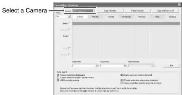
[Scheduler] Screen
Recording Camera Images (continued)
Scheduler Setting (continued)
4 Select [Set] from [Mode]
- The mouse pointer turns into a "pencil".
- Moving the mouse pointer to the day-of-week band in the calendar section enables you to zoom in/zoom out on the calendar. To check the detailed schedule, enlarge the day of week area of the calendar.
Mode
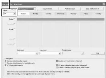
5 Select the [Online] check box
6 Specify the date to switch online in the calendar section
- Hold down the mouse in the calendar section, and move the mouse pointer to specify the date.
- The selected period is indicated in light blue color.
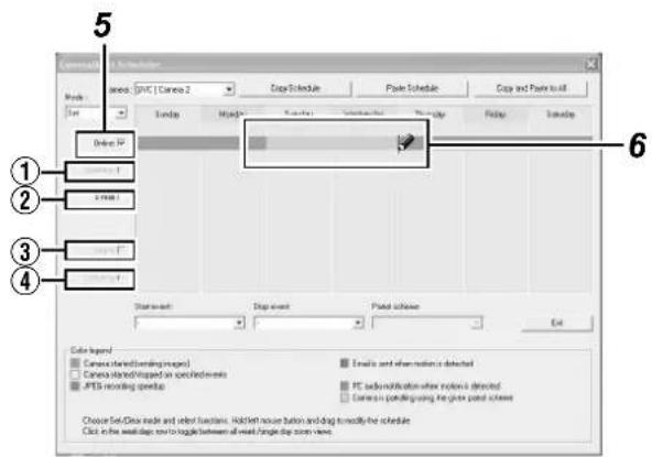
Memo :
- Selecting the [E-mail], [Patrolling], and [Enable speedup] check boxes enables you to specify the following settings.
| 1Enable speedup | Enables you to specify a constant speedup period regardless of any conditions when speedup in [Settings...] is set to “Enable” (Page 56). |
| 2E-mail | Enables you to specify the period to send out the e-mail alert when e-mail alert notification during a motion is selected (Page 96). |
| 3Audio | You cannot select this check box. |
| 4Patrolling | Enables you to specify the patrol scheme and patrolling period. Select a patrol scheme from the [Patrol scheme] list, and specify the corresponding period in the calendar section. [Patrol scheme] must be defined in advance. (Page 94) |
7 The Schedule Settings window appears
- Click [On Event] or [Always].
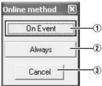
| 1On Event | Switches to the online mode only when an event occurs. Specify the event in the event start/stop item. |
| 2Always | Online mode at all time. |
| 3Cancel | Cancels the settings. |
Memo :
- To clear the period, select [Cancel] from [Mode] at the top left, select the check box of the item you want to delete ([Online], [E-mail] or [Patrolling]), and move the mouse pointer while left-clicking the mouse on the period in the calendar section.
■Camera/Alert Scheduler Screen
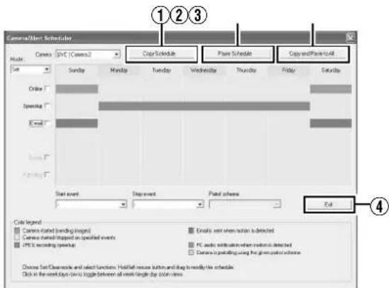
| 1Copy Schedule | Enables you to copy the schedule displayed in the calendar section. |
| 2Paste Schedule | Pastes the schedule copied using [Copy Schedule]1to the selected camera. |
| 3Copy and Paste to All | Pastes the schedule displayed in the calendar section to all cameras. |
| 4Close | Exits the [Scheduler...] screen. |
● Display Bar
The display bar indicates the active period for each option ([Online], [E-mail] and [Patrolling]) in different colors.
•Online Bar
| Pink Indicates | the period during which this unit always displays images of the selected camera. |
| Yellow Indicates | the period during which images of the selected camera are displayed when an event is input to this unit. |
●E-mail Bar
Active periods are indicated in blue.
●Patrolling Bar
Active periods are indicated in gray.
Memo :
- The Patrolling Bar is only available when at least one [Patrol scheme] has been registered in advance. When several patrol schemes have been registered and are used successively, changes between the schemes are indicated by a thin vertical line. (18) Page 94
- To check the [Patrol scheme], click the bar of the period to check in the calendar section. The [Patrol scheme] specified for that period will appear in the [Patrol scheme] list.
Specifying Image Recording Settings
1 Select [Camera Record Setting] from the main menu
![Camera Recording Administrator Device Manager + AOTS 207W (192,168.0.5) + AOTS 212 PTZ (192,168.0.5) + JVC (192,168.0.26) + MIR (192,6.0.1) Add Device... Add Device... Remove Device... Settings... J/O Setup... Event Buttons... General Control... I/O Control... Service Manager... Scheduler... General Settings... Archive Setup... Import... Help... Transaction... Exit [Settings...]](/content/2026/05/859290/images/a8dea33e88ceaad580816b28096f364e976f5f346c292a7afb6e5aa59f0574aa.jpg)
[Camera Recording Administrator] Screen
2 Select a camera from [Device Manager] and click [Settings...]
• The [Camera Settings] screen appears.
- Specify the setting for each item. (Page 56)
![Camera Settings for [LPC-EN-C625] Figure 3 Scan-up Settings Dramed Formatize: 0 Fillet(s) per Second 0.13 Second(s) Min. Images Recording Settings Dramed Formatize: 0 Fillet(s) per Second 0.13 Second(s) Min. Images Enable speedup Open Onset Onset Conditionally Onset 5 seconds pre/post recordings on motion/present Line Settings Dramed Formatize: Save as recording Save as speedup Camera Monitor Setup Show/Show Show/Show Lower Speedup Enabled Audio source [Speed] Audio source settings: Max. records in database Plan time spent in database Archive automatically when database is full In case of database features the for: using action should be taken. Archive (or repair) Motion Detection Settings Motion Detection... Motion Color... Exclude Response Settings Exclude Response... Region Color... Image Quality... Event Specifications... Cutoff... OK Cancel](/content/2026/05/859290/images/1e261c8b8db8ed1ba9a6467bb1744213362b34e9a29fb7f2ba045d9eeb709be4.jpg)
[Camera Settings] Screen
Recording Camera Images (continued)
Settings
(●: Factory settings)
| Item Preset Values Description | ||
| 1Speedup Settings | ||
| Frame Rate | — | Enables you to specify the frame rate to acquire from the camera. This is the frame rate during speedup recording. Specify the frame rates such that the total rate of all cameras displayed in each view of the [Live Viewing] screen does not exceed 80 ips (image per second) for VR-N1600U/E, 160 ips for VR-N1600U/E(A), and 60 ips for VR-N900U.When playing back the recorded images of VR-N1600U/E(A), set the total display rate to 80 ips or below to display the playback from the main unit and distribution for 13 channels or more simultaneously.Note :Do not set a value that exceeds the camera's capacity.If the frame rate is not specified for the camera, a frame rate that is supported by the camera is automatically set. |
| 2Live Settings | ||
| Frame Rate | Same as recording●Same sa speedup | Displays the viewing frame rate of the [Live Viewing] screen.Same sa speedup:Displays live images using the frame rate specified in the [Speedup Settings] item1.Same as recording:Displays live images using the frame rate specified in the [Recording Settings] item5.When speedup is set to "ON" and the recording frame rate increases such as due to detection of motion, the live viewing rate also increases. |
| 3Camera Monitor Setup | Show MotionShow RegionsUpdate on motion only●Disabled | Select the "Disabled" checkbox to disable the camera.Memo :“Show Motion”, “Show Regions” and “Update on motion only” cannot be selected. |
| 4Audio Source | Audio1 | You can select the audio source to play back when a camera is selected in the NVR Viewer.You can also specify the audio source in the NVR Viewer if the audio source is included in the source to be exported in the [Database Export...] format. (e8: Page 47 [Writing Images/Audio Sound to CDs, DVDs and Other Media (Export)])This has no impact on audio recording. |
| 5Recording Settings | ||
| Desired framerate | [none] | Enables you to specify the recording frame rate. You need to specify a value that is larger than the [Frame Rate] of the [Speedup Settings] item1. Specify the frame rates such that the total rate of all cameras displayed in each view of the [Live Viewing] screen does not exceed 80 ips (image per second) for VR-N1600U/E, 160 ips for VR-N1600U/E(A), and 60 ips for VR-N900U.Note :See below for the recordable frame rate of each model. Set the total frame rate of all cameras so that it does not exceed the respective values. When speedup settings are used, restore the frame rate of the speedup settings to the original value.VR-N1600U/E :160 ips or below (When using NAS: 80 ips or below)VR-N900U(A),(B):120 ips or below (When using NAS: 60 ips or below)Analog input of VR-N900U(A),(B): 60 ips or belowAnalog input of VR-N900U: 20 ips or belowRecording frame rate may fall below the preset frame rate depending on the signal processing condition of this unit.Recording frame rate may deteriorate under the following conditions:During exportWhen changing the picture quality of the displayed imageWhen the total frame rate of the display images (including display on PC) exceeds 80 ips for VR-N1600U/E, 160 ips for VR-N1600U/E(A), and 60 ips for VR-N900UWhen the frame rate is set to a high value, the recording frame rate may be slightly higher or lower. |
| 5Recording Settings (continued) | ||
| Enable speedup | On motionOn event | Enables you to specify whether to execute recording with a higher maximum frame rate when motion is detected or when an event occurs.When [On event] is selected: Specify the starting and ending events in the [Start] and [Stop] fields respectively.The speedup recording frame rate uses the [Frame Rate] in the [Speedup Settings] 1 item.When the input is analog: Values of frame rate that can be set are 30, 15, 10, 7, 6, 5, 3, 2, and 1.When set to 7, the rate is 7.5 frames per second. |
| When to store images in database | AlwaysNever●Conditionally | Always: Select this check box to record images at all times.Never: Do not perform recording in the recording control mode. Record starts when the [REC/STOP] button is pressed.Enables you to specify the recording conditions in recording control mode. If you have selected [Conditionally], specify the following fields as well.On motion: Select this check box to record all images for which motion has been detected.On event: Select this check box to record all images from the occurrence of an event until the next event occurs regardless of motion. Specify the starting and ending events in the [Start] and [Stop] fields respectively.Memo:For details on events, refer to [Camera Input/Output Port and Events] Page 95.Note:If you have selected [Conditionally], the [ALARM] indicator on the front panel lights up regardless of the recording status when the motion or event specified in [When to store images in database] occurs. Press the [ALARM CLEAR] button to turn off the light of the [ALARM] indicator.()seconds pre/post recordings on motion/event:You can record images preceding and following a detected motion or event. Specify the time interval to record in the number of seconds before and after the occurrence. (Page 139)Memo:Do not set to “0 seconds”.If Offline is selected in [Scheduler...], images will not be recorded.This setting has no impact on manual recording, emergency recording, and [EXT REC IN] recording. |
| 6 Database Settings | — | Enables you to specify the database settings. (Page 110) |
| 7 Motion Detection Settings | — | |
| Motion Detection.. | Enables you to specify the two parameters for motion detection, namely [Sensitivity] and [Motion Sensitivity]. (Page 104) | |
| Motion Color.. | Enables you to specify the color to be used for highlighting detected motion. | |
Recording Camera Images (continued)
Settings (continued)
| Item Preset Values Description | ||
| 8 Exclude Regions Settings | — | Enables you to specify the regions to exclude from motion detection. (Page 104) |
| Exclude Regions... | ||
| Region Color... | Not used. | |
| 9 PTZ Preset Positions... | — | Enables you to specify preset positions and patrolling.When a configurable camera is selected, this button is displayed to the right of the [Outputs...] button. |
| 10 Outputs... — | Enables you to specify output settings. (Page 102) | |
| 11 Event Notifications... | — | Enables you to select events for triggering event notification. (Page 102) |
| 12 Image Quality... — | Enables you to specify the image resolution and picture quality. (Page 58) | |
Note :
- When the recording program (recording server) is operating, the [PTZ Preset Positions...] button is disabled. To stop the recording server temporarily, press the [Service Manager...] button on the [Camera Record Setting] screen, followed by clicking the [Pause] button. (r ^2 Page 83)
- Video images and audio sound are not recorded when the recording server is temporarily stopped. Display of live images on the surveillance computer is also turned off.
- Even when “Always” is selected under [When to store images in database]④ in the recording control mode, recording is not executed during the interval when the [Scheduler...] is set to “offline”. (E7 Page 53)
- Clicking [Cancel] does not cancel the picture quality and settings that are specified on another screen.
Setting Picture Quality
Clicking the [Preview Image] button while you are adjusting the camera settings enables you to view the effect of your settings.
1 Select [Camera Record Setting] from the main menu
2 Select a camera from [Device Manager] and click [Camera Settings]
- The [Camera Settings] screen appears.
3 Click [Image Quality...]
● The [Configure Device] screen appears.
Note :
- It is recommended that you set the picture quality to approximately 24 KB (VGA). Specifying a higher image quality may affect the sound and cause the frames to be dropped.
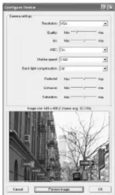
Example of [Configure Device] Screen
Memo :
- The [Configure Device] screen may vary with cameras.
- Refer to the [Instruction Manual] of the respective cameras for the setting items.
Specifying Audio Recording Settings
1 Select [Camera Record Setting] from the main menu
- The [Camera Recording Administrator] screen appears.
Memo :
- You can also specify audio settings using the following operation.
① Click the [+] mark beside the device with an audio source
② Select the audio source and right-click on it. Click [Edit] and specify the settings accordingly on the [Audio Device Settings] screen.
2 Select an audio source from [Device Manager], and press the [Settings...] button
● The [Audio Device Settings] screen appears.
● Audio sound is indicated using a microphone icon.
![Audio Device Settings Enabled Device name: Audio 1 Target Database: [JVC] Camera 3 OK Cancel](/content/2026/05/859290/images/72acbb82a9b734bd0d5bdd60bd31c8f80c7ba6695829861f7360310416c5a317.jpg)
- Specify the setting for the following items.
| Item Description | |
| 1Enabled | Enables/Disables the audio source.Memo:Right-click on the camera or audio source in the [Device Manager] section to select [Disable] or [Edit]. |
| 2Device name | Displays the name of the audio source. You can overwrite the existing name with a new one. |
| 3Target Database | Enables you to specify the camera database to record audio sound to. |
Memo :
- The audio sound is recorded in the database of the camera image specified in the [Target Database] item ③.
- Audio sound is recorded throughout the interval when the scheduler of the camera specified in the [Target Database] item ③ is in the online mode.
- In the case of VR-N1600U/E, audio signals that are input to [AUDIO IN 1/AUDIO IN 2] on the rear panel are allocated as [Audio1] and [Audio2] in NVR on the [Device Manager].
- In the case of VR-N900U, audio signals that are input to [AUDIO IN 1/AUDIO IN 2] on the rear panel are allocated as [Audio1] and [Audio2] in N900 on the [Device Manager].
Note :
- If the camera specified in the [Target Database] item③ is set to "Disable", audio sound is not recorded.
- To play back audio sound of the camera selected using NVR Viewer, you need to specify the audio source on the [Settings...] screen under [Camera Record Setting] (Page 55).
Precautions when enabling the analog audio source of VR-N1600U/E
When entering a device for [Target Database] in the [Audio1] and [Audio2] settings of NVR, make use of an input channel that is after the channel for recording the audio device of the selected device.
(Example)
○ VN-E4 Audio1 → E4 Camera2, NVR Audio1 → VN-E4 Camera1
× VN-E4 Audio1 → E4 Camera1, NVR Audio1 → VN-E4 Camera2
× VN-E4 Audio1 → Disable, NVR Audio1 → VN-E4 Camera1
Recording Camera Images (continued)
Renaming Cameras and Assigning Camera Numbers
1 Select a camera name and right-click on it, followed by clicking [Edit]
● The Camera Name and Number editing screen appears.
| Item Description | |
| 1Camera Name | Displays the name of the camera. You can overwrite the existing name with a new one. |
| 2 Camera Number | Enables you to specify the camera number. |
Note :
- Do not assign a camera number that is used by other cameras. If the camera numbers overlap, the camera may not function properly.
Screen Setup
Screen Display (Groups and Views)
Multi-view setting for multiple cameras is referred to as [Views]. All views are placed in folders called [Groups].
Memo :
• [Groups] can be private or shared.
- [Private] folder:
Views in this folder can only be accessed by the user who created them.
- [Shared] folder:
Views in this folder can be accessed by all remote PC users with access to the system.
(Page 61 [Creating Groups and Views])
[Views] Section
![Views Shared Default Group (4) Default View Entrance (1) Second Side Private [Screen Setup] Screen [System Overview] Section Shortcut: [Delete] Button [Rename] Button [Create New View] Button [Create New Group] Button](/content/2026/05/859290/images/8728e15994651491d5692fcb77e70f1523598ed203abaa7243167b5a367148d4.jpg)
Note :
- The default user setting is "Administrator".
- The Default View created by the Auto Detect feature may change the camera placement in the view. To maintain a fixed position, name the view and save it.
- When changing the view of the [Shared] folder, the [Save View Group Error] screen may sometimes appear. In this case, click the [OK] button to close the screen, log out from the [NVR Viewer] once (Page 126), and log in again to repeat the procedures for changing the view.
Creating Groups and Views
■Creating a Group
1 Select [Screen Setup] from the main menu
- If the [Live] or [Browse] screen is displayed, you can also click on the [Setup] tab using the mouse.
![Main Menu Unit Setting 1 Unit Setting 2 OS Setting Flash Memory Utility HDD Utility Event Audio Setting Language Setting Return to default settings Jensen Response Setting Live Viewing Auto Detect Setting Camera Record Setting Optional Installation Exit [Operation] ↑: Up ↓: Down Enter : Enter Cancel : Exit](/content/2026/05/859290/images/79e0af07b66a5e86559ba402617a11137cf7085f814774d509505b5e1ef5ea55.jpg)
Main Menu
2 Select the root folder in which you want to create a new group
![[Create New Group] Button](/content/2026/05/859290/images/51aa7a0e76083cfac924150f046eff1ebbfcf8610461e055558427d5819505b7.jpg)
3 Click the [Create New Group] button in the [Views] section
- A new group is created.
![JVC VR-N1600E(A) - Click the [Create New Group] button in the [Views] section - 1](/content/2026/05/859290/images/6949ef145b24f39018ab4262b5968a091cba7d49fb29f7aee2f6cedb6324da25.jpg)
4 Enter a name for the new group

■Creating [Views] within a Group
1 Select the group in which you want to create a new view
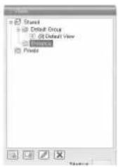
2 Click the [Create New View] button, and select a layout for the new view
![[Create New View] Button View Layouts](/content/2026/05/859290/images/206ad19142a6990f830adea60b0b6800838423481d3d671fb741aec1ffbcaa69.jpg)
- A new view is created under the group you selected.
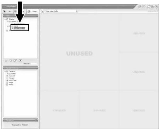
Note :
- Do not display more than 17 windows at any one time. (VR-N1600U/E)
- Do not display more than 10 windows at any one time. (VR-N900U)
- For live images only, VR-N1600U/E(A) can display more than 17 windows.
Screen Setup (continued)
Creating Groups and Views (continued)
3 Enter a name for the new view
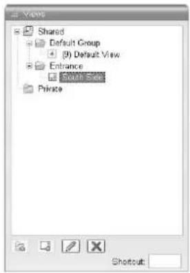
- Next, add cameras to the view. ( Page 63 [Adding Cameras to a View])
■Renaming a Group/View
1 Select the group or view that you want to rename in the Views section.
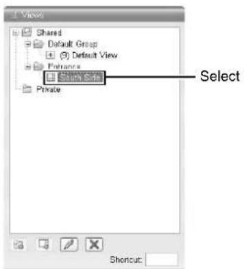
2 Click the [Rename] button
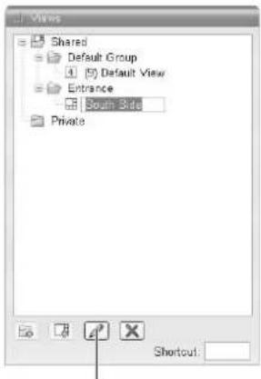
[Rename] Button
3 Overwrite the existing group or view name with a new name
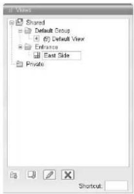
■Deleting a Group or View
1 Select the group(s) or view(s) that you want to delete from the Views section.
2 Click the [Delete] button
A confirmation message appears to ask whether you want to delete the selected group and all views inside the group, or whether you want to delete the selected views.
Adding Cameras to a View
1 Select a view
- The layout of the selected view appears.
2 Click the [+] mark to the left of [Server] under [System Overview]
- A list of available cameras appears.
![System Camera Camera List 2 Camera Cameras Sensor (1) [AXIS 207W] Camera 1 (2) [AVC] Camera 2 (3) [AXIS 212 PTZ] Camera 3 Camouse Hotspot Html Page Image Matrix [Screen Setup] Screen [Server]](/content/2026/05/859290/images/6e4318c16dc8dc17cee0e4b086319f751af67c8e79e841b3762ecb39828fd318.jpg)
3 Select the camera you want to add from the list, and drag the camera name over the screen of the view on the right
- An image from the selected camera appears together with the camera name. - Repeat the procedure for each camera that you want to add.
Memo :
- Images from a total of 16 cameras can be simultaneously displayed. (VR-N1600U/E)
- Images from a total of 9 cameras can be simultaneously displayed. (VR-N900U)
Adjusting Camera Settings
1 Select the camera you want to adjust on the [Screen Setup] screen
2 Select [Properties]
![Camera Name: JYC1 Camera 2 Image Quality: Full Frame Rate: Unlimited IPX Split Mode: One by One Maintain Image Aspect Ratio Update on Motion Sound on Motion Detection: Always off Sound on Event: Always off Apply To All [Screen Setup] Screen](/content/2026/05/859290/images/75589f0fe446cdf1207ebb40b204571e4b88cb7911443a91988c73d9bcaf2291.jpg)
3 Adjust the following camera settings accordingly
| Item Description | |
| 1Camera Name | Displays the name of the selected camera. (This is a read-only field.) |
| 2Image Quality | Enables you to adjust the image resolution and picture quality during viewing. Select [Full] at all times. |
| 3Frame Rate | This is the viewing frame rate. Select [Unlimited] (default value; same as live settings), [Medium] (25 % of the frame rate), or [Low] (5 % of the frame rate), depending on the frame rate specified in [Live Settings] (Page 56) on the [Camera Settings] screen. |
| 4Maintain Image Aspect Ration | If this check box is selected, images will not be stretched to fit the size of the display position. Images will be displayed in the aspect ratio (horizontal to vertical ratio of the screen) that they have been recorded. |
| 5Update on Motion | If this check box is selected, the camera's images will only be updated on the [Live] screen when motion is detected. |
| 6Sound on Motion Detection | Enables notification with a simple sound when motion is detected while viewing images from the camera on the [Live] screen. |
| Always off Does not produce sound notification when motion is detected. | |
| Always on Notifies with a sound each time motion is detected. | |
Screen Setup (continued)
Adjusting Camera Settings (continued)
| Item Description | |
| 7Sound on Event | Enables notification with a simple alert sound when events related to the selected camera occur while viewing images from the camera on the [Live] screen.To use this feature, you need to configure the event notification setting. (15 Page 102) |
| Always off Does not output sound alert when an event related to the camera occurs. | |
| Always on Outputs a sound alert each time an event related to the camera occurs. | |
| 8Apply To All | Press this button to apply the new settings to all cameras. |
Note :
- Set this unit such that the total distribution frame rate to all surveillance computers does not exceed 80 ips (VR-N1600U/E), 160 ips (VR-N1600U/E(A)), or 30 ips (VR-N900U).
- The recording frame rate may deteriorate if you change the picture quality. Changing the [Image Quality] settings may affect the recording performance. As such, use this function with the value fixed at "Full".
- When you drag the timeline browser using the mouse during playback, the frame rate setting is disabled. [Searching Recorded Image Using the Timeline Browser] (Page 44)
- Notification sound is not output from this unit during motion detection or occurrence of an event. This function is for use by the NVR Viewer, which is downloaded onto the surveillance computer.
4 To adjust the settings on other cameras, repeat Steps 2 to 3
Memo :
- To adjust the settings of all cameras at once, click the [Apply To All] button. The new camera settings will be applied to all cameras in the view.
Using Your Views on Different Computers
User settings, including the [Private] view, are stored on this unit. In other words, you can use your [Private] views on any surveillance computer that has this unit and the "NVR Viewer" installed (Page 123) by logging in with your own user name and password.
1 Double-click the [Setup] tab on the NVR Viewer.
Note :
- User rights may be configured to restrict access to the [Setup] tab. In this case, consult your system administrator.
2 Select the folder you want to use in the [Views] section
- You can create or edit views.
- Folders that cannot be edited are indicated by the [LOCK] icons.
Adding a Carousel
You can use the carousel feature to display images from multiple cameras in sequence in a single view position. Also, you can set the time interval for switching the camera to view.
1 Displaying the [Screen Setup] Screen
![View Shared Default Group Default View Entrance East Side Private Shoutcut System Overview Cameras Server (1) [AXIS 207W] Camera 1 (2) [AVC ] Camera 2 (3) [AXIS 212 PTZ] Camera 3 Eco0000 [Carousel] Integer Html Page Image Matrix](/content/2026/05/859290/images/83ae4ad11943fd5fd98d52b70795ec6b968ed9dbb781fa954e615862f026555f.jpg)
2 Click and drag the [Carousel] icon in the [System Overview] section to the position that you want to set in the view
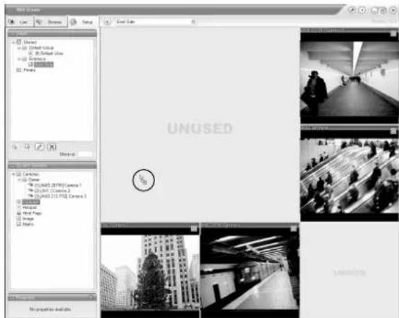
3 Release the mouse button at the position
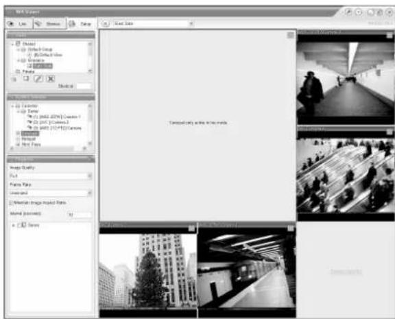
4 Select the preset carousel position and specify its properties in the [Properties] section
- Begin by selecting the cameras to include in the carousel. You can also select all cameras on a server at once by selecting the check box next to the [Server] icon.
| Item Description | |
| 1Image Quality | Enables you to adjust the image resolution and picture quality during viewing. Select “Full” at all times. |
| 2Frame Rate | This is the viewing frame rate.Select [Unlimited] (default value; same as live settings), [Medium] (25 % of the frame rate), or [Low] (5 % of the frame rate), depending on the frame rate specified in [Live Settings]( page 56) on the [Camera Settings] screen. |
| 3Maintain Image Aspect Ration | If this check box is selected, images will not be stretched to fit the size of the display position. Images will be displayed in the aspect ratio (horizontal to vertical ratio of the screen) that they have been recorded. |
Note :
- The recording frame rate may deteriorate if you change the picture quality. The [Image] settings may affect the recording performance. As such, use this function with the value fixed at "Full".
- When you drag the timeline browser using the mouse during playback, the frame rate setting is "disabled". [Searching Recorded Image Using the Timeline Browser] (Page 44)
Memo :
- The green border indicates that the position is used for the carousel feature.
- The sequence in which cameras appear in the carousel is automatically determined by camera and device names. The cameras appear recurrently in alphabetical order.
Screen Setup (continued)
Adding Hot Spots (Enlarged Images)
The selected camera within the view is displayed in the hot spot designated position. Setting the hot spot in a larger position, such as in [1] of the [1+7] view, displays an enlarged image when the hot spot is selected.
1 Displaying the [Screen Setup] Screen
2 Click and drag the [Hotspot] icon in the [System Overview] section to the position that you want to set in the [Views]
![3 (2) PTZ | 011.0.2 (3) [AXIS 212 PTZ] Camera 3 Carnival Hotspot Html Page Imago Matrix [Screen Setup] Screen [Hotspot]](/content/2026/05/859290/images/d2f21a70ddd685927d0b995350ed05018e4e2153b7ee5dd7c546ee41bdfb43c9.jpg)
3 Release the mouse button at the position
4 Select the preset position in [Hotspot] and specify its properties in the [Properties] section
| Item Description | |
| 1Image | Enables you to adjust the image resolution and picture quality during viewing. Select “Full” at all times. |
| 2Frame Rate | This is the viewing frame rate.Select [Unlimited] (default value; same as live settings), [Medium] (25 % of the frame rate), or [Low] (5 % of the frame rate), depending on the frame rate specified in [Live Settings](https Page 56) on the [Camera Settings] screen. |
| 3Maintain Image Aspect Ration | If this check box is selected, images will not be stretched to fit the size of the display position. Images will be displayed in the aspect ratio (horizontal to vertical ratio of the screen) that they have been recorded. |
Note :
- The recording frame rate may deteriorate if you change the picture quality. The [Image] settings may affect the recording performance. As such, use this function with the value fixed at "Full".
- When you drag the timeline browser using the mouse during playback, the frame rate setting is "disabled". [Searching Recorded Image Using the Timeline Browser] (Page 44)
Memo :
- Using the [Hotspot] function enables you to use a low frame rate for other cameras and a high frame rate for the hot spot.
- The orange border indicates that the position is used for a hotspot.
- When the hot spot is set in multiple views and the view is switched, the camera image displayed in the view before switching continues to be displayed in the hot spot window in the view after switching.
Using the [Html Page]
1 Click [Html Page] under [System Overview]
![(1) [AXIS 207W] Camera 1 (2) [LVC] Camera 2 (3) [AXIS 212 PTZ] Camera 3 Carousel Internet Print Page Image Matrix [Screen Setup] Screen [Html Page]](/content/2026/05/859290/images/c75be07fca5e0f4dbbcaf714dbe3ead800f67e317e0e373ea5d963f49b61b52f.jpg)
2 Drag and drop at the required position using the mouse.
The [Open URL] screen appears.
3 Type in the URL and click [OK]
4 Select [Html Page] under [Views], and specify the properties in the [Properties] section
| Item Description | |
| Url Click the [New...] button to specify a new URL. | |
| Scaling Select the display size of the HTML page. | |
| Enable HTML scripting | Select this check box to specify HTML files that contain navigation or trigger functions. |
Note :
- Pages containing such content as ActiveX and Flash will not be supported.
- Pages containing such content as ActiveX and Flash will not be supported.
- Note that some links may involve security issues.
Using Still Images (GIF/JPEG files, etc.)
1 Click [Image] under [System Overview]
![[A/C] Camera 2 [A/XIS 212 PTZ] Camera 3 Carousel Hotspot Html Page [Image] image](/content/2026/05/859290/images/34647fa65e3c5b904f0205e50a90e10df19aab6056808ab779b36c7612c0e038.jpg)
2 Drag and drop at the required position using the mouse.
• The [Open] screen appears.
[Open] Screen
3 Select the required image file
Note :
- When connected to a surveillance computer, still images that are set on a different computer are not displayed.
● Still images cannot be added to this unit.
Adding Matrix Content
Select this option to use the Milestone XProtect Matrix feature. For details, refer to the Milestone XProtect Smart Client User's Manual available on the website of Milestone Systems (http://www.milestonesys.com).
Memo :
● The URL address may be subject to changes.
Main Menu List
List of Menu Screens
flowchart
graph TD
    A["Main Menu"] --> B["Unit Setting 1"]
    A --> C["Unit Setting 2"]
    A --> D["OS Setting"]
    A --> E["Flash Memory Utility"]
    A --> F["HDD Utility"]
    A --> G["Event Audio Setting"]
    A --> H["Language Setting"]
    A --> I["Return to default settings"]
    A --> J["Image Server Setting"]
    A --> K["Live Viewing"]
    A --> L["Auto Detect Setting"]
    A --> M["Camera Record Setting"]
    A --> N["Optional Installation"]
    A --> O["Exit"]
    O --> P["[Operation"]]
    P --> Q["Up"]
    P --> R["I: Down"]
    P --> S["Enter: Enter"]
    P --> T["Cancel: Exit"]

    U["(Page 69)"] --> V["OChange"]
    V --> W["User Name"]
    V --> X["Order Name"]

    Y["(Page 72)"] --> Z["OCTK"]
    Z --> AA["User Name"]
    Z --> AB["Order Name"]

    AC["(Page 73)"] --> AD["OK"]
    AD --> AE["User Name"]
    AD --> AF["Order Name"]

    AG["(Page 129) *VR-N1600U/E only"] --> AH["OK"]
    AH --> AI["User Name"]
    AH --> AJ["Order Name"]

    AK["(Page 76)"] --> AL["Audio Link"]
    AL --> AM["User Name"]

    AN["(Page 85)"] --> AO["Install"]
    AN --> AP["Close"]

    AQ["(Page 83)"] --> AR["Camera Reset in the Environment"]

    AS["(Page 80)"] --> AT["Device Name & Interface"]

    AU["(Page 83)"] --> AV["Device Name & Interface"]

    AW["(Page 85)"] --> AX["Device Name & Interface"]

    AY["(Form Name)"] --> AZ["Add Document"]

    BA["(Form Name)"] --> BB["Add Document"]

    BC["(Form Name)"] --> BD["Add Document"]

    BE["(Form Name)"] --> BF["Add Document"]

    BG["(Form Name)"] --> BH["Add Document"]

    BI["(Form Name)"] --> BJ["Add Document"]

    BK["(Form Name)"] --> BL["Add Document"]

    BM["(Form Name)"] --> BN["Add Document"]

    BO["(Form Name)"] --> BP["Add Document"]

    BQ["(Form Name)"] --> BR["Add Document"]

    BS["(Form Name)"] --> BT["Add Document"]

    BU["(Form Name)"] --> BV["Add Document"]

    BW["(Form Name)"] --> BX["Add Document"]

    BY["(Form Name)"] --> BY["Add Document"]

    CA["(Form Name)"] --> CB["Add Document"]

    CC["(Form Name)"] --> CC["Add Document"]

    DA["(Form Name)"] --> DA["Add Document"]

    DB["(Form Name)"] --> DB["Add Document"]

    BEQ["(Form Name)"] --> BEQ["Add Document"]

    BFQ["(Form Name)"] --> BFQ["Add Document"]
Unit Setting 1
Unit Setting 1 enables you to specify settings related to this unit, including account configuration, error recovery, and serial port configuration.
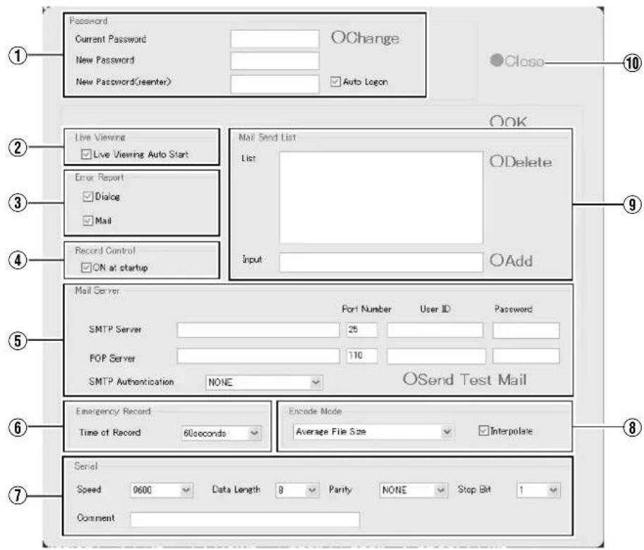
| Item Preset Values Description | Reference Page | ||
| 1Password | Enables you to specify the login password for this unit.Note: ____Specify the password using numeric characters only. | Page 31 | |
| Current Password | — | To change to a new password, enter the [Current Password]. | |
| New Password | — | Enter a new password. | |
| New Password(reenter) | — | Enter the new password again for confirmation, and click [Change] to enable the password change. | |
| Auto Logon | ●Select check boxDo not select check box | To log in automatically after turning on the power of this unit, select the [Auto Logon] check box. | |
| Change | — | Executes the password change. | |
| 2Live viewing | |||
| Live viewing Auto Start | ●Select check boxDo not select check box | Select this check box to display live images automatically when the system starts up. | |
Main Menu List (continued)
Unit Setting 1 (continued)
| Item Preset Values Description | Reference Page | ||
| 3Error Report | Enables you to select how you want to be notified when an error is detected in the system. | — | |
| Dialog ●Select check boxDo not select check box | Select [Dialog] to display a warning dialog on the screen. | Page 156 | |
| Mail ●Select check boxDo not select check box | Select [Mail] to receive an e-mail notification on any abnormality at the preset e-mail address.Memo:For details on errors, refer to the actions to take when the [WARNING] indicator lights up. (Page 156) | — | |
| 4Record Control | — | ||
| ON at startup ●Select check boxDo not select check box | Select this check box to turn on the recording control mode when the system starts up. | ||
| 5Mail Server | — | Enables you to configure the necessary information on the mail server to be used if you have selected “Mail” in the [Error Report] item 3. | — |
| SMTP Server | Setting for the outgoing mail server. | ||
| Port Number ●25 | |||
| User ID | — | ||
| Password | — | ||
| POP Server | Setting for the incoming mail server. | ||
| Port Number ●110 | |||
| User ID | — | ||
| Password | — | ||
| SMTP Authentication | ●NONEAuthenticationPOP before SMTP | Enables you to select the method of user authentication when sending out a mail. For queries on the settings, consult your system administrator. | |
| Send Test Mail | Click to send out a test mail to the address specified in the [Mail Send List] item 9. | ||
| 6Emergency Record | Page 52 | ||
| Time of Record NONE30seconds●60seconds5minutes10minutes20minutesContinue | Select the duration of emergency recording, which starts recording of all channels when a signal is input to the [EMERGENCY] terminal on the rear panel.Select “Continue” to continue recording until it is stopped manually on the front panel. | ||
| 7Serial(VR-N900U) | Lets you specify the settings for the serial ports controlling the cameras. Please refer to the [Instruction Manual] of the camera in use to configure the parameters correctly for all settings. | — | |
| Speed Speed | 180024004800●96001920038400 | ||
| Data Lenght 7 | ●8 | ||
| Parity | ●NONEODDEVEN | ||
| Stop Bit | ●12 | ||
| 8Encode Mode (VR-N900U) | Variable File Size●Average File SizeConstant File Size | Lets you select the encoding mode for converting analog image data into digital data. You can choose from the following three modes.Specify the encoding size control method and target file size when encoding JPEG files.Variable File Size:The file size increases or decreases depending on the image.Specify this to maintain a constant image quality.Memo:● Note that maximum recording time varies when recording JPEG files with this option as the file size increases or decreases. | — |
| Average File Size:Multiple JPEG files are encoded to reach the designated size as average size.Constant File Size:Each JPEG file is encoded to reach the designated size. The processing load is heavy with “Constant File Size”, which decreases the maximum processing frame rate to approximately one quarter of the value.Memo:● Specify the designated size using the [Quality] bar on the [Configure Device] screen under [Camera Record Setting].(uF Page 58) | |||
| Interpolate ●Select | check boxDo not select check box | Select this check box to eliminate the comb-shaped noise (noise that appears jagged) of the moving object. | |
| 9Mail Send List | Enables you to specify the mail recipient if you have selected “Mail” in the [Error Report] item 3. To add a new recipient, type the e-mail address in the entry field and click the [Add] button. To remove an e-mail address from the notification list, select the required e-mail address in the [List] and click [Delete]. | — | |
| List | — | ||
| Input | — | ||
| 10Close | Closes the [Unit Setting 1] screen. | — | |
Main Menu List (continued)
Unit Setting 2
![HDD meter □ Display at startup Clock setting □ Display at startup □ Display at date □ Display at second SNMP setting □ Enable of SNMP □ Enable of TRAP SNMP manager's address : Community name : Confirmation interval of alarm : 10 [Sec] Confirmation interval of DPU usage : 10 [Sec] Confirmation interval of D-drive : 60 [Sec] Confirmation interval of NVR Viewer : 10 [Sec] Confirmation interval of camera : 00 [Sec] Copy extension MIB onto the flash memory OK Cancel](/content/2026/05/859290/images/1d21aeeb149dd46f4b721faf64a199b76f9fcd8516046ae22df3b7103bdc804b.jpg)
| Item Preset Values Description | Reference Page | ||
| 1HDD meter | |||
| Display at startup Select check boxDo not select check box | Select this check box to display the HDD meter when the system starts up.For details on HDD meter, refer to [HDD Meter] (Page 133). | Page 133 | |
| 2Clock setting | |||
| Display at startup Select check boxDo not select check box | Select this check box to display the clock when the system starts up. | Page 152 | |
| Display at date Select check boxDo not select check box | Select this check box to display the date on the clock. | Page 152 | |
| Display at second Select check boxDo not select check box | Select this check box to display the seconds on the clock. | Page 152 | |
| 3SNMP setting | |||
| Enable of SNMP Select check boxDo not select check box | Select this check box to enable the SNMP function. | Page 134 | |
| Enable of TRAP Select check boxDo not select check box | Select this check box to enable the TRAP function. | Page 134 | |
| SNMP manager's address — | Specify the IP address of the SNMP manager. (IP address) | Page 134 | |
| Community name — | Specify the SNMP community name. (1 to 32 characters. Alphanumeric characters only.) | Page 134 | |
| Confirmation interval of alarm | 10 seconds | Specify the interval to monitor the alarm.(10 to 9999 seconds) | Page 152 |
| Confirmation interval of CPU usage | 10 seconds | Specify the interval to monitor CPU usage.(10 to 9999 seconds) | Page 152 |
| Confirmation interval of D-drive | 60 seconds | Specify the interval to monitor the writing rate to the D drive.(30 to 9999 seconds) | Page 152 |
| Confirmation interval of NVR Viewer | 10 seconds | Specify the interval to monitor the startup status of NVR viewer.(10 to 9999 seconds) | Page 152 |
| Confirmation interval of camera | 60 seconds | Specify the interval to monitor connection status of the camera.(60 to 9999 seconds) | Page 152 |
| Copy extension MIB onto the flash memory | Copy the MIB extension information into a flash memory device.For details on SNMP settings, refer to [Setting SNMP](Page 134). | Page 134 | |
| 4OK/Cancel — | OK: Exits after entries and the selected content are configured to the system.Cancel: Exits without saving all entries and selected settings. | — | |
OS Setting
Enables you to specify settings related to the OS, including network, time, and volume settings. You may need to reboot your computer depending on the settings.
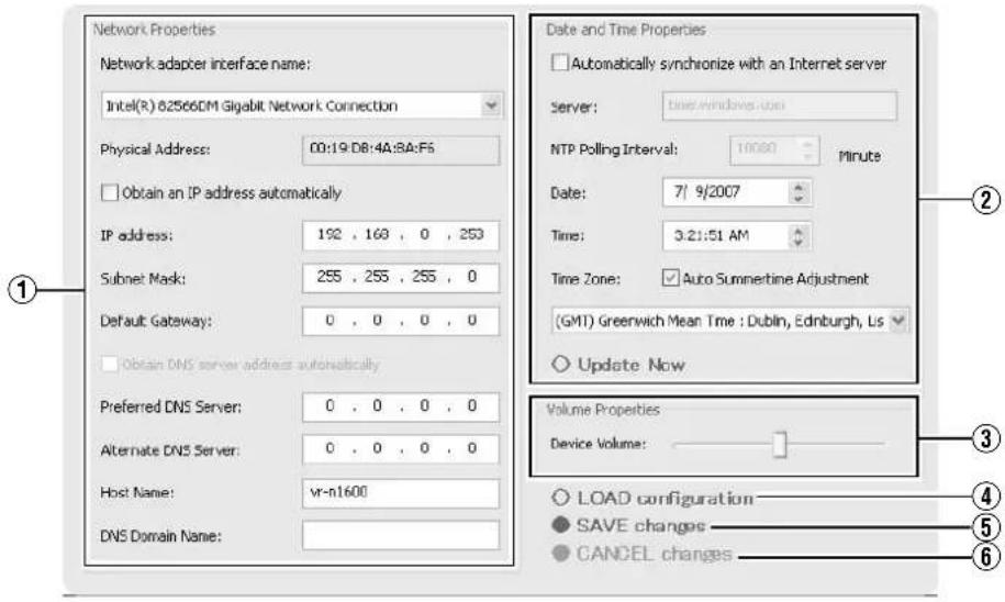
Network Adapter
This section enables you to specify settings such as the IP address of this unit. The camera network and Intranet of this unit are configured with a different IP address. The default address for the camera network is (192.168.0.253), and that for the Intranet is (192.168.1.253).
There is a common host name for all adapters.
●When specifying LAN1 (camera network) settings
| Item Preset Values Description | ||
| 1Network adapter interface name | VR-N1600U/E:Intel® 82566DM Gigabit NetworkVR-N1600U/E(A):Realtek RTL8168C(P)/8111C(P) PCI-EGigabit Ethernet NICVR-N900U:Realtek RTL8169/8110Family Gigabit Ethernet NIC | Settings when you are using LAN1 (camera network). |
| Obtain an IP address automatically | Select check box●Do not select check box | |
| IP address ●192.168.0.253 | Memo :To specify an IP address other than the default value, consult your system administrator.If the host name is changed, you need to add a new Windows user in [User Administration] under [Image Server Setting]. (× Page 118)Do not set the default gateway for both the camera network and Intranet on the [OS Setting] screen. Doing so may cause the system to malfunction. | |
| Subnet Mask ●255.255.0 | ||
| Default Gateway ●0.0.0 | ||
| Perferred DNS Server | ●0.0.0.0 | |
| Alternate DNS Server | ●0.0.0.0 | |
| Host Name VR-N1600U/E :vr-n1600VR-N900U :vr-n900 | ||
| DNS Domain Name | ●0.0.0.0 | |
Main Menu List (continued)
OS Setting (continued)
●When specifying LAN2 (Intranet) settings
| Item Preset Values Description | ||
| 1Network adapter interface name (continued) | VR-1600/VR-N900: IntelTM8225xER PCI AdapterVR-N1600U/E(A): Realtek RTL8168C(P)/ 8111C(P) PCI-E Gigabit Ethernet NIC#2 | Settings when you are using LAN2 (Intranet). |
| Obtain an IP address automatically | Select check box●Do not select check box | |
| IP address ●192.168.1.253 | Memo :To specify an IP address other than the default value, consult your system administrator.If the host name is changed, you need to add a new Windows user in [User Administration] under [Image Server Setting]. (※ Page 118)Do not set the default gateway for both the camera network and Intranet on the [OS Setting] screen. Doing so may cause the system to malfunction. | |
| Subnet Mask ●255.255.255.0 | ||
| Default Gateway ●192.168.1.254 | ||
| Perferred DNS Server | ●0.0.0.0 | |
| Alternate DNS Server | ●0.0.0.0 | |
| Host Name VR-N1600 | U/E :vr-n1600VR-N900U :vr-n900 | |
| DNS Domain Name | — | |
●When specifying analog camera network settings (VR-N900U only)
| Item Preset Values Description | ||
| 1Network adapter interface name (continued) | Enc Board Bus Master Driver | Settings when you are using an analog camera network. |
| Obtain an IP address automatically | Select check box●Do not select check box | |
| IP address ●192.168.201.253 | Memo:——To specify an IP address other than the default value, consult your system administrator.If the host name is changed, you need to add a new Windows user in [User Administration] under [Image Server Setting]. (Page 118)Do not set the default gateway for both the camera network and Intranet on the [OS Setting] screen. Doing so may cause the system to malfunction. | |
| Subnet Mask ●255.255.255.0 | ||
| Default Gateway ●0.0.0.0 | ||
| Perferred DNS Server | ●0.0.0.0 | |
| Alternate DNS Server | ●0.0.0.0 | |
| Host Name ●vr-n900 | ||
| DNS Domain Name | — | |
Note :
- In VR-N900U, analog input circuitry is considered as a network encoder (IP video server) and the IP address is set to "192.168.201.12" by default.
- The IP address of the analog camera network for VR-N900U is set to "192.168.201.253" by default. Do not change the IP address. Doing so may cause the system to malfunction.
●Other Settings
| Item Preset Values Description | ||
| 2Day and Time Properties | To synchronize the time with the Internet time server or to specify the date and time manually, click [Update Now]. | |
| Automatically synchronize with an Internet server | Select check box●Do not select check box | Select this check box to synchronize the time with the Internet time server.Note:●You cannot specify the date and time manually when this box is selected. The settings in the boxes cannot be changed.The date and time properties are not enabled until you have clicked the [Update Now] button.Changing the time setting may prevent normal playback of recordings made at the same time as a result.Changing the “Time” field of the time setting when operations are in progress may prevent normal display of live images. In this case, reboot this unit. |
| Server | — | Enter the address of the Internet time server.Note:●Connect the time server to the LAN2 network. |
| NTP Polling Interval | — | For specifying the time interval (in minutes) for synchronizing with the Internet time server. |
| Date | — | Enter this field when you are specifying the date manually.Memo:●The [Day and Time Properties] settings are not enabled until you have clicked the [Update Now] button.Changing the time setting may prevent normal playback of recordings made at the same time as a result.Changing the “hour” value of the hour/minute/second setting when operations are in progress may prevent normal display of the live images. In this case, reboot this unit. |
| Time | ||
| Time Zone ●VR-1600U: | (GMT-05:00)Eastern Time●VR-1600E:(GMT) Greenwich Mean Time | For specifying the time zone.Note:●Make sure that the date and time that you specify does not overlap with any previous recorded data.If the specified time zone is incorrect, the system may not run at the correct time after synchronizing with the Internet time server.When the time zone is altered, press the [LIVE/BROWSE] while holding down the [FUNCTION] button to reboot the NVR Viewer. |
| 3Volume Properties | ||
| Device Volume | ●Center position | Adjust the volume using the slider bar. |
| 4LOAD configuration | — | Reads the preset configuration files and displays them on the screen. |
| 5SAVE changes | — | Exits after entries and the selected content are configured to the system.Manual update of time is disabled. To update the time manually, go to the [Day and Time Properties] item 3. |
| 6CANCEL changes | — | Exits without saving all entries and selected settings. |
Main Menu List (continued)
Image Server Setting
This section enables you to specify settings for connecting this unit to a computer, and for displaying the [Live] and [Browse] screens. The distribution settings are also applied to operation on the [Live], [Browse], and [Screen Setup] screens of this unit.
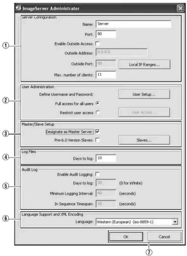
| Item Preset Values Description | |||
| 1Server Configuration | Enables you to specify the server name, port number, and details on external access to the server. | ||
| Name ●Server | For specifying the server name. | ||
| Port ●80 | For specifying the port number to use for the server. | ||
| Enable Outside IP Address | Select check box●Do not select check box | Select this check box to enable access to this unit from a surveillance computer connected to the Internet via the router or firewall.If you have selected this option, specify the global IP address in the [IP address] column for the Internet router or firewall, and the port number in the [Port] column for access to the Internet by the surveillance computer.You have to configure an appropriate port forwarding on the router or firewall to allow access by a surveillance computer that is connected to the Internet.For details, refer to the “Instruction Manual” of the respective devices. | |
| Outside address | — | For specifying the global IP address or host name when connecting to this unit via the Internet. | |
| Outside Port | — | For specifying the port number to use when connecting to this unit via the Internet. | |
| Local IP Ranges... | — | Settings for using the Master/Slave feature by Milestone Systems.For specifying the beginning of the IP address range in the left field on the screen, and the end of the IP address range in the right field. Click the [Add] button.You may define as many local IP address ranges as required.Memo:● You may specify only one IP address. (Example: 192.168.10.1 to 192.168.10.1)● For details, refer to the Milestone XProtect Smart Client User’s Manual available on the website of Milestone Systems (http://www.milestonesys.com).● The URL address may be subject to changes. | |
| Max,number of clients | ●11 | For specifying the maximum number of NVR Viewer users allowed for connection at any one time. The number of users also includes the use of the [NVR Viewer] on the [Live] and [Browse] screens of this unit. Do not set a number of larger than 11. | |
| 2User Administration | This section describes procedures to configure user accounts and rights. | ||
| User Setup... | — | Click this button to display the [User Administration] screen for setting the [User] and [Password]. You can add new users in two ways: (※ Page 118 [User Settings])Memo:● After adding a new user, a small square appears to the top left of the icon on the [User Administration] screen. You can distinguish between [Add Basic User...] and [Add Windows User...] using this mark when the same user name is registered with both. | |
| User | VR-N1600U/E:vr-n1600VR-N900U:vr-n900 | Type:Basic userPassword:vr-n1600(VR-N1600U/E), vr-n900(VR-N900U) | |
| Administrator Type: Windows or Active Directory user or Active Director UserPassword: Nil | |||
| Add Basic User... | — | You can create a dedicated user account for the surveillance system through authentication of the user name and password. | |
Main Menu List (continued)
Image Server Setting (continued)
| Item Preset Values Description | |||
| 2User Administration (continued) | |||
| User Setup... (continued) | |||
| Add Windows User... | — | Do not select this option. For details, consult your system administrator.Note:When the host name in the OS settings is changed, enter [Administrator] in [Enter the object names to select] on the [Select Users or Groups] screen, and click the [Advanced...] button. Next, click the [OK] button.Windows users need to define a Windows user for each host name specified in [Host Name] in [OS Setting]. (Page 73)As the user's host name is not displayed on the [User Administration] screen, it is recommended that you delete the Windows user and add again if you have changed the host name. (Page 118) | |
| Delete | — | Deletes a preset user.Select the user to delete from the [Current isers/groups] list, and click the [Delete] button. The user that has been deleted from the list is no longer able to login to NVR Viewer. | |
| Change password... | — | Enables you to edit a preset user name and password.Select the user to edit from the [Current isers/groups] list, and click the [Change password...] button. | |
| Define Username and Password | ●Full access for all usersRestrict user access | [Full access for all users]:Select this option to grant all users access to all NVR Viewer features and cameras.[Restrict user access]:Select this option to restrict users' access. Then click the [User Access...] button to define access right for each user.Memo:For details on access rights, refer to [Defining User Rights] (Page 118). | |
| 3Master/Slave Setup | |||
| Designate as Master Server | Select check box●Do not select check box | Select this check box to use this unit as the master server. When multiple units of slave servers are registered to the master server, multiple units of NVR cameras can be mixed and displayed on the NVR viewer. | |
| Pre-6.0 Version Slaves | Select check box●Do not select check box | This check box is always not selected. | |
| 4 Log Files | Log information may be required for diagnosing troubles. | ||
| Days to log ●10 | For specifying the number of days for storing the event log in the [Image Server Setting]. | ||
| 5 Audit Log | Enables you to configure log file settings related to client computer users. | ||
| Enable Audit Logging | Select check box●Do not select check box | ||
| Days to log ●30 | For specifying the number of days for storing the audit log files. | ||
| Minimum Logging Interval | — | For specifying the minimum time interval for acquiring logs. | |
| In Sequence Timespan | — | For specifying the maximum viewing time interval that is to be considered as the same sequence. | |
| 6 Language Support and XML Encoding | Enables you to select the available languages. Select a language (local character set) for the camera name, user name, and password. Select the language of your choice. | ||
| Language | Traditional Chinese (Big5)Japanese (euc-jp)Simplified Chinese (GB2312)Central,Eastern European (ibm852)Cyrillic (ibm866)●Western(European)(iso-8859-1)Thai(iso-8859-11)Central,Eastern European (iso-8859-2)Southern European (latin) (iso-8859-3)Baltic (iso-8859-4)Cyrillic (iso-8859-5)Arabic (iso-8859-6)Greek (iso-8859-7)Hebrew (iso-8859-8)Turkish (iso-8859-9)Korean (ks_c_5601-1987)Japanese (shift-jis)Universal(UTF7) (utf-7)Universal(UTF8) (utf-8)Central,Eastern European (windows-1250)Cyrillic (windows-1251)Western(European) (windows-1252)Greek (windows-1253)Hebrew (windows-1255)Arabic (windows-1256)Baltic (windows-1257)Vietnamese (windows-1258)Thai (windows-874)Japanese (_iso-2022-jp$ESC) | ||
Memo :
- The settings for [Days to log] under [Image Server Setting]–[Log Files] (Item ③) as well as [Days to log] under [Audit Log] (Item ④) are disabled.
- [Camera Record Setting]–[General Settings]–Logfile Settings is enabled.
Main Menu List (continued)
Auto Detect Setting
This section enables you to assign an IP address to each camera and configure various auto detect settings. For procedures on using the Auto Detect feature, refer to [Auto Detect Settings] (r= Page 113).
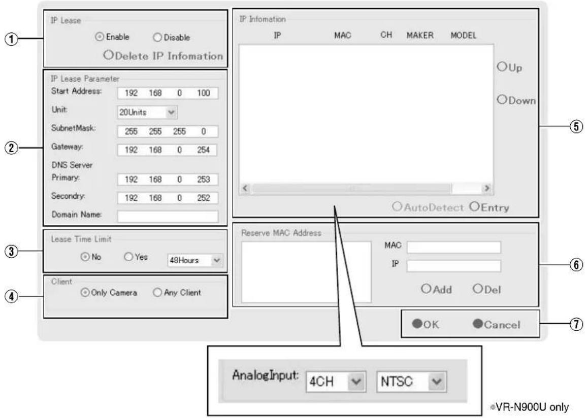
| Item Preset Values Description | Reference Page | ||
| 1IP Lease | ●EnableDisable | For configuring the function to assign IP addresses to each network camera.Memo:In order to assign an IP address of the network camera using the IP Lease feature, you need to enable the DHCP of the network camera. For procedures to enable the DHCP of the network camera, refer to the [INSTRUCRTIONS] of the network camera.If a network uses a multiple number of this product, enable [IP Lease] only for one unit. Select “Disable” if a DHCP server is operating on the same network. When the [IP Lease] is enabled for two or more devices at the same time, the IP address may change to a static address, and cause malfunction of the cameras. | Page 113 |
| 2IP Lease Parameter — | |||
| Start Address | ● 192.168.0.100 | For specifying the first IP address to be assigned to the cameras. | |
| Unit ●20Units | 1Unit to 99Units | For selecting the number of IP addresses to be assigned to the cameras. The selected number of IP addresses will be assigned starting from the first IP address. | |
| Subnet Mask | ● 255.255.255.0 | For specifying the subnet mask for the cameras. | |
| Gateway | ● 192.168.0.254 | For specifying the gateway for the cameras. | |
| DNS Server | |||
| Primary | ● 192.168.0.253 | For specifying the primary DNS for the cameras. | |
| Secondary | ● 192.168.0.252 | For specifying the secondary DNS for the cameras. | |
| Domain Name | — | For specifying the domain name for the cameras. | |
| 3Lease Time Limit ●No Yes | For specifying the valid period of the IP address assigned to the cameras.If “Yes” is selected, you can set the lease time in units of hours.(Setting value: 1 hour to 99 hours) | — | |
| 4Client | ● Only Camera Any Client | For selecting whether to apply restrictions on the device when assigning the IP address. If “Only Camera” is selected, IP address will only be assigned to the corresponding camera. If “Any Client” is selected, IP address will be assigned to all devices. | — |
| 5IP Information | — | The [IP Information] list contains information on the [IP address] of the automatically detected camera, MAC address, number of video CH, manufacturer, and model.Click [Auto Detect] to start auto detect and display the result.The camera at the top of the list is used with priority.You can click the Sort button to sort the order of detected cameras.There are five types of sort buttons, including Sort by [IP], Sort by [MAC], Sort by [CH], Sort by [MAKER], and Sort by [MODEL] buttons.Select the detected cameras, followed by clicking the [Up] or [Down] button to change the order of the cameras.Deselect the check box of any camera that you are not using. After doing so, click [Entry]–[OK]. The [Autodetect Device] screen appears. After entering the camera password, the [Camera Record Setting] screen appears. Clicking [Close] automatically creates a Default View. To save this view, change its name.Memo :When multicast packets are configured such that they do not pass through the network equipment, such as a switching hub, the Auto Detect of the camera may not function properly.Analog-in] is the built-in analog input of VR-N900U. The highest priority is given to the number of CH used during configuration. (VR-N900U)Devices other than the cameras may appear in the list.Uncheck the boxes of these devices.Note :Deselecting the [Analog-in] check box disables the [ALARM IN 1 to 4] signal input terminal at the rear of the unit. (VR-N900U) | 13Page 11313Page 23 |
| 6Reserve MAC Address | — | Configure the [Reserve MAC Address] if you want to assign a specific IP address to the cameras. A specific IP address is always mapped to a MAC address. Enter a value in the [MAC] and [IP] fields, and click [Add] to set the addresses. To cancel the setting, select a displayed MAC and IP address, and click [Del]. | — |
| 7 OK/Cancel | — | Clicking this button closes the setup screen, and starts/stops the IP address assignment function according to the settings. | — |
Main Menu List (continued)
Note :
- When the “Do not detect in the future.” check box on the [Detect Device] screen is selected during automatic detection, the [Detect Device] screen of the said camera will not appear during subsequent automatic detection operations. You can add the camera manually to enable its detection again. [Adding Cameras] (页 86)
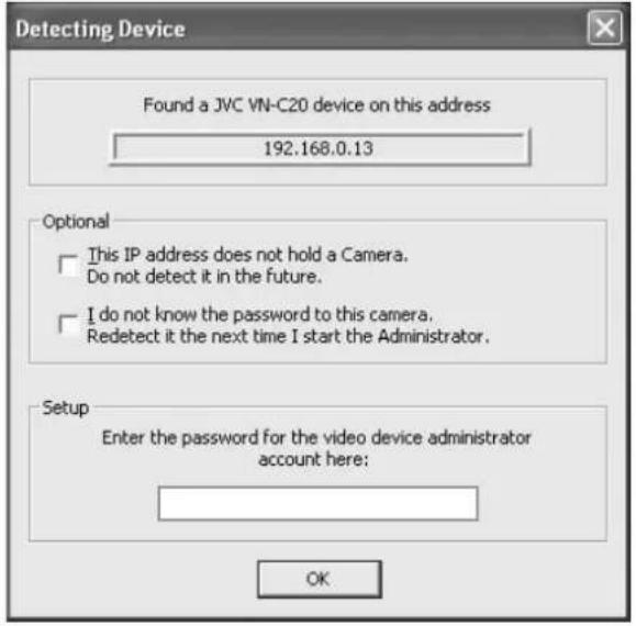
Camera Record Setting
![Camera Recording Administrator Device Manager AXIS 207W (192.168.0.5) AXIS 212 PTZ (192.168.0.2) JVC (192.168.0.20) NVR (127.0.0.1) Add Device... Edit Device... Remove Device Settings... I/O Setup... Event Buttons... Generic Events... I/O Control... Service Manager Recording Server running Pause Cancel Memo : • If you are configuring the [PTZ Preset Positions...] from the [Settings...] button (13), do so after stopping recording server temporarily using this menu. (F) P](/content/2026/05/859290/images/cbab7d066e20264ceb0f71075b825aaa7dc2127edfeb25eb84a931a6424587e8.jpg)
Memo :
- If you are configuring the [PTZ Preset Positions...] settings from the [Settings...] button ⑬, do so after stopping the recording server temporarily using this menu. (Page 90)
Main Menu List (continued)
| Item Description | Reference Page | |
| 1Service Manager... | Pressing the [Service Manager...] button opens a small [Service Manager] screen, which enables you to pause/resume the “Recording Server” recording program. Use this feature when you need to pause the program, such as when configuring PTZ cameras. | Page 90 |
| 2Scheduler... | Displays the [Scheduler...] screen. | Page 53 |
| 3General Settings... | Displays the [General Settings] screen. | Page 106 |
| 4Archive Setup... | Displays the [Archive Setup] screen. | Page 108 |
| 5Import DLKs... | Not used. | — |
| 6Matrix... | Settings for using the Milestone XProtect Matrix by Milestone Systems. Memo:For details, refer to the Milestone XProtect Smart Client User’s Manual available on the website of Milestone Systems (http://www.milestonesys.com).The URL address may be subject to changes. | — |
| 7Transact... | Not used. | — |
| 8Exit | Closes the [Camera Recording Administrator] screen. | — |
| 9Device Manager | Displays the list of all added devices and connected cameras, which provides you with a summarized view of the surveillance system. | — |
| 10Add Device... | Starts the [Device Setup Wizard]. | Page 86 |
| 11Edit Device... | Displays the [Edit device settings] screen. | Page 87 |
| 12Remove Device | For deleting a device selected in the [Device Manager] section9. Note:If you remove the device, you will not be able to view recorded images. Do not delete devices that are needed to view recorded images subsequently. In this case, select “Disabled” under [Camera Monitor Setup] (Page 56) on the [Camera Settings] screen. To view recorded images, cancel “Disabled” in [Camera Monitor Setup]. | — |
| 13Settings... | For specifying the recording settings for a selected camera or settings for a selected audio device. | Page 55Page 59 |
| 14I/O Setup... | Displays the [I/O Setup] screen. | Page 95 |
| 15Event Buttons... | Displays the [Event Buttons] screen. | Page 99 |
| 16Generic Events... | Displays the [Generic Events] screen. | Page 100 |
| 17I/O Control... | Displays the [I/O Control] screen. | Page 102 |
Optional Installation
This section enables you to install camera drivers and additional softwares.
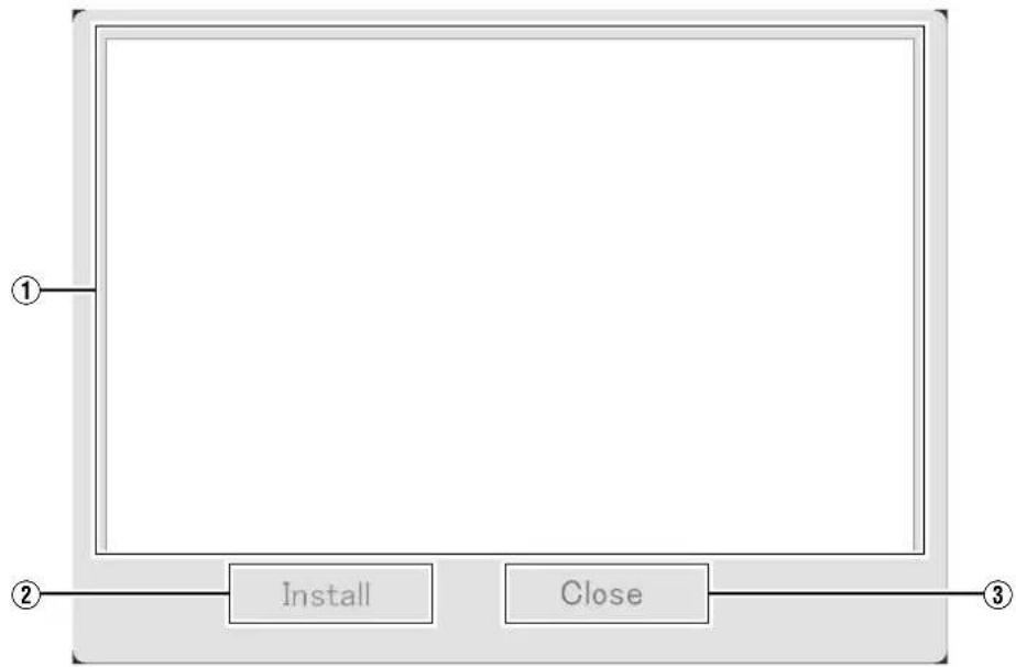
flowchart
graph LR
    A[" "] --> B["Install"]
    A --> C["Close"]
    B --> D["③"]
    C --> E["②"]
    style A fill:#f9f,stroke:#333
    style B fill:#ccf,stroke:#333
    style C fill:#cfc,stroke:#333
    style D fill:#fcc,stroke:#333
    style E fill:#cff,stroke:#333
| Item Description | |
| 1Information on additional softwares | Insert the flash memory device with the additional software saved in the root folder and select Optional Installation. The additional software will appear in the list. |
| 2Install | Select the additional software and click [Install]. The installer starts up and the software is installed. |
| 3Close | Closes the [Optional Installation] window . |
Adding Cameras
To specify settings on camera connection, you first need to add the required devices, such as network cameras or network encoders (IP video servers), to the system. Devices have their own IP addresses and host names. The system identifies the devices based on their IP address or host name.
Memo :
- Even though each device is managed using a unique IP address or host name, in cases such as when multiple analog cameras are connected to a network encoder (IP video server), a multiple number of cameras may be connected to a single device and thus share the same IP address or host name. Although several cameras are connected to one device in this case, this unit manages the cameras on an individual basis.
- In addition to the network camera and network encoder (IP video server), you can also add a number of dedicated I/O (input/output) devices to the system. You can configure and use the event settings for the I/O devices in the same way as cameras.
- When a device is added to the system, it is listed on the [Camera Recording Administrator] screen. To add a new device, follow the procedure below. Firstly, configure the IP address and password of the device according to instructions in the camera manual.
- You cannot add a camera for which there is user access restriction. For details on access restrictions, refer to the camera's "Instruction Manual".
- If the camera is registered with the user access restriction set to ON, the camera is registered with access restriction and unable to display live images unless the settings are changed.
1 Select [Camera Record Setting] from the main menu
2 Click [Add Device...]
● The [Device Setup Wizard] screen appears.
3 Enter the IP address or DNS host name that can be identified by the system
- To enter the DNS host name, select the [Use DNS host name] check box and click [Next].
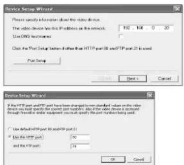
[Device Setup Wizard] Screen
Note :
- The "http port 80" followed by "FTP port 21" are used by default. To use a different port, click [Port Setup] and specify the required port numbers. You may need to specify a different port if the device is located behind a NAT router or firewall. In this case, configure the router or firewall so that it maps the ports and IP address used by the device.
4 If an administrator password is specified for the device, enter the password
- The password is usually set to [root] or [admin].
- Click [Next] without specifying [Autodetect Device].
5 Enter a unique name for the device that has been detected
- The device is listed in the [Device Manager].
6 Click [Finish]
- To view the list of cameras connected to the device, click the plus (+) sign to the left of the device name.
Memo :
- The camera names are set as [Camera1], [Camera2], [Camera3], [Camera4], ...etc. by default. To change the name of a camera, select the device and click the camera name.
● The camera number increases in sequence as new cameras are added. - Registration of the cameras can also be performed automatically. (Page 113 [Auto Detect Settings])
Analog Cameras (VR-N900U)
In VR-N900U, analog input circuitry is considered a network encoder (IP video server), and the IP address is set to 192.168.201.12. This is registered as "N900" on the Device Manager of the [Camera Record Setting] screen. Cameras connected to the [VIDEO IN1 to 4] input terminal at the rear correspond to Cameras 1 to 4 of "N900". You can alter the default name "N900" using the [Edit Device...] button. However, the IP address "192.168.201.12" cannot be changed.
Memo :
- Audio signals that are input to [AUDIO IN 1/AUDIO IN 2] on the rear panel are allocated as [Audio1] and [Audio2] in N900 on the [Device Manager].
Adding an Analog Camera (VR-N900U)
To add an analog camera manually when using VR-N900U, specify "192.168.201.12" as the IP address on the [Edit device settings] screen. As no password has been specified, leave the password entry field blank and continue to the next step. Analog cameras are already added on VR-N900U by default.
Editing Device Settings
This section describe the procedures to edit the settings of added devices.
1 Select [Camera Record Setting] from the main menu
● The [Camera Recording Administrator] screen appears.
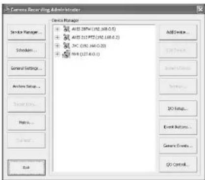
[Camera Recording Administrator] Screen
2 Select a device in the [Device Manager] section, and click the [Edit Device...] button
- The [Edit device settings] screen appears.
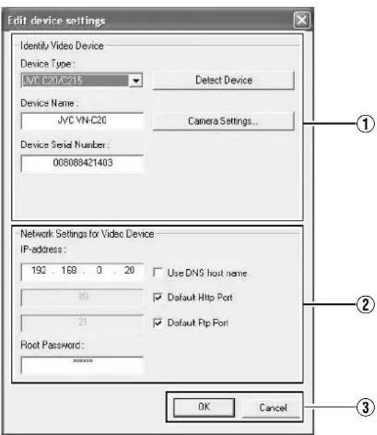
[Edit device settings] Screen
● The following items can be specified.
| Item Description | |
| 1Identify Video Device | |
| Device Type | For selecting the type of device from the list. |
| Detect Device | Click this button to enable automatic detection of the device type and serial number. |
| Device Name | Name used to identify the device. You cannot assign the same name to multiple devices. |
| Camera Settings... | Displays the camera setting screen. |
| Device Serial Number | Serial number of the device. The 12-character MAC address of the device is normally used. |
| 2Network Settings for Video Device | |
| IP-address | IP address or DNS host name of the device. |
| Use DNS host name | Select this check box to identify the device using the DNS host name instead of its IP address. |
| Default Http Port | Select this check box to allow HTTP traffic to the device through the default port (Port 80). To use another port, deselect the check box and specify the port number in the field to the left of the check box. |
| Default Ftp Port | Select this check box to allow FTP traffic to the device through the default port (Port 21). To use another port, deselect the check box and specify the port number in the field to the left of the check box. |
| Root Password | Enter the password for logging into the device using the root account (also known as Admin or Administrator account).Memo:If you are using VN-C625U/VN-C655U, an error message does not appear if you have entered a wrong password and clicked OK, but access to the camera may fail, such as not being able to view the live images. |
| 3OK/Cancel | Confirms or cancels the settings. |
PTZ Camera Settings (COM1/COM2)
The [Camera Settings] screen enables you to specify of the information on cameras. The number of configurable parameters available on the [Camera Settings] screen may be limited if the camera does not come with the PTZ features or if the device connected to the network encoder (IP video server) is not a camera.
To display the [Camera Settings] screen, click the [Camera Settings...] button on the [Edit device settings] screen.
![Camera Settings for JVC VN C20 P/1/Z Camera Selection □ Select of the selected Camera or Bus Port/TK/C20 control panel P/1/Z type controlled through COM1: None P/1/Z type controlled through COM2: None Camera Name Camera Nu... Camera Type Device Port Port Addl. Camera 1 Fixed Camera Name Camera Numo Camera Typ Device Port Port Addl. Appls OK Can Hi [Camera Settings] ① ② ③ ④⑤⑥⑦](/content/2026/05/859290/images/bbee699f7306772ca658dc1b8515fba540ca38edf943169b614cc140c1cb42c5.jpg)
| Item Description | |
| 1PTZ Camera Section | |
| Some of the connected cameras are Pna/Tilt/Zoom cameras | Select this check box if any of the cameras connected to the network encoder (IP video server) is a PTZ camera. If the PTZ features are not available on the device, the check box is disabled. |
| P/T/Z type controlled through COM1/COM2 | For selecting a control method that conforms with the PTZ camera from the list if the PTZ camera is controlled through the COM1 or COM2 port of the network encoder (IP video server).If all the PTZ cameras are not controlled through the COM1 or COM2 port, select “None”. |
| 2Camera List | On the camera list, the camera numbers on the device are listed in sequence.For example, the top line corresponds to camera number 1, and the second line corresponds to camera number 2, and so on.To change the camera settings, select a camera number from the list, specify the required information in the following fields, and click the [Apply] button. |
| 3Camera Name | Name used to identify the selected camera. Do not assign a camera name that is used by other devices.Note:The “Camera Name” is not the name specified for the camera unit, but for identifying the camera on this unit. |
| 4Camera Number | For specifying the camera number.Note:Do not assign a camera number that is used by other cameras. |
| 5Camera Type | For specifying whether the camera corresponding to the selected number is [Fixed] or [Moveable].Fixed : Fixed CameraMoveable : PTZ Camera |
| 6Device Port | This option is enabled only if “Moveable” is selected in the [Camera Type] item 5.For specifying which control port on the network encoder (IP video server) to use for controlling the PTZ features. |
| 7Port Addr. | This option is enabled only if “Moveable” is selected in the [Camera Type] item 5.Use this option to specify the port address of the camera. The port address is usually set to “0” or “1”.If the PTZ cameras are serially connected, they are identified by their the port addresses. Refer to the camera’s [INSTRUCRTIONS] for the recommended settings. |
[CAMERA CONTROL] Terminal at the Rear of VR-N900U (VR-N900U)
The analog camera acts as a network encoder (IP video server) in the VR-N900U system, and the device name assigned to it is [N900]. The [CAMERA CONTROL] terminal at the rear is assigned as "COM1" on the Camera Settings screen.
Page 88
Defining a Preset PTZ Position
Stopping the Recording Server
Stop the recording server before defining the PTZ camera settings.
1 Select [Camera Record Setting] from the main menu
![Main Menu Unit Setting 1 Unit Setting 2 OS Setting Flash Memory Utility HDD Utility Event Audio Setting Language Setting Return to default settings Image Server Setting Live Viewing Auto Detect Setting Camera Record Setting Optional Installation Exit [Operation] ↑: Up ↓: Down Enter: Enter Cancel: Exit](/content/2026/05/859290/images/d73f0e4fa88e0e2bcfe3729e42698973e09ef7e7ec902cdccaae891fcb65f2e8.jpg)
Main Menu
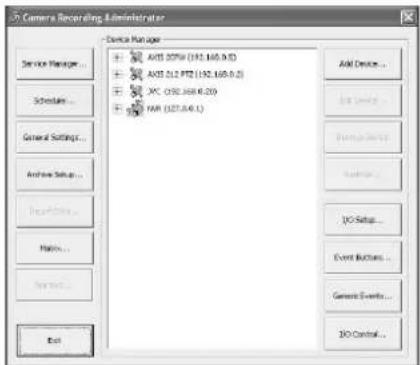
[Camera Recording Administrator] Screen
2 Click the [Service Manager...] button
The [Service Manager] screen appears.
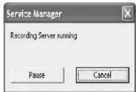
[Service Manager...] Screen
3 Click the [Pause] button
Note :
- Video images and audio sound are not recorded when the recording server is temporarily stopped. Display of live images on the surveillance computer is also turned off.
Display the [PTZ Preset Positions for Device Name] Window
The [PTZ Preset Positions for Device Name] window lets you define preset positions for the PTZ cameras.
1 Select [Camera Record Setting] from the main menu
2 Select a camera from [Device Manager] and click [Settings...]
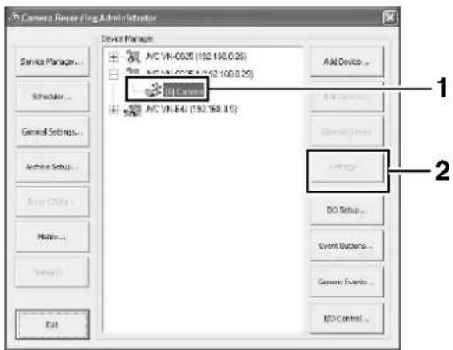
[Camera Recording Administrator] Screen
[Camera Settings] Screen
[PTZ Preset Positions...] Button
Note :
- The preset position may be displaced by a few degrees for some cameras.
3 Click the [PTZ Preset Positions...] button
- The [PTZ Preset Positions for Device Name] window appears.
![PTZ Preset Positions for [AXIS 212 PTZ] Camera 3 PTZ View Wide Teis ① ② ③ ④ Preset Positions Use preset positions from device A1 Undefined A2 Undefined A3 Undefined A4 Undefined A5 Undefined B1 Undefined B2 Undefined B3 Undefined B4 Undefined B5 Undefined C1 Undefined Set Position Edit Name... Text Delete Preset Position on Events Golo preset on event Setup... Pantiling Setup... OK Cancel [PTZ Preset Positions for Device Name] Window](/content/2026/05/859290/images/e8030075171313a78113ca59021eb0b9e830f1936585997cc617c10f1837b5c4.jpg)
Note :
- When using VN-C625U/VN-C655U, the preset position cannot be registered if electronic zoom feature of camera is functioning. Please take note that no error message will be displayed in such case. During PTZ preset setting, turn off electronic zoom in the following operations to prevent registration by mistake.
- From [PTZ page] of VN-C625U/VN-C655U, set [EZoom Limit] to "1". For details, refer to [INSTRUCRTIONS] of VN-C625U/VN-C655U.
- The following configuration options are available in the [PTZ Preset Positions for Device Name] window.
| Item Description | |
| 1PTZ View | For moving the PTZ camera to the desired position. You can check the position on the screen. |
| 2Preset Positions | For registering, deleting and testing a PTZ camera position. |
| Use preset positions from device | This is only applicable to cameras that support this feature.Select this check box to use preset positions defined by the camera or network encoder (IP video server). |
| Note:To import preset PTZ positions from a device, the preset PTZ positions of this unit first has to be deleted.Note that by doing this you will lose all information on the preset PTZ positions in this unit.Memo:In order to use preset positions from the camera or network encoder (IP video server) on, the names of the preset positions must contain only alphanumeric characters (space is not allowed). Preset positions with names that contain blank characters cannot be imported. | |
| Set Position Registers the position specified in [PTZ View] as the preset position selected in the list. | |
| Edit Name... For editing the preset position name selected in the list. | |
| Test For testing a defined preset position. Select the preset position from the list, and click the [Test] button. The result is displayed immediately in [PTZ View]. | |
| Delete For deleting the preset position selected in the list. | |
| ▲▼ | For moving a preset position selected in the list upward or downward. |
| 3Preset Position on Events | For specifying settings to move the PTZ camera to a preset position when an event occurs. |
| 4Patrolling | For configuring PTZ patrolling.(Page 93 [Auto PTZ Patrolling]) |
Note :
- The configurable items may differ according to the camera in use.
Defining a Preset PTZ Position (continued)
Defining a Preset Position
1 Display the [PTZ Preset Positions for Device Name] window (Page 90)
[PTZ Preset Positions for Device Name] Window
2 Move the camera and determine the position using the [PTZ View]
3 Select an item in the [Preset Positions] list to register the preset position to.
- The position at the top of the list corresponds to Preset Position 1.
- The number of preset positions that can be registered may differ according to the camera in use.
4 Click the [Set Position] button and name the preset position
5 To define another preset position, repeat Steps 2 to 4
Moving to Preset Positions by Events
This feature enables the PTZ camera to move automatically to a preset position when an event occurs.
1 Display the [PTZ Preset Positions for Device Name] window (Page 90)
2 Select the [Goto preset on event] check box under [Preset Position on Events]
3 Click the [Setup...] button
![P12 Project Position for [AX/6: 212 P12] Camera 3 P12 View: Wide Title Preset Positions Use preset positions from device A1 Underlined A2 Underlined A3 Underlined A4 Underlined A5 Underlined B1 Underlined B2 Underlined B3 Underlined B4 Underlined B5 Underlined B6 Underlined B7 Underlined Set Position Edit Name... Test Delete Preset Position on Events Data preset on event Setup Pensiling Setup OK Cancel 2 3](/content/2026/05/859290/images/dbfff9ceb3266c1ee9a5711afa60ca90cd8c64269bde102cac3d942f7574252e.jpg)
[PTZ Preset Positions for Device Name] Window
4 Select a preset position from the [Available Preset Positions] list
5 Select an event from [Available Events]
6 Click the []button
- Doing so copies the selected event to the list on the right. This list shows events that are assigned by the selected preset position.
Memo :
- To remove the association between a preset position and an event, select the event from the list on the right and click the << button.
Auto PTZ Patrolling
PTZ patrolling is a feature that enables automatic movement of a PTZ camera between several preset positions.
1 Display the [PTZ Preset Positions for Device Name] window (Page 90)
[PTZ Preset Positions for Device Name] Window
2 Click the [Setup...] button of [Patrolling]
● The [Setup PTZ Patrolling] screen appears.
[Setup PTZ Patrolling] Screen
| Item Description | |
| 1New | For adding a new patrol scheme to the [Patrol scheme] list. |
| 2Copy | For creating a new patrol scheme based on an existing one. Select the patrol scheme to copy in the [Patrol scheme] list beforehand. |
| 3Rename | For changing the name of an existing patrol scheme. Select the patrol scheme to rename in the [Patrol scheme] list beforehand. |
| 4Remove | For deleting an existing patrol scheme. Select the patrol scheme to delete in the [Patrol scheme] list beforehand. |
3 Select the preset positions you want to use in the [Preset Positions] list, and click the [ ] button.
- Doing so copies the selected preset positions to the [Patrolling list].
- A preset position can be used more than once in a patrol scheme.
- The camera will move between the preset positions in the sequence shown in the [Patrolling list], starting from the top position.
- To change the sequence of preset positions in the [Patrolling list] list, select a preset position name, and click the Up/Down buttons.
- To remove a preset position from the [Patrolling list], select the preset position and click the button.
Defining a Preset PTZ Position (continued)
Auto PTZ Patrolling (continued)
■Specifying Patrol Timing
1 Select the patrol scheme that you want to define from the [Patrol scheme] list
2 Specify the duration (seconds) for the PTZ camera to stop at each preset position in the [Stay at each position in the patrol schedule(in seconds)] field
3 Specify the time required for the PTZ camera to move between two preset positions in the [Time for each PTZ camera movement to complete(in seconds). Motion detection is disabled during movement.] field
[Setup PTZ Patrolling] Screen
Memo :
- In order not to generate false motion alarms, motion detection and recording are automatically disabled when the PTZ camera is moving between two preset positions. After the lapse of the specified interval, motion detection is automatically enabled again.
Note :
- It is important that the camera is able to reach all the preset positions defined in the patrolling scheme within the time interval you have specified. Otherwise, false motion may be detected.
■PTZ Patrolling Actions Upon Detection of Motion
1 Select the [Disable patrolling schedule if motion is detected] check box
2 Select the conditions for resuming PTZ patrolling
- When a specific time interval has lapsed after the first detected motion, regardless of whether any subsequent motion is detected
- When a specific time interval has lapsed after the last detected motion
3 Specify the selected condition in units of seconds
■PTZ Scanning
For cameras that support PTZ scanning, you can enable this feature in the [Setup of PTZ Scanning] section to select a PTZ scanning speed.
Note :
- To define a patrol scheme, you must specify at least two preset positions. You must also specify the period for which the patrol scheme is enabled in [Camera Record Setting]–[Scheduler...].
- Patrolling of PTZ cameras may be interrupted either manually or when an event occurs. When this occurs, you need to specify the duration (seconds) before resuming patrol in [Camera Record Setting]–[General Settings]–[Patrolling Settings]. The settings in this section are applied to all PTZ cameras installed in the system. The default setting is 30 seconds.
Camera Input/Output Port and Events
The input/output port is the input/output terminal that is found on each device registered with this unit. You can register the input port as [Input events], and the output port as [Outputs...].
A registered input/output port can be linked to an event as described below. (Page 102 [Specifying an Output Port])
- Events can be used to start recording, send e-mails, move the PTZ camera to a preset position, and control the output port of the device. Events are divided into the four types as described below.
| Input events Registers input signals of sensors connected to the input port of the device as an [Input events]. |
| Generic events Registers as a generic event. |
| VMD events Registers the detected image motion as a VMD (Video Motion Detection) event. |
| Event buttons Event generated by buttons that enable manual operation. |
I/O Settings
1 Click the [I/O Setup...] button on the [Camera Record Setting] screen
● The [I/O Setup] screen appears.
- The [I/O Setup] screen enables you to add input events, VMD events and outputs that can be used by the network cameras.
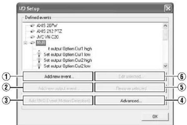
[I/O Setup] Screen
| Item Description | |
| 1Add new event... | For specifying input events for the device selected in the [Defined events] list. You may be able to specify multiple input events for some devices.Click the [+] mark next to the device in the [Defined events] list, select the preset input event, and click the [Add new event...] button to specify a timer event.( page 97) |
| 2Add new output event... | Displays the [Add new output] screen.( page 98) |
| 3Add VMD Event(Motion Detection) | For specifying a VMD (Video Motion Detection) event for the device selected in the [Defined events] list. Only one VMD event can be defined for each camera.Note :To avoid the risk of generating an excessive number of VMD events, a new VMD event cannot occur within five seconds after the occurrence of the last VMD event.VMD events cannot be sent by e-mail. |
| 4Advanced... | Displays the [Advanced...] screen.( page 98) |
| 5Remove selected | For deleting the event selected in the [Defined events] list. |
| 6Edit selected... | For editing the event selected in the [Defined events] list. |
Note :
● The available events differ among network cameras.
- When an event is defined using the [I/O Setup] screen, this automatically overwrites the alarm settings at the camera. If a generic event is already in use (when the alarm settings at the camera are configured manually), the generic event or the event audio that makes use of the generic event (Page 129) will be disabled. However, the generic event settings at the recorder unit remain unchanged. (VR-N1600U/E)
Camera Input/Output Port and Events (continued)
I/O Settings (continued)
■Specifying an Input Event
1 Select the camera for specifying the event from the [Defined events] list on the [I/O Setup] screen
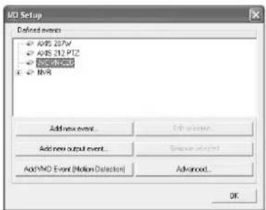
[I/O Setup] Screen
2 Click the [Add new event...] button
● The [Multiple Input Events] screen appears.
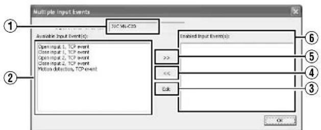
[Multiple Input Events] Screen
| Item Description | |
| 1Input events for device | Displays the device name for which the input event is specified. (This is a read-only field.) |
| 2Available Input Event(S) | Lists the available input events. |
| 3 >> | You can enable an event by selecting it in the [Available Input Event(S)] list 2, followed by clicking the [] button. |
| 4 << | For selecting an event in the [Enabled Input Event(S)] list 3, and moving it to the [Available Input Event(S)] list 2. Doing so disables the event. |
| 5Edit | For editing the event setting selected in the [Enabled Input Event(S)] list. |
| 6Enabled Input Event(S) | Lists the input events that can be used. |
3 Select the required event from the [Available Input Event(S)] list and click the button to add the event
Specify the event name and e-mail settings on the [Add New Event] screen.
[Add New Event] Screen
| Item Description | |
| 1External event name | For specifying a name for the particular input event. Memo: _The following characters cannot be used as part of the event name. <> & ^8217 ^8220 \/: *? | []_ |
| 2Send e-mail if this event occurs | Select this check box to send an e-mail alert when the input event occurs. |
| 3Include image from camera | Select this check box to attach the currently recorded images to the e-mail when the input event is triggered. Select a camera from the list next to the check box. |
Note :
- The [Add new event...] button is disabled if there is no event available for the network camera.
- The [Add New Event] screen may vary according to the type of event to be added.
- If the [SKIP] and [↑/↓/←→] buttons are disabled while you are modifying the settings, use the software keyboard (Page 28) or the mouse.
Input/Output Terminal on Rear Panel
- The audio input acts as a network device in the VR-N1600U/E system, and the device name assigned to it is "NVR". The input/output terminals on the rear panel have been assigned to the "NVR" device by default. (VR-N1600U/E)
- In VR-N900U, analog input circuitry is considered as a network encoder (IP video server), and the device name assigned to it is "N900". The input/output terminals on the rear panel have been assigned to the "N900" device by default. (VR-N900U)
■Rear Panel Input Terminals
| Rear Panel Input Terminal Name | Name of Input Event Event Description | |
| ALARM IN 1 to 8 (VR-N1600U/E) ALARM IN 1 to 4 (VR-N900U) | Alarm IN 1 to 8 Falling (VR-N1600U/E) Alarm IN 1 to 4 Falling (VR-N900U) | Event during detection of Make signal input |
| Alarm IN 1 to 8 Rising (VR-N1600U/E) Alarm IN 1 to 4 Rising (VR-N900U) | Even during detection of Break signal input | |
■Output Terminals
| Rear Panel Output Terminal Name | Name of Output Event Out | Output Action |
| OPTION OUT1,2 | Set output Option Out 1,2 high | Outputs the Make status |
| Set output Option Out 1,2 low | Outputs the Break status |
Note :
- Although the duration of output for the rear panel output terminals is indicated as0 seconds, it is infinitely output.
- Output events of the rear output terminals cannot be deleted.
- All terminal inputs are treated as alerts, but there can only be association (sequence) between one terminal with recording start.
Specifying a VMD Event
1 Select the camera for specifying the VMD event from the [Defined events] list on the [I/O Setup] screen
2 Click the [Add VMD Event(Motion Detection)] button
If a multi-camera device is selected, such as a network encoder (IP video server), a dialog for you to select the required camera will appear.
Note :
- The [Add VMD Event(Motion Detection)] button is disabled if there is no VMD event available for the network camera.
Specifying Timer Events
You can add a timer event to an added event. A timer event is defined with respect to an input event and is triggered by that event. Timer events are triggered when the specified time interval has lapsed after occurrence of the input event at the preset destination.
1 Select the event for adding a timer event from the [Defined events] list on the [I/O Setup] screen (An example of adding a timer event to the input event)
[I/O Setup] Screen
2 Click the [Add new event...] button
• The [New Timer] screen appears.
[New Timer] Screen
3 Specify the timer interval and timer event name.
| Item Description | |
| 1Timer event is started by: | Displays the event or event button name for which a timer event is added. (This is a read-only field.) |
| 2Timer event name | For specifying a name for the timer event. |
| 3Timer event occurs after: | For specifying the time interval from the occurrence of the event or clicking of the event button until the timer event is triggered. Specify the time interval in seconds or minutes. |
Camera Input/Output Port and Events (continued)
Specifying an Output
1 Select the camera for specifying the event from the [Defined events] list on the [I/O Setup] screen
2 Click the [Add new output event...] button
- The [Add New Output] screen appears.
Note :
- The [Add new output event...] button is disabled if there is no output available for use by the network camera.
[Advanced] Screen
The [Advanced] screen enables you to specify network settings for handling events.
1 Click the [Advanced...] button on the [I/O Setup] screen
• The [Advanced] screen appears.
[I/O Setup] Screen
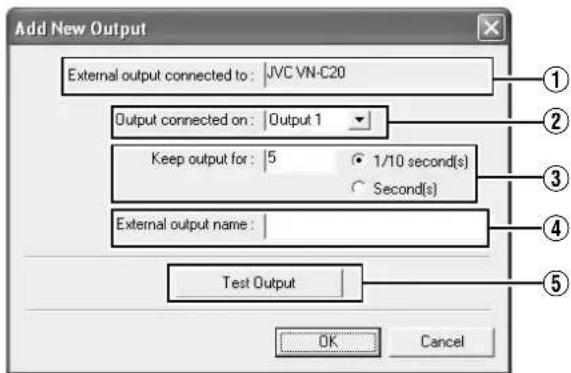
[Add new output] Screen
![Advanced Network Settings Ftp Server Port : 21 Alert Port : 1234 SMTP Port : 25 Polling Frequency [1/10 sec] : 10 OK Cancel](/content/2026/05/859290/images/bbb890a16a61014df61fd65bcf39b140121381b4002adba7f0555ab239c8edc4.jpg)
[Advanced] Screen
3 Specify the output connection destination, output holding time, and output name
| Item Description | |
| 1External output connected to | Displays the device name for which output is specified. (This is a read-only field.) |
| 2Output connected on | For selecting which destination to connect the output to. |
| 3Keep output for | For specifying the output holding time in units of 1/10 seconds or seconds. |
| 4External output name | For specifying a name for the output.Memo:● The following characters cannot be used as part of the event name.<> & ^8217 ^8220 \/: *? | []_ |
| 5Test Output | Click this to perform a test on the output settings. |
2 Specify the following items.
| Item Description | |
| 1Ftp Server Port | For specifying the port number to use for sending event information from the device to the surveillance system via FTP. (Specify a number between 1 to 65535.) |
| 2Alert Port | For specifying the port number to use for handling warnings related to events, including generic events. (Specify a number between 1 to 65535.) |
| 3SMTP Port | For specifying the port number to use for sending event information from the device to the surveillance system via SMTP. (Specify a number between 1 to 65535.) |
| 4Polling Frequency[1/10sec] | For some devices, the surveillance system may need to check the status of their input ports in order to detect whether input has been received. These regular status checks are called “polling”.The [Polling Frequency[1/10sec]] field enables you to specify the interval between status checks. Specify the interval in units of 1/10 seconds.Memo:____For I/O devices, it is highly recommended that the polling frequency be shortened as much as possible.Refer to the “Instruction Manual” of the I/O device for devices that require polling.____ |
Note :
- Do not alter these settings unless under special circumstances. Altering the setting unnecessarily may cause the system to malfunction. They need not be altered under normal circumstances.
Precautions during alteration
- When using event audio, the [Transfer port] of [Event Audio Setting]–[Communication setting] must coincide with the [Alert Port] number. (Page 132)
- It is also necessary to set the [Alert Port] to a different number from the [Event receive port] of [Event Audio Setting]—[Communication setting]. (Page 132)
Configuring Event Buttons
Event buttons are used to manually trigger events from the [Live Viewing] screen.
1 Click the [Event Buttons...] button on the [Camera Recording Administrator] screen
![Camera Recording Administration Service Manager + AOS 2407W (190, 168.0.15) + AOS 212 PTG (190, 168.0.2) + PC (190, 348.0.20) + NBR (127, 0.0.1) Add/Remove... Delete... Save As... Save As... DO Setup... Event Buttons... Generic Events... DO Control... Edit [Event Buttons...]](/content/2026/05/859290/images/894880d541d95a4535fb7e2aecf34bcc513b96ba170273b0e57e2e7dba875c45.jpg)
[Camera Recording Administrator] Screen
2 Select [Global] (apply to all cameras) or a specific camera
3 Click [Add new event...] to add the event button
![Event Buttons Defined events Global [AXIS 207W] Camera 2 [AXIS 212 PTZ] Camera 3 [AVC VII-C20] Camera 1 [NVR] Camera 17 [NVR] Camera 18 Add Event... Remove selected OK](/content/2026/05/859290/images/32882455b8783e20195bc68fe1b5ab2e2d34a52fa6a0b6a006a8ecf3adfee6fd.jpg)
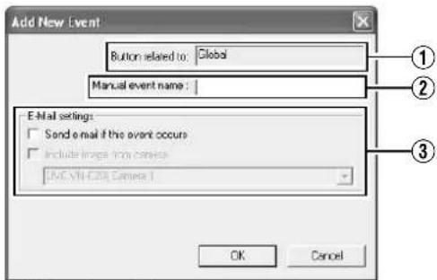
[Add New Event] Screen
| Item Description | |
| 1Button related to | Displays the camera name for which the event is specified. (This is a read-only field.) |
| 2Manual event name | For specifying a name for the event button.Memo:● The following characters cannot be used as part of the event name.<> & ^8217 ^8220 \/: * ? | []_ |
| 3E-Mail settings | |
| Send e-mail if this event occurs | Select this check box to send an e-mail alert when the event button is clicked. |
| Include image from camera | Select this check box to attach the currently recorded images to the e-mail when the event button is clicked. Select a camera from the list below the check box. |
Memo :
- To specify a timer event for an event, select the event added in Step 3, and click [Add new event...].
Camera Input/Output Port and Events (continued)
Specifying Generic Events
What is a generic event?
This is a function that uses TCP or UDP protocol communication as an input event for this unit.
When character strings in the communication data received by the unit matches the predetermined conditions, the corresponding generic event is triggered. To define a generic event, you need to configure the incoming data settings at this unit as well as the outgoing data settings at the camera (or network device to be used).
The procedures for configuring the incoming data settings at this unit are described below.
1 Click the [Generic Events...] button on the [Camera Recording Administrator] screen
![Camera Recording Administration Device Manager 4x45.207V (192.168.0.5) 4x45.212 PTZ (192.168.0.2) JVC (192.168.0.20) JVR (127.0.9.1) Add Device... Edit... Remove Setup... Help... I/O Setup... Event Buttons... Generic Events... I/O Control... [Generic Events...] Button Service Manager... Schneider... General Settings... Archive Setup... Main... Matrix... Preview... OUT](/content/2026/05/859290/images/cd090a49e83b50c50bf453710178797348938477d5dae24f0bab8447eab09ff6.jpg)
[Camera Recording Administrator] Screen
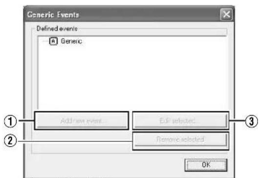
[Generic Events] Screen
| Item Description | |
| Add new event... For adding new events. | |
| Edit selected... For editing the event selected in the [Defined events] list. | |
| Remove selected For deleting the event selected in the [Defined events] list. |
2 Select Generic and click [Add new event...]
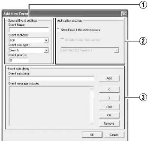
[Add New Event] Screen
①General Event settings
| Item Description | |
| Event Name For specifying a name for the event. Enter a unique name for the event.Memo:● The following characters cannot be used as part of the event name.< > & ^8217 ^8220 \ / : * ? | [] | |
| Event Protocol Forselecting the protocol that this unit uses to receive data when detecting the event: | |
| Any Receives and analyzes data that uses either the TCP or UDP protocol. | |
| TCP Receives and analyzes only data that uses the TCP protocol. | |
| UDP Receives and analyzes only data that uses the UDP protocol. | |
| Event rule type Forspecifying the rules when analyzing the received data. | |
| Match | In order for an event to be triggered, the received data must totally coincide with the message specified in the [Event message include] field of the [Event rules string] section 3, and must not contain any other messages. |
| Search | In order for an event to be triggered, the received data must contain the message specified in the [Event message include] field of the [Event rules string] section 3. Other messages may be included in the data. |
| Event priority | The same data may be used by different events. Assigns the order of priority to each event for determining the event to trigger when the received data matches the criteria of multiple events. Set the priority level to a value between “0” (lowest priority) and “1000” (highest priority). |
Memo :
- This unit receives generic events from the port that is specified in [Alert Port] on the [Advanced] screen. (r ^2 Page 98)
②Notification settings
| Item Description | |
| Send e-mail if this event occurs | Select this check box to send an e-mail alert when an event occurs. |
| Include image from camera | Select this check box to attach the currently recorded images to the e-mail when the input event is triggered. Select a camera from the list below the check box. |
③Event rules string
| Item Description | |
| Event substring For | specifying the expression to search for during data analysis by this unit.Specify at least one expression, and click the [Add] button. The specified expression is added to the [Event message include] field.If you have added multiple expressions as one item, the expressions enclosed in the quotation marks must appear together in the data in the specified sequence in order to match the criteria. |
| Event message include | Displays the string that is used for the actual data analysis. The field is not directly editable. However, you can place the cursor inside the field and click the following buttons. |
| Add Adds the information in the [Event substring] to the [Event message include] field. | |
| (Adds [()] to the [Event message include] field.The parenthesis is used to process the expressions as a single entity. In other words, the content inside the parenthesis is processed first. | |
| )Adds [()] to the [Event message include] field. | |
| AND Adds the operator | “AND” to the [Event message include] field. Use the “AND” operator when you want to specify that the expressions on both sides of “AND” must be present. |
| OR Adds the operator | “OR” to the [Event message include] field. Use the OR operator when you want to specify that either one of the expressions on the two sides of OR must be present. |
| Delete For deleting | the item to the left of the cursor in the [Event message include] field. |
Memo :
- To specify the timer settings for a generic event, select the event added in Step 2, and click the [Add new event...] button.
Camera Input/Output Port and Events (continued)
Event Notification Settings
When a specific event occurs, this can be indicated using yellow color in the title bar area at the top of the live image display screen. The yellow indicator lights up when the specified event has occurred, the red indicator lights up when motion has been detected, and the green indicator lights up when images are received from a camera.
1 Select the camera to configure from the [Camera Recording Administrator] screen, and select [Settings...]
● A setting dialog box appears.
2 Click the [Event Notifications...] button
![Camera Settings for [JNC (JN C625)] Camera 3 Speedup Settings Desired frames: 0 frame(s)per Second 0.13 Seconds(s) low images Recording Settings Desired frames: 0 frame(s)per Second 0.13 Second(s) low images Enable speedup On set On set After display image in database Always Layer Conditionally Convection Onset Onset 3 seconds project recordings on multilevel Database Settings Max. records in database Max. times per in database Archive automatically when database is full In case of database failure the following action should be below: Archive (increase) Motion Detection Settings Motion Detection... Motion Color... Image Quality... Event Next/first... Exclude Regions Settings Exclude Regions... Region Colors... Outsets... OK Cancel [Camera Settings] Screen 2](/content/2026/05/859290/images/b88451b54a466eb0195cce941eb3ac14fbf31e0adef3eb3fe06ec65aa5f3af8a.jpg)
3 Select the event to trigger notification from [Available Events]
4 Click the [] button
- The selected event is copied to [Active Events].
[Setup Notifications on Events] Screen
5 Repeat 2 to 4 for each event
- To delete an event for which notification has been configured, select the event and click the [] button.
Specifying an Output Port
A specific event or manual button can be associated with a particular output port.
To do this, specify the output port from which output is to be triggered when a specific event or manual event occurs.
1 Select [I/O Control] from the [Camera Record Setting] screen
- A setting dialog box appears.
[I/O Control] Screen
2 Select the event to specify from the list on the left
3 Select the output to specify, and click the [] button located below [Selected Outputs]
- To delete an output from the [Selected Outputs] list, select the output and click the [] button.
Camera Output Settings
You can assign external outputs specified on the [I/O Setup] screen to a camera, such as sounding of a siren or switching on of lights.
- The assigned outputs can be triggered automatically when motion is detected, or manually by pressing the output buttons.
- You can display the [Output Settings] screen by clicking the [Outputs...] button on the [Camera Recording Administrator] screen (Page 55).
![Output Settings for [JVC VNC20] Camera 1 All Outputs JVC VNC20 AXIS 267V/ AXIS 212 PTZ NVR Set output Options Diff Set output Options Diff Set output Options Diff On Manual Control Set output Options Diff high Set output Options Diff low On Motion Detected : Set output Options Diff low Output Information Name: Set output Option Diff high - Output 1 - Direction 01/18 second(s) Exit](/content/2026/05/859290/images/a67ba565646530edaa3963cc5820c22525d5e4137b73bcfc7f1720b0f3b4ae35.jpg)
[Output Settings] Screen
■Specifying Output During Manual Control
You can specify outputs to be triggered manually using the output button or from a list on the [Live] screen.
1 Select an output from the [All Output] list
2 Click the button between the [All Output] and [On Manusl Control] lists
- Doing so copies the selected output to the [On Manusl Control] list.
- You can use the Up/Down buttons at the top right corner of the [On Manusl Control] list to move the selected output upward/downward within the [On Manusl Control] list.
- To delete an output from the [On Manusl Control] list, select the output and click the button between the [All Output] and [On Manusl Control] lists.
![Output Settings for [JVC VNC20] Camera 1 All Outputs JVC VNC20 ABS 207V ABS 212 PTZ NVR Set output Option Output Set output Option Output Set output Option Output Set output Option Output On Manual Control: Set output Option Output Low Set output Option Output Low On Motion Detected: Set output Option Output Low Output Information Name: Set output Option Output High - Output 1 Transition 0.1/10 second(s) Exit](/content/2026/05/859290/images/f681f9ac765186d203a4274cfa085b2c45db76b4ddde1460a85497b86f275409.jpg)
[Output Settings] Screen
■Specifying Output via Motion Detection
You can specify outputs to be triggered automatically when motion is detected.
1 Select an output from the [All Output] list
2 Click the button between the [All Output] and [On Motion Detected] lists
- Doing so copies the selected output to the [On Motion Detected] list.
- To delete an output from the [On Motion Detected] list, select the output and click the button between the [All Output] and [On Motion Detected] lists.
![Output Settings for [JVC VN-C20] Camera 1 All Outputs: JVC VN-C20 AXIS 257V AXIS 212PTZ NVR Set output Option Out1 Set output Option Out2 Set output Option Out3 On Manual Control Set output Option Out1 line Set output Option Out2 line On Motion Detected : Set output Option Out1 line Output Information Name: Set output Option Out1 high - Output 1 - Dérations: 8 V/10 second(s) Exit](/content/2026/05/859290/images/3bc9f14730f2679c81ed4fc1d133314de88ce3e9ecbf7ea7997fda760c825ab1.jpg)
[Output Settings] Screen
Motion Settings
Note :
- Before configuring the motion detection settings, it is recommended that you complete the settings related to image resolution, compression, and motion detection exclusion areas. Otherwise, you may need to adjust the sensitivity level in the motion detection settings again when you change the picture quality and set the exclusion areas at a later date.
Defining Motion Detection Exclusion Regions
You can specify specific areas to be excluded from motion detection to prevent the detection of irrelevant motion, such as trees swaying in the wind or cars that drive past continuously in the background.
1 Select a camera from the [Device Manager] on the [Camera Recording Administrator] screen, and click [Exclude Regions...] in [Settings...]
- If the [Show Grid] check box is selected, the preview screen appears, which is divided into small areas by a grid. Areas highlighted in blue indicate the exclusion areas.
[Exclude Regions...] Screen
2 To select an area, click and drag the mouse pointer to move the grid on the screen
- Selected areas are highlighted in blue.
Memo :
- To clear the exclusion areas, right click and drag the mouse pointer to move the grid.
■Setting Buttons and Check Boxes
| Item Description | |
| 1Set All | Sets all sections in the grid on the preview image as exclusion areas. |
| 2Clear All | Clears all sections in the grid on the preview image that are specified as exclusion areas. |
| 3Auto | Click this button to automatically detect areas with insignificant image changes (noises) that are not to be detected as “motion”, and mark such areas to exclude them from motion detection. As a large number of images need to be analyzed during the marking operation, it may take a while to complete after you have clicked the [Auto] button. |
| 4Show Grid | Select this check box to enable the display of grids on the preview image. The default setting is [Show Grid]. |
Note :
- Note that when motion detection is set at short intervals, the number of alarms may increase and a longer search time may be required during playback.
- When a camera is connected, flickers such as those of a fluorescent light may cause a false motion detection. In this case, set the camera to flickerless.
- Noises in the camera image may also trigger a false detection. Set the camera to prevent false detection even when the ACG function is enabled, such as during nighttime.
Specifying Motion Detection
Motion detection enables you to specify the timing to transfer images from the camera, generate alerts, and trigger external outputs (lights or sirens).
Note :
- This feature is essential to the system's operation. In order to avoid unnecessary alerts during application, it is recommended that you specify the settings for each camera carefully. Depending on the physical location where the camera is installed, it may be necessary to perform tests and adjustments of the settings under different conditions (time of the day, weather such as windiness, etc.).
1 Select a camera from [Device Manager] on the [Camera Recording Administrator] screen, and click the [Motion Detection...] button in [Settings...] to open [Adjust Motion Detection]
2 Specify [Noise Sensitivity] and [Motion Sensitivity]
- The [Noise Sensitivity] slider is used to determine the level of change in the image pixel that is to be recognized as motion. The "High" setting recognizes minute changes in the pixel as motion. Areas in the image that have changed when compared with the previous image are highlighted (default color is green).
[Adjust Motion Detection] Screen
Memo :
- The [Motion Sensitivity] slider is used to determine the number of pixels for which a change is to be recognized as motion. When the slider is moved from side to side, the black vertical line at the bottom of the screen moves together, and the boundary (Motion Sensitivity) is adjusted. When detected motion exceeds the selected sensitivity level, the bar changes from green to red, indicating a positive detection.
General Settings
Use [Camera Record Setting] – [General Settings] to specify general settings related to the system, such as e-mails.
[General Settings] Screen
Note :
- Do not use the [Enable Protection]/[Chenge Password...] function in the [Administrator Settings].
| Item Description | |
| 1Milestone XProtect Central Settings | Settings for using Milestone XProtect Central by Milestone Systems. |
| Memo:For details, refer to the Milestone XProtect Smart Client User's Manual available on the website of Milestone Systems (http://www.milestonesys.com).The URL address may be subject to changes. | |
| 2Patrolling Settings | Specify the settings in this section when you are using PTZ cameras for the patrolling feature. (Page 93) |
| 3Joystick | For specifying settings related to the joystick. (Page 144) |
| Memo:There may be cases where settings cannot be specified on this screen. For details on other methods of setting, refer to [Customizing Joystick Settings] (Page 144). | |
| 4E-Mail settings | For specifying the e-mail settings. (Page 107) |
| Item Description | |
| 5Advanced | |
| Don't send e-mail on camera failures | Select this check box to stop sending e-mail alerts if a camera is no longer in the online mode. |
| Start cameras on remote live requests | You are able to view live images from cameras even when they are in the offline mode.The camera switches automatically to the online mode when the live screen of NVR Viewer is displayed. During the interval when the scheduler is set to offline, recording will not be performed even if this feature is in the online mode.Note: :When “ Start cameras on remote live requests” is selected, the camera switches to the online mode while you are viewing live images. Depending on the settings when in the recording control mode, recording may start when you start viewing live images. This also applies to viewing live images on a surveillance computer. |
| Create default schedule for new cameras | Select this check box to automatically create the online schedule of the camera in the [Scheduler] at all times. (6) Page 53) |
| 6Event Recording Settings | Do not change. |
| 7Logfile Settings | Do not change. |
E-mail Settings
[E-mal setup] Screen
| Item Description | |
| 1Enable E-mail(Monitor) | Select this check box to enable sending of e-mail alerts. |
| 2Recipient(S) | For specifying the e-mail addresses to send alerts to. If you are specifying more than one e-mail address, separate the e-mail addresses using semicolons. |
| 3Sender Settings | For specifying the sender's e-mail address, outgoing (SMTP) mail server name and login settings. |
| 4Subject text | For specifying the mail title. |
| 5Message text | For specifying the message text. |
| 6Time btw.mail(minutes) | For specifying the time interval (minutes) for sending each e-mail alert. |
| 7Include Image | Select this check box to include images in the message. |
Memo :
- You can send a test e-mail by clicking the [Test] button. If the e-mail address of the sender is not registered with the mail server of the recipient, the [The mail address of the sender is not valid...] message may appear. When this occurs, double-check the sender's e-mail address and outgoing mail server, and re-enter the e-mail address.
● E-mail messages are sent in the following cases.
- When an input event occurs (Page 96 [Specifying an Input Event])
- When the event button is clicked (Page 99 [Configuring Event Buttons])
- When a generic event occurs (Page 100 [Specifying Generic Events])
- When motion is detected (Page 105 [Specifying Motion Detection])
- When camera failure occurs
- When an archiving error occurs (Page 108 [Archiving])
- In order to send an e-mail via Motion Detection, you need to specify the timing for sending out e-mails in [Scheduler Setting] (Page 53).
- After you have completed the e-mail setting, perform a test to verify that it can be sent successfully.
Archiving
With the archiving feature, you can store recorded images up to the maximum available capacity of the hard disk.
By default, recorded images received from cameras are stored in the database for each camera, and data is automatically archived when the database is full.
Memo :
- To adjust the database settings for each camera, click [Camera Record Setting]–[Device Manager]–[Camera Name]– and select [Datebase Settings]. You can store up to 600,000 frames or 40 GB of data. If the maximum capacity is exceeded, data is deleted starting from the oldest information. By archiving on a daily basis, you can store image data up to the maximum available capacity of the hard disk.
- You can specify the number of times to create archives in a day.
- The archiving location for each camera is automatically selected. The drive with a large amount of free space is selected.
- You can use the playback features for archived images in the same way as normal recorded images.
1 Click [Camera Recording Administrator]—[Archive Setup]
![Archives option Delete databases in the backup directory order than 19509 days Send email on archive error 1 Automatic path selection Select cameras for which the archiving/function should apply [4A5 207V] Camera 2 [4A5 213 PHZ] Camera 1 [4C] Camera 3 Auto path selection Auto path selection Auto path selection Auto path selection Set all Clear all Set all paths OK Cancel Time to add: 12:06:00 Add Delete ① ② ③ ④ ⑤ ⑥ ⑦ ⑧ ⑨](/content/2026/05/859290/images/00f6a2e620dded7e35d7136946a2da91aa87ff263143f78b434e3591ab28c083.jpg)
[Archive Setup] Screen
2 Specify the number of days for storing the archived data in [Delet databases in the backup directory older then [] days]
3 Use the [Add] and [Delete] buttons to specify the time to create archives everyday
4 Select the camera for which archive is to be created
Note :
- The recorded images may be interrupted for several seconds when archiving starts.
Memo :
- If audio is enabled during recording, audio data from the device will also be archived.
■Setting Items and Buttons
| Item Description | |
| 1EnableArchiving | This function is not available.The check box is selected at all times. |
| 2Delet databases in the backup directory older then [ ] days | For specifying the number of days you want to store archived images. |
| 3Automatic delete old archives if space is needed | This function is not available. The check box is selected at all times. |
| 4Send email on archive error | Sends out an e-mail alert when archiving fails. |
| 5Automatic path selection | The archiving location is automatically selected. The drive with a large amount of free space is selected.Select this check box.If the check box is deselected, the[Save to] button appears.Deselect this check box if you are specifying a drive to save the archive data to, such as NAS. |
| Save to This button appears when the[Automatic path selection] check box is deselected. Specify the archive location for each camera. Enter the archive location if you are specifying a drive to save the archive data to, such as NAS.Note :● If you change the archive path after applying the setting, playback of previously archived data will fail. | |
| 6Select cameras for which the archiving function should apply | If you have selected the [Enable Archiving] check box, a list of cameras that enable archiving appears.To specify the archiving settings for a specific camera, select the check box next to the name of the camera. |
| 7Set All | Selects the check box for all cameras. |
| 8Clear All | Clears the check box for all cameras. |
| 9Set all paths | Not used. |
■Setting Items and Buttons
| Item Description | |
| 10Time to add | For specifying the archiving time. |
| Add Adds the archiving time specified in the [Time to add] field to the [[Daily archiving times] 11 list. | |
| Delete Removes a selected archiving time from the list. | |
| 11Daily archiving times | Lists specified archiving times. Archiving takes place everyday at the specified time. |
Memo :
- NAS is a dedicated file server that is connected to the network. In the case of this unit, you can specify NAS as a drive for archiving data.
- For details on the NAS drive settings, refer to the [Details] item under [HDD Utility]. (Page 117)
Note :
- When other operations (e.g., startup of Live Viewing) overlap with the startup of the archiving process, up to 3 seconds of the recording may be lost.
- Set the interval of performing achieving to more than 1 hour.
- Do not specify the same NAS drive for multiple cameras. If there is an insufficient number of NAS drives to be specified for each camera, divide the NAS drive into multiple partitions, and configure each of them as a separate NAS drive.
- Changing the [Automatic path selection] settings may cause playback of data prior to the change to fail.
![Archive setup Delete database in the backup directory partition: 10000 steps Add to add: 14x27.16 Add Delete Select courses for which the arching function should apply: Name Page [AVES 257V] Camera 2 if (yes or drops), [AVES 252 PT2] Camera 3 if (yes or drops), [AVC Win-C20] Camera 1 if (yes or drops),](/content/2026/05/859290/images/4dcf4212a2405e86f6d6cd789eb782ad5eb701c396e8f1b94c083e7600dbdda7.jpg)
Precautions when Changing NAS Archive Settings
When NAS is specified as the archive destination, the path that is displayed on the "Select Directory" screen may not coincide with the preset value.
[Archive Setup] Screen (h:/is specified as the archive destination)
![Select Directory Directory: C:\program files\cys-1900 XC APLued_Eng APLued_French APLued_German APLued_Railon APLued_Jpn APLued_Spanish APLued_Dng Files: [ ] SP.LCS.V1_00 OK Cancel Help Network...](/content/2026/05/859290/images/be622441598f1928dea34e6e11a99a89244dcbf816af5eb5f2e1cadb84540c92.jpg)
[Select Directory] Screen (C drive is displayed)
Precautions when Changing Archive Settings
Do not specify the C, L, or M drive as the archive destination. Doing so may cause the system to malfunction.
Database Settings
This section enables you to specify the database settings. Select a camera from [Main Menu]–[Camera Record Setting]–[Device Manager], and select –[Settings...].
Memo :
- Recorded image data is referred to as the database in this manual.
The recorded images are saved as database.
![[Camera Settings] Screen Database Setup Max. security in database Run Transport in database Active as properly what database is full In case of database failure (if following action should be taken) Archive this record)](/content/2026/05/859290/images/fbb109bf9537185f3964859b433254093aee6026fece3a654329279635988859.jpg)
■Specify the Database Settings
| Item Description | |
| 1Max.records in database | Saves recorded images to the database until the maximum number of records is reached. Specify the maximum number of records in the neighboring field.If the [Archive automatically when database is full]3 check box is not selected, old records are automatically overwritten upon exceeding the maximum number of records. |
| 2Max timespan in database | Saves recorded images to the database up to the specified recording time. Specify the total recording time from the list in the neighboring field in minutes, hours and days.If the [Archive automatically when database is full]3 check box is not selected, old records are automatically overwritten upon exceeding the recording time. |
| 3 Archive automatically when database is full | Starts archiving data automatically when the database is full.Deletes old archive data when the available space of the hard disk is running low. |
| Item Description | |
| 4In case of database failure the following action syould be taken | For selecting the action to take when problems are found in the database. The number of options available varies depending on whether archiving is enabled.Select “Archive(no repair)”. If you have selected another option, the data may be lost if problems occur in the database. |
| [Repair,Scan,Delete if fails]:Two different repair methods, quick repair (recovery) and complete repair (scan), are used. Content of the database will be deleted if both repair methods fail.[Repair,Delete if fails]:The fast repair method is used. Content of the database will be deleted if fast repair fails.[Archive if fails]:This option is available only if archiving is enabled for the camera. The fast repair method is used. Content of the database will be archived if fast repair fails.[Delete(no repair)]:Do not select this item.[Archive(no repair)]:This option is available only if archiving is enabled for the camera. Content of the database is archived. Select this option. | |
| 5Database path | Do not change the settings. |
Memo :
● The database can store up to 600,000 records.
- The maximum database size is set to 108,000 records by default. Do not change this setting as it may adversely affect the recording time and recording performance.
- When archiving is used, you can store images without being constrained by this limit.
- The following screen may appear for some settings. When it appears, click [No].
Note :
- If you are not using a UPS, it is recommended that you select "Max timespan in database" and set the time to "60minutes".
Flash Memory Utility
You can save set values to flash memory devices or retrieve data from them.
1 Select [Flash Memory Utility] from the main menu
● The [Flash Memory Utility] screen appears.
OSave Setting Data
OLoad Setting Data
○Remove Flash Memory
Close
[Flash Memory Utility] Screen
■Save Setting Date
The following are procedures to save the preset data in the flash memory device.
1 Insert the flash memory device into the [SERIAL] terminal on the front (rear) panel
2 Select [Save Setting Date]
- A [Save Setting Data?] confirmation message appears.
- The [Flash memory cannot be detected] message may appear in some cases. In this case, wait for about 30 seconds and select [Save Setting Date] again.
3 Press the [OK] button
- The preset data is saved.
- When saving is complete, a message informing you that data has been saved appears. Click the [OK] button again.
4 Select [Remove Flash Memory]
- The [Remove Flash Memory?] confirmation message appears. Press [OK].
- The [Flash Memory was removed] message appears. Press [OK].
5 Remove the flash memory device from the [SERIAL] on the front (rear) panel
Memo :
- Items specified in the [Image Quality...] settings of [Main Menu]–[Camera Record Setting] (Page 58), OS Setting, and [Password] section of [Unit Setting 1] (Page 69) will not be saved.
- Settings data is saved to the VR-N1600U/E folder in the flash memory (USB memory). (VR-N1600U/E)
- Settings data is saved to the VR-N900U folder in the flash memory (USB memory). (VR-N900U)
- To save the preset data after you have selected [Remove Flash Memory], remove the flash memory device from the serial terminal and insert it again. The flash memory inserted will be automatically detected.
Flash Memory Utility (continued)
■Reading Preset Data
This section describes procedures for reading the preset data from the flash memory.
1 Insert the flash memory device into the [SERIAL] terminal on the front (rear) panel
2 Select [Load Setting Data]
- If data is stored on the flash memory device, a list of data stored in the device will appear in the preset data list.
- The [Flash memory cannot be detected] message may appear in some cases. In this case, wait for about 30 seconds and select [Load Setting Data] again.
- Preset data that is stored on this unit is indicated by "My Machine" at the beginning. Data stored on other NVR units is displayed as "Other Machine". This is followed by a pair of parentheses, which contains the MAC address of the NVR where data was saved. This is followed by the saved date/time in the "yyyy-mm-dd-sec-Setting" format.
- If multiple data are displayed, highlight the data in the list that you want to read.
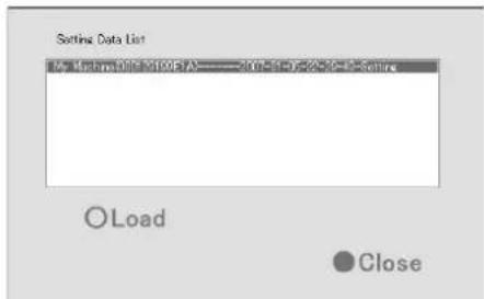
[Setting Data List] Screen
3 Select the setting to load, followed by pressing [Load]
● The highlighted data will be read.
4 The [Load Setting Data?] confirmation message appears. Press [OK].

- The preset data will be read.
- When reading is complete, a message informing you that data has been read appears. Click the [OK] button.
5 Press [Close] to return to the [Flash Memory Utility] screen
■Removing the Flash Memory Device
1 Select [Remove Flash Memory]
- The [Remove Flash Memory?] confirmation dialog appears. Press [OK].
Remove Flash Memory?
![JVC VR-N1600E(A) - Select [Remove Flash Memory] - 1](/content/2026/05/859290/images/e27e9e26f61bb2d5914983737bf5926ac8dd7ef0635b2da14b479cead9d1da29.jpg)
![JVC VR-N1600E(A) - Select [Remove Flash Memory] - 2](/content/2026/05/859290/images/7846c07273c722eac5288436a1513b42aa30cb50620c0d45fbb7df1096cff144.jpg)
● The [Flash Memory was removed] message appears. Press [OK].
Flash Memory was removed
![JVC VR-N1600E(A) - Select [Remove Flash Memory] - 3](/content/2026/05/859290/images/96694a5b479978abc62dcaadf3ba9b18bfcb165e2a2a6851c4b10b1c02da6daf.jpg)
2 Remove the flash memory device from the [SERIAL] on the front (rear) panel
Memo :
- Items specified in the [Image Quality...] settings of [Main Menu]–[Camera Record Setting] (Page 58), [OS Setting] (Page 73), and [Password] section of [Unit Setting 1] (Page 69) will not be saved.
- To read the preset data after you have selected [Remove Flash Memory], remove the flash memory device from the serial terminal and insert it again. When the flash memory is inserted, it will be automatically detected.
Note :
- If you are reading preset data saved using a different language setting, change [Language Setting] of the [Main Menu] to the language used when the data is saved.
- If a Master/Slave setup is created using Milestone System's Enterprise 6.0 on an NVR, settings on that unit cannot be loaded on another NVR.
- Data saved using VR-N900U cannot be used on VR-N1600U/E. and vice versa.
Auto Detect Settings
This section enables you to assign an IP address to each camera and configure various auto detect settings.
Specifying IP Lease
For configuring the function to assign IP addresses to each network camera.
Note :
- In order to assign an IP address of the network camera using the IP Lease feature, you need to enable the DHCP of the network camera. For procedures to enable the DHCP of the network camera, refer to the instruction manual of the network camera.
1 Select [Auto Detect Setting] from [Main Menu]
● The [Auto Detect Settings] screen appears.
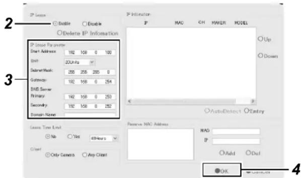
[Auto Detect Settings] Screen
2 Select [Enable] in [IP Lease]
Memo :
- If a network uses a multiple number of NVR units, enable the [IP Lease] only for one unit. Select [Disable] if a DHCP server is operating on the same network.
- When the [IP Lease] is enabled for two or more devices at the same time, the IP address may change to a static address, and cause malfunction of the cameras.
3 Specify the following items under [IP Lease Parameter]
| Item Description | |
| Start Address For specifying the first IP address to be assigned to the cameras. | |
| Unit For selecting the number of IP addresses to be assigned to the cameras. The selected number of IP addresses will be assigned starting from the first IP address. | |
| Subnet Mask For specifying the subnet mask for the cameras. | |
| Default Gateway For specifying the gateway for the cameras. | |
| DNS Server For specifying the DNS server address for the camera(s). | |
| Domain Name For specifying the domain name for the cameras. | |
| Lease Time Limit For specifying the valid period of the IP address assigned to the cameras. If “Yes” is selected, you can set the lease time in units of hours. | |
| Client For selecting whether to apply restrictions on the device when assigning the IP address. If “Only Camera” is selected, IP address will only be assigned to the corresponding camera. If “Any Client” is selected, IP address will be assigned to all devices. | |
| Reserve MAC Address | Configure the [Reserve MAC Address] if you want to assign a specific IP address to the cameras. A specific IP address is always mapped to a MAC address. Enter a value in the MAC and IP fields, and click [Add] to set the addresses. To cancel the setting, select a displayed MAC and IP address, and click [Del]. |
4 Click [OK]
- Doing so hides the setting screen and starts IP Lease.
- Select "Disable" in Step 2 to stop IP Lease.
Auto Detect Settings (continued)
Using the Auto Detect Feature
The Auto Detect feature enables automatic detection of network cameras.
Memo :
- When multicast packets are configured such that they do not pass through the network equipment, such as a switching hub, the Auto Detect of the camera may not function properly.
The [IP Information] list contains information on the IP address of the automatically detected camera, MAC address, number of video CH, manufacturer, and model.
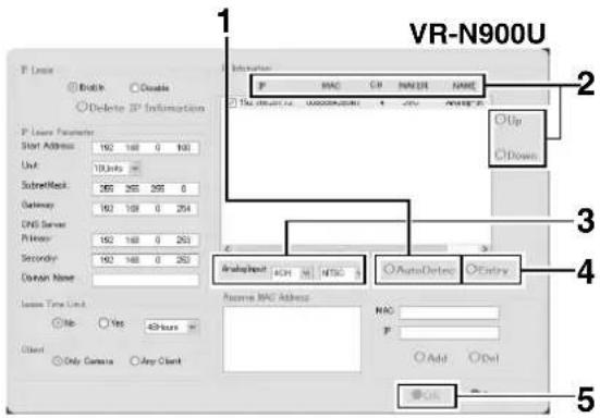
1 Click [Auto Detect]
- Auto Detect starts and the camera image appears on the screen.
2 Replace the detected camera accordingly in sequence
- You can click the Sort button to sort the order of detected cameras.
- There are five types of sort buttons, including Sort by [IP], Sort by [MAC], Sort by [CH], Sort by [MAKER], and Sort by [MODEL] buttons.
- Select the detected cameras, followed by clicking the [Up] or [Down] button to change the order of the cameras.
- Deselect the check box of any camera that you are not using.
Memo :
● The camera at the top of the list is used with priority.
3 Configure the analog input (VR-N900U)
- For specifying the number of channels and format of the analog input to be used.
Note :
- If the signals of the analog camera connected to the rear panel [VIDEO IN1 to 4] terminal are different from those in the [AnalogInput] settings (NTSC/PAL), a message indicating "ENCODE ERROR(format)" will appear. In this case, click the [OK] button using the mouse to hide the "ENCODE ERROR(format)" message, followed by specifying the NTSC/PAL selection for [AnalogInput] correctly.
- For details on how to use the mouse, refer to [Character Input and Mouse Pointer] (Page 28).
4 Click [Entry]
5 Click [OK]
• The [Camera Record Setting] screen appears.
6 Click the [Close] button on the [Camera Record Setting] screen
- The Default View is automatically created. To save this view, change its name.
Memo :
- The Default View created by the Auto Detect feature may change the camera placement in the view. To maintain a fixed position, name the view and save it.
Note :
- Select "Do not detect in the future." check box on the [Detect Device] screen during the Auto Detect operation if you do not want the [Detect Device] screen of that camera to appear during subsequent Auto Detect operations. For cameras that you have excluded from detection, you can add (Page 86) them again manually at a later time.
Language Setting
This option enables you to specify the language you want to use.
Memo :
- The functions and GUI (graphical user interface) are the same as the [Selecting a Language] (Page 23) screen that is displayed when this unit is first switched on.
1 Exit NVR Viewer
2 Select [Language Setting] from the main menu
- The [Language Setting] screen appears when the NVR Viewer is switched on for the first time.
3 Select a language
- Click on the [Language Selection] pull-down tab and select the language you want to use.
4 Click the [OK] button
- Click the [OK] button to enable your selection. The system will reboot when the language setting is changed.
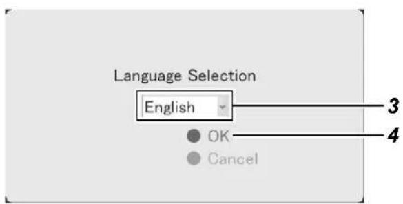
[Language Selection] Screen
Note :
- Specify the language settings immediately after this unit has started up.
- When language setting is complete, the device automatically reboots. It may take about five minutes to exit the settings.
- Set the language after shutting down the NVR Viewer.
● Never turn off the power while setting the language.
HDD Utility
This feature enables you to check the status of the hard disk, and format (initialize), or defragment (eliminate fragmented space) it. The [Progress indicator] shows the progress of formatting and defragmentation.
![Volume Capacity 0 MB Available 0 N ① Close ODefrag OInitialize OError Check ② ③ ④ Quick Format ODetails [Progress] [HDD Utility] Screen ⑥ ⑤ HDD User Settings User name Password MRL Drive Address List OSet OAdd ODel Quick Unlock Double continue to internal HDD OClose](/content/2026/05/859290/images/3331dc2151e6e892682446ea57daf71021a6b60ab5f8aeac451109c4eba38e70.jpg)
1 Select [HDD Utility] from the main menu
- The [HDD Utility] screen appears. Specify the following items.
| Item Description | |
| 1Volume | Click the Down arrow to the right of the [Volume] field to select a hard disk. When you have selected a hard disk, the capacity and percentage of free space will appear in the fields below. |
| Item Description | |
| 2Defrag | Executes the defragmentation function to eliminate fragmented files in the volume selected in the [Volume] field. The defragmentation process may take several hours depending on the status of the hard disk.If defragmentation cannot be executed for some reasons, a message indicating that “Defrag cannot be performed now.” appears. Press [Close] to close the dialog. |
| 3Initialize | Executes initialization of the hard disk with respect of the volume selected in the [Volume] field. All data contained in the volume will be lost after initializing. You will be asked to confirm whether you want to format the hard disk. If an unformatted disk is selected, the “unformat disk” or “unpartition disk” message will appear.Click [OK] to start initialization. To cancel, click the [Cancel] button. If initialization cannot be executed for some reasons, a message indicating that “Initialization cannot be performed now.” appears. Press [OK] or [Cancel] to close the dialog.Normally, the hard disk is formatted prior to shipping, but some types of hard disk may remain unformatted. In this case, you will see the [unformat disk] message in the [Volume] field. For unformatted disks, select [unformat disk] and press [Initialize].Note: ● Volumes C, D and L cannot be initialized. |
| 4Error Check | This is usually not selected. Use it only if you suspect there is abnormality in the hard disk, or if you want to check the data structure of the disk. Recovery of large-capacity hard disks may take several hours. Recovery of the hard disk in the system is impossible. Recovery will be executed the next time the system is started.Recovery may not be possible when the volume to recover is currently in use. In this case, a message indicating “Error check cannot be performed now. Do you want to schedule a recovery during the next system startup?” will be displayed. Select whether you want to click the [Cancel] button and retry by clicking the [Recover] button again, or whether you want to click the [OK] button to execute recovery the next time the system is started. |
| 5Details | Click this option to display the [Advanced] screen.You can specify the settings when archiving to NAS or the built-in HDD on this screen. |
| NAS User Settings | |
| User name For | specifying the user name for connecting to NAS. |
| Password For | specifying the password for connecting to NAS. |
| NAS Drive | |
| Add Enter the | IP address of the NAS to be connected to the [Address], and click the [Add] button.Example) ¥¥192.168.0.200¥¥NAS Device's IP Address¥Shared Name |
| Del Select the | NAS to delete in [List], and click the [Del] button. |
| Auto Archive | |
| Enable archiving to internal HDD | Select this check box.Data will not be archived to the built-in HDD if this check box is not selected. |
| 6Quick Format | Selecting the [Quick Format] check box, followed by clicking the [Initialize] button enables you to shorten the time required for the initialization process.If bad sectors are found during the HDD initialization process, deselect the [Quick Format] check box and press the [Initialize] button. |
Memo :
- NAS is a dedicated file server that is connected to the network. For this unit, you can specify the NAS as a drive for archiving data.
- For details on archiving to the NAS drive, refer to [Archiving] (Page 108).
Note :
- Specify the user name with a different name from the [OS Setting] (Page 73) host name under the user setting for NAS connection.
- After configuring the NAS drive, an error message will appear on the NVR Viewer for several minutes, and live images may not be displayed during this interval.
Restoring Default Settings
Follow the procedures below to restore the default settings.
1 Select [Return to default setting] from the main menu
- The [After initializing, the system is automatically rebooted. Reboot now?] message appears.
2 Click [OK]
● Reboots the unit after initializing.
![Main Menu Unit Setting 1 Unit Setting 2 OS Setting Flash Memory Utility HDD Utility Event Audio Setting Language Setting Return to default settings Image Server Setting Live Viewing Auto Detect Setting Camera Record Setting Optional Installation Exit [Operation] ↑: Up ↓: Down Enter: Enter Cancel: Exit](/content/2026/05/859290/images/b2c5bf788767e424e6ae2362196fd8c9b89754e0767ac68e2b68be7dd25a3cb5.jpg)
Note :
- Settings in the [Password] sections (Page 69) in OS Setting, [Language Setting], and [Unit Setting 1] of the [Main Menu] will not be initialized.
Distribution Settings (Details)
User Administration
This section describes procedures to configure user accounts and rights.
■User Settings
After the [User Administration] screen appears, you are able to define individual users and their passwords. There are two ways to add new users.
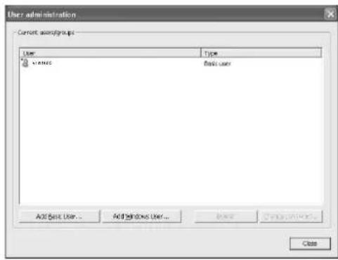
- Add Basic User...:
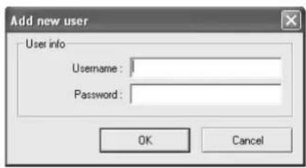
You can create a dedicated user account for the surveillance system through authentication of the user name and password.
- Add Windows User...:
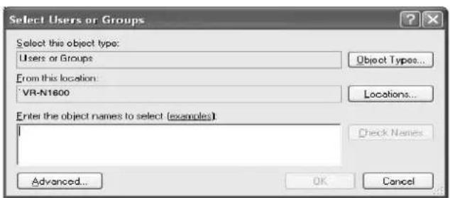
Note :
- Do not select this option. For details, consult your system administrator.
- If the [Host Name] in [OS Setting] has been changed, enter "Administrator" in [Enter the object names to select] on the [Select Users or Groups] screen, and click the [Advanced...] button. Next, click the [OK] button.
- Windows users need to define a Windows user for each host name specified in [Host Name] in [OS Setting]. As the user's host name is not displayed on the [User Administration] screen, it is recommended that you delete the Windows user and add again if you have changed the host name.
Memo :
- To edit a preset user name or password, select the user to edit from the [Current isers/groups] list, and click the [Change password...] button.
- To delete a preset user, select the user from the [Current isers/groups] list, and click the [Delete] button. The user that has been deleted from the list is no longer able to login to NVR Viewer.
- After adding a new user in [Add Basic User...], a small square appears to the top left of the icon on the [User Administration] screen. You can distinguish between [Add Basic User...] and [Add Windows User...] using this mark when the same user name is registered with both.
■Defining User Rights
1 Select [Restrict user access] in the [User Administration] section
2 Click [User Access...]
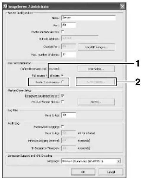
3 Select the user for which user right is to be specified from the [User] list
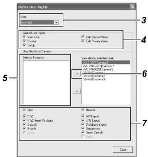
4 Select the user's global rights (not restricted by cameras) in the [Global User Rights] list
| Item Description | |
| View Live Enables | you to view live images. |
| Browse Enables you | to play back recorded images. |
| Setup Enables you | to use the Screen Setup tab. |
| Edit Shared Views | Enables you to create and edit views within the shared group. |
| Edit Private Views | Enables you to create and edit private views. |
5 Select the camera to allow access from the [Defined Cameras]
6 Click [] to move to [Viewable by selected user]
7 Select the functions for each of the cameras that have been moved to [Viewable by selected user]
- Select the functions from the list of options below. All options are selected by default.
| Item Description | |
| Live Enables you to view live images from the selected camera. | |
| PTZ Enables you to control the PTZ camera using the NVR Viewer. | |
| PTZ Presets Enables you to move a PTZ camera to a preset position using the NVR Viewer. | |
| Outoputs Enables you to trigger outputs such as by switching on lights and sounding sirens, if such outputs can be generated. | |
| Events Enables you to trigger manual events using the NVR Viewer. | |
| Audio Enables you to listen to live audio sound from the selected camera. (Only when an audio sound source is specified for the camera) | |
| Browse Enables you to play back recorded images from the selected camera. | |
| AVI Export Enables you to export images in the AVI format. | |
| JPG Export | Enables you to export images in the JPEG format. |
| Database Export | Enables you to export images and audio sound in the database format. |
| Sequence | Enables you to use the Sequences feature to play back images from a selected camera. |
| Smart Search Enables you to use the Smart Search feature (Page 46) using the NVR Viewer. | |
| Audio Enables you to listen to playback audio sound from the selected camera. (Only when an audio sound source is specified for the camera) | |
8 Repeat the same procedures for other users
Memo :
- It is recommended that you limit [Setup] rights to prevent any inadvertent changes made by system users.
Distribution Settings (Details) (continued)
Master/Slave Settings
This section enables you to add/delete NVR units as the slave server.
To use an NVR unit as the master server, you need to select the [Designate as Master Server] check box and register slave servers using the steps below.
■Adding Slave Servers
1 Select [Slaves] in the [Master/Slave Setup] section
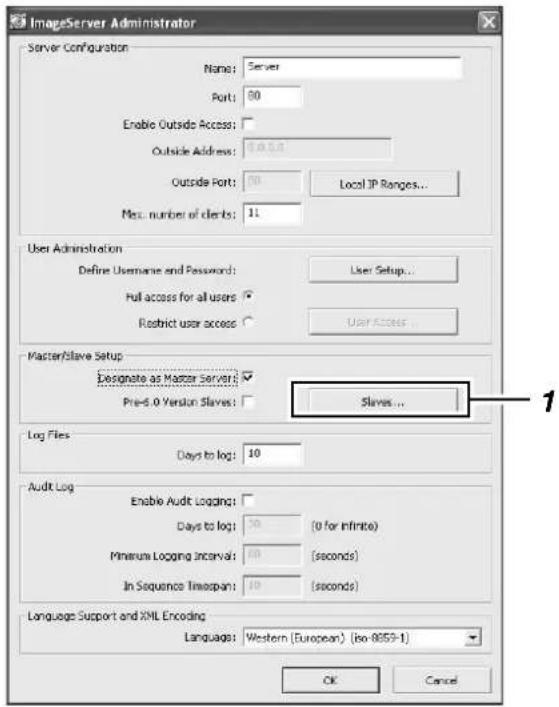
2 Select [Add Slave] on the [Slave Administration] screen
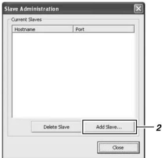
3 Select [Hostname]/[Port] on the [Add New Slave] screen
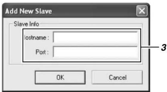
4 Click the [OK] button to register the specified NVR unit as a slave server
Note :
- Up to four slave servers can be registered for one NVR unit (master).
●A total of 80 cameras can be managed by one master/slave system. - The version of all NVR units in a master/slave system must be set the same.
●The NVR unit operating as a master server cannot be used as a slave server for another NVR unit. - When operating as a master server, the recording display performance may drop.
Memo :
- VR-N1600U/E and VR-N900U may be mixed in a master/slave system.
Connecting to a Computer
The following operations are possible when you connect this unit to a computer.
- Viewing live images on the computer
● Controlling network cameras on the computer - Viewing recorded images on the computer
Note :
- Connect the computer to the LAN2 terminal network.
- Settings for cameras connected to the LAN1 network cannot be specified from a computer connected to the LAN2 network.
System requirements
| Item Description | |
| Operating System | Microsoft Windows 2000 Professional, Windows 2000 Server and Advanced Server, Windows XP Professional (32- and 64-bit), Windows Vista Business (32- and 64-bit), Ultimate (32- and 64-bit) or Windows Server 2003 (32- and 64-bit) |
| CPU Intel Pentium4 | or higher ( Xeon recommended for large views), minimum 2.4 GHz |
| RAM Minimum 512 | MB (1 GB recommended for large views) |
| Network Ethernet, | 100 Mbps or higher recommended |
| Graphics Card AGP | or PCI-Express, minimum 1024 x 768 (1280 x 1024 recommended), 16-bit colors or higher |
| Hard Disk Space At least 50 MB free | |
| Software Microsoft | NET Framework 2.0 and DirectX 9.0 or later versions Microsoft Internet Explorer 6.0 |
Computer Network Settings
The following is an example for building a small-scale LAN on Windows XP Professional using the default settings of this unit. (All screens shown below are Windows XP SP2 configuration screens.)
1 Click the [Start] button, followed by clicking [Control Panel]
2 Click [Network and Internet Connections]—[Network Connections]
Connecting to a Computer (continued)
3 Select the network to which NVR is connected
4 Right-click and select [Properties]
5 Check to ensure that both the [Client for Microsoft Networks] and [Internet Protocol(TCP/IP)] check boxes are selected
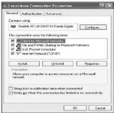
6 Select [Internet Protocol(TCP/IP)] and click the [Properties] button
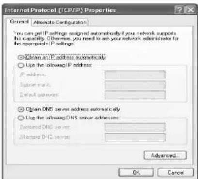
7 Select [Use the following IP address]
8 Set [IP address] to 192.168.1.11
9 Set [Subnet Mask] to 255.255.255.0
10 Set [Default gateway] to 192.168.1.254
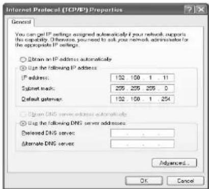
11 Click the [OK] button
12 Click the [OK] button on the [Local Area Connections Properties] screen
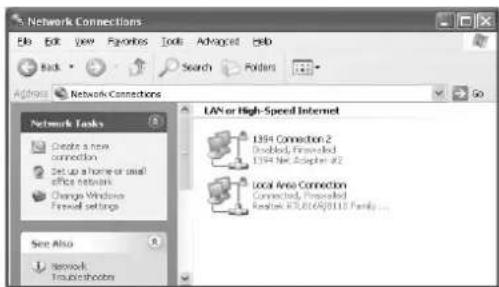
Note :
- Do not use the same IP address in the same network environment.
- Do not register multiple IP addresses with one NIC when specifying the computer network settings.
Install the NVR Viewer on the Computer
Note :
- Before installing, check to ensure that Microsoft. NET Framework 2.0, DirectX 9.0 or later versions, and Microsoft Internet Explorer 6.0 or later versions are already installed on the computer. If any of these are not installed, installation of the NVR Viewer may fail.
1 Open the Internet Explorer browser (6.0 or later versions), and enter the IP address of NVR as "http://192.168.1.253"
• A welcome page will appear.
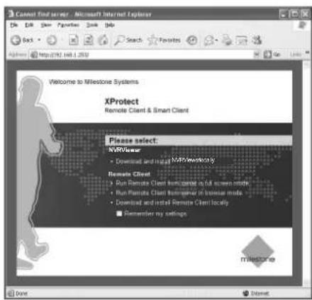
Note :
- Do not select [Remote Client].
2 Click [Download and install NVR Viewer locally]
- The [Do you want to run or save this files?] confirmation message appears.
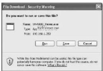
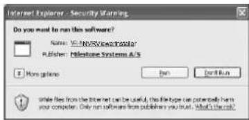
3 Click the [Run] button
Doing so starts up the NVR Viewer Setup Wizard.
![WinZip Self-Extractor - NVR_Viewer[1].exe Installing Please wait... Cancel About](/content/2026/05/859290/images/6e79edf7b1ef1c6fc6ff1de9c64768a20180c9c8f3337832403019ff53cd1166.jpg)
4 Click [Next] and follow the installation instructions
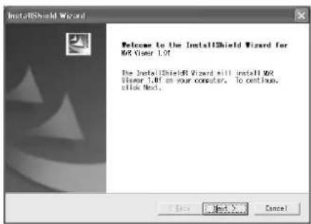
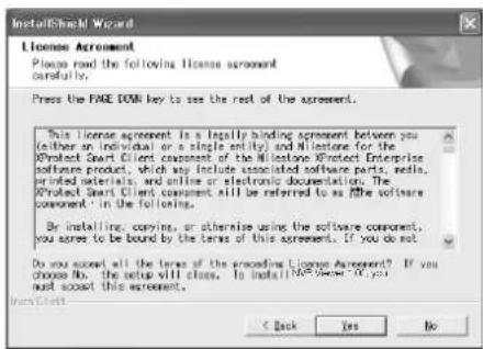
For Windows Vista, select "all users".
Connecting to a Computer (continued)
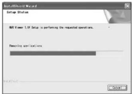
5 Installation complete
- Installation ends and a shortcut to the "NVR Viewer" is created on the desktop.
Login to the NVR Viewer
1 Double-click the NVR Viewer shortcut on the desktop
- When using Windows Vista, right-click the icon and select "Run as administrator" to activate NVR Viewer. (In the properties box that appear when the icon is right-clicked, select "Compatibility" - "Privilege Level" and check "Run this program as administrator". This enables you to activate the program by double-clicking.)
Memo :
- If the NVR Viewer shortcut is not found on the desktop, select "NVR Viewer" from the [Start] menu.
● The NVR Viewer Login screen appears.
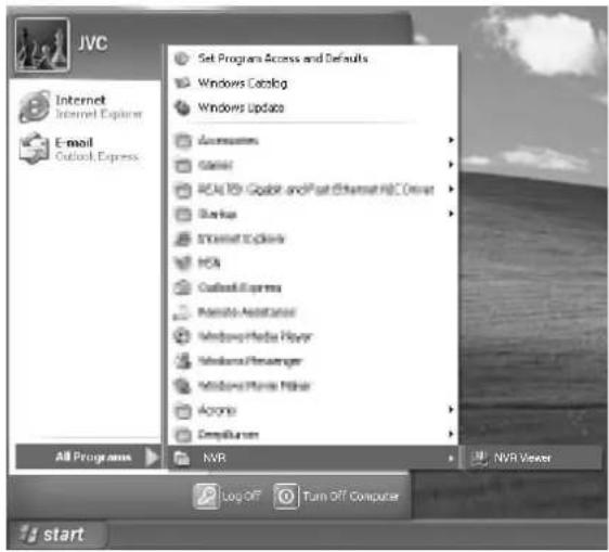
Login to NVR Viewer (Continued)
2 Specify your login information in the following fields
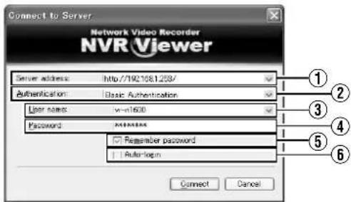
●VR-N1600U/E
●VR-N900U
User name :vr-n1600
User name : vr-n900
Password :vr-n1600
Password :vr-n900
| Item Description | |
| 1Server address | For specifying the IP address and port number of this unit. (For example, in the case of [http://192.168.1.253:80], [:80] is the port number.)The port number is the number as specified in [Server Configuration] under [Image Server Setting]. (Page 77) |
| 2 Authentication | For selecting one of the three types of authentication.Select “Basic authentication”. |
| Windows authentication(current user) | Windows authentication. Login as the current Windows user. |
| Windows authentication | Windows authentication.You can login as a Windows user, but a user name and password will be required. |
| Basic authentication | Basic authentication.A user name and password will be required to login to this unit. |
| 3 User name | For entering the Windows user name if you have selected “Windows authentication” for the [Authentication] item 2. For entering the user name registered in the [User Administration] item under [Image Server Setting](Page 118) if you have selected “Basic authentication”. |
| 4 Password | For entering the login password for this unit if you have selected “Windows authentication” for the [Authentication] item 2. For entering the password registered in the [User Administration] item under [Image Server Setting](Page 118) if you have selected “Basic authentication”. |
| Item Description | |
| 5Remember password | Saves the password.If you have selected “Windows authentication” or “Basic authentication” for the [Authentication] item 2, selecting this check box enables you to login the next time simply by clicking the [Connect] button. |
| 6 Auto-login | Enables you to login automatically. Select this check box to enable you to login to [NVR Viewer] automatically. |
3 Click the [Connect] button
- The NVR Viewer screen appears after a short while.
Memo :
- If you have previously logged in to the NVR Viewer, a message will appear asking if you want the view that was used during the last login to be displayed. (Only when connecting from a surveillance computer)
[Main View]:
Select this check box to restore the view that you last used in the main window of the [NVR Viewer].
[Detached Views]:
Select this check box to display the views on the [Primary Display] screen, multi-monitor, or floating screen.
Note :
- When you log out after reaching the maximum number of distribution clients, you may need to wait for several minutes before you can establish the connection again.
- When multiple computers are connected and audio sound is played back, the sound may be distorted.
4 Set the display language according to the country of use
① Click the [▼] button at the top right corner of the screen.
②Select [Language] from the menu that appears.
③Select the language used in your country from the displayed submenu.
④Click [OK] when you see a dialog box.
⑤ Click the [×] button at the top right corner to exit the NVR Viewer.
→The viewer will display in the selected language during the next startup.
![[▼] Button [×] Button Joystick Setup Keyboard Setup Language Danish (Denmark) German (Germany) French (France)](/content/2026/05/859290/images/786c79ee978af7226f81403ed217722582063a8b95e7048ffbd25de3ed6134ee.jpg)
Connecting to a Computer (continued)
Uses of the NVR Viewer
For uses of the NVR Viewer, refer to the following pages.
● [Viewing Live Images via Mouse Control] (Page 36)
●[Playing Back Recorded Images via Mouse Control] (Page 42)
● [Screen Setup] (Page 60)
Exiting/Logging Out of the NVR Viewer
![[Log Out] Button [×] Button](/content/2026/05/859290/images/ca88b927da0c673cfeaeafb31c1f4a8e01b2b14e47fc686a20cd840f5692f39f.jpg)
■Logging Out
1 Click the [Log Out] button
- You are logged out and the Login screen of the NVR Viewer appears again.
Note :
- If you have restarted this unit, or the NVR Viewer on this unit, log out from the NVR Viewer at the surveillance computer once, and login again.
■Exiting
1 Click the [×] button
- Exits the NVR Viewer.
Audio Transmission Application Control (VR-N1600U/E)
Audio sound input (such as from a microphone) to the [AUDIO IN 1] terminal is sent to a camera that supports bidirectional audio, and output to the speakers connected to the camera.
Preparation
■Connection
1 Refer to [System Connection Example] (Page 26) to connect the microphone to the microphone amplifier or mixer, and connect the output to [AUDIO IN 1] on the rear panel
Memo :
- Audio sound input to the [AUDIO IN 2] terminal cannot be sent to cameras that support bidirectional audio.
■Registering camera that supports bidirectional audio
1 Refer to [Adding Cameras] (✗ Page 86) to register the camera that supports bidirectional audio
Note :
- If you have changed the camera password, specify the new password in [Event Audio Setting] of the main menu. [Password] (Page 131)
Audio Transmission
1 Start up the NVR Viewer to check the live images of the camera
- With the wallpaper or main menu displayed, press the [LIVE/BROWSE] button to start up the NVR Viewer.
2 Press and hold the [FUNCTION] button, and press the [7/] keypad button at the same time to start up the [Audio Transmission] screen
![Audio Transmission Select Camera Multi Mode Single Mode [Device] Camera Name [NVR] Camera 17 Status Information Destination Status [NVR] Camera 17 Disconnected Connect Disconnect Close](/content/2026/05/859290/images/0a2d15390ba57390a406683a2d36d6de72dc0eb24f97fa6359d68629bb1d848c.jpg)
[Audio Transmission] Screen
3 Select an audio transmission mode
- There are two audio transmission modes, namely [Multi Mode] and [Single Mode]. [Multi Mode] enables you to send out audio sound to multiple cameras at one time. [Single Mode] sends out audio sound to only one camera.
- In the case of [Multi Mode], select the camera for receiving the audio data on the [Event Audio Setting] screen of the main menu. Select "Multi Mode" from the list at the left end of the [Event Audio Setting] screen, and select the checkbox corresponding to the camera for receiving the audio data. (Page 129)
- In the case of [Single Mode], you can select the camera for receiving the audio data in [[Device]Camera Name].
- The camera that is receiving the audio sound appears on the [Status Information] list.
4 Press the [Connect] button to connect to the camera and start audio transmission
- Connection status with the camera is displayed in the [Status] area of the [Status Information] list. Press the [Connect] button and audio sound that input to [AUDIO IN 1] terminal of this unit will be transmitted to the cameras that are displayed as "Connected".
- If "Disconnected" appears, check the network between this unit and the camera, IP address of the camera, and the power of the camera. If [Authentication failed] appears, repeat procedures on the [Event Audio Setting] screen to register the password of the camera for which the [Authentication failed] message is displayed. [Password] (Page 131)
Audio Transmission Application Control (VR-N1600U/E) (continued)
5 Press the [Disconnect] button to disconnect the camera
Memo :
- Cameras that are not registered in [Camera Record Setting] of the main menu cannot be selected.
- If the audio setting of the camera is set to the half duplex mode, you will not be able to hear audio sound from the camera when in the "Connect" status.
- If you are sending the microphone sound to a camera for which an event audio has been set, the audio playback function that is associated with an event will be disabled during microphone sound transmission, and priority is given to the microphone sound transmission.
- You can also operate the [Connect] and [Disconnect] button from the alarm terminal on the rear panel. In this case, select the alarm terminal to be used for control with [Push To Talk] under [Event Audio Setting]. An alarm input triggers an action equivalent to the [Connect] button, and canceling the alarm is equivalent to the action when you pressed the [Disconnect] button. Control of the [Connect] and [Disconnect] is valid only when these buttons are enabled.
Note :
- If you are configuring the settings or performing an audio playback test in the [Camera Record Setting] or [Event Audio Setting] of the main menu, do so after you have closed this dialog box.
- If the performance meter lights up in yellow or red, the microphone sound may be interrupted. To make sure that audio sound is successfully transmitted, perform operations such as temporarily stopping the recording operation so that the performance meter does not light up in yellow or red. [Performance Meter] (Page 27)
Event Audio Settings (VR-N1600U/E)
This feature plays back a specific audio file from the designated destination on the camera or this unit when a generic event registered with this unit is triggered or when alarm signals are input to the rear terminal. The Event Audio Settings screen enables you to configure the above setting as well as other settings related to the event audio feature.
1 Select [Event Audio Setting] from [Main Menu]
- The [Event Audio Setting] screen appears.
![Event Alarm 1 telling Alarm 1 none Alarm 2 telling Alarm 2 none Alarm 3 telling Alarm 3 none Alarm 4 telling Alarm 4 none Alarm 5 telling Alarm 5 none Alarm 6 telling Alarm 6 none Alarm 7 telling Alarm 7 none Alarm 8 telling Alarm 8 none Multi Mode TOP-EVENT UDP-EVENT Ush To Talk ALARM IN 1 Conditional expression Audio files Audio playing for 3Address [NVR] Camera 17 1270.01 Uses Audio files copy Setting copy Password setting Communication settir](/content/2026/05/859290/images/7ff4e85b38f3978b75864c361dc3650013e6bbc67b1dd6f6a550fd6f50fadf75.jpg)
| Item Description | |
| 1Event | A list of events that can be used with the event audio are displayed.You can use up to a maximum of 100 events (including both [External Alarm Terminal] and [Multi Mode]). [Generic Event] that has been configured on the [Camera Record Setting] screen, [External Alarm Terminal] on the rear panel of the VR-N1600U/E unit, as well as [Multi Mode] are displayed.Memo :After setting an event for the external alarm terminal of VR-N1600U/E, do not delete the “[NVR](127.0.0.1)” audio input of the main unit in [Camera Record Setting]. Doing so clears the settings. |
| 2Conditional expression | The conditional expression of the [Generic Event] selected in the [Event] item 1 is displayed. |
| 3Renew | Updates the current settings of the event audio feature, and closes the [Event Audio Setting] screen. |
| 4Cancel | Cancels all settings and closes the [Event Audio Setting] screen.Memo :The password at the receiving end specified on the [Password] screen cannot be canceled. |
| Item Description | |
| 5Audio files | For specifying the audio file to play back and number of playbacks when an event is triggered.Specify the number of playbacks between “1times” and “10times”. You can also select continuous playback to enable infinite loop playback. Leave the field blank if you do not want to designate a playback audio file for a specific event. |
| 6Start Button on the Different Pages | [Audio files copy] Button:Starts up the [Audio file utility] screen.( page 130)[Setting copy] Button:Starts up the [Setting copy] screen.( page 131)[Password setting] Button:Starts up the [Password setting] screen.( page 131)[Communication setting] Button:Starts up the [Communication setting] screen. ( page 132) |
| 7Audio playing for/IPaddress | Displays a list of cameras or IP addresses that are used as destinations of audio playback files.Select a destination to play back audio files when an event is triggered from the list.Select the check box of the camera to play back audio sound.You can sort the list accordingly by clicking [Audio playing for] or [IP address]. |
| 8Push To Talk | Push to Talk is a feature that enables transmission of audio sound to a camera that supports bidirectional audio when the microphone button is pressed down (when Make signal is input to the [ALARM IN] terminal of this unit). ( page 20)To use this feature, select the external alarm terminal on the rear panel of the VR-N1600U/E unit.Leave this blank if you are not using the [Push To Talk] feature.The action that is associated with the [ALARM IN 1 to 8] terminals configured on the [Camera Record Setting] screen are disabled when the [Push To Talk] feature is in use. (Only alarm input of the selected terminal is disabled. Actions of terminals that are not selected remain valid.) [Input/Output Terminal on Rear Panel]( page 97) |
Event Audio Settings (VR-N1600U/E) (continued)
Audio Copying
This feature enables you to copy (register with this unit), delete, perform test play, and record audio files used on the [Event Audio Setting] screen. Format supported is G711 μ-law monaural sound. Playback time up to 300 seconds is supported.
Memo :
- Set the audio file playback time to an interval not longer than 180 seconds.
1 Click [Audio files copy] on the [Event Audio Setting] screen
● The [Audio file utility] screen appears.
![Audio file utility Flash: memory Audio files Alert1.mov Alert2.mov Add Delete Recording file name Test play Recording Audio playing for [ NVR] Camera 17 [ PAddress 1270.01](/content/2026/05/859290/images/f3eeb2028e0e8169aca507f0e9bee3fc161c6bc2f754ce1bd0603799d32ea729.jpg)
| Item Description | |
| 1Flash memory | The G711μ-law monaural format audio files in the root folder of the USB memory device connected to this unit are displayed. |
| 2Add (Stop) | Select one audio file from the [Flash memory] list, and press [Add] to copy the audio file inside the [Flash memory] to this unit. When audio file copy is in progress, the [Add] button switches to a [Stop] button. To stop copying of the audio file, press the [Stop] button.Memo:If an audio file with the same name already exists on this unit, a confirmation message asking whether you want to overwrite the existing file appears.You can add up to a maximum of 100 audio files to this unit. An error message appears when the number of files exceeds 100, and copying cannot be performed. |
| Item Description | |
| 3Recording file neme | For entering the file name when you perform recording using the microphone connected to this unit. The [Recording (Stop)] button 9 is enabled once you have entered a file name. |
| 4Audio playing for/IPaddress | For selecting the camera for audio playback during test play of audio files. Select a camera by ticking the corresponding check box. You can sort the order of the list accordingly by clicking [Audio playing for] or [IP address]. |
| 5Close | Closes the [Audio file utility] screen. The [Close] button cannot be selected during addition, deletion, test play, or recording of an audio file. |
| 6Audio files | The G711μ-law monaural format audio files stored on this unit are displayed.Memo: ● To stop playback while it is in progress, press the [ALARM CLEAR] button. |
| 7Delete | To delete an audio file from the USB memory device or this unit, select the audio file from the [Flash memory] or [Audio files] list, followed by clicking the [Delete] button. A confirmation message appears, and the selected audio file is deleted. |
| 8Test pray (Stop) | For performing test play of audio files using a camera that supports bidirectional audio sound or this unit.Select an audio file from the [Flash memory] or [Audio files] list, and press the [Test pray (Stop)] button. Select the camera to use for the test from the [Audio playing for] list 4.When test play is in progress, the [Test pray] button switches to a [Stop] button. To stop test play while it is in progress, press the [Stop] button.When password authentication of the camera receiving the audio file fails, the indicator of the receiving camera lights up in red. When connection with the camera receiving the audio file fails, the indicator of the receiving camera lights up in yellow. Playback time is displayed in the [Recording file neme]3 field when playback is in progress.As the audio playback is transmitted through the network, the playback time displayed is only a reference time. This may slightly differ from the actual playback time. |
| 9Recording (Stop) | Enables you to mix and record audio sound input to the [AUDIO IN 1/AUDIO IN 2] terminal of this unit by entering the file name in [Recording file neme]3 and pressing the [Recording] button. (Maximum duration: 180 seconds)During recording, the [Recording] button switches to a [Stop] button. To stop recording while it is in progress, press the [Stop] button. Recording time is displayed in the [Recording file neme]3 field when recording is in progress. |
Setting Copy
This feature copies the settings of event audio associated with an event (audio file name, destination of transmitted audio file, number of deliveries) to another event.
1 Select the event to copy settings to (existing settings are overwritten) from the [Audio playing for] list on the [Event Audio Setting] screen
2 Click [Setting copy]
- The [Setting copy] screen appears.
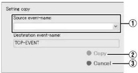
| Item Description | |
| 1Source event-neme: | Select from the list the event to copy settings from. |
| 2Copy | Click the [Copy] button to copy the settings. After copy is complete, press the [Renew] button on the [Event Audio Setting] screen to enable the copied settings. |
| 3Cancel | Closes the [Setting copy] screen without executing copy. |
Password
Enter the password to establish connection with the camera that supports bidirectional audio. Audio transmission to the camera that supports bidirectional audio will not be executed if the password entered is incorrect.
Memo :
- To enter the password, you need to ensure that communication of the selected camera on the network is enabled.
1 Select a camera from the [Audio playing for] list on the [Event Audio Setting] screen
Memo :
- To select a camera, click on the camera name to highlight the display. Note that selecting the check box does not select the camera.
2 Click [Password setting]
- The [Password setting] screen appears.
![Password setting Camera name [NVR] Camera 17 IPaddress 127.0.0.1 Password OK Cancel](/content/2026/05/859290/images/5da49b62875ccba99a965cb0d8cdfcab4a8c438267418a66961ff382d3e97e67.jpg)
| Item Description | |
| 1Camera name | The name of the camera for entering the password appears. You cannot alter the [Camera name]. |
| 2IPaddress | The IP address of the camera for entering the password appears. You cannot alter the [IPaddress]. |
| 3Password | For entering the camera password. The default password appears during the first entry.Memo:There is no default password for cameras manufactured by AXIS. When using AXIS cameras, you need to specify a camera password in advance. For details, refer to the [Instruction Manual] of the camera. |
| 4OK | Authenticates the entered password. If authentication is successful, the setting is saved and the [Password setting] screen closes automatically.If the password entered is incorrect, or if access to the camera fails such as when the camera is not connected to the network, an error message appears and the password setting will not be saved. |
| 5Cancel | Cancels password authentication on the camera. Closes the [Password setting] screen without saving the password setting. |
Event Audio Settings (VR-N1600U/E) (continued)
Communication Settings
To make use of the event audio feature, you need to receive the communication data for triggering the generic event issued by an external device using the event audio program, and transfer it to the alert port of this unit.
You can enter the port number and alert port number ( Page 102 ) for receiving communication data for triggering the generic event on the [Communication setting] screen.
Note :
- Do not alter the setting unless under special circumstances. Altering the setting unnecessarily may cause the system to malfunction.
1 Click [Communication setting] on the [Event Audio Setting] screen
● The [Communication setting] screen appears.
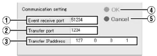
| Item Description | |
| 1Event receive port | For specifying the port number for receiving communication data for triggering the generic event issued by an external device. |
| 2Transfer port | For specifying the port number to transfer communication data to.Memo :Specify the same port as Main Menu→[Camera Record Setting]→[I/O Setup]→[Details]→[Network Settings]→[Alert Port]. ( page 98) |
| 3Transfer IPaddress | For specifying the IP address to transfer the generic event to. (Specify the unit itself using 127.0.0.1) |
| 4OK | Closes the [Communication setting] screen. After setting is complete, press the [Renew] button on the [Event Audio Setting] screen to enable the new settings. |
| 5Cancel | Closes the [Communication setting] screen without doing anything. |
Memo :
-
To play back an audio file, register the event with [General Event Settings] of [Camera Record Setting]. (Page 100)
● External device settings: -
Set the port for receiving the event (51234) as the alarm output (communication data for triggering the generic event) destination port of the external device, such as camera.
- Set the IP address of this unit as the destination IP address. However, note that the IP address of this unit is not 127.0.0.1.
- If the audio setting of the camera is set to the half duplex mode, you will not be able to hear audio sound from the camera during event audio transmission.
Note :
- If you configure the camera event settings on the [I/O Setup] screen of [Camera Record Setting] after alarm output setting for the generic event at the camera is complete, information of the existing generic event will be overwritten, and this may cause the system to malfunction.
- Do not specify the same number for the [Event receive port] and [Transfer port].
HDD Meter
You can display the free space and usage rate of the specified hard disk drive on the screen.
Displaying the HDD Meter
1 Press and hold the [FUNCTION] button, and press the [8] keypad button at the same time to display the HDD meter on the top right corner of the screen
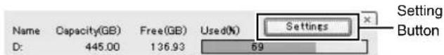
[HDD Meter] Screen
Memo :
- To hide the HDD meter, press the [8] keypad button while holding down the [FUNCTION] button.
●To move the display position of the HDD meter, left click and drag it to the desired position.
■Changing the HDD Meter Settings
You can press the [Settings] button on the [HDD meter] screen to perform various settings such as specifying the target hard disk drive or setting alerts.
![Settings Monitor settings Update interval 10 [sec] Transparency 0 [%] Select drives to monitor Drive Letter Type C: Local HDD D: Local HDD Alert notification settings D: Enable notify Notify when the free-space less than 5 [GB] OK Cancel](/content/2026/05/859290/images/51c1d5bc595af6d220e6605d8b2e1ce025d9fdcfcf4e433f986e8c738fbab1f5.jpg)
| Item | Preset Values | Description |
| 1Update interval | 10 seconds | For specifying the time interval (seconds) for updating. (Range of 10 to 300 seconds) |
| 2 Transparency | 0 % | For specifying the transparency of the HDD meter. (Range of 0 to 90 %) |
| 3Select drives to monitor | OFF Displays the built-in hard disk drive and external USB hard disk drive in a list.Select the check box of the hard disk drive to monitor. Each drive is used for its respective purpose as below.C : System diskM : Saves the temporary files of the CD/DVD export data.L : Saves the operation log.Others: Saves the recorded images. | |
| 4Alert notification setting | - Displays only the hard disk drive selected in 3. | |
| 5 Enable notify | OFF | ● Switches the alert notification on or off. 6 can be set only when this is turned on.●The alert message “Free space of HDD less than *GB (*drive)” will be displayed.Memo :Specify the alert notification method (dialog or email) in Unit Setting 1. |
| 6Notify when the free-space less than | 5 GB An | alert will occur when the amount of free space falls below the specified size.Free space can be set in the range 1 to 999 GB. |
Setting SNMP
When SNMP is enabled, the status of this unit can be monitored from the SNMP manager of the surveillance computer. The MIB extension information (JVCNVRMIB.txt) must be registered to the SNMP manager.
1 Insert a commercially available flash memory device into the serial terminal
2 Select [Unit Setting 2] from the main menu
![Main Menu Unit Setting 1 OS Setting Flash Memory Utility HDD Utility Event Audio Setting Language Setting Return to default settings Image Server Setting Live Viewing Auto Detect Setting Camera Record Setting Optional Installation Exit [Operation] ↑: Up ↓: Down Enter: Enter Cancel: Exit](/content/2026/05/859290/images/f5a8e22f4ed9f86ed94c818fe9a68aff568757f5efac3e87a0a9a0cec1d8980d.jpg)
[Main Menu List] Screen
3 Select the [Enable of SNMP] check box in the [SNMP setting] section
●To use TRAP, select the [Enable of TRAP] check box in the [SNMP setting] section.
- Refer to [List of TRAP Supported by this Unit] (Page 135) for the TRAP notifications supported by this unit.
4 Enter the IP address of the surveillance computer in the [SNMP manager's address] field
5 Specify the SNMP community name
Example) kanshi1
Note :
- Up to 32 alphanumeric characters can be used for the community name.
- TRAP signals may be missed on the receiving end depending on the communication specifications. Operate with judgement based on polling primarily and make use of TRAP only secondarily.
6 Press [Copy extension MIB onto the flash memory] in the [SNMP setting] section
●The MIB extension information is copied to a flash memory device.
![HDD water □ Display at startup Clock setting □ Display at startup □ Display at date □ Display at second SNRP settings □ Enable of SNMP □ Enable of TRAP SNRP manager's advice Community name Confirmation interval of start : 16 [Sec] Confirmation interval of CPU usage : 16 [Sec] Confirmation interval of Drive : 90 [Sec] Confirmation interval of NVR Viewer : 16 [Sec] Confirmation interval of camera : 90 [Sec] ○ Open extension MEI on the flash memory OK Cancel](/content/2026/05/859290/images/56ea0fe842809fa5fa5bd476f4f06a14c2d69d3d94a70def38654e3e542aa6b4.jpg)
[Unit Setting 2] Screen
7 Register the MIB extension information to the SNMP manager of the surveillance computer
- To register the MIB extension information to the surveillance computer, refer to the instruction manual of the SNMP manager.
8 Specify the surveillance (polling) settings for the SNMP manager of the surveillance computer
- For details on how to set, refer to the instruction manual of the SNMP manager.
- Refer to [List of Status that can be Obtained from this Unit] (e.g. Page 135) for the list of status that can be obtained from this unit.
■List of Status that can be Obtained from this Unit
iso(1) - org(3) - dod(6) - internet(1) - private(4) - enterprises(1) - jvc(718) - nvr(916) - nvrObjects(1)
| Group Identifier Name | SYNTAX MAX-ACCESS UNITS | Explanation | |||
| Current Value | nvrStausGroup(1) | 1 nvrRecStatus | INTEGER {off(0),on(1)} | read-only - REC | status |
| 2 nvrRecMode | INTEGER {off(0),recCtrl(1),recAll(2)} | read-only - REC | mode | ||
| 3 nvrLastAlarmDate DateAndTime | read-only - | Latest alarm date | |||
| 4 nvrCpuUsage INTEGER(0..100) | read-only % | CPU usage rate | |||
| 5 nvrDdriveWrite | INTEGER(0..4294967295) | read-only | Byte/Sec Writing rate to D drive | ||
| 6 nvrRunViewer | INTEGER {stop(0),run(1)} | read-only - | Viewer execution status | ||
| Warning List | nvrWarningGroup(2) | 1 nvrWarningTable | SEQUENCE OF nvrWarningEntry | not-accessible | - Table of last 10 warnings |
| 1.1 nvrWarningEntry | nvrWarningEntryINDEX {nvrWarningIndex} | not-accessible | - Entries of last 10 warnings | ||
| 1.1.1 nvrWarningIndex | INTEGER(1..10) | read-only | - Index of warning list | ||
| 1.1.2 nvrWarningDate | DateAndTime read-only | - | Dates when warnings occurred | ||
| 1.1.3 nvrWarningInfo | DisplayString read-only | - Warning information | |||
| Camera List | nvrCameraGroup(3) | 1 nvrRegistCameraTable | SEQUENCE OF nvrRegistCameraEntry | not-accessible | - Table of 32 connected cameras |
| 1.1 nvrRegistCameraEntry | nvrRegistCameraEntryINDEX {nvrRegCamIndex} | not-accessible | - Entries of 32 connected cameras | ||
| 1.1.1 nvrRegCamIndex | INTEGER(1..32) | read-only | - Index of connected cameras list | ||
| 1.1.2 nvrRegCamIpAddress Ip | Address | read-only - | IP addresses of connected cameras | ||
| 1.1.3 nvrRegCamName DisplayString read-only - | Camera names | ||||
| 1.1.4 nvrRegCamConnection | INTEGER {disconnect(0),connect(1)} | read-only - | Camera connection status | ||
■List of TRAP Supported by this Unit
iso(1) - org(3) - dod(6) - internet(1) - private(4) - enterprises(1) - jvc(718) - nvr(916) - nvrTraps(2)
| Identifier | Name | OBJECTS | STATUS | Explanation |
| 1 | nvrRecStatusChange | nvrRecStatus, nvrRecMode | current | Notification of REC status change |
| 2 | nvrNotifyAlarm | nvrAlarmDate | current | Notification of alarm occurrence |
| 3 | nvrNotifyWarning | nvrWarningIndex, nvrWarningDate, nvrWarningInfo | current | Notification of warning occurrence |
| 4 | nvrNotifyCamConnect nvrRegCamIndex, nvrRegCamIpAddress, nvrRegCamName, nvrRegCamConnection | nvrRegCamIndex, nvrRegCamIpAddress, nvrRegCamName, nvrRegCamConnection | current | Notification of camera connection status change |
Compatible Equipment
Make sure that peripheral devices are used in accordance with their operating environment.
Compatible Network Cameras
| FunctionIP cameras | JPG | PTZ | Audio | PTZ Joystick | MPG4 | VMD Event | Bidirectional Audio | Mega Pixel |
| JVC VN-V25 | ● | ● | ||||||
| JVC VN-V26 | ● | ● | ● | |||||
| JVC VN-V685 | ● | ● | ● | ● | ● | |||
| JVC VN-V686 | ● | ● | ● | ● | ||||
| JVC VN-V686B | ● | ● | ● | ● | ● | |||
| JVC VN-V686WPC | ● | ● | ● | ● | ● | ● | ||
| JVC VN-V225/VP | ● | ● | ● | ● | ||||
| JVC VN-X235/VP | ● | ● | ● | ● | ● | ● | ● | ● |
| JVC VN-C20 | ● | |||||||
| JVC VN-C655 | ● | ● | ● | |||||
| JVC VN-C625 | ● | ● | ● | |||||
| JVC VN-E4 | ● | ● | ● | ● | ● | |||
| JVC VN-C215 | ● | |||||||
| JVC VN-X35 | ● | ● | ● | ● | ● | ● | ● | ● |
| AXIS 206 | ● | |||||||
| AXIS 207 | ● | ● | ● | |||||
| AXIS 209FD | ● | ● | ||||||
| AXIS 211 | ● | ● | ● | ● | ||||
| AXIS 212 | ● | ● | ● | ● | ● | ● | ||
| AXIS 213 | ● | ● | ● | ● | ||||
| AXIS 214 | ● | ● | ● | ● | ● | ● | ||
| AXIS 216 | ● | ● | ● | ● | ||||
| AXIS 225 | ● | ● | ● | |||||
| Verint S1700 | ● | ● | ● | |||||
| Verint S1704 | ● | ● | ● | |||||
| Verint S1708 | ● | ● | ● | |||||
| Verint S1900 | ● | |||||||
| Verint S2700E | ● |
Memo :
- When VN-V685 and VN-V686B are registered to NVR, do not enable the audio device although it is displayed. If it is enabled, camera images may not be displayed correctly.
- VN-V686WPC may be recognized by NVR as VN-V686B, but this is normal. WPC works normally even if the audio device is enabled.
- When VN-X35 is used, make sure that the firmware version of VN-X35 is V2.00 or a newer version.
- When sending out audio data to VN-V26U, make sure that the firmware version of VN-V26U is 1.01 or a newer version. (VR-N1600U/E)
Connecting a UPS
Connecting an uninterruptible power supply (UPS) to the hard disk will protect it from damage by automatically shutting down all operations prior to switching off the power supply in the event of a power failure.
1 Press and hold the [FUNCTION] button, and press the [3/4] keypad button at the same time to start up the [UPS SetUp] screen
2 Select "UPS Mode" and press the [OK] button
3 Connect the UPS communication cable to the [SERIAL] port on the rear panel
4 Connect the power cable of this unit to the UPS power output connector
5 Switch on the power of the UPS, followed by the power of this unit
Note :
- Consult your nearest JVC dealer or service center for details on the types of UPS that can be used.
● Make sure that the UPS communication cable is connected before switching on the power of this unit. - Do not disconnect the communication cable when operations are in progress.
- When a power failure occurs while formatting a hard disk or archiving, subsequent operations may be affected even when a UPS is connected.
- The recorded images may not be played back properly if they are not archived before the power failure. (Page 110)
- If you are not using a UPS, do not select [UPS SetUp] on the the [UPS SetUp] screen. Inappropriate selections may affect subsequent operations.
External Hard Disk Drives
You can connect an external hard disk drive to the [SERIAL] terminal at the rear of this unit. Up to two hard disks of capacity 500 GB, 1 TB or 2 TB can be combined and used together.
Connecting the External Hard Disk Drive
1 Press and hold the [OPERATE] button for about2 seconds to turn off the power
2 Turn off the power switch on the rear panel
Note :
- Make sure that you turn off the power switch.
3 Connect the external hard disk drive to the [SERIAL] port on the rear panel, and switch on the power
- Make sure that you switch on the power to the external hard disk drive before switching on this unit. The system may not recognize the external drive if it is not switched on beforehand.
4 Switch on the power of this unit
- If recording is in progress, a [New HDD was found. Are you OK to stop recording and format new HDD?] confirmation message appears.
New HDD was found. Are you OK to stop recording and format new HDD?
OK
Cancel
- Upon clicking [OK], a multipartition confirmation screen appears. (Only when the VR-D series is used)
VR-D series was detected.
Set Multipartition?
OK
CANCEL
- Click [OK] to start multipartition. The HDD Utility starts up automatically. (Page 116)
Memo :
- External hard disk drives can be used without multipartition. However, if any one of the hard disks in VR-D breaks down, all data in VR-D will be corrupted.
- Use each of the "unformat disk" in HDD Utility to perform initialization.
- The confirmation message will only appear during recording.
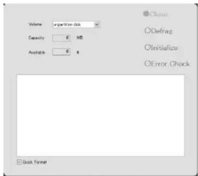
5 Check the entry in the [Volume] field, and click the [Initialize] button
● The external hard disk drive is initialized.
- Check to ensure that the [Volume] field is set to [unformat disk], [unpartition disk] and [unknown partition]. Selecting any other volume may result in the deletion of recorded data.
Note :
- Consult your nearest JVC dealer or service center for details on the type of external hard disk drive that can be used.
- When an additional hard disk is connected, several seconds of the recorded image may be lost during archiving.
- Note that playing back video recorded in an external HDD simultaneously on this unit and multiple clients may cause delay in the playback of video images and audio sound.
This is not a malfunction and there is no problem with the recorded images. Normal playback will be restored when simultaneous playback stops or when the number of devices playing back at the same time decreases.
Memo :
- It is recommended that a UPS be used to ensure stable operation of the system.
- You are unable to view recorded images on the computer by disconnecting the external hard disk from this unit and connecting it to the computer.
NAS
NAS is a dedicated file server that is connected to the network. In the case of NVR, you can specify NAS as a drive for archiving data.
Memo :
- For details on the settings of this unit when using NAS, refer to [Archiving] (Page 108) and [HDD Utility] (Page 116).
- Follow the NAS [Instruction Manual] for settings on NAS. This may take a while depending on the format and RAID settings. For further details, please contact the NAS manufacturer.
Special Key Operations
Combining a Button with the [FUNCTION] Button
■[FUNCTION] + [REC CONTROL]
Displays the main menu.
Page 32 [Opening the Main Menu]
■[FUNCTION] + LIVE/BROWSE
[FUNCTION] + [ALARM CLEAR] + SELECT
Reboots the NVR Viewer internal distribution server. ( page 33)
■[FUNCTION] + [KEY]
Locks/Unlocks the panel operation.
(Page 22 [Operation Lock])
■[FUNCTION] + [1]
Displays/Hides the performance meter.
(Page 27 [Performance Meter]))
■[FUNCTION] + [2]
Displays/Hides the clock.
(Page 27 [Clock Display])
■[FUNCTION] + [3]
Enables/Disables UPS.
Page 136 [Connecting a UPS])
■[FUNCTION] + [4]
For use when writing data to a CD-R.
Page 47 [Burning a CD/DVD])
■[FUNCTION] + [5]
For controlling the PTZ camera.
(Page 139 [PTZ Camera Control])
■[FUNCTION] + [6]
Displays the maintenance information screen.
( page 141 [Display and Saving of Maintenance Information])
■[FUNCTION] + 7
For sending audio sound to a camera that supports bidirectional audio.
Page 127 [Audio Transmission Application Control (VR-N1600U/E)])
■[FUNCTION] + [8]
Displays/Hides the HDD meter.
Pressing a Button for Two Seconds or Longer
■[REC CONTROL]
Turns on/off the recording control mode.
[Selecting the Recording Control Mode] ( page 53)
[ALARM CLEAR]
The light of the [WARNING] indicator goes off.
(Page 156 [Actions when Warning Indicator Lights Up])
■[FUNCTION] + [LIVE/BROWSE]
Logs out of the system.
Memo :
- When [Auto Logon] is enabled, the login operation starts automatically immediately after logging out. (v ^2 Page 69 [Unit Setting 1])
■[FUNCTION] + [OPERATE]
Shuts down the system forcibly.
Recording Before/After Occurrence of Event or Motion
You can record images before and after the occurrence of an event or motion when recording in the recording control mode (Page 53).
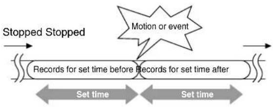
flowchart
graph LR
    A["Records for set time before Records for set time after"] --> B["Set time"]
    B --> C["Motion or event"]
    C --> D["Stopped Stopped"]
    style C fill:#f9f,stroke:#333
    style D fill:#ccf,stroke:#333
1 Go to [Settings] (Page 56), and select "Conditionally" in [Recording Settings]—[When to store images in database]
2 Select "On motion" or "On event"
3 Specify the number of seconds in [()seconds pre/post recordings on motion/event]
- Images are recorded during the specified time interval before and after an alarm or motion is detected.
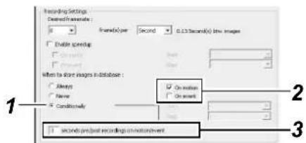
Memo :
- Sequences refers to sequences of images that are recorded when an event or motion is detected.
- For details on using sequences, refer to [Searching Recorded Image Using Sequence] (Page 44).
PTZ Camera Control
Connecting the PTZ camera to the COM port of the network encoder (VN-E4) enables the PTZ control on the live screen of the NVR Viewer. For details on PTZ camera settings, refer to [PTZ Camera Settings (COM1/COM2)] (Page 88). For cameras that have specified the [JCBP-S] protocol in "P/T/Z type controlled through COM1/COM2" of [PTZ Camera Settings (COM1/COM2)], control of the iris, focus and camera menu are also enabled on the live screen of the NVR Viewer in addition to PTZ control.
Memo :
- A PTZ camera is an analog camera with an analog output that enables PTZ control via RS-485.
![[5] Button [FUNCTION] Button](/content/2026/05/859290/images/76c6009b2a6977b6ce935b4e5fdac3d505be24e36ec762f2fe697e9110980024.jpg)
1 Press and hold the [FUNCTION] button, and press the [5] keypad button at the same time
• The [Camera Control] screen appears.
2 Select the camera you want to control from the camera selection list, and click the [Connect(ENTER)] button
- Camera control is enabled.
● The functions of the buttons are described below.
![Camera Control [NVR] Camera 1 Connect [ENTER] 2 HOME → ↓ ↑ ↓ AF Control 1 Regulator Move A Set ON OFF [ENTER] Menu Set → ↓ ↑ [HOME] Set [ENTER] End](/content/2026/05/859290/images/26685d67c7f4869e2571ddc11b2b45053c9d323cdad3134de188af72dda09fea.jpg)
PTZ Camera Control (continued)
Pan/Tilt

: Tilts the camera upwards

: Tilts the camera downwards

: Pans the camera to the right

: Pans the camera to the left
Zoom

: Zooms out

: Z o o m s i n
Iris

: Opens the iris

: Closes the iris
Focus

: Sets the focus to a distant position

: Focuses automatically

: Sets the focus to a closer position
■Speed
For setting the movement speed of the PTZ action to eight different levels. (1 represents the slowest speed)
■Preset
Position Selection : Select HOME or a different position.


For moving to the position selected using Position Selection
For registering a position selected using Position Selection as the current position
Scene
Scene
Selection

: For selecting a scene between A to H.
: For setting a scene selected using Scene Selection
Night Mode
: Turns on the night mode
: Turns off the night mode
Menu

: Displays the PTZ camera menu

: Selects the PTZ camera menu

: PTZ camera's menu (Up cursor)

: PTZ camera's menu (Down cursor)

: PTZ camera's menu (Right cursor)

: PTZ camera's menu (Left cursor)
Exit
Exits PTZ camera control
Memo :
- You can use the [SKIP] buttons to change the item to control.
- You can also use the cursor buttons on the keypad to control movement in the direction indicated by the respective buttons.
- You can use the 13/CANCEL button to exit the PTZ camera control mode.
Note :
- If you are unable to establish connection with the camera by clicking the [Connect(ENTER)] button, try again after stopping and rebooting the recording server. (* Page 84 [Service Manager...])
Display and Saving of Maintenance Information
This section describes procedures for displaying various information.
1 Press and hold the [FUNCTION] button, and press the [6/HOME](5/HOME) keypad button at the same time.
● The [Maintenance Information] screen appears.
![JVC VR-N1600E(A) - Press and hold the [FUNCTION] button, and press the [6/HOME](5/HOME) keypad button at the same time. - 1](/content/2026/05/859290/images/156a6044a366275a1eef797b083f832ddc6db45f79eee135621b543280f55d57.jpg)
flowchart
graph TD
    A["Power Failure History"] --> B["Information"]
    B --> C["Screen Resolution: 1200 x 1004\nOperating Time: 389.42"]
    C --> D["VR-N1600U/E only"]
    D --> E["Close"]
| Item Description | |
| 1Power Failure History | The power failure history appears. The [Power Failure History] is empty if no power failure has occurred in the past. |
| 2Information | |
| Screen Resolution | Displays the screen resolution.This is expressed in units of “vertical pixel x horizontal pixel”. |
| Operating Time (VR-N1600U/E) | Displays the total operating time of VR-N1600U/E.This is expressed in the “hours:minutes:seconds” format. |
| 3Close | Closes the [Maintenance Information] screen. |
Export Viewer
You can view data exported to a USB memory device, CD-R/RW, or DVD/R-RW on the computer.
Starting the Export Viewer
1 Insert the USB memory device containing the exported data into the USB port of the computer
- The USB memory device is automatically recognized by the computer as a removable disk.
2 Go to the Start menu, and select [Windows Explorer] in [All Programs]-[Accessories]
● The [Windows Explorer] appears.
3 Select the [Exported Images] folder in the removable disk from the folder list in the Explorer.
● The exported folder appears on the list on the right.
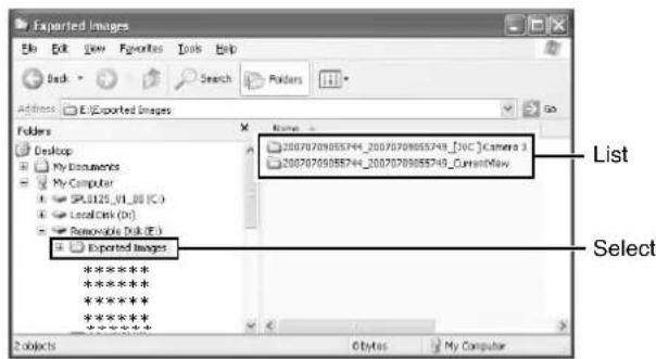
Memo :
- The name of the exported folder is indicated as follows. The date in the folder name indicates the time interval of export.
- [YYYYMMDDhhmmss_YYYYMMDDhhmmss] _[Camera Model] Camera name
4 Double-click the data folder in the list on the right side of the Explorer
- A file list appears in the right list.
5 Double-click [Browser.exe] in the list on the right side of the Explorer
- When using Windows Vista, right-click the icon and select "Run as administrator" to activate Browser.exe.
• The Export Viewer starts up.
![20070709055744_20070709055749_CurrentView File Edit View Favorites Tools Help Back Search Folders Address: E:\Exported Images\20070709055744_20070709055749_CurrentView Folders Name 127.0.0.1_80 - [AXIS 3079] Camera 2 127.0.0.1_80 - [AXIS 212 P72] Camera 1 127.0.0.1_80 - [DXC] Camera 3 Color Audio Exported Images 20070709055744_200707090 20070709055744_200707090 127.0.0.1_80 - [AXIS 207 127.0.0.1_80 - [AXIS 212 Double-click Browser Browser.dll Common.dll JBSX.x.dll Description: Milestone\Protected\ Yemen Company: Milestone Systems A/S1 3.30 MB My Computer](/content/2026/05/859290/images/ce195795a59bdec2069fd367fba2b5d685660de9745e35a9e31efe9e72d461ab.jpg)
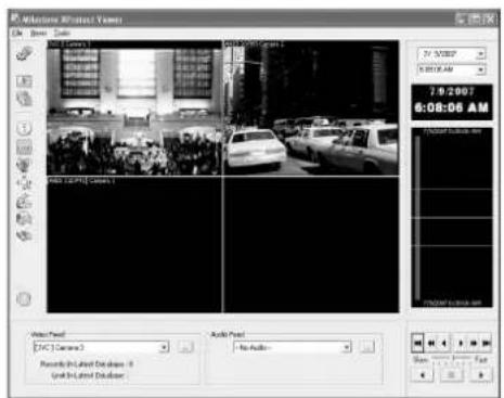
[Milestone XProtect Viewer] Screen
Viewing Exported Data
■Viewing Data on a Specific Date/Time Using Date/Time Selection
1 Click the [▼] button for date selection
- A calendar appears.
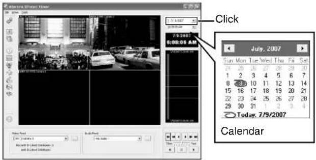
2 Select a specific date from the calendar
- Image on the selected date appears.
3 Click the [▼] button for time selection, and select a specific time
- Image of the selected time appears.
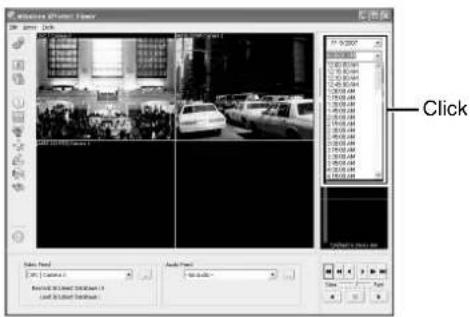
■Viewing Data on a Specific Date/Time Using Timeline
The vertical timeline indicates the progress status of a recording operation.
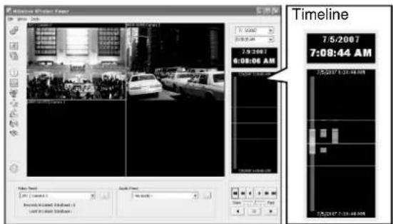
1 Drag the mouse pointer upwards or downwards on the Timeline
- You can view data at the specified date/time while checking the images.
Data Playback/Stopping Data Playback
■Playback
1 Set the playback speed using the speed control
2 Click the Play button
- The database is played back at the specified speed.
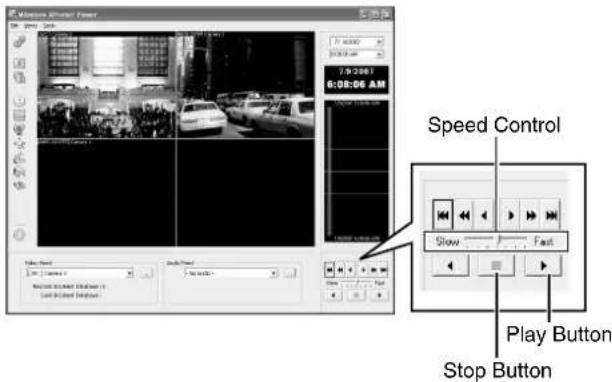
■Stopping Playback
1 Click the Stop button
• Data playback stops.
Exiting the Export Viewer
1 Go to the Start menu, and select [File]-[Close]
• Ends the Export Viewer.
Memo :
- You can also click [×] on the right side of the screen to exit the Export Viewer.
- For details of the viewer, refer to the Milestone XProtect Smart Client User's Manual available on the website of Milestone Systems (http://www.milestonesys.com).
- The URL address may be subject to changes.
Customizing Joystick Settings
1 Click the [▼] button at the top right corner of the screen
![Joystick Setup Keyboard Setup Language [▼] Button 0/2006 3:06:08.706 PM Version 1.0c](/content/2026/05/859290/images/05ffbf0c0d12fccd9388f26d98d885b75c3b1755dbb011c07f297c7167bed837.jpg)
2 Select [Joystick Setup] from the menu that appears
3 Select a joystick from the selected joystick list
![[Joystick] List [Axis Setup] Section [Button Setup] Section](/content/2026/05/859290/images/ea8d15455ef0340a6121887bf5e057c5d20f51c1d0391d21f98fefe56489d551.jpg)
4 Specify the settings for each axis in the [Axis Setup] section
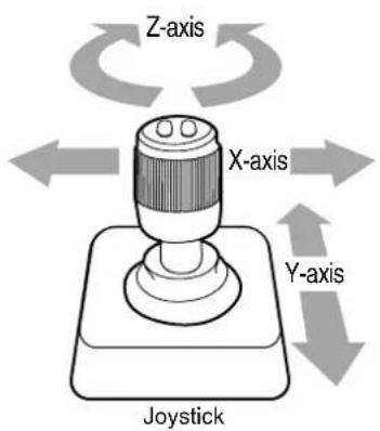
| Item Description | |
| 1Invert | By default, the PTZ camera moves to the right when you push the joystick to the right along the X-axis, and moves up when you pull the joystick towards you along the Y-axis. The movements are reversed if you select [Invert]. |
| 2Absolute | By selecting “Absolute”, the angle of the joystick corresponds to the direction of the camera. |
| 3Action | For specifying the action when you move the joystick. |
| PTZ Pan Moves the camera horizontally | |
| PTZ Tilt Moves the camera vertically | |
| PTZ Zoom Zooms in or zooms out the camera | |
| No Action No action | |
| 4Preview Image | You can check how each camera moves on each axis with the joystick. |
5 Assign an action to each joystick button in the [Button Setup] section
- Select the action to assign in the [Action] field.
Disabling Joystick Operation
To disable the joystick operation, select the [Disable all joysticks] check box.
Configuring NAS
1 Click [HDD Utility] under [Main Menu] (Page 116)
● The [HDD Utility] screen appears.
2 Click [Details]
3 Enter the [User name] and [Password] that are configured on the NAS device for access to NAS in [NAS User Settings], and click [Set]
4 Enter the IP address and shared name of the NAS device in the format of "¥ Address ¥ shared name" in the [Address] field under [NAS Drive], followed by clicking [Add]
Example) ¥¥192.168.0.200¥
5 If the NAS device is the only device for recording images, deselect the [Enable archiving to internal HDD] check box
6 Click [Close]
![[HDD Utility] Screen Name: Security: Buildings: Close Ordering Obstition Order Check Check Point Order 2 NAS User Settings User name: Password: OSet 3 4 NAS Drive Address: Add List: ODel Auto Archive Enable archiving to internal HDD 5 6 Close](/content/2026/05/859290/images/2c2a9e7b18a3bfe17da30159cc5384fc587f5898d940783e736e007f6bf917f3.jpg)
7 Click [Main Menu]—[Camera Record Setting]—[Archive Setup...] (Page 108)
- The [Archive Setup] screen appears.
8 Deselect the [Automatic path selection] check box
![Archiving setup Delete database in the backup directory older than 1 9999 days AutoCAD file path selection Send read on surface rows: Automatic path selection | Select camera for which the archiving function should apply: Name Pass [005 (20%) Camera 2] Automatic path selection [005 (21) F72) Camera 1] Automatic path selection [01] Camera 3 Automatic path selection Set all Clear all Set all parts Cancel Cancel](/content/2026/05/859290/images/cdbbef0312ad422befbc668a9bf10ad0b3188db3f19cf1e2e0c3cff02d334ce9.jpg)
[Archive Setup] Screen
9 Configure each drive as destinations for storing images of the respective cameras.
Note :
- Performing the above setting only after the NAS device setting is complete and when the device is connected to the network.
- If you change the archive destination after applying the setting, playback of previously archived data will fail.
- The configurable items may differ according to the camera in use.
- Specify the user name with a different name from the [OS Setting] (Page 73) host name under the user setting for NAS connection.
Note :
- After configuring the NAS drive, an error message will appear on the NVR Viewer for several minutes, and live images may not be displayed during this interval.
Recording Time Schedule (VR-N1600U/E)
The actual recording time varies according to the camera settings, input image content, and condition of the hard disk.
Use the tables below as a guide to the recording time.
●16 Channel Recording/No Audio Recording/No Additional HDD
[Hour]
| Image Size | Data/Image [kB] | Frame rate per channel, per second [ips] | ||||||||
| 30 15 10 5 3 1 0.5 0.2 | ||||||||||
| Picture Quality Settings | VGA 32.0 | —14 22 43 72 | 223 | 470 1211 | ||||||
| 24.0 | —20 30 60 100 | 305 | 635 1623 | |||||||
| 20.0 | —24 37 73 122 | 371 | 767 1953 | |||||||
| 16.0 | —31 46 93 | 155 | 470 964 244 | 7 | ||||||
| QVGA 27.0 | —18 26 53 88 | 269 | 561 1439 | |||||||
| 15.0 | —33 50 99 166 | 503 | 1029 2609 | |||||||
| 8.0 | —64 96 | 191 | 319 963 1951 | 4913 | ||||||
| 5.0 | —103 | 155 | 310 517 155 | 6 3136 7875 | ||||||
• 16 Channel Recording/2 Channel Audio Recording/No Additional HDD
[Hour]
| Image Size | Data/Image [kB] | Frame rate per channel, per second [ips] | ||||||||
| 30 15 10 5 3 1 0.5 0.2 | ||||||||||
| Picture Quality Settings | VGA 32.0 | —14 22 43 72 | 216 | 441 1044 | ||||||
| 24.0 | —20 30 59 98 | 292 | 584 1339 | |||||||
| 20.0 | —24 36 72 120 | 353 | 695 1557 | |||||||
| 16.0 | —31 46 92 | 151 | 441 855 1859 | |||||||
| QVGA 27.0 | —17 26 52 86 258 | 521 | 1210 | |||||||
| 15.0 | —33 49 98 162 | 470 | 905 1951 | |||||||
| 8.0 | —63 95 187 | 306 | 854 1556 301 | 4 | ||||||
| 5.0 | —102 152 | 298 | 484 1293 223 | 3 3926 | ||||||
- 16 Channel Recording/No Audio Recording/External HDD (1 TB × 1 Unit)
[Hour]
| Image Size | Data/Image [kB] | Frame rate per channel, per second [ips] | ||||||||
| 30 15 10 5 3 1 0.5 0.2 | ||||||||||
| Picture Quality Settings | VGA 32.0 | —49 74 148 | 247 | 747 1519 3833 | ||||||
| 24.0 | —67 100 200 | 333 | 1004 2033 5118 | |||||||
| 20.0 | —80 120 | 241 | 401 1210 244 | 44 6147 | ||||||
| 16.0 | —101 151 | 303 | 504 1519 306 | 61 7689 | ||||||
| QVGA 27.0 | —59 88 | 177 | 295 890 1804 | 4547 | ||||||
| 15.0 | —108 162 | 323 | 538 1621 326 | 67 8203 | ||||||
| 8.0 | — | 204 | 306 611 1018 | 3061 | 6147 | 15402 | ||||
| 5.0 | — | 327 | 491 981 | 1635 491 | 2 9849 | 24658 | ||||
- 16 Channel Recording/2 Channel Audio Recording/External HDD (1 TB × 1 Unit)
[Hour]
| Image Size | Data/Image [kB] | Frame rate per channel, per second [ips] | ||||||||
| 30 15 10 5 3 1 0.5 0.2 | ||||||||||
| Picture Quality Settings | VGA 32.0 | —49 74 147 | 244 | 724 1428 33 | 11 | |||||
| 24.0 | —66 99 198 | 328 | 963 1875 42 | 32 | ||||||
| 20.0 | —80 120 | 238 | 395 1151 22 | 20 4912 | ||||||
| 16.0 | —100 150 | 299 | 494 1428 27 | 18 5853 | ||||||
| QVGA 27.0 | —59 88 | 175 | 291 858 167 | 3833 | ||||||
| 15.0 | —107 160 | 319 | 527 1519 28 | 80 6147 | ||||||
| 8.0 | — | 202 | 302 596 977 | 2718 | 4912 9469 | |||||
| 5.0 | — | 323 | 481 943 | 1533 409 | 0 7028 | 12317 | ||||
Recording time in the chart is calculated based on recording in the JPEG format.
24 to 168
1 day to 1 week
169 to 720
1 week to 1 month
721 to 2160
1 month to 3 months
2161 or more
3 months or longer
Note :
-
Recording time may be shortened by approximately 10% according to the condition of the hard disk and the images recorded.
● Recording time may be shortened due to aging of the hard disk. -
8 Channel Recording/No Audio Recording/No Additional HDD
[Hour]
| Image Size | Data/Image [kB] | Frame rate per channel, per second [ips] | ||||||||
| 30 15 10 5 3 1 0.5 0.2 | ||||||||||
| Picture Quality Settings | V | G | A | 3 | 2 | . | 0 | 1 470 | 96 62446 | 3 |
| 2 | 4 | . | 0 | 2 | 1 210 | 635 1293 32 | 6 | 3 | ||
| 2 | 0 | . | 0 | 2 | 5 253 | 766 1557 39 | 28 | 6 | ||
| 1 | 6 | . | 0 | 3 192 | 319 964 195 | 2 4916 4 | 9 | 6 | ||
| Q | V | G | A | 2 | 7 | . | 185 | 562 1147 29 | 3 | |
| 15.0 | 34 68 102 | 205 | 341 1030 20 | 84 5246 | ||||||
| 8.0 | 65 130 | 194 | 389 648 168 | 5 3925 9847 | ||||||
| 5.0 | 104 | 209 | 313 | 626 1044 31 | 38 6299 | 15785 | ||||
1 1
7
- 8 Channel Recording/2 Channel Audio Recording/No Additional HDD
[Hour]
| Image Size | Data/Image [kB] | Frame rate per channel, per second [ips] | ||||||||
| 30 15 10 5 3 1 0.5 0.2 | ||||||||||
| Picture Quality Settings | V | G | A | 3 | 2 | . | 0 | 1 441 | 854 1858 | 3 |
| 2 | 4 | . | 0 | 2 | 1 204 | 684 1105 2201 | 6 | 2 | ||
| 2 | 0 | . | 0 | 2 | 5 245 | 695 1293 2611 | 7 | 5 | ||
| 1 | 6 | . | 0 | 3 187 | 306 854 1556 | 3016 3 | 9 | 5 | ||
| Q | V | G | A | 2 | 7 | 180 | 521 99612112 | 8 | 3 | |
| 15.0 | 34 68 101 | 199 | 326 906 1640 | 3138 | ||||||
| 8.0 | 64 128 | 190 | 370 | 598 1557 2611 | 43 | 67 | ||||
| 5.0 | 103 | 203 | 301 | 580 920 2234 | 3489 5246 | |||||
1 1
7
- 8 Channel Recording/No Audio Recording/External HDD (1 TB×1 Unit)
[Hour]
| Image Size | Data/Image [kB] | Frame rate per channel, per second [ips] | ||||||||
| 30 15 10 5 3 1 0.5 0.2 | ||||||||||
| Picture Quality Settings | VGA | 32.0 | 50 101 151 | 303 | 504 1519 306 | 61 7689 | ||||
| 24.0 | 68 135 | 203 | 405 | 676 2033 408 | 89 102 | 59 | ||||
| 20.0 | 81 163 | 244 | 488 | 813 2444 491 | 12 123 | 16 | ||||
| 16.0 | 102 | 204 | 305 | 611 1018 306 | 61 6146 | 15401 | ||||
| QVGA | 27.0 | 60 120 | 180 | 360 | 599 1804 363 | 32 91 | 17 | |||
| 15.0 | 109 | 217 | 326 | 652 1087 326 | 67 6557 | 16429 | ||||
| 8.0 | 205 | 409 | 614 | 1228 | 2047 | 6146 | 12316 | 30826 | ||
| 5.0 | 328 | 656 | 984 | 1968 | 3281 | 9848 | 19720 | 49336 | ||
- 8 Channel Recording/2 Channel Audio Recording/External HDD (1 TB × 1 Unit)
[Hour]
| Image Size | Data/Image [kB] | Frame rate per channel, per second [ips] | ||||||||
| 30 15 10 5 3 1 0.5 0.2 | ||||||||||
| Picture Quality Settings | VGA | 32.0 | 50 100 150 | 299 | 494 1428 27 | 18 5852 | ||||
| 24.0 | 67 134 | 201 | 399 | 657 1874 35 | 02 | 72 | 35 | |||
| 20.0 | 81 161 | 241 | 478 | 786 2220 40 | 89 | 82 | 03 | |||
| 16.0 | 101 | 202 | 302 | 596 977 27 | 8 4912 9468 | |||||
| QVGA | 27.0 | 60 119 | 178 | 354 | 585 1678 31 | 61 | 66 | 48 | ||
| 15.0 | 108 | 215 | 322 | 635 1040 28 | 80 5172 9848 | |||||
| 8.0 | 203 | 403 | 599 1169 18 | 88 4912 8203 | 13687 | |||||
| 5.0 | 324 | 639 | 946 | 1822 | 2894 | 7027 | 10945 | 16429 | ||
Recording time in the chart is calculated based on recording in the JPEG format.
24 to 168
1 day to 1 week
169 to 720
1 week to 1 month
721 to 2160
1 month to 3 months
2161 or more
3 months or longer
Note :
- Recording time may be shortened by approximately 10% according to the condition of the hard disk and the images recorded.
- Recording time may be shortened due to aging of the hard disk.
Recording Time Schedule (VN-N900)
The actual recording time varies according to the camera settings, input image content, and condition of the hard disk.
Use the tables below as a guide to the recording time.
● 9 channel recording without audio recording or additional HDD upgrade
[Hour]
| Image Size | Data/Image [kB] | Frame rate per channel, per second [ips] | |||||||
| 30 15 10 5 3 1 0.5 0.2 | |||||||||
| VGA | 32 | -- 40 79 132 | 403 | 830 2112 | |||||
| 24 | -- 54 108 | 180 | 546 1115 2824 | ||||||
| 16 | -- 82 165 | 275 | 830 1685 4248 | ||||||
| 10 | -- 134 | 267 | 446 1343 2710 | 6811 | |||||
| QVGA | 27 | -- 48 95 159 | 482 | 989 2507 | |||||
| 15 | -- 88 | 176 | 294 887 1799 | 4533 | |||||
| 8 | -- 168 | 336 | 560 1685 3393 | 8520 | |||||
| 5 | - | - | 270 | 541 901 2710 | 5444 13646 | ||||
● 9 channel recording with 2 channel audio recording and without additional HDD upgrade
[Hour]
| Image Size | Data/Image [kB] | Frame rate per channel, per second [ips] | |||||||
| 30 15 10 5 3 1 0.5 0.2 | |||||||||
| VGA | 32 | -- 39 78 130 | 381 | 745 1648 | |||||
| 24 | -- 54 106 | 175 | 506 968 2054 | ||||||
| 16 | -- 81 161 | 265 | 745 1374 2722 | ||||||
| 10 | -- 131 | 258 | 420 1137 1993 | 3594 | |||||
| QVGA | 27 | -- 47 94 155 | 451 | 871 1880 | |||||
| 15 | -- 87 | 172 | 282 791 1449 | 2837 | |||||
| 8 | -- 164 | 321 | 520 1374 2342 | 4023 | |||||
| 5 | - | - | 261 | 504 805 1993 | 3172 4897 | ||||
● 9 channel recording without audio recording and with one additional 1 TB HDD upgrade
[Hour]
| Image Size | Data/Image [kB] | Frame rate per channel, per second [ips] | |||||||
| 30 15 10 5 3 1 0.5 0.2 | |||||||||
| VGA | 32 | -- 133 | 266 | 443 1335 2694 | 6772 | ||||
| 24 | -- | 178 | 356 594 1788 | 3600 9037 | |||||
| 16 | -- | 269 | 538 896 2694 | 5413 13568 | |||||
| 10 | -- | 432 | 864 1440 4325 | 8675 21723 | |||||
| QVGA | 27 | -- 158 | 316 | 527 1587 3198 | 8030 | ||||
| 15 | -- | 287 | 574 957 2876 | 5775 14474 | |||||
| 8 | - | - | 541 | 1081 1802 541 | 13 10849 27159 | ||||
| 5 | - | - | 867 | 1734 2890 867 | 17373 43469 | ||||
● 9 channel recording with 2 channel audio recording and one additional 1 TB HDD upgrade
[Hour]
| Image Size | Data/Image [kB] | Frame rate per channel, per second [ips] | |||||||
| 30 15 10 5 3 1 0.5 0.2 | |||||||||
| VGA | 32 | -- 132 | 263 | 435 1264 2423 | 5294 | ||||
| 24 | -- | 177 | 351 580 1663 | 3133 6588 | |||||
| 16 | -- | 266 | 526 864 2423 | 4424 8714 | |||||
| 10 | -- | 424 | 834 1359 3669 | 6393 11489 | |||||
| QVGA | 27 | -- 157 | 312 | 515 1487 2823 | 6035 | ||||
| 15 | -- | 284 | 560 920 2568 | 4664 9079 | |||||
| 8 | - | - | 529 | 1035 1677 4424 | 7504 12852 | ||||
| 5 | - | - | 837 | 1618 2582 6393 | 10143 15634 | ||||
Recording time in the chart is calculated based on recording in the JPEG format.
24 to 168
1 day to 1 week
169 to 720
1 week to 1 month
721 to 2160
1 month to 3 months
2161 or more
3 months or longer
Note :
- Recording time may be shortened by approximately 10 % according to the condition of the hard disk and the images recorded.
● Recording time may be shortened due to aging of the hard disk.
●4 Channel Recording/No Audio Recording/No Additional HDD
[Hour]
| Image Size | Data/Image [kB] | Frame rate per channel, per second [ips] | ||||||||
| 30 15 10 5 3 1 0.5 0.2 | ||||||||||
| Picture Quality Settings | V | G | A | 3 | 2 | 186 | 310 937 189 | 8 4781 | 6 | 2 |
| 24 42 83 125 | 250 | 417 1257 25 | 39 6382 | |||||||
| 16 63 126 | 189 | 378 631 189 | 8 3820 9586 | |||||||
| 10 | 102 | 203 | 305 | 609 1015 30 | 51 6126 | 15352 | ||||
| QVGA | 27 37 74 111 | 222 | 370 1115 22 | 54 5671 | ||||||
| 15 67 135 | 202 | 404 | 673 2026 40 | 76 10226 | ||||||
| 8 | 127 | 254 | 381 | 763 1271 38 | 20 7664 | 19195 | ||||
● 4 Channel Recording/2 Channel Audio Recording/No Additional HDD
[Hour]
| Image Size | Data/Image [kB] | Frame rate per channel, per second [ips] | ||||||||
| 30 15 10 5 3 1 0.5 0.2 | ||||||||||
| Picture Quality Settings | V | G | A | 3 | 2 | 182 | 298 830 1514 | 2933 | 6 | 2 |
| 24 41 82 | 123 | 242 | 395 1074 1898 | 3470 | ||||||
| 16 63 124 | 185 | 360 | 581 1514 2539 | 4247 | ||||||
| 10 | 100 | 198 | 293 | 563 894 2173 | 3393 5101 | |||||
| QVGA | 27 37 73 | 109 | 215 | 352 968 1733 | 3247 | |||||
| 15 67 132 | 197 | 383 | 618 1594 2650 | 4369 | ||||||
| 8 | 125 | 246 | 363 | 693 1088 2539 | 3820 5467 | |||||
| 5 | 199 | 387 | 566 1054 1608 | 3393 4707 | 6126 | |||||
● 4 Channel Recording/No Audio Recording/Additional HDD (1 TB x 1 Unit)
[Hour]
| Image Size | Data/Image [kB] | Frame rate per channel, per second [ips] | ||||||||
| 30 15 10 5 3 1 0.5 0.2 | ||||||||||
| Picture Quality Settings | VGA | 32 | 101 | 202 | 303 | 606 1009 30 | 34 6092 | 15266 | ||
| 24 | 135 | 270 | 405 | 809 1349 40 | 53 8131 | 20362 | ||||
| 16 | 203 | 406 | 609 | 1217 | 2029 | 6092 | 12208 | 30555 | ||
| 10 | 325 | 650 | 976 | 1951 | 3252 | 9761 | 19547 | 48903 | ||
| QVGA | 27 | 120 | 240 | 359 | 719 1198 36 | 00 7224 | 18097 | |||
| 15 | 216 | 433 | 649 | 1299 | 2165 | 6500 | 13023 | 32594 | ||
| 8 | 407 | 813 | 1220 | 2440 | 4067 | 12208 | 24440 | 61135 | ||
| 5 | 651 | 1303 | 1954 | 3908 | 6514 | 19547 | 39118 | 97830 | ||
● 4 Channel Recording/2 Channel Audio Recording/Additional HDD (1 TB x 1 Unit)
[Hour]
| Image Size | Data/Image [kB] | Frame rate per channel, per second [ips] | ||||||||
| 30 15 10 | 5 3 1 0.5 0.2 | |||||||||
| Picture Quality Settings | VGA | 32 | 101 | 200 | 299 | 591 969 269 | 4 4869 9385 | |||
| 24 | 134 | 267 | 398 | 783 1278 34 | 71 6092 | 11096 | ||||
| 16 | 201 | 399 | 594 1159 18 | 72 4869 8131 | 13567 | |||||
| 10 | 321 | 633 | 938 | 1806 | 2868 | 6966 | 10849 | 16285 | ||
| QVGA | 27 | 119 | 237 | 354 | 698 1141 31 | 33 5568 | 10386 | |||
| 15 | 215 | 425 | 632 1233 19 | 87 5126 8485 | 13955 | |||||
| 8 | 400 | 787 1162 22 | 18 3485 8131 | 12208 | 17450 | |||||
| 5 | 634 | 1237 | 1809 | 3368 | 5140 | 10849 | 15031 | 19547 | ||
Recording time in the chart is calculated based on recording in the JPEG format.
24 to 168 1 day to 1 week
169 to 720 1 week to 1 month
721 to 2160 1 month to 3 months
2161 or more
3 months or longer
Note :
- Recording time may be shortened by approximately 10% according to the condition of the hard disk and the images recorded.
● Recording time may be shortened due to aging of the hard disk.
Default Value List
Scheduler [Scheduler Setting] (Page 53)
[] : Factory Settings
| Online [Always Online] | |
| Enable speedup [Always Offline] | |
| E-mail [Always Offline] | |
| Patrolling [Always Offline] |
Camera Settings [Edit Device...]—[Settings] (Page 56)
PTZ Camera Section
| Some of the connected cameras are Pna/Tilt/Zoom cameras [Not Selected] | |
| Camera Type [Fixed] |
Camera Settings [Specifying Image Recording Settings] (Page 55)
Speedup Settings
| Frame Rate [8] | |
| Frame/ [Sec.] /Min. /Hour |
Recording Settings
| Desired framerate [8] | |
| Frame/ [Sec.] /Min. /Hour | |
| Enable speedup [Not Selected] | |
| When to store images in database Always /Never /[Conditionally] | |
| On motion | [Selected] |
| On event | [Not Selected] |
| ( )seconds pre/post recordings on motion/event | [3] |
Database Settings [Database Settings] (Page 110)
| Max.records in database | [Selected] [108000] |
| Max timespan in database | [Not Selected] |
| Archive automatically when database is full | [Selected] |
| In case of database failure the following action syould be taken | Repair,Scan,Delete if fails /Repair,Delete if fails /Archive if fails /Delete(no repair) /Archive(no repair) |
PTZ Preset [Display the [PTZ Preset Positions for Device Name] Window] (Page 90)
Presets
| Use preset positions from device | [Not Selected] |
| Preset Position on Events | |
| Preset Position on Events | [Not Selected] |
PTZ Patrolling Settings [Auto PTZ Patrolling] (Page 93)
| Patrol scheme | [My patrol sheme] |
| PTZ Patrolling Schedule Settings | |
| Stay at each position in the patrol schedule(in seconds) | [5] |
| Time for each PTZ camera movement to complete(in seconds). Motion detection is disabled during movement. | [3] |
| Motion-Triggered PTZ Patrolling Settings | |
| Disable patrolling schedule if motion is detected | [Not Selected] |
Motion Detection [Specifying Motion Detection] (Page 105)
| Sensitivity [40] | |
| Motion Sensitivity [640] |
General Settings [General Settings] (Page 106)
| Milestone XProtect Central Settings | |
| Enable Milestone XProtect Central Connections [Not Selected] | |
| Patrolling Settings | |
| Resume Patrol after Manual or Event PTZ(sec.) [30] | |
| Logfile Settings | |
| Logfile Path [L:¥Log¥MS] | |
| Days to log [5] | |
| Event Recording Settings | |
| Path [D:¥Events¥] | |
| Days to keep [5] | |
| Advanced... | |
| Don't send e-mail on camera failures [Not Selected] | |
| Start cameras on remote live requests [Selected] | |
| Create default schedule for new cameras [Selected] | |
| E-Mail settings | |
| Enable E-mail(Monitor) [Not Selected] | |
Archive Setup [Archiving] (Page 108)
| Delet databases in the backup directory older then [ ] days [9999] | |
| Send email on archive error | [Selected] |
| Automatic path selection | [Selected] |
| Daily archiving times | [12:00:00] |
| Name | All [Selected] |
Camera's [Properties][Adjusting Camera Settings] (Page 63)
| Image Quality... | [Full] /Super High(for megapixel) /High /Medium / Low |
| Frame Rate [Unlimited] /Medium /Low | |
| Maintain Image Aspect Ration | [Selected] |
| Update on motion only | [Not Selected] |
| Sound on Event | [Always off] /Always on |
| Sound on Event | [Always off] /Always on |
Joystick Setup [Customizing Joystick Settings] (Page 144)
| Disable all joysticks | [Not Selected] | ||
| Axis Setup | |||
| Invert | Absolute | Action | |
| X Axis | [Not Selected] | [Not Selected] | PTZ Zoom /PTZ Tilt /[PTZ Pan] /No Action |
| Y Axis | [Not Selected] | [Not Selected] | PTZ Zoom /[PTZ Tilt] /PTZ Pan /No Action |
| Z Axis | [Not Selected] | [Not Selected] | [PTZ Zoom] /PTZ Tilt /PTZ Pan /No Action |
| Button Setup | |||
| Buttons 1 to 12 | [No Action] | ||
Default Value List (continued)
Unit Settings 1 [Unit Setting 1] (Page 69)
| Password [None] | |
| Auto Logon [Selected] | |
| Live | |
| Live viewing Auto Start [Selected] | |
| Error Report | |
| Dialog [Selected] | |
| Mail [Selected] | |
| Record Control | |
| ON at startup [Selected] | |
| Mail Server | |
| SMTP Server Port[25] | |
| POP Server Port[110] | |
| SMTP Authentication [NONE]/SMTP Authentication/POP before SMTP | |
| Emergency Record | |
| Time of Record NONE /30seconds/[60seconds]/5minutes/ | 10minutes/10minutes/Continue |
| Encode Mode (VR-N900U) | |
| Encode Mode Variable File Size/[Average File Size]/ | Constant File Size |
| Interpolate | [Selected] |
| Serial (VR-N900U) | |
| Speed | 1200/1800/2400/4800/[9600]/19200/4800/19200/38400 |
| Data Lenght | 7/[8] |
| Parity | [NONE]/ODD/EVEN |
| Stop Bit | [1]/2 |
| Unit Settings 2 [Unit Setting 2] (Page 72) | |
| HDD meter | |
| Display at startup | [Not Selected] |
| Clock setting | |
| Display at startup | [Not Selected] |
| Display at date | [Not Selected] |
| Display at second | [Not Selected] |
| SNMP setting | |
| Enable of SNMP | [Not Selected] |
| Enable of TRAP | [Not Selected] |
| SNMP manager's address | -(IP address) |
| Community name | -(1 to 32 characters. Alphanumeric characters only.) |
| Confirmation interval of alarm | 10 seconds (10 to 9999 seconds) |
| Confirmation interval of CPU usage | 10 seconds (10 to 9999 seconds) |
| Confirmation interval of D-drive | 60 seconds (30 to 9999 seconds) |
| Confirmation interval of NVR Viewer | 10 seconds (10 to 9999 seconds) |
| Confirmation interval of camera | 60 seconds (30 to 9999 seconds) |
OS Settings [OS Setting] (Page 73)
Network Adapter Interface Name
Intel® 82566DM Gigabit Network: LAN1 (Camera Network) (VR-N1600U/E)
Realtek RTL8168C(P)/8111C(P) PCI-E Gigabit Ethernet NIC: LAN1 (Camera Network) (VR-N1600U/E(A))
Realtek RTL8169/8110 Family Gigabit Ethernet NIC: LAN1 (Camera Network) (VR-N900U)
| Obtain an IP address automatically [Not Selected] | |
| IP address [192.168.0.253] | |
| Subnet Mask [255.255.255.0] | |
| Default Gateway [0.0.0.0] | |
| Perferred DNS Server [0.0.0.0] | |
| Alternate DNS Server [0.0.0.0] | |
| Host Name [vr-n1600]/[vr-n900] | |
| DNS Domain Name [None] |
Intel™8225xER PCI Adapter: LAN2 (Intranet), (VR-N1600U/E), (VR-N900U)
Realtek RTL8168C(P)/8111C(P) PCI-E Gigabit Ethernet NIC#2: LAN2 (Intranet), (VR-N1600U/E(A))
| Obtain an IP address automatically [Not Selected] | |
| IP address [192.168.1.253] | |
| Subnet Mask [255.255.255.0] | |
| Default Gateway [192.168.1.254] | |
| Perferred DNS Server [0.0.0.0] | |
| Alternate DNS Server [0.0.0.0] | |
| Host Name [vr-n1600] | |
| DNS Domain Name [None] |
Enc Board Bus Master Driver: Analog Camera Network (VR-N900U)
| Obtain an IP address automatically [Not Selected] | |
| IP address [192.168.201.253] | |
| Subnet Mask [255.255.255.0] | |
| Default Gateway [0.0.0.0] | |
| Perferred DNS Server [0.0.0.0] | |
| Alternate DNS Server [0.0.0.0] | |
| Host Name [vr-n900] | |
| DNS Domain Name [None] |
Day and Time Properties
| Automatically synchronize with an Internet server [Not Selected] | |
| Time Zone [(GMT-05:00) Eastern Time](VR-1600U/VR-N900U) | [(GMT) Greenwich Mean Time](VR-1600E) |
Default Value List (continued)
Auto Detect Settings [Auto Detect Settings] (Page 113)
| IP Lease [Enable] /Disable | |
| IP Lease Parameter | |
| Start Address [192.168.0.100] | |
| Unit 1 Unit to/[20Units]/to 99 Units | |
| Subnet Mask [255.255.255.0] | |
| Gateway [192.168.0.254] | |
| DNS Server | |
| Primary [192.168.0.253] | |
| Secondry [192.168.0.252] | |
| Domain Name [None] | |
| Lease Time Limit [No] /Yes | |
| Client [Only Camera] /Any Client | |
| Reserve MAC Address [None] | |
Distribution Settings [Distribution Settings (Details)] (Page 118)
| Server Configuration | |
| Name | [Server] |
| Port [80] | |
| Enable Outside IP Address | [Not Selected] |
| Max, number of clients | [11] |
| User Administration | |
| Full access for all users | [Selected] |
| Master/Slave Setup | |
| Designate as Master Server | [Not Selected] |
| Pre-6.0 Version Slaves [Not Selected] | |
| Log Files | |
| Days to log | [10] |
| Audit Log | |
| Audit Log | Enable Audit Logging/[Not Selected] |
| Language Support and XML Encoding | |
| Language | [Western(European)(iso-8859-1)] |
User Administration (Distribution Settings Page 118)
VR-N1600U/E
| User Password Type | ||
| vr-n1600 [vr-n1600] Basic user | ||
| Administrator [None] [Windows or Active Directory user] |
VR-N900U
| User Password Type | ||
| vr-n900 [vr-n900] Basic user | ||
| Administrator [None] [Windows or Active Directory user] |
HDD Utility (Advanced Settings ☐ Page 116)
NAS User Settings
| Password [None] | |
| User name [None] |
Auto Archive
| Enable archiving to internal HDD [Selected] |
HDD Meter Option Settings (Advanced Settings Page 133)
Monitor settings
| Update interval 10 seconds (10 to 300 seconds) | |
| Transparency [Selected] | |
| Select drives to monitor | OFF |
Alarm notification settings
| Enable notify | OFF (ON/OFF) |
| Notify when the free-space less than | 5 GB (1 to 999 GB) |
Troubleshooting
| Symptom Action | |
| Power cannot be turned on. | Check to ensure that the power cable has been plugged in correctly.Check to ensure that the power switch on the rear panel is switched on. |
| Camera is not automatically detected. | Follow instructions in the camera's [Instruction Manual] to check the IP address settings.When the IP Lease feature is in use, turn OFF the camera and ON again with this unit started up. |
| Unable to control using [REC] and [PLAY]. | Check to ensure that the operation lock is not turned on. |
| Images are not recorded in the recording control mode. | Check the [Camera Recording Settings].Check to ensure that the scheduler is set to online.Check to ensure that the camera is in the recording control mode. |
| Unable to play back audio sound. | Check to ensure that the audio item of the camera device is set to “Enabled” in the [Camera Record Setting] menu.Check to ensure that audio is selected in [Audio]. |
| Operation of the unit is disabled. | Press and hold the [FUNCTION] button on the front panel, and press the [OPERATE] button for 7 seconds or longer to shut down the power forcibly.Memo: ·When the power is forcibly shut down, recorded images that are not archived (Page 108) may not be properly played back. |
| The message below appears after turning on the power."COMS Settings Wrong CMOS Date/ Time Not Press F1 to Run SETUP Press F2 to load default values and continue" | The built-in backup battery level is running low.Consult your nearest JVC dealer. |
■Actions when Warning Indicator Lights Up
| Error Message Action to Take | |
| Free space of HDD less than *GB (*drive) | If this message is displayed for the D drive, try to recover using HDD Utility.Replacement is recommended. Consult your nearest JVC dealer. |
| WARNING:HDD(Disk) The HDD seems is no longer serviceable. Replacement is recommended.Consult your nearest JVC dealer. | |
| HDD was removed Check to ensure that the power of the external HDD is switched on.Check to ensure that the connecting cable is properly inserted.If no abnormality is found above, consult your nearest JVC dealer. | |
| WARNING:HDD(Raid) | This is a hard disk (during RAID setting) warning.Consult your nearest JVC dealer. |
| WARNING:HDD(xxx:) Disconnect | The NAS drive is disconnected.Check the operation of NAS.Check the connection with NAS. |
| FAN STOP | Fan abnormality. Check to ensure that the fan is running.If the fan is not moving, stop using it.Otherwise, it may break down.Consult your nearest JVC dealer. |
Specifications
VR-N1600U/E
General
Allowable Operating Temperature : 5 °C to 40 °C
Allowable Storage Temperature : - 2 0 °C to 60 °C
Allowable Operating Humidity : 30 % to 80 %
Power Supply
VR-1600U : AC 120 V, 50 Hz/60 Hz
VR-1600E : AC 220 - 240 V, 50 Hz/60 Hz
Power Consumption
VR-1600U : 1.2 A
VR-1600E : 0.8 A
Mass : Approx. 7.8 kg
Interface
Network : RJ-45×2
LAN1 : 1000BASE-T/100BASE-TX/10BASE-T
LAN2 : 1000BASE-T/100BASE-TX/10BASE-T
Serial : USB2.0 A-type (or equivalent) × 5
VGA Output : Up to 1600 × 1200
Audio Input : Analog audio RCA×2 - 8 dBs 50 kΩ (Unbalanced)
Audio Output : Analog audio RCA×1 - 8 dBs 600 Ω (Unbalanced)
I/O Terminals : Push terminal Input × 12 Output × 5 GND × 3
■Compression Format
Video : JPEG/MPEG-4
Audio : μ-law (64 kbps) A/D 8 bits, Fs = 8 kHz
■Recording
HDD Capacity : 500 GB × 1
■Recording/Displaying live images/Distribution performance (for JPEG VGA 24 KB)
When viewing live images on NVR
: Up to 160 ips/80 ips/80 ips (VR-N1600U/E)
: Up to 160 ips/160 ips/160 ips (VR-N1600U/E(A))
When not viewing live images on NVR
: Up to 240 ips/0 ips/80 ips (VR-N1600U/E)
: Up to 240 ips/0 ips/160 ips (VR-N1600U/E(A)) (When NVR Viewer is not started up)
When using NAS
When viewing live images on NVR
: Up to 80 ips/80 ips/80 ips (VR-N1600U/E)
: Up to 80 ips/160 ips/160 ips (VR-N1600U/E(A))
When not viewing live images on NVR
: Up to 80 ips/0 ips/80 ips (VR-N1600U/E)
: Up to 80 ips/0 ips/160 ips (VR-N1600U/E(A))
■Attachments/Accessories
VR-1600U
Start-up Guide....1
CD-ROM....1
Power Cord (2 m) 1
Rack Mount Bracket 2
Warranty Card 1
Service Information Card...... 1
Screw (M4×10 mm)....4
Screw (M5×11 mm)......4
VR-1600E
Start-up Guide....1
CD-ROM....1
Power Cord (2 m) 2
Rack Mount Bracket 2
Screw (M4×10 mm).... 4
Screw (M5×11 mm)....4
■Dimensional Outline Drawing (Unit: mm)
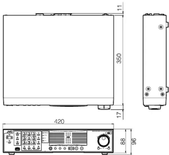
※ The specifications and appearance of this unit may be modified for improvement without prior notice.
Specifications (continued)
VR-N900U
General
Allowable Operating Temperature
: 5 °C to 40 °C
Allowable Storage Temperature
:- 20 °C to 60 °C
Allowable Operating Humidity
: 30 % to 80 %
Power Supply: AC 120 ∼ 240 V, 50 Hz/60 Hz
Power Consumption
: 1.7 A
Mass : Approx. 8.0 kg
Interface
Network : RJ-45×2
LAN1 : 1000BASE-T/100BASE-TX/10BASE-T
LAN2 : 100BASE-TX/10BASE-T
Serial : USB2.0 A-type (or equivalent) × 5
VGA Output : Up to 1600×1200
Video Input : NTSC/PAL composite video
75 Ω (BNC unbalanced) × 4
Audio Input: Analog audio RCA × 2
-8 dBs 10 kΩ (Unbalanced)
Audio Output : Analog audio RCA × 1
-8 dBs 600 Ω (Unbalanced)
I/O Terminals : Push terminal
Input × 8
Output × 5
GND × 3
■Compression Format
Video : JPEG/MPEG-4 (Network camera)
JPEG (Analog camera)
Audio : μ-law (64 kbps) A/D 8 bits, Fs = 8 kHz
■Recording
HDD Capacity : 250 GB × 1
■Recording/Displaying live images/Distribution performance (for JPEG VGA 24 KB)
When viewing live images on NVR
: Up to 120 ips/60 ips/30 ips
When not viewing live images on NVR
: Up to 120 ips/0 ips/82 ips (when NVR
Viewer is not started up)
When using NAS
When viewing live images on NVR
: Up to 60 ips/60 ips/30 ips
When not viewing live images on NVR
: Up to 60 ips/0 ips/30 ips
■Attachments/Accessories
Start-up Guide....1
CD-ROM....1
Power Cord (2 m) 1
Rack Mount Bracket 2
Warranty Card 1
Service Information Card....1
Screw (M4×10 mm)......4
Screw (M5×11 mm)......4
■Dimensional Outline Drawing (Unit: mm)
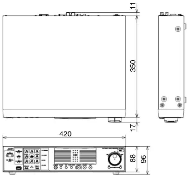
※ The specifications and appearance of this unit may be modified for improvement without prior notice.