
PLA-402 v3 - Carte réseau/Adaptateur ZYXEL - Free user manual and instructions
Find the device manual for free PLA-402 v3 ZYXEL in PDF.


| Product Type | Powerline Network Adapter |
| Model | PLA-402 v3 |
| Brand | ZyXEL |
| Standards | HomePlug AV, IEEE 1901 |
| Data Transfer Rate | Up to 200 Mbps |
| Frequency Band | 2-28 MHz |
| Encryption | 128-bit AES |
| Ports | 1x 10/100 Ethernet Port |
| Dimensions (W x D x H) | 98 x 62 x 28 mm |
| Weight | 130 g |
| Power Supply | AC 100-240V, 50-60 Hz (via powerline) |
| Power Consumption | <3 W typical |
| LED Indicators | Power, Ethernet, Powerline (3 LEDs) |
| Pairing Button | Yes |
| Operating Temperature | 0°C to 40°C |
| Storage Temperature | -20°C to 70°C |
| Humidity | 10% to 90% (non-condensing) |
| Maintenance & Cleaning | Wipe with dry cloth; do not use liquids |
| Safety | CE, FCC, RoHS certified |
| Spare Parts & Repairability | No user-serviceable parts; contact support |
| General Information | Works with all HomePlug AV compliant devices |
Frequently Asked Questions - PLA-402 v3 ZYXEL
User questions about PLA-402 v3 ZYXEL
0 question about this device. Answer the ones you know or ask your own.
Ask a new question about this device
Download the instructions for your Carte réseau/Adaptateur in PDF format for free! Find your manual PLA-402 v3 - ZYXEL and take your electronic device back in hand. On this page are published all the documents necessary for the use of your device. PLA-402 v3 by ZYXEL.
USER MANUAL PLA-402 v3 ZYXEL
Powerline Coaxial Ethernet Adapter
User's Guide
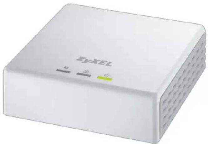
natural_image
White wireless device labeled 'ZyXEL' with ports marked by icons (no additional text or symbols)Firmware Version 3.3.4 Edition 1, 5/2009
www.zyxel.com
ZyXEL
About This User's Guide
Intended Audience
This manual is intended for people who want to configure the PLA-402 v3 using the web configurator.
Tips for Reading User's Guides On-Screen
When reading a ZyXEL User's Guide On-Screen, keep the following in mind:
- If you don't already have the latest version of Adobe Reader, you can download it from http://www.adobe.com.
- Use the PDF's bookmarks to quickly navigate to the areas that interest you. Adobe Reader's bookmarks pane opens by default in all ZyXEL User's Guide PDFs.
- If you know the page number or know vaguely which page-range you want to view, you can enter a number in the toolbar in Reader, then press [ENTER] to jump directly to that page.
- Type [CTRL]+[F] to open the Adobe Reader search utility and enter a word or phrase. This can help you quickly pinpoint the information you require. You can also enter text directly into the toolbar in Reader.
- To quickly move around within a page, press the [SPACE] bar. This turns your cursor into a "hand" with which you can grab the page and move it around freely on your screen.
- Embedded hyperlinks are actually cross-references to related text. Click them to jump to the corresponding section of the User's Guide PDF.
Related Documentation
- Quick Start Guide
The Quick Start Guide is designed to help you get your PLA-402 v3 up and running right away. It contains information on setting up your network and configuring for Internet access.
- Support Disc
Refer to the included CD for support documents.
Documentation Feedback
Send your comments, questions or suggestions to: techwriters@zyxel.com.tw
Thank you!
The Technical Writing Team, ZyXEL Communications Corp.,
6 Innovation Road II, Science-Based Industrial Park, Hsinchu, 30099, Taiwan.
Need More Help?
More help is available at www.zyxel.com.
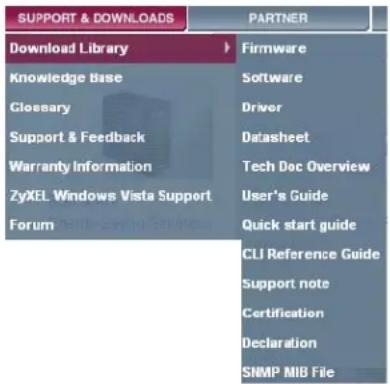
- Download Library
Search for the latest product updates and documentation from this link. Read the Tech Doc Overview to find out how to efficiently use the User Guide, Quick Start Guide and Command Line Interface Reference Guide in order to better understand how to use your product.
- Knowledge Base
If you have a specific question about your product, the answer may be here. This is a collection of answers to previously asked questions about ZyXEL products.
- Forum
This contains discussions on ZyXEL products. Learn from others who use ZyXEL products and share your experiences as well.
Customer Support
Should problems arise that cannot be solved by the methods listed above, you should contact your vendor. If you cannot contact your vendor, then contact a ZyXEL office for the region in which you bought the device.
See http://www.zyxel.com/web/contact_us.php for contact information. Please have the following information ready when you contact an office.
- Product model and serial number.
- Warranty Information.
- Date that you received your device.
Brief description of the problem and the steps you took to solve it.
Document Conventions
Warnings and Notes
These are how warnings and notes are shown in this User's Guide.
Warnings tell you about things that could harm you or your device.
Note: Notes tell you other important information (for example, other things you may need to configure or helpful tips) or recommendations.
Syntax Conventions
- The PLA-402 v3 may be referred to as the "PLA-402 v3", the "ZyXEL device", the "device" or the "coaxial adapter" in this User's Guide.
- The PLA-4xx Series Configuration Utility version 3.3.4(AG) may be referred to as the "configuration utility" or the "utility" in this User's Guide.
- Product labels, screen names, field labels and field choices are all in bold font.
- A key stroke is denoted by square brackets and uppercase text, for example, [ENTER] means the "enter" or "return" key on your keyboard.
- "Enter" means for you to type one or more characters and then press the [ENTER] key. "Select" or "choose" means for you to use one of the predefined choices.
- A right angle bracket ( > ) within a screen name denotes a mouse click. For example, Maintenance > Log > Log Setting means you first click Maintenance in the navigation panel, then the Log sub menu and finally the Log Setting tab to get to that screen.
- Units of measurement may denote the "metric" value or the "scientific" value. For example, "k" for kilo may denote "1000" or "1024", "M" for mega may denote "1000000" or "1048576" and so on.
- "e.g.," is a shorthand for "for instance", and "i.e.," means "that is" or "in other words".
Icons Used in Figures
Figures in this User's Guide may use the following generic icons. The PLA-402 v3 icons used may not be an exact representation of your device.
PLA-402 v3 Computer Internet |  |  |
Modem / Router Printer | Notebook |  |
TV |
Safety Warnings
- Do NOT use this product near water, for example, in a wet basement or near a swimming pool.
- Do NOT expose your device to dampness, dust or corrosive liquids.
- Do NOT store things on the device.
- Do NOT install, use, or service this device during a thunderstorm. There is a remote risk of electric shock from lightning.
- Connect ONLY suitable accessories to the device.
- Do NOT open the device or unit. Opening or removing covers can expose you to dangerous high voltage points or other risks. ONLY qualified service personnel should service or disassemble this device. Please contact your vendor for further information. Make sure to connect the cables to the correct ports.
- Place connecting cables carefully so that no one will step on them or stumble over them.
- Always disconnect all cables from this device before servicing or disassembling.
- Use ONLY an appropriate power adapter or cord for your device.
- Connect the power adapter or cord to the right supply voltage (for example, 110V AC in North America or 230V AC in Europe).
- Do NOT allow anything to rest on the power adapter or cord and do NOT place the product where anyone can walk on the power adapter or cord.
- Do NOT use the device if the power adapter or cord is damaged as it might cause electrocution.
- If the power adapter or cord is damaged, remove it from the power outlet.
- Do NOT attempt to repair the power adapter or cord. Contact your local vendor to order a new one.
- Do not use the device outside, and make sure all the connections are indoors. There is a remote risk of electric shock from lightning.
- Do NOT obstruct the device ventilation slots, as insufficient airflow may harm your device.
- This power unit is intended to be correctly orientated in a vertical or floor mount position.
Your product is marked with this symbol, which is known as the WEEE mark. WEEE stands for Waste Electronics and Electrical Equipment. It means that used electrical and electronic products should not be mixed with general waste. Used electrical and electronic equipment should be treated separately.

Table of Contents
About This User's Guide....3
Document Conventions....6
Safety Warnings....8
Table of Contents......9
Part I: Introduction.... 13
Chapter 1 Introducing the PLA-402 v3 .... 15
1.1 Overview ...... 15
1.2 Expand Your Network with the PLA-402 v3 16
1.3 Ways to Manage the PLA-402 v3 17
1.4 Security 17
1.4.1 Passwords 18
1.4.2 Setting Up Security 18
1.5 Multiple Networks 19
Chapter 2 Installing the Utility....21
2.1 Overview 21
2.2 Installing the Utility 21
2.3 Low Power Mode 24
Part II: Managing the PLA-402 v3 25
Chapter 3 Firmware Tool ....27
3.1 Overview ...... 27
3.2 Firmware Upgrade Tool 27
Chapter 4 The SETUP Button....29
4.1 SETUP Button Overview 29
4.2 Set Up a HomePlug AV Network with SETUP 29
4.3 Setting Up Multiple Networks 31
4.4 SETUP Button Behavior 34
Chapter 5
The Configuration Utility 35
5.1 Overview 35
5.1.1 Powerline Network Security 35
5.1.2 Device Access Key (DAK) 36
5.2 Starting the Configuration Utility 36
5.3 Configuration Screen 37
5.4 Firmware Screen 38
5.5 Network Info Screen 40
5.6 Advanced Screen 41
5.7 About Screen 44
Chapter 6
The OS X Configuration Utility 47
6.1 Overview 47
6.1.1 System Requirements 47
6.1.2 Start the Configuration Utility 48
6.1.3 Add a Device 48
6.1.4 Change Network Name 48
6.1.5 Change Nickname 49
6.1.6 QoS Settings 50
6.1.7 Set HomePlug Light Color 51
6.1.8 Link Information 52
6.1.9 Download Firmware 55
6.2 Firmware Detection Tool 55
6.3 Firmware Upgrade Tool 56
6.3.1 Notes on Upgrading Firmware 56
6.3.2 Procedure to Upgrade Firmware 57
Chapter 7
Powerline Coaxial Network Setup Tutorial....61
7.0.1 Overview 61
7.0.2 Important Terms 62
7.0.3 Accessing Your Coaxial Adapter 62
7.0.4 Adding a Coaxial Adapter 63
7.0.5 Setting Up a New Network with a New Adapter 65
7.0.6 Splitting a Network into Two Networks 66
7.1 Troubleshooting 69
Chapter 8
PLA Compatibility 71
8.1 Overview 71
8.2 Firmware and Utility Compatibility 71
Part III: Appendices and Index.... 75
Chapter 9
LEDs and Troubleshooting....77
9.1 LEDs 77
9.2 Power and Light Problems 79
9.3 Configuration Utility Problems 81
9.4 Powerline Coaxial Problems 81
9.5 SETUP Button Problems 82
Chapter 10
Product Specifications....85
Appendix A Legal Information 89
Index....93
PART I
Introduction
Introducing the PLA-402 v3 (15)
Installing the Utility (21)
Introducing the PLA-402 v3
1.1 Overview
This chapter introduces the main applications and features of the PLA-402 v3 HomePlug AV compliant coaxial adapter. In this User's Guide the coaxial wiring network is referred to as the "powerline coaxial network". The HomePlug AV standard specifies how network devices communicate using coaxial cables.
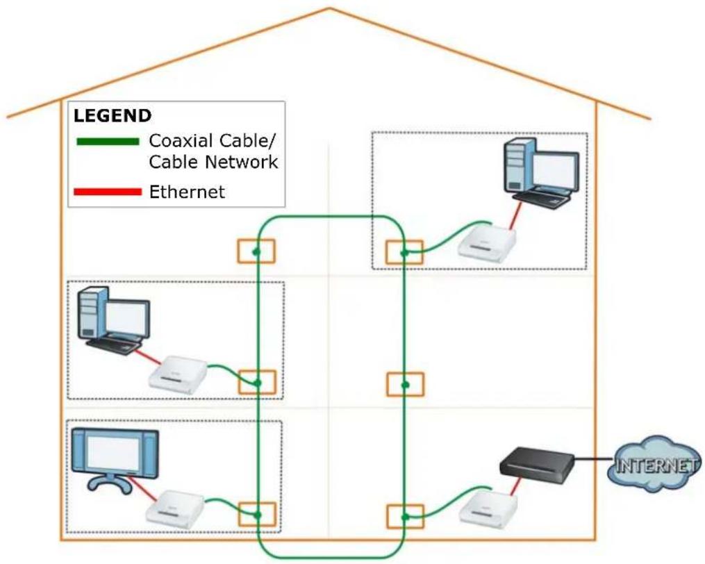
The PLA-402 v3 plugs into a coaxial cable outlet to easily extend a DSL broadband connection or existing Ethernet (LAN) network to any other coaxial cable outlet in any room of a house, all without the need for any new cabling as shown in the following figure.
Figure 1 PLA-402 v3 Home Setup
flowchart
graph TD
    subgraph Conventional
        direction LR
        A["Coaxial Cable/Cable Network"] --> B["Internet"]
        C["Ethernet"] --> D["Computer"]
        E["Computer"] --> F["Server"]
        G["Server"] --> H["Server"]
        I["Server"] --> J["Server"]
    end
    style Conventional fill:#f9f,stroke:#333
    style Conventional fill:#ccf,stroke:#333
    style Ethernet fill:#cfc,stroke:#333
    style Internet fill:#fcc,stroke:#333
The PLA-402 v3 securely communicates with each other at high data transfer rates. It uses 128-bit Advanced Encryption Standard (AES) to ensure safe transfer of information. See Chapter 10 on page 85 for speeds currently supported by the PLA-402 v3 and detailed product specifications.
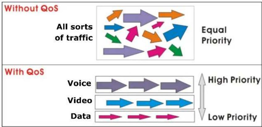
Additionally, the Quality of Service (QoS) feature of the PLA-402 v3 (refer to Section 5.6 on page 41) prioritizes voice, video and data traffic (such web browsing, file transfer and e-mail). The figure below illustrates the advantage of implementing QoS.
Figure 2 QoS on PLA-402 v3
flowchart
graph TD
    A["All sorts of traffic"] --> B{Equal Priority}
    B --> C["Voice"]
    B --> D["Video"]
    B --> E["Data"]
    F["Without QoS"] --> G["All sorts of traffic"]
    G --> H["Equal Priority"]
    H --> I["Voice"]
    H --> J["Video"]
    H --> K["Data"]
    L["With QoS"] --> M["High Priority"]
    M --> N["Voice"]
    M --> O["Video"]
    M --> P["Data"]
    Q["With QoS"] --> R["High Priority"]
    R --> S["Voice"]
    R --> T["Video"]
    R --> U["Data"]
    V["With QoS"] --> W["High Priority"]
    W --> X["Voice"]
    W --> Y["Video"]
    W --> Z["Data"]
    AA["With QoS"] --> AB["High Priority"]
    AB --> AC["Voice"]
    AB --> AD["Video"]
    AB --> AE["Data"]
    AF["With QoS"] --> AG["High Priority"]
    AG --> AH["Voice"]
    AG --> AI["Video"]
    AG --> AJ["Data"]
    AK["With QoS"] --> AL["High Priority"]
    AL --> AM["Voice"]
    AL --> AN["Video"]
    AL --> AO["Data"]
    AP["With QoS"] --> AQ["High Priority"]
    AQ --> AR["Voice"]
    AP --> AS["Low Priority"]
1.2 Expand Your Network with the PLA-402 v3
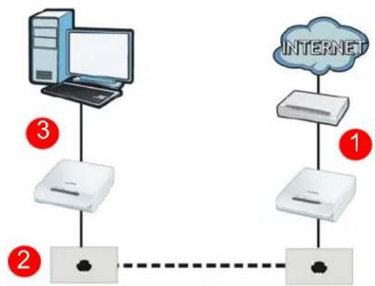
Connect your PLA-402 v3 to an Internet gateway such as a modem and plug it into a coaxial cable outlet in your home (1). Plug a second PLA-402 v3 into another coaxial cable outlet (2) and connect a computer to the PLA-402 v3 for Internet access (3).
Figure 3 Expand Your Network with the PLA-402 v3
flowchart
graph TD
    A["Computer 3"] --> B["Router"]
    C["Internet"] --> D["Router"]
    D --> E["Router"]
    style A fill:#f9f,stroke:#333
    style C fill:#ccf,stroke:#333
    style B fill:#dfd,stroke:#333
    style D fill:#dfd,stroke:#333
    style E fill:#dfd,stroke:#333
Your network can be further expanded by plugging additional PLA-402 v3s into other coaxial cable outlets in your home and connecting other computers or network devices (for example, a printer) to them.
Refer to your Quick Start Guide for hardware connection information.
If you are setting up a coaxial connection in a room with only one coaxial outlet you can use a coaxial splitter to connect more than one device. For example, if you want to connect a TV and a PLA-402 v3 to a single outlet you could use a coaxial splitter.
1.3 Ways to Manage the PLA-402 v3
Use the SETUP button to add coaxial devices to your powerline coaxial network if they have this button. See Chapter 4 on page 29 for instructions on using the SETUP feature.
Use the PLA-4xx Series Configuration Utility (or utility, for short) to manage the PLA-402 v3. See Section 2.2 on page 21 for instructions on installing the utility.
Use the firmware upgrade tool to upgrade to the latest firmware. Because the latest PLA-402 v3s are only compatible with other coaxial devices with the latest HomePlug AV firmware, as well as the latest version Utility, these tool is available to help you upgrade. You can download this tool from the ZyXEL website (www.zyxel.com.tw). See Chapter 3 on page 27 for information in using these tools.
This User's Guide describes the latest version utility. This utility is only compatible with a PLA-402 v3 which has the latest firmware installed. If you don't already have them, download the latest firmware and utility from the ZyXEL website.
1.4 Security
Since your powerline coaxial network may extend outside your premises, it is important to set up security on your PLA-402 v3.
1.4.1 Passwords
You use two types of passwords in the HomePlug AV powerline coaxial network. The following table describes the differences between the passwords.
Table 1 Password Summary
| PASSWORD DESCRIPTION | |
| Network Name All | coaxial adapters that follow the HomePlug AV standard are shipped with the same powerline coaxial network name "HomePlugAV". Change the network name via the PLA-4xx Series Configuration Utility to create a private network. See Section 5.3 on page 37. |
| DAK (Data Access Key) Password | In order to manage the coaxial adapters on your powerline coaxial network you must enter the adapters' DAK password in the PLA-4xx Series Configuration Utility. This password is printed on the coaxial adapter itself.You don't need to add the password for the coaxial adapter directly connected to the computer running the configuration utility (local coaxial adapter), you only have to add the remote coaxial adapters' passwords (those on your circuit, but not directly connected to your computer). |
1.4.2 Setting Up Security
The SETUP feature automatically sets up security on your powerline coaxial network. Use this feature if your coaxial devices have the SETUP button.
If your devices do not have the SETUP button, use the PLA-4xx Series Configuration Utility to set up security on the PLA-402 v3. Although the PLA-402 v3 is a "plug-and-play" network expanding solution there are several reasons for enabling security on the powerline coaxial network in your home.
1 It's easy and only requires you to change a network name.
2 It's a good idea to ensure privacy of your communication. When you use the PLA-402 v3 and other coaxial adapters, the coaxial wiring in your home becomes an extension of your Ethernet network. Your network traffic flows freely within the coaxial circuit of your home and is bounded in most cases by a power meter.
Without security (encryption) your information is accessible to anyone using a coaxial adapter on the same coaxial circuit. In some cases, a circuit can be shared by more than one household.
To prevent compromising your network security, you can create a private network. A private network uses a secret password (Network Name) to make sure that only permitted coaxial adapters can communicate in your network. See Section 5.3 on page 37 for information on setting up a private network.
3 You may need to change the Network Name to create multiple powerline coaxial networks. See the next section for more information on how to set up a multiple network.
1.5 Multiple Networks
Multiple powerline coaxial networks can coexist on a single coaxial circuit. You might want to implement multiple powerline coaxial networks in a small office environment where you have two separate Ethernet networks.
1 Connect one coaxial adapter to a router or switch on the first Ethernet network and assign a Network Name (for example "Password1") to this coaxial adapter. Add additional coaxial adapters to your network by plugging them into your coaxial cable outlets and assigning them "Password1". This completes the configuration of your first powerline coaxial network.
2 Connect another coaxial adapter to a router or switch on the second Ethernet network and assign a different Network Name (for example "Password2") to this coaxial adapter. Again, add additional coaxial adapters and assign them "Password2".
You now have two private networks on your powerline coaxial circuit. Information is not shared between the two networks as only coaxial adapters with the same Network Name can communicate with each other.
Installing the Utility
2.1 Overview
This chapter guides you through the installation of the configuration utility for your PLA-402 v3.
The installation of the configuration utility does the following:
1 Checks for and installs Microsoft's .NET Framework version 2.0 software on your computer. This software is necessary for the installation of the PLA-4xx Series Configuration Utility. If you already have .NET Framework version 2.0 installed on your computer this step will be skipped.
Note: At the time of writing the utility is only compatible with Microsoft Windows XP and Microsoft Windows Vista (32-bit version) operating systems. Users with Windows XP (64-Bit version) operating systems can go to Microsoft's website to upgrade their systems to .NET Framework version 2.0 so it can work with the utility. To check for your Windows operating system version, right-click on My Computer > Properties. You should see this information in the General tab.
2 Installs ZyXEL's PLA-4xx Series Configuration Utility. This utility allows you to manage the network name (See Section 5.3 on page 37 for more information) or view the devices recognized on your powerline coaxial network.
Note: This User's Guide describes the latest version utility. This utility is only compatible with a PLA-402 v3 which has the latest firmware installed. If you don't already have them, download the latest firmware and utility from the ZyXEL website.
2.2 Installing the Utility
Follow the steps below to install .NET Framework version 2.0 and the PLA-4xx Series Configuration Utility on your computer.
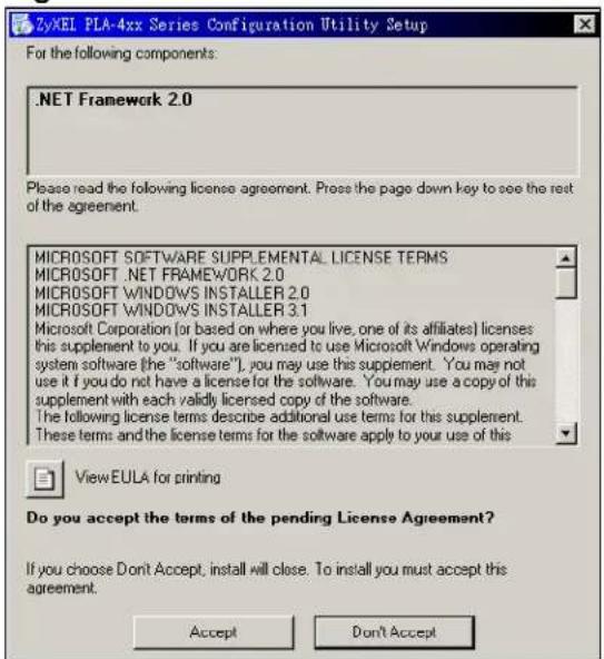
1 Insert the included CD-ROM into your computer's CD-ROM drive. The Setup utility runs automatically. Alternatively this can also be done manually by double clicking the setup.exe file on the CD. A prompt appears asking you to install the .NET Framework version 2.0. Review Microsoft's License Agreement, select Accept to proceed.
Figure 4 .NET Framework Installation Prompt
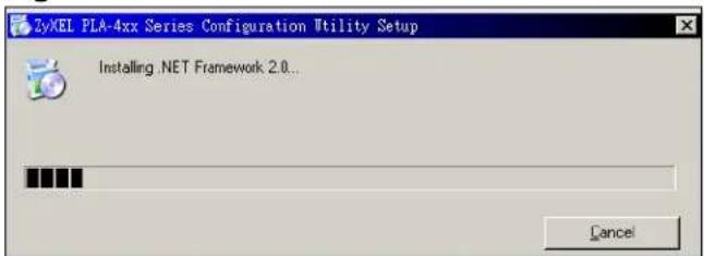
2 The next screen allows you to see the progress of the installation.
Figure 5 .NET Framework Installation Process
3 The Setup utility runs automatically. Click Yes or Next to continue through the initial screen. Click Cancel only if you want to abort the installation.
Figure 6 InstallShield Wizard Start Screen
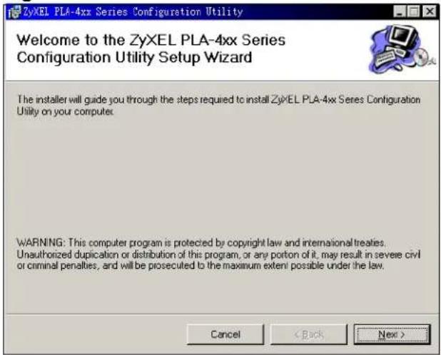
4 If you want the utility to be only available to the currently logged in user, select Only for me(...). Otherwise, click Everyone to allow all users to use the configuration utility. Click Next to install the utility to the default folder, or click Browse to specify a different location on your computer.
Figure 7 Install Destination Folder
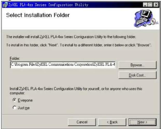
Note: You can also click Disk Cost to know how much available disk space you have in the hard drives found in your computer.
5 When the installation is finished, a screen appears to confirm that the PLA-4xx Series Configuration Utility has been successfully installed on your computer. Click Close to exit the wizard.
Figure 8 Installation Complete
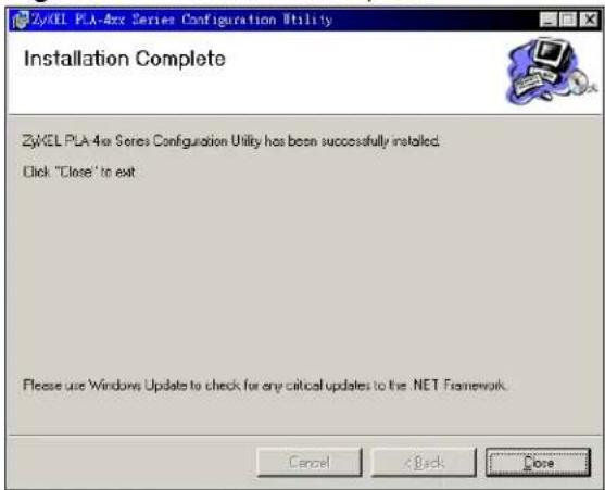
Note: You may be asked to restart your computer when the installation is complete. Click "Yes" to restart your computer. If you select "No, I will restart my computer later", you will not be able to launch the utility until after a restart of your computer.
2.3 Low Power Mode
Your PLA-402 v3 is a certified green product. It goes into Low Power mode when there is no Ethernet connection.
When you plug the PLA-402 v3 into an electric socket, it waits for an Ethernet connection. When no connection is detected after 120 seconds, the Power LED blinks indicating that it is going into Low Power mode.
The same process occurs when you disconnect the PLA-402 v3 from a previously working Ethernet connection. 120 seconds after disconnecting the Ethernet cable, the PLA-402 v3's Power LED blinks signalling that it is going into Low Power mode.
The Ethernet and HomePlug LEDs are turned off in Low Power mode.
While in Low Power mode, you cannot use the SETUP button. To enable the SETUP button again, you have to connect the PLA-402 v3's Ethernet cable to a computer/notebook or modem/router first. The PLA-402 v3 wakes up from Low Power mode and you can start using the SETUP button.
Low Power mode is enabled by default.
PART II
Managing the PLA-402 v3
Firmware Tool (27)
The SETUP Button (29)
The Configuration Utility (35)
Powerline Coaxial Network Setup Tutorial (61)
PLA Compatibility (71)
Firmware Tool
3.1 Overview
Use the Firmware Upgrade Tool to ensure you have the latest firmware (version 3.3.4 or later) on your PLA-402 v3(s).
You need to upgrade all your PLA-402 v3s to the latest firmware to ensure they can connect with each other and they are compatible with the latest version Utility.
If your firmware is an early version (earlier than 3.3.4), then upgrade your firmware using the Firmware Upgrade Tool.
3.2 Firmware Upgrade Tool
Use the firmware upgrade tool to upgrade your PLA-402 v3's firmware to the latest version.
You can use this tool to upgrade the firmware on the coaxial device directly connected to your computer. This is necessary as devices with ZyXEL's early version firmware are not compatible with the latest Utility or with devices running ZyXEL's latest version firmware.
At the time of writing, firmware version 3.3.4 is only available to PLA-402 v3.
Note: The firmware is included in the Tool. You do not need to download the firmware separately.
The SETUP Button
Use the SETUP button to automatically set up a secure coaxial connection between your PLA-402 v3s.
4.1 SETUP Button Overview
The SETUP button allows you to set up a secure coaxial connection with other HomePlug AV compliant coaxial devices which also support the SETUP feature. No other setting changes are required to connect.
You can use the SETUP button to:
- set up a new powerline coaxial network
- separate an existing powerline coaxial network into multiple networks
4.2 Set Up a HomePlug AV Network with SETUP
You can connect a number of devices on a powerline coaxial network, but you can use the SETUP button on only two devices at a time.
1 Place a coaxial device close to another coaxial device so you have time to set up each one. After you set up the first coaxial device, you have 120 seconds to set up the second coaxial device.
2 You can disconnect them from your computer or modem (or other networking equipment) if you need to move them close to each other, but the coaxial devices need to be plugged into power outlets.
Note: Because your PLA-402 v3 goes into Low Power mode, it must be connected to a networking equipment for the SETUP button to work. Refer to Section 2.3 on page 24 for more details.
3 Press the SETUP button at the rear of your coaxial device for more than 10 seconds until the power (↓)light flashes. This resets the network name to a random value and removes your device from any network it may belong to.
4 Press the SETUP button at the side of your coaxial device for 1\~2 seconds. The power (↓)light will blink as the PLA-402 v3 tries to set up a connection.
Figure 9 SETUP Connection Procedure
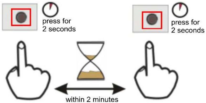
Note: The SETUP button's location varies for each coaxial device.
5 Repeat step 4 in this section for the other coaxial device you wish to connect. This must be done within 120 seconds of pressing the SETUP button on the PLA-402 v3.
6 Check the lights on the two coaxial devices. The power (⏻) and HomePlug (⏻) lights should be blinking while the devices are connecting. Several times all lights blink simultaneously and the HomePlug (⏻light also shows red. Wait for about one minute while your coaxial devices connect.
If the power (⏻) light does not blink when you press SETUP, you have probably pressed the SETUP button for too long. Try again, pressing the SETUP button for 1\~2 seconds.
If the HomePlug (▲lights on both coaxial devices do not light up, the coaxial devices are not connected. Repeat steps 4 and 5 in this section. If that doesn't work, see the Troubleshooting in Section 9.5 on page 82 for suggestions.
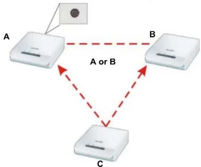
7 To add more coaxial devices to your network, press the SETUP button on device C (shown below) for more than 10 seconds until the power (light flashes.
8 Then repeat steps 4 and 5 in this section using any coaxial device (A or B) you have connected using SETUP and the coaxial device you want to connect (C). You must use the SETUP button on both devices.
Figure 10 Adding More Powerline Adapters to Your Network
flowchart
graph TD
    A["Device A"] -->|A or B| B["Device B"]
    B --> C["Device C"]
    C --> A
    style A fill:#f9f,stroke:#333
    style B fill:#ccf,stroke:#333
    style C fill:#cfc,stroke:#333
9 If you disconnected your computer or modem (or any other networking product connected to your coaxial device) in step 1 of this section, you can now reconnect them.
This sets up your powerline coaxial network between your coaxial devices.
4.3 Setting Up Multiple Networks
You can use the SETUP button to set up multiple powerline coaxial networks using your existing powerline coaxial network.
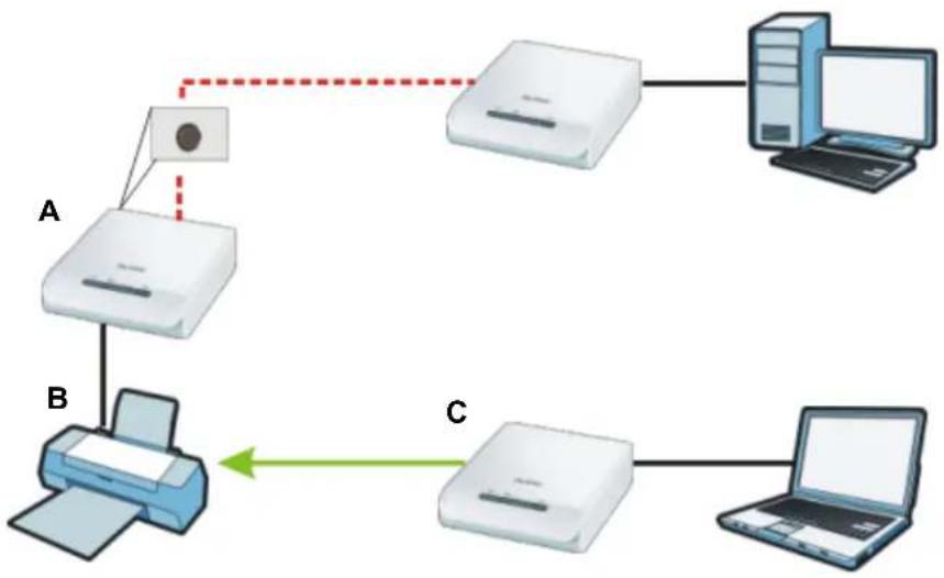
For example, you have already set up a powerline coaxial network in your home (A) which accesses a printer (B). Now you want a separate powerline coaxial network connection from your laptop to your printer (C).
Figure 11 One Existing Powerline Network
flowchart
graph TD
    A["Printer"] -->|Data Flow| B["Printer"]
    B -->|Data Flow| C["Printer"]
    C --> D["Laptop"]
    D --> E["Server"]
    style A fill:#f9f,stroke:#333
    style B fill:#bbf,stroke:#333
    style C fill:#bfb,stroke:#333
    style D fill:#ffb,stroke:#333
    style E fill:#fbb,stroke:#333
1 Click the SETUP button on (A) for more than 10 seconds until the power (⏻) light flashes. This disconnects (A) from (B).
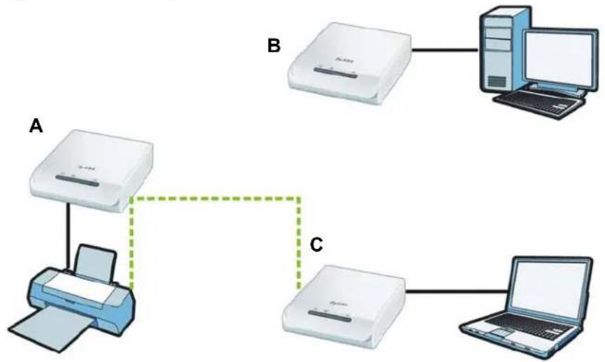
2 Click the SETUP button on (A) and (C) for 1\~2 seconds and within two minutes of each other.
3 Wait for about one minute while (A) and (C) connect.
4 Check the LEDs on both (A) and (C). When the power (⏻) and HomePlug (⏻) lights stop blinking and the power (⏻) light shines steadily, the devices are connected.
Figure 12 Two Separate Powerline Networks
flowchart
graph TD
    A["Printer A"] -->|Data Flow| B["Server B"]
    A --> C["Printer C"]
    C --> D["Laptop"]
    style A fill:#f9f,stroke:#333
    style B fill:#ccf,stroke:#333
    style C fill:#cfc,stroke:#333
    style D fill:#fcc,stroke:#333
Congratulations. You now have two separate powerline coaxial networks as shown above.
If the HomePlug (lights on both coaxial devices do not light up, the coaxial devices are not connected. Repeat the connection process, making certain you press the SETUP buttons for the correct time and within two minutes of each other. If that does not work see Section 9.5 on page 82 for suggestions.
4.4 SETUP Button Behavior
The following table summarizes the actions that occur when the SETUP button is pressed for specific lengths of time.
Table 2 Time SETUP Button is Pressed and Action
| TIME ACTION POWER LIGHT BEHAVIOR | HOMEPLUG LIGHT BEHAVIOR | ||
| less than 3 seconds | The device joins a network. It shares the same network name as other devices on the network. | The power ( )light blinks until the device is connected. This may take a minute. | The HomePlug ( )light turns on if your device is connected to another coaxial device or a powerline coaxial network. |
| more than 10 seconds | The device leaves any network it is associated with and its network name assumes a random value. | The power ( )light blinks several times and then shines steadily. | The HomePlug ( )light blinks red one time and then turns off when it disconnects from the powerline coaxial network. |
See Troubleshooting in Chapter 9 on page 82 for suggestions on problems with the SETUP button and the lights.
The Configuration Utility
5.1 Overview
This chapter shows you how to use the Configuration Utility (or Utility) to secure, manage and set up Quality of Service (QoS) on your powerline coaxial network.
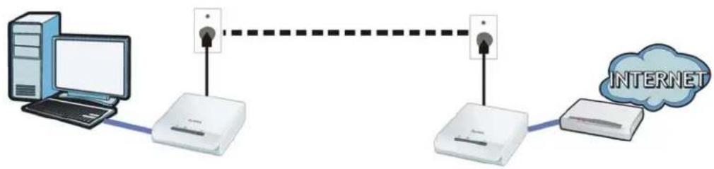
The PLA-402 v3 is designed as a plug-and-play network expanding solution. This means that once you complete your hardware connections, the PLA-402 v3s in your network (without additional configuration) are able to communicate with each other by sending and receiving information over your home's electrical wiring (A). You also have the option to use coaxial cables (B) to expand your network.
Figure 13 Example Network Setup
flowchart
graph LR
    A["Desktop Computer"] --> B["Switch"]
    B --> C["Internet"]
    D["Switch"] --> E["Internet"]
    style A fill:#333,stroke:#fff,color:#fff
    style B fill:#fff,stroke:#000
    style C fill:#fff,stroke:#000
    style D fill:#fff,stroke:#000
    style E fill:#fff,stroke:#000
All HomePlug AV compliant coaxial adapters within range can join your network. The range varies depending on the quality of your home's wiring.
Note: See Section 5.1.1 on page 35 for more information on enhancing your powerline coaxial network security.
In the case of coaxial cable this can extend beyond the boundary of your home (for example your neighbor's house or apartment).
5.1.1 Powerline Network Security
When the PLA-402 v3s communicate with each other, they use encryption to protect the information that is sent in the powerline coaxial network. Encryption is like a secret code. If you do not know the secret code, you cannot understand the
message. The HomePlug AV standard uses 128-bit AES (Advanced Encryption Standard) to safely transmit data between coaxial adapters.
For the coaxial adapters to communicate with each other they all need to use the same network name. This network name allows the coaxial adapters to understand the encrypted information sent in the coaxial network.
By default the PLA-402 v3s are all configured with the network name HomePlugAV, this allows you to simply plug the devices in and not worry about setting up security. If you want to enhance the security on your powerline coaxial network, you can change the network name on the coaxial adapters you want to allow to communicate in your powerline coaxial network.
5.1.2 Device Access Key (DAK)
In order to manage the coaxial adapters on your powerline coaxial network you must enter the adapters' password in the PLA-4xx Series Configuration Utility. This password is called the DAK (Device Access Key) password. This password is printed on the coaxial adapter itself.
You don't need to enter the DAK password for the coaxial adapter directly connected to the computer running the utility (local coaxial adapter), you only have to add the remote coaxial adapters' passwords (those in your powerline coaxial network, but not directly connected to your computer).
5.2 Starting the Configuration Utility
To launch the PLA-4xx Series Configuration Utility simply double click on the configuration icon on your desktop.
Figure 14 PLA-4xx Series Configuration Utility Icon
Alternatively, start the utility by browsing to it from the start menu. Click Start > Programs > ZyXEL PLA-4xx Series Configuration > PLA-4xx Series Configuration Utility.
Note: Close the Firmware Upgrade Tool and Firmware Detection Tool if either of them are open for the Utility to work properly.
5.3 Configuration Screen
Use the Configuration screen to see which devices are recognized by your powerline coaxial network, to configure your PLA-402 v3 and to set up a secure powerline coaxial network by changing the powerline coaxial network name. This screen opens up when you launch the utility.
Note: Use the ? icon to view online help information in each screen of the utility.
Figure 15 Configuration Screen
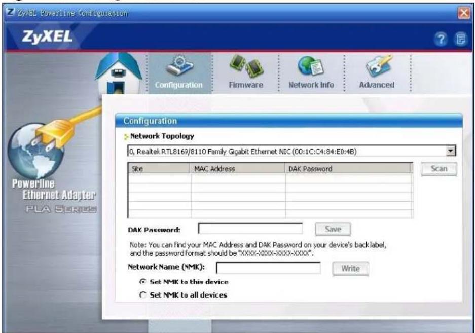
The following table describes the labels in this screen.
Table 3 Configuration Screen
| LABEL DESCRIPTION | |
| Network Topology | Use this to select which powerline coaxial network information is displayed. Different powerline coaxial networks are identified by the Ethernet interface (network card) connected directly to the PLA-402 v3. Typically there is only one connection, however, if your computer has two network cards and both are connected to a coaxial device then you have two powerline coaxial networks. |
| The fields described below are used to identify the coaxial adapters recognized on the powerline coaxial network. The configuration utility automatically updates this information every 10 seconds. Click Scan to refresh the information in these fields (immediately).Note: Only devices which share the same network name are displayed in this table. | |
| Site This field | displaysLocal, if it is identifying the coaxial adapter directly connected to the computer running the configuration utility.Remote, if it is a coaxial adapter in your powerline coaxial network but not directly connected to the computer running the configuration utility. |
| MAC Address | This is a read-only field which shows the MAC address of the coaxial adapter you are configuring. You can find the MAC address of your PLA-402 v3 displayed on a sticker on the bottom of your device. |
| DAK Password | DAK (Device Access Key) password is used to verify that you are authorized to perform changes on a remote device. You can find the DAK password printed on a sticker on the bottom of your PLA-402 v3.Select the remote coaxial adapter you want to manage by clicking the MAC address which corresponds to it in the MAC Address column. Enter the DAK Password value and click Save.Note: You must enter the DAK Password value exactly as it is printed on the label (all caps and with dashes “-”). |
| Network Name | The default network name (sometimes called a network password or network membership key (NMK)) of the PLA-402 v3 is “HomePlugAV”. HomePlug compatible devices use the same network name to recognize and communicate with each other over the powerline coaxial network. If you change the network name of one device on the network, it will no longer be recognized as part of that network.If you change the network name, make sure you change the network name for all of the coaxial adapters that you want to be part of your powerline coaxial network.The network name can be from 8 to 64 characters in length, using “A”~“Z”, “a”~“z”, “0”~“9”; spaces are not allowed. |
| Set NMK to this device | Select this to apply the NMK (entered in the field above) as the network name for the coaxial adapter directly connected to the computer running the configuration utility. |
| Set NMK to all devices | Select this to apply the NMK (entered in the field above) as the network name for all coaxial adapter detected by the utility. |
| Save | Click this to apply your changes. The new Network Name is applied to the selected coaxial adapter.Note: You must enter the correct DAK password for the selected coaxial adapter before you can make changes to it. |
5.4 Firmware Screen
Use the Firmware screen to update the firmware on the PLA-402 v3 directly connected to the computer running the configuration utility.
Firmware is the software which is embedded in the PLA-402 v3. This software contains processing instructions for how the PLA-402 v3 sends and receives information in a secure way.
Parameter Information Block (PIB) is similar to firmware. It contains the most basic operating instructions for the PLA-402 v3 such as how to power up and how to load the firmware.
You can check the ZyXEL website for firmware upgrades for your PLA-402 v3.
Note: To upgrade to the latest firmware, use the firmware upgrade tool available from the ZyXEL website (www.zyxel.com), or from the CD included with your PLA-402 v3. Make sure you also upgrade the PLA-4xx Series Configuration Utility if you do so, as older version utilities are not compatible with PLA-402 v3s using the latest firmware.
Note: Be sure to upload the correct model firmware as uploading the wrong model firmware may damage your device.
Figure 16 Firmware Screen
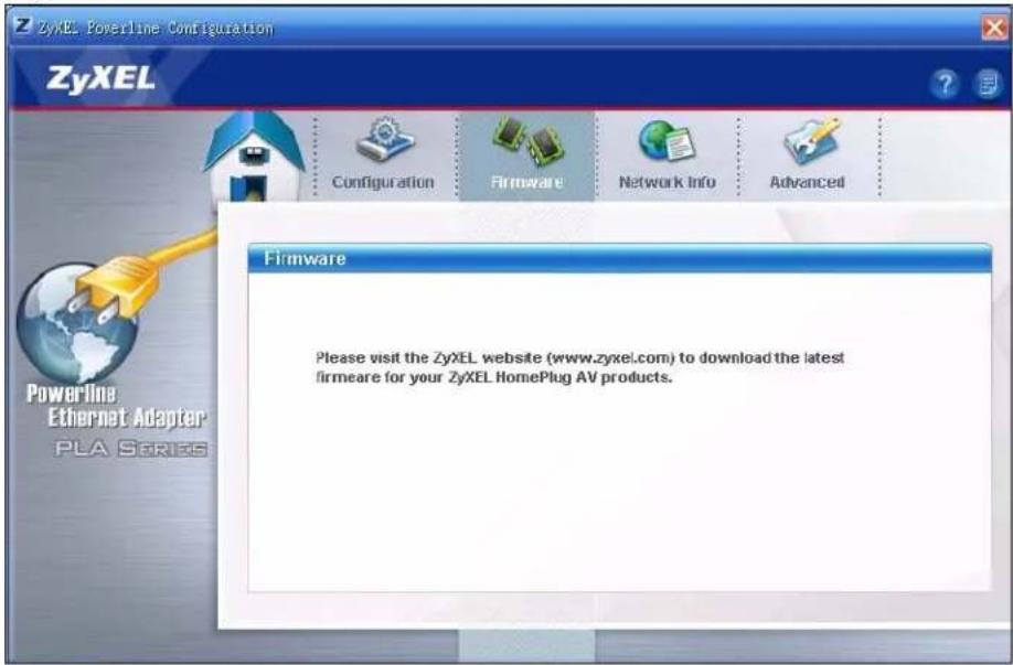
5.5 Network Info Screen
Use the Network Info screen to see the rates at which a specific PLA-402 v3 is communicating with other coaxial adapters on your powerline coaxial network.
Figure 17 Network Info Screen
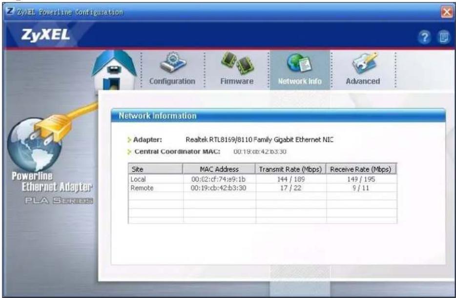
The following table describes the labels in this screen.
Table 4 Network Info Screen
| LABEL DESCRIPTION | |
| Adapter This field identifies which powerline coaxial network information is displayed. Different powerline coaxial networks are identified by the Ethernet interface (network card) connected directly to the PLA-402 v3. Typically there is only one connection, however, if your computer has two network cards and both are connected to a PLA-402 v3, then you have two powerline coaxial networks. | |
| Central Coordinator MAC | The Central Coordinator of the powerline coaxial network is the coaxial adapter which keeps track of which devices are part of the network as well as synchronizes communication within the powerline coaxial network. If the Central Coordinator is removed from the powerline coaxial network then another coaxial adapter takes its place. This field displays the MAC address of the PLA-402 v3 which is the Central Coordinator of the powerline coaxial network. The coaxial adapters in your powerline coaxial network automatically select the Central Coordinator. |
| The information provided in the following table reflects transmission rate information about the coaxial adapters which communicate in your powerline coaxial network.The coaxial adapters listed in this table are all the coaxial adapters in your powerline coaxial network except the coaxial adapter selected in theConfigurationpage of the configuration utility. In other words, if theLocalcoaxial adapter is selected in theConfigurationscreen, then this table will display the rates of transmission from the coaxial adapter connected to the computer running the configuration utility to all theRemotecoaxial adapters. | |
| Site This field | displays:Local, if it is the PLA-402 v3 directly connected to the computer running the configuration utility.Remote, if it is a PLA-402 v3 in your powerline coaxial network but not directly connected to the computer running the configuration utility. |
| MAC Address | This field displays the MAC address of your coaxial adapter. The MAC address of your coaxial adapter can be found by looking at the label on your device. It consists of six pairs of hexadecimal characters (hexadecimal characters are "0-9" and "a-f"). In the case of the PLA-402 v3, this label is on the bottom of the device. |
| Transmit Rate (Mbps) | This field displays how fast information is sent from the coaxial adapter selected in theConfigurationscreen to this coaxial adapter. The rate is given in the following format: "application data transmission rate / raw data transmission rate". Application data reflects more accurately how fast devices are transmitting application relevant traffic (for example Internet Protocol (IP) traffic). Raw data refers to the whole payload of the packets transmitted across the powerline coaxial network. |
| Receive Rate (Mbps) | This field displays how fast information is received from the coaxial adapter selected in theConfigurationscreen to this coaxial adapter. The rate is given in the following format: "application data transmission rate / raw data transmission rate". Application data reflects more accurately how fast devices are transmitting application relevant traffic (for example Internet Protocol (IP) traffic). Raw data refers to the whole payload of the packets transmitted across the powerline coaxial network. |
5.6 Advanced Screen
Note: This feature is only available with the latest version utility. Go to the ZyXEL website to download the latest utility and firmware for your ZyXEL HomePlug AV adapter.
You can configure the coaxial adapters on your network to give priority to network traffic depending on its importance. When you set the priority of a coaxial adapter, you set how quickly messages FROM your coaxial adapter are sent in your powerline coaxial network. Transmissions TO your coaxial adapter do not receive any priority.
For example, if you have a file server on your home network to deliver music and movie files to computers in your home, you should set the priority of the coaxial adapter connected to this server to Medium. If video traffic is delivered too slowly, quality problems may occur.
On the other hand, a coaxial adapter attached to a printer should have a low priority setting since the slow delivery of messages will not affect the print job.
Similarly, if you want to prioritize any downloads from the Internet, set the priority on the coaxial adapter attached to your Internet gateway to High.
Allocate priority settings based on application type as follows.
Table 5 Priority Settings
| PRIORITY LEVEL APPLICATION | |
| High Voice Application | |
| Medium Video and Audio Applications | |
| Normal Data Applications | |
| Low Data Applications | |
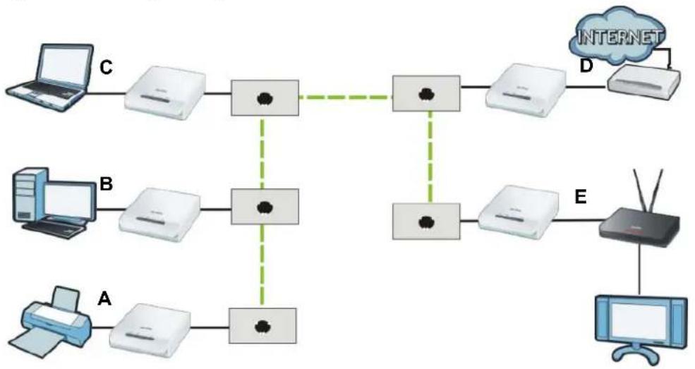
The figure below shows an example powerline coaxial home network connected to the Internet.
- Device A is a printer and does not handle traffic with high importance, so the coaxial adapter connected to it can be set to low priority.
- Device B is a file server, delivering audio or movie files to other users on the network. The coaxial adapter attached to it should have a medium setting.
- Device C, a home computer which connects to the Internet, can receive a normal priority setting as it usually sends simple requests for data. For example, when you surf the Internet, your computer sends requests to open web pages.
- Device D is a modem attached to the Internet. It should receive a high priority setting if you want faster downloading through your network.
- Although device E receives audio or movie files, it does not send a lot of traffic, so the coaxial adaptor attached to it can be set to a low priority.
Figure 18 Priority Settings
flowchart
graph TD
    A["Client A"] --> B["Printer 1"]
    A --> C["Printer 2"]
    B --> D["Router"]
    C --> D
    D --> E["Router"]
    E --> F["Internet"]
    F --> G["Server"]
    H["Client B"] --> I["Printer 3"]
    H --> J["Printer 4"]
    I --> K["Router"]
    J --> K
    K --> L["Router"]
    L --> M["Server"]
    N["Client C"] --> O["Printer 5"]
    N --> P["Printer 6"]
    O --> Q["Router"]
    P --> Q
    Q --> R["Server"]
    S["Client D"] --> T["Router"]
    U["Client E"] --> V["Server"]
Use this screen to configure priority settings for traffic from the coaxial adapters on your network.
Figure 19 Advanced Screen
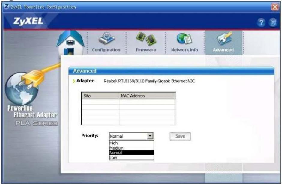
The following table describes the labels in this screen.
Table 6 Advanced Screen
| LABEL DESCRIPTION | |
| Adapter This | field identifies which powerline coaxial network information is displayed. Different powerline coaxial networks are identified by the Ethernet interface (network card) on your computer which is connected directly to a coaxial adapter. Typically there is only one connection. However, if your computer has two network cards and both are connected to a coaxial adapter, then you have two powerline coaxial networks. |
| Site This field | displays:Local, if it is the PLA-402 v3 directly connected to the computer running the configuration utility.Remote, if it is a coaxial adapter in your powerline coaxial network but not directly connected to the computer running the configuration utility. |
| MAC Address | This is a read-only field which shows the MAC address of the coaxial adapter you are configuring. You can find the MAC address of your PLA-402 v3 displayed on a sticker on the bottom of your device. |
| Priority Select | a priority setting from the drop-down box for traffic FROM your selected device. The options, in order of importance, areHigh, Medium, NormalandLow. |
| Save | Click this to apply your changes. The newPrioritysetting is applied to the selected coaxial adapter. |
5.7 About Screen
Use the About screen to view information regarding the configuration utility and firmware version of the PLA-402 v3 you are connected to. Click the icon in the top right corner of the utility to view the About screen.
Figure 20 About Screen
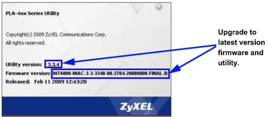
The following table describes the labels in this screen.
Table 7 About Screen
| LABEL DESCRIPTION | |
| Utility version: | This field displays the software version of the configuration utility. |
| Firmware version | This field displays the firmware version of the device you selected in theDevice Selectionfield of theConfigurationscreen.In the example firmware version given in the screen,3-3-3348,the firmware version is shown by the numbers334, meaning this is firmware version 3.3.4.If your device’s firmware is earlier than 3.3.4, please use theFirmware Upgrade Toolto upgrade your firmware. |
| Released This field displays the date when the firmware was released. | |
| Close | Click thebutton in upper right corner to close theAboutwindow. |
The OS X Configuration Utility
6.1 Overview
This chapter shows you how to use the configuration utility on a Mac computer with the Leopard operating system. See the User's Guide Chapter 5 on page 35 for background information on some powerline coaxial features.
All HomePlug AV compliant coaxial adapters within range can join your network. The range varies depending on the quality of your home's wiring. In the case of coaxial cable this can extend beyond the boundary of your home such as your neighbor's house or apartment for example.
Use the Mac utility to configure the following tasks:
- Change Network Name (NMK)
- Change Nickname
- QoS Settings
- Set HomePlug Light Color
- Link Information
- Download Firmware
6.1.1 System Requirements
These are the OS X utility system requirements at the time of writing.
• Supported Models:
PLA-402 v3
- Supported Mac operating systems:
Mac OS X 10.3, Mac OS X 10.4, Mac OS X 10.5
• Supported Language/s:
English
6.1.2 Start the Configuration Utility
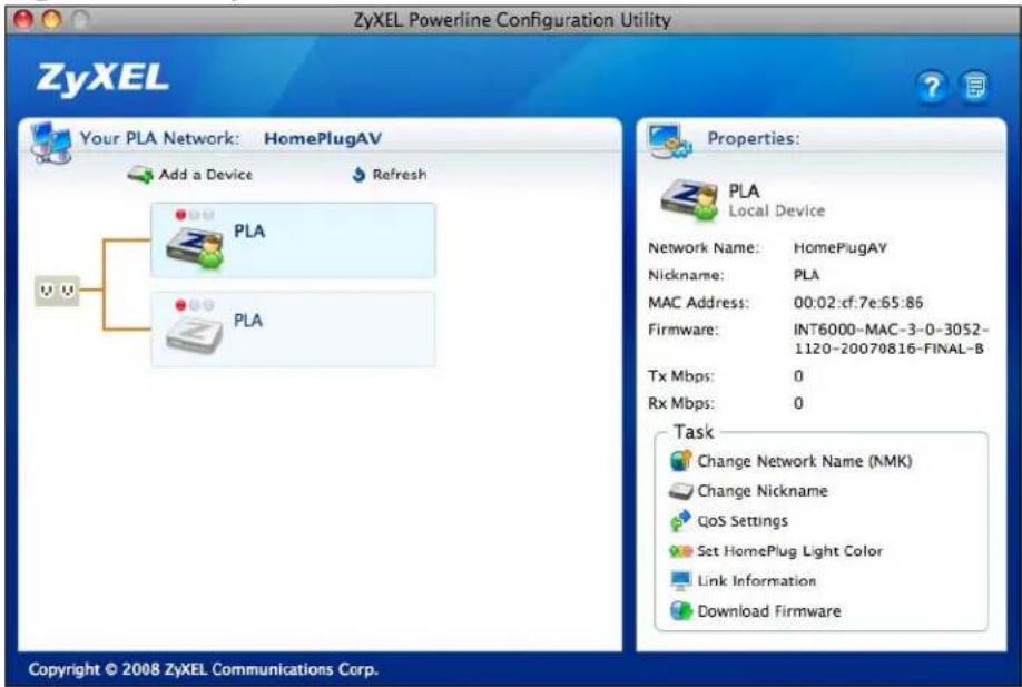
Drag the utility application from the CD (or download it from the ZyXEL download library) to the Applications folder on your computer. Double-click it to open it.
Figure 21 Utility Main Screen
6.1.3 Add a Device
To add a device, click Add a Device in the configuration utility main screen.
6.1.4 Change Network Name
The network name or Network Membership Key (NMK) is a password that identifies a powerline coaxial network. All coaxial devices with the same NMK are in the same powerline coaxial network. The default network name of the PLA-402 v3 is HomePlugAV. HomePlug compatible devices use the same network name to recognize and communicate with each other over the powerline coaxial network. If you change the network name of one device on the network, it will no longer be recognized as part of that network.
If you change the network name, make sure you change the network name for all of the coaxial adapters that you want to be part of your powerline coaxial network.
To enter the NMK for a coaxial adapter, select the device icon in the left panel of the main utility screen and then click Change Network Name (NMK) in the main utility screen.
Figure 22 Change Network Name (NMK)
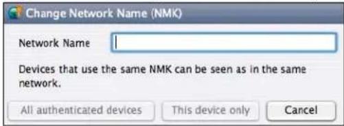
Table 8 Change Network Name (NMK)
| LABEL DESCRIPTION | |
| Network Name The network | work name may consist of 8 to 64 letters, numerals and any printable character found on a typical English language keyboard. Spaces are not allowed. |
| All authenticated devices | Click this button to display a screen showing other coaxial devices that are already in the same powerline coaxial network as the selected coaxial adapter.Click OK to change their NMKs to the Network Name you entered here. Click Cancel to not change them and return to the previous screen. |
| This device only Click this button | this button to just update the NMK on the selected coaxial adapter. |
| Cancel Click this button | to close this window without saving any changes. |
6.1.5 Change Nickname
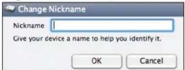
You can give each device in your powerline coaxial network a 'friendly name' in order to easily distinguish them in your powerline coaxial network. The name may consist of up to 64 letters, numerals and any printable character found on a typical English language keyboard. Type a nickname, for example, 'bedroom', and then click OK.
Figure 23 Change Nickname)
6.1.6 QoS Settings
You can configure the coaxial adapters on your network to give priority to data they transmit.
The following table shows some example priority settings based on application type.
Table 9 Priority Settings
| PRIORITY LEVEL APPLICATION | |
| Highest Voice Application | |
| High Video and Audio Applications | |
| Mid Data Applications | |
| Low Data Applications | |
Figure 24 QoS Settings
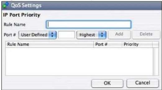
Table 10 QoS Settings
| LABEL DESCRIPTION | |
| IP Port Priority You can | configure up to eight rules defining priority for traffic transmitted from the selected coaxial device. |
| Rule Name Type a rule | name. The name may consist of up to 31 letters, numerals and any printable character found on a typical English language keyboard. Spaces are not allowed. |
| Port # Select the type | of traffic to which this rule applies. You may select one of the following:FTPHTTPE-MailTelnetUser - DefinedIf you selectUser-Definedthen enter the port number that defines that traffic type, such as 1823 for MSN traffic. See the commom services appendix for port numbers of other traffic types.After you select the traffic type, select the priority level (Highest, High, Mid, Low) assigned to this traffic.ClickAddto save the rule to the list in this screen.If you want to delete an existing rule, select it in the text box and then clickDelete. |
| Rule Name This field displays the name of a previously created priority rule. | |
| Port # This field displays the port number for the type of traffic to which this rule applies. | |
| Priority This field displays the priority level that this traffic receives. | |
| OK Click this button to save the settings to the device. | |
| Cancel Click this button to close this window without saving any changes. | |
6.1.7 Set HomePlug Light Color
Use this screen to define which color the HomePlug light shines at various speeds. For example, configure the light to shine red when the speed is slow enough to warrant your attention, amber for 'near slow' speeds and green for acceptable powerline coaxial speeds for your network. The Maximum Possible Speed is the best speed that can be attained on your electrical circuit. It varies depending on the electrical wiring, insulation, distance between devices, and electromagnetic interference from adjacent wiring or other electrical devices on your network.
In the default screen shown in Figure 25 on page 52, the maximum possible speed is 150 Mbps. If the speed falls below 10 Mbps, the light will shine red. It will shine amber for speeds between 10 and 40 Mbps and green for speeds above 40 Mbps.
Figure 25 Set HomePlug Light Color
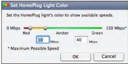
Use the slider to define the light behaviour or type a range in the text boxes for when the light should shine amber. For example, if the maximum possible speed in your network is 100 Mbps and you feel that speeds below 15 Mbps are abnormally slow, and speeds above 50 Mbps are good, then enter '15' in the first text box and '50' in the second. The maximum possible speed, 100 Mbps in our example, is detected automatically by the device; you do not enter it.
If the HomePlug light displays red, indicating that the powerline coaxial speed is abnormally slow, try unplugging electrical devices such as lamps, phone chargers, hair dryers, drills and vacuum cleaners from the electrical circuit where your coaxial adapters are connected.
6.1.8 Link Information
Use the Link Info screen to find out more information on the connection between two coaxial adapters on your powerline coaxial network. The link information screen shows the MAC addresses of connected coaxial adapters and statistics on the links.
Figure 26 Link Information
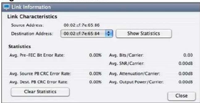
Table 11 Link Information
| LABEL DESCRIPTION | |
| Link Characteristics | |
| Source Address This is | the MAC address of the local powerline adapter. The local powerline adapter is the one connected directly to your computer. A MAC address is a number that uniquely identifies a device in a network. |
| Destination Address | This is the MAC address of a remote powerline adapter. A remote powerline adapter is in the same powerline network as the local powerline adapter but is not connected directly to your computer. |
| Show Statistics Click this | this button to show detailed link information between the local and remote power adapters.. |
| Statistics | |
| Avg. Pre-FEC Bit Error Rate | In powerline networks data is sent in physical blocks (PB). This field shows the average percentage of errors in the physical blocks received by the destination device from your source device before the errors are corrected using FEC (Forward Error Correction). Forward Error Correction (FEC) is a system where the sender adds redundant data to its transmissions. It allows the receiver to correct errors without the need of asking the sender to resend the data.A high error rate may not necessarily result in a poor connection as PBs with errors are discarded and the coaxial device adjusts the signal to a frequency level where fewer errors occur. |
| Avg. Source PB CRC Error Rate | This field displays the average CRC (Cyclic Redundancy Check) error rate of transmission from the source device (as shown in the screen) received by destination coaxial device.A Cyclic Redundancy Check (CRC) is used as a checksum to detect alteration of data during transmission. The CRC error check is performed after Forward Error Correction. If the error rate after FEC error correction is still high, then this indicates a lot of noise at all frequencies on this section of your powerline coaxial network. Data transmission rates are reduced if there is a lot of noise on the line. |
| Avg. Destination PB CRC Error Rate | A Cyclic Redundancy Check (CRC) is used as a checksum to detect alteration of data during transmission. This field displays the average CRC (Cyclic Redundancy Check) error rate of transmission from the destination coaxial device to the source device (as shown in the screen).The CRC error check is performed after Forward Error Correction. If the error rate after FEC error correction is still high, then this indicates a lot of noise at all frequencies on this section of your powerline coaxial network. Data transmission rates are reduced if there is a lot of noise on the line. |
| Avg. Bits/Carrier This fi | field displays the average number of bits transferred over the connection measured in Mbps. This represents the physical rate of data transmission (the PHY rate) which includes not only the files sent on your powerline, but also line overhead required to manage your network, such as error correction bits.The PHY rate is the clearest indicator of the quality of your line.If the PHY rate is close to the HomePlug AV maximum data transfer rate, then the quality of this section of the line is very high, with very little attenuation.If the PHY rate varies between the maximum level and a lower level (such as 60 Mbps), there is noise on this section of your powerline. Attenuation is not a factor.If the PHY rate is steady at a lower level (such as 80 Mbps), this is caused by attenuation and not noise on this section of your powerline. |
| Avg. SNR/Carrier This | field displays the average Signal to Noise Ratio (SNR) measured in dB. Use this to check the amount of noise on this part of your powerline network. The higher the number the better the connection quality.Noise on your powerline coaxial network is usually caused by household appliances running on your powerline coaxial network. The motor of a refrigerator can create electrical interference. A cell/mobile phone recharger which rapidly alternates between on and off can also generate noise. Poor cable quality and installation can also cause noise. To identify causes of noise on your network, disconnect an appliance connected on this part of your powerline coaxial network and observe whether this reduces the Signal-to-Noise ratio. |
| Avg. Attentuation/ Carrier | This field displays the average attenuation measured in dB. Attenuation is the reduction in strength of a signal as it travels over a transmission line. Use this field to check the reduction in the strength of the signal between two devices.Attenuation may vary considerably across a powerline coaxial network as line conditions also vary. A typical level of attenuation may be 40 dB, but may reach over 70 dB, depending on line quality and distance.A main cause of attenuation is the power requirements of appliances on your electrical circuit. Powerline traffic near an appliance such as a refrigerator may be affected by attenuation more than on other sections of your powerline coaxial network. |
| Avg. Output Power/ Carrier | This field shows the average power produced by the source device. Power levels should be constant and limited by the output power standard of your country. Unusually high output power levels may damage your device. |
| Clear Statistics Click this | this button to reset all counters in this screen to zero. |
| Close Click this button | to close this window. |
6.1.9 Download Firmware
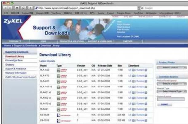
Use this screen to go to the ZyXEL download library from where you can download firmware to your computer.
Figure 27 Download Firmware
6.2 Firmware Detection Tool
Use the Firmware Detection Tool to detect the firmware version of the coaxial devices on your network. All coaxial devices of the same type should use the same firmware version. Use the Firmware Upgrade Tool to upload new firmware.
You cannot run the Firmware Detection Tool, the Firmware Upgrade Tool or the Configuration Utility at the same time, as only one of these applications can access the PLA-402 v3 connected to your computer at any time.
Figure 28 Firmware Detection Tool
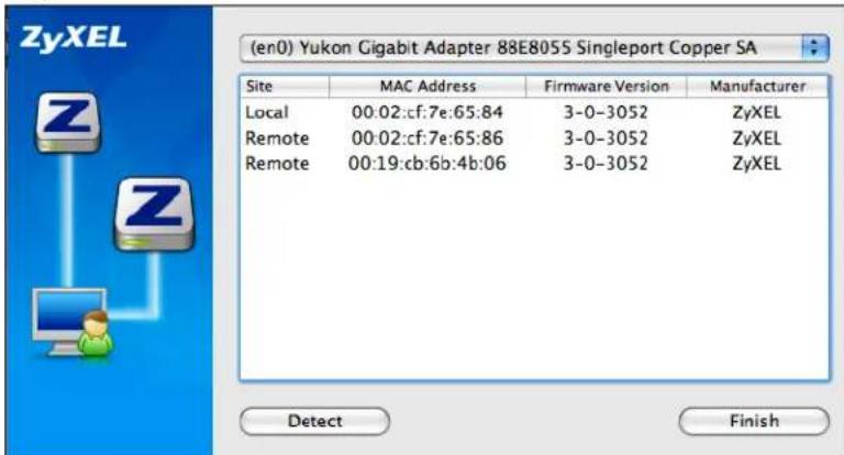
Table 12 Firmware Detection Tool
| LABEL DESCRIPTION | |
| Site | This field shows Local, if it is identifying the powerline adapter directly connected to the computer running the configuration utility and Remote, if it is a powerline adapter in your powerline network but not directly connected to the computer running the configuration utility. |
| MAC Address This shows the MAC address of the powerline adapter. You can find the MAC address of your PLA-402 v3 displayed on a sticker on the bottom of your device. | |
| Firmware Version This field displays the version number of the powerline device. In the example firmware version given in the screen, 3-0-3052, the numbers 305 represent firmware version 3.0.5. | |
| Manufacturer This field displays the manufacturer of the coaxial device. You can upgrade your device if this field displays ZyXEL. If Other displays then you cannot use the Firmware Upgrade Tool. | |
| Detect Click this button to display the firmware versions of local and remote devices in the same powerline coaxial network. | |
| Finish Click this button to close this screen. | |
6.3 Firmware Upgrade Tool
Use the firmware upgrade tool to upgrade firmware to the coaxial device directly connected to your computer.
To upgrade to the latest firmware, use the firmware upgrade tool on the CD included with your PLA-402 v3. Make sure you also use the latest PLA-4xx Series Configuration Utility; older utilities may not be compatible with PLA-402 v3s using the latest firmware.
6.3.1 Notes on Upgrading Firmware
- If the firmware version of devices in your powerline coaxial network is greater than 3.0.5, then you may only need to upgrade the utility; otherwise you must upgrade both the utility and the firmware!
- Be sure to upload the correct model firmware as uploading the wrong model firmware may damage your device.
- The firmware is included in the upgrade tool. You do not need to download the firmware separately.
-
After you upgrade firmware, all settings that you configured in the utility revert to their factory defaults. Before upgrading, write down your current settings. After you upgrade the firmware, you need to reconfigure your device using the utility.
-
Your device automatically reboots after you upload the firmware.
- You cannot downgrade firmware to an older version firmware.
6.3.2 Procedure to Upgrade Firmware
1 Connect the coaxial device to be upgraded to your computer.
2 Close the Configuration Utility and Firmware Detection Tool if either of them are open.
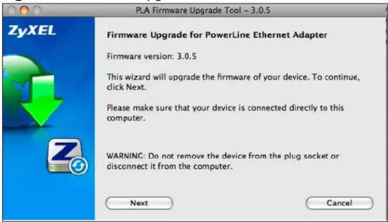
3 Open the Firmware Upgrade Tool application. Click Next to begin the firmware upgrade process.
Figure 29 Firmware Upgrade Tool: Start
4 If you already have the latest version firmware, you'll see a warning screen. Click No unless you want to re-upload the firmware.
Figure 30 Firmware Upgrade Tool: Start
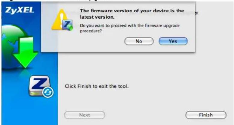
5 Select the region where your powerline coaxial network is located in the following screen. Make sure you upload the correct firmware for your region as different regions have different firmware characteristics.
Figure 31 Firmware Upgrade Tool: Start
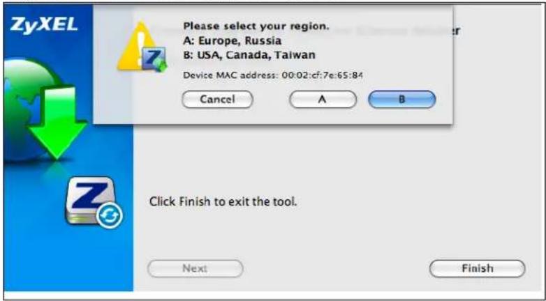
6 The firmware upgrade may take several minutes. Do not click anything or reboot the device while firmware upgrade is in progress.
Figure 32 Firmware Upgrade Tool: Upgrading
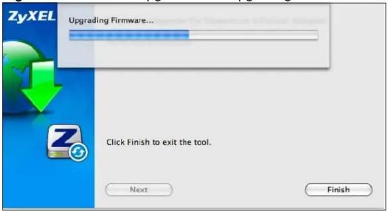
7 If your firmware is successfully upgraded, a successful screen appears. Click OK, then Finish to close the application. Your device automatically restarts.
Figure 33 Firmware Upgrade Tool: Finish
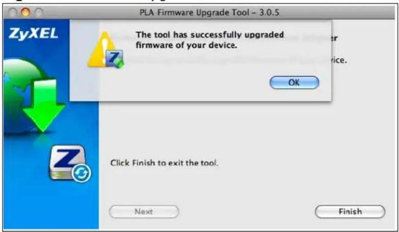
8 To check if your firmware is successfully upgraded, run the Firmware Detection Utility again and check your firmware version.
9 Repeat this upgrade process for each coaxial device you need to upgrade.
Powerline Coaxial Network Setup Tutorial
7.0.1 Overview
Use this tutorial to expand your existing powerline coaxial network.
After setting up your first home powerline coaxial network (instructions for that are in the Quick Start Guide for your ZyXEL PLA-402 v3) you may want to extend the network or create a new one by adding additional coaxial adapters. This tutorial shows you the following.
- How to start up your new coaxial adapter. You need to do this before you can begin the next sections.
- How to make your existing powerline coaxial network bigger by adding new coaxial adapters.
- How to make a new network separate from your existing network with new coaxial adapters.
- How to make a new, separate powerline coaxial network with the coaxial adapters you have.
The tutorial uses the PLA-4xx Series Configuration Utility to set up your coaxial adapter.
If you haven't already installed the utility, see Chapter 2 on page 21 for instructions. If you do not have the CD with the utility, the utility software is also available for download at www.zyxel.com. Navigate to the coaxial products section of the ZyXEL website to find this software. Follow the instructions provided by the software to install it on your computer.
See the product specifications in the User's Guide for a list of hardware and software compatible with the utility.
Note: The PLA-402 v3 in this tutorial is an example only. Your coaxial adapter may be different.
7.0.2 Important Terms
| Network Name The network name allows a coaxial adapter to connect with other coaxial adapters that have the same network name. It provides security for your powerline coaxial network. The network name uses English letters or numbers, from 8 to 64 characters long, with no spaces allowed. |
| DAK Password DAK = Device Access Key.The DAK Password lets you access the coaxial adapter. You can find the DAK Password on a label on your coaxial device. |
7.0.3 Accessing Your Coaxial Adapter
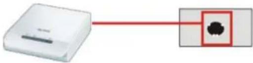
1 Plug the coaxial adapter you want to add to your network into a coaxial socket.
Figure 34 Plug Your Coaxial Adapter into the Coaxial Socket
natural_image
Simple diagram showing a device connected to a highlighted circular object (no text or symbols)2 Connect the coaxial adapter to your computer.
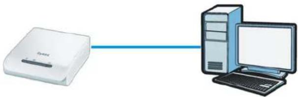
3 Use a LAN or Ethernet cable (shown below) to connect the LAN or Ethernet port on your adapter to the same kind of port on your computer.
Figure 35 Connect Your Coaxial Adapter to a Computer
natural_image
Illustration of a desktop computer connected via a blue cable to a white router (no text or symbols)4 Open the PLA-4xx Series Configuration Utility on your computer. Go to Start > (All) Programs > ZyXEL PLA-4xx Series Configuration > PLA-4xx Series Configuration Utility, or click on the icon on your desktop shown below.
Figure 36 Click on the PLA-4xx Series Configuration Utility Icon
5 You are now ready to extend your powerline coaxial network or set up a second network.
• See Section 7.0.4 on page 63 to add a new coaxial adapter to your network.
• See Section 7.0.5 on page 65 to set up a second network with your new adapters.
• See Section 7.0.6 on page 66 to set up a second network with your existing adapters.
7.0.4 Adding a Coaxial Adapter
This section shows you how to add a new coaxial adapter to expand your existing network.
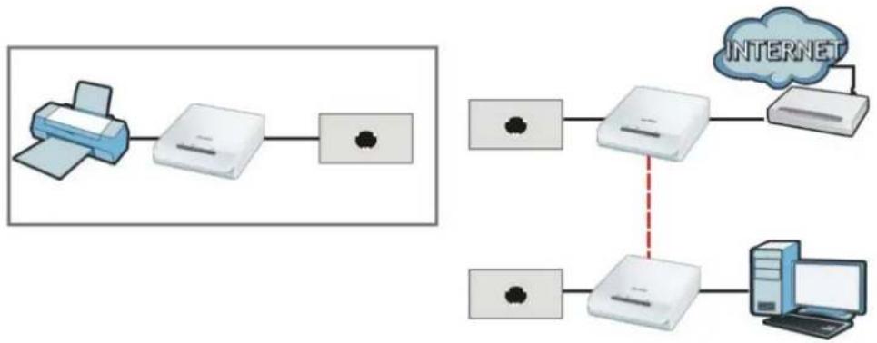
The figure below shows the family computer with Internet access on a powerline coaxial network. Expand the network by adding a new coaxial adapter connected to a printer.
Figure 37 Add a Printer to Your Powerline Coaxial Network
Note: You do not need to know the network name of the new adapter to add it to your network.
1 Connect your computer to the coaxial adapter you want to add to your network and open the PLA-4xx Series Configuration Utility (see Section 7.0.3 on page 62).
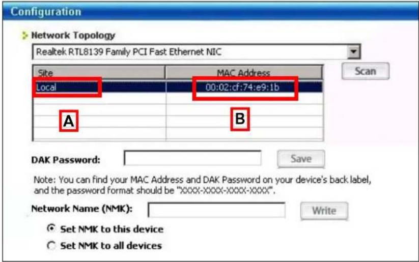
2 The utility should open to the configuration tab. On this screen in the Site column your new coaxial adapter should appear as Local (A). Check the Local adapter's MAC address (B). It should match the MAC address listed on the label on the back of your coaxial adapter.
Figure 38 Adding a New Adapter
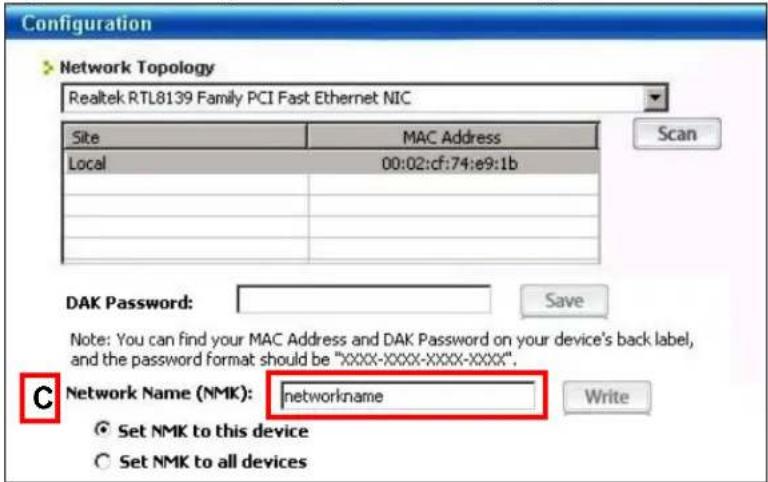
3 Select your adapter by selecting Local and type the network name for your existing network in the Network Name field (C).
Figure 39 Adding an Adapter to an Existing Network
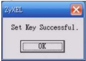
4 Click Save and click OK on the pop-up.
Figure 40 Network Name Pop-up
5 Your new adapter will now have the same Network Name as your existing network and so has now joined your existing network.
6 Connect the adapter to the device you want to add to the network, for example, your Internet refrigerator in the kitchen.
7 Plug the adapter's power cord into a power outlet and, if required, switch the power outlet on.
8 Repeat this procedure for all additional coaxial adapters that you want to add to your existing or new powerline coaxial network.
7.0.5 Setting Up a New Network with a New Adapter
This section shows you how to use your new coaxial adapters to set up a new powerline coaxial network separate to your existing network.
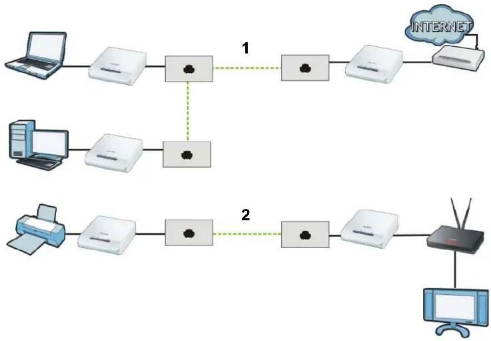
The figure below shows two powerline coaxial networks in a house. The first network (1) shows the home computer connected to a printer and access to the Internet. The second network (2) has no Internet access but with a media adapter such as the ZyXEL DMA-1100P you can use your TV to watch movies and play games which are stored on a computer.
Figure 41 Add New Coaxial Adapters to Make a Second Network
flowchart
graph LR
    A["Desktop"] --> B["Printer"]
    B --> C["Router"]
    C --> D["PC"]
    style A fill:#f9f,stroke:#333
    style B fill:#ccf,stroke:#333
    style C fill:#cfc,stroke:#333
    style D fill:#fcc,stroke:#333
1 Connect your new coaxial adapter and open the configuration utility as shown in Section 7.0.5 on page 65. The screen shown below appears.
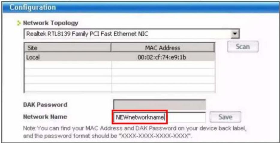
2 Type a Network Name that is different from the Network Name for your existing network. Make sure you use the same new Network Name for all new adapters you want to add to your new network.
Figure 42 Making a New Network with the New Adapter
3 After you have set up a new network, you are ready to connect each coaxial adapter on your new network to devices, for example, a computer or a games console.
7.0.6 Splitting a Network into Two Networks
This section shows you how to split your existing network into two networks. This is useful if you want to set up a second powerline coaxial network in your home, for example, in your study connecting a laptop and printer. See Figure 41 on page 65 for an example.
To set up your existing powerline coaxial network you had to set each coaxial adapter with the same network name. To move some of these adapters to a new network, you need to give them a new network name.
1 Connect a coaxial adapter to your computer and open the PLA-4xx Series Configuration Utility (see Section 7.0.3 on page 62).
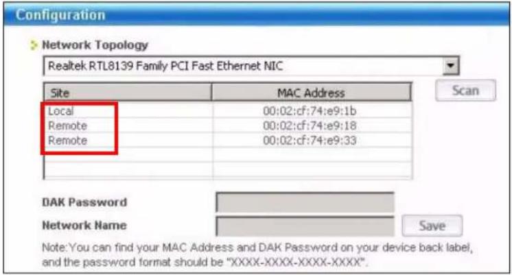
2 The utility should open to the configuration tab as shown below. A list of coaxial adapters on your network displays. These adapters all have the same network name as the adapter you are connected to. The adapter you are connected to will appear as Local in this table. All others are listed as Remote.
Figure 43 Local/Remote Adapters on a Powerline Coaxial Network
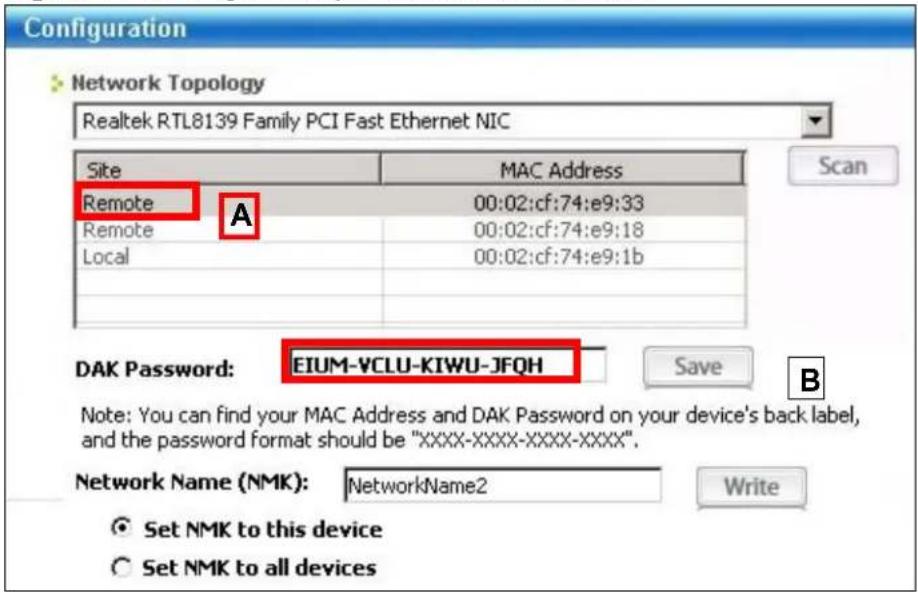
3 To set up a new powerline coaxial network, type the DAK Password and change the Network Name on all coaxial adapters you wish to add to your network.
- Look for the DAK Password on a label on your coaxial adapter. The DAK Password lets you access the adapter.
- Select the Remote adapter you want to add (A) and type the DAK Password in the DAK Password field (B).
- Then type the new network name in the Network Name field.
Figure 44 Adding an Adapter to Your New Network
4 Click Save.
- If you do not type the DAK password or type it incorrectly either of the following pop-ups appear. Click OK and type the DAK Password correctly in the DAK Password field.
Figure 45 Incorrect DAK or No DAK

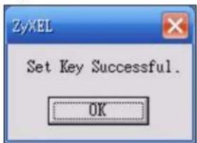
- If you have correctly entered the DAK Password, click OK on the pop-up.
Figure 46 Correct DAK
5 The settings for the adapter will now grey out and the adapter will disappear from the table after a few minutes.
Figure 47 An Adapter on Your New Network
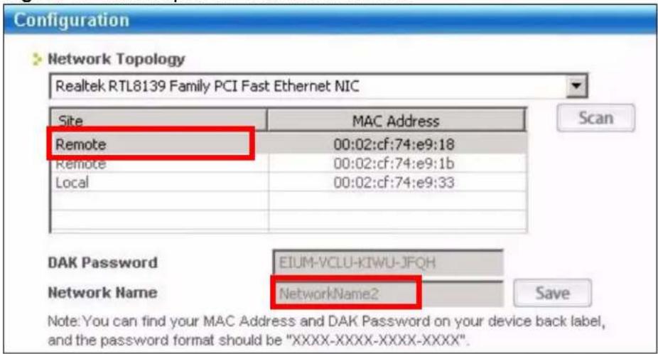
6 Go back to step 3 in this section to set the same, new Network Name for all remote adapters you want to add to your new network.
7 Check you have added the adapters correctly by changing the network name for the local adapter. All adapters with the new Network Name now appear in the list of adapters on your network. These adapters are now part of your new network.
Figure 48 Adapters on a New Powerline Coaxial Network
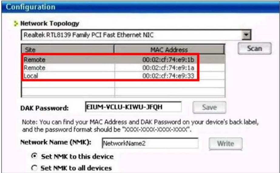
- If you want to access any of your new powerline coaxial networks using the PLA-4xx Series Configuration Utility, change the Network Name on your local adapter to the network name for the network you want to access. The adapters on that network will then display in the adapter table, allowing you to select and configure each one.
7.1 Troubleshooting
The HomePlug (LED (light) should light up on your adapter when it successfully connects to other adapters on your network. If it does not, try the following measures.
- Make sure the adapter is plugged in to a power socket and the power socket is turned on.
- Check you have entered the correct network name for your network.
- Check your coaxial adapter is connected to the same electrical circuit as other coaxial adapters on your network.
PLA Compatibility
8.1 Overview
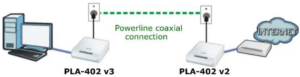
Your PLA-402 v3 can work with different PLA models that have a firmware version of at least 3.0.5. However, the PLA-402 v3 can only connect to another coaxial device (such as the PLA-402 v2) as shown in the following figure.
Figure 49 PLA Setup
flowchart
graph LR
    A["Computer"] --> B["PLA-402 v3"]
    B --> C["Powerline coaxial connection"]
    C --> D["PLA-402 v2"]
    D --> E["Internet"]
PLA-402 v3 can connect to PLA-402 v2 through the coaxial outlets.
8.2 Firmware and Utility Compatibility
The following table shows a quick summary of firmware and utility versions compatible with the different PLA models.
Table 13 Firmware and Utility Compatibility
| PLA MODEL | FIRMWARE V 3.0.5 | UTILITY V 3.0.5 | FIRMWARE V 3.3.4 | UTILITY V 3.3.4 |
| PLA v1 models | Compatible | Compatible | Compatible | |
| PLA v2 models | Compatible | Compatible | Compatible | |
| PLA v3 models | Incompatible | Compatible | Compatible |
For PLA v1 models (for example, PLA-400, PLA-401, PLA-470, PLA-491 and so on) upgrade the firmware version from 1.4.5 to 3.0.5. Refer to the PLA-4XX series User's Guide for instructions on how to do this.
For PLA v2 models (for example, PLA400 v2, PLA402 v2, PLA401 v2, PLA470 v2 and so on) make sure the firmware version is 3.0.5.
Note: The PLA v2 models can be upgraded to firmware version 3.3.4.
At the time of writing, PLA-402 v3 can only work with firmware version 3.3.4.
Use Configuration Utility version 3.3.4 to manage PLA v2 and PLA v1 models with firmware versions 3.0.5.
Note: You cannot downgrade the PLA-402 v3's firmware to a version earlier than 3.3.4.
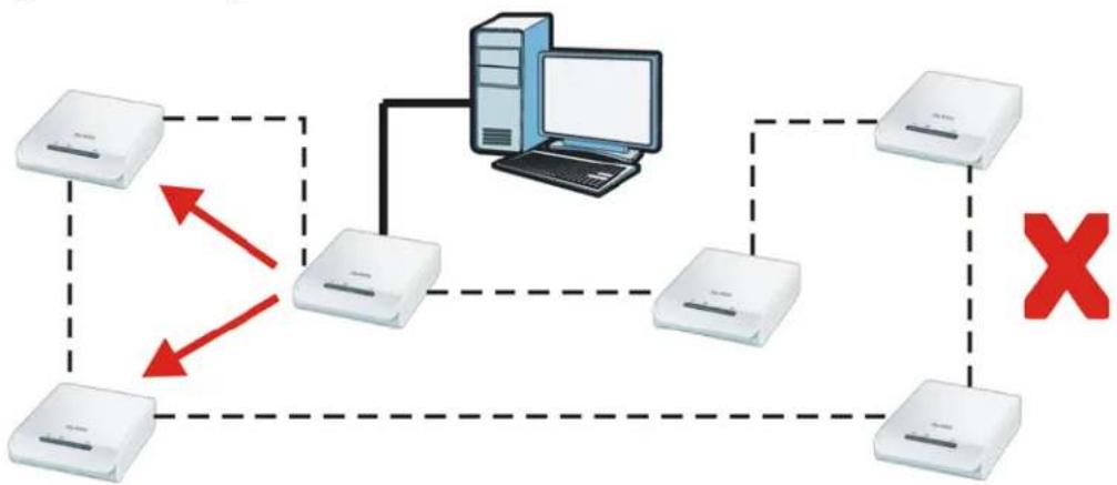
This diagram below shows a Powerline network where two PLAs have an earlier firmware that cannot be managed by the 3.3.4 Configuration Utility. You should upgrade the firmware of these PLAs.
Figure 50 Wrong Firmware in a Powerline Network
flowchart
graph TD
    A["Device 1"] -->|Red Arrow Down| B["Device 2"]
    B --> C["Device 3"]
    C --> D["Device 4"]
    D --> E["Device 5"]
    E --> F["Device 6"]
    F --> G["Device 7"]
    G --> H["Device 8"]
    H --> I["Device 9"]
    I --> J["Device 10"]
    J --> K["Device 11"]
    K --> L["Device 12"]
    L --> M["Device 13"]
    M --> N["Device 14"]
    N --> O["Device 15"]
    O --> P["Device 16"]
    P --> Q["Device 17"]
    Q --> R["Device 18"]
    R --> S["Device 19"]
    S --> T["Device 20"]
    T --> U["Device 21"]
    U --> V["Device 22"]
    V --> W["Device 23"]
    W --> X["Device 24"]
    X --> Y["Device 25"]
    Y --> Z["Device 26"]
    Z --> AA["Device 27"]
    AA --> AB["Device 28"]
    AB --> AC["Device 29"]
    AC --> AD["Device 30"]
    AD --> AE["Device 31"]
    AE --> AF["Device 32"]
    AF --> AG["Device 33"]
    AG --> AH["Device 34"]
    AH --> AI["Device 35"]
    AI --> AJ["Device 36"]
    AJ --> AK["Device 37"]
    AK --> AL["Device 38"]
    AL --> AM["Device 39"]
    AM --> AN["Device 40"]
    AN --> AO["Device 41"]
    AO --> AP["Device 42"]
    AP --> AQ["Device 43"]
    AQ --> AR["Device 44"]
    AR --> AS["Device 45"]
    AS --> AT["Device 46"]
    AT --> AU["Device 47"]
    AU --> AV["Device 48"]
    AV --> AW["Device 49"]
    AW --> AX["Device 50"]
The diagram below shows a Powerline network where each PLA has the correct firmware. Use Configuration Utility v 3.3.4 to manage the PLAs in this Powerline network.
Correct Powerline Network
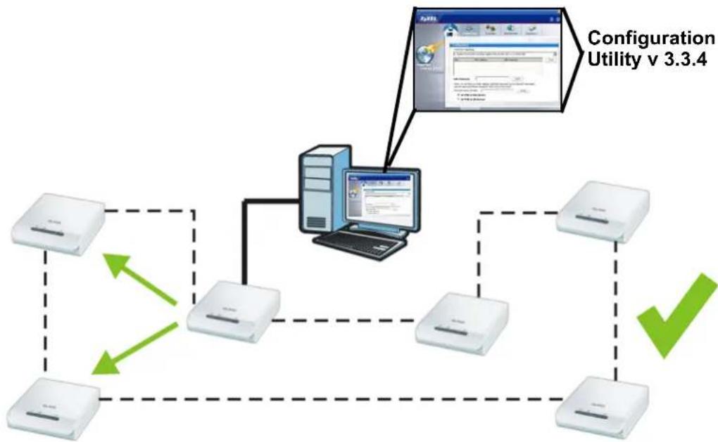
Appendices and Index
LEDs and Troubleshooting (77)
Product Specifications (85)
Legal Information (89)
Index (93)
LEDs and Troubleshooting
This chapter describes the behavior of the LEDs (lights) and offers some suggestions to solve problems you might encounter.
9.1 LEDs
The following sections describes the lights on the PLA-402 v3.
The following figure is the front panel of the PLA-402 v3. Use the lights to determine if the PLA-402 v3 is behaving normally or if there are some problems on your powerline coaxial network.
Figure 51 PLA-402 v3 Lights
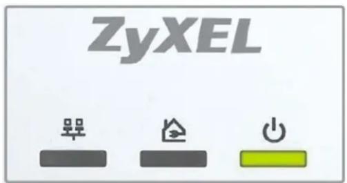
The following table describes the behavior of the lights on the PLA-402 v3.
Table 14 PLA-402 v3 Lights
| LIGHTS ICON COLOR | STATUS | DESCRIPTION | ||
| POWER Green On The PLA-402 v3 is on and receiving power. | ||||
9.2 Power and Light Problems
The PLA-402 v3 does not turn on. None of the lights turn on.
1 Make sure you are using the power cord included with the PLA-402 v3.
2 Make sure the power cord is connected to the PLA-402 v3 and plugged in to an appropriate power source. Make sure the power source is turned on.
3 Disconnect and re-connect the power cord to the PLA-402 v3.
4 Remove the coaxial adapter from the outlet. Then connect an electrical device that you know works into the same power outlet. This checks the status of the power outlet.
5 If the problem continues, contact the vendor.
The ETHERNET light does not turn on.
1 Check the hardware connections. See the Quick Start Guide.
2 Inspect your cables for damage. Contact the vendor to replace any damaged cables.
3 Check the Ethernet adapter on your computer and make sure it's enabled and working properly.
4 If the PLA-402 v3 is connected to an Ethernet switch or router, make sure the device is working correctly, and that the LAN network is working and configured correctly as well.
The HomePlug light does not turn on.
1 Check all PLA-402 v3s on your network have the latest firmware installed. PLA-402 v3s with the latest firmware cannot communicate with PLA-402 v3s using earlier versions of the firmware. Go to Section 5.4 on page 38 for instructions on installing the latest firmware.
2 Use the PLA-4xx Series Configuration Utility to detect all other HomePlug devices on your powerline coaxial network. Make sure that the network name (sometimes called the network password) is the same on all of your coaxial adapters. See Section 5.3 on page 37 for instructions on checking the network name.
3 Check the DAK password and MAC address for all coaxial adapters are typed correctly in the utility. See Section 5.3 on page 37 for instructions on checking the DAK and MAC address.
4 Make sure that all your coaxial adapters are HomePlug AV compliant. Check the package it came in or ask your vendor. This PLA-402 v3 can not detect earlier versions of HomePlug coaxial adapters such as HomePlug 1.0 or 1.0.1. (Although they can coexist on the same electrical wiring without interfering with each other.)
5 Make sure that the coaxial adapters on your network are all on the same electrical wiring. Connect another coaxial adapter into an outlet close to your PLA-402 v3's power outlet. They are probably now on the same electrical wiring. Check the HomePlug light. If it now lights up your coaxial adapter was probably previously on separate electrical wiring. Ask an electrician for more information on the electrical wiring in your building.
6 If your powerline coaxial network is using coaxial cable, check all coaxial adapters are on the same coaxial cable.
7 If your powerline coaxial network is using electrical wiring (not coaxial cable), check you do not have a power meter between coaxial adapters. Powerline signals cannot pass this.
The POWER and HomePlug light blink at the same time.
- You have pressed the SETUP button for more than three seconds. Try setting up a connection again, this time pressing the SETUP buttons on both devices for less than three seconds.
9.3 Configuration Utility Problems
The PLA-4xx Series Configuration Utility displays an error during installation.
- Make sure your computer is using Windows XP or Windows Vista (32-bit) operating system. At the time of writing, this is the only compatible operating system for the configuration utility.
The PLA-4xx Series Configuration Utility does not display all or any of my devices.
- Inspect the LEDs on your PLA-402 v3 and make sure that the ETHERNET and HomePlug LEDs are on or blinking. See Section 9.1 on page 77 for troubleshooting LED related problems.
- Check all ZyxEL HomePlug AV devices on your network have the latest firmware installed. The latest utility cannot communicate with PLA-402 v3s using earlier versions of the firmware. Go to Section 5.4 on page 38 for instructions on installing the latest firmware.
- Check you are using the latest version utility. Earlier version utilities cannot communicate with PLA-402 v3s using the latest firmware. If you do not have the latest utility, download it from the ZyXEL website.
- If the device is not a ZyXEL device, then the DAK and Network Name will be greyed out.
- If you are running another tool such as the Firmware Detection Tool or Firmware Upgrade Tool, the Utility will not detect your local device.
9.4 Powerline Coaxial Problems
The signal on my powerline coaxial network is weak.
1 Your coaxial adapters may be connected to electrical surge protectors. Connect them to standard power outlets.
2 Your coaxial adapters may be located close to large appliances such as refrigerators or air-conditioners that cause interference with the powerline signal. Move the adapters further away from such appliances to reduce interference.
3 Your coaxial adapters may be placed close to electrical devices such as electrical insect-killers which produce radio waves. These may interfere with the powerline signals. Move the adapters further away from such electrical devices.
4 Your wiring may be old and/or low quality or with a long wiring path.
9.5 SETUP Button Problems
This section applies only to PLA-402 v3s with the SETUP button.
The HomePlug light is already on, but I haven't pressed the SETUP button yet.
Your device has already connected to another coaxial device. Press the SETUP button for more than 10 seconds to release the connection.
The POWER light does not blink when I press the SETUP button.
- Check the device is on.
- Press the SETUP button again, making certain you have pressed the button for more than one second and less than three seconds.
- The POWER light on some coaxial devices do not blink as part of the SETUP process. Check your coaxial device is a PLA-402 v3.
- For PLA-402 v3, you cannot use the SETUP button when it is in Low Power mode. Connect the PLA-402 v3 to a computer/router then try again.
The POWER light blinks two times quickly then pauses, before repeating.
The SETUP process has failed. Press the SETUP button on both devices for more than 10 seconds, then try to reconnect.
The POWER lights on both devices blink when I press the SETUP buttons, but the HomePlug light does not turn on.
- Ensure you have pressed the SETUP button on both devices.
- Wait for about a minute while the devices set up a connection.
- If that does not work, try again with both devices connected to a power strip next to each other. If they now connect, then the devices were not on the same electrical circuit before.
The POWER lights on both devices blink, then many lights blink and the HomePlug light blinks red.
Do not worry, the connection process is proceeding normally.
The POWER lights on both devices finished blinking, but only one device's HomePlug light is on.
One device may have connected to a third coaxial device. To check device A is connected to device B and not another device, disconnect device B from its power source. Device A's HomePlug ( Light will turn off if the connection is with Device B. Press the SETUP button on both devices for more than 10 seconds, then try to reconnect, pressing the SETUP button for less than 3 seconds on both devices.
I pressed the SETUP button for more than 10 seconds, but the HomePlug light is still on.
The HomePlug light is on, indicating it is still connected to another coaxial device. Try again, pressing the SETUP button for more than 10 seconds.
Product Specifications
The following tables summarize the PLA-402 v3's hardware and firmware features.
Table 15 Hardware Specifications
| Dimensions (W x D x H) | 113 mm (L) x 105 (H) mm x 35 (W) mm |
| Weight 200g | |
| Power Input 100 - 240 | VAC, 50/60 Hz, 0.12 A |
| Ethernet Port Auto-negotiating: 10 Mbps or 100 Mbps in either half-duplex or full-duplex mode.Auto-crossover: Use either crossover or straight-through Ethernet cables. | |
| RESET Pressing this button in for less than 3 seconds resets the device to factory default settings. Network Name becomes HomePlugAV. | |
| SETUP Pressing this button in for less than 3 seconds begins the connection setup process.Pressing this button in for more than 10 seconds resets the network name to a random value. | |
| Operation Environment | Temperature: 0°C ~ 45° CHumidity: 10% ~ 90% Noncondensing |
| Storage Environment | Temperature: -20°C ~ 70° CHumidity: 10% ~ 95% Noncondensing |
| Cabling Type 1 x LAN UTP Category 5 or Better | |
| Network Interface 1 x | 10/100M Ethernet port with Auto MDI/MDIXIEEE 802.3 10 Base-T EthernetIEEE 802.3u 100 Base-T Fast EthernetIEEE 802.3x Flow ControlIEEE 802.1p Priority Tagging (VLAN TAG) |
| Coaxial Interface 75 ohmsF connector | |
Table 16 Firmware Specifications
| FEATURE DESCRIPTION | |
| Powerline Functionality The HomePlug AV standard specifies how network devices communicate using standard electrical wiring. It is compliant with IEEE 802.3, 802.3u 10/100 Ethernet standards. It supports a data transfer rate of up to 200Mbps. Data is encrypted using 128-bit AES (Advanced Encryption Standard). HomePlug AV compatible devices co-exist with HomePlug 1.0 devices but do not detect each other. The range of a HomePlug AV network is 300 meters/984 feet in optimal conditions. HomePlug AV is compatible with all OSs. The maximum number of devices connected (bridged) to single coaxial adapter is 64. The maximum number of coaxial devices on a single network is 64. The maximum number of powerline coaxial networks on a single electrical circuit is 4. HomePlug AV devices using version 3.3.4 firmware cannot communicate with earlier version firmware. It supports up to 4-level type QoS and up to 8-level VLAN priority fields. | |
| Encryption 128-bit AES Encryption | |
| Frequency Band 2 MHz ~ | 30 MHz Filter for CATV: PSD under -100 dBm/Hz |
| Certifications CE, RoHS | |
| Device Management Use the PLA-4xx Series Configuration Utility version 3.3.4(AG) to easily configure the PLA-402 v3. Note: The PLA-4xx Series Configuration Utility version 3.3.4(AG) is only compatible with PLA-402 v3s with the latest firmware installed. | |
| Network Name Change the powerline coaxial network name to only allow the coaxial adapters you specify to join your network. | |
Table 16 Firmware Specifications
| FEATURE DESCRIPTION | |
| Firmware Upgrade Download new firmware (when available) from the ZyXEL website and use the configuration utility to install it.Note: You do not need the configuration utility to install the latest firmware. Follow the instructions in Section 5.4 on page 38 for installing the latest firmware.Note: Only install firmware for your specific model! | |
| Low Power mode The coaxial adapter goes into Low Power mode when no Ethernet connection is detected. | |
Table 17 Performance
| FEATURE DESCRIPTION | |
| Throughput over PHYSical Transport Medium (PHY) | Supports up to 200 Mbps in half duplex mode |
| Throughput over UDP Supports up to | 150 Mbps over in-house power/coaxial lines (LAN port limits to 100 Mbps) |
| Number of devices in one powerline coaxial network | Supports up to 64 devices in 4 network groups |
| Package Throughput with Package Size: 64 Bytes | 25 Mbps (without package loss)Distance: 100mCoaxial cable: 5C-2V |
| Package Throughput with Package Size: 1518 Bytes | 75 Mbps (without package loss)Distance: 100mCoaxial cable: 5C-2V |
The following list, which is not exhaustive, illustrates the standards supported in the PLA-402 v3.
Table 18 Standards Supported
| STANDARD DESCRIPTION | |
| HomePlug AV Designed | for transmitting audio/video on a home powerline coaxial network. |
| RFC 868 Time Protocol. | |
| RFC 1112 IGMP v1 | |
| RFC 1157 SNMPv1: Simple Network Management Protocol version 1 | |
| RFC 1901 SNMP v2c Simple Network Management Protocol version 2c | |
| RFC 2236 Internet Group Management Protocol, Version 2. | |
Cable Pin Assignments
RJ-45 Connector Pin Assignments
Figure 52 RJ-45 Connector Pins
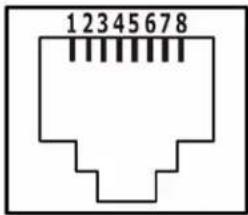
Table 19 RJ-45 Connector Pin Assignments
| PIN NO RJ-45 SIGNAL ASSIGNMENT | ||||
| 1 | R | x | D | + |
| 2 | R | x | D | - |
| 3 | T | x | D | + |
| 4 Not connected | ||||
| 5 Not connected | ||||
| 6 | T | x | D | - |
| 7 Not connected | ||||
| 8 Not connected | ||||
Legal Information
Copyright
Copyright © 2009 by ZyXEL Communications Corporation.
The contents of this publication may not be reproduced in any part or as a whole, transcribed, stored in a retrieval system, translated into any language, or transmitted in any form or by any means, electronic, mechanical, magnetic, optical, chemical, photocopying, manual, or otherwise, without the prior written permission of ZyXEL Communications Corporation.
Published by ZyXEL Communications Corporation. All rights reserved.
Disclaimers
ZyXEL does not assume any liability arising out of the application or use of any products, or software described herein. Neither does it convey any license under its patent rights nor the patent rights of others. ZyXEL further reserves the right to make changes in any products described herein without notice. This publication is subject to change without notice.
Your use of the PLA-402 v3 is subject to the terms and conditions of any related service providers.
Do not use the PLA-402 v3 for illegal purposes. Illegal downloading or sharing of files can result in severe civil and criminal penalties. You are subject to the restrictions of copyright laws and any other applicable laws, and will bear the consequences of any infringements thereof. ZyXEL bears NO responsibility or liability for your use of the download service feature.
Make sure all data and programs on the PLA-402 v3 are also stored elsewhere. ZyXEL is not responsible for any loss of or damage to any data, programs, or storage media resulting from the use, misuse, or disuse of this or any other ZyXEL product.
Trademarks
ZyNOS (ZyXEL Network Operating System) is a registered trademark of ZyXEL Communications, Inc. Other trademarks mentioned in this publication are used for identification purposes only and may be properties of their respective owners.
Certifications
Federal Communications Commission (FCC) Interference Statement
The device complies with Part 15 of FCC rules. Operation is subject to the following two conditions:
- This device may not cause harmful interference.
- This device must accept any interference received, including interference that may cause undesired operations.
This device has been tested and found to comply with the limits for a Class B digital device pursuant to Part 15 of the FCC Rules. These limits are designed to provide reasonable protection against harmful interference in a residential installation. This device generates, uses, and can radiate radio frequency energy, and if not installed and used in accordance with the instructions, may cause harmful interference to radio communications. However, there is no guarantee that interference will not occur in a particular installation.
Notices
Changes or modifications not expressly approved by the party responsible for compliance could void the user's authority to operate the equipment.
This Class B digital apparatus complies with Canadian ICES-003.
Viewing Certifications
1 Go to http://www.zyxel.com.
2 Select your product on the ZyXEL home page to go to that product's page.
3 Select the certification you wish to view from this page.
ZyXEL Limited Warranty
ZyXEL warrants to the original end user (purchaser) that this product is free from any defects in materials or workmanship for a period of up to two years from the date of purchase. During the warranty period, and upon proof of purchase, should the product have indications of failure due to faulty workmanship and/or materials, ZyXEL will, at its discretion, repair or replace the defective products or components without charge for either parts or labor, and to whatever extent it shall deem necessary to restore the product or components to proper operating condition. Any replacement will consist of a new or re-manufactured functionally equivalent product of equal or higher value, and will be solely at the discretion of ZyXEL. This warranty shall not apply if the product has been modified, misused, tampered with, damaged by an act of God, or subjected to abnormal working conditions.
Note
Repair or replacement, as provided under this warranty, is the exclusive remedy of the purchaser. This warranty is in lieu of all other warranties, express or implied, including any implied warranty of merchantability or fitness for a particular use or purpose. ZyXEL shall in no event be held liable for indirect or consequential damages of any kind to the purchaser.
To obtain the services of this warranty, contact your vendor. You may also refer to the warranty policy for the region in which you bought the device at http://www.zyxel.com/web/support_warranty_info.php.
Registration
Register your product online to receive e-mail notices of firmware upgrades and information at www.zyxel.com.
Index
Symbols
.NET Framework 21
A
about screen 44
Advanced Encryption Standard, see AES 15
AES 18, 35
AES (Advanced Encryption Standard) 15
applications 15
E
electrical and cable wiring 35
electrical circuit boundaries 35
encryption 15, 35, 86
ETHN LED 77
F
firmware 38
frequency band 86
C
cabling type 85
CE 86
certifications 86, 90
notices 90
viewing 90
Coaxial Interface 85
configuration screen 37
connections overview 16
copyright 89
H
HomePlug AV standard 15
humidity, operation and storage 85
|
installation
overview 21
procedure 21
requirements 21
InstallShield wizard 23
introduction 15
D
DAK 35, 37
DAK (Data Access Password) 18
Data Access Password, see DAK 18
dimensions 85
disclaimer 89
L
LED 77
ETHN 77
LINK 77
PWR 77
LINK LED 77
local vs. remote adapter 37
M
MAC address 37
management
multiple networks 19
overview 35
managing the device
using the web configurator. See web configurator.
multiple networks 19
N
network example 35
network information 40
network ports 85
P
Parameter Information Block, see PIB 38
passwords 35, 37, 38
types of 18
PIB (Parameter Information Block) 38
plug-and-play 35
power specification 85
priority settings 41
application type 42, 50
priority levels 44
private network 18
problems and solutions 77
product registration 91
PWR LED 77
R
receive rate 40
registration
product 91
related documentation 3
s
safety warnings 8
security 17, 19, 35
passwords 18
starting the utility 36, 48
syntax conventions 6
T
temperature, operation and storage 85
trademarks 90
transfer rates 15
transmit rate 40
troubleshooting 77
U
utility
launching 36, 48
W
warranty 90
note 91
web configurator 17
- User's Guide
- About This User's Guide
- Intended Audience
- Tips for Reading User's Guides On-Screen
- Related Documentation
- Documentation Feedback
- Need More Help?
- Customer Support
- Document Conventions
- Warnings and Notes
- Warnings tell you about things that could harm you or your device.
- Syntax Conventions
- Icons Used in Figures
- Safety Warnings
- Table of Contents
- Chapter 5
- The Configuration Utility 35
- Chapter 6
- The OS X Configuration Utility 47
- Chapter 7
- Powerline Coaxial Network Setup Tutorial....61
- Chapter 8
- PLA Compatibility 71
- Part III: Appendices and Index.... 75
- Chapter 9
- LEDs and Troubleshooting....77
- Chapter 10
- Product Specifications....85
- Appendix A Legal Information 89
- Index....93
- PART I
- Introduction
- Introducing the PLA-402 v3
- Overview
- Expand Your Network with the PLA-402 v3
- Ways to Manage the PLA-402 v3
- Security
- Passwords
- Setting Up Security
- Multiple Networks
- Installing the Utility
- Overview
- Installing the Utility
- Low Power Mode
- PART II
- Managing the PLA-402 v3
- Firmware Tool
- Overview
- Firmware Upgrade Tool
- The SETUP Button
- SETUP Button Overview
- Set Up a HomePlug AV Network with SETUP
- Setting Up Multiple Networks
- SETUP Button Behavior
- The Configuration Utility
- Overview
- Powerline Network Security
- Device Access Key (DAK)
- Starting the Configuration Utility
- Configuration Screen
- Firmware Screen
- Network Info Screen
- Advanced Screen
- About Screen
- The OS X Configuration Utility
- Overview
- System Requirements
- Start the Configuration Utility
- Add a Device
- Change Network Name
- Change Nickname
- QoS Settings
- Set HomePlug Light Color
- Link Information
- Download Firmware
- Firmware Detection Tool
- Firmware Upgrade Tool
- Notes on Upgrading Firmware
- Procedure to Upgrade Firmware
- Powerline Coaxial Network Setup Tutorial
- Overview
- Important Terms
- Accessing Your Coaxial Adapter
- Adding a Coaxial Adapter
- Setting Up a New Network with a New Adapter
- Splitting a Network into Two Networks
- Troubleshooting
- PLA Compatibility
- Overview
- Firmware and Utility Compatibility
- Appendices and Index
- LEDs and Troubleshooting
- LEDs
- Power and Light Problems
- The PLA-402 v3 does not turn on. None of the lights turn on.
- The ETHERNET light does not turn on.
- The HomePlug light does not turn on.
- The POWER and HomePlug light blink at the same time.
- Configuration Utility Problems
- Powerline Coaxial Problems
- SETUP Button Problems
- Product Specifications
- Cable Pin Assignments
- RJ-45 Connector Pin Assignments
- Legal Information
- Copyright
- Disclaimers
- Trademarks
- Certifications
- Federal Communications Commission (FCC) Interference Statement
- Notices
- Viewing Certifications
- ZyXEL Limited Warranty
- Note
- Registration
- Index
- Symbols
- A
- E
- F
- C
- H
- |
- D
- L
- M
- N
- P
- R
- s
- T
- U
- W
Brand : ZYXEL
Model : PLA-402 v3
Category : Carte réseau/Adaptateur