
7055 062 - Cooker Foster - Free user manual and instructions
Find the device manual for free 7055 062 Foster in PDF.


| Product Type | Gas hob (cooker) |
| Brand | Foster |
| Model | 7055 062 |
| Dimensions (W x D) | 840 x 480 mm |
| Cutout Dimensions (W x D) | 840 x 480 mm |
| Number of Burners | 4 |
| Burner Types | Auxiliary, Semi-quick, Quick, Triple Crown |
| Gas Types | Methane G20 (20 mbar), LPG G30/G31 (28-30/37 mbar) |
| Power Ratings (Methane) | Aux: 1.00 kW, Semi-quick: 1.75 kW, Quick: 2.70 kW, Triple Crown: 3.50 kW |
| Power Ratings (LPG) | Aux: 1.00 kW, Semi-quick: 1.75 kW, Quick: 2.70 kW, Triple Crown: 3.50 kW |
| Electrical Supply | 230 V ~ 50 Hz, 0.75 mm² cable |
| Ignition | Electric spark (push-turn knob) |
| Safety Device | Flame failure thermocouple on each burner |
| Material | Stainless steel top, cast iron grates |
| Cleaning | Removable burner caps and crowns, hand wash with non-abrasive detergent |
| Weight (approx.) | 10 kg |
| Installation Type | Built-in (flush or traditional) |
| Certifications | CE, WEEE |
| Warranty | As per local regulations |
Frequently Asked Questions - 7055 062 Foster
User questions about 7055 062 Foster
0 question about this device. Answer the ones you know or ask your own.
Ask a new question about this device
Download the instructions for your Cooker in PDF format for free! Find your manual 7055 062 - Foster and take your electronic device back in hand. On this page are published all the documents necessary for the use of your device. 7055 062 by Foster.
USER MANUAL 7055 062 Foster
via M.S. Ottone, 18/20
42041 Brescello (RE) - Italy
We thank you for having chosen a Foster cooker hob.
Your preference is our pride and satisfaction.
In this document are the recommendations and instructions that will enable you to make the best use of the purchased cooker hob and guarantee its best preservation in time. We ask that you take a few minutes to protect the efficiency of the product and for your satisfaction.
With kind regards
Foster spa
Table of Contents

GENERAL WARNINGS
General recommendation to be consulted before installation and use of the purchased cooker hob.
- Usage warnings ...... 21
- Safety warnings.... 22
- Warnings for disposal....22
- Know your appliance....23

INSTALLER INSTRUCTIONS
They are intended for the qualified technician that will complete appliance installation, commissioning and initial testing.
- First installation....24
- Positioning in the work top 24
- Fastening the cooker hob to the cabinet....26
- Connecting the cooker hob to the gas network.... 29
- Room ventilation....30
- Discharging combustion products (exhaust) 31
- Adapting to different types of gasses.... 31
- Adjustment of the minimum....33
- Electrical connection of the cooker hob.... 33

USER INSTRUCTIONS
The indicate usage recommendations, a description of controls and the correct cleaning and maintenance operations for the appliance.
- Cooker hob use....34
- Cleaning and maintenance....37
Gas cooker hobs summary....182
1. Usage warnings

This manual is and integral part of this appliance. It is necessary to keep it undamaged and on hand for the entire life cycle of the hob. We recommend carefully reading this document and all instructions contained within before using the appliance.
Installation must be completed by qualified personnel according to current standards. This appliance is intended for domestic type use, and is conform with CE Directives currently in force.

The appliance has been manufactured to carry out the following function: COOKING AND HEATING FOOD, ANY OTHER USE MUST BE CONSIDERED IMPROPER.
The manufacturer declines any responsibility for uses that are different from those indicated.
- Never use this appliance for heating environments.
- Do not leave packaging material waste unguarded in the household environment.
- Separate the various packaging waste materials and deliver them to the closest selective waste collection centres.

This appliance has a mark pursuant to European Directive 2002/96/EC with regard to waste, electric and electronic appliances (waste electrical and electronic equipment - WEEE). This Directive defines the Standards for the collection and recycling of dismissed appliances valid throughout the territory of the European Union.

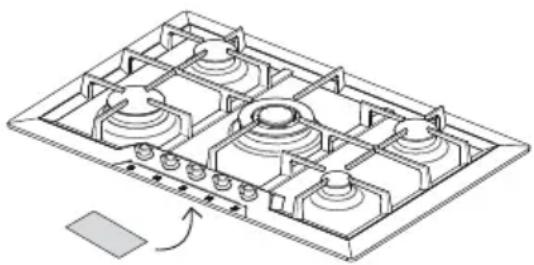
The identification plate, with technical data, serial number and marking, is positioned in view under the housing [Fig. 1].
THE PLATE MUST NEVER BE RE-MOVED.
natural_image
Isometric technical diagram of a multi-chamber electrical enclosure with no visible text or symbolsFig. 1: position of the identification plate
2. Safety warnings

In your interest and for your safety, by law it has been established that installation and service for all electric or gas appliances must be carried out by qualified personnel, according to current regulations and the requirements of local companies supplying gas and electric power.
• Gas or electric appliances must always be disengaged by competent persons.
- The plug to be connected to the power supply cable and the related socket must be of the same kind and conform to regulations in force.
- The socket must be accessible once the appliance is installed.
- Never detach the plug by pulling on the cord.
- It is mandatory to have an earth connection as per modes foreseen in the electrical system safety standards.
- Do not block the openings and ventilation and heat dispersion slots.

Immediately after installation complete a short test on the appliance following the instructions contained in subsequent pages in this manual. If it does not operate correctly, disconnect the appliance from the power mains and contact the closest technical assistance centre: NEVER ATTEMPT TO REPAIR THE APPLIANCE.
During use the appliance becomes very hot. The use of proper thermal gloves is recommended for any type of operation. This appliance is not intended to be used by persons (including children) with reduced physical, sensory or mental capabilities, or lacking experience and knowledge, unless supervised or instructed concerning the use of the appliance by a person responsible for their safety. CHILDREN MUST BE SUPERVISED TO MAKE SURE THEY DO NOT PLAY WITH THE APPLIANCE.

The manufacturer declines any liability for damages to persons or property, caused by the non observance of the following regulations or resulting from tampering with even a single part of the appliance and using non original spare parts.
3. Warnings for disposal
OUR CARE FOR THE ENVIRONMENT
Our products are packaged using non polluting materials, that are therefore compatible with the environment and recyclable. We request your cooperation in making sure that packaging materials are
disposed of correctly. Contact your reseller or competent organizations in your area for information about waste collection centres, recycling and disposal.

DO NOT ABBANDON THE PACKAGING MATERIAL OR PARTS OF IT. THEY MAY CREATE A SUFFOCATION DANGER FOR CHILDREN, ESPECIALLY PLASTIC BAGS.
Even your old appliance must be disposed of properly, this will contribute to avoiding negative environmental and health consequences, that would occur as a result of improper disposal.

IMPORTANT: this appliance cannot be treated as household waste. Deliver the old appliance to the local company that is authorised to collect appliances that are no longer in use. A proper disposal makes an intelligent recovery of precious materials. It is also necessary to cut the cable connecting to the power mains and remove it along with the plug.
4. Know your appliance
All drawings relating to the Foster cooker hobs manufactured today, are at the end of this manual, Gas cooker hobs summary [Page 182].
We ask that you recognise the drawing of the cooker hob you have purchased to familiarise with the main technical-functional features.
For research practicality the cooker hobs are distinguished in two macro-families:
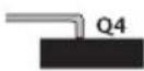
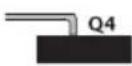
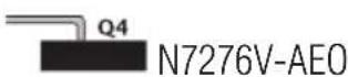
- Traditional built-in cooker hobs: "8 mm edge", "Q4 edge" and "semi-flush edge";
- Flush built-in cooker hobs: "flush-mount" edge.
Regardless of the type of edge, the first group has a simple traditional built-in hole. The cooker hobs with "flush-mount" edge have a more detailed drawing to enable realisation of the "made to measure" hole, or having a step necessary to house the edge of the cooker hub so it is "flush" with the worktop.
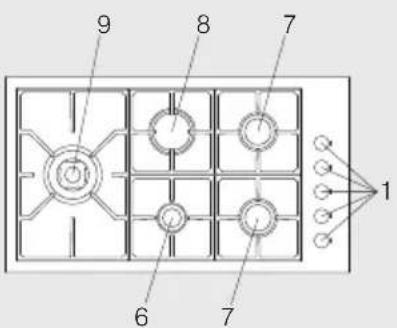
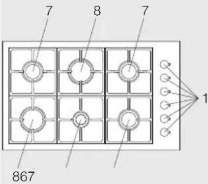
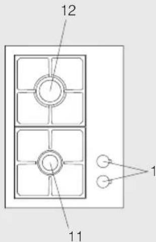
Numbers in correspondence with the burners are present in all drawings. Such numbers identify the type of burner. To know the powers of the burners of the gas cooker hub you purchased, refer to reading the powers table depending on the type of gas used [Page 182].
5. First installation

Do not leave packaging material waste unguarded in the household environment. Separate the various packaging waste materials and deliver them to the closest selective waste collection centres.
In order to remove all manufacturing residues, we recommend cleaning the appliance.
For further information on cleaning see Chapter 15 [Page 37].
6. Positioning in the work top

The following interventions require masonry and/or carpentry work and must therefore be completed by a competent technician. Installation can be completed on different materials, such as masonry, metal, solid wood and plastic laminated wood, as long as it is heat resistant (T 100°C).
6.1 Installation on the support structure (worktop) of a traditional built-in cooker hob (8 mm edge, Q4 edge, semi-flush edge)

Cut an opening on the top surface of the cabinet with the dimensions and position indicated here below and represented in the drawing [Fig. 2].
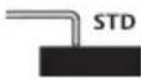
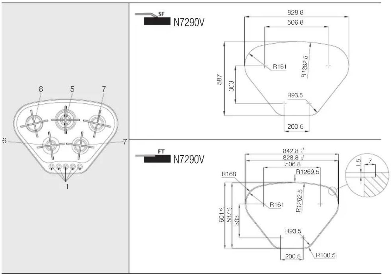
The dimensions of the built-in hole are shown in the Gas cooker hobs summary - models with traditional built-in [Page 182], in correspondence of the drawing of the purchased cooker hob.

natural_image
Technical line drawing of a mechanical component with labeled dimensions A and B (no text or symbols beyond labels)Fig. 2: cutting the hole for the built-in

- The distance of the cooker hob from the back edge must be at least 50 mm;
- The distance of the cooker hob from the walls that exceed worktop height must be at least 100 mm;
- Should a hood be installed above the hob, see the hood assembly instructions which provide the correct distance to be respected.
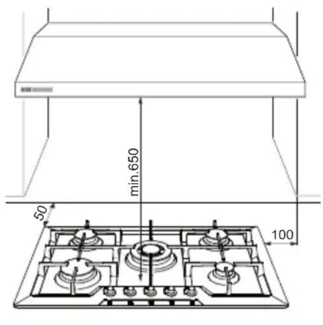
Fig. 3: cooker hob distances

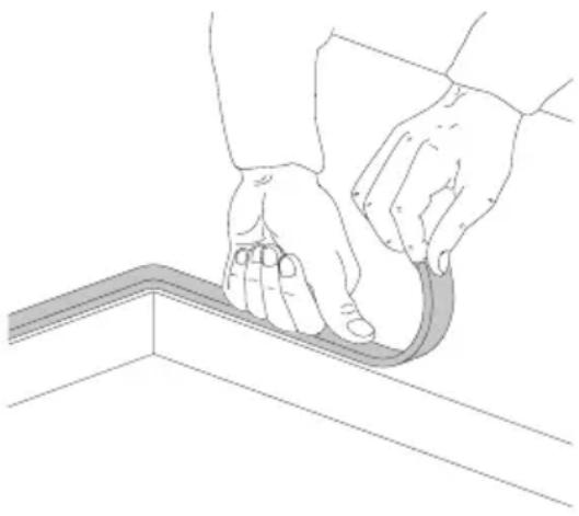
- Carefully position the supplied insulating gasket along the external perimeter of the hole created on the worktop, trying to make it adhere along the entire surface by slightly pressing it by hand [Fig. 4].
- Once these operations have been completed, use the supplied brackets to fasten the hob to the structure. Refer to the "Fastening the cooker hob to the cabinet" paragraph [Page 26].
natural_image
Line drawing of two hands performing a massage on a wall corner (no text or symbols)Fig. 4: positioning the insulating gasket
6.2 Installation on the support structure (worktop) of a flush built-in cooker hob (flush-mount edge)

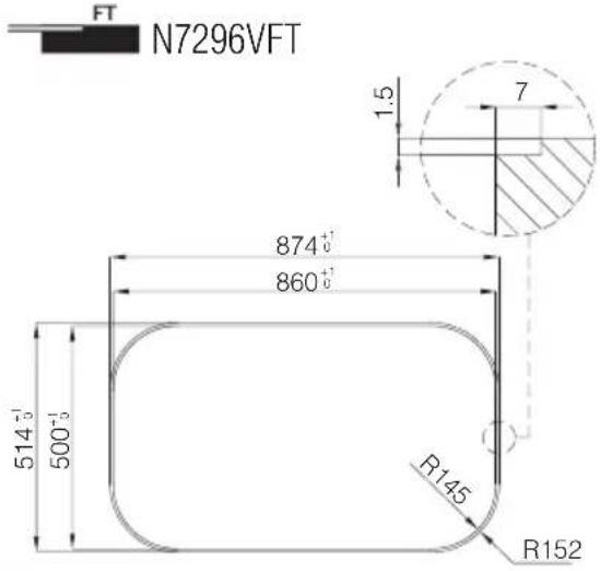
This type of appliance requires milling on the 1.5 mm deep worktop, which measurements are indicated in the top drawing, identifiable in the section Gas cooker hobs summary - models with "flush" built-in [Page 182]. The step is necessary to house the cooker hub edge so that it is "flush" with the worktop.

• Accurately clean milling.
- Before positioning the top, lay the sealer gasket provided on the entire milling surface [Fig. 5].
- Once these operations have been completed, use the supplied brackets to fasten the hob to the structure. Refer to the “Fastening the cooker hob to the cabinet” paragraph [Page 26].

natural_image
Line drawing of hands performing a gentle massage on a curved surface (no text or symbols)Fig. 5: positioning the insulating gasket

A constant light of at least 0.5 mm is envisioned between the external dimensions of the stainless steel platform and the internal dimensions of the lowering that must be respected during assembly. The temperatures that develop during use of the cooker hub induce a slight elongation on the stainless steel platform, therefore, the envisioned light enables avoiding any interferences. With regard to the kitchen worktop, the temperatures induced by the cooker hub - whether in the section and on the contact top - are very contained. We recommend assembling the cooker hubs with flush-mount edge on water-repellent materials.
7. Fastening the cooker hob to the cabinet

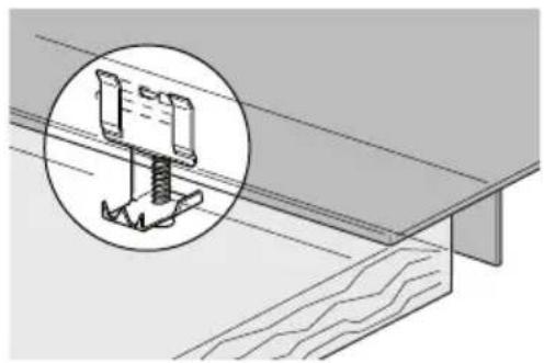
Fasten the supplied hooks to the brackets under the appliance, as shown here below. The supplied hooks make it possible to fasten to a top whose thickness is between 30 and 40 mm.

IMPORTANT:
- For fastening this product to the support structure, the use of mechanical or electric screwdrivers is not recommended and only moderate pressure must be exerted by hands to the clamping parts.
- The surface under the appliance must be at least 5 mm from the bottom of it and must have an opening for passing gas and electric conduit that is at least 50x50 mm.
- If this product is installed above an oven, it must be equipped with a cooling fan.
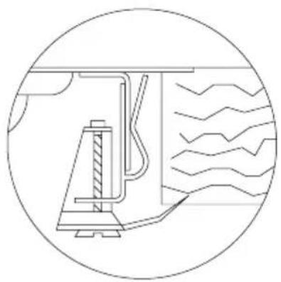
7.1 Fixed hooks
They make it possible to fasten the cooker hob using fixing frames pre-set along specific points.

Standard edge (8 mm)

natural_image
Technical illustration of a mechanical component with a magnified inset showing a spring mechanism (no text or symbols)

natural_image
Simple line drawing of a mechanical device inside a circle, showing internal components and wave patterns (no text or symbols)Q4 edge (4 mm)

natural_image
Technical illustration of a structural connection detail showing a magnified inset of a mechanical component (no text or symbols present)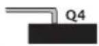

natural_image
Simple line drawing of a mechanical device inside a circle, showing internal components and wave patterns (no text or symbols)Semi-flush edge (3 mm)

natural_image
Technical illustration of a structural bracket with an inset showing a mechanical clamp assembly (no text or symbols present)

natural_image
Technical line drawing of a mechanical assembly inside a circular frame (no text or symbols)Flush-mount edge
natural_image
Technical diagram showing a structural assembly with an inset magnified view of a bracket detail (no text or symbols present)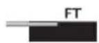
natural_image
Technical line drawing of a mechanical device inside a circular frame, showing internal components and motion lines (no text or symbols)
Set hook B in frame A welded to the hob, making sure that it is blocked in the specific holes based on top thickness (for a 30 mm thick top, lock the hook in the the highest hole in the frame; for a 40 mm thick top, block the hook in the lowest hole of the frame).
Rotate tongue CA until it is positioned above the top, then tighten screw D.

7.2 Sliding hooks
Make it possible to fasten the cooker hob without pre-set fastening points.

Standard edge (8 mm)

natural_image
Technical illustration of a wooden beam joint with a magnified inset showing the detail (no text or symbols)

Flush-mount edge - Q4 (only for S4000 series)
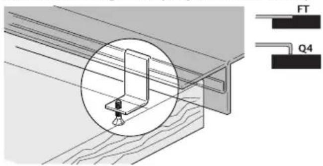

Insert hook B in the sliding guide CA. Manually lock the hook using screw A.
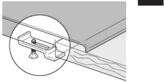
7.3 Fixed brackets
Make it possible to fasten the cooker hob in pre-set fastening points.

Standard edge (8 mm)
natural_image
Technical diagram showing a mechanical component inserted into a structural beam, with an inset close-up highlighting the detail (no text or symbols present)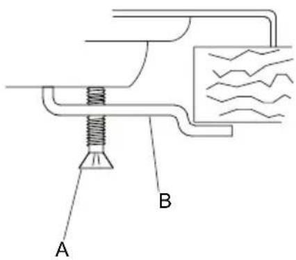
Introduce the bracket B in appropriate top seat.
Manually lock the bracket using screw A.
8. Connecting the cooker hob to the gas network

It is necessary for the gas supply system to conform to local regulations in force.
It is necessary to verify that local distribution conditions (gas nature and pressure) and the appliance adjustment status are compatible.
IMPORTANT: If the appliance is installed above an oven, it is necessary to avoid passing the gas tube behind the oven in order to avoid overheating.

The connection to the gas supply network can be completed using rigid copper piping or with a continuous flexible steel pipe on the wall, according to established regulations that are parts of the regulations in force [Fig. 6]. In any case every pipe connected to the gas supply network must be equipped with a safety interception valve.

Fig. 6: connection to the gas supply network

IMPORTANT: Always place the gasket between the hob fitting and the connection pipe.

- If using a stainless steel flexible pipe, it must be installed so that it does not come in contact with any part of the cabinet, but passes through an unoccupied area where its entire length can be inspected. Maximum extension of the flexible pipe must be less than 2 metres.
- The gas fitting is the type with a 1/2" gas ISO R7 tapered thread.

After connecting the appliance to the gas supply network always verify fittings seal using a soapy solution. VERIFYING THE SEAL USING NAKED FLAMES IS ABSOLUTELY PROHIBITED.

The cooker hob is tested for methane gas G20 (2H) at a pressure of 20 mbar. For supplying with other types of gas, see the Adapting to the different types of gas table [Page 31]
8.1 Connection to liquid gas

Use a pressure regulator and realise connection on cylinder in compliance with the prescriptions established by the current Standards.
Ensure the supply pressure respects the values indicated in the table Adapting to different types of gasses [Page 31]. In this case also, connection must be carried out with copper rigid pipe or with stainless steel flexible pipe with continuous wall.
9. Room ventilation

IMPORTANT: The appliance can only be installed in rooms that are permanently ventilated, as required by standards in force.
10. Discharging combustion products (exhaust)

Discharge of combustion products must be ensured through hoods connected to an efficient natural draught flue, or through a forced exhaust.
An efficient exhaust system requires an accurate design by a specialist that is approved for this work, following positions and distances contained in regulations.

IMPORTANT: At the end of the intervention the installer must issue a conformity certificate.
11. Adapting to different types of gasses
| Gas type | Burner | Nominal power (KW) | Rated consumption (g/h) | Injector (ø mm) | Min. nominal power (KW) | ||
| Series | No. Ref. | ||||||
| LPG GAS G30/G31 28-30/37 mbar | II | 2 Auxiliary 1,00 73 | 0,50 0,52 | ||||
| 3 Semi-quick 1,75 | 127 0,65 0,52 | ||||||
| 4 Quick 2,70 196 0 | 80 0,90 | ||||||
| 5 | Triple crown | 3,50 25 | 4 0,95 1,80 | ||||
| 10 | Dual | 4,50 | 328 | i 0.46 / and 0.66 | i 0.46 / and 0.66 | ||
| III | 6 Auxiliary 1,10 80 | 0,52 0,52 | |||||
| 7 Semi-quick 1,75 | 127 0,65 0,52 | ||||||
| 8 Quick 3,00 218 0 | 85 0,90 | ||||||
| 9 | Triple crown | 3,80 27 | 6 0,98 1,80 | ||||
| AE | 11 | Auxiliary 1,00 | 0 73 0,50 0,52 | ||||
| 12 | Semi-quick 1 | 75 127 0,65 0,52 | |||||
| 13 | Quick 3,00 | 218 0,85 0,90 | |||||
| 14 | Dual gear | 5,00 | 364 | i 0.46 / and 0.95 | i 0.30 / and 1.40 | ||
| METHANE GAS G20 20 mbar | II | 2 Auxiliary 1,00 95 | 0,72 0,52 | ||||
| 3 Semi-quick 1,75 | 167 0,97 0,52 | ||||||
| 4 Quick 2,70 257 1 | 08 0,90 | ||||||
| 5 Triple crown 3,50 | 333 1,35 1,80 | ||||||
| 10 | Dual | 4,50 | 429 | i 0.72 / and 1.02 | i 0.46 / and 0.66 | ||
| III | 6 Auxiliary 1,10 105 | 0,73 0,52 | |||||
| 7 Semi-quick 1,75 | 167 0,98 0,52 | ||||||
| 8 Quick 3,00 285 1 | 26 0,90 | ||||||
| 9 Triple crown 3,80 | 362 1,35 1,80 | ||||||
| AE | 11 Auxiliary 1,00 | 95 0,72 0,52 | |||||
| 12 | Semi-quick 1,75 167 0,97 0,52 | ||||||
| 13 | Quick 3,00 285 1,32 0,90 | ||||||
| 14 | Dual gear | 5,00 | 476 | i 0.75 / and 1.58 | i 0.30 / and 1.40 | ||

The appliance is tested for methane gas G20 (2H) at a pressure of 20 mbar. When using with other types of gas it is necessary to replace the burner nozzles, and adjust the minimum flame on the gas taps. For nozzle replacement, proceed as described in the following paragraphs.
11.1 Cooker hob nozzle replacement

IMPORTANT: Before completing the following operations, always make sure that the appliance is disconnected from the power mains.

- Remove the grids, remove all flame spreading caps and crowns.
- Using a 7 mm tube spanner, unscrew the burner nozzles [Fig.7].
- Proceed with burner nozzle replacement based on the type of gas to be used (table "Adapting to different types of gasses" [Page 31]).
- Correctly reposition the burner in its seat.

natural_image
Line drawing of a hand holding a tool over a mechanical component (no text or symbols)Fig. 7: nozzle replacement

IMPORTANT: After adjusting for use with a gas that is different from the initial testing one, replace the label on appliance housing with the one that corresponds to the new gas type.
12. Adjustment of the minimum

Instructions for urban and methane gas
- Light the burner and bring it to the minimum position.
- Remove the gas tap knob and turn the adjustment screw [Fig. 8] inside or on the side of the tap rod (depending on the model), until a regular minimum flame is obtained.
- Re-assemble the knob and verify burner flame stability (when quickly rotating the hand from maximum to minimum position the flame must not shut off).
- Repeat the operation on all gas taps.

natural_image
Diagram showing two mechanical assembly steps with rotating components and base plates (no text or symbols)Fig. 8: adjustment of the minimum

Instructions for liquid gas (LPG)
Tighten the screw inside, or on the side of the tap (depending on the mode), rod clockwise completely.
13. Electrical connection of the cooker hob

IMPORTANT: Before completing the following operation, always make sure that the voltage and sizing of the power supply line correspond to the characteristics indicated on the place located under the housing of the appliance. This plate must never be removed.

It is mandatory to have an earth connection as per modes foreseen in the electrical system safety standards.
- For direct connection to the electric mains, a device must be applied which guarantees disconnection from the mains with a contact opening distance which allows complete disconnection in overvoltage category III conditions in compliance with installation rules.
- If using a connection with a plug and socket, verify that they are of the same type. Avoid using reducers, adaptors or diverters because they may cause overheating or burns.

IMPORTANT: The manufacturer declines any liability for damages to persons or property, caused by the non observance of the following regulations or resulting from tampering with even a single part of the appliance.

When replacing the power cable, a H05RR-F type cable must be used with a 3x0,75 mm ^2 cross-section.
14. Cooker hob use
14.1 Lighting the burners

Before lighting hob burners, make sure that the flame spreading crowns are positioned in their seat with the respective caps.


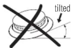

Fig. 9: crown position

The new burners called "Series III" are assembled on certain cooker hobs. The lock system between cover (B) and flame spreading (A) guarantees perfect positioning and large cleaning ability.

Fig. 10: positioning of the series III burner
The upper cover (B) of the burners must be placed in opposite seat with the two introductions notches in correspondence of the two cylinders below (C) and tighten clockwise.

The associated burner is indicated near each knob. The appliance is equipped with an electric ignition device. It is sufficient to press the knob and rotate it anti-clockwise to the maximum flame symbol, until it is lit. If it does not ignite within the first 15 seconds, bring the knob on ●chiuso] (closed) and do not try to re-ignite for 60 seconds.
Once it is lit, keep the knob pressed for a few seconds in order for thermocouple to heat up. It is possible that the burner shuts off when the knob is released: this means that the thermocouple was not sufficiently heated. Wait a few seconds and repeat the operation, keeping the knob pressed for a little longer. Once the burner is lit, it is possible to adjust the flame based on need.

After every use of the hob, always verify that the control knobs are in ● [chiuso] (closed) position.
If the burners were to shut off accidentally, after about 20 seconds a safety device intervenes and blocks gas output, even when the tap is open. In this case bring the knob to ● [chiuso] (closed) position and do not try to light the burner for at least 60 seconds.

Fig. 11: standard burner knob

Fig. 12: burner knob dual (S4000)/dual gear

Fig. 13: burner knob dual (GIOTTO/VULCANO)
14.2 Practical recommendations for burner use

For better burner yield, and minimum gas consumption, it is necessary to use flat and regular bottom pots, equipped with a cover and proportioned to the burner, in order to avoid that the flame goes up their sides (see the “Pots diameter” paragraph [Page 36]).
When boiling, reduce the flame as much as needed to make sure that the liquid does not overflow.

natural_image
Illustration of six cooking pots with crossed-out black-and-white symbols, no text or labels presentFig. 14: pots use

During cooking, all containers or steak pans, also to avoid burns or damage to the hob, must not exceed the measurements indicated in the paragraph "Pot diameter" [Page 36]). Do not heat empty pots or pans, because they may overheat.

When using greases or oils, pay careful attention because, when overheating, they may catch on fire. If a pan containing greases or oil catches on fire, do not pour water on it because it may cause burns; extinguish the fire by covering the pan with a wet cloth and disconnect the appliance from the power mains.
14.3 Pot diameter
• Auxiliary burner: from 6 to 14 cm
• Semi-quick burner: from 15 to 20 cm
• Quick burner: from 21 to 26 cm
• Double crown, triple crown, dual burners: from 24 to 28 cm

During operation, the cooker hob generates heat and humidity in the room it is installed in. Make sure that the kitchen is well ventilated. A prolonged used of the appliance with some or all burners may require additional ventilation such as opening a window and/or a greater suction power from the exhaust hood.
15. Cleaning and maintenance

Do not use a steam jet to clean the appliance.
Before any intervention it is necessary to disengage the appliance power supply.
Avoid leaving acid or alkaline (vinegar, lemon juice, salt, tomato juice,...) substances on the steel, grids and other parts of the appliance.
15.1 Cleaning the stainless steel
In order to properly preserve the stainless steel, it is necessary to regularly clean it after each use, once it has cooled down.
15.1.1 Daily ordinary cleaning
In order to clean and preserve stainless steel surfaces, only use specific products that do not contain abrasives or chlorine based acid substances.
Usage mode: pour the product on a wet cloth and pass it over the surface, carefully rinse and dry using a soft cloth or a deerskin.
15.1.2 Food stains or residue

Absolutely avoid using metal sponges and sharp scrapers to avoid damaging the surfaces. Use normal products for steel, non abrasives, using wood or plastic material tools if needed. Carefully rinse and dry using a soft cloth or a deerskin.
We recommend using Foster Steel Clean to clean the steel; for information on where it can be obtained, contact the after-sales technical assistance centre.
Do not use chemical detergents such as oven sprays or stain removers.
15.2 Cleaning gas components
The grids, caps and flame spreading crowns are removable in order to simplify cleaning: wash then in hot water with non abrasive detergent, making sure that any crud is removed and dry them immediately using a cloth. Re-assemble the caps on their crowns. The cast iron components, like the grids and the burners, must never be washed in dishwashers.
For the ignition glow plugs to work correctly, the thermocouples must always be clean. Frequently check them and, if necessary, clean using a wet cloth and then dry them. Any dry residue must be removed using a wood toothpick or a needle.

Foster S.P.A. will not answer for the possible inaccuracies contained in this manual attributable to printing or transcription errors. The right is reserved to make amendments to own products considered necessary or useful, also in the interest of the utility, without jeopardising its functional and safety features.
1.1 4000
 |  N7272VA = 1160 mmB = 480 mm N7272VA = 1160 mmB = 480 mm | 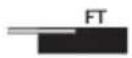 N7272V N7272V   |
 |  N7252VA = 860 mmB = 480 mm N7252VA = 860 mmB = 480 mm |  N7252V N7252V   |
 |  N7270VA = 860 mmB = 480 mm N7270VA = 860 mmB = 480 mm |  N7270V N7270V  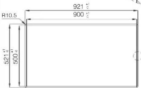 |
 | N7253VA = 830 mmB = 480 mm |  |
 | N7251VA = 560mmB = 480 mm | 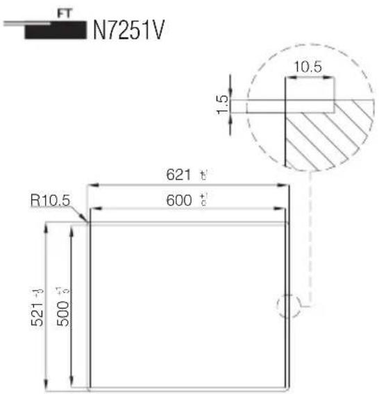 |
 | N7254VA = 1159 mmB = 348 mm |  |
| N7254VA = 1162B = 351 mm |
 |  A = 430 mmB = 480 mm A = 430 mmB = 480 mm |
 |  A = 430 mmB = 480 mm A = 430 mmB = 480 mm |
 |  A = 360 mmB = 480 mm A = 360 mmB = 480 mm |
1.2 QUADRA
 | N7215VA = 1162 mmB = 351 mm |  |
 | N7211VA = 862 mmB = 351 mm | 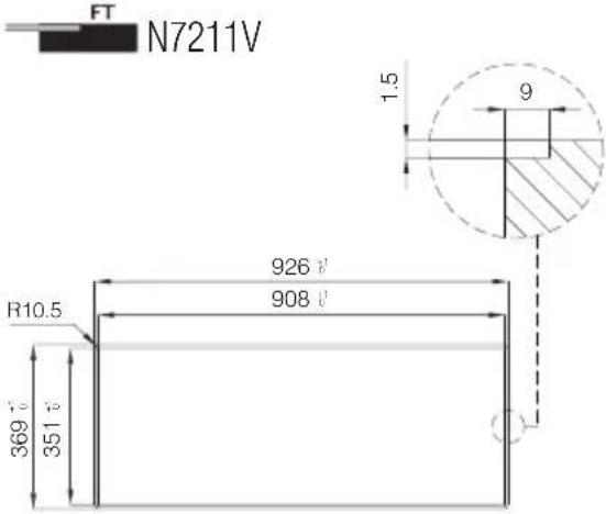 |
 | N7221VA = 309 mmB = 454 mm |  |
 |  N7223VA = 309 mmB = 454 mm N7223VA = 309 mmB = 454 mm |  N7223V N7223V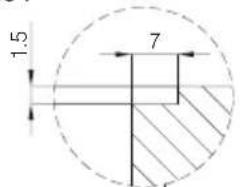  |
 | 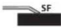 N7238V N7238V | |
 N7238V N7238V | ||
1.3 KE
 |  A = 840 mmB = 480 mm A = 840 mmB = 480 mm |  |
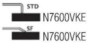 A = 770 mmB = 480 mm A = 770 mmB = 480 mm |
1.4 KS
 |  A = 770 mmB = 480 mm A = 770 mmB = 480 mm | |
 | 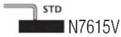 A = 560 mmB = 480 mm A = 560 mmB = 480 mm |
1.5 PROFESSIONALE
 |  N7055V-10N7055V-10A = 840 mmB = 480 mm N7055V-10N7055V-10A = 840 mmB = 480 mm | 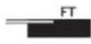 N7055V-10 N7055V-10  |
 |  N7053V-10A = 560 mmB = 480 mm N7053V-10A = 560 mmB = 480 mm | 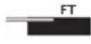 N7053V-10[1.5 KW73] N7053V-10[1.5 KW73]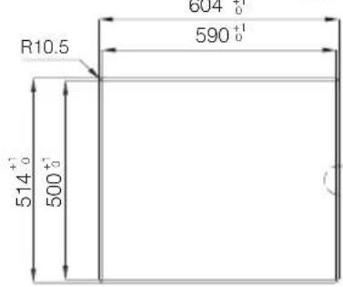 |
 |  N7062V-08A = 270 mmB = 480 mm N7062V-08A = 270 mmB = 480 mm |


A = 270 mm
B = 480 mm
1.6 LISA
1.7 FAUST
 |  A = 770 mmB = 480 mm A = 770 mmB = 480 mm |  |
1.8 ELEONORA
 |  A = 770 mmB = 480 mm A = 770 mmB = 480 mm |  |
 |
1.9 VULCANO
 | A = 950 mmB = 480 mm |  |
1.10 VERONIKA
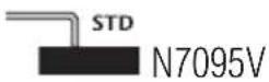
 |  A = 560 mmB = 480 mm A = 560 mmB = 480 mm | |
 |  A = 560 mmB = 480 mm A = 560 mmB = 480 mm | |
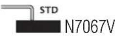
 |  N7063VA = 420 mmB = 480 mm N7063VA = 420 mmB = 480 mm | |
 | 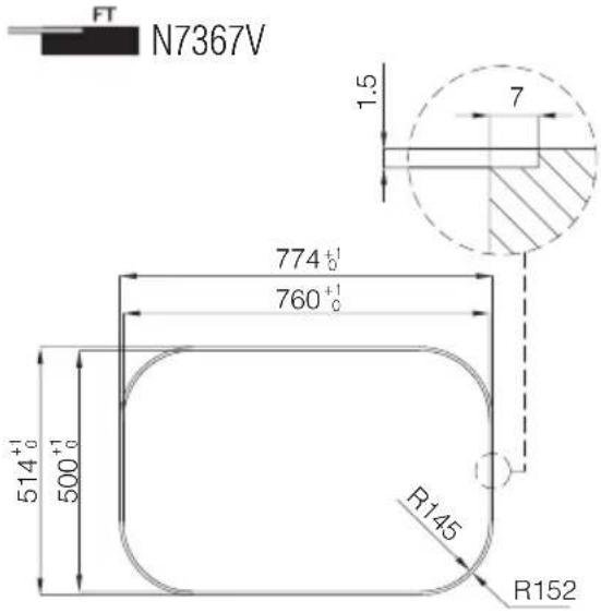 | |
 |  |
1.11 ELETTRA - PANDORA
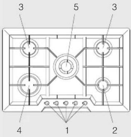 | 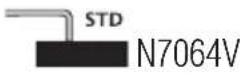 A = 560 mmB = 480 mm A = 560 mmB = 480 mm | |
 |  A = 560 mmB = 480 mm A = 560 mmB = 480 mm |
1.12 MAGIC
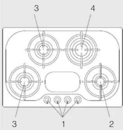 |  A = 740 mmB = 480 mm A = 740 mmB = 480 mm |  |
 | 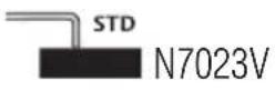 A = 560 mmB = 480 mm A = 560 mmB = 480 mm |  |
1.13 ALIEN
 |  |
1.14 ANGOLARE

1.15 F2000
| 3 5 2 1 | STD N7053000V A = 560 mm B = 480 mm | |
| 3 5 3 1 4 2 | STD N7055000V A = 840 mm B = 480 mm |
1.16 RONDÒ - GIOTTO
 |  ∅ 500 mm ∅ 500 mm | |
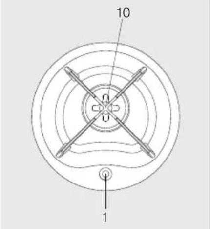 | 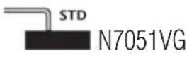 ∅ 500 mm ∅ 500 mm |
1.17 ALFA
 |  A = 840 mmB = 480 mm A = 840 mmB = 480 mm | 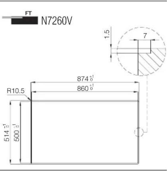 |
1.18 GK
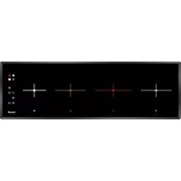
 |  A = 1030 mmB = 450 mm A = 1030 mmB = 450 mm |  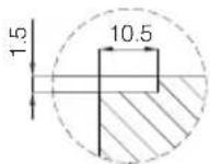  |
Foster spa
via M.S. Ottone, 18/20
42041 Brescello (RE) - Italy
- Table of Contents
- GENERAL WARNINGS
- INSTALLER INSTRUCTIONS
- USER INSTRUCTIONS
- Usage warnings
- Safety warnings
- Warnings for disposal
- OUR CARE FOR THE ENVIRONMENT
- DO NOT ABBANDON THE PACKAGING MATERIAL OR PARTS OF IT. THEY MAY CREATE A SUFFOCATION DANGER FOR CHILDREN, ESPECIALLY PLASTIC BAGS.
- Know your appliance
- First installation
- Positioning in the work top
- Installation on the support structure (worktop) of a traditional built-in cooker hob (8 mm edge, Q4 edge, semi-flush edge)
- Installation on the support structure (worktop) of a flush built-in cooker hob (flush-mount edge)
- Fastening the cooker hob to the cabinet
- IMPORTANT:
- Fixed hooks
- Sliding hooks
- Fixed brackets
- Connecting the cooker hob to the gas network
- Connection to liquid gas
- Room ventilation
- Discharging combustion products (exhaust)
- Adapting to different types of gasses
- Cooker hob nozzle replacement
- Adjustment of the minimum
- Instructions for urban and methane gas
- Instructions for liquid gas (LPG)
- Electrical connection of the cooker hob
- Cooker hob use
- Lighting the burners
- Practical recommendations for burner use
- Pot diameter
- Cleaning and maintenance
- Cleaning the stainless steel
- Daily ordinary cleaning
- Food stains or residue
- Cleaning gas components
- 4000
- QUADRA
- KE
- KS
- PROFESSIONALE
- LISA
- FAUST
- ELEONORA
- VULCANO
- VERONIKA
- ELETTRA - PANDORA
- MAGIC
- ALIEN
- ANGOLARE
- F2000
- RONDÒ - GIOTTO
- ALFA
- GK
- Foster spa
Brand : Foster
Model : 7055 062
Category : Cooker