
AVM265 - Surveillance Camera LOGILINK - Free user manual and instructions
Find the device manual for free AVM265 LOGILINK in PDF.


| Product Type | IP Surveillance Camera |
| Model | AVM265 |
| Brand | LogiLink |
| Image Sensor | 1/3" CMOS |
| Resolution | D1 (720x480) / CIF (352x240) |
| Lens | f6.0mm / F1.4 |
| Viewing Angle | 44° (Horizontal) x 34° (Vertical) x 57° (Diagonal) |
| IR LEDs | 56 units, effective range up to 40m |
| Min. Illumination | 0.1 Lux (color), 0 Lux (IR on) |
| Video Compression | H.264, MPEG4, MJPEG |
| Network | 10/100 Ethernet; supports DDNS, PPPoE, DHCP, NTP, SMTP, FTP, HTTP, RTP, RTSP, RTCP, IPv4, Bonjour, UPnP, DNS, UDP, IGMP, QoS |
| Waterproof Rating | IP67 |
| Power Supply | DC 12V, 1A |
| Operating Temperature | -20°C to 40°C |
| Dimensions (Diameter x Height) | 115.6mm x 216.4mm |
| Remote Access | Internet Explorer (Windows), EagleEyes app (iOS/Android) |
| Security | Multi-level user access with password; IP filtering; digest authentication |
| Alarm / Trigger | Motion detection, external alarm I/O; notifications via email, FTP, SMS |
| Recording | Built-in 10MB memory (up to 3 alarm recordings); compatible with NVR |
| Package Contents | Network camera, bracket, quick setup guide, power adapter (optional) |
| Compliance | RoHS, FCC Class A |
Frequently Asked Questions - AVM265 LOGILINK
User questions about AVM265 LOGILINK
0 question about this device. Answer the ones you know or ask your own.
Ask a new question about this device
Download the instructions for your Surveillance Camera in PDF format for free! Find your manual AVM265 - LOGILINK and take your electronic device back in hand. On this page are published all the documents necessary for the use of your device. AVM265 by LOGILINK.
USER MANUAL AVM265 LOGILINK
Please read instructions thoroughly before operation and retain it for future reference.
IMPORTANT SAFEGUARD

All lead-free products offered by the company comply with the requirements of the European law on the Restriction of Hazardous Substances (RoHS) directive, which means our manufacture processes and products are strictly “lead-free” and without the hazardous substances cited in the directive.

The crossed-out wheeled bin mark symbolizes that within the European Union the product must be collected separately at the product end-of-life. This applies to your product and any peripherals marked with this symbol. Do not dispose of these products as unsorted municipal waste. Contact your local dealer for procedures for recycling this equipment.

This is a class A product. In a domestic environment this product may cause radio interference in which case the user may be required to take adequate measures.
Federal Communications Commission Interference Statement
This equipment has been tested and found to comply with the limits for a Class A digital device, pursuant to Part 15 of the FCC Rules. These limits are designed to provide reasonable protection against harmful interference when the equipment is operated in a commercial environment. This equipment generates, uses, and can radiate radio frequency energy and, if not installed and used in accordance with the instruction manual, may cause harmful interference to radio communications. Operation of this equipment in a residential area is likely to cause harmful interference in which case the user will be required to correct the interference at his own expense.
This device complies with Part 15 of the FCC Rules. Operation is subject to the following two conditions:
(1) This device mat not cause harmful interference, and
(2) This device must accept any interference received, including interference that may cause undesired operation.
Trademark Acknowledgements
iPad® & iPhone® are the registered trademarks of Apple Inc.
Android ^™ is a trademark of Google Inc. Use of this trademark is subject to Google Permissions.
Microsoft®, Windows® & Internet Explorer® are registered trademarks of Microsoft Corporation in the United States and/or other countries.
Disclaimer
We reserve the right to revise or remove any content in this manual at any time. We do not warrant or assume any legal liability or responsibility for the accuracy, completeness, or usefulness of this manual. The content of this manual is subject to change without notice.
This product doesn't have a standby / shutdown mode.
MPEG4 Licensing
THIS PRODUCT IS LICENSED UNDER THE MPEG4 VISUAL PATENT PORTFOLIO LICENSE FOR THE PERSONAL AND NON-COMMERCIAL USE OF A CONSUMER FOR (i) ENCODING VIDEO IN COMPLIANCE WITH THE MPEG4 VISUAL STANDARD ("MPEG-4 VIDEO") AND/OR (ii) DECODING MPEG4 VIDEO THAT WAS ENCODED BY A CONSUMER ENGAGED IN A PERSONAL AND NON-COMMERCIAL ACTIVITY AND/OR WAS OBTAINED FROM A VIDEO PROVIDER LICENSED BY MPEG LA TO PROVIDE MPEG4 VIDEO. NO LICENSE IS GRANTED OR SHALL BE IMPLIED FOR ANY OTHER USE. ADDITIONAL INFORMATION INCLUDING THAT RELATING TO PROMOTIONAL INTERNAL AND COMMERCIAL USES AND LICENSING MAY BE OBTAINED FROM MPEG LA, LLC. SEE HTTP://WWW.MPEGLA.COM.
GPL Licensing

This product contains codes which are developed by Third-Party-Companies and which are subject to the GNU General Public License ("GPL") or the GNU Lesser Public License ("LGPL").
The GPL Code used in this product is released without warranty and is subject to the copyright of the corresponding author.
Further source codes which are subject to the GPL-licenses are available upon request.
We are pleased to provide our modifications to the Linux Kernel, as well as a few new commands, and some tools to get you into the code. The codes are provided on the FTP site, and please download them from the following site or you can refer to your distributor:
http://download.dvrtw.com.tw/GPL/076D_Series/arm-linux-2.6.tar.gz
TABLE OF CONTENTS
1. OVERVIEW.... 1
1.1 Product Features....1
1.2 Package Content....1
1.3 Cable Overview....1
2. CAMERA ACCESS WITH INTERNET EXPLORER.... 2
2.1 Camera Login....2
2.2 Control Panel Overview 2
2.3 Event Record Search & Playback....4
3. CAMERA CONFIGURATIONS....5
3.1 System configuration menu....5
3.2 Network 6
3.2.1 Network 6
3.2.2 QoS 6
3.2.3 DDNS 6
3.2.4 SNTP 7
3.2.5 FTP 7
3.2.6 MAIL 7
3.2.7 SMS....8
3.2.8 Filter 9
3.2.9 UPnP / Bonjour....9
3.2.10 RTP 10
3.3 Camera 11
3.3.1 Camera....11
3.3.2 Video 11
3.3.3 Color....12
3.3.4 Advance....12
3.4 Record....13
3.4.1 Record....13
3.4.2 Record Timer....13
3.5 Storage....13
3.5.1 Memory 13
3.6 Trigger 14
3.6.1 Trigger 14
3.7 General 15
3.7.1 General....15
3.7.2 Time....15
3.7.3 Server Log....16
3.7.4 Online 16
3.7.5 Account....17
3.7.6 Google Maps....17
3.7.7 Maintenance....18
APPENDIX 1 PRODUCT SPECIFICATIONS....20
APPENDIX 2 BIT RATE TABLE FOR REFERENCE 21
APPENDIX 3 API ID APPLICATION FOR SMS MESSAGING....22
APPENDIX 4 Q&A 24
1. OVERVIEW
1.1 Product Features
- Easy network setup with your iPhone / iPad
- ONVIF standard supported to simplify system integration
- External alarm I/O device connection
- 56 IR LEDs built-in for night surveillance
- Remote Surveillance
-- Fully compatibility on iPhone & iPad, and Internet Explorer® on Windows® operating system
1.2 Package Content
□ Network camera
Bracket
☐ Quick Setup with iPhone / iPad
Adapter
1.3 Cable Overview

| Color Cable | Description | |
| -- | Power | Connect to DC12V power supply.cable.Note:The power adapter is optional. |
| -- RJ45 network | cable | Connect it to the supplied RJ45 cable extender adapter for cable extension, and prepare another RJ45 network cable with suitable length for your connection. |
| Black & Brown | GND | Ground wire, used for reset default or external device connection. |
| Yellow | Alarm-in | Reserved for connecting to an external alarm device. For details, please refer the user manual of your alarm device. |
| Pink | Alarm-out | Reserved for connecting to an external alarm device. For details, please refer the user manual of your alarm device. |
| Red | RESET | Remove the insulating coating of this wire, and twist it with a ground wire together to reset default. This will reset all parameters, including the IP address to factory default settings.Note:Disconnect power before twisting these two wires together, and connect to power again for reset default. |
2. CAMERA ACCESS WITH INTERNET EXPLORER
This network camera can be accessed via Microsoft® Internet Explorer® and iPhone / iPad / Android mobile devices with our self-developed program "EagleEyes" installed depending on different using situations.
Note: For details about accessing network cameras via iPhone / iPad / Android mobile devices, please refer to http://www.eagleeyescctv.com.
Before using the camera, make sure you have configured the network settings, and the network connection is fine.
For network configurations, please refer to:
■ "Quick Setup With iPhone / iPad" supplied with your camera if you're using iPhone / iPad, and your network environment is wireless.
■ "ADVANCED NETWORK SETUP" downloadable from www.surveillance-download.com/user/m265.swf if your network environment is not wireless.
2.1 Camera Login
Step1: Open your web browser, and key in http://ipaddress:portnum in the URL address box.
For example, for the IP address 60.121.46.236 and port No. 888, please key in "http://60.121.46.236:888" into the URL address box, and press "Enter".
Step2: In the login page, key in the user name and password, and enter the security code from the image below if any. Then, click "LOGIN".
Step3: The wizard is then started.
- To skip the wizard and directly access the camera live view, click "Close".
• To directly access the camera live view without starting the wizard for the login next time, check "Do not start wizard at login".
Note: If you're prompted to install "VLC player", "Software" and "H264 Streaming Viewer", please agree to proceed the installation.
Step5: When the login is successful, the live view is shown.
2.2 Control Panel Overview
Note: The buttons available depend on the user level used to log in.

| Function Icon | User Level Description | ||
| Live | [730x] | Supervisor / Power User / Normal User / Guest | Switch to the live view page. |
| Backup | [29WY7] | Supervisor / Power User | Enter the event record list for video playback.For details, please refer to "2.3 Event Record Search & Playback' at page 4. |
| Config. | [56XX] | Supervisor / Power User | Switch to the system configuration page, and the functions available for "Supervisor" and "Power User" are different.For details, please refer to "3.1 System configuration menu" at page 5. |
| / Normal User / Guest | Select the image player from the drop-down list: Media Type -- Supervisor / Powe■ H.264 / MPEG-4 / Motion JPEG■ QuickTimeQuickTime is Apple Inc.'s multimedia software. You need to have QuickTime installed in your operating system before selecting "QuickTime".When it is selected, you will be promoted to enter the user name and password to access the camera.■ VLC | ||
| Quality -- Supervisor / Power User | / Normal User | Click & drag the slider to select the video quality:BASIC / NORMAL / HIGH / BEST. | |
| Video Resolution | -- | Supervisor / Power User / Normal User | Select the image resolution from the drop list:■ D1 (720 x 480) ■ CIF (352 x 240) |
| Live View Size: | Supervisor / Power User / Normal User | ||
| Full Screen | [6x2x7] | Click to display the image in full screen.To exit the full screen mode, press "Esc" on your keyboard. | |
| Snapshot | [6x4x7] | Supervisor / Power User / Normal User | Click to take a snapshot of the current view on a new window. Right click on the picture and re-save it to the location you want. |
| Alarm Out | [6x4x9] | Supervisor / Power User / Normal User | Click to force your alarm-out device to work. For example, when your alarm device is a buzzer, click this button and your buzzer will start to sound even if there's no alarm event. |
2.3 Event Record Search & Playback
This camera can only save up to three alarm recordings in its 10MB memory built-in.
Note: To save more recorded data, it's recommended to use this camera with the compatible NVR.

| / | Previous / Next Hour | Click to jump to the next / previous time interval in an hour, for example, 11:00 ~ 12:00 or 14:00 ~ 15:00, and start playing the earliest event video clip recorded during this whole hour. |
| Fast Forward | Increase the speed for fast forward. Click to get 2X, 4X, 8X & 16X speed forward eventually. | |
| Fast Rewind | Increase the speed for fast rewind. Click to get 2X, 4X, 8X & 16X speed rewind eventually. | |
| Play | Click to play the current video clip. | |
| Pause | Click to pause the video playback. | |
| Stop | Click to stop the video playback. | |
| Step | In the pause mode, click to get one frame forward. | |
| Audio Click to mute the playback if necessary, and click again to restore. | ||
| Download | Click to download the current video clip to the specified path in your PC.The downloaded video can only be opened by our own video player. Please go to "General" > "Maintenance" to download the video player, or get the player from the CD supplied with the sales package. | |
3. CAMERA CONFIGURATIONS
Users can further configure this network camera by accessing via Internet Explorer.
3.1 System configuration menu
Click "Config." to enter the configuration page.
The functions are categorized into six menus: Network, Camera, Record Timer, Storage, Trigger and General.
■ For details about "Network", please refer to "3.2 Network" at page 6.
■ For details about "Camera", please refer to "3.3 Camera" at page 11.
■ For details about "Record", please refer to "3.4 Record" at page 13.
■ For details about "Storage", please refer to "3.5 Storage" at page 13.
■ For details about "Trigger", please refer to "3.6 Trigger" at page 14.
■ For details about "General", please refer to "3.7 General" at page 15.
| Main Menu Sub-Menu Reference | ||
| Network Network Configure network settings. | ||
| DDNS Enter DDNS information when the network type is PPPOE or DHCP. | ||
| SNTP Synchronize your camera time with the networked computer systems. | ||
| Enter the FTP information for event notifications when "FTP" is chosen in "Trigger" → "Trigger". | ||
| Enter Email information for event notifications when "Email" is chosen in "Trigger" → "Trigger". | ||
| Enter text messaging information for SMS notifications when "SMS" is chosen in "Trigger" → "Trigger". | ||
| Choose to permit or block the IP address(es) which can access this camera. | ||
| *Suitable for Windows-based operating system.Allow this camera to be detected among devices within the same network area for easy and quick usage. | ||
| *Suitable for Apple Mac-based operating system.Allow this camera to be detected among devices within the same network area for easy and quick usage. | ||
| Set the parameters for video data transmission when you're using multimedia other than web browsers and Video Viewer for remote access. | ||
| Camera | Camera | Rename the camera.Change the place where the camera name is shown on the screen. |
| Video | Adjust video-related settings in different video format. | |
| Color | Adjust the color performance. | |
| Advance | Adjust the camera parameters if necessary. | |
| Record | Record | Configure the record function. |
| Record Timer Schedule external alarm recording. | ||
| Storage | Memory | Check the current storage capacity and clear all recorded data when needed. |
| Trigger | Trigger | Enable / disable the motion detection.Set the motion detection area.Configure how the camera reacts for any event. |
| General | General | 1. Select the language of the web browser.2. Check the MAC address of the camera.3. Lock camera access after the specified time.4. Enable or disable LED status indication. |
| Time Set daylight | saving time and the current time. | |
| Server Log Check | the system event logs. | |
| Online Check the | current online user(s). | |
| Google Maps Allow | Account | 1. Create a new user account with different access privilege.2. Modify or delete an existing user account. |
| you to know where the network camera is. | ||
| Maintenance | 1. Check the current firmware version and upgrade your camera.2. Copy system configurations.3. Reboot the camera.4. Download the video player to play the recorded data. | |
3.2 Network
3.2.1 Network
You can set the network configuration of the network camera depending on your network type.
For details, please refer to "Advanced Network Setup" from www.surveillance-download.com/user/m265.swf.

3.2.2 QoS
QoS, Quality of Service, is the ability to control the data flow for real-time streaming. This function is important if your network bandwidth is insufficient and you have other devices to share the network bandwidth.
Check "QoS Enable", and set the max. upload rate from 256 to 10240 kbps.

3.2.3 DDNS
Select "On" when the selected network type in "Network" is "PPPOE" or "DHCP".
For details, please refer to "Advanced Network Setup" from www.surveillance-download.com/user/m265.swf.

3.2.4 SNTP
SNTP (Simple Network Time Protocol) is used to synchronize your camera time with the networked computer systems.

| Function Description | |
| GMT Once users choose the time zone, the network camera will adjust the local area time of the system automatically. | |
| NTP Server | Simply use the default SNTP server (For example, tock.stdtime.gov.tw) or change to another server with which users are familiar. |
| Sync. Period | Select “Daily” to synchronize the camera time with the network time every day or “None” to turn off this function. |
| Sync Click and the network camera will synchronize the time with the network time. | |
3.2.5 FTP
Enter the detailed FTP information and click "Save" to confirm. The information you set here will be applied when "FTP" is selected in "Trigger" → "Trigger".

3.2.6 MAIL
Enter the detailed e-mail information and click "Save" to confirm. The information you set here will be applied when "Email" is selected in "Trigger" → "Trigger".

Function Description
| SMTP Server Enter the SMTP server address provided from your e-mail system supplier. | |
| Port | Enter the port number provided from your e-mail system supplier. If this column is left blank, the e-mail server will use port 25 to send e-mails. |
| Mail From Enter the name of the sender. | |
| SSL Encryption | Select "Yes" if your e-mail server is using SSL encryption to protect your e-mail content from unauthorized access. |
| Verify Password | Some mail servers are required to verify the password. Please enter the "user name" and "password". |
| E-Mail Address List Add the e-mail address(s) of the assigned recipient(s). | |
| Test When all information is entered, click "Test Mail" to try if the receipt. | |
3.2.7 SMS
Note: Before using this function, you need to apply an API ID from the mobile messaging company, Clickatell, and you will be charged starting from the 11 ^th message. For details, please refer to "APPENDIX 3 API ID APPLICATION FOR SMS MESSAGING" at page 22.
Enter the detailed information needed for text messaging, and click "Save" to confirm. The information you set here will be applied when "SMS" is selected in "General" → "Trigger".
![SMS Configuration System: clickatel Username: tech Password: •••••••• API ID: 3281378 Recipient: +886934077160 Transfer Interval: 15 Message: [192.168.1.10] unauthorized access! Minute(s) Reset Counter ✓ include Hostname or IP Save Test Reload](/content/2026/05/858703/images/a5febefb80e2d8dcdb307710eea8654d416e29866662d22aa0c5f329d93918a3.jpg)
Function Description
| System The text messaging service provider is Clickatell. | |
| User name / Password | Enter the account user name and password you created in Clickatell. |
| API ID Enter the API ID you applied from Clickatell. | |
| Recipient | Click "Add" to enter the phone number, including the country code, to receive the text message. Five sets of phone numbers are allowed. |
| Transfer Interval | Set the interval time in minutes between two-message sending.The options are 0, 15, 30 & 60. |
| Reset Counter | Click to restart the text messaging, and the SMS will be sent after the specified time interval since you click this button. |
| Message | Enter the text content (up to 70 characters) you want to send with the text message. |
| Test | To know whether your SMS setting is correct, click this button to immediately send a SMS to your phone.Note: This testing is not free and you will be charged for SMS sending base on your local rate. |
3.2.8 Filter
Choose to permit or block the IP address(es) which can access this camera, and click "Save" to confirm.

Function Description
| ■ Filter Configuration | |
| Error Count | Set the maximum count for login failure. When the maximum count is reached, the IP address trying to access the network camera will be locked. |
| Error Lock Time | Set the lock time in minutes when the maximum count of error login for an IP address is reached. |
| Echo Request | Select "Non-Block" to allow other users to use the ping command to detect the IP address of your network camera, or "Block" to deny the ping command request. |
| ■ IP/MAC Filter Configuration | |
| IP/MAC Filter Choose | to enable or disable the filter function. |
| IP/MAC Filter Policy | If "Enable" is selected, choose whether you want to permit (Allow) or block (Deny) the IP address list below. |
| ■ IP/MAC Filter Rules | |
| Rule | To add an item to the IP address list, key in the IP address in "Rule", and click "Add".To remove an existing item in the IP address list, click the item you want to remove, and click "Delete". |
"UPnP" stands for "Universal Plug and Play", which allows devices to connect seamlessly in the home and corporate environments and simplify installation of computer components, and is only suitable for Microsoft Windows-based operating system.
"Bonjour" functions the same as "UPnP", but it's only suitable for Apple Mac-based operating system.
UPnP

> Bonjour
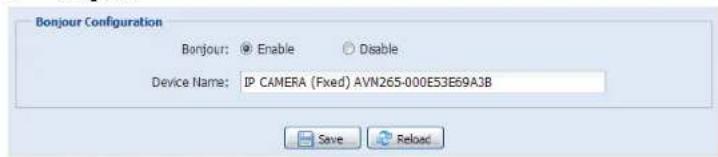
Check "Enable" to allow the network camera to be detected among devices within the same network area, and set the identification name of the camera in "Friendly name".
When this function is activated, the other PC within the same domain as this camera will be able to search this camera in:
“Network Neighbor” with the identification name set in “Friendly name” for Windows-based PC, or


(finder) or "Bookmark" with the identification name set in "Device Name" for Mac-based PC.
Double-click it to quickly open the web browser for camera access.
Port Mapping (Available only in UPnP)
This function can eliminate the need to additionally access the router for port forwarding.
For details, please refer to "Advanced Network Setup" from www.surveillance-download.com/user/m265.swf.
Note: Before using this function, make sure your router supports UPnP, and this function is enabled. If not, please access your router additionally for port forwarding.
When "Port Mapping" is set to "Enable", the system will automatically assign an IP address or port number for you if no IP address or port number is entered.

Note: When the configurations are saved successfully, you'll see a message indicating the IP address and port number assigned to this network camera.
3.2.10 RTP
The Real-time Transport Protocol (RTP) is an Internet protocol standard to manage the real-time transmission of multimedia, such as VLC player.
The media player you want to use for remote access must support RTP transmission for this function to work normally.
Note: When you're about to end the remote access, please press the stop button on your media player first, and then close the program. This is to ensure the server receives the stop command, and also help to protect the server from redundant data transmission.
Note: QCIF is for mobile surveillance only.
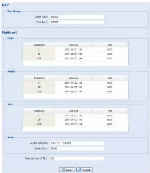
Function Description
■ Port Range
The port range used by RTP is limited, and preserving 100 ports between the start port and end port is necessary.
Start Port The range of the start port is 1024 \~ 65434.
End Port The range of the end port is 1124 \~ 65534.
■ Multicast
Address and port for | Set a specific address and port for multicast of each stream format (H264/ MPEG4/ JPEG).
H264 / MPEG4 / JPEC transmission The range of the address is limited between 224.0.0.1 \~ 239.255.255.255.
The port for multicast must be an even number.
Time to Live (TTL) The range of Time to Live of the package is between 1 \~ 255. As soon as Time to Live of the package is 0, it will be dropped.
3.3 Camera
3.3.1 Camera
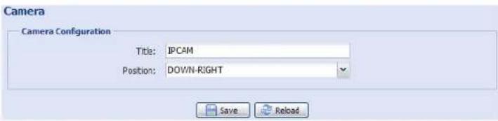
Rename the camera, and change the place where the camera name is shown on the screen, UP-LEFT / UP-RIGHT / DOWN-LEFT / DOWN-RIGHT.
3.3.2 Video
Adjust video-related settings in different video format.
■ "Quality" is related to image clearness.
■ "FPS" is related to the fluency of the video. The more the FPS, the more fluent the video.
■ "Max Bit Rate" is the maximum limitation of data transmission in the selected image format and resolution.
Note: QCIF is for mobile surveillance only.

3.3.3 Color
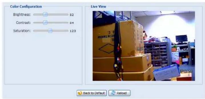
Adjust the color performance from Brightness, Contract, Hue and Saturation. Click and drag the slider to preview the color change on the right side of this page and adjust the image color.
To restore the default values, click "Back to Default".
3.3.4 Advance
Adjust the camera parameters if necessary.

| Item Description | |
| Back Light | Select “ON” to have clearer image when the background is too bright or the object is too dark. |
| Mirror | Select “ON” to rotate the images horizontally based on your installation situation when necessary. |
| Flip Select “ON” to rotate the image 180° when necessary. | |
| IR Control | Select “Auto” to automatically enable IR LEDs at night or in the dark environment, “On” to always enable IR LEDs, or “OFF” to disable this function. |
| Sharpness | Sharpness enhances the clarity of image detail by adjusting the aperture and sharpening the edges in the pictures.Hold and drag the slider to adjust the level of sharpness from 0 ~ 100. The higher the value, the sharper the image. |
3.4 Record
3.4.1 Record
In "Record Configuration", you can:
Enable or disable the alarm record function. When "Enable" is set to "No", the alarm record function is disabled even if you enable it in other configuration pages.
Select if the data should be overwritten when the memory storage is full.
Select the video resolution for event recording.
Note: The higher resolution you choose, the more accuracy and higher image quality the recording will be, but the faster the memory storage is consumed and become full.

3.4.2 Record Timer
To schedule alarm recording, enable it, and select the day and time for recording.
Note: The timer must be enabled for the record function to work properly.

3.5 Storage
3.5.1 Memory
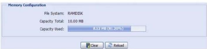
In "Memory", you can check the remaining capacity of the built-in 10MB flash memory storage, or clear all recorded data saved if needed.
Note: The recorded data will be removed also when you reset or reboot this camera.
This camera can only save up to three alarm recordings.
Note: To save more recorded data, it's recommended to use this camera with the compatible NVR.
3.6 Trigger
3.6.1 Trigger
You can configure how this camera reacts when there's an alarm or motion event.
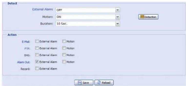
◆ Detect
| Item Description | |
| External Alarm | Enable or disable detection from external alarm-in device, and click the title “External Alarm” (in blue) to set “N.O.” or “N.C.” depending on the configuration of your alarm-in device. |
| Motion Enable or disable motion detection.Motion detection is not supported when the stream format is Motion JPEG. | |
| Sensitivity: | Set the detection sensitivity from the drop-down list: High, Normal or Low. |
| Area Setting: | Set the motion detection area by selecting the area grids with your mouse. Pink grids represent the area that is not being detected while the transparent grids are the area under detection. You can set multiple areas under detection.Click “Clear All” to set the whole area undetected.Click “Select All” to set the whole area under detection. |
| Duration Set the duration time for trigger recording (5 / 10 / 20 / 40 seconds). | |
Action
Here defines how the camera delivers alerts to you for any event.
| Item Description | |
| Select the event type you want to receive E-mail notifications when it occurs.Then, click the title “E-Mail” (in blue) to configure the media type (H264 / JPEG / MPEG4), file format (AVC / AVI), and record time (1 ~ 5 seconds) for the event video clip.The camera will send the captured video clip to the E-mail address(s) you assigned in “Network” → “Mail” once the selected event type occurs. | |
| FTP Select the event type you want to receive FTP notifications when it occurs.Then, click the title “FTP” (in blue) to configure the media type (H264 / JPEG / MPEG4), file format (AVC / AVI), and record time (1 ~ 5 seconds) for the event video clip.The camera will upload the captured video clip to the FTP site you assigned in “Network” → “FTP” once the selected event type occurs. | |
| SMS Select the event type you want to receive a text message when it occurs.The camera will send a text message to the mobile phone number you assigned in “Network” → “SMS” once the selected event type occurs. | |
| Alarm Out | Select the event type you want to trigger the alarm-out device to work when it occurs.Then, click the title “Alarm Out” (in blue) to configure the trigger rule (LOW / HIGH). |
| Record | Select the event type you want to enable event recording when it occurs. |
3.7 General
3.7.1 General
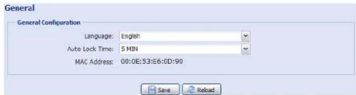
To change the language of UI interface, select from the drop-down list in "Language".
To lock camera access when it's not used after the specified time, select "5 MIN", "15 MIN" or "30 MIN" from the drop-down list of "Auto Lock Time", or select "NEVER" to disable this function.
Note: When the camera access is locked after the specified time, to resume camera access, please enter the password.
3.7.2 Time
Set daylight saving time and the current time, and click "Save" to confirm.

Function Description
■ Time Configuration
| Date | Set the current date. |
| Time | Set the current time. |
| ■ Daylight Saving Time Configuration | |
| Daylight Saving Time | Specify whether to use daylight saving time (Enable / Disable). |
| If this function is enabled, set the time period (Start Time / End Time), and adjust the daylight saving time in hours (Adjust Time). | |
3.7.3 Server Log
To quickly search the system logs you want by event type, click "Prev. Page" or "Next Page" to find the logs you want, or check the event type(s) and click "Reload" to start searching.
To clear all system event logs, click "Clear All".

3.7.4 Online
You can check the current online user(s) with respective online information. To refresh the list, click "Reload".
To allow anonymous login, select "Enable" in "Anonymous Viewer Login".
To disable image code verification at login, select "No" in "Login with CAPTCHA Image".

3.7.5 Account
You can create a new account with different user access privilege, or delete or modify an existing account setting.
How to create a new account
Step1: Click "New", and fill in the following columns.

| Column Description | |
| User Name | Set a user name that will be used for camera access. The user name allows up to 16 alphanumeric characters. |
| Password Set the password that will be used for remote login. The password allows up to 16 alphanumeric characters. | |
| Confirm Password Enter the password again to confirm. | |
| User Level | Set the security level of an account to give the permission to control different functions. There are four user levels: SUPERVISOR, POWER USER, NORMAL USER and GUEST. |
| Life Time | Select how long this account is allowed to stay online (1 MIN / 5 MIN / 10 MIN / 1 HOUR / 1 DAY / INFINITE) |
Step2: Then, click "Save" to save your setting and create a new account.
How to modify or delete an existing account
Step1: Select the account you want to modify or delete.
Step2: To modify the account, click "Edit" to change the settings, and click "Save". To remove the account, click "Delete".
Note: It's not allowed to remove an account when there's only one account in the account list.
3.7.6 Google Maps
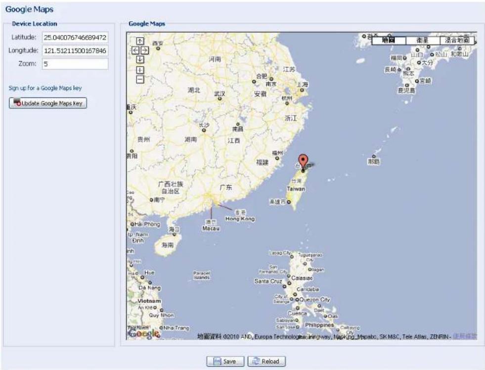
This function is used to let you know where the network camera is.
The system will prompt you to apply a Goole Maps Key if your access is denied. Please follow the instructions below when you're denied:
Step1: Click "Sign up for a Google Maps key" to enter the application page.
Step2: Check the terms and conditions, and enter the IP address of the network camera. Then, click "Generate API Key".
Step3: Copy the generated API key, and click "Update Google Maps Key" on the web browser to paste it.
3.7.7 Maintenance
Firmware Upgrade
This function is used when users need to upgrade the camera for function scalability.
Note: Before using this function, make sure you have the correct upgrade files provided by your installer or distributor.
Note: The event videos saved in the camera will be removed after firmware upgrade. Make sure you've copied important events to your PC before firmware upgrade.
Step1: Select "☐" to browse to where you save the upgrade files, and select them one by one until all files are selected (up to four files).
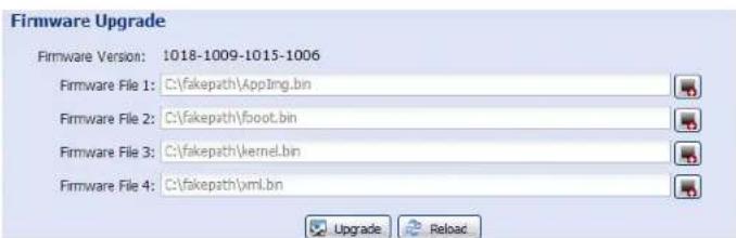
Step2: Select "Upgrade" to start system upgrading.
Note: You'll be prompted to keep current configurations. It's recommended to keep them, or all configurations will be restored to default values after upgrade.
Note: It takes a few minutes to finish the upgrade process. Do not disconnect the power during firmware upgrade, or the upgrade may be failed. The camera will reboot after the upgrade.
System Configuration Backup
This function is used to copy your system configuration to a "System.bin" file.
You may import the same system configuration to another camera, or restore your system configuration when the camera is reset to default values.
Select "System.bin" in "Firmware Upgrade", and select "Upgrade" to import the system configuration.

System Reboot
Select "Reboot" to restart your camera if needed.
System Reboot
If you want to reboot your system, click 'Reboot' to start the system reboot.

Player Download
To see the event video clips downloaded to your PC, you need to first install our own video player in your PC. Select "Free Download" to download the video player, and double click the file to install it.
Player Download
If you want to open the video downloaded from playback. Please download and install the player at first.

APPENDIX 1 PRODUCT SPECIFICATIONS
| AVM265 | |
| ■ Network | |
| Network Compression H.264 / MPEG4 / MJPEG | |
| Multiple Video Streaming (Encode Modes, IPS, Resolution) | 3 (H.264, MJPEG, MPEG4) |
| LAN Port YES | |
| LAN Speed 10/100 Based-T Ethernet | |
| Supported Protocols | DDNS, PPPoE, DHCP, NTP, SNTP, TCP/IP, ICMP, SMTP, FTP, HTTP, RTP, RTSP, RTCP,IPv4, Bonjour, UPnP, DNS,UDP,IGMP, QoS |
| Frame Rate NTSC:30, PAL:25 | |
| Number of Online Users 10 | |
| Security | (1) Multiple user access levels with password(2) IP address filtering(3) Digest authentication |
| Remote Access | (1) Internet Explorer® on Windows® operating system(2) EagleEyes on iPhone, iPad & Android mobile devices |
| ■ Camera | |
| Image Sensor 1/3" image sensor | |
| Video Resolution D1 / CIF | |
| Min Illumination 0.1 Lux / F1.4, 0 Lux (LED ON) | |
| Shutter Speed 1 / 60 (1/50) to 1 / 900,000 sec. | |
| S/N Ratio More than 48dB (AGC off) | |
| Lens | f6.0mm / F1.4 |
| Viewing Angle | 44° (Horizontal) / 34° (Vertical) / 57° (Diagonal) |
| IR LED | 56 units |
| IR Effective Range | Up to 40 meters |
| IR Shift | YES |
| White Balance | ATW |
| AGC | Auto |
| IRIS Mode | AES |
| External Alarm I/O | YES |
| Power Source (±10%) | DC12V / 1A |
| Operating Temperature | -20°C~40°C |
| Startup Temperature | 0°C~40°C |
| Current | 160mA (IR Off) ±10%;720mA (IR ON) ±10% |
| Waterproof | IP67 |
| Dimensions (mm)** | 115.6mm(O) × 216.4mm(H) |
| ■ Others | |
| Mobile Surveillance | iPad, iPhone & Android mobile device |
| RTC (real-time clock) | YES |
| Motion Detection | YES |
| Event Notification | FTP / Email / SMS |
| Minimum Web Browsing Requirements | Pentium 4 CPU 1.3 GHz or higher, or equivalent AMD256 MB RAMAGP graphics card, Direct Draw, 32MB RAMWindows 7, Vista & XP, DirectX 9.0 or laterInternet Explorer 7.x or later |
* The specifications are subject to change without notice.
** Dimensional tolerance: ± 5mm
APPENDIX 2 BIT RATE TABLE FOR REFERENCE
The data below is for reference only.
The bit rates listed here may vary depending on the resolution, image quality & frame rate you choose, the complexity of your monitoring area, and how often the moving objects show in your monitoring area.
Testing Environment
■ Place: Office Entrance
■ Network translation: H.264
■ Camera type: Megapixel camera

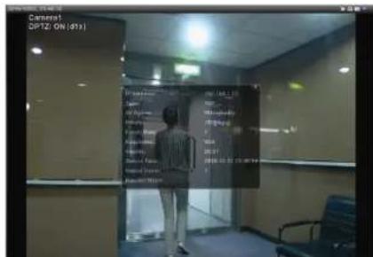
Static: No one coming in and out Dynamic: One or two people coming in and out
| Resolution Quality Frame Rate | (Dynamic) kbps (Static) kbps | |||
| D1 | Best | FULL | 2786 | |
| High | 1375 | 705 | ||
| Normal | 1234 | |||
| Basic | 441 | |||
| CIF | Best | 955 | ||
| High | 364 | 171 | ||
| Normal | 328 | 111 | ||
| Basic | 161 | |||
| D1 | Best | 1/5 | 935 | |
| High | 506 | 272 | ||
| Normal | 297 | 175 | ||
| Basic | 223 | |||
| CIF | Best | 222 | ||
| High | 133 | 67 | ||
| Normal | 81 | |||
| Basic | 71 | 32 | ||
| D1 | Best | 1/30 | 127 | 70 |
| High | 197 | 20 | ||
| Normal | 61 | 11 | ||
| Basic | 50 | |||
| CIF | Best | 42 | 7 | |
| High | 38 | |||
| Normal | 22 | 1 | ||
| Basic | 28 | |||
APPENDIX 3 API ID APPLICATION FOR SMS MESSAGING
To allow the camera automatically sending a text message when an event happens, you need to apply an API ID from Clickatell, one mobile messaging company, first.
Note: The SMS messaging is not totally free. You will be charged starting from the 11^th message.
Please follow the steps below for application.
Step1: Go to http://www.clickatell.com/login.php. In "New Customers", select "Clickatell Central (API)" from the drop-down list.
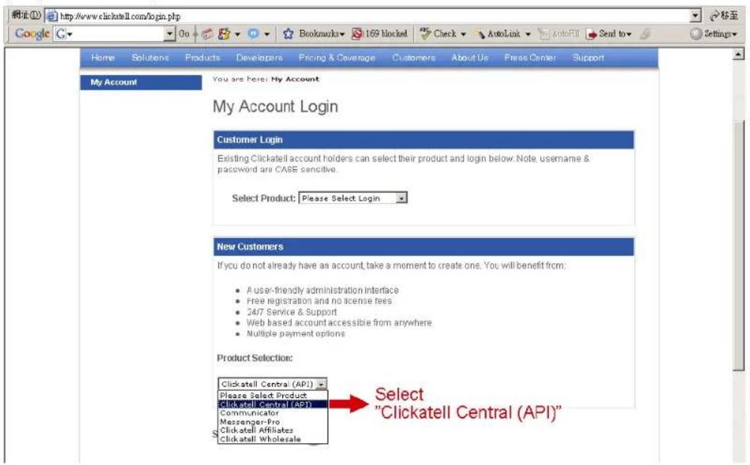
Step2: Fill in your information to create an account, and click "CONTINUE".
Note: Note down the user name and password, and the mobile phone number you specified here for SMS notification setting later.

Step2: When the account is created, the system will automatically send an Email to your specified Email address and ask you to activate your account.
Click the link in the Email to complete account activation, and enter the login page as follows. Enter the password you set, and click "Login".
My Account Login
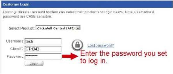
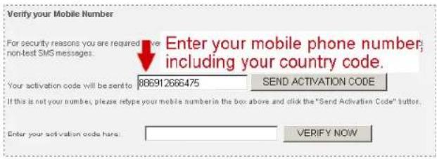
Step3: Enter the mobile phone number (including your country code) you want the text message to be sent, and click "SEND ACTIVATION CODE". The system will send an activation code to that number for verification.
Check if you receive a text message from Clickatell.
Step4: Go back to Clickatell, and click the tab "Manage my Products". Then, select "HTTP" from the drop-down list "My Connections".

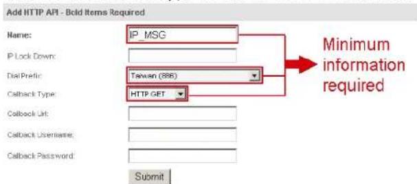
Step5: In "Add HTTP API", enter a descriptive name for this service, and make sure the dial prefix is correct and callback type is "HTTP GET". Then, click "Submit".
Step5: You will get an API ID as follows.
Note: Note down the API ID for SMS notification setting later.

APPENDIX 4 Q&A
For more details about Q&A, please visit our official website: www.eagleeyescctv.com/supp_QnA.aspx.
| Question Answer | |
| I can connect to this camera in my house or office where it's installed with wireless network.But when I leave my house or office, I can't connect to it from my mobile phone (with 3G network), or other PC (connected to Internet). Why? | You didn't configure this camera to Internet, but only in LAN.Please follow the steps in this manual to complete network configurations, or it's recommended for you to check with your local installer or reseller for this service because it's usually hard for a person who doesn't have network knowledge to set network configurations. |
| My live images are not fluent. Why? | Image fluency could be affected by the local network upload bandwidth, router efficiency, client network download bandwidth, complexity of live view, and more.(Recommended) To have better image fluency, select “CIF”; to have better image quality, select “D1”. |
| The live video keeps flickering. Why? | Please try adjusting the power line frequency to “60 Hz” or “50 Hz” for the camera.For iPhone users, access the camera, and select “on the top right corner to enter IPCAM Configuration page. Then, go to “Advance Setup” → “Camera” to change setting.For access from Internet Explorer, log into the camera, and select “Config.” → “Camera” → “Video”. |
- IMPORTANT SAFEGUARD
- Federal Communications Commission Interference Statement
- Trademark Acknowledgements
- Disclaimer
- MPEG4 Licensing
- GPL Licensing
- TABLE OF CONTENTS
- OVERVIEW.... 1
- CAMERA ACCESS WITH INTERNET EXPLORER.... 2
- CAMERA CONFIGURATIONS....5
- Camera 11
- Record....13
- Storage....13
- Trigger 14
- General 15
- APPENDIX 1 PRODUCT SPECIFICATIONS....20
- APPENDIX 2 BIT RATE TABLE FOR REFERENCE 21
- APPENDIX 3 API ID APPLICATION FOR SMS MESSAGING....22
- APPENDIX 4 Q&A 24
- OVERVIEW
- Product Features
- Package Content
- Cable Overview
- CAMERA ACCESS WITH INTERNET EXPLORER
- Camera Login
- Control Panel Overview
- Event Record Search & Playback
- CAMERA CONFIGURATIONS
- System configuration menu
- Network
- Network
- QoS
- DDNS
- SNTP
- FTP
- SMS
- Filter
- UPnP
- > Bonjour
- Port Mapping (Available only in UPnP)
- RTP
- Function Description
- ■ Port Range
- ■ Multicast
- Camera
- Camera
- Video
- Color
- Advance
- Record
- Record
- Record Timer
- Storage
- Memory
- Trigger
- Trigger
- ◆ Detect
- Action
- General
- General
- Time
- Server Log
- Online
- Account
- How to create a new account
- How to modify or delete an existing account
- Google Maps
- Maintenance
- Firmware Upgrade
- System Configuration Backup
- System Reboot
- Player Download
- APPENDIX 1 PRODUCT SPECIFICATIONS
- APPENDIX 2 BIT RATE TABLE FOR REFERENCE
- Testing Environment
- APPENDIX 3 API ID APPLICATION FOR SMS MESSAGING
- APPENDIX 4 Q&A
Brand : LOGILINK
Model : AVM265
Category : Surveillance Camera