
OEL8500 - Uncategorized Owon - Free user manual and instructions
Find the device manual for free OEL8500 Owon in PDF.


| Product Type | Programmable DC Electronic Load |
| Brand | Owon |
| Model | OEL8500 |
| Input Voltage Range | 0–80 V |
| Input Current Range | 0–50 A |
| Maximum Input Power | 400 W |
| Load Modes | Constant Current (CC), Constant Voltage (CV), Constant Power (CP), Constant Resistance (CR) |
| CC Accuracy | ±(0.1% + 0.1% of range) |
| CV Accuracy | ±(0.1% + 0.1% of range) |
| Resolution | 1 mA / 1 mV |
| Protection Features | Overvoltage, Overcurrent, Overpower, Overtemperature, Reverse Polarity |
| Display | 4.3-inch TFT LCD with numeric and graphical readout |
| Interface | USB Device, USB Host, RS232 (optional LAN) |
| Cooling | Intelligent fan with speed control |
| Operating Temperature | 0°C to 40°C |
| Storage Temperature | -20°C to 70°C |
| Dimensions (W x H x D) | 210 x 88 x 350 mm |
| Weight | Approx. 3.5 kg |
| Power Supply | AC 100–240 V, 50/60 Hz |
| Accessories Included | AC power cord, USB cable, user manual, test leads |
Frequently Asked Questions - OEL8500 Owon
User questions about OEL8500 Owon
0 question about this device. Answer the ones you know or ask your own.
Ask a new question about this device
Download the instructions for your Uncategorized in PDF format for free! Find your manual OEL8500 - Owon and take your electronic device back in hand. On this page are published all the documents necessary for the use of your device. OEL8500 by Owon.
USER MANUAL OEL8500 Owon
For product support, visit:www.owon.com.hk/download
※:The illustrations, interface, icons and characters in the user manual may be slightly
different from the actual product. Please refer to the actual product.
Copyright © LILLIPUT Company. All rights reserved.
The LILLIPUT's products are under the protection of the patent rights, including ones which have already obtained the patent rights and those which are applying for. The information in this manual will replace all that in the materials published originally.
The information in this manual was correct at the time of printing. However, LILLIPUT will continue to improve products and reserves the rights to change specification at any time without notice.
owon ^® is the registered trademark of the LILLIPUT Company.
Fujian LILLIPUT Optoelectronics Technology Co., Ltd.
No. 19, Heming Road
Lantian Industrial Zone, Zhangzhou 363005 P.R. China
Tel: +86-596-2130430 Fax: +86-596-2109272
Web: www.owon.com.cn
E-mail: info@owon.com.cn
General Warranty
We warrant that the product will be free from defects in materials and workmanship for a period of 2 years from the date of purchase of the product by the original purchaser from our company. The warranty period for accessories are 12 months. This warranty only applies to the original purchaser and is not transferable to a third party.
If the product proves defective during the warranty period, we will either repair the defective product without charge for parts and labour, or will provide a replacement in exchange for the defective product. Parts, modules and replacement products used by our company for warranty work may be new or reconditioned like new. All replaced parts, modules and products become the property of our company.
To obtain service under this warranty, the customer must notify our company of the defect before the expiration of the warranty period. Customer shall be responsible for packaging and shipping the defective product to our designated service centre, a copy of the customer's proof of purchase is also required.
This warranty shall not apply to any defect, failure or damage caused by improper use or improper or inadequate maintenance and care. We shall not be obligated to furnish service under this warranty a) to repair damage resulting from attempts by personnel other than our company representatives to install, repair or service the product; b) to repair damage resulting from improper use or connection to incompatible equipment; c) to repair any damage or malfunction caused by the use of not our supplies; or d) to service a product that has been modified or integrated with other products when the effect of such modification or integration increases the time or difficulty of servicing the product.
Please contact the nearest sales and service offices for services.
Excepting the after-sales services provided in this summary or the applicable warranty statements, we will not offer any guarantee for maintenance definitely declared or hinted, including but not limited to the implied guarantee for marketability and special-purpose acceptability. We should not take any responsibilities for any indirect, special or consequent damages.
Table of Contents
- General Safety Requirements ....1
- Safety Terms And Symbols.... 2
- Quick Start ....3
3.1 Product Introduction ....3
3.2 Panel and User Interface 4
3.2.1 Front Panel 4
3.2.2 Rear Panel 5
3.2.3 User Interface 7
3.3 General Inspection ....7
3.4 Power-on Inspection 8
- Functional features and Panel operation .....9
4.1 Turn On/Off the Channel Output 9
4.2 Local/Remote mode Operation switch 10
4.3 Constant Mode Operation 10
4.3.1 Constant Current Mode (CC) 10
4.3.2 Constant Voltage Mode (CV) 12
4.3.3 Constant Resistance Mode (CR) 14
4.3.4 Constant Power Mode (CP) 15
4.4 Input Control function 17
4.5 Keyboard Lock Function 17
4.6 Short Circuit Simulation Function .....18
4.7 System Menu Function 19
4.7.1 System Setting 19
4.7.2 Parameter Setting 20
4.8 Multiple Device Parallel Function 22
4.8.1 Parallel Output line Connection 22
4.8.2 Parallel Communication line Connection 23
4.8.3 Operating Instructions 24
4.9 Protection Functions and Fault Information 24
4.10 Communication Port Introduction 26
4.11 Test Function 27
4.11.1 Dynamic Test Function 27
4.12 Compensation Function 29
-
Troubleshooting....30
-
Technical Specification....31
-
Appendix ......34
7.1 Appendix A: Accessories 34
7.2 Appendix B: General Care and Cleaning 34
1. General Safety Requirements
Before use, please read the following safety precautions to avoid any possible bodily injury and to prevent this product or any other connected products from damage. In order to avoid any contingent danger, ensure this product is only used within the range specified.
Only the qualified technicians can implement the maintenance.
To avoid Fire or Personal Injury:
- Use Proper Power Cord. Use only the power cord supplied with the product and certified to use in your country.
- Connect the probe correctly. The grounding end of the probe corresponds to the grounding phase. Please don't connect the grounding end to the positive phase.
- Check all Terminal Ratings. To avoid fire or shock hazard, check all ratings and markers of this product. Refer to the user's manual for more information about ratings before connecting to the instrument.
- Do not operate without covers. Do not operate the instrument with covers or panels removed.
- Use Proper Fuse. Use only the specified type and rating fuse for this instrument.
- Avoid exposed circuit. Do not touch exposed junctions and components when the instrument is powered.
- Do not operate if in any doubt. If you suspect damage occurs to the instrument, have it inspected by qualified service personnel before further operations.
- Use your instrument in a well-ventilated area. Make sure the instrument installed with proper ventilation, refer to the user manual for more details.
- Do not operate in wet conditions. To avoid the risk of internal circuit short circuits or electric shock, do not operate the instrument in a humid environment.
- Do not operate in an explosive atmosphere. To avoid damage to the instrument or personal injury, do not operate the instrument in flammable or explosive environments.
- Keep product surfaces clean and dry. To prevent dust or moisture in the air from affecting the instrument's performance, please keep the product's surface clean and dry.
2. Safety Terms And Symbols
Safety Terms
Terms in this manual. The following terms may appear in this manual:

Warning: Warning indicates the conditions or practices that could result in injury or loss of life.

Caution: Caution indicates the conditions or practices that could result in damage to this product or other property.
Terms on the product. The following terms may appear on this product:
Danger: It indicates an injury or hazard may immediately happen.
Warning: It indicates an injury or hazard may be accessible potentially.
Caution: It indicates a potential damage to the instrument or other property might occur.
Safety Symbols
Symbols on the product. The following symbol may appear on the product:
 | Hazardous Voltage |  | Caution, risk of danger (refer to this manual for specific Warning Caution information) |
 | Protective Earth Terminal |  | Chassis Ground |
 | Test Ground |
3. Quick Start
This chapter will introduce the power-on inspection steps for the OEL85 series load, ensuring that the load can be properly turned on and used in its initialized state. It will also cover the front panel, rear panel, button functions, and display functions of the OEL85 series load, ensuring that before operating the load, users can quickly understand the load's appearance, structure, and button functionality, which will help you make better use of this series of loads.
3.1 Product Introduction
The OEL85 series single-channel programmable electronic load offers power ratings of 200W and 400W, with a resolution as high as 1mV and 0.1mA. It is primarily designed for applications such as fast chargers, battery discharge, and power supply testing, and other product performance validation tests. The series provides optimal solution for design R&D and production line testing.
OEL85 Series Model Selection Table:
| Model | Voltage | Current | Power | Communication interface |
| OEL8511 | 150V | 20A | 200W | USB, RS232, RS485 |
| OEL8511B | 300V | 20A | 200W | USB, RS232, RS485 |
| OEL8511C | 600V | 20A | 200W | USB, RS232, RS485 |
| OEL8512 | 150V | 40A | 400W | USB, RS232, RS485 |
| OEL8512B | 300V | 40A | 400W | USB, RS232, RS485 |
| OEL8512C | 600V | 40A | 400W | USB, RS232, RS485 |
3.2 Panel and User Interface
3.2.1 Front Panel
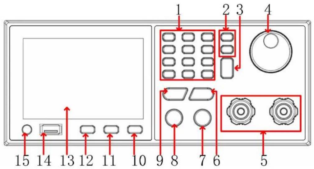
Figure 3-1 Front Panel
| 1 | 0-9 and .Esc | Number and dot key: input number;Esc key: return to the previous page. |
| 2 | < > | Use to move the cursor left and right to the desi parameter position. |
| 3 | Enter | Confirm parameter setting. |
| 4 | Knob | Users can turn the knob to enter programming information or options. |
| 5 | DC sourceInput terminal | The input connection of the DC source. |
| 6 | CC | Constant current mode setting button: When the us presses this button, the constant current setting mo selected, and user can use the numeric buttons o to input the set current value. |
| 7 | ON/OFF | Control the output status: ON or OFF. |
| 8 | LOCK | Lock all buttons and knobs;Way to remove: press and hold the LOCK key to the setting. |
| 9 | CV | Constant voltage setting button: When the user pre this button, the constant voltage setting mode is selected; and user can use the numeric buttons o to input the set voltage value. |
| 10 | SHIF | Reuse function keys. |
| 11 | MODE | Switch load mode setting selection |
| 12 | CONF | Switch to the system menu to select the system and parameter settings. |
| 13 | Display area | TFT color screen display, output Settings and measurement results. |
| 14 | USB | USB data interface. |
| 15 | Power button | Turn on/off instrument. |
3.2.2 Rear Panel
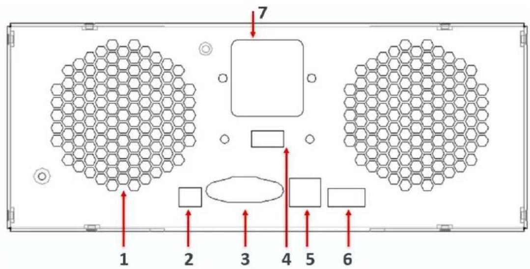
Figure 3-2 Rear Panel
| 1 Fan | Do not block the outlet of the fan, otherwise tr |
| internal heat dissipation of the machine will lead excessive internal temperature. | ||
| 2 | Remote compensation | When the remote sensing function is enabled, the sampling terminal should be connected to the low side to compensate for the voltage drop across wires. After enabling the function, please ensure Vsen+ is connected to the output positive (+), a Vsen- is connected to the output negative (-). [ reverse the connections or leave them floating. |
| 3 | DB9 interface | This port includes RS232 and RS485 function, u can use RS232 for communication control, and RS485 can be used as multi-machines parallel function. |
| 4 | AC power selection switch | 220V/110V switch selector. |
| 5 | USB serial port | This USB serial port can be used to connect t computer. |
| 6 | Trig | The Trigger In/Out function allow external trigger signal input and output. |
| 7 | AC Power terminal | The power supply line inputs AC power, from th connection terminal to the input terminal. |
3.2.3 User Interface
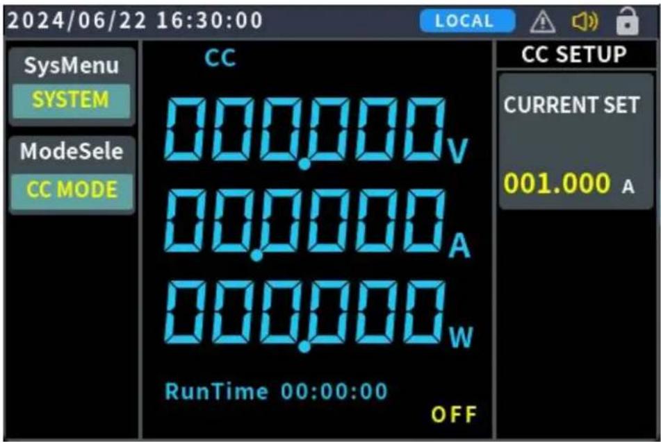
Figure 3-3 User Interface
Status Icon
| Icon | Description |
| The panel keys are locked | |
| Enable beeper | |
| A failure alarm |
3.3 General Inspection
When you receive a new OEL85 series DC electronic load, it is recommended that you follow the steps below to inspect the instrument.
1. Check whether there is any damage caused by transportation.
If it is found that the packaging carton or the foamed plastic protection cushion has suffered serious damage, do not throw it away first till the complete device and its accessories succeed in the electrical and mechanical property tests.
2. Check the Accessories.
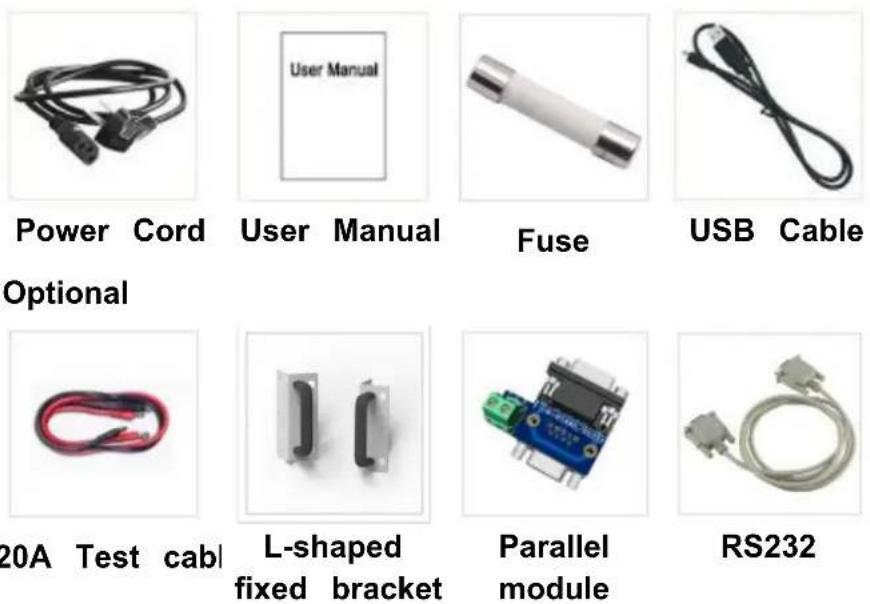
The supplied accessories have been already described in Appendix A: Accessories of this manual. You can check whether there is any loss of accessories with reference to this description. If it is found that there is any accessory lost or damaged, please get in touch with our distributor responsible for this service or our local offices.
3. Check the Complete Instrument.
If it is found that there is damage on the first appearance of the instrument, or the instrument cannot work normally, or fails in the performance test, please get in touch with our distributor responsible for this business or our local offices. If there is damage to the instrument caused by the transportation, please keep the package. With the transportation department or our distributor responsible for this business informed about it, a repairing or replacement of the instrument will be arranged by us.
3.4 Power-on Inspection
(1) Connect the instrument to an AC power source using the power cord supplied with the accessory.

Warning:
To prevent electric shock, make sure the instrument is properly grounded.
(2) Press the power button on the front panel and the startup screen will be displayed on the screen.
4. Functional features and Panel operation
This chapter will provide a detailed description of the features and functions of the OEL85 DC electronic load, as well as the panel menu operations. It will be divided into the following sections:
- Turn on/off channel output
- Local/Remote mode operation switch
- Constant mode function
- Input control function
● Keyboard lock function - Short circuit simulation function
- System menu function
● Multiple device parallel function - Fault information
● Introduction to communication interfaces
● Test function - dynamic test (CC Dynamic)
4.1 Turn On/Off the Channel Output
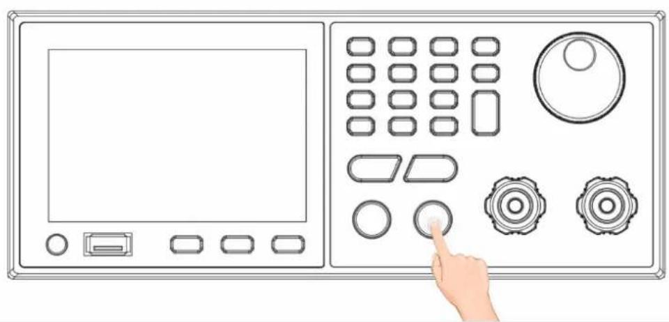
Press the ON/OFF key to turn on/off the channel. When the ON/OFF key is bright, the output is turned ON; when the ON/OFF key light is off, the output is turned off. When the power is turned on, the panel defaults to the main interface to display the current state.
natural_image
Illustration of a control panel with buttons and a hand pointing at the button (no text or symbols present)Press the button, the indicator light shows that the output is open; Press the key again and the indicator light goes off to indicate that the output is off.
4.2 Local/Remote mode Operation switch
The instrument provides both local and remote operation mode, and the two modes can be switched by communication commands. In power initialization mode, the machine is operated locally by default.
- Local operation mode: Use the keys on the panel to perform relevant operations.
- Remote operation mode: The instrument is connected to the PC, and the PC performs relevant operations on the instrument. When the instrument is in remote mode, all the buttons in the panel do not work except for the LOCK key. You can switch to local operation mode by press and hold LOCK key. When the operation mode is changed, it will not affect the output parameters of the instrument.
4.3 Constant Mode Operation
The electronic load can operate in the following four constant modes:
- Constant Current mode (CC)
- Constant Voltage mode (CV)
- Constant Resistance mode (CR)
- Constant Power mode(CP)
4.3.1 Constant Current ModeCC)
When the user selects the CC function key, the load enters constant current mode. In constant current operation mode, regardless of changes in the input voltage, the electronic load consumes a constant current. The relationship between voltage and current is shown in the figure below.
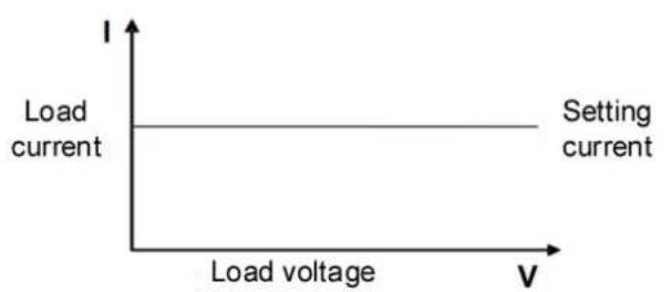
Figure 4.3.1-1 CC mode: The Voltage-Current Relationship Diagram
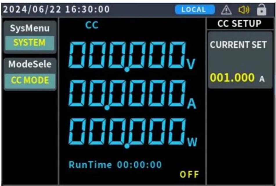
Figure 4.3.1-2 CC mode operation interface
There are two ways to set the output current (CC mode):
Mode one:
- Press MODE and rotary the knob to select CC mode.
- Press Enter key to edit current setting, use the numeric 0-9 softkey to set desired current. Press Enter key to save current setting, or turn the knob to adjust directly to the set value.
- Press ON/OFF key to output the setting current.
Mode two:
- Press CC, at the same time, the user interface will switch into CC mode.
- Press Enter key to edit current setting, use the numeric 0-9 softkey to set desired current. Press Enter key to save current setting, or turn the knob
to adjust directly to the set value.
- Press ON/OFF key to output the setting current.
In constant current mode, the user can also set the following parameters.
Operation steps:
- Press CONF to enter parameter setting interface
- Set the maximum working current
- Set voltage/current range
- Set the rising slope of current
- Set the falling slope of current
- OCP, OVP, OPP setting
4.3.2 Constant Voltage Mode (CV)
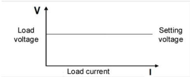
When the user selects the CV function key, the load enters constant voltage mode. In constant voltage operation mode, the electronic load will draw sufficient current to maintain the input voltage at the set value. The relationship between voltage and current is shown in the figure below.
line
| Load current | Voltage | | ------------ | ------- | | 0 | 2.5 | | 1 | 2.5 |Figure 4.3.2-1 CV mode: The Voltage-Current Relationship Diagram
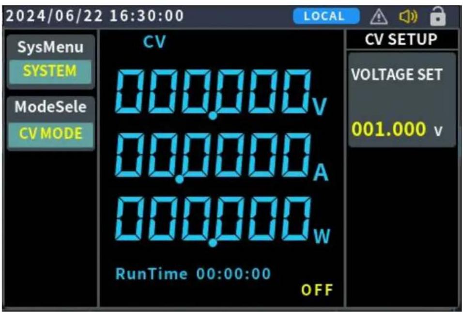
Figure 4.3.2-2 CV mode operation interface
There are two ways to set the output voltage (CV mode):
Mode one:
- Press MODE and rotary the knob to select CV mode.
- Press Enter key to edit voltage setting, use the numeric 0-9 softkey to set desired voltage. Press Enter key to save voltage setting, or turn the knob to adjust directly to the set value.
- Press ON/OFF key to output the setting voltage.
Mode two:
- Press CV, at the same time, the user interface will switch into CV mode.
- Press Enter key to edit voltage setting, use the numeric 0-9 softkey to set desired voltage. Press Enter key to save voltage setting, or turn the knob to adjust directly to the set value.
- Press ON/OFF key to output the setting voltage. In constant voltage mode, the user can also set the following parameters.
Operation steps:
- Press CONF to enter parameter setting interface
- Set the maximum working current
-
Set the voltage range
-
Set the rising/falling slope of the voltage
- OCP, OVP, OPP setting
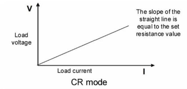
4.3.3 Constant Resistance Mode (CR) When the user selects the SHIFT+ CV function key, the load enters constant resistance mode (CR). In constant resistance operation mode, the electronic load will behave as a constant resistor. The current will change linearly with the input voltage. The relationship between voltage and current is shown in the figure below.
line
| Load current | V | | ------------ | ----- | | I | 0 | | V | 1 |Figure 4.3.3-1 CR mode: The Voltage-Current Relationship Diagram
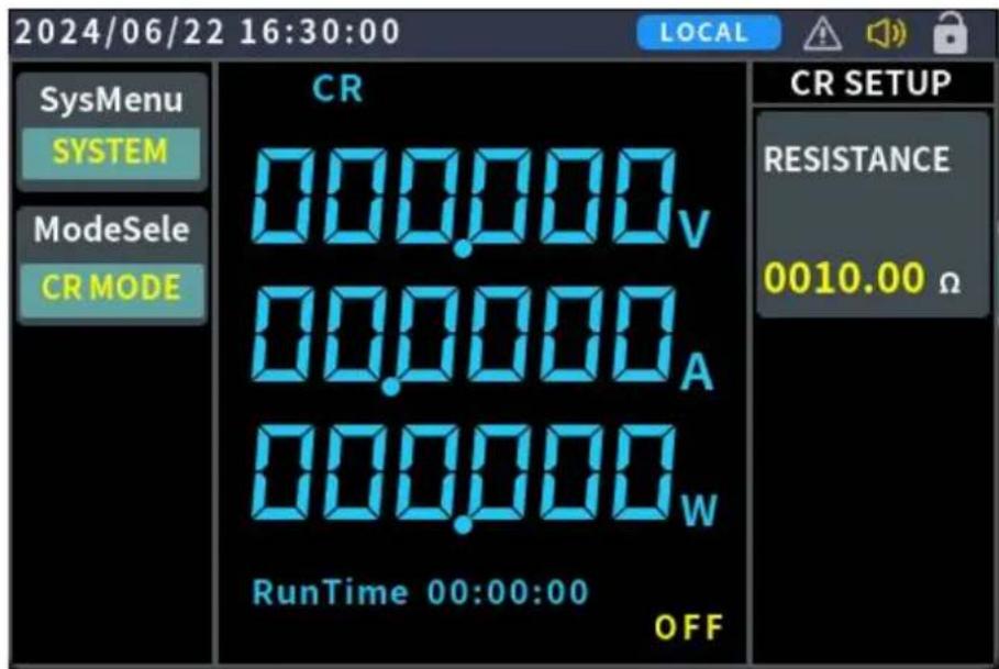
Figure 4.3.3-2 CR mode operation interface
There are two ways to set the output resistance (CR mode):
Mode one:
- Press MODE and rotary the knob to select CR mode.
-
Press Enter key to edit resistance setting, use the numeric 0-9 softkey to set desired resistance. Press Enter key to save resistance setting, or turn the knob to adjust directly to the set value.
-
Press ON/OFF key to output the setting resistance.
Mode two:
- Press SHIFT+CV, at the same time, the user interface will switch into CR mode.
-
Press Enter key to edit resistance setting, use the numeric 0-9 softkey to set desired resistance. Press Enter key to save resistance setting, or turn the knob to adjust directly to the set value.
-
Press ON/OFF key to output the setting resistance.
In constant resistance mode, the user can also set the following parameters.
Operation steps
- Press CONF to enter parameter setting interface
- Set the maximum working current
- Set voltage range
- Set the rising/falling slope of resistance
a) Fast b) Normal c) Slow - OCP, OVP, OPP setting
4.3.4 Constant Power Mode (CP)
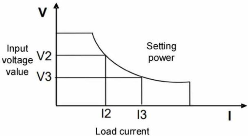
When the user selects the SHIFT+ CP function key, the load enters constant power mode. The electronic load will consume a constant power, as shown in the figure below. If the input voltage increases, the input current will decrease. The relationship between voltage and current is shown in the figure below.
line
| Load current | Input voltage value | | ------------ | ------------------- | | I2 | V2 | | I3 | V3 |Figure 4.3.4-1 CP mode: The Voltage-Current Relationship Diagram
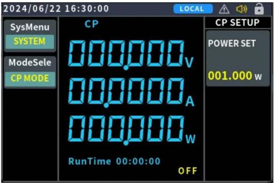
Figure 4.3.4-2 CP mode operation interface
There are two ways to set the output power (CP mode):
Mode one:
- Press MODE and rotary the knob to select CP mode.
- Press Enter key to edit power setting, use the numeric 0-9 softkey to set desired power. Press Enter key to save power setting, or turn the knob to adjust directly to the set value.
- Press ON/OFF key to output the setting power.
Mode two:
- Press SHIFT+CC, at the same time, the user interface will switch into CP mode.
- Press Enter key to edit power setting, use the numeric 0-9 softkey to set desired power. Press Enter key to save power setting, or turn the knob to adjust directly to the set value.
- Press ON/OFF key to output the setting power. In constant power mode, the user can also set the following parameters.
Operation steps
- Press CONF to enter parameter setting interface
- Set the maximum working current
- Set voltage range
- Set the rising/falling slope of power a) Fast b) Normal c) Slow
- OCP, OVP, OPP setting
4.4 Input Control function
After the electronic load is turned on, it is in an unconnected (no load) state. The input switch of the electronic load can be controlled by pressing the ON/OFF button on the front panel of the electronic load.
- When the ON/OFF indicator light is on, it means the input is turned on, and the TFT screen displays the current real-time voltage and current information.
- When the ON/OFF indicator light is off, the screen will display OFF, indicating that the input is turned off.
4.5 Keyboard Lock Function
The front panel buttons of the electronic load can be locked by pressing the LOCK button. The screen will display the LOCK status. In this mode, all buttons are disabled except for unlocking the function by pressing and holding the LOCK button.
4.6 Short Circuit Simulation Function
The electronic load can simulate a short circuit at the input terminal to test whether the protection function of the device under test (DUT) operates correctly when a short circuit occurs at its output terminal.
To switch to the short circuit state, press (SHIFT) + 1 (SHORT) on the front panel of the electronic load. The short circuit operation does not affect the current settings, and pressing (SHIFT) + 1 (SHORT) or MODE again will return the electronic load to its original set state. The actual current consumed by the electronic load during a short circuit depends on the current operating mode and current range. In CC , CP, and CR modes, when the current is within the maximum range, the short-circuit current will be equal to the current input value. If the current exceeds the maximum range, the maximum short-circuit current will be 110% of the current range. In CP mode, a short circuit is equivalent to setting the load's constant voltage value to 0V.
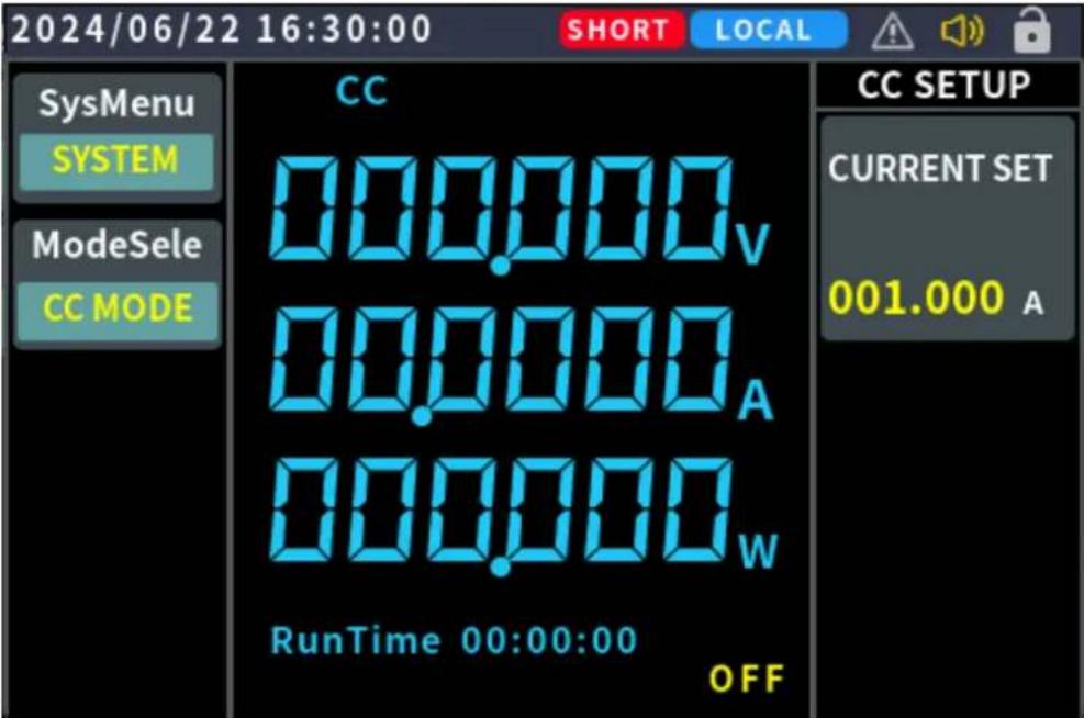
Figure 4.6-1 Short circuit simulation interface
4.7 System Menu Function
Press CONF to enter system setting function.
Detail operation steps:
Press CONF to enter "Function menu" item setting.
- Rotary the knob to select the item you want to set.
- Press Enter to confirm.
- Press Esc or CONF to return the function menu.
Description:
- To cancel the setting, press the **Esc** key to return to the function page.
- If you are on any setting page, pressing the CC key or CV key will quickly return you to main page.
4.7.1 System Setting
The menu of the electronic load is as follows:
| Menu | Settings | Description |
| SYSTEM SETUP | LANGUAGE | Chinese/ENGLISH |
| DATA SET | Set year/month/day | |
| TIME SET | Set hour/minute/second | |
| COMM PRO | SCPI communication setting | |
| BUTTON VOICE | Enable or disable button sound | |
| ALARM VOICE | Enable or disable alarm sound | |
| BRIGHTNESS | Screen brightness adjustment from 10% to 100%, with a 10% adjustment each time. | |
| BAUD | The baud rate setting range of the communication device is from 115200 to 18 baud rates are available for selection. | |
| RESET | Restore the settings on the panel to facto defaults. | |
| PARALLEL | Set the parallel enable or disable. | |
| MASTER/SLAVE | Set the local machine as the master device the slave device. | |
| ADDRESS | The parallel machine address can be sele from 1 to 10 to set the local machine's address. | |
| MULTIPLE | Parallel |
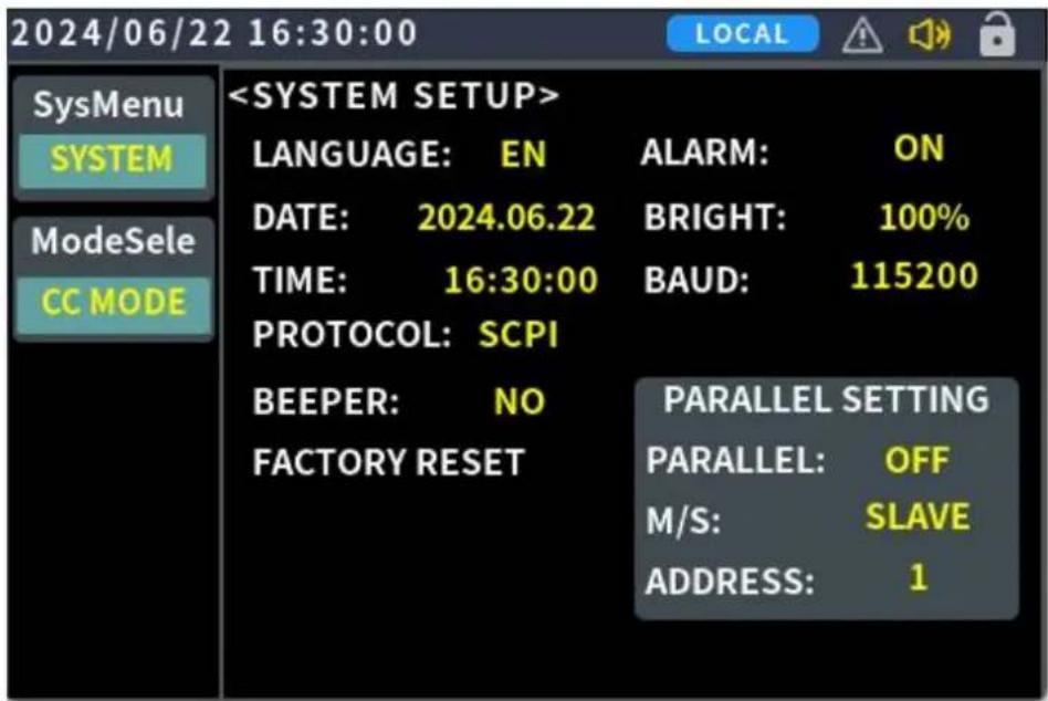
4-7-1 system setup page
4.7.2 Parameter Setting
Select System Settings, then choose Parameter Settings. Press the Enter key to enter the Parameter Settings options, as shown in the table below. The parameter settings of the electronic load are as follows:
| Menu | Settings | Description |
| Parameter setup | OVP | If the input voltage exceeds the set safety threshold point), the OVP protection will be triggered. |
| OCP | If the input current exceeds the set safety threshold point), the OCP protection will be triggered. | |
| OPP | If the input power exceeds the set safety threshold point), the OPP protection will be triggered. | |
| RISE SLOPE | The setting value for the rise rate of input voltage current during load operation. | |
| FALL SLOPE | The setting value for the fall rate of input voltage current during load operation. | |
| CURRENT LIMIT | The maximum current value that can be set for no load operation. | |
| REMOTE COMPENSATION | This option allows enabling the remote sensing fund at the rear terminals, with the default setting for compensation at the front panel input terminals. | |
| NO-LOAD VOLTAGE | After the load is connected and operating normally, device will shut down when the input voltage reach unload voltage setting value. | |
| VOLTAGE RANGE | The input voltage range supported by the electronic is as follows:● Low range: 0-15V● High range: 0-150V | |
| CURRENT RANGE | The input current range supported by the electronic is as follows:● Low range: 0-4A (8512B version only)● High range: 0-40A | |
| LOAD VOLTAGE | After the load is connected, normal load operation occur once the input voltage reaches the set load voltage. |
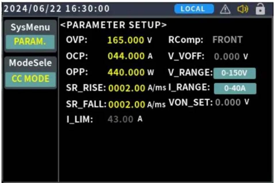
4-7-2 parameters setup page
4.8 Multiple Device Parallel Function
The OEL85 series products can be operated in parallel, supporting up to 10 units, with a maximum current of up to 400A.
| Model | Parallel mode | |
| Maximum number of combinations | Maximum current | |
| OEL8511 | ||
| OEL8511B | 10 | 200A |
| OEL8511C | ||
| OEL8512 | ||
| OEL8512B | 10 | 400A |
| OEL8512C | ||
Description:
- Different models cannot be operated in parallel.
- Parallel operation is supported in CC, CP, and CR modes (CV, s dynamic modes are not supported).
- If the number of parallel units exceeds 10, please consult OWON customer service or authorized distributor.
- Please note that there can only be one master unit in the system addresses of all units should be different.
- Communication between multiple units in parallel is done using RS
4.8.1 Parallel Output line Connection
The parallel output wiring method is shown in the figure below.
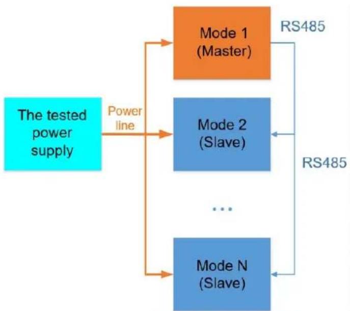
flowchart
graph TD
    A["The tested power supply"] -->|Power line| B["Mode 1 (Master)"]
    A --> C["Mode 2 (Slave)"]
    A --> D["..."]
    A --> E["Mode N (Slave)"]
    B --> F["RS485"]
    C --> G["RS485"]
    E --> H["RS485"]
Note: N represents the number of parallel modules
4.8.2 Parallel Communication line Connection
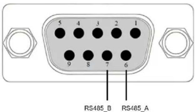
The OEL85 series parallel communication uses RS485. Users can communicate through the DB9 interface, with the communication pins as shown in the diagram below: Pin 6 and Pin 7.
| Pin | Function |
| Pin 6 | RS485_A |
| Pin 7 | RS485_B |
4.8.3 Operating Instructions
- First setting Master address
To set a unit as the master, go to the "System Settings" page on the panel, and select "Master" under the "Master/Slave" option.
Then set the address (the default address for the master is 10).
Finally, select Enable Parallel.
- Then, configure the addresses for the parallel slave
To set a unit as a slave, go to the "System Settings" page on the panel and select "Slave" under the "Master/Slave" option.
Then, set the address (slave addresses range from 1 to 9, and it is recommended to start from 1).
Finally, select Enable Parallel.
- Set the current parameters on the master and power it on.
Finally, configure the relevant operating parameters (such as current, resistance, power, etc.) in the master unit's parameter settings.
Once the settings are complete, press the power button to turn on the system.
4.9 Protection Functions and Fault Information
The OEL85 series products monitor the internal operation of the machine in real time, including system logic faults, external mains power faults, internal power stage faults such as OVP (Over Voltage Protection), OCP (Over Current Protection), OPP (Over Power Protection), OTP (Over Temperature Protection), as well as parallel operation faults, input reverse voltage protection, etc.
When any of the above protections are triggered, the electronic load enters the corresponding self-protection mode. For example, in the case of over-temperature protection, the load will trigger an alarm and automatically switch to the OFF state, with the main unit displaying OTP.
Protection mode can be cleared by pressing the power button or the ENTER button on the front panel.
Over Voltage Protection (OVP)
If the over-voltage circuit is triggered, after a 100us delay, the electronic load
will immediately turn OFF, and the buzzer will sound. The main unit will display OVP. Protection can be cleared by pressing the power button or the ENTER button.
Over Current Protection (OCP)
There are two types of over-current protection in the electronic load:
- Hardware overcurrent protection: The maximum load current of the OEL8500 will be limited to the corresponding current value by the hardware maximum power (such as OEL8512: 400W). Once the hardware overcurrent protection is triggered, the machine is at the maximum power value and will not trigger the current ON/OFF state.
- Software Over Current Protection: When the software overcurrent protection function is turned on, if the load current exceeds the overcurrent protection setting value, after 100ms, the load will automatically turn off, and the panel will display OCP. In order to ensure the reliability of the machine, if the load current abnormally exceeds 2 times the rated maximum current of the machine for 40us or 1.1 times the rated current for 100us, the fast software overcurrent protection is triggered, the load will automatically turn off, and the panel will display OCP. Users can set the software overcurrent protection value of the OEL8500 series product. For related configuration, please refer to CONF key to enter the parameter setting.
Over Power Protection (OPP)
There are two types of over-power protection in the electronic load:
- Hardware Over Power Protection: The maximum load power will be limited to the corresponding power value by the hardware maximum power (such as OEL8512: 400W). Once the hardware over-power protection is triggered, the machine is at the maximum power value and will not trigger the current ON/OFF state.
- Software Over Power Protection: When the software over-power protection function is turned on, if the load power exceeds the over-power protection setting value and lasts for 100ms, the load will automatically turn off and the panel will display OPP. In order to ensure the reliability of the machine, if the load power abnormally exceeds 2
times the rated maximum current of the machine for 40us or 1.1 times the rated current for 100us, the fast software over-power protection is triggered, the load will automatically turn off and the panel will display OPP. Users can set the software over-power protection value of the load. For related configuration items, please refer to CONF to enter the parameter setting.
Over Temperature Protection (OTP)
When the internal devices' temperature of the electronic load exceeds about 85^ , the electronic load would trigger the temperature protection mode, and the electronic load automatically turns OFF and the panel displays OTP.
Local Reverse Voltage Protection (LRV)
When the electronic load detects a reverse voltage input on the front panel, it will trigger the Local Reverse Voltage (LRV) protection warning. In this case, please confirm that the front panel input terminals are correctly connected to the device under test. It can be released by pressing the power button or the ENTER button.
| Fault Type | ERROR CODE | Fault cause Description |
| MAINS AC FAULT | 0x0002 | Abnormal mains undervoltage |
| INTERNAL FAULT | 0x0004 | Over temperature protection |
| 0x0010 | Error in internal parameter storage | |
| 0x0020 | Model firmware match error | |
| OUTPUT FAULTS | 0x0002 | Output over voltage protection |
| 0x0008 | Output over current protection | |
| 0x0010 | Output over power protection | |
| 0x0004 | Local Reverse Voltage Protection | |
| PARALLEL FAULTS | 0x0001 | Parallel address conflict |
| 0x0002 | Multiple master fault | |
| 0x0008 | Communication drop | |
| 0x0010 | Mismatch in operable unit fault |
4.10 Communication Port Introduction
The rear panel of the load in this series is equipped with a USB serial port. After connecting to a PC, ensure that the serial port settings in the PC software interface match those of the load device (9600 baud rate, 8 data bits,
no parity, 1 stop bit).
USB port
Use a USB cable with USB A-type on one end and USB B-type on the other end to connect the load to the computer. All electronic load functions can be controlled through USB programming. After connecting the load and PC via USB, the CH340 USB driver needs to be installed (available for download from the OWON website or by directly contacting OWON technical support), otherwise, communication will not be successful.
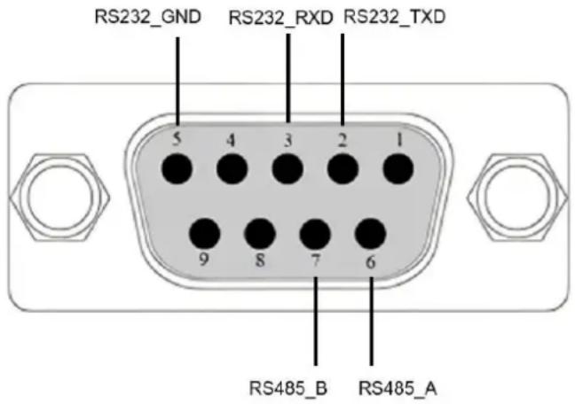
The electronic load supports RS232 and RS485 (for internal parallel use). The following table provides the corresponding pin definitions (output via DB9 terminal connector):
| Pin | Function | Supported protocols | Function |
| Pin 2 | RS232 | SCPI | TXD |
| Pin 3 | RXD | ||
| Pin 5 | GND |
4.11 Test Function
4.11.1 Dynamic Test Function
In dynamic mode, the OEL85 series electronic load allows the user to set
two load current parameters corresponding to the constant mode. By configuring the operation mode, the load current will switch back and forth between the two set values.
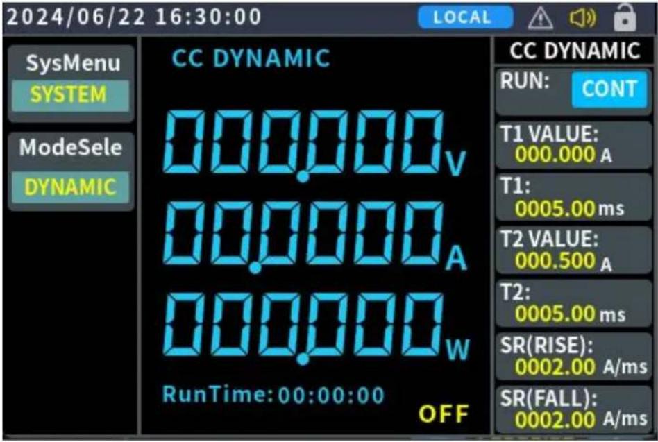
Dynamic Mode Setting Parameters:
| Dynamic Test | Description |
| Operation Mode | Select the continuous operation mode: Continu / Single |
| T1 Value | Set the T1 load current parameter |
| T1 Time | Set the T1 load current duration |
| T2 Value | Set the T2 load current parameter |
| T2 Time | Set the T2 load current duration |
| Rise Slope | Set the rise slope |
| Fall Slope | Set the fall slope |
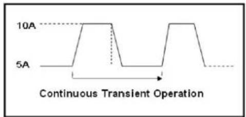
Continuous Mode
In continuous mode, when dynamic test operation is enabled, the load will continuously switch between the T1 value and T2 value.
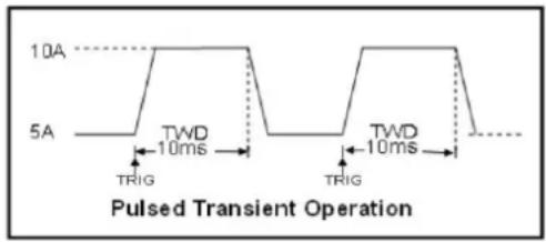
Single Pulse Mode (Pulse)
In single pulse mode, when dynamic test operation is enabled, the load will switch once between the T1 value and T2 value. Each time the load receives a “SHIF.” trigger command, it will perform a single switching action. The diagram below shows a schematic of the operation interface in this mode.
4.12 Compensation Function
When the electronic load operates with high current, significant voltage drops can occur across the connection cables between the load and the device under test (DUT). To ensure measurement accuracy, the electronic load provides a pair of remote compensation terminals. Users can use these terminals to sample the precise output voltage of the DUT.
Operating Steps:
- In the system parameter settings page, locate the remote compensation (RComp) option and select "Rear." Press confirm to enable the remote compensation function. At this point, the remote sampling voltage will be used as the actual detected voltage.
- Return to the parameter settings page and select the remote compensation (RComp) option as "Front." This will disable the remote compensation function for the rear terminal, and the load will measure the voltage at the main front-panel binding posts as the actual voltage.
Note:
After enabling rear remote compensation, ensure correct polarity connections between the DUT and the terminals. Do not leave connections floating or reverse the polarity! Do not switch the sense mode while the system is running!
5. Troubleshooting
-
The instrument is powered on but no display. Please following the steps:
-
Check if the power is connected properly.
- Check if the fuse which is below the AC Power socket is used appropriately and in good condition (the cover can be pried open with a straight screwdriver).
- Restart the instrument after the steps above.
- If the problem still exists, please contact our customer service.
6. Technical Specification
The instrument must be operated continuously for more than 30 minutes at the specified operating temperature to achieve the following specifications:
| Model | OEL8512 | OEL8512B | OEL8512C | OEL8511 | OEL8511B | OEL8511C | |||||||
| Input | Voltage | 0-150V | 0-300V | 0-600V | 0-150V | 0-300V | 0-600V | ||||||
| Current | 0-40A | 0-20A | |||||||||||
| Power | 400W | 200W | |||||||||||
| MinimumOperationvoltage | 1.1V@40A | 0.8V@20A | |||||||||||
| Constant voltage mode (CV) | |||||||||||||
| Range | 0-150V | 0-300V | 0-600V | 0-150V | 0-300V | 0-600V | |||||||
| Resolution | 1mV | 1mV | |||||||||||
| Accuracy | 0.05%+0.05%FS | ||||||||||||
| Constant current mode (CC) | |||||||||||||
| Range | 0-40A | 0-20A | |||||||||||
| Resolution | 1mA | 1mA | |||||||||||
| Accuracy | 0.03%+0.03%IFS | ||||||||||||
| Constant resistance mode (CR) | |||||||||||||
| Range | 0.05-7.5k | ||||||||||||
| Accuracy *1 | 0.1%+0.01%R | ||||||||||||
| Constant power mode (CP) | |||||||||||||
| Range | 400W | 200W | |||||||||||
| Resolution | 10mW | 10mW | |||||||||||
| Accuracy *1 | 0.1%+0.1%FS | ||||||||||||
| Dynamic mode (CCD) | |||||||||||||
| T1&T2 | 0.1ms-50s | ||||||||||||
| Rise/Fallslope | 0.01A/ms-2000A/ms | ||||||||||||
| Min rise time | 20us | ||||||||||||
| Voltage readback value | |||||||||||||
| Range | 0-15V | 0-150V | 0-30V | 0-300V | 0-60V | 0-600V | 0-15V | 0-150V | 0-30V | 0-300V | 0-60V | 0-600V | |
| Resolution | 1mV | 1mV | 1mV | 1mV | 1mV | 1mV | |||||||
| Accuracy | 0.03%+0.05%FS | 0.03%+0.05%FS | 0.03%+0.05%FS | 0.03%+0.05%FS | 0.03%+0.05%FS | 0.03%+0.05%FS | |||||||
| Current readback value | |||||||||||||
| Range | 0-40A | 0-20A | |||||||||||
| Resolution | 0.1mA | 0.1mA | |||||||||||
| Accuracy | 0.03%+0.03%FS | ||||||||||||
| Power readback value | |||||||||||||
| Range | 0-400W | 0-200W | |||||||||||
| Resolution | 10mW | ||||||||||||
| Accuracy | 0.1%+0.1%FS | ||||||||||||
| Protection function | |||||||||||||
| OPP | >OPP value 10ms protection | ||||||||||||
| OVP | >OVP value 0.1ms protection | ||||||||||||
| OCP | >OCP value 0.1ms protection | ||||||||||||
| OTP | 85°C | ||||||||||||
| Short circuit | |||||||||||||
| Current (CC) | >40A | >20A | |||||||||||
| Voltage (CV) | 0 | ||||||||||||
| Resistance(CR) | 50mΩ | ||||||||||||
| Test Function | |||||||||||||
| Battery test,OCP | Optional, only for “T”version | ||||||||||||
| AC parameter | |||||||||||||
| Voltage range | 110V ±10% or 220V ±10% | ||||||||||||
| Frequency range | 50/60Hz | ||||||||||||
| Interface | ||
| RS-232 | Supported SCPI | |
| General | ||
| Heat dissipation | Internal intelligent fan forced air cooling | |
| Safety | Compliant with the European EMC Directive 89/336/EEC, for Class A test measurement products | |
| Withstand voltage (Input to Ground) | 1.5KV/AC/5mA | |
| Volume (L*W*H) | 375mm*215mm*88mm | |
| Net weight | Approx. 5kg | Approx. 4.2kg |
* 1 Accuracy: The voltage and current input values should not be less than 10%FS
If there are any changes to parameters, no separate notice will be given.
Please refer to the website update for the latest information.
Interval Period of Adjustment: One year is recommended for the calibration interval period.
7. Appendix
7.1 Appendix A: Accessories
(The accessories subject to final delivery.)
Standard
7.2 Appendix B: General Care and Cleaning
General Care
Do not store or leave the instrument where the liquid crystal display could be exposed to direct sunlight for long periods of time.
Caution: To avoid any damage to the instrument, do not exposed it to any sprays, liquids, or solvents.
Cleaning
Inspect the instrument as often as operating conditions require. To clean the instrument exterior, perform the following steps:
-
Wipe the dust from the instrument surface with a soft cloth. Take care not to scratch the transparent LCD protection screen when cleaning.
-
Disconnect power before cleaning your instrument. Clean the instrument with a damp soft cloth (not dripping with water). It is recommended to clean with soft detergent or fresh water. To avoid damage to the instrument, do not use any corrosive chemical cleaning agents.

Warning:
Before re-applying power, ensure that the instrument is complete avoiding any electric shock or electrical short circuit resulting from moisture.

- General Warranty
- Table of Contents
- General Safety Requirements
- Safety Terms And Symbols
- Safety Terms
- Safety Symbols
- Quick Start
- Product Introduction
- Panel and User Interface
- Front Panel
- Rear Panel
- User Interface
- Status Icon
- General Inspection
- Check whether there is any damage caused by transportation.
- Check the Accessories.
- Check the Complete Instrument.
- Power-on Inspection
- Warning:
- Functional features and Panel operation
- Turn On/Off the Channel Output
- Local/Remote mode Operation switch
- Constant Mode Operation
- Constant Current ModeCC)
- Operation steps:
- Constant Voltage Mode (CV)
- There are two ways to set the output resistance (CR mode):
- Mode one:
- Mode two:
- Operation steps
- Constant Power Mode (CP)
- Input Control function
- Keyboard Lock Function
- Short Circuit Simulation Function
- System Menu Function
- Description:
- System Setting
- Parameter Setting
- Multiple Device Parallel Function
- Parallel Output line Connection
- Parallel Communication line Connection
- Operating Instructions
- - First setting Master address
- - Then, configure the addresses for the parallel slave
- - Set the current parameters on the master and power it on.
- Protection Functions and Fault Information
- Over Voltage Protection (OVP)
- Over Current Protection (OCP)
- Over Power Protection (OPP)
- Over Temperature Protection (OTP)
- Local Reverse Voltage Protection (LRV)
- Communication Port Introduction
- Test Function
- Dynamic Test Function
- Continuous Mode
- Single Pulse Mode (Pulse)
- Compensation Function
- Operating Steps:
- Note:
- Troubleshooting
- Technical Specification
- Appendix
- Appendix A: Accessories
- Appendix B: General Care and Cleaning
- General Care
- Cleaning
Brand : Owon
Model : OEL8500
Category : Uncategorized