
P4000 - Uncategorized Owon - Free user manual and instructions
Find the device manual for free P4000 Owon in PDF.


| Product Type | Single Channel DC Power Supply |
| Model | P4000 |
| Brand | Owon |
| Output Channels | 1 |
| Display | LCD with Number and Curve display modes |
| Output Voltage Range | 0 – 61.00 V |
| Output Current Range | 0 – 3.10 A |
| Output Power | Not specified |
| Protection | Over Voltage Protection (OVP), Over Current Protection (OCP) |
| Interfaces | RS232 (COM port), USB (optional) supporting USBTMC |
| Memory | 5 sets (M1–M5) for quick output |
| Power Supply | AC input via included power cord; fuse protection |
| Safety | Grounding required; use proper fuse; avoid damp/explosive environments |
| Cleaning | Disconnect power; use damp soft cloth; mild detergent; dry completely before use |
| Accessories Included | Power cord, RS232 cable, user manual, fuse, CD |
| Warranty | 2 years for main unit, 1 year for accessories |
Frequently Asked Questions - P4000 Owon
User questions about P4000 Owon
0 question about this device. Answer the ones you know or ask your own.
Ask a new question about this device
Download the instructions for your Uncategorized in PDF format for free! Find your manual P4000 - Owon and take your electronic device back in hand. On this page are published all the documents necessary for the use of your device. P4000 by Owon.
USER MANUAL P4000 Owon
P Series Single Channel Output DC Power Supply User Manual
www.owon.com
Copyright © LILLIPUT Company. All rights reserved.
The LILLIPUT's products are under the protection of the patent rights, including ones which have already obtained the patent rights and those which are applying for. The information in this manual will replace all that in the materials published originally.
The information in this manual was correct at the time of printing. However, LILLIPUT will continue to improve products and reserves the rights to change specification at any time without notice.
owon ^® is the registered trademark of the LILLIPUT Company.
Fujian LILLIPUT Optoelectronics Technology Co., Ltd.
No. 19, Heming Road
Lantian Industrial Zone, Zhangzhou 363005 P.R. China
Tel: +86-596-2130430
Fax: +86-596-2109272
Web: www.owon.com
E-mail: info@owon.com.cn
General Warranty
We warrant that the product will be free from defects in materials and workmanship for a period of 2 years (1 year for accessories) from the date of purchase of the product by the original purchaser from our company. This warranty only applies to the original purchaser and is not transferable to a third party.
If the product proves defective during the warranty period, we will either repair the defective product without charge for parts and labour, or will provide a replacement in exchange for the defective product. Parts, modules and replacement products used by our company for warranty work may be new or reconditioned like new. All replaced parts, modules and products become the property of our company.
In order to obtain service under this warranty, the customer must notify our company of the defect before the expiration of the warranty period. Customer shall be responsible for packaging and shipping the defective product to the designated service centre, a copy of the customers proof of purchase is also required.
This warranty shall not apply to any defect, failure or damage caused by improper use or improper or inadequate maintenance and care. We shall not be obligated to furnish service under this warranty a) to repair damage resulting from attempts by personnel other than our company representatives to install, repair or service the product; b) to repair damage resulting from improper use or connection to incompatible equipment; c) to repair any damage or malfunction caused by the use of not our supplies; or d) to service a product that has been modified or integrated with other products when the effect of such modification or integration increases the time or difficulty of servicing the product.
Please contact the nearest Sales and Service Offices for services.
Excepting the after-sales services provided in this summary or the applicable warranty statements, we will not offer any guarantee for maintenance definitely declared or hinted, including but not limited to the implied guarantee for marketability and special-purpose acceptability. We should not take any responsibilities for any indirect, special or consequent damages.
Table of Contents
- General Safety Requirements....1
- Safety Terms and Symbols 2
- Quick Review .... 3
3.1 Panel and Interface....3
3.1.1 Front Panel....3
3.1.2 Rear Panel....4
3.1.3 User Interface....5
3.2 General Inspection ....5
3.3 Power Inspection....6
3.4 Output Inspection....6
- Panel Operation ....7
4.1 Turn On/Off the Channel Output....7
4.2 Set the Output Voltage/Current....7
4.3 Over Voltage/Current Protection ....7
4.4 Memory key shortcut settings....8
4.4.1 Quick output 8
4.4.2 Edit ....8
4.5 System Settings....9
4.5.1 Display Brightness....9
4.5.2 Language Setting....9
4.5.3 Buzzer....9
4.5.4 Display....9
4.6 Interface Setting....12
4.7 System Information....13
4.7.1 Review System Information....13
4.7.2 Restore Factory Settings....13
-
Troubleshooting ....14
-
Appendix....14
6.1 Appendix A: Accessories....14
6.2 Appendix B: General Care and Cleaning ....15
General Care 15
1. General Safety Requirements
Before use, please read the following safety precautions to avoid any possible bodily injury and to prevent this product or any other connected products from damage. To avoid any contingent danger, ensure this product is only used within the ranges specified.
Only a qualified person should perform internal maintenance.
To avoid Fire or Personal Injury:
■ Use Proper Power Cord. Use only the power cord supplied with the product and certified to use in your country.
■ Product Grounded. This instrument is grounded through the power cord grounding conductor. To avoid electric shock, the grounding conductor must be grounded. The product must be grounded properly before any connection with its input or output terminals.
■ Check all Terminal Ratings. To avoid fire or shock hazard, check all ratings and markings on this product. Refer to the user manual for more information about ratings before connecting to the instrument.
■ Do not operate without covers. Do not operate the instrument with covers or panels removed.
■ Use the Proper Fuse. Use only the specified type and rating fuse for this instrument.
■ Avoid exposed circuit. Be careful when working on exposed circuitry to avoid risk of electric shock or other injury.
■ Do not operate if any damage. If you suspect damage to the instrument, have it inspected by qualified service personnel before further use.
■ Use your instrument in a well-ventilated area. Please keep well ventilated and inspect the intake and fan regularly.
■ Do not operate in damp conditions. To avoid short circuiting to the interior of the device or electric shock, please do not operate in a humid environment.
■ Do not operate in an explosive atmosphere. To avoid damages to the device or personal injuries, it is important to operate the device away from an explosive atmosphere.
- Keep product surfaces clean and dry. To avoid the influence of dust or moisture in air, please keep the surface of device clean and dry.
2. Safety Terms and Symbols
Safety Terms
Terms in this manual (The following terms may appear in this manual):

Warning: Warning indicates conditions or practices that could result in injury or loss of life.

Caution: Caution indicates the conditions or practices that could result in damage to this product or other property.
Terms on the product. The following terms may appear on this product:
Danger: Indicates an immediate hazard or injury possibility.
Warning: Indicates a possible hazard or injury.
Caution: Indicates potential damage to the instrument or other property.
Safety Symbols
Symbols on the product. The following symbols may appear on the product:

Hazardous Voltage

Refer to Manual

Protective Earth Terminal

Chassis Ground

Public Ground
3. Quick Review
3.1 Panel and Interface
3.1.1 Front Panel
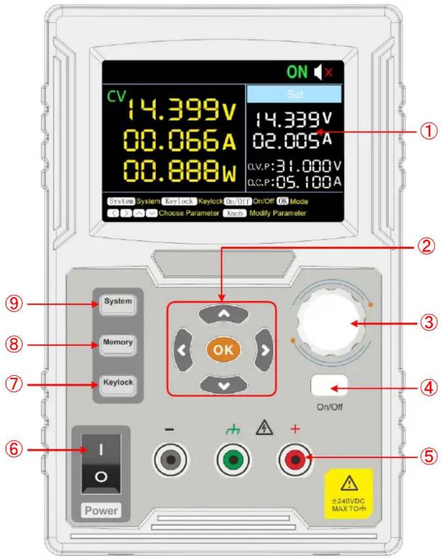
Figure 3-1 Front Panel Overview
| 1 | Display Area | Display user interface. |
| 2 | Direction Key | Select menu; select parameters; Edit the cursor. |
| OK Key | 1) Enter the menu or confirm the entered parameters.2) Switch the display mode between Number and Curve. | |
| 3 | Knob | Select the main menu or change the value, function equals to the confirmation key. |
| 4 | On/Off Key | Turn on/off the channel. |
| 5 | Channel Output Terminal | Output access of channel. |
| 6 | Power Button | Turn on/off the instrument. |
| 7 | Keylock Key | Long press this button for more than 5 seconds to lock the panel button. Pressing any other button while locked does not work. Long press this button for more than 5 seconds to unlock. |
| 8 | Memory Key | 5 sets of channel parameters can be stored for quick output. |
| 9 | System Key | System settings, interface settings, system information. |
Button light instruction
On/Off key: The key lights up when the channel turns on.
3.1.2 Rear Panel
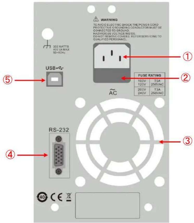
Figure 3-2 Rear Panel Overview
① AC Power Input AC power input interface Jack
| 2 Fuse | Power fuse |
| 3 Air Vent | Air vent |
| 4 COM port | Connect the serial port of the instrument and external device |
| 5 USB port (optional for specific model) | It is used to transfer data when external USB equipment connects to the power supply regarded as "slave device". Support USBTMC communication protocol. |
3.1.3 User Interface
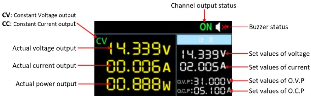
Figure 3-3 User Interface
3.2 General Inspection
After you get a new power supply, it is recommended that you should make a check on the instrument according to the following steps:
1. Check whether there is any damage caused by transportation.
If it is found that the packaging carton or the foamed plastic protection cushion has suffered serious damage, do not throw it away first till the complete device and its accessories succeed in the electrical and mechanical property tests.
2. Check the Accessories
The supplied accessories have been already described in the "Appendix A: Enclosure" of this Manual. You can check whether there is any loss of accessories with reference to this description. If it is found that there is any accessory lost or damaged, please get in touch with the distributor of our responsible for this service or the our local offices.
3. Check the Complete Instrument
If it is found that there is damage to the appearance of the instrument, or the instrument can not work normally, or fails in the performance test, please get in touch with the our distributor responsible for this business or the our local offices. If there is damage to the instrument caused by the transportation, please keep the package. With the transportation department or the our distributor responsible for this business informed about it, a repairing or replacement of the instrument will be arranged by the we.
3.3 Power Inspection
(1) Use the power cord supplied with the accessories to connect the instrument to the AC power.

Warning:
To prevent electric shock, make sure that the instrument is properly grounded.
(2) Press the power button on the front panel, the button light will be on, and the startup screen will be displayed on the screen.
3.4 Output Inspection
Output inspection is to ensure that the instrument can achieve its rated outputs and properly respond to operation from the front panel. For the procedures below, it is suggested that you read "Turn On/Off the Channel Output" on page 8 and "Set the Output Voltage/Current" on page 8.
3.4.1 Voltage Output Inspection
The following steps verify basic voltage functions without load:
(1) When the instrument is under no load, select a channel and ensure the output current setting for this channel is not at zero.
(2) Turn on the channel output, then ensure the channel is in Constant Voltage output mode.
(3) Set some different voltage values on this channel; check if the actual voltage value displayed is close to the set voltage value, and also that the actual current value displayed is nearly to zero.
(4) Check that if the output voltage can be adjusted from zero to the maximum rating.
3.4.2 Current Output Inspection
The following steps check basic current functions with a short across the power supply's output:
(1) Connect a short across (+) and (-) output terminals with an insulated test lead on this channel. Use a wire size sufficient to handle the maximum current.
(2) Set the output voltage to the maximum rating on this channel.
(3) Turn on the channel output. Ensure the channel you used is in Constant Current output mode.
(4) Set some different current values on this channel; check if the actual current value displayed is close to the set current value, and to check if the actual voltage value displayed is nearly zero.
(5) Check that if the output current can be adjusted from zero to the maximum rating.
(6) Turn off the channel output and remove the short circuit from the output terminals.
4. Panel Operation
4.1 Turn On/Off the Channel Output
Press the On/Off key to turn on/off the channel;
4.2 Set the Output Voltage/Current
In the channel setting area, press the △ / ∨ keys to move the red cursor between parameters. After selecting the output voltage/current setting value, turn the knob to change the current cursor value, and press ◀ / ▷ key to move the cursor position.
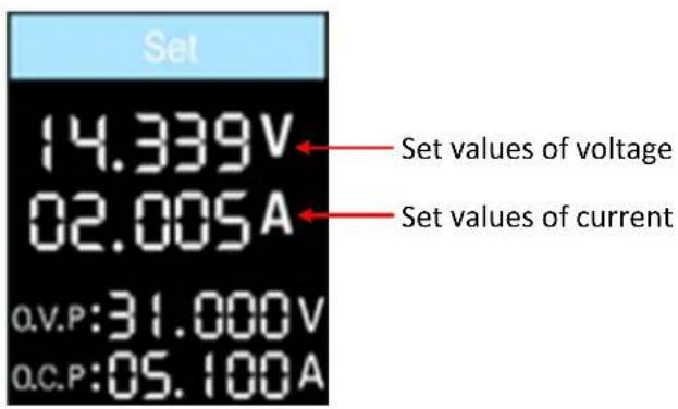
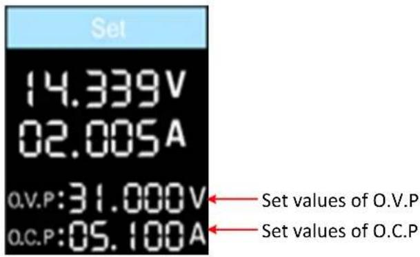
4.3 Over Voltage/Current Protection
When the Over Voltage Protection (O.V.P) or Over Current Protection (O.C.P) is enabled, once the output voltage/current reaches the set value of O.V.P/O.C.P, the instrument will cut off the output, a warning will show on the screen.
Note:
When the instrument disables the output due to protection, after you make some adjustments, the channel must be restarted to output normally.
This function can keep the power output from exceeding the load rating to protect the load.
In the channel setting area, press the / keys to move the red cursor between parameters. After selecting the overvoltage/overcurrent protection value, turn the Knob to change the current cursor value, and press the </ direction key to move the cursor position.
4.4 Memory key shortcut settings
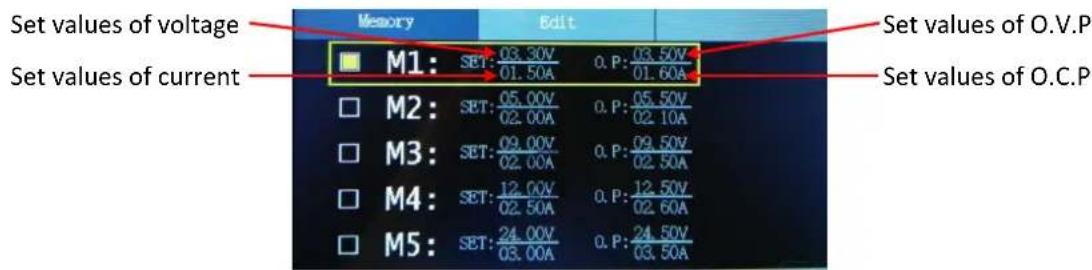
Press Memory key on front panel, the M1, M2, and M3 keys can store five sets of channel parameters M1, M2, M3, M4, and M5, respectively, for quick output.
4.4.1 Quick output
To output a set of parameters from M1 to M5, follow these steps:
(1) Press Memory key on front panel, the shortcut interface will display.
(2) Press √ key and shows the yellow select box. Press ∧ / √ to move the select box.
(3) After selecting the certain parameter, press knob or OK on the panel to confirm the input value.
4.4.2 Edit
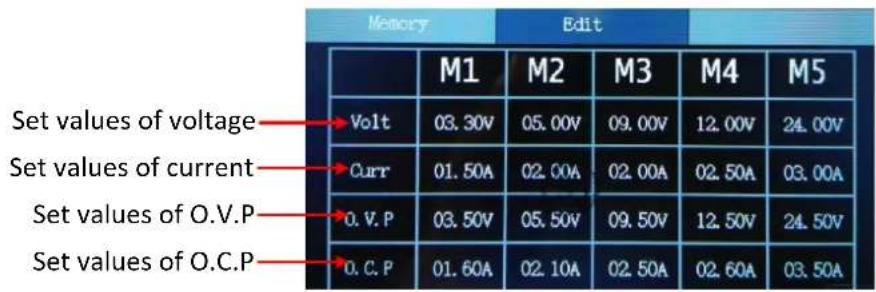
To edit the channel parameters of M1 to M5, follow these steps:
(1) Press the front panel Memory button, the screen displays the quick setup interface.
(2) Press the ▷arrow keys to display the editing interface.
(3) Press the ∨ keys to show a red cursor.
(4) Press the ∧ / ∨ / < / > keys to move the red cursor between parameters. Turn the knob to change the current cursor value, press the < / > arrow keys to move the cursor.
4.5 System Settings
4.5.1 Display Brightness
Press the System softkey and turn the knob to highlight the System main menu. Press the keys to highlight the Brightness submenu. Press the < / > keys to adjust the brightness of the screen. The adjustment range is from 1 to 100.
4.5.2 Language Setting
Press the System softkey and turn the knob to select the [Utility] menu. Press the √arrow keys to choose the language. Press the < / > arrow keys to select the desired language. Supported languages include Chinese and English.
4.5.3 Buzzer
Press the System softkey and turn the knob to select the [Utility] menu. Press the √ arrow keys to choose buzzer submenu. Press the < / > arrow keys to toggle the beeper on/off. When the buzzer is on, the status bar icon lights up. When the system prompts, it beeps, such as when the output is cut due to overvoltage/overcurrent protection.
4.5.4 Display
Press the System softkey and turn the knob to select the [Utility] menu. Press the √ arrow keys to choose Display submenu. Press the < / > arrow keys or turn the knob to set the display mode to Number or Curve.
In system main interface, you can also press the OK key or press the knob to toggle between Number and Curve display mode.
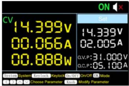
Number
Press the System softkey and turn the knob to select the [Utility] menu. Press the ▼ arrow keys to choose Display submenu. Press the < / > arrow keys or turn the knob to set the display mode to Number.
In system main interface, you can also press the OK key or press the knob to select the Number display mode. When the power supply is powered on, the default display mode is Number.
Curve
Press the System softkey and turn the knob to select the [Utility] menu. Press the √ arrow keys to choose Display submenu. Press the < / > arrow keys or turn the knob to set the display mode to Curve.
In system main interface, you can also press the OK key or press the knob to select the Curve display mode.
Curve Type
You can set the type of the displayed curve to voltage curve or current curve.
1) Voltage Curve
Two methods to set the curve type to voltage curve.
1st Method:
Press the System softkey and turn the knob to select the [Utility] menu. Press the √ arrow keys to choose Display submenu. Press the < / > arrow keys or turn the knob to set the display mode to Curve. Press the √ arrow keys to choose CurveType submenu, press the < / > arrow keys or turn the knob to set the curve type to Volt.
2nd Method:
In system main interface, you can also press the OK key or press the knob to select the
Curve display mode. Press the ∧ / ∨ arrow keys to select the Volt curve type.
The display mode of Volt curve is as below:
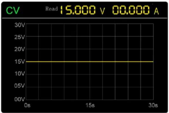
line
| Time | CV | |------|--------| | 0s | 15.000 V | | 15s | 15.000 A | | 30s | 15.000 A |Note: In Volt curve display mode, you can still set the value of voltage or current. Press the □ / ▶ arrow keys or turn the knob to enter editing mode (edit voltage first). If the value is not changed, editing mode will be exited.
2) Current Curve
Two methods to set the curve type to current curve.
1st Method:
Press the System softkey and turn the knob to select the [Utility] menu. Press the √ arrow keys to choose Display submenu. Press the < / > arrow keys or turn the knob to set the display mode to Curve. Press the √ arrow keys to choose CurveType submenu, press the < / > arrow keys or turn the knob to set the curve type to Curr.
2nd Method:
In system main interface, you can also press the OK key or press the knob to select the Curve display mode. Press the ∧ / ∨ arrow keys to select the Curr curve type.
The display mode of Curr curve is as below:
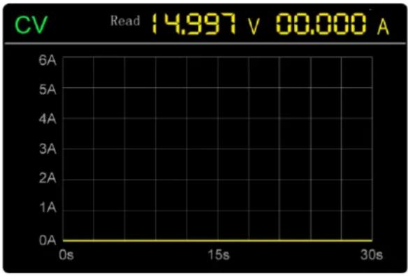
Note: In Curr curve display mode, you can still set the value of voltage or current. Press the □ / ▶ arrow keys or turn the knob to enter editing mode (edit current first). If the value is not changed, editing mode will be exited.
Curve Time
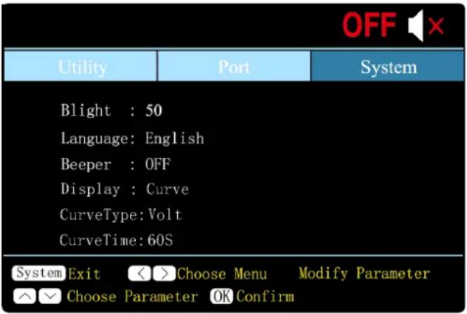
Press the System softkey and turn the knob to select the [Utility] menu. Press the √ arrow keys to choose CurveTime submenu. Press the < / > arrow keys or turn the knob to set the display mode to Curve. Press the √ arrow keys to choose CurveTime submenu, press the < / > arrow keys or turn the knob to set the curve time to 30S or 60S..
4.6 Interface Setting
(1) Press the √ arrow keys to select the baud rate, and press the < / ▷ arrow keys to set the baud rate of the RS232 serial interface. The optional values for the baud rate are: 2400, 4800, 9600, 19200, 38400, 57600, 115200, and the factory default setting is 115200. Make sure the instrument's baud rate setting matches the
baud rate setting of the computer you are using.
(2) Press the ∨ arrow keys to select the check digit and press the < / > arrow keys to toggle None, Odd, Even.
(3) Press the ∨ arrow keys to select the stop bit, and press the < / > arrow keys to toggle 1 or 2.
Note: The data bits submenu cannot be set, and the data bits are fixed at 8 bits.
4.7 System Information
4.7.1 Review System Information
Press the System softkey and turn the knob to select the [SYSTEM] menu. The screen shows the model number, version number, serial number, and CheckSum of the machine.
4.7.2 Restore Factory Settings
Press the System softkey and turn the knob to select the [SYSTEM] menu. Press ▼ arrow keys to select the Factory Reset submenu. Press OK to restore the factory default settings. See the factory setting detail table below
| Output | Voltage | Current |
| 5 V | 2 A |
| Limit | Voltage | Current |
| 61.00V | 3.10A |
| System | Backlight | 50% | ||
| Buzzer | On | |||
| Port | Port Setting | Baud Rate | 115200 | |
| Data Digit | 8 | |||
| Parity Check | None | |||
| Stop Digit | 1 | |||
| Display | Number | |||
5. Troubleshooting
1. The instrument is powered on but no Display.
- Check if the power is connected properly.
- Check if the fuse which is below the AC Power socket is used appropriately and in good condition (the cover can be pried open with a straight screwdriver).
- Restart the instrument after the steps above.
- If the problem still exists, please contact our for our service.
2. The output is abnormal:
- Check if the output voltage is set to 0V. If so, set it to other value.
- Check if the output current is set to 0A. If so, set it to other value.
- When in programmable output status, check if there is any voltage/current value is set to 0. If so, set it to other value.
● If the problem still exists, please contact our for our service.
6. Appendix
6.1 Appendix A: Accessories
(The accessories subject to final delivery.)
standard:
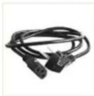
Power Cord
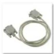
RS232 Cable

User Manual
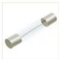
Fuse

natural_image
Plain white circular object with a central hole, no text or symbols visible.CD
optional:

Banana plug to crocodile clip test leads

USB2.0 to RS232 common port connector
6.2 Appendix B: General Care and Cleaning
General Care
Do not store or leave the instrument where the liquid crystal display could be exposed to direct sunlight for long periods of time.
Caution: To avoid any damage to the instrument, do not exposed it to any sprays, liquids, or solvents.
Cleaning
Inspect the instrument as often as operating conditions require. To clean the instrument exterior, perform the following steps:
Wipe the dust from the instrument surface with a soft cloth. Take care not to scratch the transparent LCD protection screen when cleaning.
Disconnect power before cleaning your instrument. Clean the instrument with a damp soft cloth (not dripping with water). It is recommended to clean with soft detergent or fresh water. To avoid damage to the instrument, do not use any corrosive chemical cleaning agents.

Warning: Before re applying power, ensure that the instrument is completely dry, avoiding any electric shock or electrical short circuit resulting from moisture.

- P Series Single Channel Output DC Power Supply User Manual
- General Warranty
- Table of Contents
- General Safety Requirements
- To avoid Fire or Personal Injury:
- Safety Terms and Symbols
- Safety Terms
- Safety Symbols
- Quick Review
- Panel and Interface
- Front Panel
- Button light instruction
- Rear Panel
- User Interface
- General Inspection
- Check whether there is any damage caused by transportation.
- Check the Accessories
- Check the Complete Instrument
- Power Inspection
- Warning:
- Output Inspection
- Voltage Output Inspection
- Current Output Inspection
- Panel Operation
- Turn On/Off the Channel Output
- Set the Output Voltage/Current
- Over Voltage/Current Protection
- Note:
- Memory key shortcut settings
- Quick output
- Edit
- System Settings
- Display Brightness
- Language Setting
- Buzzer
- Display
- Number
- Curve
- Curve Type
- 1) Voltage Curve
- 1st Method:
- 2nd Method:
- 2) Current Curve
- Curve Time
- Interface Setting
- System Information
- Review System Information
- Restore Factory Settings
- Troubleshooting
- The instrument is powered on but no Display.
- The output is abnormal:
- Appendix
- Appendix A: Accessories
- Appendix B: General Care and Cleaning
- General Care
- Cleaning
Brand : Owon
Model : P4000
Category : Uncategorized