
T545 - Car Speaker JBL - Free user manual and instructions
Find the device manual for free T545 JBL in PDF.


| Type | Car Speaker |
| Brand | JBL |
| Model | T545 |
| Speaker Size | 5.25 inches (13 cm) |
| Impedance | 4 ohms |
| Power Handling (RMS) | 40 Watts |
| Power Handling (Peak) | 120 Watts |
| Sensitivity | 90 dB |
| Frequency Response | 60 Hz - 20 kHz |
| Mounting Depth | 1.75 inches (45 mm) |
| Woofer Material | Polypropylene Cone |
| Tweeter Type | Balanced Dome Tweeter |
| Grille Included | Yes |
| Recommended Amplifier Power | 10 - 60 Watts RMS per channel |
| Product Dimensions (per speaker) | 5.5 x 5.5 x 2.1 inches |
| Weight (per speaker) | 0.8 kg (1.76 lbs) |
| Wiring | Sold separately |
| Mounting Hardware | Included |
| Water Resistance | Not water-resistant |
| Recommended Use | Rear or front fill in vehicles |
| Certification | CE, RoHS |
Frequently Asked Questions - T545 JBL
User questions about T545 JBL
0 question about this device. Answer the ones you know or ask your own.
Ask a new question about this device
Download the instructions for your Car Speaker in PDF format for free! Find your manual T545 - JBL and take your electronic device back in hand. On this page are published all the documents necessary for the use of your device. T545 by JBL.
USER MANUAL T545 JBL
natural_image
Illustration of multiple speaker speakers with visible circuitry and mounting brackets (no text or symbols)T205
T420
T425
T540
T545
Introduction:
Thank you for purchasing a JBL loudspeaker system. Your JBL automotive loudspeakers have been built to meet the same rigorous standards that have been established for our renowned home and professional speaker systems.
This installation manual has been designed to make your JBL loudspeaker installation as trouble-free as possible. Please read this manual thoroughly before performing your installation and familiarize yourself with all steps of the installation.
Acoustics and Proper Mounting Locations:
To bring the best in high fidelity sound reproduction to the automobile, JBL has incorporated many important design features in the T205, T420, T425, T540 and T545 speaker systems. These features help the JBL systems overcome many of acoustic problems found in automobile interiors. JBL has taken great care in designing automotive loudspeakers to provide the utmost in wide dynamic range, broad frequency response, proper imaging, and low levels of distortion.
The following practices should be incorporated to realize the full potential of your automotive sound system:
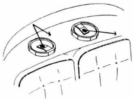
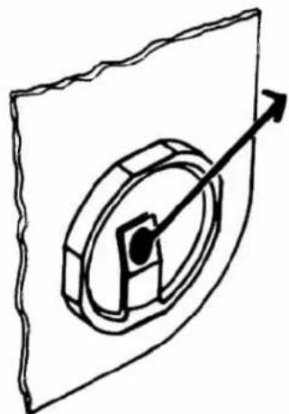
1) Placement of the speakers in the automobile will have an important effect on proper imaging of the system. Front doors provide a good mounting location for the T205, T420, and T425 speaker systems in most cars. In addition to spacing the speakers at a distance desirable for good stereophonic separation, the front doors also form an enclosure which properly loads the woofers to help produce solid, well-defined bass response. The same considerations make the rear deck desirable for the mounting of the T540 and T545 speaker systems. (The T205, T420, and T425 may also be mounted in the rear deck.) To improve the imaging characteristics of the speakers, JBL has mounted the high frequency driver assemblies at an angle. Figures 1 and 2 show how the mounting of the speakers can help direct high frequencies (either directly or by reflection) to the listener. NOTE: In front door installations the high frequency drivers should always be angled towards the listener.
2) Low frequency response of your speaker system can be greatly enhanced by the proper mounting of the speakers. Care must be taken to prevent low frequency sound cancellation, which can be caused by either of the following conditions: A) Air leakage between the front and rear of the speaker. This condition
natural_image
Diagram of a car interior showing two circular components with directional arrows indicating movement or force (no text or symbols)Figure 1
natural_image
Pure mechanical diagram showing a rotating component with an arrow indicating direction (no text or symbols)Figure 2


Figure 5
is possible when the speaker is mounted on a contoured surface or when the mounting hole is improperly cut. (See Figures 3 and 4).
B) The second condition is flexing of the mounting panel (baffle board). During peak power passages, a thin or poorly reinforced mounting panel will flex in response to the bass output of the speaker, resulting in weakened bass response (See Figure 5).
Acoustic and Mounting Precautions:
1) Make certain the speaker will physically fit in the mounting location (See JBL application book). Check for adequate clearance between speaker and window, window crank, power window mechanism, seat, glovebox, rear deck torsion bars and other items which may interfere with mounting. CAUTION: Fuel tanks are located directly beneath the rear deck in some cars. Check for adequate speaker basket clearance before considering these locations.
2) Do not mount the speakers where water may splash on the cones.
3) Angle the high frequency drivers toward listeners.
4) Make certain the speaker mounts tightly against the mounting surface, with no air leaks around its perimeter.
5) Make certain the mounting surface is
rigid and resists flexing (Reinforce the surface if necessary).
Tools Required:
• Phillips-head screwdriver
• Upholstery or utility knife
- Pencil
- Drill with ^2/16 " (4.7mm) and ^1/8 " (3.2mm) drill bits
• Metal saw (when cutting metal)
- Metal file
• Soldering iron with resin flux solder
- Small wire ties (recommended, but not required)
Preparing the Mounting Location:
The proper preparation of the speaker mounting area will ensure many years of trouble-free listening enjoyment from your JBL loudspeaker system.
Unless you are replacing existing speakers of the same size, mounting locations will have to be cut into the doors or rear deck. These locations are usually covered with a cloth-wrapped fiberboard. In some cases speaker mounting holes will be precut in the door and rear deck steel. Due to their structural integrity and accessibility.
these precut mounting holes should be used whenever possible.
Confirm mounting locations by removing door or rear deck panels. Using the template supplied with the packaging, mark the mounting location on the trim panel. Using a utility knife, carefully cut a hole in the trim panel. If cutting steel, reinstall the panel, and using it as a guide, mark the body steel for proper cutting. At this time also drill four 316 " (4.7 mm) diameter holes for the speaker mounting screws for the trim panel, 18 " (3.2 mm) diameter in sheet metal.
After cutting and drilling all holes, inspect the mounting area for any burrs or rough edges on cut steel. File any areas which may interfere with speaker mounting. As a final step in preparing the mounting location, clean all metal shavings from the area and check for areas where water may enter speaker cavities (door jambs, window troughs, etc.). These areas should be sealed with heavy gauge (2-3 mil) plastic sheeting.
Wiring:
For door applications, wires should be run through the existing holes (if available). The wire can be easily concealed behind kickpanels and carpeting. When running wires through door jambs be certain that wires are protected from metal edges with rubber grommets or electrical tape and that
enough slack is available for opening and closing the doors.
Wires run to the rear deck can be concealed beneath door sills and carpeting. In most installations, removal of the rear seat will be necessary. Care should be taken to secure the wiring so that objects placed in the trunk will not become entangled in the speaker wires. Plastic wire ties are helpful in securing wires to the underside of rear decks. When replacing the rear seat, be sure the wires are not pinched along seat edges or beneath metal seat frames.
Connecting the wires to the speaker can be done in two ways. The preferred method of connection is to solder the wires directly to the speaker terminals. An alternate method of connection is to use .200" (5.1 mm) spade terminals soldered (preferred) or crimped to speaker wires. The positive (+) terminal on the speaker is marked in red. The positive terminal of each speaker must be connected to the respective positive output terminal of the amplifier/radio/tape player. For proper speaker/radio/tape player connections, follow the instructions given in the instruction manual for that unit. (See wiring
natural_image
Diagram of a precision tool tipting a small component into a rectangular block (no text or symbols)Removing blamplification jumpers.
Figure 6

natural_image
Simple line drawing of an oval shape with four small squares inside, connected by a curved line (no text or symbols)Tinnerman nuts installed on trim panel.
Figure 7
diagrams for alternate wiring procedures.) Make certain all splices are soldered and insulated with electrical tape or shrink tubing.
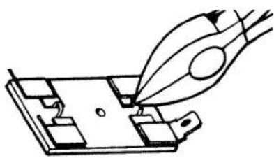
Biamplification: The T540 and T545 speaker systems are equipped with two sets of speaker terminals connected by short jumper strips. Owners who wish to power their speaker systems with two amplifiers must separate the two sets of speaker terminals. By simply clipping the jumper wires your speaker system will be ready for bi-amplification (See Figure 6). For proper connections to the power units, follow the instructions given in the instruction manuals for the units or refer to the wiring diagrams in this manual.
Speaker Mounting:
Front Door and Top of Rear Deck Mounting:
Secure the loudspeakers to mounting location using the #8 x 1 1/2" sheet metal screws provided in the speaker kit. If mounting the speakers directly to fiberboard panels, install tinnerman nuts (supplied with speakers) as shown in Figure 7. Place the speaker in opening, be sure that the high frequency drivers are angled in proper direction, and partially thread all four mounting screws until they just contact the speaker face. Then tighten all screws evenly
Below-Deck Speaker Mounting:
NOTE: This installation requires the use of the optional Model G545 grille kit.
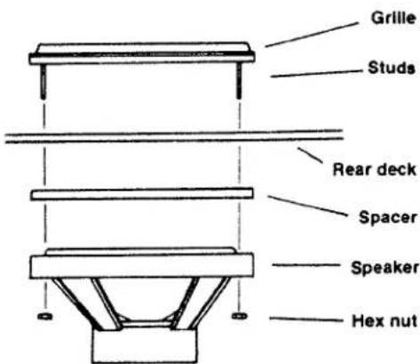
Thread the four mounting studs (included with the G545 kit) into the mounting holes on the grille, then place the grille on the rear deck. (In cases where the rear window is closed to the deck, the studs may have to be threaded into the grille after the grille is placed on the deck.) Working in the trunk, place the speaker over the studs and thread one hex nut with washer onto each stud (See Figure 8). Once all four nuts and washers are installed, tighten all nuts evenly.
After all speakers are installed affix the JBL emblem to each speaker grille.
Service
Should your speakers require service, return them to the dealer from whom they were purchased. If this is not practical, write to the JBL Service Department, describing the problem as fully as possible. Do not return speakers to the factory without prior authorization. Speakers returned to the factory must be sent prepaid to the JBL Service Department, 8500 Balboa Boulevard, P. O. Box 2200, Northridge, California 91329 U.S.A. (213/893-8411).
6" x 9" under deck speaker mounting.
Figure 8
JBL continually engages in research related to product improvement. New materials, production methods, and design refinements are introduced into existing products without notice as a routine expression of this philosophy. For this reason, any current JBL product may differ in some respect from its published description but will always equal or exceed the original design specifications unless otherwise stated.
Two sets of speakers connected in parallel.

flowchart
graph TD
    A["Left Input"] --> B["Filter"]
    B --> C{Growth}
    C --> D["Output"]
    E["Left Output"] --> F["Filter"]
    F --> G{Growth}
    G --> H["Output"]
    I["Right Input"] --> J["Filter"]
    J --> K{Growth}
    K --> L["Output"]
    M["Right Output"] --> N["Filter"]
    N --> O{Growth}
    O --> P["Output"]
This hookup will yield a 2-ohm system impedance. Refer to the instruction manual for your amplifier to determine its suitability for this impedance.
Two sets of speakers connected in series.
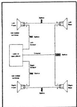
flowchart
graph TD
    A["Input Source"] --> B["Amplifier"]
    B --> C["Capacitor"]
    C --> D["Output Device"]
    E["Input Source"] --> F["Amplifier"]
    F --> G["Capacitor"]
    G --> H["Output Device"]
    I["Input Source"] --> J["Amplifier"]
    J --> K["Capacitor"]
    K --> L["Output Device"]
    M["Input Source"] --> N["Amplifier"]
    N --> O["Capacitor"]
    O --> P["Output Device"]
    Q["Input Source"] --> R["Amplifier"]
    R --> S["Capacitor"]
    S --> T["Output Device"]
This hookup will yield an 8-ohm system impedance. This impedance is safe for all amplifiers, but the power output may be reduced. Refer to the amplifier specifications.
Speakers connected with separate grounds (normal operation).
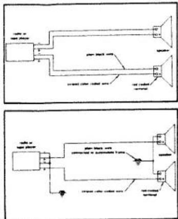
Speakers connected using common ground.

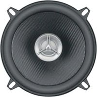
Brand : JBL
Model : T545
Category : Car Speaker