
Reference RS 500 - Car Speaker INFINITY - Free user manual and instructions
Find the device manual for free Reference RS 500 INFINITY in PDF.


| Product Type | Coaxial Car Speaker |
| Brand | Infinity |
| Model | Reference RS 500 |
| Speaker Size | 5 x 7 inches / 6 x 8 inches |
| Speaker Type | 2-Way Coaxial |
| RMS Power Handling | 60 Watts |
| Peak Power Handling | 180 Watts |
| Impedance | 4 Ohms |
| Sensitivity | 95 dB |
| Frequency Response | 50 Hz – 20 kHz |
| Mounting Depth | 2.5 inches |
| Woofer Material | Polypropylene Cone with Rubber Surround |
| Tweeter Type | Edge-Driven Textile Dome |
| Grille Included | Yes |
| Voice Coil Diameter | 1.5 inches |
| Magnet Weight | 8 oz |
| Dimensions (Overall) | 7.5 x 5.4 x 2.9 inches |
| Weight | 2.2 lbs |
| Installation Kit | Includes mounting hardware and wiring adapter |
| Recommended Amplifier Power | 15-60 Watts RMS per channel |
Frequently Asked Questions - Reference RS 500 INFINITY
User questions about Reference RS 500 INFINITY
0 question about this device. Answer the ones you know or ask your own.
Ask a new question about this device
Download the instructions for your Car Speaker in PDF format for free! Find your manual Reference RS 500 - INFINITY and take your electronic device back in hand. On this page are published all the documents necessary for the use of your device. Reference RS 500 by INFINITY.
USER MANUAL Reference RS 500 INFINITY
natural_image
Abstract curved line drawing with no text or symbolsInfinity®
RS Series Installation Guide RS 400/RS 500/RS 600
Specifications
| RS 400 | RS 500 | RS 600 | |
| Power Capacity (per channel): | 60 watts | 80 watts | 100 watts |
| Frequency Response (±3 db): | 90 Hz-20 kHz | 80 Hz - 20 kHz | 60 Hz - 20 kHz |
| Sensitivity (2.83 volts @ 1 meter): | 89 dB | 89 dB | 89 dB |
| Impedance: | 4 ohms | 4 ohms | 4 ohms |
| Mounting Cutout: | 3 1/8" (98.5 mm) | 4 1/2" (114 mm) | 5 1/8" (130 mm) |
| Mounting Depth (no spacer): | 1 3/4" (44.5 mm) | 2 1/4" (57 mm) | 2 1/2" (64 mm) |
| (with spacer): | N/A | 2" (50 mm) | 2 1/4" (57 mm) |
| Crossover Frequency: | 3500 Hz | 3500 Hz | 3500 Hz |
Infinity constantly strives to update and improve existing products, as well as create new ones. Therefore, the specifications and construction details in this and related publications are subject to change without notice.
Wire Codes
Introduction
Thank you for purchasing an Infinity RS Component System. All three systems feature 34 " Polycell ^™ tweeters and crossovers with progressively larger woofers for each ascending model number. The RS 400 system uses 4" woofers, while the RS 500 and RS 600 systems have 5 14 " and 6" woofers, respectively.
You've selected a premium product that offers wide dynamic range, high-power handling, advanced materials, and is efficiently engineered to drop into existing cutouts in most cars, trucks, and vans.
Each RS Component System includes the following features:
- Low-profile design for easy installation in factory openings
- Polypropylene woofer cones for high internal damping and resistance to temperature and humidity extremes
- Separate tweeters with 34'' Polycell domes
- Encapsulated 3500 Hz passive crossovers complete with color- and terminal-keyed wires for easy connection to RS tweeters and woofers
- Attractive black molded speaker grilles to complement your vehicle's interior
- Heavy-duty stamped steel frame and use of high-tech materials ensure rugged construction and consistent reliability
• Full one year parts and labor warranty
This Infinity product is made with our ongoing dedication to create the best consumer audio products possible. As a result, you can expect your RS Component System to provide you with many years of listening enjoyment.
IMPORTANT
Before you start your installation, please read this guide for instructions and techniques to achieve maximum product performance. Although this installation guide explains how to install the RS component system in a general sense, it does not show the exact installation methods for your particular vehicle. Installation of automotive stereo components requires extensive experience in dealing with a variety of mechanical and electrical procedures. If you do not feel you have the experience, do not attempt the installation yourself, but instead ask your Authorized Infinity Car Audio Dealer about professional installation options.
Precautions
- Turn off all audio systems and other electrical devices before you start. As an extra precaution, disconnect the (-) negative lead from your vehicle's battery.
- Protect the woofers and tweeters by keeping them in their packages until final installation. This will keep the magnets in these components from attracting metal clips and filings.
- When moving a woofer or tweeter, always rest each component so that the cone or dome is facing up.
- Never use force to install any woofer or tweeter.
- At the installation sites, locate and make a note of all fuel lines, hydraulic brake lines, and electrical wiring. Use extreme caution when cutting or drilling in and around these areas.
- Check clearances on both sides of a planned mounting surface before drilling any holes or installing any screws. Remember that the enclosed screws can extend up to an inch behind the surface.
- Before drilling or cutting holes, use a utility knife to remove unwanted fabric or vinyl. This will help keep the material from snagging in a drill bit or hole saw.
• Always wear protective eyewear when using power or conventional tools.
Planning Your Installation
Carefully read and understand the following instructions before you attempt any installation procedures. Plan for adequate time and the possibility of overnight storage of your vehicle, since it may take more than one day to complete an installation.
Unpack and examine the components. Verify that your package includes the following items:
- Two 34 " Polycell Dome tweeters with mounting plates and attached color-keyed wires with terminals (all RS models)
-
Two crossovers with attached color-keyed wires with terminals
-
Two 4" woofers with grilles and grille tray for RS 400 system, or two 5 ¼" woofers with grilles and spacers for RS 500 system, or two 6" woofers with grilles and spacers for RS 600 system
- Two woofer mounting templates
- Four #8 x 3/4'' (20mm) self-tapping sheet metal screws (all RS tweeters)
- Eight #8 x 1" (25mm) self-tapping sheet metal screws (RS 400/500 woofers) or six #8 x 1" (25mm) self-tapping sheet metal screws (RS 600 woofers)
- Eight mounting clips (for RS 400/500 woofers) or six mounting clips (for RS 600 woofers)
As you survey your vehicle, keep the following installation plan in mind:
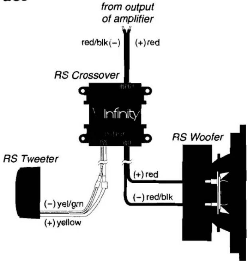
- Studying the wiring diagram shown in Figure 1.
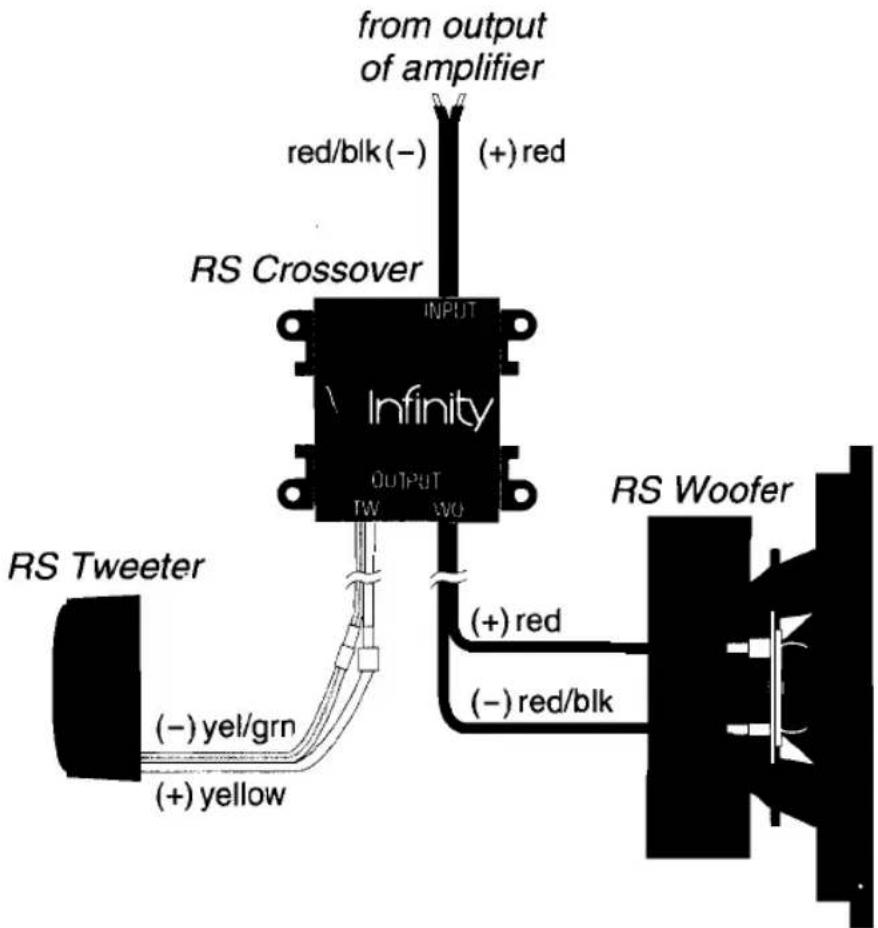
Figure 1. Wiring diagram shows an RS Component System connected to an amplifier. (For clarity, only one channel is shown).
Infinity
- Choosing locations for woofers and tweeters (also see Speaker Placement).
- Picking crossover locations that will make use of the color-keyed wires and attached terminals.
- Installing crossovers and running wires to amplifier(s).
- Installing woofers and tweeters and connecting wires.
- Testing the audio system and finishing up the installation.
Speaker Placement
Where you place your speakers will greatly affect the total sound quality of your vehicle's audio system. Often the best locations are compromises between the ideal sound stage and the physical limitations of your vehicle. However, there are several techniques you can use to place a woofer or tweeter in a location where it sounds best.
Woofer Placement
You can install a woofer in a door panel, the dashboard, or in the rear deck. If possible, try installing each woofer next to its corresponding tweeter. This will help minimize timing errors in emitting sound waves that occur when associated components are spaced too far apart. For the RS500 and RS600 systems, we've also included adapter plates to alleviate mounting depth problems and provide mounting surfaces to compensate for heavily carpeted or padded locations.
Tweeter Placement
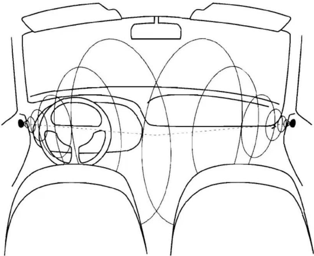
Since the tweeter is a small size, it can be mounted in a number of convenient locations. Suggested areas include the dash, door panels, rear deck, or rear window pillars. For best imaging, install the tweeters at ear level, aimed so emitting sound waves will cross at a point between the two front passenger seats, as shown in Figure 2 (on the next page). Make sure there are no obstructions between the tweeters and intended listeners.
natural_image
Line drawing of a car interior showing steering wheel, dashboard, and rear seats (no text or symbols)Figure 2. Suggested placement of RS Tweeters for optimum imaging.
Installation Tools
For proper installation, the following tools are required:
• A small hole-punch
• An electric hand drill with 18 " and 516 " bits
• Phillips screwdriver
- Flat blade screwdriver
- Wire strippers
• Crimping tool and butt splices
- Saber saw, hole saw, or nibbler
Infinity
- Utility knife
- Marking pen or pencil
- Eight #8 x 1" (25mm) self-tapping sheet metal screws for mounting crossovers or tie wraps (optional)
- Soldering station (optional)
• 18 gauge speaker wire (optional)
• Electrical tape (optional)
Crossover Installation
The enclosed crossovers can be mounted in any convenient location. However, do not mount a crossover in an exposed outside area and try to place the crossover nearer to the speakers than the amplifier.
NOTE: Use only the enclosed Infinity crossovers. They are specifically designed to work with the RS component speakers. Use of any other crossover may damage one or more audio components and is not covered by the warranty.
To install the RS crossovers, refer to Figure 3 (on the next page) as you perform the following steps:
NOTE: As an option, you can use tie wraps to install a crossover via slots on the crossover case.
- At the chosen sites, use a crossover as a template to mark the four screw holes. Make sure the intended site provides necessary clearance for the mounting screws.
- Use a hole punch for drilling guides. If necessary, clear away any carpet or other material prior to drilling.
- Use a drill with a 18 " bit to drill four holes for each crossover.
- Fasten each crossover with the supplied mounting screws.
- Butt splice or solder pre-run speaker wires from the left and right amplifier outputs to each associated crossover input. The crossover's bare red wire is positive (+) and the red/black wire is negative (-).
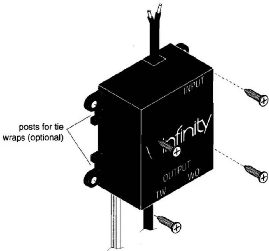
Figure 3. Installing an RS crossover.
Woofer Installation
RS woofers are specifically designed to drop into existing cutouts in most cars, trucks, and vans. In a sense, these openings are proven installation sites. However, if you decide to install a woofer in a non-standard location, use the supplied woofer template to trace a mounting site. Also observe the following mounting precautions:
- Check the woofer sites for adequate clearance. Make sure the woofer will not interfere with the operation of door controls or windows. Avoid contact with door frames, handles, and window tracks.
- Pick a location that provides a strong, rigid structure to support the weight of the woofers. You may have to create a mounting area if sufficient metal does not exist.
∞ Infinity
- Check the site for potential water leakage. Make sure to protect the back of the woofer with a moisture barrier (i.e., heavy plastic sheet attached above back of speaker).
To install the RS woofers, see Figure 4 (below) and Figure 5 (on the next page) and perform the following steps:
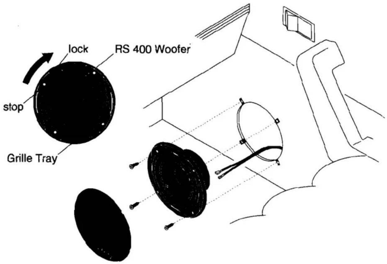
Figure 4. Installing the RS 400 woofer. Before installing, lock the woofer into the supplied grille tray.
- For woofer installations in existing cutouts, start with step 5. For non-standard locations, use the supplied woofer templates to create each cutout. Tape or trace a template at each site and mark the locations of the mounting holes and circumference of baffle openings.
-
Use a hole punch for drilling guides. If necessary, clear away any carpet or other material prior to drilling.
-
Use a drill with 18 " bit to drill a pilot hole at the center of each baffle opening. Then drill four holes for mounting screws. Use a sabre or hole saw to create a cutout for each baffle opening.
- Slip a supplied metal mounting clip over each screw mounting hole.
- Route the red terminal-keyed wires for the woofer from the crossover through each cutout.
- For RS 400 installations, route woofer wires through each supplied grille tray (refer to Figure 4). Position the woofer in the backup plate and turn the woofer clockwise an eighth-turn to lock it into place. The mounting holes will align with the holes in the grille when the woofer is correctly seated in the tray.
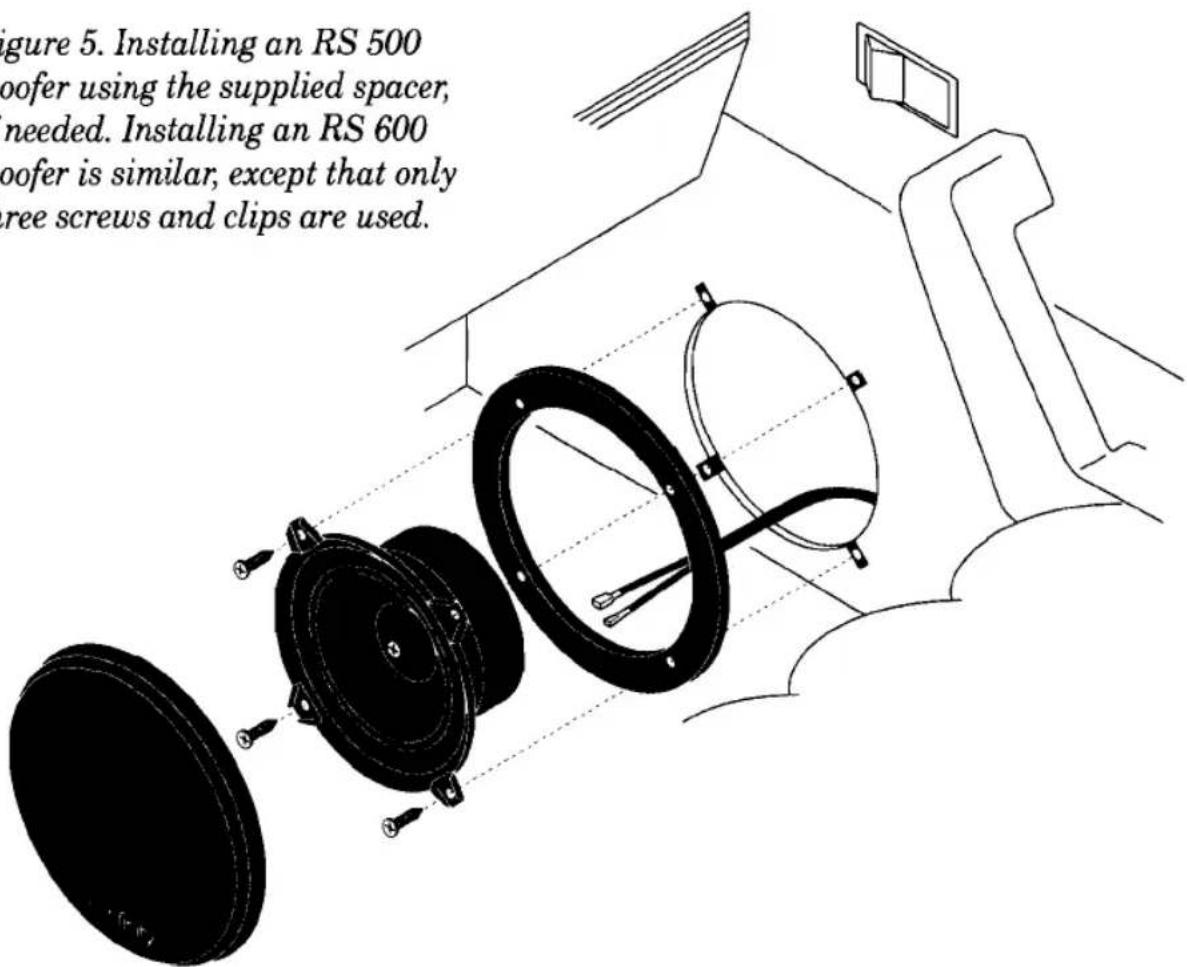
- For RS 500 or RS 600 installations, route woofer wires through each supplied spacer (refer to Figure 5).
Infinity
- Attach the wires to the keyed terminals on each woofer.
- Position each woofer in its cutout and align the mounting holes to match the drilled holes. For RS 500 or RS 600 installations, also align the spacer so that its mounting holes match the drilled holes.
- Push the wires into the opening and carefully fasten each woofer (and spacer (if used) to its site with the supplied #8 x 1" screws.
- Place a supplied grille over each woofer.
Tweeter Installation
RS tweeters are easy to install. Each is housed in an attractive surface-mount enclosure with grille and is equipped with an attached color- and terminal-keyed wire pigtail.
To install RS tweeters, refer to Figure 6 as you perform the following steps:
natural_image
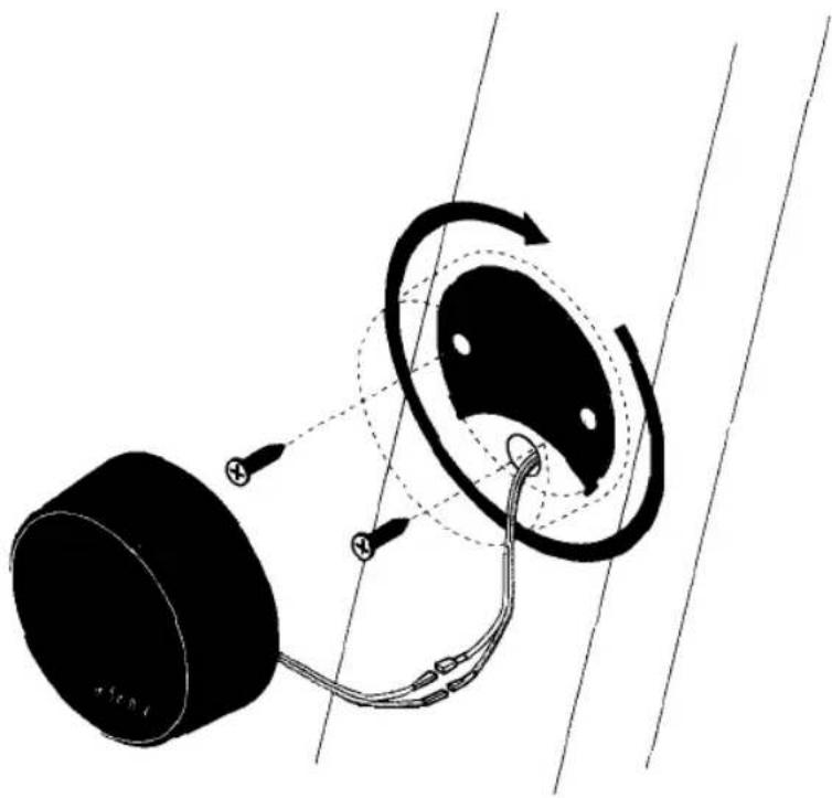
Diagram of a mechanical or electrical component with rotating arms and wiring, no visible text or symbolsFigure 6. Installing an RS tweeter. After installing the mounting plate, lock the tweeter onto the plate with a clockwise eighth-turn.
- At the chosen sites, use the crescent-shaped mounting plate to mark locations of mounting holes and feed-through hole for speaker wires. Refer to Figure 5 for correct orientation. A 516 " diameter hole is required to pass the tweeter wires and pre-attached terminals. Make sure the proposed hole will not extend beyond the boundary of the tweeter enclosure (see Figure 6).
- Use a hole punch for drilling guides. If necessary, clear away any carpet or other material prior to drilling.
- Use a drill with 516 " bit to create a feed-through hole at each tweeter location.
- Use a drill with 18 " bit to create mounting holes at each tweeter location.
- Fasten each mounting plate to its site with the supplied #8 x 3/4" screws.
- Route the yellow terminal-keyed tweeter wires from the crossover through each feed-through hole, and make the connections at each pigtail.
- Push the wires into the opening and carefully place each tweeter onto the mounting plate.
- Turn each tweeter clockwise an eighth-turn to lock it into place.
Warranty
THE INFINITY WARRANTY PROTECTS YOUR ORIGINAL PURCHASE FOR A PERIOD OF ONE YEAR FROM ANY FAILURE AS A RESULT OF AN ORIGINAL MANUFACTURING DEFECT SO LONG AS:
- The Infinity product was purchased by you within the United States, or purchased by military personnel from an authorized military outlet, and
- THE ORIGINAL DATED BILL OF SALE IS PRESENTED WHENEVER SERVICE IS REQUIRED DURING THE WARRANTY PERIOD. This warranty does not apply to products purchased elsewhere and is not transferable. Other purchasers should contact their local Infinity distributor for warranty information.
The Infinity Warranty covers all defects in original materials and workmanship. The following are not covered: damage caused by faulty installation, accident, misuse, abuse, neglect, product modification; damage occurring during shipment, damage caused by failure to follow instructions in this owner's manual; damage resulting from repairs by someone not authorized by Infinity; claims based upon any misrepresentations by the seller; and any Infinity product on which the serial number has been altered, defaced, or removed.
During the warranty period, Infinity will cover both parts and labor or will replace or repair the unit at our discretion.
In the event that your Infinity product requires service, see the Authorized Infinity dealer where you purchased the product, or if this is not practical, contact us at:
Infinity Systems, Inc. 9409 Owensmouth Avenue Chatsworth, CA 91311
Attention: Customer Service
PH: (818) 407-0228 or FAX (818) 709-7496
We may direct you to an Authorized Service Center for Infinity products or ask you to send your unit to us for repair. In either case, you will have to present your original dated bill of sale to establish warranty coverage.
DO NOT SEND YOUR SPEAKERS TO US WITHOUT OBTAINING PRIOR AUTHORIZATION.
You are responsible for transporting your speakers for repair and for payment of all shipping charges. If possible, use the original packaging, or ask us how to best pack the product for shipping. We will pay the return shipping charges if the repairs are covered by the warranty. If you experience difficulty in transporting your product, please advise us, and we may suggest alternative procedures.
LIMITATION OF IMPLIED WARRANTIES: All implied warranties, including fitness for a particular purpose and merchantability are limited in duration to the length of the warranty period for your product.
LIMITATION OF INCIDENTAL OR CONSEQUENTIAL DAMAGES: Infinity is not responsible for any incidental or consequential damage of any kind. Our liability is limited to the repair or replacement, at our option, of a defective product.
Some states do not allow limitations on how long an implied warranty lasts and/or do not allow the exclusion of incidental or consequential damage, so the above limitations or exclusions may not apply to you.
This warranty gives you specific legal rights, and you may also have other rights which vary from state to state.
© 1992 Infinity Systems, Inc.
- Infinity®
- RS Series Installation Guide RS 400/RS 500/RS 600
- Introduction
- IMPORTANT
- Precautions
- Planning Your Installation
- Infinity
- Speaker Placement
- Woofer Placement
- Tweeter Placement
- Installation Tools
- Crossover Installation
- Woofer Installation
- ∞ Infinity
- Tweeter Installation
- Warranty
- DO NOT SEND YOUR SPEAKERS TO US WITHOUT OBTAINING PRIOR AUTHORIZATION.
Brand : INFINITY
Model : Reference RS 500
Category : Car Speaker