ERA250AMYFB - Ventilateur domestique DAIKIN - Free user manual and instructions
Find the device manual for free ERA250AMYFB DAIKIN in PDF.

| Product Type | Domestic Tower Fan |
| Brand | Daikin |
| Model | ERA250AMYFB |
| Dimensions (Height x Width x Depth) | 130 x 40 x 40 cm |
| Weight | 5.5 kg |
| Power Supply | 220-240 V, 50/60 Hz |
| Power Consumption | 45 W |
| Speed Settings | 4 (Low, Medium, High, Turbo) |
| Oscillation | 90° horizontal oscillation |
| Tilt Adjustment | Manual tilt up to 15° |
| Remote Control | Included, with battery (CR2032) |
| Timer | Up to 8 hours |
| Noise Level | 35-55 dB(A) depending on speed |
| Airflow | Up to 1200 m³/h |
| Filter | Washable pre-filter for dust |
| Safety Features | Overheat protection, auto shut-off on tip-over |
| Maintenance | Clean with soft damp cloth; do not use abrasive cleaners |
| Spare Parts Availability | Remote control, fan blades, motor assembly available |
| Warranty | 2 years |
| Energy Efficiency Class | A+ |
Frequently Asked Questions - ERA250AMYFB DAIKIN
User questions about ERA250AMYFB DAIKIN
0 question about this device. Answer the ones you know or ask your own.
Ask a new question about this device
Download the instructions for your Ventilateur domestique in PDF format for free! Find your manual ERA250AMYFB - DAIKIN and take your electronic device back in hand. On this page are published all the documents necessary for the use of your device. ERA250AMYFB by DAIKIN.
USER MANUAL ERA250AMYFB DAIKIN
Installation and operation manual

Inverter outdoor unit for AHU option kit and air curtains
natural_image
Technical line drawing of a multi-chamber HVAC unit with fan blades and ventilation grilles (no text or symbols)
natural_image
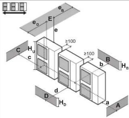
Technical line drawing of a dual-panel HVAC unit with fan blades (no text or symbols)| A~E | H_B H_D H_U | [mm] | ||||||||
| abcdee | B | e_D | ||||||||
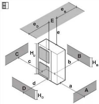 | B—≥100 | |||||||||
| A, B, C—≥1 | 100 ≥100 ≥100 | |||||||||
| B, E—≥100 | ≥1000 ≤500 | |||||||||
| A, B, C, E— | ≥150 ≥150 ≥150 ≥1000 ≤500 | |||||||||
| D—≥500 | ||||||||||
| D, E—≥1000 | ≥1000 ≤500 | |||||||||
| B, D—≥100 | ≥1000 | |||||||||
| B, D, E H | _B < H_D | H_B ≤ 12H_U | ≥250 | ≥1000 | ≥1000 | ≤500 | ||||
| 12H_U < H_B ≤ H_U | ≥250 | ≥1250 | ≥1000 | ≤500 | ||||||
| H_B >H_U | ∅ | |||||||||
| H_B >H_D | H_D ≤ 12H_U | ≥100 | ≥1000 | ≥1000 | ≤500 | |||||
| 12H_U < H_D ≤ H_U | ≥200 | ≥1000 | ≥1000 | ≤500 | ||||||
| H_D >H_U | ≥200 | ≥1700 | ≥1000 | ≤500 | ||||||
 | A, B, C—≥2 | 200 ≥300 ≥1000 | ||||||||
| A, B, C, E— | ≥200 ≥300 ≥1000 | ≥1000 ≤500 | ||||||||
| D—≥1000 | ||||||||||
| D, E—≥1000 | ≥1000 ≤500 | |||||||||
| B, D H | _D >H_U | ≥300 | ≥1000 | |||||||
| H_D ≤ 12H_U | ≥250 | ≥1500 | ||||||||
| 12H_U < H_D ≤ H_U | ≥300 | ≥1500 | ||||||||
| B, D, E H | _B < H_D | H_B ≤ 12H_U | ≥300 | ≥1000 | ≥1000 | ≤500 | ||||
| 12H_U < H_D ≤ H_U | ≥300 | ≥1250 | ≥1000 | ≤500 | ||||||
| H_B >H_U | ∅ | |||||||||
| H_B >H_D | H_D ≤ 12H_U | ≥250 | ≥1500 | ≥1000 | ≤500 | |||||
| 12H_U < H_D ≤ H_U | ≥300 | ≥1500 | ≥1000 | ≤500 | ||||||
| H_D >H_U | ≥300 | ≥2200 | ≥1000 | ≤500 | ||||||
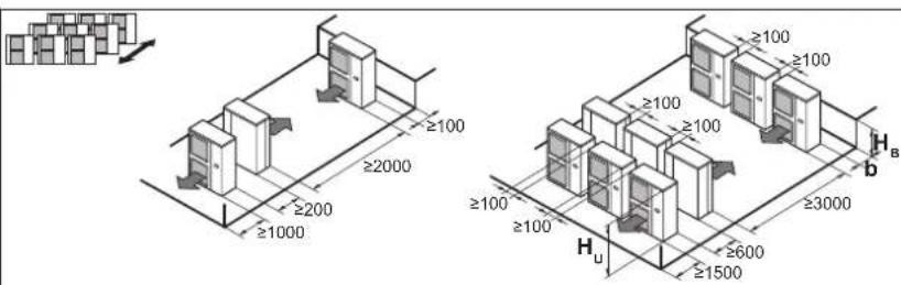
| HBHU | b [mm] |
| HR≤1/2HU | b≥250 |
| 1/2HU<bH≤HU | b≥300 |
| HB>HU |
 |
line
| m [kg] m [kg] | No safety measure (c) | Alarm OR Natural ventilation (d) | NOT allowed (e) | | ------------- | --------------------- | -------------------------------- | --------------- | | 5 | 16 | 16 | 10 | | 10 | 20 | 20 | 12 | | 14 | 24 | 24 | 14 | | 18 | 28 | 28 | 16 | | 22 | 32 | 32 | 18 | | 26 | 36 | 36 | 20 | | 30 | 40 | 40 | 22 | | 34 | 44 | 44 | 24 | | 38 | 48 | 48 | 26 | | 42 | 52 | 52 | 28 | | 46 | 56 | 56 | 30 | | 50 | 60 | 60 | 32 |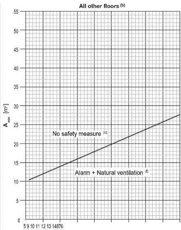
line
| Floor Number | No safety measure (a) | Alarm + Natural ventilation (a) | | ------------ | --------------------- | -------------------------------- | | 5 | 10 | - | | 9 | - | - | | 10 | - | - | | 11 | - | - | | 12 | - | - | | 13 | - | - | | 14 | - | - | | 1876 | - | - | | 20 | - | - | | 22 | - | - | | 24 | - | - | | 26 | - | - | | 28 | - | - | | 30 | - | - | | 32 | - | - | | 34 | - | - | | 36 | - | - | | 38 | - | - | | 40 | - | - | | 42 | - | - | | 44 | - | - | | 46 | - | - | | 48 | - | - | | 5 | 10 | - | | 9 | 10 | - | | 10 | 10 | - | | 11 | 10 | - | | 12 | 10 | - | | 13 | 10 | - | | 14 | 10 | - | | 1876 | 10 | - | | 20 | 10 | - | | 22 | 10 | - | | 24 | 10 | - | | 26 | 10 | - | | 28 | 10 | - | | 30 | 10 | - | | 32 | 10 | - | | 34 | 10 | - | | 36 | 10 | - | | 38 | 10 | - | | 40 | 10 | - | | 42 | 10 | - | | 44 | 10 | - | | 46 | 10 | - | | 48 | 10 | - | | 5 | 10 | - | | 9 | 10 | - | | 10 | 10 | - | | 11 | 10 | - | | 12 | 10 | - | | 13 | 10 | - | | 14 | 10 | - || m [kg] | A_ m^2 | ||
| Lowest underground floor (a) | All other floors (b) | ||
| No safety measure (c) | Alarm OR Natural ventilation (d) | No safety measure (c) | |
| 5.2 15.4 10.3 | 10.3 | ||
| 5.4 16.0 10.7 | 10.7 | ||
| 5.6 16.6 11.1 | 11.1 | ||
| 5.8 17.2 11.5 | 11.5 | ||
| 6.0 17.8 11.8 | 11.8 | ||
| 6.2 18.4 12.2 | 12.2 | ||
| 6.4 19.0 12.6 | 12.6 | ||
| 6.6 19.5 13.0 | 13.0 | ||
| 6.8 20.1 13.4 | 13.4 | ||
| 7.0 20.7 13.8 | 13.8 | ||
| 7.2 21.3 14.2 | 14.2 | ||
| 7.4 21.9 14.6 | 14.6 | ||
| 7.6 22.5 15.0 | 15.0 | ||
| 7.8 23.1 15.4 | 15.4 | ||
| 8.0 23.7 15.8 | 15.8 | ||
| 8.2 24.3 16.2 | 16.2 | ||
| 8.4 24.9 16.6 | 16.6 | ||
| 8.6 25.5 17.0 | 17.0 | ||
| 8.8 26.1 17.4 | 17.4 | ||
| 9.0 26.7 17.8 | 17.8 | ||
| 9.2 27.2 18.2 | 18.2 | ||
| 9.4 27.8 18.6 | 18.6 | ||
| 9.6 28.4 19.0 | 19.0 | ||
| m [kg] | A_ m^2 | ||
| Lowest underground floor (a) | All other floors (b) | ||
| No safety measure (c) | Alarm OR Natural ventilation (d) | No safety measure (c) | |
| 9.8 29.0 19.3 | 19.3 | ||
| 10.0 29.6 19.7 | 19.7 | ||
| 10.2 | 30.2 20.1 | 20.1 | |
| 10.4 | 30.8 20.5 | 20.5 | |
| 10.6 | 31.4 20.9 | 20.9 | |
| 10.8 | 32.0 21.3 | 21.3 | |
| 11.0 | 32.6 21.7 | 21.7 | |
| 11.2 | 33.2 22.1 | 22.1 | |
| 11.4 | 33.8 22.5 | 22.5 | |
| 11.6 | 34.4 22.9 | 22.9 | |
| 11.8 | 34.9 23.3 | 23.3 | |
| 12.0 | 35.5 23.7 | 23.7 | |
| 12.2 | 36.1 24.1 | 24.1 | |
| 12.4 | 36.7 24.5 | 24.5 | |
| 12.6 | 37.3 24.9 | 24.9 | |
| 12.8 | 37.9 25.3 | 25.3 | |
| 13.0 | 38.5 25.7 | 25.7 | |
| 13.2 | 39.1 26.1 | 26.1 | |
| 13.4 | 39.7 26.5 | 26.5 | |
| 13.6 | 40.3 26.8 | 26.8 | |
| 13.8 | 40.9 27.2 | 27.2 | |
| 14.0 | 41.5 27.6 | 27.6 | |
Table of contents
1 About this document 5
2 Specific installer safety instructions 5
2.1 Instructions for equipment using R32 refrigerant....7
For the user 8
3 User safety instructions 8
3.1 General....8
3.2 Instructions for safe operation 8
4 About the system 10
4.1 System layout 11
5 User interface 11
6 Operation 11
6.1 Operation range.... 11
6.2 Operating the system 11
6.2.1 About operating the system 11
6.2.2 About cooling, heating, fan only, and automatic operation 11
6.2.3 About the heating operation.... 12
6.2.4 To operate the system (WITHOUT cool/heat changeover remote control switch) 12
6.2.5 To operate the system (WITH cool/heat changeover remote control switch).... 12
7 Maintenance and service 12
7.1 Precautions for maintenance and service 12
7.2 About the refrigerant.... 12
7.3 After-sales service 13
7.3.1 Recommended maintenance and inspection.... 13
8 Troubleshooting 13
8.1 Error codes: Overview 13
8.2 Symptoms that are NOT system malfunctions 14
8.2.1 Symptom: The system does not operate 14
8.2.2 Symptom: Cool/Heat cannot be changed over ..... 14
8.2.3 Symptom: Fan operation is possible, but cooling and heating do not work.... 14
8.2.4 Symptom: White mist comes out of a unit (Indoor unit, outdoor unit) 15
8.2.5 Symptom: The user interface reads "U4" or "U5" and stops, but then restarts after a few minutes ..... 15
8.2.6 Symptom: Noise of air conditioners (Indoor unit)..... 15
8.2.7 Symptom: Noise of air conditioners (Indoor unit, outdoor unit).... 15
8.2.8 Symptom: Noise of air conditioners (Outdoor unit)..... 15
8.2.9 Symptom: Dust comes out of the unit.... 15
8.2.10 Symptom: The units can give off odours.... 15
8.2.11 Symptom: The outdoor unit fan does not spin 15
8.2.12 Symptom: The compressor in the outdoor unit does not stop after a short heating operation .... 15
8.2.13 Symptom: The inside of an outdoor unit is warm even when the unit has stopped ..... 15
9 Relocation 15
10 Disposal 15
For the installer 15
11 About the box 15
11.1 To handle the outdoor unit.... 15
11.2 To remove the accessories from the outdoor unit 16
11.3 To remove the transportation stay.... 16
12 About the units and options 16
12.1 About the outdoor unit 16
12.2 System layout.... 17
13 Special requirements for R32 units 17
13.1 Requirements for compatible air curtains 17
13.1.1 Installation space requirements 17
13.1.2 System layout requirements 17
13.1.3 To determine the required safety measures 18
13.1.4 Safety measures 20
13.2 Requirements for air handling units.... 23
14 Unit installation 24
14.1 Preparing the installation site 24
14.1.1 Installation site requirements of the outdoor unit ..... 24
14.1.2 Additional installation site requirements of the outdoor unit in cold climates 24
14.2 Opening and closing the unit 24
14.2.1 To open the outdoor unit.... 24
14.2.2 To close the outdoor unit 25
14.3 Mounting the outdoor unit 25
14.3.1 To provide the installation structure 25
14.3.2 To install the outdoor unit.... 25
14.3.3 To provide drainage 25
14.3.4 To prevent the outdoor unit from falling over 25
15 Piping installation 26
15.1 Preparing refrigerant piping 26
15.1.1 Refrigerant piping requirements.... 26
15.1.2 Refrigerant piping material.... 26
15.1.3 Refrigerant piping insulation 26
15.1.4 Combination table and heat exchanger volume limitations 26
15.1.5 To select the piping size 26
15.2 Connecting the refrigerant piping 26
15.2.1 Using the stop valve and service port 26
15.2.2 To remove the pinched pipes.... 27
15.2.3 To braze the pipe end 27
15.2.4 To connect the refrigerant piping to the outdoor unit .. 28
15.3 Checking the refrigerant piping.... 29
15.3.1 Checking refrigerant piping: Setup.... 29
15.3.2 To perform a leak test 29
15.3.3 To perform vacuum drying 29
15.3.4 To insulate the refrigerant piping 29
15.3.5 To check for leaks after charging refrigerant 30
16 Charging refrigerant 30
16.1 Precautions when charging refrigerant.... 30
16.2 To determine the additional refrigerant amount.... 31
16.3 To charge refrigerant 31
16.4 Error codes when charging refrigerant 32
16.5 To fix the fluorinated greenhouse gases label.... 32
16.6 To check refrigerant piping joints for leaks after charging refrigerant 32
17 Electrical installation 33
17.1 About electrical compliance.... 33
17.2 Specifications of standard wiring components 33
17.3 Connecting the electrical wiring.... 33
17.4 To connect the electrical wiring to the outdoor unit 34
17.5 To connect the external outputs 35
17.6 To connect the cool/heat selector switch option.... 35
17.7 To check the insulation resistance of the compressor.... 36
18 Configuration 36
18.1 Making field settings 36
18.1.1 About making field settings 36
18.1.2 Field setting components 37
18.1.3 To access mode 1 or 2 37
18.1.4 To use mode 1 37
18.1.5 To use mode 2 37
18.1.6 Mode 1: monitoring settings.... 37
18.1.7 Mode 2: field settings 38
18.1.8 Indoor unit field setting.... 38
19 Commissioning 38
19.1 Precautions when commissioning 39
19.2 Checklist before commissioning 39
19.3 Checklist during commissioning 39
19.4 About the system test run.... 39
19.4.1 To perform a test run 40
19.4.2 Correcting after abnormal completion of the test run.. 40
20 Hand-over to the user 40
21 Maintenance and service 40
21.1 Maintenance safety precautions.... 40
21.1.1 To prevent electrical hazards.... 40
21.2 Checklist for yearly maintenance of the outdoor unit.... 41
21.3 About service mode operation.... 41
21.3.1 To use vacuum mode 41
21.3.2 To recover refrigerant 41
22 Troubleshooting 41
22.1 Solving problems based on error codes 41
22.1.1 Error codes: Overview 42
22.2 Refrigerant leak detection system 44
23 Disposal 44
24 Technical data 44
24.1 Service space: Outdoor unit 45
24.2 Piping diagram: Outdoor unit 45
24.3 Wiring diagram: Outdoor unit.... 46
1 About this document
Target audience
Authorised installers + end users

INFORMATION
This appliance is intended to be used by expert or trained users in shops, in light industry, and on farms, or for commercial and household use by lay persons.
Documentation set
This document is part of a documentation set. The complete set consists of:
- General safety precautions:
- Safety instructions that you must read before installing
- Format: paper (in the box of the outdoor unit)
- Outdoor unit installation and operation manual:
- Installation and operation instructions
- Format: paper (in the box of the outdoor unit)
- Installer and user reference guide:
- Preparation of the installation, reference data,...
- Detailed step-by-step instructions and background information for basic and advanced usage
- Format: Digital files on https://www.daikin.eu. Use the search function 🔒 to find your model.
The latest revision of the supplied documentation is published on the regional Daikin website and is available via your dealer.
The original instructions are written in English. All other languages are translations of the original instructions.
2 Specific installer safety instructions
Always observe the following safety instructions and regulations.
Installation site (see "14.1 Preparing the installation site" [▶ 24])

WARNING
Follow the service space dimensions in this manual to install the unit correctly. See "24.1 Service space: Outdoor unit" [▶ 45].

WARNING
Tear apart and throw away plastic packaging bags so that nobody, especially children, can play with them. Possible consequence: suffocation.

CAUTION
Excessive refrigerant concentrations in a closed room can lead to oxygen deficiency.

WARNING
If the appliance contains R32 refrigerant, the floor area of the room in which the appliance is stored shall be at least 429 m^2 .
Opening and closing the unit (see "14.2 Opening and closing the unit" [▶ 24])

DANGER: RISK OF BURNING/SCALDING

DANGER: RISK OF ELECTROCUTION

DANGER: RISK OF ELECTROCUTION
Do NOT leave the unit unattended when the service cover is removed.
Mounting the outdoor unit (see "14.3 Mounting the outdoor unit" [▶ 25])

WARNING
Fixing method of the outdoor unit MUST be in accordance with the instructions from this manual. See "14.3 Mounting the outdoor unit" [▶25].
Connecting the refrigerant piping (see "15.2 Connecting the refrigerant piping" [▶ 26])

WARNING
Field piping MUST be in accordance with the instructions from this manual. See "15 Piping installation" [▶ 26].

CAUTION
Piping MUST be installed according to instructions given in "15 Piping installation" [▶ 26]. Only mechanical joints (e.g. braze+flare connections) that are compliant with the latest version of ISO14903 can be used.
Low temperature solder alloys shall not be used for pipe connections.

CAUTION
- Do NOT use mineral oil on flared part.
- Do NOT reuse piping from previous installations.
- NEVER install a drier to this unit to guarantee its lifetime. The drying material may dissolve and damage the system.
2 Specific installer safety instructions

CAUTION
Install the refrigerant piping or components in a position where they are unlikely to be exposed to any substance which may corrode components containing refrigerant, unless the components are constructed of materials that are inherently resistant to corrosion or are suitably protected against corrosion.

WARNING
Take sufficient precautions in case of refrigerant leakage. If refrigerant gas leaks, ventilate the area immediately. Possible risks:
- Excessive refrigerant concentrations in a closed room can lead to oxygen deficiency.
- Toxic gas might be produced if refrigerant gas comes into contact with fire.

WARNING
ALWAYS recover the refrigerant. Do NOT release them directly into the environment. Use a vacuum pump to evacuate the installation.

WARNING
During tests, NEVER pressurise the product with a pressure higher than the maximum allowable pressure (as indicated on the nameplate of the unit).

CAUTION
Do NOT vent gases into the atmosphere.

WARNING
Any gas or oil remaining inside the stop valve may blow off the pinched piping.
Failure to observe the instructions in procedure below properly may result in property damage or personal injury, which may be serious depending on the circumstances.

WARNING

NEVER remove the pinched piping by brazing.
Any gas or oil remaining inside the stop valve may blow off the pinched piping.
Charging refrigerant (see "16 Charging refrigerant" [▶ 30])
![DAIKIN ERA250AMYFB - Charging refrigerant (see "16 Charging refrigerant" [▶ 30]) - 1](/content/2026/05/855215/images/775ff77c42603c874af2e5131dfc64d94c1c747aa904a1eae0f851b7f5aa34ed.jpg)
WARNING
- The refrigerant inside the unit is mildly flammable, but normally does NOT leak. If the refrigerant leaks in the room and comes in contact with fire from a burner, heater, or a cooker, this may result in fire, or the formation of a harmful gas.
- Turn OFF any combustible heating devices, ventilate the room, and contact the dealer where you purchased the unit.
- Do NOT use the unit until a service person confirms that the part from which the refrigerant leaked has been repaired.

WARNING
Charging of refrigerant MUST be in accordance with the instructions from this manual. See "16 Charging refrigerant" [▶ 30].

WARNING
- Only use R32 as refrigerant. Other substances may cause explosions and accidents.
- R32 contains fluorinated greenhouse gases. Its global warming potential (GWP) value is 675. Do NOT vent these gases into the atmosphere.
- When charging refrigerant, ALWAYS use protective gloves and safety glasses.
Electrical installation (see "17 Electrical installation" [▶ 33])
![DAIKIN ERA250AMYFB - Electrical installation (see "17 Electrical installation" [▶ 33]) - 1](/content/2026/05/855215/images/912545334d2c20e84e26e59e8c18594998f10985e6c992c5a3f5109c20402b9b.jpg)
WARNING
Electrical wiring MUST be in accordance with the instructions from:
- This manual. See "17 Electrical installation" [▶ 33].
- The wiring diagram, which is delivered with the unit, located at the inside of the service cover. For a translation of its legend, see "24.3 Wiring diagram: Outdoor unit" [▶ 46].

WARNING
The appliance MUST be installed in accordance with national wiring regulations.

CAUTION
Do NOT push or place redundant cable length into the unit.

WARNING
- If the power supply has a missing or wrong N-phase, equipment might break down.
- Establish proper earthing. Do NOT earth the unit to a utility pipe, surge absorber, or telephone earth. Incomplete earthing may cause electrical shocks.
- Install the required fuses or circuit breakers.
- Secure the electrical wiring with cable ties so that the cables do NOT come in contact with sharp edges or piping, particularly on the high-pressure side.
- Do NOT use taped wires, extension cords, or connections from a star system. They can cause overheating, electrical shocks or fire.
- Do NOT install a phase advancing capacitor, because this unit is equipped with an inverter. A phase advancing capacitor will reduce performance and may cause accidents.

WARNING
- All wiring MUST be performed by an authorised electrician and MUST comply with the national wiring regulation.
- Make electrical connections to the fixed wiring.
- All components procured on-site and all electrical construction MUST comply with the applicable legislation.

WARNING
The electrical components shall only be replaced with parts specified by the appliance manufacturer. Replacement with other parts may result in the ignition of refrigerant in the event of a leak.

WARNING
If the supply cord is damaged, it MUST be replaced by the manufacturer, its service agent or similarly qualified persons in order to avoid a hazard.

WARNING
ALWAYS use multicore cable for power supply cables.

CAUTION
- When connecting the power supply: connect the earth cable first, before making the current-carrying connections.
- When disconnecting the power supply: disconnect the current-carrying cables first, before separating the earth connection.
- The length of the conductors between the power supply stress relief and the terminal block itself MUST be as such that the current-carrying wires are tautened before the earth wire is in case the power supply is pulled loose from the stress relief.
Commissioning (see "19 Commissioning" [▶ 38])
![DAIKIN ERA250AMYFB - Commissioning (see "19 Commissioning" [▶ 38]) - 1](/content/2026/05/855215/images/22da109f1f8dae0ebea71cec2b35a70e5aeb7d4584d8f0593681c2610d061115.jpg)
WARNING
Commissioning MUST be in accordance with the instructions from this manual. See "19 Commissioning" [▶ 38].

CAUTION
Do NOT perform the test operation while working on the indoor unit(s).
When performing the test operation, NOT ONLY the outdoor unit, but the connected indoor unit will operate as well. Working on an indoor unit while performing a test operation is dangerous.

CAUTION
Do NOT insert fingers, rods or other objects into the air inlet or outlet. Do NOT remove the fan guard. When the fan is rotating at high speed, it will cause injury.
Troubleshooting (see "22 Troubleshooting" [▶ 41])
![DAIKIN ERA250AMYFB - Troubleshooting (see "22 Troubleshooting" [▶ 41]) - 1](/content/2026/05/855215/images/c4e0bcaf1e992761d480bf723bae98147ba14108cb26b4d330eb3d764553f50a.jpg)
WARNING
- When carrying out an inspection on the switch box of the unit, ALWAYS make sure that the unit is disconnected from the mains. Turn off the respective circuit breaker.
- When a safety device was activated, stop the unit and find out why the safety device was activated before resetting it. NEVER shunt safety devices or change their values to a value other than the factory default setting. If you are unable to find the cause of the problem, call your dealer.

WARNING
Prevent hazards due to inadvertent resetting of the thermal cut-out: power to this appliance MUST NOT be supplied through an external switching device, such as a timer, or connected to a circuit that is regularly turned ON and OFF by the utility.
2.1 Instructions for equipment using R32 refrigerant

WARNING: MILDLY FLAMMABLE MATERIAL
The refrigerant inside this unit is mildly flammable.

WARNING
- Do NOT pierce or burn refrigerant cycle parts.
- Do NOT use cleaning materials or means to accelerate the defrosting process other than those recommended by the manufacturer.
- Be aware that the refrigerant inside the system is odourless.

WARNING
The appliance shall be stored as follows:
- in such a way as to prevent mechanical damage.
- in a well-ventilated room without continuously operating ignition sources (example: open flames, an operating gas appliance or an operating electric heater).
- in a room with dimensions as specified in "13 Special requirements for R32 units" [▶ 17].

WARNING
Make sure installation, servicing, maintenance and repair comply with instructions from Daikin and with applicable legislation (for example national gas regulation) and are executed ONLY by authorised persons.

WARNING
- Take precautions to avoid excessive vibration or pulsation to refrigeration piping.
- Protect the protection devices, piping and fittings as much as possible against adverse environmental effects.
- ALWAYS support the piping at distances of 1 m and 2 m from the indoor unit.
- Provide space for expansion and contraction of long runs of piping.
- Design and install piping in refrigerating systems such as to minimise the likelihood of hydraulic shock damaging the system.
- Mount the indoor equipment and pipes securely and protect them to avoid accidental rupture of equipment or pipes in case of events such as moving furniture or reconstruction activities.

CAUTION
Do NOT use potential sources of ignition in searching for or detection of refrigerant leaks.

NOTICE
- Do NOT re-use joints and copper gaskets which have been used already.
- Joints made in the installation between parts of the refrigerant system shall be accessible for maintenance purposes.
For the user
3 User safety instructions
Always observe the following safety instructions and regulations.
3.1 General

WARNING
If you are NOT sure how to operate the unit, contact your installer.

WARNING
This appliance can be used by children aged from 8 years and above and persons with reduced physical, sensory or mental capabilities or lack of experience and knowledge if they have been given supervision or instruction concerning use of the appliance in a safe way and understand the hazards involved.
Children SHALL NOT play with the appliance.
Cleaning and user maintenance SHALL NOT be made by children without supervision.

WARNING
To prevent electrical shocks or fire:
- Do NOT rinse the unit.
- Do NOT operate the unit with wet hands.
- Do NOT place any objects containing water on the unit.

CAUTION
- Do NOT place any objects or equipment on top of the unit.
- Do NOT sit, climb or stand on the unit.
- Units are marked with the following symbol:
This means that electrical and electronic products may NOT be mixed with unsorted household waste. Do NOT try to dismantle the system yourself: dismantling the system, treatment of the refrigerant, of oil and of other parts MUST be done by an authorised installer and MUST comply with applicable legislation.
Units MUST be treated at a specialised treatment facility for reuse, recycling and recovery. By ensuring this product is disposed of correctly, you will help to prevent potential negative consequences for the environment and human health. For more information, contact your installer or local authority.
- Batteries are marked with the following symbol:

This means that the batteries may NOT be mixed with unsorted household waste. If a chemical symbol is printed beneath the symbol, this chemical symbol means that the battery contains a heavy metal above a certain concentration.
Possible chemical symbols are: Pb: lead (>0.004%).
Waste batteries MUST be treated at a specialised treatment facility for reuse. By ensuring waste batteries are disposed of correctly, you will help to prevent potential negative consequences for the environment and human health.
3.2 Instructions for safe operation

WARNING
Make sure installation, servicing, maintenance, repair and applied materials follow the instructions from Daikin (including all documents listed in "Documentation set") and, in addition, comply with applicable legislation and are performed by qualified persons only. In Europe and areas where IEC standards apply, EN/IEC 60335-2-40 is the applicable standard.

WARNING
Do NOT install operating ignition sources (example: open flames, an operating gas appliance or an operating electric heater) in the ductwork.

CAUTION
- NEVER touch the internal parts of the controller.
- Do NOT remove the front panel. Some parts inside are dangerous to touch and appliance problems may happen. For checking and adjusting the internal parts, contact your dealer.

CAUTION
Do NOT operate the system when using a room fumigation-type insecticide. Chemicals could collect in the unit, and endanger the health of people who are hypersensitive to chemicals.

CAUTION
It is unhealthy to expose your body to the air flow for a long time.

WARNING
This unit contains electrical and hot parts.

WARNING
Before operating the unit, be sure the installation has been carried out correctly by an installer.
Maintenance and service (see "7 Maintenance and service" [▶ 12])

WARNING
The unit is equipped with a refrigerant leak detection system for safety.
To be effective, the unit MUST be electrically powered at all times after installation, except for maintenance.

WARNING
NEVER replace a fuse with a fuse of a wrong ampere ratings or other wires when a fuse blows out. Use of wire or copper wire may cause the unit to break down or cause a fire.

WARNING
If the supply cord is damaged, it MUST be replaced by the manufacturer, its service agent or similarly qualified persons in order to avoid a hazard.

CAUTION
Do NOT insert fingers, rods or other objects into the air inlet or outlet. Do NOT remove the fan guard. When the fan is rotating at high speed, it will cause injury.

CAUTION: Pay attention to the fan!
It is dangerous to inspect the unit while the fan is running.
Make sure to turn OFF the main switch before executing any maintenance task.

CAUTION
After a long use, check the unit stand and fitting for damage. If damaged, the unit may fall and result in injury.
About the refrigerant (see "7.2 About the refrigerant" [▶ 12])

WARNING: MILDLY FLAMMABLE MATERIAL
The refrigerant inside this unit is mildly flammable.

WARNING: MILDLY FLAMMABLE MATERIAL
The refrigerant inside this unit is mildly flammable.

WARNING
- The refrigerant inside the unit is mildly flammable, but normally does NOT leak. If the refrigerant leaks in the room and comes in contact with fire from a burner, a heater, or a cooker, this may result in fire, or the formation of a harmful gas.
- Turn OFF any combustible heating devices, ventilate the room, and contact the dealer where you purchased the unit.
- Do NOT use the unit until a service person confirms that the part from which the refrigerant leaked has been repaired.

WARNING
The appliance shall be stored in a room without continuously operating ignition sources (example: open flames, an operating gas appliance or an operating electric heater).

WARNING
- Do NOT pierce or burn refrigerant cycle parts.
- Do NOT use cleaning materials or means to accelerate the defrosting process other than those recommended by the manufacturer.
- Be aware that the refrigerant inside the system is odourless.
After-sales service and warranty (see "7.3 After-sales service" [▶ 13])

WARNING
- Do NOT modify, disassemble, remove, reinstall or repair the unit yourself as incorrect dismantling or installation may cause an electrical shock or fire. Contact your dealer.
- In case of accidental refrigerant leaks, make sure there are no naked flames. The refrigerant itself is entirely safe, non-toxic and mildly flammable, but it will generate toxic gas when it accidentally leaks into a room where combustible air from fan heaters, gas cookers, etc. is present. Always have qualified service personnel confirm that the point of leakage has been repaired or corrected before resuming operation.
Troubleshooting (see "8 Troubleshooting" [▶ 13])

WARNING
Stop operation and shut OFF the power if anything unusual occurs (burning smells etc.).
Leaving the unit running under such circumstances may cause breakage, electrical shock or fire. Contact your dealer.

WARNING
The unit is equipped with a refrigerant leak detection system for safety.
To be effective, the unit MUST be electrically powered at all times after installation, except for maintenance.

CAUTION
NEVER expose little children, plants or animals directly to the airflow.

CAUTION
Do NOT touch the heat exchanger fins. These fins are sharp and could result in cutting injuries.
4 About the system
The ERA uses R32 refrigerant which is rated as A2L and is mildly flammable. For compliance with the requirements for enhanced tightness refrigerating systems and IEC60335-2-40 the installer must take extra measures. For more information, see "2.1 Instructions for equipment using R32 refrigerant" [▶ 7].
The ERA unit is intended for outdoor installation and aimed for air to air heat pump applications.
The indoor unit part of this ERA heat pump system can be used for heating/cooling, and fresh air or air curtain applications.

NOTICE
Only one indoor unit pair application is allowed for the ERA outdoor unit, this means:
- one AHU connection with one EKEA + EKEXVA kit,
- or one compatible air curtain.

WARNING
- Do NOT modify, disassemble, remove, reinstall or repair the unit yourself as incorrect dismantling or installation may cause an electrical shock or fire. Contact your dealer.
- In case of accidental refrigerant leaks, make sure there are no naked flames. The refrigerant itself is entirely safe, non-toxic and mildly flammable, but it will generate toxic gas when it accidentally leaks into a room where combustible air from fan heaters, gas cookers, etc. is present. Always have qualified service personnel confirm that the point of leakage has been repaired or corrected before resuming operation.

WARNING
The unit is equipped with a refrigerant leak detection system for safety.
To be effective, the unit MUST be electrically powered at all times after installation, except for short service periods.

NOTICE
Do NOT use the system for other purposes. In order to avoid any quality deterioration, do NOT use the unit for cooling precision instruments, food, plants, animals, or works of art.

NOTICE
For future modifications or expansions of your system:
A full overview of allowable combinations (for future system extensions) is available in technical engineering data and should be consulted. Contact your installer to receive more information and professional advice.
4.1 System layout

INFORMATION
The following figure is an example and may NOT completely match your system layout.
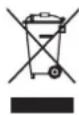
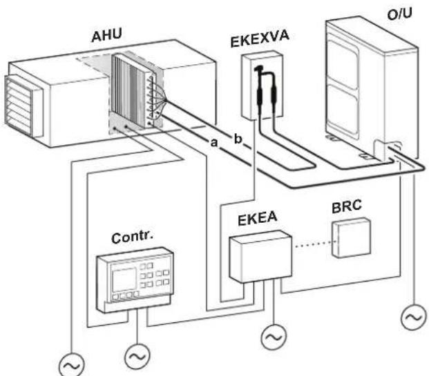
AHU connection
flowchart
graph TD
    A["AHU"] -->|a| B["EKEXVA"]
    B -->|b| C["Contr."]
    C --> D["EKEA"]
    D --> E["BRC"]
    E --> F["O/U"]
    style A fill:#f9f,stroke:#333
    style B fill:#ccf,stroke:#333
    style C fill:#cfc,stroke:#333
    style D fill:#fcc,stroke:#333
    style E fill:#cff,stroke:#333
    style F fill:#ffc,stroke:#333
a Gas piping (field supply)
b Liquid piping (field supply)
AHU Air handling unit (field supply)
BRC Wired remote controller
Contr. Controller (field supply)
EKEA Control box
EKEXVA Expansion valve kit
O/U Outdoor unit

INFORMATION
- This equipment is not designed for year-round cooling applications with low indoor humidity conditions, such as Electronic Data Processing rooms.
- Combination of EKEA + EKEXVA + AHU is not a comfort product.
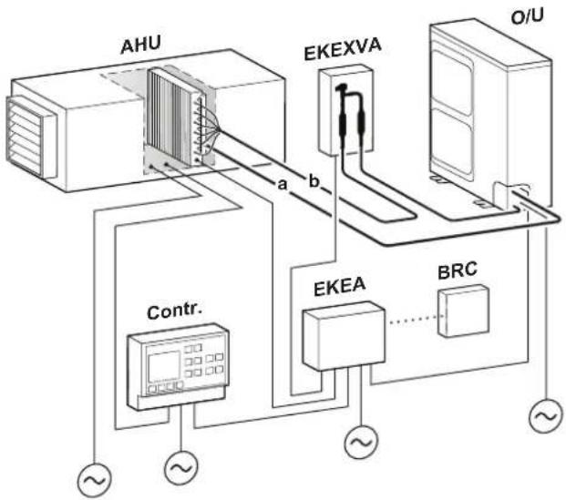
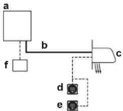
Air curtain connection
flowchart
graph TD
    a --> b
    b --> c
    b --> d
    b --> e
    f --> b
    style a fill:#f9f,stroke:#333
    style b fill:#ccf,stroke:#333
    style c fill:#cfc,stroke:#333
    style d fill:#fcc,stroke:#333
    style e fill:#cff,stroke:#333
a Heat pump outdoor unit
b Refrigerant piping
c Compatible air curtain
d Remote controller in normal mode
e Remote controller in supervisor mode (mandatory in some situations)
f Centralised controller (optional)

INFORMATION
An air curtain is a heating-only product designed primarily for providing air separation. Therefore, it cannot be considered a comfort product.
5 User interface

CAUTION
- NEVER touch the internal parts of the controller.
- Do NOT remove the front panel. Some parts inside are dangerous to touch and appliance problems may happen. For checking and adjusting the internal parts, contact your dealer.
This operation manual offers a non-exhaustive overview of the main functions of the system.
Detailed information on required actions to achieve certain functions can be found in the dedicated installation and operation manual of the indoor unit.
Refer to the operation manual of the installed user interface.
6 Operation
6.1 Operation range
Use the system in the following temperature and humidity ranges for safe and effective operation.
| Cooling Heating | ||
| Outdoor temperature | -5~52°C DB -20~21°C DB | -20~15.5°C WB |
| Indoor temperature | 21~32°C DB 14~25°C WB | 15~27°C DB |
| Indoor humidity | ≤80%(a) | |
To avoid condensation and water dripping out of the unit. If the temperature or the humidity is beyond these conditions, safety devices may be put in action and the air conditioner may not operate.
Above operation range is only valid in case direct expansion indoor units are connected to the ERA system.
Special operation ranges are valid in case of using AHU. They can be found in the installation/operation manual of the dedicated unit. Latest information can be found in the technical engineering data.
6.2 Operating the system
6.2.1 About operating the system
- Operation procedure varies according to the combination of outdoor unit and user interface.
- To protect the unit, turn on the main power switch 6 hours before operation.
- If the main power supply is turned off during operation, operation will restart automatically after the power turns back on again.
6.2.2 About cooling, heating, fan only, and automatic operation
- Changeover cannot be made with a user interface whose display shows "changeover under centralised control" (refer to installation and operation manual of the user interface).
7 Maintenance and service
- The fan may keep on running for about 1 minute after the heating operation stops.
- The air flow rate may adjust itself depending on the room temperature or the fan may stop immediately. This is not a malfunction.
6.2.3 About the heating operation
It may take longer to reach the set temperature for general heating operation than for cooling operation.
The following operation is performed in order to prevent the heating capacity from dropping or cold air from blowing.
Defrost operation
In heating operation, freezing of the outdoor unit's air cooled coil increases over time, restricting the energy transfer to the outdoor unit's coil. Heating capability decreases and the system needs to go into defrost operation to be able to remove frost from the outdoor unit's coil. During defrost operation the heating capacity on the indoor unit side will temporarily drop until defrosting is completed. After defrosting, the unit will regain its full heating capacity.
The indoor unit will stop fan operation, the refrigerant cycle will reverse and energy from inside the building will be used to defrost the outdoor unit coil.
The indoor unit will indicate defrost operation on the display
Hot start
In order to prevent cold air from blowing out of an indoor unit at the start of heating operation, the indoor fan is automatically stopped. The display of the user interface shows 📄 may take some time before the fan starts. This is not a malfunction.
6.2.4 To operate the system (WITHOUT cool/heat changeover remote control switch)
1 Press the operation mode selector button on the user interface several times and select the operation mode of your choice.
Cooling operation
Heating operation
Fan only operation
2 Press the ON/OFF button on the user interface.
Result: The operation lamp lights up and the system starts operating.
6.2.5 To operate the system (WITH cool/heat changeover remote control switch)
Overview of the changeover remote control switch
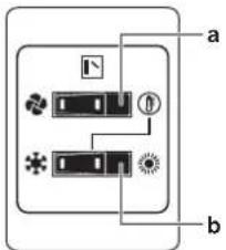
a FAN ONLY/AIR CONDITIONING SELECTOR SWITCH
Set the switch to 🧑 for fan only operation or to 🟡 for heating or cooling operation.
b COOL/HEAT CHANGEOVER SWITCH
Set the switch to for cooling or to for heating
Note: In case a cool/heat changeover remote control switch is used, the position of DIP switch 1 (DS1-1) on the main PCB needs to be switched to the ON position.
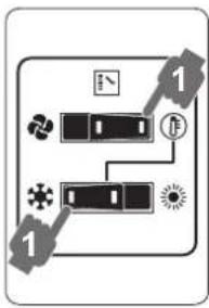
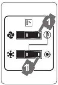
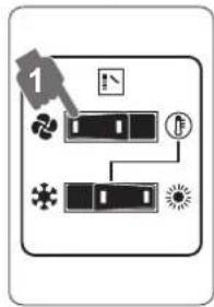
To start
1 Select operation mode with the cool/heat changeover switch as follows:
Cooling operation

Heating operation

Fan only operation

flowchart
graph TD
    A["Input"] --> B["Process"]
    B --> C["Output"]
    style A fill:#f9f,stroke:#333
    style B fill:#ccf,stroke:#333
    style C fill:#cfc,stroke:#333
flowchart
graph TD
    A["Input"] --> B["Processing Unit"]
    B --> C["Output"]
    style A fill:#f9f,stroke:#333
    style B fill:#ccf,stroke:#333
    style C fill:#cfc,stroke:#333
flowchart
graph TD
    A["Start"] --> B{Step 1}
    B --> C["Process Step 1"]
    C --> D["End"]
    style A fill:#f9f,stroke:#333
    style B fill:#ccf,stroke:#333
    style C fill:#cfc,stroke:#333
    style D fill:#fcc,stroke:#333
2 Press the ON/OFF button on the user interface.
Result: The operation lamp lights up and the system starts operating.
To stop
3 Press the ON/OFF button on the user interface once again.
Result: The operation lamp goes out and the system stops operating.

NOTICE
Do not turn off power immediately after the unit stops, but wait for at least 5 minutes.
To adjust
For programming temperature, fan speed and air flow direction refer to the operation manual of the user interface.
7 Maintenance and service
7.1 Precautions for maintenance and service

CAUTION
See "3 User safety instructions" [▶ 8] to acknowledge all related safety instructions.

NOTICE
NEVER inspect or service the unit by yourself. Ask a qualified service person to perform this work.

NOTICE
Do NOT wipe the controller operation panel with benzine, thinner, chemical dust cloth, etc. The panel may get discoloured or the coating peeled off. If it is heavily dirty, soak a cloth in water-diluted neutral detergent, squeeze it well and wipe the panel clean. Wipe it with another dry cloth.
7.2 About the refrigerant

CAUTION
See "3 User safety instructions" [▶ 8] to acknowledge all related safety instructions.
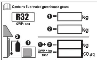
This product contains fluorinated greenhouse gases. Do NOT vent gases into the atmosphere.
Refrigerant type: R32
Global warming potential (GWP) value: 675
Periodical inspections for refrigerant leaks may be required depending on the applicable legislation. Contact your installer for more information.

NOTICE
Applicable legislation on fluorinated greenhouse gases requires that the refrigerant charge of the unit is indicated both in weight and CO_2 equivalent.
Formula to calculate the quantity in CO_2 equivalent tonnes: GWP value of the refrigerant × total refrigerant charge [in kg]/1000
Contact your installer for more information.
7.3 After-sales service
7.3.1 Recommended maintenance and inspection
Since dust collects when using the unit for several years, performance of the unit will deteriorate to some extent. As taking apart and cleaning interiors of units requires technical expertise and in order to ensure the best possible maintenance of your units, we recommend to enter into a maintenance and inspection contract on top of normal maintenance activities. Our network of dealers has access to a permanent stock of essential components in order to keep your unit in operation as long as possible. Contact your dealer for more information.
When asking your dealer for an intervention, always state:
- The complete model name of the unit.
- The manufacturing number (stated on the nameplate of the unit).
- The installation date.
- The symptoms or malfunction, and details of the defect.

WARNING
- Do NOT modify, disassemble, remove, reinstall or repair the unit yourself as incorrect dismantling or installation may cause an electrical shock or fire. Contact your dealer.
- In case of accidental refrigerant leaks, make sure there are no naked flames. The refrigerant itself is entirely safe, non-toxic and mildly flammable, but it will generate toxic gas when it accidentally leaks into a room where combustible air from fan heaters, gas cookers, etc. is present. Always have qualified service personnel confirm that the point of leakage has been repaired or corrected before resuming operation.
8 Troubleshooting
If one of the following malfunctions occurs, take the measures shown below and contact your dealer.

WARNING
Stop operation and shut OFF the power if anything unusual occurs (burning smells etc.).
Leaving the unit running under such circumstances may cause breakage, electrical shock or fire. Contact your dealer.
The system MUST be repaired by a qualified service person.
| Malfunction | Measure |
| If a safety device such as a fuse, a breaker or an earth leakage breaker frequently actuates or the ON/OFF switch does NOT properly work. | Turn OFF the main power switch. |
| Malfunction | Measure |
| The operation switch does NOT work well. | Turn OFF the power supply. |
| If the user interface display indicates the unit number, the operation lamp flashes and the malfunction code appears. | Notify your installer and report the malfunction code. |
If the system does NOT operate properly except for the above mentioned cases and none of the above mentioned malfunctions is evident, investigate the system in accordance with the following procedures.
| Malfunction | Measure |
| If a refrigerant leak occurs (error code AQI CH ) | Actions will be taken by the system. Do NOT turn OFF the power supply.Notify your installer and report the malfunction code. |
| If the system does not operate at all. | Check if there is no power failure. Wait until power is restored. If power failure occurs during operation, the system automatically restarts immediately after power is restored.Check if no fuse has blown or breaker is activated. Change the fuse or reset the breaker if necessary. |
| If the system goes into fan only operation, but as soon as it goes into heating or cooling operation, the system stops. | Check if air inlet or outlet of outdoor or indoor unit is not blocked by obstacles. Remove any obstacles and make sure the air can flow freely.Check if the user interface display shows on the home screen. Refer to the installation and operation manual delivered with the indoor unit. |
| The system operates but cooling or heating is insufficient. | Check if air inlet or outlet of outdoor or indoor unit is not blocked by obstacles. Remove any obstacles and make sure the air can flow freely.Check if the air filter is not clogged (refer to AHU or air curtain manual).Check the temperature setting.Check the fan speed setting on your user interface.Check for open doors or windows. Close doors and windows to prevent wind from coming in.Check if there are too many occupants in the room during cooling operation. Check if the heat source of the room is excessive.Check if direct sunlight enters the room. Use curtains or blinds.Check if the air flow angle is proper. |
After checking all the items above, if it is impossible to fix the problem yourself, contact your installer and state the symptoms, the complete model name of the unit (with manufacturing number if possible) and the installation date.
8.1 Error codes: Overview
In case a malfunction code appears on the indoor unit user interface display, contact your installer and inform the malfunction code, the unit type, and serial number (you can find this information on the nameplate of the unit).
8 Troubleshooting
For your reference, a list with malfunction codes is provided. You can, depending on the level of the malfunction code, reset the code by pushing the ON/OFF button. If not, ask your installer for advice.
| Main code | Contents |
| AO | External protection device was activated |
| AO-11 | The R32 sensor of the compatible air curtain has detected a refrigerant leak(a) |
| AO/Safety | system error (leak detection)(a) |
| AI | EEPROM failure (indoor) |
| A6 | Fan motor malfunction (indoor) |
| A9 | Expansion valve malfunction (indoor) |
| AJ | Capacity setting malfunction (indoor) |
| CI | Transmission malfunction between main PCB and sub PCB (indoor) |
| CY | Heat exchanger thermistor malfunction (indoor; liquid) |
| CS | Heat exchanger thermistor malfunction (indoor; gas) |
| C9 | Suction air thermistor malfunction (indoor) |
| CA | Discharge air thermistor malfunction (indoor) |
| CH-01 | R32 sensor malfunction or disconnection (indoor)(a) |
| CH-02 | R32 sensor lifetime exceeded (indoor)(a) |
| CH-05 | R32 sensor end of lifetime<6 months (indoor)(a) |
| CH-10 | Waiting for indoor unit R32 sensor replacement input(a) |
| CJ | User interface thermistor malfunction (indoor) |
| E1 | PCB malfunction (outdoor) |
| E2 | Current leakage detector was activated (outdoor) |
| E3 | High pressure switch was activated (outdoor) |
| E4 | Low pressure malfunction (outdoor) |
| ES | Compressor lock detection (outdoor) |
| E7 | Fan motor malfunction (outdoor) |
| E9 | Electronic expansion valve malfunction (outdoor) |
| F3 | Discharge temperature malfunction (outdoor) |
| F4 | Abnormal suction temperature (outdoor) |
| H3 | High pressure switch malfunction |
| H7 | Fan motor malfunction (outdoor) |
| H9 | Ambient temperature sensor malfunction (outdoor) |
| J3 | Discharge temperature sensor malfunction (outdoor) |
| JS | Suction temperature sensor malfunction (outdoor) |
| J6 | De-icing temperature sensor malfunction (outdoor) or heat exchanger gas temperature sensor malfunction (outdoor) |
| J7 | Liquid temperature sensor (after subcool HE) malfunction (outdoor) |
| J8 | Liquid temperature sensor (coil) malfunction (outdoor) |
| J9 | Gas temperature sensor (after subcool HE) malfunction (outdoor) |
| JA | High pressure sensor malfunction (S1NPH) |
| JC | Low pressure sensor malfunction (S1NPL) |
| LI | INV PCB abnormal |
| LY | Fin temperature abnormal |
| LS | INV PCB abnormal |
| LB | Compressor over current detected |
| L9 | Compressor lock (startup) |
| LC | Transmission outdoor unit - inverter: INV transmission trouble |
| PI | INV unbalanced power supply voltage |
| PY | Fin thermistor malfunction |
| PJ | Capacity setting malfunction (outdoor) |
| Main code | Contents |
| U0 | Abnormal low pressure drop, faulty expansion valve |
| U1 | Reversed power supply phase malfunction |
| U2 | INV voltage power shortage |
| U3 | System test run not yet executed |
| U4 | Faulty wiring indoor/outdoor |
| U5 | Abnormal user interface - indoor communication |
| UR-03 | Connection malfunction over indoor units or type mismatch |
| UR-55 | System lock |
| UR-57 | External ventilation input error |
| UC | Centralised address duplication |
| UE | Malfunction in communication centralised control device - indoor unit |
| UH | Auto address malfunction (inconsistency) |
| UJ-37 | AHU supply airflow rate below the legal limit ^(b) |
^(6) The error code is only shown on the user interface of the compatible air curtain where the error occurs.
(b) In case the AHU supply airflow rate is above the legal limit for 5 minutes continuously, this error is automatically solved.
8.2 Symptoms that are NOT system malfunctions
The following symptoms are NOT system malfunctions:
8.2.1 Symptom: The system does not operate
- The air conditioner does not start immediately after the ON/OFF button on the user interface is pressed. If the operation lamp lights, the system is in normal condition. To prevent overloading of the compressor motor, the air conditioner starts 5 minutes after it is turned ON again in case it was turned OFF just before. The same starting delay occurs after the operation mode selector button was used.
- If "Under Centralised Control" is displayed on the user interface, pressing the operation button causes the display to blink for a few seconds. The blinking display indicates that the user interface cannot be used.
- The system does not start immediately after the power supply is turned on. Wait one minute until the microcomputer is prepared for operation.
8.2.2 Symptom: Cool/Heat cannot be changed over
- When the display shows 📁 (changeover under centralised control), it shows that this is a slave user interface.
- When the cool/heat changeover remote control switch is installed, or T3T4 input is used and the display shows (changeover under centralised control), this is because cool/heat changeover is controlled by the cool/ heat changeover remote control switch. Ask your dealer where the remote control switch is installed.
8.2.3 Symptom: Fan operation is possible, but cooling and heating do not work
Immediately after the power is turned on. The micro computer is getting ready to operate and is performing a communication check with the indoor unit. Please wait 12 minutes maximally until this process is finished.
8.2.4 Symptom: White mist comes out of a unit (Indoor unit, outdoor unit)
When the system is changed over to heating operation after defrost operation. Moisture generated by defrost becomes steam and is exhausted.
8.2.5 Symptom: The user interface reads "U4" or "U5" and stops, but then restarts after a few minutes
This is because the user interface is intercepting noise from electric appliances other than the air conditioner. The noise prevents communication between the units, causing them to stop. Operation automatically restarts when the noise ceases. A power reset may help to remove this error.
8.2.6 Symptom: Noise of air conditioners (Indoor unit)
- A "zeen" sound is heard immediately after the power supply is turned on. The electronic expansion valve inside an indoor unit starts working and makes the noise. Its volume will reduce in about one minute.
- A "pishi-pishi" squeaking sound is heard when the system stops after heating operation. Expansion and contraction of plastic parts caused by temperature change make this noise.
8.2.7 Symptom: Noise of air conditioners (Indoor unit, outdoor unit)
- A continuous low hissing sound is heard when the system is in cooling or defrost operation. This is the sound of refrigerant gas flowing through both indoor and outdoor units.
- A hissing sound which is heard at the start or immediately after stopping operation or defrost operation. This is the noise of refrigerant caused by flow stop or flow change.
8.2.8 Symptom: Noise of air conditioners (Outdoor unit)
When the tone of operating noise changes. This noise is caused by the change of frequency.
8.2.9 Symptom: Dust comes out of the unit
When the unit is used for the first time in a long time. This is because dust has gotten into the unit.
8.2.10 Symptom: The units can give off odours
The unit can absorb the smell of rooms, furniture, cigarettes, etc., and then emit it again.
8.2.11 Symptom: The outdoor unit fan does not spin
During operation, the speed of the fan is controlled in order to optimise product operation.
8.2.12 Symptom: The compressor in the outdoor unit does not stop after a short heating operation
This is to prevent refrigerant from remaining in the compressor. The unit will stop after 5 to 10 minutes.
8.2.13 Symptom: The inside of an outdoor unit is warm even when the unit has stopped
This is because the crankcase heater is warming the compressor so that the compressor can start smoothly.
9 Relocation
Contact your dealer to remove and reinstall the entire unit. Moving units requires technical expertise.
10 Disposal
This unit uses hydrofluorocarbon. Contact your dealer when discarding this unit. It is required by law to collect, transport and discard the refrigerant in accordance with the "hydrofluorocarbon collection and destruction" regulations.

NOTICE
Do NOT try to dismantle the system yourself: dismantling of the system, treatment of the refrigerant, oil and other parts MUST comply with applicable legislation. Units MUST be treated at a specialised treatment facility for reuse, recycling and recovery.
For the installer
11 About the box
Keep the following in mind:
- At delivery, the unit MUST be checked for damage and completeness. Any damage or missing parts MUST be reported immediately to the claims agent of the carrier.
- Bring the packed unit as close as possible to its final installation position to prevent damage during transport.
- Prepare in advance the path along which you want to bring the unit to its final installation position.
11.1 To handle the outdoor unit

CAUTION
To avoid injury, do NOT touch the air inlet or aluminium fins of the unit.
12 About the units and options
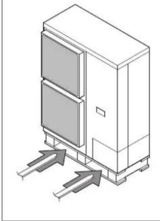
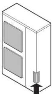
Forklift. If the unit remains on its pallet, you can also use a forklift.
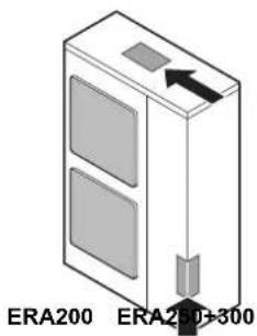
Crane. For ERA250+300 models, you can also use a crane and lift the unit as follows:
natural_image
Isometric line drawing of a cabinet with two doors and directional arrows indicating airflow or movement (no text or symbols)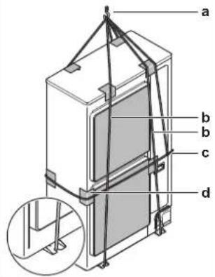
a Lifting hook
b Two vertical ropes (at least 8 m and ∅20 mm) to lift the unit
c One horizontal rope (also fixed to the lifting hook) to prevent the unit from dropping
d Protective material (rags, soft material) between the ropes and the casing to protect the casing

WARNING
The unit's center of gravity deviates to the right side (compressor side). If you lift the unit using a crane and you do not fix a horizontal rope to the lifting hook as shown, the unit might drop.
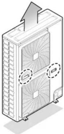
Carry the unit slowly as shown:
natural_image
Technical line drawing of a dual-chamber HVAC unit with fan blades and mounting feet (no text or symbols)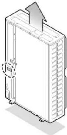
natural_image
Diagram of a server rack unit with an upward arrow and a circular button, no text or symbols present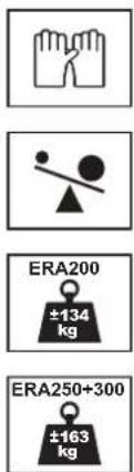
11.2 To remove the accessories from the outdoor unit
1 Remove the service cover. See "14.2.1 To open the outdoor unit" [▶ 24].
2 Remove the accessories.
natural_image
Isometric illustration of a cabinet with two doors and a double door, showing an upward arrow (no text or symbols)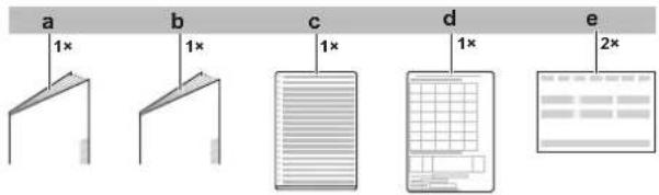
a General safety precautions
b Outdoor unit installation and operation manual
c Multilingual fluorinated greenhouse gases label
d Installation information leaflet
e Declaration of conformity
f Fluorinated greenhouse gases label
g Gas piping accessory 1 (only for ERA250: ∅19.1 mm)
h Gas piping accessory 2 (ERA200: ∅19.1 mm;
ERA250+300: ∅22.2 mm)
i Cable tie (ERA200: 2×; ERA250+300: 3×)
11.3 To remove the transportation stay

NOTICE
If the unit is operated with the transportation stay attached, abnormal vibration or noise may be generated.
The transportation stay for protecting the unit during transport must be removed. Proceed as shown in the figure and procedure below.
1 Remove the bolt (a) and washers.
2 Remove the transportation stay (b) as shown in the figure below.
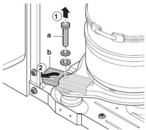
a Bolt
b Transportation stay
12 About the units and options
12.1 About the outdoor unit
This installation manual concerns the ERA, full inverter driven, heat pump system.
These units are intended for outdoor installation and aimed for heating/cooling, and fresh air or air curtain applications.
| Specification | ||
| Capacity | Heating | 25~37.5 kW |
| Cooling | 22.4~33.5 kW | |
| Ambient design temperature | Heating | -20~21°C DB-20~15.5°C WB |
| Cooling | -5~52°C DB | |
12.2 System layout

WARNING
The installation MUST comply with the requirements that apply to this R32 equipment. For more information, see "13 Special requirements for R32 units" [▶ 17].

INFORMATION
The following figure is an example and may NOT completely match your system layout.
AHU connection
flowchart
graph TD
    A["AHU"] -->|a| B["EKEXVA"]
    B -->|b| C["BRC"]
    C --> D["Contr."]
    D --> E["~"]
    D --> F["~"]
    D --> G["~"]
    H["O/U"] --> I["..."]
    style A fill:#f9f,stroke:#333
    style B fill:#ccf,stroke:#333
    style C fill:#cfc,stroke:#333
    style D fill:#fcc,stroke:#333
    style E fill:#ffc,stroke:#333
    style F fill:#fcc,stroke:#333
    style G fill:#ffc,stroke:#333
a Gas piping (field supply)
b Liquid piping (field supply)
AHU Air handling unit (field supply)
BRC Wired remote controller
Contr. Controller (field supply)
EKEA Control box
EKEXVA Expansion valve kit
O/U Outdoor unit

INFORMATION
- This equipment is not designed for year-round cooling applications with low indoor humidity conditions, such as Electronic Data Processing rooms.
- Combination of EKEA + EKEXVA + AHU is not a comfort product.
Air curtain connection

flowchart
graph TD
    a --> b
    b --> c
    b --> d
    b --> e
    f --> b
    style a fill:#f9f,stroke:#333
    style b fill:#ccf,stroke:#333
    style c fill:#cfc,stroke:#333
    style d fill:#fcc,stroke:#333
    style e fill:#cff,stroke:#333
a Heat pump outdoor unit
b Refrigerant piping
c Compatible air curtain
d Remote controller in normal mode
e Remote controller in supervisor mode (mandatory in some situations)
f Centralised controller (optional)

INFORMATION
An air curtain is a heating-only product designed primarily for providing air separation. Therefore, it cannot be considered a comfort product.
13 Special requirements for R32 units
13.1 Requirements for compatible air curtains

INFORMATION
In this section, the term "indoor unit" is used for air curtain applications.
13.1.1 Installation space requirements

WARNING
If the appliance contains R32 refrigerant, the floor area of the room in which the appliance is stored shall be at least 429 m ^2 .

NOTICE
- The pipework shall be securely mounted and guarded protected from physical damage.
- Keep the pipework installation to a minimum.
13.1.2 System layout requirements
The ERA uses R32 refrigerant which is rated as A2L and is mildly flammable.
To comply with the requirements of enhanced tightness refrigerating systems of the IEC 60335-2-40, this system is equipped with an alarm in the remote controller and natural ventilation can be used as a safety measure. Both safety measures are installation specific and can be determined using the requirements mentioned in this manual. In case the requirements of this manual are followed, no additional safety measures are needed.
A big range of charge and room area combinations is allowed thanks to the countermeasures that are implemented in the system by default.
Follow the installation requirements below to ensure that the complete system is compliant to legislation.
Outdoor unit installation
The outdoor unit must be installed outside. For indoor installation of the outdoor unit, additional measures can be necessary to comply with the applicable legislation.
A terminal for external output is available in the outdoor unit. This SVS output can be used when additional countermeasures are needed. The SVS output is a contact on terminal X2M that closes in case a leak is detected, failure or disconnection of an R32 sensor (located in the air curtain).
For more information about the SVS output, see "17.5 To connect the external outputs" [▶ 35].
Indoor unit installation
For installation of the compatible air curtain, refer to the installation and operation manual delivered with the air curtain. For compatibility of air curtain refer to the latest version of the technical data book of this outdoor unit.
Depending on the room size in which the air curtain is installed and the total amount of refrigerant in the system, other safety measures are necessary for these indoor units. See "13.1.3 To determine the required safety measures" [▶ 18].
An optional output, if available on a compatible air curtain, can be used for an external device. The output will trigger in case a leak is detected, the R32 sensor fails or when the sensor is disconnected. For more information about this output, refer to the installation manual of the compatible air curtain unit.
Piping requirements

CAUTION
Piping MUST be installed according to instructions given in "15 Piping installation" [▶ 26]. Only mechanical joints (e.g. braze+flare connections) that are compliant with the latest version of ISO14903 can be used.
Low temperature solder alloys shall not be used for pipe connections.
For piping installed in the occupied space, make sure that the piping is protected against accidental damage. Piping should be checked according to the procedure as mentioned in "15.3 Checking the refrigerant piping" [▶ 29].
Remote controller requirements for compatible air curtains equipped with R32 sensor
flowchart
graph TD
    a --> b
    b --> c
    b --> d
    b --> e
    f --> b
    style a fill:#fff,stroke:#000
    style b fill:#fff,stroke:#000
    style c fill:#fff,stroke:#000
    style d fill:#fff,stroke:#000
    style e fill:#fff,stroke:#000
a Heat pump outdoor unit
b Refrigerant piping
c Compatible air curtain
d Remote controller in normal mode
e Remote controller in supervisor mode (mandatory in some situations)
f Centralised controller (optional)
For installation of the remote controller, please refer to the installation and operation manual delivered with the remote controller. Any compatible air curtain equipped with a R32 sensor must be connected with a R32 safety system compatible remote controller (e.g. BRC1H52/82* or later type). In case of air curtains, the remote controllers have implemented safety measures that will warn the user visually and audibly in case of a leak.
For installation of the remote controller of an air curtain, it is mandatory to follow the requirements:
1 Only a safety system compatible remote controller can be used. See technical data sheet for remote controller compatibility (e.g. BRC1H52/82 ^* ).
2 The air curtain must be connected to a compatible remote controller.
13.1.3 To determine the required safety measures
Step 1 – Determine the total amount of refrigerant in the system. Use the values on the unit nameplate to determine the total amount of refrigerant in the system.
Total charge=Factory charge ① ^(a) +additional charge ② ^(b)
(a) The factory charge value can be found on the nameplate.
(b) The R value (additional refrigerant to be charged) is calculated in "16.2 To determine the additional refrigerant amount" [▶ 31].

NOTICE
The total refrigerant charge amount in the system MUST always be lower than 79.8 kg.
Step 2 – Determine the area of the room (A) where an air curtain is installed/serving.
The room area can be determined by projecting the walls, doors and partitions to the floor and calculating the enclosed area. Spaces connected by only false ceilings, ductwork, or similar connections are not considered a single space.
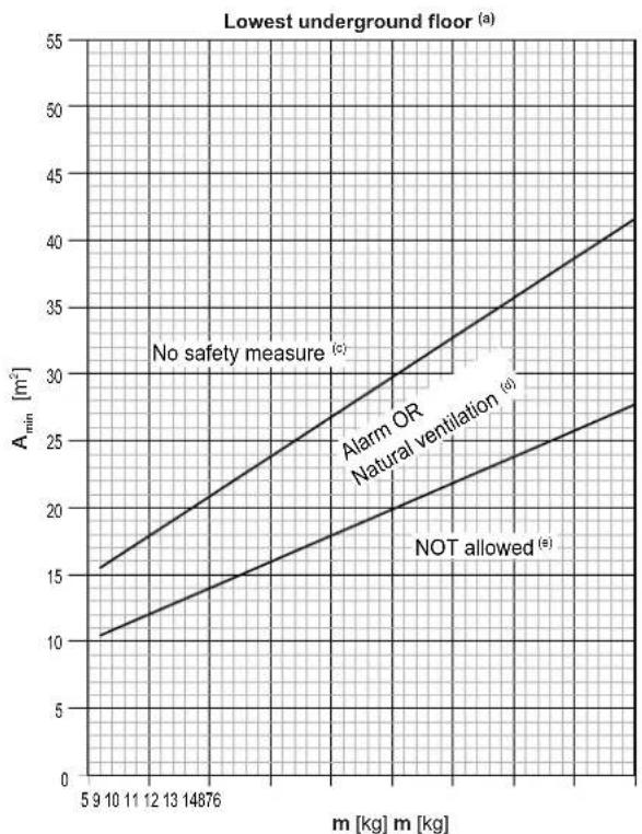
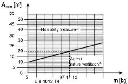
Step 3 – Use the graphs or tables (see "Figure 4" [▶ 3] at the beginning of this manual) to determine the required safety measures for the air curtain.
m Total refrigerant charge in the system [kg]
A_ Minimum room area limit [m^2]
(a) Lowest underground floor (=Lowest underground floor)
(b) All other floors (=All other floors)
(c) No safety measure (=No safety measure)
(d) Alarm OR Natural ventilation (=Alarm OR Natural ventilation)
(e) NOT allowed (=NOT allowed)
(f) Alarm + Natural ventilation (=Alarm + Natural ventilation)
Use the total amount of refrigerant in the system and the area of the room in which the air curtain is installed/serving, to check which safety measure is required.
Note: When "No safety measure" is required, it is still allowed to apply natural ventilation or alarm) if wanted. Follow the respective instructions as described further below.
Note: When natural ventilation is required, it is still allowed to apply alarm) if wanted. Follow the respective instructions as described further below.
Use the first graph (Lowest underground floor ^(a) ) in case the air curtain is installed/serving in the lowest underground floor of a building. For other floors, use the second graph (All other floors ^(b) ).
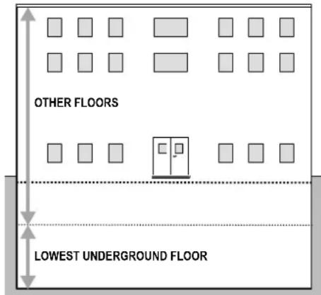
The graphs and table are based on an installation height of the air curtain between 1.8 m and 2.2 m (bottom of the air curtain). See "14.1.1 Installation site requirements of the outdoor unit" [▶ 24].
If the installation height is more than 2.2 m, different boundaries for the applicable safety measures can apply. To know which safety measure is required in case the installation height is more than 2.2 m, refer to the online tool (VRV Xpress).

NOTICE
A compatible air curtain cannot be installed lower than 1.8 m from the lowest point of the floor.
Example
The total amount of refrigerant in the ERA system is 10 kg. The air curtain is installed in spaces that do NOT belong to the lowest underground floor of the building. The space in which the air curtain is installed has a room area of 50 m ^2 .
- Based on the graph for "All other floors" (All other floors), the room area limit is 19.7 ~m^2 (approx. 20 ~m^2 ) for "No safety measure" (No safety measures).
- This means that the following safety measures are required:
Room area Required safety measure
A=50 m²≥20 m² No safety measures
line
| m [kg] | A_min [m] | | ------ | --------- | | 5 | 10 | | 6 | 12 | | 8 | 14 | | 10 | 16 | | 12 | 18 | | 14 | 20 | | 97 | 22 | | 11 | 24 | | 13 | 26 | | 13 | 28 |m Total refrigerant charge in the system [kg]
A_min Minimum room area limit [m²]
(c) No safety measure (=No safety measure)
(f) Alarm + Natural ventilation (=Alarm + Natural ventilation)
Overview: flowchart
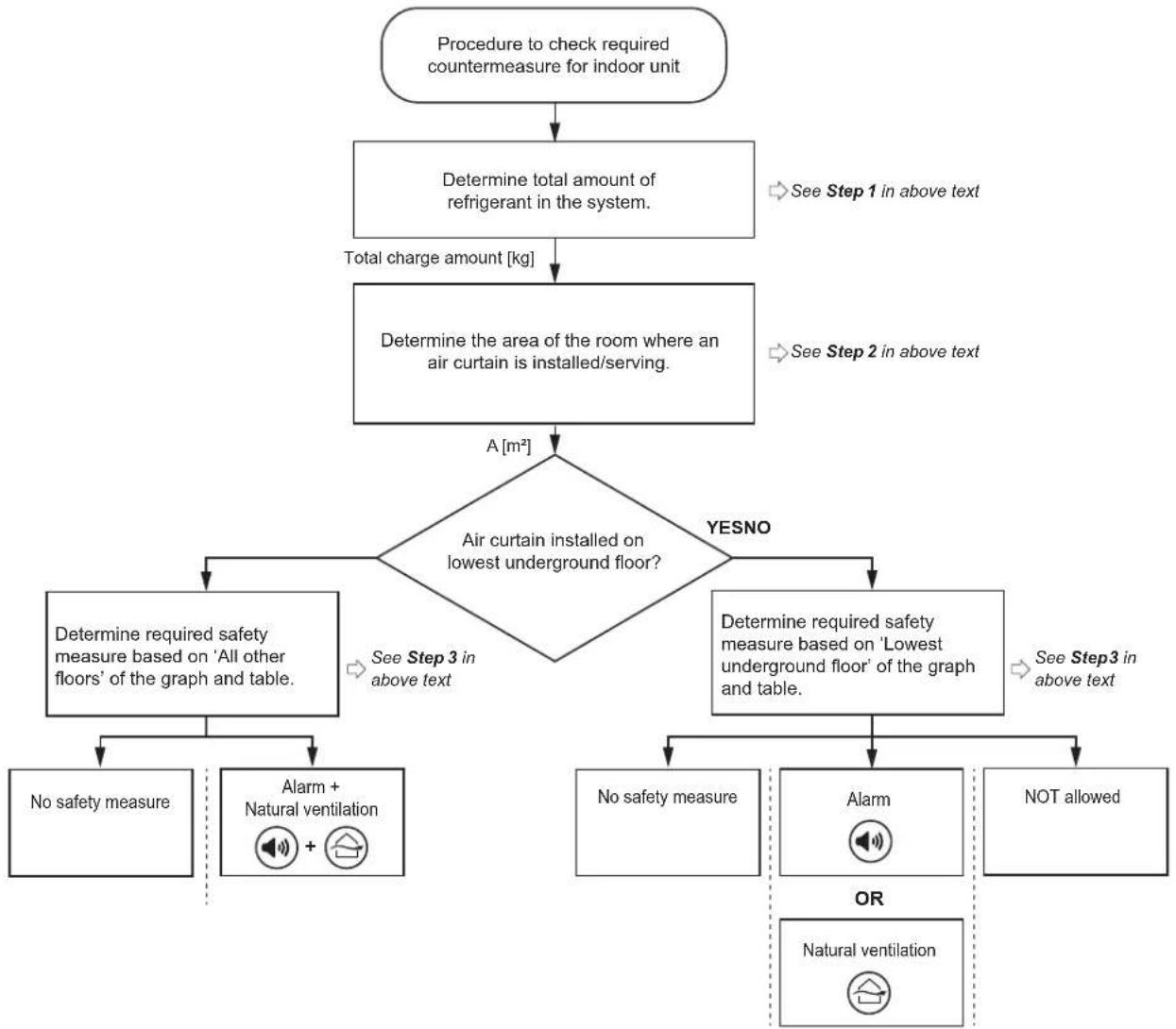
flowchart
graph TD
    A["Procedure to check required countermeasure for indoor unit"] --> B["Determine total amount of refrigerant in the system."]
    B --> C["Total charge amount [kg"]]
    C --> D["Determine the area of the room where an air curtain is installed/serving."]
    D --> E{Air curtain installed on lowest underground floor?}
    E -->|YesNO| F["Determine required safety measure based on 'All other floors' of the graph and table."]
    E -->|YESNO| G["Determine required safety measure based on 'Lowest underground floor' of the graph and table."]
    F --> H["No safety measure"]
    F --> I["Alarm + Natural ventilation"]
    G --> J["No safety measure"]
    G --> K["Alarm"]
    G --> L["NOT allowed"]
    H --> M["OR"]
    I --> M
    J --> M
    K --> M
    L --> M
    style A fill:#f9f,stroke:#333
    style B fill:#ccf,stroke:#333
    style C fill:#cfc,stroke:#333
    style D fill:#fcc,stroke:#333
    style E fill:#cff,stroke:#333
    style F fill:#ffc,stroke:#333
    style G fill:#ffc,stroke:#333
    style H fill:#cfc,stroke:#333
    style I fill:#cfc,stroke:#333
    style J fill:#cfc,stroke:#333
    style K fill:#cfc,stroke:#333
    style L fill:#cfc,stroke:#333
Note: The flowchart is an overview. Always refer to the full text mentioned in this manual for clear understanding and detailed explanation.
13.1.4 Safety measures
No safety measure
When the room area is sufficiently large, no safety measures are required. This also includes an indoor unit installed in the lowest underground floor.
Therefore the R32 safety system in the indoor unit in a sufficiently large room can be deactivated (active by default) by changing the setting in the user interface as shown below:
Field settings
| No safety measure | ||||
| Setting 1 | ^st code | Function 2 | ^nd code | Description |
| 15/25 13 | R32 leak | safety system setting | 01 Disabled | |
Note: For more information, see "18.1.8 Indoor unit field setting" [▶ 38].
Alarm

WARNING
√ Do NOT use 'Alarm' as the ONLY safety measure in case the indoor unit is installed in an occupied space where people are restricted in their movement.
- Combine or use another safety measure.
R32 safety system compatible remote controllers (e.g. BRC1H52/82* or later type) used with the air curtain have a built-in alarm as a safety measure. For installation of the remote controller, please refer to the installation and operation manual delivered with the remote controller.
The compatible air curtain must be connected with a R32 safety system compatible remote controller (e.g. BRC1H52/82* or later type). These remote controllers have implemented safety measures that will warn the user visually and audibly in case of a leak.
For installation of the remote controller, it is mandatory to follow the requirements.
1 Only a safety system compatible remote controller can be used. See technical data sheet for remote controller compatibility (e.g. BRC1H52/82*).
2 The remote controller put in the room served by the air curtain must be in 'fully functional' or 'alarm only' mode. For details about the different remote controller modes and how to set up, please refer to the installation and operation manual delivered with the remote controller.
3 For buildings where sleeping facilities are offered (e.g. hotel), where persons are restricted in their movements (e.g. hospitals), an uncontrolled number of persons is present or buildings where people are not aware of the safety precautions it is mandatory to install one of the following devices at a location with 24-hour monitoring:
- a supervisor remote controller
- or a centralised controller. E.g., iTM with external alarm via WAGO module, iTM with built-in alarm, ...
Note: The remote controllers with built-in alarm will generate a visible and audible warning. E.g. the BRC1H52/82* remote controllers can generate an alarm of 65 dB (sound pressure, measured at 1 m distance of the alarm). Sound data is available in the technical data sheet of the remote controller. The alarm should always be 15 dB louder than the background noise of the room.
A field supply external alarm with a sound output 15 dB louder than the background noise of the room MUST be installed in the following cases:
- The sound output of the remote controller is not sufficient to guarantee the 15 dB difference. This alarm can be connected to the SVS output channel of the outdoor unit, or to the optional output of the air curtain, if available. The outdoor SVS will trigger when a R32 leak is detected. For more information on the SVS output signal, see "17.5 To connect the external outputs" [▶ 35].
- A centralised controller without built-in alarm is used, or the sound output of the centralised controller with built-in alarm is not sufficient to guarantee the 15 dB difference. Please refer to the installation manual of the centralised controller for the correct procedure to install the external alarm.
Note: Depending on configuration, the remote controller is operable in three possible modes. Each mode offers different controller functionality. For detailed information about setting the operation mode of the remote controller and its function, please refer to the installer and user reference guide of the remote controller.
| Mode | Function |
| Fully functional | The controller is fully functional. All normal functionality is available. |
| Alarm only | The controller only acts as leak detection alarm (for a single indoor unit). No functionality is available. The remote controller should always be put in the same room as the indoor unit. |
| Supervisor | The controller only acts as leak detection alarm. No other functionality is available. The remote controller should be placed at a supervised location.Note: In order to add a supervisor remote controller to the system, a field setting must be set on remote controller and outdoor unit. The air curtain needs to be assigned an address number. |
Note: Incorrect use of remote controllers can result in occurrence of error codes, non-operating system or system that is not compliant to applicable legislation.
Note: Some centralised controllers can also be used as supervisor remote controller. For further details on installation, please refer to the installation manual of the centralised controllers.
Examples
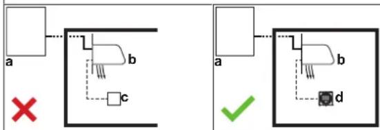
1 Remote controller is not R32 safety system compatible.
flowchart
graph TD
    subgraph Left_Circuit
        A1["a"] --> B1["b"]
        B1 --> C1["c"]
        D["X"] --> B1
        B1 --> E1["Square"]
    end
    subgraph Right_Circuit
        F1["a"] --> G1["b"]
        G1 --> H1["d"]
        I["✓"] --> J["Green check"]
2 Indoor units without remote controller are not allowed.
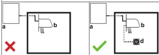
flowchart
graph TD
    A1["a"] --> B1["b"]
    B1 --> C1["×"]
    D1["a"] --> E1["b"]
    E1 --> F1["d"]
    style A1 fill:#fff,stroke:#000
    style B1 fill:#fff,stroke:#000
    style C1 fill:#fff,stroke:#000
    style D1 fill:#fff,stroke:#000
    style E1 fill:#fff,stroke:#000
    subgraph Left_Circuit
        A1 --> B1
        B1 -.-> C1
        C1 -.-> D1
        D1 -.-> E1
    end
    subgraph Right_Circuit
        A1 --> E1
        E1 -.-> F1
        F1 -.-> G["d"]
        G --> H["✓"]
3 In case of two R32 safety system compatible remote controllers, at least one remote controller should be in the room of the indoor.
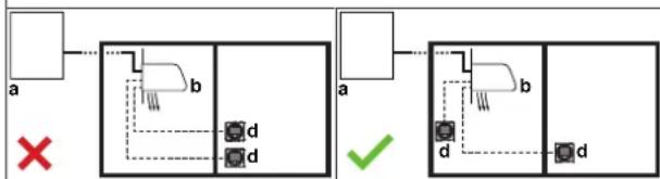
flowchart
graph TD
    A["a"] --> B["b"]
    B --> C["d"]
    D["×"] --> E["d"]
    F["a"] --> G["b"]
    G --> H["d"]
    I["✓"] --> J["d"]
    K["d"] --> L["d"]
4 In particular situations it is mandatory to install a remote controller at a supervised location.
In room: master remote controller in fully functional OR alarm only.
In supervisor room: supervisor remote controller.
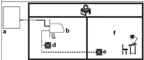
flowchart
graph TD
    A["a"] --> B["b"]
    B --> C["d"]
    C --> D["e"]
    D --> E["f"]
    style A fill:#f9f,stroke:#333
    style B fill:#ccf,stroke:#333
    style C fill:#cfc,stroke:#333
    style D fill:#fcc,stroke:#333
    style E fill:#ffc,stroke:#333
a Outdoor unit
b Compatible air curtain
c Remote controller NOT compatible with R32 safety system
d Remote controller compatible with R32 safety system
e Remote controller in supervisor mode
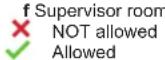
Natural ventilation
Natural ventilation is a safety measure where ventilation is made to a place where sufficient air is available to dilute the leaked refrigerant such as a large space.
The natural ventilation safety measure can be applied by following the steps below:
Step 1 – Determine total room area, which is the total area of the space that has natural ventilation and the space in which the air curtain is installed/serving:
The respective room area can be determined by projecting the walls, doors and partitions to the floor and calculating the enclosed area. Spaces connected only through false ceilings, ductwork, or similar connections are not considered a single space.
Step 2 – Use the graph or table below to determine the total refrigerant charge limit:
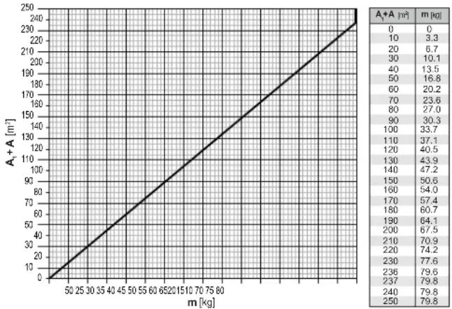
line
| m [kg] | A₁ + A [m²] | |---|---| | 50 | 0 | | 25 | 10 | | 30 | 20 | | 35 | 30 | | 40 | 40 | | 45 | 50 | | 50 | 60 | | 55 | 70 | | 60 | 80 | | 65 | 90 | | 70 | 100 | | 75 | 110 | | 80 | 120 | | 250 | 250 | | 240 | 240 | | 237 | 237 | | 236 | 236 | | 235 | 235 | | 234 | 234 | | 233 | 233 | | 232 | 232 | | 231 | 231 | | 230 | 230 | | 229 | 229 | | 228 | 228 | | 227 | 227 | | 226 | 226 | | 225 | 225 | | 224 | 224 | | 223 | 223 | | 222 | 222 | | 221 | 221 | | 220 | 220 | | 219 | 219 | | 218 | 218 | | 217 | 217 | | 216 | 216 | | 215 | 215 | | 214 | 214 | | 213 | 213 | | 212 | 212 | | 211 | 211 | | 210 | 210 | | 209 | 209 | | 208 | 208 | | 207 | 207 | | 206 | 206 | | 205 | 205 | | 204 | 204 | | 203 | 203 | | 202 | 202 | | 201 | 201 | | 200 | 200 | | 199 | 199 | | 198 | 198 | | 197 | 197 | | 196 | 196 | | 195 | 195 | | 194 | 194 | | 193 | 193 | | 192 | 192 | | 191 | 191 | | 190 | 190 | | 189 | 189 | | 188 | 188 | | 187 | 187 | | 186 | 186 | | 185 | 185 | | 184 | 184 | | 183 | 183 | | 182 | 182 | | 181 | 181 | | 180 | 180 | | 179 | 179 | | 178 | 178 | | 177 | 177 | | 176 | 176 | | 175 | 175 | | 174 | 174 | | 173 | 173 | | 172 | 172 | | 171 | 171 | | 170 | 170 | | 169 | 169 | | 168 | 168 | | 167 | 167 | | 166 | 166 | | 165 | 165 | | 164 | 164 | | 163 | 163 | | 162 | 162 | | 161 | 161 | | 160 | 160 | | 159 | 159 | | 158 | 158 | | 157 | 157 | | 156 | 156 | | 155 | 155 | | 154 | 154 | | 153 | 153 | | 152 | 152 | | 151 | 151 | | 150 | 150 | | 149 | 149 | | 148 | 148 | | 147 | 147 | | 146 | 146 | | 145 | 145 | | 144 | 144 | | 143 | 143 | | 142 | 142 | | 141 | 141 | | 140 | 140 | | 139 | 139 | | 138 | 138 | | 137 | 137 | | 136 | 136 | | 135 | 135 | | 134 | 134 | | 133 | 133 | | 132 | 132 | | 131 | 131 | | 130 | 130 | | Note: The data provided in the image is a simplified representation based on the visual content. The chart contains only the labels for the data series.m Total refrigerant charge limit in the system [kg]
A _1 Area of the room with natural ventilation [m ^2 ]
A Area of the room where an air curtain is installed/serving [m^2]
Note: Round down the derived values.
The graphs and table are based on an installation height of the air curtain between 1.8 m and 2.2 m (bottom of air curtain or bottom of duct openings).
If the installation height is more than 2.2 m, higher total refrigerant charge limit of the system can apply. To know the total refrigerant charge limit of the system in case the installation height is more than 2.2 m, refer to the online tool (VRV Xpress).
Step 3 – The total amount of refrigerant in the system MUST be less than the refrigerant charge limit derived from the graph above. If NOT, natural ventilation safety measure is not allowed.
Step 4 – The partition between two rooms on the same floor MUST meet one of the following two requirements for natural ventilation.
1 Rooms on the same floor that are connected with a permanent opening that extends to the floor and is intended for people to walk through.
2 Rooms on the same floor connected with permanent openings that fulfil the requirements listed below. The openings must consist out of two parts to allow air circulation for natural ventilation.
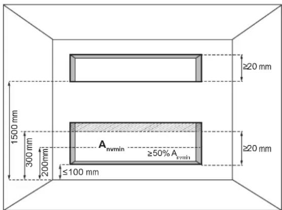
A_nvmin Minimal natural ventilation area
For the lower opening:
- It is not an opening to the outside
- The opening cannot be closed
- The opening must be ≥ 0.012m^2 ( A_nvmin )
- The area of any openings above 300 mm from the floor does not count when determining A_nvmin
- At least 50% of A_nvmin is less than 200~mm above the floor
- The bottom of the lower opening is ≤100 mm from the floor
- The height of the opening is ≥ 20 mm
For the upper opening:
- It is not an opening to the outside
- The opening cannot be closed
- The opening must be ≥ 0.006m^2 (50% of A_nvmin )
- The bottom of the upper opening must be ≥ 1500 mm above the floor
- The height of the opening is ≥ 20 mm
Note: The requirement for the upper opening can be met by false ceilings, ventilation ducts or similar arrangements that provide an airflow path between the connected rooms.
Example
The total amount of refrigerant in the ERA system is 7 kg. The ERA system has an air curtain which is installed in a space that does not belong to the lowest underground floor of the building. The space in which the air curtain is installed has a room area of 10 m². An adjacent room has a room area of 40 m² to which air circulation is possible through a partition that meets one of the two requirements in the above text. The available safety measure is Alarm + Natural ventilation (based on the total amount of refrigerant and room area from the graph for "All other floors").
1 To apply the Alarm safety measure, see "Alarm" [▶ 20].
2 In addition, apply the Natural ventilation safety measure: total room areas of installed room and adjacent room where natural ventilation can be made: A+A_1=10 m^2+40 m^2=50 m^2
13 Special requirements for R32 units
Result: Total refrigerant charge limit for the system determined using the graph for natural ventilation is 16.8 kg.
Total amount of refrigerant in the system (7 kg) < Total refrigerant charge limit (16.8 kg), which means that the Natural ventilation safety measure can be applied.
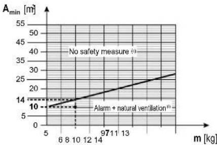
line
| m [kg] | A_min [m] | | ------ | --------- | | 5 | 10 | | 10 | 14 | | 14 | 20 | | 18 | 25 | | 22 | 30 |m Total refrigerant charge in the system [kg]
A_min Minimum room area limit [m^2]
(c) No safety measure (=No safety measure)
(f) Alarm + Natural ventilation (=Alarm + Natural ventilation)
Overview: flowchart
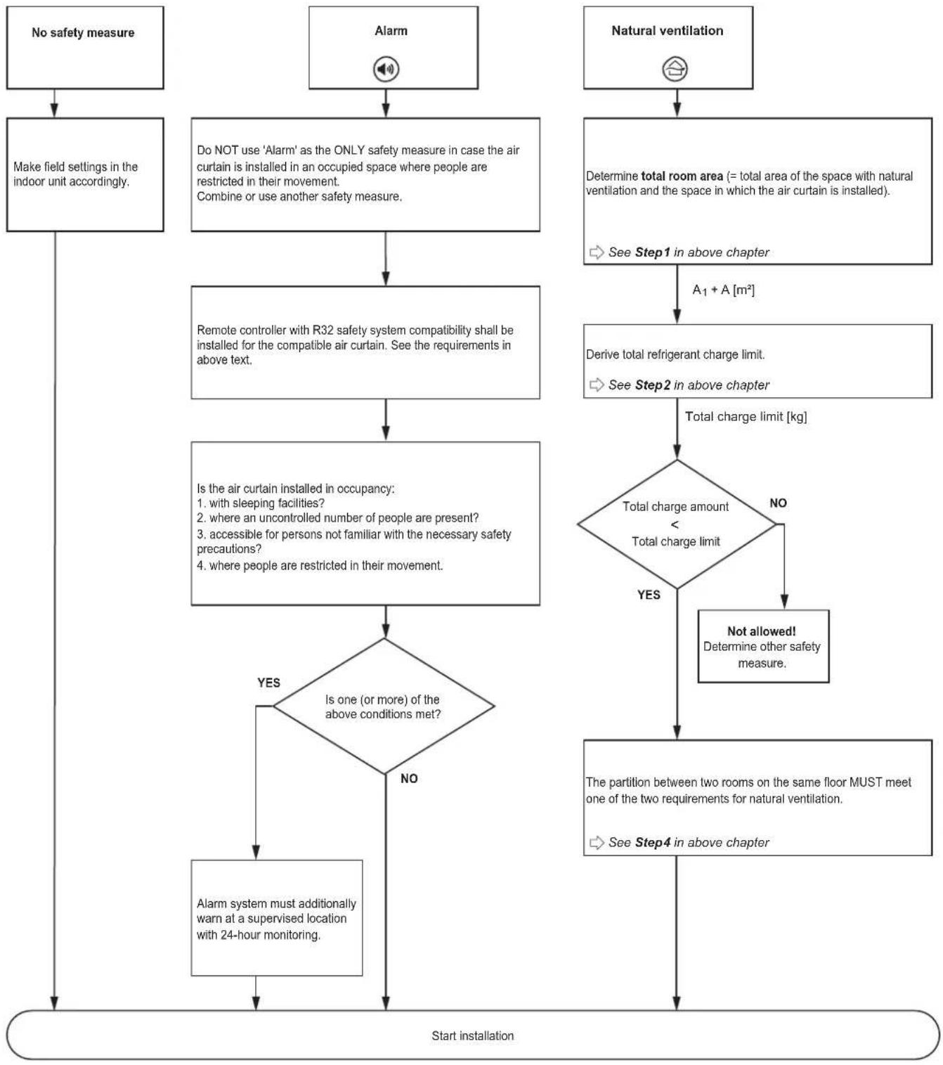
flowchart
graph TD
    A["No safety measure"] --> B["Make field settings in the indoor unit accordingly."]
    C["Alarm"] --> D["Do NOT use 'Alarm' as the ONLY safety measure in case the air curtain is installed in an occupied space where people are restricted in their movement. Combine or use another safety measure."]
    E["Natural ventilation"] --> F["Determine total room area (= total area of the space with natural ventilation and the space in which the air curtain is installed)."]
    F --> G["A1 + A [m²"]]
    G --> H["Derive total refrigerant charge limit."]
    H --> I["See Step2 in above chapter"]
    I --> J["Total charge limit [kg"]]
    J --> K{Total charge amount < Total charge limit}
    K -->|NO| L["Not allowed! Determine other safety measure."]
    K -->|YES| M{Is one (or more) of the above conditions met?}
    M -->|YES| N["Alarm system must additionally warn at a supervised location with 24-hour monitoring."]
    M -->|NO| O["Start installation"]
    N --> O
Note: The flowchart is an overview. Always refer to the full text mentioned in this manual for clear understanding and detailed explanation.
13.2 Requirements for air handling units
For special R32 requirements in case of an AHU connection, refer to the EKEA installation and operation manual.
14 Unit installation

WARNING
The installation MUST comply with the requirements that apply to this R32 equipment. For more information, see "13 Special requirements for R32 units" [▶ 17].
14.1 Preparing the installation site

WARNING
The appliance shall be stored in a room without continuously operating ignition sources (example: open flames, an operating gas appliance or an operating electric heater).

WARNING
The appliance shall be stored as follows:
- in such a way as to prevent mechanical damage.
- in a well-ventilated room without continuously operating ignition sources (example: open flames, an operating gas appliance or an operating electric heater).
- in a room with dimensions as specified in "13 Special requirements for R32 units" [▶ 17].
14.1.1 Installation site requirements of the outdoor unit
Mind the spacing guidelines. See the "Technical data" chapter, and the figures on the inside of the front cover.

INFORMATION
The sound pressure level is less than 70 dBA.
- Make sure the area is well ventilated. Do NOT block any ventilation openings.
- The outdoor unit is designed for outdoor installation only, and for the following ambient temperatures:
| Heating -20~21°C DB | -20~15.5°C WB |
| Cooling -5~52°C DB |
Note: For indoor installation of the outdoor unit, check the applicable legislation.
14.1.2 Additional installation site requirements of the outdoor unit in cold climates
Protect the outdoor unit against direct snowfall and take care that the outdoor unit is NEVER snowed up.
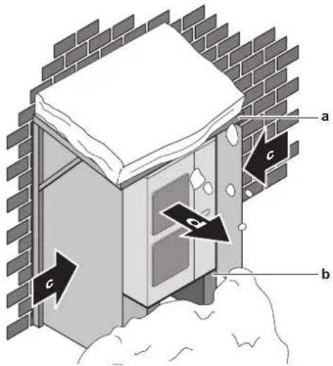
a Snow cover or shed
b Pedestal (minimum height=150 mm)
c Prevailing wind direction
d Air outlet
Snow might build up and freeze between the heat exchanger and the casing of the unit. This might decrease the operating efficiency. For instructions on how to prevent this (after mounting of the unit), see "14.3.3 To provide drainage" [▶ 25].

NOTICE
When operating the unit in heating in a low outdoor ambient temperature with high humidity conditions, make sure to take precautions to keep the drain holes of the unit free by using proper equipment.
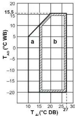
line
| T_AI (°C DB) | T_AD (°C WB) | | ------------ | ------------ | | 10 | 5 | | 15 | 10 | | 20 | 15 | | 25 | 15 | | 30 | 15 |a: Warming up operation range; b: Heating operation range; T_AI : Ambient indoor temperature; T_AO : Ambient outdoor temperature
If the unit is selected to operate at ambient temperatures lower than -5^ for 5 days or longer, with relative humidity levels exceeding 95% , we recommend to apply a Daikin range specifically designed for such application and/or to contact your dealer for further advice.
14.2 Opening and closing the unit
14.2.1 To open the outdoor unit

DANGER: RISK OF ELECTROCUTION

DANGER: RISK OF BURNING/SCALDING
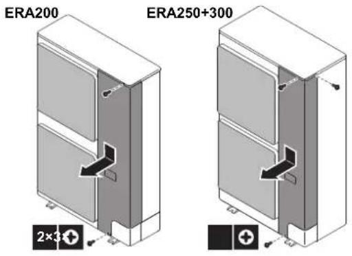
14.2.2 To close the outdoor unit

NOTICE
When closing the outdoor unit cover, make sure that the tightening torque does NOT exceed 4.1 N·m.
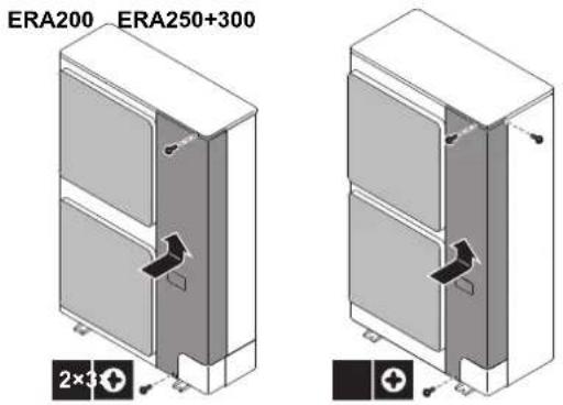
14.3 Mounting the outdoor unit
14.3.1 To provide the installation structure
Prepare four sets of anchor bolts, nuts, and washers (field supply) as follows:
![4× M12 ERA 200, 300 (345-355) 490 (485-495) 620 ERA 250+300, 490 (485-495) [mm] a Make sure not to cover the drain holes of the bottom plate of the unit.](/content/2026/05/855215/images/4fda5389db8080ca1b1d921770ce282059dc1b29bc0c5ca1fa86ba74834c4b08.jpg)

INFORMATION
The recommended height of the upper protruding part of the bolts is 20 mm.
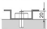

NOTICE
Fix the outdoor unit to the foundation bolts using nuts with resin washers (a). If the coating on the fastening area is stripped off, the metal can rust easily.
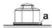
14.3.2 To install the outdoor unit
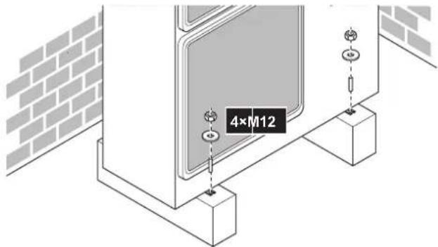
14.3.3 To provide drainage

NOTICE
If drain holes of the outdoor unit are covered by a mounting base or by floor surface, raise the unit to provide a free space of more than 150 mm under the outdoor unit.
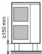
Drain holes (dimensions in mm)
| Model Bottom view [mm] | |
| ERA200 | a 297 286 281 277 218 211 151 91 498 68 5490 307266 856 872 892 916 |
| ERA250+300 | a 52 102 59 118 62 216 130 20 98 21 89 32 |
14.3.4 To prevent the outdoor unit from falling over
In case the unit is installed in places where strong wind can tilt the unit, take following measure:
15 Piping installation
1 Prepare 2 cables as indicated in the following illustration (field supply).
2 Place the 2 cables over the outdoor unit.
3 Insert a rubber sheet between the cables and the outdoor unit to prevent the cables from scratching the paint (field supply).
4 Attach the ends of the cables.
5 Tighten the cables.
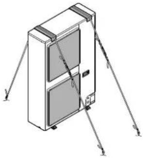
natural_image
Isometric line drawing of a refrigerator with labeled parts (no text or symbols)15 Piping installation

CAUTION
See "2 Specific installer safety instructions" [▶ 5] to make sure this installation complies with all safety regulations.
15.1 Preparing refrigerant piping
15.1.1 Refrigerant piping requirements

NOTICE
The piping and other pressure-containing parts shall be suitable for refrigerant. Use phosphoric acid deoxidised seamless copper for refrigerant piping.
- Foreign materials inside pipes (including oils for fabrication) must be ≤ 30 mg/10 m.
15.1.2 Refrigerant piping material
- Piping material: phosphoric acid deoxidised seamless copper
- Flare connections: Only use annealed material.
- Piping temper grade and thickness:
| Outer diameter(∅) | Temper grade Thickness (t)(a) | |
| 9.5 mm (3/8")12.7 mm (1/2") | Annealed (O) ≥0.80 mm |  |
| 15.9 mm (5/8") Annealed (O) ≥0.99 mm | ||
| 19.1 mm (3/4")22.2 mm (7/8") | Half hard (1/2H) ≥0.80 mm |
(a) Depending on the applicable legislation and the maximum working pressure of the unit (see "PS High" on the unit name plate), larger piping thickness might be required.
15.1.3 Refrigerant piping insulation
- Use polyethylene foam as insulation material:
- with a heat transfer rate between 0.041 and 0.052 W/mK (0.035 and 0.045 kcal/mh°C)
- with a heat resistance of at least 120°C
- Insulation thickness:
| Ambient temperature | Humidity | Minimum thickness |
| ≤30°C | 75% to 80% RH | 15 mm |
| >30°C | ≥80% RH | 20 mm |
15.1.4 Combination table and heat exchanger volume limitations
The ERA outdoor unit can only be combined with one expansion valve kit EKEXVA according to the combination table shown below:
| Expansion valve kit EKEXVA | ||||
| 140 | 200 | 250 | 300 | |
| ERA200 | P(2.94) | P(3.02) | — | — |
| ERA250 | — | P(3.02) | P(3.97) | — |
| ERA300 | — | P(3.49) | P(3.97) | P(4.53) |
— Not allowed
P () Pair AHU layout (value for minimum AHU heat exchanger volume [dm³])
15.1.5 To select the piping size
In case the required pipe sizes (inch sizes) are not available, it is also allowed to use other diameters (mm sizes), taken the following into account:
- Select the pipe size nearest to the required size.
- Use the suitable adapters for the changeover from inch to mm pipes (field supply).
- The additional refrigerant calculation has to be adjusted as mentioned in "16.2 To determine the additional refrigerant amount" [▶ 31].
Use the same diameters as the connections (liquid, gas) on the indoor unit/air curtain. The diameters of the indoor unit/air curtain are as follows:
| Indoor unit capacity index | Piping outer diameter size [mm] | |
| Gas pipe | Liquid pipe | |
| 140 | 15,9 | 9,5 |
| 200 | 19,1 | 9,5 |
| 250 | 19,1 | 9,5 |
| 300 | 22,2 | 12,7 |
15.2 Connecting the refrigerant piping

DANGER: RISK OF BURNING/SCALDING
15.2.1 Using the stop valve and service port
To handle the stop valve
Take the following guidelines into account:
- The gas and liquid stop valves are factory closed.
- Make sure to keep all stop valves open during operation.
- Do NOT apply excessive force to the stop valve. Doing so may break the valve body.
To open the stop valve
1 Remove the dust cap.
2 Insert a hexagon wrench into the stop valve.
3 FULLY turn the stop valve counterclockwise and tighten until the correct tightening torque value is achieved (see "Tightening torques" [▶ 27]).
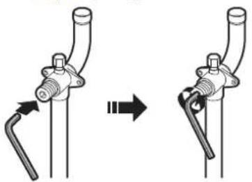
natural_image
Diagram showing a mechanical assembly with two stages of pipe connection (no text or symbols)
NOTICE
Stop valves need to be opened on torque specified in this manual. It is not allowed to turn valve "a quarter turn" back when opening it.
4 Install the dust cap.
Result: The valve is now open.

NOTICE
Reinstall dust cap to prevent aging of O-ring and risk of leakage.
To close the stop valve
1 Remove the stop valve cover.
2 Insert a hexagon wrench into the stop valve and turn the stop valve clockwise.
3 When the stop valve cannot be turned any further, stop turning.
4 Install the stop valve cover.
Result: The valve is now closed.
To handle the service port
- Always use a charge hose equipped with a valve depressor pin, since the service port is a Schrader type valve.
- After handling the service port, make sure to tighten the service port cover securely. For the tightening torque, refer to the table below.
- Check for refrigerant leaks after tightening the service port cover.
Tightening torques
| Stop valve size [mm] | Tightening torque [N·m](a) | ||
| Valve body Hexagonal wrench | Service port | ||
| ∅9.5 5~7 | 4 mm 10.7~14.7 | ||
| ∅12.7 8~10 | |||
| ∅15.9 14~16 6 mm | |||
| ∅19.1 19~21 8 mm | |||
| ∅25.4 | |||
(a) When opening or closing.
15.2.2 To remove the pinched pipes

WARNING
Any gas or oil remaining inside the stop valve may blow off the pinched piping.
Failure to observe the instructions in procedure below properly may result in property damage or personal injury, which may be serious depending on the circumstances.
Use the following procedure to remove the pinched piping:
1 Make sure that the stop valves are fully closed.
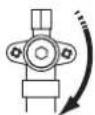
2 Connect the vacuuming/recovery unit through a manifold to the service port of all stop valves.
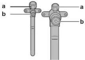
a Service port b Stop valve
3 Recover gas and oil from the pinched piping by using a recovery unit.

CAUTION
Do NOT vent gases into the atmosphere.
4 When all gas and oil is recovered from the pinched piping, disconnect the charge hose and close the service ports.
5 Cut off the lower part of the gas and liquid stop valve pipes along the black line. Use an appropriate tool (e.g. a pipe cutter).
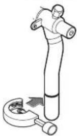
natural_image
Illustration of a human figure performing a manual press or tool lift operation (no text or symbols present)
WARNING

NEVER remove the pinched piping by brazing.
Any gas or oil remaining inside the stop valve may blow off the pinched piping.
6 Wait until all oil has dripped out before continuing with the connection of the field piping in case the recovery was not complete.
15.2.3 To braze the pipe end

NOTICE
Precautions when connecting field piping. Add brazing material as shown in the figure.
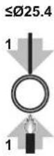
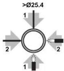
15 Piping installation
- When brazing, blow through with nitrogen to prevent creation of large quantities of oxidised film on the inside of the piping. This film adversely affects valves and compressors in the refrigerating system and prevents proper operation.
- Set the nitrogen pressure to 20 kPa (0.2 bar) (just enough so it can be felt on the skin) with a pressure-reducing valve.
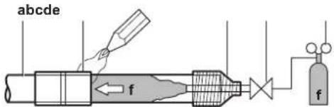
a Refrigerant piping
b Part to be brazed
c Taping
d Manual valve
e Pressure-reducing valve
f Nitrogen
- Do NOT use anti-oxidants when brazing pipe joints. Residue can clog pipes and break equipment.
- Do NOT use flux when brazing copper-to-copper refrigerant piping. Use phosphor copper brazing filler alloy (BCuP), which does NOT require flux.
Flux has an extremely harmful influence on refrigerant piping systems. For instance, if chlorine based flux is used, it will cause pipe corrosion or, in particular, if the flux contains fluorine, it will deteriorate the refrigerant oil.
- ALWAYS protect the surrounding surfaces (e.g. insulation foam) from heat when brazing.
15.2.4 To connect the refrigerant piping to the outdoor unit
- Piping length. Keep field piping as short as possible.
- Piping protection. Protect the field piping against physical damage.
1 Do the following:
- Remove the service cover. See "14.2.1 To open the outdoor unit" [▶ 24].
- Remove the piping intake plate (a) with screw (b).
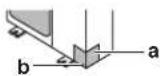
2 Choose a piping route (a, b or c).
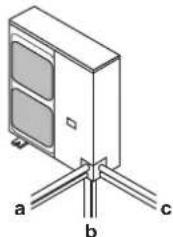
natural_image
Diagram of a server rack with three labeled connection points (a, b, c) and no visible text or symbols.
INFORMATION
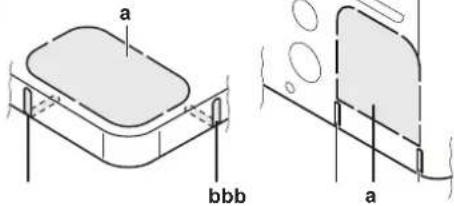
- Punch out the knockout (a) in the bottom plate or cover plate by tapping on the attachment points with a flat head screwdriver and a hammer.
- Optionally, cut out the slits (b) with a metal saw.

NOTICE
Precautions when making knockout holes:
- Avoid damaging the casing and underlying piping.
- After making the knockout holes, we recommend to remove the burrs and paint the edges and areas around the edges using repair paint to prevent rusting.
- When passing electrical wiring through the knockout holes, wrap the wiring with protective tape to prevent damage.
3 Do the following:
- Connect the liquid pipe (a) to the liquid stop valve. (brazing)
- Connect the gas pipe (b) to the gas stop valve. (brazing)
ERA200
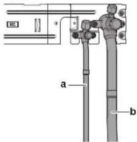
ERA250+300
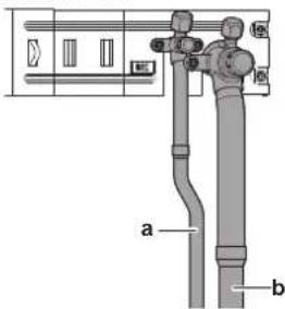

NOTICE
When brazing: First braze the liquid side piping, then the gas side piping. Enter the electrode from the front of the unit and the welding torch from the right side to braze with the flames facing outside and avoid the compressor sound insulation and other piping.
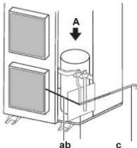
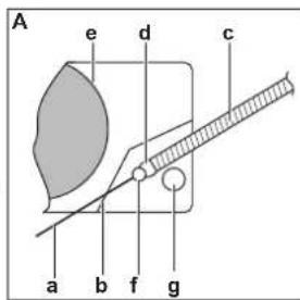
a Electrode
b Burning-resistant plate
c Welding torch
d Flames
e Compressor sound insulation
f Liquid side piping
g Gas side piping
- Connect the gas piping accessories c and d (d: only for ERA250). There are three possibilities:
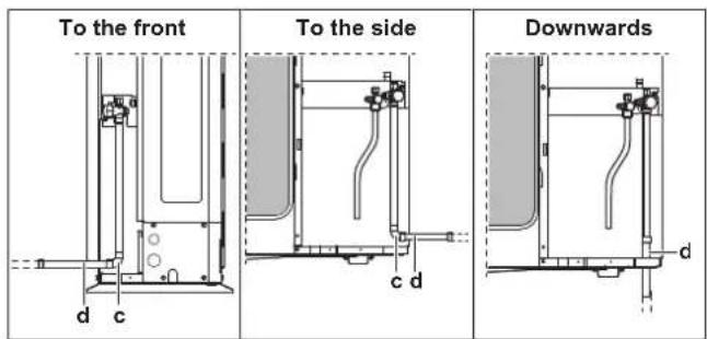

WARNING
Provide adequate measures to prevent that the unit can be used as a shelter by small animals. Small animals that make contact with electrical parts can cause malfunctions, smoke or fire.

NOTICE
Make sure to open the stop valves after installing the refrigerant piping and performing vacuum drying. Running the system with the stop valves closed may break the compressor.

NOTICE
- Be sure to use the supplied accessory pipes when carrying out piping work in the field.
- Be sure that the field installed piping does not touch other pipes, the bottom panel or side panel. Especially for the bottom and side connection, be sure to protect the piping with suitable insulation, to prevent it from coming into contact with the casing.
The connections to the branch kits are the responsibility of the installer (field piping).
15.3 Checking the refrigerant piping
15.3.1 Checking refrigerant piping: Setup
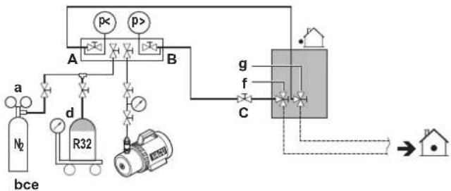
flowchart
graph TD
    A["Gas Tank N2"] -->|a| B["Valve"]
    B --> C["R32"]
    C --> D["Valve"]
    D --> E["Central Chamber"]
    E --> F["Outlet"]
    G["Pressure Source p<"] --> H["Valve"]
    I["Pressure Source p>"] --> J["Valve"]
    K["Flow Control g"] --> L["Valve"]
    M["Flow Control f"] --> N["Valve"]
    O["Flow Control C"] --> P["Valve"]
    Q["Return to Home"] --> R["Output"]
a Pressure reducing valve
b Nitrogen
c Weighing scales
d Refrigerant R32 tank (siphon system)
e Vacuum pump
f Liquid line stop valve
g Gas line stop valve
A Valve A
B Valve B
C Valve C
| Valve Status | |
| Valve A | Open |
| Valve B | Open |
| Valve C | Open |
| Liquid line stop valve | Close |
| Gas line stop valve | Close |

NOTICE
Indoor units should also be leak and vacuum tested. Keep any possible (field supplied) field piping valves open as well.
15.3.2 To perform a leak test
The leak test must satisfy the specifications of EN378-2.
Vacuum leak test
1 Evacuate the system from the liquid and gas piping to a gauge pressure of -100.7 kPa (-1.007 bar) for more than 2 hours.
2 Once reached, turn off the vacuum pump and check that the pressure does not rise for at least 1 minute.
3 Should the pressure rise, the system may either contain moisture (see vacuum drying below) or have leaks.
Pressure leak test
1 Break the vacuum by pressurising with nitrogen gas to a minimum gauge pressure of 0.2 MPa (2 bar). Never set the gauge pressure higher than the maximum operation pressure of the unit, i.e. 4.0 MPa (40 bar).
2 Test for leaks by applying a bubble test solution to all piping connections.
3 Discharge all nitrogen gas.

NOTICE
ALWAYS use a recommended bubble test solution from your wholesaler.
NEVER use soap water:
- Soap water may cause cracking of components, such as flare nuts or stop valve caps.
- Soap water may contain salt, which absorbs moisture that will freeze when the piping gets cold.
- Soap water contains ammonia which may lead to corrosion of flared joints (between the brass flare nut and the copper flare).
15.3.3 To perform vacuum drying
To remove all moisture from the system, proceed as follows:
1 Evacuate the system for at least 2 hours to a target vacuum of -100.7 kPa (-1.007 bar)(5 Torr absolute).
2 Check that, with the vacuum pump turned off, the target vacuum is maintained for at least 1 hour.
3 Should you fail to reach the target vacuum within 2 hours or maintain the vacuum for 1 hour, the system may contain too much moisture. In that case, break the vacuum by pressurising with nitrogen gas to a gauge pressure of 0.05 MPa (0.5 bar) and repeat steps 1 to 3 until all moisture has been removed.
4 Depending on whether you want to immediately charge refrigerant through the refrigerant charge port or first pre-charge a portion of refrigerant through the liquid line, either open the outdoor unit stop valves, or keep them closed. See "16.3 To charge refrigerant" [▶ 31] for more information.
15.3.4 To insulate the refrigerant piping
After finishing the leak test and vacuum drying, the piping must be insulated. Take into account the following points:
- Make sure to insulate the connection piping entirely.
- Be sure to insulate the liquid and gas piping.
- Make sure to insulate the connection piping entirely. - Be sure to insulate the liquid and gas piping.
16 Charging refrigerant
- Use heat resistant polyethylene foam which can withstand a temperature of 70^ for liquid piping and polyethylene foam which can withstand a temperature of 120^ for gas piping.
- Reinforce the insulation on the refrigerant piping according to the installation environment.
| Ambient temperature | Humidity Minimum thickness |
| ≤30°C 75% to | 80% RH 15 mm |
| >30°C ≥80% RH | 20 mm |
Between outdoor and indoor unit
1 Insulate and fix the refrigerant piping and cables as follows:
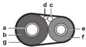
a Gas pipe
b Gas pipe insulation
c Interconnection cable
d Field wiring (if applicable)
e Liquid pipe
f Liquid pipe insulation
g Finishing tape
2 Install the service cover.
Inside the outdoor unit
To insulate the refrigerant piping, proceed as follows:
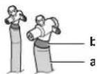
a Insulation material
b Caulking etc.
1 Insulate the liquid and gas piping.
2 Wind heat insulation around the curves, and then cover it with vinyl tape.
3 Make sure the field piping does not touch any compressor components.
4 Seal the insulation ends (sealant etc.) (b, see above).
5 Where necessary, wrap the field piping with vinyl tape to protect the insulation against sharp edges.
6 If the outdoor unit is installed above the indoor unit, cover the stop valves with sealing material to prevent condensed water on the stop valves from moving to the indoor unit.

NOTICE
Any exposed piping can cause condensation.
7 Reattach the service cover and the piping intake plate.
8 Seal all gaps to prevent snow and small animals from entering the system.
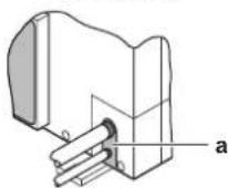
a Seal

WARNING
Provide adequate measures to prevent that the unit can be used as a shelter by small animals. Small animals that make contact with electrical parts can cause malfunctions, smoke or fire.

NOTICE
Do not block the air vents. This could affect air circulation inside the unit.
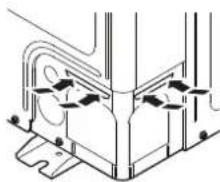
natural_image
Pure mechanical assembly diagram without any text, numbers, or symbols15.3.5 To check for leaks after charging refrigerant
After charging refrigerant in the system an additional leak test must be performed. Refer to "16.6 To check refrigerant piping joints for leaks after charging refrigerant" [▶32].
16 Charging refrigerant
16.1 Precautions when charging refrigerant

WARNING
- Only use R32 as refrigerant. Other substances may cause explosions and accidents.
- R32 contains fluorinated greenhouse gases. Its global warming potential (GWP) value is 675. Do NOT vent these gases into the atmosphere.
- When charging refrigerant, ALWAYS use protective gloves and safety glasses.

NOTICE
If the power of some units is turned off, the charging procedure cannot be finished properly.

NOTICE
Turn ON the power 6 hours before operation in order to have power running to the crankcase heater and to protect the compressor.

NOTICE
If operation is performed within 12 minutes after the indoor and outdoor units are powered on, the compressor will not operate before the communication is established in a correct way between outdoor unit(s) and indoor units.

NOTICE
Before starting charging procedures, check if the 7-segment display indication of the outdoor unit A1P PCB is as normal (see "18.1.3 To access mode 1 or 2" [▶ 37]). If a malfunction code is present, see "22.1 Solving problems based on error codes" [▶ 41].

NOTICE
Make sure all connected indoor units are recognised (see setting [1-10] in "18.1.6 Mode 1: monitoring settings" [▶37]).

NOTICE
In case of maintenance and the system (outdoor unit+field piping+indoor units) does not contain any refrigerant any more (e.g., after refrigerant reclaim operation), the unit has to be charged with its original amount of refrigerant (refer to the nameplate on the unit) and the determined additional refrigerant amount.

NOTICE
- Ensure that contamination of different refrigerants does not occur when using charging equipment.
- Charging hoses or lines shall be as short as possible to minimise the amount of refrigerant contained in them.
- Cylinders shall be kept in an appropriate position according to the instructions.
- Ensure that the refrigerating system is earthed prior to charging the system with refrigerant. See "17.4 To connect the electrical wiring to the outdoor unit" [▶ 34].
- Label the system when charging is complete.
- Extreme care shall be taken not to overfill the refrigerating system.

NOTICE
Prior to charging the system, it shall be pressure tested with the appropriate purging gas. The system shall be leak tested on completion of charging but prior to commissioning. A follow up leak test shall be carried out prior to leaving the site.
16.2 To determine the additional refrigerant amount

WARNING
In case the system serves the lowest underground floor of a building, there is an extra limit to the maximum allowable total refrigerant amount. This maximum refrigerant amount is determined based on the area of the smallest room on the lowest underground floor.
See "13 Special requirements for R32 units" [▶ 17] to determine the maximum allowable total refrigerant amount.

INFORMATION
For final charge adjustment in the test laboratory, please contact your local dealer.

INFORMATION
Note down the amount of additional refrigerant that is calculated here, for later use on the additional refrigerant charge label. See "16.5 To fix the fluorinated greenhouse gases label" [▶ 32].

NOTICE
The refrigerant charge of the system must be less than 79.8 kg. For factory charge, refer to the unit name plate.
Formula:
$$ R = \left[ \left(X _ {1} \times \varnothing 1 2. 7\right) \times 0. 1 0 + \left(X _ {2} \times \varnothing 9. 5\right) \times 0. 0 5 3 \right] $$
R Additional refrigerant to be charged [kg] (rounded off to one decimal place)
X_1...2 Total length [m] of liquid piping size at ∅a
Metric piping. When using metric piping, replace the weight factors in the formula by the ones from the following table:
| Inch piping Metric piping | |||
| Piping Weight factor Piping | Weight factor | ||
| ∅9.5 mm | 0.053 | ∅10 mm | 0.058 |
| ∅12.7 mm | 0.10 | ∅12 mm | 0.088 |
16.3 To charge refrigerant
To speed up the refrigerant charging process, it is in case of larger systems recommended to first pre-charge a portion of refrigerant through the liquid line before proceeding with the manual charging. It can be skipped, but charging will take longer then.
Pre-charging refrigerant
Pre-charging can be done without compressor operation, by connecting the refrigerant bottle to the service port of the liquid stop valve.
1 Connect as shown. Make sure that all outdoor unit stop valves, as well as valve A are closed.
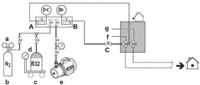
flowchart
graph TD
    A["N2 Gas"] -->|a| B["R32 Reactor"]
    B --> C["Valve 1"]
    B --> D["Valve 2"]
    B --> E["Valve 3"]
    B --> F["Valve 4"]
    B --> G["Valve 5"]
    B --> H["Valve 6"]
    B --> I["Valve 7"]
    B --> J["Valve 8"]
    B --> K["Valve 9"]
    B --> L["Valve 10"]
    B --> M["Valve 11"]
    B --> N["Valve 12"]
    B --> O["Valve 13"]
    B --> P["Valve 14"]
    B --> Q["Valve 15"]
    B --> R["Valve 16"]
    B --> S["Valve 17"]
    B --> T["Valve 18"]
    B --> U["Valve 19"]
    B --> V["Valve 20"]
    B --> W["Valve 21"]
    B --> X["Valve 22"]
    B --> Y["Valve 23"]
    B --> Z["Valve 24"]
    B --> AA["Valve 25"]
    B --> AB["Valve 26"]
    B --> AC["Valve 27"]
    B --> AD["Valve 28"]
    B --> AE["Valve 29"]
    B --> AF["Valve 30"]
    B --> AG["Valve 31"]
    B --> AH["Valve 32"]
    B --> AI["Valve 33"]
    B --> AJ["Valve 34"]
    B --> AK["Valve 35"]
    B --> AL["Valve 36"]
    B --> AM["Valve 37"]
    B --> AN["Valve 38"]
    B --> AO["Valve 39"]
    B --> AP["Valve 40"]
    B --> AQ["Valve 41"]
    B --> AR["Valve 42"]
    B --> AS["Valve 43"]
    B --> AT["Valve 44"]
    B --> AU["Valve 45"]
    B --> AV["Valve 46"]
    B --> AW["Valve 47"]
    B --> AX["Valve 48"]
    B --> AY["Valve 49"]
    B --> AZ["Valve 50"]
a Pressure reducing valve
b Nitrogen
c Weighing scales
d Refrigerant R32 tank (siphon system)
e Vacuum pump
f Liquid line stop valve
g Gas line stop valve
A Valve A
B Valve B
C Valve C
2 Open valves C and B.
3 Pre-charge refrigerant until the determined additional refrigerant amount is reached or pre-charging is not possible anymore, and then close valves C and B.
4 Do one of the following:
| If | Then |
| The determined additional refrigerant amount isreached | Disconnect the manifold from the liquid line.You do not have to perform the "Charging refrigerant (in manual additional refrigerant charge mode)" instructions. |
| Too much refrigerant is charged | Recover refrigerant.Disconnect the manifold from the liquid line.You do not have to perform the "Charging refrigerant (in manual additional refrigerant charge mode)" instructions. |
| The determined additional refrigerant amount isnotreachedyet | Disconnect the manifold from the liquid line.Continue with the "Charging refrigerant (in manual additional refrigerant charge mode)" instructions. |
16 Charging refrigerant
Charging refrigerant (in manual additional refrigerant charge mode)
The remaining additional refrigerant charge can be charged by operating the outdoor unit by means of the manual additional refrigerant charge mode.
5 Connect as shown. Make sure valve A is closed.
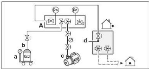
flowchart
graph TD
    A["Valve A"] --> B["P<"]
    A --> C["P>"]
    B --> D["Valve b"]
    C --> E["Valve c"]
    D --> F["Reactor R32"]
    E --> G["Reactor"]
    F --> H["Output"]
    G --> I["Output"]
    style A fill:#f9f,stroke:#333
    style B fill:#ccf,stroke:#333
    style C fill:#ccf,stroke:#333
    style D fill:#cfc,stroke:#333
    style E fill:#cfc,stroke:#333
    style F fill:#fcc,stroke:#333
    style G fill:#fcc,stroke:#333
    style H fill:#fff,stroke:#333
    style I fill:#fff,stroke:#333
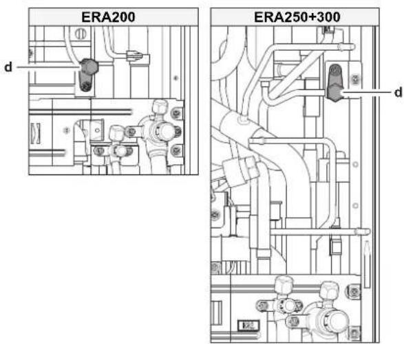
a Weighing scales
b Refrigerant R32 tank (siphon system)
c Vacuum pump
d Refrigerant charge port (heat exchanger)
A Valve A

NOTICE
The refrigerant charging port is connected to the piping inside the unit. The unit's internal piping is already factory charged with refrigerant, so be careful when connecting the charge hose.
6 Open all outdoor unit stop valves. At this point, valve A must remain closed!
7 Take all the precautions mentioned in "18 Configuration" [▶ 36] and "19 Commissioning" [▶ 38] into account.
8 Turn on the power of the indoor unit(s) and outdoor unit.
9 Activate setting [2-20] to start the manual additional refrigerant charge mode. For details, see "18.1.7 Mode 2: field settings" [▶ 38].
Result: The unit will start operation.

INFORMATION
The manual refrigerant charge operation will automatically stop within 30 minutes. If charging is not completed after 30 minutes, perform the additional refrigerant charging operation again.
10 Open valve A.
11 Charge refrigerant until the remaining determined additional refrigerant amount is added, and then close valve A.
12 Press BS3 to stop the manual additional refrigerant charge mode.

NOTICE
Make sure to open all stop valves after (pre-) charging the refrigerant.
Operating with the stop valves closed will damage the compressor.

NOTICE
After adding the refrigerant, do not forget to close the lid of the refrigerant charging port. The tightening torque for the lid is 11.5 to 13.9 N·m.
16.4 Error codes when charging refrigerant

INFORMATION
If a malfunction occurs, the error code is displayed on the outdoor unit's 7-segments display and on the user interface of the indoor unit.
If a malfunction occurs, close valve A immediately. Confirm the malfunction code and take corresponding action, "22.1 Solving problems based on error codes" [▶ 41].
16.5 To fix the fluorinated greenhouse gases label
1 Fill in the label as follows:
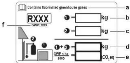
a If a multilingual fluorinated greenhouse gases label is delivered with the unit (see accessories), peel off the applicable language and stick it on top of a.
b Factory refrigerant charge: see unit name plate
c Additional refrigerant amount charged
d Total refrigerant charge
e Quantity of fluorinated greenhouse gases of the total refrigerant charge expressed as tonnes CO₂ equivalent.
f GWP = Global Warming Potential

NOTICE
Applicable legislation on fluorinated greenhouse gases requires that the refrigerant charge of the unit is indicated both in weight and CO_2 equivalent.
Formula to calculate the quantity in CO_2 equivalent tonnes: GWP value of the refrigerant × total refrigerant charge [in kg] / 1000
Use the GWP value mentioned on the refrigerant charge label.
2 Fix the label on the inside of the outdoor unit. There is a dedicated place for it on the wiring diagram label.
16.6 To check refrigerant piping joints for leaks after charging refrigerant
Tightness test of field-made refrigerant joints indoors
1 Use a leakage test method with a minimum sensitivity of 5 g of refrigerant/year. Test leaks using a pressure of at least 0.25 times the maximum working pressure (see "PS High" on the unit nameplate).
If a leak is detected
1 Recover the refrigerant, repair the joint, and repeat the test.
2 Perform the leak tests see "15.3.2 To perform a leak test" [▶ 29].
3 Charge refrigerant.
4 Check for refrigerant leaks after charging (see above).
17 Electrical installation

CAUTION
See "2 Specific installer safety instructions" [▶ 5] to make sure this installation complies with all safety regulations.
17.1 About electrical compliance
This equipment complies with:
- EN/IEC 61000-3-12 provided that the short-circuit power S_sc is greater than or equal to the minimum S value at the interface point between the user's supply and the public system.
- EN/IEC 61000-3-12 = European/International Technical Standard setting the limits for harmonic currents produced by equipment connected to public low-voltage systems with input current >16 A and ≤75 A per phase.
- It is the responsibility of the installer or user of the equipment to ensure, by consultation with the distribution network operator if necessary, that the equipment is connected ONLY to a supply with a short-circuit power S_sc greater than or equal to the minimum S_sc value.
| Model Minimum S | sc value |
| ERA200 2685 kVA | |
| ERA250 3137 kVA | |
| ERA300 3422 kVA |
17.2 Specifications of standard wiring components

NOTICE
We recommend using solid (single-core) wires. If stranded wires are used, slightly twist the strands to consolidate the end of the conductor for either direct use in the terminal clamp or insertion in a round crimp-style terminal. Details are described in "Guidelines when connecting the electrical wiring" in the installer reference guide.
| Component Outdoor unit | ||||
| Power supply cable | MCA(a) | 18.5 A | 22 A | 24 A |
| Voltage | 380-415 / 400 V | |||
| Phase | 3N~ | |||
| Frequency | 50/60 Hz | |||
| Wire size | 5 core cable | |||
| Must comply with national wiring regulation. | ||||
| Wire size based on the current, but not less than: | ||||
| 2.5 mm2 | 4 mm2 | |||
| Component Outdoor | unit | |||
| ERA200 | ERA250 | ERA300 | ||
| Interconnection cable | Voltage | 220-240 V | ||
| Wire size | Only use harmonised wire providing double insulation and suitable for applicable voltage.2-core shielded cable 0.75-1.5 mm^2 | |||
| Recommended field fuse | 25 A | 32 A | ||
| Earth leakage circuit breaker/ residual current circuit breaker | Must comply with national wiring regulation. | |||
(a) MCA=Minimum circuit ampacity. Stated values are maximum values.
Please use the table above to specify the requirements for the power supply wiring.

NOTICE
When using residual current operated circuit breakers, be sure to use a high-speed type 300 mA rated residual operating current.
17.3 Connecting the electrical wiring
Use the following methods for installing wires:
| Wire type | Installation method | |
| Single-core wireOrStranded conductor wire twisted to "solid-like" connection | 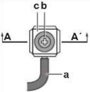 | 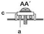 |
| a Curled wire (single-core or twisted stranded conductor wire)b Screwc Flat washer | ||
| Stranded conductor wire with round crimp-style terminal | cb | 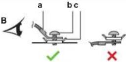 |
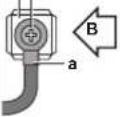 | ||
| a Terminalb Screwc Flat washer✓ Allowed✗ NOT allowed | ||
For earth connections, use the following method:
17 Electrical installation
Wire type Installation method
| Single-core wireOrStranded conductor wire twisted to "solid-like" connection | 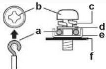 a Clockwise curled wire (single-core or twisted stranded conductor wire)b Screwc Spring washerd Flat washere Coupling washerf Sheet metal a Clockwise curled wire (single-core or twisted stranded conductor wire)b Screwc Spring washerd Flat washere Coupling washerf Sheet metal |
Tightening torques
| Wiring Screw size Tightening torque | |
| Transmission wiring M | 3.5 0.8~0.97 N·m |
| Power supply wiring E | RA200 : M5 2.2~2.7 N·m |
| ERA250+300 : M8 5.5~7.3 N·m | |
17.4 To connect the electrical wiring to the outdoor unit

CAUTION
- When connecting the power supply: connect the earth cable first, before making the current-carrying connections.
- When disconnecting the power supply: disconnect the current-carrying cables first, before separating the earth connection.
- The length of the conductors between the power supply stress relief and the terminal block itself MUST be as such that the current-carrying wires are tautened before the earth wire is in case the power supply is pulled loose from the stress relief.

NOTICE
- Follow the wiring diagram (delivered with the unit, located at the inside of the service cover).
- Make sure the electrical wiring does NOT obstruct proper reattachment of the service cover.
1 Remove the service cover. See "14.2.1 To open the outdoor unit" [▶ 24].
2 Connect the transmission wiring as follows:
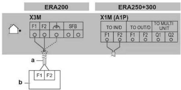
flowchart
graph TD
    subgraph ERA200
        A["House"] --> B["X3M"]
        B --> C["F1"]
        B --> D["F2"]
        B --> E["SFB"]
        B --> F["Ground"]
        G["a"] --> H["F1"]
        G --> I["F2"]
    end
    subgraph ERA250+300
        J["X1M (A1P)"]
        K["TO IN/D"]
        L["TO OUT/D"]
        M["TO MULTI UNIT"]
        N["F1"]
        O["F2"]
        P["F1"]
        Q["F2"]
        R["Q1"]
        S["Q2"]
    end
a Use the conductor of sheathed wire (2 wire) (no polarity)
b Terminal board (field supply)
Note: The indoor F1/F2 interconnection cable MUST be shielded:
- ERA200: the shielding is earthed (only at outdoor unit side of the cable) via the middle screw on the terminal X3M.
- ERA250+300: the shielding is earthed (only at outdoor unit side of the cable) via a metal P-clamp. Strip the insulation up to the shielding mesh, to provide full contact of the earth with the shielding. See illustration below:
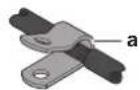
a P-clamp for cable shield earthing
Note: For ERA250+300, the interconnection cable MUST pass through the ferrite core 3 times (3 passes, 2 turns). See illustration below:
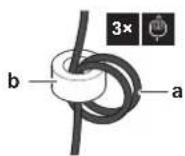
a Interconnection cable
b Ferrite core
3 Connect the power supply as follows:
3N\~50/60 Hz
380-415 /400V
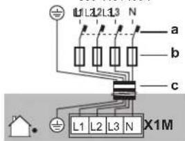
a Earth leakage circuit breaker
b Fuse
c Power supply cable
4 Fix the cables (power supply and interconnection cable) with a cable tie to the stop valve attachment plate and route the wiring according to the illustration below.
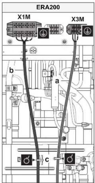
a Interconnection cable
b Power supply cable
c Cable tie

WARNING
Do NOT strip the outer cable jacket lower than the fixation point on the stop valve attachment plate.
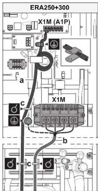
5 Route the cables through the frame according to the illustration below.
Note: for ERA200, choose one of the two possibilities to route the cables through the frame.
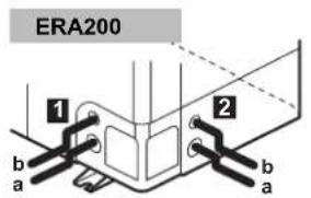
a Interconnection cable
b Power supply cable
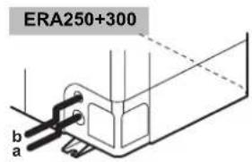
6 Remove the selected knockout holes by tapping on the attachment points with a flat head screwdriver and a hammer.
7 Install a cable protection in the knockout hole:
- It is recommended to install a PG type cable gland in the knockout hole.
- When you do not use a cable gland, protect the cables with vinyl tubes to prevent the edge of the knockout hole from cutting the wires:
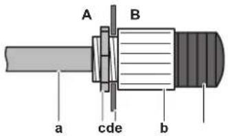
A Inside of the outdoor unit
B Outside of the outdoor unit
a Cable
b Bush
c Nut
d Frame
e Tube
8 Route the cables out of the unit.
9 Reattach the service cover. See "14.2.2 To close the outdoor unit" [▶ 25].
10 Connect an earth leakage circuit breaker and fuse to the power supply line as specified in "17.2 Specifications of standard wiring components" [▶ 33].
17.5 To connect the external outputs
SVS and SVEO output
The SVS and SVEO outputs are contacts on terminal X2M.
The SVS output is a contact on terminal X2M that closes in case a leak is detected, failure or disconnection of the R32 sensor (located in the indoor unit).
The SVEO output is a contact on terminal X2M that closes in case of occurrence of general errors. See "8.1 Error codes: Overview" [▶ 13] and "22.1.1 Error codes: Overview" [▶ 42] for errors that will trigger this output.
| Outdoor output connection requirements | |
| Voltage 220~240 V | |
| Maximum current | 0.5 A |
| Wire size | Only use harmonised wiring providing double insulation and suitable for the applicable voltage. |
| 2-core cable | |
| Minimum cable section of 0.75 mm ^2 | |

NOTICE
Do NOT use the outputs as a power source. Instead, use each output to energize a relay that controls the external circuit.
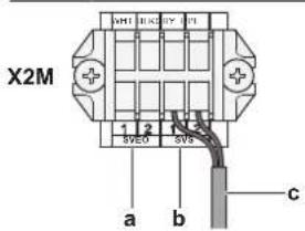
a SVEO output terminals (1 and 2)
b SVS output terminals (1 and 2)
c Cable to SVS output device (example)
Example:
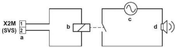
a SVS output terminal
b Relay
c AC power supply 220\~240 V AC
d External alarm

INFORMATION
Sound data about the refrigerant leakage alarm are available in the technical data sheet of the user interface. E.g. the BRC1H52* controller generates an alarm of 65 dB (sound pressure, measured at 1 m distance from the alarm).
17.6 To connect the cool/heat selector switch option

NOTICE
Do NOT use the cool/heat selector switch in case the T3T4 input is used.
In order to control the cooling or heating operation from a central location, the following optional cool/heat selector switch (KRC19-26A) can be connected:
1 Connect the cool/heat selector switch to terminal X1M of the cool/heat selector PCB.
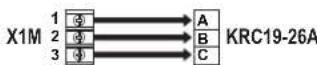
X1M Terminal on the PCB
KRC19-26A Cool/heat selector switch
2 Route the wires in the switchbox as shown:
18 Configuration
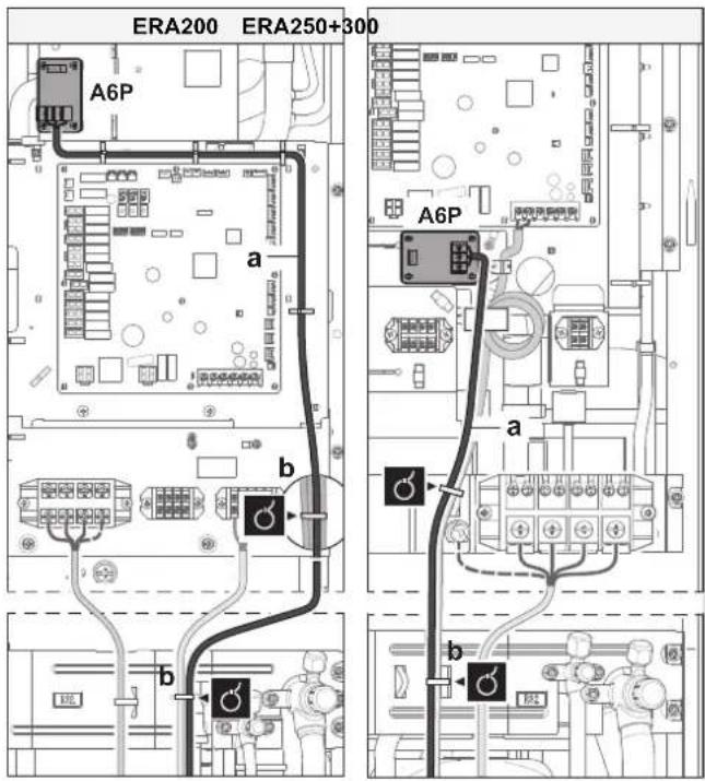
A6P Printed circuit board (cool/heat selector)
a Cable to cool/heat selector switch (KRC19-26A)
b Cable tie
3 Turn ON the DIP switch (DS1-1). See "18.1.2 Field setting components" [▶37] for more information on the DIP switch.
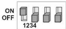
DS1 DIP switch 1
17.7 To check the insulation resistance of the compressor

NOTICE
If, after installation, refrigerant accumulates in the compressor, the insulation resistance over the poles can drop, but if it is at least 1 MΩ, then the unit will not break down.
- Use a 500 V mega-tester when measuring insulation.
- Do NOT use a mega-tester for low voltage circuits.
1 Measure the insulation resistance over the poles.
| If Then | |
| ≥1 MΩ Insulation resistance is OK. This procedure is finished. | |
| <1 MΩ Insulation resistance is not OK. Go to the next step. | |
2 Turn ON the power and leave it on for 6 hours.
Result: The compressor will heat up and evaporate any refrigerant in the compressor.
3 Measure the insulation resistance again.
18 Configuration

DANGER: RISK OF ELECTROCUTION

INFORMATION
It is important that all information in this chapter is read sequentially by the installer and that the system is configured as applicable.
18.1 Making field settings
18.1.1 About making field settings
To continue the configuration of the ERA system, it is required to give some input to the PCB of the unit. This chapter will describe how manual input is possible by operating the push buttons on the PCB and reading the feedback from the 7-segment displays.
Next to making field settings it is also possible to confirm the current operation parameters of the unit.
Push buttons and DIP switches
| Item | Description |
| Push buttons | By operating the push buttons it is possible to:Perform special actions (refrigerant charge, testrun, etc).Perform field settings (demand operation, low noise, etc). |
| DIP switches | By operating the DIP switches it is possible to:DS1 (1): COOL/HEAT selector (refer to the manual of the cool/heat selector switch).OFF=not installed=factory settingDS1 (2~4): NOT USED. DO NOT CHANGE THE FACTORY SETTING.DS2 (1~4): NOT USED. DO NOT CHANGE THE FACTORY SETTING. |
See also:
- "18.1.2 Field setting components" [▶ 37]
Mode 1 and 2
| Mode | Description |
| Mode 1 (monitoring settings) | Mode 1 can be used to monitor the current situation of the outdoor unit. Some field setting contents can be monitored as well. |
| Mode 2 (field settings) | Mode 2 is used to change the field settings of the system. Consulting the current field setting value and changing the current field setting value is possible.In general, normal operation can be resumed without special intervention after changing field settings.Some field settings are used for special operation (e.g., one time operation, recovery/vacuuming setting, manual adding refrigerant setting, etc.). In such a case, it is required to abort the special operation before normal operation can restart. It will be indicated in below explanations. |
See also:
- "18.1.3 To access mode 1 or 2" [▶ 37]
- "18.1.4 To use mode 1" [▶ 37]
- "18.1.5 To use mode 2" [▶ 37]
- "18.1.6 Mode 1: monitoring settings" [▶ 37]
- "18.1.7 Mode 2: field settings" [▶ 38]
18.1.2 Field setting components
Location of the 7-segment displays, buttons and DIP switches:
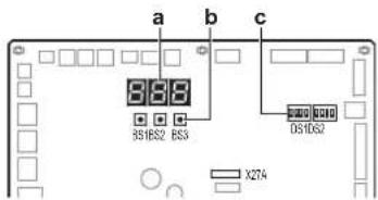
BS1 MODE: for changing the set mode
BS2 SET: for field setting
BS3 RETURN: for field setting
Turn ON the power 6 hours before operation in order to have power running to the crankcase heater and to protect the compressor.
Turn ON the power supply of the outdoor unit and indoor unit. When the communication between indoor unit and outdoor unit is established and normal, the 7-segment display indication state will be as below (default situation when shipped from factory).
| Stage Display | |
| When turning on the power supply: blinking as indicated. First checks on power supply are executed (8~10 min). | |
| When no trouble occurs: lighted as indicated (1~2 min). | |
| Ready for operation: blank display indication as indicated. |

Off Blinking On
In case of malfunction, the malfunction code is displayed on the indoor unit user interface and the outdoor unit 7-segment display. Solve the malfunction code accordingly. The communication wiring should be checked at first.
Access
BS1 is used to switch between the default situation, mode 1 and mode 2.
| Access Action | |
| Default situation |  |
Mode 1 · Push BS1 one time.7-segment display indication changes to: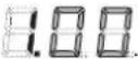 ·Push BS1 one more time to return to the default situation. ·Push BS1 one more time to return to the default situation. | |
Mode 2 · Push BS1 for at least five seconds.7-segment display indication changes to: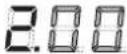 ·Push BS1 one more time (short) to return to the default situation. ·Push BS1 one more time (short) to return to the default situation. | |

INFORMATION
If you get confused in the middle of the process, push BS1 to return to the default situation (no indication on 7-segment displays: blank, see "18.1.3 To access mode 1 or 2" [▶37].
18.1.4 To use mode 1
Mode 1 is used to set basic settings and to monitor the status of the unit.
| What | How |
| Changing and accessing the setting in mode 1 | 1 Push BS1 one time to select mode 1.2 Push BS2 to select the required setting.3 Push BS3 one time to access the selected setting's value. |
| To quit and return to the initial status | Push BS1. |
18.1.5 To use mode 2
Mode 2 is used to set field settings of the outdoor unit and system.
| What | How |
| Changing and accessing the setting in mode 2 | Push BS1 for more than five seconds to select mode 2.Push BS2 to select the required setting.Push BS3 one time to access the selected setting's value. |
| To quit and return to the initial status | Push BS1. |
| Changing the value of the selected setting in mode 2 | Push BS1 for more than five seconds to select mode 2.Push BS2 to select the required setting.Push BS3 one time to access the selected setting's value.Push BS2 to select the required value of the selected setting.Push BS3 one time to validate the change.Push BS3 again to start operation with the chosen value. |
18.1.6 Mode 1: monitoring settings
[1-1]
Shows the status of low noise operation.
| [1-1] | Description |
| 0 | Unit is currently not operating under low noise restrictions. |
| 1 | Unit is currently operating under low noise restrictions. |
[1-2]
Shows the status of power consumption limitation operation.
| [1-2] | Description |
| 0 | Unit is currently not operating under power consumption limitations. |
| 1 | Unit is currently operating under power consumption limitation. |
19 Commissioning
[1-5] [1-6]
| Code Shows ... | |
| [1-5] The current T | _e target parameter position |
| [1-6] The current T | _c target parameter position |
[1-10]
Shows the total number of connected indoor units.
[1-17] [1-18] [1-19]
| Code Shows ... |
| [1-17] The latest malfunction code |
| [1-18] The 2nd last malfunction code |
| [1-19] The 3rd last malfunction code |
[1-40] [1-41]
| Code Shows | ... |
| [1-40] The current cooling comfort setting | |
| [1-41] The current heating comfort setting | |
18.1.7 Mode 2: field settings
[2-8]
T_e target temperature during cooling operation.
| [2-8] T | _e target [°C] |
| 0 (default) Auto | |
| 2 | 6 |
| 3 | 7 |
| 4 | 8 |
| 5 | 9 |
| 6 | 10 |
| 7 | 11 |
[2-9]
T_c target temperature during heating operation.
| [2-9] T | _c target [°C] |
| 0 (default) Auto | |
| 1 | 41 |
| 2 | 42 |
| 3 | 43 |
| 4 | 44 |
| 5 | 45 |
| 6 | 46 |
[2-20]
Manual additional refrigerant charge.
| [2-20] Description | |
| 0 (default) Deactivated. | |
| 1 Activated. | To stop the manual additional refrigerant charge operation (when the required additional refrigerant amount is charged), push BS3. If this function was not aborted by pushing BS3, the unit will stop its operation after 30 minutes. If 30 minutes was not sufficient to add the needed refrigerant amount, the function can be reactivated by changing the field setting again. |
[2-22]
Automatic low noise setting and level during night time.
By changing this setting, you activate the automatic low noise operation function of the unit and define the level of operation. Depending on the chosen level, the noise level will be lowered. The
start and stop moments for this function are defined under setting [2-26] and [2-27]. For more details about settings [2-26] and [2-27], see installer user reference guide
| [2-22] Description | ||
| 0 (default) Deactivated | ||
| 1 Level 1 Level 5LEVEL3 | level 5LEVEL 3 | level 3 |
| 2 Level 2 | ||
| 3 Level 3 | ||
| 4 Level 4 | ||
| 5 Level 5 | ||
[2-35]
Height difference setting.
| [2-35] Description | |
| 0 In case the | the outdoor unit is installed in the lowest position (indoor units are installed on a higher position than outdoor units) and the height difference between the highest indoor unit and the outdoor unit exceeds 40 m, the setting [2-35] should be changed to 0. |
| 1 (default) — | |
[2-60]
Supervisor remote controller setting. A power reset is required to save this setting.
For details about the supervisor remote controller, see "13.1.2 System layout requirements" [▶ 17] or refer to the remote controller installation and user reference guide.
| [2-60] Description | |
| 0 (default) No s | supervisor remote controller connected to the system |
| 1 Supervisor | or remote controller connected to system |
18.1.8 Indoor unit field setting
15(25)-13
Safety system deactivation.
When the room where the indoor unit is installed is big enough that no safety measure is required, the R32 leak safety system in that indoor unit can be deactivated by this setting.
| Safety system deactivation | ||||
| Setting | 1^st code | Function 2 | ^nd code | Description |
| 15/25 | 13 | R32 leak safety system setting | 01 | Disabled |
| 02 | Enabled | |||
19 Commissioning

CAUTION
See "2 Specific installer safety instructions" [▶ 5] to make sure commissioning complies with all safety regulations.

NOTICE
General commissioning checklist. Next to the commissioning instructions in this chapter, a general commissioning checklist is also available on the Daikin Business Portal (authentication required).
The general commissioning checklist is complementary to the instructions in this chapter and can be used as a guideline and reporting template during commissioning and hand-over to the user.
19.1 Precautions when commissioning

CAUTION
Do NOT perform the test operation while working on the indoor unit(s).
When performing the test operation, NOT ONLY the outdoor unit, but the connected indoor unit will operate as well. Working on an indoor unit while performing a test operation is dangerous.

NOTICE
Turn ON the power 6 hours before operation in order to have power running to the crankcase heater and to protect the compressor.

NOTICE
Test run is possible for ambient temperatures between -10^ and 50^ .
During test operation, the outdoor unit and the indoor unit will start up. Make sure that the preparation of the indoor unit is finished (field piping, electrical wiring, air purge, ...). See installation manual of the indoor unit for details.
19.2 Checklist before commissioning
1 After the installation of the unit, check the items listed below.
2 Close the unit.
3 Power up the unit.

You have read the complete installation and operation instructions described in the installer and user reference guide.

Installation
Check that the unit is properly installed, to avoid abnormal noises and vibrations when starting up the unit.

Transportation stay
Check that the outdoor unit's transportation stay is removed.

Field wiring
Check that the field wiring has been carried out according to the instructions described in the chapter "17 Electrical installation" [▶ 33], according to the wiring diagrams and according to the applicable national wiring regulation.

Power supply voltage
Check the power supply voltage on the local supply panel. The voltage MUST correspond to the voltage on the nameplate of the unit.

Earth wiring
Be sure that the earth wires have been connected properly and that the earth terminals are tightened.

Insulation test of the main power circuit
Using a megatester for 500 V, check that the insulation resistance of 2 MΩ or more is attained by applying a voltage of 500 V DC between power terminals and earth. NEVER use the megatester for the interconnection wiring.

Fuses, circuit breakers, or protection devices
Check that the fuses, circuit breakers, or the locally installed protection devices are of the size and type specified in the chapter "17.2 Specifications of standard wiring components" [▶ 33]. Be sure that neither a fuse nor a protection device has been bypassed.
| Internal wiringVisually check the switch box and the inside of the unit for loose connections or damaged electrical components. | |
| Pipe size and pipe insulationBe sure that correct pipe sizes are installed and that the insulation work is properly executed. | |
| Stop valvesBe sure that the stop valves are open on both liquid and gas side. | |
| Damaged equipmentCheck the inside of the unit for damaged components or squeezed pipes. | |
| Refrigerant leakCheck the inside of the unit on refrigerant leakage. If there is a refrigerant leak, try to repair the leak. If the repair is unsuccessful, call your local dealer. Do not touch any refrigerant which has leaked out from refrigerant piping connections. This may result in frostbite. | |
| Oil leakCheck the compressor for oil leakage. If there is an oil leak, try to repair the leak. If the repairing is unsuccessful, call your local dealer. | |
| Air inlet/outletCheck that the air inlet and outlet of the unit is NOT obstructed by paper sheets, cardboard, or any other material. | |
| Additional refrigerant chargeThe amount of refrigerant to be added to the unit shall be written on the included "Added refrigerant" plate and attached to the rear side of the front cover. | |
| Requirements for R32 equipmentMake sure the system meets all requirements that are described in the following chapter: "2.1 Instructions for equipment using R32 refrigerant" [▶ 7]. | |
| Field settingsMake sure all field settings you want are set. See "18.1 Making field settings" [▶ 36]. | |
| Installation date and field settingBe sure to keep record of the installation date on the sticker on the rear of the upper front panel according to EN60335-2-40 and keep record of the contents of the field setting(s). |
19.3 Checklist during commissioning

To perform a test run.
19.4 About the system test run

NOTICE
Make sure to carry out the test run after the first installation. Otherwise, the malfunction code U3 will be displayed on the user interface and normal operation or individual indoor unit test run cannot be carried out.
The procedure below describes the test operation of the complete system. This operation checks and judges following items:
- Check for incorrect wiring (communication check with indoor units).
- Check of the stop valves opening.
- Judgement of piping length.
- After the test operation is finished, check the indoor unit by performing a normal operation using the user interface. Refer to the indoor unit installation manual for more details concerning the individual test run.

INFORMATION
- It may take 10 minutes to achieve a uniform refrigerant state before the compressor starts.
- During the test operation, the refrigerant running sound or the magnetic sound of a solenoid valve may become loud and the display indication may change. These are not malfunctions.
19.4.1 To perform a test run
1 Close all front panels to prevent misjudgement.
2 Make sure all field settings you want are set; see "18.1 Making field settings" [▶ 36].
3 Turn ON the power to the outdoor unit and the connected indoor units.

NOTICE
Turn ON the power 6 hours before operation in order to have power running to the crankcase heater and to protect the compressor.
4 Make sure the default (idle) situation is existing; see "18.1.3 To access mode 1 or 2" [▶ 37]. Push BS2 for 5 seconds or more. The unit will start test operation.
Result: The test operation is automatically carried out, the outdoor unit display will indicate "Land the indication "Test operation" and "Under centralised control" will display on the user interface of indoor units.
Steps during the automatic system test run procedure:
| Step Description | |
| t01 | Control before start up (pressure equalisation) |
| t02 | Cooling start up control |
| t03 | Cooling stable condition |
| t04 | Communication check and stop valve check |
| t06 | Pipe length check |
| t09 | Pump down operation |
| t10 | Unit stop |

INFORMATION
During the test operation, it is not possible to stop the unit operation from a user interface. To abort the operation, press BS3. The unit will stop after ±30 seconds.
5 Check the test operation results on the outdoor unit 7-segment display.
| Completion Description | |
| Normal completion | No indication on the 7-segment display (idle). |
| Abnormal completion | Indication of malfunction code on the 7-segment display.Refer to "19.4.2 Correcting after abnormal completion of the test run" [▶40] to take actions for correcting the abnormality. When the test operation is fully completed, normal operation will be possible after 5 minutes. |
19.4.2 Correcting after abnormal completion of the test run
The test operation is only completed if there is no malfunction code displayed on the user interface or outdoor unit 7-segment display. In case of a displayed malfunction code, perform correcting actions as explained in the malfunction code table. Carry out the test operation again and confirm that the abnormality is properly corrected.

INFORMATION
Refer to the installation manual of the indoor unit for detailed malfunction codes related to indoor units.
20 Hand-over to the user
Once the test run is finished and the unit operates properly, make sure the following is clear for the user:
- Make sure that the user has the printed documentation and ask him/her to keep it for future reference. Inform the user that he can find the complete documentation at the URL mentioned earlier in this manual.
- Explain the user how to properly operate the system and what to do in case of problems.
- Show the user what to do for the maintenance of the unit.
21 Maintenance and service

NOTICE
Maintenance MUST be done by an authorised installer or service agent.
We recommend performing maintenance at least once a year. However, applicable legislation might require shorter maintenance intervals.

NOTICE
Applicable legislation on fluorinated greenhouse gases requires that the refrigerant charge of the unit is indicated both in weight and CO_2 equivalent.
Formula to calculate the quantity in CO_2 equivalent tonnes: GWP value of the refrigerant × total refrigerant charge [in kg] / 1000
21.1 Maintenance safety precautions

DANGER: RISK OF ELECTROCUTION

DANGER: RISK OF BURNING/SCALDING

WARNING
Prior to start working on systems containing flammable refrigerant, safety checks are necessary to ensure that the risk of ignition is minimised. Therefore, some instructions should be followed.
Please refer to the service manual for more information.

NOTICE: Risk of electrostatic discharge
Before performing any maintenance or service work, touch a metal part of the unit in order to eliminate static electricity and to protect the PCB.
21.1.1 To prevent electrical hazards
When performing service to inverter equipment:
1 Do NOT perform electrical work for 10 minutes after turning off the power supply.
2 Measure the voltage between terminals on the terminal block for power supply with a tester and confirm that the power supply is shut off. In addition, measure points as shown in the figure,
with a tester and confirm that the voltage of the capacitor in the main circuit is less than 50 V DC. If the voltage measured is still higher than 50 V DC, discharge the capacitors in a safe manner by using a dedicated capacitor discharge pen to avoid possibility of sparking.
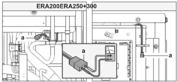
a Connector for capacitor voltage check
3 Pull out junction connectors X1A, X2A for the fan motors in the outdoor unit before starting service operation on the inverter equipment. Be careful NOT to touch the live parts. (If a fan rotates due to strong wind, it may store electricity in the capacitor or in the main circuit and cause electrical shock.)
4 After the service is finished, plug the junction connector back in. Otherwise the malfunction code E will be displayed on the user interface or on the outdoor unit 7-segment display and normal operation will NOT be performed.
For details refer to the wiring diagram labelled on the back of the switch box/service cover.
Pay attention to the fan. It is dangerous to inspect the unit while the fan is running. Make sure to turn off the main switch and to remove the fuses from the control circuit located in the outdoor unit.
21.2 Checklist for yearly maintenance of the outdoor unit
Check the following at least once a year:
- Heat exchanger
The heat exchanger of the outdoor unit can get blocked up due to dust, dirt, leaves, etc. It is recommended to clean the heat exchanger yearly. A blocked heat exchanger can lead to too low pressure or too high pressure leading to worse performance.
21.3 About service mode operation
Refrigerant recovery operation/vacuuming operation is possible by applying setting [2-21]. Refer to "18.1 Making field settings" [▶ 36] for details how to set mode 2.
When vacuuming/recovery mode is used, check very carefully what should be vacuumed/recovered before starting. See installation manual of the indoor unit for more information about vacuuming and recovery.
21.3.1 To use vacuum mode
1 When the unit is at standstill, set the unit in [2-21]=1 .
Result: When confirmed, the indoor and outdoor unit expansion valves will fully open. At that moment the 7-segment display indication=☐ and the user interface of the indoor unit indicate TEST (test operation) and ☐ (external control) and the operation will be prohibited.
2 Evacuate the system with a vacuum pump.
3 Press BS3 to stop vacuuming mode.
21.3.2 To recover refrigerant
This should be done with a refrigerant recovery unit. Follow the same procedure as for vacuuming method.

DANGER: RISK OF EXPLOSION
Pump down – Refrigerant leakage. If you want to pump down the system, and there is a leak in the refrigerant circuit:
- Do NOT use the unit's automatic pump down function, with which you can collect all refrigerant from the system into the outdoor unit. Possible consequence: Self-combustion and explosion of the compressor because of air going into the operating compressor.
- Use a separate recovery system so that the unit's compressor does NOT have to operate.

NOTICE
Make sure to NOT recover any oil while recovering refrigerant. Example: By using an oil separator.
22 Troubleshooting

CAUTION
See "2 Specific installer safety instructions" [▶ 5] to make sure troubleshooting complies with all safety regulations.
22.1 Solving problems based on error codes
In case of a displayed malfunction code, perform correcting actions as explained in the malfunction code table.
After correcting the abnormality, press BS3 to reset the malfunction code and retry operation.
The malfunction code which is displayed on the outdoor unit will indicate a main malfunction code and a sub code. The sub code indicates more detailed information about the malfunction code. The malfunction code will be displayed intermittent.
Example:
| Code | Example |
| Main code | |
| Sub code |
With an interval of 1 second, the display will switch between main code and sub code.

INFORMATION
See the service manual for:
- The complete list of error codes
- A more detailed troubleshooting guideline for each error
22.1.1 Error codes: Overview
| Main code | Sub code | Cause Solution SVEO | (a) | SVS(b) | |
| R0 | -11 | The R32 sensor of the compatible air curtain has detected a refrigerant leak(c) | Possible R32 leak. The compressor will shut down and the unit will stop operating. Service is needed to repair the leak and activate the system. Refer to the service manual for more information. | √ | |
| /Safety | system error (leak detection)(c) | An error related to the safety system occurred.Refer to the service manual for more information. | |||
| CH | -01 | R32 sensor malfunction or disconnection (indoor)(c) | Check connection on PCB or actuator.The system will stop operating, together with the indoor unit. Refer to the service manual for more information. | √ | |
| -02 | R32 sensor lifetime exceeded (indoor)(c) | The sensor is at the end of lifetime and must be replaced.Refer to the service manual for more information. | |||
| -05 | R32 sensor end of lifetime<6 months (indoor)(c) | The sensor is almost at the end of lifetime and must be replaced.Refer to the service manual for more information. | |||
| -10 | Waiting for indoor unit R32 sensor replacement input(c) | Refer to the service manual for more information. | |||
| E2 | -01 | Earth leakage detector activated Restart the unit. | If the problem reoccurs, contact your dealer. | ||
| -06 | Earth leakage detector malfunction (open circuit)- A1P (X101A) | Check connection on PCB or actuator. | |||
| E3 | -01 | High pressure switch was activated (S1PH)-main PCB (X2A) | Check stop valve situation or abnormalities in (field) piping or airflow over air cooled coil. | ||
| -02 | • Refrigerant overcharge• Stop valve closed | • Check refrigerant amount+recharge unit.• Open stop valves | |||
| -13 | Stop valve closed (liquid) Open liquid stop valve. | ||||
| -18 | • Refrigerant overcharge• Stop valve closed | • Check refrigerant amount+recharge unit.• Open stop valves. | |||
| E4 | -01 | Low pressure malfunction:• Stop valve closed• Refrigerant shortage• Indoor unit malfunction | • Open stop valves.• Check refrigerant amount+recharge unit.• Check the user interface's display or interconnection wiring between the outdoor unit and the indoor unit. | ||
| E9 | -01 | Electronic expansion valve malfunction (heat exchanger) (Y1E) - main PCB (X21A) | Check connection on PCB or actuator. | ||
| -04 | Electronic expansion valve malfunction (inverter cooling) (Y3E) - main PCB (X23A) | Check connection on PCB or actuator. | |||
| -26 | Electronic expansion valve malfunction (liquid injection) (Y4E) - main PCB (X25A) | Check connection on PCB or actuator. | |||
| -29 | Electronic expansion valve malfunction (subcool heat exchanger) (Y2E) - main PCB (X26A) | Check connection on PCB or actuator. | |||
| F3 | -01 | Discharge temperature too high (R21T) - main PCB (X33A):• Stop valve closed• Refrigerant shortage | • Open stop valves.• Check refrigerant amount+recharge unit. | ||
| -20 | Compressor casing temperature too high (R8T) - main PCB (X33A):• Stop valve closed• Refrigerant shortage | • Open stop valves.• Check refrigerant amount+recharge unit. | |||
| H9 | -01 | Ambient temperature sensor malfunction (R1T) - main PCB (X18A) | Check connection on PCB or actuator. | ||
| J3 | -16 | Discharge temperature sensor malfunction (R21T): open circuit - main PCB (X33A) | Check connection on PCB or actuator. | ||
| -17 | Discharge temperature sensor malfunction (R21T): short circuit - main PCB (X33A) | Check connection on PCB or actuator. | |||
| -47 | Compressor casing temperature sensor malfunction (R8T): open circuit - main PCB (X33A) | Check connection on PCB or actuator. | |||
| -48 | Compressor casing temperature sensor malfunction (R8T): short circuit - main PCB (X33A) | Check connection on PCB or actuator. | |||
| JS | -18 | Suction temperature sensor (R3T) - main PCB (X30A) | Check connections on PCB or actuator. | ||
| J6 | -01 | Heat exchanger deicer temperature sensor (R7T) - main PCB (X30A) | Check connection on PCB or actuator | ||
| J7 | -06 | Subcool heat exchanger - liquid - temperature sensor (R5T) - main PCB (X30A) | Check connection on PCB or actuator. | ||
| J8 | -01 | Heat exchanger - liquid -temperature sensor (R4T) - main PCB (X30A) | Check connection on PCB or actuator. | ||
| J9 | -01 | Subcool heat exchanger - gas - temperature sensor (R6T) - main PCB (X30A) | Check connection on PCB or actuator. | ||
| JA | -06 | High pressure sensor malfunction (S1NPH): open circuit - main PCB (X32A) | Check connection on PCB or actuator. | ||
| -07 | High pressure sensor malfunction (S1NPH): short circuit - main PCB (X32A) | Check connection on PCB or actuator. | |||
| JC | -06 | Low pressure sensor malfunction (S1NPL): open circuit - main PCB (X31A) | Check connection on PCB or actuator. | ||
| -07 | Low pressure sensor malfunction (S1NPL): short circuit - main PCB (X31A) | Check connection on PCB or actuator. | |||
| LC | -14 | Transmission outdoor unit - inverter: INV1 transmission trouble - main PCB (X20A, X28A, X40A) | Check connection. | ||
| -19 | Transmission outdoor unit - inverter: FAN1 transmission trouble - main PCB (X20A, X28A, X40A) | Check connection. | |||
| -24 | Transmission outdoor unit - inverter: FAN2 transmission trouble - main PCB (X20A, X28A, X40A) | Check connection. | |||
| PI | -01 | INV1 unbalanced power supply voltage Check if power supply is within range. | |||
| UI | -01 | Reversed power supply phase malfunction Correct phase order. | |||
| -04 | Reversed power supply phase malfunction Correct phase order. | ||||
| U2 | -01 | INV1 voltage power shortage Check if power supply is within range. | |||
| -02 | INV1 power phase loss Check if power supply is within range. | ||||
| U3 | -03 | Malfunction code: system test run not yet executed (system operation not possible) | Execute system test run. | ||
| -04 | An error occurred during the test run Re-execute the test run. | ||||
| -05,-06strun aborted Re-execute the test run. | |||||
| -07,-08strun aborted due to communication issues Check the communication wires and re-execute the test run. | |||||
| U4 | -03 | Indoor unit communication error Check user interface connection. | |||
| U9 | -01 | Warning because there is an error on another indoor unit | Check if other indoor units have a malfunction and confirm if indoor unit mix is allowed. | ||
| UR | -03 | Connection malfunction over indoor units or type mismatch | Check the type of indoor unit that is currently connected. Make sure that a correct indoor unit (only one EKEA or one compatible air curtain) is connected. If an incorrect type of indoor unit is connected, replace it with the correct one. After the correct indoor unit is connected long-press BS3 to complete the identification of indoor unit. | ||
| -18 | Connection malfunction over indoor units or type mismatch | Check if other indoor units have a malfunction and confirm if indoor unit mix is allowed. | |||
| -20 | Wrong outdoor unit connected Disconnect the outdoor unit. |
23 Disposal
| Main code | Sub code | Cause Solution SVEO | (a) | SVS(b) | |
| UH | -01 | Auto address malfunction (inconsistency) Check if | interconnected unit amount matches with powered unit amount (by monitor mode) or wait until initialisation is finished. | ||
| UJ | -37 | AHU supply airflow rate below the legal limit(d) | Make sure the T5T6 digital input is set correctly, refer to EKEA installation and operation manual. | √ | |
| In case other error codes appear, contact your dealer. | |||||
(a) The SVEO terminal provides an electrical contact that closes in case the indicated error occurs.
(b) The SVS terminal provides an electrical contact that closes in case the indicated error occurs.
(c) The error code is only shown on the user interface of the compatible air curtain where the error occurs.
(d) In case the AHU supply airflow rate is above the legal limit for 5 minutes continuously, this error is automatically solved.
22.2 Refrigerant leak detection system
Normal operation
During normal operation, the alarm only and supervisor remote controller have no functionality. The screen of the remote controller in alarm only and supervisor mode will be off. Operation of the remote controller can be checked by pushing the ☐ton to open the installer menu.
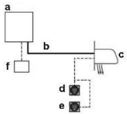
flowchart
graph TD
    a --> b
    b --> c
    c --> d
    c --> e
    f --> b
    style a fill:#f9f,stroke:#333
    style b fill:#ccf,stroke:#333
    style c fill:#cfc,stroke:#333
    style d fill:#fcc,stroke:#333
    style e fill:#cff,stroke:#333
a Heat pump outdoor unit
b Refrigerant piping
c Compatible air curtain
d Remote controller in normal mode
e Remote controller in supervisor mode (mandatory in some situations)
f Centralised controller (optional)
Note: During start-up of the system, the mode of the remote control can be verified from the screen.
Leak detection operation
If the R32 sensor in the air curtain unit detects a refrigerant leak, the user will be warned by both audible and visible signals of the remote controller of the leaking indoor unit (and the supervisor remote controller, if applicable). At the same time the compressor will be shut down and the system cannot operate anymore. Service is needed to repair the leak and activate the system. Refer to the service manual for more information.
Feedback of the remote controller after leak detection operation will depend on its mode.

WARNING
The unit is equipped with a refrigerant leak detection system for safety.
To be effective, the unit MUST be electrically powered at all times after installation, except for maintenance.
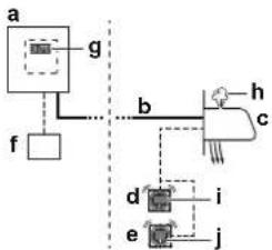
flowchart
graph TD
    a["Component a"] --> g["g"]
    f["f"] --> g
    g --> b["b"]
    b --> h["h"]
    h --> c["c"]
    c --> d["d"]
    c --> i["i"]
    d --> e["e"]
    e --> j["j"]
a Heat pump outdoor unit
b Refrigerant piping
c Compatible air curtain
d Remote controller in normal mode and alarm only mode
e Remote controller in supervisor mode (mandatory in some situations)
f Centralised controller (optional)
g Outdoor unit error code on 7-segment display
h Refrigerant leak
I Error code 'A0-11' and audible alarm and red warning signal is generated from this remote controller.
j Error code 'A0-11' and audible alarm and red warning signal is generated from this supervisor remote controller. The unit address is displayed on this remote controller.
Note: It is possible to stop the leak detection alarm from the remote controller and from the app. To stop the alarm from the remote controller, press +r 3 seconds.
Note: Leak detection will trigger SVS output. For more information, see "17.5 To connect the external outputs" [▶ 35].
Note: An optional output, if available on a compatible air curtain, can be used for an external device. This output will trigger in case a leak is detected. For more information about this output, refer to the installation manual of the compatible air curtain unit.
Note: Some centralised controllers can also be used as supervisor remote controller. For further details on installation, please refer to the installation manual of the centralised controllers.

NOTICE
The R32 refrigerant leakage sensor is a semiconductor detector which may incorrectly detect substances other than R32 refrigerant. Avoid using chemical substances (e.g. organic solvents, hair spray, paint) in high concentrations, in the close proximity of the indoor unit because this may cause misdetection by the R32 refrigerant leakage sensor.
23 Disposal

NOTICE
Do NOT try to dismantle the system yourself: dismantling of the system, treatment of the refrigerant, oil and other parts MUST comply with applicable legislation. Units MUST be treated at a specialised treatment facility for reuse, recycling and recovery.
24 Technical data
- A subset of the latest technical data is available on the regional Daikin website (publicly accessible).
- The full set of the latest technical data is available on the Daikin Business Portal (authentication required).
24.1 Service space: Outdoor unit
When mounting units side by side, the piping route must be to the front or downwards. In this case the piping route to the side is not possible.
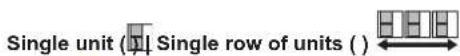
→ See "figure 1" [▶2] on the inside of the front cover of this manual.
A,B,C,D Obstacles (walls/baffle plates)
E Obstacle (roof)
a,b,c,d,e Minimum service space between the unit and obstacles A, B, C, D and E
e_B Maximum distance between the unit and the edge of obstacle E, in the direction of obstacle B
e_D Maximum distance between the unit and the edge of obstacle E, in the direction of obstacle D
H_u Height of the unit
H_B_1H_D Height of obstacles B and D
1 Seal the bottom of the installation frame to prevent discharged air from flowing back to the suction side through the bottom of the unit.
2 Maximum two units can be installed. Not allowed
Note: For better serviceability, use a distance ≥ 250 mm for all dimensions marked with 'a'.
Multiple rows of units
→ See "figure 2" [▶ 2] on the inside of the front cover of this manual.
Note: For better serviceability, use a side by side distance ≥ 250 mm (instead of ≥ 100 mm as shown on the figures above).
Stacked units (max. 2 levels)
→ See "figure 3" [▶2] on the inside of the front cover of this manual.
A1=>A2 (A1) If there is danger of drainage dripping and freezing between the upper and lower units...
(A2) Then install a roof between the upper and lower units. Install the upper unit high enough above the lower unit to prevent ice buildup at the upper unit's bottom plate.
B1=>B2 (B1) If there is no danger of drainage dripping and freezing between the upper and lower units...
(B2) Then it is not required to install a roof, but seal the gap between the upper and lower units to prevent discharged air from flowing back to the suction side through the bottom of the unit.
Note: For better serviceability, use a side by side distance ≥ 250 mm (instead of ≥ 100 mm as shown on the figures above).
24.2 Piping diagram: Outdoor unit
Piping diagram: ERA200
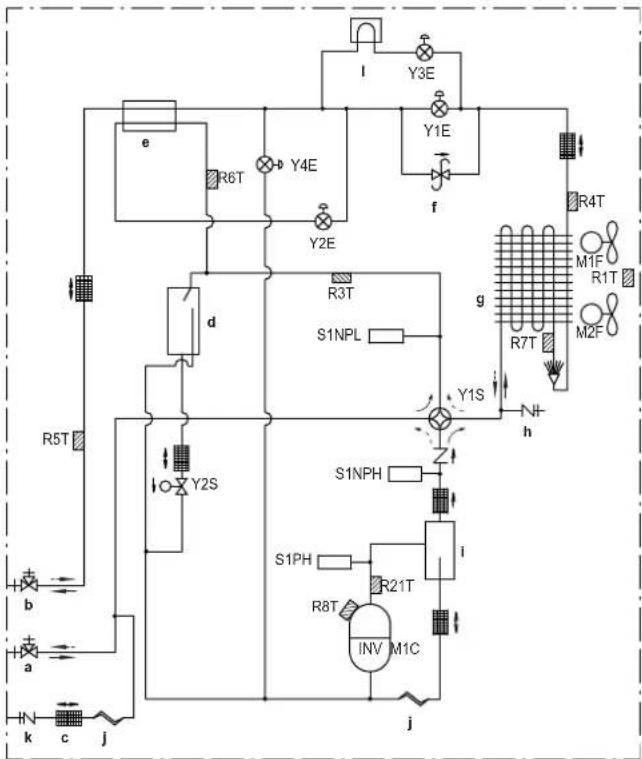
flowchart
graph TD
    A["Power Source"] --> B["Resistors R5T, R6T, R7T, R8T, R9T, R10T, R11T, R12T, R13T, R14T, R15T, R16T, R17T, R18T, R19T, R20T, R21T, R22T, R23T, R24T, R25T"]
    B --> C["Resistors Y2S, Y2E, Y3E, Y4E, Y5E, Y6E, Y7E, Y8E, Y9E, Y10E, Y11E, Y12E, Y13E, Y14E, Y15E, Y16E, Y17E, Y18E, Y19E, Y20E"]
    C --> D["Resistors S1NPL"]
    D --> E["Resistors S1PH"]
    E --> F["Resistors R21T"]
    F --> G["Resistors INV M1C"]
    G --> H["Output h"]
    style A fill:#f9f,stroke:#333
    style H fill:#ccf,stroke:#333
Piping diagram: ERA250+300
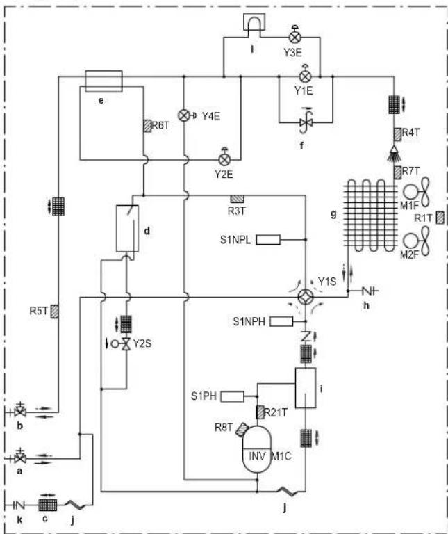
flowchart
graph TD
    A["a"] --> B["b"]
    B --> C["e"]
    C --> D["d"]
    D --> E["Y2S"]
    E --> F["S1NPH"]
    F --> G["i"]
    G --> H["INV M1C"]
    H --> I["j"]
    I --> J["k"]
    J --> K["c"]
    K --> L["j"]
    L --> M["f"]
    M --> N["Y3E"]
    N --> O["Y4E"]
    O --> P["Y6T"]
    P --> Q["Y2E"]
    Q --> R["R3T"]
    R --> S["S1NPL"]
    S --> T["Y1S"]
    T --> U["h"]
    U --> V["N+"]
    V --> W["g"]
    W --> X["R7T"]
    X --> Y["M1F"]
    Y --> Z["R1T"]
    Z --> AA["M2F"]
Legend:
a Stop valve (gas)
b Stop valve (liquid)
c Filter (6×)
d Accumulator
e Subcool tube heat exchanger
f Pressure regulating valve
g Heat exchanger
h Service port
i Oil separator
j Capillary tube (2×)
k Charge port
I Heat sink
M1C Compressor
M1F-M2F Fan motor
R1T Thermistor (air)
R3T Thermistor (suction accumulator)
R4T Thermistor (heat exchanger, liquid)
R5T Thermistor (liquid)
R6T Thermistor (subcool heat exchanger, gas)
R7T Thermistor (de-icer)
R8T Thermistor (M1C body)
R21T Thermistor (M1C discharge pipe)
S1NPH High pressure sensor
S1NPL Low pressure sensor
S1PH High pressure switch
Y1E Electronic expansion valve (main)
Y2E Electronic expansion valve (subcool heat exchanger)
Y3E Electronic expansion valve (inverter cooling)
Y4E Electronic expansion valve (liquid injection)
Y1S Solenoid valve (4-way valve)
Y2S Solenoid valve (accumulator oil return)
Cooling
Heating
24.3 Wiring diagram: Outdoor unit
The wiring diagram is delivered with the unit, located at the inside of the service cover.
Notes:
1 Symbols (see below).
2 Refer to the installation or service manual on how to use the BS1\~BS3 push buttons and DS1\~DS2 switches.
3 Do not operate the unit by short-circuiting protection device S1PH.
4 Refer to the installation manual for indoor-outdoor transmission F1-F2 wiring.
5 When using the central control system, connect outdoor-outdoor transmission F1-F2.
6 The capacity of the contact is 220\~240 VAC - 0.5 A. (Rush current needs 3 A or less)
7 Use dry contact for micro-current (1 mA or less 12VDC).
Symbols:
X1M Main terminal
......
Earth wiring
15
Wire number 15
Field wire
[NO TEXT]
Field cable
→**/12.2
Connection ** continues on page 12 column 2
①
Several wiring possibilities
[Figure]
Option
[Non-Text]
Not mounted in switch box
□
Wiring depending on model
[Non-Text]
PCB
Colours:
BLK Black
BLU Blue
BRN Brown
GRN Green
ORG Orange
RED Red
WHT White
YLW Yellow
Legend for wiring diagram:
A1P Printed circuit board (main)
A2P Printed circuit board (noise filter)
A3P Printed circuit board (inverter)
A4P Printed circuit board (fan 1)
A5P Printed circuit board (fan 2)
A6P Printed circuit board (cool/heat selector)
BS* (A1P) Push button switch
E1HC Crankcase heater
F1U (A1P) Fuse (T 10 A / 250 V)
F1U, F2U Fuse (T 1 A / 250 V)
F3U Field fuse (field supply)
HAP (A1P) Light-emitting diode (service monitor is green)
K*R (A*P) Relay on PCB
L1R Reactor
M1C Motor (compressor)
M1F, M2F Motor (upper and lower fan)
Q1DI Earth leakage circuit breaker (field supply)
R1T Thermistor (air)
R3T Thermistor (suction accumulator)
R4T Thermistor (heat exchanger liquid)
R5T Thermistor (liquid)
R7T Thermistor (de-icer)
R8T Thermistor (M1C body)
R21T Thermistor (M1C discharge pipe)
S1NPH High pressure sensor
S1NPL Low pressure sensor
S1PH High pressure switch
S1S Air control switch (optional)
S2S Cool/heat switch (optional)
SEG* (A1P) 7-segment display
SFB Mechanical ventilation error input (field supply)
T1A Current sensor
X*A Connector
X*M Terminal strip
Y1E Electronic expansion valve (heat exchanger)
Y2E Electronic expansion valve (subcool heat exchanger)
Y3E Electronic expansion valve (inverter cooling)
Y4E Electronic expansion valve (liquid injection)
Y1S Solenoid valve (4-way valve)
Y2S Solenoid valve (accumulator oil return)
Y3S Error operation output (SVEO)(field supply)
Y4S Leak sensor output (SVS)(field supply)
Z*C Noise filter (ferrite core)