
T-Bat H 12.0 - Uncategorized SolaX Power - Free user manual and instructions
Find the device manual for free T-Bat H 12.0 SolaX Power in PDF.


| Product Type | High-Voltage Lithium-Ion Battery for Solar Energy Storage |
| Model | T-Bat H 12.0 |
| Brand | SolaX Power |
| Nominal Energy Capacity | 12.0 kWh |
| Usable Energy Capacity | 10.8 kWh (90% Depth of Discharge) |
| Nominal Voltage | 384 V |
| Voltage Range | 336 V – 438 V |
| Battery Chemistry | Lithium Iron Phosphate (LFP) |
| Dimensions (H × W × D) | Approx. 670 × 585 × 310 mm |
| Weight | Approx. 105 kg |
| Operating Temperature Range | Charge: 0°C to 50°C; Discharge: -20°C to 50°C |
| IP Rating | IP65 |
| Communication Interface | CAN, RS485 |
| Cooling Method | Natural Convection |
| Mounting Type | Wall-mounted or Floor-standing |
| Cycle Life | ≥ 6000 cycles at 80% DOD |
| Warranty | 10 years |
| Certifications | IEC 62619, UN 38.3 |
| Compatible Inverters | SolaX Power X3-Hybrid and X1-Hybrid series |
Frequently Asked Questions - T-Bat H 12.0 SolaX Power
User questions about T-Bat H 12.0 SolaX Power
0 question about this device. Answer the ones you know or ask your own.
Ask a new question about this device
Download the instructions for your Uncategorized in PDF format for free! Find your manual T-Bat H 12.0 - SolaX Power and take your electronic device back in hand. On this page are published all the documents necessary for the use of your device. T-Bat H 12.0 by SolaX Power.
USER MANUAL T-Bat H 12.0 SolaX Power
Triple Power Lithium-ion Battery
30Ah
User Manual

natural_image
Exterior view of a white industrial cabinet or storage unit with vertical panels and a red background (no visible text or symbols)Solax Power Network Technology(Zhe jiang) Co., Ltd.
No.288 Shizhu Road, Tonglu Economic Development Zone,
Tonglu City, Zhejiang province, China.
Tel: +86 0571-56260011
E-mail: info@solaxpower.com
614.00519.02
Copyright Declaration
The copyright of this manual belongs to SolaX Power Network Technology (Zhe jiang) Co., Ltd. Any corporation or Individual should not plagiarize, partially or fully copy (including software, etc.), and no reproduction or distribution of it in any form or by any means. All rights reserved. SolaX Power Network Technology (Zhe jiang) Co., Ltd. reserves the right of final interpretation.
www.solaxpower.com
Contents
1 NOTE ON THIS MANUAL 1
1.1 SCOPE OF VALIDITY 1
1.2 TARGET GROUP....1
1.3 SYMBOLS USED.... 1
2 SAFETY 2
2.1 SAFETY INSTRUCTIONS.... 2
2.1.1 GENERAL SAFETY PRECAUTIONS.... 2
2.1.2 EXPLANATION OF SYMBOLS....3
2.2 RESPONSE TO EMERGENCY SITUATIONS.... 4
2.2.1 LEAKING BATTERIES....4
2.2.2 FIRE 4
2.2.3 WET BATTERIES AND DAMAGED BATTERIES....4
2.3 QUALIFIED INSTALLER 5
3 PRODUCT INTRODUCTION.... 6
3.1 PRODUCT OVERVIEW.... 6
3.1.1 DIMENSIONS AND WEIGHT 6
3.1.2 INSTALLATION SPACE....7
3.1.3 APPEARANCE 8
3.2 BASIC FEATURES.... 10
3.2.1 FEATURES....10
3.2.2 CERTIFICATIONS....10
3.3 SPECIFICATIONS.... 11
3.3.1 T-BAT SYS-HV CONFIGURATION LIST....11
3.3.2 PERFORMANCE....11
4 INSTALLATION....12
4.1 INSTALLATION PREREQUISITES.... 12
4.2 SAFETY GEAR 12
4.3 TOOLS....13
4.4 INSTALLATION....13
4.4.1 CHECK FOR TRANSPORT DAMAGE....13
4.4.2 UNPACKING....13
4.4.3 ACCESSORIES....14
4.4.4 OVERALL INSTALLATION....16
4.4.5 INSTALL BMS TO BATTERY MODULE....19
4.5 CABLE CONNECTION.... 22
4.5.1 CONNECTING CABLES TO INVERTER....22
4.5.2 CONNECTING THE COMM CIOMMUNICATION CABLE.....25
4.5.3 CONNECTING THE GROUND WIRE....25
4.5.4 CONNECTING CABLES TO BATTERY MODULES.....26
5 COMMISSIONING.... 32
5.1 COMMISSIONING.... 32
5.2 STATUS INDICATORS.... 33
5.2.1 BMS(MC0600) 33
5.2.2 BATTERY MODULE (HV10230)....34
5.3 SHUTTING DOWN T-BAT SYSTEM 35
6 TROUBLESHOOTING 36
6.1 TROUBLESHOOTING.... 36
7 DECOMMISSIONING.... 36
7.1 DISMANTLING THE BATTERY 38
7.2 PACKAGING 38
8 MAINTENANCE 39
9 DISCLAIMER....40
1 Note on this Manual
1.1 Scope of Validity
This manual is an integral part of the T-BAT Series. It describes the assembly, installation, commissioning, maintenance and failure of the product. Read carefully prior to operation.
T-BAT BMS
MC0600
T-BAT Module
HV10230
Note: There are 4 models of the T-BAT system, which include the BMS and battery module(s). Refer to section 3.3.1 T-BAT SYS-HV Configuration List on page 11 for detailed models.
1.2 Target Group
This manual is for qualified electricians. The tasks described in this manual may only be performed by qualified electricians.
1.3 Symbols Used
The following types of safety instructions appear in this document and are described below:

GER!
GER ^® indicates a hazardous situation which, if not avoided, will result in serious injury or death.

NING!
"WARNING" indicates a hazardous situation which, if not avoided, could result in serious injury or death.

ION!
TION" indicates a hazardous situation which, if not avoided, could result in minor or moderate injury.

* provides tips that are valuable for the optimal operation of your product.
2 Safety
2.1 Safety Instructions
For safety reasons, installers are responsible for familiarizing themselves with the contents of this manual and all warnings before performing installation.
2.1.1 General Safety Precautions

WARNING!
Do not crush or impact the battery, and always dispose of it according to safety regulations.
Observe the following precautions:
- Risks of explosion:
→ Do not subject the battery module to heavy impacts.
→ Do not crush or puncture the battery module.
→ Do not dispose of the battery module in a fire. - Risks of fire:
Do not expose the battery module to temperatures in excess of 140°F.
Do not place the battery module near a heat source, such as a fireplace.
→ Do not expose the battery module to direct sunlight.
→ Do not allow the battery connectors to touch conductive objects such as wires.
• Risks of electric shock;
→ Do not disassemble the battery module.
→ Do not touch the battery module with wet hands.
→ Do not expose the battery module to moisture or liquids.
→ Keep the battery module away from children and animals. - Risks of damage to the battery module:
→ Do not expose the battery module to liquids.
→ Do not subject the battery module to high pressures.
→ Do not place any objects on top of the battery module.
T-BAT SYS-HV should only be installed for residential applications and is not for commercial applications.

CAUTION!
If the battery is not installed within one month after receipt, it must be charged for maintenance.
Wasted batteries must be discarded according to local regulations.
2.1.2 Explanation of Symbols
| Symbol | Explanation |
| CE | The inverter complies with the requirements of the applicable CE guildlines. |
| UKCA | The inverter complies with the requirements of the applicable UKCA guildlines. |
| UKNI | The inverter complies with the requirements of the applicable UKNI guildlines. |
| The battery system must be disposed of at a proper facility for environmentally-safe recycling. | |
| The battery system should not be disposed of together with household waste. Disposal information can be found in the enclosed documentation. | |
| Wear protective glasses. | |
| Observe enclosed documentation. | |
| Keep the battery system away from open flames or ignition sources. | |
| Keep the battery system away from children. | |
| Danger of high voltages. | |
| Danger. Risk of electric shock. | |
| The battery module may explode. |
2.2 Response to Emergency Situations
2.2.1 Leaking Batteries
If the battery leaks electrolyte which is corrosive, avoid contact with the leaking liquid or gas. Direct contact may lead to skin irritation or chemical burns. If one is exposed to the leaked substance, perform these actions:
Accidental inhalation of harmful substances: Evacuate from the contaminated area, and seek medical attention immediately.
Eye contact: Rinse eyes with flowing water for 15 minutes, and seek medical attention immediately.
Dermal contact: Wash the affected area thoroughly with soap and water, and seek medical attention immediately.
Ingestion: Induce vomiting, and seek medical attention immediately.
2.2.2 Fire
In case of a fire, ensure that an ABC or a carbon dioxide extinguisher is nearby.


WARNING!
The battery module may catch fire when heated above 302°F.
If a fire breaks out where the battery module is installed, perform these actions:
1) Extinguish the fire before the battery module catches fire
2) If the battery module catches fire, do not try to extinguish the fire. Evacuate immediately.

WARNING!
If the battery module catches fire, it will produce noxious and poisonous gases. Do not approach.
2.2.3 Wet Batteries and Damaged Batteries
If the battery module is wet or submerged in water, do not try to access it.
If the battery module seems to be damaged, it is not fit for use and may pose a danger to people or property.
Please pack the battery in its original packaging, and return it to SolaX or your distributor.

CAUTION!
Damaged batteries may leak electrolyte or produce flammable gas. If you suspect such damage, Immediately contact SolaX for advice and information.
2.3 Qualified Installer

WARNING!
All operations of T-BAT SYS-HV relating to electrical connection and installation must be carried out by qualified personnel.
A skilled worker is defined as a trained and qualified electrician or installer who has all of the following skills and experience:
• Knowledge of the functional principles and operation of grid-tied systems
- Knowledge of the dangers and risks associated with installing and using electrical devices and acceptable mitigation methods
• Knowledge of the installation of electrical devices
- Knowledge of and adherence to this manual and all safety precautions and best practices
3 Product Introduction
3.1 Product Overview
For safety reasons, installers are responsible for familiarizing themselves with the contents of this manual and all warnings before performing installation.
3.1.1 Dimensions and Weight
A battery management system (BMS) is an electronic system that manages a rechargeable battery.
A battery module is a type of electrical battery which can be charged or discharged into a load.
A battery system includes the BMS and battery module(s).
| Base Mounting | MC0600 | HV10230 | |
| Length | 482mm | 482.5mm | 482.5mm |
| Width | 167mm | 173.5mm | 471.5mm |
| Height | 71mm | 153mm | 153mm |
| Weight | 2.5KG | 7.5KG | 34.5KG |

Base M ounting

BMS (MC0600)

Battery Module (HV10230)
3.1.2 Installation Space

3.1.3 Appearance
• Section view of MC0600


| Object Mark | Description | |
| I | B- | Connector B- of BMS to B- of battery module |
| II | B+ | Connector B+ of BMS to B+ of battery module |
| III | BAT+ | Connector BAT+ of BMS to BAT+ of inverter |
| IV | BAT- | Connector BAT- of BMS to BAT- of inverter |
| V | GND | |
| VI | CAN | Connector CAN of BMS to CAN of inverter |
| VII | COMM | Connector COMM of BMS to COM1 of battery module |
| VIII | POWER | Power Button |
| IX | ON/OFF | Circuit Breaker |
• Section view of HV10230

natural_image
Technical diagram of a device rear panel with two ports and a highlighted circular component (no text or symbols)
| Object Mark | Description | |
| I' | B+ | Connector B+ of BMS, or B- of upper/next battery module |
| II' | B- | Connector B- of BMS, or B+ of upper/next battery module |
| III' | GND | |
| IV' | COM1 | Connector to BMS COMM, or COM2 of next battery module |
| V' | COM2 | Connector to COM1 of next battery module |
| VI' | / | Air Valve |
3.2 Basic Features
3.2.1 Features
The T-BAT SYS-HV is one of the most advanced energy storage systems on the market today, incorporating state-of-the-art technology, high reliability, and convenient control features shown as below:
- 90% DOD
• 95% Battery Roundtrip Efficiency
• Cycle Life > 6000 Cycles
• Secondary Protection by Hardware
• IP65 Protection Level
• Safety & Reliability
• Small Occupied Area
• Floor or Wall Mounting
3.2.2 Certifications
| BAT system safety | CE, RCM, IEC 62619 |
| UN number | UN 3480 |
| Hazardous materials classification | Class 9 |
| UN transportation testing requirements | UN 38.3 |
| International protection marking | IP 65 |
3.3 Specifications
3.3.1 T-BAT SYS-HV Configuration List
| ModelNo. | BMS | Battery Module | Energy(kWh) | Voltage (V) | |
| 1 | T-BATH 3.0 | MC0600×1 | HV10230×1 | 3.1 | 90-116 |
| 2 | T-BATH 6.0 | MC0600×1 | HV10230×2 | 6.1 | 180-232 |
| 3 | T-BATH 9.0 | MC0600×1 | HV10230×3 | 9.2 | 270-348 |
| 4 | T-BATH 12.0 | MC0600×1 | HV10230×4 | 12.3 | 360-464 |
3.3.2 Performance
| Model | MC0600+HV10230× | MC0600+HV10230×2 | MC0600+HV10230×3 | MC0600+HV10230×4 |
| Nominal Voltage (Vdc) | 102.4 | 204.8 | 307.2 | 409.6 |
| Operating Voltage (Vdc) | 90-116 | 180-232 | 270-348 | 360-464 |
| Nominal Capacity (Ah) | 30 | 30 | 30 | 30 |
| Nominal Energy (kWh) | 3.1 9.2 | 6.1 | 12.3 | |
| Usable Energy (kWh) | 2.8 8.3 | 5.5 | 11.0 | |
| Max. Charge/Discharge Current (A) | 30 | 30 | 30 | 30 |
| Recommend Charge/Discharge Current (A) | 25 | 25 | 25 | 25 |
| Standard Power (kW) | 2.55 | 5.1 | 7.65 | 10.2 |
| Max. Power (kW) | 3.1 | 6.1 | 9.2 | 12.3 |
| Battery Roundtrip Efficiency(0.2C, 25°C/77°F) | 95% | |||
| Expected Lifetime (25°C/77°F) | 10 years | |||
| Cycle Lite 90% DOD, (25°C/77°F) | 8000 cycles | |||
| -30°C--50°C(with heating function) | ||||
| Available Charge/Discharge Temperature Range | -10°C--50°C(no heating function) | |||
| Storage Temperature | -20°C--50°C(3 months) | |||
| 0°C--40°C(12 months) | ||||
| Ingress Protection | IP65 | |||
** ① Test conditions: 100% DOD, 0.2C charge & discharge @+25°C
- 90% DOD; System usable energy may vary with inverter different setting
② Discharging: 0-5°C and 45-50°C will be rating; Charging: 0-15°C and 40-50°C will be rating
The battery can be discharged and charged at -30-0°C
●The battery can be discharged and only can not be charged at -10-0°C
4 Installation
4.1 Installation Prerequisites
When assembling the system, avoid touching the battery terminal with any metal objects or bare hands. T-BAT SYS-HV provides a safe source of electrical energy when operated as designed. Potentially hazardous circumstances such as excessive heat or electrolyte leakage may occur under improper operating conditions, damage, misuse and abuse. The previous safety precautions and the warning messages described in this section must be observed. If any of the previous precautions are not fully understood, or if you have any questions, contact customer service for guidance. The Safety Section may not include all regulations for your region.
Ensure that the installation location meets the following conditions:
• The building is designed to withstand earthquakes
• The location is far from the sea to avoid salt water and humidity, over 0.62 miles
• The floor is flat and level
• There are no flammable or explosive materials, at a minimum of 3ft
• The ambiance is shady and cool, away from heat and direct sunlight
• The temperature and humidity remain at a constant level
• There is minimal dust and dirt in the area
- There are no corrosive gases present, including ammonia and acid vapor in practice, the requirements of battery installation may be different due to environment and locations.
In that case, follow up the exact requirements of the local laws and standards.

NOTE!
If the ambient temperature exceeds the operating range, the battery pack will stop operating to protect itself. The optimal temperature range for operation is 59^ F to 86^ F. Frequent exposure to harsh temperatures may deteriorate the performance and lifetime of the battery module.
4.2 Safety Gear
Installation and maintenance personnel must operate according to applicable federal, state, and local regulations as well as industry standards regarding product installation. Personnel must wear safety gear as indicated below in order to avoid short circuit and personal injury.


Insulated Gloves Safety Goggles Safety Shoes
4.3 Tools
These tools are required to install the T-BAT system.

Torque Screw Driver Phillips-Screw Driver


Hexagon Wrench


Phillips-Head Screw Driver Flat-Head Screw Driver Torque Wrench

Tape Measure

Drill

Pencil or Marker
4.4 Installation
4.4.1 Check for Transport Damage
Ensure the battery is intact during and after transportation. If there are visible damages such as cracks, contact your dealer immediately.
4.4.2 Unpacking
Unpack the battery package by removing the packing tape. Ensure the battery modules and relevant items are complete. Refor to the packaging items in section 4.4.3 and check the packing lists carefully. If any items are missing, immediately contact SolaX or your distributor directly.

CAUTION!
According to regional regulations, several people may be required for moving the equipment.

WARNING!
Strictly follow the installation steps. SolaX will not be responsible for any injuries or loss incurred by incorrect assembly and operation.

NOTE!
When installing the battery for the first time, the manufacturing date between battery modules should not exceed 3 months.
4.4.3 Accessories
BMS (MC0600):


natural_image
Three technical illustrations of mechanical components: a rod, a cross-section with circular features, and a base housing (no text or symbols)
The table below lists the number of each component.
| Object | Description | Quantity |
| A | Charging Cable (+)(2m) | 1 |
| B | Charging Cable (-)(2m) | 1 |
| C | Power Cable between BMS and Battery Module (0.12m) | 1 |
| D | CAN Communication Cable (2m) | 1 |
| E | COMM Communication Cable (0.2m) | 1 |
| F | Rotation Wrench | 1 |
| G | Wall bracket | 1 |
| H | M5 Combination Screw | 2 |
| I | Flat gasket | 2 |
| J | Earth Wire (150 mm) | 1 |
| K | Expansion Screw | 2 |
| L | Ring Terminal (for grounding) | 1 |
| M | ST3.9*16 Screw | 2 |
| N | Expension tube | 2 |
| O | Guard Ring | 2 |
| P | Base Mounting | 1 |
| Q | BMS | 1 |
| R | User Manual | 1 |
One Battery Module (HV10230×1):


Accessories (1) of the three and four Battery Modules (HV10230×3/4):


Accessories (2) of the three and four Battery Modules (Hv10230×3/4):

Note:A3×1 and B3×1 need to be purchased separately
The table below lists the number of each component.
| Object | Description | Quantity |
| A1 | Power Cable between BMS and Battery Module (690mm) | 1 |
| B1 | COMM Communication Cable (600mm) | 1 |
| C1 | ST3.9*16 Screw | 2 |
| D1 | Earth Wire (450 mm) | 1 |
| E1 | Battery Module | 1 |
| F1 | Quick Installation Guide | 1 |
| A2 | Power Cable between Battery Modules (1200mm) | 1 |
| B2 | COMM Communication Cable of Battery Module (1200mm) | 1 |
| C2 | Earth Wire (1200 mm) | 1 |
| D2 | ST3.9*16 Screw | 2 |
| E2 | Base M nting ou | 1 |
| F2 | Cover Plate | 1 |
| G2 | Snap-fit | 2 |
| H2 | Guard Ring | 4 |
| I2 | Accessories of Wall bracket | 1 |
| J2 | Quick Installation Guide | 1 |
| A3 | Power Cable between Battery Modules or BMS (1200mm) | 1 |
| B3 | Power Cable between BMS and Battery Module (1800mm) | 1 |
4.4.4 Overall Installation
According to the battery used, choose the following corresponding form for installation.
It is recommended to use corrugated pipe protect the outside cables between three and four battery modules.
1):MC0600×1+HV10230×1
2):MC0600×1+HV10230×2 3):MC0600×1+HV10230×3

natural_image
Pure geometric diagram of a divided rectangle with no text, numbers, or symbols
natural_image
Pure geometric diagram with vertical and horizontal lines, no text or symbols present
natural_image
Pure architectural line drawing of two rectangular structures with vertical divisions and horizontal beams, no text or symbols present.4):MC0600×1+HV10230×4

natural_image
Line drawing of two rectangular storage cabinets with vertical dividers (no text or symbols)
DANGER!
One T-BAT system can contain at most four battery modules. Connecting more than four battery modules will blow the fuse and the battery module(s) will be damaged. Ensure the number of battery module(s) meets this requirement.
4.4.5 Install BMS to Battery Module
Make sure the wall is strong enough to withstand the weight of battery.
Step 1: Fix the base mounting
- Firstly, adjust the height of the anchor bolt to make it parallel to the ground.
- Then place the base (193±2)mm away from the wall and mark the diagonal hole position of the base.

Note!
Base can be fixed after the balance of the battery is adjusted.mounting

Step 2: Match the battery with the wall bracket (May change without notice)
- Lift the battery you need to the wall bracket, mark the location of the wall bracket.
- Drill holes with 10 driller, make sure the holes are deep enough (at least 80mm ) for installing and tightening the expansion tubes (N or K)
• Install the expansion tubes in the wall, and tighten the screws on the bracket by using the screw driller. - Hang the battery over the wall bracket, move the battery close to the wall and Match it on the wall bracket
Take two battery s as an example module
Step 3: Match the battery with base mounting
- Place the battery module on top of base mounting.

natural_image
Simple line drawing of a rectangular container with two hands above it, showing internal components and arrows indicating movement (no text or symbols)- Place the second one on top of the module and two sides are locked with ST3.9*16 screws.

- Fix the battery module and wall bracket with expansion screws. (I,N and K) One battery module or connected to the BMS, need to be installed a bracket to fix.

- Place the BMS on top of the module and two sides are locked with ST3.9*16 screws.

4.5 Cable Connection
Before connecting the cables, the right cover of the battery needs to be unscrewed by hand

4.5.1 Connecting Cables to Inverter
BMS to Inverter: BAT+ to BAT+(A:2000mm), BAT- to BAT- (B:2000mm), CAN to CAN (D:2000mm)

▶ Cable Connection Steps:
Step1. Strip the cable(A/B:2m) to 15mm.
Step2. Insert the stripped cable up to the stop (negative cable for DC plug(-) and positive cable for DC socket(+) are live). Hold the housing on the screw connection.
Step3. Press down the spring clamp until it clicks audibly into place (You should be able to see the fine wie strands in the chamber)
Step4. Tighten the screw connection(tightening torque:2.0+0.2Nm)
Step2.


DC plug housing(-) DC socket housing(
Step3. Step 4. /spring


Connecting the CAN Communication Cable
It is required for the BMS to communicate with the inverter for proper operation. Note that the CAN communication cable is shielded with steel tubes.
The wire order of the communication cable is the same as the CAN communication cable.
| Sequence | 123 | 45678 | ||||||
| CAN | / | GND | / | CAN_H | CAN_L | / | A1 | B1 |
Notes for Unplugging Power Cables

CAUTION!
Do not plug or unplug the power cables when the T-BAT system is on. Doing so could result in an arc discharge which could cause serious harm.
1) Shut down the T-BAT system (refer to Section 5.4 Shutting Down T-BAT System of User Manual on page 30)
2) Remove the lock cover
a. Pull the back end of the lock cover using a finger or an instrument.
b. Remove the lock cover and store for later use


natural_image
Pure mechanical diagram showing two connected components with directional arrows, no text or symbols present3) Push the plastic button on each end of the power cable in the direction of the arrow
4) Unplug the power cable

4.5.2 Connecting the COMM Communication Cable
1) Connect the COMM communication cable (E) from the right side of the BMS to the COM1 communication port that is on the right side of the battery module.
2) Connect the COM1 of the upper battery module on the right side to COM1 of the follow-up battery module.
3) Tighten the plastic screw nut which is set on the cable with a rotation wrench.


natural_image
Technical line drawing of an electrical cabinet with internal components and a blue indicator light (no text or symbols)The wire order of the communication cable is as follows:


1) Orange stripes on white
2) Orange
3) Green stripes on white
4) Blue
5) Blue stripes on white
6) Green
7) Brown stripes on white
8) Brown
| Sequence | 1 | 2 | 3 | 4 | 5 | 6 | 7 | 8 |
| COM1 | VCC_1 | GND | VCC_2 | CANH CANL | GND N-P+ | |||
| COM2 | VCC_1 | GND | VCC_2 | CANH CANL | GND N-P+ | |||
4.5.3 Connecting the Ground Wire
For BMS and 3-4 battery modules:
Connect the ground wire from the BMS to the battery module
Note: 10AWG ground wire is required for grounding

4.5.4 Connecting Cables to artery ModulesB
Ensure that both ends of the cables are connected to the correct connector, which are on the right side of the BMS and battery module.
The BMS and battery module need to be grounded.
BMS to Slave1:
B+ to B+ (C:1200mm),
B- to B- (A1:690mm),
COMM to COML (E:200mm)

natural_image
Technical line drawing of a vertical structural component with a circular annotation and dimension lines (no text or symbols)

natural_image
Technical line drawing of a refrigerant cabinet with attached sensors and indicator lights (no text or symbols)For two battery modules:
Install a fixed wall bracket on the battery module, and then check to make sure the connections are securely locked.
The BMS and battery modules need to be grounded. Between battery modules need to be grounded.
BMS to Slave1: B+ to B- (C:120mm); COMM to COM1 (E:200mm) BMS to Slave2: B- to B- (A1:690mm)
Slave1 to Slave2: B- to B+ (A1:690mm); COM2 to COM1 (B1:600mm)

For three battery modules:
Install a fixed wall bracket on the battery modules.
It (slave3 and slave4 if you need) is required to install the snap-fits to fix the cover plate.

- Installation
➢ Check to make sure the connections are securely locked.
BMS to Slave1:
B+ to B+ (C:120mm); COMM to
COM1 (E:200mm);
BMS to Slave3:
B- to B- (B3:1.8m); Get the cables
through corrugate pipe.
Slave1 to Slave2:
B- to B+ (AL:690mm); COM2 to
COM1 (B1:600mm)
Slave2 to Slave3:
B- to B+ (A2:1.2m); COM2 to
COM1 (B2:1.2m); Get the cables
through corrugate pipe.


natural_image
Electrical wiring diagram showing connections between components (no text or symbols)For four battery modules:
Install a fixed wall bracket on the battery module, and then check to make sure the connections are securely locked.
BMS to Slave1:
B+ to B+ (C:120mm);COMM to COM1
(E:200mm);

natural_image
Technical line drawing of a vertical structural frame with circular annotations indicating features (no text or symbols present)BMS to Slave4:
B- to B- (A3:1.2m), Get the cable through
corrugate pipe.
Slave1 to Slave2:
B- to B+ (A1:690mm);COM2 to COM1
(B1:600mm);
Slave2 to Slave3:
B- to B+ (A2:1.2m); COM2 to COM1 (B2:1.2m);
Slave3 to Slave4:
B- to B+ (A1:690mm) and COM2 to COM1
(B2:1.2m)
Get the cables through corrugate pipe.
- Installation

5 Commissioning
5.1 COMMISSIONING
Verify the model number of each battery module to ensure that they are all the same model.
Once all battery module(s) are installed, follow these steps for beginning operation:
1) Open the cover board of the BMS
2) Move the circuit breaker switch to the ON position
3) Long press the POWER button for more than 1s to turn on the T-BAT system
4) Turn on the AC switch of inverter
NOTE!
Frequently pressing the POWER button may cause a system error.
Wait at least 10 seconds after pressing the POWER button prior to making another attempt.
5.2 Status Indicators
5.2.1 Battery Module (MC0600)
The LED indicators on the front panel of the battery pack are showing the operating status.
Status
100%
75%
25v
SOC
The following table shows the status of BMS.
| No. | Status of BMS | Mode |
| 1 | Light off | Power off |
| 2 | The Green LED is light on for 1s, and light off for 4s | Inverter sends Idle command |
| 3 | The Orange LED is light on for 1s, and light off for 4s | BMS Protection |
| 4 | The Red LED keeps lighting on for 10min, then flickers with light on for 1s, and light off for 4s | Fault |
| 5 | The Green LED is light on for 0.3s, and light off for 0.3s | Upgrade for BMS |
| 6 | The Green LED keeps light on | Active |
The capacity indicators show the SOC:
- When the battery pack is neither charging nor discharging, the indicator lights are off.
- When the battery pack is charging, part of the Blue LED fashes with the frequency of light on for 0.5s, light off for 0.5s, and part of the Blue LED keeps light on. Take SOC 60% for instance, in charging state:
1). The first two Blue LED indicators keep on
2). The third Blue LED indicator flashes once every 1s - When the battery pack is discharging, the Blue LED fashes with the frequency of light on for 1s, and light off for 4s. Take SOC 60% for instance, in discharging state:
1). The first three blue LED indicators flash once every 5 seconds
5.2.2 Battery Module (HV10230)

S represents independent status indicators. The status of S has the same meaning for battery modules in the following table.
Note: The battery system is active only when both 5 are flashing in Green LED every 5 seconds.
| No. | Status of battery module | Mode |
| 1 | Green LED flashes once every 5 sec | Active |
| 2 | Yellow LED flashes once every 5 sec | Protection |
| 3 | Red LED flashes once every 5 sec | Fault |
| 4 | Red, Green and Yellow LED flash alternately | Upgrade for the BMS |

NOTE!
After powering off the BMS, the LED lights for S will keep flashing for 20 minutes.
5.3 Shutting Down T-BAT System
To shut down the system, follow the steps described below:
1) Turn off the breaker between the inverter and T-BAT System
2) Long press 10s to shut down the BMS
3) Turn off the system by moving the circuit breaker switch to the OFF position
4) Ensure that every indicator on the T-BAT system is off
5) Disconnect the cables
6 Troubleshooting
6.1 Troubleshooting
Check the previous indicators to determine the status of the T-BAT system.
A warning state is triggered when conditions such as voltage or temperature exceed the design limitations. T-BAT system's BMS periodically reports its operating state to the inverter.
When the T-BAT system falls outside the prescribed limits, it enters into a warning state.
When a warning is reported, the inverter immediately stops its operation.
Use the monitoring software on the inverter to identify what caused the warning.
The possible error messages are as follows:
| Error Messages Description Troubleshooting | ||
| BMS_Ver_Unmatch | The version of BMS is unmatched | Contact your distributor or SolaX directly for servicing. |
| BMS_Internal_Err | 1) DIP switch on the wrong position2) The communication between battery modules is interrupted. | 1) Move the DIP switch to the correct position2) Check if the communication cable between the battery modules is correctly and properly connected. |
| BMS_OverVoltage_Battery over voltage | Contact your distributor or SolaX directly for servicing. | |
| BMS_LowerVoltage | Battery under voltage | Contact your distributor or SolaX directly for servicing. |
| BMS_ChargeOCP | Battery charge over current protection | Contact your distributor or SolaX directly for servicing. |
| Warning Messages Description Troubleshooting | ||
| BMS_TemHigh | Battery over temperature | Wait until the temperature of the cells returns to the normal state. |
| BMS_TemLow | Battery under temperature | Wait until the temperature of the cells returns to the normal state. |
| BMS_DishargeOCP | Battery discharge over current protection | Contact your distributor or SolaX directly for servicing. |
| BMS_Hardware_Protect | Battery hardware under protection | Contact your distributor or SolaX directly for servicing. |
| BMS Insulation Fault | Battery insulation fault | Contact your distributor or SolaX directly for servicing. |
| BMS_VoltSensor_Fault | Battery voltage sensor fault | Contact your distributor or SolaX directly for servicing. |
| BMS_TempSensor Fault | Battery temperature sensor fault | Contact your distributor or SolaX directly for servicing. |
| BMS_CurrSensor_Fault | Battery current sensor fault | Contact your distributor or SolaX directly for servicing. |
| BMS_Relay_Fault Battery relay fault | 1) Ensure the power cable is correctly and properly connected to the power connector (XPLUG) of the BMS2) If the first step still does not work, contact your distributor or SolaX directly. | |
| BMS_Type_Unmatch | The type of BMS is unmatched | Contact your distributor or SolaX directly for servicing. |
7 Decommissioning
7.1 Dismantling the Battery
Shutting down the battery unit
- Disconnect the cables between the BMS and inverter
• Disconnect the series wiring terminal on the battery - Disconnect the cables
7.2 Packing
Pack the BMS and battery modules in the original packaging.
If the original packaging is no longer available, use an equivalent carton or box that meets the following requirements:
• Suitable for loads over 154.32lb
• Properly closed and sealed
8 Maintenance
-If the ambient temperature for storage is -4-113°F, recharge the batteries at least one time every 3 months.
-If the ambient temperature for storage is -4-68°F, recharge the batteries at least one time every 6 months.
-If the battery is not used for more than 9 months, the battery must be charged to at least SOC 50 % each time.
-When installing the battery for the first time, the manufacturing date between battery modules should not exceed 3 months.
-If the battery is replaced, the SOC between the batteries used should be as consistent as possible, with a maximum difference of ± 5% .
-If you want to expand your battery system capacity, please make sure your existing system capacity's SOC is about 40%. The expansion battery is required to be manufactured within 6 months; If more than 6 months, recharge the battery module to about 40%.
9 Disclaimer
Triple Power protects this product under warranty when it is installed and used as listed in this manual. Violation of the installation procedure or use of the product in any way not described in this manual will immediately void all warranties on the product.
Triple Power does not provide warranty coverage or assume any liability for direct or indirect damages or defects that result from the following causes:
- Force majeure (flooding, lightning strike, overvoltage, fire, thunderstorm, flooding etc.)
- Improper or noncompliant use
- Improper installation, commissioning, start up or operation (contrary to the guidance detailed in the installation manual supplied with each product)
- Inadequate ventilation and circulation resulting in minimized cooling and natural air flow
• Installation in a corrosive environment
• Damage during transportation
• Unauthorized repair attempts - Failure to adequately maintain the equipment. An on-site inspection by a qualified technician is possible following 120 months of continuous use. Warranty claims made beyond 120 months from date of commissioning may be declined if it cannot be demonstrated that the equipment has been adequately maintained
- External influence including unusual physical or electrical stress (power failure surges, inrush current, etc.)
• Use of an incompatible inverter or devices - Connect to other brands inverters without authority from Solax


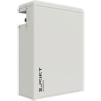
- Triple Power Lithium-ion Battery
- Solax Power Network Technology(Zhe jiang) Co., Ltd.
- Copyright Declaration
- Contents
- Note on this Manual
- Scope of Validity
- Target Group
- Symbols Used
- Safety
- Safety Instructions
- General Safety Precautions
- WARNING!
- Observe the following precautions:
- CAUTION!
- Response to Emergency Situations
- Leaking Batteries
- Wet Batteries and Damaged Batteries
- Qualified Installer
- Product Introduction
- Product Overview
- Dimensions and Weight
- Appearance
- Basic Features
- Features
- Specifications
- Installation
- Installation Prerequisites
- NOTE!
- Safety Gear
- Tools
- Installation
- Check for Transport Damage
- Unpacking
- Accessories
- One Battery Module (HV10230×1):
- Accessories (1) of the three and four Battery Modules (HV10230×3/4):
- Accessories (2) of the three and four Battery Modules (Hv10230×3/4):
- The table below lists the number of each component.
- Overall Installation
- DANGER!
- Install BMS to Battery Module
- Cable Connection
- Connecting Cables to artery ModulesB
- For two battery modules:
- Commissioning
- COMMISSIONING
- Status Indicators
- Battery Module (MC0600)
- Battery Module (HV10230)
- Shutting Down T-BAT System
- Troubleshooting
- Troubleshooting
- Decommissioning
- Dismantling the Battery
- Packing
- Maintenance
- Disclaimer
Brand : SolaX Power
Model : T-Bat H 12.0
Category : Uncategorized