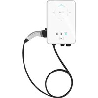
X3-EVC - Car charger SolaX Power - Free user manual and instructions
Find the device manual for free X3-EVC SolaX Power in PDF.


| Product Type | Electric Vehicle Charger |
| Model | X3-EVC |
| Brand | SolaX Power |
| Category | Car Charger |
| Power Output | 7.2 kW (32A single-phase) |
| Input Voltage | 220-240V AC, 50/60Hz |
| Output Current | 32A max |
| Connector Type | Type 2 (IEC 62196) |
| Cable Length | 5 meters (attached) |
| Dimensions (H x W x D) | 300 x 200 x 100 mm |
| Weight | Approx. 5 kg |
| Installation | Wall-mounted or pedestal |
| Display | LED status indicators |
| Connectivity | Wi-Fi / Bluetooth via SolaX app |
| Protection Features | Overcurrent, overvoltage, undervoltage, overheat, earth leakage, surge protection |
| Operating Temperature | -25°C to +50°C |
| Ingress Protection | IP54 (indoor/outdoor) |
| Standards Compliance | IEC 61851, EN 61000-6-3/6-1 |
| Warranty | 2 years (subject to registration) |
Frequently Asked Questions - X3-EVC SolaX Power
User questions about X3-EVC SolaX Power
0 question about this device. Answer the ones you know or ask your own.
Ask a new question about this device
Download the instructions for your Car charger in PDF format for free! Find your manual X3-EVC - SolaX Power and take your electronic device back in hand. On this page are published all the documents necessary for the use of your device. X3-EVC by SolaX Power.
USER MANUAL X3-EVC SolaX Power
X1/X3-EVC Series User Manual 7.2 kW - 22 kW (Home Edition)

natural_image
White SOLAX power supply device with control buttons and indicator lights (no visible text or symbols on body)

SolaX Power Network Technology (Zhejiang) Co., Ltd.
ADD.: No. 288, Shizhu Road, Tonglu Economic Development Zone, Tonglu City, Zhejiang Province, China.
TEL.: 186 571-56260011 E-mail: info@solaxpower.com
614.00623.04
Copyright Declaration
The copyright of this manual belongs to SolaX Power Network Technology (Zhejiang) Co., Ltd. Any corporation or individual should not plagiarize, partially or fully copy it (including software, etc.), and no reproduction or distribution of it in any form or by any means shall be allowed. All rights reserved. SolaX Power Network Technology (Zhejiang) Co., Ltd. reserves the right of final interpretation:
www.solaxpower.com
Contents
1 Note on this Manual....03
1.1 Scope of Validity....03
1.2 Target Group....03
1.3 Symbols Used....03
2 Safety 04
2.1 Appropriate Usage 04
2.2 Important Safety Instructions....05
2.3 Explanation of Symbols 06
3 Introduction 07
3.1 Basic Features 07
3.2 Dimension....08
3.3 Product Description....10
4 Technical Data 11
4.1 General Data....11
4.2 Security Protection....12
5 Installation....13
5.1 Check for Transport Damage 13
5.2 Packing List....13
5.3 Installation Precaution 14
5.4 Installation Steps....15
5.5 CTConnection....24
5.6 Run the EV-Charger....26
6 Operation Method 27
6.1 States....27
6.2 Start-up Patterns 27
6.3 Charging Modes 29
6.3.1 GREEN Mode 30
6.3.2 ECO Mode 30
6.3.3 FAST Mode 31
6.3.4 Smart Boost 32
6.3.5 Timer Boost 32
6.4 Dynamic Load Balance 33
7 App Setting....34
8 Troubleshooting....44
8.1 Troubleshooting....44
8.2 Routine Maintenance 47
9 Decommissioning....48
9.1 Dismantling the Inverter 48
9.2 Packaging 48
9.3 Storage and Transportation 48
9.4 Disposing of the EV-Charger 48
10 Disclaimer....49
* Warranty Registration Form
1 Notes on this Manual
1.1 Scope of Validity
This manual is an integral part of the X1/X3-EVC Series EV-Charger. It describes the
assembly, installation, commissioning, maintenance and failure of the product.
Please read it carefully before operating.
| X1-EVC-7.2K(SXH) | X3-EVC-11K(SXH) | X3-EVC-22K(SXH) |
| X1-EVC-7.2K(PXH) | X3-EVC-11K(PXH) | X3-EVC-22K(PXH) |
Note:
"X1" means single-phase, "X3" means three-phase.
"EVC" means "EV-Charger".
"7.2K" means 7.2 kW, "11K" means 11 kW, "22K" means 22 kW.
"S": Socket Type, only socket outlet, "P": Plug Type (also called Connector Type), with charging cable and connector.
"X": without LCD screen.
"H": home edition.
Keep this manual at where it is accessible all the time.
1.2 Target Group
This manual is for qualified electricians. The tasks described in this manual can only be performed by qualified electricians.
1.3 Symbols Used
The following types of safety instructions and general information appear in this document as described below:

DANGER!
"Danger" indicates a hazardous situation which, if not avoided, will result in death or serious injury.

WARNING!
"Warning" indicates a hazardous situation which, if not avoided, could result in death or serious injury.

CAUTION!
"Caution" indicates a hazardous situation which, if not avoided, could result in minor or moderate injury.

NOTE!
"Note" provides tips that are valuable for the optimal operation of your product.
Safety Safety
2 Safety
2.1 Appropriate Usage
The X1/X3-EVC Series are AC EV charger, intended to be installed in a fixed location and connected to the AC supply.

flowchart
graph TD
    A["PV array"] --> B["Inverter"]
    B --> C["AC distribution box"]
    C --> D["CT/Meter"]
    D --> E["Electricity meter, bidirectional"]
    E --> F["Grid"]
    G["other home load"] --> C
    H["Electric grid"] --> E
Communication with CT/Meter
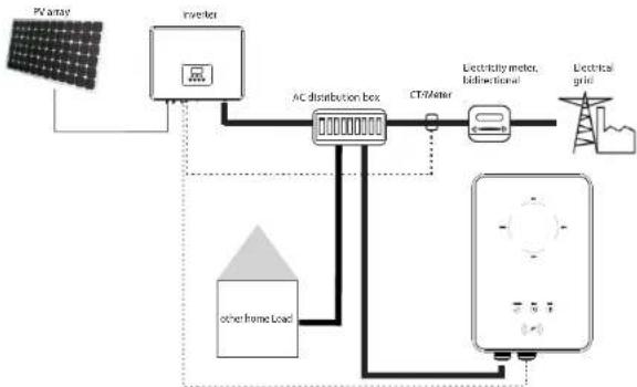
flowchart
graph TD
    A["PV array"] --> B["Inverter"]
    B --> C["AC distribution box"]
    C --> D["CT/Meter"]
    D --> E["Electricity meter, bidirectional"]
    E --> F["Electrical grid"]
    G["other frame load"] --> C
    H["Other"] --> C
Communication with Inverter
2.2 Important Safety Instructions

DANGER!
• Danger to life due to output and input high voltages in this device!
- All work must be carried out by qualified electrician who has knowledge of and experience in dealing with electrical installations.
• The device is not to be used by children or persons with reduced physical sensory or mental capabilities, or lack of experience and knowledge, unless they have been given supervision or instruction.
- Children should be supervised to ensure that they do not play with the device.

CAUTION!
* Danger of burn injuries due to hot enclosure parts!
- During operation, the EV-Charger may become hot.

CAUTION!
Incorrect operation or misuse may result in:
* Injury or death to the operator or third parties.
• Damage to the device and other property of the operator.
- Inefficient operation of the device.

WARNING!
Risk of electric shock!
* Prior to the application, please read this section carefully to ensure correct and safe application. Please keep the user manual properly.
* Use only accessories recommended or sold by SolaX. Otherwise may result in a risk of fire, electric shock, or injury to person.
* Make sure that existing wiring is in good condition and that wire is not undersized.
* Do not disassemble any parts of the EV-Charger which are not mentioned in installation guide. It contains no user-serviceable parts. See Warranty for instructions on obtaining service. Attempting to maintain the X1/X3-EVC Series EV-Charger by yourself may result in a risk of electric shock or fire and will void your warranty.
- Keep away from flammable, explosive materials to avoid fire disaster.
- The installation place should be away from humid or corrosive substance.
- Authorized service personnel must use insulated tools when installing or working with this equipment.
Do not use the EV-Charger in case the device has defects, crack, abrasion, bare leakage and so on. Please contact the working staff in case of above conditions. In case any emergency condition happens, please press the EMERGENCY STOP button immediately, cut off all input and output power supply.
During charging, the electric vehicle is not allowed to drive. Charging only when the electric vehicle stays still. For hybrid car, charging only when switching the engine off.
2.3 Explanation of Symbols
This section gives an explanation of all the symbols shown on the EV-Charger type label.
| Symbol Explanation | |
| CE | CE mark.The EV-Charger complies with the requirements of the applicable CE guidelines. |
| TUV certification. | |
| Danger of high voltages.Danger to life due to high voltages in the EV-Charger! | |
| Danger.Risk of electric shock! | |
| The EV-Charger can not be disposed together with household waste.Used electrical devices must be collected separately and recycled in an environmentally responsible manner. Ensure that you return your used device to your dealer or obtain information regarding a local, authorised collection and disposal system. | |
| The EV-Charger can be recycled. | |
3 Introduction
3.1 Basic Features
Thanks for purchasing with the SolaX X1/X3-EVC Series EV-Charger. The SolaX X1/X3-EVC Series can be used for charging your electric vehicle in your home. Also you can choose single or three phase with plug or socket type, you can consult our salesmen for specific details. The features of the SolaX X1/X3-EVC Series are listed as below.
• Plug or socket outlet selectable
• Integrated current failure monitoring (30mA AC & 6mA DC)
• Integrated with PEN protection and no earth rod
• Encrypted communication based on TLS
• Indoor and outdoor easy installation
- Form an intelligent photovoltaic, storage and EV charging energy system through the communication between the smart EV charger and SolaX inverter
- Capable with 100% green energy generated from your solar generation
• Multiple work modes to fit different situations
• Integrated RFID function
• Remote setting and monitoring with APP and website
• Smart dynamic load balance control
- Set timers to reduce your cost during peak and valley price
3.2 Dimension
Socket Type

Plug Type (Connector Type)

3.3 Product Description

| Object | Name | Description |
| A | Switch | EMERGENCY STOP: Press in emergency, the EV-Charger will stop operating. |
| B | Button | MODE SELECTION: Press to select certain mode. |
| C | Charging connection base | For connecting charging connector. |
| D | LED indicator | Operating status: The corresponding mode light will be on when operating. |
| E | Complete: When the light is on the EV-Charger completes charging or is in idle state. | |
| F | Timer: When the light is on, the boost mode is running. | |
| G | Fault: The red light will be on when error occurs. | |
| H | Card swiping position | Swipe card here. |
| I | Connector | INPUT: For AC input connection. |
| J | COM: For communication connection. |
4 Technical Data
4.1 General Data
| Model | X1-EVC-7.2K | X3-EVC-11K | X3-EVC-22K |
| AC Nominal Input | |||
| Phases/Lines | L+N+PE | 3P+N+PE | 3P+N+PE |
| Voltage [V] | 230 | 400 | 400 |
| Frequency [Hz] | 50/60±5 | 50/60±5 | 50/60±5 |
| AC Nominal Output | |||
| Voltage [V] | 230 | 400 | 400 |
| Current [A] | 32 16 32 | ||
| Power [W] | 7200 11000 22000 | ||
| Interface | |||
| RS-485 | YES | ||
| RFID Frequency | 13.50 M | ||
| LCD Screen | Optional | ||
| CT Clamps | x1 | x3 x3 | |
| Housing Material | Plastic/Metal | ||
| Installation Method | Wall-mounted(Optional: pedestal-mounted) | ||
| Wall-mount Bracket | YES | ||
| Charging Outlet | Socket Type(Socket-outlet)/Plug Type (Charging cable with connector) | ||
| Cable Length [m] | 6.5(for Plug Type) | ||
| Operating Temperature [°C] | -30~+50 | ||
| Working Humidity | 5%~95% without condensation | ||
| Working Altitude [m] | <2000 | ||
| Degree of Protection | IP65 | ||
| Protection Class | Class I | ||
| Application Site | Indoor/Outdoor | ||
| Cooling Method | Natural cooling | ||
| Dimension IW*1*D[mm] | 249*370*155(for Socket Type)/265*370*155(for Plug Type) | ||
| Net Weight [kg] | 7(for Socket Type)/10.5(for Plug Type) | ||
| Communication Info | |||
| Communication Mode | WiFi | ||
| EIRP Power | 17.41 dBm(Measured Max. Average) | ||
| Frequency | 2412~2484 MHz | ||
| Antenna Gain | 4 dBi | ||
| Antenna Type | IPEX | ||
| Wireless Mode | 802.11 b/g/m | ||
4.2 Security Protection
| Model | X1-EVC-7.2K | X3-EVC-11K | X3-EVC-22K |
| Multiple Protection | |||
| Over/Under voltage protection | YES | ||
| Overload protection | YES | ||
| Current leakage monitoring | YES | ||
| Grounding protection | YES | ||
| Surge protection | YES | ||
| Over temperature protection | YES | ||
| Integral earth leakage monitoring | Integrated current failure monitoring (30 mA AC & 6 mA DC) * | ||
| Safety Standard | IFC61851-1; IEC62196-2 | ||
| Built-in PEN fault technology | YES | ||
| Warranty | 3 years | ||
* This document does not replace any regional, state, provincial or national laws, regulations or standards that apply to the installation, electrical safety and use of the product. Always observe the local regulations as well.
5 Installation
5.1 Check for Transport Damage
Make sure the EV-Charger is intact during transportation. If there are some visible damages, such as cracks, please contact your dealer immediately.
5.2 Packing List
Open the package and fetch out the product, check the accessories at first. The packing list is shown as below.

| Object | Quantity | Description |
| A | 1 | EV-Charger |
| B | 3/5 | Expansion bolt (3 for Socket Type, 5 for Plug Type) |
| C | 3/5 | Self tapping screw (3 for Socket Type, 5 for Plug Type) |
| D | 3/5 | Gasket (3 for Socket Type, 5 for Plug Type) |
| E | 1 | Manual |
| F | 1 | Quick Installation Guide |
| G | 3/5 | European terminal(3 for single-phase; 5 for three-phase) |
| H | 1 | RJ45 terminal adapter |
| I | 2 | RFID card |
| J | 1 | CT (J1 for single-phase; J2 for three-phase) |
| K | 1 | Cable hook (only for Plug Type) |
5.3 Installation Precaution
The EV-Charger is designed for wall-mounted installation (IP 65).
Make sure the installation site meets the following conditions:
• Not exposed to sunlight directly.
• Not in areas where highly flammable materials are stored.
• Not in potential explosive areas.
• Not near the television antenna or antenna cable.
• Not higher than altitude of about 2000 m above sea level.
• Not in environment of precipitation or humidity (5%\~95%).
• Make sure that the ventilation is good enough.
• The ambient temperature in the range of -30^ +50^ .
• The slope of the wall should be within ±5°.
The wall on which the EV-Charger will be installed should meet the conditions below:
1) Solid brick/concrete, or strength equivalent mounting surface;
2) The EV-Charger must be supported or strengthened if the wall's strength isn't enough (such as wooden wall, the wall covered by thick layer of decoration).
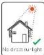


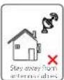
Available Space Size

Table: Available Space Size
| Position Min. size | |
| Left | 300 mm |
| Right | 400-700 mm |
| Top | 200 mm |
| Bottom | 1.2-1.5 m |
| Front | 300 mm |
5.4 Installation Steps
Preparation
- Below tools are needed before installation.

Marker

φ 8 drill

Stripping pliers

Wire crimper

Cross screwdriver Straight screwdriver

- Prepare a communication cable with RJ45 and an input cable with outer diameter of 12.5-18 mm(three-core for single-phase, five-core for three-phase).
STEP 1: Remove the screw from the EV-Charger with the cross screwdriver. Then remove the back bracket away carefully.
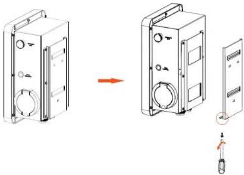
natural_image
Technical line drawing of a device housing with internal components and a close-up view showing a component being inserted (no text or symbols present)STEP 2: Fix the back bracket and the cable hook (only for Plug Type) to the wall.
- Mark the position of the holes.
Insert the expansion bolts. - Drill holes with φ 8 drill.
- Depth: at least 45 mm.

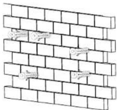
natural_image
Diagram of a brick wall with embedded symbols (no text or labels)- Align the bracket and the cable hook (only for Plug Type) with the holes, and screw the self tapping screws with the cross screwdriver.
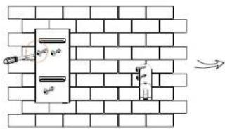

(torque:1.5-2 N·m)
STEP 3: Hang the EV-Charger on the wall for trial, then estimate the required length of input cable and communication cable. After that, take the EV-Charger down.
STEP 4: Unscrew the EV-Charger's rear cover with the cross screwdriver and take it down. the fastening heads and take the waterproof materials away as Then undo shown below.
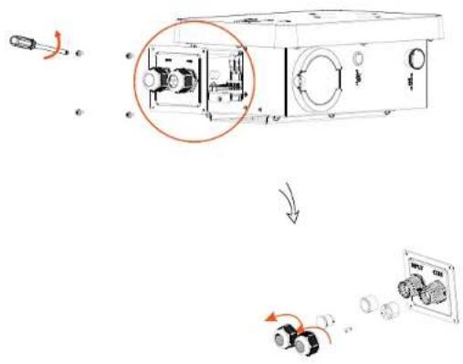
STEP 5: Unscrew the countersunk screw of the base plate of communication board with the cross screwdriver. Then pull the base plate of communication board out.

STEP 6: Insert the prepared communication cable through the waterproof connector in sequence as shown below (If the cable is self-made, also insert the wires into the RJ45 terminals and then use crimping pliers to press them tightly).
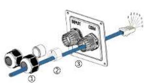

1) White with orange stripes
2) Orange
3) White with green stripes
4) Blue
5) White with blue stripes
6) Green
7) White with brown stripes
8) Brown
| PIN | 1 | 2 | 3 | 4 | 5 | 6 | 7 | 8 |
| Definition | L1 CT- | L1 CT- | L2 CT+ | A1 | B1 | L2 CT- | L3 CT- | L3 CT- |
* PIN 3, 6, 7, 8 is null for single-phase.
STEP 7: Strip the outer sheath of the input cable for a length of 60-70 mm, ensuring all the wires can reach the terminal blocks with a little excessive length. Use the stripping pliers to strip approx. 12 mm of insulation from the end of all the coloured wires as below. Then crimp the European terminal with the wire crimper.
strip length

STEP 8: Insert the input cable through the waterproof connector in sequence as shown below.

STEP 9: Insert the wires into the appropriate holes of the terminal blocks, then block the terminals with the s .traight screwdriver
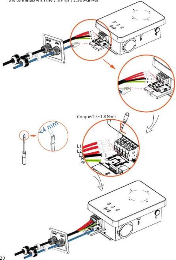
Installation Installation
STEP 10: Press the spring upward and push the base plate of communication board in. Then screw the countersunk screw.

Installation Installation
STEP 11: Push the rear cover to appropriate position of the cables and screw the self tapping screws with the cross screwdriver. Then tighten the waterproof fastening head.

STEP 12: Hang the EV-Charger up carefully and steady the EV-Charger with the self tapping screw and the cross screwdriver.

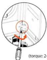
(torque: 2\~2.5 N·m)
For Plug Type, connect the charging connector with the EV-Charger and hang the connecting cable on the hook.

natural_image
Electric shock plug connected to a black cable against a brick wall background (no text or symbols visible)5.5 CT connection
Diagram:
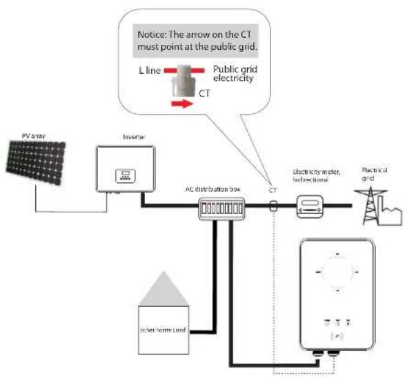
flowchart
graph TD
    A["PV array"] --> B["Inverter"]
    B --> C["AC distribution box"]
    C --> D["CT"]
    D --> E["Electricity meter, hydroelectric"]
    E --> F["Electrical grid"]
    G["power home load"] --> C
    H["L line"] --> I["Public grid electricity"]
    I --> J["CT"]
    J --> C
    K["Notice: The arrow on the CT must point at the public grid."] --> L["CT"]
-Steady the CT on the public grid.
-Insert the other end of the communication cable and the terminal of CT on each side of the RJ45 terminal adapter.


NOTE!
- Do not place the CT on the N Wire or the PE wire.
- Do not place the CT on the N and L wire simultaneously.
- Do not place the CT on the non-insulated wires.
- When using the three-phase CT, please clip the CT clamps on the corresponding phases.
5.6 Run the EV-Charger
➢ Start EV-Charger after checking all below steps:
a) Check that the device is fixed well on the wall.
b) AC cable is connected to grid correctly.
Start the EV-Charger
* Check the status of LED indicators, the complete light should be on when the EV-Charger starts normally.
- If the complete light is not on, please check if it is correctly installed and connected to the grid.

WARNING!
Power to the unit must be turned on only after installation work has been completed. All electrical connections must be carried out by qualified personnel in accordance with legislation in force in the country concerned.

NOTE!
Equipment only to be used for the purpose outlined by SolaX.
6 Operation Method
6.1 States
There are six states of the X1/X3-EVC Series EV-Charger, i.e. Idle, Stop, Charge, Complete, Fault and Unavailable.
| States | Indicator Light & Description |
| Idle | The Complete light is on and the MODE SELECTION button is invalid. The connector is not inserted. |
| Stop | The STOP light is on. The EV-Charger is connected but not charging. |
| Charge | The corresponding charging mode light is on. The EV-Charger is charging. |
| Complete | The Complete light and the STOP light are on at the same time. The EV-Charger has completed charging and the MODE SELECTION button is invalid. |
| Fault | The Fault light is on. The EV-Charger is in fault state. |
| Unavailable | The four charging mode lights are on at the same time. The EV-Charger is remote upgrading. |
6.2 Start-up Patterns
The X1/X3-EVC Series EV-Charger has two start-up patterns, namely plug & charge and card-swiping pattern. The plug & charge pattern is the default pattern, and the card-swiping pattern needs to "enable" the "RFID Function" in the APP advanced settings.
1) Plug & charge pattern
For Socket Type, the electronic lock will be locked when the EV-Charger starts charging and unlocked when the charging stops.
For Plug Type, there is no electronic lock.
2) Card-swiping pattern
For Socket Type, the electronic lock will be locked when the EV-Charger starts charging after swiping the card, and unlocked after swiping the card when the charging stops.
For Plug Type, there is no electronic lock.
Note:
The charging can be stopped from the vehicle end or the charger end (by long pressing "MODE SELECTION" button, by APP setting or by swiping card). In card-swiping pattern, the electronic lock will not unlock automatically when the charging stops, and users need to swipe the card again to unlock it.
\* Card Activation
If the user wants to use the card-swiping pattern, the RFID cards need to be activated at the EV-Charger. Please follow the instructions below:
1. Enable the Card Activation Mode of Advanced Settings in the APP. Once enabled, the four operating LED indicator lights on the EV-Charger will light up in sequence and cycle.

NOTE!
The default RFID PIN is 111111, the user can modify the RFID PIN before activation, and the password of the RFID card will be updated to the RFID PIN after activation. The password of the RFID card must be consistent with the one set in the APP. The RFID PIN is 6 digits.
- Swipe the RFID card at the EV-Charger.
- If successfully activated, the EV-Charger will beep.
- Disable the Card Activation Mode in the APP or wait for 1 minute after activation, the EV-Charger will turn to standby state.
- Enable the RFID Function of Advanced Settings in the APP to use the card.
Advanced Settings
^
Overvoltage Limit (V)
265
Undervoltage Limit (V)
160
Save
Grid Data Source CT
RFID Function
RFID Function
Disable
Card Activation Mode
Enable
RFID PIN
111111
Save
6.3 Charging Modes
Short press the "MODE SELECTION" button, the charging mode will switch among FAST, ECO and GREEN Modes.

Long press the "MODE SELECTION" button, the current charging mode will switch to STOP mode. When the EV-Charger is in STOP mode, short press the "MODE SELECTION" button, the EV-Charger will switch back to the previous charging mode.(Only available in plug & charge pattern.)

6.3.1 GREEN Mode
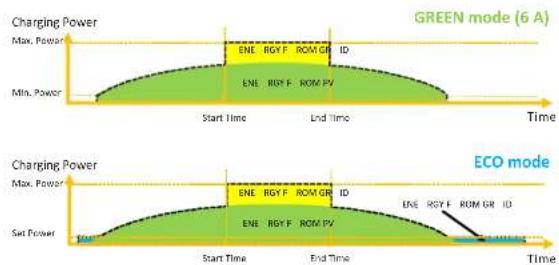
In GREEN Mode the EV-Charger will maximize the use of surplus power generated from the Inverter. According to the minimum start-up charging power, the charging current can be divided into two levels as 3 A and 6 A. The default level is 6 A.
In the 6 A level, the EV-Charger won't use the power generated from grid at all.
In the 3 A level, the EV-Charger would start charging only when photovoltaic power supply is more than 3 A. Meanwhile, if the photovoltaic power supply is less than 6 A, the EV-Charger needs to buy extra electricity from grid for minimum start-up charging power (1.4 kW for single-phase, 4.2 kW for three-phase).

6.3.2 ECO mode
In ECO Mode, the charging power is continuously adjusted according to changes in generation or power consumption elsewhere in the house, thereby minimizing the use of grid power. In this mode, users can set charging current at five different levels, i.e. 6 A, 10 A, 16 A, 20 A and 25 A (only two levels for X3-EVC-11K). If at any time, the available surplus power falls below the fixed value of power, such as 1.4 kW (4.2 kW for three-phase), the shortfall will be drawn from the grid.
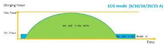
area
| Time | Change Power | |---|---| | Min. Power | Low | | Max. Power | High | | ECO mode (6/10/16/20/25 A) | Peak value |NOTE!

When the X1/X3-EVC Series EV-Charger is charging in GREEN or ECO mode:
The charging electric vehicle must comply with the IEC61851 standard, otherwise the EV-Charger won't work.
If there is a zero injection requirement for the system, the EV-Charger must communicate with the inverter in order to charge normally.
6.3.3 FAST mode
In FAST Mode, the EV-Charger will charge the EV at the fastest rate regardless of whether the power generated by PV is sufficient and import grid electricity if the power generated by PV is insufficient.

6.3.4 Smart Boost
Before using the Smart Boost function, set the desired charging energy(kWh) and end time for the vehicle charging on the APP. The EV-Charger will complete the charging of the EV with desired energy before the preset end time at maximum charging power and will use the photovoltaic power supply as much as possible and minimize the use of grid power. (E.g.: The user needs to charge the EV to 40 kWh before 10:00 AM, then the Charging power is depended on the surplus power generated by the inverter.)

line
| Mode | Start Time | End Time Time | | ---------------- | ---------- | ------------- | | Green mode(6 A) | Max. Power | Min. Power | | Green mode(6 A) | Max. Power | End Time | | ECO mode | Set Power | End Time | | ECO mode | Max. Power | End Time | | ECO mode | Max. Power | End Time | | ECO mode | Energy From Grid | End Time | | ECO mode | Energy From Grid | End Time |6.3.5 Timer Boost
When using ECO or GREEN charging modes, the EV-Charger can be programmed to 'boost' the current charge in a certain period. In timer boost mode, the charging rate is set to maximum (just like FAST mode), regardless of the amount of available surplus power. This means that the power may be drawn from the mains grid supply during boost times. If the EV is fully charged, the EV-Charger will stop charging.
line
| Mode | Max. Power | Min. Power | |------------|------------|------------| | Green mode | ENL | ENL | | ECO mode | ENL | ENL |6.4 Dynamic Load Balance
The X1/X3-EVC Series EV-Charger has default dynamic load balancing function. During the charging period, no matter in which work mode, the total power of the house will not exceed the main grid capacity. To ensure the total power of the house doesn't exceed the grid capacity, the charging power will be adjusted in real time following the total load power.

area
| Time | Charging Power | | ---------- | -------------- | | Start Time | Low | | End Time | High |7 App Setting
The screen shots here are for reference only and the actual interfaces may differ. Users can update their APP as needed.
APP account login
- If you don't have the app or SolaX Cloud's account yet, you can operate as below:
SolaXCloud Registration
Step 1: Use your smart phone to scan below QR code or search for the keyword "SolaXCloud" in browser to download the Monitoring App.

os

Google
Step 2: Touch the Setting button at upper left corner of the Monitoring App to choose language.
Step 3: Touch "Create a new account" at the bottom of Monitoring App.
Step 4: Type In or scan the Registration No. and type in other information to complete the registration.


Example for Registration No.1
- If you already have the app and SolaX Cloud's account, you can operate as below:
Wi-Fi Connection
Step 1: Login your account and turn to Account page in the app.
Step 2: Click "Wi-Fi Connection".

Step 3: Type in or scan the Registration No. of the EV-Charger. Then touch Next and agree to join the network of the EV-Charger.

Step 4: Type in your home Wi-Fi SSID and password, then Setting. *5GHz Wi-Fi is unavailable for now.
WIFI Network*
HomeRouter
Password*
********

Step 5: Wi-Fi setting successes.
*Check more Wi-Fi setting information on www.solaxcloud.com/wifiSetting/
Local Mode
Use your smart phone to connect the SolaX Wi-Fi signal (Wifi_SCxxxxxxxx).
Then touch Local and type in password (initially same as the Registration No.) to access the Local Mode In the Monitoring App.
*Visit the local password setting instruction on
www.solaxcloud.com/wifiSetting/

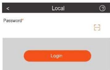
Settings for the EV-Charger
- Select "Site" at the bottom and then touch the "EV Charger" icon and select your EV-Charger on the list.

- Touch the "EV Charger" icon and then touch the setting button to enter the setting page.

- Select "Mode Settings" and a drop-down list will appear. Set the levels of Green Mode (2 levels) and ECO Mode(5 levels for X1-EVC-7.2K & X3-EVC-22K, 2 Levels for X3-EVC-11K) as you want.
| Setting | |
| Version | 1.02 |
| Date Time | 2022-03-01 00:00 |
| Mode Settings | ^ |
| Green Mode | Level1 3A |
| ECO Mode | Level1 6A |
| Boost Settings | v |
| Main Breaker Limit | v |
| Advanced Settings | v |
- Select "Boost Settings" and a drop-down list will appear. Set the Start Time and End Time for Timer Boost, the Charge(kWh) energy and End Time for Smart Boost as you want.
| Setting | |
| Version | 1.02 |
| Date Time | 2022-03-01 00:00 |
| Mode Settings | v |
| Boost Settings | ^ |
| Timer Boost | |
| Start time | 00:00 |
| End time | 00:00 |
| Smart Boost | |
| Charge (kWh) | |
| 0 | Save |
| End time | 00:00 |
| Main Breaker Limit | v |
| Advanced Settings | v |
- Select "Main Breaker Limit" and set the value. With the dynamic load balance function, when the power consumption approaches the preset max value, the EV-Charger will reduce charge power so that the main breaker current will reduce to the preset value minus 5 A, thus avoid the situation of main breaker trip due to overload.
| < | Setting |
| Version | 1.02 |
| Date Time | 2022-03-01 00:00 |
| Mode Settings | v |
| Boost Settings | v |
| Main Breaker Limit | ^ |
| Main Breaker Limit (A) | |
| 60 | Save |
| Advanced Settings | v |
- Select "Advanced Settings" and a drop-down list will appear.
1) Set and save the value of "Overvoltage Limit" and "Undervoltage Limit".
2) Touch "Grid Data Source" to select the source.
3) Touch "RFID Function" to enable or disable the function. Touch "Card Activation Mode" for the activation of the RFID card as described in section "Operation Method".
4) The default setting can be restored and the EV-Charger can be reset by touching correspondent option.
| Setting | |
| Version | 1.02 |
| Date Time | 2022-03-01 00:00 |
| Mode Settings | v |
| Boost Settings | v |
| Main Breaker Limit | v |
| Advanced Settings | A |
| Overvoltage Limit (V) | |
| 265 | Save |
| Undervoltage Limit (V) | |
| 160 | Save |
| Grid Data Source CT | |
| RFID Function | |
| RFID Function | Disable |
| Card Activation Mode | Disable |
| Restore factory settings | Save |
| EV Charger Reset | Save |
8 Troubleshooting
8.1 Troubleshooting
This section contains information and procedures for solving possible problems with the X1/X3-EVC Series EV-Charger, and provides you with troubleshooting tips to identify and solve most problems that could occur with the X1/X3-EVC Series EV-Charger.
This section will help you narrow down the source of any problems you may encounter. Please read the following troubleshooting steps.
Check warnings or fault messages on System Control Panel or Fault codes on the EV-Charger information panel. If a message is displayed, record it before doing anything further.
Attempt the solution indicated in troubleshooting lists.
| No. | Faults Solution | |
| 0 | PowerSelect_Fault | Contact installers for help |
| 1 | EmStop_Fault | 1.Release the Emergency Switch;2.Contact installers for help |
| 2 | OverVoltL1_Fault | 1.Confirm that the Grid Voltage is within the working range;2.If the "Fault" indicator is off, try charging EV again;3.If not, set the value of "Overvoltage Limit" to a proper range, the buzzer will beep after the value is saved;4.repeat step 2;5.Contact installers for help |
| 3 | UnderVoltL1_Fault | 1.Confirm that the Grid Voltage is within the working range;2.If the "Fault" indicator is off, try charging EV again;3.If not, set the value of "Undervoltage Limit" to a proper range, the buzzer will beep after the value is saved;4.repeat step 2;5.Contact installers for help |
| 4 | OverVoltL2_Fault | Same as ErrorCode 2 |
| 5 | UnderVoltL2_Fault | Same as ErrorCode 3 |
| 6 | OverVoltL3_Fault | Same as ErrorCode 2 |
| 7 | UnderVoltL3_Fault | Same as ErrorCode 3 |
| 8 | ElecLock_Fault | Contact installers for help |
| 9 | OverLoad_Fault | 1.Unplug the connector from the EV;2.If the "Fault" indicator is off, re-plug in and try charging EV again;3.If the "Fault" indicator persists, try another EV;4.Contact installers for help |
| No. | Faults Solution | |
| 10 | OverCurr_Fault | 1.Unplug the connector from the EV; 2.If the "Fault" Indicator is off, re-plug in and try charging EV again; 3.Contact installers for help |
| 11 | OverTemp_Fault | 1.Unplug the connector from the EV; 2.If the "Fault" Indicator is off, re-plug in and try charging EV again; 3.If not, confirm that the conditions for installation are proper and waiting for cooling down, then re-plug in and try charging EV again when the Indicator turns off; 4.Contact installers for help |
| 12 | PEGround_Fault | 1.Unplug the connector from the EV; 2.If the "Fault" Indicator is off, check the EV whether it is normal; 3.If not, confirm that all the cables and wires are intact; 4.Contact installers for help |
| 13 | PELeakCurr_Fault | 1.Unplug the connector from the EV; 2.If the "Fault" Indicator is off, check the EV whether it is normal; 3.If not, confirm that all the cables and wires are intact; 4.If the "Fault" Indicator is off, re-plug in and try charging EV again; 5.Contact installers for help |
| 14 | OverLeakCurr_Fault | Same as ErrorCode 12 |
| 15 | MeterCom_Fault | Contact installers for help |
| 16 | 485Com_Fault | 1.If the "Fault" Indicator is off, try charging EV again; 2.If not, confirm that all the communication wires are intact and confirm the selection of "Grid Data Source"; 3.Restart; 4.Contact installers for help |
| 17 | CPVolt_Fault | Same as ErrorCode 12 |
* When your EV-Charger needs to be upgraded by the service personnel, please make sure to unplug the connector from the EV.
- If your EV-Charger's Information panel is not displaying a Fault light, check the following list to make sure that the present state of the installation allows proper operation of the unit.
— Is the EV-Charger located in a clean, dry, adequately ventilated place?
— Are the specification and length of the cables suitable?
— Are the input connections and wiring in good condition?
— Are the configuration settings correct for your particular installation?
— Are the display panel and the communication cable properly connected and undamaged?
Contact SolaX Customer Service for further assistance. Please be prepared to describe details of your system installation and provide model and serial number of the unit.
Global Service Center: +86 (571) 56260033 ext 749
General Enquiry: +86 (571) 56260011
Sales Enquiry: +86 (571) 56260008
E-Mail: info@solaxpower.com
Fax: +86 (571) 56075753
8.2 Routine Maintenance
The EV-Charger do not need any maintenance or correction in most condition. To ensure that the EV-Charger can operate properly for a long term, you are advised to perform routine maintenance on it.
Only trained and authorized professional personnel who are familiar with the requirements of safety was allowed to perform servicing and maintenance work.
▶ Safety checks
Safety checks should be performed at least every 12 months by manufacturer's qualified person who has adequate training, knowledge, and practical experience to perform these tests. The data should be recorded in an equipment log. If the device is not functioning properly or falls any of the tests, the device has to be repaired. For safety check details, refer to section 2 Safety instruction in this manual.
▶ Maintain periodically
Only qualified person may perform the following works.
During the process of using the EV-Charger, the manage person shall examine and maintain the machine regularly. The concrete operations are as follows.
1) Check that if the indicators of the EV-Charger are in normal state, check if the buttons of the EV-Charger are in normal state, check if the display of the EV-Charger is normal. This check should be performed at least every 6 months.
2) Check that if the input cable and the connector are damaged or aged. This check should be performed at least every 6 months.
3) Check whether the ground terminal and ground cable are securely connected every 12 months.
4) Clean the outer shell of the EV-Charger cleaned and check its security at least every 6 months.
9 Decommissioning
9.1 Dismantling the EV-Charger
- Disconnect the EV-Charger from the inverter and the grid.
- Wait for 5 minutes for de-energizing.
- Remove the EV-Charger from the bracket.
- Remove the bracket if necessary.
9.2 Packaging
If possible, please pack the EV-Charger with the original packaging.
If it is no longer available, you can also use an equivalent carton that meets the following requirements.
• Suitable for loads more than 10 kg.
- With handle.
* Can be fully closed.
9.3 Storage and Transportation
Store the EV-Charger In dry place where ambient temperatures are always between -30^ +50^ . Take care of the EV-Charger during the storage and transportation, keep less than 4 cartons in one stack.
9.4 Disposing of the EV-Charger
When the EV-Charger or other related components need to be disposed, have it carried out according to local waste handling regulations. Please be sure to deliver the wasted EV-Charger and packing materials to certain site where can assist relevant department to dispose and recycle.
10 Disclaimer
The EV-Charger series are transported, used and operated under limited condition, such as environmental, electrical etc. SolaX shall not be liable to provide the service, technical support or compensation under conditions listed below, including but not limited to:
- The EV-Charger is damaged or broken by force majeure (such as earthquake, flooding, thunderstorm, lighting, fire hazard, volcanic eruption etc.).
• The EV-Charger's warranty is expired and not extended. - The EV-Charger's SN, warranty card or invoice cannot be provided.
- The EV-Charger is damaged by man-made causes.
- The EV-Charger is used or operated against any items in local policy.
- The EV-Charger's installation, configuration, commissioning doesn't follow the requirements mentioned in this manual.
- The EV-Charger is installed, refitted or operated in improper ways mentioned in this manual without authority from SolaX.
- The EV-Charger is installed, operated under improper environment or electrical condition mentioned in this manual without authority from SolaX.
- The EV-Charger is changed, updated or disassembled on hardware or software without authority from SolaX.
- Obtain the communication protocol from other illegal channels.
• Build monitoring, control system without authority from SolaX.
SolaX will keep right to explain all the contents in this user manual.
Warranty Registration Form

For Customer (Compulsory)
Name Country
Phone Number Email
Address
State Zip Code
Product Serial Number
Date of Commissioning
Installation Company Name
Installer Name .... Electrician License No. ....
For Installer
Module ( If Any )
Module Brand
Module Size(W)
Number of String Number of Panel Per String
Battery ( If Any )
Battery Type
Brand
Number of Battery Attached
Date of Delivery Signature
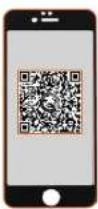
Please visit our warranty website: https://www.solaxcloud.com/#/warranty to complete the online warranty registration or use your mobile phone to scan the QR code to register.
For more detailed warranty terms, please visit SolaX official website: www.solaxpower.com to check it.
614.00002.07

PLEASE REGISTER THE WARRANTY
IMMEDIATELY AFTER INSTALLATION!
GET YOUR WARRANTY CERTIFICATE
FROM SOLAX!
KEEP YOUR INVERTER ONLINE & WIN
SOLAX POINTS!
1
Open your camera app and point your device at the QR code

2
Wait for the camera to recognize the QR code
3
Click banner or notification when it appears on the screen

4
Warranty registration page will be loaded automatically


- X1/X3-EVC Series User Manual 7.2 kW - 22 kW (Home Edition)
- Copyright Declaration
- Contents
- Notes on this Manual
- Scope of Validity
- Target Group
- Symbols Used
- DANGER!
- WARNING!
- CAUTION!
- NOTE!
- Safety
- Appropriate Usage
- Important Safety Instructions
- Explanation of Symbols
- Introduction
- Basic Features
- Dimension
- Technical Data
- Installation
- Check for Transport Damage
- Packing List
- Installation Precaution
- Installation Steps
- CT connection
- Run the EV-Charger
- Operation Method
- States
- Start-up Patterns
- \* Card Activation
- RFID Function
- Charging Modes
- GREEN Mode
- ECO mode
- FAST mode
- Smart Boost
- Timer Boost
- Dynamic Load Balance
- App Setting
- Troubleshooting
- Troubleshooting
- Routine Maintenance
- ▶ Safety checks
- ▶ Maintain periodically
- Decommissioning
- Dismantling the EV-Charger
- Packaging
- Storage and Transportation
- Disposing of the EV-Charger
- Disclaimer
- Warranty Registration Form
- For Customer (Compulsory)
- For Installer
- Module ( If Any )
- Battery ( If Any )
Brand : SolaX Power
Model : X3-EVC
Category : Car charger