
AVerVision 310AF - Visualiseur AVer - Free user manual and instructions
Find the device manual for free AVerVision 310AF AVer in PDF.


| Product Type | Document Camera (Visualizer) |
| Brand | AVer |
| Model | AVerVision 310AF |
| Image Sensor | 1/2" progressive scan CMOS |
| Total Pixels | 3.2 megapixels |
| Frame Rate | 24 fps (max.) |
| White Balance | Auto/Manual |
| Exposure | Auto/Manual/Flicker/Night View |
| Image Modes | Text, Graphics, High Frame |
| Effects | Color, B/W, Negative, Reverse, Mirror |
| Lens | F3.0, auto focus |
| Shooting Area (max.) | 320 mm x 240 mm |
| Zoom | AVERZOOM: 2x, Digital: 8x |
| Focusing | Auto and manual |
| Analog RGB Output | HD 720P, XGA 60 Hz, SVGA 60 Hz, VGA 60 Hz |
| Video Output | S-Video (Mini-DIN), Composite (RCA), NTSC/PAL |
| DVI Output | DVI type |
| VGA Input | 15-pin D-sub |
| USB | USB 2.0 (camera or image download) |
| Built-in Memory | 128 MB NAND Flash |
| Image Capture | Up to 80 frames, single or continuous |
| Lighting | LED lamp (on/off) |
| Power Supply | DC 12V, 100-240V AC, 50-60 Hz |
| Power Consumption | 7.44 W (lamp off), 10.68 W (lamp on) |
| Dimensions (operating) | 424 mm x 173.4 mm x 330 mm |
| Dimensions (folded) | 365 mm x 173.4 mm x 95.85 mm |
| Weight | 2 kg (approx. 4.4 lb) |
Frequently Asked Questions - AVerVision 310AF AVer
User questions about AVerVision 310AF AVer
0 question about this device. Answer the ones you know or ask your own.
Ask a new question about this device
Download the instructions for your Visualiseur in PDF format for free! Find your manual AVerVision 310AF - AVer and take your electronic device back in hand. On this page are published all the documents necessary for the use of your device. AVerVision 310AF by AVer.
USER MANUAL AVerVision 310AF AVer
Federal Communications Commission Statement(Class A)

NOTE- This equipment has been tested and found to comply with the limits for a Class A digital device, pursuant to Part 15 of the FCC Rules. These limits are designed to provide reasonable protection against harmful interference in a residential installation. This equipment generates uses and can radiate radio frequency energy and, if not installed and used in accordance with the
instructions, may cause harmful interference to radio communications. However, there is no guarantee that interference will not occur in a particular installation. If this equipment does cause harmful interference to radio or television reception, which can be determined by tuning the equipment off and on, the user is encouraged to try to correct the interference by one or more of the following measures:
■ Reorient or relocate the receiving antenna.
■ Increase the separation between the equipment and receiver.
■ Connect the equipment into an outlet on a circuit different from that to which the receiver is connected.
■ Consult the dealer or an experienced radio/television technician for help.
Class A ITE:
Class A ITE is a category of all other ITE which satisfies the class A ITE limits but not the class B ITE limits. Such equipment should not be restricted in its sale but the following warning shall be included in the instructions for use:
Warning - This is a class A product. In a domestic environment this product may cause radio interference in which case the user may be required to take adequate measures.
CE Class A (EMC)
This product is herewith confirmed to comply with the requirements set out in the Council Directives on the Approximation of the laws of the Member States relating to Electromagnetic Compatibility Directive 2004/108/EEC.
Warning - This is a Class A product. In a domestic environment this product may cause radio
interference in which case the user may be required to take adequate measures to correct this interference.
DISCLAIMER
No warranty or representation, either expressed or implied, is made with respect to the contents of this documentation, its quality, performance, merchantability, or fitness for a particular purpose. Information presented in this documentation has been carefully checked for reliability; however, no responsibility is assumed for inaccuracies. The information contained in this documentation is subject to change without notice.
In no event will AVer be liable for direct, indirect, special, incidental, or consequential damages arising out of the use or inability to use this product or documentation, even if advised of the possibility of such damages.
TRADEMARKS
AVerVision is registered trademarks of AVer Information Inc. IBM PC is a registered trademark of International Business Machines Corporation. Macintosh is a registered trademark of Apple Computer, Inc. Microsoft is a registered trademark and Windows is a trademark of Microsoft Corporation. All other products or corporate names mentioned in this documentation are for identification and explanation purposes only, and may be trademarks or registered trademarks of their respective owners.
COPYRIGHT
© 2011 by AVer Information Inc. All rights reserved. No part of this publication may be reproduced, transmitted, transcribed, stored in a retrieval system, or translated into any language in any form by any means without the written permission of AVer Information Inc.
THE MARK OF CROSSED-OUT WHEELED BIN INDICATES THAT THIS PRODUCT MUST NOT BE DISPOSED OF WITH YOUR OTHER HOUSEHOLD WASTE. INSTEAD, YOU NEED TO DISPOSE OF THE WASTE EQUIPMENT BY HANDING IT OVER TO A DESIGNATED COLLECTION POINT FOR THE RECYCLING OF WASTE ELECTRICAL AND ELECTRONIC EQUIPMENT. FOR MORE INFORMATION ABOUT WHERE TO DROP OFF YOUR WASTE EQUIPMENT FOR RECYCLING, PLEASE CONTACT YOUR HOUSEHOLD WASTE DISPOSAL SERVICE OR THE SHOP WHERE YOU PURCHASED THE PRODUCT.
Remote Control Battery Safety Information
- Store batteries in any cool & dry place.
- Do not dispose used batteries in domestic waste. Dispose batteries at special collection points or return to stores if applies.
- Remove the batteries if they are not in use for long period of time. Battery leakage and corrosion can damage the remote control, dispose batteries safely.
- Do not mix and use old and new batteries.
- Do not mix and use different types of batteries: alkaline, standard (carbon-zinc) or rechargeable (nickel-cadmium).
- Do not dispose batteries in a fire.
- Do not attempt to short circuit the battery terminals.
Table of Contents
Introduction .... 1
Package Contents.... 1
Optional Accessories 2
AVerVision M30 Parts 3
Technical Specifications 4
Image....4
Optics 4
Power 4
Lighting 4
Input/Output 4
Dimension 4
Making the Connections 5
Connecting the Power Adapter....6
Connecting a TV....6
Connecting a VGA, Mac Display Monitor or LCD/DLP Projector...... 7
Connecting a Computer via USB Connection....8
Installing the Optional Light Box 9
Connecting to a Microscope 9
Setting Up AVerVision M30 10
Camera Head 10
Mechanical Arm....10
LED Light Module....11
Anti-glare Sheet....11
Using the Infrared Remote Control 12
Touch Button Control Panel 14
LED Panel 15
OSD Navigation Tree 15
IMAGE MENU.... 15
SETTING MENU.... 16
Menu Functions.... 16
Transferring the Captured Image to PC.... 20
RS-232C Diagram Connection 20
RS-232C Cable Spec 20
RS-232C Transmission Spec 21
RS-232C Communication Format.... 21
RS-232C Command Table 21
Troubleshooting....22
Limited Warranty 23
Introduction Package Contents
Thank you for purchasing the AVerVision M30. This document camera displays any documents, negatives, transparencies and 3D objects onto a TV, LCD or DLP projector making presentations a snap.
AVerVision M30 is an ideal presentation tool for business, academic, medical and the scientific community.
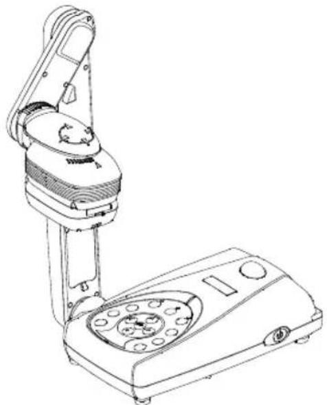
natural_image
Line drawing of a handheld device with a circular dial and control panel (no text or symbols)AVerVision M30
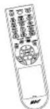
Remote Control (batteries included)
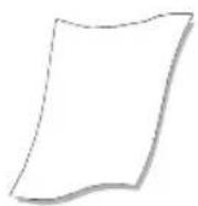
(1) Anti-glare Sheet
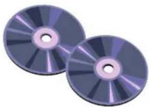
natural_image
Two CD or DVD discs with reflective surfaces, no visible text or symbolsSoftware & Manual CD
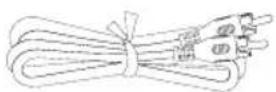
RCA Cable
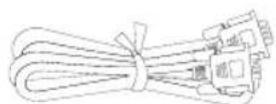
Computer Extension cable (VGA Cable)
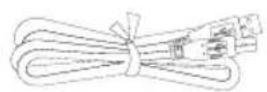
USB Cable
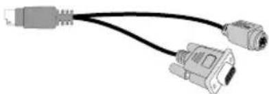
natural_image
Illustration of two connected USB connectors (no text or symbols)S-Video/RS-232 Cable
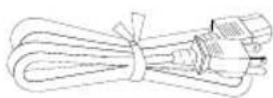
Power Cord
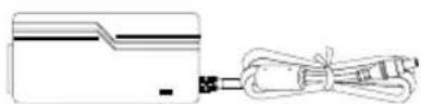
Power Adapter
* The power cord will vary depending on the standard power outlet of the country where it is sold.
Optional Accessories
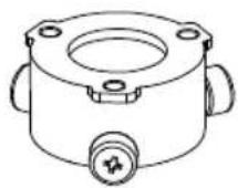
34mm Microscopic Adapter
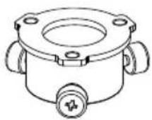
28mm Microscopic Adapter
natural_image
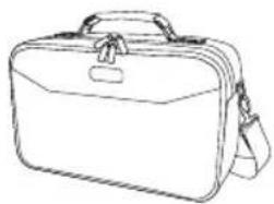
Line drawing of a briefcase with handle and side strap (no text or symbols)Carrying Bag
natural_image
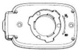
Technical line drawing of a mechanical component with mounting holes and a central gear-like feature (no text or symbols)Microscopic Coupler
natural_image
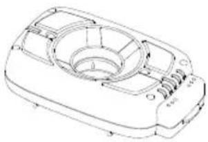
Technical line drawing of a mechanical component with no visible text or symbolsLED Lamp with Laser Positioning Pointer
natural_image
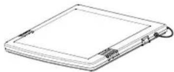
Line drawing of a rectangular electronic device with a flat top and a coiled cable (no text or symbols)Light Box
AVerVision M30 Parts
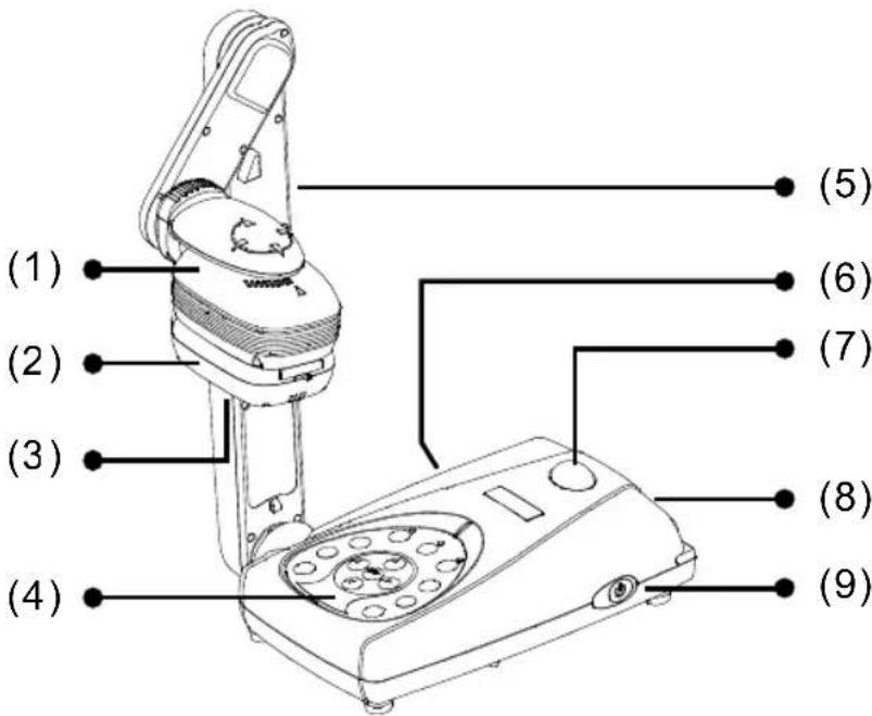
The illustrations below identify the parts of AVerVision M30.
(1) Camera head
(2) LED light module
(3) Camera lens
(4) Control panel
(5) Arm
(6) Left panel
(7) IR sensor
(8) Rear panel
(9) Right panel
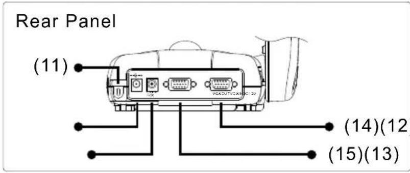
(11) Security slot
(12) DC 12V port
(13) Light box power port
(14) VGA output port
(15) VGA input port
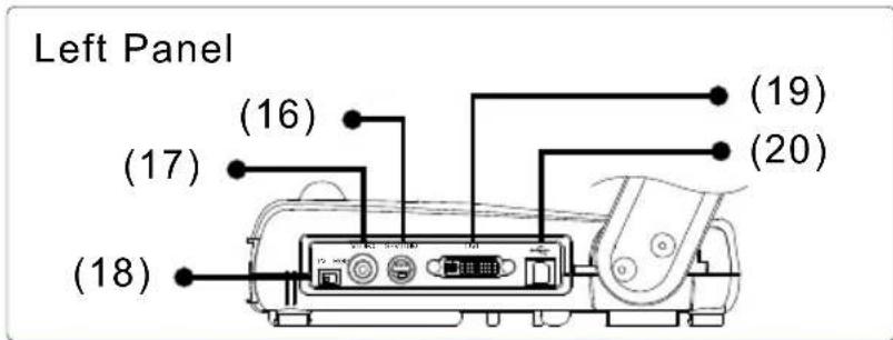
(16) S-Video output port
(17) Composite video output port
(18) TV/RGB display switch
(19) DVI output port
(20) USB port
Technical Specifications
Image
| Sensor 1/2" progress scan CMOS | |
| Total Pixels 3.2 mega pixel | |
| Frame Rate 24 fps (Max.) | |
| White Balance Auto / Manual | |
| Exposure Auto / Manual / Flicker / Night View | |
| Image Mode Text / Graphics / High Frame | |
| Effect Color / B/W / Negative; Reverse; Mirror | |
| Analog RGB Output HD 720P; XGA 60 Hz; SVGA 60 Hz; VGA 60 Hz | |
| S-Video, Composite Video Output | NTSC or PAL |
| Image Capture Up to 80 Frames | |
| Built-In Memory 128MB NAND Flash Memory | |
Optics
| Lens | F3.0; | Auto |
| Shooting Area 320mm | x 240mm (Max.); | |
| Zooming AVERZOOM: | 2x, Digital: 8x |
Focusing
Power
| Power Source | DC 12V, 100-240V ~ 2.0-4.2A, 50-60 Hz |
| Consumption | 7.44 Watts (Lamp off); 10.68 Watts (Lamp on) |
Lighting
| Lamp Type | LED lamp |
Input/Output
| VGA Input | 15-Pins D-sub (VGA) |
| VGA Output | 15-Pins D-sub (VGA) |
| DVI Output | DVI type |
| S-Video | Mini-DIN Jack |
| Composite Video | RCA Jack |
| USB | USB2.0 |
| DC 6V Output | Power Jack |
Dimension
| Operating | 424mm x 173.4mm x 330mm |
| Folded | 365mm x 173.4mm x 95.85mm |
| Weight | 2 kg (about 4.4 lb) |
Making the Connections
The ports on the back and side panel of the AVerVision M30 enable you to connect the unit to a computer, graphics display monitor or LCD/DLP projector, TV or other device. Illustrated below are the ports that are located at the back and side panel of the AVerVision M30 with their corresponding labels.
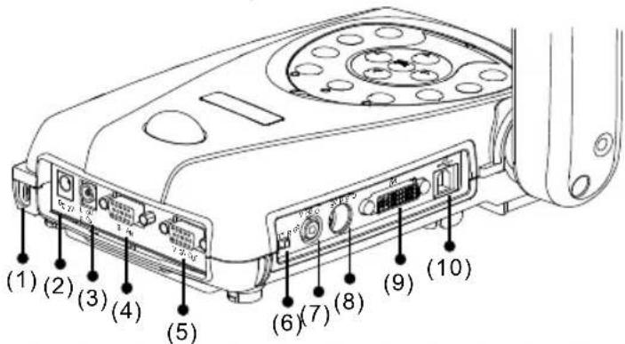
(2) DC 12V (input) Connect the power adapter into this port.
(3) Light Box Port Plug the optional light box into this port.
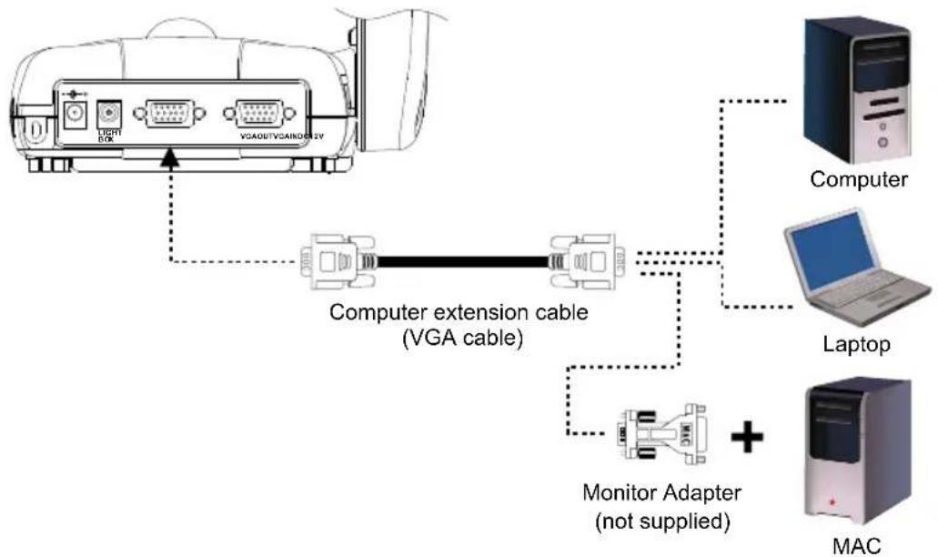
(4) VGA IN Port Input RGB signal from a computer or other sources and actively pass it through to the VGA output port only. Connect this port to the VGA output port of the computer.
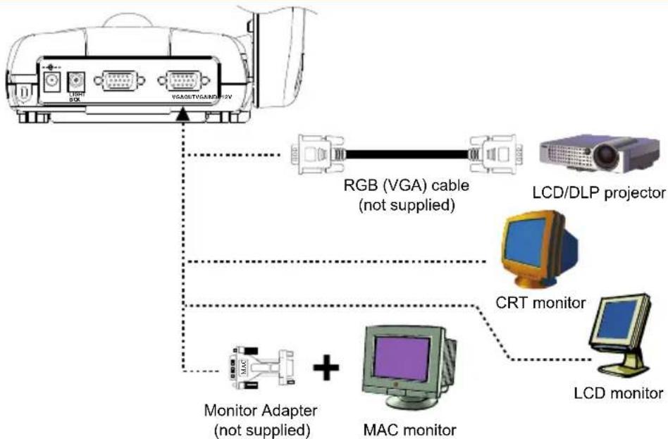
(5) VGA OUT Port Output RGB signal from the camera, VGA input port, or the captured images from the memory on a VGA/Mac monitor or LCD/DLP projector.
(6) TV/RGB Switch Set to select the between RGB (VGA Out) or TV (Composite Video/S-Video Out) display output.
(7) VIDEO Port (RCA/Composite) Output the signal from the camera or the captured images from the built-in memory on TV or video equipment.
(8) S-VIDEO Port Output the signal from the camera or the captured images from the memory on TV or video equipment.
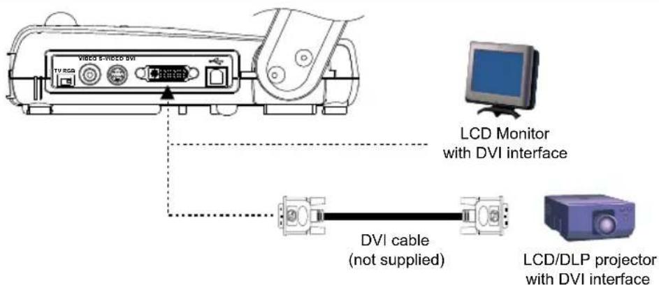
(9) DVI Port Output video signal from the camera, or the captured images from the memory on an LCD monitor or LCD/DLP projector with DVI interface.
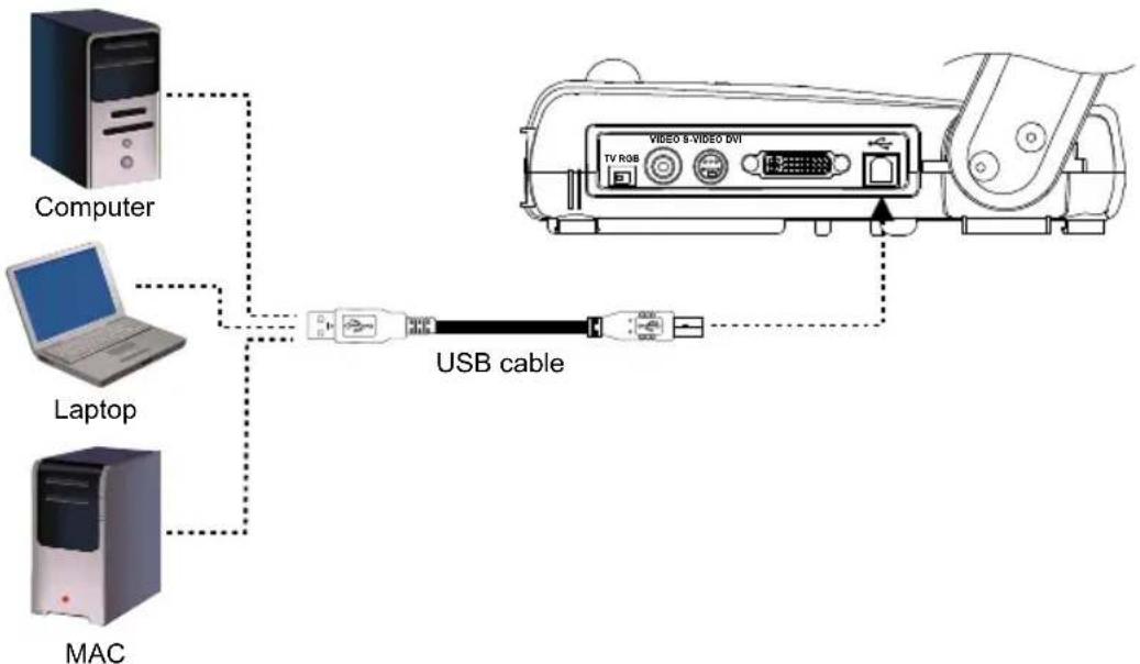
(10) USB Port Use AVerVision M30 as a USB Camera or Image Download allowing you to transfer the captured images to and from the AVerVision M30 built-in memory and PC.
Connecting the Power Adapter
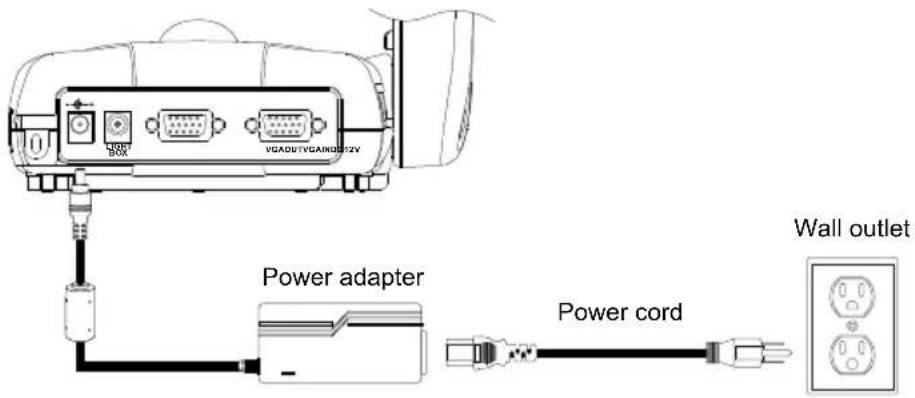
Connect the power adapter to a standard 100V\~240V AC power source.
Connecting a TV
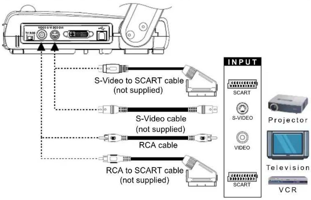
Locate the video, s-video or SCART RGB input port of the TV or Video equipment (i.e., VCR) to record your presentation on a videotape. If you are not sure, please refer to the user manual of the TV or Video equipment.

- Make sure the TV/RBG switch is set to TV.
- For better video quality, we strongly suggest using s-video connection.
Connecting a VGA, Mac Display Monitor or LCD/DLP Projector
Locate the RGB (VGA) input port of the display device. If you are not sure, please refer to the user manual of the device.

Make sure the TV/RBG switch is set to RGB.
flowchart
graph TD
    A["Device"] --> B["RGB (VGA) cable (not supplied)"]
    A --> C["LCD/DLP projector"]
    A --> D["CRT monitor"]
    A --> E["LCD monitor"]
    A --> F["Monitor Adapter (not supplied)"]
    A --> G["MAC monitor"]
Connecting a VGA Monitor or LCD/DLP Projector with DVI interface
Locate the DVI input port of the display device. If you are not sure, please refer to the user manual of the device.

Make sure the TV/RBG switch is set to RGB.
Connecting a Computer
Locate the RGB video output port of the computer or laptop to display your PC presentation on screen. AVerVision M30 supports active pass-thru connectivity, wherein the video signal from the VGA input port is continuously streamed to VGA output port and displayed on screen even when the AVerVision M30 is turned off.
flowchart
graph TD
    A["Computer"] -->|Computer extension cable (VGA cable)| B["Laptop"]
    B --> C["Monitor Adapter (not supplied)"]
    C --> D["MAC"]
    A -.->|Light BAC VGAOUT/VCARDEN 2V| A
Connecting a Computer via USB Connection
Locate the USB port of the computer or laptop. This enables you to use AVerVision M30 as a USB Camera or to transfer the captured images from the built-in memory to your computer. Also see “Transfer Image from AVerVision M30 to PC” and refer to the bundled software user guide in the CD.
flowchart
graph TD
    A["Computer"] -->|Dotted| B["USB cable"]
    C["Laptop"] -->|Dotted| B
    D["MAC"] -->|Dotted| B
    B --> E["VIDEO & VIDEO DVI"]
    style A fill:#f9f,stroke:#333
    style C fill:#f9f,stroke:#333
    style D fill:#f9f,stroke:#333
    style E fill:#ccf,stroke:#333
Installing the Optional Light Box
Connecting an optional light box enables you to view x-rays, transparencies and negative slides.
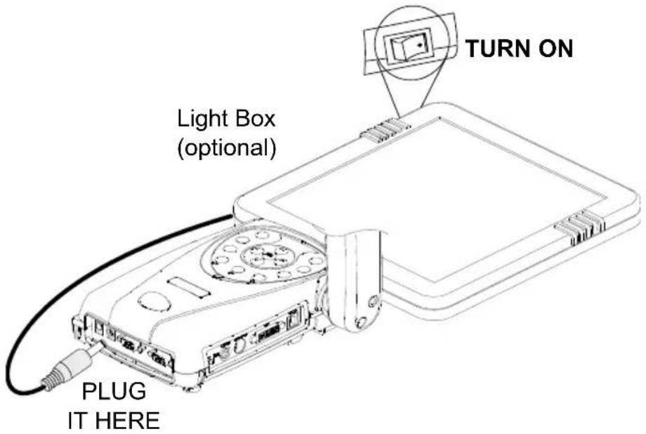
Connecting to a Microscope
Connecting the AVerVision M30 to a microscope enables you to examine microscopic objects on a big screen without straining your eyes.
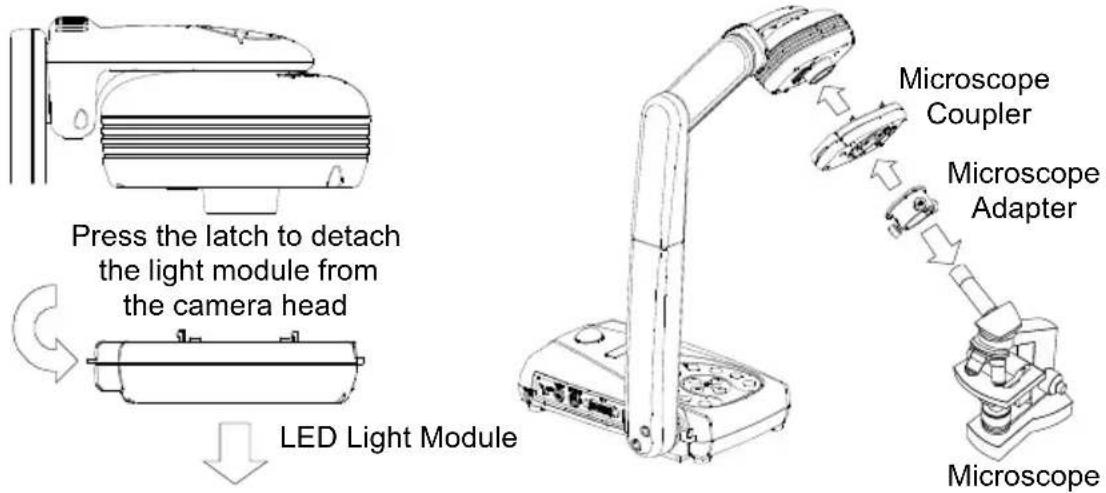
Setting Up AVerVision M30
This section provides useful tips on how to adjust the AVerVision M30 to meet your needs.
Camera Head
The camera head can be rotated 135 degrees from left to right. You can also manually adjust the focus from here to improve the quality of the pictures.
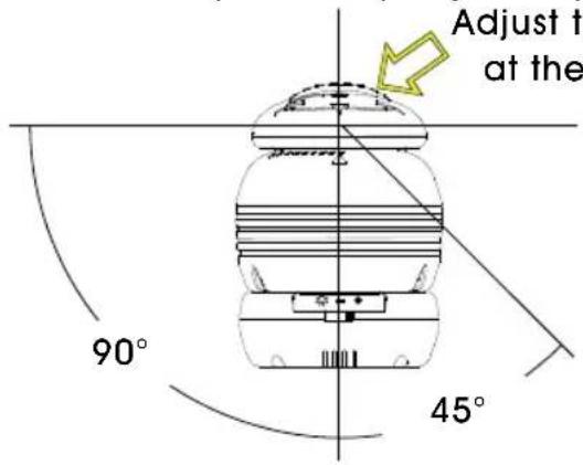
Adjust the angle here at the ridged side
Mechanical Arm
The mechanical arm design allows you to project an image to its full height for full A4 paper landscape viewing.
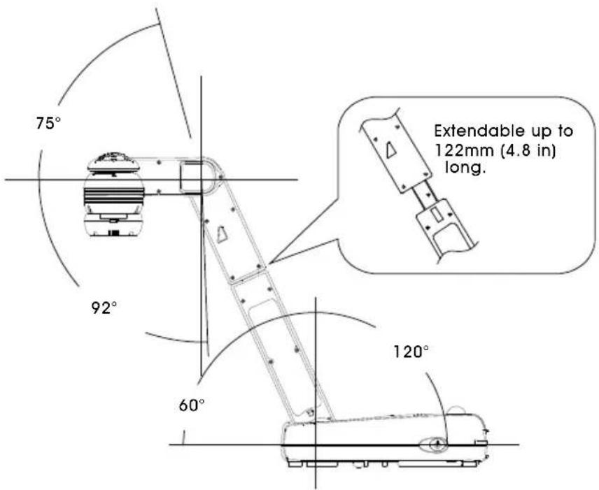
LED Light Module
The LED light module provides white light and it is best used when presenting in low lighting condition.
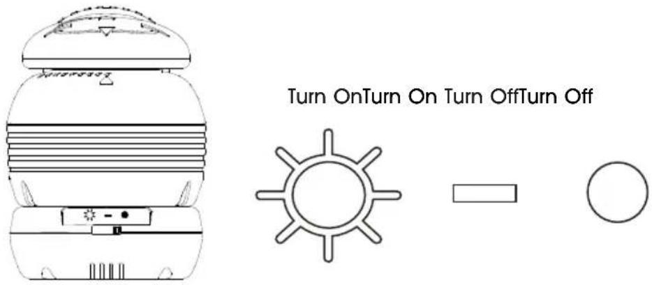
Anti-glare Sheet
The anti-glare sheet is a special coated film that helps eliminate any glare you may encounter when you are displaying very shiny object or glossy surfaces such as magazines, pictures, etc. Simply place the anti-glare sheet on top of the shiny document to reduce reflected light.
natural_image
Simple line drawing of a folded paper or document (no text or symbols)Using the Infrared Remote Control
The remote control requires two (2) "AAA" size batteries (supplied), make sure batteries are installed properly before use. You can access all the features of AVerVision M30 with the remote.
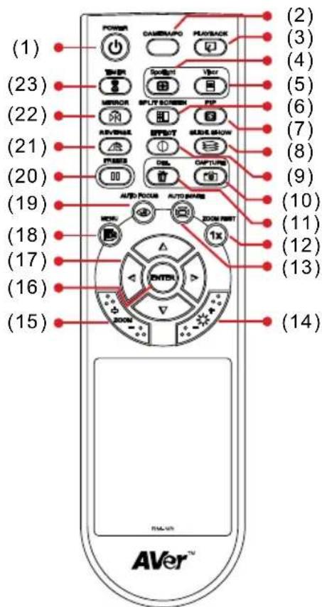
Name Function
(1) POWER Turn the unit on/standby.
(2) CAMERA / PC Switch between Camera and computer mode.
- Camera mode displays the video signal from the built-in camera.
- PC mode displays the video signal from the RGB INPUT port of AVERVISION M30.
(3) PLAYBACK View the captured picture from the memory in 16-thumbail images.
(4) SPOTLIGHT Overlay a box frame on the presentation screen, you can move it around and adjust the box size
(5) VISOR Cover part of the presentation screen and allow presenter to reveal the material as desire.
(6) SPLIT SCREEN Divide the screen into two. One side displays the live image from the built-in camera and the other side displays 8-thumbail size picture/video from the memory.
(7) PIP Show a thumbnail size captured picture from the memory at the corner of the screen in Camera mode.
Name Function
(8) SLIDE SHOW Start/Stop automatically showing the captured picture one-by-one.
(9) EFFECT Convert and display the image in BW, Negative or Color in Camera and Playback mode only.
(10) CAPTURE Capture still image in Camera mode. In continuous capture mode, press this button again to stop.
(11) DEL Delete the selected picture in Playback mode.
(12) ZOOM RESET Reset zoom level to 100%.
(13) AUTO IMAGE Automatically adjust and set the white balance and exposure setting.
(14) BRIGHTNESS Adjust the brightness. +/-
(15) ZOOM +/- Increase/decrease the image magnification in camera and picture playback mode.
(16) ENTER - Make a selection in Playback mode and OSD menu.
(17) ▲, ▼, ◀, & ▶ - Pan the image when image is above 10X zoom in live mode or in playback captured image mode.
- Move the selection in Playback mode and in OSD menu.
- Move the Spotlight frame and Visor screen cover.
(18) MENU Open and exit the OSD menu.
(19) AUTO FOCUS Adjust the focus automatically.
(20) FREEZE - Freeze live images.
(21) REVERSE Rotate the image by 90° in Camera mode and Playback mode.
(22) MIRROR Flip the image in Camera mode.
(23) TIMER Start/Pause timer countdown.
Touch Button Control Panel
The touch button control panel located on the top side of the AVerVision M30 provides quick access to commonly used functions.
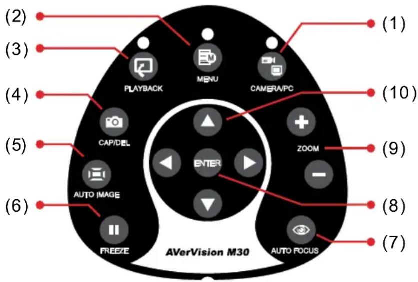
Function Description
| (1) CAMERA / PC | Switch between Camera and computer mode.- Camera mode displays the video signal from the built-in camera.- PC mode displays the video signal from the RGB INPUT port of AVERVISION M30. |
| (2) MENU | Open and exit the OSD menu. |
| (3) PLAYBACK | View the captured picture from the memory in 16-thumbnail images. |
| (4) CAPTURE | Capture still image in Camera mode. In continuous capture mode, press this button again to stop. |
| (5) AUTO IMAGE | Automatically adjust and set the white balance and exposure setting. |
| (6) FREEZE | - Freeze live images. |
| (7) AUTO FOCUS | Adjust the focus automatically. |
| (8) ENTER | - Make a selection in Playback mode and OSD menu. |
| (9) ZOOM +/- | Increase/decrease the image magnification in camera and picture playback mode. |
| (10) ▲,▼,◀, & ▶ | - Pan the image when image is above 10X zoom in live mode or in playback captured image mode.- Move the selection in Playback mode and in OSD menu.- Move the Spotlight frame and Visor screen cover. |
LED Panel
The LED on the front panel of AVerVision M30 indicates the status of the unit.
Color Description
Green The unit is operated with VGA output.
Orange The unit is operated with TV output
Red The unit is in standby mode.
OSD Navigation Tree
There are 2 tab menus in AVERVISION M30: IMAGE and SETTING tabs. For TV output, the RESOLUTION will be disabled in SETTING menu list.
IMAGE MENU
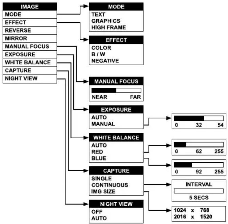
flowchart
graph TD
    A["IMAGE"] --> B["MODE"]
    B --> C["EFFECT"]
    C --> D["MANUAL FOCUS"]
    D --> E["EXPOSURE"]
    E --> F["WHITE BALANCE"]
    F --> G["CAPTURE"]
    G --> H["NIGHT VIEW"]

    B --> I["TEXT"]
    B --> J["GRAPHICS"]
    B --> K["HIGH FRAME"]

    C --> L["COLOR"]
    C --> M["B / W"]
    C --> N["NEGATIVE"]

    D --> O["NEAR FAR"]

    E --> P["AUTO MANUAL"]

    F --> Q["AUTO RED BLUE"]

    G --> R["SINGLE CONTINUOUS IMG SIZE"]

    H --> S["OFF AUTO"]

    P --> T["0 32 54"]
    Q --> U["0 62 255"]
    R --> V["0 92 255"]

    T --> W["INTERVAL"]
    U --> W
    V --> W
    W --> X["1024 x 768\n2016 x 1520"]
SETTING MENU
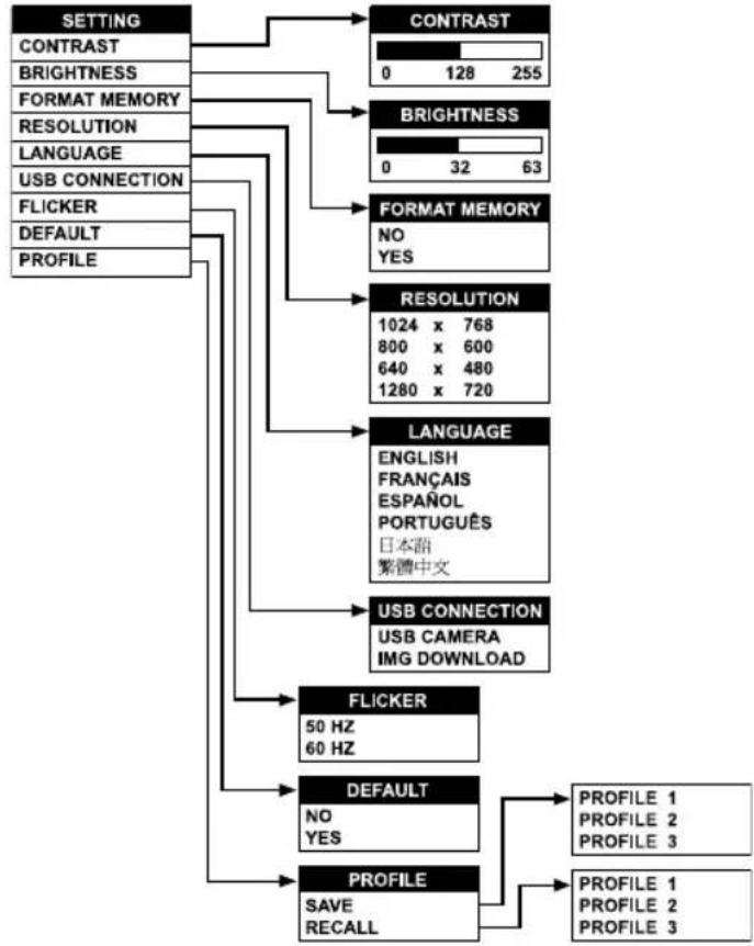
flowchart
graph TD
    A["SETTING"] --> B["CONTRAST"]
    A --> C["BRIGHTNESS"]
    A --> D["RESOLUTION"]
    A --> E["LANGUAGE"]
    A --> F["USB CONNECTION"]
    A --> G["FLICKER"]
    A --> H["DEFAULT"]
    A --> I["PROFILE"]
    B --> J["0 128 255"]
    C --> K["0 32 63"]
    D --> L["NO YES"]
    E --> M["1024 x 768\n800 x 600\n640 x 480\n1280 x 720"]
    F --> N["LANGUAGE ENGLISH FRANÇAIS ESPAÑOL PORTUGUÊS 日本語繁體中文"]
    G --> O["USB CONNECTION USB CAMERA IMG DOWNLOAD"]
    H --> P["FLICKER\n50 Hz\n60 Hz"]
    I --> Q["DEFAULT\nNO YES"]
    I --> R["PROFILE SAVE RECALL"]
    R --> S["PROFILE 1\nPROFILE 2\nPROFILE 3"]
Menu Functions
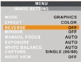
The MENU functions of AVERVISION M30 enhance fine-tuning your screen display, set the timer, select OSD language and more. Press the MENU button to call up and exit from the main menu or sub-menu display. Use ◀or▶ to select between IMAGE and SETTING menu list. Then use ▲or▼ to select the items in the menu list. To make a selection or change setting, press ENTER. To adjust the setting, press ◀or▶.
OSD Menu Description
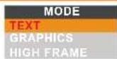
IMAGE > MODE
Use ▲ or ▼ to select between Text, Graphics and High Frame enhancement mode and then ENTER to make a selection.
Text - corrects the intensity of the adjacent pixel making it more uniform producing sharper and clearer images.
Graphics - adjusts the gradient of the adjacent pixel making it appears to have a smooth image.
High Frame - increases the frame rate capture and can visually tracks the motion and react quickly. Sufficient lighting is required when using this mode.
OSD Menu Description
 | IMAGE > EFFECTUse ▲or▼ to select and display the image in Camera mode into positive (true color), monochrome (black and white) or negative. Then press ENTER to make a selection. |
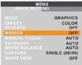 | IMAGE > MIRRORPress ENTER to turn off/on REVERSE. Reverse rotates the image by 180° in Camera mode. |
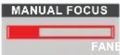 | IMAGE > MANUAL FOCUSUse ◀or► to manually adjust the focus and then press ENTER to save the setting and exit. |
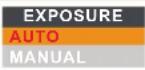 | IMAGE > EXPOSUREUse ▲or▼ to select between AUTO or MANUAL. Then press ENTER to make a selection.AUTO to automatically adjust the camera exposure to determine how much light is required.MANUAL to manually adjust the exposure level. Press ENTER and the bar will turn red, use ◀ & ► to increase and decrease the exposure level, and then press ENTER to save the setting and the bar will turn white. Press MENU to close the menu.[IMAGE] |
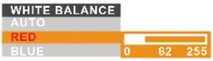
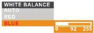
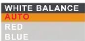 | IMAGE > WHITE BALANCEUse ▲or▼ to select between auto or manually adjust the red and blue color to suit the lighting condition or color temperature. Then press ENTER to make a selection.To manually adjust the red or blue color level, select RED or BLUE, press ENTER and the bar will turn red, use ◀ & ► to increase and decrease the level, and then press ENTER to save the setting and the bar will turn white. |
  |
OSD Menu Description
| CAPTURESINGLECONTINUOUSIMG SIZE | IMAGE > CAPTUREUse ▲ or▼ to select SINGLE or CONTINUOUS capture mode and IMG SIZE to select the capture pixel size of the image.Select SINGLE to save one still image only and CONTINUOUS to save successive still images until the built-in memory is full or when the CAP/DEL button is being press again to stop.In Continuous mode, press ENTER the bar will turn red, use ◀ & ▶ to increase and decrease the capture time interval between frames and then press ENTER to save the setting and the bar will turn white. The time interval can be set from 5 to 600 sec.CAPTURESINGLECONTINUOUSINTERVALIMG SIZE5 SECSIn IMG SIZE, press ENTER, use ▲ and▼ to make a selection, and press ENTER to save the setting.CAPTURESINGLECONTINUOUSIMG SIZE1024 x 7682016 x 1520 |
| NIGHT VIEWOFFAUTO | IMAGE > NIGHT VIEWUse ▲ or▼ to turn Night View OFF or AUTO.If you are presenting in a low-light condition, Night View enables the image of the object to appear as though under normal lighting conditions. AVERVISION M30 can automatically adjust the exposure to compensate for the adverse condition, but the captured image will appear to be in slow motion. |
| CONTRAST0128255 | SETTING > CONTRASTUse ▶ or◀ to emphasize or reduce the difference between light and dark conditions then press ENTER. The contrast level can be adjustable up to 255. |
| BRIGHTNESS03263 | SETTING > BRIGHTNESSUse ▶ or◀ to increase or decrease the brightness level and improve the visibility of the image then press ENTER. The brightness level can be set up to 63. |
| FORMAT MEMORYNOYES | SETTING > FORMAT MEMORYUse ▲ or▼ to select NO to exit or YES to format and delete all the images saved in the built-in memory then press ENTER.Please wait till the message “FORMAT” at the lower right corner of the screen disappear to finish the process. |
| RESOLUTION1024 x 768800 x 600640 x 4801280 x 720 | SETTING > RESOLUTIONUse ▲ or▼ to choose from different supported display resolutions then press ENTER to make the selection.This selection will be disabled in TV output mode. |
OSD Menu Description
| LANGUAGEENGLISHFRANÇAISESPAÑOLPORTUGUÉS日本語繁體中文 | SETTING > LANGUAGEUse ▲or▼ to select from different supported languages then press ENTER to make the selection. |
| USB CONNECTIONUSB CAMERAIMG DOWNLOAD | SETTING > USB CONNECTIONUse ▲or▼ buttons to select the function of USB between USB CAMERA and IMG DOWNLOAD. Then press ENTER.USB Camera - can be used as a computer webcam or with our bundled software to record video and capture still image.Img Download - transfer the captured images from the built-in memory to computer hard disk. |
| FLICKER50 HZ60 HZ | SETTING > FLICKERUse ▲or▼ to select between 50Hz or 60Hz. Some display devices cannot handle high refresh rates. The image will flicker a couple of times as the output is switched to another refresh rate. |
| DEFAULTNOYES | SETTING > DEFAULTUse ▲or▼ to select YES to restore to original factory default setting or NO to exit then press ENTER to make the selection. |
| MENUIMAGE SETTINGCONTRAST 92BRIGHTNESS 32FORMAT MEMORY NORESOLUTION 1024 X 768LANGUAGE ENGLISHUSB CONNECTION USB CAMERAFLICKER 60 HZDEFAULT NOPROFILE OFF | SETTING > PROFILEPress ENTER and use ▲or▼ to select between SAVE or RECALL. Then press ENTER again to make a selection.SAVE - store the current setting in the selected profile number. Only effect, mode, brightness and contrast settings can be saved.RECALL - restore the setting back to the selected profile number.In the SAVE/RECALL selection, use ▲or▼ to select saving/restoring the setting from the three profile number then press ENTER. |
| PROFILESAVE PROFILE 1RECALL PROFILE 2PROFILE 3PROFILE 3 |
Transferring the Captured Image to PC
This enables you to transfer the captured image from the built-in memory to PC.

The instruction below MUST be read and followed BEFORE connecting the USB cable.
- MUST set the USB CONNECTION as IMG DOWNLOAD before connecting the USB cable.
To set the USB CONNECTION as IMG DOWNLOAD, press MENU > select USB CONNECTION in SETTING menu list and press ENTER, select IMG DOWNLOAD and press ENTER.
- When "IMG DOWNLOAD" appears at the lower right corner of the presentation screen, you may now connect the USB cable.
- Upon connecting the USB cable, the system automatically detects the new removable disk. You may now transfer the captured image(s) from the AVERVISION M30 built-in memory to PC hard disk.
RS-232C Diagram Connection
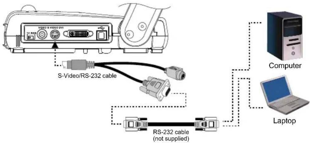
AVerVision M30 can be controlled using a PC through RS-232 connection.
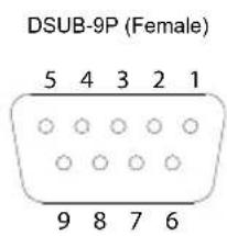
RS-232C Cable Spec
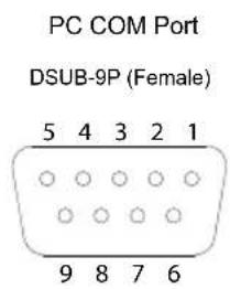
Make sure the RS-232 cable matches the cable spec design.
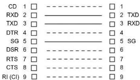
AVerVision RS-232 Port
RS-232C Transmission Spec
■ Star bit : 1 bit
- Data bit : 8 bit
- Stop bit : 1 bit
■ Parity bit : None
- X parameter : None
■ Baud rate(Communication speed) : 9600bps
RS-232C Communication Format
Start Code(1 Byte) : 0xFF
RS-232C Command Table
| Start Code | Type Code | Data Length | Data Code | Checksum | |
| KEY_POWER | FF | 70 | 1 | 0 | 71 |
| KEY_TIMER | FF | 70 | 1 | 1 | 70 |
| KEY_AVBOX | FF | 70 | 1 | 2 | 73 |
| KEY_AVVISOR | FF | 70 | 1 | 3 | 72 |
| KEY_MIRROR | FF | 70 | 1 | 4 | 75 |
| KEY_SPLT SCREEN | FF | 70 | 1 | 5 | 74 |
| KEY_PIP | FF | 70 | 1 | 6 | 77 |
| KEY_REVERSE | FF | 70 | 1 | 7 | 76 |
| KEY_EFFECT | FF | 70 | 1 | 8 | 79 |
| KEY_SLIDESHOW | FF | 70 | 1 | 9 | 78 |
| KEY_DEL | FF | 70 | 1 | A | 7B |
| KEY_PLAYBACK | FF | 70 | 1 | B | 7A |
| KEY_FREEZE | FF | 70 | 1 | C | 7D |
| KEY_CAPTURE | FF | 70 | 1 | D | 7C |
| KEY_MENU | FF | 70 | 1 | E | |
| KEY_AUTOFOCUS | FF | 70 | 1 | F | |
| KEY_AUTOIMAGE | FF | 70 | 1 | 10 | |
| KEY_ZOOM_1X | FF | 70 | 1 | 11 | 60 |
| KEY_UP | FF | 70 | 1 | 12 | 63 |
| KEY_LEFT | FF | 70 | 1 | 13 | 62 |
| KEY_ENTER | FF | 70 | 1 | 14 | 65 |
| KEY_RIGHT | FF | 70 | 1 | 15 | 64 |
| KEY_DOWN | FF | 70 | 1 | 16 | 67 |
| KEY_ZOOM_IN | FF | 70 | 1 | 17 | 66 |
| KEY_BRT_UP | FF | 70 | 1 | 18 | 69 |
| KEY_DEL | FF | 70 | 1 | 45 | 34 |
| KEY_CAM/PC | FF | 70 | 1 | 4A | 3B |
| KEY_ZOOM_OUT | FF | 70 | 1 | 4B | |
| KEY_BRT_DOWN | FF | 70 | 1 | 4C | 3D |
Troubleshooting
This section provides many useful tips on how to solve common problems while using the AVERVISION M30.
There is no picture on the presentation screen.
- Check all the connectors again as shown in this manual.
- Check the on/off switch of the display output device.
- Verify the setting of the display output device.
- If you are presenting from a notebook or computer through the display output device, check the cable connection from computer RGB (VGA) output to RGB input of AVERVISION M30 and make sure AVERVISION M30 is in PC Mode.
I have set up the AVERVISION M30 and checked all the connections as specified in the manual but I cannot get a picture on the preferred presentation screen.
- Once the power is connected, the LED light turns RED in standby mode. Simply switch the AVerVision M30 "ON" by pressing the on/off switch until the LED light is blinking and turns GREEN.
- The default camera display resolution setting is on 1024x768. If your output device does not support this resolution; no image can be projected. Simply press the MENU and RIGHT or LEFT button to the increase or decrease the resolution setting.
- If your display output device is TV or any analog device, make sure the TV/RGB display switch is set to TV.
The picture on the presentation screen is distorted or the image is blurry.
- Reset all changed settings, if any, to the original manufacturer default setting (Refer to the Menu Functions for more details and steps).
- Use the Brightness and Contrast menu functions to reduce the distortion if applicable.
- If you discover that the image is blurry or out of focus, press the Auto Focus button on the control panel or remote control.
There is no computer signal on presentation screen.
- Check all the cable connections among the display device, AVERVISION M30 and your PC.
- Connect your PC to the AVERVISION M30 first before you power on your computer.
- For notebook, repeatedly press FN+F5 to toggles between display modes and display the computer image on the presentation screen. For different command, please refer to your laptop manual.
The presentation screen does not show the exact desktop image on my PC or Notebook after I toggle from Camera to PC mode.
- Return to your PC or Notebook, place the mouse on the desktop and right click, choose "Properties", choose "Setting" tab, click on "2" monitor and check the box "Extend my Windows desktop onto this monitor".
- Then go back one more time to your PC or Notebook and place the mouse on the desktop and right click again.
- This time choose "Graphics Options", then "Output To", then "Intel® Dual Display Clone", and then choose "Monitor + Notebook".
- After you follow these steps, you should be able to see the same desktop image on your PC or Notebook as well as on the presentation screen.
How do I transfer the images from AVERVISION M30 to a computer? Is it normal that AVERVISION M30 will reset to camera mode after I download images and disconnect the USB cable?
Choose "IMG DOWNLOAD" in SETTING tab, USB CONNECTION menu, and then connect the USB cable to transfer the captured images from the AVERVISION M30 to the computer. When finished, unplug the USB cable. The AVERVISION M30 will automatically reset and switch to camera mode.
Limited Warranty
For a period of time beginning on the date of purchase of the applicable product and extending as set forth in the “Warranty Period of AVer Product Purchased” section of the warranty card, AVer Information Inc. (“AVer”) warrants that the applicable product (“Product”) substantially conforms to AVer’s documentation for the product and that its manufacture and components are free of defects in material and workmanship under normal use. “You” as used in this agreement means you individually or the business entity on whose behalf you use or install the product, as applicable. This limited warranty extends only to You as the original purchaser. Except for the foregoing, the Product is provided “AS IS.” In no event does AVer warrant that You will be able to operate the Product without problems or interruptions, or that the Product is suitable for your purposes. Your exclusive remedy and the entire liability of AVer under this paragraph shall be, at AVer’s option, the repair or replacement of the Product with the same or a comparable product. This warranty does not apply to (a) any Product on which the serial number has been defaced, modified, or removed, or (b) cartons, cases, batteries, cabinets, tapes, or accessories used with this product. This warranty does not apply to any Product that has suffered damage, deterioration or malfunction due to (a) accident, abuse, misuse, neglect, fire, water, lightning, or other acts of nature, commercial or industrial use, unauthorized product modification or failure to follow instructions included with the Product, (b) misapplication of service by someone other than the manufacturer’s representative, (c) any shipment damages (such claims must be made with the carrier), or (d) any other causes that do not relate to a Product defect. The Warranty Period of any repaired or replaced Product shall be the longer of (a) the original Warranty Period or (b) thirty (30) days from the date of delivery of the repaired or replaced product.
Limitations of Warranty
AVer makes no warranties to any third party. You are responsible for all claims, damages, settlements, expenses, and attorneys' fees with respect to claims made against You as a result of Your use or misuse of the Product. This warranty applies only if the Product is installed, operated, maintained, and used in accordance with AVer specifications. Specifically, the warranties do not extend to any failure caused by (i) accident, unusual physical, electrical, or electromagnetic stress, neglect or misuse, (ii) fluctuations in electrical power beyond AVer specifications, (iii) use of the Product with any accessories or options not furnished by AVer or its authorized agents, or (iv) installation, alteration, or repair of the Product by anyone other than AVer or its authorized agents.
Disclaimer of Warranty
EXCEPT AS EXPRESSLY PROVIDED OTHERWISE HEREIN AND TO THE MAXIMUM EXTENT PERMITTED BY APPLICABLE LAW, AVER DISCLAIMS ALL OTHER WARRANTIES WITH RESPECT TO THE PRODUCT, WHETHER EXPRESS, IMPLIED, STATUTORY OR OTHERWISE, INCLUDING WITHOUT LIMITATION, SATISFACTORY QUALITY, COURSE OF DEALING, TRADE USAGE OR PRACTICE OR THE IMPLIED WARRANTIES OF MERCHANTABILITY, FITNESS FOR A PARTICULAR PURPOSE OR NONINFRINGEMENT OF THIRD PARTY RIGHTS.
Limitation of Liability
IN NO EVENT SHALL AVER BE LIABLE FOR INDIRECT, INCIDENTAL, SPECIAL, EXEMPLARY, PUNITIVE, OR CONSEQUENTIAL DAMAGES OF ANY NATURE INCLUDING, BUT NOT LIMITED TO, LOSS OF PROFITS, DATA, REVENUE, PRODUCTION, OR USE, BUSINESS INTERRUPTION, OR PROCUREMENT OF SUBSTITUTE GOODS OR SERVICES ARISING OUT OF OR IN CONNECTION WITH THIS LIMITED WARRANTY, OR THE USE OR PERFORMANCE OF ANY PRODUCT, WHETHER BASED ON CONTRACT OR TORT, INCLUDING NEGLIGENCE, OR ANY OTHER LEGAL THEORY, EVEN IF AVER HAS ADVISED OF THE POSSIBILITY OF SUCH DAMAGES. AVER'S TOTAL, AGGREGATE LIABILITY FOR DAMAGES OF ANY NATURE, REGARDLESS OF FORM OF ACTION, SHALL IN NO EVENT EXCEED THE AMOUNT PAID BY YOU TO AVER FOR THE SPECIFIC PRODUCT UPON WHICH LIABILITY IS BASED.
Governing Law and Your Rights
This warranty gives you specific legal rights; You may also have other rights granted under state law. These rights vary from state to state.

For warranty period, please refer to the warranty card.
- Federal Communications Commission Statement(Class A)
- Class A ITE:
- CE Class A (EMC)
- DISCLAIMER
- TRADEMARKS
- COPYRIGHT
- Remote Control Battery Safety Information
- Table of Contents
- Introduction Package Contents
- Optional Accessories
- AVerVision M30 Parts
- Technical Specifications
- Making the Connections
- Connecting the Power Adapter
- Connecting a TV
- Connecting a VGA, Mac Display Monitor or LCD/DLP Projector
- Connecting a VGA Monitor or LCD/DLP Projector with DVI interface
- Connecting a Computer
- Connecting a Computer via USB Connection
- Installing the Optional Light Box
- Connecting to a Microscope
- Setting Up AVerVision M30
- Camera Head
- Mechanical Arm
- LED Light Module
- Anti-glare Sheet
- Using the Infrared Remote Control
- Name Function
- Touch Button Control Panel
- LED Panel
- Color Description
- OSD Navigation Tree
- Menu Functions
- OSD Menu Description
- IMAGE > MODE
- Transferring the Captured Image to PC
- RS-232C Diagram Connection
- RS-232C Cable Spec
- RS-232C Transmission Spec
- RS-232C Communication Format
- RS-232C Command Table
- Troubleshooting
- There is no picture on the presentation screen.
- I have set up the AVERVISION M30 and checked all the connections as specified in the manual but I cannot get a picture on the preferred presentation screen.
- There is no computer signal on presentation screen.
- The presentation screen does not show the exact desktop image on my PC or Notebook after I toggle from Camera to PC mode.
- How do I transfer the images from AVERVISION M30 to a computer? Is it normal that AVERVISION M30 will reset to camera mode after I download images and disconnect the USB cable?
- Limited Warranty
- Limitations of Warranty
- Disclaimer of Warranty
- Limitation of Liability
- Governing Law and Your Rights
Brand : AVer
Model : AVerVision 310AF
Category : Visualiseur