Vision F17HD - Visualiser AVer - Free user manual and instructions
Find the device manual for free Vision F17HD AVer in PDF.


| Product Type | Document Camera (Visualiser) |
| Brand | AVer |
| Model | Vision F17HD |
| Resolution | Full HD 1080p (1920x1080) |
| Image Sensor | 5 Megapixel CMOS |
| Optical Zoom | 12x |
| Digital Zoom | 8x |
| Frame Rate | 30 fps |
| Output Interfaces | HDMI, VGA, USB 2.0 |
| Input Interfaces | HDMI, VGA |
| Built-in Lighting | LED lights with adjustable brightness |
| Image Capture | Still image capture to SD card or USB |
| Video Recording | Record to SD card or USB (MP4 format) |
| Annotation Software | Compatible with AVerPlus+ software |
| Dimensions (W x D x H) | Approx. 18.1 x 39.8 x 34.5 cm |
| Weight | Approx. 2.5 kg |
| Power Supply | 12V DC, 2A |
| Power Consumption | Approx. 15W |
| Maintenance | Clean the lens with a soft, dry cloth. Avoid liquids. |
| Safety | Keep away from water and high humidity. Use only the provided power adapter. |
| Spare Parts & Repairability | Contact AVer support for spare parts. Repairs should be performed by authorized service centers. |
| General Information | Designed for education and business presentations. Supports Windows, Mac, and Chrome OS. |
Frequently Asked Questions - Vision F17HD AVer
User questions about Vision F17HD AVer
0 question about this device. Answer the ones you know or ask your own.
Ask a new question about this device
Download the instructions for your Visualiser in PDF format for free! Find your manual Vision F17HD - AVer and take your electronic device back in hand. On this page are published all the documents necessary for the use of your device. Vision F17HD by AVer.
USER MANUAL Vision F17HD AVer
natural_image
Line drawing of a handheld electronic device with a curved arm and internal components (no text or symbols)AVerVision F17HD
User Manual
Federal Communications Commission Statement(Class A)

NOTE- This equipment has been tested and found to comply with the limits for a Class A digital device, pursuant to Part 15 of the FCC Rules. These limits are designed to provide reasonable protection against harmful interference in a residential installation. This equipment generates uses and can radiate radio frequency energy and, if not installed and used in accordance with the instructions, may cause harmful interference to radio communications. However, there is no guarantee that interference will not occur in a particular installation. If this equipment does cause harmful interference to radio or television reception, which can be determined by tuning the equipment off and on, the user is encouraged to try to correct the interference by one or more of the following measures:
■ Reorient or relocate the receiving antenna.
■ Increase the separation between the equipment and receiver.
- Connect the equipment into an outlet on a circuit different from that to which the receiver is connected.
- Consult the dealer or an experienced radio/television technician for help.
Class A ITE:
Class A ITE is a category of all other ITE which satisfies the class A ITE limits but not the class B ITE limits. Such equipment should not be restricted in its sale but the following warning shall be included in the instructions for use:
Warning - This is a class A product. In a domestic environment this product may cause radio interference in which case the user may be required to take adequate measures.
CE Class A (EMC)

This product is herewith confirmed to comply with the requirements set out in the Council Directives on the Approximation of the laws of the Member States relating to Electromagnetic Compatibility Directive 2014/30/EU.
Warning - This is a Class A product. In a domestic environment this product may
cause radio interference in which case the user may be required to take adequate measures to correct this interference.
DISCLAIMER
No warranty or representation, either expressed or implied, is made with respect to the contents of this documentation, its quality, performance, merchantability, or fitness for a particular purpose. Information presented in this documentation has been carefully checked for reliability; however, no responsibility is assumed for inaccuracies. The information contained in this documentation is subject to change without notice.
In no event will AVer be liable for direct, indirect, special, incidental, or consequential damages arising out of the use or inability to use this product or documentation, even if advised of the possibility of such damages.
TRADEMARKS
“AVer” is a trademark owned by AVer Information Inc. Other trademarks used herein for description purpose only belong to each of their companies.
COPYRIGHT
© 2015 AVer Information Inc. All rights reserved.
All rights of this object belong to AVer Information Inc. Reproduced or transmitted in any form or by any means without the prior written permission of AVer Information Inc. is prohibited. All information or specifications are subject to change without prior notice.
NOTICE
SPECIFICATIONS ARE SUBJECT TO CHANGE WITHOUT PRIOR NOTICE. THE INFORMATION CONTAINED HEREIN IS TO BE CONSIDERED FOR REFERENCE ONLY.
WARNING
TO REDUCE RISK OF FIRE OR ELECTRIC SHOCK, DO NOT EXPOSE THIS APPLIANCE TO RAIN OR MOISTURE. WARRANTY VOID FOR ANY UNAUTHORIZED PRODUCT MODIFICATION.
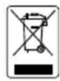
THE MARK OF CROSSED-OUT WHEELED BIN INDICATES THAT THIS PRODUCT MUST NOT BE DISPOSED OF WITH YOUR OTHER HOUSEHOLD WASTE. INSTEAD, YOU NEED TO DISPOSE OF THE WASTE EQUIPMENT BY HANDING IT OVER TO A DESIGNATED COLLECTION POINT FOR THE RECYCLING OF WASTE ELECTRICAL AND ELECTRONIC EQUIPMENT. FOR MORE INFORMATION ABOUT WHERE TO DROP OFF YOUR WASTE EQUIPMENT FOR RECYCLING, PLEASE CONTACT YOUR HOUSEHOLD WASTE DISPOSAL SERVICE OR THE SHOP WHERE YOU PURCHASED THE PRODUCT.
Remote Control Battery Safety Information
- Store batteries in any cool & dry place.
- Do not dispose used batteries in domestic waste. Dispose batteries at special collection points or return to stores if applies.
- Remove the batteries if they are not in use for long period of time. Battery leakage and corrosion can damage the remote control, dispose batteries safely.
- Do not mix and use old and new batteries.
- Do not mix and use different types of batteries: alkaline, standard (carbon-zinc) or rechargeable (nickel-cadmium).
- Do not dispose batteries in a fire.
- Do not attempt to short circuit the battery terminals.
Table of Contents
Package Contents....1
Optional Accessories .... 1
Get Familiar with the AVerVision F17HD 2
Right Panel....3
Rear Panel....3
Left Panel 4
Control Panel....4
Remote Control 6
Making the Connections 9
Set the TV-RGB Switch Setting 9
Connect to a Monitor or LCD/DLP Projector....9
Connect to a Monitor or LCD/DLP Projector with HDMI Output interface......10
Connect to a TV....10
Connecting the Power 11
Connect to a Computer 11
Connect to a Computer via USB....12
Connect to a Computer with HDMI Input interface 12
Connect to a Microscope....13
Setting Up AVerVision F17HD 14
Storing and Handling 14
Shooting Area....15
Overhead Light....16
Infrared Sensor....16
Mounting the F17HD on a Flat Surface 17
Anti-glare Sheet....17
External Memory Storage....18
Insert an SD Card....18
OSD MENU....19
Navigate the Menu and Submenu 20
Image 20
Brightness....20
Contrast 20
Mode....21
Effect....21
Mirror 21
Advanced....21
Auto Image 21
Exposure....22
White Balance....22
Focus 22
Presentation 23
Spotlight....23
Visor....23
PIP 24
Split Screen....24
Timer....24
Setting 25
Capture 25
Resolution....25
Quality....25
Type....25
Interval....25
Storage 26
Format 26
USB to PC 26
Flicker 26
System 27
Language....27
Output Display 27
Backup....27
Save Setting 27
Recall Setting....27
Information....28
Default 28
Playback....29
Slide Show....29
Interval....29
Slide Show Effect....29
Current Storage 29
Delete All....29
Transfer Captured Images to a computer....30
Technical Specifications 31
Image....31
Optics 31
Power 31
Lighting 31
Input/Output 31
Dimension....31
External Storage 31
Troubleshooting....32
Limited Warranty....33
Package Contents
Make sure the following items are included in the package.
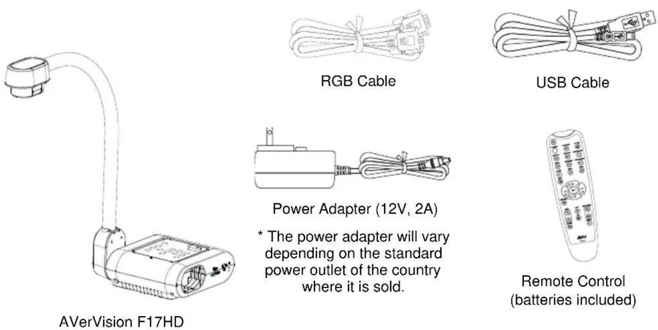
* The power adapter will vary depending on the standard power outlet of the country where it is sold.
Optional Accessories
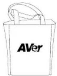
Carrying Bag
natural_image
Simple line drawing of a folded paper or document (no text or symbols)Anti-glare Sheet
natural_image
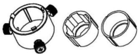
Technical line drawings of three different mechanical components (no text or symbols)Microscope Adapter
(28mm & 34mm Rubber Coupler)
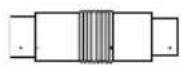
CVBS adapter
natural_image
Two CD or DVD discs with reflective surfaces, no visible text or symbolsSoftware & Manual CD*
* For User Manual and Software, please visit the link below http://averusa.com/classroom-technology/support/.
Get Familiar with the AVerVision F17HD
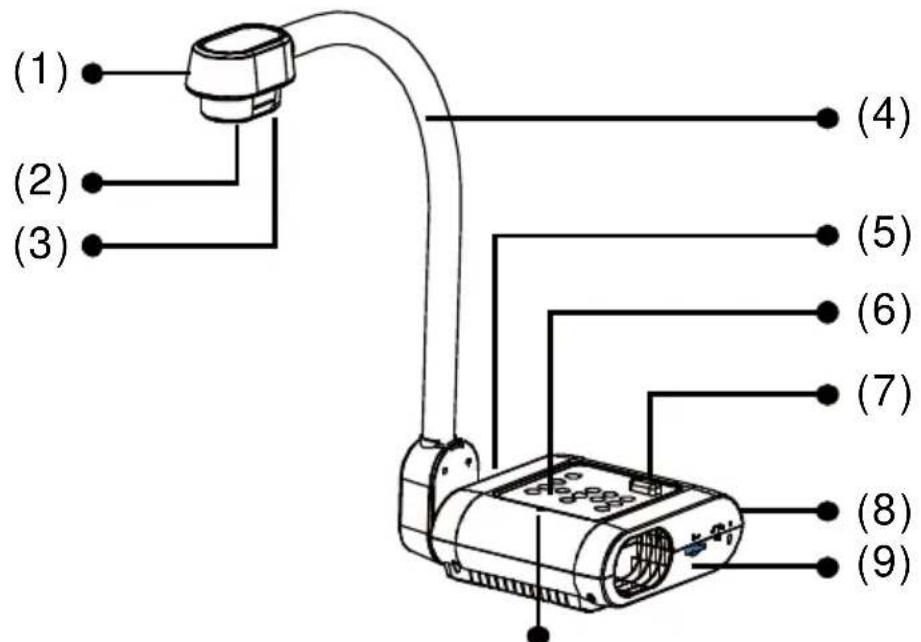
| Name | Function |
| (1) Camera head | Contain the camera sensor. |
| (2) Camera lens | Focus the image in the camera. |
| (3) LED light | Provide light to enhance the lighting condition. |
| (4) Flexible arm | Provide adjustable viewing coverage. |
| (5) Left panel | Connections for HDMI output/input external display device. |
| (6) Control panel | Easy access to various functions. |
| (7) IR sensor | Receive remote control commands. |
| (8) Rear panel | Connections for power, computer, RGB/RCA external display device, and USB to PC. |
| (9) Right panel | Connections for the camera head holder, SD card, TV-RGB display output switch, and antitheft Kensington security lock compatible slot. |
| (10) Built-in MIC | For UAC. |
Right Panel
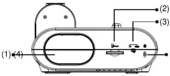
(fig. 1.2)
| Name | Function |
| (1) Camera Holder | Hold the camera head for storage. |
| (2) SD card slot | Insert the SD card with the label facing up. |
| (3) TV-RGB switch | TV switches to output display video from RCA (via CVBS adapter) to RGB OUT and HDMI OUT. |
| (4) Antitheft Slot | Attach a Kensington compatible security lock or antitheft device. |
Rear Panel
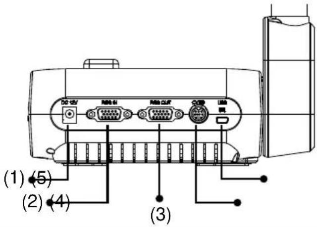
(fig. 1.3)
| Name | Function |
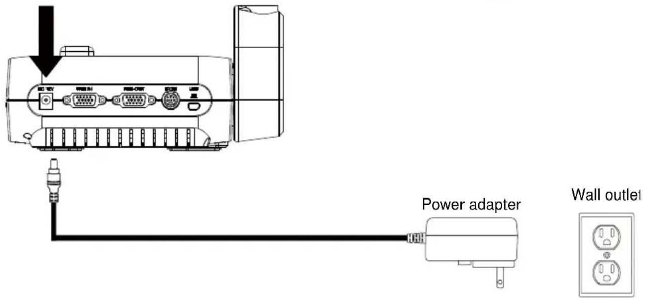
| (1) DC12V | Connect the power adapter into this port. |
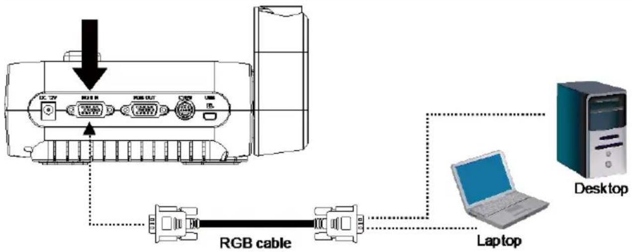
| (2) RGB INPUT port | Input the signal from a computer or other sources and pass it through to the RGB OUT port only. Connect this port to the RGB/VGA output port of a computer. |
| (3) RGB OUTPUT port | Connect the AVerVision F17HD to any display device with RGB cable. |
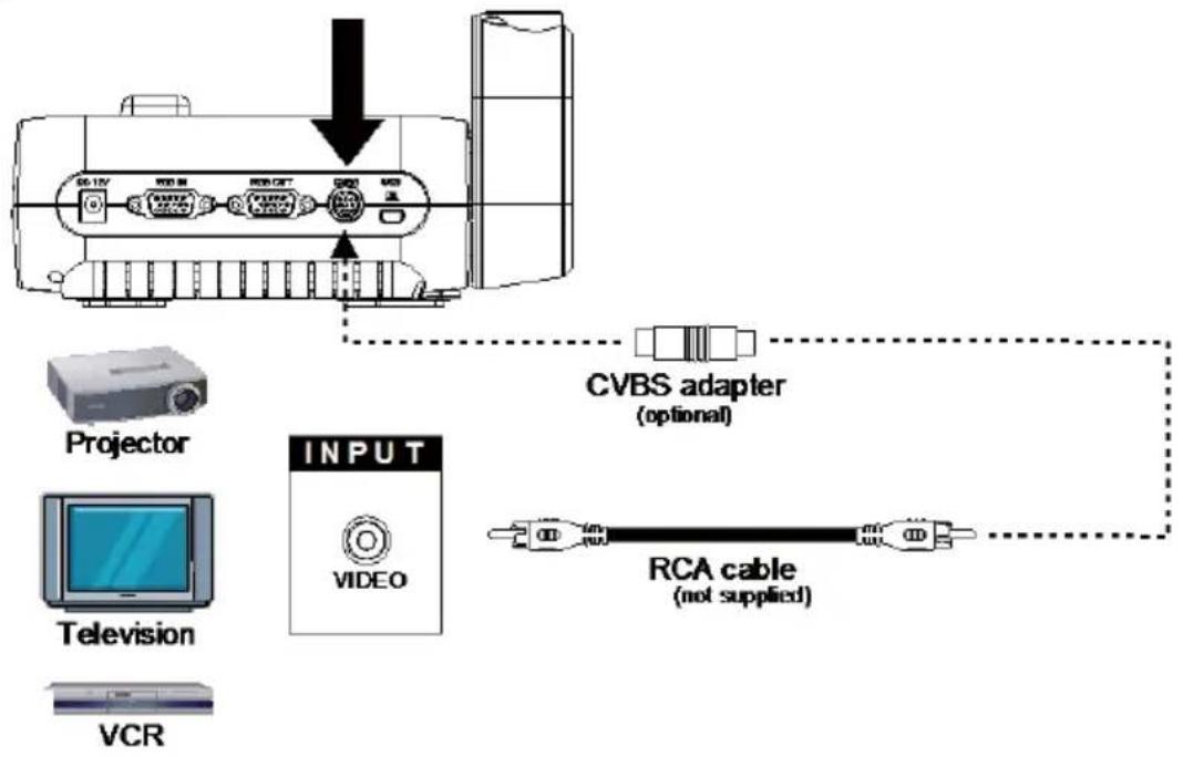
| (4) CVBS port | Connect the CVBS adapter (optional) into this port. The RCA jack outputs the video signal from the camera to a TV or video equipment. |
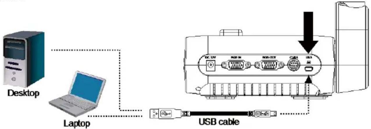
| (5) Mini USB port | Connect to a USB port of a computer with a USB cable and use AVerVision F17HD as a USB camera or transfer the captured images/videos from the memory source to computer. |
Left Panel
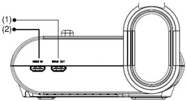
(fig. 1.4)
| Name | Function |
| (1) HDMI Out port | Output the video signal from the main system on an LCD monitor or LCD/DLP projector with HDMI interface using HDMI cable. |
| (2) HDMI In port | Connect an external HDMI source as an input via this port |
Control Panel
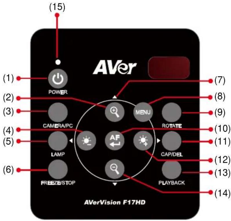
flowchart
graph TD
    A["Power"] --> B["CAMERA/PC"]
    B --> C["LAMP"]
    C --> D["FREEZE/STOP"]
    D --> E["AF"]
    E --> F["MENU"]
    F --> G["ROTATE"]
    G --> H["CAP/DEL"]
    H --> I["PLAYBACK"]
    I --> J["(14)"]
    I --> K["(13)"]
    I --> L["(12)"]
    I --> M["(11)"]
    I --> N["(10)"]
    I --> O["(9)"]
    I --> P["(8)"]
    I --> Q["(7)"]
    A --> R["(15)"]
(fig. 1.5)
| Name | Function | |
| (1) POWER | Turn the unit on/standby mode. | |
(2)  | Increase the image magnification in camera and picture playback mode. | |
| (3) CAMERA / PC | Switch the video signal between camera or computer from the RGB IN port. | |
(4)  | Reduce the brightness of live view. | |
| (5) LAMP | Turn the overhead light on/off. | |
| (6) FREEZE/STOP | Pause or resume image display in Camera mode. | |
| (7) | ▲,▼,◀, & ▶ | - Select options in OSD menu.- Move the Spotlight frame and Visor screen cover. |
| (8) | MENU | Open and exit the OSD menu. |
| (9) | Rotate | Rotate the image by 90° in Camera mode and Playback mode. |
| (10) |  | - Adjust the focus automatically.- Make a selection in Playback mode and OSD menu. |
| (11) | CAP/DEL | - Capture picture in Camera mode. In continuous capture mode, press this button again to stop.- Delete the selected picture in Playback mode. |
| (12) |  | Increase the brightness of live view. |
| (13) | PLAYBACK | View & playback captured still images files. |
| (14) |  | Decrease the image magnification in camera and picture playback mode. |
| (15) | Power LED indicator | - Red: Standby- Green: RGB/HDMI output- Orange: TV output |
Remote Control
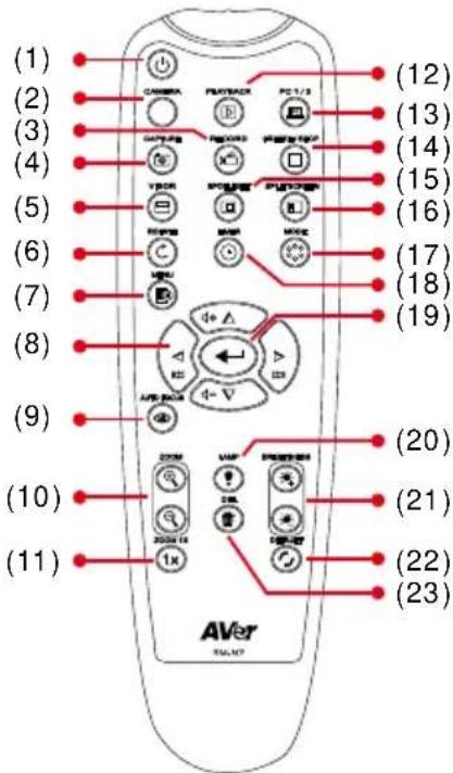
The remote control requires two (2) “AAA” size batteries (supplied), make sure batteries are installed properly before use. You can access all the features of AVerVision F17HD with the remote.
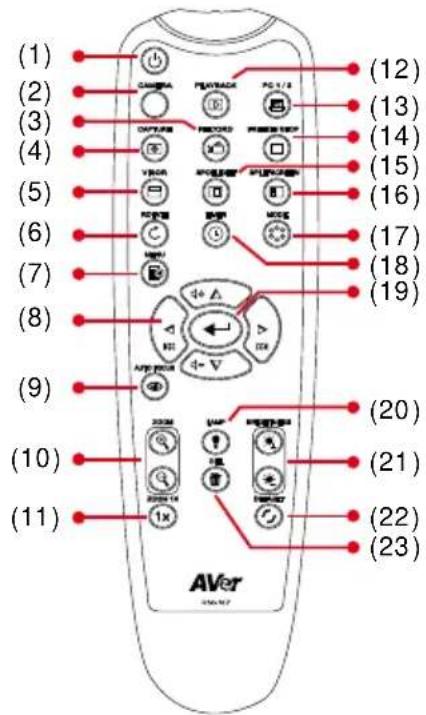
| Name | Function |
| (1) POWER | Turn the unit on/standby. |
| (2) CAMERA | Camera mode displays the video signal from the built-in camera. |
| (3) RECORD | The recording function doesn’t support on AVerVision F17HD. |
| (4) CAPTURE | Capture still image in Camera mode. In continuous capture mode, press this button again to stop. |
| (5) VISOR | Call the Visor submenu. Visor covers part of the presentation screen and allow presenter to reveal the material as desire.In the Visor submenu, the following options are available.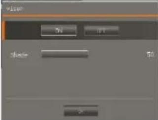 ON/OFF – select to run/cancel the Visor.Pressto move to the next selection.Shade– set the opacity level of the covered area. The shaded area will completely turns black when it is set to level 100. Pressto move to the next selection.OK– pressforthe setting to take effect. If you select ON, upper part of the presentation screen is slightly exposed. Use the▲,▼,◀, &▶buttons to reveal more of the covered area; and OFF will close the submenu.To turn off Visor, pressagain. ON/OFF – select to run/cancel the Visor.Pressto move to the next selection.Shade– set the opacity level of the covered area. The shaded area will completely turns black when it is set to level 100. Pressto move to the next selection.OK– pressforthe setting to take effect. If you select ON, upper part of the presentation screen is slightly exposed. Use the▲,▼,◀, &▶buttons to reveal more of the covered area; and OFF will close the submenu.To turn off Visor, pressagain. |
| (6) ROTATE | Rotate the image by 90° in Camera mode and Playback mode. |
| (7) MENU | Open and exit the OSD menu. |
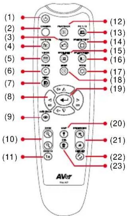
| Name | Function |
| (8) ▲,▼,◀, & ▶ | - From remote control to pan the image when is above 2X in live mode or playback captured image mode.- Select options in OSD menu.Move the Spotlight frame and Visor screen cover. |
| (9) AUTO FOCUS | Adjust the focus automatically. |
| (10) ZOOM +/- | Increase/decrease the image magnification in camera and picture playback mode. |
| (11) ZOOM RESET | Reset zoom level to 100%. |
| (12) PLAYBACK | View the captured picture from the memory in 16-thumbnail images. |
| (13) PC 1/2 | PC mode displays the video signal from the RGB/HDMI INPUT port of F17HD. |
| (14) FREEZE / STOP | Freeze live images |
| (15) SPOTLIGHT | Call the Spotlight submenu. Spotlight overlays a box frame on the presentation screen. You can adjust the box size and move it around.In the Spotlight submenu, the following options are available.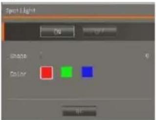 ON/OFF – select to run/cancel the Spotlight. Press to move to the next selection.Shade – set the opacity level of the area outside the box. The shaded area will completely turns black when it is set to level 100. Press to move to the next selection. ON/OFF – select to run/cancel the Spotlight. Press to move to the next selection.Shade – set the opacity level of the area outside the box. The shaded area will completely turns black when it is set to level 100. Press to move to the next selection. |
| Name | Function |
| (15) SPOTLIGHT | Color – select the Spotlight frame color.Press to move to the next selection.OK – press for the setting to take effect. If you select ON, the frame will appear and blink, use the ▲,▼,◀, &▶ buttons to adjust the frame size and press to set the desired size; and OFF will close the submenu.To turn off Spotlight, press again. |
| (16) SPLIT SCREEN | Divide the screen into two. One side displays the live image from the built-in camera and the other side displays 8- thumbnail size picture from the memory. |
| (17) MODE | Select from 4 type of modes:Sharp - adjust the contrast along the edges making text appear more visible.Graphics - adjust the gradient of image.Motion - increase frame rate. Sufficient lighting is required when using this mode.Microscope - automatically adjust optical zoom for microscopic viewing. |
| (18) TIMER | Call the Timer submenu. Select to Start/Pause/Stop the timer countdown and set the timer duration.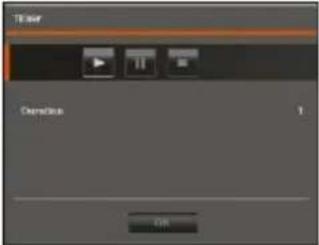 |
| (19) [←] | - Make a selection in Playback mode and OSD menu. |
| (20) LAMP | Turn the overhead light on/off. |
| (21) BRIGHTNESS +/- | Adjust the brightness. |
| (22) DEFAULT | Reset to factory default setting. |
| (23) DEL | Delete the selected picture in Playback mode. |
Making the Connections
Before making the connection, make sure the power of all devices are turned off. If you are not sure on where to connect, simply follow the illustrated connections below and also refer to the user manual of the device you are connecting the AVerVision F17HD with.
Set the TV-RGB Switch Setting
The TV-RGB switch determines the display output selection. Switch it to RGB (right) to output signal using RGB/HDMI connection and TV (left) to output signal using RCA connection. (see fig. 1.2 #3)
| Switch | AVerVision Port | Display Device Port | |
| RGB | 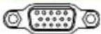 RGB OUTPUT RGB OUTPUT | To | 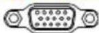 RGB INPUT RGB INPUT |
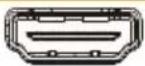 HDMI OUTPUT HDMI OUTPUT | 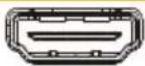 HDMI INPUT HDMI INPUT | ||
| TV |  CVBS(use CVBS adapter)(optional) CVBS(use CVBS adapter)(optional) |  VIDEO IN VIDEO IN | |
Connect to a Monitor or LCD/DLP Projector
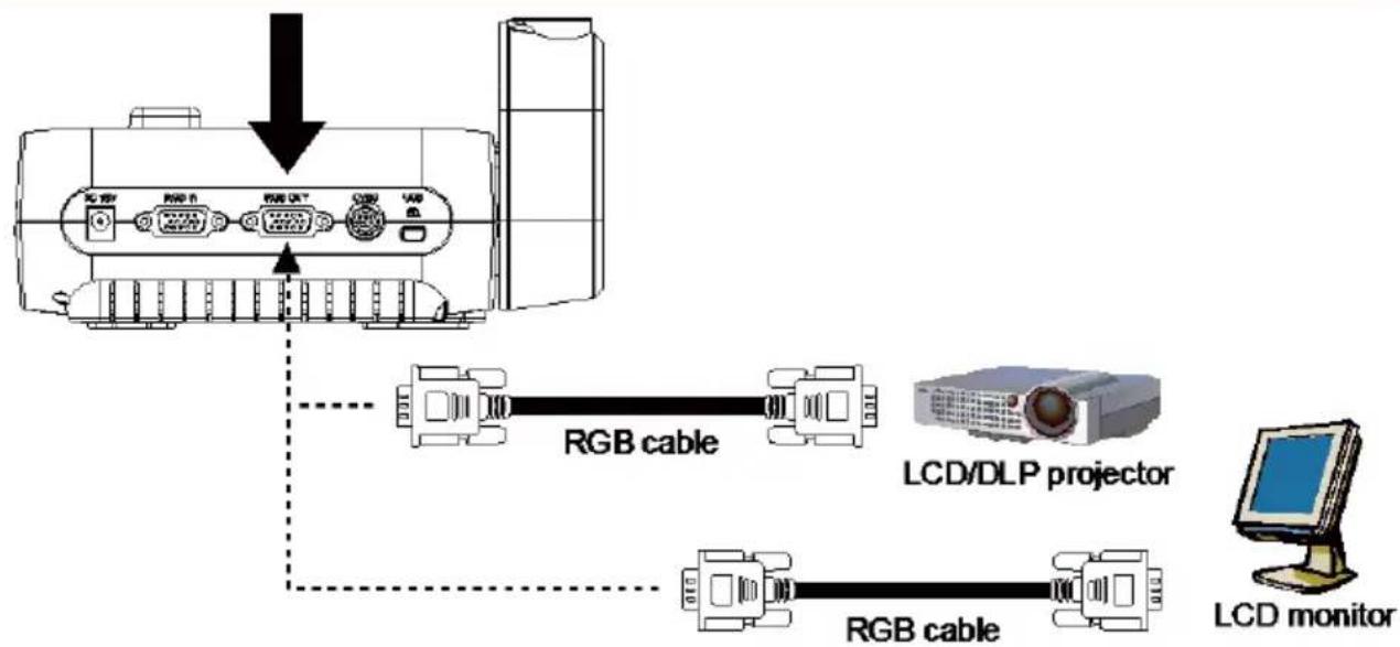
Locate the RGB (VGA) input port of the graphics display device and connect it to RGB OUT port of AVerVision F17HD.

Make sure the TV/RGB switch is set to RGB.
flowchart
graph TD
    A["Device"] -->|RGB cable| B["LCD/DLP projector"]
    A -->|RGB cable| C["LCD monitor"]
    B --> D["Laptop"]
Connect to a Monitor or LCD/DLP Projector with HDMI Output interface
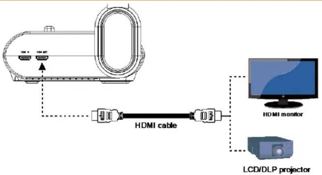
Locate the HDMI input port of the display device and connect it to HDMI out port of AVerVision F17HD.

Make sure the TV/RGB switch is set to RGB.
Connect to a TV
Locate the VIDEO or SCART RGB (if applicable) input port of the TV or Video equipment (i.e., VCR) to record your presentation and connect it to RCA jack of CVBS adapter (optional).
flowchart
graph TD
    A["Projector"] --> B["TVR"]
    C["Television"] --> D["VCR"]
    E["CVBS adapter (optional)"] --> F["RCA cable (not supplied)"]
    G["INPUT"] --> H["VIDEO"]
Connecting the Power
Connect the power adapter to a standard 100V\~240V AC power outlet. The unit automatically in standby mode once the power is connected. Press 📞 turn on.
Connect to a Computer
Locate the RGB (VGA) output port of the computer or laptop and connect it to RGB IN port of DocCam. The video signal from the RGB IN port is streamed to RGB OUT.

- To display computer image, press Camera/PC button on the control panel or remote control to switch AVerVision F17HD to computer mode.
- For laptop to output display image, use the keyboard command (FN+F5) to switch between the display modes. For different command, please refer to your laptop manual.
flowchart
graph TD
    A["Device"] -->|USB OUT| B["USB Cable"]
    B --> C["Laptop"]
    C --> D["Desktop"]
    style A fill:#f9f,stroke:#333
    style D fill:#bbf,stroke:#333
    note1["↓"] --> A
    note2["RGB cable"] --> B
    note3["Laptop"] -.-> D
Connect to a Computer via USB
Locate the USB port of the computer or laptop and connect it to PC port of AVerVision F17HD.
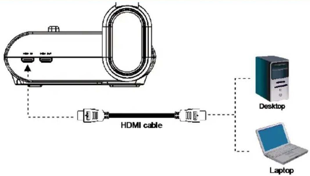
Connect to a Computer with HDMI Input interface
Locate the HDMI output port of the computer of laptop and connect it to HDMI in port of AVerVision F17HD.

- Make sure the TV/RGB switch is set to RGB.
- To display computer image, press Camera/PC button on the control panel or remote control to switch AVerVision F17HD to computer mode.
- For laptop to output display image, use the keyboard command (FN+F5) to switch between the display modes. For different command, please refer to your laptop manual.
Connect to a Microscope
Connect the AVerVision F17HD to a microscope enables you to examine microscopic objects on a big screen.
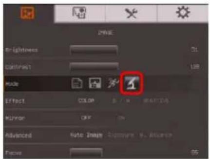
- Change the image display mode to Microscope. Press MENU > select
IMAGE tab > select MODE > select

(microscope) and press
- Aim the camera head at the farthest point and press AUTO FOCUS.
- Adjust the focus of the microscope.
- Select the appropriate rubber coupler size for the microscope eyepiece and insert it in the microscope adapter.
- Remove the microscope eyepiece from the microscope and connect it to the microscope adapter with the rubber coupler inserted. Fasten the 3 bolts until the adapter secures the eyepiece.

For the eyepiece, we suggest using 15.5mm eye relief or higher.
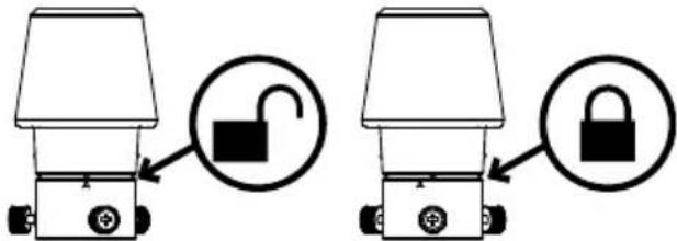
- Attach the microscope adapter to the AVerVision camera head. Then connect it to the AVerVision and microscope.
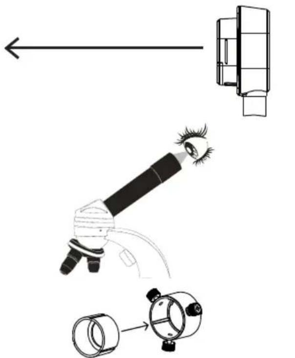
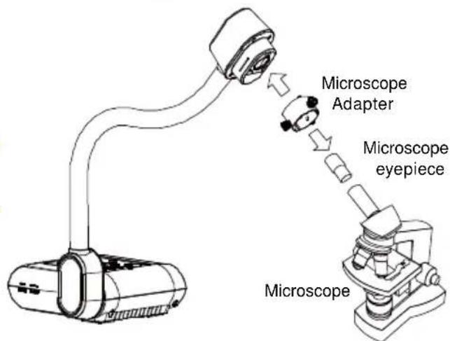
Make sure the arrow on the camera head and microscope adapter are on the same side to connect and twist clockwise for the arrows to meet and lock.
Setting Up AVerVision F17HD
This section provides useful tips on how to adjust the AVerVision F17HD to meet your needs.
Storing and Handling
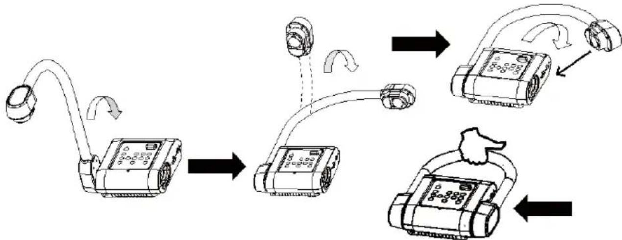
The gooseneck design allows you to freely bend the arm and store the camera head in the camera holder. Once you have properly secured the camera head to the camera holder, you may use the arm to carry AVerVision F17HD.
flowchart
graph TD
    A["Signal Transmission"] --> B["Device Position"]
    B --> C{Display Setup}
    C -->|Transitions| D["Device Layout"]
    D --> E["Delivery to Device"]
    E --> F["Final Display"]
Shooting Area
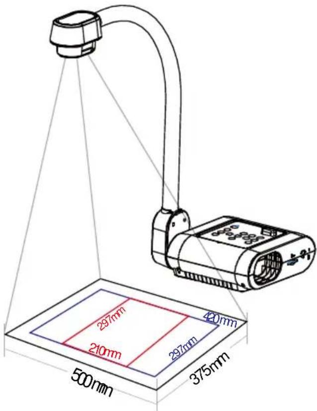
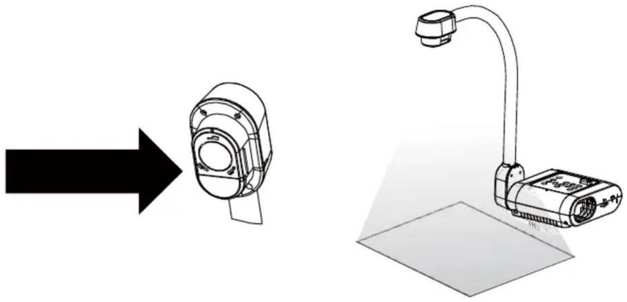
The shooting area can view an area of 500x375mm which allows you to show an A4 and A3 size portrait paper.
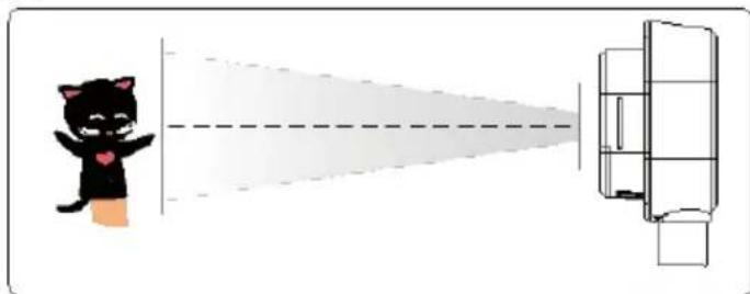
If the camera head is in upright position, press ROTATE on the remote control twice to rotate the image in 180^ .
natural_image
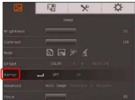
Illustration of a cartoon cat giving a shadowy light beam to a rectangular device (no text or symbols)To mirror the image, press MENU > select Mirror, press ⏻ and select On.
Overhead Light
Press LAMP button on the control panel or remote control to turn on and off light.
natural_image
Technical illustration showing a mechanical device with a left-side arrow pointing to a cylindrical component and a right-side schematic of a monitor mounted on a stand (no text or symbols present)Infrared Sensor
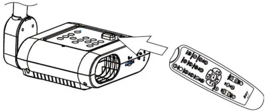
Aim the remote control at the infrared sensor to operate the unit.
natural_image
Line drawing of a remote control device with ports and a separate remote control panel (no text or symbols)Mounting the F17HD on a Flat Surface
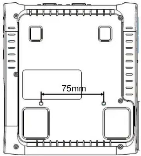
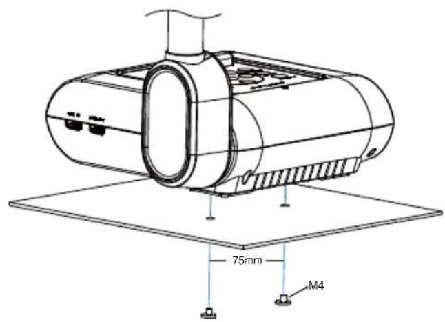
Measure and mark the horizontal of 75 ~mm from the center line distance between the holes on the flat surface as describe in the illustration below. Use 2 pieces of M4.0 screws for 6 mm holes and secure the F17HD on the flat surface.
Anti-glare Sheet
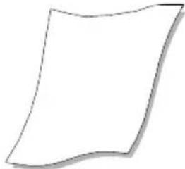
The anti-glare sheet is a special coated film that helps eliminate any glare that maybe encountered while displaying very shiny objects or glossy surfaces such as magazines and pictures. To use, simply place the anti-glare sheet on top of the shiny document to reduce reflected light.
natural_image
Simple line drawing of a folded paper or document (no text or symbols)External Memory Storage
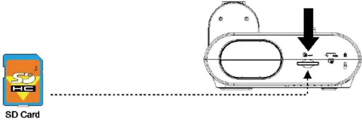
AVerVision F17HD supports both SD memory card for more image capture. AVerVision F17HD can detect when there is an external storage media and automatically switch to the last detected storage. If no external storage is connected, all captured still images will be saved in the built-in memory.
Insert an SD Card
Insert the card with the contact facing down until it reaches the end. To remove the card, push to eject and pull the card out. The supported SD card capacity is from 1GB to 32GB (FAT32). We recommend using SDHC card with class-6 or above for high quality recording.
OSD MENU
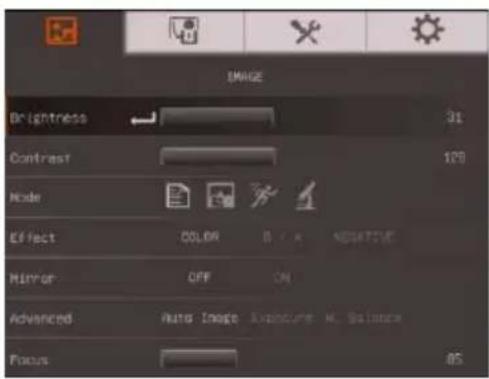
There are 4 tabs on the OSD menu: IMAGE, PRESENTATION, SETTING and SYSTEM. In Playback mode, you can access PLAYBACK OSD menu to enable the Slide Show feature and modify Slide Show interval and transition setting if desire.

For TV output, the RESOLUTION will be disabled in SETTING menu list.
IMAGE
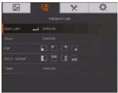
PRESENTATION
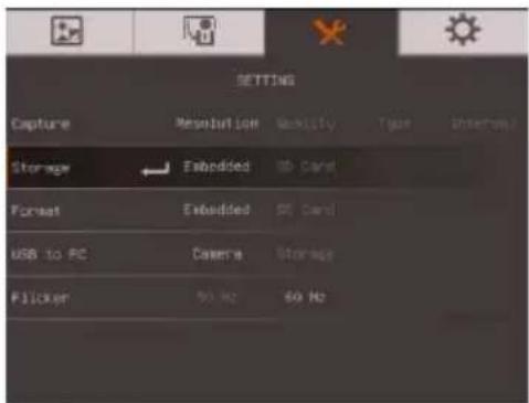
SETTING
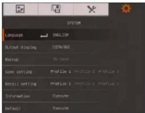
SYSTEM
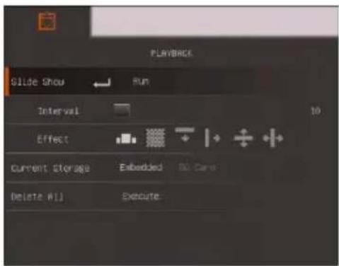
PLAYBACK
Navigate the Menu and Submenu
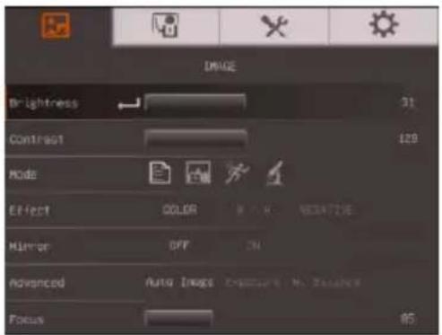
- Press MENU button on the remote or control panel.
- Press ▶ and ◀ to toggle between tabs
-
Press ▼ and ▲ to choose a selection in the menu list.
-
Press to make a selection.
- Use ▶ and ◀ to adjust the setting or make a selection.
- Press to enter submenu.
- Press MENU to close the OSD menu.
Image
Menu Screen
Function
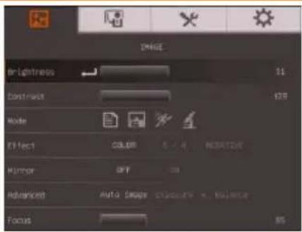
Brightness
Adjust brightness level manually between 0 and 63.
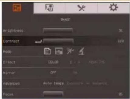
Contrast
Adjust the contrast level manually between 0 and 255 under bright and dark environments.
Menu Screen
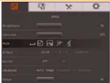
Function
Mode
Select from the various image display settings.
Sharp - adjust the contrast along the edges making text appear more visible.
Graphics - adjust the gradient of image.
Motion - increase frame rate. Sufficient lighting is required when using this mode.
Microscope - automatically adjust optical zoom for microscopic viewing.
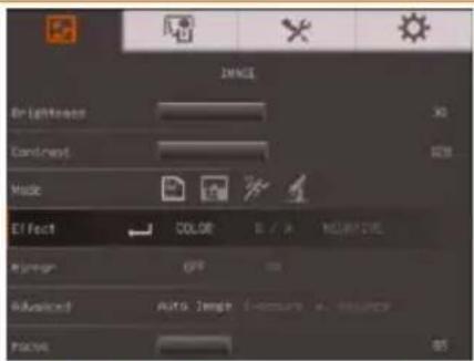
Effect
Convert the image into positive (true color), monochrome (black and white) or negative.
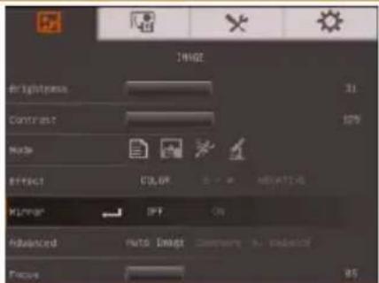
Mirror
Select to flip the image in Camera mode.
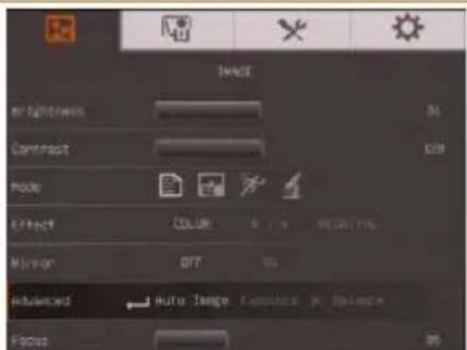
Advanced
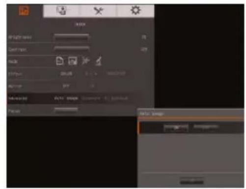
Select to set the Auto Image, Exposure, and White Balance settings.
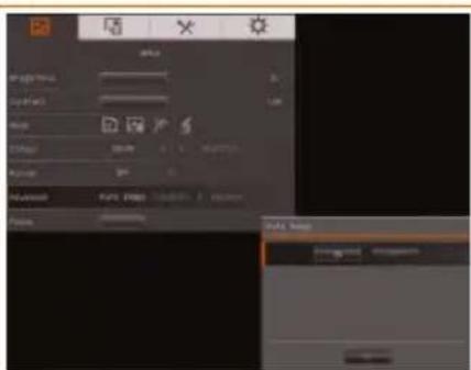
Auto Image
Select ON or OFF to automatically adjust the white balance and exposure setting, and correct the color and exposure compensation.
Menu Screen
Function
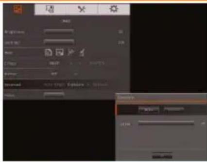
Exposure
Select the exposure setting.
AUTO - automatically adjust the camera exposure and the amount of light required.
MANUAL - manually adjust the exposure level. The exposure can be adjusted up to 100.
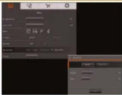
White Balance
Select the White Balance setting for various light conditions or color temperature.
AUTO - automatically adjust the white balance.
MANUAL - manually adjust the red and blue color level. The color level can be adjusted up to 255.
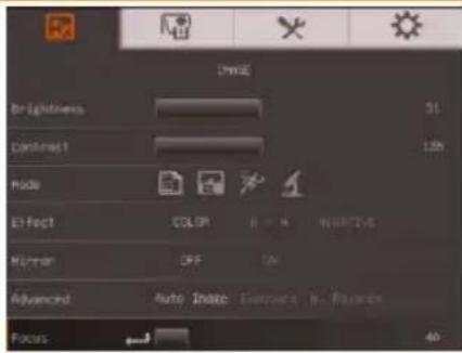
Focus
Manually adjust the focus.
Presentation
Menu Screen
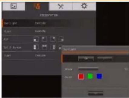
Function
Spotlight
Spotlight overlays a frame on the presentation screen. You can move the Spotlight around the presentation screen using the ▲,▼,◀, & ▶ buttons. Select Execute to call the Spotlight submenu.
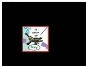
In the Spotlight submenu, the following options are available.
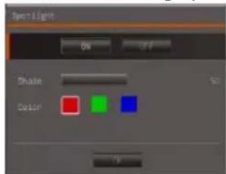
ON/OFF – select to run/cancel the Spotlight. Press to move to the next selection.
Shade – set the opacity level of the area outside the box. The shaded area will completely turns black when it is set to level 100. Press to move to the next selection.
Color – select the Spotlight frame color. Press to move to the next selection.
OK – press ← for the setting to take effect. If you select ON, the frame will appear and blink, use the ▲, ▼, ◀, & ▶ buttons to adjust the frame size and press ← to set the desired size; and OFF will close the submenu.
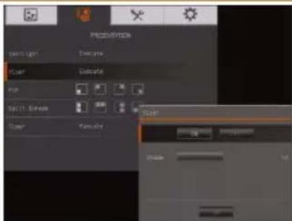
Visor
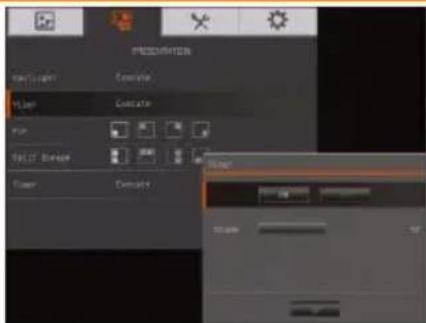
Visor covers the presentation screen. The upper part of the presentation screen is slightly exposed. Use the ▲,▼,◀, &▶ buttons to reveal more of the covered area. Select Execute to call the Visor submenu.
natural_image
Completely black image with no visible content or text.Menu Screen
Function
In the Visor submenu, the following options are available.
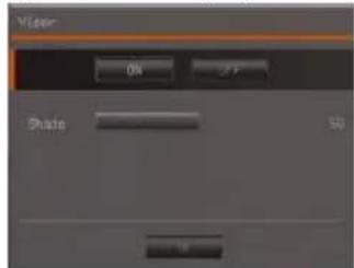
ON/OFF – select to run/cancel the Visor. Press ☑ move to the next selection.
Shade – set the opacity level of the covered area. The shaded area will completely turns black when it is set to level 100. Press ⬇ to move to the next selection.
OK – press for the setting to take effect. If you select ON, upper part of the presentation screen is slightly exposed. Use the ▲, ▼, ◀, & ▶ buttons to reveal more of the covered area; and OFF will close the submenu.
PIP
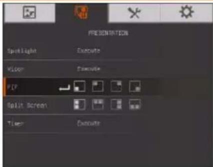
Select the thumbnail playback screen location and show the thumbnail playback screen at the corner of the screen to recall the captured image from the memory in Camera mode. Select OFF to cancel PIP.
Lower Left
Upper Left
Upper Right
Lower Right
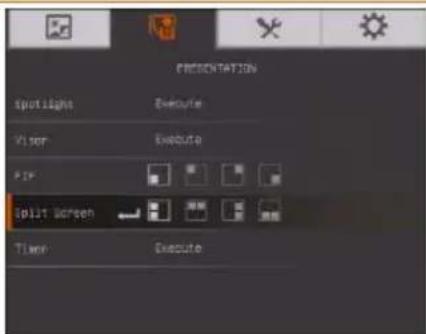
Split Screen
Divide the screen into two parts. Half of the screen displays the 8-thumbnail images and the other half display the image from the AVerVision F17HD camera. Select the display location of the 8- thumbnail playback images. Select OFF to cancel Split Screen.
Left
Top
Right
Below
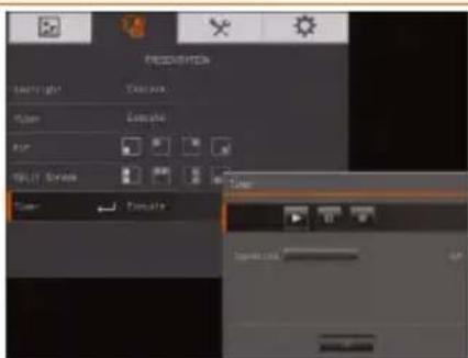
Timer
Start/Pause/Stop the timer and set the timer duration. The timer automatically counts up after the countdown reaches zero to show the elapsed time. Even when you switch between Playback, PC or Camera modes, the timer will continue.
Setting
Menu Screen
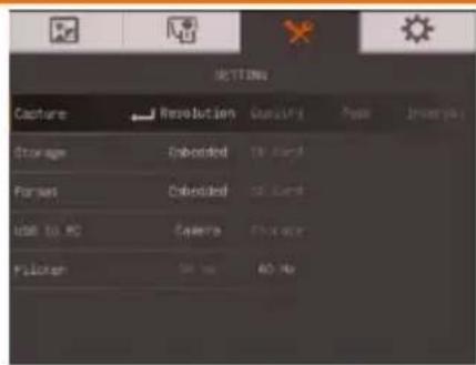
Function
Capture
Select to set the capture resolution, quality, type and interval settings.
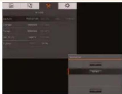
Resolution
Select the capture size. In 5M setting, the capture resolution size is 2560 X 1920.
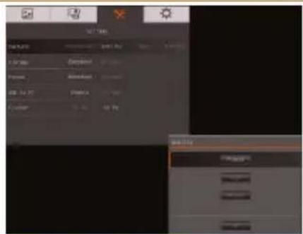
Quality
Select the capture compression setting.
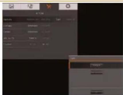
Type
Select the capture type.
Single - capture one picture only.
Continuous - capture successive pictures.
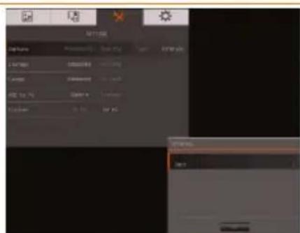
Interval
Set the time interval for continuous capture. The length can be set up to 600 sec (10 min).
| Menu Screen | Function |
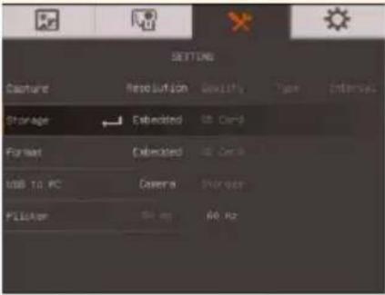 | StorageChange the storage location. Captured image can only be saved in SD memory card. |
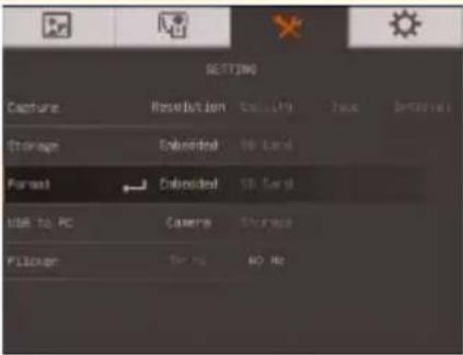 | FormatFormat to delete all the data in the selected memory. |
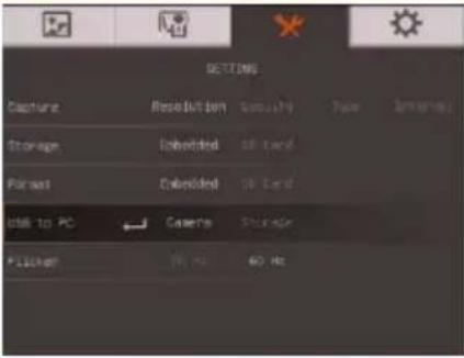 | USB to PCCamera - can be used as a computer webcam or with our bundled software to capture still image.Storage - transfer the captured pictures from the memory to computer hard disk. |
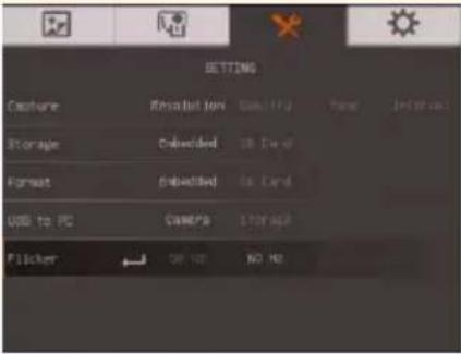 | FlickerSelect between 50Hz or 60Hz. Some display devices cannot handle high refresh rates. The image will flicker a couple of times as the output is switched to another refresh rate. |
System
Menu Screen
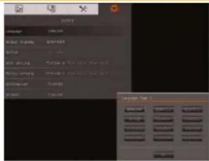
Function
Language
Change and select different language.
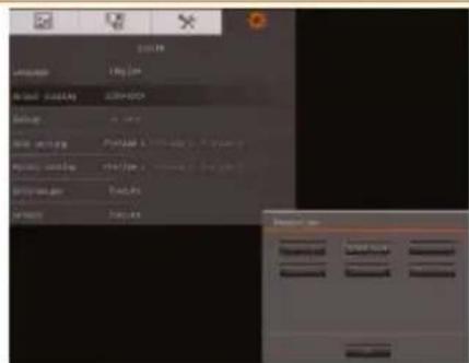
Output Display
Set the resolution to display the image on screen. This selection will be disabled in TV output mode.
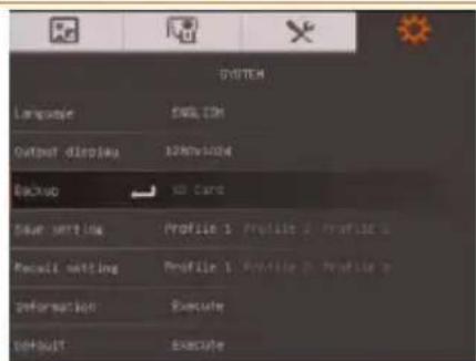
Backup
Copy the image from the built-in memory to SD card.
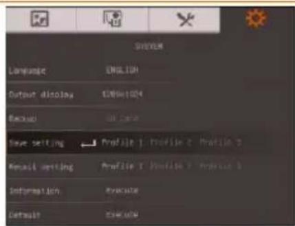
Save Setting
Save current setting in the selected profile number. Only effect, mode, brightness and contrast settings can be saved.
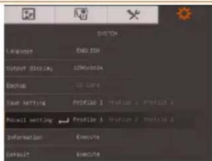
Recall Setting
Restore the setting back to the selected profile number.
Menu Screen
Function
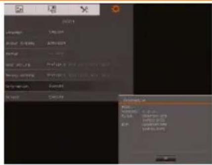
Information
Display the product information.
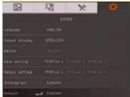
Default
Restore all the settings into original factory default setting.
Playback
Menu Screen

Function
Slide Show
Display all captured still pictures in an automated slide show.
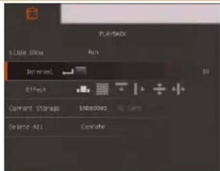
Interval
Set the interval before displaying the next picture. The length can be set up to 100 sec.
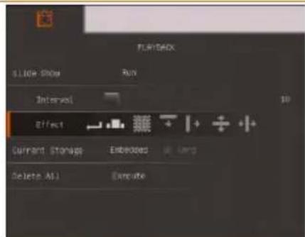
Slide Show Effect
Select the slide show transition effect.

Slide image

Checker down

Wipe down

Wipe right

Split Vertical Out

Split Horizontal In
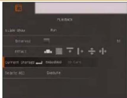
Current Storage
Select the source of the images.
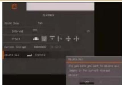
Delete All
Permanently delete all the data in selected memory source. A Warning Message will appear. Select YES to continue and NO to stop formatting the storage.
Transfer Captured Images to a computer
This enables you to transfer the captured image from the built-in memory or SD to a computer.

The instruction below MUST be read and followed BEFORE connecting the USB cable.
- MUST set the USB to PC as STORAGE before connecting the USB cable.
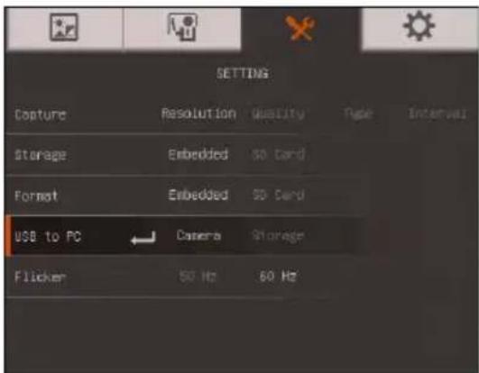
- When "Mass Storage Start..." appears at the lower right corner of the presentation screen, you may now connect the USB cable.
- Upon connecting the USB cable, the system automatically detects the new removable disk. You can now transfer the captured image(s) from the F17HD built-in memory to the computer hard disk.
Technical Specifications
Image
| Sensor | 1/4” CMOS |
| Pixel Count | 5 mega pixels |
| Frame Rate | 30 fps (max.) |
| White Balance | Auto / Manual |
| Exposure | Auto / Manual |
| Image mode | Sharp / Graphics / Motion / Microscope |
| Effect | Color / B/W / Negative |
| RGB output | 1920x1080, 1600x1200, 1280x1024, 1280x720, 1024x768, 1280 x 800 |
| HDMI Output | HD 1080p 60Hz; HD 720p 60Hz |
| Image Capture | 240 Frames(XGA) ; 80 Frames(5M Pixel) |
Optics
| Focusing | Auto / Manual |
| Shooting Area | 500mm x 375mm |
| Zooming | Total 32X (2X AVer ZoomTM, 16X Digital zoom) |
Power
| Power Source | DC : 12V/2A ; AC : 100-200V,50-60Hz |
| Consumption | 12 Watts (lamp off); 12.8 Watts (lamp on) |
Lighting
| Lamp Type | LED light |
Input/Output
| RGB Input | 15-Pins D-sub (VGA) |
| RGB Output | 15-Pins D-sub (VGA) |
| HDMI Output | HDMI |
| HDMI Input | HDMI |
| Composite Video | RCA Jack |
| USB | USB2.0 |
| DC 12V Input | Power Jack |
| MIC | Built-in MIC |
Dimension
| Operating | 380(L)*200(W)*525mm(H) (+/-2mm include rubber foot) |
| Folded | 305(L)*230(W)*73mm(H) (+/-2mm include rubber foot) |
| Weight | 2.44 kg (about 5.38lbs) |
External Storage
| Secure Digital (SDHC) | 1GB ~ 32GB (FAT32) |
Troubleshooting
This section provides many useful tips on how to solve common problems while using the AVerVision F17HD.
There is no picture on the presentation screen.
- Check all the connectors again as shown in this manual.
- Check the on/off switch of the display output device.
- Verify the setting of the display output device.
- If you are presenting from a notebook or computer through the display output device, check the cable connection from computer RGB (VGA) output to RGB input of AVerVision F17HD and make sure AVerVision F17HD is in PC Mode.
I have set up the AVerVision F17HD and checked all the connections as specified in the manual but I cannot get a picture on the preferred presentation screen.
- Once the power is connected the unit is set to standby mode. Press the POWER button to turn on.
- If your display output device is on TV or any analog device, please switch the TV-RGB dip switch to TV.
The picture on the presentation screen is distorted or the image is blurry.
- Reset all changed settings, if any, to the original manufacturer default setting. Press MENU then go to SYSTEM > Default and select YES in the OSD menu.
- Use the Brightness and Contrast menu functions to reduce the distortion if applicable.
- If you discover that the image is blurry or out of focus, press the Auto Focus button on the control panel or remote control.
There is no computer signal on presentation screen.
- Check all the cable connections among the display device, AVerVision F17HD and your PC.
- Connect your PC to the AVerVision F17HD first before you power on your computer.
- For notebook, repeatedly press FN+F5 to toggles between display modes and display the computer image on the presentation screen. For different command, please refer to your laptop manual.
The presentation screen does not show the exact desktop image on my PC or Notebook after I toggle from Camera to PC mode.
- Return to your PC or Notebook, place the mouse on the desktop and right click, choose "Properties", choose "Setting" tab, click on "2" monitor and check the box "Extend my Windows desktop onto this monitor".
- Then go back one more time to your PC or Notebook and place the mouse on the desktop and right click again.
- This time choose "Graphics Options", then "Output To", then "Intel® Dual Display Clone", and then choose "Monitor + Notebook".
- After you follow these steps, you should be able to see the same desktop image on your PC or Notebook as well as on the presentation screen.
Limited Warranty
For a period of time beginning on the date of purchase of the applicable product and extending as set forth in the “Warranty Period of AVer Product Purchased” section of the warranty card, AVer Information, Inc. (“AVer”) warrants that the applicable product (“Product”) substantially conforms to AVer’s documentation for the product and that its manufacture and components are free of defects in material and workmanship under normal use. “You” as used in this agreement means you individually or the business entity on whose behalf you use or install the product, as applicable. This limited warranty extends only to You as the original purchaser. Except for the foregoing, the Product is provided “AS IS.” In no event does AVer warrant that You will be able to operate the Product without problems or interruptions, or that the Product is suitable for your purposes. Your exclusive remedy and the entire liability of AVer under this paragraph shall be, at AVer’s option, the repair or replacement of the Product with the same or a comparable product. This warranty does not apply to (a) any Product on which the serial number has been defaced, modified, or removed, or (b) cartons, cases, batteries, cabinets, tapes, or accessories used with this product. This warranty does not apply to any Product that has suffered damage, deterioration or malfunction due to (a) accident, abuse, misuse, neglect, fire, water, lightning, or other acts of nature, commercial or industrial use, unauthorized product modification or failure to follow instructions included with the Product, (b) misapplication of service by someone other than the manufacturer’s representative, (c) any shipment damages (such claims must be made with the carrier), or (d) any other causes that do not relate to a Product defect. The Warranty Period of any repaired or replaced Product shall be the longer of (a) the original Warranty Period or (b) thirty (30) days from the date of delivery of the repaired or replaced product.
Limitations of Warranty
AVer makes no warranties to any third party. You are responsible for all claims, damages, settlements, expenses, and attorneys' fees with respect to claims made against You as a result of Your use or misuse of the Product. This warranty applies only if the Product is installed, operated, maintained, and used in accordance with AVer specifications. Specifically, the warranties do not extend to any failure caused by (i) accident, unusual physical, electrical, or electromagnetic stress, neglect or misuse, (ii) fluctuations in electrical power beyond AVer specifications, (iii) use of the Product with any accessories or options not furnished by AVer or its authorized agents, or (iv) installation, alteration, or repair of the Product by anyone other than AVer or its authorized agents.
Disclaimer of Warranty
EXCEPT AS EXPRESSLY PROVIDED OTHERWISE HEREIN AND TO THE MAXIMUM EXTENT PERMITTED BY APPLICABLE LAW, AVER DISCLAIMS ALL OTHER WARRANTIES WITH RESPECT TO THE PRODUCT, WHETHER EXPRESS, IMPLIED, STATUTORY OR OTHERWISE, INCLUDING WITHOUT LIMITATION, SATISFACTORY QUALITY, COURSE OF DEALING, TRADE USAGE OR PRACTICE OR THE IMPLIED WARRANTIES OF MERCHANTABILITY, FITNESS FOR A PARTICULAR PURPOSE OR NONINFRINGEMENT OF THIRD PARTY RIGHTS.
Limitation of Liability
IN NO EVENT SHALL AVER BE LIABLE FOR INDIRECT, INCIDENTAL, SPECIAL, EXEMPLARY, PUNITIVE, OR CONSEQUENTIAL DAMAGES OF ANY NATURE INCLUDING, BUT NOT LIMITED TO, LOSS OF PROFITS, DATA, REVENUE, PRODUCTION, OR USE, BUSINESS INTERRUPTION, OR PROCUREMENT OF SUBSTITUTE GOODS OR SERVICES ARISING OUT OF OR IN CONNECTION WITH THIS LIMITED WARRANTY, OR THE USE OR PERFORMANCE OF ANY PRODUCT, WHETHER BASED ON CONTRACT OR TORT, INCLUDING NEGLIGENCE, OR ANY OTHER LEGAL THEORY, EVEN IF AVER HAS ADVISED OF THE POSSIBILITY OF SUCH DAMAGES. AVER'S TOTAL, AGGREGATE LIABILITY FOR DAMAGES OF ANY NATURE, REGARDLESS OF FORM OF ACTION, SHALL IN NO EVENT EXCEED THE AMOUNT PAID BY YOU TO AVER FOR THE SPECIFIC PRODUCT UPON WHICH LIABILITY IS BASED.
Governing Law and Your Rights
This warranty gives you specific legal rights; You may also have other rights granted under state law. These rights vary from state to state.

For warranty period, please refer to the warranty card.

- AVerVision F17HD
- Federal Communications Commission Statement(Class A)
- Class A ITE:
- CE Class A (EMC)
- DISCLAIMER
- TRADEMARKS
- COPYRIGHT
- NOTICE
- WARNING
- Remote Control Battery Safety Information
- Table of Contents
- Package Contents....1
- Optional Accessories .... 1
- Get Familiar with the AVerVision F17HD 2
- Making the Connections 9
- Setting Up AVerVision F17HD 14
- OSD MENU....19
- Package Contents
- Optional Accessories
- Get Familiar with the AVerVision F17HD
- Right Panel
- Rear Panel
- Left Panel
- Control Panel
- Remote Control
- Making the Connections
- Set the TV-RGB Switch Setting
- Connect to a Monitor or LCD/DLP Projector
- Connect to a Monitor or LCD/DLP Projector with HDMI Output interface
- Connect to a TV
- Connecting the Power
- Connect to a Computer
- Connect to a Computer via USB
- Connect to a Computer with HDMI Input interface
- Connect to a Microscope
- Setting Up AVerVision F17HD
- Storing and Handling
- Shooting Area
- Overhead Light
- Infrared Sensor
- Mounting the F17HD on a Flat Surface
- Anti-glare Sheet
- External Memory Storage
- Insert an SD Card
- OSD MENU
- Navigate the Menu and Submenu
- Image
- Function
- Brightness
- Contrast
- Mode
- Effect
- Mirror
- Advanced
- Auto Image
- Exposure
- White Balance
- Focus
- Presentation
- Menu Screen
- Spotlight
- Visor
- PIP
- Split Screen
- Timer
- Setting
- Capture
- Resolution
- Quality
- Type
- Interval
- System
- Language
- Output Display
- Backup
- Save Setting
- Recall Setting
- Information
- Default
- Playback
- Slide Show
- Slide Show Effect
- Current Storage
- Delete All
- Transfer Captured Images to a computer
- Technical Specifications
- Troubleshooting
- There is no picture on the presentation screen.
- I have set up the AVerVision F17HD and checked all the connections as specified in the manual but I cannot get a picture on the preferred presentation screen.
- The picture on the presentation screen is distorted or the image is blurry.
- There is no computer signal on presentation screen.
- The presentation screen does not show the exact desktop image on my PC or Notebook after I toggle from Camera to PC mode.
- Limited Warranty
- Limitations of Warranty
- Disclaimer of Warranty
- Limitation of Liability
- Governing Law and Your Rights
Brand : AVer
Model : Vision F17HD
Category : Visualiser